Embed Size (px)
Citation preview

Synergizing Physical Layer for PlantOptimization
Unnikrishnan R
Manager – Components & Technologies
Pepperl + Fuchs India Pvt Ltd

© 1994 – 2011 Fieldbus Foundation2
Agenda
Introduction to FF and FF Physical Layer
FF Physical Layer Components
FF Wiring Topologies
Process Interfaces
Summary and Conclusion

© 1994 – 2011 Fieldbus Foundation3
What is Fieldbus?
HOST
Field Device
How Do we Link the Various components in the network?
Fieldbus is a digital, two-way, multi-drop communication link among intelligent measurement and control devices. It serves as a Local Area Network (LAN) for advanced process control, remote input/output and high-speed factory automation applications.

© 1994 – 2011 Fieldbus Foundation4
Main components of physical layer
FF - Power Supply, Cables, Surge Protector, Terminators, Wiring Blocks, Process interfaces etc
Wiring Block
HOST
Wiring Block FIELDBUS TERMINATOR
SURGE PROTECTOR
PROCESS
INTERFACE
Ff POWER SUPPLY
CONVENTIONAL FIELD DEVICES
FIELDBUS DEVICES
JUNCTION BOX
Home Run Spurs

© 1994 – 2011 Fieldbus Foundation5
How to optimize FF Physical Layer?
Optimization of field devices by using proper segment design methodology as well as segment revalidation tools where we can optimize loop checking and commissioning time.
Usage of digital communication to achieve predictive intelligence through advanced diagnostics and asset management of the plant.
Usage of features of the device to effect control in field which will optimize lower bandwidth of 31.25kb/sec.

© 1994 – 2011 Fieldbus Foundation6
Why separate FF power supply?
Bulk power supply represents a very low impedance� Much less than 50 Ohm
If this impedance is connected directly to a fieldbus segment this will “short” the communication signal
+ fieldbus
- fieldbus
Active design
+ fieldbus
- fieldbus
Passive design

© 1994 – 2011 Fieldbus Foundation7
How balanced design is achieved?
Z
Z/2
Potential noise source:- bad wiring practices
(AC cables close to bus cables)
- Corrosion (i.e. field device flooded)
Noise
+ fieldbus
- fieldbus
Z/2
Balance reducesthe sensitivityagainst noise

© 1994 – 2011 Fieldbus Foundation8
FF Power Supply – Recommendations
Each Segment shall have a dedicated FFPS
FFPS shall beIsolated and Redundant
FFPS shall be modular and hot Swappable
FFPS shall provide facilities for monitoring faults and failures
FFPS rating shall allow longer home run / Trunk length to benefit user ( typically 28V / 500mA )

© 1994 – 2011 Fieldbus Foundation9
FF Power Supply
© 1994 – 2011 Fieldbus Foundation10
FF Power Supply – With DCS System Connectors
APPROVED

© 1994 – 2011 Fieldbus Foundation11
FF Wiring Blocks

© 1994 – 2011 Fieldbus Foundation12
Significance of Terminators in Physical Layer
One small device – two important tasks� Translates signal current into detectable voltage change� Suppresses signal reflections at end of the trunk
FIELDBUS DEVICES
TRUNK
Terminator on the T-Connector
Terminator integrated in Power Hub. Selectable via DIP-Switch
Flameproof in rugged housing (IP 67) for the hazardous area
© 1994 – 2011 Fieldbus Foundation13
FF Surge Protectors
Surge Protection ( 6.4 AG 181 V3.1)
Surge protection for FOUNDATION fieldbus devices may be required in areas where induced voltage is an issue.
This includes areas such as close wiring proximity where large inductive loads are started and stopped, or areas known for lightning incidence.
Surge suppression consists of a low-capacitance device installed at the device's electrical connection. It shall normally appear as an open circuit to the spur and segment to prevent any adverse effect on communications.

© 1994 – 2011 Fieldbus Foundation14
FF Surge Protectors - Recommendations
Surge suppression device should not measurably attenuate the fieldbus signal
Shall be installed at the Field Devices and host H1 Interface
Current-limiting couplers ( Wiring Block spurs ) should not be used in combination with surge protectors. The surge protectors will cause failure of the current limiting circuits when a lightning strike occurs
© 1994 – 2011 Fieldbus Foundation15
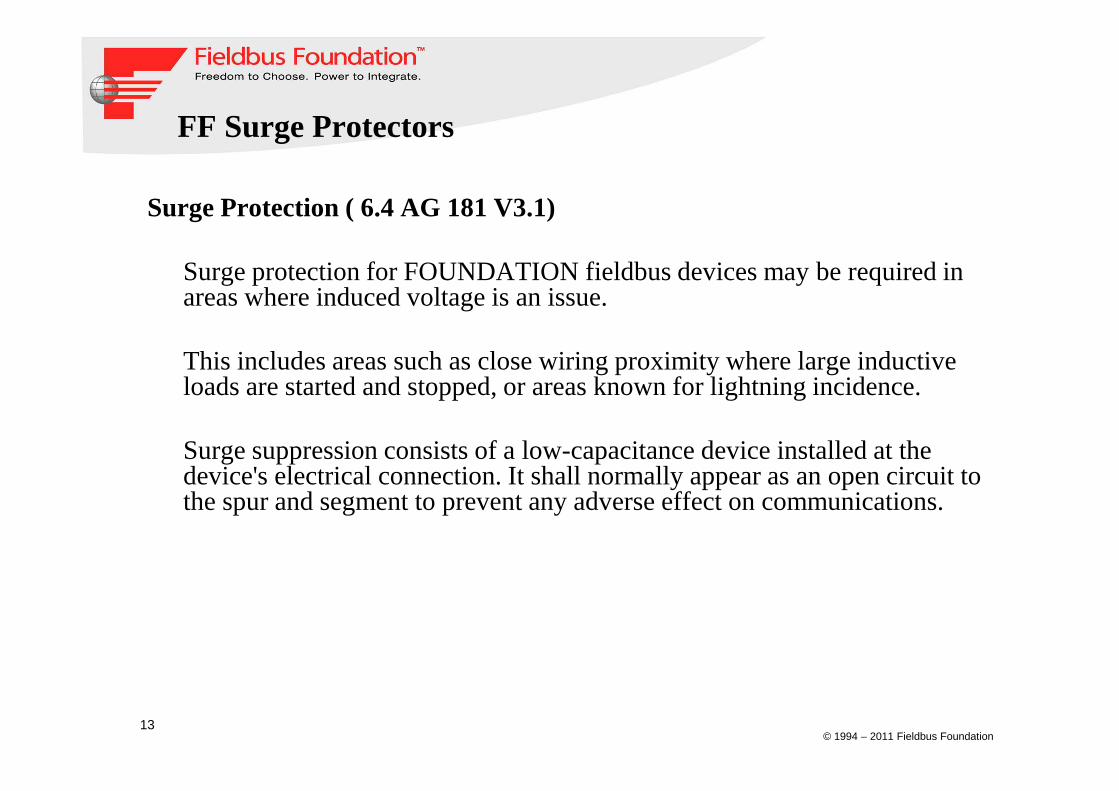
Various process Interfaces
Zone 1
DCS
Zone 2 / DIV 2
Foundation Fieldbus

© 1994 – 2011 Fieldbus Foundation16
Process Interfaces
Zone 1
Ex e
16..32V
16..32V
230VAC

© 1994 – 2011 Fieldbus Foundation17

© 1994 – 2011 Fieldbus Foundation18
FF Wiring Topologies in Hazardous Area

© 1994 – 2011 Fieldbus Foundation19
Segment Topology for General Purpose application
HOST
FIELDBARRIERS FIELDBUS TERMINATOR
SURGE PROTECTOR
PROCESSINTERFACE
POWER SUPPLY
CONVENTIONAL FIELD DEVICES
FIELDBUS DEVICES
JUNCTION BOXES
Surge Protector

© 1994 – 2011 Fieldbus Foundation20
Segment Topology for Zone 2 (Ex ic)
Segment Protector Ex me
Zone 1
17--28
17…28V
230VAC
Fieldbus Power Hub
Ex e
InstrumentsEx ic/Ex d

© 1994 – 2011 Fieldbus Foundation21
Zone 1
Zone 0/1
Segment Topology for Zone 1 and Zone 0 - IS
Ex e
Ex ia(FISCO + Entity)
FieldBarrier
16..32V
16..32V
230VAC
Fieldbus Power Hub

© 1994 – 2011 Fieldbus Foundation22
DART Fieldbus
The Simplicity of Intrinsic Safety
Main Attributes of DART Fieldbus: Trunk cable up to 1000 m
Built-in power redundancy
Same topology as a general purpose high-power trunk
For FOUNDATION fieldbus H1 and PROFIBUS PA
DART Fieldbus is certified according to international standard IEC 60079-11 (ATEX and IECEx)

© 1994 – 2011 Fieldbus Foundation23
General Purpose Area
Zone 2To DCS
Zone 1
DART: Intrinsically safe High-Power Trunk
Redundant, three-port isolated
DART Power Supply
DART Segment Protectors
The intrinsically safe High-Power Trunk protected by DART®
Intrinsically safe spursEx ib IIC

© 1994 – 2011 Fieldbus Foundation24
Zone 1
DART: Intrinsically safe High-Power Trunk
� More cable distance (compared to FISCO)
� Higher device count (compared to FISCO)
� Same installation throughout
� Hot work on supplies, couplers, devices
For any fieldbus device: Ex ib IIC

© 1994 – 2011 Fieldbus Foundation25
DART Overview
A DART fieldbus segment consist of� Standard H1 or PROFIBUS PA controller
� DART fieldbus power supply
� DART fieldbus segment protector
� Standard intrinsically safe FOUNDATION fieldbus orPROFIBUS PA field devices
DART fieldbus does NOT require special field devices!
In A DART fieldbus application only the TRUNK is protected by DART

© 1994 – 2011 Fieldbus Foundation26
Comparison of Various Concepts

© 1994 – 2011 Fieldbus Foundation27
FF Physical Layer Monitoring and Diagnosis

© 1994 – 2011 Fieldbus Foundation28
Recommendation for an ideal FF physical layer diagnostic toolMeasurements Multi-meter Handheld
TesterHandheld
CommunicatorOscilloscope Note-book
Bus AnalyzerAdvanced Diagnostic
Module
Segment voltage ● ● ● ● �
Segment current ◙ �
Segment noise (low freq.) ● ● ● �
Segment noise (high freq.) ● �
Segment signal level ● ● ● �
Segment signal jitter ● �
Instrument signal level = �
Instrument signal jitter �
Instrument noise (individual) �
Fieldbus termination = = ● �
Segment earth fault (imbalance) �
Device communication ● ● �
Communication faults ● �
Cable degradation (trending) �
Device configuration ● ●
Remote access �

© 1994 – 2011 Fieldbus Foundation29
Summary
� Fieldbus technology reduces effort in every phase of a project
� Fieldbus is established as reliable technology
� Power Supply in the Ex-Zone is simple
� Advanced Diagnostic Tools bring transparency and simplicity
� Fieldbus itself is now an Asset in plant management