Embed Size (px)
Citation preview

Rev.1.10 Feb 2018
Renesas Synergy™ Platform Synergy Tools & Kits Tools: Connectivity
User’s M
anual
www.renesas.com
All information contained in these materials, including products and product specifications, represents information on the product at the time of publication and is subject to change by Renesas Electronics Corp. without notice. Please review the latest information published by Renesas Electronics Corp. through various means, including the Renesas Electronics Corp. website (http://www.renesas.com).
Synergy Enterprise Cloud Toolbox for PK-CLOUD1
Quick Start Guide
Quick S
tart Guide

Notice 1. Descriptions of circuits, software and other related information in this document are provided only to illustrate the operation of
semiconductor products and application examples. You are fully responsible for the incorporation or any other use of the circuits, software, and information in the design of your product or system. Renesas Electronics disclaims any and all liability for any losses and damages incurred by you or third parties arising from the use of these circuits, software, or information.
2. Renesas Electronics hereby expressly disclaims any warranties against and liability for infringement or any other claims involving patents, copyrights, or other intellectual property rights of third parties, by or arising from the use of Renesas Electronics products or technical information described in this document, including but not limited to, the product data, drawings, charts, programs, algorithms, and application examples.
3. No license, express, implied or otherwise, is granted hereby under any patents, copyrights or other intellectual property rights of Renesas Electronics or others.
4. You shall not alter, modify, copy, or reverse engineer any Renesas Electronics product, whether in whole or in part. Renesas Electronics disclaims any and all liability for any losses or damages incurred by you or third parties arising from such alteration, modification, copying or reverse engineering.
5. Renesas Electronics products are classified according to the following two quality grades: "Standard" and "High Quality". The intended applications for each Renesas Electronics product depends on the product’s quality grade, as indicated below. "Standard": Computers; office equipment; communications equipment; test and measurement equipment; audio and visual
equipment; home electronic appliances; machine tools; personal electronic equipment; industrial robots; etc. "High Quality": Transportation equipment (automobiles, trains, ships, etc.); traffic control (traffic lights); large-scale
communication equipment; key financial terminal systems; safety control equipment; etc. Unless expressly designated as a high reliability product or a product for harsh environments in a Renesas Electronics data sheet or other Renesas Electronics document, Renesas Electronics products are not intended or authorized for use in products or systems that may pose a direct threat to human life or bodily injury (artificial life support devices or systems; surgical implantations; etc.), or may cause serious property damage (space system; undersea repeaters; nuclear power control systems; aircraft control systems; key plant systems; military equipment; etc.). Renesas Electronics disclaims any and all liability for any damages or losses incurred by you or any third parties arising from the use of any Renesas Electronics product that is inconsistent with any Renesas Electronics data sheet, user’s manual or other Renesas Electronics document.
6. When using Renesas Electronics products, refer to the latest product information (data sheets, user’s manuals, application notes, "General Notes for Handling and Using Semiconductor Devices" in the reliability handbook, etc.), and ensure that usage conditions are within the ranges specified by Renesas Electronics with respect to maximum ratings, operating power supply voltage range, heat dissipation characteristics, installation, etc. Renesas Electronics disclaims any and all liability for any malfunctions, failure or accident arising out of the use of Renesas Electronics products outside of such specified ranges.
7. Although Renesas Electronics endeavors to improve the quality and reliability of Renesas Electronics products, semiconductor products have specific characteristics, such as the occurrence of failure at a certain rate and malfunctions under certain use conditions. Unless designated as a high reliability product or a product for harsh environments in a Renesas Electronics data sheet or other Renesas Electronics document, Renesas Electronics products are not subject to radiation resistance design. You are responsible for implementing safety measures to guard against the possibility of bodily injury, injury or damage caused by fire, and/or danger to the public in the event of a failure or malfunction of Renesas Electronics products, such as safety design for hardware and software, including but not limited to redundancy, fire control and malfunction prevention, appropriate treatment for aging degradation or any other appropriate measures. Because the evaluation of microcomputer software alone is very difficult and impractical, you are responsible for evaluating the safety of the final products or systems manufactured by you.
8. Please contact a Renesas Electronics sales office for details as to environmental matters such as the environmental compatibility of each Renesas Electronics product. You are responsible for carefully and sufficiently investigating applicable laws and regulations that regulate the inclusion or use of controlled substances, including without limitation, the EU RoHS Directive, and using Renesas Electronics products in compliance with all these applicable laws and regulations. Renesas Electronics disclaims any and all liability for damages or losses occurring as a result of your noncompliance with applicable laws and regulations.
9. Renesas Electronics products and technologies shall not be used for or incorporated into any products or systems whose manufacture, use, or sale is prohibited under any applicable domestic or foreign laws or regulations. You shall comply with any applicable export control laws and regulations promulgated and administered by the governments of any countries asserting jurisdiction over the parties or transactions.
10. It is the responsibility of the buyer or distributor of Renesas Electronics products, or any other party who distributes, disposes of, or otherwise sells or transfers the product to a third party, to notify such third party in advance of the contents and conditions set forth in this document.
11. This document shall not be reprinted, reproduced or duplicated in any form, in whole or in part, without prior written consent of Renesas Electronics.
12. Please contact a Renesas Electronics sales office if you have any questions regarding the information contained in this document or Renesas Electronics products.
(Note 1) "Renesas Electronics" as used in this document means Renesas Electronics Corporation and also includes its directly or indirectly controlled subsidiaries.
(Note 2) "Renesas Electronics product(s)" means any product developed or manufactured by or for Renesas Electronics. (Rev.4.0-1 November 2017)
General Precautions 1. Precaution against Electrostatic Discharge (ESD)
A strong electrical field, when exposed to a CMOS device, can cause destruction of the gate oxide and ultimately degrade the device operation. Steps must be taken to stop the generation of static electricity as much as possible, and quickly dissipate it when it occurs. Environmental control must be adequate. When it is dry, a humidifier should be used. This is recommended to avoid using insulators that can easily build up static electricity. Semiconductor devices must be stored and transported in an anti-static container, static shielding bag or conductive material. All test and measurement tools including work benches and floors must be grounded. The operator must also be grounded using a wrist strap. Semiconductor devices must not be touched with bare hands. Similar precautions must be taken for printed circuit boards with mounted semiconductor devices.
2. Processing at power-on The state of the product is undefined at the time when power is supplied. The states of internal circuits in the LSI are indeterminate and the states of register settings and pins are undefined at the time when power is supplied. In a finished product where the reset signal is applied to the external reset pin, the states of pins are not guaranteed from the time when power is supplied until the reset process is completed. In a similar way, the states of pins in a product that is reset by an on-chip power-on reset function are not guaranteed from the time when power is supplied until the power reaches the level at which resetting is specified.
3. Input of signal during power-off state Do not input signals or an I/O pull-up power supply while the device is powered off. The current injection that results from input of such a signal or I/O pull-up power supply may cause malfunction and the abnormal current that passes in the device at this time may cause degradation of internal elements. Follow the guideline for input signal during power-off state as described in your product documentation.
4. Handling of unused pins Handle unused pins in accordance with the directions given under handling of unused pins in the manual. The input pins of CMOS products are generally in the high-impedance state. In operation with an unused pin in the open-circuit state, extra electromagnetic noise is induced in the vicinity of the LSI, an associated shoot-through current flows internally, and malfunctions occur due to the false recognition of the pin state as an input signal become possible.
5. Clock signals After applying a reset, only release the reset line after the operating clock signal becomes stable. When switching the clock signal during program execution, wait until the target clock signal is stabilized. When the clock signal is generated with an external resonator or from an external oscillator during a reset, ensure that the reset line is only released after full stabilization of the clock signal. Additionally, when switching to a clock signal produced with an external resonator or by an external oscillator while program execution is in progress, wait until the target clock signal is stable.
6. Voltage application waveform at input pin Waveform distortion due to input noise or a reflected wave may cause malfunction. If the input of the CMOS device stays in the area between VIL (Max.) and VIH (Min.) due to noise, for example, the device may malfunction. Take care to prevent chattering noise from entering the device when the input level is fixed, and also in the transition period when the input level passes through the area between VIL (Max.) and VIH (Min.).
7. Prohibition of access to reserved addresses Access to reserved addresses is prohibited. The reserved addresses are provided for possible future expansion of functions. Do not access these addresses as the correct operation of the LSI is not guaranteed.
8. Differences between products Before changing from one product to another, for example to a product with a different part number, confirm that the change will not lead to problems. The characteristics of a microprocessing unit or microcontroller unit products in the same group but having a different part number might differ in terms of internal memory capacity, layout pattern, and other factors, which can affect the ranges of electrical characteristics, such as characteristic values, operating margins, immunity to noise, and amount of radiated noise. When changing to a product with a different part number, implement a system-evaluation test for the given product.
Quick Start Guide
R20QS0003EU0110 Rev.1.10 Page 1 of 23 Feb 21, 2018
Renesas Synergy™ Platform
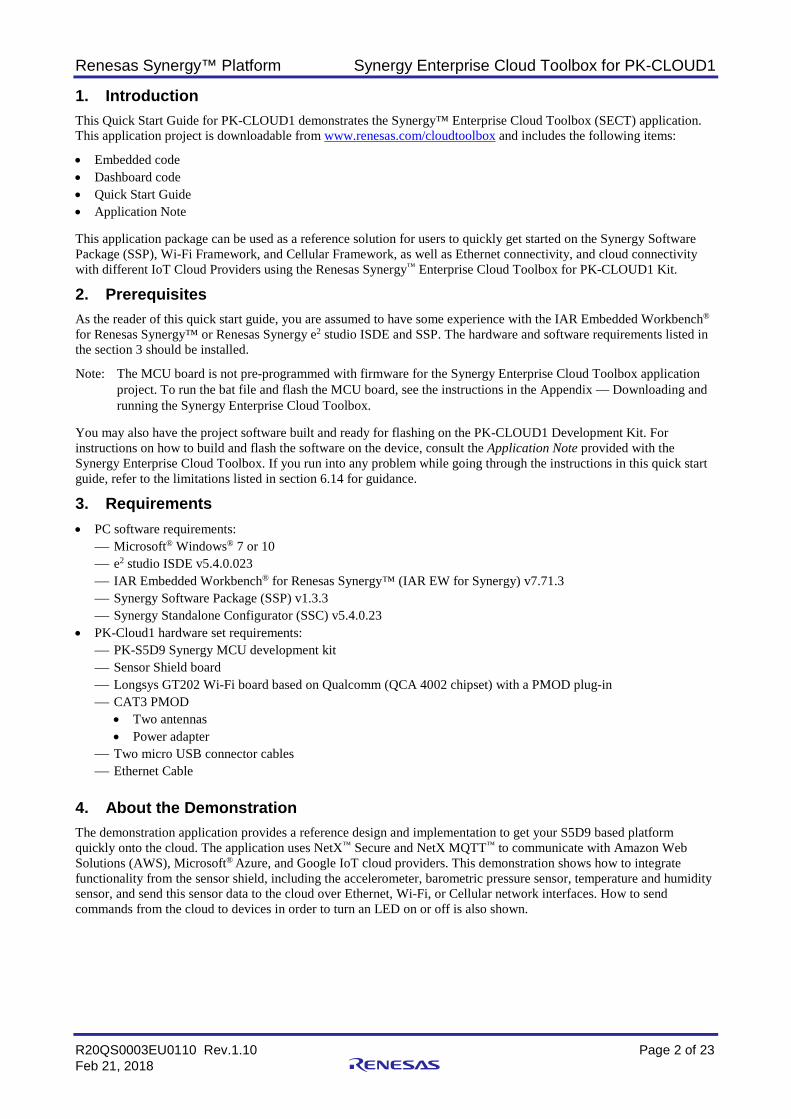
Synergy Enterprise Cloud Toolbox for PK-CLOUD1 Contents
1. Introduction .............................................................................................................................. 2
2. Prerequisites............................................................................................................................ 2
3. Requirements .......................................................................................................................... 2
4. About the Demonstration ......................................................................................................... 2
5. Setting up the Hardware .......................................................................................................... 3
6. Setting up and executing the Demonstration ........................................................................... 5 6.1 Setting up the PK-CLOUD1 Project ........................................................................................................ 5 6.2 Setting up PK-CLOUD1 for Wi-Fi ............................................................................................................ 7 6.3 Setting up PK-CLOUD1 for Ethernet ....................................................................................................... 9 6.4 Setting up the Cellular network interface for PK-CLOUD1 ................................................................... 10 6.5 Signing up for the Synergy Enterprise Cloud Toolbox Dashboard ....................................................... 11 6.6 Adding a Device to the Synergy Enterprise Cloud Toolbox Dashboard ............................................... 13 6.7 Configuring User Credentials for PK-CLOUD1 ..................................................................................... 14 6.8 Provisioning for PK-CLOUD1 ................................................................................................................ 15 6.9 Starting the Wind Turbine model on PK-CLOUD1 ................................................................................ 15 6.10 Remote Monitoring on the Synergy Enterprise Cloud Toolbox Dashboard .......................................... 16 6.11 Stimulating sensors on PK-CLOUD1 .................................................................................................... 16 6.12 Changing IoT cloud providers ............................................................................................................... 17 6.13 Resetting the system from the Synergy Enterprise Cloud Toolbox Dashboard .................................... 18 6.14 Notes and Limitations ............................................................................................................................ 19
7. Configuring the Cellular Framework ....................................................................................... 20
8. Appendix — Downloading and running the Synergy Enterprise Cloud Toolbox ..................... 21
R20QS0003EU0110 Rev.1.10
Feb 21, 2018
Renesas Synergy™ Platform Synergy Enterprise Cloud Toolbox for PK-CLOUD1
R20QS0003EU0110 Rev.1.10 Page 2 of 23 Feb 21, 2018
1. Introduction This Quick Start Guide for PK-CLOUD1 demonstrates the Synergy™ Enterprise Cloud Toolbox (SECT) application. This application project is downloadable from www.renesas.com/cloudtoolbox and includes the following items:
• Embedded code • Dashboard code • Quick Start Guide • Application Note This application package can be used as a reference solution for users to quickly get started on the Synergy Software Package (SSP), Wi-Fi Framework, and Cellular Framework, as well as Ethernet connectivity, and cloud connectivity with different IoT Cloud Providers using the Renesas Synergy™ Enterprise Cloud Toolbox for PK-CLOUD1 Kit.
2. Prerequisites As the reader of this quick start guide, you are assumed to have some experience with the IAR Embedded Workbench® for Renesas Synergy™ or Renesas Synergy e2 studio ISDE and SSP. The hardware and software requirements listed in the section 3 should be installed.
Note: The MCU board is not pre-programmed with firmware for the Synergy Enterprise Cloud Toolbox application project. To run the bat file and flash the MCU board, see the instructions in the Appendix — Downloading and running the Synergy Enterprise Cloud Toolbox.
You may also have the project software built and ready for flashing on the PK-CLOUD1 Development Kit. For instructions on how to build and flash the software on the device, consult the Application Note provided with the Synergy Enterprise Cloud Toolbox. If you run into any problem while going through the instructions in this quick start guide, refer to the limitations listed in section 6.14 for guidance.
3. Requirements • PC software requirements:
Microsoft® Windows® 7 or 10 e2 studio ISDE v5.4.0.023 IAR Embedded Workbench® for Renesas Synergy™ (IAR EW for Synergy) v7.71.3 Synergy Software Package (SSP) v1.3.3 Synergy Standalone Configurator (SSC) v5.4.0.23
• PK-Cloud1 hardware set requirements: PK-S5D9 Synergy MCU development kit Sensor Shield board Longsys GT202 Wi-Fi board based on Qualcomm (QCA 4002 chipset) with a PMOD plug-in CAT3 PMOD
• Two antennas • Power adapter
Two micro USB connector cables Ethernet Cable
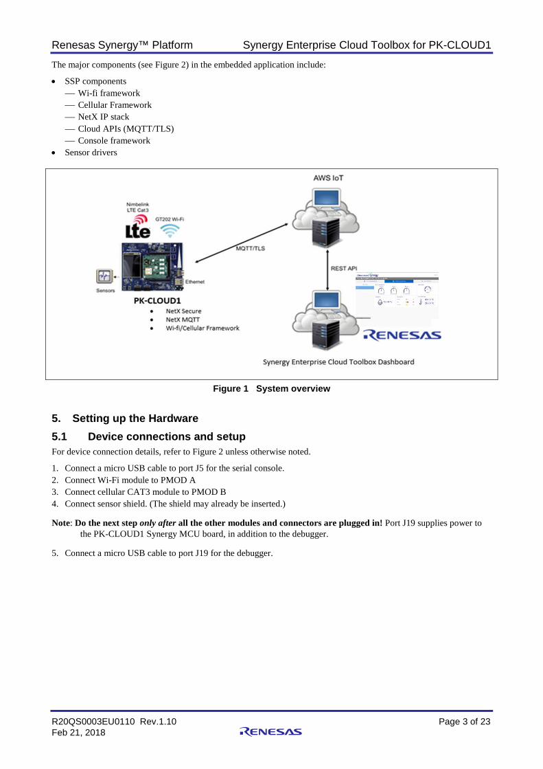
4. About the Demonstration The demonstration application provides a reference design and implementation to get your S5D9 based platform quickly onto the cloud. The application uses NetX™ Secure and NetX MQTT™ to communicate with Amazon Web Solutions (AWS), Microsoft® Azure, and Google IoT cloud providers. This demonstration shows how to integrate functionality from the sensor shield, including the accelerometer, barometric pressure sensor, temperature and humidity sensor, and send this sensor data to the cloud over Ethernet, Wi-Fi, or Cellular network interfaces. How to send commands from the cloud to devices in order to turn an LED on or off is also shown.
Renesas Synergy™ Platform Synergy Enterprise Cloud Toolbox for PK-CLOUD1
R20QS0003EU0110 Rev.1.10 Page 3 of 23 Feb 21, 2018
The major components (see Figure 2) in the embedded application include:
• SSP components Wi-fi framework Cellular Framework NetX IP stack Cloud APIs (MQTT/TLS) Console framework
• Sensor drivers
Figure 1 System overview
5. Setting up the Hardware 5.1 Device connections and setup For device connection details, refer to Figure 2 unless otherwise noted.
1. Connect a micro USB cable to port J5 for the serial console. 2. Connect Wi-Fi module to PMOD A 3. Connect cellular CAT3 module to PMOD B 4. Connect sensor shield. (The shield may already be inserted.) Note: Do the next step only after all the other modules and connectors are plugged in! Port J19 supplies power to
the PK-CLOUD1 Synergy MCU board, in addition to the debugger. 5. Connect a micro USB cable to port J19 for the debugger.
Renesas Synergy™ Platform Synergy Enterprise Cloud Toolbox for PK-CLOUD1
R20QS0003EU0110 Rev.1.10 Page 4 of 23 Feb 21, 2018
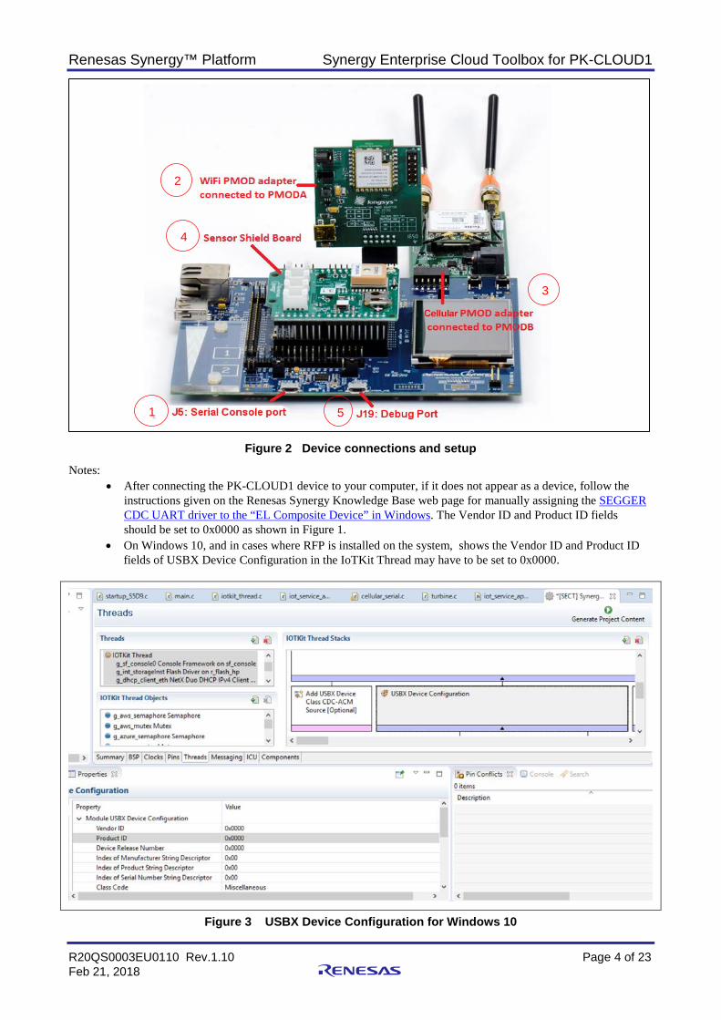
Figure 2 Device connections and setup
Notes: • After connecting the PK-CLOUD1 device to your computer, if it does not appear as a device, follow the
instructions given on the Renesas Synergy Knowledge Base web page for manually assigning the SEGGER CDC UART driver to the “EL Composite Device” in Windows. The Vendor ID and Product ID fields should be set to 0x0000 as shown in Figure 1.
• On Windows 10, and in cases where RFP is installed on the system, shows the Vendor ID and Product ID fields of USBX Device Configuration in the IoTKit Thread may have to be set to 0x0000.
Figure 3 USBX Device Configuration for Windows 10
1
2
3
4
5
Renesas Synergy™ Platform Synergy Enterprise Cloud Toolbox for PK-CLOUD1
R20QS0003EU0110 Rev.1.10 Page 5 of 23 Feb 21, 2018
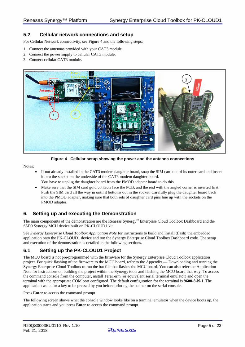
5.2 Cellular network connections and setup For Cellular Network connectivity, see Figure 4 and the following steps:
1. Connect the antennas provided with your CAT3 module. 2. Connect the power supply to cellular CAT3 module. 3. Connect cellular CAT3 module.
Figure 4 Cellular setup showing the power and the antenna connections
Notes: • If not already installed in the CAT3 modem daughter board, snap the SIM card out of its outer card and insert
it into the socket on the underside of the CAT3 modem daughter board. You have to unplug the daughter board from the PMOD adapter board to do this.
• Make sure that the SIM card gold contacts face the PCB, and the end with the angled corner is inserted first. Push the SIM card all the way in until it bottoms out in the socket. Carefully plug the daughter board back into the PMOD adapter, making sure that both sets of daughter card pins line up with the sockets on the PMOD adapter.
6. Setting up and executing the Demonstration The main components of the demonstration are the Renesas Synergy™ Enterprise Cloud Toolbox Dashboard and the S5D9 Synergy MCU device built on PK-CLOUD1 kit.
See Synergy Enterprise Cloud Toolbox Application Note for instructions to build and install (flash) the embedded application onto the PK-CLOUD1 device and run the Synergy Enterprise Cloud Toolbox Dashboard code. The setup and execution of the demonstration is detailed in the following sections.
6.1 Setting up the PK-CLOUD1 Project The MCU board is not pre-programmed with the firmware for the Synergy Enterprise Cloud Toolbox application project. For quick flashing of the firmware to the MCU board, refer to the Appendix — Downloading and running the Synergy Enterprise Cloud Toolbox to run the bat file that flashes the MCU board. You can also refer the Application Note for instructions on building the project within the Synergy tools and flashing the MCU board that way. To access the command console from the computer, install TeraTerm (or equivalent serial terminal emulator) and open the terminal with the appropriate COM port configured. The default configuration for the terminal is 9600-8-N-1. The application waits for a key to be pressed by you before printing the banner on the serial console.
Press Enter to access the command prompt.
The following screen shows what the console window looks like on a terminal emulator when the device boots up, the application starts and you press Enter to access the command prompt.
1 2
3
Renesas Synergy™ Platform Synergy Enterprise Cloud Toolbox for PK-CLOUD1
R20QS0003EU0110 Rev.1.10 Page 6 of 23 Feb 21, 2018
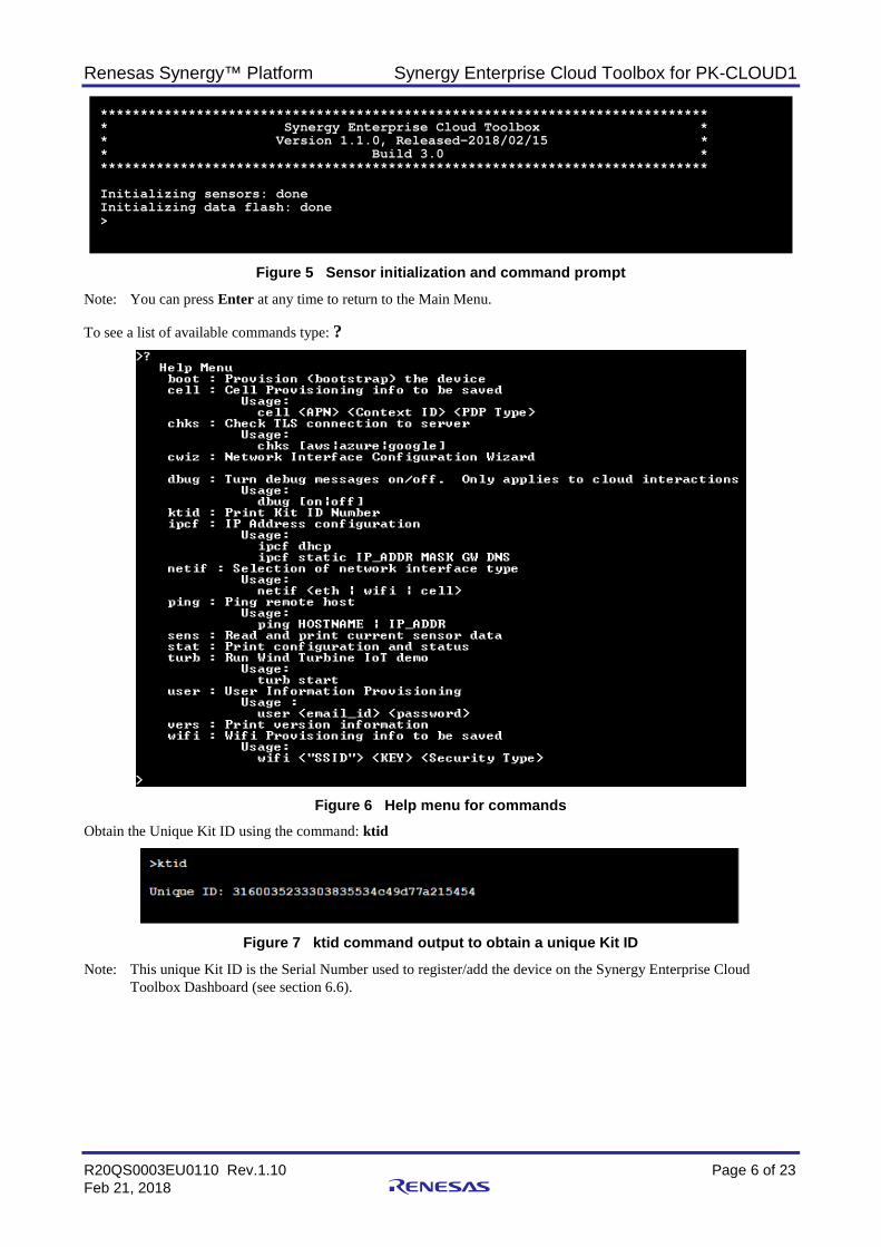
Figure 5 Sensor initialization and command prompt
Note: You can press Enter at any time to return to the Main Menu. To see a list of available commands type: ?
Figure 6 Help menu for commands
Obtain the Unique Kit ID using the command: ktid
Figure 7 ktid command output to obtain a unique Kit ID
Note: This unique Kit ID is the Serial Number used to register/add the device on the Synergy Enterprise Cloud Toolbox Dashboard (see section 6.6).
**************************************************************************** * Synergy Enterprise Cloud Toolbox * * Version 1.1.0, Released-2018/02/15 * * Build 3.0 * **************************************************************************** Initializing sensors: done Initializing data flash: done >
Renesas Synergy™ Platform Synergy Enterprise Cloud Toolbox for PK-CLOUD1
R20QS0003EU0110 Rev.1.10 Page 7 of 23 Feb 21, 2018
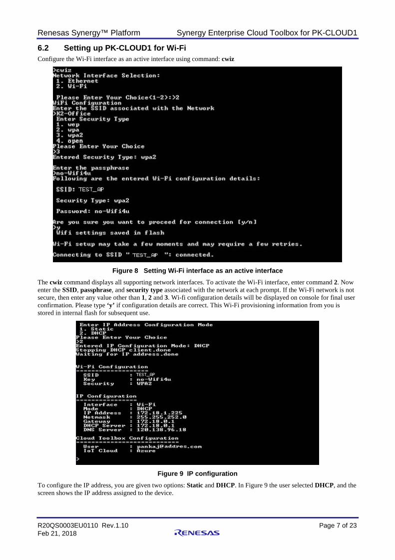
6.2 Setting up PK-CLOUD1 for Wi-Fi Configure the Wi-Fi interface as an active interface using command: cwiz
Figure 8 Setting Wi-Fi interface as an active interface
The cwiz command displays all supporting network interfaces. To activate the Wi-Fi interface, enter command 2. Now enter the SSID, passphrase, and security type associated with the network at each prompt. If the Wi-Fi network is not secure, then enter any value other than 1, 2 and 3. Wi-fi configuration details will be displayed on console for final user confirmation. Please type ‘y’ if configuration details are correct. This Wi-Fi provisioning information from you is stored in internal flash for subsequent use.
Figure 9 IP configuration
To configure the IP address, you are given two options: Static and DHCP. In Figure 9 the user selected DHCP, and the screen shows the IP address assigned to the device.
Renesas Synergy™ Platform Synergy Enterprise Cloud Toolbox for PK-CLOUD1
R20QS0003EU0110 Rev.1.10 Page 8 of 23 Feb 21, 2018
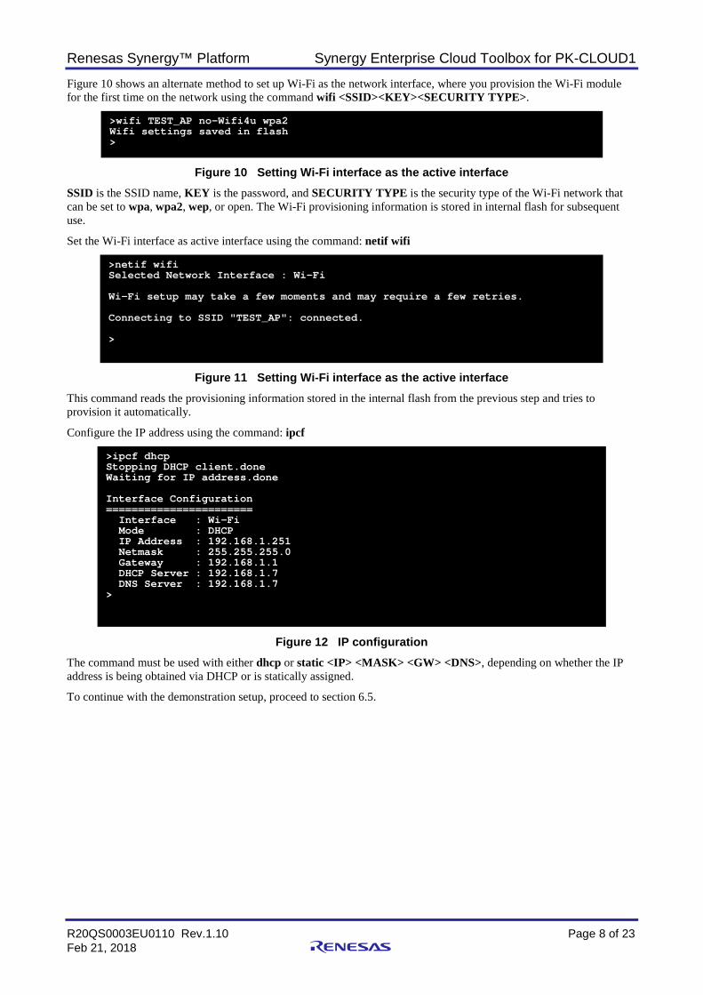
Figure 10 shows an alternate method to set up Wi-Fi as the network interface, where you provision the Wi-Fi module for the first time on the network using the command wifi <SSID><KEY><SECURITY TYPE>.
Figure 10 Setting Wi-Fi interface as the active interface
SSID is the SSID name, KEY is the password, and SECURITY TYPE is the security type of the Wi-Fi network that can be set to wpa, wpa2, wep, or open. The Wi-Fi provisioning information is stored in internal flash for subsequent use.
Set the Wi-Fi interface as active interface using the command: netif wifi
Figure 11 Setting Wi-Fi interface as the active interface
This command reads the provisioning information stored in the internal flash from the previous step and tries to provision it automatically.
Configure the IP address using the command: ipcf
Figure 12 IP configuration
The command must be used with either dhcp or static <IP> <MASK> <GW> <DNS>, depending on whether the IP address is being obtained via DHCP or is statically assigned.
To continue with the demonstration setup, proceed to section 6.5.
>wifi TEST_AP no-Wifi4u wpa2 Wifi settings saved in flash >
>netif wifi Selected Network Interface : Wi-Fi Wi-Fi setup may take a few moments and may require a few retries. Connecting to SSID "TEST_AP": connected. >
>ipcf dhcp Stopping DHCP client.done Waiting for IP address.done Interface Configuration ======================= Interface : Wi-Fi Mode : DHCP IP Address : 192.168.1.251 Netmask : 255.255.255.0 Gateway : 192.168.1.1 DHCP Server : 192.168.1.7 DNS Server : 192.168.1.7 >
Renesas Synergy™ Platform Synergy Enterprise Cloud Toolbox for PK-CLOUD1
R20QS0003EU0110 Rev.1.10 Page 9 of 23 Feb 21, 2018
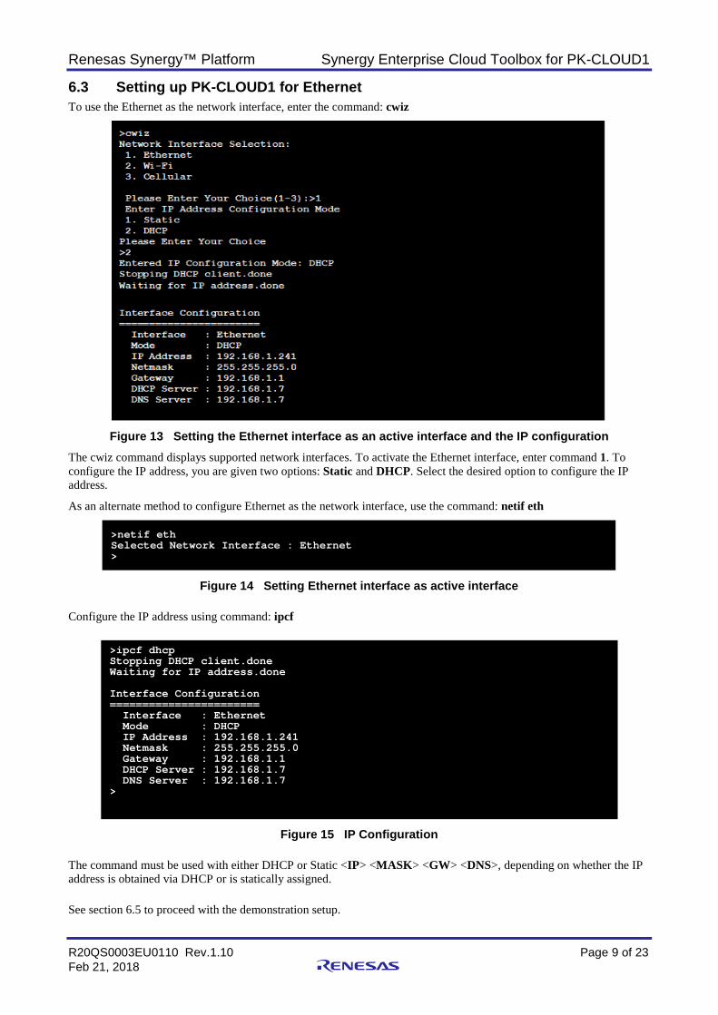
6.3 Setting up PK-CLOUD1 for Ethernet To use the Ethernet as the network interface, enter the command: cwiz
Figure 13 Setting the Ethernet interface as an active interface and the IP configuration
The cwiz command displays supported network interfaces. To activate the Ethernet interface, enter command 1. To configure the IP address, you are given two options: Static and DHCP. Select the desired option to configure the IP address.
As an alternate method to configure Ethernet as the network interface, use the command: netif eth
Figure 14 Setting Ethernet interface as active interface
Configure the IP address using command: ipcf
Figure 15 IP Configuration
The command must be used with either DHCP or Static <IP> <MASK> <GW> <DNS>, depending on whether the IP address is obtained via DHCP or is statically assigned.
See section 6.5 to proceed with the demonstration setup.
>netif eth Selected Network Interface : Ethernet >
>ipcf dhcp Stopping DHCP client.done Waiting for IP address.done Interface Configuration ======================= Interface : Ethernet Mode : DHCP IP Address : 192.168.1.241 Netmask : 255.255.255.0 Gateway : 192.168.1.1 DHCP Server : 192.168.1.7 DNS Server : 192.168.1.7 >
Renesas Synergy™ Platform Synergy Enterprise Cloud Toolbox for PK-CLOUD1
R20QS0003EU0110 Rev.1.10 Page 10 of 23 Feb 21, 2018
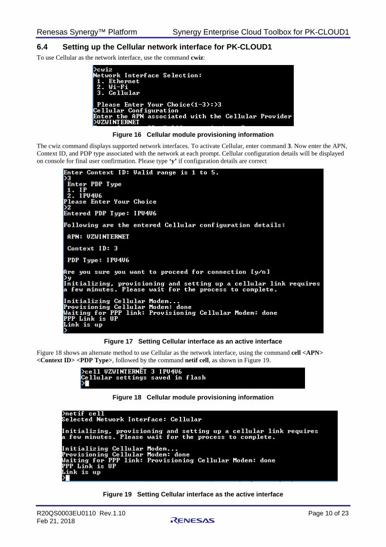
6.4 Setting up the Cellular network interface for PK-CLOUD1 To use Cellular as the network interface, use the command cwiz:
Figure 16 Cellular module provisioning information
The cwiz command displays supported network interfaces. To activate Cellular, enter command 3. Now enter the APN, Context ID, and PDP type associated with the network at each prompt. Cellular configuration details will be displayed on console for final user confirmation. Please type ‘y’ if configuration details are correct
Figure 17 Setting Cellular interface as an active interface
Figure 18 shows an alternate method to use Cellular as the network interface, using the command cell <APN> <Context ID> <PDP Type>, followed by the command netif cell, as shown in Figure 19.
Figure 18 Cellular module provisioning information
Figure 19 Setting Cellular interface as the active interface
Renesas Synergy™ Platform Synergy Enterprise Cloud Toolbox for PK-CLOUD1
R20QS0003EU0110 Rev.1.10 Page 11 of 23 Feb 21, 2018
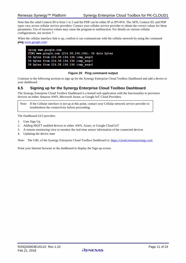
Note that the valid Context ID is from 1 to 5 and the PDP can be either IP or IPV4V6. The APN, Context ID, and PDP types vary across cellular service providers. Contact your cellular service provider to obtain the correct values for these parameters. Use of incorrect values may cause the program to malfunction. For details on various cellular configurations, see section 7.
When the cellular interface link is up, confirm it can communicate with the cellular network by using the command ping www.google.com:
Figure 20 Ping command output
Continue to the following sections to sign up for the Synergy Enterprise Cloud Toolbox Dashboard and add a device to your dashboard.
6.5 Signing up for the Synergy Enterprise Cloud Toolbox Dashboard The Synergy Enterprise Cloud Toolbox Dashboard is a hosted web application with the functionality to provision devices on either Amazon AWS, Microsoft Azure, or Google IoT Cloud Providers.
The Dashboard GUI provides:
1. User Sign Up 2. Adding MQTT enabled devices to either AWS, Azure, or Google Cloud IoT 3. A remote monitoring view to monitor the real-time sensor information of the connected devices 4. Updating the device state Note: The URL of the Synergy Enterprise Cloud Toolbox Dashboard is: https://cloud.renesassynergy.com Point your Internet browser to the dashboard to display the Sign-up screen.
Note: If the Cellular interface is not up at this point, contact your Cellular network service provider to troubleshoot the connectivity before proceeding.
Renesas Synergy™ Platform Synergy Enterprise Cloud Toolbox for PK-CLOUD1
R20QS0003EU0110 Rev.1.10 Page 12 of 23 Feb 21, 2018
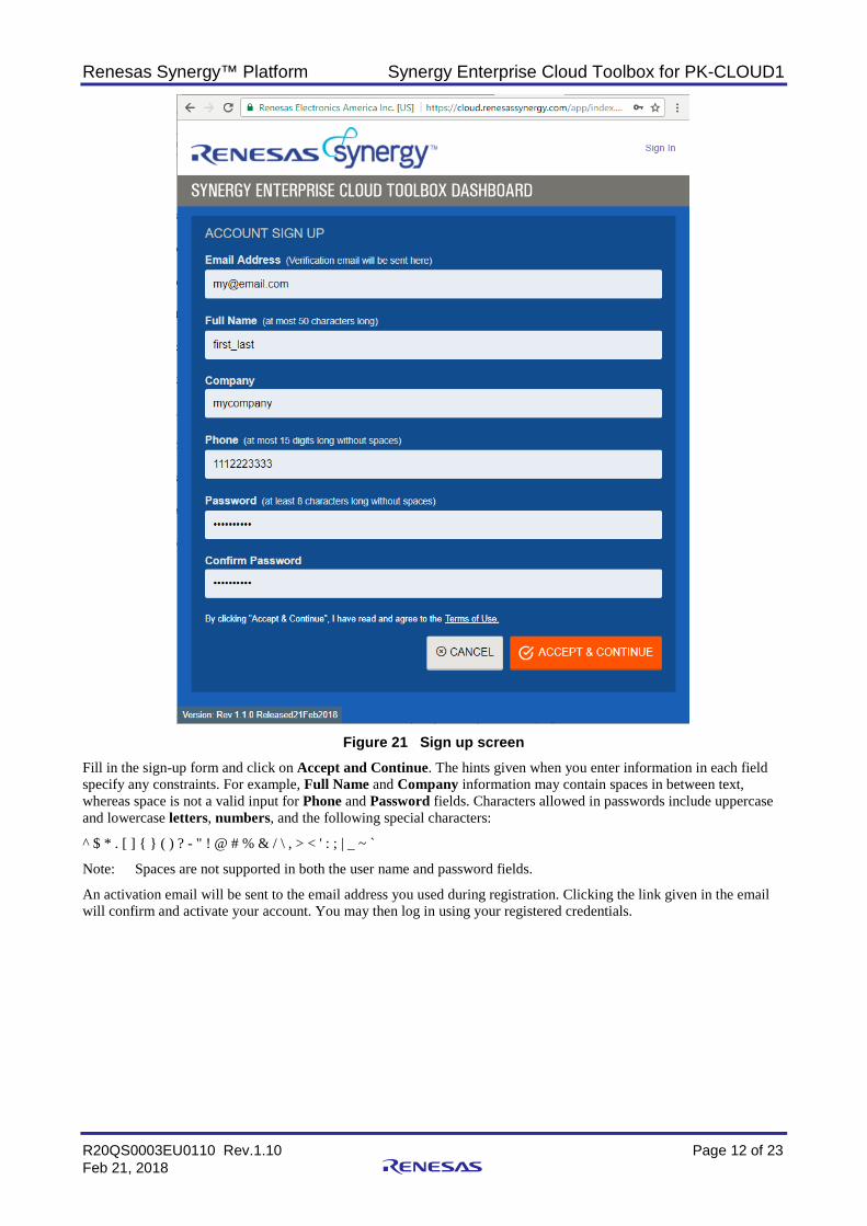
Figure 21 Sign up screen
Fill in the sign-up form and click on Accept and Continue. The hints given when you enter information in each field specify any constraints. For example, Full Name and Company information may contain spaces in between text, whereas space is not a valid input for Phone and Password fields. Characters allowed in passwords include uppercase and lowercase letters, numbers, and the following special characters:
^ $ * . [ ] { } ( ) ? - " ! @ # % & / \ , > < ' : ; | _ ~ `
Note: Spaces are not supported in both the user name and password fields.
An activation email will be sent to the email address you used during registration. Clicking the link given in the email will confirm and activate your account. You may then log in using your registered credentials.
Renesas Synergy™ Platform Synergy Enterprise Cloud Toolbox for PK-CLOUD1
R20QS0003EU0110 Rev.1.10 Page 13 of 23 Feb 21, 2018
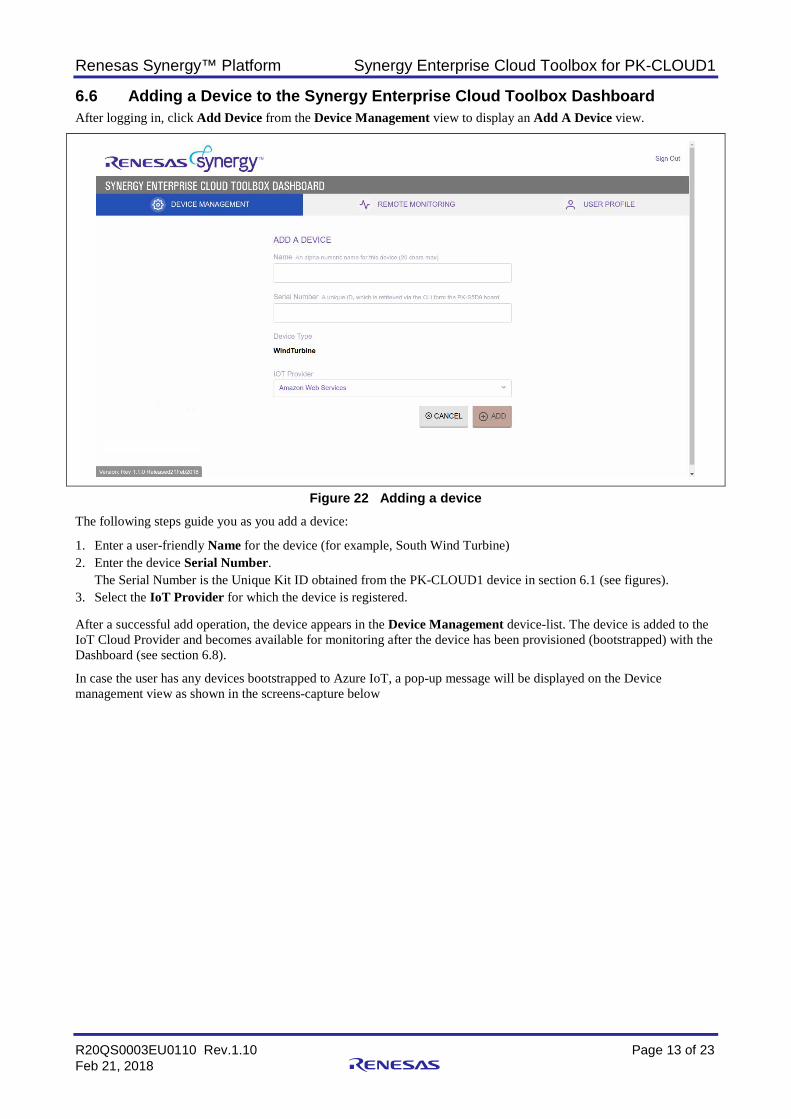
6.6 Adding a Device to the Synergy Enterprise Cloud Toolbox Dashboard After logging in, click Add Device from the Device Management view to display an Add A Device view.
Figure 22 Adding a device
The following steps guide you as you add a device:
1. Enter a user-friendly Name for the device (for example, South Wind Turbine) 2. Enter the device Serial Number.
The Serial Number is the Unique Kit ID obtained from the PK-CLOUD1 device in section 6.1 (see figures). 3. Select the IoT Provider for which the device is registered. After a successful add operation, the device appears in the Device Management device-list. The device is added to the IoT Cloud Provider and becomes available for monitoring after the device has been provisioned (bootstrapped) with the Dashboard (see section 6.8).
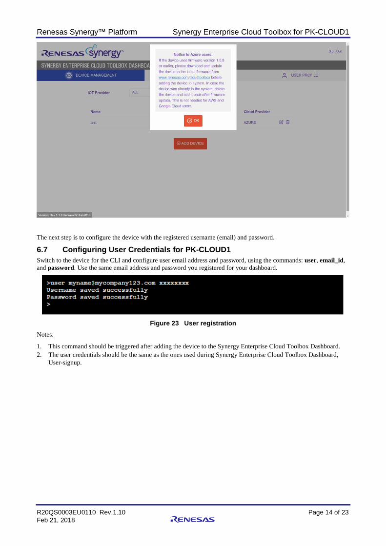
In case the user has any devices bootstrapped to Azure IoT, a pop-up message will be displayed on the Device management view as shown in the screens-capture below
Renesas Synergy™ Platform Synergy Enterprise Cloud Toolbox for PK-CLOUD1
R20QS0003EU0110 Rev.1.10 Page 14 of 23 Feb 21, 2018
The next step is to configure the device with the registered username (email) and password.
6.7 Configuring User Credentials for PK-CLOUD1 Switch to the device for the CLI and configure user email address and password, using the commands: user, email_id, and password. Use the same email address and password you registered for your dashboard.
Figure 23 User registration
Notes:
1. This command should be triggered after adding the device to the Synergy Enterprise Cloud Toolbox Dashboard. 2. The user credentials should be the same as the ones used during Synergy Enterprise Cloud Toolbox Dashboard,
User-signup.
Renesas Synergy™ Platform Synergy Enterprise Cloud Toolbox for PK-CLOUD1
R20QS0003EU0110 Rev.1.10 Page 15 of 23 Feb 21, 2018
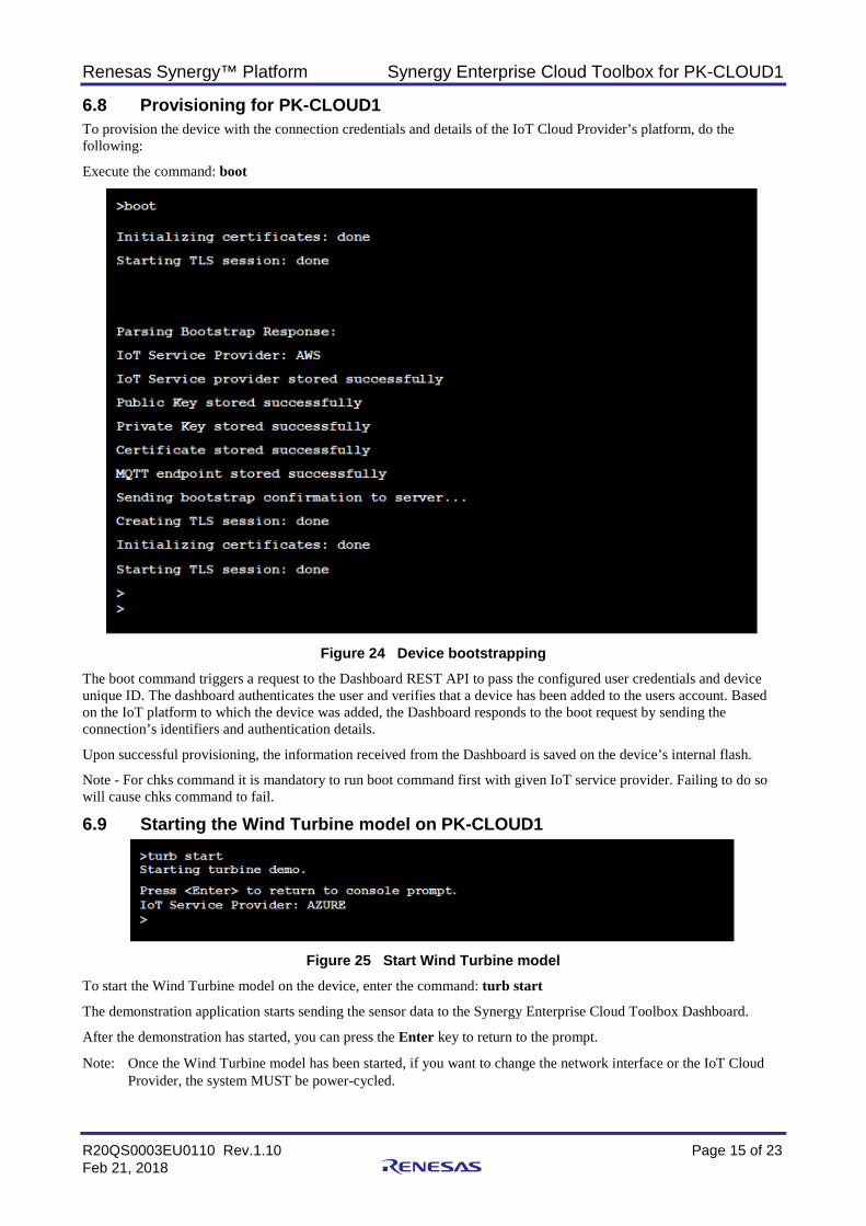
6.8 Provisioning for PK-CLOUD1 To provision the device with the connection credentials and details of the IoT Cloud Provider’s platform, do the following:
Execute the command: boot
Figure 24 Device bootstrapping
The boot command triggers a request to the Dashboard REST API to pass the configured user credentials and device unique ID. The dashboard authenticates the user and verifies that a device has been added to the users account. Based on the IoT platform to which the device was added, the Dashboard responds to the boot request by sending the connection’s identifiers and authentication details.
Upon successful provisioning, the information received from the Dashboard is saved on the device’s internal flash.
Note - For chks command it is mandatory to run boot command first with given IoT service provider. Failing to do so will cause chks command to fail.
6.9 Starting the Wind Turbine model on PK-CLOUD1
Figure 25 Start Wind Turbine model
To start the Wind Turbine model on the device, enter the command: turb start
The demonstration application starts sending the sensor data to the Synergy Enterprise Cloud Toolbox Dashboard.
After the demonstration has started, you can press the Enter key to return to the prompt.
Note: Once the Wind Turbine model has been started, if you want to change the network interface or the IoT Cloud Provider, the system MUST be power-cycled.
Renesas Synergy™ Platform Synergy Enterprise Cloud Toolbox for PK-CLOUD1
R20QS0003EU0110 Rev.1.10 Page 16 of 23 Feb 21, 2018
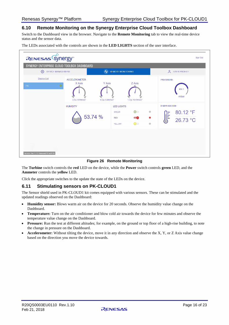
6.10 Remote Monitoring on the Synergy Enterprise Cloud Toolbox Dashboard Switch to the Dashboard view in the browser. Navigate to the Remote Monitoring tab to view the real-time device status and the sensor data.
The LEDs associated with the controls are shown in the LED LIGHTS section of the user interface.
Figure 26 Remote Monitoring The Turbine switch controls the red LED on the device, while the Power switch controls green LED, and the Ammeter controls the yellow LED.
Click the appropriate switches to the update the state of the LEDs on the device.
6.11 Stimulating sensors on PK-CLOUD1 The Sensor shield used in PK-CLOUD1 kit comes equipped with various sensors. These can be stimulated and the updated readings observed on the Dashboard:
• Humidity sensor: Blows warm air on the device for 20 seconds. Observe the humidity value change on the Dashboard.
• Temperature: Turn on the air conditioner and blow cold air towards the device for few minutes and observe the temperature value change on the Dashboard.
• Pressure: Run the test at different altitudes; for example, on the ground or top floor of a high-rise building, to note the change in pressure on the Dashboard.
• Accelerometer: Without tilting the device, move it in any direction and observe the X, Y, or Z Axis value change based on the direction you move the device towards.
Renesas Synergy™ Platform Synergy Enterprise Cloud Toolbox for PK-CLOUD1
R20QS0003EU0110 Rev.1.10 Page 17 of 23 Feb 21, 2018
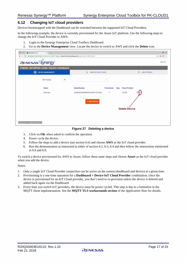
6.12 Changing IoT cloud providers Devices bootstrapped with the Dashboard can be switched between the supported IoT Cloud Providers.
In the following example, the device is currently provisioned for the Azure IoT platform. Use the following steps to change the IoT Cloud Provider to AWS:
1. Login to the Synergy Enterprise Cloud Toolbox Dashboard. 2. Go to the Device Management view. Locate the device to switch to AWS and click the Delete icon.
Figure 27 Deleting a device
3. Click on OK when asked to confirm the operation. 4. Power cycle the device. 5. Follow the steps to add a device (see section 6.6) and choose AWS as the IoT cloud provider. 6. Run the demonstration as instructed in either of section 6.2, 6.3, 6.4 and then follow the instructions mentioned
in 6.8 and 6.9. To switch a device provisioned for AWS to Azure, follow these same steps and choose Azure as the IoT cloud provider when you add the device.
Notes:
1. Only a single IoT Cloud Provider connection can be active on the system (dashboard and device) at a given time. 2. Provisioning is a one-time operation for a Dashboard + Device-IoT Cloud Provider combination. Once the
device is provisioned for an IoT Cloud provider, you don’t need to re-provision unless the device is deleted and added back again via the Dashboard.
3. Every time you switch IoT providers, the device must be power cycled. This step is due to a limitation in the MQTT client implementation. See the MQTT-TLS workarounds section of the Application Note for details.

Renesas Synergy™ Platform Synergy Enterprise Cloud Toolbox for PK-CLOUD1
R20QS0003EU0110 Rev.1.10 Page 18 of 23 Feb 21, 2018
6.13 Resetting the system from the Synergy Enterprise Cloud Toolbox Dashboard The reset feature is available only to the admin user. Using the reset functionality, the admin user can delete all devices and users from the system.
Note: This is an irreversible action. To access the reset view, click the Settings icon on the UI’s top-right corner. Clicking Reset System, on the reset view, resets the system (see Figure 28 and Figure 29).
Figure 28 Device Management tab on the Dashboard
Figure 29 Reset System
Renesas Synergy™ Platform Synergy Enterprise Cloud Toolbox for PK-CLOUD1
R20QS0003EU0110 Rev.1.10 Page 19 of 23 Feb 21, 2018
6.14 Notes and Limitations 1. It is mandatory that user compiles the IAR project in a different folder from where the e2studio project has been
compiled. 2. After a network interface has been selected, if you want to change it, the system MUST be power-cycled and a new
network interface selected. 3. If certificate provisioning fails for a device, you need to delete the device from Dashboard and add it back.
In the case of a provisioning failure, see section 6.1 for instructions. 4. If the boot command fails for a device, you must delete the device from the Dashboard and add it back. In the case
of a boot command failure, see section 6.1 for instructions. The command could fail with the following errors: A. Starting TLS session; could not start TLS session (0x109) B. Parsing Bootstrap Response: IoT Provider not found. Aborting. C. The command gets stuck after starting the TLS session and bootstrap does not begin.
5. After changing the LED status from the Dashboard, it can take up to 10 seconds for the LED on the PK-CLOUD1 device to change.
6. Google-cloud IoT does not provide information regarding the connected state of the devices to its IoT platform. As a result, on the Remote Monitoring tab view, the icon indicating the connectivity status is gray, instead of green, for the device.
7. The Dashboard UI uses Server Sent Events (SSE). SSE is part of the HTML5 standard. However, Microsoft (MSFT) does not support SSE in Internet Explorer (IE) and Edge. As an alternative, polling is used to get events from the server. Depending on the polling interval, the updates may appear to be delayed. For details on SSE and the lack of support on MSFT browsers, visit https://en.wikipedia.org/wiki/Server-sent_events and https://caniuse.com/#feat=eventsource.
8. In some corporate Ethernet and Wi-Fi connections, the browser refresh rate could be slow and may need manual refreshing to receive updates. In certain cases, this error is indicated on the Dashboard with a warning on the status of communication between the device and the Dashboard. To mitigate this issue, ensure that the Corporate Network allows the following ports to successfully run Synergy Enterprise Cloud Toolbox: TCP Ports: 80 (HTTP), 443 (HTTPS) and 8883 (MQTT over TLS) UDP Ports: 123 (SNTP), 53 (DNS). In cases when these solutions do not update the browsers, the firewall settings should be checked.
9. If the command line returns an Unsupported Command error, check the format and retype the command using the correct format.
10. Google-cloud IoT is not supported in Rev 1.0. 11. The Dashboard on Azure IoT for some kits does not get updated automatically and needs to be manually refreshed
to see the changes. 12. If ‘turb start’ command on Google-cloud fails with an error “Unable to initialize IoT service Google,” power cycle
the device and retry the command. 13. When upgrading from Rev 1.0 to Rev 1.1, user will need to re-bootstrap a device using “boot" command after
flashing new version of firmware. 14. For Synergy Enterprise Cloud Toolbox release build older than 1.1 ver 3.0, user will face issue during “turb start”
command to connect Azure IoT due change in server certificate and will need to upgrade to SECT release 1.1 rev 3.0.
Note: Google-cloud IoT is in Beta Launch stage. For details, see https://cloud.google.com/terms/launch-stages
Renesas Synergy™ Platform Synergy Enterprise Cloud Toolbox for PK-CLOUD1
R20QS0003EU0110 Rev.1.10 Page 20 of 23 Feb 21, 2018
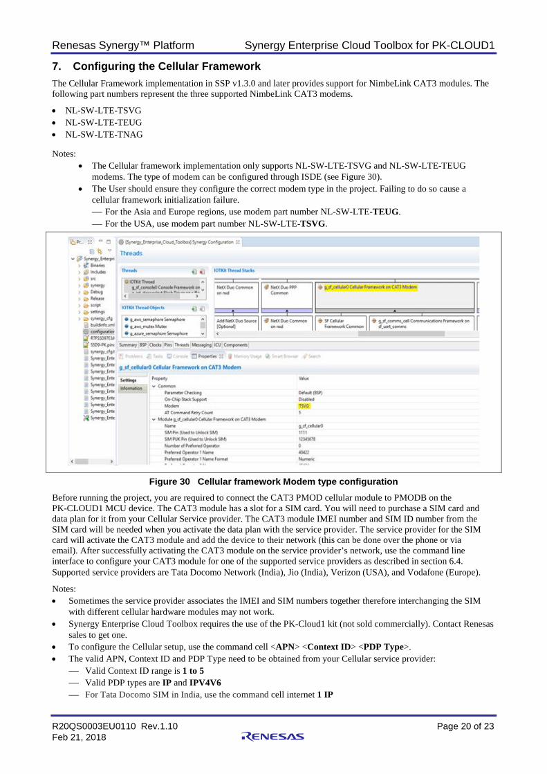
7. Configuring the Cellular Framework The Cellular Framework implementation in SSP v1.3.0 and later provides support for NimbeLink CAT3 modules. The following part numbers represent the three supported NimbeLink CAT3 modems.
• NL-SW-LTE-TSVG • NL-SW-LTE-TEUG • NL-SW-LTE-TNAG Notes:
• The Cellular framework implementation only supports NL-SW-LTE-TSVG and NL-SW-LTE-TEUG modems. The type of modem can be configured through ISDE (see Figure 30).
• The User should ensure they configure the correct modem type in the project. Failing to do so cause a cellular framework initialization failure. For the Asia and Europe regions, use modem part number NL-SW-LTE-TEUG. For the USA, use modem part number NL-SW-LTE-TSVG.
Figure 30 Cellular framework Modem type configuration Before running the project, you are required to connect the CAT3 PMOD cellular module to PMODB on the PK-CLOUD1 MCU device. The CAT3 module has a slot for a SIM card. You will need to purchase a SIM card and data plan for it from your Cellular Service provider. The CAT3 module IMEI number and SIM ID number from the SIM card will be needed when you activate the data plan with the service provider. The service provider for the SIM card will activate the CAT3 module and add the device to their network (this can be done over the phone or via email). After successfully activating the CAT3 module on the service provider’s network, use the command line interface to configure your CAT3 module for one of the supported service providers as described in section 6.4. Supported service providers are Tata Docomo Network (India), Jio (India), Verizon (USA), and Vodafone (Europe).
Notes: • Sometimes the service provider associates the IMEI and SIM numbers together therefore interchanging the SIM
with different cellular hardware modules may not work. • Synergy Enterprise Cloud Toolbox requires the use of the PK-Cloud1 kit (not sold commercially). Contact Renesas
sales to get one. • To configure the Cellular setup, use the command cell <APN> <Context ID> <PDP Type>. • The valid APN, Context ID and PDP Type need to be obtained from your Cellular service provider:
Valid Context ID range is 1 to 5 Valid PDP types are IP and IPV4V6 For Tata Docomo SIM in India, use the command cell internet 1 IP
Renesas Synergy™ Platform Synergy Enterprise Cloud Toolbox for PK-CLOUD1
R20QS0003EU0110 Rev.1.10 Page 21 of 23 Feb 21, 2018
For Jio SIM in India, use the command cell internet 1 IP For Verizon SIM in USA, use the command cell 463b012d31363846394e04a551215454INTERNET 3
IPV4V6 For Vodafone in Europe, use the command cell internet 1 IP
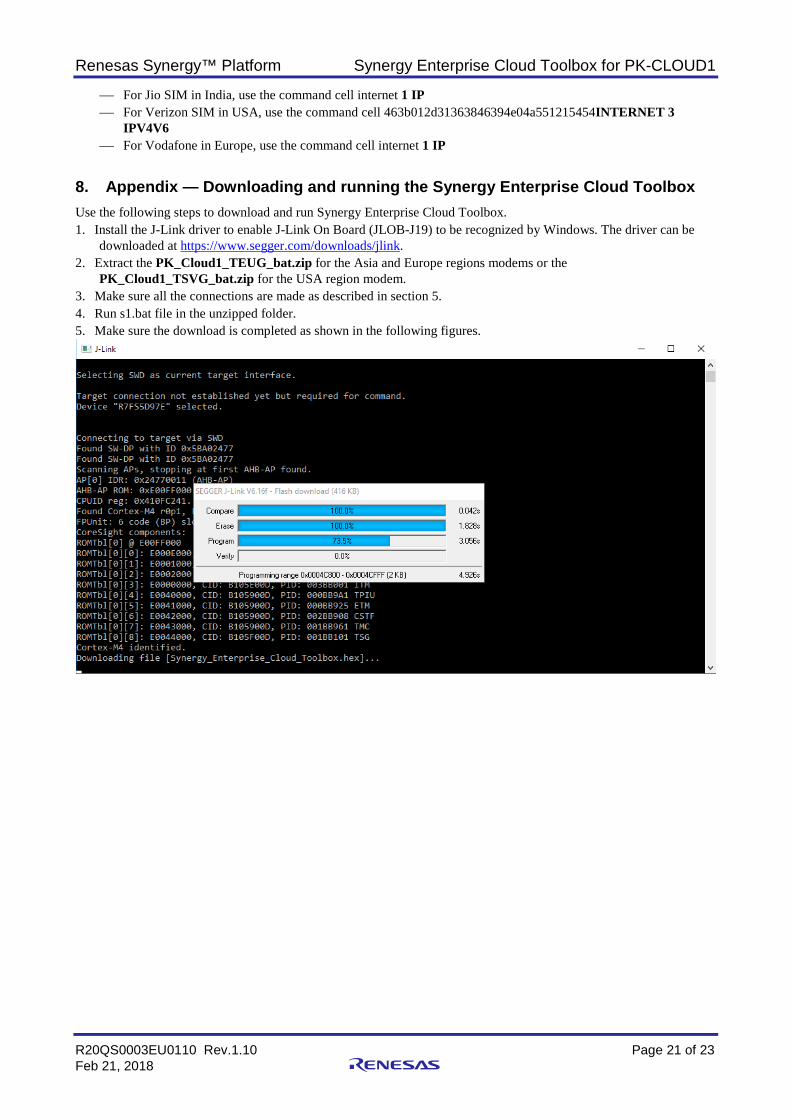
8. Appendix — Downloading and running the Synergy Enterprise Cloud Toolbox Use the following steps to download and run Synergy Enterprise Cloud Toolbox. 1. Install the J-Link driver to enable J-Link On Board (JLOB-J19) to be recognized by Windows. The driver can be
downloaded at https://www.segger.com/downloads/jlink. 2. Extract the PK_Cloud1_TEUG_bat.zip for the Asia and Europe regions modems or the
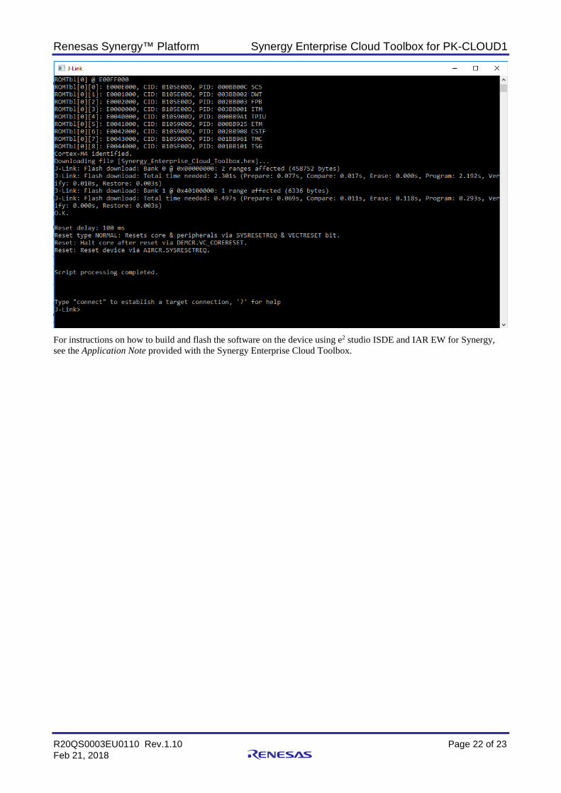
PK_Cloud1_TSVG_bat.zip for the USA region modem. 3. Make sure all the connections are made as described in section 5. 4. Run s1.bat file in the unzipped folder. 5. Make sure the download is completed as shown in the following figures.
Renesas Synergy™ Platform Synergy Enterprise Cloud Toolbox for PK-CLOUD1
R20QS0003EU0110 Rev.1.10 Page 22 of 23 Feb 21, 2018
For instructions on how to build and flash the software on the device using e2 studio ISDE and IAR EW for Synergy, see the Application Note provided with the Synergy Enterprise Cloud Toolbox.
Renesas Synergy™ Platform Synergy Enterprise Cloud Toolbox for PK-CLOUD1
R20QS0003EU0110 Rev.1.10 Page 23 of 23 Feb 21, 2018
Website and Support Support: https://synergygallery.renesas.com/support
Technical Contact Details:
• America: https://www.renesas.com/en-us/support/contact.html • Europe: https://www.renesas.com/en-eu/support/contact.html • Japan: https://www.renesas.com/ja-jp/support/contact.html All trademarks and registered trademarks are the property of their respective owners.

Revision History
Rev. Date Description Page Summary
1.00 Sep 29, 2017 — Initial release 1.08 Jan 11, 2018 — Changed PK-S5D9 to PK-CLOUD1 and updated procedures. 1.10 Feb 21, 2018 — Updated the following items in the document: — Screenshots throughout — Dashboard UI to display firmware upgrade message
for Azure devices. — Pop-up message in Dashboard display for Azure
devices

Synergy Enterprise Cloud Toolbox for PK-CLOUD1 Quick Start Guide
Publication Date: Rev.1.10 Feb 21, 2018 Published by: Renesas Electronics Corporation
http://www.renesas.comRefer to "http://www.renesas.com/" for the latest and detailed information.
Renesas Electronics America Inc.1001 Murphy Ranch Road, Milpitas, CA 95035, U.S.A.Tel: +1-408-432-8888, Fax: +1-408-434-5351Renesas Electronics Canada Limited9251 Yonge Street, Suite 8309 Richmond Hill, Ontario Canada L4C 9T3Tel: +1-905-237-2004Renesas Electronics Europe LimitedDukes Meadow, Millboard Road, Bourne End, Buckinghamshire, SL8 5FH, U.KTel: +44-1628-651-700, Fax: +44-1628-651-804Renesas Electronics Europe GmbHArcadiastrasse 10, 40472 Düsseldorf, GermanyTel: +49-211-6503-0, Fax: +49-211-6503-1327Renesas Electronics (China) Co., Ltd.Room 1709 Quantum Plaza, No.27 ZhichunLu, Haidian District, Beijing, 100191 P. R. ChinaTel: +86-10-8235-1155, Fax: +86-10-8235-7679Renesas Electronics (Shanghai) Co., Ltd.Unit 301, Tower A, Central Towers, 555 Langao Road, Putuo District, Shanghai, 200333 P. R. ChinaTel: +86-21-2226-0888, Fax: +86-21-2226-0999Renesas Electronics Hong Kong LimitedUnit 1601-1611, 16/F., Tower 2, Grand Century Place, 193 Prince Edward Road West, Mongkok, Kowloon, Hong KongTel: +852-2265-6688, Fax: +852 2886-9022Renesas Electronics Taiwan Co., Ltd.13F, No. 363, Fu Shing North Road, Taipei 10543, TaiwanTel: +886-2-8175-9600, Fax: +886 2-8175-9670Renesas Electronics Singapore Pte. Ltd.80 Bendemeer Road, Unit #06-02 Hyflux Innovation Centre, Singapore 339949Tel: +65-6213-0200, Fax: +65-6213-0300Renesas Electronics Malaysia Sdn.Bhd.Unit 1207, Block B, Menara Amcorp, Amcorp Trade Centre, No. 18, Jln Persiaran Barat, 46050 Petaling Jaya, Selangor Darul Ehsan, MalaysiaTel: +60-3-7955-9390, Fax: +60-3-7955-9510Renesas Electronics India Pvt. Ltd.No.777C, 100 Feet Road, HAL 2nd Stage, Indiranagar, Bangalore 560 038, IndiaTel: +91-80-67208700, Fax: +91-80-67208777Renesas Electronics Korea Co., Ltd.17F, KAMCO Yangjae Tower, 262, Gangnam-daero, Gangnam-gu, Seoul, 06265 KoreaTel: +82-2-558-3737, Fax: +82-2-558-5338
SALES OFFICES
© 2018 Renesas Electronics Corporation. All rights reserved.Colophon 5.0
Renesas Synergy™ Platform Synergy Enterprise Cloud Toolbox
for PK-CLOUD1 Quick Start Guide
R20QS0003EU0110