Embed Size (px)
Citation preview
Rev.1.00 Aug 2021
Renesas Synergy™ Platform Synergy Software SSP v2.1.0
User’
s Manual
www.renesas.com
All information contained in these materials, including products and product specifications, represents information on the product at the time of publication and is subject to change by Renesas Electronics Corp. without notice. Please review the latest information published by Renesas Electronics Corp. through various means, including the Renesas Electronics Corp. website (http://www.renesas.com).
Synergy Software Package (SSP)
Datasheet
Datasheet
© 2021 Renesas Electronics Corporation. All rights reserved.
Notice 1. Descriptions of circuits, software and other related information in this document are provided only to illustrate the operation of semiconductor products
and application examples. You are fully responsible for the incorporation or any other use of the circuits, software, and information in the design of your product or system. Renesas Electronics disclaims any and all liability for any losses and damages incurred by you or third parties arising from the use of these circuits, software, or information.
2. Renesas Electronics hereby expressly disclaims any warranties against and liability for infringement or any other claims involving patents, copyrights, or other intellectual property rights of third parties, by or arising from the use of Renesas Electronics products or technical information described in this document, including but not limited to, the product data, drawings, charts, programs, algorithms, and application examples.
3. No license, express, implied or otherwise, is granted hereby under any patents, copyrights or other intellectual property rights of Renesas Electronics or others.
4. You shall be responsible for determining what licenses are required from any third parties, and obtaining such licenses for the lawful import, export, manufacture, sales, utilization, distribution or other disposal of any products incorporating Renesas Electronics products, if required.
5. You shall not alter, modify, copy, or reverse engineer any Renesas Electronics product, whether in whole or in part. Renesas Electronics disclaims any and all liability for any losses or damages incurred by you or third parties arising from such alteration, modification, copying or reverse engineering.
6. Renesas Electronics products are classified according to the following two quality grades: “Standard” and “High Quality”. The intended applications for each Renesas Electronics product depends on the product’s quality grade, as indicated below. "Standard": Computers; office equipment; communications equipment; test and measurement equipment; audio and visual equipment; home
electronic appliances; machine tools; personal electronic equipment; industrial robots; etc. "High Quality": Transportation equipment (automobiles, trains, ships, etc.); traffic control (traffic lights); large-scale communication equipment; key
financial terminal systems; safety control equipment; etc. Unless expressly designated as a high reliability product or a product for harsh environments in a Renesas Electronics data sheet or other Renesas Electronics document, Renesas Electronics products are not intended or authorized for use in products or systems that may pose a direct threat to human life or bodily injury (artificial life support devices or systems; surgical implantations; etc.), or may cause serious property damage (space system; undersea repeaters; nuclear power control systems; aircraft control systems; key plant systems; military equipment; etc.). Renesas Electronics disclaims any and all liability for any damages or losses incurred by you or any third parties arising from the use of any Renesas Electronics product that is inconsistent with any Renesas Electronics data sheet, user’s manual or other Renesas Electronics document.
7. No semiconductor product is absolutely secure. Notwithstanding any security measures or features that may be implemented in Renesas Electronics hardware or software products, Renesas Electronics shall have absolutely no liability arising out of any vulnerability or security breach, including but not limited to any unauthorized access to or use of a Renesas Electronics product or a system that uses a Renesas Electronics product. RENESAS ELECTRONICS DOES NOT WARRANT OR GUARANTEE THAT RENESAS ELECTRONICS PRODUCTS, OR ANY SYSTEMS CREATED USING RENESAS ELECTRONICS PRODUCTS WILL BE INVULNERABLE OR FREE FROM CORRUPTION, ATTACK, VIRUSES, INTERFERENCE, HACKING, DATA LOSS OR THEFT, OR OTHER SECURITY INTRUSION (“Vulnerability Issues”). RENESAS ELECTRONICS DISCLAIMS ANY AND ALL RESPONSIBILITY OR LIABILITY ARISING FROM OR RELATED TO ANY VULNERABILITY ISSUES. FURTHERMORE, TO THE EXTENT PERMITTED BY APPLICABLE LAW, RENESAS ELECTRONICS DISCLAIMS ANY AND ALL WARRANTIES, EXPRESS OR IMPLIED, WITH RESPECT TO THIS DOCUMENT AND ANY RELATED OR ACCOMPANYING SOFTWARE OR HARDWARE, INCLUDING BUT NOT LIMITED TO THE IMPLIED WARRANTIES OF MERCHANTABILITY, OR FITNESS FOR A PARTICULAR PURPOSE.
8. When using Renesas Electronics products, refer to the latest product information (data sheets, user’s manuals, application notes, “General Notes for Handling and Using Semiconductor Devices” in the reliability handbook, etc.), and ensure that usage conditions are within the ranges specified by Renesas Electronics with respect to maximum ratings, operating power supply voltage range, heat dissipation characteristics, installation, etc. Renesas Electronics disclaims any and all liability for any malfunctions, failure or accident arising out of the use of Renesas Electronics products outside of such specified ranges.
9. Although Renesas Electronics endeavors to improve the quality and reliability of Renesas Electronics products, semiconductor products have specific characteristics, such as the occurrence of failure at a certain rate and malfunctions under certain use conditions. Unless designated as a high reliability product or a product for harsh environments in a Renesas Electronics data sheet or other Renesas Electronics document, Renesas Electronics products are not subject to radiation resistance design. You are responsible for implementing safety measures to guard against the possibility of bodily injury, injury or damage caused by fire, and/or danger to the public in the event of a failure or malfunction of Renesas Electronics products, such as safety design for hardware and software, including but not limited to redundancy, fire control and malfunction prevention, appropriate treatment for aging degradation or any other appropriate measures. Because the evaluation of microcomputer software alone is very difficult and impractical, you are responsible for evaluating the safety of the final products or systems manufactured by you.
10. Please contact a Renesas Electronics sales office for details as to environmental matters such as the environmental compatibility of each Renesas Electronics product. You are responsible for carefully and sufficiently investigating applicable laws and regulations that regulate the inclusion or use of controlled substances, including without limitation, the EU RoHS Directive, and using Renesas Electronics products in compliance with all these applicable laws and regulations. Renesas Electronics disclaims any and all liability for damages or losses occurring as a result of your noncompliance with applicable laws and regulations.
11. Renesas Electronics products and technologies shall not be used for or incorporated into any products or systems whose manufacture, use, or sale is prohibited under any applicable domestic or foreign laws or regulations. You shall comply with any applicable export control laws and regulations promulgated and administered by the governments of any countries asserting jurisdiction over the parties or transactions.
12. It is the responsibility of the buyer or distributor of Renesas Electronics products, or any other party who distributes, disposes of, or otherwise sells or transfers the product to a third party, to notify such third party in advance of the contents and conditions set forth in this document.
13. This document shall not be reprinted, reproduced or duplicated in any form, in whole or in part, without prior written consent of Renesas Electronics. 14. Please contact a Renesas Electronics sales office if you have any questions regarding the information contained in this document or Renesas
Electronics products.
(Note1) “Renesas Electronics” as used in this document means Renesas Electronics Corporation and also includes its directly or indirectly controlled subsidiaries.
(Note2) “Renesas Electronics product(s)” means any product developed or manufactured by or for Renesas Electronics. (Rev.5.0-1 October 2020)
Corporate Headquarters Contact information TOYOSU FORESIA, 3-2-24 Toyosu, Koto-ku, Tokyo 135-0061, Japan www.renesas.com
For further information on a product, technology, the most up-to-date version of a document, or your nearest sales office, please visit: www.renesas.com/contact/.
Trademarks Renesas and the Renesas logo are trademarks of Renesas Electronics Corporation. All trademarks and registered trademarks are the property of their respective owners.
Datasheet
R01DS0398EU0100 Rev.1.00 Page 1 of 1 Sep.23.21
Renesas Synergy™ Platform
Synergy Software Package (SSP) v2.1.0 Contents
1. Description of Renesas Synergy™ Software Package ............................................................. 4 Key Features ........................................................................................................................................... 6 Introduction to this Software Datasheet .................................................................................................. 9
1.2.1 Compatible Development Tools ............................................................................................................ 9 1.2.2 Supported Kits ....................................................................................................................................... 9
2. Third-Party Software modules included in SSP ...................................................................... 10 Azure RTOS ThreadX® embedded real-time operating system (RTOS) .............................................. 10
2.1.1 ThreadX® Certifications ....................................................................................................................... 10 2.1.2 ThreadX® API ...................................................................................................................................... 10 2.1.3 Thread Services .................................................................................................................................. 11 2.1.4 Message Queues ................................................................................................................................ 11 2.1.5 Counting Semaphores ......................................................................................................................... 11 2.1.6 Mutexes ............................................................................................................................................... 11 2.1.7 Event Flags .......................................................................................................................................... 11 2.1.8 Block Memory Pools ............................................................................................................................ 11 2.1.9 Byte Memory Pools ............................................................................................................................. 11 2.1.10 Application Timers ............................................................................................................................... 11 2.1.11 ThreadX® Core Scheduler ................................................................................................................... 11
Azure RTOS NetX™ Embedded TCP/IP and UDP Stacks ................................................................... 12 Azure RTOS NetX ™ Duo™ Dual IPv4/IPv6 Stack .............................................................................. 13 Azure RTOS NetX™ Applications Bundle ............................................................................................. 14 Azure RTOS NetX Duo™ Applications Bundle ..................................................................................... 15 Azure RTOS NetX and NetX Duo SNMP Agent ................................................................................... 16 Azure RTOS NetX Secure™ and MQTT for NetX Duo ......................................................................... 17
2.7.1 NetX Secure™..................................................................................................................................... 17 2.7.1.1 NetX Secure™ Requirements ........................................................................................................... 17 2.7.1.2 NetX Secure™ Constraints and Support .......................................................................................... 17 2.7.1.3 Ciphers Implemented ........................................................................................................................ 18 2.7.2 MQTT for NetX Duo™ ......................................................................................................................... 19 2.7.2.1 MQTT for NetX Duo Requirements ................................................................................................... 19
Azure RTOS FileX® Embedded File System ......................................................................................... 19 Azure RTOS GUIX™ GUI Development Toolkit ................................................................................... 21 Azure RTOS USBX™ ............................................................................................................................ 22
3. Application Frameworks ........................................................................................................ 26
Renesas Synergy™ Platform Synergy Software Package (SSP) v2.1.0
R01DS0398EU0100 Rev.1.00 Page 2 of 2 Sep.23.21
ADC Periodic Framework ...................................................................................................................... 27 Audio Playback Framework ................................................................................................................... 28 Audio Playback DAC Framework .......................................................................................................... 29 Audio Playback I2S Framework ............................................................................................................. 30 Audio Record ADC Framework ............................................................................................................. 31 Audio Record I2S Framework ................................................................................................................ 32 Block Media LevelX NOR Framework ................................................................................................... 33 Block Media QSPI Framework .............................................................................................................. 34 Block Media RAM Framework ............................................................................................................... 34 Block Media SDMMC Framework ......................................................................................................... 35 Bluetooth Low Energy (BLE) Framework .............................................................................................. 36 Capacitive Touch Button Framework .................................................................................................... 39 Capacitive Touch Framework ................................................................................................................ 41 Capacitive Touch Slider Framework ..................................................................................................... 42 Capacitive Touch Framework Version 2 ............................................................................................... 43 Cellular Framework ............................................................................................................................... 43 Communications Framework on NetX................................................................................................... 47 Communications Framework on NetX Telnet ....................................................................................... 48 Communications Framework on USBX Version 2 ................................................................................ 49 Console Framework .............................................................................................................................. 50 Cryptographic Framework ..................................................................................................................... 51 External IRQ Framework ....................................................................................................................... 54 I2C Framework ....................................................................................................................................... 55 JPEG Decode Framework ..................................................................................................................... 56 Memory Framework............................................................................................................................... 57 Messaging Framework .......................................................................................................................... 58 Port LevelX Framework ......................................................................................................................... 59 Power Profile Framework Version 2 ...................................................................................................... 60 Serial Peripheral Interface (SPI) Framework ........................................................................................ 61 Synergy FileX® Port Block Media Interface Framework ........................................................................ 62 Synergy GUIX™ Interface Framework .................................................................................................. 64 Synergy NetX™ Port Ethernet Module.................................................................................................. 65 Synergy USBX™ Port Framework ........................................................................................................ 66 Thread Monitor Framework ................................................................................................................... 67 Touch Panel I2C Framework ................................................................................................................. 68 Touch Panel Version 2 Framework ....................................................................................................... 69 UART Communications Framework ...................................................................................................... 70 Wi-Fi Framework ................................................................................................................................... 71 Wi-Fi QCA4010 Framework .................................................................................................................. 73
4. CMSIS DSP Library ............................................................................................................... 74
Renesas Synergy™ Platform Synergy Software Package (SSP) v2.1.0
R01DS0398EU0100 Rev.1.00 Page 3 of 3 Sep.23.21
5. CMSIS Neural Network Library .............................................................................................. 75
6. Hardware Abstraction Layer (HAL) Modules .......................................................................... 76 Analog Comparator High-Speed (ACMPHS) ........................................................................................ 77 Analog Comparator Low Power (ACMPLP) .......................................................................................... 78 Analog to Digital Converter (ADC) ........................................................................................................ 79 Asynchronous General Purpose Timer (AGT) ...................................................................................... 81 AGT Input Capture ................................................................................................................................ 83 Analog Connection Module (ACM) ........................................................................................................ 85 Clock Frequency Accuracy Measurement (CAC) ................................................................................. 86 Controller Area Network (CAN) ............................................................................................................. 90 Clock Generation Circuit (CGC) ............................................................................................................ 93 Cyclic Redundancy Check calculator (CRC) ......................................................................................... 95 Capacitive Touch Sensing Unit (CTSU) ................................................................................................ 97 Capacitive Touch Sensing Unit Version 2 (CTSU v2) ........................................................................... 99 Digital to Analog (DAC) ......................................................................................................................... 99 Digital to Analog 8-bit (DAC8) ............................................................................................................. 101 Direct Memory Access Controller (DMAC) .......................................................................................... 102 Data Operation Circuit (DOC) ............................................................................................................. 103 Data Transfer Controller (DTC) ........................................................................................................... 104 Event Link Controller (ELC) ................................................................................................................. 106 Flash Memory ...................................................................................................................................... 107 Graphics LCD Controller (GLCD) ........................................................................................................ 109 General Purpose Timer (GPT) ............................................................................................................ 111 Independent Watchdog Timer (IWDT) ................................................................................................ 113 Input Capture (GPT_INPUT_CAPTURE) ............................................................................................ 115 I2C Master and Slave (Full Featured) .................................................................................................. 117 Interrupt Controller Unit – External (ICU) ............................................................................................ 121 I/O Port (GPIO / IOPORT) ................................................................................................................... 123 JPEG Decode ...................................................................................................................................... 125 JPEG Encode ...................................................................................................................................... 127 Key Matrix Driver Interface (KINT) ...................................................................................................... 129 Low Power Modes Version 2 (LPM V2) .............................................................................................. 130 Low Voltage Detection (LVD) .............................................................................................................. 132 Operational Amplifier (OPAMP) .......................................................................................................... 134 Parallel Data Capture Unit (PDC) ........................................................................................................ 135 Precision Time Protocol (PTP) ............................................................................................................ 137 DMA Controller for EPTPC (PTPEDMAC) .......................................................................................... 138 Quad SPI (QSPI) ................................................................................................................................. 139 Realtime Clock (RTC).......................................................................................................................... 141 SD Multi Media Card (SDMMC) .......................................................................................................... 143
Renesas Synergy™ Platform Synergy Software Package (SSP) v2.1.0
R01DS0398EU0100 Rev.1.00 Page 4 of 4 Sep.23.21
Secure Cryptographic Engine (SCE)................................................................................................... 145 Serial Communication Interface I2C (SCI_I2C) ................................................................................... 148 Serial Communication Interface SPI (SCI_SPI) .................................................................................. 150 Serial Communication Interface UART (SCI_UART) .......................................................................... 152 Serial Peripheral Interface (RSPI) ....................................................................................................... 155 Segment LCD (SLCDC) ...................................................................................................................... 158 Serial Sound Interface (SSI) — also known as I2S ............................................................................. 160 Sigma Delta A/D Converter (SDADC) ................................................................................................. 162 Watchdog Timer (WDT) ...................................................................................................................... 164
7. Board Support Package (BSP) ............................................................................................ 166
8. Revision History ................................................................................................................... 168
1. Description of Renesas Synergy™ Software Package The Synergy Software Package (SSP), the heart of the Synergy Platform, was designed and tested to commercial standards to be a fully integrated software package that is thoroughly tested and maintained by Renesas.
Key components in SSP include Microsoft’s Azure RTOS comprising of ThreadX® Real Time Operating System (RTOS), NetX™ IPv4 and NetX Duo™ IPv4/IPv6 compliant TCP/IP stacks, NetX Secure™ (TLS), NetX/NetX Duo applications bundle, Datagram Transport Layer Security (DTLS), MQTT (IoT), HTTPS and SNMP protocol stacks, USBX™ USB Host/Device protocol stack, FileX® MS-DOS compatible file system, and GUIX™ graphics runtime library.
Integrated in SSP are a set of Application Frameworks, Hardware Abstraction Layer (HAL) drivers, Board Support Packages (BSPs) and libraries, all of which are optimized for use with Synergy Microcontrollers (MCU). Developed under a robust Software Life Cycle Process while complying with most of the MISRA C: 2012 coding guidelines, Renesas maintains, enhances and supports SSP on continuous basis.
Renesas Synergy™ Platform Synergy Software Package (SSP) v2.1.0
R01DS0398EU0100 Rev.1.00 Page 5 of 5 Sep.23.21
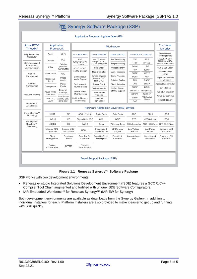
Figure 1.1 Renesas Synergy™ Software Package
SSP works with two development environments:
• Renesas e2 studio Integrated Solutions Development Environment (ISDE) features a GCC C/C++ Compiler Tool Chain augmented and fortified with unique ISDE Software Configurators.
• IAR Embedded Workbench® for Renesas Synergy™ (IAR EW for Synergy) Both development environments are available as downloads from the Synergy Gallery. In addition to individual Installers for each, Platform Installers are also provided to make it easier to get up and running with SSP quickly.
Renesas Synergy™ Platform Synergy Software Package (SSP) v2.1.0
R01DS0398EU0100 Rev.1.00 Page 6 of 6 Sep.23.21
Key Features Azure RTOS ThreadX® RTOS • Multithreaded, deeply embedded, real-time
systems • Small, fast Picokernel™ architecture • Multitasking capabilities • Preemptive and cooperative scheduling • Flexible thread priority support (32-1024 priority
levels) • Small memory footprint and fast response times • Optimized interrupt handling • Stack Pointer Overflow Monitor
Azure RTOS GUIX™ • Supports 2D Graphics Acceleration in Hardware • Unlimited objects (screens, windows, widgets) • Dynamic object creation/deletion • Alpha blending and anti-aliasing at higher color
depths • Canvas blending • Dithering support • Complete windowing support, including viewports
and Z-order maintenance • Multiple canvases and physical displays • Window blending and fading • Screen transitions, sprites, and dynamic
animations • Touchscreen and virtual keyboards • Multilingual support with UTF8 string encoding • Automatic size scaling • 8-bit Color Lookup Table (CLUT) support • Touch Rotation • Radial Progress Bar • Endian Neutral • Monochrome through 32-bit true-color with alpha
graphics formats • Skinning and Themes • Bitmap compression • GUIX Studio desktop tool and Win32 simulation • Integrated with hardware JPEG/MJPEG decoder
Azure RTOS USBX™ • USB 2.0 Full Speed and High-Speed support • Device class: MSC, HID, CDC-ACM • Host class: MSC, HID, CDC-ACM, UVC, HUB,
Printer, Video • Supports fast DMA and isochronous transfers
Azure RTOS FileX® • MS-DOS compatible file system integrated with
ThreadX • FAT12, 16, 32-bit support • exFAT • Fault-tolerant file system (uses journaling) • Multiple media instances • LevelX Flash block media driver • LevelX support for NOR Flash on QSPI
Azure RTOS NetX™ • Integrated with wired (Ethernet) and wireless (WiFi,
Cellular) networking interfaces for Synergy
• IPv4 compliant TCP/IP Protocol Stack • Integrated with ThreadX • Zero-copy API • UDP Fast Path Technology • BSD-compatible socket layer • RFC 791 Internet Protocol (IP) • RFC 826 Address Resolution Protocol (ARP) • RFC 903 Reverse Address Resolution Protocol
(RARP) • RFC 792 Internet Control Message Protocol
(ICMP) • RFC 3376 Internet Group Management Protocol
(IGMP) • RFC 768 User Datagram Protocol (UDP) • RFC 793 Transmission Control Protocol (TCP) • RFC 1112 Host Extensions for IP Multicasting
Application Frameworks • ADC Periodic framework • Audio Playback framework • Audio Playback HW DAC framework • Audio Playback HW I2S framework • Audio Record framework • Audio Recording HW ADC framework • Block Media Interface for SD Multi Media Card • Block Media LevelX NOR framework • Block Media QSPI framework • Block Media RAM framework • Block Media SDMMC framework • Bluetooth Low Energy (BLE) framework • Deprecated – Capacitive Touch Sensing Unit
framework • Capacitive Touch Sensing Unit framework Version
2 • Deprecated – Capacitive Touch Sensing Unit
Button framework • Deprecated – Capacitive Touch Sensing Unit
Slider framework • Cellular framework • Communications framework on NetX • Communications framework on NetX Telnet • Deprecated - Communications framework on
USBX • Communications Framework on USBX version2 • Console framework • External Interrupt framework • I2C framework • Inter-Thread Messaging framework • JPEG Decode framework • Memory framework • Port LevelX framework • Periodic Sampling ADC framework • Power Profile Version 2 framework • SPI Framework
Renesas Synergy™ Platform Synergy Software Package (SSP) v2.1.0
R01DS0398EU0100 Rev.1.00 Page 7 of 7 Sep.23.21
• Synergy FileX® Port Block Media Interface framework
• Synergy GUIX™ Interface framework • Synergy NetX™ Port framework • Synergy USBX™ Port framework • Thread Monitor framework • Deprecated - Touch Panel framework • Touch Panel Version 2 framework • UART framework • Wi-Fi Framework
Security Cryptographic (SCE) Library • True RNG (TRNG) • SHA1, SHA224/SHA256 • ECC P-192, P-224, P-256 and P-384 curves.
Includes APIs for scalar multiplication, key generation, ECDSA signature generation, and ECDSA signature verification operations
• AES 128, 192, and 256-bits ECB, CBC, CTR, GCM, XTS
• 3DES, 192-bit key, ECB, CBC, CTR • ARC4 • RSA up to 2048-bit keys • DLP, DSA up to 2048-bit keys • Encryption/Decryption • Key Generation (plaintext and wrapped keys) and
Installation. • Signature Generation and Verification • MD5
CMSIS DSP Library • Basic math functions • Fast math functions • Complex math functions • Filters • Convolution • Matrix functions • Transforms • Motor control functions • Statistical functions • Support functions • Interpolation functions
CMSIS Neural Network Library • Convolution Functions • Activation Functions • Fully-connected Layer Functions • Pooling Functions • Softmax Functions • Basic math Functions
AzureRTOS NetX Duo™ • IPv4 and IPv6 compliant TCP/IP Protocol Stack • Integrated with ThreadX • Integrated with wired (Ethernet) and wireless (WiFi,
Cellular) networking interfaces for Synergy • Zero-copy API • UDP Fast Path Technology • BSD-compatible socket layer • RFC 2460 IPv6 Specification
• RFC 4861 Neighbor Discovery for IPv6 • RFC 4862 IPv6 Stateless Address • RFC 1981 Path MTU Discovery for IPv6 • RFC 4443 ICMPv6 • RFC 791 Internet Protocol (IP) • RFC 826 Address Resolution Protocol (ARP) • RFC 903 Reverse Address Resolution Protocol
(RARP) • RFC 792 Internet Control Message Protocol
(ICMP) • RFC 3376 Internet Group Management Protocol
(IGMP) • RFC 768 User Datagram Protocol (UDP) • RFC 793 Transmission Control Protocol (TCP) • RFC 1112 Host Extensions for IP Multicasting • RFC 1661 - The Point-to-Point Protocol (PPP)
Azure RTOS NetX™ Applications (IPv4 Networking Services) • DHCP Client and Server • DNS Client • HTTP 1.0 Client and Webserver • HTTP 1.1 Client • FTP Client and Server • TFTP Client and Server • Telnet Client and Server • Auto IP • NAT • SMTP Client • POP3 Client and Server • SNMP Agent • SNTP Client • PPP (Not currently supported by Synergy
Configuration tool)
Azure RTOS NetX Duo™ Applications (IPv4/v6 Networking Services) • DHCP Client and Server • DNS Client • HTTP 1.0 Client and Webserver • HTTP 1.1 Client • HTTPS Client and Server • FTP Client and Server • TFTP Client and Server • Telnet Client and Server • Auto IP • NAT • SMTP Client • POP3 Client and Server • SNMP Agent • SNTP Client • MDNS/DNS-SD • PPP (Not currently supported by Synergy
Configuration tool)
Azure RTOS NetX Secure • Deprecated – TLS v1.1 (RFC 4346, 2246) • TLS v1.2 (RFC 5246) and v1.3 (RFC 8446) • DTLS v1.2 (RFC 6347)

Renesas Synergy™ Platform Synergy Software Package (SSP) v2.1.0
R01DS0398EU0100 Rev.1.00 Page 8 of 8 Sep.23.21
• RFC 5280 Internet X.509 Public Key Infrastructure Certificate and Certificate Revocation List (CRL) Profile
• RFC 5280 X.509 PKI Certificates (v3) • Supports X.509 extensions for Key Usage and
Extended Key Usage • RFC 3268 Advanced Encryption Standard (AES)
Cipher suites for Transport Layer Security (TLS) • RFC 3447 Public-Key Cryptography Standards
(PKCS) #1: RSA Cryptography Specifications Version 2.1
• RFC 2104 HMAC: Keyed-Hashing for Message Authentication
• RFC 6234 US Secure Hash Algorithms (SHA and SHA-based HMAC and HKDF)
• RFC 8422 Elliptic Curve Cryptography (ECC) Cipher Suites for Transport Layer Security (TLS) Versions 1.2 and Earlier
• RFC 4279 Pre-Shared Key Cipher suites for TLS • Supports TLS extensions for:
Secure Renegotiation Indication Server Name Indication Signature Algorithms
• Subject Alternative Name • Integrated with hardware accelerated
Cryptographic library on Synergy
Azure RTOS MQTT client for NetX Duo • Compliant with OASIS MQTT Version 3.1.1 • Provides option to enable/disable TLS for secure
communications using NetX Secure in SSP
• Supports QoS and provides the ability to choose the levels that can be selected while publishing the message
• Supports multiple Instances of MQTT Client Per Device
Memory Support • Flash programming support via JTAG • Code and Data Flash drivers • External memory bus support
Human Machine Interface (HMI) • Graphics LCD controller driver • Segment LCD controller driver • Capacitive Touch Sensing Unit (CTSU)
Hardware Abstract Layer (HAL) Driver Modules • Analog Comparator High-Speed (ACMPHS) • Analog Comparator Low Power (ACMPLP) • Analog Connect Module (ACM) • Analog to Digital Converter (ADC) (12-bit, 14-bit) • Asynchronous General Purpose Timer (AGT) • AGT Input Capture (AGT Input Capture) • Capacitive Touch Sensing Unit (CTSU) • Clock Frequency Accuracy Measurement (CAC) • Clock Generation Circuit (CGC) • Controller Area Network Interface (CAN) • Cyclic Redundancy Check calculator (CRC)
• Data Operation Circuit (DOC) • Data Transfer Controller (DTC) • Digital to Analog converter (DAC) • Digital to Analog converter 8-bit (DAC8) • Direct Memory Access Controller (DMAC) • Event Link Controller (ELC) • Flash Memory-High Performance (FLASH_HP) • Flash Memory-Low Power (FLASH_LP) • General Purpose I/O Port (GPIO / IOPORT) • General Purpose Timer (GPT) • General PWM Timer with Input Capture
(GPT_INPUT_CAPTURE) • Graphics LCD Controller (GLCD) • IEEE 1588 Precision Time Protocol (PTP) • I2IC (RIIC) • Independent Watchdog Timer (IWDT) • Interrupt Controller Unit (ICU) • JPEG Codec (JPEG_COMMON, JPEG_ENCODE,
JPEG_DECODE) • Keyboard Interrupt Interface (KINT) • Deprecated – Low Power Mode (LPM) • Low Power Mode Version 2 (LPMv2) • Low Voltage Detection (LVD) • Parallel Data Capture Unit (PDC) • Quad SPI (QSPI) • Real Time clock (RTC) • SD Multi Media Card (SDMMC) • Segment LCD (SLCD) • Serial Communication Interface I2C (SCI_I2C) • Serial Communication Interface SPI (SCI_SPI) • Serial Communication Interface UART
(SCI_UART) • Sigma-Delta ADC (SDADC) • Serial Peripheral Interface (SPI) • Serial Sound Interface (SSI) • Watchdog Timer (WDT)
GPIO and Key Interrupts • GPIO module • Key Interrupts module
Renesas Synergy™ Platform Synergy Software Package (SSP) v2.1.0
R01DS0398EU0100 Rev.1.00 Page 9 of 9 Sep.23.21
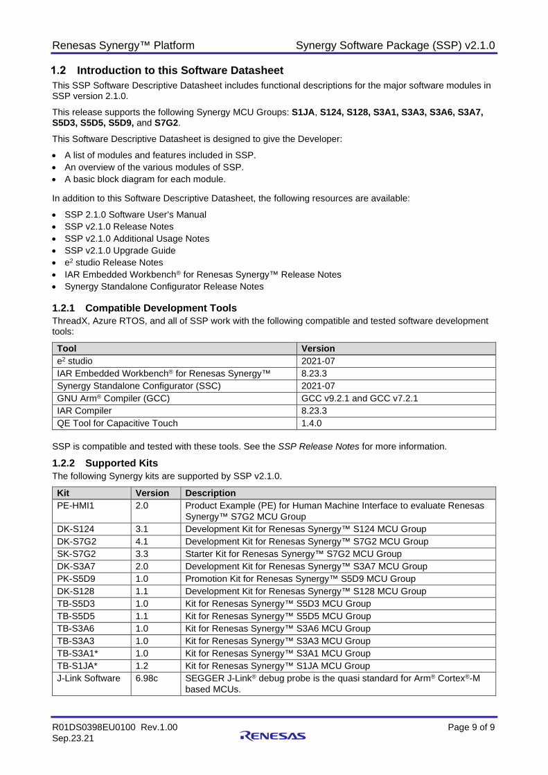
Introduction to this Software Datasheet This SSP Software Descriptive Datasheet includes functional descriptions for the major software modules in SSP version 2.1.0.
This release supports the following Synergy MCU Groups: S1JA, S124, S128, S3A1, S3A3, S3A6, S3A7, S5D3, S5D5, S5D9, and S7G2.
This Software Descriptive Datasheet is designed to give the Developer:
• A list of modules and features included in SSP. • An overview of the various modules of SSP. • A basic block diagram for each module. In addition to this Software Descriptive Datasheet, the following resources are available:
• SSP 2.1.0 Software User’s Manual • SSP v2.1.0 Release Notes • SSP v2.1.0 Additional Usage Notes • SSP v2.1.0 Upgrade Guide • e2 studio Release Notes • IAR Embedded Workbench® for Renesas Synergy™ Release Notes • Synergy Standalone Configurator Release Notes 1.2.1 Compatible Development Tools ThreadX, Azure RTOS, and all of SSP work with the following compatible and tested software development tools:
Tool Version e2 studio 2021-07 IAR Embedded Workbench® for Renesas Synergy™ 8.23.3 Synergy Standalone Configurator (SSC) 2021-07 GNU Arm® Compiler (GCC) GCC v9.2.1 and GCC v7.2.1 IAR Compiler 8.23.3 QE Tool for Capacitive Touch 1.4.0
SSP is compatible and tested with these tools. See the SSP Release Notes for more information.
1.2.2 Supported Kits The following Synergy kits are supported by SSP v2.1.0.
Kit Version Description PE-HMI1 2.0 Product Example (PE) for Human Machine Interface to evaluate Renesas
Synergy™ S7G2 MCU Group DK-S124 3.1 Development Kit for Renesas Synergy™ S124 MCU Group DK-S7G2 4.1 Development Kit for Renesas Synergy™ S7G2 MCU Group SK-S7G2 3.3 Starter Kit for Renesas Synergy™ S7G2 MCU Group DK-S3A7 2.0 Development Kit for Renesas Synergy™ S3A7 MCU Group PK-S5D9 1.0 Promotion Kit for Renesas Synergy™ S5D9 MCU Group DK-S128 1.1 Development Kit for Renesas Synergy™ S128 MCU Group TB-S5D3 1.0 Kit for Renesas Synergy™ S5D3 MCU Group TB-S5D5 1.1 Kit for Renesas Synergy™ S5D5 MCU Group TB-S3A6 1.0 Kit for Renesas Synergy™ S3A6 MCU Group TB-S3A3 1.0 Kit for Renesas Synergy™ S3A3 MCU Group TB-S3A1* 1.0 Kit for Renesas Synergy™ S3A1 MCU Group TB-S1JA* 1.2 Kit for Renesas Synergy™ S1JA MCU Group J-Link Software 6.98c SEGGER J-Link® debug probe is the quasi standard for Arm® Cortex®-M
based MCUs.

Renesas Synergy™ Platform Synergy Software Package (SSP) v2.1.0
R01DS0398EU0100 Rev.1.00 Page 10 of 10 Sep.23.21
2. Third-Party Software modules included in SSP SSP includes high performance, low foot print Azure RTOS ThreadX® and Azure RTOS suite (NetX/NetX Duo, USBX, FileX®, LevelX, GUIX™, NetX Secure, MQTT, SNMP and HTTPS) integrated on Synergy MCUs and enabled by easy to use, GUI driven XML configurators and automated code generation tools for accelerating application development. SSP also includes HAL drivers and application framework for TES D/AVE 2D graphics engine that are integrated with GUIX. GUIX Studio, a Windows PC tool for developing rich GUI is provided separately for the Synergy platform. For a complete list of third party modules and supported MCUs refer to the SSP Release Note.
Azure RTOS ThreadX® embedded real-time operating system (RTOS) At the core of Synergy Software Package (SSP) is the Microsoft, Inc. Azure RTOS ThreadX®. Optimized for Synergy MCUs and tightly integrated with the SSP, ThreadX includes an optimized, high-performance real-time kernel designed specifically for real-time embedded systems running on microcontrollers. ThreadX provides a fast, sub microsecond context switching time and a small footprint (as small as 2-KB Flash memory).
The key features of ThreadX include:
• Picokernel™ design where services are not layered • Preemptive and preemption-threshold scheduling • Event-chaining • Inter-task synchronization • Highly optimized interrupt processing where only scratch registers are saved/restored upon ISR entry/exit,
unless preemption is necessary • Fast interrupt response time • Fast context switching • Low RTOS service overhead • Stack pointer overflow monitor
ThreadX memory protection ensures that application threads and the ThreadX kernel are protected against accidental read or write access from other threads. This prevents code or data corruption from latent application bugs and eliminates one of the most common causes of application crashes.
Figure 2.1 ThreadX® Features
2.1.1 ThreadX® Certifications ThreadX® has been pre-certified by TUV and UL to IEC 61508 SIL 4, IEC 62304 Class C, ISO 26262 ASIL D, UL/IEC 60730, UL/IEC 60335, UL 1998, and SW-SIL EN 50128.
2.1.2 ThreadX® API With an intuitive and consistent API naming convention (noun-verb naming, all APIs have a leading “tx_” to easily identify the call as a ThreadX call), the ThreadX APIs provide the foundation on which multi-threaded, real-time Internet of Things (IoT) applications can be built.
Renesas Synergy™ Platform Synergy Software Package (SSP) v2.1.0
R01DS0398EU0100 Rev.1.00 Page 11 of 11 Sep.23.21
Blocking APIs have an optional thread timeout feature to defeat dead-hangs, and many APIs are directly available from application Interrupt Service Routines (ISRs).
2.1.3 Thread Services With dynamic thread creation, Thread Services allow for an unlimited number of threads (based on available hardware resources and real-time demands).
2.1.4 Message Queues Like Thread Services, Messages Queues allow for dynamic queue creation. There are no limits on the number of queues (based on available hardware resources and real-time demands). Messages can be copied by value or by reference via pointer. Message sizes are from 1 to 16, 32-bit words. Optional thread suspension on empty and full, and optional timeout on all suspensions, help to avoid lock-ups.
2.1.5 Counting Semaphores With dynamic semaphore creation and no limits on the number of semaphores, the 32-bit semaphores provide inter-thread coordination services. Both consumer-producer and resource-protection models are included. Optional thread suspension when the semaphore is unavailable and optional timeout on suspension increase robustness.
2.1.6 Mutexes Another form of inter-thread communication synchronization, there are no limits to the number of mutexes you can have (based on available hardware resources).Allowing for dynamic mutex creation, this system supports nested resource protection. Optional priority inheritance is supported. Optional thread suspension when the mutex is unavailable is supported as well.
2.1.7 Event Flags As with other ThreadX® resources, with dynamic event flag group creation and no limits on event flag groups (based on available hardware resources), event flags allow synchronization of one thread or multiple threads. Atomic “get” and “clear” is supported, as is optional multi-thread suspension on AND/OR set of events and optional timeout on all suspension.
2.1.8 Block Memory Pools ThreadX offers Dynamic block pool creation, with no limits on the number of block pools (except for physical memory limits), and no limits on the size of fixed-size blocks or the size of the pool. The fastest possible memory allocation/deallocation is supported, and features like optional thread suspension on empty pool and optional timeout on all suspension are available.
2.1.9 Byte Memory Pools ThreadX® offers dynamic byte pool creation, with no limits on the number of byte pools (except for physical memory limits), and no limits on the number of byte pools managed. This is the most flexible variable-length memory allocation/deallocation, and allocation size locality is supported. Includes optional thread suspension on empty pool. Optional timeout on all suspensions are available.
2.1.10 Application Timers ThreadX® offers dynamic timer creation, with no limits on the number of timers, and support for periodic or one-shot timers. Periodic timers may have different initial expiration value, and there is no searching on timer activation or deactivation.
2.1.11 ThreadX® Core Scheduler ThreadX® offers as low as a minimal 2-KB flash footprint, 1-KB RAM footprint capability, but the most important feature of the Scheduler is very fast, sub-microsecond context switch times. Fully deterministic regardless of the number of threads, this priority-based, fully pre-emptive Scheduler has 32 default priority levels (optionally up to 1024). In addition to pre-emptive scheduling, it can also perform cooperative scheduling within a priority level (FIFO). Preemption-threshold technology prevents thread inversion.
Optional time services include: • Per-thread optional time-slice • Optional time-out on all blocking APIs (requires on-hardware time interrupt). • Execution profiling to help tune your application is offered, as well as system-wide trace.
Renesas Synergy™ Platform Synergy Software Package (SSP) v2.1.0
R01DS0398EU0100 Rev.1.00 Page 12 of 12 Sep.23.21
Azure RTOS NetX™ Embedded TCP/IP and UDP Stacks SSP includes an optimized embedded TCP/IP-IPv4-compliant protocol stack, Azure RTOS NetX™, for enabling Internet of Things (IoT), Machine to Machine (M2M) communication protocols, and embedded applications that require network connectivity. NetX ™ is completely integrated with ThreadX® and is based on Microsoft’s unique Piconet™ architecture that provides a zero-copy API interface for applications.
Key features and capabilities provided with NetX™ include: • Fast execution • TraceX® system analysis support • BSD sockets compatible API • UDP Fast-Path lets basic UDP packets pass through NetX™ without copying or context switches • Flexible packet management NetX™ provides a complete set of protocol components that comprise the TCP/IP standard: • RFC 791 Internet Protocol (IP) • RFC 826 Address Resolution Protocol (ARP) • RFC 903 Reverse Address Resolution Protocol (RARP) • RFC 792 Internet Control Message Protocol (ICMP) • RFC 3376 Internet Group Management Protocol (IGMP) • RFC 768 User Datagram Protocol (UDP) • RFC 793 Transmission Control Protocol (TCP) • RFC 1112 Host Extensions for IP Multicasting. In the SSP, both e2 studio and IAR EW for Synergy have configurators to assist developers in creating code for NetX™.
Figure 2.2 NetX™ Stack Configuration

Renesas Synergy™ Platform Synergy Software Package (SSP) v2.1.0
R01DS0398EU0100 Rev.1.00 Page 13 of 13 Sep.23.21
Azure RTOS NetX ™ Duo™ Dual IPv4/IPv6 Stack For applications requiring IPv6 support, the SSP includes Microsoft’s Azure RTOS NetX Duo™, a dual IPv4 and IPv6 compliant TCP/IP protocol stack. NetX Duo™ is completely integrated with ThreadX® RTOS and includes all the features and capabilities available with NetX™. NetX Duo™ further extends the capabilities of SSP-based devices to auto-configure their interface addresses through the Stateless Address Auto configuration protocol. Devices can also use layered structures to enable devices to process IPv6 headers more efficiently. NetX Duo™ applications are individually selectable for each project offering flexibility to the system designer to incorporate only the applications necessary for the target application.
Figure 2.3 NetX Duo™ Stack Configuration
NetX Duo™ implements the following protocols:
• All IPv4 protocols available in NetX™ • Zero-copy API • UDP Fast Path Technology • BSD-compatible socket layer • RFC 2460 IPv6 Specification • RFC 4861 Neighbor Discovery for IPv6 • RFC 4862 IPv6 Stateless Address Auto configuration • RFC 1981 Path MTU Discovery for IPv6 • RFC 4443 ICMPv6 • RFC 791 Internet Protocol (IP) • RFC 826 Address Resolution Protocol (ARP) • RFC 903 Reverse Address Resolution Protocol (RARP) • RFC 792 Internet Control Message Protocol (ICMP) • RFC 3376 Internet Group Management Protocol (IGMP) • RFC 768 User Datagram Protocol (UDP) • RFC 793 Transmission Control Protocol (TCP) • RFC 1112 Host Extensions for IP Multicasting NetX Duo™ has been accredited by the IPv6 Forum with Phase-II IPv6-Ready Logo certification. NetX Duo™ has been pre-certified by TUV and UL to IEC 61508 SIL 4, IEC 62304 Class C, ISO 26262 ASIL D, UL/IEC 60730, UL/IEC 60335, UL 1998, and EN 50128 SW-SIL 4.
Renesas Synergy™ Platform Synergy Software Package (SSP) v2.1.0
R01DS0398EU0100 Rev.1.00 Page 14 of 14 Sep.23.21
Azure RTOS NetX™ Applications Bundle Included with SSP are additional application layer protocols that are frequently used in networking devices:
• Auto IP RFC 3927 Dynamic Configuration of IPv4 Link-Local Addresses
• Dynamic Host Configuration Protocol for Servers (DHCP Server) and Client (DHCP Client) RFC 2131 Dynamic Host Configuration Protocol RFC 2132 DHCP Options and BOOTP Vendor Extensions
• Domain Name System (DNS Client) RFC 1034 Domain Names – Concepts and Facilities RFC 1035 Domain names – Implementation and Specification RFC 1480 The US Domain RFC 2782 A DNS RR for specifying the location of services (DNS SRV)
• HTTP Client and Webserver RFC 1945 Hypertext Transfer Protocol/1.0 RFC 2616 Hypertext Transfer Protocol -- HTTP/1.1 RFC 2581 TCP Congestion Control RFC 1122 Requirements for Internet Hosts - Communication Layers RFC 2818 HTTP over TLS (HTTPS) client and server
• RFC 959 FILE TRANSFER PROTOCOL (FTP) Client and Server • TFTP Client and Server
RFC 1350 The TFTP Protocol (Revision 2) • Telnet Client and Server
RFC 854 Telnet Protocol Specification • RFC 1939 Post Office Protocol - Version 3 (POP3) • RFC 1661 The Point-to-Point Protocol (PPP)
RFC 1332 The PPP Internet Protocol Control Protocol (IPCP) RFC1334 PPP Authentication Protocols RFC1994 PPP Challenge Handshake Authentication Protocol (CHAP)
• Simple Mail Transfer Protocol (SMTP) RFC 2821 Simple Mail Transfer Protocol (SMTP) RFC 2554 SMTP Service Extension for Authentication RFC4330 Simple Network Time Protocol (SNTP) Version 4 for IPv4, IPv6 and OSI
These implementations of core networking protocols are thread-safe, compliant with respective RFCs/standards, and have been optimized for memory footprint and CPU utilization. Networking applications are individually selectable for each project providing flexibility to system designer to incorporate only applications necessary for the target application.

Renesas Synergy™ Platform Synergy Software Package (SSP) v2.1.0
R01DS0398EU0100 Rev.1.00 Page 15 of 15 Sep.23.21
Azure RTOS NetX Duo™ Applications Bundle Included with SSP are additional application layer protocols that are frequently used in networking devices:
• Auto IP RFC 3927 Dynamic Configuration of IPv4 Link-Local Addresses
• Dynamic Host Configuration Protocol for Servers (DHCP Server) and Client (DHCP Client) RFC 2131 Dynamic Host Configuration Protocol RFC 2132 DHCP Options and BOOTP Vendor Extensions
• Domain Name System (DNS Client) RFC 1034 Domain Names – Concepts and Facilities RFC 1035 Domain names – Implementation and Specification RFC 1480 The US Domain RFC 2782 A DNS RR for specifying the location of services (DNS SRV)
• HTTP Client and Webserver RFC 1945 Hypertext Transfer Protocol/1.0 RFC 2581 TCP Congestion Control RFC 1122 Requirements for Internet Hosts - Communication Layers RFC 2818 HTTP over TLS RFC 2616 Hypertext Transfer Protocol -- HTTP/1.1
• RFC 959 FILE TRANSFER PROTOCOL (FTP) Client and Server • TFTP Client and Server
RFC 1350 The TFTP Protocol (Revision 2) • Telnet Client and Server
RFC 854 Telnet Protocol Specification • RFC 1939 Post Office Protocol - Version 3 (POP3) • RFC 1661 The Point-to-Point Protocol (PPP)
RFC 1332 The PPP Internet Protocol Control Protocol (IPCP) RFC1334 PPP Authentication Protocols RFC1994 PPP Challenge Handshake Authentication Protocol (CHAP)
• Simple Mail Transfer Protocol (SMTP) RFC 2821 Simple Mail Transfer Protocol (SMTP) RFC 2554 SMTP Service Extension for Authentication
• RFC4330 Simple Network Time Protocol (SNTP) Version 4 for IPv4, IPv6 and OSI • Multicast DNS/DNS-SD
RFC 6762 mDNS Specification RFC 6763 DNS-SD Specification
These implementations of core networking protocols are thread-safe, compliant with respective RFCs/standards, and have been optimized for memory footprint and CPU utilization. Networking applications are individually selectable for each project providing flexibility to the system designer to incorporate only applications necessary for the target application.
Renesas Synergy™ Platform Synergy Software Package (SSP) v2.1.0
R01DS0398EU0100 Rev.1.00 Page 16 of 16 Sep.23.21
Azure RTOS NetX and NetX Duo SNMP Agent The NetX and NetX Duo SNMP Agent module provides high-level APIs that implements the SNMP agent for SSP architecture. It’s part of the NetX and NetX Duo application bundle included in the SSP Azure RTOS integration. This module is MCU independent, so any MCU supporting NetX and NetX Duo can implement the SNMP agent.
Note: Unless otherwise stated there is no difference in how this module works in NetX or NetX Duo projects.
Supported Features • The NetX and NetX Duo SNMP agent module is compliant with RFC1155, RFC1157, RFC1215,
RFC1901, RFC1905, RFC1906, RFC1907, RFC1908, RFC2571, RFC2572, RFC2574, RFC2575, RFC 3414 and related RFCs.
• The SNMP agent operates only on UDP. TCP is not supported. • The SNMP agent module doesn’t support Transport Layer Security (TLS) or Datagram Transport Layer
Security (DTLS) • The NetX and NetX Duo SNMP protocol implements SNMP Version 1, 2, and 3. The SNMPv3
implementation supports MD5 and Secure Hash Algorithm 1 (SHA-1) authentication, and Data Encryption Standard (DES) encryption. This version of the NetX and NetX Duo SNMP Agent has the following constraints: One SNMP Agent per NetX IP Instance. No support for RMON. SNMP v3 Inform messages are not supported
• Provides a mechanism to register callbacks for handling username, get, set, and getnext when creating a SNMP agent.
Figure 2.4 SNMP Agent
Renesas Synergy™ Platform Synergy Software Package (SSP) v2.1.0
R01DS0398EU0100 Rev.1.00 Page 17 of 17 Sep.23.21
Azure RTOS NetX Secure™ and MQTT for NetX Duo 2.7.1 NetX Secure™ NetX Secure™ is a high-performance real-time implementation of cryptographic network security standards, including the TLS (Transport Layer Security) that is designed exclusively for embedded ThreadX-based Renesas Synergy applications. NetX Secure™ works with private or public clouds, such as Amazon Web Services™ (AWS) IoT interface and implements APIs similar in format and structure to other Renesas Synergy NetX™/NetX Duo™ APIs.
NetX Secure™ supports the following protocols related to TLS. The list is not necessarily comprehensive, as there are numerous RFCs pertaining to TLS and cryptography. NetX Secure™ follows all general recommendations and basic requirements within the constraints of a real-time operating system with small memory footprint and efficient execution:
• Transport Layer Security (TLS) Protocol RFC 2246, The TLS Protocol Version 1.0 - Deprecated RFC 5246, The Transport Layer Security (TLS) Protocol Version 1.2 RFC 8446, The Transport Layer Security (TLS) Protocol Version 1.3
• Datagram Transport Layer Security (DTLS) Protocol RFC 6347, The Datagram Transport Layer Security (DTLS) Protocol Version 1.2
• X.509 PKI Certificates RFC 5280, X.509 PKI Certificates Version 3 X.509 certificate verification with signature hash using RSA with SHA384/512 and ECDSA with
SHA384/512 • TLS Cryptography
RFC 3268, Advanced Encryption Standard (AES) Ciphersuites for Transport Layer Security (TLS) RFC 3447, Public-Key Cryptography Standards (PKCS) #1: RSA Cryptography Specifications Version
2.1 RFC 2104, HMAC: Keyed-Hashing for Message Authentication RFC 6234, US Secure Hash Algorithms (SHA and SHA-based HMAC and HKDF)
2.7.1.1 NetX Secure™ Requirements To function properly, the NetX Secure run-time library requires that a NetX IP instance has already been created. In addition, and depending on the application, one or more DER-encoded X.509 Digital Certificates are required, either to identify a TLS instance or to verify certificates coming from a remote host.
NetX Secure assumes the existence of ThreadX and NetX/NetX Duo. From ThreadX, it requires thread execution, suspension, periodic timers, and mutual exclusion facilities. From NetX/NetX Duo it requires the TCP/IP networking facilities and drivers
2.7.1.2 NetX Secure™ Constraints and Support The NetX Secure™ protocol implements the requirements specified in RFC 5246 and Standard(s) for TLS 1.2, RFC 8446 and Standard(s) for TLS 1.3, RFC 6347 and Standard(s) for DTLS 1.2, as well as backwards-compatibility with RFCs 4346 (TLS 1.1). The following constraints and support levels are applicable to NetX Secure™:
1. Due to the nature of embedded devices, some applications may not have the resources to support the maximum TLS record size of 16 KB. NetX Secure can handle 16 KB records on devices with sufficient resources.
2. Minimal certificate verification: NetX Secure performs basic X.509 chain verification on a certificate to assure that the certificate is valid and signed by a trusted Certificate Authority and can validate the certificate Common Name against the Top-Level Domain Name of the remote host. However, the verification of certificate extensions and other data is the responsibility of the application implementer.
3. All versions of the official “SSL” protocol are considered obsolete and insecure and currently NetX Secure™ does not provide an SSL implementation.
4. The NetX or NetX Duo TCP/IP stack must be initialized prior to using NetX Secure TLS. Refer to the NetX or NetX Duo User Guide for information on how to properly initialize the TCP/IP stack.
5. If a server incorrectly implements TLS, then NetX Secure TLS only connects to the newest version of TLS (1.2) by default.
Renesas Synergy™ Platform Synergy Software Package (SSP) v2.1.0
R01DS0398EU0100 Rev.1.00 Page 18 of 18 Sep.23.21
6. Server implementations that use bad_record_mac to indicate a padding error are supported. But, whether or not padding errors exist, NetX Secure TLS supports computing the MAC.
7. Server implementations should support constant-time decryption, but on software cryptography library-based systems (in other words, no hardware decryption support). NetX Secure does not yet support constant-time decryption. On hardware supported cryptography, constant-time decryption is supported.
8. Currently, the server certificate and its chain are sent unconditionally. 9. Server implementations shall be able to terminate the connection with a “fatal handshake failure” alert
when the client does not have a certificate or an acceptable certificate, and this is supported. 10. Certificate Revocation List (CRL) is supported, but Online Certificate Status Protocol (OCSP) is not yet
supported. 11. Basic X.509 chain validation is supported, validating each incoming certificate against the trusted store.
The X.509 special value “any-policy” is used for the user-initial-policy-set (this indicates that the application is not concerned about certificate policy).
12. Section 6 of RFC 5280 (see section 3.5.1 of NIST 800-52) defines the certificate path validation. Section 6.1 defines the basic path authentication for which NetX Secure implements a subset. Certificate processing will be expanded to include additional policy enforcement, as specified in section 6.1.3 and 6.1.4 of RFC 5280, to satisfy NIST 800-52. Basic policy enforcement needs to be added. X.509 validation failures terminate the TLS connection.
13. Client implementations should support name constraint checking—to ensure unauthorized certificates are properly rejected—but this is not currently supported.
14. Client implementations should check that the DNS name or IP addresses presented in the client TLS request matches a name or IP address contained in the server certificate’s subject distinguished name field or subject alternative name extension. Currently this is application dependent—if a NetX Secure TLS application has DNS enabled, then name checking involves verifying the DNS name in the certificate matches the IP address of the remote server. Since some applications may not include DNS support, DNS and IP address checking will be done in the certificate verification callback.
15. Support for up to 4096 bit RSA certificates. 2.7.1.3 Ciphers Implemented NetX Secure currently supports the following ciphers:
• TLS_RSA_WITH_AES_128_CBC_SHA • TLS_RSA_WITH_AES_256_CBC_SHA • TLS_PSK_WITH_AES_128_CBC_SHA • TLS_PSK_WITH_AES_256_CBC_SHA • TLS_RSA_WITH_NULL_MD5 • TLS_RSA_WITH_NULL_SHA • TLS_ECDHE_ECDSA_WITH_AES_128_GCM_SHA256 • TLS_ECDHE_RSA_WITH_AES_128_GCM_SHA256 • TLS_ECDHE_ECDSA_WITH_AES_128_CBC_SHA256 • TLS_ECDHE_RSA_WITH_AES_128_CBC_SHA256 • TLS_ECDH_ECDSA_WITH_AES_128_GCM_SHA256 • TLS_ECDH_RSA_WITH_AES_128_GCM_SHA256 • TLS_ECDH_ECDSA_WITH_AES_128_CBC_SHA256 • TLS_ECDH_RSA_WITH_AES_128_CBC_SHA256 • TLS_AES_128_GCM_SHA256 Cryptographic support exists for ECC, RSA, DES, 3DES, AES, MD5, SHA1, and SHA2. Hardware accelerated cryptography support exists for ECC, RSA, AES, SHA1, SHA2, and MD5.

Renesas Synergy™ Platform Synergy Software Package (SSP) v2.1.0
R01DS0398EU0100 Rev.1.00 Page 19 of 19 Sep.23.21
2.7.2 MQTT for NetX Duo™ MQTT (Message Queue Telemetry Transport) is a lightweight, publish-subscribe model useful for low power sensors and other machine-to-machine (M2M) and/or Internet of Things (IoT) situations. The MQTT for NetX Duo implementation is compliant with OASIS MQTT Version 3.1.1 Oct 29th 2014. MQTT is an open standard specification that can be found at: http://mqtt.org/. MQTT for NetX is better suited to constrained environments than HTTP, provides methods for asynchronous communication, and runs over the Internet (IP).
2.7.2.1 MQTT for NetX Duo Requirements To function properly, the MQTT for NetX Duo client package requires that a NetX Duo (version 5.10 or later) is installed. Before the MQTT can be used, application must properly configure and start the IP instance, and TCP must be enabled. In addition, if TLS security is required, TLS needs to be configured.
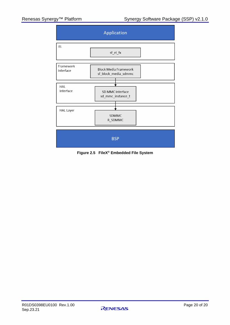
Azure RTOS FileX® Embedded File System The SSP provides a high performance and low memory footprint MS-DOS compatible file system, Azure RTOS FileX®, for the embedded applications that require file operations. FileX® is implemented as a C library. Only the features used by the application are brought into the final image. The footprint of FileX® is as small as 6 KB. Additionally, FileX® has minimal function call layering, an internal logical sector cache, contiguous cluster allocation, and consecutive cluster reading and writing. All of these attributes make FileX® extremely fast and efficient.
FileX® provides many advanced features for embedded file applications, including the following key capabilities:
• Multiple media instances • FAT12-, 16-, 32-bit support • Extended File Allocation Table (exFAT)1* • Long file name support • Contiguous file support • Consecutive cluster read/write • Internal logical sector cache • Fast seek logic • Multiple partition support • Fault-tolerant journaled file system • LevelX Flash wear leveling, including:
Block media driver Support for NOR Flash on QSPI
1 Requires separate exFAT patent license from Microsoft
Renesas Synergy™ Platform Synergy Software Package (SSP) v2.1.0
R01DS0398EU0100 Rev.1.00 Page 20 of 20 Sep.23.21
Figure 2.5 FileX® Embedded File System
Renesas Synergy™ Platform Synergy Software Package (SSP) v2.1.0
R01DS0398EU0100 Rev.1.00 Page 21 of 21 Sep.23.21
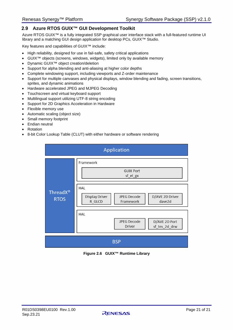
Azure RTOS GUIX™ GUI Development Toolkit Azure RTOS GUIX™ is a fully integrated SSP graphical user interface stack with a full-featured runtime UI library and a matching GUI design application for desktop PCs, GUIX™ Studio.
Key features and capabilities of GUIX™ include:
• High reliability, designed for use in fail-safe, safety critical applications • GUIX™ objects (screens, windows, widgets), limited only by available memory • Dynamic GUIX™ object creation/deletion • Support for alpha blending and anti-aliasing at higher color depths • Complete windowing support, including viewports and Z-order maintenance • Support for multiple canvases and physical displays, window blending and fading, screen transitions,
sprites, and dynamic animations • Hardware accelerated JPEG and MJPEG Decoding • Touchscreen and virtual keyboard support • Multilingual support utilizing UTF-8 string encoding • Support for 2D Graphics Acceleration in Hardware • Flexible memory use • Automatic scaling (object size) • Small memory footprint • Endian neutral • Rotation • 8-bit Color Lookup Table (CLUT) with either hardware or software rendering
Figure 2.6 GUIX™ Runtime Library

Renesas Synergy™ Platform Synergy Software Package (SSP) v2.1.0
R01DS0398EU0100 Rev.1.00 Page 22 of 22 Sep.23.21
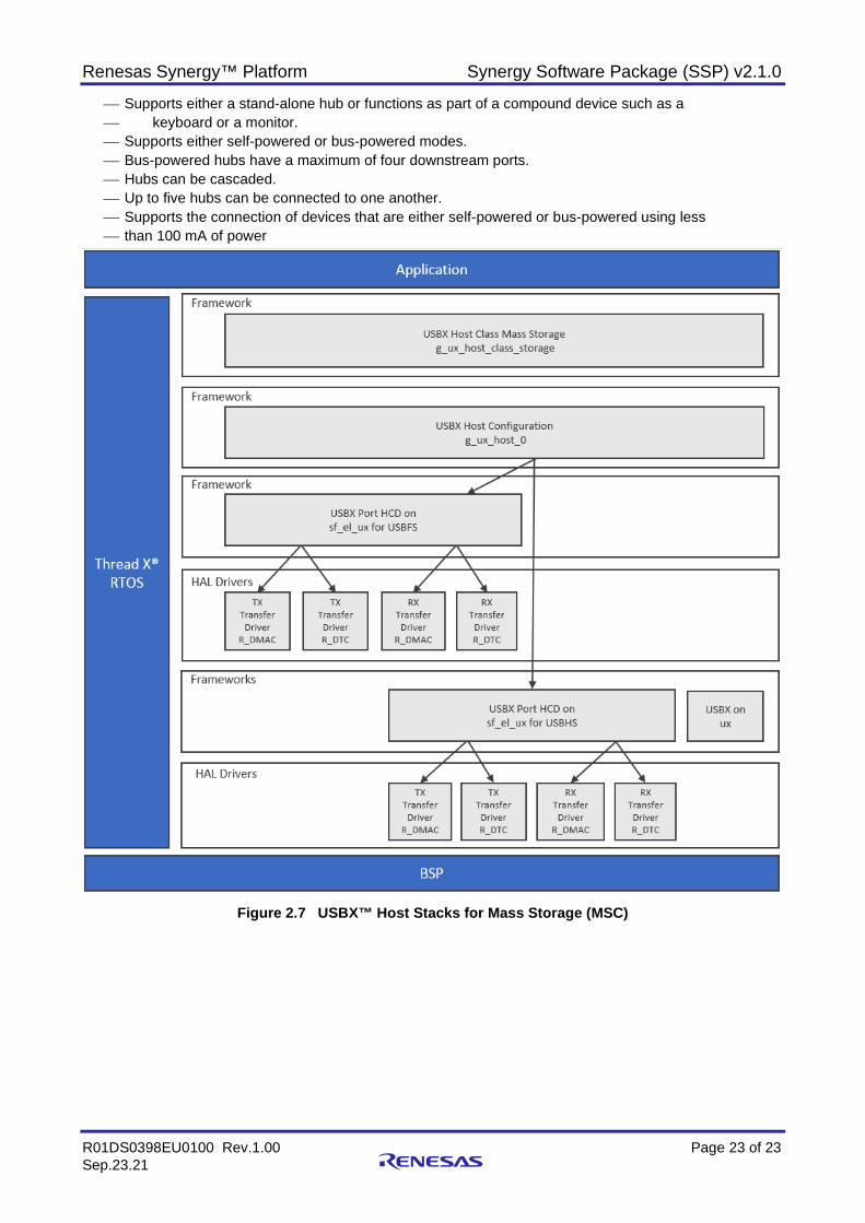
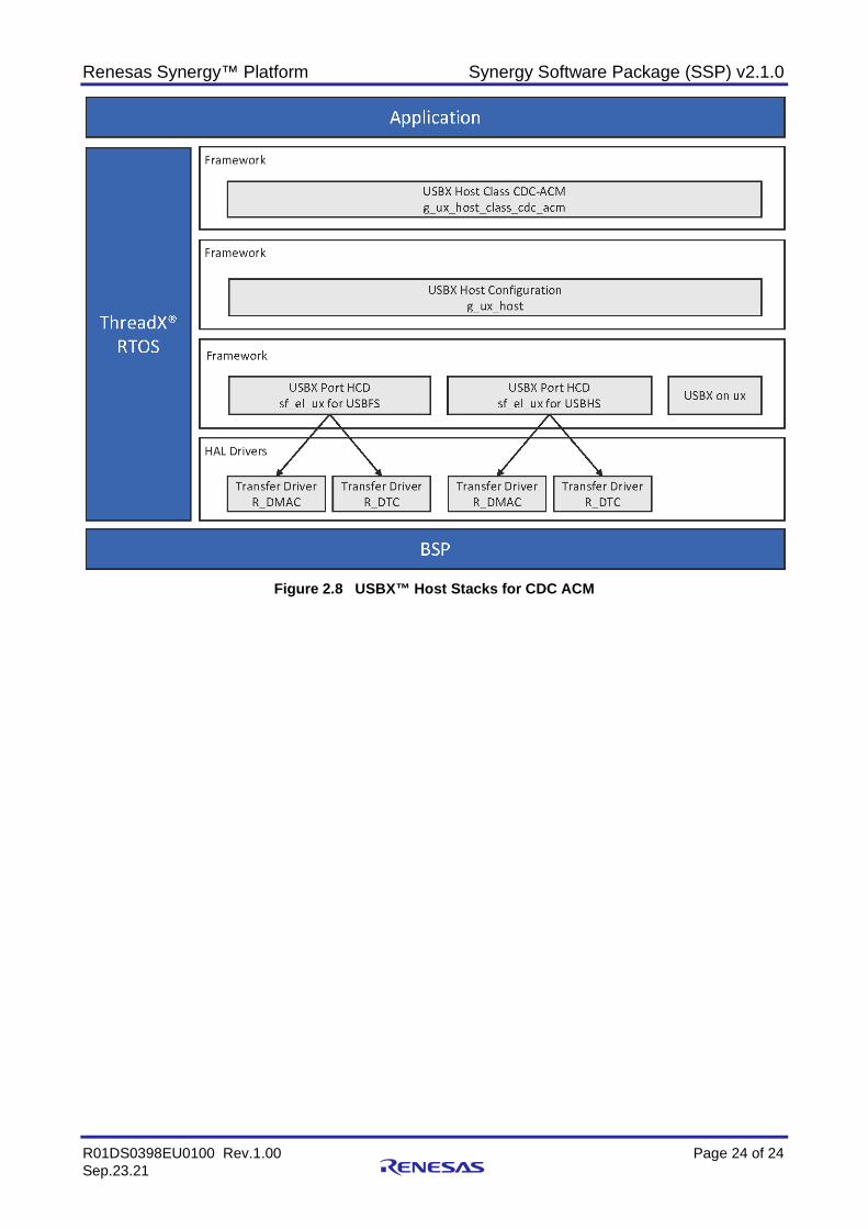
Azure RTOS USBX™ SSP includes an embedded USB stack fully integrated with ThreadX® and supporting high-performance USB Host and Device modes for embedded applications. USBX requires a small memory footprint and is modular, allowing for only the features used by the application to be included into the final image. This minimizes the footprint of the USB stack being built for the target device. USB Low Speed, Full Speed, and High Speed modes are supported. Some of the key features include the following:
• USB Host and Device modes support standard USB class drivers including Mass Storage, HID, and CDC-ACM. UVC and HUB are additional classes supported for USB Host.
• USB Isochronous mode is also supported in SSP. • Integrated with Microsoft components (FileX® and NetX™). • Option to build in Device-only mode to reduce code size. • Pre-build library for USBX for Synergy S124 MCU Group devices defaults to Device mode. Key USB Device Class features: • USBX Device Class Mass Storage Module Features
ThreadX®-aware framework. Storage Media Parameter Setup Last LBA Byte-per-sector Type of storage media Removable flag USB Device Configuration (Device Configuration) Vendor ID Product ID Device Release Number Index of Serial Number String Descriptor Supported USB Specification (DCD) USBFS USBHS USB Device interrupts (DCD)
Key USB Host Class features: • USBX Host Class HID Module Features
Supports HID report data transfers Supports the following clients: Keyboard Mouse Remote-Control
• USBX Host Class Hub Module Features Supports either a stand-alone hub or functions as part of a compound device such as a keyboard or a monitor. Supports either self-powered or bus-powered modes. Bus-powered hubs have a maximum of four downstream ports. Hubs can be cascaded. Up to five hubs can be connected to one another. Supports the connection of devices that are either self-powered or bus-powered using less than 100
mA of power. • USBX Host Class Mass Storage Module Features
Host controller for USB 2.0 with support for: Root Hub, Power Management, Endpoints and Transfers High-level APIs simplify storage operations Supports optional data transfers using MCU hardware for improved efficiency
• USBX Host Class Video Module Features
Renesas Synergy™ Platform Synergy Software Package (SSP) v2.1.0
R01DS0398EU0100 Rev.1.00 Page 23 of 23 Sep.23.21
Supports either a stand-alone hub or functions as part of a compound device such as a keyboard or a monitor. Supports either self-powered or bus-powered modes. Bus-powered hubs have a maximum of four downstream ports. Hubs can be cascaded. Up to five hubs can be connected to one another. Supports the connection of devices that are either self-powered or bus-powered using less than 100 mA of power
Figure 2.7 USBX™ Host Stacks for Mass Storage (MSC)
Renesas Synergy™ Platform Synergy Software Package (SSP) v2.1.0
R01DS0398EU0100 Rev.1.00 Page 24 of 24 Sep.23.21
Figure 2.8 USBX™ Host Stacks for CDC ACM
Renesas Synergy™ Platform Synergy Software Package (SSP) v2.1.0
R01DS0398EU0100 Rev.1.00 Page 25 of 25 Sep.23.21
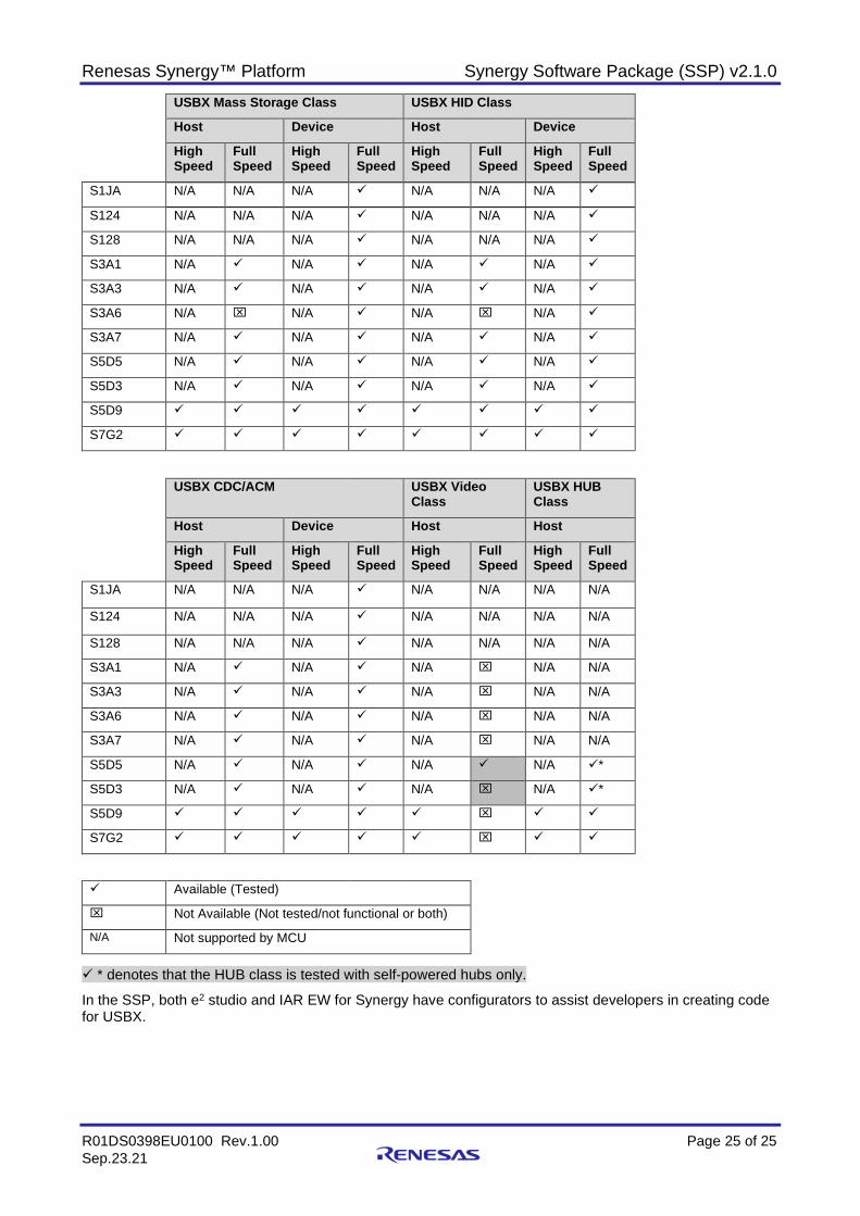
USBX Mass Storage Class USBX HID Class
Host Device Host Device
High Speed
Full Speed
High Speed
Full Speed
High Speed
Full Speed
High Speed
Full Speed
S1JA N/A N/A N/A N/A N/A N/A
S124 N/A N/A N/A N/A N/A N/A
S128 N/A N/A N/A N/A N/A N/A
S3A1 N/A N/A N/A N/A
S3A3 N/A N/A N/A N/A
S3A6 N/A N/A N/A N/A
S3A7 N/A N/A N/A N/A
S5D5 N/A N/A N/A N/A
S5D3 N/A N/A N/A N/A
S5D9
S7G2
USBX CDC/ACM USBX Video Class
USBX HUB Class
Host Device Host Host
High Speed
Full Speed
High Speed
Full Speed
High Speed
Full Speed
High Speed
Full Speed
S1JA N/A N/A N/A N/A N/A N/A N/A
S124 N/A N/A N/A N/A N/A N/A N/A
S128 N/A N/A N/A N/A N/A N/A N/A
S3A1 N/A N/A N/A N/A N/A
S3A3 N/A N/A N/A N/A N/A
S3A6 N/A N/A N/A N/A N/A
S3A7 N/A N/A N/A N/A N/A
S5D5 N/A N/A N/A N/A *
S5D3 N/A N/A N/A N/A *
S5D9
S7G2
Available (Tested)
Not Available (Not tested/not functional or both)
N/A Not supported by MCU
* denotes that the HUB class is tested with self-powered hubs only.
In the SSP, both e2 studio and IAR EW for Synergy have configurators to assist developers in creating code for USBX.
Renesas Synergy™ Platform Synergy Software Package (SSP) v2.1.0
R01DS0398EU0100 Rev.1.00 Page 26 of 26 Sep.23.21
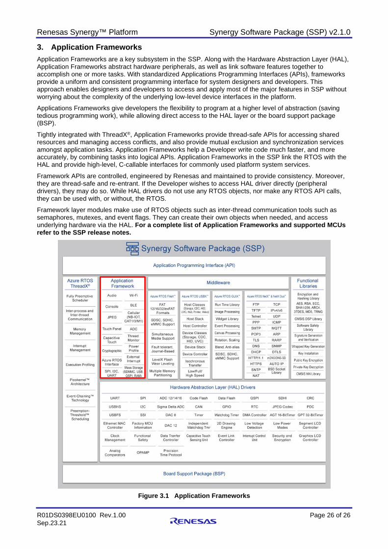
3. Application Frameworks Application Frameworks are a key subsystem in the SSP. Along with the Hardware Abstraction Layer (HAL), Application Frameworks abstract hardware peripherals, as well as link software features together to accomplish one or more tasks. With standardized Applications Programming Interfaces (APIs), frameworks provide a uniform and consistent programming interface for system designers and developers. This approach enables designers and developers to access and apply most of the major features in SSP without worrying about the complexity of the underlying low-level device interfaces in the platform.
Applications Frameworks give developers the flexibility to program at a higher level of abstraction (saving tedious programming work), while allowing direct access to the HAL layer or the board support package (BSP).
Tightly integrated with ThreadX®, Application Frameworks provide thread-safe APIs for accessing shared resources and managing access conflicts, and also provide mutual exclusion and synchronization services amongst application tasks. Application Frameworks help a Developer write code much faster, and more accurately, by combining tasks into logical APIs. Application Frameworks in the SSP link the RTOS with the HAL and provide high-level, C-callable interfaces for commonly used platform system services.
Framework APIs are controlled, engineered by Renesas and maintained to provide consistency. Moreover, they are thread-safe and re-entrant. If the Developer wishes to access HAL driver directly (peripheral drivers), they may do so. While HAL drivers do not use any RTOS objects, nor make any RTOS API calls, they can be used with, or without, the RTOS.
Framework layer modules make use of RTOS objects such as inter-thread communication tools such as semaphores, mutexes, and event flags. They can create their own objects when needed, and access underlying hardware via the HAL. For a complete list of Application Frameworks and supported MCUs refer to the SSP release notes.
Figure 3.1 Application Frameworks
Renesas Synergy™ Platform Synergy Software Package (SSP) v2.1.0
R01DS0398EU0100 Rev.1.00 Page 27 of 27 Sep.23.21
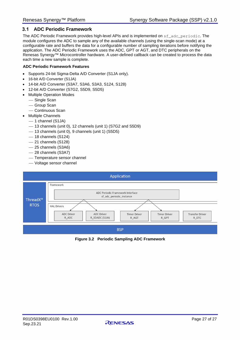
ADC Periodic Framework The ADC Periodic Framework provides high-level APIs and is implemented on sf_adc_periodic. The module configures the ADC to sample any of the available channels (using the single-scan mode) at a configurable rate and buffers the data for a configurable number of sampling iterations before notifying the application. The ADC Periodic Framework uses the ADC, GPT or AGT, and DTC peripherals on the Renesas Synergy™ Microcontroller hardware. A user-defined callback can be created to process the data each time a new sample is complete.
ADC Periodic Framework Features • Supports 24-bit Sigma-Delta A/D Converter (S1JA only). • 16-bit A/D Converter (S1JA) • 14-bit A/D Converter (S3A7, S3A6, S3A3, S124, S128) • 12-bit A/D Converter (S7G2, S5D9, S5D5) • Multiple Operation Modes
Single Scan Group Scan Continuous Scan
• Multiple Channels 1 channel (S1JA) 13 channels (unit 0), 12 channels (unit 1) (S7G2 and S5D9) 13 channels (unit 0), 9 channels (unit 1) (S5D5) 18 channels (S124) 21 channels (S128) 25 channels (S3A6) 28 channels (S3A7) Temperature sensor channel Voltage sensor channel
Figure 3.2 Periodic Sampling ADC Framework
Renesas Synergy™ Platform Synergy Software Package (SSP) v2.1.0
R01DS0398EU0100 Rev.1.00 Page 28 of 28 Sep.23.21
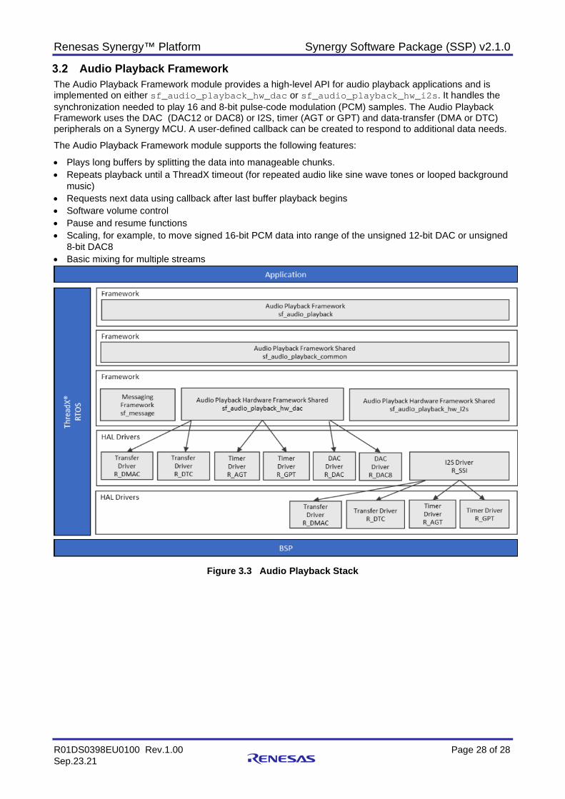
Audio Playback Framework The Audio Playback Framework module provides a high-level API for audio playback applications and is implemented on either sf_audio_playback_hw_dac or sf_audio_playback_hw_i2s. It handles the synchronization needed to play 16 and 8-bit pulse-code modulation (PCM) samples. The Audio Playback Framework uses the DAC (DAC12 or DAC8) or I2S, timer (AGT or GPT) and data-transfer (DMA or DTC) peripherals on a Synergy MCU. A user-defined callback can be created to respond to additional data needs.
The Audio Playback Framework module supports the following features:
• Plays long buffers by splitting the data into manageable chunks. • Repeats playback until a ThreadX timeout (for repeated audio like sine wave tones or looped background
music) • Requests next data using callback after last buffer playback begins • Software volume control • Pause and resume functions • Scaling, for example, to move signed 16-bit PCM data into range of the unsigned 12-bit DAC or unsigned
8-bit DAC8 • Basic mixing for multiple streams
Figure 3.3 Audio Playback Stack
Renesas Synergy™ Platform Synergy Software Package (SSP) v2.1.0
R01DS0398EU0100 Rev.1.00 Page 29 of 29 Sep.23.21
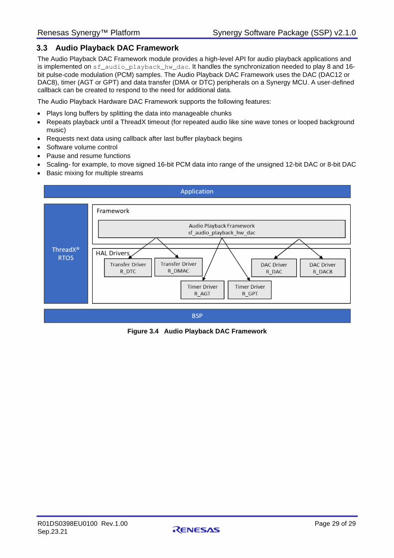
Audio Playback DAC Framework The Audio Playback DAC Framework module provides a high-level API for audio playback applications and is implemented on sf_audio_playback_hw_dac. It handles the synchronization needed to play 8 and 16-bit pulse-code modulation (PCM) samples. The Audio Playback DAC Framework uses the DAC (DAC12 or DAC8), timer (AGT or GPT) and data transfer (DMA or DTC) peripherals on a Synergy MCU. A user-defined callback can be created to respond to the need for additional data.
The Audio Playback Hardware DAC Framework supports the following features:
• Plays long buffers by splitting the data into manageable chunks • Repeats playback until a ThreadX timeout (for repeated audio like sine wave tones or looped background
music) • Requests next data using callback after last buffer playback begins • Software volume control • Pause and resume functions • Scaling- for example, to move signed 16-bit PCM data into range of the unsigned 12-bit DAC or 8-bit DAC • Basic mixing for multiple streams
Figure 3.4 Audio Playback DAC Framework
Renesas Synergy™ Platform Synergy Software Package (SSP) v2.1.0
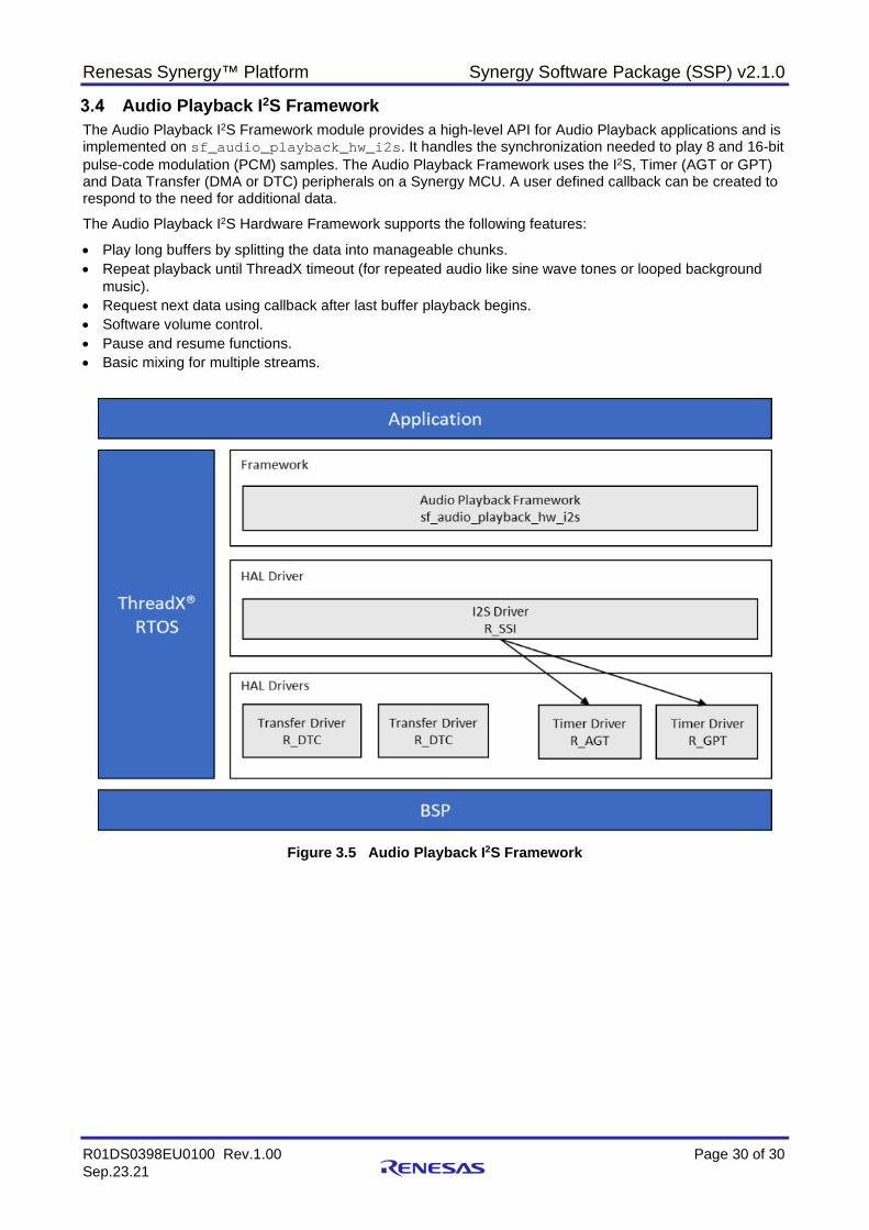
R01DS0398EU0100 Rev.1.00 Page 30 of 30 Sep.23.21
Audio Playback I2S Framework The Audio Playback I2S Framework module provides a high-level API for Audio Playback applications and is implemented on sf_audio_playback_hw_i2s. It handles the synchronization needed to play 8 and 16-bit pulse-code modulation (PCM) samples. The Audio Playback Framework uses the I2S, Timer (AGT or GPT) and Data Transfer (DMA or DTC) peripherals on a Synergy MCU. A user defined callback can be created to respond to the need for additional data.
The Audio Playback I2S Hardware Framework supports the following features:
• Play long buffers by splitting the data into manageable chunks. • Repeat playback until ThreadX timeout (for repeated audio like sine wave tones or looped background
music). • Request next data using callback after last buffer playback begins. • Software volume control. • Pause and resume functions. • Basic mixing for multiple streams.
Figure 3.5 Audio Playback I2S Framework
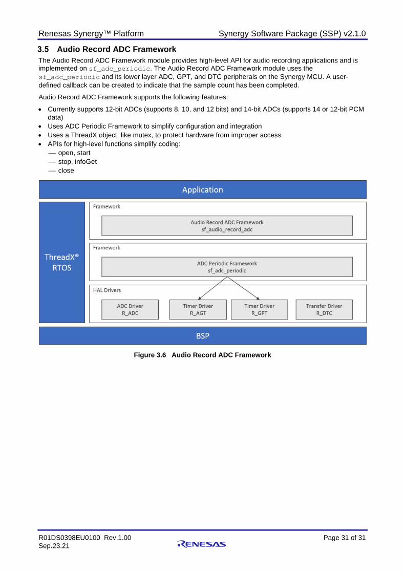
Renesas Synergy™ Platform Synergy Software Package (SSP) v2.1.0
R01DS0398EU0100 Rev.1.00 Page 31 of 31 Sep.23.21
Audio Record ADC Framework The Audio Record ADC Framework module provides high-level API for audio recording applications and is implemented on sf_adc_periodic. The Audio Record ADC Framework module uses the sf_adc_periodic and its lower layer ADC, GPT, and DTC peripherals on the Synergy MCU. A user-defined callback can be created to indicate that the sample count has been completed.
Audio Record ADC Framework supports the following features:
• Currently supports 12-bit ADCs (supports 8, 10, and 12 bits) and 14-bit ADCs (supports 14 or 12-bit PCM data)
• Uses ADC Periodic Framework to simplify configuration and integration • Uses a ThreadX object, like mutex, to protect hardware from improper access • APIs for high-level functions simplify coding:
open, start stop, infoGet close
Figure 3.6 Audio Record ADC Framework
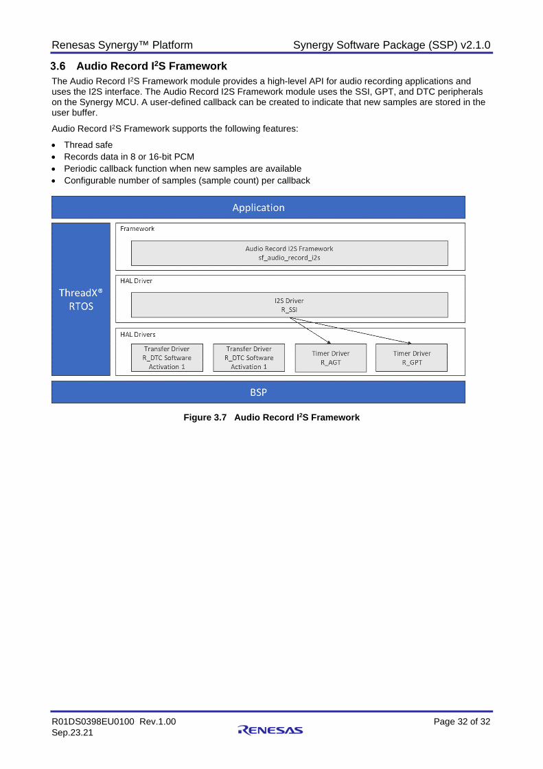
Renesas Synergy™ Platform Synergy Software Package (SSP) v2.1.0
R01DS0398EU0100 Rev.1.00 Page 32 of 32 Sep.23.21
Audio Record I2S Framework The Audio Record I2S Framework module provides a high-level API for audio recording applications and uses the I2S interface. The Audio Record I2S Framework module uses the SSI, GPT, and DTC peripherals on the Synergy MCU. A user-defined callback can be created to indicate that new samples are stored in the user buffer.
Audio Record I2S Framework supports the following features:
• Thread safe • Records data in 8 or 16-bit PCM • Periodic callback function when new samples are available • Configurable number of samples (sample count) per callback
Figure 3.7 Audio Record I2S Framework
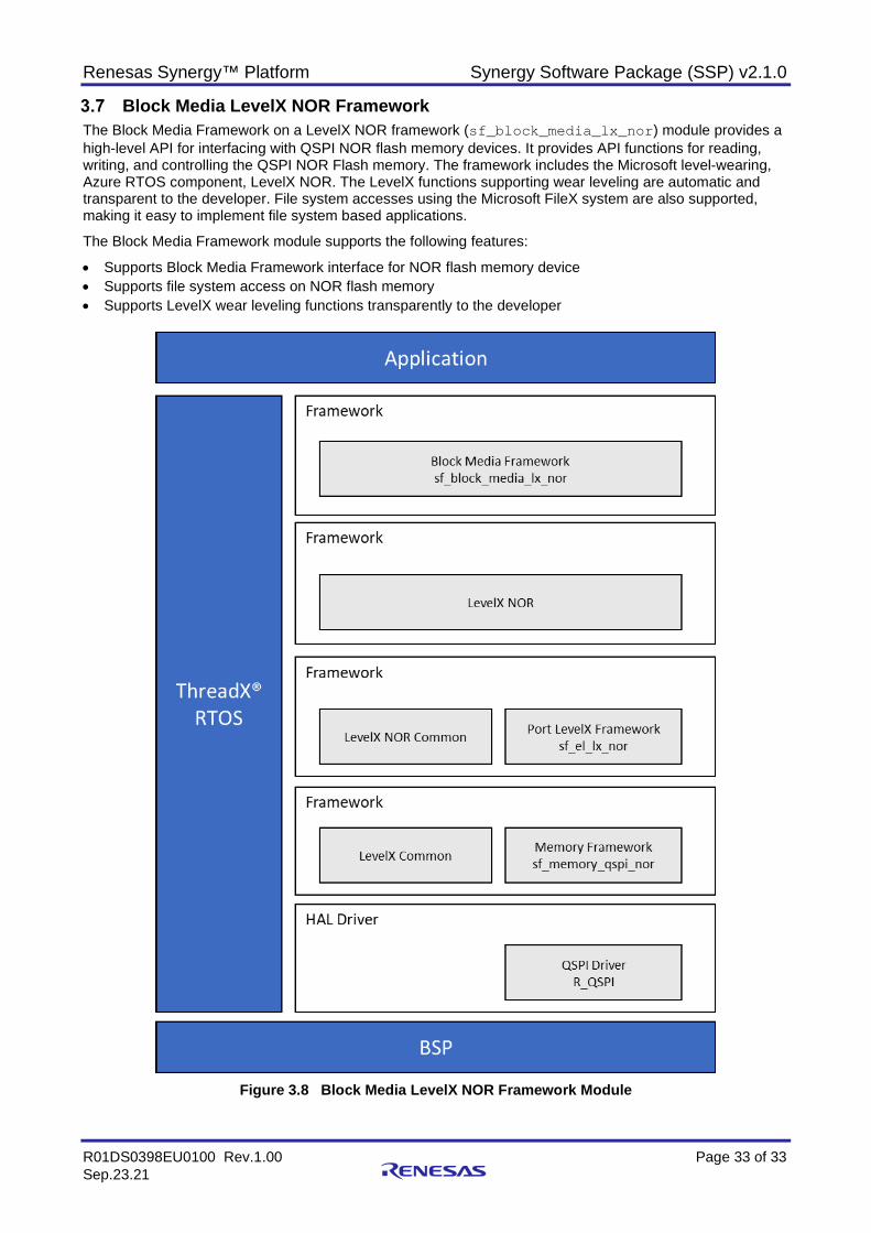
Renesas Synergy™ Platform Synergy Software Package (SSP) v2.1.0
R01DS0398EU0100 Rev.1.00 Page 33 of 33 Sep.23.21
Block Media LevelX NOR Framework The Block Media Framework on a LevelX NOR framework (sf_block_media_lx_nor) module provides a high-level API for interfacing with QSPI NOR flash memory devices. It provides API functions for reading, writing, and controlling the QSPI NOR Flash memory. The framework includes the Microsoft level-wearing, Azure RTOS component, LevelX NOR. The LevelX functions supporting wear leveling are automatic and transparent to the developer. File system accesses using the Microsoft FileX system are also supported, making it easy to implement file system based applications.
The Block Media Framework module supports the following features:
• Supports Block Media Framework interface for NOR flash memory device • Supports file system access on NOR flash memory • Supports LevelX wear leveling functions transparently to the developer
Figure 3.8 Block Media LevelX NOR Framework Module
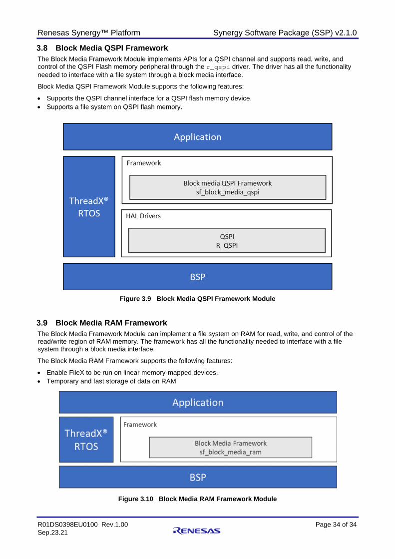
Renesas Synergy™ Platform Synergy Software Package (SSP) v2.1.0
R01DS0398EU0100 Rev.1.00 Page 34 of 34 Sep.23.21
Block Media QSPI Framework The Block Media Framework Module implements APIs for a QSPI channel and supports read, write, and control of the QSPI Flash memory peripheral through the r_qspi driver. The driver has all the functionality needed to interface with a file system through a block media interface.
Block Media QSPI Framework Module supports the following features:
• Supports the QSPI channel interface for a QSPI flash memory device. • Supports a file system on QSPI flash memory.
Figure 3.9 Block Media QSPI Framework Module
Block Media RAM Framework The Block Media Framework Module can implement a file system on RAM for read, write, and control of the read/write region of RAM memory. The framework has all the functionality needed to interface with a file system through a block media interface.
The Block Media RAM Framework supports the following features:
• Enable FileX to be run on linear memory-mapped devices. • Temporary and fast storage of data on RAM
Figure 3.10 Block Media RAM Framework Module
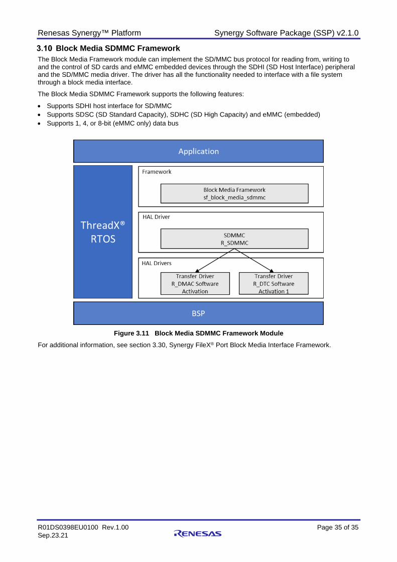
Renesas Synergy™ Platform Synergy Software Package (SSP) v2.1.0
R01DS0398EU0100 Rev.1.00 Page 35 of 35 Sep.23.21
Block Media SDMMC Framework The Block Media Framework module can implement the SD/MMC bus protocol for reading from, writing to and the control of SD cards and eMMC embedded devices through the SDHI (SD Host Interface) peripheral and the SD/MMC media driver. The driver has all the functionality needed to interface with a file system through a block media interface.
The Block Media SDMMC Framework supports the following features:
• Supports SDHI host interface for SD/MMC • Supports SDSC (SD Standard Capacity), SDHC (SD High Capacity) and eMMC (embedded) • Supports 1, 4, or 8-bit (eMMC only) data bus
Figure 3.11 Block Media SDMMC Framework Module
For additional information, see section 3.30, Synergy FileX® Port Block Media Interface Framework.
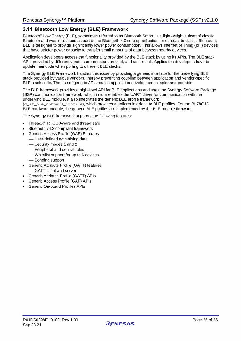
Renesas Synergy™ Platform Synergy Software Package (SSP) v2.1.0
R01DS0398EU0100 Rev.1.00 Page 36 of 36 Sep.23.21
Bluetooth Low Energy (BLE) Framework Bluetooth® Low Energy (BLE), sometimes referred to as Bluetooth Smart, is a light-weight subset of classic Bluetooth and was introduced as part of the Bluetooth 4.0 core specification. In contrast to classic Bluetooth, BLE is designed to provide significantly lower power consumption. This allows Internet of Thing (IoT) devices that have stricter power capacity to transfer small amounts of data between nearby devices.
Application developers access the functionality provided by the BLE stack by using its APIs. The BLE stack APIs provided by different vendors are not standardized, and as a result, Application developers have to update their code when porting to different BLE stacks.
The Synergy BLE Framework handles this issue by providing a generic interface for the underlying BLE stack provided by various vendors, thereby preventing coupling between application and vendor-specific BLE stack code. The use of generic APIs makes application development simpler and portable.
The BLE framework provides a high-level API for BLE applications and uses the Synergy Software Package (SSP) communication framework, which in turn enables the UART driver for communication with the underlying BLE module. It also integrates the generic BLE profile framework (g_sf_ble_onboard_profile), which provides a uniform interface to BLE profiles. For the RL78G1D BLE hardware module, the generic BLE profiles are implemented by the BLE module firmware.
The Synergy BLE framework supports the following features:
• ThreadX® RTOS Aware and thread safe • Bluetooth v4.2 compliant framework • Generic Access Profile (GAP) Features
User-defined advertising data Security modes 1 and 2 Peripheral and central roles Whitelist support for up to 6 devices Bonding support
• Generic Attribute Profile (GATT) features GATT client and server
• Generic Attribute Profile (GATT) APIs • Generic Access Profile (GAP) APIs • Generic On-board Profiles APIs
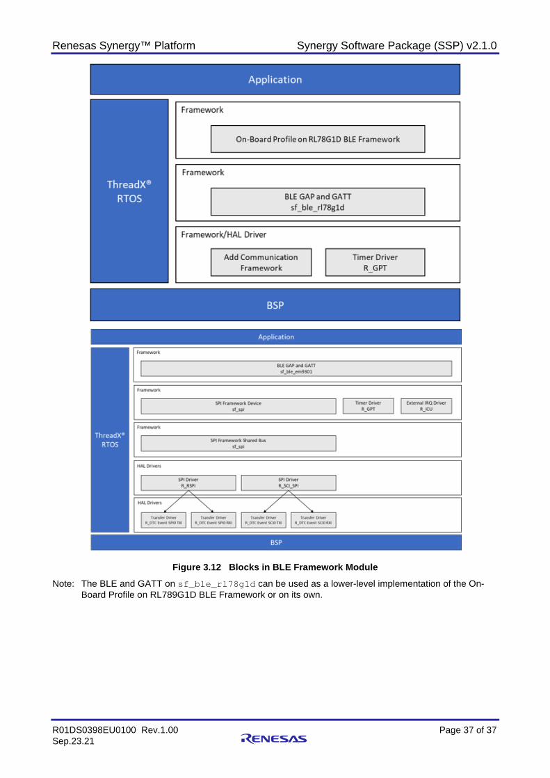
Renesas Synergy™ Platform Synergy Software Package (SSP) v2.1.0
R01DS0398EU0100 Rev.1.00 Page 37 of 37 Sep.23.21
Figure 3.12 Blocks in BLE Framework Module
Note: The BLE and GATT on sf_ble_rl78g1d can be used as a lower-level implementation of the On-Board Profile on RL789G1D BLE Framework or on its own.
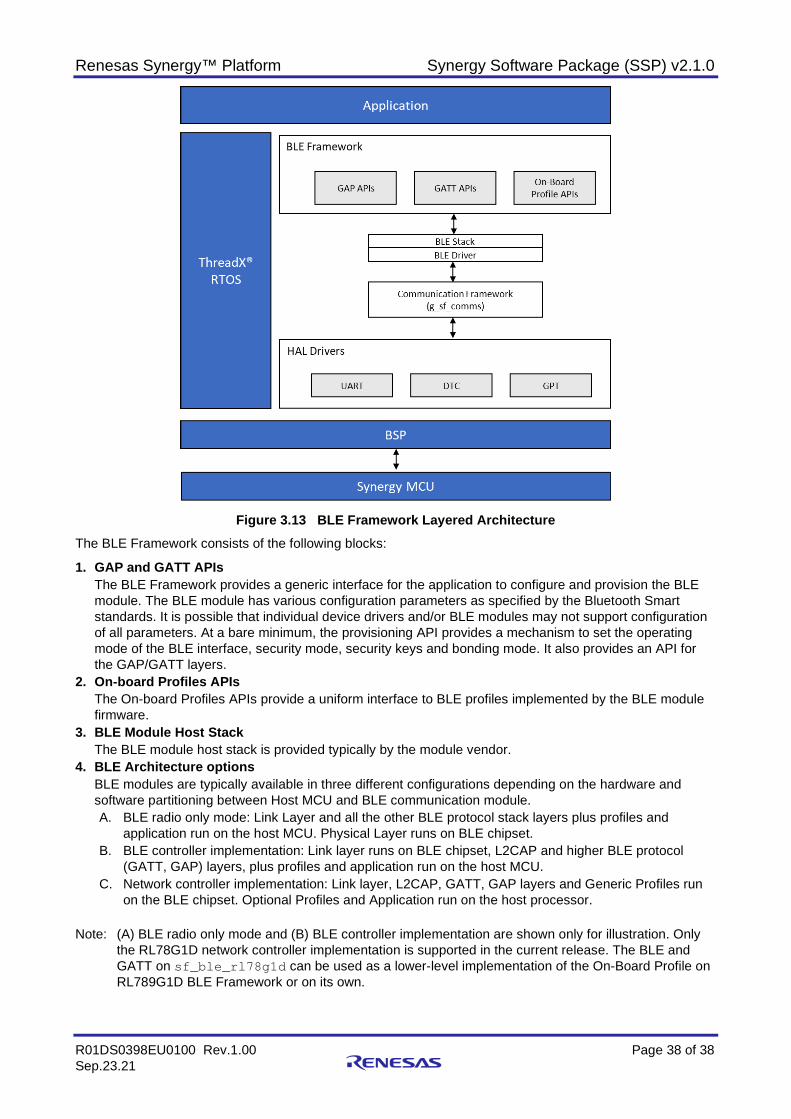
Renesas Synergy™ Platform Synergy Software Package (SSP) v2.1.0
R01DS0398EU0100 Rev.1.00 Page 38 of 38 Sep.23.21
Figure 3.13 BLE Framework Layered Architecture
The BLE Framework consists of the following blocks:
1. GAP and GATT APIs The BLE Framework provides a generic interface for the application to configure and provision the BLE module. The BLE module has various configuration parameters as specified by the Bluetooth Smart standards. It is possible that individual device drivers and/or BLE modules may not support configuration of all parameters. At a bare minimum, the provisioning API provides a mechanism to set the operating mode of the BLE interface, security mode, security keys and bonding mode. It also provides an API for the GAP/GATT layers.
2. On-board Profiles APIs The On-board Profiles APIs provide a uniform interface to BLE profiles implemented by the BLE module firmware.
3. BLE Module Host Stack The BLE module host stack is provided typically by the module vendor.
4. BLE Architecture options BLE modules are typically available in three different configurations depending on the hardware and software partitioning between Host MCU and BLE communication module. A. BLE radio only mode: Link Layer and all the other BLE protocol stack layers plus profiles and
application run on the host MCU. Physical Layer runs on BLE chipset. B. BLE controller implementation: Link layer runs on BLE chipset, L2CAP and higher BLE protocol
(GATT, GAP) layers, plus profiles and application run on the host MCU. C. Network controller implementation: Link layer, L2CAP, GATT, GAP layers and Generic Profiles run
on the BLE chipset. Optional Profiles and Application run on the host processor.
Note: (A) BLE radio only mode and (B) BLE controller implementation are shown only for illustration. Only the RL78G1D network controller implementation is supported in the current release. The BLE and GATT on sf_ble_rl78g1d can be used as a lower-level implementation of the On-Board Profile on RL789G1D BLE Framework or on its own.
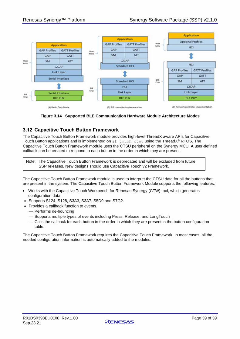
Renesas Synergy™ Platform Synergy Software Package (SSP) v2.1.0
R01DS0398EU0100 Rev.1.00 Page 39 of 39 Sep.23.21
Figure 3.14 Supported BLE Communication Hardware Module Architecture Modes
Capacitive Touch Button Framework The Capacitive Touch Button Framework module provides high-level ThreadX aware APIs for Capacitive Touch Button applications and is implemented on sf_touch_ctsu using the ThreadX® RTOS. The Capacitive Touch Button Framework module uses the CTSU peripheral on the Synergy MCU. A user-defined callback can be created to respond to each button in the order in which they are present.
The Capacitive Touch Button Framework module is used to interpret the CTSU data for all the buttons that are present in the system. The Capacitive Touch Button Framework Module supports the following features:
• Works with the Capacitive Touch Workbench for Renesas Synergy (CTW) tool, which generates configuration data.
• Supports S124, S128, S3A3, S3A7, S5D9 and S7G2. • Provides a callback function to events. Performs de-bouncing Supports multiple types of events including Press, Release, and LongTouch Calls the callback for each button in the order in which they are present in the button configuration
table. The Capacitive Touch Button Framework requires the Capacitive Touch Framework. In most cases, all the needed configuration information is automatically added to the modules.
Note: The Capacitive Touch Button Framework is deprecated and will be excluded from future SSP releases. New designs should use Capacitive Touch v2 Framework.

Renesas Synergy™ Platform Synergy Software Package (SSP) v2.1.0
R01DS0398EU0100 Rev.1.00 Page 40 of 40 Sep.23.21
Figure 3.15 Tuning Tool for Capacitive Touch
Figure 3.16 Capacitive Touch Button Framework
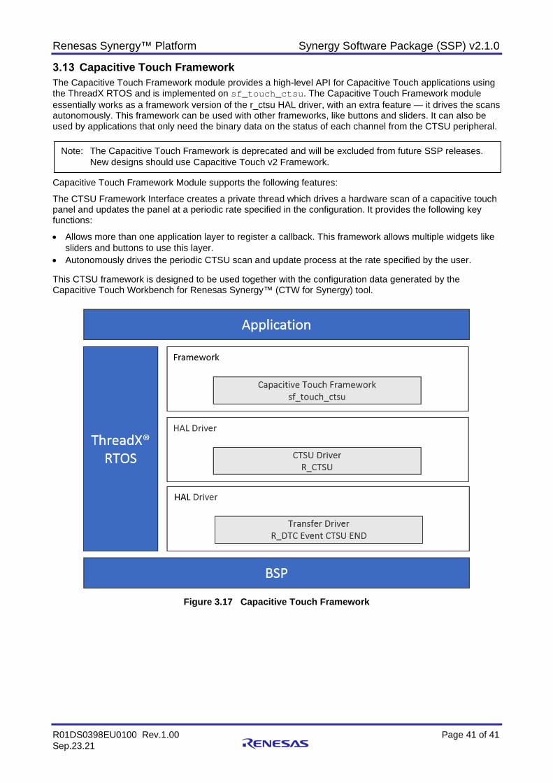
Renesas Synergy™ Platform Synergy Software Package (SSP) v2.1.0
R01DS0398EU0100 Rev.1.00 Page 41 of 41 Sep.23.21
Capacitive Touch Framework The Capacitive Touch Framework module provides a high-level API for Capacitive Touch applications using the ThreadX RTOS and is implemented on sf_touch_ctsu. The Capacitive Touch Framework module essentially works as a framework version of the r_ctsu HAL driver, with an extra feature — it drives the scans autonomously. This framework can be used with other frameworks, like buttons and sliders. It can also be used by applications that only need the binary data on the status of each channel from the CTSU peripheral.
Capacitive Touch Framework Module supports the following features:
The CTSU Framework Interface creates a private thread which drives a hardware scan of a capacitive touch panel and updates the panel at a periodic rate specified in the configuration. It provides the following key functions:
• Allows more than one application layer to register a callback. This framework allows multiple widgets like sliders and buttons to use this layer.
• Autonomously drives the periodic CTSU scan and update process at the rate specified by the user. This CTSU framework is designed to be used together with the configuration data generated by the Capacitive Touch Workbench for Renesas Synergy™ (CTW for Synergy) tool.
Figure 3.17 Capacitive Touch Framework
Note: The Capacitive Touch Framework is deprecated and will be excluded from future SSP releases. New designs should use Capacitive Touch v2 Framework.
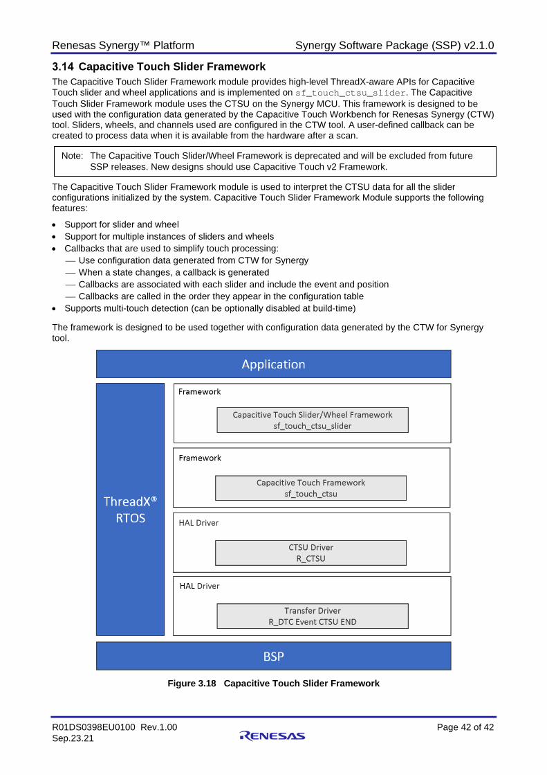
Renesas Synergy™ Platform Synergy Software Package (SSP) v2.1.0
R01DS0398EU0100 Rev.1.00 Page 42 of 42 Sep.23.21
Capacitive Touch Slider Framework The Capacitive Touch Slider Framework module provides high-level ThreadX-aware APIs for Capacitive Touch slider and wheel applications and is implemented on sf_touch_ctsu_slider. The Capacitive Touch Slider Framework module uses the CTSU on the Synergy MCU. This framework is designed to be used with the configuration data generated by the Capacitive Touch Workbench for Renesas Synergy (CTW) tool. Sliders, wheels, and channels used are configured in the CTW tool. A user-defined callback can be created to process data when it is available from the hardware after a scan.
The Capacitive Touch Slider Framework module is used to interpret the CTSU data for all the slider configurations initialized by the system. Capacitive Touch Slider Framework Module supports the following features:
• Support for slider and wheel • Support for multiple instances of sliders and wheels • Callbacks that are used to simplify touch processing:
Use configuration data generated from CTW for Synergy When a state changes, a callback is generated Callbacks are associated with each slider and include the event and position Callbacks are called in the order they appear in the configuration table
• Supports multi-touch detection (can be optionally disabled at build-time) The framework is designed to be used together with configuration data generated by the CTW for Synergy tool.
Figure 3.18 Capacitive Touch Slider Framework
Note: The Capacitive Touch Slider/Wheel Framework is deprecated and will be excluded from future SSP releases. New designs should use Capacitive Touch v2 Framework.
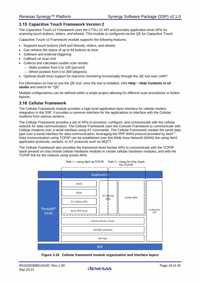
Renesas Synergy™ Platform Synergy Software Package (SSP) v2.1.0
R01DS0398EU0100 Rev.1.00 Page 43 of 43 Sep.23.21
Capacitive Touch Framework Version 2 The Capacitive Touch v2 Framework uses the CTSU V2 API and provides application-level APIs for scanning touch buttons, sliders, and wheels. This module is configured via the QE for Capacitive Touch.
Capacitive Touch v2 Framework module supports the following features:
• Supports touch buttons (Self and Mutual), sliders, and wheels • Can retrieve the status of up to 64 buttons at once • Software and external triggering • Callback on scan end • Collects and calculates usable scan results:
Slider position from 0 to 100 (percent) Wheel position from 0 to 359 (degrees)
• Optional (build time) support for real-time monitoring functionality through the QE tool over UART For information on how to use the QE tool, once the tool is installed, click Help > Help Contents in e2 studio and search for "QE".
Multiple configurations can be defined within a single project allowing for different scan procedures or button layouts.
Cellular Framework The Cellular Framework module provides a high-level application layer interface for cellular modem integration in the SSP. It provides a common interface for the applications to interface with the Cellular modems from various vendors.
The Cellular Framework provides a set of APIs to provision, configure, and communicate with the cellular network for data communication. The Cellular Framework uses the Console Framework to communicate with Cellular modems over a serial interface using AT commands. The Cellular Framework creates the serial data pipe over a serial interface for data communication, leveraging the PPP WAN protocol provided by NetX™. Data communication using TCP/IP can be established over this Wide Area Network (WAN) link using NetX application protocols, sockets, or IoT protocols such as MQTT.
The Cellular Framework also provides the framework level Socket APIs to communicate with the TCP/IP stack present on-chip (inside cellular hardware module) in certain cellular hardware modules, and with the TCP/IP link for the network using socket APIs.
Figure 3.19 Cellular framework module organization and interface layers
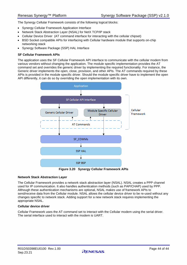
Renesas Synergy™ Platform Synergy Software Package (SSP) v2.1.0
R01DS0398EU0100 Rev.1.00 Page 44 of 44 Sep.23.21
The Synergy Cellular Framework consists of the following logical blocks:
• Synergy Cellular Framework Application Interface • Network Stack Abstraction Layer (NSAL) for NetX TCP/IP stack • Cellular Device Driver (AT command interface for interacting with the cellular chipset) • BSD Socket compatible APIs for interfacing with Cellular hardware module that supports on-chip
networking stack • Synergy Software Package (SSP) HAL Interface SF Cellular Framework APIs The application uses the SF Cellular Framework API interface to communicate with the cellular modem from various vendors without changing the application. The module specific implementation provides the AT command set and overrides the generic driver by implementing the required functionality. For instance, the Generic driver implements the open, close, provision, and other APIs. The AT commands required by these APIs is provided in the module specific driver. Should the module specific driver have to implement the open API differently, it can do so by overriding the open implementation with its own.
Figure 3.20 Synergy Cellular Framework APIs
Network Stack Abstraction Layer The Cellular Framework provides a network stack abstraction layer (NSAL). NSAL creates a PPP channel used for IP communication. It also handles authentication methods (such as PAP/CHAP) used by PPP. Although these authentication mechanisms are optional, NSAL makes use of framework APIs to send/receive data from the Cellular module. NSAL allows the cellular device driver to be re-used without any changes specific to network stack. Adding support for a new network stack requires implementing the appropriate NSAL.
Cellular device driver Cellular Framework uses the AT command set to interact with the Cellular modem using the serial driver. The serial interface used to interact with the modem is UART.
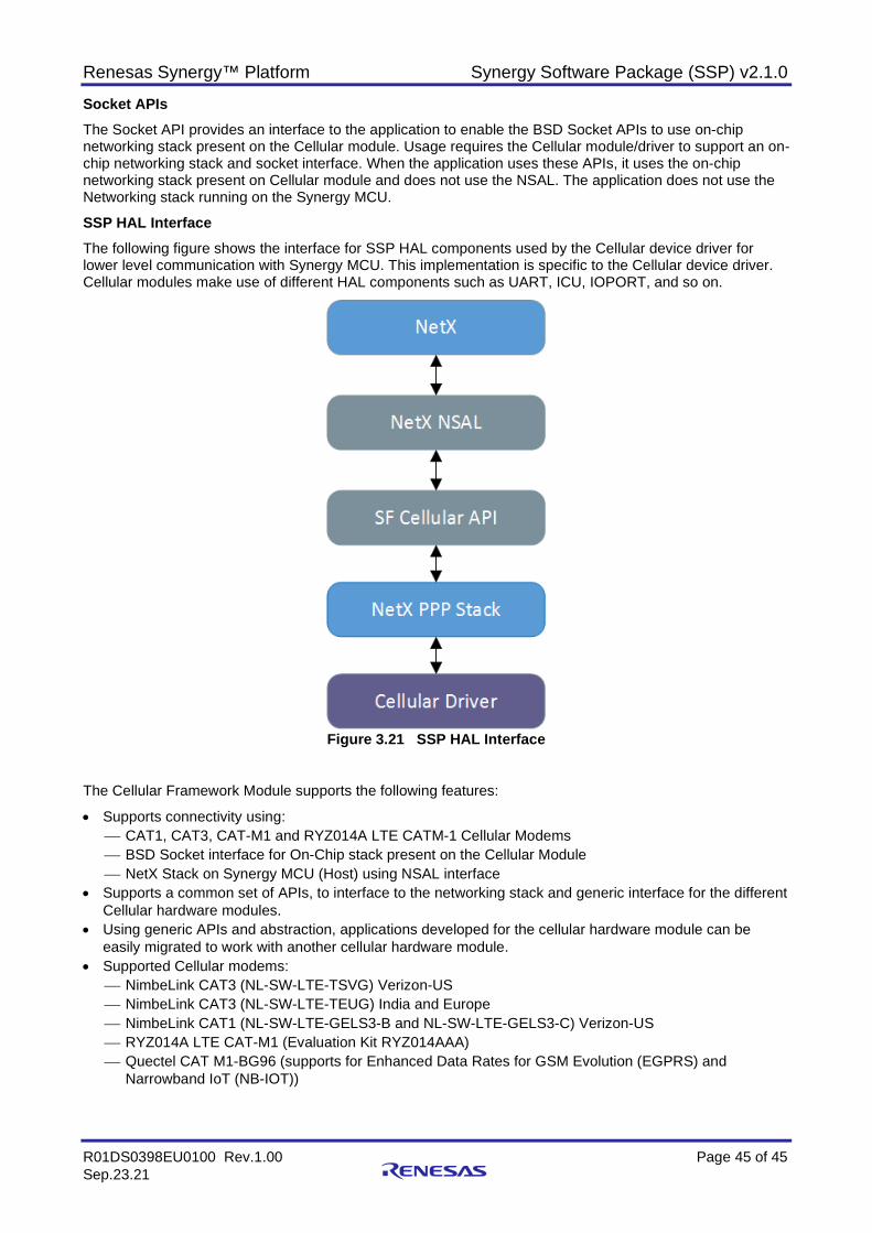
Renesas Synergy™ Platform Synergy Software Package (SSP) v2.1.0
R01DS0398EU0100 Rev.1.00 Page 45 of 45 Sep.23.21
Socket APIs The Socket API provides an interface to the application to enable the BSD Socket APIs to use on-chip networking stack present on the Cellular module. Usage requires the Cellular module/driver to support an on-chip networking stack and socket interface. When the application uses these APIs, it uses the on-chip networking stack present on Cellular module and does not use the NSAL. The application does not use the Networking stack running on the Synergy MCU.
SSP HAL Interface The following figure shows the interface for SSP HAL components used by the Cellular device driver for lower level communication with Synergy MCU. This implementation is specific to the Cellular device driver. Cellular modules make use of different HAL components such as UART, ICU, IOPORT, and so on.
Figure 3.21 SSP HAL Interface
The Cellular Framework Module supports the following features:
• Supports connectivity using: CAT1, CAT3, CAT-M1 and RYZ014A LTE CATM-1 Cellular Modems BSD Socket interface for On-Chip stack present on the Cellular Module NetX Stack on Synergy MCU (Host) using NSAL interface
• Supports a common set of APIs, to interface to the networking stack and generic interface for the different Cellular hardware modules.
• Using generic APIs and abstraction, applications developed for the cellular hardware module can be easily migrated to work with another cellular hardware module.
• Supported Cellular modems: NimbeLink CAT3 (NL-SW-LTE-TSVG) Verizon-US NimbeLink CAT3 (NL-SW-LTE-TEUG) India and Europe NimbeLink CAT1 (NL-SW-LTE-GELS3-B and NL-SW-LTE-GELS3-C) Verizon-US RYZ014A LTE CAT-M1 (Evaluation Kit RYZ014AAA) Quectel CAT M1-BG96 (supports for Enhanced Data Rates for GSM Evolution (EGPRS) and
Narrowband IoT (NB-IOT))
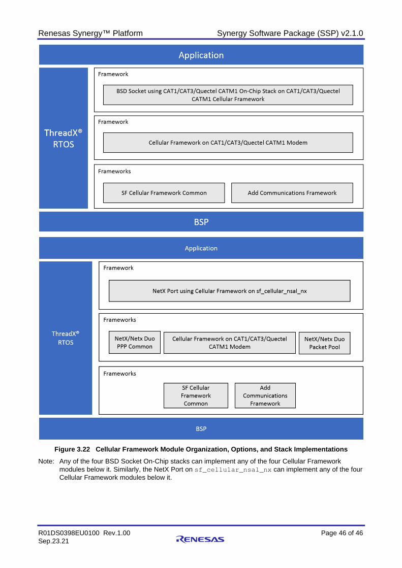
Renesas Synergy™ Platform Synergy Software Package (SSP) v2.1.0
R01DS0398EU0100 Rev.1.00 Page 46 of 46 Sep.23.21
Figure 3.22 Cellular Framework Module Organization, Options, and Stack Implementations
Note: Any of the four BSD Socket On-Chip stacks can implement any of the four Cellular Framework modules below it. Similarly, the NetX Port on sf_cellular_nsal_nx can implement any of the four Cellular Framework modules below it.
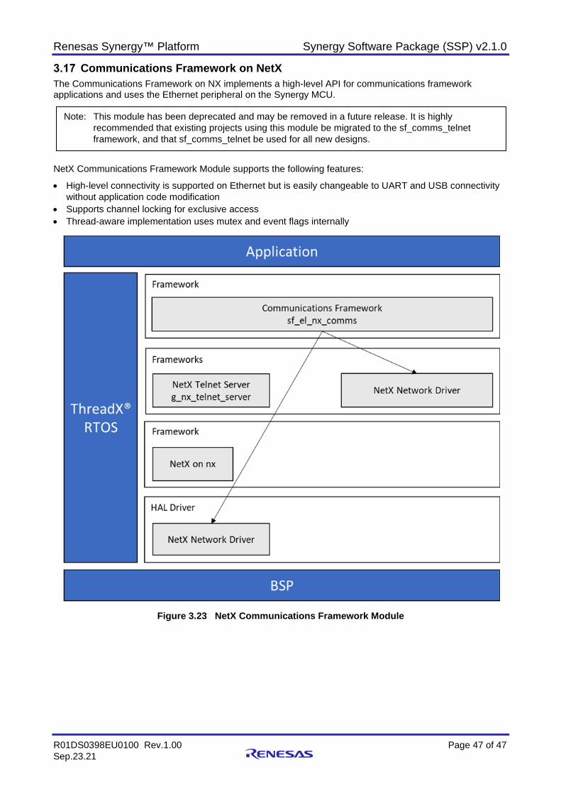
Renesas Synergy™ Platform Synergy Software Package (SSP) v2.1.0
R01DS0398EU0100 Rev.1.00 Page 47 of 47 Sep.23.21
Communications Framework on NetX The Communications Framework on NX implements a high-level API for communications framework applications and uses the Ethernet peripheral on the Synergy MCU.
NetX Communications Framework Module supports the following features:
• High-level connectivity is supported on Ethernet but is easily changeable to UART and USB connectivity without application code modification
• Supports channel locking for exclusive access • Thread-aware implementation uses mutex and event flags internally
Figure 3.23 NetX Communications Framework Module
Note: This module has been deprecated and may be removed in a future release. It is highly recommended that existing projects using this module be migrated to the sf_comms_telnet framework, and that sf_comms_telnet be used for all new designs.
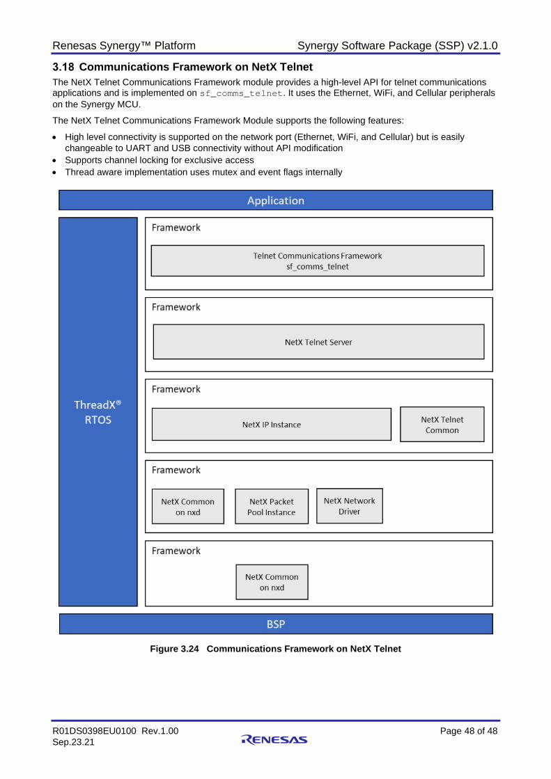
Renesas Synergy™ Platform Synergy Software Package (SSP) v2.1.0
R01DS0398EU0100 Rev.1.00 Page 48 of 48 Sep.23.21
Communications Framework on NetX Telnet The NetX Telnet Communications Framework module provides a high-level API for telnet communications applications and is implemented on sf_comms_telnet. It uses the Ethernet, WiFi, and Cellular peripherals on the Synergy MCU.
The NetX Telnet Communications Framework Module supports the following features:
• High level connectivity is supported on the network port (Ethernet, WiFi, and Cellular) but is easily changeable to UART and USB connectivity without API modification
• Supports channel locking for exclusive access • Thread aware implementation uses mutex and event flags internally
Figure 3.24 Communications Framework on NetX Telnet
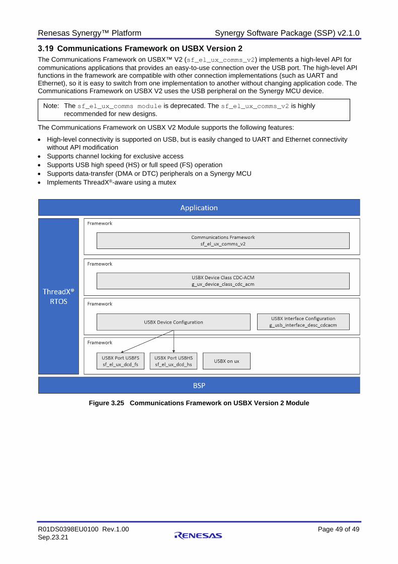
Renesas Synergy™ Platform Synergy Software Package (SSP) v2.1.0
R01DS0398EU0100 Rev.1.00 Page 49 of 49 Sep.23.21
Communications Framework on USBX Version 2 The Communications Framework on USBX™ V2 (sf_el_ux_comms_v2) implements a high-level API for communications applications that provides an easy-to-use connection over the USB port. The high-level API functions in the framework are compatible with other connection implementations (such as UART and Ethernet), so it is easy to switch from one implementation to another without changing application code. The Communications Framework on USBX V2 uses the USB peripheral on the Synergy MCU device.
The Communications Framework on USBX V2 Module supports the following features:
• High-level connectivity is supported on USB, but is easily changed to UART and Ethernet connectivity without API modification
• Supports channel locking for exclusive access • Supports USB high speed (HS) or full speed (FS) operation • Supports data-transfer (DMA or DTC) peripherals on a Synergy MCU • Implements ThreadX®-aware using a mutex
Figure 3.25 Communications Framework on USBX Version 2 Module
Note: The sf_el_ux_comms module is deprecated. The sf_el_ux_comms_v2 is highly recommended for new designs.
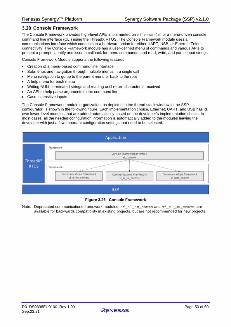
Renesas Synergy™ Platform Synergy Software Package (SSP) v2.1.0
R01DS0398EU0100 Rev.1.00 Page 50 of 50 Sep.23.21
Console Framework The Console Framework provides high-level APIs implemented on sf_console for a menu-driven console command line interface (CLI) using the ThreadX RTOS. The Console Framework module uses a communications interface which connects to a hardware option for either UART, USB, or Ethernet Telnet connectivity. The Console Framework module has a user-defined menu of commands and various APIs to present a prompt, identify and issue a callback for menu commands, and read, write, and parse input strings.
Console Framework Module supports the following features:
• Creation of a menu-based command-line interface • Submenus and navigation through multiple menus in a single call • Menu navigation to go up to the parent menu or back to the root • A help menu for each menu • Writing NULL terminated strings and reading until return character is received • An API to help parse arguments to the command line • Case-insensitive inputs The Console Framework module organization, as depicted in the thread stack window in the SSP configurator, is shown in the following figure. Each implementation choice, Ethernet, UART, and USB has its own lower-level modules that are added automatically based on the developer’s implementation choice. In most cases, all the needed configuration information is automatically added to the modules leaving the developer with just a few important configuration settings that need to be selected.
Figure 3.26 Console Framework
Note: Deprecated communications framework modules, sf_el_nx_comms and sf_el_ux_comms, are available for backwards compatibility in existing projects, but are not recommended for new projects.
Renesas Synergy™ Platform Synergy Software Package (SSP) v2.1.0
R01DS0398EU0100 Rev.1.00 Page 51 of 51 Sep.23.21
Cryptographic Framework The Crypto Framework layer is composed of multiple Crypto modules providing varied cryptographic services. The Crypto Framework modules include SF_CRYPTO for resource synchronization between the crypto modules, SF_CRYPTO_TRNG for true random number generation, SF_CRYPTO_HASH for message digest generation, and SF_CRYPTO_KEY for RSA, ECC, and AES Key Generation services, SF_CRYPTO_CIPHER for encryption and decryption services, SF_CRYPTO_SIGNATURE for RSA signature generation and verification services, and SF_CRYPTO_KEY_INSTALLATION for key installation services. See section 6.39, Secure Cryptographic Engine (SCE) module and Table 6.1 for cryptographic functions supported on target MCUs.
The Crypto Framework layer is composed of multiple Crypto modules providing varied cryptographic services. The Crypto Framework modules include SF_CRYPTO for resource synchronization between the crypto modules, SF_CRYPTO_TRNG for true random number generation, SF_CRYPTO_HASH for message digest generation, and SF_CRYPTO_KEY for RSA, ECC, and AES Key Generation services, SF_CRYPTO_CIPHER for encryption and decryption services, SF_CRYPTO_SIGNATURE for RSA signature generation and verification services, and SF_CRYPTO_KEY_INSTALLATION for key installation services. See section 6.39, Secure Cryptographic Engine (SCE) module and Table 6.1 for cryptographic functions supported on target MCUs.
The Crypto Framework module supports the following features:
• SF CRYPTO Framework The SF CRYPTO Framework opens/initializes the underlying Secure Crypto Engine. Provides services to access shared resources for other Crypto Framework modules
SF_CRYPTO_TRNG, SF_CRYPTO_HASH, SF_CRYPTO_KEY, SF_CRYPTO_CIPHER, SF_CRYPTO_SIGNATURE, and SF_CRYPTO_KEY_INSTALLATION.
• SF CRYPTO TRNG Framework The SF CRYPTO TRNG Framework module uses the TRNG HAL interfaces to the underlying Secure
Crypto Engine. Access to shared resources through SF CRYPTO Framework module.
• SF CRYPTO HASH Framework The SF CRYPTO HASH Framework utilizes the underlying Secure Crypto Engine to provide HASH
services. This module provides enhancements over the HAL driver such as:
• Initializing the HASH value • Processing chunks of data through hashUpdate API before finalizing the hash operation. • Formatting the final block for the final HASH operation.
• SF CRYPTO KEY Framework Module Features RSA 2048-bit, 1024-bit plain text/raw keys in standard and CRT format. RSA 2048-bit, 1024-bit standard format wrapped private keys (public keys in plain). AES 128-bit, 192-bit and 256-bit wrapped keys for ECB, CBC, CTR and GCM chaining modes. AES 128-bit and 256-bit wrapped keys for XTS chaining mode. ECC 192-bit, 224-bit, 256-bit,384-bit plain-text and wrapped keys (wrapped key is for private key only).
• SF CRYPTO SIGNATURE Framework Module Features This module currently supports signature generation and signature-verification for RSA algorithm.
There is support for both 1024-bits and 2048-bits key lengths for standard format plain-text, standard format wrapped private key and CRT plain-text keys.
RSASSA-PKCS1 v1.5 is the supported signature scheme. The input message can be passed as raw message to be signed/verified or can be PKCS1 v1.5 encoded and padded before sign/verify.
SHA1, SHA224, SHA256 are the supported hashing algorithms for PKCS1 v1.5 encoding /padding schemes.
This module allows signature generation/verification on data which is smaller than a block size. If all of the data is not available at once, update APIs can be used to accumulate the incoming chunks
of data and finally sign/verify the message only when all the message is gathered. Allows switching between sign and verify operations with less expensive API calls which are not
involved in allocating and deallocating memory.
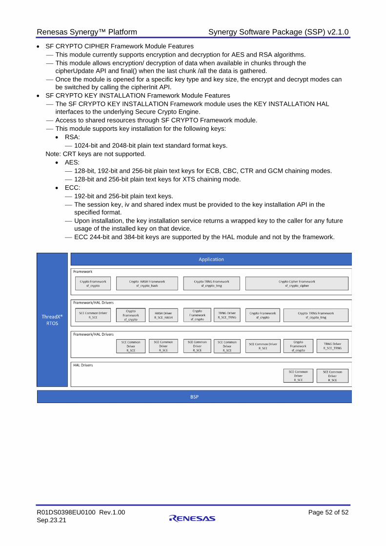
Renesas Synergy™ Platform Synergy Software Package (SSP) v2.1.0
R01DS0398EU0100 Rev.1.00 Page 52 of 52 Sep.23.21
• SF CRYPTO CIPHER Framework Module Features This module currently supports encryption and decryption for AES and RSA algorithms. This module allows encryption/ decryption of data when available in chunks through the
cipherUpdate API and final() when the last chunk /all the data is gathered. Once the module is opened for a specific key type and key size, the encrypt and decrypt modes can
be switched by calling the cipherInit API. • SF CRYPTO KEY INSTALLATION Framework Module Features
The SF CRYPTO KEY INSTALLATION Framework module uses the KEY INSTALLATION HAL interfaces to the underlying Secure Crypto Engine.
Access to shared resources through SF CRYPTO Framework module. This module supports key installation for the following keys:
• RSA: 1024-bit and 2048-bit plain text standard format keys.
Note: CRT keys are not supported. • AES:
128-bit, 192-bit and 256-bit plain text keys for ECB, CBC, CTR and GCM chaining modes. 128-bit and 256-bit plain text keys for XTS chaining mode.
• ECC: 192-bit and 256-bit plain text keys. The session key, iv and shared index must be provided to the key installation API in the
specified format. Upon installation, the key installation service returns a wrapped key to the caller for any future
usage of the installed key on that device. ECC 244-bit and 384-bit keys are supported by the HAL module and not by the framework.
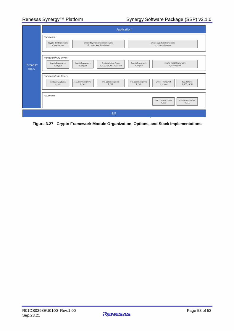
Renesas Synergy™ Platform Synergy Software Package (SSP) v2.1.0
R01DS0398EU0100 Rev.1.00 Page 53 of 53 Sep.23.21
Figure 3.27 Crypto Framework Module Organization, Options, and Stack Implementations
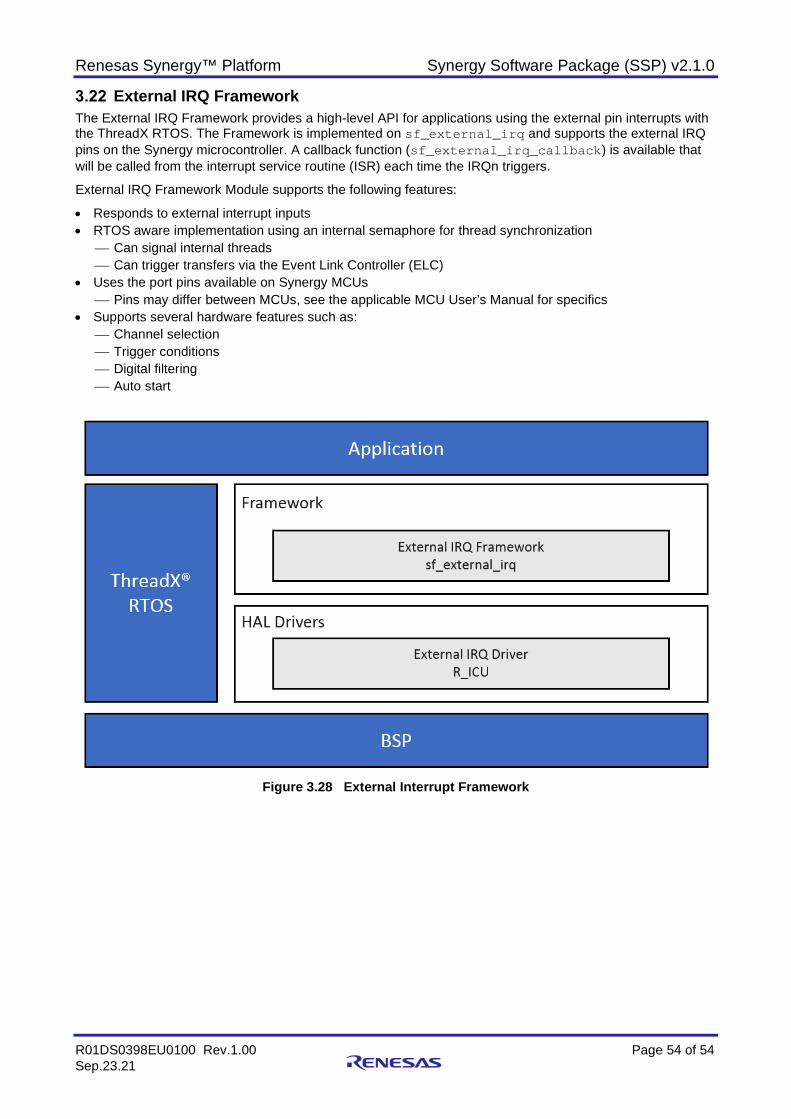
Renesas Synergy™ Platform Synergy Software Package (SSP) v2.1.0
R01DS0398EU0100 Rev.1.00 Page 54 of 54 Sep.23.21
External IRQ Framework The External IRQ Framework provides a high-level API for applications using the external pin interrupts with the ThreadX RTOS. The Framework is implemented on sf_external_irq and supports the external IRQ pins on the Synergy microcontroller. A callback function (sf_external_irq_callback) is available that will be called from the interrupt service routine (ISR) each time the IRQn triggers.
External IRQ Framework Module supports the following features:
• Responds to external interrupt inputs • RTOS aware implementation using an internal semaphore for thread synchronization
Can signal internal threads Can trigger transfers via the Event Link Controller (ELC)
• Uses the port pins available on Synergy MCUs Pins may differ between MCUs, see the applicable MCU User’s Manual for specifics
• Supports several hardware features such as: Channel selection Trigger conditions Digital filtering Auto start
Figure 3.28 External Interrupt Framework
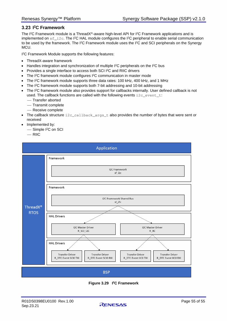
Renesas Synergy™ Platform Synergy Software Package (SSP) v2.1.0
R01DS0398EU0100 Rev.1.00 Page 55 of 55 Sep.23.21
I2C Framework The I2C Framework module is a ThreadX®-aware high-level API for I2C Framework applications and is implemented on sf_i2c. The I2C HAL module configures the I2C peripheral to enable serial communication to be used by the framework. The I2C Framework module uses the I2C and SCI peripherals on the Synergy MCU.
I2C Framework Module supports the following features:
• ThreadX-aware framework • Handles integration and synchronization of multiple I2C peripherals on the I2C bus • Provides a single interface to access both SCI I2C and RIIC drivers • The I2C framework module configures I2C communication in master mode • The I2C framework module supports three data rates: 100 kHz, 400 kHz, and 1 MHz • The I2C framework module supports both 7-bit addressing and 10-bit addressing • The I2C framework module also provides support for callbacks internally. User defined callback is not
used. The callback functions are called with the following events i2c_event_t: Transfer aborted Transmit complete Receive complete
• The callback structure i2c_callback_args_t also provides the number of bytes that were sent or received
• Implemented by: Simple I2C on SCI RIIC
Figure 3.29 I2C Framework
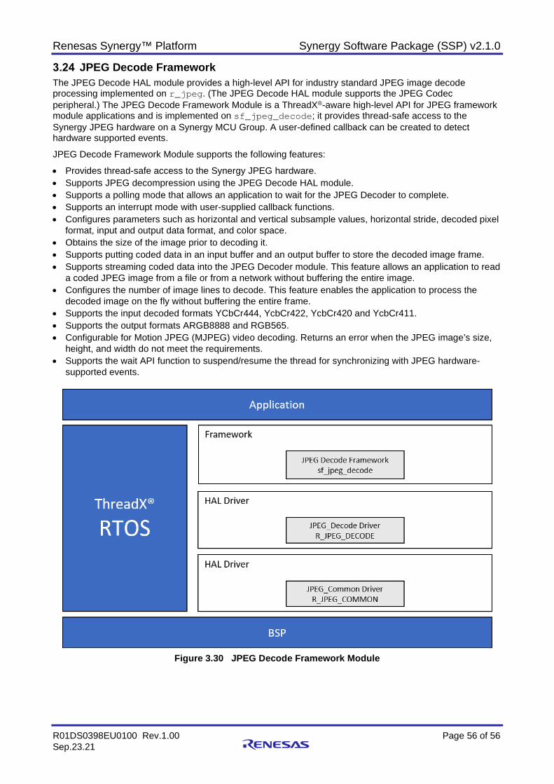
Renesas Synergy™ Platform Synergy Software Package (SSP) v2.1.0
R01DS0398EU0100 Rev.1.00 Page 56 of 56 Sep.23.21
JPEG Decode Framework The JPEG Decode HAL module provides a high-level API for industry standard JPEG image decode processing implemented on r_jpeg. (The JPEG Decode HAL module supports the JPEG Codec peripheral.) The JPEG Decode Framework Module is a ThreadX®-aware high-level API for JPEG framework module applications and is implemented on sf_jpeg_decode; it provides thread-safe access to the Synergy JPEG hardware on a Synergy MCU Group. A user-defined callback can be created to detect hardware supported events.
JPEG Decode Framework Module supports the following features:
• Provides thread-safe access to the Synergy JPEG hardware. • Supports JPEG decompression using the JPEG Decode HAL module. • Supports a polling mode that allows an application to wait for the JPEG Decoder to complete. • Supports an interrupt mode with user-supplied callback functions. • Configures parameters such as horizontal and vertical subsample values, horizontal stride, decoded pixel
format, input and output data format, and color space. • Obtains the size of the image prior to decoding it. • Supports putting coded data in an input buffer and an output buffer to store the decoded image frame. • Supports streaming coded data into the JPEG Decoder module. This feature allows an application to read
a coded JPEG image from a file or from a network without buffering the entire image. • Configures the number of image lines to decode. This feature enables the application to process the
decoded image on the fly without buffering the entire frame. • Supports the input decoded formats YCbCr444, YcbCr422, YcbCr420 and YcbCr411. • Supports the output formats ARGB8888 and RGB565. • Configurable for Motion JPEG (MJPEG) video decoding. Returns an error when the JPEG image’s size,
height, and width do not meet the requirements. • Supports the wait API function to suspend/resume the thread for synchronizing with JPEG hardware-
supported events.
Figure 3.30 JPEG Decode Framework Module
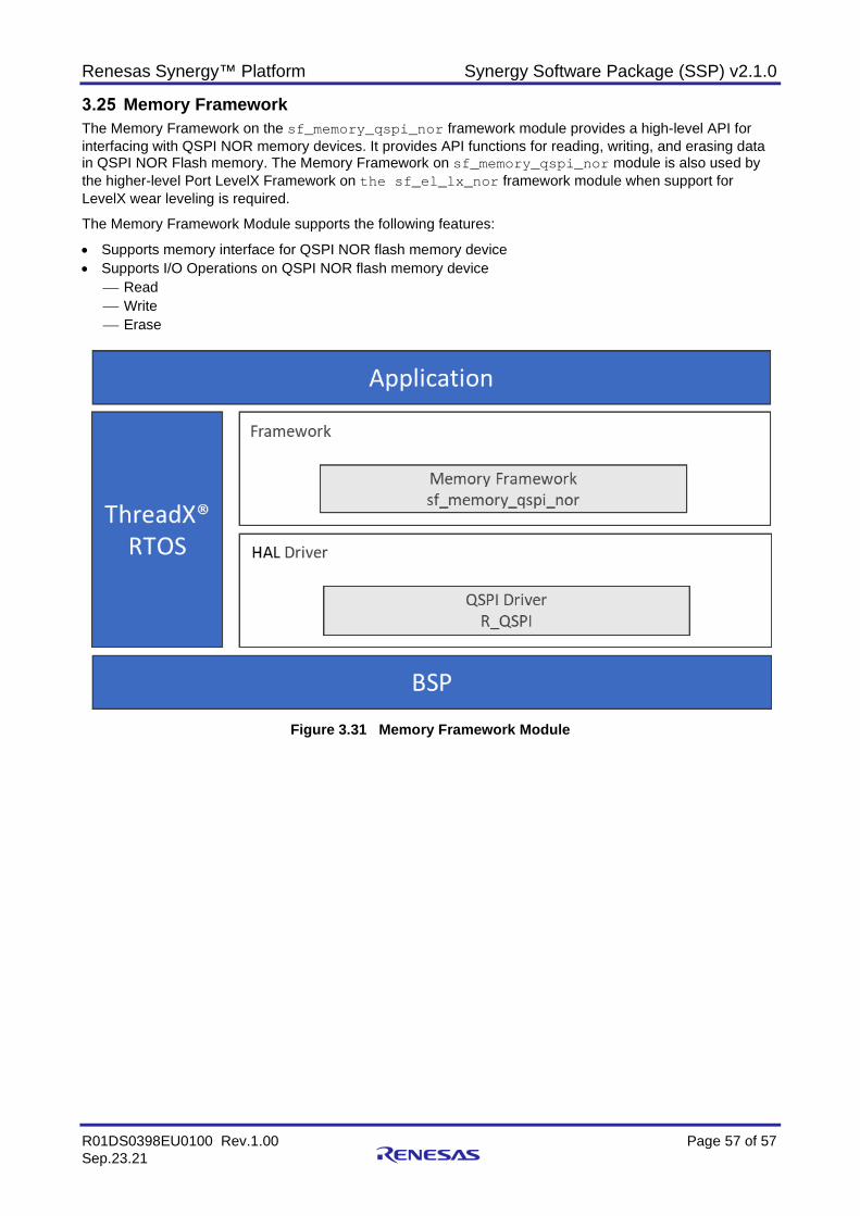
Renesas Synergy™ Platform Synergy Software Package (SSP) v2.1.0
R01DS0398EU0100 Rev.1.00 Page 57 of 57 Sep.23.21
Memory Framework The Memory Framework on the sf_memory_qspi_nor framework module provides a high-level API for interfacing with QSPI NOR memory devices. It provides API functions for reading, writing, and erasing data in QSPI NOR Flash memory. The Memory Framework on sf_memory_qspi_nor module is also used by the higher-level Port LevelX Framework on the sf_el_lx_nor framework module when support for LevelX wear leveling is required.
The Memory Framework Module supports the following features:
• Supports memory interface for QSPI NOR flash memory device • Supports I/O Operations on QSPI NOR flash memory device
Read Write Erase
Figure 3.31 Memory Framework Module
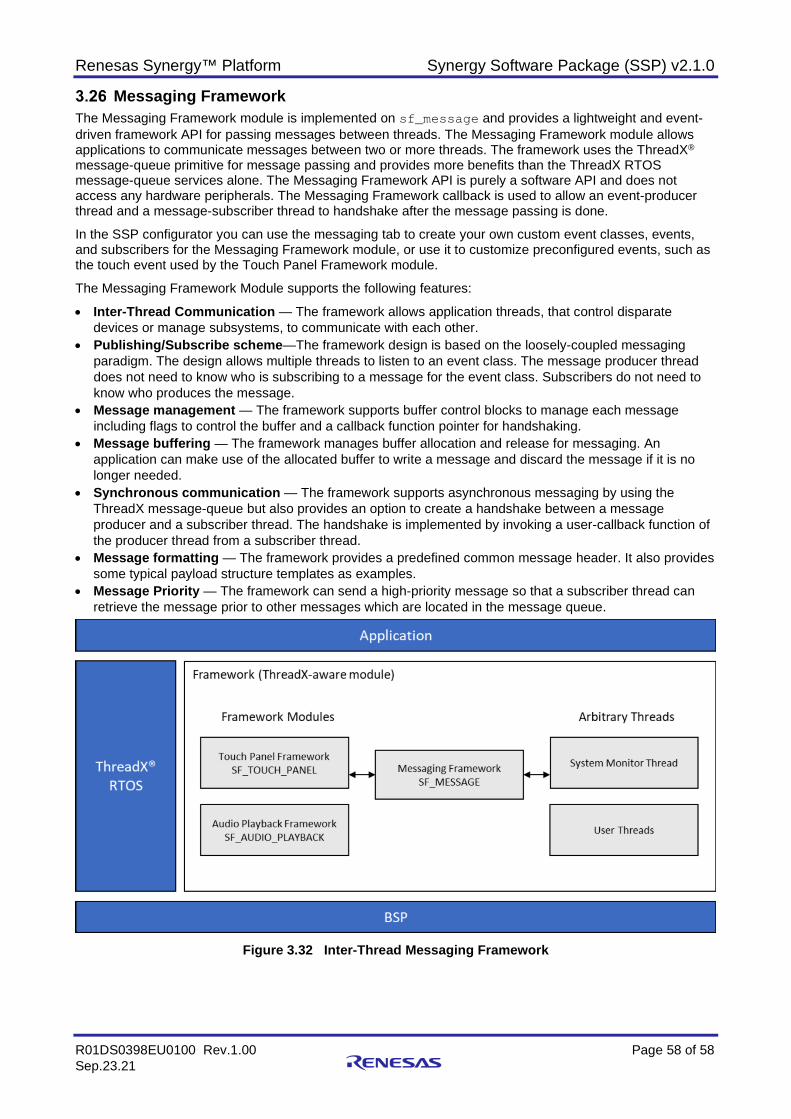
Renesas Synergy™ Platform Synergy Software Package (SSP) v2.1.0
R01DS0398EU0100 Rev.1.00 Page 58 of 58 Sep.23.21
Messaging Framework The Messaging Framework module is implemented on sf_message and provides a lightweight and event-driven framework API for passing messages between threads. The Messaging Framework module allows applications to communicate messages between two or more threads. The framework uses the ThreadX® message-queue primitive for message passing and provides more benefits than the ThreadX RTOS message-queue services alone. The Messaging Framework API is purely a software API and does not access any hardware peripherals. The Messaging Framework callback is used to allow an event-producer thread and a message-subscriber thread to handshake after the message passing is done.
In the SSP configurator you can use the messaging tab to create your own custom event classes, events, and subscribers for the Messaging Framework module, or use it to customize preconfigured events, such as the touch event used by the Touch Panel Framework module.
The Messaging Framework Module supports the following features:
• Inter-Thread Communication — The framework allows application threads, that control disparate devices or manage subsystems, to communicate with each other.
• Publishing/Subscribe scheme—The framework design is based on the loosely-coupled messaging paradigm. The design allows multiple threads to listen to an event class. The message producer thread does not need to know who is subscribing to a message for the event class. Subscribers do not need to know who produces the message.
• Message management — The framework supports buffer control blocks to manage each message including flags to control the buffer and a callback function pointer for handshaking.
• Message buffering — The framework manages buffer allocation and release for messaging. An application can make use of the allocated buffer to write a message and discard the message if it is no longer needed.
• Synchronous communication — The framework supports asynchronous messaging by using the ThreadX message-queue but also provides an option to create a handshake between a message producer and a subscriber thread. The handshake is implemented by invoking a user-callback function of the producer thread from a subscriber thread.
• Message formatting — The framework provides a predefined common message header. It also provides some typical payload structure templates as examples.
• Message Priority — The framework can send a high-priority message so that a subscriber thread can retrieve the message prior to other messages which are located in the message queue.
Figure 3.32 Inter-Thread Messaging Framework
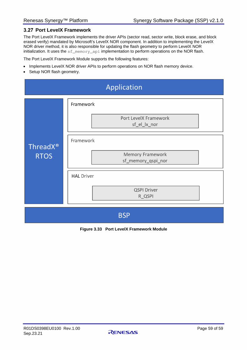
Renesas Synergy™ Platform Synergy Software Package (SSP) v2.1.0
R01DS0398EU0100 Rev.1.00 Page 59 of 59 Sep.23.21
Port LevelX Framework The Port LevelX Framework implements the driver APIs (sector read, sector write, block erase, and block erased verify) mandated by Microsoft’s LevelX NOR component. In addition to implementing the LevelX NOR driver method, it is also responsible for updating the flash geometry to perform LevelX NOR initialization. It uses the sf_memory_api implementation to perform operations on the NOR flash.
The Port LevelX Framework Module supports the following features:
• Implements LevelX NOR driver APIs to perform operations on NOR flash memory device. • Setup NOR flash geometry.
Figure 3.33 Port LevelX Framework Module
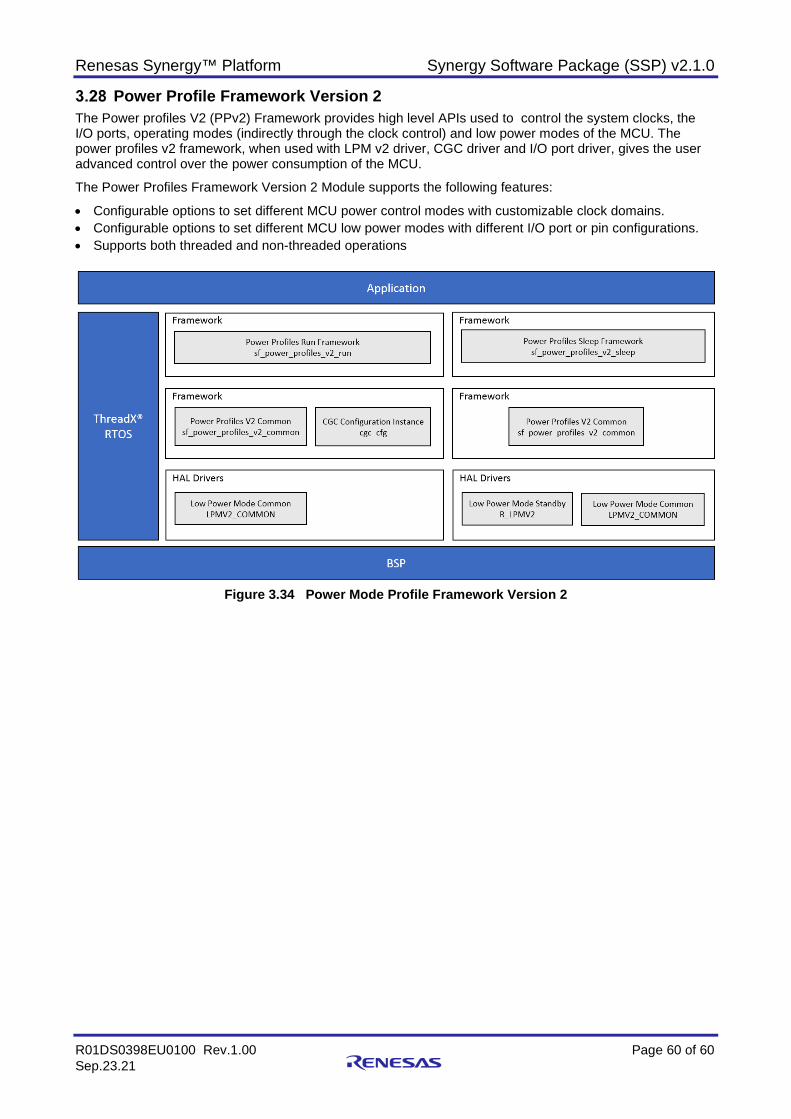
Renesas Synergy™ Platform Synergy Software Package (SSP) v2.1.0
R01DS0398EU0100 Rev.1.00 Page 60 of 60 Sep.23.21
Power Profile Framework Version 2 The Power profiles V2 (PPv2) Framework provides high level APIs used to control the system clocks, the I/O ports, operating modes (indirectly through the clock control) and low power modes of the MCU. The power profiles v2 framework, when used with LPM v2 driver, CGC driver and I/O port driver, gives the user advanced control over the power consumption of the MCU.
The Power Profiles Framework Version 2 Module supports the following features:
• Configurable options to set different MCU power control modes with customizable clock domains. • Configurable options to set different MCU low power modes with different I/O port or pin configurations. • Supports both threaded and non-threaded operations
Figure 3.34 Power Mode Profile Framework Version 2
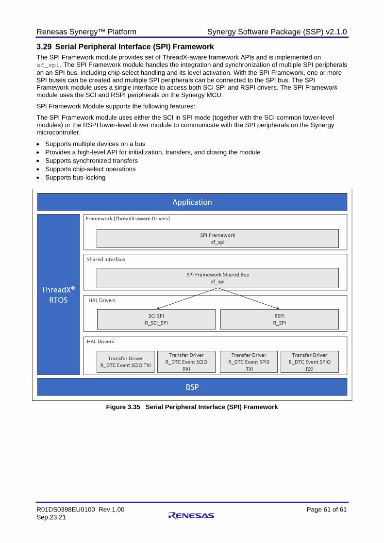
Renesas Synergy™ Platform Synergy Software Package (SSP) v2.1.0
R01DS0398EU0100 Rev.1.00 Page 61 of 61 Sep.23.21
Serial Peripheral Interface (SPI) Framework The SPI Framework module provides set of ThreadX-aware framework APIs and is implemented on sf_spi. The SPI Framework module handles the integration and synchronization of multiple SPI peripherals on an SPI bus, including chip-select handling and its level activation. With the SPI Framework, one or more SPI buses can be created and multiple SPI peripherals can be connected to the SPI bus. The SPI Framework module uses a single interface to access both SCI SPI and RSPI drivers. The SPI Framework module uses the SCI and RSPI peripherals on the Synergy MCU.
SPI Framework Module supports the following features:
The SPI Framework module uses either the SCI in SPI mode (together with the SCI common lower-level modules) or the RSPI lower-level driver module to communicate with the SPI peripherals on the Synergy microcontroller.
• Supports multiple devices on a bus • Provides a high-level API for initialization, transfers, and closing the module • Supports synchronized transfers • Supports chip-select operations • Supports bus-locking
Figure 3.35 Serial Peripheral Interface (SPI) Framework
Renesas Synergy™ Platform Synergy Software Package (SSP) v2.1.0
R01DS0398EU0100 Rev.1.00 Page 62 of 62 Sep.23.21
Synergy FileX® Port Block Media Interface Framework The FileX Port Block Media Framework module, implemented on sf_el_fx, supports the Microsoft FileX system, a complete FAT and exFAT format media and file management system for deeply embedded applications. The FileX Port Block Media Framework module provides I/O calls for FileX to access Synergy Media drivers through the Block Media Interface and adaptation layers. The SD/MMC HAL module and the SDIO HAL module are implemented on r_sdmmc and are used to read/write and control SD/MMC media devices as well as SDIO cards. The sf_el_fx module uses the SD/MMC peripherals on the Synergy MCU.
FileX Port Block Media Framework Features The FileX Port Block Media Framework module features include:
• Single Partition (using total available memory size) Support for FAT32, FAT16, FAT12 and exFAT filesystems Supports single FAT and exFAT partition operations in all SSP block media, that is,
sf_block_media_lx_nor, sf_block_media_sdmmc, sf_block_media_qspi and sf_block_media_ram. Multiple FileX objects (that is, media, directories, and files, only limited by available memory) Dynamic FileX object creation/deletion
Flexible memory usage Size scales automatically Small footprint Complete integration with ThreadX
• Multi Partition
Support for FAT32, FAT16 and exFAT filesystem. Supports the creation of any number of partition on single physical media, and supports all other
fileX operations on them, for underlying block media sf_block_media_lx_nor and sf_block_media_sdmmc.
MBR/EBR support with visibility of partitions under Windows® OS Each partition can be operated-on independently of other partitions. Provides following operations on Synergy platform:
• Format/re-format • Open • Close • Write • Read
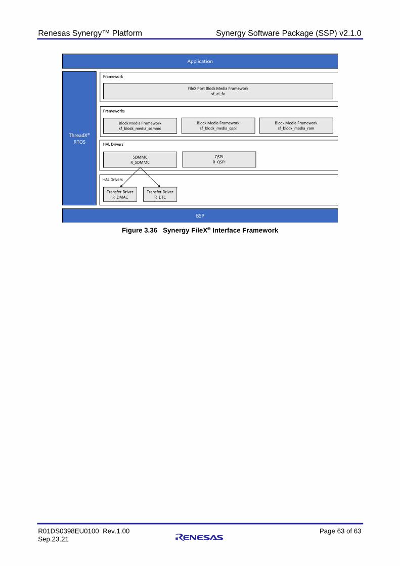
Renesas Synergy™ Platform Synergy Software Package (SSP) v2.1.0
R01DS0398EU0100 Rev.1.00 Page 63 of 63 Sep.23.21
Figure 3.36 Synergy FileX® Interface Framework
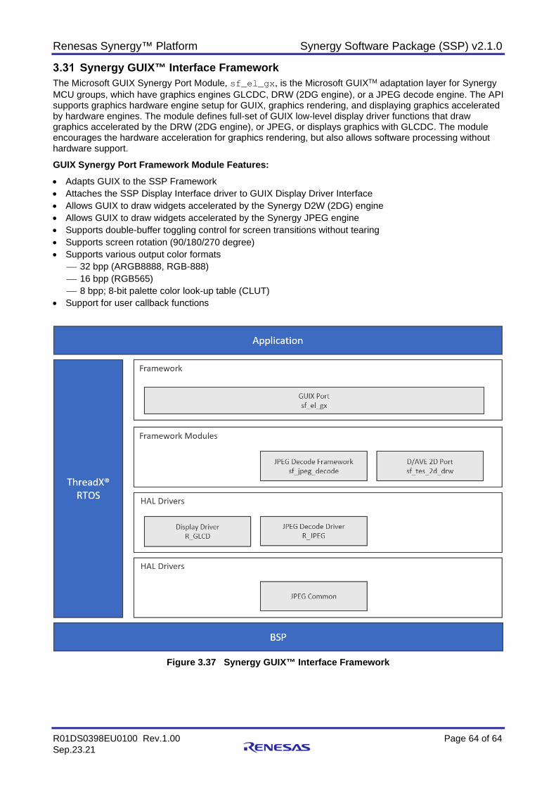
Renesas Synergy™ Platform Synergy Software Package (SSP) v2.1.0
R01DS0398EU0100 Rev.1.00 Page 64 of 64 Sep.23.21
Synergy GUIX™ Interface Framework The Microsoft GUIX Synergy Port Module, sf_el_gx, is the Microsoft GUIXTM adaptation layer for Synergy MCU groups, which have graphics engines GLCDC, DRW (2DG engine), or a JPEG decode engine. The API supports graphics hardware engine setup for GUIX, graphics rendering, and displaying graphics accelerated by hardware engines. The module defines full-set of GUIX low-level display driver functions that draw graphics accelerated by the DRW (2DG engine), or JPEG, or displays graphics with GLCDC. The module encourages the hardware acceleration for graphics rendering, but also allows software processing without hardware support.
GUIX Synergy Port Framework Module Features: • Adapts GUIX to the SSP Framework • Attaches the SSP Display Interface driver to GUIX Display Driver Interface • Allows GUIX to draw widgets accelerated by the Synergy D2W (2DG) engine • Allows GUIX to draw widgets accelerated by the Synergy JPEG engine • Supports double-buffer toggling control for screen transitions without tearing • Supports screen rotation (90/180/270 degree) • Supports various output color formats
32 bpp (ARGB8888, RGB-888) 16 bpp (RGB565) 8 bpp; 8-bit palette color look-up table (CLUT)
• Support for user callback functions
Figure 3.37 Synergy GUIX™ Interface Framework
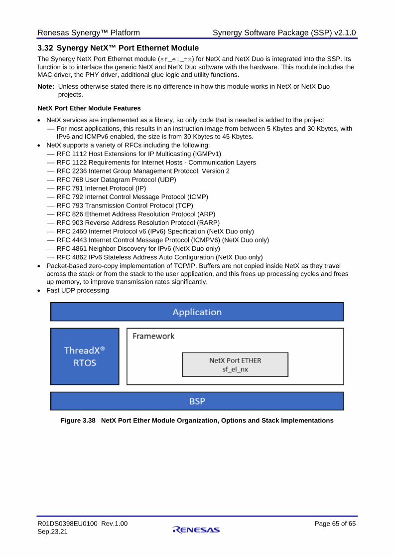
Renesas Synergy™ Platform Synergy Software Package (SSP) v2.1.0
R01DS0398EU0100 Rev.1.00 Page 65 of 65 Sep.23.21
Synergy NetX™ Port Ethernet Module The Synergy NetX Port Ethernet module (sf_el_nx) for NetX and NetX Duo is integrated into the SSP. Its function is to interface the generic NetX and NetX Duo software with the hardware. This module includes the MAC driver, the PHY driver, additional glue logic and utility functions.
Note: Unless otherwise stated there is no difference in how this module works in NetX or NetX Duo projects.
NetX Port Ether Module Features • NetX services are implemented as a library, so only code that is needed is added to the project
For most applications, this results in an instruction image from between 5 Kbytes and 30 Kbytes, with IPv6 and ICMPv6 enabled, the size is from 30 Kbytes to 45 Kbytes.
• NetX supports a variety of RFCs including the following: RFC 1112 Host Extensions for IP Multicasting (IGMPv1) RFC 1122 Requirements for Internet Hosts - Communication Layers RFC 2236 Internet Group Management Protocol, Version 2 RFC 768 User Datagram Protocol (UDP) RFC 791 Internet Protocol (IP) RFC 792 Internet Control Message Protocol (ICMP) RFC 793 Transmission Control Protocol (TCP) RFC 826 Ethernet Address Resolution Protocol (ARP) RFC 903 Reverse Address Resolution Protocol (RARP) RFC 2460 Internet Protocol v6 (IPv6) Specification (NetX Duo only) RFC 4443 Internet Control Message Protocol (ICMPV6) (NetX Duo only) RFC 4861 Neighbor Discovery for IPv6 (NetX Duo only) RFC 4862 IPv6 Stateless Address Auto Configuration (NetX Duo only)
• Packet-based zero-copy implementation of TCP/IP. Buffers are not copied inside NetX as they travel across the stack or from the stack to the user application, and this frees up processing cycles and frees up memory, to improve transmission rates significantly.
• Fast UDP processing
Figure 3.38 NetX Port Ether Module Organization, Options and Stack Implementations
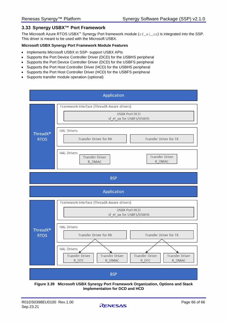
Renesas Synergy™ Platform Synergy Software Package (SSP) v2.1.0
R01DS0398EU0100 Rev.1.00 Page 66 of 66 Sep.23.21
Synergy USBX™ Port Framework The Microsoft Azure RTOS USBX™ Synergy Port framework module (sf_el_ux) is integrated into the SSP. This driver is meant to be used with the Microsoft USBX.
Microsoft USBX Synergy Port Framework Module Features • Implements Microsoft USBX in SSP- support USBX APIs • Supports the Port Device Controller Driver (DCD) for the USBHS peripheral • Supports the Port Device Controller Driver (DCD) for the USBFS peripheral • Supports the Port Host Controller Driver (HCD) for the USBHS peripheral • Supports the Port Host Controller Driver (HCD) for the USBFS peripheral • Supports transfer module operation (optional)
Figure 3.39 Microsoft USBX Synergy Port Framework Organization, Options and Stack
Implementation for DCD and HCD
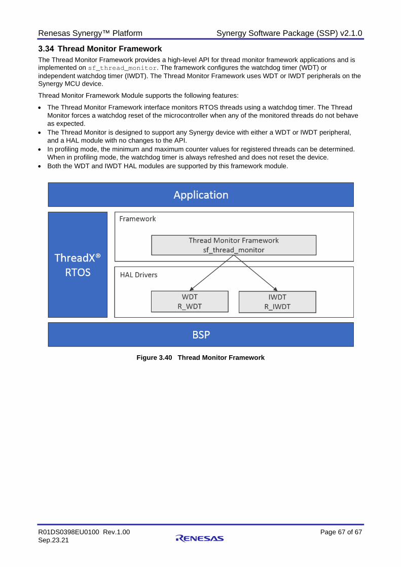
Renesas Synergy™ Platform Synergy Software Package (SSP) v2.1.0
R01DS0398EU0100 Rev.1.00 Page 67 of 67 Sep.23.21
Thread Monitor Framework The Thread Monitor Framework provides a high-level API for thread monitor framework applications and is implemented on sf_thread_monitor. The framework configures the watchdog timer (WDT) or independent watchdog timer (IWDT). The Thread Monitor Framework uses WDT or IWDT peripherals on the Synergy MCU device.
Thread Monitor Framework Module supports the following features:
• The Thread Monitor Framework interface monitors RTOS threads using a watchdog timer. The Thread Monitor forces a watchdog reset of the microcontroller when any of the monitored threads do not behave as expected.
• The Thread Monitor is designed to support any Synergy device with either a WDT or IWDT peripheral, and a HAL module with no changes to the API.
• In profiling mode, the minimum and maximum counter values for registered threads can be determined. When in profiling mode, the watchdog timer is always refreshed and does not reset the device.
• Both the WDT and IWDT HAL modules are supported by this framework module.
Figure 3.40 Thread Monitor Framework
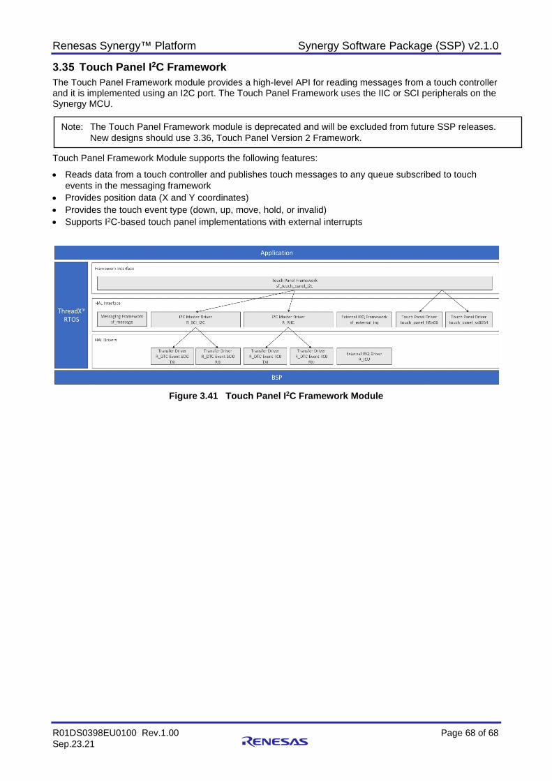
Renesas Synergy™ Platform Synergy Software Package (SSP) v2.1.0
R01DS0398EU0100 Rev.1.00 Page 68 of 68 Sep.23.21
Touch Panel I2C Framework The Touch Panel Framework module provides a high-level API for reading messages from a touch controller and it is implemented using an I2C port. The Touch Panel Framework uses the IIC or SCI peripherals on the Synergy MCU.
Touch Panel Framework Module supports the following features:
• Reads data from a touch controller and publishes touch messages to any queue subscribed to touch events in the messaging framework
• Provides position data (X and Y coordinates) • Provides the touch event type (down, up, move, hold, or invalid) • Supports I2C-based touch panel implementations with external interrupts
Figure 3.41 Touch Panel I2C Framework Module
Note: The Touch Panel Framework module is deprecated and will be excluded from future SSP releases. New designs should use 3.36, Touch Panel Version 2 Framework.
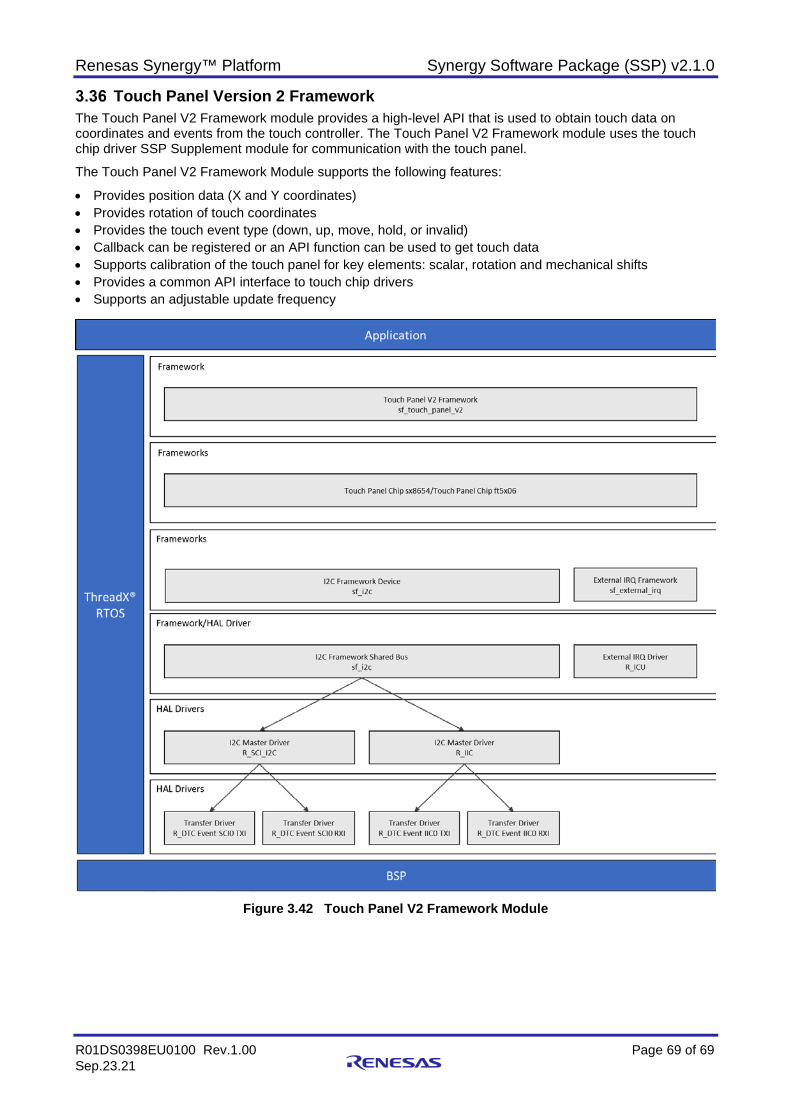
Renesas Synergy™ Platform Synergy Software Package (SSP) v2.1.0
R01DS0398EU0100 Rev.1.00 Page 69 of 69 Sep.23.21
Touch Panel Version 2 Framework The Touch Panel V2 Framework module provides a high-level API that is used to obtain touch data on coordinates and events from the touch controller. The Touch Panel V2 Framework module uses the touch chip driver SSP Supplement module for communication with the touch panel.
The Touch Panel V2 Framework Module supports the following features:
• Provides position data (X and Y coordinates) • Provides rotation of touch coordinates • Provides the touch event type (down, up, move, hold, or invalid) • Callback can be registered or an API function can be used to get touch data • Supports calibration of the touch panel for key elements: scalar, rotation and mechanical shifts • Provides a common API interface to touch chip drivers • Supports an adjustable update frequency
Figure 3.42 Touch Panel V2 Framework Module
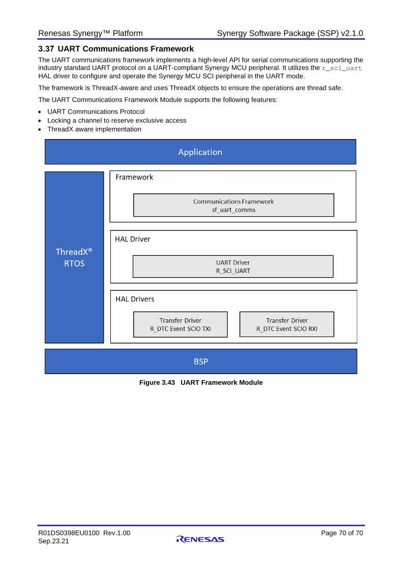
Renesas Synergy™ Platform Synergy Software Package (SSP) v2.1.0
R01DS0398EU0100 Rev.1.00 Page 70 of 70 Sep.23.21
UART Communications Framework The UART communications framework implements a high-level API for serial communications supporting the industry standard UART protocol on a UART-compliant Synergy MCU peripheral. It utilizes the r_sci_uart HAL driver to configure and operate the Synergy MCU SCI peripheral in the UART mode.
The framework is ThreadX-aware and uses ThreadX objects to ensure the operations are thread safe.
The UART Communications Framework Module supports the following features:
• UART Communications Protocol • Locking a channel to reserve exclusive access • ThreadX aware implementation
Figure 3.43 UART Framework Module
Renesas Synergy™ Platform Synergy Software Package (SSP) v2.1.0
R01DS0398EU0100 Rev.1.00 Page 71 of 71 Sep.23.21
Wi-Fi Framework The Wi-Fi framework provides high-level APIs to configure and provision Wi-Fi modules, and also performs data transfers with or without on-chip networking capability. Currently, only the Qualcomm GT202 module is supported. The Wi-Fi framework communicates through the SPI with the underlying GT202 module.
The Wi-Fi framework module has the following key features:
• Provides high-level APIs to configure and provision a Wi-Fi module • Provides four different implementations for:
A Wi-Fi device driver stack using the sf_wifi_gt202 framework An on-chip stack using the sf_wifi_onchip_stack framework A BSD socket stack using the sf_wifi_onchip_stack framework A NetX and NetX Duo port using the sf_wifi_nsal_nx framework
• Using NetX and NASL: Allows the same application code to be used across different Wi-Fi modules Allows easy migration of the Ethernet-based application to a Wi-Fi based application Allows for debugging and fine-tuning the application and TCP/IP stack as required by the application. The current NSAL implementation only provides NetX NSAL. Adding support for a new network stack
requires implementing the appropriate NSAL. • Using the On-chip networking stack:
Is beneficial when using MCUs with a small memory footprint Provides BSD sockets interface to create socket-based applications with the On-chip TCP/UDP
• Provides an option to integrate 3rd-party application protocols on top of the TCP/IP such as MQTT and COAP without using the NetX stack.
• Provides support for Wi-Fi Protected Setup (WPS) router configuration using Push-Button and PIN methods
Note: This on-chip networking stack is supported only when supported by the Wi-Fi module or WiFi module
driver.

Renesas Synergy™ Platform Synergy Software Package (SSP) v2.1.0
R01DS0398EU0100 Rev.1.00 Page 72 of 72 Sep.23.21
The following figure shows the Wi-Fi Framework Module.
Figure 3.44 Wi-Fi Framework Module
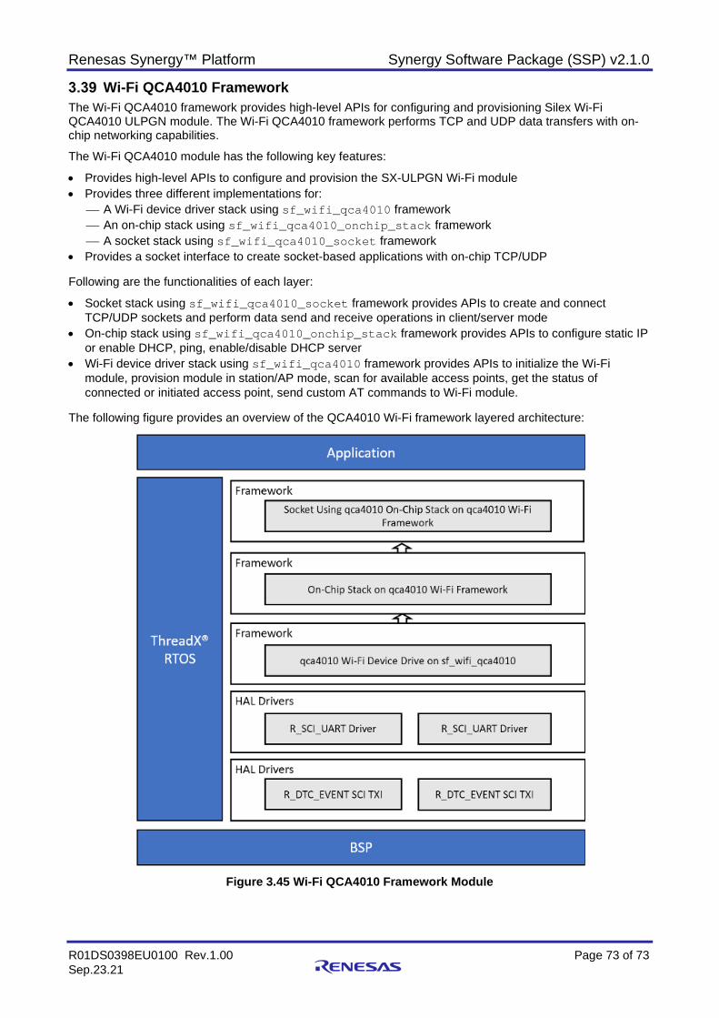
Renesas Synergy™ Platform Synergy Software Package (SSP) v2.1.0
R01DS0398EU0100 Rev.1.00 Page 73 of 73 Sep.23.21
Wi-Fi QCA4010 Framework The Wi-Fi QCA4010 framework provides high-level APIs for configuring and provisioning Silex Wi-Fi QCA4010 ULPGN module. The Wi-Fi QCA4010 framework performs TCP and UDP data transfers with on-chip networking capabilities.
The Wi-Fi QCA4010 module has the following key features:
• Provides high-level APIs to configure and provision the SX-ULPGN Wi-Fi module • Provides three different implementations for:
A Wi-Fi device driver stack using sf_wifi_qca4010 framework An on-chip stack using sf_wifi_qca4010_onchip_stack framework A socket stack using sf_wifi_qca4010_socket framework
• Provides a socket interface to create socket-based applications with on-chip TCP/UDP Following are the functionalities of each layer:
• Socket stack using sf_wifi_qca4010_socket framework provides APIs to create and connect TCP/UDP sockets and perform data send and receive operations in client/server mode
• On-chip stack using sf_wifi_qca4010_onchip_stack framework provides APIs to configure static IP or enable DHCP, ping, enable/disable DHCP server
• Wi-Fi device driver stack using sf_wifi_qca4010 framework provides APIs to initialize the Wi-Fi module, provision module in station/AP mode, scan for available access points, get the status of connected or initiated access point, send custom AT commands to Wi-Fi module.
The following figure provides an overview of the QCA4010 Wi-Fi framework layered architecture:
Figure 3.45 Wi-Fi QCA4010 Framework Module
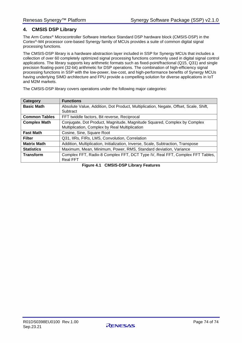
Renesas Synergy™ Platform Synergy Software Package (SSP) v2.1.0
R01DS0398EU0100 Rev.1.00 Page 74 of 74 Sep.23.21
4. CMSIS DSP Library The Arm Cortex® Microcontroller Software Interface Standard DSP hardware block (CMSIS-DSP) in the Cortex®-M4 processor core-based Synergy family of MCUs provides a suite of common digital signal processing functions.
The CMSIS-DSP library is a hardware abstraction layer included in SSP for Synergy MCUs that includes a collection of over 60 completely optimized signal processing functions commonly used in digital signal control applications. The library supports key arithmetic formats such as fixed-point/fractional (Q15, Q31) and single precision floating-point (32-bit) arithmetic for DSP operations. The combination of high-efficiency signal processing functions in SSP with the low-power, low-cost, and high-performance benefits of Synergy MCUs having underlying SIMD architecture and FPU provide a compelling solution for diverse applications in IoT and M2M markets.
The CMSIS-DSP library covers operations under the following major categories:
Category Functions Basic Math Absolute Value, Addition, Dot Product, Multiplication, Negate, Offset, Scale, Shift,
Subtract Common Tables FFT twiddle factors, Bit reverse, Reciprocal Complex Math Conjugate, Dot Product, Magnitude, Magnitude Squared, Complex by Complex
Multiplication, Complex by Real Multiplication Fast Math Cosine, Sine, Square Root Filter Q31, IIRs, FIRs, LMS, Convolution, Correlation Matrix Math Addition, Multiplication, Initialization, Inverse, Scale, Subtraction, Transpose Statistics Maximum, Mean, Minimum, Power, RMS, Standard deviation, Variance Transform Complex FFT, Radix-8 Complex FFT, DCT Type IV, Real FFT, Complex FFT Tables,
Real FFT Figure 4.1 CMSIS-DSP Library Features
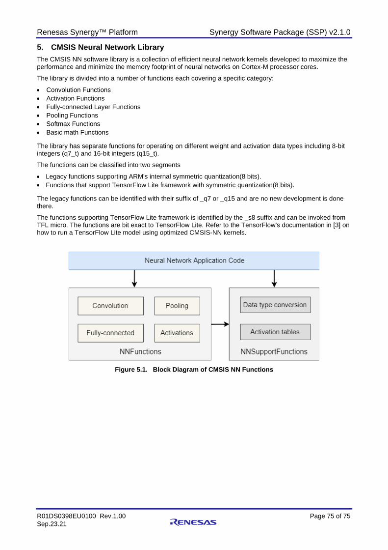
Renesas Synergy™ Platform Synergy Software Package (SSP) v2.1.0
R01DS0398EU0100 Rev.1.00 Page 75 of 75 Sep.23.21
5. CMSIS Neural Network Library The CMSIS NN software library is a collection of efficient neural network kernels developed to maximize the performance and minimize the memory footprint of neural networks on Cortex-M processor cores.
The library is divided into a number of functions each covering a specific category:
• Convolution Functions • Activation Functions • Fully-connected Layer Functions • Pooling Functions • Softmax Functions • Basic math Functions The library has separate functions for operating on different weight and activation data types including 8-bit integers (q7_t) and 16-bit integers (q15_t).
The functions can be classified into two segments
• Legacy functions supporting ARM's internal symmetric quantization(8 bits). • Functions that support TensorFlow Lite framework with symmetric quantization(8 bits). The legacy functions can be identified with their suffix of _q7 or _q15 and are no new development is done there.
The functions supporting TensorFlow Lite framework is identified by the _s8 suffix and can be invoked from TFL micro. The functions are bit exact to TensorFlow Lite. Refer to the TensorFlow's documentation in [3] on how to run a TensorFlow Lite model using optimized CMSIS-NN kernels.
Figure 5.1. Block Diagram of CMSIS NN Functions
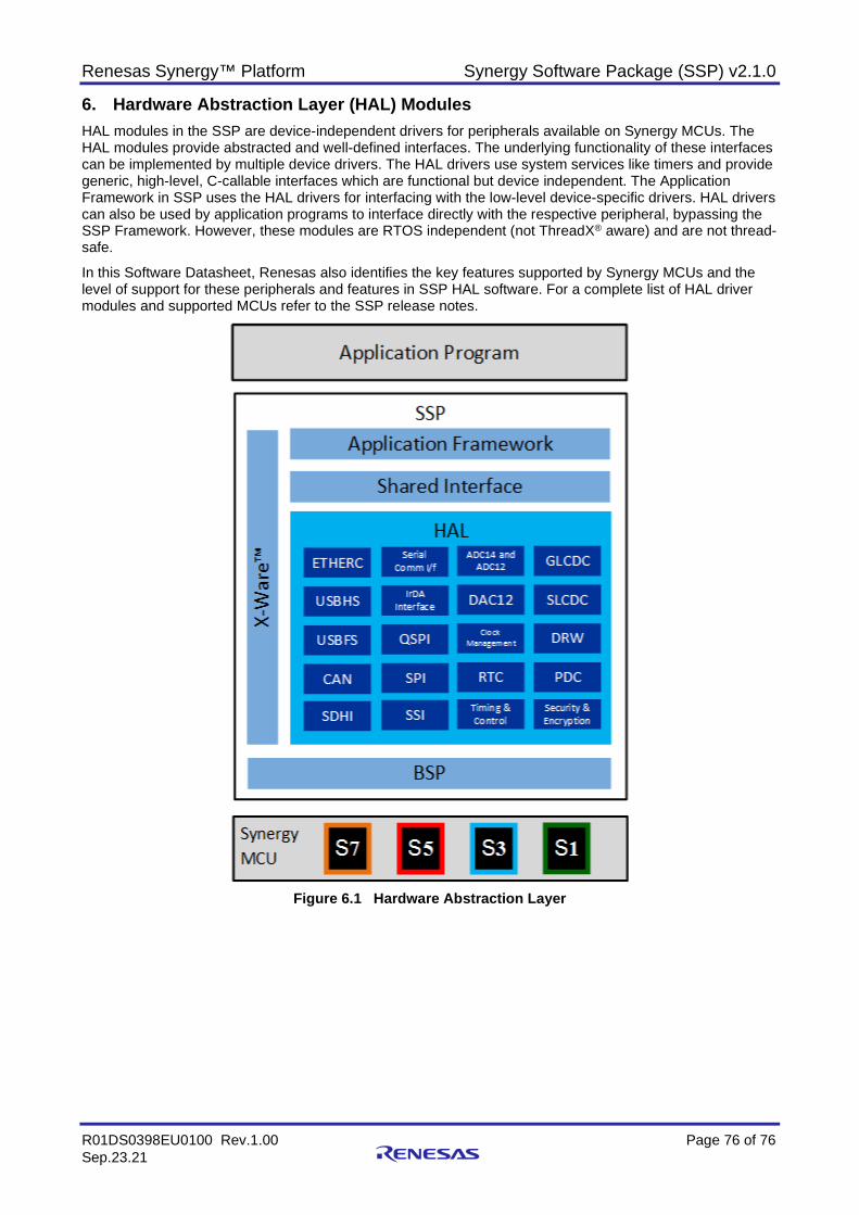
Renesas Synergy™ Platform Synergy Software Package (SSP) v2.1.0
R01DS0398EU0100 Rev.1.00 Page 76 of 76 Sep.23.21
6. Hardware Abstraction Layer (HAL) Modules HAL modules in the SSP are device-independent drivers for peripherals available on Synergy MCUs. The HAL modules provide abstracted and well-defined interfaces. The underlying functionality of these interfaces can be implemented by multiple device drivers. The HAL drivers use system services like timers and provide generic, high-level, C-callable interfaces which are functional but device independent. The Application Framework in SSP uses the HAL drivers for interfacing with the low-level device-specific drivers. HAL drivers can also be used by application programs to interface directly with the respective peripheral, bypassing the SSP Framework. However, these modules are RTOS independent (not ThreadX® aware) and are not thread-safe.
In this Software Datasheet, Renesas also identifies the key features supported by Synergy MCUs and the level of support for these peripherals and features in SSP HAL software. For a complete list of HAL driver modules and supported MCUs refer to the SSP release notes.
Figure 6.1 Hardware Abstraction Layer
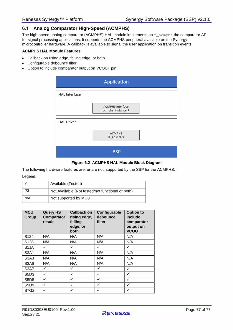
Renesas Synergy™ Platform Synergy Software Package (SSP) v2.1.0
R01DS0398EU0100 Rev.1.00 Page 77 of 77 Sep.23.21
Analog Comparator High-Speed (ACMPHS) The high-speed analog comparator (ACMPHS) HAL module implements on r_acmphs the comparator API for signal processing applications. It supports the ACMPHS peripheral available on the Synergy microcontroller hardware. A callback is available to signal the user application on transition events.
ACMPHS HAL Module Features • Callback on rising edge, falling edge, or both • Configurable debounce filter • Option to include comparator output on VCOUT pin
Figure 6.2 ACMPHS HAL Module Block Diagram
The following hardware features are, or are not, supported by the SSP for the ACMPHS:
Legend:
Available (Tested)
Not Available (Not tested/not functional or both)
N/A Not supported by MCU
MCU Group
Query HS Comparator result
Callback on rising edge, falling edge, or both
Configurable debounce filter
Option to include comparator output on VCOUT
S124 N/A N/A N/A N/A S128 N/A N/A N/A N/A S1JA S3A1 N/A N/A N/A N/A S3A3 N/A N/A N/A N/A S3A6 N/A N/A N/A N/A S3A7 S5D3 S5D5 S5D9 S7G2
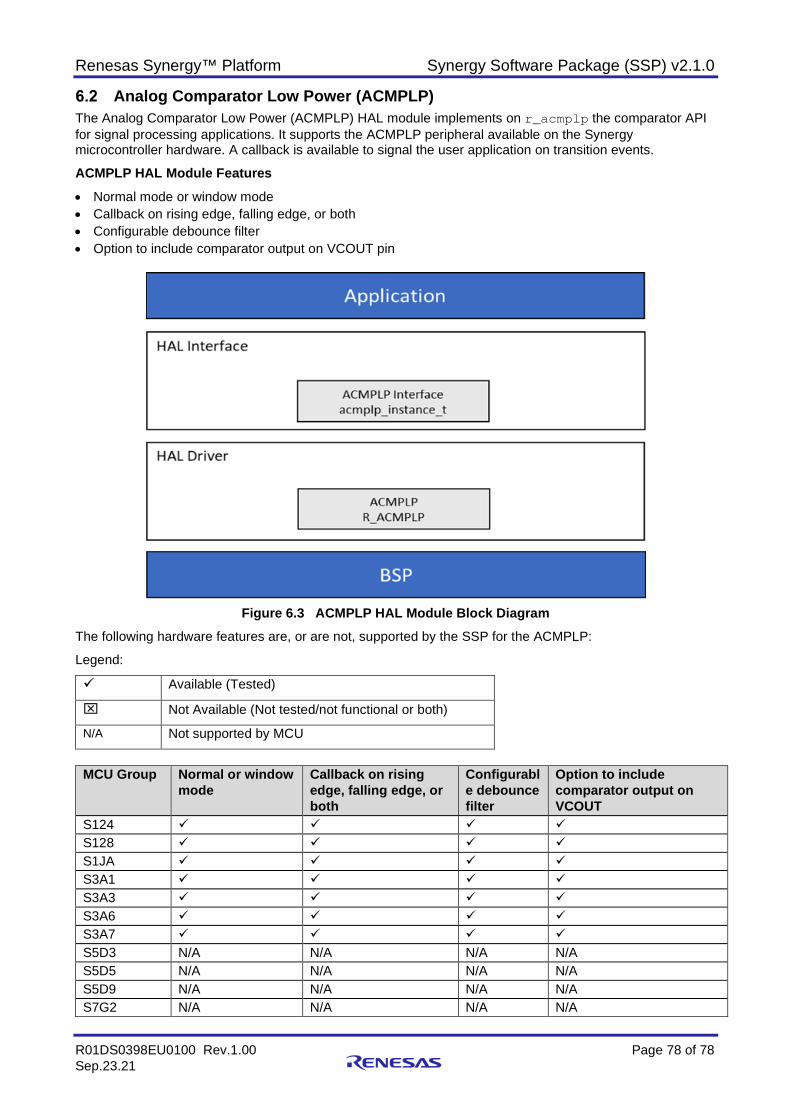
Renesas Synergy™ Platform Synergy Software Package (SSP) v2.1.0
R01DS0398EU0100 Rev.1.00 Page 78 of 78 Sep.23.21
Analog Comparator Low Power (ACMPLP) The Analog Comparator Low Power (ACMPLP) HAL module implements on r_acmplp the comparator API for signal processing applications. It supports the ACMPLP peripheral available on the Synergy microcontroller hardware. A callback is available to signal the user application on transition events.
ACMPLP HAL Module Features
• Normal mode or window mode • Callback on rising edge, falling edge, or both • Configurable debounce filter • Option to include comparator output on VCOUT pin
Figure 6.3 ACMPLP HAL Module Block Diagram
The following hardware features are, or are not, supported by the SSP for the ACMPLP:
Legend:
Available (Tested)
Not Available (Not tested/not functional or both)
N/A Not supported by MCU
MCU Group Normal or window
mode Callback on rising edge, falling edge, or both
Configurable debounce filter
Option to include comparator output on VCOUT
S124 S128 S1JA S3A1 S3A3 S3A6 S3A7 S5D3 N/A N/A N/A N/A S5D5 N/A N/A N/A N/A S5D9 N/A N/A N/A N/A S7G2 N/A N/A N/A N/A

Renesas Synergy™ Platform Synergy Software Package (SSP) v2.1.0
R01DS0398EU0100 Rev.1.00 Page 79 of 79 Sep.23.21
Analog to Digital Converter (ADC) The ADC HAL module implements on r_adc an API for analog-to-digital conversion applications. It supports the ADC12, ADC14 and ADC16 for associated peripherals available on Synergy MCUs. A user-defined callback can be used to process the data each time a new sample is complete.
ADC HAL Module Features • A/D Converter
16-Bit (S1JA MCU Group) 14-Bit A (S3A7, S3A3, S3A6, S3A1, S128, and S124 MCU Groups) 12-Bit (S7G2, S5D9, S5D5, and S5D3 MCU Groups)
• Multiple Operation Modes Single Scan Group Scan Continuous Scan
• Multiple Channels All analog channels on MCU
• 13 channels (unit 0) or 12 channels (unit 1) for S7G2 • 17 channels for S1JA • 18 channels for S124 • 28 channels for S3A7
Temperature sensor channel Voltage sensor channel
• ADC Voltage Reference on 16-Bit A/D Converter (for S1JA) Internal voltage reference External voltage reference VREFH0
• Programmable Gain Amplifier (PGA) (S7G2, S5D9, S5D3) Single-ended input mode Differential input mode
Figure 6.4 ADC HAL Module
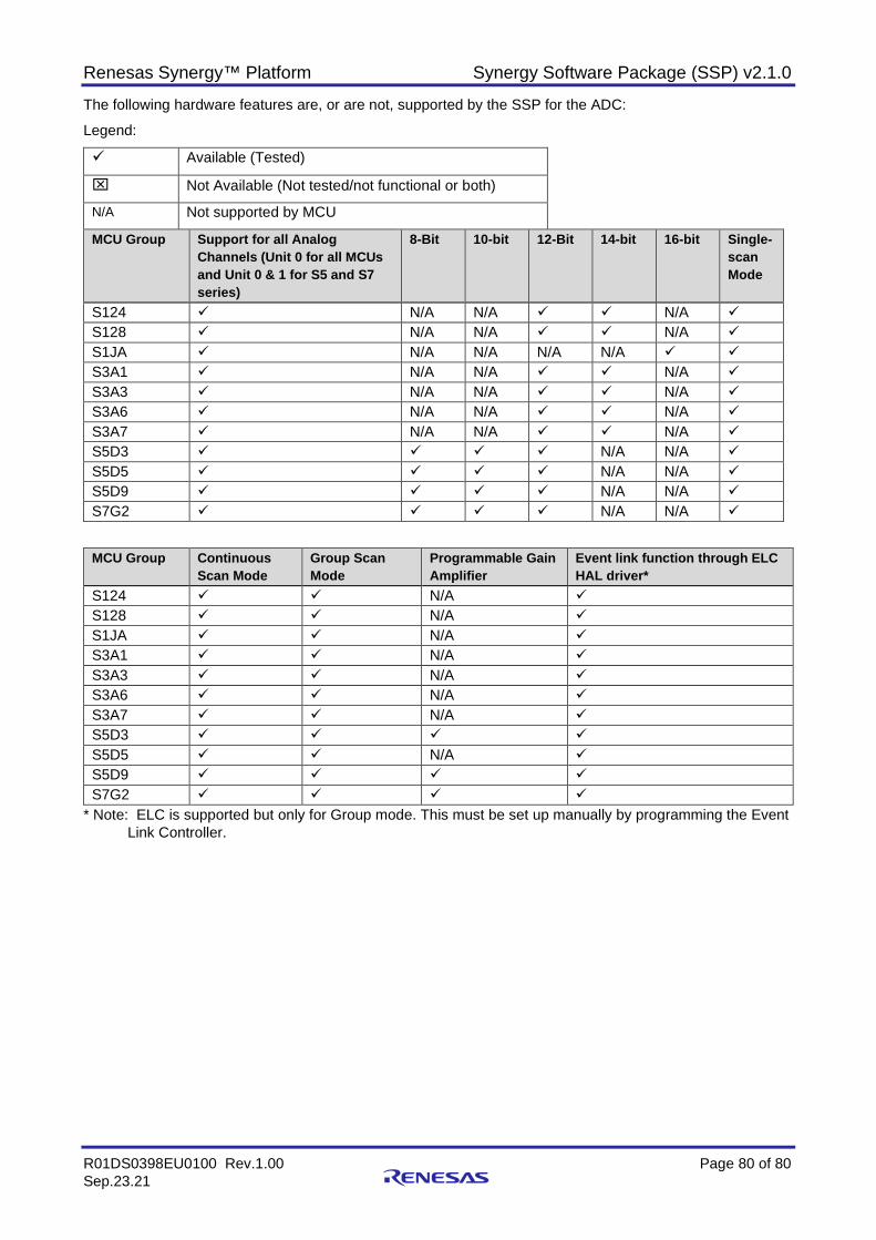
Renesas Synergy™ Platform Synergy Software Package (SSP) v2.1.0
R01DS0398EU0100 Rev.1.00 Page 80 of 80 Sep.23.21
The following hardware features are, or are not, supported by the SSP for the ADC:
Legend:
Available (Tested)
Not Available (Not tested/not functional or both)
N/A Not supported by MCU
MCU Group Support for all Analog Channels (Unit 0 for all MCUs and Unit 0 & 1 for S5 and S7 series)
8-Bit 10-bit 12-Bit 14-bit 16-bit Single-scan Mode
S124 N/A N/A N/A S128 N/A N/A N/A S1JA N/A N/A N/A N/A S3A1 N/A N/A N/A S3A3 N/A N/A N/A S3A6 N/A N/A N/A S3A7 N/A N/A N/A S5D3 N/A N/A S5D5 N/A N/A S5D9 N/A N/A S7G2 N/A N/A
MCU Group Continuous Scan Mode
Group Scan Mode
Programmable Gain Amplifier
Event link function through ELC HAL driver*
S124 N/A S128 N/A S1JA N/A S3A1 N/A S3A3 N/A S3A6 N/A S3A7 N/A S5D3 S5D5 N/A S5D9 S7G2
* Note: ELC is supported but only for Group mode. This must be set up manually by programming the Event Link Controller.
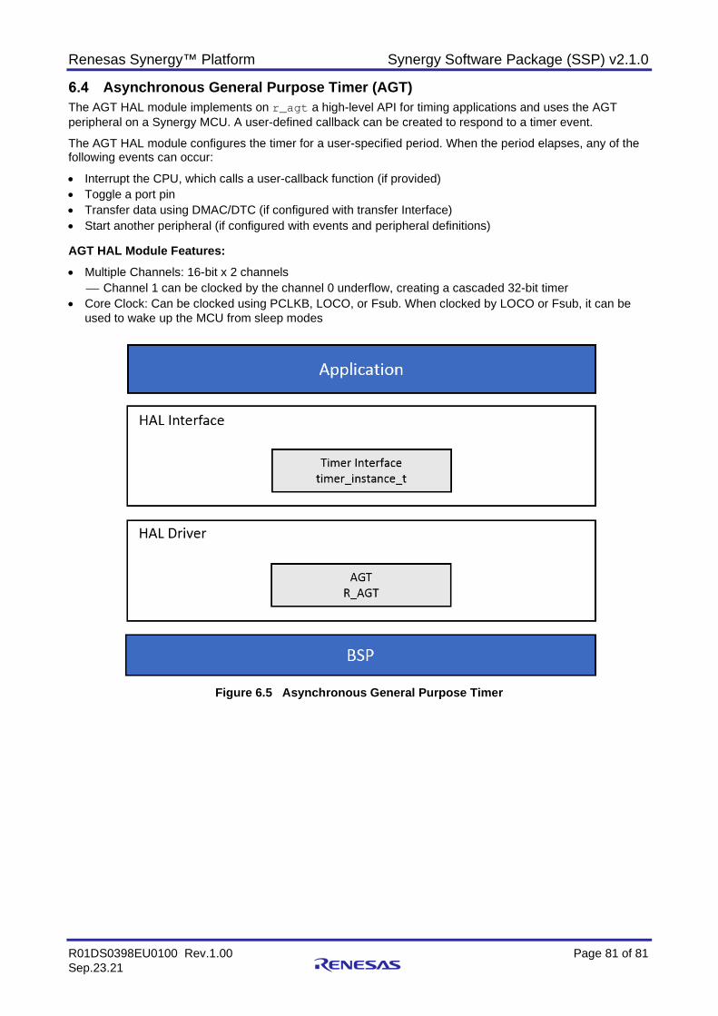
Renesas Synergy™ Platform Synergy Software Package (SSP) v2.1.0
R01DS0398EU0100 Rev.1.00 Page 81 of 81 Sep.23.21
Asynchronous General Purpose Timer (AGT) The AGT HAL module implements on r_agt a high-level API for timing applications and uses the AGT peripheral on a Synergy MCU. A user-defined callback can be created to respond to a timer event.
The AGT HAL module configures the timer for a user-specified period. When the period elapses, any of the following events can occur:
• Interrupt the CPU, which calls a user-callback function (if provided) • Toggle a port pin • Transfer data using DMAC/DTC (if configured with transfer Interface) • Start another peripheral (if configured with events and peripheral definitions) AGT HAL Module Features: • Multiple Channels: 16-bit x 2 channels
Channel 1 can be clocked by the channel 0 underflow, creating a cascaded 32-bit timer • Core Clock: Can be clocked using PCLKB, LOCO, or Fsub. When clocked by LOCO or Fsub, it can be
used to wake up the MCU from sleep modes
Figure 6.5 Asynchronous General Purpose Timer
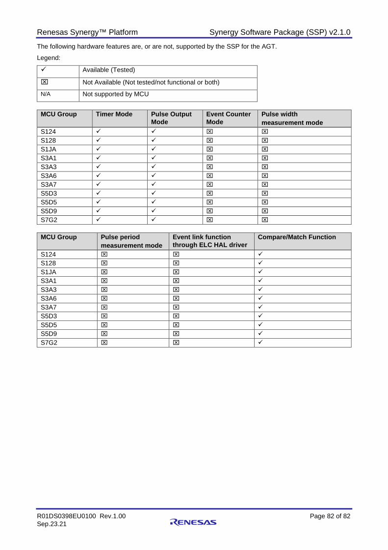
Renesas Synergy™ Platform Synergy Software Package (SSP) v2.1.0
R01DS0398EU0100 Rev.1.00 Page 82 of 82 Sep.23.21
The following hardware features are, or are not, supported by the SSP for the AGT.
Legend:
Available (Tested)
Not Available (Not tested/not functional or both)
N/A Not supported by MCU
MCU Group Timer Mode Pulse Output
Mode Event Counter Mode
Pulse width measurement mode
S124 S128 S1JA S3A1 S3A3 S3A6 S3A7 S5D3 S5D5 S5D9 S7G2
MCU Group Pulse period
measurement mode Event link function through ELC HAL driver
Compare/Match Function
S124 S128 S1JA S3A1 S3A3 S3A6 S3A7 S5D3 S5D5 S5D9 S7G2
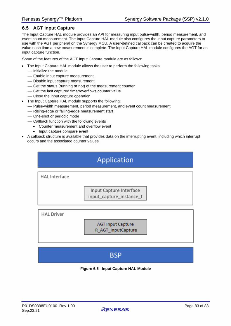
Renesas Synergy™ Platform Synergy Software Package (SSP) v2.1.0
R01DS0398EU0100 Rev.1.00 Page 83 of 83 Sep.23.21
AGT Input Capture The Input Capture HAL module provides an API for measuring input pulse-width, period measurement, and event count measurement. The Input Capture HAL module also configures the input capture parameters to use with the AGT peripheral on the Synergy MCU. A user-defined callback can be created to acquire the value each time a new measurement is complete. The Input Capture HAL module configures the AGT for an input capture function.
Some of the features of the AGT Input Capture module are as follows:
• The Input Capture HAL module allows the user to perform the following tasks: Initialize the module Enable input capture measurement Disable input capture measurement Get the status (running or not) of the measurement counter Get the last captured timer/overflows counter value Close the input capture operation
• The Input Capture HAL module supports the following: Pulse-width measurement, period measurement, and event count measurement Rising-edge or falling-edge measurement start One-shot or periodic mode Callback function with the following events
• Counter measurement and overflow event • Input capture compare event
• A callback structure is available that provides data on the interrupting event, including which interrupt occurs and the associated counter values
Figure 6.6 Input Capture HAL Module
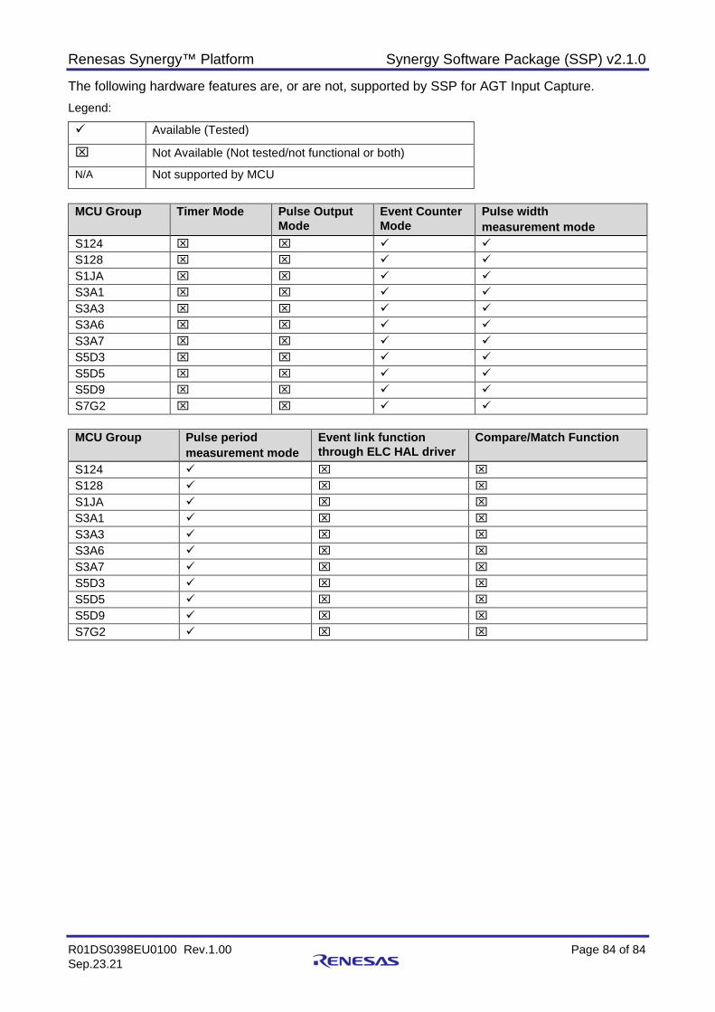
Renesas Synergy™ Platform Synergy Software Package (SSP) v2.1.0
R01DS0398EU0100 Rev.1.00 Page 84 of 84 Sep.23.21
The following hardware features are, or are not, supported by SSP for AGT Input Capture. Legend:
Available (Tested)
Not Available (Not tested/not functional or both)
N/A Not supported by MCU
MCU Group Timer Mode Pulse Output
Mode Event Counter Mode
Pulse width measurement mode
S124 S128 S1JA S3A1 S3A3 S3A6 S3A7 S5D3 S5D5 S5D9 S7G2
MCU Group Pulse period
measurement mode Event link function through ELC HAL driver
Compare/Match Function
S124 S128 S1JA S3A1 S3A3 S3A6 S3A7 S5D3 S5D5 S5D9 S7G2

Renesas Synergy™ Platform Synergy Software Package (SSP) v2.1.0
R01DS0398EU0100 Rev.1.00 Page 85 of 85 Sep.23.21
Analog Connection Module (ACM) The Analog Connection HAL module implements the analog connect API on r_analog_connect to simplify the connection of internal analog connections on Synergy MCUs. It also handles the hardware procedures and timing requirements required to make internal connections.
The Analog Connection module supports the OPAMP (operational amplifier), ACMPHS (high speed analog comparator), and ACMPLP (low power analog comparator) peripherals, and their allowed interconnections to the DAC (digital to analog converter) and ADC (analog to digital converter) on a particular Synergy MCU. For example, on most MCUs, the comparator reference voltage can be connected internally to a DAC output without using any pins. A list of available connections can be seen in the Synergy Configuration tool.
Figure 6.7 Analog Connect HAL Module
Renesas Synergy™ Platform Synergy Software Package (SSP) v2.1.0
R01DS0398EU0100 Rev.1.00 Page 86 of 86 Sep.23.21
Clock Frequency Accuracy Measurement (CAC) The CAC HAL module provides a high-level API for clock accuracy-control applications and is implemented on r_cac. The module uses the Clock Frequency Accuracy Measurement Circuit (CAC) peripheral on the Synergy MCU, which is useful in implementing a fail-safe mechanism for reliability-oriented applications. A user-defined callback can be created to respond to various error indications.
CAC HAL Module Features:
• The CAC HAL module API interfaces with a clock frequency-measurement circuit capable of monitoring the clock frequency based on a reference-signal input.
The frequency of the following clocks can be measured:
− Clock output from main clock oscillator (main clock) − Clock output from sub-clock oscillator (sub-clock) − Clock output from high-speed on-chip oscillator (HOCO clock) − Clock output from low-speed on-chip oscillator (LOCO clock) − Clock output from mid-speed on-chip oscillator (MOCO clock) − Clock output from IWDT-dedicated on-chip oscillator (IWDTCLK clock) − Peripheral module clock (PCLKB)
• The measurement clock is monitored using a reference clock. The reference clock may be an external clock, supplied on the CACREF input pin, or one of the following internal clocks:.
− Clock output from main clock oscillator (main clock)
− Clock output from sub-clock oscillator (sub-clock) − Clock output from high-speed on-chip oscillator (HOCO clock) − Clock output from mid-speed on-chip oscillator (MOCO clock) − Clock output from low-speed on-chip oscillator (LOCO clock) − Clock output from IWDT-dedicated on-chip oscillator (IWDTCLK clock) − Peripheral module clock (PCLKB)
• An interrupt request may optionally be generated by a completed measurement, a detected frequency error, or a counter overflow.
• A digital filter is available for an externally supplied reference clock, and dividers are available for both internally supplied measurement and reference clocks.
• Edge-detection options for the reference clock are configurable as rising, falling, or both.
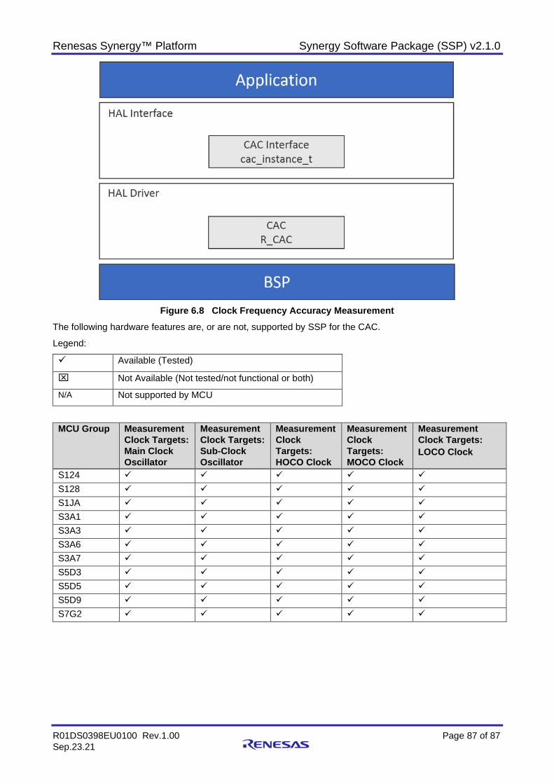
Renesas Synergy™ Platform Synergy Software Package (SSP) v2.1.0
R01DS0398EU0100 Rev.1.00 Page 87 of 87 Sep.23.21
Figure 6.8 Clock Frequency Accuracy Measurement
The following hardware features are, or are not, supported by SSP for the CAC.
Legend:
Available (Tested)
Not Available (Not tested/not functional or both)
N/A Not supported by MCU
MCU Group Measurement Clock Targets: Main Clock Oscillator
Measurement Clock Targets: Sub-Clock Oscillator
Measurement Clock Targets: HOCO Clock
Measurement Clock Targets: MOCO Clock
Measurement Clock Targets: LOCO Clock
S124
S128
S1JA
S3A1
S3A3
S3A6
S3A7
S5D3
S5D5
S5D9
S7G2
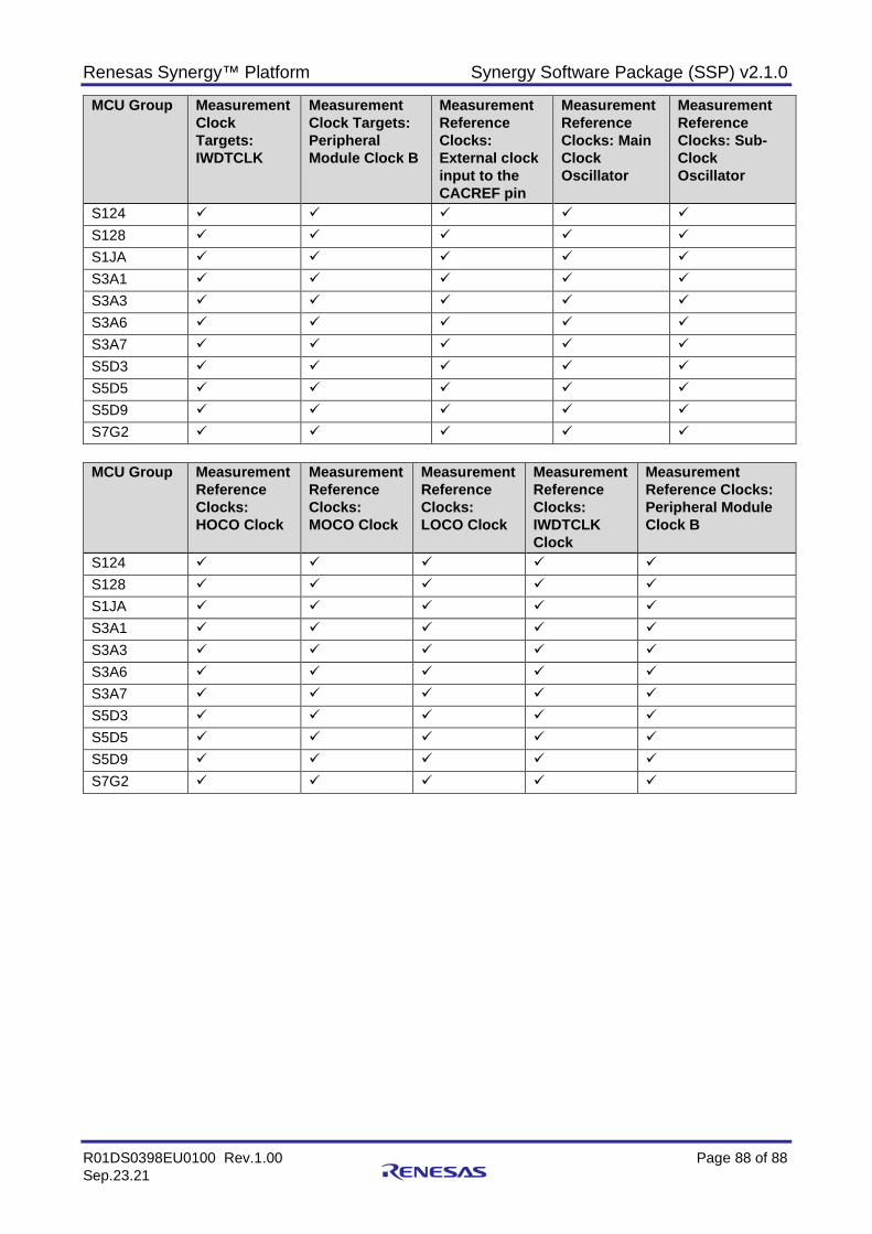
Renesas Synergy™ Platform Synergy Software Package (SSP) v2.1.0
R01DS0398EU0100 Rev.1.00 Page 88 of 88 Sep.23.21
MCU Group Measurement Clock Targets: IWDTCLK
Measurement Clock Targets: Peripheral Module Clock B
Measurement Reference Clocks: External clock input to the CACREF pin
Measurement Reference Clocks: Main Clock Oscillator
Measurement Reference Clocks: Sub-Clock Oscillator
S124
S128
S1JA
S3A1
S3A3
S3A6
S3A7
S5D3
S5D5
S5D9
S7G2
MCU Group Measurement
Reference Clocks: HOCO Clock
Measurement Reference Clocks: MOCO Clock
Measurement Reference Clocks: LOCO Clock
Measurement Reference Clocks: IWDTCLK Clock
Measurement Reference Clocks: Peripheral Module Clock B
S124
S128
S1JA
S3A1
S3A3
S3A6
S3A7
S5D3
S5D5
S5D9
S7G2

Renesas Synergy™ Platform Synergy Software Package (SSP) v2.1.0
R01DS0398EU0100 Rev.1.00 Page 89 of 89 Sep.23.21
MCU Group Selectable Function: Digital Filter
Interrupt Sources: Measurement End
Interrupt Sources: Frequency Error
Interrupt Sources: Overflow
Module-stop function to reduce power consumption
S124
S128
S1JA
S3A1
S3A3
S3A6
S3A7
S5D3
S5D5
S5D9
S7G2
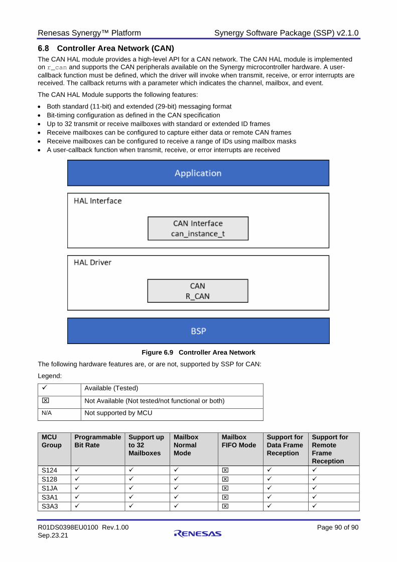
Renesas Synergy™ Platform Synergy Software Package (SSP) v2.1.0
R01DS0398EU0100 Rev.1.00 Page 90 of 90 Sep.23.21
Controller Area Network (CAN) The CAN HAL module provides a high-level API for a CAN network. The CAN HAL module is implemented on r_can and supports the CAN peripherals available on the Synergy microcontroller hardware. A user-callback function must be defined, which the driver will invoke when transmit, receive, or error interrupts are received. The callback returns with a parameter which indicates the channel, mailbox, and event.
The CAN HAL Module supports the following features:
• Both standard (11-bit) and extended (29-bit) messaging format • Bit-timing configuration as defined in the CAN specification • Up to 32 transmit or receive mailboxes with standard or extended ID frames • Receive mailboxes can be configured to capture either data or remote CAN frames • Receive mailboxes can be configured to receive a range of IDs using mailbox masks • A user-callback function when transmit, receive, or error interrupts are received
Figure 6.9 Controller Area Network
The following hardware features are, or are not, supported by SSP for CAN:
Legend:
Available (Tested)
Not Available (Not tested/not functional or both)
N/A Not supported by MCU
MCU Group
Programmable Bit Rate
Support up to 32 Mailboxes
Mailbox Normal Mode
Mailbox FIFO Mode
Support for Data Frame Reception
Support for Remote Frame Reception
S124 S128 S1JA S3A1 S3A3
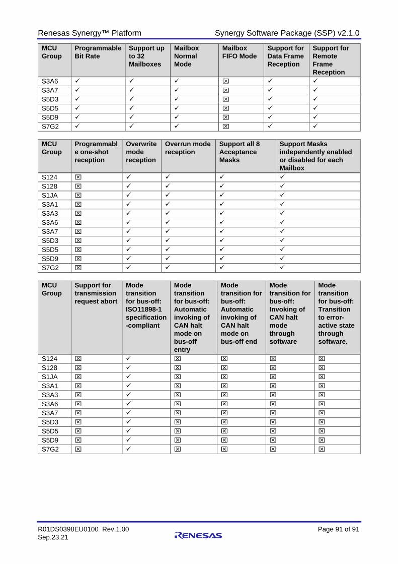
Renesas Synergy™ Platform Synergy Software Package (SSP) v2.1.0
R01DS0398EU0100 Rev.1.00 Page 91 of 91 Sep.23.21
MCU Group
Programmable Bit Rate
Support up to 32 Mailboxes
Mailbox Normal Mode
Mailbox FIFO Mode
Support for Data Frame Reception
Support for Remote Frame Reception
S3A6 S3A7 S5D3 S5D5 S5D9 S7G2
MCU Group
Programmable one-shot reception
Overwrite mode reception
Overrun mode reception
Support all 8 Acceptance Masks
Support Masks independently enabled or disabled for each Mailbox
S124 S128 S1JA S3A1 S3A3 S3A6 S3A7 S5D3 S5D5 S5D9 S7G2
MCU Group
Support for transmission request abort
Mode transition for bus-off: ISO11898-1 specification-compliant
Mode transition for bus-off: Automatic invoking of CAN halt mode on bus-off entry
Mode transition for bus-off: Automatic invoking of CAN halt mode on bus-off end
Mode transition for bus-off: Invoking of CAN halt mode through software
Mode transition for bus-off: Transition to error-active state through software.
S124 S128 S1JA S3A1 S3A3 S3A6 S3A7 S5D3 S5D5 S5D9 S7G2

Renesas Synergy™ Platform Synergy Software Package (SSP) v2.1.0
R01DS0398EU0100 Rev.1.00 Page 92 of 92 Sep.23.21
MCU Group
Monitoring of all CAN bus errors {Stuff, Form, ACK, 15-bit CRC, Bit error, ACK Delimiter}
Detection of all transition to error states {error-warning, error-passive, bus-off entry, and bus-off Recovery}
Support Interrupt Sources {Receive FIFO, Transmit FIFO }
Support Interrupt Sources {Reception complete. Transmission complete, Error interrupts}
Support CAN sleep mode 1 {stop CAN clock}
Support all 3 software units {Acceptance filter support, Mailbox search support, including receive mailbox search, transmit mailbox search, and message lost Search, Channel search support}
S124 S128 S1JA S3A1 S3A3 S3A6 S3A7 S5D3 S5D5 S5D9 S7G2
MCU Group
CAN Source Clock: PCLKB
CAN Source Clock: CANMCLK
Support all 3 Test Modes {Listen-only, Self-Test 1 (external loopback), Self-Test 2 (internal loopback)}
Module-stop Function
Support Standard CAN (11 bit)
Support Extended CAN (29 bit)
S124 N/A S128 N/A S1JA N/A S3A1 S3A3 S3A6 S3A7 S5D3 S5D5 S5D9 S7G2
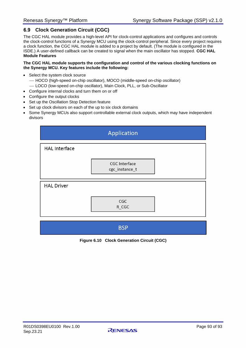
Renesas Synergy™ Platform Synergy Software Package (SSP) v2.1.0
R01DS0398EU0100 Rev.1.00 Page 93 of 93 Sep.23.21
Clock Generation Circuit (CGC) The CGC HAL module provides a high-level API for clock-control applications and configures and controls the clock-control functions of a Synergy MCU using the clock-control peripheral. Since every project requires a clock function, the CGC HAL module is added to a project by default. (The module is configured in the ISDE.) A user-defined callback can be created to signal when the main oscillator has stopped. CGC HAL Module Features The CGC HAL module supports the configuration and control of the various clocking functions on the Synergy MCU. Key features include the following: • Select the system clock source
HOCO (high-speed on-chip oscillator), MOCO (middle-speed on-chip oscillator) LOCO (low-speed on-chip oscillator), Main Clock, PLL, or Sub-Oscillator
• Configure internal clocks and turn them on or off • Configure the output clocks • Set up the Oscillation Stop Detection feature • Set up clock divisors on each of the up to six clock domains • Some Synergy MCUs also support controllable external clock outputs, which may have independent
divisors
Figure 6.10 Clock Generation Circuit (CGC)
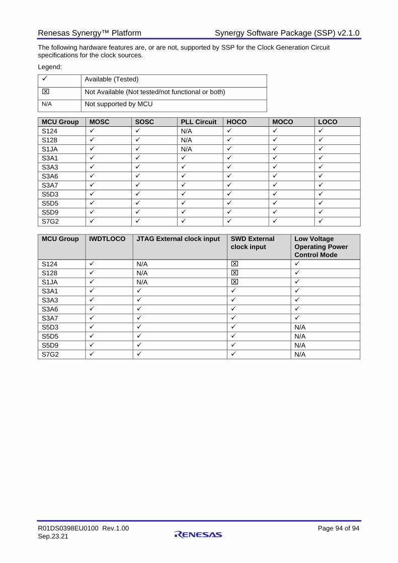
Renesas Synergy™ Platform Synergy Software Package (SSP) v2.1.0
R01DS0398EU0100 Rev.1.00 Page 94 of 94 Sep.23.21
The following hardware features are, or are not, supported by SSP for the Clock Generation Circuit specifications for the clock sources.
Legend:
Available (Tested)
Not Available (Not tested/not functional or both)
N/A Not supported by MCU
MCU Group MOSC SOSC PLL Circuit HOCO MOCO LOCO S124 N/A S128 N/A S1JA N/A S3A1 S3A3 S3A6 S3A7 S5D3 S5D5 S5D9 S7G2
MCU Group IWDTLOCO JTAG External clock input SWD External
clock input Low Voltage Operating Power Control Mode
S124 N/A S128 N/A S1JA N/A S3A1 S3A3 S3A6 S3A7 S5D3 N/A S5D5 N/A S5D9 N/A S7G2 N/A
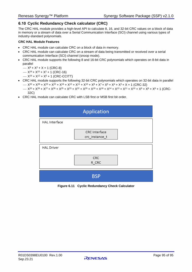
Renesas Synergy™ Platform Synergy Software Package (SSP) v2.1.0
R01DS0398EU0100 Rev.1.00 Page 95 of 95 Sep.23.21
Cyclic Redundancy Check calculator (CRC) The CRC HAL module provides a high-level API to calculate 8, 16, and 32-bit CRC values on a block of data in memory or a stream of data over a Serial Communication Interface (SCI) channel using various types of industry-standard polynomials.
CRC HAL Module Features • CRC HAL module can calculate CRC on a block of data in memory. • CRC HAL module can calculate CRC on a stream of data being transmitted or received over a serial
communication Interface (SCI) channel (snoop mode). • CRC HAL module supports the following 8 and 16-bit CRC polynomials which operates on 8-bit data in
parallel X8 + X2 + X + 1 (CRC-8) X16 + X15 + X2 + 1 (CRC-16) X16 + X12 + X5 + 1 (CRC-CCITT)
• CRC HAL module supports the following 32-bit CRC polynomials which operates on 32-bit data in parallel X32 + X26 + X23 + X22 + X16 + X12 + X11 + X10 + X8 + X7 + X5 + X4 + X2 + X + 1 (CRC-32) X32 + X28 + X27 + X26 + X25 + X23 + X22 + X20 + X19 + X18 + X14 + X13 + X11 + X10 + X9 + X8 + X6 + 1 (CRC-
32C) • CRC HAL module can calculate CRC with LSB first or MSB first bit order.
Figure 6.11 Cyclic Redundancy Check Calculator
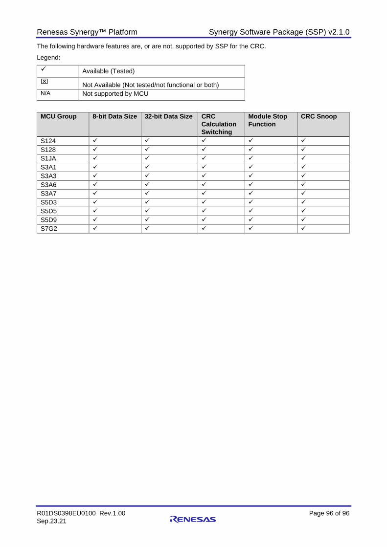
Renesas Synergy™ Platform Synergy Software Package (SSP) v2.1.0
R01DS0398EU0100 Rev.1.00 Page 96 of 96 Sep.23.21
The following hardware features are, or are not, supported by SSP for the CRC.
Legend:
Available (Tested) Not Available (Not tested/not functional or both) N/A Not supported by MCU
MCU Group 8-bit Data Size 32-bit Data Size CRC Calculation Switching
Module Stop Function
CRC Snoop
S124 S128 S1JA S3A1 S3A3 S3A6 S3A7 S5D3 S5D5 S5D9 S7G2
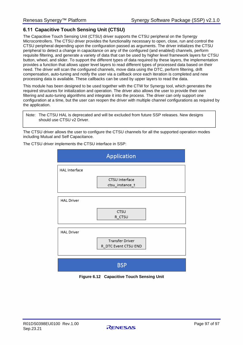
Renesas Synergy™ Platform Synergy Software Package (SSP) v2.1.0
R01DS0398EU0100 Rev.1.00 Page 97 of 97 Sep.23.21
Capacitive Touch Sensing Unit (CTSU) The Capacitive Touch Sensing Unit (CTSU) driver supports the CTSU peripheral on the Synergy Microcontrollers. The CTSU driver provides the functionality necessary to open, close, run and control the CTSU peripheral depending upon the configuration passed as arguments. The driver initializes the CTSU peripheral to detect a change in capacitance on any of the configured (and enabled) channels, perform requisite filtering, and generate a variety of data that can be used by higher level framework layers for CTSU button, wheel, and slider. To support the different types of data required by these layers, the implementation provides a function that allows upper level layers to read different types of processed data based on their need. The driver will scan the configured channels, move data using the DTC, perform filtering, drift compensation, auto-tuning and notify the user via a callback once each iteration is completed and new processing data is available. These callbacks can be used by upper layers to read the data.
This module has been designed to be used together with the CTW for Synergy tool, which generates the required structures for initialization and operation. The driver also allows the user to provide their own filtering and auto-tuning algorithms and integrate it into the process. The driver can only support one configuration at a time, but the user can reopen the driver with multiple channel configurations as required by the application.
The CTSU driver allows the user to configure the CTSU channels for all the supported operation modes including Mutual and Self Capacitance.
The CTSU driver implements the CTSU interface in SSP:
Figure 6.12 Capacitive Touch Sensing Unit
Note: The CTSU HAL is deprecated and will be excluded from future SSP releases. New designs should use CTSU v2 Driver.
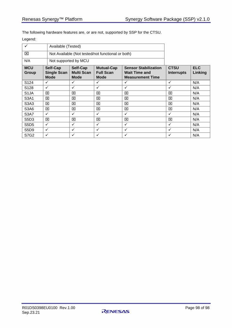
Renesas Synergy™ Platform Synergy Software Package (SSP) v2.1.0
R01DS0398EU0100 Rev.1.00 Page 98 of 98 Sep.23.21
The following hardware features are, or are not, supported by SSP for the CTSU.
Legend:
Available (Tested)
Not Available (Not tested/not functional or both)
N/A Not supported by MCU
MCU Group
Self-Cap Single Scan Mode
Self-Cap Multi Scan Mode
Mutual-Cap Full Scan Mode
Sensor Stabilization Wait Time and Measurement Time
CTSU Interrupts
ELC Linking
S124 N/A S128 N/A S1JA N/A S3A1 N/A S3A3 N/A S3A6 N/A S3A7 N/A S5D3 N/A S5D5 N/A S5D9 N/A S7G2 N/A
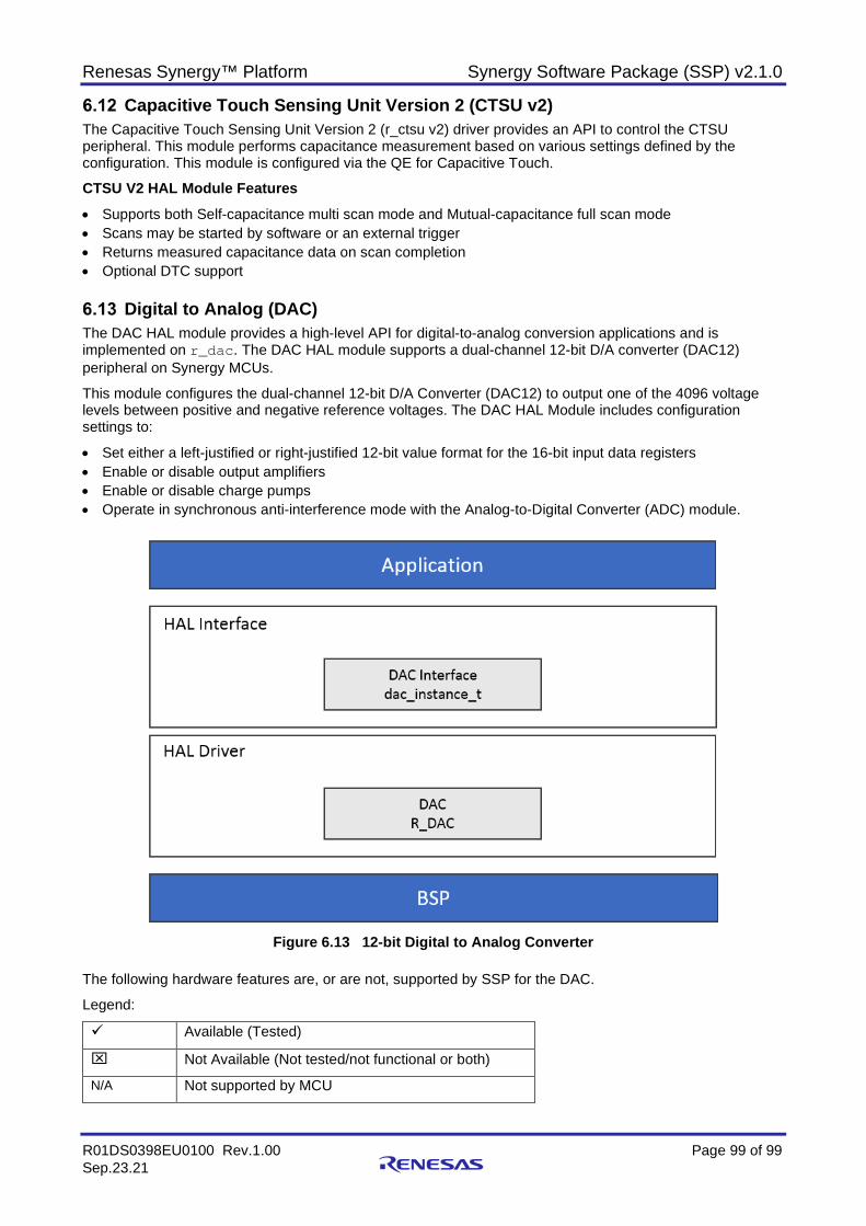
Renesas Synergy™ Platform Synergy Software Package (SSP) v2.1.0
R01DS0398EU0100 Rev.1.00 Page 99 of 99 Sep.23.21
Capacitive Touch Sensing Unit Version 2 (CTSU v2) The Capacitive Touch Sensing Unit Version 2 (r_ctsu v2) driver provides an API to control the CTSU peripheral. This module performs capacitance measurement based on various settings defined by the configuration. This module is configured via the QE for Capacitive Touch.
CTSU V2 HAL Module Features • Supports both Self-capacitance multi scan mode and Mutual-capacitance full scan mode • Scans may be started by software or an external trigger • Returns measured capacitance data on scan completion • Optional DTC support
Digital to Analog (DAC) The DAC HAL module provides a high-level API for digital-to-analog conversion applications and is implemented on r_dac. The DAC HAL module supports a dual-channel 12-bit D/A converter (DAC12) peripheral on Synergy MCUs.
This module configures the dual-channel 12-bit D/A Converter (DAC12) to output one of the 4096 voltage levels between positive and negative reference voltages. The DAC HAL Module includes configuration settings to:
• Set either a left-justified or right-justified 12-bit value format for the 16-bit input data registers • Enable or disable output amplifiers • Enable or disable charge pumps • Operate in synchronous anti-interference mode with the Analog-to-Digital Converter (ADC) module.
Figure 6.13 12-bit Digital to Analog Converter
The following hardware features are, or are not, supported by SSP for the DAC.
Legend:
Available (Tested)
Not Available (Not tested/not functional or both)
N/A Not supported by MCU
Renesas Synergy™ Platform Synergy Software Package (SSP) v2.1.0
R01DS0398EU0100 Rev.1.00 Page 100 of 100 Sep.23.21
MCU Group 12-Bit 2 Channels Output
Module Stop Function
Event link function through ELC HAL driver *
S124 N/A S128 N/A N/A N/A S1JA N/A S3A1 N/A S3A3 N/A S3A6 N/A S3A7 S5D3 S5D5 S5D9 S7G2
* Note: The ELC event could be used instead of calling the DAC start() interface. This would have to be programmed by the user by setting up the link rather than using the ELC API.
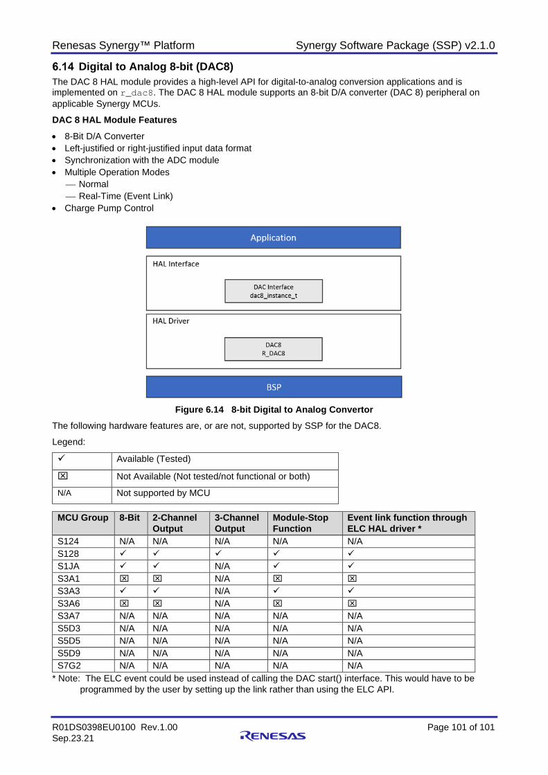
Renesas Synergy™ Platform Synergy Software Package (SSP) v2.1.0
R01DS0398EU0100 Rev.1.00 Page 101 of 101 Sep.23.21
Digital to Analog 8-bit (DAC8) The DAC 8 HAL module provides a high-level API for digital-to-analog conversion applications and is implemented on r_dac8. The DAC 8 HAL module supports an 8-bit D/A converter (DAC 8) peripheral on applicable Synergy MCUs.
DAC 8 HAL Module Features • 8-Bit D/A Converter • Left-justified or right-justified input data format • Synchronization with the ADC module • Multiple Operation Modes
Normal Real-Time (Event Link)
• Charge Pump Control
Figure 6.14 8-bit Digital to Analog Convertor
The following hardware features are, or are not, supported by SSP for the DAC8.
Legend:
Available (Tested)
Not Available (Not tested/not functional or both)
N/A Not supported by MCU
MCU Group 8-Bit 2-Channel Output
3-Channel Output
Module-Stop Function
Event link function through ELC HAL driver *
S124 N/A N/A N/A N/A N/A S128 S1JA N/A S3A1 N/A S3A3 N/A S3A6 N/A S3A7 N/A N/A N/A N/A N/A S5D3 N/A N/A N/A N/A N/A S5D5 N/A N/A N/A N/A N/A S5D9 N/A N/A N/A N/A N/A S7G2 N/A N/A N/A N/A N/A
* Note: The ELC event could be used instead of calling the DAC start() interface. This would have to be programmed by the user by setting up the link rather than using the ELC API.
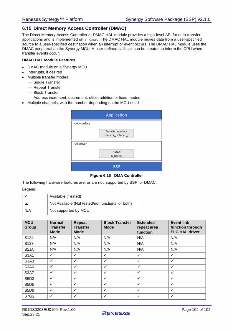
Renesas Synergy™ Platform Synergy Software Package (SSP) v2.1.0
R01DS0398EU0100 Rev.1.00 Page 102 of 102 Sep.23.21
Direct Memory Access Controller (DMAC) The Direct Memory Access Controller or DMAC HAL module provides a high-level API for data-transfer applications and is implemented on r_dmac. The DMAC HAL module moves data from a user-specified source to a user-specified destination when an interrupt or event occurs. The DMAC HAL module uses the DMAC peripheral on the Synergy MCU. A user-defined callback can be created to inform the CPU when transfer events occur.
DMAC HAL Module Features • DMAC module on a Synergy MCU • Interrupts, if desired • Multiple transfer modes
Single Transfer Repeat Transfer Block Transfer Address increment, decrement, offset addition or fixed modes
• Multiple channels, with the number depending on the MCU used
Figure 6.15 DMA Controller
The following hardware features are, or are not, supported by SSP for DMAC.
Legend:
Available (Tested)
Not Available (Not tested/not functional or both)
N/A Not supported by MCU
MCU Group
Normal Transfer Mode
Repeat Transfer Mode
Block Transfer Mode
Extended repeat area function
Event link function through ELC HAL driver
S124 N/A N/A N/A N/A N/A S128 N/A N/A N/A N/A N/A S1JA N/A N/A N/A N/A N/A S3A1 S3A3 S3A6
S3A7
S5D3
S5D5
S5D9
S7G2
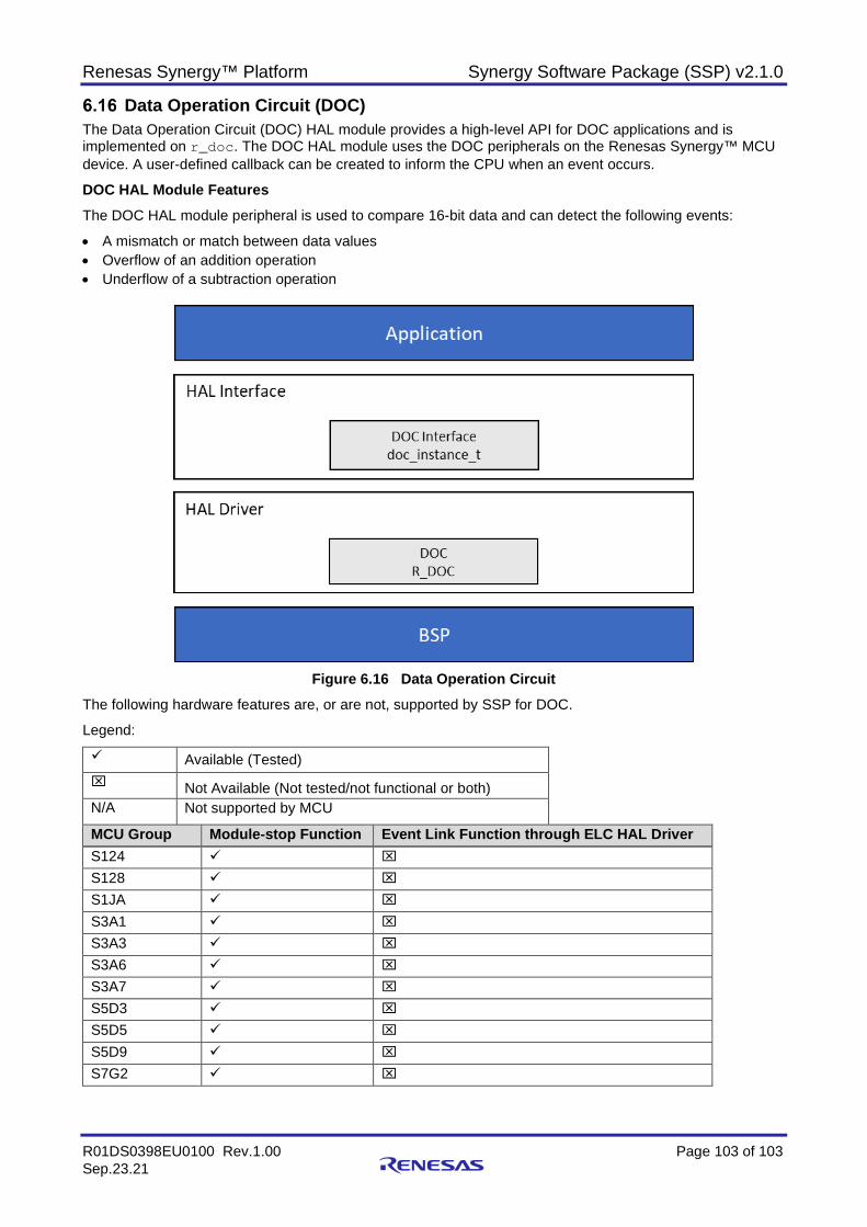
Renesas Synergy™ Platform Synergy Software Package (SSP) v2.1.0
R01DS0398EU0100 Rev.1.00 Page 103 of 103 Sep.23.21
Data Operation Circuit (DOC) The Data Operation Circuit (DOC) HAL module provides a high-level API for DOC applications and is implemented on r_doc. The DOC HAL module uses the DOC peripherals on the Renesas Synergy™ MCU device. A user-defined callback can be created to inform the CPU when an event occurs.
DOC HAL Module Features The DOC HAL module peripheral is used to compare 16-bit data and can detect the following events:
• A mismatch or match between data values • Overflow of an addition operation • Underflow of a subtraction operation
Figure 6.16 Data Operation Circuit
The following hardware features are, or are not, supported by SSP for DOC.
Legend:
Available (Tested) Not Available (Not tested/not functional or both) N/A Not supported by MCU
MCU Group Module-stop Function Event Link Function through ELC HAL Driver S124 S128 S1JA
S3A1
S3A3
S3A6 S3A7 S5D3
S5D5 S5D9 S7G2
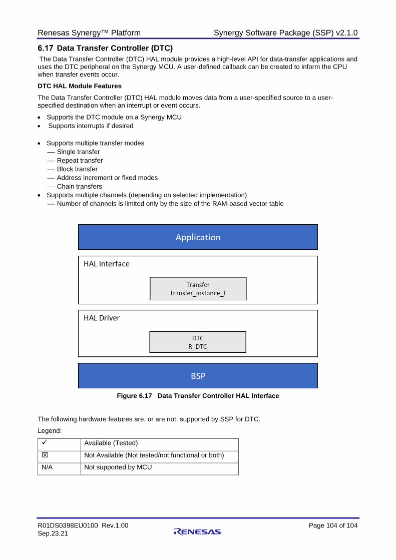
Renesas Synergy™ Platform Synergy Software Package (SSP) v2.1.0
R01DS0398EU0100 Rev.1.00 Page 104 of 104 Sep.23.21
Data Transfer Controller (DTC) The Data Transfer Controller (DTC) HAL module provides a high-level API for data-transfer applications and uses the DTC peripheral on the Synergy MCU. A user-defined callback can be created to inform the CPU when transfer events occur.
DTC HAL Module Features The Data Transfer Controller (DTC) HAL module moves data from a user-specified source to a user-specified destination when an interrupt or event occurs.
• Supports the DTC module on a Synergy MCU • Supports interrupts if desired • Supports multiple transfer modes
Single transfer Repeat transfer Block transfer Address increment or fixed modes Chain transfers
• Supports multiple channels (depending on selected implementation) Number of channels is limited only by the size of the RAM-based vector table
Figure 6.17 Data Transfer Controller HAL Interface
The following hardware features are, or are not, supported by SSP for DTC.
Legend:
Available (Tested)
Not Available (Not tested/not functional or both)
N/A Not supported by MCU
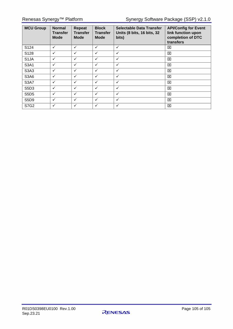
Renesas Synergy™ Platform Synergy Software Package (SSP) v2.1.0
R01DS0398EU0100 Rev.1.00 Page 105 of 105 Sep.23.21
MCU Group Normal Transfer Mode
Repeat Transfer Mode
Block Transfer Mode
Selectable Data Transfer Units (8 bits, 16 bits, 32 bits)
API/Config for Event link function upon completion of DTC transfers
S124
S128
S1JA
S3A1
S3A3
S3A6
S3A7
S5D3
S5D5
S5D9
S7G2
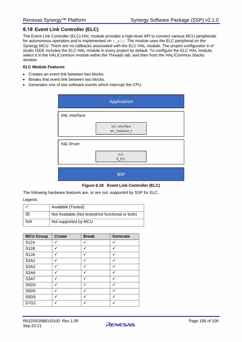
Renesas Synergy™ Platform Synergy Software Package (SSP) v2.1.0
R01DS0398EU0100 Rev.1.00 Page 106 of 106 Sep.23.21
Event Link Controller (ELC) The Event Link Controller (ELC) HAL module provides a high-level API to connect various MCU peripherals for autonomous operation and is implemented on r_elc. The module uses the ELC peripheral on the Synergy MCU. There are no callbacks associated with the ELC HAL module. The project configurator in e2 studio ISDE includes the ELC HAL module in every project by default. To configure the ELC HAL module, select it in the HAL/Common module within the Threads tab, and then from the HAL/Common Stacks window.
ELC Module Features • Creates an event link between two blocks. • Breaks that event link between two blocks. • Generates one of two software events which interrupt the CPU.
Figure 6.18 Event Link Controller (ELC)
The following hardware features are, or are not, supported by SSP for ELC.
Legend:
Available (Tested)
Not Available (Not tested/not functional or both)
N/A Not supported by MCU
MCU Group Create Break Generate S124 S128 S1JA
S3A1
S3A3
S3A6 S3A7 S5D3
S5D5 S5D9 S7G2
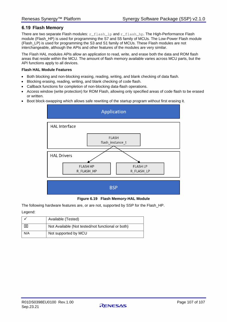
Renesas Synergy™ Platform Synergy Software Package (SSP) v2.1.0
R01DS0398EU0100 Rev.1.00 Page 107 of 107 Sep.23.21
Flash Memory There are two separate Flash modules: r_flash_lp and r_flash_hp. The High-Performance Flash module (Flash_HP) is used for programming the S7 and S5 family of MCUs. The Low-Power Flash module (Flash_LP) is used for programming the S3 and S1 family of MCUs. These Flash modules are not interchangeable, although the APIs and other features of the modules are very similar.
The Flash HAL modules APIs allow an application to read, write, and erase both the data and ROM flash areas that reside within the MCU. The amount of flash memory available varies across MCU parts, but the API functions apply to all devices.
Flash HAL Module Features • Both blocking and non-blocking erasing, reading, writing, and blank checking of data flash. • Blocking erasing, reading, writing, and blank checking of code flash. • Callback functions for completion of non-blocking data-flash operations. • Access window (write protection) for ROM Flash, allowing only specified areas of code flash to be erased
or written. • Boot block-swapping which allows safe rewriting of the startup program without first erasing it.
Figure 6.19 Flash Memory-HAL Module
The following hardware features are, or are not, supported by SSP for the Flash_HP.
Legend:
Available (Tested)
Not Available (Not tested/not functional or both)
N/A Not supported by MCU
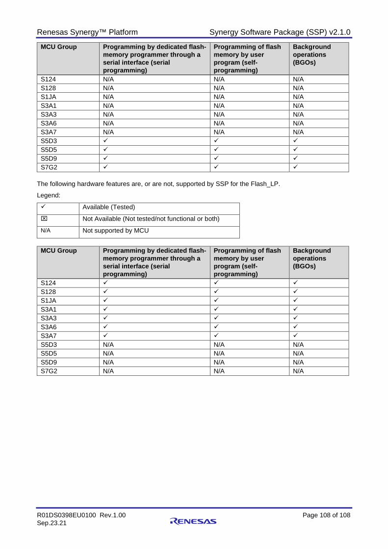
Renesas Synergy™ Platform Synergy Software Package (SSP) v2.1.0
R01DS0398EU0100 Rev.1.00 Page 108 of 108 Sep.23.21
MCU Group Programming by dedicated flash-memory programmer through a serial interface (serial programming)
Programming of flash memory by user program (self-programming)
Background operations (BGOs)
S124 N/A N/A N/A S128 N/A N/A N/A S1JA N/A N/A N/A S3A1 N/A N/A N/A S3A3 N/A N/A N/A S3A6 N/A N/A N/A S3A7 N/A N/A N/A S5D3 S5D5 S5D9 S7G2
The following hardware features are, or are not, supported by SSP for the Flash_LP.
Legend:
Available (Tested)
Not Available (Not tested/not functional or both)
N/A Not supported by MCU
MCU Group Programming by dedicated flash-
memory programmer through a serial interface (serial programming)
Programming of flash memory by user program (self-programming)
Background operations (BGOs)
S124 S128 S1JA S3A1 S3A3 S3A6 S3A7 S5D3 N/A N/A N/A S5D5 N/A N/A N/A S5D9 N/A N/A N/A S7G2 N/A N/A N/A
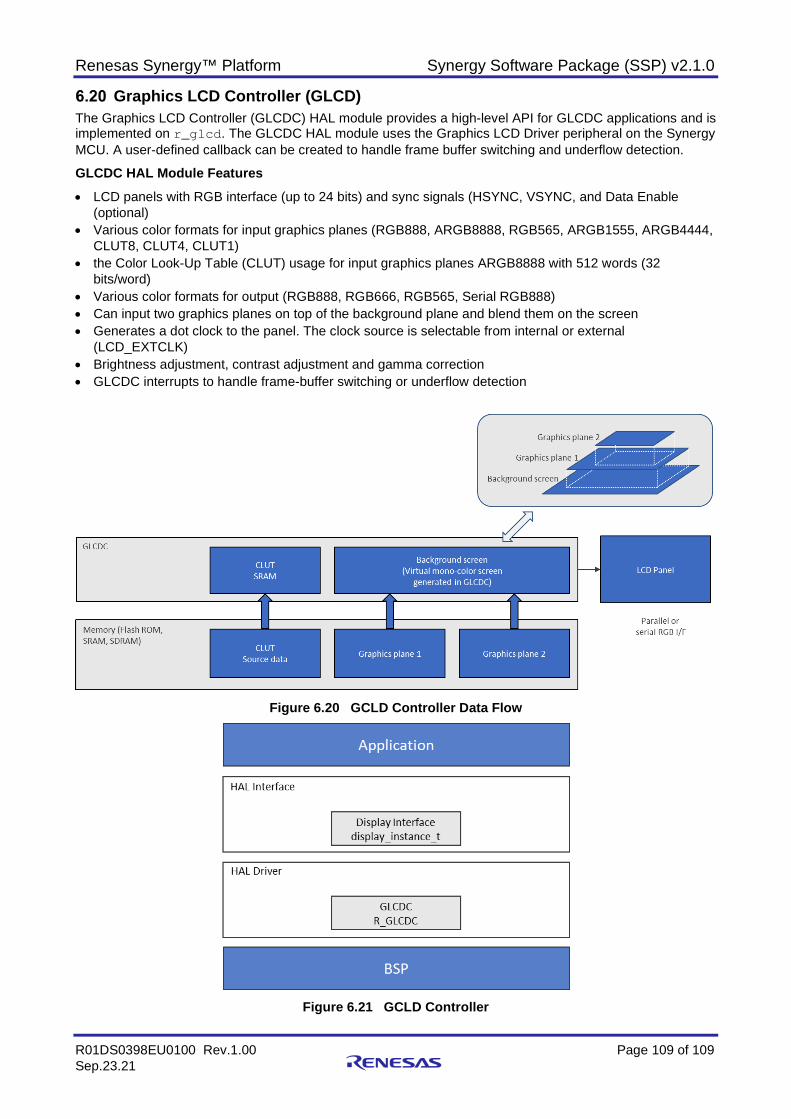
Renesas Synergy™ Platform Synergy Software Package (SSP) v2.1.0
R01DS0398EU0100 Rev.1.00 Page 109 of 109 Sep.23.21
Graphics LCD Controller (GLCD) The Graphics LCD Controller (GLCDC) HAL module provides a high-level API for GLCDC applications and is implemented on r_glcd. The GLCDC HAL module uses the Graphics LCD Driver peripheral on the Synergy MCU. A user-defined callback can be created to handle frame buffer switching and underflow detection.
GLCDC HAL Module Features • LCD panels with RGB interface (up to 24 bits) and sync signals (HSYNC, VSYNC, and Data Enable
(optional) • Various color formats for input graphics planes (RGB888, ARGB8888, RGB565, ARGB1555, ARGB4444,
CLUT8, CLUT4, CLUT1) • the Color Look-Up Table (CLUT) usage for input graphics planes ARGB8888 with 512 words (32
bits/word) • Various color formats for output (RGB888, RGB666, RGB565, Serial RGB888) • Can input two graphics planes on top of the background plane and blend them on the screen • Generates a dot clock to the panel. The clock source is selectable from internal or external
(LCD_EXTCLK) • Brightness adjustment, contrast adjustment and gamma correction • GLCDC interrupts to handle frame-buffer switching or underflow detection
Figure 6.20 GCLD Controller Data Flow
Figure 6.21 GCLD Controller
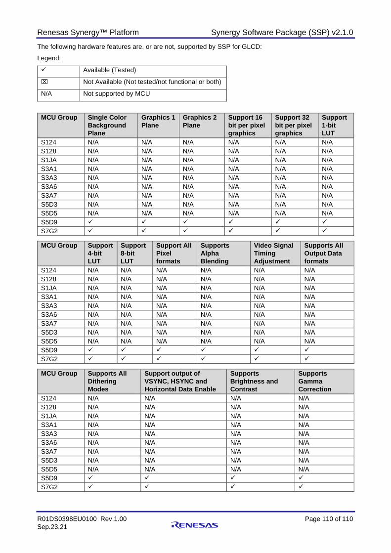
Renesas Synergy™ Platform Synergy Software Package (SSP) v2.1.0
R01DS0398EU0100 Rev.1.00 Page 110 of 110 Sep.23.21
The following hardware features are, or are not, supported by SSP for GLCD:
Legend:
Available (Tested)
Not Available (Not tested/not functional or both)
N/A Not supported by MCU
MCU Group Single Color Background Plane
Graphics 1 Plane
Graphics 2 Plane
Support 16 bit per pixel graphics
Support 32 bit per pixel graphics
Support 1-bit LUT
S124 N/A N/A N/A N/A N/A N/A S128 N/A N/A N/A N/A N/A N/A S1JA N/A N/A N/A N/A N/A N/A S3A1 N/A N/A N/A N/A N/A N/A S3A3 N/A N/A N/A N/A N/A N/A S3A6 N/A N/A N/A N/A N/A N/A S3A7 N/A N/A N/A N/A N/A N/A S5D3 N/A N/A N/A N/A N/A N/A S5D5 N/A N/A N/A N/A N/A N/A S5D9 S7G2
MCU Group Support
4-bit LUT
Support 8-bit LUT
Support All Pixel formats
Supports Alpha Blending
Video Signal Timing Adjustment
Supports All Output Data formats
S124 N/A N/A N/A N/A N/A N/A S128 N/A N/A N/A N/A N/A N/A S1JA N/A N/A N/A N/A N/A N/A S3A1 N/A N/A N/A N/A N/A N/A S3A3 N/A N/A N/A N/A N/A N/A S3A6 N/A N/A N/A N/A N/A N/A S3A7 N/A N/A N/A N/A N/A N/A S5D3 N/A N/A N/A N/A N/A N/A S5D5 N/A N/A N/A N/A N/A N/A S5D9 S7G2
MCU Group Supports All
Dithering Modes
Support output of VSYNC, HSYNC and Horizontal Data Enable
Supports Brightness and Contrast
Supports Gamma Correction
S124 N/A N/A N/A N/A S128 N/A N/A N/A N/A S1JA N/A N/A N/A N/A S3A1 N/A N/A N/A N/A S3A3 N/A N/A N/A N/A S3A6 N/A N/A N/A N/A S3A7 N/A N/A N/A N/A S5D3 N/A N/A N/A N/A S5D5 N/A N/A N/A N/A S5D9 S7G2
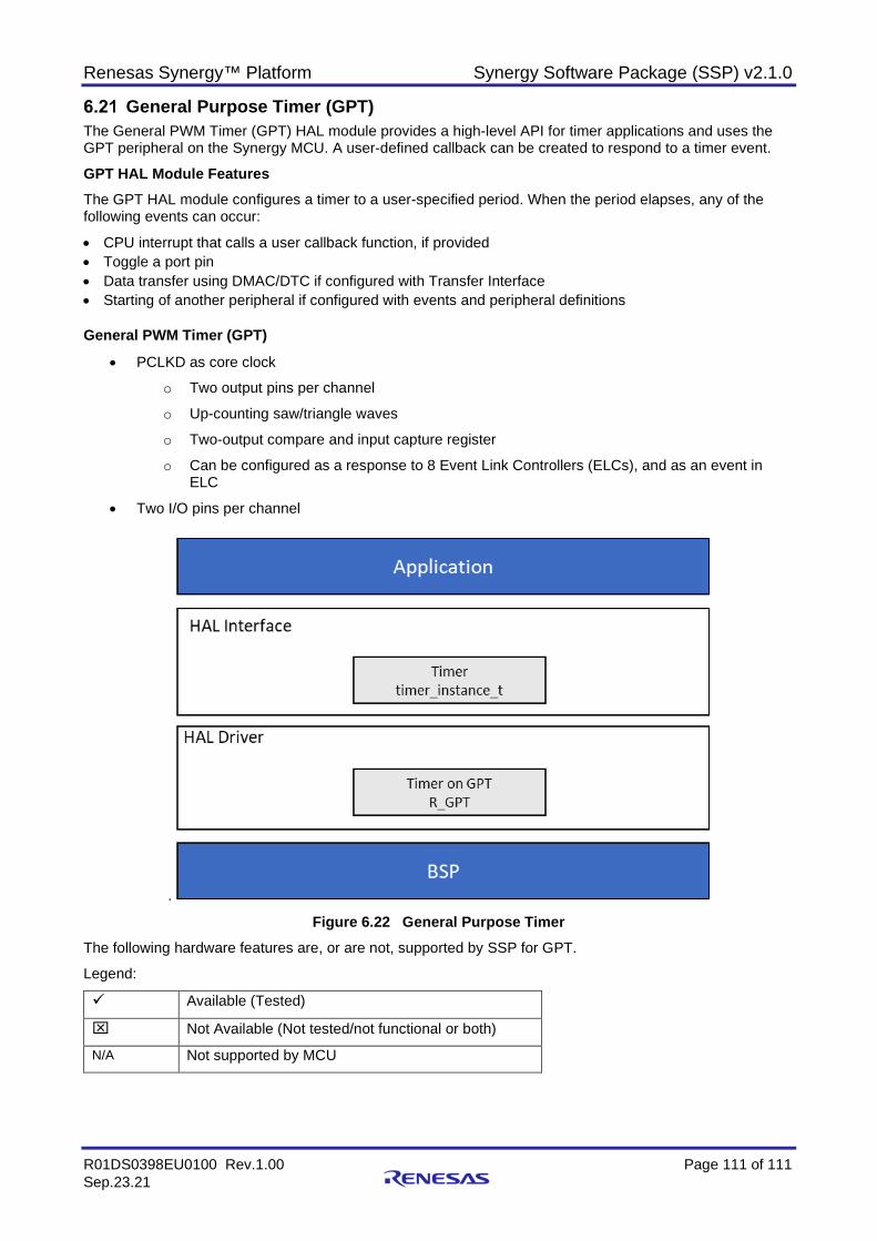
Renesas Synergy™ Platform Synergy Software Package (SSP) v2.1.0
R01DS0398EU0100 Rev.1.00 Page 111 of 111 Sep.23.21
General Purpose Timer (GPT) The General PWM Timer (GPT) HAL module provides a high-level API for timer applications and uses the GPT peripheral on the Synergy MCU. A user-defined callback can be created to respond to a timer event. GPT HAL Module Features The GPT HAL module configures a timer to a user-specified period. When the period elapses, any of the following events can occur:
• CPU interrupt that calls a user callback function, if provided • Toggle a port pin • Data transfer using DMAC/DTC if configured with Transfer Interface • Starting of another peripheral if configured with events and peripheral definitions
General PWM Timer (GPT)
• PCLKD as core clock
o Two output pins per channel
o Up-counting saw/triangle waves
o Two-output compare and input capture register
o Can be configured as a response to 8 Event Link Controllers (ELCs), and as an event in ELC
• Two I/O pins per channel
.
Figure 6.22 General Purpose Timer The following hardware features are, or are not, supported by SSP for GPT.
Legend:
Available (Tested)
Not Available (Not tested/not functional or both)
N/A Not supported by MCU
Renesas Synergy™ Platform Synergy Software Package (SSP) v2.1.0
R01DS0398EU0100 Rev.1.00 Page 112 of 112 Sep.23.21
MCU Group Saw Waves
Triangle Waves
PWM waveform for controlling brushless DC motors
Compare match output for Low, High, and Toggle
Input capture function
Automatic addition of dead time
S124 S128 S1JA
S3A1
S3A3
S3A6 S3A7 S5D3
S5D5 S5D9 S7G2
MCU Group PWM Mode Phase Count
Function One-Shot Operation
Event link function through ELC HAL driver
Noise filtering function
S124 S128 S1JA
S3A1
S3A3
S3A6 S3A7 S5D3
S5D5 S5D9 S7G2
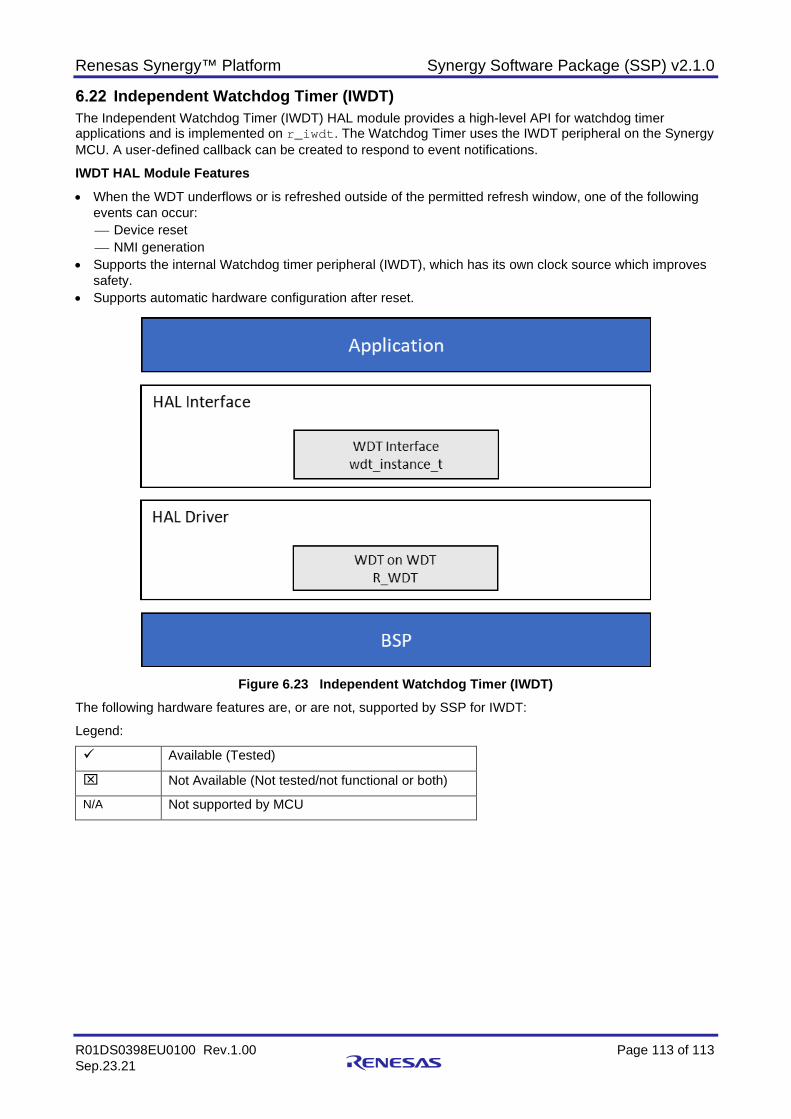
Renesas Synergy™ Platform Synergy Software Package (SSP) v2.1.0
R01DS0398EU0100 Rev.1.00 Page 113 of 113 Sep.23.21
Independent Watchdog Timer (IWDT) The Independent Watchdog Timer (IWDT) HAL module provides a high-level API for watchdog timer applications and is implemented on r_iwdt. The Watchdog Timer uses the IWDT peripheral on the Synergy MCU. A user-defined callback can be created to respond to event notifications.
IWDT HAL Module Features • When the WDT underflows or is refreshed outside of the permitted refresh window, one of the following
events can occur: Device reset NMI generation
• Supports the internal Watchdog timer peripheral (IWDT), which has its own clock source which improves safety.
• Supports automatic hardware configuration after reset.
Figure 6.23 Independent Watchdog Timer (IWDT)
The following hardware features are, or are not, supported by SSP for IWDT:
Legend:
Available (Tested)
Not Available (Not tested/not functional or both)
N/A Not supported by MCU
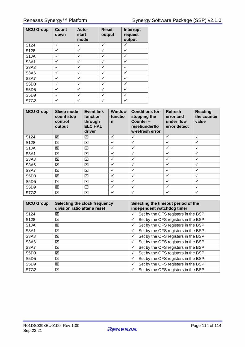
Renesas Synergy™ Platform Synergy Software Package (SSP) v2.1.0
R01DS0398EU0100 Rev.1.00 Page 114 of 114 Sep.23.21
MCU Group Count down
Auto-start mode
Reset output
Interrupt request output
S124 S128 S1JA S3A1 S3A3 S3A6 S3A7 S5D3 S5D5 S5D9 S7G2
MCU Group Sleep mode
count stop control output
Event link function through ELC HAL driver
Window function
Conditions for stopping the Counter – reset/underflow-refresh error
Refresh error and under flow error detect
Reading the counter value
S124 S128 S1JA S3A1 S3A3 S3A6 S3A7 S5D3 S5D5 S5D9 S7G2
MCU Group Selecting the clock frequency
division ratio after a reset Selecting the timeout period of the independent watchdog timer
S124 Set by the OFS registers in the BSP S128 Set by the OFS registers in the BSP S1JA Set by the OFS registers in the BSP S3A1 Set by the OFS registers in the BSP S3A3 Set by the OFS registers in the BSP S3A6 Set by the OFS registers in the BSP S3A7 Set by the OFS registers in the BSP S5D3 Set by the OFS registers in the BSP S5D5 Set by the OFS registers in the BSP S5D9 Set by the OFS registers in the BSP S7G2 Set by the OFS registers in the BSP
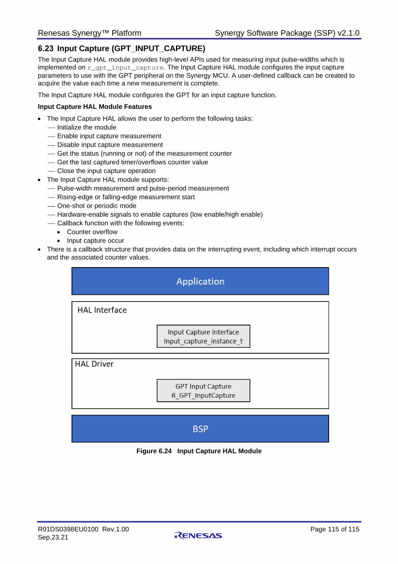
Renesas Synergy™ Platform Synergy Software Package (SSP) v2.1.0
R01DS0398EU0100 Rev.1.00 Page 115 of 115 Sep.23.21
Input Capture (GPT_INPUT_CAPTURE) The Input Capture HAL module provides high-level APIs used for measuring input pulse-widths which is implemented on r_gpt_input_capture. The Input Capture HAL module configures the input capture parameters to use with the GPT peripheral on the Synergy MCU. A user-defined callback can be created to acquire the value each time a new measurement is complete.
The Input Capture HAL module configures the GPT for an input capture function.
Input Capture HAL Module Features • The Input Capture HAL allows the user to perform the following tasks:
Initialize the module Enable input capture measurement Disable input capture measurement Get the status (running or not) of the measurement counter Get the last captured timer/overflows counter value Close the input capture operation
• The Input Capture HAL module supports: Pulse-width measurement and pulse-period measurement Rising-edge or falling-edge measurement start One-shot or periodic mode Hardware-enable signals to enable captures (low enable/high enable) Callback function with the following events:
• Counter overflow • Input capture occur
• There is a callback structure that provides data on the interrupting event, including which interrupt occurs and the associated counter values.
Figure 6.24 Input Capture HAL Module
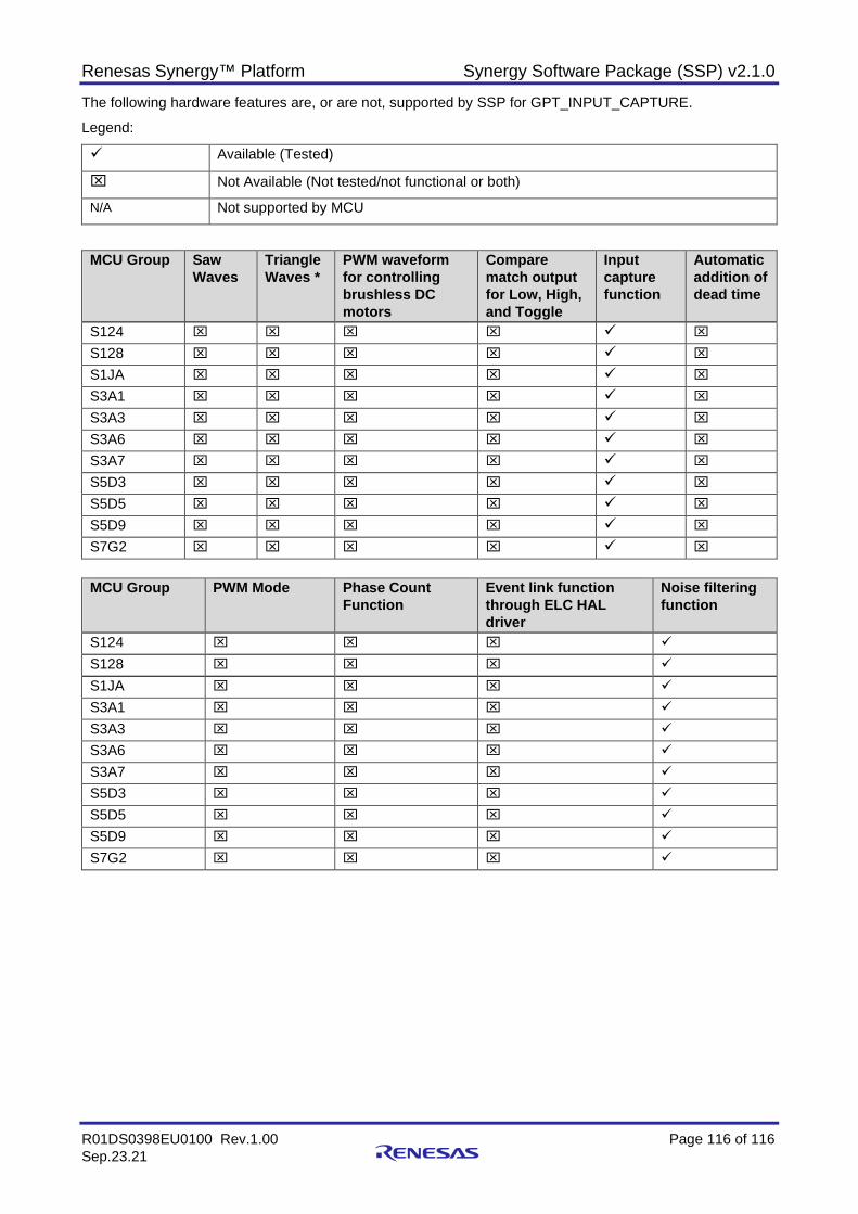
Renesas Synergy™ Platform Synergy Software Package (SSP) v2.1.0
R01DS0398EU0100 Rev.1.00 Page 116 of 116 Sep.23.21
The following hardware features are, or are not, supported by SSP for GPT_INPUT_CAPTURE.
Legend:
Available (Tested)
Not Available (Not tested/not functional or both)
N/A Not supported by MCU
MCU Group Saw Waves
Triangle Waves *
PWM waveform for controlling brushless DC motors
Compare match output for Low, High, and Toggle
Input capture function
Automatic addition of dead time
S124 S128 S1JA
S3A1
S3A3
S3A6 S3A7 S5D3
S5D5 S5D9 S7G2
MCU Group PWM Mode Phase Count
Function Event link function through ELC HAL driver
Noise filtering function
S124 S128
S1JA
S3A1 S3A3
S3A6 S3A7
S5D3
S5D5
S5D9
S7G2
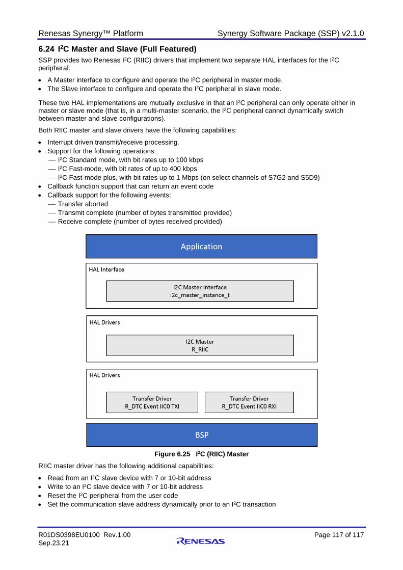
Renesas Synergy™ Platform Synergy Software Package (SSP) v2.1.0
R01DS0398EU0100 Rev.1.00 Page 117 of 117 Sep.23.21
I2C Master and Slave (Full Featured) SSP provides two Renesas I2C (RIIC) drivers that implement two separate HAL interfaces for the I2C peripheral:
• A Master interface to configure and operate the I2C peripheral in master mode. • The Slave interface to configure and operate the I2C peripheral in slave mode. These two HAL implementations are mutually exclusive in that an I2C peripheral can only operate either in master or slave mode (that is, in a multi-master scenario, the I2C peripheral cannot dynamically switch between master and slave configurations).
Both RIIC master and slave drivers have the following capabilities:
• Interrupt driven transmit/receive processing. • Support for the following operations:
I2C Standard mode, with bit rates up to 100 kbps I2C Fast-mode, with bit rates of up to 400 kbps I2C Fast-mode plus, with bit rates up to 1 Mbps (on select channels of S7G2 and S5D9)
• Callback function support that can return an event code • Callback support for the following events:
Transfer aborted Transmit complete (number of bytes transmitted provided) Receive complete (number of bytes received provided)
Figure 6.25 I2C (RIIC) Master
RIIC master driver has the following additional capabilities:
• Read from an I2C slave device with 7 or 10-bit address • Write to an I2C slave device with 7 or 10-bit address • Reset the I2C peripheral from the user code • Set the communication slave address dynamically prior to an I2C transaction
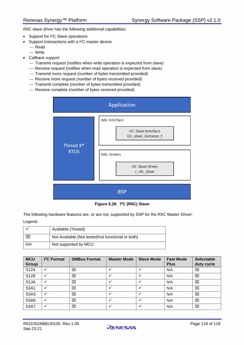
Renesas Synergy™ Platform Synergy Software Package (SSP) v2.1.0
R01DS0398EU0100 Rev.1.00 Page 118 of 118 Sep.23.21
RIIC slave driver has the following additional capabilities:
• Support for I2C Slave operations • Support transactions with a I2C master device
Read Write
• Callback support Transmit request (notifies when write operation is expected from slave) Receive request (notifies when read operation is expected from slave) Transmit more request (number of bytes transmitted provided) Receive more request (number of bytes received provided) Transmit complete (number of bytes transmitted provided) Receive complete (number of bytes received provided)
Figure 6.26 I2C (RIIC) Slave
The following hardware features are, or are not, supported by SSP for the RIIC Master Driver:
Legend:
Available (Tested)
Not Available (Not tested/not functional or both)
N/A Not supported by MCU
MCU Group
I2C Format SMBus Format Master Mode Slave Mode Fast Mode Plus
Selectable duty cycle
S124 N/A S128 N/A S1JA N/A
S3A1 N/A
S3A3 N/A
S3A6 N/A S3A7 N/A
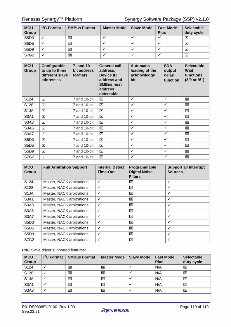
Renesas Synergy™ Platform Synergy Software Package (SSP) v2.1.0
R01DS0398EU0100 Rev.1.00 Page 119 of 119 Sep.23.21
MCU Group
I2C Format SMBus Format Master Mode Slave Mode Fast Mode Plus
Selectable duty cycle
S5D3
S5D5 S5D9 S7G2
MCU Group
Configurable to up to three different slave addresses
7- and 10-bit address formats
General call address, Device ID address and SMBus host address detectable
Automatic loading of the acknowledge bit
SDA output delay function
Selectable Wait functions (8/9 or 9/1)
S124 7 and 10-bit
S128 7 and 10-bit
S1JA 7 and 10-bit
S3A1 7 and 10-bit
S3A3 7 and 10-bit
S3A6 7 and 10-bit
S3A7 7 and 10-bit
S5D3 7 and 10-bit
S5D5 7 and 10-bit
S5D9 7 and 10-bit
S7G2 7 and 10-bit
MCU Group
Full Arbitration Support Internal Detect Time-Out
Programmable Digital Noise Filters
Support all Interrupt Sources
S124 Master, NACK arbitrations S128 Master, NACK arbitrations S1JA Master, NACK arbitrations
S3A1 Master, NACK arbitrations
S3A3 Master, NACK arbitrations
S3A6 Master, NACK arbitrations S3A7 Master, NACK arbitrations S5D3 Master, NACK arbitrations
S5D5 Master, NACK arbitrations S5D9 Master, NACK arbitrations S7G2 Master, NACK arbitrations
RIIC Slave driver supported features:
MCU Group
I2C Format SMBus Format Master Mode Slave Mode Fast Mode Plus
Selectable duty cycle
S124 N/A
S128 N/A
S1JA N/A
S3A1 N/A
S3A3 N/A
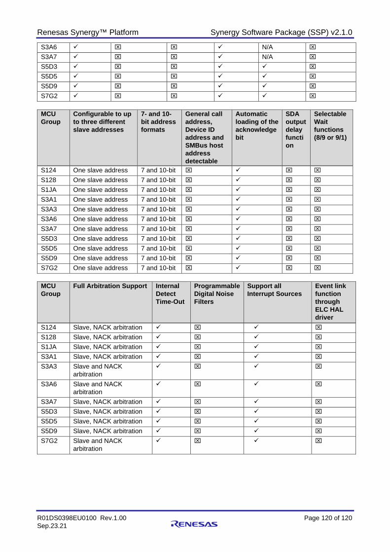
Renesas Synergy™ Platform Synergy Software Package (SSP) v2.1.0
R01DS0398EU0100 Rev.1.00 Page 120 of 120 Sep.23.21
S3A6 N/A
S3A7 N/A
S5D3
S5D5
S5D9
S7G2
MCU Group
Configurable to up to three different slave addresses
7- and 10-bit address formats
General call address, Device ID address and SMBus host address detectable
Automatic loading of the acknowledge bit
SDA output delay function
Selectable Wait functions (8/9 or 9/1)
S124 One slave address 7 and 10-bit
S128 One slave address 7 and 10-bit
S1JA One slave address 7 and 10-bit
S3A1 One slave address 7 and 10-bit
S3A3 One slave address 7 and 10-bit
S3A6 One slave address 7 and 10-bit
S3A7 One slave address 7 and 10-bit
S5D3 One slave address 7 and 10-bit
S5D5 One slave address 7 and 10-bit
S5D9 One slave address 7 and 10-bit
S7G2 One slave address 7 and 10-bit
MCU Group
Full Arbitration Support Internal Detect Time-Out
Programmable Digital Noise Filters
Support all Interrupt Sources
Event link function through ELC HAL driver
S124 Slave, NACK arbitration S128 Slave, NACK arbitration S1JA Slave, NACK arbitration
S3A1 Slave, NACK arbitration
S3A3 Slave and NACK arbitration
S3A6 Slave and NACK arbitration
S3A7 Slave, NACK arbitration S5D3 Slave, NACK arbitration
S5D5 Slave, NACK arbitration S5D9 Slave, NACK arbitration S7G2 Slave and NACK
arbitration

Renesas Synergy™ Platform Synergy Software Package (SSP) v2.1.0
R01DS0398EU0100 Rev.1.00 Page 121 of 121 Sep.23.21
Interrupt Controller Unit – External (ICU) The External IRQ HAL module is an API for configuring and using external IRQ pins on Synergy MCUs. The External IRQ HAL module is implemented on r_icu and uses the Interrupt Controller Unit (ICU) of the Synergy MCU.
External IRQ HAL Module Features • External interrupt pins available on the target Synergy MCU • Multiple function options:
Enabling and disabling generation of an interrupt Enabling and disabling the IRQ noise filter Setting external pin IRQ trigger (Rising edge, falling edge or low level on the IRQ pin)
• Configuring a user callback function, which will be invoked by the HAL module when an external pin interrupt is generated.
Figure 6.27 External Interrupt Controller Unit (ICU)
The following hardware features are, or are not, supported by SSP for ICU.
MCU Group
Peripheral function interrupts
External pin interrupts
DTC and DMAC control
Interrupt sources for NVIC
Non-maskable interrupts (see notes)
Return from lowpower- mode (see notes)
S124 S128 S1JA S3A1 S3A3 S3A6 S3A7 S5D3 S5D5 S5D9 S7G2
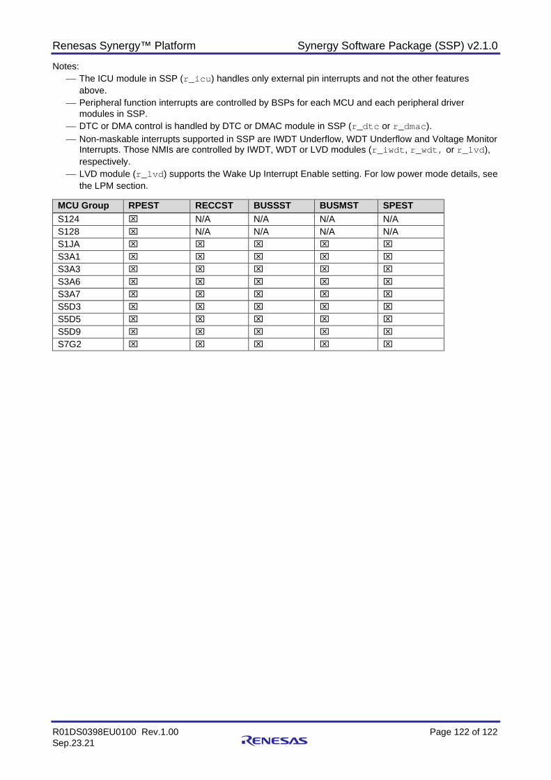
Renesas Synergy™ Platform Synergy Software Package (SSP) v2.1.0
R01DS0398EU0100 Rev.1.00 Page 122 of 122 Sep.23.21
Notes: The ICU module in SSP (r_icu) handles only external pin interrupts and not the other features
above. Peripheral function interrupts are controlled by BSPs for each MCU and each peripheral driver
modules in SSP. DTC or DMA control is handled by DTC or DMAC module in SSP (r_dtc or r_dmac). Non-maskable interrupts supported in SSP are IWDT Underflow, WDT Underflow and Voltage Monitor
Interrupts. Those NMIs are controlled by IWDT, WDT or LVD modules (r_iwdt, r_wdt, or r_lvd), respectively.
LVD module (r_lvd) supports the Wake Up Interrupt Enable setting. For low power mode details, see the LPM section.
MCU Group RPEST RECCST BUSSST BUSMST SPEST S124 N/A N/A N/A N/A S128 N/A N/A N/A N/A S1JA S3A1 S3A3 S3A6 S3A7 S5D3 S5D5 S5D9 S7G2
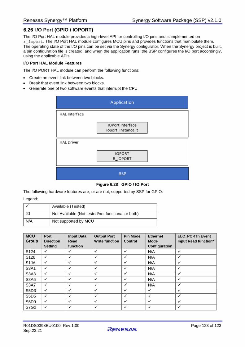
Renesas Synergy™ Platform Synergy Software Package (SSP) v2.1.0
R01DS0398EU0100 Rev.1.00 Page 123 of 123 Sep.23.21
I/O Port (GPIO / IOPORT) The I/O Port HAL module provides a high-level API for controlling I/O pins and is implemented on r_ioport. The I/O Port HAL module configures MCU pins and provides functions that manipulate them. The operating state of the I/O pins can be set via the Synergy configurator. When the Synergy project is built, a pin configuration file is created, and when the application runs, the BSP configures the I/O port accordingly, using the applicable APIs.
I/O Port HAL Module Features The I/O PORT HAL module can perform the following functions:
• Create an event link between two blocks. • Break that event link between two blocks. • Generate one of two software events that interrupt the CPU
Figure 6.28 GPIO / IO Port
The following hardware features are, or are not, supported by SSP for GPIO.
Legend:
Available (Tested)
Not Available (Not tested/not functional or both)
N/A Not supported by MCU
MCU Group
Port Direction Setting
Input Data Read function
Output Port Write function
Pin Mode Control
Ethernet Mode Configuration
ELC_PORTn Event Input Read function*
S124 N/A S128 N/A S1JA N/A S3A1 N/A S3A3 N/A S3A6 N/A S3A7 N/A S5D3 S5D5 S5D9 S7G2
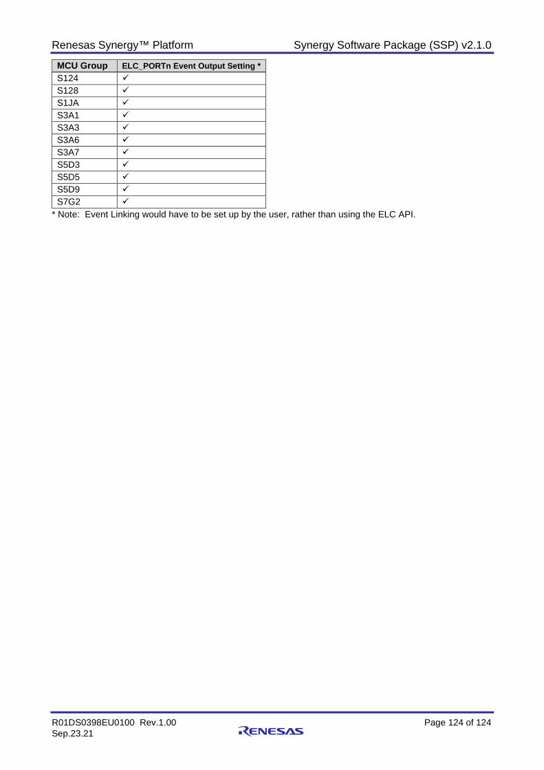
Renesas Synergy™ Platform Synergy Software Package (SSP) v2.1.0
R01DS0398EU0100 Rev.1.00 Page 124 of 124 Sep.23.21
MCU Group ELC_PORTn Event Output Setting * S124 S128 S1JA S3A1 S3A3 S3A6 S3A7 S5D3 S5D5 S5D9 S7G2
* Note: Event Linking would have to be set up by the user, rather than using the ELC API.
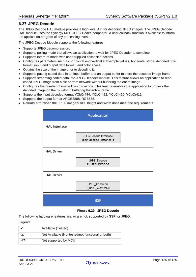
Renesas Synergy™ Platform Synergy Software Package (SSP) v2.1.0
R01DS0398EU0100 Rev.1.00 Page 125 of 125 Sep.23.21
JPEG Decode The JPEG Decode HAL module provides a high-level API for decoding JPEG images. The JPEG Decode HAL module uses the Synergy MCU JPEG Codec peripheral. A user callback function is available to inform the application program of key processing events.
The JPEG Decode Module supports the following features:
• Supports JPEG decompression. • Supports polling mode that allows an application to wait for JPEG Decoder to complete. • Supports interrupt mode with user-supplied callback functions. • Configures parameters such as horizontal and vertical subsample values, horizontal stride, decoded pixel
format, input and output data format, and color space. • Obtains the size of the image prior to decoding it. • Supports putting coded data in an input buffer and an output buffer to store the decoded image frame. • Supports streaming coded data into JPEG Decoder module. This feature allows an application to read
coded JPEG image from a file or from network without buffering the entire image. • Configures the number of image lines to decode. This feature enables the application to process the
decoded image on the fly without buffering the entire frame. • Supports the input decoded format YCbCr444, YCbCr422, YCbCr420, YCbCr411. • Supports the output format ARGB8888, RGB565. • Returns error when the JPEG image’s size, height and width don’t meet the requirements
Figure 6.29 JPEG Decode
The following hardware features are, or are not, supported by SSP for JPEG.
Legend:
Available (Tested)
Not Available (Not tested/not functional or both)
N/A Not supported by MCU
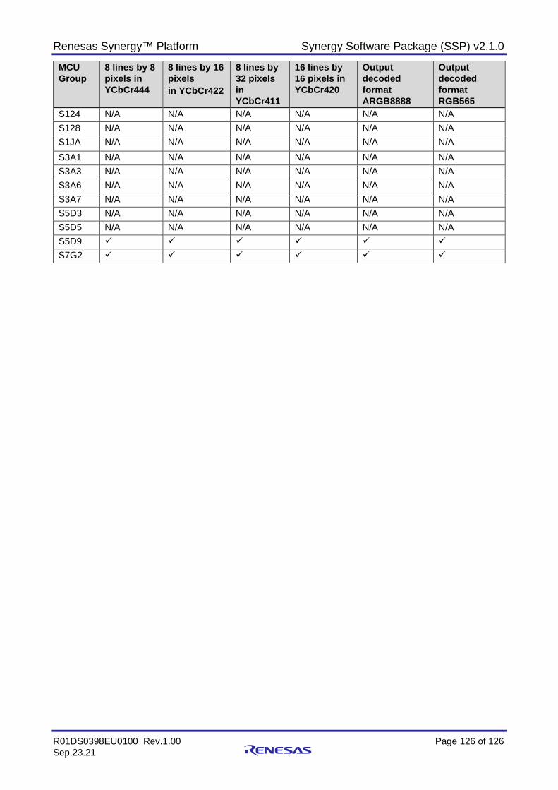
Renesas Synergy™ Platform Synergy Software Package (SSP) v2.1.0
R01DS0398EU0100 Rev.1.00 Page 126 of 126 Sep.23.21
MCU Group
8 lines by 8 pixels in YCbCr444
8 lines by 16 pixels in YCbCr422
8 lines by 32 pixels in YCbCr411
16 lines by 16 pixels in YCbCr420
Output decoded format ARGB8888
Output decoded format RGB565
S124 N/A N/A N/A N/A N/A N/A S128 N/A N/A N/A N/A N/A N/A S1JA N/A N/A N/A N/A N/A N/A S3A1 N/A N/A N/A N/A N/A N/A S3A3 N/A N/A N/A N/A N/A N/A S3A6 N/A N/A N/A N/A N/A N/A S3A7 N/A N/A N/A N/A N/A N/A S5D3 N/A N/A N/A N/A N/A N/A S5D5 N/A N/A N/A N/A N/A N/A S5D9 S7G2
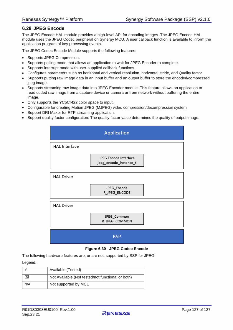
Renesas Synergy™ Platform Synergy Software Package (SSP) v2.1.0
R01DS0398EU0100 Rev.1.00 Page 127 of 127 Sep.23.21
JPEG Encode The JPEG Encode HAL module provides a high-level API for encoding images. The JPEG Encode HAL module uses the JPEG Codec peripheral on Synergy MCU. A user callback function is available to inform the application program of key processing events.
The JPEG Codec Encode Module supports the following features:
• Supports JPEG Compression. • Supports polling mode that allows an application to wait for JPEG Encoder to complete. • Supports interrupt mode with user-supplied callback functions. • Configures parameters such as horizontal and vertical resolution, horizontal stride, and Quality factor. • Supports putting raw image data in an input buffer and an output buffer to store the encoded/compressed
jpeg image. • Supports streaming raw image data into JPEG Encoder module. This feature allows an application to
read coded raw image from a capture device or camera or from network without buffering the entire image.
• Only supports the YCbCr422 color space to input. • Configurable for creating Motion JPEG (MJPEG) video compression/decompression system • Support DRI Maker for RTP streaming application. • Support quality factor configuration: The quality factor value determines the quality of output image.
Figure 6.30 JPEG Codec Encode
The following hardware features are, or are not, supported by SSP for JPEG.
Legend:
Available (Tested)
Not Available (Not tested/not functional or both)
N/A Not supported by MCU
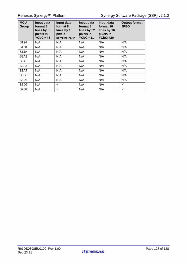
Renesas Synergy™ Platform Synergy Software Package (SSP) v2.1.0
R01DS0398EU0100 Rev.1.00 Page 128 of 128 Sep.23.21
MCU Group
Input data format 8 lines by 8 pixels in YCbCr444
Input data format 8 lines by 16 pixels in YCbCr422
Input data format 8 lines by 32 pixels in YCbCr411
Input data format 16 lines by 16 pixels in YCbCr420
Output format JPEG
S124 N/A N/A N/A N/A N/A S128 N/A N/A N/A N/A N/A S1JA N/A N/A N/A N/A N/A S3A1 N/A N/A N/A N/A N/A S3A3 N/A N/A N/A N/A N/A S3A6 N/A N/A N/A N/A N/A S3A7 N/A N/A N/A N/A N/A S5D3 N/A N/A N/A N/A N/A S5D5 N/A N/A N/A N/A N/A S5D9 N/A N/A N/A S7G2 N/A N/A N/A
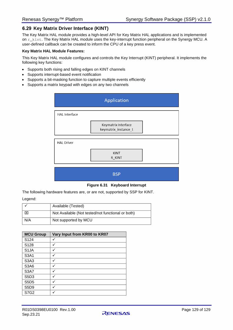
Renesas Synergy™ Platform Synergy Software Package (SSP) v2.1.0
R01DS0398EU0100 Rev.1.00 Page 129 of 129 Sep.23.21
Key Matrix Driver Interface (KINT) The Key Matrix HAL module provides a high-level API for Key Matrix HAL applications and is implemented on r_kint. The Key Matrix HAL module uses the key-interrupt function peripheral on the Synergy MCU. A user-defined callback can be created to inform the CPU of a key press event.
Key Matrix HAL Module Features: This Key Matrix HAL module configures and controls the Key Interrupt (KINT) peripheral. It implements the following key functions:
• Supports both rising and falling edges on KINT channels • Supports interrupt-based event notification • Supports a bit-masking function to capture multiple events efficiently • Supports a matrix keypad with edges on any two channels
Figure 6.31 Keyboard Interrupt
The following hardware features are, or are not, supported by SSP for KINT.
Legend:
Available (Tested)
Not Available (Not tested/not functional or both)
N/A Not supported by MCU
MCU Group Vary Input from KR00 to KR07 S124 S128 S1JA S3A1 S3A3 S3A6 S3A7 S5D3 S5D5 S5D9 S7G2
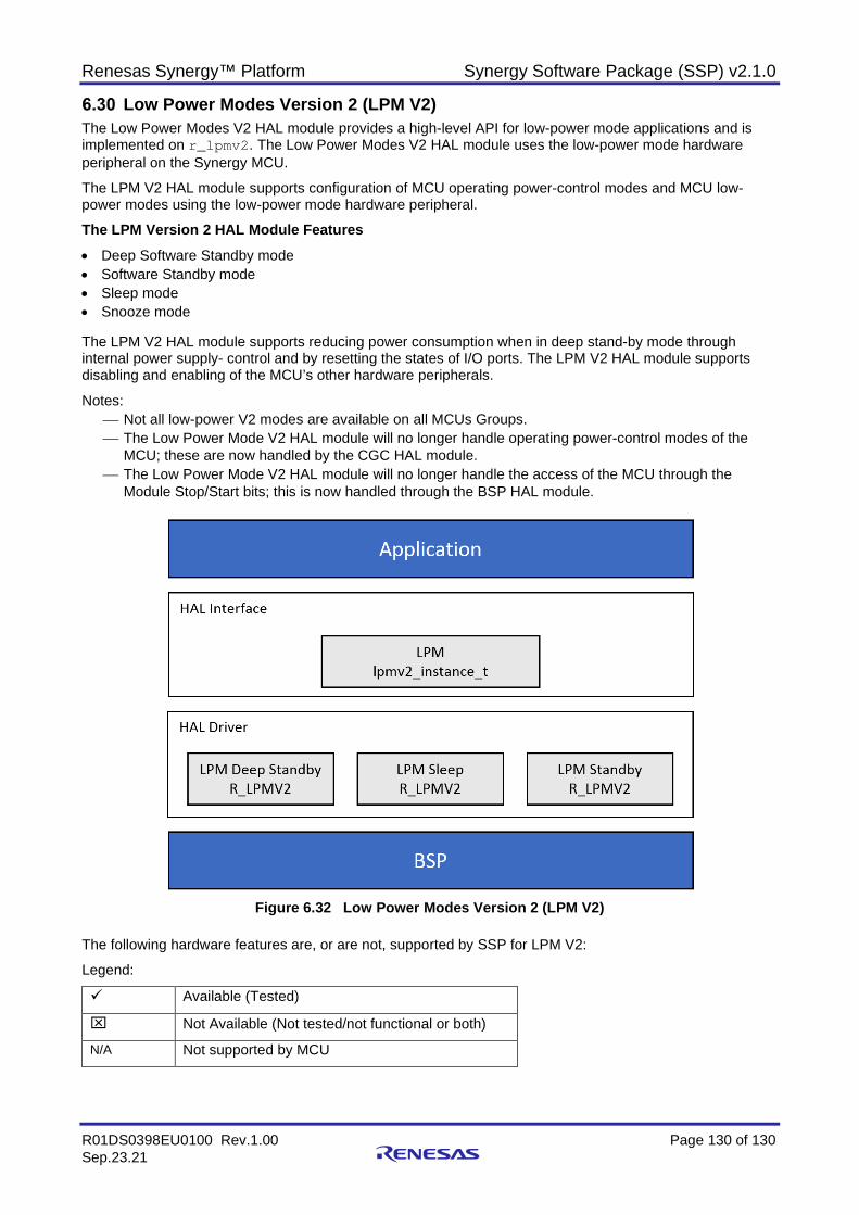
Renesas Synergy™ Platform Synergy Software Package (SSP) v2.1.0
R01DS0398EU0100 Rev.1.00 Page 130 of 130 Sep.23.21
Low Power Modes Version 2 (LPM V2) The Low Power Modes V2 HAL module provides a high-level API for low-power mode applications and is implemented on r_lpmv2. The Low Power Modes V2 HAL module uses the low-power mode hardware peripheral on the Synergy MCU.
The LPM V2 HAL module supports configuration of MCU operating power-control modes and MCU low-power modes using the low-power mode hardware peripheral.
The LPM Version 2 HAL Module Features • Deep Software Standby mode • Software Standby mode • Sleep mode • Snooze mode The LPM V2 HAL module supports reducing power consumption when in deep stand-by mode through internal power supply- control and by resetting the states of I/O ports. The LPM V2 HAL module supports disabling and enabling of the MCU’s other hardware peripherals.
Notes: Not all low-power V2 modes are available on all MCUs Groups. The Low Power Mode V2 HAL module will no longer handle operating power-control modes of the
MCU; these are now handled by the CGC HAL module. The Low Power Mode V2 HAL module will no longer handle the access of the MCU through the
Module Stop/Start bits; this is now handled through the BSP HAL module.
Figure 6.32 Low Power Modes Version 2 (LPM V2)
The following hardware features are, or are not, supported by SSP for LPM V2:
Legend:
Available (Tested)
Not Available (Not tested/not functional or both)
N/A Not supported by MCU
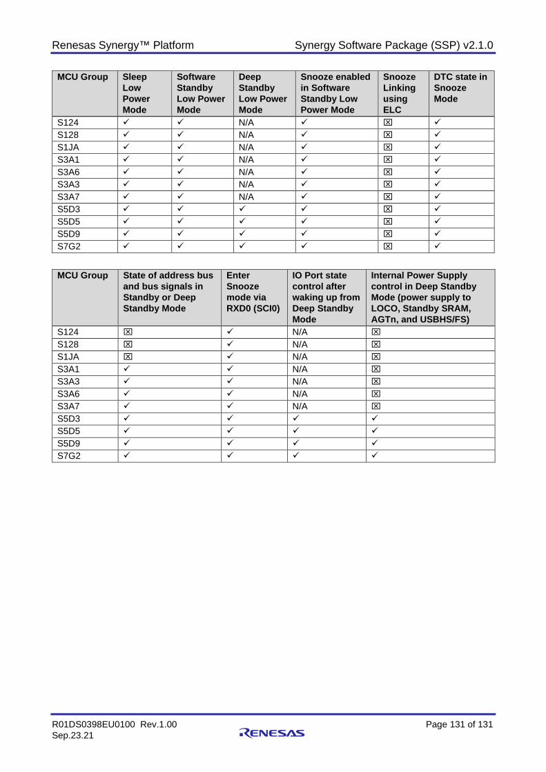
Renesas Synergy™ Platform Synergy Software Package (SSP) v2.1.0
R01DS0398EU0100 Rev.1.00 Page 131 of 131 Sep.23.21
MCU Group Sleep Low Power Mode
Software Standby Low Power Mode
Deep Standby Low Power Mode
Snooze enabled in Software Standby Low Power Mode
Snooze Linking using ELC
DTC state in Snooze Mode
S124 N/A S128 N/A S1JA N/A S3A1 N/A S3A6 N/A S3A3 N/A S3A7 N/A S5D3 S5D5 S5D9 S7G2
MCU Group State of address bus and bus signals in Standby or Deep Standby Mode
Enter Snooze mode via RXD0 (SCI0)
IO Port state control after waking up from Deep Standby Mode
Internal Power Supply control in Deep Standby Mode (power supply to LOCO, Standby SRAM, AGTn, and USBHS/FS)
S124 N/A S128 N/A S1JA N/A S3A1 N/A S3A3 N/A S3A6 N/A S3A7 N/A S5D3 S5D5 S5D9 S7G2
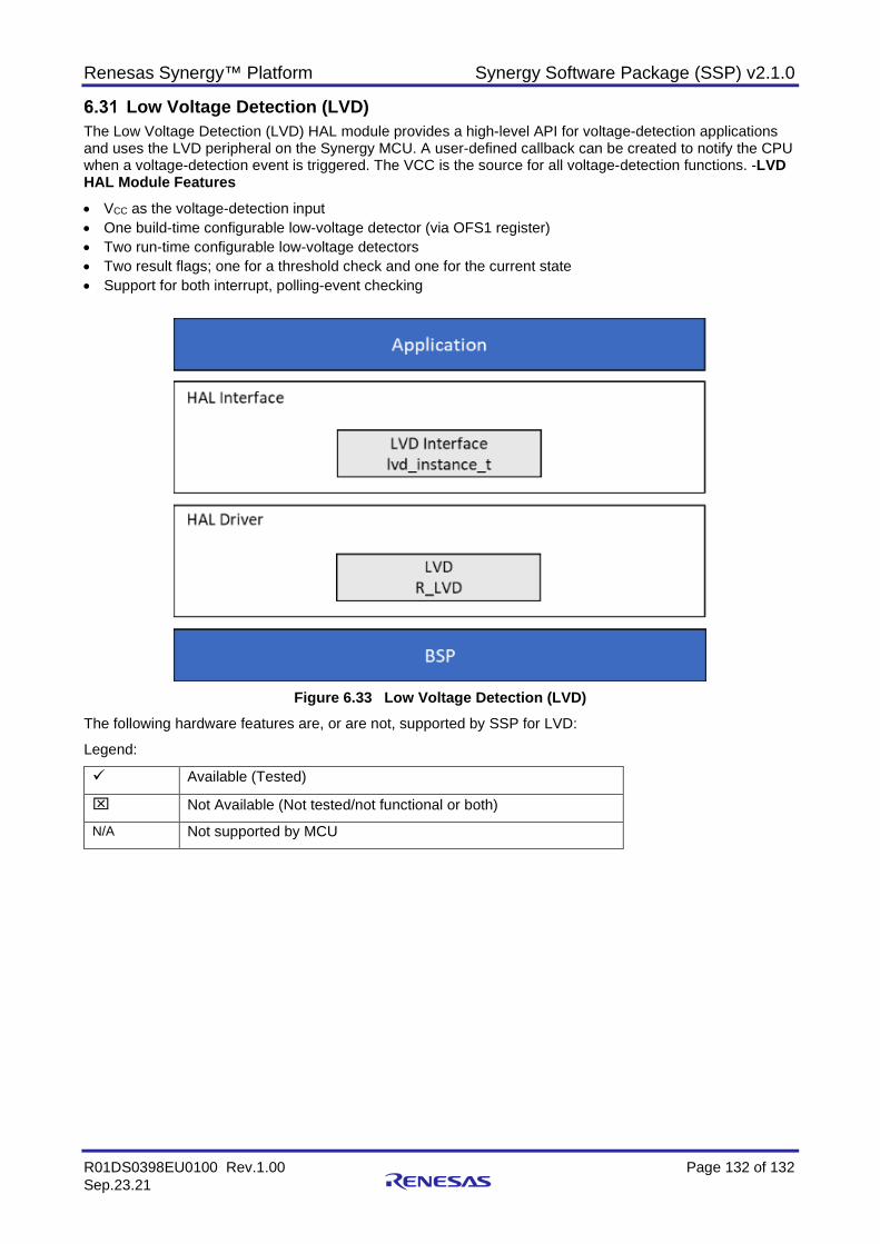
Renesas Synergy™ Platform Synergy Software Package (SSP) v2.1.0
R01DS0398EU0100 Rev.1.00 Page 132 of 132 Sep.23.21
Low Voltage Detection (LVD) The Low Voltage Detection (LVD) HAL module provides a high-level API for voltage-detection applications and uses the LVD peripheral on the Synergy MCU. A user-defined callback can be created to notify the CPU when a voltage-detection event is triggered. The VCC is the source for all voltage-detection functions. -LVD HAL Module Features • VCC as the voltage-detection input • One build-time configurable low-voltage detector (via OFS1 register) • Two run-time configurable low-voltage detectors • Two result flags; one for a threshold check and one for the current state • Support for both interrupt, polling-event checking
Figure 6.33 Low Voltage Detection (LVD)
The following hardware features are, or are not, supported by SSP for LVD:
Legend:
Available (Tested)
Not Available (Not tested/not functional or both)
N/A Not supported by MCU
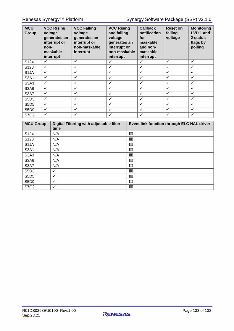
Renesas Synergy™ Platform Synergy Software Package (SSP) v2.1.0
R01DS0398EU0100 Rev.1.00 Page 133 of 133 Sep.23.21
MCU Group
VCC Rising voltage generates an interrupt or non-maskable interrupt
VCC Falling voltage generates an interrupt or non-maskable interrupt
VCC Rising and falling voltage generates an interrupt or non-maskable interrupt
Callback notification for maskable and non-maskable interrupt
Reset on falling voltage
Monitoring LVD 1 and 2 status flags by polling
S124 S128 S1JA S3A1 S3A3 S3A6 S3A7 S5D3 S5D5 S5D9 S7G2
MCU Group Digital Filtering with adjustable filter
time Event link function through ELC HAL driver
S124 N/A S128 N/A S1JA N/A S3A1 N/A S3A3 N/A S3A6 N/A S3A7 N/A S5D3 S5D5 S5D9 S7G2
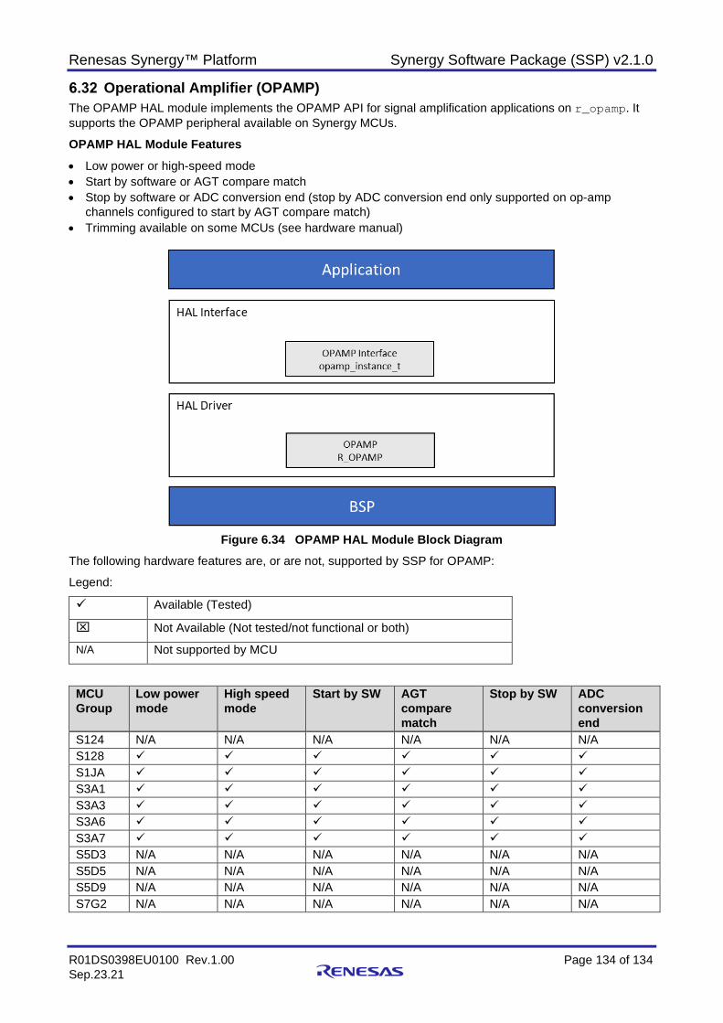
Renesas Synergy™ Platform Synergy Software Package (SSP) v2.1.0
R01DS0398EU0100 Rev.1.00 Page 134 of 134 Sep.23.21
Operational Amplifier (OPAMP) The OPAMP HAL module implements the OPAMP API for signal amplification applications on r_opamp. It supports the OPAMP peripheral available on Synergy MCUs.
OPAMP HAL Module Features
• Low power or high-speed mode • Start by software or AGT compare match • Stop by software or ADC conversion end (stop by ADC conversion end only supported on op-amp
channels configured to start by AGT compare match) • Trimming available on some MCUs (see hardware manual)
Figure 6.34 OPAMP HAL Module Block Diagram
The following hardware features are, or are not, supported by SSP for OPAMP:
Legend:
Available (Tested)
Not Available (Not tested/not functional or both)
N/A Not supported by MCU
MCU Group
Low power mode
High speed mode
Start by SW AGT compare match
Stop by SW ADC conversion end
S124 N/A N/A N/A N/A N/A N/A S128 S1JA S3A1 S3A3 S3A6 S3A7 S5D3 N/A N/A N/A N/A N/A N/A S5D5 N/A N/A N/A N/A N/A N/A S5D9 N/A N/A N/A N/A N/A N/A S7G2 N/A N/A N/A N/A N/A N/A
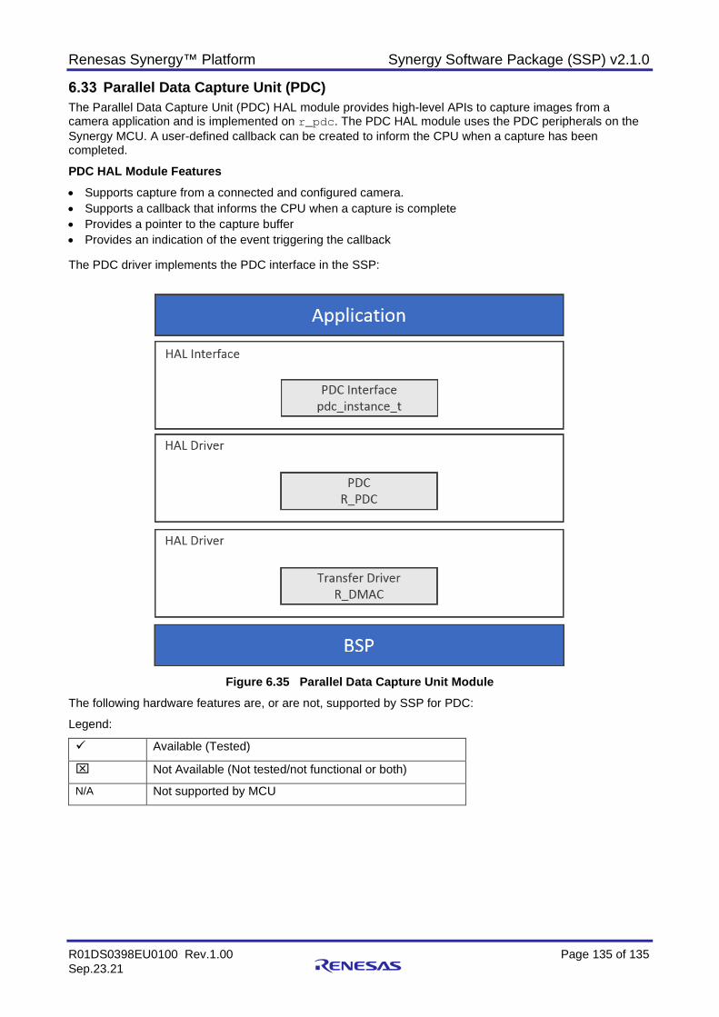
Renesas Synergy™ Platform Synergy Software Package (SSP) v2.1.0
R01DS0398EU0100 Rev.1.00 Page 135 of 135 Sep.23.21
Parallel Data Capture Unit (PDC) The Parallel Data Capture Unit (PDC) HAL module provides high-level APIs to capture images from a camera application and is implemented on r_pdc. The PDC HAL module uses the PDC peripherals on the Synergy MCU. A user-defined callback can be created to inform the CPU when a capture has been completed.
PDC HAL Module Features • Supports capture from a connected and configured camera. • Supports a callback that informs the CPU when a capture is complete • Provides a pointer to the capture buffer • Provides an indication of the event triggering the callback The PDC driver implements the PDC interface in the SSP:
Figure 6.35 Parallel Data Capture Unit Module
The following hardware features are, or are not, supported by SSP for PDC:
Legend:
Available (Tested)
Not Available (Not tested/not functional or both)
N/A Not supported by MCU
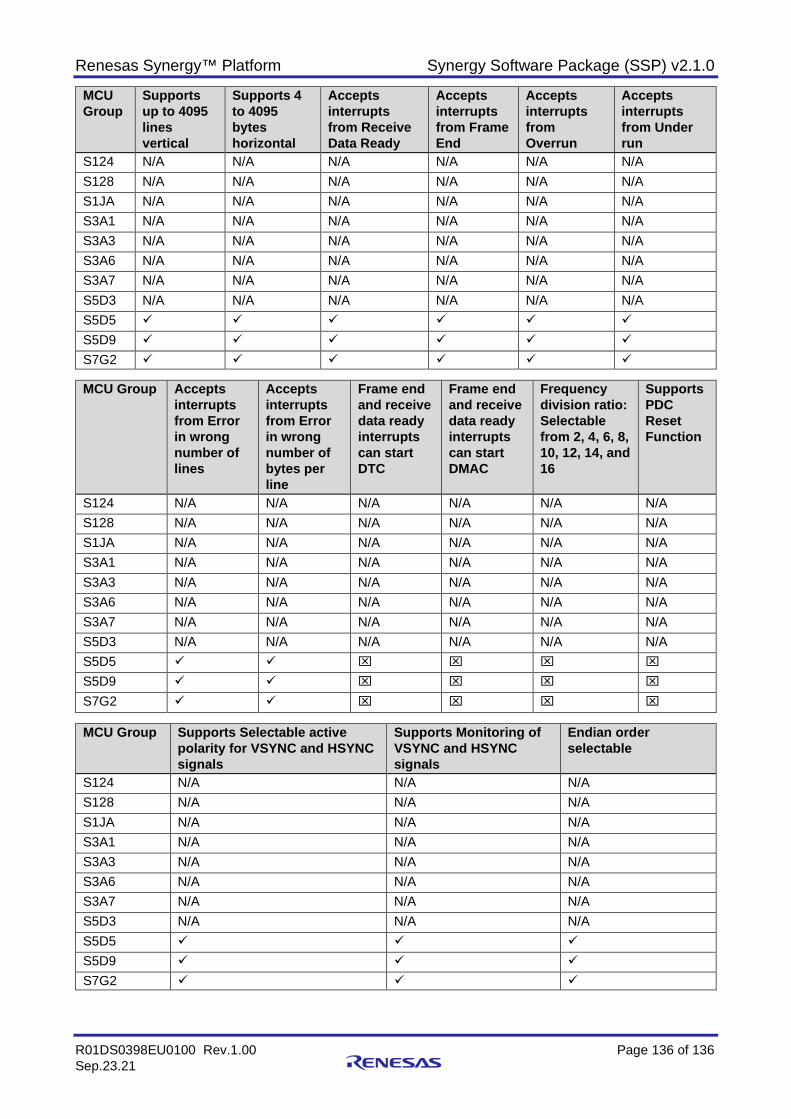
Renesas Synergy™ Platform Synergy Software Package (SSP) v2.1.0
R01DS0398EU0100 Rev.1.00 Page 136 of 136 Sep.23.21
MCU Group
Supports up to 4095 lines vertical
Supports 4 to 4095 bytes horizontal
Accepts interrupts from Receive Data Ready
Accepts interrupts from Frame End
Accepts interrupts from Overrun
Accepts interrupts from Under run
S124 N/A N/A N/A N/A N/A N/A S128 N/A N/A N/A N/A N/A N/A S1JA N/A N/A N/A N/A N/A N/A S3A1 N/A N/A N/A N/A N/A N/A S3A3 N/A N/A N/A N/A N/A N/A S3A6 N/A N/A N/A N/A N/A N/A S3A7 N/A N/A N/A N/A N/A N/A S5D3 N/A N/A N/A N/A N/A N/A S5D5 S5D9 S7G2
MCU Group Accepts
interrupts from Error in wrong number of lines
Accepts interrupts from Error in wrong number of bytes per line
Frame end and receive data ready interrupts can start DTC
Frame end and receive data ready interrupts can start DMAC
Frequency division ratio: Selectable from 2, 4, 6, 8, 10, 12, 14, and 16
Supports PDC Reset Function
S124 N/A N/A N/A N/A N/A N/A S128 N/A N/A N/A N/A N/A N/A S1JA N/A N/A N/A N/A N/A N/A S3A1 N/A N/A N/A N/A N/A N/A S3A3 N/A N/A N/A N/A N/A N/A S3A6 N/A N/A N/A N/A N/A N/A S3A7 N/A N/A N/A N/A N/A N/A S5D3 N/A N/A N/A N/A N/A N/A S5D5 S5D9 S7G2
MCU Group Supports Selectable active
polarity for VSYNC and HSYNC signals
Supports Monitoring of VSYNC and HSYNC signals
Endian order selectable
S124 N/A N/A N/A S128 N/A N/A N/A S1JA N/A N/A N/A S3A1 N/A N/A N/A S3A3 N/A N/A N/A S3A6 N/A N/A N/A S3A7 N/A N/A N/A S5D3 N/A N/A N/A S5D5 S5D9 S7G2
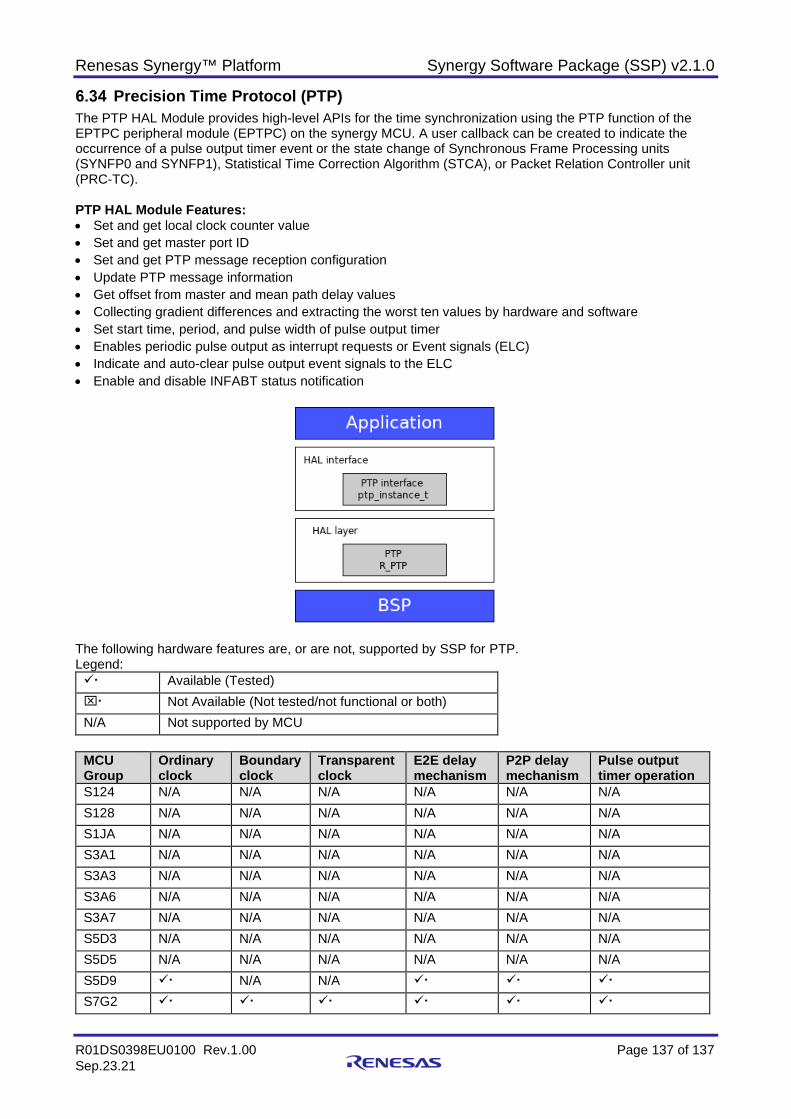
Renesas Synergy™ Platform Synergy Software Package (SSP) v2.1.0
R01DS0398EU0100 Rev.1.00 Page 137 of 137 Sep.23.21
Precision Time Protocol (PTP) The PTP HAL Module provides high-level APIs for the time synchronization using the PTP function of the EPTPC peripheral module (EPTPC) on the synergy MCU. A user callback can be created to indicate the occurrence of a pulse output timer event or the state change of Synchronous Frame Processing units (SYNFP0 and SYNFP1), Statistical Time Correction Algorithm (STCA), or Packet Relation Controller unit (PRC-TC). PTP HAL Module Features: • Set and get local clock counter value • Set and get master port ID • Set and get PTP message reception configuration • Update PTP message information • Get offset from master and mean path delay values • Collecting gradient differences and extracting the worst ten values by hardware and software • Set start time, period, and pulse width of pulse output timer • Enables periodic pulse output as interrupt requests or Event signals (ELC) • Indicate and auto-clear pulse output event signals to the ELC • Enable and disable INFABT status notification
The following hardware features are, or are not, supported by SSP for PTP. Legend: Available (Tested) Not Available (Not tested/not functional or both) N/A Not supported by MCU
MCU Group
Ordinary clock
Boundary clock
Transparent clock
E2E delay mechanism
P2P delay mechanism
Pulse output timer operation
S124 N/A N/A N/A N/A N/A N/A S128 N/A N/A N/A N/A N/A N/A S1JA N/A N/A N/A N/A N/A N/A S3A1 N/A N/A N/A N/A N/A N/A S3A3 N/A N/A N/A N/A N/A N/A S3A6 N/A N/A N/A N/A N/A N/A S3A7 N/A N/A N/A N/A N/A N/A S5D3 N/A N/A N/A N/A N/A N/A S5D5 N/A N/A N/A N/A N/A N/A S5D9 N/A N/A S7G2
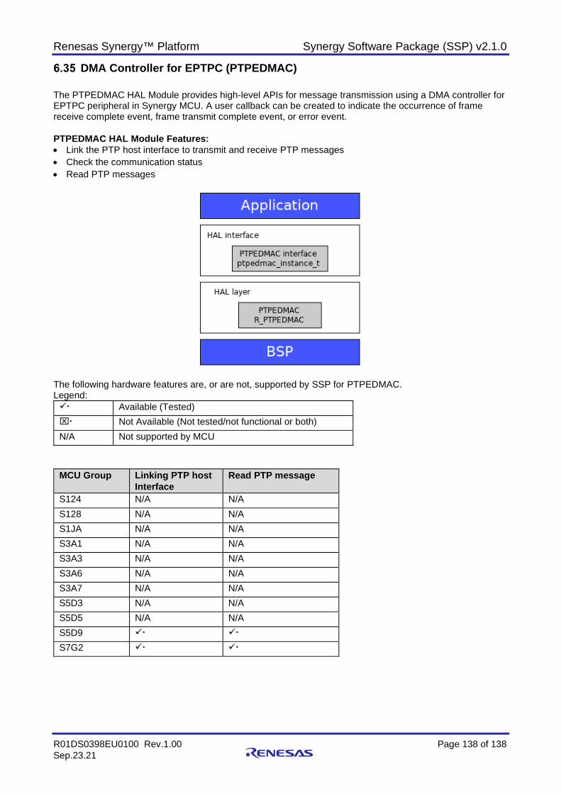
Renesas Synergy™ Platform Synergy Software Package (SSP) v2.1.0
R01DS0398EU0100 Rev.1.00 Page 138 of 138 Sep.23.21
DMA Controller for EPTPC (PTPEDMAC) The PTPEDMAC HAL Module provides high-level APIs for message transmission using a DMA controller for EPTPC peripheral in Synergy MCU. A user callback can be created to indicate the occurrence of frame receive complete event, frame transmit complete event, or error event. PTPEDMAC HAL Module Features: • Link the PTP host interface to transmit and receive PTP messages • Check the communication status • Read PTP messages
The following hardware features are, or are not, supported by SSP for PTPEDMAC. Legend: Available (Tested) Not Available (Not tested/not functional or both) N/A Not supported by MCU
MCU Group Linking PTP host Interface
Read PTP message
S124 N/A N/A S128 N/A N/A S1JA N/A N/A S3A1 N/A N/A S3A3 N/A N/A S3A6 N/A N/A S3A7 N/A N/A S5D3 N/A N/A S5D5 N/A N/A S5D9 S7G2
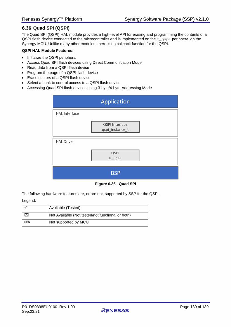
Renesas Synergy™ Platform Synergy Software Package (SSP) v2.1.0
R01DS0398EU0100 Rev.1.00 Page 139 of 139 Sep.23.21
Quad SPI (QSPI) The Quad SPI (QSPI) HAL module provides a high-level API for erasing and programming the contents of a QSPI flash device connected to the microcontroller and is implemented on the r_qspi peripheral on the Synergy MCU. Unlike many other modules, there is no callback function for the QSPI.
QSPI HAL Module Features: • Initialize the QSPI peripheral • Access Quad SPI flash devices using Direct Communication Mode • Read data from a QSPI flash device • Program the page of a QSPI flash device • Erase sectors of a QSPI flash device • Select a bank to control access to a QSPI flash device • Accessing Quad SPI flash devices using 3-byte/4-byte Addressing Mode
Figure 6.36 Quad SPI
The following hardware features are, or are not, supported by SSP for the QSPI.
Legend:
Available (Tested)
Not Available (Not tested/not functional or both)
N/A Not supported by MCU
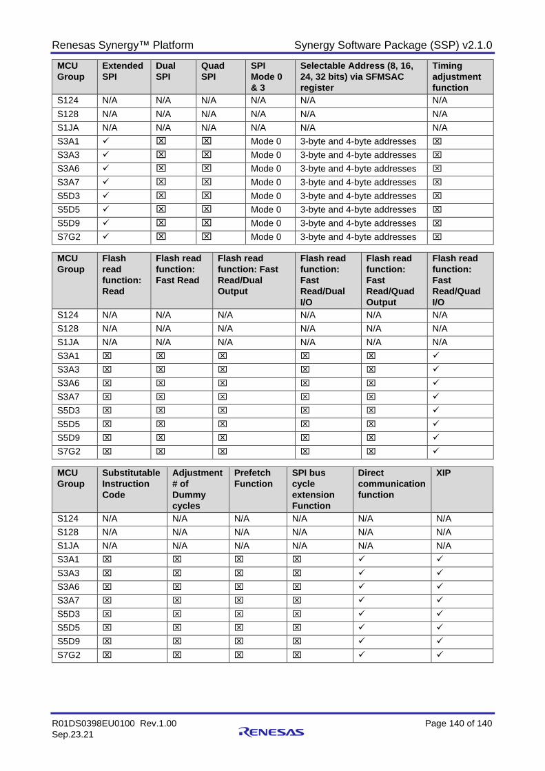
Renesas Synergy™ Platform Synergy Software Package (SSP) v2.1.0
R01DS0398EU0100 Rev.1.00 Page 140 of 140 Sep.23.21
MCU Group
Extended SPI
Dual SPI
Quad SPI
SPI Mode 0 & 3
Selectable Address (8, 16, 24, 32 bits) via SFMSAC register
Timing adjustment function
S124 N/A N/A N/A N/A N/A N/A S128 N/A N/A N/A N/A N/A N/A S1JA N/A N/A N/A N/A N/A N/A S3A1 Mode 0 3-byte and 4-byte addresses S3A3 Mode 0 3-byte and 4-byte addresses S3A6 Mode 0 3-byte and 4-byte addresses S3A7 Mode 0 3-byte and 4-byte addresses S5D3 Mode 0 3-byte and 4-byte addresses
S5D5 Mode 0 3-byte and 4-byte addresses S5D9 Mode 0 3-byte and 4-byte addresses S7G2 Mode 0 3-byte and 4-byte addresses
MCU Group
Flash read function: Read
Flash read function: Fast Read
Flash read function: Fast Read/Dual Output
Flash read function: Fast Read/Dual I/O
Flash read function: Fast Read/Quad Output
Flash read function: Fast Read/Quad I/O
S124 N/A N/A N/A N/A N/A N/A S128 N/A N/A N/A N/A N/A N/A S1JA N/A N/A N/A N/A N/A N/A S3A1 S3A3 S3A6 S3A7 S5D3
S5D5 S5D9 S7G2
MCU Group
Substitutable Instruction Code
Adjustment # of Dummy cycles
Prefetch Function
SPI bus cycle extension Function
Direct communication function
XIP
S124 N/A N/A N/A N/A N/A N/A S128 N/A N/A N/A N/A N/A N/A S1JA N/A N/A N/A N/A N/A N/A S3A1 S3A3 S3A6 S3A7 S5D3 S5D5 S5D9 S7G2
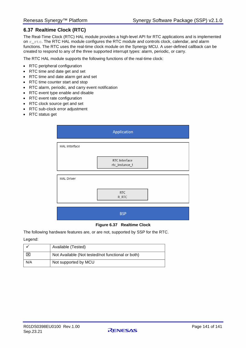
Renesas Synergy™ Platform Synergy Software Package (SSP) v2.1.0
R01DS0398EU0100 Rev.1.00 Page 141 of 141 Sep.23.21
Realtime Clock (RTC) The Real-Time Clock (RTC) HAL module provides a high-level API for RTC applications and is implemented on r_rtc. The RTC HAL module configures the RTC module and controls clock, calendar, and alarm functions. The RTC uses the real-time clock module on the Synergy MCU. A user-defined callback can be created to respond to any of the three supported interrupt types: alarm, periodic, or carry.
The RTC HAL module supports the following functions of the real-time clock:
• RTC peripheral configuration • RTC time and date get and set • RTC time and date alarm get and set • RTC time counter start and stop • RTC alarm, periodic, and carry event notification • RTC event type enable and disable • RTC event rate configuration • RTC clock source get and set • RTC sub-clock error adjustment • RTC status get
Figure 6.37 Realtime Clock
The following hardware features are, or are not, supported by SSP for the RTC.
Legend:
Available (Tested)
Not Available (Not tested/not functional or both)
N/A Not supported by MCU
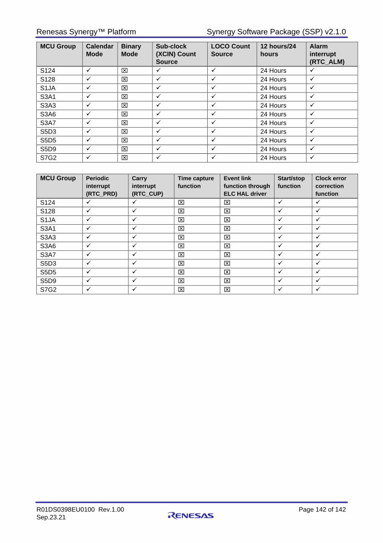
Renesas Synergy™ Platform Synergy Software Package (SSP) v2.1.0
R01DS0398EU0100 Rev.1.00 Page 142 of 142 Sep.23.21
MCU Group Calendar Mode
Binary Mode
Sub-clock (XCIN) Count Source
LOCO Count Source
12 hours/24 hours
Alarm interrupt (RTC_ALM)
S124 24 Hours S128 24 Hours S1JA 24 Hours S3A1 24 Hours S3A3 24 Hours S3A6 24 Hours S3A7 24 Hours S5D3 24 Hours S5D5 24 Hours S5D9 24 Hours S7G2 24 Hours
MCU Group Periodic interrupt (RTC_PRD)
Carry interrupt (RTC_CUP)
Time capture function
Event link function through ELC HAL driver
Start/stop function
Clock error correction function
S124 S128 S1JA S3A1 S3A3 S3A6 S3A7 S5D3 S5D5 S5D9 S7G2
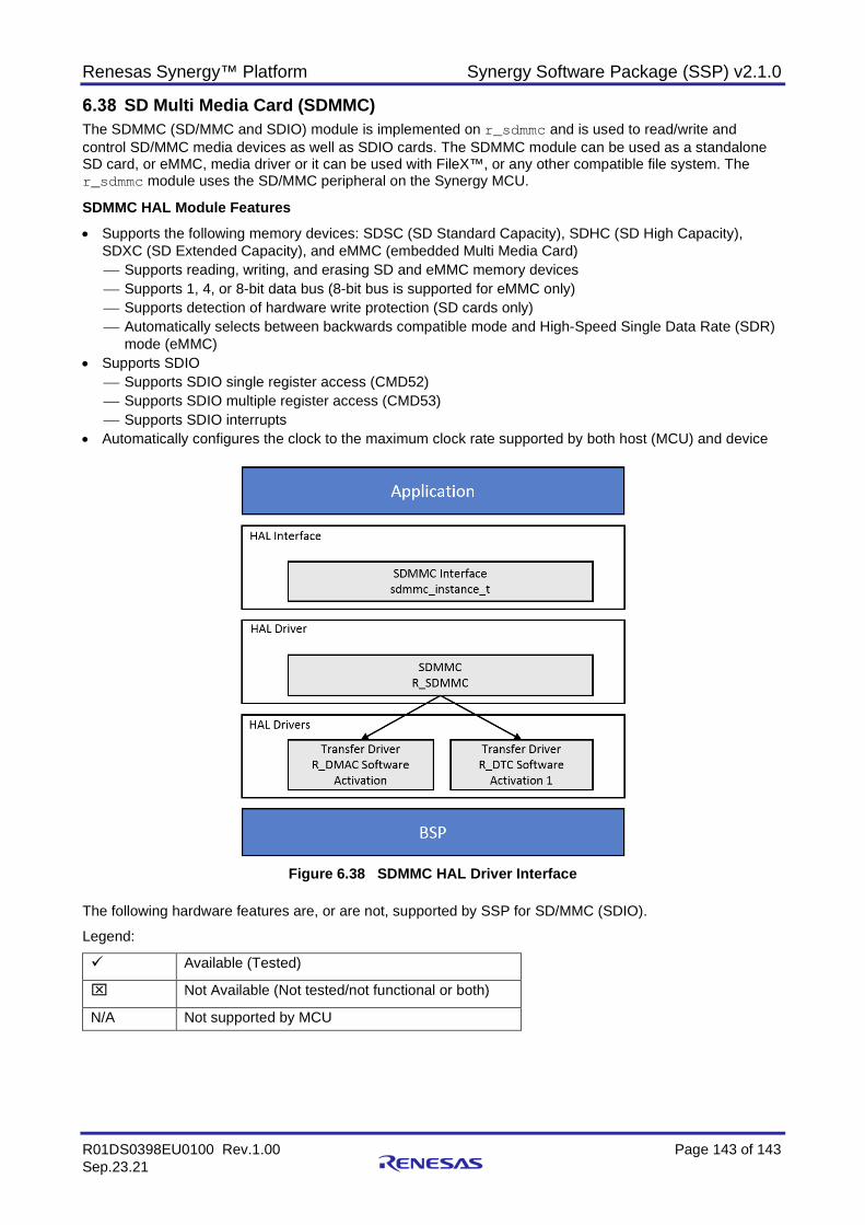
Renesas Synergy™ Platform Synergy Software Package (SSP) v2.1.0
R01DS0398EU0100 Rev.1.00 Page 143 of 143 Sep.23.21
SD Multi Media Card (SDMMC) The SDMMC (SD/MMC and SDIO) module is implemented on r_sdmmc and is used to read/write and control SD/MMC media devices as well as SDIO cards. The SDMMC module can be used as a standalone SD card, or eMMC, media driver or it can be used with FileX™, or any other compatible file system. The r_sdmmc module uses the SD/MMC peripheral on the Synergy MCU.
SDMMC HAL Module Features • Supports the following memory devices: SDSC (SD Standard Capacity), SDHC (SD High Capacity),
SDXC (SD Extended Capacity), and eMMC (embedded Multi Media Card) Supports reading, writing, and erasing SD and eMMC memory devices Supports 1, 4, or 8-bit data bus (8-bit bus is supported for eMMC only) Supports detection of hardware write protection (SD cards only) Automatically selects between backwards compatible mode and High-Speed Single Data Rate (SDR)
mode (eMMC) • Supports SDIO
Supports SDIO single register access (CMD52) Supports SDIO multiple register access (CMD53) Supports SDIO interrupts
• Automatically configures the clock to the maximum clock rate supported by both host (MCU) and device
Figure 6.38 SDMMC HAL Driver Interface
The following hardware features are, or are not, supported by SSP for SD/MMC (SDIO).
Legend:
Available (Tested)
Not Available (Not tested/not functional or both)
N/A Not supported by MCU
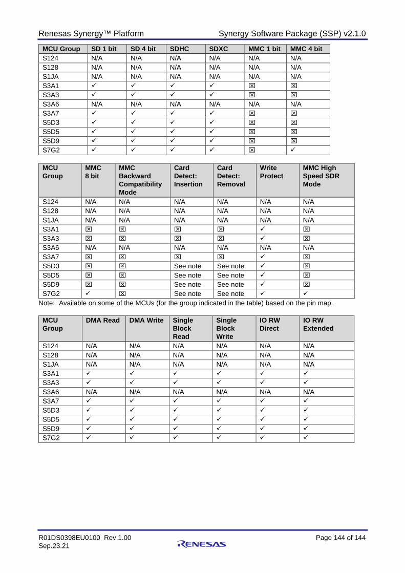
Renesas Synergy™ Platform Synergy Software Package (SSP) v2.1.0
R01DS0398EU0100 Rev.1.00 Page 144 of 144 Sep.23.21
MCU Group SD 1 bit SD 4 bit SDHC SDXC MMC 1 bit MMC 4 bit S124 N/A N/A N/A N/A N/A N/A S128 N/A N/A N/A N/A N/A N/A S1JA N/A N/A N/A N/A N/A N/A S3A1 S3A3 S3A6 N/A N/A N/A N/A N/A N/A S3A7 S5D3 S5D5 S5D9 S7G2
MCU Group
MMC 8 bit
MMC Backward Compatibility Mode
Card Detect: Insertion
Card Detect: Removal
Write Protect
MMC High Speed SDR Mode
S124 N/A N/A N/A N/A N/A N/A S128 N/A N/A N/A N/A N/A N/A S1JA N/A N/A N/A N/A N/A N/A S3A1 S3A3 S3A6 N/A N/A N/A N/A N/A N/A S3A7 S5D3 See note See note S5D5 See note See note S5D9 See note See note S7G2 See note See note
Note: Available on some of the MCUs (for the group indicated in the table) based on the pin map.
MCU Group
DMA Read DMA Write Single Block Read
Single Block Write
IO RW Direct
IO RW Extended
S124 N/A N/A N/A N/A N/A N/A S128 N/A N/A N/A N/A N/A N/A S1JA N/A N/A N/A N/A N/A N/A S3A1 S3A3 S3A6 N/A N/A N/A N/A N/A N/A S3A7 S5D3 S5D5 S5D9 S7G2
Renesas Synergy™ Platform Synergy Software Package (SSP) v2.1.0
R01DS0398EU0100 Rev.1.00 Page 145 of 145 Sep.23.21
Secure Cryptographic Engine (SCE) The Secure Cryptographic Engine (SCE) HAL module provides a high-level API for random number generation, digest computation (hash), data encryption and decryption, digital signing and verification, key generation (using RSA, AES and ECC algorithms) , ECC scalar multiplication and key installation (for RSA, AES and ECC keys). The SCE is a dedicated hardware block and the functionality provided by the SCE varies across the supported MCUs.
The SCE HAL module configures the cryptographic module, to enable users to build cryptographic protocols for security with the following cryptographic primitives:
• Random-number generation • Data encryption and decryption using AES or Triple DES (3DES), ARC4 algorithms • Signature generation and verification using the ECC, RSA, or DSA algorithms • Scalar multiplication support for ECDH key agreement operations • Message-digest computation using HASH algorithms MD5, SHA1, SHA224, or SHA256 • Key generation – AES wrapped keys, RSA plain text and wrapped keys, and ECC plain text and wrapped
keys • RSA CRT wrapped keys for 1024-bit and 2048-bit key sizes, including support for key generation,
decryption, signature generation, and key installation
• Installing the encrypted user key on to the Synergy Platform The SCE interface provides a common API for SCE HAL module. The SCE interface supports multiple operations depending on the chosen module (AES, ARC4, RSA, DSA, HASH, TDES, or TRNG).
The SSP Cryptographic library provides high-level, C-callable APIs for the following security functions in SCE7:
• True RNG (TRNG) • Generates cryptographically secure 128-bit random numbers • Generates seeds to deterministic random number generators (such as the NIST SP800-90A DRBG) • Cryptographic HASH functions • Generates hash values that provide a digital fingerprint of data • Supports SHA1 and SHA224/SHA256 and MD5 Encryption mechanism used for symmetric-key cryptography: • Encryption/decryption key is secretly shared between transmitter and receiver • Advanced Encryption Standard (AES) • Supports 128-bit, 192-bit, and 256-bit key lengths • Supports various chaining modes: ECB, CBC, CTR, GCM, and XTS • Data Encryption Standard 3DES • Supports 192-bit key length, operates on a fixed 8-byte block of data • Supports ECB CBC and CTR chaining modes • Used in legacy secure socket layer (SSL) and transport layer security (TLS) protocols • 3DES applies DES three times to each block • Alleged RC4 (ARC4) • Supports 2048-bit key length • Used in TLS and wired equivalent privacy (WEP) • Throughput for 128-bit data Encryption mechanism used for asymmetric-key cryptography:
• Public keys are exchanged between the transmitter and receiver, then the public and private keys are used to compute the shared secret between transmitter and receiver.
• Rivest, Shamir, and Adleman (RSA) supports 1024-bit and 2048-bit keys • Elliptical Curve Cryptography (ECC) supports P-192, P-224, P-256 and P-384 • Digital Signature Algorithm (DSA) supports (1024, 160)-bit, (2048, 224)-bit, (2048, 256)-bit keys • Used for public-key cryptography • Generates two keys: public and private

Renesas Synergy™ Platform Synergy Software Package (SSP) v2.1.0
R01DS0398EU0100 Rev.1.00 Page 146 of 146 Sep.23.21
• Transmitter encrypts using the public key • Receiver decrypts using the private key • Used in digital verification for authentication, signature generation and verification, encryption/decryption
for key exchange and wrapping, and other security functions
Figure 6.39 SCE HAL Module Block Diagram
Note: The prior figure shows all nine available crypto modules. The SCE COMMON module is repeated for
each one since it is included when the module is added to a thread stack. Common modules can be referenced by multiple other module instances across multiple Synergy stacks.
Table 6.1 Support of MCU Groups: SCE Driver
Function S7G2, S5D9, S5D5, S5D3
S3A1, S3A3, S3A7, S3A6
S1JA, S124, S128 Notes
TRNG Generate and read random number
Generate and read random number
Generate and read random number
Generate and read random number
AES Encryption, decryption, key generation - wrapped keys
Encryption, decryption, key generation - wrapped keys
Encryption, decryption
Symmetric key encryption based on AES standard
AES Key Size 128-bit, 192-bit, 256-bit
128-bit, 256-bit 128-bit, 256-bit
AES Key Type Plain text / raw key, wrapped key
Plain text / raw key, wrapped key
Plain text / raw key
AES Chaining Modes
ECB, CBC, CTR, GCM, XTS††
ECB, CBC, CTR, GCM, XTS
ECB, CBC, CTR
ARC4 Encryption, decryption
NA NA
TDES Encryption, decryption
NA NA
TDES Key Size 192-bit NA NA TDES Chaining Modes
ECB, CBC, CTR NA NA
RSA Signature Generation, Signature Verification, Public-key Encryption, Private-key Decryption, Key Generation - plain text and wrapped keys
NA NA Supports CRT keys and standard keys for private key operations for both plain-text and wrapped key types
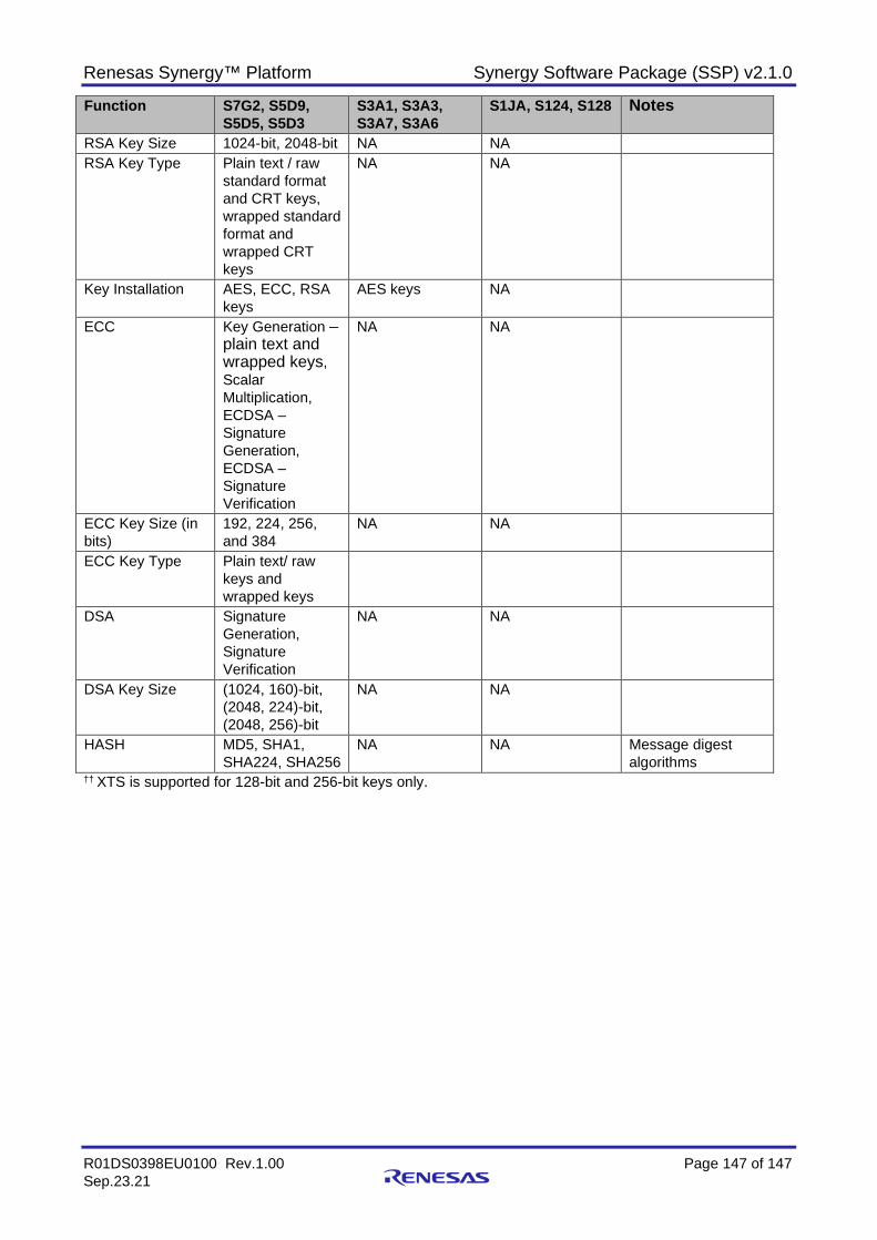
Renesas Synergy™ Platform Synergy Software Package (SSP) v2.1.0
R01DS0398EU0100 Rev.1.00 Page 147 of 147 Sep.23.21
Function S7G2, S5D9, S5D5, S5D3
S3A1, S3A3, S3A7, S3A6
S1JA, S124, S128 Notes
RSA Key Size 1024-bit, 2048-bit NA NA RSA Key Type Plain text / raw
standard format and CRT keys, wrapped standard format and wrapped CRT keys
NA NA
Key Installation AES, ECC, RSA keys
AES keys NA
ECC Key Generation – plain text and wrapped keys, Scalar Multiplication, ECDSA – Signature Generation, ECDSA – Signature Verification
NA NA
ECC Key Size (in bits)
192, 224, 256, and 384
NA NA
ECC Key Type Plain text/ raw keys and wrapped keys
DSA Signature Generation, Signature Verification
NA NA
DSA Key Size (1024, 160)-bit, (2048, 224)-bit, (2048, 256)-bit
NA NA
HASH MD5, SHA1, SHA224, SHA256
NA NA Message digest algorithms
†† XTS is supported for 128-bit and 256-bit keys only.
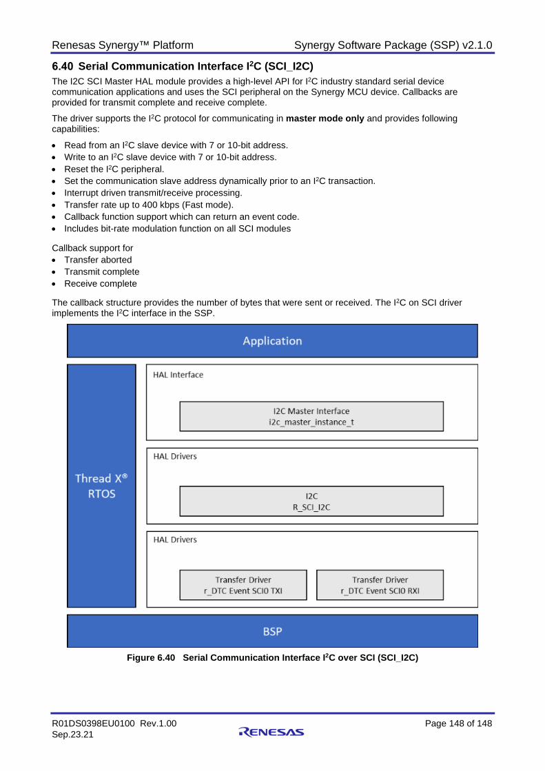
Renesas Synergy™ Platform Synergy Software Package (SSP) v2.1.0
R01DS0398EU0100 Rev.1.00 Page 148 of 148 Sep.23.21
Serial Communication Interface I2C (SCI_I2C) The I2C SCI Master HAL module provides a high-level API for I2C industry standard serial device communication applications and uses the SCI peripheral on the Synergy MCU device. Callbacks are provided for transmit complete and receive complete.
The driver supports the I2C protocol for communicating in master mode only and provides following capabilities:
• Read from an I2C slave device with 7 or 10-bit address. • Write to an I2C slave device with 7 or 10-bit address. • Reset the I2C peripheral. • Set the communication slave address dynamically prior to an I2C transaction. • Interrupt driven transmit/receive processing. • Transfer rate up to 400 kbps (Fast mode). • Callback function support which can return an event code. • Includes bit-rate modulation function on all SCI modules Callback support for • Transfer aborted • Transmit complete • Receive complete The callback structure provides the number of bytes that were sent or received. The I2C on SCI driver implements the I2C interface in the SSP.
Figure 6.40 Serial Communication Interface I2C over SCI (SCI_I2C)
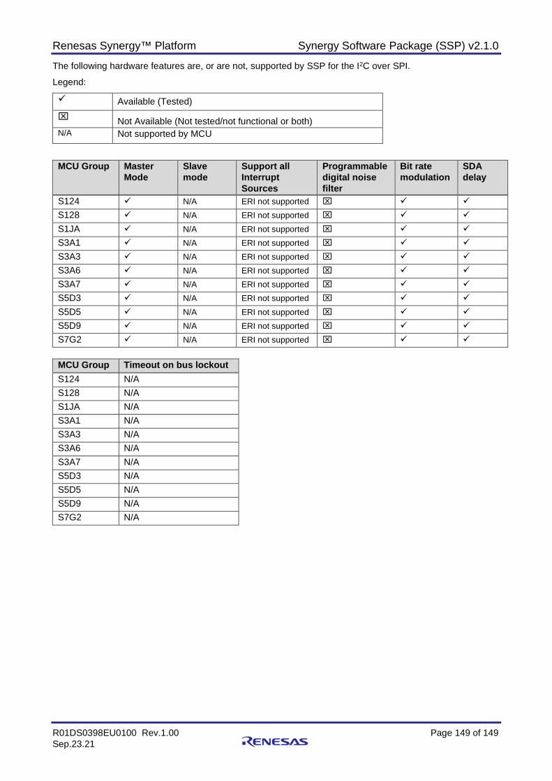
Renesas Synergy™ Platform Synergy Software Package (SSP) v2.1.0
R01DS0398EU0100 Rev.1.00 Page 149 of 149 Sep.23.21
The following hardware features are, or are not, supported by SSP for the I2C over SPI.
Legend:
Available (Tested) Not Available (Not tested/not functional or both) N/A Not supported by MCU
MCU Group Master Mode
Slave mode
Support all Interrupt Sources
Programmable digital noise filter
Bit rate modulation
SDA delay
S124 N/A ERI not supported
S128 N/A ERI not supported
S1JA N/A ERI not supported
S3A1 N/A ERI not supported
S3A3 N/A ERI not supported
S3A6 N/A ERI not supported
S3A7 N/A ERI not supported
S5D3 N/A ERI not supported
S5D5 N/A ERI not supported
S5D9 N/A ERI not supported
S7G2 N/A ERI not supported
MCU Group Timeout on bus lockout S124 N/A S128 N/A S1JA N/A S3A1 N/A S3A3 N/A S3A6 N/A S3A7 N/A S5D3 N/A S5D5 N/A S5D9 N/A S7G2 N/A
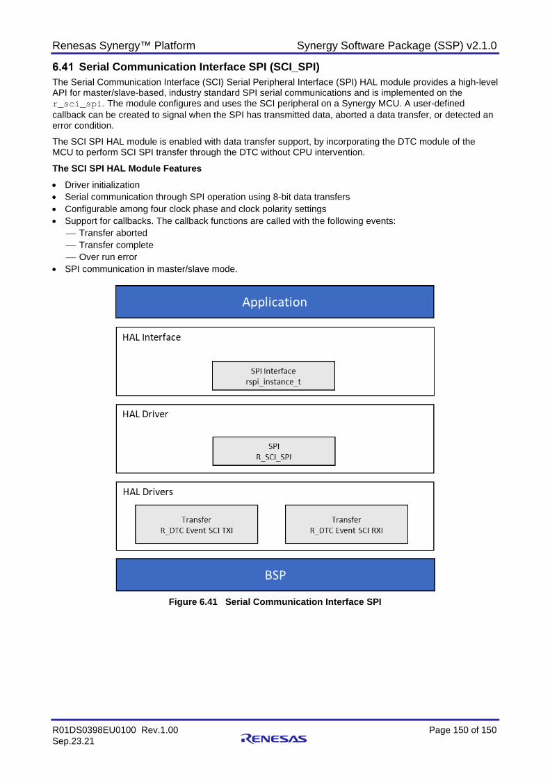
Renesas Synergy™ Platform Synergy Software Package (SSP) v2.1.0
R01DS0398EU0100 Rev.1.00 Page 150 of 150 Sep.23.21
Serial Communication Interface SPI (SCI_SPI) The Serial Communication Interface (SCI) Serial Peripheral Interface (SPI) HAL module provides a high-level API for master/slave-based, industry standard SPI serial communications and is implemented on the r_sci_spi. The module configures and uses the SCI peripheral on a Synergy MCU. A user-defined callback can be created to signal when the SPI has transmitted data, aborted a data transfer, or detected an error condition.
The SCI SPI HAL module is enabled with data transfer support, by incorporating the DTC module of the MCU to perform SCI SPI transfer through the DTC without CPU intervention.
The SCI SPI HAL Module Features • Driver initialization • Serial communication through SPI operation using 8-bit data transfers • Configurable among four clock phase and clock polarity settings • Support for callbacks. The callback functions are called with the following events:
Transfer aborted Transfer complete Over run error
• SPI communication in master/slave mode.
Figure 6.41 Serial Communication Interface SPI
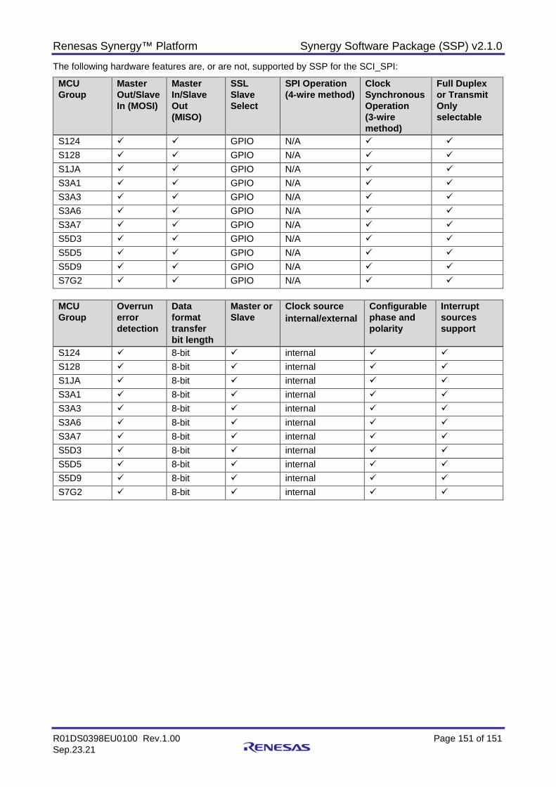
Renesas Synergy™ Platform Synergy Software Package (SSP) v2.1.0
R01DS0398EU0100 Rev.1.00 Page 151 of 151 Sep.23.21
The following hardware features are, or are not, supported by SSP for the SCI_SPI:
MCU Group
Master Out/Slave In (MOSI)
Master In/Slave Out (MISO)
SSL Slave Select
SPI Operation (4-wire method)
Clock Synchronous Operation (3-wire method)
Full Duplex or Transmit Only selectable
S124 GPIO N/A S128 GPIO N/A S1JA GPIO N/A S3A1 GPIO N/A S3A3 GPIO N/A S3A6 GPIO N/A S3A7 GPIO N/A S5D3 GPIO N/A S5D5 GPIO N/A S5D9 GPIO N/A S7G2 GPIO N/A
MCU Group
Overrun error detection
Data format transfer bit length
Master or Slave
Clock source internal/external
Configurable phase and polarity
Interrupt sources support
S124 8-bit internal
S128 8-bit internal
S1JA 8-bit internal
S3A1 8-bit internal
S3A3 8-bit internal
S3A6 8-bit internal
S3A7 8-bit internal
S5D3 8-bit internal
S5D5 8-bit internal
S5D9 8-bit internal
S7G2 8-bit internal
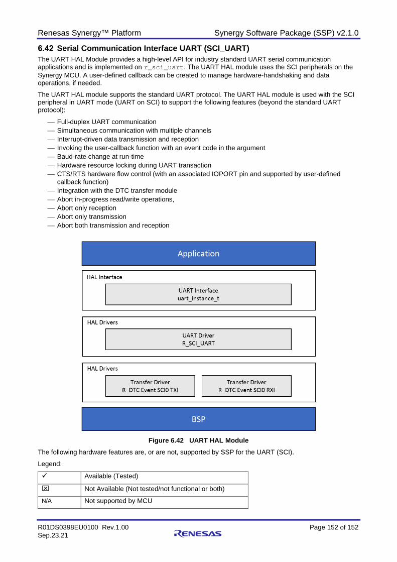
Renesas Synergy™ Platform Synergy Software Package (SSP) v2.1.0
R01DS0398EU0100 Rev.1.00 Page 152 of 152 Sep.23.21
Serial Communication Interface UART (SCI_UART) The UART HAL Module provides a high-level API for industry standard UART serial communication applications and is implemented on r_sci_uart. The UART HAL module uses the SCI peripherals on the Synergy MCU. A user-defined callback can be created to manage hardware-handshaking and data operations, if needed.
The UART HAL module supports the standard UART protocol. The UART HAL module is used with the SCI peripheral in UART mode (UART on SCI) to support the following features (beyond the standard UART protocol):
Full-duplex UART communication Simultaneous communication with multiple channels Interrupt-driven data transmission and reception Invoking the user-callback function with an event code in the argument Baud-rate change at run-time Hardware resource locking during UART transaction CTS/RTS hardware flow control (with an associated IOPORT pin and supported by user-defined
callback function) Integration with the DTC transfer module Abort in-progress read/write operations, Abort only reception Abort only transmission Abort both transmission and reception
Figure 6.42 UART HAL Module
The following hardware features are, or are not, supported by SSP for the UART (SCI).
Legend:
Available (Tested)
Not Available (Not tested/not functional or both)
N/A Not supported by MCU
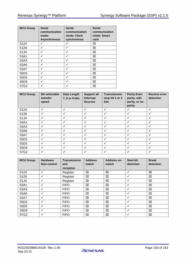
Renesas Synergy™ Platform Synergy Software Package (SSP) v2.1.0
R01DS0398EU0100 Rev.1.00 Page 153 of 153 Sep.23.21
MCU Group Serial communication mode: Asynchronous
Serial communication mode: Clock synchronous
Serial communication mode: Smart card
S124 S128 S1JA S3A1 S3A3 S3A6 S3A7 S5D3 S5D5 S5D9 S7G2
MCU Group Bit selectable
transfer speed
Data Length 7, 8 or 9 bits
Support all Interrupt Sources
Transmission stop bit 1 or 2 bits
Parity Even parity, odd parity, or no parity
Receive error detection
S124 S128 S1JA S3A1 S3A3 S3A6 S3A7 S5D3 S5D5 S5D9 S7G2
MCU Group Hardware
flow control Transmission and reception
Address match
Address un-match
Start-bit detection
Break detection
S124 Register S128 Register S1JA Register S3A1 FIFO S3A3 FIFO S3A6 FIFO S3A7 FIFO S5D3 FIFO S5D5 FIFO S5D9 FIFO S7G2 FIFO

Renesas Synergy™ Platform Synergy Software Package (SSP) v2.1.0
R01DS0398EU0100 Rev.1.00 Page 154 of 154 Sep.23.21
MCU Group Clock source Internal/ external
Double-speed mode
Multi-processor communications
Noise cancellation
Bit rate modulation function
iRDA support
S124 S128 S1JA S3A1 S3A3 S3A6 S3A7 S5D3 S5D5 S5D9 S7G2
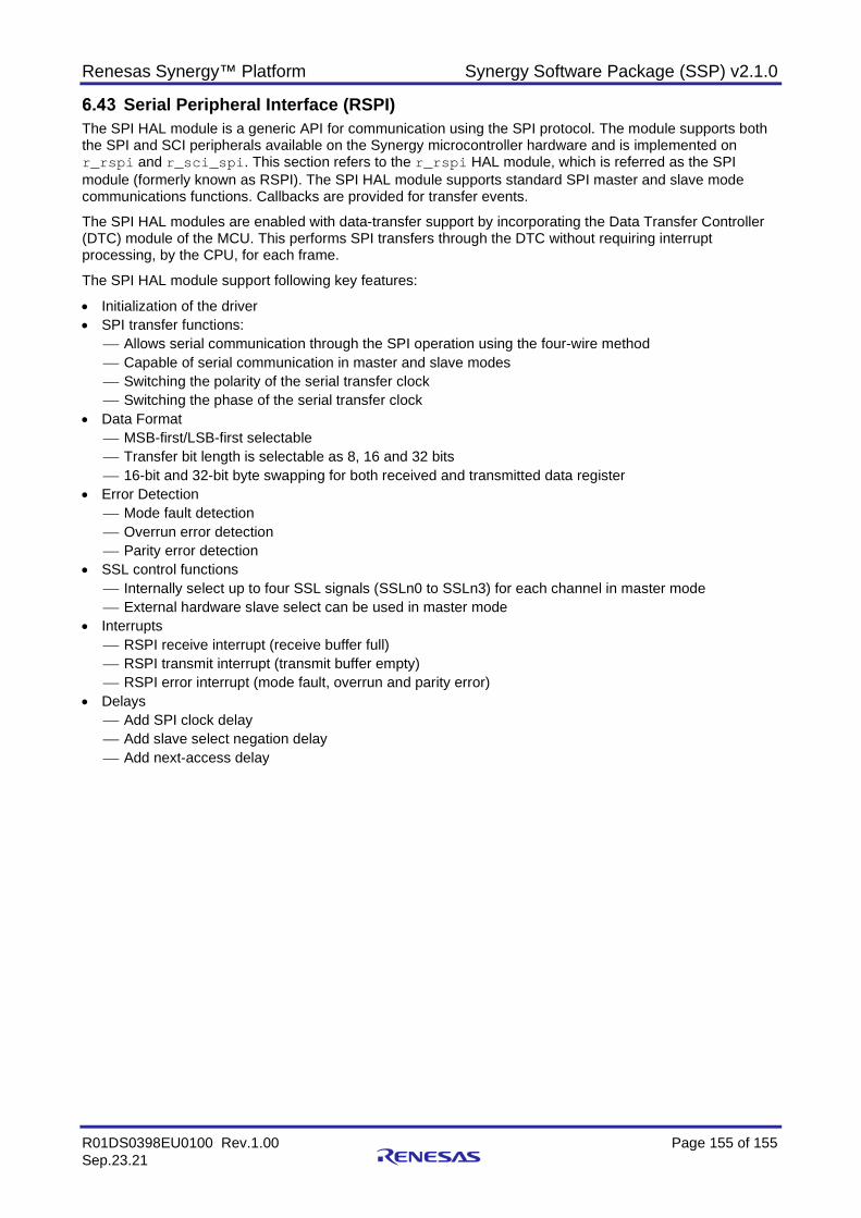
Renesas Synergy™ Platform Synergy Software Package (SSP) v2.1.0
R01DS0398EU0100 Rev.1.00 Page 155 of 155 Sep.23.21
Serial Peripheral Interface (RSPI) The SPI HAL module is a generic API for communication using the SPI protocol. The module supports both the SPI and SCI peripherals available on the Synergy microcontroller hardware and is implemented on r_rspi and r_sci_spi. This section refers to the r_rspi HAL module, which is referred as the SPI module (formerly known as RSPI). The SPI HAL module supports standard SPI master and slave mode communications functions. Callbacks are provided for transfer events.
The SPI HAL modules are enabled with data-transfer support by incorporating the Data Transfer Controller (DTC) module of the MCU. This performs SPI transfers through the DTC without requiring interrupt processing, by the CPU, for each frame.
The SPI HAL module support following key features:
• Initialization of the driver • SPI transfer functions:
Allows serial communication through the SPI operation using the four-wire method Capable of serial communication in master and slave modes Switching the polarity of the serial transfer clock Switching the phase of the serial transfer clock
• Data Format MSB-first/LSB-first selectable Transfer bit length is selectable as 8, 16 and 32 bits 16-bit and 32-bit byte swapping for both received and transmitted data register
• Error Detection Mode fault detection Overrun error detection Parity error detection
• SSL control functions Internally select up to four SSL signals (SSLn0 to SSLn3) for each channel in master mode External hardware slave select can be used in master mode
• Interrupts RSPI receive interrupt (receive buffer full) RSPI transmit interrupt (transmit buffer empty) RSPI error interrupt (mode fault, overrun and parity error)
• Delays Add SPI clock delay Add slave select negation delay Add next-access delay
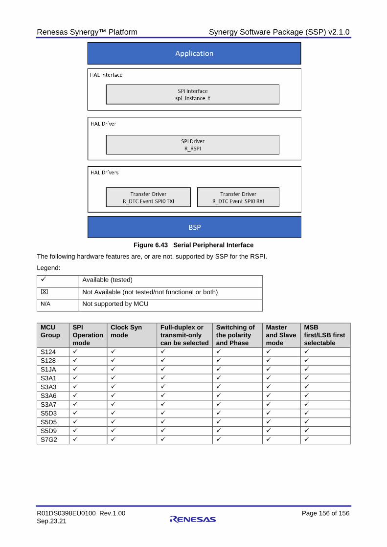
Renesas Synergy™ Platform Synergy Software Package (SSP) v2.1.0
R01DS0398EU0100 Rev.1.00 Page 156 of 156 Sep.23.21
Figure 6.43 Serial Peripheral Interface
The following hardware features are, or are not, supported by SSP for the RSPI.
Legend:
Available (tested)
Not Available (not tested/not functional or both)
N/A Not supported by MCU
MCU Group
SPI Operation mode
Clock Syn mode
Full-duplex or transmit-only can be selected
Switching of the polarity and Phase
Master and Slave mode
MSB first/LSB first selectable
S124 S128 S1JA S3A1 S3A3 S3A6 S3A7 S5D3 S5D5 S5D9 S7G2
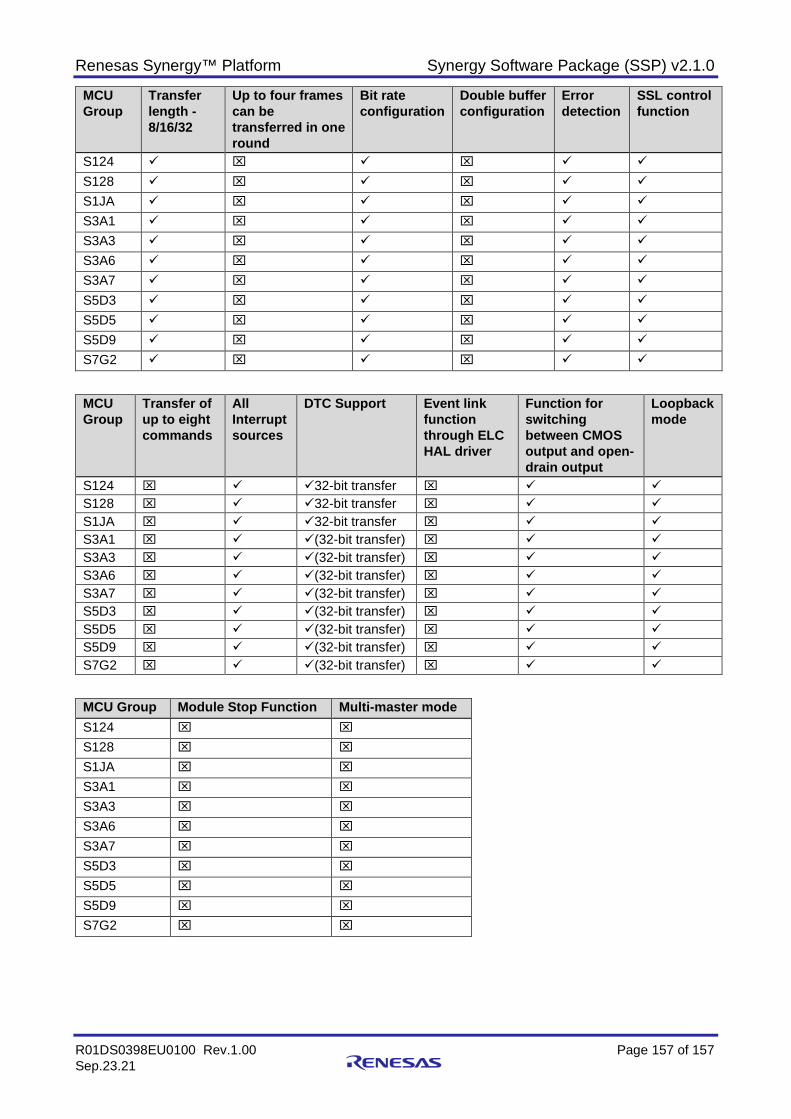
Renesas Synergy™ Platform Synergy Software Package (SSP) v2.1.0
R01DS0398EU0100 Rev.1.00 Page 157 of 157 Sep.23.21
MCU Group
Transfer length - 8/16/32
Up to four frames can be transferred in one round
Bit rate configuration
Double buffer configuration
Error detection
SSL control function
S124
S128
S1JA
S3A1
S3A3
S3A6
S3A7
S5D3
S5D5
S5D9
S7G2
MCU Group
Transfer of up to eight commands
All Interrupt sources
DTC Support Event link function through ELC HAL driver
Function for switching between CMOS output and open-drain output
Loopback mode
S124 32-bit transfer S128 32-bit transfer S1JA 32-bit transfer S3A1 (32-bit transfer) S3A3 (32-bit transfer) S3A6 (32-bit transfer) S3A7 (32-bit transfer) S5D3 (32-bit transfer) S5D5 (32-bit transfer) S5D9 (32-bit transfer) S7G2 (32-bit transfer)
MCU Group Module Stop Function Multi-master mode S124
S128
S1JA
S3A1
S3A3
S3A6
S3A7
S5D3
S5D5
S5D9
S7G2
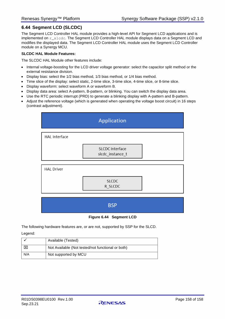
Renesas Synergy™ Platform Synergy Software Package (SSP) v2.1.0
R01DS0398EU0100 Rev.1.00 Page 158 of 158 Sep.23.21
Segment LCD (SLCDC) The Segment LCD Controller HAL module provides a high-level API for Segment LCD applications and is implemented on r_slcdc. The Segment LCD Controller HAL module displays data on a Segment LCD and modifies the displayed data. The Segment LCD Controller HAL module uses the Segment LCD Controller module on a Synergy MCU.
SLCDC HAL Module Features: The SLCDC HAL Module other features include:
• Internal voltage-boosting for the LCD driver voltage generator: select the capacitor split method or the external resistance division.
• Display bias: select the 1/2 bias method, 1/3 bias method, or 1/4 bias method. • Time slice of the display: select static, 2-time slice, 3-time slice, 4-time slice, or 8-time slice. • Display waveform: select waveform A or waveform B. • Display data area: select A-pattern, B-pattern, or blinking. You can switch the display data area. • Use the RTC periodic interrupt (PRD) to generate a blinking display with A-pattern and B-pattern. • Adjust the reference voltage (which is generated when operating the voltage boost circuit) in 16 steps
(contrast adjustment).
Figure 6.44 Segment LCD
The following hardware features are, or are not, supported by SSP for the SLCD.
Legend:
Available (Tested)
Not Available (Not tested/not functional or both)
N/A Not supported by MCU
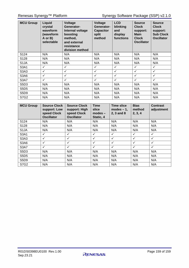
Renesas Synergy™ Platform Synergy Software Package (SSP) v2.1.0
R01DS0398EU0100 Rev.1.00 Page 159 of 159 Sep.23.21
MCU Group Liquid crystal waveform (waveform A or B) selectable
Voltage Generator- Internal voltage boosting method, and external resistance division method
Voltage Generator- Capacitor split method
LCD blinking and display functions
Source Clock support: Main Clock Oscillator
Source Clock support: Sub Clock Oscillator
S124 N/A N/A N/A N/A N/A N/A S128 N/A N/A N/A N/A N/A N/A S1JA N/A N/A N/A N/A N/A N/A S3A1 S3A3 S3A6 S3A7 S5D3 N/A N/A N/A N/A N/A N/A S5D5 N/A N/A N/A N/A N/A N/A S5D9 N/A N/A N/A N/A N/A N/A S7G2 N/A N/A N/A N/A N/A N/A
MCU Group Source Clock
support: Low speed Clock Oscillator
Source Clock support: High speed Clock Oscillator
Time slice modes – Static, 4
Time slice modes – 1, 2, 3 and 8
Bias method 2, 3, 4
Contrast adjustment
S124 N/A N/A N/A N/A N/A N/A S128 N/A N/A N/A N/A N/A N/A S1JA N/A N/A N/A N/A N/A N/A S3A1 S3A3 S3A6 S3A7 S5D3 N/A N/A N/A N/A N/A N/A S5D5 N/A N/A N/A N/A N/A N/A S5D9 N/A N/A N/A N/A N/A N/A S7G2 N/A N/A N/A N/A N/A N/A
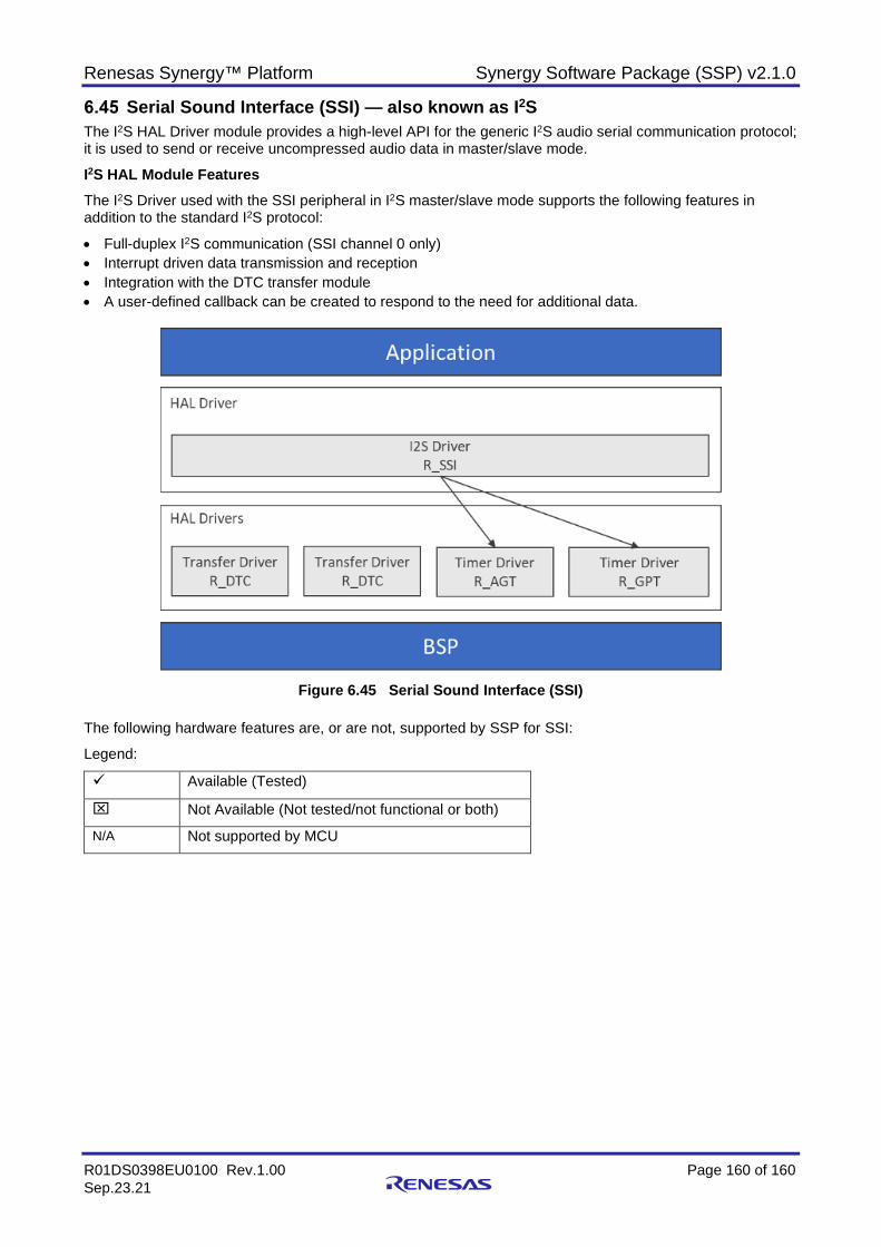
Renesas Synergy™ Platform Synergy Software Package (SSP) v2.1.0
R01DS0398EU0100 Rev.1.00 Page 160 of 160 Sep.23.21
Serial Sound Interface (SSI) — also known as I2S The I2S HAL Driver module provides a high-level API for the generic I2S audio serial communication protocol; it is used to send or receive uncompressed audio data in master/slave mode.
I2S HAL Module Features The I2S Driver used with the SSI peripheral in I2S master/slave mode supports the following features in addition to the standard I2S protocol:
• Full-duplex I2S communication (SSI channel 0 only) • Interrupt driven data transmission and reception • Integration with the DTC transfer module • A user-defined callback can be created to respond to the need for additional data.
Figure 6.45 Serial Sound Interface (SSI)
The following hardware features are, or are not, supported by SSP for SSI:
Legend:
Available (Tested)
Not Available (Not tested/not functional or both)
N/A Not supported by MCU

Renesas Synergy™ Platform Synergy Software Package (SSP) v2.1.0
R01DS0398EU0100 Rev.1.00 Page 161 of 161 Sep.23.21
MCU Group
Supports 2 Channels
SSI Format Support
MSB-first Format Support
Serial bit clock configurable {16, 32, 48, and 64 sampling rates}
Master clock input from the master clock pin for audio (AUDIO_CLK)
Master clock input from the master clock pin for GPT output (GTIOC1A)
S124 N/A N/A N/A N/A N/A N/A S128 N/A N/A N/A N/A N/A N/A S1JA N/A N/A N/A N/A N/A N/A S3A1 S3A6 S3A3 S3A7 S5D3 S5D5 S5D9 S7G2
MCU Group
Ability to select Stop Word SSIWS
Accepts Interrupts from Communication Errors
Accepts Interrupts from Receive Data Full
Accepts Interrupts from Transmit Data Empty
Internal Connection to GPT output GTIOC1A
S124 N/A N/A N/A N/A N/A S128 N/A N/A N/A N/A N/A S1JA N/A N/A N/A N/A N/A S3A1 S3A3
S3A6
S3A7
S5D3
S5D5
S5D9 S7G2
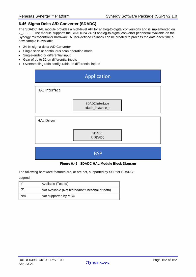
Renesas Synergy™ Platform Synergy Software Package (SSP) v2.1.0
R01DS0398EU0100 Rev.1.00 Page 162 of 162 Sep.23.21
Sigma Delta A/D Converter (SDADC) The SDADC HAL module provides a high-level API for analog-to-digital conversions and is implemented on r_sdadc. The module supports the SDADC24 24-bit analog-to-digital converter peripheral available on the Synergy microcontroller hardware. A user-defined callback can be created to process the data each time a new sample is available.
• 24-bit sigma delta A/D Converter • Single scan or continuous scan operation mode • Single-ended or differential input • Gain of up to 32 on differential inputs • Oversampling ratio configurable on differential inputs
Figure 6.46 SDADC HAL Module Block Diagram
The following hardware features are, or are not, supported by SSP for SDADC:
Legend:
Available (Tested)
Not Available (Not tested/not functional or both)
N/A Not supported by MCU
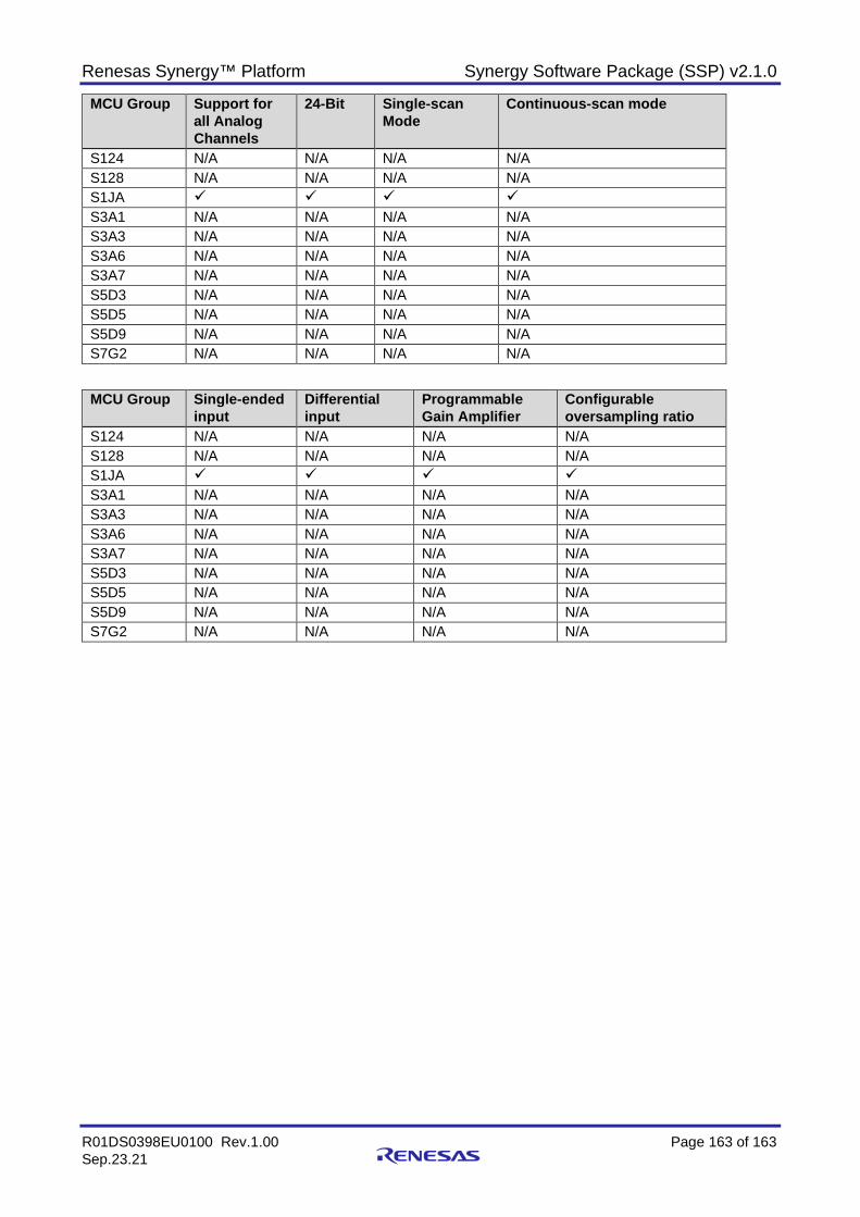
Renesas Synergy™ Platform Synergy Software Package (SSP) v2.1.0
R01DS0398EU0100 Rev.1.00 Page 163 of 163 Sep.23.21
MCU Group Support for all Analog Channels
24-Bit Single-scan Mode
Continuous-scan mode
S124 N/A N/A N/A N/A S128 N/A N/A N/A N/A S1JA S3A1 N/A N/A N/A N/A S3A3 N/A N/A N/A N/A S3A6 N/A N/A N/A N/A S3A7 N/A N/A N/A N/A S5D3 N/A N/A N/A N/A S5D5 N/A N/A N/A N/A S5D9 N/A N/A N/A N/A S7G2 N/A N/A N/A N/A
MCU Group Single-ended input
Differential input
Programmable Gain Amplifier
Configurable oversampling ratio
S124 N/A N/A N/A N/A S128 N/A N/A N/A N/A S1JA S3A1 N/A N/A N/A N/A S3A3 N/A N/A N/A N/A S3A6 N/A N/A N/A N/A S3A7 N/A N/A N/A N/A S5D3 N/A N/A N/A N/A S5D5 N/A N/A N/A N/A S5D9 N/A N/A N/A N/A S7G2 N/A N/A N/A N/A
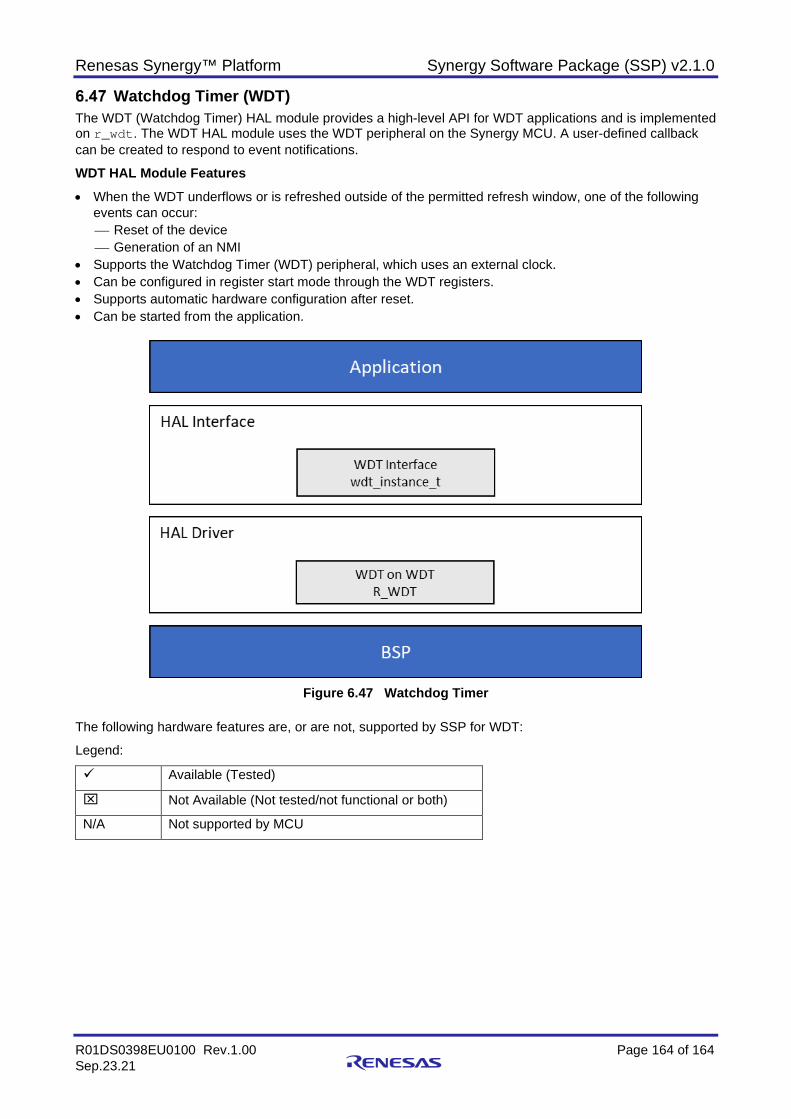
Renesas Synergy™ Platform Synergy Software Package (SSP) v2.1.0
R01DS0398EU0100 Rev.1.00 Page 164 of 164 Sep.23.21
Watchdog Timer (WDT) The WDT (Watchdog Timer) HAL module provides a high-level API for WDT applications and is implemented on r_wdt. The WDT HAL module uses the WDT peripheral on the Synergy MCU. A user-defined callback can be created to respond to event notifications.
WDT HAL Module Features • When the WDT underflows or is refreshed outside of the permitted refresh window, one of the following
events can occur: Reset of the device Generation of an NMI
• Supports the Watchdog Timer (WDT) peripheral, which uses an external clock. • Can be configured in register start mode through the WDT registers. • Supports automatic hardware configuration after reset. • Can be started from the application.
Figure 6.47 Watchdog Timer
The following hardware features are, or are not, supported by SSP for WDT:
Legend:
Available (Tested)
Not Available (Not tested/not functional or both)
N/A Not supported by MCU
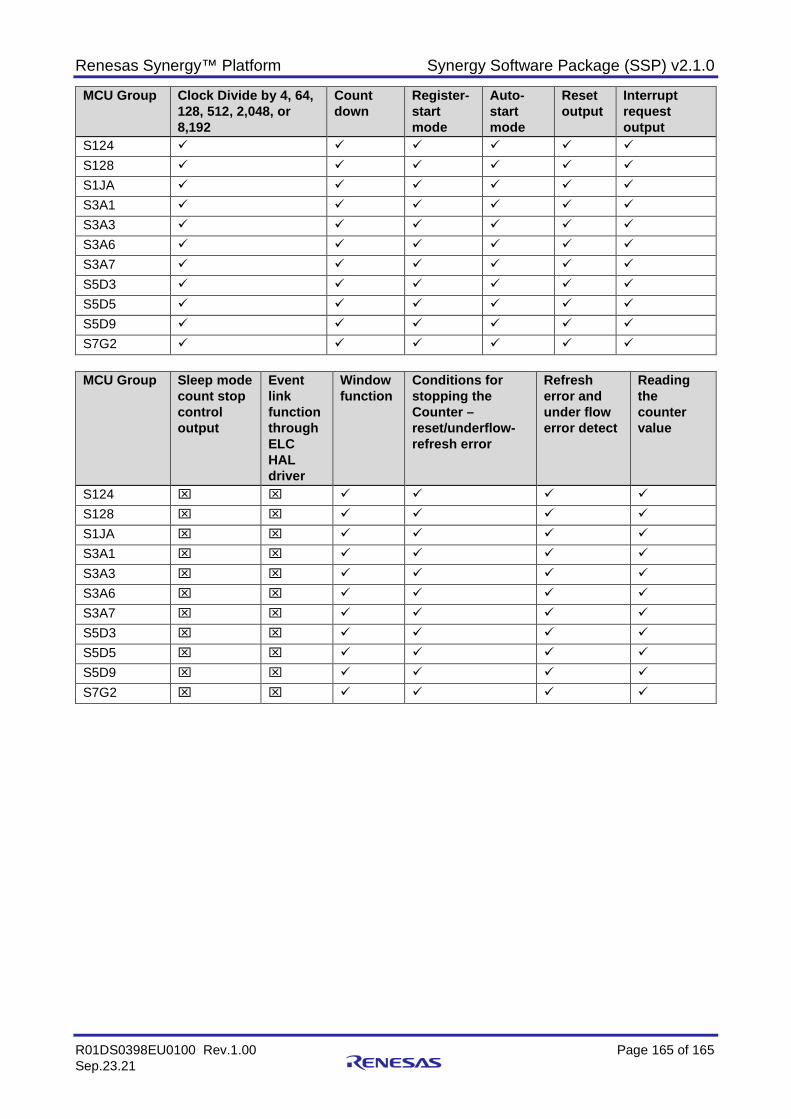
Renesas Synergy™ Platform Synergy Software Package (SSP) v2.1.0
R01DS0398EU0100 Rev.1.00 Page 165 of 165 Sep.23.21
MCU Group Clock Divide by 4, 64, 128, 512, 2,048, or 8,192
Count down
Register-start mode
Auto-start mode
Reset output
Interrupt request output
S124 S128 S1JA
S3A1
S3A3
S3A6 S3A7 S5D3
S5D5 S5D9 S7G2
MCU Group Sleep mode
count stop control output
Event link function through ELC HAL driver
Window function
Conditions for stopping the Counter – reset/underflow-refresh error
Refresh error and under flow error detect
Reading the counter value
S124 S128 S1JA
S3A1
S3A3
S3A6 S3A7 S5D3
S5D5 S5D9 S7G2
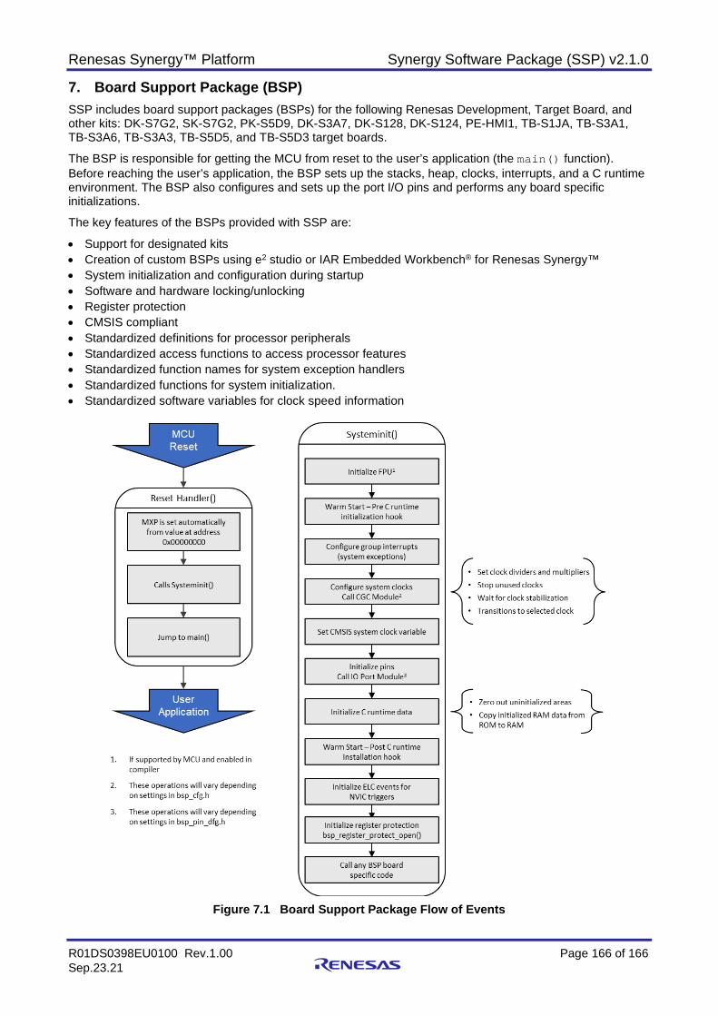
Renesas Synergy™ Platform Synergy Software Package (SSP) v2.1.0
R01DS0398EU0100 Rev.1.00 Page 166 of 166 Sep.23.21
7. Board Support Package (BSP) SSP includes board support packages (BSPs) for the following Renesas Development, Target Board, and other kits: DK-S7G2, SK-S7G2, PK-S5D9, DK-S3A7, DK-S128, DK-S124, PE-HMI1, TB-S1JA, TB-S3A1, TB-S3A6, TB-S3A3, TB-S5D5, and TB-S5D3 target boards.
The BSP is responsible for getting the MCU from reset to the user’s application (the main() function). Before reaching the user’s application, the BSP sets up the stacks, heap, clocks, interrupts, and a C runtime environment. The BSP also configures and sets up the port I/O pins and performs any board specific initializations.
The key features of the BSPs provided with SSP are:
• Support for designated kits • Creation of custom BSPs using e2 studio or IAR Embedded Workbench® for Renesas Synergy™ • System initialization and configuration during startup • Software and hardware locking/unlocking • Register protection • CMSIS compliant • Standardized definitions for processor peripherals • Standardized access functions to access processor features • Standardized function names for system exception handlers • Standardized functions for system initialization. • Standardized software variables for clock speed information
Figure 7.1 Board Support Package Flow of Events
Renesas Synergy™ Platform Synergy Software Package (SSP) v2.1.0
R01DS0398EU0100 Rev.1.00 Page 167 of 167 Sep.23.21
Website and Support Visit the following vanity URLs to learn about key elements of the Synergy Platform, download components and related documentation, and get support.
Synergy Software www.renesas.com/synergy/software Synergy Software Package www.renesas.com/synergy/ssp Software add-ons www.renesas.com/synergy/addons Software glossary www.renesas.com/synergy/softwareglossary
Development tools www.renesas.com/synergy/tools
Synergy Hardware www.renesas.com/synergy/hardware Microcontrollers www.renesas.com/synergy/mcus MCU glossary www.renesas.com/synergy/mcuglossary Parametric search www.renesas.com/synergy/parametric
Kits www.renesas.com/synergy/kits
Synergy Solutions Gallery www.renesas.com/synergy/solutionsgallery Partner projects www.renesas.com/synergy/partnerprojects
Application projects www.renesas.com/synergy/applicationprojects Self-service support resources:
Documentation www.renesas.com/synergy/docs Knowledgebase www.renesas.com/synergy/knowledgebase Forums www.renesas.com/synergy/forum Training www.renesas.com/synergy/training Videos www.renesas.com/synergy/videos Chat and web ticket www.renesas.com/synergy/resourcelibrary
Renesas Synergy™ Platform Synergy Software Package (SSP) v2.1.0
R01DS0398EU0100 Rev.1.00 Page 168 of 168 Sep.23.21
8. Revision History
Rev. Date Description Page Summary
1.00 Sep.23.21 - Initial release

Synergy Software Package (SSP) v2.1.0 Datasheet
Publication Date: Sep.23.21
Published by: Renesas Electronics Corporation

R01DS0398EU0100
Renesas Synergy™ Platform Synergy Software Package (SSP) v2.1.0