Embed Size (px)
Citation preview

0
Synthesis and characterization of novel cathode material with improved specific capacity and safety for lithium ion batteries
Dissertation
zur Erlangung des akademischen Grades
Doktoringenieur (Dr.-Ing.)
vorgelegt der
Fakultät für Elektrotechnik und Informationstechnik der
Technischen Universität Ilmenau
von
Frau M. Sc. Wassima El Mofid
geboren am 20.12.1987 in Marrakech/Marokko
vorgelegt am: 01.07.2016 Gutachter:
1. Univ.-Prof. Dr. rer. nat. habil. Dr. h. c. Andreas Bund 2. Univ.-Prof. Dr.-Ing. habil. Edda Rädlein 3. Prof. Dr. Ismael Saadoune
Verteidigung am: 19.09.2016 Verf.-Nr.: EI 393 urn:nbn:de:gbv:ilm1-2016000524

i

ii
Abstract
The increasing requirements for high power and energy lithium ion batteries have led to the
development of several classes of materials for the positive electrode. Some of those are the
promising LiNixMnyCo1−x−yO2 (NMC) materials.
In this context, the subject of this thesis is related to the extensive study of the electrochemical
and structural properties of the pristine material NMC (3:1:1) (LiNi0.6Mn0.2Co0.2O2) and the
three novel materials obtained either by mono-substitution of Co with Al or Fe: NMCA
(LiNi0.6Mn0.2Co0.15Al0.05O2) and NMCF (LiNi0.6Mn0.2Co0.15Fe0.05O2) or by double substitution
of Co with Al and Fe NMCAF (LiNi0.6Mn0.2Co0.15Al0.025 Fe0.025O2).
As a first step, an optimization of the synthesis conditions was carried out using various
methods (e.g. X-ray diffraction, scanning electron microscopy) in order to obtain
homogeneous phases with well-ordered structures.
Structural, morphological and electrochemical properties of the four materials were then
investigated. A more detailed study was devoted to NMCAF which showed better
electrochemical properties compared to the pristine and the mono-substituted materials. The
aim was to understand the phenomena behind the improvement of the electrochemical
behavior of the double substituted material. The safety aspect of NMCAF was also discussed
through a detailed study of the thermal stability during the lithium ion de-intercalation
process.

iii

iv
Kurzzusammenfassung
Die steigenden Anforderungen an Lithium-Ionen-Batterien mit hoher spezifischer Leistung
und Energie haben zur Entwicklung von mehreren Klassen von Materialien für die positive
Elektrode geführt. Darunter sind unter anderem die vielversprechenden LiNixMnyCo1−x−yO2
(NMC) Materialien.
In diesem Zusammenhang ist das Thema dieser Arbeit eine umfangreichen Studie der
elektrochemischen und strukturellen Eigenschaften des ursprünglichen Materials NMC
(3:1:1) (LiNi0.6Mn0.2Co0.2O2) und der drei neuen Materialien, die entweder durch Mono-
Substitution von Co mit Al oder Fe: NMCA (LiNi0.6Mn0.2Co0.15Al0.05O2) und NMCF
(LiNi0.6Mn0.2Co0.15Fe0.05O2) oder durch doppelte Substitution von Co mit Al und Fe NMCAF
(LiNi0.6Mn0.2Co0.15Al0.025 Fe0.025O2) hergestellt wurden.
Im ersten Schritt wurde eine Optimierung der Synthesebedingungen durchgeführt. Dazu
wurden verschiedene Verfahren (z.B. Röntgenbeugung, Rasterelektronenmikroskopie)
verwendet, um homogene Phasen mit gut geordneter Struktur zu erhalten.
Im zweiten Schritt wurden Struktur, morphologische und elektrochemische Eigenschaften der
vier Materialien untersucht. Eine detailliertere Untersuchung wurde NMCAF gewidmet.
Dieses Material zeigte die besten elektrochemischen Eigenschaften im Vergleich zu den
ursprünglichen und den mono-substituierten Materialien. Ziel ist eszu verstehen, was die
Mechanismen hinter der Verbesserung des elektrochemischen Verhaltens des
doppelsubstituierten Materials sind.
Schließlich wurde der Sicherheitsaspekt von NMCAF auf Basis einer detaillierten
Untersuchung der thermischen Stabilität während der Lithium-Ionen-Deinterkalation
diskutiert.

v

vi
Contents
Abstract ....................................................................................................................................................ii
Kurzzusammenfassung ............................................................................................................................ iv
Nomenclature ........................................................................................................................................... x
1. Abbreviations .............................................................................................................................. x
2. Symbols...................................................................................................................................... xii
List of figures ........................................................................................................................................ xiv
I. Introduction and motivation ........................................................................................................ 1
II. State of the art ............................................................................................................................ 5
1. Industry of lithium ion batteries .................................................................................................. 5
2. Lithium ion battery components ................................................................................................ 10
2.1. Negative electrode materials ............................................................................................. 12
2.2. Electrolytes ........................................................................................................................ 17
2.3. Separators .......................................................................................................................... 20
2.4. Positive electrode materials ............................................................................................... 23
2.5. Current collectors .............................................................................................................. 30
3. Lithium ion battery operating principle ..................................................................................... 31
III. Characterization methods....................................................................................................... 35
1. Structural characterization ......................................................................................................... 35
1.1. Characterization by X-ray diffraction (XRD) ................................................................... 35
1.2. Structural refinement by Rietveld method......................................................................... 35
1.3. Electron paramagnetic resonance ...................................................................................... 37
2. Physico-chemical characterization ............................................................................................ 37
2.1. Morphological characterization by scanning electron microscopy (SEM) ....................... 37
2.2. Specific surface measurement by Brunauer Emmett and Teller (BET) ............................ 38
3. Thermal analysis by thermogravimetry coupled with differential thermal analysis (DTA-TG) 38
4. Electrochemical characterization ............................................................................................... 38
IV. Optimization of the synthesis conditions ............................................................................... 41
1. Introduction ............................................................................................................................... 41
2. Synthesis methods ..................................................................................................................... 41
2.1. Co-precipitation ................................................................................................................. 41
2.2. Self-combustion ................................................................................................................. 42
3. Annealing plateau ...................................................................................................................... 43

vii
4. Annealing temperature .............................................................................................................. 49
5. Annealing atmosphere ............................................................................................................... 51
6. Aging effect ............................................................................................................................... 52
V. Characterization of the novel cathodes obtained by cationic substitution ............................. 59
1. Introduction ............................................................................................................................... 59
2. Structural characterization ......................................................................................................... 59
2.1. by XRD .............................................................................................................................. 59
2.2. Structural refinement by Rietveld method......................................................................... 61
3. Morphological characterization ................................................................................................. 62
3.1. by SEM .............................................................................................................................. 62
3.2. Specific surface measurement by BET .............................................................................. 63
4. Thermal characterization by DTA-TG ...................................................................................... 64
5. Electrochemical performance .................................................................................................... 65
5.1. Cyclic voltammetry ........................................................................................................... 65
5.2. Galvanostatic cycling at different C rates.......................................................................... 67
VI. Synthesis and characterization of the double substituted cathode material
LiNi0.6Mn0.2Co0.15Al0.025Fe0.025O2.......................................................................................................... 71
1. Introduction ............................................................................................................................... 71
2. Synthesis by self-combustion .................................................................................................... 71
3. Structural characterization by XRD .......................................................................................... 72
4. Physico-chemical characterization ............................................................................................ 76
4.1. Electron paramagnetic resonance ...................................................................................... 76
5. Electrochemical performance in cycling ................................................................................... 79
5.1. Galvanostatic cycling at constant slow rate C/20 .............................................................. 79
5.2. Cyclic voltammetry at various scan rates .......................................................................... 82
5.3. Electrochemical impedance spectroscopy ......................................................................... 87
5.4. Rate capability ................................................................................................................... 89
5.5. Lithium diffusion coefficient study by GITT .................................................................... 91
6. Chemical deintercalation ........................................................................................................... 93
6.1. Preparation of the samples ................................................................................................. 93
6.2. Characterization of the deintercalated phases ................................................................... 94
Summary and outlook ......................................................................................................................... 105
Bibliography ........................................................................................................................................ 109

viii
Preface
At this prominent position, I have the pleasure to thank all the people who contributed to the
achievement of this thesis.
First of all, it is my pleasure to express my highly gratitude and appreciation to Prof. Andreas
Bund who gave me the opportunity to pursue my PhD in his group. I appreciated during the
period of my PhD his broad skills, critical thinking and wise advice. I am equally thankful to
his guidance in my research work, his continuous support, his availability, and generosity.
Additionally, I am indebted to him for giving me the opportunity to participate in several
highly ranked national and international conferences.
At the same time, I would like to thank Prof. Edda Rädlein and Prof. Ismael Saadoune for
accepting to review my PhD thesis and be members of the thesis commission. I am likewise
thankful to Prof. Peter Schaaf to accept being the chair of my defense.
Additionally, I am very grateful to Dr. Svetlozar Ivanov for his appreciable help and support,
for his enthusiasm and friendly advice and for his valuable and critical comments. I am also
grateful for our scientific discussions.
This thesis would not be achieved without supports by many persons. I would like to thank:
- Dr. Adriana Ispas for her help with the SEM measurements and for our interesting
discussions,
- Dr. Alexander Konkin for the EPR measurements,
- Dr. Rolf Grieseler for his assistance and help with SEM and XRD measurements,
- Dr. Yong Yan and Diana Roßberg for their help with the thermal treatment of my
samples,
- Dr. Dagmar Raab for her help with DTA-TG measurements and for her kindness,
- Dr. Bernd Halbedel for his assistance with ball milling process,
- Dr. Kerstin Pfeifer for her help especially with the preparation of my samples for
SEM.
Special thanks are addressed to Prof. Sreedevi Upadhyayula and her working group from the
Indian Institute of Technology in New Delhi who gladly accepted to welcome me for one
month and to perform meanwhile BET and FTIR measurements.
Also, I would like to thank Prof. Lee Jong Min from Nanyang Technological University in
Singapore and his PhD students Anjali Jayakumar and Tim Huang for the Raman
measurements and for their pleasant and friendly welcome in NTU Singapore.
Further thanks go to all my colleagues from the ECG group: Dr. Udo Schmidt, Dr. Cornel
Constantin Lalau, Dr. Violeta Tincuta Gruia, Dr. Codruta Aurelia Vlaic, Dr .Ralf Peipmann,
Magali Camargo Leon, Sri Mulyaningsih, Sanaz Khajeh Hesamedini, Marianne Lerp, Mathias
Fritz, Michael Stich, Denny Schmidt, Mario Kurniawan, Martin Leimbach, Florina Cuibus …

ix
who accompanied me on my journey. I will not forget our lively discussions, our celebrations
and trips.
I would like to express my gratitude to Frau Karin Keller and Frau Anneliese Täglich who
assisted me in the lab.
Many thanks to our secretaries Maren Lange, Gaby Böhme, Susan Mämpel who helped me all
the time with all the administration issues.
The financial support by Thüringen Landesgratuiertenförderung, by Li-Tec Battery GmbH, by
LiMTech Helmholtz Alliance, by the DFG funded program WeNDeLIB, by
Gleichstellungsrat der TU Ilmenau and by AGEF e.V. is gratefully acknowledged.
Last but not least, I am extremely grateful to my parents El Batoul Lokrifa and Abdeljalil El
Mofid who raised me with unquestioned love. (Maman et Papa je vous aime énormèment et je
ne parviendrai jamais à vous remercier suffisamment).
Great thanks go to my husband Mohamed Bichra who was my pillar of strength during the
last five years. Thank you for your great help, support and affection. I will never be able to
express my deep gratitude to him.
Thanks to my sisters, brother and all my family and family in law.
x
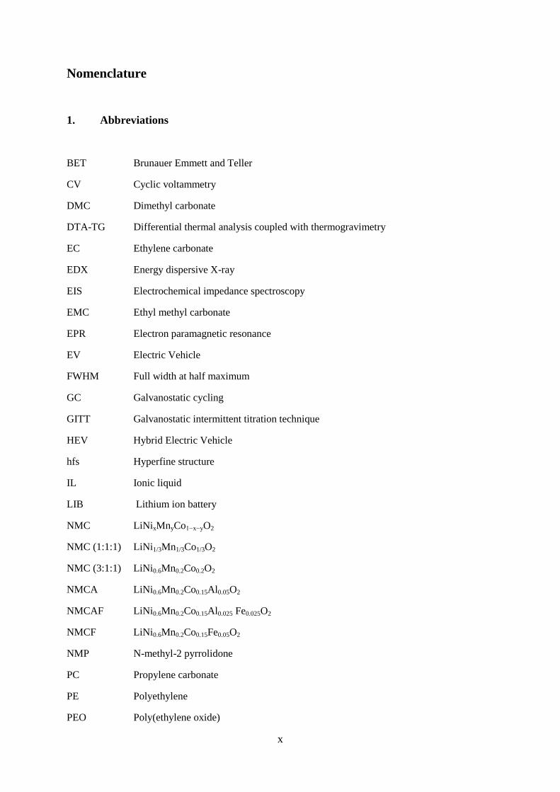
Nomenclature
1. Abbreviations
BET Brunauer Emmett and Teller
CV Cyclic voltammetry
DMC Dimethyl carbonate
DTA-TG Differential thermal analysis coupled with thermogravimetry
EC Ethylene carbonate
EDX Energy dispersive X-ray
EIS Electrochemical impedance spectroscopy
EMC Ethyl methyl carbonate
EPR Electron paramagnetic resonance
EV Electric Vehicle
FWHM Full width at half maximum
GC Galvanostatic cycling
GITT Galvanostatic intermittent titration technique
HEV Hybrid Electric Vehicle
hfs Hyperfine structure
IL Ionic liquid
LIB Lithium ion battery
NMC LiNixMnyCo1−x−yO2
NMC (1:1:1) LiNi1/3Mn1/3Co1/3O2
NMC (3:1:1) LiNi0.6Mn0.2Co0.2O2
NMCA LiNi0.6Mn0.2Co0.15Al0.05O2
NMCAF LiNi0.6Mn0.2Co0.15Al0.025 Fe0.025O2
NMCF LiNi0.6Mn0.2Co0.15Fe0.05O2
NMP N-methyl-2 pyrrolidone
PC Propylene carbonate
PE Polyethylene
PEO Poly(ethylene oxide)

xi
PHEV Plug-in Hybrid Electric Vehicle
PMC Propyl methyl carbonate
PP Polypropylene
PVDF Poly(vinylidenefluoride)
PYR1RTFSI N-alkyl-N-methylpyrrolidinium bis(trifluoromethanesulfonyl)imide
SEI Solid Electrolyte Interphase
SEM Scanning electron microscopy
SG Space group
SHE Standard hydrogen electrode
VC Vinylene carbonate
XRD X-ray diffraction
xii
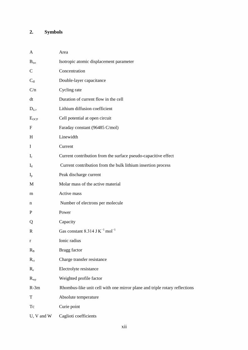
2. Symbols
A Area
Biso Isotropic atomic displacement parameter
C Concentration
Cdl Double-layer capacitance
C/n Cycling rate
dt Duration of current flow in the cell
DLi+ Lithium diffusion coefficient
EOCP Cell potential at open circuit
F Faraday constant (96485 C/mol)
H Linewidth
I Current
Ic Current contribution from the surface pseudo-capacitive effect
Id Current contribution from the bulk lithium insertion process
Ip Peak discharge current
M Molar mass of the active material
m Active mass
n Number of electrons per molecule
P Power
Q Capacity
R Gas constant 8.314 J K−1
mol−1
r Ionic radius
RB Bragg factor
Rct Charge transfer resistance
Re Electrolyte resistance
Rwp Weighted profile factor
R-3m Rhombus-like unit cell with one mirror plane and triple rotary reflections
T Absolute temperature
Tc Curie point
U, V and W Caglioti coefficients

xiii
VM Molar volume
W Energy
x Lithium composition
Zw Warburg impedance
Δx Number of electrons inserted per mole of active material
η Form factor
Warburg factor
τ Pulse duration
ѵ Scan rate

xiv
List of figures
Fig. 1: Major countries lithium mine production between 2010 and 2014 (in metric tons) [67] ............ 5
Fig. 2: Global market share of lithium battery makers in 2015 [72] ....................................................... 6
Fig. 3: Projected global lithium battery market size from 2011 to 2020 [73] ......................................... 7
Fig. 4: Projected market for lithium-ion batteries used in consumer electronics from 2012 to 2020 (in
million U.S. dollars) [74] ........................................................................................................................ 7
Fig. 5: Projected market for lithium-ion batteries used in automobiles from 2012 to 2020 (in million
U.S. dollars) [79] ..................................................................................................................................... 9
Fig. 6: Typical cost of lithium ion batteries for electric vehicles in 2012 and 2016, by vehicle type (in
U.S. dollars per kilowatt hour) [80]......................................................................................................... 9
Fig. 7: Schematic representation of LIB components [81] .................................................................... 10
Fig. 8: Comparison of the volume expansion during Li insertion in graphite and metal matrices [103]
............................................................................................................................................................... 14
Fig. 9: Schematic illustration of the SEI layer on graphite [143] .......................................................... 17
Fig. 10: Electrochemically induced polymerization of vinylene carbonate. ......................................... 18
Fig. 11: Ions typically used for LIB ionic liquid electrolytes ................................................................ 20
Fig. 12: Schematic representation of LiMO2 cationic distribution [221]. ............................................. 24
Fig. 13: Schematic representation of the ideal LiNiO2 structure [230] ................................................. 25
Fig. 14: Schematic representation of an ideal LiNiO2 hexagonal lattice [230] ..................................... 26
Fig. 15: Schematic representation of cationic distribution in LiNiO2 in the case of an ideal structure (a)
and a real structure (b) [230] ................................................................................................................. 27
Fig. 16: Schematic representation of the atomic distribution of LiMn2O4 (a) and lithium diffusion
pathways (b) [243]................................................................................................................................. 28
Fig. 17: Schematic representation of the atomic distribution of (a) LiFePO4 (b) and FePO4 [253,254] 29
Fig. 18: Operating principle of a LIB [292] .......................................................................................... 31
Fig. 19: LiNi0.6Mn0.2Co0.2O2: NMC (3:3:1) and LiNi1/3Mn1/3Co1/3O2: NMC (1:1:1) precipitates during
synthesis by co-precipitation. ................................................................................................................ 42
Fig. 20: Steps of self-combustion synthesis method. From left to right, the first picture presents a
crystallizer with the mixed solution of transition metal nitrates and sucrose heated by means of a sand
bath, then in the second picture the solution becomes foamy after evaporation of water. The last
picture presents the self-combustion product ........................................................................................ 43
Fig. 21: Comparison between X-ray diffraction patterns of the materials LiNi0.6Mn0.2Co0.2O2 (a) and
LiNi1/3Mn1/3Co1/3O2 (b) synthesized by self-combustion method ......................................................... 44
Fig. 22: Comparison between X-ray diffraction patterns of the materials LiNi0.6Mn0.2Co0.2O2 (a) and
LiNi1/3Mn1/3Co1/3O2 (b) synthesized by co-precipitation method .......................................................... 45

xv
Fig. 23: SEM images of LiNi0.6Mn0.2Co0.2O2 annealed at 900°C/1h (a) 900°C/12h (b) 900°C/24h (c)
and LiNi1/3Mn1/3Co1/3O2 annealed at 900°C/1h (d) 900°C/12h (e) 900°C/24h (f) prepared by self-
combustion ............................................................................................................................................ 47
Fig. 24: SEM images of LiNi0.6Mn0.2Co0.2O2 annealed at 900°C/12h (a) 900°C/24h (b) and
LiNi1/3Mn1/3Co1/3O2 annealed at 900°C/12h (c) 900°C/24h (d) prepared by co-precipitation ............. 48
Fig. 25: Comparison between X-ray diffraction patterns of the material LiNi0.6Mn0.2Co0.2O2 annealed
at 900°C, 800°C and 700°C during 1 h ................................................................................................. 49
Fig. 26: SEM images of the material LiNi0.6Mn0.2Co0.2O2 annealed at 700°C/1h (a) 800°C/1h (b) and
900°C/1h (c) .......................................................................................................................................... 50
Fig. 27: X-ray diffraction patterns of the NMC (3:1:1) positive electrode materials annealed under air
(black) and under argon (orange) .......................................................................................................... 51
Fig. 28: SEM images of the sample NMC (3:1:1) annealed for 12h under air (a) and the one annealed
for 12h under argon (b) ......................................................................................................................... 52
Fig. 29: X-ray diffraction patterns of the aged (red) and fresh NMC (3:1:1) positive electrode materials
(black) .................................................................................................................................................... 53
Fig. 30: Rietveld profile refinement results of the aged NMC electrode material: __ observed, __
calculated, __ difference, I Bragg positions .......................................................................................... 54
Fig. 31: SEM images of the fresh sample that was annealed immediately after synthesis (a) and the
aged sample that was left in air for 6 months then was annealed (b) .................................................... 54
Fig. 32: DTA-TG curves of the aged sample that was left in air for 6 months then was annealed (a) and
the fresh one that was annealed immediately after synthesis (b) DTA-TG tests were carried out
simultaneously in the temperature range between 20 and 1020°C with a scan rate of 5°C/min ........... 56
Fig. 33: Cyclic voltamorgamms of the aged (a) and fresh (b) samples vs. Li/Li+ at a scan rate of 0.5
mV/s. The fresh sample was annealed immediately after synthesis and the aged one was left in air for
6 months then was annealed .................................................................................................................. 57
Fig. 34: Galvanostatic cycling at C/20 rate of the aged (a) and fresh (b) samples of the material
LiNi0.6Mn0.2Co0.2O2. ............................................................................................................................... 58
Fig. 35: Comparison between X-ray diffraction patterns of the four materials NMC, NMCA, NMCF
and NMCAF (a) and the insets of their diffraction lines (003) (b) and (104) (c). ................................ 60
Fig. 36: SEM images of the four materials NMC (a), NMCA (b), NMCF (c) and NMCAF (d). ......... 63
Fig. 37: DTA and TGA curves of NMC (a), NMCA (b), NMCF (c) and NMCAF (d) performed in air
from room temperature to 1020 °C with a heating temperature rate of 5 °C / min ............................... 65
Fig. 38: Cyclic voltammetry curves I = f(V) of the four materials NMC (a), NMCA (b), NMCF (c) and
NMCAF (d) of the 1st and 10th cycles at 0.1 mV/s scan rate ............................................................... 66
Fig. 39: Charge/discharge curves of the battery Li//EC:DMC//cathode material: NMC (a), NMCA (b),
NMCF (c) and NMCAF (d) during the 10 first cycles under C/20 rate ................................................ 68
xvi
Fig. 40: Discharge capacity evolution with the cycle number of the materials NMC (a), NMCA (b),
NMCF (c) and NMCAF (d) during the 50 first cycles under C/5 and 1C rates .................................... 69
Fig. 41: SEM images of the NMC (3:1:1) material before ball milling (a) and after ball milling (b);
The ball milling speed was about 600 rounds/min for a total milling time of 6 minutes ...................... 72
Fig. 42: Rietveld profile refinement results of the NMC (3:1:1) (a) and NMCAF (b) electrode
materials: __ observed, __ calculated, __ difference, I Bragg positions ............................................... 75
Fig. 43: Experimental EPR spectra of commercial NMC (1:1:1), recorded at 77°K and 295°K. Fitting
of the experimental spectra was carried out by a Lorentzian line approach. Fitted and experimental
curves are shown ................................................................................................................................... 76
Fig. 44: Experimental EPR spectra of the NMC (3:1:1) (a) and NMCAF (b) materials, recorded at
77°K and 295°K. Fitting of the experimental spectra was carried out by a Lorentzian line approach.
The fitted and separated after fitting curves are shown for each material ............................................. 77
Fig. 45: ΔH as a function of temperature for the commercial NMC (1:1:1) and the NMC (3:1:1) and
NMCAF materials prepared in this work, where i= 1; 2 are respectively related to R1 (assigned to
paramagnetic Mn4+
) and R2 (attributed to the presence of paramagnetic Ni2+
defects) ......................... 78
Fig. 46: Representation of the paramagnetic-ferromagnetic phase transition for the in-lab prepared
NMC (3:1:1) and the commercial NMC (1:1:1). ................................................................................... 79
Fig. 47: Comparison of voltage profiles vs. normalized capacity obtained from galvanostatic cycling at
C/20 rate of NMC (3:1:1) (black) and NMCAF (red) positive electrode materials at the 10th cycle .... 80
Fig. 48: Variation of the incremental capacity - dx / |dV| as a function of potential for NMC (3:1:1) (a)
and NMCAF (b). This function was deduced by deriving the 1st charge / discharge cycle performed in
the potential range 2.7 - 4.4 V under C/20 rate ..................................................................................... 82
Fig. 49: Cyclic voltammograms of the two cathode materials NMCAF (a) and NMC (3:1:1) (b) in the
2.7V - 4.4V potential range at various scan rates .................................................................................. 83
Fig. 50: Evolution of the peak discharge current Ip of NMCAF and NMC (3:1:1) with the scan rate.
The blue dashed line represents the linear function Ip∝v referring to the surface pseudo-capacitive
lithium storage process; the green dashed line represents the square root function Ip∝v1/2
referring to
the bulk lithium insertion process.......................................................................................................... 84
Fig. 51: Evolution of Ip/v1/2
as a function of v1/2
for NMCAF (a) and NMC (3:1:1) (b) in order to
extract the C1 and C2 parameters that correspond to the slope and the y-axis intercept point of the
curves .................................................................................................................................................... 85
Fig. 52: Calculated surface pseudocapacitive Ic and bulk insertion discharge currents Id for NMCAF
(a) and NMC (3:1:1) (b) ........................................................................................................................ 86
Fig. 53: Nyquist impedance spectra of NMCAF and NMC (3:1:1) before CV (a) and after CV (b)
versus Li/Li+ and an inset of the impedance at high frequencies presented on the right side ............... 87
Fig. 54: Equivalent circuit used for fitting the EIS spectra of the NMC(3:1:1) and NMCAF .............. 88

xvii
Fig. 55: Evolution of ZRe as a function of the inverse square root of the angular frequency ω for
NMCAF before (a) and after CV (b) and NMC (3:1:1) before (c) and after CV (d) in order to extract
the Warburg factors that correspond to the slope of the curves ......................................................... 88
Fig. 56: Rate capability of NMCAF (a) and NMC (3:1:1) (b) tested between C/20 and 5C rates in the
2.7V - 4.4V potential range ................................................................................................................... 90
Fig. 57: Galvanostatic intermittent titration of the NMCAF material during charge (blue) and
discharge (orange) (a) and a scheme of a single GITT step at around 3.63 V (b) ................................. 91
Fig. 58: Potential transient linearization during charge injection period in the coordinates E=f(τ1/2
) ... 92
Fig. 59: Evolution of the apparent diffusion coefficient upon charge (blue) and discharge (orange) of
the NMCAF material ............................................................................................................................. 93
Fig. 60: XRD patterns of the LixNi0.6Mn0.2Co0.15Al0.025Fe0.025O2 phase (0.1 ≤ x ≤ 0.9) chemically de-
intercalated by NO2BF4 in acetonitrile (a) an inset in the 2θCu range 15º - 46º of the same phase at (0.1
≤ x ≤ 0.4) is presented in (b).................................................................................................................. 95
Fig. 61: XRD patterns of the LixNi0.6Mn0.2Co0.2O2 phase (0.1 ≤ x ≤ 0.9) chemically de-intercalated by
NO2BF4 in acetonitrile (a) an inset in the 2θCu range 15º - 46º of the same phase at (0.1 ≤ x ≤ 0.4) is
presented in (b) ...................................................................................................................................... 96
Fig. 62: Schematic representation of the O1 stacking (left) and the O3 stacking (right). A,B and C
indicate the positions of the oxygen ions in the lattice [336,337] ......................................................... 97
Fig. 63: Evolution of the lattice parameters ahex (a) and chex (b) (deduced from XRD Rietveld
refinement of the phases LixNi0.6Mn0.2Co0.2O2 and LixNi0.6Mn0.2Co0.15Al0.025Fe0.025O2 (0.1 ≤ x ≤ 0.9) as
a function of lithium composition (x) .................................................................................................... 98
Fig. 64: Evolution of the lattice volume Vhex of the phases LixNi0.6Mn0.2Co0.2O2 and
LixNi0.6Mn0.2Co0.15Al0.025Fe0.025O2 (0.1 ≤ x ≤ 0.9) as a function of lithium composition (x) ................. 99
Fig. 65: Thermogravimetric analysis of the de-intercalated phases LixNi0.6Mn0.2Co0.2O2 and
LixNi0.6Mn0.2Co0.15Al0.025Fe0.025O2 with x=0.9 (a) x=0.6 (b) x=0.3 (c) x=0.1 (d) carried out under air,
from room temperature to 600 ° C. ..................................................................................................... 100
Fig. 66: XRD patterns of the LixNi0.6Mn0.2Co0.15Al0.025Fe0.025O2 phase (x=0.1; 0.3; 0.6; 0.9) chemically
de-intercalated by NO2BF4 in acetonitrile and treated by DTA-TG from room temperature to 600°C in
air The absence of any additives, such as PVDF or carbon black, that are necessary for preparing the
electrodes, allowed us to record X-ray diffraction patterns of good quality and to determine then the
lattice parameters by refining the structure. ........................................................................................ 101
Fig. 67: Variation of the ratio chex/ahex (deduced from XRD Rietveld refinement) of the phases
LixNi0.6Mn0.2Co0.15Al0.025Fe0.025O2 (x=0.1; 0.3; 0.6; 0.9) chemically de-intercalated by NO2BF4 in
acetonitrile and treated by DTA-TG from room temperature to 600°C in air ..................................... 102
Fig. 68: XRD patterns of the LixNi0.6Mn0.2Co0.2O2 phase (x=0.1; 0.3; 0.6; 0.9) chemically de-
intercalated by NO2BF4 in acetonitrile and treated by DTA-TG from room temperature to 600°C in air
atmosphere .......................................................................................................................................... 103

xviii
List of tables
Table 1: Cathode and anode materials for lithium-ion batteries and their characteristics [82-84] ........ 11
Table 2: Advantages and drawbacks of titanium intercalation oxides .................................................. 15
Table 3: Typical properties of some commercial separators [207] ....................................................... 21
Table 4: Main requirements for a LIB separator [215]. ........................................................................ 23
Table 5: Characteristics of some phospho-olivine cathode materials ................................................... 30
Table 6: Intensity ratios of the diffraction lines (003)/(104) for the phases prepared by self-combustion
synthesis method ................................................................................................................................... 45
Table 7: Intensity ratio of the diffraction lines (003) / (104) for the phases prepared by co-precipitation
synthesis method ................................................................................................................................... 46
Table 8: EDX element analysis of the fresh and aged samples ............................................................. 55
Table 9: Structural parameters of the four materials NMC, NMCA, NMCF and NMCAF obtained by
XRD ...................................................................................................................................................... 61
Table 10: Cation distribution determined by Rietveld refinement method of the XRD diagrams of the
four materials NMC, NMCA, NMCF and NMCAF ............................................................................. 61
Table 11: Structural parameters determined by Rietveld refinement method of the XRD diagrams of
the four materials NMC, NMCA, NMCF and NMCAF........................................................................ 62
Table 12: Comparison of specific surface measured by the BET. method for the four phases NMC,
NMCA, NMCF and NMCAF ................................................................................................................ 63
Table 13: Electrochemical parameters obtained for the four materials NMC, NMCA, NMCF and
NMCAF at C/20, C/5 and 1C rates ....................................................................................................... 68
Table 14: The main parameters deduced from the XRD data refinement as well as the cationic
distribution of the material NMC (3:1:1) .............................................................................................. 73
Table 15: The main parameters deduced from the XRD data refinement as well as the cationic
distribution of the material NMCAF ..................................................................................................... 74

xix

I. Introduction and motivation
1
I. Introduction and motivation
Nowadays, given the extreme dependence on portable electronic devices as well as the
increasing demand for electric cars, the development of new rechargeable energy storage
systems has become increasingly important.
Over the last decades, different electrochemical energy storage systems have been developed
ranging from primary systems to rechargeable cells that have finally allowed a greater
autonomy at reduced mass and volume.
Among all the rechargeable systems, lithium ion batteries show higher energy density,
stability and improved lifetime compared to lead acid, Ni-Cd and Ni-MH accumulators [1-4].
In the early 1970s, M. Stanley Whittingham suggested the first rechargeable batteries
consisting of titanium disulfide as positive electrode and metallic lithium as negative
electrode [5,6]. However, problems related to changes at the lithium electrode during cycling
due to the consumption of the lithium as well as the formation of dendrites lead to severe
safety issues. Thus, came the idea of developing lithium intercalation materials for both
negative and positive electrodes. In 1980, Rachid Yazami was the first to discover the
graphite-based lithium reversible intercalation material. This discovery has led to the lithium-
graphite anode used so far in the commercial lithium-ion batteries [7].
The first lithium ion battery using the positive electrode material LiCoO2 and the graphite
based negative electrode was commercialized by Sony in 1991 [8] exhibiting operating
voltages of up to 4 volts and fairly large energy density and specific energy values of the
order of 200-300Wh/L and 100-130Wh/kg respectively [9].
This new rechargeable battery was at that time a turning point and a key factor for the
development of portable electronic devices. Since then, active research has been conducted in
a way to improve the performance of each battery component [9].
LiCoO2 as the positive electrode material was for a long time widely used [10-12] due to its
high capacity and good cycling stability even at high rates [13]. However, the toxicity and the
high costs of cobalt are considered disadvantages of this positive electrode material.
Therefore, other lithium-containing transition metal oxides have been proposed to replace
LiCoO2 such as spinel phase LiMn2O4, layered oxides LiNiO2, mixed layered oxides Li
(NixMnyCo1-x-y) O2 called NMC and olivine phase LiFePO4.
Among these materials, LiNiO2 seemed first to present good potential to replace LiCoO2 due
to its lower cost and its great discharge capacity. However, studies on this lamellar oxide
suggested an excess of Ni in the structure, more precisely in the interlayer space. This
disorder results in a capacity fade and a decrease of the lithium diffusion coefficient [14].
For cost reasons as well as improved toxicity and thermal stability issues compared to nickel
and cobalt oxides [15], the LiMn2O4 spinel phase was also considered as a good candidate to
replace LiCoO2. However, the disproportionation reaction of Mn induces a rapid capacity
loss. On the other hand, the structural instability of the compound in the intercalated state [16]
limits the use of this system especially for electric and hybrid vehicles applications.
Among the most studied compounds of the olivine group, LiFePO4 proves to be an attractive
one given its low cost, low toxicity and especially its high thermal stability in the charged
state even better than those obtained for the LiNiO2, LiCoO2 and LiMn2O4 cathode materials.
[17].

I. Introduction and motivation
2
However, due to its low electronic and ionic conductivities [18], it was necessary to conduct
more studies on LiFePO4 compound [19-22].
An established approach to obtain novel materials with improved reversible capacity and
cycling stability, lower cost, less toxicity and better thermal stability is to combine the
advantages of the three materials LiNiO2, LiCoO2 and LiMn2O4 and at the same time limit
their drawbacks. This class of positive electrode materials called (LiNixMnyCo1−x−yO2 NMC
type materials) is currently in the focus of research [23-35].
Since Ohzuku’s early work on Li[Ni1/3Co1/3Mn1/3]O2 in 2001 [34] several studies have been
conducted on NMC type materials. Contrary to LiCoO2, NMC shows a flexible stoichiometry
which allows an adjustment of the electrochemical properties of the material.
The most widely researched NMC composition LiNi1/3Mn1/3Co1/3O2 was seen as one of the
most promising materials in this class [34]. However, more compositions exist, among which
some have not been extensively investigated, including LiNi0.6Mn0.2Co0.2O2 that is currently in
our focus. There has been interest in studying this composition because it represents a
compromise between the good electrochemical performance due to the presence of a high
amount of nickel, the increased thermal stability induced by manganese ions Mn4+
and the
minimization of the cost and toxicity by decreasing the cobalt content.
Nevertheless, it has been shown in a considerable number of studies that the exchange
between Li and Ni ions within the NMC lattice plays a negative role for the structural stability
and further deteriorates the electrochemical performance of layered oxides [36]. The physical
reason for this phenomenon is related to similarity between the ionic radii of Li+ and Ni
2+.
The ionic radius of Li+ (0.76 Å) is close to that of Ni
2+ (0.69 Å), hence a partial occupation of
Ni2+
sites by Li+ (by exchange between a Li
+ and a nearest neighbor Ni
2+) induces a cation
mixing in the structure, which hinders the efficient Li ion transport in the solid state [36].
Taking into account this problem, cationic substitution to a transition metal is considered, as
for LiNiO2 and LiMn2O4 [37-57], a promising approach for the cathode materials of NMC
type. Such an approach has been an effective strategy to adjust the electrochemical
performance or the structural/thermal stability of the material due to the decrease of the cation
mixing between Li and Ni ions in the NMC lattice. The changes in the cationic distribution
within these transition metal oxides can have a noticeable impact on the reversible capacities
and on lithium diffusion during the intercalation/deintercalation process.
Many scientists worldwide have reported important theoretical studies on substituted NMC-
type materials to Al, Mg, Cr, Fe, Be, Ga etc. [58-64]. This idea has been applied in the current
study through cationic substitution of Co with Al and/or Fe. This idea was investigated for
several reasons. First, a simultaneous double substitution has led to a novel composition that
has not been studied so far. Second, earlier studies about cationic substitution for other
systems have been conducted and showed that metal substitution in layered materials
generally brings an improved performance for a number of cathode compositions, but the
effect of simultaneous cationic substitution has not been extensively approached. Third, the
pristine cathode material LiNi0.6Mn0.2Co0.2O2, which already exhibits good electrochemical
behavior, will be used as a promising compound for further substitution. For this, the main
motivation in this thesis arises from the will to achieve a lower cost and environmentally

I. Introduction and motivation
3
benign, less cobalt containing structure while retaining a high safety and electrochemical
performance.
The present work is divided into six chapters:
First a bibliographical recall on lithium ion batteries including their components as well as
their operating principle will be presented in chapter 2 followed by the different experimental
techniques used to characterize the materials studied throughout this work (chapter 3).
Chapter 4 concerns studies performed to optimize the synthesis conditions such as synthesis
method, annealing temperatures, synthesis atmosphere etc ... This enabled the preparation of
phases with well-ordered structures exhibiting improved electrochemical performance.
The 5th
chapter is devoted to structural, morphological and electrochemical properties of four
materials: the pristine material NMC (3:1:1), two aluminum or iron mono-substituted
materials NMCA (LiNi0.6Mn0.2Co0.15Al0.05O2), NMCF (LiNi0.6Mn0.2Co0.15Fe0.05O2)
respectively, and the double substituted material NMCAF (LiNi0.6Mn0.2Co0.15Al0.025
Fe0.025O2).
Finally, a more detailed comparison between NMC and NMCAF which presented the best
properties will be compiled in the 6th
chapter in such a way that a better understanding of the
phenomena behind the improvement of the electrochemical behavior of the double substituted
cathode can be achieved. That chapter also discusses the safety aspect of the two materials
through a detailed study of their thermal stability during the lithium ion de-intercalation
process.

I. Introduction and motivation
4

II. State of the art
5
II. State of the art
1. Industry of lithium ion batteries
Lithium-ion batteries are power batteries used for energy storage in numerous electronic
devices available on the market such as mobile phones, cameras and many others. Moreover,
the demand for this kind of batteries in the automotive industry is expected to increase due to
the growing demand for battery electric vehicles. The reason behind this constantly growing
demand comes from the fact that they are capable of storing a significant amount of energy
for relatively small volume and weight, in addition to the ongoing improvement of many of
their technology aspects such as the cycling stability, energy density, safety, costs, and more.
Then, in order to cover this huge demand of energy storage, it was crucial to take full
advantage of lithium mines worldwide. Overall distinguished reserves of lithium in 2008 were
evaluated by the US Geological Survey as 13 million tons [65]. However it is amazingly hard
to precisely assess the world's lithium reserves [66].
Figure 1 represents the nations with the biggest mine production of lithium worldwide
between 2010 and 2014. The top 3 producers according to the statistic are Australia, Chile and
China respectively. However, Chile´s lithium mine production reached the highest amount in
2012, about 13200 metric tons coming then at the lead position.
Fig. 1: Major countries lithium mine production between 2010 and 2014 (in metric tons) [67]
13.000
12.900
5.000
2.900
1.000
570
400
12.700
11.200
4.700
2.500
1.000
570
400
12.800
13.200
4.500
2.700
1.060
560
150
12.500
12.900
4.140
2.950
470
820
320
9.260
10.510
3.950
2.950
470
800
160
Australia
Chile
China
Argentina
Zimbabwe
Portugal
Brazil
Production in metric tons
2014* 2013 2012 2011 2010

II. State of the art
6
The Chilean company SQM considered as one of the largest lithium producers in the world
estimates that global demand for lithium has increased with an average of 7 to 8% per year
during the last decade. About half of this growth was due to the increase in demand for
lithium traditional uses in the fabrication of manufactured products and the other half would
be attributable to manufacturing batteries, including lithium-ion battery used in cell phones
and laptops [68]. The overall consumption of lithium used in the battery manufacturing has
increased more than 20% annually over the past years as the demand for lithium-ion and
lithium polymer batteries is growing strongly. Other lithium uses are also increasing but at a
lower rate [68].
From the production side, China, Japan and South Korea account for nearly 85% to 90% of
the global production worldwide among the major market players (figure 2). The Japanese
giants Panasonic and AESC (Automotive Energy Supply Corporation) are the leaders. In
addition to the Korean Samsung SDI and LG Chem, all are considered the major
manufacturers of lithium-ion batteries worldwide. On the other hand, China has the highest
concentration, with over 200 producers [69]. In Europe, the German company Li-Tec Battery
GmbH which is a wholly owned Daimler subsidiary [70], contributed to a significant extent in
the market in 2015 standing at around four percent. Until the end of 2015, the company
developed, produced and sold under the brand name CERIO large-scale lithium-ion batteries
for automotive applications and battery systems for industrial and stationary applications [71].
Fig. 2: Global market share of lithium battery makers in 2015 [72]
41,19%
18,46%
7,13%
7,11%
5,92%
4,68%
4,08%
3,34%
3,18%
2,76%
2,14%
0,0% 5,0% 10,0% 15,0% 20,0% 25,0% 30,0% 35,0% 40,0% 45,0%
Panasonic Sanyo
AESC
Samsung
LG Chem
Others
Litec
Toshiba
A123
GS Yuasa
SK Energy
BYD
Market share

II. State of the art
7
Lithium-ion batteries have represented in 2011 a market of 1.5 billion dollars, which is
expected to reach 9.8 billion dollars in 2015 and could even exceed 15.6 billion in 2020 (Fig.
3). The consumer electronics market is taking up the majority of this growth (Fig. 4).
Fig. 3: Projected global lithium battery market size from 2011 to 2020 [73]
Fig. 4: Projected market for lithium-ion batteries used in consumer electronics from 2012 to 2020 (in
million U.S. dollars) [74]
1,5
9,8
15,6
0
2
4
6
8
10
12
14
16
18
2011 2015* 2020*
Mark
et valu
e in
bill
ion U
.S. dolla
rs
9.627
10.878
12.131
13.169
13.881 14.282
14.547 14.658 14.745
0
2000
4000
6000
8000
10000
12000
14000
16000
2012 2013 2014 2015 2016 2017 2018 2019 2020
Mark
et siz
e in
mill
ion U
.S. dolla
rs

II. State of the art
8
The statistic in figure 4 shows the consumer electronics lithium-ion battery business sector
between 2012 and 2020. It was evaluated that this business sector will attain 13.2 million U.S.
dollars by 2015. The utilization of lithium-ion batteries in consumer electronics, for example,
cell phones, power tools and handsets is intended to expand as market for these products.
Li-ion battery market for mobile phones has a bigger piece of the overall consumer
electronics industry. The predominance of this section is a result of the high infiltration of low
cost smartphones in developing countries. The mobile phones fragment is trailed by the
laptops due to the continually growing interest from the education sector. Therefore,
numerous organizations are contributing intensely to improve the quality of education and
learning. For example, Intel has put more than 1 billion US dollars in 70 nations in the last
decade to change the traditional education framework. For this, laptop manufacturers are
expected to present new and propelled features that enhance the transportability and
accessibility of laptops [75].
Although lithium-based batteries are the most well-known propelled batteries for use in
compact portable consumer electronics and battery electric vehicles, they were not the first
choice for use in hybrid electric vehicles for quite a long while due to the high cost connected
with this sort of battery contrasted with Ni-MH batteries. With the falling costs of lithium-
based batteries after 2005, auto makers started to utilize lithium batteries in hybrid electric
vehicles expanding the market size fundamentally [76]. The statistic in figure 5 shows the
evaluated car lithium-ion battery business sector between 2012 and 2020. It was expected that
this business sector will reach about 4.4 million U.S. dollars by 2015. The business sector is
marked by electric vehicle production growth. On the vehicle production side, it is expected
to produce about 4 million electric and hybrid vehicles per year. Light vehicles represent more
than 85% of the total market for lithium-ion batteries in 2015 [77].
The projection of lithium-ion batteries costs for electric vehicles in 2012 and 2016, by vehicle
type is presented in figure 6. The difference in costs between EVs (Electric Vehicles) and
PHEVs (Plug-in Hybrid Electric Vehicles) is mostly because a PHEV uses both an IC
(Internal Combustion) engine and an electric motor for propulsion. Thereby, the utilization of
twofold fuel system makes PHEVs costly. In 2012, lithium-ion batteries costed about 814
U.S. dollars per kilowatt hour in PHEVs and about 633 U.S. dollars per kilowatt hour in EVs.
The decrease in lithium-ion batteries costs will be intensely persuasive on the achievement of
plug-in hybrid electric vehicles with lower costs. Furthermore, the diminishment in expenses
of cobalt, metal, wiring, and plastic have brought down battery costs [78]. This can only be a
fundamental and compelling reason for the battery market growth in both portable consumer
electronics (fig. 4) and electric vehicles (fig. 5) sectors.

II. State of the art
9
Fig. 5: Projected market for lithium-ion batteries used in automobiles from 2012 to 2020 (in million
U.S. dollars) [79]
Fig. 6: Typical cost of lithium ion batteries for electric vehicles in 2012 and 2016, by vehicle type (in
U.S. dollars per kilowatt hour) [80]
2.010
2.828
3.486
4.422
5.483
6.585
7.745
8.903
10.156
0
2000
4000
6000
8000
10000
12000
2012 2013 2014 2015 2016 2017 2018 2019 2020
Mark
et siz
e in
mill
ion U
.S. dolla
rs
633
425
814
570
0
100
200
300
400
500
600
700
800
900
2012 2016
Costs
in
U.S
. dolla
rs p
er
kilo
watt
hour
EVs PHEVs

II. State of the art
10
2. Lithium ion battery components
A lithium ion battery (LIB) consists of two electrodes, one positive (cathode) and one
negative (anode) separated by an electrolyte impregnated in a separator. Both electrodes are
connected to the external electric circuit through current collectors (Fig. 7). The term
"battery" is itself reserved for systems consisting of several cells, connected in parallel or in
series.
In this work, and as it is common, the term battery will be used to designate a cell.
Fig. 7: Schematic representation of LIB components [81]
The first LIBs consisted of graphite and LiCoO2 at the anode and cathode sides respectively.
Their energy storage ability was more than double that of nickel or lead batteries for the same
size and mass.
Electrolyte + separator Anode Cathode
Cu current
collector Graphene
structure
Li+ Solvent
molecule LiMO2 layer
structure
Al current
collector

II. State of the art
11
Nevertheless, the reversible intercalation of lithium ions is for the most part constrained by
the modifications in the host material´s structure which influences the energy density. Thus,
advancements will only be achieved by discovering through continuous advanced research
novel electrode materials with improved performance in terms of cyclability, safety, energy
density, power, price and environmental impact. Some of the cathode and anode materials that
have been developed and tested since the establishment of the LIB technology more than 20
years ago are reported in table 1.
Table 1: Cathode and anode materials for lithium-ion batteries and their characteristics [82-84]
Type
Chemistry
Specific
Capacity in
mAh/g
(theoretical/
observed)
Potential
vs.
Li+/Li
Note
Cathode
LiCoO2
LiNiO2
LiNixCoyMnzO2
LiNixCoyAlzO2
LiMn2O4
LiMn1.5Ni0.5O4
LiFePO4
LiMnPO4
LiNiPO4
LiCoPO4
273/160
274/180
~270/150–180
~250/180
148/130
146/130
170/160
171/80–150
166/-
166/60–130
3.9
3.6
3.8
3.7
4.1
4.7
3.45
4.1
5.1
4.8
First cathode, expensive
Cheaper than LiCoO2, unstable
Cheap and stable
Stable
Unstable cycling
High voltage, cheap
Low voltage, safe, cheap, stable
Slow kinetics, cheap, high voltage
No suitable high voltage electrolyte
Expensive
Anode
Graphite
Li4Ti5O12
TiO2 (anatase/rutile)
SnO2
Sn
Si
Al
372/330
175/170
168/168
782/780
993/990
4198/<3500
2235
0.1–0.2
1.55
1.85
<0.5
<0.5
0.5–1
<0.3
LiC6, vol. change: ~11%
High voltage, no vol. change
Cheap, vol. change: ~4%
Large initial irreversible loss
Poor cycling, vol. change: 257%
Poor cycling, vol. change: 297%
Poor cycling, vol. change: 238%

II. State of the art
12
2.1. Negative electrode materials
This paragraph is committed to anode materials available on the market or being investigated
in order to replace graphite, the most prominent material as commercial negative electrode.
Candidates for the negative electrode material must meet the following criteria:
Good chemical stability towards electrolytes to prevent degradation of the electrolyte
or of the material during cycling. Such degradation phenomena are leading to side
reactions that affect the electrochemical performance of the battery;
High ionic and electronic conductivity;
Large amount of inserted lithium in order to achieve a maximum specific capacity;
Good electrochemical stability and reversibility of the insertion / extraction process.
Contrary to cathode materials, the composition of anode materials for LIBs is more various
and might involve transition metals, post-transition metals as well as nonmetallic elements
using different stoichiometries.
2.1.1. Metallic lithium
The electrochemical couple Li+/Li has a low standard potential of -3.04 V vs. the standard
hydrogen electrode (SHE). Another metallic lithium feature is its low molecular weight: 6.94
g mol-1
which allows a considerable gain in terms of mass, energy, power and specific
capacity (theoretical capacity of lithium is 3200 mAh.g-1
).
Nevertheless, the use of lithium as the negative electrode material was abandoned especially
for safety reasons such as the thermodynamic instability of lithium in most electrolytes. Yet,
its corrosion is stopped by the formation of a passivation layer on the surface called SEI
(Solid Electrolyte Interphase) especially in solvents containing a carbonate group. A
conceivable arrangement is the utilization of a less reactive with the lithium electrolyte, to be
specific, a solid polymer electrolyte. However, solid electrolytes have shown so far limitations
in their use due to their low ionic conductivities and hindered ion transport.
Another safety issue that was highlighted is the formation of dendrites on the lithium
electrode during cycling. The growth of these dendrites can cause their contact with the
cathode leading to a short circuit of the battery which can induce explosion especially when
unfavorable conditions related to the battery thermal stability are met. For all those reasons,
the lifetime of the batteries using a lithium negative electrode is limited.
2.1.2. Graphite
To overcome the problems encountered in lithium metal batteries, replacing lithium by an
insertion material is a standout amongst the most considered solutions. Carbonaceous
materials have been proposed as negative electrode materials in the LIB commercialized by
Sony in 1991 [85-88].

II. State of the art
13
Among the numerous types of carbon electrodes, graphite is the most prevalent material due
to its low cost, safety, better cycling stability and its Nernst potential close to that of lithium
[89]. It is used to insert in the vacant space between its sheets a large amount of lithium
(theoretical capacity 372 mAh.g-1
). The lithium storage mechanism into the carbonaceous
material unequivocally relies on its morphology and structure. The intercalation of lithium
ions into rhombohedral and hexagonal graphite takes place through the consecutive n-stages
and the consequent expansion of the intersheet distance from 0.335 to 0.372 nm [90]. In the
potential versus capacity plot, the staging phenomena are visible as plateaus.
Similar to what is observed on the lithium anode, the electrolyte is reduced at the carbon
electrode at its operating potential (approximately 0.2 V versus Li+/Li), resulting in the
formation of a passivation layer (SEI). Part of the lithium electrolyte is then consumed
permanently. This type of anode therefore has an irreversible capacity in the first cycle of the
battery.
2.1.3. Transition metal oxides
Recently, various transition metal oxides of MO type (M = Co, Cu, Ni, Fe, etc.) have been
investigated for use as a negative electrode [91,92]. These oxides are characterized by a very
good cycling performance with specific capacities up to 600 mAh/g for tin oxide.
It has been found that tin oxide is a potential candidate for use as a negative electrode for
LIBs. This material delivers reversible capacity in the order of 500-600 mAh / g at an average
potential of 0.5 V vs. Li+/Li. The reaction of tin oxide with lithium takes place mainly in two
stages: firstly, there is a reduction of tin to the metallic state Sn0 and the formation of Li2O.
The second step concerns the formation of an alloy between lithium and tin LixSn. The Li2O-
forming reaction is irreversible and only the second process is reversible. The more tin
nanoparticles are well distributed in the matrix of Li2O, the more cycling stability of the
electrode is improved.
At the following charging process, the metal nanoparticles are reoxidized, that step is
accompanied by the decomposition of the Li2O matrix. It is noteworthy that this new lithium
storage mechanism is not limited to divalent oxides. Indeed, Co3O4 is a transition metal oxide
storing lithium with the same cited mechanism. It has the highest specific capacity during the
first discharge of about 1100 mAh g-1
vs Li+/Li. [93]. Fe2O3 [94,95] and Cu2O materials also
exhibit high capacity values around 900 mAh g-1
.
2.1.4. Lithium alloys
A new family of negative electrodes based on the materials forming alloys with lithium is
likewise used. Such anodes are the subject of numerous investigations.
Li alloys have several advantages as negative electrode such as being environmentally benign
and presenting very high theoretical specific capacity values, up to 4200 mAh/g for silicon,
much greater than that of graphite (372 mAh/g).

II. State of the art
14
Many studies are also devoted to other alloys formed by lithium with elements such as
aluminum [96], tin [97], or antimony [97] in addition to silicon [98]. They operate at
potentials between 0.15 and 0.9 V vs. Li+/Li and deliver specific capacities between 300 and
4000 mAh/g. However, these compounds exhibit a very poor performance in cycling during
discharge especially when at hight depths of discharge. The volume expansion undergone by
this class of materials during the alloying reaction with lithium can vary according to the
working conditions, between 97% [99] and 238% [100] in the case of LiAl and even 260%
[101] and 358% [102] for Li4,4Sn. Therefore, volume expansion is the major problem faced
when using Li alloys as negative electrodes. It leads to high mechanical stress resulting in
surface cracking and consequently a capacity fading after few cycles.
0
10
20
30
40
50
60
70
80
Li 3
Sb
Sb
Li 2
2S
n5
Sn
C
Al
LiC
6
LiA
l
Volu
me
(cm
3/m
ol)
Fig. 8: Comparison of the volume expansion during Li insertion in graphite and metal matrices [103]
.
In order to increase the structural stability of these electrodes and thus to improve the cycling
performance, two solutions have been proposed: first, the use of nanoparticles [104].
However, this strategy has not effectively led to the development of metallic materials that
provide good electrochemical cyclability since the nanoparticles are able to aggregate,
forming dense and inactive blocks after ten cycles [105, 106]. Another proposed method to
reduce the volume expansion of the electrodes during the lithiation / delithiation is the use of
an electrochemically inactive matrix, such as Sn2Fe, SnFe3C, SiNi [103] and Si / SnSb [107]
with a stable capacity of about 700-1000 mAh/g.

II. State of the art
15
2.1.5. Titanium intercalation oxides
Due mainly to their low manufacturing costs in addition to many more advantages, research
on titanium mixed oxides (Li4Ti5O12 [108] Li2Ti3O7 [109] and LiTi2O4 [110], Table 2) as
negative electrodes is experiencing considerable growth.
Table 2: Advantages and drawbacks of titanium intercalation oxides
Advantages
Drawbacks
- No hazard to the environment.
- Higher operating potential than that of
graphite (~ 1.5V vs Li+/Li). This prevents the
formation of passivation layers.
- good cycling performance even at high
charge/discharge currents used mainly for
power applications
- Low polarization due to the ease of lithium
ions intercalation process especially in the 3D
spinel structure.
- No structural changes through cycling,
making it a stable material with low
mechanical stresses
- Weak theoretical specific capacities (175
[111] 200 [112] and 335 [113] mAh/g for
Li4Ti5O12, Li2Ti3O7 and TiO2 respectively)
because of their higher molecular weights.
- Low electronic conductivity [114].
Several researches have been done to improve the electrochemical performance of titanium
based electrodes. Therefore, many approaches have been established such as nanostructuring
of these materials or coating with a conductive material. This allowed obtaining materials
with outstanding performance [115].
2.1.6. Tin based anode materials
It is known that the lithium-tin binary system forms seven different phases: Li2Sn5, LiSn,
Li7Sn3, Li5Sn2, Li13Sn5, Li7Sn2 and Li22Sn5. It seemed difficult to achieve the latter
composition Li22Sn5 [116, 117]. Courtney et al. (1998) [118] calculated the total energies of
the lithium tin phase diagram using mathematical simulation studies by the ab initio method
"pseudopotential plane-wave method". From these results, they assessed the theoretical
electrochemical voltage profile, which showed an excellent agreement with the experimental
curve. The successive appearance of new phases has been confirmed by the voltage reduction
and the obtaining of several plateaus allocated to numerous lithiated phases LixSn.
II. State of the art
16
Various intermetallic compounds based on tin have also been studied as alternatives to the
commercial negative electrode for lithium-ion batteries such as FeSn2 [119], Ni3Sn4, CoSn2
[120] CoSn3 [121], Cu6Sn5 [122], CrSn2 [123] LaSn3 [124]. In general, these compounds
showed a long-term increase in cycling stability.
2.1.7. Nitrides and phosphides
The investigation of new anodic materials has likewise been extended to nitrides and
phosphides. The lithium reaction mechanism for this material family is mainly based on
lithium insertion and conversion.
2.1.7.1. Nitrides
Another relatively new scientific orientation is the study of mixed nitrides with lithium and
other metals. Their electroactivity was demonstrated for the first time by Nishijima et al. with
Li3FeN2 [125] and Li7MnN4 [126] in 1994. The specific capacities of these materials reached
150 and 250 mAh/g respectively.
Nishijima et al. [127] and Shodai et al. [128] have then put their focus on mixed lithium metal
nitrides Li3-xMxN type (M= Co, Cu, Ni). The most interesting material in terms of
electrochemical performance is Li2.6Co0.4N. Indeed, the specific capacities delivered by this
material are rather high ranging from 480 to 900 mAh/g [127,128]. When the metal used is
copper or nickel, the specific capacities are lower (ca. 100 mAh/g) [128,129].
2.1.7.2. Phosphides
In numerous phosphides, the lithium intercalation causes an adjustment of P bonds and
considerable structural changes.
Some of the transition metal phosphides are MnP4 [130] CoP3 [131] FeP2 [132], Li2CuP [133]
and InP [134]. Their operating potential is around 0.7 V vs Li+/Li. For Li7TiP4 and Li9TiP4
compounds, initial specific capacities are 971 mAh/g and 700 mAh/g respectively at C/20 rate
[135].
Different mechanisms between lithium and phosphide have been established according to the
studied phase.
2.1.8. Vanadium mixed oxides
Several studies have reported the good electrochemical behavior of mixed vanadium oxides.
Vanadate compounds containing transition metals such as LixMVO4 (M = Ni, Co, Zn, Cd)
[136] and presenting different structures, can intercalate reversibly between 5.6 and 7.2 Li
atoms per formula unit giving a specific capacity of 600 mAh/g for M = Ni or Zn. Likewise,
MVO4 (M = In, Cr, Al, Fe, Y), [137] M2V2O7 (M = Co, Ni, Zn, Cd) [138] and MV2O6+δ (M =
Mn, Fe or Co) [139] materials have the advantage of reacting with a large number of lithium
ions at low potential, which provides good specific capacities. Some of the most promising
candidates within mixed vanadium oxides family are MnV2O6,96, InVO4, FeVO4 and
LiNiVO4.

II. State of the art
17
According to studies conducted on wide range of anode materials for LIB, a selection of
promising materials could be envisaged. Among the most attractive materials, carbon is no
doubt hard to be replaced.
Concerning promising materials that are close to a real application or already in prototype or
used in recent commercial products, silicon is probably the most attractive.
2.2. Electrolytes
The role of the electrolyte in a lithium battery is to ensure lithium ion transport between the
negative and the positive electrodes.
Some of the most important criteria to decide on the choice of any electrolyte are the safety,
the cost and the environmental compatibility. Then, in order to improve the battery cycle life,
the accurate formulation of the electrolyte is imperative [140].
Furthermore, the right candidate to be chosen as an electrolyte for a LIB must meet the
following criteria:
High ionic conductivity to ensure a good ionic transport, conversely no electronic
conductivity to limit self-discharge,
High chemical inertness towards the battery components and particularly the
electrodes and separators,
Wide electrochemical stability in the used potential range to avoid decomposition of
the electrolyte during the battery use,
Efficient passivation of the negative electrode surface
Large thermal stability window allowing the use of the battery at various temperatures.
The electrochemical stability of the electrolyte is a key to its application in a lithium battery
within a wide potential range since the negative electrode materials are strong reducing and
those of the positive electrode are strong oxidizing agents.
In the case of a liquid electrolyte, SEI layer formation has been demonstrated in particular for
metallic lithium [141] and carbon based compounds [142]. The activation energies at the
graphite interface reflect the energies for the lithium ion desolvation from the solvent
molecule (Fig. 9).
Once the SEI protective passivation layer formed, no further decomposition of the electrolyte
is expected.
Fig. 9: Schematic illustration of the SEI layer on graphite [143]

II. State of the art
18
+ e-
n
Among the most used electrolytes in Li-ion batteries, can be cited organic solvent based liquid
electrolytes, polymer electrolytes and ionic liquids.
2.2.1. Organic solvent based liquid electrolytes
Nowadays, in most of the commercial LIBs, organic solvent based liquid electrolytes are
used. These are for the most part composed of a lithium salt dissolved in one or more organic
solvents. The most utilized organic solvents are carbonates, for instance ethylene carbonate
(EC), dimethyl carbonate (DMC), propylene carbonate (PC), ethylmethyl carbonate (EMC)
and methyl propyl carbonate (PMC). The commonly used lithium salt is LiPF6 since it offers
advantages such as high conductivity in the organic solvents. Furthermore, LiPF6 is able to
form a passivating layer at the aluminum positive electrode current collector, which is
considered an efficient way to avoid the aluminum corrosion. However, the thermal instability
of LiPF6 with delithiated layered transition metal oxides on the cathode side and lithiated
graphite on the anode side in addition to the generation of hydrofluoric acid (HF) with water
represent some of LiPF6 drawbacks. Hence, as currently there is still no lithium salt which
shows better performance, the utilization of LiPF6 is a trade-off.
Alternative salts have been discussed such as LiBF4, LiAsF6 or LiClO4. However, their
explosivity, toxicity and low conductivity limit their use, which is why numerous studies have
been carried out lately to find a good alternative to LiPF6 [144]. Some of these are lithium
cheloatophosphates,[145,146] lithium fluoroalkyl phosphates, [147-149] lithium
chelatoborates,[150-152] and lithium salts based on heterocyclic anions such as imidazolates
[153] and imidazolides [154].
One approach to enhance the performance of Li-ion battery systems, in terms of SEI layer
formation, safety and flammability of the electrolyte systems, is the amendment of liquid
electrolytes by using additives [155]. The most investigated is vinylene carbonate (VC) [156]
[157-163], it has the advantages of reducing the irreversible capacity of graphite and
improving the cycleability especially at high temperature [157,164,165].
The SEI formation mechanism for VC consists of an electrochemically induced
polymerization process based on VC reduction on the graphite electrode forming then a
polymeric layer (Fig. 10).
Fig. 10: Electrochemically induced polymerization of vinylene carbonate

II. State of the art
19
2.2.2. Polymer electrolytes
Subsequent to the initiation of poly(ethylene oxide) (PEO)–LiX electrolytes in 1979, great
efforts have been devoted to enhance the mechanical properties as well as the low ionic
conductivity of polymer electrolytes. For practical applications the conductivity should be at
least 10−3
S·cm−1
.
The development of polymer electrolytes took three directions: solid polymer electrolytes,
gelled polymer electrolytes, and plasma polymer electrolytes.
Solid polymer electrolytes like PEO-based systems consist of a polymer framework in
which a lithium salt is dissolved and are used as a thin layer. However, the elevated
degree of crystallinity of the formed PEO/salt complexes leads to a low conductivity at
room temperature of the order of 10−4
S·cm−1
[166] caused by the limitation of ion
mobility.
Gelled polymer electrolytes are composed of a solid polymer matrix that traps the
conductive organic solvent based liquid electrolyte. They have both the characteristics
of solids (cohesive properties) and liquids (diffusion properties) [167]. The most
frequently used solid polymer matrices are poly(vinylidenefluoride) (PVDF) [168,169]
and copolymerized PVDF with hexafluoropropylene (HFP) [170-176] in order to
decrease the polymer crystallinity. For further reduction of the crystallinity and
stabilization of the lithium interfacial properties, nano-sized fillers like BaTiO3 [170],
Al2O3 [169,170], SiO2 [169,170,172] and TiO2 [171,173] might be added. Likewise,
polymer blends consisting of PVDF or PVDF-HFP and a second polymer have been
researched [177-179]. The conductivities of these systems vary between 0.98 and 4.36
mS·cm−1
at 20°C [180],
The plasma polymer electrolytes were studied primarily by Ogumi et al. [181]. These
polymers are often synthesized from a mixture of organosilicon compounds and
lithium salts using plasma polymerization technique. An ionic conductivity of 10-6
-
10-5
S cm-1
is obtained for the polymer 2- [2- (2-ethoxyethoxy) ethoxy]
ethoxydimethylvinylsilane (EDVS) -LiCF3SO3 at room temperature [181].
2.2.3. Ionic liquids
Noteworthy interest has been shown in terms of using ionic liquids (ILs) as substitutes for the
organic solvents utilized as LIB electrolytes. ILs have promising features including high
conductivity, very low volatility, negligible flammability and outstanding electrochemical
stability. ILs are salts or salts mixtures that are liquid at room temperature [182-184]. They
consist mainly from an organic or inorganic anion and an organic cation (Fig. 11).
Accordingly, IL based electrolytes are obtained by mixing an IL with the suitable lithium salt
(LiX). The most broadly utilized IL electrolytes for LIBs are those based on N-alkyl-N-
methylpyrrolidinium bis(trifluoromethanesulfonyl)imide (PYR1RTFSI) salts [185].

II. State of the art
20
FSI
bis(fluorosulfonyl)imide
bis((trifluoromethyl)sulfonyl)imide
TFSI
-
-
Pyr
N-butyl-N-methylpyrrolidinium
Pyr
N-propyl-N-methylpyrrolidinium
C mim
1-ethyl-3-methylimidazolium
+
14
+
13
+
2
Fig. 11: Ions typically used for LIB ionic liquid electrolytes
.
Zheng et al. [186] investigated the electrochemical temperature reliance of LiCoO2 with a
quaternary ammonium IL–LiTFSI electrolyte (with N1116TFSI).
Cyclic voltammetry was used to study the Li+ extraction/insertion from the LiCoO2 cathode.
The poor electrochemical performance was credited to the high viscosity and low wettability
of the electrolyte with the active material at room temperature, which resulted in a
considerable hysteresis for the Li+ extraction/insertion process
2.3. Separators
Separators are porous membranes set between positive and negative electrodes to allow the
ionic flux between the electrodes while being good electronic insulators [187,189].
Very little consideration has been given to separators even in publications surveying batteries
[187-195]. The number of reviews on separators [196-206] is small in comparison with those
on electrodes and electrolytes.

II. State of the art
21
2.3.1. Separators and batteries
Numerous properties are required for the separators utilized as a part of LIB. Some of the
considerations that are imperative and impact the selection of the separator are the following:
Negligible electrolyte (ionic) resistance
Good electronic insulation
Considerable dimensional stability
Adequate mechanical strength to permit easy manipulation
Chemical resistance to degradation
Efficiency in hindering particle migration between the electrodes
Good wettability by electrolyte
Uniformity in properties, for instance thickness, resistance, etc...
The typical properties such as thickness, Gurley number (air permeability), ionic resistivity,
porosity and melt temperature of some commercial separators are reported in Table 3. Celgard
2730 (used in the framework of this PhD work) and Celgard 2400 are respectively PE and PP
single layer separators, while Celgard 2320 is a trilayer separator with a thickness of 20 μm.
Table 3: Typical properties of some commercial separators [207]
Separator/ Properties Celgard 2730 Celgard 2400 Celgard 2320
Structure Single layer Single layer Trilayer
Composition PE PP PP/PE/PP
Thickness (µm) 20 25 20
Gurley (s) 22 24 20
Ionic resistivity (Ω.cm) a 2.23 2.55 1.36
Porosity (%) 43 40 46
Melt temperature (°C) 135 165 135/165
a: 1 M of LiPF6 in (EC:EMC) solvent of 30:70 volume ratio.
Celgard's separators are by far the most studied battery separators in literature in terms of
physical and chemical properties [207] as well as their use as a part of LIBs [208, 209]. They
have been characterized using different characterization techniques such as SEM, air
permeability, mercury porosimetry, electrical resistivity analysis … [210-213].
2.3.2. Separator requirements
In LIBs, one crucial function of the separator is to block any electronic contact while allowing
ionic transport between the electrodes.

II. State of the art
22
The main requirements [214] for a LIB separator are the following:
Thickness— LIBs used as a part of portable electronic devices utilize thin
microporous separators with a thickness less than 25 μm. Such thin separators help
bringing down the resistance which increase both rate capability and capacity. For EV
and HEV applications, thicker separators of about 40 μm are required, which brings
higher mechanical strength.
Gurley — Air permeability and electrical resistivity are proportional. For a good
electric performance, the separator ought to have small gurley values.
Porosity— Regularly, LIB separators have porosity in the order of 40%. The control
of porosity is vital for battery separators.
Wettability— The separators must wet out rapidly and totally in battery electrolytes.
The deficiency of wetting causes spots on the surface with high resistance.
Electrolyte absorption and retention— A separator has to be capable of absorbing and
retaining the electrolyte to ensure a good ion transport.
Chemical stability— The separator ought to be stable inside the battery and stand the
strong oxidizing and reducing conditions without degrading or reacting then producing
impurities. The more prominent the oxidation resistance, the longer the separator will
subsist in a battery.
Dimensional stability— The separator should not twist at the edges when unrolled as
this can complicate the cell assembly. The separator ought to additionally not shrink
when exposed to the electrolyte.
Pore measure— A key requirement of LIBs separators is that their pores be
sufficiently small to avoid dendritic lithium infiltration through them. LIBs require
membranes with submicron pore sizes
All of the aforementioned properties must be optimized in order to qualify a membrane as
separator for a LIB. Some of the most important requirements for a separator are reported in
table 4.

II. State of the art
23
Table 4: Main requirements for a LIB separator [215]
Parameter Goal
Thickness (µm)[216,217]
<25
Gurley (s)[218]
~25/mil
Pore size (µm)[219]
<1
Porosity (%) ~40
Shrinkage (%)[220]
<5%
High temperature melt integrity (°C) >150
Wettability Complete wet out in typical battery
electrolytes
Chemical stability Good stability in battery for long period
Dimensional stability Necessity of keeping flat and stable in
electrolytes
2.4. Positive electrode materials
With the aim of improving the electrochemical performance or to suggest new positive
electrode materials with low cost and high intrinsic safety, numerous research work were
carried out on the positive electrode in order to improve the properties of commercial LiCoO2
positive electrode material or to find new material families capable of providing better
performance than LiCoO2.
The positive electrode materials that represent the source of lithium inside the battery must
meet several criteria:
The materials must contain a readily reducible/oxidizable ion,
They must react with lithium reversibly and without any major structural change that
can destroy its electrochemical performance,
They should react with lithium very rapidly to give high power,
They should ideally be good electronic and ionic conductors,
They should be chemically stable towards electrolytes throughout cycling,
They must be low cost and environmentally friendly.
2.4.1. Lamellar transition metal oxides
Lithiated transition metal oxides with a lamellar structure rapidly became potential candidates
for the positive electrodes as they allow reversible lithium ion insertion at high potentials.
Furthermore, they present a high electronic conductivity. For these characteristics, layered
transition metal oxides have been used for several years.

II. State of the art
24
The structure of these compounds is composed of a succession of lithium ions and transition
metal (Co, Ni, Mn …) ions layers in an oxygenated environment (Fig. 12).
Fig. 12: Schematic representation of LiMO2 cationic distribution [221]
2.4.1.1. LiCoO2
LiCoO2 is the most popular cathode material for commercial LIBs. However, this material has
several drawbacks, for instance toxicity, high cost and the deterioration of its structure when
more than half lithium ions are extracted at high potentials (greater than 4.5 V). The structural
instability of LiCoO2 might create serious problems related to the battery safety. The use of
this material is therefore providing limited reversible capacity values between 130 and 140
mAh g-1
[222] while the theoretical capacity is 274 mAh g-1
.
The aging phenomenon of the LiCoO2 positive electrode can occur either from the material
degradation at high voltages around 4.5 V, or because of the significant variations in the
lattice parameters induced during the de-intercalation of high amounts of lithium [223] which
can lead to micro-cracks at the particles [224].
2.4.1.2. LiNiO2
To replace LiCoO2, various works were carried out on LiNiO2 thanks to its low toxicity and
cost compared to LiCoO2. However, the systematic nickel over-stoichiometry induces the
presence of divalent nickel ions in the lithium ions sites, therefore the decrease of the
electrochemical properties of LiNiO2 [225, 226].
MO6 Octahedra (M: Co, Ni, Mn…)
Lithium ions

II. State of the art
25
Besides, LiNiO2 suffers from thermal instability at the charged state (deintercalated). These
inescapable drawbacks have discarded LiNiO2 [227, 228].
Ideal structure
LiNiO2 phase crystallizes in the trigonal system and belongs to α-NaFeO2 type structure. The
space group is R-3m [229] in Hermann-Mauguin notation, meaning a rhombus-like unit cell
with one mirror plane and triple rotary reflections. LiNiO2 structure can more simply be
described from a face-centered cubic NaCl type formed by oxygen atoms. The slight
difference in ionic radii between lithium and nickel ions (r (Li+) = 0.76 Å; r (Ni
2 +) = 0.69 Å)
causes ordering of these cations in the oxygen octahedral sites in [111] cubic direction. A
rhombohedral lattice distortion is then induced (Fig. 13).
Fig. 13: Schematic representation of the ideal LiNiO2 structure [230]
.
As the rhombohedral unit cell does not allow a simple description of the structure, the
hexagonal cell is generally used instead. In the hexagonal cell, the lithium, nickel and oxygen
ions occupy the sites 3b (0, 0, 1/2), 3a (0, 0, 0) and 6c (0, 0, zox.) of the R-3m space group
respectively (Fig. 14). This structure is characterized by its lattice parameters ahex. and chex.,
characteristics of the intrasheet distance Ni-Ni and the interlayer distance (chex./3) [230].
Chex
[111] cubic direction

II. State of the art
26
Fig. 14: Schematic representation of an ideal LiNiO2 hexagonal lattice [230]
.
Due to its pronounced two-dimensional character, the structure can also be described as a
stack of NiO2 sheets consisting of NiO6 octahedra with common edges. Lithium ions can
occupy the octahedral sites between the sheets forming the interlayer space [231] (Fig. 15a).
This structure is of O3 type, meaning that three sheets are required for describing the
hexagonal lattice, and the lithium ions are located in octahedral sites.
NiO2 sheets are characterized by strong Ni-O bonds, since they have a strong covalent
character, which is why they form a rigid host structure. In contrast, Li-O bonds are weak as
they have more ionic character and allow then the intercalation and de-intercalation of lithium
ions without structural modification of the host network. This configuration and the
anisotropic nature of the structure give this class of materials interesting properties and
motivates their use as electrode materials for battery applications [232].
Real structure
Many studies have shown the difficulty of obtaining stoichiometric LiNiO2 [232]. In general,
the Li/Ni ratio is less than 1 and the real formula of the lithium nickelate is Li1-zNi1+zO2 (z> 0)
[233,234]. The 3b sites of the interlayer space are jointly occupied by lithium and excess
nickel ions (Fig. 15b). This deviation from stoichiometry is mainly caused by the relative
instability of Ni3+
ions compared to Ni2+
ions [235], resulting in a charge compensation of z
Ni2+
on the lithium sites. The real cationic distribution is then: [Li1-ZNi2+
z]3b [Ni2+
zNi3+
1-z]3aO2.
Chex
[111] cubic direction

II. State of the art
27
Fig. 15: Schematic representation of cationic distribution in LiNiO2 in the case of an ideal structure (a)
and a real structure (b) [230]
.
2.4.1.3. LiNixMnyCo1-x-yO2
Research has later been oriented towards the substitution of nickel by cobalt and / or
manganese to increase the structural and thermal stability of the positive electrode and
therefore to produce a battery with a longer life span. Several papers have been devoted
mainly to the study of the electrochemical properties of materials belonging to the
LiNixMnyCo1-x-yO2 materials given their interesting properties.
Indeed, several NMC phases have been studied as positive electrode materials such as
LiNi0.1Mn0.1Co0.8O2 [236], LiNi0.3Mn0.3Co0.4O2 [237], LiNi0.4Mn0.4Co0.2O2 [238],
LiNi0.5Mn0.3Co0.2O2 [239], LiNi0.7Mn0.2Co0.1O2 [240], LiNi0.6Mn0.1Co0.1O2 [241]. The
motivation was to investigate the influence of the partial substitution of cobalt with
manganese and nickel and consequently the determination of the material that has the best
structural, morphological and electrochemical properties.
In this thesis work, pristine LiNi0.6Mn0.2Co0.2O2 and Al and/or Fe substituted NMC(3:1:1)
phases has been investigated.
The structural and morphological properties of LiNi0.6Mn0.2Co0.2O2 synthesized by self-
combustion method will be presented as well as a detailed study of the optimization of the
electrochemical properties of the prepared NMC phase (Ch. IV and Ch. V).
Since the electrochemical performance of cathode materials for rechargeable LIBs are
strongly related to their crystalline structure and their structural changes during cycling, a
(a)
(b)

II. State of the art
28
study of the material reaction mechanism during charge has been conducted to assess the
structural stability of NMC(3:1:1) in the charged state.
At high temperatures and in the charged state, the layered transition metal oxides decompose
and release oxygen. This degassing can contribute to an increase in the internal pressure,
which may lead in extreme cases to a thermal runaway [242]. For this purpose, study of the
thermal stability in the charged state of the pristine and double-substituted NMC (3:1:1)
materials was interesting to carry out (Ch. VI).
2.4.2. Spinel transition metal oxides
LiMn2O4 is an intensively studied material with a spinel type structure. The latter consists of
manganese occupying the octahedral sites and lithium mainly filling the tetrahedral sites (Fig.
16). The anionic network consists of oxygen octahedra, the paths for lithiation and delithiation
form a three dimensional network.
Fig. 16: Schematic representation of the atomic distribution of LiMn2O4 (a) and lithium diffusion
pathways (b) [243]
LiMn2O4 has been widely studied as a cathode for LIBs thanks to its low cost and toxicity.
However, this material presents a high capacity loss during cycling. In fact, the main problem
regarding the use of LiMn2O4 as commercial cathode material is related to the phase changes
that can occur during cycling [244,245].
The substitution of manganese with other metals and in particular iron [246], cobalt [247-249]
and chromium [250] allows a considerable stabilization of the structure during cycling and
therefore a significant improvement of the electrochemical performance. The substitution of
manganese by nickel resulting in the composition LiMn1.5Ni0.5O4 remains a widely studied
phase in this material family [251, 252].

II. State of the art
29
2.4.3. Olivines
The phospho-olivine compounds combine several interesting properties that offer them a wide
field of applications.
LiFePO4 shows excellent structural stability in the charged state (FePO4) and low volume
changes (Fig. 17). It is very safe and secure material in addition to its low cost and its specific
energy which is comparable to that of LiCoO2.
Fig. 17: Schematic representation of the atomic distribution of (a) LiFePO4 (b) and FePO4 [253,254]
.
LiFePO4 operating potential is located in the electrolytes electrochemical stability range,
which allows avoiding any possible reaction with the electrolytes organic compounds. In
addition, LiFePO4 does not release oxygen which is responsible for batteries explosions and
fires.
All of LiFePO4 material strengths (high reversible capacity, excellent cyclability, low cost,
reduced environmental harm, high thermal stability, safety) motivate its use in commercial
LIBs.
Nevertheless, the low electronic conductivity of this material remains a major drawback.
Decreasing the particle size of LiFePO4 is one approach that helped improving the contact
between the particles and decreasing the average distance traveled by lithium [255-258]. The
addition of a conductive agent is another approach that may improve its conductivity [259-
263].
(b) (a)

II. State of the art
30
In fact, more compositions belonging to the phosphor-olivine materials family exist and have
been topics of numerous research works. The main properties for some of these materials are
summarized in table 5.
Table 5: Characteristics of some phospho-olivine cathode materials
LiFePO4 [264]
LiMnPO4 [265]
LiCoPO4 [266]
LiNiPO4 [267]
Advantages
- High thermal
stability
- Elevated
theoretical
capacity
- High operating
potential : 4.1V
vs Li+/Li
- High
theoretical
capacity
- High potential
~ 4.8V vs Li+/Li
- High
theoretical
capacity
- Low volume
change of the
lattice
- Elevated redox
potential: 5.1V
vs Li+/Li
- High
theoretical
capacity
- Low volume
change of the
lattice
Drawbacks
- Low redox
potential: 3.4V
vs Li+/Li
- Low electronic
conductivity
- High volume
change during
cycling
- Low electronic
conductivity
- Low electronic
conductivity
- Low electronic
conductivity
2.5. Current collectors
Great interest and effort have been dedicated to the development of novel and high
performance cathode and anode materials as well as electrolyte [268-279]. In contrast, far less
consideration has been given to the current collectors.
Current collectors for LIBs are fabricated using metal foils. Most often copper foil is used for
the negative electrode and aluminum foil is used for the positive electrode, the thickness of
these sheets range from 10 to 50 micrometers [280]. During the LIB manufacturing process,
anode and cathode active materials slurries are coated onto the appropriate metallic foils that
serve as electrical conductors and mechanical supports [281].
Enhanced cyclability, energy and power densities of the Li ion batteries under operation
conditions involve not only great performance electrode materials, but also good adhesion
properties of the electrode composite at its current collector interface throughout the operation
period.

II. State of the art
31
Therefore, to preserve the mechanical durability of the electrodes and improve the adhesion
properties of the current collectors, many approaches such as roll pressing, surface roughing
and addition of binders are applied. Such mechanical improvements have demonstrated better
electrochemical performance of batteries [282-284].
Moreover, commercial current collectors might not be 100% pure in terms of metal content.
Impurities can lead to corrosion which can result in an increase of the battery´s internal
resistance then to a capacity fade during cycling [285]. On the other hand, some metals, when
they are in contact with the electrolyte, may passivate and develop an anti-corrosion ability
such as the formation of a protective film [286-291].
3. Lithium ion battery operating principle
The operating principle of a lithium-ion battery is based on the conversion of chemical energy
into electrical energy through two redox reactions taking place at both negative and positive
electrodes (Fig. 18)
Fig. 18: Operating principle of a LIB [292]
During charging, electron flow is imposed by the external circuit, and an equivalent molar
amount of lithium ions is migrating through the electrolyte which should be ionically
conductive and electronically insulating. This allows the insertion of lithium ions in the
negative electrode and their reduction.
II. State of the art
32
Reverse phenomena take place spontaneously during the discharge of the battery. The
advantage of such a system is related to the possibility of storing electrical energy in chemical
form during the charge, which can be restored at any time in electrical form during the
discharge of the accumulator.
In the case of cells used in the laboratory, the negative electrode consists of metallic lithium.
Although the reversibility of the Li+/Li couple is poor in terms of long-term cycling, the fixed
value of the Li+/Li couple potential during cycling allows observing directly the potential
variation of the studied positive electrode material.
The performance of a battery is quantified by several variables [293] including:
Capacity (Q): The capacity of a battery is the amount of supplied electricity; it is given by the
Faraday equation (2.1):
𝑄 = ∫ 𝐼. 𝑑𝑡𝑡
0 (2.1)
I (A): is the current passing through the battery,t (h) is the duration of current flow.
The capacity unit is Ah, but it can also be expressed as a mass, surface or volume capacity.
From the Faraday equation, it is possible to calculate the number of electrons per unit formula
inserted into the host material (2.2). It is often equated to the number of Li+ ions inserted per
mole of active material:
𝑄 = 𝐼.𝑡
𝑚=
Δ𝑥.𝐹
3600.M ↔ Δ𝑥 =
3600.𝑀.𝑄
𝐹 (2.2)
m (g) is the active mass of the host material, M (g / mol) is the molar mass of the active
material, Δx: is the number of electrons inserted per mole of active material, F: is the Faraday
constant (96485 C/mol)
Energy (W): The energy of an electrochemical cell is given by the equation (2.3):
𝑊 = ∫ 𝑈. 𝐼. 𝑑𝑡𝑡
0 (2.3)
U (V) is the voltage, I (A): is the current passing through the cell, t (h) is the duration of
current flow.
The energy of the cell is expressed in Wh.
Power (P): The power of a battery is defined as the delivered energy per unit time and is
expressed by the equation (2.4):
𝑃 =𝑊
𝑡 (2.4)

II. State of the art
33
Capacity retention: the number of times the battery is charged and discharged without losing
more than half of its initial capacity. This variable is related to the reversibility of
electrochemical processes and is very important from the applications point of view.
Efficiency: it corresponds to the fraction of electrical energy stored in the Li-ion battery
during charging which is recoverable during discharge. It can also refer to the percentage of
electric charge stored in the battery during charging, which is recoverable during discharge,
the used term in this case is the Coulomb efficiency.
Cycling rate (C/n): this variable means that the theoretical capacity Qmax will be obtained by
charging the battery for n hours.

II. State of the art
34

III. Characterization methods
35
III. Characterization methods
In order to analyze the NMC cathode materials that were studied throughout this PhD work
structurally, morphologically, electrochemically… several characterization techniques were
used such as X-Ray diffraction, scanning electron microscopy, thermogravimetry coupled
with differential thermal analysis, galvanostatic cycling, cyclic voltammetry… In the
following chapter, a short overview on the experimental conditions of the utilized
characterization methods will be presented. Thereafter, in chapters IV, V and VI, there will be
only a discussion of the results without mentioning the experimental conditions.
1. Structural characterization
1.1. Characterization by X-ray diffraction (XRD)
The X-ray diffraction characterization method can provide important information related to
the structure, such as the purity of the phases, the crystallographic structures... The X-ray
diffraction patterns were recorded by a Siemens D5000 diffractometer in reflection mode with
Cu Ka radiation under the following conditions: (2θ between 10 ° and 80 °, steps of 0.02 °
with a rest time of 1 second per step. To accurately characterize the materials structure, it is
necessary to perform a refinement of the diffraction data by the Rietveld method (Ch. III.1.2).
The experimental diffraction patterns must then be of good quality. In this case, the rest time
per step was set to 3 seconds instead of 1 s.
1.2. Structural refinement by Rietveld method
The structure of the different samples studied in the framework of this thesis was determined
through XRD refinement by Rietveld refinement method using Fullprof software [294]. This
method is based on the minimization of the difference between the observed and calculated
intensities y = f (2θ), by a least squares approach. The refinement is performed in two steps:
full pattern matching then Rietveld.
1.2.1. Full pattern matching (or Le Bail method)
The refined parameters are:
The continuous background estimated by a linear interpolation between points for
which no peak contribution exists,
The lattice parameters,
The profile parameters of the diffraction lines: η0, X, U, V, W. The diffraction lines
profile is described by a pseudo-Voigt function (3.1) which is a linear combination of
Gaussian (G) and Lorentzian (L) functions:
PV = ηL + (1-η) G (3.1)

III. Characterization methods
36
The form factor η, which defines the form of the peaks between the Gaussian (η = 0) and
Lorentzian (η = 1) limits, varies with the diffraction angle 2θ according to the equation (3.2):
η = η0 + X (2θ) (3.2)
where X takes into account the evolution of the form factor depending on the angle 2θ. The
linewidth (H) varies with 2θ according to Caglioti formula (3.3):
H² = Utan²θ + Vtanθ + W (3.3)
where U, V and W are the Caglioti coefficients.
1.2.2. Rietveld method
For further refinement, we proceed by Rietveld method. The lattice and profile parameters
are set initially to the obtained values in Full Pattern Matching. The structural model
considered to describe all phases reported in this thesis is isotypic to that of α-NaFeO2 and
described by the space group R-3m. Lithium ions mainly occupy the 3b crystallographic site
(0, 0, ½), the transition metal ions the 3a site (0, 0, 0) and the oxygen ions the 6c sites (0, 0,
z~0.25). The parameters successively refined are the scale factor, the ion occupancy in the
different crystallographic sites and the isotropic atomic displacement factors (identical for
ions occupying the same site). Finally, the lattice parameters and profile are again refined.
In order to quantify the agreement between the experimental and calculated diffraction
patterns for a given structural hypothesis, we use the Rwp (3.4) and RBragg (3.5) reliability
factors:
The weighted profile factor:
𝑅𝑤𝑝 = √∑ 𝑤𝑖.[𝑦𝑖(𝑜𝑏𝑠)−𝑦𝑖(𝑐𝑎𝑙𝑐)]2
𝑖
∑ 𝑤𝑖.𝑦𝑖(𝑜𝑏𝑠)2
𝑖 (3.4)
yi (obs) is the observed intensity for a 2θi angle, yi (calc) is the calculated intensity for the 2θi
angle, wi is the statistical weight of each intensity.
Bragg factor:
𝑅𝐵𝑟𝑎𝑔𝑔 =∑ |𝐼𝑖(𝑜𝑏𝑠) −𝐼𝑖(𝑐𝑎𝑙𝑐)|𝑖
∑ 𝐼𝑖(𝑜𝑏𝑠) 𝑖 (3.5)
Ii is the integrated intensity of the i reflection.

III. Characterization methods
37
RBragg is very sensitive to intensity variations of the diffraction line, thus to changes in the
structural parameters. Direct observation of the difference curve between the experimental
and calculated profiles provides an effective and quick way to judge the quality of the
refinement.
Note that the standard deviations, given in the refinement output file are calculated by
considering that the counting statistics is the only source of error. Systematic errors caused by
background noise or by the use of an inadequate model are not considered. Several methods
to take into consideration the standard deviations exist, including one that involves their
multiplication by Scor factor (if it is greater than 3) provided in the refinement resulting file
[295].
1.3. Electron paramagnetic resonance
Electron Paramagnetic Resonance (EPR) is a non-destructive technique that refers to the
ability of some electrons to absorb and re-emit the energy of an electromagnetic radiation
when placed in a magnetic field. Only unpaired electrons that are present eg, in radical
chemical species and transition metal complexes, exhibit this property.
As the majority of the stable chemical species are having pairs of paired electrons, this
technique allows bringing out the chemical species having unpaired electrons.
Furthermore, because of the importance of the magnetic moment of the electron spin, this
technique is likewise very sensitive.
The classical EPR parameters are the linewidth, the peak-to-peak amplitude and the g factor
[296].
EPR spectra were recorded using a continuous wave Bruker X-band spectrometer ELEXYS
E500 with a field modulation of the order of 100 kHz in the temperature range [77-295K]. For
exact g-factor determination, a standard consisting of a hyperfine structure (hfs) line of the
Cu2+
(dtc)2 complex in benzene (noted by Cu2+
L2) was utilized. The positions of the studied
samples and the used Cu2+
L2 standard in the resonator are independent. Recording takes place
at room temperature. In all the experiments conducted in this work, Cu2+
L2 hfs (m= - 1/2) has
been utilized as reference line with an amplitude peak of g-factor equal to 2.025.
2. Physico-chemical characterization
2.1. Morphological characterization by scanning electron microscopy (SEM)
The micrographs of the studied materials were recorded by a high-resolution scanning
electron microscope (Hitachi S-4800 II).
For the SEM the samples were fixed on a carbon adhesive disk and sputtered with an ultra-
thin gold layer (~10nm) to prevent any possible charge accumulation on the surface.

III. Characterization methods
38
SEM images were taken on several positions of the powder with the same magnifications to
improve the statistics.
2.2. Specific surface measurement by Brunauer Emmett and Teller (BET)
The specific surface area measurements were conducted by the Brunauer , Emmet and Teller
(BET) method at the Indian institute of technology Delhi, using Gemini 2360 Surface Area
Analyser.
BET measurements consist of measuring the adsorbed nitrogen volume at the sample surface
at liquid nitrogen temperature (77 K). The studied samples were dried at 120°C overnight
under a nitrogen purge. During the measurement, the U-tube containing the sample is cooled
in liquid nitrogen. Nitrogen molecules are adsorbed on the sample surface. Returning to room
temperature, the gas molecules are desorbed. The BET theory assumes that the adsorbed gas
molecules form, in dynamic equilibrium with nitrogen, a monolayer at the sample surface
allowing then connecting the accessible surface of the sample to the volume of the adsorbed
gas. The measured area is divided by the sample mass to obtain a specific surface value [297].
3. Thermal analysis by thermogravimetry coupled with differential thermal analysis
(DTA-TG)
Thermogravimetric analysis (TGA) is an analytical technique that involves measuring the
mass change of a sample as a function of temperature. Such analysis requires good accuracy
on three parameters: mass, temperature and temperature variation. Thermogravimetric and
differential thermal analysis were carried out simultaneously using Netzsch STA 409 device
in the temperature range between 20 and 1020°C with a scan rate of 5°C/min
The inert reference used is alumina Al2O3 and the amount of the sample taken for each
measurement is 20 mg ± 1mg.
4. Electrochemical characterization
The prepared LIBs consist of metallic lithium as negative electrode, organic based liquid
electrolyte composed of LiPF6 salt (1 mol/L) dissolved in a mixture of ethylene carbonate
(EC) and dimethyl carbonate (DMC) in volume proportions (1: 1). The positive and negative
electrodes are separated by Celgard polyethylene separator (Ch. II.2.3.1). The ideal slurry
composition for the cathode material was proven in this work to be 75 wt. % active material,
10 wt. % carbon black serving as conductive agent and 15 wt. % polyvinylidene fluoride
(PVDF) in N-methyl-2 pyrrolidone (NMP) utilized as binder.
The slurry is then coated on Al current collectors. An extensive study concerning the slurry
composition was carried out by varying the weight percentage of each component then testing
the morphology of the obtained coatings. This study was not reported in this work.

III. Characterization methods
39
Cathodes are then cut to a size compatible for a standard CR2016 coin cell, dried at 120°C for
12 h and weighed. The coin cells were then assembled in a glove box under a dry and high
purity argon atmosphere using MSK-110 Hydraulic Crimping Machine, MTI Co.
The charge/discharge process was characterized galvanostatically over a potential range of 2.5
to 4.4 V versus Li/Li+ for slow rates and from 2.8 to 4.6 V versus Li/Li
+ for fast rates using a
VMP BioLogic multichannel potentiostat/galvanostat .
The battery cycling curve corresponds to the evolution of the positive electrode potential with
time and will directly describe the electrochemical behavior of the positive electrode material.

III. Characterization methods
40

IV. Optimization of the synthesis conditions
41
IV. Optimization of the synthesis conditions
1. IntroductionEven though NMC materials lead to batteries that deliver high
voltages and very good energy densities, there is a high expectation that the properties of
these materials can be adjusted in order to improve the structural stability as well as the
performance. Two ways were selected throughout this PhD work:
Optimization of the synthesis conditions since the cycling behavior of NMC cathode
materials significantly depends on the preparation conditions such as synthetic route
and annealing conditions [298,299]. It was established that the annealing temperature
and plateau of the as-prepared NMC materials influence strongly the material´s
morphology including particle size as well as the electrochemical performance.
Cationic substitution to a transition metal. This can allow structural stability
improvement and reduces the capacity loss during cycling.
In the present chapter, the preparation by two synthesis methods and different annealing
conditions of NMC cathode materials with the compositions LiNi0.6Mn0.2Co0.2O2 (NMC
3:1:1) and LiNi1/3Mn1/3Co1/3O2 (NMC 1:1:1) and their characterization will be discussed. The
aim is to demonstrate that the structural, morphological and electrochemical properties of the
obtained materials can be fine-tuned via the preparation conditions such as annealing
temperature and plateau, annealing atmosphere, time between synthesis and annealing and the
effect of pre-annealing.
In the following all potential values refer to Li+/Li if not otherwise stated.
2. Synthesis methods
2.1. Co-precipitation
The NMC materials (NMC 3:1:1) and (NMC 1:1:1) were prepared using the co-precipitation
synthesis method. The latter involves the co-precipitation of a mixed hydroxide in aqueous
solution, using a method described by Caurant et al. [300].
An aqueous solution (1 mol/L) of Ni(NO3)2.6H2O, Mn(NO3)2.xH2O and Co(NO3)2.6H2O,
with the molar ratios (Ni : Mn : Co) = (0.6 : 0.2 : 0.2) and (Ni : Mn : Co) = (1/3 : 1/3 : 1/3) for
(NMC 3:1:1) and (NMC 1:1:1) respectively, is added drop by drop using a burette in a basic
solution (LiOH (1M) / NH4OH (3M)) under magnetic stirring. The initial ratio Li / (Ni + Co +
Mn) is adjusted to 1 to prevent the formation of overlithiated phases Li1+x(Ni0.6Mn0.2Co0.2)1-
xO2 and Li1+x(Ni1/3Mn1/3Co1/3)1-xO2 [301].
A green precipitate with blue supernatant was formed immediately especially for NMC
(3:1:1) (Fig. 19). It corresponds to the presence of nickel ions complexed with ammonia. On
the other hand, the precipitate takes rather a brown color, characteristic of the oxidation in air

IV. Optimization of the synthesis conditions
42
of Mn2+
to Mn4+
ions, for NMC (1:1:1) (Fig. 19), which must be due to the higher amount of
manganese in this material composition. Solvents (water, ammonia) are then evaporated under
vacuum at 80°C for 3 h by means of a rotary evaporator. Afterwards, the coprecipitate was
dried for 12h at 105°C and pre-annealed at 500°C for 5 h in air. Prior to annealing, the pre-
annealed residue is milled mechanically using an agate mortar.
Fig. 19: LiNi0.6Mn0.2Co0.2O2: NMC (3:1:1) and LiNi1/3Mn1/3Co1/3O2: NMC (1:1:1) precipitates
during synthesis by co-precipitation
2.2. Self-combustion
The self-combustion method has been used for the synthesis of the two positive electrode
materials NMC (3:1:1) and NMC (1:1:1). This synthetic route has several advantages:
it is a fast and inexpensive process,
it can be done with simple equipment,
it allows a good homogenization of the starting materials and therefore their excellent
reactivity, which provides phases with high purity even by using moderate
temperatures and short duration thermal treatments.
Self-combustion synthesis method is widely used for the preparation of materials
characterized by very good homogeneity and formed by small size particles. Several studies
have shown that the materials prepared by self-combustion method present better properties
than those synthesized by conventional methods [302-304].
The synthesis is carried out in aqueous phase according to the reaction equation (4.1):
1.05 LiNO3 + x Ni(NO3)2 + y Mn(NO3)2 + 1-x-y Co(NO3)2 + 2/3 C12 H22O11
Li Nix Mny Co1-x-y O2 + NOx + N2+ CO2 + H2O (4.1)
The procedure consists of preparing aqueous solutions (1M) of LiNO3 (99 %, Alfa Aesar),
Ni(NO3)2.6H2O (98 %, Alfa Aesar), Co(NO3)2.6H2O (98 %, Alfa Aesar) and Mn(NO3)2.xH2O
NMC (3:1:1) NMC (1:1:1)

IV. Optimization of the synthesis conditions
43
(99.98 %, Alfa Aesar). Lithium is used in excess in order to compensate its loss by
evaporation during annealing and to limit the lithium deficiency in the prepared phase.
Stoichiometric amounts of reactants are mixed under magnetic stirring with an aqueous
solution of sucrose used as a combustion agent. The molar ratio of sucrose has been optimized
through several works in the literature in order to avoid the possibility of explosion that might
be due to an excess of sucrose in the solution [302-309]. The solution is heated in a sand bath
at 120°C for 2 hours. This gives rise to a foamy mass after total evaporation of water.
Combustion is triggered spontaneously and spreads over the entire surface
The different steps of the self-combustion synthesis method are illustrated in figure 20.
The obtained powder is grinded mechanically, by an agate mortar, before undergoing the heat
treatment.
Fig. 20: Steps of self-combustion synthesis method. From left to right, the first picture presents a
crystallizer with the mixed solution of transition metal nitrates and sucrose heated by means of a sand
bath, then in the second picture the solution becomes foamy after evaporation of water. The last
picture presents the self-combustion product
.
3. Annealing plateau
The annealing involves heating the samples to 900°C with a temperature rate equal to
5°C/min, then maintaining that temperature (900°C) for 12 h and 24 h for the samples
prepared by co-precipitation synthesis method and for 1 h, 12 h and 24 h for the samples
synthesized by self-combustion method.The X-ray diffraction patterns of LiNi0.6Mn0.2Co0.2O2
and LiNi1/3Mn1/3Co1/3O2 prepared by the two different synthesis methods and having
undergone different heat treatments are shown in Figures 21 and 22.
For all the phases, a structure α- NaFeO2 type is obtained according to the X-ray diffraction
patterns. All the peaks can be indexed in the space group R-3m.
The intensity ratio of the diffraction lines (003)/(104) is an important parameter to evaluate
the cation distribution as well as the lattice crystallinity [310]. It was found that the increase
of this ratio (>1) is related to the formation of a well ordered phase.
Accordingly, in our case, the highest values for the (003)/(104) ratio were obtained for the
phase LiNi0.6Mn0.2Co0.2O2 prepared by self-combustion and annealed at 900°C for 1h (table
6) and for the phase LiNi1/3Mn1/3Co1/3O2 prepared by co-precipitation method and annealed at
900°C during 12h (table 7).

IV. Optimization of the synthesis conditions
44
From the XRD analysis, it is then obvious that reduced annealing plateaus are generally ideal
to achieve well-ordered crystalline phases.
10 20 30 40 50 60 70 80 90 100 1100
2000
4000
6000
8000
10000
12000
(10
4)
(00
3)
900°C/24h
900°C/12h
900°C/1h
LiNi0.6Mn0.2Co0.2O2 prepared by self-combustion
Cu
Inte
nsi
ty (
A.U
.)
2
10 20 30 40 50 60 70 80 90 100 110-500
0
500
1000
1500
2000
2500
3000
3500
4000
4500
5000
5500
6000
6500
7000
7500
8000
8500
(00
3)
(10
4)
900°C/1h
Inte
nsi
ty (
A.U
.)
LiNi1/3Mn1/3Co1/3O2 prepared by self-combustion
900°C/24h
900°C/12h
2 Cu
Fig. 21: Comparison between X-ray diffraction patterns of the materials LiNi0.6Mn0.2Co0.2O2 (a) and
LiNi1/3Mn1/3Co1/3O2 (b) synthesized by self-combustion method
a
b

IV. Optimization of the synthesis conditions
45
Table 6: Intensity ratios of the diffraction lines (003)/(104) for the phases prepared by self-combustion
synthesis method
(003) / (104)
Phases
1h 12h 24h
LiNi0.6Mn0.2Co0.2O2 1.10 0.96 1.01
LiNi1/3Mn1/3Co1/3O2 1.06 0.99 0.97
10 20 30 40 50 60 70 80 90 100 1100
500
1000
1500
2000
2500
3000
3500
4000
4500
5000
5500
6000
6500
7000
7500
(10
4)
(00
3)
LiNi1/3Mn1/3Co1/3O2 prepared by co-precipitation
Inte
nsi
ty (
A.U
.)
2 Cu
900°C/12h
900°C/24h
10 20 30 40 50 60 70 80 90 100 110
-500
0
500
1000
1500
2000
2500
3000
3500
4000
4500
5000
5500
6000
6500
7000
LiNi0.6Mn0.2Co0.2O2 prepared by co-precipitation
Inte
nsi
ty (
A.U
.)
(10
4)
(00
3)
900°C/24h
900°C/12h
2 Cu
Fig. 22: Comparison between X-ray diffraction patterns of the materials LiNi0.6Mn0.2Co0.2O2 (a) and
LiNi1/3Mn1/3Co1/3O2 (b) synthesized by co-precipitation method
a
b

IV. Optimization of the synthesis conditions
46
Table 7: Intensity ratio of the diffraction lines (003) / (104) for the phases prepared by co-precipitation
synthesis method
(003) / (104)
Phases
12h 24h
LiNi0.6Mn0.2Co0.2O2 0.91 0.97
LiNi1/3Mn1/3Co1/3O2 1.14 1.03
The particle size and morphology of the prepared phases were analyzed by SEM (Figs. 23 and
24).
For the two phases NMC (3:1:1) and NMC (1:1:1) prepared by self-combustion method,
when increasing the annealing plateau, an evolution of the morphology from small and well
defined to less defined particles is observed especially for the composition (3:1:1). Larger
aggregates of primary particles are also observed for the longer annealing periods.
In terms of the co-precipitation method, there is no remarkable dependence on annealing. The
particles in this case are relatively well defined however with bigger size especially for the
compound (3:1:1).
It should be noted then that with the co-precipitation synthesis method, it is necessary for the
phases to undergo longer annealing periods, unlike the combustion method that has shown the
possibility to obtain crystalline phases with a morphology consisting of small particle size
even at 1 h annealing plateau. This reduces energy consumption.
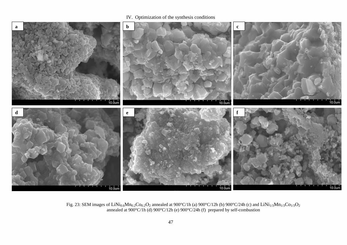
IV. Optimization of the synthesis conditions
47
Fig. 23: SEM images of LiNi0.6Mn0.2Co0.2O2 annealed at 900°C/1h (a) 900°C/12h (b) 900°C/24h (c) and LiNi1/3Mn1/3Co1/3O2
annealed at 900°C/1h (d) 900°C/12h (e) 900°C/24h (f) prepared by self-combustion
a b c
d e f

IV. Optimization of the synthesis conditions
48
Fig. 24: SEM images of LiNi0.6Mn0.2Co0.2O2 annealed at 900°C/12h (a) 900°C/24h (b) and LiNi1/3Mn1/3Co1/3O2
annealed at 900°C/12h (c) 900°C/24h (d) prepared by co-precipitation
a b
d c

IV. Optimization of the synthesis conditions
49
4. Annealing temperature
In order to demonstrate how the annealing temperature affects the structural and morphological
properties we studied by XRD and SEM three NMC materials with the composition (3:1:1)
prepared by self-combustion method. They were annealed for 1 h at 700°C, 800°C and 900°C.
As shown in the diffractograms (figure 25) the phases crystallize in the rhombohedral system
and all diffraction peaks can be indexed in the α-NaFeO2 type structure (space group: R3¯m).
Also, the shape of the diffraction lines as well as their narrowness especially for the third
compound indicates good crystallinity and homogenous distribution of the cations in the
structure.
10 20 30 40 50 60 70 80 90 100 110
3000
4000
5000
6000
7000
8000
9000
10000
11000
12000
13000
14000
15000
16000
17000
18000
700°C/1h
800°C/1h
LiNi0.6Mn0.2Co0.2O2 prepared by self-combustion
(003)
(104)
Inte
nsi
ty (
A.U
.)
900°C/1h
2 Cu
Fig. 25: Comparison between X-ray diffraction patterns of the material LiNi0.6Mn0.2Co0.2O2 annealed at
900°C, 800°C and 700°C during 1 h
.
The morphological characterization was conducted by SEM (figure 26). The sample annealed
at 900°C consists of small aggregates of elementary particles with a size distribution in the
range of 500-600 nm. While the two samples annealed at 700°C and 800°C respectively are
characterized by aggregates of larger size in the order of 20 µm. The primary particles in this
case are also in the micrometer range. The small size of the particles obtained by annealing at
900°C allows a rapid diffusion of lithium ions and leads to a large amount of lithium ions
exchanged.

IV. Optimization of the synthesis conditions
50
Fig. 26: SEM images of the material LiNi0.6Mn0.2Co0.2O2 annealed at 700°C/1h (a) 800°C/1h (b) and
900°C/1h (c)
a
b
c

IV. Optimization of the synthesis conditions
51
5. Annealing atmosphere
In order to demonstrate the importance of the annealing atmosphere and assess how much air
is needed to obtain NMC phases with crystalline structure, two NMC samples with the
composition LiNi0.6Mn0.2Co0.2O2 prepared by self-combustion method were annealed during
12 h in air and argon, respectively. Structural and morphological analyses for both compounds
were carried out by means of XRD and SEM.
From the XRD patterns (figure 27), it can be seen that the sample annealed under argon
cannot be indexed in the space group R-3m as the most characteristic diffraction peaks of α-
NaFeO2 type structure are missing. Further analysis of the diffraction lines showed that the
sample consists mainly of Li2CO3 that crystallizes in the monoclinic system and presents
diffraction peaks in the 2θ region 21°-35°. Li2CO3 is in fact the result of reaction between
lithium and carbon coming from sucrose used as fuel. In addition, diffraction peaks related to
Ni, Co and Mn oxides are present.
10 20 30 40 50 60 70 80 90 100 1100
500
1000
1500
2000
2500
3000
3500
Annealing under air
LiNi0.6Mn0.2Co0.2O2 prepared by self-combustion
Inte
nsi
ty (
A.U
.)
Annealing under argon
(104)
(003)
2 Cu
Fig. 27: X-ray diffraction patterns of the NMC (3:1:1) positive electrode materials annealed under air
(black) and under argon (orange)

IV. Optimization of the synthesis conditions
52
SEM was performed to check the morphology and particle sizes of the two phases (figure 28).
We notice an evolution of the morphology from individual particles for the sample annealed
under air to more non-uniform and undefined shape particles with bigger size for the phase
annealed under argon.
Fig. 28: SEM images of the sample NMC (3:1:1) annealed for 12h under air (a) and the one annealed
for 12h under argon (b)
From the previous results, we were able to demonstrate the necessity of carrying out the
annealing under air according to the reaction equation:
6. Aging effect
In order to better understand how the time between synthesis and annealing affects the
structural and morphological properties, we studied by XRD two NMC (3:1:1) samples. The
first was annealed immediately after synthesis and the second was aged 6 months before
annealing in air atmosphere (figure 29). From the XRD patterns, all diffraction peaks for both
phases can be indexed in the α-NaFeO2 type structure (space group: R3¯m). The shape and
narrowness of the diffraction lines show a good crystallinity. However, for the aged sample,
we notice the presence of peaks related to Li2CO3.
1.05 LiNO3
+ 0.6 Ni(NO3)2
+ 0.2 Co(NO3)2
+ 0.2 Mn(NO3)2
+ 2/3 C12
H22
O11
+ O2
Li Ni0.6
Mn0.2
Co0.2
O2
+ N2+ NO
x +CO
2 + H
2O
a b

IV. Optimization of the synthesis conditions
53
Fig. 29: X-ray diffraction patterns of the aged (red) and fresh NMC (3:1:1) positive electrode materials
(black)
In order to evaluate in detail the deviation of the NMC lattice parameters between the fresh and
aged samples, the XRD diffractograms were further analyzed by Rietveld refinement method.
A good minimization function was obtained even for the aged material (figure 30).
Furthermore, the lattice parameter a, representing the metal–metal intra-sheet distance, slightly
increased from 2.8608 Å for the fresh sample to 2.8660 Å for the aged sample. This can be
attributed to the migration of some Ni2+
ions from the 3a sites to the interlayer 3b sites.
This phenomenon was confirmed by the decrease of the lattice parameter c, representing the
interlayer space thickness, from 14.167Å for the fresh sample to 14.188Å for the aged one.
Such decrease is mainly due to the stronger electrostatic attraction between oxygen and
Li+/Ni
2+ ions in the interlayer space. Therefore, we can conclude that the occupancy of Ni
2+
ions on Li+ ions sites is higher for the aged sample.
10 20 30 40 50 60 70 80 90 100 110
Inte
nsi
ty (
A.U
.)
LiNi0.6Mn0.2Co0.2O2 prepared by self-combustion
Fresh sample
Aged sample
2Cu

IV. Optimization of the synthesis conditions
54
20 30 40 50 60 70 80 90 100
0
2000
4000
6000
8000
10000
Cu
Inte
nsi
ty (
arb. unit
s)
2(°)
Fig. 30: Rietveld profile refinement results of the aged NMC electrode material: __ observed, __
calculated, __ difference, I Bragg positions
The morphological characterization was carried out by SEM (figure 31). For the fresh sample,
the particles are smaller and their shapes are more defined while for the aged sample, the
particle size increases and the shape is more fritted and less well-defined. Moreover, some
fissures and cracks are present all over the particle surface of the aged sample.
Fig. 31: SEM images of the fresh sample that was annealed immediately after synthesis (a) and the
aged sample that was left in air for 6 months then was annealed (b)
a b

IV. Optimization of the synthesis conditions
55
The elemental analysis by EDX showed that the amount of oxygen is higher for the aged
sample than for the fresh one (table 8). Likewise, the amounts of the carbon and nitrogen are
much higher for the aged sample than for the fresh one. We can therefore understand that for
an aged material, it is more difficult to extract oxygen, carbon and nitrogen oxides of the
material through annealing.
Table 8: EDX element analysis of the fresh and aged samples
In order to investigate the influence of the time between synthesis and annealing on the
material’s thermal properties, DTA-TG tests were performed (figure 32). The mass losses for
both materials are mainly due to water, oxygen, carbon and nitrogen oxides release. The mass
loss for the aged material is higher than for the fresh one. On the other hand, DTA curves show
for both materials the presence of an exothermic peak related to the release of oxygen and
carbon oxides, this peak is more pronounced for the aged material. This is probably due to the
decomposition of Li2CO3 that is present in the case of aged NMC (3:1:1).
DTA-TG results confirm the EDX results that showed a higher amount of oxygen, carbon and
nitrogen still present in the aged sample even after annealing. On the other hand, DTA curves
present an endothermic peak for both materials; it is indicating the temperature from which we
obtain the crystallized phase. This peak is almost the same for both materials.
Element Wt. % (fresh sample) Wt. % (aged sample)
C
N
O
Mn
Co
Ni
4.4 ± 0.6
1.0 ± 0.2
27.8 ± 1.4
13.5 ± 1.6
13.7 ± 2.3
39.8 ± 4.1
7.9 ± 1.2
7.4 ± 2.1
31.6 ± 1.6
11.5 ± 1.3
10.2 ± 2.1
31.3 ± 3.7

IV. Optimization of the synthesis conditions
56
0 100 200 300 400 500 600 700 800 900 1000 1100
-30
-25
-20
-15
-10
-5
0
5
-30
-25
-20
-15
-10
-5
0
5
DTA-TG curves of the aged material
DT
A (
µV
)
TG
(%
)
T (°C)
0 100 200 300 400 500 600 700 800 900 1000 1100
-25
-20
-15
-10
-5
0
5
-25
-20
-15
-10
-5
0
5
DTA-TG curves of the fresh sample
DT
A (
µV
)
TG
(%
)
T (°C)
Fig. 32: DTA-TG curves of the aged sample that was left in air for 6 months then was annealed (a) and
the fresh one that was annealed immediately after synthesis (b) DTA-TG tests were carried out
simultaneously in the temperature range between 20 and 1020°C with a scan rate of 5°C/min
a
b

IV. Optimization of the synthesis conditions
57
Cyclic voltammetry was performed for cells at room temperature with metallic lithium as
counter and reference electrodes at a scan rate of 0.5 mV/s.
For the fresh sample, the first cycle anodic peak is related to the extraction of Li ions from the
lattice, it occurs at 4.20 V, and the main cathodic peak is at 3.68 V and is related to the
insertion of Li. The positions of oxidation and reduction peaks are very stable from one cycle
to another, which indicates good reversibility of the charge–discharge reaction. However, the
relative peak-intensities and the area under the peaks decrease slightly with cycle number.
This is due to capacity fading phenomenon.
Regarding the aged sample, the cyclic voltammograms reported in figure 33 are showing a
totally different behavior illustrated by the absence of cathodic and anodic peaks that
correspond to the extraction and the insertion of lithium. This can be explained by a very low
exchange of lithium ions caused by the high cation mixing in the aged sample´s structure.
2,0 2,5 3,0 3,5 4,0 4,5
-0,2
-0,1
0,0
0,1
0,2
0,3
J /
mA
.cm
-2
1st cycle
10th cycle
E vs Li,Li+ / V
Fig. 33: Cyclic voltamorgamms of the aged (a) and fresh (b) samples vs. Li/Li+ at a scan rate of 0.5
mV/s. The fresh sample was annealed immediately after synthesis and the aged one was left in air for
6 months then was annealed
a
1,5 2,0 2,5 3,0 3,5 4,0 4,5
-0,2
-0,1
0,0
0,1
0,2
0,3
J /
mA
.cm
-2
1st cycle
10th cycle
E vs Li,Li+ / V

IV. Optimization of the synthesis conditions
58
The electrochemical performance of the two NMC (3:1:1) samples was evaluated by
galvanostatic cycling at slow rate C/20 (figure 34). For the fresh material, the similarity
between the charge-discharge curves indicates a good reversibility of the Li+ ion intercalation-
deintercalation process. The reversible capacity obtained during the first cycle is of the order of
155 mAh g-1
. For the aged material, a similarity between the charge-discharge curves is also
observed during the ten first cycles except the first cycle´s charge curve which is irreversible.
However, the reversible capacity in the case of aged NMC (3:1:1) is very low (about 25 mAh
g-1
). The differences in the particle size as well as morphology between the two samples can
explain their electrochemical behavior. Indeed, the small size of the particles in the case of
fresh NMC (3:1:1) sample allows a rapid diffusion of Li+ ions and lead to an intense exchange
of lithium ions and therefore to a larger reversible capacity. On the other hand, the increase of
Ni2+
ions in the interlayer space, for the aged sample, results in cation mixing which hinders
the efficient Li-ion transport and reduces significantly the reversible capacity.
0 5 10 15 20 25 30 35 40 45 50 55 60
2,6
2,8
3,0
3,2
3,4
3,6
3,8
4,0
4,2
4,4
4,6
1st cycle10
th cycle
Specific capacity / mAh.g-1
Vo
ltag
e /
V v
s L
i+,L
i
0 25 50 75 100 125 150 175 200 225
2,0
2,5
3,0
3,5
4,0
4,5 1st cycle10
th cycle
Volt
age
/ V
vs
Li+
,Li
Specific capacity / mAh.g-1
Fig. 34: Galvanostatic cycling at C/20 rate of the aged (a) and fresh (b) samples of the material
LiNi0.6Mn0.2Co0.2O2
b
a

V. Characterization of the novel cathodes obtained by cationic substitution
59
V. Characterization of the novel cathodes obtained by cationic
substitution
1. Introduction
As it was evident through state of the art on NMC type materials and through the previous
chapter, the synthesis conditions can have a great influence on the electrochemical
performance of NMC type cathode materials.
According to the study that was conducted in chapter 3, we were able to fix for all of the
following, the optimal conditions for the preparation of the investigated cathode materials
throughout this work. Thereby, the phases were prepared by self-combustion synthesis
method. They were annealed directly after synthesis in air at 900°C for one hour. The main
phase was the nickel rich one with the composition (3: 1: 1)
In the following chapter, we chose to examine the influence of the cobalt substitution by
aluminum and / or iron in an attempt to further optimize the starting material NMC (3:1:1). In
the following, these materials are shortly called NMCA (LiNi0.6Mn0.2Co0.15Al0.05O2), NMCF
(LiNi0.6Mn0.2Co0.15Fe0.05O2) and NMCAF (LiNi0.6Mn0.2Co0.15Al0.025 Fe0.025O2).
2. Structural characterization
2.1. by XRD
X-ray diffraction diagrams of the four materials (fig. 35)show that all diffraction peaks can be
indexed in the R-3m space group. According to the XRD data, the phase α-NaFeO2 type was
obtained systematically pure for all of the aforementioned materials. Analysis of the
continuous background has not detected any presence of the impurity Li2CO3.
The full width at half maximum (FWHM) values of the reflections (003) and (104) are
reported in table 9. The smallest values of the FWHM of the reflections (003) and (104) were
obtained for the double substituted phase NMCAF and they are respectively equal to 0.32°
and 0.36°. This indicates better crystallinity obtained for the NMCAF material and suggests a
homogeneous distribution of the cations in the structure. The FWHM of the (003) and (104)
peaks are gradually increasing when moving from NMCF to NMCA and finally NMC. The
latter presented the highest values: 0.43 for FWHM(003) and 0.42 for FWHM(104).
In contrast, the intensity ratio of the peaks (003)/(104) tends to decrease as the FWHM tends
to increase. The broadening of the diffraction lines could indicate a reduction in crystallinity
of the phases, whereas the evolution of the intensity ratio I(003) / I(104) may indicate an
improvement in the structure. As reported in table 9, higher I(003)/I(104) value was obtained for
the double substituted material compared to the mono and non-substituted materials. This
confirms the formation of more ordered lamellar phase for NMCAF material than for NMCF
and NMCA and NMC.

V. Characterization of the novel cathodes obtained by cationic substitution
60
Fig. 35: Comparison between X-ray diffraction patterns of the four materials NMC, NMCA, NMCF
and NMCAF (a) and the insets of their diffraction lines (003) (b) and (104) (c)
a
b c
0 2 4 6 8 10
0
2
4
6
8
10
20 30 40 50 60 70 80 90 100-4000
-2000
0
2000
4000
6000
8000
10000
12000
14000
Inte
nsi
ty (
A.U
.)
NMC
NMCA
NMCF
NMCAF
2Cu
(00
3)
(10
4)
17,5 18,0 18,5 19,0 19,5 20,0
-4000
-2000
0
2000
4000
6000
8000
10000
12000
14000
16000
Inte
nsi
ty (
A.U
.)
FWHM of the diffraction line (003)
NMCAF
NMCF
NMCA
NMC
2Cu
43,5 44,0 44,5 45,0 45,5-4000
-2000
0
2000
4000
6000
8000
10000
12000
14000
16000
Inte
nsi
ty (
A.U
.)
FWHM of the diffraction line (104)
NMC
NMCA
NMCF
NMCAF
2Cu

V. Characterization of the novel cathodes obtained by cationic substitution
61
Table 9: Structural parameters of the four materials NMC, NMCA, NMCF and NMCAF obtained by
XRD
Cathode materials FWHM(003) FWHM(104) I(003)/I(104)
NMC 0.43° 0.42° 0.86°
NMCA 0.39° 0.41° 0.89°
NMCF 0.35° 0.40° 0.96°
NMCAF 0.32° 0.36° 1.19°
2.2. Structural refinement by Rietveld method
The X-ray diffraction patterns of the four materials studied in the previous section of this
chapter were refined by Rietveld method using Fullprof software and considering the
presence of a single phase α- NaFeO2 type. For refinement, we have considered the presence
of additional lithium ions on the 3a sites of the transition metals and a possible exchange
between the lithium ions of the 3b sites and the divalent nickel ions of the 3a sites.
The cation distribution in LiMO2 lamellar type structures is mainly due to the size difference
between Li+ and M
n+ cations. Therefore, taking into account the size of the different cations
only (r(Li+) = 0.76Å, r(Ni
2+) = 0.69Å, r(Mn
4+) = 0.53Å, r(Co
3+) = 0.54Å, r(Al
3+) = 0.53Å,
r(Fe3+
) = 0.64Å, r(Ni3+
) = 0.56Å), we assumed that aluminum and iron ions are preferentially
expected to occupy the 3a sites of the transition metals.
Table 10 presents the cation distribution determined by Rietveld refinement for the four
materials.
As an example, for the NMCAF material, XRD refinement by Rietveld has led to the
following cationic distribution:
(Li0.97Ni0.03)3b(Lioverlithiation
0.01Li0.03NiII
0.55NiIII
0.02Mn0.21Co0.15Al0.025Fe0.025)3a(O2)6c.
Table 10: Cation distribution determined by Rietveld refinement method of the XRD diagrams of the
four materials NMC, NMCA, NMCF and NMCAF
Cathode
materials
3b sites (interlayer space) 3a sites (MO2 layers)
Li+ Ni
2+ Li
+ Ni
2+ Ni
3+ Mn
4+ Co
3+ Al
3+ Fe
3+
NMC 0.92 0.06 0.09 0.52 0.03 0.21 0.20 - -
NMCA 0.95 0.04 0.06 0.54 0.02 0.20 0.15 0.050 -
NMCF 0.96 0.04 0.05 0.54 0.02 0.20 0.14 - 0.051
NMCAF 0.97 0.03 0.04 0.55 0.02 0.21 0.15 0.025 0.025
On the other hand, a good agreement was obtained between the experimental and calculated
patterns and the difference (Iobs-Icalc) was well minimized for all of the four materials NMC,
NMCA, NMCF and NMCAF.
Moreover, we can see from table 11 that there is a slight expansion of the lattice parameters a
and c for the Fe substituted materials due to the larger radius of the Fe3+
ions (64.5 pm)
compared to that of Co3+
ions (54.5 pm).

V. Characterization of the novel cathodes obtained by cationic substitution
62
In contrast, the very similar ionic radii of Al3+
(53.5 pm) and Co3+
(54.5 pm) resulted in a
negligible decrease of the lattice parameter ahex with aluminum substitution. This result is in
good agreement with literature [311, 312].
Besides, if we compare the occupancy of the Ni ions on the 3b crystallographic sites of the
lattice, we notice that the smallest amount was obtained for the double substituted material
suggesting less cation mixing in the structure, and then we could expect better cycling
performance (Ch. V.5.2) due to the better lithium diffusion.
Table 11: Structural parameters determined by Rietveld refinement method of the XRD diagrams of
the four materials NMC, NMCA, NMCF and NMCAF
Crystal data NMC NMCA NMCF NMCAF
a 2.861 Å 2.859 Å 2,869 Å 2,868 Å
c 14,167 Å 14,162 Å 14,215 Å 14,211 Å
V 100,56 Å3 100,53 Å
3 101,34 Å
3 101,22 Å
3
Occupancy of Ni2+
on Li+ sites 13 % 9 % 8 % 5%
3. Morphological characterization
3.1. by SEM
The primary particles of NMC, NMCA, NMCF and NMCAF have a relatively homogeneous
size distribution (Fig. 36). The non-substituted material NMC presents larger primary
particles (~ 450 nm average diameter) than those of the substituted materials.
Regarding the aluminum substituted material, the particle size ranges between 350 nm and
500 nm. This size reduction of the primary particles was also observed by Hu et al. [312].
Besides, by comparing SEM micrographs obtained for the two iron substituted materials
NMCF and NMCAF and the pristine non-substituted material NMC, it is noticeable that for
the Fe substituted compounds the spherical shape of the particles is more uniform and their
sizes are smaller ranging between ~ 280 nm and 500 nm. Similar results have been reported in
the literature by Li et al. [36]. Substituted materials especially with iron also exhibit rather
airy and less compact powders, unlike substituted NMC material for which the agglomerates
appear more sintered.

V. Characterization of the novel cathodes obtained by cationic substitution
63
Fig. 36: SEM images of the four materials NMC (a), NMCA (b), NMCF (c) and NMCAF (d)
3.2. Specific surface measurement by BET
Table 12 reports the values of specific surface measured by BET method (Ch. III.2.2) for the
four samples NMC, NMCA, NMCF and NMCAF. The highest specific surface has been
obtained for the double substituted material NMCAF, while the lowest one was achieved for
the pristine non-substituted NMC material. BET results confirmed to be in good agreement
with the SEM analysis.
Table 12: Comparison of specific surface measured by the BET. method for the four phases NMC,
NMCA, NMCF and NMCAF
Cathode materials SB.E.T. (m2/g)
NMC 4.02 ± 0.03
NMCA 4.08 ± 0.13
NMCF 4.18 ± 0.19
NMCAF 4.21 ± 0.08
a b
d c

V. Characterization of the novel cathodes obtained by cationic substitution
64
The noticeable differences in the particle size between the four materials as well as in the
specific surfaces can provide insight on their electrochemical behavior. Indeed, the small
particle size observed for the double substituted material NMCAF will allow a rapid diffusion
of lithium ions and therefore will lead to a significant amount of exchanged lithium ions and a
greater reversible capacity, whereas the large particles observed for the pristine NMC material
seem likely to prevent their impregnation by the electrolyte and may thus provide weaker
electrochemical performance.
4. Thermal characterization by DTA-TG
DTA-TGA tests were carried out in the temperature range T = [20°C; 1020°C] with a heating
temperature rate equal to 5°C/min for the four as-prepared cathode materials NMC, NMCA,
NMCF and NMCAF (figure 37).
TGA curves show that the mass loss for the four compounds is produced during all the
thermal treatment, which is mainly due to water, oxygen, carbon and nitrogen oxides release.
The mass loss is smaller for the two iron substituted materials NMCF and NMCAF.
On the other hand, DTA curves show for the three materials the presence of an exothermic
peak related mainly to the release of oxygen. An endothermic peak is also present for the four
materials and indicates the crystallization temperature. This peak is at the same value (~
725°C) for the four materials.

V. Characterization of the novel cathodes obtained by cationic substitution
65
Fig. 37: DTA and TGA curves of NMC (a), NMCA (b), NMCF (c) and NMCAF (d) performed in air
from room temperature to 1020 °C with a heating temperature rate of 5 °C / min
5. Electrochemical performance
5.1. Cyclic voltammetry
The cyclic voltammograms were recorded for cells at room temperature with metallic lithium
as the counter and reference electrodes at a slow scan rate 0.1 mV/s. The voltammetric
behavior of the metal substituted and non-substituted materials display approximately
identical features (Fig. 38).
For NMCA, the first cycle anodic peak corresponding to the extraction of Li ions from the
lattice occurs at 4.20 V vs. Li/Li+, whereas the main cathodic peak (insertion of Li) is at 3.68
V vs. Li/Li+. The difference between anodic and cathodic peak voltages remains almost
constant, which indicates good reversibility of the charge–discharge reaction. The relative
peak intensities and the area under the peaks slightly decrease with cycling. This indicates a
capacity fading for the aluminum substituted material throughout cycling.
a b
d c
0 100 200 300 400 500 600 700 800 900 1000 1100
-25
-20
-15
-10
-5
0
5
-25
-20
-15
-10
-5
0
5
TG
(%
)
DT
A (
µV
)
Temperature (°C)
0 100 200 300 400 500 600 700 800 900 1000 1100
-50
-40
-30
-20
-10
0
10
Temperature (°C)
DT
A (
uV
)
-50
-40
-30
-20
-10
0
10
TG
(%
)
0 100 200 300 400 500 600 700 800 900 1000 1100
-35
-30
-25
-20
-15
-10
-5
0
5
Temperature (°C)
TG
(%
)
DT
A (
uV
)
-35
-30
-25
-20
-15
-10
-5
0
5
0 100 200 300 400 500 600 700 800 900 1000 1100
-35
-30
-25
-20
-15
-10
-5
0
5
-35
-30
-25
-20
-15
-10
-5
0
5
DTA-TG for NMCF material
Temperature (°C)
DT
A (
uV
)
TG
(%
)

V. Characterization of the novel cathodes obtained by cationic substitution
66
An identical behavior was observed for the iron substituted material NMCF regarding the
main anodic and cathodic peak values. A good reversibility of the charge–discharge process is
also noticeable. Regarding the double substituted material NMCAF, the extraction of Li ions
from the lattice occurs already at 3.60 V vs. Li/Li+, and the insertion of Li ions is taking place
at about 3.35 V vs. Li/Li+. NMCAF cathode material also presents a good reversibility of the
charge–discharge reaction and with less capacity fading.
The oxidation and reduction peaks positions remain at constant potential with the cycle
number for all the four materials. This indicates their good stability during voltammetric
cycling.
The potential range that was used for the four materials lies between 1.5 V and 4.7 V. Even
though this potential window is greater than that required for this type of materials, it remains
suitable for the used electrolyte (Ch. III.4) since its stability window is located in this range.
The aim through operating at such wider potential window was to specify the potential range
that enables avoiding any side redox reaction of the active species in the material and any
activation of the electrochemically inactive ions such as cobalt and iron ions especially when
the potential is higher than 4.4 V. In the following, the potential window that was used is the
one highlighted in figures 38 (a), (b), (c) and (d), ranging between 2.7 V and 4.4 V.
Fig. 38: Cyclic voltammetry curves I = f(V) of the four materials NMC (a), NMCA (b), NMCF (c) and
NMCAF (d) of the 1st and 10th cycles at 0.1 mV/s scan rate
.
b a
c d
1,5 2,0 2,5 3,0 3,5 4,0 4,5
-0,2
-0,1
0,0
0,1
0,2
0,3
J /
mA
.cm
-2
E vs Li,Li+ / V
1st cycle
10th cycle
1,5 2,0 2,5 3,0 3,5 4,0 4,5
-0,2
-0,1
0,0
0,1
0,2
0,3
J /
mA
.cm
-2
1st cycle
10th cycle
E vs Li,Li+ / V
1,5 2,0 2,5 3,0 3,5 4,0 4,5
-0,2
-0,1
0,0
0,1
0,2
0,3
E vs Li,Li+ / V
J /
mA
.cm
-2
1st cycle
10th cycle
E vs Li,Li+ / V
1,5 2,0 2,5 3,0 3,5 4,0 4,5
-0,2
-0,1
0,0
0,1
0,2
0,3
1st cycle
10th cycle
E vs Li,Li+ / V
J /
mA
.cm
-2

V. Characterization of the novel cathodes obtained by cationic substitution
67
5.2. Galvanostatic cycling at different C rates
The electrochemical behavior of the four electrodes NMC, NMCA, NMCF and NMCAF was
studied at room temperature by galvanostatic cycling applying different C rates: C/20, C/5
and 1C.
Figure 39 shows the variation of the potential with the specific capacity at slow rate C/20. A
continuous and similar evolution of the potential with the time can be perceived for all four
materials. The shape of the charge-discharge curves shows then a good reversibility of the
intercalation-deintercalation process. Therefore, a partial substitution of the cobalt by an
amount of aluminum and / or iron limited to 1/20 in the layered oxide is accompanied by an
improvement in the reversible capacity compared to the non-substituted material. NMC
(3:1:1) in addition to a remarkable reduction in the irreversible capacity. This can be
explained by the presence of less Ni2+
ions in the interlayer space for the substituted materials
especially NMCAF.
From Figure 39, one can easily note that the initial discharge capacity for the double
substituted electrode is of the order of 190 mAh/g, higher than those of the mono substituted
electrodes with Fe (165 mAh/g ) or Al (162 mAh/g) and the non-substituted NMC electrode
(156 mAh/g). However, small changes in plateau potentials are observed after the metal
substitution. The voltage plateau at ca. 3.75 V for the four studied NMC type materials can be
attributed to Ni2+
/Ni4+
reaction.
The plateau potential variations for the studied materials can be related to the drop of the
chemical potential in case of Al substituted materials and to a polarization effect for the Fe
substituted materials. The effect of voltage change is in a good correlation with the change of
the structural parameters after the substitution, since a very small amount of substitution
caused a big difference in terms of cation mixing.
The evolution of the discharge capacity as a function of the cycle number obtained at faster
rates C/5 and 1C for the four materials over the first 50 cycles is shown in Figure 40. The
cycling stability was also improved for the substituted materials especially NMCAF in the
used cycling conditions. Table 13 is a summary of the most significant values obtained for the
four materials. Indeed, at the C/5 rate for instance, the non-substituted material exhibited a
continuous decrease in its reversible capacity with a loss of about 26% after 50 cycles,
whereas the double substituted material, for example, lost less than 15% of its reversible
capacity at the end of the test. Better stability of the capacity during cycling is obtained for the
NMCAF material followed by NMCF and NMCA with capacity retention of the order of
85.7%, 75.8% and 75.1% respectively, after 50 cycles.

V. Characterization of the novel cathodes obtained by cationic substitution
68
Fig. 39: Charge/discharge curves of the battery Li//EC:DMC//cathode material: NMC (a), NMCA (b),
NMCF (c) and NMCAF (d) during the 10 first cycles under C/20 rate
. Table 13: Electrochemical parameters obtained for the four materials NMC, NMCA, NMCF and
NMCAF at C/20, C/5 and 1C rates
Samples
Irreversible
capacity
(C/20 rate)
Rev. capacity
1st cycle
(C/20 rate)
Rev. capacity
10th cycle
(C/20 rate)
Capacity
retention after
10 cycles
(C/20 rate)
Capacity
retention after
50 cycles (C/5
rate)
Capacity
retention after
50 cycles (1C
rate)
NMC 81 mAh/g 156 mAh/g 138 mAh/g 88.4 % 74.7 % 73.5 % NMCA 60 mAh/g 162 mAh/g 144 mAh/g 88.8 % 75.1 % 78.8 % NMCF 62 mAh/g 165 mAh/g 147 mAh/g 89.1 % 75.8 % 71.7 %
NMCAF 70 mAh/g 190 mAh/g 176 mAh/g 92.6 % 85.7 % 78.5 %
0 25 50 75 100 125 150 175 200 225 250
2,50
2,75
3,00
3,25
3,50
3,75
4,00
4,25
4,50
E /
V v
s L
i,L
i+
Specific capacity mAh.g-1
1st cycle
5th cycle
10th cycle
0 25 50 75 100 125 150 175 200 225 250
2,6
2,8
3,0
3,2
3,4
3,6
3,8
4,0
4,2
4,4
4,6
1st cycle
5th cycle
10th cycle
E /
V v
s L
i,L
i+
Specific capacity mAh.g-1
0 25 50 75 100 125 150 175 200 225 250
2,6
2,8
3,0
3,2
3,4
3,6
3,8
4,0
4,2
4,4
E
/ V
vs
Li,
Li+
Specific capacity mAh.g-1
1st cycle
5th
cycle
10th cycle
0 20 40 60 80 100 120 140 160 180 200 220
2,6
2,8
3,0
3,2
3,4
3,6
3,8
4,0
4,2
4,4
4,6
1st cycle
5th cycle
10th cycle
E /
V v
s L
i,L
i+
Specific capacity mAh.g-1
a b
d c

V. Characterization of the novel cathodes obtained by cationic substitution
69
Fig. 40: Discharge capacity evolution with the cycle number of the materials NMC (a), NMCA (b),
NMCF (c) and NMCAF (d) during the 50 first cycles under C/5 and 1C rates
.
0 5 10 15 20 25 30 35 40 45 50
0
25
50
75
100
125
150
C/5 rate
C rate
dis
char
ge
capac
ity
/ m
Ah.g
-1
Cycle number
0 5 10 15 20 25 30 35 40 45 50
0
25
50
75
100
125
150
Cycle number
dis
char
ge
capac
ity
/ m
Ah.g
-1
C/5 rate
C rate
a b
d c
0 5 10 15 20 25 30 35 40 45 50
0
25
50
75
100
125
150
C/5 rate
C rate
dis
char
ge
capac
ity /
mA
h.g
-1
Cycle number
0 5 10 15 20 25 30 35 40 45 50
0
20
40
60
80
100
120
140
160
180
200
220
C/5 rate
C rate
dis
char
ge
capac
ity
/ m
Ah
.g-1
Cycle number

V. Characterization of the novel cathodes obtained by cationic substitution
70

VI. Synthesis and characterization of the double substituted cathode material
71
VI. Synthesis and characterization of the double substituted
cathode material LiNi0.6Mn0.2Co0.15Al0.025Fe0.025O2
1. Introduction
As shown in the previous chapter, metal substitution increases the order in the structure
inducing a considerable structural stabilization, less cation mixing and strong electrochemical
performance improvement by providing possibility for easier and more efficient Li
intercalation.
According to the preliminary studies discussed in the previous chapter, the double substituted
material NMCAF presented higher reversible capacities and better capacity retention
compared to the pristine NMC(3:1:1) and to the mono-substituted materials (Ch. V.5.2).
However, the link between its improved electrochemical performance and its structural
propertieshas not been established in detail. In order to make this connection, extensive
structural and electrochemical studies were carried out and correlated.
On the other hand, given the great concern attributed to safety aspects of active electrode
materials for LIBs [314-317], the investigation of the temperature effect on the structural
stability is of great importance since the thermal stability of the cathode materials is crucial
for the safety.
Thereby, it was necessary to investigate the thermal and structural properties of the
chemically de-intercalated phases of both NMCAF and NMC (3:1:1).
2. Synthesis by self-combustion
The preparation of the NMC (3:1:1) and NMCAF cathode materials was made by self-
combustion synthesis method (Ch. VI.2.2).
Afterwards, to obtain better distribution of the particles and improved homogeneity, the
synthesized phases were grinded by ball milling. An amount of 30g of active material was
required. The milling speed was about 600 rounds/min for a period of time equal to 6 minutes
consisting of two minutes milling followed by one minute rest to avoid the heating effect
caused by the high milling speed. This procedure is repeated 3 times and each time the milling
is in the opposite direction of the previous.
The difference between the NMC (3:1:1) material, for instance, before and after ball milling
can be seen in Fig. 41. It is clear that no more aggregates exist after ball milling and the
particles are more individual.

VI. Synthesis and characterization of the double substituted cathode material
72
Fig. 41: SEM images of the NMC (3:1:1) material before ball milling (a) and after ball milling (b);
The ball milling speed was about 600 rounds/min for a total milling time of 6 minutes
.
3. Structural characterization by XRD
In order to determine precisely the structural parameters of the studied phases, structural
refinement by Rietveld method using Fullprof software has been performed.
First, the two samples NMC (3:1:1) and NMCAF are considered to crystallize in the ideal α-
NaFeO2 like structure. In this structure, and as has been confirmed in chapter 4, lithium and
the transition metals occupy respectively the 3b (0, 0, ½) and 3a (0, 0, 0) crystallographic sites
of the R-3m space group while oxygen occupies the 6c (0, 0, zox.) sites.
The occupancy of lithium, oxygen and transition metal cations was initially fixed to the
experimental values. The zero offset, the lattice parameters, the scale factor, the parameters of
the pseudo-Voigt type profile function and the isotropic atomic displacement parameters of
the different atoms were refined.
The refined occupancy values showed no big difference compared to the experimental ones
(the deviation is less than 8%), which indicates that we succeeded in synthesizing a
stoichiometric phase.
The value obtained for the isotropic atomic displacement parameter related to the 3b lithium
sites (Biso (Li)) is positive (tables 14 and 15), indicating that no lithium excess was detected
and almost all of the lithium is located in the interlayer space which shows the validity of the
considered structural model.
A good agreement between the experimental and calculated XRD patterns was obtained as
illustrated in Fig. 42 which gives a comparison between the observed and calculated diagrams
of both NMC (3:1:1) and NMCAF materials. Indeed, a good minimization of the difference
(Iobs. - Icalc.) and low values of the reliability factors of the order of (Rwp = 12.9 % and RB =
4.7%) for the NMC (3:1:1) material and (Rwp = .8.1 % and RB = 3.9 %) for NMCAF material
were obtained. This suggests the good quality of refinement and further confirms the validity
of the considered structural model.
a b

VI. Synthesis and characterization of the double substituted cathode material
73
Table 14: The main parameters deduced from the XRD data refinement as well as the cationic
distribution of the material NMC (3:1:1)
LiNi0.6Mn0.2Co0.2O2
Space group: R-3m n (Co) = 0.2 ; n(Mn)=0.2
ahex. = 2.861 Å n (Ni)3a+ n (Ni)3b = 0.6
chex. = 14.167 Å n (Ni)3b+ n (Li)3b = 1
Atom Site Wyckoff positions Occupancy Biso(Å2)
Experimental conditions
Temperature ~ 298° K
2θ range 15° ≤ 2θ ≤ 100°
2θ step 0.02°
Zero point 0.008
Number of the refined parameters 16
Half-width parameters: U = 0.094; V = -0.031; W = 0.112
Reliability factors: Rwp= 12.9 % et RB = 4.7 %
Li (1) 3a 0 0 0.00 0.08 1.83
Ni (1) 3a 0 0 0.00 0.52 1.83
Li (2) 3b 0 0 0.50 0.92 1.61
Ni (2) 3b 0 0 0.50 0.08 1.61
Co 3a 0 0 0.00 0.20 1.83
Mn 3a 0 0 0.00 0.20 1.83
O 6c 0 0 0.26 2.00 0.63

VI. Synthesis and characterization of the double substituted cathode material
74
Table 15: The main parameters deduced from the XRD data refinement as well as the cationic
distribution of the material NMCAF
LiNi0.6Mn0.2Co0.15 Al0.025 Fe0.025O2
Space group: R-3m n (Co) = 0.2 ; n(Mn)=0.2
ahex. = 2.868 Å n (Ni)3a+ n (Ni)3b = 0.6
chex. = 14.211 Å n (Ni)3b+ n (Li)3b = 1
n (Al) = 0.025 ; n(Fe)=0.025
Atom Site Wyckoff positions Occupancy Biso(Å2)
Experimental conditions
Temperature ~ 298° K
2θ range 15° ≤ 2θ ≤ 100°
2θ step 0.02°
Zero point 0.013
Number of the refined parameters 16
Half-width parameters: U = 0.073; V = -0.011; W = 0.117
Reliability factors: Rwp= 8.1 % et RB = 3.9 %
Li (1) 3a 0 0 0.00 0.030 1.82
Ni (1) 3a 0 0 0.00 0.570 1.82
Li (2) 3b 0 0 0.50 0.970 1.59
Ni (2) 3b 0 0 0.50 0.030 1.59
Co 3a 0 0 0.00 0.150 1.82
Mn 3a 0 0 0.00 0.200 1.82
Al 3a 0 0 0.00 0.025 1.82
Fe 3a 0 0 0.00 0.025 1.82
O 6c 0 0 0.26 2.000 0.57
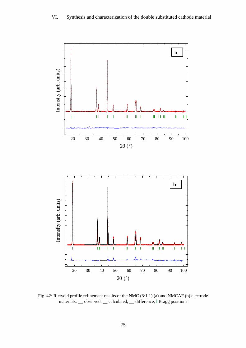
VI. Synthesis and characterization of the double substituted cathode material
75
20 30 40 50 60 70 80 90 100
0
2000
4000
6000
8000
10000
Inte
nsi
ty (
arb.
unit
s)
2(°)
20 30 40 50 60 70 80 90 100-1000
-500
0
500
1000
1500
2000
2500
3000
3500
Inte
nsi
ty (
arb
. u
nit
s)
2(°)
Fig. 42: Rietveld profile refinement results of the NMC (3:1:1) (a) and NMCAF (b) electrode
materials: __ observed, __ calculated, __ difference, I Bragg positions
a
b

VI. Synthesis and characterization of the double substituted cathode material
76
4. Physico-chemical characterization
4.1. Electron paramagnetic resonance
Three electrode materials NMC (3:1:1), NMCAF and a commercial NMC (1:1:1) were
investigated by EPR spectroscopy in the temperature range 77°K-295° K. Figs 43 and 44
display the experimental EPR spectra of the three materials recorded respectively at 77°K and
295°K in addition to their corresponding best fits.
The Lorentzian line approach [296] was adopted to achieve a best fit of the experimental
spectra [318,319] and gave rise to a single EPR line for the commercial NMC (1:1:1) and two
separate EPR lines for the in-lab synthesized NMC (3:1:1) and NMCAF (Fig. 44). The broad
line denoted as R1 has been assigned to paramagnetic Mn4+
and the narrower line denoted as
R2 has been attributed to the presence of paramagnetic Ni2+
defects [320]. The EPR
spectroscopic parameter ΔHi (line width) is presented as function of the temperature (Fig. 45)
where i= 1; 2 are respectively related to R1 and R2.
0 2000 4000 6000 8000 10000
NMC (1:1:1)
- experimental (T=77°K)
- fitting (R1)
- experimental (295°K)
H / 10-4T
Fig. 43: Experimental EPR spectra of commercial NMC (1:1:1), recorded at 77°K and 295°K. Fitting
of the experimental spectra was carried out by a Lorentzian line approach. Fitted and experimental
curves are shown
.

VI. Synthesis and characterization of the double substituted cathode material
77
0 2000 4000 6000 8000 10000
H / 10-4T
NMC (3:1:1)
- experimental (T=77°K)
- fitting
- separated R1
- separated R2
- experimental (T=295°K)
0 2000 4000 6000 8000 10000
H / 10-4 T
NMCAF
- experimental (T=77°K)
- fitting
- separated R1
- separated R2
- experimental (T=295°K)
Fig. 44: Experimental EPR spectra of the NMC (3:1:1) (a) and NMCAF (b) materials, recorded at
77°K and 295°K. Fitting of the experimental spectra was carried out by a Lorentzian line approach.
The fitted and separated after fitting curves are shown for each material
.
It can be seen that the increase of the temperature resulted in a decrease of ΔHi. Therefore, the
temperature dependence of ΔHi for the studied materials is in good correlation with the
reported data in the literature about NMC materials [320,321].
a
b

VI. Synthesis and characterization of the double substituted cathode material
78
Recent studies have reported that the EPR line width is strongly related to the material
stoichiometry, this can be reflected by the narrowing of the EPR line width ΔHi when the
Ni/Mn ratio diminishes [318]. This effect was likewise observed for the studied materials in
the present work since we obtained for NMC (1:1:1), that has a Ni/Mn ratio approximately
equal to 1, a value for ΔHi ~1200 G, while for NMC (3:1:1) with Ni/Mn ~3 we obtained ΔHi
~2000 G , which agrees well with the EPR results reported in the literature [318]. According
to the EPR method, a broadening of the EPR line can be mainly due to a dipole-dipole
interaction or / and some exchange interaction between the transition metal ions located in the
layered structure especially for materials with high concentration of the paramagnetic centers.
It is noteworthy that such interactions in our case are occurring not only for the Mn4+
- Mn4+
couple, but also for the Mn4+
- Ni2+
and Ni2+
- Ni2+
couples.
It can be seen from Fig. 44 that Al and Fe substitution has clearly affected the EPR spectrum
of the material. In this case, the results related to the function ΔHi ~ f (Ni2+
) reported in the
reference [321] are not valid as the NMC (3:1:1) and NMCAF materials have the same Ni
stoichiometry. The substantial decrease of the R2 line width for NMCAF can be related to a
decrease of Ni2+
defect density. This suggests that the cationic substitution of the active NMC
material induced a redistribution of the Ni ions within the structure, which can be a reason
behind the decreased cation mixing in NMCAF detected as well by means of Rietveld
refinement of the XRD data.
100 150 200 250300
400
500
600
1000
1500
2000
2500
3000
H2 NMC (3:1:1)
H2 NMCAF
H1 NMC (1:1:1)
H1 NMC (3:1:1)
H1 NMCAF
H
/ G
T / °K
Fig. 45: ΔH as a function of temperature for the commercial NMC (1:1:1) and the NMC (3:1:1) and
NMCAF materials prepared in this work, where i= 1; 2 are respectively related to R1 (assigned to
paramagnetic Mn4+
) and R2 (attributed to the presence of paramagnetic Ni2+
defects)

VI. Synthesis and characterization of the double substituted cathode material
79
One important property to be investigated is the paramagnetic-ferromagnetic phase transition
occurring at Tc (Curie point) which is a characteristic temperature for a given type of
material. The paramagnetic-ferromagnetic phase transition can be extracted from the analysis
of the function ΔHi ~ f (T).
Characteristically, when the temperature diminishes, a quick enhancement of ΔHi can be
observed beginning at Tc. For the three studied materials NMC (3:1:1), NMC (1:1:1) (fig. 46)
and NMCAF (fig. 45), it can be seen from ΔHi temperature evolution that Tc keeps a constant
value around 125°K, being close to that reported for example in reference [321]. Accordingly,
it can be presumed that neither the stoichiometry change nor the cationic substitution has
impact on the paramagnetic-ferromagnetic phase transition of the studied on materials.
50 100 150 200 250 300
1000
1100
1900
2000
2100
2200
H
1 /
10
-4 T
Paramagnetic
region
Ferromagn.
region
TC
H1 = F (T)
NMC (1:1:1)
NMC (3:1:1)
T / °K
Fig. 46: Representation of the paramagnetic-ferromagnetic phase transition for the in-lab prepared
NMC (3:1:1) and the commercial NMC (1:1:1)
5. Electrochemical performance in cycling
5.1. Galvanostatic cycling at constant slow rate C/20
For this electrochemical study, cycling was carried out at the constant slow rate C/20 in the
potential range 2.7 - 4.4 V.
To properly compare the potential of lithiation and delithiation taking into account the state of
charge for the two active materials NMC (3:1:1) and NMCAF, the galvanostatic curves as a
function of the normalized capacity are presented (Fig. 47). In this way, the potential
differences can be displayed at any lithiation degree.
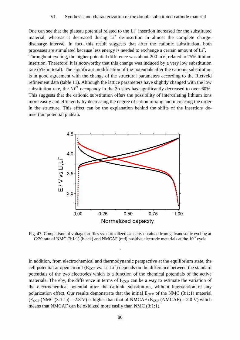
VI. Synthesis and characterization of the double substituted cathode material
80
One can see that the plateau potential related to the Li+ insertion increased for the substituted
material, whereas it decreased during Li+ de-insertion in almost the complete charge-
discharge interval. In fact, this result suggests that after the cationic substitution, both
processes are stimulated because less energy is needed to exchange a certain amount of Li+.
Throughout cycling, the higher potential difference was about 200 mV, related to 25% lithium
insertion. Therefore, it is noteworthy that this change was induced by a very low substitution
rate (5% in total). The significant modification of the potentials after the cationic substitution
is in good agreement with the change of the structural parameters according to the Rietveld
refinement data (table 11). Although the lattice parameters have slightly changed with the low
substitution rate, the Ni2+
occupancy in the 3b sites has significantly decreased to over 60%.
This suggests that the cationic substitution offers the possibility of intercalating lithium ions
more easily and efficiently by decreasing the degree of cation mixing and increasing the order
in the structure. This effect can be the explanation behind the shifts of the insertion/ de-
insertion potential plateau.
Fig. 47: Comparison of voltage profiles vs. normalized capacity obtained from galvanostatic cycling at
C/20 rate of NMC (3:1:1) (black) and NMCAF (red) positive electrode materials at the 10th cycle
.
In addition, from electrochemical and thermodynamic perspective at the equilibrium state, the
cell potential at open circuit (EOCP vs. Li, Li+) depends on the difference between the standard
potentials of the two electrodes which is a function of the chemical potentials of the active
materials. Thereby, the difference in terms of EOCP can be a way to estimate the variation of
the electrochemical potential after the cationic substitution, without intervention of any
polarization effect. Our results demonstrate that the initial EOCP of the NMC (3:1:1) material
(EOCP (NMC (3:1:1)) = 2.8 V) is higher than that of NMCAF (EOCP (NMCAF) = 2.0 V) which
means that NMCAF can be oxidized more easily than NMC (3:1:1).

VI. Synthesis and characterization of the double substituted cathode material
81
As we have demonstrated that the structure of the substituted material has been reorganized,
it is very likely that the advantageous transformation in the local Ni2+
environment has a
dominant effect in improving the electrochemical performance.
5.1.1. Study of the derived curve - dx / | dV | = f (V)
In order to facilitate the interpretation of the different slope changes in the potential-
composition curve V = f (x), the curves dx/dV (obtained by derivation of the potential-
composition curve) were calculated for the two materials NMC (3:1:1) and NMCAF (Fig. 48).
Moreover, the curve dx/dV = f (V) is proportional to I = f (V) recorded during cyclic
voltammetry. To meet the conventions for the sign of the current, the incremental capacity is
taken equal to - dx/| dV |.
The shapes of the intensiostatic curves that represent the evolution of the potential as a
function of the lithium composition (V = f (x)) and the derived (-dx/|dV| = f (V)) curves are
closely linked. The potential plateau of the intensiostatic curve is reflected in a narrow peak
on the derivative curve. An inflection point in the V = f (x)) curve results in a small peak on
the derivative curve.
To obtain a good quality derived curve, galvanostatic cycling is preferred to be performed at
the slow rate C/20 to remain as close as possible to the thermodynamic equilibrium.
The derived curves in both Fig. 48 present single relatively broad peaks corresponding to the
oxidation peak of Ni2+
to Ni4+
via Ni3+
ions during lithium deintercalation (charge). However,
no sharp peak was observed, suggesting the absence of first order phase transition during the
charge-discharge process.

VI. Synthesis and characterization of the double substituted cathode material
82
2,6 2,8 3,0 3,2 3,4 3,6 3,8 4,0 4,2 4,4 4,6
- dx/d
E
E (V)
2,6 2,8 3,0 3,2 3,4 3,6 3,8 4,0 4,2 4,4 4,6
- d
x/d
E
E (V)
Fig. 48: Variation of the incremental capacity - dx / |dV| as a function of potential for NMC (3:1:1) (a)
and NMCAF (b). This function was deduced by deriving the 1st charge / discharge cycle performed in
the potential range 2.7 - 4.4 V under C/20 rate
.
5.2. Cyclic voltammetry at various scan rates
Fig. 49 shows cyclic voltammetry curves of NMC (3:1:1) and NMCAF electrodes measured
at three different scan rates (0.05, 0.1 and 0.5 mV·s-1
). All CV curves show for both materials
pairs of cathodic/anodic peaks in the potential ranges 3.60 – 3.75 V and 3.88 – 4.10 V
respectively, which corresponds to the lithium ions intercalation/de-intercalation potentials
that are characteristics of cathode materials of NMC type.
a
b

VI. Synthesis and characterization of the double substituted cathode material
83
We also observe that the positions of oxidation and reduction peaks are more stable from one
cycle to another for NMCAF which indicates better reversibility of the charge–discharge
process for this material even with the scan rate variation.
2,8 3,2 3,6 4,0 4,4
-0,50
-0,25
0,00
0,25
0,50
0,75
1,00
J /
mA
.cm
-2
E vs Li,Li+ / V
0.05 mV.s-1
0.1 mV.s-1
0.5 mV.s-1
2,8 3,2 3,6 4,0 4,4
-0,50
-0,25
0,00
0,25
0,50
0,75
1,00
0.05 mV.s-1
0.1 mV.s-1
0.5 mV.s-1
J /
mA
.cm
-2
E vs Li,Li+ / V
Fig. 49: Cyclic voltammograms of the two cathode materials NMCAF (a) and NMC (3:1:1) (b) in the
2.7V - 4.4V potential range at various scan rates
.
The anodic and cathodic current densities for both NMC (3:1:1) and NMCAF increased
considerably with increasing scan rates. Only two broad peaks are observed in each loop for
NMC (3:1:1). For NMCAF the two peaks are sharp and more distinguishable.
Thereby, it is noteworthy through the qualitative analysis of the cyclic voltammograms that
NMCAF has a kinetic advantage over NMC (3:1:1).
a
b

VI. Synthesis and characterization of the double substituted cathode material
84
The potential separation between the cathodic and anodic peaks increased with the scan rate,
but the ratio of the anodic to the cathodic peak current remains stable (~ -1.8), an indication
that there was no side reaction during the intercalation/de-intercalation process [328,329].
Fig. 50 shows the evolution of the current densities of the charge and discharge peaks Ip with
the scan rate v for the two materials in a double logarithmic scale.
This relationship can be presented by the following equation [330]:
Ip= Ic + Id = C1 v + C2 v1/2
(5.1)
where Ip is the peak current density; v is the scan rate; C1v and C2v1/2
are respectively the
current contributions from the surface pseudo-capacitive effect (Ic) and the bulk lithium
insertion process (Id).
1,0x10⁻⁴
2,0x10⁻⁴
3,0x10⁻⁴
4,0x10⁻⁴
5,0x10⁻⁴
10-3
10-2
10-1
100
101
Pea
k c
urr
ent
den
sity
(A
.g-1
)
scan rate V.s-1
Ip NMC (3:1:1)
Ip NMCAF
linear
square root
Fig. 50: Evolution of the peak discharge current Ip of NMCAF and NMC (3:1:1) with the scan rate.
The blue dashed line represents the linear function Ip∝v referring to the surface pseudo-capacitive
lithium storage process; the green dashed line represents the square root function Ip∝v1/2
referring to
the bulk lithium insertion process
The representation of Ip as a function of v for the two materials resulted in a curve that is
much closer to the square root than the linear curve, likewise shown in Fig. 50 for
comparison. This indicates that the Li+ diffusion process was the most important key factor
for the electrode kinetics.
For further quantitative analysis, the equation (5.1) can be rewritten as follows:
Ip/ v1/2
=C1 v1/2
+ C2 (5.2)

VI. Synthesis and characterization of the double substituted cathode material
85
When plotting Ip/ v1/2
as a function of v1/2
(Fig. 51), a straight curve was obtained for the two
studied materials. C1 and C2 can then be determined respectively from the curve slope and the
interception between the y-axis and the curve.
For instance, the best fit of the Ip/v1/2
=f(v1/2
) for NMCAF provided the following values:
C1=0.089 (Ag-1
V-1
s) and C2=1.17E-4
(Ag-1
V-1/2
s1/2
).
5,0x10⁻³
1,0x10⁻²
1,5x10⁻²
2,0x10⁻²
0,0
5,0x10⁻⁴
1,0x10⁻³
1,5x10⁻³
Ip/v1/2
=0.089 (Ag-1V
-1s) v
1/2+1.17E
-4 (Ag
-1V
1/2s
1/2)
I p/v
1/2 (
A.g
-1/(
V/s
)1/2)
v1/2
(V/s)1/2
5,0x10⁻³
1,0x10⁻²
1,5x10⁻²
2,0x10⁻²
0,0
5,0x10⁻⁴
1,0x10⁻³
1,5x10⁻³
Ip/v1/2
=0.106 (Ag-1
V-1s) v
1/2+1.87E
-4 (Ag
-1V
1/2s
1/2)
I p/v
1/2 (
A.g
-1/(
V/s
)1/2)
v1/2
(V/s)1/2
Fig. 51: Evolution of Ip/v1/2
as a function of v1/2
for NMCAF (a) and NMC (3:1:1) (b) in order to
extract the C1 and C2 parameters that correspond to the slope and the y-axis intercept point of the
curves
.
Afterwards, once C1 and C2 values are known, the two different current contributions can be
quantified. It is then possible to evaluate Ic and Id evolution with the scan rates according to
equation (5.1) (Fig. 52).
a
b

VI. Synthesis and characterization of the double substituted cathode material
86
At the three scan rates, Id is much smaller than Ic for the two cathode materials NMC (3:1:1)
and NMCAF suggesting then that the lithium insertion is the dominating storage process for
both materials.
Fig. 52: Calculated surface pseudocapacitive Ic and bulk insertion discharge currents Id for NMCAF
(a) and NMC (3:1:1) (b)
.
b
1E-12
1E-10
1E-8
1E-6
1E-4
0,01
Ic NMCAF
Id NMCAF
Curr
ent
den
sity
(A
.g-1
)
Scan rate (V.s-1)
0.05 0.1 0.5
1E-12
1E-10
1E-8
1E-6
1E-4
0,01
0.50.10.05
Ic NMC (3:1:1)
Id NMC (3:1:1)
Scan rate (V.s-1)
Cu
rren
t d
ensi
ty (
A.g
-1)

VI. Synthesis and characterization of the double substituted cathode material
87
5.3. Electrochemical impedance spectroscopy
In order to quantify the Li+ kinetics for the NMC (3:1:1) and NMCAF cathodes, EIS was
employed to determine the diffusion coefficient of the lithium ions, DLi+. The Nyquist plots of
the two materials recorded before and after cyclic voltammetry in the frequency range from
100kHz to 100mHz are shown in Fig. 53.
Fig. 53: Nyquist impedance spectra of NMCAF and NMC (3:1:1) before CV (a) and after CV (b)
versus Li/Li+ and an inset of the impedance at high frequencies presented on the right side
a
0 50 100 150 200 250 300 350 400
0
50
100
150
200
250
300
350
400
0 25 50 75 100 125 150
0
10
20
30
40
50
60
NMCAF before CV
NMC (3:1:1) before CV
-Im
(Z)/
Oh
m
Re(Z)/Ohm
-Im
(Z)/
Oh
m
Re(Z)/Ohm
0 50 100 150 200 250 300 350
0
100
200
300
400
500
0 10 20 30 40 50 60 70
0
5
10
15
20
25
30
35
40
-Im
(Z)/
Oh
m
Re(Z)/Ohm
NMCAF after CV
NMC (3:1:1) after CV
-Im
(Z)/
Oh
m
Re(Z)/Ohm
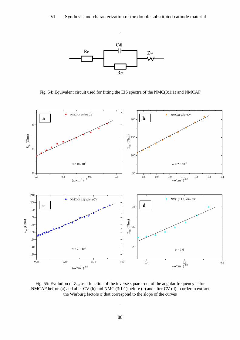
VI. Synthesis and characterization of the double substituted cathode material
88
.
Fig. 54: Equivalent circuit used for fitting the EIS spectra of the NMC(3:1:1) and NMCAF
Fig. 55: Evolution of ZRe as a function of the inverse square root of the angular frequency ω for
NMCAF before (a) and after CV (b) and NMC (3:1:1) before (c) and after CV (d) in order to extract
the Warburg factors that correspond to the slope of the curves
.
d
b
c
a
Cdl
Re
Rct
Zw
0,3 0,4 0,5 0,6
20
25
30
ZR
e (O
hm
)
NMCAF before CV
= 0.6 10-3
(cm)
0,8 0,9 1,0 1,1 1,2 1,3 1,4
50
100
150
200
= 2.5 10-2
ZR
e (O
hm
)
NMCAF after CV
(cm)
0,25 0,50 0,75 1,00
130
140
150
160
170
180
190
200
210
= 7.1 10-2
ZR
e (O
hm
)
(cm)
NMC (3:1.1) before CV
0,4 0,5 0,6
25
30
35
= 1.6
(cm)
ZR
e (
Ohm
)
NMC (3:1:1) after CV
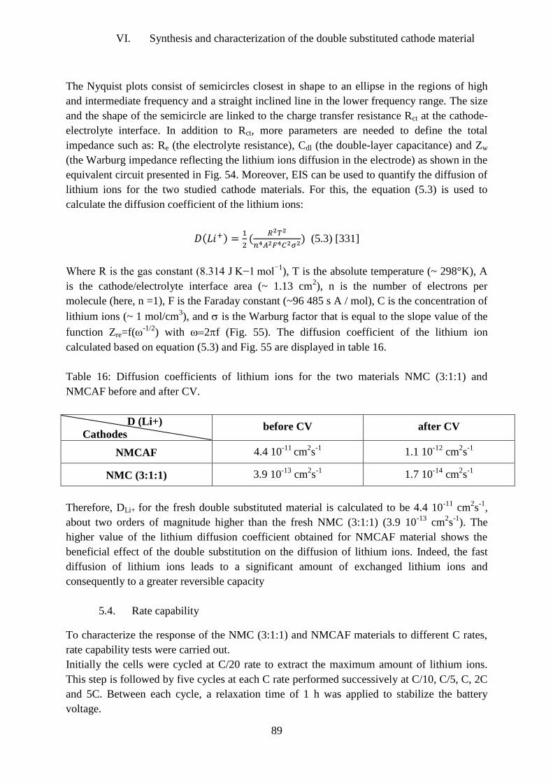
VI. Synthesis and characterization of the double substituted cathode material
89
The Nyquist plots consist of semicircles closest in shape to an ellipse in the regions of high
and intermediate frequency and a straight inclined line in the lower frequency range. The size
and the shape of the semicircle are linked to the charge transfer resistance Rct at the cathode-
electrolyte interface. In addition to Rct, more parameters are needed to define the total
impedance such as: Re (the electrolyte resistance), Cdl (the double-layer capacitance) and Zw
(the Warburg impedance reflecting the lithium ions diffusion in the electrode) as shown in the
equivalent circuit presented in Fig. 54. Moreover, EIS can be used to quantify the diffusion of
lithium ions for the two studied cathode materials. For this, the equation (5.3) is used to
calculate the diffusion coefficient of the lithium ions:
𝐷(𝐿𝑖+) =1
2(
𝑅2𝑇2
𝑛4𝐴2𝐹4𝐶2𝜎2) (5.3) [331]
Where R is the gas constant (8.314 J K−1 mol−1
), T is the absolute temperature (~ 298°K), A
is the cathode/electrolyte interface area (~ 1.13 cm2), n is the number of electrons per
molecule (here, n =1), F is the Faraday constant (~96 485 s A / mol), C is the concentration of
lithium ions (~ 1 mol/cm3), and is the Warburg factor that is equal to the slope value of the
function Zre=f(-1/2
) with 2f (Fig. 55). The diffusion coefficient of the lithium ion
calculated based on equation (5.3) and Fig. 55 are displayed in table 16.
Table 16: Diffusion coefficients of lithium ions for the two materials NMC (3:1:1) and
NMCAF before and after CV.
D (Li+)
Cathodes
before CV
after CV
NMCAF
4.4 10-11
cm2s
-1
1.1 10-12
cm2s
-1
NMC (3:1:1)
3.9 10-13
cm2s
-1
1.7 10-14
cm2s
-1
Therefore, DLi+ for the fresh double substituted material is calculated to be 4.4 10-11
cm2s
-1,
about two orders of magnitude higher than the fresh NMC (3:1:1) (3.9 10-13
cm2s
-1). The
higher value of the lithium diffusion coefficient obtained for NMCAF material shows the
beneficial effect of the double substitution on the diffusion of lithium ions. Indeed, the fast
diffusion of lithium ions leads to a significant amount of exchanged lithium ions and
consequently to a greater reversible capacity
5.4. Rate capability
To characterize the response of the NMC (3:1:1) and NMCAF materials to different C rates,
rate capability tests were carried out.
Initially the cells were cycled at C/20 rate to extract the maximum amount of lithium ions.
This step is followed by five cycles at each C rate performed successively at C/10, C/5, C, 2C
and 5C. Between each cycle, a relaxation time of 1 h was applied to stabilize the battery
voltage.

VI. Synthesis and characterization of the double substituted cathode material
90
This electrochemical test shows that the response of the double substituted material is
significantly better compared to the pristine NMC (3:1:1) even at high rates up to 5C (Fig.
56). Indeed, the capacities of the NMCAF material are about 187, 167, 152, 143, 128 and 106
mAh g-1
at C/20, C/10, C/5, C, 2C and 5C, respectively; while pristine NMC (3:1:1) provides
capacities of about 154, 129, 82, 52, 41 and 32 mAh g-1
at the corresponding rates.
Moreover, considerable capacity retention throughout cycling at the different applied C rates
is observed for NMCAF, which is in good agreement with the results previously reported in
Fig. 40.
Fig. 56: Rate capability of NMCAF (a) and NMC (3:1:1) (b) tested between C/20 and 5C rates in the
2.7V - 4.4V potential range
a
0 5 10 15 20 25 30
0
25
50
75
100
125
150
175
200
225
250
C/20
5C
2C
1C
C/5
C/10
C/20
discharge
charge
Spec
ific
cap
acit
y (
mA
h/g
)
Cycle number
0 5 10 15 20 25 30
0
25
50
75
100
125
150
175
200
225
discharge
charge
Sp
ecif
ic c
apac
ity
(m
Ah
/g)
Cycle number
C/20
C/10
C/5
1C
2C5C
C/20

VI. Synthesis and characterization of the double substituted cathode material
91
.
5.5. Lithium diffusion coefficient study by GITT
In order to accurately follow the intercalation-deintercalation reaction of lithium ions and to
determine the chemical diffusion coefficient of the doubly substituted material NMCAF, a
GITT study was performed. During the measurement, a current of 0.2 mA was applied as
pulses (τ) of 5 minutes each and alternated with relaxation periods of 1 hour during which the
circuit is open. The system then relaxes spontaneously to its equilibrium potential. The
procedure is continued until the system reaches the cut-off voltage.
The variation of the potential at equilibrium versus time is reported in Fig. 57. Indeed, the
continuous evolution of the potential at thermodynamic equilibrium reveals that no structural
phase transition of the first order is taking place during the electrochemical cycling.
0 10 20 30 40 50 60 70 80
3,0
3,5
4,0
4,5
E/
V v
s L
i,L
i+
t / h
Lithiation
Delithiation
6,0 6,5 7,0 7,5 8,0
3,62
3,64
3,66
3,68
3,70
3,72
3,74
Es
E0
min
IR
E/
V v
s L
i,L
i+
t / h
Delithiation
ΔEτ
ΔEs
Fig. 57: Galvanostatic intermittent titration of the NMCAF material during charge (blue) and
discharge (orange) (a) and a scheme of a single GITT step at around 3.63 V (b)
a
b

VI. Synthesis and characterization of the double substituted cathode material
92
For illustration, one titration profile recorded at 3.63 V is presented in Fig. 57b with the
related parameters.
The chemical diffusion is accepted to follow Fick´s second law of diffusion. With some
simplifications, the equation for DLi+
can be written as follows [332]:
𝐷𝐿𝑖+ =4
𝜋(
𝑚𝐵𝑉𝑀
𝑀𝐵𝑆)
2
(∆𝐸𝑠
𝜏(𝑑𝐸𝜏
𝑑√𝜏⁄ )
)
2
(5.4)
where mB, VM and MB are respectively the mass, the molar volume and the molecular
weight, S is the surface area of the electrode, ΔEs is the difference between the original
voltage E0 and the steady-state voltage Es, τ is the pulse duration.
First, ΔEs variation with the square root of τ is presented in Fig. 58 and shows a good
linearization. The corresponding values to the curve slope and interception with the y axis are
likewise reported.
0 2 4 6 8 10 12 14
3,78
3,79
3,80
3,81
1/2
+ 3.7781
E/
V v
s L
i,L
i+
1/2
/ s1/2
Fig. 58: Potential transient linearization during charge injection period in the coordinates E=f(τ1/2
)
Based on those results, the Li+ chemical diffusion coefficients as a function of the cell voltage
can be plotted as shown in Fig. 59. As one can see, the curve of the chemical diffusion
coefficients takes a twisting shape and the values are in the range of 1.10-12
and 1.10-9
cm2/s in
the voltage range of 3.6–4.4 V, which is in good agreement with the values obtained by EIS
and reported in table 16. The calculated values for DLi+ by the GITT method correlate well
with literature data for similar compounds [333].

VI. Synthesis and characterization of the double substituted cathode material
93
3,6 3,8 4,0 4,2 4,4
1E-12
1E-11
1E-10
1E-9
DL
i+ /
cm
2 s
-1
E / V vs Li,Li+
Fig. 59: Evolution of the apparent diffusion coefficient upon charge (blue) and discharge (orange) of
the NMCAF material
.
6. Chemical deintercalation
6.1. Preparation of the samples
LixNi0.6Mn0.2Co0.2O2 and LixNi0.6Mn0.2Co0.15Al0.025Fe0.025O2 phases were chemically prepared
by mixing a non-aqueous NO2BF4 / acetonitrile solution and the starting materials NMC
(3:1:1) and NMCAF. Given the strong oxidizing character of NO2BF4, chemical de-
intercalation was performed inside a glove box under argon atmosphere. In general, NO2BF4
may cause an irreversible de-intercalation; therefore, it should be diluted in acetonitrile up to
0.1 mol/l. About 300 mg of active material was used in suspension in the appropriate volume
the NO2BF4 / acetonitrile solution under magnetic stirring for 24 hours. The de-intercalated
lithium ratio can be determined experimentally according to the following reaction equation:
LiMO2 + (1 - x) NO2BF4 LixMO2 + (1 - x) NO2 + (1 - x) LiBF4 (5.5)
with M = Ni0.6Mn0.2Co0.2 or Ni0.6Mn0.2Co0.15Al0.025Fe0.025
Once the reaction is completed, the formed products are recovered by filtering. They are then
rinsed several times with acetonitrile in order to remove all traces of LiBF4. The de-
intercalated materials are then ready when they have undergone a heat treatment at 80°C for 2
hours under vacuum.

VI. Synthesis and characterization of the double substituted cathode material
94
6.2. Characterization of the deintercalated phases
6.2.1. XRD+Rietveld refinement
A comparison of the X-ray diffractorgamms of the de-intercalated phases (Figs 60 and 61)
shows a slight shift of the diffraction lines, with lithium extraction, in the order of 0.01% for
both materials. All the de-intercalated phases crystallize in the rhombohedral (R-3m) system
and therefore have the same structure as the starting phase. No significant variation in the
position of the diffraction lines and no appearance of new diffraction peaks are then observed.
This means that the method of chemical deintercalation by NO2BF4 oxidant allows the
extraction of the desired lithium amount by adjusting the starting stoichiometry without
structural changes.
Nevertheless, it is noteworthy that for the lithium poor phases Li0.1Ni0.6Mn0.2Co0.2O2 and
Li0.1Ni0.6Mn0.2Co0.15Al0.025Fe0.025O2 , the X ray diffractogramms present larger diffraction lines
indicating a loss of the material crystallinity.
According to Choi and Manthiram who confirmed that the disorder obtained in the structures
of NMC is mainly due to a transformation of the O3-type (space group R-3m) into O1-type
(space group P-3m1) [334], we can attribute the loss of crystallinity observed for NMC
(3:1:1) and NMCAF at x(Li) ~ 0.1 to the presence of traces of the new phase called O1. Such
a transformation was indicated in the XRD patterns of the de-intercalated phases by the
appearance of a shoulder on the right hand side of the strong reflection around 2θ =19.44° for
NMC and 2θ =19.08° for NMCAF.

VI. Synthesis and characterization of the double substituted cathode material
95
20 30 40 50 60 70 80 90
Inte
nsi
ty (
a.u.)
2Cu
x=0.1
x=0.2
x=0.3
x=0.4
x=0.5
x=0.6
x=0.7
x=0.8
x=0.9
Fig. 60: XRD patterns of the LixNi0.6Mn0.2Co0.15Al0.025Fe0.025O2 phase (0.1 ≤ x ≤ 0.9) chemically de-
intercalated by NO2BF4 in acetonitrile (a) an inset in the 2θCu range 15º - 46º of the same phase at (0.1
≤ x ≤ 0.4) is presented in (b)
a
b

VI. Synthesis and characterization of the double substituted cathode material
96
20 30 40 50 60 70 80 90
x=0.9
x=0.8
x=0.7
x=0.6
x=0.5
x=0.4
x=0.3
x=0.2
x=0.1
2Cu
Inte
nsi
ty (
a.u.)
20 40 453525
x=0.4
x=0.3
x=0.2
x=0.1
2Cu
Inte
nsi
ty (
a.u
.)
Fig. 61: XRD patterns of the LixNi0.6Mn0.2Co0.2O2 phase (0.1 ≤ x ≤ 0.9) chemically de-intercalated by
NO2BF4 in acetonitrile (a) an inset in the 2θCu range 15º - 46º of the same phase at (0.1 ≤ x ≤ 0.4) is
presented in (b)
a
b

VI. Synthesis and characterization of the double substituted cathode material
97
The O1 stacking can be described by assuming that the octahedral sites of the interlayer space
are sharing faces with MO6 octahedra [335,336] (Fig. 62). For instance, the transformation of
the O3- LixNi0.6Mn0.2Co0.2O2 phase into O1- LixNi0.6Mn0.2Co0.2O2 phase which is a
thermodynamically unstable stacking is occurring at low lithium compositions (x ~ 0.1) but
with very slow reaction kinetics.
Fig. 62: Schematic representation of the O1 stacking (left) and the O3 stacking (right). A,B and C
indicate the positions of the oxygen ions in the lattice [336,337]
.
In order to deduce in particular the percentage of each phase in the mixture, it was necessary
to perform a structural refinement by Rietveld of the de-intercalated phases.
Initially, the structural refinement was conducted by considering the existence of a single
dominant phase with hexagonal symmetry described in the R-3m space group. We noticed
that the XRD profile was not simulated adequately, which was explained by the presence of
traces of the O1 phase described in the P-3m1 space group.
To this end, a second step consisted of refining the structure supposing the presence of two
phases O3 and O1. The refinement resulted then in a phase mixture O3-type/O1-type with the
molar proportions (94:6) for NMC(3:1:1) and (97:3) for NMCAF, indicating that for both
materials and especially for the double substituted one, a small amount of O3-
LixNi0.6Mn0.2Co0.15Al0.025Fe0.025O2 turned into O1- LixNi0.6Mn0.2Co0.15Al0.025Fe0.025O2
Results from the literature showed that for LixNiO2 and LixCoO2, the samples maintain their
initial O3 structure for 0.4 <x< 1 and 0.35 <x< 1 respectively [336]. This makes the two
studied compounds especially NMCAF that was able to maintain O3 structure for a wider
lithium amount of x~0.2, a strong candidate in terms of stability throughout lithium de-
intercalation process.
B
A
B
A
B
A
C
B
A
C
B
A

VI. Synthesis and characterization of the double substituted cathode material
98
To better quantify the structural stability of NMC (3:1:1) and NMCAF materials, Rietveld
refinement of the XRD data recorded for all the de-intercalated phases (0.1<x<0.9) was
conducted. The lattice parameters ahex and chex were therefore presented as a function of x(Li)
(Fig. 63).
Up to the lithium composition x = 0.2, ahex parameter which characterize the metal-metal
distance decreases with lithium extraction due to the oxidation of Ni3+
ions Ni4+
ions of
smaller size. The chex parameter increases initially due to the increase of the electrostatic
repulsions between oxygen layers located on either side of the interlayer space, then chex
decreases slightly for 0.5<x<0.2 then falls dramatically once the lithium composition becomes
less than 0.2. The structure becomes sufficiently covalent so that the steric effects are
predominant over the electrostatic effects [338].
For the NMC (3:1:1) material, starting from x<0.3, the significant broadening of the
diffraction lines, particularly (003), suggests the presence of fluctuations in the cationic
distribution (excess nickel ions and remaining lithium ions) in the interlayer space, leading to
a heterogeneous distribution of interlayer distances in the structure. This value is lower for
NMCAF material which exhibited already less cation mixing at the initial state x(Li)=1.0.
Fig. 63: Evolution of the lattice parameters ahex (a) and chex (b) (deduced from XRD Rietveld
refinement of the phases LixNi0.6Mn0.2Co0.2O2 and LixNi0.6Mn0.2Co0.15Al0.025Fe0.025O2 (0.1 ≤ x ≤ 0.9) as
a function of lithium composition (x)
Despite ahex and chex variations, the lattice volume varies slightly in the studied composition
range (Fig. 64) (approximately 0.013% for NMC (3:1:1) and 0.010% for NMCAF). This
result is very important from applications point of view and in terms of safety. Indeed, the
good cycleability of the cell depends on the volume change of the material.
a b
0,0 0,2 0,4 0,6 0,8 1,0
14,0
14,1
14,2
14,3
14,4
14,5
NMC (3:1:1)
NMCAF
c hex
(Å
)
Li composition x
0,0 0,2 0,4 0,6 0,8 1,0
2,82
2,83
2,84
2,85
2,86
2,87
(Å)
a hex
Li composition x
NMC (3:1:1)
NMCAF

VI. Synthesis and characterization of the double substituted cathode material
99
0,0 0,2 0,4 0,6 0,8 1,0
99,0
99,5
100,0
100,5
101,0
101,5
102,0
(Å3 )
NMC (3:1:1)
NMCAFV
hex
Li composition x
Fig. 64: Evolution of the lattice volume Vhex of the phases LixNi0.6Mn0.2Co0.2O2 and
LixNi0.6Mn0.2Co0.15Al0.025Fe0.025O2 (0.1 ≤ x ≤ 0.9) as a function of lithium composition (x)
In the following, the thermal stability of the two compounds at the de-intercalated state will
be studied in a way to assess the heating effect on the structural changes.
6.2.2. Safety study at the deintercalated state
6.2.2.1. Introduction
The thermal stability of cathode materials is a crucial factor in terms of of safety. Indeed, the
electrochemical properties and performance of cathode materials for LIB are strongly related
to the crystal structure of materials and their structural changes induced by the heating effect
at the charge state.
Most of the reported works focused on studying the thermal stability of phases achieved by
electrochemical de-intercalation. However, this method gives rise to phases with not only the
active material but also the usual additives, mainly the conductive agent and the binder. This
makes analysis of the active material relatively difficult. For this reason, in this work the
phases were prepared by chemical de-intercalation to remove all contributions of the
electrolyte and additives.

VI. Synthesis and characterization of the double substituted cathode material
100
0 100 200 300 400 500 600
-40
-35
-30
-25
-20
-15
-10
-5
0
5
10
-40
-35
-30
-25
-20
-15
-10
-5
0
5
10
DTA NMC (x=0.6)
TG NMC (x=0.6)
DTA NMCAF (x=0.6)
TG NMCAF (x=0.6)
DT
A (
uV
)
Temperature (°C)
TG
(%
)
0 100 200 300 400 500 600
-35
-30
-25
-20
-15
-10
-5
0
5
10
-35
-30
-25
-20
-15
-10
-5
0
5
10
DT
A (
uV
)
Temperature (°C)
TG
(%
)
DTA NMC (x=0.9)
TG NMC (x=0.9)
DTA NMCAF (x=0.9)
TG NMCAF (x=0.9)
0 100 200 300 400 500 600
-40
-35
-30
-25
-20
-15
-10
-5
0
5
10
-40
-35
-30
-25
-20
-15
-10
-5
0
5
10
DT
A (
uV
)
DTA NMC (x=0.1)
TG NMC (x=0.1)
DTA NMCAF (x=0.1)
TG NMCAF (x=0.1)
Temperature (°C)
TG
(%
)
0 100 200 300 400 500 600
-40
-35
-30
-25
-20
-15
-10
-5
0
5
10
-40
-35
-30
-25
-20
-15
-10
-5
0
5
10
TG
(%
)
DT
A (
uV
)
DTA NMC (x=0.3)
TG NMC (x=0.3)
DTA NMCAF (x=0.3)
TG NMCAF (x=0.3)
Temperature (°C)
6.2.2.2. Study by DTA-TG
Thermogravimetric analysis (TGA) was used to study the thermal stability of de-intercalated
phases by measuring and tracking the mass changes throughout a heat treatment in air from
room temperature to 600°C with a heating rate of 10°C/min.
As shown by the weight loss curves in Fig. 65, the thermogravimetric curves for the two
materials NMC (3:1:1) and NMCAF present almost similar behaviors. Continuous mass
losses are observed between 100 and 600°C, corresponding most probably to oxygen release.
Indeed, it has been proved that the thermal degradation phenomena are mainly due to the
oxygen evolution and not to the structure degradation [227,339]. The danger posed by the
oxygen release from the material in the charged state is that oxygen can react with the
electrolyte and lead to exothermic reactions that can affect the cycleability and cause thermal
runaway of the battery.
.
Fig. 65: Thermogravimetric analysis of the de-intercalated phases LixNi0.6Mn0.2Co0.2O2 and
LixNi0.6Mn0.2Co0.15Al0.025Fe0.025O2 with x=0.9 (a) x=0.6 (b) x=0.3 (c) x=0.1 (d) carried out under air,
from room temperature to 600 ° C
c d
a b

VI. Synthesis and characterization of the double substituted cathode material
101
According to the TGA curves, a higher mass loss was observed for LixNi0.6Mn0.2Co0.2O2
phases than for LixNi0.6Mn0.2Co0.15Al0.025Fe0.025O2 which is probably due to the stabilizing
effect of the double substitution with Al and Fe. Indeed, Al3+
and Fe3+
ions, that are
electrochemically inactive in the selected potential range, played obviously a role in the
stabilization of the structure and for damping the oxygen loss during the heat treatment,
leading then to an improvement in the thermal stability of the doubly substituted phase.
6.2.2.3.X-ray diffraction analysis
Subsequently, we performed a study by XRD of the de-intercalated phases
LixNi0.6Mn0.2Co0.2O2 and LixNi0.6Mn0.2Co0.15Al0.025Fe0.025O2 (with x = 0.1; 0.3; 0.6; 0.9),
having undergone DTA-TG treatment up to 600 ° C.
LixNi0.6Mn0.2Co0.15Al0.025Fe0.025O2
We clearly see from Fig. 66 that no change or appearance of additional diffraction peaks that
characterize a spinel phase (S.G.: Fd3m) took place, confirming the structural stability of the
de-intercalated NMCAF phases up to 600°C despite the weight loss of about 1.73%. All X-
ray diffractograms of the de-intercalated phases can be indexed in the hexagonal system
(S.G.: R-3m).
Fig. 66: XRD patterns of the LixNi0.6Mn0.2Co0.15Al0.025Fe0.025O2 phase (x=0.1; 0.3; 0.6; 0.9) chemically
de-intercalated by NO2BF4 in acetonitrile and treated by DTA-TG from room temperature to 600°C in
air The absence of any additives, such as PVDF or carbon black, that are necessary for preparing the
electrodes, allowed us to record X-ray diffraction patterns of good quality and to determine then the
lattice parameters by refining the structure.
20 30 40 50 60 70 80 90
Inte
nsi
ty (
a.u.)
2Cu
x=0.1
x=0.3
x=0.6
x=0.9

VI. Synthesis and characterization of the double substituted cathode material
102
The only difference that was observed by comparing the X-ray diffractograms is the
continuous shift of the diffraction lines to higher diffraction angles. This suggests that a
change in the lattice parameters occurred due to the temperature increase, which is most
probably due to the loss of oxygen that is ensuring the cohesion of the lattice. The oxygen loss
in the case of NMCAF de-intercalated phases is so low that no structural transition occurred.
Fig. 67 illustrates the variation of the lattice parameters ratio chex/ahex as a function of the
lithium composition. Whatever the amount of extracted lithium is, the chex/ahex ratio remains
above the critical value (~ 4.90) for which the structure becomes of a cubic symmetry [336].
This result confirms that NMCAF material keeps its initial structure α-NaFeO2 (S.G.: R-3m)
even at the de-intercalated state and at high temperatures up to 600°C.
0,0 0,2 0,4 0,6 0,8 1,0
4,900
4,925
4,950
4,975
5,000
5,025
c hex
/ah
ex
Li composition x
Fig. 67: Variation of the ratio chex/ahex (deduced from XRD Rietveld refinement) of the phases
LixNi0.6Mn0.2Co0.15Al0.025Fe0.025O2 (x=0.1; 0.3; 0.6; 0.9) chemically de-intercalated by NO2BF4 in
acetonitrile and treated by DTA-TG from room temperature to 600°C in air
LixNi0.6Mn0.2Co0.2O2
As shown in Fig. 68, one can see that the NMC (3:1:1) de-intercalated phases underwent
structural changes at high temperature. In fact, there is no conservation of the original
structure as we notice almost a disappearance of the peak (003) especially for low lithium
composition. This suggests the loss of the structure crystallinity and the deviation from the R-
3m space group of the starting material.

VI. Synthesis and characterization of the double substituted cathode material
103
The thermal study by DTA-TG followed by ex-situ XRD allow us to show the positive effect
of the double substitution with Al and Fe on the pristine NMC (3:1:1) material. Indeed, the
substitution of 5% of cobalt contributed to inhibit the structural transitions and to significantly
improve the thermal stability.
20 30 40 50 60 70 80 90
In
ten
sity
(a.
u.)
2Cu
x=0.1
x=0.3
x=0.6
x=0.9
Fig. 68: XRD patterns of the LixNi0.6Mn0.2Co0.2O2 phase (x=0.1; 0.3; 0.6; 0.9) chemically de-
intercalated by NO2BF4 in acetonitrile and treated by DTA-TG from room temperature to 600°C in air
atmosphere
When substituting the pristine material with Al and Fe, the ordering of the transition metal
cations is modified and prevents ionic and electronic rearrangements which normally happen
during the material oxidation or when the de-intercalated phases are exposed to a temperature
increase. Therefore, improved structural stability even at high temperatures up to 600°C is
due to the presence of Al3+
and Fe3+
in addition to Mn4+
ions that are electrochemically
inactive but have a great contribution to the stability of the de-intercalated phase during
cycling and during temperature increase.

VI. Synthesis and characterization of the double substituted cathode material
104

Summary and Outlook
105
Summary and outlook
The layered transition metal oxides of NMC type are considered promising positive electrode
materials for LIBs and alternatives to the conventional LiCoO2 positive electrode.
The achieved work throughout this thesis had as main objective the optimization of NMC
material both in terms of electrochemical performance and thermal stability via a cationic
substitution.
As first step, the impact of different synthesis parameters on the purity, the morphology and
the electrochemical performance of the studied materials was highlighted (Ch. IV). It turned
out that in order to obtain pure and well crystallized compounds and to adjust the average
particle size and size distribution, the following conditions are necessary:
- Preparation by self-combustion synthesis method using metal nitrates and sucrose
considered as fuel.
- Annealing process, directly after synthesis, in air at a temperature of 900°C for one
hour.
- Preference of the nickel rich phase with the composition LiNi0.6Mn0.2Co0.2O2: NMC
(3:1:1).
Subsequently, substitution of cobalt by aluminum and / or iron was carried out in an attempt
to further optimize the starting compound NMC (3.1.1) (Ch. V). The studied materials were
NMCA (LiNi0.6Mn0.2Co0.15Al0.05O2), NMCF (LiNi0.6Mn0.2Co0.15Fe0.05O2) and NMCAF
(LiNi0.6Mn0.2Co0.15 Al0.025Fe0.025O2).
X-ray diffraction was carried out as first step and showed that all the obtained materials
belong to α-NaFeO2-type structure (space group R-3m) with hexagonal ordering. Rietveld
refinement analysis of the XRD patterns revealed a very low Li+ / Ni
2+ exchange between the
MO6 sheets and the interlayer space (cationic mixing) for the double substituted material
NMCAF (5%) compared to the mono-substituted materials NMCF (8%), NMCA (9%) and
the non-substituted material (13%) suggesting a higher structural stabilization for the double
substituted compound. Galvanostatic cycling indicates improved electrochemical
performance, good cycling stability and higher reversible capacity preferentially for NMCAF
(190 mAh g-1
), NMCF (165 mAh g-1
), NMCA (162 mAh g-1
) then NMC (156 mAh g-1
).
Cycling at C/20 rate displayed capacity retentions after 10 cycles of about 93% for NMCAF,
around 89% for NMCF and NMCA and 88% for NMC (3:1:1).
Then a more detailed comparison between NMC and NMCAF was compiled to better
understand the phenomena behind the improvement of the electrochemical behavior of the
double substituted cathode (Ch. VI).

Summary and Outlook
106
In order to accurately follow the intercalation/de-intercalation reaction of lithium ions and to
determine the chemical diffusion coefficient DLi+, both GITT and EIS studies were performed
and DLi+ for the double substituted material was calculated to be 4.4 10-11
cm2
s-1
, about two
orders of magnitude higher than that of the NMC (3:1:1) (3.9 10-13
cm2 s
-1).
EPR spectroscopy showed that the double substitution with Al and Fe influenced significantly
the EPR spectrum of the non-substituted NMC (3:1:1), especially the Ni2+
line, which was
attributed to a redistribution of the Ni ions in the layered structure, and might be the reason
for the reduced cation mixing in the NMCAF.
On the other hand, considering the great concern given to safety aspects of active electrode
materials for LIBs, it was necessary to investigate the thermal and structural properties of the
NMCAF and NMC (3:1:1) phases chemically de-intercalated by mixing a non-aqueous
NO2BF4 / acetonitrile solution and the active materials. The absence of any additives, such as
PVDF or carbon black, that are necessary for preparing the electrodes, allowed obtaining
results related to the active materials only without contributions of the electrolyte and
additives.
Structural analysis of the chemically de-intercalated phases showed that the lattice volume
varied slightly especially for the double substituted material (approximately 0.010% for
NMCAF and 0.013% for NMC (3:1:1)) which is very important from applications point of
view and in terms of safety as the good cycleability of the cell depends on the volume change
of the material.
Emphasis on the safety aspect of the two materials was put through a detailed study of their
thermal stability during the lithium ions de-intercalation process. According to the TGA
analysis, a higher mass loss was observed for LixNi0.6Mn0.2Co0.2O2 phases than for
LixNi0.6Mn0.2Co0.15Al0.025Fe0.025O2 (0.1<x<0.9) which was assigned to the stabilizing effect of
the double substitution with Al and Fe.
The thermal study by DTA-TG followed by ex-situ XRD enabled demonstrating the positive
effect of the double substitution with Al and Fe on the pristine NMC (3:1:1) material. Indeed,
the substitution of 5% of cobalt contributed to inhibit the structural transitions and to
significantly improve the thermal stability.
Eventually this thesis remains a subject rich in perspectives. Indeed, it is possible to:
- Investigate novel NMC type materials obtained by simultaneous double cationic
substitution of cobalt with other metals such as Mg, Cr, Be and/or Ga and assess their
electrochemical performance,
- Use the second approach which is surface modification by coating with metal oxides
such as ZrO2, Al2O3, TiO2, B2O3 or carbon to improve the structural stability and the
electrochemical performance of the pristine cathode material for LIBs,
- Evaluate the electrochemical performance of batteries at higher temperature 60 °C for
example and for longer periods of cycling that can reach 500 cycles.
List of original publications
107
-
List of Original Publications
[1] W. El Mofid, S. Ivanov, A. Konkin, A. Bund, “A high performance layered transition
metal oxide cathode material obtained by simultaneous aluminum and iron cationic
substitution”, J. Power Sources 268 (2014) 414-422.
[2] W. El Mofid, S. Ivanov, A. Bund, “A Novel Al and Fe Double Substituted NMC Positive
Electrode Material for Lithium Ion Batteries”, 65th annual meeting of the international
society of electrochemistry, Lausanne-Switzerland, 31 August - 5 September 2014
(Poster).
[3] H. Wulfmeier, D. Gao, D. Albrecht, H. Fritze, W. El Mofid, S. Ivanov, A. Bund,
“Thermodynamic Investigation of NMC-based Cathode Materials Performed by Thin-
Film Calorimetry”, Materials Science Engineering conference (MSE 2014), Darmstadt-
Germany, 23-25 September 2014 (Oral).
[4] W. El Mofid, S. Ivanov, A. Bund, “The Effect of Al and Fe Substitution on the Structure
and the Electrochemical Properties of NMC Type Positive Electrode Materials for
Lithium Ion Batteries”, 226th meeting of the electrochemical society, Cancun-Mexico, 5-
9 October 2014 (Oral).
[5] W. El Mofid, S. Ivanov, A. Bund, “Effect of synthesis conditions and composition
modification on the structural and electrochemical properties of layered transition metal
oxide cathode materials”, 2nd International Renewable and Sustainable Energy
Conference (IRSEC'14), Ouarzazate-Morocco, 17-19 October 2014 (Oral).
[6] W. El Mofid, A. Bund, “A Novel environmentally Benign Positive Electrode Material
with Improved Energy Density for Lithium Ion Batteries”, International Conference on
Advanced Engineering Materials, NewDelhi- India, 07-08 February 2015 (Oral).
[7] W. El Mofid, S. Ivanov, A. Bund, D. Goers, S. Rentenberger, “Inhibition of Al/Cu
Contact Corrosion in Lithium Ion Batteries”, 227th meeting of the electrochemical
society, Chicago-USA, 24-28 May 2015 (Oral).

List of original publications
108
[8] H. Wulfmeier, A.Omelcenko, D. Albrecht, D. Klimm, W. El Mofid, M. Strafela, S.
Ulrich, A. Bund and H.Fritze, “Thermal Stability of Materials for Thin-Film
Electrochemical Cells Investigated by Thin-Film Calorimetry”, Cambridge journals MRS
advances 1 (2016) 1043-1049.
[9] W. El Mofid, S. Ivanov, A. Bund, “Study of the Structural and Thermal Stabilities of
Chemically Deintercalated Phases of NMC Type Positive Electrode Materials for
Lithium Ion Batteries”, 229th meeting of the electrochemical society Honolulu, Hawaii-
USA, 2-7 October 2016 (Oral).

Bibliography
109
Bibliography
[1] A. De Guibert, L'actualité chimique 3 (1998) 15-17.
[2] M. B. Armand, Materials for advanced Batteries (1980) 145-161.
[3] A. K. Shukla, N. R. Avery and B. C. Muddle, “Future cars: The electric option”, Current Science, 77 (1999)
1141–1146.
[4] Challenge Bidendum, “Batteries and super-capacitors : Roadmap to market”, Tech. Rep., Michelin, 2007.
[5] B. G. Silbernagel, M. S. Whittingham, Mat. Res. Bull., 11 (1976) 29-36.
[6] M. S. Whittingham, Science, 192 (1976) 1126–1127.
[7] R. Yazami, Ph. Touzain, J. Power Sources 9 (1983) 365-371
[8] JEC Batt. Newsletter, 2 (1994) 31.
[9] M. Broussely, L'actualité chimique 25 (1994) 1-2.
[10] K. Mizushima, P. C. Jones, P. J. Wiseman and J. B. Goodenough, Mat. Res. Bull. 15 (1980) 783.
[11] C. Zhu, C. Yang, W. Yang, C. Hsieh, H. Ysai, Y. Chen, J. Alloys Compd. 496 (2010) 703–709.
[12] J. Shu, M. Shui, F. Huang, Y. Ren, Q. Wang, D. Xu, L. Hou, J. Phys. Chem. C 114 (2010) 3323–3328.
[13] J.N. Reimers, J.R. Dahn, LixCoO2, J. Electrochem. Soc. 139 (1992) 2091-2097.
[14] M.S. Whittingham, Chem. Rev. 104 (2004) 4271-4301.
[15] JR Dahn, EW Fuller, M. Obrovac, U. von Sacken, Solid State Ionics 69 (1994) 265-270.
[16] R. Stoyanova, E. Zhecheva, L. Zarkova, Solid State Ion. 73 (1994) 233-240.
[17] Masaya Takahashi, Shinichi Tobishima, Koji Takei, Yoji Sakurai, Solid State Ion. 148 (2002) 283–289.
[18] D. Zane, M. Carewska, S. Scaccia, F. Cardellini, and P. P. Prosini, Electrochim. Acta, 49 (2004) 4259–
4271.
[19] P. P. Prosini, D. Zane, and M. Pasquali, Electrochim. Acta, 46 (2001) 3517–3523.
[20] S.-T.Myung, S. Komaba, N. Hirosaki, H. Yashiro, and N.Kumagai, Electrochim. Acta 49 (2004) 4213–
4222.
[21] H.C. Shin, S.B. Park, H. Jang, K.Y. Chung, W.I.Cho, C.S. Kim, and B.W. Cho, Electrochim. Acta 53
(2008) 946–7951.
[22] Y.-H. Nien and J.-S. Chen, ECS Meeting Abstracts 702 (2007) 647.
[23] J. Li, R. Klöpsch, M.C. Stan, S. Nowak, M. Kunze, M. Winter, S. Passerini, J. Power Sources, 196 (2011)
4821–4825.
[24] Naoaki Yabuuchi, Tsutomu Ohzuku, J. Power Sources, 119–121 (2003) 171–174.
[25] K. M. Shaju, P. G. Bruce, Advanced materials, 18 (2006) 2330–2334.
[26] Yang-Kook Sun, Seung-Taek Myung, Byung-Chun Park, Jai Prakash, Ilias Belharouak, Khalil Amine,
Nature Materials 8 (2009) 320-324.
[27] Ismael Saadoune, Mohamed Labrini, Mustapha Yahya, Abdelmajid Almaggoussi, Helmut Ehrenberg,
Electrochim. Acta, 55 (2010) 5180-5185.

Bibliography
110
[28] M.-H. Lee, Y.-J. Kang, S.-T. Myung, Y.-K. Sun, 50 (2004) 939-948.
[29] Abdelfattah Mahmoud, Mayumi Yoshita, Ismael Saadoune, Joachim Broetz, Kenjiro Fujimoto, Shigeru Ito,
47 (2012) 1936-1941,
[30] T. Ohzuku, Y. Makimura, Chem. Lett. 30 (2001) 642-643.
[31] I. Belharouak, Y.K. Sun, J. Liu, K. Amine, J. Power Sources 123 (2003) 247-252.
[32] S. Patoux, M.M. Doeff, Electrochem. Commun. 6 (2004) 767-772.
[33] B.J. Hwang, Y.W. Tsai, D. Carlier, Chem. Mater. 15 (2003) 3676-3682.
[34] T. Ohzuku, Y. Makimura, Chem. Letters 7 (2001) 642-646.
[35] Y. Chen, G.X. Wang, K. Konstantinov, H.K. Liu, S.X. Dou, J. Power Sources 119–121 (2003) 184–188.
[36] X. Zhang, W. Jiang, A. Mauger, F. Gendron, C. Julien, J. Power Sources 195 (2010) 1292-1301.
[37] R. Sathiyamoorthi, P. Shakkthivel, S. Ramalakshmi, Yong-Gun Shul, J. Power Sources 171 (2007) 922-927.
[38] B.V.R. Chowdari, G.V. Subba Rao, S.Y. Chow, Solid State Ionics 140 (2001) 55-62.
[39] C. Pouillerie, L. Croguennec, C. Delmas, Solid State Ionics 132 (2000) 15-29.
[40] T. Ohzuku, A. Ueda, M. Kouguchi, J. Electrochem. Soc. 142 (1995) 4033-4039.
[41] M.Y. Song, R. Lee, I.H. Kwon, Solid State Ionics 156 (2003) 319-328.
[42] Y. Nishida, K. Nakane, T. Satoh, J. Power Sources 68 (1997 ) 561-564.
[43] C. Delmas, G. Prado, A. Rougier, E. Suard, L. Fournès, Solid State Ionics 135 (2000) 71-79.
[44] M. Yoshio, Y. Todorov, K. Yamato, H. Noguchi, J. Itoh, M. Okada, T. Mouri, J. Power Sources 74 (1998)
46-53.
[45] Haiqiang Liu, Ruiyuan Tian, Yi Jiang, Xinghua Tan, Jiankun Chen, Lina Zhang, Yanjun Guo, Hanfu Wang,
Lianfeng Sun, Weiguo Chu, Electrochim Acta, 180 (2015) 138-146.
[46] Dao-Lai Fang, Jun-Chao Li, Xin Liu, Peng-Fei Huang, Tian-Ran Xu, Ming-Chuan Qian, Cui-Hong Zheng,
Journal of Alloys and Compounds, 640 (2015) 82-89.
[47] G. Li, H. Ikuta, T. Uchida, M. Wakihara, J. Electrochem. Soc. 143 (1996) 178-182.
[48] S.H. Wu, H.J. Su, Mater. Chem. Phys. 78 (2002) 189-195.
[49] K.M. Shaju, G.V.S. Rao, B.V.R. Chowdari, Solid State Ionics 148 (2002) 343-350.
[50] H.J. Bang, V.S. Donepudi, J. Prakash, Electrochim. Acta 48 (2002) 443-451.
[51] B.H. Kim, Y.K. Choi, Y.H. Choa, Solid State Ionics 158 (2003) 281-285.
[52] M. Yoshio, Y. Xia, N. Kumada, S. Ma, J. Power Sources 101 (2001) 79-85.
[53] M. Hosoya, H. Ikuta, M. Wakihara, Solid State Ionics 111 (1998) 153-159.
[54] S. Komaba, K. Oikawa, S.T. Myung, N. Kumagai, T. Kamiyama, Solid State Ionics 149 (2002) 47-52.
[55] B.J. Hwang, R. Santhanam, D.G. Liu, Y.W. Tsai, J. Power Sources 102 (2001) 326-331.
[56] D. Song, H. Ikuta, T. Uchida, M. Wakihara, Solid State Ionics 117 (1999) 151-156.
[57] I.S. Jeong, J.U. Kim, H.B. Gu, J. Power Sources 102 (2001) 55-59.
[58] Li H, Chen G, Zhang B, Xu J, Solid State Commun 146 (2008) 115–120.

Bibliography
111
[59] Y.S. Meng, Y.W. Wu, B.-J. Hwang, Y. Li, G. Ceder, J. Electrochem. Soc. 151 (2004) A1134- A1140.
[60] Zhang B, Li L, Zheng J, J. Alloy. Compd. 520 (2012) 190-194.
[61] Idemoto Y, Kitamura N, Ueki K, Vogel SC, Uchimoto Y, J. Electrochem. Soc. 159 (2012) A673-A677.
[62] Luo W, Zhou F, Zhao X, Lu Z, Li X, Dahn JR, Chem. Mater. 22 (2009) 1164-1172.
[63] T. Ohzuku, A. Ueda, N. Nagayama, Y. Iwakoski, H. Komori, Electrochim. Acta 38 (1993) 1159-1167.
[64] Arun Kumar Varanasi & Arghya Bhowmik & Tanmay Sarkar & Umesh V. Waghmare & Mridula Dixit
Bharadwaj, Ionics 20 (2014) 315–321.
[65] Lithium Statistics and Information U.S. Geological Survey (2015) 201401280924315001.
[66] Tarascon, J. M., Nature Chemistry 2 (2010) 510.
[67] US Geological Survey; ID 268789.
[68] JASKULA, B.W., Lithium, U.S. Geological Survey Minerals Yearbook (2008) 44.4-44.9.
[69] http://www.ccfa.fr/Le-marche-des-batteries-lithium,119269.
[70] Stefan Wimmelbücker, Batterieproduktion, 1. April 2014.
[71] Sächsische Zeitung, 15./16. November 2014, S.1.
[72] http://www.statista.com/statistics/235323/lithium-batteries-top-manufacturers.
[73] Roland Berger; ID 235316.
[74] Citibank; ID 309562.
[75] http://www.technavio.com/report/global-li-ion-battery-market-for-consumer-electronics-2015-2019.
[76] http://www.marketresearch.com/product/sample-8323376.pdf.
[77]http://www.avem.fr/actualite-etude-5-fabricants-se-partageront-70-du-marche-des-batteries-li-ion-a-l-
horizon-2015.
[78] http://www.technavio.com/report/global-li-ion-battery-market-for-evs-2015-2019.
[79] Citibank; ID 309564.
[80] PwC; ID 304920.
[81] K. Xu, Chemical Reviews, 104 (2004) 4303.
[82] Ellis, B.L., Lee, K.T., and Nazar, L.F., Chem. Mater., 22 (2010) 691–714.
[83] Armand, M. et al., Nat. Mater., 8 (2009) 120–125.
[84] Nazri, G. and Pistoia, G., Lithium Batteries: Science and Technology, Springer, 2009.
[85] Tarascon, J.M. and M. Armand, Nature, 414 (2001) 359–367.
[86] Nishi, Y., J. Power Sources 100 (2001) 101–106.
[87] Scrosati, J. Electrochem. Soc. 139 (1992) 2776–2781.
[88] Tirado, J.L., Materials Science and Engineering Reports 40 (2003) 103–136.
[89] Broussely, M. and G. Archdale, J. Power Sources 136 (2004) 386–394.
[90] Winter, M., J.O. Besenhard, M.E. Spahr and P. Novák, Advanced Materials 10 (1998) 725–763.

Bibliography
112
[91] P. Poizot, S. Laruelle, S. Grugeon, L. Dupont , J. M. Tarascon, Nature 407 (2000) 496.
[92] P. Poizot, S. Laruelle, S. Grugeon, L. Dupont, J. M. Tarascon, J. Power Sources 235 (2001) 97-98.
[93] P. Poizot, S. Laruelle, S. Grugeon, L. Dupont, B. Beaudoin, J. M. Tarascon, C.R. Acad. Sci. 3 (2000) 681.
[94] Y. M. Kang, K. T. Kim, J. H. Kim, H .S. Kim, P. S. Lee, J. Y. Lee, H. K. Liu, S.X. Dou, J. Power Sources,
133 (2004) 252.
[95] P. C. Wang, H. P. Ding, T. Bark, C. H. Chen, Electrochim Acta, 52 (2007) 6650.
[96] H. J. Bang, S. Kim, J. Prakash, J. Power Sources, 45 (2001) 92.
[97] J. O. Besenhard, P. Komenda, A. Paxinos, E. Wudy, M. Josowicz, Solid State Ionics., 823 (1986) 18-19.
[98] W. J. Weydanz, M. Wohlfahrt-Mehrens, R. A. Huggins, J. Power Sources, 237 (1999) 81-82.
[99] D. Fauteux, R. Koksbang, Journal Applied Electrochemistry, 23 (1993) 1
[100] L.F. Nazar, O. Crosnier, Anodes and composite anode: an overview, in Lithium batteries, ed. Kluwer, New
York (2004)
[101] L.Y. Beaulieu, K.W. Eberman, R.L. Turner, L.J. Krause, J.R. Dahn, Electrochemical and Solid State
Letter, 4 (2001) A137.
[102] J.T. Vaughey, J. O’hara, M.M. Thackeray, Electrochemical and Solid State Letters, 3 (2000)13.
[103] J. Yang, Y. Takeda, N. Imanishi, T. Ichikawa, O. Yamamoto, Solid State Ionics., 135 (2000) 175.
[104] H. Li, X. Huang, L. Chen, Z. Wu, Y. Liang, Electrochem. Solid State Lett. 2 (1999) 547.
[105] H. Li, X.J. Huang, L.Q. Chen, Z.G. Wu, Y. Liang, Electrochemical Solid-State Letters. 2 (1999) 547.
[106] Z.X. Liao, F.Z. Ma, J.H. Hu, Electrochemistry Communications, 5 (2003) 657.
[107] H. Guo, H. Zhao, C. Yin et W. Qiu, J. Alloys Compd., 426 (2006) 277.
[108] T. Ohzuku, A. Ueda, and N. Yamamoto, J. Electrochem. Soc., 142 (1995) 1431.
[109] A. Van Thournout, L. Aldon, M. Womes, B. Ducourant, J. Olivier- Fourcade, C. Tessier, S. Levasseur, J.
Power Sources, 174 (2007) 1270.
[110] Y. Liu, K. Horikawa, M. Fujiyoshi, T. Matsumura, N. Imanishi, Y. Takeda, Solid State Ionics., 172 (2004)
69.
[111] A. N. Jansen, A. J. Kahaian, K. D. Kepler, P. A. Nelson, K. Amine, D. W. Dees, D. R. Vissers, M. M.
Thackeray, J. Power Sources, 902 (1999) 81-82.
[112] M. E. A. y. d. Dompablo, E. Moran, A. Varez, F. Garcia-Alvarado, Material Research Bulletin, 32 (1997)
993.
[113] D. Deng, M. G. Kim, J. Y. Lee, J. Cho, Energy Environment Sciety. 2 (2009), 818.
[114] David Young, Alan Ransil, Ruhul Amin, Zheng Li, Yet-Ming Chiang, Advanced energy materials 3
(2013) 1125–1129
[115] P. G. Bruce, B. Scrosati, J. M. Tarascon, Angew. Chemie, 47 (2008) 2930.
[116] I.A. Courtney, J.S. Tse, O. Mao, J. Hafner, J.R. Dahn, Physical Review, B, 58 (1998) 15583.
[117] J. Chouvin, J. Olivier-Fourcade, J.-C. Jumas, B. Simon, O. Godiveau, Chemical Physical Letters, 308
(1999) 413.
[118] I. A. Courtney, J. S. Tse, O. Mao, J. Hafner, J. R. Dahn, Physical Review. B, 58 (1998) 15583.

Bibliography
113
[119] M. Chamas, P-E. Lippens, J-C. Jumas, K. Boukerma, R. Dedryvère, D. Gonbeau, J. Hassoun, S. Panero, B.
Scrosati, J. Power Sources, 196 (2011) 7011–7015.
[120] S. Naille, C.M. Ionica-Bousquet, F. Robert, F. Morato, P.-E. Lippens, J. Olivier-Fourcade, J. Power
Sources, 174 (2007) 1091–1094.
[121] H. Guo, H. zhao, X. JIA, W. Qiu, R. Metals, 25 (2006) 369-373.
[122] A. Finke, P. Poizot, C. Guery, J. M. Tarascon, Journal Electrochemical Society, 152 (2005) A2364–
A2368.
[123] M. Z. Xue, Z. W. Fu, Solid State Ionics, 177 (2006) 1501–1507.
[124] J. T Vaughey, M. M. Thackeray; D. Shin, C. J. Wolverton, Electrochemical Society, 156 (2009) A536–
A540.
[125] M. Nishijima, Y. Takeda, N. Imanishi, O. Yamamoto, J. Solid State Chem., 113 (1994) 205.
[126] M. Nishijima, N. Tadokoro, Y. Takeda, N. Imanishi, O. Yamamoto, J. Electrochem. Soc., 141 (1994)
2966.
[127] M. Nishijima, T. Kagohashi, M. Imanishi, Y. Takeda, O. Yamamoto, S. Kondo, Solid State Ionics., 83
(1996) 107.
[128] T. Shodai, S. Okada, S. I. Tobishima, J. I. Yamaki, Solid State Ionics., 86-88 (1996) 785.
[129] M. Nishijima, T. Kagohashi, Y. Takeda, M. Imanishi, O. Yamamoto, J. Power Sources, 68 (1997) 510.
[130] D.C.S. Souza, V. Pralong, A.J. Jacobson, L.F. Nazar, Science, 296 (2002) 2012.
[131] V. Pralong, D.C.S. Souza, K.T. Leung, L.F. Nazar, Electrochem Commun., 4 (2002) 516.
[132] D.C. C. Saliva, O. Crosnier, G. Ouvrard, J. Greedan, A. S. Sefat, L. F. Nazar, Electrochem. Solid State
Lett., 6 (2003) A162.
[133] O. Crosnier, C. Mounsey, P. Subramanya Herle, N. Taylor, L.F. Nazar, Chem. Mater., 15 (2003) 4890.
[134] M. V. V. M. Satya Kishore, U. V. Varadaraju, J. Power Sources, 156 (2006) 594.
[135] F. Gillot, M.P. Bichat, F. Favier, M. Morcrette, M.L. Doublet, L. Monconduit, Electrochim Acta, 49
(2004) 2325.
[136] D. Guyomard, C. Sigala, A. Le Gal La Salle, Y. Piffard, J. Power Sources, 68 (1997) 692.
[137] S. Denis, E. Beudrin, M. Touboul, J. M, Tarascon, J. Electrochem., 144 (1997) 4099.
[138] A. F. fuentes, L. Trevino, A. M. la Cruz, L. M. Torres-Martinez, J. Power Sources 81-82 (1999) 264.
[139] Y. Piffard, F. Leroux, D. Guyomard, J. L. Mansot, M. Tournoux, J. Power Sources, 68 (1997) 698.
[140] E. Peled, J. Electrochem. Soc. 126 (1979) 2047-2051.
[141] N. Munichandraiah, L. G. Scanlon, R. A. Marsh, J. Power Sources, 72 (1998) 203.
[142] D. Aurbach, E. Zinigrad, Y. Cohen et H. Teller, Solid State Ion., 148 (2002) 405.
[143] Y. Yamada, Y. Iriyama, T. Abe and Z. Ogumi, Langmuir, 21 (2009) 25.
[144] K. Xu, Chemical Reviews 104 (2004) 4303.
[145] M. Handa, M. Suzuki, J. Suzuki, H. Kanematsu, Y. Sasaki, Electrochemical and Solid-State Letters, 2
(1999) 60.
[146] M. Eberwein, A. Schmid, M. Schmidt, M. Zabel, T. Burgemeister, J. Barthel, W. Kunz, H.J. Gores,
Journal of the Electrochemical Society 150 (2003) A994.

Bibliography
114
[147] M. Schmidt, U. Heider, A. Kuehner, R. Oesten, M. Jungnitz, N. Ignat’ev, P. Sartori, J. Power Sources 557
(2001) 97-98.
[148] J.S. Gnanaraj, M.D. Levi, Y. Gofer, D. Aurbach, M. Schmidt, Journal of the Electrochemical Society 150
(2003) A445.
[149] J.S. Gnanaraj, E. Zinigrad, L. Asraf, M. Sprecher, H.E. Gottlieb, W. Geissler, M. Schmidt and D. Aurbach,
J. Electrochem. Soci., 150 (2003) A1533.
[150] J. Barthel, R. Buestrich, E. Carl, H.J. Gores, Journal of the Electrochemical Society 143 (1996) 3572.
[151] J. Barthel, A. Schmid, H.J. Gores, Journal of the Electrochemical Society 147 (2000) 21.
[152] W. Xu, C.A. Angell, Electrochemical and Solid-State Letters 4 (2001) E1.
[153] T.J. Barbarich, P.F. Driscoll, S. Izquierdo, L.N. Zakharov, C.D. Incarvito, A. L. Rheingold, Inorg. Chem.
43 (2004) 7764-7773.
[154] T.J. Barbarich, P.F. Driscoll, Electrochemical and Solid-State Letters 6 (2003) A113.
[155] S.S. Zhang, J Power Sources 162 (2006) 1379.
[156] R. Oesten, U. Heider, M. Schmidt, Solid State Ionics 148 (2002) 391.
[157] D. Aurbach, K. Gamolsky, B. Markovsky, Y. Gofer, M. Schmidt, U. Heider, Electrochimica Acta 47
(2002) 1423.
[158] O. Matsuoka, A. Hiwara, T. Omi, M. Toriida, T. Hayashi, C. Tanaka, Y. Saito, T. Ishida, H. Tan, S.S.
Ono, S. Yamamoto, J. Power Sources 108 (2002) 128.
[159] S.S. Zhang, K. Xu, T.R. Jow, Electrochimica Acta 51 (2006) 1636.
[160] H. Buqa, A. Wursig, J. Vetter, M.E. Spahr, F. Krumeich, P. Novak, J. Power Sources 153 (2006) 385.
[161] M. Lu, H. Cheng, Y. Yang, Electrochimica Acta 53 (2008) 3539.
[162] L. El Ouatani, R. Dedryvere, C. Siret, P. Biensan, D. Gonbeau, Journal of the Electrochemical Society 156
(2009) A468.
[163] L. El Ouatani, R. Dedryvere, C. Siret, P. Biensan, S. Reynaud, P. Iratcabal, D. Gonbeau, Journal of the
Electrochemical Society 156 (2009) A103.
[164] H. Ota, Y. Sakata, A. Inoue, S. Yamaguchi, Journal of the Electrochemical Society 151 (2004) A1659.
[165] M. Itagaki, S. Yotsuda, N. Kobari, K. Watanabe, S. Kinoshita, M. Ue, Electrochimica Acta 51 (2006)
1629.
[166] M. Armand, “Materials for Advanced Batteries”, Eds. D. W. Murphy, J. Broadhead, B. C. H. Steele,
Plenum Press, New-York, (1980) 145.
[167] S. Panero, B. Scrosati, 90 (2000) 13.
[168] Y.J. Wang, D. Kim, Electrochimica Acta 52 (2007) 3181.
[169] V. Gentili, S. Panero, P. Reale, B. Scrosati, J. Power Sources 170 (2007) 185.
[170] P. Raghavan, X.H. Zhao, J.K. Kim, J. Manuel, G.S. Chauhan, J.H. Ahn, C. Nah, Electrochimica Acta 54
(2008) 228.
[171] Z.H. Li, H.P. Zhang, P. Zhang, Y.P. Wu, X.D. Zhou, Journal of Power Sources 184 (2008) 562.
[172] J.K. Kim, G. Cheruvally, X. Li, J.H. Ahn, K.W. Kim, H.J. Ahn, J. Power Sources 178 (2008) 815.
[173] R.Y. Miao, B.W. Liu, Z.Z. Zhu, Y. Liu, J.L. Li, X.D. Wang, Q.F. Li, J. Power Sources 184 (2008) 420.

Bibliography
115
[174] Z. Ren, K.N. Sun, Y.Y. Liu, X.L. Zhou, N.Q. Zhang, X.D. Zhu, Solid State Ionics 180 (2009) 693.
[175] Y.H. Ding, W. Di, Y. Jiang, F. Xu, Z.L. Long, F.M. Ren, P. Zhang, Ionics 15 (2009) 731.
[176] Z.Y. Cui, Y.Y. Xu, L.P. Zhu, J.Y. Wang, B.K. Zhu, Ionics 15 (2009) 469.
[177] Z. Ren, Y.Y. Liu, K.N. Sun, X.L. Zhou, N.Q. Zhang, Electrochimica Acta 54 (2009) 1888.
[178] P. Raghavan, X. Zhao, C. Shin, D.H. Baek, J.W. Choi, J. Manuel, M.Y. Heo, J.H. Ahn, C. Nah, J. Power
Sources 195 (2010) 6088.
[179] A.I. Gopalan, P. Santhosh, K.M. Manesh, J.H. Nho, S.H. Kim, C.G. Hwang, K.P. Lee, Journal of
Membrane Science 325 (2008) 683.
[180] J.W. Fergus, Journal of Power Sources 195 (2010) 4554.
[181] Z. Ogumi, T. Abe, S. Nakamura, M. Inaba, Solid State Ionics 121 (1999) 289.
[182] S.A. Forsyth, J.M. Pringle, D.R. MacFarlane, Australian Journal of Chemistry 57 (2004) 113.
[183] D.R. MacFarlane, M. Forsyth, P.C. Howlett, J.M. Pringle, J. Sun, G. Annat, W. Neil, E.I. Izgorodina,
Accounts of Chemical Research 40 (2007) 1165.
[184] P. Hapiot, C. Lagrost, Chemical Reviews 108 (2008) 2238.
[185] D.R. MacFarlane, P. Meakin, J. Sun, N. Amini, M. Forsyth, Journal of Physical Chemistry B 103 (1999)
4164.
[186] H.H. Zheng, J.H. Qin, Y. Zhao, T. Abe, Z. Ogumi, Solid State Ionics 176 (2005) 2219.
[187] Linden, D., Reddy, T. B. Handbook of Batteries (3rd ed.), McGraw Hill, New York, 2002.
[188] Besenhard, J. O. (Ed.). Handbook of Battery Materials, Wiley-VCH, Weimheim, 1999.
[189] Berndt, D. Maintenance Free Batteries (3rd ed.), Research Studies Press Ltd., Taunton, Somerset, England,
2003.
[190] Bode, H. Lead–Acid Batteries, John Wiley, New York, 1977.
[191] Falk, S. U., Salkind, A. J. Alkaline Storage Batteries, John Wiley, New York, 1969.
[192] Brodd R. J., Friend, H. M., Nardi, J. C. (Eds.). Lithium Ion Battery Technology, ITEJEC Press,
Brunswick, OH, 1995.
[193] Wakihara, M., Yamamoto, O. (Eds.). Lithium Ion Batteries, Fundamentals and Performance, Wiley-VCH,
New York, 1998.
[194] Yoshino A., Chemical Industry 146 (1995) 870.
[195] Schalkwijk, W. A. V. (Ed.). Advances in Lithium Ion Batteries, Kluwer Academic, New York, 2002.
[196] Kinoshita, K., Yeo, R., Survey on Separators for Electrochemical Systems, LBNL, Berkeley CA, January
1985.
[197] Zhang, S.S, J. Power Sources 164 (2007) 351.
[198] Arora, P. and Zhang, Z., Chem. Rev., 104 (2004) 4419–4462.
[199] Boehnstedt, W. In Handbook of Battery Materials, J.O. Besenhard (Ed.), VCH Wiley, Amsterdam and
New York, 1999.
[200] Spotnitz, R. In Handbook of Battery Materials, J.O. Besenhard (Ed.), VCH Wiley, Amsterdam and New
York, 1999.

Bibliography
116
[201] Shirai, H., Spotnitz, R. In Lithium Ion Secondary Battery—Materials and Applications, Kozawa Yoshio,
Nikkan Kogyo Shin-bun Eds. (1996) 91.
[202] Shirai, H., Spotnitz, R., Atsushi, A. Chemical Industry, Tokyo, Japan (1997) 48-47.
[203] Hiroshi, T. In The Latest Technologies of the New Secondary Battery Materials, Zempachi Ogumi (Ed.),
CMC, 99.
[204] Hiroshi, T. In Advanced Technologies for Polymer Battery, Noboru Oyama (Ed.), CMC, 165.
[205] Koichi, K. In Advanced Technologies for Polymer Battery, Noboru Oyama (Eds.), CMC, 174.
[206] Kiyoshi, K. In Lithium Secondary Battery Technology for the 21st Century, Kiyoshi Kanamura (Ed.),
CMC, 116.
[207] Bierenbaum, H.S., Isaacson, R.B., Druin, M.L., Plovan, S.G. Industrial and Engineering Chemistry
Product Research and Development 2 (1974) 13.
[208] Fleming, R., Taskier, H. Prog. Batt. Solar Cells 9 (1990) 58.
[209] Hoffman, D., Fisher, H., Langford, E., Diwiggins, C. Prog. Batt Solar Cells, JEC Press, Inc., Cleveland,
OH, 9 (1990) 48.
[210] Callahan, R.W., Nguyen, K.V., McLean, J.G., Propost, J., Hoffman, D.K. Proceedings of the 10th
International Seminar on Primary and Secondary Battery Technology and Application, Fort Lauderdale,
Florida Educational Seminars (1993).
[211] Geiger, M., Callahan, R.W., Diwiggins, C.F., Fisher, H.M., Hoffman, D.K., Yu, W.C., Abraham, K.M.,
Jillson, M.H., Nguyen, T.H. The Eleventh International Seminar on Primary and Secondary Battery
Technology and Application, Fort Lauderdale, FL, Florida Educational Seminars (1994).
[212] Spotnitz, R., Ferebee, M., Callahan, R.W., Nguyen, K., Yu, W.C., Geiger, M., Dwiggens, C., Fischer, H.,
Hoffman, D. Proceedings of the 12th International Seminar on Primary and Secondary battery Technology
and Applications, Fort Lauderdale, FL, Florida Educational Seminars (1995).
[213] Yu, W.C., Callahan, R.W., Diwiggins, C.F., Fischer, H.M., Geiger, M.W., Schell, W.J., North America
Membrane Society Conference, Breckenridge (1994).
[214] Hoffman, D.K., Abraham, K.M. Proceedings of the Fifth International Seminar on Lithium Battery
Technology and Applications, Deerfield Beach, FL, Florida Educational Seminars (1991).
[215] USABC, “Development of low cost separators for lithium-ion batteries,” RFPI 2001.
[216] ASTM D5947–96, “Standard Test Methods for Physical Dimensions of Solid Plastics Specimens,” ASTM
International.
[217] ASTM D2103, “Standard Specification for Polyethylene Film and Sheeting,” ASTM International.
[218] ASTM D726, “Standard Test Methods for Identification of Fibers in Textiles,”ASTM International.
[219] ASTM E128–99, “Standard test method for Maximum Pore Diameter and Permeability of Rigid Porous
Filters for Laboratory Use,” ASTM International.
[220] ASTM D1204, “Standard Test methods for Linear Dimensional Changes of Non-rigid Thermoplastic
Sheeting or Film at Elevated Temperatures,” ASTM International.
[221] M. S. Whittingham, Chemical Reviews 104 (2004) 4271-4301.
[222] T. Lee, K. Cho, J. Oh, D. Shin, J. Power Sources, 174 (2007) 394.
[223] O. Tsutomu and U. Atsushi, Journal of the Electrochemical Society, 141 (1994) 2972-2977.
[224] J. Zhou and P. H. L. Notten, J. Power Sources, 177 (2008) 553-560.

Bibliography
117
[225] R. Kanno, H. Kubo, Y. Kawamoto, T. Kamyamia, F. Izumi, Y. Takeda and M. Takano, Journal of Solid
State Chemistry 110 (1994) 216.
[226] A. Rougier, P. Gravereau and C. Delmas, Journal of the Electrochemical Society, 143 (1996) 1168.
[227] J. R. Dahn, E. W. Fuller, M. Obrovac, U. Von Sacken, Solid State Ionics, 69 (1994) 265.
[228] T. Ohzuku, A. Ueda and M. Konguchi, Journal of the Electrochemical Society, 142 (1995) 4033.
[229] H. J. Orman and P. J. Wiseman, Acta Crystallographica Section C40 (1984) 12–14.
[230] C. Delmas, C. Fouassier and P. Hagenmüller, Physica B, 99 (1980) 81.
[231] Yang Shao-Horn, Laurence Croguennec, Claude Delmas, E. Chris Nelson and Michael A. O'Keefe, Nature
Materials 2 (2003) 464–467.
[232] R. Kanno , Encyclopedia of Electrochemical Power Sources (2009) 297–306.
[233] J. B. Goodenough, D. G. Wickham, and W. J. Croft, Journal of Applied Physics, 29 (1958) 382–383.
[234] A. Rougier, P. Gravereau, and C. Delmas, Journal of The Electrochemical Society, 143 (1996) 1168–1175.
[235] E Zhecheva and R. Stoyanova, Solid State Ionics, 66 (1993) 143–149.
[236] I. Saadoune, M. Labrini, M. Yahya, A. Almaggoussi, H. Ehrenberg, Electrochimica Acta 55 (2010) 5180–
5185.
[237] A. Mahmoud, M. Yoshita, I. Saadoune, J. Broetz, K. Fujimoto, S. Ito, Materials Research Bulletin 47
(2012) 1936–1941.
[238] Tze Qing Tan, Mohd Sobri Idris, Rozana Aina Maulat Osman, M.V. Reddy, B.V.R. Chowdari, Solid State
Ionics 278 (2015) 43-48.
[239] Min Nie, Yun-Fei Xia, Zhen-Bo Wang, Fu-Da Yu, Yin Zhang, Jin Wu, Bing Wu, Ceramics International,
41 (2015) 15185-15192.
[240] Longwei Liang, Guorong Hu, Yanbing Cao, Ke Du, Zhongdong Peng, Journal of Alloys and Compounds,
635 (2015) 92-100.
[241] Huaquan Lu, Haitao Zhou, Ann Mari Svensson, Anita Fossdal, Edel Sheridan, Shigang Lu, Fride Vullum-
Bruer, Solid State Ionics, 249 (2013) 105-111.
[242] P. Arora, R. White, and M. Doyle, Capacity fade mechanisms (1998)
[243] L. X. Yuan, Z. H. Wang, W. X. Zhang, X. L. Hu, J. T. Chen, Y. H. Huang and J. B. Goodenough, Energy
Environ. Sci., 4 (2011) 269.
[244] Q. Liu, D. Mao, C. Chang and F. Huang, J. Power Sources, 173 (2007) 538-544.
[245] J. Molenda, M. Ziemnicki, J. Marzec, W. Zajac, M. Molenda and M. B. Ako, Journal of Power Sources,
173 (2007) 707-711.
[246] H. Shigemura, H. Sakaebe, H. Kageyama, H. Kobayashi, A. R. West, R. Kanno, S. Morimoto, S. Nasu and
M. Tabuchi, Journal of the Electrochemical Society, 148 (2001) A730-A736.
[247] P. Arora, B. N. Popov and R. E. White, Journal of the Electrochemical Society, 145 (1998) 807-815.
[248] J. M. Amarilla, K. Petrov, F. PicÃ, G. Avdeev, J. M. Rojo and R. M. Rojas, J. Power Sources, 191(2009)
591-600.
[249] H. Huang, C. Wang, W. K. Zhang, Y. P. Gan and L. Kang, J. Power Sources, 184 (2008) 583-588.
[250] M. Aklalouch, R. M. Rojas, J. M. Rojo, I. Saadoune, J. M. Amarilla, Electrochimica Acta 54 (2009) 7542–
7550

Bibliography
118
[251] S. Patoux, L. Sannier, H. Lignier, Y. Reynier, C. Bourbon, S. Jouanneau, F. Le Cras and S. Martinet,
Electrochimica Acta, 53 (2008) 4137-4145.
[252] N. E. Sung, Y. K. Sun, S. K. Kim and M. S. Jang, Journal of the Electrochemical Society, 155 (2008)
A845-A850.
[253] "Metal, Ceramic and Polymeric Composites for Various Uses", book edited by John Cuppoletti, Published:
July 20, 2011.
[254] Jiajun Wanga and Xueliang Sun, Energy Environ. Sci. 5 (2012) 5163-5185.
[255] A. Yamada, S. C. Chung, K. Hinokuma, Journal of the Electrochemical Society, 148 (2001) A224.
[256] C. Delacourt, P. Poizot, S. Levasseur, C. Masquelier, Electrochemical and Solid State Letters, 9 (2006)
A352-A355.
[257] G. Arnold, J. Garche, R. Hemmer, S. Strobele, C. Vogler, A. Wohlfahrt Mehrens, Journal of Power
Sources, 119 (2003) 247-251.
[258] S. Franger, F. Le Cras, C. Bourbon, H. Rouault, J. Power Sources, 119 (2003) 252-257.
[259] N. Ravet, Y. Chouinard, J. F. Magnan, S. Besner, M. Gauthier, M. Armand, J Power Sources, 97 (2001)
503-507.
[260] S. L. Bewlay, K. Konstantinov, G. X. Wang, S. X. Dou, H. K. Liu, Materials Letters, 58 (2004) 1788-
1791.
[261] H. Huang, S.-C. Yin, L. F. Nazar, Electrochemical and Solid-State Letters, 4 (2001) A170.
[262] A. Ait Salah, A. Mauger, K. Zaghib, J. B. Goodenough, N. Ravet, M. Gauthier, F. Gendron, C. M. Julien,
Journal of the Electrochemical Society, 153 (2006) A1692-A1701.
[263] K. Dokko, S. Koizumi, K. Kanamura, Chemistry Letters, 35 (2006) 338-339.
[264] A.K. Padhi, K.S. Najundaswamy, J.B. Goodenough, J. Electrochem. Soc. 144 (1997) 1188.
[265] Li, G.; Azuma, H.; Tohda, M. J. Electrochem. Soc. 2002, 149 (6), A743–A747.
[266] Amine, A.; Yasuda, H.; Yamachi, Electrochem. Solid-State Lett. 3 (2000) 178.
[267] Yang, J.; Xu, J.J, J. Electrochem. Soc. 153 (2006) A716–A723.
[268] R. Marom, S. F. Amalraj, N. Leifer, D. Jacob and D. Aurbach, J. Mater. Chem., 21 (2011) 9938.
[269] N.-S. Choi, Z. Chen, S. A. Freunberger, X. Ji, Y.-K. Sun, K. Amine, G. Yushin, L. F. Nazar, J. Cho and P.
G. Bruce, Angew. Chem, 51 (2012) 9994.
[270] G. Zhang and X. W. Lou, Angew. Chem, 53 (2014) 9041.
[271] J. B. Goodenough, Energy Environ. Sci, 7 (2014) 14.
[272] J. B. Goodenough, Acc. Chem. Res. 46 (2012) 1053.
[273] J. B. Goodenough and Y. Kim, Chem. Mater. 22 (2009) 587.
[274] A. Kraytsberg and Y. Ein-Eli, Adv. Energy Mater. 2 (2012) 922.
[275] M. V. Reddy, G. V. Subba Rao and B. V. R. Chowdari, Chem. Rev. 113 (2013) 5364.
[276] C. M. Julien and A. Mauger, Ionics 19 (2013) 951.
[277] J. Liu and X.-W. Liu, Adv. Mater. 24 (2012) 4097.
[278] Y. Zhao and L. L. Daemen, J. Am. Chem. Soc. 134 (2012) 15042.

Bibliography
119
[279] G. Zhang, H. B. Wu, H. E. Hoster and X. W. Lou, Energy Environ. Sci. 7 (2014) 302.
[280] http://www.targray.com/fr/li-ion-battery/cathode-materials/foils
[281] Shuwen Kang, Haiming Xie, Wei Zhai, Zi-feng Ma, Rongshun Wang and Weimin Zhang, Int. J.
Electrochem. Sci., 10 (2015) 2324-2335.
[282] B. Son, M.-H. Ryou, J. Choi, T. Lee, H. K. Yu, J. H. Kim and Y. M. Lee, ACS Appl. Mater. Interfaces 6
(2013) 526.
[283] M.-H. Ryou, J. Kim, I. Lee, S. Kim, Y. K. Jeong, S. Hong, J. H. Ryu, T.-S. Kim, J.-K. Park, H. Lee and J.
W. Choi, Adv. Mater. 25 (2013) 1571.
[284] L. Chen, X. Xie, J. Xie, K. Wang and J. Yang, J. Appl. Electrochem. 36 (2006) 1099.
[285] T. C. Hyams, J. Go and T. M. Devine, J. Electrochem. Soc. 154 (2007) C390.
[286] D. A. Shifler, P. J. Moran and J. Kruger, J. Electrochem. Soc. 141 (1994) 934.
[287] B. A. Shaw, G. D. Davis, T. L. Fritz, B. J. Rees and W. C. Moshier, J. Electrochem. Soc. 138 (1991) 3288.
[288] S.-T. Myung, K. Izumi, S. Komaba, Y.-K. Sun, H. Yashiro and N. Kumagai, Chem. Mater. 17 (2005)
3695.
[289] S.-T. Myung, K. Izumi, S. Komaba, H. Yashiro, H. J. Bang, Y.-K. Sun and N. Kumagai, J. Phys. Chem. C
111 (2007) 4061.
[290] L. J. Krause, W. Lamanna, J. Summerfield, M. Engle, G. Korba, R. Loch and R. Atanasoski, J. Power
Sources 68 (1997) 320.
[291] S.-T. Myung, Y. Hitoshi and Y.-K. Sun, J. Mater. Chem. 21 (2011) 9891.
[292] http://supercondensateur.com/schema-batterie-li-ion-cobalt.
[293] P.A. Nelson, K.G. Gallagher, I. Bloom, and D.W. Dees, Modeling the Performance and Cost of Lithium-
Ion Batteries for Electric-Drive Vehicles, SECOND EDITION, Argonne National Laboratory December
(2012).
[294] J. Rodriguez-Carvajal, Laboratoire Léon Brillouin. llb.cea.fr, (2004).
[295] J. F. Berar and Lelann, J. App. Cryst., 24 (1991) 1.
[296] Mathilde Bourbin, Yann Le Du, Laurent Binet, Didier Gourier, Source Code for Biology and Medicine 8
(2013) 15.
[297] Brunauer Stephen, Emmett P. H., Teller Edward, Journal of the American Chemical
Society 60 (1938) 309–319.
[298] Kuichen Wu, Fei Wang, Lulu Gao, Man-Rong Li, Lingli Xiao, Liutao Zhao, Sujuan Hu, Xiaojun Wang,
Zhongling Xu, Qingguo Wu, Electrochimica Acta 75 (2012) 393–398.
[299] I. Saadoune, M. Dahbi, M. Wikberg, T. Gustafsson, P. Svedlindh, K. Edström, Solid State Ionics 178
(2008) 1668-1675.
[300] D. Caurant, N. Baffier, B. Garcia and J. P. Pereira-Ramos, Solid State Ionics, 91 (1996) 45-54.
[301] N. Tran, L. Croguennec, C. Labrugère, C. Jordy, P. Biensan and C. Delmas, J. Electrochem. Soc.,
153 (2006) A261-A269.
[302] M. Dahbi, I. Saadoune, J-M. Amarilla, Electrochimica Acta 53 (2008) 5266–5271.
[303] I. Saadoune, M. Labrini, M. Yahya, A. Almaggoussi, H. Ehrenberg, Electrochimica Acta55 (2010) 5180–
5185.

Bibliography
120
[304] Y. Bentaleb, I. Saadoune, K. Maher, L. Saadi, K. Fujimoto, S. Ito, Journal of PowerSources 195 (2010)
1510–1515.
[305] A. Abdel-Ghany, K. Zaghib, A. Mauger, M. Massot, F. Gendron, C.V. Ramana and C.M. Julien, ECS
Transactions, 36 (2007) 129-136.
[306] K. Ben Kamel, N. Amdouni, A. Abdel-Ghany, K. Zaghib, A. Mauger, F. Gendron, C.M.Julien, Ionics 14
(2008) 89
[307] E. Shinova, R. Stoyanova , E. Zhecheva, G.F. Ortiz , P. Lavela , J.L.Tirado, Solid StateIonics 179 (2008)
2198–2208
[308] J. Liu, W. Qiu, L. Yu, H. Zhao, and T. Li, Journal of University of Science and Technology Beijing, 2
(2007) 173.
[309] Seo Hee Ju, Yun Chan Kang Ceramics International 35 (2009) 1205–1210
[310] T. Ohzuku, A. Ueda, M. Nagayama, J. Electrochem. Soc. 140 (1993) 1862.
[311] F. Zhou, X. Zhao, Z. Lu, J. Jiang, and J.R. Dahn, Electrochem. Communications, 10 (2008) 1168–1171.
[312] J. Wilcox, and M. Doeff, ECS Transactions, 11 (2008) 27–33.
[313] S.-K. Hu, T.-C. Chou, B.-J. Hwang, and G. Ceder, J. Power Sources, 160 (2006) 1287–1293.
[314] Dan Doughty, E. Peter Roth, The electrochemical society interface (2012) 37-44.
[314] E.P Roth, D.H Doughty, J. Power Sources 128 (2004) 308-318
[316] Diego Lisbona, Timothy Snee, Process Safety and Environmental Protection 89 (2011) 434-442.
[317] P.G. Balakrishnan, R. Ramesh, T. Prem Kumar, J. Power Sources 155 (2006) 401-414
[318] H. Sclar, D. Kovacheva, E. Zhecheva, R. Stoyanova, R. Lavi, G. Kimmel, J. Grinblat, O. Girshevitz, F.
Amalraj, O. Haik, E. Zinugrad, B. Markovsky, D. Aurbach, J. Electrochem. Soc. 156 (2009) A939-A948.
[319] R. Stoyanova, A.-L. Barra, M. Yoncheva, E. Zhecheva, E. Shinova, P. Tzvetkova, S. Simova, Inorg.
Chem. 49 (2010) 1032-1941.
[320] E. Zhecheva, R. Stoyanova, R. Alcantara, P. Lavela, J. Tirado, J. Power Sources 174 (2007) 519-523.
[321] A. Mauger, F. Gendron, C. Julien, J. Alloys Compd. 520 (2012) 42-51.
[322] M. Inaba, Y. Iriyama, Z. Ogumi, Y. Todzuka, and A. Tasaka, J. Raman Spectrosc.,28 (1997) 613.
[323] C. M. Julien, Mater. Sci. Eng. R-Rep., 40 (2003) 47.
[324] W. W. Huang and R. Frech, Solid State Ionics, 86–8 (1996) 395.
[325] L. El-Farh, M. Massot, M. Lemal, C. Julien, S. Chitra, P. Kalyani, T. Mohan, and R. Gangadharan, J.
Electroceram., 3 (1999) 425.
[326] C. M. Julien and M. Massot, Mater. Sci. Eng., B, 100 (2003) 69.
[327] H. S. Park, S. J. Hwang, and J. H. Choy, J. Phys. Chem. B, 105 (2001) 4860.
[328] D.K. Gosser Jr., Cyclic Voltammetry, VCH Publishers, Inc., New York, 1994.
[329] D.Y.W. Yu, C. Fietzek, W. Weydanz, K. Donoue, T. Inoue, H. Kurokawa, S. Fujitani, J. Electrochem.
Soc. 154 (2007) A253.
[330] K. Zhu, Q. Wang, J. H. Kim, A. A. Pesaran, A. J. Frank, J. Phys. Chem. C, 116 (2012) 11895.
[331] H. Liu , C. Li , H. P. Zhang, L. J. Fu, Y. P. Wu, H. Q. Wu, J. Power Sources, 159 (2006) 717.

Bibliography
121
[332] Dess E, Electrochim. Acta, 50 (2005) 2927.
[333] S. Yang, X. Wang, X. Yang, Y. Bai, Z. Liu, H. Shu, Q. Wie, Electrochim. Acta, 66 (2012) 88.
[334] J. Choi, and A. Manthiram, Solid State Ionics, 176 (2005) 2251.
[335] A. A. Bachin, Crystallography and crystal chemistry of materials with layered structures, Reidel
Publishing Company, Dordrecht-Holland.
[336] « New Trends in Intercalation Compounds for Energy Storage » edited by C. Juilian, J.P. Pereira-Ramos
and A. Momchilov, II Mathematics, Physics and Chemistry - vol. 61.
[337] C. Delmas, C. Fouassier and P. Hagenmuller, Physica, 99B (1980) 81.
[338] L. Croguennec, C. Pouillerie, A.N. Mansour and C. Delmas, J. Mater. Chem., 11 (2001) 131.
[339] M. Guilmard, L. Croguennec, D. Denux, C. Delmas, Chemistry of Materials, 15 (2003) 4476.