Embed Size (px)
Citation preview

University of Kentucky University of Kentucky
UKnowledge UKnowledge
University of Kentucky Doctoral Dissertations Graduate School
2008
SYNTHESIS AND DEVICE CHARACTERIZATION OF SYNTHESIS AND DEVICE CHARACTERIZATION OF
FUNCTIONALIZED PENTACENES AND ANTHRADITHIOPHENES FUNCTIONALIZED PENTACENES AND ANTHRADITHIOPHENES
Sankar Subramanian University of Kentucky, [email protected]
Right click to open a feedback form in a new tab to let us know how this document benefits you. Right click to open a feedback form in a new tab to let us know how this document benefits you.
Recommended Citation Recommended Citation Subramanian, Sankar, "SYNTHESIS AND DEVICE CHARACTERIZATION OF FUNCTIONALIZED PENTACENES AND ANTHRADITHIOPHENES" (2008). University of Kentucky Doctoral Dissertations. 588. https://uknowledge.uky.edu/gradschool_diss/588
This Dissertation is brought to you for free and open access by the Graduate School at UKnowledge. It has been accepted for inclusion in University of Kentucky Doctoral Dissertations by an authorized administrator of UKnowledge. For more information, please contact [email protected].

ABSTRACT OF DISSERTATION
Sankar Subramanian
The Graduate School
University of Kentucky
2008

SYNTHESIS AND DEVICE CHARACTERIZATION OF FUNCTIONALIZED
PENTACENES AND ANTHRADITHIOPHENES
________________________________________________________
ABSTRACT OF DISSERTATION
________________________________________________________
A dissertation submitted in partial fulfillment of the
requirements for the degree of Doctor of Philosophy in the
College of Art and Sciences
at the University of Kentucky
By
Sankar Subramanian
Lexington, Kentucky
Director: Dr. John Anthony, Professor of Chemistry
Lexington, Kentucky
2008
Copyright © Sankar Subramanian 2008

ABSTRACT OF DISSERTATION
SYNTHESIS AND DEVICE CHARACTERIZATION OF FUNCTIONALIZED
PENTACENES AND ANTHRADITHIOPHENES
Research on pi-conjugated organic materials in the recent past has produced
enormous developments in the field of organic electronics and it is mainly due to their
applications in electronic devices such as organic field effect transistors (OFETs), organic
light emitting diodes (OLEDs) and organic photovoltaic cells (OPVs). The primary goal
of this research work is to design and synthesize high performing charge transport
organic semiconductors.
One of the criteria for better performance of the organic thin film transistor (OTFT) is
to have high uniform thin film morphology of the organic semiconductor layer on the
substrate. The first project in this dissertation has been directed towards improving the
thin film morphology of the functionalized pentacenes through liquid crystalline
behaviour. The results have suggested the possibility of thermotropic liquid crystalline
phases in 6,13-bis(diisopropylhexylsilylethynyl) pentacene which has no pi-stacking in
its solid state and the presence of silyl group at the peri-position is crucial for the stability
of the functionalized pentacenes. In the second project, i have investigated the effect of
alkyl groups with varying chain length on the anthradithiophene chromophore on the
performance of the charge transporting devices. Organic blend cell based on solution
processable 2,8-diethyl-5,12-bis(triethylsilylethynyl) anthradithiophene has showed 1%
power conversion efficiency and the performance is mainly attributed to the large
crystalline phase segregation of the functionalized anthradithiophene from the amorphous
soluble fullerene derivative matrix. OTFT study on alkyl substituted functionalized
anthradithiophenes suggested the need of delegate balance between thin film morphology
and the crystal packing. Third project has been directed towards synthesizing halogen
substituted functionalized anthradithiophenes and their influence in the performance of
OFETs. OTFT made of 2,8-difluoro-5,12-bis(triethylsilylethynyl) anthradithiophene
produced devices with thin film hole mobilities greater than 1 cm2/Vs. The result
suggested that the device is not contact limited rather this high performance OTFTs are
due to the contact induced crystallinity of the organic semiconductor.
KEY WORDS: organic thin film transistors, organic solar cells, thin film morphology,
crystal packing, pentacenes, anthradithiophenes
Sankar Subramanian
____________________________
03/03/2008
____________________________

SYNTHESIS AND DEVICE CHARACTERIZATION OF FUNCTIONALIZED
PENTACENES AND ANTHRADITHIOPHENES
By
Sankar Subramanian
Dr. John Anthony
Director of Dissertation
Dr. Robert Grossman
Director of Graduate Studies
03/03/2008
________________________________________
Date

RULES FOR USE OF DISSERTATIONS
Unpublished dissertations submitted for the Doctor’s degree and deposited in the
University of Kentucky Library are as a rule open for inspection, but are to be used only
with due regard to the rights of the authors. Bibliographical references may be noted, but
quotations or summaries of parts may be published only with the permission of the
author, and with the usual scholarly acknowledgements.
Extensive copying or publication of the dissertation in whole or in part also requires the
consent of the Dean of Graduate School of the University of Kentucky.
The library that borrows this dissertation for use by its patrons is expected to secure the
signature of each user.
Name Date
________________________________________________________________________
________________________________________________________________________
________________________________________________________________________
________________________________________________________________________
________________________________________________________________________
________________________________________________________________________
________________________________________________________________________
________________________________________________________________________
________________________________________________________________________
________________________________________________________________________
________________________________________________________________________
________________________________________________________________________

DISSERTATION
Sankar Subramanian
The Graduate School
University of Kentucky
2008

SYNTHESIS AND DEVICE CHARACTERIZATION OF FUNCTIONALIZED
PENTACENES AND ANTHRADITHIOPHENES
______________________________
DISSERTATION
______________________________
A dissertation submitted in partial fulfillment of the
requirements for the degree of Doctor of Philosophy in the
College of Art and Sciences
at the University of Kentucky
By
Sankar Subramanian
Lexington, Kentucky
Director: Dr. John Anthony, Professor of Chemistry
Lexington, Kentucky
2008
Copyright © Sankar Subramanian 2008

iii
Acknowledgements
Last four and a half years have passed in no time but with lots of exciting moments as
well as with frustration. Before I take the newer opportunity I have lots of people to thank
to make this place a very memorable one in my life. First, the most important person I
would like to thank is my research advisor and the director of dissertation, Dr. John
Anthony for his guidance. When I joined the Anthony Aromatic Research Group, I had
no idea about the electronic theories except little synthetic knowledge. His brilliant and
novel ideas in the field of organic electronics have helped me understanding the concepts
and stimuated my scientific thinking. His exceptionally adroit trouble shooting character
has left an indelible impression in me. I thank my PhD dissertation committee members,
Dr. Mark Meier, Dr. Folami Ladipo, and Dr. Bruce Hinds very much for their excellent
scientific advices.
I would like to thank all the collaborators, Dr. Tom Jackson and co-workers of
Pennsylvania State University, Dr. George Malliaras and co-workers of Cornell
University, Dr. David Martin and co-workers of University of Michigan, Ann Arbor, and
Dr. Lynn Loo and co-workers of University of Texas, Austin for their excellent efforts in
device characterization of our functionalized acenes. I would like to express my gratitude
to all the departmental staffs for their help and support throughout my PhD career at
University of Kentucky when I needed them the most. Thanks to all the faculties who
have shared their wisdom during my stay here.
I would like to thank all my colleagues (in the Anthony lab) the most for their support
and co-operation in maintaining great working environment. I would also like to thank all
of my friends for making my life at Lexington a very notable one.
Most importantly, I would like to mention my wife, Uma, my parents, Subramanian and
Rukmani, my elder brother, Ramkumar and all other family members for their
unconditional love and support.
Finally, I would like to thank the Office of Naval Research (ONR), Advanced Carbon
Nanotechnology Program (ACNP) and Gill Fellowship for their financial support.

iv
Table of Contents
ACKNOWLEDGEMENTS ............................................................................................... iii
Table of Contents ............................................................................................................... iv
List of Figures. ...................... .............................................................................................vi
List of Synthetic Schemes ................................................................................................... x
List of Tables........................................................... ......................................................... xii
List of Files........................................................... ............................................................ xii
Chapter 1 Introduction
1.1 Organic electronic materials ....................................................................... 1
1.2 Fundamental concepts of charge transport in organic electronic
materials..... ................................................................................................. 2
1.3 Organic field effect transistors (OFETs) ..................................................... 3
1.3.1 Functionalized acenes and derivatives ...................................................... 11
1.4 Organic solar cells (OSCs)........................................................................ 14
1.4.1 Important Parameters ................................................................................ 15
1.4.2 Organic photovoltaic processes ................................................................ 17
1.4.3 Different architectures of OSCs ................................................................ 19
a. Single layer OSCs ..................................................................................... 19
b. Bilayer heterojunction OSCs .................................................................... 20
c. Bulk heterojunction OSCs ........................................................................ 22
1.5 Objectives of functionalized pentacene and anthradithiophene researchs.....
....................................................................................................................25
Chapter 2 Thermotropic Functionalized Pentacenes
2.1 Liquid crystalline materials....................................................................... 26
2.2 Liquid crystalline materials for organic electronics.................................. 26
2.3 Alkynyl pentacenes ................................................................................... 29
2.4 Diisopropylalkylsilyl pentacenes...............................................................37
2.5 Experimental details.................................................................................. 44

v
Chapter 3 Alkyl Substituted Functionalized Anthradithiophenes
3.1 Thienyl electronic materials ...................................................................... 52
3.2 Alkyl substituted functionalized anthradithiophenes ................................ 54
3.3 Organic thin film transistor (OTFT) studies ............................................. 61
3.4 Organic solar cell (OSC) studies............................................................... 63
3.5 Experimental details.................................................................................. 73
Chapter 4 Halogen Substituted Functionalized Anthradithiophenes
4.1 Halogen effects in conjugated materials ................................................... 79
4.2 Halogen substituted functionalized anthradithiophenes ........................... 81
4.3 Organic single crystal transistor study ...................................................... 90
4.4 Organic thin film transistor (OTFT) study................................................ 91
4.5 Experimental details.................................................................................. 98
Chapter 5 Attempted Functionalization on Anthradithiophene Chromophore
5.1 Methoxy substituted functionalized anthradithiophene .......................... 105
5.2 Trimethoxyphenyl substituted functionalized anthradithiophene ........... 107
5.3 Cyano substituted functionalized anthradithiophene .............................. 110
5.4 Trimethylsilylethynyl substituted functionalized anthradithiophene...... 114
5.5 Experimental details................................................................................ 117
Chapter 6 Conclusion
6.1 Summary of functionalized pentacenes and anthradithiophenes ............ 124
6.2 Future targets .......................................................................................... 126
References........................................................................................................................129
Vita...................................................................................................................................138

vi
List of Figures
Figure 1.1 Polyacetylene ............................................................................................... 1
Figure 1.2 (a) Phthalocyanine (b) Polythiophene ......................................................... 4
Figure 1.3 Two types of organic thin film transistor (OTFT) device configuration
(a) Bottom-contact configuration (b) Top-contact configuration ....................................... 5
Figure 1.4 Output characteristics of a typical organic field effect transistor (OFET) ... 6
Figure 1.5 Examples of p-type organic semiconductors ................................................ 8
Figure 1.6 Examples of n-type organic semiconductors ................................................ 9
Figure 1.7 Poly (3-hexylthiophene) ............................................................................. 10
Figure 1.8 α, α’ -Diethylsexithiophene. ....................................................................... 10
Figure 1.9 Pentacene .................................................................................................... 11
Figure 1.10 6,13-Bis(triisopropylsilylethynyl) pentacene ............................................. 12
Figure 1.11 2,8-Dihexylanthradithiophene .................................................................... 13
Figure 1.12 5,12-Bis(triethylsilylethnyl) anthradithiophene ......................................... 13
Figure 1.13 Current-voltage plot of a photovoltaic (PV) cell ........................................ 16
Figure 1.14 Light conversion steps in a organic PV cell. .............................................. 17
Figure 1.15 Different architectures of an organic solar cell (OSC) (a) single layer OSC
(b) Bilayer heterojunction OSC (c) Bulk heterojunction OSC ......................................... 19
Figure 1.16 Examples of organic photovoltaic materials .............................................. 24
Figure 1.17 Structure of PCPDTBT............................................................................... 24
Figure 2.1 2,3,6,7,10,11-Hexahexylthiotriphenylene .................................................. 27
Figure 2.2 (a) α,ω-Dihexylquarterthiophene (b) 5,5’-Bis(5-hexyl-2-thienylethynyl)-
2,2’.5’,2’-terthiophene ...................................................................................................... 28
Figure 2.3 As-spun thin film image of TIPS pentacene ............................................... 29
Figure 2.4 Thermal cracking of the thin film made of TIPS pentacene ...................... 30

vii
Figure 2.5 Pictorial representation of calamatic liquid crystals ................................... 31
Figure 2.6 Thermal ellipsoid plots of 34,35, and 36 .................................................... 33
Figure 2.7 pi-stacking of alkynyl pentacenes ............................................................. 34
Figure 2.8 UV-vis absorption spectra of 34 and 53 ..................................................... 35
Figure 2.9 Electrochemistry of 34 ............................................................................... 35
Figure 2.10 Alternative route to induce liquid crystallinity to pentacene...................... 36
Figure 2.11 Thermal ellipsoid plots of 50, 51, 53 and 54 .............................................. 38
Figure 2.12 pi-stacking of diisopropylalkylsilyl pentacenes ......................................... 39
Figure 2.13 Electrochemistry of 53 ............................................................................... 40
Figure 2.14 DSCs of 6,13-di(alkynyl) pentacenes (34-38) ............................................ 41
Figure 2.15 DSCs of 6,13-bis(diisopropylalkylsilylethnynyl) pentacenes .................... 41
Figure 2.16 Proposed pathway of decomposition of functionalized pentacenes ........... 42
Figure 2.17 Optical micrographs of the functionalized pentacene thin films made of 35
and 53 ................................................................................................................................ 43
Figure 3.1 Unsubstituted anthradithiophene ................................................................ 53
Figure 3.2 Thermal ellipsoid plots of 66-67. ............................................................... 56
Figure 3.3 Solid state pi-stacking arrangement for 66, 67, 68 ..................................... 57
Figure 3.4 Thermal ellipsoid plots of 71 and 72 .......................................................... 59
Figure 3.5 UV-vis spectra of alkyl substituted anthradithiophenes ............................. 60
Figure 3.6 Thin film morphological images of functionalized anthradithiophenes..... 61
Figure 3.7 Thin film transistor characteristics of functionalized anthradithiophenes . 62
Figure 3.8 Current-voltage characteristics of 68- based PV device............................. 65
Figure 3.9 UV-vis spectra of 19 and 68........................................................................66
Figure 3.10 Structure of PαMS.......................................................................................67

viii
Figure 3.11 Cross polarized micrographs of thin films made of 66 and 72 with and
without PαMS....................................................................................................................67
Figure 3.12 Diels-Alder reaction study of TIPS pentacene (19) and PCBM (23).......68
Figure 3.13 Photostability study of thin film made of 21............................................68
Figure 3.14 X-shaped oligothiophene (74)..................................................................69
Figure 3.15 Optical microscopic images of spherulite growth.....................................70
Figure 3.16 General structure of 67 based organic PV device.....................................71
Figure3.17 Current-voltage characteristics of a device with high spherulite
coverage.............................................................................................................................72
Figure 4.1 Structures of tetracene and dichlorotetracene........................................... 80
Figure 4.2 Structure and crystal packing of pentacene and perfluoropentacene ....... 80
Figure 4.3 Thermal ellipsoid plots of 87 and 88.........................................................83
Figure 4.4 pi-stacking solid state arrangements of 85-88..........................................84
Figure 4.5 Thermal ellipsoid plots of 89 and 94.........................................................86
Figure 4.6 pi-stacking interactions in 89 and 94........................................................87
Figure 4.7 UV-vis absorption spectra of functionalized anthradithiophenes.............88
Figure 4.8 DSC experiment on 89..............................................................................89
Figure 4.9 Photostability of thin films made of 85.....................................................89
Figure 4.10 Crystals of 89 from (a) toluene (b) dichloroethane...................................90
Figure 4.11 Organic single crystal transistor characteristics of 89...............................91
Figure 4.12 Structure of parylene.................................................................................91
Figure 4.13 Optical micrographs of 85 based OTFT devices with channel length (a) 5
µm, (b) 10 µm, (c) 20 µm, (d) 50 µm................................................................................92
Figure 4.14 (a) The transfer characteristics of a 85-based transistor with channel
length L = 5 µm and channel width W = 1000 µm, (b) The output characteristics of the
same device (c) Structure of 85 and pentafluorobenzene thiol, (d) General structure of
OTFT device......................................................................................................................93
Figure 4.15 Output and transfer characteristics of a spin-coated 85-based OTFT
device.................................................................................................................................94
Figure 4.16 Output characteristics of a drop-cast 85 based OTFT device...................95
Figure 4.17 Thermal ellipsoid plot of 85a....................................................................96

ix
Figure 4.18 Optical micrographs of thin films made of 87 and 89..............................97
Figure 5.1 pi-stacking interactions in 100...............................................................106
Figure 5.2 Thermal ellipsoid plot of 107.................................................................109
Figure 5.3 pi-stacking interactions in 107...............................................................110
Figure 5.4 Thermal ellipsoid plot of 109............................................................ ....112
Figure 5.5 pi-stacking interactions in109................................................................113
Figure 5.6 Thermal ellipsoid plot of 110.................................................................115
Figure 5.7 pi-stacking interactions in 110................................................................116
Figure 6.1 Future targets..........................................................................................127
x
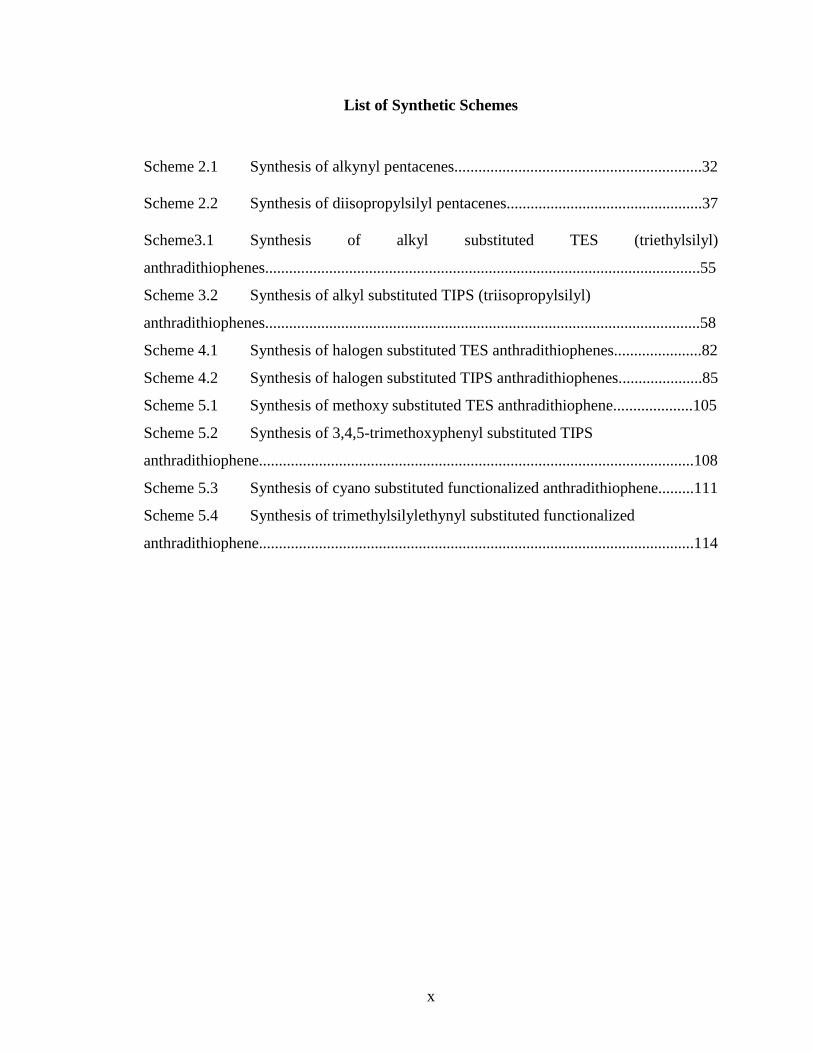
List of Synthetic Schemes
Scheme 2.1 Synthesis of alkynyl pentacenes..............................................................32
Scheme 2.2 Synthesis of diisopropylsilyl pentacenes.................................................37
Scheme3.1 Synthesis of alkyl substituted TES (triethylsilyl)
anthradithiophenes.............................................................................................................55
Scheme 3.2 Synthesis of alkyl substituted TIPS (triisopropylsilyl)
anthradithiophenes.............................................................................................................58
Scheme 4.1 Synthesis of halogen substituted TES anthradithiophenes......................82
Scheme 4.2 Synthesis of halogen substituted TIPS anthradithiophenes.....................85
Scheme 5.1 Synthesis of methoxy substituted TES anthradithiophene....................105
Scheme 5.2 Synthesis of 3,4,5-trimethoxyphenyl substituted TIPS
anthradithiophene.............................................................................................................108
Scheme 5.3 Synthesis of cyano substituted functionalized anthradithiophene.........111
Scheme 5.4 Synthesis of trimethylsilylethynyl substituted functionalized
anthradithiophene.............................................................................................................114

xi
List of Tables
Table 6.1 UV-vis and electrochemical measurements on functionalized
anthradithiophenes .......................................................................................................... 128

xii
List of Files
Sankar Dissertation.pdf ……………………………………………………………....4 MB

1
Chapter 1: Introduction
1.1 Organic Electronic Materials
The microelectronics industry of the 20th
century has been completely dominated by
inorganic field-effect transistors (FETs) ever since the invention of the first transistor in
1947 at Bell Laboratories. However, the high cost of production for these traditional
silicon based FETs has stimulated extensive scientific research on π-conjugated organic
small molecule, oligomer, dendrimer and polymer based semiconductors.1-4
Interest in
organic materials is mainly due to the electronic and optical properties that come from the
delocalization of charges in a system of atoms covalently bonded with alternating single
and multiple bonds. Unlike their inorganic counterparts, organic electronic materials can
be processed using low-cost solution-based techniques such as spin-coating and ink-jet
printing at low temperature, and have the potential to eliminate the use of high vacuum
deposition and photolithography. Mechanical flexibility,5 and the possibility of large area
deposition onto substrates6 are other advantages of these carbon-based semiconductors.
The breakthrough in the research of organic electronics was the discovery of
electrically conducting organic polymers by Shirakawa7 and co-workers in 1977. By
means of suitable halogen doping, polyacetylene (1, Fig. 1.1) showed high conductivity
at room temperature. For this discovery, Shirakawa, MacDiarmid and Heeger were
awarded with Nobel Prize for Chemistry in 2000.
Figure 1.1 Polyacetylene
n
1

2
Over the past three decades, extensive research has been dedicated to understanding
charge transport mechanisms in organic semiconductors in order to employ them in
devices such as organic field effect transistors (OFETs), organic light emitting diodes
(OLEDs) and organic photovoltaics (OPVs).8-11
The efficiency of conduction of charge
carriers (electrons and holes) in semiconductors is referred to as their mobility, which
will be discussed in the following sections.
1.2 Fundamental Concepts of Charge Transport in Organic Electronic Materials
There are several ways to introduce charge carriers into the lowest unoccupied
molecular orbital (LUMO) energy level or the highest occupied molecular orbital
(HOMO) energy level in organic semiconductors, by means of photo-generation,
chemical doping, excess thermal energy, and most importantly through injection from
metal electrodes.
Charge transport in semiconductors is mainly determined by the type of atomic or
molecular interactions present in the solid. Organic molecular solids possess weak van
der Waals interactions between neighboring molecules. On the other hand, atoms are held
together with very strong covalent bond interactions in traditional inorganic
semiconductors. Due to strong overlap of atomic orbitals observed in these conventional
silicon based semiconductors, charge transport occurs in delocalized bands which are
limited by the phonon (thermally induced lattice vibrations) scattering within the solid
and show a very high single crystal charge carrier mobility (electron mobility, µe = 1430
cm2/Vs, and hole mobility, µh = 466 cm
2/Vs).
12 Therefore, the mobility is lowered as the
temperature increases. In contrast, even after tremendous advances in the field of organic

3
semiconductors over several decades, the exact charge transport mechanism in organic
electronic materials is a frequently contested subject. Part of the confusion arises because
there are various methods to determine the electrical characteristics of organic electronic
materials, including time-of-light (TOF), space charge limited current (SCLC), and field-
effect transistor (FET) measurements.13-17
In chapter 3 and 4, I will describe the electrical
properties of functionalized anthradithiophenes that have been measured by organic FET
studies. A detailed structure of a field effect transistor, followed by its study in the
developments of organic semiconductors, will be discussed in the following sections.
1.3 Organic Field Effect Transistors (OFETs)
In principle, a FET acts as a capacitor, as first proposed by Lilienfeld in 1930.18
However, it was only after the introduction of the silicon-based metal-oxide-
semiconductor FET (MOSFET) concept in 1960, that FETs became an important element
in modern microelectronic chips.19
Even though they are not expected to compete with
high performing crystalline silicon-based FETs, organic semiconductor based devices
have the potential to overcome amorphous silicon (a-Si:H) based transistors (hole
mobility in the range of 0.1 - 1 cm2/Vs) where low on-off switching speed is required. In
1970, the first organic FET was described when FET measurements were carried out on
the surface of metal-free phthalocyanine (2, Fig. 1.2a).20
The first organic semiconductor
based thin-film transistor was demonstrated in 1987 by Koezuka et al. when
electrochemically polymerized polythiophene (3, Fig. 1.2b) showed thin film hole
mobility of 2 x 10⁻⁵
cm2/Vs.
21, 22

4
In field effect transistors, the conductivity or flow of charges across the semiconducting
material is influenced by the voltage applied at the gate electrode with respect to source
(Fig. 1.3). The organic field effect transistor plays a critical role in carbon based
electronics, and the success in the development of these organic electronic devices
mainly relies on improved charge career mobility of organic semiconductors and reduced
operation voltage of the transistors. The architecture of an OFET is generally similar to
that of thin film transistor (TFT) based on amorphous hydrogenated silicon.
Figure 1.2 a. Phthalocyanine b. Polythiophene
NH
N
N
N
N
N
HN
NS
SS
S
n
2 3
An organic thin film transistor (OTFT) consists of three major components; three
electrodes (source (S), drain (D), and gate (G)), a dielectric layer (insulator), and an
active organic semiconductor layer. It can be constructed either with top-contact or
bottom-contact geometry (Fig. 1.3 b and a, respectively). In the top-contact devices, an
active organic semiconductor layer (OSL) is first deposited on the dielectric, and then the
two electrodes (source and drain) are evaporated through a shadow mask. In the bottom-
contact device, the source and drain electrodes are pre-patterned on the dielectric, and
then the organic layer is deposited on top of them.

5
Figure 1.3 Two types of organic thin film transistor device configuration:
a. Bottom-Contact Configuration
b. Top-Contact Configuration
The current flow between the source and drain electrodes is controlled by the applied
gate voltage. When no voltage is applied at the gate electrode, there will be low or no
current, and the transistor is said to be off. When the gate voltage is applied, charge
carriers (holes or electrons depending on the polarity of gate voltage) will be accumulated
at the interface between the dielectric and the organic semiconductor layer due to the
polarization of dielectric. The charge carriers will allow current flow between the source
and drain electrodes under applied voltage, and the transistor is on.

6
The potential usefulness of an OTFT is mainly determined by four important
parameters; First, charge carrier mobility (µ), which is the drift velocity of charge carriers
in the conducting channel (the region covered between source and drain electrodes) under
electric field (measured in cm2 / Vs). Second, the on / off current ratio (Ion / off) is the ratio
of current flow between the source and drain electrodes at the on state of the transistor to
that of off state. Third, threshold voltage (VT) is the voltage required at the gate electrode
to induce the current flow in the channel. And, finally, the sub-threshold slope (S),
determines how fast the device can switch back to the on state in the region of
exponential current increase from the off state.
Figure 1.4 Output characteristics of a typical OFET

7
At constant gate voltage (VG), as the drain-source voltage (VSD) increases, the current
flow in the conducting channel increases almost linearly and then gradually saturates at
higher VSD (see Fig. 1.4).The source-drain current (ISD) generated in the linear and
saturation regions can be calculated by the following equations.
For the linear region,
ISD, Linear = (CiWµFET / L) (VG-VT)VSD
For the saturation region,
ISD, Saturation = (CiWµFET / 2L) (VG-VT)2
Where Ci is the capacitance of the dielectric, W and L are the distance across the
conducting channel, channel width and distance between the source and drain electrodes,
conducting channel length respectively, VT is the threshold voltage, and µFET is the
charge carrier mobility.

8
Figure 1.5 Examples of p-type organic semiconductors
S S
S SSS
N
N
N
N
N
N
N
NM
S
S
S
S
n
C12H25
C12H25
C12H25
C12H25
C12H25
C12H25
4 5
6 7
89
S
S
S
S
In general, organic semiconductors can be classified into two categories; p-type
(majority hole carriers) and n-type (majority electron carriers) depending on the density
of states in the energy band – a high dispersion in the valence band for p-type materials,
and high dispersion in the conduction band for n-types. Energy levels in organic materials
can be tuned through functionalization. Electron donating groups such as alkyl,

9
Figure 1.6 Examples of n-type organic semiconductors
N N
O
O O
O
C8H17C8H17
N
N
N
N
N
N
N
NM
SSS
S
F F F F FF
FFFFFF
F
F
F FF
F
F
F
F
F
F
F
FFF
FF
F
FF
F
FF
FF
F
FF
SS
S
NC
NCCN
CNC4H9 C4H9
10
11
12 13
14 15
alkoxy, amino are used to synthesize p-type organic materials. On the other hand,
electron withdrawing groups such as cyano, fluoro, nitro are used to make n-type
materials. Figures 1.5 and 1.6 depict some examples of commonly studied p-type and n-
type organic semiconductors respectively.23-34
The active layer is usually deposited
through either vacuum-sublimation or from solution.
The first solution processable organic semiconductor based FET was demonstrated in
the late 1980s using the alkylated polythiophene poly(3-hexylthiophene),35
P3HT (16,

10
Fig. 1.7). Even though polymer based FETs produced highly uniform thin films over a
large area, the performance of the devices was limited by the poor control of conjugation
length,
Figure 1.7 Poly (3-hexylthiophene)
S n
16
and the difficulties in purification of polymers to remove impurities. Improving
regioregularity (>91 % of head-tail linkages) of the P3HT thin film improved hole
mobility to 0.1 cm2/Vs.
36 Recently, using a dip coating technique which induced high
regioregularity produced mobilities approaching 0.2 cm2/Vs.
37
In contrast with polymeric systems, the solid state order of small molecules can be
more effectively controlled by chemical modification. The addition of alkyl chains to the
Figure 1.8 α, α’-diethylsexithiophene
SS
SS
C2H5 SS C2H5
17
end of α-sexithiophene (6, Fig. 1.5) rings enhanced the molecular orientation and
improved π-π stacking of the oligomer layer, and the extracted thin film hole mobility of
α, α’-diethylsexithiophene (17, Fig. 1.8) was around 1.1 cm2/Vs.
38, 39

11
1.3.1 Functionalized Acenes and Derivatives
Pentacene (18, Fig. 1.9), an acene oligomer, has been extensively studied for OTFT
devices because of its unique thin film forming ability.40
High performance pentacene
based OTFTs with spin coated polymer dielectric layers were fabricated by Klauk and
co-workers, 41
showing an extracted thin film hole mobility of 3 cm2/Vs and on/off
Figure 1.9 Pentacene
O O
18
current ratio of 105. Further improvements on pentacene based devices are limited by
herringbone interactions between neighboring molecules, insolubility in commonly used
organic solvents, and poor oxidative stability. Typical pathways of pentacene degradation
are endo-peroxide formation by interacting with singlet oxygen in air or dimerization at
the central ring of the pentacene (Fig. 1.9). Earlier, our group overcame these problems
through peri-functionalization of pentacene using trialkylsilyl groups as solubilizers and
an ethynyl spacer was employed to avoid complete disruption of π-stacking between the

12
neighboring molecules due to the bulkiness of silyl substituents. It was found that the size
of the silyl substituents determines the crystal π-stacking of the molecules. Improved π-
overlap and stability were imparted when the diameter of the silyl group is
Figure 1.10 TIPS Pentacene
Si
Si
19
half the length of the length of the acene core. From X-ray crystal diffraction studies, the
solid-state arrangement of 6,13-bis (triisopropylsilylethynyl)pentacene (TIPS pentacene,
19) is found to be a two-dimensional π-stack (brickwork arrangement)42
with interatomic
distances as close as 3.41Ǻ (Fig. 1.10). Recently, researchers at Penn State fabricated
solution-processed TIPS pentacene OTFTs with thin film hole mobility of 1.21 cm2/Vs
and On/Off current ratio of 107.43

13
Figure 1.11 2, 8- dihexylanthradithiophene
S
SC6H13C6H13
20
Figure 1.12 TES Anthradithiophene
S
S
Si
Si
21
Anthradithiophene, a pentacene analogue where the two terminal benzene rings are
replaced by two thiophene units, shows greater stability over pentacene because of high
energy barrier to oxidation. Katz et al. demonstrated that vacuum evaporated 2,8-
dihexylanthradithiophene 20 (Fig. 1.11) formed high quality thin films with extracted
charge carrier mobility of vacuum sublimed thin films as high as 0.15 cm2/Vs.
44

14
Applying our peri-functionalization approach to anthradithiophene also produced
materials with excellent electronic properties. Our best performing functionalized
anthradithiophene was 5,12-bis (triethylsilylethynyl)anthradithiophene (TES
Anthradithiophene, 21) which adopts two-dimensional π-stacks with carbon-carbon
interatomic distances as close as 3.25 Ǻ (Fig. 1.12). Our collaborator fabricated the
solution processed TES anthradithiophene based OTFTs with extracted thin film hole
mobility of 1.0 cm2/Vs. However, hole injection from the metal electrode is limited by its
high oxidation potential (Eox = 904 mV).45
21 can easily be chemically tuned due to the
presence of acidic hydrogens in the terminal thiophene rings of the acene core. In
chapters 3-5, I will discuss my work on the chemical synthesis of functionalized
anthradithiophenes in detail.
1.4 Organic Solar Cells (OSC)
As natural energy sources such as coal, oil, and natural gas are depleted and the price
of energy continues to rise, a high demand for renewable energy (such as solar, wind,
hydroelectric, bio) production prevails around the world. According to a recent US
department of energy report, the United States government spends 500 billion dollars46
annually on energy production which is not really surprising since energy drives
everything from businesses to transportation. The sun being a plentiful energy source on
earth, solar energy has been widely recognized as an indispensable element to fulfill
global energy needs. Otherwise known as a photovoltaic (PV) cell, a solar cell is a device
which converts sunlight energy into electrical energy.

15
Since the discovery of the photovoltaic effect in 1839,47
silicon-based photovoltaic
cells have been predominantly utilized for the conversion of sunlight into electrical
energy. In 1954, the first crystalline silicon PV cell was developed by scientists at Bell
Laboratories, and showed a 6% power conversion efficiency.48
The maximum efficiency
predicted for crystalline Si (band gap = 1.1eV) based solar cell is 30%49
and 25%
efficiency has already been achieved from these conventional cells.50
Other inorganic-
based solar cells have produced even higher results.51
Spectrolab, a well known solar cell
company, recently developed a solar cell that can harvest energy at up to 36%
efficiency.52
However, installations of these traditional inorganic semiconductor based
power plants are very expensive and an alternative to reduce the cost of energy
production is a desperate objective. The process of refining silicon is highly resource and
cost-intensive. (the cost of a silicon chip factory is more than $ 1 billion53
) The thirst for
developing inexpensive renewable energy sources encourages effective research on low-
cost solar cells.
1.4.1 Important Parameters:
The performance of a PV device is determined by the following four important
parameters.
(i) Power conversion efficiency (η) is the number relating the amount of power
generated from a PV cell to the energy of incident photons. This value is decided by the
absorption efficiency of the thin film (ηabs), exciton dissociation efficiency (ηdiss) into
electrons and holes, and charge collection efficiency (ηcoll) at the electrodes. The overall
power conversion efficiency can be determined as
ηoverall = ηabs x ηdiss x ηcoll

16
Figure 1.13 Current –Voltage plot of a photovoltaic (PV) cell
(ii) Short circuit current (Isc) is the maximum current that one can generate through an
external circuit that has no load or resistance upon illumination.
(iii) Open circuit voltage (Voc) refers to the maximum possible voltage across a PV cell
when no current is flowing. Usually, Voc is determined by the difference between the
work functions of the two metal electrodes used. However, in many organic systems a
deviation from this definition is also observed.54
(iv) Fill Factor (FF) measures the squareness of fourth quadrant in the I-V curve, hence
the performance of the PV cell. This can also be defined by the ratio of the maximum
power point (Fig. 1.13) output to the maximum possible power that can be generated
when the current and voltage are at their maximum (ie, Isc and Voc respectively). Hence,
FF can be expressed as

17
FF = ImppVmpp /ISCVOC
and, the power conversion efficiency can be rewritten as
η = ISCVOCFF/ Pin
In traditional inorganic solar cells, the absorption of photons generates electron-hole
pairs evenly distributed in the semiconductor layer and the photocurrent is controlled by
the electrostatic field generated across the cell due to the drift of charge carriers
(electrons and holes).
1.4.2 Organic Photovoltaic Processes
The process of converting light energy into electrical energy in an organic PV is executed
by the following five consecutive steps (Fig. 1.14).
Figure 1.14 light conversion steps in an organic PV cell
(i) Absorption of photons in the solar spectrum results in the photogeneration of excitons
(mobile electron-hole pairs). This is mainly affected by the absorption coefficient of the
organic material and the thickness of the organic film.
(ii) Diffusion of photoexcited excitons in the organic thin film to reach the dissociation
sites. This is affected by the lifetime of the excitons and the exciton diffusion length.

18
(iii) Charge separation of electron-hole pairs into individual charge carriers when
excitons reach the dissociated sites (usually, the organic donor–acceptor interface or the
organic- metal electrode interfaces).
(iv) Charge transport of the electrons and holes in the organic semiconductor layer to the
organic-electrode interface.
(v) Charge collection at the conductive electrodes to supply a direct current (DC) for
power generation. Holes will be collected at the high work function electrode and
electrons will be collected at the low work function electrode.
The first organic photovoltaic was investigated in 1958 by Kallmann and Pope when an
anthracene thin single crystal was examined by placing the crystal between two 0.01M
NaCl solutions and Ag electrodes were used to make contact with the solutions.55
The PV
cell exhibited a photovoltage of 200 mV with an exceedingly low efficiency of 2 X 10⁻⁶
.
Since then, various device architectures have been introduced by different research
groups in order to improve the power conversion efficiency of an organic PV cell. Here, I
describe three of the device structures and their advantages over one another. Fig. 1.15
depicts the three different architectures of organic PV cells. One of the common criteria
of all these device structures is one of the the two electrodes used in the solar cell should
be at least semi-transparent in order for light to pass through the film, and two major
differences between them lie in the exciton dissociation and charge transport processes.

19
Figure 1.15 Different architectures of an organic solar cell. a. single layer organic
solar cell. b. Bilayer heterojunction PV cell and c. Bulk heterojunction PV.
1.4.3 Different architectures of OSCs
(a) Single layer PV cell
The first organic PV cells were investigated on a single thermally evaporated or spin-
coated organic semiconductor layer sandwiched between two different metal electrodes.
One of the electrode interfaces in this is assumed to be an Ohmic-contact, and the other
end is considered to be Schottky diode since exciton dissociation occurs at the rectifying
metal-semiconductor junction. A recent study on MEH-PPV (27) based devices
proclaimed that only 10% of excitons were dissociated into free charge carriers and that
is attributed to the high exciton binding energy and recombination of free carriers after a

20
very short time.56
Although it is the simplest form of all PV cells, the typical single layer
PV cell light conversion efficiency still remains below 0.05%.57
(b) Bilayer heterojunction PV cell
A major discovery in the field of organic solar cells was the introduction of a novel
single-heterojunction approach in 1986 by C. W. Tang of Eastman Kodak Company,58
where electron acceptor material (A) and electron donor material (D) are deposited
separately with a planar interface and the bilayer is sandwiched between two different
electrodes. The organic layers can be deposited either through vacuum evaporation or
from solution techniques such as spin-coating. Electrodes are chosen according to the
work function of the metal electrodes and energy levels of the organic semiconductors for
the best charge injection (low work function electrode is near the electron-acceptor layer
and high work function electrode for the electron-donor organic material). Since the free
charge carriers (electrons and holes) generated after the exciton dissociation at the donor-
acceptor interface move in the pure layers (either n-type or p-type) towards their
corresponding electrodes, the recombination pathways in this type of PV cell are
significantly reduced.
Since the organic semiconductor molecules are bound by weak van der Waals
interactions, high charge carrier mobility is required in order to drive the free charge
carriers generated at the D-A interface to their respective electrodes. During the
photoexcitation process, an electron is promoted from the HOMO energy level to the
LUMO of the donor molecule. If the potential difference between the ionization potential
of the donor and the electron affinity of the acceptor is larger than the exciton binding
energy, then the photoexcited electron in the LUMO of donor will transfer to LUMO of

21
the electron acceptor material provided the HOMO the donor is higher than HOMO of
the acceptor molecule so that the hole will remain in the HOMO of the donor material.
This is commonly known as photo-induced charge transfer. On the other hand, if the
HOMO of the electron acceptor material is higher than that of the donor, then the
photogenerated exciton will be completely transferred through energy loss to the low
band gap material. This process is called energy transfer.
The first bilayer organic PV cell consisted of 3, 4, 9, 10 - perylenetetracarboxyl-bis-
benzimidazole (25, electron acceptor layer) and copper phthalocyanine (electron-donor
layer), and produced a power conversion efficiency of about 1%. Since then many
different material combinations have been employed in bilayer devices.59
Solar cells
made from sequential spin-coating of p-type poly(p-phenylene vinylene) (PPV, 7) and n-
type conjugated ladder polymer poly (benzimidazobenzophenanthroline ladder) (BBL,
23) produced a power conversion efficiency of 2%.60
Forrest et al. demonstrated vacuum-
evaporated copper phthalocyanine (CuPc) / 3,4,9,10- perylenetetracarboxylic-bis-
benzimidazole (PTCBI, 25) thin film bilayer heterostructure organic PV cells
incorporating an exciton blocking layer (EBL) with an external power conversion
efficiency of 2.4%.61
By replacing the electron acceptor material PTCBI with C-60 (10), the solar cell
efficiency increased to 3.6%.62
The same research group recently achieved power
conversion efficiency of 4.2% under simulated Air Mass 1.5G solar spectrum (4 -12 suns
intensity) with low series resistance and the FF of >0.6%.63
One of the drawbacks of
these bilayer heterojunction PV devices is that only photogenerated excitons that are 10-
20 nm or closer to the D-A interface will dissociate into free carriers. In other words, if

22
the thickness of the individual layers is larger than the exciton diffusion length, then the
free charge carriers (electrons and holes) generated tend to recombine. This leads to the
low photon to power conversion efficiency of the solar cells. On the other hand, if the
active layers are very thin, then, less amount of light is absorbed which leads to low
currents.
(c) Bulk heterojunction PV cell
The significance of the bulk heterojunction is to increase donor-acceptor (D-A)
interfacial area in such a way that the distance between each D-A interface is less than the
photogenerated exciton diffusion length of each photon absorbing site. This type of PV
cell is made from an intimate blend of electron acceptor and electron donor molecules
deposited between two different electrodes (see Fig. 1.15). The bulk heterojunction can
be achieved by either co-vacuum-evaporation of small molecules or by depositing
mixtures of polymers or small molecules from solution. Currently, this device structure
becomes cynosure of organic PV scientific research due to low-cost solution processing
techniques such as spin-coating, screen printing and ink-jet printing that can be used over
large areas on flexible substrates. Since the discovery of two layer heterojunction PV
cells in 1986, many material combinations have been extensively studied for improved
power efficiency of organic solar cells.64
In 1995, Yu et al, demonstrated the first organic bulk heterojunction cell employing
mixture of a soluble conjugated polymer (poly(2-methoxy-5-(2’-ethyl-hexyloxy)-1,4-
phenylene vinylene, (MEH-PPV, 26)) as an electron donor and a soluble fullerene
derivative (methanofullerene (6,6)-phenyl c61-butyric acid methyl ester, (PCBM, 22)) as
an electron acceptor.65
A major breakthrough in BHJ solar cells happened when Shaheen

23
et al. obtained 2.5% power conversion efficiency by mixing a p-type conjugated polymer
(poly(2-methoxy-5-(3’,7’-dimethyl-octyloxy)-p-phenylene vinylene), (MDMO-PPV, 24))
and the soluble n-type PCBM in 2001.66
The performance of the device is affected by
nanoscale morphology of the thin film and observed threefold improvement when they
changed the solvent from toluene to chlorobenzene. Atomic force microscopic (AFM)
studies suggested that the tendency of PCBM molecules to form clusters due to phase
segregation is reduced when chlorobenzene is used compared with toluene as the solvent.
Recent results show that the pristine PCBM crystals exhibit high degree of intermolecular
coupling when they were grown from chlorobenzene instead of toluene.67
Research on conjugated block co-polymers has received attention very recently
because of their ability to form self-organized nanostructures. Romero et al. found that
the molecular morphology and the PV characteristics of the devices are strongly affected
by the block copolymer concentration of the blend.68
BHJ solar cells based on polythiophene derivatives as photon absorbing materials have
shown very promising results with power conversion efficiency of > 4.4%.69
Previous
results confirm that the thin film morphology can be controlled by post-fabrication
annealing techniques or controlled solvent evaporation rate.70
Very recently, Bazan et al.
discovered that by incorporating a few volume percent of alkanedithiols in the blend of
low band gap polymer (poly(2,6-(4,4-bis-(2-ethylhexyl)-4H-cylcopenta(2,1-b;3,4-b’)-
dithiophene)-alt-4,7-(2,1,3-benzothiadiazole), (PCPDTBT, 27)), and PCBM before spin-
casting increased the cell efficiency from 2.8 % to 5.5 % without the use of any post-
annealing methods.71
They suggested that addition of dithiols to the solution induces the

24
physical interaction between the polymer chains and/or between the polymer and
fullerene phases.
Figure 1.16 Examples of Organic photovoltaic materials
OCH3
O
N
N
O
N
O
N n
N
O
N
O
N
N
O
O
n
O
O n
10 22
23 24
2625
Figure 1.17 Structure of PCPDTBT
SS
NS N
n
27

25
One of the challenging problems of the bulk heterojunction devices is to generate phase
separated domains in the bulk smaller than the exciton diffusion length in order to avoid
recombination losses of free charge carriers. The second demanding problem is inducing
a percolating pathway (interpenetrating network) in the bulk volume of the organic
semiconductor layer so that the free charge carriers can easily travel towards their
respective electrodes. In chapter 3, I will describe the success of our alkylated
functionalized anthradithiophenes in the fully solution processed organic solar cell.
1.5 Objectives of functionalized pentacene and anthradithiophene researchs
In the following four chapters, I will describe the synthesis and device characterization
of functionalized pentacenes and anthradithiophenes. Chapter 2 will relate my attempts to
functionalize pentacene in order to induce liquid crystallinity, and studies of the thermal
properties of these compounds. Chapter 3 will describe the blocking of the active C – H
bonds in the terminal thiophene rings of the anthradithiophene core using alkyl chains for
the improvement of chemical and thermal stability, high solubility and their applications
in organic thin film transistors and bulk heterojunction layer organic solar cells. Chapter
4 will detail the synthesis of halogen substituted functionalized anthradithiophenes and
the application of fluorinated anthradithiophenes in organic thin film transistors as well as
organic single crystal transistors. In chapter 5, I will describe my attempts to increase the
conjugation length of the heteroacene core and will outline the outcome of all of my
investigation along with prospective ideas to improve the performance of OTFTs and
OSCs.
Copyright © Sankar Subramanian 2008

26
Chapter 2: Thermotropic Functionalized Pentacenes
2.1 Liquid Crystalline Materials
Theoretically, liquid crystalline materials exhibit properties in-between perfect solid
phase (with properly aligned positional and directional order) and isotropic liquid phase
(disordered) materials, and possess some orientational order and partial positional order.
Their physical properties can be easily affected by external influences such as pressure,
temperature, applied electric and magnetic fields, and different composition of mixture.
Depending on their behavior under external circumstances, liquid crystals (LCs) can be
mainly classified into two categories. First, thermotropic liquid crystals, which undergo
phase transition upon varying the temperature. Second, lyotropic liquid crystals, which
show phase transition due to change in concentration of the mesogen (a fundamental unit
which determines the orientational order in the liquid crystals) in a solvent as well as
temperature. When a polarized light is passed through the LCs, they exhibit different
textures of characteristic liquid crystalline phases (such as birefringence). Each texture is
related to the orientation of the molecules in one direction.
2.2 Liquid Crystalline Materials for Organic Electronics
Due to low-cost manufacturing and the possibility to deposit them over large areas,
organic π-conjugated materials have been identified as potential fundamental constituents
in the development of carbon-based electronics. Very recently, the employment of liquid
crystalline materials has become a promising novel approach in improving the
performance of organic electronic devices72-76
since they can self-organize themselves to
form uniform thin films. The breakthrough in the liquid crystalline materials approach in

27
thin film organic electronics came from the success of discotic (disc-like structure) liquid
crystals developed by Adam and co-workers in the early 1990s.77
They found that the
highly ordered columnar stacked molecule, 2, 3, 6, 7, 10, 11-hexahexylthiotriphenylene
(28, Fig. 2.1) exhibits charge carrier mobility of 0.1 cm2
/ Vs, which is in the range of
hole mobility shown by amorphous silicon.
Figure 2.1 2, 3, 6, 7, 10, 11 - Hexahexylthiotriphenylene (28)
28
Rod-like (calamitic) liquid crystal structures have the advantage of achieving two-
dimensional maximum π-stacking solid state arrangements required for high performance
of OTFTs, in contrast to the one-dimensional columnar π-stacking of discotic materials.
Garnier et al., demonstrated that the end-substitution of quarterthiophene with alkyl

28
groups improved the morphology of the thin films as compared to unsubstituted
quarterthiophene (4T). Both spin-coated and vacuum deposited α, ω -
dihexylquarterthiophene (DH4T, 29) OTFTs produced extracted hole mobilities of 10-2
cm2 / Vs, due to the highly ordered structure within the thin films.
78
Figure 2.2 (a) α, ω -dihexylquarterthiophene (29), (b) 5,5” -bis(5-hexyl-2-
thenylethynyl)-2,2’:5’,2’ -terthiophene (30)
SS S
S
29
SS s S
S C6H13C6H13
30
Recently, Van Breemen et. al developed calamitic liquid crystalline materials that
formed thin films with large area coverage. Thermally annealed spin-coated thin films of
30 resulted in the formation of monodomains up to 150 mm in diameter, showing
saturation hole mobility as large as 0.02 cm2 / Vs. This high thin film hole mobility was
attributed to the absence of domain boundaries of the thin film on the substrate.79
Most
recently, Bao el. at at Stanford University used a photoalignment technique in solution
deposited liquid crystalline polymer and small molecule semiconductor based OTFTs to
improve the morphology of the thin films.80
This method has been remarkably helpful in
avoiding sample contamination, static charge generation and reducing the high degree of

29
surface roughness at the dielectric interface that were caused by traditional techniques
used for alignment of LC molecules.
2.3 Alkynyl Pentacenes:
Though an extensive research on pentacene (18) based electronic devices has been
done for many years due to its excellent thin film forming ability,40
its poor solubility,
oxidative instability under ambient conditions, and herringbone crystal packing has
restricted commercial applications. Earlier, the Anthony group overcame these problems
by means of a peri-functionalization approach using trialkylsilylethynyl groups. 19
adopts a two dimensional π-stacking with the closest interatomic carbon-carbon distance
of 3.41 Ǻ as shown in Fig. 1.11. The extracted mobility of 19 from a solution-cast device
is reported as 1.21 cm2
/ Vs.43
However, the thin film made from the solution processable
techniques (such as spin-coating and drop-casting) were not uniform (see Fig. 2. 3).
Figure 2.3 As-Spun Thin Film Image of 19 81
There are many post-fabrication methods, such as solvent vapor annealing and thermal
annealing that have been commonly used in the organic electronics field in order to
improve the morphology of thin films. Upon thermal annealing of spin-cast thin films,

30
19 exhibits thermal cracking (see Fig. 2.4) in the long-axis orientation, which was studied
by our collaborators at University of Michigan using Hot-Stage Optical Microscopy
(HSOM).
Figure 2.4 Thermal cracking of thin films made of 19.
Differential Scanning Calorimetry (DSC) experiments showed a reversible endothermic
peak at 124 °C before 19 melts at 268 °C.82
These data confirm the presence of thermally
induced solid-state phase transition in the as-deposited crystalline thin film of 19 that
causes the cracking.
For this project, my goal was to design soluble, low-melting functionalized pentacenes
with liquid crystalline properties in order to produce high quality thin films on the
devices. The hypothesis of this project is: first, deposit the organic semiconductor layer
on the substrate through a solution-based technique, second, thermal annealing the active
layer followed by slow cooling will induce the alignment of the molecules in one
direction due to liquid crystallinity, to form continuous high quality thin films. From the
previous studies, it is well understood that liquid crystals are generally made with rigid π-
electronic chromophore as the central part of the molecule, which induces the directional

31
order in the system, and flexible alkyl chains on the terminal or peripheral positions,
which induce the self assembly of the molecules on the substrate. My first approach was
to introduce alkyl groups at the peri-positions of
Figure 2.5 Pictorial representation of calamitic LC
R = substituent
the pentacene ring. To avoid difficulties in synthesis, ethynyl groups were utilized as a
bridge between alkyl group and acene chromophore. Alkyl groups were chosen not only
to induce liquid crystallinity but also to increase the solubility of the molecule.
Synthesis of 6,13-di(alkynyl) pentacenes were done in a straight forward two-step
process (see Scheme 2.1). In the first step, quadruple aldol condensation of
phthalaldehyde (31) and 1,4-cyclohexane dione (32) in THF / absolute ethanol (EtOH)
solvent mixuture was carried out to generate pentacene-6,13-quinone (33) in nearly
quantitative yield which immediately came out of the reaction mixture as bright yellow
precipitate with the addition of a few drops of 15 % potassium hydroxide (KOH)
solution.83
And, in the second step, the lithium alkyl acetylide in THF was added to 33 at
room temperature, and the mixture was allowed to stir overnight. It was followed by the
deoxygenation of the resulting diol in-situ with stannous chloride dihydrate / 10 %

32
aqueous hydrochloric acid to yield the desired alkynyl pentacenes (34 - 38) in moderate
to good yields. They were easily purified by chromatography
Scheme 2.1 Synthesis of 6,13-di(alkynyl) pentacene derivatives
R
R
R = n-Butyl, 34, 80 % Pentyl, 35, 75 % Hexyl, 36, 62 % Octyl, 37, 56 % Decyl, 38, 61 %
1. HR / n-BuLiTHF
2. SnCl2.2H2O 10%HCl
O
O
+
O
O
O
O
15 % KOH /
abs. EtOH
31 32
> 99 %
33
and recrystallization. It should be noted that the higher alkyl chain pentacenes (37 and
38) tend to decompose on exposure to air and light for more than 1h.
Functionalized pentacenes 34 - 36 formed dark blue crystals which were stable
enough to analyze by single crystal X-ray diffraction. On the other hand, with higher
alkyl chain lengths on the acene chromophore, both 37 and 38 tend to decompose
yielding orange crystals. The thermal ellipsoid plots of 34 - 36 are shown in Fig. 2.6

33
Figure 2.6 Thermal ellipsoid plots of 34, 35 and 36.
Single-crystal XRD studies reveal that 34 adopts a one-dimensional pi-stacking
arrangement with the closest interatomic carbon-carbon distance of 3.41 Ǻ. On the other
hand, 35 and 36 didn’t show any π-face interactions within the system. It is observed that
as the length of the alkyl chain increases, the aryl-aryl π-face interaction becomes an aryl-
alkyl interaction with no π-interactions between the neighboring molecules. In other
words, longer alkyl groups act as an insulating layer between the π-systems (see Fig. 2.7).
35 is found to be the most unstable derivative in the solid state due to close interaction
between the rigid aromatic core and the ethynyl spacer.

34
Figure 2.7 π-Stacking of Alkynyl Pentacenes: a. Hexynyl Pentacene (34), b.
Heptynyl Pentacene (35), c. Octynyl Pentacene (36).

35
Figure 2.8 UV-vis absorption spectra of 34 and 53.
Figure 2.9 Electrochemistry of 34 (Ferrocene was used as an internal standard. Cyclic
Voltammetry experiment was carried out using 0.1 M solution of Bu4NPF6 in
dichloromethane as an electrolyte with the scan rate of 150 mV / s.)
The UV-vis absorption spectra of 6,13-alkynyl pentacenes recorded in dichlormethane
show a characteristic maximum long wavelength absorption (λmax) of 635 nm (see Fig.
2.8) and the electrochemical measurements demonstrate that these alkynyl pentacene
derivatives exhibit a reversible oxidation centered at 0.72 V vs SCE (see Fig. 2.9).

36
The possible explanation for the relatively low stability of 6,13-di(alkynyl) pentacene
derivatives (34 - 38) could be due to either endo-peroxide formation, the dimerization of
π-electronic core, or intermolecular reaction between the alkyne and the aromatic core.
From our group’s earlier empirical model for peri-functionalizing pentacene,40
it is
understood that we need to have bulky groups at the peri-positions of pentacene in order
to avoid the possible degradation pathways, hence, improving the stability of the acenes.
Keeping this concept in mind, my next strategy
Figure 2.10 Alternative Route to Induce Liquid Crystallinity to Pentacene.
to synthesize stable functionalized pentacenes with liquid crystallinity was to introduce
bulky silyl groups at the peri-positions of the acene chromophore. Having shown high
stability, solubility in most organic solvents and strong π-stacking between the
neighboring molecules, 19 has become an excellent benchmark molecule for the peri-
functionalization of the acene ring chromophores. In order to induce the liquid

37
crystallinity into the system, I replaced one of the isopropyl groups of the silyl ball in 19
with a flexible alkyl group, varying the alkyl chain length as shown in Fig. 2.10.
Scheme 2.2 Synthesis of Diisopropylalkyl Silyl Pentacenes.
SiCl
ClSiR
TMS
SiR
1. RLi / THF
2. LiTMS
R = Ethyl, 40, 76 % n- Butyl, 41, 76 % sec-Butyl, 42, 76 % Hexyl, 43, 78 % Octyl, 44, 80 %
K2CO3 / MeOH
RTRT
R = Ethyl, 45, 85 % n- Butyl, 46, 88 % sec-Butyl, 47, 83 % Hexyl, 48, 97 % Octyl, 49, 95 %
Si
Si
R
R
R = Ethyl, 50, 90 % n- Butyl, 51, 95 % sec-Butyl, 52, 90 % Hexyl, 53, 91 % Octyl, 54, 85 %
1. n- BuLi/ THF
2. 6,13-pentacenequinone
3. SnCl2.2H2O
10% HCl
39
2.4 Diisopropylalkylsilyl Pentacenes
Acene derivatives (50 - 54) are made in a four-step process starting from
dichlorodiisopropyl silane (39) as shown in Scheme 2.2. Addition of equimolar quantities
of alkyl lithium and lithium trimethylsilyl acetylide to 39 is the key to generate
trimethylsilyl protected diisopropylalkyl silyl acetylenes (40 - 44) in good yields.
Subsequent deprotection of trimethylsilyl groups from 40 - 44 using potassium carbonate
in methanol yields silyl acetylenes 45 - 49 in very good yields. The desired functionalized
pentacene derivatives (50 - 54) were made using a similar approach to that used for

38
synthesizing alkynyl pentacenes (34 - 38). For purification, elution of the reaction
mixture through a silica gel pad was carried out using hexanes / dichloromethane.
Figure 2.11 Thermal ellipsoid plots of 50, 51, 53 and 54.

39
solvent mixture. Evaporation of solvent followed by recrystallization in hexanes
produced 50 - 54 as dark blue crystals, which were then analyzed by X-ray
Figure 2.12 π-Stacking of Diisopropylalkyl Silyl Pentacenes.
crystallography. They are observed to be highly stable both in solutions and in their
crystalline forms.
Single-crystal XRD studies reveal that both 50 and 51 adopt one-dimensional π-
stacking arrangements with the closest carbon-carbon contact distance of 3.39 and 3.44 Ǻ
respectively. However, as the alkyl chain length on the silyl group increases, alkyl-aryl

40
interactions again dominate, as seen in the functionalized pentacene derivatives 53 and 54
(see Fig. 2.11 and 2.12). Unfortunately, crystal packing of 52 couldn’t be derived since it
didn’t diffract well during the XRD study. UV-vis spectroscopy and cyclic voltammetry
studies report that these 6,13-bis(diisopropylalkylsilylethynyl) pentacenes show a
maximum absorption peak (λmax) of 645 nm and an oxidation potential of 0.84 V vs SCE
respectively, similar to 19 (see Fig. 2.13).
Figure 2.13 Electrochemistry of 53 (Ferrocene was used as an internal standard. Cyclic
Voltammetry experiment was carried out using 0.1 M solution of Bu4NPF6 in
dichloromethane as an electrolyte with the scan rate of 150 mV / s.)
The thermal and morphological studies on the pentacene derivatives I synthesized were
done by the Martin group at the University of Michigan, Ann Arbor. Study on thermal
stability of these functionalized pentacenes 34 - 38 and 50 - 54 were carried out by
Differential Scanning Calorimetry (DSC). It was observed that all the alkynyl pentacenes
(34 - 38) tend to decompose before melting, at temperatures below 150°C (Fig. 2.14).
Also, as the length of the alkyl chain increases the decomposition point decreases. This

41
Figure 2.14 DSCs of 6,13-di(alkynyl) pentacenes (34 - 38).
Figure 2.15 DSCs of 6,13-bis(diisopropylalkylsilylethnyl) pentacenes 50 - 54 and 19.
42
result correlates well with our earlier observation from the single-crystal XRD studies
that alkyl-aryl interactions become predominant as the length of the alkyl chain increases.
The presence of silyl groups on the acenes helped to improve their thermal stability
which was demonstrated by DSCs of 50, 19 and 52 with melting points of 226 °C, 263 °C
and 220 °C respectively (Fig. 2.15). As the alkyl chain length on the silyl group
increases the melting point can decrease dramatically as shown by acenes 51, 53 and 54,
which melt at 142°C, 99°C and 68°C respectively. The decrease in melting point also
correlates with a decrease in the amount of π-stacking observed in the crystals. It is also
noticed that 19, 51 and 53 exhibit one or more sub-melting phase transitions. Especially,
53 shows three sub-melting phase transition before its melting point which suggested the
possibilities of thermotropic crystalline phases.
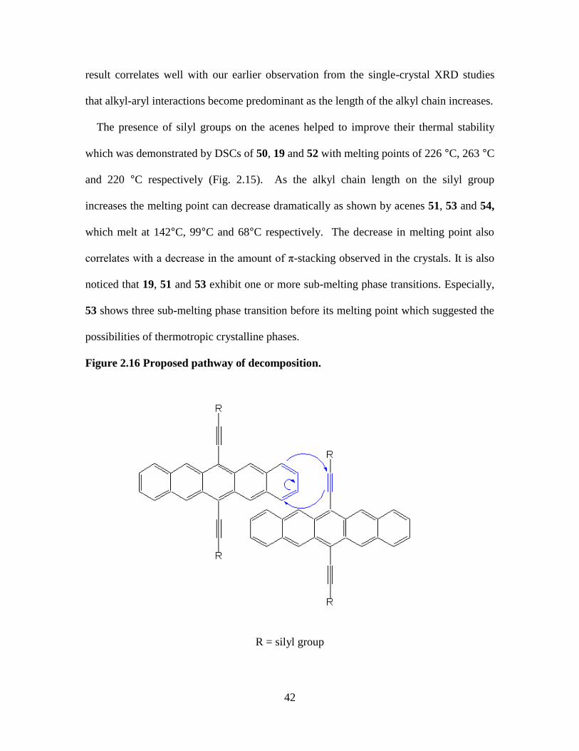
Figure 2.16 Proposed pathway of decomposition.
R = silyl group

43
The DSCs on diisopropylalkylsilyl pentacenes (50 - 54) also reveal the fact that those
molecules with low melting point, show a broad decomposition point centered at 180 °C.
This could possibly be due to a Diels-Alder reaction between the ethynyl portion of one
molecule and the pentacene chromophore of the other molecule in the melt as shown in
Fig. 2.16. The acenes which have high melting point decompose immediately upon
melting, which could be explained by the ability of molecules in the melt to arrange
themselves in such a way to undergo Diels-Alder reaction. The reversibility of heating
curve of all these pentacene derivatives (50 - 54) was noticed if they are heated only up to
150°C. Thin film morphology of alkynyl (34 - 38) and diisopropylalkylsilylethynyl
pentacenes (50 - 54) were studied by solution casting them in THF on a clean glass slide.
From the bright-field transmission electron microscopy (TEM) and optical microscopy
data, it was observed that 51, 52 and 53 form larger crystalline domains than 50 and 54,
suggesting that the π-stacking solid state arrangement in the crystal is affected by too
long (octyl) or too short (ethyl) alkyl groups.
Figure 2.17 Optical micrographs of the functionalized pentacene thin films made of
35 and 53.
44
The effect of evaporation rate on the thin film morphology was studied by two different
sets of experiments. One is with a cover on the as-deposited film and the other is without
the cover on. For both alkynyl and diisopropylalkylsilyl pentacenes, uncovered drying
was found to be more advantageous since prolonged existence of molecules in solution
(in air) led to decomposition. Hence, higher evaporation rate is required to form
crystalline films. Optical micrographs reveal that diisopropylalkylsilyl pentacenes form
birefringent crystalline thin films. On the other hand, alkynyl pentacenes form non-
birefringent amorphous thin films (see Fig. 2.17).
This project demonstrated that 6,13-di(alkynyl) pentacene derivatives (34 - 38) are
stable enough to do UV, NMR and electrochemical studies, and a number of derivatives
could also be analyzed through single crystal XRD. We observed that their stability
decreases as the alkyl chain lengths increase. My approach to use the silyl groups
dramatically improved the stability of the molecules. Even though the possibility of
thermotropic liquid crystalline phases could be observed from the DSC of 53, due to the
lack of any π-stacking interactions, it is not a suitable organic semiconductor for high
performance electronic devices.
2.5 Experimental Details
General Procedure for 6,13-di(Alkynyl) Pentacene.
To an oven dried 100 mL single necked round bottom flask, n-BuLi (2.5 mmol)
was added slowly to 1-alkyne (4.6 mmol) in dry THF (25 mL) under N2 atm and stirred
for 40 minutes at RT. Then, 33 (0.25 g, 0.8 mmol) was added very quickly, to avoid
quenching of the lithium acetylide by moisture in air, and the mixture was stirred

45
overnight at RT. The next day, stannous chloride dihydrate (2 mmol) followed by 10%
HCl (2mL) was added and the reaction mixture was stirred for 7 hrs. It was then extracted
into hexanes, washed with saturated brine solution, dried over anhydrous MgSO4 and
concentrated. The crude products were purified by silica plug using hexanes / methylene
chloride (9 / 1).
6,13–di(hexynyl) Pentacene (34). Yield = 0.28 g (80 %), M. P. = 83 °C (dec). 1H NMR
(200 MHz, CDCl3): 1.15 (t, J = 7.2 Hz, 6H), 1.74-1.99 (m, 8H), 2.95 (t, J = 6.8 Hz, 4H),
7.39 (dd, J = 3.0 Hz, J = 6.6 Hz, 4H), 8.01 (dd, J = 3.0 Hz, J = 6.4 Hz, 4H), 9.18 (s, 4H)
ppm. 13
C NMR (50 MHz, CDCl3): 13.93, 20.46, 25.52, 31.43, 79.11, 105.69, 118.52,
125.92, 126.34, 128.94, 130.73, 132.32 ppm. MS (EI 70 eV) m/z 438 (100 %, M+), 395
(35 %, M+ - Propyl).
6,13–di(heptynyl) Pentacene (35). Yield = 0.28 g (75 %), M. P. = 115 °C. 1H NMR (200
MHz, CDCl3): 1.06 (t, J = 7.2 Hz, 6H), 1.50-1.61 (m, 4H), 1.7 (quintet, J = 7.0 Hz, 4H),
1.97 (quintet, J = 7.0 Hz, 4H), 2.94 (t, J = 6.8 Hz, 4H), 7.39 (dd, J = 2.8 Hz, J = 6.8 Hz,
4H), 8.01 (dd, J = 3.2 Hz, J = 6.4 Hz, 4H), 9.20 (s, 4H) ppm. 13
C NMR (50 MHz,
CDCl3): 14.31, 20.76, 22.57, 29.03, 31.66, 79.13, 105.78, 118.54, 125.94, 126.35,
128.93, 130.76, 132.34 ppm. MS (EI 70 eV) m/z 466 (100 %, M+), 409 (20 %, M
+ -
Butyl).
6,13–di(octynyl) Pentacene (36). Yield = 0.25 g (62 %), 1H NMR (200 MHz, CDCl3):
0.99 (t, J = 6.7 Hz, 6H), 1.4–1.6 (m, 8H), 1.77 (quintet, J = 6.6 Hz, 4H), 1.96 (quintet, J =
7.06 Hz, 4H), 2.95 (t, J = 6.8 Hz, 4H), 7.39 (dd, J = 3.0 Hz, J = 6.7 Hz, 4H), 8.01 (dd, J =
3.1 Hz, J = 6.6 Hz, 4H), 9.21 (s, 4H) ppm. 13
C NMR (50 MHz, CDCl3): 14.30, 20.81,
46
22.92, 29.17, 29.33, 31.74, 79.13, 105.81, 115.59, 126, 126.42, 128.99, 130.82, 132.4
ppm. MS (EI 70 eV) m/z 494 (95 %, M+).
6,13–di(decynyl) Pentacene (37). Yield = 0.25 g (56 %). 1H NMR (200 MHz, CDCl3):
0.91 (t, J = 6.6 Hz, 6H), 1.25–1.6 (m, 16H), 1.77 (quintet, J = 6.7 Hz, 4H), 1.96 (quintet, J
= 7.06 Hz, 4H), 2.94 (t, J = 7.0 Hz, 4H), 7.39 (dd, J = 3.2 Hz, J = 6.8 Hz, 4H), 8.02 (dd, J
= 3.4 Hz, J = 6.6 Hz, 4H), 9.20 (s, 4H) ppm. 13
C NMR (50 MHz, CDCl3): 14.23, 20.81,
22.88, 29.37, 29.52, 29.59, 32.11, 79.15, 105.8, 118.55, 125.91, 126.35, 128.93, 130.76,
132.33 ppm. MS (EI 70 eV) m/z 445 (25 %), 429 (45 %), 308 (100 %).
6,13–di(dodecynyl) Pentacene (38). Yield = 0.3 g (61 %). 1H NMR (200 MHz, CDCl3):
0.87 (t, J = 6.6 Hz, 6H), 1.20–1.60 (m, 24H), 1.77 (quintet, J = 7.0 Hz, 4H), 1.96
(quintet, J = 7.06 Hz, 4H), 2.94 (t, J = 6.8 Hz, 4H), 7.39 (dd, J = 3.0 Hz, J = 6.6 Hz, 4H),
8.02 (dd, J = 3.0 Hz, J = 6.6 Hz, 4H), 9.20 (s, 4H) ppm. 13
C NMR (50 MHz, CDCl3):
14.23, 20.81, 22.85, 29.37, 29.55, 29.87, 29.93, 32.09, 79.14, 105.79, 118.54, 125.91,
126.36, 128.94, 130.76, 132.33 ppm. MS (EI 70 eV) m/z 606 (20 %, M+), 479 (20 %, M
+
-Nonyl).
General procedure for TMS protected diisopropylalkyl silyl acetylene.
In a flame dried 250 mL single necked round bottom flask, trimethylsilyl acetylene
(32.4 mmol) was dissolved in dry THF under N2 atm. To that, n-BuLi (27 mmol) was
added slowly at room temperature. The mixture was stirred for 5-6 hrs. In another flame
dried 250 mL single necked round bottom flask, 39 (27 mmol) was dissolved in dry THF
under N2 atm. To that, alkyl lithium (27 mmol) was added slowly and the mixture stirred
at RT. After 5-6 hrs, lithium trimethylsilyl acetylide was added by cannula. After
overnight stirring, the reaction mixture was quenched with DI water carefully and

47
extracted with hexanes, washed with saturated brine solution, dried over anhydrous
MgSO4 and concentrated. The crude compounds were purified by silica plug using
hexanes (75 mL).
Trimethylsilylethynyl diisopropylethyl silane (40). Yield = 76%. 1H NMR (400 MHz,
CDCl3): δ 0.19 (s, 9H), 0.55–0.69 (m, 2H), 0.5–1.00 (m, 17H) ppm. 13
C NMR (100 MHz,
CDCl3): δ 0.25, 2.07, 8.29, 11.64, 18.21, 18.44, 110.37, 116.23 ppm. MS (EI 70 eV) m/z
218, 207 (M+ - isopropyl).
Trimethylsilylethynyl diisopropyln-butyl silane (41). Yield = 76%. 1H NMR (200
MHz, CDCl3): δ 0.22 (s, 9H), 0.58-0.72 (m, 2H), 0.90–1.02 (m, 3H), 1.02–1.18 (m, 12H),
1.30–1.53 (m, 4H) ppm. 13
C NMR (50 MHz, CDCl3): δ 0.22, 9.91, 11.83, 13.93, 17.58,
18.24, 18.45, 26.79, 26.88, 110.94, 116.35 ppm. MS (EI 70 eV) m/z 268 (M+), 225 (M
+ -
isopropyl).
Trimethylsilylethynyl diisopropyl sec-butyl silane (42). Yield = 76%. 1H NMR (400
MHz, CDCl3): δ 0.19 (s, 9H), 0.78–0.94 (m, 2H), 1.00 (t, J = 7.2 Hz, 3H), 1.03–1.18 (m,
15H), 1.20–1.34 (m, 2H), 1.66–1.78 (m, 1H) ppm. 13
C NMR (100 MHz, CDCl3): δ 0.25,
11.36, 11.38, 13.89, 14.40, 14.56, 18.72, 18.83, 19.06, 25.53, 110.66, 116.37 ppm. MS
(EI 70 eV) m/z 268 (M+), 225 (M
+ - isopropyl).
Trimethylsilylethynyl diisopropylhexyl silane (43). Yield = 78%. 1H NMR (200 MHz,
CDCl3): δ 0.18 (s, 9H), 0.53–0.70 (m, 2H), 0.91 (t, J = 6.6 Hz, 3H), 0.98–1.12 (m, 16H),
1.20–1.50 (m, 6H) ppm. 13
C NMR (50 MHz, CDCl3): δ 0.11, 10.12, 11.76, 14.25, 18.04,
18.15, 18.36, 22.79, 24.44, 31.71, 33.56, 110.76, 116.18 ppm. MS (EI 70 eV) m/z 296
(M+), 253 (M
+ - isopropyl).

48
Trimethylsilylethynyl diisopropyloctyl silane (44).
In a dried single necked 250 mL RBF, n-BuLi (10.14 mmol) was added to
trimethylsilyl acetylene (10.14 mmol) in dry THF slowly. After stirring for 30 minutes at
RT, chloro diisopropyloctyl silane (11.16 mmol, purchased from Gelest, Inc.) was added
and the mixture stirred at RT overnight. The reaction mixture was extracted into hexanes
and purified silica chromatography using hexanes. Yield = 80%. 1H NMR (200 MHz,
CDCl3): δ 0.18 (s, 9H), 0.61 (t, J = 8.0 Hz, 2H), 0.9 (m, 6H), 1.05 (m, 15H), 1.29 (m,
10H) ppm. 13
C NMR (50 MHz, CDCl3): δ 0.16, 10.14, 11.65, 11.77, 11.88, 14.28, 18.09,
18.19, 18.28, 18.40, 22.40, 24.49, 29.49, 32.18, 33.94, 110.83, 116.23 ppm. MS (EI 70
eV) m/z 324 (M+), 281 (M
+ - isopropyl).
General procedure for the deprotection of the trimethylsilyl group.
The TMS-protected alkyne (6.7 mmol) was dissolved in methanol (50 mL) in a 250
mL RBF. To that, potassium carbonate (7.25 mmol) was added and the mixture stirred
for 2 hours at RT. The reaction mixture was taken up in excess hexane and washed with
DI water and brine solution, dried over anhydrous MgSO4 and concentrated. Finally, the
compounds were purified by silica chromatography using hexanes (75 mL).
Diisopropylethylsilyl acetylene (45). Yield = 85%. 1H NMR (200 MHz, CDCl3): δ
0.55–0.75 (m, 2H), 0.90–1.15 (m, 17H), 0.04 (s, 1H) ppm. 13
C NMR (50 MHz, CDCl3): δ
1.91, 8.05, 11.43, 17.98, 18.20, 18.55, 86.38, 94.83 ppm. MS (EI 70 eV) m/z 168 (M+),
125 (M+ - isopropyl).
Diisopropyl n-butylsilyl acetylene (46). Yield = 88%. 1H NMR (200 MHz, CDCl3): δ
0.60–0.80 (m, 2H), 0.90–1.05 (m, 4H), 1.06-1.20 (m, 12H), 1.30 – 1.55 (m, 5H), 2.38 (s,

49
1H) ppm. 13
C NMR (50 MHz, CDCl3): δ 9.80, 11.65, 13.81, 17.77, 18.04, 18.23, 26.67,
26.89, 86.72, 94.80 ppm. MS (EI 70 eV) m/z 196 (M+), 153 (M
+ - isopropyl).
Diisopropyl sec-butyl silylacetylene (47). Yield = 83%. 1H NMR (400 MHz, CDCl3): δ
0.80–0.90 (m, 2H), 0.96–1.02 (m, 3H), 1.02–1.14 (m, 15H), 1.18–1.32 (m, 2H), 1.66–
1.78 (m, 1H), 2.35 (s, 1H) ppm. 13
C NMR (100 MHz, CDCl3): δ 11.25, 13.83, 14.37,
18.68, 18.70, 18.72, 18.94, 25.37 86.62, 95.00 ppm. MS (EI 70 eV) m/z 196 (M+), 153
(M+ - isopropyl).
Diisopropylhexylsilyl acetylene (48). Yield = 97%. 1H NMR (200 MHz, CDCl3): δ
0.55–0.70 (m, 2H), 0.90 (t, J = 6.0 Hz, 3H), 0.97-1.15 (m, 16H), 1.20–1.50 (m, 6H), 2.34
(s, 1H) ppm. 13
C NMR (50 MHz, CDCl3): δ 10.09, 11.63, 14.23, 18.03, 18.23, 22.80,
24.40, 31.69, 33.66, 86.67, 94.78 ppm. MS (EI 70 eV) m/z 224 (M+), 181 (M
+ -
isopropyl).
Diisopropyloctylsilyl acetylene (49). Yield = 95%. 1H NMR (200 MHz, CDCl3): δ 0.64
(m, 2H), 0.9 (m, 3H), 1.00-1.12 (m, 14H), 1.24-1.50 (m, 12H), 2.35 (s, 1H) ppm. 13
C
NMR (50 MHz, CDCl3): δ 10.89, 11.63, 11.86, 14.25, 18.06, 18.18, 18.26, 18.41, 22.87,
24.42, 29.41, 29.47, 32.14, 33.99, 88.81, 94.78 ppm. MS (EI 70 eV) m/z 252 (M+), 209
(M+ - isopropyl).
Synthesis of Diisopropylalkylsilyl Ethynyl Pentacene.
In a flame dried 500 mL single necked round bottom flask, diisopropylalkyl silyl
acetylene (8 mmol) was dissolved in 50 mL of hexanes under N2 atm. To that, n-BuLi
(4.87 mmol) was added slowly at RT and allowed to stir for 30-45 min. Then,
pentacenequinone (1.6 mmol) followed by 150 ml of hexane was added to the reaction
mixture which was heated to 65 °C overnight. The next day, 0.5 mL of DI water, 1.5 mL

50
of 10% HCl and tin(II)chloride dihydrate (4 mmol) was added to the reaction mixture and
stirred at 65 °C for 6-7 h. The reaction mixture was cooled and dried with anhydrous
MgSO4, purified through silica plug using hexane/ dichloromethane (9/1) solvent system
and concentrated.
6,13-Bis(diisopropylethylsilylethynyl) pentacene (50). Yield = 90 %. 1H NMR (200
MHz, CDCl3): 0.90-1.10 (m, 4H), 1.26-1.44 (m, 34H), 7.43 (dd, J = 3.2 Hz, J = 6.8 Hz,
4H), 8.00 (dd, J = 3.2 Hz, J = 6.6 Hz, 4H), 9.31 (s, 4H) ppm. 13
C NMR (50 MHz,
CDCl3): 2.55, 8.74, 12.18, 18.57, 18.86, 104.89, 107.51, 118.65, 126.32, 126.61,
128.99, 130.94, 132.64 ppm. MS (EI 70 eV) m/z 611 (56 %, M+).
6,13-Bis(diisopropyl n-butylsilylethynyl) pentacene (51). Yield = 95 %. 1H NMR (200
MHz, CDCl3): 0.96-1.04 (m, 8H), 1.29-1.46 (m, 30H), 1.50-1.60 (m, 4H), 1.70-1.80
(m, 4H), 8.00 (m, 4H), 7.43 (m, 4H), 9.31 (s, 4H) ppm. 13
C NMR (50 MHz, CDCl3):
10.28, 12.29, 14.10, 18.57, 18.84, 27.05, 27.28 104.64, 107.62, 118.46, 126.18, 126.44,
128.80, 130.75, 132.44 ppm. MS (EI 70 eV) m/z 667 (65 %, M+), 610 (20 %, M
+ - Butyl).
6,13-Bis(diisopropyl sec-butylsilylethynyl) pentacene (52). Yield = 90 %, 1H NMR
(200 MHz, CDCl3): 1.2 (m, 8H), 1.4 (m, 32H), 1.58 (m, 4H), 2.03-2.09 (m, 2H), 7.44
(m, 4H), 8.00 (m, 4H), 9.32 (s, 4H) ppm. 13
C NMR (50 MHz, CDCl3): 11.89, 14.13,
14.95, 19.22, 19.15, 19.30, 19.54, 25.93, 104.94, 107.70, 118.58, 126.23, 126.53, 128.88,
130.85, 132.47 ppm. MS (EI 70 eV) m/z 667 (68 %, M+), 610 (20 %, M
+ - sec-Butyl).
6,13-Bis(diisopropylhexylsilylethynyl) pentacene (53). Yield = 91 %. 1H NMR (200
MHz, CDCl3): 0.90 (m, 12H), 1.35 (m, 38H), 1.76 (m, 4H), 7.45 (m, 4H), 8.00 (m,
4H), 9.30 (m, 4H) ppm. 13
C NMR (50 MHz, CDCl3): 10.68, 12.38, 14.38, 18.65, 18.92,

51
22.92, 25.11, 31.92, 33.90, 104.74, 107.71, 118.55, 126.22, 126.53, 128.89, 130.82,
132.50 ppm. MS (EI 70 eV) m/z 723 (68 %, M+), 638 (10 %, M
+ - Hexyl).
6,13-Bis(diisopropyloctylsilylethynyl) pentacene (54). Yield = 85 %. 1H NMR (200
MHz, CDCl3): 0.92(m, 10H), 1.38 (m, 48H), 1.77(m, 4H), 7.43 (dd, J = 3.0 Hz, J = 6.6
Hz, 4H), 8.00 (dd, J = 3.2 Hz, J= 6.6 Hz, 4H), 9.30 (s, 4H) ppm. 13
C NMR (50 MHz,
CDCl3): 10.71, 12.42, 14.29, 18.67, 18.94, 22.88, 25.19, 29.60, 29.70, 32.22, 34.26,
104.93, 107.85, 118.71, 126.36, 126.68, 129.05, 131.00, 132.69 ppm. MS (EI 70 eV) m/z
779 (68 %, M+), 666 (15 %, M
+ - Octyl).
Copyright © Sankar Subramanian 2008

52
Chapter 3: Alkyl Substituted Functionalized Anthradithiophenes
3.1 Thienyl Electronic Materials.
Recent advances in organic semiconductor research have been driven by low-cost
solution-based fabrication techniques such as spin coating84
, and ink-jet printing85
and the
potential for processing on large area flexible substrates.86
Pentacene (18), considered to
be a benchmark molecule among organic electronic materials, has been subjected to
extensive investigation due to its excellent thin film forming ability,40
and high thin film
hole mobility.41
Very recently, extensive investigations have focused on oligothiophenes
and polythiophenes, because of their formation of high charge transport TFTs. Attaching
alkyl chains to the thiophene units not only improved the solubility, but also improved
the thin film morphology. Halik et al. demonstrated that the longer side chains on
oligothiophenes with thick alkyl intrinsic barrier (1.3 nm for decyl chain and 0.3 nm for
ethyl chain) at the interface resulted in an increase in contact resistance for the top-
contact devices. However, oligothiophenes with longer alkyl chains outperformed the
shorter ones in a bottom-contact configuration due to reduced gate current caused by the
increase in effective thickness of the gate dielectric.87
Sirringhaus et al. showed that the
thin film hole mobility of poly (3-hexylthiophene) (16, see Chapter 1) increases by two
orders of magnitude when the substrate is subjected to surface treatment because of
improved film morphology.88
Studies on the electrical properties of fused thienyl π-
conjugated materials was pioneered by Katz and co-workers at Bell Laboratories in the
late 1990s. Showing high oxidative stability, vacuum-deposited thin film of
benzodithiophene dimer 4 exhibited thin film hole mobility of 0.04 cm2/Vs.
89 However,
alkyl substitution at the terminal thiophene rings didn’t improve the solubility of the

53
parent molecule (4). On the other hand, alkyl substitution on anthradithiophene (55, a
pentacene analogue where the terminal benzene rings are replaced by thiophene rings)
provided promising results. Vacuum-deposited syn- and anti- mixture of 2,8-
dihexylanthradithiphene (20) formed highly ordered poly-crystalline films on the devices,
showed hole mobility as high as 0.15 cm2/Vs.
44 Moreover, alkyl-substituted
anthradithiophene was more soluble and exhibited thin film hole mobility of 0.01 - 0.02
cm2/Vs from solution-cast films.
Figure 3.1 Unsubtituted anthradithiophene (55).
55
Recently, application of the Anthony group’s peri-functionalization approach to
anthradithiophene yielded devices with excellent transistor characteristics. TES
anthradithiophene (21) which adopts a two-dimensional π-stacking solid state
arrangement with interatomic distances as close as 3.25 Ǻ exhibits thin film film hole
mobility of 1.0 cm2/Vs.
45 However, upon illumination, the thin film formed by 21
photobleached completely within 1h. At this point, my goal for this project is to modify
21 through systematically increasing the length of carbon chains at the 2, 8 positions in
order to improve the photostability and increase the solubility in common organic
solvents, thereby allowing low-cost solution-processing techniques.

54
3.2 Alkyl Substituted Functionalized Anthradithiophenes.
Alkyl substituted anthradithiophenes 66 - 69 are easily prepared as shown in Scheme
3.1. Smaller alkyl groups (methyl, ethyl, propyl and butyl) were chosen for the systematic
study of the effect of alkyl substitution on crystal packing and electrical properties of the
acene derivatives. 5-alkyl thiophene-2,3-carboxaldehydes 58 - 61 were made in two steps
starting from thiophene-2,3-dicarboxaldehyde (56) using previously reported methods.44,
45 Condensation of these dialdehydes (58 - 61) with cyclohexane-1,4-dione yielded alkyl
substituted anthradithiophene quinones (62 - 65) as the mixture of syn- and anti- isomers.
Due to insolubility in common organic solvents, all the end-substituted anthradithiophene
quinones mentioned in this dissertation were only characterized by mass spectrometry.
My initial strategy was to use triethylsilyl (TES) as the peri-functionalizing group of
anthradithiophene chromophore. Target semiconductors 66 - 69 were synthesized by the
addition of lithium triethylsilyl acetylide to the quinone, followed by deoxygenation with
stannous chloride / 10% sulfuric acid. All of the derivatives were purified by silica gel
chromatography followed by multiple recrystallizations from hexanes.

55
Scheme 3.1 Synthesis of alkylated TES anthradithiophenes (66 - 69).
S
CHO
SCHO
O
OO
O
HO(CH2)2OH /
PTSA / BenzeneS
CHO
CHOR
1. n- BuLi / THF/
- 78oC
2. RI
3. 10% HCl / THFR = Methyl, 58, 62 % Ethyl, 59, 79 % Propyl, 60, 66 % Butyl, 61, 66 %
100 %
S
SR R
O
O
S
SR R
TES
TES
2. SnCl2. 2H2O/
10 % H2SO4
LiTES1.Hexanes, 60
oC
R = Methyl, 62, 70 % Ethyl, 63, 65 % Propyl, 64, 65 % Butyl, 65, 71 %
R = Methyl, 66, 51 % Ethyl, 67, 61 % Propyl, 68, 56 % Butyl, 69, 71 %
O
O
15 % NaOHTHF / MeOH
56 57
High-quality single crystals of anthradithiophenes 66 - 69 were easily grown from
hexanes, and their solid state arrangements were studied by single crystal X-ray
diffraction. Thermal ellipsoid plots of 66 - 69 and pi-stacking solid state arrangements of
66 - 68 are shown in Fig. 3.2 and Fig. 3.3, respectively. Ethyl-substituted
triethylsilylethynyl anthradithiophene (67) exhibits a one-dimensional slipped π-stacked
arrangement with an inter-stack carbon-carbon (C-C) distance of 3.84 Ǻ and the closest
contact distance of 3.49 Ǻ within the π-stack (intra-stack).

56
Figure 3.2 Thermal ellipsoid plots of 66 - 69.
Propyl-substituted anthradithiophene (68) adopts a two-dimensional stacking motif,
showing very weak π-interactions between the neighboring molecules with 3.62 Ǻ inter-
stack contacts and 3.95 Ǻ intra-stack contacts - well outside the van der Waals radius for
carbon. Interestingly, methyl-substituted acene derivative (66) adopts π-stacking
arrangement somewhere between a strict one-dimensional slipped π-stack (67) and two-
dimensional order (e.g. 21). Even though both 66 and 67 have similar crystal packing in
the solid state, the major difference comes from the distance between the neighboring
acene chromophores in the 1-D pi-stacks. The contact distance between two acene cores

57
Figure 3.3 Solid state pi-stacking arrangement for 66, 67 and 68.
in 66 is as close as 3.50 Å, which is within the range of van der Waals radius of carbon
atoms. Hence, stronger π-cloud interactions between the neighboring molecules should
lead to improved electronic coupling. Even though the separation is 3.49 Å for
intercolumn stacking in 67, the intra-stack distance is greater than 3.8 Å - well outside the
limit for strong electronic coupling. From this rationalization, with strongly interacting
adjacent 1-D π-stacks, 66 clearly represents a bridge between purely 1-D π-stacked 67
and strongly 2-D π-stacked 21.

58
From the Anthony group’s work on the peri-functionalization of fused acene ring
systems using trialkylsilylethynyl groups,42
it is understood that the diameter of silyl
group should be half the length of the acene chromophore. Also, knowing triethylsilyl
(TES) as the best silyl substituent at the peri-positions of unsubstituted anthradithiophene
for stronger π-interactions,45
my next strategy was to use bulky triisopropylsilyl (TIPS) at
the peri-positions of the larger alkyl substituted anthradithiophene in order to improve π-
interactions of
Scheme 3.2 Synthesis of Alkylated TIPS Anthradithiophenes (70 - 72)
S
SR R
O
O
S
SR R
TIPS
TIPS
2. SnCl2. 2H2O/
10 % H2SO4
LiTIPS1.Hexanes, 60
oC
R = Methyl, 70, 51 % Ethyl, 71, 55 % Propyl, 72, 45 %
the neighboring acene chromophores. The desired semiconductors 70 - 72 were made by
the addition of lithium triisopropylsilyl acetylide to the quinone, followed by
deoxygenation with stannous chloride / 10% sulfuric acid as shown in scheme 3.2.

59
Figure 3.4 Thermal ellipsoid plots of 71 and 72.

60
All of the derivatives were purified by silica gel chromatography followed by multiple
recrystallizations from hexanes. These alkylated TIPS anthradithiophene derivatives 70 -
72 diffracted poorly during the single crystal XRD study and exhibited 1-D slipped π-
stack arrangement with weak intermolecular electronic coupling. Crystals of 70 were
difficult to solve by X-ray analysis and the thermal ellipsoid plots of 71 and 72 are shown
in Fig. 3.4.
The UV-vis absorption spectra of alkyl substituted functionalized anthradithiophenes
66 - 69 recorded in dichloromethane show the longest-wavelength absorption (λmax) at
550 nm (Fig. 3.5), which matches very closely with that of 21. These functionalized
anthradithiophenes are stable in their crystalline forms as well in
Figure 3.5 UV-vis spectra of alkyl substituted anthradithiophenes (66 - 69).
solution. From electrochemical studies, the oxidation potential of all of the derivatives 66
- 72 was found to be 0.84 V vs SCE, a slight decrease from 0.90 V vs SCE reported for
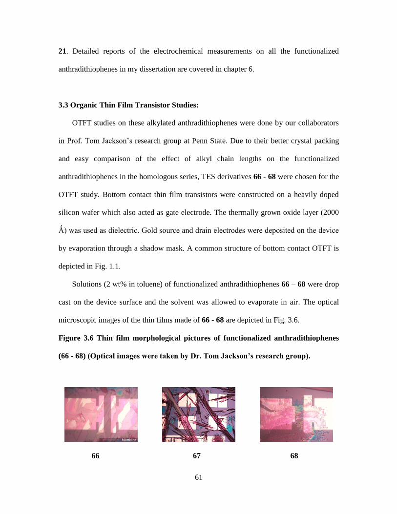
61
21. Detailed reports of the electrochemical measurements on all the functionalized
anthradithiophenes in my dissertation are covered in chapter 6.
3.3 Organic Thin Film Transistor Studies:
OTFT studies on these alkylated anthradithiophenes were done by our collaborators
in Prof. Tom Jackson’s research group at Penn State. Due to their better crystal packing
and easy comparison of the effect of alkyl chain lengths on the functionalized
anthradithiophenes in the homologous series, TES derivatives 66 - 68 were chosen for the
OTFT study. Bottom contact thin film transistors were constructed on a heavily doped
silicon wafer which also acted as gate electrode. The thermally grown oxide layer (2000
Ǻ) was used as dielectric. Gold source and drain electrodes were deposited on the device
by evaporation through a shadow mask. A common structure of bottom contact OTFT is
depicted in Fig. 1.1.
Solutions (2 wt% in toluene) of functionalized anthradithiophenes 66 – 68 were drop
cast on the device surface and the solvent was allowed to evaporate in air. The optical
microscopic images of the thin films made of 66 - 68 are depicted in Fig. 3.6.
Figure 3.6 Thin film morphological pictures of functionalized anthradithiophenes
(66 - 68) (Optical images were taken by Dr. Tom Jackson’s research group).
66 67 68

62
Typical transfer curves for the TFT characteristics of the functionalized
anthradithiophenes are shown in Fig. 3.7. From the linear region of the gate voltage vs
square root of drain current (VG- ID ) curves, one can extract the thin film hole mobility
and the threshold voltage. The bottom-contact OTFTs fabricated using drop-cast 66
rendered devices with extracted hole mobility of 0.3 cm2/Vs, and on/off current ratio of
105. On the other hand, extracted hole mobility for devices made up of 67 and 68 were
reduced by more than three orders of magnitude, 2.7 x 10⁻⁵
cm2/Vs and 5.2 x 10
-4 cm
2/Vs
respectively. The threshold voltages of devices made up of 66, 67 & 68 are 21 V, 11 V
and 3 V respectively.
Figure 3.7 Thin film transistor characteristics of functionalized anthradithiophenes
(66 - 68) (Transistor data were taken by Dr. Tom Jackson’s research group).

63
The difference in performance of the devices made up of 66 - 68 can be explained by
a combination of film morphology and crystal packing effects. The morphology of the
drop-cast films was studied by optical microscopy (Fig. 3.6), which revealed dramatic
differences between the materials. Combining figures 3.3 and 3.6, it is understood that
67, which possesses strong 1-D crystal π-stacking solid state arrangement leading to 3-D
thin film growth, formed as discontinuous needle like crystallites, resulting in low
extracted hole mobilities. On the other hand, 66 with strong intermolecular electronic
coupling in two dimensions, yielded the most uniform 2-D thin films on the devices,
leading to high thin film hole mobility. 68, which adopts 2-D crystal packing motif in the
solid state, also yielded 2-D thin film growth with smaller grains and slightly decreased
uniformity compared to 66. However, due to poor intermolecular electronic coupling
resulting from the large distance between the neighboring anthradithiophene
chromophores, devices made up of 68 led to low hole mobility. From the above
discussions, we could say that both thin film morphology and intermolecular electronic
couplings are very critical factors in order to develop high-performance OTFT materials.
3. 4 Organic Solar Cell Studies:
OPV studies on these alkyl substituted anthradithiophene derivatives were done by our
collaborators in Prof. George Malliaras’s research group at Cornell University. Organic
solar cells are regarded as a versatile alternative for inexpensive photovoltaics due to the
ability of being fabricated on flexible substrates at low temperatures and at low-cost. The
small molecule organic semiconductors are considered to be suitable candidates for OPV
production because of their facile chemical tunability. Recently, vapor-deposited

64
pentacene based multilayer photovoltaics have produced high performance devices.90
Very recently, solution-processed 19 in a thermally evaporated C60 (10) based bilayer
solar cell have demonstrated 0.5% power conversion efficiency.91
Researchers at Cornell studied our alkyl substituted functionalized
anthradithiophenes along with 19 in a layered device consisting of ITO / PEDOT:PSS /
alkyl substituted functionalized anthradithiophenes / C60 / BCP / Ag. Poly (3,4-
ethylenedioxythiophene):poly(styrene sulfonate) (PEDOT:PSS) was deposited as hole
injection layer on a indium-tin oxide (ITO) coated glass substrate. Bathocuprine (BCP)
was used as exciton blocking layer. The layered heterojunction was created by thermally
evaporating C60 on a spin-coated film of functionalized anthradithiophenes. The optical
bandgaps for 19, 66, 68, 70 and 72 were found to be 1.59 eV, 1.97 eV, 2.05 eV, 2.09 eV
and 2.09 eV respectively. For the photogenerated exciton dissociation via charge transfer
to happen at the heterointerface, the difference between the LUMOs of donor and
acceptor materials should be larger than the exciton binding energy. For 19/C60
heterojunctions, the LUMO offset was estimated between 1.0 - 1.2 eV, sufficient for
exciton dissociation through charge transfer since the exciton binding energy can be as
high as 0.5 eV for a five membered acene rings.92
For long-range (Forster) resonant energy transfer, the photoexcited donor material
and the adjacent acceptor material should be within the Forster resonant energy transfer
radius of 2 - 5 nm.93
Forster radius for 19 and 68 were calculated as 1.6 nm and 2.2 nm
respectively, and from the spectral response of these acene based devices, there was no
evidence of energy transfer for a donor material Egap below 1.9 eV. However, charge
transfer cannot be completely ruled out in these anthradithiophene based devices. Spin-

65
coated anthradithiophene derivatives produced crystalline thin films. On the other hand,
spin-coated amorphous thin films made of 19, were forced to crystallize by thermal
annealing. Charge transfer in these acenes is expected to compete with energy transfer
because of the increase in exciton diffusion length derived from crystalline organic
semiconductors. From the above PV study, devices consisting of the donor 68 showed
0.7% power conversion efficiency under 100 mW/cm2 simulated AM1.5 light. The
extracted values for Voc and FF are found to be 700 mV and 0.44 respectively. The
current-voltage characteristics of a 68 based device are shown in Fig. 3.8. Without the
use of thermal annealing or the incorporation of mobile ions, 68 outperformed previously
reported 19 based devices, even though they absorb less of the solar spectrum (see Fig.
3.9).91
Figure 3.8 Current-Voltage characteristics of 68 based PV device (The I-V plot was
taken by Dr. George Malliaras’s research group)

66
Figure 3.9 UV-vis spectra of 19 and 68.
Upon thermal annealing the electron donor film at 70°C, 66, 70 and 72 based solar cells
produced the power conversion efficiencies of 0.5%, < 0.1%, and 0.2% respectively with
the same device structure that used for 68. To study the effect of polymeric binder on the
performance of these devices, our collaborators at Cornell University spin-coated the
blend of 1:1 ratio of an atactic polystyrene (PαMS, 73 (see Fig. 3.10)) and the
functionalized anthradithiophenes before depositing the electron acceptor layer (C60). It
was found that the power conversion efficiencies of the bilayer solar cells based on 66
and 70 were increased to 0.7% and 0.4%, respectively, in contrast to dismal performance
(< 0.1%) shown by 72 based devices. This was explained using cross-polarized images of
the thin film made of functionalized anthradithiophenes as shown in Fig. 3.11. With the
use of polymeric binder, the surface roughness of the thin film made of 66 is moderately
reduced to 10.4 nm from 45.4 nm that formed without using the polymeric blend. On the
other hand, 72 formed very smooth surface (surface roughness of 0.9 nm) thin film upon

67
blending with PαMS. From the above studies, it is understood that the polymeric blend
which restricts the activity of 72 by forming very smooth surface leading to poor
performance of the device and optimal surface roughness is required to improve the
efficiency of the solar cell.
Figure 3.10 Structure of PαMS, 73.
C CH2
CH3
n
73
Figure 3.11 Cross polarized micrographs of thin films made of 66 and 72 with and
without PαMS (Pictures were taken from Dr. George Malliaras’s research group).
Even though 19-based layered PV devices performed well, upon blending with soluble
fullerene derivative PCBM (23), the pentacene underwent degradation. I studied this
decomposition by recording UV-vis spectra (see Fig. 3.12) of a mixture of 19 and 23 in

68
Figure 3.12 Diels-Alder reaction study of TIPS pentacene (19) with PCBM (23).
Figure 3.13 Photostability study of thin films made of 21.
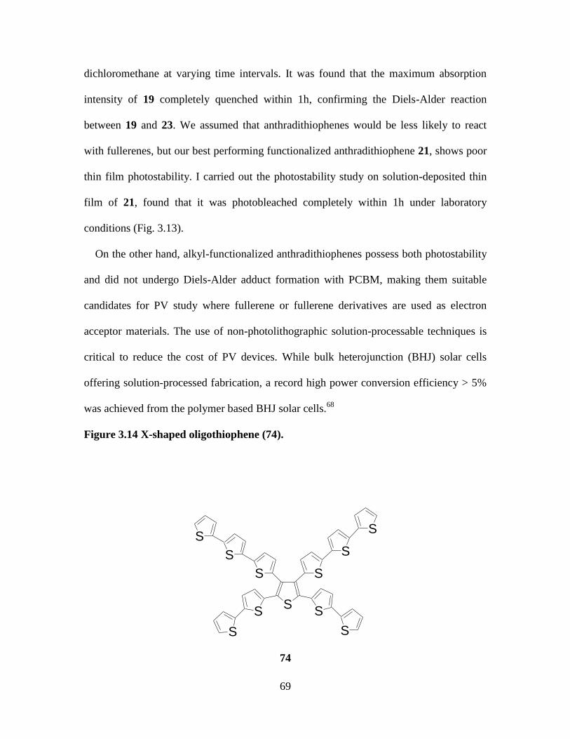
69
dichloromethane at varying time intervals. It was found that the maximum absorption
intensity of 19 completely quenched within 1h, confirming the Diels-Alder reaction
between 19 and 23. We assumed that anthradithiophenes would be less likely to react
with fullerenes, but our best performing functionalized anthradithiophene 21, shows poor
thin film photostability. I carried out the photostability study on solution-deposited thin
film of 21, found that it was photobleached completely within 1h under laboratory
conditions (Fig. 3.13).
On the other hand, alkyl-functionalized anthradithiophenes possess both photostability
and did not undergo Diels-Alder adduct formation with PCBM, making them suitable
candidates for PV study where fullerene or fullerene derivatives are used as electron
acceptor materials. The use of non-photolithographic solution-processable techniques is
critical to reduce the cost of PV devices. While bulk heterojunction (BHJ) solar cells
offering solution-processed fabrication, a record high power conversion efficiency > 5%
was achieved from the polymer based BHJ solar cells.68
Figure 3.14 X-shaped oligothiophene (74).
SS S
S S
S
S
S
S
S
S
74

70
For the solution-processed small molecule based BHJ cells, power conversion
efficiency of 0.8% have been recently recorded from an X-shaped oligothiophene (74,
Fig. 3.14).94
Post-fabrication solvent annealing is one way to form crystalline thin films
and 21 has shown increases in thin film charge carrier mobility as much as 2 orders of
magnitude upon solvent vapor annealing.95
Some amount of crystallization is also
expected in the case of alkyl substituted functionalized anthradithiophene / 23 blends.
Malliaras et al. performed morphological studies on spin-coated films made of 67 in
toluene and 23 in ortho-dichlorobenzene at a 70:30 weight ratio. Optical fluorescence
microscopy displayed complete photoluminescence quenching of the highly fluorescent
67 in the as-spun blend film. The as-cast blend film was kept in a sealed vessel along
with a vapor of solvent mixture, causing fine grain spherulites to nucleate (100-300
nuclei/cm2) with a high fractional coverage on the substrate at increasing time (see Fig
3.15) leading to phase segregation of 67.
Figure 3.15 Optical microscopic images of spherulite growth (Pictures were taken
by Dr. George Malliaras’s research group).

71
PEDOT: PSS (60 nm) was spin-coated on a pre-patterned ITO coated glass substrate.
Blend solutions of 67 and 23 in toluene and ortho-dichlorobenzene, respectively at a
70:30 weight ratio were then spin-coated on the device. The films were exposed to
solvent mixture vapor at different time interval. Film crystallization of 67 was followed
by the deposition of the cathode consisting of a 10 Ǻ layer of CsF and 400 Ǻ of themally
evaporated Al as shown in Fig. 3.16. The current-voltage characteristics of the device
with high spherulite coverage is shown in Fig. 3.17.
Figure 3.16 General structure of 67 based OPV device.
Under reverse bias, a positive slope and direct proportionality between current and
voltage were observed in the dark, implying that the device exhibits low shunt resistance
or a partial short-circuit. The device produced photocurrent in the low reverse bias and
the difference between light and dark current gradually decreases upon illumination. The
engineers attribute this behavior to an imperfectly interpenetrating network. However, the
I-V curves are well behaved, with Isc of 2.97 mA/cm2, Voc of 840 mV, FF of 0.40 and the

72
overall power conversion efficiency is calculated to be 1%. In general, short circuit
current (Isc) was proportional to the area of crystalline spherulite coverage on the device.
Figure 3.17 Current-Voltage Characteristics of a device with high sperulite
coverage.
The design and synthesis of alkyl substituted anthradithiophenes has yielded a
tremendous amount of information. The optimal alkyl chain length is crucial for strong
intermolecular electronic coupling and thin film morphology of anthradithiphene
derivatives. 66, which possess 1-D π-stacks with strong intermolecular coupling and two-
dimensional thin film growth, produced OTFT devices with high thin film hole mobility
of 0.3 cm2/Vs. This project shows that a very fine balance of thin film morphology and
strong π-stacking is required for high charge transport thin film transistors. These
photostable anthradithiophene derivatives also showed excellent performance in PV
devices. Without the incorporation of mobile ions and thermal annealing technique, 68
performed well with 0.7% power conversion efficiency from a bilayer heterojunction PV

73
device. The use of polymeric binder in 66, 70 and 72 based solar cells explains the
importance of the optimal quality thin films for the better performance photovoltaics.
Even though thin film morphology of 67 was poor on OTFT devices, it provided
excellent performance in OPV studies with 1% power conversion efficiency from a
completely solution processed BHJ solar cell.
3.5 Experimental Details
General.
Solvents (acetone, methylene chloride, hexanes) were purchased from Fisher. Dry
THF was either purchased in anhydrous form from EMS Science or distilled over sodium
/ benzophenone under N2 atmosphere. Trialkylsilyl acetylenes were purchased from GFS
Chemicals. Silica gel 230-400 mesh was bought from Sorbent Technologies. NMR
spectra were measured on a Varian (Gemini 200 MHz / Unity 400 MHz) spectrometer.
Chemical shifts were reported in ppm relative to CDCl3 as internal standard. The UV
spectra were measured on a UV-2501PC Shimadzu instrument. Mass spectroscopy was
analyzed in EI mode at 70 eV or MALDI with TCNQ matrix on a JEOL (JMS-700T)
Mass Spectrometer. Cyclic Voltammetry was carried out on a BAS CV-50W, with
ferrocene as an internal standard.
Thiophene-2,3-diacetal (57).
This compound was synthesized using previously reported literature.44
General procedure for the synthesis of 5- alkyl thiophene-2,3-dialdehydes.
To a flame dried flask, n-BuLi (27.4 mmol) was added slowly to thiophene-2,3-
diacetal 57 (21 mmol ) in THF (60 mL) at -78 °C under dry N2 . After stirring 1 h, alkyl
iodide (29.5 mmol) was added and the reaction mixture was warmed to room

74
temperature, and stirred overnight. The next day, the reaction mixture was quenched by
adding cold water very carefully, extracted with diethyl ether, and washed with water.
The organic layer was dried with anhydrous MgSO4 and concentrated. Without
purification, the diacetal was hydrolyzed by 3M HCl / THF (1 / 1) for 1h. The resulting
product was purified by column chromatography using hexanes / dichloromethane eluent
(2 : 3).
5 - Methyl thiophene-2,3-dialdehyde (58).
Yield = 62%. 1H NMR (200 MHz, CDCl3): δ 2.55 (s, 3H), 7.27 (s, 1H), 10.27 (s,
1H), 10.34 (s, 1H) ppm. 13
C NMR (50 MHz, CDCl3): δ 16.16, 128.31, 144.29, 145.55,
150.42, 182.38, 184.91 ppm. MS (EI 70 eV) m/z 154 (M+), 125 (M+ - CHO)
5 – Ethyl thiophene-2,3-dialdehyde (59).
Yield = 79 %. 1H NMR (200 MHz, CDCl3): δ 1.37 (t, J = 7.5 Hz, 3H), 2.92 (q, J =
7.6 Hz, 2H), 7.34 (s, 1H), 10.33 (s, 1H), 10.39 (s, 1H) ppm. 13
C NMR (50 MHz, CDCl3):
δ 14.99, 23.71, 126.24, 143.98, 144.80, 157.59, 182.20, 184.85 ppm. MS (EI 70 eV) m/z
168 (M+), 140 (M
+ - CHO).
5- Propyl thiophene-2,3-dialdehyde (60).
Yield = 66%. 1H NMR (200 MHz, CDCl3): δ 0.94 (t, J = 7.3 Hz, 3H), 1.68 (m, 2H),
2.80 (t, J = 7.6 Hz, 2H), 7.27 (s, 1H), 10.26 (s, 1H), 10.32 (s, 1H) ppm. 13
C NMR (50
MHz, CDCl3): δ 13.51, 24.41, 32.43, 127.07, 143.96, 145.04, 156.03, 182.31, 184.97
ppm. MS (EI 70 eV) m/z 182 (M+), 154 (M
+ - CHO).
5 – Butyl thiophene-2,3-dialdehyde(61).
Yield = 66%. 1H NMR (200 MHz, CDCl3): δ 0.95 (t, J = 7.4 Hz, 3H), 1.41 (m, 2H),
1.71 (m, 2H), 2.88 (t, J = 7.7 Hz, 2H), 7.33 (s, 1H), 10.33 (s, 1H), 10.39 (s, 1H) ppm. 13
C

75
NMR (50 MHz, CDCl3): δ 13.48, 21.91, 30.04, 33.02, 126.93, 144.03, 145.01, 156.24,
182.26, 184.95 ppm. MS (EI 70 eV) m/z 196 (M+), 168 (M
+ - CHO).
General procedure for the preparation of alkyl-substituted anthradithiophene
quinones.
A few drops of 15 % aqueous KOH solution was added to a mixture of 1,4-
cyclohexanedione (0.6 g , 5.5 mmol) and 5-alkyl thiophene dialdehyde (11.0 mmol)
dissolved in tetrahydrofuran / ethanol (5 mL / 15 mL) in a 100 mL round-bottom flask,
and the rapidly-precipitating mixture was stirred at room temperature for 3 h. The
insoluble yellow precipitate was filtered through a Büchner funnel, washed with ether
and dried in air to yield the desired product.
2,8-Dimethyl anthradithiophene-5,11-dione (62). Yield = 70%. MS (MALDI, TCNQ
matrix) m/z 348 (100%, M+).
2,8-Diethyl anthradithiophene-5,11-dione (63). Yield = 65%. MS (MALDI, TCNQ
matrix) m/z 377 (100%, M+
+ 1)
2,8-Dipropyl anthradithiophene-5,11-dione (64). Yield = 65%. MS (MALDI, TCNQ
matrix) m/z 404 (100%, M+).
2,8-Dibutyl anthradithiophene-5,11-dione (65). Yield = 71%. MS (MALDI, TCNQ
matrix) m/z 433 (100%, M+
+ 1).
General procedure for the synthesis of 5,12-bis(trialkylsilylethynyl)
anthradithiophenes.
n-BuLi (1.86 mL, 4.66 mmol) was added to trialkylsilylacetylene (5.32 mmol) in
hexanes (50 mL) under dry N2 at room temperature in a flame dried 500 mL round-
bottom flask, and the resulting solution stirred for 30 min. The alkyl substituted

76
anthradithiophenequinone (1.33 mmol) was then added, followed by dry hexanes (200
mL), and the resulting suspension stirred at 66 °C until the quinone had completely
dissolved - typically overnight. Stannous chloride (0.9 g, 3.99 mmol), 0.5 mL of water
and 1.5 mL of 10% H2SO4 were then added to the reaction mixture, which was
maintained at 66 °C for an additional 5 h. The reaction mixture was cooled and dried
over anhydrous MgSO4. It was then purified by silica plug, eluted with hexanes. The
solvent was evaporated and the product purified further by multiple crystallization from
hexanes. The resulting product was filtered and dried in air to obtain the pure product.
2,8-Dimethyl-5,12-bis(triethylsilylethynyl)anthradithiophene (66). Yield = 48%. 1H
NMR (200 MHz, CDCl3): δ 0.91 (q, J = 7.6Hz, 12H), 1.25 (t, J = 7.8Hz, 18H), 2.65 (s,
6H), 7.09 (s, 2H), 8.89 (s, 2H), 9.00 (s, 2H) ppm. 13
C NMR (50 MHz, CDCl3): δ 4.94,
8.04, 17.15, 103.71, 103.83, 103.95, 106.20, 106.41, 106.63, 116.23, 117.23, 118.23,
119.35, 119.43, 119.61, 119.71, 121.35, 123.95, 129.56, 129.59, 129.84, 130.09, 130.12,
140.44, 140.48, 141.28, 141.30, 144.55, 144.59. MS (EI 70 eV) m/z 594 (100%, M+
- 1),
595 (50%, M+). Anal. calcd. % C: 72.66, % H: 7.11, Found % C: 72.38, % H: 6.98. MP:
276.5 °C.
2,8-Diethyl-5,12-bis(triethylsilylethynyl)anthradithiophene (67). Yield = 61%. 1
H
NMR (200 MHz, CDCl3): δ 0.92 (q, J = 7.8Hz, 12H), 1.26 (t, J = 7.7Hz, 18H), 1.46 (t, J
= 7.5Hz, 6H), 3.00 (q, J = 7.46Hz, 4H), 7.12 (s, 2H), 8.92 (s, 2H), 9.03 (s, 2H) ppm. 13
C
NMR (50 MHz, CDCl3): δ 4.91, 7.91, 14.90, 24.94, 103.96, 106.18, 117.26, 119.39,
119.53, 119.62, 119.86, 119.95, 129.70, 130.19, 140.05, 141.22, 151.84, 151.89 ppm. MS
(EI 70 eV) m/z 622 (25%, M+
- 1), 623 (15%, M+). Anal. calcd. % C: 73.25, % H: 7.44,
Found % C: 73.21, % H: 7.51. MP: 215 °C.

77
2,8-Dipropyl-5,12-bis(triethylsilylethynyl)anthradithiophene (68). Yield = 56%. 1H
NMR (400 MHz, CDCl3): δ 0.92 (q, J = 8.0Hz, 12H), 1.07 (t, J = 7.4Hz, 6H), 1.25 (m,
18H), 1.86 (m, 4H), 2.94 (t, J = 7.2Hz, 4H), 7.12 (s, 2H), 8.91 (s, 2H), 9.02 (s, 2H) ppm.
13C NMR (100 MHz, CDCl3): δ 4.95, 8.04, 13.97, 23.98, 33.70, 103.86, 103.96, 106.35,
117.18, 119.49, 119.57, 119.76, 119.85, 120.28, 129.59, 130.08, 130.10, 140.04, 140.08,
141.11, 150.15, 150.19. MS (EI 70 eV) m/z 650 (100%, M+
- 1), 651 (50%, M+). Anal.
calcd. % C: 73.78, % H: 7.73, Found % C: 73.55, % H: 7.76. MP: 225.27 °C.
2,8-Dibutyl-5,12-bis(triethylsilylethynyl)anthradithiophene (69). Yield = 71%. 1
H
NMR (200 MHz, CDCl3): δ 0.95 (q, J = 7.8 Hz, 12H), 1.01 (t, J = 6.8 Hz, 6H), 1.26 (m,
18H), 1.49 (m, 4H), 1.82 (m, 4H), 2.97 (t, J = 7.3 Hz, 4H), 7.11 (s, 2H), 8.91 (s, 2H), 9.03
(s, 2H) ppm. MS (EI 70 eV) m/z 678 (15%, M+-1), 679 (10%, M
+). Anal. calcd. % C:
77.27, % H: 8.01, Found % C: 74.14, % H: 7.98.
2,8-Dimethyl-5,12-bis(triisopropylsilylethynyl)anthradithiophene (70). Yield = 51%.
1H NMR (200 MHz, CDCl3): δ 1.33 (m, 42H), 2.65 (s, 6H), 7.07 (s, 2H), 8.94 (s, 2H),
9.04 (s, 2H) ppm. MS (EI 70 eV) m/z 678 (15%, M+
- 1), 679 (10%, M+). Anal. calcd. %
C: 74.27, % H: 8.01, Found % C: 73.50, % H: 7.62.
2,8-Diethyl-5,12-bis(triisopropylsilylethynyl)anthradithiophene (71). Yield = 55%. 1H
NMR (200 MHz, CDCl3): δ 1.34 (m, 42H), 1.46 (t, J = 7.5 Hz), 6H), 3.00 (q, J = 7.6 Hz,
4H), 7.10 (s, 2H), 8.96 (s, 2H), 9.07 (s, 2H) ppm. MS (EI 70 eV) m/z 706 (100%, M+
- 1),
707 (55%, M+).
2,8-Dipropyl-5,12-bis(triisopropylsilylethynyl)anthradithiophene (72). Yield = 55%.
1H NMR (200 MHz, CDCl3): δ 1.07 (t, J = 7.4 HZ, 8H), 1.33 (m, 40H), 1.86 (m, 4H),
2.94 (t, J = 7.6 HZ, 4H), 7.09 (s, 2H), 8.95 (s, 2H), 9.06 (s, 2H) ppm. 13
C NMR (50 MHz,

78
CDCl3): δ 11.87, 13.98, 19.17, 24.03, 29.94, 33.72, 104.63, 105.13, 105.35, 105.56,
116.30, 117.33, 119.53, 119.63, 119.85, 119.94, 120.29, 129.76, 130.23, 140.04, 141.08,
150.16, 150.26 ppm. MS (EI 70 eV) m/z 736 (35%, M+ + 1), 735 (65%, M
+), 734 (100%,
M+ - 1). Anal. calcd. % C: 75.14, % H: 8.49, Found % C: 73.76, % H: 8.45.
Copyright © Sankar Subramanian 2008

79
Chapter 4: Halogen Substituted Functionalized Anthradithiophenes
4.1. Halogen Effects in Conjugated Materials.
Earlier studies demonstrated that both intrinsic properties such as energy level
matching,96
strong π-orbital overlap between neighboring molecules,97
molecular
orientation,98
and extrinsic properties such as thin film morphology,99
film thickness,100
better interfaces with the electrodes101
and the dielectric102
are essential for improved
charge transport in OTFTs. Substitution on the π-conjugated system is expected to alter
not only the electronic properties but also the crystal packing. In 1986, Desiraju et al,
demonstrated the influence of non-bonded intermolecular Cl…Cl and C-H…Cl
interactions for the β-structures (short axis is below 4 Ǻ) of chlorinated planar
aromatics.103
Recently, Bao et al. demonstrated that 5,11-dichlorinated tetracene (DCT,
76) exhibited single crystal mobility as high as 1.6 cm2/Vs which is greater than that
showed by unsubstituted tetracene (75). This high charge transporting property of 76 was
attributed to enhanced π-orbital overlap (Fig. 4.1) because of Cl...Cl spatial interactions
(3.86 Ǻ).104
Due to high electronegativity of the fluorine atom, perfluorination is an
efficient way to convert p-type to n-type organic semiconductors. Suzuki and coworkers
effectively synthesized perfluoropentacene (11), which exhibited herringbone crystal
packing similar to that of 18 (see Fig. 4.2), however, with close intermolecular contacts
(3.25 Ǻ) and edge-to-face angle of 91.2° (compared to 3.65 Ǻ and 51.9° respectively for
18).30 Even though fluorine substitution was not expected to change greatly the molecular
packing because of the relatively smaller size of fluorine atom (the atomic radii for H and
F are 25 pm and 50 pm, respectively), 11 based OTFTs exhibited electron mobilities as
high as 0.22 cm2/Vs.
105

80
Figure 4.1 Structures of tetracene (75), dichlorotetracene (76) and crystal packing of
76.
Cl
Cl75 76
76
Figure 4.2 Structure and crystal packing of pentacene (18) and perfluoropentacene
(11).

81
My goals for this project are to increase the π-electron surface interaction through
sulfur-halogen and halogen-halogen spatial interactions. We believe that varying the
electronegativity and the size of the halogen atoms should not only change the molecule’s
orbital energy levels, but should also allow us to vary the crystal packing of the
functionalized anthradithiophenes.
4.2 Halogen-Substituted Functionalized Anthradithiophenes
Halogen-substituted functionalized anthradithiophenes (85 - 88) were synthesized using
methods similar to those for the alkyl-substituted functionalized anthradithiophenes
mentioned in the previous chapter, and the synthetic routes starting from 57 are shown in
Scheme 4.1. 5-fluoro thiophene-2,3-dicarboxaldehyde (77) was made in low yields by the
addition of electrophilic fluorine (from N-fluoro benzene sulfonimide) to the lithium salt
of 57 at - 78°C under N2 atmosphere, followed by acid hydrolysis. Purification of this
material is critical, since even a small amount of thiophene-2,3-dicarboxaldehyde present
with 77, generates mono fluoro-substituted anthradithiophenes (85a and 89a) as the
byproduct in the final step. Other 5-halogen substituted thiophene-2,3-dicarboxaldehydes
(78 - 80) were prepared under same conditions that used for 77 by the addition of N-
chlorosuccinimide, N-bromo succinimide, and iodine, respectively, to the lithium salt of
57.

82
Scheme 4.1 Synthesis of halogen-substituted functionalized anthradithiophenes (85 -
88).
S
CHO
CHOX
S
SX X
O
O
S
SX X
TES
TES
2. SnCl2. 2H2O/
10 % H2SO4
LiTES1.
Hexanes, 60oC
X = Fluoro, 81, 78 % Chloro, 82, 65 % Bromo, 83, 50 % Iodo, 84, 96 %
X = Fluoro, 85, 51 % Chloro, 86, 60 % Bromo, 87, 43 % Iodo, 88, 65 %
O
O
15 % NaOHTHF / MeOH
S
O
O1. n- BuLi / THF / - 78
oC
2. X2 or R2NX
3. 10% HCl / THF
R = PhSO2- ; X = F, 77, 32 %R = -CH2CO- ; X = Cl, 78,51 %R = -CH2CO- ; X = Br, 79, 60 % X = I, 80, 90 %
O
O
57
Condensation of these aldehydes (77 - 80) with cyclohexane-1,4-dione yielded 2, 8-
dihalo anthradithiophene quinones (81 - 84) as a mixture of syn- and anti- isomer.44, 45
Due to insolubility in common organic solvents, all the end-substituted anthradithiophene
quinones mentioned in this dissertation were only characterized by mass spectrometry.

83
Figure 4.3 Thermal ellipsoid plots of 87, and 88.
Having found the triethylsilyl ethynyl (TES) group to be the best peri-functionalizing
group to induce strong π-interactions in 21 and 66, my first approach was to introduce
TES into the peri-positions of these end-substituted anthradithiophene chromophores.
The desired organic semiconductors (85 - 88) were synthesized using similar approach
that used for other functionalized anthradithiophenes. All of the derivatives were purified
by silica gel chromatography followed by multiple recrystallizations from hexanes.
Single Crystal X-ray Diffraction Studies.
High-quality single crystals of anthradithiophenes 85 - 88 were grown from hexanes,
and their solid state arrangements were studied by single crystal X-ray diffraction.
Thermal ellipsoid plots of 87 and 88 were shown in Fig. 4.3. From the XRD studies,

84
Figure 4.4 π-stacking solid state arrangements of 85 - 88.

85
it is observed that molecules in 85 exhibit strong two-dimensional π-stacking interactions
with the closest carbon-carbon interatomic distance of 3.36 Ǻ, and S…F contacts as close
as 3.16 Ǻ. The other halogenated anthradithiophenes (86 - 88) possess one-dimensional
slipped π-stacking solid state arrangements as shown in Fig. 4.4.
From our group’s empirical model for the peri-functionalization of acene
chromorphores,42
it is clearly understood that the size of the silyl group determines the
nature of the crystal packing of an acene derivative in the solid state. Having understood
this theory, my second approach was to engineer halogen-substituted anthradithiophene
chromophores using a bulkier triisopropylsilyl ethynyl (TIPS) group. Organic
semiconductors 89 - 91 were prepared by the addition of lithium triisopropylsilyl
acetylide to their corresponding quinones, followed by deoxygenation with stannous
chloride / 10% sulfuric acid in moderate yields as shown in Scheme. 4.2.
Scheme 4.2 Synthesis of halogen-substituted functionalized anthradithiophenes (89 -
91)
S
SX X
O
O
S
SX X
TIPS
TIPS
2. SnCl2. 2H2O/
10 % H2SO4
LiTIPS1.
Hexanes, 60oC
X = Fluoro, 89, 52 % Bromo, 90, 53 % Iodo, 91, 70 %
All of these derivatives were recrystallized from various organic solvents such as
acetone, hexanes, dichloromethane, toluene. From single crystal X-ray diffraction studies,

86
89 was found to have very strong two-dimensional π-stacking interactions between the
neighboring molecules with the closest carbon-carbon interatomic distance of 3.29 Ǻ and
F…F intermolecular
Figure 4.5 Thermal ellipsoid plots of 89 and 94.
interactions predominate the pi-stacking with the contacts as close as 2.53 Ǻ (see Fig.
4.6). 90 and 91 diffract poorly and possess 1-D slipped π-stacking solid state
arrangements. The thermal ellipsoid plot of 89 can be seen in Fig. 4.5. It is noteworthy
that among the halogen-substituted derivatives, only the fluoro derivatives 85 and 89
show strong two-dimensional interactions in the crystal packing. To determine how
much the silyl group can be varied in this class of materials, my next plan was to use the
tri-n-propylsilyl ethynyl group to engineer the packing of the acene chromophore. The
synthetic routes for this functionalized heteroacene (94) are the same as that used for
other functionalized anthradithiophenes.
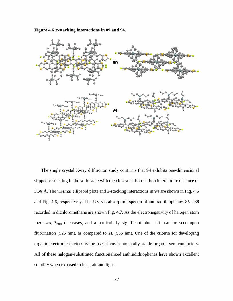
87
Figure 4.6 π-stacking interactions in 89 and 94.
The single crystal X-ray diffraction study confirms that 94 exhibits one-dimensional
slipped π-stacking in the solid state with the closest carbon-carbon interatomic distance of
3.38 Ǻ. The thermal ellipsoid plots and π-stacking interactions in 94 are shown in Fig. 4.5
and Fig. 4.6, respectively. The UV-vis absorption spectra of anthradithiophenes 85 - 88
recorded in dichloromethane are shown Fig. 4.7. As the electronegativity of halogen atom
increases, λmax decreases, and a particularly significant blue shift can be seen upon
fluorination (525 nm), as compared to 21 (555 nm). One of the criteria for developing
organic electronic devices is the use of environmentally stable organic semiconductors.
All of these halogen-substituted functionalized anthradithiophenes have shown excellent
stability when exposed to heat, air and light.

88
Figure 4.7 UV-vis absorption spectra of functionalized anthradithiophenes (21 and
85 - 88).
From electrochemical studies, the oxidation potential for all of the derivatives 85 - 88
was found to be about 1.0 V vs SCE, significantly greater than 0.90 V vs SCE reported
for 21. Detailed reports of the electrochemical measurements on all the functionalized
anthradithiophenes in my dissertation are covered in chapter 6. Differential scanning
calorimetry (DSC) experiments on fluorine-substituted anthradithiophenes (85 and 89)
show thermal stability at higher temperature. Especially, 89 possesses very high thermal
stability, which is supported by the reproducibility of the heating and cooling curves
found in the DSC experiment (see Fig. 4.8) even after heating at 280°C.

89
Figure 4.8 DSC experiment on 89.
Figure 4.9 Photostability study of thin films made of 85.

90
I also studied the photostability of thin films made of halogen-substituted
anthradithiophenes under laboratory conditions using UV-vis spectroscopy. When
exposed to light, 21 photobleached completely in 1h (see Chapter 3, Fig. 3.13). On the
other hand, 85 showed exceptional photostability even after 2000 h (see Fig. 4.9).
4. 3 Organic Single Crystal Transistor Study.
The single crystal XRD analysis of the high quality crystals of halogen-substituted
anthradithiophenes demonstrated the amount of π-stacking in these compounds. Most
interestingly, monstrous crystals were obtained for 89 from solution. By changing the
recrystallizing organic solvent from toluene to dichloroethane, the shape of the crystals
were completely changed from long needle of 2 cm to cubes of 0.5 cm in dimensions (see
Fig. 4.10). Organic single crystal
Figure 4.10 Crystals of 89 from (a) Toluene. (b) Dichloroethane.
transistor studies on 89 was done by our collaborator Dr. Vitaly Podzorov at Rutgers.
Graphite paste was used to deposit source and drain electrodes on a relatively smooth
surface of the free-standing crystal (see Fig. 4.11). Using parylene (95, Fig. 4.12) as
insulator and silver as gate electrode, the device exhibited a gate-voltage independent
single crystal hole mobility of 0.1 cm2/Vs. It is observed that the single crystal hole
mobility and threshold voltage are affected by the surface roughness.

91
Figure 4.11 Organic single crystal transistor characteristics of 89 (Data taken by Dr.
Vitaly Podzorov’s research group, Rutgers).
Figure 4.12 Structure of parylene (95).
CCn
H
H H
H
95
4.4 Organic Thin Film Transistor Study.
Due to strong two-dimensional pi-stacking, 85 and 89 were chosen for OTFT studies,
which were performed in several different research groups. Our collaborator, Dr. Dave
Gundlach and co-workers at NIST built bottom contact FETs on a heavily-doped silicon
wafer with 200 nm thermally grown SiO2 as gate electrode and insulator, respectively.

92
The source and drain electrodes consist of 5 nm Ti / 40 nm Au deposited by e-beam
evaporation. The contacts were treated with pentafluorobenzene thiol (10 mM solution in
ethanol) for better organic-electrode interface. Spin coated thin films of 85 were formed
from 2 wt% toluene solution of the fluoro-substituted anthradithiophenes. From the
devices studied with various channel lengths, it was found that the extracted field effect
charge carrier mobility increases with decreasing channel length. This change in hole
mobility is strongly affected by the local microstructure of the organic material in the
channel region (see Fig 4.13). Device mobilities vary from ~0.2 cm2/Vs to ~ 0.001
cm2/Vs for channel length 5 µm to 100 µm, respectively (Fig. 4.14).
Figure 4.13 Optical Micrographs of 85 based OTFT devices with channel length (a)
5 µm, (b) 10µm, (c) 20 µm, (d) 50 µm (Pictures were taken by Dr. Dave Gundlach’s
research group, NIST)
A B
C D

93
Figure 4.14 (a) bottom left : The transfer characteristics of a 85-based transistor
with Channel length L = 5 µm and Channel width = 1000 µm (b) top left : The
output characteristics of the same device. (c) Top right : Structure of 85 and
pentafluorobenzene thiol (d) Bottom right :General structure of the OTFT device
(Transistor data from Dr. Dave Gundlach’s research group, NIST).

94
Although fluorination of 21 did not affect the crystal packing of 85, an improvement in
thin film forming ability is observed for 85. In contrast to the unsubstituted functionalized
anthradithiophene (21), where doctor-blading or solvent vapor annealing were required to
form crystalline thin films, 85 formed high quality crystalline thin films upon spin-
coating from solution. OTFT studies on 85 by a group of researchers from NIST and
Penn state demonstrated the influence of source and drain contacts in obtaining improved
microstructure in the conducting channel, hence, high performance of the devices. The
use of hexamethyldisilazane (HMDS) to decrease the surface energy of the silicon
dioxide (as is done frequently for TIPS pentacene) was found to cause significant
dewetting of 85 solutions resulting in low mobility.
Of the various thiol-based monolayer treatments (octadecanethiol, benzenethiol,
pentafluorobenzene thiol (PFBT)) explored to decrease the surface energy106
of the gold
interface, the use of PFBT produced the best results in terms of microstructure of the thin
film in the channel region and the charge carrier mobility.
Figure 4.15 Output (left) and transfer (right) characteristics of a spin-coated 85
based OTFT device (Data taken by Dr. Tom Jackson’s research group, Penn State).

95
Another OTFT study on 85 by our collaborator Prof. Tom Jackson’s research group at
Penn State, with similar device structures that used by Dr. Dave Gundlach et al. were able
to produce devices with thin film hole mobility as high as 0.9 cm2 / Vs from spin-cast
films (Fig. 4.15). On/off current ratio and threshold voltage were measured as 106 and
9.67 V, respectively. On the other hand, drop-cast films of 85 produced FET devices with
even higher performance - the transfer characteristics of a drop-cast 85 based OTFT
device is shown in Fig. 4.16.
Figure 4.16 Output characteristics of a drop-cast 85 based OTFT device (Transistor
data taken from Dr. Tom Jackson’s research group, Penn State).
X-ray crystallographic studies revealed that the monofluoro-substituted
functionalized anthradithiophene (85a) diffracted poorly and the random occupancy of
fluorine atoms can be clearly seen from its thermal ellipsoid plot (see Fig. 4.17). OTFT
experiments demonstrated that on this material exhibits thin film hole mobility in the
order of 10-4
cm2/Vs.
-40 -30 -20 -10 0 10 20 300.000
0.002
0.004
0.006
0.008
0.010
1E-12
1E-11
1E-10
1E-9
1E-8
1E-7
1E-6
1E-5
1E-4
1E-3
= 3.69 cm2/V-s
W / L = 220 / 20 m
tox = 320 nm
Dra
in C
urr
en
t (A
)
Gate-source Voltage (V)
Sq
uare
-ro
ot
of
dra
in c
urr
en
t (A
1/2)

96
Figure 4.17 Thermal ellipsoid plot of 85a.
Dr. Dave Gundlach and co-workers also studied 87 and 89 with the same OTFT
device structure that used for 85. Even though 89 showed single crystal hole mobility of
0.1 cm2/Vs from the solution grown organic crystals, 89 based OTFTs yielded devices
with hole mobilities of 10-7
cm2/Vs. On the other hand, 87 based OTFTs produced
devices with the extracted hole mobility of 0.004 cm2/Vs. These low thin film hole
mobilities exihibited by 87 and 89 are attributed to its poor thin film forming ability as
shown in Fig. 4.18.

97
Figure 4.18 Optical Micrographs of thin films made of 87 and 89 (Pictures were
taken by Dr. Dave Gundlach research’s group, NIST).
87 89
Halogen substitution on functionalized anthradithiophenes has produced very
promising solution-processable organic semiconductors with high thermal, oxidative and
photostability. Of all the halogen-substituted anthradithiophene derivatives I have
discussed in this chapter, strongly two-dimensionally π-stacking 85 and 89 have yielded
devices with excellent electronic properties. 89, where nonbonded F…F interaction is
predominant, crystallize with relatively smooth surface, exhibited single crystal hole
mobility of 0.1 cm2/Vs. 85, on the other hand, where nonbonded S…F interaction is
predominant, produced high quality crystalline thin films upon spin coating, and
exhibited extracted thin film hole mobility of 0.9 cm2/Vs. The 85 based OTFT study
demonstrated that the device performance is dependent on the channel length and the
contact-organic interface. Finally, the drop-cast film of 85 have shown thin film hole
mobility of 3.69 cm2/Vs from an unreported device data. The overall outcome of this

98
project is that halogen substitution on anthradithiophene chromophore produced highly
stable organic semiconductors. Especially, fluorinated functionalized anthradithiophenes
(85 and 89) are highly promising candidates for OTFT and organic single crystal
transistors, respectively.
4.5 Experimental Details
General.
Solvents (acetone, methylene chloride, hexanes) were purchased from Fisher. Dry
THF was either purchased from EMS Science or distilled over sodium / benzophenone
under N2 atmosphere. Trialkylsilyl acetylenes and N-Fluoro benzene sulfonamide were
purchased from GFS Chemicals and Matrix Scientific respectively. Silica gel 230-400
mesh was bought from Sorbent Technologies. NMR spectra were measured on Varian
instruments (Gemini 200 MHz / Unity 400 MHz) spectrometer. Chemical shifts were
reported in ppm relative to CDCl3 as internal standard. The UV-vis spectra were
measured on a UV-2501PC Shimadzu instrument. Mass spectroscopy was analyzed in EI
mode at 70 eV on a JEOL (JMS-700T) Mass Spectrometer. Cyclic voltammetry was
carried out on a BAS CV-50W potentiostat, with ferrocene as an internal standard.
Thiophene-2,3-diacetal (57).
This compound was synthesized using previously reported literature.44
5-Flouro thiophene-2,3-dialdehyde (77).
In a flame dried flask, n-BuLi (29.6 mL, 74 mmol) was added slowly to thiophene-
2,3-diacetal (13 g, 56.9 mmol) in THF (75 mL) at -78 °C under N2 atm. After one hour
of stirring, N-fluorobenzene sulfonamide (NFSi) (21.86 g, 69.1 mmol) was added, the
reaction mixture was warmed to room temperature, and stirred overnight. The reaction

99
mixture was quenched by adding cold water very carefully, extracted with diethyl ether,
and washed with water. The organic layer was dried with anhydrous MgSO4 and
concentrated. Without purification, this material was hydrolyzed by 3M HCl (100 mL)
for 1 hr. The product was extracted in ether and purified by column chromatography
using hexanes / dichloromethane (120 mL / 180 mL). Yield = 2.9 g (32%). 1H NMR (200
MHz, CDCl3): δ 7.04 (s, 1H), 10.28 (s, 1H), 10.43 (s, 1H) ppm. 13
C NMR (50 MHz,
CDCl3): δ 110.58, 110.70, 128.05, 129.49, 134.01, 181.94, 181.96, 183.56 ppm. MS (EI
70 eV) m/z 158 (M+), 129 (M
+ - CHO).
5-Chloro thiophene-2,3-dialdehyde (78).
In a flame dried flask, n-BuLi (74 mmol) was added slowly to thiophene-2,3-
diacetal (56.9 mmol) in THF (75 mL) at -78 °C under N2 atm. After one hour of stirring,
N-chloro succinimide (69.1 mmol) was added, the reaction mixture was warmed to room
temperature and stirred overnight. The reaction mixture was quenched by adding cold
water very carefully, extracted with diethyl ether, and washed with water. The organic
layer was dried with anhydrous MgSO4 and concentrated. Without purification, this was
hydrolyzed by 3M HCl (100 mL) for 1 hr. This product was extracted in ether, and was
purified by column chromatography by using hexanes / dichloromethane (120 mL / 180
mL). Yield = 51%. 1H NMR (200 MHz, CDCl3): δ 7.45 (s, 1H), 10.26 (s, 1H), 10.39 (s,
1H) ppm. 13
C NMR (50 MHz, CDCl3): δ 128.85, 141.08, 143.34, 145.97, 181.70, 183.69
ppm. MS (EI 70 eV) m/z 174 (M+), 145 (M
+ - CHO).
5-Bromo thiophene-2,3-dialdehyde (79).
In a flame dried flask, n-BuLi (74 mmol) was added slowly to thiophene-2,3-
diacetal (56.9 mmol) in THF (75 mL) at -78 °C under N2 atm. After one hour of stirring,

100
N-bromo succinimide (69.1 mmol) was added and reaction mixture was warmed to room
temperature, stirred for overnight. The reaction mixture was quenched by adding cold
water very carefully, extracted with diethyl ether, and washed with water. Organic layer
was dried in anhydrous MgSO4 and concentrated. Without purification, this was
hydrolyzed by 3M HCl (100 mL) for 1 hr. This product was extracted in ether, and was
purified by column chromatography by using hexanes / dichloromethane (120 mL / 180
mL). Yield = 60%. 1H NMR (200 MHz, CDCl3): δ 7.59 (s, 1H), 10.26 (s, 1H), 10.37 (s,
1H) ppm. 13
C NMR (50 MHz, CDCl3): δ 124.09, 132.64, 143.94, 148.74, 181.60, 183.53
ppm. MS (EI 70 eV) m/z 220 (M+), 191 (M
+ - CHO).
5-Iodo thiophene-2,3-dialdehyde (80).
In a flame dried flask, n-BuLi (9.6 mL, 24 mmol) was added slowly to thiophene-
2,3-diacetal (4.2 g, 18.4 mmol) in THF (50 mL) at -78 °C under N2 atm. After 1 hr
stirring, iodine (7.5 g, 29.4 mmol) was added and reaction mixture was warmed to room
temperature, and stirred overnight. The reaction mixture was quenched by adding cold
water very carefully, extracted with ethyl acetate, washed with 10 % sodium thiosulfate
(100 mL), and water. Organic layer was dried in anhydrous MgSO4 and concentrated.
Without purification, this was hydrolyzed by 3M HCl (100 mL) for 1 hr. This product
was extracted in ether, and was purified by column chromatography by using hexanes /
dichloromethane (120 mL / 180 mL). Yield = 3.58 g (90%). 1H NMR (200 MHz, CDCl3):
δ 7.79 (s, 1H), 10.24 (s, 1H), 10.34 (s, 1H) ppm. 13
C NMR (50 MHz, CDCl3): δ 86.54,
139.61, 144.54, 152.87, 181.37, 183.34 ppm. MS (EI 70 eV) m/z 354 (M+), 325 (M
+ -
CHO).

101
General procedure for the preparation of 2,8-dihalo anthradithiophene-5,12-diones.
To the mixture 1.4-cyclohexanedione (5.5 mmol) and 2.0 equivalent of 5-
substituted thiophene dialdehyde (11.0 mmol) in tetrahydrofuran / ethanol (5 mL / 15
mL) 15 % of KOH (a few drops) was added, and the mixture stirred at RT for 3 h. The
quinone was filtered through buchner funnel and washed with methanol and dried in air.
2,8-Difluoro anthradithiophene-5,12-dione (81). Yield = 78%. MS (MALDI, TCNQ
matrix) m/z 356 (100%, M+).
2,8-Dichloro anthradithiophene-5,12-dione (82). Yield = 65%. MS (MALDI, TCNQ
matrix) m/z 389 (16%, M+).
2,8-Dibromo anthradithiophene-5,12-dione (83). Yield = 50%. MS (MALDI, TCNQ
matrix) m/z 478 (100%, M+).
2,8-Diiodo anthradithiophene-5,12-dione (84). Yield = 91%. MS (MALDI, TCNQ
matrix) m/z 572 (100%, M+).
General procedure of halogen substituted trialkylsilylethynyl anthradithiophene.
n-BuLi (1.86 mL, 4.66 mmol) was added to the trialkylsilylacetylene (5.32 mmol)
in hexanes (50 mL) under N2 atm at RT in a flame dried 500 mL RB flask, and the
mixture stirred for 30 min. To that, halogen substituted anthradithiophenequinone (1.33
mmol) was added along with additional hexanes (200 mL) and the mixture heated at 66
°C overnight. The next day, stannous chloride (0.9 g, 3.99 mmol), 0.5 mL of water and
1.5 mL of 10% H2SO4 were added and the heating was continued for 5 more hrs. The
reaction mixture was cooled and dried over anhydrous MgSO4. It was purified by silica
plug, washed by using hexanes and concentrated to get pure product.

102
2,8-Difluoro-5,12-bis(triethylsilylethynyl)anthradithiophene (85). Yield = 51%. 1H
NMR (400 MHz, CDCl3): δ 0.91 (q, J = 2.0Hz, 12H), 1.24 (t, J = 2.0Hz, 18H), 6.82 (s,
2H), 8.86 (s, 2H), 8.93 (s, 2H) ppm. 13
C NMR (100 MHz, CDCl3): δ 4.92, 8.01, 102.76,
102.99, 103.16, 103.29, 107.10, 117.22, 120.56, 120.65, 120.76, 120.85, 120.94, 121.03,
129.62, 129.76, 130.14, 130.35, 134.08, 136.69, 136.74, 136.83, 136.87, 163.09, 169.03.
MS (EI 70 eV) m/z 602 (100%, M+ - 1), 603 (45%, M
+), 517 (17%). Anal. calcd. % C:
67.73, % H: 6.01, Found % C: 67.38, % H: 5.78.
2-fluoro-5,12-bis(triethylsilylethynyl)anthradithiophene (85a). This derivative was
isolated as a byproduct from the synthesis of 90. 1H NMR (400 MHz, CDCl3): δ 0.92 (m,
12H), 1.25 (m, 18H), 6.82 (d, J = 0.7Hz, 1H), 7.47 (d, J = 1.4Hz, 1H), 7.58 (d, J = 1.4Hz,
1H), 8.88 (s, 1H), 8.95 (s, 1H), 9.11 (s, 1H), 9.16 (q, J = 0.27Hz, 1H) ppm. 13
C NMR
(100 MHz, CDCl3): δ 4.92, 8.03, 102.87, 103.42, 106.95, 107.22, 116.51, 117.15, 117.76,
118.42, 120.22, 120.62, 120.87, 120.96, 121.46, 123.93, 129.73, 130.03, 130.38, 133.95,
136.69, 139.88, 140.29, 164.49, 167.46 ppm. MS (EI 70 eV) m/z 584 (7%, M+ - 1), 585
(4%, M+).
2,8-Dichloro-5,12-bis(triethylsilylethynyl)anthradithiophene (86). Yield = 60%. 1H
NMR (400 MHz, CDCl3): δ 0.92 (q, J = 2.0Hz, 12H), 1.24 (m, 18H), 7.30 (td, J = 0.2Hz,
J = 0.8Hz, 2H), 8.89 (dd, J = 0.15Hz, J = 1.25Hz, 2H), 8.93 (td, J = 0.2Hz, J = 0.73Hz,
2H) ppm. 13
C NMR (100 MHz, CDCl3): δ 4.88, 8.03, 102.97, 103.09, 103.20, 107.16,
107.45, 107.75, 116.69, 117.80, 118.92, 119.55, 119.61, 120.61, 120.68, 122.66, 129.75,
129.82, 130.12, 130.18, 135.29, 135.33, 139.05, 139.12 ppm. MS (EI 70 eV) m/z 634
(66%, M+ - 2), 636 (61%, M
+). Anal. calcd. % C: 64.22, % H: 5.70, Found % C: 63.85, %
H: 5.65.

103
2,8-Dibromo-5,12-bis(triethylsilylethynyl)anthradithiophene (87). Yield = 43%. 1H
NMR (400 MHz, CDCl3): δ 0.92 (q, J = 2.0Hz, 12H), 1.24 (m, 18H), 7.46 (d, J = 1.1Hz,
2H), 8.92 (dd, J = 0.2Hz, J = 2.1Hz, 2H), 8.94 (td, J = 0.2Hz, J = 1.2Hz, 2H) ppm. 13
C
NMR (100 MHz, CDCl3): δ 4.88, 8.01, 102.97, 103.11, 103.25, 107.20, 107.50, 107.82,
116.75, 117.90, 119.24, 119.30, 119.77, 119.83, 120.40, 120.46, 126.57, 129.69, 129.78,
130.10, 130.18, 139.91, 140.85 ppm. MS (EI 70 eV) m/z 724 (17%, M+). Anal. calcd. %
C: 56.34, % H: 5.0, Found % C: 56.56, % H: 5.20.
2,8-Diiodo-5,12-bis(triethylsilylethynyl)anthradithiophene (88). Yield = 65%. 1H
NMR (200 MHz, CDCl3): δ 0.92 (q, J = 3.3Hz, 12H), 1.25 (t, J = 3.7Hz, 18H), 7.68 (s,
2H), 8.94 (s, 2H), 8.97 (s, 2H) ppm. 13
C NMR (50 MHz, CDCl3): δ 4.88, 7.95, 84.20,
84.30, 103.31, 107.65, 118.12, 118.78, 120.04, 129.80, 129.98, 130.12, 130.30, 134.08,
141.16, 141.24, 143.78, 143.94. MS (EI 70 eV) m/z 818 (30%, M+
- 1), 692 (12%, M+ -
I). Anal. calcd. % C: 49.87, % H: 4.43, Found % C: 50.00, % H: 4.27.
2,8-Difluoro-5,12-bis(triisopropylsilylethynyl)anthradithiophene (89). Yield = 52%.
1H NMR (200 MHz, CDCl3): δ 1.32 (s, 42H), 6.81 (d, J = 1.2Hz, 2H), 8.92 (s, 2H), 8.98
(s, 2H) ppm. 13
C NMR (50 MHz, CDCl3): δ 11.74, 19.03, 102.77, 102.99, 103.89,
103.94, 103.99, 106.12, 106.19, 120.63, 120.73, 120.89, 120.98, 121.07, 121.16, 129.85,
130.03, 130.38, 130.58, 134.16, 136.77, 136.95 163.19, 169.13 ppm. MS (EI 70 eV) m/z
686 (6%, M+ - 1), 687 (5%, M
+). Anal. calcd. % C: 69.92, % H: 7.04, Found % C: 70.19,
% H: 7.19.
2-fluoro-5,12-bis(triisopropylsilylethynyl)anthradithiophene (89a). MS (EI 70 eV)
m/z 668 (6%, M+ - 1), 669 (4%, M
+).

104
2,8-Diiodo-5,12-bis(triisopropylsilylethynyl)anthradithiophene (91). Yield = 70%. 1H
NMR (200 MHz, CDCl3): δ 1.32 (s, 42H), 7.67 (s, 2H), 9.03 (t, J = 1.0Hz, 4H) ppm. MS
(EI 70 eV) m/z 902 (30%, M+ - 1), 903 (15%, M
+). Anal. calcd. % C: 53.2, % H: 5.35,
Found % C: 54.10, % H: 5.61.
Tri-n-propylsilyl acetylene (93).
Ethynyl magnesium bromide (0.5 M, 10 mmol) in THF was added to tri-n-
propylchlorosilane 92 (10 mmol, purchased from GFS chemicals) in a 250 mL round
bottom flask. The reaction mixture was stirred at room temperature overnight. It was then
quenched with cold ammonium chloride solution, was extracted with ether. The organic
layer was washed with water, dried over anhydrous MgSO4 and concentrated. It was then
purified on a short pad of silica gel using hexanes. The desired product was obtained after
removal of solvent. Yield = 89 %. 1H NMR (200 MHz, CDCl3): δ 0.64 (m, 6H), 0.99 (t, J
= 7.4 Hz, 9H), 1.42 (m, 6H), 2.36 (s, 1H). 13
C NMR (50 MHz, CDCl3): δ 16.01, 17.61,
18.37, 88.46, 94.25.
2,8-Difluoro-5,12-bis(tri-n-propylsilylethynyl)anthradithiophene (94).
This was synthesized using the same procedure that used for other halogen-substituted
functionalized anthradithiophenes. Yield = 61 %. 1H NMR (200 MHz, CDCl3): δ 0.91
(m, 12H), 1.15 (t, J = 6.8 Hz, 18H), 1.67 (m, 12H), 6.81 (d, J = 2.6 Hz, 2H), 8.84 (s, 2H),
8.93 (s, 2H). MS (EI 70 eV) m/z 686 (100 %, M+ - 1), 687 (55 %, M
+)
Copyright © Sankar Subramanian 2008

105
Chapter 5: Attempted functionalization on anthradithiophene chromophore
5.1 Methoxy substituted functionalized anthradithiophenes
With the success of the peri-functionalization approach on oligoacenes, the next
logical strategy would be to increase the conjugation length of anthradithiophene
chromophores for improved crystal packing and enhanced electronic properties. Earlier
studies demonstrated that pentacene (18) showed thin film hole mobility as high as 1.5
cm2/Vs on chemically treated silicon dioxide substrates.
107 That value is more than an
order of magnitude higher than that observed for tetracene (75, 0.1 cm2/Vs).
108 This high
charge carrier mobility was attributed to the uniform thin film morphology and molecular
ordering on devices exhibited by the more conjugated material 18.
Scheme 5.1 Synthesis of 2,8-dimethoxy-5,12-bis(triethylsilylethynyl)
anthradithiophene (100).
S
SMeO OMe
O
O
CuO / NaOMe
in MeOH (25%)
10% HCl /
THF
O
O
THF/ MeOH/ 15%NaOH
S
SMeO OMe
TES
TES
2. SnCl2. 2H2O/
10 % H2SO4
LiTES1.Hexanes, 60
oC
S
OO
O
O
S
OO
O
OI MeO
S
OO
MeO
83 % 65 % 85 %
65 %
96 97 98
99 100

106
Figure 5.1 π-stacking interactions in 100.
In order to improve the charge injection into the active layer from the metal electrode, my
first approach was to reduce the oxidation potential of the organic semiconductor by
means of introducing electron donating groups at the end positions of the acene
chromophore. For this, methoxy-substituted functionalized anthradithiophene (100) was

107
synthesized in four-step process starting from the copper (II) oxide catalyzed
methoxylation of 96109
(Scheme 5.1). The resultant organic semiconductor 100 was
purified by recrystallization in hexanes. The crystals were analyzed by single crystal X-
ray diffraction, which reveals that 100 diffracted poorly and exhibits weak two-
dimensional π-stacking interactions with the closest interatomic carbon-carbon distance
of 3.48 Ǻ (see Fig. 5.1). Hence, neither functioning transistors nor photovoltaics could be
constructed from this material.
5.2 3,4,5-Trimethoxyphenyl substituted functionalized anthradithiophene
My next rational approach for extending conjugation of the anthradithiophene
chromophore was the introduction of phenyl rings. To induce more conjugation (as well
as lower oxidation potential to improve charge injection), I used electron-rich 3,4,5-
trimethoxy phenyl groups at the α-positions of the terminal thiophene rings (Scheme 5.2).
The necessary 5-substituted thiophene-2, 3-diacetal 107 was prepared by Suzuki coupling
of 5-iodothiophene-2, 3-diacetal 85 with the boronic acid 106,110
and the general
synthesis for all of our acenes was followed to yield 110.

108
Scheme 5.2 Synthesis of 3,4,5-trimethoxyphenyl-substituted functionalized
anthradithiophene (107).
NH2
OMeOMeMeO
I
OMeOMeMeO
B(OH)2
OMeOMeMeO
1. aq.NaNO2/ 0oC
25% H2SO4
2. KI / 80oC
1. n-BuLi/ THF/-78oC
2. B(OMe)3
3. 1M HCl
SMeO
MeO
MeOO
O
O
O
Pd(PPh3)4 / K2CO3
EtOH:H2O:C6H6 / 1:1:2
90oC/ 30hrs
75 %65 %
37 %
85
SMeO
MeO
MeOO
O
S
SR R
O
O
OMeMeO OMeR =
O
O
15% KOH /THF / EtOH
10% HCl /
THF
S
S
TIPS
TIPS
TIPS Li / Hexanes / 60
oC
SnCl2. 2H2O /
10% HCl
90 %46 %
27 %
1.
2.
MeO
MeO
MeO
OMe
OMe
OMe
101 102 103
104 105
106 107
X - ray crystallographic analysis of crystals grown from toluene revealed that the
molecule adopts two dimensional π-stacking with closest interatomic carbon-carbon
distance of 3.56 Ǻ. The thermal ellipsoid plot and π-stacking interactions in 107 are
shown in Fig. 5.2 and Fig. 5.3, respectively.

109
Figure 5.2 Thermal ellipsoid plot of 107.

110
Figure 5.3 π-stacking interactions in 107.
5.3 Cyano substituted functionalized anthradithiophenes
One of the advantages of the end substitution on anthradithiophene chromophore is to
synthesize n-type organic semiconductors by attaching electron withdrawing groups.
Here, I have tried to increase the conjugation length of the acene chromophore through
electron withdrawing cyano groups. 108 and 109 were easily synthesized by a Pd (0)

111
catalyzed cyanation of 88 and 91 (Scheme 5.3), and crystals were grown from
dichloromethane.
Scheme 5.3 Synthesis of cyano-substituted functionalized anthradithiophenes (108
and 109).
S
SI I
R
R
S
SC C
R
R
1. KCN
2. Pd(PPh3)4
3. CuI / THF
65o C
NN
R = TES, 108, 76 %
R = TIPS, 109, 78 %
Single crystal X-ray diffraction studies reveal that 109 possesses one-dimensional
slipped π-stacking with a closest carbon-carbon interatomic distance of 3.49 Ǻ. The
thermal ellipsoid plot and π-stacking interactions are shown in Fig. 5.4 and Fig. 5.5,
respectively. Unfortunately, attempts to recrystallize 108 from various organic solvents
such as hexanes, dichloromethane, dichloroethane, toluene, xylene, dichlorobenzene left
108 in amorphous powders, hence, no XRD data could be derived from 108.
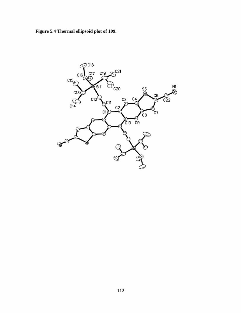
112
Figure 5.4 Thermal ellipsoid plot of 109.

113
Figure 5.5 π-stacking interactions in 109.

114
5.4 Trimethylsilylethynyl functionalized anthradithiophenes
My next strategy was to end-functionalize the anthradithiophenes with
trialkylsilylethynyl groups. 2,8-bis(trimethylsilylethynyl)-substituted functionalized
anthradithiophene (110) was easily synthesized by a palladium-catalyzed coupling
between an alkyne and 91. The product was finally purified by recrystallization from
hexanes.
Scheme 5.4 Synthesis of trimethylsilylethynyl-substituted functionalized
anthradithiophenes (110).
S
SI I
TIPS
TIPS
S
S
TIPS
TIPS
1. PdCl2 / PPh3
2. CuI
3. TMS acetylene
4. TEA / DMF / 65o C
83 %
TMS TMS
110

115
Figure 5.6 Thermal ellipsoid plot of 110.

116
Figure 5.7 π-stacking interactions in 110.
Single crystal X-ray diffraction studies revealed that 110 diffracted poorly and possesses
1-D π-stacks with herringbone-type interactions (edge-to-face interactions) between two
adjacent stacks, with the closest interatomic carbon-carbon distance of 3.45 Ǻ. The
thermal ellipsoid plot and crystal packing of 110 are shown in Fig. 5.6 and Fig. 5.7,
respectively. Solvent molecules (dichloroethane) were found between the pi-stacking of

117
neighboring molecules. Upon selective desilylation of trimethylsilyl group using
potassium carbonate in methanol (with little THF for solubility), 110 (dark red) turned
into black solution indicating decomposition.
5.5 Experimental Details
General.
Solvents (acetone, methylene chloride, hexanes) were purchased from Fisher. Dry
THF was either purchased in anhydrous form from EMS Science or distilled over sodium
/ benzophenone under N2 atmosphere. Trialkylsilyl acetylenes were purchased from GFS
Chemicals. Silica gel 230-400 mesh was bought from Sorbent Technologies. NMR
spectra were measured on a Varian (Gemini 200 MHz / Unity 400 MHz) spectrometer.
Chemical shifts were reported in ppm relative to CDCl3 as internal standard. The UV
spectra were measured on a UV-2501PC Shimadzu instrument. Mass spectroscopy was
analyzed in EI mode at 70 eV on a JEOL (JMS-700T) Mass Spectrometer. Cyclic
Voltammetry was carried out on a BAS CV-50W potentiostat, with ferrocene as an
internal standard.
5-iodo thiophene-2,3-diacetal (96).
See the experimental section, chapter 4.
5- Methoxy thiophene 2,3-dialdehyde (98).
Copper (II) oxide (0.51g, 6.4 mmol) and 96 (4.5g, 12.7 mmol) were added to a
solution of 25 wt % sodium methoxide (9 ml, 51 mmol) in methanol in a flame dried
single necked 250 mL round bottom flask, and the reaction mixture was refluxed for 24
h. It was then filtered and poured into cold water (250 mL), and extracted with ether. The
organic layer was separated, dried over anhydrous MgSO4 and the solvent was

118
evaporated to yield 83 % of 5-methoxy thiophene-2,3-diacetal (97). MS (EI 70 eV) m/z
258 (100 %, M+). Without purification, this material was hydrolyzed with 3M HCl (100
mL) for 1 hr. This product was extracted in ether, and was purified by column
chromatography using hexanes / dichloromethane (120 mL / 180 mL). Yield = 65%. 1H
NMR (200 MHz, CDCl3): δ 4.02 (s, 3H), 6.63 (s, 1H), 10.33 (s, 1H), 10.35 (s, 1H) ppm.
13C NMR (50 MHz, CDCl3): δ 60.99, 106.10, 135.02, 144.07, 174.16, 181.43, 184.38
ppm. MS (EI 70 eV) m/z 170 (M+), 142 (M
+ - CHO).
2,8-Dimethoxy anthradithiophene-5,12-dione (99).
To the mixture of 1.4-cyclohexanedione (5.5 mmol) and 5-methoxy thiophene -2,3-
dialdehyde (11.0 mmol) in tetrahydrofuran / ethanol (5 mL / 15 mL), 15 % of KOH (few
drops) was added, stirred at RT for 3 hrs. The quinone was filtered through buchner
funnel and washed with ethanol and dried in air. Yield = 85%. MS (MALDI, TCNQ
matrix) m/z 380 (100%, M+).
2,8-Dimethoxy-5,12-bis(triethylsilylethynyl)anthradithiophene (100).
n-BuLi (1.54 mL, 3.85 mmol) was added to triethylsilylacetylene (0.8 mL, 4.4 mmol)
in tetrahydrafuran (50 mL) under N2 atm at RT in a flame dried 500 mL RB flask, stirred
for 30 min. To that, methoxy substituted anthradithiophenequinone (0.42 g, 1.1 mmol)
was added and stirred for overnight. The next day, stannous chloride (3.3 mmol), 0.5 mL
of water and 1.5 mL of 10% HCl were added, and the reaction mixture allowed to stir for
5 h. The reaction mixture was dried over anhydrous MgSO4 and concentrated. It was
purified by silica plug, washed by using hexanes and concentrated to get pure product.
Yield = 65%. 1H NMR (400 MHz, CDCl3): δ 0.90 (m, 12H), 1.24 (m, 18H), 4.09 (s, 6H),
6.39 (s, 2H), 8.68 (s, 2H), 8.84 (s, 2H) ppm. 13
C NMR (100 MHz, CDCl3): δ 4.94, 8.04,

119
59.92, 96.70, 103.52, 103.79, 104.05, 105.78, 105.88, 116.30, 116.45, 117.84, 118.04,
119.45, 119.66, 128.92, 129.41, 130.09, 130.59, 134.45, 134.74, 139.54, 139.77, 166.97,
167.07 ppm. MS (EI 70 eV) m/z 628 (12%, M+), 627 (16%, M
+ - 1), 626 (32%, M
+ - 2).
Anal. calcd. % C: 68.96, % H: 6.75, Found % C: 68.58, % H: 6.67.
3, 4, 5-Trimethoxyphenyl iodide (102).
In a two necked 500 mL round bottom flask, 3, 4, 5-trimethoxy aniline 101 (5 g, 27.3
mmol) in 25% H2SO4 was added slowly to NaNO2 (5.66 g, 82 mmol) in water (40 mL) at
0-4 °C. After stirring for 30 minutes, potassium iodide pellets (13.6 g, 82 mmol) were
added, followed by vigorous evolution of N2. It was then heated at 80 °C for 90 minutes
until the evolution of the gas ceased. The reaction mixture was cooled and extracted with
ether, washed with 10% sodium thiosulphate (100 mL), water and saturated brine
solution. The organic layer was dried over anhydrous MgSO4 and concentrated. It was
purified by silica plug using hexanes / methylene chloride (200 mL / 300 mL). Yield = 6
g (75%). 1H NMR (200 MHz, CDCl3): δ 3.84 (s, 9H), 6.89 (s, 2H) ppm.
3, 4, 5-Trimethoxyphenyl boronic acid (103).
In a single necked 250 mL RB Flask, n- BuLi (3.5 mL, 8.7 mmol) was added to 102 (1.5
g, 5.1 mmol) in dry THF at -78 °C under N2 atm. After stirring for 30 min. at -78 °C, the
reaction mixture was was warmed to 0 °C and then cooled back to -78 °C immediately.
To the mixture, trimethyl borate (1.4 g, 13.3 mmol) was then added and stirred at RT for
14 hrs. It was then quenched by addition of 1M HCl (18 mL) and was extracted with
ether, washed with water and brine solution. It was then dried and concentrated. Yield =
0.7 g (65%). Without purification, it was taken to the next step.

120
5-(3, 4, 5-trimethoxyphenyl) thiophene-2,3-diacetal (104).
In a single necked 250 mL RB Flask, a mixture of 103 (0.7 g, 3.3 mmol) and 5-iodo
thiophene-2,3-diacetal 96 (0.98 g, 2.8 mmol), was taken in EtOH:H2O:C6H6 (1:1:2) (50
mL) and sparged with N2 for 30 min. To that, potassium carbonate (1.4 g, 10.08 mmol)
and tetrakis(triphenylphosphine) palladium(0) (0.5 g, 0.4 mmol) were added, the mixture
sparged for a further 15 min. then heated at 90 °C for 30 hours. The solvents were
evaporated, cooled to room temperature and extracted with ether, washed with water and
the organic layer was dried over anhydrous MgSO4 and concentrated. It was then purified
by silica plug using hexanes / ethyl acetate mixture (200 mL / 300 mL). Yield = 0.4 g
(37%). MS (EI 70 eV) m/z 394 (100%, M+).
5-(3, 4, 5-trimethoxyphenyl) thiophene-2,3-dialdehyde (105).
The diacetal 104 was hydrolysed with 1 M HCl in 2 h and the reaction mixture was
extracted with ether. The organic layer was separated, dried over anhydrous MgSO4 and
concentrated. Without any purification, the dialdehyde 105 was taken to next step. Yield
= 90%. MS (EI 70 eV) m/z 306 (100%, M+), 263 (70%, M+ – 43).
2,8-Di(3, 4, 5-trimethoxyphenyl)anthradithiophene-5,12-dione (106).
To the mixture of 1,4-cyclohexanedione (5.5 mmol) and 5-(3, 4, 5-trimethoxyphenyl)
thiophene -2,3-dialdehyde (11.0 mmol) in tetrahydrofuran / ethanol (5 mL / 15 mL), 15
% of KOH (few drops) was added, stirred at RT for 3 hrs. The quinone was filtered
through a buchner funnel and the solid washed with ethanol and dried in air. Yield =
46%. MS (MALDI, TCNQ matrix) 652 (100%, M+).

121
2,8-Di(3,4,5-trimethoxyphenyl)-5,12-bis(triisopropylsilylethynyl)anthradithiophene
(107).
n-BuLi (0.72 mL, 1.8 mmol) was added to triisopropylsilylacetylene (0.36 g, 2.0 mmol)
in hexane (50 mL) under N2 atm at RT in a flame dried 500 mL round bottom flask, and
stirred for 30 min. To that, 5-(3, 4, 5-trimethoxy phenyl) anthradithiophene quinone (0.5
g, 0.5 mmol) and hexanes (200 mL) were added and the solution heated at 66 °C
overnight. The next day, stannous chloride (1.5 mmol), 0.5 mL of water and 1.5 mL of
1% sulphuric acid were added and the mixture heated for 5 hrs. The reaction mixture
was cooled and dried over anhydrous MgSO4. It was purified by filtration through a silica
plug (hexanes) and concentrated to get pure product. Yield = 0.2 g (27 %). 1H NMR (200
MHz, CDCl3): δ 1.31 – 1.37 (s, 42H), 3.94 (s, 6H), 4.02 (s, 12H), 7.07 (s, 4H), 7.56 (s,
2H), 9.02 – 9.16 (d, J = 6.2 Hz, 4H). MS (EI 70 eV) m/z 984 (35%, M+ + 1), 983 (40%,
M+), 982 (45%, M+ - 1). Anal. calcd. % C: 70.83, % H: 7.17, Found % C: 70.38, % H:
6.88.
General procedure for the preparation of cyano-substituted trialkylsilylethynyl
anthradithiophenes:
In a 250 mL round bottom flask, the iodo-substituted functionalized anthradithiophenes
(88 or 91, 0.44 mmol) was added to the mixture of Pd (PPh3)4 (76.2 mg, 0.066 mmol),
potassium cyanide (120 mg, 1.85 mmol), and copper (I) iodide (16.75 mg, 0.088 mmol)
in degasified THF, and the reaction mixture was heated at 65 °C for overnight. The room
temperature cold reaction mixture was then extracted with ether, and washed with water.
The organic layer was separated, dried over anhydrous MgSO4, and concentrated. The

122
desired cyano-substituted anthradithiophenes were purified on a short pad of silica gel
using hexanes / dichlormethane (2 : 5).
2,8-Dicyano-5,12-bis(triethylsilylethynyl)anthradithiophene (108). Yield = 76%. 1H
NMR (200 MHz, CDCl3): δ 0.96 (s, 12H), 1.26 (s, 18H) 8.02 (s, 2H), 9.09 (s, 2H), 9.18
(s, 2H) ppm. MS (EI 70 eV) m/z 618 (25%, M+ + 1), 617 (50%, M+), 616 (100%, M+ -
1).
2,8-Dicyano-5,12-bis(triisopropylsilylethynyl)anthradithiophene (109). Yield = 78%.
This was recrystallized in dichloromethane. 1H NMR (200 MHz, CDCl3): δ 1.34 (s, 42H),
8.04 (s, 2H), 9.18 (s, 2H), 9.30 (s, 2H) ppm. 13
C NMR (50 MHz, CDCl3): δ 11.71, 19.05,
97.29, 103.15, 108.09, 108.72, 109.34, 113.30, 113.50, 114.20, 117.33, 119.35, 120.74,
120.81, 121.40, 125.17, 130.30, 130.82, 131.16, 131.68, 135.64, 137.91, 138.20, 139.14,
139.58 ppm. MS (EI 70 eV) m/z 702 (30%, M+ + 1), 701 (65%, M+), 700 (100%, M+ -
1).
2,8-Di(trimethylsilylethynyl)-5,12-bis(triisopropylsilylethynyl)anthradithiophene
(110).
In a flame dried 100 mL single necked round bottom flask, the mixture of 91 (1g, 1.1
mmol), trimethylsilyl acetylene (0.27g, 2.77 mmol), palladium (II) chloride (19.5 mg,
0.11 mmol), triphenyl phosphine (57.6 mg, 0.22 mmol), and copper (I) iodide (21 mg,
0.11 mmol) in a degasified solvent mixture of triethylamine (30 mL) and DMF (10 mL)
was heated at 70 °C for overnight. The reaction mixture was extracted in ether, washed
with water, the organic layer was dried over anhydrous MgSO4 and concentrated. It was
then purified on a short pad of silica gel, followed by recrystallization in hexanes. Yield =
83%. 1H NMR (400 MHz, CDCl3): δ 0.33 (s, 18H), 1.33 (s, 42H), 7.58 (t, J = 0.2Hz, 2H),

123
9.05 (q, J = 2.3Hz, 2H), 9.06 (s, 2H) ppm. 13
C NMR (100 MHz, CDCl3): δ -0.04, 11.80,
19.13, 97.97, 103.96, 104.03, 106.11, 106.54, 106.99, 116.48, 118.01, 119.57, 119.59,
122.09, 122.13, 126.05, 126.19, 129.48, 130.23, 130.48, 130.73, 139.74, 139.77, 139.91,
140.02 ppm. MS (EI 70 eV) m/z 843 (5%, M+), 746 (10%, M+ - trimethylsilylethynyl).
Copyright © Sankar Subramanian 2008

124
Chapter 6: Conclusion
6.1 Summary of New Functionalized Pentacenes and Anthradithiophenes.
Extensive investigation of organic semiconductors over the past two decades has
helped to produce high performance electronic devices. However, more research is
needed to allow the commercialization of organic electronic devices. Using our group’s
peri-functionalization approach, I have synthesized a variety of stable and soluble
functionalized pentacenes and anthradithiophenes (along with a few unstable derivatives).
In the second chapter, I discussed my attempts to induce liquid crystallinity through
functionalization of pentacene in order to form high quality, uniform thin films. I found
that alkyl chain length is directly related to crystal packing as well as to the stability of
the organic semiconductors. As the number of carbons in the alkyl substitutent increases,
the aryl - aryl interactions shift to aryl - alkyl interactions, leading to poor electronic
interactions in the solid state. Oxidative stability of these functionalized pentacenes was
greatly enhanced by the introduction of silyl substitutents at the peri-positions of
pentacene. The multiple thermal phase transitions observed for 53 by DSC experiment
suggested the possibility of thermotropic liquid crystalline phases. However, due to lack
of π-stacking between the neighboring molecules, 53 is a poor organic semiconductor. As
found in the alkynyl pentacenes, optimal alkyl chain lengths on silyl substitutents are
required for strong π-stacking interactions in peri-functionalized trialkylsilylethynyl
pentacenes.
Substitution of the reactive thiophene positions of 21 produced materials with
increased stability. In the third chapter, the effect of small increases in alkyl chain length
on crystal packing and thin film morphology of functionalized anthradithiophenes had

125
been addressed. 66 showed the highest thin film hole mobility (0.3 cm2/Vs) among the
alkylated anthradithiophene derivatives, which was attributed to its crystal packing and
its uniform thin film forming ability. On the other hand, other alkylated
anthradithiophenes (67 and 68) showed promising results in stacked organic photovoltaic
devices. 68-based organic solar cells exhibited 0.33 % power conversion efficiency,
where C60 and 68 were deposited through vacuum evaporation and from solution,
respectively. Interestingly, 67-based bulk heterojunction solar cells, where both 67 and
PCBM were deposition from solution, produced 1.003% power conversion efficiency.
Chapter 4 discussed halogen substitution on functionalized anthradithiophenes, which
produced devices with excellent electronic properties in organic field effect transistors.
The fluorine-substituted anthradithiophene derivatives possessed strong two-dimensional
pi-stacking, and the single crystal XRD studies disclose that the other halogen-substituted
anthradithiophenes adopt weak 1-D π-stacked solid state arrangements. In addition to the
exceptional photostability, oxidative stability and thermal stability shown by 85 and 89,
the type of spatial fluorine and sulfur-fluorine interactions determine the nature of thin
films and solution grown crystals made from these anthradithiophenes. 89, in which the
nonbonded F…F interactions are predominant, forms the moderately smooth surface
solution grown big (~ 2 cm long or 1 cm3) crystals, which exhibited single crystal hole
mobility of 0.1 cm2/Vs from the organic single crystal transistors. In contrast, 85, in
which the nonbonded S…F interactions are predominant, forms uniform thin films on
devices and exhibited thin film hole mobility of 1 cm2/Vs consistently from organic thin
film transistors.

126
In chapter 5, the use the methoxy and trimethoxyphenyl substitution on
anthradithiophene chromophore didn’t help to achieve my goal of reducing the oxidation
potential of the organic semiconductor in order for better charge injection from the metal
electrode. Also, it is observed that the electron withdrawing cyano group substitution on
acene chromophore was not sufficiently electron deficient to synthesize n-type organic
semiconductor. Attempt to increase the conjugation length of the acene chromophore
through dimerisation using ethynyl spacer was not successful since decomposition of 110
upon the selective desilylation of 110.
6.2 Future Targets
The presence of acidic hydrogens at the terminal thiophene rings of anthradithiophene
chromophore allows us to engineer the acene crystal packing further. In continuation with
this extended conjugation approach, the following type of materials (111 and 112) might
be expected to improve the crystal packing because of larger pi-orbital overlap between
neighboring molecules (Fig. 5.8). Due to time constraints, those compounds were not
synthesized and studied for organic electronic devices. In addition to different
functionalization that can be done on phenyl and thienyl groups of 111 and 112,
respectively, much more non-bonded sulphur…halogen interactions could be explored by
attaching halogens (especially fluorine atom from the outcome of this dissertation) on
thienyl groups of 112. Another interesting and challenging material would be increasing
the fluorine substituents on trialkylsilylethynyl anthradithiophenes. Synthesizing more
fluorine substituted anthradithiophenes such as 113 are expected to enhance the
nonbonded S…F and F…F interactions compared to 85 and 89, thereby, increasing the

127
amount of pi-overlapping of neighboring molecules, could eventually yield novel high
performing organic semiconductors for electronic applications.
Figure 5.8. Future Targets.
S
S
Si
Si
X
X
RRR
RR R
S
S
Si
Si RRR
RR R
S
SX X
S
S
Si
Si RRR
RR R
R = alkyl chainsX = substituents
111 112
113
F
F F
F
Our approach to peri-functionalize acene oligomers has produced materials with
increased oxidative stability, solubility in organic solvents, and remarkably improved pi-
stacking solid state arrangements. A slight change in solubilizing silyl groups as well as
end-substitution on acene chromophore has enormous influence on the crystal packing,
thin film morphology and charge transport properties. Taking advantage of chemical
tunability and rationalizing the structure and property relationships of the functionalized
oligoacenes, we can design and synthesize improved organic electronic materials. In

128
addition, it allows us to provide proper direction for the scientific community in the field
of organic electronics to develop novel solution processable organic semiconductors.
Table 5.1 UV-vis and electrochemical measurements on functionalized
anthradithiophenes.
No. Materials λmaxa
(nm)
Eoxb
(mV)
Optical
Gap
(eV)
EHOMO
(eV)
ELUMO
(eV)
1. TES anthradithiophene, 21 555 904 2.17 5.22 3.05
2. Methyl TES anthradithiophene, 66 549 839 2.19 5.16 2.97
3. Ethyl TES anthradithiophene, 67 550 833 2.19 5.15 2.96
4. Propyl TES anthradithiophene, 68 550 829 2.18 5.15 2.97
5. Butyl TES anthradithiophene, 69 551 823 2.18 5.14 2.96
6. Fluoro TES anthradithiophene, 85 527 1017 2.29 5.34 3.05
7. Chloro TES anthradithiophene, 86 541 1021 2.23 5.34 3.11
8. Bromo TES anthradithiophene, 87 545 1015 2.20 5.34 3.14
9. Iodo TES anthradithiophene, 88 551 996 2.19 5.32 3.13
10. Methoxy TES anthradithiophene,
100
537 800 2.22 5.12 2.90
11. Trimethoxyphenyl TIPS
anthradithiophene, 107
571 870 2.11 5.19 3.08
12. Cyano TES anthradithiophene, 108 583 1216 2.06 5.55 3.49
13. Trimethylsilylethynyl TIPS
anthradithiophene, 110
570 971 2.13 5.29 3.16
aRecorded in dichloromethane.
bPerformed in 0.1 M solution of Bu4NPF6 in
dichloromethane, Pt electrode, scan rate 150 mV/s, Ferrocene as internal standard.
Copyright © Sankar Subramanian 2008

129
References
1. Zhang, Y.; Petta, J. R.; Ambily, S.; Shen, Y.; Ralph, D. C.; Malliaras, G. G. Adv.
Mater. 2003, 15, 1632.
2. Katz, H. E. J. Mater. Chem. 1997, 7, 369.
3. Xiang, M.; Li, X.; Ober, C. K.; Char, K.; Genzer, J.; Sivaniah, E.; Kramer, E. J.;
Fisher, D. A. Macromolecules, 2000, 33, 6106.
4. Bao, Z.; Dodabalapur, A.; Lovinger, A. J. Appl. Phys. Lett. 1996, 69, 4108.
5. Loo, Y. -L.; Someya, T.; Baldwin, K. W.; Bao, Z.; Ho, P.; Dodabalapur, A.; Katz, H.
E.; Rogers, J. A. Proc. Natl. Acad. Sci. 2002, 99, 10252.
6. Blanchet, G. B.; Loo, Y. -L.; Rogers, J. A.; Gao, F.; Fincher, C. R. App. Phys. Lett.
2003, 82, 463.
7. Shirakawa, H.; Louis, E. J.; MacDiarmid, A. G.; Chiang, C. K.; Heeger, A. J. J. C. S.
Chem. Comm. 1977, 578.
8. Dimitrakopoulos, C. D.; Malenfant, P. R. L. Adv. Mater. 2002, 14, 99.
9. Horowitz, G. J. Mater. Res. 2004, 19, 1946.
10. Tang, C. W.; Slyke, V. S. A. Appl. Phys. Lett. 1987, 51, 913.
11. Peumans, P.; Forrest, S. R. Appl. Phys. Lett. 2001, 79, 126.
12. a) Li, S. S.; Thurber, W. R. Solid-St. Electron. 1977, 20, 609. b) Dorkel, J. M.;
Leturcq, Ph. Solid-St. Electron. 1981, 24, 821.
12. Kepler, R. G. Phys. Rev. 1960, 119, 1226.
14. Leblanc, O.H. J. Chem. Phys. 1960, 33, 626.
15. de Boer, R. W. I.; Jochemsen, M.; Klapwijk, T. M.; Morpurgo, A. F.; Niemax, J.;
Tripathi, A. K.; Pflaum, J. J. Appl. Phys. 2004, 104, 4891.

130
16. Horowitz, G. Adv. Mater. 1998, 10, 365.
17. Dodabalapur, A.; Torsi, L.; Katz, H. E. Science. 1995, 268, 270.
18. a) see ref 14. b) J. E. Lilienfield, US Patent 1 745 175, 1930.
19. a) Kahng, D.; Atalla, M. M. DRC, Pittsburg, 1960. b) US Patent No. 3, 102, 230,
1963. c) https://www.electrochem.org/dl/ma/201/pdfs/0366.pdf
20. Barbe, D. F.; Westgate, C. R. J. Phys. Chem. Solids. 1970, 31, 2679.
21. Koezuka, H.; Tsumura, T.; Ando, Y. Synth. Met. 1987, 18, 699.
22. Tsumura, T.; Koezuka, H.; Ando, Y. Synth. Met. 1988, 25, 11.
23. Lanquindanum, J. G.; Katz, H. E.; Lovinger, A. J.; Dodabalapur, A. Adv. Mater.
1997, 9, 36.
24. Mas-Torrent, M.; Hadley, P.; Bromley, S. T.; Crivillers, N.; Veciana, J.; Rovira, C.
Appl. Phys. Lett. 2005, 86, 012110.
25. See ref. 17.
26. Burroughes, J. H.; Friend, R. H.; Allen, P. C. J. Phys. D: Appl. Phys. 1989, 22, 956.
27. a) Bao, Z.; Lovinger, A. J.; Dodabalapur, A. Adv. Mater. 1997, 9, 42. b) Bao, Z.;
Lovinger, A. J.; Dadabalapur, A. Appl. Phys. Lett. 1996, 69, 3066.
28. Pisula, W.; Menon, A.; Stepputat, M.; Lieberwirth, I.; Kolb, U.; Tracz, A.;
Sirringhaus, H.; Pakula, T.; Mullen, K. Adv. Mater. 2005, 17, 684.
29. a) Hoshimono, K.; Fujimori, S.; Fujita, S.; Fujita, S. Jpn. J. Appl. Phys. 1993, 32,
L1070. b) Haddon, R. C.; Perel, A. S.; Morris, R. C.; Palstra, T. T. M.; Hebard, A. F.;
Fleming, R. M. Appl. Phys. Lett. 1995, 67, 121. c). Tapponnier, A.; Biaggio, I.;
Gunter, P. Appl. Phys. Lett. 2005, 86, 112114.
30. Sakamoto, Y.; Suzuki, T.; Kobayashi, M.; Goa, Y.; Fukai, Y.; Inoue, Y.; Sato, F.;

131
Tokito, S. J. Am. Chem. Soc. 2004, 126, 8138.
31. Malenfant, P. R. L.; Dimitrakopoulos, C. D.; Gelorme, J. D.; Kosbar, L. L.; Graham,
T.O. Appl. Phys. Lett. 2002, 80, 2517.
32. a) Bao. S.; Lovinger, A. J.; Brown, J. J. Am. Chem. Soc. 1998, 120, 207. b) de
Oteyza, D. G.; Barrena, E.; Osso, J. O.; Dosch, H.; Meyer, S.; Pflaum, J. Appl. Phys.
Lett. 2005, 87, 183504.
33. Chesterfield, R. J.; Newman, C. R.; Pappenfus, T. M.; Ewbank, P. C.; Haukaas, M.
H.; Mann, K. R.; Miller, L. L.; Frisbie, C. D. Adv. Mater. 2003, 15, 1278.
34. Facchetti, A.; Yoon, M. H.; Stern, C. L.; Katz, H. E.; Marks, T. J. Angew, Chem. Int.
Ed. 2003, 42, 3900.
35. Assadi, A.; Svensson, C.; Willander, M.; Inganas, O. Appl. Phys. Lett. 1988, 53, 195.
36. Sirringhaus, H.; Brown, P. J.; Friend, R. H.; Nielsen, M. M.; Bechgaard, K.;
Langeveld-Voss, B. M. W.; Spiering, A. J. H.; Janssen, R. A. J.; Meijer, E. W.;
Herwig, P. T.; de Leeuw, D. M. Nature 1999, 401, 685.
37. Wang, G.; Swensen, J.; Moses, D.; Heeger, A. J. J. Appl. Phys. 2003, 93, 6137.
38. a) Garnier, F.; Yassa, A.; Hajlaoui, R.; Horowitz, G.; Deloffre, F.; Servet, B.; Ries,
S.; Alnot, P. J. Am. Chem. Soc. 1993, 115, 8716. b) Dimitrakopoulos, C. D.; Furman,
B. K.; Graham, T.; Hedge, S.; Purushothaman, S. Synth. Met. 1998, 92, 47.
39. Halik, M.; Klauk, H.; Zschieschang, U.; Schmid, G.; Ponomarenko, S.; Kirchmeyer,
S.; Weber, W. Adv. Mater. 2003, 15, 917.
40. Minakata, T.; Nagoya, I.; Ozaki, M. J. Appl. Phys. 1991, 69, 7354. Laquindanam, J.
G.; Katz, H. E.; Lovinger, A. J.; Dodabalapur, A. Chem. Mater. 1996, 8, 2542.
41. Klauk, H.; Halik, M.; Zschieschang, U.; Schmid, G.; Radllik, W.; Weber, W. J. Appl.

132
Phys. 2002, 92, 5259.
42. Anthony, J. E.; Brooks, J. S.; Eaton, D. L.; Parkin, S. R. J. Am. Chem. Soc 2001,
123, 9482.
43. Park, S. K.; Jackson, T. N.; Anthony, J. E.; Mourey, D. A. Appl. Phys. Lett. 2007, 91,
063514.
44. Laquindanum, J. G.; Katz, H. E.; Lovinger, A. J. J. Am. Chem. Soc. 1998, 120, 664.
45. Payne, M. M.; Parkin, S. R.; Anthony, J. E.; Kuo, C. C.; Jackson, T. N. J. Am. Chem.
Soc. 2005, 127, 4986.
46. United States Department of Energy Report’07
http://www.energy.gov/energysources/index.htm
47. a) Becquerel, A. E. Comt. Rend. Acad. Sci. 1839, 9, 561. b) Oh, H. S.; Lee, J. U.; Lee,
W. J.; Jang, K. U.; Ahn, J. H.; Lee, D. K.; Lee, H. S.; Kim, T. W. J. Korean. Phys.
Soc. 2006, 48, 1488
48. Chapin, D. M.; Fuller, C. S.; Pearson, G. L. J. Appl. Phys. 1954, 25, 676.
49. Shockley, W.; Queisser, H. J. J. Appl. Phys. 1961, 32, 510.
50. Zhao, J.; Wang, A.; Green, M. A.; Ferrazza, F. Appl. Phys. Lett. 1998, 73, 1991.
51. Zhao, J.; Wang, A.; Green, M.; Ferrazza. Appl. Phys. Lett. 1998, 73, 1991.
52. www.spectrolab.com
53. http://www.future-fab.com/documents.asp?d_ID=4211&grID=208#
54. a) Ramsdale, C. M.; Barker, J. A.; Arias, A. C.; MacKenzie, J. D.; Friend, R. H.;
Greenham, N. C. J. Appl. Phys. 2002, 92, 4266. b) Barker, J. A.; Ramsdale, C. M.;
Greenham, N. C. Phys. Rev. B 2003, 67, 075205.
55. Kallmann, H.; Pope, M. J. Chem. Phys. 1959, 30, 585.

133
56. Miranda, P. B.; Moses, D.; Heeger, A. J. Phys. Rev B 2001, 64, 081201.
57.Yu, G.; Zhang, C.; Heeger, A. J. Appl. Phys. Lett. 1994, 64, 1540.
58. Tang, C. W. Appl. Phys. Lett. 1986, 48, 183.
59. a) Yoo, S.; Domercq, B.; Kippelen, B. J. Appl. Phys. 2005, 97, 103706. b) Song, Q.
L.; Li, F. Y.; Yang, H.; Wu, H. R.; Wang, X. Z.; Zhou, W.; Zhao, J. M.; Ding, X. M.;
Huang, C. H.: Hou, X. Y. Chem. Phys. Lett. 2005, 416, 42. c) Pandey, A. K.; Nunzi,
J-M. Appl. Phys. Lett. 2006, 89, 213506. d) Pandey, A. K.; Siegnon, S. D.; Nunzi, J
M. Appl. Phys. Lett. 2006, 89, 113506. e) Yang, J.; Garcia, A.; Nguyen, T-Q. Appl.
Phys. Lett. 2007, 90, 103514.
60. Jenekhe, S. A.; Yi, S. Appl. Phys. Lett. 2000, 77, 2635.
61. a) Yakimov, A.; Forrest, S. R. Appl. Phys. Lett. 2002, 80, 1667. b) Peumans, P.;
Bulovic, V.; Forrest, S. R. Appl. Phys. Lett. 2000, 76, 2650.
62. Peumans, P.; Bulovic, V.; Forrest, S. R. Appl. Phys. Lett. 2001, 79, 126.
63. Xue, J.; Uchida, S.; Rand, B. P.; Forrest, S. R. Appl. Phys. Lett. 2004, 84, 3013.
64. a) Gebeyehu, D.; Maennig, B.; Drechsel, J.; Leo, K.; Pfeiffer, M. Sol. Energy Mater.
Sol. cells. 2003, 79, 81. b) Cremer, J.; Bauerle, P.; Wienk, M. M.; Janssen, R. A.
J. Chem. Mater. 2006, 18, 5832. c) Kietzke, T.; Shin, R. Y. C.; Egbe, D. A. M.; Chen,
Z. K.; Sellinger, A. Macromolecules, 2007, 40, 4424. d) Rusu, M.; Vogel, M.; Lux-
Steiner, M. Ch.; Fostiropoulos, K. Appl. Phys. Lett. 2007, 90, 153511.
65. Yu, G.; Gao, J.; Hummelen, J. C.; Wudl, F.; Heeger, A. J. Science 1995, 270, 1789.
66. Shaheen, S. E.; Brabec, C. J.; Sariciftci, N. S.; Padinger, F.; Fromherz, T.;
Hummelen, J. C. Appl. Phys. Lett. 2001, 78, 841.
67. Rispens, M. T.; Meetsma, A.; Rittberger, R.; Brabec, C. J.; Sariciftci, N. S.;

134
Hummelen, J. C. Chem. Commun. 2003, 17, 2116.
68. Barber Jr, R. P.; Gomez, R. D.; Herman, W. N.; Romero, D. B. Org. Elec. 2006, 7,
508.
69. Backer, S. A.; Sivula, K.; Kavulak, D. F.; Frechet, J. M. J. Chem. Mater. 2007, 19,
2927.
70. Reyes, R. M.; Kim, K.; Carroll, D. L. Appl. Phys. Lett. 2005, 87, 083506.
71. Peet, J.; Kim, J. Y.; Coates, N. E.; Ma, W. L.; Moses, D.; Heeger, A. J.; Bazan, G. C.
Nat. Mater. 2007, 6, 497.
72. Katsuhara, M.; Aoyagi, I.; Nakajima, H.; Mori, T.; Kambayashi, T.; Ofuji, M.;
Takanishi, Y.; Ishikawa, K.; Takezoe, H.; Hosono, H. Synth. Met. 2005, 149, 219.
73. Heeney, M.; Bailey, C.; Giles, M.; Sukunov, M.; Sparrowe, D.; Tierney, S.; Zhang,
W.; McCulloch, I. Macromolecules, 2004, 37, 5250.
74. Siringhaus, H.; Wilson, R. J.; Friend, R. H.; Inbasekaran, M.; Wu, W.; Woo, E. P.;
Grell, M.; Bradley, D. D. C. Appl. Phys. Lett. 2000, 77, 406.
75. O’Neill, M.; Kelly, S. M. Adv. Mater. 2003, 15, 1135.
76. McCulloch, I.; Heeney, M.; Bailey, C.; Genevicius, K.; MacDonald, I.; Shkunov, M.;
Sparrowe, D.; Tierney, S.; Wagner, R.; Zhang, W.; Chabinyc, M. L.; Kline, R. J.;
Mcgehee, M. D.; Toney, M. F. Nat. Mater. 2006, 5, 328.
77. Adam, D.; Schuhmacher, P.; Simmerer, J.; Haussling, L.; Siemensmeyer, K.;
Etzbach, K. H.; Ringsdorf, H.; Haarer, D. Nature. 1994, 371, 141.
78. Garnier, F.; Hajlaoui, R.; El Kassmi, A.; Horowitz, G.; Laigre, L.; Porzio, W.;
Armanini, M.; Provasoli, F. Chem. Mater. 1998, 10, 3334.
79. Van Breemen, A. J. J.; Herwig, P. T.; Chlon, C. H. T.; Sweelson, J.; Schoo, H. F. M.;

135
Setayesh, S.; Hardeman, W. M.; Martin, C. A.; De Leeuw, D. M.; Valeton, J. J. P.;
Bastiaansen, C. W. M. Broer, D. J.; Popa-Merticaru, A. R.; Meskers, S. C. J. J. Am.
Chem. Soc. 2006, 128, 2336.
80. Fujiwara, T.; Locklin, J.; Bao, Z. Appl Phys. Lett. 2007, 90, 232108.
81. Picture taken by Jackson research group at Penn State.
82. Chen, J.; Martin, D.; Anthony, J. E. J. Mater. Res. 2007, 22, 1701.
83. a. Bruckner, V.; Tomasz, J. Acta. Chim. Hung. 1961, 28, 405. b. Vets, N.; Smet, M.;
Dehaen, W. Tet. Lett. 2004, 45, 7287.
84. Deen, M. J.; Kazemeini, M. H.; Haddara, Y. M.; Yu, J.; Vamvounis, G.; Holdcroft,
S.; Woods, W, IEEE Trans. Electron Devices. 2004, 51, 1892.
85. Wu, Y.; Li, Y.; Ong, B.; Liu, P.; Gardner, S.; Chiang, B., Adv. Mater. 2005, 17, 185.
86. Mizukami, M.; Hirohata, N.; Iseki, T.; Ohtawara, K.; Tada, T.; Yagyu, S.; Abe, T.;
Suzuki, T.; Fujisaki, Y.; Inoue, Y.; Tokito, S.; Kurita, T., IEEE Electron Device
Letters. 2006, 27, 249.
87. Halik, M.; Klauk, H.; Zschieschang, U.; Schmid, G.; Ponomarenko, S.; Kirchmeyer,
S.; Weber, W. Adv. Mater. 2003, 15, 917.
88. a) Sirringhaus, H.; Tessler, N.; Friend, R. H., Science. 1998, 280, 1741.
b) Sirringhaus, H.; Tessler, N.; Friend, R. H., Synth. Met. 1999, 102, 857.
89. Laquindanum, J. G.; Katz, H. E.; Lovinger, A. J.; Dodabalapur, A. Adv. Mater. 1997,
9, 36.
90. Yoo, S.; Domercq, B.; Kippelen, B. Appl. Phys. Lett. 2004, 85, 5427.
91. Lloyd, M. T.; Mayer, A. C.; Tayi, A. S.; Bowen, A. M.; Kasen, T. G.; Herman, D. J.;
Mourey, D. A.; Anthony, J. E.; Malliaras, G. G. Org. Electron. 2006, 7, 243.

136
92. Hummer, K.; Ambrosch-Draxl, C. Phys. Rev. B. 2005, 71.081202.
93. Band-edge offset values are approximations based on the solid state energy levels of
C60 and the TIPS-pentacene energy levels found via cyclic voltammetry.
94. Sun, X.; Zhou, Y.; Wu, W.; Liu, Y.; Tian, W.; Yu, G.; Qiu, W.; Chen, S.; Zhu, D. J.
Phys. Chem. B. 2006, 220, 7702.
95. Dickey, C. K.; Anthony, J. E.; Loo, Y, -L. Adv. Mater. 2006, 18, 1721.
96. Meijer, E. J.; De Leeuw, D. M.; Setayesh, S.; Van Veenendaal, E.; Huisman, B. H.;
Blom, P. W. M.; Hummelen, J. C.; Scherf, U.; Klapwijk, T. M. Nat.Mater. 2003, 2,
678.
97. Minari, T.; Seto, M.; Nemoto, T.; Isoda, S.; Tsukagoshi, K.; Aoyagi, Y. Appl. Phys.
Lett. 2007, 91, 123501.
98. Koch, N.; Salzmann, I.; Johnson, R. L.; Pflaum, J.; Friedlein, R.; Rabe, J. P. Org.
Electron. 2006, 7, 537.
99. Ackermann, J.; Videlot, C.; Dumas, P.; El Kassmi, A.; Guglielmetti, R.; Safarov, V.
Org. Electron. 2004, 5, 213.
100. Lee, M, W.; Song, C. K. J. Korean Phys. Soc. 2005, 47, 111.
101. Grobosch, M.; Knupfer, M. Adv. Mater. 2007, 19, 754.
102. Lim, S. C.; Kim, S. H.; Lee, J. H.; Kim, M. K.; Kim, D. J.; Zyung, T. Synth. Met.
2005, 148, 75.
103. Sarma, J. A. R. P.; Desiraju, G. R. Acc. Chem. Res. 1986, 19, 222.
104. Moon, H.; Zeis, R.; Borkent, E. -J.; Besnard, C.; Lovinger, A. J.; Siegrist, T.; Kloc,
C.; Bao, Z. J. Am. Chem. Soc. 2004, 126, 15322.
105. Sakamoto, Y.; Suzuki, T.; Kobayashi, M.; Gao, Y.; Inoue, Y.; Tokito, S. Mol. Cryst.

137
Liq. Cryst. 2006, 444. 225.
106. Kymissis, I.; Dimitrakopoulos, C. D.; Purushothaman, S. IEEE Trans. Electron
Devices. 2001, 48, 1060.
107. Lin, Y.-Y.; Gundlach, D. J.; Nelson, S. F.; Jackson, T. N. IEEE. Electr. Dev. Lett.
1997, 18, 606.
108. Gundlach, D. J.; Nichols, J. A.; Zhou, L.; Jackson, T. N. Appl. Phys. Lett. 2002, 80,
2925.
109. Jean, S. J. Am. Chem. Soc. 1953, 75, 3697.
110. Lincker, F.; Bourgun, P.; masson, P.; Didier, P.; Guidone, L.; Bigot, J. Y.; Nicoud,
J. F.; Donnio, B.; Guillon, D. Org.lett. 2005, 7(8),1505.

138
Vita
Author’s Name: Sankar Subramanian
Sankar Subramanian was born on 18th
May 1978 in Thirunelveli, Tamilnadu, India.
EDUCATION
PhD Expected in 2008. Organic Chemistry, University of Kentucky, Lexington,
KY, USA. Research Advisor: Prof. John Anthony
MSc 1998-2000. Organic Chemistry, Madurai Kamaraj University, Madurai,
Tamilnadu, India
BSc 1995-1998. Chemistry, St. John’s College, Palayamkottai, Thirunelveli,
Tamilnadu, India
INDUSTRIAL EXPERIENCE
2000 –2003 Scientific Associate, Syngene International Limited, Bangalore,
India.
AWARDS
Gill Fellowship University of Kentucky, USA 2006
First Rank Certificate Madurai Kamaraj University, India, 2000
Junior Research Fellowship Council of Scientific Industrial Research, India, 2000
PUBLICATIONS
1. Dickey, K. C.; Smith, T. J.; Stevenson, K. J.; Subramanian, S.; Anthony, J. E.; Loo,
Y-L. Establishing efficient electrical contact to the weak crystals of triethylsilylethynyl
anthradithiophene. Chemistry of Materials (2007), 19(22), 5210-5215.
2. Dickey, K. C.; Subramanian, S.; Anthony, J. E.; Han, L-H.; Chen, S.; Loo, Y-L.
Large-area patterning of a solution-processable organic semiconductor to reduce parasitic
leakage and off currents in thin-film transistors. Applied Physics Letters (2007), 90(24),
244103/1-244103/3.
3. Lloyd, M. T.; Mayer, A. C.; Subramanian, S.; Mourey, D. A.; Herman, D. J.; Bapat,
A. V.; Anthony, J. E.; Malliaras, G. G. Efficient solution-processed photovoltaic cells
based on an anthradithiophene/fullerene Blend. Journal of the American Chemical
Society (2007), 129(29), 9144-9149.

139
4. Gundlach, D. J.; Royer, J. E.; Hamadani, B. H.; Teague, L. C.; Moad, A. J.; Jurchescu,
O. D.; Kirillov, O.; Richter, C. A.; Kushmerick, J. G.; Richter, L. J.; Park, S. K; Jackson,
T. N.; Subramanian, S.; Anthony, J. E. Contact induced crystallinity for high
performance soluble acene-based transistors and circuits. Nature Materials, (2008), 7 (3),
216-221.
5. Subramanian, S.; Park, S.; Parkin, S. R.; Podzorov, V.; Jackson, T. N.; Anthony, J. E.
Chromophore fluorination enhances crystallization and stability of soluble
anthradithiophene semiconductors. (accepted in Journal of the American Chemical
Society, 2008. Web release date: 02/09/2008).
6. Chen, J.; Subramanian, S.; Parkin, S. R.; Siegler, M.; Gallup, K.; Haughn, C.; Martin,
D. C.; Anthony, J. E. The influence of side chains on the structure and properties of
functionalized pentacenes. (accepted in Journal of Materials Chemistry, 2008. Web
release date: 02/12/2008).
PRESENTATIONS
1. S. Subramanian, J. E. Anthony, Synthesis and device characterization of
functionalized anthradithiophenes, 232nd
American Chemical Society (ACS) National
Meeting, September 10-14, San Francisco, CA, USA, 2006.
2. S. Subramanian, J. E. Anthony, Small molecule organic semiconductors for flexible
electronics, Program Review, Advanced Carbon Nano-technology Program (ACNP), 30th
January, Gainsville, FL, USA, 2007.
3. S. Subramanian, S. R. Parkin, J. E. Anthony, Effect of functionalization on acenes and
their electronic properties, 233rd
ACS National Meeting, Chicago, IL, United States,
March 25-29, 2007.