Embed Size (px)
Citation preview
Synthesis and tunable emission of novel
polyfluorene co-polymers with 1,8-
naphthalimide pendant groups and
application in a single layer–single
component white emitting device
Carmen Coyac, Raúl Blanco
a, Rafael Juárez
a, b, Rafael Gómez
a, Rocío Martínez
d, Alicia
de Andrésd, Ángel Luis Álvarez
e, Carlos Zaldo
d, María M. Ramos
b, Alejandro de la
Peñaa, Carlos Seoane
a, José L. Segura
a
a Departamento de Química Orgánica, Facultad de Ciencias Químicas, Universidad
Complutense de Madrid, E-28040 Madrid, Spain
b Departamento de Tecnología Química y Ambiental, Escuela Superior de Ciencias
Experimentales y Tecnología, Universidad Rey Juan Carlos, E-28933 Móstoles, Spain
c Área de Electrónica, Departamento de Teoría de la Señal y Comunicaciones, Escuela
Superior de Ingeniería de Telecomunicación, Universidad Rey Juan Carlos, E-28943
Fuenlabrada, Spain
d Instituto de Ciencia de Materiales, CSIC, Cantoblanco, 28049 Madrid, Spain
e Departamento de Tecnología Electrónica, Escuela Superior de Ciencias
Experimentales y Tecnología, Universidad Rey Juan Carlos, E-28933 Madrid, Spain
Versión final:
European Polymer Journal, Volume 46, Issue 8, August 2010, Pages 1778–1789
DOI: 10.1016/j.eurpolymj.2010.04.020
http://dx.doi.org/10.1016/j.eurpolymj.2010.04.020
Abstract
New luminescent polymers containing two individual emission species-poly(fluorene-alt-
phenylene) as a blue host and variable amounts of 1,8-naphthalimide as red dopant have been
designed and synthesized. Optical studies (optical absorption (OA) and steady-state
photoluminescence emission (PL)) in diluted solutions and thin solid films reveal that the
emission spectrum can be tuned by varying the content of 1,8-naphthalimide moieties.
Although no significant interaction can be observed between both moieties in the ground
state, after photoexcitation an efficient energy transfer takes place from the PFP backbone to
the red chromophore, indeed, by adjusting the polymer/naphthalimide ratio it is possible to
obtain single polymers which emit white light to the human eye in solid state. Energy transfer
is more effective in the co-polymers than in physical mixtures of the two chromophores. We
prepared single-layer electroluminescent simple devices with structure: ITO/poly(3,4-
ethylenedioxythiophene)/poly(4-styrenesulfonate) (PEDOT:PSS)/active layer/Ba/Al. With this
single layer–single component device structure, white light with Commission Internationale de
l’Eclairage (CIE) color coordinates (0.3, 0.42) is obtained for the electroluminescence (EL)
emission with an efficiency of 22.62 Cd/A.
1. Introduction
A great deal of effort has been devoted in recent years to the design and synthesis of
conjugated polymers functionalized with different groups with the aim to obtain materials
with specific physical and chemical properties. This approach has been explored for the
preparation of materials with exciting properties and applications, such as sensors [1] or
energy conversion materials [2], [3] and [4]. In the latter regard, semiconducting polymers
substituted with chromophores and exhibiting photoinduced electron and/or energy transfer
have been synthesized as promising candidates for the preparation of enhanced devices [4].
Thus, we and others have synthesized and investigated the photophysical behaviour of
semiconducting polymer backbones carrying chromophores such as fullerenes [5],
tetracyanoanthraquinodimethane [6], [7] and [8], anthraquinone [9], [10] and [11] or
perylenediimide (PDI) as the pendant groups [12], [13] and [14]. An active area of research
involves the development of single polymers with simultaneous blue and orange emission, in
which a small amount of orange light-emissive derivatives are incorporated into the main
chain of a blue light emitting polymer with the aim to obtain white luminescent materials for
light emitting diodes [15], [16], [17] and [18].
White polymer light emitting diodes (WPLEDs) have attracted particular research interest
owing to their possible use in full-color displays combined with a color filter, such as backlights
for liquid–crystal displays or other lighting applications [19]. In fact, as they are solution
processed, these materials have become an strategic issue in solid-state lighting (SSL) for their
potential energy saving, thin, flexible WOLEDs to replace traditional incandescent white light
sources in large area displays [20].
A variety of methods have been proposed to achieve white-light-emitting diodes. One
approach to produce white-light-emission has been the use of a multilayer device system
consisting of two or more active layers, where each layer emitted a primary color [21].
However, multilayer devices fabricated by vapour deposition were difficult to assemble [22].
On the other hand, simultaneously, several approaches using polymer blend systems, such as
three-polymer blends containing red-, green- and blue-light-emitting polymers and two-
polymer blends containing blue- and orange-light-emitting polymers [23] have been
investigated. Heeger’s group reported white electroluminescence by combination of two
fluorescent polymers blended with an organometallic complex [24]. The problem found in this
kind of single-layer device was color instability due to phase separation of the different
polymer components. Using a single polymer as the emissive layer could solve the problem of
phase separation in blend systems. Thus, compared to the multi-emitting-component
WOLEDs, a single-emitting-component WPLED could show many advantages, such as better
stability, better reproducibility, and simpler fabrication process. Therefore, the search for new
organic light-emitting materials with new structures for use in single-emitting-component
WOLEDs is of obvious interest and importance.
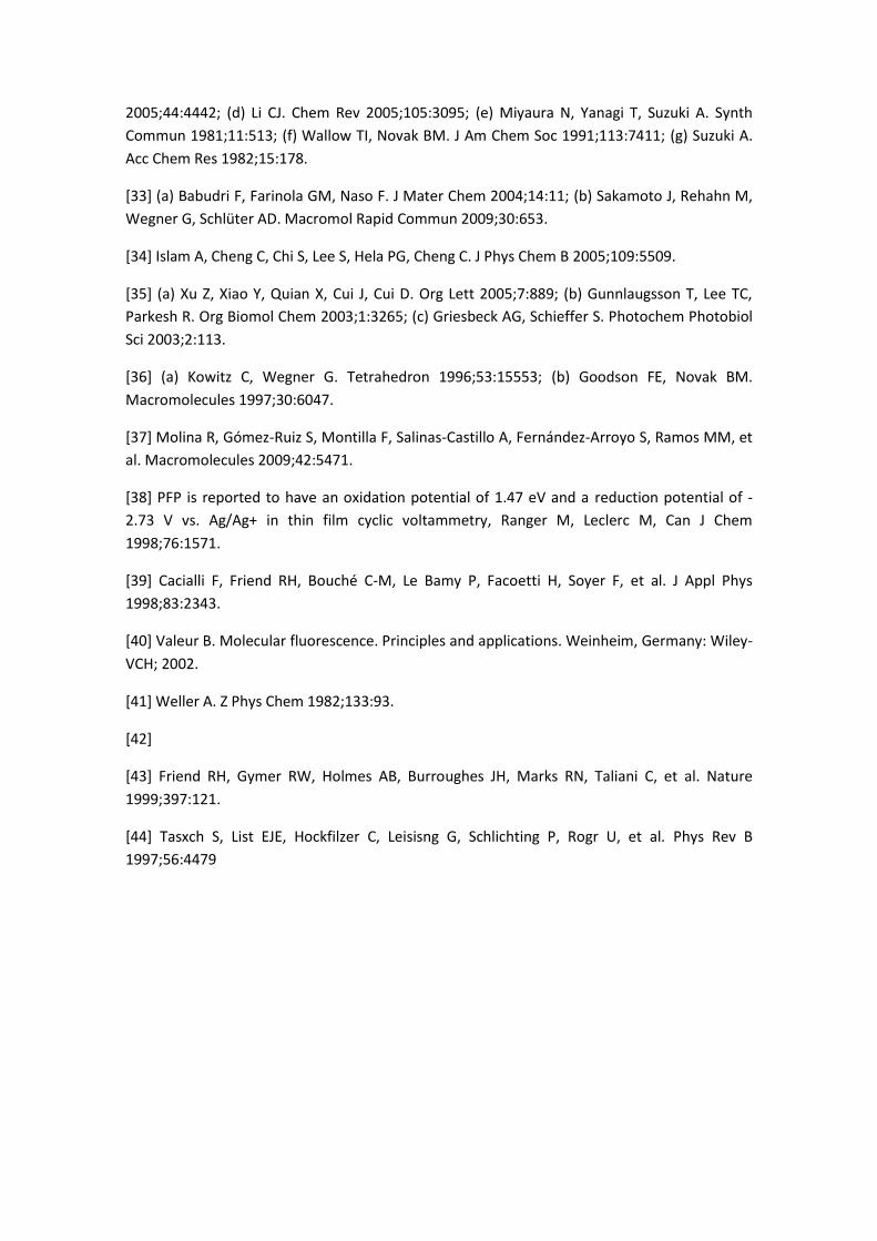
In this work we report a new synthetic route toward blue emitting poly(fluorene-alt-
phenylene) (PFP) derivatives containing comonomers bearing red-emitting 1,8-naphthalimide
units as pendant groups (P1–P4, Fig. 1). The naphthalimide dopant has been covalently
attached to the pendant chain of the host with an alkyl spacer to realize molecular dispersion
of the dopant. We demonstrate that this strategy prevents phase separation and the
formation of aggregates and favours energy transfer in the compound, allowing the tuning of
the emission by tailoring the content of the naphthalimide dopant. We have investigated the
photophysical behaviour of the novel polymers by means of optical absorption (OA) and
steady-state photoluminescence (PL), PL decay and we have tested their device properties in
single-component, single-layer organic light emitting diodes (OLEDs).
2. Experimental
Compounds 1-hexyloxy-2,5-diiodo-4-(6′-iodohexyloxy)-benzene (3) [25], 4-(phenyl-2-
naphthyl)amino-1,8-naphthalic anhydride (1) [13], 4-(1-naphthylphenylamine)-N-phenyl-1,8-
naphthalimide (7) [26], 2,7-bis(4,4,5,5-tetramethyl-1,3,2-dioxoborolan-2-yl)-9,9-
dioctylfluorene (5) [27], 1,4-dihexyloxy-2,5-diiodobenzene (6) [28] and poly[9,9-dioctyl-9H-
fluorene-2,7-diyl][2,5-bis(hexyloxy)-1,4-phenylene] (PFP) [29] were prepared according to the
literature. All other chemicals were purchased from Aldrich and used as received without
further purification. Column chromatography was performed on Merck Kieselgel 60 silica gel
(230–240 mesh). Thin layer chromatography was carried out on Merck silica gel F-254 flexible
TLC plates. Solvents and reagents were dried by usual methods prior to use and typically used
under inert gas atmosphere.
2.1. Characterization
Melting points were measured with an electrothermal melting point apparatus and are
uncorrected. FTIR spectra were recorded as KBr pellets in a Shimadzu FTIR 8300 spectrometer.
NMR were recorded on a Bruker AC-200, Avance 300 or AMX-400 apparatus as noted, and the
chemical shifts were reported relative to tetramethylsilane (TMS) at 0.0 ppm (for 1H NMR) and
CDCl3 at 77.16 ppm (for 13C NMR). The splitting patterns are designated as follows: s (singlet), d
(doublet), t (triplet), m (multiplet) and q (quadruplet). Mass spectra were recorded with a
Varian Saturn 2000 GC–MS and with a MALDI-TOF MS Bruker Reflex 2 (dithranol as matrix).
Elemental analyses were performed on a Perkin–Elmer EA 2400. Average molecular weights
and and molecular weight distribution were determined by gel permeation
chromatography (GPC) in a Aliance 2000 Waters GPC coupled with refractive index (RI) and
viscosity detectors. The solvent used for the analysis was 1,2,4,5-tetrachlorobenzene (TCB),
the flow rate was 1.0 mL/min and the temperature was 145 °C. The GPC-viscosity system was
calibrated using polystyrene standards.
2.2. Electrochemistry
Cyclic voltammetry experiments were performed with a computer controlled EG & G PAR 273
potentiostat in a three-electrode single-compartment cell (5 ml). The platinum working
electrode consisted of a platinum wire sealed in a soft glass tube with a surface of
A = 0.785 mm2, which was polished down to 0.5 μm with Buehler polishing paste prior to use
in order to obtain reproducible surfaces. The counter electrode consisted of a platinum wire
and the reference electrode was a Ag/AgCl secondary electrode. All potentials were internally
referenced to the ferrocene–ferrocinium couple. For the measurements, concentrations of
5 × 10⁻³ mol l−1 of the electroactive species were used in freshly distilled and deaerated
dichloromethane (Lichrosolv, Merck) and 0.1 M tetrabutylammonium perchlorate (TBAClO4,
Fluka) which was twice recrystallized from ethanol and dried under vacuum prior to use.
2.3. Devices fabrication
The structure of the devices are ITO/PEDOT:PSS (50 nm)/active layer (91–123 nm)/Ba
(20 nm)/Al. Pre-patterned ITO glass plates were extensively cleaned, using chemical and UV-
ozone methods, just before the deposition of the organic layers. The thickness of the layers
were measured using an Alpha step 200 profilomenter (Tenkor Instruments). The active layers
were deposited by spin coating from chloroform (CHCl3) solutions (10 mg/ml). The resulting
layers thickness was: 121, 91, 123, 112 and 91 nm for PFP, P1, P2, P3 and P4, respectively. We
have found that heating the sample just below the solvent boiling point reduces aggregation
and results in an improved film uniformity (highly reflecting surfaces) [30]. The Ba and Al
cathode was thermally evaporated in an atmosphere of 5 × 10⁻⁵ Torr on top of the organic
layer surface and the structure is encapsulated using a glass cover attached by a bead of epoxy
adhesive [EPO-TEK(302-3 M)]. All the process is carried out in an inert atmosphere glovebox
(<0.1 ppm O2 and H2O).
Thin films of P1–P4 and PFP on quartz substrates were fabricated by spin coating from
10 mg/ml chloroform precursor solutions to investigate the optical properties in thin film. Also
a thin film of a physical blend (Blend) between PFP and the naphthalimide reference 7 was
fabricated with the same polymer/naphthalimide ratio as in P4 (i.e. 0.08) for comparison
porpouses.
2.4. Optical measurements
The OA and PL spectra of the material in solution and in thin films on quartz substrates have
been measured at room temperature. UV–vis OA of solutions and PL spectra for both,
solutions and films, were recorded with a Perkin–Elmer Lambda 900 spectrophotometer and
an Edinburgh Instruments FS920 double-monochromator luminescence spectrometer using a
Peltier-cooled red-sensitive photomultiplier, respectively. The OA thin film spectra were
recorded with a Varian spectrophotometer model Cary 4000. Spectral luminance from diodes
was recorded with a Konica-Minolta CS-2000 spectroradiometer, in the same excitation
conditions (duty cycle) as those used to measure I–V characteristics (duty cycle of 0.2%). The
PL quantum efficiencies of polymer were estimated by using a thin film of perylene as blue
standard (ϕPL = 0.87) [31].
In the above expression, ϕ is the fluorescent quantum yield, F the integrated emission
intensity, n the refractive index, and A the absorbance at the exciting wavelength. The
subscripts r and s denote the reference and unknown samples, respectively.
The PL lifetimes were recorded at room temperature. The excitation was made at 380 nm with
a dye laser using PBBO. This laser provides pulses with 10 μJ of energy and a FWHM of 5 ns,
however it also radiates a 50 ns delayed pulse replica with intensity 25 times lower than the
main pulse, this compromises the analysis of the long time tails of the light decays. The
emission dispersed by an SPEX spectrometer (f = 34 cm) was recorded with a Hamamatsu
R2658 cooled photomultiplier and the signal is stored and analyzed in a digital 500 MHz
Tektronix oscilloscope. To remove straight light from the excitation laser long-wavelength pass
filters were set before the photomultiplier window; nevertheless some light contamination
was always present. Since the time decays of the signals analyzed were below 20 ns the
contribution of the excitation light scattered by the samples was evaluated and discounted
from the photoluminescence signals.
2.5. Electrical measurements
The device current–voltage characteristics were measured using a semiconductor parameter
analyzer Agilent 4155C and a SMU pulse generator Agilent 41501B. A pulse train was used as
input signal. The duty cycle was set to be 0.2%, thus having a pulse width of 0.5 ms for a period
of 100 ms. Refresh time between two consecutive pulses ensures long time operation without
significant device degradation. Furthermore, the I–V curve stability was achieved by gradually
increasing the pulse amplitude up to the point where reproducible measurements were
observed. The voltage range is below the onset for the electroluminescence (EL).
2.6. Synthesis of 6-(1-naphthalenylphenylamino)-2-(4-hydroxyphenyl)-1H-benz[de]-
isoquinoline-1,3(2H)-dione (2)
Under argon atmosphere, 4-(phenyl-2-naphthyl)amino-1,8-naphthalic anhydride (1) (100 mg,
0.24 mmol) and 4-aminophenol (105 mg, 0.96 mmol) were mixed with imidazole (7 g) and
heated at 180 °C for 4 h. After cooling, the solid was disolved in dichloromethane (30 ml) and
washed with a concentrated solution of HCl three times (×30 ml) and then with brine. The
organic phase was dried over MgSO4, filtered and vacuum evaporated. The remaining residue
was purified by column chromatography (silica gel, dichloromethane/methanol 99/1) to yield
compound 2 in 73% yield as a red–orange solid.
M.p.: 182–184 °C (dichloromethane/methanol).
1H NMR (CDCl3, 400 MHz). 8.59 (dd, J = 7.26 Hz, J = 1.00 Hz, 1H), 8.58 (d, J = 8.00 Hz, 1H), 8.28
(dd, J = 8.55 Hz, J = 1.00 Hz, 1H), 7.79 (d, J = 9.00 Hz, 1H), 7.78 (d, J = 8.80 Hz, 1H), 7.59–7.39
(m, 5H), 7.37–7.27 (m, 5H), 7.14–7.08 (m, 4H), 6.89–6.80 (m, 2H), 6.46 (br, 1H).
13C NMR (CDCl3, 100 MHz). 165.0 (C O), 164.4 (C O), 156.3, 151.3, 148.2, 145.9, 134.2,
132.8, 131.9, 131.7, 130.7, 130.4, 129.7, 129.6, 128.3, 128.0, 127.6, 127.3, 127.1, 126.7, 126.5,
125.6, 125.2, 124.1, 123.6, 123.3, 120.5, 118.7, 116.7.
FTIR (KBr). ν = 3360, 3075, 1704, 1657, 1582, 1491, 1368, 754 cm−1.
MS (FAB) (m/z) 507 ([M+1]+).
Anal. calc. for C34H22N2O3: C: 80.62%; H: 4.38%; N: 5.53%. Found: C: 80.70%; H: 4.36%; N:
5.60%.
2.7. Synthesis of 6-(1-naphthalenylphenylamino)-2-[4-[[6-[4-(hexyloxy)-2,5-diiodo-
phenoxy]hexyl]oxy]phenyl]-1H-benz[de]isoquinoline-1,3(2H)-dione (4)
Under an argon atmosphere, a mixture of 1-hexyloxy-2,5-diiodo-4-(6′-iodohexyloxy)benzene
(3) (150 mg, 0.23 mmol), 6-(1-naphthalenylphenylamino)-2-(4-hydroxyphenyl)-1H-
benz[de]isoquinoline-1,3(2H)-dione (2) (151 mg, 0.30 mmol) and potassium carbonate
(124 mg, 0.90 mmol) was heated at 100 °C in 25 ml of anhydrous N,N-dimethylformamide for
48 h. After this time, the crude was allowed to reach room temperature and treated with a
1 M aqueous solution of hydrochloric acid. The mixture was extracted with dichloromethane
and the organic extracts dried over anhydrous magnesium sulphate and then evaporated
under vacuum. The residue was purified by flash chromatography (silica gel,
hexane/dichloromethane 2/8) to yield monomer 3 in 32% yield as an orange solid.
M.p.: 84–85 °C (hexane/dichloromethane).
1H NMR (CDCl3, 200 MHz). δ = 8.59–8.54 (m, 2H, Napht), 8.25 (dd, J = 8.6 Hz, J = 1.22 Hz, 1H,
Napht), 7.82–7.75 (m, 2H, Napht), 7.59–7.03 (m, 18H), 4.01–3.90 (m, 6H, –OCH2-), 1.90–1.76
(m, 6H, –CH2-), 1.37–1.25 (m, 10H, –CH2
-), 0.91 (t, 3H, –CH3).
13C NMR (CDCl3, 125 MHz). δ = 164.70 (C O), 164.13 (C O), 159.09, 152.92, 152.83,
151.04, 148.34, 145.95, 134.26, 132.55, 131.74, 131.47, 130.75, 130.39, 129.75, 129.60,
129.54, 128.45, 128.17, 128.13, 127.79, 127.72, 127.45, 127.13, 126.88, 126.75, 126.54,
125.74, 125.21, 124.12, 124.03, 123.65, 123.50, 122.81, 120.49, 119.07, 115.26, 86.38 (CAr–I),
86.34 (CAr–I), 70.37 (O–CH2), 70.19 (O–CH2), 68.05 (CH2–O), 30.23, 29.75, 29.42, 29.23, 25.82,
25.75, 25.46, 22.64, 14.10.
FTIR (KBr). ν = 2926, 2855, 1707, 1668, 1586, 1511, 1490, 1465, 1365, 1241, 1212, 1175,
855 cm−1.
MS (FAB) (m/z): 1036 ([M+1]+).
Anal. calcd. for C52H48I2N2O5: C: 60.36%; H: 4.68%; N: 2.71%. Found: C: 60.49%; H: 4.61%; N:
2.55%.
2.8. Polymers P1–P4
General procedure for polymerizations. Under an argon atmosphere, a solution of 2,7-
bis(4,4,5,5-tetramethyl-1,3,2-dioxoborolan-2-yl)-9,9-dioctylfluorene (4), 1,4-dihexyloxy-2,5-
diiodobenzene (5), monomer 6 and tetrakis(triphenylphosphine)palladium (0) in a deareated
mixture of THF and an aqueous 2 M potassium carbonate solution was heated at 100 °C for
48 h. The mixture was allowed to reach the room temperature and then poured into
methanol. The precipitate was collected by filtration, dissolved in dichloromethane and
precipitated out of methanol. After soxhlet extraction with cloroform for 48 h, the polymer
was further purified by re-precipitation from dichloromethane/methanol several times. The
corresponding polymers were isolated by centrifugation and dried under vacuum. The
products were obtained after drying in vacuum with yields between 52% and 70%.
P4: 2,7-Bis(4,4,5,5-tetramethyl-1,3,2-dioxoborolan-2-yl)-9,9-dioctylfluorene (4) (150 mg,
0.23 mmol), 1,4-dihexyloxy-2,5-diiodobenzene (5) (112.0 mg, 0.2116 mmol) and monomer 3
(19.0 mg, 0.0184 mmol) were used in the polymerization. GPC: Mn = 1.44 × 10⁴, PDI = 3.26.
P3: 2,7-Bis(4,4,5,5-tetramethyl-1,3,2-dioxoborolan-2-yl)-9,9-dioctylfluorene (4) (150 mg,
0.23 mmol), 1,4-dihexyloxy-2,5-diiodobenzene (5) (119.0 mg, 0.2254 mmol) and monomer 3
(4.76 mg, 4.60 × 10⁻³ mmol) were used in the polymerization. GPC: Mn = 1.45 × 10⁴, PDI = 2.75.
P2: 2,7-Bis(4,4,5,5-tetramethyl-1,3,2-dioxoborolan-2-yl)-9,9-dioctylfluorene (4) (150 mg,
0.23 mmol), 1,4-dihexyloxy-2,5-diiodobenzene (5) (121.3 mg, 0.2288 mmol) and monomer 3
(1.19 mg, 1.15 × 10⁻³ mmol) were used in the polymerization. GPC: Mn = 1.41 × 10⁴, PDI = 2.62.
P1: 2,7-Bis(4,4,5,5-tetramethyl-1,3,2-dioxoborolan-2-yl)-9,9-dioctylfluorene (4) (150 mg,
0.23 mmol), 1,4-dihexyloxy-2,5-diiodobenzene (5) (121.8 mg, 0.2299 mmol) and monomer 3
(0.119 mg, 1.15 × 10⁻⁴ mmol) were used in the polymerization. GPC: Mn = 1.34 × 10⁴,
PDI = 2.51.
Since the content of naphthalimide dopant in polymers P1–P4 is very low, all these polymers
showed similar 1H NMR spectra. Only P4 showed weak signals typical of the naphthalimide
moiety. 13C NMR spectra and elemental analysis results were similar for all these polymers as
well. For example, for P1: 1H NMR (CDCl3, 200 MHz). δ = 7.82–7.57 (m, 6H), 7.14 (s, 2H), 3.99
(bs, 4H, –OCH2-), 2.04 (bs, 4H, –CH2
-), 1.90–1.10 (m, 40H, –CH2-) 0.88–0.79 (m, 12H, –CH3).
13C NMR (CDCl3, 75 MHz). δ = 150.59 (C O), 150.50 (C O), 139.89, 137.05, 131.26, 127.95,
124.52, 119.30, 116.77, 69.91 (O–CH2), 55.09 (Cbridge), 40.62 (Cbridge –CH2), 31.87, 31.58, 30.43,
29.51, 25.85, 24.13, 22.74, 22.67, 14.11, 14.08.
Anal. calcd. for C47H70O2: C: 84.63%; H: 10.58%; Found C: 83.97%; H: 10.08%.
3. Results and discussion
3.1. Synthesis and characterization
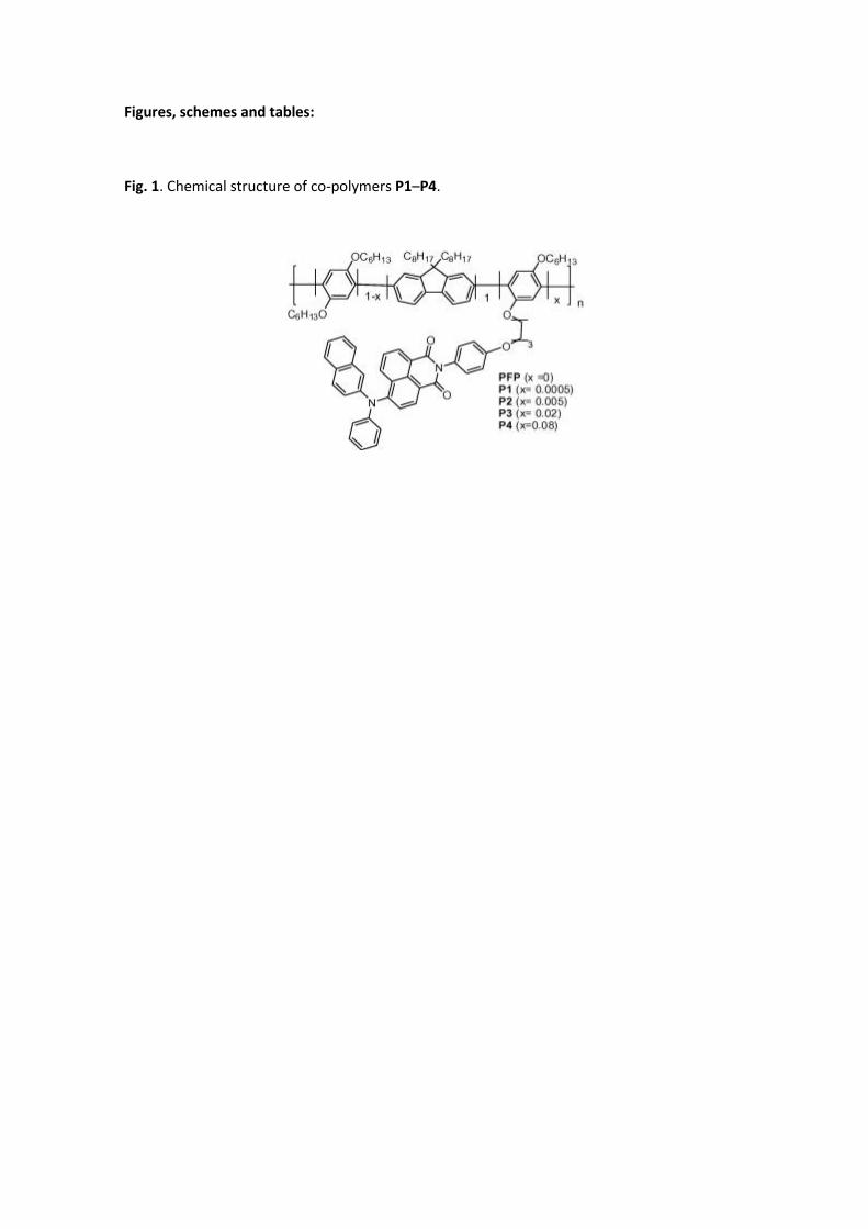
The synthetic approach followed for the synthesis of functionalized co-polymers P1–P4 with
different content of naphthalimide and the reference polymer poly(fluorene-alt-phenylene)
(PFP) is shown in Scheme 1. As it can be seen, it requires the preparation of a monomer (4)
containing the selected napthalimide chromophore and appropriate functional groups which
could enable its further co-polymerization, with fluorene monomer 5 and benzene derivative
6. The presence in these comonomers of long alkyl chains will make possible the synthesis of
processable materials, which is a prerequisite for the fabrication of devices and the
investigation of their optical properties in solution and solid phase, as discussed below. Also to
enhance the solubility and processability we have chosen a long non-conjugated alkyl spacer
between the poly(fluorene-alt-phenylene) backbone and the naphthalimide side groups. This
is expected to improve the conformational flexibility of the side groups with respect to the
chain, which has proven to be of interest regarding the photophysics of these materials [14].
Suzuki [32] couplings constitute one of the most convenient procedures for the preparation of
polyarylenes, by the Pd-catalyzed cross-coupling reaction of aromatic diboron derivatives with
aryl-dihalides in the presence of a base. This methodology has provided polyarylenes with high
structural variety [33] and has enabled us the attachment of different electroactive functional
moieties to conjugated polymers [25]. Besides, the compatibility of the reaction conditions
with the imide functionality and the possibility to obtain structurally well-defined alternating
fluorene-phenylene co-polymers has motivated us to choose this protocol for the preparation
of co-polymers PFP and P1–P4.
Monomer 4 was synthesized from naphthalimide 2, prepared by heating the corresponding
anhydride 1[34] with p-aminophenol in imidazole under the classical conditions [35]. This has
enabled the synthesis of a versatile naphthalimide building block endowed with a strongly
electron-donor diphenylamino group and a phenol functionality, which can be covalently
linked to 3[13], a polymerizable diiodoarylene derivative bearing an additional complementary
iodine reactive group. Thus, the Williamson etherification reaction between 3 and the
complementarily functionalized naphtalimide 2 using potassium carbonate as the base in DMF
afforded monomer 4 in a moderate 32% yield.
Monomer 4 has been characterized by the usual spectroscopic and analytical techniques. Thus,
the 1H NMR spectra of 4 shows the characteristic signals corresponding to the aromatic
protons of both the naphthalimide and the naphthylphenylamine substituent at low fields, and
signals for the alkyl chain at higher fields. On the other hand, the 13C NMR spectrum shows,
together with the carbonyl groups, the signals of the iodine-bearing aromatic carbons, the
alkoxy groups and the alkyl spacer. The FTIR spectrum of monomer 4 further proves its
structure and contains the typical strong bands at 1707 and 1668 cm−1 for imide groups and
evidence concerning its purity is given by elemental analysis, which is in accordance with the
expected values.
As it has been mentioned, co-polymers P1–P4 were synthesized by Suzuki polycondensations.
Thus, mixtures with different content of the naphthalimide-containing monomer 4, 2,5-diiodo-
1,4-dihexyloxybenzene (6) [28], and 2,7-bis(4,4,5,5-tetramethyl-1,3,2-dioxaborolan-2-yl)-9,9-
dioctylfluorene (5) [27] in the presence of 5 mol% Pd(PPh3)4 in a mixture of degassed THF and
aqueous potassium carbonate was heated at reflux for 48 h (Scheme 1).
Although boronic acids have often been directly used as reagents in poly-Suzuki couplings,
boronic esters like 5 have proven to be more advantageous in this kind of reactions, since the
presence of the 1,1,2,2-tetramethylethylene glycol units has a protective effect on the labile
boronic acid precursor. Simultaneously to the polymerization, a hydroxylation deprotection
process takes place, in which the removal of such protecting groups as ethylene glycol does
not affect the couplings [36]. The resulting alternating copolymers were then precipitated out
of the thick reaction mixtures by addition of methanol, and soxlhet extracted with chloroform
to separate from the insoluble fractions. Further purification of co-polymers P1–P4 was
achieved by re-precipitation from dichloromethane/methanol several times and thorough
washes with additional methanol and diethyl ether to remove ionic species and unreacted
materials, to give yellow to orange solids in moderate to good yields. The starting 6:4
monomer ratios were adjusted in order to investigate the effect of polymer composition on
the physical and optical properties of the final polymers. Thus, the content of 1,8-
naphthalimide in the resulting polymers was controlled in the range 0.05–8 mol%. As it will be
discussed below, this low concentration of naphthalimide is enough by itself to modify the
optical properties of co-polymers P1–P4 with respect to the parent non-substituted reference
PFP.
In order to be used as a reference material, we have also synthesized co-polymer poly[9,9-
dioctyl-9H-fluorene-2,7-diyl][2,5-bis(hexyloxy)-1,4-phenylene] (PFP, x = 0 in Scheme 1),
containing the same polymeric backbone as P1–P4 but without pendant naphthalimide units,
by an analogous Suzuki polycondensation between 1,4-dihexyloxy-2,5-diiodobenzene (6) and
bisborolane 5 under the same conditions employed in the synthesis of P1–P4. Also for
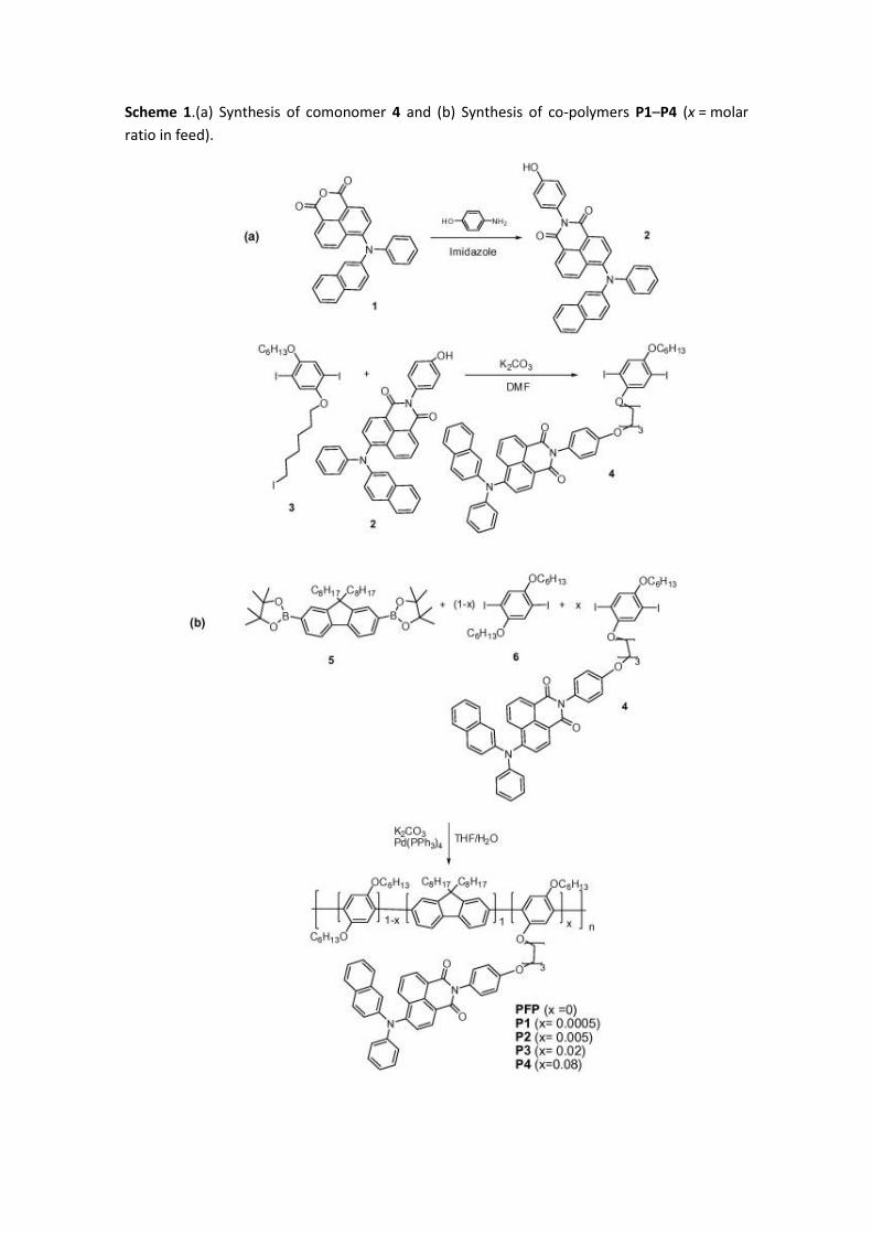
comparison, we synthesized as reference material the 1,8-naphtalimide derivative 7[27] as
shown in Scheme 2.
The alkyl substituents in the main chain of co-polymers P1–P4 provide these materials good
solubility in common organic solvents, such as toluene, chloroform or THF, and enabled their
full characterization by NMR and electrochemical and optical techniques.
In spite of the increasing naphthalimide dopant content, all polymers P1–P4 showed similar 1H
NMR patterns. A multiplet corresponding to the six fluorene aromatic protons is visible at
around 7.8–7.6 ppm and the singlet of the two protons on the benzene ring is seen at around
7.14 ppm. The characteristic signals of the alkoxy chains appear in the expected region (ca.
4.0 ppm) and the 1H NMR spectra is completed with the signals of the alkyl chains at lower
fields, including at slightly higher shifts those of the methylenes directly linked to the fluorene
carbon bridge at around 2.0 ppm. Only P4, the functionalized polymer with the highest
content of naphthalimide, showed very weak multiplets that could be assignated by
comparison to the pendant naphthalimide groups. For P4, integration of the weak signals
between 8.59 and 8.25 ppm corresponding to the naphthalimide group and those diagnostic
signals corresponding to the aromatic backbone indicate a 0.08% of naphthalimide units in the
polymer. This corresponds to the percent of naphthalimide-containing monomer added in the
reaction and provides evidence of the similar reactivity of monomers 4 and 6.
Gel permeation chromatography (GPC) with polystyrene as standard revealed that the co-
polymers P1–P4 have similar molecular weights ( ), between 14,400 and 13,400 g/mol,
with polydispersities (PD) ranging from 2.51 to 3.26 (Table 1). The molecular weights, without
considering the known overestimation based on PS calibration [37] and considering the Mw as
major weight provides polymer lengths between 70 (P4) and 50 (P1) units based on a
molecular unity of 664 g/mol. The lower values of molecular weights for co-polymers P1–P4 in
comparison with the reference PFP (75 units) suggest that the presence of the lateral
chromophore units affects slightly the polymerization process. Nevertheless, the
electrochemical and photophysical properties of the polymers are not expected to be
influenced by this slight differences in the polymer length considering that all of them exceed
by far the effective conjugation length.
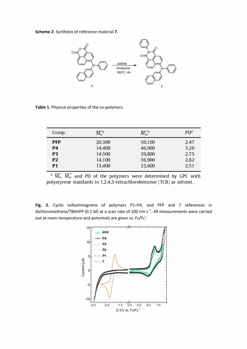
3.2. Electrochemical properties
The redox properties of novel polymers P1–P4 and PFP were determined by cyclic
voltammetry at room temperature in dichloromethane solutions, using a platinum disk and
wire as working and counter electrodes, respectively, Ag/AgCl as reference electrode, and
tetrabutylammonium hexafluorophosphate (TBAHFP, 0.1 M) as supporting electrolyte.
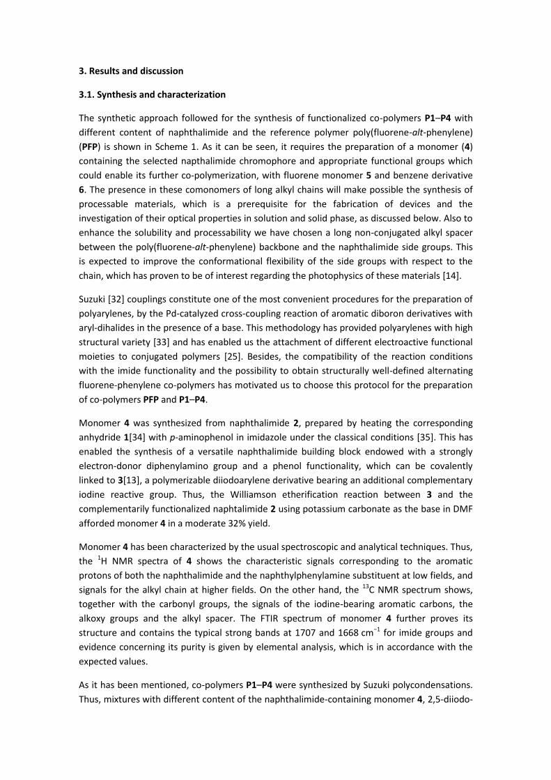
The cyclic voltammograms of polymers P1–P4 show the same redox behaviour as PFP (Fig. 2),
presenting a relatively broad quasireversible wave with an onset oxidation potential at
around +0.53 V (vs. Fc/Fc+) assigned to the reversible p-doping processes of the poly(fluorene-
alt-phenylene) conjugated chain. No reduction processes on the polymeric backbone could be
detected up to –2.5 V under our experimental conditions [38]. This result indicates that these
concentrations of naphthalimide units lead to little change in the electrochemical properties of
the resulting polymers. Naphthalimide reference 7 showed a sharp and well resolved
quasireversible reduction wave at around –1.80 V, evidencing the moderate electron acceptor
ability of this moiety due to the presence of the electron-rich diarylamino substituent. We
have observed for this type of functionalized polymers that both electroactive units, the
electron donor conjugated backbone and the electron acceptor naphthalimide units preserve
their nature on the ground state [8], [12] and [13]. Consequently, no electron transfer
processes are expected in the ground state.
3.3. Photophysical properties
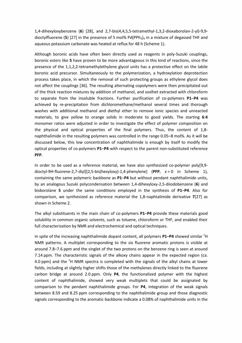
The UV–vis absorption spectra of co-polymers P1–P4 and PFP in dichloromethane solutions
together with the excitation spectrum of the reference 7 in chloroform solution are depicted in
Fig. 3a. Functionalized co-polymers P1–P4 exhibit the same absorption spectra as PFP, with a
maximum at 375 nm which can be attributed to the π–π∗ transition of the conjugated
poly(fluorene-alt-phenylene) backbone. As it was the case in the electrochemical investigation,
the low naphthalimide chromophore content does not produce any noticiable change on the
absorption properties of these materials. Only a residual absorption from the pendant
chromophore, peaking at around 469 nm in reference 7, could be observed, confirming the
minimal interaction between the chromophores in the ground state.
Fig. 3b shows the absorption spectra of the P1–P4 and PFP thin films together with a blend
film with the same polymer/naphthalimide ratio as in P4 (i.e. 0.08), which are very similar to
that in solution. Again, there is no observable difference between the copolymers and the PFP
absorption spectra and only a very weak contribution of the band around 466 nm
corresponding to the naphthalimide chromophore 7 could be detected. Nevertheless, for the
blend thin film, the absorption maximum is slightly red shifted with respect to the co-polymers
and shows a larger contribution in the naphthalymide chromophore 7 absorption region. The
optical gap for the thin films, estimated from the departure of the OA derivative from zero,
does not experiment important changes: 2.87 and 2.81 eV for the co-polymers and the Blend
film, respectively.
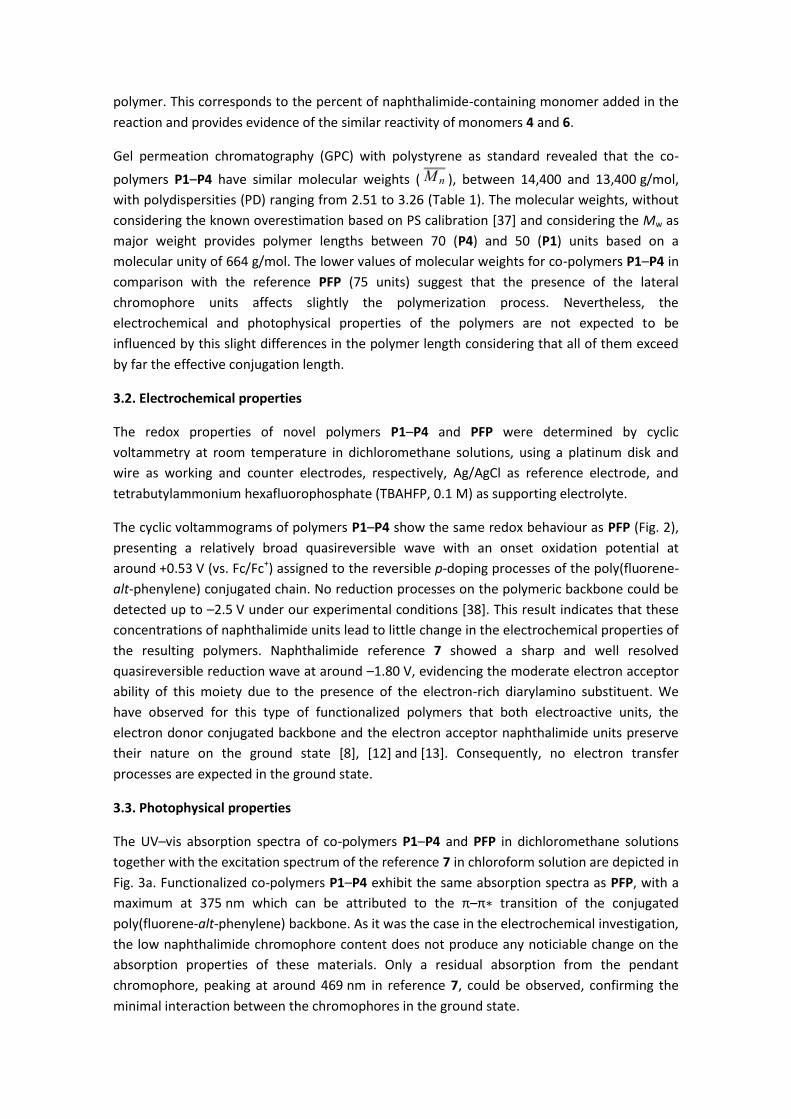
Fig. 4 shows the emission spectra in diluted (ca. 10−5 M) chloroform solutions of the P1–P4 co-
polymers, a solution mixture with the same polymer/naphthalimide ratio as in P4 (recorded all
of them with excitation at 370 nm) and the PFP and naphthalimide 7 for reference. For the
sake of clarity, we present the 560–790 nm region magnified to appreciate the emission of the
solutions in Fig. 4b. PFP emission shows their known emission peaking at 420 nm [13]. The
naphthalimide reference 7 presents its maximum at 622 nm.
The co-polymers and the mixture in diluted solutions present the same blue emission of PFP,
with maximum at 420 nm, together with a small emission associated with the naphthalimide
pendant group peaking at 622 nm (except for P1 thin film). No changes in the bands are
observed except for a quenching of the blue emission (420 nm) when increasing the
naphthalimide chromophore concentration and a small increase of the 622 nm band with
increasing cromophore content.
Although this 622 nm band of the spectrum is not very strong in comparison with the blue part
of the spectra, it can be seen in Fig. 4b that the red band intensity is higher for the P4 co-
polymer, with the pendant group covalently attached, than for the mixture, indicating that the
energy transfer is more efficient in the co-polymers than in the mixture prepared with PFP and
the reference 7, with the same ratio as in P4. This can be understood since the energy transfer
between donor and acceptor chromophores depends on the intermolecular distance between
the donor and acceptor molecules which is favoured in the covalently attached co-polymers
compared to the mixture of components in solution.
Thus, the incorporation of the 1,8-naphtalimide derivative as side chain to poly(fluorene-alt-
phenylene) leads to negligible changes in the solution UV–vis absorption spectra but results in
a quenching of the PFP emission and the more effective emission of the 622 nm band in the
solution PL spectra of these co-polymers. This can be explained by a Föster energy transfer
from the polymer backbone to the naphthalimide moiety unit as a consequence of the overlap
between the absorption spectrum of the naphthalimide and the PFP backbone emission
spectrum. Moreover, since the absorbance is greater for the PFP backbone than for the
naphtalimide chromophore (Fig. 3a) at the excitation wavelength for PL (370 nm), nearly all
the incident photons are absorbed by the PFP main chain, indicating that this Föster energy
transfer is very efficient. With the increase of the content of naphtalimide, the contribution of
the 622 nm emission in Fig. 4 becomes larger in the co-polymers due to the completion of the
energy transfer which is less efficient in the physical blend.
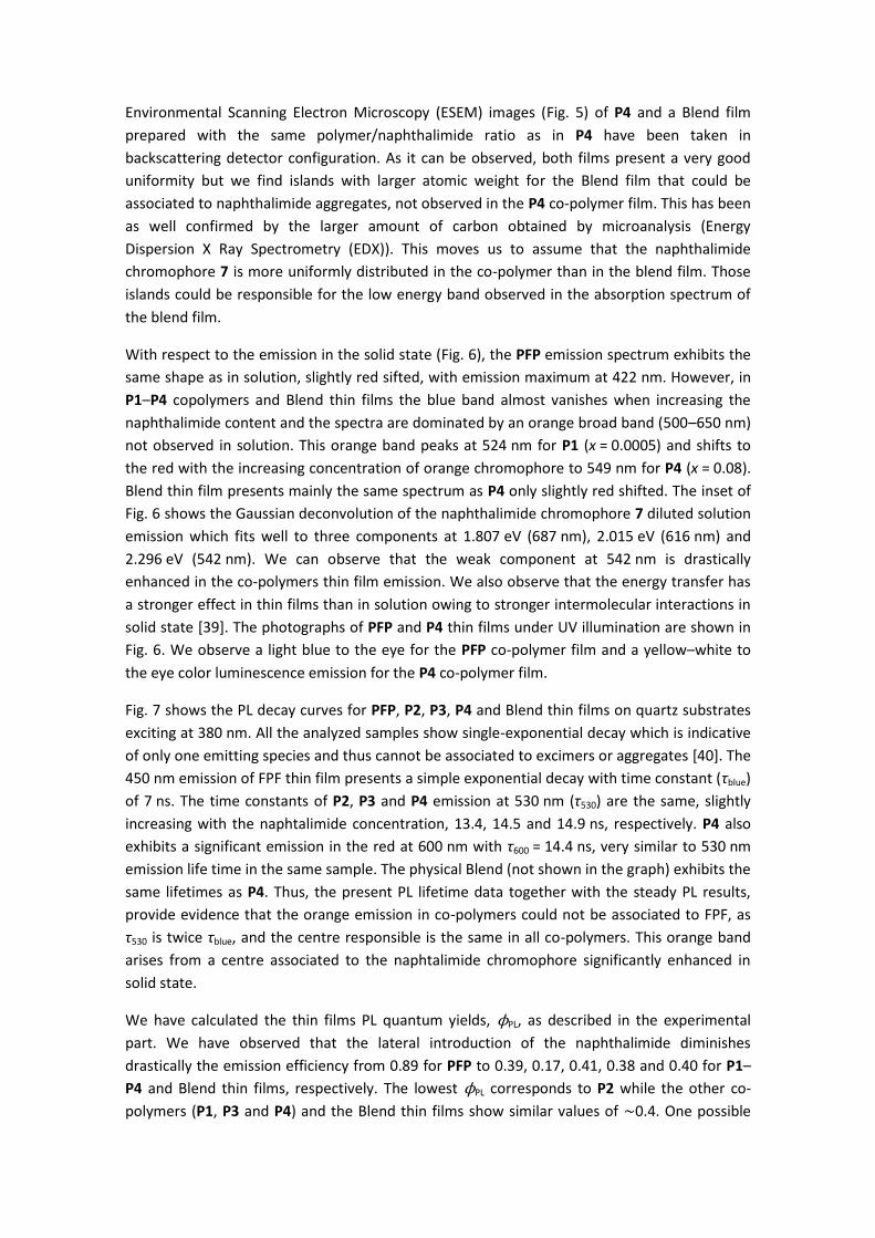
Environmental Scanning Electron Microscopy (ESEM) images (Fig. 5) of P4 and a Blend film
prepared with the same polymer/naphthalimide ratio as in P4 have been taken in
backscattering detector configuration. As it can be observed, both films present a very good
uniformity but we find islands with larger atomic weight for the Blend film that could be
associated to naphthalimide aggregates, not observed in the P4 co-polymer film. This has been
as well confirmed by the larger amount of carbon obtained by microanalysis (Energy
Dispersion X Ray Spectrometry (EDX)). This moves us to assume that the naphthalimide
chromophore 7 is more uniformly distributed in the co-polymer than in the blend film. Those
islands could be responsible for the low energy band observed in the absorption spectrum of
the blend film.
With respect to the emission in the solid state (Fig. 6), the PFP emission spectrum exhibits the
same shape as in solution, slightly red sifted, with emission maximum at 422 nm. However, in
P1–P4 copolymers and Blend thin films the blue band almost vanishes when increasing the
naphthalimide content and the spectra are dominated by an orange broad band (500–650 nm)
not observed in solution. This orange band peaks at 524 nm for P1 (x = 0.0005) and shifts to
the red with the increasing concentration of orange chromophore to 549 nm for P4 (x = 0.08).
Blend thin film presents mainly the same spectrum as P4 only slightly red shifted. The inset of
Fig. 6 shows the Gaussian deconvolution of the naphthalimide chromophore 7 diluted solution
emission which fits well to three components at 1.807 eV (687 nm), 2.015 eV (616 nm) and
2.296 eV (542 nm). We can observe that the weak component at 542 nm is drastically
enhanced in the co-polymers thin film emission. We also observe that the energy transfer has
a stronger effect in thin films than in solution owing to stronger intermolecular interactions in
solid state [39]. The photographs of PFP and P4 thin films under UV illumination are shown in
Fig. 6. We observe a light blue to the eye for the PFP co-polymer film and a yellow–white to
the eye color luminescence emission for the P4 co-polymer film.
Fig. 7 shows the PL decay curves for PFP, P2, P3, P4 and Blend thin films on quartz substrates
exciting at 380 nm. All the analyzed samples show single-exponential decay which is indicative
of only one emitting species and thus cannot be associated to excimers or aggregates [40]. The
450 nm emission of FPF thin film presents a simple exponential decay with time constant (τblue)
of 7 ns. The time constants of P2, P3 and P4 emission at 530 nm (τ530) are the same, slightly
increasing with the naphtalimide concentration, 13.4, 14.5 and 14.9 ns, respectively. P4 also
exhibits a significant emission in the red at 600 nm with τ600 = 14.4 ns, very similar to 530 nm
emission life time in the same sample. The physical Blend (not shown in the graph) exhibits the
same lifetimes as P4. Thus, the present PL lifetime data together with the steady PL results,
provide evidence that the orange emission in co-polymers could not be associated to FPF, as
τ530 is twice τblue, and the centre responsible is the same in all co-polymers. This orange band
arises from a centre associated to the naphtalimide chromophore significantly enhanced in
solid state.
We have calculated the thin films PL quantum yields, ϕPL, as described in the experimental
part. We have observed that the lateral introduction of the naphthalimide diminishes
drastically the emission efficiency from 0.89 for PFP to 0.39, 0.17, 0.41, 0.38 and 0.40 for P1–
P4 and Blend thin films, respectively. The lowest ϕPL corresponds to P2 while the other co-
polymers (P1, P3 and P4) and the Blend thin films show similar values of ∼0.4. One possible
reason for the decrease in the PL quantum yield may be the presence of a competitive
photoinduced electron transfer (PET) process. In this regard, by using the Weller equation [41],
it has been calculated that the PET process is energetically favourable as the corresponding
ΔGPET was estimated to be −0.42 eV in dichloromethane [42]. The PL quantum yields, together
with the charge injection efficiency [43] and the intrinsic transport properties of the co-
polymers, have a great influence in the electroluminescence efficiency of the devices as it is
proportional to PL quantum yield.
3.4. Electrical measurements
Simple OLED structures were fabricated according to the method described in the
experimental section, with configuration: ITO/PEDOT:PSS (50 nm)/polymer (90–125 nm)/Ba/Al
(200 nm), in order to investigate the electroluminescent (EL) properties of the materials. Fig. 8
shows the I–V characteristic for the diodes based on P1 to P4 copolymers together with a
scheme of the energy levels of the devices based on these materials. The P2 based diode,
exhibits the worse performance with a threshold voltage at around 9 V. In P3 and P4 based
diodes, the threshold voltage decrease to 7 and 5.5 V, respectively. The P1 based diode shows
a very similar performance to P4, with threshold voltage of 5.5 V. Unfortunately, the
correlation between the I–V threshold voltage and the naphthalimide content is obscured by
the dispersion in the active layer thicknesses.
The EL emissions are presented in Fig. 9 together with the driving currents, applied voltage and
CIE color coordinates obtained for each device. It has to be noted that all the devices exhibited
emission in the μA range: 47, 73, 39, 60 μA for P1, P2, P3 and P4 based devices, respectively.
The efficiencies obtained are 22.62, 7.53, 47.11 and 2.93 Cd/A for P1, P2, P3 and P4 based
devices, respectively.
A good match between the PL and EL spectra is observed, indicating that both emissions are
produced by the same species. Although in the EL spectra, a larger contribution of the orange
band is observed. This is attributed to the additional charge-trapping effect of the 1,8-
naphthalimide which will act as a charge-trapping centre during the electron transport
process, as described in organic host/guest systems [44]. This will be an additional contribution
to the orange emission apart from the Föster energy transfer from the polymer backbone to
the 1,8-naphthalimide chromophore which corresponds to that observed in the PL
measurements. Indeed, the orange broad band is the bigger contribution in all the spectra and
the blue emission is only observed for P1 and residually for P2 based devices. P3 and P4 based
devices exhibit only the broad orange contribution, as observed in the thin films PL emission.
We observe white emission (0.30, 0.42) for the P1 based device, where the blue and orange
emission is more balanced.
4. Summary
A series of single polymers exhibiting simultaneous blue and orange emission in solid state that
gives rise to white emission have been synthesized and characterized. Photophysical studies
suggest that this broad band is associated with an efficient energy transfer from the PFP
backbone to the naphthalimide orange chromophore. Although energy transfer may be
observed in diluted solutions, solid state drastically enhances it due to a increasing of
intermolecular interactions that gives rise to a more efficient excitation energy transfer from
the blue emission of the PFP backbone to the naphthalimide chromophore. This energy
transfer is more effective in co-polymers than for physical mixtures of the two chromophores.
White light (0.30, 0.42) is obtained from a single layer, single component WOLED with a
efficiency of 22.62 Cd/A.
Acknowledgement
We thank Comunidad Autónoma de Madrid (Project S2009/MAT-1756 and S2009/MAT-1467),
the UCM-BSCH Joint Project (GR58/08), the CAM-UCM Joint Project (CCG08-UCM-PPQ-3957)
and the MCyT of Spain (MAT2009-08786, CTQ2007-60459) for financial support. We also thank
to G. del Rosario of URJC-CAT services for the ESEM discussion. R.B, R.J and A.P. are indebted,
respectively, to the “Comunidad de Madrid” the “Universidad Rey Juan Carlos” and
“Universidad Complutense” for predoctoral fellowships.
References
[1] (a) McQuade DT, Pullen A, Swager ETM. Chem Rev 2000;100:2537; (b) Thomas III SW, Joly
GD, Swager TM. Chem Rev 2007;107:1339.
[2] Gómez R, Segura JL. In: Nalwa HS, editor. Handbook of organic electronic and photonics.
Los Angeles: American Scientific Publishers; 2007.
[3] Gunes S, Neugebauer H, Sariciftci NS. Chem Rev 2007;107:1324.
[4] Roncali J. Chem Soc Rev 2005;34:483.
[5] Ramos AM, Rispens MT, van Duren JKJ, Hummelen JC, Janssen RAJ. J Am Chem Soc
2001;123:6714.
[6] Zerza G, Cravino A, Neugebauer H, Sariciftci NS, Gomez R, Segura JL, et al. J Phys Chem A
2001;105:4172.
[7] Giacalone F, Segura JL, Martín N, Catellani M, Luzzati S, Lupsac N. Org Lett 2003;5:1669.
[8] Segura JL, Gómez R, Blanco R, Reinold E, Bäuerle P. Chem Mater 2006;18:2834.
[9] (a) Blanco R, Seoane C, Segura JL. Tetrahedron Lett 2008;49:2056; (b) Gómez R, Blanco R,
Veldman D, Segura JL, Janssen RAJ. J Phys Chem B 2008;112:4953.
[10] Catellani M, Luzzati S, Lupsac NO, Mendichi R, Consonni R, Famulari A, et al. J Mater Chem
2004;14:67.
[11] Luzzati S, Scharber M, Catellani M, Giacalone F, Segura JL, Martín N, et al. J Phys Chem B
2006;110:5351.
[12] Segura JL, Gómez R, Reinold E, Bäuerle P. Org Lett 2005;7:2345.
[13] Gómez R, Veldman D, Blanco R, Seoane C, Segura JL, Janssen RAJ. Macromolecules
2007;40:2760.
[14] Montilla F, Esquembre R, Gómez R, Blanco R, Segura JL. J Phys Chem C 2008;112:16668.
[15] (a) Tu GL, Zhou QG, Cheng YX, Wang LX, Ma DG, Jing XB, et al. Appl Phys Lett
2004;85:2172; (b) Tu GL, Mei CY, Zhou QG, Cheng YX, Wang LX, Ma DG, et al. Adv Funct Mater
2006;16:101.
[16] (a) Liu J, Zhou QG, Cheng YX, Geng YH, Wang LX, Ma DG, et al. Adv Funct Mater
2006;16:957; (b) Liu J, Min C, Zhou QG, Cheng YX, Wang L, Ma D, et al. Appl Phys Lett 2006;88.
[17] Liu J, Guo X, Bu L, Xie Z, Cheng Y, Geng Y, et al. Adv Funct Mater 2007;17:1917.
[18] (a) Liu J, Zhou Q, Cheng Y, Geng Y, Wang L, Ma D, et al. Adv Mater 2005;17:2974; (b) Tu G,
Mei C, Zhou Q, Geng Y, Wang L, Ma D, et al. Adv Funct Mater 2006;16:101.
[19] Lee SK, Ahn T, Cho NS, Lee J-I, Jung YK, Lee J, et al. Polym Sci Part A Polym Chem
2007;45:1199.
[20] <http://www1.eere.energy.gov/buildings/ssl/>.
[21] (a) D’Andrade BW, Forrest SR. Adv Mater 2004;16:1585; (b) Wang YZ, Sun RG, Meghdadi
F, Leising G, Epstein AJ. Appl Phys Lett 1999;74:3613.
[22] Strukelj M, Jordan RH, Dodabalapur P. J Am Chem Soc 1996;118:1213.
[23] Tasch S, List EJW, Ekströn O, Graupner W, Leising G, Schlichting P, et al. Appl Phys Lett
2004;85:4076.
[24] (a) Gong X, Wang S, Moses D, Bazan GC, Heeger AJ. Adv Mater 2005;17:2053; (b) Gong X,
Ma W, Ostrowski JC, Bazan GC, Moses D, Heeger AJ. Adv Mater 2004;16:615.
[25] Blanco R, Seoane C, Segura JL. Tetrahedron Lett 2008;49:2056.
[26] Jiang W, Yueming S, Wang X, Wang Q, Xu W. Dyes Pigments 2008;77:125.
[27] Dudek SP, Pouderoijen M, Abbel R, Schenning AHP, Meijer EW. J Am Chem Soc
2005;127:11763.
[28] Wang C, Batsanov AS, Bryce MR, Sage I. Org Lett 2004;6:2181.
[29] Lee J, Cho HJ, Cho NS, Hwang D-H, Kang J-M, Lim E, et al. J Polym Sci Part A Polym Chem
2006;44:2943; (a) Thomas III SW, Swager TM. Macromolecules 2005;38:2716.
[30] Coya C, de Andrés A, Gómez R, Seoane C, Segura JL. On the blue emission of a novel
solution processed stilbenoid dendrimer thin film for OLED displays. J Lum 2008;128:761.
[31] Birks JB. Photophysics of aromatic molecules. New York, NY: Wiley; 1970.
[32] (a) Selected references on the Suzuki coupling: Suzuki A. Chem Commun 2005;38:4759;
(b) Suzuki A. Proc Jpn Ac 2004;80:359; (c) Nicolau KC, Bulger PG, Sarlah D. Angew Chem Int Ed
2005;44:4442; (d) Li CJ. Chem Rev 2005;105:3095; (e) Miyaura N, Yanagi T, Suzuki A. Synth
Commun 1981;11:513; (f) Wallow TI, Novak BM. J Am Chem Soc 1991;113:7411; (g) Suzuki A.
Acc Chem Res 1982;15:178.
[33] (a) Babudri F, Farinola GM, Naso F. J Mater Chem 2004;14:11; (b) Sakamoto J, Rehahn M,
Wegner G, Schlüter AD. Macromol Rapid Commun 2009;30:653.
[34] Islam A, Cheng C, Chi S, Lee S, Hela PG, Cheng C. J Phys Chem B 2005;109:5509.
[35] (a) Xu Z, Xiao Y, Quian X, Cui J, Cui D. Org Lett 2005;7:889; (b) Gunnlaugsson T, Lee TC,
Parkesh R. Org Biomol Chem 2003;1:3265; (c) Griesbeck AG, Schieffer S. Photochem Photobiol
Sci 2003;2:113.
[36] (a) Kowitz C, Wegner G. Tetrahedron 1996;53:15553; (b) Goodson FE, Novak BM.
Macromolecules 1997;30:6047.
[37] Molina R, Gómez-Ruiz S, Montilla F, Salinas-Castillo A, Fernández-Arroyo S, Ramos MM, et
al. Macromolecules 2009;42:5471.
[38] PFP is reported to have an oxidation potential of 1.47 eV and a reduction potential of -
2.73 V vs. Ag/Ag+ in thin film cyclic voltammetry, Ranger M, Leclerc M, Can J Chem
1998;76:1571.
[39] Cacialli F, Friend RH, Bouché C-M, Le Bamy P, Facoetti H, Soyer F, et al. J Appl Phys
1998;83:2343.
[40] Valeur B. Molecular fluorescence. Principles and applications. Weinheim, Germany: Wiley-
VCH; 2002.
[41] Weller A. Z Phys Chem 1982;133:93.
[42]
[43] Friend RH, Gymer RW, Holmes AB, Burroughes JH, Marks RN, Taliani C, et al. Nature
1999;397:121.
[44] Tasxch S, List EJE, Hockfilzer C, Leisisng G, Schlichting P, Rogr U, et al. Phys Rev B
1997;56:4479
Figures, schemes and tables:
Fig. 1. Chemical structure of co-polymers P1–P4.
Scheme 1.(a) Synthesis of comonomer 4 and (b) Synthesis of co-polymers P1–P4 (x = molar
ratio in feed).
Scheme 2. Synthesis of reference material 7.
Table 1. Physical properties of the co-polymers.
Fig. 2. Cyclic voltammograms of polymers P1–P4, and PFP and 7 references in
dichloromethane/TBAHFP (0.1 M) at a scan rate of 100 mV s−1. All measurements were carried
out at room temperature and potentials are given vs. Fc/Fc+.
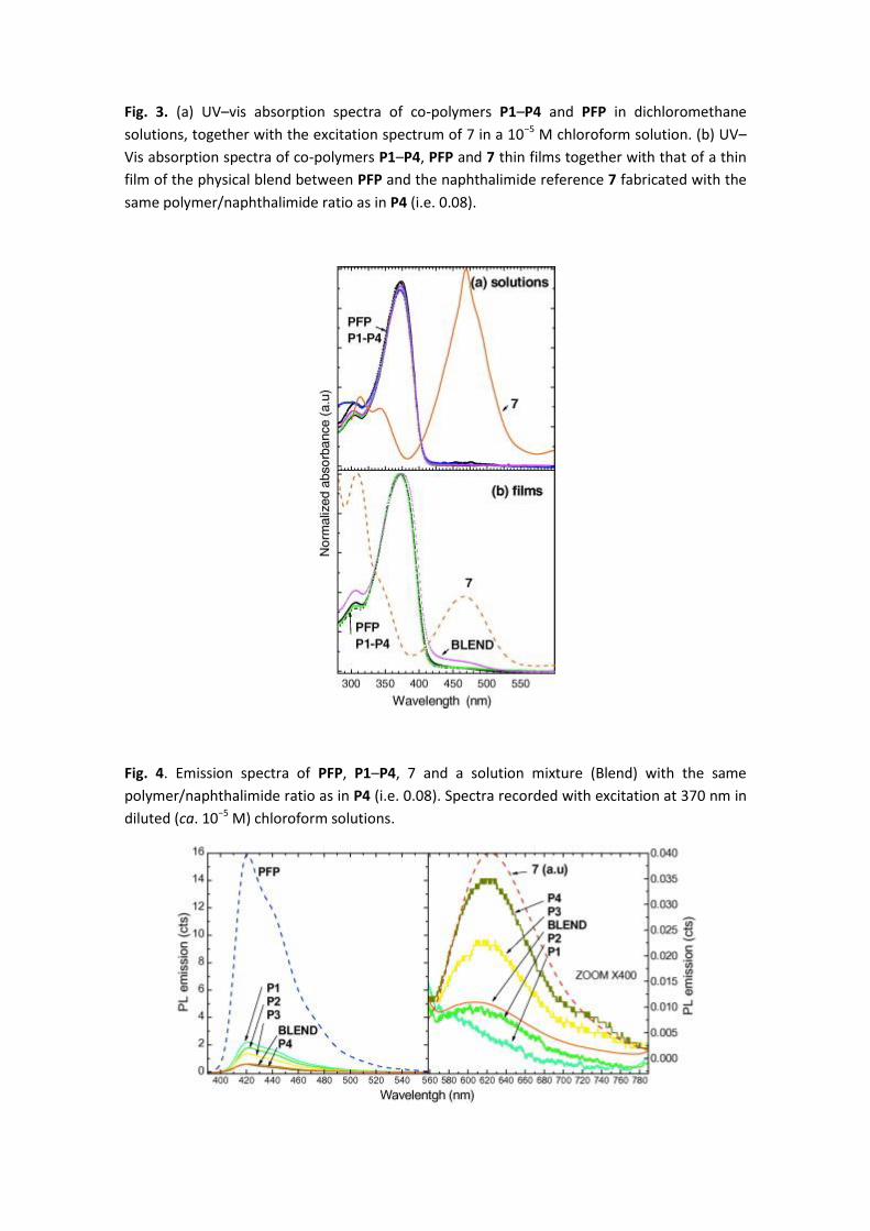
Fig. 3. (a) UV–vis absorption spectra of co-polymers P1–P4 and PFP in dichloromethane
solutions, together with the excitation spectrum of 7 in a 10−5 M chloroform solution. (b) UV–
Vis absorption spectra of co-polymers P1–P4, PFP and 7 thin films together with that of a thin
film of the physical blend between PFP and the naphthalimide reference 7 fabricated with the
same polymer/naphthalimide ratio as in P4 (i.e. 0.08).
Fig. 4. Emission spectra of PFP, P1–P4, 7 and a solution mixture (Blend) with the same
polymer/naphthalimide ratio as in P4 (i.e. 0.08). Spectra recorded with excitation at 370 nm in
diluted (ca. 10−5 M) chloroform solutions.
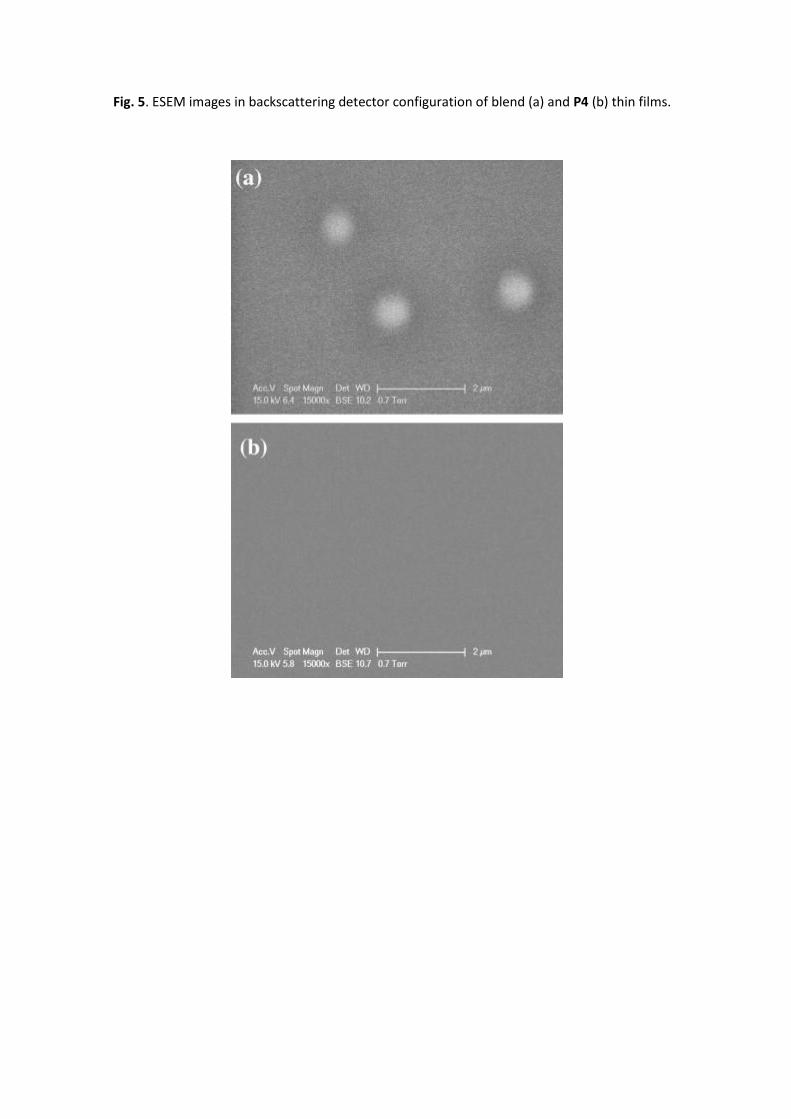
Fig. 5. ESEM images in backscattering detector configuration of blend (a) and P4 (b) thin films.
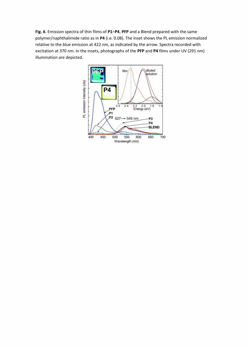
Fig. 6. Emission spectra of thin films of P1–P4, PFP and a Blend prepared with the same
polymer/naphthalimide ratio as in P4 (i.e. 0.08). The inset shows the PL emission normalized
relative to the blue emission at 422 nm, as indicated by the arrow. Spectra recorded with
excitation at 370 nm. In the insets, photographs of the PFP and P4 films under UV (291 nm)
illumination are depicted.
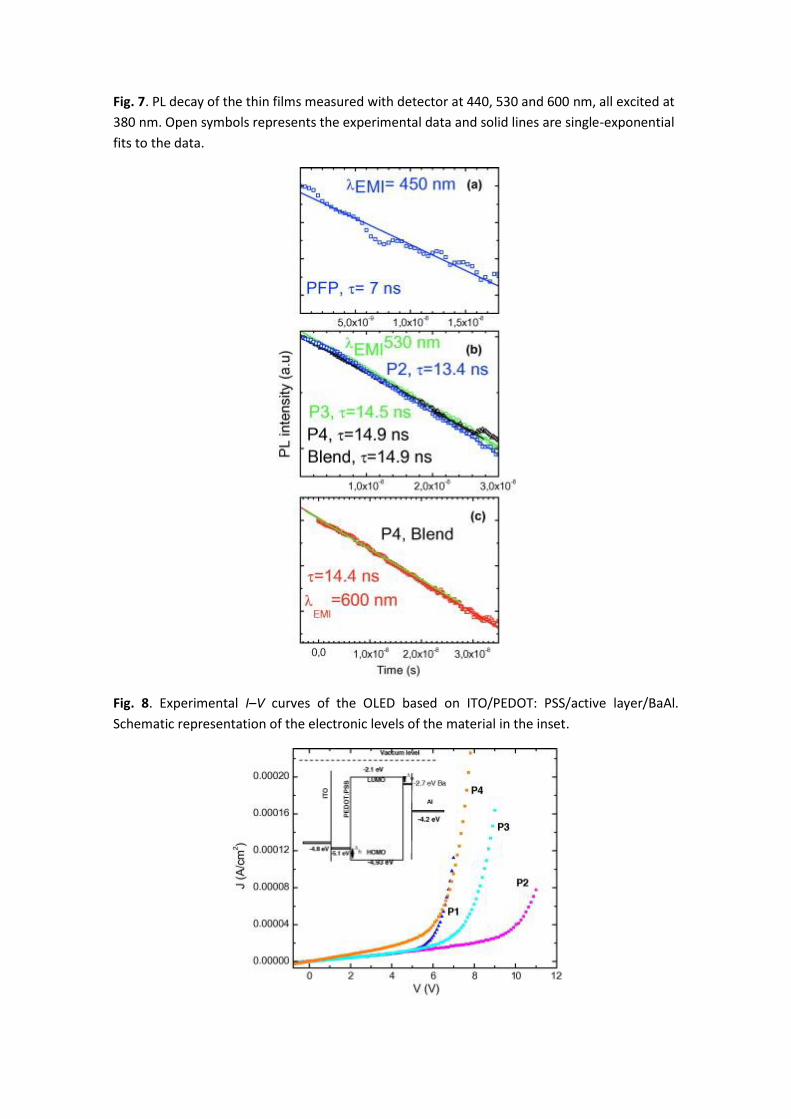
Fig. 7. PL decay of the thin films measured with detector at 440, 530 and 600 nm, all excited at
380 nm. Open symbols represents the experimental data and solid lines are single-exponential
fits to the data.
Fig. 8. Experimental I–V curves of the OLED based on ITO/PEDOT: PSS/active layer/BaAl.
Schematic representation of the electronic levels of the material in the inset.
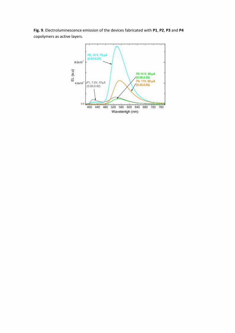
Fig. 9. Electroluminescence emission of the devices fabricated with P1, P2, P3 and P4
copolymers as active layers.