Embed Size (px)
Citation preview
1
Synthesis of Digital SystemsCS 411N / CSL 719
Part 3: Hardware Description Languages - VHDL
Instructor: Preeti Ranjan PandaDepartment of Computer Science and Engineering
Indian Institute of Technology, Delhi
(C) P. R. Panda, I.I.T Delhi, 2003 2
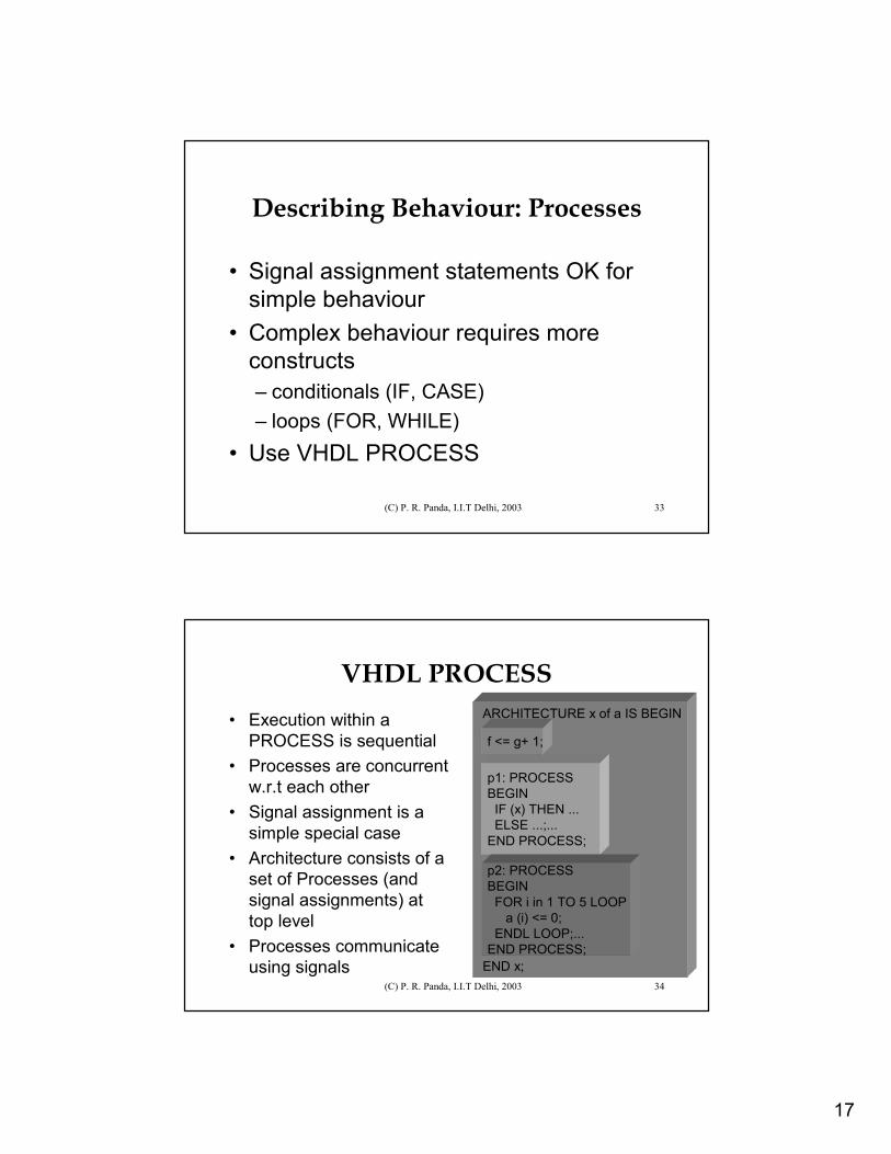
Contents
• Introduction• Signal assignment• Modelling delays• Describing behaviour• Structure, test benches, libraries,
parameterisation• Standards
2
(C) P. R. Panda, I.I.T Delhi, 2003 3
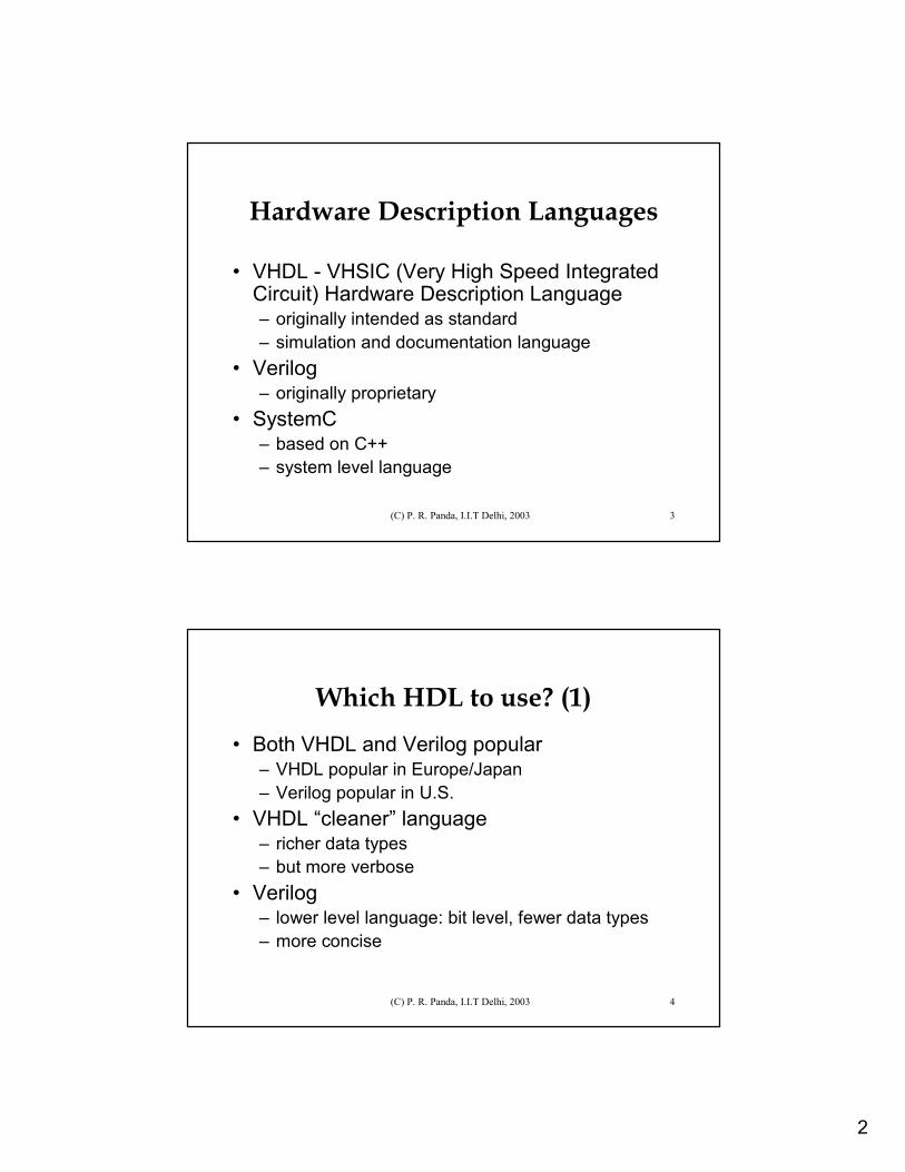
Hardware Description Languages
• VHDL - VHSIC (Very High Speed Integrated Circuit) Hardware Description Language– originally intended as standard– simulation and documentation language
• Verilog – originally proprietary
• SystemC– based on C++– system level language
(C) P. R. Panda, I.I.T Delhi, 2003 4
Which HDL to use? (1)• Both VHDL and Verilog popular
– VHDL popular in Europe/Japan– Verilog popular in U.S.
• VHDL “cleaner” language– richer data types– but more verbose
• Verilog– lower level language: bit level, fewer data types– more concise
3
(C) P. R. Panda, I.I.T Delhi, 2003 5
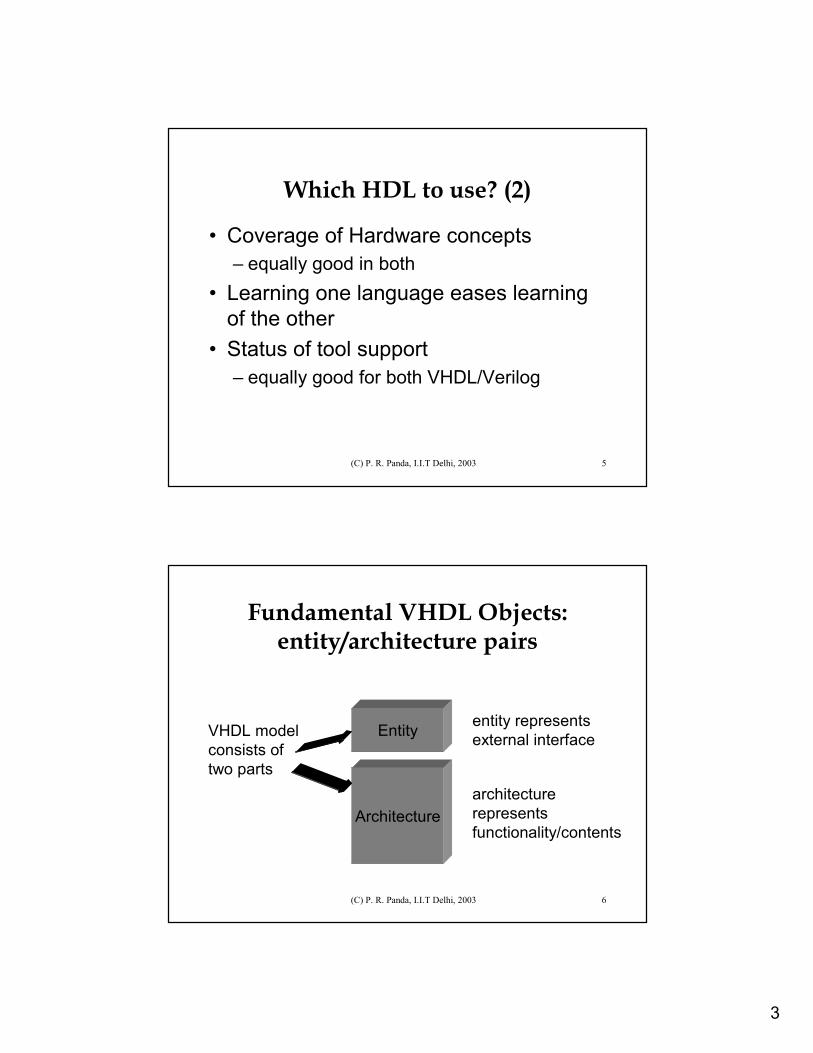
Which HDL to use? (2)
• Coverage of Hardware concepts– equally good in both
• Learning one language eases learning of the other
• Status of tool support– equally good for both VHDL/Verilog
(C) P. R. Panda, I.I.T Delhi, 2003 6
Fundamental VHDL Objects: entity/architecture pairs
VHDL modelconsists of two parts
Entity
Architecture
entity represents external interface
architecturerepresents functionality/contents
4
(C) P. R. Panda, I.I.T Delhi, 2003 7
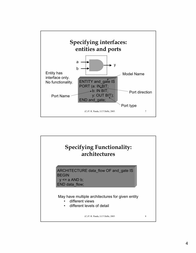
ENTITY and_gate ISPORT (a: IN BIT;
b: IN BIT;y: OUT BIT);
END and_gate;
Specifying interfaces: entities and ports
Port NamePort direction
Port type
Entity hasinterface only.No functionality.
Model Name
a
by
(C) P. R. Panda, I.I.T Delhi, 2003 8
ARCHITECTURE data_flow OF and_gate ISBEGIN
y <= a AND b;END data_flow;
Specifying Functionality: architectures
May have multiple architectures for given entity• different views• different levels of detail
5
(C) P. R. Panda, I.I.T Delhi, 2003 9
Contents
• Introduction• Signal assignment• Modelling delays• Describing behaviour• Structure, test benches, libraries,
parameterisation• Standards
(C) P. R. Panda, I.I.T Delhi, 2003 10
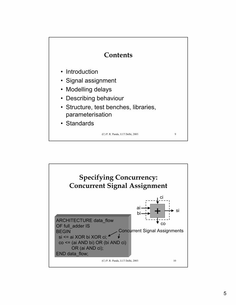
ARCHITECTURE data_flow OF full_adder ISBEGIN
si <= ai XOR bi XOR ci;co <= (ai AND bi) OR (bi AND ci)
OR (ai AND ci);END data_flow;
Specifying Concurrency: Concurrent Signal Assignment
si+aibi
ci
coConcurrent Signal Assignments
6
(C) P. R. Panda, I.I.T Delhi, 2003 11
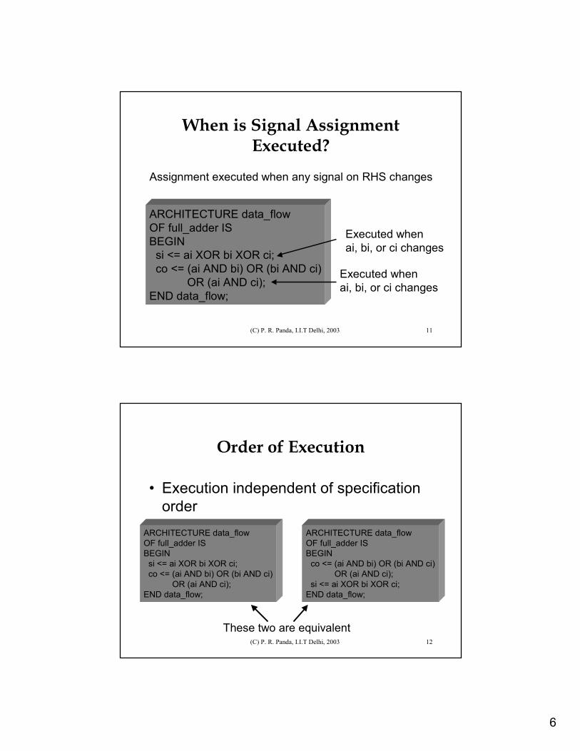
ARCHITECTURE data_flow OF full_adder ISBEGIN
si <= ai XOR bi XOR ci;co <= (ai AND bi) OR (bi AND ci)
OR (ai AND ci);END data_flow;
When is Signal Assignment Executed?
Executed whenai, bi, or ci changes
Assignment executed when any signal on RHS changes
Executed whenai, bi, or ci changes
(C) P. R. Panda, I.I.T Delhi, 2003 12
Order of Execution
• Execution independent of specification order
ARCHITECTURE data_flow OF full_adder ISBEGIN
si <= ai XOR bi XOR ci;co <= (ai AND bi) OR (bi AND ci)
OR (ai AND ci);END data_flow;
ARCHITECTURE data_flow OF full_adder ISBEGIN
co <= (ai AND bi) OR (bi AND ci)OR (ai AND ci);
si <= ai XOR bi XOR ci;END data_flow;
These two are equivalent
7
(C) P. R. Panda, I.I.T Delhi, 2003 13
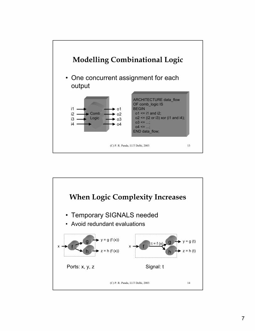
Modelling Combinational Logic
• One concurrent assignment for each output
CombLogic
o1o2o3o4
i1i2i3i4
ARCHITECTURE data_flow OF comb_logic ISBEGIN
o1 <= i1 and i2;o2 <= (i2 or i3) xor (i1 and i4);o3 <= ...;o4 <= ...;
END data_flow;
(C) P. R. Panda, I.I.T Delhi, 2003 14
When Logic Complexity Increases
• Temporary SIGNALS needed• Avoid redundant evaluations
fg
hx
y = g (f (x))
z = h (f (x))f
g
hx
y = g (t)
z = h (t)
t = f (x)
Ports: x, y, z Signal: t
8
(C) P. R. Panda, I.I.T Delhi, 2003 15
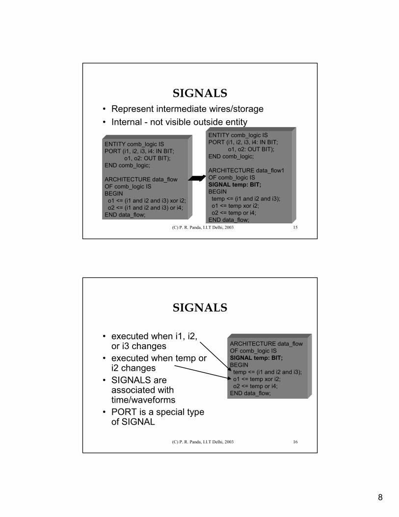
SIGNALS• Represent intermediate wires/storage• Internal - not visible outside entity
ENTITY comb_logic ISPORT (i1, i2, i3, i4: IN BIT;
o1, o2: OUT BIT);END comb_logic;
ARCHITECTURE data_flow OF comb_logic ISBEGIN
o1 <= (i1 and i2 and i3) xor i2;o2 <= (i1 and i2 and i3) or i4;
END data_flow;
ENTITY comb_logic ISPORT (i1, i2, i3, i4: IN BIT;
o1, o2: OUT BIT);END comb_logic;
ARCHITECTURE data_flow1 OF comb_logic ISSIGNAL temp: BIT;BEGIN
temp <= (i1 and i2 and i3);o1 <= temp xor i2;o2 <= temp or i4;
END data_flow;
(C) P. R. Panda, I.I.T Delhi, 2003 16
SIGNALS
• executed when i1, i2, or i3 changes
• executed when temp or i2 changes
• SIGNALS are associated with time/waveforms
• PORT is a special type of SIGNAL
ARCHITECTURE data_flow OF comb_logic ISSIGNAL temp: BIT;BEGIN
temp <= (i1 and i2 and i3);o1 <= temp xor i2;o2 <= temp or i4;
END data_flow;
9
(C) P. R. Panda, I.I.T Delhi, 2003 17
Contents
• Introduction• Signal assignment• Modelling delays• Describing behaviour• Structure, test benches, libraries,
parameterisation• Standards
(C) P. R. Panda, I.I.T Delhi, 2003 18
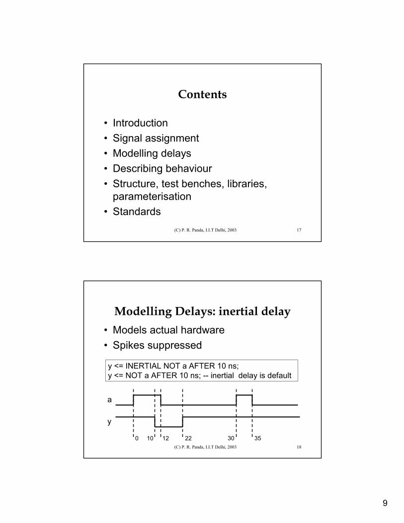
Modelling Delays: inertial delay• Models actual hardware• Spikes suppressed
y <= INERTIAL NOT a AFTER 10 ns;y <= NOT a AFTER 10 ns; -- inertial delay is default
a
y
0 10 12 22 30 35
10
(C) P. R. Panda, I.I.T Delhi, 2003 19
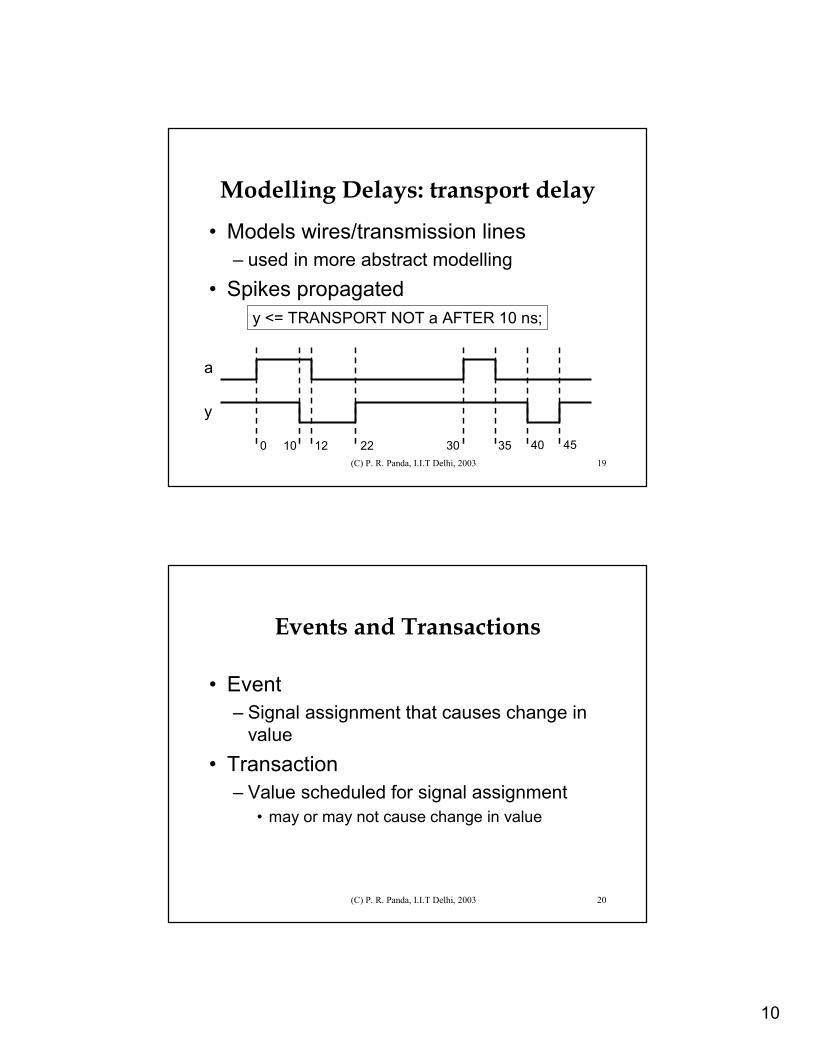
Modelling Delays: transport delay
• Models wires/transmission lines– used in more abstract modelling
• Spikes propagatedy <= TRANSPORT NOT a AFTER 10 ns;
a
y
0 10 12 22 30 35 40 45
(C) P. R. Panda, I.I.T Delhi, 2003 20
Events and Transactions
• Event– Signal assignment that causes change in
value• Transaction
– Value scheduled for signal assignment• may or may not cause change in value
11
(C) P. R. Panda, I.I.T Delhi, 2003 21
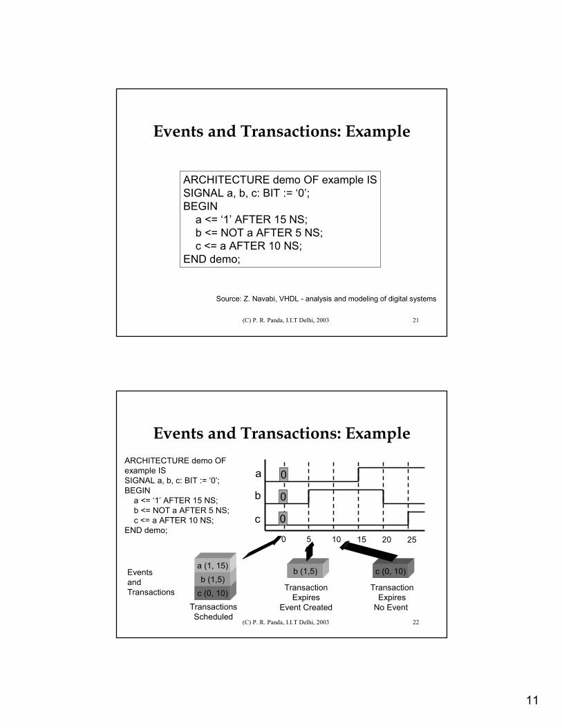
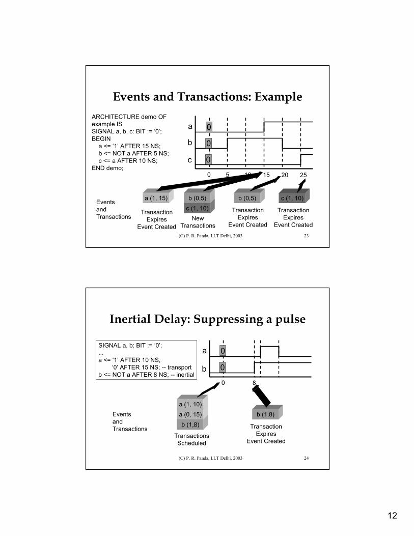
Events and Transactions: Example
ARCHITECTURE demo OF example ISSIGNAL a, b, c: BIT := ‘0’;BEGIN
a <= ‘1’ AFTER 15 NS;b <= NOT a AFTER 5 NS;c <= a AFTER 10 NS;
END demo;
Source: Z. Navabi, VHDL - analysis and modeling of digital systems
(C) P. R. Panda, I.I.T Delhi, 2003 22
Events and Transactions: ExampleARCHITECTURE demo OF example ISSIGNAL a, b, c: BIT := ‘0’;BEGIN
a <= ‘1’ AFTER 15 NS;b <= NOT a AFTER 5 NS;c <= a AFTER 10 NS;
END demo;
a
b
c
0 5 10 15 20 25
0
0
0
c (0, 10)b (1,5)
a (1, 15)EventsandTransactions
TransactionsScheduled
b (1,5)
TransactionExpires
Event Created
c (0, 10)
TransactionExpires
No Event
12
(C) P. R. Panda, I.I.T Delhi, 2003 23
Events and Transactions: ExampleARCHITECTURE demo OF example ISSIGNAL a, b, c: BIT := ‘0’;BEGIN
a <= ‘1’ AFTER 15 NS;b <= NOT a AFTER 5 NS;c <= a AFTER 10 NS;
END demo;
a
b
c
0 5 10 15 20 25
0
0
0
c (1, 10)b (0,5)Events
andTransactions New
Transactions
b (0,5)
TransactionExpires
Event Created
c (1, 10)
TransactionExpires
Event Created
a (1, 15)
TransactionExpires
Event Created
(C) P. R. Panda, I.I.T Delhi, 2003 24
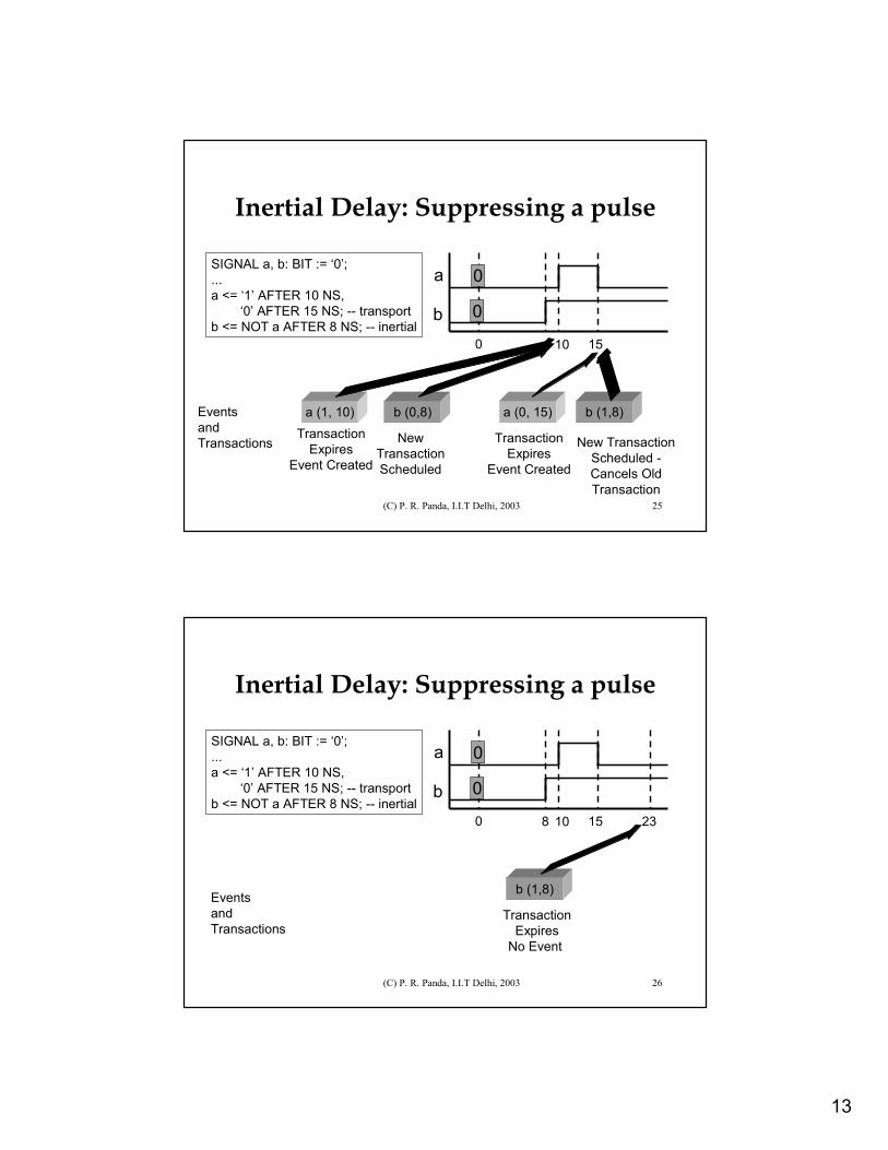
Inertial Delay: Suppressing a pulse
SIGNAL a, b: BIT := ‘0’;...a <= ‘1’ AFTER 10 NS,
‘0’ AFTER 15 NS; -- transportb <= NOT a AFTER 8 NS; -- inertial
EventsandTransactions
a
b0
0
0
b (1,8)
TransactionsScheduled
a (0, 15)a (1, 10)
8
b (1,8)
TransactionExpires
Event Created
13
(C) P. R. Panda, I.I.T Delhi, 2003 25
Inertial Delay: Suppressing a pulse
SIGNAL a, b: BIT := ‘0’;...a <= ‘1’ AFTER 10 NS,
‘0’ AFTER 15 NS; -- transportb <= NOT a AFTER 8 NS; -- inertial
EventsandTransactions
a
b0 10
0
0
15
b (0,8)
NewTransactionScheduled
a (1, 10)Transaction
ExpiresEvent Created
a (0, 15)
TransactionExpires
Event Created
b (1,8)
New TransactionScheduled -Cancels Old Transaction
(C) P. R. Panda, I.I.T Delhi, 2003 26
Inertial Delay: Suppressing a pulse
SIGNAL a, b: BIT := ‘0’;...a <= ‘1’ AFTER 10 NS,
‘0’ AFTER 15 NS; -- transportb <= NOT a AFTER 8 NS; -- inertial
EventsandTransactions
a
b0 10
0
0
15
b (1,8)
8
TransactionExpires
No Event
23
14
(C) P. R. Panda, I.I.T Delhi, 2003 27
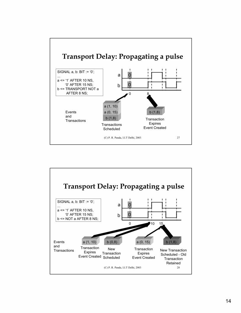
Transport Delay: Propagating a pulse
SIGNAL a, b: BIT := ‘0’;...a <= ‘1’ AFTER 10 NS,
‘0’ AFTER 15 NS; b <= TRANSPORT NOT a
AFTER 8 NS;
EventsandTransactions
a
b0
0
0
b (1,8)
TransactionsScheduled
a (0, 15)a (1, 10)
8
b (1,8)
TransactionExpires
Event Created
(C) P. R. Panda, I.I.T Delhi, 2003 28
Transport Delay: Propagating a pulse
SIGNAL a, b: BIT := ‘0’;...a <= ‘1’ AFTER 10 NS,
‘0’ AFTER 15 NS; b <= NOT a AFTER 8 NS;
EventsandTransactions
b (0,8)
NewTransactionScheduled
a (1, 10)Transaction
ExpiresEvent Created
a (0, 15)
TransactionExpires
Event Created
b (1,8)
New TransactionScheduled - Old
Transaction Retained
a
b0 10
0
0
15
15
(C) P. R. Panda, I.I.T Delhi, 2003 29
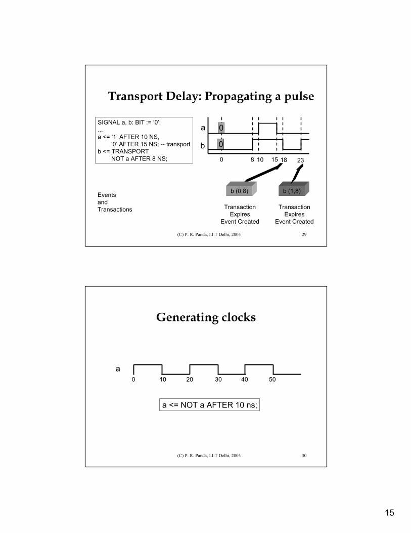
Transport Delay: Propagating a pulse
SIGNAL a, b: BIT := ‘0’;...a <= ‘1’ AFTER 10 NS,
‘0’ AFTER 15 NS; -- transportb <= TRANSPORT
NOT a AFTER 8 NS;
EventsandTransactions
a
b0 10
0
0
158 18 23
b (0,8)
TransactionExpires
Event Created
b (1,8)
TransactionExpires
Event Created
(C) P. R. Panda, I.I.T Delhi, 2003 30
Generating clocks
a0 10
a <= NOT a AFTER 10 ns;
20 30 40 50
16
(C) P. R. Panda, I.I.T Delhi, 2003 31
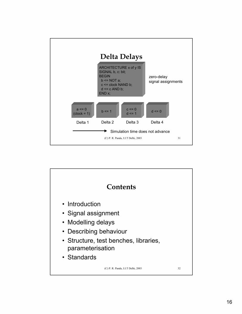
Delta DelaysARCHITECTURE x of y ISSIGNAL b, c: bit;BEGIN
b <= NOT a;c <= clock NAND b;d <= c AND b;
END x;
a <= 0(clock = 1) b <= 1 c <= 0
d <= 1 d <= 0
Delta 1 Delta 2 Delta 3 Delta 4
zero-delaysignal assignments
Simulation time does not advance
(C) P. R. Panda, I.I.T Delhi, 2003 32
Contents
• Introduction• Signal assignment• Modelling delays• Describing behaviour• Structure, test benches, libraries,
parameterisation• Standards
17
(C) P. R. Panda, I.I.T Delhi, 2003 33
Describing Behaviour: Processes
• Signal assignment statements OK for simple behaviour
• Complex behaviour requires more constructs– conditionals (IF, CASE)– loops (FOR, WHILE)
• Use VHDL PROCESS
(C) P. R. Panda, I.I.T Delhi, 2003 34
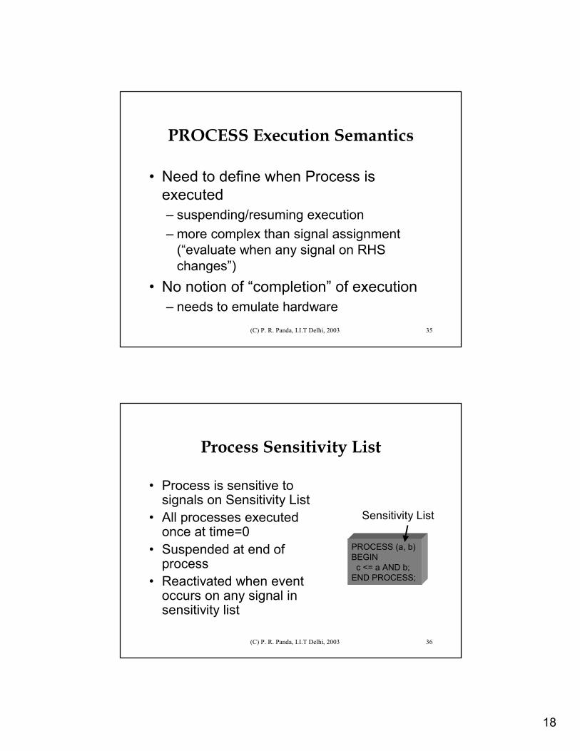
VHDL PROCESS• Execution within a
PROCESS is sequential• Processes are concurrent
w.r.t each other• Signal assignment is a
simple special case• Architecture consists of a
set of Processes (and signal assignments) at top level
• Processes communicate using signals
p1: PROCESS BEGIN
IF (x) THEN ...ELSE ...;...
END PROCESS;
p2: PROCESS BEGIN
FOR i in 1 TO 5 LOOPa (i) <= 0;
ENDL LOOP;...END PROCESS;
f <= g+ 1;
ARCHITECTURE x of a IS BEGIN
END x;
18
(C) P. R. Panda, I.I.T Delhi, 2003 35
PROCESS Execution Semantics
• Need to define when Process is executed– suspending/resuming execution– more complex than signal assignment
(“evaluate when any signal on RHS changes”)
• No notion of “completion” of execution– needs to emulate hardware
(C) P. R. Panda, I.I.T Delhi, 2003 36
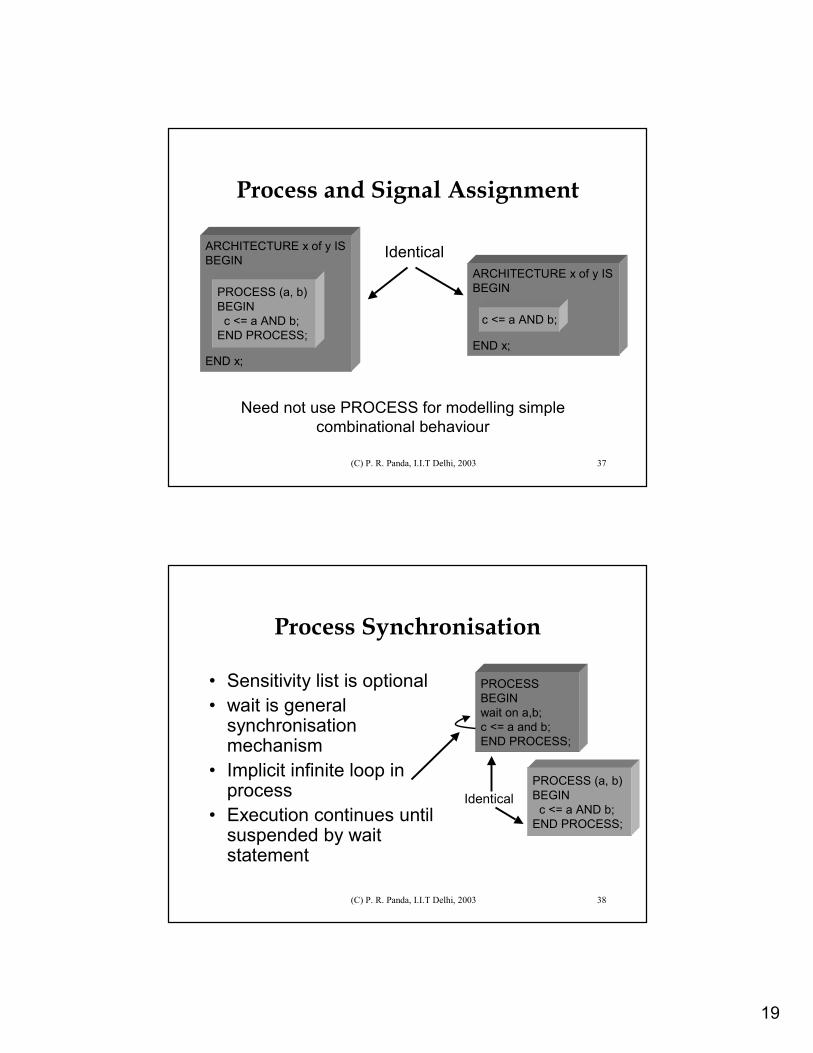
Process Sensitivity List
• Process is sensitive to signals on Sensitivity List
• All processes executed once at time=0
• Suspended at end of process
• Reactivated when event occurs on any signal in sensitivity list
PROCESS (a, b)BEGIN
c <= a AND b;END PROCESS;
Sensitivity List
19
(C) P. R. Panda, I.I.T Delhi, 2003 37
Process and Signal Assignment
ARCHITECTURE x of y ISBEGIN
END x;
Identical ARCHITECTURE x of y ISBEGIN
END x;
PROCESS (a, b)BEGIN
c <= a AND b;END PROCESS;
c <= a AND b;
Need not use PROCESS for modelling simplecombinational behaviour
(C) P. R. Panda, I.I.T Delhi, 2003 38
Process Synchronisation
• Sensitivity list is optional• wait is general
synchronisation mechanism
• Implicit infinite loop in process
• Execution continues until suspended by waitstatement
PROCESSBEGINwait on a,b;c <= a and b;END PROCESS;
PROCESS (a, b)BEGIN
c <= a AND b;END PROCESS;
Identical
20
(C) P. R. Panda, I.I.T Delhi, 2003 39
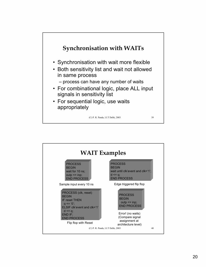
Synchronisation with WAITs
• Synchronisation with wait more flexible• Both sensitivity list and wait not allowed
in same process– process can have any number of waits
• For combinational logic, place ALL input signals in sensitivity list
• For sequential logic, use waitsappropriately
(C) P. R. Panda, I.I.T Delhi, 2003 40
WAIT ExamplesPROCESSBEGINwait for 10 ns;outp <= inp;END PROCESS
Sample input every 10 ns
PROCESSBEGINwait until clk’event and clk=‘1’;d <= q;END PROCESS
Edge triggered flip flop
PROCESS (clk, reset)BEGINIF reset THEN
q <= ‘0’;ELSIF clk’event and clk=‘1’
d <= q;END IF;END PROCESS
Flip flop with Reset
PROCESSBEGIN
outp <= inp;END PROCESS
Error! (no waits)(Compare signalassignment at
architecture level)
21
(C) P. R. Panda, I.I.T Delhi, 2003 41
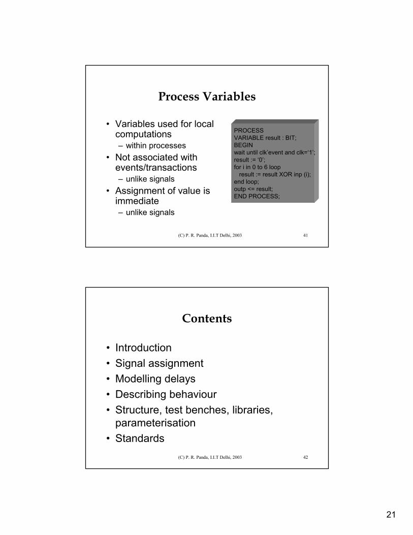
Process Variables
• Variables used for local computations– within processes
• Not associated with events/transactions– unlike signals
• Assignment of value is immediate– unlike signals
PROCESSVARIABLE result : BIT;BEGINwait until clk’event and clk=‘1’;result := ‘0’;for i in 0 to 6 loop
result := result XOR inp (i);end loop;outp <= result;END PROCESS;
(C) P. R. Panda, I.I.T Delhi, 2003 42
Contents
• Introduction• Signal assignment• Modelling delays• Describing behaviour• Structure, test benches, libraries,
parameterisation• Standards
22
(C) P. R. Panda, I.I.T Delhi, 2003 43
Structural Description
• Instantiation• Interconnection
(C) P. R. Panda, I.I.T Delhi, 2003 44
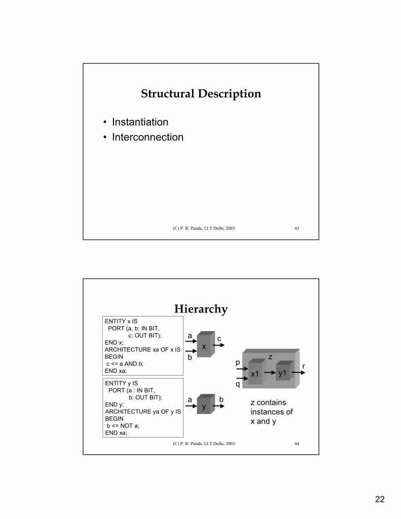
HierarchyENTITY x IS
PORT (a, b: IN BIT,c: OUT BIT);
END x;ARCHITECTURE xa OF x ISBEGINc <= a AND b;
END xa;
ENTITY y ISPORT (a : IN BIT,
b: OUT BIT);END y;ARCHITECTURE ya OF y ISBEGINb <= NOT a;
END xa;
x
y
a
b
c
a b
x1p
qy1
rz
z containsinstances ofx and y
23
(C) P. R. Panda, I.I.T Delhi, 2003 45
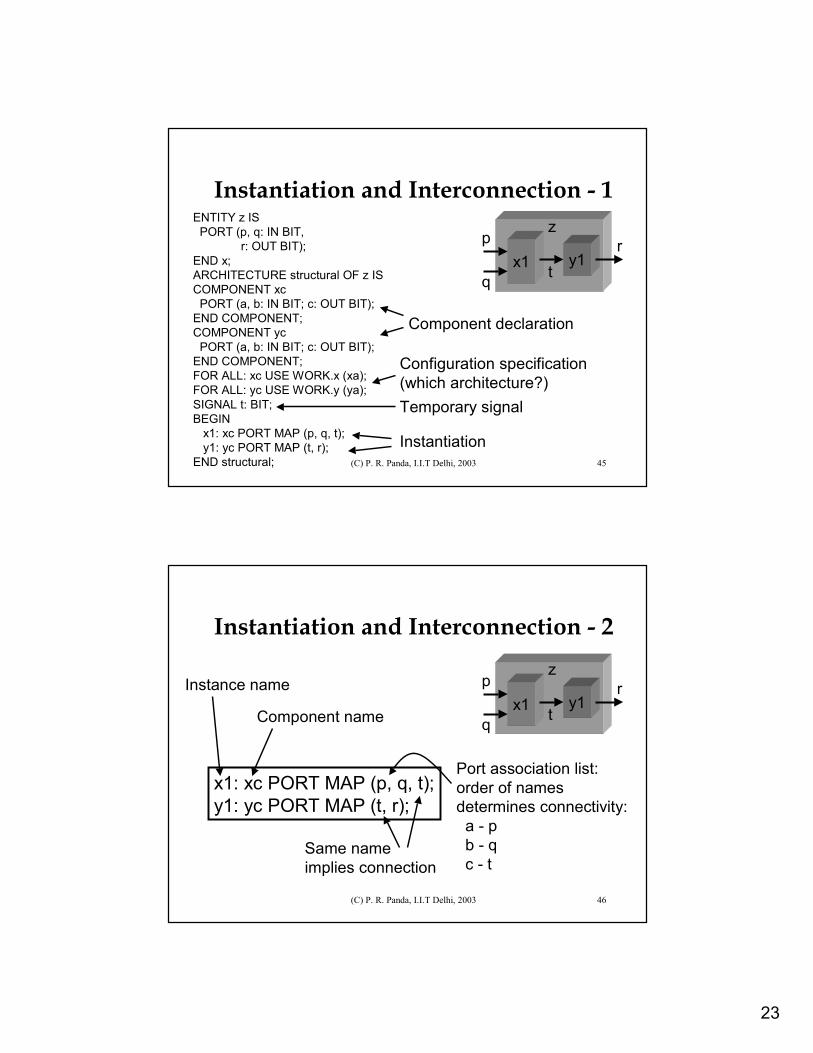
Instantiation and Interconnection - 1ENTITY z IS
PORT (p, q: IN BIT,r: OUT BIT);
END x;ARCHITECTURE structural OF z ISCOMPONENT xc
PORT (a, b: IN BIT; c: OUT BIT);END COMPONENT;COMPONENT yc
PORT (a, b: IN BIT; c: OUT BIT);END COMPONENT;FOR ALL: xc USE WORK.x (xa);FOR ALL: yc USE WORK.y (ya);SIGNAL t: BIT;BEGIN
x1: xc PORT MAP (p, q, t);y1: yc PORT MAP (t, r);
END structural;
x1p
qy1
rz
Component declaration
Configuration specification(which architecture?)
t
Temporary signal
Instantiation
(C) P. R. Panda, I.I.T Delhi, 2003 46
Instantiation and Interconnection - 2
x1: xc PORT MAP (p, q, t);y1: yc PORT MAP (t, r);
x1p
qy1
rz
t
Instance name
Component name
Port association list:order of names determines connectivity:
a - p b - qc - t
Same name implies connection
24
(C) P. R. Panda, I.I.T Delhi, 2003 47
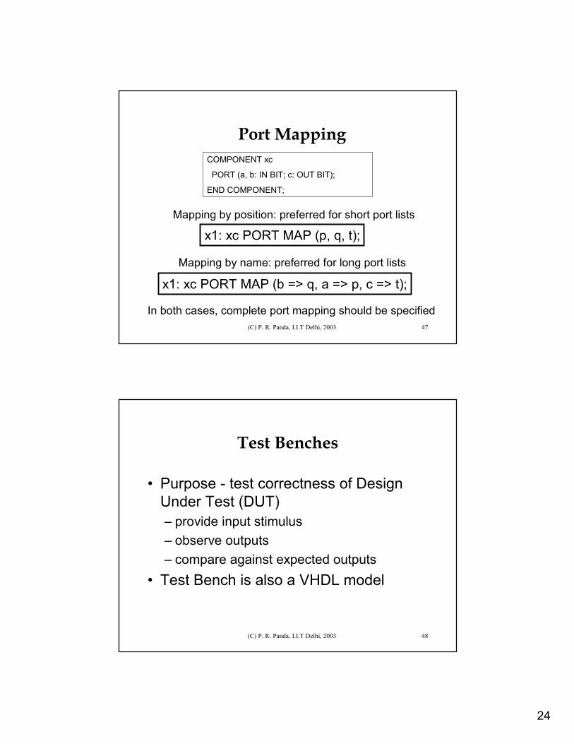
Port Mapping
x1: xc PORT MAP (p, q, t);
COMPONENT xc
PORT (a, b: IN BIT; c: OUT BIT);
END COMPONENT;
x1: xc PORT MAP (b => q, a => p, c => t);
Mapping by position: preferred for short port lists
Mapping by name: preferred for long port lists
In both cases, complete port mapping should be specified
(C) P. R. Panda, I.I.T Delhi, 2003 48
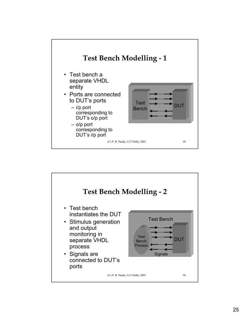
Test Benches
• Purpose - test correctness of Design Under Test (DUT)– provide input stimulus– observe outputs– compare against expected outputs
• Test Bench is also a VHDL model
25
(C) P. R. Panda, I.I.T Delhi, 2003 49
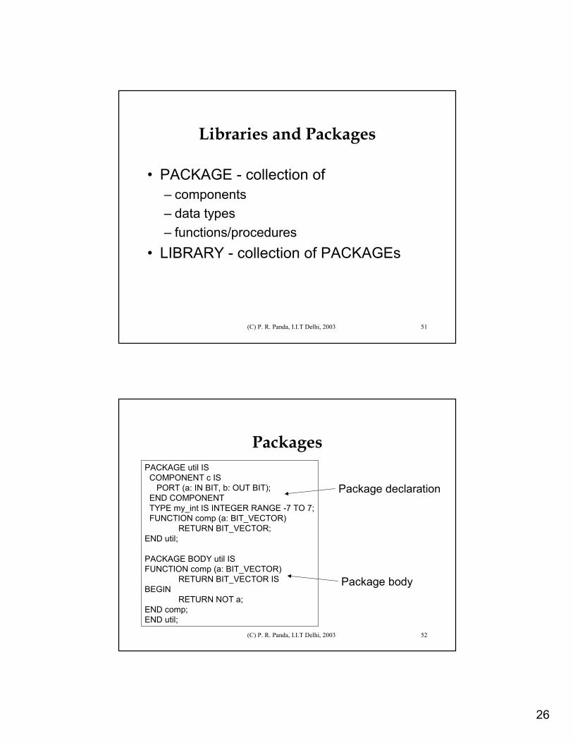
Test Bench Modelling - 1
• Test bench a separate VHDL entity
• Ports are connected to DUT’s ports– i/p port
corresponding to DUT’s o/p port
– o/p port corresponding to DUT’s i/p port
TestBench DUT
(C) P. R. Panda, I.I.T Delhi, 2003 50
Test Bench Modelling - 2
• Test bench instantiates the DUT
• Stimulus generation and output monitoring in separate VHDL process
• Signals are connected to DUT’s ports
DUT
Test Bench
TestBench
Process
Signals
26
(C) P. R. Panda, I.I.T Delhi, 2003 51
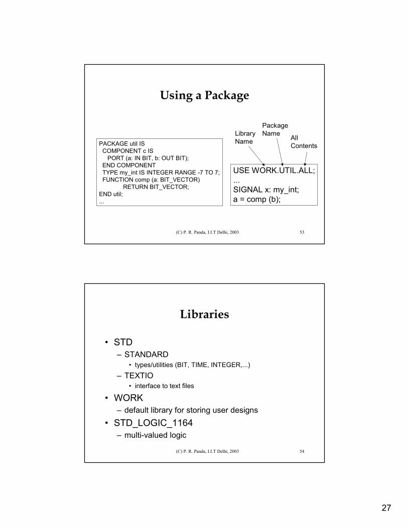
Libraries and Packages
• PACKAGE - collection of– components– data types– functions/procedures
• LIBRARY - collection of PACKAGEs
(C) P. R. Panda, I.I.T Delhi, 2003 52
PackagesPACKAGE util IS
COMPONENT c IS PORT (a: IN BIT, b: OUT BIT);
END COMPONENTTYPE my_int IS INTEGER RANGE -7 TO 7;FUNCTION comp (a: BIT_VECTOR)
RETURN BIT_VECTOR;END util;
PACKAGE BODY util ISFUNCTION comp (a: BIT_VECTOR)
RETURN BIT_VECTOR ISBEGIN
RETURN NOT a;END comp;END util;
Package declaration
Package body
27
(C) P. R. Panda, I.I.T Delhi, 2003 53
Using a Package
PACKAGE util ISCOMPONENT c IS
PORT (a: IN BIT, b: OUT BIT); END COMPONENTTYPE my_int IS INTEGER RANGE -7 TO 7;FUNCTION comp (a: BIT_VECTOR)
RETURN BIT_VECTOR;END util;...
USE WORK.UTIL.ALL;...SIGNAL x: my_int;a = comp (b);
LibraryName
PackageName All
Contents
(C) P. R. Panda, I.I.T Delhi, 2003 54
Libraries
• STD– STANDARD
• types/utilities (BIT, TIME, INTEGER,...)– TEXTIO
• interface to text files
• WORK– default library for storing user designs
• STD_LOGIC_1164– multi-valued logic
28
(C) P. R. Panda, I.I.T Delhi, 2003 55
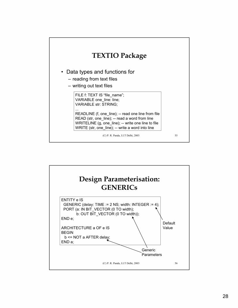
TEXTIO Package
• Data types and functions for – reading from text files– writing out text files
FILE f: TEXT IS “file_name”;VARIABLE one_line: line;VARIABLE str: STRING;...READLINE (f, one_line); -- read one line from fileREAD (str, one_line); -- read a word from lineWRITELINE (g, one_line); -- write one line to fileWRITE (str, one_line); -- write a word into line
(C) P. R. Panda, I.I.T Delhi, 2003 56
Design Parameterisation: GENERICs
ENTITY e ISGENERIC (delay: TIME := 2 NS; width: INTEGER := 4);PORT (a: IN BIT_VECTOR (0 TO width);
b: OUT BIT_VECTOR (0 TO width));END e;
ARCHITECTURE a OF e ISBEGIN
b <= NOT a AFTER delay;END a;
GenericParameters
DefaultValue
29
(C) P. R. Panda, I.I.T Delhi, 2003 57
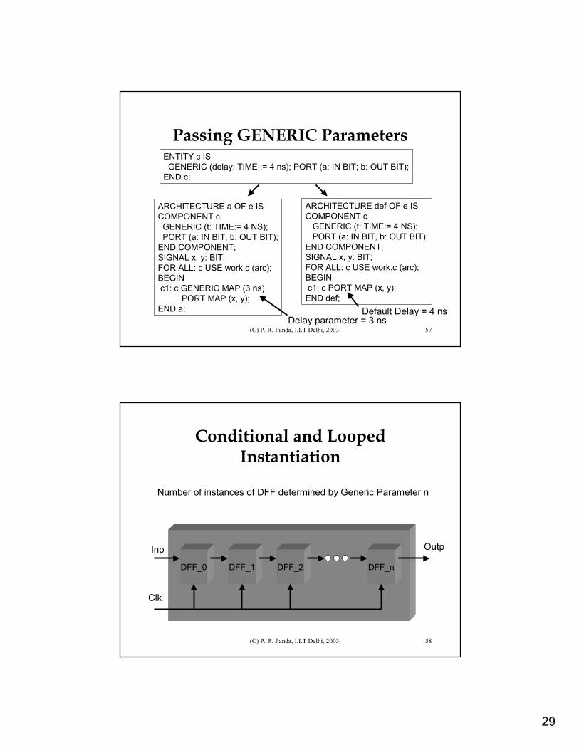
Passing GENERIC Parameters
ARCHITECTURE a OF e ISCOMPONENT c
GENERIC (t: TIME:= 4 NS);PORT (a: IN BIT, b: OUT BIT);
END COMPONENT;SIGNAL x, y: BIT;FOR ALL: c USE work.c (arc);BEGINc1: c GENERIC MAP (3 ns)
PORT MAP (x, y);END a;
ARCHITECTURE def OF e ISCOMPONENT c
GENERIC (t: TIME:= 4 NS);PORT (a: IN BIT, b: OUT BIT);
END COMPONENT;SIGNAL x, y: BIT;FOR ALL: c USE work.c (arc);BEGINc1: c PORT MAP (x, y);
END def;
ENTITY c ISGENERIC (delay: TIME := 4 ns); PORT (a: IN BIT; b: OUT BIT);
END c;
Default Delay = 4 nsDelay parameter = 3 ns
(C) P. R. Panda, I.I.T Delhi, 2003 58
Conditional and Looped Instantiation
DFF_0 DFF_1 DFF_2 DFF_n
Clk
Inp Outp
Number of instances of DFF determined by Generic Parameter n
30
(C) P. R. Panda, I.I.T Delhi, 2003 59
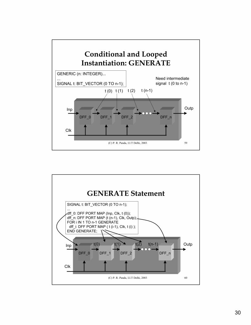
Conditional and Looped Instantiation: GENERATE
Need intermediate signal t (0 to n-1)
DFF_0 DFF_1 DFF_n
Clk
Inp Outp
DFF_2
t (0) t (1) t (2) t (n-1)
GENERIC (n: INTEGER)......SIGNAL t: BIT_VECTOR (0 TO n-1);
(C) P. R. Panda, I.I.T Delhi, 2003 60
GENERATE Statement
DFF_0 DFF_1 DFF_n
Clk
Inp Outp
DFF_2
t(0) t(1) t(2) t(n-1)
SIGNAL t: BIT_VECTOR (0 TO n-1);...dff_0: DFF PORT MAP (Inp, Clk, t (0)); dff_n: DFF PORT MAP (t (n-1), Clk, Outp);FOR i IN 1 TO n-1 GENERATE
dff_i: DFF PORT MAP ( t (i-1), Clk, t (i) );END GENERATE;
31
(C) P. R. Panda, I.I.T Delhi, 2003 61
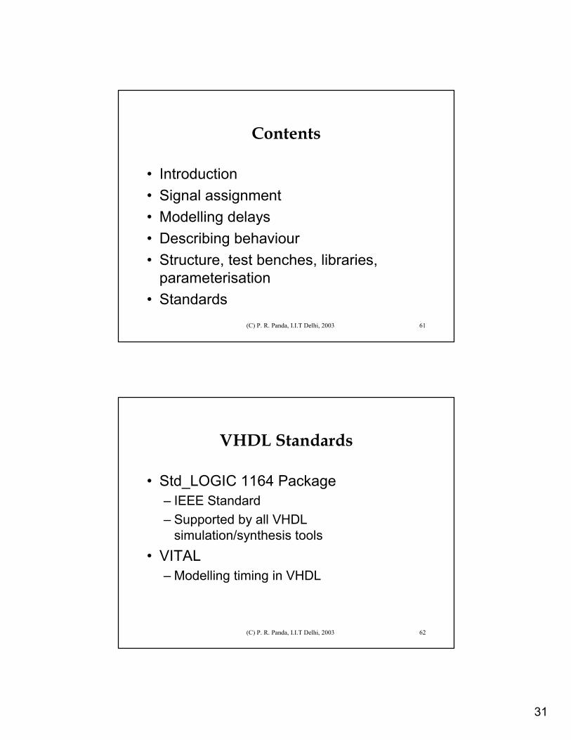
Contents
• Introduction• Signal assignment• Modelling delays• Describing behaviour• Structure, test benches, libraries,
parameterisation• Standards
(C) P. R. Panda, I.I.T Delhi, 2003 62
VHDL Standards
• Std_LOGIC 1164 Package– IEEE Standard– Supported by all VHDL
simulation/synthesis tools• VITAL
– Modelling timing in VHDL
32
(C) P. R. Panda, I.I.T Delhi, 2003 63
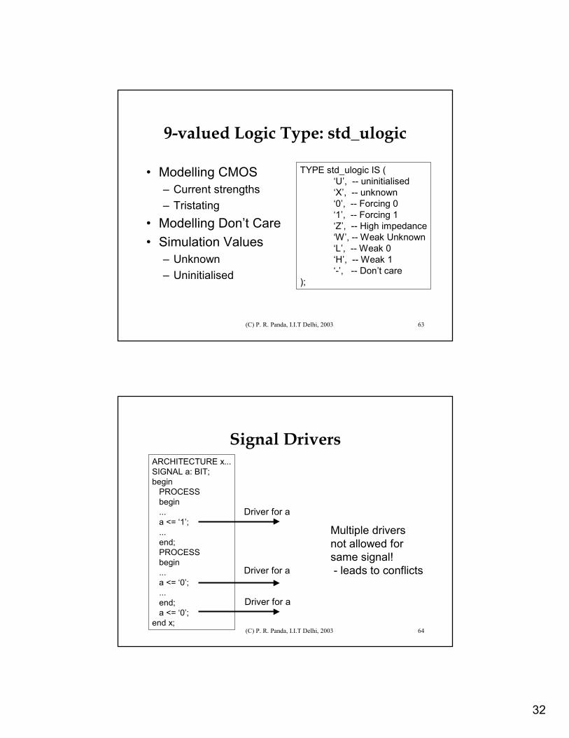
9-valued Logic Type: std_ulogic
• Modelling CMOS– Current strengths– Tristating
• Modelling Don’t Care• Simulation Values
– Unknown – Uninitialised
TYPE std_ulogic IS (‘U’, -- uninitialised‘X’, -- unknown‘0’, -- Forcing 0‘1’, -- Forcing 1‘Z’, -- High impedance‘W’, -- Weak Unknown‘L’, -- Weak 0‘H’, -- Weak 1‘-’, -- Don’t care
);
(C) P. R. Panda, I.I.T Delhi, 2003 64
Signal DriversARCHITECTURE x...SIGNAL a: BIT;begin
PROCESSbegin...a <= ‘1’;...end; PROCESSbegin...a <= ‘0’;...end;a <= ‘0’;
end x;
Driver for a
Driver for a
Driver for a
Multiple driversnot allowed forsame signal!- leads to conflicts
33
(C) P. R. Panda, I.I.T Delhi, 2003 65
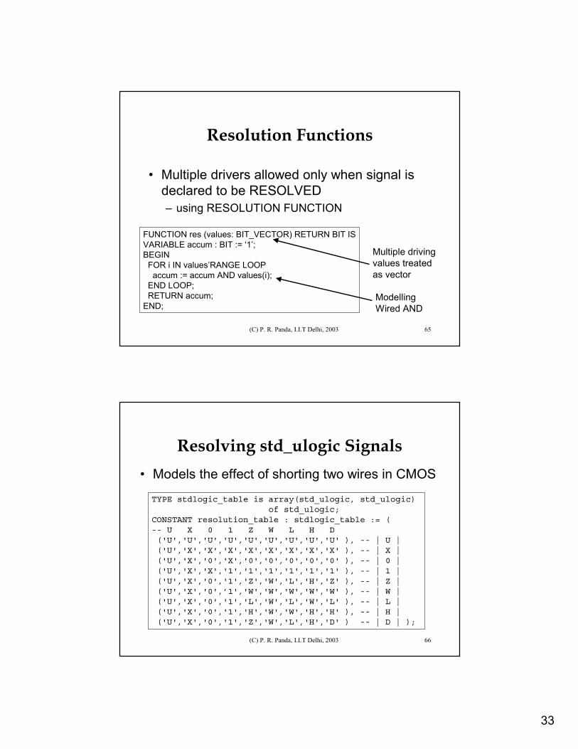
Resolution Functions
• Multiple drivers allowed only when signal is declared to be RESOLVED– using RESOLUTION FUNCTION
FUNCTION res (values: BIT_VECTOR) RETURN BIT ISVARIABLE accum : BIT := ‘1’;BEGIN
FOR i IN values’RANGE LOOPaccum := accum AND values(i);
END LOOP;RETURN accum;
END;
Multiple drivingvalues treated as vector
ModellingWired AND
(C) P. R. Panda, I.I.T Delhi, 2003 66
Resolving std_ulogic Signals• Models the effect of shorting two wires in CMOS
TYPE stdlogic_table is array(std_ulogic, std_ulogic) of std_ulogic;
CONSTANT resolution_table : stdlogic_table := ( -- U X 0 1 Z W L H D ('U','U','U','U','U','U','U','U','U' ), -- | U | ('U','X','X','X','X','X','X','X','X' ), -- | X | ('U','X','0','X','0','0','0','0','0' ), -- | 0 | ('U','X','X','1','1','1','1','1','1' ), -- | 1 | ('U','X','0','1','Z','W','L','H','Z' ), -- | Z | ('U','X','0',’1','W','W','W','W','W' ), -- | W | ('U','X','0','1','L','W','L','W','L' ), -- | L | ('U','X','0','1','H','W','W','H','H' ), -- | H | ('U','X','0','1','Z','W','L','H','D' ) -- | D | );
34
(C) P. R. Panda, I.I.T Delhi, 2003 67
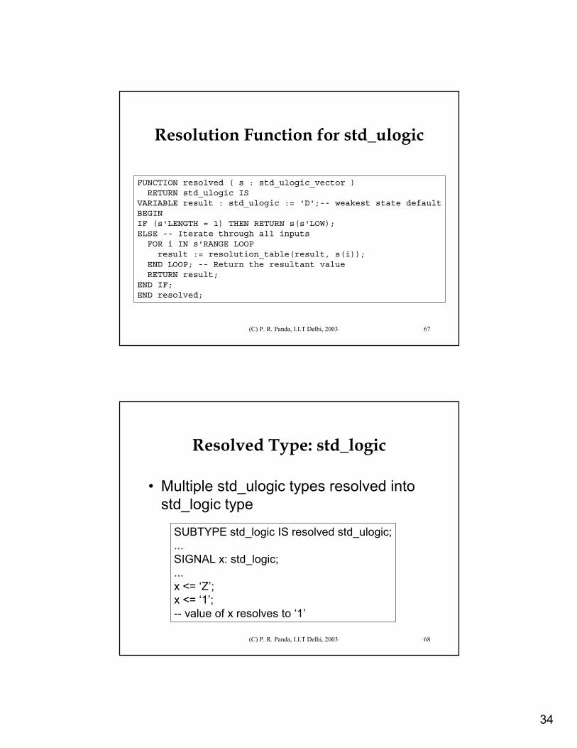
Resolution Function for std_ulogic
FUNCTION resolved ( s : std_ulogic_vector ) RETURN std_ulogic IS
VARIABLE result : std_ulogic := 'D';-- weakest state defaultBEGIN IF (s'LENGTH = 1) THEN RETURN s(s'LOW); ELSE -- Iterate through all inputs
FOR i IN s'RANGE LOOP result := resolution_table(result, s(i));
END LOOP; -- Return the resultant value RETURN result;
END IF; END resolved;
(C) P. R. Panda, I.I.T Delhi, 2003 68
Resolved Type: std_logic
• Multiple std_ulogic types resolved into std_logic type
SUBTYPE std_logic IS resolved std_ulogic;...SIGNAL x: std_logic;...x <= ‘Z’;x <= ‘1’;-- value of x resolves to ‘1’
35
(C) P. R. Panda, I.I.T Delhi, 2003 69
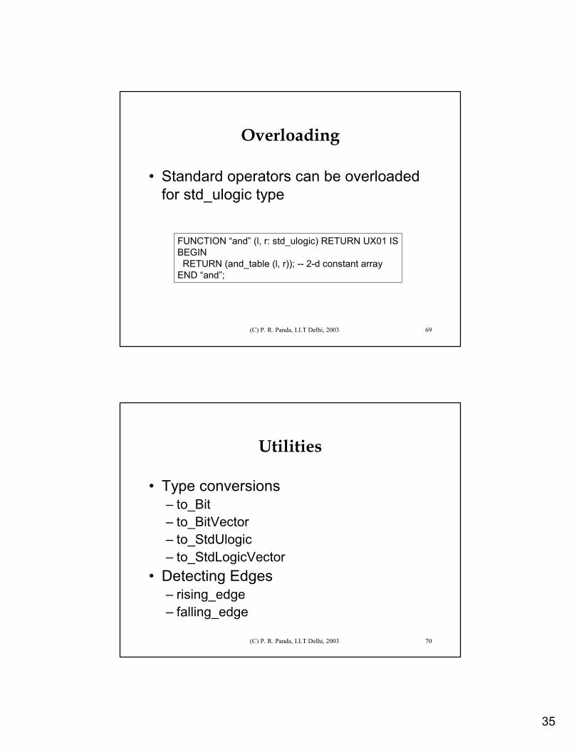
Overloading
• Standard operators can be overloaded for std_ulogic type
FUNCTION “and” (l, r: std_ulogic) RETURN UX01 ISBEGINRETURN (and_table (l, r)); -- 2-d constant array
END “and”;
(C) P. R. Panda, I.I.T Delhi, 2003 70
Utilities
• Type conversions– to_Bit– to_BitVector– to_StdUlogic– to_StdLogicVector
• Detecting Edges– rising_edge– falling_edge
36
(C) P. R. Panda, I.I.T Delhi, 2003 71
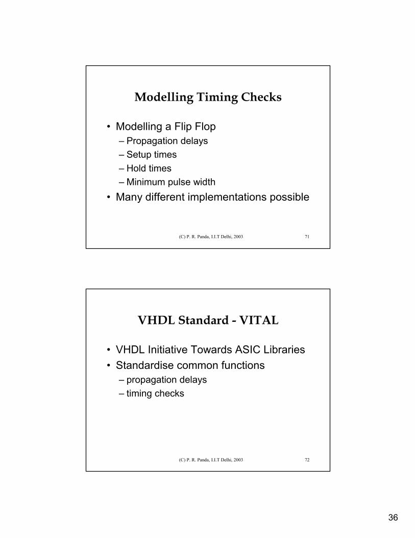
Modelling Timing Checks
• Modelling a Flip Flop– Propagation delays– Setup times– Hold times– Minimum pulse width
• Many different implementations possible
(C) P. R. Panda, I.I.T Delhi, 2003 72
VHDL Standard - VITAL
• VHDL Initiative Towards ASIC Libraries• Standardise common functions
– propagation delays– timing checks
37
(C) P. R. Panda, I.I.T Delhi, 2003 73
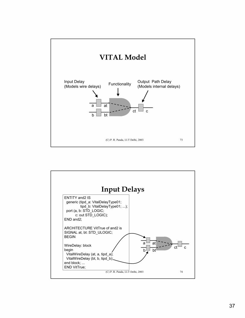
VITAL Model
Input Delay(Models wire delays) Functionality Output Path Delay
(Models internal delays)
a at
b btct c
(C) P. R. Panda, I.I.T Delhi, 2003 74
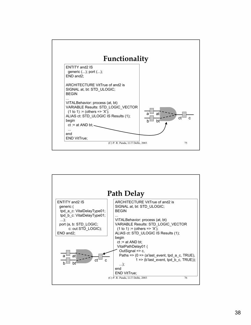
Input DelaysENTITY and2 IS
generic (tipd_a: VitalDelayType01; tipd_b: VitalDelayType01; ...);
port (a, b: STD_LOGIC;c: out STD_LOGIC);
END and2;
ARCHITECTURE VitTrue of and2 isSIGNAL at, bt: STD_ULOGIC;BEGIN
WireDelay: blockbegin
VitalWireDelay (at, a, tipd_a);VitalWireDelay (bt, b, tipd_b);
end block; ...END VitTrue;
a at
b btct c
38
(C) P. R. Panda, I.I.T Delhi, 2003 75
FunctionalityENTITY and2 IS
generic (...); port (...);END and2;
ARCHITECTURE VitTrue of and2 isSIGNAL at, bt: STD_ULOGIC;BEGIN...VITALBehavior: process (at, bt)VARIABLE Results: STD_LOGIC_VECTOR
(1 to 1) := (others => ‘X’);ALIAS ct: STD_ULOGIC IS Results (1);begin
ct := at AND bt;...
endEND VitTrue;
a at
b btct c
(C) P. R. Panda, I.I.T Delhi, 2003 76
Path DelayARCHITECTURE VitTrue of and2 isSIGNAL at, bt: STD_ULOGIC;BEGIN...VITALBehavior: process (at, bt)VARIABLE Results: STD_LOGIC_VECTOR
(1 to 1) := (others => ‘X’);ALIAS ct: STD_ULOGIC IS Results (1);begin
ct := at AND bt;VitalPathDelay01 (
OutSignal => c,Paths => (0 => (a’last_event, tpd_a_c, TRUE),
1 => (b’last_event, tpd_b_c, TRUE));...);
endEND VitTrue;
a at
b btct c
ENTITY and2 ISgeneric (tpd_a_c: VitalDelayType01; tpd_b_c: VitalDelayType01;...);
port (a, b: STD_LOGIC;c: out STD_LOGIC);
END and2;
39
(C) P. R. Panda, I.I.T Delhi, 2003 77
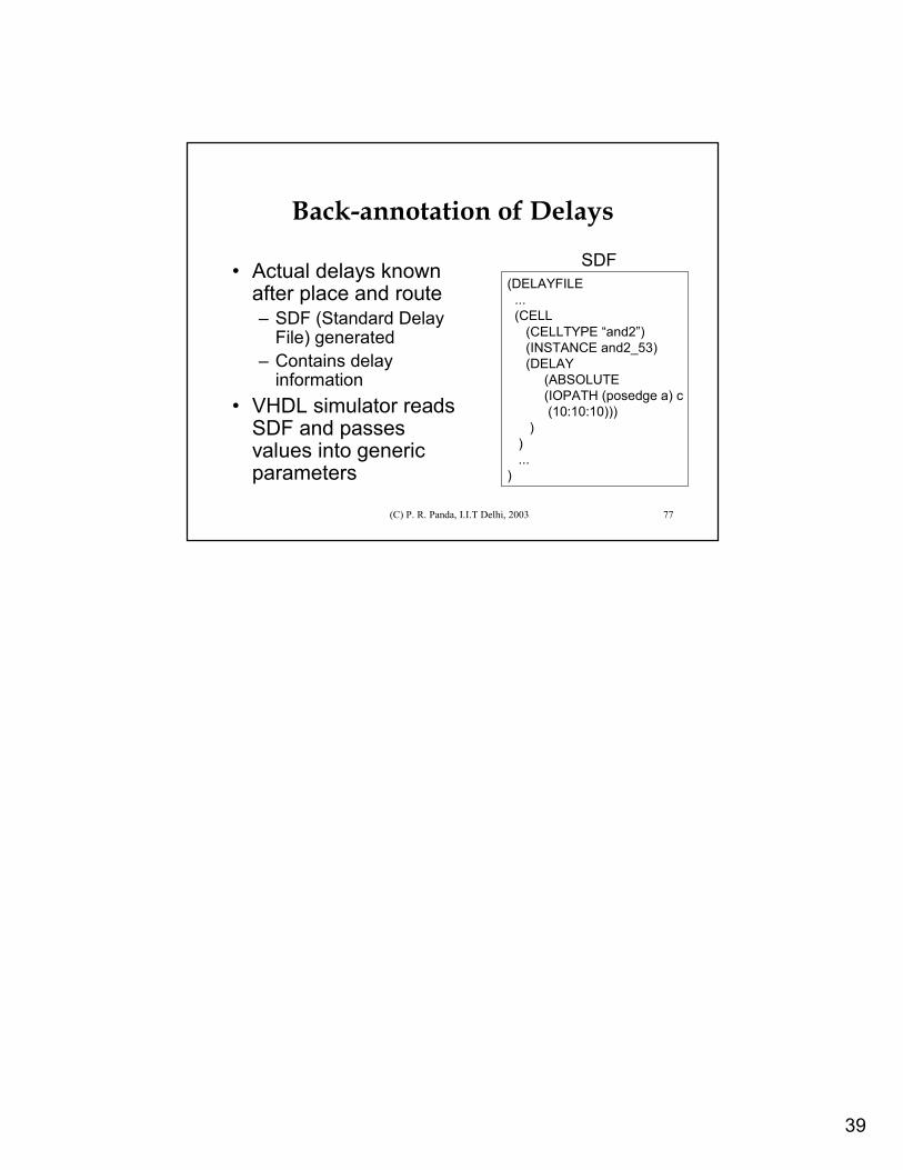
Back-annotation of Delays
• Actual delays known after place and route– SDF (Standard Delay
File) generated– Contains delay
information• VHDL simulator reads
SDF and passes values into generic parameters
(DELAYFILE...(CELL
(CELLTYPE “and2”)(INSTANCE and2_53)(DELAY
(ABSOLUTE(IOPATH (posedge a) c(10:10:10)))
))...
)
SDF