Embed Size (px)
Citation preview

Journal of Microwaves, Optoelectronics and Electromagnetic Applications, Vol. 18, No. 2, June 2019
DOI: http://dx.doi.org/10.1590/2179-10742019v18i21550 157
Brazilian Microwave and Optoelectronics Society-SBMO received 22 Nov 2018; for review 22 Nov 2018; accepted 25 Feb 2019
Brazilian Society of Electromagnetism-SBMag © 2019 SBMO/SBMag ISSN 2179-1074
Abstract— This paper describes a new design methodology for
reconfigurable printed circuits with limited size, using an improved
hybrid particle swarm optimization (HPSO) algorithm, reducing the
search space by the definition of negative zones (NZ), regions where the
swarm of particles should not travel. The proposed design methodology
(HPSO-NZ) is used in the development of reconfigurable frequency
selective surfaces (RFSSs), restricted to a limited overall size, resulting
in entirely new frequency selective surface (FSS) geometries. Two FSS
prototypes are designed, fabricated, and measured for comparison
purpose. A good agreement is observed between simulation and
measurements results, confirming the efficiency and accuracy of the
HPSO-NZ algorithm. Also, the performance of the HPSO-NZ
algorithm is compared to the ones of genetic algorithm (GA) and
particle swarm optimization (PSO) algorithm, showing good
consistency results.
Index Terms— Particle swarm optimization, PSO, negative zones, HPSO-NZ, GA,
reconfigurable FSS.
I. INTRODUCTION
Wireless communication systems are evolving to a new generation of multifunctional platforms that
offer high-quality services that demand high data transmission rates such as global positioning system
(GPS) applications, video, and audio transmissions, internet and others. All these services require the
development of devices and circuits capable of adapting to different conditions of transmission rate,
interference, and fading [1].
These new radio systems necessarily will require the development of devices such as antennas, filters
and feeding line circuits which are capable of operating in different frequency bands and intensity. The
reconfiguration of an antenna or microwave circuit is achieved by a deliberate change in its operating
Synthesis of New Reconfigurable Limited
Size FSS Structures Using an Improved
Hybrid Particle Swarm Optimization
Patric Lacouth1,2 , Adaildo Gomes D’Assunção2 , Alfrêdo Gomes Neto1 1Federal Institute of Paraíba, Av. João da Mata 256, Jaguaribe, CEP: 58015-430, João Pessoa, PB, Brazil.
[email protected], [email protected] 2Federal University of Rio Grande do Norte, Department of Communication Engineering, Caixa Postal 1655,
CEP: 59072-970, Natal, RN, Brazil, [email protected]

Journal of Microwaves, Optoelectronics and Electromagnetic Applications, Vol. 18, No. 2, June 2019
DOI: http://dx.doi.org/10.1590/2179-10742019v18i21550 158
Brazilian Microwave and Optoelectronics Society-SBMO received 22 Nov 2018; for review 22 Nov 2018; accepted 25 Feb 2019
Brazilian Society of Electromagnetism-SBMag © 2019 SBMO/SBMag ISSN 2179-1074
frequency, polarization or radiation characteristics [2]. This change can be obtained by different
techniques redistributing the electrical current density of the antenna and modifying its radiation pattern.
Recently, it is observed a high interest in the development of reconfigurable and compact printed
circuits because of their ease integration to small equipment and ability to operate in different frequencies
according to the communication system requirements. The performance of many radio-based
communications systems can be significantly improved by using small and reconfigurable integrated
circuits.
The design process and development of reconfigurable printed circuits require the appropriate
integration of different components in the structure, such as radio frequency microelectromechanical
system (RF MEMS), PIN diodes, and varactors, among others, on the surface of the printed circuit or
feeding lines. Indeed, this is a real challenge since it is necessary to consider all the influences caused by
switching components and activation lines in the final frequency response of the printed circuit [3].
Frequency selective surfaces (FSSs) are periodic structures interacting with electromagnetic (EM)
waves to provide resonant frequencies selectivity [4]. FSSs were successfully introduced in antenna
designs for several purposes such as suppressing surface waves and achieving low profile patch antennas
and switched-beam antennas [5]. Recently, several FSS structures have been applied to design Fabry-Pérot
cavities [6], [7].
Typically, frequency selective surfaces are designed by changing popular designs or classical
topologies and usually involve a process of "trial and error" to get the desired results. The most critical
step in the design process of the desired FSS is the proper choice of elements for the array. The element
type and geometry, substrate parameters, presence or absence of superstrates, and inter-element spacing,
in general, determine the overall frequency response of the structure, such as bandwidth (BW), transfer
function, and dependence on the incidence angle and polarization [8]. A comprehensive review of FSS
designs is provided in [4].
However, to address the real challenges and requirements presented by nowadays wireless systems,
there is a need to develop new solutions and strategies for the design of FSS, antennas, and radio
frequency (RF) printed circuits. Moreover, one of these challenges is the development of structures
capable of changing the behavior of the operation dynamically and efficiently.
One of the most efficient approaches proposed to design new integrated circuit structures
systematically is the integration of electromagnetic analysis software, as the High-Frequency Structure
Simulator (HFSS) commercial software, with different optimization techniques [9].
Optimization algorithms as particle swarm optimization (PSO), genetic algorithms (GAs), and artificial
neural networks (ANNs), have been widely used for the design and development of microwave passive
printed circuits [10], [11].

Journal of Microwaves, Optoelectronics and Electromagnetic Applications, Vol. 18, No. 2, June 2019
DOI: http://dx.doi.org/10.1590/2179-10742019v18i21550 159
Brazilian Microwave and Optoelectronics Society-SBMO received 22 Nov 2018; for review 22 Nov 2018; accepted 25 Feb 2019
Brazilian Society of Electromagnetism-SBMag © 2019 SBMO/SBMag ISSN 2179-1074
Although the integration between the optimization and electromagnetic analysis algorithms provides a
wide design possibility, the computational cost becomes high due to the need for a large number of
simulations. Therefore, a new concept is presented within the HPSO implementation that aims to enhance
the accuracy of the algorithm, thus reducing the number of iterations needed to achieve convergence,
resulting in the development of the HPSO-NZ algorithm which is used to synthesize new active
reconfigurable FSSs.
The proposed optimization technique is used to design active reconfigurable FSSs with limited size
patch elements printed on single dielectric layers, for operation in the S and C bands, of easy manufacture
and integration to other microwave circuits. This technique can be used to synthesize other planar circuits,
including antennas, filters, directional couplers and matching circuits.
Section II describes the implementation of the algorithm and the use of classic functional testbeds to
verify the algorithm performance. To illustrate the application of the HPSO-NZ algorithm, two RFSSs are
designed, fabricated, and measured, as presented in Section III. Conclusions are summarized in Section
IV.
II. HPSO AND HPSO-NZ ALGORITHMS: IMPLEMENTATION AND VALIDATION
The PSO algorithm is a global optimizer developed with the main objective of simulating the behavior
of a flock of birds in search of food in an open field [9]. The birds (particles) would have a personal and
social awareness of the best points visited in that field. These birds (particles) would remember the best-
seen position from their personal history, and they would know the best-seen position of the entire flock.
With this memory, each bird (particle) is driven toward its best-seen position (pbest) and the flock’s global
best-seen position (gbest) [9].
Using PSO for hybrid optimization problems with both real and binary parameters is suitable and
interesting because the operations related to each problem dimension do not depend on information about
other dimensions. This independence allows for different dimensions of the same problem to be
represented by real or binary values and subjected to the same PSO update scheme.
A. HPSO Implementation
The PSO shares many similarities with evolutionary techniques such as genetic algorithms (GAs). The
system is initialized with a population of random solutions and searches for the optimal solution by
successive update iterations. However, unlike GA, PSO has no evolutionary operators such as crossover
and mutation.

Journal of Microwaves, Optoelectronics and Electromagnetic Applications, Vol. 18, No. 2, June 2019
DOI: http://dx.doi.org/10.1590/2179-10742019v18i21550 160
Brazilian Microwave and Optoelectronics Society-SBMO received 22 Nov 2018; for review 22 Nov 2018; accepted 25 Feb 2019
Brazilian Society of Electromagnetism-SBMag © 2019 SBMO/SBMag ISSN 2179-1074
The PSO is based on the principle that each solution can be represented as a particle within a swarm.
Each particle has a vector position and velocity, and each coordinate represents a value of a parameter to
be optimized. Then for an N-dimensional optimization, each particle will have a position in an N-
dimensional space that represents a possible solution to the problem. The underlying implementation of
the PSO algorithm is described in a reduced form in Table I since the flowchart of classical PSO can be
found in [10]-[12]. The emphasis here is on the several critical steps that requires special attention when
dealing with real and binary parts in different manners.
TABLE I. ALGORITHM IMPLEMENTATION OF HPSO-NZ
REAL PART BINARY PART
= [ ] = 𝑹1, 𝑹2 = 𝑩1, 𝑩2, … 𝑩𝑁
pbest, gbest Both parts share the same pbest and the same gbest
v-update 𝑽𝑡 = 𝑤𝑽𝑡−1 + 𝑐1𝜂1(𝑷𝑡−1 − 𝑿𝑡−1) + 𝑐2𝜂2(𝑮𝑡−1 − 𝑿𝑡−1)
Inertia weight time varying, 0.9-0.4 constant 1.0
Vmax 0.1 × (𝑅𝑚𝑎𝑥 − 𝑅𝑚𝑖𝑛) 6.0
x-update
= 𝑡−1 + 𝑟,𝑡
𝑆(𝑣𝑚𝑛,𝑡) = 1
1 + 𝑒−𝑣𝑚𝑛,𝑡
𝑥𝑚𝑛,𝑡 = 1, 𝑟𝑚𝑛,𝑡 < 𝑆(𝑣𝑚𝑛,𝑡)
0, 𝑟𝑚𝑛,𝑡 ≥ 𝑆(𝑣𝑚𝑛,𝑡)
Boundary Yes No
NZ - Radius 0.05 × (𝐵𝑜𝑢𝑛𝑑𝑎𝑟𝑦𝑚𝑎𝑥 − 𝐵𝑜𝑢𝑛𝑑𝑎𝑟𝑦𝑚𝑖𝑛)
Assume each particle in a swarm is represented by an (M + N)-dimensional vector
𝑥 = 𝑅1, 𝑅2, ⋯ , 𝑅𝑀,𝐵1, 𝐵2, ⋯ , 𝐵𝑁 (1)
by cascading M real variables RM (𝑚 = 1,2, ⋯ , 𝑀) and N binary variables BN(𝑛 = 1,2, ⋯ , 𝑁).
At each iteration, the real part and binary part share the same personal best, the global best and the
velocity updating (v-update) equation. The uniqueness of HPSO lies in the position updating (x-update)
[13], [14]. In particular, the position of the real part is updated by the vector summation formulated in
Table I, and the binary part needs to be updated via the sigmoid transformation 𝑆(𝑣𝑚𝑛,𝑡) as applied in

Journal of Microwaves, Optoelectronics and Electromagnetic Applications, Vol. 18, No. 2, June 2019
DOI: http://dx.doi.org/10.1590/2179-10742019v18i21550 161
Brazilian Microwave and Optoelectronics Society-SBMO received 22 Nov 2018; for review 22 Nov 2018; accepted 25 Feb 2019
Brazilian Society of Electromagnetism-SBMag © 2019 SBMO/SBMag ISSN 2179-1074
regular binary particle swarm optimization (BPSO) [13]. Other suggested optimization such as the inertia
weight 𝑤 and the maximum velocity 𝑉𝑚𝑎𝑥 are also provided by Table I. It is worthwhile mentioning that
the boundary condition is only applied to the real part, since the x-update in HPSO intrinsically defines no
out-of-boundary solutions in a binary space [14].
B. HPSO with Negative Zones
As defined in the updating basic equations of PSO, the information used to update the speed and
position of each particle refer to the position of the best particle of the swarm (gbest) and the best position
previously obtained by the particle (pbest). Despite creating a strong tendency toward the best search
space positions, there is no mechanism to prevent the particles from going through paths that have already
been traced by other particles causing computational resource waste. To avoid such behavior, in this work,
the concept of negative zones is proposed.
Negative zones (NZ) are regions within the search space where the swarm of particles should not
travel. Negative zones, in the context of the search space, would act as the inverse of the global best, but
with the significant difference that while the gbest can change at each iteration, the negative zones are
saved in a list that increases with each iteration. As the negative zones increase, the swarm's search space
becomes increasingly smaller, allowing particles to travel only in the most promising directions. The
algorithm determines a new negative zone from the particle with the worst ranking at each iteration. The
negative zone radius is calculated using the boundaries of the search space.
If any particle falls into any of these areas their speed and position are recalculated as follows:
Vt = (−1 + η3)Vt (2)
Xt = Xt + Vt (3)
Where η3 is a random value between 0 and 1.
In this way, the particle is repelled by the negative zone and gains speed in a new direction
proportional to its previous speed. Figure 1 illustrates the effect of negative zones in the way that each
particle travels in search of the desired solution.

Journal of Microwaves, Optoelectronics and Electromagnetic Applications, Vol. 18, No. 2, June 2019
DOI: http://dx.doi.org/10.1590/2179-10742019v18i21550 162
Brazilian Microwave and Optoelectronics Society-SBMO received 22 Nov 2018; for review 22 Nov 2018; accepted 25 Feb 2019
Brazilian Society of Electromagnetism-SBMag © 2019 SBMO/SBMag ISSN 2179-1074
Fig. 1. Description of a swarm that is searching through a 2-D field. Gray circles represent the negative zones and X the
optimization objective.
The HPSO-NZ algorithm can be validated by optimizing the Rastrigin function as proposed in [13].
The Rastrigin function is a non-convex function used as a performance test problem for optimization
algorithms. It is a typical example of a non-linear multimodal function. Finding the minimum of this
function is a somewhat difficult problem due to its large search space and its large number of local
minima [14]. The Rastrigin function is defined by [13]:
𝑓 = ∑ [𝑎𝑖2 − 10 cos(2𝜋𝑎𝑖) + 10]𝑁
𝑖=1 (4)
In Fig. 2, it is shown an example of Rastrigin function with N = 2, and their overall minimum located
at a1 = a2 = 0.
Fig. 2. Topology of the 2-D multimodal Rastrigin function.

Journal of Microwaves, Optoelectronics and Electromagnetic Applications, Vol. 18, No. 2, June 2019
DOI: http://dx.doi.org/10.1590/2179-10742019v18i21550 163
Brazilian Microwave and Optoelectronics Society-SBMO received 22 Nov 2018; for review 22 Nov 2018; accepted 25 Feb 2019
Brazilian Society of Electromagnetism-SBMag © 2019 SBMO/SBMag ISSN 2179-1074
In [14] tests were performed with the Rastrigin function using N = 3 to enable a more complex
optimization test. The optimizer is a minimizer by default, and the optimization is performed in a search
space of 18 dimensions consisting of two real variables R1, R2 ∈ [−5,5] and sixteen binary bits, and
according to (4) with 𝑎1 = R1, 𝑎2 = R2, and 𝑎3 is related to the binary part via the mapping:
𝑎3 =10
216−1∑ 2N−1 × BN − 516
N=1 (5)
where BN are the binary variables.
Table I shows information on the parameters used in the optimization algorithms.
A swarm of 10 individuals is used on the function optimization for 200 iterations. Due to the stochastic
nature of the algorithms, the same test is repeated for 200 independent trials.
The standard HPSO algorithm was used to solve the same problem to compare to previous results.
According to [14] a final value lower than 0.5 is considered as an optimal result for the optimization
process.
The histogram of Fig. 3 shows the results of 200 independent optimizations performed on the Rastrigin
function. Using HPSO-NZ in 169 tests optimum results, less than 0.5, are obtained, while using HPSO
only 136 tests returned an optimum value, indicating a difference of approximately 20% between the two
algorithms. It is noteworthy that in the 200 HPSO-NZ tests the mean of the results was 0.26 with the
standard deviation of 0.38, whereas with the HPSO the mean and standard deviation were 0.56 and 0.50,
respectively.
Fig. 3. Histogram of the best fitness values approached in 200 independent trials by HPSO-NZ and standard HPSO.

Journal of Microwaves, Optoelectronics and Electromagnetic Applications, Vol. 18, No. 2, June 2019
DOI: http://dx.doi.org/10.1590/2179-10742019v18i21550 164
Brazilian Microwave and Optoelectronics Society-SBMO received 22 Nov 2018; for review 22 Nov 2018; accepted 25 Feb 2019
Brazilian Society of Electromagnetism-SBMag © 2019 SBMO/SBMag ISSN 2179-1074
Table II shows a comparison of the HPSO-NZ algorithm with four different algorithms implemented in
[14] to solve the same problem.
For a more in-depth validation of our proposal, the HPSO algorithm presented in [14] was also
implemented, and it is possible through Table II to verify the reproducibility of the results presented by
the authors.
These numerical results indicate that the HPSO-NZ algorithm is more efficient in solving hybrid
optimization problems (real/binary) by offering a higher chance of convergence with a smaller number of
iterations and particles.
TABLE II. COMPARISON OF 6 COUNTERPART ALGORITHMS (10 PARTICLES, 200 ITERATIONS, 200 TRIALS)
Furthermore, other aspects of the proposed HPSO-NZ algorithm can pass through other validation
processes [15] in order to test other search spaces and to better understand the influence of the
hyperparameters on the convergence of the algorithm.
III. RECONFIGURABLE FSS PERIODIC STRUCTURES
A reconfigurable FSS is a structure that can allow or block wave propagation simply by activating or
deactivating primary switchers such as diodes.
The basic unit cell of an active FSS structure used in this work is shown in Fig. 4. The diodes are
inserted between the parallel discontinuous strips. This unit cell is reproduced in the x-y plane. An
electromagnetic wave illuminates the unit cells with an electric field polarized parallel to the strips. It is
well-known that an array of parallel continuous wires will act as a high-pass filter which is mainly due to
the inductive behavior of the wires [1]. On the other hand, a similar passive array of discontinuous wires
shows band rejection filter behavior due to the capacitive effect between the discontinuous elements
conjugated in series to the previously considered inductive effect [1], [2].
Figure 4 shows simulated results for a RFSS structure with active elements (PIN diodes). The unit cell
is 20 mm x 20 mm, the strip width (W) is 1 mm, and the gap discontinuity dimension (g) is 1 mm. The
Algorithm gbest < 0.5
HPSO-NZ (this work) 169
HPSO (this work) 136
HPSO [14] 137
Binary PSO [14] 80
Binary GA [14] 12
Round-Off Real PSO [14] 6

Journal of Microwaves, Optoelectronics and Electromagnetic Applications, Vol. 18, No. 2, June 2019
DOI: http://dx.doi.org/10.1590/2179-10742019v18i21550 165
Brazilian Microwave and Optoelectronics Society-SBMO received 22 Nov 2018; for review 22 Nov 2018; accepted 25 Feb 2019
Brazilian Society of Electromagnetism-SBMag © 2019 SBMO/SBMag ISSN 2179-1074
RFSS transmission coefficient frequency response is depicted assuming that all PIN diodes are forward
biased (ON state) or unbiased (OFF state), corresponding to unit cells with continuous or discontinuous
conducting strips, respectively. In the HFSS analysis, the OFF state is simulated by replacing each PIN
diode by a capacitor of 0.17 pF. In the ON state, each diode is replaced by a 2.1 Ω resistor.
In order to achieve different frequency responses, it is necessary to change the cell unit shown in Fig.
4. In the optimization process, the active FSS analysis and synthesis is performed without using (at the
beginning) any basic patch element geometry.
The hybrid optimization approach was chosen because it allows the cell dimensions (Wx and Wy) to be
encoded as integer values and the patch geometry as a binary string. Without the constraint of specific
geometry, the algorithm can obtain an entirely new patch configuration for the problem.
Fig. 4. Simulation results for the transmission coefficient frequency response of the RFSS with PIN diodes and the illustrated unit
cell. All PIN diodes are biased (ON state), for continuous strips, or unbiased (OFF state), for discontinuous strips.
Figure 5 illustrates the concept of a primary FSS structure divided into small patches that can be
optimized to create the necessary configuration for the desired FSS frequency response.

Journal of Microwaves, Optoelectronics and Electromagnetic Applications, Vol. 18, No. 2, June 2019
DOI: http://dx.doi.org/10.1590/2179-10742019v18i21550 166
Brazilian Microwave and Optoelectronics Society-SBMO received 22 Nov 2018; for review 22 Nov 2018; accepted 25 Feb 2019
Brazilian Society of Electromagnetism-SBMag © 2019 SBMO/SBMag ISSN 2179-1074
Fig. 5. Concept of a binary FSS structure with patch elements.
A. Optimized Reconfigurable Frequency Selective Surfaces
Using the HPSO-NZ algorithm with the constraints summarized in Table III, the algorithm started with
the goal of creating a new geometric configuration to operate as a band-pass filter at the 7 GHz band,
when all the PIN diodes are on the OFF state, and to behave as a stopband filter at this frequency band,
when all diodes are on the ON state. The algorithm converged after 600 iterations. Figure 6 shows an
illustration of the internal patches’ configuration (“pixels”) of the synthesized RFSS with 20 mm x 20 mm
unit cells.
TABLE III. OPTIMIZED RFSS DESIGN GOALS AND STRUCTURAL PARAMETERS
OPTIMIZED FSS PARAMETERS VALUES
MAXIMUM RECTANGULAR CELL WIDTH (mm), WX 100
MAXIMUM RECTANGULAR CELL LENGTH (mm), WY 100
MINIMUM RECTANGULAR CELL WIDTH (mm), WX 10
MINIMUM RECTANGULAR CELL LENGTH (mm), WY 10
FREQUENCY DESIGN GOAL (GHZ), F 7.0
SUBSTRATE LAYER RELATIVE PERMITTIVITY (FR4), εr 4.4
SUBSTRATE LAYER LOSS TANGENT, tan 0.02
SUBSTRATE LAYER HEIGHT (mm), h1 1.57
NUMBER OF INTERNAL PATCHES (“PIXELS”) 400
NUMBER OF PATCHES USED IN HPSO-NZ 100
DIMENSIONAL PROBLEM SPACE 2100
SWARM SIZE 20
MAXIMUM ITERATION NUMBER 600
Fig. 6. Illustration of the RFSS patch element with a central air gap (1 mm x 1 mm) to integrate a PIN diode.
The HPSO-NZ algorithm optimized configuration was used to fabricate a RFSS prototype with
Infineon BAR64-03W PIN diodes, 20 cm x 20 cm overall size, and 100 cells. Figure 7 shows photographs

Journal of Microwaves, Optoelectronics and Electromagnetic Applications, Vol. 18, No. 2, June 2019
DOI: http://dx.doi.org/10.1590/2179-10742019v18i21550 167
Brazilian Microwave and Optoelectronics Society-SBMO received 22 Nov 2018; for review 22 Nov 2018; accepted 25 Feb 2019
Brazilian Society of Electromagnetism-SBMag © 2019 SBMO/SBMag ISSN 2179-1074
of the fabricated prototype. Conducting strips are used to ensure that all the RFSS PIN diodes would be
connected to the feed line on the ON state, as shown in Fig. 7(b).
Furthermore, the proposed HPSO-NZ algorithm synthesized a RFSS with 20 mm x 20 mm unit cells
and the configuration of internal patches (“pixels”) shown in Fig. 7(a).
(a) (b)
Fig. 7. Photographs of the RFSS prototype. (a) Unit cell and (b) array.
Simulation and measurement results for the frequency response of the RFSS transmission coefficient
are presented in Fig. 8, for both ON-state and OFF-state, for comparison purpose. Infineon BAR64-03W
PIN diodes [16], [17], are used to enable the FSS reconfigurability.
As shown in Fig. 8, the optimized RFSS, with all diodes on the OFF state, presents a stopband
performance with simulated and measured bandwidth results of about 1.5 GHz and 1.9 GHz, respectively,
for a -10 dB reference level. Similarly, the optimized RFSS, with all diodes on the ON state, presents a
bandpass performance with simulated and measured bandwidth results of about 3.8 GHz and 1 GHz,
respectively, for a -3 dB reference level. In addition, the difference between the FSS transmission
coefficients at the center frequency, in both cases (ON and OFF states), is greater than 15 dB.

Journal of Microwaves, Optoelectronics and Electromagnetic Applications, Vol. 18, No. 2, June 2019
DOI: http://dx.doi.org/10.1590/2179-10742019v18i21550 168
Brazilian Microwave and Optoelectronics Society-SBMO received 22 Nov 2018; for review 22 Nov 2018; accepted 25 Feb 2019
Brazilian Society of Electromagnetism-SBMag © 2019 SBMO/SBMag ISSN 2179-1074
Fig. 8. Simulation and measurement results for the transmission coefficient versus frequency of the optimized FSS.
To further test the proposed optimization algorithm for different conditions, another optimization
problem is carried out with new constraints and objectives. The optimized RFSS should operate as a
stopband filter at the 3 GHz band, when all the PIN diodes are on the OFF state and present two rejection
bands at 2 GHz and 4 GHz, but not at 3 GHz, when all the PIN diodes are on the ON state.
To reduce the FSS fabrication complexity observed in the fabrication of the first RFSS prototype,
shown in Fig. 7, the number of internal pixels was reduced to 100 “pixels”. Once again, Infineon BAR64-
03W PIN diodes [16], [17], are used to enable the FSS reconfigurability. After using the same algorithm
constraints summarized in Table I, the algorithm has been started and converged after 600 iterations with a
60 mm x 60 mm unit cell. Figure 9 shows an illustration of the internal patches’ configuration (“pixels”)
of the synthesized RFSS.
Fig. 9. Illustration of the RFSS unit cell and patch element with central air gap to integrate a PIN diode.

Journal of Microwaves, Optoelectronics and Electromagnetic Applications, Vol. 18, No. 2, June 2019
DOI: http://dx.doi.org/10.1590/2179-10742019v18i21550 169
Brazilian Microwave and Optoelectronics Society-SBMO received 22 Nov 2018; for review 22 Nov 2018; accepted 25 Feb 2019
Brazilian Society of Electromagnetism-SBMag © 2019 SBMO/SBMag ISSN 2179-1074
The HPSO-NZ algorithm optimized configuration was used to fabricate a RFSS prototype with
Infineon BAR64-03W PIN diodes, 20 cm x 20 cm overall size, and 16 cells. Again, the algorithm was
able to propose a patch geometry that exhibits the desired behavior. Figure 10 shows photographs of the
fabricated prototype.
The experimental results were measured at the GTEMA/IFPB Microwaves Laboratory, using an
Agilent two ports network analyzer, N5230A, and two 20 dB standard horn antennas. The PIN diodes are
activated using a controlled power supply to avoid any risk of damage to the circuits. Two feeding lines
have been added to the structure to allow the diodes biasing as shown in Fig. 10(b).
Furthermore, the proposed HPSO-NZ algorithm synthesized a RFSS with 20 mm x 20 mm unit cells
and the configuration of internal patches (“pixels”) shown in Fig. 10(a).
(a) (b)
Fig. 10. Photographs of the RFSS prototype. (a) Unit cell and (b) array.
Simulation and measurement results for the frequency response of the RFSS transmission coefficient
are presented in Fig. 11, for both ON-state and OFF-state, for comparison purpose. Infineon BAR64-03W
PIN diodes [16], [17], are used to enable the FSS reconfigurability.
As shown in Fig. 11, the optimized RFSS, with all diodes on the OFF state, presents a stopband
performance with simulated and measured resonant frequency (and bandwidth) results of about 3.2 GHz
(BW = 3.3 GHz) and 3.05 GHz (BW = 3 GHz), respectively. Similarly, the optimized RFSS, with all
diodes on the ON state, presents an stopband performance with two resonance bands with simulated and
measured resonant frequency results of about 1.9 GHz and 2 GHz, for the first resonance, and of about 4.2
GHz and 4.3 GHz, respectively.
Journal of Microwaves, Optoelectronics and Electromagnetic Applications, Vol. 18, No. 2, June 2019
DOI: http://dx.doi.org/10.1590/2179-10742019v18i21550 170
Brazilian Microwave and Optoelectronics Society-SBMO received 22 Nov 2018; for review 22 Nov 2018; accepted 25 Feb 2019
Brazilian Society of Electromagnetism-SBMag © 2019 SBMO/SBMag ISSN 2179-1074
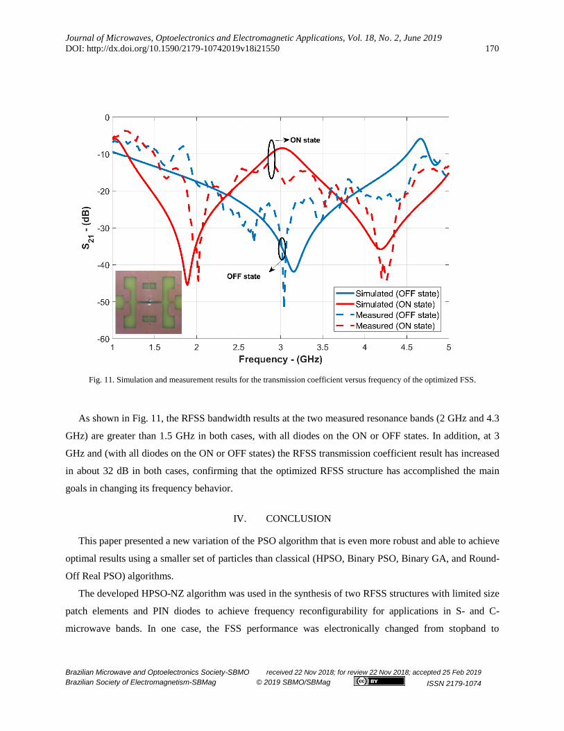
Fig. 11. Simulation and measurement results for the transmission coefficient versus frequency of the optimized FSS.
As shown in Fig. 11, the RFSS bandwidth results at the two measured resonance bands (2 GHz and 4.3
GHz) are greater than 1.5 GHz in both cases, with all diodes on the ON or OFF states. In addition, at 3
GHz and (with all diodes on the ON or OFF states) the RFSS transmission coefficient result has increased
in about 32 dB in both cases, confirming that the optimized RFSS structure has accomplished the main
goals in changing its frequency behavior.
IV. CONCLUSION
This paper presented a new variation of the PSO algorithm that is even more robust and able to achieve
optimal results using a smaller set of particles than classical (HPSO, Binary PSO, Binary GA, and Round-
Off Real PSO) algorithms.
The developed HPSO-NZ algorithm was used in the synthesis of two RFSS structures with limited size
patch elements and PIN diodes to achieve frequency reconfigurability for applications in S- and C-
microwave bands. In one case, the FSS performance was electronically changed from stopband to
Journal of Microwaves, Optoelectronics and Electromagnetic Applications, Vol. 18, No. 2, June 2019
DOI: http://dx.doi.org/10.1590/2179-10742019v18i21550 171
Brazilian Microwave and Optoelectronics Society-SBMO received 22 Nov 2018; for review 22 Nov 2018; accepted 25 Feb 2019
Brazilian Society of Electromagnetism-SBMag © 2019 SBMO/SBMag ISSN 2179-1074
bandpass (at the same resonant frequency) and, in the other case, the RFSS performance was changed
from single-band to dual-band.
Two RFSS prototypes are fabricated and measured. The RFSS transmission coefficient simulation and
measurement results, for both forward (ON state) and reverse (OFF state) bias, are compared showing a
good agreement. It is observed that the proposed RFSS optimization model is innovative and can be used
in the development of other planar microwave circuits, such as antennas, filters, power dividers, and
couplers for embedded and limited size circuit applications.
The use of the HPSO-NZ algorithm provided unique conducting patch configurations for the RFSS
patch elements, which are different from the usual Euclidean and fractal geometries, with the possibility of
defining structural symmetries and asymmetries.
However, it is important to point out that there is a greater complexity of implementation that must be
observed with attention since small changes can influence the convergence of the optimization process.
Another drawback of the algorithm is the inclusion of a new hyperparameter to be adjusted. In addition,
comparisons of optimization results of a classical problem were presented to validate the proposed
changes and highlight the benefits of the new algorithm.
ACKNOWLEDGMENTS
This work was supported by CNPq under covenant 573939/2008-0 (INCT-CSF), Federal Institute of
Paraíba (IFPB), and Federal University of Rio Grande do Norte (UFRN).
REFERENCES
[1] M. A. Habib, M. N. Jazi, A. Djaiz, M. Nedil, and T. A. Denidni, "Switched-beam antenna based on EBG
periodic structures," IEEE MTT-S Int. Microw. Symp. Dig., Boston, MA, 2009, pp. 813-816.
[2] C. G. Christodoulou, Y. Tawk, S. A. Lane, and S. R. Erwin, "Reconfigurable antennas for wireless and space
applications," Proc. IEEE, vol. 100, no. 7, pp. 2250-2261, 2012.
[3] Y. Tawk, J. Constantine, and C. Christodoulou, "Reconfigurable Filtennas and MIMO in Cognitive Radio
Applications," IEEE Trans. Antennas Propag., vol. 62, no. 3, pp. 1074-1083, 2014.
[4] B. A. Munk, Frequency Selective Surfaces, John Wiley & Sons, NY, 2000.
[5] M. A. Habib, M. N. Jazi, A. Djaiz, M. Nedil, and T. A. Denidni, "Switched-beam antenna based on EBG
periodic structures," IEEE MTT-S Int. Microw. Symp. Dig., Boston, MA, 2009, pp. 813-816.

Journal of Microwaves, Optoelectronics and Electromagnetic Applications, Vol. 18, No. 2, June 2019
DOI: http://dx.doi.org/10.1590/2179-10742019v18i21550 172
Brazilian Microwave and Optoelectronics Society-SBMO received 22 Nov 2018; for review 22 Nov 2018; accepted 25 Feb 2019
Brazilian Society of Electromagnetism-SBMag © 2019 SBMO/SBMag ISSN 2179-1074
[6] D. B. Brito, A. G. D'Assunção, R. H. C. Maniçoba, and X. Begaud, “Metamaterial-inspired Fabry–Pérot antenna
with cascaded frequency selective surfaces”, Microw. Opt. Technol. Lett., vol. 55, pp. 981–985, 2013.
[7] M. Abdelghani, H. Attia, and T. A. Denidni, "Dual- and wide-band Fabry-Pérot resonator antenna for WLAN
applications," IEEE Antennas Wireless Propag. Lett., 2016.
[8] K. Sarabandi and N. Behdad, "A frequency selective surface with miniaturized elements," IEEE Trans.
Antennas Propag., vol. 55, no. 5, pp. 1239-1245, 2007.
[9] Y. Rahmat-Samii, J. M. Kovitz, and H. Rajagopalan, "Nature-inspired optimization techniques in
communication antenna designs," Proc. IEEE, vol. 100, no. 7, 2012.
[10] N. Jin and Y. Rahmat-Samii, "Advances in particle swarm optimization for antenna designs: Real-number,
binary, single-objective and multiobjective implementations," IEEE Trans. Antennas Propag., 2007.
[11] P. H. F. Silva, P. Lacouth, G. Fontgalland, A. L. P. Campos, and A. G. D'Assunção, "Design of frequency
selective surfaces using a novel MoM-ANN-GA technique," Proc. SBMO/IEEE MTT-S Int. Microwave
Optoelectronics Conf., Salvador, Brazil, 2007, pp. 275-279.
[12] J. Kennedy and R. Eberhart, Swarm Intelligence, New York: Morgan Kaufmann, 2001.
[13] J. Kennedy and R. Eberhart, "Particle swarm optimization," Proc. IEEE Int. Conf. Neural Networks, Perth,
Australia, 1995, pp. 1942-1948.
[14] N. Jin and Y. Rahmat-Samii, "Hybrid Real-Binary Particle Swarm Optimization (HPSO) in Engineering
Electromagnetics," IEEE Transactions on Antennas and Propagation, vol. 58, no. 12, pp. 3786-3794, December
2010.
[15] K. A. De Jong, “An analysis of the behavior of a class of genetic adaptive systems”, Ph.D. thesis, University of
Michigan, 1975.
[16] Infineon Technologies. (2015, Mars) Infineon. [Online]. http://www.infineon.com/dgdl/Infineon-
BAR64SERIES-DS-v01_01-en.pdf?fileId=db3a304314dca3890114fef8f4ca0aca
[17] Skyworks. (2016, September) [Online]. http://www.skyworksinc.com/uploads/documents/200051J.pdf