Embed Size (px)
Citation preview
Synthesis of Organic-Inorganic HybridMaterials Using Functional NanoporousMaterials
著者 Kamachi Yuichiroyear 2016-12-27その他のタイトル 機能性ナノ多孔体を用いた無機有機複合材料の合成学位授与年度 平成28年度学位授与番号 17104甲工第424号URL http://hdl.handle.net/10228/5973
Synthesis of Organic-Inorganic Hybrid Materials
Using Functional Nanoporous Materials
機能性ナノ多孔体を用いた
無機有機複合材料の合成
Yuichiro Kamachi
Department of Applied Chemistry
Graduate School of Engineering
Kyushu Institute of Technology

Synthesis of Organic-Inorganic Hybrid Materials
Using Functional Nanoporous Materials
Contents
Chapter 1.
G e n e r a l I n t r o d u c t i o n・・・・・・・・・・・・・・・・ 1
1.1. Various nanoporous materials
1.1.1. Coordination compounds - Prussian Blue and related analogues・・・・・・・2
1 .1 .2 . Mesoporous Mater ia l s・・・・・・・・・・・・・・・・・・3
1.2. Hydrogel
1 . 2 .1 . H yd r o ge l・・・・・・・・・・・・・・・・・・・・・・・ 11
1.2.2. Hybrid hydrogel containing Inorganic nanomaterials・・・・・13
1 .3 . Object ives of thi s thes is・・・・・・・・・・・・・・・・・22
1 . 4 . R e f e r e n c e s・・・・・・・・・・・・・・・・・・・・・・ 2 5
Chapter 2.
Hydrogels containing Prussian blue nanoparticles
for facile removal of Cs ions・・・・・・・・・・・・・・・31
2 . 1 . In t r o d u c t i o n・・・・・・・・・・・・・・・・・・・・・・ 3 2
2 . 2 . E x p e r i m e n t ・・・・・・・・・・・・・・・・・・・・・・ 3 4
2 .3. Resul t s and discuss ion・・・・・・・・・・・・・・・・・・37
2 . 4 . Co n c l us i on・・・・・・・・・・・・・・・・・・・・・・・45
2 . 5 . R e f e r en ces・・・・・・・・・・・・・・・・・・・・・・・ 4 7
Chapter 3.
Hydrogels containing mesoporous silica particles
for control behavior of guest molecules adsorption/desorption
・・・・・・・・49
3 . 1 . In t r o d u c t i o n・・・・・・・・・・・・・・・・・・・・・・ 5 1
3 . 2 . E x p e r i m e n t ・・・・・・・・・・・・・・・・・・・・・・ 5 3
3 .3. Resul t s and discuss ion・・・・・・・・・・・・・・・・・・55
3 . 4 . Co n c l us i on・・・・・・・・・・・・・・・・・・・・・・・63
3 . 5 . R e f e r en ces・・・・・・・・・・・・・・・・・・・・・・・ 6 4
Chapter 4.
Silicone rubbers containing mesoporous silica particles
for improvement thermal property and strength・・・・・・・67
4 . 1 . In t r o d u c t i o n・・・・・・・・・・・・・・・・・・・・・・ 6 9
4 . 2 . E x p e r i m e n t ・・・・・・・・・・・・・・・・・・・・・・ 7 1
4 .3. Resul t s and discuss ion・・・・・・・・・・・・・・・・・・77
4 . 4 . C o n c l u s i o n・・・・・・・・・・・・・・・・・・・・・・ 8 7
4 . 5 . R e f e r en ces・・・・・・・・・・・・・・・・・・・・・・・ 8 8
Chapter 5.
G e n e r a l C o n c l u s i o n・・・・・・・・・・・・・・・・ 9 3
List of Achievements・・・・・・・・・・・・・・・・・・・・97
Acknowledgements・・・・・・・・・・・・・・・・・・・・・108

1
Chapter 1.
General Introduction
2
1.1. Various nanoporous materials
1.1.1. Coordination compounds - Prussian Blue and related analogues
Coordination compounds have received great attention as novel nanomaterials because
of their desirable characteristics including their electrochemical properties, molecular
magnetism, and catalytic abilities [1, 2]. Coordination compounds recognized as metal–
organic frameworks (MOFs) and porous coordination polymers (PCP) with unique
features such as uniform nanopores and high surface areas are specifically considered
potentially useful for current energy and environmental issues [3-5]. It is well known
that the properties and applications of nanomaterials are strongly dependent on their
sizes and shapes. For instance, the magnetism of nanosized coordination polymers
(CPs) can be significantly changed from ferromagnetic to super-paramagnetic.
Moreover, improved sensitivity for particles of a given size and the accelerated
adsorption capabilities of CPs have been studied [6, 7]. To obtain these promising
properties, the rational design and systematic control of the sizes of the particles of CPs
is needed. So far, several templating methods utilizing mesoporous silica [8, 9],
emulsion droplets [10-13], and microfluids [14] have been developed to control particle
size, although precise morphological control is still unreachable. As an alternative
approach, template-free methods can overcome this drawback by mixing some additives
[15, 16] or by applying a rapid heating strategy [17].
The synthesis of CPs is based on the crystallization between the metal ions and
the organic ligands in a proper solvent. Therefore, control of the stages of nucleation
and crystal growth during crystallization is crucial in determining the sizes and shapes
of the particles in the products [18, 19]. With the assistance of a chelating agent that
3
coordinates to metal ions, crystallization with a controllable rate could be achieved, and
this results in precise control of size and shape. Prussian blue (PB) is one of the
well-known CPs that is specific for the adsorption of Cesium and thallium ions [20]. In
addition, it indicates good properties of Cs adsorption than the zeolite in the presence of
sodium and potassium [21]. For this reason, PB is expected to be Cs adsorption material.
PB analogues {AaMb[Mc(CN)6], A: cation, M: metal iron} are also widely studied
because of their valuable electrochemical and magnetic properties [22, 23]. Among the
PB analogues, Ni–Fe PB analogues were found to be excellent absorbents for Cs ions
[24].
Very recently, Hu et al. demonstrated that sodium citrate could serve as a
chelating agent, and thus could slowly react with metal ions to afford slow nucleation
and controllable crystal growth [25]. Chiang et al. further applied this synthetic concept
to prepare other cyano-bridged coordination polymers consisting of NiII–C≡N–FeII units
with the aim to control the particle size precisely. They focused on critical effects of the
cheating agent in the reaction system to clarify the crystallization mechanism. By
changing the amount of the cheating agent added, the average particle size could be
widely controlled from 20 to 350 nm with retention of a well-defined cubic shape. Also,
the use of different hexacyanoferrate sources further expands the possible range of the
controlled particle sizes.
1.1.2. Mesoporous Materials
Porous materials can generally be classified as macroporous (> 50 nm), mesoporous
(250 nm), and microporous materials (< 2 nm). For a fixed pore density, the surface
area is inversely proportional to the pore size. Hence, in contrast to macroporous
4
materials with low surface area and large non-uniform pores, micro- and mesoporous
materials provide a promising alternative. Micro and mesoporous materials are often
called nanoporous materials and are of great scientific and technological importance
because of their ability to interact with atoms, ions, and molecules within their relatively
large contained surface and spatially confined nanospaces. Such unique properties offer
new opportunities in the area of inclusion chemistry, guest-host interaction and
molecular manipulations, showcasing their great potential in a wide range of research
fields and applications such as adsorption, catalysis, electronic devices, and drug
delivery systems [26-28].
Amphiphilic molecules, including surfactants and block copolymers, contain
both hydrophilic and hydrophobic groups, which tend to reduce locally the surface
tension of a medium and are widely used as detergents, emulsifiers, foaming agents, and
dispersants. According to the nature of the hydrophilic moieties, they can be classified
as nonionic, anionic, cationic, or amphoteric types. Amphiphilic molecules are
spontaneously self-assembled into aggregates with various morphologies, such as
spherical or rod-like micelles. By increasing their concentration, periodic liquid crystal
mesophases can also be obtained. Self-assembled substances can ultimately be used as
structure-directing agents (SDAs) of the soft-templating method for synthesis
mesoporous materials. The first example of ordered mesoporous silica was reported in
1992 [29, 30].
At high concentration, the surfactants preliminarily form a liquid crystal phase.
Then, the inorganic source is introduced on the surface of the micelles to form a
mesostructured composite. Subsequent studies have shown that the well-ordered
mesostructured composites can also be prepared when the surfactant concentration is
5
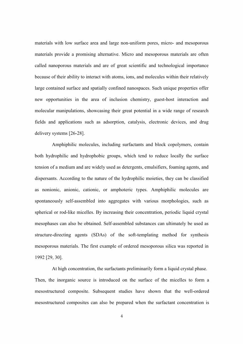
much lower than that required for the formation of a liquid crystal. Cooperative
self-assembly is generally known as the most common method (Fig. 1.1 a), in which
both the surfactant and the framework undergo conformational changes to form an
ordered mesophase.
Fig. 1.1
Systematic presentation of the synthesis of mesoporous materials
(a) cooperative self-assembly route, (b) lyotropic liquid crystal templating route.
6
Considering the interactions between both components is critical to obtain
highly ordered mesostructured materials. Several interactions such as electrostatic, van
der Waals, hydrogen or coordination bonding, were previously reported [31]. For
instance, in basic conditions, where the surface of the silica species is negatively
charged, a cationic surfactant is favored as a template. The selection of the template
removal process should be carefully considered in the preparation of mesoporous
materials. Various removal methods have been developed, such as conventional
calcination, solvent extraction, ozone treatment [32], supercritical CO2 fluid extraction
[33], and H2SO4 treatment [34]. The suitable process must be selected depending on the
nature of the framework compositions.
In the past two decades, many efforts have been made to synthesize
nanoporous materials with well-controlled pore size, shape, composition, and spatial
arrangement. The hard-templating method is widely used and is a promising strategy for
the synthesis of nanoporous carbons, metals, and metal oxides. This procedure, which is
similar to the casting method used in metallurgy, can generally be conceptually adapted
to the nanometer scale and applied to the synthesis of nanostructured materials using
various hard-templates.
Hard-templating is a facile synthetic method for fabricating porous materials
with a stable porous structure by depositing the targeted materials into the confined
spaces of the template resulting in a reverse replica.
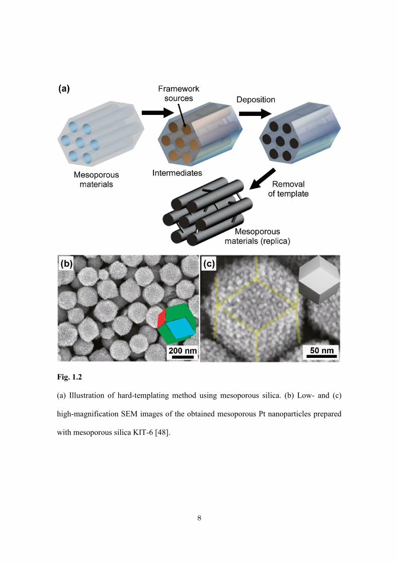
In this methodology, the mesopores of the hard templates (silica or carbon) are
filled with precursors such as carbon sources or metal species (Fig. 1.2 a). Then, the
desired compositions within the mesopores can be achieved through thermal conversion
or chemical reduction. Finally, the desired mesoporous materials are obtained by
7
removing the hard-template. Pioneering works were reported by Ryoo and co-workers
in which they synthesized ordered mesoporous carbons “CMK-1” [35] and “CMK-3”
[36] using MCM-48 and SBA-15 as template, respectively. Independently, Hyeon et al.
proposed a similar approach to prepare well-ordered mesoporous carbons designated as
the SNU series [37].
8
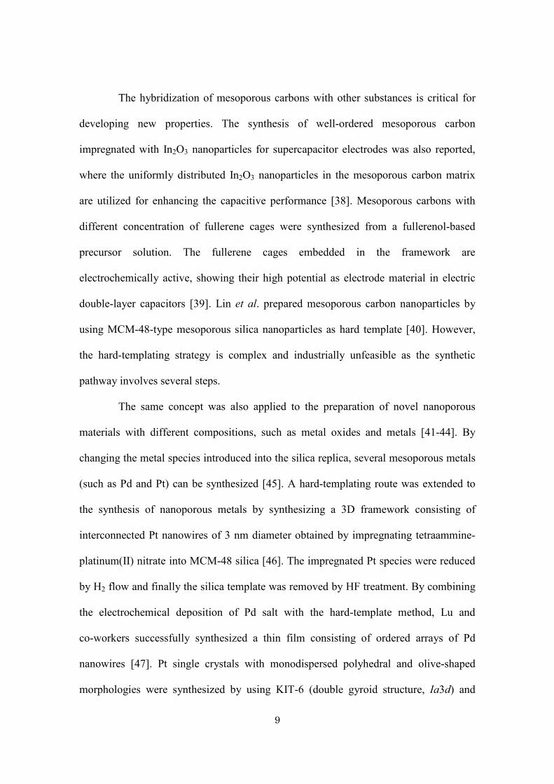
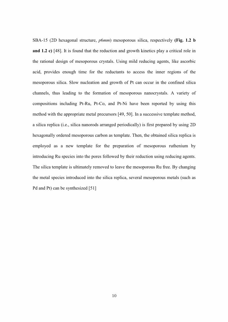
Fig. 1.2
(a) Illustration of hard-templating method using mesoporous silica. (b) Low- and (c)
high-magnification SEM images of the obtained mesoporous Pt nanoparticles prepared
with mesoporous silica KIT-6 [48].
9
The hybridization of mesoporous carbons with other substances is critical for
developing new properties. The synthesis of well-ordered mesoporous carbon
impregnated with In2O3 nanoparticles for supercapacitor electrodes was also reported,
where the uniformly distributed In2O3 nanoparticles in the mesoporous carbon matrix
are utilized for enhancing the capacitive performance [38]. Mesoporous carbons with
different concentration of fullerene cages were synthesized from a fullerenol-based
precursor solution. The fullerene cages embedded in the framework are
electrochemically active, showing their high potential as electrode material in electric
double-layer capacitors [39]. Lin et al. prepared mesoporous carbon nanoparticles by
using MCM-48-type mesoporous silica nanoparticles as hard template [40]. However,
the hard-templating strategy is complex and industrially unfeasible as the synthetic
pathway involves several steps.
The same concept was also applied to the preparation of novel nanoporous
materials with different compositions, such as metal oxides and metals [41-44]. By
changing the metal species introduced into the silica replica, several mesoporous metals
(such as Pd and Pt) can be synthesized [45]. A hard-templating route was extended to
the synthesis of nanoporous metals by synthesizing a 3D framework consisting of
interconnected Pt nanowires of 3 nm diameter obtained by impregnating tetraammine-
platinum(II) nitrate into MCM-48 silica [46]. The impregnated Pt species were reduced
by H2 flow and finally the silica template was removed by HF treatment. By combining
the electrochemical deposition of Pd salt with the hard-template method, Lu and
co-workers successfully synthesized a thin film consisting of ordered arrays of Pd
nanowires [47]. Pt single crystals with monodispersed polyhedral and olive-shaped
morphologies were synthesized by using KIT-6 (double gyroid structure, Ia3d) and
10
SBA-15 (2D hexagonal structure, p6mm) mesoporous silica, respectively (Fig. 1.2 b
and 1.2 c) [48]. It is found that the reduction and growth kinetics play a critical role in
the rational design of mesoporous crystals. Using mild reducing agents, like ascorbic
acid, provides enough time for the reductants to access the inner regions of the
mesoporous silica. Slow nucleation and growth of Pt can occur in the confined silica
channels, thus leading to the formation of mesoporous nanocrystals. A variety of
compositions including Pt-Ru, Pt-Co, and Pt-Ni have been reported by using this
method with the appropriate metal precursors [49, 50]. In a successive template method,
a silica replica (i.e., silica nanorods arranged periodically) is first prepared by using 2D
hexagonally ordered mesoporous carbon as template. Then, the obtained silica replica is
employed as a new template for the preparation of mesoporous ruthenium by
introducing Ru species into the pores followed by their reduction using reducing agents.
The silica template is ultimately removed to leave the mesoporous Ru free. By changing
the metal species introduced into the silica replica, several mesoporous metals (such as
Pd and Pt) can be synthesized [51]
11
1.2. Hydrogel
1.2.1. Hydrogel
A hydrogel is three-dimensional networks made of polymer or supermolecular chains
swollen by water. It can retain a large amount of water while maintaining its structure.
The gels are basically classified into two types: chemical gels and physical gels.
Chemical gels are formed by covalently cross-linking polymer chains, and they possess
a relatively higher elasticity. On the other hand, physical gels are weakly cross-linked
through hydrogen bonds, van der Waals interactions, or sterical entanglements. Because
physical cross-links are reversible, these gels exhibit unique properties, such as
self-healing, which make them suitable for drug delivery systems (DDS), as well as
biomedical and tissue engineering.
Poly(N-isopropylacrylamide) (PNIPAm) has been well known as a
thermosensitive polymer and has been extensively studied until now [52, 53]. PNIPAm
possesses an inverse solubility: upon heating, the polymer chains change abruptly at
their lower critical solution temperature (LCST) from hydrophilic to hydrophobic.
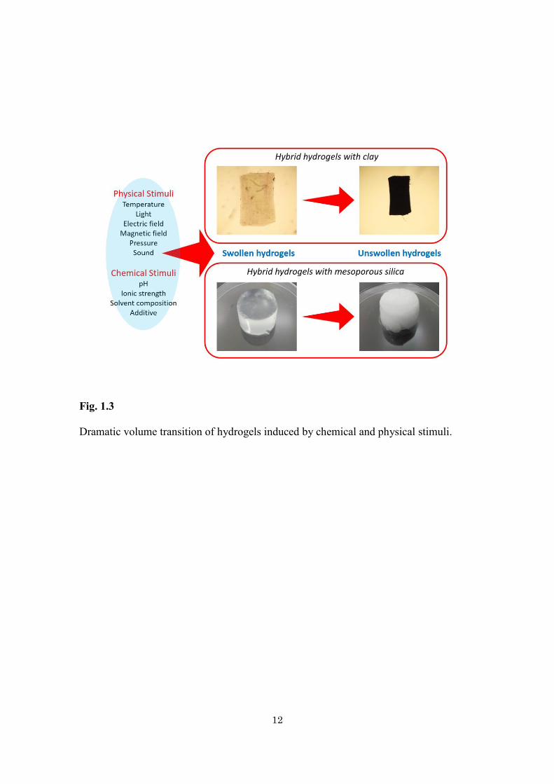
When heated in water, the PNIPAm gel undergoes a reversible LCST phase
transition from a swollen hydrated state to a shrunken dehydrated state, thereby showing
a large reduction of its volume. Other variety of physical stimuli (e.g., electric or
magnetic field, light, pressure, and sound) and chemical stimuli (e.g., pH, solvent
composition, ionic strength, and molecular specie) are also effective in inducing a
dramatic volume transition (Fig. 1.3).
12
Fig. 1.3
Dramatic volume transition of hydrogels induced by chemical and physical stimuli.
13
1.2.2. Hybrid hydrogel containing Inorganic nanomaterials
Formation of composite hydrogels are considered to be a simple way of improving the
mechanical properties of hydrogels by adding organic/inorganic fillers such as clays,
celluloses, etc [54]. Carbon nanotubes (CNTs) can also be used as fillers [55].
Hydrogels prepared by hybridizing CNTs into poly(vinyl alcohol) (PVA) hydrogels
improved the overall mechanical properties. As observed with the hydrogels hybridized
with clays, the mechanical properties of the CNT/PVA hydrogels are superior to those
of the original PVA hydrogel. When only a little amount of CNTs is loaded, the tensile
modulus, tensile strength, and strain at break are largely increased by 78.2%, 94.3% and
12.7%, respectively.
Mesoporous materials synthesized by condensing silica species in the presence of
structure directing templates have been extensively investigated [56, 57]. Uniformly
sized mesopores and a large surface area are suitable factors for many applications such
as performant adsorbents and catalyst supports. These materials can also serve as novel
fillers for polymer materials. By adding only a small amount of fillers, effective
physical interactions between the polymer chains and the pore surfaces along with
topological confinement of the polymer chains piercing through the mesopores can be
expected, which can ultimately enhance significantly the mechanical properties of the
materials. It has been demonstrated that mesoporous silicas (MPSs) with
three-dimensional bicontinuous pores (Ia-3d) can be employed as an effective
topological cross-linker for PNIPAm hydrogel to improve the mechanical properties
[58]. Here, the materials properties were varied by using different mesoporous materials
with different structures and pore sizes. The improved mechanical properties of the gels
doped with MPSs can be attributed to the formation of both topological and rigid
14
cross-links. Since these cross-links can freely move on the chains, heterogeneities in the
gel structure and mechanical stress are balanced so that the gel possesses a large fracture
strain and equilibrium swelling ratio. Individual polymer chains or bundles are observed
to be piercing through the mesopores to form movable topological cross-links near the
particle surface.
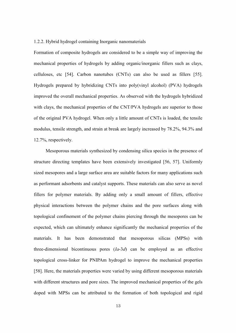
Haraguchi et al. have reported the synthesis of polymer-clay nanocomposite gels
(NC gels) consisting of PNIPAm and inorganic clay which they investigated in terms of
their optical and swelling/deswelling properties (Fig. 1.4) [59, 60]. Interestingly,
depending on the clay concentration, the obtained NC gels exhibit unique changes in
their optical transmittance and anisotropy, as well as in their swelling/deswelling
behaviors. These characteristics are distinct from those of chemically cross-linked
hydrogels. Even when chemical cross-linkers are not used, the polymer chains can be
bound by the clay nanosheets to form mechanically robust gels, which can be referred to
as ‘physical cross-linkers’. Liu et al. reported a series of PNIPAm hydrogels with a high
hectorite content modified by tetrasodium pyrophosphate [61]. The tensile strength is
1 MPa, and the elongation at break is 1400%, highlighting the promising mechanical
properties of this composite. A complicated deswelling behavior was also observed, due
to the high clay content in the hydrogels and the ionic dispersant contained in hectorite.
15
Fig. 1.4
(a, b) Photographs depicting changes in transparency for NC3 and NC15 gels; (a) 20 oC
(< LCST) and (b) 50 oC (> LCST), respectively. (c, d) Schematic representation of the
structural models for NC20 gels; (c) a uniform and random dispersion of clay platelets,
and (d) spontaneous aggregation (layer stacking) of clay platelets. The clay content in
NC gel is expressed using a simplified numerical value of 3, 15, and 20 corresponding
to the clay concentration in the initial reaction solution [60].
16
Similar concepts are applicable to other types of hydrogels using graphene oxide
nanosheets [62, 63]. Recently, graphene and graphene oxide have been attracting
tremendous attention as fillers for polymer reinforcement due to their large theoretical
specific surface area. In particular, graphene oxide has a large number of
oxygen-containing groups, such as hydroxyl, epoxide and carboxyl groups, and
therefore, can be easily dispersed in water. The dispersity of fillers is an important
factor when it comes to the preparation of high quality hybrid hydrogels. Uniform
distribution nanometer scale fillers play critical role for enhancing the mechanical
performance.
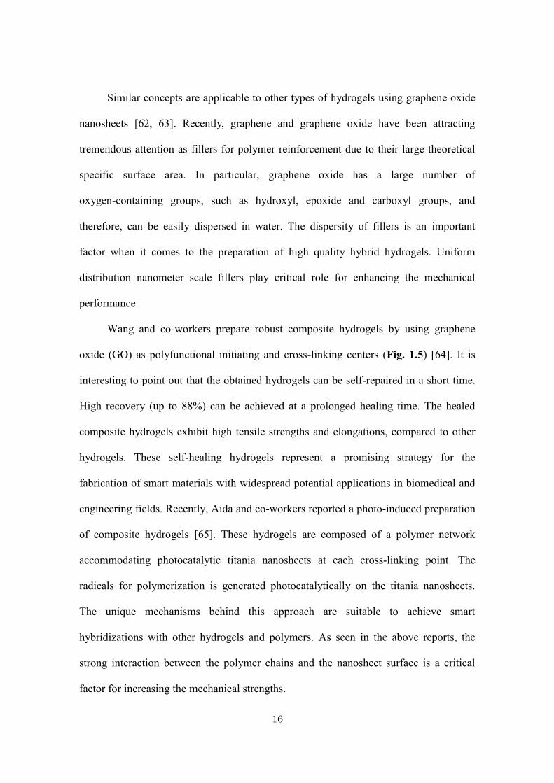
Wang and co-workers prepare robust composite hydrogels by using graphene
oxide (GO) as polyfunctional initiating and cross-linking centers (Fig. 1.5) [64]. It is
interesting to point out that the obtained hydrogels can be self-repaired in a short time.
High recovery (up to 88%) can be achieved at a prolonged healing time. The healed
composite hydrogels exhibit high tensile strengths and elongations, compared to other
hydrogels. These self-healing hydrogels represent a promising strategy for the
fabrication of smart materials with widespread potential applications in biomedical and
engineering fields. Recently, Aida and co-workers reported a photo-induced preparation
of composite hydrogels [65]. These hydrogels are composed of a polymer network
accommodating photocatalytic titania nanosheets at each cross-linking point. The
radicals for polymerization is generated photocatalytically on the titania nanosheets.
The unique mechanisms behind this approach are suitable to achieve smart
hybridizations with other hydrogels and polymers. As seen in the above reports, the
strong interaction between the polymer chains and the nanosheet surface is a critical
factor for increasing the mechanical strengths.
17
Fig. 1.5
(a) The proposed self-healing mechanism of the GO composite hydrogels. (b)
Photographs of the damaged and the self-healed GO composite gels [(b-1) Round
shaped gel cut into two parts, (b-2) gel healed at 4 oC for 20 s, and (b-3) the healed G1
gels after being equilibrium swollen in deionized]. The scale bars are 1 cm [64].
18
The clay sheets align parallel to the electric field, resulting in a uniaxial
orientational order. Paineau et al. reported clay-containing composite hydrogels from
aqueous suspensions of swelling clays by applying high-frequency AC electric fields
[66]. Interestingly, polarized optical microscopy shows that the clay platelets are
perfectly oriented by the electric field and that this field-induced alignment can be fixed
by in-situ polymerization. The patterns of the platelet orientation are coherently
extended over the entire area (at length scales down to 20 μm). The use of external
fields is effective to control the orientation of the used filler materials, and this
technique can be easily extended to a wide range of inorganic anisotropic particles.
Recently, colloids of inorganic nanosheets have been rediscovered as fascinating
soft materials with a liquid crystallinity. Liquid crystal (LC) phases of antimony
phosphate [67], niobates [68, 69], clays [70, 71], and graphene oxide [72] have been
reported by different groups. Due to extremely anisotropic shape of the inorganic
nanosheets (lateral size of up to 100 μm and a thickness of a few nanometers), the
colloids of fully exfoliated inorganic nanosheets are able to form a LC phase [73]. By
forming large oriented LC domains inside the hydrogels, remarkable anisotropic
properties and chemical stability, along with a high mechanical strength, can be
achieved.
Miyamoto et al. demonstrated that macroscopically anisotropic hydrogels can be
synthesized by hybridization of PNIPAm with liquid crystalline inorganic nanosheets
[74]. The anisotropic gels are facilely synthesized by radical polymerization of
N-isopropylacrylamide in the presence of a liquid crystalline fluorohectorite (FHT)
nanosheets with N,N'-methylenebisacrylamide (as a chemical cross-linker). The liquid
crystalline mixture is aligned when introduced into a thin glass capillary and the aligned
19
structure is retained after the polymerization. Due to the anisotropic structure,
anisotropic properties in molecule transport, optical property, and thermoresponsive
volume change are observed. The mechanical properties of the obtained hybrid
hydrogels is significantly improved compared to that of the gel without FHT. A tough
gel can be obtained even when no chemical cross-linkers is added during the synthesis,
because the polymer chains are physically cross-linked by the nanosheets. The same
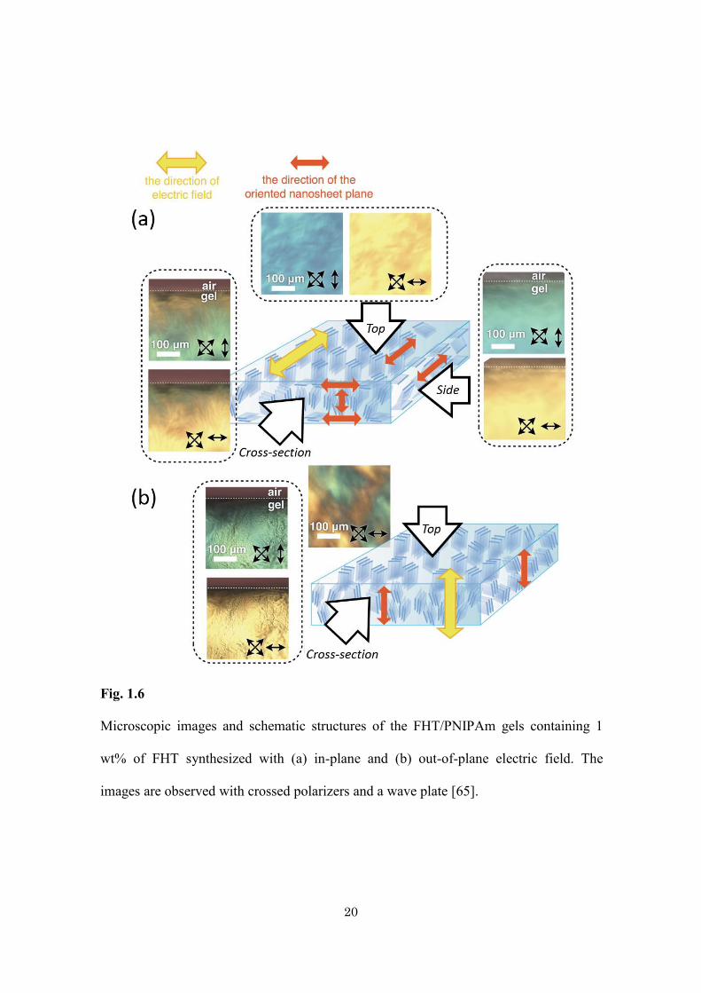
group reported PNIPAm hydrogel doped with uniaxially aligned LC nanosheets (Fig.
1.6) [75]. The alignment of the LC nanosheets at the cm-scale is easily achieved by the
application of an in-plane or an out-of-plane AC electric field during
photo-polymerization. Upon adsorption of the dye, a photoresponsive pattern can be
printed onto the gel with a μm-scale resolution. When the gel is irradiated with light,
only the colored region is photothermally deformed. Interestingly, the photo-irradiated
gel shows temporal expansion along one direction followed by anisotropic shrinkage,
which is an unexpected behavior for a conventional PNIPAm gel.
20
Fig. 1.6
Microscopic images and schematic structures of the FHT/PNIPAm gels containing 1
wt% of FHT synthesized with (a) in-plane and (b) out-of-plane electric field. The
images are observed with crossed polarizers and a wave plate [65].
21
Following the above reports, Meija et al. [76] and Aida et al. [77, 78] also
reported anisotropic nanosheets/polymer composite gels synthesized through a similar
approach. Mejia et al. hybridized liquid crystalline α-ZrP nanosheets with
poly(acrylamide-co-N-isopropylacrylamide) to obtain birefringent gels. They clarify that
the equilibrium swelling ratios and the size of the oriented domains can be tuned with
appropriately controlling the synthetic conditions. Aida et al. used nanosheets of titanate
or niobate for hybridization with PNIPAm gel. By applying a strong magnetic field
during the synthesis, the strongly anisotropic monodomain gels are obtained.
22
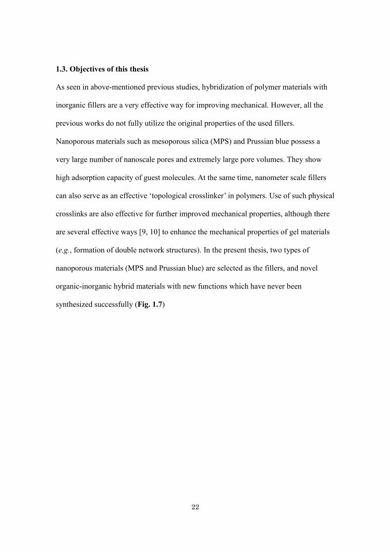
1.3. Objectives of this thesis
As seen in above-mentioned previous studies, hybridization of polymer materials with
inorganic fillers are a very effective way for improving mechanical. However, all the
previous works do not fully utilize the original properties of the used fillers.
Nanoporous materials such as mesoporous silica (MPS) and Prussian blue possess a
very large number of nanoscale pores and extremely large pore volumes. They show
high adsorption capacity of guest molecules. At the same time, nanometer scale fillers
can also serve as an effective ‘topological crosslinker’ in polymers. Use of such physical
crosslinks are also effective for further improved mechanical properties, although there
are several effective ways [9, 10] to enhance the mechanical properties of gel materials
(e.g., formation of double network structures). In the present thesis, two types of
nanoporous materials (MPS and Prussian blue) are selected as the fillers, and novel
organic-inorganic hybrid materials with new functions which have never been
synthesized successfully (Fig. 1.7)
23
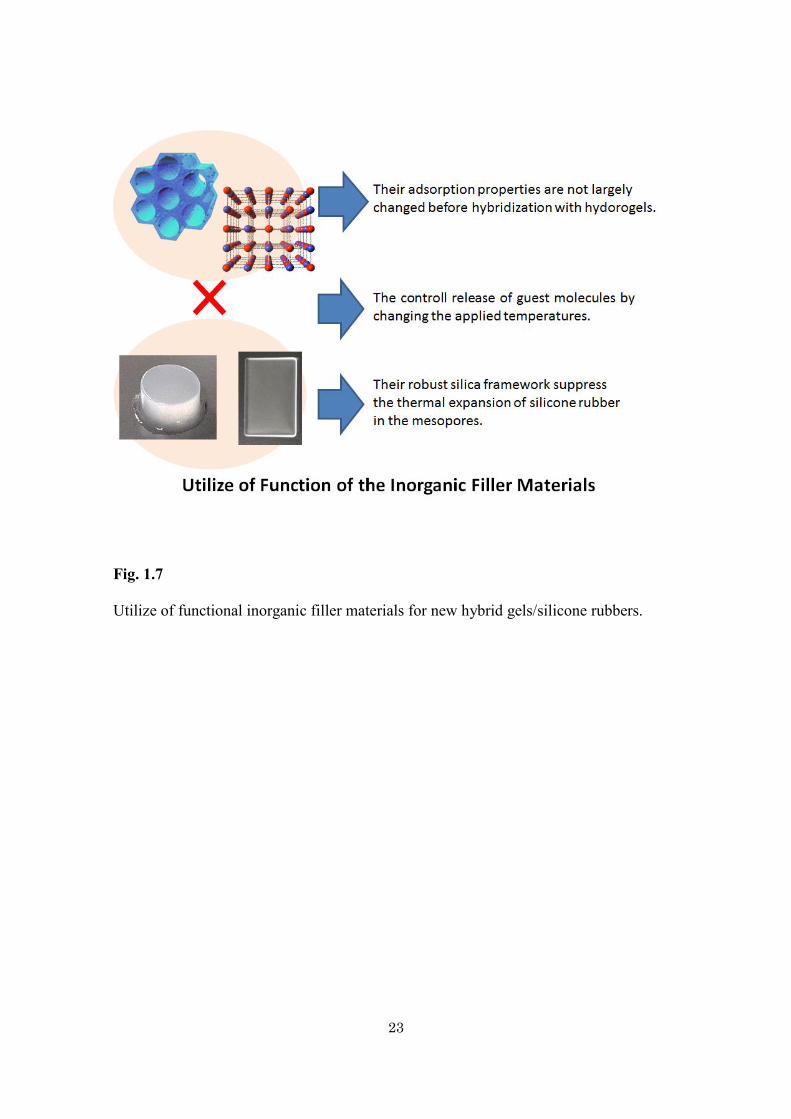
Fig. 1.7
Utilize of functional inorganic filler materials for new hybrid gels/silicone rubbers.
24
1.4. References
[1] V. Mereacre, Y.-H. Lan, R. Clérac, A. M. Ako, W. Wernsdorfer, G. Buth, C. E.
Anson, A. K. Powell, Inorg. Chem. 50, (2011), 12001.
[2] S. Nayak, S. Malik, S. Indris, J. Reedijk, A. K. Powell,
Chem. Eur. J. 16, (2010), 1158.
[3] S. Kitagawa, R. Kitaura, S. Noro, Angew. Chem. 116, (2004), 2388; Angew. Chem.
Int. Ed. 43, (2004), 2334.
[4] A. J. Lan, K. H. Li, H. H. Wu, L. Z. Kong, N. Nijem, D. H. Olson, T. J. Emge, Y. J.
Chabal, D. C. Langreth, M. C. Hong, J. Li, Inorg. Chem. 48, (2009), 7165;
[5] K. Srinivasu, S. K. Ghosh, J. Phys. Chem. C., 115, (2011), 16984.
[6] S. Reitz, M. Cebi, P. Reiß, G. Studnik, U. Linne, U. Koert, L. O. Essen, Angew.
Chem. 121, (2009), 4947.
[7] D. Tanaka, A. Henke, K. Albrecht, M. Moeller, K. Nakagawa, S. Kitagawa, J. Groll,
Nat. Chem. 2, (2010), 410.
[8] G. Fornasieri, M. Aouadi, P. Durand, P. Beaunier, E. Rivière, A. Bleuzen, Chem.
Commun. 46, (2010), 8061.
[9] R. Mouawia, J. Larionova, Y. Guari, S. Oh, P. Cook, E. Prouzet, New J. Chem. 33,
(2009), 2449.
[10] L. Catala, T. Gacoin, J. P. Boilot, É. Rivière, C. Paulsen, E. Lhotel, T. Mallah, Adv.
Mater. 15, (2003), 826.
[11] E. Coronado, J. R. Galán-Mascarós, M. Monrabal-Capilla, J. García-Martínez, P.
Pardo-Ibán´ ez, Adv. Mater. 19, (2007), 1359.
[12] W. J. Rieter, K. M. L. Taylor, H. Y. An, W. L. Lin, W. B. Lin, J. Am. Chem. Soc.
128, (2006), 9024.
25
[13] Y. J. Zhao, J. L. Zhang, B. X. Han, J. L. Song, J. S. Li, Q. Wang, Angew. Chem.
123, (2011), 662.
[14] J. Puigmartí-Luis, M. Rubio-Martínez, U. Hartfelder, I. Imaz, D. Maspoch, P. S.
Dittrich, J. Am. Chem. Soc. 113, (2011), 4216.
[15] E. Chelebaeva, Y. Guari, J. Larionova, A. Trifonov, C. Guérin, Chem. Mater. 20,
(2008), 1367.
[16] M. Jahan, Q. L. Bao, J. X. Yang, K. P. Loh, J. Am. Chem. Soc. 132, (2010), 14487.
[17] Z. Ni, R. I. Masel, J. Am. Chem. Soc. 128, (2006), 12394.
[18] S. Diring, S. Furukawa, Y. Takashima, T. Tsuruoka, S. Kitagawa, Chem. Mater. 22,
(2010), 4531.
[19] A. Umemura, S. Diring, S. Furukawa, H. Uehara, T. Tsuruoka, S. Kitagawa, J. Am.
Chem. Soc. 133, (2011), 15506.
[20] M. Pyrasch, B. Tieke, Langmuir 17, (2001), 7706.
[21] Y. Ban, I. Yamagishi, Y. Morita, JAEA-Research (2011), 2011-037
[22] K. Itaya, I. Uchida, V. D. Neff, Acc. Chem. Res. 19, (1986), 162.
[23] S. S. Kaye, J. R. Long, J. Am. Chem. Soc. 127, (2005), 6506.
[24] M. Hu, N. L. Torad, Y. Yamauchi, Eur. J. Inorg. Chem. 30, (2012), 4795.
[25] M. Hu, S. Ishihara, K. Ariga, M. Imura, Y. Yamauchi, Chem. Eur. J. 19, (2013),
1882.
[26] N. Suzuki, Y. Kamachi, K. Takai, S. Kiba, Y. Sakka, N. Miyamoto, Y. Yamauchi,
Eur. J. Inorg. Chem. 17, (2014), 2773.
[27] N. Suzuki, Y.-T. Huang, Y. Nemoto, A. Nakahira, Y. Yamauchi, Chem. Lett. 41,
(2012), 1518.
26
[28] N. Suzuki, X. Jiang, L. Radhakrishnan, K. Takai, K. Shimasaki, Y.-T. Huang, N.
Miyamoto, Y. Yamauchi, Bull. Chem. Soc. Jpn. 84, (2011), 812.
[29] C. T. Kresge, M. E. Leonowicz, W. J. Roth, J. C. Vartuli, J. S. Beck, Nature 359,
(1992), 710.
[30] J. S. Beck, J. C. Vartuli, W. J. Roth, M. E. Leonowicz, C. T. Kresge, K. D. Schmitt,
C. T. W. Chu, D. H. Olson, E. W. Sheppard, S. B. McCullen, J. B. Higgins, J. L.
Schlenker, J. Am. Chem. Soc. 114, (1992), 10834.
[31] Y. Wan, D. Zhao, Chem. Rev. 107, (2007), 2821.
[32] M. T. J. Keene, R. Denoyel, P. L. Llewellyn, Chem. Commun. (1998), 2203.
[33] S. Kawi, M. W. Lai, Chem. Commun. (1998), 1407.
[34] C. M. Yang, B. Zibrowius, W. Schmidt, F. Schüth, Chem. Mater. 16, (2004), 2918.
[35] R. Ryoo, S. H. Joo, S. Jun, J. Phys. Chem. B 103, (1999), 7743.
[36] S. Jun, S. H. Joo, R. Ryoo, M. Kruk, M. Jaroniec, Z. Liu, T. Ohsuna, O. Terasaki,
J. Am. Chem. Soc. 122, (2000), 10712.
[37] J. Lee, S. Yoon, T. Hyeon, S. M. Oh, K. Bum Kim, Chem. Commun. (1999),
2177.
[38] B. P. Bastakoti, H. Oveisi, C.-C. Hu, K. C.-W. Wu, N. Suzuki, K. Takai, Y.
Kamachi, M. Imura, Y. Yamauchi, Eur. J. Inorg. Chem. 7, (2013), 1109.
[39] Y. Doi, A. Takai, S. Makino, L. Radhakrishnan, N. Suzuki, W. Sugimoto, Y.
Yamauchi, K. Kuroda, Chem. Lett. 39, (2010), 777.
[40] T.-W. Kim, P.-W. Chung, I. I. Slowing, M. Tsunoda, E. S. Yeung, V. S.-Y. Lin,
Nano Lett. 8, (2008), 3724.
[41] A. Takai, H. Ataee-Esfahani, Y. Doi, M. Fuziwara, Y. Yamauchi, K. Kuroda,
Chem. Commun. 47, (2011), 7701.
27
[42] A. Takai, Y. Doi, Y. Yamauchi, K. Kuroda, J. Phys. Chem. C 114, (2010), 7586.
[43] Y. Doi, A. Takai, Y. Sakamoto, O. Terasaki, Y. Yamauchi, K. Kuroda, Chem.
Commun. 46, (2010), 6365.
[44] D. Gu, F. Schüth, Chem. Soc. Rev. 43, (2014), 313.
[45] A. Takai, Y.Doi, Y. Yamauchi, K. Kuroda, Chem.-Asian J. 6, (2011), 881.
[46] H. J. Shin, R. Ryoo, Z. Liu, O. Terasaki, J. Am. Chem. Soc. 123, (2001), 1246.
[47] D. Wang, W. L. Zhou, B. F. McCaughy, J. E. Hampsey, X. Ji, Y. B. Jiang, H. Xu,
J. Tang, R. H. Schmehl, C. O’Connor, C. J. Brinker, Y. Lu, Adv. Mater. 15,
(2003), 130.
[48] H. Wang, H. Y. Jeong, M. Imura, L. Wang, L. Radhakrishnan, N. Fujita, T.Castle,
O. Terasaki, Y. Yamauchi, J. Am. Chem. Soc. 133, (2011), 14526.
[49] P. Karthika, H. Ataee-Esfahani, H. Wang, M. A. Francis, H. Abe, N. Rajalakshmi,
K. S. Dhathathreyan, D. Arivuoli, Y. Yamauchi, Chem.-Asian J. 8, (2013), 902.
[50] P. Karthika, H. Ataee-Esfahani, Y.-H. Deng, K. C.-W. Wu, N. Rajalakshmi, K. S.
Dhathathreyan, D. Arivuoli, K. Ariga, Y. Yamauchi, Chem. Lett. 42, (2013), 447.
[51] A. Takai, Y.Doi, Y. Yamauchi, K. Kuroda, Chem.-Asian J. 6, (2011), 881.
[52] L. Liang, J. Liu, X. Y. Gong, Langmuir, 16, (2000), 9895.
[53] H. G. Schild, Prog. Polym. Sci., 17, (1992), 163.
[54] R. Dash, M. Foston, A. J. Ragauskas, Carbohydr. Polym., 91, (2013), 638.
[55] X. Tong, J. Zheng, Y. Lu, Z. Zhang, H. Cheng, Mater. Lett., 61, (2007), 1704.
[56] K. Ariga, A. Vinu, Y. Yamauchi, Q. Ji, J. P. Hill, Bull. Chem. Soc. Jpn.,
85, (2012), 1.
[57] V. Malgras, Q. Ji, Y. Kamachi, T. Mori, F. K. Shieh, K. C. W. Wu, K. Ariga, Y.
Yamauchi, Bull. Chem. Soc. Jpn., 88, (2015), 1171.
28
[58] N. Miyamoto, K. Shimasaki, K. Yamamoto, M. Shintate, Y. Kamachi, B. P.
Bastakoti, N. Suzuki, R. Motokawa, Y. Yamauchi, Chem. Eur. J., 20, (2014),
14955.
[59] K. Haraguchi, T. Takehisa, Adv. Mater., 14, (2002), 1120.
[60] K. Haraguchi, H. J. Li, L. Song, K. Murata, Macromolecules, 40, (2007), 6973.
[61] Y. Liu, M. Zhu, X. Liu, W. Zhang, B. Sun, Y. Chen, H. J. P. Adler, Polymer,
47, (2006), 1.
[62] J. Fan, Z. Shi, M. Lian, H. Lia, J. Yina, J. Mater. Chem. A, 1, (2013), 7433.
[63] J. Shen, B. Yan, T. Li, Y. Long, N. Lia, M. Ye, Soft Matter, 8, (2012), 1831.
[64] J. Liu, G. Song, C. He, H. Wang, Macromol. Rapid Commun., 34, (2013), 1002.
[65] M. Liu, Y. Ishida, Y. Ebina, T. Sasaki, T. Aida, Nature Commun., 4, (2013), 2029.
[66] E. Paineau, I. Dozov, I. Bihannic, C. Baravian, M. M. Krapf, A. Philippe, S.
Rouzière, L. J. Michot, P. Davidson, ACS Appl. Mater. Interfaces, 4, (2012), 4296
[67] J. P. Gabriel, F. Camerel, B. J. Lemaire, H. Desvaux, P. Davidson, P. Batail,
Nature, 413, (2001), 504.
[68] N. Miyamoto, T. Nakato, Adv. Mater., 14, (2002), 1267.
[69] N. Miyamoto, S. Yamamoto, K. Shimasaki, K. Harada, Y. Yamauchi, Chem.-Asian
J., 6, (2011), 2936.
[70] L. J. Michot, I. Bihannic, S. Maddi, S. S. Funari, C. Baravian, P. Levitz, P.
Davidson, Proc. Natl. Acad. Sci. USA, 103, (2006), 16101.
[71] N. Miyamoto, H. Iijima, H. Ohkubo, Y. Yamauchi, Chem. Commun., 46, (2010),
4166.
[72] J. E. Kim, T. H. Han, S. H. Lee, J. Y. Kim, C. W. Ahn, J. M. Yun, S. O. Kim,
Angew. Chem., Int. Ed., 50, (2011), 3043.
29
[73] N. Miyamoto, T. Nakato, J. Phys. Chem. B, 108, (2004), 6152.
[74] N. Miyamoto, M. Shintate, S. Ikeda, Y. Hoshida, Y. Yamauchi, R. Motokawa, M.
Annaka, Chem. Commun., 49, (2013), 1082.
[75] T. Inadomi, S. Ikeda, Y. Okumura, H. Kikuchi, N. Miyamoto, Macro. Rapid
Commun., 35, (2014), 1741.
[76] A. F. Mejia, R. Ng, P. Nguyen, M. Shuai, H. Y. Acosta, M. S. Mannan, Z. Cheng,
Soft Matter, 9, (2013), 10257.
[77] M. Liu, Y. Ishida, Y. Ebina, T. Sasaki, T. Hikima, M. Takata, T. Aida, Nature, 517,
(2015), 68.
[78] Y. S. Kim, M. Liu, Y. Ishida, Y. Ebina, M. Osada, T. Sasaki, T. Hikima, M. Takata,
T. Aida, Nature Mater., 14, (2015), 1002.

30
31
Chapter 2.
Hydrogels containing Prussian blue nanoparticles
for facile removal of Cs ions
32
Abstract
Recent reports have demonstrated the practical application of Prussian blue (PB)
nanoparticles toward environmental clean-up of radionuclide 137Cs. Herein, the author
prepared a large amount of PB nanoparticles by mixing both iron(III) chloride and
sodium ferrocyanide hydrate as starting precursors. The obtained PB nanoparticles
showed a high surface area (440 m2・g−1) and consequently an excellent uptake ability of
Cs ions from aqueous solutions. By incorporation of PB nanoparticles, the uptake
ability of Cs ions into poly(N-isopropylacrylamide (PNIPAm) hydrogel was drastically
increased up to 156.7 m2・g−1 compared with 30.2 m2・g−1 for PNIPAm hydrogel with
commercially available PB. Thus, The obtained PB-containing PNIPAm hydrogel is
considered as an excellent candidate for the removal of Cs ions from aqueous solutions,
which will be useful for the remediation of the nuclear waste.
33
2.1. Introduction
Among many kinds of organic materials, physically or chemically cross-linked polymer
networks swollen by water, i.e. polymer hydrogels, are emerging as novel functional
soft-materials [1-3]. Especially, poly(N-isopropylacrylamide) (PNIPAm) hydrogel is
attractive for industrial, biological and medical applications and it has been drawing a
great attention from the scientific community because of its sensitivity to external
stimuli (light, temperature, pressure, pH, solvents, and magnetic and electric fields)
which makes it promising for a broad range of applications [4-7]. The PNIPAm
hydrogels are facilely synthesized by radical polymerization of N-isopropylacrylamide
(NIPAm) monomer. Currently, various gels with different functions have been reported.
Yoshida et al. reported the self-oscillating gels designed by utilizing the
Belousov-Zhabotinsky (BZ) reaction, an oscillating reaction, as a chemical model for
tricarboxylic acid cycle [8]. PNIPAm/inorganic nanosheet composite gels have been
also studied by several groups. Miyamoto et al. reported the synthesis of liquid
crystalline nanosheet/PNIPAm composite gels with anisotropic swelling which
responds to light and temperature [9, 10]. Haraguchi et al. also reported
PNIPAm/inorganic clay nanosheet composite gels with extremely high mechanical
property [11-13].
In this chapter, the author demonstrated a novel PNIPAm hydrogel containing
Prussian Blue (PB) nanoparticles. The main purpose of this study is to prepare
functional hydrogels for the removal of radioactive contaminants with high transport
abilities which can be dissolved in soils and finally end up being absorbed by plants and
ultimately by animals and human beings. The isotope 137Cs from nuclear power plant
waster is considered as a dangerous radionuclide from the environmental standpoint
34
because of its relatively long half-life time (years), high volatility, high activity, and
high solubility. It has been generally known that PB itself exhibits excellent capabilities
in removing radioactive Cs because of its strong affinity for these specific ions [14, 15].
The synthesis of various PB particles with different shapes have been extensively
studied recently [16-20]. Therefore, the author expects that the hydrogels containing PB
nanoparticles can be utilized for the separation of Cs ions in the context of a nuclear
waste cleaning technology. The present gels are easily synthesized by mixing NIPAm
with PB nanoparticles. Use of such physical crosslinks [9-13], such as nanosheets or
nanoparticles, are also effective for further improved mechanical properties, although
there are several effective ways [21, 22] to enhance the mechanical properties of gel
materials (e.g., formation of double network structures).
35
2.2. Experimental
2.2.1. Chemicals
FeCl3 · 6H2O was purchased from Sigma-Aldrich, trisodium citrate and Na4[Fe(CN)6] ·
xH2O were purchased from Nacalai Tesque, commercially available PB particles were
purchased from Yoshida Chemical Industrial Co., Ltd., Japan and
N-isopropylacrylamide (NIPAm), N,N-methylenebisacrylamide (BIS), ammonium
peroxodisulfate (APS), and N, N, N’, N’-tetramethylethylenediamine (TEMED) were
purchased from Kanto Chemical Co., Ltd., Japan.
2.2.2. Preparation of PNIPAm hydrogel containing PB nanoparticles
For the preparation of PB nanoparticles, a 20 mL aqueous solution of FeCl3 · 6H2O (8.6
g) and tri-sodium citrate (8.6 g) were mixed with another 20 mL aqueous solution of
Na4[Fe(CN)6] · xH2O (11.0 g) under constant magnetic stirring. After aging for 10 min,
a suspension containing 10 wt% PB nanoparticles (small-sized PB particles, SPBs) was
obtained. For the preparation of PNIPAm hydrogels containing PB nanoparticles, PB
nanoparticles, NIPAm (730 mg), BIS (10.0 mg), APS (20.0 mg), TEMED (13.0 μL),
and distilled water (10.0 g) were mixed together. After stirring for 1 hour and
subsequent bubbling with nitrogen for 30 min, the PNIPAm/SPB hydrogels were
obtained. Various amounts of PB nanoparticles were studied: 7.50 mg, 15.0 mg and
23.0 mg, which were labelled as PNIPAm/SPB hydrogel (I), (II), and (III), respectively.
The samples containing commercially available PB particles (large-sized PB particles,
LPBs) were prepared with the same procedure and molar ratios and were labelled as
PNIPAm/LPB hydrogel (I), (II), and (III), respectively.
36
2.2.3. Quartz Crystal Microbalance (QCM) study for Cs ions adsorption
A 9 MHz AT-cut quartz crystal with Au electrodes on both sides was used to measure
the frequency. The QCM electrode coated with the sample was fixed inside a QCM
instrument (QCA922, SEIKO EG&G Co., Ltd., Japan). Before the film deposition
process, the QCM electrodes were firstly sonicated in a mixture of ethanol and
deionized water for 30 min. After being rinsed with deionized water and dried under
flowing nitrogen gas, the initial frequency (F0) was recorded for both the electrodes and
was further used to estimate the mass of the PB samples deposited onto QCM electrodes
according to the Sauerbrey equation. In order to coat the QCM electrodes with PB
samples for Cs ions adsorption, the PB samples were dispersed in an aqueous solution
of Nafion (0.1 wt%) with a concentration of 1 mg·mL−1. The PB particles were
deposited as precursor layers onto the surface of the parent Au electrode by drop-casting
at room temperature. After drying the electrode in a gentle nitrogen gas flow, the
surface was rinsed with water and dried under vacuum for 2 h. Then, the real-time
monitoring of Cs ion adsorption uptake was recorded at room temperature.
2.2.4. Characterization
Scanning electron microscope (SEM) images were taken under a 5 keV accelerating
voltage by using a Hitachi SU-8000 scanning microscope. Transmission electron
microscope (TEM) observations were performed using a JEM-2010 TEM system
operated at 200 keV. Wide-angle powder X-ray diffraction (XRD) patterns were
obtained with a Rigaku RINT 2500X diffractometer using a monochromated Cu K_
radiation (40 kV, 40 mA) at a scanning rate of 2o・min−1. Nitrogen sorption isotherms
were obtained by using a Quantachrome Autosorb Automated Gas Sorption System at
37
77 K. Comporession tests were performed with a Shimadzu AG-100-KNG-M3 testing
machine. For the compression test, the samples (diameter: 30.0 mm, height: 8 mm) were
compressed along their shorter axis at a compression rate of 5 mm・min-1 until a fracture
occurred. Cs adsorption analysis were obtained with a Shimadzu ICPM-8500.
38
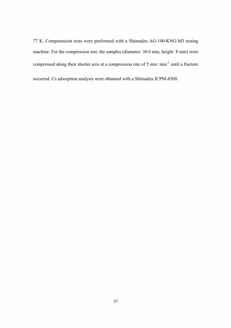
2.3. Results and disucussion
The surface morphology of the LPBs and the SPBs was examined by SEM and TEM.
The LPB powder consists of irregularly-shaped particles with an average particle size of
around 50 nm (Fig. 2.1a). On the other hand, the SPBs synthesized in this study are
nanoparticles with a uniform size distribution centered around 20 nm (Fig. 2.1b) Zeta
potential measurements reveal a monodispersed distribution and an average particle size
around 20 nm. The SPBs are negatively charged (−80 mV) and well dispersed in water
without any significant aggregation, which is favorable for the preparation of hydrogel
composites.
A TEM image of individual PB nanoparticle is shown in Fig. 2.1c. The particle
size observed here was around 20 nm with semi-spherical shape, which was in
agreement with SEM image (Fig. 2.1b). The electron diffraction from the aggregated
SPBs can be assigned to the face-centercubic (fcc) structure of a typical PB crystal (Fig.
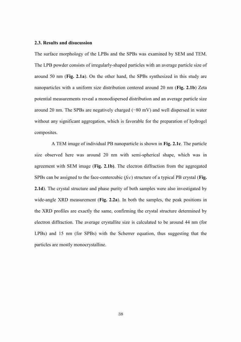
2.1d). The crystal structure and phase purity of both samples were also investigated by
wide-angle XRD measurement (Fig. 2.2a). In both the samples, the peak positions in
the XRD profiles are exactly the same, confirming the crystal structure determined by
electron diffraction. The average crystallite size is calculated to be around 44 nm (for
LPBs) and 15 nm (for SPBs) with the Scherrer equation, thus suggesting that the
particles are mostly monocrystalline.
39
Fig. 2.1
SEM image of (a) LPBs and (b) SPBs. (c) TEM image of individual SPB, and (d)
selected area ED patterns taken from several SPBs aggregate.
40
Fig. 2.2
(a) Wide-angle XRD patterns and (b) N2 adsorption–desorption isotherms of (i) LPBs
and (ii) SPBs.
41
N2 adsorption–desorption isotherms were measured for both LPBs and SPBs
(Fig. 2.2b). The SPBs show a high surface area (440 m2・g−1) and display a type IV
isotherm with a broad hysteresis loop associated with a capillary condensation taking
place in the inter particle space among the aggregated nanoparticles. In contrast, the
LPBs show very low surface area (10 m2・g−1) due to their large size.
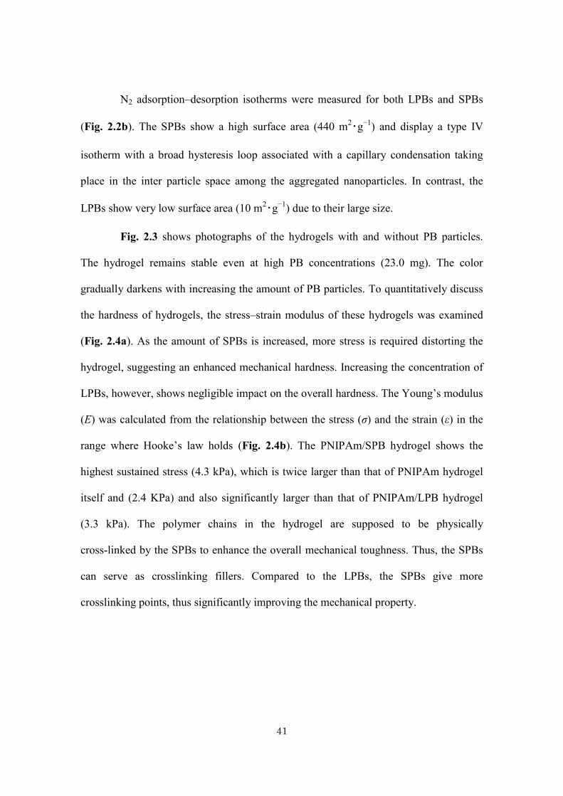
Fig. 2.3 shows photographs of the hydrogels with and without PB particles.
The hydrogel remains stable even at high PB concentrations (23.0 mg). The color
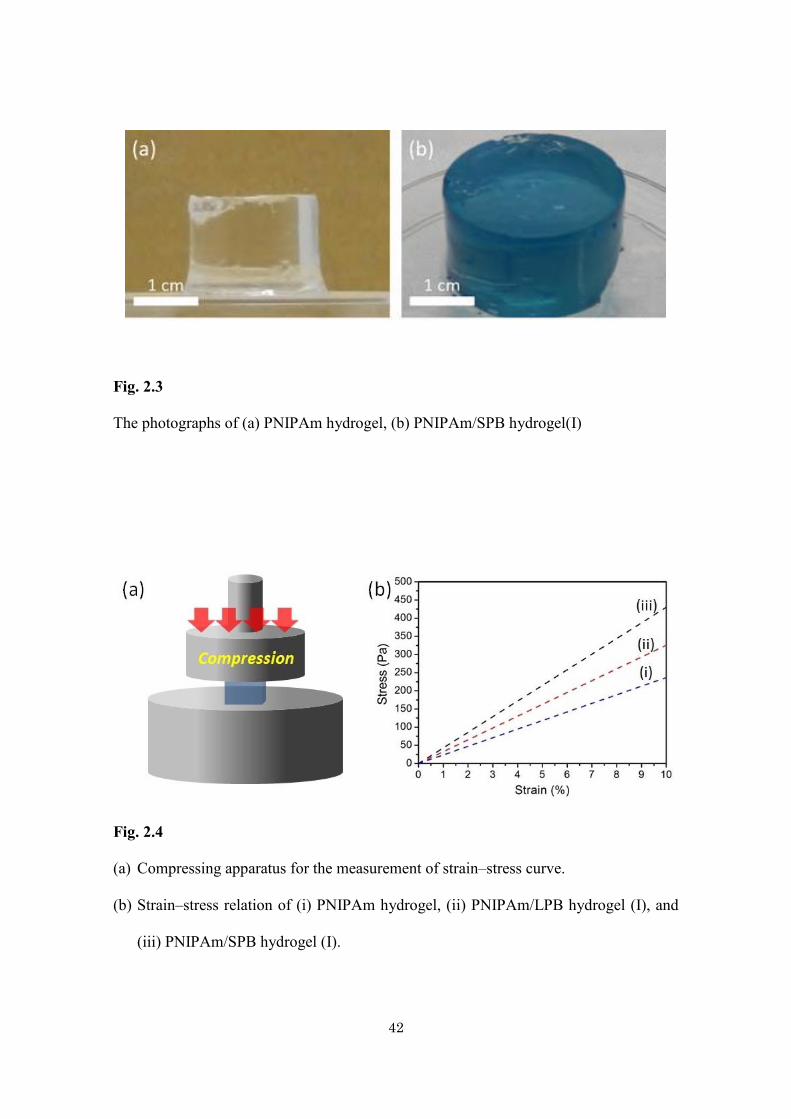
gradually darkens with increasing the amount of PB particles. To quantitatively discuss
the hardness of hydrogels, the stress–strain modulus of these hydrogels was examined
(Fig. 2.4a). As the amount of SPBs is increased, more stress is required distorting the
hydrogel, suggesting an enhanced mechanical hardness. Increasing the concentration of
LPBs, however, shows negligible impact on the overall hardness. The Young’s modulus
(E) was calculated from the relationship between the stress (σ) and the strain (ε) in the
range where Hooke’s law holds (Fig. 2.4b). The PNIPAm/SPB hydrogel shows the
highest sustained stress (4.3 kPa), which is twice larger than that of PNIPAm hydrogel
itself and (2.4 KPa) and also significantly larger than that of PNIPAm/LPB hydrogel
(3.3 kPa). The polymer chains in the hydrogel are supposed to be physically
cross-linked by the SPBs to enhance the overall mechanical toughness. Thus, the SPBs
can serve as crosslinking fillers. Compared to the LPBs, the SPBs give more
crosslinking points, thus significantly improving the mechanical property.
42
Fig. 2.3
The photographs of (a) PNIPAm hydrogel, (b) PNIPAm/SPB hydrogel(I)
Fig. 2.4
(a) Compressing apparatus for the measurement of strain–stress curve.
(b) Strain–stress relation of (i) PNIPAm hydrogel, (ii) PNIPAm/LPB hydrogel (I), and
(iii) PNIPAm/SPB hydrogel (I).
43
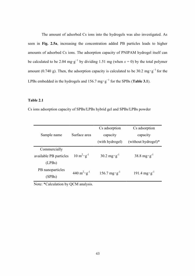
The amount of adsorbed Cs ions into the hydrogels was also investigated. As
seen in Fig. 2.5a, increasing the concentration added PB particles leads to higher
amounts of adsorbed Cs ions. The adsorption capacity of PNIPAM hydrogel itself can
be calculated to be 2.04 mg·g−1 by dividing 1.51 mg (when x = 0) by the total polymer
amount (0.740 g). Then, the adsorption capacity is calculated to be 30.2 mg・g−1 for the
LPBs embedded in the hydrogels and 156.7 mg・g−1 for the SPBs (Table 3.1).
Table 2.1
Cs ions adsorption capacity of SPBs/LPBs hybrid gel and SPBs/LPBs powder
Sample name Surface area
Cs adsorption
capacity
(with hydrogel)
Cs adsorption
capacity
(without hydrogel)*
Commercially
available PB particles
(LPBs)
10 m2・g-1 30.2 mg・g-1 38.8 mg・g-1
PB nanoparticles
(SPBs) 440 m2・g-1 156.7 mg・g-1 191.4 mg・g-1
Note: *Calculation by QCM analysis.
44
The Cs adsorption capacity of both LPBs and SPBs without hydrogels was also
investigated by QCM technique. The QCM-based adsorption offers the capability to
monitor in real-time the Cs ions uptake at a nanogram precision. The shift in the
resonance frequency of the quartz following the deposition of materials on the electrode
surface can be described by Sauerbrey’s theory. By measuring the decrease in frequency,
the mass per unit area (Δm, g·cm−2) of the PB particles deposited onto the parent Au
electrode can be systematically calculated by using frequency change (Δf ) measured by
a QCM with a fundamental resonance frequency (f0) before and after drop-coating. The
relationship of Δf to the mass loading of the PB samples (Δm) is defined by the
Sauerbrey equation [23]:
∆𝑓 = −2𝑁𝑓0
2
√𝜌𝜇
∆𝑚
𝐴 (1)
where N, f0, ρ, μ, and A are the harmonic overtone, the fundamental resonance
frequency, the crystal density (2.649 g・cm−3), the shear modulus of the quartz crystal
(2.947×10¹¹ g・cm−1・s−2), and the surface area (0.196 cm2), respectively. The mass of
the PB samples deposited onto QCM electrodes can be thus calculated using Eq. (1). Δf
after drop-coating and drying-up were 11150 Hz for SPBs and 11094 Hz for LPBs, thus
the deposited mass for each sample calculated to be 11.90 and 11.85 μg·cm−2,
respectively.
The QCM electrodes coated with PB samples were immersed in 50 mL water.
After reaching the equilibrium where no more water molecules could adsorb onto the
PB films, the Cs ions solution (50 mL, 1000 ppm) was injected into the water. A sharp
decreasing in the crystal frequency was observed due to the adsorption uptake of Cs
ions onto the surface of the PB samples. The time-dependence of Δf , which corresponds
45
to the amount of adsorbed Cs ions, was plotted and illustrated in Fig. 2.5b. The author
clearly observed a large adsorption uptake of Cs ions into the SPBs with a total Δf (after
6,000 s) of 417 Hz. In contrast, LPBs a relatively small Δf of 88 Hz and consequently,
reflecting a much lesser adsorption uptake of Cs ions from the solution. The adsorption
capacity was drastically increased and the significant difference in the adsorption uptake
was attributed to the increase in the effective surface area of the PB nanoparticles. The
calculated Cs ions adsorption capacity of the SPBs is 191.4 mg·g−1, which is around six
times than that of LPBs (38.8 mg·g−1) (Table 2.1). These obtained values indicate the
maximum Cs ions adsorption capacity, as an excess concentration of Cs ions was used
under these experimental conditions.
46
2.4. Conclusion
The author successfully prepared PB nanoparticles, which could be well dispersed in an
aqueous suspension. After drying, the obtained 20 nm size PB nanoparticles show high
surface area (440 m2・g−1) and were successfully hybridized with PNIPAm hydrogel to
form PNIPAm/PB composite hydrogels. The Cs ions adsorption capacity of the SPBs
embedded in the hydrogels (156.7 mg·g−1) is about five times higher than that of the
LPBs (30.2 mg·g−1).
47
2.5. References
[1] Y. Osada, J. P. Gong, Prog. Polym. Sci. 18 (1993) 187.
[2] A. Nakayama, A. Kakugo, J. P. Gong, Y. Osada, M. Takai, T. Erata, S. Kawano,
Adv. Funct. Mater. 14 (2004) 1124.
[3] K. Yasuda, J. P. Gong, Y. Katsuyama, A. Nakayama, Y. Tanabe, E. Kondo, M.
Ueno, Y. Osada, Biomaterials 26 (2005) 4468.
[4] S. Maeda, Y. Hara, T. Sakai, R. Yoshida, S. Hashimoto, Adv. Mater. 19 (2007)
3480.
[5] N. Yamada, T. Okano, H. Sakai, F. Karikusa, Y. Sawasaki, Y. Sakurai, Macromol.
Chem. Rapid Commun. 11 (1990) 571.
[6] B. Ziołkowski, L. Florea, J. Theobald, F. Benito-Lopez, D. Diamond, Soft Matter 9
(2013) 8754.
[7] T. Fujigaya, T. Morimoto, Y. Niidome, N. Nakashima, Adv. Mater. 20 (2008) 3610.
[8] R. Yoshida, T. Ueki, NPG Asia Materials. 6 (2014) e107.
[9] N. Miyamoto, M. Shintate, S. Ikeda, Y. Hoshida, Y. Yamauchi, R. Motokawa, M.
Annaka, Chem. Commun. 49 (2013) 1082.
[10] T. Inadomi, S. Ikeda, S. Yoshimura, Y. Okumura, H. Kikuchi, N. Miyamoto,
Macromol. Rapid Commun. 35 (2014) 1741.
[11] K. Haraguchi, T. Takehisa, Adv. Mater. 14 (2002) 1120.
[12] K. Haraguchi, T. Takehisa, S. Fan, Macromolecules 35 (2002) 10162.
[13] K. Haraguchi, H. J. Li, Macromolecules 39 (2006) 1898.
[14] N. L. Torad,M. Hu, M. Imura, M. Naito, Y. Yamauchi,
J. Mater. Chem. 22 (2012) 18261.
[15] M. Hu, N. L. Torad, Y. Yamauchi, Eur. J. Inorg. Chem. 2012 (2012) 4795.
48
[16] M. Hu, S. Furukawa, R. Ohtani, H. Sukegawa, Y. Nemoto, J. Reboul, S. Kitagawa,
Y. Yamauchi, Angew. Chem. Int. Ed. 51 (2012) 984.
[17] K. Ariga, Y. Yamauchi, G. Rydzek, Q. Ji, Y. Yonamine, K. C. W. Wu, J. P. Hill,
Chem. Lett. 43 (2014) 36.
[18] M. Hu, A. A. Belik, M. Imura, Y. Yamauchi, J. Am. Chem. Soc. 135 (2013) 384.
[19] H. Y. Lian, M. Hu, C. H. Liu, Y. Yamauchi, K. C. W. Wu, Chem. Commun. 48
(2012) 5151.
[20] H. Ming, N. L. K. Torad, Y. D. Chiang, K. C. W. Wu, Y. Yamauchi,
CrystEngComm. 14 (2012) 3387.
[21] J. P. Gong, Y. Katsuyama, T. Kurokawa, Y. Osada, Adv. Mater. 15 (2003) 1155.
[22] Y. Okumura, K. Ito, Adv. Mater. 13 (2001) 485.
[23] G. Sauerbrey, Z. Phys. 155 (1959) 206.
[24] K. Ariga, A. Vinu, Y. Yamauchi, Q. Ji, J. P. Hill, Bull. Chem. Soc. Jpn. 85 (2012)
1.
[25] B. P. Bastakoti, S. Ishihara, S. Y. Leo, K. Ariga, K. C. W. Wu, Y. Yamauchi,
Langmuir 30 (2014) 651.
[26] V. Malgras, Q. Ji, Y. Kamachi, T. Mori, F. K. Shieh, K. C. W. Wu, K. Ariga, Y.
Yamauchi, Bull. Chem. Soc. Jpn. 88 (2015) 1171.
49
Chapter 3.
Hydrogels containing mesoporous silica particles
for control behavior of guest molecules adsorption/desorption
50
Abstract
Here the author prepared thermo-responsive hydrogel containing mesoporous silica
(KIT-6) with high surface area. The hybrid hydrogel was prepared by gelation of
NIPAm monomer with mesoporous silica particles in presence of cross linker.
Owing to the doped mesoporous silica, a large amount of guest molecules were
adsorbed easily. With increase of temperature, the hybrid hydrogel shrinked to retard
the release of guest molecules.
51
3.1. Introduction
Mesoporous silica (MPS) materials have demonstrated very interesting properties in
the development of drug delivery system (DDS), because of high adsorption capacity
of guest molecules and their release [1-4]. Also, MPS has shown to be highly
biocompatible and its self-degradation in aqueous solution solves the problems related
to the removal of the material after use [5]. MPS itself, however, cannot show the
intelligent properties such as controlled release as a function of external stimuli,
which is highly demanding in DDS. On the other hand, use of several
stimuli-responsive polymers (e.g., polymeric micelles) can optimize adsorption and
delivery of drugs [6-9]. In spite of their fast response with change in external factors,
their poor mechanical properties limit their applications, since most of the polymers
consist of organic backbone.
The combination of stimuli responsive properties of polymer and mechanical
and thermal stability of MPS can help to develop smart MPS-based delivery systems
in which encapsulation and release of guest molecules can be controlled by a variety
of external stimuli [10-12]. Some efforts have been made to realize hybrid systems
using MPS materials for controlled release. pH-responsive hybrid carrier system is
constructed by electrostatic interaction between polycations and anionic SBA-15.
The ionizable carboxylic acid can act as a reversible gate to release drug in a
controlled way [13]. pH-induced conformational change of protein molecules forms
pH-responsive nanovalve to lock and unlock the pore entrances of MCM-41 [14].
Poly(N-isopropylacrylamide) (PNIPAm) is a thermoresponsive polymer,
which shows a reversible coil-to-globule transition at elevated temperature (known as
lower critical solution temperature (LCST)) in aqueous solution [15]. Raising the
52
temperature above its LCST, water bound to the polymer chain is released and soluble
polymer coils start to form insoluble globular particles. The LCST of PNIPAm is at
around 32-34 oC which is very close to human body temperature. Therefore,
PNIPAm-based hybrid gel has been widely studied in biomedical applications [16-18].
Hybridization of MPS particles with functional polymer not only enables
functionalization with various molecules but also provides the opportunity to tune the
loading and release of guest molecules [19]. Liu et al. synthesized a magnetic MPS
nanoparticle coating with PNIPAm polymer. The phase transition temperature of
hybrid spheres can be finely tuned by adjusting the amount of hydrophilic comonomer
[20]. Interpenetrating network of PNIPAm is formed within the pores by organic and
inorganic gelation. The property of hybrid gel is optimized by controlling the molar
ratios of silica source and NIPAm [21]. Radical microemulsion polymerization is used
to graft PNIPAm on the Fe3O4@SiO2 core-shell nanoparticles [22]. Lopez et al.
impregnated the polymer into the pores of MCM-41 [23]. The kinetics of molecular
diffusion was observed when the polymer chain changes from open coil to globule
conformation as a function of temperature.
The author’s goal of this chapter is a smart hybridization of PNIPAm
hydrogels with MPS particles to realize sustainable release. Mesoporous structures are
easily accessible for the adsorption of guest molecules. Mechanical strength,
encapsulation and controlled release of guest molecules as a function of temperature
are investigated.
53
3.2. Experimental
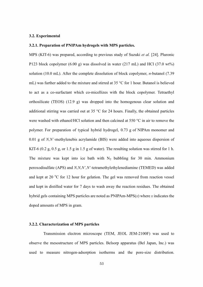
3.2.1. Preparation of PNIPAm hydrogels with MPS particles.
MPS (KIT-6) was prepared, according to previous study of Suzuki et al. [24]. Pluronic
P123 block copolymer (6.00 g) was dissolved in water (217 mL) and HCl (37.0 wt%)
solution (10.0 mL). After the complete dissolution of block copolymer, n-butanol (7.39
mL) was further added to the mixture and stirred at 35 °C for 1 hour. Butanol is believed
to act as a co-surfactant which co-micellizes with the block copolymer. Tetraethyl
orthosilicate (TEOS) (12.9 g) was dropped into the homogenous clear solution and
additional stirring was carried out at 35 °C for 24 hours. Finally, the obtained particles
were washed with ethanol/HCl solution and then calcined at 550 °C in air to remove the
polymer. For preparation of typical hybrid hydrogel, 0.73 g of NIPAm monomer and
0.01 g of N,N’-methylenebis acrylamide (BIS) were added into aqueous dispersion of
KIT-6 (0.2 g, 0.5 g, or 1.5 g in 1.5 g of water). The resulting solution was stirred for 1 h.
The mixture was kept into ice bath with N2 bubbling for 30 min. Ammonium
peroxodisulfate (APS) and N,N,N’,N’-tetramethylethylenediamine (TEMED) was added
and kept at 20 oC for 12 hour for gelation. The gel was removed from reaction vessel
and kept in distilled water for 7 days to wash away the reaction residues. The obtained
hybrid gels containing MPS particles are noted as PNIPAm-MPS(x) where x indicates the
doped amounts of MPS in gram.
3.2.2. Characterization of MPS particles
Transmission electron microscope (TEM, JEOL JEM-2100F) was used to
observe the mesostructure of MPS particles. Belsorp apparatus (Bel Japan, Inc.) was
used to measure nitrogen-adsorption isotherms and the pore-size distribution.

54
Low-angle XRD patterns were recorded by using a NANO VIEWER (Rigaku, Japan).
55
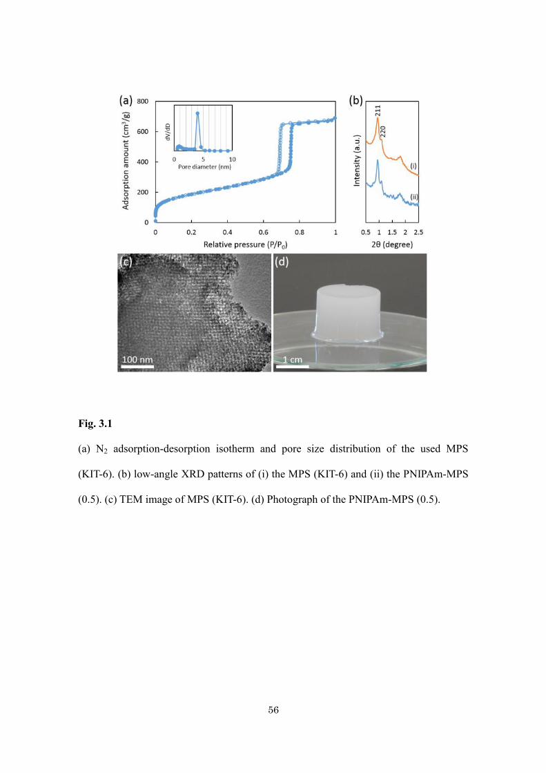
3.3. Results and Discussion
N2 adsorption desorption isotherm of MPS shows typical IV type with specific surface
area (717 m2·g-1) (Fig. 3.1a). XRD peaks in low-angle region shows excellent structural
ordering with Ia-3d symmetry (Fig. 3.1b). Highly interconnected mesopores of MPS
(KIT-6) was observed by TEM (Fig. 3.1c). The main achievement of this study is that
gelation of PNIPAm on/into the MPS does not perturb the mesoporosity. The XRD
pattern of the hybrid gel (Fig. 3.1b) is nearly the same as the original one, indicating no
mesostructural shrinkage or destruction was occurred. The d-spacing of the hybrid gel is
the same as that of pure KIT-6, indicating the original mesopores are also retained after
inclusion of PNIPAm. A little weaker peaks of hybrid gel can be attributed to the reduced
X-ray scattering contrast between the pores and the wall of the materials due to partial
interpenetration of polymer into the mesopores. The photograph of the obtained
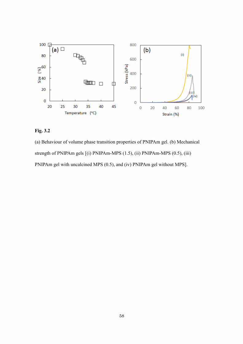
PNIPAm-MPS hybrid gel is shown in Fig. 3.1d. During the heating and cooling cycle
(Fig. 3.2a) from 20 to 45 oC, a sharp change in the volume of gel appears at around 34 oC.
There is no significant deviation from the LCST of pure PNIPAm hydrogel indicating that
the PNIPAm retains its characteristic properties in hybrid gel. It underwent reversible
70% volume change when heated from ambient temperature to above the LCST. The
reversible temperature driven phase transition is very useful for the adsorption and
release of guest molecules, which is discussed later.
56
Fig. 3.1
(a) N2 adsorption-desorption isotherm and pore size distribution of the used MPS
(KIT-6). (b) low-angle XRD patterns of (i) the MPS (KIT-6) and (ii) the PNIPAm-MPS
(0.5). (c) TEM image of MPS (KIT-6). (d) Photograph of the PNIPAm-MPS (0.5).
57
The mechanical properties of the PNIPAm gels were remarkably improved by
the addition of MPS particles. Fig. 3.2b shows the stress-strain curves obtained by
compression test. By loading 0.5 g of MPS particles, the fracture strain is almost
constant, but the fracture stress largely increases from 93.5 to 378 kPa. When excess
amounts of MPS particles (more than 1.5 g) are loaded, the fracture stress further
largely increases, and the fracture strain (%) decreases. In the equilibrium swelling state,
the average number (n) of the monomer units between the cross links is calculated as
mNIPAm/mBIS (= ~492) where mNIPAm and mBIS indicate the moles of NIPAm and BIS,
respectively. From this value, the root-mean-square end-to-end distance (<R2>1/2) and
fully stretched chain length (L) are calculated as (C×n×b2)1/2 (= ~16 nm) and n×b (=
~120 nm), respectively, based on the characteristic ratio (C= ~8) and the bond length of
the polymer chain (b= ~0.25 nm). It is expected that the free polymer chains outside the
pore are rather less stretched than the chains inside the narrow pores. Inside the pores,
not a single chain but multiple numbers of chains can be incorporated because the
mesopore size is much larger than a cross-sectional size of the chains (~1 nm). It is
expected that the mesopores can accommodate around 16 polymer chains.
58
Fig. 3.2
(a) Behaviour of volume phase transition properties of PNIPAm gel. (b) Mechanical
strength of PNIPAm gels [(i) PNIPAm-MPS (1.5), (ii) PNIPAm-MPS (0.5), (iii)
PNIPAm gel with uncalcined MPS (0.5), and (iv) PNIPAm gel without MPS].
59
Considering the gel structure discussed above, the improved mechanical
properties of the gel doped with 0.5 g MPS particles is accounted for the formation of
both topological and rigid crosslinks. The polymer chains or their bundles are piercing
through the mesopores to form movable topological crosslinks near the particle surface,
and then the total mechanical stress is uniformly dispersed, leading to the improvement
of mechanical property of gels. For comparison, hydrogel containing as-prepared
mesostructured silica particles (without mesopores) were also prepared, as shown in Fig.
3.2b. It indicates almost the same mechanical behavior as the pure hydrogel. When
excess amounts of MPS particles (more than 1.5 g) are loaded, more polymer chain
networks are incorporated deep inside the particles. These polymers are mostly
immobilized well so that the effective density of the polymer chains and the chemical
cross linker outside the pores decreases [25].
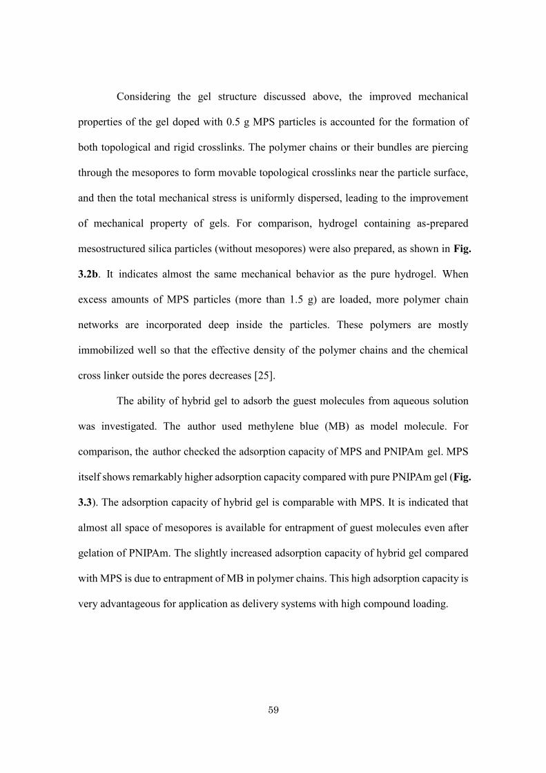
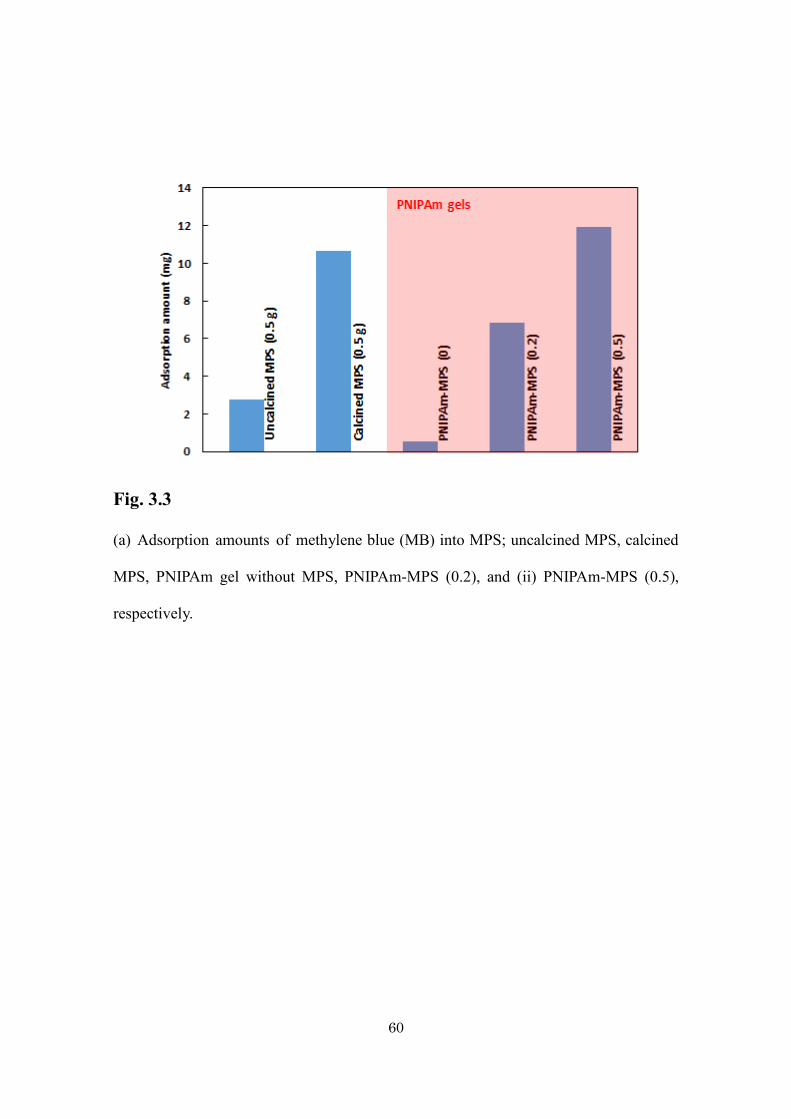
The ability of hybrid gel to adsorb the guest molecules from aqueous solution
was investigated. The author used methylene blue (MB) as model molecule. For
comparison, the author checked the adsorption capacity of MPS and PNIPAm gel. MPS
itself shows remarkably higher adsorption capacity compared with pure PNIPAm gel (Fig.
3.3). The adsorption capacity of hybrid gel is comparable with MPS. It is indicated that
almost all space of mesopores is available for entrapment of guest molecules even after
gelation of PNIPAm. The slightly increased adsorption capacity of hybrid gel compared
with MPS is due to entrapment of MB in polymer chains. This high adsorption capacity is
very advantageous for application as delivery systems with high compound loading.
60
Fig. 3.3
(a) Adsorption amounts of methylene blue (MB) into MPS; uncalcined MPS, calcined
MPS, PNIPAm gel without MPS, PNIPAm-MPS (0.2), and (ii) PNIPAm-MPS (0.5),
respectively.
61
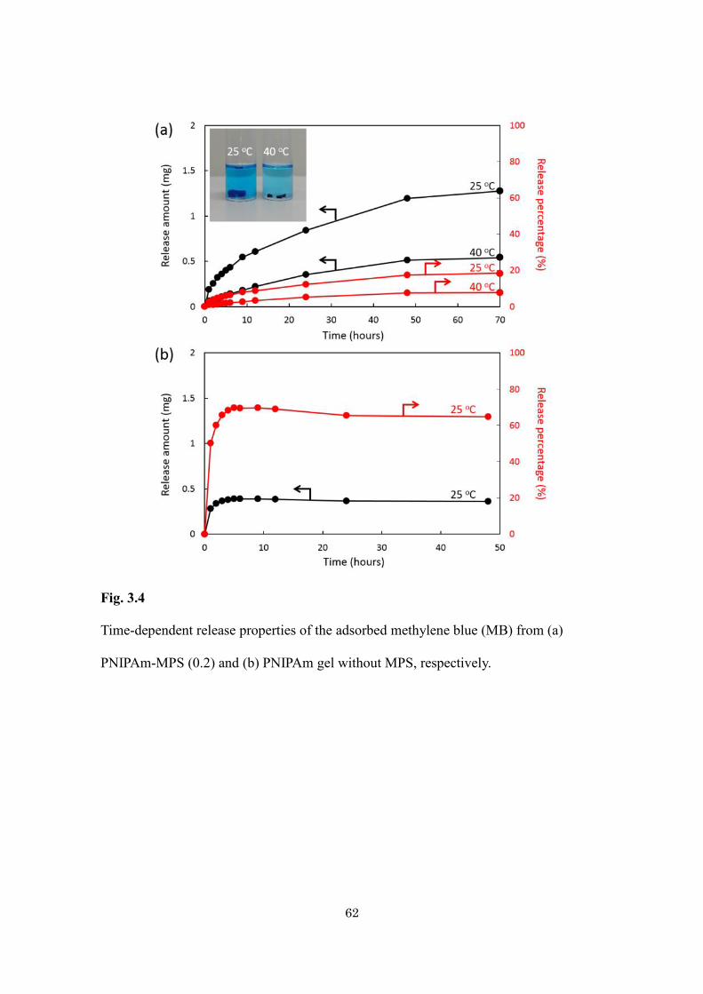
Adsorption of large amount of guest molecules and their controlled release is
always demanding in biomedical application. Here, the author investigated the
temperature-dependent release of MB from the hybrid gel. The gel was immersed in pure
water at two different temperatures (25 °C and 40 °C) and studied the kinetics of release
of MB. The amount of MB released was estimated by the absorbance at 630 nm of the
supernatant solution. The release profile of MB was shown in Fig. 3.4a. The
time-dependent release amount is higher at temperature (25 oC) lower than LCST of
PNIPAm. The faster release rate is due to opening of the gate as the PNIPAm becomes
hydrophilic and cannot close the pore tightly. The extended polymer chains open the gate
and allow releasing the entrapped MB quickly. At temperature (40 oC) above the LCST of
PNIPAm, the transformation from coil to globule structure occurs which increases the
hydrophobicity of the polymer chain results into shrinking and closes the gate more
tightly, thereby preventing the drug from being significantly released from hybrid gels.
The direct observation of photograph of hybrid gel at ambient temperature and above
LCST clearly shows the phase transition behavior (Inset of Fig. 3.4a). The shrinking and
expansion of hybrid gel as a function of temperature is directly observed. For comparison,
the burst release was observed for the pure PNIPAm gel (Fig. 3.4b). It is found that the
hybridization of thermoresponsive polymer with silica not only enhances the adsorption
efficiency but also releases the drug in sustained manner.
62
Fig. 3.4
Time-dependent release properties of the adsorbed methylene blue (MB) from (a)
PNIPAm-MPS (0.2) and (b) PNIPAm gel without MPS, respectively.
63
3.4. Conclusion
A thermoresponsive PNIPAm-based hybrid gel containing MPS (KIT-6) is successfully
synthesized. The ordered mesostructure of KIT-6 is completely preserved after
incorporating the PNIPAm. The high surface area MPS offers high loading efficiency and
PNIPAm polymer chains contribute the controlled release of guest molecules by
changing the applied temperatures. This novel hybrid gel containing thermally and
mechanically stable MPS and thermoresponsive polymer with the LCST value being
around physiological temperature of human body will be a highly useful system for drug
delivery applications in the future.
64
3.5. References
[1] K. Ariga, A. Vinu, Y. Yamauchi, Q. Ji, J. P. Hill, Bull. Chem. Soc. Jpn. 85, (2012), 1.
[2] V. Valtchev, L. Tosheva, Chem. Rev. 113, (2013), 6734.
[3] N. Ehlert, P. P. Mueller, M. Stieve, T. Lenarz, P. Behrens, Chem. Soc. Rev. 42, (2013),
3847.
[4] V. Malgras, Q. Ji, Y. Kamachi, T. Mori, F. Shieh, K. C. W. Wu, K. Ariga, Y.
Yamauchi, Bull. Chem. Soc. Jpn. 88, (2015), 1171.
[5] T. Asefa, Z. Tao, Chem. Res. Toxicol. 25, (2012), 2265.
[6] Ge Z, Liu S. Chem. Soc. Rev. 42, (2013), 7289.
[7] D. Roy, W. L. Brooks, B. S. Sumerlin, Chem. Soc. Rev. 42, (2013), 7214.
[8] B. P. Bastakoti, K. W. C. Wu, M. Inoue, S. Yusa, K. Nakashima, Y. Yamauchi,
Chem. Eur. J. 19, (2013), 4812.
[9] B. P. Bastakoti, S. Liao, M. Inoue, S. Yusa, M. Imura, K. Nakashima, K. C. W. Wu, Y.
Yamauchi, Sci. Technol. Adv. Mater. 14, (2013), 44402.
[10] H. Meng, M. Xue, T. Xia, Y. L. Zhao, F. Tamanoi, J. F. Stoddert, J. I. Zink, A. E.
Nel, J. Am. Chem. Soc. 132, (2010), 12690.
[11] J. Allouche, A. L. Beulze, J. C. Dupin, J. B. Ledeuil, S. Blanca, D. Gonbeau, J.
Mater. Chem. 20, (2010), 9370.
[12] A. Bernardos, E. Aznar, M. D. Marcos, R. Martinez-Máñez, F. Sancenón, J. Soto, J.
M. Barat, P. Amorós, Angew. Chem. Int. Ed. 48, (2009), 5884.
[13] Q. Yang, S. Wang, P. Fan, L. Wang, Y. Di, K. Lin, F. S. Xiao, Chem. Mater. 17,
(2005), 5999.
[14] M. Xue, G. H. Findenegg, Langmuir. 28, (2012), 17578.
65
[15] J. Zhuang, M. R. Gordon, J. Ventura, L. Li, S. Thayumanavan, Chem. Soc. Rev. 42,
(2013), 7421.
[16] W. Li, L. Deng, B. Moosa, G. Wang, A. Mashat, N. M. Khashab, Biomater. Sci. 2,
(2014), 476.
[17] X. Zhu, C. Yan, F. M. Winnik, D. Leckband, Langmuir. 23, (2007), 162.
[18] Y. Hoshino, M. Nakamoto, Y. Miura, J. Am. Chem. Soc. 134, (2012), 15209.
[19] N. Singh, A. Karambelkar, L. Gu,K. Lin,J. S. Miller,C. S. Chen, M. J. Sailor, S. N.
Bhatia, J. Am. Chem. Soc. 133, (2011), 19582.
[20] C. Liu, J. Guo, W. Yang, J. Hu, C. Wang, S. Fu, J. Mater. Chem. 19, (2009), 4764.
[21] P. Banet, P. Griesmar, S. Serfaty, F. Vidal, V. Jaouen, J. Y. K. Huerou, J. Phys.
Chem. B. 113, (2009), 14914.
[22] Y. H. Lien, T. M. Wu, J. Colloid. Interface. Sci. 326, (2008), 517.
[23] Q. Fu,G. V. R. Rao, T. L. Ward, Y. Lu, G. P. Lopez, Langmuir. 23, (2007), 170.
[24] N. Suzuki, S. Kiba, Y. Yamauchi, Mater. Lett. 65, (2011), 544.
[25] N. Miyamoto, K. Shimasaki, K. Yamamoto, M. Shintate, Y. Kamachi, B. P.
Bastakoti, N. Suzuki, R. Motokawa, Y. Yamauchi, Chem. Euro. J. 20, (2014),
14955.

66
67
Chapter 4.
Silicone rubbers containing mesoporous silica particles
for improvement thermal property and strength
68
Abstract
The author fabricated mesoporous silica/silicone composites in a simple way and
systematically examine their thermal stability and mechanical strength. Simple
calculations showed that more than 90 vol% of mesopores are filled with silicone
rubbers. Compared to non-porous silica/silicone composites, mesoporous silica/silicone
composites showed a lower coefficient of linear thermal expansion (CTE). In addition,
dramatic improvements of the tensile strength and Young’s modulus were obtained with
mesoporous silica/silicone composites.
69
4.1. Introduction
Unlike organic rubbers, the backbone of which consists of C–C bonds, silicone rubber
has a stronger siloxane bond (Si–O–Si) backbone. Therefore, silicone rubber can
withstand hostile environments, such as high temperature, UV irradiation, and ozone
exposure, in which the C–C bonds break. Owing to these characteristics, silicone rubber
is commonly used for parts exposed to hostile environments, such as combustion
engines, rocketry, and satellites. In addition, because silicone rubber is chemically
stable and has high biocompatibility, it is used for medical apparatuses, such as
catheters, cochlear implants, cardiac pacemakers, artificial skins, contact lenses, and
oxygenators. Currently, on account of its transparency, flexibility, and environmental
resistance, silicone rubber is being used for optoelectronic devices, such as the cover of
LED, light guide films, and optical fibers.
However, low mechanical strength, especially tensile strength, and high
thermal expansion are the main drawbacks of silicone rubber for practical uses. To
expand the applications of silicone rubber, these obstacles need to be overcome. To
reinforce the mechanical strength, the addition of inorganic fillers is very common in
polymers [1-13], gels [14, 15], and natural rubbers [16-20]. Many filler-loading
experiments with silicone rubber have been reported [21-35].
As a new inorganic filler material, the author has focused on mesoporous silica.
Mesoporous silica, with a very large number of nanoscale pores and extremely large
pore volumes, can be prepared through the spontaneous self-assembly of surfactants
[36-45]. In previous papers, Yamauchi et al. pointed out that mesoporous silica particles
effectively reduce the coefficient of linear thermal expansion (CTE) of epoxy polymer
composites [46-50]. The author has also demonstrated that mesoporous silica particles
70
are more effective in reducing CTE values and hardening silicone rubber composites
than conventional non-porous silica fillers. In addition, silicone rubber composites with
mesoporous silica particles showed higher transparency than those with non-porous
silica particles [51].
However, the fabrication process of silicone rubber composites in the previous
work took a long fabrication time because many steps are required to obtain the
composites [51]. First, mesoporous silica was mixed with the main component of the
silicone rubber with the aid of a solvent, and the obtained slurry was then dried until the
solvent completely evaporated. After mechanical mixing of the slurry, a curing agent
was added and mixed. Finally, the curing procedure was conducted in a vacuum to
obtain the final products. From an industrial viewpoint, reducing processes and saving
time are important. In this study, the author proposes a simple fabrication process by
using silicone rubber, which does not require a curing agent. Furthermore, the thermal
stability, swelling characteristics, mechanical strength, and transparency are examined
in detail for supporting the effectiveness of mesoporous silica particles as filler
materials.
71
4.2. Experimental
4.2.1. Chemicals
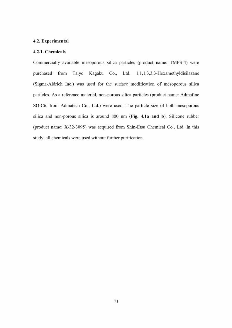
Commercially available mesoporous silica particles (product name: TMPS-4) were
purchased from Taiyo Kagaku Co., Ltd. 1,1,1,3,3,3-Hexamethyldisilazane
(Sigma-Aldrich Inc.) was used for the surface modification of mesoporous silica
particles. As a reference material, non-porous silica particles (product name: Admafine
SO-C6; from Admatech Co., Ltd.) were used. The particle size of both mesoporous
silica and non-porous silica is around 800 nm (Fig. 4.1a and b). Silicone rubber
(product name: X-32-3095) was acquired from Shin-Etsu Chemical Co., Ltd. In this
study, all chemicals were used without further purification.
72
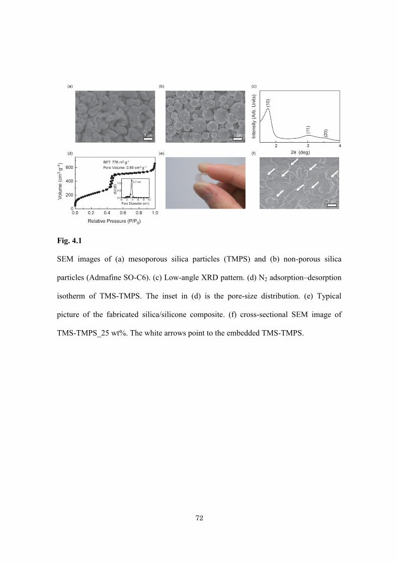
Fig. 4.1
SEM images of (a) mesoporous silica particles (TMPS) and (b) non-porous silica
particles (Admafine SO-C6). (c) Low-angle XRD pattern. (d) N2 adsorption–desorption
isotherm of TMS-TMPS. The inset in (d) is the pore-size distribution. (e) Typical
picture of the fabricated silica/silicone composite. (f) cross-sectional SEM image of
TMS-TMPS_25 wt%. The white arrows point to the embedded TMS-TMPS.
73
4.2.2. Preparation of silica/silicone composites
Trimethylsilyl modification of TMPS-4 was conducted to increase the affinity between
the mesopore surface and silicone.TMPS-4 (10 g) and 1,1,1,3,3,3-hexamethyl-
disilazane (1.0 g) were mixed in the polypropylene bag. The powders were
subsequently treated at 120 oC for 24 h; then, TMS-modified TMPS-4 (hereafter,
referred to as ‘‘TMS-TMPS’’) was obtained. TMS-TMPS and silicone were mixed with
the THINKY vacuum mixer ARV-310 at room temperature until a bubble-free mixture
was obtained. The obtained mixture was heated under a reduced-pressure condition.
First, the mixture was kept at 40 oC for around 20 h, then gradually heated up to 150 oC,
and finally held at 150 oC for 30 min. For a comparative study, the author prepared a
composite with nonporous silica particles (NS) in the same way. The author prepared
several silica/silicone composites by varying the amounts of TMS-TMPS (or NS). The
total composite amounts were fixed to be 7.0 g. The details for each component are
listed in Table 4.1. Hereafter, mesoporous silica/silicone and non-porous silica/silicone
composites are described as TMS-TMPS_X wt% and NS_X wt%, respectively, where
‘‘X’’ indicates the weight percentages of TMS-TMPS and NS.
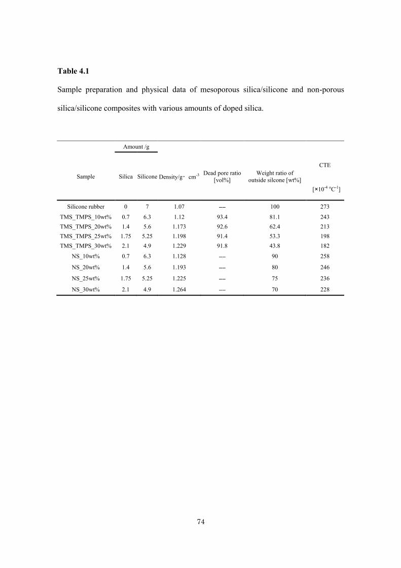
74
Table 4.1
Sample preparation and physical data of mesoporous silica/silicone and non-porous
silica/silicone composites with various amounts of doped silica.
Amount /g
Sample Silica Silicone Density/g・cm-3 Dead pore ratio [vol%]
Weight ratio of outside silcone [wt%]
CTE
[×10-4 oC-1]
Silicone rubber 0 7 1.07 ―― 100 273
TMS_TMPS_10wt% 0.7 6.3 1.12 93.4 81.1 243 TMS_TMPS_20wt% 1.4 5.6 1.173 92.6 62.4 213 TMS_TMPS_25wt% 1.75 5.25 1.198 91.4 53.3 198 TMS_TMPS_30wt% 2.1 4.9 1.229 91.8 43.8 182
NS_10wt% 0.7 6.3 1.128 ―― 90 258
NS_20wt% 1.4 5.6 1.193 ―― 80 246
NS_25wt% 1.75 5.25 1.225 ―― 75 236
NS_30wt% 2.1 4.9 1.264 ―― 70 228
75
4.2.3 Characterization
The low-angle X-ray diffraction of TMS-TMPS was measured with RINT 2000/PC
(Rigaku) using a CuKα X-ray. The total pore volume of TMS-TMPS was estimated
from the N2 adsorption–desorption isotherm measured with BELSORP-mini II (BEL
JAPAN) at 77 K. Prior to the measurement, the particles were pretreated in a vacuum at
100 oC for 24 h with BELPREP-vac II (BEL JAPAN). The specific gravity of the
obtained silica/silicone composites was determined using the Archimedean method.
Thermal mechanical analysis (TMA) data of the composites were obtained using
Thermoplus TMA 8310 (Rigaku). Prior to the measurement, rectangular specimens
(10mm × 4.5 mm × 4.5 mm) were prepared from the fabricated composites. The
temperature was increased at a rate of 5 oC min-1 during the measurement. The obtained
TMA charts were normalized by the original specimen length (10 mm). The weight loss
at 260 oC was measured with an EXSTAR TG/DTA 6200 (SII). The swelling
characteristic of the composites was examined as follows. First, each composite (5 mm
× 5 mm × 10 mm) was put into a 15 mL screw bottle (diameter is 2.5 cm); 8 mL of
toluene was added; and the cap was closed to prevent evaporation of the solvent. The
composites were completely immersed in toluene. A fixed point observation was
conducted until the swelling of the composite reached equilibrium. By dividing the
volume of a swelled composite by the initial volume, the time-dependence of the
volume expansion ratio was measured. Stress–strain measurements were performed
with an AG-100-KNG-M3 testing machine (Shimadzu). For the compression test, the
rectangular composites (4 mm × 4 mm × 3 mm) were compressed along their shorter
axis at a compression rate of 5 mm mm_1. For the tensile strength measurements, a strip
sample (1 mm × 5 mm × 40 mm) was put on the machine with an initial gap of 20 mm
76
and stretched at a rate of 5 mm mm-1 until a fracture occurred. To investigate the
transparency of the composites, the UV-VIS-NIR spectrum of each composite was
measured with a V-570 spectrophotometer (JASCO). The thickness of each composite
was fixed to 50 mm.
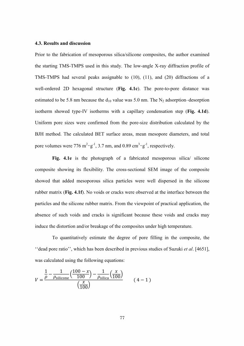
77
4.3. Results and discussion
Prior to the fabrication of mesoporous silica/silicone composites, the author examined
the starting TMS-TMPS used in this study. The low-angle X-ray diffraction profile of
TMS-TMPS had several peaks assignable to (10), (11), and (20) diffractions of a
well-ordered 2D hexagonal structure (Fig. 4.1c). The pore-to-pore distance was
estimated to be 5.8 nm because the d10 value was 5.0 nm. The N2 adsorption–desorption
isotherm showed type-IV isotherms with a capillary condensation step (Fig. 4.1d).
Uniform pore sizes were confirmed from the pore-size distribution calculated by the
BJH method. The calculated BET surface areas, mean mesopore diameters, and total
pore volumes were 776 m2・g-1, 3.7 nm, and 0.89 cm3・g-1, respectively.
Fig. 4.1e is the photograph of a fabricated mesoporous silica/ silicone
composite showing its flexibility. The cross-sectional SEM image of the composite
showed that added mesoporous silica particles were well dispersed in the silicone
rubber matrix (Fig. 4.1f). No voids or cracks were observed at the interface between the
particles and the silicone rubber matrix. From the viewpoint of practical application, the
absence of such voids and cracks is significant because these voids and cracks may
induce the distortion and/or breakage of the composites under high temperature.
To quantitatively estimate the degree of pore filling in the composite, the
‘‘dead pore ratio’’, which has been described in previous studies of Suzuki et al. [4651],
was calculated using the following equations:
𝑉 =
1𝜌 −
1𝜌silicone
(100 − 𝑥
100 ) −1
𝜌silica(
𝑥100)
(𝑥
100) ( 4 − 1 )
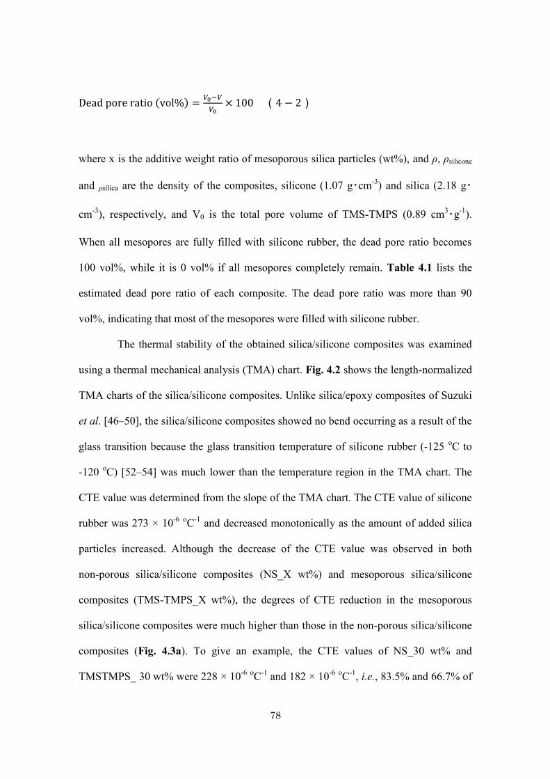
78
Dead pore ratio (vol%) =𝑉0−𝑉
𝑉0× 100 (4 − 2)
where x is the additive weight ratio of mesoporous silica particles (wt%), and ρ, ρsilicone
and ρsilica are the density of the composites, silicone (1.07 g・cm-3) and silica (2.18 g・
cm-3), respectively, and V0 is the total pore volume of TMS-TMPS (0.89 cm3・g-1).
When all mesopores are fully filled with silicone rubber, the dead pore ratio becomes
100 vol%, while it is 0 vol% if all mesopores completely remain. Table 4.1 lists the
estimated dead pore ratio of each composite. The dead pore ratio was more than 90
vol%, indicating that most of the mesopores were filled with silicone rubber.
The thermal stability of the obtained silica/silicone composites was examined
using a thermal mechanical analysis (TMA) chart. Fig. 4.2 shows the length-normalized
TMA charts of the silica/silicone composites. Unlike silica/epoxy composites of Suzuki
et al. [46–50], the silica/silicone composites showed no bend occurring as a result of the
glass transition because the glass transition temperature of silicone rubber (-125 oC to
-120 oC) [52–54] was much lower than the temperature region in the TMA chart. The
CTE value was determined from the slope of the TMA chart. The CTE value of silicone
rubber was 273 × 10-6 oC-1 and decreased monotonically as the amount of added silica
particles increased. Although the decrease of the CTE value was observed in both
non-porous silica/silicone composites (NS_X wt%) and mesoporous silica/silicone
composites (TMS-TMPS_X wt%), the degrees of CTE reduction in the mesoporous
silica/silicone composites were much higher than those in the non-porous silica/silicone
composites (Fig. 4.3a). To give an example, the CTE values of NS_30 wt% and
TMSTMPS_ 30 wt% were 228 × 10-6 oC-1 and 182 × 10-6 oC-1, i.e., 83.5% and 66.7% of
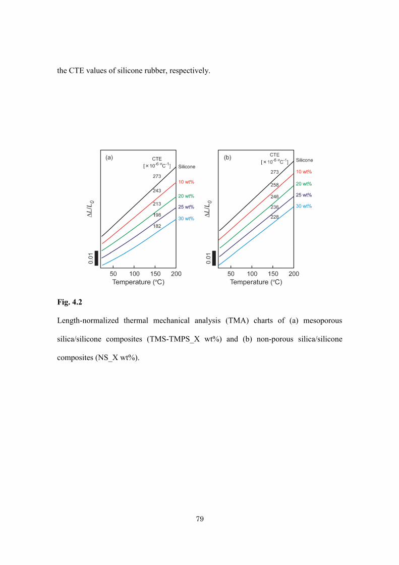
79
the CTE values of silicone rubber, respectively.
Fig. 4.2
Length-normalized thermal mechanical analysis (TMA) charts of (a) mesoporous
silica/silicone composites (TMS-TMPS_X wt%) and (b) non-porous silica/silicone
composites (NS_X wt%).
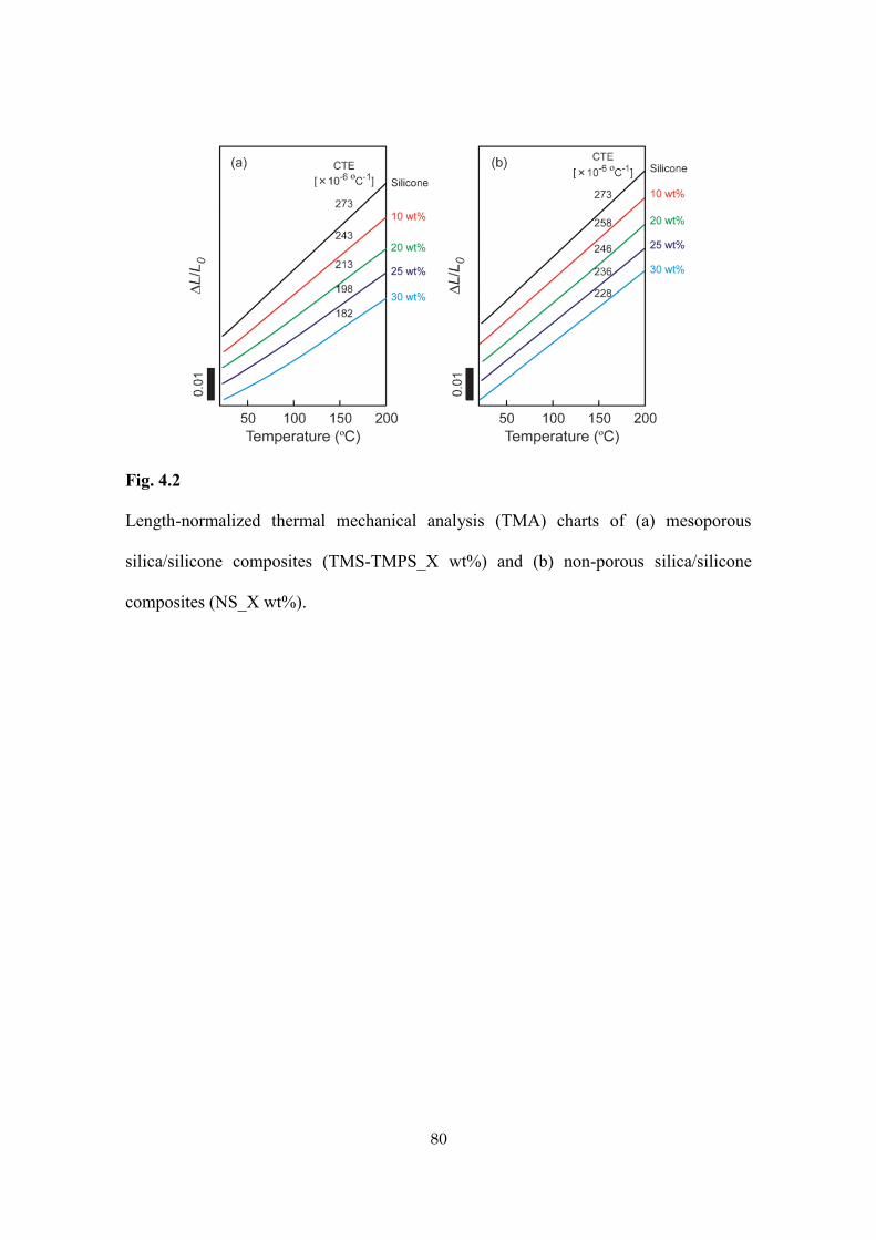
80
Fig. 4.2
Length-normalized thermal mechanical analysis (TMA) charts of (a) mesoporous
silica/silicone composites (TMS-TMPS_X wt%) and (b) non-porous silica/silicone
composites (NS_X wt%).
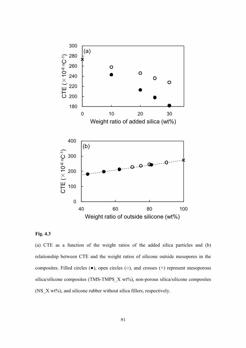
81
Fig. 4.3
(a) CTE as a function of the weight ratios of the added silica particles and (b)
relationship between CTE and the weight ratios of silicone outside mesopores in the
composites. Filled circles (●), open circles (○), and crosses (×) represent mesoporous
silica/silicone composites (TMS-TMPS_X wt%), non-porous silica/silicone composites
(NS_X wt%), and silicone rubber without silica fillers, respectively.
180
200
220
240
260
280
300
0 10 20 30
CTE
(×10
-6 o C
-1)
Weight ratio of added silica (wt%)
(a)
0
100
200
300
400
40 60 80 100
CTE
(×10
-6 o C
-1)
Weight ratio of outside silicone (wt%)
(b)
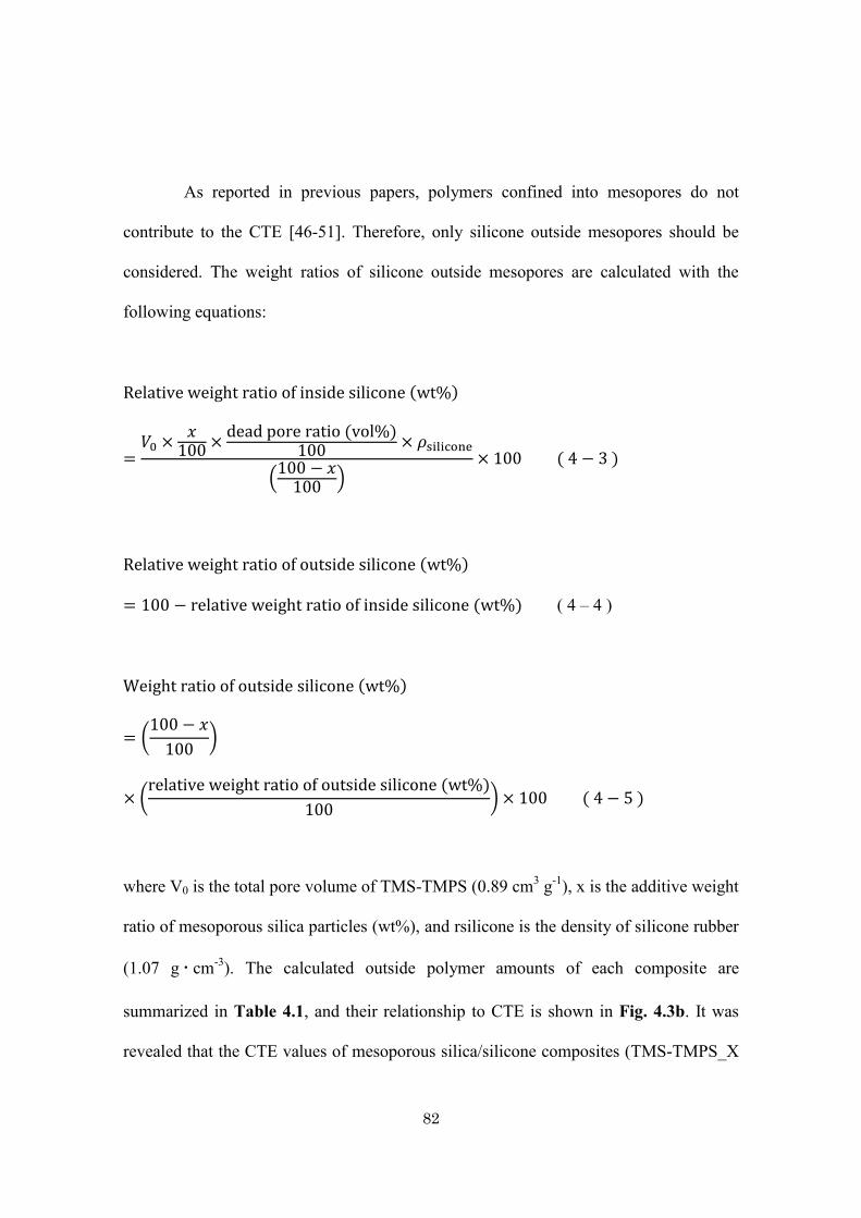
82
As reported in previous papers, polymers confined into mesopores do not
contribute to the CTE [46-51]. Therefore, only silicone outside mesopores should be
considered. The weight ratios of silicone outside mesopores are calculated with the
following equations:
Relative weight ratio of inside silicone (wt%)
=𝑉0 ×
𝑥100 ×
dead pore ratio (vol%)100 × 𝜌silicone
(100 − 𝑥
100 )× 100 ( 4 − 3 )
Relative weight ratio of outside silicone (wt%)
= 100 − relative weight ratio of inside silicone (wt%) ( 4 – 4 )
Weight ratio of outside silicone (wt%)
= (100 − 𝑥
100)
× (relative weight ratio of outside silicone (wt%)
100) × 100 ( 4 − 5 )
where V0 is the total pore volume of TMS-TMPS (0.89 cm3 g-1), x is the additive weight
ratio of mesoporous silica particles (wt%), and rsilicone is the density of silicone rubber
(1.07 g・ cm-3). The calculated outside polymer amounts of each composite are
summarized in Table 4.1, and their relationship to CTE is shown in Fig. 4.3b. It was
revealed that the CTE values of mesoporous silica/silicone composites (TMS-TMPS_X
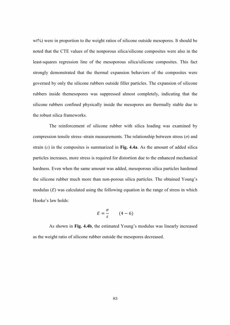
83
wt%) were in proportion to the weight ratios of silicone outside mesopores. It should be
noted that the CTE values of the nonporous silica/silicone composites were also in the
least-squares regression line of the mesoporous silica/silicone composites. This fact
strongly demonstrated that the thermal expansion behaviors of the composites were
governed by only the silicone rubbers outside filler particles. The expansion of silicone
rubbers inside themesopores was suppressed almost completely, indicating that the
silicone rubbers confined physically inside the mesopores are thermally stable due to
the robust silica frameworks.
The reinforcement of silicone rubber with silica loading was examined by
compression tensile stress–strain measurements. The relationship between stress (σ) and
strain (ε) in the composites is summarized in Fig. 4.4a. As the amount of added silica
particles increases, more stress is required for distortion due to the enhanced mechanical
hardness. Even when the same amount was added, mesoporous silica particles hardened
the silicone rubber much more than non-porous silica particles. The obtained Young’s
modulus (E) was calculated using the following equation in the range of stress in which
Hooke’s law holds:
𝐸 =𝜎
𝜀 (4 − 6)
As shown in Fig. 4.4b, the estimated Young’s modulus was linearly increased
as the weight ratio of silicone rubber outside the mesopores decreased.
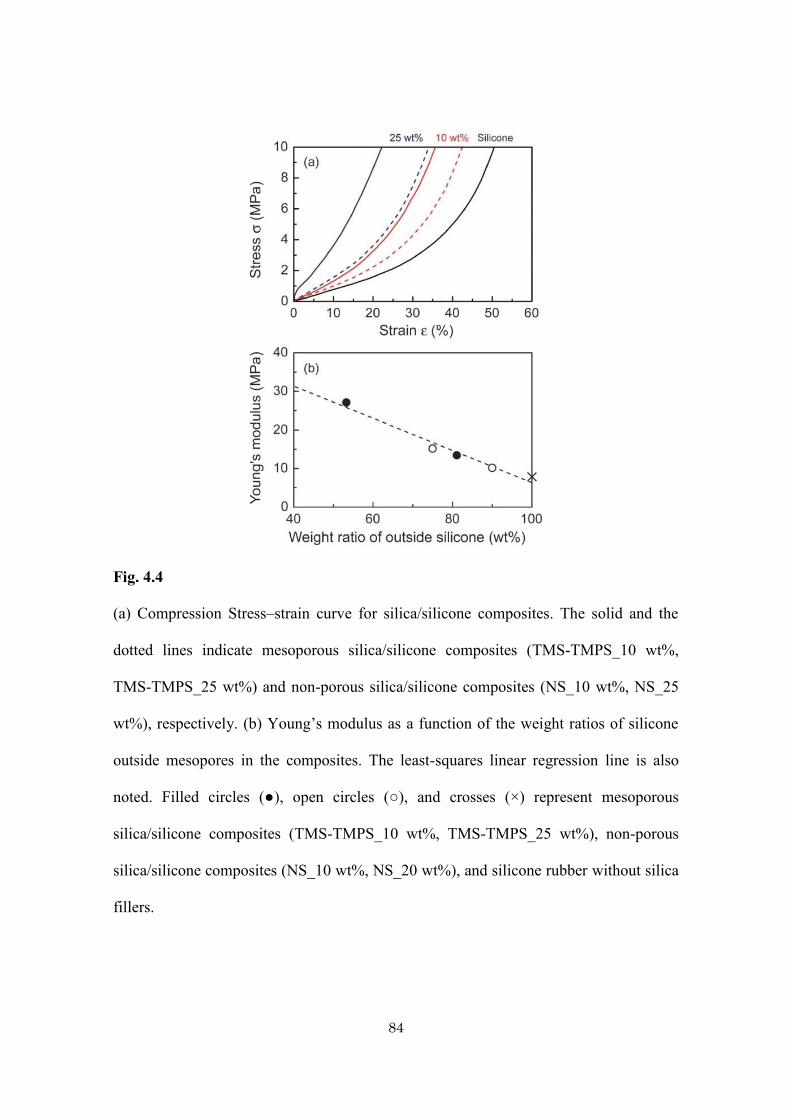
84
Fig. 4.4
(a) Compression Stress–strain curve for silica/silicone composites. The solid and the
dotted lines indicate mesoporous silica/silicone composites (TMS-TMPS_10 wt%,
TMS-TMPS_25 wt%) and non-porous silica/silicone composites (NS_10 wt%, NS_25
wt%), respectively. (b) Young’s modulus as a function of the weight ratios of silicone
outside mesopores in the composites. The least-squares linear regression line is also
noted. Filled circles (●), open circles (○), and crosses (×) represent mesoporous
silica/silicone composites (TMS-TMPS_10 wt%, TMS-TMPS_25 wt%), non-porous
silica/silicone composites (NS_10 wt%, NS_20 wt%), and silicone rubber without silica
fillers.
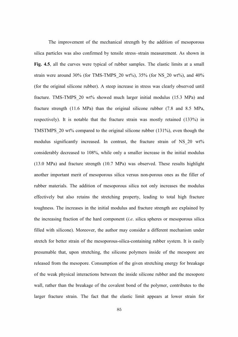
85
The improvement of the mechanical strength by the addition of mesoporous
silica particles was also confirmed by tensile stress–strain measurement. As shown in
Fig. 4.5, all the curves were typical of rubber samples. The elastic limits at a small
strain were around 30% (for TMS-TMPS_20 wt%), 35% (for NS_20 wt%), and 40%
(for the original silicone rubber). A steep increase in stress was clearly observed until
fracture. TMS-TMPS_20 wt% showed much larger initial modulus (15.3 MPa) and
fracture strength (11.6 MPa) than the original silicone rubber (7.8 and 8.5 MPa,
respectively). It is notable that the fracture strain was mostly retained (133%) in
TMSTMPS_20 wt% compared to the original silicone rubber (131%), even though the
modulus significantly increased. In contrast, the fracture strain of NS_20 wt%
considerably decreased to 108%, while only a smaller increase in the initial modulus
(13.0 MPa) and fracture strength (10.7 MPa) was observed. These results highlight
another important merit of mesoporous silica versus non-porous ones as the filler of
rubber materials. The addition of mesoporous silica not only increases the modulus
effectively but also retains the stretching property, leading to total high fracture
toughness. The increases in the initial modulus and fracture strength are explained by
the increasing fraction of the hard component (i.e. silica spheres or mesoporous silica
filled with silicone). Moreover, the author may consider a different mechanism under
stretch for better strain of the mesoporous-silica-containing rubber system. It is easily
presumable that, upon stretching, the silicone polymers inside of the mesopore are
released from the mesopore. Consumption of the given stretching energy for breakage
of the weak physical interactions between the inside silicone rubber and the mesopore
wall, rather than the breakage of the covalent bond of the polymer, contributes to the
larger fracture strain. The fact that the elastic limit appears at lower strain for
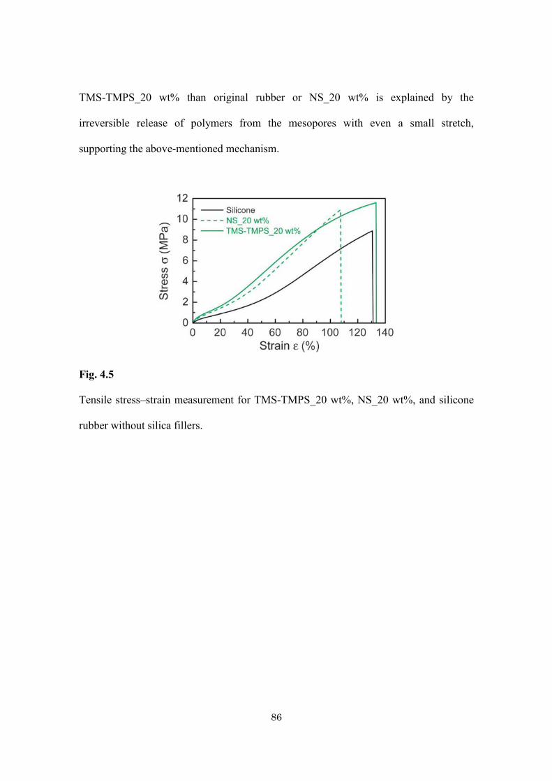
86
TMS-TMPS_20 wt% than original rubber or NS_20 wt% is explained by the
irreversible release of polymers from the mesopores with even a small stretch,
supporting the above-mentioned mechanism.
Fig. 4.5
Tensile stress–strain measurement for TMS-TMPS_20 wt%, NS_20 wt%, and silicone
rubber without silica fillers.
87
4.4. Conclusion
The author proposed a simple fabrication procedure for mesoporous silica/silicone
composites by using the silicone rubber without a curing agent. The dead pore ratio
calculation showed that almost all mesopores were completely filled with silicone
rubbers due to influence of improvement the affinity between mesopore and silicone by
trimethylsilyl modification of TMPS-4. This systematic study demonstrated that
mesoporous silica particles were a smarter filler material than non-porous ones for
enhancing the properties of silicone rubber. Compared to non-porous silica/silicone
composites, mesoporous silica/silicone composites showed lower CTE values because
their robust silica framework suppressed the thermal expansion of silicone rubber
confined in the mesopores. As for the mechanical reinforcement, mesoporous silica
particles effectively increased the tensile strength and Young’s modulus. In the near
future, the author will show practical applications using silicone composite with
improved thermal and mechanical strength.
88
4.5. References
[1] T. Lan, T. J. Pinnavaia, Chem. Mater. 6, (1994), 2216.
[2] A. Okada, A. Usuki, Mater. Sci. Eng. C. 3, (1995), 109.
[3] T. Liu, I. Y. Phang, L. Shen, S. Y. Chow, W. Zhang, Macromolecules. 37, (2004),
7214.
[4] H. Miyagawa, L. T. Drzal, Polymer. 45, (2004), 5163.
[5] R. Andrews, M. C. Weisenberger, Curr. Opin. Solid State Mater. Sci. 8, (2004), 31.
[6] P. J. F. Harris, Int. Mater. Rev. 49, (2004), 31.
[7] M. A. L. Manchado, L. Valentini, J. Biagiotti, J. M. Kenny, Carbon. 43, (2005),
1499.
[8] S. C. Tjong, Mater. Sci. Eng. R. 53, (2006), 73.
[9] J. N. Coleman, U. Khan, W. J. Blau, Y. K. Gun’ko, Carbon. 44, (2006), 1624.
[10] J. N. Coleman, U. Khan, Y. K. Gun’ko, Adv. Mater. 18, (2006), 689.
[11] A. Yasmin, J. Luo, I. M. Daniel, Compos. Sci. Technol. 66, (2006), 1182.
[12] J. Yang, G. Yang, G. Xu, S. Fu, Compos. Sci. Technol. 67, (2007), 2934.
[13] Z. Chen, J. Yang, Q. Ni, S. Fu, Y. Huang, Polymer. 50, (2009), 4753.
[14] K. Haraguchi, H. Li, Macromolecules. 39, (2006), 1898.
[15] M. Fukasawa, T. Sakai, U. Chung, K. Haraguchi, Macromolecules. 43, (2010),
4370.
[16] Y. T. Vu, J. E. Mark, L. H. Pham, M. Engelhardt, J. Appl. Polym. Sci. 82, (2001),
1391.
[17] L. Bokobza, O. Rapoport, J. Appl. Polym. Sci. 85, (2002), 2301,
[18] L. Bokobza, J. P. Chauvin, Polymer. 46, (2005), 4144.
89
[19] S. Joly, G. Garnaud, R. Ollitrault, L. Bokobza, J. E. Mark, Chem. Mater. 14, (2002),
4202.
[20] N. Rattanasom, T. Saowapark, C. Deeprasertkul, Polym. Test. 26, (2007), 369.
[21] E. L. Warrick, O. R. Pierce, K. E. Polmanteer, J. C. Saam, Rubber Chem. Technol.
52, (1979), 437.
[22] Z. Rigbi, Adv. Polym. Sci. 36, (1980), 21.
[23] J. Wen, J. E. Mark, J. Mater. Sci. 29, (1994), 499.
[24] S. Wang, C. Long, X. Wang, Q. Li, Z. Qi, J. Appl. Polym. Sci. 69, (1998), 1557.
[25] J. Wu, J. Huang, N. Cheng, Z. Shen, Chem. Lett. 27, (1998), 509.
[26] H. Takeuchi, C. Cohen, Macromolecules. 32, (1999), 6792.
[27] P. C. LeBaron, T. J. Pinnavaia, Chem. Mater. 13, (2001), 3760.
[28] M. A. Osman, A. Atallah, M. Muller, U. W. Suter, Polymer. 42, (2001), 6545.
[29] M. D. Frogley, D. Ravich, H. D.Wagner, Compos. Sci. Technol. 63, (2003), 1647.
[30] L. Bokobza, J. Appl. Polym. Sci. 93, (2004), 2095.
[31] J. Ma, Z. Z. Yu, H. C. Kuan, A. Dasari, Y. W. Mai, Macromol. Rapid Commun. 26,
(2005), 830.
[32] V. P. Silva, M. C. Gonc,alves, I. V. P. Yoshida, J. Appl. Polym. Sci. 101, (2006),
290.
[33] L. Bokobza, Polymer. 48, (2007), 4907.
[34] M. L. Q. A. Kaneno, I. V. P. Yoshida, J. Appl. Polym. Sci. 108, (2008), 2587.
[35] M. L. Q. A. Kaneko, R. B. Romero, M. C. Gonçalves, I. V. P. Yoshida, Eur. Polym.
J. 46, (2010), 881.
90
[36] T. Yanagisawa, T. Shimizu, K. Kuroda, C. Kato, Bull. Chem. Soc. Jpn. 63, (1990),,
988.
[37] C. T. Kresge, M. E. Leonowicz, W. J. Roth, J. C. Vartuli, J. S. Beck, Nature. 359,
(1992), 710.
[38] S. Inagaki, Y. Fukushima and K. Kuroda, J. Chem. Soc., Chem. Commun. (1993),
680.
[39] S. Inagaki, A. Koiwai, N. Suzuki, Y. Fukushima, K. Kuroda, Bull. Chem. Soc. Jpn.
69, (1996), 1449.
[40] D. Y. Zhao, J. L. Feng, Q. S. Huo, N. Meloh, G. H. Fredickson, B. F. Chmelka, G.
D. Stuky, Science. 279, (1998), 548.
[41] T. Kimura, D. Itho, T. Shigeno, K. Kuroda, Bull. Chem. Soc. Jpn. 77, (2004), 585.
[42] A. Shimojima, K. Kuroda, Chem. Rec. 6, (2006), 53.
[43] M. P. Kapoor, S. Inagaki, Bull. Chem. Soc. Jpn. 79, (2006), 1463.
[44] Y. Wan, D. Zhao, Chem. Rev. 107, (2007), 2821.
[45] Y. Yamauchi, N. Suzuki, L. Radhakrishnan, L.Wang, Chem. Rec. 9, (2009), 321.
[46] S. Kiba, N. Suzuki, Y. Okawauchi, Y. Yamauchi, Chem.–Asian J. 5, (2010), 2100.
[47] N. Suzuki, S. Kiba, Y. Yamauchi, Phys. Chem. Chem. Phys. 13, (2011), 4957.
[48] N. Suzuki, S. Kiba, Y. Yamauchi, J. Nanosci. Nanotechnol. 12, (2012), 983.
[49] N. Suzuki, S. Kiba, Y. Yamauchi, Mater. Lett. 65, (2011), 544.
[50] N. Suzuki, S. Kiba, Y. Yamauchi, J. Mater. Chem. 21, (2011), 14941.
[51] N. Suzuki, S. Kiba, Y. Kamachi, N. Miyamoto, Y. Yamauchi, J. Mater. Chem. 21,
(2011), 5338.
[52] J. E. Mark, Silicones, Silicone-Modified Materials. Chapter 1. Overview of
Siloxane Polymer, 2000.
91
[53] S. Sakka, J. D. Mackenzie, J. Non-Cryst. Solids. 6, (1971), 145.
[54] J. C. Lötters, W. Olthusis, P. H. Veltink, P. Bergveld, J. Micromech. Microeng. 7,
(1997), 145.

92
93
Chapter 5.
General conclusion
94
With the studies of the present thesis, the author developed some novel
organic-inorganic hybrids of organic polymer hydrogels and porous inorganic fillers. In
contrast to previous examples of organic polymer-inorganic hybrids where the inorganic
fillers were mainly employed for improving mechanical strength of the organic
polymers, the materials developed by the author utilize the pores of inorganic fillers as
adsorption sites that endow novel functions with the hybrids.
In chapter 2, novel PNIPAm hydrogels containing Prussian Blue (PB)
nanoparticles was synthesized. By incorporation of PB nanoparticles, the uptake ability
of Cs ions into PNIPAm hydrogel was drastically increased up to 156.7 m2・g−1 in
comparison with PNIPAm hydrogel with commercially available PB. Thus, the author
shows that the PB-containing PNIPAm hydrogel is considered as an excellent candidate
for the removal of Cs ions from aqueous solutions, which will be useful for the
remediation of the nuclear waste. Chapters 3 and 4 demonstrate the use of mesoporous
silica (MPS) as the fillers. In chapter 3, hybridization of PNIPAm hydrogels with MPS
particles realized sustainable and controlled release of molecules. This is very
interesting properties in the development of drug delivery system (DDS). In Chapter 4,
the use of MPS is further applied to prepare MPS-containing silicone rubbers. The
stable polymers embedded inside the mesochannels of MPS effectively reduced the
coefficient of linear thermal expansion (CTE) of polymer composites. The important
thing is that the original nanoporous materials is retained even after hybridization with
hydrogels and silicone rubbers. Then, it is possible to utilize the inherent properties
derive from the used nanoporous materials.
Recently, the hybridization of hydrogels and silicone rubbers with well-defined
nanostructured inorganic materials are emerging as a promising and efficient technique
95
to improve the properties. Especially, hybridization of hydrogels with other
nanomaterials will be useful to bring out new functions in future. While hydrogel
materials have been already used in many commercial products such as soft contact
lenses and disposal diapers, newly developed hybrid hydrogels with superior properties
and smart functions will be able to achieve a great performance in the field of drug
delivery systems, sensors, coatings, artificial organs, and chemical actuators for
microfluidics and molecular robots, as mentioned in Chapters 2 and 3. In future, further
combination of different porous fillers with functional polymers, it will be possible to
the creation of new functions as well as improvement of mechanical strength of
materials.

96
97
List of Achievements
本論文に関する論文発表
1) “Unusual reinforcement of silicone rubber compounds containing mesoporous silica
particles as inorganic fillers”
Norihiro Suzuki, Shosuke Kiba, Yuichiro Kamachi, Nobuyoshi Miyamoto,
Yusuke Yamauchi
Phys. Chem. Chem. Phys., 14, (2012), 3400–3407.
2) “Templated Synthesis for Nanoarchitectured Porous Materials”
Victor Malgras, Qingmin Ji, Yuichiro Kamachi, Taizo Mori, Fa-Kuen Shieh,
Kevin C.-W. Wu, Katsuhiko Ariga, Yusuke Yamauchi
Bull. Chem. Soc. Jpn. 88, (2015), 1171–1200.
3) “Hydrogels Containing Prussian Blue Nanoparticles Toward Removal of Radioactive
Cesium Ions”
Yuichiro Kamachi, Mohamed B. Zakaria, Nagy L. Torad, Teruyuki Nakato, Tansir
Ahamad, Saad M. Alshehri, Victor Malgras, Yusuke Yamauchi
J. Nanosci. Nanotechnol. 16, (2016), 4200–4204.
4) “Thermo-Responsive Hydrogels Containing Mesoporous Silica toward Controlled and
Sustainable Releases”
Yuichiro Kamachi, Bishnu Prasad Bastakoti, Saad M. Alshehri, Nobuyoshi
Miyamoto, Teruyuki Nakato, Yusuke Yamauchi,
Mater. Lett. 168, (2016), 176–179.
98
5) “Perspective: Recent Developments in Hybrid Hydrogels Containing Inorganic
Nanomaterials”
Victor Malgras, Yuichiro Kamachi, Teruyuki Nakato, Yusuke Yamauchi,
Nobuyoshi Miyamoto,
Nanoscience and Nanotechnology Letters, 8 (2016), 355-359.
99
研究業績
(1) 論文発表
1) “Mesoporous silica as smart inorganic filler: preparation of robust silicone
rubber with low thermal expansion property”
Norihiro Suzuki, Shosuke Kiba, Yuichiro Kamachi, Nobuyoshi Miyamoto,
Yusuke Yamauchi
J. Mater. Chem. 21, (2011), 5338-5344.
2) “フッ素四ケイ素雲母ナノシート液晶とポリ-N-イソプロピルアクリル
アミドの複合化による異方性ヒドロゲルの合成"
蒲池雄一郎, 宮元展義
福岡工業大学研究論集 Res. Bull. Fukuoka Inst. Tech., 43 (2011) 117-122.
3) “Unusual reinforcement of silicone rubber compounds containing mesoporous
silica particles as inorganic fillers”
Norihiro Suzuki, Shosuke Kiba, Yuichiro Kamachi, Nobuyoshi Miyamoto,
Yusuke Yamauchi
Phys. Chem. Chem. Phys. 14, (2012), 3400-3407.
100
4) “Facile synthesis of nanoporous carbons with controlled particle sizes by direct
carbonization of monodispersed ZIF-8 crystals”
Nagy L Torad, Ming Hu, Yuichiro Kamachi, Kimiko Takai, Masataka Imura,
Masanobu Naito, Yusuke Yamauchi
Chem. Commun. 49, (2013), 2521-2523.
5) “Synthesis of mesoporous antimony-doped tin oxide (ATO) thin films and
investigation of their electrical conductivity”
Norihiro Suzuki, Yuichiro Kamachi, Ya-Dong Chiang, Kevin C-W Wu, Shinsuke
Ishihara, Keisuke Sato, Naoki Fukata, Mikiya Matsuura, Kazuhiko Maekawa,
Hirofumi Tanabe, Katsuhiko Ariga, Yusuke Yamauchi
CrystEngComm 15, (2013), 4404-4407.
6) “Hydrothermal Synthesis of Binary Ni–Co Hydroxides and Carbonate Hydroxides
as Pseudosupercapacitors”
Bishnu Prasad Bastakoti, Yuichiro Kamachi, Hou‐Sheng Huang, Lin‐Chi Chen,
Kevin C‐W Wu, Yusuke Yamauchi
Eur. J. Inorg. Chem. 2013, (2013), 39-43.
101
7) “Mesoporous Carbon Incorporated with In2O3 Nanoparticles as High ‐
Performance Supercapacitors”
Bishnu Prasad Bastakoti, Hamid Oveisi, Chi‐Chang Hu, Kevin C‐W Wu,
Norihiro Suzuki, Kimiko Takai, Yuichiro Kamachi, Masataka Imura, Yusuke
Yamauchi
Eur. J. Inorg. Chem. 2013, (2013), 1109-1112.
8) “Rational Design and Synthesis of Cyano‐Bridged Coordination Polymers with
Precise Control of Particle Size from 20 to 500 nm”
Ya‐Dong Chiang, Ming Hu, Yuichiro Kamachi, Shinsuke Ishihara, Kimiko Takai,
Yoshihiro Tsujimoto, Katsuhiko Ariga, Kevin C‐W Wu, Yusuke Yamauchi
Eur. J. Inorg. Chem. 2013, (2013), 3141-3145.
9) “MOF-derived nanoporous carbon as intracellular drug delivery carriers”
Nagy L Torad, Yunqi Li, Shinsuke Ishihara, Katsuhiko Ariga, Yuichiro Kamachi,
Hong-Yuan Lian, Hicham Hamoudi, Yoshio Sakka, Watcharop Chaikittisilp, Kevin
C-W Wu, Yusuke Yamauchi
Chem. Lett. 43 (2014), 717-719.
102
10) “Fabrication of symmetric supercapacitors based on MOF-derived nanoporous
carbons”
Rahul R Salunkhe, Yuichiro Kamachi, Nagy L Torad, Soo Min Hwang, Ziqi Sun,
Shi Xue Dou, Jung Ho Kim, Yusuke Yamauchi
J. Mater. Chem. A 2 (2014), 19848-19854.
11) “Effective Use of Mesoporous Silica Filler: Comparative Study on Thermal Stability
and Transparency of Silicone Rubbers Loaded with Various Kinds of Silica
Particles”
Norihiro Suzuki, Yuichiro Kamachi, Kimiko Takai, Shosuke Kiba, Yoshio Sakka,
Nobuyoshi Miyamoto, Yusuke Yamauchi
Eur. J. Inorg. Chem. 2014 (2014), 2773-2778.
12) “Controlled Crystallization of Cyano‐Bridged Cu–Pt Coordination Polymers with
Two‐Dimensional Morphology”
Mohamed B Zakaria, Ming Hu, Yoshihiro Tsujimoto, Yoshio Sakka, Norihiro
Suzuki, Yuichiro Kamachi, Masataka Imura, Shinsuke Ishihara, Katsuhiko Ariga,
Yusuke Yamauchi
Chem. ―Asian. J. 9, (2014), 1511-1514.
103
13) “Mesoporous Silica Particles as Topologically Crosslinking Fillers for Poly (N‐
isopropylacrylamide) Hydrogels”
Nobuyoshi Miyamoto, Kotaro Shimasaki, Kosuke Yamamoto, Morio Shintate,
Yuichiro Kamachi, Bishnu Prasad Bastakoti, Norihiro Suzuki, Ryuhei Motokawa,
Yusuke Yamauchi
Chem. ―Eur. J. 20, (2014), 14955-14958.
14) “Templated synthesis for nanoarchitectured porous materials”
Victor Malgras, Qingmin Ji, Yuichiro Kamachi, Taizo Mori, Fa-Kuen Shieh, Kevin
CW Wu, Katsuhiko Ariga, Yusuke Yamauchi
Bull. Chem. Soc. Jap. 88, (2015), 1171–1200.
15) “Sodium Hydroxide Activated Nanoporous Carbons Based on Lapsi Seed Stone”
Sahira Joshi, Lok Kumar Shrestha, Yuichiro Kamachi, Yusuke Yamauchi, Mandira
Adhikari Pradhananga, Bhadra Prasad Pokhre, Katsuhiko Ariga, Raja Ram
Pradhananga
J. Nanosci. Nanotechnol. 15, (2015), 1465-1472.
16) “Synthesis and characterizations of nanoporous carbon derived from Lapsi
(Choerospondias axillaris) seed: Effect of carbonization conditions”
Sahira Joshi, Lok Kumar Shrestha, Yuichiro Kamachi, Victor Malgras, Mandira
Adhikari Pradhananga, Bhadra Prasad Pokhrel, Teruyuki Nakato, Raja Ram
Pradhananga, Katsuhiko Ariga, Yusuke Yamauchi
Adv. Powder Technol. 26, (2015), 894–900.
104
17) “Preparation of a platinum electrocatalyst by coaxial pulse arc plasma deposition”
Yoshiaki Agawa, Hiroyuki Tanaka, Shigemitsu Torisu, Satoshi Endo, Akihiro
Tsujimoto, Narishi Gonohe, Victor Malgras, Ali Aldalbahi, Saad M Alshehri,
Yuichiro Kamachi, Cuiling Li, Yusuke Yamauchi
Sci. Tech. Adv. Mater. 16 (2015), 024804
18) “A Concept for Asymmetric Supercapacitors Using 3D Nanoporous Carbon and
Cobalt Oxide Electrodes Synthesized from Single Metal Organic Framework”
Rahul R Salunkhe, Jing Tang, Yuichiro Kamachi, Teruyuki Nakato, Jung Ho Kim,
Yusuke Yamauchi
ACS Nano, 9, (2015), 6288–6296
19) “Fabrication of Asymmetric Supercapacitors Based on Coordination Polymer
Derived Nanoporous Materials”
Rahul R Salunkhe, Mohamed B Zakaria, Yuichiro Kamachi, Saad M Alshehri,
Tansir Ahamad, Nagy L Torad, Shi Xue Dou, Jung Ho Kim, Yusuke Yamauchi
Electrochim. Acta. 183, (2015), 94–99.
20) “Hydrogels Containing Prussian Blue Nanoparticles Toward Removal of
Radioactive Cesium Ions”
Yuichiro Kamachi, Mohamed B. Zakaria, Nagy L. Torad, Teruyuki Nakato, Tansir
Ahamad, Saad M. Alshehri, Victor Malgras, Yusuke Yamauchi
J. Nanosci. Nanotechnol. 16, (2016), 4200–4204.
105
21) “Thermo-Responsive Hydrogels Containing Mesoporous Silica toward Controlled
and Sustainable Releases”
Yuichiro Kamachi, Bishnu Prasad Bastakoti, Saad M. Alshehri, Nobuyoshi
Miyamoto, Teruyuki Nakato, Yusuke Yamauchi,
Mater. Lett. 168, (2016), 176–179.
22) “Perspective: Recent Developments in Hybrid Hydrogels Containing Inorganic
Nanomaterials”
Victor Malgras, Yuichiro Kamachi, Teruyuki Nakato, Yusuke Yamauchi,
Nobuyoshi Miyamoto,
Nanoscience and Nanotechnology Letters, 8 (2016), 355-359.
106
(2) 学会発表
(2-1) 国際会議発表
1) “Thermo-responsive hydrogels containing mesoporoussilica particles” Yuichiro
Kamachi, Bishnu Prasad Bastakoti, Nobuyoshi Miyamoto, Teruyuki Nakato,
Yusuke Yamauchi, Japan-Taiwan Joint Workshop on Nanospace Materials,
Fukuoka (March 2014), Oral
(2-2) 国内会議発表
1) “フッ素四ケイ素雲母ナノシート液晶とポリ(N-イソプロピルアクリルアミ
ド)の複合化による異方性ヒドロゲルの合成 “
蒲池雄一郎, 宮元展義
日本化学会第 90春季年会, 大阪, (2010年 3月), 口頭
2) “フッ素四ケイ素雲母ナノシート液晶とポリ(N-イソプロピの複合化による
異方性ヒドロゲルの合成と物性“
蒲池雄一郎, 宮元展義
2010年日本液晶学会講演会・討論会, 福岡, (2010年 9月), ポスター
107
3) “メソポーラスシリカを包含した高強度ハイドロゲルの合成”
中島拓也, 新立盛生, 蒲池雄一郎, 島崎浩太朗, 山内悠輔, 元川竜平,
宮元展義
平成 22 年度物理化学インターカレッジセミナー 兼 日本油化学会界面科
学部会 九州地区講演会, 福岡, (2010年 11月)ポスター連名
4) “フッ素四ケイ素雲母ナノシート液晶とポリ-N-イソプロピルアクリルアミド
の複合化による異方性ヒドロゲルの合成と物性”
蒲池雄一郎, 宮元展義
平成 22 年度物理化学インターカレッジセミナー 兼 日本油化学会界面科
学部会 九州地区講演会, 福岡, (2010年 11月)ポスター
5) “フッ素四ケイ素雲母ナノシート液晶を利用した異方性複合ゲルの合成と
物性”
蒲池雄一郎, 宮元展義
第 60回高分子学会年次大会, 大阪, (2011年 5月), 口頭
6) “液晶性粘土鉱物との複合化による異方性 PNIPAmゲルの合成 “
蒲池雄一郎, 宮元展義
高分子学会九州支部若手研究会 2011年度 九州地区高分子若手研究会・冬
の講演会, 大分 (2011年 12月), ポスター
108
Acknowledgements
It is a great pleasure to express my sincere graduate to Professor Dr. Teruyuki
Nakato for his immense instruction and encouragement. I would like to extend my
sincere appreciation to Professor Dr. Youichi Shimizu, Professor Dr. Teruhisa Ohno and
Associate Professor Dr. Toshiki Miyazaki for their valuable suggestion and
encouragement.
I would like to express my heartfelt thanks to Dr. Yusuke Yamauchi, National
Institute for Materials Science, for his precious instruction, encouragement, and
suggestions. I wish to thank to Associate Professor Dr. Nobuyoshi Miyamoto, Fukuoka
Institute of Technology, and Professor Dr. Kevin C.-W. Wu, National Taiwan University,
for their instructions, encouragement and valuable suggestions. I wish to thank Dr,
Mohamed B Zakaria and Dr. Victor Malgras, National Institute for Materials Science,
for their discussions and suggestions as well as encouragement..
I would like to thank Dr. Norihiro Suzuki, Dr. Bishnu Prasad Bastakoti, Dr.
Ming Hu, for their helpful advises and encouragement. I would like to thank Mr. Morio
Shintate, Mr. Shogo Ikeda, Ms. Michiko Sato, Fukuoka Institute of Technology, for their
assistance in experiments. Moreover I would like to thank all the members of my
laboratory and technical support team of National Institute for Materials Science.
Finally, I would like to send my many thanks to my parents for their kind
encouragement, moral and financial supports.


![Synthesis and characterization of molecularly imprinted ... · technologies in the synthesis of inorganic polymers and organic-inorganic hybrid materials [14]. Some research teams](https://img.pdfslide.net/doc/110x75/5ec84d7a03b6762dd54192b0/synthesis-and-characterization-of-molecularly-imprinted-technologies-in-the.jpg)