Embed Size (px)
Citation preview

Syracuse University – Ainsley Drive Facility
January 2013
Petroleum Bulk Storage Spill Prevention Control and
Countermeasure (SPCC) Plan PBS ID No. 7-129054

SYRACUSE UNIVERSITY – AINSLEY DRIVE FACILITY
PETROLEUM BULK STORAGE
SPILL PREVENTION CONTROL AND COUNTERMEASURE (SPCC) PLAN
PBS ID NO. 7-129054
Prepared For:
SYRACUSE UNIVERSITY
Prepared By:
GHD CONSULTING ENGINEERS, LLC One Remington Park Drive
Cazenovia, NY 13035
Project No. 8615115.1
January 2013

Table of Contents 1 Facility Description 1-1 2 Discharge Reporting Procedures 2-1 3 Discharge Potential from major Equipment Failures 3-1 4 Containment and Diversion Structures 4-1 5 Inspections, Tests, and Records 5-1 6 Personnel, Training, and Discharge Prevention Procedures 6-1 7 Security 7-1 8 Tank Car and Tank Truck Loading/Unloading 8-1 9 Conformance with more Stringent State Rules, Regulations, and Guidelines 9-1 10 Facility Drainage Assessment 10-1 11 Bulk Storage Containers 8-1 12 Facility Transfer Operations, Pumping, and Facility Process 9-1 13 Certificate of the Applicability of the Substantial Harm Criteria 10-1
List of Tables Table 1 Summary of Facility Oil Storage Table 2 Discharge or Drainage Controls
List of Appendices Appendix A Site Location Map Appendix B Site Layout / Oil Storage Location Map Appendix C Spill History Appendix D Spill Emergency Procedures Appendix E Petroleum Spill Report Appendix F Syracuse University Petroleum Bulk Storage Tank Maintenance Procedures Manual Appendix G Monthly Bulk Storage Tank Inspection Form Appendix H Tank Vehicle Transfer Policy Appendix I Certificate of the Applicability of the Substantial Harm Criteria Appendix J Cross-Reference Table Appendix K SPCC Plan Amendment Log Appendix L PBS Registration Certificate Appendix M 5-Year SPCC Plan Review and Evaluation Log Appendix N Oil Containment Device Drainage Discharge Record Form
8615115.1 Syracuse University – Ainsley Drive Facility i Petroleum Bulk Storage Spill Prevention Control and Countermeasure Plan

8615115.1 Syracuse University – Ainsley Drive Facility 1-1 Petroleum Bulk Storage Spill Prevention Control and Countermeasure Plan
1 Facility Description
1.1 Facility Owner and Operator: (i) Facility Owner Address:
Syracuse University c/o Skytop Office Building Syracuse, New York 13244-5100
(ii) Facility Operator Address:
c/o Environmental Health and Safety Services 029 Lyman Hall Syracuse, New York 13244-5100
1.2 Physical Layout (40 CFR Part 112.7(a)(3)):
The Syracuse University Ainsley Drive Facility is located in Syracuse, New York. The Ainsley Drive Facility is generally comprised of the Food Service Commissary and Physical Plant. The Food Service Commissary was upgraded and renovated in 1993 to become the primary food preparation and distribution center for the Syracuse University Food Service Program. It is at this facility where food is cooked and packaged for distribution to the Carrier Dome, Dining Halls, and several of the on-campus Snack Bar sites. Physical Plant is the primary maintenance and repair facility for Syracuse University buildings and grounds. The facility includes Storeroom, Stock Room, Electric Shop, Sheet Metal Shop, Utilities, Carpenters Shop, Lock Shop, Paint Shop, Automotive Maintenance Garage, and Grounds. Ainsley Drive Facility also includes features such as walkways, turf areas, driveways, and parking areas. Physical Plant operates 24 hours per day, 7 days a week, all year round. The Food Service Commissary typically operates from 7:00 a.m. to 5:00 p.m., seven days a week, throughout the year. See Figure 1 in Appendix A for site location. 1.3 Inventory of Storage Containers (40 CFR Part 112.7(a)(3)(i)):
This section describes types of oil product storage at the facility. It should be noted that oil is defined as "oil of any kind or in any form, including, but not limited to: fats, oils, or greases of animal, fish, or marine mammal origin; vegetable oils, including oils from seeds, nuts, fruits, or kernels; and other oils and greases, including petroleum, fuel oil, sludge, synthetic oils, mineral oils, oil refuse, or oil mixed with wastes other than dredged spoil." Table 1 lists and provides a general description of the facility’s bulk oil storage containers and oil filled operational equipment.
Physical Plant
Petroleum Bulk Storage Tanks
The vehicle fueling facility is located outdoors and consists of 6,000-gallon unleaded gasoline and 3,000-gallon diesel fuel aboveground storage tanks. Both of these tanks are of steel double wall design with secondary containment consistent with state and federal environmental requirements. Tanks are placed on a concrete pad and are protected from collision by steel pipe bollards filled with concrete. A light pole and automatic fire suppression system are located in the fuel dispensing area.
Both tanks are equipped with direct vision level gauges, normal and emergency vents, proper labeling, leak detection devices, fire safety valves, operating valves, remote (tank mounted) dispensing systems,

8615115.1 Syracuse University – Ainsley Drive Facility 1-2 Petroleum Bulk Storage Spill Prevention Control and Countermeasure Plan
and a key/card fuel management system. To prevent spills at the fill ports, the storage tanks are equipped with dry break connections. To capture drips from the delivery hoses at the fill ports, the tanks are equipped with a locking remote fill box. To prevent overfills through the vents and other openings, these tanks are equipped with high level alarms and overfill prevention devices. The unleaded gasoline storage tank is also equipped with a stage 1 vapor recovery system.
There is also a 1,000 gallon diesel fuel aboveground storage tank used to supply fuel to an on-site emergency generator. This tank is encased in concrete consistent with NFPA fire resistance requirements and with secondary containment consistent with state and federal environmental requirements. The tank is placed on a concrete pad and is protected from collision by steel pipe bollards filled with concrete. The tank is equipped with a direct vision level gauge, normal and emergency vents, proper labeling, leak detection devices, fire safety valves, and operating valves. To prevent spills at the fill ports, the storage tank is equipped with dry break connections. To capture drips from the delivery hoses at the fill port, the tank is equipped with a spill catch basin. To prevent overfills through the vents and other openings, the tank is equipped with high level alarms and overfill prevention devices.
The vehicle fueling facility does not have transfer station containment consistent with requirements of 40 CFR Part 112.7(e)(4)(ii). However, consistent with alternative provisions of Part 112.7(d)(l) and (2) and the fact that the SPCC regulation is performance-based, it is believed in the P.E.’s opinion, that the installation of transfer station containment is not practicable because it is not reasonably expected that a spill would ever reach navigable waters. In addition, the facility is in compliance with this alternative provision since the facility has a high level of supervision during transfers, strong oil spill response plan, and incorporates several procedures to minimize spills. Spill equipment is located nearby that would be deployed to contain spills for clean-up.
Motor Oil Tank
The motor oil storage tank is a 275-gallon double-wall steel tank equipped with secondary containment monitoring tube and a 5-gallon spill box at the fill port. The tank is painted for corrosion protection, labeled, and equipped with a direct vision level gauge to prevent tank overfills. This tank is located within the automobile maintenance garage.
This tank does not have transfer station containment consistent with requirements of 40 CFR Part 112.7(c). However, consistent with provisions of Part 112.7(d)(l) and (2) and the fact that the SPCC regulation is performance-based, it is believed in the P.E.’s opinion that the installation of transfer station containment is not practicable because of the relatively low quantities and frequencies of product transferred. The tank capacity is only 275-gallons and it is filled approximately 2 to 3 times per year. As noted above, the facility is in compliance with this alternative provision for containment since the facility has a high level of supervision during transfers, strong oil spill response plan, and incorporates several procedures to minimize spills. Spill equipment is located nearby that would be deployed to contain spills for clean-up.
The physical plant automotive maintenance garage has an aboveground oil/water separator system which has an oil storage capacity of approximately 750 gallons. The oil/water separator is inspected periodically to determine the levels of oil in the system and whether the oil in the separator needs to be pumped out and removed offsite for disposal. Specifically, the facility utilizes a level stick that allows them to test the sludge level in the oil/water separator to determine whether the system needs to be cleaned out.

8615115.1 Syracuse University – Ainsley Drive Facility 1-3 Petroleum Bulk Storage Spill Prevention Control and Countermeasure Plan
Non-Stationary Containers
Non-stationary containers (typically 55 gallons or less capacity) of various petroleum-based oil products (e.g., oils and greases) are stored throughout Physical Plant. Waste motor oil is stored in 55-gallon drums placed on spill containment pallets. New motor oils are stored in 55-gallon drums in a curbed Oil Storage Room, which would contain spills occurring within the room. Specifically, the curbed Oil Storage Room has the capacity to contain 110 percent of the largest single container within the room (i.e. 55-gallon drum).
Furthermore, the waste motor oil drums and other non-stationary containers stored in the Maintenance Garage and Oil Storage Room are located in areas that would drain to the existing oil/water separator system previously described. In other cases, leaks or spills from non-stationary containers would flow onto, and be contained by, existing floors simply because the quantities would be small and the distance to floor drains would be such that a spill reaching a floor drain would be unlikely.
Food Service Commissary
Transformer
The transformer is checked for leaks and inspected at least annually by Environmental Health and Safety Services (EHSS) and/or Physical Plant personnel.
Used Grease Storage Container
Used grease from the Food Commissary Building is stored outside on the loading dock in a 150-gallon steel double walled container. The used grease is transferred to the container by pouring the grease from pails, while standing on the loading dock mezzanine, which is next to the container. Spills occurring during transfer operations, if unchecked, would drain to the nearby 210-gallon grease interceptor separator system, which is the secondary containment system for the used grease storage container. With the exception of the grease interceptor, there are no other stormwater drains in the vicinity of the grease storage container.
Table 1 summarizes oil storage containers at the facility and the products stored in each container. Containers include stationary bulk storage containers of fuel oil and diesel fuel, portable containers such as 55-gallon drums of oil and waste grease, and operational equipment such as oil-filled electrical transformers. See Figure 2 in Appendix B for site layout, which identifies oil storage locations.
1.4 Discharge Prevention Measures (40 CFR Part 112.7(a)(3)(ii))
1.4.1 Routine Procedures
Procedures for routine handling of product loading, unloading, and facility transfers are addressed in the facility's Tank Vehicle Transfer Policy, described in Section 8.
1.4.2 Discharge or Drainage Controls (40 CFR Part 112.7(a)(3)(iii))
This section describes the potential spill drainage pathways for areas where experience indicates a reasonable potential for operational or equipment failure (such as tank overflow areas, leaks, etc.). Information provided here is useful in determining a course of action to take in the event of a spill in order to reduce the potential for fire or negative impacts to the natural environment. Table 2 provides a general description of discharge and drainage controls for the facility’s bulk oil storage containers and oil filled operational equipment.

8615115.1 Syracuse University – Ainsley Drive Facility 1-4 Petroleum Bulk Storage Spill Prevention Control and Countermeasure Plan
Potential for Spills and Accidents
The Site and Drainage Plan in Figure 2 (located in Appendix B) indicates potential spill drainage pathways for storage tank fill ports/transfer stations and oil filled electrical transformer located outdoors at the Syracuse University Ainsley Drive Facility. Arrows on the site plan indicate the approximate direction that spills from these areas would flow.
Physical Plant
Small spills at the vehicle fueling area should be immediately cleaned up using sorbent materials from an adjacent spill kit. The facility staff is trained on the facility’s spill response protocol, which is located in Appendix D.
A large spill in the vehicle fueling area (unleaded gasoline and diesel fuel) would flow over a concrete tank pad and down an asphalt driveway toward a grassed area. The nearest stormwater drainage inlet is several hundred feet away from the tanks, beyond the grassed area. This drainage inlet drains to the Onondaga County Department of Drainage and Sanitation's (OCDDS) combined sewer overflow (CSO) system. This system typically drains to the Metropolitan Treatment Plant. However, during precipitation events, stormwater can overfill the system causing combined sanitary and stormwater to overflow into Onondaga Creek and other tributaries to Onondaga Lake.
Similarly, an unchecked spill in the motor oil transfer area and emergency generator transfer area would also flow to catch basins tributary to the OCDDS CSO system. A stormwater drainage inlet is located within approximately 100 feet of the transfer areas.
To avoid having larger spills reach storm drainage inlets, it is imperative that sorbent booms and “drain blockers” be immediately applied. Manpower and equipment must be immediately deployed to prevent spills from reaching the storm drainage system. The facility staff is trained on the facility’s spill response protocol, which is located in Appendix D.
Spills inside of the Maintenance Garage (including oil storage room), such as a motor oil storage tank overfills or leaks, or a spill of other oil products within the Garage, would drain into the Maintenance Garage floor drain system. The floor drain system is equipped with an oil/water separator system designed to remove oil and grease prior to discharge to the OCDDS CSO system.
Spills in other areas of Physical Plant would be contained on the existing floors. Most other areas are either not equipped with floor drains or the floor drains are distant to stored oil areas.
Food Service Commissary
If not contained, spills in the loading dock areas would flow toward stormwater catch basins that are tributary to the OCDDS CSO system. The only exception to this is the loading dock located on the east side of the building where the used grease storage container is located. Spills in this area would flow to the existing grease intercepting manhole.
Spills in interior building areas equipped with floor drains, such as the Bakery, Storeroom, Flat Ware Wash, and the Catering Kitchen, would flow to a grease intercepting manhole, designed to contain approximately 210-gallons of grease. Effluent from the intercepting manhole flows to the OCDDS CSO system. An outside contractor cleans out the intercepting manhole two times per year.

8615115.1 Syracuse University – Ainsley Drive Facility 1-5 Petroleum Bulk Storage Spill Prevention Control and Countermeasure Plan
A spill at the electrical transformer located outdoors would flow onto the ground and possibly into the OCDDS CSO system. The transformer is 750 kVA rated and is filled with an estimated quantity of 330-gallons of mineral oil. Located on the West Side of the Commissary, the transformer is approximately 200 feet from the nearest storm sewer inlet catch basin.
Spills in other areas of Food Service Commissary would be contained on the existing floors. Most storeroom and stock room areas are not equipped with floor drains.
Spill History
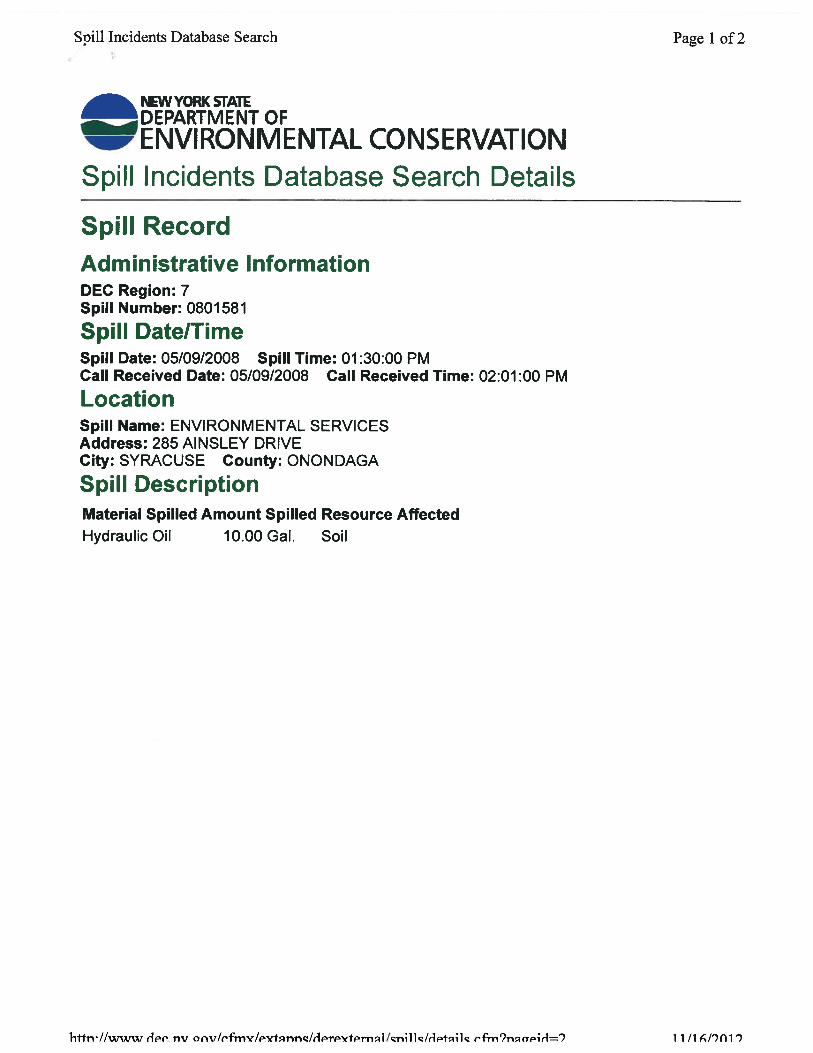
40 CFR 112.7 requires facilities that have experienced one or more spill events within twelve months prior to the effective date of this plan to include a written description of each such spill, corrective action taken, and plans for preventing recurrence. A spill event is defined by the EPA as a discharge of oil (petroleum oils and non-petroleum oils such as silicone and mineral-based oils, animal and vegetable oils) into or upon the navigable waters of the United States or adjoining shorelines in harmful quantities (i.e., violation of applicable water quality standards, or cause a film or sheen or discoloration of the surface of the water). The available Syracuse University Oil Spill Database dates back to 1991 and there is no written spill information prior to that time. A review of that database and conversations with the EHSS indicate that there have been seven spill events since 1998, none of which discharged into or upon navigable waters of the United States or adjoining shorelines in harmful quantities. See Appendix C for the list of spills.
New York law has a different definition of reportable spill events under 17 NYCRR Part 32 and 6 NYCRR Part 612. New York State regulates petroleum spills that do not reach navigable waters. The NYSDEC also requires that any person with knowledge of a spill, leak, or discharge of petroleum must report the incident within two hours of discovery. As noted above and as shown in Appendix C, the Syracuse University Oil Spill Database indicates that there were 7 oil spill events since 1998 which were reportable to the NYSDEC.
A written description of each future oil spill at the Syracuse University Ainsley Drive Facility, the corrective action taken, and plans for preventing a recurrence will be recorded and maintained on file at the EHSS. A sample Petroleum Spill Report form is included in Appendix E.
1.4.3 Spill Potential Analysis
This section provides a description of the predicted rate of flow and total quantity of oil that could be discharged from the facility as a result of each major type of failure. The descriptions summarize potential releases that are considered reasonably possible, and the probable results of the release for petroleum storage systems.
Physical Plant
Tank Overfill (petroleum bulk storage tanks)
As noted above, tank overfilling is the greatest cause of oil spills. Tanker truck pumping systems are typically used to fill bulk fuel storage tanks. Typical flow rates are 150 gpm. The total quantity of oil that could be discharged depends on the actual flow rate and the amount of time expired before an overfill condition is terminated. For example, a spill from a 150 gpm pumping system that goes unattended for a 5-minute period would result in a total spill of 750-gallons.

8615115.1 Syracuse University – Ainsley Drive Facility 1-6 Petroleum Bulk Storage Spill Prevention Control and Countermeasure Plan
Tank and Piping Leaks
Component failure, poor installation, corrosion, lack of maintenance, accidents, or vandalism may cause tank and piping leaks. The rate of flow for tank and piping leaks depends on several factors. Factors include type of leak (e.g., rust-through, pipe joint seep, tank rupture, etc.), location of leak (e.g., underside of tank where a constant liquid head is exerted, or on top of tank where product is present only when the tank/pipe is full or a pump is on), and pumping rate. Worse case, the rate of flow would equal the tank truck pumping system (typically 150 gpm). The quantity of product leaked depends on the type of leak and length of time that the leak goes uncorrected.
Under 40 CFR Part 112.7(e)(3), loading and unloading connections and piping terminal connections must be capped or blank-flanged when not in service or in standby service for an extended period of time. In addition, pipe supports must be designed to minimize vibration and corrosion, and allow for expansion and contraction. The Ainsley Drive facility does not currently have any loading/unloading connections and piping terminal connections which are not in service or in standby service, and is therefore currently not applicable to this requirement.
Non-Stationary Container Leaks
Non-stationary containers (generally with capacities of 55 gallons or less) of various oil products are stored throughout Physical Plant. The products are mainly comprised of petroleum-based lubricants such as oils and greases. Spills may occur at various locations throughout the facility, including:
• shipping/loading dock areas (transfer stations); • storage areas (stock/storerooms); • end use areas (maintenance garage, carpentry shop, etc.); • in transit to or from any of the above areas; and • waste oil storage areas.
The rate of flow and total quantity of product spilled depends on the design capacity of the storage container and type of spill or leak. Worse case, a 55-gallon drum could tip over or burst and spill the entire contents.
Food Service Commissary
Transformer
The electrical transformer at the Food Service Commissary is located outdoors on a concrete pad and reportedly contains a mineral oil. Leaks may develop from corrosion, leaky drains, component failure, damage from accidents, etc. The rate of flow and total quantity of spilled oil would depend on the type of leak or spill and length of time before the problem is corrected. Because transformers are not regularly refilled, the quantity of a potential spill is normally limited to the storage capacity of the unit. The rate of flow depends on whether the leak is a slow seep, or if the container is overfilled during maintenance.
Non-Stationary Containers
Non-stationary containers (generally with capacities of 55 gallons or less) of various oil products are stored throughout the Food Service Commissary. The products include petroleum-based lubricants such as oils and greases, as well as non-petroleum-based oils such as animal and vegetable cooking oils. Spills may occur at various locations throughout the facility, including:

8615115.1 Syracuse University – Ainsley Drive Facility 1-7 Petroleum Bulk Storage Spill Prevention Control and Countermeasure Plan
• shipping/loading dock areas (transfer stations); • storage areas (stock/storerooms); • end use areas (bakery, kitchen, etc.); • in transit to or from any of the above areas; and • waste oil storage areas.
The rate of flow and total quantity of product spilled depends on the design capacity of the storage container and type of spill or leak. Worse case, a 55-gallon drum could tip over or burst and spill the entire contents.
Table 2 indicates types of discharge or drainage controls, such as secondary containment around containers and other structures and equipment, for the control of a discharge from containers at the facility.
1.5 Discharge Countermeasures (40 CFR Part 112.7(a)(3)(iv))
Countermeasures for discovering, responding to, and cleaning up discharges (both the facility's capability and of those that might be required of a contractor) include the following:
• Discovery countermeasures include regular inspections of oil storage areas as described in Section 5 and Section 12E of this Plan. Countermeasures for discharge discovery include routine awareness by facility personnel while passing by an oil storage area during normal business and/or after hour activities. Discovery countermeasures also include regular inspections of oil storage areas as described in Section 5 and Section 12E of this Plan.
• Countermeasures used in response to a discharge are provided in the Spill Response section (page 14) of the Petroleum Bulk Storage Tank Maintenance Procedures Manual attached as Appendix F. Spill control equipment and materials are located near various oil storage locations at the facility.
• Countermeasures for cleanup by the facility depend on the magnitude of the spill. The Facility Response Coordinator will determine whether the spills should be cleaned up by the facility or by an outside contractor. An outside contractor shall clean up spills beyond the capability of the facility. The Facility Response Coordinator will coordinate cleanup activities with outside contractors as necessary to respond to a spill.
1.6 Disposal Methods (40 CFR Part 112(a)(3)(v))
The Facility Response Coordinator will determine whether oil that has been spilled and recovered is suitable for re-use or recycling, depending on the condition of the recovered oil, or containerization and transport to a properly permitted offsite disposal or treatment facility where the material will be treated and/or disposed in a manner consistent with applicable regulations.
1.7 Contact List (40 CFR Part 112.7(a)(3)(vi))
As allowed in 40 CFR Part 112.7(a)(5), the list of contacts to notify in the event of a discharge are as shown on the inside cover of this Plan.

8615115.1 Syracuse University – Ainsley Drive Facility 2-1 Petroleum Bulk Storage Spill Prevention Control and Countermeasure Plan
2 Discharge Reporting Procedures [40 CFR Part 112.7(a)(4)] SPCC regulations require a facility to provide information and procedures in the Plan to enable a person reporting the discharge to relate vital information regarding a discharge. Federal, state, and local discharge reporting requirements are described below.
It is the policy of Syracuse University Ainsley Drive Facility that all oil spills (discharges) regardless of quantity, be reported to the Facility Response Coordinator at the Syracuse University Environmental Health and Safety Services (EHSS) to initiate cleanup activities and for a determination of whether a spill must be reported to local, state, and/or federal authorities. In the event the EHSS is not open, the person who has discovered, or the person who has knowledge of a spill, must immediately contact the Syracuse University Department of Public Safety at 711 or (315) 443-2224. Public Safety will proceed to contact the appropriate personnel. Refer to the Contact List located in the inside cover of this Plan for contacts to notify in the event of a discharge.
40 CFR Part 110 requires any person in charge of an onshore facility with knowledge of any discharge of oil that either violates applicable water quality standards or causes a film or sheen or discoloration of the surface of the water or adjoining shorelines or cause a sludge or emulsion to be deposited beneath the surface of the water or upon adjoining shore-lines to immediately notify the National Response Center (NRC) (800-424-8802). If direct reporting to the NRC is not practicable, reports may be made to the Coast Guard.
According to 40 CFR Part 112.4(a), whenever the facility has discharged more than 1,000 gallons of oil in a single discharge, or discharged more than 42 gallons of oil in each of two discharges occurring within any 12 month period, the EPA Regional Administrator must be notified within 60 days. Information to provide to the Regional Administrator is shown below.
A. Name of facility;
B. Name of person reporting the incident;
C. Location of the facility;
D. Maximum storage or handling capacity of the facility and normal daily throughput;
E. Corrective action and countermeasures you have taken, including a description of equipment repairs and replacements;
F. An adequate description of the facility, including maps, flow diagrams, and topographical maps, as necessary;
G. The cause of such discharge including a failure analysis of the system or subsystem in which the failure occurred;
H Additional preventative measures you have taken or contemplated to minimize the possibility of recurrence; and
I. Such other information as the Regional Administrator may reasonably require pertinent to the plan or discharge.

8615115.1 Syracuse University – Ainsley Drive Facility 2-2 Petroleum Bulk Storage Spill Prevention Control and Countermeasure Plan
In addition, New York State regulations require any person with knowledge of a discharge of petroleum to report the incident to the NYSDEC within two (2) hours of the discovery. The results of any inventory record, test, or inspection which shows a petroleum-containing storage vessel is leaking must also be reported to the NYSDEC within two (2) hours of discovery. Notification must be made by calling the telephone hotline (518-457-7362 or 1-800-457-7362).
The facility is exempt from reporting a petroleum spill if all of the following criteria are met:
• Spill is known to be less than 5 gallons;
• Spill is contained and under control of the spiller;
• Spill has not and will not reach the water or land; and
• Spill is cleaned up within two (2) hours of discovery.
The Fire Code of New York State, specifically Chapter 34: Flammable and Combustible Liquids, contains spill reporting procedures applicable to the facility. Per Chapter 34, a consistent or accidental loss of liquid, or other indication of a leak from a tank system, shall be reported immediately to the fire department, the code enforcement official, or other authorities having jurisdiction. The City of Syracuse Code Enforcement Office can be notified by calling (315) 448-8695.
Lastly, the Onondaga County Department of Water Environment Protection (OCDWEP), Telephone No. 315-435-2260, must also be notified immediately upon discharging petroleum products into the County sewer system in violation of the County of Onondaga Rules and Regulations Relating to the Use of the Public Sewer System.
8615115.1 Syracuse University – Ainsley Drive Facility 3-1 Petroleum Bulk Storage Spill Prevention Control and Countermeasure Plan
3 Discharge Potential from Major Equipment Failures As required by 40 CFR Part 112.7(b), "Where experience indicates a reasonable potential for equipment failure (such as loading or unloading equipment, tank overflow, rupture, or leakage or any other equipment known to be a source of a discharge), the plan should include a prediction of the direction, rate of flow, and total quantity of oil which could be discharged from the facility as a result of each major type of failure." The total quantity of oil that could be discharged from the facility is based on a worst case situation and the time it would take to respond to a spill (e.g., shutting off a pump, or closing a valve).
Table 2 indicates potential spill directions, volumes, and rates for oil storage containers at the facility.

8615115.1 Syracuse University – Ainsley Drive Facility 4-1 Petroleum Bulk Storage Spill Prevention Control and Countermeasure Plan
4 Containment and Diversion Structures According to 40 CFR Part 112.7(c), "Provide appropriate containment and/or diversionary structures or equipment to prevent a discharge described in §112.1(b). The entire containment system, including walls and floor, must be capable of containing oil and must be constructed so that any discharge from the primary containment system such as a tank or pipe will not escape the containment system before cleanup occurs. At a minimum, you must use one of the following prevention systems or its equivalent."
• Dikes, berms, or retaining walls sufficiently impervious to contain oil;
• Curbing;
• Culverting, gutters, or other drainage systems;
• Weirs, booms, or other barriers;
• Spill diversion ponds;
• Retention ponds; or
• Sorbent materials.
Table 1 indicates the type of containment system for each oil storage tank/container and transfer area at the facility. Unless noted otherwise, each of the containment systems are designed, implemented, and/or maintained to meet the standard of sufficiently impervious. Locations of stationary bulk storage tanks and transfer areas are shown on Figure No. 2.
Transfer area and bulk storage tank containment systems are discussed in Section 8 and Section 11 of this Plan, respectively. Undiked areas are discussed in Section 10B.
As provided in 40 CFR Part 112.7(d), if it is determined that the installation of any of the structures or pieces of equipment listed to prevent discharged oil from reaching the navigable waters is not practicable, the owner or operator should clearly explain such impracticability and in the case of bulk storage containers, conduct both periodic integrity testing of the containers and periodic integrity and leak testing of the valves and piping, and provide the following:
• An Oil Spill Contingency Plan following the provision of 40 CFR Part 109.
• A written commitment of manpower, equipment, and materials required to expeditiously control and remove any quantity of oil discharged that may be harmful.
As discussed in this Plan, facility oil filled operational equipment and transfer areas are provided with appropriate secondary containment or alternate performance based provisions. Therefore, the preparation of an oil spill contingency plan is not necessary.

8615115.1 Syracuse University – Ainsley Drive Facility 5-1 Petroleum Bulk Storage Spill Prevention Control and Countermeasure Plan
5 Inspections, Tests, and Records 40 CFR Part 112.7(e) states "Conduct inspections and tests required by this part in accordance with written procedures that you or the certifying engineer develop for the facility. You must keep these written procedures and a record of the inspections and tests, signed by the appropriate supervisor or inspector, with the SPCC Plan for a period of three years. Records of inspections and tests kept under usual and customary business practices will suffice for purposes of this paragraph."
The written procedures for conducting inspections and tests associated with SPCC maintenance are described in this and other sections of this Plan. A record of the inspections and tests, signed by the appropriate supervisor or inspector, are maintained with this Plan for a minimum of three years. Inspections include for example: monthly bulk storage tanks inspections (i.e. stationary above ground oil storage tanks) consistent with New York State regulations Part 613.6, and annual reviews of stationary bulk storage tanks, outdoor electrical transformers, and hydraulic elevators. In addition, the University also conducts a review of its SPCC plan on an annual basis. A copy of the monthly bulk storage tank inspection form is provided in Appendix G.
In addition, any vendor that provides petroleum products to the Ainsley Drive Facility is responsible, as part of the delivery agreement, to be trained in the proper operation and maintenance of equipment and in proper safety procedures to prevent discharges. Vendors also may be obligated to perform necessary remedial actions when they are responsible for spills, and to provide immediate notification to Syracuse University of all spills. Each vendor is also required to carry liability insurance that covers oil spills and indemnifies Syracuse University for costs related to responding to an oil spill caused by the vendor.

8615115.1 Syracuse University – Ainsley Drive Facility 6-1 Petroleum Bulk Storage Spill Prevention Control and Countermeasure Plan
6 Personnel Training and Discharge Prevention Procedures
6.1 Personnel Instructions
40 CFR Part 112.7(f)(l) states "At a minimum, train your oil-handling personnel in the operation and maintenance of equipment to prevent discharges; discharge procedure protocols; applicable pollution control laws, rules, and regulations; general facility operations; and, the contents of the facility SPCC Plan."
Training for oil-handling personnel at the Ainsley Drive Facility is provided following an individual's placement into positions associated with oil storage, transfer, or utilization, and includes:
• Operation and maintenance of equipment to prevent discharges;
• Routine procedures to be followed to minimize the potential for discharges (including use of sorbent materials or barriers to mitigate migration across surfaces, use of drain blocking pads to prevent a spill from entering a drainage inlet, use of booms to contain spills into surface water, and use of pumps to remove oil from surface water or containment areas);
• Procedures to be followed in the event of a discharge;
• Applicable pollution control laws, rules, and regulations;
• General facility operations; and
• The contents of the facility SPCC Plan.
Additional training is provided to employees whose oil-handling responsibilities change during the course of their employment, to the extent that such additional training is required based on the change of responsibilities.
6.2 Designated Person Accountable for Spill Prevention
40 CFR Part 112.7(f)(2) states: "Designate a person at each facility who is accountable for discharge prevention and who reports to facility management." As indicated in the Emergency Contact List (located inside the front cover of this Plan), the Director of Environmental Health, is the individual accountable for discharge prevention and who will report to facility management. Specifically, the Director of Environmental Health will ensure that facility personnel are trained, understand, and follow the spill response and prevention procedures outlined in this plan. The Director of Environmental Health will also verify that the inspections are being conducted and will be the person contacting appropriate agencies in the event of a spill.
6.3 Spill Prevention Briefings
40 CFR Part 112.7(f)(3) states "Schedule and conduct discharge prevention briefings for your oil-handling personnel at least once a year to assure adequate understanding of the SPCC Plan for that facility. Such briefings must highlight and describe known discharges as described in §112.1(b) or failures, malfunctioning components, and any recently developed precautionary measures."
Discharge prevention briefings for oil-handling personnel are held at least once a year to assure adequate understanding of the SPCC Plan for the Ainsley Drive Facility. These briefings highlight and describe known discharges or equipment failures, malfunctioning components, and recently developed precautionary measures.

8615115.1 Syracuse University – Ainsley Drive Facility 7-1 Petroleum Bulk Storage Spill Prevention Control and Countermeasure Plan
7 Security
7.1 Fencing
40 CFR Part 112.7(g)(l) states "Fully fence each facility handling, processing, or storing oil, and lock and/or guard entrance gates when the facility is not in production or is unattended."
Outdoor oil storage at the Ainsley Drive Facility is not completely enclosed in a fenced area. Equivalent environmental protection (regarding security) to prevent a discharge of outdoor tanks/containers is achieved via frequent monitoring by facility staff and routine patrols by Syracuse University Public Safety. In addition, outdoor tanks/containers are located in areas equipped with area lighting to minimize vandalism and enhance monitoring.
Indoor oil storage tanks/containers are not fenced because they are located in the facility buildings or other areas that are only accessible to facility personnel during normal business hours. The buildings are locked during off-hours. Fencing of these areas is not practical because it would not provide additional security. In these areas, equivalent environmental protection (regarding security) to prevent a discharge is provided by the physical barriers imposed by the locked buildings and/or rooms which deter vandalism and prevent unauthorized access to containers and equipment that could be involved in an oil discharge.
7.2 Flow Valves Locked
40 CFR Part 112.7(g)(2) states "Ensure that the master flow and drain valves and any other valves permitting direct outward flow of the container's contents to the surface have adequate security measures so that they remain in the closed position when in non-operating or non-standby status."
Master flow and drain valves and any other valves permitting direct outward flow of an oil container's contents to the surface are equipped with security measures so that they remain in the closed position when in non-operating or non-standby status.
The facility currently does not have master flow or drain values associated with their petroleum bulk storage tanks and is therefore not applicable to this requirement. 7.3 Starter Controls Locked
40 CFR Part 112.7(g)(3) states "Lock the starter control on each oil pump in the "off" position and locate it at a site accessible only to authorized personnel when the pump is in a non-operating or non-standby status."
The starter control on each oil pump at the facility is locked in the "off position and located at a site accessible only to authorized personnel when the pump is in a non-operating or non-standby status.
The facility currently does not have starter controls associated with their petroleum bulk storage tanks and is therefore not applicable to this requirement.
7.4 Pipeline Loading/Unloading Connections Securely Capped
40 CFR Part 112.7(g)(4) states "Securely cap or blank-flange the loading/ unloading connections of oil pipelines or facility piping when not in service or when in standby service for an extended time. This
8615115.1 Syracuse University – Ainsley Drive Facility 7-2 Petroleum Bulk Storage Spill Prevention Control and Countermeasure Plan
security practice also applies to piping that is emptied of liquid content either by draining or by inert gas pressure."
The Ainsley Drive facility does not currently have any loading/unloading connections and piping terminal connections which are not in service or in standby service, and is therefore currently not applicable to this requirement. 7.5 Lighting Adequate to Detect Spills
40 CFR Part 112.7(g)(5) states "Provide facility lighting commensurate with the type and location of the facility that will assist in the:
• Discovery of discharges occurring during hours of darkness, both by operating personnel, if present, and by non-operating personnel (the general public, local police, etc.); and
• Prevention of discharges occurring through acts of vandalism."
The facility has sufficient lighting to assist in the discovery of spills during hours of darkness (both by operating personnel and non-operating personnel), and the minimization of oil spills occurring through acts of vandalism.

8615115.1 Syracuse University – Ainsley Drive Facility 8-1 Petroleum Bulk Storage Spill Prevention Control and Countermeasure Plan
8 Tank Car and Tank Truck Loading/Unloading Rack
8.1 Loading/Unloading (Transfer) Area Drainage
40 CFR Part 112.7(h)(l) states "Where loading/unloading area drainage does not flow into a catchment basin or treatment facility designed to handle discharges, use a quick drainage system for tank car or tank truck loading and unloading areas. You must design any containment system to hold at least the maximum capacity of any single compartment of a tank car or tank truck loaded or unloaded at the facility."
The Ainsley Drive Facility does not utilize loading/unloading racks for the transfer of oil products and, therefore, Part 112.7(h)(l) is not applicable. The Ainsley Road Facility does, however, have transfer areas regulated by Part 112.7(c). Tank trucks offload fuel at these transfer areas into stationary bulk storage containers via bottom load connections and a flexible hose attached to hard piping (aboveground tanks). These transfer areas are provided with appropriate containment consistent with Part 112.7(c) by implementing active containment measures as follows:
As described on Table 2 and in the Tank Vehicle Transfer Policy (Appendix H), the Ainsley Drive Facility deploys spill kits located near the fuel loading/unloading stations for use in the event of a spill/leak during transfer operations. 8.2 Warning or Barrier System for Vehicles
40 CFR Part 112.7(h)(2) states "Provide an interlocked warning light or physical barrier system, warning signs, wheel chocks, or vehicle break interlock system in loading/unloading areas to prevent vehicles from departing before complete disconnection of flexible or fixed oil transfer lines."
Transfer vehicles are required to utilize wheel chocks to prevent vehicles from departing before complete disconnection of oil transfer lines.
8.3 Vehicles Examined for Drainage Outlets before Leaving (Tank Vehicle Transfer Policy)
40 CFR Part 112.8(h)(3) states "Prior to filling and departure of any tank car or tank truck, closely inspect for discharges the lowermost drain and all outlets of such vehicles, and if necessary, ensure that they are tightened, adjusted, or replaced to prevent liquid discharge while in transit."
Facility personnel remain present, along with the transporter's personnel, during the entire transfer process of bulk oil. Facility personnel are trained in the proper procedures for verifying and documenting conditions before, during, and after each transfer activity. Additional routine procedures include manual verification of product levels (i.e., "sticking" of tanks), periodic verification of the operability of electronic spill/leak-detection equipment, and periodic visual inspection of aboveground tank condition.
The facility has instituted a tank vehicle transfer policy for the transfer of bulk oil products as provided in Appendix H.

8615115.1 Syracuse University – Ainsley Drive Facility 9-1 Petroleum Bulk Storage Spill Prevention Control and Countermeasure Plan
9 Conformance with More Stringent State Rules, Regulations, and Guidelines
In addition to the minimal prevention standards listed under 40 CFR Part 112.7(c), 40 CFR Part 112.7(j) states "include in your Plan a complete discussion of conformance with the applicable requirements and other effective discharge prevention and containment procedures listed in this part or any applicable more stringent State rules, regulations, and guidelines."
The discharge prevention and containment procedures implemented by this facility have been designed to conform with the applicable requirements of 40 CFR Part 112, as well as other applicable more stringent state rules, regulations, and guidelines.
More stringent state rules include, but are not limited to, the following:
A. As described in the Tank Vehicle Transfer Policy in Appendix H, the responsibility for transfer operations is consistent with 6NYCRR Part 613.3(a).
B. Color coding of fill ports is consistent with 6NYCRR Part 613.3(b).
C. The design capacity, working capacity, and identification number of stationary bulk storage tanks are marked on the tanks consistent with 6NYCRR Part 613.3(c)(3)(ii).
D. Tank connections through which petroleum can normally flow are equipped with operating valves to control the flow consistent with 6NYCRR Part 613.3(c)(5).
E. Bulk storage tanks are inspected on a monthly basis consistent with 6NYCRR Part 613.6.

8615115.1 Syracuse University – Ainsley Drive Facility 10-1 Petroleum Bulk Storage Spill Prevention Control and Countermeasure Plan
10 Facility Drainage Assessment 10.1 Use of Valves and Pumps in Diked Areas
40 CFR Part 112.8(b)(l) states "Restrain drainage from diked storage areas by valves to prevent a discharge into the drainage system or facility effluent treatment system, except where facility systems are designed to control such discharge. You may empty diked areas by pumps or ejectors; however, you must manually activate these pumps or ejectors and must inspect the condition of the accumulation before starting, to ensure no oil will be discharged."
In addition, 40 CFR Part 112.8(b)(2) states "Use valves of manual, open-and-closed design, for the drainage of diked areas. You may not use flapper-type drain valves to drain diked areas. If your facility drainage drains directly into a watercourse and not into an on-site wastewater treatment plant, you must inspect and may drain uncontaminated retained stormwater, as provided in paragraphs (c)(3)(ii), (Hi), and (iv) of this section."
Most portable containers (i.e., 55-gallon drums) are situated on dike-style containment pallets. Containment pallets are equipped with outlet drains. These drains are plugged or capped, except when they are drained, as described in Section 11C. At the maintenance garage, portable containers in the oil storage room are situated in a bermed area with no valves. In the instance of a spill, motor and hydraulic oils would be drained manually with a portable pump.
No other oil storage containers at the facility utilize a dike-style containment system.
10.2 Undiked Areas
40 CFR Part 112.8(b)(3) states "Design facility drainage systems from undiked areas with a potential for a discharge (such as where piping is located outside containment walls or where tank truck discharges may occur outside the loading area) to flow into ponds, lagoons, or catchment basins designed to retain oil or return it to the facility. You must not locate catchment basins in areas subject to periodic flooding."
In addition, 40 CFR Part 112.8(b)(4) states "If facility drainage is not engineered as in paragraph (b)(3) of this section, equip the final discharge of all ditches inside the facility with a diversion system that would, in the event of an uncontrolled discharge, retain oil in the facility."
Areas at the facility where piping is located outside containment structures or where tank truck discharges may occur outside a contained area are not designed for drainage to flow into containment ponds, lagoons, or catchment basins or to return it to the facility. Most of these areas are related to the transfer of oil from tank vehicles into storage, or from storage to an emergency generator via aboveground hoses and/or piping systems.
Regarding areas where oil is transferred from tank vehicles into storage, as described in Section 8A, the facility deploys environmental protection with supervised transfers and spill kits to prevent spills from entering the storm sewer.
Regarding areas where oil is transferred from storage to an emergency generator, the transfer is accomplished via aboveground piping. To provide equivalent environmental protection, the facility maintains spill kits in these areas to be deployed in the event of a spill to prevent oil from entering drains

8615115.1 Syracuse University – Ainsley Drive Facility 10-2 Petroleum Bulk Storage Spill Prevention Control and Countermeasure Plan
and discharging to the sanitary sewer system. In addition, when emergency generators are operational (and oil is transferred), the generator system is visually monitored by oil-handling personnel.
Due to the facility layout, relatively low volumes of oil transferred, and infrequent deliveries of oil products, in the P.E.’s opinion, it is not practical to construct facility drainage from undiked areas to flow into ponds, lagoons, or catchment basins designed to retain oil or return it to the facility. To provide additional equivalent environmental protection, the facility has several measures in place to prevent a discharge reaching a water source, such as spill kits and facility personnel trained in spill prevention and response procedures.
10.3 Facility Drainage Systems and Equipment
40 CFR Part 112.8(b)(5) states "Where drainage waters are treated in more than one treatment unit and such treatment is continuous, and pump transfer is needed, provide two "lift" pumps and permanently install at least one of the pumps. Whatever techniques you use, you must engineer facility drainage systems to prevent a discharge as described in §112.1(b) in case there is an equipment failure or human error at the facility."
Facility drainage discharges into the Onondaga County Department of Water Environment Protection combined sewer overflow system. There is currently no on-site treatment of facility drainage and is therefore not applicable to this requirement.

8615115.1 Syracuse University – Ainsley Drive Facility 11-1 Petroleum Bulk Storage Spill Prevention Control and Countermeasure Plan
11 Bulk Storage Containers 11.1 Container Construction
40 CFR Part 112.8(c)(l) states "Not use a container for the storage of oil unless its material and construction are compatible with the material stored and conditions of storage such as pressure and temperature."
The material and construction of bulk storage containers at the facility are compatible with the material stored and conditions of storage. Table 1 identifies the material and standard of construction, where known, for bulk storage containers at the facility and specific features of individual tanks (e.g., double wall steel) as applicable.
11.2 Secondary Containment Construction
40 CFR Part 112.8(c)(2) states "Construct all bulk storage container installations so that you provide a secondary means of containment for the entire capacity of the largest single container and sufficient freeboard to contain precipitation. You must ensure that diked areas are sufficiently impervious to contain discharged oil. Dikes, containment curbs, and pits are commonly employed for this purpose. You may also use an alternative system consisting of a drainage trench enclosure that must be arranged so that any discharge will terminate and be safely confined in a facility catchment basin or holding pond."
Regulations further explain that precipitation freeboard should be based on regional rainfall patterns.
Table 2 indicates the approximate containment volume for bulk storage containers at the facility. In each instance, the capacity of secondary containment provides for the entire capacity of the largest single container, and sufficient freeboard to contain precipitation as appropriate. Bulk storage container secondary containment structures are sufficiently impervious to contain discharged oil. Methods used for secondary containment of bulk storage containers at the facility include double wall tanks, bermed rooms, containment pallets, and dikes.
11.3 Secondary Containment Drainage Procedures
40 CFR Part 112.8(c)(3) states "Not allow drainage of uncontaminated rainwater from the diked area into a storm drain or discharge of an effluent into an open watercourse, lake, or pond, bypassing the facility treatment system unless you:
• Normally keep the bypass valve sealed closed.
• Inspect the retained rainwater to ensure that its presence will not cause a discharge as described in §112.1(b).
• Open the bypass valve and reseal it following drainage under responsible supervision; and
• Keep adequate records of such events" (as described in Section 11.4).
The Ainsley Drive Facility does not contain outdoor diked/secondary containment systems where stormwater may accumulate and thus require secondary containment drainage procedures.

8615115.1 Syracuse University – Ainsley Drive Facility 11-2 Petroleum Bulk Storage Spill Prevention Control and Countermeasure Plan
11.4 Recordkeeping
As noted above, 40 CFR Part 112.8(c)(3)(iv) requires adequate records of dike drainage events be maintained. In addition, any records required under permits issued in accordance with §§122.41(j)(2) and 122.41(m)(3) of this chapter might be applicable (i.e., SPDES Permit).
Regulations further suggest a detailed discussion of the inspection and drainage procedures used for diked areas and how drainage discharge is documented (e.g., checklist noting the appearance of the water, time of valve opening, time of valve closing, signature of inspector, etc.). This section should also include a discussion of an alternative method of drainage to be employed if an oil sheen or an oil accumulation is observed.
Because the Ainsley Facility does not contain dike drainage systems, the facility is not applicable to the recordkeeping requirements outlined in this section. However, if an interior oil containment device requires drainage, Appendix N contains an oil containment device drainage discharge record form.
11.5 Corrosion Protection for Underground and Partially Buried Containers
40 CFR Part 112.8(c)(4) states "Protect any completely buried metallic storage tank installed on or after January 10, 1974, from corrosion by coatings or cathodic protection compatible with local soil conditions. You must regularly leak test such completely buried metallic storage tanks."
Underground storage tanks (UST) for purposes of SPCC are defined as completely buried, unlike "underground storage tanks" in EPA's UST program (40 CFR Part 280), which may be partially buried.
There are no completely buried metallic storage tanks installed on or after January 10, 1974 at the facility to which 40 CFR Part 112 is applicable.
Corrosion Protection of Partially Buried Metallic Tanks: 40 CFR Part 112.8(c)(5) states "Not use partially buried or bunkered metallic tanks for the storage of oil, unless you protect the buried section of the tank from corrosion. You must protect partially buried and bunkered tanks from corrosion by coatings or cathodic protection compatible with local soil conditions."
There are no partially buried tanks at the facility.
11.6 Tank Testing Procedures
40 CFR Part 112.8(c)(6) states "Test each above ground container for integrity on a regular schedule, and whenever you make material repairs. The frequency of and type of testing must take into account container size and design (such as floating roof, skid-mounted, elevated, or partially buried). You must combine visual inspection with another testing technique such as hydrostatic testing, radiographic testing, ultrasonic testing, acoustic emissions testing, or another system of non-destructive shell testing. You must keep comparison records and you must also inspect the container's supports and foundations. In addition, you must frequently inspect the outside of the container for signs of deterioration, discharges, or accumulation of oil inside diked areas. Records of inspections and tests kept under usual and customary business practices will suffice for purposes of this paragraph."
Integrity testing is not required for electrical, operating, and manufacturing equipment that contain oil because they are not bulk storage containers. In addition, smaller shop-built containers, inspected monthly and with all sides visible, visual inspection alone will suffice, when subject to good engineering practices.

8615115.1 Syracuse University – Ainsley Drive Facility 11-3 Petroleum Bulk Storage Spill Prevention Control and Countermeasure Plan
The facility's oil storage tanks are inspected on a monthly basis. Those that are visible on all sides do not require regular testing due to the inspection frequency and high level of supervision during transfers, which is when most discharges occur.
11.7 Procedures for Controlling Leakage from Internal Heating Coils
40 CFR Part 112.8(c)(7) states "Control leakage through defective internal heating coils by monitoring the steam return and exhaust lines for contamination from internal heating coils that discharge into an open watercourse, or pass the steam return or exhaust lines through a settling tank, skimmer, or other separation or retention system."
Internal heating coils are not utilized by the facility.
11.8 Engineering Controls to Avoid Discharges
40 CFR Part 112.8(c)(8) states "Engineer or update each container installation in accordance with good engineering practice to avoid discharges. You must provide at least one of the following devices:
• High liquid level alarms with an audible or visual signal at a constantly attended operation or surveillance station. In smaller facilities an audible air vent may suffice.
• High liquid level pump cutoff devices set to stop flow at a predetermined container content level.
• Direct audible or code signal communication between the container gauge and the pumping station.
• A fast response system for determining the liquid level of each bulk storage container such as digital computers, telepulse, or direct vision gauges. If you use this alternative, a person must be present to monitor gauges and the overall filling of bulk storage containers.
• You must regularly test liquid level sensing devices to ensure proper operation."
The USEPA also suggests, in order to provide adequate fail-safe engineering, redundancy should be employed. Inventory control and "sticking" are not adequate methods unless a second form of overfill prevention is utilized.
Table 1 lists specific engineering controls utilized for each oil storage container at the facility. To the extent practicable, redundancy has been employed. Inventory control and/or "sticking" are used along with at least one other form of overfill prevention at the facility.
11.9 Inspection of Treatment Facilities
40 CFR Part 112.8(c)(9) states "Observe effluent treatment facilities frequently enough to detect possible system upsets that could cause a discharge as described in §112.1(b)."
The oil/water separator is inspected/monitored periodically for captured oil levels via dip stick to ensure that the system has not reached maximum capacity where potential oil flow-through might occur. The facility should document/log when the oil/water separator is inspected and when the system is cleaned out.

8615115.1 Syracuse University – Ainsley Drive Facility 11-4 Petroleum Bulk Storage Spill Prevention Control and Countermeasure Plan
11.10 Correction of Observed Discharges
40 CFR Part 112.8(c)(10) states "Promptly correct visible discharges which result in a loss of oil from the container, including but not limited to seams, gaskets, piping, pumps, valves, rivets, and bolts. You must promptly remove any accumulations of oil in diked areas."
Visible discharges and accumulations are promptly removed and the cause for the discharge is corrected. Such corrections are documented in the Petroleum Spill Report located in Appendix E and maintained with this Plan.
11.11 Locations and Construction of Mobile or Portable Containers
40 CFR Part 112.8(c)(ll) states "Position or locate mobile or portable oil storage containers to prevent a discharge as described in §112.1(b). You must furnish a secondary means of containment, such as a dike or catchment basin, sufficient to contain the capacity of the largest single compartment or container with sufficient freeboard to contain precipitation."
Table 1 identifies mobile and/or portable bulk storage containers and describes containment for each of these containers and Table 2 provides container volumes. It is possible during the course of facility operations that additional mobile or portable containers (e.g. 55-gallon drum, portable generators, light banks, etc.) will be brought on-site. In these instances, each container will be provided with secondary containment while at the facility.

8615115.1 Syracuse University – Ainsley Drive Facility 12-1 Petroleum Bulk Storage Spill Prevention Control and Countermeasure Plan
12 Facility Transfer Operations, Pumping, and Facility Process 12.1 Corrosion Protection for Buried Piping Systems
40 CFR Part 112.8(d)(l) states "Provide buried piping that is installed or replaced on or after August 16, 2002, with a protective wrapping and coating. You must also cathodically protect such buried piping installations or otherwise satisfy the corrosion protection standards for piping in part 280 of this chapter or a State program approved under part 281 of this chapter."
As of the date of this Plan, there has been no buried piping installed or replaced on or after August 16, 2002. Buried piping installed after that date shall be provided with a protective wrapping and coating. Such buried piping will also be cathodically protected or otherwise satisfy the corrosion protection standards for piping in 40 CFR Part 280.
12.2 Inspection of Exposed Piping for Buried Piping Systems
40 CFR Part 112.8(d)(l) also states "If a section of buried line is exposed for any reason, you must carefully inspect it for deterioration. If you find corrosion damage, you must undertake additional examination and corrective action as indicated by the magnitude of the damage."
As of the date of this Plan, there has been no buried piping that is exposed for any reason. In the event of future installations, the buried line that is exposed for any reason shall be carefully inspected for deterioration. If corrosion damage is observed, personnel will undertake additional examination and corrective action as appropriate for the magnitude of damage. Such inspections, observations, and corrective actions are documented in the monthly inspection reports.
12.3 Terminal Connections at Transfer Points
40 CFR Part 112.8(d)(2) states "Cap or blank-flange the terminal connection at the transfer point and mark it as to origin when piping is not in service or is in standby service for an extended time."
When piping is not in service or is in standby service for an extended time, the terminal connections are capped or blank-flanged at the transfer point and marked as to origin.
12.4 Pipe Support Design
40 CFR Part 112.8(d)(3) states "Properly design pipe supports to minimize abrasion and corrosion and allow for expansion and contraction."
Pipe supports are designed and installed in a manner that will minimize abrasion and corrosion and allow for expansion and contraction.
12.5 Regular Inspection of Aboveground Valves and Piping
40 CFR Part 112.8(d)(4) states "Regularly inspect all aboveground valves, piping, and appurtenances. During the inspection you must assess the general condition of items, such as flange joints, expansion joints, valve glands and bodies, catch pans, pipeline supports, locking of valves, and metal surfaces. You must also conduct integrity and leak testing of buried piping at the time of installation, modification, construction, relocation, or replacement."

8615115.1 Syracuse University – Ainsley Drive Facility 12-2 Petroleum Bulk Storage Spill Prevention Control and Countermeasure Plan
Aboveground valves, piping, and appurtenances are inspected on a monthly basis as shown on the Monthly PBS Tank Inspection – Ainsley Drive Facility in Appendix G of this Plan.
Integrity and leak testing of buried piping is conducted at the time of installation, modification, construction, relocation, or replacement. The Ainsley Drive facility does not currently have buried piping associated with the petroleum bulk storage tanks and is therefore currently not applicable to this requirement.
12.6 Vehicular Warning
40 CFR Part 112.8(d)(5) states "Warn all vehicles entering the facility to be sure that no vehicle will endanger aboveground piping or other oil transfer operations."
Transfer operators are verbally warned at transfer areas by on-site personnel to not endanger aboveground piping or other oil transfer operations at the facility.

8615115.1 Syracuse University – Ainsley Drive Facility 13-1 Petroleum Bulk Storage Spill Prevention Control and Countermeasure Plan
13 Certificate of the Applicability of the Substantial Harm Criteria
Regulations in 40 CFR Part 112 require certain larger facilities that may pose a substantial harm to the environment to prepare and submit a Facility Response Plan to the Regional Environmental Protection Agency Administrator. The total oil storage capacity for the Syracuse University – Ainsley Drive Facility totals slightly over 12,000 gallons, which is well below the thresholds for such facilities. Therefore, a Facility Response Plan is not required for this facility.
Appendix C to 40 CFR Part 112 requires certification for facilities that do not pose substantial harm to the environment. A Certificate of the Applicability of the Substantial Harm Criteria form is attached as Appendix I of this Plan to document that this facility is not required to produce such a response plan. In the event that the facility was further developed in the future such that these thresholds were exceeded, or should the rule be altered to incorporate smaller facilities, a Facility Response Plan may be required.

8615115.1 Syracuse University – Ainsley Drive Facility Petroleum Bulk Storage Spill Prevention Control and Countermeasure Plan
TABLES

8615115.1 Syracuse University – Ainsley Drive Facility Petroleum Bulk Storage Spill Prevention Control and Countermeasure Plan
Table 1: Summary of Facility Oil Storage
Location/Purpose Tank ID No.
Tank Type (UST/AST)
Tank Size (Gallons) Tank Contents Secondary Containment – Overfill
Prevention Systems Physical Plant/Vehicle Fueling
008 AST 6,000 Unleaded Gasoline Steel Double Walled Tank; Leak Detection Monitoring System; Visual Level Gauges
Physical Plant/Emergency Generator
005 AST 1,000 Diesel Concrete Encased Single Wall Steel Tank; Leak Detection Monitoring System; Visual Level Gauges
Physical Plant/Vehicle Fueling
010 AST 3,000 Diesel Steel Double Walled Tank; Leak Detection Monitoring System; Visual Level Gauges
Maintenance Garage 009 AST 275 Motor Oil Steel Double Walled Tank; Visual Level Gauges
Physical Plant --- 55-Gallon Drum 55 (Typical)
Used Oils and Transformer Oil
Spill Pallet
Maintenance Garage --- Oil/Water Separator
750 Used Oils None*
Maintenance Garage --- 55-Gallon Drum 55 (Typical) Motor & Hydraulic Oils Diked Oil Storage Room Central Hazardous Waste and Non-Hazardous Sheds
--- 55-Gallon Drum 55 (Typical) Used Petroleum- Based Products
Spill Pallets
Food Service Commissary/Transformer
--- Transformer Reservoir
330 Transformer Fluid None**
Food Service Commissary
--- Containers & Drums
< 55 Cooking Oils None**
Food Service Commissary
--- Waste Grease Storage
Container
150 Waste Grease Double walled container
Food Service Commissary
--- Underground Grease
Interceptor/Trap
210 Used Grease None*
* - Flow-through wastewater treatment systems are not considered bulk oil storage containers and therefore, not considered applicable to SPCC regulations. As such, the Syracuse University Ainsley Drive Facility’s oil/water separator and grease interceptor is exempt from SPCC regulations. However, these are included in this SPCC plan for consistency regarding procedures and response planning with the other SPCC applicable oil storage at the Syracuse University Ainsley Drive Facility. ** - Although these petroleum bulk storage locations do not contain structural secondary containment systems, these areas are in compliance with SPCC regulations through the implementation and deployment of spill kits, frequent inspections, and facility personnel trained in spill prevention and response procedures.

8615115.1 Syracuse University – Ainsley Drive Facility Petroleum Bulk Storage Spill Prevention Control and Countermeasure Plan
Table 2: Discharge and Drainage Controls
Tank ID No.
Tank Size (Gallons)
Tank Contents
Type of Failure
Potential Spill
Quantity (gallons)
Potential Spill Rate
(gallons/minute)
Containment Volume (gallons)
Direction of Flow
008 6,000 Unleaded Gasoline
Tank Overfill, Hose Rupture
750* 150 Double Walled Tank
West-southwest toward grassy area
005 1,000 Diesel Tank Overfill, Hose Rupture
750* 150 Double Walled Tank
West-southwest toward grassy area
010 3,000 Diesel Tank Overfill, Hose Rupture
750* 150 Double Walled Tank
West-southwest toward grassy area
009 275 Motor Oil Tank Overfill, Hose Rupture
750* 150 Double Walled Tank
Northeast toward stormwater catchment basin
--- 55 (drum) Motor Oil Tank Spill/Rupture
55 55 >55 Contained in Oil Storage Room
--- 55 (drum) Used Oil/ Transformer
Oil
Tank Spill/Rupture
55 55 >55 Contained in Spill Pallet
--- 330 (Reservoir)
Transformer Oil
Reservoir Leak/Spill
330 (maximum)
Variable --- Surrounding Stone/Soils
--- 150 Used Grease Container Leak/Spill
Variable Variable Double Walled Container
East towards 210-gallon grease interceptor manhole
* - The potential spill quantity from a tank overfill or hose rupture event is based on a fuel delivery flow rate of 150 gallons per minute and a maximum of five minute response time to turn off fuel flow from the delivery truck.