Embed Size (px)
DESCRIPTION
PSV
Citation preview
Process Add-On Instructions and Graphics: Motor Operated Valve (P_ValveMO)
Reference Manual
Compatible with the Plant-wide Integrated Architecture™
Important User InformationSolid state equipment has operational characteristics differing from those of electromechanical equipment. Safety Guidelines for the Appli-
cation, Installation and Maintenance of Solid State Controls (publication SGI-1.1 available from your local Rockwell Automation sales office
or online at http://rockwellautomation.com/literature) describes some important differences between solid state equipment and hard-wired
electromechanical devices. Because of this difference, and also because of the wide variety of uses for solid state equipment, all persons re-
sponsible for applying this equipment must satisfy themselves that each intended application of this equipment is acceptable.
In no event will Rockwell Automation, Inc. be responsible or liable for indirect or consequential damages resulting from the use or application
of this equipment.
The examples and diagrams in this manual are included solely for illustrative purposes. Because of the many variables and requirements as-
sociated with any particular installation, Rockwell Automation, Inc. cannot assume responsibility or liability for actual use based on the ex-
amples and diagrams.
No patent liability is assumed by Rockwell Automation, Inc. with respect to use of information, circuits, equipment, or software described in
this manual.
Reproduction of the contents of this manual, in whole or in part, without written permission of Rockwell Automation, Inc., is prohibited.
Throughout this manual, when necessary, we use notes to make you aware of safety considerations.
Allen-Bradley, Rockwell Automation, Plant PAx Process Automation System, and TechConnect are trademarks of Rockwell Automation, Inc.
Trademarks not belonging to Rockwell Automation are property of their respective companies.
WARNINGIdentifies information about practices or circumstances that can cause an explosion in a hazardous environment, which may lead to personal injury or death, property damage, or economic loss.
IMPORTANT Identifies information that is critical for successful application and understanding of the product.
ATTENTION Identifies information about practices or circumstances that can lead to personal injury or death, property damage, or economic loss. Attentions help you identify a hazard, avoid a hazard, and recognize the consequence.
SHOCK HAZARD Labels may be on or inside the equipment, for example, a drive or motor, to alert people that dangerous voltage may be present.
BURN HAZARD Labels may be on or inside the equipment, for example, a drive or motor, to alert people that surfaces may reach dangerous temperatures.
Summary of Changes
Introduction This release of this document is updated throughout for version 2.0 of the Motor Operated Valve (P_ValveMO) Add-On Instruction and Graphics. Please refer to the Release Notes that are distributed with version 2.0 of the Library.
Updated Information This document contains the following changes:
Change: See:
Version 2.0 of instruction All
iiiPublication SYSLIB-RM014C-EN-E - October 2011 iii

Summary of Changes
Notes:
iv Publication SYSLIB-RM014C-EN-E - October 2011

Table of ContentsPreface Use of this Document . . . . . . . . . . . . . . . . . . . . . . . . . . . . . . . . . . . . . . vii
Conventions and Related Terms . . . . . . . . . . . . . . . . . . . . . . . . . . . . . . vii
Set and Clear . . . . . . . . . . . . . . . . . . . . . . . . . . . . . . . . . . . . . . . . . . vii
Edge and Level. . . . . . . . . . . . . . . . . . . . . . . . . . . . . . . . . . . . . . . . viii
Relay Ladder Rung Condition . . . . . . . . . . . . . . . . . . . . . . . . . . . . . ix
Pre-Scan . . . . . . . . . . . . . . . . . . . . . . . . . . . . . . . . . . . . . . . . . . . . . . . x
Function Block States . . . . . . . . . . . . . . . . . . . . . . . . . . . . . . . . . . . xi
Entering Text in FactoryTalk View SE. . . . . . . . . . . . . . . . . . . . . . xii
Chapter 1Overview Functional Description . . . . . . . . . . . . . . . . . . . . . . . . . . . . . . . . . . . . . . 2
Primary Operations . . . . . . . . . . . . . . . . . . . . . . . . . . . . . . . . . . . . . . . . . 2
Operating Modes . . . . . . . . . . . . . . . . . . . . . . . . . . . . . . . . . . . . . . . . . . . 4
Alarms. . . . . . . . . . . . . . . . . . . . . . . . . . . . . . . . . . . . . . . . . . . . . . . . . . . . 5
Execution . . . . . . . . . . . . . . . . . . . . . . . . . . . . . . . . . . . . . . . . . . . . . . . . . 5
Revision Compatibility . . . . . . . . . . . . . . . . . . . . . . . . . . . . . . . . . . . . . . . 6
Chapter 2Configuration Options Configuration Parameters . . . . . . . . . . . . . . . . . . . . . . . . . . . . . . . . . . . . 7
Chapter 3Instruction Data Reference Execution Data. . . . . . . . . . . . . . . . . . . . . . . . . . . . . . . . . . . . . . . . . . . . 19
Inputs (Inp_) . . . . . . . . . . . . . . . . . . . . . . . . . . . . . . . . . . . . . . . . . . . . . 20
Outputs (Out_). . . . . . . . . . . . . . . . . . . . . . . . . . . . . . . . . . . . . . . . . . . . 21
Configurations (Cfg_) . . . . . . . . . . . . . . . . . . . . . . . . . . . . . . . . . . . . . . 22
Program Settings (PSet_) . . . . . . . . . . . . . . . . . . . . . . . . . . . . . . . . . . . . 25
Program Commands (PCmd_) . . . . . . . . . . . . . . . . . . . . . . . . . . . . . . . 25
Device Commands. . . . . . . . . . . . . . . . . . . . . . . . . . . . . . . . . . . . . . 25
Mode Commands. . . . . . . . . . . . . . . . . . . . . . . . . . . . . . . . . . . . . . . 26
Alarm Commands . . . . . . . . . . . . . . . . . . . . . . . . . . . . . . . . . . . . . . 26
Operator Commands, Maintenance Commands, Command Readies (OCmd_, MCmd_, Rdy_) . . . . . . . . . . . . . . . . . . . . . . . . . . . . . . . . . . . 28
Device Commands. . . . . . . . . . . . . . . . . . . . . . . . . . . . . . . . . . . . . . 28
Mode Commands. . . . . . . . . . . . . . . . . . . . . . . . . . . . . . . . . . . . . . . 29
Alarm Commands . . . . . . . . . . . . . . . . . . . . . . . . . . . . . . . . . . . . . . 29
Device Command Readies . . . . . . . . . . . . . . . . . . . . . . . . . . . . . . . 31
Mode Command Readies . . . . . . . . . . . . . . . . . . . . . . . . . . . . . . . . 31
Alarm Command Readies . . . . . . . . . . . . . . . . . . . . . . . . . . . . . . . . 32
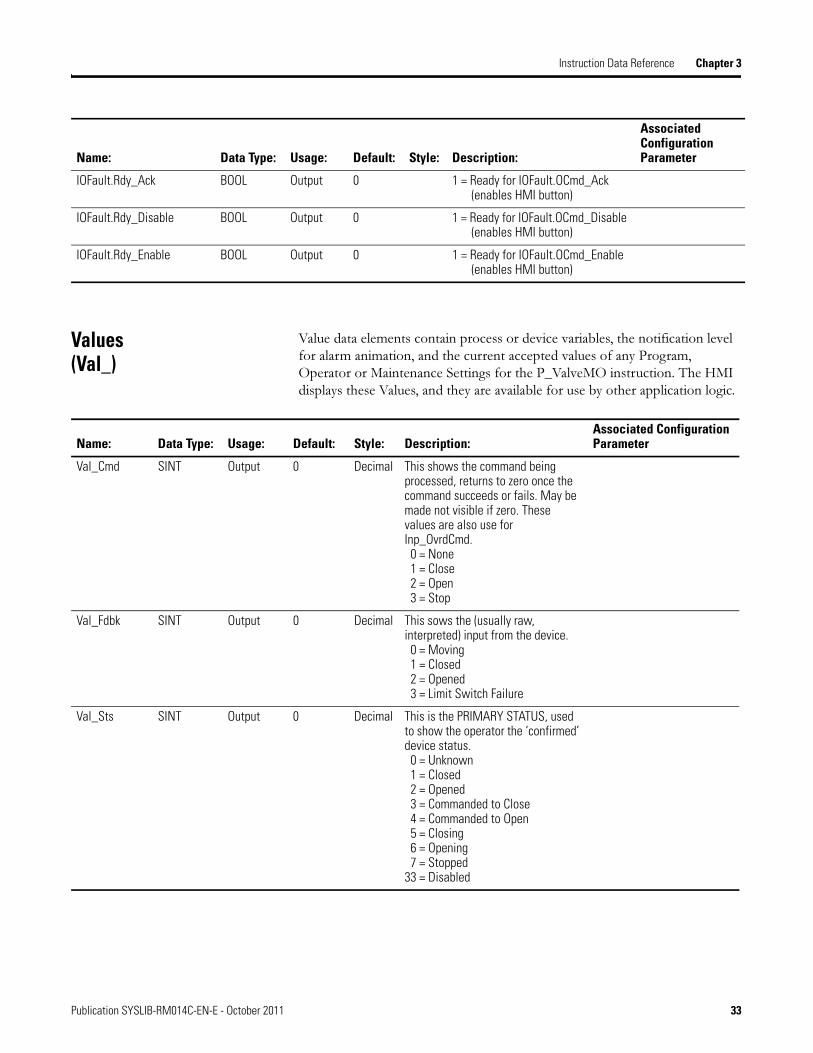
Values (Val_) . . . . . . . . . . . . . . . . . . . . . . . . . . . . . . . . . . . . . . . . . . . . . 33
Status (Sts_) . . . . . . . . . . . . . . . . . . . . . . . . . . . . . . . . . . . . . . . . . . . . . . 35
Device Status . . . . . . . . . . . . . . . . . . . . . . . . . . . . . . . . . . . . . . . . . . 35
Mode Status . . . . . . . . . . . . . . . . . . . . . . . . . . . . . . . . . . . . . . . . . . . 36
Alarm Status . . . . . . . . . . . . . . . . . . . . . . . . . . . . . . . . . . . . . . . . . . . 37
vPublication SYSLIB-RM014C-EN-E - October 2011 v
Table of Contents
Chapter 4HMI Reference Graphic Symbols . . . . . . . . . . . . . . . . . . . . . . . . . . . . . . . . . . . . . . . . . . 39
State Indicators . . . . . . . . . . . . . . . . . . . . . . . . . . . . . . . . . . . . . . . . 40
Mode Indicators . . . . . . . . . . . . . . . . . . . . . . . . . . . . . . . . . . . . . . . . 42
Alarm Indicators . . . . . . . . . . . . . . . . . . . . . . . . . . . . . . . . . . . . . . . 43
Using Graphics Symbols . . . . . . . . . . . . . . . . . . . . . . . . . . . . . . . . . 44
Faceplate . . . . . . . . . . . . . . . . . . . . . . . . . . . . . . . . . . . . . . . . . . . . . . . . . 44
Operator Tab . . . . . . . . . . . . . . . . . . . . . . . . . . . . . . . . . . . . . . . . . . 45
Alarms Tab. . . . . . . . . . . . . . . . . . . . . . . . . . . . . . . . . . . . . . . . . . . . 49
Maintenance Tab . . . . . . . . . . . . . . . . . . . . . . . . . . . . . . . . . . . . . . . 51
Engineering Tab. . . . . . . . . . . . . . . . . . . . . . . . . . . . . . . . . . . . . . . . 55
Alarm Configuration Tab . . . . . . . . . . . . . . . . . . . . . . . . . . . . . . . . 63
Motor Operated Valve Faceplate Help. . . . . . . . . . . . . . . . . . . . . . 65
vi Publication SYSLIB-RM014C-EN-E - October 2011
Preface
Use of this Document This document provides a programmer with details on the P_ValveMO instruction for a Logix-based controller. You should already be familiar with how the Logix-based controller stores and processes data.
Novice programmers should read all the details about an instruction before using the instruction. Experienced programmers can refer to the instruction information to verify details.
Conventions and Related Terms
Set and Clear
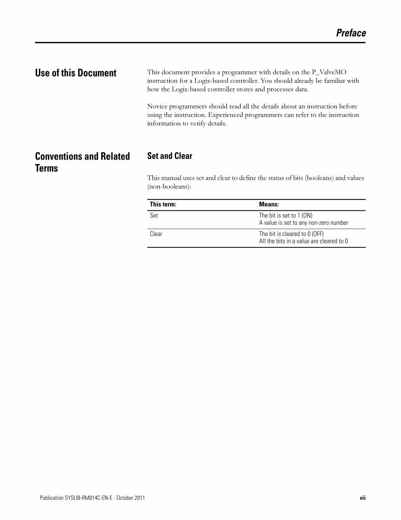
This manual uses set and clear to define the status of bits (booleans) and values (non-booleans):
This term: Means:
Set The bit is set to 1 (ON) A value is set to any non-zero number
Clear The bit is cleared to 0 (OFF) All the bits in a value are cleared to 0
viiPublication SYSLIB-RM014C-EN-E - October 2011 vii

Preface
Edge and Level
This manual uses Edge and Level to describe how bit (BOOL) Commands, Settings, Configurations, and Inputs to this instruction are sent by other logic
and processed by this instruction.
Send/Receive Method: Description:
Edge • Action is triggered by ‘rising edge’ transition of input (0-1)
• Separate inputs are provided for complementary functions (such as ‘enable’ and ‘disable’)
• Sending logic SETS the bit (writes a 1) to initiate the action; this instruction CLEARS the bit (to 0) immediately, then acts on the request, if possible
• Ladder Diagram (LD): use conditioned OTL (Latch) to send
• Structured Text (ST): use conditional assignment [if (condition) then bit:=1;] to send
• Function Block Diagram (FBD): OREF writes a 1 or 0 every scan, should use Level, not Edge
Edge-triggering allows multiple senders per Command, Setting, Configuration, or Input (many-to-one relationship).
Level • Action (‘enable’) is triggered by input being at a level (in a state, usually 1)
• Opposite action (‘disable’) is triggered by input being in opposite state (0)
• Sending logic SETS the bit (writes a 1) or CLEARS the bit (writes a 0); this instruction does not change the bit
• LD: use OTE (Energize) to send
• ST: use unconditional assignment [bit: = expression_resulting_in_1_or_0;] or ‘if-then-else’ logic [if (condition) then bit: = 1; else bit: = 0;]
• FBD: use OREF to the input bit
Level triggering allows only one sender to drive each Level input on the instruction (one-to-one relationship restriction).
IMPORTANT All Operator Commands (OCmd_) and Maintenance Commands (MCmd_) are Edge triggered. The HMI Graphic Symbol or Faceplate SETS (writes a 1 to) each Command bit and the Instruction CLEARS (writes a 0 to) the Command bit, then performs the function, if possible.
viii Publication SYSLIB-RM014C-EN-E - October 2011
Preface
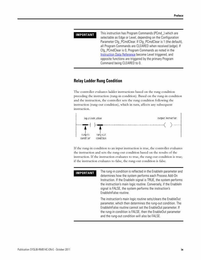
Relay Ladder Rung Condition
The controller evaluates ladder instructions based on the rung condition preceding the instruction (rung-in condition). Based on the rung-in condition and the instruction, the controller sets the rung condition following the instruction (rung-out condition), which in turn, affects any subsequent instruction.
If the rung-in condition to an input instruction is true, the controller evaluates the instruction and sets the rung-out condition based on the results of the instruction. If the instruction evaluates to true, the rung-out condition is true; if the instruction evaluates to false, the rung-out condition is false.
IMPORTANT This instruction has Program Commands (PCmd_) which are selectable as Edge or Level, depending on the Configuration Parameter Cfg_PCmdClear. If Cfg_PCmdClear is 1 (the default), all Program Commands are CLEARED when received (edge). If Cfg_PCmdClear is 0, Program Commands as noted in the Instruction Data Reference become Level triggered, and opposite functions are triggered by the primary Program Command being CLEARED to 0.
IMPORTANT The rung-in condition is reflected in the EnableIn parameter and determines how the system performs each Process Add-On Instruction. If the EnableIn signal is TRUE, the system performs the instruction’s main logic routine. Conversely, if the EnableIn signal is FALSE, the system performs the instruction’s EnableInFalse routine.
The instruction’s main logic routine sets/clears the EnableOut parameter, which then determines the rung-out condition. The EnableInFalse routine cannot set the EnableOut parameter. If the rung-in condition is FALSE, then the EnableOut parameter and the rung-out condition will also be FALSE.
Publication SYSLIB-RM014C-EN-E - October 2011 ix
Preface
Pre-Scan
During the transition into RUN, the controller performs a pre-scan before the first logic scan. Pre-scan is a special scan of all routines in the controller. The controller scans all main routines and subroutines during pre-scan, but ignores jumps that could skip the execution of instructions. The controller executes all FOR loops and subroutine calls. If a subroutine is called more than once, it is executed each time it is called. The controller uses pre-scan instructions to reset non-retentive data values.
During pre-scan, input values are not current and outputs are not written. The following conditions generate pre-scan:
• toggle from Program to Run mode.
• automatically enter Run mode from a power-up condition.
Pre-scan does not occur for a program when:
• the program becomes scheduled while the controller is running.
• the program is unscheduled when the controller enters Run mode.
IMPORTANT The pre-scan process performs the Process Add-On Instruction’s logic routine as all FALSE and then performs its pre-scan routine as TRUE.
x Publication SYSLIB-RM014C-EN-E - October 2011

Preface
Function Block States
The controller evaluates function block instructions based on the state of different conditions.
Every function block instruction also includes EnableIn and EnableOut parameters.
If the EnableIn parameter is not wired, the instruction always executes as normal and EnableIn remains set. If you clear EnableIn, it changes to set the next time the instruction executes.
Possible Condition: Description:
Pre-scan Pre-scan for function block routines is the same as for relay ladder routines. The only difference is that the Enableln parameter for each function block instruction is cleared during pre-scan.
Instruction first scan Instruction first scan refers to the first time an instruction is executed after pre-scan. The controller uses instruction first scan to read current inputs and determine the appropriate state to be in.
Instruction first run Instruction first run refers to the first time the instruction executes with a new instance of a data structure. The controller uses instruction first run to generate coefficients and other data stores that do not change for a function block after initial download.
IMPORTANT When programming in function block, restrict the range
of engineering units to ±10±15 because internal floating point calculations are done using single precision floating point. Engineering units outside of this range may result in a loss of accuracy if results approach the limitations of
single precision floating point (±10±38).
Publication SYSLIB-RM014C-EN-E - October 2011 xi

Preface
Entering Text in FactoryTalk View SE
When entering data into String Input fields in FactoryTalk View SE, the data is not saved to the tag until the user presses the Enter key. When the Input Field is enabled, its border changes based on the state of the input:
• When the Input Field is Active (the cursor is in the field), the Input Field border is a solid line.
• If the user modifies the data in the input field and moves to a different field without pressing the Enter key, the border remains a solid line indicating that the data has not been saved to the tag.
• If the data in the Input Field has not changed or has been written to the controller tag, the border is a dashed line.
EXAMPLE
EXAMPLE
EXAMPLE
xii Publication SYSLIB-RM014C-EN-E - October 2011
Chapter 1
Overview
The P_ValveMO (Motor-Operated Valve) Add-On Instruction is used to operate (open and close) a motor-operated valve in a variety of modes, monitoring for fault conditions.
Use when:
• You need to operate a motor-operated valve or other valve that requires separate Open and Close outputs. The valve may have, but does not require, limit switch feedback for the ends of travel. The valve may or may not require an output to trigger a ‘valve stop’ function, such as breaking a seal-in circuit on the valve operator to stop travel or switch the direction of travel.
Do NOT use when:
• You need to operate a single-solenoid spring-return valve (fail closed or fail open). Use the P_ValveSO Solenoid-Operated Valve Add-On Instruction instead.
• You need to operate a multi-solenoid valve such as a Mix-Proof Valve that has positions (such as CIP) other than ‘opened’ and ‘closed’. Use the P_ValveMP Mix-Proof Valve Add-On Instruction instead.
• You need to monitor a valve that is primarily operated by hand. The valve could support a ‘trip’ output to drive it to a ‘safe’ position. Use the P_ValveHO Hand-Operated Valve Add-On Instruction instead.
• You have a throttling (continuously variable) valve. Use the P_AOut Analog Output Instruction, the P_ValveC Control Valve Instruction, or operate the valve directly from a PIDE or PID built-in instruction.
• For some valves, you may also find the P_DOut (Discrete Output), P_D4SD (Discrete Four-State Device), or P_nPos (n-Position Device) Instruction suitable.
1Publication SYSLIB-RM014C-EN-E - October 2011 1
Chapter 1 Overview
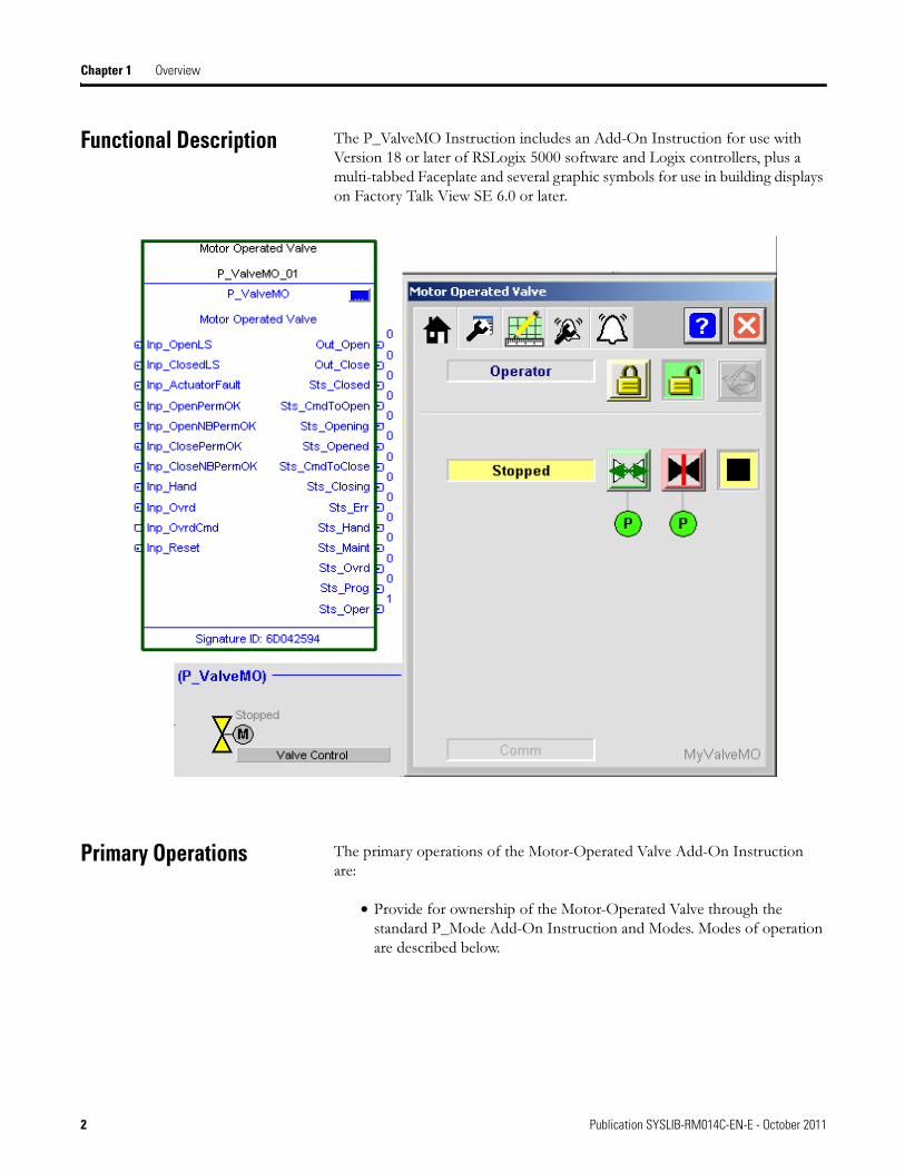
Functional Description The P_ValveMO Instruction includes an Add-On Instruction for use with Version 18 or later of RSLogix 5000 software and Logix controllers, plus a multi-tabbed Faceplate and several graphic symbols for use in building displays on Factory Talk View SE 6.0 or later.
Primary Operations The primary operations of the Motor-Operated Valve Add-On Instruction are:
• Provide for ownership of the Motor-Operated Valve through the standard P_Mode Add-On Instruction and Modes. Modes of operation are described below.
2 Publication SYSLIB-RM014C-EN-E - October 2011

Overview Chapter 1
• Provide the ability to Open or Close a Motor-Operated Valve, and if the valve is so equipped, monitor open/close limit switch feedback to verify the Motor-Operated Valve is Opened or Closed. Whether or not the Motor-Operated Valve HAS each of the feedback limit switches can be configured at the Engineer level. Whether or not to USE each of the feedback limit switches can be configured at the Maintenance level.
• Provide an optional ability to Stop the motion of the Motor-Operated Valve, and a Stop Output, which is typically used to break the valve motor ‘seal-in’ circuit and stop the actuating motor. If the option to allow Stopping the valve is enabled, the instruction allows the operator to reverse travel (e.g., select ‘Open’ while closing), which will stop the valve, then move it in the opposite direction.
• Provide an Alarm for Full Stall if the valve feedback indicates it did not move off the original position within a configured amount of time when commanded to the other position. Provide an Alarm for Transit Stall if the valve feedback indicates the valve moved from the original position but did not reach the target position within a configured amount of time. The Transit Stall or Full Stall condition can optionally de-energize the outputs to the valve, requiring a reset.
• Provide a limit switch Failure indication if the limit switches indicate the valve is not closed, not opened and not moving (invalid state). Provide a configuration for the failure state: whether both switches are ON or both switches are OFF to indicate limit switch failure.
• Provide for Open Permissives (Bypassable and Non-Bypassable), which are conditions that allow the Motor-Operated Valve to Open, and Close Permissives (Bypassable and Non-Bypassable), which are conditions that allow the Motor-Operated Valve to Close. Provide Maintenance the capability to bypass the Bypassable Permissives.
• Provide Maintenance the capability to Disable (soft lock out) the Motor-Operated Valve.
• Monitor an I/O Fault input and Alarm on an I/O Fault. The I/O Fault condition can optionally de-energize the outputs to the valve, requiring a reset.
• In Override mode, provide Override inputs which determine whether the Override is to Open, Close or Stop the Motor-Operated Valve. See Modes below for more information on Override.
Publication SYSLIB-RM014C-EN-E - October 2011 3
Chapter 1 Overview
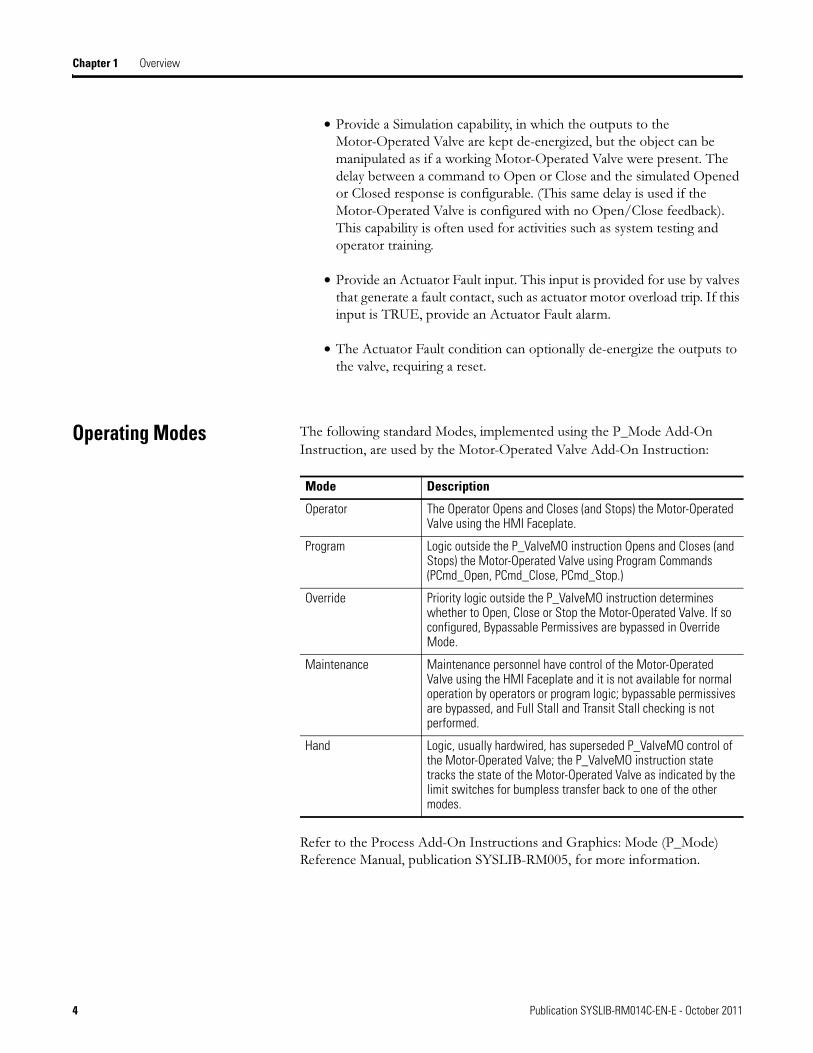
• Provide a Simulation capability, in which the outputs to the Motor-Operated Valve are kept de-energized, but the object can be manipulated as if a working Motor-Operated Valve were present. The delay between a command to Open or Close and the simulated Opened or Closed response is configurable. (This same delay is used if the Motor-Operated Valve is configured with no Open/Close feedback). This capability is often used for activities such as system testing and operator training.
• Provide an Actuator Fault input. This input is provided for use by valves that generate a fault contact, such as actuator motor overload trip. If this input is TRUE, provide an Actuator Fault alarm.
• The Actuator Fault condition can optionally de-energize the outputs to the valve, requiring a reset.
Operating Modes The following standard Modes, implemented using the P_Mode Add-On
Instruction, are used by the Motor-Operated Valve Add-On Instruction:
Refer to the Process Add-On Instructions and Graphics: Mode (P_Mode) Reference Manual, publication SYSLIB-RM005, for more information.
Mode Description
Operator The Operator Opens and Closes (and Stops) the Motor-Operated Valve using the HMI Faceplate.
Program Logic outside the P_ValveMO instruction Opens and Closes (and Stops) the Motor-Operated Valve using Program Commands (PCmd_Open, PCmd_Close, PCmd_Stop.)
Override Priority logic outside the P_ValveMO instruction determines whether to Open, Close or Stop the Motor-Operated Valve. If so configured, Bypassable Permissives are bypassed in Override Mode.
Maintenance Maintenance personnel have control of the Motor-Operated Valve using the HMI Faceplate and it is not available for normal operation by operators or program logic; bypassable permissives are bypassed, and Full Stall and Transit Stall checking is not performed.
Hand Logic, usually hardwired, has superseded P_ValveMO control of the Motor-Operated Valve; the P_ValveMO instruction state tracks the state of the Motor-Operated Valve as indicated by the limit switches for bumpless transfer back to one of the other modes.
4 Publication SYSLIB-RM014C-EN-E - October 2011
Overview Chapter 1
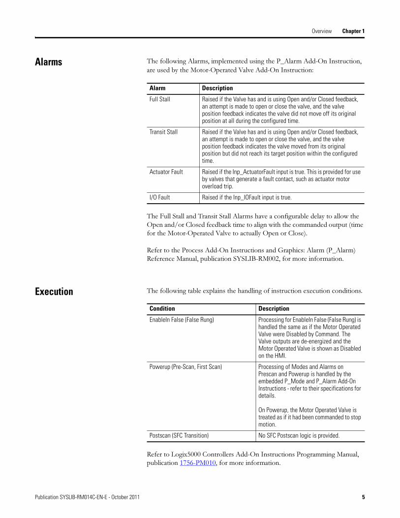
Alarms The following Alarms, implemented using the P_Alarm Add-On Instruction,
are used by the Motor-Operated Valve Add-On Instruction:
The Full Stall and Transit Stall Alarms have a configurable delay to allow the Open and/or Closed feedback time to align with the commanded output (time for the Motor-Operated Valve to actually Open or Close).
Refer to the Process Add-On Instructions and Graphics: Alarm (P_Alarm) Reference Manual, publication SYSLIB-RM002, for more information.
Execution The following table explains the handling of instruction execution conditions.
Refer to Logix5000 Controllers Add-On Instructions Programming Manual, publication 1756-PM010, for more information.
Alarm Description
Full Stall Raised if the Valve has and is using Open and/or Closed feedback, an attempt is made to open or close the valve, and the valve position feedback indicates the valve did not move off its original position at all during the configured time.
Transit Stall Raised if the Valve has and is using Open and/or Closed feedback, an attempt is made to open or close the valve, and the valve position feedback indicates the valve moved from its original position but did not reach its target position within the configured time.
Actuator Fault Raised if the Inp_ActuatorFault input is true. This is provided for use by valves that generate a fault contact, such as actuator motor overload trip.
I/O Fault Raised if the Inp_IOFault input is true.
Condition Description
EnableIn False (False Rung) Processing for EnableIn False (False Rung) is handled the same as if the Motor Operated Valve were Disabled by Command. The Valve outputs are de-energized and the Motor Operated Valve is shown as Disabled on the HMI.
Powerup (Pre-Scan, First Scan) Processing of Modes and Alarms on Prescan and Powerup is handled by the embedded P_Mode and P_Alarm Add-On Instructions - refer to their specifications for details.
On Powerup, the Motor Operated Valve is treated as if it had been commanded to stop motion.
Postscan (SFC Transition) No SFC Postscan logic is provided.
Publication SYSLIB-RM014C-EN-E - October 2011 5
Chapter 1 Overview
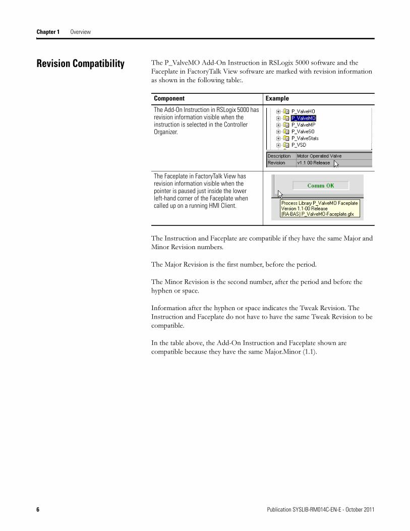
Revision Compatibility The P_ValveMO Add-On Instruction in RSLogix 5000 software and the Faceplate in FactoryTalk View software are marked with revision information as shown in the following table:.
The Instruction and Faceplate are compatible if they have the same Major and Minor Revision numbers.
The Major Revision is the first number, before the period.
The Minor Revision is the second number, after the period and before the hyphen or space.
Information after the hyphen or space indicates the Tweak Revision. The Instruction and Faceplate do not have to have the same Tweak Revision to be compatible.
In the table above, the Add-On Instruction and Faceplate shown are compatible because they have the same Major.Minor (1.1).
Component Example
The Add-On Instruction in RSLogix 5000 has revision information visible when the instruction is selected in the Controller Organizer.
The Faceplate in FactoryTalk View has revision information visible when the pointer is paused just inside the lower left-hand corner of the Faceplate when called up on a running HMI Client.
6 Publication SYSLIB-RM014C-EN-E - October 2011
Chapter 2
Configuration Options
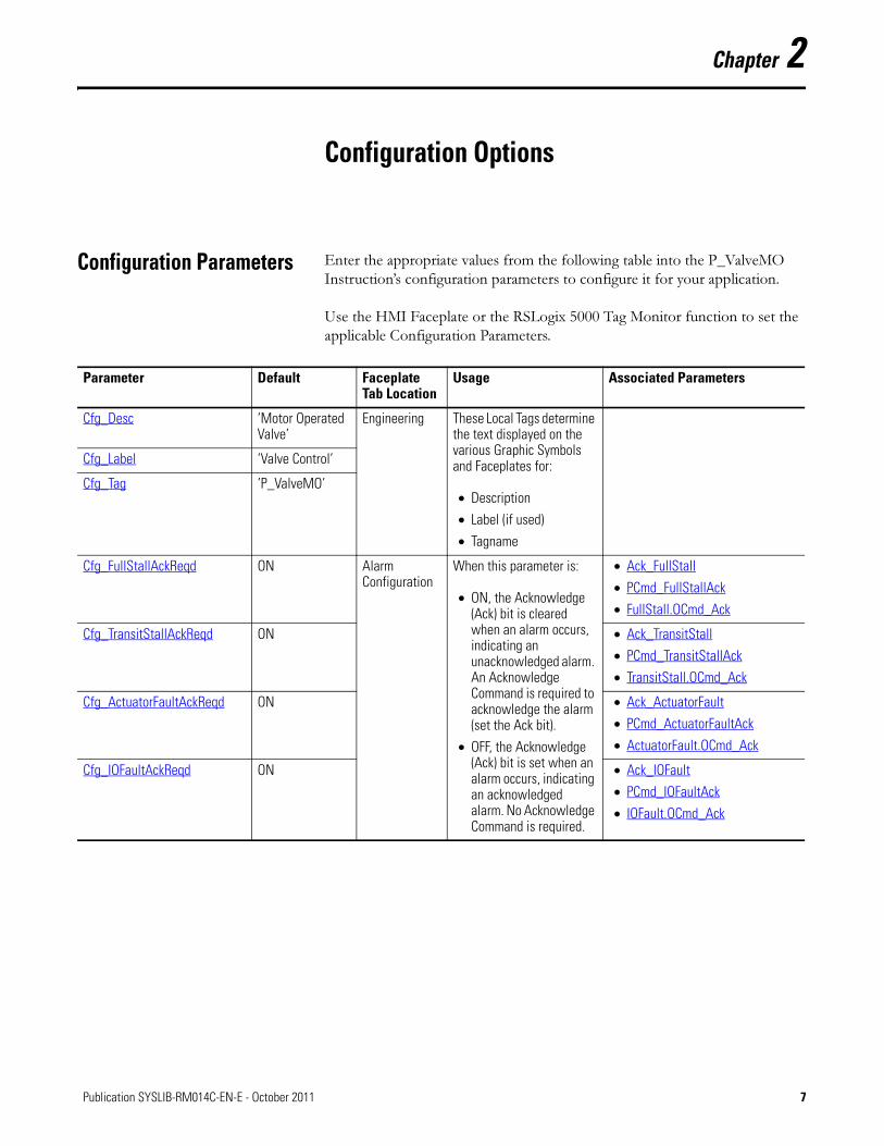
Configuration Parameters Enter the appropriate values from the following table into the P_ValveMO Instruction’s configuration parameters to configure it for your application.
Use the HMI Faceplate or the RSLogix 5000 Tag Monitor function to set the applicable Configuration Parameters.
Parameter Default Faceplate Tab Location
Usage Associated Parameters
Cfg_Desc ’Motor Operated Valve’
Engineering These Local Tags determine the text displayed on the various Graphic Symbols and Faceplates for:
• Description
• Label (if used)
• Tagname
Cfg_Label ’Valve Control’
Cfg_Tag ’P_ValveMO’
Cfg_FullStallAckReqd ON Alarm Configuration
When this parameter is:
• ON, the Acknowledge (Ack) bit is cleared when an alarm occurs, indicating an unacknowledged alarm. An Acknowledge Command is required to acknowledge the alarm (set the Ack bit).
• OFF, the Acknowledge (Ack) bit is set when an alarm occurs, indicating an acknowledged alarm. No Acknowledge Command is required.
• Ack_FullStall
• PCmd_FullStallAck
• FullStall.OCmd_Ack
Cfg_TransitStallAckReqd ON • Ack_TransitStall
• PCmd_TransitStallAck
• TransitStall.OCmd_Ack
Cfg_ActuatorFaultAckReqd ON • Ack_ActuatorFault
• PCmd_ActuatorFaultAck
• ActuatorFault.OCmd_Ack
Cfg_IOFaultAckReqd ON • Ack_IOFault
• PCmd_IOFaultAck
• IOFault.OCmd_Ack
7Publication SYSLIB-RM014C-EN-E - October 2011 7

Chapter 2 Configuration Options
Cfg_FullStallResetReqd OFF Alarm Configuration
When this parameter is:
• ON, the alarm status is latched ON when an alarm occurs. After the alarm condition returns to normal, a Reset is required to clear the alarm status.
IMPORTANT If the Reset clears the alarm, it also acknowledges the alarm.
• OFF, the alarm status is set when an alarm occurs and cleared when the alarm condition returns to normal. No Reset is required.
• Inp_Reset
• Alm_FullStall
• FullStall.OCmd_Reset
Cfg_TransitStallResetReqd OFF • Alm_TransitStall
• TransitStall.OCmd_Reset
Cfg_ActuatorFaultResetReqd OFF • Alm_ActuatorFault
• ActuatorFault.OCmd_Reset
Cfg_IOFaultResetReqd OFF • Alm_IOFault
• IOFault.OCmd_Reset
Cfg_FullStallT 15 sec Alarm Configuration
If an Open or Close Command is given to the valve and valve feedbacks are being used, the P_ValveMO instruction allows this much time for the feedbacks to show the valve has moved off its previous position before generating a Full Stall Alarm.
• Cfg_HasClosedLS
• Cfg_HasOpenLS
• Cfg_UseClosedLS
• Cfg_UseOpenLS
• OCmd_Close
• OCmd_Open
• PCmd_Close
• PCmd_Open
• Sts_Closing
• Sts_Opening
• Alm_FullStall
Cfg_FullStallSeverity
Cfg_TransitStallSeverity
Cfg_ActuatorFaultSeverity
Cfg_IOFaultSeverity
4
4
2
4
Alarm Configuration
These parameters determine the Severity of each alarm, and thus the color of alarm animations for each alarm.
Valid values are:
1 = Information (blue)2 = Warning (yellow)3 = Exception (red)4 = Fault (magenta)
• Val_Notify
Parameter Default Faceplate Tab Location
Usage Associated Parameters
8 Publication SYSLIB-RM014C-EN-E - October 2011
Configuration Options Chapter 2
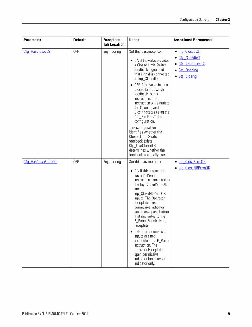
Cfg_HasClosedLS OFF Engineering Set this parameter to:
• ON if the valve provides a Closed Limit Switch feedback signal and that signal is connected to Inp_ClosedLS.
• OFF if the valve has no Closed Limit Switch feedback to this instruction. The instruction will simulate the Opening and Closing status using the Cfg_SimFdbkT time configuration.
This configuration identifies whether the Closed Limit Switch feedback exists. Cfg_UseClosedLS determines whether the feedback is actually used.
• Inp_ClosedLS
• Cfg_SimFdbkT
• Cfg_UseClosedLS
• Sts_Opening
• Sts_Closing
Cfg_HasClosePermObj OFF Engineering Set this parameter to:
• ON if this instruction has a P_Perm instruction connected to the Inp_ClosePermOK and Inp_CloseNBPermOK inputs. The Operator Faceplate close permissive indicator becomes a push button that navigates to the P_Perm (Permissives) Faceplate.
• OFF if the permissive inputs are not connected to a P_Perm instruction. The Operator Faceplate open permissive indicator becomes an indicator only.
• Inp_ClosePermOK
• Inp_CloseNBPermOK
Parameter Default Faceplate Tab Location
Usage Associated Parameters
Publication SYSLIB-RM014C-EN-E - October 2011 9
Chapter 2 Configuration Options
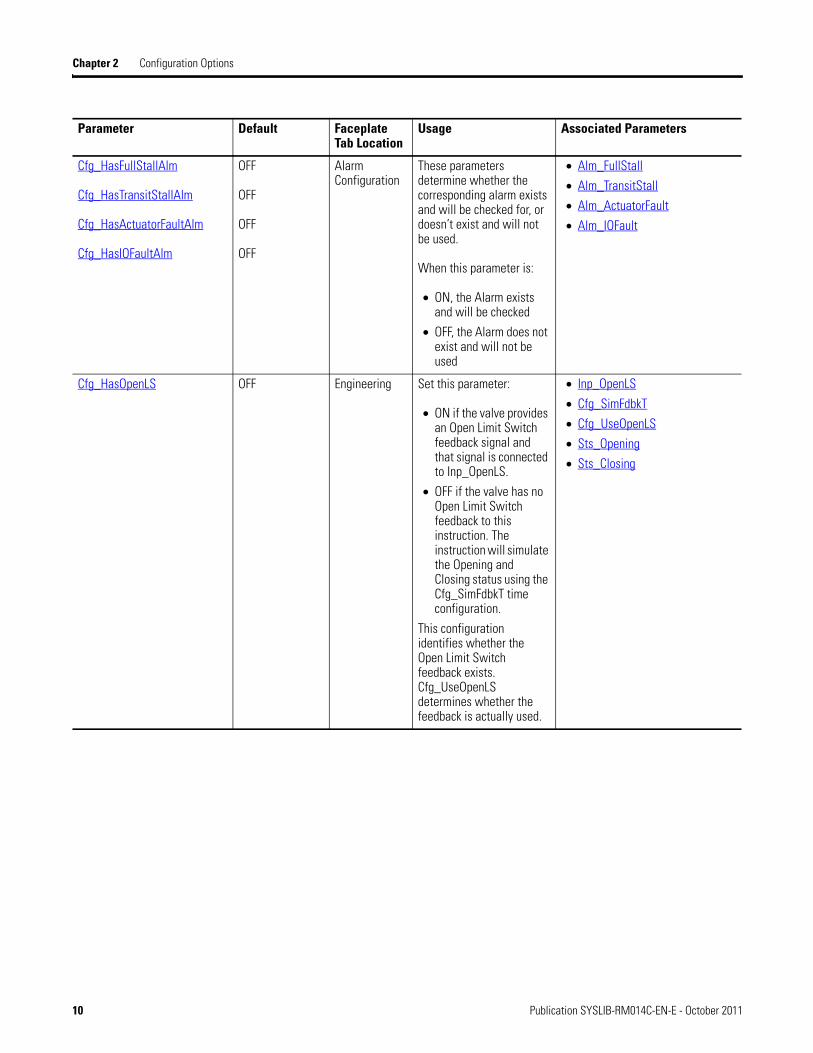
Cfg_HasFullStallAlm
Cfg_HasTransitStallAlm
Cfg_HasActuatorFaultAlm
Cfg_HasIOFaultAlm
OFF
OFF
OFF
OFF
Alarm Configuration
These parameters determine whether the corresponding alarm exists and will be checked for, or doesn’t exist and will not be used.
When this parameter is:
• ON, the Alarm exists and will be checked
• OFF, the Alarm does not exist and will not be used
• Alm_FullStall
• Alm_TransitStall
• Alm_ActuatorFault
• Alm_IOFault
Cfg_HasOpenLS OFF Engineering Set this parameter:
• ON if the valve provides an Open Limit Switch feedback signal and that signal is connected to Inp_OpenLS.
• OFF if the valve has no Open Limit Switch feedback to this instruction. The instruction will simulate the Opening and Closing status using the Cfg_SimFdbkT time configuration.
This configuration identifies whether the Open Limit Switch feedback exists. Cfg_UseOpenLS determines whether the feedback is actually used.
• Inp_OpenLS
• Cfg_SimFdbkT
• Cfg_UseOpenLS
• Sts_Opening
• Sts_Closing
Parameter Default Faceplate Tab Location
Usage Associated Parameters
10 Publication SYSLIB-RM014C-EN-E - October 2011
Configuration Options Chapter 2
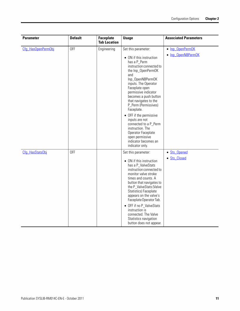
Cfg_HasOpenPermObj OFF Engineering Set this parameter:
• ON if this instruction has a P_Perm instruction connected to the Inp_OpenPermOK and Inp_OpenNBPermOK inputs. The Operator Faceplate open permissive indicator becomes a push button that navigates to the P_Perm (Permissives) Faceplate.
• OFF if the permissive inputs are not connected to a P_Perm instruction. The Operator Faceplate open permissive indicator becomes an indicator only.
• Inp_OpenPermOK
• Inp_OpenNBPermOK
Cfg_HasStatsObj OFF Set this parameter:
• ON if this instruction has a P_ValveStats instruction connected to monitor valve stroke times and counts. A button that navigates to the P_ValveStats (Valve Statistics) Faceplate appears on the valve's Faceplate Operator Tab.
• OFF if no P_ValveStats instruction is connected. The Valve Statistics navigation button does not appear.
• Sts_Opened
• Sts_Closed
Parameter Default Faceplate Tab Location
Usage Associated Parameters
Publication SYSLIB-RM014C-EN-E - October 2011 11
Chapter 2 Configuration Options
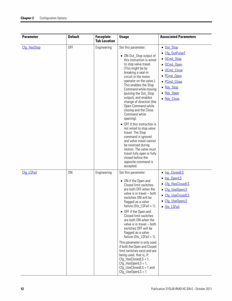
Cfg_HasStop OFF Engineering Set this parameter:
• ON Out_Stop output of this instruction is wired to stop valve travel. (This might be by breaking a seal-in circuit in the motor operator on the valve.). This enables the Stop Command while moving (pulsing the Out_Stop output), and enables change of direction (the Open Command while closing and the Close Command while opening).
• OFF if this instruction is not wired to stop valve travel. The Stop command is ignored and valve travel cannot be reversed during motion. The valve must travel fully open or fully closed before the opposite command is accepted.
• Out_Stop
• Cfg_OutPulseT
• OCmd_Stop
• OCmd_Open
• OCmd_Close
• PCmd_Open
• PCmd_Close
• Rdy_Stop
• Rdy_Open
• Rdy_Close
Cfg_LSFail ON Engineering Set this parameter:
• ON if the Open and Closed limit switches are both OFF when the valve is in travel – both switches ON will be flagged as a valve failure (Sts_LSFail = 1).
• OFF if the Open and Closed limit switches are both ON when the valve is in travel – both switches OFF will be flagged as a valve failure (Sts_LSFail = 1).
This parameter is only used if both the Open and Closed limit switches exist and are being used, that is, if: Cfg_HasClosedLS = 1, Cfg_HasOpenLS = 1, Cfg_UseClosedLS = 1 and Cfg_UseOpenLS = 1
• Inp_ClosedLS
• Inp_OpenLS
• Cfg_HasClosedLS
• Cfg_UseOpenLS
• Cfg_UseClosedLS
• Cfg_UseOpenLS
• Sts_LSFail
Parameter Default Faceplate Tab Location
Usage Associated Parameters
12 Publication SYSLIB-RM014C-EN-E - October 2011
Configuration Options Chapter 2
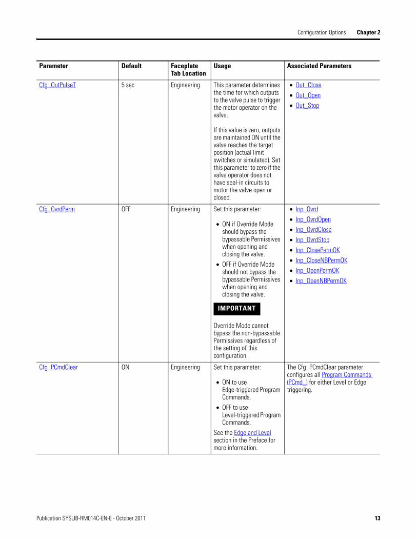
Cfg_OutPulseT 5 sec Engineering This parameter determines the time for which outputs to the valve pulse to trigger the motor operator on the valve.
If this value is zero, outputs are maintained ON until the valve reaches the target position (actual limit switches or simulated). Set this parameter to zero if the valve operator does not have seal-in circuits to motor the valve open or closed.
• Out_Close
• Out_Open
• Out_Stop
Cfg_OvrdPerm OFF Engineering Set this parameter:
• ON if Override Mode should bypass the bypassable Permissives when opening and closing the valve.
• OFF if Override Mode should not bypass the bypassable Permissives when opening and closing the valve.
IMPORTANT Override Mode cannot bypass the non-bypassable Permissives regardless of the setting of this configuration.
• Inp_Ovrd
• Inp_OvrdOpen
• Inp_OvrdClose
• Inp_OvrdStop
• Inp_ClosePermOK
• Inp_CloseNBPermOK
• Inp_OpenPermOK
• Inp_OpenNBPermOK
Cfg_PCmdClear ON Engineering Set this parameter:
• ON to use Edge-triggered Program Commands.
• OFF to use Level-triggered Program Commands.
See the Edge and Level section in the Preface for more information.
The Cfg_PCmdClear parameter configures all Program Commands (PCmd_) for either Level or Edge triggering.
Parameter Default Faceplate Tab Location
Usage Associated Parameters
Publication SYSLIB-RM014C-EN-E - October 2011 13
Chapter 2 Configuration Options
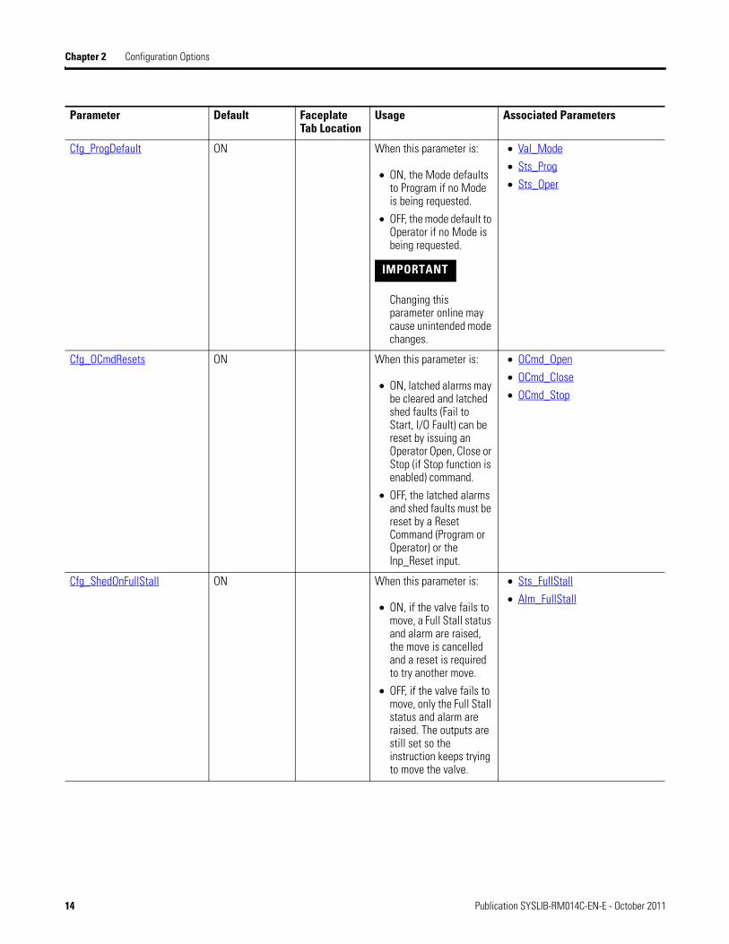
Cfg_ProgDefault ON When this parameter is:
• ON, the Mode defaults to Program if no Mode is being requested.
• OFF, the mode default to Operator if no Mode is being requested.
IMPORTANT Changing this parameter online may cause unintended mode changes.
• Val_Mode
• Sts_Prog
• Sts_Oper
Cfg_OCmdResets ON When this parameter is:
• ON, latched alarms may be cleared and latched shed faults (Fail to Start, I/O Fault) can be reset by issuing an Operator Open, Close or Stop (if Stop function is enabled) command.
• OFF, the latched alarms and shed faults must be reset by a Reset Command (Program or Operator) or the Inp_Reset input.
• OCmd_Open
• OCmd_Close
• OCmd_Stop
Cfg_ShedOnFullStall ON When this parameter is:
• ON, if the valve fails to move, a Full Stall status and alarm are raised, the move is cancelled and a reset is required to try another move.
• OFF, if the valve fails to move, only the Full Stall status and alarm are raised. The outputs are still set so the instruction keeps trying to move the valve.
• Sts_FullStall
• Alm_FullStall
Parameter Default Faceplate Tab Location
Usage Associated Parameters
14 Publication SYSLIB-RM014C-EN-E - October 2011
Configuration Options Chapter 2
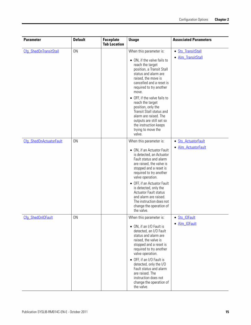
Cfg_ShedOnTransitStall ON When this parameter is:
• ON, if the valve fails to reach the target position, a Transit Stall status and alarm are raised, the move is cancelled and a reset is required to try another move.
• OFF, if the valve fails to reach the target position, only the Transit Stall status and alarm are raised. The outputs are still set so the instruction keeps trying to move the valve.
• Sts_TransitStall
• Alm_TransitStall
Cfg_ShedOnActuatorFault ON When this parameter is:
• ON, if an Actuator Fault is detected, an Actuator Fault status and alarm are raised, the valve is stopped and a reset is required to try another valve operation.
• OFF, if an Actuator Fault is detected, only the Actuator Fault status and alarm are raised. The instruction does not change the operation of the valve.
• Sts_ActuatorFault
• Alm_ActuatorFault
Cfg_ShedOnIOFault ON When this parameter is:
• ON, if an I/O Fault is detected, an I/O Fault status and alarm are raised, the valve is stopped and a reset is required to try another valve operation.
• OFF, if an I/O Fault is detected, only the I/O Fault status and alarm are raised. The instruction does not change the operation of the valve.
• Sts_IOFault
• Alm_IOFault
Parameter Default Faceplate Tab Location
Usage Associated Parameters
Publication SYSLIB-RM014C-EN-E - October 2011 15
Chapter 2 Configuration Options
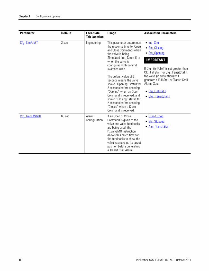
Cfg_SimFdbkT 2 sec Engineering This parameter determines the response time for Open and Close Commands when the valve is being Simulated (Inp_Sim = 1) or when the valve is configured with no limit switches used.
The default value of 2 seconds means the valve shows “Opening” status for 2 seconds before showing “Opened” when an Open Command is received, and shows “Closing” status for 2 seconds before showing “Closed” when a Close Command is received.
• Inp_Sim
• Sts_Closing
• Sts_Opening
IMPORTANT If Cfg_SimFdbkT is set greater than Cfg_FullStallT or Cfg_TransitStallT, the valve (in simulation) will generate a Full Stall or Transit Stall Alarm. See:
• Cfg_FullStallT
• Cfg_TransitStallT
Cfg_TransitStallT 60 sec Alarm Configuration
If an Open or Close Command is given to the valve and valve feedbacks are being used, the P_ValveMO instruction allows this much time for the feedbacks to show the valve has reached its target position before generating a Transit Stall Alarm.
• OCmd_Stop
• Sts_Stopped
• Alm_TransitStall
Parameter Default Faceplate Tab Location
Usage Associated Parameters
16 Publication SYSLIB-RM014C-EN-E - October 2011

Configuration Options Chapter 2
Cfg_UseClosedLS OFF Maintenance This parameter is typically used on a temporary basis by Maintenance. Set this parameter:
• ON if the Closed Limit Switch feedback signal connected to Inp_ClosedLS should be used for Full Stall and Transit Stall checking.
• OFF to disable the feedback checking and disable the Full Stall and Transit Stall alarms on closing. The instruction will instead simulate the Opening and Closing status using the Cfg_SimFdbkT time configuration.
This configuration identifies whether the Closed Limit Switch feedback should be used. Cfg_HasClosedLS determines whether the feedback exists.
If the feedback does not exist (Cfg_HasClosedLS = 0), the Cfg_UseClosedLS bit is forced to Off.
• Inp_ClosedLS
• Cfg_SimFdbkT
• Cfg_HasClosedLS
• Sts_Opening
• Sts_Closing
• Alm_FullStall
• Alm_TransitStall
Parameter Default Faceplate Tab Location
Usage Associated Parameters
Publication SYSLIB-RM014C-EN-E - October 2011 17
Chapter 2 Configuration Options
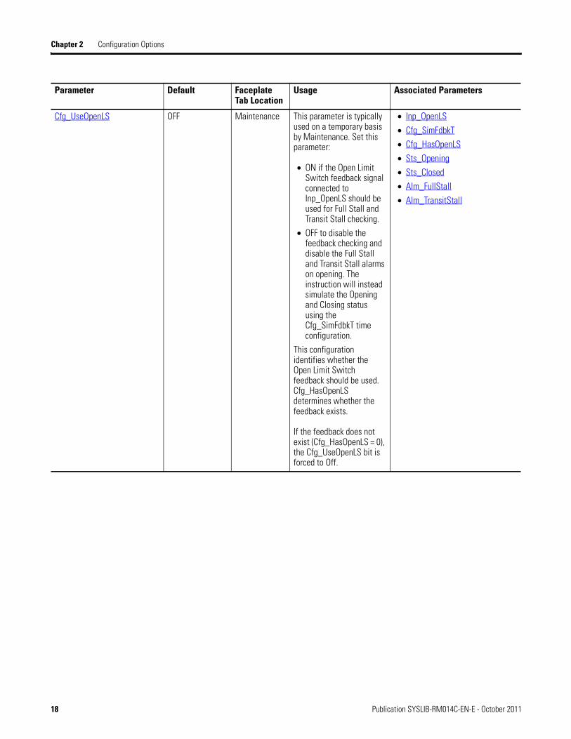
Cfg_UseOpenLS OFF Maintenance This parameter is typically used on a temporary basis by Maintenance. Set this parameter:
• ON if the Open Limit Switch feedback signal connected to Inp_OpenLS should be used for Full Stall and Transit Stall checking.
• OFF to disable the feedback checking and disable the Full Stall and Transit Stall alarms on opening. The instruction will instead simulate the Opening and Closing status using the Cfg_SimFdbkT time configuration.
This configuration identifies whether the Open Limit Switch feedback should be used. Cfg_HasOpenLS determines whether the feedback exists.
If the feedback does not exist (Cfg_HasOpenLS = 0), the Cfg_UseOpenLS bit is forced to Off.
• Inp_OpenLS
• Cfg_SimFdbkT
• Cfg_HasOpenLS
• Sts_Opening
• Sts_Closed
• Alm_FullStall
• Alm_TransitStall
Parameter Default Faceplate Tab Location
Usage Associated Parameters
18 Publication SYSLIB-RM014C-EN-E - October 2011
Chapter 3
Instruction Data Reference
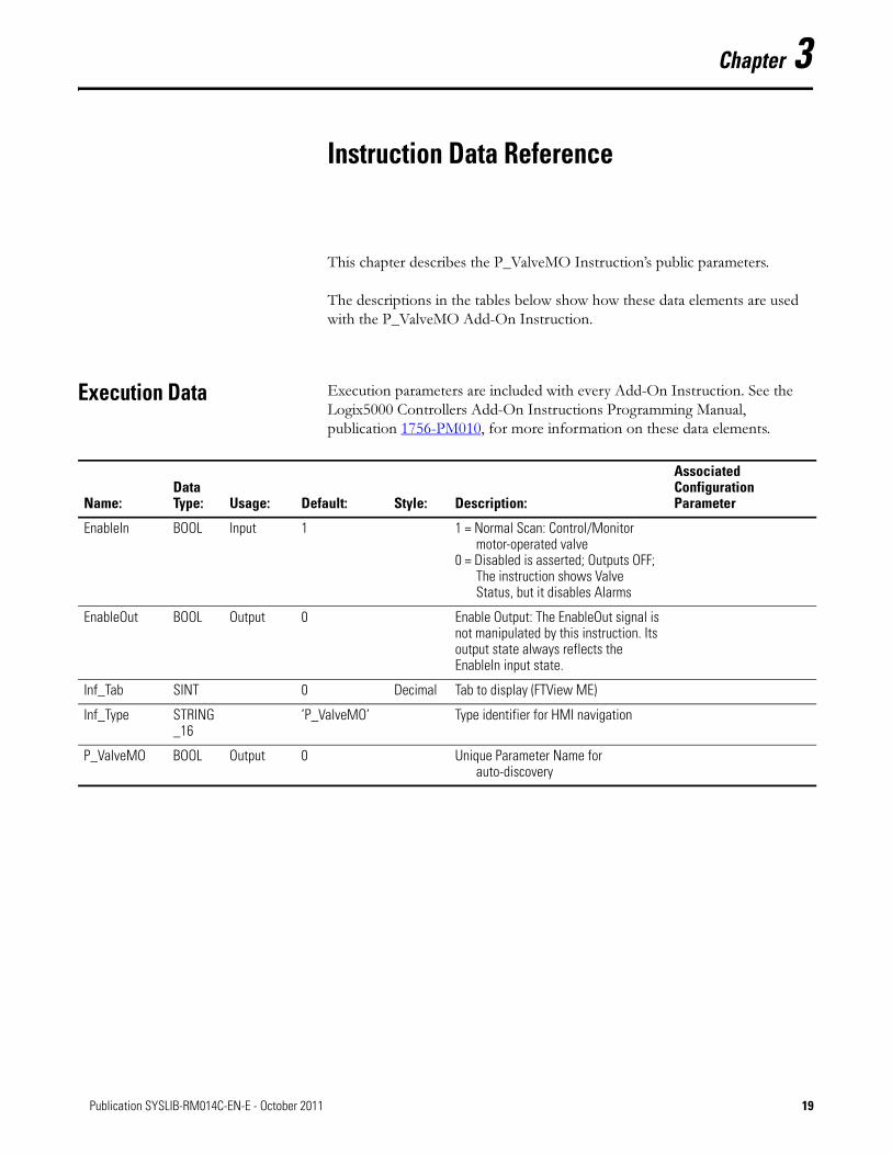
This chapter describes the P_ValveMO Instruction’s public parameters.
The descriptions in the tables below show how these data elements are used with the P_ValveMO Add-On Instruction.
Execution Data Execution parameters are included with every Add-On Instruction. See the Logix5000 Controllers Add-On Instructions Programming Manual, publication 1756-PM010, for more information on these data elements.
Name:Data Type: Usage: Default: Style: Description:
Associated Configuration Parameter
EnableIn BOOL Input 1 1 = Normal Scan: Control/Monitor motor-operated valve
0 = Disabled is asserted; Outputs OFF; The instruction shows Valve Status, but it disables Alarms
EnableOut BOOL Output 0 Enable Output: The EnableOut signal is not manipulated by this instruction. Its output state always reflects the EnableIn input state.
Inf_Tab SINT 0 Decimal Tab to display (FTView ME)
Inf_Type STRING_16
’P_ValveMO’ Type identifier for HMI navigation
P_ValveMO BOOL Output 0 Unique Parameter Name for auto-discovery
19Publication SYSLIB-RM014C-EN-E - October 2011 19
Chapter 3 Instruction Data Reference
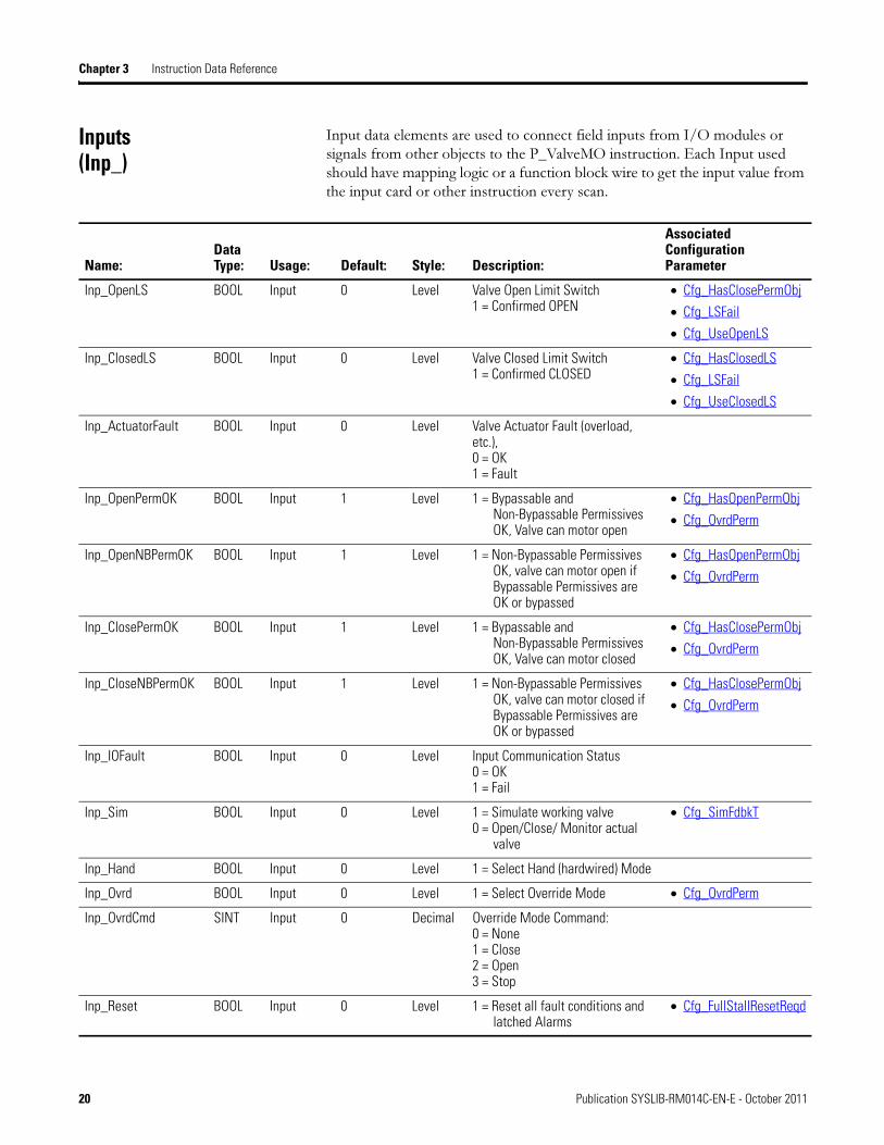
Inputs (Inp_)
Input data elements are used to connect field inputs from I/O modules or signals from other objects to the P_ValveMO instruction. Each Input used should have mapping logic or a function block wire to get the input value from the input card or other instruction every scan.
Name:Data Type: Usage: Default: Style: Description:
Associated Configuration Parameter
Inp_OpenLS BOOL Input 0 Level Valve Open Limit Switch1 = Confirmed OPEN
• Cfg_HasClosePermObj
• Cfg_LSFail
• Cfg_UseOpenLS
Inp_ClosedLS BOOL Input 0 Level Valve Closed Limit Switch 1 = Confirmed CLOSED
• Cfg_HasClosedLS
• Cfg_LSFail
• Cfg_UseClosedLS
Inp_ActuatorFault BOOL Input 0 Level Valve Actuator Fault (overload, etc.), 0 = OK 1 = Fault
Inp_OpenPermOK BOOL Input 1 Level 1 = Bypassable and Non-Bypassable Permissives OK, Valve can motor open
• Cfg_HasOpenPermObj
• Cfg_OvrdPerm
Inp_OpenNBPermOK BOOL Input 1 Level 1 = Non-Bypassable Permissives OK, valve can motor open if Bypassable Permissives are OK or bypassed
• Cfg_HasOpenPermObj
• Cfg_OvrdPerm
Inp_ClosePermOK BOOL Input 1 Level 1 = Bypassable and Non-Bypassable Permissives OK, Valve can motor closed
• Cfg_HasClosePermObj
• Cfg_OvrdPerm
Inp_CloseNBPermOK BOOL Input 1 Level 1 = Non-Bypassable Permissives OK, valve can motor closed if Bypassable Permissives are OK or bypassed
• Cfg_HasClosePermObj
• Cfg_OvrdPerm
Inp_IOFault BOOL Input 0 Level Input Communication Status 0 = OK1 = Fail
Inp_Sim BOOL Input 0 Level 1 = Simulate working valve 0 = Open/Close/ Monitor actual
valve
• Cfg_SimFdbkT
Inp_Hand BOOL Input 0 Level 1 = Select Hand (hardwired) Mode
Inp_Ovrd BOOL Input 0 Level 1 = Select Override Mode • Cfg_OvrdPerm
Inp_OvrdCmd SINT Input 0 Decimal Override Mode Command:0 = None 1 = Close 2 = Open 3 = Stop
Inp_Reset BOOL Input 0 Level 1 = Reset all fault conditions and latched Alarms
• Cfg_FullStallResetReqd
20 Publication SYSLIB-RM014C-EN-E - October 2011
Instruction Data Reference Chapter 3
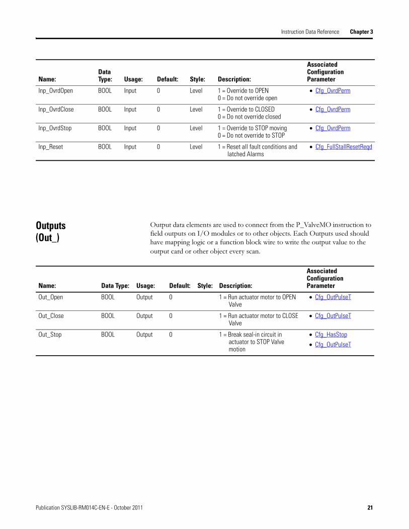
Outputs (Out_)
Output data elements are used to connect from the P_ValveMO instruction to field outputs on I/O modules or to other objects. Each Outputs used should have mapping logic or a function block wire to write the output value to the
output card or other object every scan.
Inp_OvrdOpen BOOL Input 0 Level 1 = Override to OPEN0 = Do not override open
• Cfg_OvrdPerm
Inp_OvrdClose BOOL Input 0 Level 1 = Override to CLOSED0 = Do not override closed
• Cfg_OvrdPerm
Inp_OvrdStop BOOL Input 0 Level 1 = Override to STOP moving0 = Do not override to STOP
• Cfg_OvrdPerm
Inp_Reset BOOL Input 0 Level 1 = Reset all fault conditions and latched Alarms
• Cfg_FullStallResetReqd
Name:Data Type: Usage: Default: Style: Description:
Associated Configuration Parameter
Name: Data Type: Usage: Default: Style: Description:
Associated Configuration Parameter
Out_Open BOOL Output 0 1 = Run actuator motor to OPEN Valve
• Cfg_OutPulseT
Out_Close BOOL Output 0 1 = Run actuator motor to CLOSE Valve
• Cfg_OutPulseT
Out_Stop BOOL Output 0 1 = Break seal-in circuit in actuator to STOP Valve motion
• Cfg_HasStop
• Cfg_OutPulseT
Publication SYSLIB-RM014C-EN-E - October 2011 21
Chapter 3 Instruction Data Reference
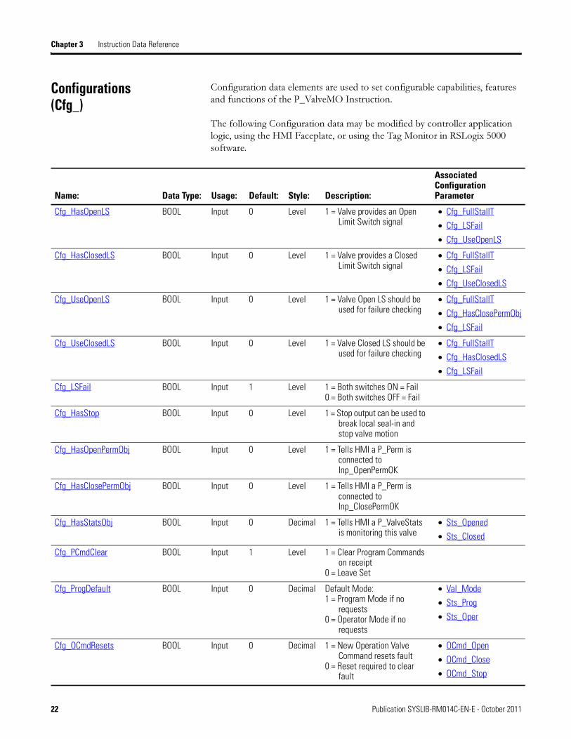
Configurations (Cfg_)
Configuration data elements are used to set configurable capabilities, features and functions of the P_ValveMO Instruction.
The following Configuration data may be modified by controller application logic, using the HMI Faceplate, or using the Tag Monitor in RSLogix 5000 software.
Name: Data Type: Usage: Default: Style: Description:
Associated Configuration Parameter
Cfg_HasOpenLS BOOL Input 0 Level 1 = Valve provides an Open Limit Switch signal
• Cfg_FullStallT
• Cfg_LSFail
• Cfg_UseOpenLS
Cfg_HasClosedLS BOOL Input 0 Level 1 = Valve provides a Closed Limit Switch signal
• Cfg_FullStallT
• Cfg_LSFail
• Cfg_UseClosedLS
Cfg_UseOpenLS BOOL Input 0 Level 1 = Valve Open LS should be used for failure checking
• Cfg_FullStallT
• Cfg_HasClosePermObj
• Cfg_LSFail
Cfg_UseClosedLS BOOL Input 0 Level 1 = Valve Closed LS should be used for failure checking
• Cfg_FullStallT
• Cfg_HasClosedLS
• Cfg_LSFail
Cfg_LSFail BOOL Input 1 Level 1 = Both switches ON = Fail0 = Both switches OFF = Fail
Cfg_HasStop BOOL Input 0 Level 1 = Stop output can be used to break local seal-in and stop valve motion
Cfg_HasOpenPermObj BOOL Input 0 Level 1 = Tells HMI a P_Perm is connected to Inp_OpenPermOK
Cfg_HasClosePermObj BOOL Input 0 Level 1 = Tells HMI a P_Perm is connected to Inp_ClosePermOK
Cfg_HasStatsObj BOOL Input 0 Decimal 1 = Tells HMI a P_ValveStats is monitoring this valve
• Sts_Opened
• Sts_Closed
Cfg_PCmdClear BOOL Input 1 Level 1 = Clear Program Commands on receipt
0 = Leave Set
Cfg_ProgDefault BOOL Input 0 Decimal Default Mode:1 = Program Mode if no
requests0 = Operator Mode if no
requests
• Val_Mode
• Sts_Prog
• Sts_Oper
Cfg_OCmdResets BOOL Input 0 Decimal 1 = New Operation Valve Command resets fault
0 = Reset required to clear fault
• OCmd_Open
• OCmd_Close
• OCmd_Stop
22 Publication SYSLIB-RM014C-EN-E - October 2011
Instruction Data Reference Chapter 3
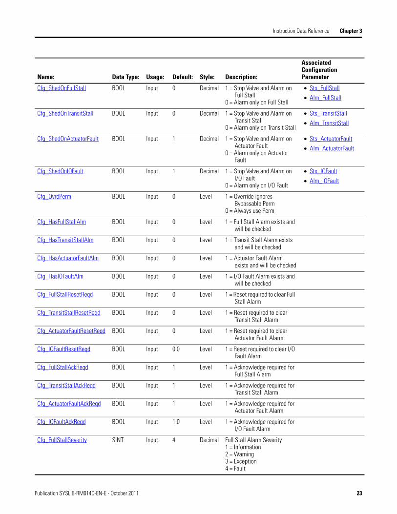
Cfg_ShedOnFullStall BOOL Input 0 Decimal 1 = Stop Valve and Alarm on Full Stall
0 = Alarm only on Full Stall
• Sts_FullStall
• Alm_FullStall
Cfg_ShedOnTransitStall BOOL Input 0 Decimal 1 = Stop Valve and Alarm on Transit Stall
0 = Alarm only on Transit Stall
• Sts_TransitStall
• Alm_TransitStall
Cfg_ShedOnActuatorFault BOOL Input 1 Decimal 1 = Stop Valve and Alarm on Actuator Fault
0 = Alarm only on Actuator Fault
• Sts_ActuatorFault
• Alm_ActuatorFault
Cfg_ShedOnIOFault BOOL Input 1 Decimal 1 = Stop Valve and Alarm on I/O Fault
0 = Alarm only on I/O Fault
• Sts_IOFault
• Alm_IOFault
Cfg_OvrdPerm BOOL Input 0 Level 1 = Override ignores Bypassable Perm
0 = Always use Perm
Cfg_HasFullStallAlm BOOL Input 0 Level 1 = Full Stall Alarm exists and will be checked
Cfg_HasTransitStallAlm BOOL Input 0 Level 1 = Transit Stall Alarm exists and will be checked
Cfg_HasActuatorFaultAlm BOOL Input 0 Level 1 = Actuator Fault Alarm exists and will be checked
Cfg_HasIOFaultAlm BOOL Input 0 Level 1 = I/O Fault Alarm exists and will be checked
Cfg_FullStallResetReqd BOOL Input 0 Level 1 = Reset required to clear Full Stall Alarm
Cfg_TransitStallResetReqd BOOL Input 0 Level 1 = Reset required to clear Transit Stall Alarm
Cfg_ActuatorFaultResetReqd BOOL Input 0 Level 1 = Reset required to clear Actuator Fault Alarm
Cfg_IOFaultResetReqd BOOL Input 0.0 Level 1 = Reset required to clear I/O Fault Alarm
Cfg_FullStallAckReqd BOOL Input 1 Level 1 = Acknowledge required for Full Stall Alarm
Cfg_TransitStallAckReqd BOOL Input 1 Level 1 = Acknowledge required for Transit Stall Alarm
Cfg_ActuatorFaultAckReqd BOOL Input 1 Level 1 = Acknowledge required for Actuator Fault Alarm
Cfg_IOFaultAckReqd BOOL Input 1.0 Level 1 = Acknowledge required for I/O Fault Alarm
Cfg_FullStallSeverity SINT Input 4 Decimal Full Stall Alarm Severity1 = Information2 = Warning3 = Exception4 = Fault
Name: Data Type: Usage: Default: Style: Description:
Associated Configuration Parameter
Publication SYSLIB-RM014C-EN-E - October 2011 23

Chapter 3 Instruction Data Reference
Because they contain arrayed or structured data types, the following Configuration data elements use P_ValveMO Add-On Instruction Local Tags. These may be modified using RSLogix 5000 or using the HMI Faceplates, but cannot be modified using controller logic:
Cfg_TransitStallSeverity SINT Input 4 Decimal Transit Stall Alarm Severity1 = Information2 = Warning3 = Exception4 = Fault
Cfg_ActuatorFaultSeverity SINT Input 2 Decimal Actuator Fault Alarm Severity1 = Information2 = Warning3 = Exception4 = Fault
Cfg_IOFaultSeverity SINT Input 2 Decimal I/O Fault Alarm Severity1 = Information2 = Warning3 = Exception4 = Fault
Cfg_OutPulseT DINT Input 5 Decimal Time (in seconds) to pulse valve outputs0 = Outputs maintained ON
• Cfg_HasStop
Cfg_SimFdbkT DINT Input 20 Decimal Delay to echo back of Open/Closed status when in Simulation (sec)
• Cfg_HasClosedLS
• Cfg_HasClosePermObj
• Cfg_UseClosedLS
• Cfg_UseOpenLS
Cfg_FullStallT DINT Input 15 Decimal After command time with no motion before Fault (sec)
• Cfg_SimFdbkT
Cfg_TransitStallT DINT Input 60 Decimal After command time to reach position before fault (sec)
• Cfg_SimFdbkT
Name: Data Type: Usage: Default: Style: Description:
Associated Configuration Parameter
Name: Data Type: Usage: Default: Style: Description:
Associated Configuration Parameter
Cfg_Desc STRING_40 'Motor Operated Valve’
String Description for display on HMI
Cfg_Label STRING_20 ’Valve Control’ String Label for graphic symbol displayed on HMI
Cfg_Tag STRING_20 ’P_ValveMO’ String Tagname for display on HMI
24 Publication SYSLIB-RM014C-EN-E - October 2011
Instruction Data Reference Chapter 3
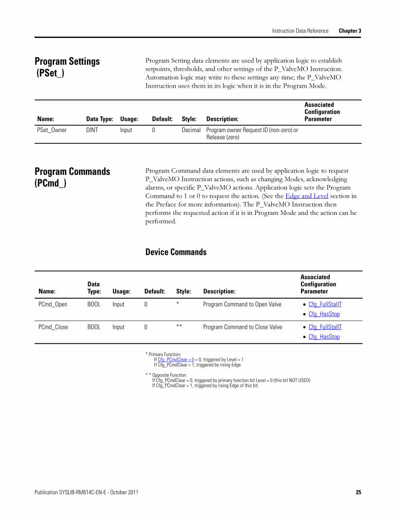
Program Settings (PSet_)
Program Setting data elements are used by application logic to establish setpoints, thresholds, and other settings of the P_ValveMO Instruction. Automation logic may write to these settings any time; the P_ValveMO Instruction uses them in its logic when it is in the Program Mode.
Program Commands (PCmd_)
Program Command data elements are used by application logic to request P_ValveMO Instruction actions, such as changing Modes, acknowledging alarms, or specific P_ValveMO actions. Application logic sets the Program Command to 1 or 0 to request the action. (See the Edge and Level section in the Preface for more information). The P_ValveMO Instruction then performs the requested action if it is in Program Mode and the action can be performed.
Device Commands
* Primary Function: If Cfg_PCmdClear = 0 = 0, triggered by Level = 1 If Cfg_PCmdClear = 1, triggered by rising Edge
* * Opposite Function: If Cfg_PCmdClear = 0, triggered by primary function bit Level = 0 (this bit NOT USED) If Cfg_PCmdClear = 1, triggered by rising Edge of this bit
Name: Data Type: Usage: Default: Style: Description:
Associated Configuration Parameter
PSet_Owner DINT Input 0 Decimal Program owner Request ID (non-zero) or Release (zero)
Name:Data Type: Usage: Default: Style: Description:
Associated Configuration Parameter
PCmd_Open BOOL Input 0 * Program Command to Open Valve • Cfg_FullStallT
• Cfg_HasStop
PCmd_Close BOOL Input 0 ** Program Command to Close Valve • Cfg_FullStallT
• Cfg_HasStop
Publication SYSLIB-RM014C-EN-E - October 2011 25
Chapter 3 Instruction Data Reference
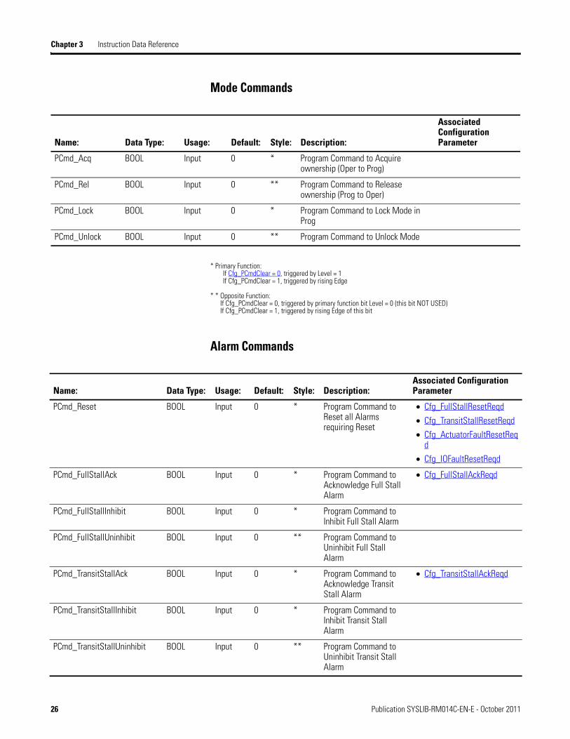
Mode Commands
* Primary Function: If Cfg_PCmdClear = 0, triggered by Level = 1 If Cfg_PCmdClear = 1, triggered by rising Edge
* * Opposite Function: If Cfg_PCmdClear = 0, triggered by primary function bit Level = 0 (this bit NOT USED) If Cfg_PCmdClear = 1, triggered by rising Edge of this bit
Alarm Commands
Name: Data Type: Usage: Default: Style: Description:
Associated Configuration Parameter
PCmd_Acq BOOL Input 0 * Program Command to Acquire ownership (Oper to Prog)
PCmd_Rel BOOL Input 0 ** Program Command to Release ownership (Prog to Oper)
PCmd_Lock BOOL Input 0 * Program Command to Lock Mode in Prog
PCmd_Unlock BOOL Input 0 ** Program Command to Unlock Mode
Name: Data Type: Usage: Default: Style: Description:Associated Configuration Parameter
PCmd_Reset BOOL Input 0 * Program Command to Reset all Alarms requiring Reset
• Cfg_FullStallResetReqd
• Cfg_TransitStallResetReqd
• Cfg_ActuatorFaultResetReqd
• Cfg_IOFaultResetReqd
PCmd_FullStallAck BOOL Input 0 * Program Command to Acknowledge Full Stall Alarm
• Cfg_FullStallAckReqd
PCmd_FullStallInhibit BOOL Input 0 * Program Command to Inhibit Full Stall Alarm
PCmd_FullStallUninhibit BOOL Input 0 ** Program Command to Uninhibit Full Stall Alarm
PCmd_TransitStallAck BOOL Input 0 * Program Command to Acknowledge Transit Stall Alarm
• Cfg_TransitStallAckReqd
PCmd_TransitStallInhibit BOOL Input 0 * Program Command to Inhibit Transit Stall Alarm
PCmd_TransitStallUninhibit BOOL Input 0 ** Program Command to Uninhibit Transit Stall Alarm
26 Publication SYSLIB-RM014C-EN-E - October 2011

Instruction Data Reference Chapter 3
* Primary Function: If Cfg_PCmdClear = 0, triggered by Level = 1 If Cfg_PCmdClear = 1, triggered by rising Edge
* * Opposite Function: If Cfg_PCmdClear = 0, triggered by primary function bit Level = 0 (this bit NOT USED) If Cfg_PCmdClear = 1, triggered by rising Edge of this bit
Name: Data Type: Usage: Default: Style: Description:Associated Configuration Parameter
PCmd_ActuatorFaultAck BOOL Input 0 * Program Command to Acknowledge Actuator Fault Alarm
• Cfg_ActuatorFaultAckReqd
PCmd_ActuatorFaultInhibit BOOL Input 0 * Program Command to Inhibit Actuator Fault Alarm
PCmd_ActuatorFaultUninhibit BOOL Input 0 ** Program Command to Uninhibit Actuator Fault Alarm
PCmd_IOFaultAck BOOL Input 0 * Program Command to Acknowledge I/O Fault Alarm
• Cfg_IOFaultAckReqd
PCmd_IOFaultInhibit BOOL Input 0 * Program Command to Inhibit I/O Fault Alarm
PCmd_IOFaultUninhibit BOOL Input 0 ** Program Command to Uninhibit I/O Fault Alarm
Publication SYSLIB-RM014C-EN-E - October 2011 27
Chapter 3 Instruction Data Reference
Operator Commands, Maintenance Commands, Command Readies (OCmd_, MCmd_, Rdy_)
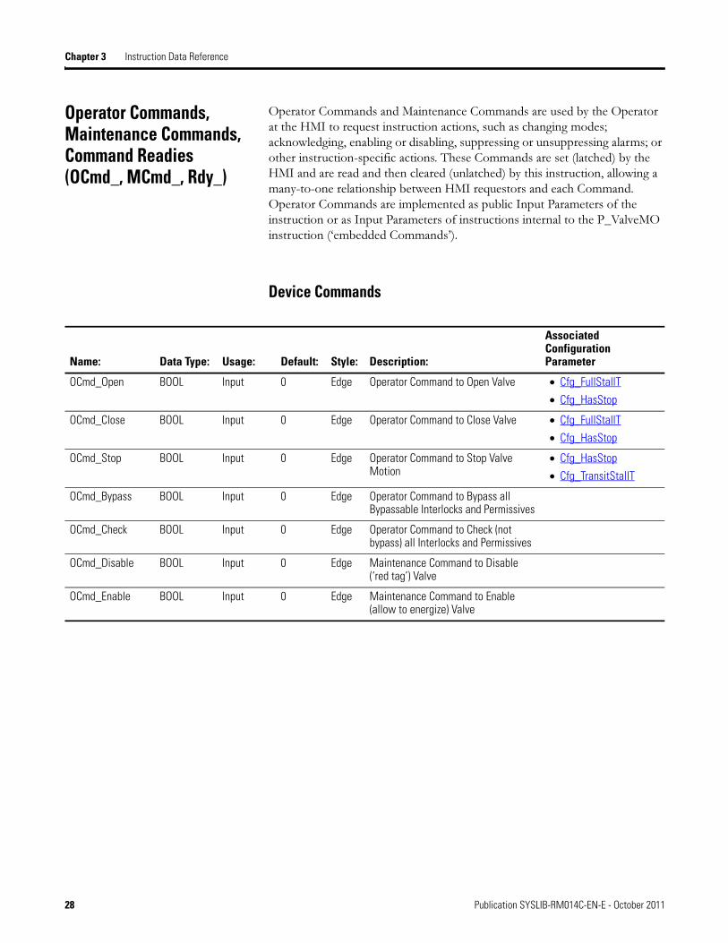
Operator Commands and Maintenance Commands are used by the Operator at the HMI to request instruction actions, such as changing modes; acknowledging, enabling or disabling, suppressing or unsuppressing alarms; or other instruction-specific actions. These Commands are set (latched) by the HMI and are read and then cleared (unlatched) by this instruction, allowing a many-to-one relationship between HMI requestors and each Command. Operator Commands are implemented as public Input Parameters of the instruction or as Input Parameters of instructions internal to the P_ValveMO instruction (‘embedded Commands’).
Device Commands
Name: Data Type: Usage: Default: Style: Description:
Associated Configuration Parameter
OCmd_Open BOOL Input 0 Edge Operator Command to Open Valve • Cfg_FullStallT
• Cfg_HasStop
OCmd_Close BOOL Input 0 Edge Operator Command to Close Valve • Cfg_FullStallT
• Cfg_HasStop
OCmd_Stop BOOL Input 0 Edge Operator Command to Stop Valve Motion
• Cfg_HasStop
• Cfg_TransitStallT
OCmd_Bypass BOOL Input 0 Edge Operator Command to Bypass all Bypassable Interlocks and Permissives
OCmd_Check BOOL Input 0 Edge Operator Command to Check (not bypass) all Interlocks and Permissives
OCmd_Disable BOOL Input 0 Edge Maintenance Command to Disable (‘red tag’) Valve
OCmd_Enable BOOL Input 0 Edge Maintenance Command to Enable (allow to energize) Valve
28 Publication SYSLIB-RM014C-EN-E - October 2011
Instruction Data Reference Chapter 3
Mode Commands
Alarm Commands
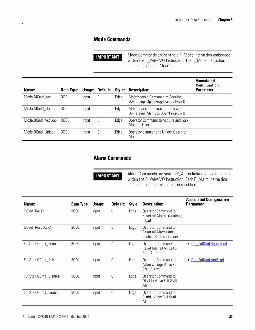
IMPORTANT Mode Commands are sent to a P_Mode Instruction embedded within the P_ValveMO Instruction. The P_Mode Instruction instance is named ‘Mode’.
Name: Data Type: Usage: Default: Style: Description:
Associated Configuration Parameter
Mode.MCmd_Acq BOOL Input 0 Edge Maintenance Command to Acquire Ownership (Oper/Prog/Ovrd to Maint)
Mode.MCmd_Rel BOOL Input 0 Edge Maintenance Command to Release Ownership (Maint to Oper/Prog/Ovrd)
Mode.OCmd_AcqLock BOOL Input 0 Edge Operator Command to Acquire and Lock Mode in Oper
Mode.OCmd_Unlock BOOL Input 0 Edge Operator command to Unlock Operator Mode
IMPORTANT Alarm Commands are sent to P_Alarm Instructions embedded within the P_ValveMO Instruction. Each P_Alarm Instruction instance is named for the alarm condition.
Name: Data Type: Usage: Default: Style: Description:Associated Configuration Parameter
OCmd_Reset BOOL Input 0 Edge Operator Command to Reset all Alarms requiring Reset
OCmd_ResetAckAll BOOL Input 0 Edge Operator Command to Reset all Alarms and latched Shed conditions
FullStall.OCmd_Reset BOOL Input 0 Edge Operator Command to Reset latched Valve Full Stall Alarm
• Cfg_FullStallResetReqd
FullStall.OCmd_Ack BOOL Input 0 Edge Operator Command to Acknowledge Valve Full Stall Alarm
• Cfg_FullStallAckReqd
FullStall.OCmd_Disable BOOL Input 0 Edge Operator Command to Disable Valve Full Stall Alarm
FullStall.OCmd_Enable BOOL Input 0 Edge Operator Command to Enable Valve Full Stall Alarm
Publication SYSLIB-RM014C-EN-E - October 2011 29
Chapter 3 Instruction Data Reference
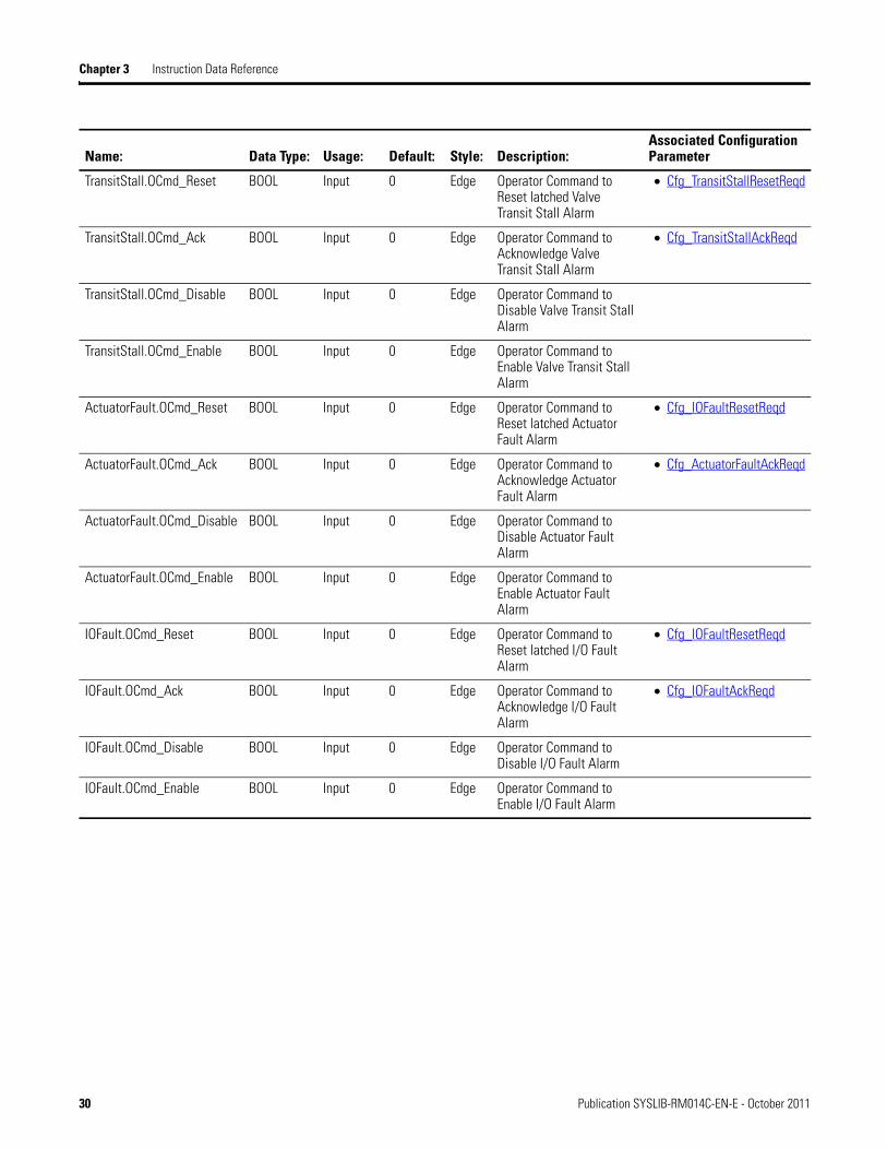
TransitStall.OCmd_Reset BOOL Input 0 Edge Operator Command to Reset latched Valve Transit Stall Alarm
• Cfg_TransitStallResetReqd
TransitStall.OCmd_Ack BOOL Input 0 Edge Operator Command to Acknowledge Valve Transit Stall Alarm
• Cfg_TransitStallAckReqd
TransitStall.OCmd_Disable BOOL Input 0 Edge Operator Command to Disable Valve Transit Stall Alarm
TransitStall.OCmd_Enable BOOL Input 0 Edge Operator Command to Enable Valve Transit Stall Alarm
ActuatorFault.OCmd_Reset BOOL Input 0 Edge Operator Command to Reset latched Actuator Fault Alarm
• Cfg_IOFaultResetReqd
ActuatorFault.OCmd_Ack BOOL Input 0 Edge Operator Command to Acknowledge Actuator Fault Alarm
• Cfg_ActuatorFaultAckReqd
ActuatorFault.OCmd_Disable BOOL Input 0 Edge Operator Command to Disable Actuator Fault Alarm
ActuatorFault.OCmd_Enable BOOL Input 0 Edge Operator Command to Enable Actuator Fault Alarm
IOFault.OCmd_Reset BOOL Input 0 Edge Operator Command to Reset latched I/O Fault Alarm
• Cfg_IOFaultResetReqd
IOFault.OCmd_Ack BOOL Input 0 Edge Operator Command to Acknowledge I/O Fault Alarm
• Cfg_IOFaultAckReqd
IOFault.OCmd_Disable BOOL Input 0 Edge Operator Command to Disable I/O Fault Alarm
IOFault.OCmd_Enable BOOL Input 0 Edge Operator Command to Enable I/O Fault Alarm
Name: Data Type: Usage: Default: Style: Description:Associated Configuration Parameter
30 Publication SYSLIB-RM014C-EN-E - October 2011
Instruction Data Reference Chapter 3
Device Command Readies
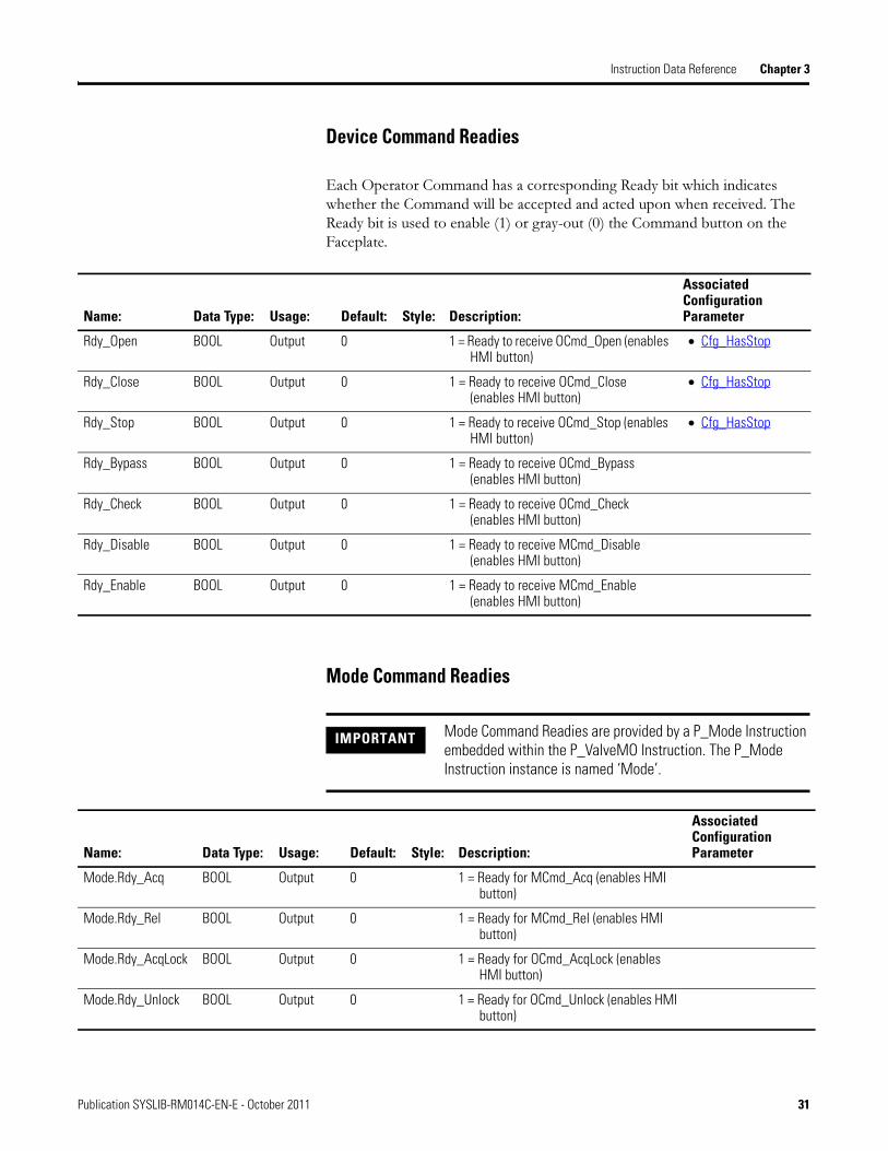
Each Operator Command has a corresponding Ready bit which indicates whether the Command will be accepted and acted upon when received. The Ready bit is used to enable (1) or gray-out (0) the Command button on the Faceplate.
Mode Command Readies
Name: Data Type: Usage: Default: Style: Description:
Associated Configuration Parameter
Rdy_Open BOOL Output 0 1 = Ready to receive OCmd_Open (enables HMI button)
• Cfg_HasStop
Rdy_Close BOOL Output 0 1 = Ready to receive OCmd_Close (enables HMI button)
• Cfg_HasStop
Rdy_Stop BOOL Output 0 1 = Ready to receive OCmd_Stop (enables HMI button)
• Cfg_HasStop
Rdy_Bypass BOOL Output 0 1 = Ready to receive OCmd_Bypass (enables HMI button)
Rdy_Check BOOL Output 0 1 = Ready to receive OCmd_Check (enables HMI button)
Rdy_Disable BOOL Output 0 1 = Ready to receive MCmd_Disable (enables HMI button)
Rdy_Enable BOOL Output 0 1 = Ready to receive MCmd_Enable (enables HMI button)
IMPORTANT Mode Command Readies are provided by a P_Mode Instruction embedded within the P_ValveMO Instruction. The P_Mode Instruction instance is named ‘Mode’.
Name: Data Type: Usage: Default: Style: Description:
Associated Configuration Parameter
Mode.Rdy_Acq BOOL Output 0 1 = Ready for MCmd_Acq (enables HMI button)
Mode.Rdy_Rel BOOL Output 0 1 = Ready for MCmd_Rel (enables HMI button)
Mode.Rdy_AcqLock BOOL Output 0 1 = Ready for OCmd_AcqLock (enables HMI button)
Mode.Rdy_Unlock BOOL Output 0 1 = Ready for OCmd_Unlock (enables HMI button)
Publication SYSLIB-RM014C-EN-E - October 2011 31

Chapter 3 Instruction Data Reference
Alarm Command Readies
IMPORTANT Alarm Command Readies are provided by P_Alarm Instructions embedded within the P_ValveMO Instruction. Each P_Alarm Instruction instance is named for the alarm condition.
Name: Data Type: Usage: Default: Style: Description:
Associated Configuration Parameter
Rdy_Reset BOOL Output 0 1 = Ready for OCmd_Reset (enables HMI button)
Rdy_ResetAckAll BOOL Output 0 1 = Ready for OCmd_ResetAckAll (enables HMI button)
FullStall.Rdy_Reset BOOL Output 0 1 = Ready for FullStall.OCmd_Reset (enables HMI button)
FullStall.Rdy_Ack BOOL Output 0 1 = Ready for FullStall.OCmd_Ack (enables HMI button)
FullStall.Rdy_Disable BOOL Output 0 1 = Ready for FullStall.OCmd_Disable (enables HMI button)
FullStall.Rdy_Enable BOOL Output 0 1 = Ready for FullStall.OCmd_Enable (enables HMI button)
TransitStall.Rdy_Reset BOOL Output 0 1 = Ready for TransitStall.OCmd_Reset (enables HMI button)
TransitStall.Rdy_Ack BOOL Output 0 1 = Ready for TransitStall.OCmd_Ack (enables HMI button)
TransitStall.Rdy_Disable BOOL Output 0 1 = Ready for TransitStall.OCmd_Disable (enables HMI button)
TransitStall.Rdy_Enable BOOL Output 0 1 = Ready for TransitStall.OCmd_Enable (enables HMI button)
ActuatorFault.Rdy_Reset BOOL Output 0 1 = Ready for ActuatorFault.OCmd_Reset (enables HMI button)
ActuatorFault.Rdy_Ack BOOL Output 0 1 = Ready for ActuatorFault.OCmd_Ack (enables HMI button)
ActuatorFault.Rdy_Disable BOOL Output 0 1 = Ready for ActuatorFault.OCmd_Disable (enables HMI button)
ActuatorFault.Rdy_Enable BOOL Output 0 1 = Ready for ActuatorFault.OCmd_Enable (enables HMI button)
IOFault.Rdy_Reset BOOL Output 0 1 = Ready for IOFault.OCmd_Reset (enables HMI button)
32 Publication SYSLIB-RM014C-EN-E - October 2011
Instruction Data Reference Chapter 3
Values (Val_)
Value data elements contain process or device variables, the notification level for alarm animation, and the current accepted values of any Program, Operator or Maintenance Settings for the P_ValveMO instruction. The HMI displays these Values, and they are available for use by other application logic.
IOFault.Rdy_Ack BOOL Output 0 1 = Ready for IOFault.OCmd_Ack (enables HMI button)
IOFault.Rdy_Disable BOOL Output 0 1 = Ready for IOFault.OCmd_Disable (enables HMI button)
IOFault.Rdy_Enable BOOL Output 0 1 = Ready for IOFault.OCmd_Enable (enables HMI button)
Name: Data Type: Usage: Default: Style: Description:
Associated Configuration Parameter
Name: Data Type: Usage: Default: Style: Description:Associated Configuration Parameter
Val_Cmd SINT Output 0 Decimal This shows the command being processed, returns to zero once the command succeeds or fails. May be made not visible if zero. These values are also use for Inp_OvrdCmd. 0 = None 1 = Close 2 = Open 3 = Stop
Val_Fdbk SINT Output 0 Decimal This sows the (usually raw, interpreted) input from the device. 0 = Moving 1 = Closed 2 = Opened 3 = Limit Switch Failure
Val_Sts SINT Output 0 Decimal This is the PRIMARY STATUS, used to show the operator the ‘confirmed’ device status. 0 = Unknown 1 = Closed 2 = Opened 3 = Commanded to Close 4 = Commanded to Open 5 = Closing 6 = Opening 7 = Stopped 33 = Disabled
Publication SYSLIB-RM014C-EN-E - October 2011 33

Chapter 3 Instruction Data Reference
Val_Fault SINT Output 0 Decimal This is the DEVICE AFAULT STATUS, used to show the operator the most sever device fault. 0 = None 16 = Transit Stall 17 = Full Stall 19 = Actuator Fault 32 = I/O Fault 34 = Configuration Error
Val_Mode SINT Output 0 Decimal This exists if P_Mode is used within the object and shows all modes used by (implemented in) the object. 0 = No mode 1 = Hand 2 = Maintenance 3 = Overload 4 = Program Lock 5 = Operator Lock 6 = Program (Operator Default) 7 = Operator (Program Default) 8 = Program (Program Default) 9 = Operator (Operator Default)
Val_Owner DINT Output 0 Decimal Current Object Owner ID (0 = not owned)
Val_Notify DINT Output 0 Decimal Current Alarm Level and Acknowledgement (enumeration): 0 = No alarm 1 = Alarm cleared, unacknowledged 2 = Information alarm 3 = Unack. Information alarm 4 = Warning alarm 5 = Unack. Warning alarm 6 = Exception alarm 7 = Unack. Exception alarm 8 = Fault alarm 9 = Unack. Fault alarm
• Cfg_FullStallSeverity
• Cfg_TransitStallSeverity
• Cfg_ActuatorFaultSeverity
• Cfg_IOFaultSeverity
Name: Data Type: Usage: Default: Style: Description:Associated Configuration Parameter
34 Publication SYSLIB-RM014C-EN-E - October 2011

Instruction Data Reference Chapter 3
Status (Sts_)
Status data elements contain process or device states, Mode status and Alarm status. The HMI displays these Status points, and they are available for use by other application logic.
Device Status
Name: Data Type: Usage: Default: Style: Description:
Associated Configuration Parameter
Sts_Closed BOOL Output 0 1 = Valve requested to Close and is confirmed Closed
Sts_CmdToOpen BOOL Output 0 1 = Valve commanded to Open, has not yet moved off Open LS
Sts_Opening BOOL Output 0 1 = Valve requested to open and awaiting open feedback
• Cfg_FullStallT
• Cfg_HasClosedLS
• Cfg_HasClosePermObj
• Cfg_SimFdbkT
• Cfg_UseClosedLS
• Cfg_UseOpenLS
Sts_Opened BOOL Output 0 1 = Valve requested to open and is confirmed Opened
Sts_CmdToClose BOOL Output 0 1 = Valve commanded to Close, has not yet moved off Closed LS
Sts_Closing BOOL Output 0 1 = Valve requested to Close and awaiting Closed feedback
• Cfg_FullStallT
• Cfg_HasClosedLS
• Cfg_HasClosePermObj
• Cfg_SimFdbkT
• Cfg_UseClosedLS
• Cfg_UseOpenLS
Sts_Stopped BOOL Output 0 1 = Valve requested to Stop and is not at either end of travel
• Cfg_TransitStallT
Sts_Available BOOL Output 0 1 = Valve available for control by automation (Prog)
Sts_Bypass BOOL Output 0 1 = Bypassable Interlocks and Permissives are Bypassed
Sts_BypActive BOOL Output 0 1 = Bypassing Active (Bypassed or Maintenance)
Sts_Disabled BOOL Output 0 1 = Valve is Disabled
Sts_LSFail BOOL Output 0 1 = Limit Switch Overlap Failure • Cfg_LSFail
Sts_NotRdy BOOL Output 0 1 = Valve is Not Ready to Energize (independent mode)
Sts_MaintByp BOOL Output 0 1 = Maintenance Bypass is Active, display icon
Publication SYSLIB-RM014C-EN-E - October 2011 35

Chapter 3 Instruction Data Reference
Mode Status
Sts_AlmInh BOOL Output 0 1 = An Alarm is Inhibited, Disabled or Suppressed, display icon
Sts_Err BOOL Output 0 1 = Error in Config: See detail bits for reason
Err_Timer BOOL Output 0 1 = Error in Config: Invalid Check or Pulse Time (use 0 to 2147483)
Err_Sim BOOL Output 0 1 = Error in Config: Simulation timer preset (use 0 to 2147483)
Err_Alarm BOOL Output 0 1 = Error in Config: Invalid Alarm Minimum On Time or Severity
Name: Data Type: Usage: Default: Style: Description:
Associated Configuration Parameter
Name: Data Type: Usage: Default: Style: Description:
Associated Configuration Parameter
Sts_Hand BOOL Output 0 1 = Mode is Hand (supersedes Maint, Ovrd, Prog, Oper)
Sts_Maint BOOL Output 0 1 = Mode is Maintenance (supersedes Ovrd, Prog, Oper)
Sts_Ovrd BOOL Output 0 1 = Mode is Override (supersedes Prog, Oper)
Sts_Prog BOOL Output 0 1 = Mode is Program (auto)
Sts_Oper BOOL Output 1 1 = Mode is Operator (manual)
Sts_ProgOperLock BOOL Output 0 1 = Program or Operator has requested Mode Lock
Sts_NoMode BOOL Output 0 1 = NoMode (Disabled because EnableIn is False)
36 Publication SYSLIB-RM014C-EN-E - October 2011
Instruction Data Reference Chapter 3
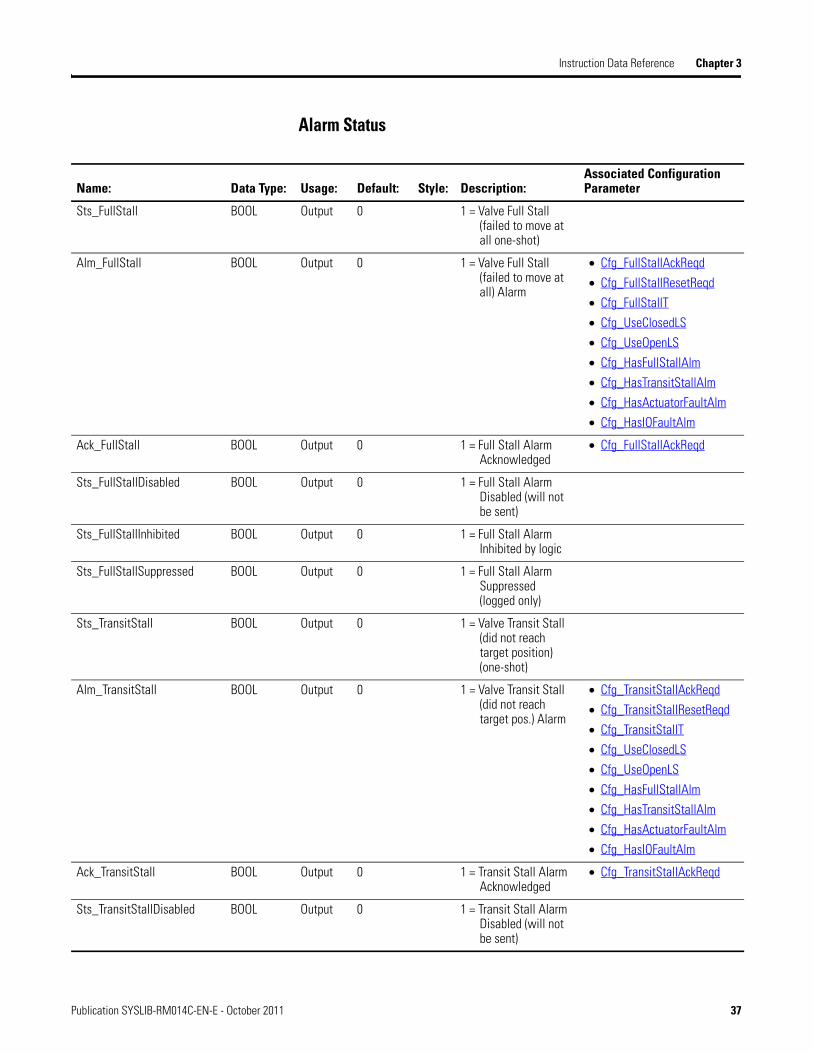
Alarm Status
Name: Data Type: Usage: Default: Style: Description:Associated Configuration Parameter
Sts_FullStall BOOL Output 0 1 = Valve Full Stall (failed to move at all one-shot)
Alm_FullStall BOOL Output 0 1 = Valve Full Stall (failed to move at all) Alarm
• Cfg_FullStallAckReqd
• Cfg_FullStallResetReqd
• Cfg_FullStallT
• Cfg_UseClosedLS
• Cfg_UseOpenLS
• Cfg_HasFullStallAlm
• Cfg_HasTransitStallAlm
• Cfg_HasActuatorFaultAlm
• Cfg_HasIOFaultAlm
Ack_FullStall BOOL Output 0 1 = Full Stall Alarm Acknowledged
• Cfg_FullStallAckReqd
Sts_FullStallDisabled BOOL Output 0 1 = Full Stall Alarm Disabled (will not be sent)
Sts_FullStallInhibited BOOL Output 0 1 = Full Stall Alarm Inhibited by logic
Sts_FullStallSuppressed BOOL Output 0 1 = Full Stall Alarm Suppressed (logged only)
Sts_TransitStall BOOL Output 0 1 = Valve Transit Stall (did not reach target position) (one-shot)
Alm_TransitStall BOOL Output 0 1 = Valve Transit Stall (did not reach target pos.) Alarm
• Cfg_TransitStallAckReqd
• Cfg_TransitStallResetReqd
• Cfg_TransitStallT
• Cfg_UseClosedLS
• Cfg_UseOpenLS
• Cfg_HasFullStallAlm
• Cfg_HasTransitStallAlm
• Cfg_HasActuatorFaultAlm
• Cfg_HasIOFaultAlm
Ack_TransitStall BOOL Output 0 1 = Transit Stall Alarm Acknowledged
• Cfg_TransitStallAckReqd
Sts_TransitStallDisabled BOOL Output 0 1 = Transit Stall Alarm Disabled (will not be sent)
Publication SYSLIB-RM014C-EN-E - October 2011 37
Chapter 3 Instruction Data Reference
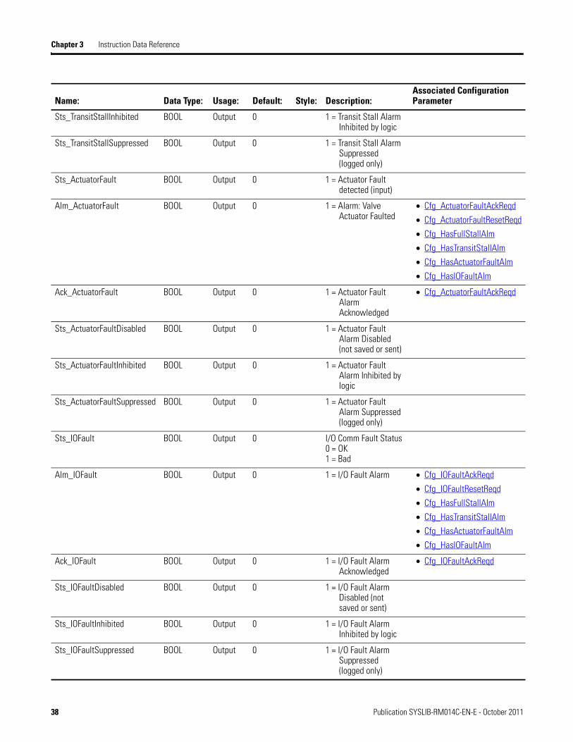
Sts_TransitStallInhibited BOOL Output 0 1 = Transit Stall Alarm Inhibited by logic
Sts_TransitStallSuppressed BOOL Output 0 1 = Transit Stall Alarm Suppressed (logged only)
Sts_ActuatorFault BOOL Output 0 1 = Actuator Fault detected (input)
Alm_ActuatorFault BOOL Output 0 1 = Alarm: Valve Actuator Faulted
• Cfg_ActuatorFaultAckReqd
• Cfg_ActuatorFaultResetReqd
• Cfg_HasFullStallAlm
• Cfg_HasTransitStallAlm
• Cfg_HasActuatorFaultAlm
• Cfg_HasIOFaultAlm
Ack_ActuatorFault BOOL Output 0 1 = Actuator Fault Alarm Acknowledged
• Cfg_ActuatorFaultAckReqd
Sts_ActuatorFaultDisabled BOOL Output 0 1 = Actuator Fault Alarm Disabled (not saved or sent)
Sts_ActuatorFaultInhibited BOOL Output 0 1 = Actuator Fault Alarm Inhibited by logic
Sts_ActuatorFaultSuppressed BOOL Output 0 1 = Actuator Fault Alarm Suppressed (logged only)
Sts_IOFault BOOL Output 0 I/O Comm Fault Status0 = OK 1 = Bad
Alm_IOFault BOOL Output 0 1 = I/O Fault Alarm • Cfg_IOFaultAckReqd
• Cfg_IOFaultResetReqd
• Cfg_HasFullStallAlm
• Cfg_HasTransitStallAlm
• Cfg_HasActuatorFaultAlm
• Cfg_HasIOFaultAlm
Ack_IOFault BOOL Output 0 1 = I/O Fault Alarm Acknowledged
• Cfg_IOFaultAckReqd
Sts_IOFaultDisabled BOOL Output 0 1 = I/O Fault Alarm Disabled (not saved or sent)
Sts_IOFaultInhibited BOOL Output 0 1 = I/O Fault Alarm Inhibited by logic
Sts_IOFaultSuppressed BOOL Output 0 1 = I/O Fault Alarm Suppressed (logged only)
Name: Data Type: Usage: Default: Style: Description:Associated Configuration Parameter
38 Publication SYSLIB-RM014C-EN-E - October 2011
Chapter 4
HMI Reference
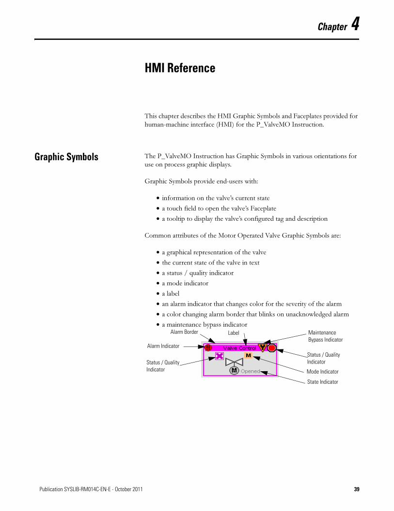
This chapter describes the HMI Graphic Symbols and Faceplates provided for human-machine interface (HMI) for the P_ValveMO Instruction.
Graphic Symbols The P_ValveMO Instruction has Graphic Symbols in various orientations for use on process graphic displays.
Graphic Symbols provide end-users with:
• information on the valve’s current state
• a touch field to open the valve’s Faceplate
• a tooltip to display the valve’s configured tag and description
Common attributes of the Motor Operated Valve Graphic Symbols are:
• a graphical representation of the valve
• the current state of the valve in text
• a status / quality indicator
• a mode indicator
• a label
• an alarm indicator that changes color for the severity of the alarm
• a color changing alarm border that blinks on unacknowledged alarm
• a maintenance bypass indicator
Status / Quality Indicator
Alarm Indicator
State Indicator
Mode Indicator
Label Maintenance Bypass Indicator
Status / Quality Indicator
Alarm Border
39Publication SYSLIB-RM014C-EN-E - October 2011 39

Chapter 4 HMI Reference
Each Graphic Symbol includes a touch field over it which calls up the object’s Faceplate. In addition, there is a tooltip on the Graphic Symbol that displays the object’s configured Tag and Description.
State Indicators
The state indicator text changes and the graphic symbol color fill changes depending on the state of the valve.
Status / Quality Indicators
One of these symbols appears to the left of the graphic symbol when the described condition is true
TIPWhen the Invalid Configuration Indicator appears, you can find what configuration setting is invalid by following the indicators like a ‘trail of breadcrumbs’. Click the Graphic Symbol to call up the Faceplate. The Invalid
Color State Text
Half Dark Gray, Half White Transition: Commanded to Open, Opening, Commanded to Close or Closing
Light Yellow Stopped
Dark Gray Closed
White Opened
Graphic Symbol Description
Invalid Configuration
I/O Fault (status is ‘stale’)
The device is not ready to be operated.
No symbol displayed I/O quality good and Configuration valid
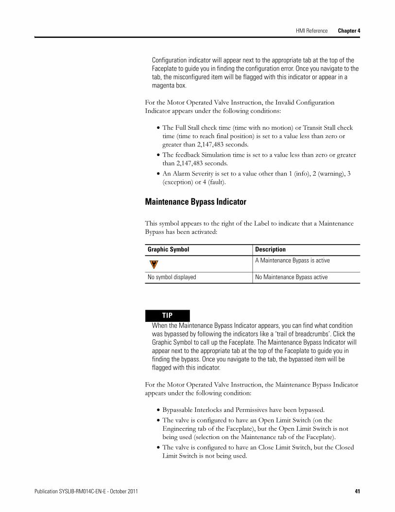
40 Publication SYSLIB-RM014C-EN-E - October 2011
HMI Reference Chapter 4
Configuration indicator will appear next to the appropriate tab at the top of the Faceplate to guide you in finding the configuration error. Once you navigate to the tab, the misconfigured item will be flagged with this indicator or appear in a magenta box.
For the Motor Operated Valve Instruction, the Invalid Configuration Indicator appears under the following conditions:
• The Full Stall check time (time with no motion) or Transit Stall check time (time to reach final position) is set to a value less than zero or greater than 2,147,483 seconds.
• The feedback Simulation time is set to a value less than zero or greater than 2,147,483 seconds.
• An Alarm Severity is set to a value other than 1 (info), 2 (warning), 3 (exception) or 4 (fault).
Maintenance Bypass Indicator
This symbol appears to the right of the Label to indicate that a Maintenance Bypass has been activated:
TIPWhen the Maintenance Bypass Indicator appears, you can find what condition was bypassed by following the indicators like a ‘trail of breadcrumbs’. Click the Graphic Symbol to call up the Faceplate. The Maintenance Bypass Indicator will appear next to the appropriate tab at the top of the Faceplate to guide you in finding the bypass. Once you navigate to the tab, the bypassed item will be flagged with this indicator.
For the Motor Operated Valve Instruction, the Maintenance Bypass Indicator appears under the following condition:
• Bypassable Interlocks and Permissives have been bypassed.
• The valve is configured to have an Open Limit Switch (on the Engineering tab of the Faceplate), but the Open Limit Switch is not being used (selection on the Maintenance tab of the Faceplate).
• The valve is configured to have an Close Limit Switch, but the Closed Limit Switch is not being used.
Graphic Symbol Description
A Maintenance Bypass is active
No symbol displayed No Maintenance Bypass active
Publication SYSLIB-RM014C-EN-E - October 2011 41

Chapter 4 HMI Reference
Mode Indicators
One of these symbols appears to the right of the graphic symbol to indicate the Mode of the Motor Operated Valve instruction:
TIPThe Mode indicator may not appear if the instruction is in its default mode.
Refer to the Process Add-On Instructions and Graphics: Mode (P_Mode) Reference Manual, publication SYSLIB-RM005, for more information.
Graphic Symbol Description
The valve is in Hand (local) Mode
The valve is in Maintenance Mode
The valve is in Override Mode
The valve is in Program Mode
The valve is in Operator Mode
The valve has been disabled
42 Publication SYSLIB-RM014C-EN-E - October 2011
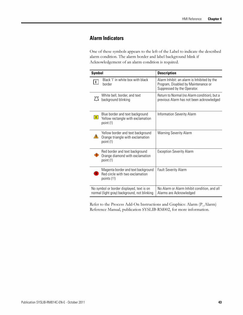
HMI Reference Chapter 4
Alarm Indicators
One of these symbols appears to the left of the Label to indicate the described alarm condition. The alarm border and label background blink if
Acknowledgement of an alarm condition is required.
Refer to the Process Add-On Instructions and Graphics: Alarm (P_Alarm) Reference Manual, publication SYSLIB-RM002, for more information.
Symbol Description
Black ‘I’ in white box with black border
Alarm Inhibit: an alarm is Inhibited by the Program, Disabled by Maintenance or Suppressed by the Operator.
White bell, border, and text background blinking
Return to Normal (no Alarm condition), but a previous Alarm has not been acknowledged
Blue border and text background Yellow rectangle with exclamation point (!)
Information Severity Alarm
Yellow border and text background Orange triangle with exclamation point (!)
Warning Severity Alarm
Red border and text background Orange diamond with exclamation point (!)
Exception Severity Alarm
Magenta border and text background Red circle with two exclamation points (!!)
Fault Severity Alarm
No symbol or border displayed, text is on normal (light gray) background, not blinking
No Alarm or Alarm Inhibit condition, and all Alarms are Acknowledged
Publication SYSLIB-RM014C-EN-E - October 2011 43
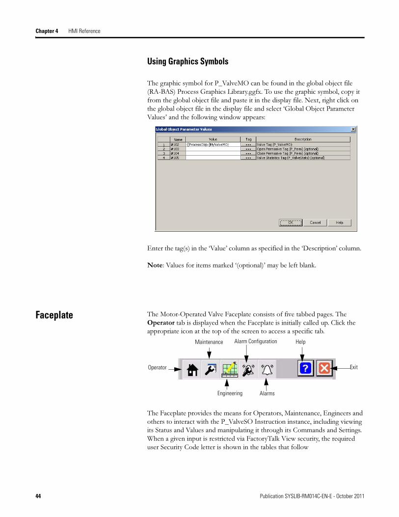
Chapter 4 HMI Reference
Using Graphics Symbols
The graphic symbol for P_ValveMO can be found in the global object file (RA-BAS) Process Graphics Library.ggfx. To use the graphic symbol, copy it from the global object file and paste it in the display file. Next, right click on the global object file in the display file and select ‘Global Object Parameter Values’ and the following window appears:
Enter the tag(s) in the ‘Value’ column as specified in the ‘Description’ column.
Note: Values for items marked ‘(optional)’ may be left blank.
Faceplate The Motor-Operated Valve Faceplate consists of five tabbed pages. The Operator tab is displayed when the Faceplate is initially called up. Click the appropriate icon at the top of the screen to access a specific tab.
The Faceplate provides the means for Operators, Maintenance, Engineers and others to interact with the P_ValveSO Instruction instance, including viewing its Status and Values and manipulating it through its Commands and Settings. When a given input is restricted via FactoryTalk View security, the required user Security Code letter is shown in the tables that follow
Operator
Maintenance
Engineering
Alarm Configuration
Alarms
Help
Exit
44 Publication SYSLIB-RM014C-EN-E - October 2011
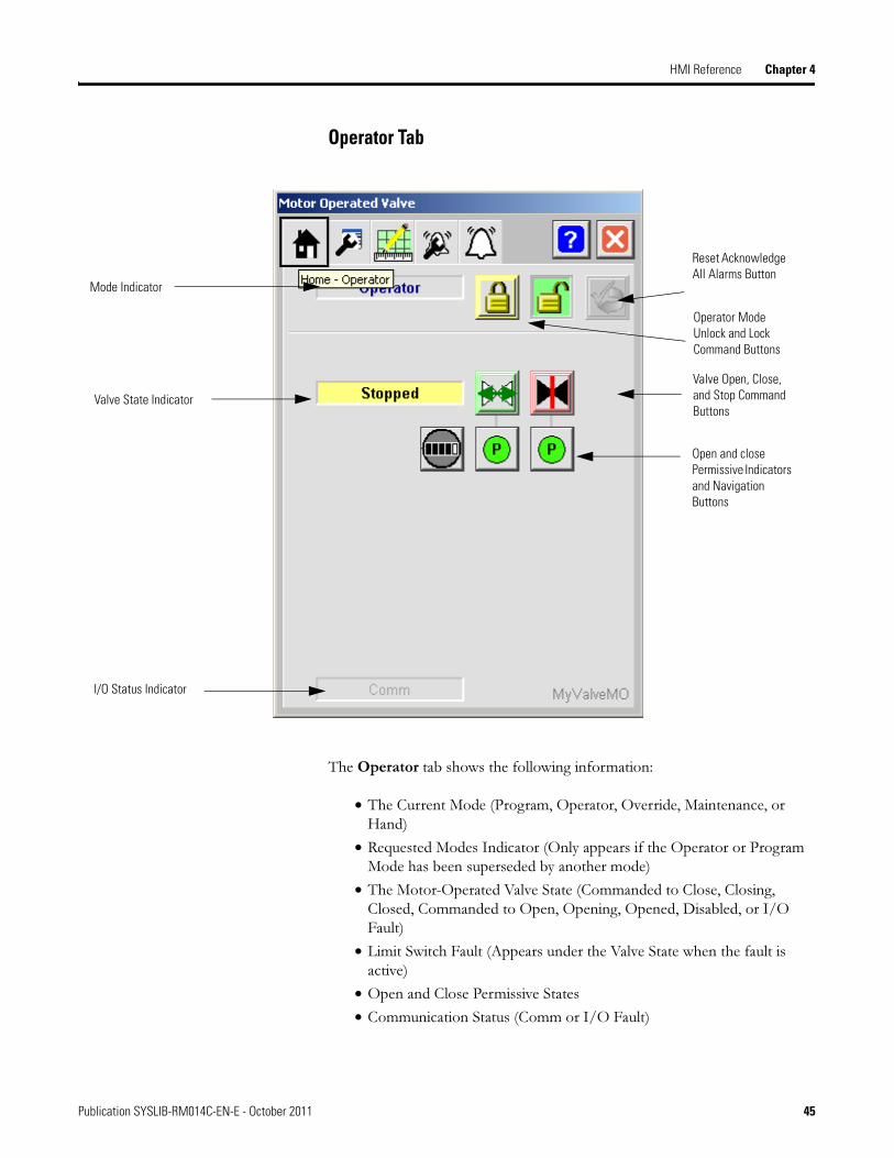
HMI Reference Chapter 4
Operator Tab
The Operator tab shows the following information:
• The Current Mode (Program, Operator, Override, Maintenance, or Hand)
• Requested Modes Indicator (Only appears if the Operator or Program Mode has been superseded by another mode)
• The Motor-Operated Valve State (Commanded to Close, Closing, Closed, Commanded to Open, Opening, Opened, Disabled, or I/O Fault)
• Limit Switch Fault (Appears under the Valve State when the fault is active)
• Open and Close Permissive States
• Communication Status (Comm or I/O Fault)
Open and close Permissive Indicators and Navigation Buttons
Valve Open, Close, and Stop Command Buttons
I/O Status Indicator
Valve State Indicator
Mode Indicator
Operator Mode Unlock and Lock Command Buttons
Reset Acknowledge All Alarms Button
Publication SYSLIB-RM014C-EN-E - October 2011 45
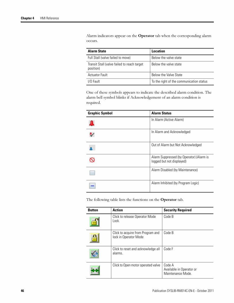
Chapter 4 HMI Reference
Alarm indicators appear on the Operator tab when the corresponding alarm occurs.
One of these symbols appears to indicate the described alarm condition. The alarm bell symbol blinks if Acknowledgement of an alarm condition is
required.
The following table lists the functions on the Operator tab.
Alarm State Location
Full Stall (valve failed to move) Below the valve state
Transit Stall (valve failed to reach target position)
Below the valve state
Actuator Fault Below the Valve State
I/O Fault To the right of the communication status
Graphic Symbol Alarm Status
In Alarm (Active Alarm)
In Alarm and Acknowledged
Out of Alarm but Not Acknowledged
Alarm Suppressed (by Operator) (Alarm is logged but not displayed)
Alarm Disabled (by Maintenance)
Alarm Inhibited (by Program Logic)
Button Action Security Required
Click to release Operator Mode Lock.
Code B
Click to acquire from Program and lock in Operator Mode
Code B
Click to reset and acknowledge all alarms.
Code F
Click to Open motor operated valve Code A Available in Operator or Maintenance Mode.
46 Publication SYSLIB-RM014C-EN-E - October 2011

HMI Reference Chapter 4
The Operator tab has buttons to open the Permissive Faceplates if the valve is configured to use the P_Perm permissive object. The buttons appear behind the permissive indicators.
Refer to the Overview (Chapter 1) for more information on permissives.
See also:
• Process Add-On Instructions and Graphics: Permissives (P_Perm) Reference Manual, publication SYSLIB-RM007.
Click to Close motor operated valve
Code A Available in Operator or Maintenance Mode.
Click to stop valve travel. Code A Available in Operator or Maintenance Mode. This button is only visible if the valve Stop capability has been enabled.
There are two Permissive status indicators/buttons. Click the button below the Open command button to view the Open Permissives Faceplate, and click the button below the Close command button to view the Close Permissives Faceplate (see Cfg_HasOpenPermObj and Cfg_HasClosePermObj)
N/A
Click to open Valve Statistics Faceplate. (This button is only visible if the valve has been configured to use a P_ValveStats Instruction to record valve stroke times and counts. See Cfg_HasStatsObj)
N/A
Button Action Security Required
Publication SYSLIB-RM014C-EN-E - October 2011 47
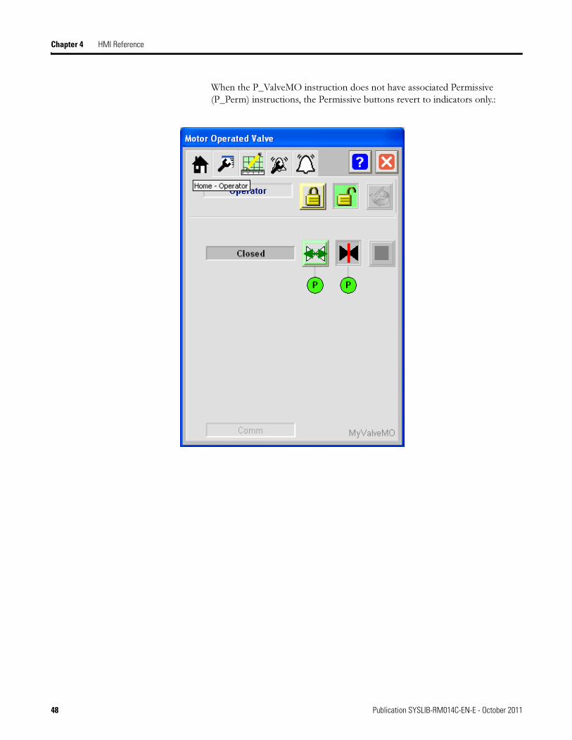
Chapter 4 HMI Reference
When the P_ValveMO instruction does not have associated Permissive (P_Perm) instructions, the Permissive buttons revert to indicators only.:
48 Publication SYSLIB-RM014C-EN-E - October 2011
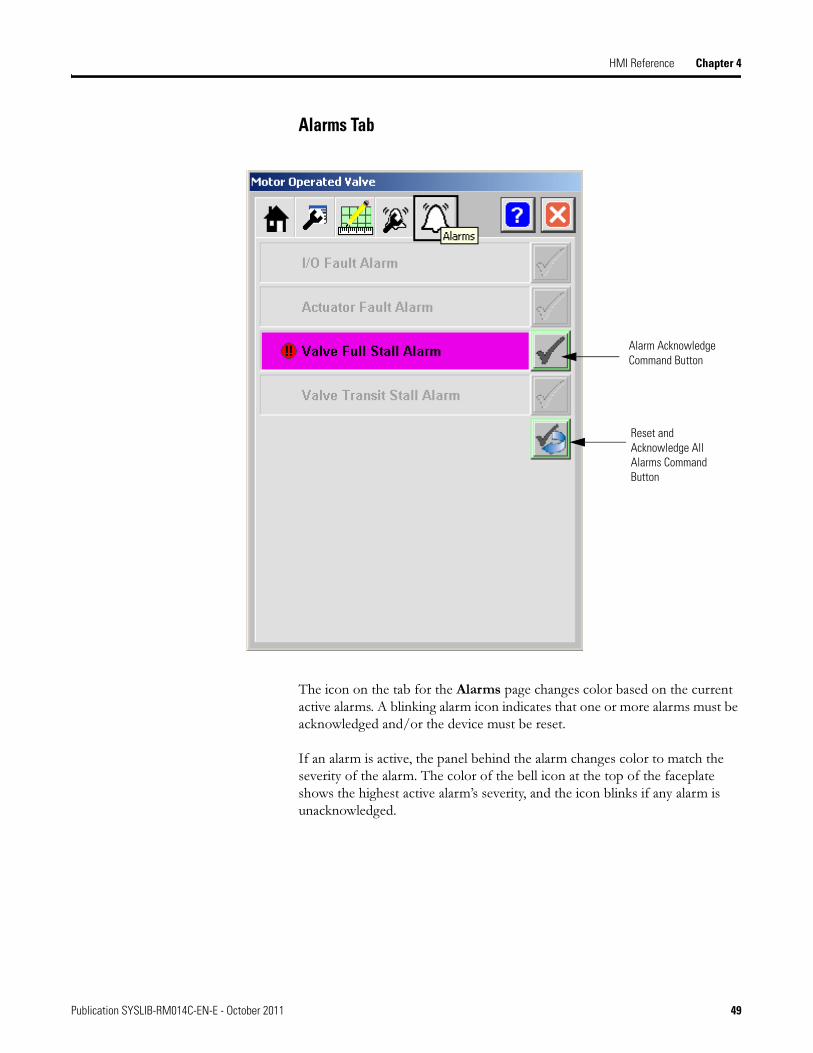
HMI Reference Chapter 4
Alarms Tab
The icon on the tab for the Alarms page changes color based on the current active alarms. A blinking alarm icon indicates that one or more alarms must be acknowledged and/or the device must be reset.
If an alarm is active, the panel behind the alarm changes color to match the severity of the alarm. The color of the bell icon at the top of the faceplate shows the highest active alarm’s severity, and the icon blinks if any alarm is unacknowledged.
Alarm Acknowledge Command Button
Reset and Acknowledge All Alarms Command Button
Publication SYSLIB-RM014C-EN-E - October 2011 49
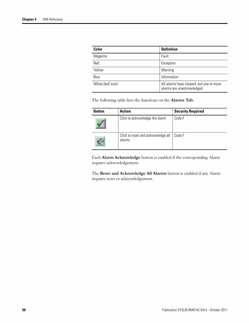
Chapter 4 HMI Reference
The following table lists the functions on the Alarms Tab..
Each Alarm Acknowledge button is enabled if the corresponding Alarm requires acknowledgement.
The Reset and Acknowledge All Alarms button is enabled if any Alarm requires reset or acknowledgement.
Color Definition
Magenta Fault
Red Exception
Yellow Warning
Blue Information
White (bell icon) All alarms have cleared, but one or more alarms are unacknowledged
Button Action Security Required
Click to acknowledge the alarm Code F
Click to reset and acknowledge all alarms
Code F
50 Publication SYSLIB-RM014C-EN-E - October 2011
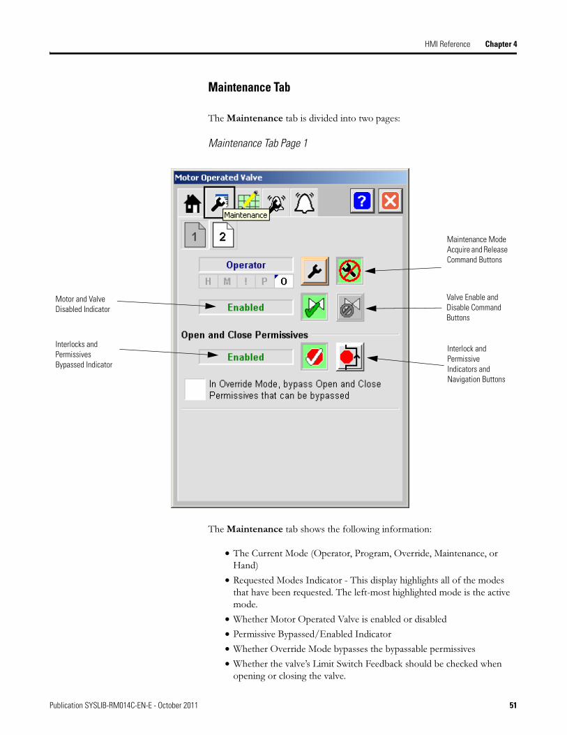
HMI Reference Chapter 4
Maintenance Tab
The Maintenance tab is divided into two pages:
Maintenance Tab Page 1
The Maintenance tab shows the following information:
• The Current Mode (Operator, Program, Override, Maintenance, or Hand)
• Requested Modes Indicator - This display highlights all of the modes that have been requested. The left-most highlighted mode is the active mode.
• Whether Motor Operated Valve is enabled or disabled
• Permissive Bypassed/Enabled Indicator
• Whether Override Mode bypasses the bypassable permissives
• Whether the valve’s Limit Switch Feedback should be checked when opening or closing the valve.
Maintenance Mode Acquire and Release Command Buttons
Valve Enable and Disable Command Buttons
Interlock and Permissive Indicators and Navigation Buttons
Interlocks and Permissives Bypassed Indicator
Motor and Valve Disabled Indicator
Publication SYSLIB-RM014C-EN-E - October 2011 51
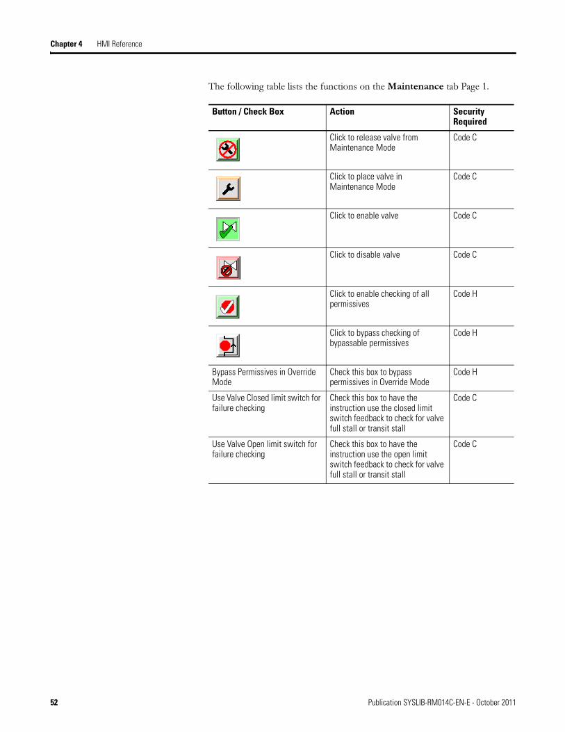
Chapter 4 HMI Reference
The following table lists the functions on the Maintenance tab Page 1.
Button / Check Box Action Security Required
Click to release valve from Maintenance Mode
Code C
Click to place valve in Maintenance Mode
Code C
Click to enable valve Code C
Click to disable valve Code C
Click to enable checking of all permissives
Code H
Click to bypass checking of bypassable permissives
Code H
Bypass Permissives in Override Mode
Check this box to bypass permissives in Override Mode
Code H
Use Valve Closed limit switch for failure checking
Check this box to have the instruction use the closed limit switch feedback to check for valve full stall or transit stall
Code C
Use Valve Open limit switch for failure checking
Check this box to have the instruction use the open limit switch feedback to check for valve full stall or transit stall
Code C
52 Publication SYSLIB-RM014C-EN-E - October 2011

HMI Reference Chapter 4
Maintenance Tab Page 2
The following table lists the functions on the Maintenance tab Page 2.
Button / Check Box Action Security Required
After commanded, time with no motion before Fault
Enter the amount of time to allow for the valve to move off the current position’s limit before raising a Full Stall alarm
Code D
After command, time to reach position before Fault
Enter the amount of time to allow for valve travel before raising a Transit Stall alarm
Code D
Time to pulse valve outputs Enter the amount of time to energize outputs to the valve actuator to ensure they are latched in. If the actuator does not latch in the signals to move, enter 0.
Code D
Publication SYSLIB-RM014C-EN-E - October 2011 53

Chapter 4 HMI Reference
Refer to the Operating Modes section in the Overview (Chapter 1) for more information on Modes.
Refer to the Overview (Chapter 1) for more information on interlocks and permissives.
54 Publication SYSLIB-RM014C-EN-E - October 2011
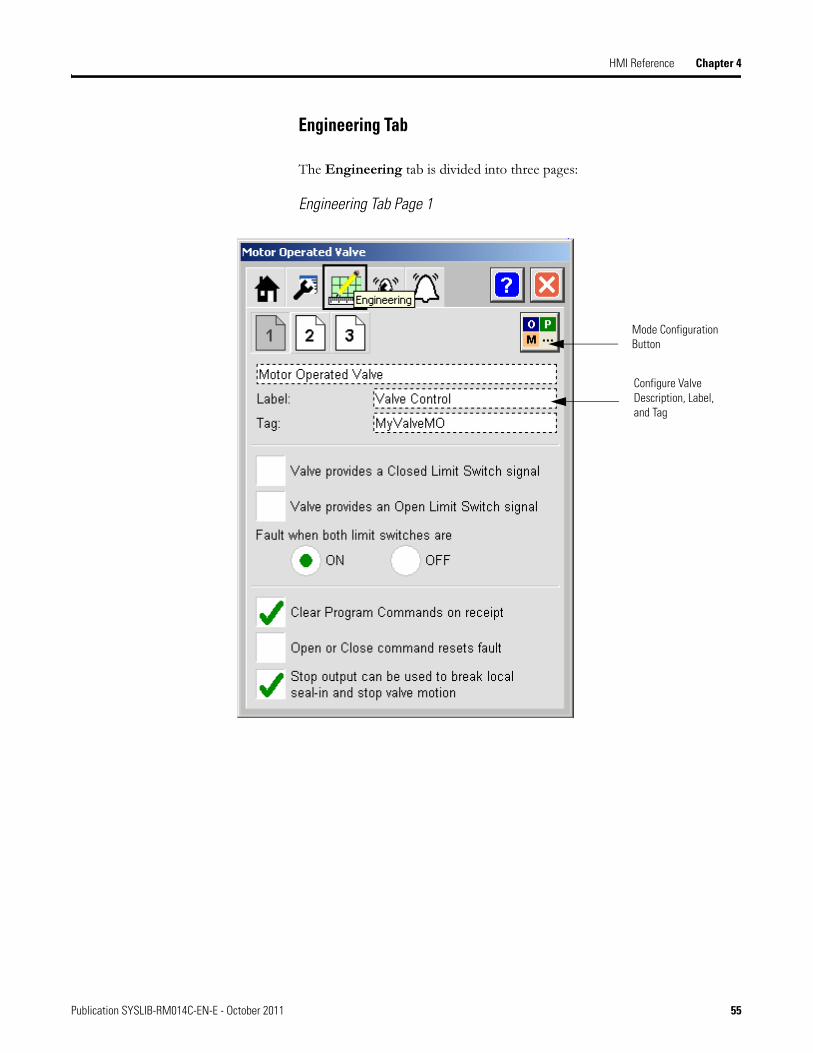
HMI Reference Chapter 4
Engineering Tab
The Engineering tab is divided into three pages:
Engineering Tab Page 1
Configure Valve Description, Label, and Tag
Mode Configuration Button
Publication SYSLIB-RM014C-EN-E - October 2011 55
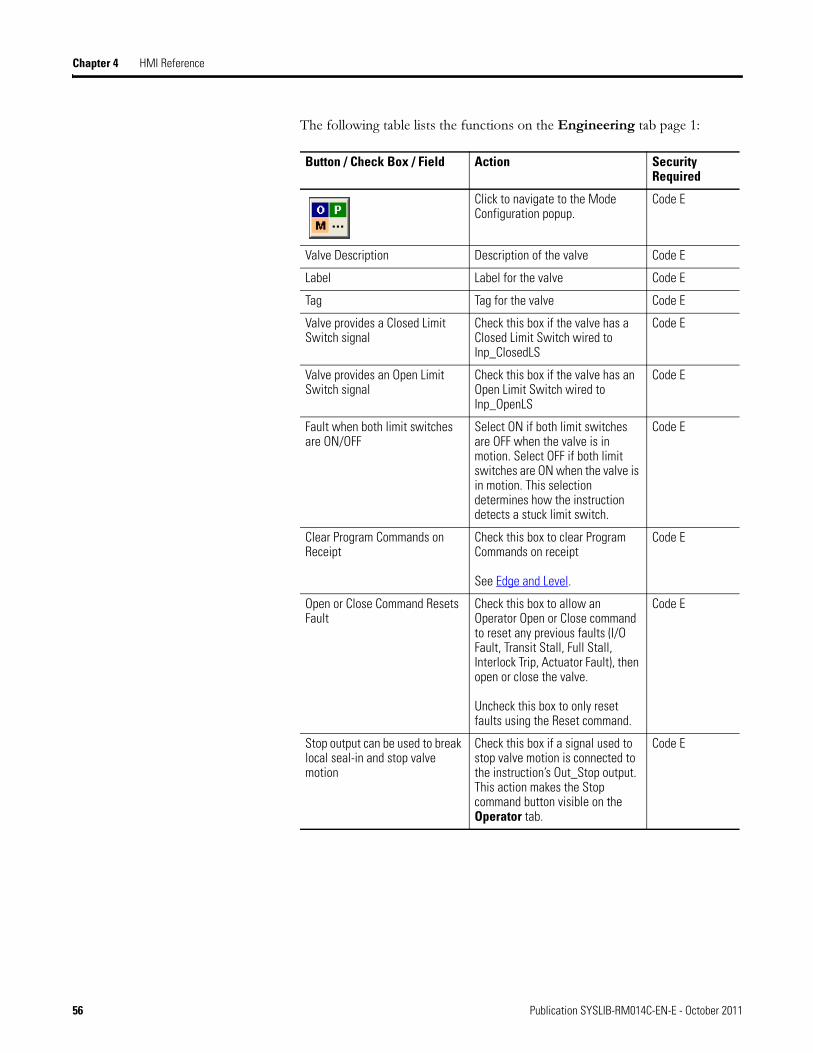
Chapter 4 HMI Reference
The following table lists the functions on the Engineering tab page 1:
Button / Check Box / Field Action Security Required
Click to navigate to the Mode Configuration popup.
Code E
Valve Description Description of the valve Code E
Label Label for the valve Code E
Tag Tag for the valve Code E
Valve provides a Closed Limit Switch signal
Check this box if the valve has a Closed Limit Switch wired to Inp_ClosedLS
Code E
Valve provides an Open Limit Switch signal
Check this box if the valve has an Open Limit Switch wired to Inp_OpenLS
Code E
Fault when both limit switches are ON/OFF
Select ON if both limit switches are OFF when the valve is in motion. Select OFF if both limit switches are ON when the valve is in motion. This selection determines how the instruction detects a stuck limit switch.
Code E
Clear Program Commands on Receipt
Check this box to clear Program Commands on receipt
See Edge and Level.
Code E
Open or Close Command Resets Fault
Check this box to allow an Operator Open or Close command to reset any previous faults (I/O Fault, Transit Stall, Full Stall, Interlock Trip, Actuator Fault), then open or close the valve.
Uncheck this box to only reset faults using the Reset command.
Code E
Stop output can be used to break local seal-in and stop valve motion
Check this box if a signal used to stop valve motion is connected to the instruction’s Out_Stop output. This action makes the Stop command button visible on the Operator tab.
Code E
56 Publication SYSLIB-RM014C-EN-E - October 2011
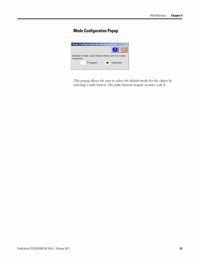
HMI Reference Chapter 4
Mode Configuration Popup
This popup allows the user to select the default mode for the object by selecting a radio button. The radio buttons require security code E.
Publication SYSLIB-RM014C-EN-E - October 2011 57
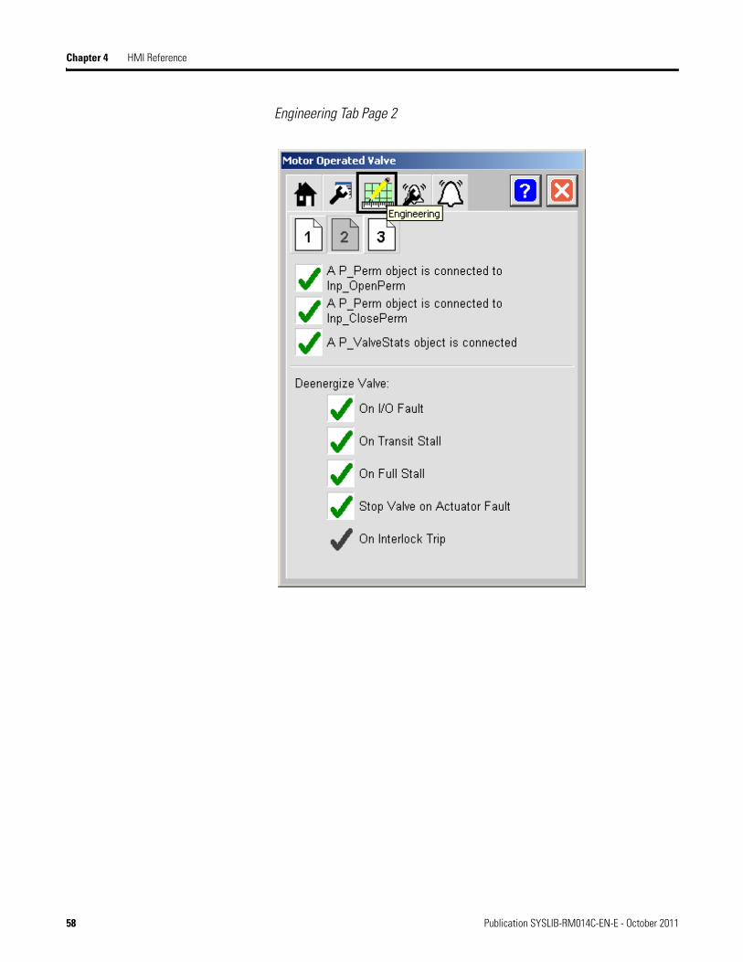
Chapter 4 HMI Reference
Engineering Tab Page 2
58 Publication SYSLIB-RM014C-EN-E - October 2011
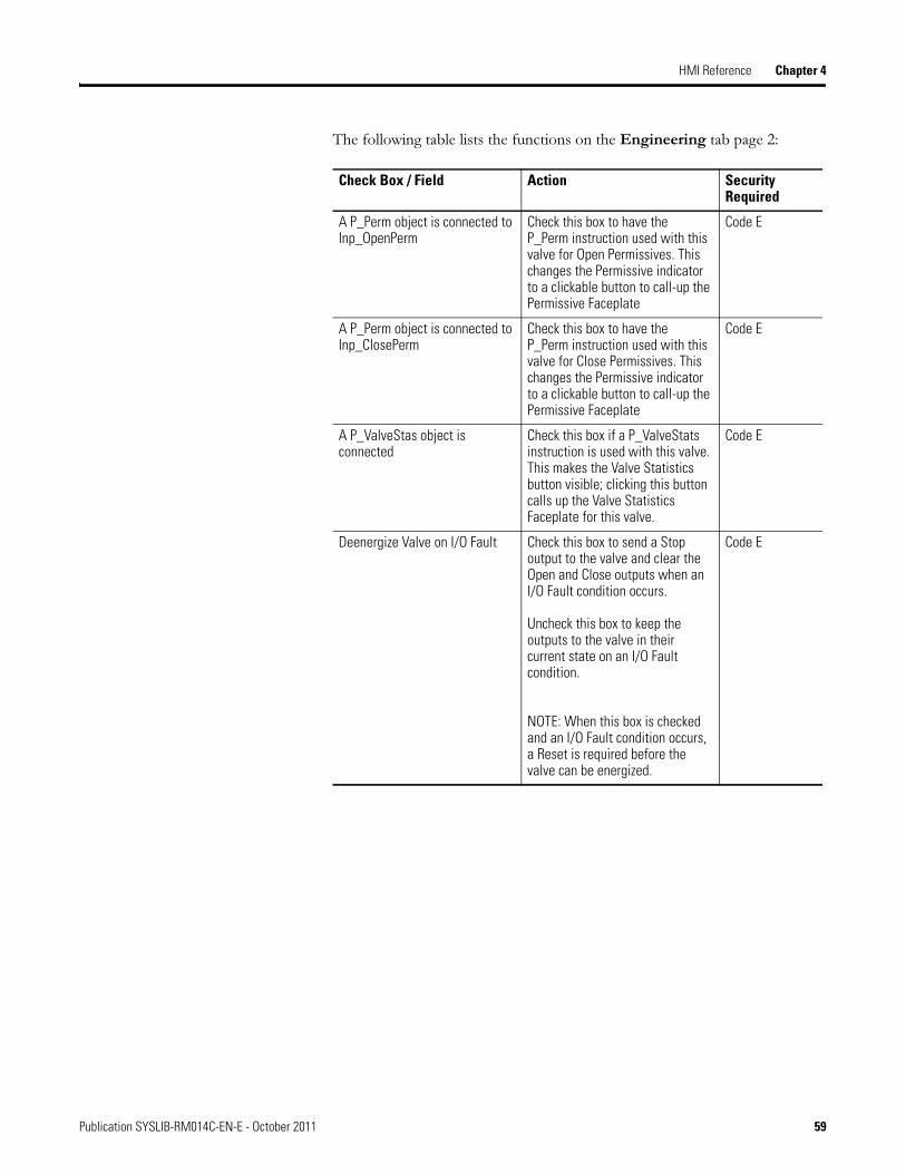
HMI Reference Chapter 4
The following table lists the functions on the Engineering tab page 2:
Check Box / Field Action Security Required
A P_Perm object is connected to Inp_OpenPerm
Check this box to have the P_Perm instruction used with this valve for Open Permissives. This changes the Permissive indicator to a clickable button to call-up the Permissive Faceplate
Code E
A P_Perm object is connected to Inp_ClosePerm
Check this box to have the P_Perm instruction used with this valve for Close Permissives. This changes the Permissive indicator to a clickable button to call-up the Permissive Faceplate
Code E
A P_ValveStas object is connected
Check this box if a P_ValveStats instruction is used with this valve. This makes the Valve Statistics button visible; clicking this button calls up the Valve Statistics Faceplate for this valve.
Code E
Deenergize Valve on I/O Fault Check this box to send a Stop output to the valve and clear the Open and Close outputs when an I/O Fault condition occurs.
Uncheck this box to keep the outputs to the valve in their current state on an I/O Fault condition.
NOTE: When this box is checked and an I/O Fault condition occurs, a Reset is required before the valve can be energized.
Code E
Publication SYSLIB-RM014C-EN-E - October 2011 59
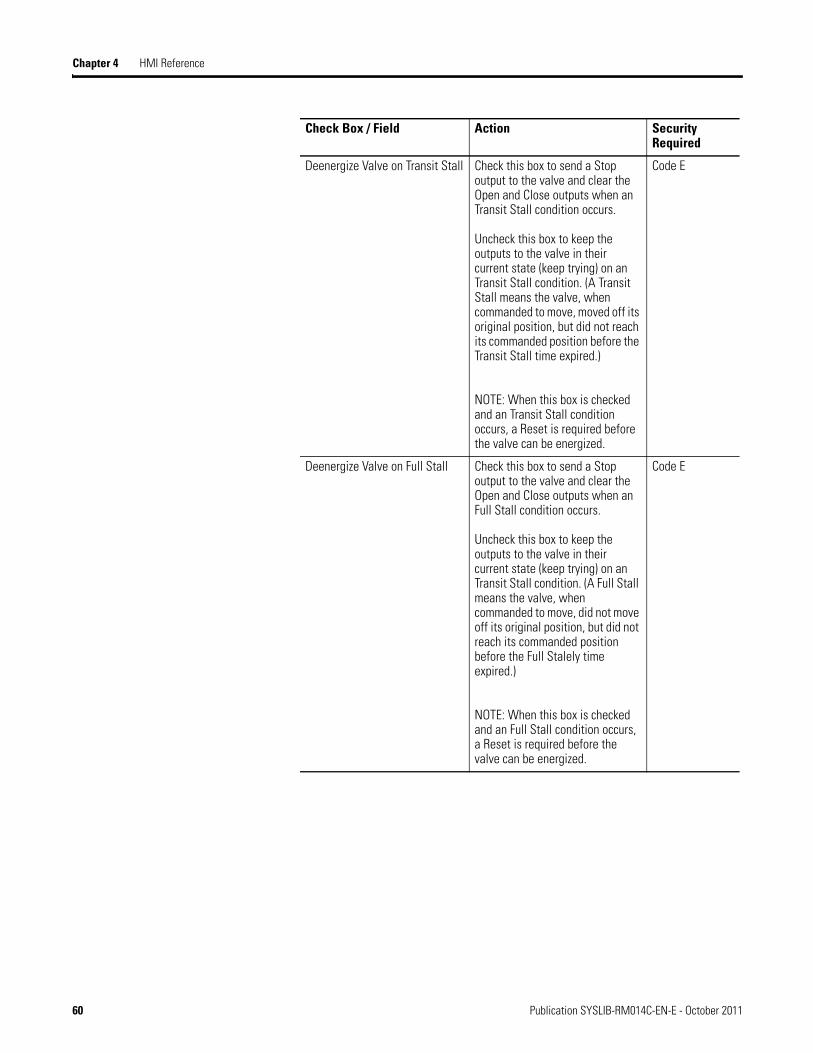
Chapter 4 HMI Reference
Deenergize Valve on Transit Stall Check this box to send a Stop output to the valve and clear the Open and Close outputs when an Transit Stall condition occurs.
Uncheck this box to keep the outputs to the valve in their current state (keep trying) on an Transit Stall condition. (A Transit Stall means the valve, when commanded to move, moved off its original position, but did not reach its commanded position before the Transit Stall time expired.)
NOTE: When this box is checked and an Transit Stall condition occurs, a Reset is required before the valve can be energized.
Code E
Deenergize Valve on Full Stall Check this box to send a Stop output to the valve and clear the Open and Close outputs when an Full Stall condition occurs.
Uncheck this box to keep the outputs to the valve in their current state (keep trying) on an Transit Stall condition. (A Full Stall means the valve, when commanded to move, did not move off its original position, but did not reach its commanded position before the Full Stalely time expired.)
NOTE: When this box is checked and an Full Stall condition occurs, a Reset is required before the valve can be energized.
Code E
Check Box / Field Action Security Required
60 Publication SYSLIB-RM014C-EN-E - October 2011
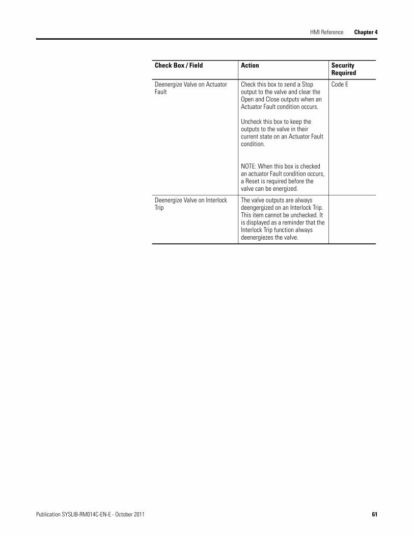
HMI Reference Chapter 4
Deenergize Valve on Actuator Fault
Check this box to send a Stop output to the valve and clear the Open and Close outputs when an Actuator Fault condition occurs.
Uncheck this box to keep the outputs to the valve in their current state on an Actuator Fault condition.
NOTE: When this box is checked an actuator Fault condition occurs, a Reset is required before the valve can be energized.
Code E
Deenergize Valve on Interlock Trip
The valve outputs are always deengergized on an Interlock Trip. This item cannot be unchecked. It is displayed as a reminder that the Interlock Trip function always deenergiezes the valve.
Check Box / Field Action Security Required
Publication SYSLIB-RM014C-EN-E - October 2011 61
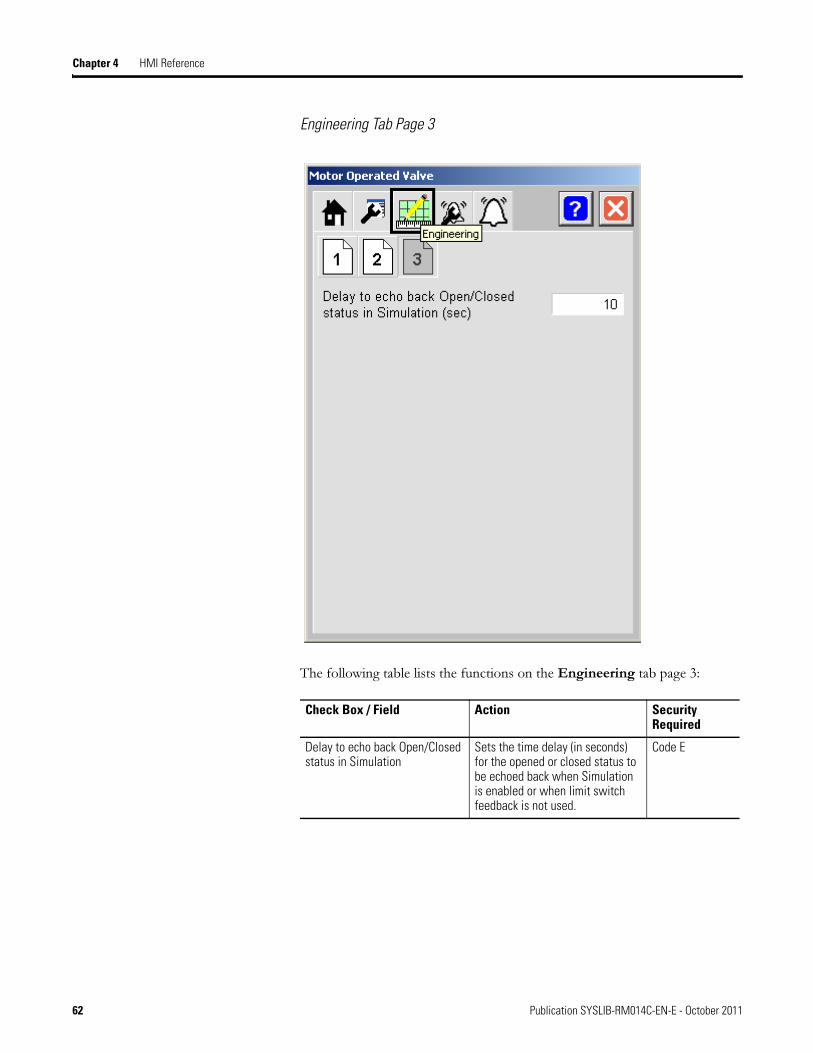
Chapter 4 HMI Reference
Engineering Tab Page 3
The following table lists the functions on the Engineering tab page 3:
Check Box / Field Action Security Required
Delay to echo back Open/Closed status in Simulation
Sets the time delay (in seconds) for the opened or closed status to be echoed back when Simulation is enabled or when limit switch feedback is not used.
Code E
62 Publication SYSLIB-RM014C-EN-E - October 2011

HMI Reference Chapter 4
Alarm Configuration Tab
The Alarm Configuration tab contains configuration related to the alarms for the device.
Publication SYSLIB-RM014C-EN-E - October 2011 63

Chapter 4 HMI Reference
The following table shows the function for the Alarm Configuration tab.
Check Box/Field Action Security Required
Alarm The alarm exists for the device. Code E
Acknowledge Required Require acknowledgement of the alarm.
IMPORTANT If using FTView Alarm and Events, configure its Alarm Tag for Acknowledge Required. The controller handles acknowledgement within this instruction.
Code E
Reset Required Require a reset to clear the alarm status. There is a single alarm reset that resets all of the alarms for the device.
IMPORTANT If using FTView Alarm and Events, DO NOT check the ‘Latched’ checkbox as the controller handles the alarm reset within this instruction.
Code E
Severity Configure the severity level of the alarm 1 = Information 2 = Warning 3 = Exception 4 = Fault
Code E
Minimum On Time When an Alarm occurs, the Alarm output will be held on for at least tis amount of time (sec). If set to 5 seconds or less, the Alarm output will be held on for at least 5 seconds to ensure it is seen by polling. Set this time higher if you want an Alarm to be held in the Alarm state (and on the Alarm summary) longer. This will keep it visible to the Operator, or keep the Alarm from clearing and being set again (for an intermittent condition) until the Operator has had time to perform any Alarm-related actions.
Note: If the alarm is configured with Reset Required (Cfg_ResetReqd = 1), the operator can reset the alarm before this time expires if the input condition has returned to normal.
Code G
64 Publication SYSLIB-RM014C-EN-E - October 2011
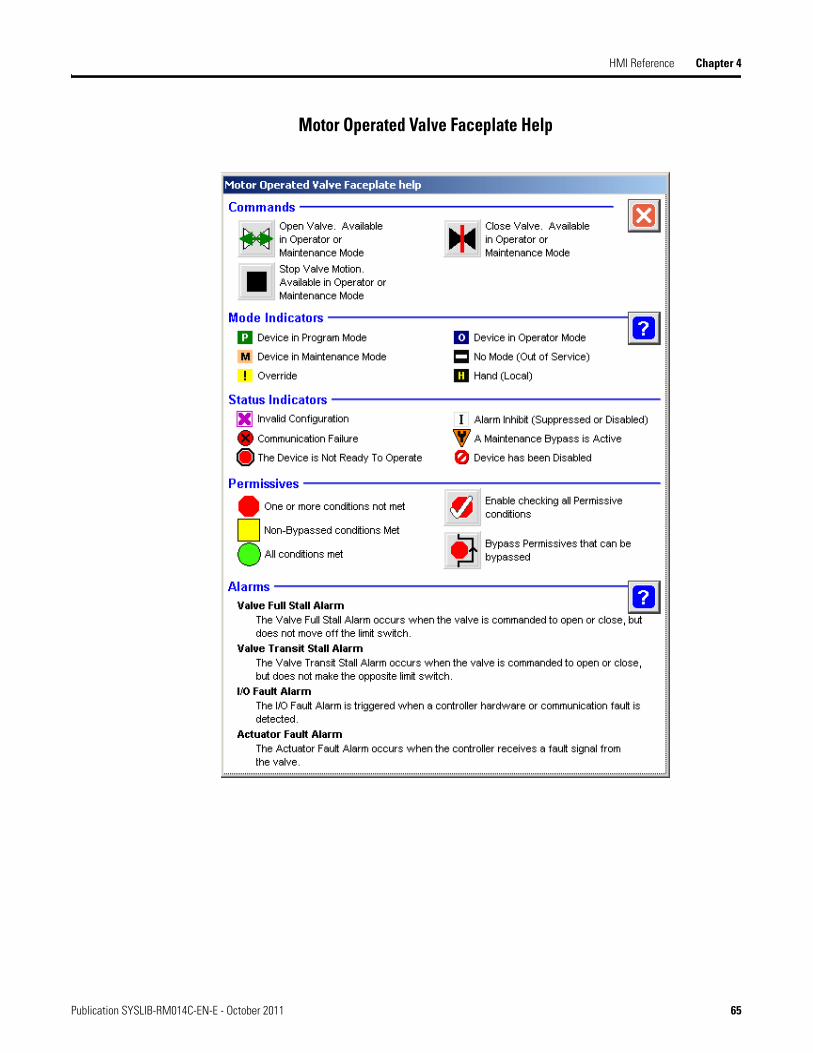
HMI Reference Chapter 4
Motor Operated Valve Faceplate Help
Publication SYSLIB-RM014C-EN-E - October 2011 65

Chapter 4 HMI Reference
Notes:
66 Publication SYSLIB-RM014C-EN-E - October 2011

Rockwell Otomasyon Ticaret A.Ş., Kar Plaza İş Merkezi E Blok Kat:6 34752 İçerenköy, İstanbul, Tel: +90 (216) 5698400
Publication SYSLIB-RM014C-EN-E - October 2011Copyright © 2011 Rockwell Automation, Inc. All rights reserved. Printed in the U.S.A.
Rockwell Automation Support
Rockwell Automation provides technical information on the Web to assist you in using its products. At http://www.rockwellautomation.com/support/, you can find technical manuals, a knowledge base of FAQs, technical and application notes, sample code and links to software service packs, and a MySupport feature that you can customize to make the best use of these tools.
For an additional level of technical phone support for installation, configuration, and troubleshooting, we offer TechConnectSM support programs. For more information, contact your local distributor or Rockwell Automation representative, or visit http://www.rockwellautomation.com/support/.
Installation Assistance
If you experience a problem within the first 24 hours of installation, review the information that is contained in this manual. You can contact Customer Support for initial help in getting your product up and running.
New Product Satisfaction Return
Rockwell Automation tests all of its products to ensure that they are fully operational when shipped from the manufacturing facility. However, if your product is not functioning and needs to be returned, follow these procedures.
Documentation Feedback
Your comments will help us serve your documentation needs better. If you have any suggestions on how to improve this document, complete this form, publication RA-DU002, available at http://www.rockwellautomation.com/literature/.
United States or Canada 1.440.646.3434
Outside United States or Canada Use the Worldwide Locator at http://www.rockwellautomation.com/support/americas/phone_en.html, or contact your local Rockwell Automation representative.
United States Contact your distributor. You must provide a Customer Support case number (call the phone number above to obtain one) to your distributor to complete the return process.
Outside United States Please contact your local Rockwell Automation representative for the return procedure.
Power, Control and Information Solutions HeadquartersAmericas: Rockwell Automation, 1201 South Second Street, Milwaukee, WI 53204-2496 USA, Tel: (1) 414.382.2000, Fax: (1) 414.382.4444Europe/Middle East/Africa: Rockwell Automation NV, Pegasus Park, De Kleetlaan 12a, 1831 Diegem, Belgium, Tel: (32) 2 663 0600, Fax: (32) 2 663 0640Asia Pacific: Rockwell Automation, Level 14, Core F, Cyberport 3, 100 Cyberport Road, Hong Kong, Tel: (852) 2887 4788, Fax: (852) 2508 1846
www.rockwel lautomation.com