Embed Size (px)
Citation preview
Cat. No. W128-E1-4
Position Control Unit
SYSMAC
C200H-NC112

C200H-NC112 Position Control UnitOperation ManualSeptember 2000

!
!
!
ii
Notice:OMRON products are manufactured for use according to proper procedures by a qualified operatorand only for the purposes described in this manual.
The following conventions are used to indicate and classify precautions in this manual. Always heedthe information provided with them. Failure to heed precautions can result in injury to people or dam-age to property.
DANGER Indicates an imminently hazardous situation which, if not avoided, will result in death orserious injury.
WARNING Indicates a potentially hazardous situation which, if not avoided, could result in death orserious injury.
Caution Indicates a potentially hazardous situation which, if not avoided, may result in minor ormoderate injury, or property damage.
OMRON Product ReferencesAll OMRON products are capitalized in this manual. The word “Unit” is also capitalized when it refersto an OMRON product, regardless of whether or not it appears in the proper name of the product.
The abbreviation “Ch,” which appears in some displays and on some OMRON products, often means“word” and is abbreviated “Wd” in documentation in this sense.
The abbreviation “PC” means Programmable Controller and is not used as an abbreviation for any-thing else.
Visual AidsThe following headings appear in the left column of the manual to help you locate different types ofinformation.
Note Indicates information of particular interest for efficient and convenient operationof the product.
Reference Indicates supplementary information on related topics that may be of interest tothe user.
1, 2, 3... 1. Indicates lists of one sort or another, such as procedures, checklists, etc.
OMRON, 1990All rights reserved. No part of this publication may be reproduced, stored in a retrieval system, or transmitted, in anyform, or by any means, mechanical, electronic, photocopying, recording, or otherwise, without the prior written permis-sion of OMRON.
No patent liability is assumed with respect to the use of the information contained herein. Moreover, because OMRON isconstantly striving to improve its high-quality products, the information contained in this manual is subject to changewithout notice. Every precaution has been taken in the preparation of this manual. Nevertheless, OMRON assumes noresponsibility for errors or omissions. Neither is any liability assumed for damages resulting from the use of the informa-tion contained in this publication.

iii
About this Manual:
The OMRON C200H-NC112 Position Control Unit is a Special I/O Unit for C200H PCs. It is designedto control positioning actions through pulse train outputs to a motor driver, based on PC programmingand external control inputs.
This manual covers the specifications and procedures necessary for operation and installation. Beforeattempting to operate the C200H Position Control Unit, be sure to thoroughly familiarize yourself withthe information contained herein.
During operation, refer to the C200H PC Operation Manual as necessary for programming and sys-tem details. Note that the term “channel” employed in the C200H PC Operation Manual (and otherearlier manuals) has been replaced by the term “word” in this manual, where it refers to a 16-bit ad-dress. Wherever the term “channel” (either written in full or abbreviated as “ch”) continues to appear,whether in earlier manuals, on displays, or on the Units themselves, it can be taken to have the samemeaning as “word.”
Section 1 describes the basic features, components, and operation of the Position Control Unit, aswell as the basic configuration and principles of positioning control systems. Reading this section firstwill give you a familiarity with the essential terminology used in this manual and an understanding ofthe fundamentals necessary for successful operation.
Section 2 covers procedures such as wiring and switch setting which are necessary before operation.
Section 3 explains data format and configuration, basic operating procedure, and various aspects ofPosition Control Unit operation other than commands.
Section 4 covers commands and the data settings which are necessary for their execution.
Section 5 provides examples of possible applications of PCU commands, inputs, and outputs.
Section 6 outlines the procedures for handling errors and alarms that occur during Position ControlUnit operation.
The appendices contain lists of error and alarm codes, DM and IR area data allocation charts, specifi-cations, and a table of standard models. There are also an index and a glossary of terms at the backof the manual.
WARNING Failure to read and understand the information provided in this manual may result inpersonal injury or death, damage to the product, or product failure. Please read eachsection in its entirety and be sure you understand the information provided in the sectionand related sections before attempting any of the procedures or operations given.
!

v
TABLE OF CONTENTS
PRECAUTIONS vii . . . . . . . . . . . . . . . . . . . . . . . . . . . . . . . . . . . . . . . . . . . . . . . . 1 Intended Audience viii . . . . . . . . . . . . . . . . . . . . . . . . . . . . . . . . . . . . . . . . . . . . . . . . 2 General Precautions viii . . . . . . . . . . . . . . . . . . . . . . . . . . . . . . . . . . . . . . . . . . . . . . . 3 Safety Precautions viii . . . . . . . . . . . . . . . . . . . . . . . . . . . . . . . . . . . . . . . . . . . . . . . . 4 Operating Environment Precautions viii . . . . . . . . . . . . . . . . . . . . . . . . . . . . . . . . . . . 5 Application Precautions ix . . . . . . . . . . . . . . . . . . . . . . . . . . . . . . . . . . . . . . . . . . . .
SECTION 1 – Introduction 1 . . . . . . . . . . . . . . . . . . . . . . . . . . . . . . . . . . . . . . . 1–1 Features 2 . . . . . . . . . . . . . . . . . . . . . . . . . . . . . . . . . . . . . . . . . . . . . . . . . . . . . . . . . 1–2 Components 3 . . . . . . . . . . . . . . . . . . . . . . . . . . . . . . . . . . . . . . . . . . . . . . . . . . . . . 1–3 Basic Operating Principles 3 . . . . . . . . . . . . . . . . . . . . . . . . . . . . . . . . . . . . . . . . . . 1–4 I/O Configuration 4 . . . . . . . . . . . . . . . . . . . . . . . . . . . . . . . . . . . . . . . . . . . . . . . . . 1–5 Positioning System Principles 5 . . . . . . . . . . . . . . . . . . . . . . . . . . . . . . . . . . . . . . .
1–5–1 Open-loop System 7 . . . . . . . . . . . . . . . . . . . . . . . . . . . . . . . . . . . . . . . . 1–5–2 Semiclosed-loop System 8 . . . . . . . . . . . . . . . . . . . . . . . . . . . . . . . . . . .
SECTION 2 – Before Operation 11 . . . . . . . . . . . . . . . . . . . . . . . . . . . . . . . . . . . 2–1 Switch Settings 12 . . . . . . . . . . . . . . . . . . . . . . . . . . . . . . . . . . . . . . . . . . . . . . . . . . .
2–1–1 Switch Setting Examples 17 . . . . . . . . . . . . . . . . . . . . . . . . . . . . . . . . . . . 2–2 Wiring 21 . . . . . . . . . . . . . . . . . . . . . . . . . . . . . . . . . . . . . . . . . . . . . . . . . . . . . . . . . .
2–2–1 Input Connection Examples 27 . . . . . . . . . . . . . . . . . . . . . . . . . . . . . . . . . 2–2–2 Output Connection Examples 29 . . . . . . . . . . . . . . . . . . . . . . . . . . . . . . . 2–2–3 Wiring Precautions 38 . . . . . . . . . . . . . . . . . . . . . . . . . . . . . . . . . . . . . . . .
2–3 Dimensions 39 . . . . . . . . . . . . . . . . . . . . . . . . . . . . . . . . . . . . . . . . . . . . . . . . . . . . . .
SECTION 3 – Operation 41 . . . . . . . . . . . . . . . . . . . . . . . . . . . . . . . . . . . . . . . . . 3–1 Operational Flow 42 . . . . . . . . . . . . . . . . . . . . . . . . . . . . . . . . . . . . . . . . . . . . . . . . . 3–2 Output Pulses 44 . . . . . . . . . . . . . . . . . . . . . . . . . . . . . . . . . . . . . . . . . . . . . . . . . . . . 3–3 Writing Data 44 . . . . . . . . . . . . . . . . . . . . . . . . . . . . . . . . . . . . . . . . . . . . . . . . . . . . . 3–4 Data Configuration and Allocation 45 . . . . . . . . . . . . . . . . . . . . . . . . . . . . . . . . . . . 3–5 DM Area Data Format 48 . . . . . . . . . . . . . . . . . . . . . . . . . . . . . . . . . . . . . . . . . . . . . 3–6 Flags and Other Input Data 48 . . . . . . . . . . . . . . . . . . . . . . . . . . . . . . . . . . . . . . . . . . 3–7 DM Area Allocation 48 . . . . . . . . . . . . . . . . . . . . . . . . . . . . . . . . . . . . . . . . . . . . . . .
3–7–1 Zones 50 . . . . . . . . . . . . . . . . . . . . . . . . . . . . . . . . . . . . . . . . . . . . . . . . . . 3–7–2 Backlash Compensation 52 . . . . . . . . . . . . . . . . . . . . . . . . . . . . . . . . . . . . 3–7–3 Internal CW/CCW Limits 53 . . . . . . . . . . . . . . . . . . . . . . . . . . . . . . . . . . 3–7–4 Data Calculations 53 . . . . . . . . . . . . . . . . . . . . . . . . . . . . . . . . . . . . . . . . .
SECTION 4 – Commands 59 . . . . . . . . . . . . . . . . . . . . . . . . . . . . . . . . . . . . . . . . 4–1 START 60 . . . . . . . . . . . . . . . . . . . . . . . . . . . . . . . . . . . . . . . . . . . . . . . . . . . . . . . . .
4–1–1 DM Area Settings 60 . . . . . . . . . . . . . . . . . . . . . . . . . . . . . . . . . . . . . . . . 4–2 Positioning Actions 61 . . . . . . . . . . . . . . . . . . . . . . . . . . . . . . . . . . . . . . . . . . . . . . . .
4–2–1 IR Area Settings 66 . . . . . . . . . . . . . . . . . . . . . . . . . . . . . . . . . . . . . . . . . . 4–2–2 Execution Examples 68 . . . . . . . . . . . . . . . . . . . . . . . . . . . . . . . . . . . . . .
4–3 ORIGIN SEARCH 71 . . . . . . . . . . . . . . . . . . . . . . . . . . . . . . . . . . . . . . . . . . . . . . . . 4–3–1 DM Area Settings 71 . . . . . . . . . . . . . . . . . . . . . . . . . . . . . . . . . . . . . . . . 4–3–2 IR Area Settings 72 . . . . . . . . . . . . . . . . . . . . . . . . . . . . . . . . . . . . . . . . . . 4–3–3 Execution Examples 73 . . . . . . . . . . . . . . . . . . . . . . . . . . . . . . . . . . . . . . 4–3–4 Completion Examples 84 . . . . . . . . . . . . . . . . . . . . . . . . . . . . . . . . . . . . .
4–4 ORIGIN RETURN 86 . . . . . . . . . . . . . . . . . . . . . . . . . . . . . . . . . . . . . . . . . . . . . . . . 4–4–1 DM Area Settings 87 . . . . . . . . . . . . . . . . . . . . . . . . . . . . . . . . . . . . . . . . 4–4–2 IR Area Settings 87 . . . . . . . . . . . . . . . . . . . . . . . . . . . . . . . . . . . . . . . . . . 4–4–3 Execution Example 87 . . . . . . . . . . . . . . . . . . . . . . . . . . . . . . . . . . . . . . .

Table of contents
vi
4–5 RELEASE PROHIBIT 89 . . . . . . . . . . . . . . . . . . . . . . . . . . . . . . . . . . . . . . . . . . . . . 4–6 READ ERROR 91 . . . . . . . . . . . . . . . . . . . . . . . . . . . . . . . . . . . . . . . . . . . . . . . . . . .
4–6–1 Execution Example 92 . . . . . . . . . . . . . . . . . . . . . . . . . . . . . . . . . . . . . . . 4–6–2 Reading from the Programming Console 92 . . . . . . . . . . . . . . . . . . . . . .
4–7 RESET ORIGIN 93 . . . . . . . . . . . . . . . . . . . . . . . . . . . . . . . . . . . . . . . . . . . . . . . . . . 4–8 TEACH 93 . . . . . . . . . . . . . . . . . . . . . . . . . . . . . . . . . . . . . . . . . . . . . . . . . . . . . . . . .
4–8–1 IR Area Settings 94 . . . . . . . . . . . . . . . . . . . . . . . . . . . . . . . . . . . . . . . . . . 4–8–2 Execution Example 94 . . . . . . . . . . . . . . . . . . . . . . . . . . . . . . . . . . . . . . . 4–8–3 Teaching From the Programming Console 94 . . . . . . . . . . . . . . . . . . . . .
4–9 TRANSFER DATA 95 . . . . . . . . . . . . . . . . . . . . . . . . . . . . . . . . . . . . . . . . . . . . . . . . 4–9–1 Normal Transfer 96 . . . . . . . . . . . . . . . . . . . . . . . . . . . . . . . . . . . . . . . . . . 4–9–2 IR Area Settings 97 . . . . . . . . . . . . . . . . . . . . . . . . . . . . . . . . . . . . . . . . . . 4–9–3 Present Position Preset 99 . . . . . . . . . . . . . . . . . . . . . . . . . . . . . . . . . . . . .
4–10 Manual Operations 102 . . . . . . . . . . . . . . . . . . . . . . . . . . . . . . . . . . . . . . . . . . . . . . . . 4–10–1 DM Area Settings 102 . . . . . . . . . . . . . . . . . . . . . . . . . . . . . . . . . . . . . . . . 4–10–2 IR Area Settings 103 . . . . . . . . . . . . . . . . . . . . . . . . . . . . . . . . . . . . . . . . . . 4–10–3 HIGH-SPEED JOG 103 . . . . . . . . . . . . . . . . . . . . . . . . . . . . . . . . . . . . . . . 4–10–4 LOW-SPEED JOG 104 . . . . . . . . . . . . . . . . . . . . . . . . . . . . . . . . . . . . . . . . 4–10–5 INCH 104 . . . . . . . . . . . . . . . . . . . . . . . . . . . . . . . . . . . . . . . . . . . . . . . . . .
4–11 External Interrupt Commands 105 . . . . . . . . . . . . . . . . . . . . . . . . . . . . . . . . . . . . . . . 4–11–1 STOP 107 . . . . . . . . . . . . . . . . . . . . . . . . . . . . . . . . . . . . . . . . . . . . . . . . . . 4–11–2 CHANGE SPEED 115 . . . . . . . . . . . . . . . . . . . . . . . . . . . . . . . . . . . . . . . .
SECTION 5 – Programming Examples 117 . . . . . . . . . . . . . . . . . . . . . . . . . . . . . 5–1 Operation with Minimum Data (Displaying JOG Positions) 118 . . . . . . . . . . . . . . . . 5–2 Positioning at Intervals Using RESET ORIGIN 119 . . . . . . . . . . . . . . . . . . . . . . . . . 5–3 Feeding Selectively with START 121 . . . . . . . . . . . . . . . . . . . . . . . . . . . . . . . . . . . . . 5–4 TRANSFER DATA from Other PC Areas 123 . . . . . . . . . . . . . . . . . . . . . . . . . . . . . . 5–5 TRANSFER DATA from External Switches 125 . . . . . . . . . . . . . . . . . . . . . . . . . . . . 5–6 Using START to Carry Out Positioning Actions 128 . . . . . . . . . . . . . . . . . . . . . . . . . 5–7 Using Origin and Origin Proximity Signals 132 . . . . . . . . . . . . . . . . . . . . . . . . . . . . . 5–8 Using Zones to Control Jogging 132 . . . . . . . . . . . . . . . . . . . . . . . . . . . . . . . . . . . . . . 5–9 Setting Speeds 134 . . . . . . . . . . . . . . . . . . . . . . . . . . . . . . . . . . . . . . . . . . . . . . . . . . . . 5–10 Using a Multiple Bank Program 134 . . . . . . . . . . . . . . . . . . . . . . . . . . . . . . . . . . . . . .
SECTION 6 – Error Processing 137 . . . . . . . . . . . . . . . . . . . . . . . . . . . . . . . . . . . 6–1 Alarms and Errors 138 . . . . . . . . . . . . . . . . . . . . . . . . . . . . . . . . . . . . . . . . . . . . . . . . . 6–2 Outputs to the IR Area 138 . . . . . . . . . . . . . . . . . . . . . . . . . . . . . . . . . . . . . . . . . . . . . 6–3 Alarm/Error Indicators 138 . . . . . . . . . . . . . . . . . . . . . . . . . . . . . . . . . . . . . . . . . . . . . 6–4 Error Code Output 138 . . . . . . . . . . . . . . . . . . . . . . . . . . . . . . . . . . . . . . . . . . . . . . . . 6–5 Troubleshooting from the PC 140 . . . . . . . . . . . . . . . . . . . . . . . . . . . . . . . . . . . . . . . .
6–5–1 Error List for Special I/O Units 140 . . . . . . . . . . . . . . . . . . . . . . . . . . . . . . 6–5–2 AR Area Error and Restart Bits for Special I/O Units 140 . . . . . . . . . . . .
6–6 Basic Troubleshooting Chart 141 . . . . . . . . . . . . . . . . . . . . . . . . . . . . . . . . . . . . . . . . 6–7 Detection of Abnormal Pulse Outputs 143 . . . . . . . . . . . . . . . . . . . . . . . . . . . . . . . . .
Appendix 145 . . . . . . . . . . . . . . . . . . . . . . . . . . . . . . . . . . . . . . . . . . . . . . . . . . . . . . A – Standard Models 145 . . . . . . . . . . . . . . . . . . . . . . . . . . . . . . . . . . . . . . . . . . . . . . . . . . . . B – Specifications 147 . . . . . . . . . . . . . . . . . . . . . . . . . . . . . . . . . . . . . . . . . . . . . . . . . . . . . . C – DM Area Allocations 149 . . . . . . . . . . . . . . . . . . . . . . . . . . . . . . . . . . . . . . . . . . . . . . . . E – Alarm Code List 159 . . . . . . . . . . . . . . . . . . . . . . . . . . . . . . . . . . . . . . . . . . . . . . . . . . . . F – Error Code List 161 . . . . . . . . . . . . . . . . . . . . . . . . . . . . . . . . . . . . . . . . . . . . . . . . . . . . . G – Using the C200H-NC112 with CS1-series PCs 165 . . . . . . . . . . . . . . . . . . . . . . . . . . . .
Glossary 173 . . . . . . . . . . . . . . . . . . . . . . . . . . . . . . . . . . . . . . . . . . . . . . . . . . . . . . .
Index 179 . . . . . . . . . . . . . . . . . . . . . . . . . . . . . . . . . . . . . . . . . . . . . . . . . . . . . . . . .

vii
PRECAUTIONS
This section provides general precautions for using the Programmable Controller (PC) and related devices.
The information contained in this section is important for the safe and reliable application of the Programmable Con-troller. You must read this section and understand the information contained before attempting to set up or operate aPC system.
1 Intended Audience viii . . . . . . . . . . . . . . . . . . . . . . . . . . . . . . . . . . . . . . . . . . . . . . . . . 2 General Precautions viii . . . . . . . . . . . . . . . . . . . . . . . . . . . . . . . . . . . . . . . . . . . . . . . . 3 Safety Precautions viii . . . . . . . . . . . . . . . . . . . . . . . . . . . . . . . . . . . . . . . . . . . . . . . . . 4 Operating Environment Precautions viii . . . . . . . . . . . . . . . . . . . . . . . . . . . . . . . . . . . 5 Application Precautions ix . . . . . . . . . . . . . . . . . . . . . . . . . . . . . . . . . . . . . . . . . . . . .

!
!
!
!
!
!
4Operating Environment Precautions
viii
1 Intended AudienceThis manual is intended for the following personnel, who must also have knowl-edge of electrical systems (an electrical engineer or the equivalent).• Personnel in charge of installing FA systems.• Personnel in charge of designing FA systems.• Personnel in charge of managing FA systems and facilities.
2 General PrecautionsThe user must operate the product according to the performance specificationsdescribed in the relevant manuals.Before using the product under conditions which are not described in the manualor applying the product to nuclear control systems, railroad systems, aviationsystems, vehicles, combustion systems, medical equipment, amusement ma-chines, safety equipment, and other systems, machines, and equipment thatmay have a serious influence on lives and property if used improperly, consultyour OMRON representative.Make sure that the ratings and performance characteristics of the product aresufficient for the systems, machines, and equipment, and be sure to provide thesystems, machines, and equipment with double safety mechanisms.This manual provides information for programming and operating the Unit. Besure to read this manual before attempting to use the Unit and keep this manualclose at hand for reference during operation.
WARNING It is extremely important that a PC and all PC Units be used for the specifiedpurpose and under the specified conditions, especially in applications that candirectly or indirectly affect human life. You must consult with your OMRONrepresentative before applying a PC system to the above-mentionedapplications.
3 Safety PrecautionsWARNING Do not attempt to take any Unit apart while the power is being supplied. Doing so
may result in electric shock.
WARNING Do not touch any of the terminals or terminal blocks while the power is beingsupplied. Doing so may result in electric shock.
WARNING Do not attempt to disassemble, repair, or modify any Units. Any attempt to do somay result in malfunction, fire, or electric shock.
Caution Confirm safety at the destination node before transferring a program to anothernode or changing contents of the I/O memory area. Doing either of these withoutconfirming safety may result in injury.
4 Operating Environment PrecautionsCaution Do not operate the control system in the following locations:
• Locations subject to direct sunlight.• Locations subject to temperatures or humidity outside the range specified in
the specifications.• Locations subject to condensation as the result of severe changes in tempera-
ture.

!
!
!
!
5Application Precautions
ix
• Locations subject to corrosive or flammable gases.• Locations subject to dust (especially iron dust) or salts.• Locations subject to exposure to water, oil, or chemicals.• Locations subject to shock or vibration.
Caution Take appropriate and sufficient countermeasures when installing systems in thefollowing locations:
• Locations subject to static electricity or other forms of noise.• Locations subject to strong electromagnetic fields.• Locations subject to possible exposure to radioactivity.• Locations close to power supplies.
Caution The operating environment of the PC system can have a large effect on the lon-gevity and reliability of the system. Improper operating environments can lead tomalfunction, failure, and other unforeseeable problems with the PC system. Besure that the operating environment is within the specified conditions at installa-tion and remains within the specified conditions during the life of the system.
5 Application PrecautionsObserve the following precautions when using the PC system.
WARNING Always heed these precautions. Failure to abide by the following precautionscould lead to serious or possibly fatal injury.
• Always ground the system to 100 Ω or less when installing the Units. Not con-necting to a ground of 100 Ω or less may result in electric shock.
• Always turn OFF the power supply to the PC before attempting any of the fol-lowing. Not turning OFF the power supply may result in malfunction or electricshock.
• Mounting or dismounting Power Supply Units, I/O Units, CPU Units,Memory Units, or any other Units.
• Assembling the Units.• Setting DIP switches or rotary switches.• Connecting cables or wiring the system.• Connecting or disconnecting the connectors.
Caution Failure to abide by the following precautions could lead to faulty operation of thePC or the system, or could damage the PC or PC Units. Always heed these pre-cautions.
• Fail-safe measures must be taken by the customer to ensure safety in theevent of incorrect, missing, or abnormal signals caused by broken signal lines,momentary power interruptions, or other causes.
• Interlock circuits, limit circuits, and similar safety measures in external circuits(i.e., not in the Programmable Controller) must be provided by the customer.
• Always use the power supply voltages specified in this manual. An incorrectvoltage may result in malfunction or burning.
• Take appropriate measures to ensure that the specified power with the ratedvoltage and frequency is supplied. Be particularly careful in places where thepower supply is unstable. An incorrect power supply may result in malfunction.
• Install external breakers and take other safety measures against short-circuit-ing in external wiring. Insufficient safety measures against short-circuiting mayresult in burning.
5Application Precautions
x
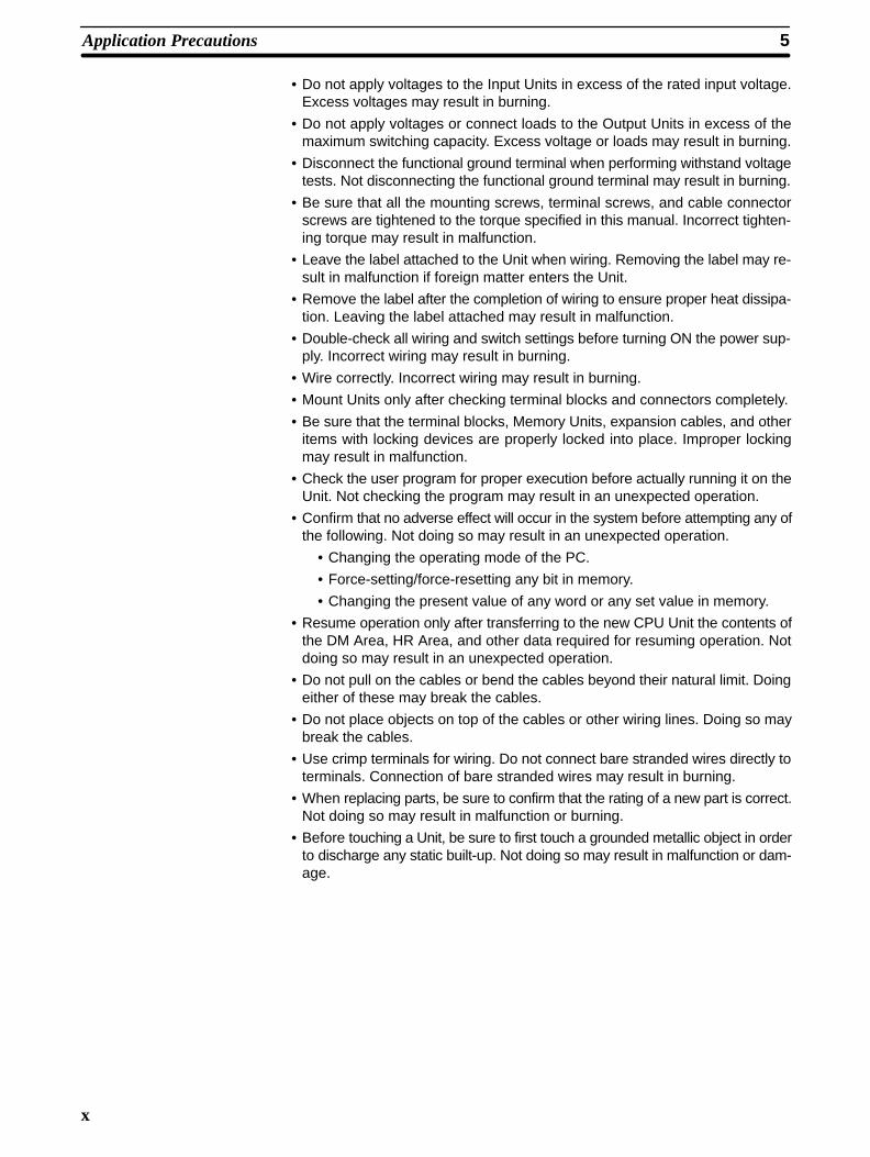
• Do not apply voltages to the Input Units in excess of the rated input voltage.Excess voltages may result in burning.
• Do not apply voltages or connect loads to the Output Units in excess of themaximum switching capacity. Excess voltage or loads may result in burning.
• Disconnect the functional ground terminal when performing withstand voltagetests. Not disconnecting the functional ground terminal may result in burning.
• Be sure that all the mounting screws, terminal screws, and cable connectorscrews are tightened to the torque specified in this manual. Incorrect tighten-ing torque may result in malfunction.
• Leave the label attached to the Unit when wiring. Removing the label may re-sult in malfunction if foreign matter enters the Unit.
• Remove the label after the completion of wiring to ensure proper heat dissipa-tion. Leaving the label attached may result in malfunction.
• Double-check all wiring and switch settings before turning ON the power sup-ply. Incorrect wiring may result in burning.
• Wire correctly. Incorrect wiring may result in burning.
• Mount Units only after checking terminal blocks and connectors completely.
• Be sure that the terminal blocks, Memory Units, expansion cables, and otheritems with locking devices are properly locked into place. Improper lockingmay result in malfunction.
• Check the user program for proper execution before actually running it on theUnit. Not checking the program may result in an unexpected operation.
• Confirm that no adverse effect will occur in the system before attempting any ofthe following. Not doing so may result in an unexpected operation.
• Changing the operating mode of the PC.
• Force-setting/force-resetting any bit in memory.
• Changing the present value of any word or any set value in memory.
• Resume operation only after transferring to the new CPU Unit the contents ofthe DM Area, HR Area, and other data required for resuming operation. Notdoing so may result in an unexpected operation.
• Do not pull on the cables or bend the cables beyond their natural limit. Doingeither of these may break the cables.
• Do not place objects on top of the cables or other wiring lines. Doing so maybreak the cables.
• Use crimp terminals for wiring. Do not connect bare stranded wires directly toterminals. Connection of bare stranded wires may result in burning.
• When replacing parts, be sure to confirm that the rating of a new part is correct.Not doing so may result in malfunction or burning.
• Before touching a Unit, be sure to first touch a grounded metallic object in orderto discharge any static built-up. Not doing so may result in malfunction or dam-age.

1
SECTION 1Introduction
The C200H-NC112 Position Control Unit is a Special I/O Unit that outputs pulse trains to control a stepping motor driveror a servomotor driver in accordance with a PC program or external inputs.
This section describes the basic features, components, and operation of the Position Control Unit, as well as the basicconfiguration and principles of positioning control systems. Reading this section first will give you a familiarity with theessential terminology used in this manual and an understanding of the fundamentals necessary for successful operation.
1–1 Features 2 . . . . . . . . . . . . . . . . . . . . . . . . . . . . . . . . . . . . . . . . . . . . . . . . . . . . . . . . . 1–2 Components 3 . . . . . . . . . . . . . . . . . . . . . . . . . . . . . . . . . . . . . . . . . . . . . . . . . . . . . . 1–3 Basic Operating Principles 3 . . . . . . . . . . . . . . . . . . . . . . . . . . . . . . . . . . . . . . . . . . . 1–4 I/O Configuration 4 . . . . . . . . . . . . . . . . . . . . . . . . . . . . . . . . . . . . . . . . . . . . . . . . . . 1–5 Positioning System Principles 5 . . . . . . . . . . . . . . . . . . . . . . . . . . . . . . . . . . . . . . . .
1–5–1 Open-loop System 7 . . . . . . . . . . . . . . . . . . . . . . . . . . . . . . . . . . . . . . . . . 1–5–2 Semiclosed-loop System 8 . . . . . . . . . . . . . . . . . . . . . . . . . . . . . . . . . . . .

2
1–1 Features
The pulse train output can be easily connected to either of the following de-vices:
1. Stepping motor driver
2. Servomotor driver designed for pulse train input
The Position Control Unit is designed to control a single axis and is capableof controlling speeds and positions in accordance with data recorded in theDM area of the C200H PC.
Three commands enable manual positioning control: HIGH-SPEED JOG,LOW-SPEED JOG, and INCH.
PCU positioning actions, speeds, and other data can be stored in the DMarea or other areas of the PC and quickly transferred to the PCU via aTRANSFER DATA command. This effectively increases the amount ofmemory available to the PCU.
The TRANSFER DATA command can also be used to change the presentposition to any desired value, including 0 (origin), any time the Position Con-trol Unit is not outputting pulses.
The present position can be written into the memory of the PC as positioningdata whenever pulses are not being output.
The C200H-NC112 Position Control Unit can be operated in any of fourmodes, which are selected via the mode switch on the Unit. Mode 0 is equiv-alent to the C200H-NC111 Position Control Unit; the other three are for usewith servomotor drivers. Mode 3 is designed especially for use with the OM-RON R88D-EP/SR (marketed in Japan) servomotor driver.
The method employed to detect the origin may be selected via the rear-panelDIP switch.
The speed range has been expanded to enable settings anywhere from 1 to250,000 pps (compared with 1 to 99,990 for the NC111). In addition, acceler-ation and deceleration speeds between 2 and 2,000 pps/ms are now possi-ble (compared with 1 to 999 pps/ms for the NC111).
The minimum switching capacity has been increased from 2.5 mA (in theNC111) to 7 mA at 5 VDC.
In the NC111, the speed number currently being executed is always increm-ented by one to obtain the subsequent target speed, but in the NC112, thenext speed number can be set in the DM area of the C200H PC. If desired,speed numbers may be allowed to increment one by one as in the NC111.
Acceleration and deceleration have been made smoother by reducing eachincremental step from the NC111’s 10 ms to 4 ms.
In addition to the five completion codes possible with the NC111, the NC112allows for a sixth, i.e., “extended with positioning”.
Applicable Motor Drivers
Number of Control Axesand Controlling Capacity
Manual Operation
Data Transfer
Establishing Position
Teaching
Operation in Four Modes
Choice of Origin DetectionMethod
Expanded Speed Range
Greater Switching Capacity
Optional Speed Numbers
Smoother Acceleration andDeceleration
More Completion Codes
Features Section 1–1

3
1–2 ComponentsIn addition to the front-panel components described below, there is a DIPswitch located on the back panel. Pin settings for this switch, which are de-scribed in Section 2–1, determine certain aspects of Unit operation.
When setting the switches, use a screwdriver if necessary.
Do not apply excessive force to the switches.
Do not leave the switches halfway between two setting points or the PositionControl unit may malfunction.
Before operating these switches, make sure that power to the PC is off.
IndicatorsRUN: indicates operation is in progress
CW: indicates motor is revolving clockwise
CCW: indicates motor is revolving counterclockwise
BUSY: indicates operation/transfer is in progress
ALARM: flashes when an abnormal-ity has occurred
ERROR: lights when an error has oc-curred
Setting switches
MACHINE No.
MODE
Allocates a unit number (0 to 9) tothe Position Control Unit
Selects an operating mode (0 to 3).
Connector
Used to connect the PositionControl Unit to a stepping mo-tor driver or servomotor driver.
Attach the enclosed connectorto the proper cable.
Position Control Unit indicators (LEDs) are used to quickly determine operat-ing status. They are particularly valuable in initial system activation and de-bugging, but can also be used to monitor Unit operation.
Indicator Color Function
RUN Green Lit during normal operation. Goes out on errors.
CW Green Lit during output of CW (clockwise) pulses.
CCW Green Lit during output of CCW (counterclockwise)pulses.
BUSY Green Lit during positioning or data transfer.
ALARM(flashing)
Red Flashing when a BCD error exists in initial data,speed data, or positioning data updated withTRANSFER DATA.
ERROR Red Lit when an error has caused operation to stop.
1–3 Basic Operating PrinciplesThe basic operation of the C200H-NC112 Position Control Unit is fairly sim-ple. It controls either a stepping motor or a servomotor in accordance with
Indicators
Basic Operating Principles Section 1–3

4
data stored in the DM area of the PC. This data includes directions, speeds,positions, and other information necessary for effective control. Before thePosition Control Unit can be operated, you must first input the essential data.This is generally done via the Programming Console, although you can alsoinput data with the TEACH command.
The way in which the Position Control Unit makes use of this data is deter-mined by the program in the PC. The program does not control all of the Po-sition Control Unit’s operations directly, but rather, executes the Unit’s com-mands by turning command bits ON and OFF. The commands control suchfunctions as the starting and stopping of positioning, returning to the origin,and so on. (The origin is simply the point which is designated as 0 at any giv-en time.) Thus, while the Position Control Unit functions as an integral part ofyour overall control system, it also exercises a good deal of autonomy. Thiscapability is essential to the concept of distributed control, whereby control ofeach portion of an automated system is located near the devices actuallybeing controlled.
The fundamental unit of positioning is the positioning action. A particular po-sitioning action moves the workpiece along the positioning axis in a direction,at a speed, and to a position determined by the data which has previouslybeen set. The positioning action begins when the appropriate command bit(START) is turned ON by the program.
A single positioning action may be executed by itself, or a bank of severalpositioning actions may be executed in sequence. A particular bank of ac-tions may be repeated again and again. Before beginning execution of posi-tioning actions, it is necessary to define the origin as a reference point by, forexample, executing ORIGIN SEARCH.
1–4 I/O ConfigurationThe basic I/O configuration is shown on the following page. Position ControlUnit outputs are connected to a motor driver, either for a stepping motor orfor a servomotor (AC or DC) capable of receiving pulse train inputs. The Unitis controlled by inputs from devices and/or a control panel. It, in turn, outputspulse trains and direction signals to control the motor driver.
The motor driver controls either a stepping motor or a servomotor, dependingon whether you choose to employ an open-loop or semiclosed-loop system.(See Section 1–5). The stepping motor or servomotor controls some type ofpositioning device (such as a feed screw). An independent power supplymust be used for the motor driver. Some configurations also require an InputUnit on a C200H Rack to control the motor driver.
A maximum of 10 Special I/O Units, including Position Control Units,High-Speed Counters, etc., can be mounted under the same PC, regardlessof whether they are on the CPU Rack, an Expansion I/O Rack, or a SlaveRack. No more than four of these can be mounted onto any one Slave Rack.Refer to the Remote I/O System Operation Manuals for further restrictions.
The Position Control Unit can be mounted to any slot on any Rack except forthe two rightmost CPU Rack slots. Mounting the Unit to either of these slotswill prevent you from mounting devices directly to the CPU. The back-panelDIP switch must be set before the Unit is mounted. This switch is inaccessi-ble on a mounted Unit. (See Section 2–1.)
Although Unit operation can be indirectly controlled from a host computer,Remote I/O Master Unit, or other control system or peripheral device, direct
Maximum Number ofSpecial I/O Units per PC
Mounting Location
Basic Configuration
I/O Configuration Section 1–4

5
control comes from the program of the PC or from connections to externalinputs (e.g., control panel switches). (Lists of Position Control Unit inputs andoutputs can be found under I/O Circuits in Section 2–2.) The following config-uration diagrams show only the positioning system itself. Refer to the operat-ing manuals for other OMRON control devices for details on extended controlsystem operation.
Control signal input switches
C200H PC Position Control Unit C200H-NC112
Input Unit
Stepping motor (or ser-vomotor) driver controlsignal line
Power supply Hand-held ProgrammingConsole C200H-PRO27
Stepping motor driver(or servomotor driver)
Operation panel
Operation switch
Stepping motor(or servomotor)
1–5 Positioning System PrinciplesPositioning systems can be quite simple or relatively complex. The most ba-sic is an open-loop system, in which a particular operation is carried out ac-cording to programmed instructions, but in which feedback is not provided for
Positioning System Principles Section 1–5

6
automatic adjustments. The C200H-NC112 Position Control Unit can be usedin an open-loop system in conjunction with a stepping motor.
In a closed-loop system, on the other hand, the PC controls an external pro-cess without human intervention. The servomotor provides direct feedbackso that actual values (of positions, speeds, and so on) are continuously ad-justed to bring them more closely in line with target values. In some systems,the digital feedback signals will be transmitted to a digital-to-analog converterto complete the feedback loop, thereby permitting automated control of theprocess.
A semiclosed-loop system is similar to a closed-loop system, except thatfeedback is provided by a tachogenerator and a rotary encoder rather thandirectly by the servomotor. If the C200H-NC112 Position Control Unit is usedwith a servomotor, the servomotor driver must be able to handle digital sig-nals. There is therefore no need for a D/A converter. Here, the servomotor isalso connected to a tachogenerator and a rotary encoder.
Both open-loop and semiclosed-loop systems are described in more detail onthe following pages.
Positioning System Principles Section 1–5

7
Data Flow
PCBUSI/F
C200H PC
Position Control Unit C200H-NC112
Rotary encoder
Tachogenerator
Servomotor driver
Pulse train
Poweramplifier
Pulsetrain
Stepping motor driver
I/O interfaceMPU
Memory
Pulsegenerator
Magnetizingdistributorcircuit
Servomotor
(Positioning output)
PCbusI/F
External input
Stepping motor
Error counter Power amplifier
I/O C
onne
ctor
1–5–1 Open-loop SystemIn an open-loop system, the Position Control Unit outputs pulse trains asspecified by the PC program to control the angle of rotation of the motor. Be-cause the Unit outputs pulse trains, it is generally used with a stepping motor.The angle of rotation of a stepping motor can be controlled through the num-ber of pulse signals supplied to the motor driver. The number of rotations ofthe stepping motor is proportional to the number of pulses supplied by theUnit, and the rotational speed of the stepping motor is proportional to the fre-quency of the pulse train.
Positioning System Principles Section 1–5

8
Positioning pulse1 2 n
Positioning output
Angle ofrotation
Angle of rotation
The following diagram and parameters illustrate a simplified positioning sys-tem.
PStepping motor
Reduction gear Object beingpositioned
M: Reduction ratio P: Feed screw pitch (mm/revolution) V: Feed velocity of object being positioned (mm/s) S: Stepping angle per pulse (degree/pulse)
M
V
Feed screw pitch
S
The positioning accuracy in mm/pulse is computed as follows:
Positioning precision = P/(pulses per revolution x M)
= P/((360/S) x M))
= (P x S)/(360 x M)
The required pulse frequency from the Unit in pulses per second is computedas follows:
Pulse frequency = V/Positioning precision
= (360 x M x V)/(P x S)
The required number of pulses to feed an object by a distance L (in mm) iscomputed as follows:
Number of pulses = L/Positioning precision
= (360 x M x L)/(P x S)
1–5–2 Semiclosed-loop SystemWhen the Position Control Unit is used in a semiclosed-loop system, the sys-tem supplies feedback which is used to compensate for any discrepancy be-tween target values and actual values in position or speed. This system de-tects motor rotation amounts, for example, computes the error between thetarget value and actual movement value, and zeroes the error through feed-back. The diagram below illustrates the basic configuration of a semi-closed-loop system.
Simplified PositioningSystem Design
Positioning System Principles Section 1–5

9
Rotary encoder
Tachogenerator
Servomotor driver Servomotor
Position output
Error counter Power amplifier
Position feedback (feedback pulses)
Speed feedback
Target position
1, 2, 3... 1. First, the target position is transmitted to the error counter in units of en-coder pulses. The servomotor driver must be able to handle digital input.
2. The motor rotates at a speed corresponding to the speed voltage. Therotary encoder connected to the motor axis rotates in sync with the mo-tor, generates feedback pulses, and decrements the error counter.
3. Consequently, the encoder rotation is equivalent to the target position,and the motor stops rotating when the error counter count and thespeed voltage become zero.
4. While the motor is stopped, the rotary encoder constantly maintains thestopped position through correction. In the event that the motor axismoves slightly, the error counter receives a feedback pulse from therotary encoder, causing a rotation voltage to be emitted in the reversedirection from which the rotary encoder moved. This makes the motorrotate toward its original position. This operation is called servolock orservoclamp.
5. In order to execute positioning with acceleration and deceleration, targetpositions are set consecutively in the error counter for processing.
6. The target position becomes the count for the error counter and controlsthe motor by conversion to a speed voltage for the servomotor driver.The position thus equals the total count of target positions and thespeed will depend on the target position per unit time.
Positioning System Principles Section 1–5

11
SECTION 2Before Operation
Before the Position Control Unit can be operated, switch settings and wiring must be correct. This section presents thesettings and functions of switches, provides examples of and precautions for wiring, and gives dimensions of Units bothwhen unmounted and mounted. Be sure that all settings and wiring match your positioning system specifications.
2–1 Switch Settings 12 . . . . . . . . . . . . . . . . . . . . . . . . . . . . . . . . . . . . . . . . . . . . . . . . . . . . 2–1–1 Switch Setting Examples 17 . . . . . . . . . . . . . . . . . . . . . . . . . . . . . . . . . . . .
2–2 Wiring 21 . . . . . . . . . . . . . . . . . . . . . . . . . . . . . . . . . . . . . . . . . . . . . . . . . . . . . . . . . . . 2–2–1 Input Connection Examples 27 . . . . . . . . . . . . . . . . . . . . . . . . . . . . . . . . . 2–2–2 Output Connection Examples 29 . . . . . . . . . . . . . . . . . . . . . . . . . . . . . . . . 2–2–3 Wiring Precautions 38 . . . . . . . . . . . . . . . . . . . . . . . . . . . . . . . . . . . . . . . .
2–3 Dimensions 39 . . . . . . . . . . . . . . . . . . . . . . . . . . . . . . . . . . . . . . . . . . . . . . . . . . . . . . .

12
2–1 Switch SettingsAlways turn off PC power before setting the unit number switch. Use a regu-lar screwdriver, being careful not to damage the slot in the screw. Be sure notto leave the switch midway between settings.
Switch Function
Unit number(Machine no.)
Used to set the unit number (between 0 and 9).Do not set the same number for more than one Special I/O Unit.Doing so will cause an error and prevent operation.
Mode Used to set the mode from 0 to 3.
This switch sets one of operation modes 0 to 3. Select an appropriate opera-tion mode in accordance with the motor driver or signal lines to be used.
Set the Position Control Unit in this mode when it controls a stepping motordriver. In this mode, connect a sensor to the origin signal lines (connector pinnos. A11 and B11). The response time of the origin signal is 1 ms.
NC112
Origin A11B11A10B10
Pulse
24 VDC
Pulse motordriver
M
Origin proximity
This mode is used to control a servomotor driver. In this mode, the origin linedriver input signal lines and deviation counter reset output signal lines areconnected, but the driver completed signal lines are not used. The responsetime of the origin line driver input signal is 0.1 ms.
NC112
Originproximity
A10B10
Originline driver
A8B8
Deviationcounterreset
A6B6
Pulse
24 VDC
5 VDC
+
–
Servomotor driver
Z-phase output
Deviation counterreset input
E
M
Use this mode when controlling a servomotor driver, and when the drivercompleted signal is necessary.
Mode Switch
Mode 0
Mode 1
Mode 2
Switch Settings Section 2–1

13
Originproximity
NC112
PositioningcompletedOrigin linedriverDeviationcounter reset
A10B10A9B9A8B8
Pulse
24 VDC
5 VDC
Servomotor driver
Driver completedsignal output
Z-phase output
Deviation counterreset input
M
E
A6B6
+
–
This mode is used when a servomotor driver having an origin adjustment sig-nal (such as OMRON Model R88D) is used.
Originproximity
Origin adjustmentsignal input
A10B10A9B9
A7B7
NC112
Positioningcompleted
Originadjustmentcommand
Pulse
24 VDC
5 VDC
Servomotor driver
Driver completedsignal output
M
E
Note The above wiring diagrams for modes 1, 2, and 3 are applicable when anOMRON R88D Servomotor Driver is used.
Adjust the servomotor driver so that its positioning complete signal turns OFFwhile the motor is operating and ON when the motor stops.
These pins must be set before the Unit is mounted.
Pin no. Name ON OFF
1 Output pulseselector
Nondirectional pulse anddirection signal outputs.
Separate CW and CCWpulse outputs
2 Origin searchdirection
CCW CW
3 Origin proximitypresent/absent
Present Absent
4 Origin proximitysignal type
NO input NC input
5 Origin signal type NO input NC input
6 External interruptsignal type
Fixed via pin #7 Determined by IR wordn, bit 06
7 External interruptsignal definition
CHANGE SPEED STOP
8 Origin proximityreverse
Present Absent
Note Setting origin proximity to absent is possible in mode 0, but in modes 1, 2, or3, even if origin proximity is set to absent, operation is performed with originproximity present.
When this pin is set to the ON position, the Position Control Unit outputs non-directional pulses and a direction signal; when it is set to the OFF position,
Mode 3
Back Panel DIP Switch
Pin 1: Output PulseSelector
Switch Settings Section 2–1

14
separate CW and CCW pulses are output. When nondirectional pulses areoutput, the direction signal determines the direction of positioning. Set thispin in accordance with the specifications of the motor and motor driver to beused.
ON: Pulses
Direction
CW
Output transistor is ON
CCW
Output transistor is OFF
CW
CCW
OFF:
This pin selects the direction in which the origin is searched for and the direc-tion from which the origin is reached. If the present position of the positioningsystem is near the origin, the origin is searched for in the direction oppositeto that set by this pin.
This pin enables or disables the origin proximity signal. When the pin is set toON, ORIGIN SEARCH is executed using the origin and origin proximity sig-nals. (Note that the origin proximity signal is necessary in modes 1, 2, and 3.)
Pin 2: Origin SearchDirection
Pin 3: Origin ProximitySignal Present/Absent
Switch Settings Section 2–1

15
Origin
(When searching for theorigin in the CCW direction)
CCW
CCW
CCW
Origin (Stop)
CW limit
Positioning axis
CW
CW
ORIGIN SEARCH (Start)
Origin proximity
ORIGIN SEARCH (Start)
Origin (Stop)
ORIGIN SEARCH (Start)
Origin (Stop)
When the pin is set to OFF, ORIGIN SEARCH is executed completely atproximity speed (low speed).
Origin
(When searching for theorigin in the CW direction)
CCW
CCW
CCW
CW limit
Positioning axis
CW
CW
ORIGIN SEARCH (Start)Origin (Stop)
ORIGIN SEARCH (Start)Origin (Stop)
ORIGIN SEARCH (Start)Origin (Stop)
CW
These pins determine whether the origin proximity and origin signals are in-put from NO or NC contacts. When the pin is set to ON, the correspondingsignal is input from an NO contact; when set to OFF, from an NC contact.
Pin 4: Origin ProximitySignal Type and Pin 5: Origin Signal Type
Switch Settings Section 2–1

16
NO contact
NC contact
External interrupt processing is determined by pins 6 and 7 in combinationwith bit 06 of IR word n (n = 100 + 10 x unit number). See Section 4–10 fordetails.
This pin selects whether the origin is detected after the origin proximity signalhas turned ON or after it has turned ON once and then OFF.
When the pin is set to ON, origin proximity reverse is enabled. You can usethis function to make sure that a sufficient deceleration period elapses whenthere are multiple origin signals. Set the origin proximity signal such that itremains on longer than the deceleration period. In the following example dia-gram, ORIGIN SEARCH is executed in the counterclockwise direction.
Origin proximity
Origin (Z phase)
Pulse output
CCW
CCW
CCW
CW limit
Positioning axis
CW
CW
CW
ORIGIN SEARCH (Start)
Origin (Stop)ORIGIN SEARCH (Start)
Origin (Stop)
ORIGIN SEARCH (Start)Origin (Stop)
When the pin is set to OFF, origin proximity reverse is disabled and the originsignal is detected after the origin proximity signal has turned ON. Note, how-ever, that the origin signal is not detected in modes 1, 2, and 3 during decel-eration, and that the origin adjustment signal is not output in mode 3 duringdeceleration. Make sure, therefore, that deceleration is completed by thetime the first origin signal is output after the origin proximity signal is turnedon.
For details, refer to Section 4–2.
Pin 6: External InterruptSignal Type and Pin 7: External InterruptSignal Definition
Pin 8: Origin ProximityReverse
Switch Settings Section 2–1

17
Origin proximity
Origin (Z phase)
Pulse output
CCW
Positioning axis
CW
ORIGIN SEARCH (Start) Origin (Stop)
2–1–1 Switch Setting ExamplesThe examples in this section show switch settings for ORIGIN SEARCH ineach of the four Position Control Unit modes. In every case, set the appropri-ate unit number and mode first, as described at the beginning of Section 2–1.See also Section 4–2.
In this example, the mode switch is set to 0 and the DIP switch pins are setas follows:
1 OFF CW/CCW output
2 ON Origin search direction: CCW
3 ON Origin proximity present
4 ON Origin proximity signal from NO input (rising edge)
5 ON Origin signal from NO input (rising edge)
6 Refer to Section 4–10 External Interrupt Commands.
7
8 OFF Origin proximity reverse absent (rising edge)
Origin search is started after the rising edge of the origin proximity signal andends with the rising edge of the origin signal.
Example 1:Settings in Mode 0
Switch Settings Section 2–1

18
ORIGIN SEARCH
Origin proximity signal
Origin signal
Pulse output
Busy flag
Time
In this example, the mode switch is set to 1 and the DIP switch pins are setas follows:
1 OFF CW/CCW output
2 ON Origin search direction: CCW
3 ON Origin proximity present
4 ON Origin proximity signal from NO input (rising edge)
5 ON Origin signal from NO input (rising edge)
6 Refer to Section 4–10 External Interrupt Commands.
7
8 ON Origin proximity reverse present (rising, falling edge)
Origin search is started after the origin proximity signal has risen and fallen,and stops with completion of the first Z-phase signal after deceleration hasstopped.
Example 2: Settings inMode 1
Switch Settings Section 2–1

19
ORIGIN SEARCH
Origin proximity signal
Z-phase signal
Pulse output
Deviation counter reset output
Busy flag
Approx. 30 ms
Time
In this example, the mode switch is set to 2 and the DIP switch pins are setas follows:
1 OFF CW/CCW output
2 ON Origin search direction: CCW
3 ON Origin proximity present
4 ON Origin proximity signal from NO input (rising edge)
5 ON Origin signal from NO input (rising edge)
6 Refer to Section 4–10 External Interrupt Commands.
7
8 ON Origin proximity reverse present (rising, falling edge)
Origin search is started after the origin proximity signal has risen and fallen,and stops with completion of the first Z-phase signal after deceleration hasstopped.
Example 3:Settings in Mode 2
Switch Settings Section 2–1

20
Deviation counter reset output
ORIGIN SEARCH
Origin proximity signal
Z-phase signal
Pulse output
Driver completed input
Busy flag
Approx. 30 ms
Time
In this example, the mode switch is set to 3 and the DIP switch pins are setas follows:
1 OFF CW/CCW output
2 ON Origin search direction: CCW
3 ON Origin proximity present
4 ON Origin proximity signal from NO input (rising edge)
5 ON Origin signal from NO input (rising edge)
6 Refer to Section 4–10 External Interrupt Commands.
7
8 ON Origin proximity reverse present (rising, falling edge)
Origin search is started after the origin proximity signal has risen and fallen,and the origin adjustment signal is output to the servomotor driver after de-celeration is completed. The positioning completed signal is then input fromthe servomotor driver and origin search ends. The servomotor driver stopsautomatically with the first Z-phase input after it has received the origin ad-justment signal.
Example 4:Settings in Mode 3
Switch Settings Section 2–1

21
ORIGIN SEARCH
Origin proximity signal
Pulse output
Origin adjustment command output
Driver completed input
Busy flag
Time
2–2 Wiring
The example diagram below shows I/O connections.
Position Control UnitC200H-NC112
Output
C200H PC
Input
Motordriver
Control panel
Emergency stopswitch
External interruptswitch
CCW limit switch
Motor
Mechanical system
CW limitswitch
Origin switch (sensor)
CCWCW
Origin proximityswitch
Connector Pin Arrangement The following I/O connector pin arrangement is as viewed from the front ofthe Position Control Unit.
External I/O Connections
Wiring Section 2–2

22
Row B Pin no. Row A
Emergency stop input (0V) 20 Emergency stop input (12 to 24 VDC)
External interrupt input (0V) 19 External interrupt input (12 to 24 VDC)
18
17
16
15
14
CW limit input (0V) 13 CW limit input (12 to 24 VDC)
CCW limit input (0V) 12 CCW limit input (12 to 24 VDC)
Origin input (0V) 11 Origin input (12 to 24 VDC)
Origin proximity input (0V) 10 Origin proximity input (12 to 24 VDC)
Driver completed input (0V) 9 Driver completed input (12 to 24 VDC)
Origin line driver input (–Z) 8 Origin line driver input (+Z)
Origin adjustment output (0V) 7 Origin adjustment output (open collector)
Decrement counter reset output (0V) 6 Decrement counter reset output (open collector)
Output power (0V) 5 Output power (0V)
CW pulse or nondirectional pulse output 4 CW pulse or nondirectional pulse output (1.6kΩ)
CW pulse or direction signal output 3 CCW pulse or direction signal output (1.6 kΩ)
5-VDC output power supply 2
1 24-VDC output power supply
External connector: FCN-361J040 (Fujitsu solder-type; included as an accessory.)
Caution Output power supply should be either 24 or 5 VDC. Never connect both 24and 5 VDC supplies at the same time. Doing so may result in a fire.
Wiring to Connectors• Solder-type connectors are included with the Unit.
• Use wire with a cross-sectional area of 0.3 mm2 or less.
• When soldering, do not short-circuit an adjacent terminal. Cover the sol-dered section with an insulator.
• When using multi-core cable, wire output and input cables separately.
Insulator
Lead (0.3 mm2 max.)
Connector
Wiring Section 2–2

23
• The connector pin numbers are as shown below. Be sure to perform con-nection correctly.
View from the Soldered Side
Pin number markings
Outline of protruding part
Differentiating Cables
Output cables
Input cables
Assembling Connectors
Usable connectors:
Fujitsu model 360 jack
1. FCN-361J040-AU (solder)
FCN-360C040-B (connector cover)
2. FCN-363J040 (solderless)
FCN-363J-AU (contact)
FCN-360C040-B (connector cover)
3. FCN-367J040-AU/F (solderless)
Connector 1, above, is included as an accessory.(Manufactured by Fujitsu)
Two 8-mm M2 pan-headscrews (short)
Connector(jack)
Four M2 nutsTwo 10-mm M2pan-head screws (long)
Case
Lock screw
Wiring Section 2–2

24
I/O Circuits In the I/O circuits depicted in the following diagrams, pin numbers on the con-nector actually start from 1 at the bottom of the connector and run through 20at the top.
Wiring Section 2–2

25
Outputs
1.6 kΩ (1/2 W)
Original adjustment commandoutput
0 V
Constant-
voltage
circuit A1
B2
1.6 kΩ (1/2 W)
A3
B3
A4
B4
A5
B5
A6
B6
A7
B7
Power for output, 24 VDC
Power for output, 5 VDC
CCW pulse output/direction output (w/1.6 kΩresistor)CCW pulse output/directionoutput
Note: The CW/CCW pulse outputs or thepulse/direction outputs can be selected bythe DIP switch on the rear panel.
CW pulse output/pulse (CW+CCW) out-put (w/1.6 kΩ resistor)
CW pulse output/pulse (CW+CCW)output
0 V
0 V
Deviation counter reset output
0 V
Provide a power supply of either5 or 24 VDC.The internal circuit will bedamaged if both the 5 and 24VDC power sources areconnected.
Wiring Section 2–2

26
Inputs
1 kΩ
1 kΩ
1 kΩ
1 kΩ
1 kΩ
1 kΩ
1 kΩ
1 kΩ
1 kΩ
1 kΩ
1 kΩ
1 kΩ
1 kΩ
1 kΩ
A10
B10
A11
B11
A8
B8
A9
B9
A12
B12
A13
B13
A19
B19
A20
B20
Origin line driver input(corresponds to line driv-er output)
End of positioning input
CCW limit input (NC input)
CW limit input (NC input)
External interruptinput (NO contact)
Emergency stop input(NC input)
(12 to 24 VDC)
(0 V)
(12 to 24 VDC)
(0 V)
(+Z)
(–Z)
(12 to 24 VDC)
(0 V)
(12 to 24 VDC)
(0 V)
(12 to 24 VDC)
(12 to 24 VDC)
(12 to 24 VDC)
(0 V)
(0 V)
(0 V)
Origin input (Select either NO or NCinputs via the back-panelDIP switch.)
Origin proximity input (Select either NO or NCinputs via the back-panelDIP switch.)
All inputs except the origin line driver input have independent grounds (com-mons) and are bi-directional.
Origin Inputs (A11, B11), (A8, B8)Mode 0 response time: 1.0 ms. Use origin input (A11, B11).Modes 1,2 response time: 0.1 ms. Use origin line input (A8, B8).
Caution Origin input should be either (A11,B11) or (A8, B8). Never connect both atthe same time; doing so may result in damage to the internal circuit.
Wiring Section 2–2

27
2–2–1 Input Connection ExamplesEach input is provided with both an NO (normally open) input and an NC(normally closed) input that can be used according to specifications.
Leave unused NO inputs open and connect unused NC inputs to the powersupply.
A10
B10
A12
B12
A13
B13
A19
B19
A20
B20
NO contact
NC contact
NC contact
Position Control Unit
Origin proximityinput
CCW limit input
CW limit input
External interrupt input
Emergency stop input
1 kΩ
1 kΩ
1 kΩ
1 kΩ
1 kΩ
1 kΩ
1 kΩ
1 kΩ
1 kΩ
1 kΩ
Powersupply (12to 24 VDC)
+ –
NC contact
Select either NO or NC inputs via the back-panelDIP switch.
• All inputs have independent grounds (commons) and are bi-directional.Connect switches of at least 12-mA capacity.
• Use a non-contact sensor (such as a proximity sensor) for the origin inputto reduce wear and deterioration.
The Position Control Unit has two pairs of origin input pins: A11 and B11, andA8 and B8. Pins A11 and B11 are used with the open-collector output of asensor, while pins A8 and B8 are used to connect the line driver output of aZ-phase encoder.
Origin Input ConnectionExamples
Wiring Section 2–2

28
Origin Input (A11, B11)
V1 kΩ
1 kΩ
A11
B11
A8
B8
Powersupply(24 VDC)
+ –
Leave these pins open
OMRON E3S-X3 CE4 (NPN output type) Photoelectric Switch
Signal
0 V
Pins A11 and B11 are internally rectified so that they can be used bi-direc-tionally.
Origin Line Driver Input (A8, B8)
OMRON R88D-EPServomotor Driver(Marketed in Japan)
1 kΩ
1 kΩ
A11
B11
A8
B8
Leave these pins open
22
Z
33
–Z
Use a separatepower source forthe Z-phase signal
Wiring Section 2–2

29
Driver Completed Input Example
7
1 kΩ
1 kΩ
A9
B9
INP
8
0 V
Powersupply(24 VDC)
OMRON R88D-EPServomotor Driver(Marketed in Japan)
+ –
The driver completed input signal is also used as an origin search completedsignal in modes 2 and 3. Adjust the setting of the servomotor driver so thatthis signal always turns OFF while the servomotor is operating, and ON whenthe motor stops.
2–2–2 Output Connection ExamplesThe figures on the following pages illustrate examples of connections to mo-tor drivers. Always confirm motor driver specifications before making connec-tions. Connect between 7 mA and 30 mA loads to the outputs of the PositionControl Unit, or add bypass resistance for loads less than 7 mA.
The built-in 1.6 kΩ resistors can be used as bypass resistors. If, as in thefollowing example diagram, the load current is 4 mA, then the output transis-tor current (7 mA) = load current (4 mA) + bypass current (3 mA).
Wiring Section 2–2

30
CCW input
CW input
Position Control Unit
24-VDC input
5-VDC input
CCW pulseoutput
CW pulse output
1.6 kΩ
Approx.7 mA
1.6 kΩ
Approx. 7 mA
A1
B2
A3
B3
A4
B4
A5
B5
5-VDC power
supply
+ –
Approx. 3 mA
Approx.3 mA
Approx. 4 mA
Approx. 4 mA
Twisted pair cables
(+)
(–)
(+)
(–)
Motor driver(rated at 5 VDC)
Where load current =approx. 4 mA
The output circuit of the Position Control Unit is provided with 1.6-kΩ (1/2 W)resistors. Use these resistors in accordance with the power requirements andthe specifications of the motor driver to be used.
Open collector output Open collector output with 1.6 kΩ series resistance
Output 7 to 30 mA
Output transistor
Output
7 to 30 mA
Pulses are not output when the output transistor in the pulse output section isOFF. (For direction output, OFF indicates CCW.)
Output transistor ON
OFF Pulses are output
Caution Use either a 5 or 24-VDC power supply for the output section.
Wiring Section 2–2

31
Example 1:Outputting CW and CCW Pulses with a 5 VDC Power Supply
CCW input
CW input
Position Control Unit
1.6 kΩ
1.6 kΩ
A1
B2
A3
B3
A4
B4
A5
B5
5-VDC powersupply
+ –
Approx. 15 mA
Approx.15 mA
Twisted pair cable
(+)
(–)
(+)
(–)
(Do not share this power supply with other pins.)
Motor driver (rated at 5 VDC)
(Example: R = 220 Ω)
24-VDC input
5-VDC input
CCW pulseoutput
CW pulseoutput
In this example, the 1.6-kΩ resistors of the Position Control Unit are used toallow a 24 VDC power supply to be used with a motor driver rated at 5 VDC.
When wiring your system, note carefully the current required by the motordriver.
Example 2:Outputting CW and CCWPulses with a 24-VDCPower Supply and a MotorDriver Rated at 5 VDC
Wiring Section 2–2

32
(+)
(+)
A3
B4 (–)
(Example: R= 220Ω)
Position Control Unit
24-VDC input
5-VDC input
CCW pulse output
CW pulse output
1.6 kΩ
1.6 kΩ
A1
B2
B3
A4
A5
B5
24-VDC power supply
+ –
Approx. 12 mA
Approx. 12 mA
(Do not share this power source with other pins.)
Motor driver (rated at 5 VDC)
(–)
Twisted pair cable
Example 3:Outputting Pulse and Direction Signals with a 5-VDC Power Supply
Pulse (CW+CCW) output Pulse input
Position Control Unit
24-VDC input
5-VDC input
Direction output
1.6 kΩ
1.6 kΩ
A1
B2
A3
B3
A4
B4
A5
B5
5-VDCpowersupply
+ –
7 to 30 mA
7 to 30 mA
Motor driver (rated at 5 VDC)
Direction input
When the Position Control Unit is used to output voltage levels, the low levelis obtained when the output transistor turns ON, while the level goes to highwhen the transistor turns OFF.
Wiring Section 2–2

33
Example 4:Other Outputs with a 5-VDC Power Supply
When the Position Control Unit is set to modes 1 or 2, this signal is output forapproximately 20 ms following completion of ORIGIN SEARCH.
B2
B5
A6
B6
5-VDCpowersupply
– +
OMRON Servomotor Driver R88D-EP(Marketed in Japan)
13
5 V 28
RESET
Origin adjustment signal OutputThis signal is output in mode 3.
B2
B5
A7
B7
5-VDC power supply
– +
OMRON Servomotor Driver R88D-EP(Marketed in Japan)
13
5 V 27
H. RET
Note Use the same power supply for deviation counter reset output and/or originadjustment signal output as for pulse output.
Deviation Counter ResetOutput
Wiring Section 2–2

34
Example 5:Stepping-Motor Driver Connection
B20
B13
B12
A12
B11
A10
B5
B2
A20
A13
A11
B4 +CW
+CCW –CCW Stepping motor UPH599
(Manufactured by Oriental Motor)
Limit switch(NC contact)
Position Control Unit
Power foroutput
Origin
CCW limit
CW limit
CW
CCW
0 V
B3
B10
+ 5 VDC
+
Stepping motor driver UDX5114(Manufactured by Oriental Motor)
Limit switch (NO or NC contact)
External sensor (e.g., photoelec-tric switch or proximity switch)(NPN output)
–CW
Originproximity
Emergencystop
24VDC
Signal
24V 0V
Example 6:Servomotor Driver Connection Examples
Mode 1 Connect a servomotor driver, using the Z-phase signal of the encoder as theorigin signal. Do not connect anything to the origin signal pins (A11 and B11).
Wiring Section 2–2

35
A20
A8
–
B2
A5
A12
A10 B10
A9
+
B7 A7
A6 B6
B5
CCW B3
B4
B20
B12
A13
B13
+
B8 22
23 24
33
12 to 24 VDC
1
RUNEM
RESET
+Z–Z
Servomotor R88M-E/S(Marketed in Japan)
Position Control Unit
Power supplyfor output
Deviation counterreset output
Origin adjustmentcommand output
Z-phase input
Driver completedinput
Originproximity
CCW limit
CW limit
Emergency stop
CW
0 V
B9
5 VDC
+
Limit switch (NC contact)
2
3 4
13, 14
28
+CW –CW
+CCW –CCW
5 V
Limit switch (NO or NC contact)
OMRON R88D-EP/SR Servomotor Driver(Marketed in Japan)
Mode 2 Connect a servomotor driver, using the Z-phase signal of the encoder as theorigin signal. Do not connect anything to the origin signal pins (A11 and B11).The servomotor driver positioning completed signal is used as both the originsearch completed and the positioning completed signals. Be sure to set theservomotor driver such that the driver completed signal is OFF during motoroperation and ON while it is stopped.
Wiring Section 2–2

36
CW limit
+
A20 B20
B13
A13
A12 B12
A10 B10
B9 A9
+
B7
A7
A6 B6
B5 A5
B2
CCW B3
B4
A8 B8
13, 14 5 V
RUN24
NC contact switch
NO limit switch (NCalso possible)
OMRON R88D-EP/SR Servomotor Driver(Marketed in Japan)
28
EM
RESET
+Z
–Z
INPGND
Servomotor R88M-E/S(Marketed in Japan)
Position Control Unit
Power supplyfor outputs
Deviation counter reset output
Origin adjustment command output
Z-phaseinput
Positioningcompleted input
Origin proximity
CCW limit
Emergency stop
CW
0 V
–
5 VDC
12 to 24 VDC
+
NC limit switch
1
2
3 4
23
22 33
7 8
+CW
–CW
+CCW
–CCW
This example diagram shows the use of the origin adjustment function of theOMRON R88D-EP/SR Servomotor Driver. The driver completed input (INP)is used as the origin search completed signal as well as the driver completedsignal. Using this servomotor driver, it is possible to determine the originquite accurately. Be sure to set the servomotor driver such that the drivercompleted signal is OFF during motor operation and ON while it is stopped.
Mode 3
Wiring Section 2–2

37
A10
A12
A13 B13
A20 B20
B12
A9 Positioningcompleted input B9
A8 B8
Origin adjustment command output
A7 B7
A6 B6
0 V
+
A5
B5
B2
CCW B3
CW B4
B10
OMRON R88D-EP/SR Servomotor Driver(Marketed in Japan)
RUN
EM
H.RET
INPGND
Servomotor R88M-E/S(Marketed in Japan)
Position Control Unit
Power supplyfor outputs
Deviation counter reset output
Z-phase input
Origin proximity
CCW limit
CW limit
Emergency stop
5 VDC
NC limit switch
12 to 24 VDC
+ NO limit switch(NC also possible)
NC limit switch
1
2
3 4
13 14
23 24
27
7 8
+CW
–CW
+CCW
–CCW
5 V
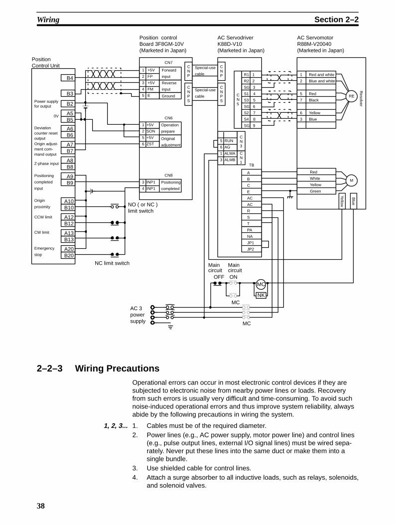
The following wiring diagram shows how to connect an OMRON R88D-V10AC Servomotor Driver. Since this wiring is used with mode 3, the ORIGINSEARCH timing charts shown in Section 4–3–3 will apply.
Mode 3: Connecting anOMRON V-Series ACServomotor Driver
Wiring Section 2–2
38
Special-use
cableB4
B3
B2
A5
A6B6
A7B7
A8B8
A9B9
A10B10
A12B12
A13B13
A20B20
B5
PositionControl Unit
MC
NK
MC
OFF ON
MC
1 +5V
2 SON
5 +5V
6 ZST
Power supplyfor output
Deviationcounter resetoutputOrigin adjust-ment com-mand output
0V
Z-phase input
Positioning
completed
input
Origin
proximity
CCW limit
CW limit
Emergency
stop
NC limit switch
Position controlBoard 3F8GM-10V(Marketed in Japan)
Forward
input
1 +5V
2 FP
3 +5V
4 FM
5 E
Reverse
input
Ground
CNP
CNPS
CN6
CN7
Operation
prepare
Original
adjustment
3 INP1
4 INP1
CN8
Positioning
completed
CNP
CNPS
NO ( or NC )limit switch
Special-use
cable
AC 3powersupply
AC ServodriverK88D-V10(Marketed in Japan)
R1 1
R2 2
SG 3
S1 4
S3 5
SG 6
S2 7
S4 8
SG 9
CN5
5 RUN
6 AG
1 ALMA
3 ALMB
CN3
CN1
TB
A
B
C
E
AC
AC
R
S
T
PA
NA
JP1
JP2
Maincircuit
Maincircuit
AC ServomotorR88M-V20040(Marketed in Japan)
1
2
5
7
6
3
Red and white
Blue and white
Red
Black
Yellow
Blue
RE
Red
White
Yellow
Green
M
Yellow
Blue
Resolver
2–2–3 Wiring PrecautionsOperational errors can occur in most electronic control devices if they aresubjected to electronic noise from nearby power lines or loads. Recoveryfrom such errors is usually very difficult and time-consuming. To avoid suchnoise-induced operational errors and thus improve system reliability, alwaysabide by the following precautions in wiring the system.
1, 2, 3... 1. Cables must be of the required diameter.2. Power lines (e.g., AC power supply, motor power line) and control lines
(e.g., pulse output lines, external I/O signal lines) must be wired sepa-rately. Never put these lines into the same duct or make them into asingle bundle.
3. Use shielded cable for control lines.4. Attach a surge absorber to all inductive loads, such as relays, solenoids,
and solenoid valves.
Wiring Section 2–2

39
+
DC
–
Diode for surge absorption AC Surge absorber RYRY
DC relays AC relays
Note Connect the diode and surge absorber as close as possible to the relay. Usea diode capable of withstanding a voltage five times greater than the circuitvoltage.
SOL Surge absorber
Solenoids
5. Insert a noise filter into the power supply line if it is noisy (e.g., when it isconnected to the same power supply as an electric welder or an electricspark machine or when there is any source generating high frequencynoise).
6. Twisted pair cable is recommended for power lines.7. For grounds, use cable with a cross-sectional area of at least 1.25 mm2.
2–3 DimensionsUnit Dimensions (Unit: mm)
35
130
100.5
Dimensions Section 2–3
40
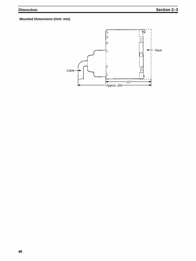
Mounted Dimensions (Unit: mm)
Cable
Approx. 200117
Rack
Dimensions Section 2–3

41
SECTION 3Operation
This section covers all aspects of Position Control Unit operation other than commands, which are covered in the follow-ing section. Included in this section are the basic operating procedure, the type of output pulses possible, the basic dataformat and configuration, some special features to aid operation (such as flags, zone settings, backlash compensation andinternal limits) and the internal data calculation methods used in processing user-input data.
3–1 Operational Flow 42 . . . . . . . . . . . . . . . . . . . . . . . . . . . . . . . . . . . . . . . . . . . . . . . . . . 3–2 Output Pulses 44 . . . . . . . . . . . . . . . . . . . . . . . . . . . . . . . . . . . . . . . . . . . . . . . . . . . . . 3–3 Writing Data 44 . . . . . . . . . . . . . . . . . . . . . . . . . . . . . . . . . . . . . . . . . . . . . . . . . . . . . . 3–4 Data Configuration and Allocation 45 . . . . . . . . . . . . . . . . . . . . . . . . . . . . . . . . . . . . 3–5 DM Area Data Format 48 . . . . . . . . . . . . . . . . . . . . . . . . . . . . . . . . . . . . . . . . . . . . . . 3–6 Flags and Other Input Data 48 . . . . . . . . . . . . . . . . . . . . . . . . . . . . . . . . . . . . . . . . . . 3–7 DM Area Allocation 48 . . . . . . . . . . . . . . . . . . . . . . . . . . . . . . . . . . . . . . . . . . . . . . . .
3–7–1 Zones 50 . . . . . . . . . . . . . . . . . . . . . . . . . . . . . . . . . . . . . . . . . . . . . . . . . . . 3–7–2 Backlash Compensation 52 . . . . . . . . . . . . . . . . . . . . . . . . . . . . . . . . . . . . 3–7–3 Internal CW/CCW Limits 53 . . . . . . . . . . . . . . . . . . . . . . . . . . . . . . . . . . . 3–7–4 Data Calculations 53 . . . . . . . . . . . . . . . . . . . . . . . . . . . . . . . . . . . . . . . . .

42
3–1 Operational FlowThe basic procedure used to operate the Unit initially is outlined below. Referto applicable sections of the manual for details on each of these steps.
Item
Wiring
Data setting
Start
Wiring motor todriver
Setting back-pan-el DIP switch
Data setting
Origin, origin proximity, CW/CCWlimits, emergency stop, external in-terrupt
Output pulse selectionOrigin search directionOrigin proximity signal typeOrigin signal typeExternal interrupt signal type
DM area (key input via Program-ming Console)ParametersPositioning actionsSpeeds
Refer to
Wiring externalinputs
Follow motor and driver and instructionmanuals for wiring details
Wiring Position Control Unit to driver
Section 2–2
Section 3–4
Section 2–1
Section 4
Section 3–7–4
Section 5Writing PC program
Programming IR area (key input viaProgramming Console)
Procedure
Operational Flow Section 3–1

43
Item
ORIGIN SEARCH,manual operation,START, etc.
Correct error
Position ControlUnit reads DM area
Refer to:Procedure
Restart by resettingpower or AR arearestart bit
Alarm/errorLED lit?
No
Yes
Error exists
READ ERROR
Alarm/errorNo
Yes
READ ERROR
Correct datacausing alarm
AR area error and restart bits for Special I/O Units
Section 6–4,Section 4–5
Section 6
Trial run
Error processing
LED flashes?
Caution Before starting trial operation, disconnect the motor from the device it is driv-ing and run the trial operation controlling the motor only. If it is not possible todisconnect the motor, check the system being controlled completely to en-sure that no dangerous situations could occur during trial operation.
Final Wiring Check Before applying power to the PCU, check the following carefully.
1, 2, 3... 1. Is the wiring correct?2. Are any clippings left from wiring causing shorts in the system?3. Are all terminals tight?4. Are all loads okay?
Operational Flow Section 3–1

44
3–2 Output PulsesThe Position Control Unit can be set to output either independent CW andCCW pulses or a nondirectional pulse and a direction signal. Set pin #1 onthe back-panel DIP switch to designate the desired type of output. (See Sec-tion 2–1.)
CW and CCW Pulse Outputs
ON
OFFCW pulse train
OFF
ON
CCW pulse train
Nondirectional Pulse and Direction Signal Outputs
Pulse train
Direction output
ON
OFF
ON
OFF
1 ms min.
CW: ON
CCW: OFF
CW CCW
3–3 Writing Data
C200H PC
ProgrammingConsole
As explained in the Introduction, the Position Control Unit executes position-ing actions and other operations in accordance with data (for speeds, posi-tions, and so on) which you write into the DM area of the PC. You write thisdata, via the Programming Console, into the section of the DM area desig-nated for Special I/O Units.
The specific words are DM 1000 through DM 1999, with 100 of these wordsallocated for each unit number assigned to a Special I/O Unit. Written data iseffective the next time power is turned on or when the system is restartedwith the Restart bit in the AR area. To write data, use the 3-word change op-eration of the Programming Console.
Writing Data Section 3–3

45
Key Input SequenceProgramming Console Display
D1824D1823D1822 0012 5000 2000
The above procedure prepares DM 1824 for change, and new data can bekeyed in. Pressing the CHG key again moves the cursor to DM 1823. Afterinputting data, press the write key to execute the rewrite. In the above exam-ple, positioning action #0 of Unit #8 is shown.
When starting the Position Control Unit, the OUT refresh area is used. (TheOUT refresh area is comprised of the first five of the ten IR words allocatedto each Unit as refresh area. See Section 3–4 for details.) The Busy flag andpresent position status can be read from the IN refresh area, the last five ofthese words.
To start the Unit, set (turn ON) the START command bit. This works regard-less of whether the Unit is in RUN or PROGRAM mode. Do not shift themode between MONITOR and PROGRAM while pulses are being output.Doing so will generate an error, preventing Unit operation.
Example: Starting Unit #8 in MONITOR or PROGRAM Mode
START (command)
Start input 18000
In the above example, IR 180 through IR 184 are allocated as the OUT re-fresh area; IR 185 through IR 190, as the IN refresh area.
Special I/O Unit Restart Bits Restart bits in AR 01 can be used to transfer altered DM area data to the Po-sition Control Unit without turning power off and on. Refer to Section 6–3 forRestart bit allocations. The following Programming Console operation exam-ple shows how to access the restart bit for Unit #0. The ladder diagram sec-tion below it shows how to achieve the same operation through program-ming.
Programming Console Display Key Input Sequence
A0101^ OFF
Program example: Unit #1
Restart switchDIFU(13) AR 0101
3–4 Data Configuration and AllocationIR 100 through IR 199 are allocated as I/O refresh areas. Each Position Con-trol Unit is allocated ten consecutive words. The first word for each Unit, des-
Starting
Data Configuration and Allocation Section 3–4

46
ignated in this manual as n, can be computed from the unit number as fol-lows:
n = 100 + 10 x unit number.
Each Unit is also allocated 100 consecutive words as a fixed data area.These words are in the DM area and run from DM 1000 through DM 1999.The first word for each Unit, m, can also be computed from the unit number:
m = 1000 + 100 x unit number.
These allocations are shown below for all unit numbers. Details of allocationswithin these words are given under the operations or commands to whichthey apply. The tables on the following pages give a quick overview of wordand bit allocations. For a more complete overview, see Appendix C and Ap-pendix D.
Data Configuration
C200H PC
IR Area
IR 100 to 109 Unit #0
IR 110 to 119 Unit #1
IR 120 to 129 Unit #2
IR 130 to 139 Unit #3
IR 140 to 149 Unit #4
IR 150 to 159 Unit #5
IR 160 to 169 Unit #6
IR 170 to 179 Unit #7
IR 180 to 189 Unit #8
IR 190 to 199 Unit #9
DM Area
DM 1000 to 1099 Unit #0
DM 1100 to 1199 Unit #1
DM 1200 to 1299 Unit #2
DM 1300 to 1399 Unit #3
DM 1400 to 1499 Unit #4
DM 1500 to 1599 Unit #5
DM 1600 to 1699 Unit #6
DM 1700 to 1799 Unit #7
DM 1800 to 1899 Unit #8
DM 1900 to 1999 Unit #9
IR area data is trans-ferred between thePC and each PositionControl Unit each timeI/O data of the PC isrefreshed.
DM area data is automaticallytransferred from the PC to eachPosition Control Unit on powerapplication or when the AR areaRestart bit is turned ON.
Position Control Unit
I/O refresh data areas
IR n to (n+4)
IR (n+5) to (n+9)OUT refresh
IN refresh
Ten words are used(n: 100 + 10 x unit no.)
Fixed data areas
DM m to m+21
DM m+22 to m+81
DM m+82 to m+97
DM m+98
DM m+99
Parameters
Position data
Speed data
Acceleration data
Deceleration data
100 words are used(m: 1000 + 100 x unit no.)
IR Area AllocationsThe command bits, flags, and signals you will employ when programmingyour control task are contained in the IR area of the PC. The following tablegives an overview of the IR area allocations. “n” is the first IR word allocatedto the Unit and equals 100 plus 10 times the unit number.
Data Configuration and Allocation Section 3–4

47
Word n n+1 n+2 n+3 n+4
Bit 00 START Initial positioning Speed Beginning word PC data area (for
01 Valid initial positioningaction number
action number coefficients TRANSFERDATA)
TRANSFER DATA)
02 ORIGIN SEARCH
03 ORIGIN RETURN
04 RELEASE PROHIBIT
05 READ ERROR
06 CHANGE SPEED Deviation counterreset
07 Valid speed coefficient Origin adjustment
08 RESET ORIGIN TEACH Beginning Number of transfers (for
09 TEACH positioning action transfer no. TRANSFER DATA)
10 TRANSFER DATA no. 00 to 19
11 HIGH-SPEED JOG
12 INCH/JOG direction
13 LOW SPEED JOG
14 INCH
15 STOP TRANSFERDATA type
Word n+5 n+6 n+7 n+8 n+9
Bit 00 Positioning completedflag
Error code Positioning actionno.
Presentposition
Direction digit
01 Bank completed flag (rightmost 4
02 At-origin flag digits)
03 Alarm flag
04 Emergency stop flag Present position
05 Error flag (leftmost 3 digits)
06 Zone 0 flag
07 Zone 1 flag Positioningcompleted input
08 Zone 2 flag Output code
09 Teaching completedflag
10 Transfer completedflag
11 No-origin flag
12 Busy flag Emergency stopinput
13 CW limit flag External interruptinput
14 CCW limit Origin input
15 STOP flag Origin proximityinput
Data Configuration and Allocation Section 3–4
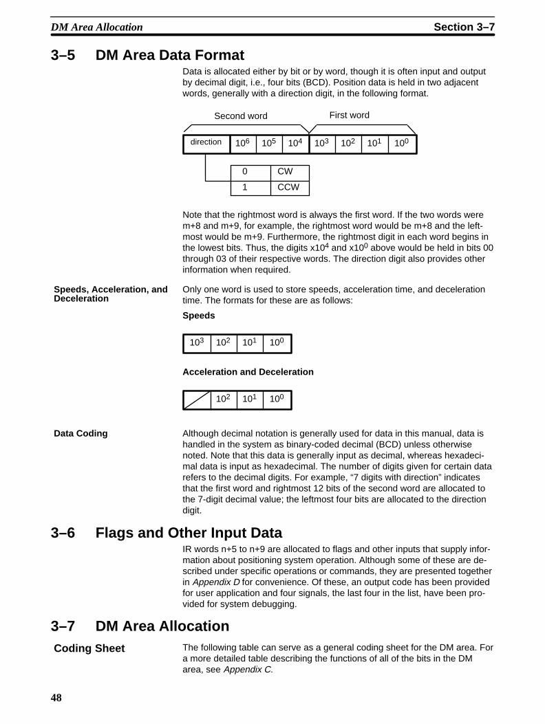
48
3–5 DM Area Data FormatData is allocated either by bit or by word, though it is often input and outputby decimal digit, i.e., four bits (BCD). Position data is held in two adjacentwords, generally with a direction digit, in the following format.
direction 103 102 101 100104105106
0
1
CW
CCW
Second word First word
Note that the rightmost word is always the first word. If the two words werem+8 and m+9, for example, the rightmost word would be m+8 and the left-most would be m+9. Furthermore, the rightmost digit in each word begins inthe lowest bits. Thus, the digits x104 and x100 above would be held in bits 00through 03 of their respective words. The direction digit also provides otherinformation when required.
Only one word is used to store speeds, acceleration time, and decelerationtime. The formats for these are as follows:
Speeds
103 102 101 100
Acceleration and Deceleration
102 101 100
Although decimal notation is generally used for data in this manual, data ishandled in the system as binary-coded decimal (BCD) unless otherwisenoted. Note that this data is generally input as decimal, whereas hexadeci-mal data is input as hexadecimal. The number of digits given for certain datarefers to the decimal digits. For example, “7 digits with direction” indicatesthat the first word and rightmost 12 bits of the second word are allocated tothe 7-digit decimal value; the leftmost four bits are allocated to the directiondigit.
3–6 Flags and Other Input DataIR words n+5 to n+9 are allocated to flags and other inputs that supply infor-mation about positioning system operation. Although some of these are de-scribed under specific operations or commands, they are presented togetherin Appendix D for convenience. Of these, an output code has been providedfor user application and four signals, the last four in the list, have been pro-vided for system debugging.
3–7 DM Area AllocationThe following table can serve as a general coding sheet for the DM area. Fora more detailed table describing the functions of all of the bits in the DMarea, see Appendix C.
Speeds, Acceleration, andDeceleration
Data Coding
Coding Sheet
DM Area Allocation Section 3–7

49
The numbers shown for the DM words in the table represent only the finaltwo digits of each word number. In other words, the first two digits (whichwould be the same for all words) are not shown. The value of the first twodigits can be obtained by computing the first DM word allocated to the Unit.This word, designated m, is equal to 1000 plus 100 times the unit number.Thus, for example, it would be 1000 for Unit #0, 1100 for Unit #1, and so on.
DM Area Allocation Section 3–7

50
00
01
02
03
04
05
06
07
08
09
10
11
12
13
14
15
16
17
18
19
20
21
22
23
24
25
26
27
28
29
30
31
32
33
15 00 Function W
Initial position nos.;speed nos.
Origin compensa-tion and direction
Backlash compensation
CW limit
CCW limit
Zone 0 CW limit
Zone 0 CCW limit
Zone 1 CW limit
Zone 1 CCW limit
Zone 2 CW limit
Zone 2 CCW limit
Not used
Positioning action #0 0
Positioning action #1 1
Positioning action #2
2
Positioning action #3
3
Transfer no.Transfer no.
15 00W Function
Positioning action #4
4
Positioning action #5
5
Positioning action #6
6
Positioning action #7
7
Positioning action #8
8
Positioning action #9
9
Positioning action #10
10
Positioning action #11
11
Positioning action #12 12
Positioning action #13
13
Positioning action #14
14
34
35
36
37
38
39
40
41
42
43
44
45
46
47
48
49
50
51
52
53
54
55
56
57
58
59
60
61
62
63
64
65
66
67
68
69
70
71
72
73
74
75
76
77
78
79
80
81
82
83
84
85
86
87
88
89
90
91
92
93
94
95
96
97
98
99
W 15 00 Function
Positioning action #15 15
Positioning action #16
16
Positioning action #17
17
Positioning action #18
18
Positioning action #19
19
Speed #1
20
21
22
23
24
25
Speed #2
Speed #3
Speed #4
Speed #5
Speed #6
Speed #7
Speed #8
Speed #9
Speed #10
Speed #11
Speed #12
Speed #13
Speed #14
Speed #15
Speed UInits
Acceleration
Deceleration
3–7–1 ZonesA zone is a range of positions or values which can be defined so that flags inthe IR area are turned ON whenever the present position is within the range.You can set up to three zones in the DM area. A zone flag is ON (1) when the
DM Area Allocation Section 3–7
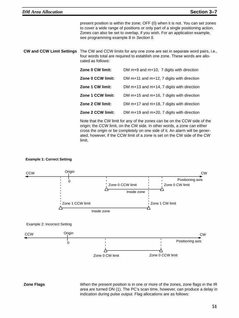
51
present position is within the zone; OFF (0) when it is not. You can set zonesto cover a wide range of positions or only part of a single positioning action.Zones can also be set to overlap, if you wish. For an application example,see programming example 8 in Section 5.
The CW and CCW limits for any one zone are set in separate word pairs, i.e.,four words total are required to establish one zone. These words are allo-cated as follows:
Zone 0 CW limit: DM m+9 and m+10, 7 digits with direction
Zone 0 CCW limit: DM m+11 and m+12, 7 digits with direction
Zone 1 CW limit: DM m+13 and m+14, 7 digits with direction
Zone 1 CCW limit: DM m+15 and m+16, 7 digits with direction
Zone 2 CW limit: DM m+17 and m+18, 7 digits with direction
Zone 2 CCW limit: DM m+19 and m+20, 7 digits with direction
Note that the CW limit for any of the zones can be on the CCW side of theorigin; the CCW limit, on the CW side. In other words, a zone can eithercross the origin or be completely on one side of it. An alarm will be gener-ated, however, if the CCW limit of a zone is set on the CW side of the CWlimit.
Zone 0 CW limit
CCW Origin CW
0
Zone 1 CCW limit
Zone 0 CCW limit
Inside zone
Inside zone
Zone 1 CW limit
Positioning axis
Example 1: Correct Setting
Zone 0 CCW limit
CCW Origin CW
0
Zone 0 CW limit
Positioning axis
Example 2: Incorrect Setting
When the present position is in one or more of the zones, zone flags in the IRarea are turned ON (1). The PC’s scan time, however, can produce a delay inindication during pulse output. Flag allocations are as follows:
CW and CCW Limit Settings
Zone Flags
DM Area Allocation Section 3–7

52
0 Outside zone
1 Inside zone
08
n+5
07 06
Zone 0 flag
Zone 1 flag
Zone 2 flag
3–7–2 Backlash CompensationThere may be a certain amount of mechanical play present in gears, that willaffect positioning accuracy when the direction of positioning actions changes.You can compensate for this by using backlash compensation.
There is only one parameter that needs to be set to compensate for back-lash:
Backlash Compensation
DM m+4
Set to between 0000 and 9999 pulses.
ÍÍÍÍÍÍÍÍÍÍÍÍÍÍÍÍÍÍÍÍÍÍÍÍÍÍÍÍÍÍÍÍÍÍÍÍÍÍÍÍÍÍÍÍÍÍÍÍÍÍÍÍÍÍÍ
Backlash
When the feeding direction is reversed, the number of pulses set in the DMarea is output at the initial speed, and the Position Control Unit then pro-ceeds with normal operations.
ÍÍÍÍ
Time
Compensation
If STOP is executed during backlash compensation for any operations requir-ing acceleration or deceleration (HIGH-SPEED JOG, ORIGIN SEARCH,ORIGIN RETURN, and START), the Position Control Unit will stop feedingimmediately after outputting the initial step of the acceleration or decelera-tion, which will include the backlash compensation set above.
Setting Parameters
Using BacklashCompensation
DM Area Allocation Section 3–7

53
ÍÍÍÍ
Stop position
Time
STOP executed
Compensation
3–7–3 Internal CW/CCW Limits
You can also make settings in the DM area to place internal limits on rotationof the axis on both the CW and CCW sides of the origin.
CCW
Internally set value of CCW limit
0
Internally set value of CW limit
CWPositioning axis
DM words m+6 through m+5, 7 digits
Set to between 1 and 8388606.
DM words m+8 through m+7, 7 digits
Set to between 1 and 8388607.
The following values will be automatically set if the internal limit settings are0.
CW: 8388607
CCW: 8388608
OperationSTART (Positioning Actions)
If either of these limits is reached during execution of positioning actions,pulse output will stop and an error code, either 5030 or 5031, will be gener-ated.
Manual Operation
If either of these limits is reached during execution of LOW-SPEED JOG,HIGH-SPEED JOG, or INCH, pulse output will stop and an error code, either5070 or 5071, will be generated.
3–7–4 Data Calculations
Slight differences exist between speeds set in the DM area and actualspeeds. These differences do not affect positioning accuracy.
Internal CW Limit
Internal CCW Limit
Speeds
DM Area Allocation Section 3–7

54
Settings between 92 and 250,000 pps
where,
INT: Nearest integer
INT(6,000,000/set value): Divider ratio
pps: Pulses per second
Actual speed (pps) = 6,000,000
INT(6,000,000/set value)
Pulse output (actual speed)
6 MHzDivider
The slight difference occurs because a 6-MHz source clock is divided by theintegral divider ratio.
Example Values
Set Value(pps)
Actual Speed (pps)
250,000 250,000.00
180,000 18,1818.18
140,000 142,857.14
95,000 95,238.10
3,500 3,500.58
92 92.00
Settings between 1 and 91 pps
Actual speed (pps) =23,437.5
INT(23,437.5/set value)
23,437.5 Hz
Pulse output (actual speed)
Divider
A 62.5-KHz source clock is divided by the integral divider ratio.
Example Values
Set Value(pps)
Actual Speed (pps)
91 91.20
60 60.10
DM Area Allocation Section 3–7

55
An internal calculation process is used to create a trapezoidal figure fromspeed, acceleration, and deceleration settings.
Speed
Time
When accelerating or decelerating between two speeds, the speed is variedin a stepwise fashion. To achieve this, acceleration and deceleration tablesare created internally when the Unit is first operated or when TRANSFERDATA is used to alter data.
The internal processing of the Position Control Unit is as follows during tablecreation.
1, 2, 3... 1. The speed difference, ∆V, is obtained to express the range of speed set-tings.
∆V = MAX – MIN
where,
MAX: Twice the maximum set value (not to exceed 250,000).
MIN: Speed indicated by initial speed number.
2. The number of division steps, L, is determined such that the unit time foreach step is 4 ms. The maximum number of steps is 250.
L = (∆V/R)
where,
r: Acceleration or deceleration data, whichever smaller
R: Acceleration or deceleration data, whichever greater.
∆V/R: Acceleration (or deceleration) time between MAX and MIN
4
T = (∆V/r)
L
At this time, the time for one step of the smaller of the acceleration or deceleration data is obtained as follows:
3. Next, the speed difference (∆υ) for each step is obtained.
∆υ = (∆V/L)
TrapezoidalAcceleration/Deceleration
Table Creation
DM Area Allocation Section 3–7

56
4. The divider ratios for all steps are calculated and set in a table.
StepTarget (step) speed Divider ratio
1 MIN
2 MIN + ∆υ
3 MIN + 2∆υ
L MAX
5. Example
Start speed 0 (pps)
Maximum value of speed data Nos. 1 to 15 20000 (pps)
Acceleration 100 (pps/1ms)
Deceleration 100 (pps/1ms)
∆υ = 40000/100 = 400
∆V = 20000 x 2 = 40000
L = (∆V/R) = (40000/100) = 100
4 4
48
12192
196200
204 388 396392 400
t (Time)ms
V (Speed)
400
4 ms
R = 400= 1004
40000396003920038800
20400200001960019200
16001200800400
pps
The time required between START command bit recognition and the begin-ning of pulse output is 0.1 second or less.
Only about 10 ms is required to begin execution of positioning actions with“single” completion codes.
The time required between CHANGE SPEED or STOP command bit recogni-tion and the beginning of execution is at least 4 ms.
START Activation Time
External InterruptResponse Time
DM Area Allocation Section 3–7

57
When executing TRANSFER DATA, the Busy flag (bit 12 of word n + 5) willbe ON during data transfer and processing for the following time periods:
Positioning Action Data Only (positioning actions #0 through #19):
Maximum: 0.1 s + k (scan time)
When Speed Data (Transfers #20 through #25) Is Included:
Maximum: 0.2 s + k (scan time)
The value of k depends on the number of transfers being made, as illustratedin the following table.
Number of transfers k
1 to 6 1
7 to 13 2
14 to 20 3
21 to 26 4
Mounting one Position Control Unit on a PC extends the PC’s scan time byabout 3 ms. In addition, when transferring data, the scan time during whichdata is transferred increases by another 5 ms. For example, to transfer all 20positioning actions, TRANSFER DATA only needs to be executed once, butboth the PC and Position Control Unit require 3 scans. Each of these 3 scantimes will be 5 ms longer than the normal scan time.
Data Transfer Time
Influence on PC Scan Time
DM Area Allocation Section 3–7

59
SECTION 4Commands
The Position Control Unit provides thirteen commands to execute automatic and manual positioning actions, define andestablish position, transfer data, and handle interrupts and errors. Any given command is executed when the program inthe PC turns ON the appropriate command bit in the IR area. In addition to the command bits themselves, the IR areacontains certain other data which are necessary for executing commands.
In executing commands, the Position Control Unit makes use of data stored in the DM area. This data includes settingsfor speeds, positions, and so on. Although the data required for execution is listed under each command, much of thisdata is used by more than one command. Refer to Section 3–4 for an outline of the structure of Position Control Unitdata, and to Section 3–5 for format specifications for particular types of data. Appendix C and Appendix D also provideconvenient overviews of data allocation. Applications of most commands are presented in Section 5.
4–1 START 60 . . . . . . . . . . . . . . . . . . . . . . . . . . . . . . . . . . . . . . . . . . . . . . . . . . . . . . . . . . 4–1–1 DM Area Settings 60 . . . . . . . . . . . . . . . . . . . . . . . . . . . . . . . . . . . . . . . . .
4–2 Positioning Actions 61 . . . . . . . . . . . . . . . . . . . . . . . . . . . . . . . . . . . . . . . . . . . . . . . . 4–2–1 IR Area Settings 66 . . . . . . . . . . . . . . . . . . . . . . . . . . . . . . . . . . . . . . . . . . 4–2–2 Execution Examples 68 . . . . . . . . . . . . . . . . . . . . . . . . . . . . . . . . . . . . . . .
4–3 ORIGIN SEARCH 71 . . . . . . . . . . . . . . . . . . . . . . . . . . . . . . . . . . . . . . . . . . . . . . . . . 4–3–1 DM Area Settings 71 . . . . . . . . . . . . . . . . . . . . . . . . . . . . . . . . . . . . . . . . . 4–3–2 IR Area Settings 72 . . . . . . . . . . . . . . . . . . . . . . . . . . . . . . . . . . . . . . . . . . 4–3–3 Execution Examples 73 . . . . . . . . . . . . . . . . . . . . . . . . . . . . . . . . . . . . . . . 4–3–4 Completion Examples 84 . . . . . . . . . . . . . . . . . . . . . . . . . . . . . . . . . . . . . .
4–4 ORIGIN RETURN 86 . . . . . . . . . . . . . . . . . . . . . . . . . . . . . . . . . . . . . . . . . . . . . . . . . 4–4–1 DM Area Settings 87 . . . . . . . . . . . . . . . . . . . . . . . . . . . . . . . . . . . . . . . . . 4–4–2 IR Area Settings 87 . . . . . . . . . . . . . . . . . . . . . . . . . . . . . . . . . . . . . . . . . . 4–4–3 Execution Example 87 . . . . . . . . . . . . . . . . . . . . . . . . . . . . . . . . . . . . . . . .
4–5 RELEASE PROHIBIT 89 . . . . . . . . . . . . . . . . . . . . . . . . . . . . . . . . . . . . . . . . . . . . . .
4–6 READ ERROR 91 . . . . . . . . . . . . . . . . . . . . . . . . . . . . . . . . . . . . . . . . . . . . . . . . . . . . 4–6–1 Execution Example 92 . . . . . . . . . . . . . . . . . . . . . . . . . . . . . . . . . . . . . . . . 4–6–2 Reading from the Programming Console 92 . . . . . . . . . . . . . . . . . . . . . . .
4–7 RESET ORIGIN 93 . . . . . . . . . . . . . . . . . . . . . . . . . . . . . . . . . . . . . . . . . . . . . . . . . . .
4–8 TEACH 93 . . . . . . . . . . . . . . . . . . . . . . . . . . . . . . . . . . . . . . . . . . . . . . . . . . . . . . . . . . 4–8–1 IR Area Settings 94 . . . . . . . . . . . . . . . . . . . . . . . . . . . . . . . . . . . . . . . . . . 4–8–2 Execution Example 94 . . . . . . . . . . . . . . . . . . . . . . . . . . . . . . . . . . . . . . . . 4–8–3 Teaching From the Programming Console 94 . . . . . . . . . . . . . . . . . . . . . .
4–9 TRANSFER DATA 95 . . . . . . . . . . . . . . . . . . . . . . . . . . . . . . . . . . . . . . . . . . . . . . . . 4–9–1 Normal Transfer 96 . . . . . . . . . . . . . . . . . . . . . . . . . . . . . . . . . . . . . . . . . . 4–9–2 IR Area Settings 97 . . . . . . . . . . . . . . . . . . . . . . . . . . . . . . . . . . . . . . . . . . 4–9–3 Present Position Preset 99 . . . . . . . . . . . . . . . . . . . . . . . . . . . . . . . . . . . . .
4–10 Manual Operations 102 . . . . . . . . . . . . . . . . . . . . . . . . . . . . . . . . . . . . . . . . . . . . . . . . . 4–10–1 DM Area Settings 102 . . . . . . . . . . . . . . . . . . . . . . . . . . . . . . . . . . . . . . . . . 4–10–2 IR Area Settings 103 . . . . . . . . . . . . . . . . . . . . . . . . . . . . . . . . . . . . . . . . . . 4–10–3 HIGH-SPEED JOG 103 . . . . . . . . . . . . . . . . . . . . . . . . . . . . . . . . . . . . . . . . 4–10–4 LOW-SPEED JOG 104 . . . . . . . . . . . . . . . . . . . . . . . . . . . . . . . . . . . . . . . . 4–10–5 INCH 104 . . . . . . . . . . . . . . . . . . . . . . . . . . . . . . . . . . . . . . . . . . . . . . . . . . .
4–11 External Interrupt Commands 105 . . . . . . . . . . . . . . . . . . . . . . . . . . . . . . . . . . . . . . . . 4–11–1 STOP 107 . . . . . . . . . . . . . . . . . . . . . . . . . . . . . . . . . . . . . . . . . . . . . . . . . . . 4–11–2 CHANGE SPEED 115 . . . . . . . . . . . . . . . . . . . . . . . . . . . . . . . . . . . . . . . . .

60
4–1 STARTExecution of positioning actions begins when the program turns ON theSTART command bit, bit 00 of IR word n (effective on signal’s rising edge).The actions are executed in order from either the initial positioning actiondesignated in the DM area or that designated in the IR area, depending onanother setting you make in the IR area. Positioning actions are executed inorder until a “single” or “bank end” positioning action is reached, at whichtime START is again required in order to begin execution of positioning ac-tions. (For an explanation of “single” and “bank end” positioning actions, seeCompletion Codes under Section 4–1–1 below.)
When a bank end positioning action is reached or when the last positioningaction (#19) has been performed, the initial positioning action designated inthe DM area is performed next. The initial positioning action and completioncodes (i.e., single, pause, continuous, bank end, and extended) are de-scribed later in this section.
4–1–1 DM Area SettingsWords 1000 to 1999 of the DM area of the PC are used as data storageareas for the Position Control Unit, storing data such as initial positioning ac-tion numbers, initial speed numbers, speed data, acceleration/decelerationdata, position data, completion codes, dwell times, and output codes. Beforepositioning actions can be executed, you must make all of the necessarydata settings in the DM area. (For an explanation of data configuration, referto Section 3–4.)
DM word m, bits 07 to 00
Set to a value between 00 and 19. This number is used for the following:
• Initial START after turning on the Unit (if bit 01 of word n is 0)
• START after bank ends
• START after completion of positioning action #19
If bit 01 of IR word n is set to 1, the initial positioning action number desig-nated in the IR area is used for the initial START after turning on the Unit,allowing for a different starting point for positioning system initialization.
Initial positioning action number
Initial speed number
x101 x100 (m = 1000 + 100 x unit number)m
11 08 07 00
DM word m, bits 11 to 08
Set to a value between 0 and F (hex). An initial speed number of 0 indicatesa speed of 0. All the other speed numbers set here refer to the speeds set inDM words m+82 through m+96.
Initial Positioning ActionNumber
Initial Speed Number
START Section 4–1

61
Acceleration AccelerationTime
Target speed Target speed
Initial speed #0 Initial speed numberother than 0
DM words m+82 through m+96
Set each word to a value between 0000 and 9999 pps (4 digits)
You can set up to fifteen speeds in these DM words, numbered from one tofifteen. To each of these values, you assign a speed unit (in word m+97),which multiplies the corresponding speed by 1, 10, or 100. You can then referto these settings by number to set speeds for START and several other com-mands.
15 00
m+82
to
m+96
m+97
Bit number
x103
x103
15 00
x102
x102
x101
x101
x100
x100
Speed No. 1
to
Speed No. 15
Set speeds in BCDfrom 0000 to 9999.
0
DM word m+97
You assign each of the bits in this word to one of the speeds you previouslyset in words m+82 through m+96. Speed unit multiplication is affected by bit04 of DM word m+3 as follows:
m + 97 bit* M+3, bit 04 Condition
0 0 Speed multiplied by 1
1 Speed multiplied by 10
1 0 Speed multiplied by 1
1 Speed multiplied by 100
*Bit assignments are as follows:Bit 00 is not used. Bit 01 is assigned to speed #1, bit 02 to speed #2, bit 03 to speed #3,and so on, up to bit 15.
DM word m+98, bits 15 to 00, 3 digits
Set from 2 to 2,000 (BCD). Acceleration is in pps per ms.
DM word m+99, bits 15 to 00, 3 digits
Set from 2 to 2,000 (BCD). Deceleration is in pps per ms.
4–2 Positioning ActionsDM words m+22 through m+81
Speeds
Speed Units
Acceleration
Deceleration
Positioning Actions Section 4–2

62
The fundamental unit of positioning is the positioning action. InC200H-NC112 Position Control Units, each positioning action is defined byits completion code, dwell time, output code, speed number, and target posi-tion, all of which are explained below.
Positioning actions are generally referred to by number and completion code.For example,“#6, continuous” indicates positioning action #6 with a comple-tion code of 2 (continuous). The settings for positioning action #0, DM wordsm+22 through m+24, are explained below. The same procedure is followedfor any other positioning action. See Appendix C for detailed word and bitallocations.
DM word m+22, bits 03 to 00
Each positioning action must be assigned a completion code. A completioncode is a setting that specifies what is to happen when the positioning actionhas been completed. You can select any of six completion codes, all de-scribed in detail below, by setting these bits anywhere from 0 to 5. For furtherexplanation, see also Section 4–1–3.
m+22
03 to 00
Completion code: 0 to 5
If you designate a positioning action as “single”, then it will be executed inaccordance with the data set for it and will not directly affect the subsequentpositioning action (except, of course, for its initial position). The target posi-tion is reached and feeding stops. After completion of this action, START isnecessary in order to to execute the next positioning action(s).
Initial speed
Acceleration
Target speed
Deceleration
Stop from initial speed
Target position
Time
START
If you designate a positioning action as “pause”, it will execute in accordancewith the data set for it, pause, and then automatically start the next position-ing action. After the target position is reached, positioning will pause for thedwell time (see following Dwell Time diagram). The next positioning action isautomatically started following the dwell time.
Target speed
Dwell time
Start of next positioning action
Time
START Pause
Completion Code
0: Single
1: Pause
Positioning Actions Section 4–2

63
If you designate a positioning action as “continuous”, then as soon as thetarget position for that positioning action is reached, the next positioning ac-tion is started. The first target position is reached at the target speed set forthe next positioning action, so that the next positioning action can be ex-ecuted immediately.
Time
Target position for firstpositioning action
Target speed for firstpositioning action
START
Target speed for next positioning action
The term “bank” refers to a combination of several positioning actions or se-quences. If you designate the positioning action as “bank end”, it will serveas the final positioning action in that bank. The target position is reached andfeeding stops. The next positioning action to be executed will be the initialpositioning action number in bits 07 to 00 of DM word m. START is requiredin order to resume execution of positioning actions.
Target speed
Stop
Time
START
If you designate a positioning action as “extended”, the Position Control Unitwill continually output pulses, at the speed set for the positioning action, untilthe action is terminated by STOP. The Unit will not calculate the present posi-tion, and the No-origin flag (bit 11 of IR n+5) will go ON during operation. Thedirection of pulse output is determined by the direction digit set in the posi-tioning data. (See Appendix C.) START is required in order to resume execu-tion of positioning actions.
Stop
Time
STOP executed
START
Target speed
If you designate a positioning action as “extended with positioning”, the Posi-tion Control Unit continually outputs pulses at the speed set for the position-ing action. This is similar to “extended”, described above. When STOP is ex-ecuted, however, the present position that was defined when the positioning
2: Continuous
3: Bank end
4: Extended
5: Extended WithPositioning
Positioning Actions Section 4–2

64
action was started is reset and positioning is executed according to the dataset for the positioning action. The Unit will not calculate the present position,and the No-origin flag (bit 11 of IR n+5) will go ON during operation. The di-rection of pulse output is determined by the direction bit set for the position-ing action. START is required in order to resume execution of positioning ac-tions.
(C) Stop
Time
(A) STOP executed
START
Target speed
CHANGE SPEED valid CHANGE SPEED cannot be executed.The extended action can be terminatedby executing STOP again.
(B) Present position reset; No-origin flag OFF.
Note STOP can be executed by either an external input signal or by IR word n, bit15. For details, refer to Section 4–10–1.
Delay Time
From position A to position B in the above diagram, there is a delay time ofapproximately 2 ms for internal processing (scan time). From position B toposition C, there may be a maximum additional delay time of 2 ms. The delaytime between points A and B does not affect the present position set in wordsn+8 and n+9. During the delay time between B and C, the present position inthose words is reset to 0 and then updated. The delay time is also output inthose words.
DM 1022 1 0 0 5
DM 1023 0 0 0 0
DM 1024 0 0 0 1
word 108 0 0 0 3
word 109 0 0 0 1
Example: Positioning Action #0 for Unit #0
Target position: 10000
Completion code: 5
Direction: CW
Speed #1: 10K pps
After STOP, the present position is as follows:
In this example, the present position after operation has stopped is 10003.Since the target position was 10000, the actual position has exceeded thetarget position by 3 pulses. Since the speed was set to 10K pps, 3/10,000 =0.003 s = 0.3 ms. Thus the delay time is 0.3 ms.
Positioning Actions Section 4–2

65
If the target position is near the position at which STOP is executed, pulseoutput will cease before deceleration is completed. However, no error codewill be output.
DM word m+22, bits 07 to 04
Set to a value between 0 and F (hex). (Unit: 0.1 s)
You can set a dwell time for however long you want positioning to pause. Thenext positioning action can be executed when the Busy flag turns OFF afterthe dwell time has expired. In other words, the Positioning Completed flagremains OFF and the Busy flag remains ON until the dwell time has expired.(See Section 4–1–3.)
DM word m+22, bits 11 to 08
Set to an integer between 0 to F (hex).
Output codes are user-defined codes output to IR word n+7, bits 11 to 08, ofthe OUT refresh area following completion of a positioning action.
m+22
15 to12 11 to 08
Positioning actionnumber
n+7 x101 x100
11 to 08 07 to 00
Output code: 0 to F (hexadecimal)
(Output to word n+7, bits 11 to 08.)
Target speed number: 1 to F (hexadecimal)
DM word m+22, bits 15 to 12
Set to a value between 1 and F (hex).
The speed number which you set here refers to the speeds which you pre-viously set in DM words m+82 through m+96 (see Speeds above).
DM words m+23 through m+24
The target position is set with the rightmost seven digits, i.e., all four digits ofword 23 and the rightmost three digits of word 24. The remaining digit ofword 24 is used as a direction digit. (See Appendix C.)
Dwell Time
Output Code
Target Speed Number
Target Position
Positioning Actions Section 4–2

66
m+24
15 00
m+23 x103 x102 x101
x101
x100
Sign x106
x105
x104
m+24 m+23
Direction x106 x105 x104 x103 x101 x100
CW absolute value
CCW absolute value
CW increment
CCW increment
0
1
2
3
Maximum values are as follows:
CW: 8,388,606 pulses
CCW: 8,388,607 pulses
Absolute values are measured from the origin. Increment values are mea-sured from the present position. Positions resulting from increments (i.e.,present value plus the increment) must be between –8,388,607 and+8,388,606.
8388607
CCW
(Origin)
0
CCW directionincrement value
Presentposition
CW directionincrementvalue
8388606
Absolutevalue
CW
Note The TEACH command can be used to write target positions into the DMarea. See Section 4–7 for details.
4–2–1 IR Area SettingsIn C200H PCs, IR words 100 to 199 are used for Special I/O Units. When aPosition Control Unit is used, they are allocated as I/O refresh areas. For adetailed explanation, see Section 3–4. For a detailed table of words and bitsin the IR area, see Appendix D.
n
15 07 01 00
START
Valid initial positioning action number
Valid speed coefficient
STOP
Positioning Actions Section 4–2
67
IR word n, bit 00
When the program turns this bit ON (i.e., sets it to 1), bits 01 and 07 are re-ferred to and positioning begins.
IR word n, bit 01
This is used when the initial positioning action number is designated in theI/O refresh areas. After the initial positioning action is set with bits 07 to 00 ofIR word n+1, the START command is executed according to bit. These val-ues are valid when set within the same scan.
1: Initial position number set in bits 07 to 00 of IR word n+1 is valid.0: Initial position number set in bits 07 to 00 of DM word m is valid.
IR word n, bit 07
This is used when the target speed of the positioning action is multiplied by acoefficient. After the speed coefficient is set with bits 07 to 00 of IR word n+2,the START command is executed according to bit. These values are validwhen set within the same scan. This bit can function simultaneously with bit01 (described above).
1: Coefficient in bits 07 to 00 of IR word n+2 is valid.0: Coefficient is 1.0.
IR word n, bit 15
The program turns this bit ON to execute STOP. Pulse output cannot be re-sumed as long as this bit remains ON. See Section 4–10–1 for a more de-tailed explanation and several STOP execution examples.
IR word n+1, bits 07 to 00
Set to an integer between 00 and 19.
START will be executed from the positioning action specified here if bit 01 ofIR word n is 1 when the START command bit (bit 00 of IR word n) is set.
IR word n+2, bits 05 to 00
Set a value between 00 and 20 (in units of 0.1). In other words, a setting of15, for example, will represent an actual value of 1.5.
This coefficient is valid if bit 07 of IR word n is 1 when the START commandbit (bit 00 of word n) is turned ON (i.e., set to 1). It is valid only for STARTand cannot be changed during positioning, passes,. or dwell time.
The speed coefficient represents the coefficient with regard to the targetspeed. If the value is set at 00, the speed will be considered to be 100 and acoefficient of 1.0 will be used. If the value is set anywhere from 01 to 20, theset value will be multiplied by 0.1 to determine the coefficient. The speed co-efficient can thus be set in increments anywhere from 0.1 to 2.0.
If the speed resulting from the coefficient exceeds 100 kpps or falls below 1kpps, the speed will be set at 100 kpps or 1 kpps, respectively. Speed coeffi-cients will have no effect on accelerations and decelerations.
START
Valid Initial PositioningAction Number
Valid Speed Coefficient
Deceleration/StopCommand (STOP)
Initial Positioning ActionNumber
Speed Coefficient
Positioning Actions Section 4–2

68
Speed
Coefficient: of 1.5
Coefficient: of 0.5
Acceleration
Time
Target speed (coefficientnot used or set at 1.0)
IR word n+2, bit 06
Bit 06 is only valid during STOP. The deviation counter reset output (A6, B6)is ON if this bit is set to 1, and OFF if it is set to 0.
IR word n+2, bit 07
Bit 07 is only valid during STOP or manual operations (JOG or INCH). Theorigin adjustment signal is turned ON if this bit is set to 1, and remains OFF ifit is set to 0.
4–2–2 Execution Examples
The example diagram on the following page illustrates the use of completioncodes. The initial position and the target position at bank end are the same,and the valid initial positioning action number is 0. Positioning actions inthese and all following diagrams are indicated simply by their numbers.
CCW
Initial position
CW positioningaxis
START START
START
START#0 #1 #2 #3 #4
#6#5
Pause
The completion code for positioning action #0 is set to 0, making it a singleaction. Positioning stops after completion of this action, and START is neces-sary for operation to begin again.
The completion codes for positioning actions #1 and #2 are set at 2, makingthem continuous actions. Positioning actions #1, #2, and #3 are thus ex-ecuted consecutively, with each action reaching its target position at the tar-get speed set for the subsequent action. The completion code for positioningaction #3 is set at 0, making it a single action and causing positioning to stopafter completion of this sequence of actions.
The completion code for positioning action #4 is set at 1, making it a pauseaction. Upon completion of this action, there will be a pause (set as dwell
Deviation Counter Reset
Origin Adjustment
Example 1: UsingCompletion Codes
Positioning Actions Section 4–2

69
time); following the pause, the next positioning action will start automatically.Positioning actions #4 and #5 are thus executed consecutively, with a presetpause in between. Since the completion code for positioning action #5 is setat 1 (single), positioning will stop after completion of this sequence.
The completion code for positioning action #6 is set at 3, making it a bankend. Completion of this action will thereby signal completion of the entirebank of actions. Upon completion of this action, the Unit will be prepared toexecute positioning action #0 but will wait for START before beginning.
Refer to the more detailed example diagrams on the following page.
Stop
Completion code
m+22
m+25
m+28
m+31
m+34
m+37
m+40
Positioningaction #0
0
2
2
0
1
0
3
Pause
Single
Bank end
Pulse output CW
CCW
Pulse output CW
CCW
Pulse output CW
CCW
Automatic start
Time
Time
Time
Single
Continuous
Continuous
Stop
Stop
Pulse output
CW
CCW
Time
Single
Positioningaction #1
Positioningaction #2
Positioningaction #3
Positioningaction #4
Positioningaction #5
Positioningaction #6
#0
#1
#2#3
#4
#5
#6
START
START
PauseSTART
START
Stop, wait for #0 START
The following example diagram illustrates the use of dwell times. The com-pletion code for positioning action #1 is set at 1 (pause), with the dwell timeset at 0.5 s. The completion code for positioning action #2 is set at 0 (single),with the dwell time set at 1.0 s.
Example 2: Using DwellTimes
Positioning Actions Section 4–2

70
Pulse output
1
0
1
0
1
0
0.5 s 1.0 s
Time
#1 #2
START (IR n, bit 00)
PositioningCompleted flag(IR n+5, bit 00)
Busy flag (IR n+5, bit 12)
Positioning sequences combining several pause and/or continuous position-ing actions normally are ended by a single or bank end positioning action.When the last positioning action is completed, including any dwell time desig-nated for it, the Positioning Completed flag turns ON and Busy flag turnsOFF. START is then required to begin further execution of positioning ac-tions. START is also required to restart operation after the STOP commandhas been executed. (See Section 4–10.)
Example 3: Using STARTwith Single or Bank EndPositioning Actions
Positioning Actions Section 4–2

71
START commandIR n, bit 00
Pulse output
Time
1
0
1
0
1
0When positioning ends, the positioningaction number is changed as follows:
210 3
Outputcode ofaction #0 action #1 action #2
code of code ofOutput Output
#0, single
#1, continuous
#2, single
Positioning Completed flagIR n+5, bit 00
Busy flag IR n+5, bit 12
Positioning action number IR n+7, bits 07 to 00
Output code
IR n+7, bits 08 to 11
4–3 ORIGIN SEARCHBefore positioning actions can be executed, the origin must be defined as areference point. The main method for this is ORIGIN SEARCH. The programexecutes ORIGIN SEARCH by turning ON the ORIGIN SEARCH commandbit, bit 02 of IR word n. When this bit is turned ON, the Position Control Unitestablishes the position of the origin through inputs from an origin sensorand, if provided, an origin proximity sensor (effective on signal’s rising edge).Before using ORIGIN SEARCH, set the DIP switch as described in Section2–1 to establish the direction from which the search will be made, the pres-ence or absence of a proximity sensor, and the type of input used.
4–3–1 DM Area SettingsIn addition to the settings described in detail in this section, the data listedbelow must also be set in order to execute ORIGIN SEARCH. They are thesame as those set for START, so they can be set by following the instructionscontained in Section 4–1.
Initial Speed Number Bits 11 to 08 of DM word m
Speeds DM words m+82 through m+96
Speed Units DM word m+97
Acceleration Bits 15 to 00 of DM word m+98
Deceleration Bits 15 to 00 of DM word m+99
DM word m+1, bits 03 to 00
Set to an integer between 1 and F (hex). The speed number set here refersto one of the speeds set in DM words m+82 through m+96. It cannot be set
ORIGIN SEARCH Proximity Speed Number(Low Speed)
ORIGIN SEARCH Section 4–3

72
higher than the ORIGIN SEARCH high speed number. If there is no originproximity signal, the speed designated here is used for the entire ORIGINSEARCH operation.
DM word m+1, bits 07 to 04
Set to an integer between 1 and F (hex). The speed number set here refersto one of the speeds set in DM words m+82 through m+96. The speed desig-nated here is used only if an origin proximity signal is present.
DM words m+2 and m+3
Set DM word m+2 to a value between 0000 and 9999 pulses.
Set bit 00 of DM word m+3 to set the direction of compensation:
0: CW1: CCW
There may be cases where it is difficult to establish the mechanical originwith precision. In such cases you may want to compensate by establishingthe origin a few pulses to either side of the origin signal input. If you want theposition determined by origin signal input to be treated as the origin (position0), set word m+2 to 0. Otherwise set the value and direction necessary toobtain the required origin. If there is an origin compensation value set in wordm+2, then, after reaching the position determined by origin signal input, com-pensation will be executed at proximity speed in the direction set at bit 00 ofword m+3. See the example given below and Section 4–2–3 for application.
In the example diagram below, bit 00 of DM word m+3 is set at 1, so origincompensation is counterclockwise.
Proximity signal
Origin signal
Pulse output
CCW
Deceleration
Search direction: CCW
Acceleration
Initial speed
positioning axis
Compensation
CW
ORIGIN SEARCH high speed
0.5 s pause
Proximity speed
Proximity speed
4–3–2 IR Area SettingsIn C200H PCs, IR words 100 to 199 are used for Special I/O Units. When aPosition Control Unit is used, they are allocated as I/O refresh areas. For adetailed explanation, see Section 3–4. For a detailed table of words and bitsin the IR area, see Appendix D.
In the IR area, the ORIGIN SEARCH command is executed with bit 02 ofword n. ORIGIN SEARCH begins when the program turns this bit ON.
ORIGIN SEARCH High Speed Number
Origin Compensation
ORIGIN SEARCH Section 4–3

73
n
02
(n = 100 + 10 x unit number)
ORIGIN SEARCH command bit (ORIGIN SEARCH is started when this bit is turned on)
4–3–3 Execution ExamplesThe following examples show the relationships among the mode number,DIP switch pin no. 3 (origin proximity present/absent), DIP switch pin no. 8(origin proximity reverse present/absent) and operation. In the examples, theorigin and origin proximity signals both use NC inputs (i.e., DIP switches 4and 5 are ON).
Mode 0Connect the open collector signals of the sensor, etc., to the origin line driverinput (A11, B11) of the Position Control Unit. Origin response time is 1.0 ms.For wiring diagrams in each mode, refer to Section 2–2.
ORIGIN SEARCH Section 4–3

74
As illustrated below, use the origin proximity signal to ensure sufficient decel-eration time when using a slit disc for the origin signal. In this example, DIPswitch pins 3 and 8 are ON. Refer to Section 2–1.
Origin proximitysignal
Origin signal
Pulse output
Origin signal
1
0
1
0
CCW
CCW
CCW
Sensor
Stepping motor
Slit disc
Deceleration begins when the origin proximity signalturns ON.
Origin (Stop)
Origin (Stop)Positioning axis
CW limit (0.5 s pause)
CW
CW
CW
ORIGIN SEARCH (Start) The origin is sought after the origin proximity signalturns OFF.
ORIGIN SEARCH(Start)
ORIGIN SEARCH(Start)
Origin (Stop)
Example 1:When Origin ProximityReverse is Enabled
ORIGIN SEARCH Section 4–3

75
In this example, DIP switch pin 3 is ON and 8 is OFF. (Refer to Section 2–1.)The origin proximity signal and origin signal each occur once.
Origin proximitysignal
Origin signal
Pulse output
1
0
1
0
CCW
CCW
CCW
ORIGIN SEARCH(Start)
Origin (Stop)
CW limit (0.5 s pause)
Positioning axis
CW
CW
CW
ORIGIN SEARCH(Start)
Origin (Stop)
ORIGIN SEARCH (Start)
Origin (Stop)
Example 2:When Origin ProximityReverse is Disabled
ORIGIN SEARCH Section 4–3

76
When the origin proximity signal is not needed, set DIP switch pin 3 to OFFand use only the origin signal. Positioning will be carried out completely atproximity speed (low speed).
Origin signal
Pulse output
1
0
CCW
CCW
CCW
CW limit (0.5 s pause)
CW
CW
ORIGIN SEARCH(Start)
Origin (Stop)
ORIGIN SEARCH(Start)
Origin (Stop)
ORIGIN SEARCH(Start)
Origin (Stop)
Positioning axis
CW
Mode 1Origin response time is 0.1 ms. Connect to pins A8 and B8 the Z-phase sig-nal from an encoder receiving output from the servomotor driver. For wiringdiagrams in each mode, refer to Section 2–2.
Note In this mode, even if origin proximity is set to absent, operation is performedwith origin proximity present.
Example 3:No Origin Proximity Signal
ORIGIN SEARCH Section 4–3

77
Use the origin proximity signal to ensure sufficient deceleration time when theorigin proximity reverse is needed. In this example, DIP switch pins 3 and 8are ON. For DIP switch settings, refer to Section 2–1.
Approx. 30 ms
Pulse output
Origin proximitysignal
Origin signal
1
0
1
0
CCW
CCW
CCWCW limit (0.5 s pause)
positioning axis
CW
Deviation counter reset
0Time
CW
ORIGIN SEARCH (Start)
CW Origin (Stop)
ORIGIN SEARCH (Start)
Deceleration begins when the origin proximity signalturns ON.
The origin is sought after the origin proximity signalturns OFF.
ORIGIN SEARCH (Start)
Origin (Stop)
Origin (Stop)
Stop
After positioning has been stopped, a deviation counter reset signal of about30 ms is output.
In this mode, if deceleration has not ended when the origin proximity signalhas turned OFF, positioning is stopped by the origin signal input after decel-eration has ended. If the deceleration period is short for some reason (suchas starting inside the origin proximity area), the Position Control Unit will de-
Example 1:When Origin ProximityReverse is Enabled
ORIGIN SEARCH Section 4–3

78
tect a different origin signal. Therefore, be sure that the origin proximity signalperiod is long enough, i.e., at least as long as the deceleration period. Thefollowing diagram shows what can happen if this is not done.
Origin proximitysignal
Origin signal
Pulse output
1
0
1
0
CCW
CCW
Ideal position for origin proximitysignal to turn OFF
Positioning axis
CW
Positioning axis
CWORIGIN SEARCH (Start)Origin (Stop)
Deceleration Time Calculations
Pulse output
TD
VL
VH
Positioning axis
CWCCW
Deceleration time:
TD = VH – VL /1000 x Rwhere R is deceleration data (pps/1 ms)
Number of pulses for deceleration period:
PD = (VH + VL ) x TD /2= VH2 – VL2 /2000 x R
For example, where VH = 20000 pps, VL = 1000 pps, and R = 1000 pps/ms,
PD = 200002 – 10002 /2000 x 100= 1995
Therefore, approximately 2,000 pulses are required for deceleration.
In this example, origin proximity reverse is not used. DIP switch pin 3 is ONand pin 8 is OFF. Positioning is stopped when the first origin signal has beeninput after deceleration has ended.
Example 2:When Origin ProximityReverse is Disabled
ORIGIN SEARCH Section 4–3

79
Origin proximitysignal
Origin signal
Pulse output
1
0
1
0
CCW
(The origin is sought after deceleration has ended.)
Positioning axis
CWORIGIN SEARCH (Start)
Origin (Stop)
Note that if the origin signal is been input during deceleration, the stop posi-tion differs depending on the length of the deceleration period.
Origin proximitysignal
Origin signal
Pulse output
1
0
1
0
CCW
CCW
positioning axis
CW
CW
In this example diagram, deceleration from ORIGIN SEARCH high speed toproximity speed (low speed) is completed between the time of the originproximity signal and the first origin signal.
ORIGIN SEARCH Section 4–3

80
Origin proximitysignal
Origin signal
Pulse output
1
0
1
0
CCW
PD : Number of pulses for deceleration period (p) VH : ORIGIN SEARCH high speed (pps) VL VL : Proximity speed (pps) R: Deceleration data (pps/ms)
VL
VH
PD = [(VH + VL ) x (VH – VL/1000 x R)]/2 = (VH2 – VL2/2000 x R)
Set the values of VH and R, using this expression, so that the value of PD
falls within the range shown in the above figure.
Mode 2Mode 2 makes use of the servomotor driver’s driver completed signal, in ad-dition to the signals used in mode 1. For the connection of this signal, refer toSection 2–2.
The Busy flag turns OFF when the driver completed signal has been input.Keep the dwell time set to 0; for however long the dwell time is set, the Busyflag takes that much longer to turn OFF.
Note In this mode, even if origin proximity is set to absent, operation is performedwith origin proximity present.
ORIGIN SEARCH Section 4–3

81
Pulse output
Busy flag
1
0
1
0
Stop
Dwell time
Time
Positioning completedsignal
Mode 3Mode 3 makes use of the origin adjustment functions of OMRON ServomotorDrivers R88D-EP and R88D-SR. The servomotor’s driver completed signal(INP) is used as the origin search completion signal. Do not use an origin,Z-phase, or deviation counter reset signal. For wiring diagrams in eachmode, refer to Section 2–2.
Note In this mode, even if origin proximity is set to absent, operation is performedwith origin proximity present.
Use the origin proximity signal to ensure sufficient deceleration time when theorigin proximity reverse is needed. In this example, DIP switch pins 3 and 8are ON. For DIP switch settings, refer to Section 2–1.
Example 1:When Origin ProximityReverse is Enabled
ORIGIN SEARCH Section 4–3

82
Origin proximitysignal
Origin adjustment command
Positioningcompletedsignal
Pulse output
Busy flag
1
0
1
0
1
0
1
0
Time
ORIGIN SEARCH (Start)Origin (Stop)
When the servomotor driver receives the origin adjustment signal (H.RET)from the Position Control Unit, the deviation counter of the servomotor driveris internally reset by the Z-phase signal (which is output by the encoder) andthe servomotor driver stops.
Processing by Servomotor Driver
Origin adjustment signal
Z-phase signal
Driver completed signal
1
0
1
0
1
0 Servomotor driver stops here.
The point at which positioning stops is the same as in modes 1 and 2. Thereare some differences in operation depending on the starting position for ORI-GIN SEARCH. For details, refer to the examples under Mode 1.
Refer also to the examples under Mode 1 for certain precautions concerningthe length of the origin proximity signal. In mode 3, if deceleration has notended by the time the origin proximity signal has turned OFF, the origin ad-justment signal is output when deceleration ends.
ORIGIN SEARCH Section 4–3

83
In this example, origin proximity reverse is not used. DIP switch pin 3 is ONand pin 8 is OFF. The origin adjustment command is output after decelerationhas ended.
Originproximitysignal
Origin adjustmentsignal
Positioningcompletedsignal
Pulse output
Busy flag
1
0
1
0
1
0
Start Stop
Time
1
0
If the Z-phase signal is input from the encoder during deceleration, the pointat which positioning is stopped differs depending on the length of the deceler-ation period.
For details on calculating the number of pulses during deceleration, refer toMode 1, Example 2: When Origin Proximity Reverse is Disabled.
Example 2:When Origin ProximityReverse is Disabled
ORIGIN SEARCH Section 4–3

84
Time
Origin proximitysignal
Z-phase signal
Pulse output
Origin adjustment command
Pulse output
Origin adjustment command
1
0
1
0
1
0
1
0
Stop
Stop
Time
(Long deceleration time)
(Short deceleration time)
4–3–4 Completion ExamplesCompletion Patterns With an Origin Proximity Signal
The following two example diagrams both illustrate completion of ORIGINSEARCH when an origin proximity signal is present (i.e., when DIP switchno. 3 is ON). There is an origin compensation value set in the second exam-ple, but not in the first.
ORIGIN SEARCH Section 4–3

85
Example 1: Without Origin Compensation
Origin proximity signal
Origin signal
Pulse output
1
0
1
0
High speed
DecelerationProximity speed
Time
At-origin flag
word n+5, bit 02
No-origin flag
word n+5, bit 11
Busy flag
word n+5, bit 12
1
0
1
0
1
0
Example 2: With Origin Compensation
0
1
0
1
0
High speed
0.5 s
Time
1
0
1
0
1
Origin proximity signal
Origin signal
Pulse output
At-origin flag
word n+5, bit 02
No-origin flag
word n+5, bit 11
Busy flag
word n+5, bit 12
Movement equivalent tocompensation value
Proximity speedDeceleration
Completion Patterns Without an Origin Proximity SignalThe following two example diagrams both illustrate completion of ORIGINSEARCH when no origin proximity signal is present (i.e., when DIP switch
ORIGIN SEARCH Section 4–3
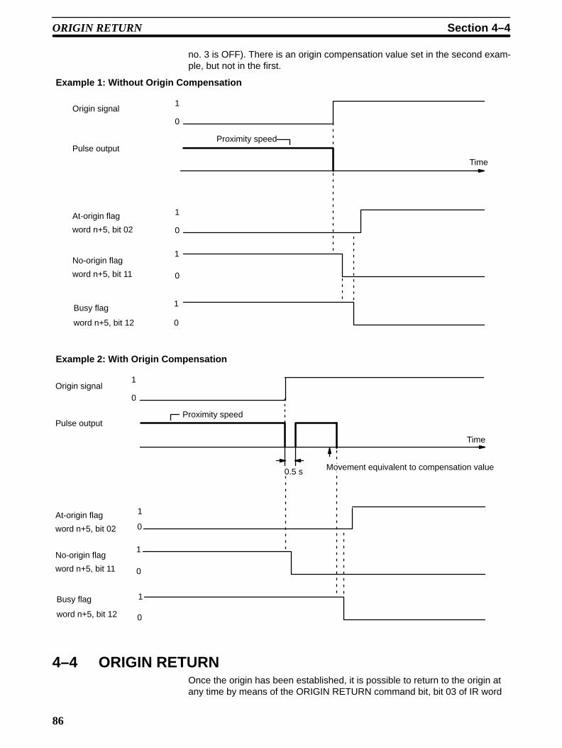
86
no. 3 is OFF). There is an origin compensation value set in the second exam-ple, but not in the first.
Example 1: Without Origin Compensation
1
0
Proximity speed
Time
1
0
1
0
1
0
Origin signal
Pulse output
At-origin flag
word n+5, bit 02
No-origin flag
word n+5, bit 11
Busy flag
word n+5, bit 12
Example 2: With Origin Compensation
Proximity speed
0
1
0
0.5 s Movement equivalent to compensation value
Time
1
0
1
0
1
Origin signal
Pulse output
At-origin flag
word n+5, bit 02
No-origin flag
word n+5, bit 11
Busy flag
word n+5, bit 12
4–4 ORIGIN RETURNOnce the origin has been established, it is possible to return to the origin atany time by means of the ORIGIN RETURN command bit, bit 03 of IR word
ORIGIN RETURN Section 4–4

87
n. When the program turns this bit ON (effective on signal’s rising edge), thePosition Control Unit outputs pulses until the origin is reached. As with ORI-GIN SEARCH, the Position Control Unit uses data stored in the DM areawhen executing ORIGIN RETURN.
Because origin and origin proximity signals are not used, the present positionrelative to the origin must be known. ORIGIN SEARCH or TRANSFER DATA(to preset the present position) must therefore be used to establish positionbefore ORIGIN RETURN is executed. When the origin is reached, the At-ori-gin flag turns ON and the Busy flag turns OFF.
4–4–1 DM Area Settings
In addition to the ORIGIN RETURN speed number (described below), thefollowing data must also be set in order to execute ORIGIN RETURN. Theyare the same as those for START, and can be set by following the instruc-tions contained in Section 4–1.
Initial Speed Number Bits 11 to 08 of DM word m
Speeds DM words m+82 through m+96
Speed Units DM word m+97
Acceleration Bits 15 to 00 of DM word m+98
Deceleration Bits 15 to 00 of DM word m+99
ORIGIN RETURN Speed Number
DM word m, bits 15 to 12
Set from 1 to F (hexadecimal). Refers to one of the speeds set in DM wordsm+82 through m+96.
4–4–2 IR Area Settings
The ORIGIN RETURN command is valid when bit 03 of word n is ON.
n
03
(n = 100 + 10 x unit number)
ORIGIN RETURN command ORIGIN RETURN is started at the leading edge of this bit.
4–4–3 Execution Example
ORIGIN RETURN can only be executed when the origin (0) is known. Asshown in this example diagram, acceleration and deceleration automaticallyform a trapezoidal pattern, stopping at the origin.
ORIGIN RETURN Section 4–4

88
0
Pulse output
1
0
Initial speed
ORIGIN RETURN (Begin)
ORIGIN RETURN speed
AccelerationDeceleration
Initial speed Time
[IN refresh data area flags]
1
0
1
ORIGIN RETURN word n, bit 03
At-origin flag word n+5, bit 02
Busy flag
word n+5, bit 12
Origin (Stop)
ORIGIN RETURN Section 4–4

89
4–5 RELEASE PROHIBITWhen Position Control Unit operation is stopped due to an emergency stop,CW limit, or CCW limit signal, (i.e., when the NC input of any of these turnsON), further pulse output is prohibited. In order to resume pulse output, it isnecessary to cancel this prohibition by means of the RELEASE PROHIBITcommand bit (bit 04 of word n) and release of the external emergency stopswitch.
External input pin no.
20
13
12
A
B
A
B
A
B
CCW
Emergency stop
CCW limit CW limit
CW
Positioning axis
Power source
0 V
24 V
Execution Examples
The present position is lost during an emergency stop, and positioning can-not be started again directly after RELEASE PROHIBIT. Execute ORIGINSEARCH before proceeding.
Example 1: EmergencyStop
RELEASE PROHIBIT Section 4–5

90
0
1
0
1
0
1
0
1
0
1
0
1
0
1
Input
6000
Time
Emergency stop signal
STARTIR n, bit 00
RELEASE PROHIBITIR n, bit 04
Pulse output
Emergency Stop flagIR n+5, bit 04
Error flagIR n+5, bit 05
No-origin flagIR n+5, bit 11
Busy flagIR n+5, bit 12
Alarm/error codeIR n+6
ORIGIN SEARCHIR n, bit 02
0000
0
1
Origin search begun
Turns OFF when origin search is completed
The emergency stop flag is not affected by exceeding the CW or CCW limit.When a limit is exceeded, only pulse output in the opposite direction is possi-ble. In other words, when the CW limit is exceeded, only CCW pulse output ispossible. Although a CCW HIGH-SPEED JOG is used to clear the CW limitflag in the example, LOW-SPEED JOG or ORIGIN SEARCH may also beused.
Example 2: Exceeding CWor CCW Limit
RELEASE PROHIBIT Section 4–5

91
0
1
0
1
0
1
0
1
0
1
CCW
1
0
1
0
1
0
1
0
6100
Time
CW
CW limit signal
STARTIR n, bit 00
RELEASE PROHIBITIR n, bit 04
HIGH-SPEED JOGIR n, bit 11
JOG directionIR n, bit 12
Pulse output
Error flagIR n+5, bit 05
No-origin flagIR n+5, bit 11
Busy flagIR n+5, bit 12
CW limit flagIR n+5, bit 13
Alarm/error codeIR n+6
4–6 READ ERRORThe READ ERROR command bit, bit 05 of word n, is set to access error andalarm codes when more than one of these is present (effective on signal’srising edge). The codes are consecutively output to IR word n+6. Errors andalarms have separate flags, as follows:
READ ERROR Section 4–6

92
15 00
Alarm flag: Set to 1 when an alarm code has been generated
Error flag: Set to 1 when an error has occurred
Error code (or alarm code)
n+5
0305
x103 x102 x101 x100n+6
IR word n+6 shows four digits in BCD when displayed on the ProgrammingConsole. If there are no errors or alarms, 0000 will be displayed. If there areany errors or alarms, they will be displayed in code. The codes will be dis-played in order as READ ERROR is executed. (If there is only one code,however, the display will not change when READ ERROR is executed.)
The error or alarm code (word n+6) is updated via I/O refreshing immediatelyafter the READ ERROR command bit is turned ON. The Busy flag does notturn ON. READ ERROR can be used within a signal scan.
For further information and details, refer to Section 6. For a complete list ofalarm codes, refer to Appendix A.
4–6–1 Execution ExampleThe following diagram shows an example in which first the alarm code 1501and then the error code 5000 are displayed.
1
0
1
0
1
0Display will not change be-cause only one alarm codehas been generated
1501
First alarm code
Display has beenchanged becauseanother error codehas been gener-ated.
5000
Second error code
Display has beenchanged because anerror code has beenread.
1501
First alarm code
READ ERROR IR n, bit 05
Alarm flagIR n+5, bit 03
Error flagIR n+5, bit 05
Alarm/error codeIR n+6
4–6–2 Reading from the Programming ConsoleThe following example diagram (for Unit #1) shows how to read an alarm/er-ror code from the Programming Console.
READ ERROR Section 4–6

93
Key sequence:Programming Console Display:
10005 c106
^ OFF 5000
10005 c106
^ OFF 1501
c106
1501
4–7 RESET ORIGINThe origin is simply the point which is designated as 0 at any given time. Youcan redefine it whenever you wish by using RESET ORIGIN. When the pro-gram turns ON the RESET ORIGIN command bit, bit 08 of word n (effectiveon signal’s rising edge), it redefines the present position as the origin.
Execution Example
1
0
1
0
1
0
1
0 Busy for 1 scan time
Present position changed to 0
RESET ORIGIN
IR n, bit 08
At-origin flagIR n+5, bit 02
No-origin flagIR n+5, bit 11
Busy flagIR n+5, bit 12
Present positionIR n+8 and n+9
4–8 TEACHThere may be cases where you want to teach your control system a particu-lar operation by leading it through the motions. In such cases, you can useTEACH to write the present position as the target position for a designatedpositioning action.
When the origin and present position are defined (i.e., when the no-origin flagis OFF), you can use TEACH to write the present position as fixed data intothe C200H PC’s DM area available for use by Special I/O Units. TEACH isexecuted by turning ON the TEACH command bit, bit 09 of IR word n. Data isset as absolute positions, and not as increments. TEACH can be executedwithin a single scan. The following diagram uses Unit #10 as an example.
TEACH Section 4–8

94
Presentposition
DM 1052
DM 1053
DM 1054
CCW
positioning axis0
CW
Data set using TEACH is valid immediately and can be used for positioningactions without turning off the power or transferring data. Note that data re-written using the Programming Console is not valid until data has been trans-ferred again.
4–8–1 IR Area SettingsIn C200H PCs, IR words 100 to 199 are used for Special I/O Units. When aPosition Control Unit is used, they are allocated as I/O refresh areas. For adetailed explanation, see Section 3–4. For a detailed table of words and bitsin the IR area, see Appendix D.
When the No-origin flag is OFF and pulse output is stopped at the position tobe taught, the present position is set in IR words n+8 and n+9.
IR word n+1, bits 15 to 08
Set an integer between 00 and 19. The number set here indicates the posi-tioning action for which the present position is to be set as the target position.
IR word n, bit 09
TEACH is executed when this bit is ON.
4–8–2 Execution Example
1
0
1
0
1
0
TEACH positioning action no. IR n+1, bits 15 to 08
TEACHIR n, bit 09
Teaching completed flagIR n+5, bit 09
Busy flagIR n+5, bit 12
4–8–3 Teaching From the Programming ConsoleThis example display shows how to teach positions from the ProgrammingConsole for Unit #0. It assumes that ORIGIN SEARCH has been executed,
Present Position
TEACH Positioning ActionNumber
TEACH Command Bit
TEACH Section 4–8

95
and writes the present position into words DM 1053 and DM 1054 as an ab-solute position (i.e., relative to the origin).
Programming Console Display Key sequence
Turns TEACH ON and OFF.
Low-speed JOG
(Designated position for sequence #10)
10013
^ OFF
10013
^ ON
c10110013
0000^ OFF
c10110013
1000^ OFF
10013 c101
^ OFF 1000
10009 c101
^ OFF 1000
10009 c101
^ OFF 1000
CLR00001 T000^ OFF 0100
4–9 TRANSFER DATAThe data which you write into the DM area (for positioning actions, speeds,and so on) is automatically transferred from the PC to the Position ControlUnit. The data designated for any given Unit is transferred to that Unit when itis powered up or restarted by the AR area Restart bit. There may be times,however, when you want to control an operation requiring additional data. Inthose situations you can use TRANSFER DATA to access additional data,not only from other parts of the DM area but from any area in the PC.
As described in Section 3–4, Position Control Units are consecutively allo-cated 100 words each from the DM area and this data is automatically trans-ferred. TRANSFER DATA, however, can transfer data from other parts of theDM area as well as from the LR, HR, and other areas. Position, speed, accel-eration, and deceleration data are all transferable. TRANSFER DATA over-writes the RAM in the Position Control Unit, but does not affect the data setfor that Unit in the DM area of the PC.
TRANSFER DATA Section 4–9

96
C200H PC
DM 1500 to 1599
I/O memory
Automatically transferred atstart-up or restart via AR arearestart bit.
Position Control Unit #5
Data table
Parameters
Positioningactions
Speeds
Acceleration
DecelerationTRANSFERDATA
IR area, LR area,HR area,etc.
TRANSFER DATA can be executed either to rewrite positioning data set inthe Unit or to change the present position to any target position. The type oftransfer is determined by the following setting.
IR word n+2, bit 15
1: Preset position0: Normal transfer
If this bit is 0, then bits 15 through 08 of word n+2 determine the beginningtransfer number, as explained below. (Bit 15 of word n+2 will always be 0when a beginning transfer number is designated. When this bit is set to 1,bits 14 through 08 are ignored and only the present position is affected.) Thiscommand can be executed within a single scan.
4–9–1 Normal TransferIf bit 15 of IR word n+2 is 0, the TRANSFER DATA command bit, bit 10 of IRword n, is set to transfer the positioning actions, speeds, acceleration, anddeceleration from a data area of the PC other than the one allocated to thePosition Control Unit. Any data area in the C200H PC may be designated.This data is directly transferred from the designated area to memory withinthe Unit; the data set for the Unit in the allocated section of DM area is notaffected. Parameters set in DM words m through m+21 are not changedwhen TRANSFER DATA is executed.
Before transferring data, you must prepare it in a PC data area in the re-quired format and in consecutive words. (See Appendix C for the content ofeach word/bit.) When TRANSFER DATA is executed, the transfers are made
TRANSFER DATA type
Data Preparation
TRANSFER DATA Section 4–9

97
consecutively by number, starting with the beginning transfer number set inthe IR area. Up to 26 transfers (three words each) can be made each timeTRANSFER DATA is executed. Each transfer consists of one positioning ac-tion, three speeds, or the speed units, acceleration, and deceleration. In anycase, three words are required for each transfer.
As can be seen from the following tables, each transfer number correspondsto one particular positioning action, three of the 15 speeds, or other data. Thedata which is transferred overwrites the data for that positioning action (orother data) which had previously been automatically transferred to the Posi-tion Control Unit. The data to be newly transferred can be drawn from any ofthe PC data area words shown in the table on the left.
Positioning action #0
Positioning action #1
Positioning action #19
Speed #1
Speed #2
Speed #3
Speed #4
Speed #5
Speed #6
Speed #13
Speed #14
Speed #15
Speed units
Acceleration
Deceleration
Data Area
DM area
DM area (for Special I/O Units)
I/O area
LR area
HR area
AR area
Words
0000 to 0999
1000 to 1999
000 to 255
000 to 63
00 to 99
00 to 27
Transfer #0
Transfer #1
Transfer #19
Transfer #20
Transfer #21
Transfer #24
Transfer #25
PC Data Areas Available for TRANSFER DATA
Position Control Unit’s Rewritten Data
4–9–2 IR Area SettingsIn C200H PCs, IR words 100 to 199 are used for Special I/O Units. When aPosition Control Unit is used, they are allocated as I/O refresh areas. For adetailed explanation, see Section 3–4. For a detailed table of words and bitsin the IR area, see Appendix D IR Area Allocations.
You use the IR area to designate the PC area from which you want to trans-fer data, the beginning word number to be transferred from that area, and thenumber of transfers (of three words each) which you want to execute. Asshown in the diagram below, you make most of these settings in two IRwords, n+3 and n+4. You write the beginning transfer number in IR word n+2.
TRANSFER DATA Section 4–9

98
15 00
Data Area
00
01
02
03
04
n+3
n+4
n+4 n+3
x103 x102 x101 x100 x101 x100 x101 x100
DM
I/O
LR
HR
AR
Beginning word number
Set a wordnumber in4-digit BCDcode
Number of transfers
IR word n+2, bits 15 to 08
Set an integer between 00 and 25.
This is the number of the first word to be transferred. The requested numberof words will be transferred starting from this word.
See Appendix C for the words transferred with each transfer number.
IR word n+3, bits 15 to 00
This is the first word in the PC data area that is to be transferred into the Po-sition Control Unit beginning at the transfer number specified by word n+2,bits 15 to 08. The beginning word and ending word (computed from the num-ber of transfers) must be within one of the data areas designated during datapreparation (see Data Configuration and Allocation in Section 3–4).
IR word n+4, bits 07 to 00
Set the data area (in four BCD digits) from which the transfer is to be made.
IR word n+4, bits 15 to 08
Set an integer between 01 and 26.
IR word n, bit 10
After the above settings are made, TRANSFER DATA is executed with thisbit. This can all be done in one scan.
This example assumes that bit 15 of IR word n+2 is 0.
Beginning Transfer Number
Beginning Word Number
PC Data Area
Number of Transfers
TRANSFER DATACommand Bit
Execution Example(Normal Transfer)
TRANSFER DATA Section 4–9

99
Set necessary information in IR area.
1
0
1
0
1
0
Datatransfer
Data processing
Preparation of datain PC’s data areas
Beginning transfer numberIR n+2, bits 15 to 08
Beginning word numberIR n+3
PC data area/no. of transfersIR n+4
TRANSFER DATAIR n, bit 10
Transfer Completed flagIR n+5, bit 10
Busy flagIR n+5, bit 12
4–9–3 Present Position PresetYou can change the function of the TRANSFER DATA command bit with asetting in the IR area. If bit 15 of IR word n+2 is set to 1, the TRANSFERDATA command bit (bit 10 of IR word n) is set to either preset or change thepresent position. This command can be used to eliminate the need to ex-ecute ORIGIN SEARCH to establish position. Since the origin, present posi-tion, and so on, are not known when the Position Control Unit is powered up,it is ordinarily necessary to execute ORIGIN SEARCH first. You can use thepresent position preset function instead, however, when it is sufficient to set aspecific numerical value and use that position as a reference point. In suchcases, the origin will be defined in relation to that position, and there is noneed to search for the origin first.
No data is retained in the Position Control Unit once power is turned OFF.When the present position needs to be retained, copy it (words n+8 and n+9)to either the HR or DM area, and then restore it by using TRANSFER DATAthe next time the Unit is powered up.
The following programming example shows IR n+8 data moving to HR 00and IR n+9 data moving to HR 01. If there is no origin, bit 11 of IR word n+5(the No-origin flag) turns ON (goes to 1). As long as there is an origin and thepresent position data is valid, the present position will be transferred.
Retaining Present Position
TRANSFER DATA Section 4–9

100
0 CW
1 CCW
n+8
n+9
15 00
x103 x102 x101 x100
x106 x105 x104
n+9 n+8
x103 x102 x101 x100 x106 x105 x104
XFER (70)
#0002
n+8
HR 00
x103 x102 x101 x100
x106 x105 x104
HR 00
HR 01
n+5, bit 11
Direction Direction
Direction
Data must be prepared in the same manner as for normal execution ofTRANSFER DATA, except that only two words indicating the target positionare necessary.
IR word n+2, bit 15
Set this bit to 1 in order to use the preset function. If this bit is set to 0, thebeginning transfer number is set in bits 15 to 08 as described in BeginningWord Number under Section 4–9–2.
IR word n+3, bits 15 to 00
This number indicates the first of the two words to be transferred in as thepresent position. The two words must be within one of the data areas desig-nated in Data Preparation toward the beginning of Section 4–9–1.
IR word n+4, bits 07 to 00
Set the data area (in four digits BCD) from which the transfer is to be made.
Data Preparation
Present Position Preset Bit
Beginning Word Number
PC Data Area
TRANSFER DATA Section 4–9

101
Data Area
00
01
02
03
04
n+3
n+4
15 00
n+4 n+3
x103 x102 x101 x100 x101 x100
DM
I/O
LR
HR
AR
Beginning word number
Set a wordnumber in4-digit BCDcode
Number of transfers(Not required)
IR word n, bit 10
After the above settings are made, TRANSFER DATA is executed by turningON this bit. This can all be done in one scan.
Execution Example (Preset)The following example assumes that bit 15 of IR word n+2 has been set to 1.
TRANSFER DATACommand Bit
TRANSFER DATA Section 4–9

102
Set necessary information in IR area.
1
0
1
0
1
0
Datatransfer
Present position presetIR n+2, bit 15
Beginning word numberIR n+3
PC data areaIR n+4 bits 07 to 00
TRANSFER DATAIR n, bit 10
Transfer completed flagIR n+5, bit 10
Busy flagIR n+5, bit 12
Present position IR n+8 and n+9
This position is reflected in the IN refresh areaPresent position determined
Preset value
4–10 Manual OperationsAlthough positioning is generally carried out according to the program in thememory of the PC, the Position Control Unit also allows you to position man-ually when you need to. You can choose from three manual feeding com-mands, depending on how far and how fast you wish to change the position.
These three, HIGH-SPEED JOG, LOW-SPEED JOG, and INCH, are ex-ecuted when their respective command bits turn ON in the IR area. As withother commands, the Position Control Unit makes use of the DM area data incarrying them out. You can use HIGH-SPEED JOG or LOW-SPEED JOG forrapid manual positioning. HIGH-SPEED JOG uses acceleration and deceler-ation as well as the target speed. You can use INCH for very fine adjust-ments, feeding one pulse at a time.
4–10–1 DM Area SettingsIn addition to the settings described in this section, the following data mustalso be set in order to execute HIGH-SPEED JOG. They are the same asthose set for START, so they can be set by following the instructions con-tained in Section 4–1. Only the first three of these need be set forLOW-SPEED JOG.
Initial Speed Number Bits 11 to 08 of DM word m
Speeds DM words m+82 through m+96
Manual Operations Section 4–10

103
Speed Units DM word m+97
Acceleration Bits 15 to 00 of DM word m+98
Deceleration Bits 15 to 00 of DM word m+99
DM word m+1, bits 15 to 12
Set an integer between 1 and F (hex).
The speed number set here refers to one of the speeds set in DM wordsm+82 through m+96, and in DM word m+3, bit 04.
DM word m+1, bits 11 to 08
Set an integer between 1 and F (hex).
The speed number set here refers to one of the speeds set in DM wordsm+82 through m+96, and in DM word m+3, bit 04.
4–10–2 IR Area Settings
In C200H PCs, IR words 100 to 199 are used for Special I/O Units. When aPosition Control Unit is used, they are allocated as I/O refresh areas. For adetailed explanation, see Section 3–4. For a detailed table of words and bitsin the IR area, see Appendix D.
IR word n, bit 11
0: Stop
1: Operate
IR word n, bit 12:
0: CW
1: CCW
IR word n, bit 13
0: Stop
1: Operate
IR word n, bit 14
0: Stop
1: Operate
4–10–3 HIGH-SPEED JOG
Feeding starts at the designated speed when the HIGH-SPEED JOG com-mand bit (IR word n, bit 11) turns ON (effective on signal’s rising edge).Feeding continues until the command bit turns OFF.
HIGH-SPEED JOG SpeedNumber
LOW-SPEED JOG SpeedNumber
HIGH-SPEED JOGCommand
INCH/JOG Direction
LOW-SPEED JOGCommand
INCH Command
Manual Operations Section 4–10

104
1
0
1
0
Initial speed
HIGH-SPEED JOG speed
AccelerationDeceleration
Initial speedTime
HIGH-SPEED JOG IR n, bit 11
Pulse output
Busy flagIR n+5, bit 12
End position (stop)Initial position (start)
4–10–4 LOW-SPEED JOGFeeding starts at the designated speed when the LOW-SPEED JOG com-mand bit (IR word n, bit 13) turns ON (effective on signal’s rising edge).Feeding continues until the command bit turns OFF.
1
0
1
0
Time
LOW-SPEED JOG IR n, bit 13
Pulse output
Busy flagIR 12, bit n+5
LOW-SPEED JOG speed
Initial position (start) End position (stop)
4–10–5 INCHYou can use INCH to manually position one pulse at a time. One pulse is fedeach time the INCH command bit, bit 14 of IR word n, is turned ON (effectiveon signal’s rising edge).
Manual Operations Section 4–10

105
1
0
1
0
1 pulse (2.5 ms)
ON for 1 scan when scan time is 12 ms or more.ON for 2 scans when scan time is less than 12 ms.
Time
INCH
IR n, bit 14
Pulse output
Busy flagIR n+5, bit 12
Approx. 5 ms
4–11 External Interrupt CommandsYou can stop positioning or change speeds with either the bits set in the IRarea or by external interrupt signal input, depending on your DIP switch set-tings. It is possible to set the pins so that both of these methods (commandbits and external interrupts) are available at the same time for either STOP orCHANGE SPEED.
As illustrated in the following diagrams, positioning decelerates to a stopwhen STOP is executed. When CHANGE SPEED is executed, positioningaccelerates or decelerates to the designated speed. Specify the target speedto be used for CHANGE SPEED by setting the speed numbers in bits 05 to00 of IR word n+2. If those bits are set to 00, the next speed number after theone currently being executed will be taken as the target speed. The targetspeeds used during CHANGE SPEED are taken in order, beginning with thelowest speed number, from the DM area.
When executing CHANGE SPEED with an external input, designate thespeed number from IR word n+2 at least one scan time in advance or it willnot be effective. Otherwise, when designating the speed number, use an IRarea work bit. (See IR Area Settings below).
External Interrupt Commands Section 4–11
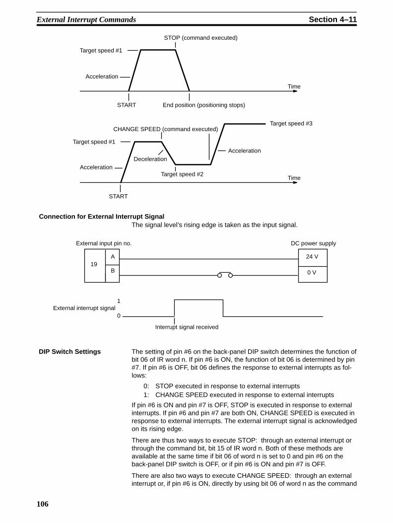
106
Acceleration
START
Time
DecelerationAcceleration
Acceleration
Time
STOP (command executed)
Target speed #1
End position (positioning stops)
START
CHANGE SPEED (command executed)
Target speed #1
Target speed #2
Target speed #3
Connection for External Interrupt SignalThe signal level’s rising edge is taken as the input signal.
External input pin no.
19A
B
External interrupt signal1
0
Interrupt signal received
DC power supply
24 V
0 V
The setting of pin #6 on the back-panel DIP switch determines the function ofbit 06 of IR word n. If pin #6 is ON, the function of bit 06 is determined by pin#7. If pin #6 is OFF, bit 06 defines the response to external interrupts as fol-lows:
0: STOP executed in response to external interrupts1: CHANGE SPEED executed in response to external interrupts
If pin #6 is ON and pin #7 is OFF, STOP is executed in response to externalinterrupts. If pin #6 and pin #7 are both ON, CHANGE SPEED is executed inresponse to external interrupts. The external interrupt signal is acknowledgedon its rising edge.
There are thus two ways to execute STOP: through an external interrupt orthrough the command bit, bit 15 of IR word n. Both of these methods areavailable at the same time if bit 06 of word n is set to 0 and pin #6 on theback-panel DIP switch is OFF, or if pin #6 is ON and pin #7 is OFF.
There are also two ways to execute CHANGE SPEED: through an externalinterrupt or, if pin #6 is ON, directly by using bit 06 of word n as the command
DIP Switch Settings
External Interrupt Commands Section 4–11

107
bit. Execution through an external interrupt is available if bit 06 of word n isset to 1 and pin #6 on the DIP switch is OFF, or if pins #6 and #7 are bothON. In the latter case, execution through the command bit and through anexternal interrupt are both available.
The following data must be set to execute STOP and CHANGE SPEED, butit is the same as that set for START. Refer to Section 4–1 for details.
Acceleration Bits 15 to 00 of DM word m+98
Deceleration Bits 15 to 00 of DM word m+99
In addition to bits 15 and 06 of word n (described under DIP Switch Settingsabove), set bits 05 to 00 of IR word n+2. If these bits are set to 00, the nextspeed number after the one currently being executed will be taken as thetarget speed for CHANGE SPEED. If they are set to from 01 to 15, then theywill specify the speed number to be taken as the target speed.
When executing CHANGE SPEED with an external interrupt signal, the datafrom this area must be written in at least one scan time before the interruptsignal. When executing CHANGE SPEED with a work bit (bit 06 of IR wordn), it can be written in simultaneously with the rising edge of the work bit.
4–11–1 STOPSTOP can be executed during pulse output for START, ORIGIN SEARCH,ORIGIN RETURN, HIGH-SPEED JOG, and LOW-SPEED JOG to decelerateto a stop (effective on signal’s rising edge). Note, however, that the nextSTART cannot be executed as long as STOP (either from bit 15 of IR word nor from an external interrupt signal) is in effect.
When the STOP command bit is set during execution of a positioning actionunder START, the Positioning Completed flag is not turned ON, and the posi-tioning action number is not changed. When START is next executed, thetarget position and speed of that action will be used, as long as the targetposition has not been exceeded. The Busy flag, however, turns OFF, allowingmanual operations to be used up to the next START.
Here is an example in which the following DM words and data are used.
Completion code: continuous
Target position
Completion code: single
Target position
15 00
Target speed #5
Target speed #8
Positioning action #0
Positioning action #1
m+22
m+23
m+24
m+25
m+26
m+27
5
8
2
0
The following diagram shows the situation when STOP is not executed.
DM Area Settings
IR Area Settings
STOP Executed DuringPositioning Actions
Example 1
External Interrupt Commands Section 4–11

108
1
0
1
0
1
0
Time
START IR n, bit 00
Positioning Completed flagIR n+5, bit 00
Busy flagIR n+5, bit 12
START
Target speed #5
Target speed #8
Target position for action #0
#0
Stop (at target positionfor action #1)
#1
The next diagram illustrates the case where STOP is executed before posi-tioning is finished. In this example, START has initiated a sequence of twopositioning actions, the first “continuous” and the second “single”. If STOPwas not executed, positioning would reach the target speed (speed #5) foraction #0, decelerate to the target speed (speed #8) for action #1, and finallystop at the target position for action #1.
When STOP is executed during positioning action #0, however, positioningimmediately decelerates to a stop. The STOP Executed flag turns ON andthe Busy flag turns OFF (allowing manual operation). The Positioning Com-pleted flag, however, remains OFF until both action #0 and action #1 havebeen fully implemented. The positioning action number remains the same,and the target speed and target position for that action are used the next timeSTART is executed (as long as the target position has not already been ex-ceeded).
Example 2
External Interrupt Commands Section 4–11

109
0
1
0
1
0
1
0
1
0
1
0 1
Time
2
START IR n, bit 00
STOPIR n, bit 15(or external interrupt)
Pulse output
Positioning Completed flagIR n+5, bit 00
Busy flagIR n+5, bit 12
Positioning action numberIR n+7, bits 07 to 00
Output codeIR n+7, bits 11 to 08
Target positionfor action #0
Stops at target positionfor action #1.
Output code ofaction #0
Output code ofaction #1
#0 #0#1
Target speed #5
This diagram shows execution when a target position designated from theorigin (i.e., not an increment) is exceeded during deceleration for STOP, ascan happen when STOP is executed during the end of a continuous position-ing action. If START is executed again before this situation is corrected, thefeeding direction for the action will be wrong, and an error (code 5020) will begenerated due to inability to begin the action. The Position Control Unit canbe restarted after manually feeding (with JOG) back to the other side of thetarget position for action #0.
This error will also be generated if the target position for action #0 is exceed-ed through manual operations before START is executed following STOP.
Example 3
External Interrupt Commands Section 4–11

110
1
0
1
0
0
1
1
0
1
1
0
#0
0
5020
Time
0
START IR n, bit 00
STOPIR n, bit 15(or external interrupt)
Pulse output
Positioning Completed flagIR n+5, bit 00
Error flagIR n+5, bit 05
Busy flagIR n+5, bit 12
STOP Executed flagIR n+5, bit 15
Error codeIR n+6
Positioning action numberIR n+7, bits 07 to 00
Target position foraction #0 is passed.
Target speed #5
External Interrupt Commands Section 4–11

111
When the target position is expressed as an increment, the positioning actionwill be automatically started over from the position arrived at after STOP wasexecuted.
1
0
1
0
1
0
1
0
1
0
Time
START IR n, bit 00
STOPIR n, bit 15
Pulse output
Positioning Completed flagIR n+5, bit 00
Busy flagIR n+5, bit 12
STOP Executed flagIR n+5, bit 15
Positioning action numberIR n+7, bits 07 to 00
Output codeIR n+7, bits 11 to 08
#0 #0
#1
Output code ofaction #0
Output code ofaction #1
0 1 2
Feeding will be decelerated to a stop and the command must be reexecutedfrom the position reached at the end of STOP.
Feeding stops according to the deceleration rate.
Example 4
STOP During ORIGINSEARCH
STOP During ORIGINRETURN
External Interrupt Commands Section 4–11
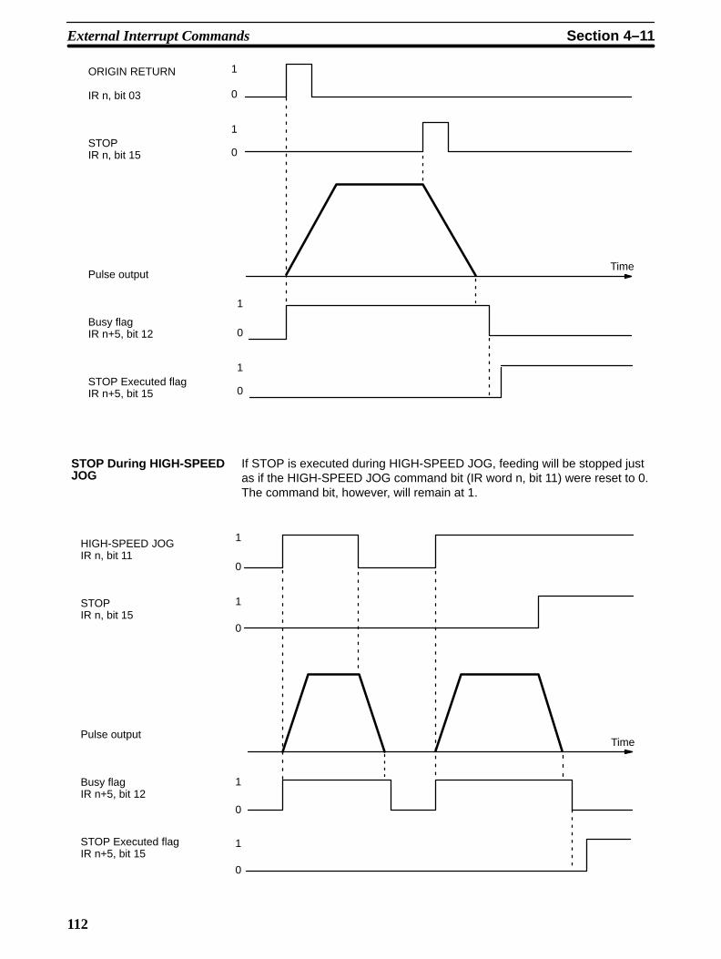
112
0
1
0
1
0
1
1
0
Time
ORIGIN RETURN
IR n, bit 03
STOPIR n, bit 15
Pulse output
Busy flagIR n+5, bit 12
STOP Executed flagIR n+5, bit 15
If STOP is executed during HIGH-SPEED JOG, feeding will be stopped justas if the HIGH-SPEED JOG command bit (IR word n, bit 11) were reset to 0.The command bit, however, will remain at 1.
1
0
1
0
1
0
1
0
Time
HIGH-SPEED JOGIR n, bit 11
STOPIR n, bit 15
Pulse output
Busy flagIR n+5, bit 12
STOP Executed flagIR n+5, bit 15
STOP During HIGH-SPEEDJOG
External Interrupt Commands Section 4–11

113
If STOP is executed during LOW-SPEED JOG, feeding will be stopped justas if the LOW-SPEED JOG command bit (IR word n, bit 13) were reset to 0.The command bit, however, will remain at 1.
0
1
0
1
0
1
1
0
Time
LOW-SPEED JOGIR n, bit 13
STOPIR n, bit 15
Pulse output
Busy flagIR n+5, bit 12
STOP Executed flagIR n+5, bit 15
When STOP is executed for the first time during a positioning action with acompletion code of 5, positioning will be executed according to whatever po-sition data is set. When it is executed for a second time (see the followingexample diagram), positioning is interrupted and decelerates to a stop. Seealso Completion Code under Section 4–1–1.
Positioning cannot be restarted as long as the signal defined as the STOPcommand (either IR word n, bit 15 or an external interrupt signal) is ON. Fordetails on defining either IR word n, bit 15 or an external interrupt signal asthe STOP command, see DIP Switch Settings under Section 4–10.
STOP During LOW-SPEEDJOG
STOP During a CompletionCode 5 Positioning Action
External Interrupt Commands Section 4–11

114
STARTIR n bit 00
STOP (first time)IR n, bit 15
Pulse output
Positioning Completed flagIR n+5, bit 00
Busy flagIR n+5, bit 12
No-origin flagIR n+5, bit 11
STOP Executed flagIR n+5, bit 15
Positioning action numberIR n+7, bits 07 to 00
Output codeIR n+7, bits 11 to 08
1
0
1
0
1
0
1
0
1
0
1
0
P P+1
Time
Positioning is already started, butthe flag turns OFF one scan later.
When STOP is executed for the second time, positioning is interrupted anddecelerates to a stop.
STOPIR n, bit 15
Pulse output
STOP Executed flagIR n+5, bit 15
Positioning Completed flag
The positioning action number and output code will not be updated.
1
0
1
0
1
0
Time
External Interrupt Commands Section 4–11

115
4–11–2 CHANGE SPEED
CHANGE SPEED can only be executed during positioning initiated withSTART. When executing CHANGE SPEED several times consecutively, youcan either choose to have speed numbers incremented one by one, or selectspecific speed numbers to be executed in any order. Set the speed numbersin bits 05 to 00 of IR word n+2. (See IR Area Settings and DIP Switch Set-tings under Section 4–10). If you set these bits to 00, the speed numbers willbe incremented in order from the one currently being executed. You can se-lect specific speed numbers by setting the bits anywhere from 01 to 15.
It is also possible to execute CHANGE SPEED with bit 06 of IR word n, de-pending on the DIP switch settings. If bit 06 is used, the data will simulta-neously be input to IR word n+2. If you use an external interrupt signal, how-ever, be sure to input the data at least one scan time early or it will not beeffective.
When the target position is being approached, CHANGE SPEED will not af-fect deceleration. In other words, normal deceleration to end at the targetposition will be carried out for single, pause, or bank end positioning actions,and the target speed for the next positioning action will take priority for a con-tinuous positioning action.
In the following example diagram, speed number 1 is used for the positioningaction executed first.
0
1
1
0
Time
START IR n, bit 00
CHANGE SPEED(external interrupt inputor IR n, bit 06)
Pulse output
Speed no. designationIR n+2, bits 05 to 00
Speed #1
Speed #2
Speed #6
Speed #7
00 06 00
Execution Example
External Interrupt Commands Section 4–11
117
SECTION 5Programming Examples
This section contains examples of possible applications of Positioning Control Unit commands, inputs, and outputs. Thefirst example (see Section 5–1) shows the minimum data required for operation. The second example (Section 5–2)shows the use of only one positioning action under START augmented by RESET ORIGIN. Section 5–3 demonstratesthe use of external switches to control positioning actions, while Sections 5–4 and 5–5 show use of TRANSFER DATA:the example in Section 5–4, from the PC, and in Section 5–5, from external switches. Section 5–6 shows a complex seriesof positioning actions under START. The example in Section 5–7 illustrates possible search patterns under ORIGINSEARCH, while that in 5–8 illustrates one possible use of zones: controlling manual feeding operations. Section 5–9shows how to set speeds by multiplying speed units, and Section 5–10 shows a program with multiple banks. Refer to theAppendixes or individual operation or command descriptions for details.
5–1 Operation with Minimum Data (Displaying JOG Positions) 118 . . . . . . . . . . . . . . . . . 5–2 Positioning at Intervals Using RESET ORIGIN 119 . . . . . . . . . . . . . . . . . . . . . . . . . . 5–3 Feeding Selectively with START 121 . . . . . . . . . . . . . . . . . . . . . . . . . . . . . . . . . . . . . . 5–4 TRANSFER DATA from Other PC Areas 123 . . . . . . . . . . . . . . . . . . . . . . . . . . . . . . . 5–5 TRANSFER DATA from External Switches 125 . . . . . . . . . . . . . . . . . . . . . . . . . . . . . 5–6 Using START to Carry Out Positioning Actions 128 . . . . . . . . . . . . . . . . . . . . . . . . . . 5–7 Using Origin and Origin Proximity Signals 132 . . . . . . . . . . . . . . . . . . . . . . . . . . . . . . 5–8 Using Zones to Control Jogging 132 . . . . . . . . . . . . . . . . . . . . . . . . . . . . . . . . . . . . . . . 5–9 Setting Speeds 134 . . . . . . . . . . . . . . . . . . . . . . . . . . . . . . . . . . . . . . . . . . . . . . . . . . . . 5–10 Using a Multiple Bank Program 134 . . . . . . . . . . . . . . . . . . . . . . . . . . . . . . . . . . . . . . .

118
5–1 Operation with Minimum Data (Displaying JOG Positions)The wiring shown below is the simplest possible for Position Control Unit op-eration.
24 VDC
ABABAB
20
13
12
C200H PC
Emergency stop
CW limit
CCW limit
Hand-held Programming ConsoleC200H-PR027Position Control Unit #0
The data settings shown below are the minimum required to prevent thealarm/error LED from flashing.
HIGH-SPEEDJOGspeed
ORIGINSEARCHproximityspeed
DM 1000 1 0 0 0
DM 1001 1 2 1 2
DM 1082 2 0 0 0 Speed #1
DM 1083 0 5 0 0 Speed #2
DM 1098 0 0 0 6 Acceleration
DM 1099 0 0 0 6 Deceleration
ORIGINRETURNspeed
Initialspeed
Initialpositionno.
LOW-SPEEDJOGspeed
ORIGINSEARCHspeed
Procedure1, 2, 3... 1. Set the PC to PROGRAM mode, and then begin operation from the Pro-
gramming Console.2. Write data into the DM area and restart.
A0100
^ OFF
3. Monitor the present position words.
c109 c108
0999 9911
Wiring
DM Area Settings
Operation with Minimum Data (Displaying JOG Positions) Section 5–1

119
4. Monitor the RESET ORIGIN command bit.
10008 c109 c108
^ OFF 0999 9911
5. Reset the present position.
10008 c109 c108
^ OFF 0000 0000
6. Set LOW-SPEED JOG command bit.
Indicators on Position Control Unit
NC112
RUN BUSY
CW
CCW ERROR
CW and busy LEDs light when 10012 (direction) is OFF.
ALARM
Programming Console Display
Indicates changes in present po-sition.
10013 c109 c108
^ ON 0000 2340
7. Stop LOW-SPEED JOG.
10013 c109 c108
^ OFF 0001 0615
5–2 Positioning at Intervals Using RESET ORIGINIn this example, the Position Control Unit is assumed to be assigned unitnumber 0.
Positioning at Intervals Using RESET ORIGIN Section 5–2

120
Configuration
C200H PC
ABABABABAB
20
13
12
11
10
Emergencystop
CW limit
CCW limit
Origin
Originproximity
Position Control Unit
24 VDC
Feeding is executed to positions lying at equal distances in the same direc-tion from a specific point, repeatedly using the same positioning action andthen RESET ORIGIN.
ORIGINSEARCH
Origin
0
Origin proximitysignal
RESET ORIGIN
Operation
Positioning at Intervals Using RESET ORIGIN Section 5–2

121
Programming
Initialspeed
0 to F
InitialpositionNo. 0 to 19
LOW-SPEEDJOG 1 to F
ORIGINSEARCH1 to F
HIGH-SPEEDJOG 1 to F
ORIGINRETURNspeed 1 to F
DM 1022 1 0 0 3
DM 1023 0 0 0 0
DM 1024 0 0 0 1
Comple-tion code0 to 4
DM 1000 1 0 0 0
DM 1001 1 2 1 2
DM 1082 5 0 0 0 Speed #1
DM 1083 0 5 0 0 Speed #2
DM 1097 0 0 0 0 Speed units
DM 1098 0 0 0 8 Acceleration
DM 1099 0 0 0 8 Deceleration
SpeedNo. 1 to F
Target position
Outputcode 0 to F
Dwelltime 0 to F
Originprox.speed1 to F
10002
10000
END
DIFU(13) 03001
DIFU(13) 03000
03002
03002
03002
03000 10512
10511 10502 10512
10500
03001 10502
10512
10008
10015
Operation stop switch
No origin
Busy (flag)
Busy ORIGIN SEARCH
START
Present position reset
Start switch
At origin
Positioning completed
STOP
5–3 Feeding Selectively with START
The configuration here is the same as that for Example 1. There is no originor origin proximity signal used. With the following data and program, the usercan select feeding 4,000, 5,000, or 6,000 pulses at a time at 1,000 pps. Thedata settings shown below are the minimum required to prevent the alarm/er-ror LED from flashing. The positioning actions are all CW (incremental) bankcompletion actions.
Configuration
Feeding Selectively with START Section 5–3

122
Comple-tion code0 to 4
Originprox.speed1 to F
InitialpositionNo. 0 to 19
DM 1022 2 0 0 3
DM 1023 4 0 0 0
DM 1024 2 0 0 0
DM 1025 2 0 0 3
DM 1026 5 0 0 0
DM 1027 2 0 0 0
DM 1028 2 0 0 3
DM 1029 6 0 0 0
DM 1030 2 0 0 0
Target position
DM1082 2 0 0 0
DM1083 0 5 0 0
DM1098 0 0 0 6
DM1099 0 0 0 6
Positioning action #1
Positioning action #2
Speed #1
Speed #2
Acceleration
Deceleration
Initialspeed
0 to F
LOW-SPEEDJOG 1 to F
ORIGINSEARCH1 to F
HIGH-SPEEDJOG 1 to F
ORIGINRETURNspeed 1 to F
DM 1000 1 0 0 0
DM 1001 1 2 1 2
Positioning action #0
SpeedNo. 1 to F
Outputcode 0 to F
Dwelltime 0 to F
With the following programming, input A, B or C can be selected and STARTexecuted to feed the desired target number of pulses.
Ladder Diagram
Feeding Selectively with START Section 5–3

123
RESET ORIGIN
Valid initial positioning action no.
Selects positioning action #0
Selects positioning action #1
Selects positioning action #2
Origin reset switch
25313
Input A
Input B
Input C
START input
10008
10001
MOV (21)#0000
101
MOV (21)#0001
101
MOV (21)#0002
101
10000 START
5–4 TRANSFER DATA from Other PC Areas
This example program shows data for three positioning actions transferredfrom DM 0010. Note that TRANSFER DATA immediately rewrites the Posi-tion Control Unit’s memory. Therefore the transfer program must be executeda second time, this time from DM 1022, if the previous origin positioning ac-tion is to be repeated.
The initial data is entered in DM 1002 to 1030. The data and positioning ac-tions are shown below.
Speed #4
Speed #3
DM 1022 3 0 0 2
DM 1023 0 0 0 0
DM 1024 0 0 0 1
DM 1025 4 0 0 0
DM 1026 5 0 0 0
DM 1027 0 0 0 1
DM 1028 3 0 0 3
DM 1029 0 0 0 0
DM 1030 0 0 0 0
START
0CCW
Stop10000
DM 1084
Speed #3
#0 (continuous)
#2 (bank end)
DM 1085
#1Stop
START
15000CW
Initial Data
TRANSFER DATA from Other PC Areas Section 5–4
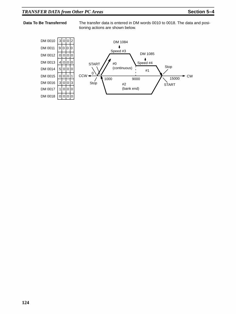
124
The transfer data is entered in DM words 0010 to 0018. The data and posi-tioning actions are shown below.
0
#2 (bank end)
#0 (continuous)
#1
9000
Speed #4
DM 1085
DM 1084
Speed #3
START
CCW
Stop1000 15000
CW
Stop
START
DM 0010 3 0 0 2
DM 0011 9 0 0 0
DM 0012 0 0 0 0
DM 0013 4 0 0 0
DM 0014 5 0 0 0
DM 0015 0 0 0 1
DM 0016 3 0 0 3
DM 0017 1 0 0 0
DM 0018 0 0 0 0
Data To Be Transferred
TRANSFER DATA from Other PC Areas Section 5–4

125
Program
MOV (21)#0000
102 MOV (21)
#1022
103 MOV (21)
#0300
104
MOV (21)#0000
102
MOV (21)#0010
103 MOV (21)
#0300104
00407 (Transfer PB)
04001
04002
04001
04002
10010
10010
04003
10510 (end of transfer)
00211
0400000211
1001004003
(Positioning Started flag)
DIFU (13) 04001
DIFU (14) 04002
DIFU (13) 04003
Transfers data from DM 0010 when 00407 is set.
Re-transfers data from DM 1022 when 00407 is reset.
Starts transfer
102 Beginning action no. (positioning action #0).
103 Beginning word no. (word 10)
104 Number of transfers (3)PC data area no. (0: DM)
(Three positioning actions transferred, beginning withDM 0010)
Transfer Completed flag
Transfer Completed flag
102 Beginning action no. (positioning action #0).
103 Beginning word no. (word 1022)
104 Number of transfers (3)PC data area no. (0: DM)
(Three positioning actions transferred, beginning withDM 1022)
5–5 TRANSFER DATA from External SwitchesIn this example, positioning is executed in accordance with the number ofpulses set by external thumbwheel switches.
TRANSFER DATA from External Switches Section 5–5

126
Configuration
C200HPC
IR 000
IN, 16 bits
SW1 (00010)SW2 (00000)Others
IR 002
IN, 16 bits
IR 003
IN, 16 bits
Thumbwheel SW (leftmost digits ofpositioning data)
Thumbwheel SW (rightmost digits ofpositioning data)
Driver/motor
Positioning ControlUnit #0
The following is the minimum data required so that an alarm will not be gen-erated.
HIGH-SPEEDJOG 1 to F
LOW-SPEEDJOG 1 to F
InitialpositionNo. 0 to 19
Originprox.speed1 to F
DM 1082 2 0 0 0 Speed #1
DM 1083 0 5 0 0 Speed #2
DM 1098 0 0 0 6 Acceleration
DM 1099 0 0 0 6 Deceleration
Initialspeed
0 to F
ORIGINSEARCH1 to F
ORIGINRETURNspeed 1 to F
DM 1000 1 0 0 0
DM 1001 1 2 1 2
Three consecutive words are transferred for positioning action #0. The bits ofIR 001, which is allocated to the Position Control Unit, are used as internalrelays. The next two words are input from thumbwheel switches connected toInput Units allocated IR 002 and IR 003. Thus, when TRANSFER DATA isexecuted with the beginning word designated as word 1, external data, whichhas been prepared according to the data format for positioning action data,can be used to achieve externally designated positioning actions.
Data Memory
Data To Be Transferred
TRANSFER DATA from External Switches Section 5–5

127
Program
Sets speed #1 and completion code 3
(SW 1) 00010
(SW 2) 00000
03000
(SW 2)00000
(SW 1)00010
10512
(busy flag)
03002
Origin re-set andposition-ing flag
10010
03002
10008
10000
10001
DIFU (13) 03000
DIFU (13) 03001
MOV (21)
#0000
102
MOV (21)
#0001
103
MOV (21)
#0101
104
MOV (21)
#1003
001
MOV (21)
#0000
101
DIFU (13) 03003
Data transfer switches
Start switches
102 Beginning action no. (positioning action #0).
103 Beginning word no. (word 1)
104 Number of transfers (1)PC data area no. (1: I/O)
TRANSFER DATA
10501 (bank end)
10502 (origin stop)
03002
03002
03001
10512
(busy flag)
10512 03003
Sets initial positioning action no. (#1)
Valid initial positioning action number
START
RESET ORIGIN
Present position reset and positioning flag
TRANSFER DATA from External Switches Section 5–5

128
5–6 Using START to Carry Out Positioning Actions
Wiring (Details Omitted)
To execute positioning in autoincrement mode, turnON 05 only. To forcibly execute the number specified by thethumbwheel switch, turn ON 06 and then 05.
ID211 ID212 OD211 NC112
IN, 8 bits
IN, 16 points
OUT, 12 points
C200HPC
Word 0 Word 1 Word 2 100 words
PR027
Driver Motor
Switches
9 9 9 9
Thumbwheel switch
Display
24 VDC
CW limit
CCW limit
Emergency stop
Origin
Origin proximity
Short-circuitthese pins.
Connect manu-al-input switchesto these pins sothat the signalscan be manuallyturned ON/OFF.
The lower 2 digits are used tospecify initial positioning actionnumber.
Word 0
00 ORIGIN SEARCH
01 RELEASE PROHIBIT
02 JOG direction
03 HIGH-SPEED JOG
04 LOW-SPEED JOG
05 START
06 Valid initial positioning action no.
07 STOP
Position ControlUnit #0
To execute ORIGIN SEARCH, first turn ON this switch, andthen manually turn ON the origin proximity signal to stopfeeding.
Using START to Carry Out Positioning Actions Section 5–6

129
Feeding Pattern
1000
3000
3000
#0, single
#2, pause
#6, continuous
10000
5000
10000
2000
20000
4000 4000 4000
30000 40000 50000 60000
20000 30000 40000 42000 60000
1000
3000
3000
–6000
#14 (lastaction)
T = 0.5 s
#7
0
#1, single
#3, pause
#8 #9#10
#11, single
#12, pause
T = 1.0 s
T = 0.5 s
#4, pauseT = 1.0 s
#5, single
#13, pause
2000
Using START to Carry Out Positioning Actions Section 5–6
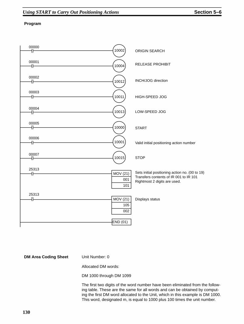
130
Program
ORIGIN SEARCH
RELEASE PROHIBIT
INCH/JOG direction
HIGH-SPEED JOG
LOW-SPEED JOG
START
Valid initial positioning action number
STOP
Sets initial positioning action no. (00 to 19) Transfers contents of IR 001 to IR 101 Rightmost 2 digits are used.
Displays status
00000
00001
00002
00003
00004
00005
00006
00007
25313
25313
10004
10002
10012
10011
10013
10000
10001
10015
MOV (21)
001
101
MOV (21)
105
002
END (01)
Unit Number: 0
Allocated DM words:
DM 1000 through DM 1099
The first two digits of the word number have been eliminated from the follow-ing table. These are the same for all words and can be obtained by comput-ing the first DM word allocated to the Unit, which in this example is DM 1000.This word, designated m, is equal to 1000 plus 100 times the unit number.
DM Area Coding Sheet
Using START to Carry Out Positioning Actions Section 5–6

131
00
01
02
03
04
05
06
07
08
09
10
11
12
13
14
15
16
17
18
19
20
21
22
23
24
25
26
27
28
29
30
31
32
33
15 00 Function W
Initial position nos.;speed nos.
Origin compensa-tion and direction
Backlash compensation
CW limit
CCW limit
Zone 0 CW limit
Zone 0 CCW limit
Zone 1 CW limit
Zone 1 CCW limit
Zone 2 CW limit
Zone 2 CCW limit
Not used
Positioning action #0 0
Positioning action #1 1
Positioning action #2
2
Positioning action #3
3
Transfer no.Transfer no.
15 00W Function
Positioning action #4 4
Positioning action #5
5
Positioning action #6 6
Positioning action #7 7
Positioning action #8 8
Positioning action #9 9
Positioning action #10
10
Positioning action #11 11
Positioning action #12 12
Positioning action #13 13
Positioning action #14 14
34
35
36
37
38
39
40
41
42
43
44
45
46
47
48
49
50
51
52
53
54
55
56
57
58
59
60
61
62
63
64
65
66
67
68
69
70
71
72
73
74
75
76
77
78
79
80
81
82
83
84
85
86
87
88
89
90
91
92
93
94
95
96
97
98
99
W 15 00 Function
Positioning action #15 15
Positioning action #16 16
Positioning action #17
17
Positioning action #18
18
Positioning action #19
19
Speed #1
Speed #2
Speed #3
Speed #4
Speed #5
Speed #6
Speed #7
Speed #8
Speed #9
Speed #10
Speed #11
Speed #12
Speed #13
Speed #14
Speed #15
Speed units
Acceleration
Deceleration
20
21
22
23
24
25
1 1 1 2
2 3 4 5
2 0 0 0
0 0 0 0
0 0 0 0
0 0 0 0
0 8 0 0
0 0 0 0
0 8 0 0
0 5 0 0
0 0 0 0
0 5 0 0
1 0 0 0
0 0 0 0
0 0 0 1
8 0 0 0
0 0 0 0
0 0 0 0
0 0 0 2
5 0 0 0
0 0 0 1
0 0 0 0
6 0 0 0
0 0 0 0
0 0 0 1
7 0 0 0
0 0 0 0
0 0 0 2
8 1 5 1
0 0 0 0
0 0 0 3
9 1 A 1
0 0 0 0
0 0 0 4
9 1 A 1
0 0 0 0
0 0 0 5
9 1 0 0
0 0 0 0
0 0 0 6
8 1 0 2
0 0 0 0
0 0 0 1
9 2 0 2
0 0 0 0
0 0 0 2
6 3 0 2
0 0 0 0
0 0 0 3
7 4 0 2
0 0 0 0
0 0 0 4
3 5 0 2
2 0 0 0
0 0 0 4
A 6 0 0
0 0 0 0
0 0 0 6
6 0 5 1
3 0 0 0
0 0 0 0
8 0 0 1
6 0 0 0
1 0 0 0
A 0 0 3
0 0 0 0
0 0 0 0
5 0 0 0
5 0 0 0
0 5 0 0
4 0 0 0
0 3 0 0
1 0 0 0
2 0 0 0
3 0 0 0
4 0 0 0
5 0 0 0
6 0 0 0
7 0 0 0
8 0 0 0
9 0 0 0
1 0 0 0
8 0 0 0
0 1 0 0
0 0 5 0
Using START to Carry Out Positioning Actions Section 5–6

132
5–7 Using Origin and Origin Proximity SignalsConfiguration
24 VDC
AB
ABABABAB
20
13
12
11
10
Emergency stop
CW limit
CCW limit
Origin
C200H PCPosition Control Unit
Origin proximity
Pin 3 ON (Designating presence of origin proximity signal)
Pin 4 ON (Designating N.O. contact for origin proximity signal)
Pin 5 ON (Designating N.C. contact for origin signal)
Operation
10002SW
ORIGIN SEARCH
The possible search patterns for ORIGIN SEARCH using both an origin sig-nal and an origin proximity signal are as follows.
CCW
CCW
CCW
CW
CW
CW
Origin proximity signal
Pulse output
Origin (Stop)
CW limit
1
0
START
STARTOrigin (Stop)
STARTOrigin (Stop)
5–8 Using Zones to Control JoggingThis examples shows how to use zones to change conditions for manual op-erations (jogging and inching). With the following setup and data, all manual
DIP Switch Settings
Operation
Using Zones to Control Jogging Section 5–8

133
operations are possible in zone 1 except for the part of it occupied by zone 0.In zone 0, CCW manual feeding is prohibited.
CCW CW
0 200
100 5000300
Zone 0
Zone 1
DM Area Settings (Zone Data)
DM 1009 0 3 0 0
DM 1010 0 0 0 0
DM 1011 0 2 0 0
DM 1012 0 0 0 0
DM 1013 5 0 0 0
DM 1014 0 0 0 0
DM 1015 0 1 0 0
DM 1016 0 0 0 0
Zone 0 CW limit
Zone 0 CCW limit
Zone 1 CW limit
Zone 1 CCW limit
Zone 0
Zone 1
Program
CW JOG switch
JOG direction
CCW JOG switch
CCW JOG switch
10507
Zone 0 flag
10506
CW JOG switch
Zone 1 flag
10013
10012
Low-speed JOG
Using Zones to Control Jogging Section 5–8
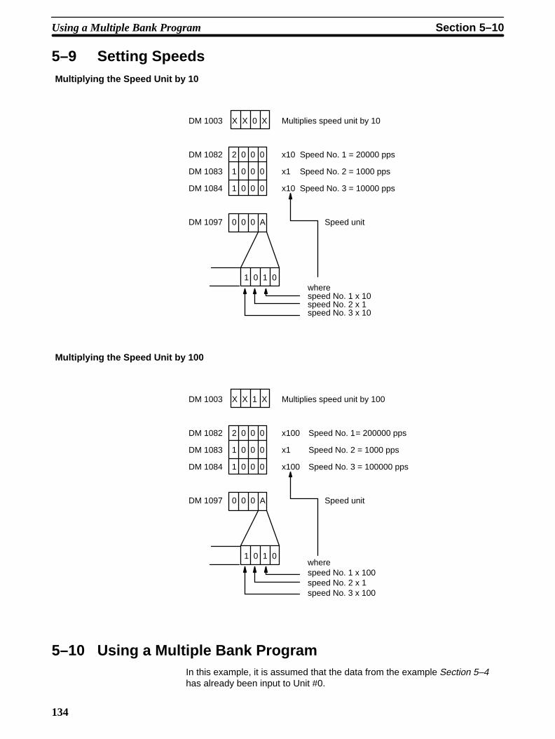
134
5–9 Setting SpeedsMultiplying the Speed Unit by 10
wherespeed No. 1 x 10speed No. 2 x 1speed No. 3 x 10
DM 1003 X X 0 X
DM 1082 2 0 0 0
DM 1083 1 0 0 0
DM 1084 1 0 0 0
DM 1097 0 0 0 A
Multiplies speed unit by 10
x10 Speed No. 1 = 20000 pps
x1 Speed No. 2 = 1000 pps
x10 Speed No. 3 = 10000 pps
1 0 1 0
Speed unit
Multiplying the Speed Unit by 100
wherespeed No. 1 x 100speed No. 2 x 1speed No. 3 x 100
DM 1003 X X 1 X
DM 1082 2 0 0 0
DM 1083 1 0 0 0
DM 1084 1 0 0 0
DM 1097 0 0 0 A
Multiplies speed unit by 100
x100 Speed No. 1= 200000 pps
x1 Speed No. 2 = 1000 pps
x100 Speed No. 3 = 100000 pps
1 0 1 0
Speed unit
5–10 Using a Multiple Bank ProgramIn this example, it is assumed that the data from the example Section 5–4has already been input to Unit #0.
Using a Multiple Bank Program Section 5–10

135
The data for one bank is entered into positioning action numbers 0, 1, and 2.
Speed No. 4
Speed No. 3
DM 1022 3 0 0 2
DM 1023 0 0 0 0
DM 1024 0 0 0 1
DM 1025 4 0 0 0
DM 1026 5 0 0 0
DM 1027 0 0 0 1
DM 1028 3 0 0 3
DM 1029 0 0 0 0
DM 1030 0 0 0 0
START
0CCW
Stop10000
DM 1084
Speed No. 3
#0 (continuous)
#2 (bank end)
DM 1085
#1Stop
START
15000CW
The data for another bank is entered into positioning action numbers 5, 6,and 7.
DM 1037 3 0 0 2
DM 1038 9 0 0 0
DM 1039 0 0 0 0
DM 1040 4 0 0 0
DM 1041 5 0 0 0
DM 1042 0 0 0 1
DM 1043 3 0 0 3
DM 1044 1 0 0 0
DM 1045 0 0 0 0
0
#7 (bank end)
#5 (continuous)
#1
9000
Speed No. 4
DM 1085
DM 1084
Speed No. 3
START
CCW
Stop
1000 15000CW
Stop
START
This program is used to distinguish between the two banks shown above (po-sition action numbers 0 to 2 and 5 to 7). In order to select and execute eitherpositioning action #0 or #5, it turns the valid bit (bit 01 of word n) of the initialpositioning number ON, then immediately OFF. Leaving the initial positioningaction valid bit ON forces execution of IR word n+1.
First Bank(Positioning ActionNumbers 0 to 2)
Second Bank (PositioningAction Numbers 5 to 7)
Operation
Using a Multiple Bank Program Section 5–10

136
Program (Unit #0)
Turns ON the valid initialpositioning no. bit for 1scan with the nextSTART following theend of the bank.
Start switch
10501 (Bank End flag)
10000 03000 0310103100
03100
10000 0300003101
03100
03101
03101
03100
#0 assignedswitch
DIFU (13) 10000
DIFU (13) 03000
MOV (21)
#0000
101
MOV (21)
#0005
101
DIFU (13) 10001
Designates #0 as thenext positioning actionafter the bank ends
#5 assignedswitch
Designates #5 as thenext positioning actionafter the bank ends
Using a Multiple Bank Program Section 5–10

137
SECTION 6Error Processing
This section covers the procedures for handling errors and alarms during Position Control Unit operation. It includes er-ror codes, alarm codes, error and alarm indicators, troubleshooting from the PC, and AR area Restart bits. For a completelist of alarm codes, see Appendix A. For a list of error codes, see Appendix B.
6–1 Alarms and Errors 138 . . . . . . . . . . . . . . . . . . . . . . . . . . . . . . . . . . . . . . . . . . . . . . . . . 6–2 Outputs to the IR Area 138 . . . . . . . . . . . . . . . . . . . . . . . . . . . . . . . . . . . . . . . . . . . . . . 6–3 Alarm/Error Indicators 138 . . . . . . . . . . . . . . . . . . . . . . . . . . . . . . . . . . . . . . . . . . . . . . 6–4 Error Code Output 138 . . . . . . . . . . . . . . . . . . . . . . . . . . . . . . . . . . . . . . . . . . . . . . . . . 6–5 Troubleshooting from the PC 140 . . . . . . . . . . . . . . . . . . . . . . . . . . . . . . . . . . . . . . . . .
6–5–1 Error List for Special I/O Units 140 . . . . . . . . . . . . . . . . . . . . . . . . . . . . . . . 6–5–2 AR Area Error and Restart Bits for Special I/O Units 140 . . . . . . . . . . . . .
6–6 Basic Troubleshooting Chart 141 . . . . . . . . . . . . . . . . . . . . . . . . . . . . . . . . . . . . . . . . . 6–7 Detection of Abnormal Pulse Outputs 143 . . . . . . . . . . . . . . . . . . . . . . . . . . . . . . . . . .

138
6–1 Alarms and ErrorsWhenever the Position Control Unit is powered up or data is transferred intothe Unit, checks are performed to ensure that the data is in proper form andcan be used for operation. If an error exists in speed or positioning actiondata at this time, an alarm code is generated. Errors that result in alarms in-clude BCD errors, out-of-range data, and no-data errors (when required datais set at 0). An alarm will thus be generated, for example, if the required set-tings are not made in the DM area of the PC. Operation can be continuedeven after an alarm has been generated, however, as long as the data thatgenerated the alarm is not used. An alarm code begins with a 1 or 2.
If operation is attempted with data for which an alarm has been generated,an error code will be generated and further operation will not be possible.Error codes can also be generated during pulse output, e.g., when an emer-gency stop results from CW limit input. An error code begins with a 5 or 9.
Refer to Appendix A and Appendix B for specific alarm and error codes.
6–2 Outputs to the IR AreaIR word n+5, bit 03
1: Alarm exists.
IR word n+5, bit 5
1: Error exists.
word n+6
This word contains only the most recent alarm or error code. Several errorand/or alarm codes can be read out in sequence by setting the READ ER-ROR command bit (bit 05 of IR word n). See Section 4–5 for details.
6–3 Alarm/Error IndicatorsThe existence of an alarm or error code is indicated both by the alarm/errorLED on the front panel (see figure below) and by the flags (see above) in theIR area of the PC.
Front Panel LED
ALARM indicator flashes when an alarm code hasbeen output and ERROR indicator lights when anerror has occurred.
RUN BUSY
CW
CCW
ALARM
ERROR
NC112
6–4 Error Code OutputWhen there is more than one error code or alarm code, use READ ERRORto read the codes in sequence.
Alarms
Errors
Alarm Flag
Error flag
Alarm/Error Codes
Error Code Output Section 6–4

139
If IR word n+6 is displayed on the Programming Console and there are noerrors or alarms, the display will be “0000”. If an error or an alarm is gener-ated, the code will be displayed. If only one error or alarm has been gener-ated, executing READ ERROR will have no effect. If there is more than oneerror or alarm, however, the codes can be displayed in order by executingREAD ERROR.
Setting for READ ERROR
(n = 100 + 10 × unit number)
At the rising edge of the READ ERRORcommand bit, the error/alarm code is read.
READ ERROR ExecutionThe error code (word n+6) is updated with the first I/O refresh immediatelyafter the READ ERROR command bit (word n, bit 5) is turned ON. The Busyflag does not turn ON.
The case where alarm code 1501 and then error code 5000 are generated isgiven here as an example.
READ ERROR command bit(IR n, bit 05)
Alarm flag(IR n+5, bit 03)
Error flag(IR n+5, bit 05)
Error code(IR n+6)
Alarm code (occurred first) Error code (occurred second) Alarm code (occurred first)
There is only one alarm/error code andso the display does not change.
The display changesbecause an error wasgenerated.
The display changes withthe execution of READERROR.
READ ERROR will still be executed even if the READ ERROR command bitis only ON for one scan.
Reading Error/Alarm Codes Using the Programming Console
Use the key operations shown below to read the error/alarm codes given inthe example above. (Unit number = 0)
Error Code Output Section 6–4

140
Key sequence:Programming Console Display:
10005 c106^ OFF 5000
10005 c106
^ OFF 1501
c106
1501
Clearing ErrorsFor details on clearing errors, refer to Appendix E and Appendix F. An outlineis given below.
• AlarmsCorrect DM area data → Restart (Refer to 6–5–2 AR Area Error and Re-start Bits for Special I/O Units below.)
• Emergency StopRelease the emergency stop input signal → Turn the RELEASE PROHIBITcommand bit (unit number 0: word 100, bit 04) ON and OFF → ExecuteORIGIN SEARCH
6–5 Troubleshooting from the PCAbnormalities in the Position Control Unit can be monitored from the C200HPC. It is monitored as a Special I/O Unit, and as such is treated the same asa High-Speed Counter.
6–5–1 Error List for Special I/O UnitsError Causes of Abnormality and Operating
StatusCorrection
Waiting for Special I/O Unitstart-up
Special I/O Unit has a hardwaremalfunction
PC will not begin operation.
Replace the malfunctioning Special I/OUnit with a new Unit.
(The malfunctioning Unit displays only “$”when the I/O table is read.)
Too many Special I/O Units Same unit number has been assigned tomore than one I/O Unit.
PC will not begin operation. SR bit 25415is ON.
Set unit numbers so that each is used onlyonce.
(Unit numbers can be accessed by readingthe I/O table.)
Error in Special I/O Unit Refreshing between the CPU and theSpecial I/O Unit was not executedcorrectly.
Only the abnormal Unit will stop operating.SR bit 25415 is ON.
Obtain the abnormal unit number byreading AR 0000 to 0009 and remove thecause of the error. Then, restart by turningthe appropriate Restart bit (AR 0100 to0109) on and then back off. If the Unitdoes not begin normal operation afterrestarting, replace it with a new one.
6–5–2 AR Area Error and Restart Bits for Special I/O Units
The following error flags will turn ON when the same unit number is assignedto more than one Special I/O Unit, or when the refreshing operation betweenthe PC and the Special I/O Unit is not executed properly.
Error Flags
Troubleshooting from the PC Section 6–5

141
Bit Unit number
AR 0000 0
AR 0001 1
AR 0002 2
AR 0003 3
AR 0004 4
AR 0005 5
AR 0006 6
AR 0007 7
AR 0008 8
AR 0009 9
The following Restart bits are turned off, on, then back off again to restartSpecial I/O Units. It is not necessary to turn off power to the Unit when itsRestart bit is used.
Bit Unit number
AR 0100 0
AR 0101 1
AR 0102 2
AR 0103 3
AR 0104 4
AR 0105 5
AR 0106 6
AR 0107 7
AR 0108 8
AR 0109 9
6–6 Basic Troubleshooting Chart
Restart Bits
Basic Troubleshooting Chart Section 6–6

142
START
Inputs and settingsmade for modelprograms
Pulse output?
Malfunction in motor ormotor driver possible.Contact Omron agent.
Error generated?
Read out error and/oralarm codes.
Remove the external factors that might be
causing error.
Dose trouble still remain evenif power supply for other equip-ment is switched off?
Motor
rotating?
Model operation
OK?
Count pulses.
Count the frequencyand number of
pulses at input to the motor driver.
Required numberof pulses supplied.
Wiring error;
correct.
Check CW and CCWLEDs on front panel.
Check alarm/error LED on
front panel.
Use up/downcounter.
Observeinput on syn-chroscope.
PC program errorpossible; check
and correct.
Required number of
pulses generated?
Malfunction in hardware
possible.Contact Omron agent and replace component.
Noise a conceivable cause.Check according to wiringprecautions at the end of
Wiring.
Observemotoraxis.
Use up/downcounter
Yes
Yes
No
No
Yes
Yes
Yes
Yes
Yes
No
No
No
No
No
Con
firm
atio
n pf
sta
tisC
orre
ctio
n ta
ken
by U
ser
Con
tact
Om
ron
orO
mro
n ag
ent
Basic Troubleshooting Chart Section 6–6

143
6–7 Detection of Abnormal Pulse Outputs
The Position Control Unit outputs pulse trains in accordance with the pro-grammed data. When tracing an abnormality, the following should be takeninto consideration.
The Unit only outputs the number of pulses required to reach the target posi-tion. Count the number of pulses being output with an up/down counter andcheck to see if the proper number of pulses is being output.
The frequency of pulse train output can be observed on a synchroscope atthe constant speed interval of the trapezoidal acceleration/deceleration. Tomeasure the frequency during acceleration and deceleration, an F/V conver-ter and X-Y recorder can be used. For regular maintenance, observation ofthe frequency at stable speed intervals with a synchroscope is sufficient.
Trapezoidal acceleration/deceleration
X-Y recorder
Time (s)
Acceleration/decelera-tion (measured with anF/V converter and anX-Y recorder).
(measured on a synchroscope)Constant speed interval frequency
Frequency f(pps)
Shaded area: Number of pulses (measured with an up/down counter)
Position Control Unit
Pulse trainoutput
F/V converter
Number of Pulses in PulseTrain
Frequency ofPulse Train Output
Detection of Abnormal Pulse Outputs Section 6–7

144
Connections to an Up/Down Counter
Position Control Unit
24 VDC powersupply input
5 VDC powersupply input
CCW pulseoutput
CW pulseoutput
5 VDCpowersupply
Approx.15 mA
Approx.15mA
Motor driver ( for 5V input )
( example : R = 220 Ω )
CCWinput
CWinput
UP/ Down Counter
Addition
Subtraction
RSTL reset
CHIBC
CHIBA
CHIAC
CHIAA
1.6kΩ
1.6kΩ
(+)
(–)
(+)
(–)
A1
B2
A3
B3
A4
B4
A4
B4
Detection of Abnormal Pulse Outputs Section 6–7

145
Appendix AStandard Models
Name Specifications Model
CPU 100 to 120/200 to 240 VAC C200H-CPU01-E
24 VDC C200H-CPU03-E
100 to 120/200 to 240 VAC. Compatible with SYSMAC LINK andSYSMAC NET Link Units; Clock funcion provided; new instrucitonsadded.
C200H-CPU11-E
Position Control Unit 1 axis. Directly connectable to servomotor driver; compatible withline driver; speeds: 1 to 250,000 pps
C200H-NC112
Programming Console Hand-held, with backlight. Except for C200H and C20, theProgramming Console Adapter AP003 and connecting cableCN222/CN422 are necessary. They are sold separately.
C200H-PRO27-E
Programming Console C ti C bl
For Hand-held Programming Console 2 m C200H-CN222g gConnecting Cable
4 m C200H-CN422

147
Appendix BSpecifications
GeneralConforms to C-series specifications.
PerformanceItem Specifications
Number of axes 1 per Unit
Positioning system Automatic trapezoidal acceleration/deceleration system
Positions –8,388,607 pulses to +8,388,606 pulses
Number of positioning actions 20
Speeds 1 to 250,000 pps
Number of speeds 15
Acceleration/deceleration 2 to 2,000 pps
Origin search Origin proximity: either absent, NO input, or NC input (selectable)
Origin signal: either NO input or NC input (selectable)
Origin compensation: 0 to 9,999 pulses
Origin search speeds: high speed and proximity speed available
Backlash compensation 0 to 9,999 pulses
Manual operation High-speed jog, low-speed jog, and inching
Internal current 200 mA max. at 5 VDC (consumption from Rack)
Dimensions (mm) 130 (h) x 35 (w) x 100.5 (d)
Weight 400 g max. (excluding connectors)
Electrical InputItem Specifications
Voltage 12 to 24 VDC ±10%
Current 5 mA (at 12 V) to 11 mA (at 24 V)
ON voltage 10.2 VDC min.
OFF voltage 3.0 VDC max.
ON response time 1 ms max.
OFF response time 1 ms max.
Electrical OutputItem Specifications
Max. switching capacity 30 mA at 5 to 24 VDC ±10%, NPN open collector
Min. switching capacity 7 mA at 5 to 24 VDC ±10%, NPN open collector
Leakage current 0.1 mA max.
Residual voltage 0.4 V max.
Power for external supply 5 VDC ±5%, 24 VDC +10%, –25% (30 mA max.)

Specifications Appendix B
148
Origin Signal InputItem Connector pins Specifications Response time
Open collector signal A11, B11 All the above specifications apply,except that the input current is 6mA (12 V) to 13 mA (24 V).
Mode 0: 1 ms max.Modes 1 and 2: 0.1 ms max.Mode 3: Not used
Line driver signal A8, B8 Am26LS31 provides a suitableline driver signal.

149
Appendix CDM Area Allocations
In these tables, m = 1000 plus 100 times the unit number.
0 CW1 CCW
Word
m
m+1
m+2
m+3
m+4
m+5
m+6
m+7
m+8
m+9
m+10
Bit Function
07 to 00 11 to 08
15 to 12
03 to 00
07 to 04
11 to 08
15 to 12
15 to 00
00
03 to 01
04
07 to 05
11 to 08
15 to 12
15 to 00
15 to 00
11 to 00
15 to 12
15 to 00
11 to 00
15 to 12
15 to 00
15 to 00
Initial position no., 00 to 19 (BCD): Initial START and START after bank end. Initial speed no., 0 to F (hexadecimal)
ORIGIN RETURN speed no., 1 to F (hexadecimal)
ORIGIN SEARCH proximity speed no., 1 to F (hexadecimal)
ORIGIN SEARCH high speed no., 1 to F (hexadecimal)
LOW-SPEED JOG speed no., 1 to F (hexadecimal)
HIGH-SPEED JOG speed no., 1 to F (hexadecimal)
Origin compensation value, 0000 to 9999 (BCD)
Origin compensation direction digit (0: CW; 1: CCW)
Not used
Speed unit multiplication 0: multiplies speed unit by 1 (if m+97: 0) or 10 (if m+97: 1)1: multiplies speed unit by 1 (if m+97: 0) or 100 (if m+97: 1)
Not used
ORIGIN SEARCH dwell time, 0 to F (hexadecimal), in units of 0.1 s
ORIGIN RETURN dwell time 0 to F (hexadecimal), in units of 0.1 s
Backlash compensation value, 0000 to 9999 (BCD)
Internally set value of CW limit
x106 x105 x104 x103 x102 x101 x100
m+6 m+5
x106 x105 x104 x103 x102 x101 x100
m+8 m+7
(7 digits BCD)
Not used
Internally set value of CCW limit
(7 digits BCD)
Not used
x106 x105 x104 x103 x102 x101 x100
m+10 m+9
Zone 0: CW side
direction(7 digits BCD with direction digit)

DM Area Allocations Appendix C
150
Word Bit Function
m+11
m+12
m+13
m+14
m+15
m+16
m+17
m+18
m+19
m+20
15 to 00
15 to 00
15 to 00
15 to 00
15 to 00
15 to 00
15 to 00
15 to 00
15 to 00
15 to 00
0 CW1 CCW
x106 x105 x104 x103 x102 x101 x100
m+12 m+11
direction(7 digits BCD with direction digit)
Zone 0: CCW side
0 CW1 CCW
x106 x105 x104 x103 x102 x101 x100
m+14 m+13
direction(7 digits BCD with direction digit)
Zone 1: CW side
0 CW1 CCW
x106 x105 x104 x103 x102 x101 x100
m+16 m+15
direction(7 digits BCD with direction digit)
Zone 1: CCW side
0 CW1 CCW
x106 x105 x104 x103 x102 x101 x100
m+18 m+17
direction(7 digits BCD with direction digit)
Zone 2: CW side
0 CW1 CCW
x106 x105 x104 x103 x102 x101 x100
m+20 m+19
direction(7 digits BCD with direction digit)
Zone 2: CCW side

Appendix CDM Area Allocations
151
1 CCW0 CW
Bit Function
m+21
m+22
m+23
m+24
m+25m+26m+27
m+28m+29m+30
m+31m+32m+33
m+34m+35m+36
m+37m+38m+39
m+40m+41m+42
m+43m+44m+45
m+46m+47m+48
m+49m+50m+51
03 to 00
07 to 04
11 to 08
15 to 12
15 to 00
15 to 00
Not used
Completion code 0: Single 3: Bank end1: Pause 4: Extended2: Continuous 5: Ext. w/ positioning
Dwell time 0 to F (hexadecimal) in units of 0.1 s
Output code 0 to F (hexadecimal)
Target speed no. 1 to F (hexadecimal)
x106 x105 x104 x103 x102 x101 x100
m+24 m+23
direction
Target position (pulses)
2 CW3 CCW
Absolute
Incremental
Positioning action #0(Transfer data #0)
Data format same as for positioning action #0
Data format same as for positioning action #0
Data format same as for positioning action #0
Data format same as for positioning action #0
Data format same as for positioning action #0
Data format same as for positioning action #0
Data format same as for positioning action #0
Data format same as for positioning action #0
Data format same as for positioning action #0
Positioning action #1(Transfer data #1)
Positioning action #2(Transfer data #2)
Positioning action #3(Transfer data #3)
Positioning action #4(Transfer data #4)
Positioning action #5(Transfer data #5)
Positioning action #6(Transfer data #6)
Positioning action #7(Transfer data #7)
Positioning action #8(Transfer data #8)
Positioning action #9(Transfer data #9)
Word
→
→
→
→
→
→
→
→
→
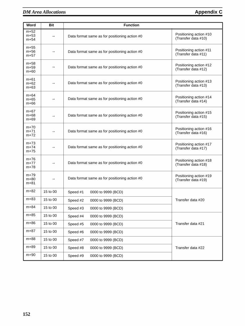
DM Area Allocations Appendix C
152
Word Bit Function
Positioning action #10(Transfer data #10)
Data format same as for positioning action #0
Data format same as for positioning action #0
Data format same as for positioning action #0
Data format same as for positioning action #0
Data format same as for positioning action #0
Data format same as for positioning action #0
Data format same as for positioning action #0
Data format same as for positioning action #0
Data format same as for positioning action #0
Positioning action #11(Transfer data #11)
Positioning action #12(Transfer data #12)
Positioning action #13(Transfer data #13)
Positioning action #14(Transfer data #14)
Positioning action #15(Transfer data #15)
Positioning action #16(Transfer data #16)
Positioning action #17(Transfer data #17)
Positioning action #18(Transfer data #18)
Positioning action #19(Transfer data #19)
m+52 m+53m+54
m+55m+56m+57
m+58m+59m+60
m+61m+62m+63
m+64m+65m+66
m+67m+68m+69
m+70m+71m+72
m+73m+74m+75
m+76m+77m+78
m+79m+80m+81
m+82
m+83
m+84
m+85
m+86
m+87
m+88
m+89
m+90
Data format same as for positioning action #0
15 to 00
15 to 00
15 to 00
15 to 00
15 to 00
15 to 00
15 to 00
15 to 00
15 to 00
Speed #1 0000 to 9999 (BCD)
Speed #2 0000 to 9999 (BCD)
Speed #3 0000 to 9999 (BCD)
Speed #4 0000 to 9999 (BCD)
Speed #5 0000 to 9999 (BCD)
Speed #6 0000 to 9999 (BCD)
Speed #7 0000 to 9999 (BCD)
Speed #8 0000 to 9999 (BCD)
Speed #9 0000 to 9999 (BCD)
Transfer data #20
Transfer data #21
Transfer data #22
→
→
→
→
→
→
→
→
→
→
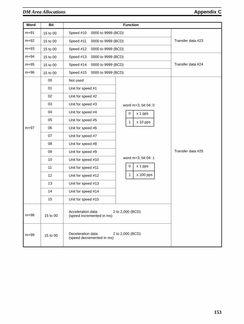
Appendix CDM Area Allocations
153
Word Bit Function
m+91
m+92
m+93
m+94
m+95
m+96
m+97
m+98
m+99
15 to 00
15 to 00
15 to 00
15 to 00
15 to 00
15 to 00
Speed #10 0000 to 9999 (BCD)
Speed #11 0000 to 9999 (BCD)
Speed #12 0000 to 9999 (BCD)
Speed #13 0000 to 9999 (BCD)
Speed #14 0000 to 9999 (BCD)
Speed #15 0000 to 9999 (BCD)
Transfer data #23
Transfer data #24
00
01
02
03
04
05
06
07
08
09
10
11
12
13
14
15
Not used
Unit for speed #1
Unit for speed #2
Unit for speed #3
Unit for speed #4
Unit for speed #5
Unit for speed #6
Unit for speed #7
Unit for speed #8
Unit for speed #9
Unit for speed #10
Unit for speed #11
Unit for speed #12
Unit for speed #13
Unit for speed #14
Unit for speed #15
Transfer data #25
15 to 00
15 to 00
Acceleration data 2 to 2,000 (BCD)(speed incremented in ms)
Deceleration data 2 to 2,000 (BCD)(speed decremented in ms)
0
1
x 1 pps
x 10 pps
0
1
x 1 pps
x 100 pps
word m+3, bit 04: 0
word m+3, bit 04: 1

155
Appendix DIR Area Allocations
Function ( ^ : leading edge; v : trailing edge)
Outputs (n = 10 xunit no.)
Word Bit
n
n+1
n+2
n+3
00
01
02
03
04
05
06
07
08
09
10
11
12
13
14
15
07 to 00
15 to 08
05 to 00
06
07
14 to 08
15
15 to 00
START: At the leading edge ( ^ ) of this bit, the Position Control Unit referencesbits 01 and 07 of IR n and begins positioning.
Valid initial positioning no.: When set to 1, the initial positioning no. set in bits 07to 00 of IR n+1 is valid. When set to 0, the initial positioning no. set in bits 07 to00 of DM word m is valid.
ORIGIN SEARCH: ( ^ ) Searches for origin proximity signals and origin signals,and determines the origin.
ORIGIN RETURN: ( ^ ) Returns to the origin (as long as the origin has alreadybeen determined).
RELEASE PROHIBIT: ( ^ )
READ ERROR: ( ^ )
CHANGE SPEED: ( ^ ) if DIP switch pin no. 6 is ON. If pin no. 6 is OFF, thenthis bit executes CHANGE SPEED when set to 1 and STOP when set to 0.
Valid speed coefficient: When set to 1, the speed coefficient set in bits 05 to 00 ofIR n+2 is valid. When set to 0, the speed coefficient of the target speed is set at1.0.
RESET ORIGIN: ( ^ )
TEACH: ( ^ ) References bits 15 to 08 of IR n+1 and registers the present posi-tion.
TRANSFER DATA: ( ^ ) References IR n+2 to n+4 and begins the transfer ofdata.
HIGH-SPEED JOG: (0: stops, 1: operates) in the direction indicated by bit 12 ofIR n.
INCH/JOG direction: (0: CW, 1: CCW)
LOW-SPEED JOG: (0: stops, 1: operates) in the direction indicated by bit 12 ofIR n.
INCH: ( ^ ) Outputs one pulse.
STOP: ( ^ ) Positioning cannot be restarted while this bit is set to 1.
Initial positioning action number: 00 to 19 (BCD)
TEACH positioning action number: 00 to 19 (BCD)
Speed coefficient: 00 to 20 (BCD) in units of x 0.1Speed numbers for CHANGE SPEED: 00 to 15 (00: current number + 1)
Deviation counter reset (A6-B6) ON/OFF bit (1: ON)
Origin adjustment (A7-B7) ON/OFF bit (1: ON)
Beginning transfer number: 00 to 25 (BCD)
When set to 1, presets the present position during DATA TRANSFER.
Beginning word number for DATA TRANSFER (4 digits BCD)

IR Area Allocations Appendix D
156
Function ( ^ : leading edge; v : trailing edge)Word Bit
Inputs (n = 100 xunit no.)
n+4
n+5
n+6
n+7
n+8
n+9
07 to 00
15 to 08
00
01
02
03
04
05
06
07
08
09
10
11
12
13
14
15
15 to 00
06 to 00
07
11 to 08
12
13
14
15
15 to 00
15 to 00
PC data area for DATA TRANSFER: 00 to 04 (BCD) (00: DM, 01: I/O, 02: LR,03: HR, 04: AR)
Number of transfers for DATA TRANSFER: 01 to 26 (BCD)
Positioning Completed flag: ( ^ : completed, v : starting )
Bank Completed flag: ( ^ : bank completed, v : starting)
At-origin flag: (1: stopped at origin)
Alarm flag: (1: alarm)
Emergency stop flag: ( ^ : Emergency stop, v : pulse output enabled)
Error flag: (1: error)
Zone 0 flag: (0: outside zone 0, 1: inside zone 0)
Zone 1 flag: (0: outside zone 1, 1: inside zone 1)
Zone 2 flag: (0: outside zone 2, 1: inside zone 2)
Teaching Completed flag: ( ^ : completed, v : starting)
Transfer Completed flag: ( ^ : completed, v : starting)
No-origin flag: (1: no origin)
Busy flag: (1: busy) during transfer, pulse output, or dwell time
CW limit flag: (1: CW limit signal is being input.)
CCW limit flag: (1: CCW limit signal is being input.)
STOP flag: ( ^ : STOP executed, v : operation begins)
Error code: 4 digits (BCD)
Positioning action number: 00 to 19 (BCD)
Positioning Completed signal
Output code: 0 to F (BCD)
Emergency stop signal: (1: Emergency stop signal is being input.)
External interrupt signal: (1: External interrupt signal is being input.)
Origin signal: (1: Origin signal is being input.)
Origin proximity signal: (1: Origin proximity signal is being input.)
0 CW1 CCW
x106 x105 x104 x103 x102 x101 x100
n+9 n+8
Direction
(7 digits BCD with direction digit)
Present position

Appendix DIR Area Allocations
157
Detailed IR AreaAllocation Table
Positioning Completed flag This bit turns OFF when positioning, ORIGIN SEARCH, or ORIGIN RETURN are started. Itturns ON when positioning is completed for single or bank end actions (including dwell time),but not when STOP is executed during operation. The Busy flag turns OFF within 1 scan afterthis flag turns ON.
Bank Completed flagThis bit turns OFF when positioning, ORIGIN SEARCH, or ORIGIN RETURN are started, andON, along with the Positioning Completed flag, when positioning is completed for a bank.
At-origin flagThis bit turns ON when positioning stops at the origin, but not when the origin is passed dur-ing operation. It turns ON within 1 scan after the Busy flag turns OFF.
Alarm flagThis bit turns ON when an alarm code (1*** or 2***) is generated.
Emergency Stop flagThis bit turns ON when an emergency stop signal is externally input, regardless of whetherthe Position Control Unit is operating or not. Pulse output is prohibited during this time. Thisbit turns OFF when the emergency stop signal is turned off and RELEASE PROHIBIT (bit 04of IR n) is turned ON.
Error flagThis bit turns ON when error code (5*** or 9***) has been generated.
Zone 0 flagZone 1 flagZone 2 flagThese bits turn ON when the present position is within the zone ranges set in DM m+9 andm+20.
Teaching Completed flagThis bit turns OFF when TEACH is executed and ON when teaching is completed.
Transfer Completed flagThis bit turns OFF when TRANSFER DATA is executed and ON when data transfer is com-pleted. The Busy flag turns OFF when this flag turns ON.
No-origin flagThis bit turns ON during initial processing and OFF when the origin has been determined. Thefollowing conditions cause this bit to turn ON:
• When positioning is stopped by an emergency stop or by a CW/CCW limit signal.• When an extended completion code is executed.• When positioning is stopped due to changing the PC’s mode during pulse output.
(i.e., changing RUN to PROGRAM).• When positioning is stopped during operation due to a hardware error.• When ORIGIN SEARCH is executed.
The following conditions cause this bit to turn OFF:• When the origin signal is input during ORIGIN SEARCH.• When RESET ORIGIN is completed.• When the present position has been reset.
Busy flagThis bit remains ON during initial data transfer or during calculation. It turns ON wheneverprocessing is started and OFF when it is completed. It also turns OFF after information hasbeen set for completion flags (such as for positioning, teaching, and transfer), or after an erroris generated and the error code and Error flag are set. If the positioning time is too short, itmay not be possible to read the status of this flag during the scan of the ladder program.
FunctionWord Bit
n+5
00
01
02
03
04
05
000708
09
10
11
12

IR Area Allocations Appendix D
158
FunctionWord Bit
n+5
n+6
n+7
n+8n+9
13 14
15
15 to 00
06 to 00
07
11 to 08
12131415
15 to 0015 to 00
CW Limit flagCCW Limit flagThese bits turn ON while the respective external signals are being input.
STOP flagThis bit goes ON when positioning, ORIGIN SEARCH, ORIGIN RETURN, or JOG stop inresponse to either an external interrupt signal or the STOP command bit (IR n, bit 15). Itgoes OFF when any of the above operations is started. Busy flag goes ON 1 scan later.
Error codeOnly the most recent error code is output. Further codes can be accessed in order by ex-ecuting READ ERROR (IR n, bit 05). Read-out does not erase error codes.
Positioning action numberThese bits output a positioning action number during positioning. Upon completion of posi-tioning, they output the next positioning action number to be executed. The positioning ac-tion number is automatically incremented except in cases where STOP has been executedduring positioning. In such cases, the number which was being executed at the time is takenas the next number to be executed. After the bank has been completed, or after positioningaction #19 has been executed, the initial positioning action set in DM word m is used.
Driver completed signalThis bit turns ON during input of the servomotor driver’s driver completed signal (connectedto A9 and B9). It is used to check external wiring.
Output codeThese bits output the output code for the completed positioning action. Use this data (0 to F)as a bit in a program as follows:
MPLX (76)
107
#0002
HR 10
25313
Normally ON
Emergency stop signalExternal interrupt signalOrigin signalOrigin proximity signalEach of these bits turns ON when its respective signal is input. These bits are used for sys-tem debugging. Confirm wiring by reading these bits on the Programming Console whilepressing switches by hand or using JOG to pass over switches. The bits turn ON at the trail-ing edge when the signal is input through an NC contact, and at the leading edge when inputthrough an NO contact. Do not use use during programming.
Present positionThe present position is always output as an absolute value (i.e., not as an increment)through these words. After powering up, output is as follows:
n+9
09xx
n+8
0xxx
DIP switch setting
Operating mode no.
Bit 7 6 5 4 3 2 1 0
Switch no. 8 7 6 5 4 3 2 1
ON 1 1 1 1 1 1 1 1
OFF 0 0 0 0 0 0 0 0

159
*1: Error cleared when new positioning data is set*2: Error cleared when new speed data is set
Appendix EAlarm Code List
Area Item AlarmCode
Problem Position *1 Speed*2
Initial speed BCD error 1000 There is a BCD error in the speedindicated by the initial speed number.
Yes
Initial positioningaction
Limit error 1100 Initial positioning action number is notbetween 00 and 19.
HIGH-SPEEDJOG speed error
1200 HIGH-SPEED JOG speed number is 0, orthere is a BCD error in the speeddesignated by the number.
Yes
Jog operations LOW-SPEEDJOG speed error
1201 LOW-SPEED JOG speed number is 0, orthere is a BCD error in the speeddesignated by the number.
Yes
Speedcontradiction
1202 The LOW-SPEED JOG is faster than theHIGH SPEED JOG.
Yes
Acceleration/ Acceleration error 1300 Acceleration is out-of-range or contains aBCD error.
Yes
Deceleration Deceleration error 1301 Deceleration is out-of-range or contains aBCD error.
Yes
ORIGIN RETURN Speed error 1400 ORIGIN RETURN speed designated bythe number is 0, or there is a BCD error inthe speed designated by the number.
Yes
Speedcontradiction
1500 Table for trapezoidalacceleration/deceleration cannot becreated due to error in speed, acceleration,or deceleration.
Yes
Speeds BCD error 1501 There is a BCD error in speed #1. Yes
1502 to1515
There is a BCD error in the speeddesignated by the last two digits of thealarm code.
OrigincompensationBCD error
1600 Origin compensation contains a BCD erroror exceeds the internal limit.
ORIGIN SEARCH High speed error 1601 ORIGIN SEARCH high speed number is 0,or there is a BCD error in the speeddesignated by the number.
Yes
Proximity speederror
1602 ORIGIN SEARCH proximity speed numberis 0, or there is a BCD error in the speeddesignated by the number.
Yes
Speedcontradiction
1603 High speed is slower than proximity speed. Yes
Backlashcompensation
BCD error 1700 There is a BCD error in the backlashcompensation.
Internal limits CW limit 1800 There is a BCD error in internal CW limitsetting or setting is not between 0 and8,388,606.
CCW limit 1801 There is a BCD error in internal CCW limitsetting or setting is not between 0 and8,388,607.

Alarm Code List Appendix E
160
Area Speed*2Position *1ProblemAlarmCode
Item
Zone 0 CW error 1900 There is a BCD error in setting for CW limitof zone 0 or setting is not between–8,388,607 and 8,388,606.
Zone 0 CCW error 1901 There is a BCD error in setting for CCWlimit of zone 0 or setting is not between–8,388,607 and 8,388,606.
Zone 0contradiction
1902 CW and CCW limit setting for zone 0 arereversed (i.e., CW limit is counterclockwiseof CCW limit).
Zones Zone 1 CW error 1910 Problems are identical to those for zone 0.
Zone 1 CCW error 1911
Zone 1contradiction
1912
Zone 2 CW error 1920 Problems are identical to those for zone 0.
Zone 2 CCW error 1921
Zone 2contradiction
1922
Target positionBCD error
2000 There is a BCD error in the target positionfor positioning action #0.
Yes
2001 to2019
There is a BCD error in the target positionfor the positioning action designated by thelast two digits of the alarm code
Speed BCD error 2100 There is a BCD error in the speeddesignated by the speed number forpositioning action #0.
Yes Yes
Positioningactions
2101 to2119
There is a BCD error in the speeddesignated by the speed number for thepositioning action designated by the lasttwo digits of the alarm code
Positioncontradiction
2200 The completion codes for all positioningactions are 2 (continuous); the Unit cannotbegin operation.
Yes
Completion codeerror
2300 Completion code for positioning action #0is not between 0 and 5.
Yes
2301 to2319
Completion code for the positioning actionindicated by the last two digits of the alarmcode is not between 0 and 5.
*1: Error cleared when new positioning data is set*2: Error cleared when new speed data is set

161
Appendix FError Code List
Error
START
Direction reversed
CW limit
CCW limit
Present positionundefined
Stopped at CW limit
Stopped at CCWlimit
Manual CW limit
Manual CCW limit
ORIGIN SEARCHdisabled
Error code
5000
5020
5030
5031
5040
5060
5061
5070
5071
5100
Problem
Pulses cannot be output for STARTcommand because of data that gener-ated an alarm. This data includes theinitial speed, initial positioning actionnumber, acceleration, deceleration,backlash compensation, internal CWlimit, internal CCW limit, speed and tar-get position.
Pulse output is not possible because thedirection was reversed following a con-tinuous positioning action.
Pulse output is not possible because theinternal CW limit would be passed.
Pulse output is not possible because theinternal CCW limit would be passed.
Execution of START, TEACH, or ORI-GIN RETURN is not possible becausethe present position has not been estab-lished.
An attempt was made to feed clockwiseusing HIGH-SPEED JOG, LOW-SPEEDJOG, or INCH following RELEASEPROHIBIT after feeding had beenstopped at CCW limit.
An attempt was made to feed counter-clockwise using HIGH-SPEED JOG,LOW-SPEED JOG, or INCH followingRELEASE PROHIBIT after feeding hadbeen stopped at CCW limit.
The internal CW limit was reached andfeeding stopped during execution ofHIGH-SPEED JOG, LOW-SPEED JOG,or INCH.
The internal CCW limit was reached andfeeding stopped during execution ofHIGH-SPEED JOG, LOW-SPEED JOG,or INCH.
ORIGIN SEARCH cannot be executedbecause of data for the origin compen-sation, search speeds, or backlash com-pensation that generated an alarm code.
Correction
Read out alarm code and correctdata accordingly. If there is noalarm, check data in IR n+7. Theerror code will be erased for thenext START if data has been prop-erly corrected.
Check positioning actions andcorrect data. After transferringdata, the error code will be erasedfor the next START if data hasbeen properly corrected
Execute ORIGIN SEARCH, RE-SET ORIGIN, or preset the presentposition with TRANSFER DATA.
Feed counterclockwise.
Feed clockwise.
Based on error code, read outalarm code and correct data ac-cordingly.

Error Code List Appendix F
162
Error
ORIGIN RETURNdisabled
HIGH-SPEEDJOG disabled
LOW-SPEED JOGdisabled
INCH disabled
Emergency stopexecuted
CW limit
CCW limit
No origin proximitysignal
Error code
5200
5300
5400
5500
6000
6100
6101
6200
Problem
ORIGIN RETURN cannot be executedbecause of data for ORIGIN RETURNspeed or backlash compensation thatgenerated alarm.
HIGH-SPEED JOG cannot be executedbecause of data for HIGH-SPEED JOGspeed, initial speed, acceleration, deceler-ation, or backlash compensation that gen-erated an alarm.
LOW-SPEED JOG cannot be executedbecause of data for LOW-SPEED JOGspeed, initial speed, or backlash compen-sation that generated an alarm.
INCH cannot be executed because ofdata for backlash compensation that gen-erated an alarm.
Feeding has been stopped by emergencystop signal input.
Feeding has been stopped by CW limitsignal input.
Feeding has been stopped by CCW limitsignal input.
No proximity signal is detected betweenthe CCW and CW limits even though pin#3 on DIP switch designates a proximitysignal.
No-origin flag
Origin signalposition
CounterclockwiseCW limit
Clockwise CCWlimit
PC mode change
Correction
Based on error code, read out alarmcode and correct and correct dataaccordingly. After transferring data,the error code will be erased for thenext operation if data has been prop-erly corrected. For data that cannotbe transferred, restart after correct-ing DM.
Check wiring.Turn off emergencystop signal and execute RELEASEPROHIBIT and ORIGIN SEARCH.
Check wiring. Execute RELEASEPROHIBIT and then feed counter-clockwise using JOG, or INCH (orexecute ORIGIN SEARCH, PresentPosition Reset, or TRANSFER DATAafter RELEASE PROHIBIT).
Check wiring. Execute RELEASEPROHIBIT and then feed clockwiseusing HIGH-SPEED JOG,LOW-SPEED JOG, or INCH (or ex-ecute ORIGIN SEARCH after RE-LEASE PROHIBIT).
Check DIP switch setting, wiring ofproximity signal, and signal type (NCor NO).
6201
6202
6400
6401
6600
The origin signal is not detected betweenCCW and CW limits.
Feeding was stopped by origin signal in-put during ORIGIN SEARCH before theproximity speed was reached, i.e., prox-imity signal and origin signal are tooclose relative to time required for decel-eration from high speed to proximityspeed
CW limit signal was input while feedingcounterclockwise.
CCW limit signal was input while feedingclockwise.
PC mode was changed between MONI-TOR and PROGRAM during pulse out-put.
Check wiring of origin signal andsignal type (NC or NO)
Check position of origin signal andproximity signal relative to requireddeceleration.
Check wiring of limit signals.
Check wiring of limit signals.
Execute ORIGIN SEARCH to obtainpresent position.

Appendix FError Code List
163
8210
8300
8301
8302
8303
8304
9000
9100
9200
TEACH cannot be executed because PCuser program memory is ROM.
Beginning transfer number for TRANSFERDATA is not between 00 and 25.
Beginning PC word number for TRANSFERDATA is out of range or becomes out ofrange when the designated number of trans-fers is added. (See Section 4–8 for rangedetails.)
PC area number for TRANSFER DATA isnot between 0 and 4.
The number of transfers for TRANSFERDATA is not between 1 and 26.
The position preset with TRANSFER DATAcontains a BCD error or is out of range.
LSI initial processing at start-up is not com-pleted normally.
Target position for a positioning action hasbeen exceeded.
Speed for a positioning action has been ex-ceeded.
ROM in PC
Transferred posi-tioning action no.
PC beginning wordnumber
PC area number
Number of transfers
Present positionpreset
Hardware
Check program. This error codewill be erased by the nextTRANSFER DATA.
Check program. This error codewill be erased by the nextTRANSFER DATA.
Check program. This error codewill be erased by the nextTRANSFER DATA.
Check program and data in PC.
Hardware may be faulty.
Hardware may be faulty or errormay be caused by noise.
Error
CHANGE SPEED
Multiple command
Initial positioningaction no.
TEACH positioningaction no.
Error code
6700
8000
8100
8200
Problem
Feeding has been stopped followingCHANGE SPEED due to the speed data ofthe next positioning action having an error orbeing set to 0.
More than one command bit has been setsimultaneously in IR word n, bits 00, 02, 03,04, 08, 09, 10, 11, 13, or 14.
Initial positioning action number contained inIR area is not between 00 and 19.
TEACH positioning action number is not be-tween 00 and 19.
Correction
Check speed data. If problem iscorrected, this error code will beerased by the next START.
Check program. This error codewill be erased when every com-mand bit in channel n goes to 0.
Check program. If problem iscorrected, this error code will beerased by the next START.
Check program. If problem iscorrected, this error code will beerased by the next TEACH.

165
Appendix GUsing the C200H-NC112 with CS1-series PCs
Differences in Memory AllocationNote the following differences in the memory areas when using the C200H-NC112 with a CS1-series PC.
IR (CIO) Area and DM Area Allocation• The beginning word, n, of the IR Area allocated to the C200H-NC112 will change as follows:
n = IR 100 + unit number × 10 → n = CIO 2000 + unit number × 10.
• The beginning word of the DM Area allocated to the C200H-NC112 will change as follows:m = DM 1000 + unit number × 100 → m = D20000 + unit number × 100.
Transferring Data Using the CIO AreaSpecifying addresses containing position and speed data using words n+3 and n+4 in the CIO Area is performed inthe way illustrated in the table below.
(n = 2000 + unit number × 10)
Area Address in CS1 PC(S 1 )
Specifying address from CIO Area(See note 1.) Data area
n+4, bits 00 to 07(2 digits BCD)
Beginning wordn+3, bits 00 to 15
(4 digits BCD)
General-purpose DM Area D00000 to D00999 00 0000 to 0999
DM Area for Special I/O Units D20000 to D20999 00 1000 to 1999 (See note 2.)
I/O Area CIO 0000 to CIO 0255 01 0000 to 0255
Data Link Area CIO 1000 to CIO 1063 02 0000 to 0063
Holding Area 1 H000 to H099 03 0000 to 0099
Holding Area 2 H100 to H127
Note: H101 cannot bespecified.
04 0000 to 0027
Note: 0001 cannot bespecified.
Note 1. Only the CS1-series PC addresses given in the above table can be specified.
2. When specifying an address in the DM Area for Special I/O Units (D20000 to D20999), do not specify anumber in the range 20000 to 20999. Use the range 1000 to 1999 (as if specifying an address for aC200HX/HG/HE, C200HS, or C200H PC).
Data Configuration
Allocated CIO Area(n = 2000 + unit number × 10)
Bit
nton+4
n+5ton+9
Commands from the CPU Unit
PCU status
15 0 Contents Direction
START, ORIGIN SEARCH, initialpositioning action number,TRANSFER DATA, etc.
CPU Unit → PCU
PCU→ CPU UnitPresent position, zones, errorflags, etc.

Appendix GUsing the C200H-NC112 with CS1-series PCs
166
Allocated DM Area(m = D20000 + unit number × 100)
Bit
mtom+20
m+22tom+81
m+82tom+99
Parameters
Position data
Speed and acceleration/deceleration data
15 0 Contents Direction
Initial positioning action number,initial speed number, backlashcompensation
Positioning actions #0 to #19
Speeds #0 to #15, accelerationdata, deceleration data
CPU Unit → PCU
CPU Unit → PCU
CPU Unit → PCU
Setup Procedure
Initial Hardware Settings1, 2, 3... 1. Set the unit number and the operation mode using the rotary switches on the front of the
PCU.2. Mount to a CS1 CPU Rack, a C200H I/O Expansion Rack, a CS1 Expansion Rack, or a SYS-
MAC BUS Remote I/O Slave Rack. For basic systems, up to 10 PCUs can be mounted.(There are no restrictions on the mounting position.)
3. Connect the external I/O connectors for each of the axes.4. Connect the Programming Device.5. Turn ON power to the PC.6. Create the I/O table.
Initial Software Settings1, 2, 3... 1. Make the settings for parameters and position, speed, acceleration, and deceleration data in
the allocated DM Area.2. Reset the power, or turn the Unit Restart flag from OFF to ON.
Transferring DataUse the TRANSFER DATA command to send data in the case where the above settings for position, speed, accel-eration, and deceleration data are insufficient, or to change initial settings for this data.
1, 2, 3... 1. When the TRANSFER DATA command bit (word n, bit 10) is turned from OFF to ON, the dataat the address in I/O memory specified with words n+3 and n+4 in the CIO Area is transferredto the address (transfer number) in the PCU specified with bits 08 to 14 in word n+2 in theCIO Area.
Starting Operation1, 2, 3... 1. Set the initial positioning action number (word n+1, bits 00 to 07) using MOV or another
instruction.2. Turn the START command bit (word n, bit 00) from OFF to ON using OUT or another instruc-
tion.
ProgrammingSet positioning data (initial data) in the allocated DM Area, and start operation. To do this, with the Busy flag (wordn+5, bit 12) as an N. C. input condition, turn the START command bit and the valid initial positioning number bitfrom OFF to ON using OUT or another instruction.
Transferring Additional Data1, 2, 3... 1. With the Busy flag (word n+5, bit 12) as an N. C. input condition, set the transfer data (words
n+2 to n+4) using the MOV instruction.

Appendix GUsing the C200H-NC112 with CS1-series PCs
167
2. With the same input condition as above, turn the TRANSFER DATA command bit (word n,bit 10) from OFF to ON using OUT or another instruction.
Programming Examples
Transferring Data from Other PC AreasThis programming example shows how to transfer the data for three positioning actions starting from D00010.
The initial data is stored in D20022 to D20030. The data and positioning ac-tions are shown below.
Speed #4START
Stop
Speed #3
#0 (continuous)
#2 (bank end)
#1 Stop
STARTSpeed #3
The transfer data is stored in D00010 to D00018. The data and positioningactions are shown below.
#2 (bank end)
#0 (continuous)
#1
Speed #4
Speed #3
START
Stop
Stop
START
Speed #3
Initial Data
Data To Be Transferred

Appendix GUsing the C200H-NC112 with CS1-series PCs
168
Program
MOV (021)#00002002
MOV (021)
#10222003
MOV (021)
#03002004
MOV (021)#00002002
MOV (021)#00102003
MOV (021)
#03002004
SW2
a
b
a
b
200010
200010
c
200510
d
e
c
DIFU (013)
Turns ON “b” for one cycle with the rising edge of SW2.
Transfercompletion
Transfer Completed flag
200512(word n+5, bit 12)
Busy flag
SW1DIFU (013) Turns ON “a” for one cycle with the rising edge of SW1.
(Transfers data from D00010 to D00012 to the PCU.)
200512(word n+5, bit 12)
Busy flag a
n+2(Beginning transfer number)
n+3(Beginning word number)
n+4(PC data area andnumber of transfers)
Position action #0 is speci-fied as the destination.
D00010 is specified as the beginningword of the data to be transferred.
The data in D00010 to D00012 isspecified as the data to be sent.#0300
PC area: DMNo. of words: 3
n+2(Beginning transfer number)
n+3(Beginning word number)
n+4(PC data area andnumber of transfers)
Position action #0 is speci-fied as the destination.
D20022 is specified as the beginningword of the data to be transferred.
The data in D20022 to D20024 isspecified as the data to be sent.#0300
PC area: DMNo. of words: 3
200010
TRANSFER DATA command bit(word n, bit 10)
TRANSFER DATA command bit (word n, bit 10)
c
d
Transfer Completed flag
DIFU (013)
b

Appendix GUsing the C200H-NC112 with CS1-series PCs
169
Using Multiple BanksA program that distinguishes between two banks, the bank starting from positioning action #0 and the bank start-ing from positioning action #5, is given below. In order to select and execute either positioning action #0 or #5, itturns the valid initial positioning action number bit (bit 01 of word n) ON, then immediately OFF. Leaving the validinitial positioning action number bit ON forces execution of IR word n+1.
The data for one bank is stored into positioning action numbers 0, 1, and 2.
Speed #4
Speed #3
D20022 3 0 0 2
D20023 0 0 0 0
D20024 0 0 0 1
D20025 4 0 0 0
D20026 5 0 0 0
D20027 0 0 0 1
D20028 3 0 0 3
D20029 0 0 0 0
D20030 0 0 0 0
START
0CCW
Stop10000
D20084
Speed #3
#0 (continuous)
#2 (bank end)
D20085
#1Stop
START
15000CW
The data for the other bank is entered into positioning action numbers 5, 6,and 7.
D20037 3 0 0 2
D20038 9 0 0 0
D20039 0 0 0 0
D20040 4 0 0 0
D20041 5 0 0 0
D20042 0 0 0 1
D20043 3 0 0 3
D20044 1 0 0 0
D20045 0 0 0 0
0
#7 (bank end)
#5 (continuous)
#6
9000
Speed #4
D20085
D20084
Speed #3
START
CCW
Stop
1000 15000CW
Stop
START
Speed #3
First Bank(Positioning ActionNumbers 0 to 2)
Second Bank (PositioningAction Numbers 5 to 7)

Appendix GUsing the C200H-NC112 with CS1-series PCs
170
Program
Turns ON the validinitial positioningnumber bit when bor c turns ON.
Start switch
200501(word n+5, bit 01)
200000(word n, bit 00) a c
b
200000(word n, bit 00) a
c
b
c
c
b
#0 assignedswitch
DIFU (013)
MOV (021)
#0010
2001
MOV (021)
#0005
2001
Designates #0as the initialpositioningaction.
#5 assignedswitch
200000 Word n, bit 00(START com-mand bit)
Bank End flagDIFU (013)
a
Turns ON the STARTcommand bit (word n,bit 00) for one cycle withthe rising edge of thestart switch.
STARTcommand bit
b If the #0 assigned switchis ON, #0000 is set as theinitial positioning action(word n+1), and at thesame time, the self-hold-ing bit (b) is turned ON.
Word n+1(Initial positioningaction number)
STARTcommand bit
Designates #5as the initialpositioningaction.
If the #5 assigned switchis ON, #0005 is set as theinitial positioning action(word n+1), and at thesame time, the self-hold-ing bit (b) is turned ON.
Word n+1(Initial positioningaction number)
DIFU (013)
200001 Word n, bit 01(Valid initialpositioningnumber bit)

Appendix GUsing the C200H-NC112 with CS1-series PCs
171
Timing ChartThe following chart shows the timing in the case where initial position action #0 is selected.
Start switch
START command bit200000(Word n, bit 00)
Bank End flag200501(Word n+5, bit 01)
#0 assigned switch
Valid initial positioningnumber bit200001(Word n, bit 01)
One cycle
ON for one cycle only
Position action #0 started
Self-holding bit
ON for one cycle only
Self-holding bit turned OFFwhen “a” turns ON.

173
Glossary
A target position given in respect to the origin rather than in respect to thepresent position.
A four-digit code which is output to a word in the IR area to identify the typeof alarm which has occurred.
A PC data area which is used for system flags and status information. Data isretained in this area during a power failure.
Compensation for the amount of mechanical play, or ‘looseness’ present ingears. Such play can create positioning inaccuracy when the direction of po-sitioning changes.
A combination of several positioning actions or sequences. A bank beginswhen START is executed for the initial positioning action and ends when aposition action with a “bank end” completion code has been executed.
A positioning action completion code that designates the positioning actionas the final one in a bank.
An acronym for binary-coded decimal. This is used to refer to decimal num-bers encoded in binary.
A parameter for positioning actions that designates what is to happen when aparticular positioning action has been completed. The four possible comple-tion codes are as follows: single, pause, continuous, bank end, and ex-tended.
A positioning action completion code that causes the next positioning actionto be executed immediately upon completion of the current one.
Abbreviations for clockwise (CW) and counterclockwise (CCW). CW andCCW are defined for a motor shaft in reference to a viewer facing the shafton the end of the motor from which the shaft extends from the motor for con-nection.
Limits on the CW and CCW sides of the origin which can be internally set torestrict Position Control Unit operation.
A memory storage area in the PC. Different types of memory blocks, withdiffering functions, are stored in the various data areas of the PC. Theseblocks of memory are built up from single units, or bits, which are groupedinto 16-bit words.
A PC data area in which general operating parameters, speeds, and parame-ters for positioning actions are stored.
A parameter that specifies the period of time during which positioning willstop before execution of the next positioning action following a positioningaction with a pause completion code.
absolute position
alarm code
AR area
backlash compensation
bank
bank end (completion)
BCD
completion code
continuous (completion)
CW and CCW
CW/CCW limits
data area
DM area
dwell time

Glossary
174
A four-digit code which is output to a word in the IR area to identify the typeof error which has occurred.
A device used to ensure positioning accuracy when positioning via pulsetrains. The error counter receives a target position as a specific number ofpulses in a pulse train from the Position Control Unit and outputs analogspeed voltages to drive a servomotor accordingly. The specified number ofpulses in the error counter is counted down by feedback from an encodermeasuring actual motor shaft movement, causing voltage output to stopwhen the number of pulses equals zero, i.e., when the target position hasbeen reached.
A positioning action completion code that causes pulses to be continuallyoutput until the positioning action is terminated with STOP.
A positioning action completion code that causes pulses to be continuallyoutput until the positioning action is terminated with STOP. After STOP is ex-ecuted, positioning does not stop immediately but is executed according tothe data set for the positioning action.
A function whereby positioning may be stopped or speed may be changed,during operation, in response to an external command.
A bit that is turned ON and OFF automatically by the system to provide sta-tus information.
A computer that is used to transfer data to or receive data from a PC in aHost Link System. The host computer is used for data management andoverall system control. Host computers are generally small personal or busi-ness computers.
The last five of the ten IR words allocated to each Position Control Unit asrefresh areas.
Manual feeding wherein positioning is executed one pulse at a time.
A target position given in respect to the present position, rather than in re-spect to the origin.
The present position when START is executed.
A PC data area allocated for inputs, outputs, and work bits. In the C200H,words 100 through 199 of this area are reserved for Special I/O Units, includ-ing the Position Control Unit. The Position Control Unit uses these words forI/O refresh areas.
An internal circuitry which is selected, via a front-panel switch, based on thetype of motor driver and signals which are to be used for a particular type ofoperation.
Normally-closed contacts. A pair of contacts on a relay that open when therelay is energized.
Normally-open contacts. A pair of contacts on a relay that close when therelay is energized.
error code
error counter
extended (completion)
extended with positioning(completion)
external interrupt
flag
host computer
IN refresh area
inching
incremental target position
initial position
IR area
mode
NC contacts
NO contacts

Glossary
175
A control system in which operations are carried out according to pro-grammed instructions, but in which feedback is not provided for automaticadjustments.
A parameter used to correct the origin from the position determined accord-ing to the origin input signal.
A signal input to indicate when the position is near the origin to enable shift-ing to a lower speed.
The region near the origin. When positioning enters this region, a proximityswitch may output a signal for deceleration.
The point which is designated as 0 at any given time.
The first five of the ten IR words allocated to each Position Control Unit asrefresh areas.
User-defined codes output following completion of a positioning action.
Data which determines limits and other conditions under which an operationwill be carried out. The Position Control Unit has both general parametersand parameters specific to individual positioning actions.
A positioning action completion code that creates a pause after reaching thetarget position for the positioning action and then automatically begins thenext positioning action. The length of the pause is specified by the dwell time.
The fundamental unit of positioning. A positioning action is defined by itscompletion code, dwell time, output code, speed number, and target position.These actions are generally referred to by number and completion code. Forexample, “#6, continuous” indicates positioning action #6 with a continuouscompletion code.
The numeric value in pulses defined as being the ‘location’ of the positioningsystem at any one point in time. The present position is not absolute, butrather can be defined or redefined as required by positioning operations.
A low speed at which positioning is executed near the origin.
The distance moved by an object driven by a motor divided by the number ofpulses required for that movement.
A series of pulses output together.
Discrete signals sent at a certain rate. The Position Control Unit outputspulses, each of which designates a certain amount of movement. Suchpulses are converted to an equivalent control voltage in actual positioning.
The Unit in a Remote I/O System through which signals are sent to all otherRemote I/O Units. The Remote I/O Master Unit is mounted either to a CPURack or to an Expansion I/O Rack connected to the CPU Rack.
A Link System in which remote I/O points are controlled through a Mastermounted to a CPU Rack or an Expansion I/O Rack connected to the CPURack.
open-loop system
origin compensation
origin proximity signal
origin proximity
origin
OUT refresh area
output code
parameters
pause (completion)
positioning action
present position
proximity speed
pulse rate
pulse train
pulses
Remote I/O Master Unit
Remote I/O System

Glossary
176
Any of the Units in a Remote I/O System. Remote I/O Units include Masters,Slaves, Optical I/O Units, I/O Link Units, Remote Terminals, and I/O Termi-nals.
The time it takes for the PC to output a control signal after it has received aninput signal. The response time depends on factors such as the system con-figuration and when the CPU receives the input signal relative to the start ofa scan.
The total time required for the PC to perform all of the operations involved inexecuting the program in its memory. The duration of the scan time differsdepending on the configuration of the system, the number of I/O points, theprogramming instructions used, and so on.
The pattern in which origin search is carried out. The particular search pat-tern performed depends on the position of the origin with respect to the initialposition and the search direction (CW or CCW).
A control system in which a PC controls an external process without humanintervention. This system provides feedback (via a tachogenerator and arotary encoder) so that actual values (of positions, speeds, and so on) arecontinuously adjusted to bring them more closely in line with target values.
An operation whereby a rotary encoder is used to maintain the position of amotor while it is stopped. Whenever the motor axis moves, the rotary encod-er sends a feedback pulse to an error counter, causing a rotation voltage tobe generated in the reverse direction so that the motor rotates back to itsoriginal position.
A positioning action completion code that causes positioning to stop after thetarget position has been reached.
A Backplane to which a Remote I/O Slave Unit is attached.
A dedicated Unit, such as a Position Control Unit, High-Speed Counter Unit,or Analog Timer Unit, which is designed for a special purpose.
An IR area setting which determines the coefficient with regard to the targetspeed.
A number used to designate (as a parameter for an operation) one of fifteenspeeds registered in memory.
A word in the DM area which can be set to multiply the speed to which it isassigned by a factor of one or ten.
A parameter for a positioning action that designates what position is to bereached at the completion of the action.
Writing the present position into the DM area of the PC as the target positionfor the designated positioning action.
Accelerating and decelerating in a stepwise pattern such that a trapezoidalfigure is formed.
Remote I/O Units
response time
scan time
search pattern
semiclosed-loop system
servolock
single (completion)
Slave Rack
Special I/O Unit
speed coefficient
speed number
speed unit
target position
teaching
trapezoidalacceleration/deceleration

Glossary
177
Numbers assigned to Special I/O Units for the purpose of allocating specificI/O words to each Unit.
IR area bits that can be used for data calculation or other manipulation inprogramming. In the IR area, all bits not used as input or output bits can beused as work bits.
A range of positions which can be defined so that flags are turned ON when-ever the present position is within the range. Up to three zones, each with itsown flag, can be defined.
unit numbers
work bits
zone

179
Index
Aacceleration, setting for START, 61 alarms, 138 alarm code list, 159160 alarm codes, 91 , 138 alarm flag, 91 , 138 indicators, 138144
applications, precautions, ix AR Area, restart flag, 44
Bbacklash compensationsetting parameters for, 52 using, 52
bank end (completion code), 63 banks, multiple, 134
Ccables, 23 , 38 , 39 CCW limitsfor zones, 51 internal, 53 recovery from exceeding, 89 , 90
CCW pulse outputs, 44 CHANGE SPEED. See commandsclosed−loop systems, 6 commands, 59 CHANGE SPEED, 115 DIP switch settings for, 106 execution example, 115
external interrupt, 105115 DIP switch settings for, 106 response time, 56
HIGH−SPEED JOG, 103 setting speed number, 103 used to clear CW or CCW limit flag, 90
INCH, 104 LOW−SPEED JOG, 104 setting speed number, 103 used to clear CW or CCW limit flag, 90
manual operations, 102115 DM Area settings, 102115 IR Area settings, 103115
ORIGIN RETURN, 8688 DM Area settings, 8788 execution example, 87 IR Area settings, 8788
ORIGIN SEARCH, 7188 completion examples, 8488 DM Area settings, 7188 examples in mode 0, 17 examples in mode 1, 18 examples in mode 2, 19 examples in mode 3, 20
executed after emergency stop, 89 execution examples, 7388 IR Area settings, 7288 search direction, 14 search patterns, 132
READ ERROR, 91115 execution example, 92 reading from the Programming Console, 92
RELEASE PROHIBIT, 89115 RESET ORIGIN, 93115 execution examples, 119
START, 6088 activation time, 56 command bit, 67 DM Area settings, 6088 executing positioning actions, 128 execution examples, 6888 , 121 , 128 IR Area settings, 6688 using with single or bank end actions, 70
STOP, 107115 DIP switch settings for, 106 executed during backlash compensation, 52 executed during completion code 5, 113 executed during HIGH−SPEED JOG, 112 executed during LOW−SPEED JOG, 113 executed during ORIGIN SEARCH, 111 executed during START, 107 execution examples, 108 , 109 , 111
TEACH, 93115 execution example, 94115 IR Area settings, 94 setting positioning action number, 94 teaching from the Programming Console, 94
TRANSFER DATA, 95115 and trapezoidal tables, 55 beginning transfer number, 96 , 98 beginning word number (for normal transfer), 98 beginning word number (present position preset),100
data preparation (normal), 97 data preparation (present position preset), 100 execution example (normal transfer), 98 execution example (preset present position), 101 execution examples, 123 IR Area settings, 97115 normal transfer, 96115 number of transfers, 98 PC data areas available, 96 present position preset, 99115 setting PC data area (for normal transfer), 98 setting PC data area (present position preset), 100 transfer time, 57 using external switches, 125 using to preset present position, 87
completion codes, 62 , 63 execution example, 68 STOP during completion code 5, 113
components, 39 connector pins, arrangement, 21

Index
180
control system principles, 59 CPU Racks, 4 CW limitsfor zones, 51 internal, 53 recovery from exceeding, 89 , 90
CW pulse outputs, 44
Ddata, writing into DM Area, 4457 data allocation, 45 data calculations, 5357 data coding, 48 data configuration, 45 basic chart, 46
data flow diagram, 7 data transfer, 2 deceleration, 16 setting for START, 61
delay time, 64 desired position, setting for START, 65 desired speed number, setting for START, 65 deviation counter reset, 77 wiring, 33
digital−to−analog converters, 6 dimensions, 39 DIP switch, 4 pin 1, 13 pin 2, 14 pin 3, 14 pin 4, 15 pin 5, 15 pin 6, 16 pin 7, 16 pin 8, 16 relation to modes and operation, 73 settings, 3 table of, 13
settings for external interrupt, 106 settings for origin proximity signal, 132 settings for origin signal, 132
direction signals, 13 , 44 DM Areaallocations, 4857 , 149 coding sheet, 48 , 130 minimum data settings, 118 , 121 , 126 settings for external interrupt, 107 settings for manual operations, 102115 settings for ORIGIN RETURN, 8788 settings for ORIGIN SEARCH, 7188 settings for START, 6088 transferring data from, 45 writing data into, 44 writing into with TEACH, 93 zones, 50
dwell time, 65 , 80 execution example, 69
Eemergency stop, 89 flag, 90 recovery after, 89
emergency stop switch, 89 error counters, 7 , 9 errors, 138 BCD errors, 138 error code generation, 138 error code list, 161163 error codes, 91 , 138 error flags, 91 AR Area, 140 IR area, 138
error list for Special I/O Units, 140144 error processing, 137 indicators, 138 no−data errors, 138 out−of−range data errors, 138
Expansion I/O Racks, 4 extended (completion code), 63 extended with positioning (completion code), 63 external I/O connections, 21 external interrupt, response time, 56 external interrupt commands, 105115 external interrupt signal, connection for, 106 external switches, used for TRANSFER DATA, 125
Ffeedback, 6 , 8 flags, 48 , 51 alarm flag, 91 busy flag, 70 , 92 during TRANSFER DATA, 57
emergency stop flag, 90 error flags, 91 AR Area, 140
no−origin flag, 93 positioning completed flag, 70
Ggrounds, 27 , 39 for inputs, 26
HHand−held Programming Console, 5 high speed number, setting for ORIGIN SEARCH, 72 HIGH−SPEED JOG. See commandshost computers, 4
II/O circuits, 24 I/O connections, external, 21

Index
181
I/O refresh areas, 45 , 67 IN refresh area, 45 INCH. See commandsindicators (LEDs), 3 alarm/error, 138
inductive loads, 38 initial positioning action number, setting for START, 60 ,67
initial speed number, setting for START, 60 Input Units, 4 , 5 installation, precautions, ix IR Areaalarm/error outputs, 138 allocations, 46 , 155 detailed table, 157
data format, 48 flags, 48 settings for external interrupt, 107 settings for manual operations, 103115 settings for ORIGIN RETURN, 8788 settings for ORIGIN SEARCH, 7288 settings for START, 6688 settings for TRANSFER DATA, 97115
LLOW−SPEED JOG. See commands
Mmagnetizing distribution circuits, 7 manual operations. See commandsmodesmode 0connection, 12 DIP switch settings (example), 17 ORIGIN SEARCH executed in, 7388 stepping−motor driver connection, 34
mode 1connection, 12 connection wiring example, 34 DIP switch settings (example), 18 ORIGIN SEARCH executed in, 76 servomotor driver connection examples, 34
mode 2connection, 12 DIP switch settings (example), 19 ORIGIN SEARCH executed in, 8088 servomotor driver connection examples, 35
mode 3connection, 13 DIP switch settings (example), 20 ORIGIN SEARCH executed in, 8188 servomotor driver connection examples, 36
mode switch, 12 , 1740 MONITOR mode, 45 motor drivers, rated at 5 VDC, 31 mounting, Position Control Unit to CPU Rack, 4
NNO and NC inputs, 15 , 27 noise (electronic), prevention, 38 nondirectional pulse outputs, 44
Oopen−loop systems, 4 , 5 , 79 operating environment, precautions, viii operation, flowchart, 42 origin, 4 origin adjustment command, 83 wiring, 33
origin compensation, 84 , 85 , 86 setting for ORIGIN SEARCH, 72
origin input, response time, 26 origin proximity reverse, 16 , 74 , 75 , 77 , 78 , 81 , 83 origin proximity signals, 84 , 87 , 132 ORIGIN RETURN. See commandsORIGIN SEARCH. See commandsorigin signals, 132 OUT refresh area, 45 output code, 65 output pulses, 44
Ppause (completion code), 62 Position Control Unit, starting the, 45 positioning accuracy, computation of, 8 positioning actionsbank end, 60 , 63 execution example (with START), 70
continuous, 63 errors in data, 138 executed with START, 128 extended, 63 extended with positioning, 63 initial positioning action number, 60 , 67 pause, 62 setting positioning action number for TEACH, 94 single, 62 execution example (with START), 70
power amplifiers, 7 , 9 power lines, 38 power supply, 5 , 22 , 31 , 38 24 VDC, 31 5 VDC, 31 , 32 , 33 for deviation counter reset output, 33
precautions, vii applications, ix general, viii operating environment, viii safety, viii

Index
182
present positionchanging with TRANSFER DATA, 2 , 96 setting for TEACH, 94 when using TEACH, 93 writing in with TEACH, 2
PROGRAM mode, 45 Programming Consolereading error/alarm codes, 92 teaching, 94 three−channel change operation, 44 writing data, 4457
programming examples, 117 proximity sensors, 27 , 71 proximity speed number, setting for ORIGIN SEARCH,71
pulse frequency, computation of, 8 pulse generators, 7 pulse output, prohibited, 89 pulse trains, 4 , 7 counting pulses, 143 detection of abnormalities, 143 measuring frequency, 143
RREAD ERROR. See commandsRELEASE PROHIBIT. See commandsRemote I/O Master Units, 4 Remote I/O Slave Units, 4 RESET ORIGIN. See commandsresistors, built−in, 29 , 30 , 31 restart bits, 44 , 45 AR area, 141
rotary encoders, 6 , 7 , 9
Ssafety precautions. See precautionsscan time, 57 search patterns, 132 semiclosed−loop systems, 4 , 6 , 89 servolock, 9 servomotor drivers, 2 , 4 , 5 , 6 , 7 , 9 , 20 and origin adjustment, 82 connection wiring examples, 34
servomotors, 5 , 6 , 7 , 9 signalsdirection, 44 origin, 14 , 15 , 16 , 17 wiring, 34 , 35
origin adjustment, 20 origin proximity, 14 , 15 , 16 , 17 , 18 , 19 , 20 origin proximity signal, 74 , 77 , 78 , 81 origin search completed, 29 , 35 wiring, 36
origin signal, slit disc used as, 74 positioning completed, 20 , 29 , 35 wiring, 36
Z−phase, 18 , 34 , 35
single (completion code), 62 slit disc, used for origin signal, 74 solenoids, 38 Special I/O Unitserror list for, 140144 maximum number connectable to PC, 4
specifications, 147 speed coefficient, setting for START, 67 speed number, setting for ORIGIN RETURN, 87 speed unitsexample of multiplying, 134 setting for START, 61
speedscalculating data for, 53 example of setting, 134136 setting for START, 61
START. See commandsstepping motor drivers, 2 , 4 , 5 , 7 connection wiring diagram, 34
stepping motors, 5 , 6 , 7 angle of rotation, 7
STOP. See commandssurge absorbers, 38 , 39 switchesmode switch, 12 , 1740 settings, 1240
system configurationbasic, 4 diagram, 5
Ttable creation, 55 tachogenerators, 6 , 7 , 9 TEACH. See commandsthumbwheel switches, 125 TRANSFER DATA. See commandstrapezoidal acceleration/deceleration, 55 troubleshootingbasic, 141144 from the PC, 140144
Uup/down counters, connections to, 144
Vvalid initial positioning action number, setting for START,67
valid speed coefficient, setting for STOP, 67
Wwiring, 2140 deviation counter reset, 33 I/O circuit diagrams, 25

Index
183
input connection examples, 2740 origin input, 28 origin line driver input, 28 positioning completed, 29
origin adjustment command, 33 output connection examples, 2940 precautions, 3840 servomotor driver connection examplesmode 1, 34 mode 2, 35 mode 3, 36
stepping−motor driver connection, 34 to connectors, 22 with multi−core cable, 22
Zzones, 50 CW and CCW limits for, 51 flags, 51 using to control jogging, 132