Embed Size (px)
Citation preview

System Ace Tutorial Stephen MacMahon
03/11/2008
1
System Ace Tutorial
This is a basic System Ace tutorial that demonstrates two methods to produce a System
ACE file; the use of the System Ace File Generator (GenACE) and through IMPACT.
Also, the steps to Format the CF card to configure an FPGA with a bitstream and an
executable (ELF) file will be described in detail.
The System ACE CF configures devices using the Boundary-Scan (JTAG) instructions
and a Boundary-Scan Chain. System ACE CF is a two-chip solution that requires the
System ACE controller, and either a CompactFlash card or a one-inch Microdrive disk
drive. In this tutorial the System ACE CF, CompactFlash card solution will be used to
configure the FPGA.
So, the first step is to generate a BSB that contains the blocks needed to carry this out.
This tutorial will use the Base System Builder (BSB) to build the project. Follow the
steps seen below to do this:
System Ace Tutorial Stephen MacMahon
03/11/2008
2
Step 1: Launching the Embedded Development Kit (EDK).
To launch EDK, go to Start -> Programs -> Xilinx ISE Design Suite 10.1 -> EDK ->
Xilinx Platform Studio
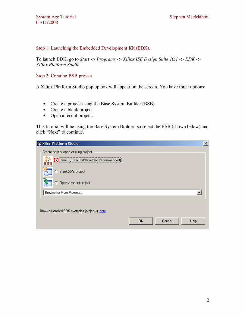
Step 2: Creating BSB project
A Xilinx Platform Studio pop up box will appear on the screen. You have three options:
• Create a project using the Base System Builder (BSB)
• Create a blank project
• Open a recent project.
This tutorial will be using the Base System Builder, so select the BSB (shown below) and
click “Next” to continue.
System Ace Tutorial Stephen MacMahon
03/11/2008
3
Step 3: Saving your project.
Save your project and select “Next” to continue.
Note: Make sure you path contains no spaces in it, as this may cause problems.
Step 4: Choosing your board in the BSB.
You have two options here:
• Create a new design
• Use an existing BSB design settings.
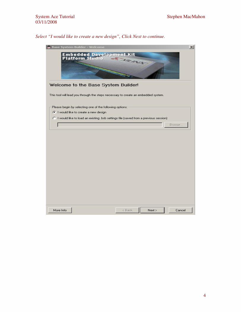
In this tutorial, a new BSB design will be created so click “I would like to create a new
design” and click “Next” to continue. This is shown below:
System Ace Tutorial Stephen MacMahon
03/11/2008
4
Select “I would like to create a new design”, Click Next to continue.
System Ace Tutorial Stephen MacMahon
03/11/2008
5
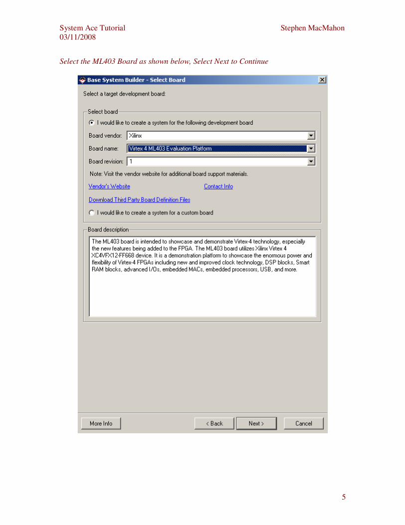
Select the ML403 Board as shown below, Select Next to Continue
System Ace Tutorial Stephen MacMahon
03/11/2008
6
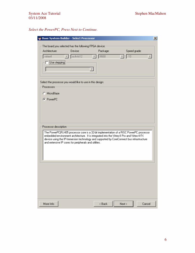
Select the PowerPC, Press Next to Continue.
System Ace Tutorial Stephen MacMahon
03/11/2008
7
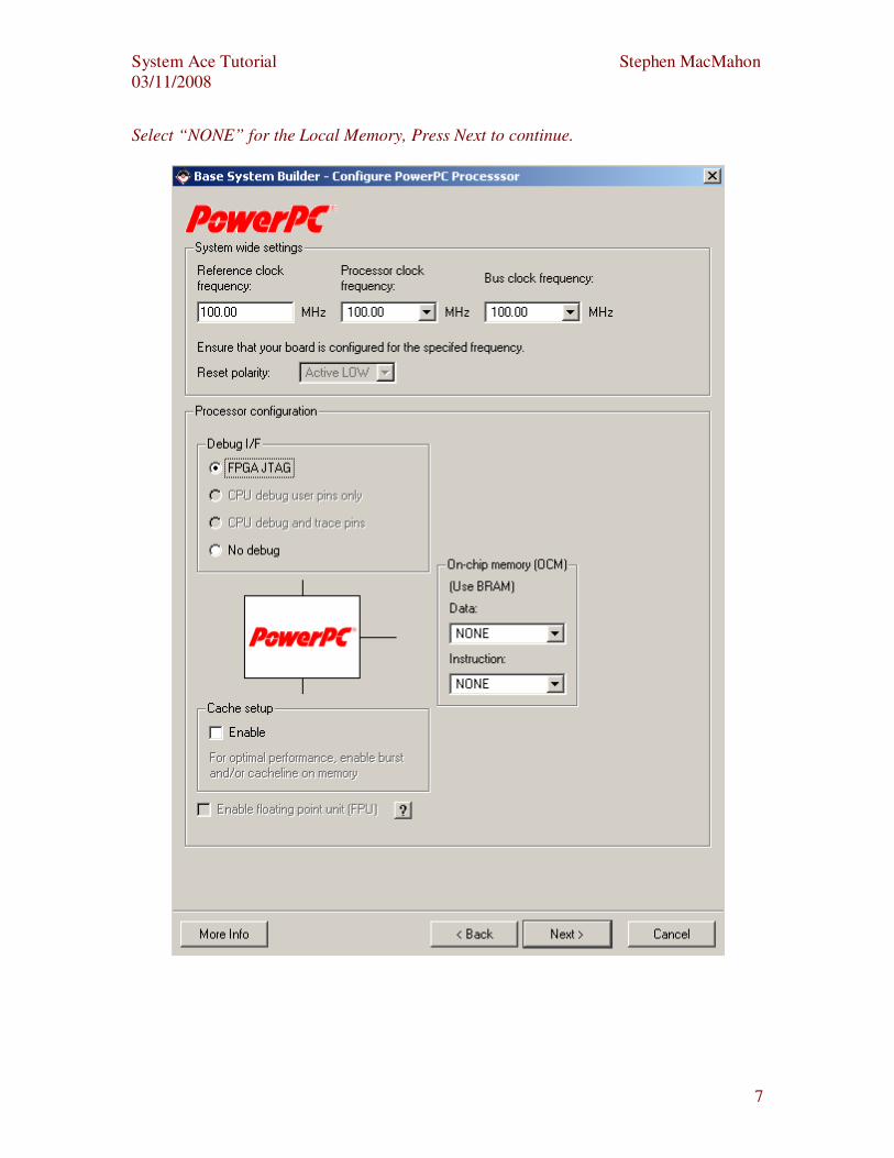
Select “NONE” for the Local Memory, Press Next to continue.
System Ace Tutorial Stephen MacMahon
03/11/2008
8
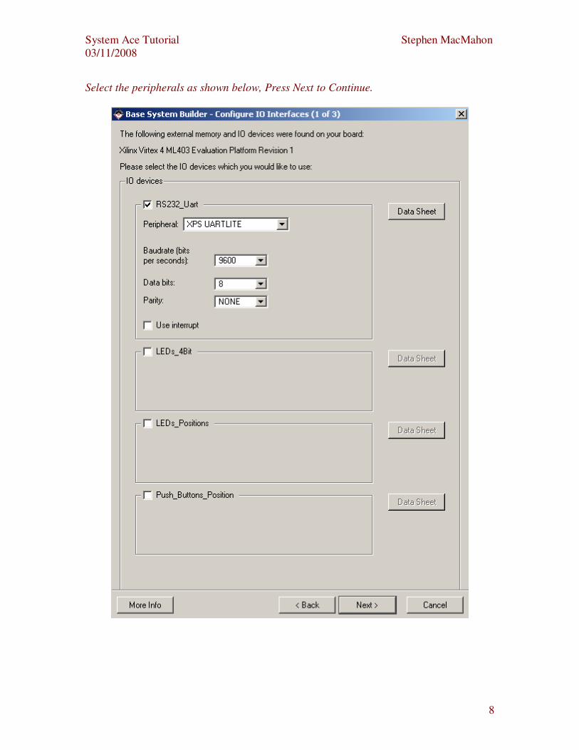
Select the peripherals as shown below, Press Next to Continue.
System Ace Tutorial Stephen MacMahon
03/11/2008
9
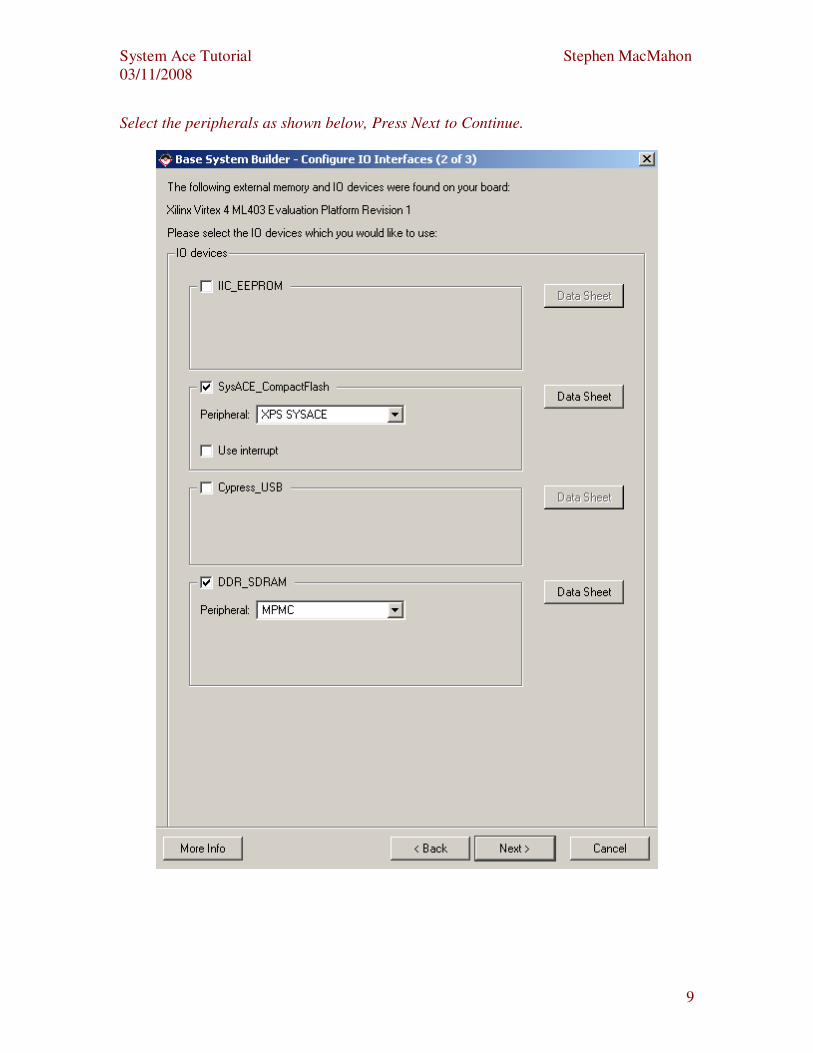
Select the peripherals as shown below, Press Next to Continue.
System Ace Tutorial Stephen MacMahon
03/11/2008
10
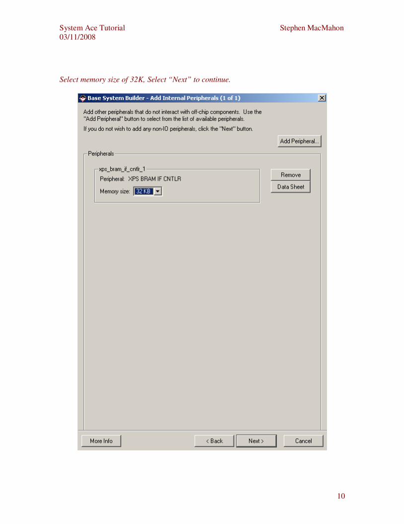
Select memory size of 32K, Select “Next” to continue.
System Ace Tutorial Stephen MacMahon
03/11/2008
11
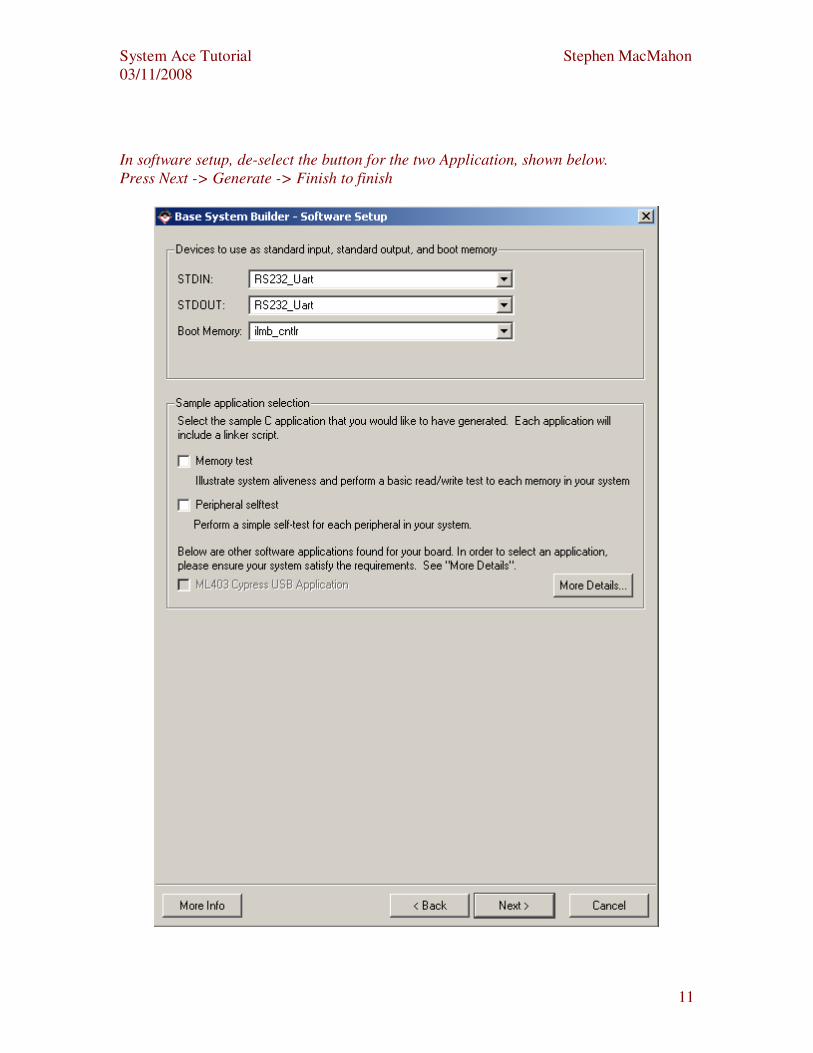
In software setup, de-select the button for the two Application, shown below.
Press Next -> Generate -> Finish to finish
System Ace Tutorial Stephen MacMahon
03/11/2008
12
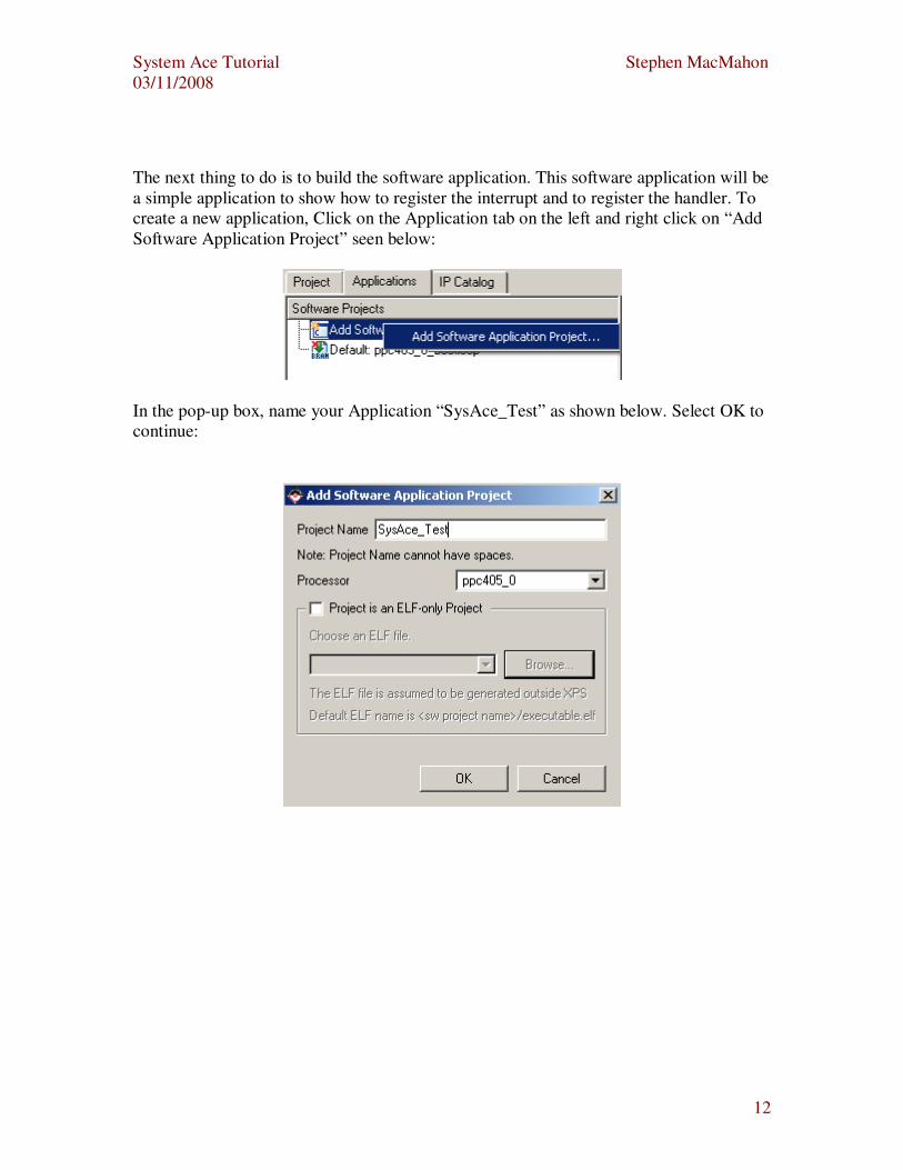
The next thing to do is to build the software application. This software application will be
a simple application to show how to register the interrupt and to register the handler. To
create a new application, Click on the Application tab on the left and right click on “Add
Software Application Project” seen below:
In the pop-up box, name your Application “SysAce_Test” as shown below. Select OK to
continue:
System Ace Tutorial Stephen MacMahon
03/11/2008
13
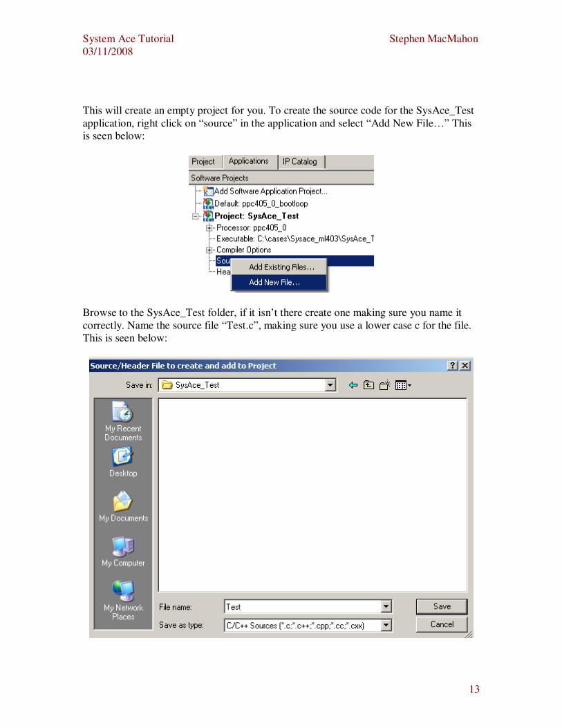
This will create an empty project for you. To create the source code for the SysAce_Test
application, right click on “source” in the application and select “Add New File…” This
is seen below:
Browse to the SysAce_Test folder, if it isn’t there create one making sure you name it
correctly. Name the source file “Test.c”, making sure you use a lower case c for the file.
This is seen below:
System Ace Tutorial Stephen MacMahon
03/11/2008
14
Copy the “Hello World” code into your Test.c program.
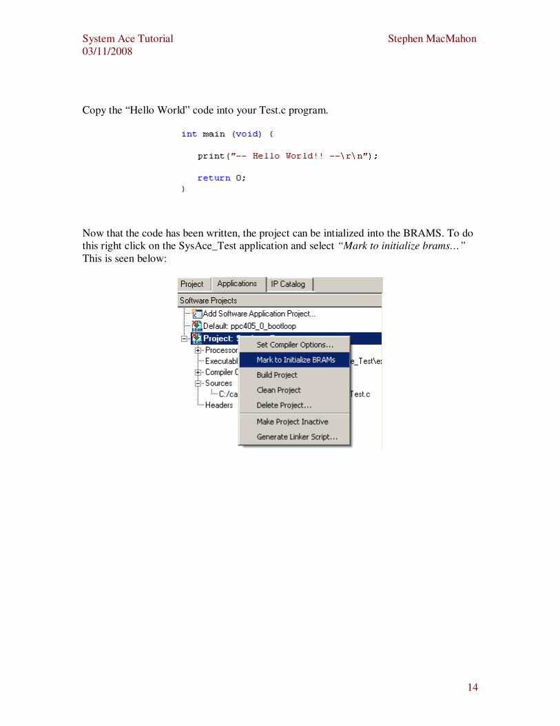
Now that the code has been written, the project can be intialized into the BRAMS. To do
this right click on the SysAce_Test application and select “Mark to initialize brams…”
This is seen below:
System Ace Tutorial Stephen MacMahon
03/11/2008
15
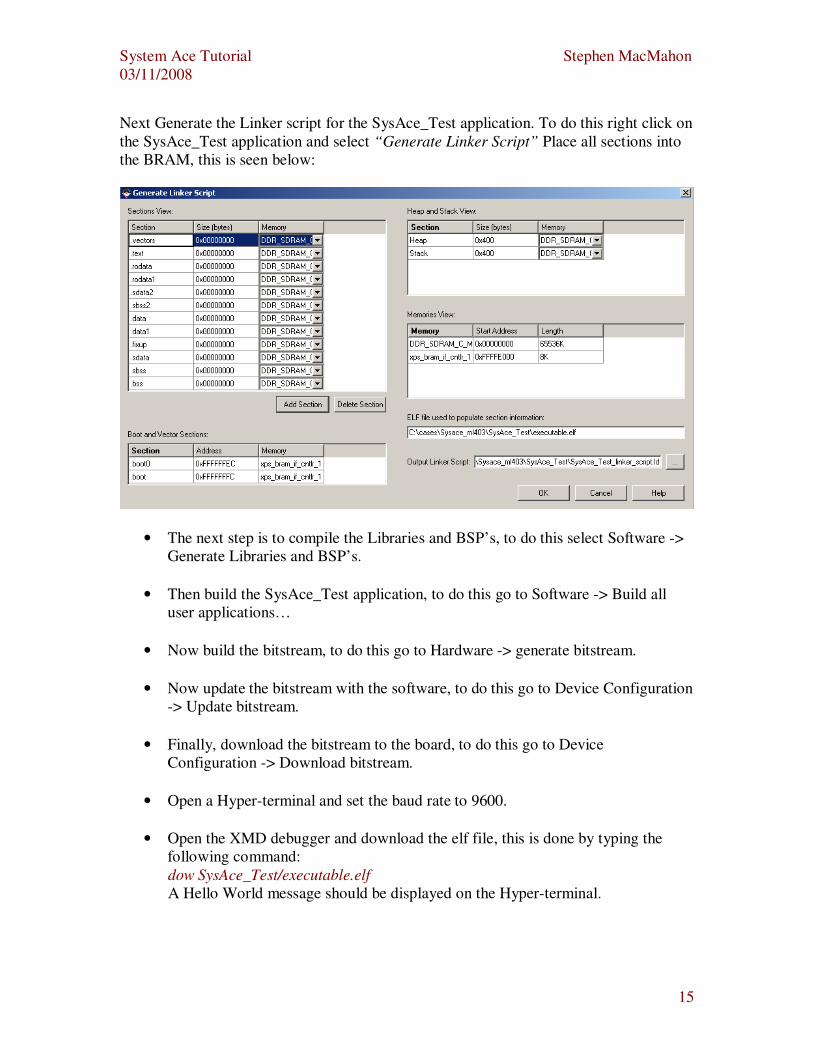
Next Generate the Linker script for the SysAce_Test application. To do this right click on
the SysAce_Test application and select “Generate Linker Script” Place all sections into
the BRAM, this is seen below:
• The next step is to compile the Libraries and BSP’s, to do this select Software ->
Generate Libraries and BSP’s.
• Then build the SysAce_Test application, to do this go to Software -> Build all
user applications…
• Now build the bitstream, to do this go to Hardware -> generate bitstream.
• Now update the bitstream with the software, to do this go to Device Configuration
-> Update bitstream.
• Finally, download the bitstream to the board, to do this go to Device
Configuration -> Download bitstream.
• Open a Hyper-terminal and set the baud rate to 9600.
• Open the XMD debugger and download the elf file, this is done by typing the
following command:
dow SysAce_Test/executable.elf
A Hello World message should be displayed on the Hyper-terminal.
System Ace Tutorial Stephen MacMahon
03/11/2008
16
Formatting the Compact Flash Card
To format the CF card, download the freeware utility called “mkdosfs.zip” from the link
below:
http://www1.mager.org/mkdosfs/mkdosfs.zip
Format the CF card by using the freeware utility called "mkdosfs" from the DOS prompt.
Inserted CF card into your PC using a card reader, lets call the drive “E”.
Extract the CF card utility “mkdosfs.zip” on root directory at “C” drive.
Issue a DOS command => c:\> mkdosfs E:
Next step is to copy the system.ace file onto the CompactFlash Card using the
CompactFlash writer USB. Plug the CF writer into the USB port and copy and paste the
system.ace file onto the CF card.
System Ace Tutorial Stephen MacMahon
03/11/2008
17
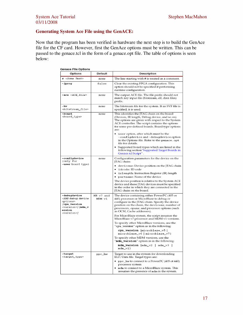
Generating System Ace File using the GenACE:
Now that the program has been verified in hardware the next step is to build the GenAce
file for the CF card. However, first the GenAce options must be written. This can be
passed to the genace.tcl in the form of a genace.opt file. The table of options is seen
below:

System Ace Tutorial Stephen MacMahon
03/11/2008
18
Seen below is the genace.opt file to be passed to the genace.tcl. Create a file called
genace.opt in your project directory and copy the options below into it.
-jprog
-hw implementation/download.bit
-ace system.ace
-board ml403
-target ppc_hw
-elf SysAce_Test/executable.elf
Next step is to open a open an EDK shell. To launch an EDK shell and go to Project ->
Launch EDK Shell (seen below):
Run the command below in the shell:
xmd -tcl genace.tcl -opt genace.opt
System Ace Tutorial Stephen MacMahon
03/11/2008
19
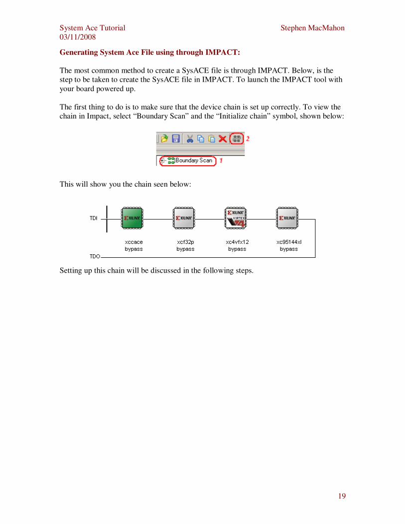
Generating System Ace File using through IMPACT:
The most common method to create a SysACE file is through IMPACT. Below, is the
step to be taken to create the SysACE file in IMPACT. To launch the IMPACT tool with
your board powered up.
The first thing to do is to make sure that the device chain is set up correctly. To view the
chain in Impact, select “Boundary Scan” and the “Initialize chain” symbol, shown below:
This will show you the chain seen below:
Setting up this chain will be discussed in the following steps.
System Ace Tutorial Stephen MacMahon
03/11/2008
20
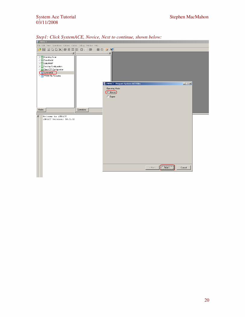
Step1: Click SystemACE, Novice, Next to continue, shown below:
System Ace Tutorial Stephen MacMahon
03/11/2008
21
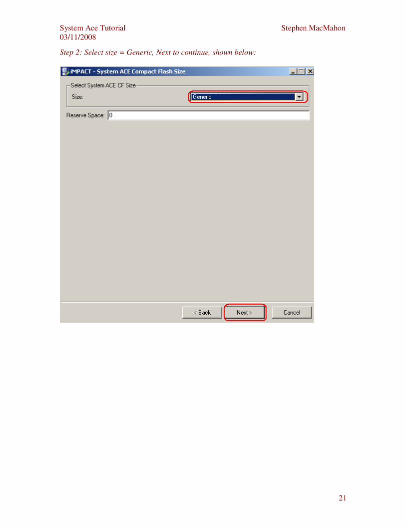
Step 2: Select size = Generic, Next to continue, shown below:
System Ace Tutorial Stephen MacMahon
03/11/2008
22
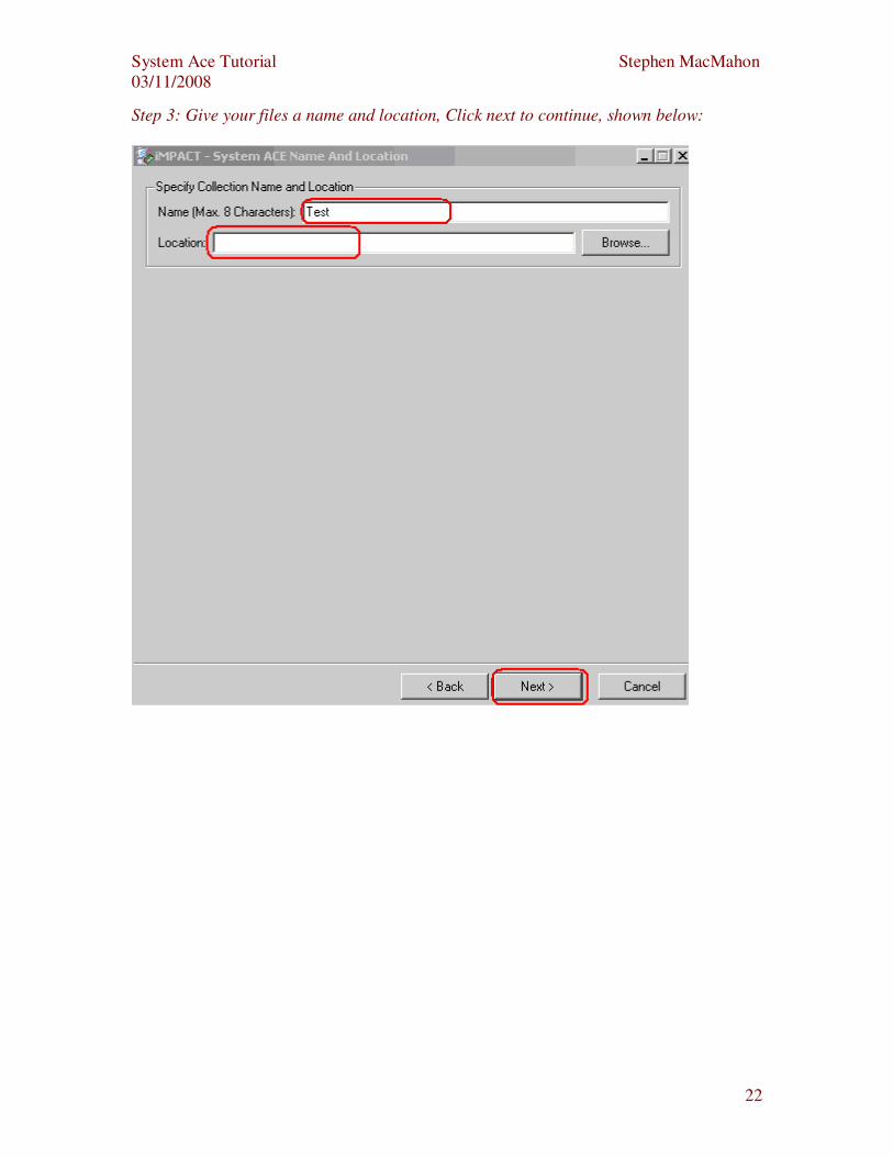
Step 3: Give your files a name and location, Click next to continue, shown below:

System Ace Tutorial Stephen MacMahon
03/11/2008
23
Step 4: Select configuration address as shown below. Click next to continue.
Step 5: Select Finish to finish.
Step 6: One page 18 the chain starts with a sysace => xcf32p => xc4fx12 =>
xc95144xl.The xcf32p will have to be added to the chain. This file can be found in the
EDK install directory for example: C:\Xilinx\10.1\ISE\xcfp\data\xcf32p.bsd. You will be
asked if you “Would like to add another design file” click yes and navigate to your
download.bit file. Again, you will be asked to add another design file click yes and select
the final device in the chain the xc95144xl this can be found in the EDK install directory
C:\Xilinx\10.1\ISE\xc9500xl\data\ xc95144xl.bsd
Note: if the FPGA comes directly after the sysace as it does in the ML507, you do not
have to do put the .bsd file in the chain.
System Ace Tutorial Stephen MacMahon
03/11/2008
24
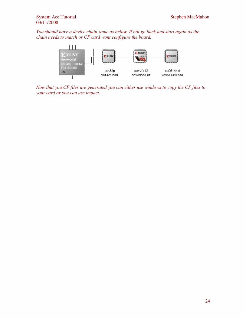
You should have a device chain same as below. If not go back and start again as the
chain needs to match or CF card wont configure the board.
Now that you CF files are generated you can either use windows to copy the CF files to
your card or you can use impact.
System Ace Tutorial Stephen MacMahon
03/11/2008
25
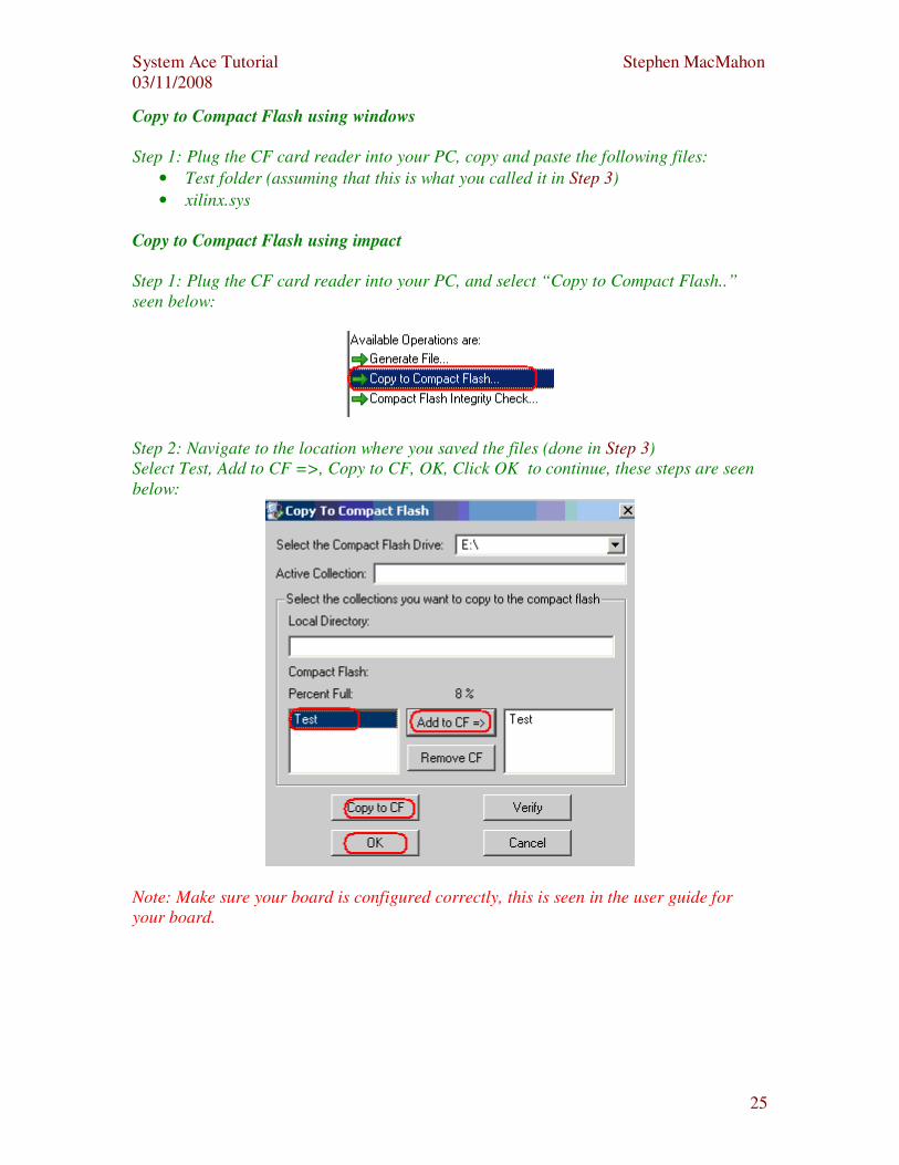
Copy to Compact Flash using windows
Step 1: Plug the CF card reader into your PC, copy and paste the following files:
• Test folder (assuming that this is what you called it in Step 3)
• xilinx.sys
Copy to Compact Flash using impact
Step 1: Plug the CF card reader into your PC, and select “Copy to Compact Flash..”
seen below:
Step 2: Navigate to the location where you saved the files (done in Step 3)
Select Test, Add to CF =>, Copy to CF, OK, Click OK to continue, these steps are seen
below:
Note: Make sure your board is configured correctly, this is seen in the user guide for
your board.
System Ace Tutorial Stephen MacMahon
03/11/2008
26
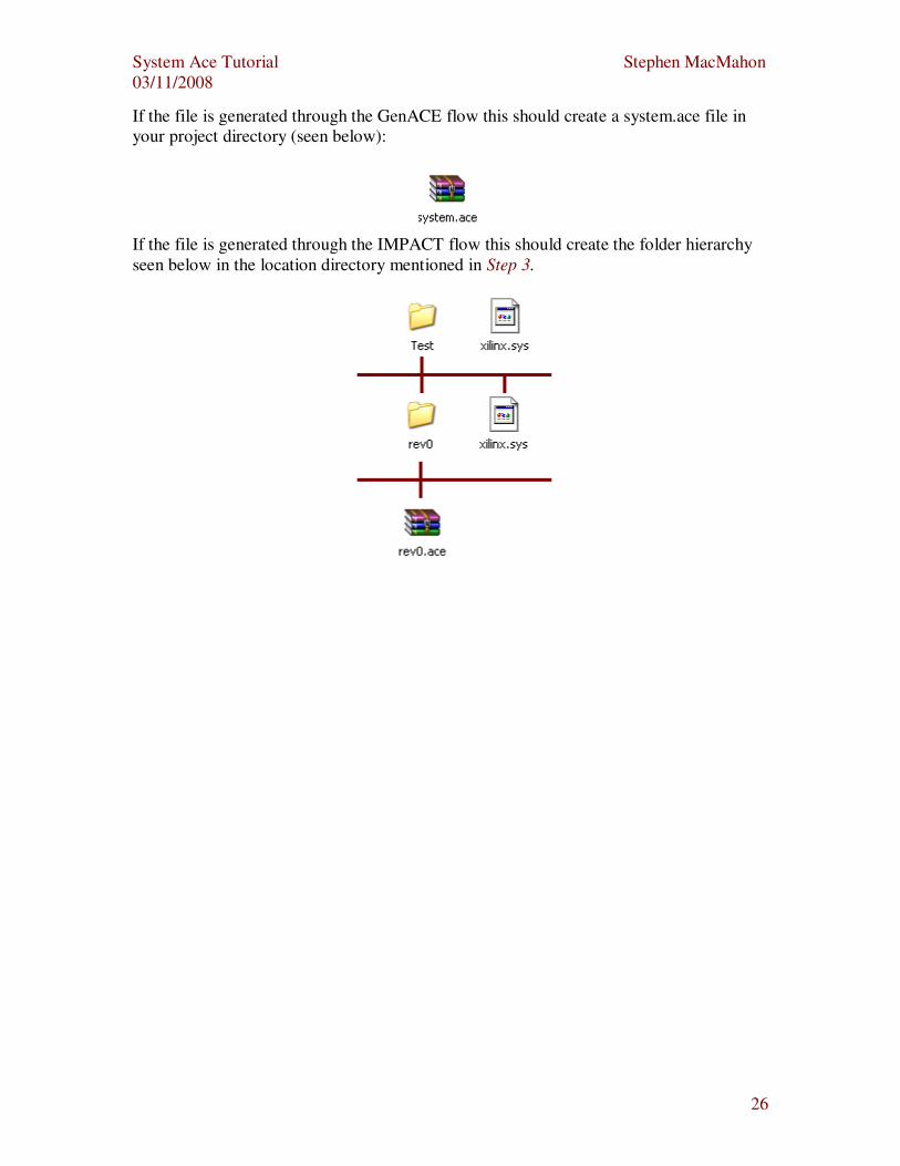
If the file is generated through the GenACE flow this should create a system.ace file in
your project directory (seen below):
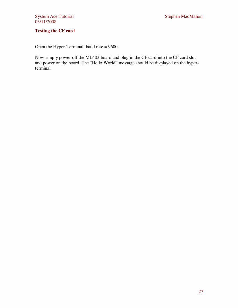
If the file is generated through the IMPACT flow this should create the folder hierarchy
seen below in the location directory mentioned in Step 3.
System Ace Tutorial Stephen MacMahon
03/11/2008
27
Testing the CF card
Open the Hyper-Terminal, baud rate = 9600.
Now simply power off the ML403 board and plug in the CF card into the CF card slot
and power on the board. The “Hello World” message should be displayed on the hyper-
terminal.


![[TUTORIAL] Dekodiranje Samsung Galaxy Mini Ace Gio Pop Fit i5500](https://img.pdfslide.net/doc/110x75/5572021b4979599169a2f6a7/tutorial-dekodiranje-samsung-galaxy-mini-ace-gio-pop-fit-i5500-55b346bc1c7da.jpg)