Embed Size (px)
Citation preview
United States Patent [191 LePori et al.
[11] Patent Number:
[451 Date of Patent: 4,848,249
Jul. 18, 1989
[54] SYSTEM AND PROCESS FOR CONVERSION OF BIOMASS INTO USABLE ENERGY
[75] Inventors: Wayne A. LePori; Calvin B. Parnell, both of College Station, Tex.
Texas A&M University, College Station, Tex.
[21] Appl. No.2 126,832 [22] Filed: Nov. 30, 1987
[51] Int. cu .............................................. .. F23B 7/00 [52] US. (:1. . . . . . . . . . .. 112/234; 48/197 R;
48/197 A; 48/209; 110/229; 110/245; 110/346; 122/2
[58] Field of Search ............. .. 110/245, 229, 346, 347, 110/234; 48/77, 76, 197 R, 197 A, 209; 122/7
R, 2
[73] Assignee:
[56] References Cited U.S. PATENT DOCUMENTS
Re. 29,312 7/1977 Malian et al. . 4,078,973 3/1978 Choi et a1. . 4,191,539 3/1980 Patel et a1. . 4,211,539 7/ 1980 Bierbach et a1. . 4,315,758 2/1982 Patel et a1. . 4,417,528 11/1983 Vining et a1. ..................... .. 110/229 4,448,589 5/1984 Fan et al. . 4,674,418 6/ 1987 Schafer ............................. .. 110/229 4,676,177 6/1987 Engstrom .. 4,738,207 4/1988 Moss ............................. .. 110/229X
OTHER PUBLICATIONS
Siebold, “Power Plant Computer Aided Design Soft
ware Char Properties Generated by a Fluidized Bed Gasi?er” (May 1987). Finch et al., ASAE Peper No. 86-6576 (Dec. 1986). Siebold, et al., ASAE Paper No. 86-1564 (Dec. 1986). Finch, “Reducing Nitrogen Oxides Emissions from the Combustion of LCV Gas by Staged Firing” (Dec. 1986). Rutherford et al., ASAE Paper No. 84-3598 (Dec. 1984). Parnell et al., ASAE Paper No. 83-3542 (Dec. 1983). LePori et al., ASAE Paper No. 83-3541 (Dec. 1983). Datin et al., ASAE Paper No. 83-3548 (Dec. 1983). “Biomass Energy: A Monograph” (1985) Hiler et al. “Final Report on System Analysis of Cotton Gin Trash Utilization Alternatives” (Apr. 1982). Parnell et al., “Energy from Cotton Gin Trash” (1984). Jones et al., ASAE Paper No. 84-1583 (Dec. 1984).
Primary Examiner-Edward G. Favors Attorney, Agent, or Firm-Arnold, White & Durkee
[57] ABSTRACT A system is disclosed for converting unconditioned biomass, such as cotton gin trash, into usable energy. This is accomplished by gasifying the biomass, remov ing the particulate char from the combustible gas using cyclonic separators, burning the gas, and using the heat to generate steam. Two stage combustion helps mini mize NO; formation.
22 Claims, 3 Drawing Sheets
4, ,249 US. Patent Jul. 18, 1989 Sheet 1 of3
US. Patent Jul. 18, 1989 Sheet 2 of3 4,848,249
13a
‘5173'; 136/ "1 110 108
/ 11A. 116 1.20 121+ _~ "
126 132 138
102 100 122 128
US. Patent Jul. 18,1989 Sheet 3 of3 4,848,249
\lyg nu“.
4,848,249 1
SYSTEM AND PROCESS FOR CONVERSION OF BIOMASS INTO USABLE ENERGY
FIELD OF THE INVENTION
This invention relates to systems and processes for converting biomass into usable energy.
BACKGROUND OF THE INVENTION
Many agriculture related industries produce biomass waste products. The ginning of cotton is one example. Ginning separates the lint, seeds, and foreign matter from the cotton ?bers, and this “cotton gin trash” must then be disposed of. In the past it was often incinerated, but that practice is not acceptable under present air pollution laws. One alternative disposal method is to haul the waste back to the farms it came from and return it to the ?elds. While this has the advantage of enriching the soil, there are also drawbacks, because cotton gin trash includes chemicals such as herbicides, weed seeds, and disease-causing organisms. The problem of disposing of cotton gin trash is of
major signi?cance. It has been estimated that conven tional disposal costs ginners from $6.50 to $9.50 per ton (as of 1983), and that in the state of Texas alone, 1,260,000 tons of cotton gin trash are produced per year (as of 1984).
Cotton gin trash has an energy content of about 6,500 to 7,500 Btu/lb. Cotton ginning requires signi?cant amounts of electrical and heat energy to process cotton. However, the cotton ginning industry is seasonal, oper ating for only 1000 hours per year on average. Related industries such as cottonseed oil mills and textile mills operate 24 hours per day, seven days per week for over 300 days per year. These two post-harvest industries are usually located near cotton gins, hence transportation costs of fuel (trash) from the gin to a cogeneration plant located at an oil mill or textile mill should be relatively low. In addition, both of these post-harvest processing industries utilize large quantities of saturated steam for processing. The natural gas used to produce this process steam can be expensive. It is possible to divert steam from the turbine in a cogeneration plant having the necessary characteristics to displace the process steam produced with natural gas. It would be attractive to utilize energy in the biomass waste to operate a cogen eration plant that would produce electrical energy and process steam for oil seed and/or textile mill processing. This is especially true in view of the increasing price and uncertain availability of oil, natural gas and electri cal energy for agricultural processing in the future. Unfortunately, a number of problems stand in the way of doing this.
Direct combustion of high ash biomass such as cotton gin trash in order to fuel a boiler usually is not satisfac tory. It leads to severe ash fouling, slagging, and corro sion, necessitating frequent maintenance.
Gasi?cation, in which solid biomass is reacted with less than stoichiometric oxygen, producing a low mo lecular weight gas product and a solid product known as char, is much more attractive for use with cotton gin trash. However, researchers have found in the past that the low molecular weight gas containing char when burned results in the same slagging, fouling, and corro sion observed in direct combustion systems. Also, bum ing the low molecular weight gas tends to produce excessive amounts of nitrogen oxides (NOx) because the
15
20
30
35
40
45
50
55
65
2 raw cotton gin trash has a high nitrogen content. NOX emissions are strictly regulated by law in the U.S. A need exists today for ways to obtain useful energy
from biomass waste, both to reduce energy costs and to reduce waste disposal problems.
SUMMARY OF THE INVENTION
A system for converting biomass to usable energy in accordance with the present invention comprises a bio mass feed apparatus which includes a feed hopper with an agitator, at least one feed auger to carry biomass feed from the hopper, and an air lock to prevent back?ow of combustible gases into the hopper. The system also includes a ?uidized bed gasi?er which receives biomass feed from the feed auger and which has a ?uidizing air inlet, and which produces combustible gas and particu lates containing activated carbon. Further, the system has a plurality of solids removal cyclones which are arranged in series and which receive the products of the ?uidized bed gasifier and remove at least 99% by weight of the particulates from the combustible gas. In addition, it includes a two stage combustion apparatus which includes in the ?rst stage a cyclonic combustion chamber with an inlet for receiving primary combustion air and combustible gas from the solids removal cy clones, and a second stage which has an inlet for receiv ing gases exiting the ?rst stage and a secondary combus tion air stream, and further includes a boiler in which the heat from the combustion gases converts water to steam.
This system can convert unconditioned biomass, such as cotton gin trash, into usable energy in the form of steam. Although gasi?cation is normally expected to produce char, the production of activated carbon by the above described system is a surprising result. Another aspect of the present invention is a process
for producing energy and activated carbon from bio mass, including the steps of feeding unpreconditioned biomass to a ?uidized bed gasi?er; feeding fluidizing air to the ?uidized bed gasi?er, with the mass ?owrate ratio of biomass to air controlled to obtain an equiva lence ratio between about 3.1 and 5.3; gasifying the biomass, thereby producing combustible gas and partic ulates containing activated carbon; removing the bulk of the particulates from the combustible gas using a plurality of solids removal cyclones; combining and burning the combustible gas with combustion air such that the combustible gas is exposed to a combustion temperature of at least 1800“ F. for at least one second, whereby the NO,‘ content of the resulting gas is no greater than about 190 ng per joule of energy generated by the process; and producing steam from the heat generated by the combustion. The present invention has several bene?ts. It takes
what in the past has been a waste product and generates usable energy from it. It can convert a wide range of biomass fuels including difficult fuels such as cotton gin trash because of the following: (1) thermal reaction (gasi?cation) takes place in a high thermal inertia, con trolled and relatively low temperature (1400“ F.) envi ronment; (2) the char is removed prior to combustion; (3) approximately 85% of the enregy in the biomass is converted to chemical energy in the gas, allowing for gas cleaning while minimizing sensible heat loss; (4) staged combustion can reduce NO,, to environmentally accepted levels; and (5) the ?rst stage combustor pro vides for continuous ignition (stability) while burning low calori?c value (LCV) gas. In contrast, combustion
4,848,249 3
processes (1) convert all energy to sensible heat disal lowing cleanup prior to introducing hot gases to the boiler; (2) would not allow for staged combustion to be used to reduce NOx concentrations in the ?ue gas; and (3) would have no temperature control in the thermal reaction chamber, resulting in slagging, fouling and metal corrosion.
It is presently believed that cogeneration units having power generating capacity of approximately 2 MW and located near a cottonseed oil mill or textile mill would be the optimum use of the systems in accordance with the present invention. These units will provide steam for power generation and processing. For example, a 2 MW system could realize a gross return of over $600,000 for electric power generation (@Sc/kWh) and over $600,000 bene?t from displaced natural gas, for process steam generation at 16,000 pounds of saturated steam per hour ($3 per Mcf natural gas). This would amount to a gross return of $1.2 M per year. Another bene?t of the present invention is the reduc
tion in solid waste, since the quantity of particulates (char) produced is much less than the quantity of bio mass feed. If the activated carbon in the particulates is used for one of its many commercially valuable pur poses, the quantity of solid to be disposed of is reduced further still. Activated carbon’s potential uses include adsorption media, ?lter media, catalysts, ?ller, suspen sion agents, carbon paper ink, and ceramics. If a value of $50/ton were achieved for the activiated carbon, a gross revenue of $400,000 could be realized. The present invention also generates energy from
biomass without generating excessive NOx and reduces particulate emissions of the ?ue gases to less than 0.1 g/m3. Further, it does not involve ?ue gas treatment which tends to be quite expensive.
BRIEF DESCRIPTION OF THE DRAWINGS
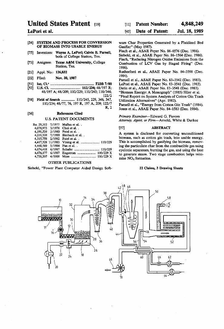
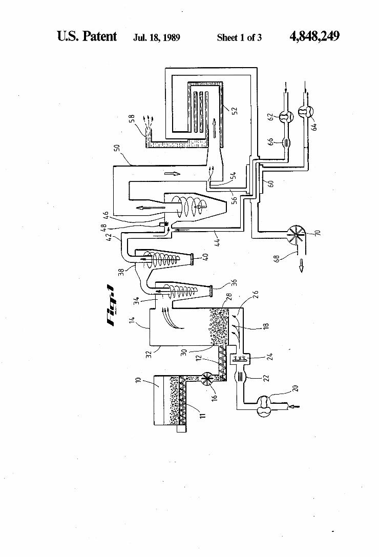
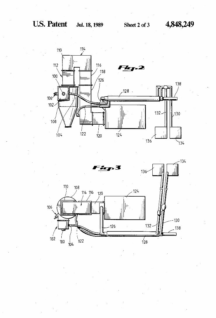
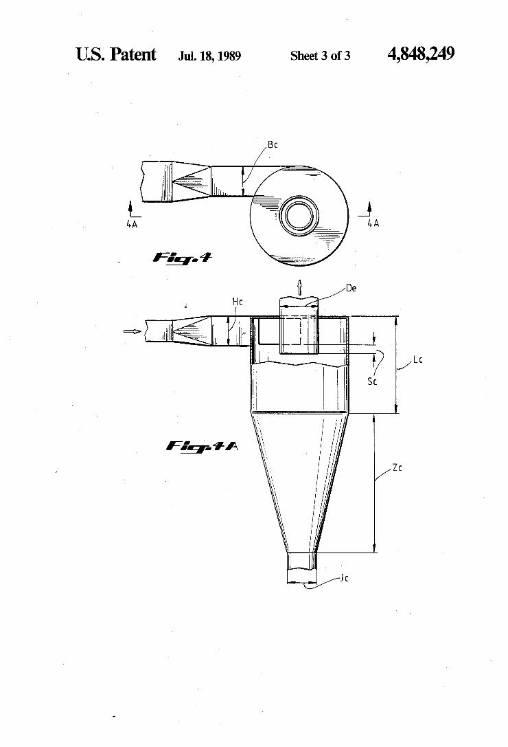
FIG. 1 is a process ?ow diagram of a system in accor dance with the present invention. _ FIG. 2 and 3 are side and top views, respectively, of combustion apparatus in accordance with the present invention. FIGS. 4 and 4A are top and side views, respectively,
of cyclones in accordance with the present invention.
DETAILED DESCRIPTION OF A SPECIFIC EMBODIMENT OF THE INVENTION
The major elements of a system in accordance with the present invention are shown in FIG. 1. Biomass feed such as cotton gin trash is placed in a feed hopper 10. The hopper has an agitator which keeps the feed from bridging in the hopper 10. A feed metering auger 11 and a feed injection auger 12 carry the feed from the hopper 10 to the ?uidized bed gasi?er 14. An air lock 16 is used to prevent gas generated in the ?uidized bed gasifier 14 from back?owing through the auger 12 into the hopper 10, where it could cause an explosion. This ‘feed apparatus can feed cotton gin trash and
similar biomass materials at precise rates without any preconditioning, despite the wide variance in sizes and shapes of the pieces of trash. The ?uidized bed gasifier 14 receives an air stream 18
in addition to the biomass feed from the auger 12. A blower 20 is used to force air into the gasi?er 14, and a laminar flow element 22 may be placed in the air line if desired. A natural gas burner 24 is used to preheat the fluidized bed material 28 to the desired temperatures.
25
40
45
55
65
4 In the gasi?er 14, inert bed particles 28 are maintained
in a ?uidized state by the ?ow of air 18 entering through the plenum 26. A turbulent ?uidized state of inert parti cles 28 in the bed 30 creates a nearly isothermal zone having high thermal inertia and enables accurate con trol of reaction temperature. Thermal energy in the particles 28 is rapidly transferred to the solid biomass fuel. The gasi?cation reaction, carried out with less than stoichiometric oxygen present, produces a com bustible gas and particulate char. The combustible gas, which will usually have a heating value of about 150 to 200 Btu/ft3, and entrained particulates pass through the freeboard section 32 of the gasi?er 14 and are piped to solids removal apparatus. A ?rst solids removal cyclone 34 receives the output
of the gasi?er 14. Most of the particulates are separated from the combustible gas, and the particulates pass out through the bottom opening 36. The combustible gas with the remaining entrained particulates enters a sec ond solids removal cyclone 38, which also separates particulates and passes them out through the bottom opening 40. The remaining combustible gas stream 42 is largely free of particulates (less than 0.2 g/m3). Systems in accordance with the present invention have been found to reduce the particulate content of the gas, which may be as high as 40 to 100 g/m3 before it enters the cyclones, to no greater than 3 g/m3 and 0.5 g/m3, and preferably to no greater than 0.6 g/m3 and 0.2 g/m3, respectively, as it leaves the ?rst and second cyclones 34 and 38. The combustible gas stream 42 is combined with a
primary combustion air stream 44 and enters a ?rst stage combustion apparatus which includes a cyclonic combustion chamber 46. A natural gas pilot 48 is used to heat the refractory of the primary combustor to above the ignition temperature of the incoming gases. The hot refractory serves as the ignitor of the LCV gas. The gases exiting the cyclonic combustion chamber 46 enter a second stage, which includes parts of a refractory duct 50 and a ?re tube boiler 52. The second stage has an inlet 54 for a secondary combustion air stream 56. The hot combustion gas in the boiler 52 causes water to boil, thereby producing steam 58. The ?ue gases exiting the boiler 52 enter a combus
tion air preheater 60, in which some of the heat remain ing in that gas is transferred to the primary and second ary combustion air streams 44 and 56. Primary and secondary air blowers 62 and 64 are used to force the air through the preheater 60 and into the combustion chambers. A laminar ?ow element 66 can be added if desired. The ?ue gas is drawn out through a stack 68 by an induced draft fan 70, and released to the atmosphere. FIGS. 2 and 3 show the combustion apparatus from
two different views. The combustible gas enters through inlet 100. The mixing box 102 which it enters also receives the primary combustion air stream through a line 104. A natural gas pilot 106 is used to preheat the refractory in the primary combustor to a temperature in excess of the ignition temperature of the LCV gases entering the ?rst stage cyclonic combustion chamber 108. The gas, which at this point is termed “interstage
gas”, exiting the cyclonic combustion chamber 108 enters a refractory duct 110, which includes a quarl 112, miter box 114, upper duct 116, lower duct 118, and boiler transition 120. A secondary air line 122 carries secondary combustion air to the lower duct 118. The combustion gases pass from the boiler transition 120
4,848,249 . 5
into the ?re tube boiler 124. The gas exiting the boiler 124 goes through a line 126 to the combustion air pre heater 128. The preheater 128 also receives primary and secondary combustion air through lines 130 and 132, which are supplied by blowers 134 and 136. The ?ue gas exiting the preheater passes to a stack 138. The solid fuel feed system allows injection of materi
als such as unprocessed gin trash into the gasi?er near the base of the bed. The fuel feed system consists of a hopper 10, agitators, an air lock 16, and two augers 11 and 12. The primary agitators are four mechanical arms which rotate at about one rpm in a plane parallel to the sloped bottom of the feed hopper. They are timed to be out of phase so that one agitator is always forcing fuel into the metering auger 11. A secondary agitator, lo cated parallel with and immediately above the metering auger 11, also forces fuel into the metering auger 11. The secondary agitator has short mechanical arms at an agle to its rotating shaft. The arms are located in a pat tern around the shaft to cause fuel to be conveyed in the opposite direction of the metering auger 11.
Fuel is metered from the fuel hopper 10 by an auger 11. The speed of the auger 11 controls the feed rate. An air lock 16 is located between the metering auger 11 and the injection auger 12 to prevent hot gases from escap ing the gasi?er 14. Purge air is introduced into the injec tion auger to offset gas loss through the air lock 16. The injection auger 12 is set to feed slightly more fuel than is supplied by the metering auger 11 to prevent plug ging. Air is also injected into the feed injection auger 12 to maintain greater than atmospheric pressure and pre vent any back ?ow of hot gases. The fluidized bed gasi?er 14 is designed to accept the
fuel near the base of the bed and distribute it throughout the bed. A distributor plate is used with bubble caps placed so that the net circulation of the bed particles 28 is down along the sidewalls and up in the center. This provides maximum retention time of light fuel particles in the bed after they are injected by the auger 12. The gasi?er capacity in terms of input fuel heating value ranges between 1 and 2 mBtu per hour per square foot of gasi?er cross-sectional area. Air velocities can be varied to maintain the preferred 0.6 to 0.9 fuel to air ratio for cotton gin trash or similar biomass materials. Inert bed particles 28 are sized to result in a minimum of carry-over with the ash for the range of air velocities needed yet maintain proper ?uidization. The bed parti cles also have these characteristics: abrasion resistance, high melting temperature, low thermal coef?cient of expansion, and low cost. Ione Super Duty Grain from North American Refractories Co., P.O. Box 44753, San Francisco, Calif. 94144, was found to provide an ac ceptable bed material. _ The solids removal cyclones are preferably designed
so that the overall pressure drop across them is no greater than eight inches of water. Furthermore, they are preferably capable of receiving gas from the ?uid ized bed gasi?er having a particulate concentration of 40 to 100 g/m3 and reducing it to no greater than 0.2 g/m3. If two cyclones are used in series, the ?rst can reduce the particulate concentration to about 0.6 g/m3, while the second can achieve the ?nal reduction. These cyclones will be designed such that the design
gas inlet velocity for the primary cyclone will be 3200 fpm with a design inlet velocity of the secondary cy clone of 5600 fpm. This is accomplished by determining the anticipated volume rate of flow (Q) and dividing by the inlet cross sectional area (Dc2/8). If a single series of
20
40
45
50
60
65
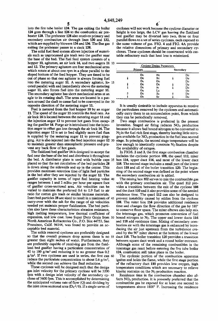
6 cyclones will not work because the cyclone diameter or height is too large, the LCV gas leaving the ?uidized bed gasi?er may be diverted into two, three or four parallel ?ows to a set of series cyclones, each exposed to the same volume of gas. FIG. 4 and FIG. 4A provide the relative dimensions of primary and secondary cy clones. These cyclones should be constructed with cas table refractory such that heat loss is minimized.
W ‘ Primagy Secondary
Dc Hc Dc 5 De Bc l Dc
Dc Dc Dc 8 ' Dc De & Dc 1 De Jc l Dc
Dc Lc Dc 5 Dc Z0 5 Dc 1 Dc Sc l Dc
It is usually desirable to include apparatus to receive the particulates removed by the cyclones and automati cally carry them to an accumulation point, from which they can be periodically removed. Two stage combustion is preferred in the present
invention. Staged air ?ring reduces NO,, production because it allows fuel bound nitrogen to be converted to N2 in the fuel rich ?rst stage, thereby leaving little nitro gen available for NO,‘ production in the fuel lean second stage. In principle, the second stage temperature will be low enough to kinetically constrain N2 ?xation despite the availability of oxygen.
In FIGS. 2 and 3, the ?rst stage combustion chamber includes the cyclonic portion 108, the quarl 112, miter box 114, upper duct 116, and most of the lower duct 118. The second stage includes a small part of the lower duct 118 and all of the boiler transition 120. The begin ning of the second stage was de?ned as the point where the secondary combustion air is added. The mixing box 102 serves to mix the combustible gas
with the primary combustion air. The quarl 112 pro vides a transition between the exit of the cyclone 108 and the duct 110 and it also provides some of the needed residence time. The quarl 112 can also be designed to prevent instability caused by eddies from the cyclone 108. The miter box 114 provides additional residence time and changes the ?ow direction of the gas by 180° to conserve floor space. The miter elbows also help mix the interstage gas, which promotes conversion of fuel bound nitrogen to N2. The upper and lower ducts 116 and 118 add residence time. Mixing of secondary com bustion air with the interstage gas is enhanced by intro ducing the air just upstream from the turbulence cre ated by the 90° miter shown at the bottom of the lower duct 118. The boiler transition 120 provides a transition between square duct work and a round boiler entrance. Although some of the remaining combustibles in the interstage gas react before entering the ?re tube boiler 124, combustion still takes place in the boiler. The cyclonic portion of the combustion apparatus
ignites and holds the ?ame, while the ?rst stage portion of the refractory duct 110 provides low oxygen, high temperature conditions which are necessary to relieve kinetic restrains on the N2 production reaction.
Residence time in the combustion chamber also af fects NO,, production. It is presently preferred that the combustible gas be exposed for at least one second to temperatures above 1800° F. Increasing the residence
4,848,249 7
time will generally decrease NOX production, but be yond a point the returns diminish. The equivalence ratio ((1)) bears on NOx production.
In the ?rst stage, as the primary combustion air flowrate is reduced in relation to the combustible gas ?owrate (i.e., as ¢ increases), the NO,‘ concentration in the inter stage gas tends to decrease. The presently preferred ?rst stage 4) ranges from 1.3 to 1.6. The correlation between NO,‘ production and overall
d) does not appear to be as strong as with ?rst stage d> but there still is a tendency for NO; to decrease as over— all d) increases. Overall d) should preferably be approxi mately 0.8 to 0.9. An excessively high overall d) hurts the ef?ciency of the boiler due to the cooling effect.
In some tests of systems in accordance with the pres ent invention, ?ue gas NO, levels were higher than the levels in the interstage gas. This was probably caused by a kinetic constraint in the ?rst stage on the conversion of fuel bound nitrogen to N2. This might be combatted by increasing primary combustion air preheat or by increasing the ?rst stage residence time.
Suitable refractory materials and insulation from which the combustion apparatus could be made would be known to a person skilled in this ?eld. Suitable exam ples are Lo-Abrade (rated for 2,400’ F.) for the ?rst stage cyclonic combustion chamber 108 and Kast-O Lite 25 (rated for 2,500’ F.) for the quarl 112, miter box 114, pilot mounting box, cyclone plug, cyclone refrac tory ?ange, and boiler refractory ?ange. Rather than refractory, insulation such as Castable Insulation No. 22 (rated for 2200° F.) could be used for some components such as the mixing box 102, upper duct 116, lower duct 118, and boiler transition 120. Insblock 19 (rated for l,900° F.) could be used to reduce refractory wall thick ness by placing it between the refractory and the exte rior structure. All of the above listed materials are avail able from A. P. Green Refractories Company, Green Boulevard, Mexico, Mo. 65265. A cyclonic ?rst stage combustor constructed n accor
dance with the present invention had a single inlet tube, an area ratio of combustion chamber cross section to inlet cross section (AD/A1‘) of 7.1, a diameter ratio of exit to combustion chamber (De/D0) of 0.46, a ratio of combustion chamber length to diameter (LC/D0) of 2.21, a geometric swirl number (S) of 10.2, and an inlet Reynolds number (Re) of 2.7 X 10⁴. These values are not necessarily the optimum. The following examples illustrate various aspects of
the present invention.
EXAMPLE 1
Proximate analysis of samples of cotton gin trash showed ash (inorganic) contents ranging from 6.16% to
5
15
20
25
30
45
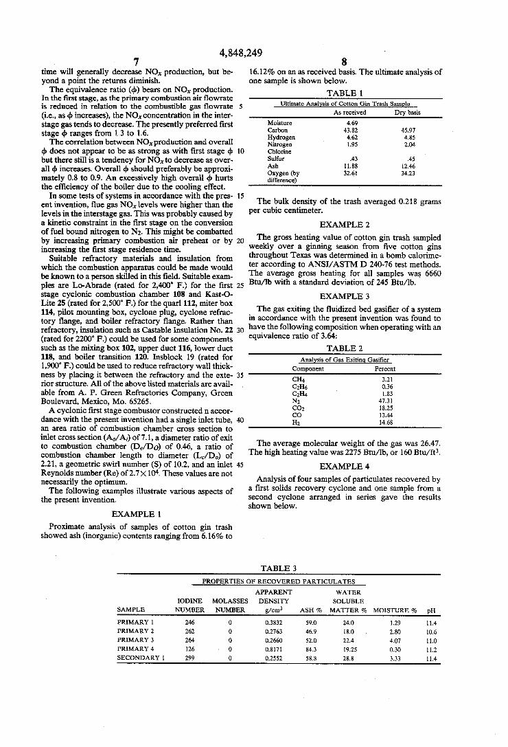
8 16.12% on an as received basis. The ultimate analysis of one sample is shown below.
TABLE 1 Ultimate Analysis of Cotton Gin Trash Sample
As received Dry basis
Moisture 4.69 Carbon 43.82 45.97 Hydrogen 4.62 4.85 Nitrogen 1.95 2.04 Chlorine Sulfur .43 .45 Ash 1 1.88 12.46 Oxygen (by 32.61 34.23 difference)
The bulk density of the trash averaged 0.218 grams per cubic centimeter.
EXAMPLE 2
The gross heating value of cotton gin trash sampled weekly over a ginning season from ?ve cotton gins throughout Texas was determined in a bomb calorime ter according to ANSI/ASTM D 240-76 test methods. The average gross heating for all samples was 6660 Btu/lb with a standard deviation of 245 Btu/lb.
EXAMPLE 3
The gas exiting the ?uidized bed gasi?er of a system in accordance with the present invention was found to have the following composition when operating with an equivalence ratio of 3.64:
TABLE 2 Anal sis of Gas Exitin Gasi?er
Component Percent
CH4 3.21 C2116 0.36 C2114 1.83 N; 47.31 CD; 18.25 CO 13.44 Hz 14.68
The average molecular weight of the gas was 26.47. The high heating value was 2275 Btu/lb, or 160 Btu/ft3.
EXAMPLE 4
Analysis of four samples of particulates recovered by a ?rst solids recovery cyclone and one sample from a second cyclone arranged in series gave the results shown below.
TABLE 3
PROPERTIES OF RECOVERED PARTICULATES
APPARENT WATER IODINE MOLASSES DENSITY SOLUBLE
SAMPLE NUMBER NUMBER g/cm3 ASH % MATTER % MOISTURE % pH
PRIMARY 1 246 0 0.3832 59.0 24.0 1.29 11.4
PRIMARY 2 262 0 0.2763 46.9 18.0 2.80 10.6
PRIMARY 3 264 0 0.2660 52.0 22.4 4.07 11.0
PRIMARY 4 126 0 0.8171 84.3 19.25 0.30 11.2
SECONDARY l 299 0 0.2552 58.8 28.8 3.33 11.4
4,848,249 9 10
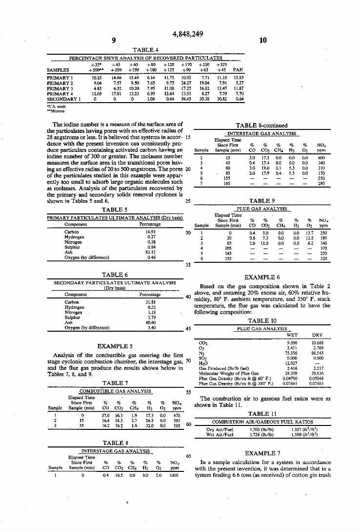
TABLE 4 PERCENTAGE SIEVE ANALYSIS OF RECOVERED PARTICULATES
+35‘ +45 +60 +80 +120 +170 +230 +325 SAMPLES +500“ +350 +250 +180 +125 +90 +63 +45 PAN
PRIMARY 1 10.25 14.66 12.49 6.14 11.75 10.05 7.71 11.10 15.85 PRIMARY 2 9.04 7.57 9.50 7.65 9.75 24.27 19.04 7.91 5.27 PRIMARY 3 4.85 6.52 10.20 7.95 11.08 17.25 16.82 13.47 11.87 “ PRIMARY 4 12.05 17.81 13.23 6.95 12.64 13.55 8.27 7.79 7.70 SECONDARY 1 0 0 0 1.08 0.64 56.45 30.38 10.82 0.64
'U.S. mesh "Microns
The iodine number is a measure of the surface area of TABLE geominued the particulates having pores with an effective ‘radius of INTERSTAGE GAS ANALYSKS 28 angstroms or less. It Is believed that systems In accor- 15 Elapsm'e'_——_—-_ dance with the present invention can consistently pro- Since First % % % % % Nox duce particulars containing activated carbon having an Sample Sample (min) C0 C02 CH4 H2 01 ppm iodine number of 300 or greater. The molasses number 2 15 39 173 Q0 00 0'0 600 measures the surface area in the transitional pores hav- 3 45 0.4 17.4 0.0 0.0 0.0 340 ing an effective radius of 20 to 500 angstroms. The pores 20 4 6° 3-° 19~° °~1 53' 0'0 210 of the particulates studied in this example were appar- 2 1:: 2i) 119 (L4 (2) £3 ently too small to adsorb large organic molecules such 7 165 _ _ _ _ _ 280
as molasses. Analysis of the particulates recovered by the primary and secondary solids removal cyclones is shown in Tables 5 and 6. 25 TABLE 9
TABLE 5 FLUE GAS ANALYSIS
PRIMARY PARTICULATES ULTIMATE ANALYSIS (Dry basis) Els‘z?idgr‘xe % % ' % % % NO X
Component Percentage Sample Sample (min) C0 C02 CH4 H1 02 ppm Carbon 1493 30 1 o 0.4 5.0 0.0 0.0 13.7 250 Hydww 017 2 30 0.6 7.3 0.0 0.0 13.5 120 M1089" ‘138 3 85 2.0 12.0 0.0 0.0 6.2 340 Sulphur 0.84 4 105 __ _ __ _ __ 37o
Ash 83.12 5 145 _ __ _ _ _ 25()
Oxygen (by difference) 0.46 6 - 155 _ _ _ _ _ 320
35
TABLE 6 EXAMPLE 6 SECONDARY PARTICULATES ULTIMATE ANALYSIS . . .
(Dry basis) Based on the gas composltlon shown In Table 2 Component percemage above, and assuming 20% excess air, 60% relative hu
midity, 80° F. ambIent temperature, and 350° F. stack Carbon 31.81 H dm n em era ure, e ue gas was ca cua e o ave e_ y Be (122 tp.t ll‘l lltdiih 1211 Nitrogen 1.18 following composItIon: $111 but 2.79 As; 6m TABLE 10 0W8“ (by difference) 34° 45 FLUE GAS ANALYSIS
WET DRY
C02 9.306 10.688 EXAMPLE 5 02 2.411 2.769
Analysis of the combustible gas entering the ?rst :62 73338 83333 stage cyclonic combustion chamber, the interstage gas, 50 H2O 121927 '_ and the ?ue gas produce the results shown below in Gas Produced (lb/lb fuel) 2.416 2.217 Tables 7, 8, and 9_ - Molecular Weight of Flue Gas 28.308 29.836
Flue Gas Density (lb/cu ft @ 60° P.) 0.04790 0.05048 TABLE 7 Flue Gas Density (lb/cu ft @ 350° F.) 0.07461 0.07863
COMBUSTIBLE GAS ANALYSIS 55
ElsépsedF'l-i'ile 7 7' q ‘7 7 No The combustion air to gaseous fuel ratios were as nice HS 0 0 0 0 0 x '
Sample Sample (min) C0 C02 c114 H2 02 ppm Show“ m Table 11'
1 0 37.0 16.3 1.9 17.3 0.0 470 TABLE 11
2 15 16-4 18-3 2-7 26-5 °-° 593 60 COMBUSTION AIR/GASEOUS FUEL RATIOS 3 35 16.2 16.2 1.6 32.0 0.0 565 _
Dry Air/Fuel 1.703 (lb/lb) 1.557 (03/03) Wet Air/Fuel 1.726 (lb/lb) 1.590 (03/03)
TABLE 8
INTERSTAGE GAS ANALYSIS EXAMPLE 7 Elapsed Time 65 _
Since First % % % % % No,‘ In a sample calculation for a system in accordance Sample 5911113180111“) ‘30 C02 CH4 “2 02 PPm with the present invention, it was determined that in a
1 0 0.4 16.5 0.0 0.0 5.0 1000 system feeding 6.6 tons (as received) of cotton gin trash
4,848,249 11
per hour, with a ?uidized bed cross-sectional area of 7.2 m2 (78 ftz), 1.6 pounds of ?uidizing air should be used per pound of biomass feed (on a dry basis). For each pound of biomass feed, about 2.6 pounds of combustible gas having a standard density of 0.07 pounds per cubic foot at 60° F. would be produced, requiring 4.46 pounds of combustion air. Char production would be 0.171 pound per pound of dry fuel. 7.04 pounds of ?ue gas would be produced per pound of feed. The steam gener ated by the boiler could be used to run a turbine, gener ating 2.78 megawatts of power at an ef?ciency of 12.8%.
EXAMPLE 8
Measured ?ue gas NO): levels from a staged combus tion system in accordance with the present invention ranged from 110 to 190 ng/J (0.26-0.44 lb/mBtu), com pared to ?gures of 650-860 ng/J (1.5 to 2.0 lb/mBtu) for a comparable radiant tube combustor. The preceding‘ examples and detailed description are
only intended to illustrate various embodiments of the present invention. They should not be interpreted as an exhaustive description of all possible embodiments. We claim: 1. A system for converting biomass to usable energy,
including: (a) a biomass feed apparatus which includes a feed hopper with an agitator, at least one auger to carry biomass feed from the hopper, and an airlock to prevent back?ow of combustible gases into the hopper;
(b) a ?uidized bed gasi?er which receives biomass feed from the feed auger and which has a ?uidizing air inlet, and which produces combustible gas and particulates containing activated carbon;
(0) a plurality of solids removal cyclones which are arranged in series and which receive the products of the ?uidized bed gasi?er and remove at least 99% by weight of the particulates from the com bustible gas; and
(d) two stage combustion apparatus which includes a ?rst stage cyclonic combustion chamber with a single gas inlet for receiving a combined stream of combustible gas from the solids removal cyclones and primary combustion air, a second stage which has an inlet for receiving gases exiting the ?rst stage and a secondary combustion air stream, and a boiler which receives combustion gases from the second stage and in which the heat from the com bustion gases converts water to steam.
2. The system of claim 1, where the biomass feed apparatus includes ?rst and second angers, the ?rst auger carrying unconditioned biomass feed from the hopper to an air lock, the air lock transferring the bio mass feed to the second auger, which carries it to the ?uidized bed gasi?er.
3. The system of claim 2, where the second auger is enclosed and where air is supplied to the second auger to maintain a pressure greater than atmospheric pres sure within its enclosure.
4. The system of claim 2, where the second auger rotates more rapidly than the ?rst auger.
5. The system of claim 1, where the ?uidized bed gasi?er is adapted to produce combustible gas having a heating value of about 150 to 200 Btu/ft3.
6. The system of claim 1, where the equivalence ratio of fuel and air entering the ?uidized bed gasi?er is be tween about 3.1 and about 5.3.
10
25
30
35
45
50
55
60
12 7. The system of claim 1, including two solids re
moval cyclones in series. 8. The system of claim 7, where the ?rst solids re
moval cyclone is adapted to reduce the particulates concentration to no greater than about 3 g/m3.
9. The system of claim 8, where the second solids removal cyclone is adapted to reduce the particulate concentration to no greater than about 0.5 g/m3.
10. The system of claim 9, where the two solids re moval cyclones are adapted to create a pressure drop of no more than about 8 inches of water in the combustible gas passing through them.
11. The system of claim 1, further including a com bustion air preheater which transfers heat from the combustion gases exiting the boiler to the primary and secondary combustion air.
12. The system of claim 1, where the ?rst stage cy clonic combustion chamber is separated from the inlet for secondary combustion air by a refractory duct that is suf?ciently long to ensure that the gases passing through the combustion apparatus will be exposed to a temperature of at least 1800° F. for at least about 1.0 seconds.
13. A system for converting biomass to usable energy, including:
(a) a biomass feed hopper with an agitator; (b) a ?rst feed auger which receives biomass feed from the hopper;
(c) an air lock which receives the biomass feed from the ?rst feed auger;
(d) an enclosed second feed auger which receives the biomass feed from the air lock, rotates more rapidly than the ?rst feed auger, and is subjected to a pres sure greater than atmospheric pressure within its enclosure;
(e) a ?uidized bed gasi?er which receives biomass from the second feed auger and ?uidizing air through a separate inlet, and which produces a combustible gas and particulates containing acti vated carbon;
(t) a ?rst solids removal cyclone which receives the combustible gas and particulates from the ?uidized bed gasi?er and reduces the particulate concentra tion in the gas;
(g) a second solids removal cyclone which receives the gas exiting the ?rst solids removal cyclone and further reduces the particulate concentration in the gas;
(h) a ?rst stage cyclonic combustion chamber which receives the combustible gas from the second solids removal cyclone along with a primary combustion air stream, and which has a pilot ignition apparatus;
(i) a refractory duct which receives the gas exiting the cyclonic combustion chamber and which has an inlet for a secondary combustion air stream;
(j) a boiler which receives the combustion gas exiting the refractory duct, and which produces steam;
(k) a combustion air preheater which receives the combustion gas exiting the boiler and transfers heat from that gas to the primary and secondary com bustion air streams; and
(l) a stack with an induced draft fan which receives the gases exiting the combustion air preheater.
14. The system of claim 13, where the particulates 65 containing activated carbon have an iodine number of at
least 300. 15. The system of claim 13, where the refractory duct
is suf?ciently long to ensure that the gas passing
4,848,249 13
through the ?rst stage combustion chamber, refractory duct, and boiler will be exposed to a temperature of at least 1800° F. for at least about 1.0 seconds.
16. The system of claim 13, where the gas exiting the stack has an NOx content of no greater than about 190 ng/J of energy generated by the system.
17. A process for producing energy and activated carbon from biomass, including the steps of:
(a) feeding unpreconditioned biomass to a ?uidized
(b) feeding ?uidizing air to the ?uidized bed gasi?er, to obtain an equivalence ratio between about 3:1 and about 5:3;
(c) gasifying the biomass, thereby producing combus tible gas and particulates containing activated car bon;
(d) removing the bulk of the particulates from the combustible gas using a plurality of solids removal cyclones;
(e) combining and burning the combustible gas with combustion air, the combustion being carried out in
- two stages, such that the combustion temperature is at least 1800° F., for at least about 1.0 second of residence time, whereby the NO,‘ content of the
5
15
20
25
35
45
50
55
65
14 resulting gas is no greater than about 190 ng/J of I energy generated by the combustion; and
(f) producing steam from the heat generated by the combustion.
18. The process of claim 17, where sufficient particu lates are removed in step (d) to leave a particulate con centration of no more than about 0.5 g/m3 in the com bustible gas.
19. The process of claim 17, where the particulates containing activated carbon which are removed from the combustible gas in step (d) have an iodine number of at least about 300.
20. The process of claim 17, where the biomass is cotton gin trash.
21. The process of claim 17, where the ratio of the ?owrate of combustible gas to the ?owrate of combus tion air to the ?rst combustion stage is between about 1.3 and about 1.6, and where the ratio of the ?owrate of combustible gas to the total ?owrate of combustion air ‘ is between about 0.8 and 0.9.
22. The process of claim 17, where the plurality of solids removal cyclones are separate from the ?uidized bed gasi?er.
* Ii 1k * *