Embed Size (px)
Citation preview
System and Software Architecture Description (SSAD)
Smart Locks Control
Team 5
CSCI 577aTeam members RolesVaibhavVishal Project Manager, Life Cycle Planner,TrainerDiego Brandao IIV&V, Software Architect, DeveloperZhe Wang Feasibility Analyst, NDI/NCS AcquirerMohammadreza Barazesh
Software Architect, Developer
Alejandro Monroy Prototyper, Evaluator, Tester, DeveloperHao-Yun Yang Requirements EngineerKatarzyna Ruszowska Quality Focal Point, UML Modeler, Developer
CSCI 577bTeam members RolesAlex Miller Project ManagerDiego Brandao Software Architect, ImplementerTerence Williams Tester, Implementer
Nick Kwong Quality Focal
William Goishi IIV&V
System and Software Architecture Description (SSAD) Version 1.5
02/13/2018
SSAD_RDCR_F18b_T05_V1.5 ii Version Date: 02/26/18
System and Software Architecture Description (SSAD) Version 1.5
Version HistoryDate Author Version Changes made Rationale
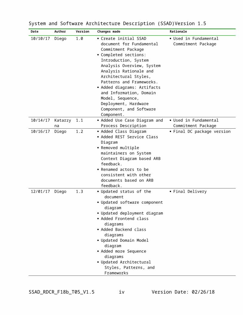
10/10/17 Diego 1.0 Create initial SSAD document for Fundamental Commitment Package
Completed sections: Introduction, System Analysis Overview, System Analysis Rationale and Architectural Styles, Patterns and Frameworks.
Added diagrams: Artifacts and Information, Domain Model, Sequence, Deployment, Hardware Component, and Software Component.
Used in Fundamental Commitment Package
10/14/17 Katarzyna 1.1 Added Use Case Diagram and Process Description
Used in Fundamental Commitment Package
10/16/17 Diego 1.2 Added Class Diagram Added REST Service Class Diagram Removed multiple maintainers on
System Context Diagram based ARB feedback.
Renamed actors to be consistent with other documents based on ARB feedback.
Final DC package version
12/01/17 Diego 1.3 Updated status of the document Updated software component diagram Updated deployment diagram Added Frontend class diagrams Added Backend class diagrams Updated Domain Model diagram Added more Sequence diagrams Updated Architectural Styles, Patterns,
and Frameworks
Final Delivery
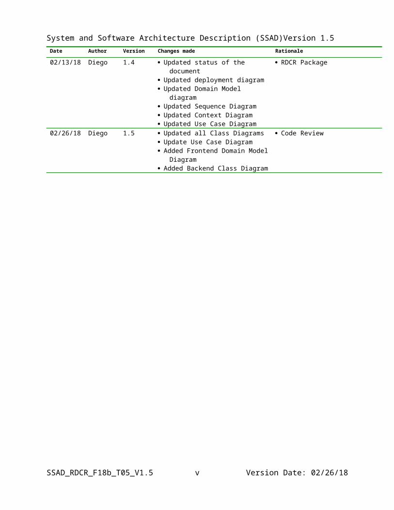
02/13/18 Diego 1.4 Updated status of the document Updated deployment diagram Updated Domain Model diagram Updated Sequence Diagram Updated Context Diagram Updated Use Case Diagram
RDCR Package
02/26/18 Diego 1.5 Updated all Class Diagrams Update Use Case Diagram Added Frontend Domain Model
Diagram Added Backend Class Diagram
Code Review
System and Software Architecture Description (SSAD) Version 1.5
Table of ContentsSystem and Software Architecture Description (SSAD).............................................................iVersion History.............................................................................................................................iiiTable of Contents..........................................................................................................................ivTable of Tables...............................................................................................................................vTable of Figures...........................................................................................................................vii
1. Introduction..............................................................................................................................1
1.1 Purpose of the SSAD.....................................................................................................1
1.2 Status of the SSAD........................................................................................................1
2. System Analysis........................................................................................................................2
2.1 System Analysis Overview............................................................................................2
2.2 Modes of Operation....................................................................................................19
2.3 System Analysis Rationale..........................................................................................19
3. Technology-Independent Model...........................................................................................20
4. Technology-Specific System Design.....................................................................................21
4.1 Design Overview..........................................................................................................21
4.2 Design Rationale..........................................................................................................37
5. Architectural Styles, Patterns, and Frameworks................................................................38
SSAD_RDCR_F18b_T05_V1.5 iv Version Date: 02/26/18
System and Software Architecture Description (SSAD) Version 1.5
Table of TablesTable 1: Actors Summary................................................................................................................3
Table 2: Artifacts and Information Summary..................................................................................4
Table 3: Use Case List....................................................................................................................5
Table 4: Add User - Process Description.......................................................................................6
Table 5: Typical Course of Action - Add User: Success.................................................................6
Table 6: Exceptional Course of Action - Add User: Failure..........................................................6
Table 7: Edit User - Process Description.......................................................................................7
Table 8: Typical Course of Action - Edit User: Success.................................................................7
Table 9: Exceptional Course of Action - Edit User: Failure..........................................................8
Table 10: Delete User - Process Description.................................................................................8
Table 11: Typical Course of Action - Delete User: Success...........................................................8
Table 12: Exceptional Course of Action - Delete User: Failure....................................................9
Table 13: Add Slot - Process Description.......................................................................................9
Table 14: Typical Course of Action - Add Slot: Success.................................................................9
Table 15: Exceptional Course of Action - Add Slot: Failure........................................................10
Table 16: Add Slot - Process Description.....................................................................................10
Table 17: Typical Course of Action - Edit Slot: Success..............................................................11
Table 18: Exceptional Course of Action - Edit Slot: Failure........................................................11
Table 19: Delete Slot - Process Description.................................................................................12
Table 20: Typical Course of Action - Delete Slot: Success...........................................................12
Table 21: Exceptional Course of Action - Delete Slot: Failure....................................................12
Table 22: View Logs- Process Description...................................................................................13
Table 23: Typical Course of Action - View Logs: Success............................................................13
Table 24: Exceptional Course of Action - View Locks: Failure...................................................13
Table 25: View Device Status- Process Description.....................................................................14
Table 26: Typical Course of Action – View Device Status: Success.............................................14
Table 27: Exceptional Course of Action – View Device Status: Failure......................................14
Table 28: View Lock Number and Code - Process Description....................................................15
Table 29: Typical Course of Action – View Lock Number and Code: Success.............................15
SSAD_RDCR_F18b_T05_V1.5 Version Date: 02/26/18
System and Software Architecture Description (SSAD) Version 1.5
Table 30: Exceptional Course of Action – View Lock Number and Code: Failure......................15
Table 31: Manage SmartThings Access Settings - Process Description.......................................16
Table 32: Typical Course of Action – Manage SmartThings Access Settings: Success................16
Table 33: Exceptional Course of Action – Manage SmartThings Access Settings: Failure.........17
Table 34: Manage Lock Security Settings - Process Description.................................................17
Table 35: Hardware Component Description...............................................................................22
Table 36: Software Component Description.................................................................................22
Table 37: Design Class Description.............................................................................................24
Table 38: Frontend Services Class Diagram Description............................................................25
Table 39: Frontend Components Class Diagram Description.....................................................26
Table 40: Frontend Domain Model Class Diagram Description.................................................27
Table 41: Repository Class Diagram Description........................................................................28
Table 42: Backend RESTful Services Class Diagram Description...............................................29
Table 43: Backend Class Diagram Description............................................................................30
Table 44: SmartApp RESTful Services Class Diagram Description.............................................31
Table 43: Architectural Styles, Patterns, and Frameworks..........................................................38
SSAD_RDCR_F18b_T05_V1.5 vi Version Date: 02/26/18
System and Software Architecture Description (SSAD) Version 1.5
Table of FiguresFigure 1: System Context Diagram.................................................................................................2
Figure 2: Artifacts and Information Diagram................................................................................4
Figure 3: Process Diagram.............................................................................................................5
Figure 4: Hardware Component Class Diagram..........................................................................21
Figure 5: Software Component Class Diagram............................................................................21
Figure 6: Deployment Diagram....................................................................................................22
Figure 7: Domain Model Class Diagram.....................................................................................24
Figure 8: Frontend Services Class Diagram................................................................................25
Figure 9: Frontend Components Class Diagram..........................................................................26
Figure 9: Frontend Domain Model Class Diagram.....................................................................27
Figure 10: Repository Class Diagram..........................................................................................28
Figure 11: Backend RESTful Services Class Diagram.................................................................29
Figure 11: Backend Hepers Class Diagram.................................................................................30
Figure 12: SmartApp RESTful Services Class Diagram...............................................................31
Figure 13: Add Slot Code Sequence Diagram..............................................................................33
Figure 14: Change Slot Code Sequence Diagram........................................................................33
Figure 15: Delete Slot Code Sequence Diagram..........................................................................34
Figure 16: Post Log Webhook Sequence Diagram.......................................................................34
Figure 17: Get Locks Sequence Diagram.....................................................................................35
Figure 18: Invalid Token Sequence Diagram...............................................................................35
Figure 19: Get updated hub status................................................................................................36
SSAD_RDCR_F18b_T05_V1.5 vii Version Date: 02/26/18
System and Software Architecture Description (SSAD) Version 1.5
1. Introduction
1.1 Purpose of the SSAD
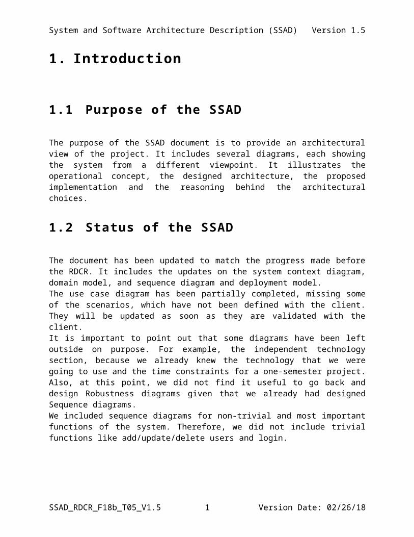
The purpose of the SSAD document is to provide an architectural view of the project. It includes several diagrams, each showing the system from a different viewpoint. It illustrates the operational concept, the designed architecture, the proposed implementation and the reasoning behind the architectural choices.
1.2 Status of the SSAD
The document has been updated to match the progress made before the RDCR. It includes the updates on the system context diagram, domain model, and sequence diagram and deployment model.The use case diagram has been partially completed, missing some of the scenarios, which have not been defined with the client. They will be updated as soon as they are validated with the client.It is important to point out that some diagrams have been left outside on purpose. For example, the independent technology section, because we already knew the technology that we were going to use and the time constraints for a one-semester project. Also, at this point, we did not find it useful to go back and design Robustness diagrams given that we already had designed Sequence diagrams. We included sequence diagrams for non-trivial and most important functions of the system. Therefore, we did not include trivial functions like add/update/delete users and login.
SSAD_RDCR_F18b_T05_V1.5 1 Version Date: 02/26/18
System and Software Architecture Description (SSAD) Version 1.5
SSAD_RDCR_F18b_T05_V1.5 2 Version Date: 02/26/18
System and Software Architecture Description (SSAD) Version 1.5
2. System Analysis
2.1 System Analysis Overview
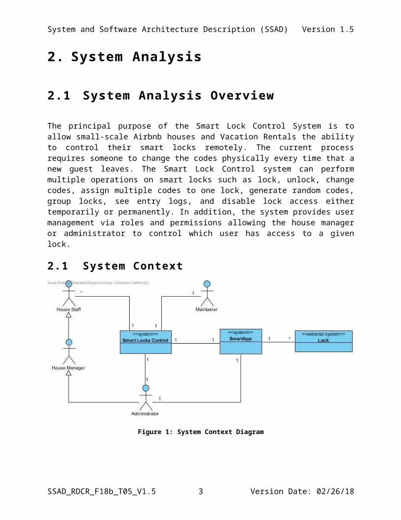
The principal purpose of the Smart Lock Control System is to allow small-scale Airbnb houses and Vacation Rentals the ability to control their smart locks remotely. The current process requires someone to change the codes physically every time that a new guest leaves. The Smart Lock Control system can perform multiple operations on smart locks such as lock, unlock, change codes, assign multiple codes to one lock, generate random codes, group locks, see entry logs, and disable lock access either temporarily or permanently. In addition, the system provides user management via roles and permissions allowing the house manager or administrator to control which user has access to a given lock.
2.1 System Context
Figure 1: System Context Diagram
SSAD_RDCR_F18b_T05_V1.5 3 Version Date: 02/26/18
System and Software Architecture Description (SSAD) Version 1.5
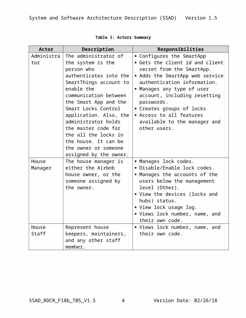
Table 1: Actors Summary
Actor Description ResponsibilitiesAdministrator The administrator of the system
is the person who authenticates into the SmartThings account to enable the communication between the Smart App and the Smart Locks Control application. Also, the administrator holds the master code for the all the locks in the house. It can be the owner or someone assigned by the owner.
Configures the SmartApp Gets the client id and client secret from the
SmartApp. Adds the SmartApp web service
authentication information. Manages any type of user account, including
resetting passwords. Creates groups of locks Access to all features available to the
manager and other users.
House Manager
The house manager is either the Airbnb house owner, or the someone assigned by the owner.
Manages lock codes. Disable/Enable lock codes. Manages the accounts of the users below the
management level (Other). View the devices (locks and hubs) status. View lock usage log. Views lock number, name, and their own
code.House Staff Represent house keepers,
maintainers, and any other staff member.
Views lock number, name, and their own code.
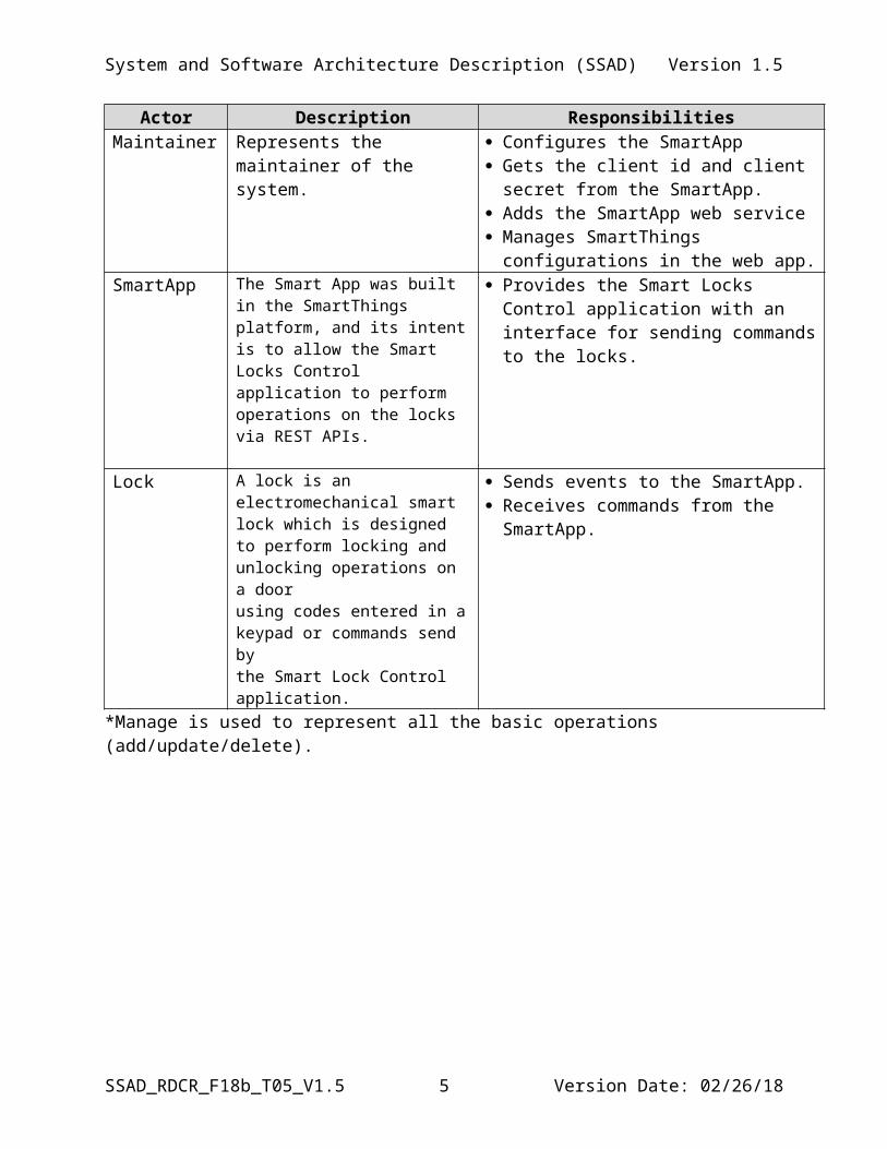
Maintainer Represents the maintainer of the system.
Configures the SmartApp Gets the client id and client secret from the
SmartApp. Adds the SmartApp web service Manages SmartThings configurations in the
web app.SmartApp The Smart App was built in the
SmartThings platform, and its intent is to allow the Smart Locks Control application to perform operations on the locks via REST APIs.
Provides the Smart Locks Control application with an interface for sending commands to the locks.
Lock A lock is an electromechanical smart lock which is designed to perform locking and unlocking operations on a doorusing codes entered in a keypad or commands send by the Smart Lock Control application.
Sends events to the SmartApp. Receives commands from the SmartApp.
*Manage is used to represent all the basic operations (add/update/delete).
SSAD_RDCR_F18b_T05_V1.5 4 Version Date: 02/26/18
System and Software Architecture Description (SSAD) Version 1.5
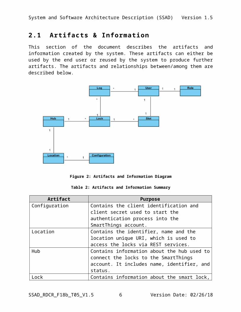
2.1 Artifacts & InformationThis section of the document describes the artifacts and information created by the system. These artifacts can either be used by the end user or reused by the system to produce further artifacts. The artifacts and relationships between/among them are described below.
Figure 2: Artifacts and Information Diagram
Table 2: Artifacts and Information Summary
Artifact PurposeConfiguration Contains the client identification and client secret used to start
the authentication process into the SmartThings account.Location Contains the identifier, name and the location unique URI,
which is used to access the locks via REST services.Hub Contains information about the hub used to connect the locks
to the SmartThings account. It includes name, identifier, and status.
Lock Contains information about the smart lock, including its name, location, status, battery, the slots containing the access codes, and its universal identifier.
Slot Contains the user assigned to the slot, the code to open the smart door, the number of the slot and a flag indicating if the slot is enabled or not.
User Contains the name of the user, password, role, and a flag indicating if the user is enabled or not.
Role It defines the type of user and their permissions. The first release includes three roles (admin, manager, other).
Log Contains the log of the a given lock, including the action
SSAD_RDCR_F18b_T05_V1.5 5 Version Date: 02/26/18
System and Software Architecture Description (SSAD) Version 1.5
performed (locked/unlocked)
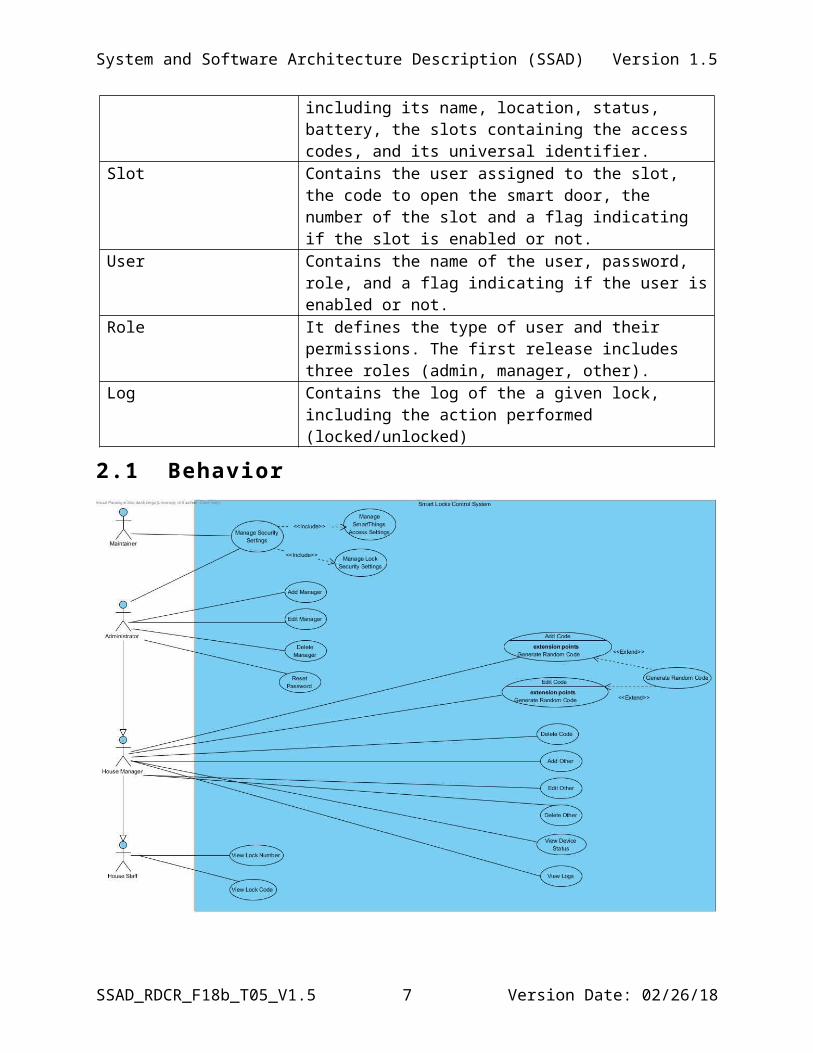
2.1 Behavior
Figure 3: Process Diagram
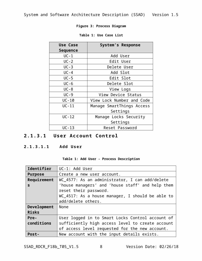
Table 1: Use Case List
Use Case Sequence System’s ResponseUC-1 Add UserUC-2 Edit UserUC-3 Delete UserUC-4 Add SlotUC-5 Edit SlotUC-6 Delete SlotUC-8 View LogsUC-9 View Device StatusUC-10 View Lock Number and CodeUC-11 Manage SmartThings Access SettingsUC-12 Manage Locks Security SettingsUC-13 Reset Password
SSAD_RDCR_F18b_T05_V1.5 6 Version Date: 02/26/18
System and Software Architecture Description (SSAD) Version 1.5
2.1.3.1 User Account Control
2.1 .3 .1 .1 Add User
Table 1: Add User - Process Description
Identifier UC-1: Add UserPurpose Create a new user account.Requirements WC_4577: As an administrator, I can add/delete ‘house managers’ and
‘house staff’ and help them reset their password.WC_4517: As a house manager, I should be able to add/delete others.
Development Risks
None
Pre-conditions User logged in to Smart Locks Control account of sufficiently high access level to create account of access level requested for the new account.
Post-conditions New account with the input details exists.
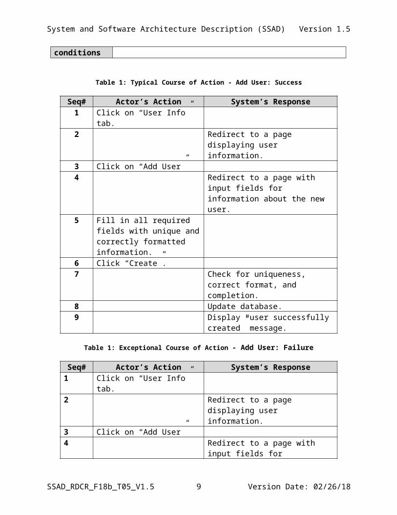
Table 1: Typical Course of Action - Add User: Success
Seq# Actor’s Action System’s Response1 Click on “User Info” tab.2 Redirect to a page displaying user
information.3 Click on “Add User”4 Redirect to a page with input fields for
information about the new user.5 Fill in all required fields with
unique and correctly formatted information.
6 Click “Create”.7 Check for uniqueness, correct format,
and completion.8 Update database.9 Display “user successfully created”
message.
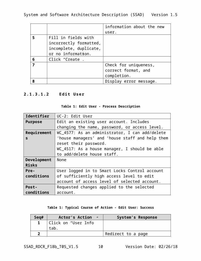
Table 1: Exceptional Course of Action - Add User: Failure
Seq# Actor’s Action System’s Response1 Click on “User Info” tab.2 Redirect to a page displaying user
information.3 Click on “Add User”
SSAD_RDCR_F18b_T05_V1.5 7 Version Date: 02/26/18
System and Software Architecture Description (SSAD) Version 1.5
4 Redirect to a page with input fields for information about the new user.
5 Fill in fields with incorrectly formatted, incomplete, duplicate, or no information.
6 Click “Create”.7 Check for uniqueness, correct format,
and completion.8 Display error message.
2.1 .3 .1 .2 Edit User
Table 1: Edit User - Process Description
Identifier UC-2: Edit UserPurpose Edit an existing user account. Includes changing the name, password,
or access level.Requirements WC_4577: As an administrator, I can add/delete ‘house managers’
and ‘house staff and help them reset their password.WC_4517: As a house manager, I should be able to add/delete house staff.
Development Risks
None
Pre-conditions User logged in to Smart Locks Control account of sufficiently high access level to edit account of access level of selected account.
Post-conditions Requested changes applied to the selected account.
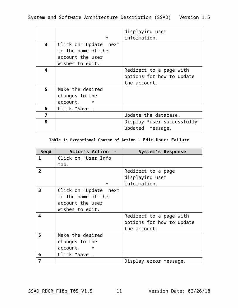
Table 1: Typical Course of Action - Edit User: Success
Seq# Actor’s Action System’s Response1 Click on “User Info” tab.2 Redirect to a page displaying user
information.3 Click on “Update” next to the
name of the account the user wishes to edit.
4 Redirect to a page with options for how to update the account.
5 Make the desired changes to the account.
6 Click “Save”.7 Update the database.8 Display “user successfully updated”
message.
SSAD_RDCR_F18b_T05_V1.5 8 Version Date: 02/26/18
System and Software Architecture Description (SSAD) Version 1.5
Table 1: Exceptional Course of Action - Edit User: Failure
Seq# Actor’s Action System’s Response1 Click on “User Info” tab.2 Redirect to a page displaying user
information.3 Click on “Update” next to the
name of the account the user wishes to edit.
4 Redirect to a page with options for how to update the account.
5 Make the desired changes to the account.
6 Click “Save”.7 Display error message.
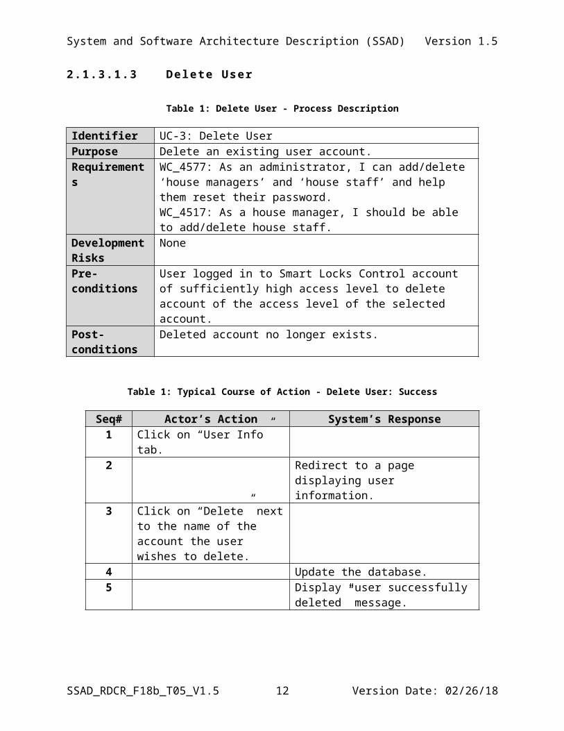
2.1 .3 .1 .3 Delete User
Table 1: Delete User - Process Description
Identifier UC-3: Delete UserPurpose Delete an existing user account.Requirements WC_4577: As an administrator, I can add/delete ‘house managers’
and ‘house staff’ and help them reset their password.WC_4517: As a house manager, I should be able to add/delete house staff.
Development Risks
None
Pre-conditions User logged in to Smart Locks Control account of sufficiently high access level to delete account of the access level of the selected account.
Post-conditions Deleted account no longer exists.
Table 1: Typical Course of Action - Delete User: Success
Seq# Actor’s Action System’s Response1 Click on “User Info” tab.2 Redirect to a page displaying user
information.3 Click on “Delete” next to the
name of the account the user wishes to delete.
4 Update the database.5 Display “user successfully deleted”
SSAD_RDCR_F18b_T05_V1.5 9 Version Date: 02/26/18
System and Software Architecture Description (SSAD) Version 1.5
message.
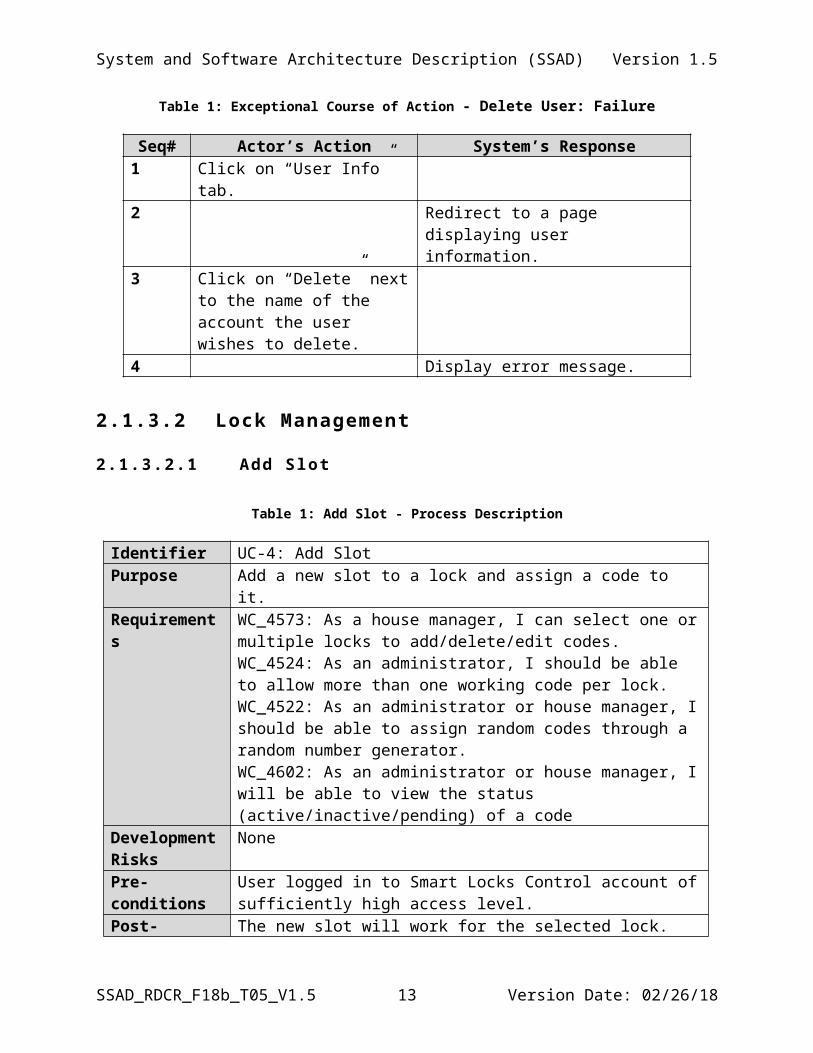
Table 1: Exceptional Course of Action - Delete User: Failure
Seq# Actor’s Action System’s Response1 Click on “User Info” tab.2 Redirect to a page displaying user
information.3 Click on “Delete” next to the
name of the account the user wishes to delete.
4 Display error message.
2.1.3.2 Lock Management
2.1 .3 .2 .1 Add Slot
Table 1: Add Slot - Process Description
Identifier UC-4: Add SlotPurpose Add a new slot to a lock and assign a code to it.Requirements WC_4573: As a house manager, I can select one or multiple locks to
add/delete/edit codes.WC_4524: As an administrator, I should be able to allow more than one working code per lock.WC_4522: As an administrator or house manager, I should be able to assign random codes through a random number generator.WC_4602: As an administrator or house manager, I will be able to view the status (active/inactive/pending) of a code
Development Risks
None
Pre-conditions User logged in to Smart Locks Control account of sufficiently high access level.
Post-conditions The new slot will work for the selected lock.
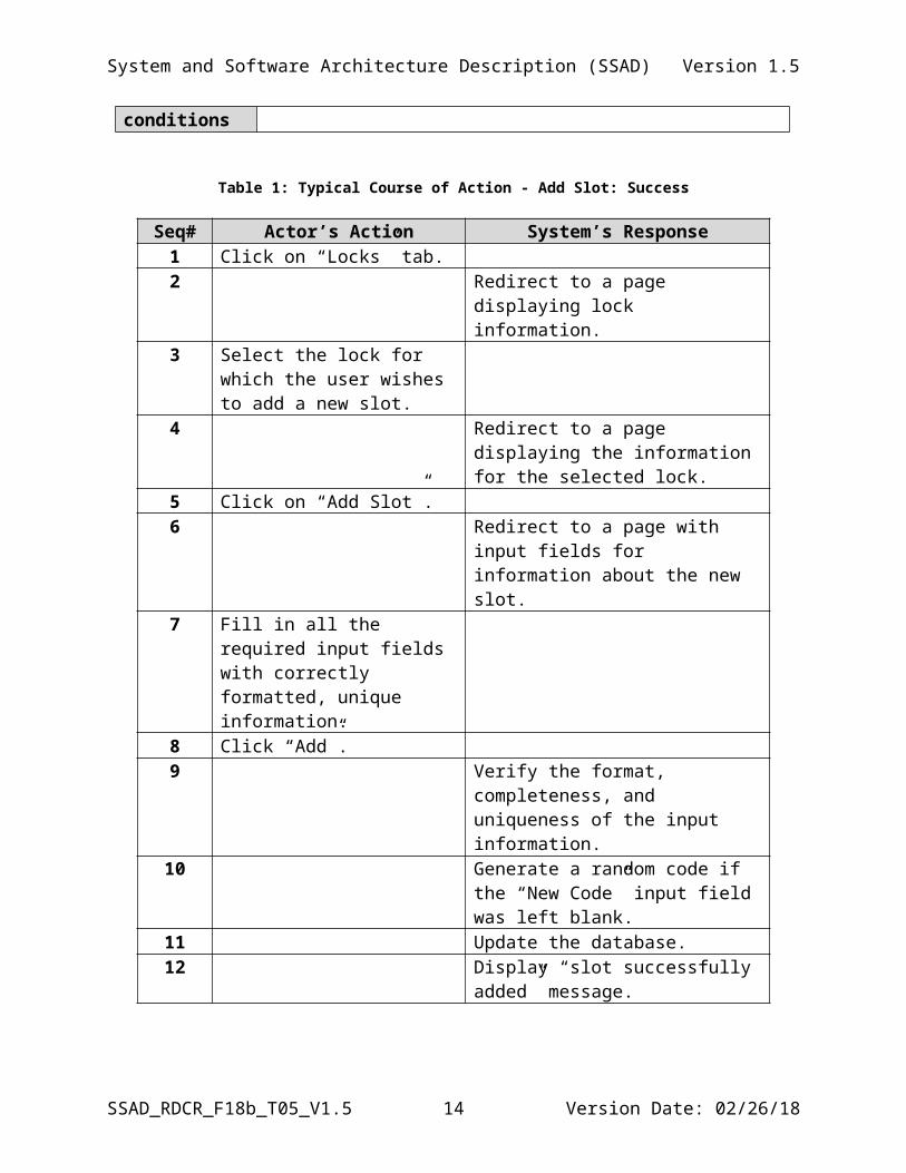
Table 1: Typical Course of Action - Add Slot: Success
Seq# Actor’s Action System’s Response1 Click on “Locks” tab.2 Redirect to a page displaying lock
information.3 Select the lock for which the
user wishes to add a new slot.4 Redirect to a page displaying the
SSAD_RDCR_F18b_T05_V1.5 10 Version Date: 02/26/18
System and Software Architecture Description (SSAD) Version 1.5
information for the selected lock.5 Click on “Add Slot”.6 Redirect to a page with input fields for
information about the new slot.7 Fill in all the required input
fields with correctly formatted, unique information.
8 Click “Add”.9 Verify the format, completeness, and
uniqueness of the input information.10 Generate a random code if the “New
Code” input field was left blank.11 Update the database.12 Display “slot successfully added”
message.
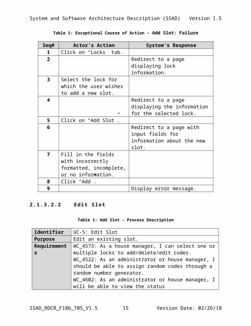
Table 1: Exceptional Course of Action - Add Slot: Failure
Seq# Actor’s Action System’s Response1 Click on “Locks” tab.2 Redirect to a page displaying lock
information.3 Select the lock for which the
user wishes to add a new slot.4 Redirect to a page displaying the
information for the selected lock.5 Click on “Add Slot”.6 Redirect to a page with input fields for
information about the new slot.7 Fill in the fields with incorrectly
formatted, incomplete, or no information.
8 Click “Add”.9 Display error message.
2.1 .3 .2 .2 Edit Slot
Table 1: Add Slot - Process Description
Identifier UC-5: Edit SlotPurpose Edit an existing slot.Requirements WC_4573: As a house manager, I can select one or multiple locks to
add/delete/edit codes.WC_4522: As an administrator or house manager, I should be able to assign random codes through a random number generator.
SSAD_RDCR_F18b_T05_V1.5 11 Version Date: 02/26/18
System and Software Architecture Description (SSAD) Version 1.5
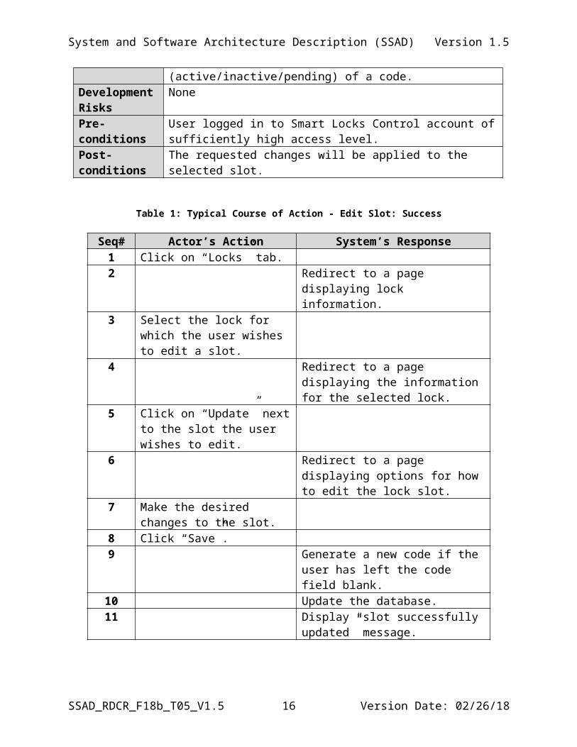
WC_4602: As an administrator or house manager, I will be able to view the status (active/inactive/pending) of a code.
Development Risks
None
Pre-conditions User logged in to Smart Locks Control account of sufficiently high access level.
Post-conditions The requested changes will be applied to the selected slot.
Table 1: Typical Course of Action - Edit Slot: Success
Seq# Actor’s Action System’s Response1 Click on “Locks” tab.2 Redirect to a page displaying lock
information.3 Select the lock for which the
user wishes to edit a slot. 4 Redirect to a page displaying the
information for the selected lock.5 Click on “Update” next to the
slot the user wishes to edit.6 Redirect to a page displaying options
for how to edit the lock slot. 7 Make the desired changes to the
slot.8 Click “Save”.9 Generate a new code if the user has left
the code field blank.10 Update the database.11 Display “slot successfully updated”
message.
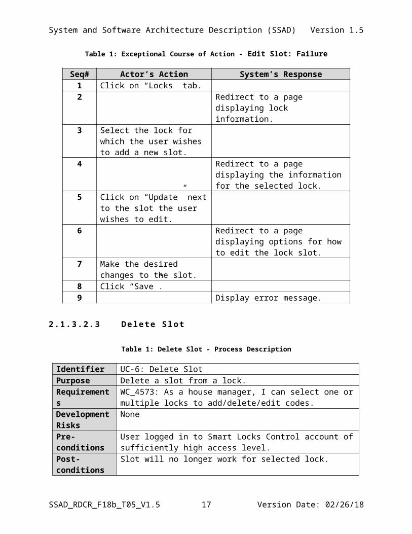
Table 1: Exceptional Course of Action - Edit Slot: Failure
Seq# Actor’s Action System’s Response1 Click on “Locks” tab.2 Redirect to a page displaying lock
information.3 Select the lock for which the
user wishes to add a new slot.4 Redirect to a page displaying the
information for the selected lock.5 Click on “Update” next to the
slot the user wishes to edit.6 Redirect to a page displaying options
for how to edit the lock slot.
SSAD_RDCR_F18b_T05_V1.5 12 Version Date: 02/26/18
System and Software Architecture Description (SSAD) Version 1.5
7 Make the desired changes to the slot.
8 Click “Save”.9 Display error message.
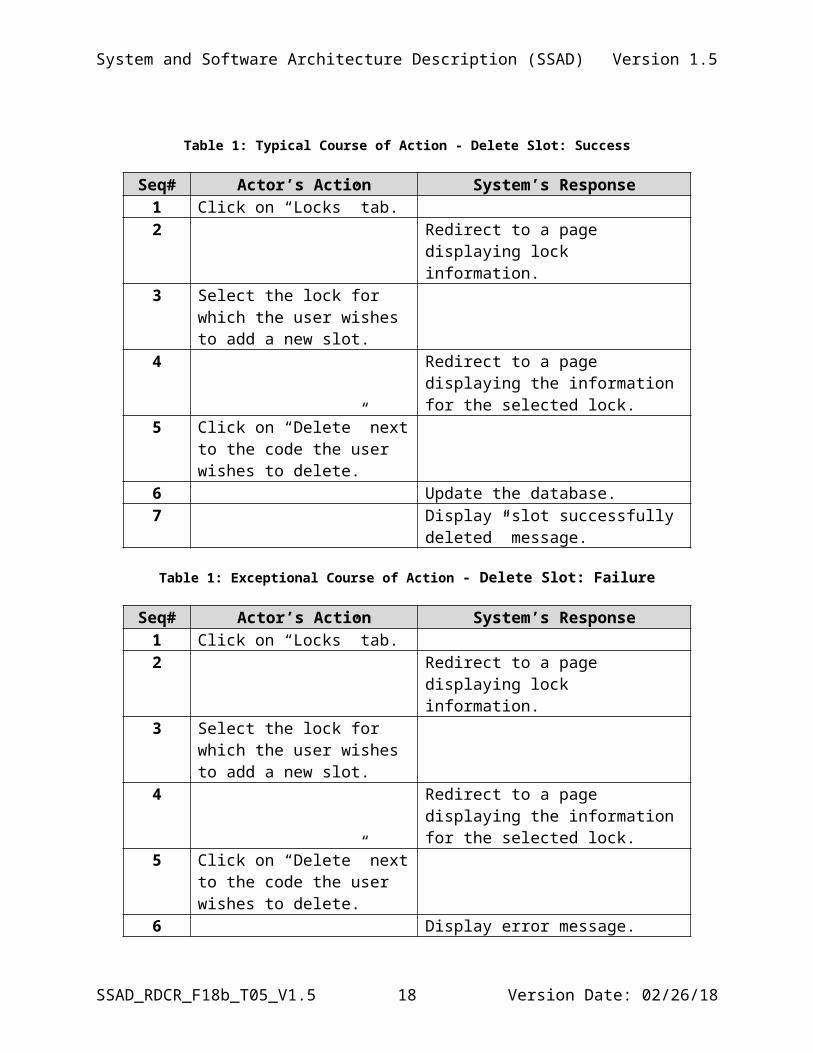
2.1 .3 .2 .3 Delete Slot
Table 1: Delete Slot - Process Description
Identifier UC-6: Delete SlotPurpose Delete a slot from a lock.Requirements WC_4573: As a house manager, I can select one or multiple locks to
add/delete/edit codes.Development Risks
None
Pre-conditions User logged in to Smart Locks Control account of sufficiently high access level.
Post-conditions Slot will no longer work for selected lock.
Table 1: Typical Course of Action - Delete Slot: Success
Seq# Actor’s Action System’s Response1 Click on “Locks” tab.2 Redirect to a page displaying lock
information.3 Select the lock for which the
user wishes to add a new slot.4 Redirect to a page displaying the
information for the selected lock.5 Click on “Delete” next to the
code the user wishes to delete.6 Update the database.7 Display “slot successfully deleted”
message.
Table 1: Exceptional Course of Action - Delete Slot: Failure
Seq# Actor’s Action System’s Response1 Click on “Locks” tab.2 Redirect to a page displaying lock
information.3 Select the lock for which the
user wishes to add a new slot.4 Redirect to a page displaying the
SSAD_RDCR_F18b_T05_V1.5 13 Version Date: 02/26/18
System and Software Architecture Description (SSAD) Version 1.5
information for the selected lock.5 Click on “Delete” next to the
code the user wishes to delete.6 Display error message.
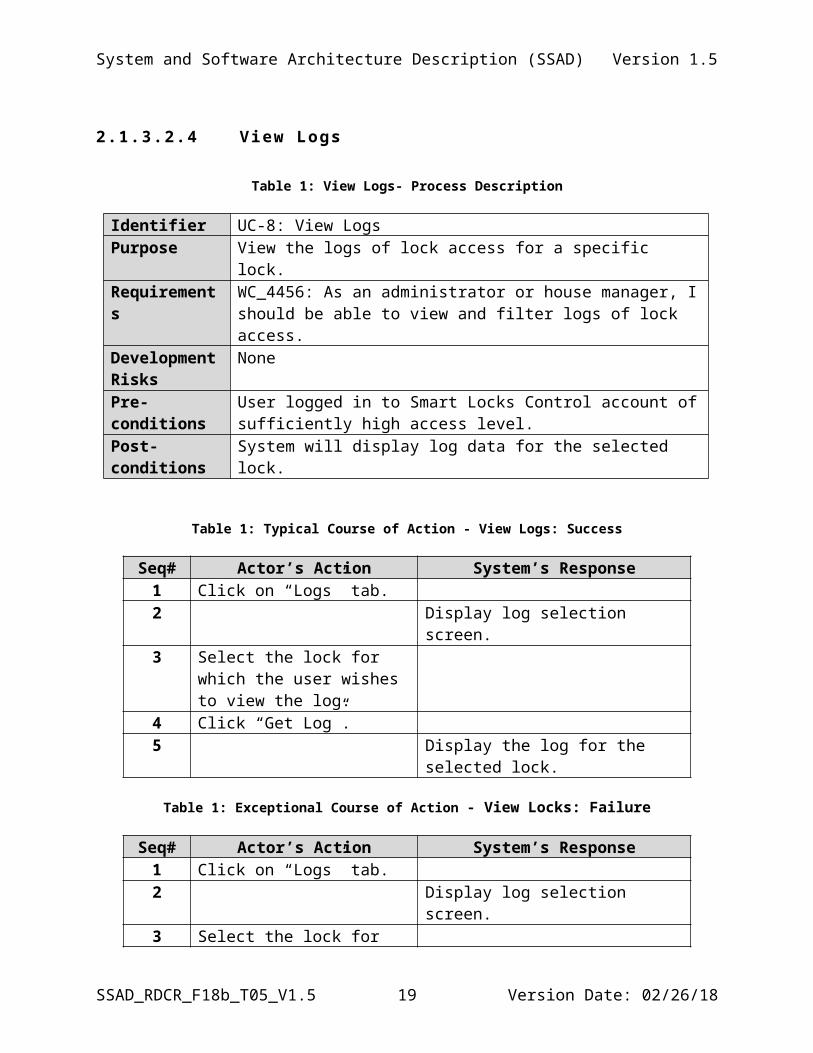
2.1 .3 .2 .4 View Logs
Table 1: View Logs- Process Description
Identifier UC-8: View LogsPurpose View the logs of lock access for a specific lock. Requirements WC_4456: As an administrator or house manager, I should be able to
view and filter logs of lock access.Development Risks
None
Pre-conditions User logged in to Smart Locks Control account of sufficiently high access level.
Post-conditions System will display log data for the selected lock.
Table 1: Typical Course of Action - View Logs: Success
Seq# Actor’s Action System’s Response1 Click on “Logs” tab.2 Display log selection screen.3 Select the lock for which the
user wishes to view the log.4 Click “Get Log”.5 Display the log for the selected lock.
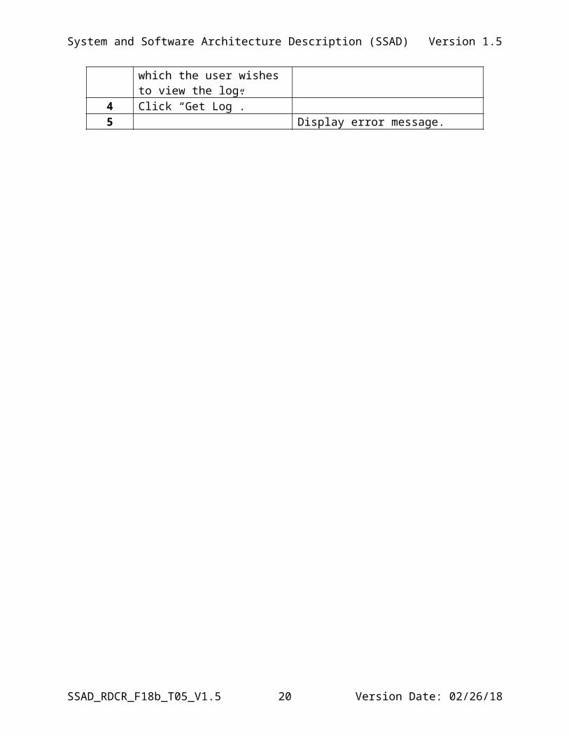
Table 1: Exceptional Course of Action - View Locks: Failure
Seq# Actor’s Action System’s Response1 Click on “Logs” tab.2 Display log selection screen.3 Select the lock for which the
user wishes to view the log.4 Click “Get Log”.5 Display error message.
SSAD_RDCR_F18b_T05_V1.5 14 Version Date: 02/26/18
System and Software Architecture Description (SSAD) Version 1.5
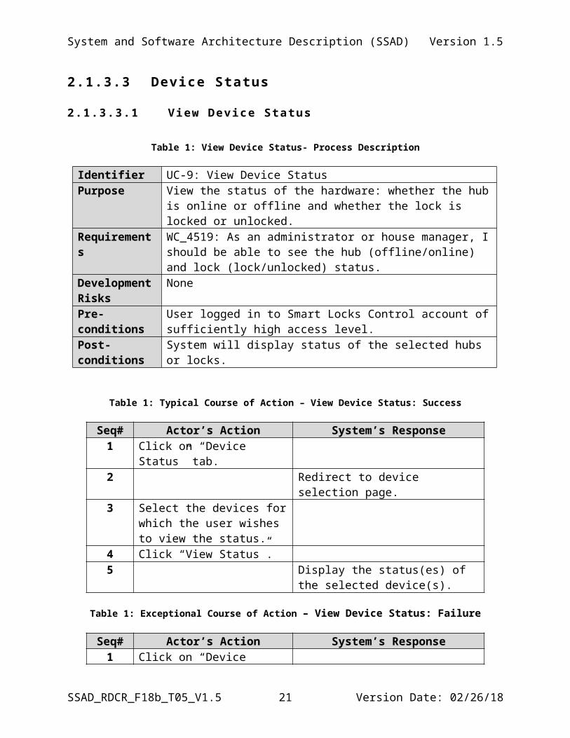
2.1.3.3 Device Status
2.1 .3 .3 .1 View Device Status
Table 1: View Device Status- Process Description
Identifier UC-9: View Device StatusPurpose View the status of the hardware: whether the hub is online or offline and
whether the lock is locked or unlocked.Requirements WC_4519: As an administrator or house manager, I should be able to
see the hub (offline/online) and lock (lock/unlocked) status.Development Risks
None
Pre-conditions User logged in to Smart Locks Control account of sufficiently high access level.
Post-conditions System will display status of the selected hubs or locks.
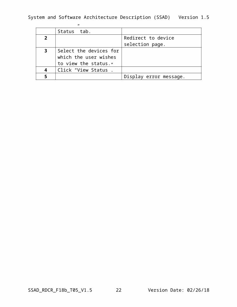
Table 1: Typical Course of Action – View Device Status: Success
Seq# Actor’s Action System’s Response1 Click on “Device Status” tab.2 Redirect to device selection page.3 Select the devices for which the
user wishes to view the status.4 Click “View Status”.5 Display the status(es) of the selected
device(s).
Table 1: Exceptional Course of Action – View Device Status: Failure
Seq# Actor’s Action System’s Response1 Click on “Device Status” tab.2 Redirect to device selection page.3 Select the devices for which the
user wishes to view the status.4 Click “View Status”.5 Display error message.
SSAD_RDCR_F18b_T05_V1.5 15 Version Date: 02/26/18
System and Software Architecture Description (SSAD) Version 1.5
2.1 .3 .3 .2 View Lock Number and Code
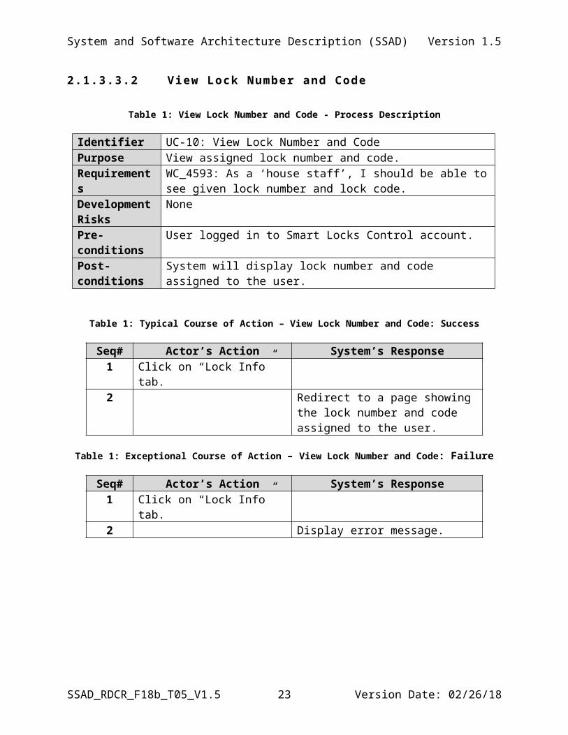
Table 1: View Lock Number and Code - Process Description
Identifier UC-10: View Lock Number and CodePurpose View assigned lock number and code.Requirements WC_4593: As a ‘house staff’, I should be able to see given lock number
and lock code.Development Risks
None
Pre-conditions User logged in to Smart Locks Control account.Post-conditions System will display lock number and code assigned to the user.
Table 1: Typical Course of Action – View Lock Number and Code: Success
Seq# Actor’s Action System’s Response1 Click on “Lock Info” tab.2 Redirect to a page showing the lock
number and code assigned to the user.
Table 1: Exceptional Course of Action – View Lock Number and Code: Failure
Seq# Actor’s Action System’s Response1 Click on “Lock Info” tab.2 Display error message.
SSAD_RDCR_F18b_T05_V1.5 16 Version Date: 02/26/18
System and Software Architecture Description (SSAD) Version 1.5
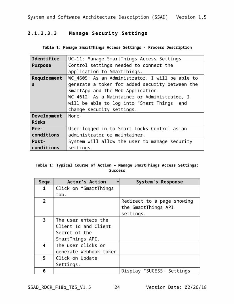
2.1 .3 .3 .3 Manage Secur i ty Set t ings
Table 1: Manage SmartThings Access Settings - Process Description
Identifier UC-11: Manage SmartThings Access SettingsPurpose Control settings needed to connect the application to SmartThings.Requirements WC_4605: As an Administrator, I will be able to generate a token for
added security between the SmartApp and the Web Application.WC_4612: As a Maintainer or Administrator, I will be able to log into “Smart Things” and change security settings.
Development Risks
None
Pre-conditions User logged in to Smart Locks Control as an administrator or maintainer.
Post-conditions System will allow the user to manage security settings.
Table 1: Typical Course of Action – Manage SmartThings Access Settings: Success
Seq# Actor’s Action System’s Response1 Click on “SmartThings” tab.2 Redirect to a page showing the
SmartThings API settings.3 The user enters the Client Id and
Client Secret of the SmartThings API.
4 The user clicks on generate Webhook token
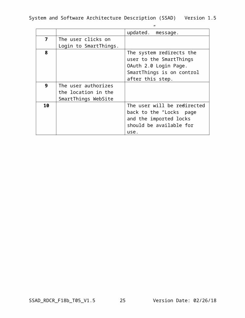
5 Click on Update Settings.6 Display “SUCESS: Settings updated.”
message.7 The user clicks on Login to
SmartThings.8 The system redirects the user to the
SmartThings OAuth 2.0 Login Page. SmartThings is on control after this step.
9 The user authorizes the location in the SmartThings WebSite
10 The user will be redirected back to the “Locks” page and the imported locks should be available for use.
SSAD_RDCR_F18b_T05_V1.5 17 Version Date: 02/26/18
System and Software Architecture Description (SSAD) Version 1.5
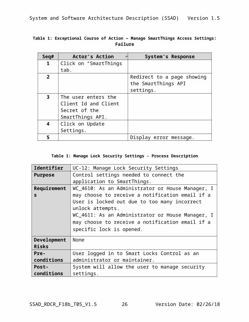
Table 1: Exceptional Course of Action – Manage SmartThings Access Settings: Failure
Seq# Actor’s Action System’s Response1 Click on “SmartThings” tab.2 Redirect to a page showing the
SmartThings API settings.3 The user enters the Client Id and
Client Secret of the SmartThings API.
4 Click on Update Settings.5 Display error message.
Table 1: Manage Lock Security Settings - Process Description
Identifier UC-12: Manage Lock Security SettingsPurpose Control settings needed to connect the application to SmartThings.Requirements WC_4610: As an Administrator or House Manager, I may choose to
receive a notification email if a User is locked out due to too many incorrect unlock attempts.WC_4611: As an Administrator or House Manager, I may choose to receive a notification email if a specific lock is opened.
Development Risks
None
Pre-conditions User logged in to Smart Locks Control as an administrator or maintainer.
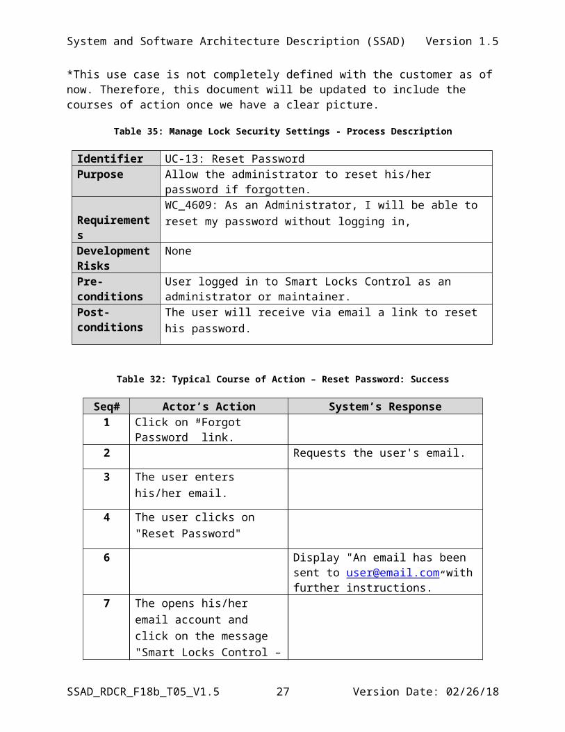
Post-conditions System will allow the user to manage security settings.*This use case is not completely defined with the customer as of now. Therefore, this document will be updated to include the courses of action once we have a clear picture.
Table 35: Manage Lock Security Settings - Process Description
Identifier UC-13: Reset PasswordPurpose Allow the administrator to reset his/her password if forgotten. Requirements WC_4609: As an Administrator, I will be able to reset my password
without logging in,
Development Risks
None
Pre-conditions User logged in to Smart Locks Control as an administrator or maintainer.
Post-conditions The user will receive via email a link to reset his password.
SSAD_RDCR_F18b_T05_V1.5 18 Version Date: 02/26/18
System and Software Architecture Description (SSAD) Version 1.5
Table 32: Typical Course of Action – Reset Password: Success
Seq# Actor’s Action System’s Response1 Click on “Forgot Password”
link.2 Requests the user's email.
3 The user enters his/her email.
4 The user clicks on "Reset Password"
6 Display "An email has been sent to [email protected] with further instructions.”
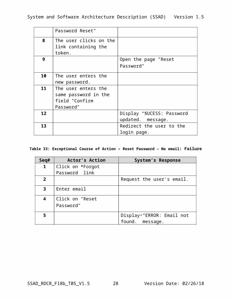
7 The opens his/her email account and click on the message "Smart Locks Control – Password Reset"
8 The user clicks on the link containing the token.
9 Open the page "Reset Password"
10 The user enters the new password.
11 The user enters the same password in the field "Confirm Password"
12 Display “SUCESS: Password updated.” message.
13 Redirect the user to the login page.
Table 33: Exceptional Course of Action – Reset Password – No email: Failure
Seq# Actor’s Action System’s Response1 Click on “Forgot Password” link2 Request the user's email.
3 Enter email
4 Click on "Reset Password"
5 Display “ERROR: Email not found.” message.
SSAD_RDCR_F18b_T05_V1.5 19 Version Date: 02/26/18
System and Software Architecture Description (SSAD) Version 1.5
2.2 Modes of Operation
The system will not have multiple modes. Therefore, no description could be stated in this section.
2.3 System Analysis Rationale
The first phase of this system, which is part of our deliverables is targeting only small-scale Airbnb homes and vacation rental houses. The goal is to target other types of business such as study rooms, office spaces, motels and hotels in next phases of the project.
An important point is that the Smart Lock Control system relies on a Smart App, also developed as part of this delivery and deployed to the SmartThings platform which is responsible for communicating with the locks. Therefore, creating a SmartThings account, registering the hub(s), lock(s) and deploying the provided Smart App is pre-requisite for the system’s operation.Regarding the Smart Locks Control system, one of its main requirements of the client in addition to the lock management feature was a hierarchical user management system, where the access could be controlled based on the type of the user. Therefore, the major operational stakeholders of the system are categorized as administrator, managers, and others. The functions performed by each user are described in the System Context Diagram description.
The categories are determined in the system as roles and each role has certain privileges in the application. This role-based permission control allows the system to grow in the future to support more use cases.
SSAD_RDCR_F18b_T05_V1.5 20 Version Date: 02/26/18
System and Software Architecture Description (SSAD) Version 1.5
3. Technology-Independent Model
This section was left out on purpose, due to the time constraints of the project and the fact that we already know the technology that will be used. Therefore, we moved the content of this section to the next section and updated the design overview and design rationale. This includes the conceptual domain model which is depicted as “Domain Model Class Diagram.”
SSAD_RDCR_F18b_T05_V1.5 21 Version Date: 02/26/18
System and Software Architecture Description (SSAD) Version 1.5
4. Technology-Specific System Design
4.1 Design Overview
4.1 System Structure
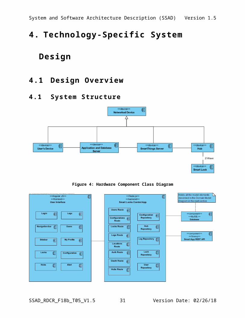
Figure 4: Hardware Component Class Diagram
Figure 5: Software Component Class Diagram
SSAD_RDCR_F18b_T05_V1.5 22 Version Date: 02/26/18
System and Software Architecture Description (SSAD) Version 1.5
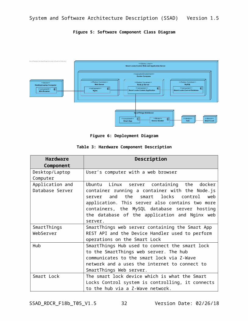
Figure 6: Deployment Diagram
Table 3: Hardware Component Description
Hardware Component DescriptionDesktop/Laptop Computer User’s computer with a web browserApplication and Database Server
Ubuntu Linux server containing the docker container running a container with the Node.js server and the smart locks control web application. This server also contains two more containers, the MySQL database server hosting the database of the application and Nginx web server.
SmartThings WebServer SmartThings web server containing the Smart App REST API and the Device Handler used to perform operations on the Smart Lock
Hub SmartThings Hub used to connect the smart lock to the SmartThings web server. The hub communicates to the smart lock via Z-Wave network and a uses the internet to connect to SmartThings Web server.
Smart Lock The smart lock device which is what the Smart Locks Control system is controlling, it connects to the hub via a Z-Wave network.
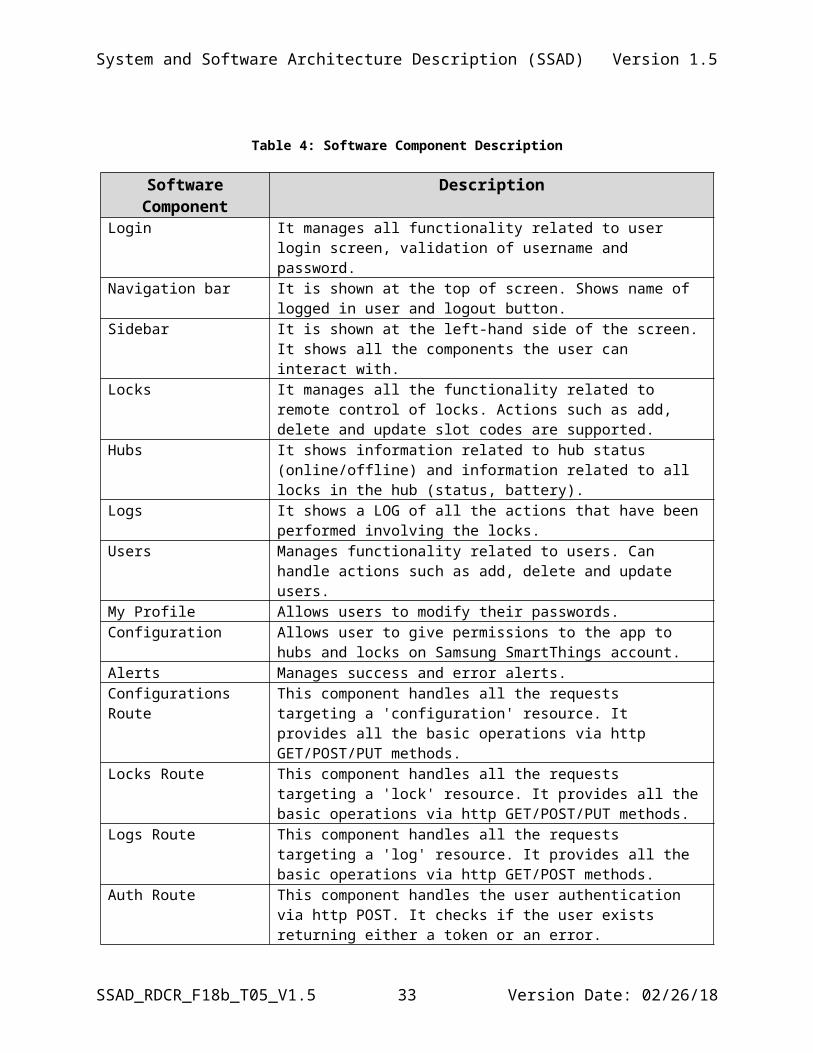
Table 4: Software Component Description
Software Component DescriptionLogin It manages all functionality related to user login screen, validation of
username and password.Navigation bar It is shown at the top of screen. Shows name of logged in user and logout
button.Sidebar It is shown at the left-hand side of the screen. It shows all the
components the user can interact with.Locks It manages all the functionality related to remote control of locks.
Actions such as add, delete and update slot codes are supported.Hubs It shows information related to hub status (online/offline) and
information related to all locks in the hub (status, battery).Logs It shows a LOG of all the actions that have been performed involving the
SSAD_RDCR_F18b_T05_V1.5 23 Version Date: 02/26/18
System and Software Architecture Description (SSAD) Version 1.5
locks.Users Manages functionality related to users. Can handle actions such as add,
delete and update users.My Profile Allows users to modify their passwords.Configuration Allows user to give permissions to the app to hubs and locks on
Samsung SmartThings account.Alerts Manages success and error alerts.Configurations Route This component handles all the requests targeting a 'configuration'
resource. It provides all the basic operations via http GET/POST/PUT methods.
Locks Route This component handles all the requests targeting a 'lock' resource. It provides all the basic operations via http GET/POST/PUT methods.
Logs Route This component handles all the requests targeting a 'log' resource. It provides all the basic operations via http GET/POST methods.
Auth Route This component handles the user authentication via http POST. It checks if the user exists returning either a token or an error.
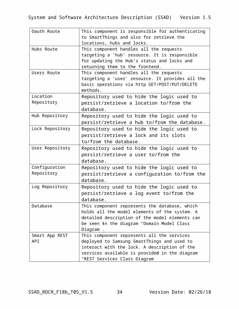
Oauth Route This component is responsible for authenticating to SmartThings and also for retrieve the locations, hubs and locks.
Hubs Route This component handles all the requests targeting a 'hub' resource. It is responsible for updating the Hub’s status and locks and returning them to the frontend.
Users Route This component handles all the requests targeting a 'user' resource. It provides all the basic operations via http GET/POST/PUT/DELETE methods.
Location Repository Repository used to hide the logic used to persist/retrieve a location to/from the database.
Hub Repository Repository used to hide the logic used to persist/retrieve a hub to/from the database.
Lock Repository Repository used to hide the logic used to persist/retrieve a lock and its slots to/from the database.
User Repository Repository used to hide the logic used to persist/retrieve a user to/from the database.
Configuration Repository Repository used to hide the logic used to persist/retrieve a configuration to/from the database.
Log Repository Repository used to hide the logic used to persist/retrieve a log event to/from the database.
Database This component represents the database, which holds all the model elements of the system. A detailed description of the model elements can be seen in the diagram “Domain Model Class Diagram”.
Smart App REST API This component represents all the services deployed to Samsung SmartThings and used to interact with the lock. A description of the services available is provided in the diagram “REST Services Class Diagram”
SSAD_RDCR_F18b_T05_V1.5 24 Version Date: 02/26/18
System and Software Architecture Description (SSAD) Version 1.5
4.1 Design Classes
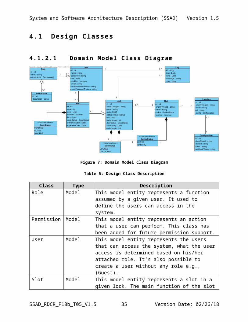
4.1.2.1 Domain Model Class Diagram
Figure 7: Domain Model Class Diagram
Table 5: Design Class Description
Class Type DescriptionRole Model This model entity represents a function assumed by a given
user. It used to define the users can access in the system. Permission Model This model entity represents an action that a user can perform.
This class has been added for future permission support.User Model This model entity represents the users that can access the
system, what the user access is determined based on his/her attached role. It’s also possible to create a user without any role e.g., (Guest).
Slot Model This model entity represents a slot in a given lock. The main function of the slot is to hold the code to access a lock.
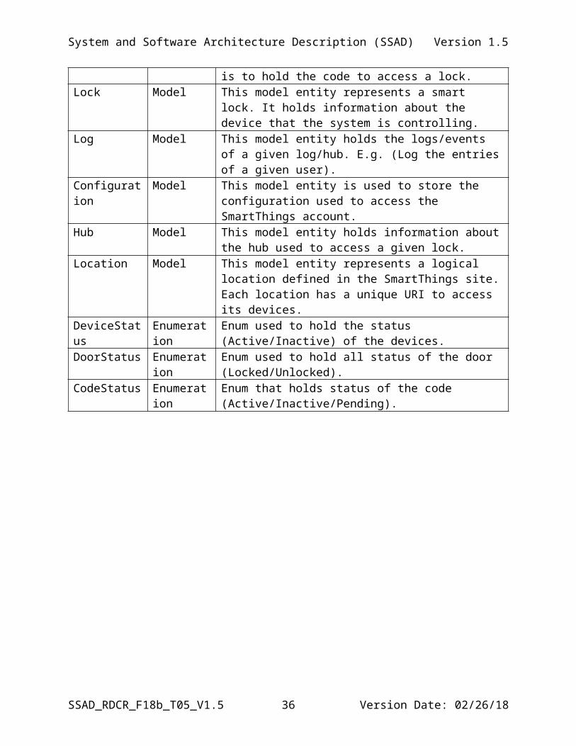
Lock Model This model entity represents a smart lock. It holds information about the device that the system is controlling.
Log Model This model entity holds the logs/events of a given log/hub. E.g. (Log the entries of a given user).
Configuration Model This model entity is used to store the configuration used to access the SmartThings account.
Hub Model This model entity holds information about the hub used to access a given lock.
Location Model This model entity represents a logical location defined in the
SSAD_RDCR_F18b_T05_V1.5 25 Version Date: 02/26/18
System and Software Architecture Description (SSAD) Version 1.5
SmartThings site. Each location has a unique URI to access its devices.
DeviceStatus Enumeration Enum used to hold the status (Active/Inactive) of the devices. DoorStatus Enumeration Enum used to hold all status of the door (Locked/Unlocked).CodeStatus Enumeration Enum that holds status of the code (Active/Inactive/Pending).
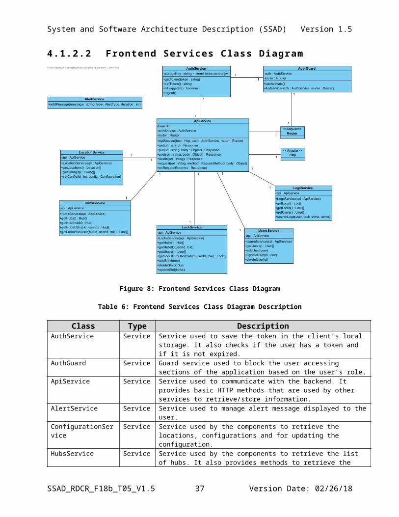
4.1.2.2 Frontend Services Class Diagram
Figure 8: Frontend Services Class Diagram
Table 6: Frontend Services Class Diagram Description
Class Type DescriptionAuthService Service Service used to save the token in the client’s local storage. It also checks if the
user has a token and if it is not expired. AuthGuard Service Guard service used to block the user accessing sections of the application based
on the user’s role.ApiService Service Service used to communicate with the backend. It provides basic HTTP
methods that are used by other services to retrieve/store information.AlertService Service Service used to manage alert message displayed to the user.ConfigurationService Service Service used by the components to retrieve the locations, configurations and for
updating the configuration.HubsService Service Service used by the components to retrieve the list of hubs. It also provides
SSAD_RDCR_F18b_T05_V1.5 26 Version Date: 02/26/18
System and Software Architecture Description (SSAD) Version 1.5
methods to retrieve the updated status of the hubs and locks.LocksService Service Service used to retrieve and update the slots that a given user can
add/delete/update.UsersService Service Service used to update/delete/add a user.LogsService Service Service used to search logs.
* Not including here classes provided by Angular (Http, Router)
4.1.2.3 Frontend Components Class Diagram
Figure 9: Frontend Components Class Diagram
Table 7: Frontend Components Class Diagram Description
Class Type DescriptionLogsComponent Controller It manages the actions performed by the user, such as search and sort. It is a
bridge between the HTML page and the logs service. HubsComponent Controller It manages the actions performed by the user, such as listing status of the locks
and the status of the hub. It is a bridge between the HTML page and the hubs service.
LocksComponent Controller It manages the actions performed by the user, such as retrieving and managing the slots. It is a bridge between the HTML page and the locks service.
UsersComponent Controller It manages the actions performed by the user, such as add/delete/update a user. It is a bridge between the HTML page and the users service.
ConfigComponent Controller It manages the actions performed by the user in the configuration page, such as updating the config id and secret and logging to SmartThings. It is a bridge between the HTML page and the location service.
UserComponent Controller It manages the actions performed by the user in the profile. It is a bridge
SSAD_RDCR_F18b_T05_V1.5 27 Version Date: 02/26/18
System and Software Architecture Description (SSAD) Version 1.5
between the HTML page and the users service. SidebarComponent Controller Shows name of logged in user and logout button.LoginComponent Controller It manages the actions performed by the user on the login page.NavbarComponent Controller It shows all the components the user can interact with.DashboardComponent Controller It wrapps all the pages around a dashboard.OnInit Interface Angular lifecycle hook that is called after data-bound properties of a directive
are initialized.
4.1.2.4 Frontend Domain Model Class Diagram
Figure 10: Frontend Domain Model Class Diagram
Table 8: Frontend Domain Model Class Diagram Description
Class Type DescriptionConfigUI Model Simplified version of “Configuration” backend class without id.HubUI Model Simplified version of “Hub” backend class containing only id, name, status.LockUI Model Simplified version of “Lock” backend class containing the attributes needed in
the frontend. UserUI Model Simplified version of “User” backend class containing the attributes needed in
the frontend and what is implemented now.SlotUI Model Frontend version of “Slot” backend class.LogUI Model Simplified version of “Log” backend class.SimpleItem Model Base class extended by SimpleLockUI and SimpleUserUI SimpleLockUI Model Simplified version of “Lock” containing only id and name.SimpleUserUI Model Simplified version of “User” containing only id and name.
SSAD_RDCR_F18b_T05_V1.5 28 Version Date: 02/26/18
System and Software Architecture Description (SSAD) Version 1.5
4.1.2.5 Repository Class Diagram
Figure 11: Repository Class Diagram
Table 9: Repository Class Diagram Description
Class Type DescriptionConfigurationRepository
Repository Repository used to hide the logic used to persist/retrieve a configuration to/from the database.
LockRepository Repository Repository used to hide the logic used to persist/retrieve a lock and its slots to/from the database.
HubRepository Repository Repository used to hide the logic used to persist/retrieve a location to/from the database.
LogRepository Repository Repository used to hide the logic used to persist/retrieve a log event to/from the database.
UserRepository Repository Repository used to hide the logic used to persist/retrieve a user to/from the database.
LocationRepository Repository Repository used to hide the logic used to persist/retrieve a location to/from the database.
SSAD_RDCR_F18b_T05_V1.5 29 Version Date: 02/26/18
System and Software Architecture Description (SSAD) Version 1.5
4.1.2.6 Backend RESTful Services Class Diagram
Figure 12: Backend RESTful Services Class Diagram
Table 10: Backend RESTful Services Class Diagram Description
Class/Resource Type DescriptionPOST /configs REST Resource It represents a service used to save a config to the database. PUT /configs REST Resource It represents a service used to update a config to the database.GET /configs/:id REST Resource It represents a service used to retrieve one configuration from the
database.Configuration JSON/Model It represents the JSON object expected/returned by the “/configs”
service.GET /locations REST Resource It represents a service used to retrieve a list of locations from the
database.Location JSON/Model It represents the JSON object returned by the “/locations” service.GET /hubs REST Resource It represents a service used to retrieve a hub or a list of hubs from the
database, based on the given parameters, i.e., (userId and hubId).Hub JSON/Model It represents the JSON object returned by the “/hubs” service.POST /users REST Resource It represents a service used to save a user to the database. PUT /users/:id REST Resource It represents a service used to update a user to the database.GET /users/:id REST Resource It represents a service used to retrieve one user from the database.GET /users REST Resource It represents a service used to retrieve a list of users from the database.DELETE /users/:id REST Resource It represents a service used to delete one user from the database.User JSON/Model It represents the JSON object expected/returned by the “/users” service.POST /locks/command/:command
REST Resource It represents a service used to add/delete/update the slots of a lock to the database, and also for sending the command to SmartThings to update the lock.
GET /locks/:id REST Resource It represents a service used to retrieve one lock from the database.GET /locks REST Resource It represents a service used to retrieve a list of locks from the database,
based on the userId and hubId if provided.User JSON/Model It represents the JSON object returned by the “/locks” service.CommandRequest JSON/ DTO It represents the JSON file expected by POST “locks/command”
service.
SSAD_RDCR_F18b_T05_V1.5 30 Version Date: 02/26/18
System and Software Architecture Description (SSAD) Version 1.5
LockCode JSON/ DTO Simple JSON object used to send only the fields required by the service.
GET /webhook/:token REST Resource It represents a REST resource used to return the webhook token.
4.1.2.7 Backend Class DiagramThis section shows a detailed view of the resources above. It does not depict a complete
list of the endpoints, which was already shown in "Backend RESTful Services Class Diagram".Also, the operations "get/put/delete/post” are represented in the code as: router.{http_method}. For details about the usage, please refer to http://expressjs.com/en/api.html.
All the constants pointing to external classes/dependencies are represented with the keyword “require”, as they are in the code, e.g., “express = require(‘express’), whereas local classes are declared pointing towards the class itself e.g., “validator = Validator”.
Figure 13: Backend Class Diagram
Table 11: Backend Class Diagram Description
Class/Resource Type DescriptionApp Helper/Utils Application entry point.ExpressApp Helper/Utils Class used to start the express framework responsible for managing the
routes and validate the requestsValidator Helper/Utils Helper class used to validate the id.ErrorHandler Helper/Utils Class used to manage the exceptions/errors.CommandsLocks Helper/Utils Helper used to prepare and send commands to SmartThings.Hubs Controller Controller used to manage the resource “hubs”, it provides routes to
retrive and update hubs.
SSAD_RDCR_F18b_T05_V1.5 31 Version Date: 02/26/18
System and Software Architecture Description (SSAD) Version 1.5
Locks Controller Controller used to manage the resource “locks”, It provides routes to retrieve and update locks and slots. It also provides a route used by the frontend to send commands to the SmartApp.
Users Controller Controller used to manage the resource “users”. It provides routes for basic CRUD operations.
Configs Controller Controller used to manage the resource “configs”. It provides routes to create, update and retrive a configuration.
Locations Controller Controller used to manage the resource “locations”. It provides routes to retrieve locations from the database.
Logs Controller Controller used to manage the resource “logs”. It provides routes to retrieve logs from the database.
Auth Controller Controller used to manage the resource “auth”. It provides routes to authenticathe the user to the application.
OAuth Controller Controller used to manage the resource “oauth”. It provides routes to authenticate the user to SmartThings.
4.1.2.8 SmartApp RESTful Services Class Diagram
Figure 14: SmartApp RESTful Services Class Diagram
Table 12: SmartApp RESTful Services Class Diagram Description
Class Type DescriptionREST POST Command REST Resource It represents a REST service used to post a command to the
Locks. E.g. (setCode, deleteCode)ChangeLockCodeRequest
JSON/Model It represents the JSON format expected by the POST Command service.
SimpleLockCode JSON/DTO A SimpleLockCode represents the JSON attributes needed by the Command POST service. The id is a universal identifier of the Lock, and the slot is the slot that we want to update the code.
StatusMessageResponse JSON/ DTO It represents the JSON format returned by the POST Command service.
REST POST Command Single Lock
REST Resource It represents a REST service used to post command to a single lock. E.g. (lock, unlock). It uses expects the same json as the endpoint used to multiple locks.*This endpoint was added to test lock/unlock/poll/refresh, these are not being used by the WebApp.
SSAD_RDCR_F18b_T05_V1.5 32 Version Date: 02/26/18
System and Software Architecture Description (SSAD) Version 1.5
REST GET Logs REST Resource It represents a REST service used to get the events logged by the lock.
SimpleLog JSON/ DTO It represents the JSON file returned by the GET logs service.REST GET Locks REST Resource It represents a REST service used to get locks available in the
location.SimpleLock JSON/ DTO It represents the JSON file returned by the GET Locks service.REST GET Hubs REST Resource It represents a REST service used to get the hubs available in the
location.SimpleHub JSON/ DTO It represents the JSON file returned by the GET Hubs service.REST GET Hub and Locks
REST Resource It represents a REST service used to get an updated version of the hub and its locks.
HubResponse JSON/ DTO It represents the JSON file returned by the GET Hub and Locks service. It contain only updateble attributes of both the hub its locks.
SmartApp Groovy Script It represents the SmartApp along with all its functions.*DTO – Data Transfer Object
SSAD_RDCR_F18b_T05_V1.5 33 Version Date: 02/26/18
System and Software Architecture Description (SSAD) Version 1.5
4.1 Process Realization
Figure 15: Add Slot Code Sequence Diagram
Figure 16: Change Slot Code Sequence Diagram
SSAD_RDCR_F18b_T05_V1.5 34 Version Date: 27/02/18
System and Software Architecture Description (SSAD) Version 1.5
Figure 17: Delete Slot Code Sequence Diagram
Figure 18: Post Log Webhook Sequence Diagram
SSAD_RDCR_F18b_T05_V1.5 35 Version Date: 27/02/18
System and Software Architecture Description (SSAD) Version 1.5
Figure 19: Get Locks Sequence Diagram
Figure 20: Invalid Token Sequence Diagram
SSAD_RDCR_F18b_T05_V1.5 36 Version Date: 27/02/18
System and Software Architecture Description (SSAD) Version 1.5
Figure 21: Get updated hub status
SSAD_RDCR_F18b_T05_V1.5 37 Version Date: 27/02/18
System and Software Architecture Description (SSAD) Version 1.5
4.2 Design RationaleWe re-designed the whole application after the mid-term, due to scalability, security, and adaptability issues to name a few that our prototype had at that point in time. Therefore, several COTS have been replaced, e.g., Node.js instead of PHP, and MySQL instead of SQLite.
The main objective of the new design was to carefully isolate each layer of the application making it less dependent on each other, using as guidance basic software engineering principles, such as separation of concerns, modularity, abstraction, among others.
The result is a modular architecture, highly flexible and prepared to grow.
SSAD_RDCR_F18b_T05_V1.5 38 Version Date: 27/02/18
System and Software Architecture Description (SSAD) Version 1.5
5. Architectural Styles, Patterns, and
Frameworks
Table 13: Architectural Styles, Patterns, and Frameworks
Name Description Benefits, Costs, and Limitations3-tier architecture
Separate the application into 3 tiers: the presentation tier using a web browser, a logic tier with Node.js server, and a data tier with MySQL.
Using web browser allows the user to use any devices that they want, resulting in no need to maintain users’ devices.
Any change made in the application in the server will be automatically presented to the users.
There is no cost for adopting the architecture. Need to acquire servers for application and database.
Also, the database might be deployed on the same server if needed.
Repository This design pattern is used to encapsulate the logic to access the database.
“A Repository mediates between the domain and data mapping layers, acting like an in-memory domain object collection. Client objects construct query specifications declaratively and submit them to Repository for satisfaction.” (Martin Fowler)
“A Repository encapsulates the set of objects persisted in a data store and the operations performed over them, providing a more object-oriented view of the persistence layer.” (Martin Fowler)
REST The Smart App exposes RESTful services to access and perform an operation on the locks.
“Representational State Transfer (REST) is an architectural style that specifies constraints, such as the uniform interface, that if applied to a web service induce desirable properties, such as performance, scalability, and modifiability, that enable services to work best on the Web.” (Oracle Website)
Node.js The backend of the application uses Node.js.
Node.js is an open-source, cross-platform JavaScript run-time environment for executing JavaScript code server-side. It operates on a single thread, using non-blocking I/O calls, allowing it to support tens of thousands of concurrent connections without incurring the cost of thread context switching.
built-in support for package management using NPM. Several free and open-source packages available.
AngularJS AngularJS is a web application framework based on JavaScript.
AngularJS provides an easy way to render user interface. Writing unit tests in AngularJS is easy It makes the code organized and easy to maintain.
SSAD_RDCR_F18b_T05_V1.5 39 Version Date: 27/02/18