Embed Size (px)
Citation preview
System B‐Mo‐Ni
Isothermal Phase Diagram of the Ni‐Mo-B System,
S.Omori, Y.Hashimoto and K.Koyama,
Kouon Gakkaishi, Vol.7 (1981), pp.162-166.
Fig. Isothermal Phase Diagram of the Ni‐Mo-B System at 1273 K.
System B‐Mo‐Ni
Liquidus Surface of the Ni‐Mo-B System,
S.Omori, Y.Hashimoto and K.Koyama,
Kouon Gakkaishi, Vol.7 (1981), pp.167-173.
Fig. Liquidus surface of the Ni-Mo-B system in the lower boron region than the Ni3B-MoB
quasi-binary system.

System B‐Mo‐Ni
Calculated Phase Diagram of the Ni-Mo-B Ternary System,
M.Morishita, K.Koyama, S.Yagi and G. Zhang,
J. Alloys and Compounds,Vol.314,(2001), pp.214-218.
Fig. The calculated Ni-Mo-B ternary phase diagram in the low boron composition range
System B‐Mo‐Ni‐O
Phase Relationship in the Ni‐Mo‐B‐O System and Oxidation Property of a Ni‐NiMo2B2 Two-Phase
Alloy,
M.Morishita, K.Koyama, K.Maeda and G. Zhang,
J. Japan Inst. Met., Vol.65 (2001), pp.279-287.
Fig. Phase relationship in the B-Mo-Ni O system at 973 K.

System B‐Mo‐O
Determination of Gibbs Energy of Formation of Molybdenum-Boron Binary System by Electromotive Force
Measurement Using Solid Electrolyte
H. Yamamoto, M. Morishita, T. Yamamoto and K. Furukawa,
Metallurgical and Materials Transactions B, Vol. 42B (2011), pp. 114-120.
Fig. Composition-oxygen partial pressure diagram of the molybdenum-boron-oxygen system at 1273 K.
(1) Mo-Mo2B-B2O3, (2) Mo2B-MoB-B2O3, (3) MoB-Mo2B5-B2O3, (4) Mo2B5-MoB4-B2O3, (5) MoB4-B-
B2O3, (6) Mo-MoO2-B2O3, (7) MoO2-MoO3-B2O3 ternary phase equilibria.
System B‐Ni
Phase Diagram of Binary Nickel‐Boron System at Nickel Side,
S. Omori, Y.Hashimoto, S.Nakamura, K.Hidaka and Y.Kohira,
J. Japan Soc. Powder Powder Metallurgy, Vo.18 (1971), pp.132-135.
Fig. Phase diagram of Ni‐B system (up to 33.3at%B).
mole fraction of Mo, XMo
0 0.2 0.4 0.6 0.8 1.0B Mo
0
-5
-10
-15
-20
-25
Lo
g(p
O2/P
a)
Mo-Mo2B
B2O3 - MoO2
Mo
2B
αM
oB
Mo
2B
5
Mo
B4
B2O3 – MoO3
B2O3 - Mo
B2O3 - αMoB
B2O3 – Mo2B
B2O3 – Mo2B5
(1)
(2)
(3)
(4)(5)
(6)
(7)
B-MoB4
B2O3-MoB4

System B‐Ni‐O
Composition-partial oxygen pressure diagram for Ni-B-O system
H. Yamamoto and M. Morishita,
J. Alloys and Comp., Vol. 438 (2007), pp. L1-L3.
Fig. Composition-oxygen partial pressure diagram for the Ni-B-O system at 1223 K. Horizontal lines
represent the equilibrium regions as follows:
(1): Ni-NiO-Ni3B2O6, (2): Ni-Ni3B2O6-B2O3, (3): Ni-Ni3B-B2O3, (4): Ni3B-Ni2B-B2O3, (5): Ni2B-
Ni0.586B0.414-B2O3, (6): Ni0.586B0.414-Ni0.564B0.436-B2O3, (7): Ni0.564B0.436-NiB-B2O3, and (8): B-B2O3-NiB.
System B‐W‐Ni
Calculated Phase Diagram of the Ni-W-B Ternary System,
M.Morishita, K.Koyama, K.Maeda and G. Zhang,
Materials Transactions of the Japan Institute of Metals,Vol.40,(1999), pp.600-605.
Fig. The calculated Ni-W-B ternary phase diagram in the low boron composition range
-25
-20
-15
-10
-5
0 0.2 0.4 0.6 0.8 1.0
Ni3B2O6
Ni3B2O6 + NiO
Ni3B2O6 + Ni
B2O3+Ni3B2O6
B2O3+Ni
B+NiB
B2O3+NiB
XNi
Ni3B+Ni
B2O3+Ni3B
B2O3+Ni2B
Lo
g(p
O2/P
a)
Ni 3
B
Ni 2
B
NiB
Ni 0
.586B
0.4
14
Ni 0
.564B
0.4
36
(1)
(2)
(3)
(4)
(5)(6)
(7)
(8)
B2O3+ Ni0.586B0.414
B2O3+ Ni0.564B0.436
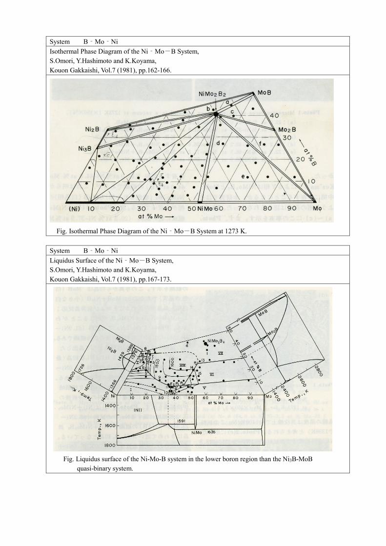
System C‐Ni‐O‐Ti
Phase Relationships and the Partial Phase Diagram of the Ni‐Ti-C-O System,
Y.Hashimoto, S.Omori, K.Koyama and Y. Arami,
Kouon Gakkaishi, Vol.7 (1981), pp.255-263.
Fig. Isothermal phase diagram in the Ni-rich region of the Ni-Ti-C-O system at 1273 K (Partially drawn).
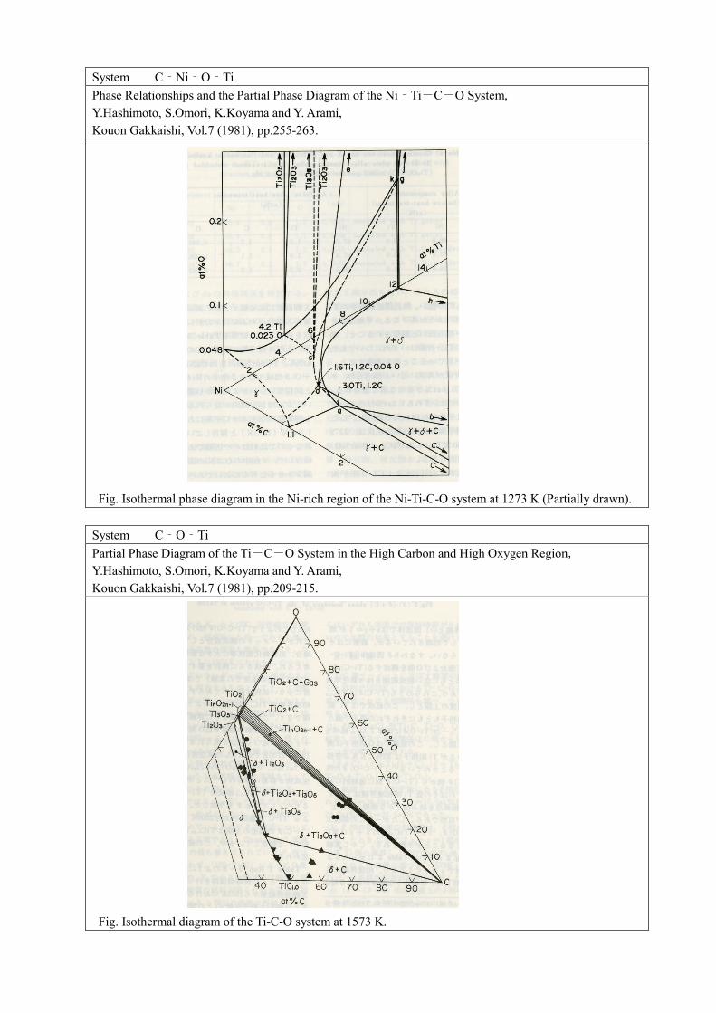
System C‐O‐Ti
Partial Phase Diagram of the Ti-C-O System in the High Carbon and High Oxygen Region,
Y.Hashimoto, S.Omori, K.Koyama and Y. Arami,
Kouon Gakkaishi, Vol.7 (1981), pp.209-215.
Fig. Isothermal diagram of the Ti-C-O system at 1573 K.

System Fe‐Mo‐O
Determination of Standard Gibbs Energies of Formation of Fe2Mo3O12, Fe2Mo3O8, Fe2MoO4, and FeMoO4
of the Fe-Mo-O Ternary System an μ Phase of the Fe-Mo Binary System by Electromotive Force
Measurte Using a Y2O3-Stabilized ZrO2 Solid Electrlyte
K.Koyama, M.Morishita, T.Harada and N.Maekawa,
Metallurgical and Materials Transactions, Vol.B34, (2003), pp.653-659.
Fig. The compositions of the electrode used for the electromotive force measurements.

System KCl‐LiCl‐MgCl2
Phase Diagram of LiCl-KCl-MgCl2 Ternary System in Low MgCl2 composition,
M.Morishita, M. Murase and K.Koyama,
J. Japan Inst. Met., Vol.59 (1995), pp.799-805.
Fig. Phase diagram of the LiCl-KCl-MgCl2 ternary system in low MgCl2 composition.
System Mo‐Ni‐O
Calorimetric Study of Nickel Molybdate: Heat Capacity, Enthalpy and Gibbs Energy of Formation,
M.Morishita and A.Navrotsky,
Journal of the American Ceramic Society, Vol.86, (2003), Vol.1927-1932.
Fig. Composition-partial pressure diagram for the Ni-Mo-O ternary system at 1373 K.
NNNNiiiiOOOO ++++ ββββNNNNiiiiMMMMooooOOOO 4444
NNNNiiiiOOOO ++++ MMMMooooOOOO 2222
ααααNNNNiiii
pp ppOO OO
22 22ll ll oo oo
gg gg (( ((
)) ))
// // PP PP
aa aa
αααα++++ NNNNiiiiMMMMoooo NNNNiiiiMMMMoooo ++++ MMMMoooo
αααα++++ MMMMooooOOOO 2222
ββββNNNNiiiiMMMMooooOOOO 4444 ++++ MMMMooooOOOO 3333 (((( llll ))))
ββββNNNNiiiiMMMMooooOOOO 4444 ++++ MMMMooooOOOO 2222
XXXX MMMM oooo
0000 0000 ....2222 0000 ....4444 0000 ....6666 0000 ....8888 1111 ....0000----11110000
----8888
----6666
----4444
----2222
0000
2222