Embed Size (px)
Citation preview
Technical Manual - English
System Board D2870for PRIMERGY RX600 S5 Technical Manual
April 2010
Comments… Suggestions… Corrections…The User Documentation Department would like toknow your opinion of this manual. Your feedback helpsus optimize our documentation to suit your individual needs.
Feel free to send us your comments by e-mail to email: [email protected].
Certified documentation according to DIN EN ISO 9001:2000To ensure a consistently high quality standard anduser-friendliness, this documentation was created tomeet the regulations of a quality management system which complies with the requirements of the standardDIN EN ISO 9001:2000.
cognitas. Gesellschaft für Technik-Dokumentation mbHwww.cognitas.de
Copyright and Trademarks
© c
ogn
itas.
Ges
ells
chft
für
Tech
nik-
Dok
umen
tatio
n m
bH 2
010
P
fad:
C:\P
rogr
am
me\
FC
T\ti
m_a
pp\ti
m_l
oca
l\wor
k\P
ICH
OL
\OB
J_D
OK
U-5
686-
001
.fm
Copyright © 2010 Fujitsu Technology Solutions GmbH.
All rights reserved.Delivery subject to availability; right of technical modifications reserved.
All hardware and software names used are trademarks of their respective manufacturers.
– The contents of this manual may be revised without prior notice.
– Fujitsu assumes no liability for damages to third party copyrights or other rights arising from the use of any information in this manual.
– No part of this manual may be reproduced in any form without the prior written permission of Fujitsu.
Microsoft, Windows, Windows Server, and Hyper V are trademarks or registered trademarks of Microsoft Corporation in the USA and other countries.
Intel and Xeon are trademarks or registered trademarks of Intel Corporation or its subsidiaries in the USA and other countries.
D2870 (RX600 S5) Technical Manual
Before reading this manual
For your safety
This manual contains important information for safely and correctly using this product.
Carefully read the manual before using this product. Pay particular attention to the accompanying manual "Safety notes and other important information" and ensure these safety notes are understood before using the product. Keep this manual and the manual "Safety notes and other important information" in a safe place for easy reference while using this product.
Radio interference
This product is a "Class A" ITE (Information Technology Equipment). In a domestic environment this product may cause radio interference, in which case the user may be required to take appropriate measures. VCCI-A
Aluminum electrolytic capacitors
The aluminum electrolytic capacitors used in the product's printed circuit board assemblies and in the mouse and keyboard are limited-life components. Use of these components beyond their operating life may result in electrolyte leakage or depletion, potentially causing emission of foul odor or smoke.
As a guideline, in a normal office environment (25°C) operating life is not expected to be reached within the maintenance support period (5 years). However, operating life may be reached more quickly if, for example, the product is used in a hot environment. The customer shall bear the cost of replacing replaceable components which have exceeded their operating life. Note that these are only guidelines, and do not constitute a guarantee of trouble-free operation during the maintenance support period.
High safety use
This product has been designed and manufactured for general uses such as general office use, personal use, domestic use and normal industrial use. It has not been designed or manufactured for uses which demand an extremely high level of safety and carry a direct and serious risk to life or body if such safety cannot be ensured.

Technical Manual D2870 (RX600 S5)
© c
ogn
itas.
Ges
ells
chft
für
Tech
nik-
Dok
umen
tatio
n m
bH 2
010
P
fad:
C:\P
rogr
am
me\
FC
T\ti
m_a
pp\ti
m_l
oca
l\wor
k\P
ICH
OL
\OB
J_D
OK
U-5
686-
001
.fm
These uses include control of nuclear reactions in nuclear power plants, automatic airplane flight control, air traffic control, traffic control in mass transport systems, medical devices for life support, and missile guidance control in weapons systems (hereafter, "high safety use"). Customers should not use this product for high safety use unless measures are in place for ensuring the level of safety demanded of such use. Please consult the sales staff of Fujitsu if intending to use this product for high safety use.
Measures against momentary voltage drop
This product may be affected by a momentary voltage drop in the power supply caused by lightning. To prevent a momentary voltage drop, use of an AC uninterruptible power supply is recommended.
(This notice follows the guidelines of Voltage Dip Immunity of Personal Computer issued by JEITA, the Japan Electronics and Information Technology Industries Association.)
Technology controlled by the Foreign Exchange and Foreign Trade Control Law of Japan
Documents produced by Fujitsu may contain technology controlled by the Foreign Exchange and Foreign Trade Control Law of Japan. Documents which contain such technology should not be exported from Japan or transferred to non-residents of Japan without first obtaining authorization in accordance with the above law.
Harmonic Current Standards
This product conforms to harmonic current standard JIS C 61000-3-2.
Only for the Japanese market:About SATA hard disk drives
The SATA version of this server supports hard disk drives with SATA / BC-SATA storage interfaces. Please note that the usage and operation conditions differ depending on the type of hard disk drive used.
Please refer to the following internet address for further information on the usage and operation conditions of each available type of hard disk drive:
http://primeserver.fujitsu.com/primergy/harddisk/
D2870 (RX600 S5) Technical Manual
Only for the Japanese market:
I Although described in this manual, some sections do not apply to the Japanese market. These options and routines include:
– CSS (Customer Self Service)
– USB Flash Module (UFM)
– Replacing the lithium battery
Technical Manual D2870 (RX600 S5)
© c
ogn
itas.
Ges
ells
chft
für
Tech
nik-
Dok
umen
tatio
n m
bH 2
010
P
fad:
C:\P
rogr
am
me\
FC
T\ti
m_a
pp\ti
m_l
oca
l\wor
k\P
ICH
OL
\OB
J_D
OK
U-5
686-
001
.fm
D2870 (RX600 S5) Technical Manual
Contents
1 Introduction . . . . . . . . . . . . . . . . . . . . . . . . . . . . 9
1.1 Notational conventions . . . . . . . . . . . . . . . . . . . . . 9
2 Important information . . . . . . . . . . . . . . . . . . . . . 11
2.1 Notes on safety . . . . . . . . . . . . . . . . . . . . . . . . . 11
2.2 CE certificate of conformity . . . . . . . . . . . . . . . . . . 14
2.3 Environmental protection . . . . . . . . . . . . . . . . . . . 15
3 Features . . . . . . . . . . . . . . . . . . . . . . . . . . . . . 17
3.1 Overview . . . . . . . . . . . . . . . . . . . . . . . . . . . . 17
3.2 Main memory . . . . . . . . . . . . . . . . . . . . . . . . . . 223.2.1 Fitting rules . . . . . . . . . . . . . . . . . . . . . . . . . . . 243.2.2 Memory configuration modes . . . . . . . . . . . . . . . . . . 253.2.3 Memory board configuration table . . . . . . . . . . . . . . . . 38
3.3 PCIe slots . . . . . . . . . . . . . . . . . . . . . . . . . . . . 40
3.4 Screen resolutions . . . . . . . . . . . . . . . . . . . . . . . 42
3.5 Temperature and system monitoring . . . . . . . . . . . . . 42
3.6 Connectors, jumpers and indicators . . . . . . . . . . . . . 443.6.1 Onboard connectors . . . . . . . . . . . . . . . . . . . . . . . 443.6.2 Onboard jumpers . . . . . . . . . . . . . . . . . . . . . . . . 463.6.3 Onboard indicators . . . . . . . . . . . . . . . . . . . . . . . 483.6.4 External connectors and indicators . . . . . . . . . . . . . . . 503.6.5 Connectors and indicators on the I/O riser board . . . . . . . . 51
4 Replacing the lithium battery . . . . . . . . . . . . . . . . . 55
Technical Manual D2870 (RX600 S5)
Contents
© c
ogn
itas.
Ges
ells
chft
für
Tech
nik-
Dok
umen
tatio
n m
bH 2
010
P
fad:
C:\P
rogr
am
me\
FC
T\ti
m_a
pp\ti
m_l
oca
l\wor
k\P
ICH
OL
\OB
J_D
OK
U-5
681-
001
.fm
D2870 (RX600 S5) Technical Manual 9
1 IntroductionThis technical manual describes the D2870 system board, which can be equipped with up to four Intel processors.
For additional driver information (if available), refer to the Readme files located on the server hard disk and on the supplied DVDs (see Installation DVD of ServerView Suite - ServerView Software Products).
You will find further information about the BIOS setup in the "D2870 BIOS Setup Utility for RX600 S5" manual.
I PRIMERGY manuals are available in PDF format on the ServerView Suite DVD 2. The ServerView Suite DVD 2 is part of the ServerView Suite supplied with every server.
PRIMERGY Abbreviations and Glossary can also be found on the ServerView Suite DVD 2.
1.1 Notational conventions
The following notational conventions are used in this manual:
Text in italics indicates commands or menu items.
"Quotation marks" indicate names of chapters and terms that are being emphasized.
Ê describes activities that must be performed in the order shown.
V CAUTION! pay particular attention to texts marked with this symbol. Failure to observe this warning may endanger your life, destroy the system or lead to the loss of data.
I indicates additional information, notes and tips.
10 Technical Manual D2870 (RX600 S5)
Notational conventions Introduction
© c
ogn
itas.
Ges
ells
chft
für
Tech
nik-
Dok
umen
tatio
n m
bH 2
010
P
fad:
C:\P
rogr
am
me\
FC
T\ti
m_a
pp\ti
m_l
oca
l\wor
k\P
ICH
OL
\OB
J_D
OK
U-5
682-
001
.fm
D2870 (RX600 S5) Technical Manual 11
2 Important informationIn this chapter you will find essential information regarding safety when working with your server.
V CAUTION!
With the system board installed you must open the system to access the system board. How to access the system board of your system is described in the appropriate service supplement (except for the Japanese market).
When handling the system board, refer to the specific notes on safety in the operating manual and/or service supplement for the respective server.
2.1 Notes on safety
V CAUTION!
● The actions described in these instructions should only be performed by authorized, qualified personnel. Equipment repairs should only be performed by qualified staff. Any failure to observe the guidelines in this manual, and any unauthorized openings and improper repairs could expose the user to risks (electric shock, fire hazards) and could also damage the equipment. Please note that any unauthorized openings of the device will result in the invalidation of the warranty and exclusion from all liability.
● Transport the device only in the antistatic original packaging or in packagings that protects it from knocks and jolts.
● Only install expansions that are allowed for the system board. If you install other expansions, you may damage the requirements and rules governing safety and electromagnetic compatibility or your system. Information on which system expansions are approved for installation can be obtained from our customer service center or your sales outlet.
● The warranty expires if the device is damaged during the installation or replacement of system expansions.
12 Technical Manual D2870 (RX600 S5)
Notes on safety Important information
© c
ogn
itas.
Ges
ells
chft
für
Tech
nik-
Dok
umen
tatio
n m
bH 2
010
P
fad:
C:\P
rogr
am
me\
FC
T\ti
m_a
pp\ti
m_l
oca
l\wor
k\P
ICH
OL
\OB
J_D
OK
U-5
683-
001
.fm
V CAUTION!
● Components can become very hot during operation. Ensure you do not touch components when making extensions to the system board. There is a danger of burns!
● Transmission lines to peripheral devices must be adequately shielded.
● Ethernet cabling has to comply with EN 50173 and EN 50174-1/2 standards or ISO/IEC 11801 standard respectively. The minimum requirement is a Category 5 shielded cable for 10/100 Ethernet, or Category 5e for Gigabit Ethernet.
● Never connect or disconnect data transmission lines during a thunderstorm (risk of lightning hazard).
Batteries
V CAUTION!
Incorrect replacement of batteries may lead to a risk of explosion. The batteries may only be replaced with identical batteries or with a type recommended by the manufacturer (this information doesn’t apply to the Japanese market).
It is essential to observe the instructions in the chapter "Replacing the lithium battery".
D2870 (RX600 S5) Technical Manual 13
Important information Notes on safety
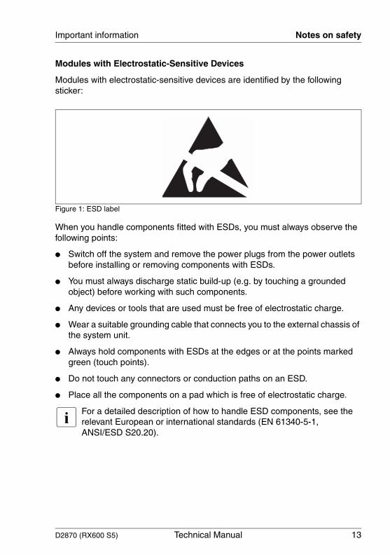
Modules with Electrostatic-Sensitive Devices
Modules with electrostatic-sensitive devices are identified by the following sticker:
Figure 1: ESD label
When you handle components fitted with ESDs, you must always observe the following points:
● Switch off the system and remove the power plugs from the power outlets before installing or removing components with ESDs.
● You must always discharge static build-up (e.g. by touching a grounded object) before working with such components.
● Any devices or tools that are used must be free of electrostatic charge.
● Wear a suitable grounding cable that connects you to the external chassis of the system unit.
● Always hold components with ESDs at the edges or at the points marked green (touch points).
● Do not touch any connectors or conduction paths on an ESD.
● Place all the components on a pad which is free of electrostatic charge.
I For a detailed description of how to handle ESD components, see the relevant European or international standards (EN 61340-5-1, ANSI/ESD S20.20).
14 Technical Manual D2870 (RX600 S5)
CE certificate of conformity Important information
© c
ogn
itas.
Ges
ells
chft
für
Tech
nik-
Dok
umen
tatio
n m
bH 2
010
P
fad:
C:\P
rogr
am
me\
FC
T\ti
m_a
pp\ti
m_l
oca
l\wor
k\P
ICH
OL
\OB
J_D
OK
U-5
683-
001
.fm
Notes about boards
● During installation/deinstallation of the board, observe the specific instructions described in the service supplement for the respective server.
● Shut down the server and disconnect the power plug, before you make modifications on an installed board.
● To prevent damage to the board, the components and conductors on it, please take great care when you insert or remove boards. Take great care to ensure that extension boards are slotted in straight, without damaging components or conductors on the board, or any other components, for example EMI spring contacts.
● Be careful with the locking mechanisms (catches, centring pins etc.) when you replace the system board or components on it, for example memory modules or processors.
● Never use sharp objects (screw drivers) for leverage.
● Do not damage or modify internal cables or devices. Doing so may cause a device failure, fire, or electric shock.
● Do not touch the circuitry on boards or soldered parts. Hold the metallic areas or the edges of the circuit boards.
2.2 CE certificate of conformity
The board complies with the requirements of the EC directives 2004/108/EC regarding “Electromagnetic Compatibility” and 2006/95/EC “Low Voltage Directive”. This is indicated by the CE marking (CE = Communauté Européenne).
Compliance was tested in a typical PRIMERGY configuration.
D2870 (RX600 S5) Technical Manual 15
Important information Environmental protection
2.3 Environmental protection
Environmentally-friendly product design and development
This product has been designed in accordance with the Fujitsu standard for "environmentally friendly product design and development". This means that key factors such as durability, selection and labeling of materials, emissions, packaging, ease of dismantling and recycling have been taken into account.
This saves resources and thus reduces the harm done to the environment. Further information can be found at:
– http://ts.fujitsu.com/products/standard_servers/index.html (for the EMEA market)– http://primeserver.fujitsu.com/primergy/concept/ (for the Japanese market)
Energy-saving information
Devices that do not need to be constantly switched on should be switched off until they are needed as well as during long breaks and after completion of work.
Packaging information
This packaging information doesn’t apply to the Japanese market.
Do not throw away the packaging. You may need it later for transporting the system. If possible, the equipment should only be transported in its original packaging.
Information on handling consumables
Please dispose of printer consumables and batteries in accordance with the applicable national regulations.
In accordance with EU directives, batteries must not be disposed of with unsorted domestic waste. They can be returned free of charge to the manufacturer, dealer or an authorized agent for recycling or disposal.
16 Technical Manual D2870 (RX600 S5)
Environmental protection Important information
© c
ogn
itas.
Ges
ells
chft
für
Tech
nik-
Dok
umen
tatio
n m
bH 2
010
P
fad:
C:\P
rogr
am
me\
FC
T\ti
m_a
pp\ti
m_l
oca
l\wor
k\P
ICH
OL
\OB
J_D
OK
U-5
683-
001
.fm
All batteries containing pollutants are marked with a symbol (a crossed-out garbage can). They are also marked with the chemical symbol for the heavy metal that causes them to be categorized as containing pollutants:
Cd CadmiumHg MercuryPb Lead
Labels on plastic casing parts
Please avoid sticking your own labels on plastic parts wherever possible, since this makes it difficult to recycle them.
Returns, recycling and disposal
Please handle returns, recycling and disposal in accordance with local regulations.
Details regarding the return and recycling of devices and consumables within Europe can also be found in the "Returning used devices" manual, via your local Fujitsu branch or from our recycling center in Paderborn:
Fujitsu Technology SolutionsRecycling CenterD-33106 Paderborn
Tel. +49 5251 8 18010
Fax +49 5251 8 333 18010
The device must not be disposed of with domestic waste. This device is labeled in compliance with European directive 2002/96/EC on waste electrical and electronic equipment (WEEE).
This directive sets the framework for returning and recycling used equipment and is valid across the EU. When returning your used device, please use the return and collection systems available to you. Further information can be found at http://ts.fujitsu.com/recycling.
D2870 (RX600 S5) Technical Manual 17
3 Features
3.1 Overview
Processors
– Up to 4 Intel Xeon 7500 series processors – 4 Intel QuickPath Interconnects (up to 6,4 GT/s in each direction)– Intel NetBurst™ micro architecture– Hyper-Threading technology– Up to 2.0 MB L2 cache and 24 MB L3 cache
Main memory
– Up to 8 memory boards with 8 slots each for DDR3 memory modules (1066/1333 MHz) with 2 GB, 4 GB, 8 GB, and 16 GB capacity.
– Up to 1024 GB memory (with availability of 16 GB memory modules)– Minimum 4 GB (2 memory modules)– Maximum 32 Gbit/s band width (DDR3)– Hardware memory scrubbing – Single Device Data Correction (SDDC) function (Chipkill™)– Memory mirroring function– Optional hot-spare memory function
Chipset devices on the system board
– Intel E7500 chipset:
– 2x Intel Memory Controller Hub (MCH) – Intel Southbridge ICH10R – Intel Boxboro I/O Hub– Intel IOP321 I/O processor
Internal connectors
– 2x USB 2.0 connector– 6x SATA connector– Trusted Platform Module (TPM) (Option)– 2x USB Flash Module (UFM) (Option)
18 Technical Manual D2870 (RX600 S5)
Overview Features
© c
ogn
itas.
Ges
ells
chft
für
Tech
nik-
Dok
umen
tatio
n m
bH 2
010
P
fad:
C:\P
rogr
am
me\
FC
T\ti
m_a
pp\ti
m_l
oca
l\wor
k\P
ICH
OL
\OB
J_D
OK
U-5
684-
001
.fm
External connectors
– 2x USB 2.0 connector
I (Most of the external connectors are located on the I/O riser board, see section "Connectors and indicators on the I/O riser board" on page 51)
PCI Slots
– 2x hot-plug PCI Express 2.0 slots (x8)– 1x PCI Express 2.0 slot (x16)– 2x PCI Express 2.0 slots (x8)– 3x PCI Express 2.0 slots (x4)– 2x PCI Express 1.0 slots (x4)– 1x PCI Express 1.0 (x1), dedicated for I/O riser board– 1x PCI Express 2.0 (x8), dedicated for SAS controller card
Server management controller iRMC S2 on I/O riser
The following features are integrated into iRMC S2:
– Server class Super I/O (SIO)
– Remote KVMS
– Baseboard Management Controller (BMC) including the following functionality:
– 250MHz 32-bit ARM9 processor– IPMI 2.0– 6x I2C SMBus– Two 10/100 Ethernet controllers with RMII support– LPC ROM interface– SPI Flash interface– USB Device– One Serial Port– Three UART interfaces– DDR2 16-bit 667MHz memory– Chassis intrusion logic– PWM Control and Fan Tach Monitor– Voltage Level Monitor and Temperature Monitor– Real-Time Clock (RTC)– Two Watchdog Timers– System and Clock Control
D2870 (RX600 S5) Technical Manual 19
Features Overview
– Three Multi-Purpose Timers– Interrupt Controller– JTAG interface
– Graphics controller including the following features:
– Integrated Graphics Core– 2D hardware graphics acceleration– DDR2 memory interface supports up to 128Mbytes of memory– Supports all display resolutions up to 1600x1200 16bpp @ 75Hz– High-speed integrated 24-bit RAMDAC– Single-lane PCI Express host interface
LAN GbE controller Intel 82576 on I/O riser
This controller supports the following features:
– Two connector standard IEEE 802.3 Ethernet interface for 10BASE-T, 100BASE-TX, and 1000BASE-T (802.3, 802.3u, and 802.3ab) applications.
– Serializer-Deserializer (SerDes) to support 1000BASE-SX/LX (optical fiber) and gigabit backplane applications.
– SGMII for external PHY or SFP module.– Management of MAC and PHY Ethernet layer functions.– Management of PCI Express packet traffic across its transaction, link, and
physical/logical layers.– External SPI (4-wire) serial interface to Flash EEPROM devices up to 8MB
memory.– NI-SI / SMBus interface to BMC
BIOS features
– ROM based setup utility– Recovery BIOS– BIOS settings save and restore– Local BIOS update from USB device– Online update tools for main Windows and Linux versions– Local and remote update via ServerView Update Manager– SMBIOS V2.4– Remote PXE boot support– Remote iSCSI boot support
Environmental protection
Battery in holder for recycling
20 Technical Manual D2870 (RX600 S5)
Overview Features
© c
ogn
itas.
Ges
ells
chft
für
Tech
nik-
Dok
umen
tatio
n m
bH 2
010
P
fad:
C:\P
rogr
am
me\
FC
T\ti
m_a
pp\ti
m_l
oca
l\wor
k\P
ICH
OL
\OB
J_D
OK
U-5
684-
001
.fm
Power management
– Sleep states S0, S4, S5– ACPI 2.0
CSS (Customer Self Service)
I This feature is not available for the japanese market.
This system board supports the CSS functionality. You will find a description of CSS functionality in the operating manual of your server.
Aspect ratio
16.3" x 18.65"
USB Flash Module (option)
I This feature is not available for the japanese market.
The system board can be equipped by the manufacturer with up to two USB Flash Modules (UFM). The module can be used as optional memory for software (e.g. VMware) or as a software dongle.
Trusted Platform Module (option)
The system board can be equipped with a Trusted Platform Module (TPM) by the manufacturer or by an add-on kit. This module enables programs from third party manufacturers to store key information (e.g. drive encryption using Windows Bitlocker Drive Encryption).
The TPM is activated via the BIOS system (for more information, refer to the BIOS manual).
V CAUTION!
– When using the TPM, note the program descriptions provided by the third party manufacturers.
– You must also create a backup of the TPM content. To do this, follow the third party manufacturer's instructions. Without this backup, if the TPM or the system board is faulty you will not be able to access your data.
D2870 (RX600 S5) Technical Manual 21
Features Overview
– If a failure occurs, please inform your service about the TPM activation before it takes any action, and be prepared to provide them with your backup copies of the TPM content.
22 Technical Manual D2870 (RX600 S5)
Main memory Features
© c
ogn
itas.
Ges
ells
chft
für
Tech
nik-
Dok
umen
tatio
n m
bH 2
010
P
fad:
C:\P
rogr
am
me\
FC
T\ti
m_a
pp\ti
m_l
oca
l\wor
k\P
ICH
OL
\OB
J_D
OK
U-5
684-
001
.fm
3.2 Main memory
The system board provides slots for eight memory boards (two for each CPU), each of which can accommodate up to eight memory modules (DIMMs). The DIMM slots are suitable for 2 GB, 4GB, 8 GB, and 16 GB DDR3 DIMMs with 1066/ 1333 MHz. Thus the system board supports a maximum memory configuration of 1024 GB.
ECC with memory scrubbing and the single-device data correction (SDDC) function are standard. There is no support for non-ECC-DIMMs.
Although there is an assignment between memory boards and CPUs (see table on page 41), every CPU can access the memory installed in memory boards of all other CPUs.
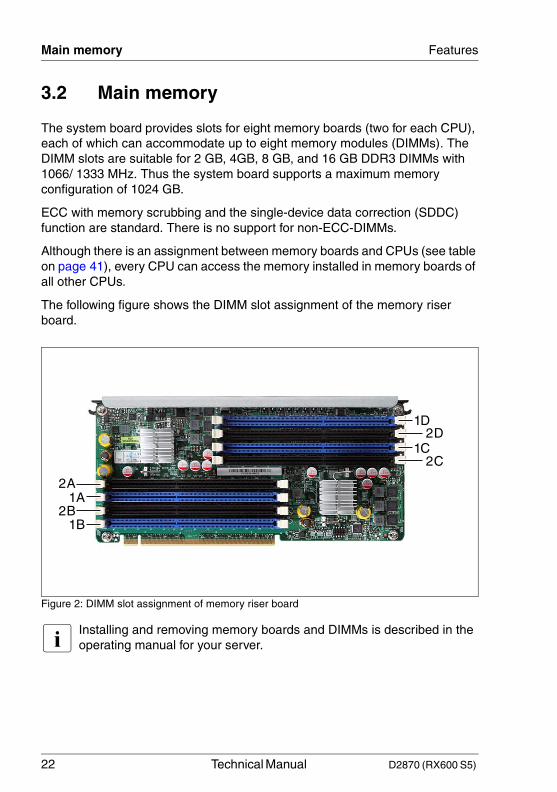
The following figure shows the DIMM slot assignment of the memory riser board.
Figure 2: DIMM slot assignment of memory riser board
I Installing and removing memory boards and DIMMs is described in the operating manual for your server.
1B2B
2A
2D
2C
1A
1D
1C
D2870 (RX600 S5) Technical Manual 23
Features Main memory
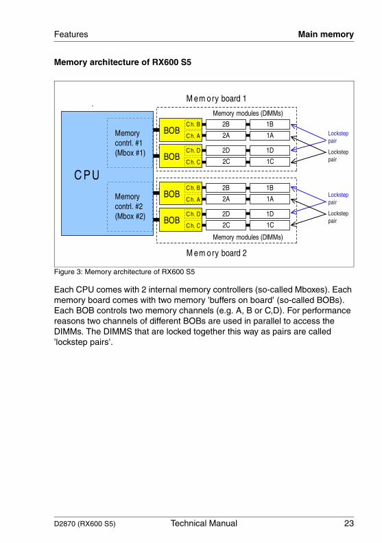
Memory architecture of RX600 S5
Figure 3: Memory architecture of RX600 S5
Each CPU comes with 2 internal memory controllers (so-called Mboxes). Each memory board comes with two memory ’buffers on board’ (so-called BOBs). Each BOB controls two memory channels (e.g. A, B or C,D). For performance reasons two channels of different BOBs are used in parallel to access the DIMMs. The DIMMS that are locked together this way as pairs are called ’lockstep pairs’.
24 Technical Manual D2870 (RX600 S5)
Main memory Features
© c
ogn
itas.
Ges
ells
chft
für
Tech
nik-
Dok
umen
tatio
n m
bH 2
010
P
fad:
C:\P
rogr
am
me\
FC
T\ti
m_a
pp\ti
m_l
oca
l\wor
k\P
ICH
OL
\OB
J_D
OK
U-5
684-
001
.fm
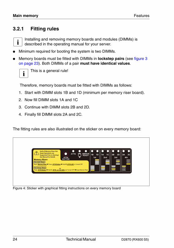
3.2.1 Fitting rules
I Installing and removing memory boards and modules (DIMMs) is described in the operating manual for your server.
● Minimum required for booting the system is two DIMMs.
● Memory boards must be fitted with DIMMs in lockstep pairs (see figure 3 on page 23). Both DIMMs of a pair must have identical values.
I This is a general rule!
Therefore, memory boards must be fitted with DIMMs as follows:
1. Start with DIMM slots 1B and 1D (minimum per memory riser board).
2. Now fill DIMM slots 1A and 1C
3. Continue with DIMM slots 2B and 2D.
4. Finally fill DIMM slots 2A and 2C.
The fitting rules are also illustrated on the sticker on every memory board:
Figure 4: Sticker with graphical fitting instructions on every memory board
D2870 (RX600 S5) Technical Manual 25
Features Main memory
3.2.2 Memory configuration modes
There are four different configuration modes:
– Spare mode
– Interleaving mode
– Mirroring mode
– Hemisphere mode
I After installing the DIMMs the necessary specific settings have to be done within the BIOS of the server. See the "D2870 BIOS Setup Utility for PRIMERGY RX600 S5" manual for detailed information.
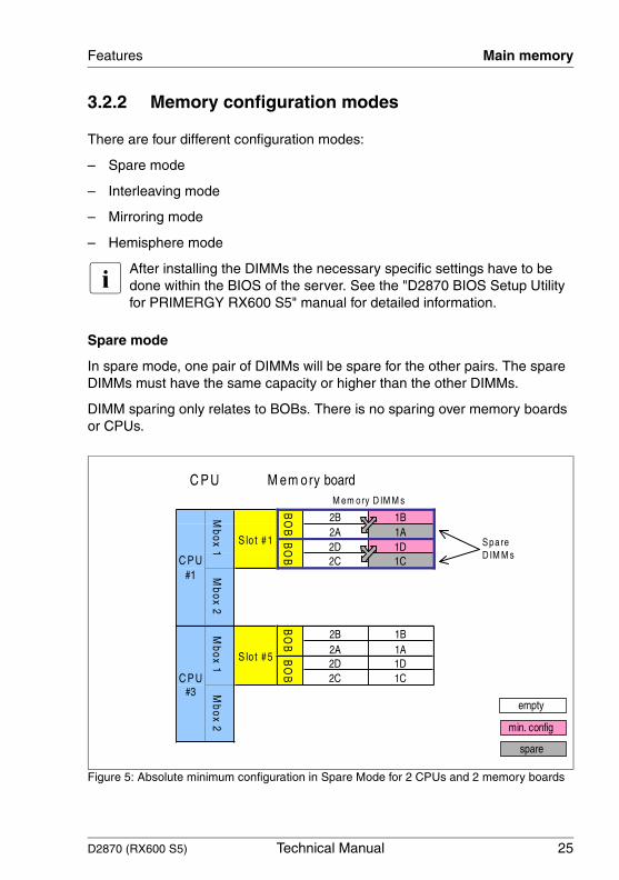
Spare mode
In spare mode, one pair of DIMMs will be spare for the other pairs. The spare DIMMs must have the same capacity or higher than the other DIMMs.
DIMM sparing only relates to BOBs. There is no sparing over memory boards or CPUs.
Figure 5: Absolute minimum configuration in Spare Mode for 2 CPUs and 2 memory boards
26 Technical Manual D2870 (RX600 S5)
Main memory Features
© c
ogn
itas.
Ges
ells
chft
für
Tech
nik-
Dok
umen
tatio
n m
bH 2
010
P
fad:
C:\P
rogr
am
me\
FC
T\ti
m_a
pp\ti
m_l
oca
l\wor
k\P
ICH
OL
\OB
J_D
OK
U-5
684-
001
.fm
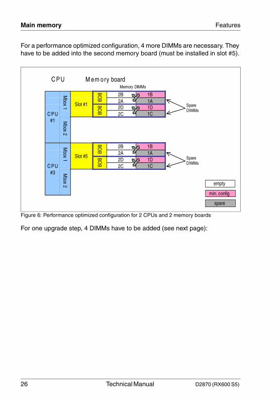
For a performance optimized configuration, 4 more DIMMs are necessary. They have to be added into the second memory board (must be installed in slot #5).
Figure 6: Performance optimized configuration for 2 CPUs and 2 memory boards
For one upgrade step, 4 DIMMs have to be added (see next page):
D2870 (RX600 S5) Technical Manual 27
Features Main memory
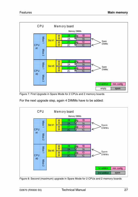
Figure 7: First Upgrade in Spare Mode for 2 CPUs and 2 memory boards
For the next upgrade step, again 4 DIMMs have to be added:
Figure 8: Second (maximum) upgrade in Spare Mode for 2 CPUs and 2 memory boards
28 Technical Manual D2870 (RX600 S5)
Main memory Features
© c
ogn
itas.
Ges
ells
chft
für
Tech
nik-
Dok
umen
tatio
n m
bH 2
010
P
fad:
C:\P
rogr
am
me\
FC
T\ti
m_a
pp\ti
m_l
oca
l\wor
k\P
ICH
OL
\OB
J_D
OK
U-5
684-
001
.fm
Interleaving Mode
In Interleaving mode the cache lines will be distributed over different memory boards (via the Mboxes) for better performance.
Interleaving Types:
– 2-way interleaving (also called "Intra Socket Interleaving")
This type requires 2 memory boards per CPU and is possible with 2, 3 or 4 CPUs. The data are distributed over the Mboxes of each CPU (see figure 9 on page 29). Therefore, this type is called "Intra Socket Interleaving".
– 4-way interleaving mode (also called "Inter Socket Interleaving")
This type requires 2 memory boards per CPU and is possible with 2 or 4 CPUs. The data are distributed over the Mboxes of two CPUs (see figure 10 on page 30). Therefore, this type is called "Inter Socket Interleaving".
– 8-way interleaving mode (also called "Inter Socket Interleaving")
This type is only possible with 4 CPUs and requires 2 memory boards per CPU. The data are distributed over the Mboxes of four CPUs (see figure 11 on page 31). Therefore, this type is called "Inter Socket Interleaving".
D2870 (RX600 S5) Technical Manual 29
Features Main memory
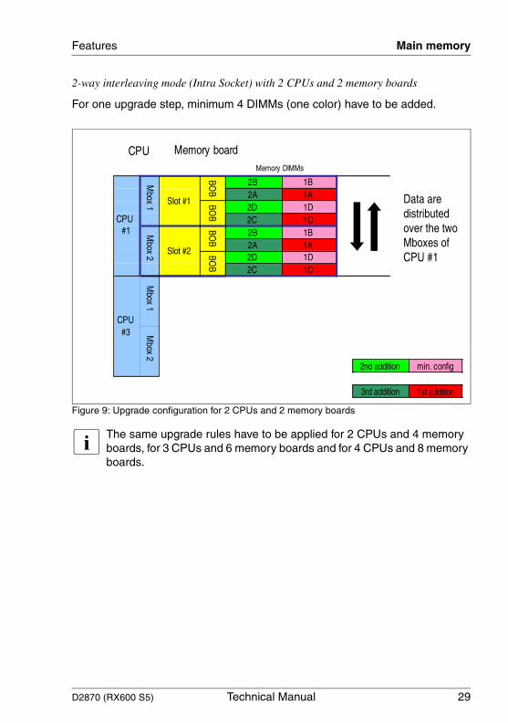
2-way interleaving mode (Intra Socket) with 2 CPUs and 2 memory boards
For one upgrade step, minimum 4 DIMMs (one color) have to be added.
Figure 9: Upgrade configuration for 2 CPUs and 2 memory boards
I The same upgrade rules have to be applied for 2 CPUs and 4 memory boards, for 3 CPUs and 6 memory boards and for 4 CPUs and 8 memory boards.
30 Technical Manual D2870 (RX600 S5)
Main memory Features
© c
ogn
itas.
Ges
ells
chft
für
Tech
nik-
Dok
umen
tatio
n m
bH 2
010
P
fad:
C:\P
rogr
am
me\
FC
T\ti
m_a
pp\ti
m_l
oca
l\wor
k\P
ICH
OL
\OB
J_D
OK
U-5
684-
001
.fm
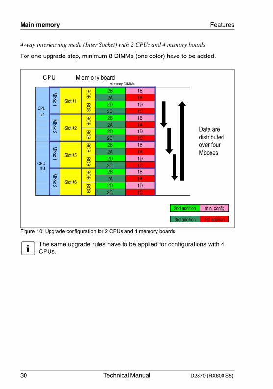
4-way interleaving mode (Inter Socket) with 2 CPUs and 4 memory boards
For one upgrade step, minimum 8 DIMMs (one color) have to be added.
Figure 10: Upgrade configuration for 2 CPUs and 4 memory boards
I The same upgrade rules have to be applied for configurations with 4 CPUs.
D2870 (RX600 S5) Technical Manual 31
Features Main memory
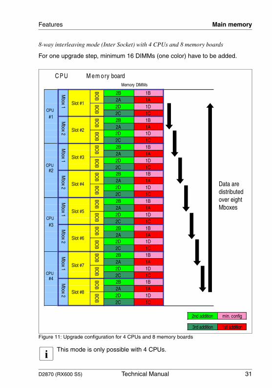
8-way interleaving mode (Inter Socket) with 4 CPUs and 8 memory boards
For one upgrade step, minimum 16 DIMMs (one color) have to be added.
Figure 11: Upgrade configuration for 4 CPUs and 8 memory boards
I This mode is only possible with 4 CPUs.
32 Technical Manual D2870 (RX600 S5)
Main memory Features
© c
ogn
itas.
Ges
ells
chft
für
Tech
nik-
Dok
umen
tatio
n m
bH 2
010
P
fad:
C:\P
rogr
am
me\
FC
T\ti
m_a
pp\ti
m_l
oca
l\wor
k\P
ICH
OL
\OB
J_D
OK
U-5
684-
001
.fm
Mirroring mode
In mirroring mode, all data are copied within the main memory. Therefore, only 50% of the total memory is available for the operating system.
Two types of mirroring modes are available:
– Intrasocket Mirroring
Memory will be mirrored from one Mbox to the other Mbox within the same CPU (see figure 12 on page 33). Intrasocket Mirroring is possible for all CPU configurations (2, 3, or 4).
I This mode requires 2 memory boards per CPU (2, 4, 6, or 8 total). All DIMMS must be identical (same capacity and technology)!
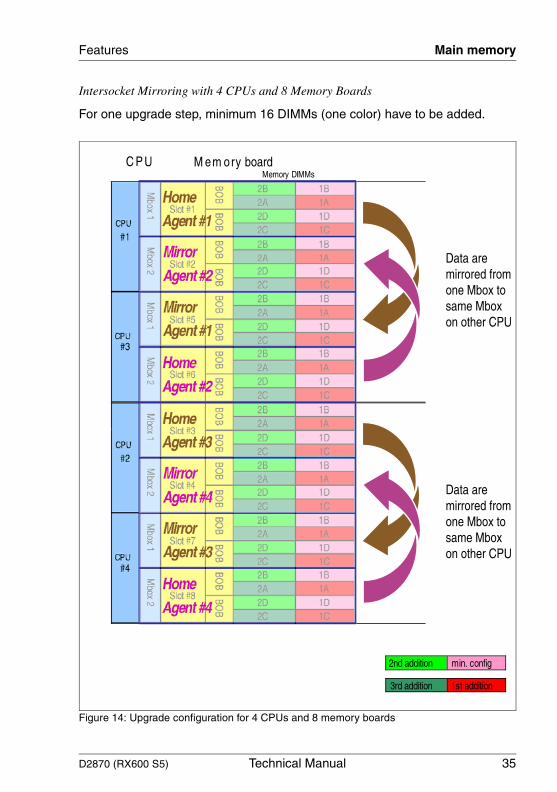
– Intersocket Mirroring
Memory will be mirrored from one Mbox to an Mbox on another CPU (home agent to mirror agent, (see figure 14 on page 35). Intersocket mirroring is only possible with 4 CPUs, not with 2 or 3 CPUs.
I This mode requires 2 memory boards per CPU (8 total). All DIMMS must be identical (same capacity and technology)!
D2870 (RX600 S5) Technical Manual 33
Features Main memory
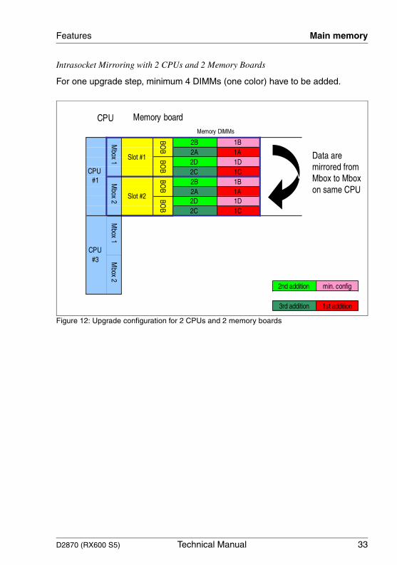
Intrasocket Mirroring with 2 CPUs and 2 Memory Boards
For one upgrade step, minimum 4 DIMMs (one color) have to be added.
Figure 12: Upgrade configuration for 2 CPUs and 2 memory boards
34 Technical Manual D2870 (RX600 S5)
Main memory Features
© c
ogn
itas.
Ges
ells
chft
für
Tech
nik-
Dok
umen
tatio
n m
bH 2
010
P
fad:
C:\P
rogr
am
me\
FC
T\ti
m_a
pp\ti
m_l
oca
l\wor
k\P
ICH
OL
\OB
J_D
OK
U-5
684-
001
.fm
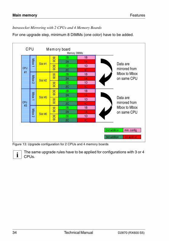
Intrasocket Mirroring with 2 CPUs and 4 Memory Boards
For one upgrade step, minimum 8 DIMMs (one color) have to be added.
Figure 13: Upgrade configuration for 2 CPUs and 4 memory boards
I The same upgrade rules have to be applied for configurations with 3 or 4 CPUs.
D2870 (RX600 S5) Technical Manual 35
Features Main memory
Intersocket Mirroring with 4 CPUs and 8 Memory Boards
For one upgrade step, minimum 16 DIMMs (one color) have to be added.
Figure 14: Upgrade configuration for 4 CPUs and 8 memory boards
36 Technical Manual D2870 (RX600 S5)
Main memory Features
© c
ogn
itas.
Ges
ells
chft
für
Tech
nik-
Dok
umen
tatio
n m
bH 2
010
P
fad:
C:\P
rogr
am
me\
FC
T\ti
m_a
pp\ti
m_l
oca
l\wor
k\P
ICH
OL
\OB
J_D
OK
U-5
684-
001
.fm
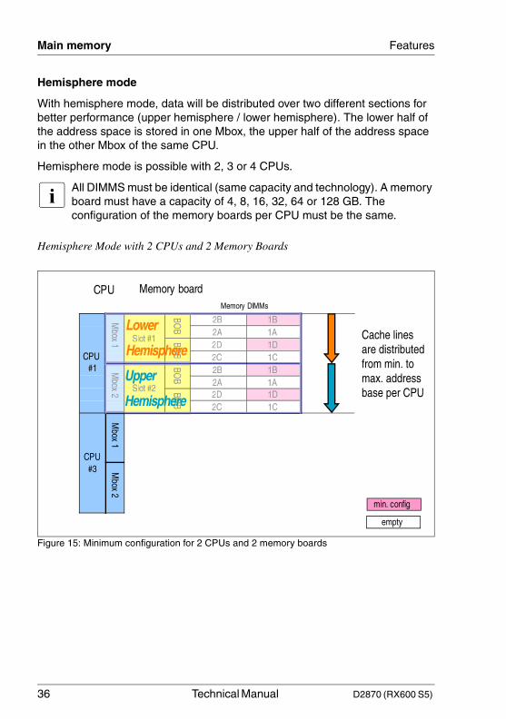
Hemisphere mode
With hemisphere mode, data will be distributed over two different sections for better performance (upper hemisphere / lower hemisphere). The lower half of the address space is stored in one Mbox, the upper half of the address space in the other Mbox of the same CPU.
Hemisphere mode is possible with 2, 3 or 4 CPUs.
I All DIMMS must be identical (same capacity and technology). A memory board must have a capacity of 4, 8, 16, 32, 64 or 128 GB. The configuration of the memory boards per CPU must be the same.
Hemisphere Mode with 2 CPUs and 2 Memory Boards
Figure 15: Minimum configuration for 2 CPUs and 2 memory boards
D2870 (RX600 S5) Technical Manual 37
Features Main memory
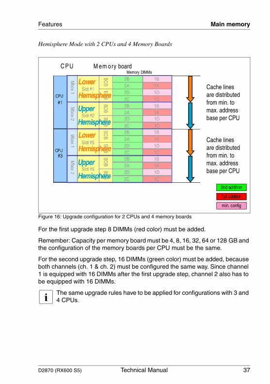
Hemisphere Mode with 2 CPUs and 4 Memory Boards
Figure 16: Upgrade configuration for 2 CPUs and 4 memory boards
For the first upgrade step 8 DIMMs (red color) must be added.
Remember: Capacity per memory board must be 4, 8, 16, 32, 64 or 128 GB and the configuration of the memory boards per CPU must be the same.
For the second upgrade step, 16 DIMMs (green color) must be added, because both channels (ch. 1 & ch. 2) must be configured the same way. Since channel 1 is equipped with 16 DIMMs after the first upgrade step, channel 2 also has to be equipped with 16 DIMMs.
I The same upgrade rules have to be applied for configurations with 3 and 4 CPUs.
38 Technical Manual D2870 (RX600 S5)
Main memory Features
© c
ogn
itas.
Ges
ells
chft
für
Tech
nik-
Dok
umen
tatio
n m
bH 2
010
P
fad:
C:\P
rogr
am
me\
FC
T\ti
m_a
pp\ti
m_l
oca
l\wor
k\P
ICH
OL
\OB
J_D
OK
U-5
684-
001
.fm
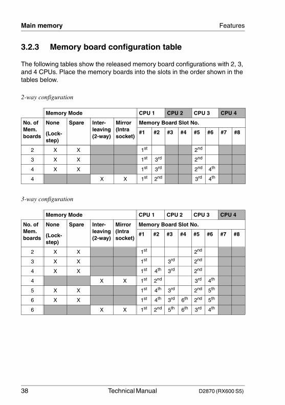
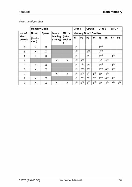
3.2.3 Memory board configuration table
The following tables show the released memory board configurations with 2, 3, and 4 CPUs. Place the memory boards into the slots in the order shown in the tables below.
2-way configuration
3-way configuration
Memory Mode CPU 1 CPU 2 CPU 3 CPU 4
No. of Mem. boards
None
(Lock-step)
Spare Inter-leaving (2-way)
Mirror (Intra socket)
Memory Board Slot No.
#1 #2 #3 #4 #5 #6 #7 #8
2 X X 1st 2nd
3 X X 1st 3rd 2nd
4 X X 1st 3rd 2nd 4th
4 X X 1st 2nd 3rd 4th
Memory Mode CPU 1 CPU 2 CPU 3 CPU 4
No. of Mem. boards
None
(Lock-step)
Spare Inter-leaving (2-way)
Mirror (Intra socket)
Memory Board Slot No.
#1 #2 #3 #4 #5 #6 #7 #8
2 X X 1st 2nd
3 X X 1st 3rd 2nd
4 X X 1st 4th 3rd 2nd
4 X X 1st 2nd 3rd 4th
5 X X 1st 4th 3rd 2nd 5th
6 X X 1st 4th 3rd 6th 2nd 5th
6 X X 1st 2nd 5th 6th 3rd 4th
D2870 (RX600 S5) Technical Manual 39
Features Main memory
4-way configuration
Memory Mode CPU 1 CPU 2 CPU 3 CPU 4
No. of Mem. boards
None
(Lock-step)
Spare Inter-leaving (2-way)
Mirror (Intra socket)
Memory Board Slot No.
#1 #2 #3 #4 #5 #6 #7 #8
2 X X 1st 2nd
3 X X 1st 3rd 2nd
4 X X 1st 3rd 2nd 4th
4 X X 1st 2nd 3rd 4th
5 X X 1st 5th 3rd 2nd 4th
6 X X 1st 5th 3rd 2nd 6th 4th
6 X X 1st 2nd 5th 6th 3rd 4th
7 X X 1st 5th 3rd 7th 2nd 6th 4th
8 X X X X 1st 2nd 5th 6th 3rd 4th 7th 8th
40 Technical Manual D2870 (RX600 S5)
PCIe slots Features
© c
ogn
itas.
Ges
ells
chft
für
Tech
nik-
Dok
umen
tatio
n m
bH 2
010
P
fad:
C:\P
rogr
am
me\
FC
T\ti
m_a
pp\ti
m_l
oca
l\wor
k\P
ICH
OL
\OB
J_D
OK
U-5
684-
001
.fm
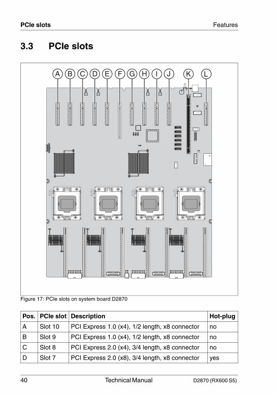
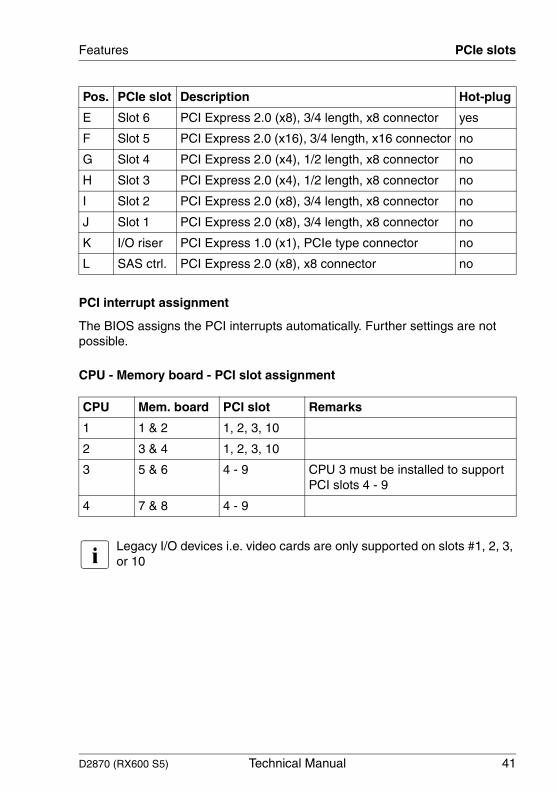
3.3 PCIe slots
Figure 17: PCIe slots on system board D2870
Pos. PCIe slot Description Hot-plug
A Slot 10 PCI Express 1.0 (x4), 1/2 length, x8 connector no
B Slot 9 PCI Express 1.0 (x4), 1/2 length, x8 connector no
C Slot 8 PCI Express 2.0 (x4), 3/4 length, x8 connector no
D Slot 7 PCI Express 2.0 (x8), 3/4 length, x8 connector yes
K LF G H I JA B C D E
D2870 (RX600 S5) Technical Manual 41
Features PCIe slots
PCI interrupt assignment
The BIOS assigns the PCI interrupts automatically. Further settings are not possible.
CPU - Memory board - PCI slot assignment
I Legacy I/O devices i.e. video cards are only supported on slots #1, 2, 3, or 10
E Slot 6 PCI Express 2.0 (x8), 3/4 length, x8 connector yes
F Slot 5 PCI Express 2.0 (x16), 3/4 length, x16 connector no
G Slot 4 PCI Express 2.0 (x4), 1/2 length, x8 connector no
H Slot 3 PCI Express 2.0 (x4), 1/2 length, x8 connector no
I Slot 2 PCI Express 2.0 (x8), 3/4 length, x8 connector no
J Slot 1 PCI Express 2.0 (x8), 3/4 length, x8 connector no
K I/O riser PCI Express 1.0 (x1), PCIe type connector no
L SAS ctrl. PCI Express 2.0 (x8), x8 connector no
CPU Mem. board PCI slot Remarks
1 1 & 2 1, 2, 3, 10
2 3 & 4 1, 2, 3, 10
3 5 & 6 4 - 9 CPU 3 must be installed to support PCI slots 4 - 9
4 7 & 8 4 - 9
Pos. PCIe slot Description Hot-plug
42 Technical Manual D2870 (RX600 S5)
Screen resolutions Features
© c
ogn
itas.
Ges
ells
chft
für
Tech
nik-
Dok
umen
tatio
n m
bH 2
010
P
fad:
C:\P
rogr
am
me\
FC
T\ti
m_a
pp\ti
m_l
oca
l\wor
k\P
ICH
OL
\OB
J_D
OK
U-5
684-
001
.fm
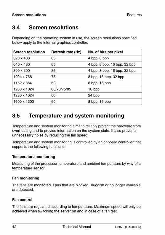
3.4 Screen resolutions
Depending on the operating system in use, the screen resolutions specified below apply to the internal graphics controller.
3.5 Temperature and system monitoring
Temperature and system monitoring aims to reliably protect the hardware from overheating and to provide information on the system state. It also prevents unnecessary noise by reducing the fan speed.
Temperature and system monitoring is controlled by an onboard controller that supports the following functions:
Temperature monitoring
Measuring of the processor temperature and ambient temperature by way of a temperature sensor.
Fan monitoring
The fans are monitored. Fans that are blocked, sluggish or no longer available are detected.
Fan control
The fans are regulated according to temperature. Maximum speed will only be achieved when switching the server on and in case of a fan test.
Screen resolution Refresh rate (Hz) No. of bits per pixel
320 x 400 85 4 bpp, 8 bpp
640 x 480 85 4 bpp, 8 bpp, 16 bpp, 32 bpp
800 x 600 85 4 bpp, 8 bpp, 16 bpp, 32 bpp
1024 x 768 75 8 bpp, 16 bpp, 32 bpp
1152 x 864 60 8 bpp, 16 bpp
1280 x 1024 60/70/75/85 16 bpp
1280 x 1024 60 24 bpp
1600 x 1200 60 8 bpp, 16 bpp
D2870 (RX600 S5) Technical Manual 43
Features Temperature and system monitoring
Sensor monitoring
Any fault in, or the removal of, a temperature sensor is detected. Should this happen, all fans monitored by this sensor run at maximum speed to ensure the highest possible protection of the hardware.
Power monitoring
When the voltage exceeds or falls below the warning levels, an alert is issued.
System Event Log (SEL)
All monitored events of the system board are signalized via the Global Error LED or CSS LED and recorded in the System Event Log. They could be retrieved in the BIOS Setup, iRMC S2’s Web interface or via the ServerView Operations Manager.
44 Technical Manual D2870 (RX600 S5)
Connectors, jumpers and indicators Features
© c
ogn
itas.
Ges
ells
chft
für
Tech
nik-
Dok
umen
tatio
n m
bH 2
010
P
fad:
C:\P
rogr
am
me\
FC
T\ti
m_a
pp\ti
m_l
oca
l\wor
k\P
ICH
OL
\OB
J_D
OK
U-5
684-
001
.fm
3.6 Connectors, jumpers and indicators
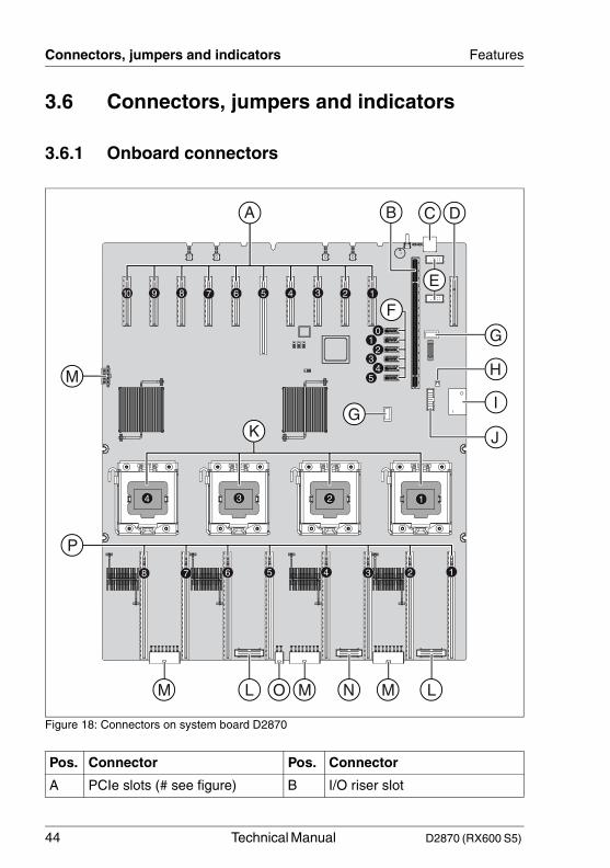
3.6.1 Onboard connectors
Figure 18: Connectors on system board D2870
Pos. Connector Pos. Connector
A PCIe slots (# see figure) B I/O riser slot
12345678
1234
12345678910
B C
G
F
M
P
LMNMOLM
H
I
J
G
E
D
54
32
10
K
A
D2870 (RX600 S5) Technical Manual 45
Features Connectors, jumpers and indicators
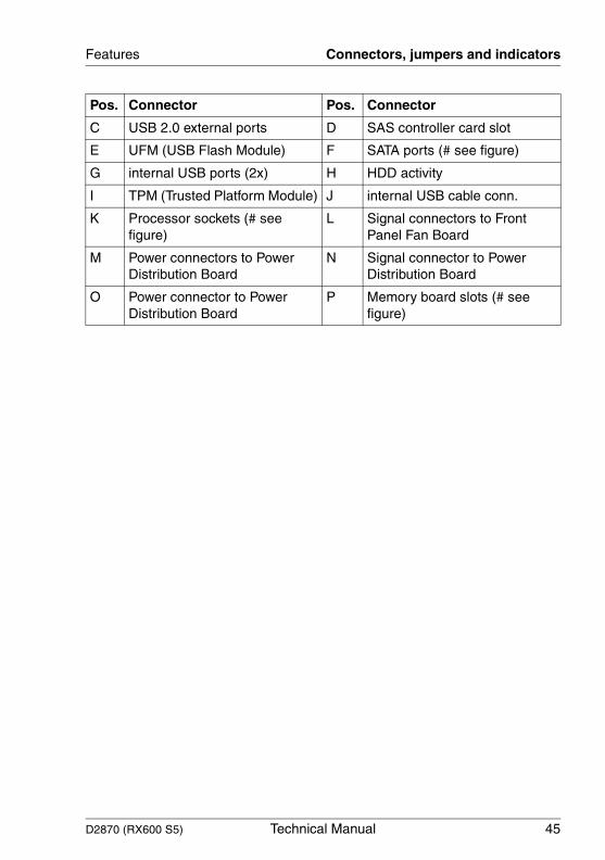
C USB 2.0 external ports D SAS controller card slot
E UFM (USB Flash Module) F SATA ports (# see figure)
G internal USB ports (2x) H HDD activity
I TPM (Trusted Platform Module) J internal USB cable conn.
K Processor sockets (# see figure)
L Signal connectors to Front Panel Fan Board
M Power connectors to Power Distribution Board
N Signal connector to Power Distribution Board
O Power connector to Power Distribution Board
P Memory board slots (# see figure)
Pos. Connector Pos. Connector
46 Technical Manual D2870 (RX600 S5)
Connectors, jumpers and indicators Features
© c
ogn
itas.
Ges
ells
chft
für
Tech
nik-
Dok
umen
tatio
n m
bH 2
010
P
fad:
C:\P
rogr
am
me\
FC
T\ti
m_a
pp\ti
m_l
oca
l\wor
k\P
ICH
OL
\OB
J_D
OK
U-5
684-
001
.fm
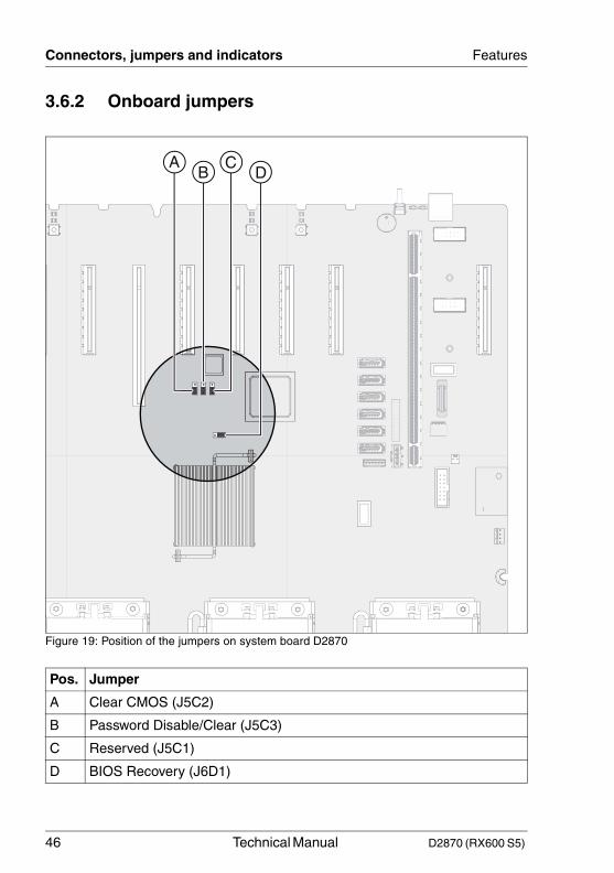
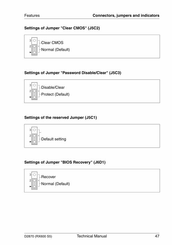
3.6.2 Onboard jumpers
Figure 19: Position of the jumpers on system board D2870
Pos. Jumper
A Clear CMOS (J5C2)
B Password Disable/Clear (J5C3)
C Reserved (J5C1)
D BIOS Recovery (J6D1)
DC
BA
D2870 (RX600 S5) Technical Manual 47
Features Connectors, jumpers and indicators
Settings of Jumper "Clear CMOS" (J5C2)
Settings of Jumper "Password Disable/Clear" (J5C3)
Settings of the reserved Jumper (J5C1)
Settings of Jumper "BIOS Recovery" (J6D1)
Clear CMOS
Normal (Default)
Disable/Clear
Protect (Default)
Default setting
Recover
Normal (Default)
48 Technical Manual D2870 (RX600 S5)
Connectors, jumpers and indicators Features
© c
ogn
itas.
Ges
ells
chft
für
Tech
nik-
Dok
umen
tatio
n m
bH 2
010
P
fad:
C:\P
rogr
am
me\
FC
T\ti
m_a
pp\ti
m_l
oca
l\wor
k\P
ICH
OL
\OB
J_D
OK
U-5
684-
001
.fm
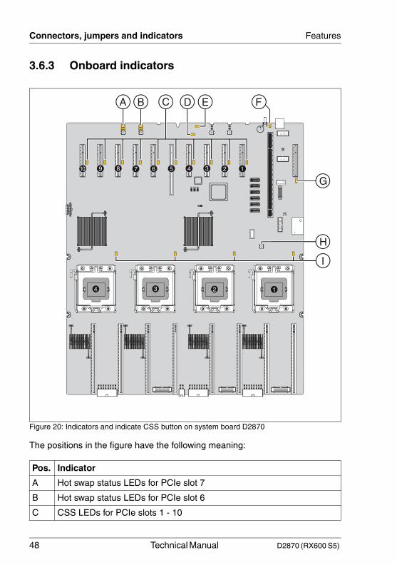
3.6.3 Onboard indicators
Figure 20: Indicators and indicate CSS button on system board D2870
The positions in the figure have the following meaning:
Pos. Indicator
A Hot swap status LEDs for PCIe slot 7
B Hot swap status LEDs for PCIe slot 6
C CSS LEDs for PCIe slots 1 - 10
1234
12345678910
F
G
H
I
A B D EC
D2870 (RX600 S5) Technical Manual 49
Features Connectors, jumpers and indicators
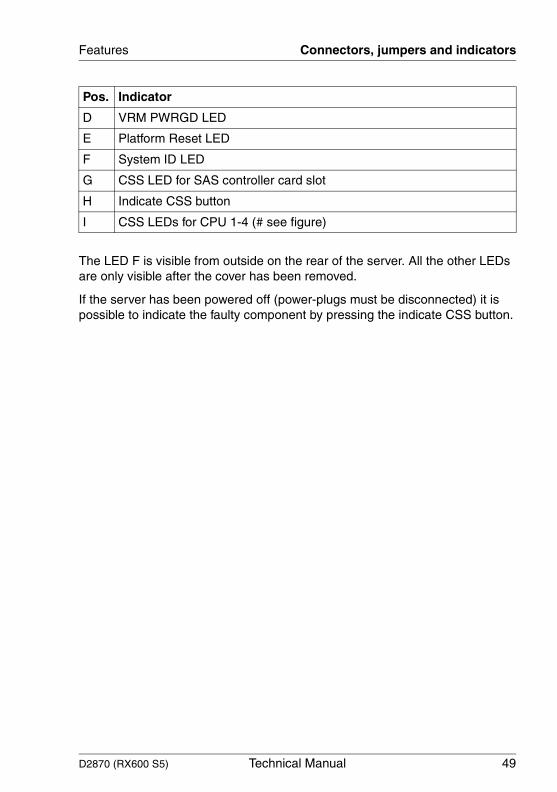
The LED F is visible from outside on the rear of the server. All the other LEDs are only visible after the cover has been removed.
If the server has been powered off (power-plugs must be disconnected) it is possible to indicate the faulty component by pressing the indicate CSS button.
D VRM PWRGD LED
E Platform Reset LED
F System ID LED
G CSS LED for SAS controller card slot
H Indicate CSS button
I CSS LEDs for CPU 1-4 (# see figure)
Pos. Indicator
50 Technical Manual D2870 (RX600 S5)
Connectors, jumpers and indicators Features
© c
ogn
itas.
Ges
ells
chft
für
Tech
nik-
Dok
umen
tatio
n m
bH 2
010
P
fad:
C:\P
rogr
am
me\
FC
T\ti
m_a
pp\ti
m_l
oca
l\wor
k\P
ICH
OL
\OB
J_D
OK
U-5
684-
001
.fm
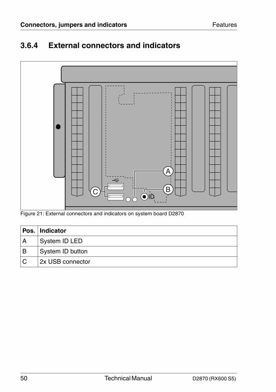
3.6.4 External connectors and indicators
Figure 21: External connectors and indicators on system board D2870
Pos. Indicator
A System ID LED
B System ID button
C 2x USB connector
B
A
CID
D2870 (RX600 S5) Technical Manual 51
Features Connectors, jumpers and indicators
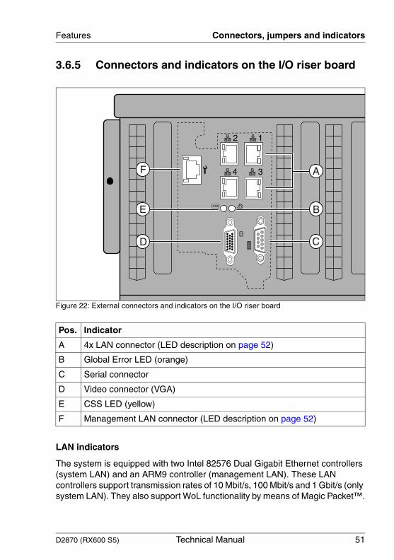
3.6.5 Connectors and indicators on the I/O riser board
Figure 22: External connectors and indicators on the I/O riser board
LAN indicators
The system is equipped with two Intel 82576 Dual Gigabit Ethernet controllers (system LAN) and an ARM9 controller (management LAN). These LAN controllers support transmission rates of 10 Mbit/s, 100 Mbit/s and 1 Gbit/s (only system LAN). They also support WoL functionality by means of Magic Packet™.
Pos. Indicator
A 4x LAN connector (LED description on page 52)
B Global Error LED (orange)
C Serial connector
D Video connector (VGA)
E CSS LED (yellow)
F Management LAN connector (LED description on page 52)
2 1
34
CSS B
A
C
F
E
D
52 Technical Manual D2870 (RX600 S5)
Connectors, jumpers and indicators Features
© c
ogn
itas.
Ges
ells
chft
für
Tech
nik-
Dok
umen
tatio
n m
bH 2
010
P
fad:
C:\P
rogr
am
me\
FC
T\ti
m_a
pp\ti
m_l
oca
l\wor
k\P
ICH
OL
\OB
J_D
OK
U-5
684-
001
.fm
It is also possible to boot a system without its own boot hard disk via LAN. PXE is supported for this.
The separate management LAN connector is used as a management interface (iRMC S2) and is prepared for operation with the Remote Management.
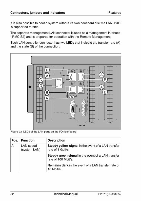
Each LAN controller connector has two LEDs that indicate the transfer rate (A) and the state (B) of the connection:
Figure 23: LEDs of the LAN ports on the I/O riser board
Pos. Function Description
A LAN speed (system LAN)
Steady yellow signal in the event of a LAN transfer rate of 1 Gbit/s.
Steady green signal in the event of a LAN transfer rate of 100 Mbit/s.
Remains dark in the event of a LAN transfer rate of 10 Mbit/s.
2 1
34
CSS
C
D
B
B
A
AB
A
BA
D2870 (RX600 S5) Technical Manual 53
Features Connectors, jumpers and indicators
B LAN link/transfer (system LAN)
Steady green signal when a LAN connection exists.
Remains dark when no LAN connection exists.
Flashes green when LAN transfer takes place.
C LAN link/transfer (management LAN)
Steady green signal when a LAN connection exists.
Remains dark when no LAN connection exists.
Flashes green when LAN transfer takes place.
D LAN speed (management LAN)
Steady green signal in the event of a LAN transfer rate of 100 Mbit/s.
Remains dark in the event of a LAN transfer rate of 10 Mbit/s.
Pos. Function Description
54 Technical Manual D2870 (RX600 S5)
Connectors, jumpers and indicators Features
© c
ogn
itas.
Ges
ells
chft
für
Tech
nik-
Dok
umen
tatio
n m
bH 2
010
P
fad:
C:\P
rogr
am
me\
FC
T\ti
m_a
pp\ti
m_l
oca
l\wor
k\P
ICH
OL
\OB
J_D
OK
U-5
684-
001
.fm
D2870 (RX600 S5) Technical Manual 55
4 Replacing the lithium batteryTo allow permanent saving of the system information, a lithium battery is installed which supplies the CMOS memory with power. If the battery voltage is too low or the battery is empty, a corresponding error message is displayed. The lithium battery must then be replaced.
V CAUTION!
The lithium battery must be replaced with an identical battery or with a battery type recommended by the manufacturer. This information doesn’t apply to the Japanese market.
Do not throw lithium batteries into the trash can. They must be disposed of in accordance with local regulations on special waste.
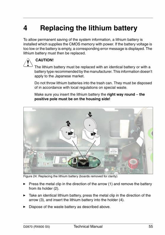
Make sure you insert the lithium battery the right way round – the positive pole must be on the housing side!
Figure 24: Replacing the lithium battery (boards removed for clarity)
Ê Press the metal clip in the direction of the arrow (1) and remove the battery from its holder (2).
Ê Take an identical lithium battery, press the metal clip in the direction of the arrow (3), and insert the lithium battery into the holder (4).
Ê Dispose of the waste battery as described above.
+
+
1
2
4
3
56 Technical Manual D2870 (RX600 S5)
Replacing the lithium battery
© c
ogn
itas.
Ges
ells
chft
für
Tech
nik-
Dok
umen
tatio
n m
bH 2
010
P
fad:
C:\P
rogr
am
me\
FC
T\ti
m_a
pp\ti
m_l
oca
l\wor
k\P
ICH
OL
\OB
J_D
OK
U-5
685-
001
.fm


![cardchecklist 391105 script · CIR acp s5-21 ON S5-36 a SPR S5-41 s5-77 DR S5-58 a R S5-5 acp OSPR S5-22 ON S5-37 C] S5-42 acp DR CIR apR a R S5-27 C] PR S-5-88 a R S5-47 CIN s5-64](https://img.pdfslide.net/doc/110x75/5f34fee96b83591bd77e360b/cardchecklist-391105-script-cir-acp-s5-21-on-s5-36-a-spr-s5-41-s5-77-dr-s5-58-a.jpg)