Embed Size (px)
Citation preview

System Description AC500
Scalable PLC for Individual Automation Hardware
DC532DC532PM581CM577CM572


____________________________________________________________________________________________________________
V2 AC500 Hardware 0-1 Contents AC500 / Issued: 05.2007
Contents Hardware AC500
System data and system configuration ......................................................................... 1-4
System data ............................................................................................................................................... 1-4
Mounting and disassembling the Terminal Bases, the CPUs and the couplers ........................................ 1-8
Mounting and disassembling the Terminal Units and the I/O modules ................................................... 1-14
Mechanical dimensions ........................................................................................................................... 1-18
Switch-gear cabinet assembly ................................................................................................................. 1-21
Insertion / replacement of the Lithium battery ......................................................................................... 1-22
Insertion of the SD Memory Card ............................................................................................................ 1-24
Connection system .................................................................................................................................. 1-25
Mechanical encoding ............................................................................................................................... 1-29
General wiring recommendations ............................................................................................................ 1-31
Behaviour of the system in case of power supply interruptions and power recovering ........................... 1-31
I/O-Bus...................................................................................................................................................... 1-32
Serial interfaces of the CPU Terminal Bases ........................................................................................... 1-32
Serial interface COM1 .............................................................................................................................. 1-33
CS31 system bus...................................................................................................................................... 1-35
Serial interface COM2 .............................................................................................................................. 1-40
FieldBusPlug / FBP................................................................................................................................... 1-42
Modbus ..................................................................................................................................................... 1-43
PROFIBUS................................................................................................................................................ 1-44
Ethernet .................................................................................................................................................... 1-50
ARCNET ................................................................................................................................................... 1-51
General considerations for EMC-conforming assembly and construction ...................................................................................................................................... 1-54
General principles ..................................................................................................................................... 1-54
Cable routing............................................................................................................................................. 1-54
Cable shields ............................................................................................................................................ 1-55
Switch-gear cabinet .................................................................................................................................. 1-55
Reference potential................................................................................................................................... 1-55
Equipotential bonding ............................................................................................................................... 1-56
Power consumption of an entire station ................................................................................................... 1-57

____________________________________________________________________________________________________________
V2 AC500 Hardware 0-2 Contents AC500 / Issued: 05.2007
Terminal Bases and Terminal Units .................................................................................. 2-1
CPU Terminal Bases TB511 to TB541....................................................................................................... 2-2
FBP Terminal Units TU505 and TU506........................................................................... see Hardware S500
I/O Terminal Units TU515 and TU516 ............................................................................. see Hardware S500
I/O Terminal Units TU531 and TU532 ............................................................................. see Hardware S500
CS31 Terminal Units TU551-CS31 and TU552-CS31 .................................................... see Hardware S500
FBP Interface Modules
PROFIBUS DP built with PDP21 and PDP22 FieldBusPlugs ........................................ see Hardware S500
FBP Interface Module DC505-FBP ................................................................................ see Hardware S500
CS31 Bus Modules
High-speed counter of S500 modules ............................................................................ see Hardware S500
CS31 Bus Module DC551-CS31 ..................................................................................... see Hardware S500
CPUs ......................................................................................................................................................... 3-1
CPUs PM571, PM581, PM582, PM590 and PM591 ................................................................................. 3-2
Communication modules .......................................................................................................... 4-1
Overview of the AC500 communication modules....................................................................................... 4-2
Communication module PROFIBUS DP CM572-DP................................................................................. 4-7
Communication module DeviceNet CM575-DN ...................................................................................... 4-12
Communication module Ethernet CM577-ETH ........................................................................................ 4-19
Communication module CANopen CM578-CN ....................................................................................... 4-23
Digital input and output modules
High-speed counter of S500 modules ............................................................................ see Hardware S500
Digital input module DI524.............................................................................................. see Hardware S500
Digital input/output module DC522.................................................................................. see Hardware S500
Digital input/output module DC523.................................................................................. see Hardware S500
Digital input/output module DC532.................................................................................. see Hardware S500
Digital input/output module DC541-CM ...................................................................................................... 5-2
Digital input/output module DX522 .................................................................................. see Hardware S500
Digital input/output module DX531 .................................................................................. see Hardware S500

____________________________________________________________________________________________________________
V2 AC500 Hardware 0-3 Contents AC500 / Issued: 05.2007
Analog input/output modules
Analog input module AI523.............................................................................................. see Hardware S500
Analog output module AO523.......................................................................................... see Hardware S500
Analog input/output module AX521 ................................................................................. see Hardware S500
Analog input/output module AX522 ................................................................................. see Hardware S500
Accessories ......................................................................................................................................... 6-1
SD Memory Card MC502 ........................................................................................................................... 6-2
Lithium battery TA521................................................................................................................................. 6-4
Pluggable Marking Holder TA523............................................................................................................... 6-6
Dummy Coupler Module TA524 ................................................................................................................. 6-8
Set of 10 white Plastic Markers TA525..................................................................................................... 6-10
Wall mounting accessory TA526 ............................................................................................................. 6-12
Programming cable TK501 ...................................................................................................................... 6-13
Programming cable TK502 ....................................................................................................................... 6-15
24 V DC Power supplies CP24... ............................................................................................................. 6-17

____________________________________________________________________________________________________________
V2 AC500 Hardware 0-4 Contents AC500 / Issued: 05.2007

____________________________________________________________________________________________________________
V2 AC500 Hardware 1-1 System data AC500 / Issued: 05.2007
Contents
System data and system construction ........................................................................1-4
System data ............................................................................................................................................1-4
Operating and ambient conditions ............................................................................................................1-4
Creepage distances and clearances .......................................................................................................1-5
Insulation test voltages, routine test, according to EN 61131-2 ...............................................................1-5
Power supply units ...................................................................................................................................1-5
Electromagnetic compatibility ..................................................................................................................1-6
Mechanical data .......................................................................................................................................1-7
Mounting and disassembling the Terminal Bases and the couplers ......................................1-8
Assembly on DIN rail ...............................................................................................................................1-8
Assembly with screws ............................................................................................................................1-13
Mounting and disassembling the Terminal Units and the I/O modules ................................1-14
Assembly on DIN rail .............................................................................................................................1-14
Assembly with screws ............................................................................................................................1-17
Mechanical dimensions .....................................................................................................................1-18
Switch-gear cabinet assembly .........................................................................................................1-21
Insertion / Replacement of the Lithium battery .................................................................. 1-22
Insertion of the SD Memory Card ........................................................................................ 1-24
Connection system .............................................................................................................................1-25
Terminals for power supply and the COM1 interface (CPU Terminal Base AC500)..............................1-25
Terminals at the Terminal Units (I/O, FBP) ............................................................................................1-26
Connection of wires at the spring terminals ...........................................................................................1-27
Mechanical encoding ..........................................................................................................................1-29
General wiring recommendations ...................................................................................................1-31
Bad wiring on power supply terminals ....................................................................................................1-31
Bad wiring on I/O terminals.....................................................................................................................1-31
Behaviour of the system in case of power supply interruptions and power recovering ..1-31
I/O-Bus.....................................................................................................................................................1-32
General ..................................................................................................................................................1-32

____________________________________________________________________________________________________________
V2 AC500 Hardware 1-2 System data AC500 / Issued: 05.2007
Wiring......................................................................................................................................................1-32
Number of user data, bus cycle time and data security .........................................................................1-32
Replacement of modules on the I/O bus ...............................................................................................1-33
Serial interfaces of the CPU Terminal Bases ................................................................................1-33
Interface standard...................................................................................................................................1-33
Technical data.........................................................................................................................................1-33
Serial interface COM1..........................................................................................................................1-33
CS31 system bus................................................................................................................... 1-35
Connection of the AC500 CPU to the CS31 system bus using COM1 of the Terminal Base ...............1-35
Wiring......................................................................................................................................................1-36
Bus topology ...........................................................................................................................................1-36
Earthing...................................................................................................................................................1-38
Number of user data, bus cycle time and data security .........................................................................1-39
Replacement of modules on the CS31 system bus ...............................................................................1-39
Serial interface COM2 ........................................................................................................... 1-40
FieldBusPlug / FBP ..............................................................................................................................1-42
Wiring......................................................................................................................................................1-42
Bus topology ...........................................................................................................................................1-42
Modbus....................................................................................................................................................1-43
General ...................................................................................................................................................1-43
Bus topology ...........................................................................................................................................1-43
Number of user data, bus cycle time and data security .........................................................................1-43
PROFIBUS ..............................................................................................................................................1-44
ISO/OSI model........................................................................................................................................1-44
Typical Field Bus Topologies..................................................................................................................1-45
Overview of transferred data ..................................................................................................................1-46
PROFIBUS DP-V0 <---> PROFIBUS DP-V1..........................................................................................1-46
Wiring......................................................................................................................................................1-49
Bus line ...............................................................................................................................................1-49
Cable lengths......................................................................................................................................1-49

____________________________________________________________________________________________________________
V2 AC500 Hardware 1-3 System data AC500 / Issued: 05.2007
Ethernet...................................................................................................................................................1-50
Wiring......................................................................................................................................................1-50
Bus line ...............................................................................................................................................1-50
Cable length restrictions ....................................................................................................................1-50
ARCNET ..................................................................................................................................................1-51
The ARCNET system (Attached Resource Computer Network) ............................................................1-51
ARCNET bus topology............................................................................................................................1-51
The networking possibilities of Linear ARCNET ................................................................................1-51
Linear ARCNET, expanded by active distribution units (Active Hubs) ...............................................1-52
Wiring......................................................................................................................................................1-53
General considerations for EMC-conforming assembly and construction ....................................................................................................................................1-54
General principles ...............................................................................................................................1-54
Cable routing .........................................................................................................................................1-54
Cable shields .........................................................................................................................................1-55
Switch-gear cabinet .............................................................................................................................1-55
Reference potential ..............................................................................................................................1-55
Equipotential bonding ........................................................................................................................1-56
Power consumption of an entire station ........................................................................................1-57

____________________________________________________________________________________________________________
V2 AC500 Hardware 1-4 System data AC500 / Issued: 05.2007
AC500 System data and system construction
The product family Advant Controller 500 control system is designed according to EN 61131-2 IEC 61131-2 standards. Data, different from IEC 61131, are caused by the higher requirements of Maritime Services.
System data
Operating and ambient conditions
Voltages, according to EN 61131-2
process and supply voltage
24 V DC (-15 %, +20 % without ripple)
absolute limits 19.2 V...30 V inclusive ripple (see remarks above)
ripple < 5 %
24 V DC
protection against reverse polarity
10 s
line voltage 120 V AC (-15 %, +10 %) 120 V AC
frequency 47 Hz..62.4 Hz / 50...60 Hz (-6 %, +4 %)
line voltage 230 V AC (-15 %, +10 %) 230 V AC
frequency 47 Hz..62.4 Hz / 50...60 Hz (-6 %, +4 %)
wide-range supply
line voltage 102 V...264 V / 120 V...240 V (-15 %, +10 %)
120-240 V AC
frequency 47 Hz..62.4 Hz / 50...60 Hz (-6 %, +4 %)
Allowed interruptions of power supply, according to EN 61131-2
DC supply interruption < 10 ms, time between 2 interruptions > 1 s, PS2
AC supply Interruption < 0.5 periods, time between 2 interruptions > 1 s
Important: Exceeding the maximum power supply voltage (>30 V DC) for process or supply voltages could lead to unrecoverable damage of the system. The system could be destroyed.
Temperature
operating 0 °C...+60 °C (horizontal mounting of modules) 0 °C...+40 °C (vertical mounting of modules and output load reduced to 50 % per group)
storage -25 °C...+75 °C
transport -25 °C...+75 °C
Temperature of the Lithium battery
operating 0 °C...+60 °C
storage -20 °C...+60 °C
transport -20 °C...+60 °C
Humidity max. 95 %, without condensation
Air pressure
operating > 800 hPa / < 2000 m
storage > 660 hPa / < 3500 m
____________________________________________________________________________________________________________
V2 AC500 Hardware 1-5 System data AC500 / Issued: 05.2007
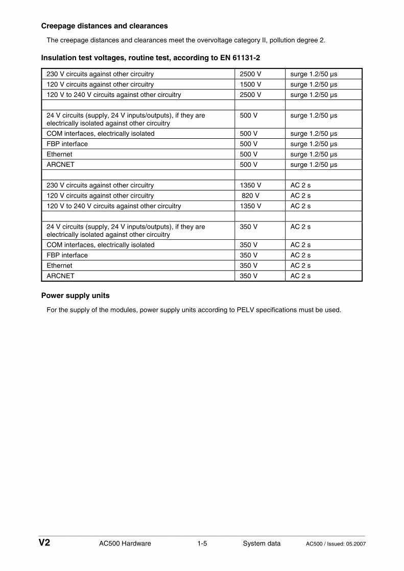
Creepage distances and clearances
The creepage distances and clearances meet the overvoltage category II, pollution degree 2.
Insulation test voltages, routine test, according to EN 61131-2
230 V circuits against other circuitry 2500 V surge 1.2/50 µs
120 V circuits against other circuitry 1500 V surge 1.2/50 µs
120 V to 240 V circuits against other circuitry 2500 V surge 1.2/50 µs
24 V circuits (supply, 24 V inputs/outputs), if they are electrically isolated against other circuitry
500 V surge 1.2/50 µs
COM interfaces, electrically isolated 500 V surge 1.2/50 µs
FBP interface 500 V surge 1.2/50 µs
Ethernet 500 V surge 1.2/50 µs
ARCNET 500 V surge 1.2/50 µs
230 V circuits against other circuitry 1350 V AC 2 s
120 V circuits against other circuitry 820 V AC 2 s
120 V to 240 V circuits against other circuitry 1350 V AC 2 s
24 V circuits (supply, 24 V inputs/outputs), if they are electrically isolated against other circuitry
350 V AC 2 s
COM interfaces, electrically isolated 350 V AC 2 s
FBP interface 350 V AC 2 s
Ethernet 350 V AC 2 s
ARCNET 350 V AC 2 s
Power supply units
For the supply of the modules, power supply units according to PELV specifications must be used.

____________________________________________________________________________________________________________
V2 AC500 Hardware 1-6 System data AC500 / Issued: 05.2007
Electromagnetic compatibility
Immunity
against electrostatic discharge (ESD) according to EN 61000-4-2, zone B, criterion B
- electrostatic voltage in case of air discharge 8 kV
- electrostatic voltage in case of contact discharge
4 kV, in a closed switch-gear cabinet 6 kV ¹)
ESD with communication connectors In order to prevent operating malfunctions, it is recommended, that the operating personnel discharge themselves prior to touching communication connectors or perform other suitable measures to reduce effects of electrostatic discharges.
ESD with connectors of Terminal Bases The connectors between the Terminal Bases and CPUs or couplers must not be touched during operation. The same is valid for the I/O-Bus with all modules involved.
Immunity
against the influence of radiated (CW radiated) according to EN 61000-4-3, zone B, criterion A
- test field strength 10 V/m
Immunity
against transient interference voltages (burst) according to EN 61000-4-4, zone B, criterion B
- supply voltage units (AC, DC) 2 kV
- digital inputs/outputs (24 V DC) 1 kV
- digital inputs/outputs (120/230 V AC) 2 kV
- analog inputs/outputs 1 kV
- CS31 system bus 2 kV
- serial RS-485 interfaces (COM) 2 kV
- serial RS-232 interfaces (COM) 1 kV
- ARCNET 1 kV
- FBP 1 kV
- Ethernet 1 kV
- I/O supply, DC-out 1 kV
Immunity
against the influence of line-conducted interferences (CW conducted)
according to EN 61000-4-6, zone B, criterion A
- test voltage 3V zone B, 10 V is also met.
High energy surges according to EN 61000-4-5, zone B, criterion B
- power supply AC 2 kV CM* / 1 kV DM*
- power supply DC 1 kV CM* / 0.5 kV DM*
- AC I/O supply, add. AC-supply-out 2 kV CM* / 1 kV DM*
- DC I/O supply, add. DC-supply-out 0.5 kV CM* / 0.5 kV DM*
- Buses, shielded 1 kV CM*
- AC-I/O unshielded 2 kV CM* / 1 kV DM*
- I/O analog, I/O DC unshielded 1 kV CM* / 0.5 kV DM*
* CM = Common Mode, * DM = Differential Mode
Radiation (radio disturbance) according to EN 55011, group 1, class A
¹) High requirement for shipping classes are achieved with additional specific measures (see specific documentation).

____________________________________________________________________________________________________________
V2 AC500 Hardware 1-7 System data AC500 / Issued: 05.2007
Mechanical data
Wiring method / terminals
Mounting horizontal
Degree of protection IP 20
Housing according to UL 94
Vibration resistance acc. to EN 61131-2 all three axes 2 Hz...15 Hz, continuous 3.5 mm 15 Hz...150 Hz, continuous 1 g (4 g in preparation)
Vibration resistance with SD Memory Card inserted
15 Hz...150 Hz, continuous 1 g
Shock test all three axes 15 g, 11 ms, half-sinusoidal
Shipping specific requirements
Mounting of the modules
- DIN rail according to DIN EN 50022 35 mm, depth 7.5 mm or 15 mm
- mounting with screws screws with a diameter of 4 mm
fastening torque 1.2 Nm

____________________________________________________________________________________________________________
V2 AC500 Hardware 1-8 System data AC500 / Issued: 05.2007
Mounting and disassembling the Terminal Bases, the CPUs and the couplers
Assembly on DIN rail
Step 1: Mount DIN rail 7.5 mm or 15 mm
Step 2: Mount Terminal Base (TB521, TB521, TB541)
Figure: Assembly of the Terminal Base (TB511, TB521 or TB541)
The Terminal Base is put on the DIN rail above and then snapped-in below. The disassembly is carried out in a reversed order.
Figure: Disassembly of the Terminal Base (TB511, TB521 or TB541)

____________________________________________________________________________________________________________
V2 AC500 Hardware 1-9 System data AC500 / Issued: 05.2007
Step 3: Mount I/O Terminal Unit (TU515, TU516, TU531 or TU532)
Figure: Assembly of the I/O Terminal Unit (TU515, TU516, TU531 or TU532)
The I/O Terminal Unit is snapped into the DIN rail in the same way as the Terminal Base. Once secured to the DIN rail, slide the I/O unit to the left until it fully locks into place creating a solid mechanical and electrical connection.
Altogether 7 I/O Terminal Units can be combined with the Terminal Base.
If both of the following conditions are fulfilled, max. 10 I/O Terminal Units can be combined with the Terminal Base: - PS501 as of version V1.2 - CPUs as of firmware V1.2.0
1 ... 7 (10) *)
Figure: Maximum configuration (1 Terminal Base plus 7 I/O Terminal Units)
*) If both of the following conditions are fulfilled, max. 10 I/O Terminal Units can be combined with the Terminal Base:

____________________________________________________________________________________________________________
V2 AC500 Hardware 1-10 System data AC500 / Issued: 05.2007
- PS501 as of version V1.2 - CPUs as of firmware V1.2.0
Figure: Disassembly of the I/O Terminal Unit (TU515, TU516, TU531 or TU532)
A screwdriver is inserted in the indicated place to separate the Terminal Units.
Step 4: Mount the CPU
PM581
Figure: Assembly of the CPU
Press the CPU into the Terminal Base until it locks in place.

____________________________________________________________________________________________________________
V2 AC500 Hardware 1-11 System data AC500 / Issued: 05.2007
The disassembly is carried out in a reversed order.
1
2
1
Figure: Disassembly of the CPU
Disassembly: Press above and below, then remove the CPU.
Step 5: Mount the coupler (communication module)
Figure: Assembly of a coupler
The coupler is first inserted below, then clicked-in above.

____________________________________________________________________________________________________________
V2 AC500 Hardware 1-12 System data AC500 / Issued: 05.2007
The disassembly is carried out in a reversed order.
1
2
1
Figure: Disassembly of a coupler
Disassembly: Press above (and below), then swing out the coupler and remove it.
The following figure shows a Terminal Base with a CPU and two couplers inserted.
PM581CM577CM572

____________________________________________________________________________________________________________
V2 AC500 Hardware 1-13 System data AC500 / Issued: 05.2007
Assembly with screws
If the Terminal Base should be mounted with screws, Wall Mounting Accessories TA526 must be inserted at the rear side first. These plastic parts prevent bending of the Terminal Base while screwing on. TB511 needs one TA526, TB521 and TB541 need two TA526.
Holes for wall mounting
1
2
1
3
Rear view
Rear view
Front view
Figure: Fastening with screws of the Terminal Base TB521-ETH (as an example)
1 The two Wall Mounting Accessories TA526 are snapped on the rear side of the Terminal Unit like DIN rails. The arrows point to the middle of the Terminal Base. One TA526 is turned by 180°.
2 Two accessories for wall mounting inserted
3 Terminal Base, fastened with screws
By wall mounting, the Terminal Base is earthed through the screws. It is necessary that
• the screws have a conductive surface (e.g. steel zinc-plated or brass nickel-plated) • the mounting plate is earthed • the screws have a good electrical contact to the mounting plate

____________________________________________________________________________________________________________
V2 AC500 Hardware 1-14 System data AC500 / Issued: 05.2007
Mounting and disassembling the Terminal Units and the I/O modules
Assembly on DIN rail
Step 1: Mount DIN rail 7.5 mm or 15 mm
Step 2: Mount FBP Terminal Unit (TU505 or TU506)
Figure: Assembly of the FBP Terminal Unit (TU505 or TU506)
The FBP Terminal Unit is put on the DIN rail above and then snapped-in below. The disassembly is carried out in a reversed order.
Figure: Disassembly of the FBP Terminal Unit (TU505 or TU506)

____________________________________________________________________________________________________________
V2 AC500 Hardware 1-15 System data AC500 / Issued: 05.2007
Step 3: Mount I/O Terminal Unit (TU515, TU516, TU531 or TU532)
Figure: Assembly of the I/O Terminal Unit (TU515, TU516, TU531 or TU532)
The I/O Terminal Unit is installed on the DIN rail in the same way as the FBP Terminal Unit. Once secured on the DIN rail, slide the I/O unit to the left until it fully locks into place creating a solid mechanical and electrical connection.
Altogether 7 I/O Terminal Units can be combined with the FBP Terminal Unit.
1 2 7...
Figure: Maximum configuration (1 FBP Terminal Unit plus 7 I/O Terminal Units)
Important: Up to 7 I/O modules can be used, of which up to 4 analog I/O modules are possible.

____________________________________________________________________________________________________________
V2 AC500 Hardware 1-16 System data AC500 / Issued: 05.2007
Figure: Disassembly of the I/O Terminal Unit (TU515, TU516, TU531 or TU532)
A screwdriver is inserted in the indicated place to separate the Terminal Units.
Step 4: Mount the modules
DC532
Figure: Assembly of the modules
Press the electronic module into the Terminal Unit until it locks in place.

____________________________________________________________________________________________________________
V2 AC500 Hardware 1-17 System data AC500 / Issued: 05.2007
The disassembly is carried out in a reversed order.
1
2
1
Figure: Disassembly of the modules
Disassembly: Press obove and below, then remove the module.
Assembly with screws
If the Terminal Unit should be mounted with screws, a Wall Mounting Accessory TA526 must be inserted at the rear side first. This plastic part prevents bending of the Terminal Unit while screwing on.
1
2Front view
Rear view
Rear view
Holes forwall mounting
31
Figure: Fastening with screws of the Terminal Unit TU516 (as an example)
1 The Wall Mounting Accessory TA526 is snapped on the rear side of the Terminal Unit like a DIN rail. The arrow points to the right side.
2 Accessory for wall mounting inserted
3 Terminal Unit, fastened with screws

____________________________________________________________________________________________________________
V2 AC500 Hardware 1-18 System data AC500 / Issued: 05.2007
By wall mounting, the Terminal Unit is earthed through the screws. It is necessary that
• the screws have a conductive surface (e.g. steel zinc-plated or brass nickel-plated) • the mounting plate is earthed • the screws have a good electrical contact to the mounting plate
Mechanical dimensions AC500
2828
59 (
2.32
)
70.5
(2.
78)
135
(5.3
1)67.5 (2.66)
(1.10)(1.10)
95.5 (3.76)
(2.27)57.7
(1.59)40.3 4.9 (0.19)
TB511
123.5 (4.86)TB521
179.5 (7.07)TB541
28(1.10)
28(1.10) 135 mm
(5.31) inches
Dimensions:
Figure: Dimensions of the AC500 CPU Terminal Bases TB511, TB521 and TB541

____________________________________________________________________________________________________________
V2 AC500 Hardware 1-19 System data AC500 / Issued: 05.2007
28
13 (0.51)62 (2.44)
75 (2.95)
59 (
2.32
)
135
(5.3
1)
76 (
2.99
)
77 (3.03)
84.5 (3.33)
(1.10)135 mm(5.31) inches
Dimensions:
View on the left side
DIN rail 15 mmDIN rail 7.5 mm
Figure: Terminal Base with coupler, view from the left side
67.5 (2.66)
TU505/506
59 (
2.32
)
70.5
(2.
78)
TU515/516/531/532
135
(5.3
1)
67.5 (2.66)
(2.27)
DC505
135 mm(5.31) inches
57.7
Dimensions:
Figure: Dimensions of the S500 Terminal Units (front view)

____________________________________________________________________________________________________________
V2 AC500 Hardware 1-20 System data AC500 / Issued: 05.2007
28
21 (0.83)54 (2.13)
75 (2.95)
59 (
2.32
)
70.5
(2.
78)
135
(5.3
1)
76 (
2.99
)
View on the left side View on the right side
77 (3.03)
84.5 (3.33)
DIN rail 15 mmDIN rail 7.5 mm
135 mm(5.31) inches
Dimensions:
(1.10)
Figure: Dimensions of the S500 Terminal Units (view from the left and the right side)
____________________________________________________________________________________________________________
V2 AC500 Hardware 1-21 System data AC500 / Issued: 05.2007
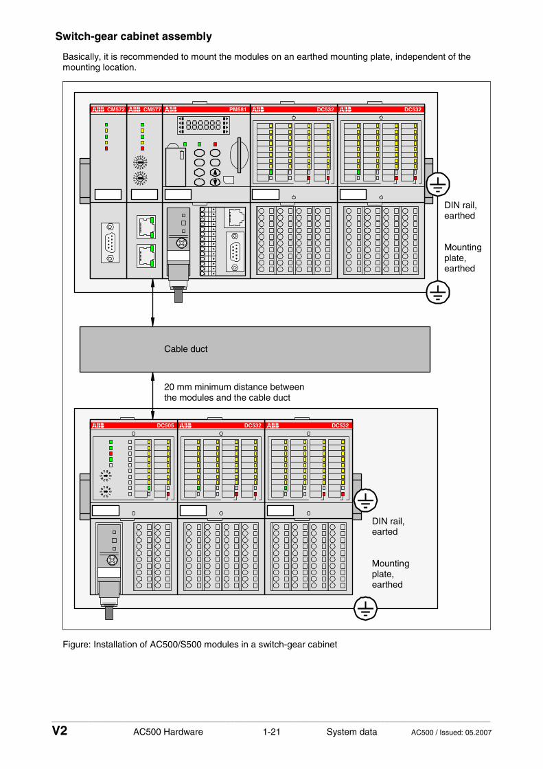
Switch-gear cabinet assembly
Basically, it is recommended to mount the modules on an earthed mounting plate, independent of the mounting location.
DC532DC532DC505
DC532DC532PM581CM577CM572
DIN rail,earthed
Mountingplate,earthed
DIN rail,earted
Mountingplate,earthed
Cable duct
20 mm minimum distance betweenthe modules and the cable duct
Figure: Installation of AC500/S500 modules in a switch-gear cabinet

____________________________________________________________________________________________________________
V2 AC500 Hardware 1-22 System data AC500 / Issued: 05.2007
Important: Horizontal mounting is highly recommended. Vertical mounting is possible, however, derating consideration should be made to avoid problems with poor air circulation and the potential for excessive temperatures (see also the AC500 system data, operating and ambient conditions, for reduction of ambient temperature).
Note: By vertical mounting, always place an end-stop terminal block at the bottom and on the top of the module to properly secure the modules. By high-vibration applications, we also recommend to place end-stop terminals at the right and the left side of the device to properly secure the modules: e.g. type BADL, P/N: 1SNA 399 903 R0200
Insertion / replacement of the Lithium battery
AC500 CPUs are supplied without a Lithium battery. It therefore must be ordered separately. The TA521 Lithium Battery is used to save RAM contents of AC500 CPUs and back-up the real-time clock. Although the CPUs can work without a battery, its use is still recommended in order to avoid process data being lost.
The CPU monitors the battery status. A low battery error is output before the battery condition becomes critical (about 2 weeks before). After the error message appears, the battery should be replaced as soon as possible.
Attention: The TA521 Lithium Battery is the only one, which can be used with AC500 CPUs.
The following procedures describe the insertion / replacement of the Lithium battery.
WARNING!Use of
incorrectbattery maycause fire orexplosion.
WARNING!Use of
incorrectbattery maycause fire orexplosion.
1a
2
3
4+5
WARNING!Use of
incorrectbattery maycause fire orexplosion.
6
1b
Figure: Insertion / replacement of the Lithium battery

____________________________________________________________________________________________________________
V2 AC500 Hardware 1-23 System data AC500 / Issued: 05.2007
Insertion of the battery:
1. Open the battery compartment by inserting a fingernail in the small locking mechanism, press it down and slip down the door. The door is attached to the front face of the CPU and cannot be removed.
2. Remove the TA521 battery from its package and hold it by the small cable.
3. Insert the battery connector into the small connector port of the compartment. The connector is keyed to find the correct polarity (red = plus-pole = above).
4. Insert first the cable and then the battery into the compartment, push it until it reaches the bottom of the compartment.
5. Arrange the cable in order not to inhibit the door to close.
6. Pull-up the door and press until the locking mechanism snaps.
Note: In order to prevent data losses or problems, the battery should be replaced after 3 years of utilisation or at least as soon as possible after receiving the "Low battery warning" indication. Do not use a battery older than 3 years for replacement, do not keep batteries too long in stock.
Replacement of the battery:
Attention: In order to avoid any data losses (if needed), the battery replacement should be done with the system under power. Without battery and power supply there is no data buffering possible.
1. Open the battery compartment by inserting a fingernail in the small locking mechanism, press it down and slip down the door. The door is attached to the front face of the CPU and cannot be removed.
2. Remove the old TA521 battery from the battery compartment by pulling it by the small cable. Remove then the small connector from the socket, do this best by lifting it out with a screwdriver (see photo).
3. Follow the previous instructions to insert a new battery.
Attention: Lithium batteries must not be re-charged, not be disassembled and not be disposed of in fire. They must be stored in a dry place. Exhausted batteries must be recycled to respect the environment.
The technical data sheet for the Lithium battery can be found in the chapter "Accessories / Lithium Battery TA521".

____________________________________________________________________________________________________________
V2 AC500 Hardware 1-24 System data AC500 / Issued: 05.2007
Insertion of the SD Memory Card
AC500 CPUs are supplied without an SD Memory Card. It therefore must be ordered separately. The SD Memory Card is used to back-up user data and store user programs as well as to update the internal CPU firmware. AC500 CPUs can be operated with and without SD Memory Cards.
The CPU uses a standard file system. This allows standard card readers to read the MC502 SD Memory Cards.
Attention: The use of memory cards other than the MC502 SD Memory Card is prohibited. ABB is not responsible nor liable for consequences resulting from the use of unapproved memory cards.
Attention: In operation, the plugged-in SD Memory Card withstands vibrations up to 1 g. Without using an SD Memory Card, the CPU itself withstands vibrations up to 4 g.
SD Memory CardMC502
ETHFBPCOM1COM2
PWR RUN ERR
RUN DIAG
VAL CFG
ESC
OK
PM581
INSERTPUSH
MC502
SYSBATT
I/O-Bus
CPU24 V DC 10 W
WARNING!Use of
incorrectbattery maycause fire orexplosion.
Figure: Insertion of the SD Memory Card
To insert the SD Memory Card, follow the procedure shown below.
1. Remove the SD Memory Card from its package.
2. Insert the memory card into the opening of the front face of the CPU with the memory aligned as shown above (contacts are visible on the left side, bevelled edge below).
3. Push on the card until it moves forward, then release your pressure, the SD card comes slightly backward and it locks into the card slot.
Removing the SD Memory Card
To remove the card, first push on the card until it moves forward (that unlocks the card), then release your pressure, the card will go forward out of the slot and can be easily removed.
The technical data sheet for the SD Memory Card can be found in the chapter "Accessories / SD Memory Card MC502".

____________________________________________________________________________________________________________
V2 AC500 Hardware 1-25 System data AC500 / Issued: 05.2007
Connection system
Terminals for power supply and the COM1 interface (CPU Terminal Base AC500)
L+
ML+
MFE123456789
COM1
Figure: Terminals for power supply and the COM1 interface (CPU Terminal Base AC500)
Terminal type: Screw-type terminal
Number of cores per terminal Conductor type Cross section
1 solid 0.08 mm² to 1.5 mm²
1 flexible 0.08 mm² to 1.5 mm²
1 with wire end ferrule (without plastic sleeve) flexible 0.25 mm² to 1.5 mm²
1 with wire end ferrule (with plastic sleeve) flexible 0.25 mm² to 0.5 mm²
1 (TWIN wire end ferrule) flexible 0.5 mm²
2 (with the same cross section) solid 0.08 mm² to 0.5 mm²
2 (with the same cross section) flexible 0.08 mm² to 0.75 mm²
2 (with the same cross section) in wire end ferrule, without plastic sleeve
flexible 0.25 mm² to 0.34 mm²
Terminal type: Spring terminal
Number of cores per terminal Conductor type Cross section
1 solid 0.08 mm² to 1.5 mm²
1 flexible 0.08 mm² to 1.5 mm²
1 with wire end ferrule (without plastic sleeve) flexible 0.25 mm² to 1.5 mm²
1 with wire end ferrule (with plastic sleeve) flexible 0.25 mm² to 0.5 mm²
1 (TWIN wire end ferrule) flexible 0.5 mm²
2 (with the same cross section) solid 0.08 mm² to 0.5 mm²
2 (with the same cross section) flexible 0.08 mm² to 0.75 mm²
2 (with the same cross section) in wire end ferrule, without plastic sleeve
flexible 0.25 mm² to 0.34 mm²

____________________________________________________________________________________________________________
V2 AC500 Hardware 1-26 System data AC500 / Issued: 05.2007
Terminals at the Terminal Units (I/O, FBP)
1.0
1.1
1.2
1.3
1.4
1.5
1.6
1.7
1.8
1.9
2.0
2.1
2.2
2.3
2.4
2.5
2.6
2.7
2.8
2.9
3.0
3.1
3.2
3.3
3.4
3.5
3.6
3.7
3.8
3.9
4.0
4.1
4.2
4.3
4.4
4.5
4.6
4.7
4.8
4.9
Figure: Terminals at the Terminal Units (I/O, FBP)
Terminal type: Screw-type terminal
Number of cores per terminal Conductor type Cross section
1 solid 0.08 mm² to 2.5 mm²
1 flexible 0.08 mm² to 2.5 mm²
1 with wire end ferrule flexible 0.25 mm² to 1.5 mm²
TWIN wire end ferrule flexible 2 x 0.25 mm² or 2 x 0,5 mm² or 2 x 0,75 mm², with square cross-section of the wire-end ferrule also 2 x 1.0 mm²
2 solid not intended
2 flexible not intended
Terminal type: Spring terminal
Number of cores per terminal Conductor type Cross section
1 solid 0.08 mm² to 2.5 mm²
1 flexible 0.08 mm² to 2.5 mm²
1 with wire end ferrule flexible 0.25 mm² to 1.5 mm²
TWIN wire end ferrule flexible 2 x 0.25 mm² or 2 x 0,5 mm² or 2 x 0,75 mm², with square cross-section of the wire-end ferrule also 2 x 1.0 mm²
2 solid not intended
2 flexible not intended

____________________________________________________________________________________________________________
V2 AC500 Hardware 1-27 System data AC500 / Issued: 05.2007
Connection of wires at the spring terminals
Connect the wire to the spring terminal
1 2 3
b
a
conductor driverscrew-
bScrewdriver
forOpening forOpening
closedTerminal
openTerminal
a
insertedScrewdriver
Screwdriver
Spring
Figure: Connect the wire to the spring terminal (steps 1 to 3)
5 6 74
Figure: Connect the wire to the spring terminal (steps 4 to 7)

____________________________________________________________________________________________________________
V2 AC500 Hardware 1-28 System data AC500 / Issued: 05.2007
1 a Side view (open terminal drawn for illustration)
1 b The top view shows the openings for wire and screwdriver
2 Insert screwdriver (2.5 x 0.4 to 3.5 x 0.5 mm) at an angle, screwdriver must be at least 15 mm free of insulation at the tip
3 a While erecting the screwdriver, insert it until the stop (requires a little strength)
3 b Screwdriver inserted, terminal open
4 Strip the wire for 7 mm (and put on wire end ferrule)
5 Insert wire into the open terminal
6 Remove the screwdriver
7 Done
Disconnect wire from the spring terminal
2 3
Screwdriver
1
Screwdriver
Figure: Disconnect wire from the spring terminal (steps 1 to 3)
4 5 6
ConductorScrewdriver
Figure: Disconnect wire from the spring terminal (steps 4 to 6)

____________________________________________________________________________________________________________
V2 AC500 Hardware 1-29 System data AC500 / Issued: 05.2007
1 Terminal with wire connected
2 Insert screwdriver (2.5 x 0.4 to 3.5 x 0.5 mm) at an angle, screwdriver must be at least 15 mm free of insulation at the tip
3 While erecting the screwdriver, insert it until the stop (requires a little strength), terminal is now open
4 Remove wire from the open terminal
5 Remove the screwdriver
6 Done
Mechanical encoding
181716151413121110987654321
Pos.181716151413121110987654321
181716151413121110987654321
Figure: Possible positions for mechanical encoding (1 to 18)
Terminal Units (S500) and CPU Terminal Bases (AC500) have an mechanical coding which prevents that modules are inserted to wrong places. Otherwise
• dangerous parasitic voltages could occur or • modules could be destroyed.
The coding either makes it impossible to insert the module to the wrong place or blocks its electrical function (outputs are not activated).

____________________________________________________________________________________________________________
V2 AC500 Hardware 1-30 System data AC500 / Issued: 05.2007
The following figure shows the possible codings.
181716151413121110987654321
181716151413121110987654321
181716151413121110987654321
181716151413121110987654321
181716151413121110987654321
181716151413121110987654321
181716151413121110987654321
181716151413121110987654321
181716151413121110987654321
Positions 1 - 18181716151413121110987654321
181716151413121110987654321
181716151413121110987654321
TB511-ETHTB521-ETHTB541-ETH
TB511-ARCNETTB521-ARCNETTB541-ARCNET
TU505TU506
TU507-RT-ETHTU508-RT-ETH
for CPUs for CPUs Interface Modules Real-Timewith Ethernet with ARCNET e.g. DC505-FBP Ethernet Modules
Mechanical codings
for FBP
181716151413121110987654321
181716151413121110987654321
181716151413121110987654321
181716151413121110987654321
181716151413121110987654321
181716151413121110987654321
TU551-CS31TU552-CS31
for
TU541TU542
forS500 CS31Positioning
ModulesModules
181716151413121110987654321
181716151413121110987654321
181716151413121110987654321
181716151413121110987654321
181716151413121110987654321
181716151413121110987654321
TU515TU516
TU531TU532
I/O Modules
I/O Modules
24 V DC
120/230 V AC
for for
for
Figure: Mechanical coding

____________________________________________________________________________________________________________
V2 AC500 Hardware 1-31 System data AC500 / Issued: 05.2007
General wiring recommendations
Bad wiring on power supply terminals
Attention: The product should be installed by trained people who have the knowledge of wiring electronic devices. In case of bad wiring, although the modules are protected against various errors (reverse polarity, short circuit, etc.), some problems could always happen: - On the CPU Terminal Base, the terminals L+ and M are doubled. If the power supply is badly connected, a short circuit could happen and lead to a destruction of the power supply or its fuse. If no suitable fuse exists, the Terminal Base itself could be destroyed. - The CPUs (Terminal Bases) and all electronic modules (and Terminal Units) are protected against reverse polarity. - All necessary measures should be carried out to avoid damages to modules and wiring. Notice the wiring plans and connection examples.
Bad wiring on I/O terminals
Attention: All I/O channels (digital and analog) are protected against reverse polarity, reverse supply, short circuit and continuous overvoltage up to 30 V DC.
Behaviour of the system in case of power supply interruptions and power recovering
AC500 system supply (terminals L+, M)
As soon as the CPU power supply is higher than 19.2 V DC, the power supply detection is activated and the CPU is started. When during operation the power supply is going down to lower than 19.2 V DC for more than 10 ms, the CPU is switched to safety mode (see System Technology of the CPUs).
A warm restart of the CPU only occurs by switching the power supply off and on again (see also the description of the function modes of the CPU in the "AC500 System Technology" chapters.
S500 system supply (is provided through the FBP plug)
AC500 or S500 process power supply (terminals UP and ZP)

____________________________________________________________________________________________________________
V2 AC500 Hardware 1-32 System data AC500 / Issued: 05.2007
I/O-Bus
General
The synchronized serial I/O-Bus connects the I/O expansion modules with the AC500 CPU or with the S500 FBP Interface Module.
The I/O-Bus provides the following signals:
• Supply voltage of 3.3 V DC for feeding the electronic interface components • 3 data lines for the synchronized serial data exchange • several control signals
With its fast data transmission, the I/O-Bus obtains very low reaction times. Up to 7 I/O expansion modules can be connected to a AC500 CPU or an FBP Interface Module.
If both of the following conditions are fulfilled, max. 10 I/O expansion modules can be connected to the I/O-Bus of the CPU: - PS501 as of version V1.2 - CPUs as of firmware V1.2.0
General data:
Supply voltage, signal level 3.3 V DC ± 10 %
Max. supply current 30 mA per expansion module
Max. number of I/O expansion modules (slaves on the I/O-Bus)
7 with the S500 FBP Interface Module with max. 4 analog modules (with up to 16 channels each), 7 with the AC500 CPU (digital or analog), 10 with the AC500 CPU (PS501 as of V1.2 with CPUs with firmware as of V1.2.0)
Type of the data interface synchronized serial data exchange
Bus data transmission speed 1.8 Mb/s
Minimum bus cycle time 500 µs ¹)
Electrical isolation no isolation between the modules, but isolation against the process supply voltage and the I/O terminals
Protection against electrostatic discharge (ESD) with an internal varistor
Max. bus length 1 m
¹) Minimum bus cycle time: This value is valid for all module combinations (from 1 to 7 expansion modules)
Wiring (bus connection)
Bus connection left-side and right-side connection from module to module via a 10-pole HE plug (male at the left side, female at the right side)
Mechanical connection established by the Terminal Units
Max. bus length 1 m
Number of user data, bus cycle time and data security
See details before

____________________________________________________________________________________________________________
V2 AC500 Hardware 1-33 System data AC500 / Issued: 05.2007
Replacement of modules on the I/O bus
The I/O-Bus is not designed for plugging and unplugging modules while in operation. If a module is plugged or replaced while the bus is in operation, the following consequences are possible
• reset of the station or of the CPU • system lockup
Caution: Removal of energized modules is not permitted. All power sources (supply and process voltages) must be switched off while working on any AC500 system.
Serial interfaces of the CPU Terminal Bases
Interface standards
The serial interfaces COM1 and COM2 are designed according to the standards EIA RS-232 and EIA RS-485. Both interfaces can be operated either in RS-232 or in RS-485 mode.
Technical data
Standard of the serial interfaces EIA RS-232 or EIA RS-485
Interface connectors COM1: 9-pole removable terminal block COM2: 9-pole Sub-D connector (female)
Electrical isolation yes, against the CPU, 500 V DC
Serial interface parameters configurable by the software
Operating modes programming or data exchange
Supported protocols Modbus or serial data exchange using special software function blocks
COM1 can be configured and terminated for either RS-232 or RS-485 (depending on used terminals). Please terminate according to the pin-out information for the COM1 port below and follow the appropriate rules and practices for RS-232 and RS-485 communication.
Serial interface COM1 of the CPU Terminal Bases
L+
ML+
MFE123456789
+24 V DC
0 V+24 V DC
0 VFunctional Earth
Term. P
Term. NRTSTxDSGNDRxDCTS
COM1 9-pole, terminals
Terminator PReceive/Transmit, positiveReceive/Transmit, negativeTerminator NRequest To Send (output)Transmit Data (output)
Signal GroundReceive Data (input)Clear To Send (input)
Supply voltage 24 V DC, 5-pole, terminals
UPUPZPZP
Terminal blockremoved
FE
Terminal block inserted
ZP
/UP
CO
M1
RS-485RS-485
RS-485
RS-485RS-232RS-232
RS-232RS-232
RxD/TxD-PRxD/TxD-N
Figure: Serial interface COM1

____________________________________________________________________________________________________________
V2 AC500 Hardware 1-34 System data AC500 / Issued: 05.2007
The serial interface COM1 is connected via a removable 9-pole terminal block. It is configurable for RS-232 or RS-485 and can be used for
• an online access (RS-232 programming interface for PC/Control Builder) • a free protocol (communication via the COMSND and COMREC function blocks) • Modbus RTU, master and slave or • a CS31 system bus (RS-485), as master only
If the RS-485 bus is used, each interconnected bus line (each bus segment) must be electrically terminated. The following is necessary:
• two resistors of 120 Ohms each at both line ends (to avoid signal reflections) • in addition, a pull-up resistor at RxD/TxD-P and a pull-down resistor at RxD/TxD-N. These two
resistors care for a defined high level on the bus, while there is no data exchange.
It is useful, to activate both the pull-up and the pull-down resistors, which only are necessary once on every bus line, at the bus master. For this reason, these two resistors are already integrated within the COM1 interface of the AC500 Terminal Bases. They can be activated by connecting the terminals 1-2 and 3-4 of COM1.
Terminator PRxD/TxD-PRxD/TxD-NTerminator N
+5V
0V
470 Ohms pull-up
470 Ohms pull-down
1234
Figure: Integrated resistors (pull-up, pull-down) at COM1, can be activated by connections between 1-2 and 3-4
The following drawing shows an RS-485 bus with the bus master at one line end.
1234
1234
1234
Master at thebus line end,
Slave withinthe bus line
Slave at thebus line end,
pull-up andpull-down
bus termination120 Ohms
activated,bus termination120 Ohms
120Ohms
120Ohms
Figure: RS-485 bus with the master at one line end
If the master is located within the bus line, it does not need a terminating resistor. The pull-up and the pull-down resistors, however, must be activated (see the following drawing).

____________________________________________________________________________________________________________
V2 AC500 Hardware 1-35 System data AC500 / Issued: 05.2007
1234
1234
1234
1234
Slave at thebus line end,
Master withinthe bus line,
Slave withinthe bus line
Slave at thebus line end,
bus termination120 Ohms
pull-up andpull-down
bus termination120 Ohms
activated
120Ohms
120Ohms
Figure: RS-485 bus with the master within the bus line
The following photo shows a wiring example "master within the bus line".
Figure: "Master within the bus line", wired at the COM1 bus connector of the Terminal Base
Attention: If the bus is operated with several masters, the pull-up and pull-down resistors may only be activated at one master.
The earthing of the cable shields of the bus lines are described in the chapter "CS31 system bus" of the AC500 system data.
CS31 system bus
Connection of the AC500 CPU to the CS31 system bus using COM1 of the Terminal Base
The AC500 CPU can be used as a CS31 bus master. The connection is performed via the serial interface COM1 used as a CS31 system bus. The following drawing shows the connection of the bus signals BUS1 and BUS2.
123456789
Term. P
Term. NRTSTxDSGNDRxDCTS
Receive/Transmit, positiveReceive/Transmit, negativeTerminator N
RS-485RS-485
RS-485
RS-485
RxD/TxD-PRxD/TxD-N
BUS1BUS2
L+
ML+
MFE
+24 V DC
0 V+24 V DC
0 VFunctional Earth
UPUPZPZP
FEFE
0 V
24 V
ZP
/UP
CO
M1
Supply voltage 24 V DC, 5-pole, terminals
COM1 9-pole, terminals
as C
S31
bus
Terminator P
Figure: AC500 CPU connected to the CS31 system bus via the serial interface COM1

____________________________________________________________________________________________________________
V2 AC500 Hardware 1-36 System data AC500 / Issued: 05.2007
With connecting the terminals 1-2 and 3-4, a pull-up and a pull-down resistor can be activated (see chapter "Serial interface COM1” for details).
Wiring
Bus line
Construction 2 cores, twisted, with common shield
Conductor cross section > 0.22 mm² (24 AWG)
- recommendation 0.5 mm² corresponds to Ø 0.8 mm
Twisting rate > 10 per meter (symmetrically twisted)
Core insulation Polyethylene (PE)
Resistance per core < 100 Ω/km
Characteristic impedance ca. 120 Ω (100...150 Ω)
Capacitance between the cores < 55 nF/km (if higher, the max. bus length must be reduced)
Terminating resistors 120 Ω ¼ W at both line ends
Commonly used telephone cables with PE insulation and a core diameter of > 0.8 mm are normally good.
Remarks
Cables with PVC core insulation and a core diameter of 0.8 mm can be used up to a length of ca. 250 m. In this case, the bus terminating resistor is ca. 100 Ω.
Bus topology
A CS31 system bus always contains only one bus master (CPU or coupler) which controls all actions on the bus. Up to 31 slaves can be connected to the bus, e.g. remote modules or slave-configured CPUs. Besides the wiring instructions shown below, the wiring and earthing instructions provided with the descriptions of the modules are valid additionally.
CS31 system bus
CS31
CS31 bus master
Shi
eld
BU
S2
BU
S1
Shi
eld
BU
S2
BU
S1slave
CS31slave
120Ohms
direct earthingwith clipon cabinetsteel plate
e.g. PM581
Master at thebus line end,pull-up andpull-downactivatedbus termination120 Ohms
1234
120Ohms
COM1
Figure: Bus topology for a CS31 system bus at COM1 (bus master at one end of the bus line)

____________________________________________________________________________________________________________
V2 AC500 Hardware 1-37 System data AC500 / Issued: 05.2007
CS31 system bus
CS31S
hiel
d
BU
S2
BU
S1
Shi
eld
BU
S2
BU
S1slave
CS31slave
120Ohms
120Ohms
directearthingwith clip
1234
COM1Master withinthe bus line,pull-up andpull-downactivated
CS31 bus mastere.g. PM581
Figure: Bus topology for a CS31 system bus at COM1 (bus master within the bus line)
CS31 system bus
CS31S
hiel
d
BU
S2
BU
S1slave
CS31
CS31
Shi
eld
BU
S2
BU
S1slave
1234
120Ohms
COM1
CS31 bus mastere.g. PM581
Master at thebus line end,
pull-up andpull-downactivated
bus termination120 Ohms
system bus
WRONG!Spur lines are notallowed.
RIGHT!Bus line is looped throughfrom module to module.
Figure: Wiring with spur lines is not allowed

____________________________________________________________________________________________________________
V2 AC500 Hardware 1-38 System data AC500 / Issued: 05.2007
Earthing
In order to avoid disturbance, the cable shields must be earthed directly.
Case a:
Multiple switch-gear cabinets: If it can be guaranteed that no potential differences can occur between the switch-gear cabinets by means of current-carrying metal connections (earthing bars, steel constructions etc.), the direct earthing is chosen.
CS31
Shi
eld
BU
S2
BU
S1slaveCS
31 s
yste
m b
us
CS31slaveC
S31
sys
tem
bus
1234
120Ohms
COM1PE
CS31 bus mastere.g. PM581
Cabinet 1 Cabinet 2
current-carrying connection current-carrying connection
direct earthing of shieldswhen entering the cabinet
Figure: Direct earthing

____________________________________________________________________________________________________________
V2 AC500 Hardware 1-39 System data AC500 / Issued: 05.2007
Case b:
Multiple switch-gear cabinets: If potential differences can occur between the switch-gear cabinets, the capacitive earthing method is chosen in order to avoid circulating currents on the cable shields.
CS31
SH
IELD
BU
S2
BU
S1slave
CS31 system bus
Earthing bar of cabinet 1
CS31-
SH
IELD
BU
S2
BU
S1Slave
120Ohms
CS31-Systembus
CS31-
BU
S1
BU
S2
SH
IELDSlave
PE
Earthing barof cabinet 2
Cabinet earthing
Cabinet earthing
Cabinet 1
Cabinet 2
PE
PE
1234
120Ohms
COM1PE
CS31 bus mastere.g. PM581
directearthingwith clipon cabinetsteel plate
capacitive earthing with 0.1 uFX-type capacitor directly on the
cabinet’s steel plate
Figure: Earthing concept with several switch-gear cabinets: direct earthing of cable shields when cables enter the first switch-gear cabinet (containing the master), and capacitive earthing at the modules
Everywhere is valid: The total length of the earthing connections between the shield of the Terminal Base and the earthing bar must be as short as possible (max. 25 cm). The conductor cross section must be at least 2.5 mm².
VDE 0160 requires, that the shield must be earthed directly at least once per system.
Number of user data, bus cycle time and data security
See the relevant chapters in the user handbook.
Replacement of modules on the CS31 system bus

____________________________________________________________________________________________________________
V2 AC500 Hardware 1-40 System data AC500 / Issued: 05.2007
Serial interface COM2 of the CPU Terminal Bases
The serial interface COM2 is connected via a 9-pole SUB-D plug. It is configurable for RS-232 or RS-485 and can be used for
• an online access (RS-232 programming interface for PC/Control Builder) • a free protocol (communication via the COMSND and COMREC function blocks) • Modbus RTU, master and slave
It is not intended to use COM2 to establish a CS31 system bus.
If the RS-485 bus is used, each interconnected bus line (each bus segment) must be electrically terminated. The following is necessary:
• two resistors of 120 Ohms each at both line ends (to avoid signal reflections) • in addition, a pull-up resistor at RxD/TxD-P and a pull-down resistor at RxD/TxD-N. These two
resistors care for a defined high level on the bus, while there is no data exchange.
It is useful, to activate both the pull-up and the pull-down resistors, which only are necessary once on every bus line, at the bus master.
COM2 9-pole, female
123456789
FETxDRxD/TxD-PRTSSGND+5 VRxD
CTS
1
59
6
Functional Earth
RS-232RS-485
Request To SendSignal Ground
Reiveive Data
Clear To Send
Housing Functional Earth
Transmit Data
outputReceive/Transmit positive
RS-232 output
RS-232 inputRS-485 Receive/Transmit negativeRS-232 input
0 V supply out5 V supply out
RxD/TxD-N
FE
Figure: Pin assignment of the serial interface COM2
The following drawing shows an RS485 bus with the bus master at the line end.
5
63
6
8
5
1RxD/TxD-P
RxD/TxD-N
0V
+5V
120Ohms
470Ohms
470Ohms
Master at thebus line end,pull-up 470 Ohmspull-down 470 Ohms
bus termination 120 Ohms
PE
Slave withinthe bus line
Slave at thebus line end,bus termination120 Ohms
120Ohms
Figure: RS-485 bus, master at a line end

____________________________________________________________________________________________________________
V2 AC500 Hardware 1-41 System data AC500 / Issued: 05.2007
If the master is located within the bus line, it does not need a terminating resistor. The pull-up and the pull-down resistors, however, are necessary (see the following drawing).
Slave at thebus line end,
Master withinthe bus line,
Slave withinthe bus line
Slave at thebus line end,
bus termination120 Ohms
pull-up 470 Ohmspull-down 470 Ohms
bus termination120 Ohms
120Ohms
120Ohms
5
63
6
8
5
1RxD/TxD-P
RxD/TxD-N
0V
+5V
470Ohms
470Ohms PE
Figure: RS-485 bus, master within the bus line
Attention: If the bus is operated with several masters, the pull-up and pull-down resistors may only be installed at one master.
The cable shields must be earthed (refer to the chapter "CS31 system bus" of the AC500 system data.

____________________________________________________________________________________________________________
V2 AC500 Hardware 1-42 System data AC500 / Issued: 05.2007
FieldBusPlug / FBP
Wiring
For example, refer to description of the PROFIBUS DP FBP, documentation 2CDC 192 001 D010x.PDF
Bus topology
For example, refer to description of the PROFIBUS DP FBP, documentation 2CDC 192 001 D010x.PDF

____________________________________________________________________________________________________________
V2 AC500 Hardware 1-43 System data AC500 / Issued: 05.2007
Modbus
General
The Modbus protocol is used all over the world. The MODICON Modbus® RTU protocol is integrated in the AC500 CPUs.
Numerous automation devices, such as PLC installations, displays, variable-frequency inverters or monitoring systems, for instance, have a Modbus® RTU interface by default or as an option and can therefore communicate with the AC500 CPUs without any problems via the serial interfaces COM1 and COM2 (RS-232 or RS-485).
Modbus® is a master-slave protocol. The master sends a request to the slave and receives its response.
Both interfaces COM1 and COM2 can work as Modbus® interfaces simultaneously.
The Modbus® operating mode of an interface is set with several function blocks.
Bus topology
Point-to-point with RS-232 or bus topology with RS-485. Modbus® is a master-slave protocol..
Technical data
Supported standards EIA RS-232 or EIA RS-485
Number of connection points 1 master max. 1 slave with RS-232 interface max. 32 slaves with RS-485 interface
Protocol Modbus® (master/slave)
Check sum CRC 16
Data transmission rate up to 19200 baud
Character frame 1 start bit, 8 data bits, 1 parity bit, even or odd (optional) 1 or 2 stop bit(s)
Maximum cable length for RS-485: 1200 m with 19200 Baud
Number of user data, bus cycle time and data security
See relevant chapters in the operating manual

____________________________________________________________________________________________________________
V2 AC500 Hardware 1-44 System data AC500 / Issued: 05.2007
PROFIBUS
ISO/OSI model
At the moment, PROFIBUS DP is the Field bus most frequently used worldwide for industrial applications. It is standardized under IEC 61158 together with other field bus protocols.
The definition of the PROFIBUS is based on the experience concerning data transmission collected during long years.
One base is the ISO/OSI model (Open Systems Interconnection Reference Model). It is an open layer model with 7 layers for the communication in information processing systems. The model describes uniformed procedures and rules for the exchange of data.
Fieldbus systems normally use only three of the 7 layers:
ISO/OSI Transmitting CPU
Receiving CPU
Layer 7 Application layer
Application layer
= Interface to the application program (CPU) with application oriented commands (read, write)
... ... ...
Layer 2 Data-link layer
Data-link layer
= Access control (to the line), telegram (start, length,..), data security (e.g. CRC=Cyclic Redundancy Code)
Layer 1 Physical layer
Physical layer
= Definition of the medium (Twinax, optical fiber, ..), coding ("1"=-4V), transmission speed (baud rate)..
Transmission medium (physical) As a result of the ISO/OSI layer model, each layer can be defined separately and (nearly) independent of the other layers.
Indeed, it is possible and common to use conventional cables, but also optical fibers as physical layer for the PROFIBUS DP or have a mixture of both in a single bus configuration.
For the application layer, there are also different versions possible, e.g. PROFIBUS DP-V0, PROFIBUS DP-V1 but also others that are not regarded here.

____________________________________________________________________________________________________________
V2 AC500 Hardware 1-45 System data AC500 / Issued: 05.2007
Typical Field Bus Topologies
Party Line
Trunc
Dro
pParty Line with branch and drop
Ring
The PROFIBUS DP realized with PDP21or PDP22 represents a real Party Linetopology that supports high baud ratesup to 12 Mbit/s best possible.
Branches and Drops cause reflexionswhich results in a dramatic reduction ofthe max. baud rate.With repeaters, this influence can beequalized partially.
Bra
nch
Figure: Typical field bus topologies

____________________________________________________________________________________________________________
V2 AC500 Hardware 1-46 System data AC500 / Issued: 05.2007
Overview of transferred data
Direction
DP/V1 onlyread / write
Group Type / example *
Qty. of DI, DO,...+product code..
Configuration,Identification
Cyclic dataexchange
other basicdata transfer
Monitored signals(inputs)
Commands (outputs)
DI = digital input
AI = analog input
DO=digital output
AO=analog output
Faults andwarnings
Control function…trip class …
Control function…trip class …
Diagnosis
Block parameters**
Single parameters
baud rate, time-out..Bus specific data
Acyclic dataexchange
read / write
read
read
write
write
read
write
read / write
Comment
DP/V0andDP/V1
Device
Data exchange on the PROFIBUS
Control SystemExample of a slave withPROFIBUS FieldBusPlug
* The quantities of bytes/words are defined by the connected device.
** Block parameters are transferred during power-up. The PDP22 (PROFIBUS DP-V1) allows to suppress the block parameter transfer (executed e.g. during power-up) setting the appropriate parameter. This parameter is not sent to the device and cannot be set via the device. In the Control Builder AC500 used for the CPU AC500, the parameter is 'Ignore Block Parameters' or 'Use Block Parameters' respectively in the PDP22 parameter part.
Figure: Overview of transferred data
PROFIBUS DP-V0 <---> PROFIBUS DP-V1
Commands and monitoring signals
The transfer of commands and monitoring signals is the essential task of the field bus and the connected units. They control and inform mainly about the process, e.g. start a motor and inform if it runs correctly, and are the same for DP-V0 and DP-V1.
Command and monitoring telegrams represent the cyclic data transfer.

____________________________________________________________________________________________________________
V2 AC500 Hardware 1-47 System data AC500 / Issued: 05.2007
Diagnosis
The diagnosis telegram provides detailed information if there is any problem, particularly in the process. A trip caused by overload of a motor is an example. Diagnosis data are automatically read by the PROFIBUS DP master if it gets a general fault info within a monitoring telegram.
Complete diagnosis telegram:
PROFIBUS DP PROFIBUS DP with PDP21, PDP22
6 bytes Standard diagnosis data 6 bytes Standard diagnosis data
1 byte + 1 byte
PDP21, PDP22 itself + length of slave diagnosis
x bytes User-specific diagnosis data
n bytes Device-specific
Remark: Diagnosis function blocks provide additional 3 bytes diagnosis data that are created by the bus master.
Configuration, Identification and other data
Configuration, identification and other data are necessary to start the operation and communication with the PROFIBUS DP slave. These data is created during configuring/selecting the bus line including the slaves/devices and is sent to the FieldBusPlugs directly after power-up.
All slaves compare the expected configuration with their real configuration and confirm if they agree as a supposition to start the data exchange.
Additionally some general data such as baud rate and time-out are transferred.
Parameters
Parameters are necessary to adapt the device to the process.
E.g., for the device UMC22 the parameter "Set current" that has to be set correctly to enable the UMC22 to protect the connected motor perfectly against overload.
Parameters can also include service-oriented data such as "Operation hours".
The main difference between the PROFIBUS DP versions DP-V0 and DP-V1 is:
DP/V0Master
Parametersonly as block
DP/V0Slave
CommandsMonitorings
Configuration
Diagnosis
DP/V1Master
Parametersas singleor as block
DP/V1Slave
CommandsMonitorings
Configuration
Diagnosis
Figure: Parameters DP-V0 and DP-V1
DP-V0 only allows to write the complete parameter set in one block.
The bus master sends the parameter block to the slave during power-up of the slave/device. Some control systems also allow to send the parameter block during normal operation.

____________________________________________________________________________________________________________
V2 AC500 Hardware 1-48 System data AC500 / Issued: 05.2007
DP-V1 offers reading and writing single parameters.
The possibility to read single parameters is an important advantage: If e.g. during commissioning the "Set current" for a motor is modified locally by the electrician, then the control system must be able to read this value to back it up into its data base.
The PDP22 (PROFIBUS DP-V1) also allows to suppress the block parameter transfer. This avoids that the parameters are overwritten during power-up of the slave / device.
The appropriate parameter is evaluated in the PDP21 / PDP22 and is not sent to the device and cannot be set via the device.
The appropriate parameter is "Ignore V0 Parameters" or "Use V0 Parameters" respectively and is available in the .GSD file for DP-V1.
In former times a separate master class 2 was needed to read and write single parameters. Currently, most of the control systems offer a class 1 master capable to perform acyclic DP-V1 services to read and write all data types.
Note: In all cases only the bus master can start the data exchange on the PROFIBUS DP bus.
PROFIBUS DP Master Class 1, PROFIBUS DP Master class 2
PROFIBUS DP Master Class 1(usually a control system / station):
all (or selected) slavestransfer of other basic data- write and read bus specific data
(baud rate, time-out,....)- write configuration data- write block parameters- read diagnosis data
Some Master Class 1 are able to
(acyclic data transfer)
PROFIBUS DP Master Class 2(usually an operator station / PC)
request (initiate) for a limited time,
Some Master Class 2 are able to
Slave Slave Slave Slave Slave
PROFIBUSDP MasterClass 2
PROFIBUSDP MasterClass 1
CPU
Control System
- continuous cyclic data transfer to
- read and write single parameters
- gets access to one slave after
- reads and writes acyclic data
- read cyclic data
Figure: PROFIBUS DP Master, class 1 and class 2

____________________________________________________________________________________________________________
V2 AC500 Hardware 1-49 System data AC500 / Issued: 05.2007
Wiring
Bus line
Type twisted wires (2 cores, shielded)
Characteristic impedance 135...165 Ω
Cable capacitance < 30 pF/m
Diameter of the cores (copper) ≥ 0.64 mm
Conductor cross section of the cores ≥ 0.34 mm²
Wire resistance per core ≤ 55 Ω/km
Loop resistance (resistance of two cores) ≤ 110 Ω/km
Cable lengths
Within one segment, the maximum possible cable length of a PROFIBUS subnet depends on the transmission speed.
Baud rate Max. cable length
9.6 kbaud to 187.5 kbaud 1000 m
500 kbaud 400 m
1.5 Mbaud 200 m
3 Mbaud to 12 Mbaud 100 m
Table: Maximum cable length of a segment within a PROFIBUS subnet
The cable ends of the bus segments must be equipped with terminating resistors according to the following drawing. The terminating resistors are commonly integrated into the bus connectors.
390 Ohms
220 Ohms
390 Ohms
VP (+5 V)
GND (0 V)
RxD/TxD-P
RxD/TxD-N
Data line B
Data line A
Figure: Configuration of the terminating resistors

____________________________________________________________________________________________________________
V2 AC500 Hardware 1-50 System data AC500 / Issued: 05.2007
Ethernet
Wiring
Bus line
Parameter 100Base-TX [100 MHz]
Attenuation [dB/100 m] 23.2
NEXT [dB/100 m] 24
ACR [dB/100 m] 4
Return Loss [db/100 m] 10
Characteristic impedance [Ω] 100
Category 5
Class D or higher
Cable length restrictions
For the maximum possible cable lengths within an Ethernet network various factors have to be taken into account. So, for twisted pair cables (for transmission rates of 10 Mbit/s and 100 Mbit/s) the maximum length of a segment which is the maximum distance between two network components is restricted to 100 m due to the electric properties of the cable.
Furthermore the length restriction for one collision domain has to be observed. A collision domain is the area within a network which can be affected by a possibly occurring collision (i.e. the area the collision can propagate over). This, however, only applies if the components operate in half duplex mode since the CSMA/CD access method is only used in this mode. If the components operate in full duplex mode, no collisions can occur.
Reliable operation of the collision detection method is important which means that it has to be able to detect possible collisions even for the smallest possible frame size of 64 bytes (512 bits). But this is only guaranteed if the first bit of the frame arrives at the most distant subscriber within the collision domain before the last bit has left the transmitting station. Furthermore the collision must be able to propagate to both directions within the same time. Therefore, the maximum distance between two ends must not be longer than the distance corresponding to the half signal propagation time of 512 bits. Thus, the resulting maximum possible length of the collision domain is 2000 m for a transmission rate of 10 Mbit/s and 200 m for 100 Mbit/s. In addition, the bit delay times caused by the passed network components have also to be considered.

____________________________________________________________________________________________________________
V2 AC500 Hardware 1-51 System data AC500 / Issued: 05.2007
ARCNET
The ARCNET system (Attached Resource Computer Network)
• ARCNET is a system for data transmission in local networks. • The ARCNET protocol is based on the Token Passing principle. • By passing an identifier (token) from station to station it is guaranteed, that only one station can start
a data transmission (transmission without collision). • The order of sequence, in which the stations are accessed, is automatically adapted by the existing
conditions in the network, i.e. that the network is reconfigured automatically each time a station is added to the network or switched off.
ARCNET bus topology
The networking possibilities of Linear ARCNET
• The Linear ARCNET connects the individual stations directly to each other, i.e. without using any distribution units.
• Each station is connected to the network by using a T connector. • Both cable ends must be terminated by termination resistors. • A maximum of 8 stations can be connected to one Linear ARCNET. • The maximum cable length of the network is 300 m. • An additional segment can be connected at the end of the wired segment via an Active Hub (active
distribution unit), see next but one drawing.
Station 1 Station 2 Station 3
T-connector Terminating resistor 93 OhmsTotal length max. 300 m
Figure: Linear ARCNET

____________________________________________________________________________________________________________
V2 AC500 Hardware 1-52 System data AC500 / Issued: 05.2007
Linear ARCNET, expanded by active distribution units (Active Hubs)
Active Hubs amplify the arriving signals. So they stabilize the network configuration and allow especially for high distances. The Active Hub decouples the station connectors from each other. Therefore, the entire network does not fail when one of the connections fails.
The maximum length of the network is 6 km.
A maximum of 255 stations can be used.
Active Hub
Station 1 Station 2
T-connectorTerminating resistor93 OhmsTotal length max. 300 m
max
. 600
m
max
. 600
m
Station 4 Station 5Station 3
Total length max. 300 m
Active Hub
Station 7 Station 8Station 6
Total length max. 300 m
Station 10 Station 11Station 9
Figure: Linear ARCNET, expanded by active distribution units (Active Hubs)

____________________________________________________________________________________________________________
V2 AC500 Hardware 1-53 System data AC500 / Issued: 05.2007
Wiring
Bus cable:
Cable RG 62 A/U: e.g. Lapp Kabel, Stuttgart Telephone: 0711/7838-0
Plugs for bus cable:
BNC plugs 75 Ω: Order No. B-9005 BNC T plug 75 Ω: OrderNo. B-9083 BNC termination 93 Ω: Order No. B-9093 Rufenach Vertriebs-GmbH, Heidelberg Telephon: +49 6221/8443-0 Telefax: +49 6221/8443-99

____________________________________________________________________________________________________________
V2 AC500 Hardware 1-54 System data AC500 / Issued: 05.2007
General considerations for EMC-conforming assembly and construction
Electric and electronical devices have to work correctly on site. This is also valid when electro-magnetic influences affect them in defined and/or expected strength. The devices themselves must not emit electro-magnetic noises.
Advant Controller components are developed and constructed so that they have a very high noise immunity. When the wiring and earthing instructions under "System data and system configuration" are met, an error-free operation is given.
However, there are applications where high electro-magnetic noises must be taken into due consideration already during the planning phase: e.g. when frequency converters, compressors, small-power pumps (high inductance) or mediumvoltage switchgear are mounted nearby. An EMC-compatible earthing concept will also guarantee an error-free operation here.
General principles
There are three important principles to be especially considered:
• Keep all connections as short as possible (in particular the earthing conductors) • Use large conductor cross sections (in particular for the earthing conductors) • Create low-impedance, i.e. good and large-sized contacts (in particular for the earthing conductors)
In particular:
• vibration-resistant connections • clean metallic contact areas (remove paint, clean surfaces) • if possible, do not use aluminium parts (they oxidize) • solid plug and screw-type connections • earth cable shields with clips on a well-grounded metallic surface • do not use sheath wires • do not use toothed lock washers under screw connections
No! Yes!bad contact good contact
Make a connection between the DIN rails and PE (Protective Earth). For this, use an earthing wire with a minimum conductor cross section of 10 mm². The wire is connected to the DIN rail with an M6 screw according to the drawing above. A large-area contact of the DIN rail with the metallic mounting plate improves the EMC behaviour significantly, as the disturbances can be discharged more effective.
Cable routing
• Route cables meeting the standards. • Sort the cables into cable groups (power current cables, power supply cables, signal cables and data
cables) • Rout signal cables and data cables separately from the power cables, i.e. in separate cable ducts or
cable bundles. The distance should be 20 cm or greater. • Lay signal and data cables close to earthed surfaces.

____________________________________________________________________________________________________________
V2 AC500 Hardware 1-55 System data AC500 / Issued: 05.2007
Cable shields
• Only use shielded data cables. The shield should be earthed at both ends. Make sure that no parasitic currents can flow through the cable shields. This can be done by installing current-carrying equipotential bondings.
• A cable shield only earthed at one end can only protect from capacitively coupled interference and low-frequency disturbances (50 Hz hum).
• Use only cables with braided shields. Foil shields are not robust enough, cannot be contacted well and have poor HF properties.
• Only use metallic or metal-plated plugs for shielded data cables. • For analog signals, only use shielded cables. Earth the shield only at one end for small signals. • Earth the cable shield directly with a clip when entering the switch-gear cabinet. Do not cut the shield
until the cable reaches the module connected. • The connection between the PE bar and the shield bar must have a low impedance.
Switch-gear cabinet
• The connections between the switch-gear cabinet, the mounting plates, the PE bar and the shield bar must have a low impedance.
• Earth the switch-gear cabinet doors with short and highly flexible conductors. • For illumination of the switch-gear cabinet, only use filament lamps (bulbs) or fluorescent tubes with
interference suppression to prevent the control system being disturbed. • For supplying the PC, use the mains socket which is located inside the switch-gear cabinet. In this
way, all earthing measures are performed with short conductors and no parasitic currents can flow even in case of non-isolated interfaces.
Reference potential
• Provide a uniform reference potential in the entire installation and earth all electrical appliances if possible.
• Route your earthing conductors in a star configuration so that no earth loops can occur.

____________________________________________________________________________________________________________
V2 AC500 Hardware 1-56 System data AC500 / Issued: 05.2007
Equipotential bonding
• Install sufficiently dimensioned equipotential bondings, if potential differences are present or have to be expected in your application between different parts of the installation.
• The impedance of a equipotential bonding must be equal or lower than 10 % of the shield impedance of the shielded signal cables between the same points.
• The conductor cross section of a equipotential bonding must be able to withstand the maximum possible compensating current. By experience, a conductor cross section of 16 mm² has proven to be sufficient.
• Equipotential bondings and shielded signal cables should be laid close to each other. This prevents coming up inductive loops in which disturbances could be induced.
• Equipotential bondings must be connected to PE with low impedance.
DX522DC532 DX522DC532
AC500 S500
24VDC
+–
PE
Cabinet 1 Cabinet 2
24VDC
+–
PE
3
7
1011
6
5 5
8
9 9
11
DIN
rai
l
1 24V power supply FBP
2 Power supply for the CPU
6 For fuses for the contacts of the relay outputssee the descriptions of the relevant modules
8 Earthing of the 0V rail9 Cabinet earthing
10 Equipotential bondingbetween the cabinets min. 16 mm
11 Cable shields earthing
2
1010
8
6
24VDC
+–
PE
7
70V 0V
PE PE
DC505
24V0V
1
2 4
5 Fuse for the I/O modules power
3 Fuse for the CPU power
4 Power supply for the I/Os
only one power
possible
supply is also
7 0V rail (reference potential for signals)
with
term
inat
ing
resi
stor
4
Figure: AC500, equipotential bondings

____________________________________________________________________________________________________________
V2 AC500 Hardware 1-57 System data AC500 / Issued: 05.2007
Power consumption of an entire station
The power consumption of a complete station consists of the sum of all individual consumptions.
An AC500 CPU cluster has
• a power consumption of the CPU itself over the terminals L+ and M of the Terminal Base. After conversion of the voltage, also the I/O-Bus for the attached I/O modules is supplied then.
• a power consumption over the process supply voltage terminals ZP and UP of the Terminal Units. Through this the digital and analog outputs are also supplied.
The two supply voltages can be provided by the same power supply unit. The CPU and the I/O modules should, however, be fused separately. Of course also separate power supplies are possible. See the previous chapters regarding equipotential bonding and cable routing.
Product Main power supply
Voltage V DC
Current consump-tion in A
Melting integral in A²s
Process voltage UP
Voltage V DC
Current consump- tion in A
Melting integral in A²s
CPUs
PM571 PM571-ETH PM581 PM581-ETH PM581-ARCNET PM582 PM582-ETH PM591 PM591-ETH PM591-ARCNET
Terminals L+ and M
24
0.050 0.110 0.050 0.110 0.050 0.110 0.090 0.150
1 *)
-
-
-
-
Communication modules (couplers)
CM572-DP CM575-DN CM577-ETH CM578-CN
Coupler bus (of the CPU)
- 0.050 0.050 0.085 0.050
*) - - - -
I/O modules
AI523 AO523 AX521 AX522 DC522 DC523 DC532 DC541 DI524 DX522 DX531
I/O-Bus (of the CPU)
-
0.002 0.002 0.002 0.002 0.002 0.002 0.002 0.002 0.002 0.002 0.002
-
Terminals ZP and UP
24
0.150 0.150 0.150 0.150 0.150 0.150 0.150 0.150 0.150 0.150
0.050 0.040 0.020 0.020 0.005 0.008 0.007 0.008 0.010 0.004
FieldBusPlug
PDP22-FBP.xxx M12 plug pins 1 and 3
24 0.040 - - - - -
Remote I/O modules
DC505-FBP DC551-CS31
FBP process supply
24 -
0.020 -
- -
ZP and UPZP and UP
24 24
0.050 0.100
0.008 0.040
*) The melting integral for the CPU is dependent on the integrated CPU supply, couplers and I/O-Bus are taken into account.

____________________________________________________________________________________________________________
V2 AC500 Hardware 1-58 System data AC500 / Issued: 05.2007
Calculation of the total current consumption
In the following example, the aC500 control system consists of
- the CPU PM581-ETH - the 4 communication modules CM572-DP (1x), CM575-DN (1x), CM577-ETH (1x), CM578-CN (1x) - the 7 expansion modules DC522 (1x), DC523 (1x), DC532 (1x), AX521 (1x), AX522 (1x), AI523 (1x), AO523 (1x) - as well as the required Terminal Bases and Terminal Units
Remark: Because of the high total current consumption of the digital I/O modules (from UP = 24 DC), the supply is divided up into several electric circuits fused separately. The maximum permitted total current over the supply terminals of the I/O Terminal Units is 8 A.
The total current can be calculated as follows:
ITotal = ICLUSTER + IUP
with the following assumptions
ICLUSTER = ICPU + II/O-Bus + IC1 + IC2 + IC3 + IC4 (CPU + couplers + I/O-Bus)
II/O-Bus = Number of expansion modules x Current consumption through the I/O-Bus per module
and
IUP = IUP1 + ILOAD1 + IUP2 + ILOAD2 + IUP3 + ILOAD3 + IUP4 + ILOAD4 + IUP5 + ILOAD5 + IUP6 + ILOAD6 + IUP7 + ILOAD7

____________________________________________________________________________________________________________
V2 AC500 Hardware 1-59 System data AC500 / Issued: 05.2007
If one assumes that all outputs are switched on and are operated with their maximum permitted load currents (under compliance with the maximum permitted currents at the supply terminals), then the following values are the result for the example shown above:
ICPU ICx II/O-Bus IUPx ILOADx
CPU part
PM581-ETH 0.110 A - - - -
CM572-DP - 0.050 A - - -
CM575-DN - 0.050 A - - -
CM577-ETH - 0.085 A - - -
CM578-CN - 0.050 A - - -
I/O part
AI523 - - 0.002 A 0.150 A -
AO523 - - 0.002 A 0.150 A 0.160 A
AX521 - - 0.002 A 0.100 A 0.080 A
AX522 - - 0.002 A 0.100 A 0.080 A
DC522 - - 0.002 A 0.050 A 8.000 A *)
DC523 - - 0.002 A 0.050 A 8.000 A *)
DC532 - - 0.002 A 0.050 A 8.000 A *)
Sums 0.110 A 0.235 A 0.014 A 0.650 A 24.320 A
\-----------------------------V------------------------------/ \---------------V----------------/
ICLUSTER = 0.359 A IUP = 24.970 A
\----------------------------------------V---------------------------------------/
ITotal = 25.329 A
*) The maximum permitted total current over the supply terminals of the I/O Terminal Units is 8 A.
Dimensioning of the fuses
To be able to select the fuses for the station correctly, both the current consumption and the inrush currents (melting integral for the series-connected fuse) must be taken into consideration.
Recommended fuse Fuse for Sum of the melting integrals
in A²s
ICluster
A IUPx
A Type Value
F1 CPU cluster 1.000 0.359 quick 10 A
F2 Module DC522 0.005 8.050 quick 10 A
F3 Module DC523 0.008 8.050 quick 10 A
F4 Module DC532 0.007 8.050 quick 10 A
F5 Modules AX521 + AX522 +
AI523 + AO523
0.130 0.820 quick 10 A

____________________________________________________________________________________________________________
V2 AC500 Hardware 1-60 System data AC500 / Issued: 05.2007

____________________________________________________________________________________________________________
V2 AC500 Hardware 2-1 CPU Terminal Bases AC500 / Issued: 05.2007
Contents
CPU Terminal Bases
CPU Terminal Bases TB511 to TB541........................................................................................... 2-2
Short description ...................................................................................................................................... 2-3
Connections............................................................................................................................................... 2-3
- I/O-Bus...................................................................................................................................................... 2-3 - Power supply ............................................................................................................................................ 2-4 - Serial interface COM1 .............................................................................................................................. 2-5 - Serial interface COM2 .............................................................................................................................. 2-5 - Ethernet networking interface................................................................................................................... 2-6 - ARCNET networking interface.................................................................................................................. 2-6 - FBP interface............................................................................................................................................ 2-6
Technical data ........................................................................................................................................... 2-7
Ordering data............................................................................................................................................. 2-7

____________________________________________________________________________________________________________
V2 AC500 Hardware 2-2 CPU Terminal Bases AC500 / Issued: 05.2007
CPU Terminal Bases TB511-TB541 - TB511-ETH: 1 CPU, 1 coupler, with networking interface Ethernet RJ45 - TB521-ARCNET: 1 CPU, 2 couplers, with networking interface ARCNET BNC - TB521-ETH: 1 CPU, 2 couplers, with networking interface Ethernet RJ45 - TB541-ETH: 1 CPU, 4 couplers, with networking interface Ethernet RJ45
TB511 for 1 coupler
TB521 for 2 couplers
TB541 for 4 couplers
1
32
74
333
8
910
ARCNET
Network interface:
EthernetTB5xx-ARCNETTB5xx-ETH
or
8
5
6
Elements of theCPU Terminal Base
I/O-Bus (10-pole, female) toelectrically connect the firstI/O Terminal Unit
1
Slot for the CPU2
Slots for couplers (max. 4)3
Interface for FieldBusPlug4
Supply for 24 V DC5
Serial interface COM16
Serial interface COM27
Network interface8(Ethernet or ARCNET)
Holes for wall mounting9
DIN rail10
Figure: CPU Terminal Bases TB 511-TB541, for CPU and couplers
The CPU Terminal Bases TB511 to TB541 are used as sockets for CPUs and communication modules (couplers) of the ABB control system AC500. Up to 7 I/O Terminal Units for I/O expansion modules can be added to these CPU Terminal Bases.
If both of the following conditions are fulfilled, max. 10 I/O expansion modules can be connected to the I/O-Bus of the CPU: - PS501 as of version V1.2 - CPUs as of firmware V1.2.0
Contents
Short description ......................................................................................................................................... 2-3 Connections ................................................................................................................................................ 2-3 - I/O-Bus...................................................................................................................................................... 2-3 - Power supply ............................................................................................................................................ 2-4 - Serial interface COM1 .............................................................................................................................. 2-5 - Serial interface COM2 .............................................................................................................................. 2-5 - Ethernet networking interface................................................................................................................... 2-5 - ARCNET networking interface.................................................................................................................. 2-6 - FBP interface............................................................................................................................................ 2-6 Technical data............................................................................................................................................. 2-7 Ordering data .............................................................................................................................................. 2-7

____________________________________________________________________________________________________________
V2 AC500 Hardware 2-3 CPU Terminal Bases AC500 / Issued: 05.2007
Short description
Note: Mounting, disassembling, electrical connection and dimensioned drawings for the Terminal Bases, CPUs, communication modules, I/O Terminal Units and the I/O expansion modules are described in detail in the AC500 system data chapters.
The CPU Terminal Bases have slots for one CPU and for communication modules (couplers) as well as terminals and interfaces for power supply, expansion and networking.
Number of slots
Terminal Base TB511 TB521 TB541
Slots for CPUs 1 1 1
Slots for communication modules 1 2 4
Terminals and interfaces
Terminal Base TB511- TB521- TB541-
available = (x) ETH (x) ARCNET ETH (x) ARCNET (x)
ETH (x) ARCNET
Connection
I/O-Bus I/O interface for directly adding up to 7 I/O Terminal Units *)
Power supply 5-pole removable terminal block with spring connections
COM1 serial interface, 9-pole removable terminal block with spring connections
COM2 serial interface, 9-pole SUB-D connector (female)
Network interface (type must be equal to the type of the used CPU)
Ethernet RJ45
ARCNETBNC
Ethernet RJ45
ARCNET BNC
Ethernet RJ45
ARCNET BNC
FBP interface Fieldbus-neutral slave interface (M12, 5-pole, male, fastening with screw)
*) If both of the following conditions are fulfilled, max. 10 I/O expansion modules can be connected to the I/O-Bus of the CPU: - PS501 as of version V1.2 - CPUs as of firmware V1.2.0
Connections
I/O-Bus
The I/O-Bus is the I/O data bus for the S500 expansion modules. Through this bus, I/O and diagnosis data are transferred between the AC500 CPU and the I/O expansion modules. Up to 7 I/O Terminal Units (for 1 I/O expansion module each) can be added to one Terminal Base. The I/O Terminal Units have a bus input at the left side and a bus output at the right side. Thus the length of the I/O-Bus increases with the number of the I/O expansion modules used.
If both of the following conditions are fulfilled, max. 10 I/O expansion modules can be connected to the I/O-Bus of the CPU: - PS501 as of version V1.2 - CPUs as of firmware V1.2.0

____________________________________________________________________________________________________________
V2 AC500 Hardware 2-4 CPU Terminal Bases AC500 / Issued: 05.2007
I/O-Bus
1
(10-pole,female)
Figure: I/O-Bus
Power supply
The supply voltage of 24 V DC is connected to a 5-pole removable terminal block. ZP and UP exist twice. So it is possible to supply external sensors from these terminals, for instance.
COM1 9-pole, terminals
Supply voltage 24 V DC, 5-pole, terminals
5
6
Terminal blockremoved Terminal block inserted
ZP
/UP
CO
M1 3 RxD/TxD-N
MFE12
456789
0 VFunctional Earth
Term. PRxD/TxD-P
Term. NRTSTxDSGNDRxDCTS
Terminator P
Terminator NRequest To Send (Output)Transmit Data (Output)
Receive Data (Input)Clear To Send (Input)
ZPM 0 V ZPL+ +24 V DC UPL+ +24 V DC UP
FE
RS-485
RS-485RS-485
RS-485RS-232RS-232Signal GroundRS-232RS-232
Receive/Transmit, positiveReceive/Transmit, negative
Figure, upper part: Power supply via a 5-pole terminal block Figure, lower part: Terminal assignment of the serial interface COM1
Important: Exceeding the maximum power supply voltage (>30 V DC) for process or supply voltages could lead to unrecoverable damage of the system. The system could be destroyed.
Important: On the CPU Terminal Bases, the terminals L+ and M are doubled. If the power supply is badly connected (e.g. +/- of power supply is connected to both L+/L+ or both M/M), a short circuit will happen and lead to a destruction of the power supply, its fuse or the Terminal Base itself.

____________________________________________________________________________________________________________
V2 AC500 Hardware 2-5 CPU Terminal Bases AC500 / Issued: 05.2007
Serial interface COM1 (see above)
The serial interface COM1 is connected to a removable 9-pole terminal block. It is configurable for RS-232 and RS-485 and can be used for
• an online access (RS-232 programming interface for PC/Control Builder) • a free protocol (communication via the function blocks COMSND and COMREC) • Modbus RTU, master and slave or • a CS31 system bus (RS-485), as master only
A detailed description for COM1 can be found under "Hardware AC500 / System data / System data and System construction / Serial interface COM1 or Serial interfaces".
Serial interface COM2
The serial interface COM2 is connected to a 9-pole SUB-D connector. It is configurable for RS-232 and RS-485 and can be used for
• an online access (RS-232 programming interface for PC/Control Builder) • a free protocol (communication via the function blocks COMSND and COMREC) • MODBUS RTU, master and slave
COM2 is not intended to establish a CS31 system bus.
COM2 9-pole, female
123456789
FETxDRxD/TxD-PRTSSGND+5 VRxD
CTS
1
59
6
Functional Earth
RS-232RS-485
Request To SendSignal Ground
Reiceive Data
Clear To Send
Housing Functional Earth
Transmit Data
outputReceive/Transmit positive
RS-232 output
RS-232 inputRS-485 Receive/Transmit negativeRS-232 input
7 0 V supply out5 V supply out
RxD/TxD-N
FE
Figure: Pin assignment of the serial interface COM2
A detailed description for COM2 can be found under "Hardware AC500 / System data / System data and System construction / Serial interface COM2 or Serial interfaces".

____________________________________________________________________________________________________________
V2 AC500 Hardware 2-6 CPU Terminal Bases AC500 / Issued: 05.2007
Ethernet networking interface
This interface is the connection to the internal Ethernet coupler of the CPUs PM5xx-ETH. Applications are:
• TCP/IP for PC/Control Builder (programming) • UDP (communication via function blocks ETH_UDP_SEND and ETH_UDP_REC) • Modbus on TCP/IP (Modbus on TCP/IP, master and slave)
1
8
87654321
NCNCRxD–NCNCRxD+TxD–TxD+
Shield Cable shield / Signal Ground
not usednot usedReceive Datanot usednot usedReceive DataTransmit DataTransmit Data
EthernetRJ458
Figure: Pin assignment of the Ethernet interface
ARCNET networking interface
This interface is the connection to the internal ARCNET coupler of the CPUs PM5xx-ARCNET.
ARCNET BNC
8
Figure: ARCNET interface
FBP interface
Through this 5-pole fieldbus-neutral interface, the AC500 CPU can be connected as a slave to a fieldbus master. The FieldBusPlug is fastened by a screw.
male
512
3 4
12345
+24 VDiagnosis pin0 VSerial dataSerial data
standard power supply
standard power supply
Pin assignment in serial mode
4
Figure: Pin assignment of the FBP interface
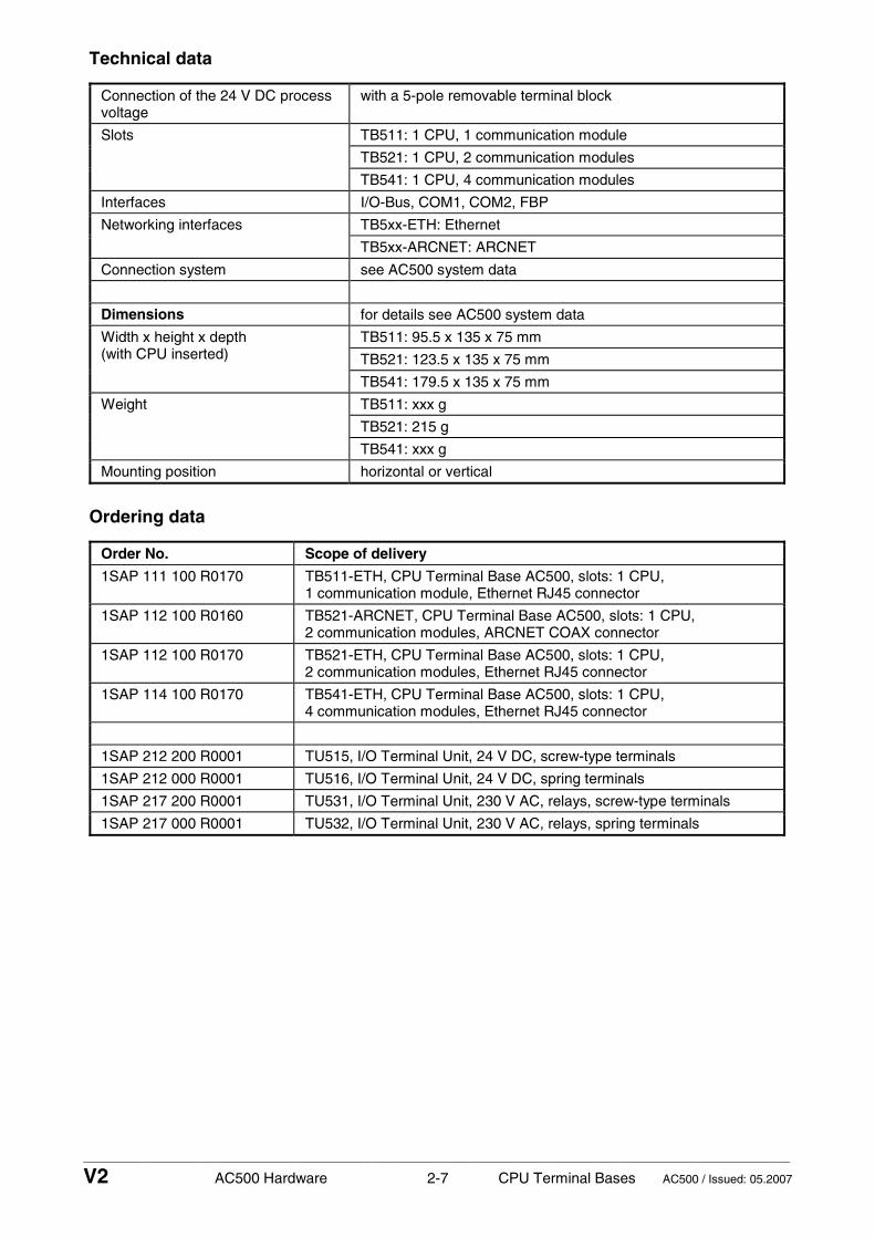
____________________________________________________________________________________________________________
V2 AC500 Hardware 2-7 CPU Terminal Bases AC500 / Issued: 05.2007
Technical data
Connection of the 24 V DC process voltage
with a 5-pole removable terminal block
TB511: 1 CPU, 1 communication module
TB521: 1 CPU, 2 communication modules
Slots
TB541: 1 CPU, 4 communication modules
Interfaces I/O-Bus, COM1, COM2, FBP
TB5xx-ETH: Ethernet Networking interfaces
TB5xx-ARCNET: ARCNET
Connection system see AC500 system data
Dimensions for details see AC500 system data
TB511: 95.5 x 135 x 75 mm
TB521: 123.5 x 135 x 75 mm
Width x height x depth (with CPU inserted)
TB541: 179.5 x 135 x 75 mm
TB511: xxx g
TB521: 215 g
Weight
TB541: xxx g
Mounting position horizontal or vertical
Ordering data
Order No. Scope of delivery
1SAP 111 100 R0170 TB511-ETH, CPU Terminal Base AC500, slots: 1 CPU, 1 communication module, Ethernet RJ45 connector
1SAP 112 100 R0160 TB521-ARCNET, CPU Terminal Base AC500, slots: 1 CPU, 2 communication modules, ARCNET COAX connector
1SAP 112 100 R0170 TB521-ETH, CPU Terminal Base AC500, slots: 1 CPU, 2 communication modules, Ethernet RJ45 connector
1SAP 114 100 R0170 TB541-ETH, CPU Terminal Base AC500, slots: 1 CPU, 4 communication modules, Ethernet RJ45 connector
1SAP 212 200 R0001 TU515, I/O Terminal Unit, 24 V DC, screw-type terminals
1SAP 212 000 R0001 TU516, I/O Terminal Unit, 24 V DC, spring terminals
1SAP 217 200 R0001 TU531, I/O Terminal Unit, 230 V AC, relays, screw-type terminals
1SAP 217 000 R0001 TU532, I/O Terminal Unit, 230 V AC, relays, spring terminals

____________________________________________________________________________________________________________
V2 AC500 Hardware 2-8 CPU Terminal Bases AC500 / Issued: 05.2007

____________________________________________________________________________________________________________
V2 AC500 Hardware 3-1 CPUs AC500 / Issued: 08.2007
Contents
AC500 CPUs
AC500-CPUs PM571, PM581, PM582, PM590 and PM591 ..................................................... 3-2
Short description ...................................................................................................................................... 3-3
Assortment ...............................................................................................................................3-5
Connections............................................................................................................................................... 3-6
- I/O-Bus...................................................................................................................................................... 3-6 - Power supply ............................................................................................................................................ 3-7 - Bad wiring on power supply terminals...................................................................................................... 3-8 - Serial interface COM1 .............................................................................................................................. 3-8 - Serial interface COM2 .............................................................................................................................. 3-8 - Network interface Ethernet ....................................................................................................................... 3-9 - Network interface ARCNET...................................................................................................................... 3-9 - FBP interface............................................................................................................................................ 3-9
Insertion / replacement of the Lithium battery ...................................................................... 3-10
Insertion of the SD Memory Card ........................................................................................... 3-12
Project planning / start-up.................................................................................................................... 3-13
Behaviour of the system in case of power supply interruptions and power recovering .... 3-13
Displays and operating elements on the front panel of the CPU............................................... 3-13
Examples for the use of the displays and pushbuttons .............................................................. 3-15
- Example 1: Setting of the slave address of the FBP plug onto the AC500 CPU (if needed, but not recommended) ......................................................................................................... 3-15 - Example 2: AC500 CPU, status display and error indication ................................................................. 3-17
Technical data ......................................................................................................................................... 3-21
Ordering data........................................................................................................................................... 3-24

____________________________________________________________________________________________________________
V2 AC500 Hardware 3-2 CPUs AC500 / Issued: 08.2007
AC500 CPUs PM571, PM581, PM582, PM590 and PM591 - PM5xx-ETH: CPU with network interface Ethernet RJ45 - PM5xx-ARCNET: CPU with network interface ARCNET BNC
DC
-IN
10W
ET
HE
RN
ET
FBP
CO
M1
CO
M2
ETHFBPCOM1COM2
PWR RUN ERR
RUN DIAG
VAL CFG
ESC
OK
PM581
INSERTPUSH
MC502
SYSBATT
I/O-Bus
CPU24 V DC 10 W
WARNING!Use of
incorrectbattery maycause fire orexplosion.
SD Memory CardMC502
1
32
6
7
5
4
8
12
20
13 13
14 17
18
19
11
10
LithiumBattery
9
TA521
CPU
Ethernet TB5xx-ETH
or ARCNETTB5xx-ARCNET
15
16
Elements of the CPU
Six 7-segment status displays1with background lighting
Elements of the CPU Terminal Base
I/O-Bus (10-pole, female) to electrically11connect the first I/O Terminal Unit
2 12Triangle displays for ”Item” Slot for the CPU (CPU is mounted)
3 13Square displays for ”Status” Slots for couplers (max. 4)
4 14Status LEDs Interface for FieldBusPlug
5 15Pushbuttons Supply for 24 V DC
6 16Slot for the SD Memory Card Serial interface COM1
7 17Label Serial interface COM2
8 18Compartment for the Lithium battery Network interface (Ethernet or ARCNET)
9 19Lithium battery TA521 Holes for wall mounting
10 20SD Memory Card MC502 DIN rail
Figure: CPU PM581-ETH plugged on a Terminal Base TB521
The CPUs PM571, PM581, PM582, PM590 and PM591 are the central units (basic units) of the control system Advant Controller 500 (AC500). The types differ in their performance (memory size, speed etc.). Each CPU must be mounted on a suitable Terminal Base. The Terminal Base type depends on the number of communication modules (couplers) which are used together with the CPU and on the CPU-

____________________________________________________________________________________________________________
V2 AC500 Hardware 3-3 CPUs AC500 / Issued: 08.2007
own network interface type (Ethernet or ARCNET). At the right side of the CPU, up to 7 I/O expansion modules can be attached.
If both of the following conditions are fulfilled, max. 10 I/O expansion modules can be connected to the I/O-Bus of the CPU: - PS501 as of version V1.2 - CPUs as of firmware V1.2.0
The CPUs have several interfaces.
Note: Mounting, disassembling, electrical connection and dimensioned drawings for the Terminal Bases, CPUs, communication modules, I/O Terminal Units and the I/O expansion modules are described in detail in the AC500 system data chapters.
Contents
Short description ......................................................................................................................................... 3-3 Assortment.................................................................................................................................................. 3-5 Connections ................................................................................................................................................ 3-6 - I/O-Bus...................................................................................................................................................... 3-6 - Power supply ............................................................................................................................................ 3-7 - Bad wiring on power supply terminals...................................................................................................... 3-8 - Serial interface COM1 .............................................................................................................................. 3-8 - Serial interface COM2 .............................................................................................................................. 3-8 - Network interface Ethernet ....................................................................................................................... 3-9 - Network interface ARCNET...................................................................................................................... 3-9 - FBP interface............................................................................................................................................ 3-9 Insertion / replacement of the Lithium battery .......................................................................................... 3-10 Insertion of the SD Memory Card ............................................................................................................. 3-12 Project planning / start-up......................................................................................................................... 3-13 Behaviour of the system in case of power supply interruptions and power recovering............................ 3-13 Displays and operating elements on the front panel of the CPU.............................................................. 3-13 Examples for the use of the displays and pushbuttons ............................................................................ 3-15 - Example 1: Setting of the slave address of the FBP plug onto the AC500 CPU (if needed, but not recommended) ......................................................................................................... 3-15 - Example 2: AC500 CPU, status display and error indication ................................................................. 3-17 Technical data........................................................................................................................................... 3-21 Ordering data ............................................................................................................................................ 3-24
Short description
Important: Currently, the AC500 CPU can only be used as slave together with the PROFIBUS DP "Modular" FBP V0/V1 (order No. 1SAJ 240 100 R10xx) and the corresponding GSD file ABB_091F.GSD.
Hardware configuration
Each CPU can operate up to 4 couplers through its coupler interface. The couplers are mounted on the left side of the CPU on the same Terminal Base. On the right side of the CPU, up to 7 digital or analog I/O expansion modules can be attached which are automatically interconnected by the I/O-Bus. Each of these modules requires its own I/O Terminal Unit, whose type depends on the module type.
If both of the following conditions are fulfilled, max. 10 I/O expansion modules can be connected to the I/O-Bus of the CPU: - PS501 as of version V1.2 - CPUs as of firmware V1.2.0
Terminal Bases, Terminal Units, I/O modules, couplers and accessories have their own technical descriptions which can be found under "Hardware AC500" and "Hardware S500".

____________________________________________________________________________________________________________
V2 AC500 Hardware 3-4 CPUs AC500 / Issued: 08.2007
Each CPU can be used as
• bus master within the control system AC500 together with several field buses and networkings • slave (remote processor together with the FieldBusPlug) within the control system AC500 • stand-alone CPU
The CPUs are powered with 24 V DC.
CAUTION: Removal of energized modules is not permitted. All power sources (supply and process voltages) must be switched off while working on any AC500 system.
The following figure shows a CPU with Terminal Base, couplers and I/O modules.
PM581CM577CM572
...
DC532
max. 4 couplers
max. 7 (10) *)I/O modules
1 7 (10) *)
Figure: CPU with Terminal Base, couplers and I/O modules
*) If both of the following conditions are fulfilled, max. 10 I/O expansion modules can be connected to the I/O-Bus of the CPU: - PS501 as of version V1.2 - CPUs as of firmware V1.2.0

____________________________________________________________________________________________________________
V2 AC500 Hardware 3-5 CPUs AC500 / Issued: 08.2007
Assortment
CPUs
Network interface
CPU Program memory
Cycle time for 1000 instructions
Ether- net
ARC- NET
Other interfaces
Suitable Terminal Bases
PM571 TB5xx-xx
PM571-ETH 64 kB
Binary: 0.3 ms Word: 0.3 ms Floating point: 6 ms
yes TB5xx-ETH
PM581 TB5xx-xx
PM581-ETH yes TB5xx-ETH
PM581-ARCNET
256 kB
yes TB5xx-ARCNET
PM582 TB5xx-xx
PM582-ETH 512 kB
Binary: 0.15 ms Word: 0.15 ms Floating point: 3 ms
yes TB5xx-ETH
PM590 TB5xx-xx
PM590-ETH yes TB5xx-ETH
PM590-ARCNET
2 MB
yes TB5xx-ARCNET
PM591 TB5xx-xx
PM591-ETH yes TB5xx-ETH
PM591-ARCNET
4 MB
Binary: 0.02 ms Word: 0.01 ms Floating point: 0.02 ms
yes
Serial interfaces COM1 and COM2, FBP, coupler interface, I/O-Bus
TB5xx-ARCNET
For further information see Technical data and Ordering data

____________________________________________________________________________________________________________
V2 AC500 Hardware 3-6 CPUs AC500 / Issued: 08.2007
Terminal Bases
Number of slots
Terminal Base TB511 TB521 TB541
Slots for CPUs 1 1 1
Slots for communication modules 1 2 4
Terminals and interfaces
Terminal Base TB511- TB521- TB541-
available = (x) ETH (x) ARCNET ETH (x) ARCNET (x)
ETH (x) ARCNET
Connection
I/O-Bus I/O interface for directly adding up to 7 I/O Terminal Units *)
Power supply 5-pole removable terminal block
COM1 serial interface, 9-pole removable terminal block
COM2 serial interface, 9-pole SUB-D connector (female)
Network interface (type must be equal to the type of the used CPU)
Ethernet RJ45
ARCNETBNC
Ethernet RJ45
ARCNET BNC
Ethernet RJ45
ARCNET BNC
FBP interface Fieldbus-neutral slave interface (M12, 5-pole, male, fastening with screw)
*) If both of the following conditions are fulfilled, max. 10 I/O expansion modules can be connected to the I/O-Bus of the CPU: - PS501 as of version V1.2 - CPUs as of firmware V1.2.0
Connections
I/O-Bus
The I/O-Bus is the I/O data bus for the S500 expansion modules. Through this bus, I/O and diagnosis data are transferred between the AC500 CPU and the I/O expansion modules. Up to 7 I/O Terminal Units (for 1 I/O expansion module each) can be added to one Terminal Base.
If both of the following conditions are fulfilled, max. 10 I/O expansion modules can be connected to the I/O-Bus of the CPU: - PS501 as of version V1.2 - CPUs as of firmware V1.2.0
The I/O Terminal Units have a bus input at the left side and a bus output at the right side. Thus the length of the I/O-Bus increases with the number of the I/O expansion modules used.
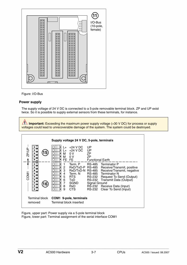
____________________________________________________________________________________________________________
V2 AC500 Hardware 3-7 CPUs AC500 / Issued: 08.2007
I/O-Bus(10-pole,female)
11
Figure: I/O-Bus
Power supply
The supply voltage of 24 V DC is connected to a 5-pole removable terminal block. ZP and UP exist twice. So it is possible to supply external sensors from these terminals, for instance.
Important: Exceeding the maximum power supply voltage (>30 V DC) for process or supply voltages could lead to unrecoverable damage of the system. The system could be destroyed.
COM1 9-pole, terminals
Supply voltage 24 V DC, 5-pole, terminals
Terminal blockremoved Terminal block inserted
ZP
/UP
CO
M1 3 RxD/TxD-N Receive/Transmit, negative
MFE12
456789
0 VFunctional Earth
Term. PRxD/TxD-P
Term. NRTSTxDSGNDRxDCTS
Terminator PReceive/Transmit, positive
Terminator NRequest To Send (Output)Transmit Data (Output)
Receive Data (Input)Clear To Send (Input)
ZPM 0 V ZPL+ +24 V DC UPL+ +24 V DC UP
FE
RS-485
RS-485RS-485
RS-485RS-232RS-232Signal GroundRS-232RS-232
15
16
Figure, upper part: Power supply via a 5-pole terminal block Figure, lower part: Terminal assignment of the serial interface COM1

____________________________________________________________________________________________________________
V2 AC500 Hardware 3-8 CPUs AC500 / Issued: 08.2007
Bad wiring on power supply terminals
Attention: The product should be installed by trained people who have the knowledge of wiring electronic devices. In case of bad wiring, although the modules are protected against various errors (reverse polarity, short circuit, etc.), some problems could always happen: - On the CPU Terminal Base, the terminals L+ and M are doubled. If the power supply is badly connected, a short circuit could happen and lead to a destruction of the power supply or its fuse. If no suitable fuse exists, the Terminal Base itself could be destroyed. - The CPUs (Terminal Bases) and all electronic modules (and Terminal Units) are protected against reverse polarity. - All necessary measures should be carried out to avoid damages to modules and wiring. Notice the wiring plans and connection examples.
Serial interface COM1 (for terminal assignment see the figure above)
The serial interface COM1 is connected to a removable 9-pole terminal block. It is configurable for RS-232 and RS-485 and can be used for
• an online access (RS-232 programming interface for PC/Control Builder) • a free protocol (communication via the function blocks COMSND and COMREC) • Modbus RTU, master and slave or • a CS31 system bus (RS-485), as master only
A detailed description for COM1 can be found under "Hardware AC500 / System data / System data and System construction / Serial interface COM1 or Serial interfaces".
Serial interface COM2
The serial interface COM2 is connected to a 9-pole SUB-D connector. It is configurable for RS-232 and RS-485 and can be used for
• an online access (RS-232 programming interface for PC/Control Builder) • a free protocol (communication via the function blocks COMSND and COMREC) • MODBUS RTU, master and slave
COM2 is not intended to establish a CS31 system bus.
COM2 9-pole, female
123456789
FETxDRxD/TxD-PRTSSGND+5 VRxD
CTS
1
59
6
Functional Earth
RS-232RS-485
Request To SendSignal Ground
Reiceive Data
Clear To Send
Housing Functional Earth
Transmit Data
OutputReceive/Transmit positive
RS-232 Output
RS-232 InputRS-485 Receive/Transmit negativeRS-232 Input
0 V supply out5 V supply out
RxD/TxD-N
FE
17
Figure: Pin assignment of the serial interface COM2
A detailed description for COM2 can be found under "Hardware AC500 / System data / System data and System construction / Serial interface COM2 or Serial interfaces".

____________________________________________________________________________________________________________
V2 AC500 Hardware 3-9 CPUs AC500 / Issued: 08.2007
Network interface Ethernet
This interface is the connection to the internal Ethernet coupler of the CPUs PM5xx-ETH. Applications are:
• TCP/IP for PC/Control Builder (programming) • UDP (communication via function blocks ETH_UDP_SEND and ETH_UDP_REC) • Modbus on TCP/IP (Modbus on TCP/IP, master and slave)
1
8
87654321
NCNCRxD–NCNCRxD+TxD–TxD+
Shield Cable shield / Signal Ground
not usednot usedReceive Datanot usednot usedReceive DataTransmit DataTransmit Data
EthernetRJ4518
Figure: Pin assignment of the Ethernet interface
Network interface ARCNET
This interface is the connection to the internal ARCNET coupler of the CPUs PM5xx-ARCNET.
ARCNET BNC
18
Figure: ARCNET interface
FBP interface
Through this 5-pole fieldbus-neutral interface, the AC500 CPU can be connected as a slave to a fieldbus master. The FieldBusPlug is fastened by a screw.
male
512
3 4
12345
+24 VDiagnosis pin0 VSerial dataSerial data
Standard power supply
Standard power supply
Pin assignment in serial mode
14
Figure: Pin assignment of the FBP interface
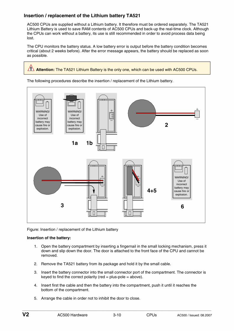
____________________________________________________________________________________________________________
V2 AC500 Hardware 3-10 CPUs AC500 / Issued: 08.2007
Insertion / replacement of the Lithium battery TA521
AC500 CPUs are supplied without a Lithium battery. It therefore must be ordered separately. The TA521 Lithium Battery is used to save RAM contents of AC500 CPUs and back-up the real-time clock. Although the CPUs can work without a battery, its use is still recommended in order to avoid process data being lost.
The CPU monitors the battery status. A low battery error is output before the battery condition becomes critical (about 2 weeks before). After the error message appears, the battery should be replaced as soon as possible.
Attention: The TA521 Lithium Battery is the only one, which can be used with AC500 CPUs.
The following procedures describe the insertion / replacement of the Lithium battery.
WARNING!Use of
incorrectbattery maycause fire orexplosion.
WARNING!Use of
incorrectbattery maycause fire orexplosion.
1a
2
3
4+5
WARNING!Use of
incorrectbattery maycause fire orexplosion.
6
1b
Figure: Insertion / replacement of the Lithium battery
Insertion of the battery:
1. Open the battery compartment by inserting a fingernail in the small locking mechanism, press it down and slip down the door. The door is attached to the front face of the CPU and cannot be removed.
2. Remove the TA521 battery from its package and hold it by the small cable.
3. Insert the battery connector into the small connector port of the compartment. The connector is keyed to find the correct polarity (red = plus-pole = above).
4. Insert first the cable and then the battery into the compartment, push it until it reaches the bottom of the compartment.
5. Arrange the cable in order not to inhibit the door to close.

____________________________________________________________________________________________________________
V2 AC500 Hardware 3-11 CPUs AC500 / Issued: 08.2007
6. Pull-up the door and press until the locking mechanism snaps.
Note: In order to prevent data losses or problems, the battery should be replaced after 3 years of utilisation or at least as soon as possible after receiving the "Low battery warning" indication. Do not use a battery older than 3 years for replacement, do not keep batteries too long in stock.
Replacement of the battery:
Attention: In order to avoid any data losses (if needed), the battery replacement should be done with the system under power. Without battery and power supply there is no data buffering possible.
1. Open the battery compartment by inserting a fingernail in the small locking mechanism, press it down and slip down the door. The door is attached to the front face of the CPU and cannot be removed.
2. Remove the old TA521 battery from the battery compartment by pulling it by the small cable. Remove then the small connector from the socket, do this best by lifting it out with a screwdriver (see photo).
3. Follow the previous instructions to insert a new battery.
Attention: Lithium batteries must not be re-charged, not be disassembled and not be disposed of in fire. They must be stored in a dry place. Exhausted batteries must be recycled to respect the environment.
The technical data sheet for the Lithium battery can be found in the chapter "Accessories / Lithium Battery TA521".
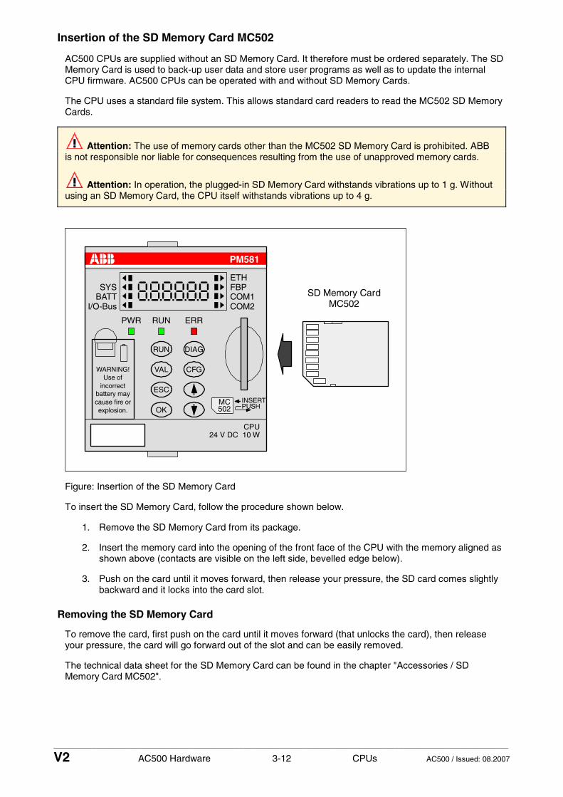
____________________________________________________________________________________________________________
V2 AC500 Hardware 3-12 CPUs AC500 / Issued: 08.2007
Insertion of the SD Memory Card MC502
AC500 CPUs are supplied without an SD Memory Card. It therefore must be ordered separately. The SD Memory Card is used to back-up user data and store user programs as well as to update the internal CPU firmware. AC500 CPUs can be operated with and without SD Memory Cards.
The CPU uses a standard file system. This allows standard card readers to read the MC502 SD Memory Cards.
Attention: The use of memory cards other than the MC502 SD Memory Card is prohibited. ABB is not responsible nor liable for consequences resulting from the use of unapproved memory cards.
Attention: In operation, the plugged-in SD Memory Card withstands vibrations up to 1 g. Without using an SD Memory Card, the CPU itself withstands vibrations up to 4 g.
SD Memory CardMC502
ETHFBPCOM1COM2
PWR RUN ERR
RUN DIAG
VAL CFG
ESC
OK
PM581
INSERTPUSH
MC502
SYSBATT
I/O-Bus
CPU24 V DC 10 W
WARNING!Use of
incorrectbattery maycause fire orexplosion.
Figure: Insertion of the SD Memory Card
To insert the SD Memory Card, follow the procedure shown below.
1. Remove the SD Memory Card from its package.
2. Insert the memory card into the opening of the front face of the CPU with the memory aligned as shown above (contacts are visible on the left side, bevelled edge below).
3. Push on the card until it moves forward, then release your pressure, the SD card comes slightly backward and it locks into the card slot.
Removing the SD Memory Card
To remove the card, first push on the card until it moves forward (that unlocks the card), then release your pressure, the card will go forward out of the slot and can be easily removed.
The technical data sheet for the SD Memory Card can be found in the chapter "Accessories / SD Memory Card MC502".

____________________________________________________________________________________________________________
V2 AC500 Hardware 3-13 CPUs AC500 / Issued: 08.2007
Project planning / start-up
Programming is carried out with the AC500 Control Builder software, which is based on the CodeSys standard. The software can be run on the operating systems Windows 2000 and XP.
A fast Online Program Modification of the user program is possible without interrupting the running operation.
If data areas should be saved during power OFF/ON, they can be stored in the Flash EPROM. The installed Lithium battery saves data in the RAM.
Behaviour of the system in case of power supply interruptions and power recovering
AC500 system supply (terminals L+, M)
As soon as the CPU power supply is higher than 19.2 V DC, the power supply detection is activated and the CPU is started. When during operation the power supply is going down to lower than 19.2 V DC for more than 10 ms, the CPU is switched to safety mode (see System Technology of the CPUs).
A warm restart of the CPU only occurs by switching the power supply off and on again (see also the description of the function modes of the CPU in the "AC500 System Technology" chapters.
Displays and operating elements on the front panel of the CPU
ETHFBPCOM1COM2
PWR RUN ERR
RUN DIAG
VAL CFG
ESC
OK
PM581
INSERTPUSH
MC502
SYSBATT
I/O-Bus
CPU24 V DC 10 W
WARNING!Use of
incorrectbattery maycause fire orexplosion.
1
32
5
4
Figure: Displays and operating elements on the front panel of the CPU
LCD display with background lighting
1 Six 7-segment status displays for displaying
• the CPU status (e.g. RUN or STOP) • error codes and error classes • address modifications and parameters of the integrated couplers (Ethernet or ARCNET) • values at the channels of I/O modules
2 Triangle displays
• show what is just selected (active)
3 Square displays
• show that the communication is running between the CPU and the bus

____________________________________________________________________________________________________________
V2 AC500 Hardware 3-14 CPUs AC500 / Issued: 08.2007
Status LEDs
4 Meaning of the status LEDs
LED Color Function
PWR green indicates that the power supply of the CPU is ON
RUN green indicates that the CPU is running (is OFF with STOP)
ERR red indicates an error occurred (goes off after error acknowledgement)
Pushbuttons
5 The CPU can be operated manually using the eight pushbuttons on the front panel. Meaning of the pushbuttons:
Button Meaning
RUN toggles the CPU between RUN and STOP mode
VAL reserved for future use
ESC ESC, quit menu without saving
OK OK, leave menu after saving
DIAG diagnosis, evaluate error message in detail
CFG set address for ARCNET, CS31 and FBP
↑ Move up selection or increase value (e.g. address) by 1
↓ Move down selection or decrease value (e.g. address) by 1
The entire functionality of the CPUs is described in detail under "System technology of the CPUs".
In the following examples, the use of the displays and pushbuttons is represented in detail.

____________________________________________________________________________________________________________
V2 AC500 Hardware 3-15 CPUs AC500 / Issued: 08.2007
Examples for the use of the displays and pushbuttons
Example 1: Setting of the slave address of the FBP plug onto the AC500 CPU (if needed, but not recommended)
The FieldBusPlug must have a properly assigned slave module address. The AC500 CPU gives them an address at system power-up. The address could be set with the use of the display and the pushbutton on the top of the module, but it is mainly assigned by the AC500 Control Builder configuration.
Attention: The local setting of an FBP address by means of pushbuttons and display has a higher priority than an FBP address configured by the AC500 Control Builder! The locally set address replaces the address configured by the software. It is highly recommended to be extremely careful when modifying the address locally, because it has high influence on the behaviour of the application.
Up to 99 addresses can be then set with the display.
ETHFBPCOM1COM2
PWR RUN ERR
RUN DIAG
VAL CFG
ESC
OK
PM581
INSERTPUSH
MC502
SYSBATT
I/O-Bus
CPU24 V DC 10 W
WARNING!Use of
incorrectbattery maycause fire orexplosion.
By using the CFG, the ar-row keys and the OKpusbutton, some parame-ters of the CPU can beconfigured.
CFG
OK
Figure: Configuration on the CPU
Attention: If the FBP address set on the AC500 CPU module (or by the AC500 Control Builder software) is different from that address assigned by the Master device for the same station, the station cannot be accessed and the complete Fieldbus cannot work properly or is completely down!

____________________________________________________________________________________________________________
V2 AC500 Hardware 3-16 CPUs AC500 / Issued: 08.2007
To configure the FBP address, please follow the procedure described below:
ETHFBPCOM1COM2
SYSBATT
I/O-Bus
1. First select the item to be configured bypressing the CFG key, the CPU changes toconfiguration mode and a small triangle isdisplayed on the LCD on the first right upposition of the display beside the ETH in-scription and the already configured ad-dress is displayed.Press one time more the CFG key to movethe triangle to the position below ”FBP”.The FBP is then selected, and the currentaddress is shown.
CFG
ETHFBPCOM1COM2
SYSBATT
I/O-Bus
CFG
2. Press then the arrow keys UP or DOWN toincrease or decrease the address, the mo-dified value blinks to indicate that it di ffersfrom the previously stored one.
ETHFBPCOM1COM2
SYSBATT
I/O-Bus
3. Once the desired address is reached,press OK to accept and quit or only ESC toexit the menu without saving the changes.The CPU status is then displayedrun/StoP.
OK
ESC
orETHFBPCOM1COM2
SYSBATT
I/O-Bus
Figure: Configuration of an FBP address
A AC500 CPU equipped with a FieldBusPlug is always a slave device on the bus. To act as a master, a AC500 CPU should be equipped with master couplers (e.g CM572-DP for PROFIBUS DP).
Attention: The locally modified address will only be valid after a power OFF/ON of the CPU!

____________________________________________________________________________________________________________
V2 AC500 Hardware 3-17 CPUs AC500 / Issued: 08.2007
Example 2: AC500-CPU, status display and error indication
All AC500 CPUs have LEDs and a LC Display for indicating operating statuses and errors. The following drawing shows the front face of a AC500 CPU.
ETHFBPCOM1COM2
PWR RUN ERR
RUN DIAG
VAL CFG
ESC
OK
PM581
INSERTPUSH
MC502
SYSBATT
I/O-Bus
CPU24 V DC 10 W
WARNING!Use of
incorrectbattery maycause fire orexplosion.
The CPU statuses are displayed on the CPU frontface with 3 LEDs:
– PWR– RUN– ERR– and by means of a background-lighted display
The display contains the following indications:
6 x 7-segment displays for ”plain text” orerror codes display
small black squares indications acting as aLED status for the device written beneathsmall black arrows used for indication bypointing the selected device to be con-figured or read
–
–
–
Figure: Front face of a AC500 CPU
The display is normally OFF and the status of the CPU is shown as plain text "run" or "Stop", which reflects the operating status of the CPU program.
By pressing one of the dialog keys "RUN, DIAG, CFG or VAL", the background lighting is turned ON and the desired function is performed.
In case of a function error, the display background lighting is also switched on and an error code is displayed.
The meaning of the LEDs and of LCD is given in the following table.

____________________________________________________________________________________________________________
V2 AC500 Hardware 3-18 CPUs AC500 / Issued: 08.2007
AC500 CPU module LEDs
LED Status Color LED = ON LED = OFF LED flashes
PWR 24 V DC power supply is provided
green voltage is present voltage is missing
--
RUN activity status green CPU is in RUN mode
CPU is in STOP mode
If flashes fast (4 Hz): The CPU is reading/writing the SD card, indicates together with the blinking error LED that the CPU is writing the internal Flash EEPROM. If flashes slow (1 Hz): The firmware update from the SD card is finished without errors.
ERR error indication red An error has occurred. After pressing the DIAG key, the error type and code is displayed in the LC Display. The error codes can be shown by means of the DIAG and OK keys.
No errors are encountered or only warnings (E4 errors). This is configurable (by error 2 - 4, the LED behaviour is configurable.
Flashing fast (4 Hz): Indicates together with RUN a firmware update process and a Flash EEPROM write.
Working activity of the beneath described device (e.g. top right of the display ETH communication line).
black Device is present and OK (e.g. the battery is present and OK).
No activity or device not present
Flashing according to the device activity, e.g. when data exchange on ETH, COM1, etc... communication lines.
or Indicates the selected device to be read or configured. Acts as a cursor moving with the arrow
keys
black Points out the selected device of which the name is written beneath (e.g. top right of the display ETH communication line).
No device selected
--

____________________________________________________________________________________________________________
V2 AC500 Hardware 3-19 CPUs AC500 / Issued: 08.2007
Displaying error messages (error codes) on the AC500 CPU
When an error occurs, the red error LED goes on.
By pressing the DIAG key, the complete error code can be shown and an acknowledgement of the error can be performed.
ETHFBPCOM1COM2
PWR RUN ERR
RUN DIAG
VAL CFG
ESC
OK
PM581
INSERTPUSH
MC502
SYSBATT
I/O-Bus
CPU24 V DC 10 W
WARNING!Use of
incorrectbattery maycause fire orexplosion.
By using the DIAG andthe OK or the ESC push-buttons, the error mes-sage/code can be dis-played and the error canbe acknowledged.
DIAG OK ESC
Figure: Error display on the CPU
The AC500 CPU can display various errors according to the error classes. The following error classes are possible. The reaction of the CPU is different for each type of error.
Error class Type Meaning Example
E1 Fatal error A safe function of the operating system is no longer guaranteed.
Checksum error in the system Flash or RAM error
E2 Severe error The operating system is functioning without problems, but the error-free processing of the user program is no longer guaranteed.
Checksum error in the user Flash, independent of the task duration
E3 Light error It depends on the application, if the user program should be stopped by the operating system or not. The user should decide, which reaction is necessary.
Flash could not be programmed, I/O module has failed.
E4 Warning Error in the periphery (e.g. I/O) which only can have influence in the future. The user should decide the reaction to provide.
Short-circuit at an I/O module, the battery is exhausted or not inserted.
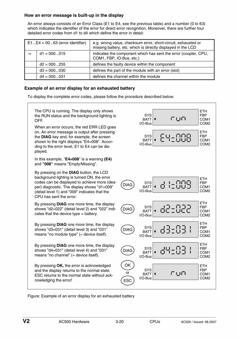
____________________________________________________________________________________________________________
V2 AC500 Hardware 3-20 CPUs AC500 / Issued: 08.2007
How an error message is built-up in the display
An error always consists of an Error Class (E1 to E4, see the previous table) and a number (0 to 63) which indicates the identifier of the error for direct error recognition. Moreover, there are further four detailed error codes from d1 to d4 which define the error in detail:
E1...E4 = 00...63 (error identifier) e.g. wrong value, checksum error, short-circuit, exhausted or missing battery, etc. which is directly displayed in the LCD
-> d1 = 000...015 indicates the component which has sent the error (coupler, CPU, COM1, FBP, IO-Bus, etc.)
d2 = 000...255 defines the faulty device within the component
d3 = 000...030 defines the part of the module with an error (slot)
d4 = 000...031 defines the channel within the module
Example of an error display for an exhausted battery
To display the complete error codes, please follow the procedure described below:
ETHFBPCOM1COM2
SYSBATT
I/O-Bus
ETHFBPCOM1COM2
SYSBATT
I/O-Bus
ETHFBPCOM1COM2
SYSBATT
I/O-Bus
The CPU is running. The display only showsthe RUN status and the background lighting isOFF.
OK
ESC
or
When an error occurs, the red ERR LED goeson. An error message is output after pressingthe DIAG key and, for example, the screenshown to the right displays ”E4=008”. Accor-ding to the error level, E1 to E4 can be dis-played.
In this example, ”E4=008” is a warning (E4)and ”008” means ”Empty/Missing”.
By pressing on the DIAG button, the LCDbackground lighting is turned ON, the errorcodes can be displayed to achieve more (dea-per) diagnostic. The display shows ”d1=009”(detail level 1) and ”009” indicates that theCPU has sent the error.
DIAG
By pressing DIAG one more time, the displayshows ”d2=022” (detail level 2) and ”022” indi-cates that the device type = battery.
DIAG
By pressing DIAG one more time, the displayshows ”d3=031” (detail level 3) and ”031”means ”no module type” (= device itself).
DIAG
By pressing DIAG one more time, the displayshows ”d4=031” (detail level 4) and ”031”means ”no channel” (= device itself).
DIAG
By pressing OK, the error is acknowledgedand the display returns to the normal state.ESC returns to the normal state without ack-nowledging the error!
ETHFBPCOM1COM2
SYSBATT
I/O-Bus
ETHFBPCOM1COM2
SYSBATT
I/O-Bus
ETHFBPCOM1COM2
SYSBATT
I/O-Bus
ETHFBPCOM1COM2
SYSBATT
I/O-Bus
Figure: Example of an error display for an exhausted battery

____________________________________________________________________________________________________________
V2 AC500 Hardware 3-21 CPUs AC500 / Issued: 08.2007
Technical data
The system data of AC500 and S500 are valid here. Only additional details are therefore documented below.
General data of the CPUs and the Terminal Bases
For more information, please refer to the "AC500 System Data" chapters.
Connection of the supply voltage 24 V DC at the Terminal Base of the CPU
at a 5-pole removable terminal block with spring connection
PM571: 50 mA PM571-ETH: 110 mA
PM581: 50 mA PM581-ETH: 110 mA PM581-ARCNET: 110 mA
PM582: 50 mA PM582-ETH: 110 mA
Current consumption from 24 V DC
PM59x: 90 mA PM59x-ETH: 150 mA PM59x-ARCNET: 150 mA
PM571: 1 A²s PM571-ETH: 1 A²s
PM581: 1 A²s PM581-ETH: 1 A²s PM581-ARCNET: 1 A²s
PM582: 1 A²s PM582-ETH: 1 A²s
Inrush current at 24 V DC
PM59x: 1 A²s PM59x-ETH: 1 A²s PM59x-ARCNET: 1 A²s
Max. power dissipation within the module
10 W
TB511: 1 CPU, 1 communication module
TB521: 1 CPU, 2 communication modules
Slots on the Terminal Bases
TB524: 1 CPU, 4 communication modules
CPU interfaces at the Terminal Bases I/O-Bus, COM1, COM2, FBP
TB5xx-ETH / PM5xx-ETH: Ethernet CPU network interfaces at the Terminal Bases TB5xx-ARCNET / PM5xx-ARCNET: ARCNET
Connection system see AC500 system data
Dimensions further details see AC500 system data
TB511 with CPU: 95.5 x 135 x 75 mm
TB521 with CPU: 123.5 x 135 x 75 mm
Width x height x depth
TB541 with CPU: 179.5 x 135 x 75 mm
PM571: 135 g PM571-ETH: 150 g
PM581: 135 g PM581-ETH: 150 g PM581-ARCNET: 160 g
PM582: 135 g PM582-ETH: 150 g
Weight (CPU without Terminal Base)
PM59x: 135 g PM59x-ETH: 150 g PM59x-ARCNET: 160 g
Mounting position horizontal or vertical with derating (50 % output load, reduction of temperature to 40°C)

____________________________________________________________________________________________________________
V2 AC500 Hardware 3-22 CPUs AC500 / Issued: 08.2007
Detailed data of the CPUs
CPU PM571 PM571-ETH
PM58x PM58x-ETH
PM581- ARCNET
PM59x PM59x -ETH
PM59x- ARCNET
Program memory Flash EPROM and RAM
64 kB PM581: 256 kB PM582: 512 kB
PM590: 2048 kB PM591: 4096 kB
Data memory, integrated 24 kB, incl. 4 kB RETAIN
288 kB, incl. 32 kB RETAIN PM590: 2048 kB, PM591:3072 kB, incl. 512 kB
RETAIN
Expandable memory none none none
Pluggable SD Memory Card for: - User data storage - Program storage - Firmware update
128 MB 128 MB 128 MB
Cycle time for 1000 instructions - Binary - Word - Floating point
0.3 ms 0.3 ms 6.0 ms
0.15 ms 0.15 ms 3.0 ms
0.05 ms 0.05 ms 0.5 ms
Max. number of central inputs and outputs (up to 7 exp. modules): - Digital inputs - Digital outputs - Analog inputs - Analog outputs
224 168 112 112
224 168 112 112
224 168 112 112
Max. number of central inputs and outputs (up to 10 exp. modules): *) - Digital inputs - Digital outputs - Analog inputs - Analog outputs
320 240 160 160
320 240 160 160
320 240 160 160
Number of decentralized inputs and outputs
depends on the used field bus (as an info on the CS31 bus: up to 31 stations with up to 120 DI / 120 DO each)
Data backup battery battery battery
Data buffering time at 25°C about 3 years
Battery low indication warning indication issued about 2 weeks before the battery charge becomes critical
Real-time clock - with battery back-up
X
X
X
Program execution - cyclic - time-controlled - multitasking
X X X
X X X
X X X
Protection of the user program by a password X X X
Serial interface COM1 - Physical link: - Connection: - Usage:
configurable for RS-232 or RS-485 (from 0.3 to 187.5 kB/s) pluggable terminal block, spring connection for programming, as Modbus (master/slave), as serial ASCI communication, as CS31 master
Serial interface COM2 - Physical link: - Connection: - Usage:
configurable for RS-232 or RS-485 (from 0.3 to 187.5 kB/s) SUB-D connector for programming, as Modbus (master/slave), as serial ASCI communication
Integrated coupler, ETH = Ethernet RJ45 ARCNET = ARCNET BNC
ETH ETH ARCNET ETH ARCNET

____________________________________________________________________________________________________________
V2 AC500 Hardware 3-23 CPUs AC500 / Issued: 08.2007
Number of external couplers up to 4 communication couplers like PROFIBUS DP, Ethernet, CANopen, DeviceNet. There is no restriction concerning the coupler types and coupler
combinations (e.g. up to 4 PROFIBUS DP couplers are possible)
LEDs, LCD display, 8 function keys
for RUN/STOP switch-over, status displays and diagnosis
Number of timers unlimited unlimited unlimited
Number of counters unlimited unlimited unlimited
Programming languages - Instruction List IL - Function Block Diagram FBD - Ladder Diagram LD - Sequential Function Chart SFC - Continuous Function Chart (CFC)
X X
X X
X
X X
X X
X
X X
X X
X
Certifications CE, GL, DNV, BV, RINA, LRS, cUL
*) If both of the following conditions are fulfilled, max. 10 I/O expansion modules can be connected to the I/O-Bus of the CPU: - PS501 as of version V1.2 - CPUs as of firmware V1.2.0
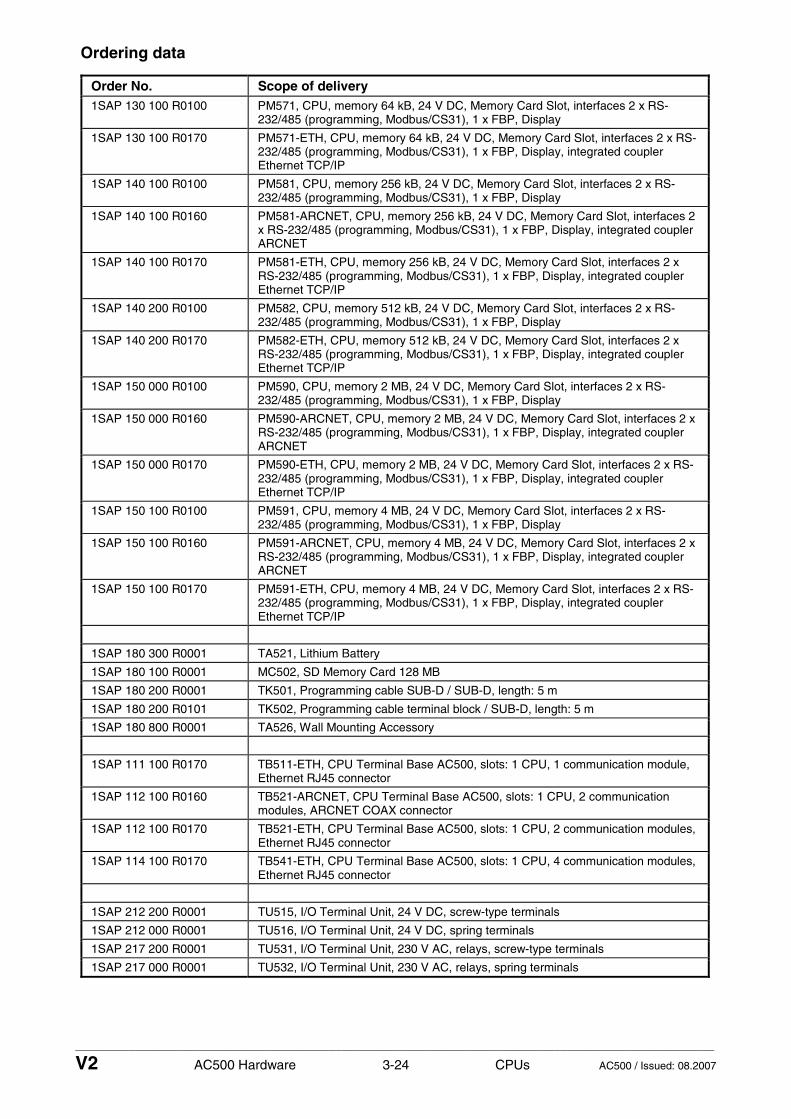
____________________________________________________________________________________________________________
V2 AC500 Hardware 3-24 CPUs AC500 / Issued: 08.2007
Ordering data
Order No. Scope of delivery 1SAP 130 100 R0100 PM571, CPU, memory 64 kB, 24 V DC, Memory Card Slot, interfaces 2 x RS-
232/485 (programming, Modbus/CS31), 1 x FBP, Display
1SAP 130 100 R0170 PM571-ETH, CPU, memory 64 kB, 24 V DC, Memory Card Slot, interfaces 2 x RS-232/485 (programming, Modbus/CS31), 1 x FBP, Display, integrated coupler Ethernet TCP/IP
1SAP 140 100 R0100 PM581, CPU, memory 256 kB, 24 V DC, Memory Card Slot, interfaces 2 x RS-232/485 (programming, Modbus/CS31), 1 x FBP, Display
1SAP 140 100 R0160 PM581-ARCNET, CPU, memory 256 kB, 24 V DC, Memory Card Slot, interfaces 2 x RS-232/485 (programming, Modbus/CS31), 1 x FBP, Display, integrated coupler ARCNET
1SAP 140 100 R0170 PM581-ETH, CPU, memory 256 kB, 24 V DC, Memory Card Slot, interfaces 2 x RS-232/485 (programming, Modbus/CS31), 1 x FBP, Display, integrated coupler Ethernet TCP/IP
1SAP 140 200 R0100 PM582, CPU, memory 512 kB, 24 V DC, Memory Card Slot, interfaces 2 x RS-232/485 (programming, Modbus/CS31), 1 x FBP, Display
1SAP 140 200 R0170 PM582-ETH, CPU, memory 512 kB, 24 V DC, Memory Card Slot, interfaces 2 x RS-232/485 (programming, Modbus/CS31), 1 x FBP, Display, integrated coupler Ethernet TCP/IP
1SAP 150 000 R0100 PM590, CPU, memory 2 MB, 24 V DC, Memory Card Slot, interfaces 2 x RS-232/485 (programming, Modbus/CS31), 1 x FBP, Display
1SAP 150 000 R0160 PM590-ARCNET, CPU, memory 2 MB, 24 V DC, Memory Card Slot, interfaces 2 x RS-232/485 (programming, Modbus/CS31), 1 x FBP, Display, integrated coupler ARCNET
1SAP 150 000 R0170 PM590-ETH, CPU, memory 2 MB, 24 V DC, Memory Card Slot, interfaces 2 x RS-232/485 (programming, Modbus/CS31), 1 x FBP, Display, integrated coupler Ethernet TCP/IP
1SAP 150 100 R0100 PM591, CPU, memory 4 MB, 24 V DC, Memory Card Slot, interfaces 2 x RS-232/485 (programming, Modbus/CS31), 1 x FBP, Display
1SAP 150 100 R0160 PM591-ARCNET, CPU, memory 4 MB, 24 V DC, Memory Card Slot, interfaces 2 x RS-232/485 (programming, Modbus/CS31), 1 x FBP, Display, integrated coupler ARCNET
1SAP 150 100 R0170 PM591-ETH, CPU, memory 4 MB, 24 V DC, Memory Card Slot, interfaces 2 x RS-232/485 (programming, Modbus/CS31), 1 x FBP, Display, integrated coupler Ethernet TCP/IP
1SAP 180 300 R0001 TA521, Lithium Battery
1SAP 180 100 R0001 MC502, SD Memory Card 128 MB
1SAP 180 200 R0001 TK501, Programming cable SUB-D / SUB-D, length: 5 m
1SAP 180 200 R0101 TK502, Programming cable terminal block / SUB-D, length: 5 m
1SAP 180 800 R0001 TA526, Wall Mounting Accessory
1SAP 111 100 R0170 TB511-ETH, CPU Terminal Base AC500, slots: 1 CPU, 1 communication module, Ethernet RJ45 connector
1SAP 112 100 R0160 TB521-ARCNET, CPU Terminal Base AC500, slots: 1 CPU, 2 communication modules, ARCNET COAX connector
1SAP 112 100 R0170 TB521-ETH, CPU Terminal Base AC500, slots: 1 CPU, 2 communication modules, Ethernet RJ45 connector
1SAP 114 100 R0170 TB541-ETH, CPU Terminal Base AC500, slots: 1 CPU, 4 communication modules, Ethernet RJ45 connector
1SAP 212 200 R0001 TU515, I/O Terminal Unit, 24 V DC, screw-type terminals
1SAP 212 000 R0001 TU516, I/O Terminal Unit, 24 V DC, spring terminals
1SAP 217 200 R0001 TU531, I/O Terminal Unit, 230 V AC, relays, screw-type terminals
1SAP 217 000 R0001 TU532, I/O Terminal Unit, 230 V AC, relays, spring terminals

____________________________________________________________________________________________________________
V2 AC500 Hardware 4-1 Communication modules AC500 / Issued: 03.2007
Contents
AC500 Communication Modules
Overview of the AC500 communication modules............................................................................ 4-2
- Short description....................................................................................................................................... 4-2 - Assortment................................................................................................................................................ 4-2 - Mounting of the couplers .......................................................................................................................... 4-3 - Hardware configuration ............................................................................................................................ 4-4 - Technical data (overview)......................................................................................................................... 4-5 - Ordering data............................................................................................................................................ 4-6
Communication module PROFIBUS CM572-DP ............................................................................... 4-7
- Purpose .................................................................................................................................................... 4-8 - Functionality.............................................................................................................................................. 4-8 - Mounting and electrical connection .......................................................................................................... 4-8 - LED status displays .................................................................................................................................. 4-9 - Further important information ................................................................................................................. 4-10 - Technical data ........................................................................................................................................ 4-11 - Ordering data.......................................................................................................................................... 4-11
Communication module DeviceNet CM575-DN .............................................................................. 4-12
- Purpose .................................................................................................................................................. 4-13 - Functionality............................................................................................................................................ 4-13 - Mounting and electrical connection ........................................................................................................ 4-13 - LED status displays ................................................................................................................................ 4-16 - Further important information ................................................................................................................. 4-17 - Technical data ........................................................................................................................................ 4-18 - Ordering data.......................................................................................................................................... 4-18
Communication module Ethernet CM577-ETH ............................................................................... 4-19
- Purpose .................................................................................................................................................. 4-19 - Functionality............................................................................................................................................ 4-20 - Mounting and electrical connection ........................................................................................................ 4-20 - LED status display.................................................................................................................................. 4-21 - Technical data ........................................................................................................................................ 4-22 - Ordering data.......................................................................................................................................... 4-22
Communication module CANopen CM578-CN ............................................................................... 4-23
- Purpose .................................................................................................................................................. 4-24 - Functionality............................................................................................................................................ 4-24 - Mounting and electrical connection ........................................................................................................ 4-24 - LED status displays ................................................................................................................................ 4-25 - Further important information ................................................................................................................. 4-26 - Technical data ........................................................................................................................................ 4-27 - Ordering data.......................................................................................................................................... 4-27

____________________________________________________________________________________________________________
V2 AC500 Hardware 4-2 Communication modules AC500 / Issued: 03.2007
Overview of the AC500 communication modules
Contents
Short description ......................................................................................................................................... 4-2 Assortment.................................................................................................................................................. 4-2 Mounting of the couplers ............................................................................................................................ 4-3 Hardware configuration............................................................................................................................... 4-4 Technical data (overview)........................................................................................................................... 4-5 Ordering data .............................................................................................................................................. 4-6
Short description
AC500 communications modules (couplers) make communications on different field busses possible. The couplers are mounted on the left side of the CPU on the same Terminal Base. The communication between the CPU and the couplers take place through the coupler bus (coupler interface), which is integrated in the Terminal Base. The data interchange is realized by a dual-port RAM. Depending on the used Terminal Base, 1, 2 or 4 couplers can be employed (see also the description of the Terminal Bases).
There are no restrictions, which couplers can be arranged for a CPU, also not in connection with the CPU's internal coupler (Ethernet or ARCNET).
Assortment
Usable CPUs
Coupler Protocol PM571- xxx
PM581- xxx
PM591- xxx
Fieldbus connector
Usable Terminal Bases
CM572-DP PROFIBUS DP Master V0 / V1
x x x SUB-D, 9-pole, female
all
CM575-DN DeviceNet x x x
Pluggable terminal block, spring term.
all
Ethernet TCP/IP
CM577-ETH UDP/IP, Modbus TCP
x x x
2 x RJ45, with integrated switch
all
CM578-CN CANopen x x x
Pluggable terminal block, spring term.
all

____________________________________________________________________________________________________________
V2 AC500 Hardware 4-3 Communication modules AC500 / Issued: 03.2007
Mounting of the couplers
The following figure shows a CPU with two couplers, put together on a Terminal Base TB521.
PM581CM577CM572
Figure: CPU with 2 couplers on a Terminal Base TB521
Note: Mounting, disassembling, electrical connection and dimensioned drawings for the Terminal Bases, CPUs, communication modules, I/O Terminal Units and the I/O expansion modules are described in detail in the AC500 system data chapters.
The following figures show how to mount and disassemble the couplers.
Mount the coupler (communication module)
Figure: Mounting a coupler
The coupler is first inserted below, then clicked-in above.

____________________________________________________________________________________________________________
V2 AC500 Hardware 4-4 Communication modules AC500 / Issued: 03.2007
The disassembly is carried out in a reversed order.
1
2
1
Figure: Disassembly of a coupler
Disassembly: (1) Press above and below, then (2) swing out the coupler and remove it.
Hardware configuration
Each CPU can operate up to 4 external couplers (in addition the internal coupler, if existing).
Depending on the selected communication protocol, each coupler can be used as
• Bus master within the AC500 control system together with several field busses and networks
The couplers are directly powered over the internal coupler bus of the Terminal Base. A separate voltage source is not required.
CAUTION: Removal of energized modules is not permitted. All power sources (supply and process voltages) must be switched off while working on any AC500 system.

____________________________________________________________________________________________________________
V2 AC500 Hardware 4-5 Communication modules AC500 / Issued: 03.2007
Technical data (overview)
The system data of AC500 and S500 are valid here. Only additional details are therefore documented below.
CM572-DP CM577-ETH CM575-DN CM578-CN
Field bus PROFIBUS DP 2 x Ethernet DeviceNet CANopen
Transmission rate 9.6 kBit/s to 12 MBit/s
10 MBit/s or 100 MBit/s
125 kBit/s 250 kBit/s 500 kBit/s
10 kBit/s to 1 MBit/s
Field bus connector D-SUB, 9-pole, female, bended
2 x RJ45 COMBICON 5-pole, bended
COMBICON 5-pole, bended
Processor EC1, 160 pins
Clock frequency 48 MHz
Ambient temperature 0 °C...60 °C
Coupler interface Dual-port memory, 8 kByte
Current consumption over the coupler bus typ. 330 mA typ. 420 mA typ. 180 mA typ. 290 mA
internal RAM memory (EC1) 256 kByte 256 kByte 256 kByte 256 kByte
external RAM memory - 2 x 128 kByte (for webserver option)
- -
External Flash memory 512 kByte (firmware)
512 kByte (firmware) 2 MByte (for Webserver option)
512 kByte (firmware)
512 kByte (firmware)
Status display PWR, RDY, RUN, STA, ERR
PWR, RDY, RUN, STA, ERR, 2 x LINK, 2 x ACT
PWR, RDY, RUN, NET, MOD
PWR, RDY, RUN, STA, ERR
Weight 150 g 150 g 150 g 150 g

____________________________________________________________________________________________________________
V2 AC500 Hardware 4-6 Communication modules AC500 / Issued: 03.2007
Ordering data
Order No. Scope of delivery
1SAP 170 200 R0001 CM572-DP, Communication module PROFIBUS DP Master, 12 MBit/s
1SAP 170 500 R0001 CM575-DN, Communication module DeviceNet Master
1SAP 170 700 R0001 CM577-ETH, Communication module Ethernet TCP/IP with integrated 2-port switch
1SAP 170 800 R0001 CM578-CN, Communication module CANopen Master
1SAP 130 100 R0100 PM571, CPU, memory 64 kB, 24 V DC, Memory Card Slot, interfaces 2 x RS-232/485 (programming, Modbus/CS31), 1 x FBP, Display
1SAP 130 100 R0170 PM571-ETH, CPU, memory 64 kB, 24 V DC, Memory Card Slot, interfaces 2 x RS-232/485 (programming, Modbus/CS31), 1 x FBP, Display, integrated coupler Ethernet TCP/IP
1SAP 140 100 R0100 PM581, CPU, memory 256 kB, 24 V DC, Memory Card Slot, interfaces 2 x RS-232/485 (programming, Modbus/CS31), 1 x FBP, Display
1SAP 140 100 R0160 PM581-ARCNET, CPU, memory 256 kB, 24 V DC, Memory Card Slot, interfaces 2 x RS-232/485 (programming, Modbus/CS31), 1 x FBP, Display, integrated coupler ARCNET
1SAP 140 100 R0170 PM581-ETH, CPU, memory 256 kB, 24 V DC, Memory Card Slot, interfaces 2 x RS-232/485 (programming, Modbus/CS31), 1 x FBP, Display, integrated coupler Ethernet TCP/IP
1SAP 150 100 R0100 PM591, CPU, memory 4 MB, 24 V DC, Memory Card Slot, interfaces 2 x RS-232/485 (programming, Modbus/CS31), 1 x FBP, Display
1SAP 150 100 R0160 PM591-ARCNET, CPU, memory 4 MB, 24 V DC, Memory Card Slot, interfaces 2 x RS-232/485 (programming, Modbus/CS31), 1 x FBP, Display, integrated coupler ARCNET
1SAP 150 100 R0170 PM591-ETH, CPU, memory 4 MB, 24 V DC, Memory Card Slot, interfaces 2 x RS-232/485 (programming, Modbus/CS31), 1 x FBP, Display, integrated coupler Ethernet TCP/IP
1SAP 180 600 R0001 TA524, Dummy Coupler Module
1SAP 180 800 R0001 TA526, Wall Mounting Accessory
1SAP 111 100 R0170 TB511-ETH, CPU Terminal Base AC500, slots: 1 CPU, 1 communication module, Ethernet RJ45 connector
1SAP 112 100 R0160 TB521-ARCNET, CPU Terminal Base AC500, slots: 1 CPU, 2 communication modules, ARCNET COAX connector
1SAP 112 100 R0170 TB521-ETH, CPU Terminal Base AC500, slots: 1 CPU, 2 communication modules, Ethernet RJ45 connector
1SAP 114 100 R0170 TB541-ETH, CPU Terminal Base AC500, slots: 1 CPU, 4 communication modules, Ethernet RJ45 connector

____________________________________________________________________________________________________________
V2 AC500 Hardware 4-7 Communication modules AC500 / Issued: 03.2007
Communication module PROFIBUS DP CM572-DP - Master 12 MBit/s
CM572
PWRRDYRUN
STAERR
1
3
2
Elements of the coupler
Five LEDs for status display1
2 Label
3 Communication interfacePROFIBUS DPSUB-D, 9-pole, female
Figure: Communication module PROFIBUS DP CM572-DP
Contents
Purpose....................................................................................................................................................... 4-8 Functionality................................................................................................................................................ 4-8 Mounting and electrical connection ............................................................................................................ 4-8 - Field bus interface .................................................................................................................................... 4-8 - Bus cable ................................................................................................................................................ 4-9 - Cable lengths.......................................................................................................................................... 4-9 - Bus termination....................................................................................................................................... 4-9 LED status displays .................................................................................................................................... 4-9 Further important information ................................................................................................................... 4-10 - PROFIBUS basics .................................................................................................................................. 4-10 - Definitions, terms, abbreviations ............................................................................................................ 4-11 - Standardization....................................................................................................................................... 4-11 - Important address................................................................................................................................... 4-11 Technical data........................................................................................................................................... 4-11 Ordering data ............................................................................................................................................ 4-11

____________________________________________________________________________________________________________
V2 AC500 Hardware 4-8 Communication modules AC500 / Issued: 03.2007
Purpose
The AC500 communications module CM572-DP makes a communication over the PROFIBUS DP field bus possible. The coupler is mounted on the left side of the CPU on the same Terminal Base. The communication between the CPU and the coupler takes place through the coupler bus (coupler interface), which is integrated in the Terminal Base. The data interchange is realized by a dual-port RAM. Depending on the used Terminal Base, 1, 2 or 4 couplers (also different types) can be employed (see also the description of the Terminal Bases).
Functionality
Coupler CM572-DP
Protocol PROFIBUS DP Master V0 / V1
Usable CPUs PM571-xxx, PM581-xxx, PM591-xxx
Usable Terminal Bases all of the TB5xx
Field bus connector D-SUB, 9-pole, female
Internal power supply through the coupler interface of the Terminal Base
Mounting and electrical connection
The coupler is mounted on the left side of the CPU on the same Terminal Base. The electrical connection is established automatically when mounting the coupler.
Note: Mounting, disassembling, electrical connection and dimensioned drawings for the Terminal Bases, CPUs, communication modules, I/O Terminal Units and the I/O expansion modules are described in detail in the AC500 system data chapters.
CAUTION: Removal of energized modules is not permitted. All power sources (supply and process voltages) must be switched off while working on any AC500 system.
Field bus interface
The PROFIBUS DP connector has the following pin assignment:
PROFIBUS DP9-pole, female
123456789
ShieldNCRxD/TxD-PCNTR-PDGNDVPNCRxD/TxD-NCNTR-N
1
59
6
Shield, Functional EarthunusedReceive/Transmit Line, positiveControl signal for repeater, positiveReference potential for data exchange and +5 V+5 V (power supply for the bus terminating resistors)unusedReceive/Transmit Line, negativeControl signal for repeater, negative
Figure: Pin assignment of the field bus interface PROFIBUS DP

____________________________________________________________________________________________________________
V2 AC500 Hardware 4-9 Communication modules AC500 / Issued: 03.2007
Bus cable
Type twisted pair (shielded)
Characteristic impedance 135...165 Ω
Cable capacity < 30 pF/m
Conductor diameter of the cores ≥ 0.64 mm
Conductor cross section of the cores ≥ 0.34 mm²
Cable resistance per core ≤ 55 Ω/km
Loop resistance (resistance of two cores) ≤ 110 Ω/km
Cable lengths
The maximum possible cable length of a PROFIBUS subnet within a segment depends on the baud rate (transmission rate).
Baud rate maximum cable length
9.6 kBaud to 187.5 kBaud 1200 m
500 kBaud 400 m
1.5 MBaud 200 m
3 MBaud to 12 MBaud 100 m
Table: Maximum cable length within a segment in a PROFIBUS subnet
Bus termination
The line ends of the bus segment must be equipped with bus termination resistors. Normally, these resistors are integrated in the interface connectors.
390 Ohms
220 Ohms
390 Ohms
VP (+5 V)
GND (0 V)
RxD/TxD-P
RxD/TxD-N
Data Line B
Data Line A
6
3
8
5
LED status displays
The status of the PROFIBUS coupler is displayed by means of 5 status LEDs. After power ON, the coupler initializes a self-test. If this test was successful, the yellow RDY LED goen ON. Otherwise the LED starts flashing and aborts the further initialization. If the RDY LED remains OFF, the coupler is defective.
In the course of initialization, the RUN LED is OFF for the first time. The LED is only activated after configuration data has been sent to the coupler and the operating mode of the coupler was set. If the operating system of the coupler detects a parameterization or a a configuration error, the green RUN LED flashes non-cyclically. If this LED flashes cyclically, the coupler is ready for communication, but the communication is not active yet. In case of an active communication, the RUN LED lights continuously.
The red ERR LED indicates errors on the PROFIBUS interface.
In the "DP slave" operating mode, the yellow STA LED indicates the active I/O data exchange with the DP master. In the "DP master" operating mode, the STA LED indicates the ownership of the token and therefore the I/O data exchange with the involved DP slaves.

____________________________________________________________________________________________________________
V2 AC500 Hardware 4-10 Communication modules AC500 / Issued: 03.2007
During the initialization procedure and also if the coupler is configured (anew) - in particular if the operating mode was changed - it can occur that all or some LEDs light up for a short period of time, before reaching a defined condition.
The green PWR LED indicates, that the supply voltage is present.
The following figure shows the positions of the LEDs. The table after that shows the LED statuses and their meanings.
CM572
PWRRDYRUN
STAERR
LED Color Status Meaning
ON (light) Voltage is present PWR green
OFF (dark) Voltage is missing
ON Coupler is ready
flashes cyclic Bootstrap Loader is active
flashes non-cyclic Hardware or system error RDY yellow
OFF Defective hardware
ON Communication is running
flashes cyclic Ready for communication
flashes non-cyclic Parameterization error RUN green
OFF No communication
ON DP master: Transmits data or token on the network STA yellow
OFF DP master: no token
ERR red ON PROFIBUS error
OFF No error
Further important information
PROFIBUS basics
PROFIBUS DP is intended for fast data exchange in the field area. Here, central control units (e.g. PLC/PC) communicate with decentralized field devices like I/O, drives and valves via a fast serial connection. The data exchange with the decentralized modules is mainly performed cyclically.
The communication functions, required for data exchange, are defined by the PROFIBUS DP basic functions in accordance to EN 50170.
For parameterization, diagnosis and alarm handling during the running cyclic data exchange also non-cyclic communication functions are necessary for intelligent field devices.

____________________________________________________________________________________________________________
V2 AC500 Hardware 4-11 Communication modules AC500 / Issued: 03.2007
Definitions, terms, abbreviations
PROFIBUS DP PROcess FIeldBUS - Decentral Periphery
DP master (class 1) Normal bus master
DP master (class 2) Commissioning device
DP slave (DPS) I/O module
DPV1 Guideline for extended functions for PROFIBUS DP PNO PROFIBUS Nutzer-Organisation (user organization)
Standardizations
EN 50170, DIN 19245 Part 1, DIN 19245 Part 3, DPV1
Important address
PROFIBUS Nutzerorganisation e. V. (PNO) Haid-und Neu-Staße 7 D-76131 Karlsruhe Germany Telephone: (+49) 721 9658 590 Telefax: (+49) 721 9658 589 Internet: http://www.profibus.com
Technical data
The system data of AC500 and S500 are valid here. Only additional details are therefore documented below.
Coupler CM572-DP
Field bus PROFIBUS DP
Transmission rate 9.6 kBit/s to 12 MBit/s
Protocol PROFIBUS DP Master V0 /V1
Field bus connector D-SUB, 9-pole, female
Processor EC1, 160 pins
Clock frequency 48 MHz
Usable CPUs PM571-xxx, PM581-xxx, PM591-xxx
Usable Terminal Bases all
Ambient temperature 0 °C...60 °C
Coupler interface Dual-port memory, 8 kByte
Current consumption over the coupler bus typ. 330 mA
Internal RAM memory (EC1) 256 kByte
External RAM memory -
External Flash memory 512 kByte (firmware)
Status display PWR, RDY, RUN, STA, ERR
Weight ca. 150 g
Ordering data
Order No. Scope of delivery
1SAP 170 200 R0001 CM572-DP, Communication module PROFIBUS DP Master, 12 MBit/s
Link to other ordering data see Overview of the AC500 communication modules

____________________________________________________________________________________________________________
V2 AC500 Hardware 4-12 Communication modules AC500 / Issued: 03.2007
CM575-DN Communication module DeviceNet - DeviceNet Master 500 kbit/s
CM575
1
2
34
5
PWRRDYRUN
NET MOD
1
3
Elements of the coupler
Four LEDs for status display1
2 Label
35-pole, Combicon, male,removable plug (female) with
2
Communication interface
spring terminals
Figure: Communication module DeviceNet CM575-DN
Contents
Purpose..................................................................................................................................................... 4-13 Functionality.............................................................................................................................................. 4-13 Mounting and electrical connection .......................................................................................................... 4-13 - Field bus interface .................................................................................................................................. 4-13 - Bus cable ................................................................................................................................................ 4-14 - Cable lengths.......................................................................................................................................... 4-15 - Bus termination....................................................................................................................................... 4-15 LED status displays .................................................................................................................................. 4-16 Further important information ................................................................................................................... 4-17 - DeviceNet basics .................................................................................................................................... 4-17 - Important address................................................................................................................................... 4-18 Technical data........................................................................................................................................... 4-18 Ordering data ............................................................................................................................................ 4-18

____________________________________________________________________________________________________________
V2 AC500 Hardware 4-13 Communication modules AC500 / Issued: 03.2007
Purpose
The AC500 communications module CM575-DN makes a communication over the DeviceNet field bus possible. The coupler is mounted on the left side of the CPU on the same Terminal Base. The communication between the CPU and the coupler takes place through the coupler bus (coupler interface), which is integrated in the Terminal Base. The data interchange is realized by a dual-port RAM. Depending on the used Terminal Base, 1, 2 or 4 couplers (also different types) can be employed (see also the description of the Terminal Bases).
Functionality
Coupler CM575-DN
Protocol DeviceNet
Usable CPUs PM571-xxx, PM581-xxx, PM591-xxx
Usable Terminal Bases all of the TB5xx
Field bus connector Pluggable connector COMBICON, 5-pole
Internal power supply via the coupler interface of the Terminal Base
Mounting and electrical connection
The coupler is mounted on the left side of the CPU on the same Terminal Base. The electrical connection is established automatically when mounting the coupler.
Note: Mounting, disassembling, electrical connection and dimensioned drawings for the Terminal Bases, CPUs, communication modules, I/O Terminal Units and the I/O expansion modules are described in detail in the AC500 system data chapters.
Caution: Removal of energized modules is not permitted. All power sources (supply and process voltages) must be switched off while working on any AC500 system.
Field bus interface
The DeviceNet connector has the following pin assignment:
Power –CAN_LDrain or Shield
CAN_H
Power +
123
4
5
123
4
5
Pin assignment
Combicon,5-pole, malecoupler interface
Combicon,5-pole, femaleremovable plugwith spring terminals
Figure: Pin assignment of the DeviceNet field bus interface

____________________________________________________________________________________________________________
V2 AC500 Hardware 4-14 Communication modules AC500 / Issued: 03.2007
Bus cable
DeviceNet uses a trunk-line/drop-line topology that provides separate twisted pair busses for both signal and power distribution. The possible variants of this topology are shown in the next figure. Thick or thin cable can be used for either trunk lines or drop lines. End-to-end network length varies with data rate and cable thickness as shown in the next table.
DeviceNet supports both isolated and non-isolated physical layer design of devices. An opto-isolated design option allows externally powered devices (e.g. AC Drives starters and solenoid valves) to share the same bus cable. The DeviceNet Specifications contain additional information concerning component requirements, protection from mis-wiring, and examples.
Node Node
Linetermination Trunk line
Node
Node
Node
Node Node
Node
Node
Node
Node
Node Node
Dropline
TapLinetermination
Zero drop Short drops
Thick or thin cables can be used for either trunk lines or drop lines
Figure: Variants of bus topology
DeviceNet supports both isolated and non-isolated physical layer design of devices. An opto-isolated design option allows externally powered devices (e.g. AC Drives starters and solenoid valves) to share the same bus cable.
Design characteristics
Cable type Thick Thin
Data/power pair Data/power Data/power
Conductor size 18 AWG = 0.823 mm² 14 AWG = 2.080 mm²
24 AWG = 0.205 mm² 22 AWG = 0.324 mm²
Individual screen Aluminium/polyester tape
Drain wire size 18 AWG = 0.823 mm² 22 AWG = 0.324 mm²
Braided shield Tin coated annealed copper wires
Sheath Oil resistant PVC
Outer diameter ca. 12 mm ca. 7 mm
Electrical characteristics
Conductor resistance 22.6 Ω/km 9.1 Ω/km
91.8 Ω/km 57.4 Ω/km
Impedance (@ 1 MHz) 120 ± 12 Ω
Attenuation
At 125 kHz max. 1.426 dB/100 m max. 0.951 dB/100 m
At 500 kHz max. 0.820 dB/100 m max. 1.64 dB/100 m
At 1 MHz max. 1.31 dB/100 m max. 2.29 dB/100 m
Propagation delay max. 4.4 ns/m max. 4.4 ns/m

____________________________________________________________________________________________________________
V2 AC500 Hardware 4-15 Communication modules AC500 / Issued: 03.2007
Cable lengths
The maximum possible cable length of a DeviceNet network depends on the baud rate (transmission rate).
Network size 125 kbit/s 250 kbit/s 500 kbit/s
Thick trunk length 500 m (1640 ft) 250 m (820 ft) 100 m (328 ft)
Thin trunk length 100 m (328 ft) 100 m (328 ft) 100 m (328 ft)
Flat trunk length 380 m (1250 ft) 200 m (656 ft) 75 m (246 ft)
Maximum drop length 6 m (20 ft) 6 m (20 ft) 6 m (20 ft)
Cumulative drop length 156 m (512 ft) 78 m (256 ft) 39 m (128 ft)
The end-to-end network distance varies with data rate and cable thickness.
Table: Maximum cable length within a DeviceNet field bus
Bus termination
Caution: A power supply voltage always comes together with the bus lines. This power supply should imperatively be connected, otherwise the DeviceNet drivers will not be powered and a coupler error will occur.
The following figure shows how to connect this power supply.
120
120
Data lines,twisted pair cable
COMBICON connection
CAN_H 4
CAN_L 2
Drain/Shield 3
Power – 1
4 CAN_H
2 CAN_L
3 Drain/Shield
1 Power –
Power + 5red
black
+24 V
0 V
white
blue
bare
COMBICON connection
DeviceNetpower supply
DeviceNet interface DeviceNet interface
5 Power +
Figure: Connecting the power supply
The data line ends must be equipped with 120-Ohm bus terminating resistors. Normally, the resistors are integrated in the interface connectors.

____________________________________________________________________________________________________________
V2 AC500 Hardware 4-16 Communication modules AC500 / Issued: 03.2007
The following table shows the correspondence between the cable colours and the wire identities and connections of the DeviceNet coupler.
Coupler connector pinout (top to bottom)
Wire identity Cable wire colour Used as
1 Power − Black Power V−
2 CAN_L Blue Signal
3 Drain Bare Shield
4 CAN_H White Signal
5 Power + Red Power V+
LED status displays
The status of the DeviceNet coupler is displayed by means of 4 status LEDs. After power ON, the coupler initializes a self-test. If this test was successful, the yellow RDY LED goes ON. Otherwise the LED starts flashing and aborts the further initialization. If the RDY LED remains OFF, the coupler is defective.
In the course of initialization, the RUN LED is OFF for the first time. The LED is only activated after configuration data has been sent to the coupler and the operating mode of the coupler was set. If the operating system of the coupler detects a parameterization or a configuration error, the green RUN LED flashes non-cyclically. If this LED flashes cyclically, the coupler is ready for communication, but the communication is not active yet. In case of an active communication, the RUN LED lights continuously.
During the initialization procedure and also if the coupler is configured (anew) - in particular if the operating mode was changed - it can occur that all or some LEDs light up for a short period of time, before reaching a defined condition.
The green PWR LED indicates, that the supply voltage is present.

____________________________________________________________________________________________________________
V2 AC500 Hardware 4-17 Communication modules AC500 / Issued: 03.2007
The following figure shows the positions of the LEDs. The table after that shows the LED statuses and their meanings.
CM575
PWRRDYRUN
NET MOD
LED Color Status Meaning
ON (light) Voltage is present PWR green
OFF (dark) Voltage is missing
ON Coupler is ready
flashes cyclic Bootstrap Loader is active
flashes non-cyclic Hardware or system error RDY yellow
OFF Defective hardware or no power supply
ON Communication is running
flashes cyclic Ready for communication
flashes non-cyclic Parameterization error RUN green
OFF No communication or no power supply
ON green Device is online and has one or more connections in established state.
Green flashes cyclic Device is online and has no connection in the established state.
Green/red flash cyclic
Communication failed
ON red Critical link failure; device has detected a network error (duplicate MAC-ID or bus off).
Red flashes cyclic Connection timeout
NET/ MOD
green/ red
OFF After start of the device and during duplicate MAC-ID check
Further important information
DeviceNet basics
DeviceNet is a digital, multi-drop network that connects and serves as a communication network between industrial controllers and I/O devices. Each device and/or controller is a node on the network. DeviceNet is a producer-consumer network that supports multiple communication hierarchies and message prioritization.
DeviceNet systems can be configured to operate in a master-slave or a distributed control architecture using peer-to-peer communication. DeviceNet systems offer a single point of connection for configuration and control by supporting both I/O and explicit messaging. DeviceNet also has the unique feature of having power on the network. This allows devices with limited power requirements to be powered directly from the network, reducing connection points and physical size.
DeviceNet follows the Open Systems Interconnection (OSI) model, an ISO standard for network communications that is hierarchical in nature. Networks that follow this model define all necessary functions from the physical implementation up to the protocol and methodology to communicate control and information data within and across networks.

____________________________________________________________________________________________________________
V2 AC500 Hardware 4-18 Communication modules AC500 / Issued: 03.2007
Network size Up to 64 nodes
Network length Selectable end-to-end network distance varies with speed. 125 kbit/s 500 m (1640 ft) 250 kbit/s 250 m (820 ft) 500 kbit/s 100 m (328 ft)
Data packets 0-8 bytes
Bus topology Linear (trunk line/drop line); power and signal on the same network cable
Bus addressing Peer-to-peer with Multi-Cast (one-to-many); Multi-Master and Multi-Slave special case; polled of change-of-state (exception-based)
System features Selectable end-to-end network distance varies with speed
Important address
ODVA Headquarters
Technology and Training Center 1099 Highland Drive, Suite A Ann Arbor, Michigan 48108-5002 U. S. A.
Telephone +1 734-975-8840 Fax +1 734-922-0027 E-mail [email protected] Internet www.odva.org
Technical data
The system data of AC500 and S500 are valid here. Only additional details are therefore documented below.
Coupler CM575-DN
Field bus DeviceNet
Transmission rate 125 kBit/s to 500 kBit/s
Protocol DeviceNet Master
Field bus connector Pluggable connector COMBICON, 5-pole
Processor EC1, 160 pins
Clock frequency 48 MHz
Usable CPUs PM571-xxx, PM581-xxx, PM591-xxx
Usable Terminal Bases all
Ambient temperature 0 °C...55 °C
Coupler interface Dual-port memory, 8 kByte
Current consumption over the coupler bus typ. 180 mA
Internal RAM memory (EC1) 256 kByte
External RAM memory -
External Flash memory 512 kByte (firmware)
Status display PWR, RDY, RUN, NET, MOD
Weight ca. 150 g
Ordering data
Order No. Scope of delivery
1SAP 170 500 R0001 CM575-DN, Communication module DeviceNet Master
Link to other ordering data See Overview of the AC500 communication modules

____________________________________________________________________________________________________________
V2 AC500 Hardware 4-19 Communication modules AC500 / Issued: 03.2007
Communication module Ethernet CM577-ETH - TCP/IP with integrated 2-port switch
CM577
x10H
x01H
PWRRDYRUN
STAERR
ADDR
ADDR
1
4
2
Elements of the coupler
Five LEDs for status display1
3 Label
4interfaces Ethernet RJ45
3
Two rotary switches for2address setting
Two communication
Figure: Communication module Ethernet CM577-ETH
Contents
Purpose..................................................................................................................................................... 4-19 Functionality.............................................................................................................................................. 4-20 Mounting and electrical connection .......................................................................................................... 4-20 - Field bus interfaces ................................................................................................................................ 4-21 LED status displays .................................................................................................................................. 4-21 Technical data........................................................................................................................................... 4-22 Ordering data ............................................................................................................................................ 4-22
Purpose
The AC500 communications module CM577-ETH makes a communication over the Ethernet bus possible. The coupler is mounted on the left side of the CPU on the same Terminal Base. The communication between the CPU and the coupler takes place through the coupler bus (coupler interface), which is integrated in the Terminal Base. The data interchange is realized by a dual-port RAM. Depending on the used Terminal Base, 1, 2 or 4 couplers (also different types) can be employed (see also the description of the Terminal Bases).
The Ethernet coupler includes an internal Ethernet switch. The connection to the Ethernet can be established directly to the coupler. An additional switch is not necessary.

____________________________________________________________________________________________________________
V2 AC500 Hardware 4-20 Communication modules AC500 / Issued: 03.2007
The Ethernet coupler is an intelligent 100-Base-T-Ethernet communication interface based on the highly integrated EC1 micro-controller. The coupler supports the complete TCP/IP protocol and the application layers, too.
The user interface is based on a dual-port memory. The coupler meets the PC/104 standard. The Ethernet communication runs via RJ45 interfaces.
The coupler is configured via the dual-port memory, the diagnosis interface or a TCP/IP connection by means of a system configurator. The configuration is saved non-volatile in a Flash EPROM.
Applications:
• TCP/IP for PC/Control Builder (programming) • UDP (communication via the function blocks ETH_UDP_SEND and ETH_UDP_REC) • Modbus on TCP/IP (Modbus on TCP/IP, master and slave)
Functionality
Coupler CM577-ETH
Protocol Ethernet TCP/IP, UDP/IP, Modbus TCP
Usable CPUs PM571-xxx, PM581-xxx, PM591-xxx
Usable Terminal Bases all
Field bus connector 2 x RJ45, with integrated 2-port switch
Internal power supply via the coupler interface of the Terminal Base
Mounting and electrical connection
The coupler is mounted on the left side of the CPU on the same Terminal Base. The electrical connection is established automatically when mounting the coupler.
Note: Mounting, disassembling, electrical connection and dimensioned drawings for the Terminal Bases, CPUs, communication modules, I/O Terminal Units and the I/O expansion modules are described in detail in the AC500 system data chapters.
CAUTION: Removal of energized modules is not permitted. All power sources (supply and process voltages) must be switched off while working on any AC500 system.

____________________________________________________________________________________________________________
V2 AC500 Hardware 4-21 Communication modules AC500 / Issued: 03.2007
Field bus interfaces
The Ethernet coupler has 2 RJ45 interfaces with the following pin assignment:
1
8
87654321
NCNCRxD–NCNCRxD+TxD–TxD+
Shield Cable shield + Signal Ground
unusedunusedReceive Data –unusedunusedReceive Data +Transmit Data –Transmit Data +
Ethernet
EthernetRJ45
RJ45
Figure: Pin assignment of the Ethernet interfaces RJ45
LED status displays
The status of the Ethernet coupler is displayed by means of 5 status LEDs. The following figure shows the positions of the LEDs. The table after that shows the LED statuses and their meanings.
CM577
PWRRDYRUN
STAERR
LED Color Status Meaning
ON (light) Voltage is present PWR green
OFF (dark) Voltage is missing
ON Coupler is ready
flashes cyclic Bootstrap Loader is active
flashes non-cyclic Hardware or system error RDY yellow
OFF defective hardware
ON Communication is running
flashes cyclic Ready for communication
flashes non-cyclic Parameterization error RUN green
OFF No communication
STA yellow flashes Ethernet Frame detected on the network
ERR red ON Error
OFF No error

____________________________________________________________________________________________________________
V2 AC500 Hardware 4-22 Communication modules AC500 / Issued: 03.2007
Technical data
The system data of AC500 and S500 are valid here. Only additional details are therefore documented below.
Coupler CM577-ETH
Field bus 2 x Ethernet
Transmission rate 10 MBit/s or 100 MBit/s
Protocol Ethernet TCP/IP, UDP/IP, Modbus TCP
Field bus connectors 2 x RJ45, with integrated 2-port switch
Processor EC1, 160 pins
Clock frequency 48 MHz
Usable CPUs PM571-xxx, PM581-xxx, PM591-xxx
Usable Terminal Bases all
Ambient temperature 0 °C...60 °C
Coupler interface Dual-port memory, 8 kByte
Current consumption over the coupler bus typ. 420 mA
Internal RAM memory (EC1) 256 kByte
External RAM memory 2 x 128 kByte (for webserver option)
External Flash memory 512 kByte (firmware), 2 MByte (for webserver option)
Status display PWR, RDY, RUN, STA, ERR, 2 x LINK, 2 x ACT
Weight ca. 150 g
Ordering data
Order No. Scope of delivery
1SAP 170 700 R0001 CM577-ETH, Communication module Ethernet TCP/IP with integrated 2-port switch
Link to other ordering data see Overview of the AC500 communication modules

____________________________________________________________________________________________________________
V2 AC500 Hardware 4-23 Communication modules AC500 / Issued: 03.2007
CM578-CN Communication module CANopen - CANopen Master 1 Mbit/s
CM578
1
2
34
5
PWRRDYRUN
STAERR
1
3
Elements of the coupler
Five LEDs for status display1
2 Label
35-pole, Combicon, male,removable plug (female) with
2
Communication interface
spring terminals
Figure: Communication module CANopen CM578-CN
Contents
Purpose..................................................................................................................................................... 4-24 Functionality.............................................................................................................................................. 4-24 Mounting and electrical connection .......................................................................................................... 4-24 - Field bus interface .................................................................................................................................. 4-24 - Cable lengths.......................................................................................................................................... 4-25 - Bus termination....................................................................................................................................... 4-25 LED status displays .................................................................................................................................. 4-25 Further important information ................................................................................................................... 4-26 - CANopen basics ..................................................................................................................................... 4-26 - Important address................................................................................................................................... 4-27 Technical data........................................................................................................................................... 4-27 Ordering data ............................................................................................................................................ 4-27

____________________________________________________________________________________________________________
V2 AC500 Hardware 4-24 Communication modules AC500 / Issued: 03.2007
Purpose
The AC500 communications module CM578-CN makes a communication over the CANopen field bus possible. The coupler is mounted on the left side of the CPU on the same Terminal Base. The communication between the CPU and the coupler takes place through the coupler bus (coupler interface), which is integrated in the Terminal Base. The data interchange is realized by a dual-port RAM. Depending on the used Terminal Base, 1, 2 or 4 couplers (also different types) can be employed (see also the description of the Terminal Bases).
Functionality
Coupler CM578-CN
Protocol CANopen
Usable CPUs PM571-xxx, PM581-xxx, PM591-xxx
Usable Terminal Bases all of the TB5xx
Field bus connector Pluggable connector COMBICON, 5-pole
Internal power supply via the coupler interface of the Terminal Base
Mounting and electrical connection
The coupler is mounted on the left side of the CPU on the same Terminal Base. The electrical connection is established automatically when mounting the coupler.
Note: Mounting, disassembling, electrical connection and dimensioned drawings for the Terminal Bases, CPUs, communication modules, I/O Terminal Units and the I/O expansion modules are described in detail in the AC500 system data chapters.
Caution: Removal of energized modules is not permitted. All power sources (supply and process voltages) must be switched off while working on any AC500 system.
Field bus interface
The CANopen connector has the following pin assignment:
CAN_GNDCAN_LCAN_SHLD
CAN_H
unused
123
4
5
123
4
5
Pin assignment
Combicon,5-pole, malecoupler interface
Combicon,5-pole, femaleremovable plugwith spring terminals
Figure: Pin assignment of the CANopen field bus interface

____________________________________________________________________________________________________________
V2 AC500 Hardware 4-25 Communication modules AC500 / Issued: 03.2007
Cable lengths
The maximum possible cable length of a CANopen network depends on the baud rate (transmission rate).
Bit rate (speed) Bus length
1 Mbit/s 30 m
800 bkit/s 50 m
500 bkit/s 100 m
250 bkit/s 250 m
125 bkit/s 500 m
62.5 bkit/s 1000 m
20 bkit/s 2500 m
10 bkit/s 5000 m
Table: Maximum cable length within a CANopen field bus
Bus termination
The data line ends must be equipped with 120-Ohm bus terminating resistors. Normally, the resistors are integrated in the interface connectors.
120
120
Data line,twisted pairCAN_H 4
CAN_L 2
CAN_GND 1
Shield
4 CAN_H
2 CAN_L
1 CAN_GND
3 Shield
COMBICON connection COMBICON connectionCANopen interface CANopen interface
Figure: CANopen interface, bus terminating resistors at the line ends
LED status displays
The status of the CANopen coupler is displayed by means of 5 status LEDs. After power ON, the coupler initializes a self-test. If this test was successful, the yellow RDY LED goes ON. Otherwise the LED starts flashing and aborts the further initialization. If the RDY LED remains OFF, the coupler is defective.
In the course of initialization, the RUN LED is OFF for the first time. The LED is only activated after configuration data has been sent to the coupler and the operating mode of the coupler was set. If the operating system of the coupler detects a parameterization or a configuration error, the green RUN LED flashes non-cyclically. If this LED flashes cyclically, the coupler is ready for communication, but the communication is not active yet. In case of an active communication, the RUN LED lights continuously.
During the initialization procedure and also if the coupler is configured (anew) - in particular if the operating mode was changed - it can occur that all or some LEDs light up for a short period of time, before reaching a defined condition.
The green PWR LED indicates, that the supply voltage is present.
The following figure shows the positions of the LEDs. The table after that shows the LED statuses and their meanings.

____________________________________________________________________________________________________________
V2 AC500 Hardware 4-26 Communication modules AC500 / Issued: 03.2007
CM578
PWRRDYRUN
STAERR
LED Color Status Meaning
ON (light) Voltage is present PWR green
OFF (dark) Voltage is missing
ON Coupler is ready
flashes cyclic Bootstrap Loader is active
flashes non-cyclic Hardware or system error RDY yellow
OFF Defective hardware or no power supply
ON Communication is running
flashes cyclic Ready for communication
flashes non-cyclic Parameterization error RUN green
OFF No communication or no power supply
ON CANopen master: transmits data STA yellow
OFF CANopen master: no data
ERR red ON CANopen error
OFF No error
Further important information
CANopen basics
CANopen is a standardized 7-layer protocol for decentralized industrial automation systems, based on the Controller Area Network (CAN) and the CAN Application Layer (CAL).
CANopen bases on a communication profile in which the basic communication mechanisms and their descriptions are defined, e.g. mechanisms for interchange of process data in real time or transmitting of alarm messages.
The different CANopen device profiles make use of this common communication profile. The device profiles describe the specific functionality of a device class or its parameters. For the most important device classes used in the industrial automation technology, such as digital and analog input/output modules, sensors, drives, operator panels, loop controllers, programmable control systems and encoders, suitable device profiles exist. Others are in preparation.
A central element of the CANopen standard is the description of the device functionality in an object directory. The object directory is subdivided into a general part and a device-specific part. The general part contains details on the device, such as device identification, name of manufacturer, communication parameters etc. The device specific part describes the specific functionality of the concerned device. These features of a CANopen device are described in a standardized Electronic Data Sheet (EDS).
A CANopen network consists of a maximum of 128 devices, one NMT master and a maximum of 127 NMT slaves. In contrast to other typical master-slave systems such as PROFIBUS, the CANopen terms Master and Slave have a different meaning.
In operational mode, all devices are able to transmit messages via the bus. In addition, the master can change the operating mode of the slaves.

____________________________________________________________________________________________________________
V2 AC500 Hardware 4-27 Communication modules AC500 / Issued: 03.2007
Normally a CANopen master is realized by a PLC or a PC. The bus address of a CANopen slave can be set from 1 to 127. By the device address, a number of identifiers are created, which are then used by the device.
Important address
CAN in automation
Am Weichselgarten 26 D-91058 Erlangen Germany/Deutschland
Telephone +49-9131-69086-0 Fax +49-9131-69086-79 E-Mail [email protected] Internet www.can-cia.org
Technical data
The system data of AC500 and S500 are valid here. Only additional details are therefore documented below.
Coupler CM578-CN
Field bus CANopen
Transmission rate 10 kBit/s to 1 MBit/s
Protocol CANopen Master
Field bus connector Pluggable connector COMBICON, 5-pole
Processor EC1, 160 pins
Clock frequency 48 MHz
Usable CPUs PM571-xxx, PM581-xxx, PM591-xxx
Usable Terminal Bases all
Ambient temperature 0 °C...60 °C
Coupler interface Dual-port memory, 8 kByte
Current consumption over the coupler bus typ. 290 mA
Internal RAM memory (EC1) 256 kByte
External RAM memory -
External Flash memory 512 kByte (firmware)
Status display PWR, RDY, RUN, STA, ERR
Weight ca. 150 g
Ordering data
Order No. Scope of delivery
1SAP 170 800 R0001 CM578-CN, Communication module CANopen Master
Link to other ordering data See Overview of the AC500 communication modules

____________________________________________________________________________________________________________
V2 AC500 Hardware 4-28 Communication modules AC500 / Issued: 03.2007

____________________________________________________________________________________________________________
V2 AC500 Hardware 5-1 Digital I/O Modules AC500 / Issued: 06.2006
Contents
Digital Input/Output Modules AC500
Digital input/output module DC541-CM .............................................................................................. 5-2
- Intended purpose...................................................................................................................................... 5-3 - Functionality.............................................................................................................................................. 5-3 - Electrical connection................................................................................................................................. 5-4 - I/O configuration and parameterization .................................................................................................... 5-5 - Diagnosis and display............................................................................................................................... 5-6 - Technical data .......................................................................................................................................... 5-6 - Ordering data............................................................................................................................................ 5-9

____________________________________________________________________________________________________________
V2 AC500 Hardware 5-2 Digital I/O Modules AC500 / Issued: 06.2006
Digital Input/Output Module DC541-CM - 8 configurable digital inputs/outputs 24 V DC, in a coupler housing - module-wise electrically isolated
DC5418DCInput
24VDCOutput24VDC
0.5A
UP 24VDC100W
1.0 C0
1.1 C1
1.2 C2
1.3 C3
1.4 C4
1.5 C5
1.6 C6
1.7 C7
1.8 UP
1.9 ZP
CH-ERR1
2
7
3
Elements of the digital input/output module DC541-CM
1 Internal coupler bus on the Terminal Base for data exchangebetween couplers (or the digital I/O module) and the CPU
2 Allocation between terminal No. and signal name
3 8 yellow LEDs to display the signal statuses at the inputs/outputsC0 to C7
4 1 green LED to display the process voltage UP
5 1 red LED to display errors (CH-ERR1)
6 Label4
5
6
PM581DC5417 Terminal block with10 terminals for8 inputs/outputs andprocess power supply(ZP/UP)
8 DC541, inserted in acoupler slot to the leftof the CPU
1 8
Figure: Digital input/output module DC541-CM, combined with CPU on a Terminal Base TB5xx
Contents
Intended purpose........................................................................................................................................ 5-3 Functionality................................................................................................................................................ 5-3 Electrical connection................................................................................................................................... 5-4 I/O configuration and parameterization ...................................................................................................... 5-5 Diagnosis and display................................................................................................................................. 5-6 Technical data............................................................................................................................................. 5-6 - Technical data of the configurable digital inputs/outputs ......................................................................... 5-7 - Technical data of the high-speed counter ................................................................................................ 5-8 Ordering data .............................................................................................................................................. 5-9

____________________________________________________________________________________________________________
V2 AC500 Hardware 5-3 Digital I/O Modules AC500 / Issued: 06.2006
Intended purpose
In contrast to other I/O modules, the digital I/O module (multi-function module) DC541-CM is installed on a coupler slot to the left of the AC500 CPU. It contacts the internal coupler bus there. In this way, the full functionality of the coupler bus is available for the module DC541-CM.
The multi-function module DC541-CM can optionally (not at the same time) be configured as an interrupt module or as a high-speed counter module for 24V signals (e.g. 24V incremental encoder). The configuration is simply done using the AC500 Control Builder programming software in the PLC configuration (see also System Technology DC541-CM / Configuration of the module DC541-CM).
The module contains 8 fast channels (C0...C7) with the following features:
• 8 digital inputs/outputs in one group (1.0...1.7), of which each can be used • as an input, • as a transistor output with short-circuit and overload protection, 0.5 A rated current or • as a re-readable output (combined input/output) with the technical data of the digital inputs and
outputs.
The status of the inputs/outputs are indicated by yellow LEDs (one per channel). There is no potential separation between the channels.
Functionality
Digital inputs/outputs 8 (24 V DC)
High-speed counter integrated, many configurable operating modes
LED displays for signal statuses, errors and supply voltage
Internal power supply through the coupler bus
External power supply via the terminals ZP and UP (process voltage 24 V DC)
In the operating mode Interrupt IO device, the channels can be configured as follows:
• Input
• Output
• Interrupt input
In this way, important input information can be evaluated independent of the program cycle and outputs can be set.
In the operating mode Counter, the channels can be configured as follows:
• Input
• Output
• 32-bit up/down counter (uses C0...C3) as a 32-bit counter without limit
• 32-bit periodic counter as a 32-bit counter with a limit
• Limiter for a 32-bit counter (limit channel 0)
• 32-bit up counter (forward counter) with the frequencies 50 kHz, 5 kHz and 2.5 kHz
• Pulse-width modulation (PWM) with a resolution of 10 kHz
• Time and frequency measurement
• Frequency output

____________________________________________________________________________________________________________
V2 AC500 Hardware 5-4 Digital I/O Modules AC500 / Issued: 06.2006
Used as a high-speed counter module, the 8 channels of the multi-function module DC541-CM can be configured and combined singly, simply and versatilely in the PLC configuration. So it is excellently usable also for universal high-frequency counting tasks up to 50 kHz. In addition, it has measuring functions for rotational speed, time and frequency.
These configurations per channel can now be combined on-board differently for the 8 channels.
Example 1: 32-bit up/down counter incl. zero trace and touch-trigger for max. 50 kHz plus 4 accompanying limiting values (comparison values). When the counter reaches one of the comparison values, the corresponding output can be set in order to trigger control functions at the machine or installation directly.
Example 2: 2 counters for 50 kHz plus frequency measurement with a resolution of 200 µs plus 4 digital I/Os.
Further examples and a detailed description of the fields of application are contained in the chapter "System Technology of the DC541" (see also System Technology DC541-CM / Configuration of the module DC541-CM).
Commissioning is carried out via the user program by using the appropriate function blocks.
Electrical connection
The I/O module DC541-CM is mounted to the left of an AC500 CPU on the same Terminal Base. The connection to the coupler bus is automatically established while mounting.
The electrical connection of the I/O channels is carried out using the 10 terminals of the removable terminal block. I/O modules can be replaced without re-wiring.
Note: Mounting, disassembling, wiring technique and dimensioned drawings for the Terminal Bases, CPUs, communication modules, I/O Terminal Units and the I/O expansion modules are described in detail in the AC500 system data chapters.
Caution: Removal of energized modules is not permitted. All power sources (supply and process voltages) must be switched off while working on any AC500 system.
The process voltage is connected in the following way:
Terminal 1.8: Process voltage UP = +24 V DC Terminal 1.9: Process voltage ZP = 0 V
The assignment of the other terminals:
Terminals Signal Meaning
1.0 to 1.7 C0 to C7 8 digital inputs/outputs
The internal supply voltage for the module's electroc circuitry comes from the coupler bus. The process voltage for the inputs/outputs is supplied over ZP and UP.
The module provides several diagnostic functions (see chapter "Diagnosis and display").
The following figure shows the electrical connection of the input/output module DC541-CM.

____________________________________________________________________________________________________________
V2 AC500 Hardware 5-5 Digital I/O Modules AC500 / Issued: 06.2006
C0 1.0
for 24 V DC
cabinet earth
Attention:The process voltage must beincluded in the earthingconcept of the control system(e.g. by earthing the minus pole).
C2 1.2
Inputs or loads
DC5418DCInput
24VDCOutput24VDC
0.5A
UP 24VDC100W
1.0 C0
1.1 C1
1.2 C2
1.3 C3
1.4 C4
1.5 C5
1.6 C6
1.7 C7
1.8 UP
1.9 ZP
CH-ERR1
C6 1.6
Power supply
+24 V 0 V
24 V DC
Switch-gear
Figure: Electrical connection of the input/output module DC541-CM
I/O configuration and parameterization
The DC541-CM module does not store configuration data itself. Configuration and parameterization are performed with the AC500 Control Builder software in the PLC configuration (see also System Technology DC541-CM / Configuration of the module DC541-CM).

____________________________________________________________________________________________________________
V2 AC500 Hardware 5-6 Digital I/O Modules AC500 / Issued: 06.2006
Diagnosis and display
In case of overload or short-circuit, the outputs switch off automatically and try to switch on again cyclically. Therefore an acknowledgement of the outputs is not necessary.
Status of the LEDs
LED Status Colour LED = OFF LED = ON
Inputs/ outputs C0...C7
Digital input or digital output
yellow Input/output = OFF Input/output = ON (the input voltage is even displayed if the supply voltage is OFF).
UP Process voltage 24 V DC via terminal
green Process voltage is missing
Process supply voltage OK and initialization terminated
CH-ERR1 Module Error red No error Error
Technical data
The system data of AC500 and S500 are valid here. Only additional details are therefore documented below.
Process supply voltage UP
- Connections Terminals 1.8 for +24 V (UP) and 1.9 for 0 V (ZP)
- Rated value 24 V DC
- max. ripple 5 %
- Protection against reversed voltage
yes
- Rated protection fuse on UP 10 A fast
- Electrical isolation yes, per module
Current consumption
- internal (via coupler bus) on request
- Current consumption from UP at normal operation / with outputs
on request
- Inrush current from UP (at power up)
on request
Max. power dissipation within the module
6 W (outputs unloaded)
Max. power dissipation within the module
on request
Weight (without terminal block)
ca. 125 g
Mounting position horizontal or vertical with derating (output load reduced to 50 % at 40°C per group)
Cooling The natural convection cooling must not be hindered by cable ducts or other parts in the switch-gear cabinet.
Attention: All I/O channels (digital or analog) are protected against reverse polarity, reverse supply, short circuit and continuous overvoltage up to 30 V DC.

____________________________________________________________________________________________________________
V2 AC500 Hardware 5-7 Digital I/O Modules AC500 / Issued: 06.2006
Technical data of the configurable digital inputs/outputs
Each of the configurable I/O channels is defined as input or output by the user program. This is done by interrogating or allocating the corresponding channel.
Number of channels per module 8 inputs/outputs (with transistors)
Distribution of the channels into groups 1 group of 8 channels
if the channels are used as inputs
- channels C0...C7 terminals 1.0...1.7
if the channels are used as outputs
- channels C0...C7 terminals 1.0...1.7
Reference potential for all inputs/outputs terminal 1.9 (ZP = Minus pole of the process supply voltage)
Indication of the input/output signals one yellow LED per channel, the LED is ON when the input/output signal is high (signal 1)
Electrical isolation from the rest of the module
Technical data of the digital inputs/outputs if used as inputs
Number of channels per module max. 8 digital inputs
Reference potential for all inputs terminal 1.9 (minus pole of the process supply voltage, signal name ZP)
Input current per channel
- input voltage +24 V typ. 5 mA
- input voltage +5 V > 1 mA
- input voltage +15 V > 5 mA
- input voltage +30 V < 8 mA
Input type acc. to EN 61131-2 Type 1
Input delay (0->1 or 1->0) typ. 8 ms, configurable from 0.1 to 32 ms
Input signal voltage 24 V DC
Signal 0 -3 V...+5 V *
undefined signal > +5 V...< +15 V
Signal 1 +15 V...+30 V
Ripple with signal 0 within -3 V...+5 V *
Ripple with signal 1 within +15 V...+30 V
Max. cable length
shielded 1000 m
unshielded 600 m
* Due to the direct connection to the output, the demagnetizing varistor is also effective at the input (see figure) above. This is why the difference between UPx and the input signal may not exceed the clamp voltage of the varistor. The varistor limits the voltage to approx. 36 V. Following this, the input voltage must range from - 12 V to + 30 V when UPx = 24 V and from - 6 V to + 30 V when UPx = 30 V.

____________________________________________________________________________________________________________
V2 AC500 Hardware 5-8 Digital I/O Modules AC500 / Issued: 06.2006
Technical data of the digital inputs/outputs if used as outputs
Number of channels per module max. 8 transistor outputs
Common power supply voltage for all outputs: terminal 1.8 (plus pole of the process supply voltage, signal name UP)
Output voltage for signal 1 UP (-0.8 V)
Output delay (0->1 or 1->0) typ. 10 µs
Output current
rated value, per channel 500 mA at UP = 24 V
maximum value (all channels together)
8 A
Leakage current with signal 0 < 0.5 mA
Rated protection fuse for UP 10 A fast
De-magnitization when inductive loads are switched off
with varistors integrated in the module (see figure below)
Switching frequency
with resistive load on request
with inductive loads max. 0.5 Hz
with lamp loads max. 11 Hz with max. 5 W
Short-circuit proof / overload proof yes
Overload message (I > 0.7 A) yes, after ca. 100 ms
Output current limitation yes, automatic reactivation after short-circuit/overload
Resistance to feedback against 24V signals
yes
Max. cable length
shielded 1000 m
unshielded 600 m
The following drawing shows the circuitry of a digital input/output with the varistors for demagnitization when inductive loads are switched off.
UPx (+24 V)
Digital input/output
ZPx (0 V)
for demagnitization when inductiveloads are switched off
Figure: Digital input/output (circuit diagram)
Technical data of the high-speed counters
Used inputs for the traces A and B C0 / C1
Used input for the zero trace, touch trigger
C2 / C3
Used outputs C4 to C7, if needed
Counting frequency max. 50 kHz
Operating modes see chapter "Functionality"
Detailed description see AC500 System Technology DC541

____________________________________________________________________________________________________________
V2 AC500 Hardware 5-9 Digital I/O Modules AC500 / Issued: 06.2006
Ordering data
Order No. Scope of delivery
1SAP 270 000 R0001 DC541-CM, Digital input/output module, 8 DC, 24 V DC / 0.5 A, 1-wire

____________________________________________________________________________________________________________
V2 AC500 Hardware 5-10 Digital I/O Modules AC500 / Issued: 06.2006

____________________________________________________________________________________________________________
V2 AC500 Hardware 6-1 Accessories AC500 / Issued: 05.2006
Contents
AC500 Accessories
SD Memory Card MC502 ......................................................................................................................... 6-2
Lithium Battery TA521............................................................................................................................. 6-4
Pluggable Marking Holder TA523......................................................................................................... 6-6
Dummy Coupler Module TA524 ............................................................................................................ 6-8
Set of 10 white Plastic Markers TA525.............................................................................................. 6-10
Wall Mounting Accessory TA526 ....................................................................................................... 6-12
Programming Cable TK501 .................................................................................................................. 6-13
Programming Cable TK502 .................................................................................................................. 6-15
24 V DC Power supplies CP24... ........................................................................................................ 6-17

____________________________________________________________________________________________________________
V2 AC500 Hardware 6-2 Accessories AC500 / Issued: 05.2006
SD Memory Card MC502 - Secure Digital Card 128 MB - Solid State Flash Memory Storage
SD
Figure: SD Memory Card MC502
Contents
Purpose Insertion of the SD Memory Card Technical data Ordering data
Purpose
The SD Memory Card is used to back-up user data and store user programs as well as to update the internal CPU firmware. AC500 CPUs are supplied without an SD Memory Card. It therefore must be ordered separately. AC500 CPUs can be operated with and without SD Memory Cards.
The CPU uses a standard file system. This allows standard card readers to read the MC502 SD Memory Cards.
Attention: The use of memory cards other than the MC502 SD Memory Card is prohibited. ABB is not responsible nor liable for consequences resulting from the use of unapproved memory cards.
The SD Memory Card has a Write Protect Switch. In the position "LOCK", the card can only be read.
Insertion of the SD Memory Card
Insertion and removal of the SD Memory Card is described in detail under "AC500 system data".
Technical data
The system data of AC500 and S500 are valid here. Only additional details are therefore documented below.
Memory capacity 128 MB
Temperature range -25 °C...85 °C
No. of writing cycles > 100 000
No. of reading cycles no limitation
Data safety > 10 years
Write Protect Switch yes, at the edge of the card
Weight 2 g
Dimensions 24 mm x 32 mm x 2.1 mm

____________________________________________________________________________________________________________
V2 AC500 Hardware 6-3 Accessories AC500 / Issued: 05.2006
Ordering data
Order No. Scope of delivery
1SAP 180 100 R0001 MC502, SD Memory Card 128 MB

____________________________________________________________________________________________________________
V2 AC500 Hardware 6-4 Accessories AC500 / Issued: 05.2006
Lithium Battery TA521 - Manganese Dioxide Lithium Button Cell, 3 V, 560 mAh - Primary cell, non-rechargeable
Figure: Lithium Battery TA521
Contents
Purpose Handling instructions Electrical connection Battery lifetime Technical data Ordering data
Purpose
The TA521 Lithium Battery is used to save RAM contents of AC500 CPUs and back-up the real-time clock. AC500 CPUs are supplied without a Lithium battery. It therefore must be ordered separately. Although the CPUs can work without a battery, its use is still recommended in order to avoid process data being lost.
The CPU monitors the discharge degree of the battery. An error is output, before the battery condition becomes critical (about 2 weeks before). After the error message has appeared, the battery should be replaced as soon as possible.
The TA521 Lithium Battery is the only one, which can be used with AC500 CPUs. It is a primary cell and cannot be re-charged.
Note: In order to prevent data losses or problems, the battery should be replaced after 3 years of utilisation or at least as soon as possible after receiving the "Low battery warning" indication. Do not use a battery older than 3 years for replacement, do not keep batteries too long in stock.
Handling instructions
• Use the TA521 battery only for AC500 CPUs.
• Do not short-circuit or re-charge the battery! It can cause excessive heating and explosion.
• Do not disassemble the battery!
• Do not heat up the battery and not put into fire! Risk of explosion.
• Store the battery in a dry place.
• Replace the battery with supply voltage ON in order not to risk data being lost.
• Please recycle exhausted batteries meeting the environmental standards.

____________________________________________________________________________________________________________
V2 AC500 Hardware 6-5 Accessories AC500 / Issued: 05.2006
Attention: In order to avoid any data losses (if needed), the battery replacement should be done with the system under power. Without battery and power supply there is no data buffering possible.
Electrical connection
Assembling and electrical connection of the battery is described in detail under the AC500 system data.
Battery lifetime
The battery lifetime is the time the battery can store data while the CPU is not powered. As long as the CPU is powered, the battery will only be discharged by its own leakage current.
Technical data
The system data of AC500 and S500 are valid here. Only additional details are therefore documented below.
Nominal voltage 3 V
Nominal capacity 560 mAh
Temperature range -20 °C...60 °C
Pre-warning information The CPU monitors the battery level and sends a warning message about 2 weeks before the battery charge becomes critical.
Battery lifetime CPU PM571, CPU PM581, CPU PM591: 3 years
Self-discharge 2 % per year at 25 °C 5 % per year at 40 °C 20 % per year at 60 °C
Pretection against reverse polarity
yes, by mechanical coding of the plug
Insulation The battery is completely insulated.
Connection red = plus pole = above at plug, black = minus pole, for assembling see AC500 system data
Weight 7 g
Dimensions Diameter of the button cell: 24.5 mm, Thickness of the button cell: 5 mm
Ordering data
Order No. Scope of delivery
1SAP 180 300 R0001 TA521, Lithium Battery

____________________________________________________________________________________________________________
V2 AC500 Hardware 6-6 Accessories AC500 / Issued: 05.2006
Pluggable Marker Holder TA523 - for labelling the channels of S500 I/O modules
1 3
2
DC532
1.0 I0
1.1 I1
1.2 I2
1.3 I3
1.4 I4
1.5 I5
1.6 I6
1.7 I7
1.8 UP
1.9 ZP
2.0 I8
2.1 I9
2.2 I10
2.3 I11
2.4 I12
2.5 I13
2.6 I14
2.7 I15
2.8 UP
2.9 ZP
3.0 C16
3.1 C17
3.2 C18
3.3 C19
3.4 C20
3.5 C21
3.6 C22
3.7 C23
3.8 UP
3.9 ZP
4.0 C24
4.1 C25
4.2 C26
4.3 C27
4.4 C28
4.5 C29
4.6 C30
4.7 C31
4.8 UP
4.9 ZP
CH-ERR3 CH-ERR4
16 DI 16 DCInput 24 V DC
Output 24 V DC 0.5A
CH-ERR2CH-ERR1
UP 24VDC 200W
(1) Pluggable Marking Holder TA523
(2) Marking stripes to be inserted into the holder
(3) Pluggable Marking Holder, snapped on an I/O module
Contents
Purpose Handling instructions Technical data Ordering data
Purpose
The Pluggable Marking Holder is used to hold 4 marking stripes, on which the meaning of the I/O channels of I/O modules can be written down. The holder is transparent so that after snapping it onto the module the LEDs shine through.
Handling instructions
The marking stripes can be printed out from a Word file.
Template: ...\Documentation\2-Hardware-AC500\TA523.doc

____________________________________________________________________________________________________________
V2 AC500 Hardware 6-7 Accessories AC500 / Issued: 05.2006
Technical data
The system data of AC500 and S500 are valid here. Only additional details are therefore documented below.
Use for labelling channels of I/O modules
Mounting snap-on to the module
Weight 20 g
Dimensions 82 mm x 67 mm x 13 mm
Ordering data
Order No. Scope of delivery
1SAP 180 500 R0001 TA523, Pluggable Marker Holder (10 pieces)

____________________________________________________________________________________________________________
V2 AC500 Hardware 6-8 Accessories AC500 / Issued: 05.2006
Dummy Coupler Module TA524 - to cover an unused coupler slot of a Terminal Base
TA524
1
2
Elements of the
Type1
2 Label
Dummy Coupler Module
Figure: Dummy Coupler Module TA524
Contents
Purpose Handling instructions Technical data Ordering data
Purpose
If a coupler slot is not used on a Terminal Base (TB511-TB541), it is useful to protect it from dust and touch using a Dummy Coupler Module TA524.
Handling instructions
The Dummy Coupler Module is mounted in the same way as with couplers. The mounting of couplers is described in the AC500 System Data chapter.

____________________________________________________________________________________________________________
V2 AC500 Hardware 6-9 Accessories AC500 / Issued: 05.2006
Technical data
The system data of AC500 and S500 are valid here. Only additional details are therefore documented below.
Use to protect an unused coupler slot from dust and touch
Mounting in the same way as with a coupler
Weight 50 g
Dimensions 135 mm x 28 mm x 62 mm
Ordering data
Order No. Scope of delivery
1SAP 180 600 R0001 TA524, Dummy Coupler Module

____________________________________________________________________________________________________________
V2 AC500 Hardware 6-10 Accessories AC500 / Issued: 05.2006
Set of 10 white Plastic Markers TA525 - to label AC500 and S500 modules
DC532
1.0 I0
1.1 I1
1.2 I2
1.3 I3
1.4 I4
1.5 I5
1.6 I6
1.7 I7
1.8 UP
1.9 ZP
2.0 I8
2.1 I9
2.2 I10
2.3 I11
2.4 I12
2.5 I13
2.6 I14
2.7 I15
2.8 UP
2.9 ZP
3.0 C16
3.1 C17
3.2 C18
3.3 C19
3.4 C20
3.5 C21
3.6 C22
3.7 C23
3.8 UP
3.9 ZP
4.0 C24
4.1 C25
4.2 C26
4.3 C27
4.4 C28
4.5 C29
4.6 C30
4.7 C31
4.8 UP
4.9 ZP
CH-ERR3 CH-ERR4
16 DI 16 DCInput 24 V DC
Output 24 V DC 0.5A
CH-ERR2CH-ERR1
TA525
DC532
1.0 I0
1.1 I1
1.2 I2
1.3 I3
1.4 I4
1.5 I5
1.6 I6
1.7 I7
1.8 UP
1.9 ZP
2.0 I8
2.1 I9
2.2 I10
2.3 I11
2.4 I12
2.5 I13
2.6 I14
2.7 I15
2.8 UP
2.9 ZP
3.0 C16
3.1 C17
3.2 C18
3.3 C19
3.4 C20
3.5 C21
3.6 C22
3.7 C23
3.8 UP
3.9 ZP
4.0 C24
4.1 C25
4.2 C26
4.3 C27
4.4 C28
4.5 C29
4.6 C30
4.7 C31
4.8 UP
4.9 ZP
CH-ERR3 CH-ERR4
16 DI 16 DCInput 24 V DC
Output 24 V DC 0.5A
CH-ERR2CH-ERR1
2UP 24VDC 200WUP 24VDC 200W
1
(1) Module without Plastic Marker TA525
(2) Module with Plastic Marker TA525
Contents
Purpose Handling instructions Technical data Ordering data
Purpose
The Plastic Markers are suitable for labelling AC500 and S500 modules (CPUs, couplers and I/O modules). The small plastic parts can be written with a standard waterproof pen.
Handling instructions
The Plastic Markers are inserted under a slight pressure. For disassembly, a small screwdriver is inserted at the lower edge of the module.

____________________________________________________________________________________________________________
V2 AC500 Hardware 6-11 Accessories AC500 / Issued: 05.2006
Technical data
The system data of AC500 and S500 are valid here. Only additional details are therefore documented below.
Use for labelling AC500 and S500 modules
Mounting insertion under a slight pressure
Disassembly with a small screwdriver
Scope of delivery 10 pieces
Weight 1 g per piece
Dimensions 8 mm x 20 mm x 5 mm
Ordering data
Order No. Scope of delivery
1SAP 180 700 R0001 TA525, Set of 10 white Plastic Markers

____________________________________________________________________________________________________________
V2 AC500 Hardware 6-12 Accessories AC500 / Issued: 05.2006
Wall Mounting Accessory TA526 - for insertion at the rear side of Terminal Bases and Terminal Units
Figure: Wall mounting accessory TA526
Contents
Purpose Handling instruction Technical data Ordering data
Purpose
If the Terminal Bases TB5xx or Terminal Units TU5xx should be mounted with screws, Wall Mounting Accessories TA526 must be inserted at the rear side first. This plastic parts prevent bending of Terminal Bases and Terminal Units while screwing up.
Handling instructions
The handling of the Wall Mounting Accessories is described in detail under "AC500 system data" and "S500 system data".
Technical data
The system data of AC500 and S500 are valid here. Only additional details are therefore documented below.
Use with wall mounting of Terminal Bases and Terminal Units
Assembly see system data of AC500 and S500
Weight 5 g
Dimensions 67 mm x 35 mm x 5,5 mm
Ordering data
Order No. Scope of delivery
1SAP 180 800 R0001 TA526, Wall Mounting Accessory

____________________________________________________________________________________________________________
V2 AC500 Hardware 6-13 Accessories AC500 / Issued: 05.2006
Programming Cable TK501 - PC side: SUB-D, 9-pole, female - AC500 side: SUB-D, 9-pole, male - Length: 5 m
SUB-D,9-pole, female,RS-232,PC side,COM interface
16
59SUB-D,9-pole, male,RS-232, AC500CPU side,COM2 interface
23
234
56
56
SGNDDSR
SGND
Shield
4DTR
PC, COM..,9-pole,maleSUB-D
RTS RxDCTS
9RI
DCD Data Carrier DetectDSR Data Set ReadyDTR Data Terminal ReadySGND Signal GroundRI Ring Indicator
1DCD
Cable,9-pole,female,SUB-D
Cable,9-pole,male,SUB-D
AC500 CPU,COM2, 9-pole,female,SUB-D
FE Functional EarthTxD Transmit DataRxD Receive DataRTS Request To SendCTS Clear TO Send
RxDTxD
FEHousing
1
9 CTS
Programming cable TK501
59
16
TxD
RTS
FE
HousingFE
TK501PC
TK501AC500
78
78
Figure: Programming cable TK501
Contents
Purpose Electrical connection Technical data Ordering data

____________________________________________________________________________________________________________
V2 AC500 Hardware 6-14 Accessories AC500 / Issued: 05.2006
Purpose
The TK501 cable connects a 9-pole serial COM interface of a PC with the serial COM2 interface of an AC500 CPU. It is used for programming purposes.
Electrical connection
The two plugs are put on the two COM interfaces and screwed up there.
Technical data
The system data of AC500 and S500 are valid here. Only additional details are therefore documented below.
Connector at the PC (COM interface) SUB-D, 9-pole, female
Connector at the AC500 CPU (COM2) SUB-D, 9-pole, male
Cable length 5 m
Cable type LiYCY 5 x 0,14 mm², shielded
Weight 220 g
Ordering data
Order No. Scope of delivery
1SAP 180 200 R0001 TK501, Programming cable SUB-D / SUB-D, length: 5 m

____________________________________________________________________________________________________________
V2 AC500 Hardware 6-15 Accessories AC500 / Issued: 05.2006
Programming Cable TK502 - PC side: SUB-D, 9-pole, female - AC500 side: terminal block, 9-pole, female - Length: 5 m
TK502PC
Plug 1,SUB-D, 9-pole,female, RS-232,PC side,COM interface
16
59
1
9
Plug 2terminal block,female, RS-232,AC500 CPU side,COM1 interface
23
234
56
56
SGNDDSR
RTSTxD
Shield
4DTR
PC, COM..,9-pole,maleSUB-D
RTS SGNDCTS RxD
9RI
DCD Data Carrier DetectDSR Data Set ReadyDTR Data Terminal ReadySGND Signal GroundRI Ring Indicator
1DCD
Cable,9-pole,female,SUB-D
Cable,9-pole,female,terminal block
AC500 CPU,COM1, 9-pole,male,terminal block
FE Functional EarthTxD Transmit DataRxD Receive DataRTS Request To SendCTS Clear TO Send
RxDTxD
FEHousing
1
9 CTS
Programming cable TK502
FE
PE
78
78
Figure: Programming cable TK502
Contents
Purpose Electrical connection Technical data Ordering data
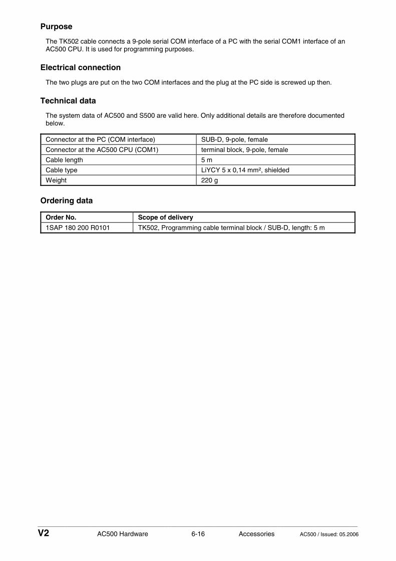
____________________________________________________________________________________________________________
V2 AC500 Hardware 6-16 Accessories AC500 / Issued: 05.2006
Purpose
The TK502 cable connects a 9-pole serial COM interface of a PC with the serial COM1 interface of an AC500 CPU. It is used for programming purposes.
Electrical connection
The two plugs are put on the two COM interfaces and the plug at the PC side is screwed up then.
Technical data
The system data of AC500 and S500 are valid here. Only additional details are therefore documented below.
Connector at the PC (COM interface) SUB-D, 9-pole, female
Connector at the AC500 CPU (COM1) terminal block, 9-pole, female
Cable length 5 m
Cable type LiYCY 5 x 0,14 mm², shielded
Weight 220 g
Ordering data
Order No. Scope of delivery
1SAP 180 200 R0101 TK502, Programming cable terminal block / SUB-D, length: 5 m

____________________________________________________________________________________________________________
V2 AC500 Hardware 6-17 Accessories AC500 / Issued: 05.2006
24 V DC Power supplies which can be used with the system - as system power supply or process supply
Figure: Power supply units CP24..
Contents
Features Characteristics Special characteristics Ordering data
Features
• Switching power supplies, primary switch mode
• High effiency
• Wide-range input voltage
• Mounting on DIN rail
• Compact design
• Tested according to EN 60950
• Complies with EMC directives EN 61000-6-2 and EN 61000-6-4
Characteristics
• Versions with output voltages from 5 V DC to 48 V DC and output currents form 300 mA to 20 A are available.
• Fixed or adjustable output voltage (depending on type).
• Most of the types provide a wide input voltage range from 90 V AC to 260 V AC and a frequency range from 47 Hz to 440 Hz. No adjustment is necessary.

____________________________________________________________________________________________________________
V2 AC500 Hardware 6-18 Accessories AC500 / Issued: 05.2006
• Integrated input fuse.
• Almost all types can also be supplied with DC voltage from 105 V DC to 260 V DC.
• High efficiency of up to 90 %.
• Extended lifetime due to low power dissipation and low heating.
• No-load proof, overload proof, continuous short-circuit proof, automatic restart.
• Fast and easy mounting on DIN rail.
• Compact slim design.
Special characteristics
• Power factor correction (PFC) according to EN 61000-3-2 for CP-24/5.0 and CP-24/5.0 adj.
• Parallel connection possible for CP-24/10 adj. and CP-24/20 adj.
• Redundancy module available.
Ordering data
Ordering data CP Range, switching power supplies
Order No. Type Input Output
1SVR 423 418 R0000 CP-24/1.0 90-260 V AC or 105-260 V DC 24 V DC, 1 A
1SVR 423 417 R0000 CP-24/2.0 90-140 V AC 24 V DC, 2 A
1SVR 423 417 R1000 CP-24/2.0 140-260 V AC 24 V DC, 2 A
1SVR 423 417 R1100 CP-24/2.0 adj. 140-260 V AC or 160-260 V DC 24 V DC, 2 A adj.
1SVR 423 416 R0000 CP-24/5.0 90-260 V AC or 127-260 V DC 24 V DC, 5 A
1SVR 423 416 R0100 CP-24/5.0 adj. 90-260 V AC or 127-260 V DC 24 V DC, 5 A adj.
1SVR 423 416 R1000 CP-24/4.2 90-260 V AC or 127-260 V DC 24 V DC, 4,2 A
Ordering data CP-S Range, switching power supplies
Order No. Type Input Output
1SVR 427 014 R0000 CP-S 24/5.0 110-240 V AC 24 V DC, 5 A
1SVR 427 015 R0100 CP-S 24/10.0 110-120 V AC or 220-240 V AC (with selector switch)
24 V DC, 10 A
1SVR 427 016 R0100 CP-S 24/20.0 110-120 V AC or 220-240 V AC (with selector switch)
24 V DC, 20 A
Ordering data CP-C Range, switching power supplies
Order No. Type Input Output
1SVR 427 024 R0000 CP-C 24/5.0 110-240 V AC 22-28 V DC, 5 A
1SVR 427 025 R0000 CP-C 24/10.0 110-240 V AC 22-28 V DC, 10 A
1SVR 427 026 R0000 CP-C 24/20.0 110-240 V AC 22-28 V DC, 20 A

System Description S500-FBP
The Innovative I/O System with Fieldbus-Neutral FBP Technology Handbook English
1.0
1.1
1.2
1.3
1.4
1.5
1.6
1.7
1.8
1.9
2.0
2.1
2.2
2.3
2.4
2.5
2.6
2.7
2.8
2.9
1.0
1.1
1.2
1.3
1.4
1.5
1.6
1.7
1.8
1.9
2.0
2.1
2.2
2.3
2.4
2.5
2.6
2.7
2.8
2.9
3.0
3.1
3.2
3.3
3.4
3.5
3.6
3.7
3.8
3.9
4.0
4.1
4.2
4.3
4.4
4.5
4.6
4.7
4.8
4.9
DC505
PWR
FBP
S-ERR
I/O-Bus
1.0 I0
1.1 I1
1.2 I2
1.3 I3
1.4 I4
1.5 I5
1.6 I6
1.7 I7
1.8 UP
1.9 ZP
2.0 C8
2.1 C9
2.2 C10
2.3 C11
2.4 C12
2.5 C13
2.6 C14
2.7 C15
2.8 UP
2.9 ZP
CH-ERR2
ADDR
ADDR
x10
x1
FBP 8 DI 8 DCInput 24 V DC
Output 24 V DC 0.5A
CH-ERR1
DC532
1.0 I0
1.1 I1
1.2 I2
1.3 I3
1.4 I4
1.5 I5
1.6 I6
1.7 I7
1.8 UP
1.9 ZP
2.0 I8
2.1 I9
2.2 I10
2.3 I11
2.4 I12
2.5 I13
2.6 I14
2.7 I15
2.8 UP
2.9 ZP
3.0 C16
3.1 C17
3.2 C18
3.3 C19
3.4 C20
3.5 C21
3.6 C22
3.7 C23
3.8 UP
3.9 ZP
4.0 C24
4.1 C25
4.2 C26
4.3 C27
4.4 C28
4.5 C29
4.6 C30
4.7 C31
4.8 UP
4.9 ZP
CH-ERR3 CH-ERR4
16 DI 16 DCInput 24 V DC
Output 24 V DC 0.5A
CH-ERR2CH-ERR1


____________________________________________________________________________________________________________
V2 S500 Hardware 0-1 Contents S500 / Issued: 01.2007
Contents Hardware S500
System data and system construction
S500 system data, assortment ................................................................................................................1-3
Use of the S500 I/O modules ...................................................................................................................1-4
Diagnosis LEDs ........................................................................................................................................1-5
Mounting and disassembling the Terminal Units and the I/O modules .................................................1-13
Mechanical dimensions S500 .................................................................................................................1-17
Switch-gear cabinet assembly ...............................................................................................................1-19
Connection system ................................................................................................................................1-20
Mechanical encoding .............................................................................................................................1-24
General wiring recommendations ..........................................................................................................1-26
Behaviour of the system in case of power supply interruptions and power recovering .........................1-26
Block diagrams, earthing concept ..........................................................................................................1-26
Terminal Units
FBP Terminal Units TU505 and TU506....................................................................................................2-3
I/O Terminal Units TU515 and TU516 ......................................................................................................2-5
I/O Terminal Units TU531 and TU532 ......................................................................................................2-7
CS31 Terminal Units TU551-CS31 and TU552-CS31 ...........................................................................2-10
FBP Interface Modules
PROFIBUS DP built with PDP21 and PDP22 FieldBusPlugs ..................................................................3-3
FBP Interface Module DC505-FBP ........................................................................................................3-21
CS31 Bus Modules
High-speed counter of S500 modules ...................................................................................................3-35
CS31 Bus Module DC551-CS31 ............................................................................................................3-40

____________________________________________________________________________________________________________
V2 S500 Hardware 0-2 Contents S500 / Issued: 01.2007
Digital input and output modules
High-speed counter of S500 modules .....................................................................................................4-3
Digital input module DI524....................................................................................................................... 4-8
Digital input/output module DC522.........................................................................................................4-16
Digital input/output module DC523.........................................................................................................4-16
Digital input/output module DC532.........................................................................................................4-30
Digital input/output module DX522 .........................................................................................................4-40
Digital input/output module DX531 .........................................................................................................4-51
Analog input and output modules
Analog input module AI523.......................................................................................................................5-3
Analog output module AO523...................................................................................................................5-3
Analog input/output module AX521 ........................................................................................................5-27
Analog input/output module AX522 ........................................................................................................5-27
Accessories
Pluggable Marking Holder TA523............................................................................................................ 6-3
Set of 10 white Plastic Markers TA525.................................................................................................... 6-5
Wall mounting accessory TA526 ............................................................................................................. 6-7
24 V DC Power supplies CP24... ............................................................................................................ 6-8

____________________________________________________________________________________________________________
V2 S500 Hardware 1-1 System Data S500 / Issued: 01.2007
System Data S500, Overview
S500 system data, assortment Page 1-3
Use of the S500 I/O modules 1-4
Diagnosis LEDs 1-5
Mounting and disassembling the Terminal Units and the I/O modules 1-13
Mechanical dimensions S500 1-17
Switch-gear cabinet assembly 1-19
Connection system 1-20
Mechanical encoding 1-24
General wiring recommendations 1-26
Behaviour of the system in case of power supply interruptions and power recovery 1-26
Block diagrams, earthing concept 1-26

____________________________________________________________________________________________________________
V2 S500 Hardware 1-2 System Data S500 / Issued: 01.2007

____________________________________________________________________________________________________________
V2 S500 Hardware 1-3 System Data S500 / Issued: 01.2007
S500 System data
The same system data as for the system AC500 apply to the system S500-FBP. Only additional details are therefore documented here.
Assortment
Parts of the S500-FBP system are
• the FBP Interface Module DC505-FBP • digital I/O modules • analog I/O modules • Terminal Units for the FBP Interface Module and the I/O modules • accessories
The FBP Interface Module DC505-FBP serves for the data interchange between a fieldbus and the I/O modules attached to the FBP Interface Module. The FBP interface module itself also has some digital inputs and outputs. The fieldbus type is defined by the choice of the FieldBusPlug (see documentation FieldBusPlug / FBP).
Subjects (overview)
Use of the S500 I/O modules ..................................................................................................................... 1-4
Diagnosis LEDs .......................................................................................................................................... 1-5
Mounting and disassembling the Terminal Units and the I/O modules ................................................... 1-13
Mechanical dimensions S500 ................................................................................................................... 1-17
Switch-gear cabinet assembly ................................................................................................................. 1-19
Connection system .................................................................................................................................. 1-20
Mechanical encoding ............................................................................................................................... 1-24
General wiring recommendations ............................................................................................................ 1-26
Behaviour of the system in case of power supply interruptions and power recovery .............................. 1-26
Block diagrams, earthing concept ............................................................................................................ 1-27

____________________________________________________________________________________________________________
V2 S500 Hardware 1-4 System Data S500 / Issued: 01.2007
Use of the S500 I/O modules
The S500 I/O modules either can be attached directly to an AC500 CPU (central expansion) or be operated by the FBP Interface Module DC505-FBP (decentralized expansion).
DC532DC532PM581CM577CM572
DIN rail,earthed
Mountingplate,earthed
Figure: S500 I/O modules directly attached to an AC500 CPU (central I/O expansion)
DC532DC532DC505
DIN rail,earted
Mountingplate,earthed
Figure: S500 I/O modules attached to the FBP Interface Module DC505-FBP (decentralized expansion)

____________________________________________________________________________________________________________
V2 S500 Hardware 1-5 System Data S500 / Issued: 01.2007
Diagnosis LEDs
All S500 modules have LEDs for the display of operating statuses and error messages. They indicate:
LED Status Color LED = ON LED = OFF LED flashes
digital input yellow input = ON input = OFF -- Input
analog input yellow brightness depends on the value of the analog signal
--
digital output yellow output = ON output = OFF -- Output
analog output yellow brightness depends on the value of the analog signal
--
UP process voltage 24 V DC via terminal
green voltage is present voltage is missing --
PWR supply voltage 24 V DC via FBP
green voltage is present voltage is missing --
S-ERR Sum Error red serious error, data exchange is stopped, depends on the behaviour of the master
no error error (e.g. error on one channel, data exchange is not stopped
FBP FBP communication
green communication between FBP and FBP Interface Module is running
communication between FBP and FBP Interface Module is broken
during initialization
I/O-Bus I/O-Bus communication
green communication between FBP Interface Module and the I/O modules is running
no communication between FBP Interface Module and the I/O modules
error on one I/O expansion module (e.g. one output short-circuited)
CH-ERR1 red
CH-ERR2 red
CH-ERR3 red
CH-ERR4
Channel Error, error messages in groups (digital or analog inputs and outputs combined into the groups 1, 2, 3, 4)
red
serious error within the corresponding group
no error error on one channel of the corresponding group (e.g. one output short-circuited)
CH-ERR *)
Module Error red error within the I/O module
-- --
*) All of the LEDs CH-ERR1 to CH-ERR4 (as far as they exist) light up together

____________________________________________________________________________________________________________
V2 S500 Hardware 1-6 System Data S500 / Issued: 01.2007
Display, if the FBP is not plugged
DC505 AX522 DC532 DI524 DX522
FBP not pluggedUP is present at all modules,initialization is impossible because of missing FBP power supply
Situation:
LEDs:
PW
RF
BP
S-E
RR
I/O-B
usU
P
CH
-ER
R1
CH
-ER
R2
UP
CH
-ER
R2
CH
-ER
R4
UP
CH
-ER
R1
CH
-ER
R2
CH
-ER
R3
CH
-ER
R4
UP
CH
-ER
R1
CH
-ER
R2
CH
-ER
R3
CH
-ER
R4
UP
CH
-ER
R1
CH
-ER
R2
DC505-FBP AX522 DC532 DI524 DX522
LED OFF
green LED ON
green LED flashesred LED ON
red LED flashes
Figure: LED displays, if the FBP is not plugged
Display examples during the initialization
Initialization of DC505-FBP without I/O modules attachedUP present, FBP plugged
Situation:
PW
RF
BP
S-E
RR
I/O-B
usU
P
CH
-ER
R1
CH
-ER
R2
DC505-FBP
DC505
LEDs before initialization, UP is present
LEDs during initialization (I/O-Bus + FBP)
LEDs after successful initialization (normal condition)
The module remains uninitialized, if errors occurCase A2
Case A1
Case A3
LEDs: LED OFF
green LED ONgreen LED flashesred LED ON
red LED flashes
Figure: Initialization DC505-FBP without I/O modules attached
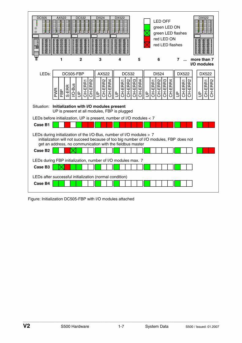
____________________________________________________________________________________________________________
V2 S500 Hardware 1-7 System Data S500 / Issued: 01.2007
AX522 DC532 DX522
Initialization with I/O modules presentUP is present at all modules, FBP is plugged
Situation:
PW
R
FB
P
S-E
RR
I/O-B
us
UP
CH
-ER
R1
CH
-ER
R2
UP
CH
-ER
R2
CH
-ER
R4
UP
CH
-ER
R1
CH
-ER
R2
CH
-ER
R3
CH
-ER
R4
UP
CH
-ER
R1
CH
-ER
R2
DC505-FBP AX522 DC532 DX522
DC505 DX522
more than 77654321 ...
DI524
UP
CH
-ER
R1
CH
-ER
R2
CH
-ER
R3
CH
-ER
R4
DI524
UP
CH
-ER
R1
CH
-ER
R2
DX522
LEDs before initialization, UP is present, number of I/O modules < 7
LEDs during initialization of the I/O-Bus, number of I/O modules > 7initialization will not succeed because of too big number of I/O modules, FBP does notget an address, no communication with the fieldbus master
LEDs during FBP initialization, number of I/O modules max. 7
LEDs after successful initialization (normal condition)
Case B1
Case B2
Case B3
Case B4
I/O modules
LEDs:
LED OFF
green LED ON
green LED flashesred LED ON
red LED flashes
Figure: Initialization DC505-FBP with I/O modules attached

____________________________________________________________________________________________________________
V2 S500 Hardware 1-8 System Data S500 / Issued: 01.2007
AX522 DX522
Initialization with one I/O module missingUP is present at all modules, FBP is plugged
Situation:
PW
RF
BP
S-E
RR
I/O-B
usU
P
CH
-ER
R1
CH
-ER
R2
UP
CH
-ER
R2
CH
-ER
R4
UP
CH
-ER
R1
CH
-ER
R2
DC505-FBP AX522 DX522
DC505 DI524
UP
CH
-ER
R1
CH
-ER
R2
CH
-ER
R3
CH
-ER
R4
DI524
LEDs before initialization, UP is present
LEDs during initializationinitialization of e.g. two modules successful, FBP, however, blocks the access byFBP-Conf_error, the red LED CONF flashes
Case C1
Case C2
LEDs:
LED OFFgreen LED ON
green LED flashes
red LED ONred LED flashes
Figure: Initialization with one I/O module missing

____________________________________________________________________________________________________________
V2 S500 Hardware 1-9 System Data S500 / Issued: 01.2007
AX522 DX522
Initialization, if more I/O modules present than have been configuredUP is present at all modules, FBP is plugged
Situation:
PW
RF
BP
S-E
RR
I/O-B
usU
P
CH
-ER
R1
CH
-ER
R2
UP
CH
-ER
R2
CH
-ER
R4
UP
CH
-ER
R1
CH
-ER
R2
DC505-FBP AX522 DX522
DC505 DI524
UP
CH
-ER
R1
CH
-ER
R2
CH
-ER
R3
CH
-ER
R4
DI524
LEDs before initialization, UP is present
LEDs during initializationinitialization of e.g. five modules (instead of 3) successful, FBP, however, blocksthe access by FBP-Conf_err, the red LED CONF flashes, details see the
UP
CH
-ER
R1
CH
-ER
R2
CH
-ER
R3
CH
-ER
R4
DC532
DC532
FBP user documentation
Case D1
Case D2
LEDs:
LED OFF
green LED ONgreen LED flashes
red LED ONred LED flashes
Figure: Initialization, if more I/O modules present than have been configured

____________________________________________________________________________________________________________
V2 S500 Hardware 1-10 System Data S500 / Issued: 01.2007
Display examples for running operation
AX522 DX522
All modules OK, then UP fails at one moduleUP still present at all the other modules, FBP plugged
Situation:
PW
RF
BP
S-E
RR
I/O-B
usU
P
CH
-ER
R1
CH
-ER
R2
UP
CH
-ER
R2
CH
-ER
R4
UP
CH
-ER
R1
CH
-ER
R2
DC505-FBP AX522 DX522
DC505 DI524
UP
CH
-ER
R1
CH
-ER
R2
CH
-ER
R3
CH
-ER
R4
DI524
The module sends an error message to the master,
Case 2: UP is missing at one I/O module (DC532), error message see above
UP
CH
-ER
R1
CH
-ER
R2
CH
-ER
R3
CH
-ER
R4
DC532
DC532
the master has to evaluate the error (STOP or GO)Case 1: UP is missing at DC505-FBP
All modules OK, then an FBP communication error appearsUP is present at all modules, FBP is plugged
Situation:
After 2 seconds the FBP is initialized again (see cases A2 or B3
All modules OK, then an I/O bus error appears at one I/O moduleUP is present at all modules, FBP is plugged
Situation:
An I/O bus error is sent to the fieldbus master, the I/O-Bus turns to the reset status orgets the replacement values
LEDs:
LED OFF
green LED ON
green LED flashesred LED ON
red LED flashes
of the initialization processes)
Figure: Appearance of errors in running operation

____________________________________________________________________________________________________________
V2 S500 Hardware 1-11 System Data S500 / Issued: 01.2007
AX522 DX522
All modules OK, then one of the I/O modules is removedUP is present at all modules, FBP is plugged
Situation:
PW
RF
BP
S-E
RR
I/O-B
usU
P
CH
-ER
R1
CH
-ER
R2
UP
CH
-ER
R2
CH
-ER
R4
UP
CH
-ER
R1
CH
-ER
R2
DC505-FBP AX522 DX522
DC505 DI524
UP
CH
-ER
R1
CH
-ER
R2
CH
-ER
R3
CH
-ER
R4
DI524
An I/O bus error is sent to the fieldbus master, the I/O-Bus turns to the reset status orgets the replacement values
After that, an I/O module of an other type is insertedinto the free place
Situation:
The status of the error message remains unchanged
LEDs:
LED OFF
green LED ON
green LED flashesred LED ON
red LED flashes
Figure: One module was removed and then replaced by a module of an other type

____________________________________________________________________________________________________________
V2 S500 Hardware 1-12 System Data S500 / Issued: 01.2007
AX522 DX522
Internal error on the processor card of the FBP Interface ModuleSituation:
PW
RF
BP
S-E
RR
I/O-B
usU
P
CH
-ER
R1
CH
-ER
R2
UP
CH
-ER
R2
CH
-ER
R4
UP
CH
-ER
R1
CH
-ER
R2
DC505-FBP AX522 DX522
DC505 DI524
UP
CH
-ER
R1
CH
-ER
R2
CH
-ER
R3
CH
-ER
R4
DI524
No function at all, the I/O-Bus turns to the reset status or gets the replacement values
UP
CH
-ER
R1
CH
-ER
R2
CH
-ER
R3
CH
-ER
R4
DC532
DC532
All modules OK, but there is an overload or short-circuit at oneSituation:
Everything is still running, but an error message is sent to the fieldbus master
output of the FBP Interface Module DC505-FBP
All modules OK, but there is an overload or short-circuit at oneSituation:output of an I/O expansion module
Internal error on the I/O card of the FBP Interface ModuleSituation:
UP is present at all modules,FBP is plugged
Internal error on the I/O card of an I/O expansion moduleSituation:
All modules OK, but there is a broken wire at an analog outputSituation:
A wrong parameter was sent to a moduleSituation:
An error message is sent to the fieldbus master
LEDs:
LED OFF
green LED ONgreen LED flashes
red LED ON
red LED flashes
No function at all, the I/O-Bus turns to the reset status or gets the replacement values
No function at all, the I/O-Bus turns to the reset status or gets the replacement values
Everything is still running, but an error message is sent to the fieldbus master
Everything is still running, but an error message is sent to the fieldbus master
Figure: Displays in case of different errors

____________________________________________________________________________________________________________
V2 S500 Hardware 1-13 System Data S500 / Issued: 01.2007
Mounting and disassembling the Terminal Units and the I/O modules
Assembly on DIN rail
Step 1: Mount DIN rail 7.5 mm or 15 mm
Step 2: Mount FBP Terminal Unit (TU505 or TU506)
Figure: Assembly of the FBP Terminal Unit (TU505 or TU506)
The FBP Terminal Unit is put on the DIN rail above and then snapped-in below. The disassembly is carried out in a reversed order.
Figure: Disassembly of the FBP Terminal Unit (TU505 or TU506)
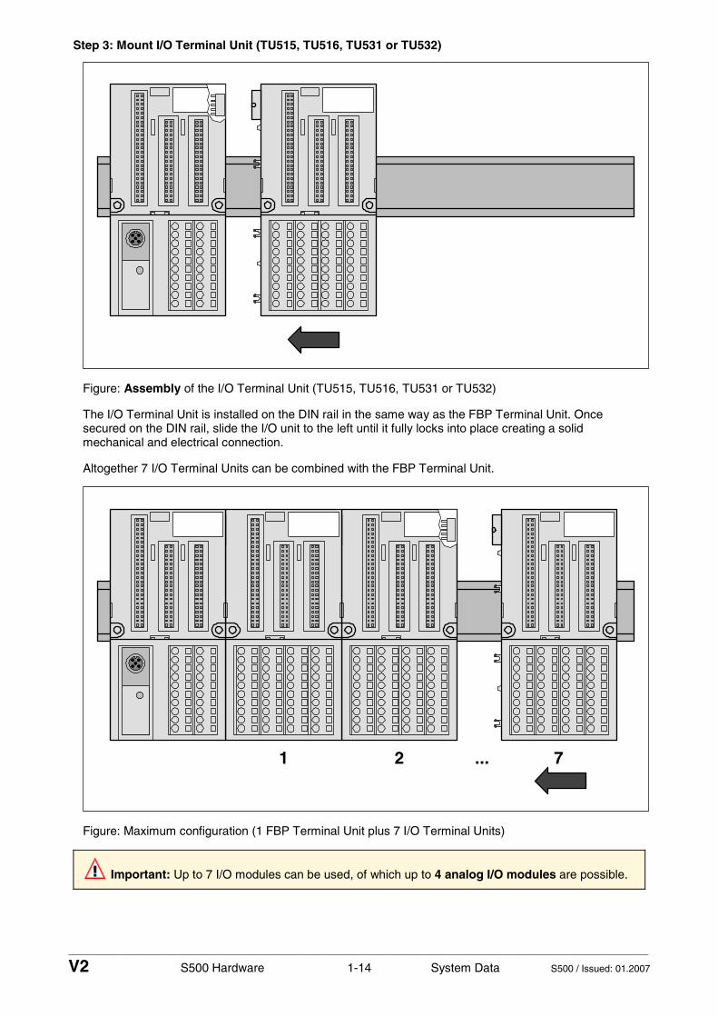
____________________________________________________________________________________________________________
V2 S500 Hardware 1-14 System Data S500 / Issued: 01.2007
Step 3: Mount I/O Terminal Unit (TU515, TU516, TU531 or TU532)
Figure: Assembly of the I/O Terminal Unit (TU515, TU516, TU531 or TU532)
The I/O Terminal Unit is installed on the DIN rail in the same way as the FBP Terminal Unit. Once secured on the DIN rail, slide the I/O unit to the left until it fully locks into place creating a solid mechanical and electrical connection.
Altogether 7 I/O Terminal Units can be combined with the FBP Terminal Unit.
1 2 7...
Figure: Maximum configuration (1 FBP Terminal Unit plus 7 I/O Terminal Units)
Important: Up to 7 I/O modules can be used, of which up to 4 analog I/O modules are possible.

____________________________________________________________________________________________________________
V2 S500 Hardware 1-15 System Data S500 / Issued: 01.2007
Figure: Disassembly of the I/O Terminal Unit (TU515, TU516, TU531 or TU532)
A screwdriver is inserted in the indicated place to separate the Terminal Units.
Step 4: Mount the modules
DC532
Figure: Assembly of the modules
Press the electronic module into the Terminal Unit until it locks in place.

____________________________________________________________________________________________________________
V2 S500 Hardware 1-16 System Data S500 / Issued: 01.2007
The disassembly is carried out in a reversed order.
1
2
1
Figure: Disassembly of the modules
Disassembly: Press obove and below, then remove the module.
Assembly with screws
If the Terminal Unit should be mounted with screws, a Wall Mounting Accessory TA526 must be inserted at the rear side first. This plastic part prevents bending of the Terminal Unit while screwing on.
1
2Front view
Rear view
Rear view
Holes forwall mounting
31
Figure: Fastening with screws of the Terminal Unit TU516 (as an example)
1 The Wall Mounting Accessory TA526 is snapped on the rear side of the Terminal Unit like a DIN rail. The arrow points to the right side.
2 Accessory for wall mounting inserted
3 Terminal Unit, fastened with screws

____________________________________________________________________________________________________________
V2 S500 Hardware 1-17 System Data S500 / Issued: 01.2007
By wall mounting, the Terminal Unit is earthed through the screws. It is necessary that
• the screws have a conductive surface (e.g. steel zinc-plated or brass nickel-plated) • the mounting plate is earthed • the screws have a good electrical contact to the mounting plate
Mechanical dimensions S500
67.5 (2.66)
TU505/506
59 (
2.32
)
70.5
(2.
78)
TU515/516/531/532
135
(5.3
1)
67.5 (2.66)
(2.27)
DC505
135 mm(5.31) inches
57.7
Dimensions:
Figure: Dimensions of the Terminal Units (front view)

____________________________________________________________________________________________________________
V2 S500 Hardware 1-18 System Data S500 / Issued: 01.2007
28
21 (0.83)54 (2.13)
75 (2.95)
59 (
2.32
)
70.5
(2.
78)
135
(5.3
1)
76 (
2.99
)
View on the left side View on the right side
77 (3.03)
84.5 (3.33)
DIN rail 15 mmDIN rail 7.5 mm
135 mm(5.31) inches
Dimensions:
(1.10)
Figure: Dimensions of Terminal Units and modules (lateral views)
TB521-ETH
2828
59 (
2.32
)
70.5
(2.
78)
135
(5.3
1)
67.5 (2.66)(1.10)(1.10)
123.5 (4.86)
(2.27)57.7
(1.59)40.3
135 mm(5.31) inches
Dimensions:
4.9 (0.19)
Figure: Dimensions of the AC500 CPU Terminal Base TB521-ETH (for comparison)

____________________________________________________________________________________________________________
V2 S500 Hardware 1-19 System Data S500 / Issued: 01.2007
Switch-gear cabinet assembly
Basically, it is recommended to mount the modules on an earthed mounting plate, independent of the mounting location.
DC532DC532DC505
DC532DC532DC505
DIN rail,earthed
Mountingplate,earthed
DIN rail,earted
Mountingplate,earthed
Cable duct
20 mm minimum distance betweenthe modules and the cable duct
Figure: Installation of AC500/S500 modules in a switch-gear cabinet

____________________________________________________________________________________________________________
V2 S500 Hardware 1-20 System Data S500 / Issued: 01.2007
Important: Horizontal mounting is highly recommended. Vertical mounting is possible, however, derating consideration should be made to avoid problems with poor air circulation and the potential for excessive temperatures (see also the AC500 system data, operating and ambient conditions, for reduction of ambient temperature).
Note: By vertical mounting, always place an end-stop terminal block at the bottom and on the top of the module to properly secure the modules. By high-vibration applications, we also recommend to place end-stop terminals at the right and the left side of the device to properly secure the modules: e.g. type BADL, P/N: 1SNA 399 903 R0200
Connection system
Terminals for power supply and the COM1 interface (CPU Terminal Base AC500)
L+
ML+
MFE123456789
COM1
Figure: Terminals for power supply and the COM1 interface (CPU Terminal Base AC500)
Terminal type: Screw-type terminal
Number of cores per terminal Conductor type Cross section
1 solid 0.08 mm² to 1.5 mm²
1 flexible 0.08 mm² to 1.5 mm²
1 with wire end ferrule (without plastic sleeve)
flexible 0.25 mm² to 1.5 mm²
1 with wire end ferrule (with plastic sleeve)
flexible 0.25 mm² to 0.5 mm²
1 (TWIN wire end ferrule) flexible 0.5 mm²
2 (with the same cross section) solid 0.08 mm² to 0.5 mm²
2 (with the same cross section) flexible 0.08 mm² to 0.75 mm²
2 (with the same cross section) in wire end ferrule, without plastic sleeve
flexible 0.25 mm² to 0.34 mm²

____________________________________________________________________________________________________________
V2 S500 Hardware 1-21 System Data S500 / Issued: 01.2007
Terminal type: Spring terminal
Number of cores per terminal Conductor type Cross section
1 solid 0.08 mm² to 1.5 mm²
1 flexible 0.08 mm² to 1.5 mm²
1 with wire end ferrule (without plastic sleeve)
flexible 0.25 mm² to 1.5 mm²
1 with wire end ferrule (with plastic sleeve)
flexible 0.25 mm² to 0.5 mm²
1 (TWIN wire end ferrule) flexible 0.5 mm²
2 (with the same cross section) solid 0.08 mm² to 0.5 mm²
2 (with the same cross section) flexible 0.08 mm² to 0.75 mm²
2 (with the same cross section) in wire end ferrule, without plastic sleeve
flexible 0.25 mm² to 0.34 mm²
Terminals at the Terminal Units (I/O, FBP)
1.0
1.1
1.2
1.3
1.4
1.5
1.6
1.7
1.8
1.9
2.0
2.1
2.2
2.3
2.4
2.5
2.6
2.7
2.8
2.9
3.0
3.1
3.2
3.3
3.4
3.5
3.6
3.7
3.8
3.9
4.0
4.1
4.2
4.3
4.4
4.5
4.6
4.7
4.8
4.9
Figure: Terminals at the Terminal Units (I/O, FBP)
Terminal type: Screw-type terminal
Number of cores per terminal Conductor type Cross section
1 solid 0.08 mm² to 2.5 mm²
1 flexible 0.08 mm² to 2.5 mm²
1 with wire end ferrule flexible 0.25 mm² to 1.5 mm²
TWIN wire end ferrule flexible 2 x 0.25 mm² or 2 x 0,5 mm² or 2 x 0,75 mm², with square cross-section of the wire-end ferrule also 2 x 1.0 mm²
2 solid not intended
2 flexible not intended

____________________________________________________________________________________________________________
V2 S500 Hardware 1-22 System Data S500 / Issued: 01.2007
Terminal type: Spring terminal
Number of cores per terminal Conductor type Cross section
1 solid 0.08 mm² to 2.5 mm²
1 flexible 0.08 mm² to 2.5 mm²
1 with wire end ferrule flexible 0.25 mm² to 1.5 mm²
TWIN wire end ferrule flexible 2 x 0.25 mm² or 2 x 0,5 mm² or 2 x 0,75 mm², with square cross-section of the wire-end ferrule also 2 x 1.0 mm²
2 solid not intended
2 flexible not intended
Connection of wires at the spring terminals
Connect the wire to the spring terminal
1 2 3
b
a
conductor driverscrew-
bScrewdriver
forOpening forOpening
closedTerminal
openTerminal
a
insertedScrewdriver
Screwdriver
Spring
Figure: Connect the wire to the spring terminal (steps 1 to 3)

____________________________________________________________________________________________________________
V2 S500 Hardware 1-23 System Data S500 / Issued: 01.2007
5 6 74
Figure: Connect the wire to the spring terminal (steps 4 to 7)
1 a Side view (open terminal drawn for illustration)
1 b The top view shows the openings for wire and screwdriver
2 Insert screwdriver (2.5 x 0.4 to 3.5 x 0.5 mm) at an angle, screwdriver must be at least 15 mm free of insulation at the tip
3 a While erecting the screwdriver, insert it until the stop (requires a little strength)
3 b Screwdriver inserted, terminal open
4 Strip the wire for 7 mm (and put on wire end ferrule)
5 Insert wire into the open terminal
6 Remove the screwdriver
7 Done
Disconnect wire from the spring terminal
2 3
Screwdriver
1
Screwdriver
Figure: Disconnect wire from the spring terminal (steps 1 to 3)

____________________________________________________________________________________________________________
V2 S500 Hardware 1-24 System Data S500 / Issued: 01.2007
4 5 6
ConductorScrewdriver
Figure: Disconnect wire from the spring terminal (steps 4 to 6)
1 Terminal with wire connected
2 Insert screwdriver (2.5 x 0.4 to 3.5 x 0.5 mm) at an angle, screwdriver must be at least 15 mm free of insulation at the tip
3 While erecting the screwdriver, insert it until the stop (requires a little strength), terminal is now open
4 Remove wire from the open terminal
5 Remove the screwdriver
6 Done
Mechanical encoding
181716151413121110987654321
Pos.181716151413121110987654321
181716151413121110987654321
Figure: Possible positions for mechanical encoding (1 to 18)

____________________________________________________________________________________________________________
V2 S500 Hardware 1-25 System Data S500 / Issued: 01.2007
Terminal Units (S500) and CPU Terminal Bases (AC500) have an mechanical coding which prevents that modules are inserted to wrong places. Otherwise
• dangerous parasitic voltages could occur or • modules could be destroyed.
The coding either makes it impossible to insert the module to the wrong place or blocks its electrical function (outputs are not activated).
The following figure shows the possible codings.
181716151413121110987654321
181716151413121110987654321
181716151413121110987654321
181716151413121110987654321
181716151413121110987654321
181716151413121110987654321
181716151413121110987654321
181716151413121110987654321
181716151413121110987654321
Positions 1 - 18181716151413121110987654321
181716151413121110987654321
181716151413121110987654321
TB511-ETHTB521-ETHTB541-ETH
TB511-ARCNETTB521-ARCNETTB541-ARCNET
TU505TU506
TU507-RT-ETHTU508-RT-ETH
for CPUs for CPUs Interface Modules Real-Timewith Ethernet with ARCNET e.g. DC505-FBP Ethernet Modules
Mechanical codings
for FBP
181716151413121110987654321
181716151413121110987654321
181716151413121110987654321
181716151413121110987654321
181716151413121110987654321
181716151413121110987654321
TU551-CS31TU552-CS31
for
TU541TU542
forS500 CS31Positioning
ModulesModules
181716151413121110987654321
181716151413121110987654321
181716151413121110987654321
181716151413121110987654321
181716151413121110987654321
181716151413121110987654321
TU515TU516
TU531TU532
I/O Modules
I/O Modules
24 V DC
120/230 V AC
for for
for
Figure: Mechanical coding

____________________________________________________________________________________________________________
V2 S500 Hardware 1-26 System Data S500 / Issued: 01.2007
General wiring recommendations
Bad wiring on power supply terminals
Attention: The product should be installed by trained people who have the knowledge of wiring electronic devices. In case of bad wiring, although the modules are protected against various errors (reverse polarity, short circuit, etc.), some problems could always happen: - On the CPU Terminal Base, the terminals L+ and M are doubled. If the power supply is badly connected, a short circuit could happen and lead to a destruction of the power supply or its fuse. If no suitable fuse exists, the Terminal Base itself could be destroyed. - The CPUs (Terminal Bases) and all electronic modules (and Terminal Units) are protected against reverse polarity. - All necessary measures should be carried out to avoid damages to modules and wiring. Notice the wiring plans and connection examples.
Bad wiring on I/O terminals
Attention: All I/O channels (digital and analog) are protected against reverse polarity, reverse supply, short circuit and continuous overvoltage up to 30 V DC.
Behaviour of the system in case of power supply interruptions and power recovering
AC500 system supply (terminals L+, M)
As soon as the CPU power supply is higher than 19.2 V DC, the power supply detection is activated and the CPU is started. When during operation the power supply is going down to lower than 19.2 V DC for more than 10 ms, the CPU is switched to safety mode (see System Technology of the CPUs).
A warm restart of the CPU only occurs by switching the power supply off and on again (see also the description of the function modes of the CPU in the "AC500 System Technology" chapters.
S500 system supply (is provided through the FBP plug)
AC500 or S500 process power supply (terminals UP and ZP)
Block diagrams, earthing concept
Block diagram DC505-FBP, earthing concept
The S500-FBP modules have to be included into the global earthing concept of the system. The following schematics will help you to understand the internal conception of the device.
The electrical isolation of the device is realized as follow:
• The isolation between the fieldbus and the internal device circuitry is realized by the FBP plug itself. • Isolation between the I/O terminals and the I/O-Bus: The I/O-Bus and the processors are powered by
the FBP plug, the process inputs and outputs need their own process supply voltage. There is an electrical isolation between these two parts within the modules.

____________________________________________________________________________________________________________
V2 S500 Hardware 1-27 System Data S500 / Issued: 01.2007
• If it is necessary to have an electrical isolation between the I/O terminals of different I/O modules, several power supply units must be used.
• There is no electrical isolation between the I/O channels of an I/O module.
Power
DC505-FBP
FBP Terminal Unit TU505/TU506
ZP
supply
DINrail
I/O-Bus
FBP
uPFBP+I/O-Bus
Powersupply
Digital I/O
UP CH-ERRx
ZP ZP
0VUP
+24VInputs Inputs/outputs
FBP
1 M 1 M
Figure: Blocks diagram DC505-FBP with FBP, earthing concept

____________________________________________________________________________________________________________
V2 S500 Hardware 1-28 System Data S500 / Issued: 01.2007
Block diagram of the digital I/O modules, earthing concept
Power
DC532/DI524
I/O Terminal Unit TU515/TU516
ZP
supply
DINrail
I/O-Bus
Digital
UP CH-ERRx
0VUP
+24VInputs/outputs
I/O-Bus
I/Os
I/O interface
1 M
1 M
ZP ZP
Figure: Block diagram of the digital I/O modules, earthing concept

____________________________________________________________________________________________________________
V2 S500 Hardware 1-29 System Data S500 / Issued: 01.2007
Block diagram of the analog I/O modules, earthing concept
Power
AX522
I/O Terminal Unit TU515/TU516
ZP
supply
DINrail
I/O-Bus
UP CH-ERRx
0VUP
+24VI+ I–
I/O-BusAnalog I/O interface
Inputs Outputs
+– +–
I+ I– O+ O–
+– +–
O+ O–
PTC PTC
1 M
1M
Figure: Block diagram of the analog I/O modules, earthing concept

____________________________________________________________________________________________________________
V2 S500 Hardware 1-30 System Data S500 / Issued: 01.2007
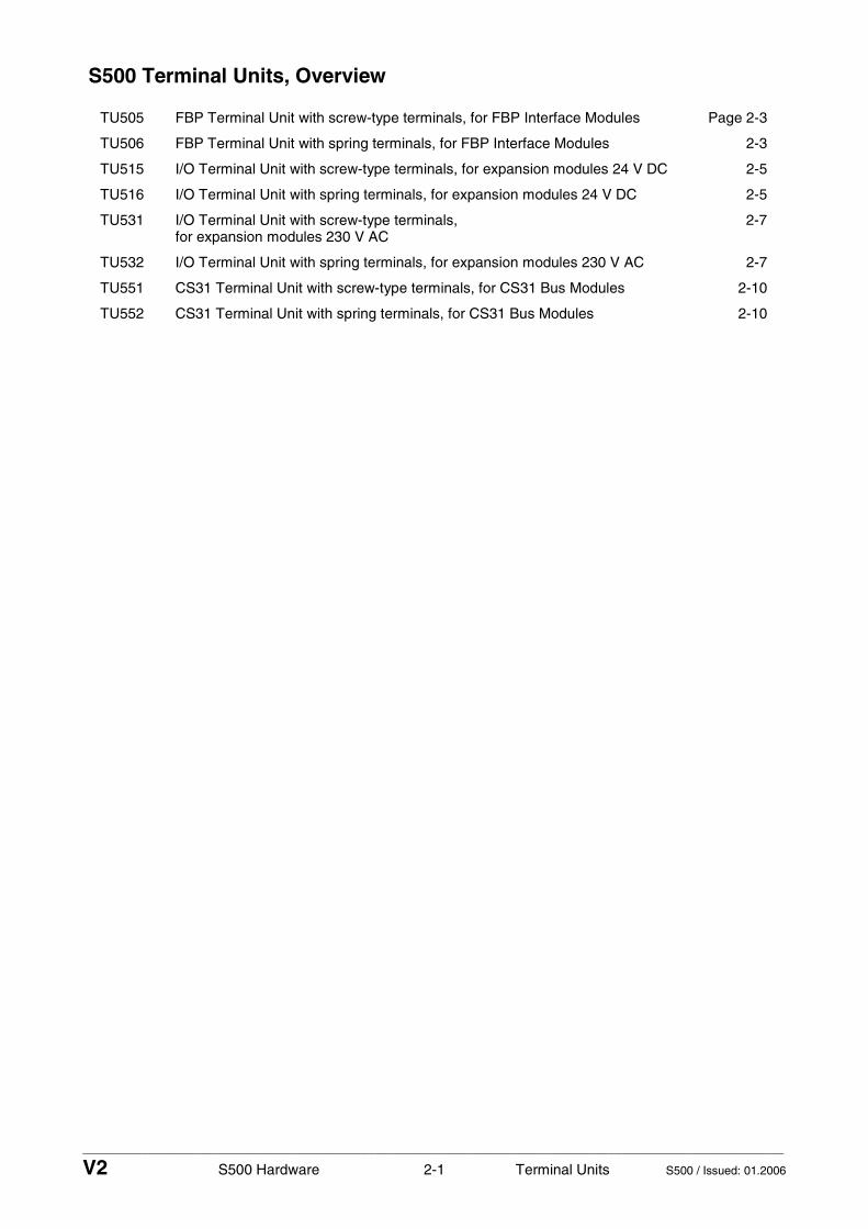
____________________________________________________________________________________________________________
V2 S500 Hardware 2-1 Terminal Units S500 / Issued: 01.2006
S500 Terminal Units, Overview
TU505 FBP Terminal Unit with screw-type terminals, for FBP Interface Modules Page 2-3
TU506 FBP Terminal Unit with spring terminals, for FBP Interface Modules 2-3
TU515 I/O Terminal Unit with screw-type terminals, for expansion modules 24 V DC 2-5
TU516 I/O Terminal Unit with spring terminals, for expansion modules 24 V DC 2-5
TU531 I/O Terminal Unit with screw-type terminals, for expansion modules 230 V AC
2-7
TU532 I/O Terminal Unit with spring terminals, for expansion modules 230 V AC 2-7
TU551 CS31 Terminal Unit with screw-type terminals, for CS31 Bus Modules 2-10
TU552 CS31 Terminal Unit with spring terminals, for CS31 Bus Modules 2-10

____________________________________________________________________________________________________________
V2 S500 Hardware 2-2 Terminal Units S500 / Issued: 01.2006

____________________________________________________________________________________________________________
V2 S500 Hardware 2-3 Terminal Units S500 / Issued: 01.2006
FBP Terminal Units TU505 and TU506 for FBP Interface Modules - TU505, FBP Terminal Unit, Screw-type Terminals - TU506, FBP Terminal Unit, Spring Terminals
1.0
1.1
1.2
1.3
1.4
1.5
1.6
1.7
1.8
1.9
2.0
2.1
2.2
2.3
2.4
2.5
2.6
2.7
2.8
2.9
2
1
4
7
5
3
Elements of the FBP Terminal Unit
1 I/O-Bus (10-pole, female) to electricallyconnect the first I/O Terminal Unit
2 Plug (1 x 50-pole, 2 x 38-pole) toelectrically connect the FBP InterfaceModule inserted
3 With a screwdriver, inserted inthis place, the FBP Terminal Unitand the adjacent I/O Terminal Unitcan be shoved from each other
4 Two holes for wall mounting
5 DIN rail
6 Neutral FieldBusPlug interface
7 20 screw-type or spring terminals,for signals and process voltage
3
6
1.5
1.6
1.7
1.8
1.9
1.5
1.6
1.7
1.8
1.9
Springterminal(TU506)
Screw-typeterminal
ductorScrew-driver
(TU505)
Screw-driver(opensterminal)
ductor
Con- Con-
Figure: FBP Terminal Unit TU 506, for FBP Interface Modules
The FBP Terminal Units TU505 (with screw-type terminals) and TU506 (with spring terminals) are specifically designed for use with AC500/S500 FBP Interface Modules (e.g. DC505-FBP).
The FBP Interface Modules plug into the FBP Terminal Unit. When properly seated, they are secured with two mechanical locks. All the electrical connections are made through the FBP Terminal Unit, which allows removal and replacement of the FBP Interface Modules without disturbing the wiring at the FBP Terminal Unit.
Note: Mounting, disassembling and electrical connection for the Terminal Units and the FBP Interface Modules are described in detail in the S500 system data chapters.
The terminals 1.8 to 2.8 and 1.9 to 2.9 are electrically interconnected within the FBP Terminal Unit and have always the same assignment, independent of the inserted module:
Terminals 1.8 to 2.8: Process voltage UP = +24 V DC Terminals 1.9 to 2.9: Process voltage ZP = 0 V

____________________________________________________________________________________________________________
V2 S500 Hardware 2-4 Terminal Units S500 / Issued: 01.2006
The assignment of the other terminals is dependent on the inserted FBP Interface Module (see the description of the FBP Interface Module).
The supply voltage 24 V DC for the module's electronic circuitry comes from the FieldBusPlug. If the FieldBusPlug is removed, the FBP Interface Module has no supply voltage. Also, all I/O expansion modules connected through the I/O-Bus have no supply for their electronic parts then.
Technical data
Number of I/O channels per module 16
Distribution of the channels into groups
2 groups of 8 channels each (1.0...1.7, 2.0...2.7), the allocation of the channels is given by the inserted FBP Interface Module
FieldBusPlug M12, 5-pole
Rated voltage 24 V DC
Max. permitted total current 10 A (between the terminals 1.8...2.8 and 1.9...2.9)
Earthing direct connection to the earthed DIN rail or via the screws with wall mounting
Screw-type terminals
Type Front terminal, conductor connection vertically with respect to the printed circuit board
Conductor cross section
- solid 0.08 mm² to 2.5 mm²
- flexible 0.08 mm² to 2.5 mm²
- with wire-end ferrule 0.25 mm² to 1.5 mm²
Stripped conductor end 8 mm
Width of the screwdriver 3.5 mm
Fastening torque 0.6 Nm
Degree of protection IP 20
For details see system data / Connection system
Spring terminals
Type Front terminal, conductor connection vertically with respect to the printed circuit board
Conductor cross section
- solid 0.08 mm² to 2.5 mm²
- flexible 0.08 mm² to 2.5 mm²
- with wire-end ferrule 0.25 mm² to 1.5 mm²
Stripped conductor end 7 mm, min. 5 mm
Degree of protection IP 20
For details see system data / Connection system
Dimensions
Width x height x depth 67.5 x 135 x 30 mm
Weight 200 g
Mounting position horizontal or vertical
Ordering data
Order No. Scope of delivery
1SAP 210 200 R0001 TU505, FBP Terminal Unit, screw-type terminals
1SAP 210 000 R0001 TU506, FBP Terminal Unit, spring terminals

____________________________________________________________________________________________________________
V2 S500 Hardware 2-5 Terminal Units S500 / Issued: 01.2006
I/O Terminal Units TU515 and TU516 for I/O expansion modules - TU515, I/O Terminal Unit, 24 V DC, Screw-type Terminals - TU516, I/O Terminal Unit, 24 V DC, Spring Terminals
1.0
1.1
1.2
1.3
1.4
1.5
1.6
1.7
1.8
1.9
2.0
2.1
2.2
2.3
2.4
2.5
2.6
2.7
2.8
2.9
3.0
3.1
3.2
3.3
3.4
3.5
3.6
3.7
3.8
3.9
4.0
4.1
4.2
4.3
4.4
4.5
4.6
4.7
4.8
4.9
1
3
2
5
7
6
4
Elements of the I/O Terminal Unit
1 I/O-Bus (10-pole, male) to electricallyconnect the previous I/O Terminal Unitor the FBP Terminal Unit or the CPUTerminal Base
2 I/O-Bus (10-pole, female) to electricallyconnect the next I/O Terminal Unit
3 Plug (1 x 50-pole, 2 x 38-pole) toelectrically connect the expansion I/OModule inserted
4 With a screwdriver, inserted inthis place, adjacent Terminal Unitscan be shoved from each other
5 Two holes for wall mounting
6 DIN rail
7 40 screw-type or spring terminals,for signals and process voltage, theterminal assignment depends on themodule type inserted
4
1.5
1.6
1.7
1.8
1.9
1.5
1.6
1.7
1.8
1.9
Springterminal(TU516)
Screw-typeterminal
ductorScrew-driver
(TU515)
Screw-driver(opensterminal)
ductorCon-Con-
Figure: I/O Terminal Unit TU 516, for I/O expansion modules
The I/O Terminal Units TU515 (with screw-type terminals) and TU516 (with spring terminals) are specifically designed for use with AC500/S500 I/O modules that incorporate only 24 V DC or analog inputs/outputs.
The input/output modules (I/O expansion modules) plug into the I/O terminal Unit. When properly seated, they are secured with two mechanical locks. All the electrical connections are made through the Terminal Unit, which allows removal and replacement of the I/O modules without disturbing the wiring at the Terminal Unit.
Note: Mounting, disassembling and electrical connection for the Terminal Units and the expansion modules are described in detail in the S500 system data chapters.
The terminals 1.8 to 4.8 and 1.9 to 4.9 are electrically interconnected within the I/O Terminal Unit and have always the same assignment, independent of the inserted module:
Terminals 1.8 to 4.8: Process voltage UP = +24 V DC Terminals 1.9 to 4.9: Process voltage ZP = 0 V

____________________________________________________________________________________________________________
V2 S500 Hardware 2-6 Terminal Units S500 / Issued: 01.2006
The assignment of the other terminals is dependent on the inserted expansion module (see the description of the used expansion module).
The supply voltage 24 V DC for the module's electronic circuitry comes from the I/O expansion bus (I/O-Bus) or from the FieldBusPlug or from the AC500 CPU.
Technical data
Number of channels per module 32
Distribution of the channels into groups
4 groups of 8 channels each (1.0...1.7, 2.0...2.7, 3.0...3.7, 4.0...4.7), the allocation of the channels is given by the inserted I/O expansion module
Rated voltage 24 V DC
Max. permitted total current 10 A (between the terminals 1.8...4.8 and 1.9...4.9)
Earthing direct connection to the earthed DIN rail or via the screws with wall mounting
Screw-type terminals
Type Front terminal, conductor connection vertically with respect to the printed circuit board
Conductor cross section
- solid 0.08 mm² to 2.5 mm²
- flexible 0.08 mm² to 2.5 mm²
- with wire-end ferrule 0.25 mm² to 1.5 mm²
Stripped conductor end 8 mm
Width of the screwdriver 3.5 mm
Fastening torque 0.6 Nm
Degree of protection IP 20
For details see system data / Connection system
Spring terminals
Type Front terminal, conductor connection vertically with respect to the printed circuit board
Conductor cross section
- solid 0.08 mm² to 2.5 mm²
- flexible 0.08 mm² to 2.5 mm²
- with wire-end ferrule 0.25 mm² to 1.5 mm²
Stripped conductor end 7 mm, min. 5 mm
Degree of protection IP 20
For details see system data / Connection system
Dimensions
Width x height x depth 67.5 x 135 x 30 mm
Weight 200 g
Mounting position horizontal or vertical
Ordering data
Order No. Scope of delivery
1SAP 212 200 R0001 TU515, I/O Terminal Unit, 24 V DC, screw-type terminals
1SAP 212 000 R0001 TU516, I/O Terminal Unit, 24 V DC, spring terminals

____________________________________________________________________________________________________________
V2 S500 Hardware 2-7 Terminal Units S500 / Issued: 01.2006
I/O Terminal Units TU531 and TU532 for I/O expansion modules - TU531, I/O Terminal Unit, 230 V AC, Screw-type Terminals - TU532, I/O Terminal Unit, 230 V AC, Spring Terminals
1.0
1.1
1.2
1.3
1.4
1.5
1.6
1.7
1.8
1.9
2.0
2.1
2.2
2.3
2.4
2.5
2.6
2.7
2.8
2.9
3.0
3.1
3.2
3.3
3.4
3.5
3.6
3.7
3.8
3.9
4.0
4.1
4.2
4.3
4.4
4.5
4.6
4.7
4.8
4.9
1 2
5
7
6
4
Elements of the I/O Terminal Unit
1 I/O-Bus (10-pole, male) to electricallyconnect the previous I/O Terminal Unitor the FBP Terminal Unit or the CPUTerminal Base
2 I/O-Bus (10-pole, female) to electricallyconnect the next I/O Terminal Unit
3 Plug (1 x 50-pole, 2 x 38-pole) toelectrically connect the expansion I/OModule inserted
4 With a screwdriver, inserted inthis place, adjacent Terminal Unitscan be shoved from each other
5 Two holes for wall mounting
6 DIN rail
7 40 screw-type or spring terminals,for signals and process voltage, theterminal assignment depends on themodule type inserted
4
1.5
1.6
1.7
1.8
1.9
1.5
1.6
1.7
1.8
1.9
Springterminal(TU532)
Screw-typeterminal
ductorScrew-driver
(TU531)
Screw-driver(opensterminal)
ductorCon-Con-
3
Figure: I/O Terminal Unit TU 532, for I/O expansion modules
The I/O Terminal Units TU531 (with screw-type terminals) and TU532 (with spring terminals) are specifically designed for use with AC500/S500 I/O modules that incorporate 115-230 V AC inputs and/or 230 V AC relay outputs.
The input/output modules (I/O expansion modules) plug into the I/O terminal Unit. When properly seated, they are secured with two mechanical locks. All the electrical connections are made through the Terminal Unit, which allows removal and replacement of the I/O modules without disturbing the wiring at the Terminal Unit.
Note: Mounting, disassembling and electrical connection for the Terminal Units and the expansion modules are described in detail in the S500 system data chapters.

____________________________________________________________________________________________________________
V2 S500 Hardware 2-8 Terminal Units S500 / Issued: 01.2006
The terminals 1.8 to 4.8 and 1.9 to 4.9 are electrically interconnected within the I/O Terminal Unit and have always the same assignment, independent of the inserted module:
Terminals 1.8 to 4.8: Process voltage UP = +24 V DC Terminals 1.9 to 4.9: Process voltage ZP = 0 V
The assignment of the other terminals is dependent on the inserted expansion module (see the description of the used expansion module).
The supply voltage 24 V DC for the module's electronic circuitry comes from the I/O expansion bus (I/O-Bus) or from the FieldBusPlug or from the AC500 CPU.
Technical data
Number of channels per module 32
Distribution of the channels into groups
4 groups of 8 channels each (1.0...1.7, 2.0...2.7, 3.0...3.7, 4.0...4.7), the allocation of the channels is given by the inserted I/O expansion module
Rated voltage 230 V AC
Max. permitted total current 10 A (between the terminals 1.8...4.8 and 1.9...4.9)
Earthing direct connection to the earthed DIN rail or via the screws with wall mounting
Screw-type terminals
Type Front terminal, conductor connection vertically with respect to the printed circuit board
Conductor cross section
- solid 0.08 mm² to 2.5 mm²
- flexible 0.08 mm² to 2.5 mm²
- with wire-end ferrule 0.25 mm² to 1.5 mm²
Stripped conductor end 8 mm
Width of the screwdriver 3.5 mm
Fastening torque 0.6 Nm
Degree of protection IP 20
For details see system data / Connection system
Spring terminals
Type Front terminal, conductor connection vertically with respect to the printed circuit board
Conductor cross section
- solid 0.08 mm² to 2.5 mm²
- flexible 0.08 mm² to 2.5 mm²
- with wire-end ferrule 0.25 mm² to 1.5 mm²
Stripped conductor end 7 mm, min. 5 mm
Degree of protection IP 20
For details see system data / Connection system
Dimensions
Width x height x depth 67.5 x 135 x 30 mm
Weight 200 g
Mounting position horizontal or vertical

____________________________________________________________________________________________________________
V2 S500 Hardware 2-9 Terminal Units S500 / Issued: 01.2006
Ordering data
Order No. Scope of delivery
1SAP 217 200 R0001 TU531, I/O Terminal Unit, 230 V AC, relays, screw-type terminals
1SAP 217 000 R0001 TU532, I/O Terminal Unit, 230 V AC, relays, spring terminals

____________________________________________________________________________________________________________
V2 S500 Hardware 2-10 Terminal Units S500 / Issued: 01.2006
Terminal Units TU551-CS31 and TU552-CS31 for CS31 Bus Modules - TU551-CS31, CS31 Bus Terminal Unit, 24 V DC, Screw-type Terminals - TU552-CS31, CS31 Bus Terminal Unit, 24 V DC, Spring Terminals
1.0
1.1
1.2
1.3
1.4
1.5
1.6
1.7
1.8
1.9
2.0
2.1
2.2
2.3
2.4
2.5
2.6
2.7
2.8
2.9
3.0
3.1
3.2
3.3
3.4
3.5
3.6
3.7
3.8
3.9
4.0
4.1
4.2
4.3
4.4
4.5
4.6
4.7
4.8
4.9
2
1
4
5
3 3
1.5
1.6
1.7
1.8
1.9
1.5
1.6
1.7
1.8
1.9
Springterminaltype
terminal
ductorScrew-driver
(TU551) (TU552)
Elements of the Terminal Unit
1 I/O-Bus (10-pole, female) to electricallyconnect the first I/O Terminal Unit
2 Plug (1 x 50-pole, 2 x 38-pole) toelectrically connect the CS31 BusModule inserted
3 With a screwdriver, inserted inthis place, adjacent Terminal Unitscan be shoved from each other
4 Two holes for wall mounting
5 DIN rail
6 CS31 bus interface
7 30 screw-type or spring terminals,for signals and process voltage, theterminal assignment depends on themodule type inserted
Screw-driver(opensterminal)
Screw-
Con-ductorCon-
76
Figure: Terminal Unit TU 552-CS31, for CS31 Bus Modules (e.g. DC551-CS31)
The Terminal Units TU551-CS31 (with screw-type terminals) and TU552-CS31 (with spring terminals) are specifically designed for use with S500 CS31 Bus Modules that incorporate only 24 V DC inputs/outputs or interface signals.
The CS31 Bus Modules plug into the Terminal Unit. When properly seated, they are secured with two mechanical locks. All the electrical connections are made through the Terminal Unit, which allows removal and replacement of the CS31 Bus Modules without disturbing the wiring at the Terminal Unit.
Note: Mounting, disassembling and electrical connection for the Terminal Units and the expansion modules are described in detail in the S500 system data chapters.
The terminals 1.8 to 4.8 and 1.9 to 4.9 are electrically interconnected within the Terminal Unit and have always the same assignment, independent of the inserted module:
Terminals 1.8 to 4.8: Process voltage UP = +24 V DC Terminals 1.9 to 4.9: Process voltage ZP = 0 V

____________________________________________________________________________________________________________
V2 S500 Hardware 2-11 Terminal Units S500 / Issued: 01.2006
The assignment of the other terminals is dependent on the inserted CS31 Bus Module (see the description of the used CS31 Bus Module).
The supply voltage 24 V DC for the module's electronic circuitry comes from ZP and UP.
Technical data
Number of channels per module 24
Distribution of the channels into groups
3 groups of 8 channels each (2.0...2.7, 3.0...3.7, 4.0...4.7), the allocation of the channels is given by the inserted CS31 Bus Module
CS31 field bus connector terminals 1.0 to 1.7
Rated voltage 24 V DC
Max. permitted total current 10 A (between the terminals 1.8...4.8 and 1.9...4.9)
Earthing direct connection to the earthed DIN rail or via the screws with wall mounting
Screw-type terminals
Type Front terminal, conductor connection vertically with respect to the printed circuit board
Conductor cross section
- solid 0.08 mm² to 2.5 mm²
- flexible 0.08 mm² to 2.5 mm²
- with wire-end ferrule 0.25 mm² to 1.5 mm²
Stripped conductor end 8 mm
Width of the screwdriver 3.5 mm
Fastening torque 0.6 Nm
Degree of protection IP 20
For details see system data / Connection system
Spring terminals
Type Front terminal, conductor connection vertically with respect to the printed circuit board
Conductor cross section
- solid 0.08 mm² to 2.5 mm²
- flexible 0.08 mm² to 2.5 mm²
- with wire-end ferrule 0.25 mm² to 1.5 mm²
Stripped conductor end 7 mm, min. 5 mm
Degree of protection IP 20
For details see system data / Connection system
Dimensions
Width x height x depth 67.5 x 135 x 30 mm
Weight 200 g
Mounting position horizontal or vertical
Ordering data
Order No. Scope of delivery
1SAP 210 600 R0001 TU551-CS31, CS31 Bus Terminal Unit, 24 V DC, screw-type terminals
1SAP 210 400 R0001 TU552-CS31, CS31 Bus Terminal Unit, 24 V DC, spring terminals

____________________________________________________________________________________________________________
V2 S500 Hardware 2-12 Terminal Units S500 / Issued: 01.2006

____________________________________________________________________________________________________________
V2 S500 Hardware 3-1 FBP Interface Modules S500 / Issued: 09.2007
FBP Interface Modules S500, Overview
PROFIBUS FBP PROFIBUS DP built with PDP21 and PDP22 FielldBusPlugs Page 3-3
DC505-FBP FBP Interface Module with 8 digital inputs and 8 configurable digital inputs/outputs
3-21

____________________________________________________________________________________________________________
V2 S500 Hardware 3-2 FBP Interface Modules S500 / Issued: 09.2007

____________________________________________________________________________________________________________
V2 S500 Hardware 3-3 FBP Interface Modules S500 / Issued: 09.2007
PROFIBUS DP built with PDP21 and PDP22 FieldBusPlugs
Contents
Slaves with FieldBusPlug ........................................................................................................................... 3-3 Important features of bus lines created with PDP21/PDP22...................................................................... 3-4 Building a PROFIBUS DP line with FieldBusPlugs .................................................................................... 3-5 Topology examples..................................................................................................................................... 3-6 Power supply considerations ...................................................................................................................... 3-9 Power supply via bus cable, calculation ..................................................................................................... 3-9 Grounding, shielding................................................................................................................................. 3-11 Data structure / addressing / configuration of the FBP station ................................................................. 3-13 PDP21/PDP22 - Diagnosis and display.................................................................................................... 3-14 Technical data........................................................................................................................................... 3-15 - Bus cable and bus length ....................................................................................................................... 3-15 - Technical data of the FBPs .................................................................................................................... 3-16 Ordering data PDP21, PDP22 .................................................................................................................. 3-18
Slaves with FieldBusPlugs
The main feature of the FieldBusPlug system is that all device types with the neutral FBP interface can be connected to several field buses using the appropriate FieldBusPlug type.
This means that a PROFIBUS DP-V0 slave (or DeviceNet, ... slave) is built up of a device with the neutral interface and the PROFIBUS DP-V0 FieldBusPlug PDP21-FBP.
There are two types of FieldBusPlug devices for PROFIBUS:
• the DP-V0 version (PDP21) for simple devices with fixed I/O types and data size • the DP-V1 version (PDP22) which can be used on a lot of different slaves acc. to the GSD Data files
used.
The DP-V1 FBP PDP22 can be used on all the FBP slaves (from simple manual motor starter to an AC500 CPU as slave). The PDP22 is also called modular FBP because it can be used on products with modular structure like S500-FBP remote I/Os, for example. The modular FBP, due to it internal structure and appropriate GSD Data can be configured to exchange data from a modular system (mixed I/O types number of I/Os), the PDP21 can only be used with products with fixed configuration.
Important: The AC500 CPU as slave or a S500-FBP remote I/O can only be used together with FBP V1 (also called modular FBP) and their dedicated GSD Data.
Example of use of a PDP21 FBP with simple slave (fixed configuration type):

____________________________________________________________________________________________________________
V2 S500 Hardware 3-4 FBP Interface Modules S500 / Issued: 09.2007
In a PROFIBUS DP network, built with FBPs slaves, it is possible to mix the FBP types according to the devices used. It is only very important to notice that the GSD files used together with the device should support the device features.
The FBP itself performs only the PROFIBUS DP communication from the device to the master, the behaviour of the device using FBP is configured by the used GSD Data.
Example for use of a PDP22 FBP "modular" with complex slave (e.g. S500-FBP remote I/Os):
FieldBusPlug,e.g. PDP22
Device: e.g.S500-FBP remote I/Os
Neutral interface
Device: e.g.S500-FBP station
One of the most important tasks during commissioning is to adjust the correct slave address carefully. Commands sent to the wrong slave can cause severe problems. For more details see the appropriate chapter in this document.
Important Features of bus lines created with PDP21/PDP22
1. The PDP21 / PDP22 represents a tee unit.
This means: If the bus node built in the PDP21 / PDP22 fails all remaining FieldBusPlugs are still connected with the bus master.
2. All PDP21 / PDP22 connected to a bus line are supplied via the bus cable.
This means: To supply the FieldBusPlugs, a power supply unit is necessary that is situated best near the bus master.
This is not a disadvantage, because without a bus master the data transmission is not possible.
The advantage is that - under some circumstances - it is possible to supply the devices via the bus cable with 24 V DC saving local supply units.
For more infomation see chapter "Supply" and the description of the devices.
3. A bus line built with PDP21 / PDP22 is a real party line without branches or drops.
This means: The max. baud rate of 12 Mbit/s is possible, provided that the termination on both ends is done correctly and the max. bus length is not exceeded.
4. The contacts - pins and jacks - are gold plated.
This means: Concerning the contacts, the PDP21 / PDP22 avoid that faults caused by loose or bad contacts.
5. Only at the ends of the bus line, termination resistors are possible and necessary.
This means: In the standard topology, as shown below, only at the ends of the line terminations are possible and necessary.

____________________________________________________________________________________________________________
V2 S500 Hardware 3-5 FBP Interface Modules S500 / Issued: 09.2007
At the Dsub9 connector, mounted on the bus master, the termination resistor set has to be switched ON and at the other end of the bus line the termination unit must be mounted.
Regarding the situation that 80 - 90% of the problems in conventional wired PROFIBUS lines are caused by loose contacts or wrong termination, the FieldBus Plug system guarantees a faultless data transmission line between the master and the slaves.
Building a PROFIBUS DP line with FieldBusPlugs
Standard Topology, only FieldBusPlugs as slaves
Powersupply24VDC
PDP21 or PDP22PROFIBUS DP-V0 orPROFIBUS DP-V1FieldBusPlug(different lengths available)
PDP22PROFIBUS DP-V1FieldBusPlug(different lengths available)AC500 CPU as
PROFIBUS DP Master
PDA11:PROFIBUS DPAdapter CableDsub9-M12
PDR11:PROFIBUS DPActiveTermination Unit
Switch (green)must be setto ON
Important: When an AC500 CPU is used as Fieldbus master, the power supply of the CPU and those of the FieldbusPlug should be separated to provide a better interference immunity. The two power supplies should be integrated in the global earthing/grounding scheme of the installation.
Installation of the PROFIBUS line step by step:
• Connect PDA11 (Adapter Cable Dsub9-M12) to the bus master. • Do not forget to set the termination switch on the PDA11 (green) to ON. • Connect the red and blue strand of the PDA11 with a 24VDC power supply (+ red, - blue). • Connect the first PDP21 or PDP22 to the PDA11, then the next PDP21 or PDP22 and so on. Tighten
the knurled knob carefully. The roughness felt during tightening shall result in resistance to vibration. • Do not forget to mount the PDR11 (active PROFIBUS termination unit).
A fault-free and stable data transmission urgently requests the perfect termination of the bus line on both ends and nowhere else. This has to be regarded also when repeaters or optical converters are used.
The max. number of stations per segment is 32 limited physically by the RS485 standard line drivers and receivers. This includes also repeaters and similar components.
For more than 32 stations repeaters or RS485-to-optical-fiber converters can be used.
Another limit is given by the max. number of 125 slave addresses. The available range is 1 through 125. More details see chapter "Data structure, addressing"

____________________________________________________________________________________________________________
V2 S500 Hardware 3-6 FBP Interface Modules S500 / Issued: 09.2007
Topology examples
Feed-in if the bus cable is long
If the distance between the bus master and the slaves is longer, it may be necessary to feed in 24 V DC for the FieldBusPlugs on a second place. Check with: "Supply Calculation" scheme.
PDA11:PROFIBUS DPAdapter CableDsub9-M12
Switch(green)must beset to ON
PDX11PROFIBUS DPExtension Cable
PDV12PROFIBUS DPFeed-In Connectortee unit + 1 connector)
1.0
1.1
1.2
1.3
1.4
1.5
1.6
1.7
2.0
2.1
2.2
2.3
2.4
2.5
2.6
2.7
1.8 2.8
1.8 2.8
1.0
1.1
1.2
1.3
1.4
1.5
1.6
1.7
2.0
2.1
2.2
2.3
2.4
2.5
2.6
2.7
1.8 2.8
1.8 2.8
1.0
1.1
1.2
1.3
1.4
1.5
1.6
1.7
2.0
2.1
2.2
2.3
2.4
2.5
2.6
2.7
1.8 2.8
1.8 2.8
1.0
1.1
1.2
1.3
1.4
1.5
1.6
1.7
2.0
2.1
2.2
2.3
2.4
2.5
2.6
2.7
1.8 2.8
1.8 2.8
1.0
1.1
1.2
1.3
1.4
1.5
1.6
1.7
2.0
2.1
2.2
2.3
2.4
2.5
2.6
2.7
1.8 2.8
1.8 2.8
1.0
1.1
1.2
1.3
1.4
1.5
1.6
1.7
2.0
2.1
2.2
2.3
2.4
2.5
2.6
2.7
1.8 2.8
1.8 2.8
suppliedslaves
suppliedslaves
Powersupply24VDC
Powersupply24VDC
Figure: Feed-in, if the bus cable is long:
Important: As the S500-FBP remote I/Os are also powered through the FieldbusPlug, the power supply of each cabinet has to be provided locally to avoid too important power loss. In the same way, when the distance between slaves or cabinets are quite important, it is always better to provide the power supply locally. Use the PDV12 Feed-in accessory to connect a new power supply. Also follow carefully the earthing/grounding and potential equalization rules (see the dedicated chapter further away).

____________________________________________________________________________________________________________
V2 S500 Hardware 3-7 FBP Interface Modules S500 / Issued: 09.2007
Topology, if also other PROFIBUS slaves are connected
FBPSlave
Bus master FBPSlave
Slaves with Dsub9 connector
DC532DC505 DC532DC532DC532DC532DC505DC505DC505DC505
ON
OFF OFF
24 V0 V
PROFI-BUSSlave
PROFI-BUSSlave
socket
PROFI-BUSSlave
ON
lu
PDA11(PROFIBUS DP adaptercable Dsub9-M12, withfeed-in, length 0.5 m)
PDA12(PROFIBUS DP adaptercable M12-Dsub9-M12,length 0.5 m / 0.5 m,the supply is fed through.)
PDM11(PROFIBUS DP cablewith male connector,Dsub9 connector isnot included.)
Topology, if only one or few FBP slaves are connected
Bus master FBP Slave Slaves with Dsub9 connector
PDA11(PROFIBUS DP adaptercable Dsub9-M12 withfeed-in, length 0.5 m)
PDM11(PROFIBUS DP Cable withmale connector, length 0.5 m,brown and blue cores not used,Dsub9 connector not included.)
Standard PROFIBUS DPcable and connector,customer prepared/mounted
OFF OFF OFF
24 V0 V
PROFI-BUSSlave
PROFI-BUSSlave
PROFI-BUSSlave
PROFI-BUSSlave
ONON

____________________________________________________________________________________________________________
V2 S500 Hardware 3-8 FBP Interface Modules S500 / Issued: 09.2007
Topology, if only one FBP slave distant from the bus master is connected
Bus master FBP SlaveSlaves with Dsub9 connector
24 / 0 V
DC532DC505 DC532DC532DC532DC532DC505DC505DC505DC505
OFF OFF
PROFI-BUSSlave
PROFI-BUSSlave
PROFI-BUSSlave
ONON
PDF11(PROFIBUS DPcable with plug,length 0.5 m. Brownand blue cores not used.Dsub9 connectornot included.
Standard PROFIBUS DPcable and connector,customer prepared/mounted
PDM11(PROFIBUS DPcable with socket,length 0.5 m. Brownand blue cores not used.Dsub9 connectornot included.PDV12
PROFIBUS DP
T-unit + 1 connector)Feed-In Connector:
Topologies with Repeater
Repeater at the end of segment 1 and at the beginning of the segment 2
**unshieldedsignal linesas short aspossible
Segment 1 Segment 2
Re eater
Powersupply24VDC
Powersupply24VDC
Termination= ON
PDM11(PROFIBUS DPcable with plug,length 0.5 m. Brownand blue cores not used.
PDF11(PROFIBUS DPcable with socket,length 0.5 m.
Termination= ON
**
AC500 CPUas DP slave
AC500 CPUwith DP Master

____________________________________________________________________________________________________________
V2 S500 Hardware 3-9 FBP Interface Modules S500 / Issued: 09.2007
Notes:
• Repeaters have to be calculated as physical stations also within the max. number 32 stations per segment. Thus only 30 slaves can be connected to a segment.
• Each segment can have the allowed bus length referring to chapter "Technical Data". • Set baud rate on the repeater carefully according to the manufacturer's instruction. • Most of the repeaters do not support baud rates up to 12 Mbit/s. • Regard termination carefully. Repeaters normally have built in termination that can be switched on.
Consult manufacture's instruction. • Do not use more repeaters than necessary. Repeaters decrease the stability of the whole field bus
system and make it more sensitive for electromagnetic influence. • Keep unshielded cores as short as possible. • Take care for perfect grounding of the shields.
Power supply considerations
The supply of the FieldBusPlug is always made via the bus cable. This enables the FieldBusPlug to monitor the actual (e.g. faulty) status to the control station even when it is removed from the device or when power down appears on the device.
Additional it is possible to supply simple components such as proximity switches or the devices MSD11 and MSR22 via the bus cable of the FieldBusPlug.
The S500-FBP remote I/Os are only powered through the bus cable. As the needed current is depending on the number and type of the I/O modules used, a total current of up to 50 mA could be necessary additionally to the current needed for the FBP itself (about 46 mA).
When the distance between master and slave or cabinet is high, the power supply of the slaves should be provided locally in each cabinet.
Notes: Prefer separate supply units or separately fused supply circuits for the FieldBusPlug line and the devices (not possible for S500-FBP which could only powered through the bus lines). For the FBP devices with selector switch for power supply, check carefully whether the switches of the devices are set to EXT before delivering to the installation site. Always check the supply situation using the calculation scheme in the chapter below. Do not forget to check the total bus length.
Power supply via bus cable, calculation
Supposed all devices are supplied externally, the supply has to feed the PDP21 or PDP22 connected to the bus. The supply current depends on the voltage (typical values):
Supply voltage 19.2 V 24 V 31.2 V
FBP supply current typ. 46 mA 37 mA 31 mA
To calculate the needed current per S500-FBP slave equipped with a FBP, you should add the supply current of the remote station itself to the above FBP needed current.
Module DC505-FBP DI524, DC532, DX522, DX531, AX522
Supply voltage 19.2 V 24 V 19.2 V 24 V
FBP supply current typ. 18 mA 12 mA 5 mA 4 mA

____________________________________________________________________________________________________________
V2 S500 Hardware 3-10 FBP Interface Modules S500 / Issued: 09.2007
Example of needed current
Station with only 1 x DC505-FBP + PDP22, total current needed with 19.2 V DC: 54 mA (46 + 18 mA)
Station with 1 x DC505-FBP + 7 x DC532 + PDP22 at 19.2 V DC supply: 99 mA (46 + 18 + 35 mA)
To simplify the calculation, the scheme below uses the highest values of the currents, but - on the other hand - does not regard the increased copper resistance and voltage drop for higher environment temperatures.
Note: All slaves, even the slave most distant from the supply unit, need to be supplied with min. 19.2 V DC including ripple. That means that the power supply unit at the beginning of the line has to provide a higher voltage to compensate the voltage drops due to the line resistance.
Use the Excel sheet "PROFIBUS-DP Supply via Bus Cable Calculation.xls" from the FieldBusPlug tools to estimate the size, nominal voltage and power of the needed power supply. This Excel sheet can be found on the ABB website.
Practical example
DP Network with 1 master and 8 slaves located in 3 cabinets/installations with the following splitting:
Power supply
line length to the most distant slave
average line length between 2 slaves
200 m 100 mMaster
S S S
• 1st cabinet with master device (AC500 + DP coupler) located in a cabinet also containing 2 remote I/Os DC532. Distance between the slaves about 2 m.
• The distance to the following cabinet is 200 m. • 2nd cabinet with 3 remote I/Os (1 x DC505-FBP + 2 x DC532), distance between the slaves about 2
m. • The distance to the following cabinet is 100 m. • 3rd cabinet with 3 remote I/Os (1 x DC505-FBP + 2 x DC532), distance between the slaves about 2
m.
With a voltage at the end of the bus of min. 19.2 V DC, the current consumption per module is as follow according to the previous table:
FBP + DC505 + 2 x DC532 = 46 + 18 + 10 = 74 mA per remote station.
Use the calculation sheet of the FBP products, adapt the values to those defined before.

____________________________________________________________________________________________________________
V2 S500 Hardware 3-11 FBP Interface Modules S500 / Issued: 09.2007
The calculation sheet delivers the following result:
200.0
2.0 m
m
Master 1 slave
2.0 m
312.0 m
74 mA
mA
74 mA
1 slave8
592 mA 27.82 V
1 slave7
1 slave6
1 slave5
1 slave4
1 slave3
1 slave2
1 slave1
100.0
2.0 m
m
2.0 m
2.0 m
2.0 m
310.0 m
308.0 m
108.0 m
106.0 m
104.0 m
4.0 m
2.0 m
0.0 m
74 mA
74 mA
74 mA
74 mA
74 mA
74 mA
592 mA
518 mA
444 mA
370 mA
296 mA
222 mA
148 mA
74 mA
27.74 V
27.66 V
21.00 V
20.94 V
20.90 V
19.23 V
19.21 V
19.20 Vmin.
Results of this example:– The power supply unit has to deliver min. 27.82 V incl. ripple and tolerances– The power supply unit has to deliver min. 592 mA– The bus length is 312 m. Note: Consider length and baud rate.
**
To connect the bus line to the master the PDA11 (PROFIBUS DP Adapter Cable Dsub9-M12,1SAJ 924 009 R0005) is recommended.
The last device needs termination: PDR11-FBP.150 (1SAJ 924 007 R0001).**
The termination resistors can be switched on at the Dsub9 connector.
The recommended power supply unit can be adjusted to 28 V DC:
Power Supply 24V / 5A adjustable, order code: 1SVR 423 416 R0100, type: CP-24/5.0
Grounding, shielding
Grounding principles
The PROFIBUS FieldBusPlug cable as well as the standard PROFIBUS cable is equipped with a perfect shield: aluminium coated foil and a braided shield.
Regarding EMC, laboratory measurements have proved that grounding is not necessary when the PROFIBUS DP is built up with PDP21 / PDP22 only, normal industrial environment supposed.
According to IEC60204 / EN60204 (chapter 6.3.3) all metallic parts must be grounded to avoid that they - in case of an insulation fault, unexpected and unobserved - are connected to a dangerous voltage.
It is highly recommended to connect the shield to ground:
• at the PROFIBUS DP master and • when entering / leaving a cabinet and • every third or forth FieldBusPlug and • when connecting other - non FieldBusPlug slaves - in accordance with the manufacturer's
instruction.

____________________________________________________________________________________________________________
V2 S500 Hardware 3-12 FBP Interface Modules S500 / Issued: 09.2007
Efficient grounding of the shield
Best workmanship is to remove the sheath partially and to fix the shield directly onto a metallic rail or surface with a clip or a saddle:
particular grounding clamp,available from all known terminal producers,to be hooked into the rail
grounding railclose to cable lead-in in the cabinet wall,bare copper or zinc or nickel plated, directlyconnected to metallic part of the cabinet.
The grounding rail must be close to the cable lead-in in the cabinet wall and should be zinc or nickel plated for proper long term connection.
The rail must be mounted directly on the metallic part of the cabinet. Zinc plated parts and surfaces are preferred inside the cabinets.
Painted surfaces inside the cabinet or aluminium surfaces hinder proper connection.
Also, too long shield wires between the cable and the cabinet wall results in bad EMC data. For the shield wire with a length up to 10 cm, the flexible lead should have minimum 6 mm².
Particularly in installations outside of cabinets, where IP65 is used, the grounding with tube clips can be used:
Connection to grounded metallicparts of the installation not longerthan 25 cm, cross section min. 10 mm²
Grounding with tube clip
Wide spread or distant parts of an installation may have different grounding potential if there is not a good metallic connection between in. The voltage difference is low but the equalizing current can be high.
Because of the small cross section, the shield of bus cables is not able to lead large equalizing currents.
Therefore it is mandatory to add an equipotential bonding conductor in these cases with a cross section of at least 25 mm².

____________________________________________________________________________________________________________
V2 S500 Hardware 3-13 FBP Interface Modules S500 / Issued: 09.2007
Control cabinet 1 Control cabinet 2
PROFIBUSStation
PROFIBUSStation
equipotential bondingconductor min 25 mm²
Equipotential bonding
Data structure / addressing / configuration of the FBP station
See the example in the "Getting Started" documentation where an application with AC500 CPU + S500-FBP remote I/Os on PROFIBUS DP is described.
Used GSD data for the different products:
PDP21: ABB_078F.GSD For use with standard devices PDP22: ABB_082F.GSD For use with DP-V1 master and standard devices (UMC, etc.)
PDP22: ABB_091F.GSD For use with modular devices like AC500 / S500-FBP

____________________________________________________________________________________________________________
V2 S500 Hardware 3-14 FBP Interface Modules S500 / Issued: 09.2007
PDP21/PDP22 - Diagnosis and display
Indicators on the front plate
H1 H2
H3 H4
H1 and H2 display the PROFIBUS status.
PROFIBUS status
Device status
H3 and H4 display the device status.
Fastening screw (provided on delivery)
Label for writing down the address setting
Meaning of the LEDs
PROFIBUS status
Device status Status / cause
LED green H1
LED red H2
LED green H3
LED red H4
off off off off Power supply is missing
on flashes Possible errors: - No connection to the bus master, e.g. PROFIBUS is not operating - The PDP21/PDP22 has a slave address that is not configured in the bus master - Parameter length and slave address are correct but the I/O configuration of the slave does not meet the configuration sent by the bus master
flashes on The device parameters received from the bus master are formal incorrect, e.g. of other length
off on Connection to the bus master is interrupted longer than the timeout set by the bus master before interruption
on off Normal data exchange to the PROFIBUS DP master
on off Normal data exchange to the terminal device
flashes flashes flashes flashes Plug is under self-test during power-up
flashes off Plug is waiting for configuration data to be sent from the device (number of input/output bytes, number of parameter bytes, internal baud rate etc.) Note: If no data has been sent by the terminal device within 3 s, the plug switches to the parallel mode.
off flashes Error: can be remedied, e.g. connection to the terminal device is broken
off on Error: cannot be remedied, e.g. incorrect check sum in the Flash. Exchange the plug.

____________________________________________________________________________________________________________
V2 S500 Hardware 3-15 FBP Interface Modules S500 / Issued: 09.2007
Technical data
Bus cable and bus length
Bus cable
The currently used FieldBusPlug PROFIBUS cable contains
Two cores for the bus signals
N/A = green = connector pin 2 P/B = red = connector pin 4 (Dsub9 connector: N/A = pin 8, P/B = pin 3)
Characteristic impedance 150 Ω ± 15 Ω (for 3...20 MHz)
Cross section 0.22 mm² = ca. AWG 24
Cable capacity typ. 30 nF/km
Insulation material PE foam
a)
Shielded with metallized foil
Two cores to supply the plugs
+24 V DC = brown = connector pin 1 0 V = blue = connector pin 3
Cross section 0.5 mm² = ca. AWG 20
Wire resistance 38.9 Ω/km
b)
Insulation material PE
2 1
35
4
view to pins
(X13 of the
PDP21/22)
mechanicalA coding
Outer shield and jacket braided screen + metallized plastic foil + shield litz = connector pin 5, for both signal and supply cores
Shield litz 0.5 mm² = ca. AWG 20
Jacket PU, pink, colour ca. RAL 4001
Bending radius (fixed installation)
10 times jacket diameter
Temperature range (fixed installation)
-30°C...+80°C
c)
outer sheath: PUR, pink (RAL 4001)braided screen
0 V DC: PUR or PE (blue)metallized plastic foil
bus N/A: PE-foam (green)bus P/B: PE-foam (red)
shield litz (bare, left or right of the brown core)
24 V DC: PUR or PE (brown)
Caution: Exchange of bus signal lines with supply lines can cause destruction of the plug.
Bus length versus data rate
The max. data rate depends directly on the bus length:
Data rate [kBit/s] 9.6 | 19.2 | 45.45 | 93.75 187.5 500 1500 3000 | 6000 | 12000
Bus length [m] 800 650 300 160 80
max. drop length* [m]
* * 6.6 0 0
* The max drop length is defined by the standard only for 500 kBit/s, but for lower data rates higher drop lengths are possible. Higher data rates do not allow drop lines.

____________________________________________________________________________________________________________
V2 S500 Hardware 3-16 FBP Interface Modules S500 / Issued: 09.2007
Technical data of the FBPs
PDP21, PDP22, pin assignment
512
3 4
521
4 3
521
4 3
Fieldbus-neutralinterface,to the terminal device
female
female
male
Pin assignment forparallel mode:
+24 V (standard1power supply unit)Digital input (DI 1)20 V (standard3power supply unit)Digital input (DI 0)4Digital output (DO 0)5
Pin assignment forserial mode:
+24 V (standard1power supply unit)Diagnosis pin)20 V (standard3power supply unit)Serial data4Serial data5
M12 plug at thecable end,to previous FieldBusPlugor to bus master
PROFIBUS DP-V0(PDP21) orPROFIBUS DP-V1(PDP22)slave circuitry
PROFIBUS interface.Here, the M12 plugof the next FieldBusPlugis plugged in.
At the end of the busline, the terminationunit PDR11 must beinstalled for correctbus termination.
Pin assignment:+24 V1Bus-N = A20 V DC3Bus-P = B4Shield5
(brown)(green)(blue)(red)(bare)
M12 plug / cableof the nextFieldBusPlug
EXT = external supply
3
2
1
4
0 V
24 VDC
Signal P/B
PDP21, PDP22 DeviceExample:UMC22
Internal potential separation
Signal N/A

____________________________________________________________________________________________________________
V2 S500 Hardware 3-17 FBP Interface Modules S500 / Issued: 09.2007
Technical Data PDP21, PDP22
Supply voltage 24 V DC +30 % / -20 % (19.2...31.2 V DC)
Safety insulation PELV according to EN 60950
Current consumption
- at 19.2 V 46 mA
- at 24.0 V 37 mA
- at 31.2 V 31 mA
Mounting on the terminal device, fixed with a screw (provided on delivery) or by M12 box nut fixing
Power line failure bridging time, to be performed by the power supply unit
min. 10 ms
Recommended power supply unit
Type: CP-24/5.0 adj.
Order number: 1 SVR 423 416 R0100
can be adjusted to max. 28 V DC
Bus termination active bus-line terminator 150 Ω at both ends of the bus, the bus master units (or repeaters) often offer a bus-line terminator at the beginning of the bus line
Modes of data communication between FieldBusPlug and device
parallel and serial
Scope of data according to PROFIBUS DP specifications
Construction of the FieldBusPlug cable
round cable, black, 2 x 0.34 mm² for supply voltage, 2 x 0.25 mm² for data lines, 2 connected shields
PDP21, PDP22 pin assignment 1 +24 V DC (brown) 2 Bus-N = A (green) 3 0 V DC (blue) 4 BUS-P = B (rot) 5 Shield (bare)
2 1
35
4
1 2
4 35
Pins Sockets
Warning: Exchange of bus signal lines with supply lines can cause
destruction of the plug.
Load capacity of plugs and cables
max. 4 A
Degree of protection IP 65, if M12 box nut fixing is used at the terminal device (e.g. sensor), IP 20, if mounting is performed using the supplied fastening screw (e.g. for UMC22-FBP)
Ambient temperature
- storage -20°C...+70°C
- operation 0...+55°C
Dimensions see
Total power dissipation PDP21, PDP22
max. 0.9 W
Weight - plug with cable 0.25 m - plug with cable 0.5 m - plug with cable 1.0 m - plug with cable 5.0 m
0.09 kg 0.10 kg 0.13 kg 0.35 kg
Bus address setting - with address switches or similar on the terminal device - with addressing set CAS21-FBP
Address range 1 to 126, recommended 3 to 125, 0 to 2 and 126 to 128 are reserved for particular tasks
Diagnosis with LEDs see PDP21, PDP22 description "Indicators on the front panel"

____________________________________________________________________________________________________________
V2 S500 Hardware 3-18 FBP Interface Modules S500 / Issued: 09.2007
Ordering data PDP21, PDP22
PROFIBUS DP-V1 (for AC500 / S500-FBP devices)
Note: The PROFIBUS DP-V1 FBPs can be used with all the FBP devices which use the normal FBP-V0 plug. The AC500 or S500-FBP absolutely need the DP-V1 FBP and cannot be used with the simple DP-V0 FBP.
Type Description Order number
PDP22-FBP.025 PROFIBUS DP-V1 FieldBusPlug 0.25 m 1SAJ 240 100 R1003
PDP22-FBP.050 PROFIBUS DP-V1 FieldBusPlug 0.5 m 1SAJ 240 100 R1005
PDP22-FBP.100 PROFIBUS DP-V1 FieldBusPlug 1.0 m 1SAJ 240 100 R1010
PDP22-FBP.500 PROFIBUS DP-V1 FieldBusPlug 5.0 m 1SAJ 240 100 R1050
Accessories
Type Description Order number
PDX11-FBP.100 PROFIBUS DP Extension Cable 1 m 1SAJ 924 001 R0010
PDX11-FBP.300 PROFIBUS DP Extension Cable 3 m 1SAJ 924 001 R0030
PDX11-FBP.500 PROFIBUS DP Extension Cable 5 m 1SAJ 924 001 R0050
1
4
23
1
4
23
PDF11-FBP.050 PROFIBUS DP Cable with female connector 1SAJ 924 002 R0005
PDM11-FBP.050 PROFIBUS DP Cable with male connector 1SAJ 924 003 R0005
1
4
23
PDC11-FBP.999 PROFIBUS DP Round Cable 100 m 1SAJ 924 004 R1000
PDM11-FBP.0 PROFIBUS DP Male Assembling Connector 1SAJ 924 005 R0001
PDF11-FBP.0 PROFIBUS DP Female Assembling Connector 1SAJ 924 006 R0001
Note: Mount carefully. Loose contacts cause communication problems.
PDR11-FBP.150 PROFIBUS DP Termination Unit 1SAJ 924 007 R0001

____________________________________________________________________________________________________________
V2 S500 Hardware 3-19 FBP Interface Modules S500 / Issued: 09.2007
Type Description Order number
PDV11M12code A
M12code B
M12code A
PDV12
all M12code A
PDV11-FBP.0 PROFIBUS DP Feed-In Connector Code B-A 1SAJ 924 008 R0001
PDV12-FBP.0 PROFIBUS DP Feed-In Connector Code A-A 1SAJ 924 011 R1010
12345
12345
1 2 3 424 V DC (brown) 0 V DC (blue)
Bus-N = A (green)0 V DC (blue)
Bus-P = B (red)
Bus-N = A (green)
Bus-P = B (red)
24 V DC (brown)
Shield wireShield
PDV11,PDV12,Circuitdiagram
PDA11_FBP.050 PROFIBUS DP Adapter Cable Dsub9-M12 1SAJ 924 009 R0005
PDA12-FBP.050 PROFIBUS DP Adapter Cable M12-Dsub9-M12 1SAJ 924 010 R0005
24 V
0 V
socket
switch forterminationresistor set
additionalconnection oftest unit etc.
PDA11
plug socket
switch forterminationresistor set
PDA12

____________________________________________________________________________________________________________
V2 S500 Hardware 3-20 FBP Interface Modules S500 / Issued: 09.2007
PDA11, PDA12, Circuit Diagrams
M12, view to socket Dsub9, view to socket
0 V (blue)
Bus-P = B (red)
Bus-N = A (green)
+24 V DC (brown)
1 2
345
3
8
PDA11
PDA12 M12, view to pins Dsub9, view to socket M12, view to socket
2 1
35
4
1 2
4 35
0 V (blue)Bus-P = B (red)
+24 V DC (brown)
Bus-N = A (green)
38

____________________________________________________________________________________________________________
V2 S500 Hardware 3-21 FBP Interface Modules S500 / Issued: 09.2007
FBP Interface Module DC505-FBP with digital inputs and outputs - with power supply and neutral interface for the FieldBusPlug - 8 digital inputs 24 V DC, 8 configurable digital inputs/outputs - module-wise electrically isolated
1.0
1.1
1.2
1.3
1.4
1.5
1.6
1.7
1.8
1.9
2.0
2.1
2.2
2.3
2.4
2.5
2.6
2.7
2.8
2.9
Elements of theFBP Interface Module DC505-FBP
1 I/O-Bus (10-pole, female) to electricallyconnect the first expansion module
2 Allocation between terminal No. andsignal name
3 8 yellow LEDs to display the signalstatuses at the inputs I0 to I7
4 8 yellow LEDs to display the signalstatuses at the inputs/outputsC8 to C15
5 1 green LED to display the processvoltage UP
6 2 red LEDs to display errors(CH-ERR1 and CH-ERR2)
7 DIN rail
8 4 system LEDs:PWR = Voltage (system)FBP = FBP communicationS-ERR = Sum ErrorI/O-Bus = I/O-Bus communication
9 2 rotary switches to set themodule address (00 to 99)
10 FBP Terminal Unit (TU505 or TU506)with 20 terminals (screw-type orspring terminals)
DC505
PWR
FBP
S-ERR
I/O-Bus
1.0 I0
1.1 I1
1.2 I2
1.3 I3
1.4 I4
1.5 I5
1.6 I6
1.7 I7
1.8 UP
1.9 ZP
2.0 C8
2.1 C9
2.2 C10
2.3 C11
2.4 C12
2.5 C13
2.6 C14
2.7 C15
2.8 UP
2.9 ZP
CH-ERR2
ADDR
ADDR
x10
x1
FBP 8 DI 8 DCInput 24 V DC
Output 24 V DC 0.5A
CH-ERR1
3
2
596
10
4
8
7
1
Figure: FBP Interface Module DC505-FBP, plugged on a FBP Terminal Unit TU506
Contents
Intended purpose...................................................................................................................................... 3-22 Functionality.............................................................................................................................................. 3-22 Electrical connection................................................................................................................................. 3-22 Internal data exchange ............................................................................................................................. 3-24 Addressing ................................................................................................................................................ 3-24 I/O configuration........................................................................................................................................ 3-24 Parameterization....................................................................................................................................... 3-24 Structure of the diagnosis block via FBP with S500 DC505-FBP ............................................................ 3-26 Diagnosis and display............................................................................................................................... 3-27 Technical data........................................................................................................................................... 3-29 - Technical data of the entire module ....................................................................................................... 3-29 - Technical data of the digital inputs ......................................................................................................... 3-30 - Technical data of configurable digital inputs/outputs ............................................................................. 3-30 Ordering data ............................................................................................................................................ 3-32

____________________________________________________________________________________________________________
V2 S500 Hardware 3-22 FBP Interface Modules S500 / Issued: 09.2007
Intended purpose
Important: Currently, the FBP Interface Module DC505-FBP con only be used together with the PROFIBUS DP "Modular" FBP V0/V1 (order No. 1SAJ 240 100 R10xx) and the corresponding GSD file ABB_091F.GSD.
The FBP Interface Module is used as a decentralized I/O module on several field busses. The bus connection is performed by a neutral FieldBusPlug interface, which allows the connection of all existing FieldBusPlugs. In addition, the FBP Interface Module provides 16 I/O channels with the following properties:
• 8 digital inputs 24 V DC in one group (1.0...1.7) • 8 digital inputs/outputs in one group (2.0...2.7), of which each can be used
• as an input, • as a transistor output with short-circuit and overload protection, 0.5 A rated current or • as a re-readable output (combined input/output) with the technical data of the digital inputs and
outputs.
The inputs and output are electrically isolated from the other electronic circuitry of the module.
Functionality
Interface neutral FieldBusPlug interface
Supply of the module's electronic circuitry
from the FieldBusPlug
Supply of the electronic circuitry of the I/O expansion modules attached
through the expansion bus interface (I/O-Bus)
Address switches for setting the field bus address (0 to 99)
Digital inputs 8 (24 V DC)
Digital inputs/outputs 8 (24 V DC)
LED displays for system displays, signal statuses, errors and power supply
External supply voltage via the terminals ZP and UP (process voltage 24 V DC)
Electrical connection
The FBP Interface Module is plugged on the FBP Terminal Unit TU505 or TU506. Hereby, it clicks in with two mechanical locks. The Terminal Unit is mounted on a DIN rail or with 2 screws plus the additional accessory for wall mounting (TA526).
The electrical connection of the I/O channels is carried out using the 20 terminals of the FBP Terminal Unit. It is possible, to replace FBP Interface Modules and I/O modules without loosening the wiring.
Note: Mounting, disassembling and electrical connection for the Terminal Units, the FBP Interface Modules and the I/O modules are described in detail in the S500 system data chapters.
The terminals 1.8 to 2.8 and 1.9 to 2.9 are electrically interconnected within the FBP Terminal Unit and have always the same assignment, independent of the inserted module:
Terminals 1.8 to 2.8: Process voltage UP = +24 V DC Terminals 1.9 to 2.9: Process voltage ZP = 0 V
The assignment of the other terminals:
Terminals Signal Meaning
1.0 to 1.7 I0 to I7 8 digital inputs
2.0 to 2.7 C8 to C15 8 digital inputs/outputs

____________________________________________________________________________________________________________
V2 S500 Hardware 3-23 FBP Interface Modules S500 / Issued: 09.2007
The supply voltage 24 V DC for the module's electronic circuitry comes from the FieldBusPlug.
The module provides several diagnosis functions (see chapter "Diagnosis and display").
Caution: Removal of energized modules is not permitted. All power sources (supply and process voltages) must be switched off while working on any AC500 system.
The following figure shows the electrical connection of the FBP Interface Module DC505-FBP.
loads for 24 V DC
and 1.9 to 2.9 (ZP) are connected toeach other within the FBP Terminal Unit
Attention:The process voltage must beincluded in the earthing conceptof the control system(e.g. earthing the minus pole).
I/O-Bus out
Inputs or
DI7 1.7
1.0
1.1
1.2
1.3
1.4
1.5
1.6
1.7
1.8
1.9
2.0
2.1
2.2
2.3
2.4
2.5
2.6
2.7
2.8
2.9
D(I)8 2.0
Sw
itch-
gear
cab
inet
ear
th
Note: The terminals 1.8 to 2.8 (UP)
Power supply
+24 V 0 V
D(O)11 2.3
D(I)15 2.7
DI0 1.0
24 V DC
FieldBusPlug
to set theFBP module
2 rotary switches
address,setting range00 to 99
DC505
PWR
FBP
S-ERR
I/O-Bus
1.0 I0
1.1 I1
1.2 I2
1.3 I3
1.4 I4
1.5 I5
1.6 I6
1.7 I7
1.8 UP
1.9 ZP
2.0 C8
2.1 C9
2.2 C10
2.3 C11
2.4 C12
2.5 C13
2.6 C14
2.7 C15
2.8 UP
2.9 ZP
CH-ERR2
ADDR
ADDR
x10
x1
FBP 8 DI 8 DCInput 24 V DC
Output 24 V DC 0.5A
CH-ERR1
Figure: Electrical connection of the FBP Interface Module DC505-FBP

____________________________________________________________________________________________________________
V2 S500 Hardware 3-24 FBP Interface Modules S500 / Issued: 09.2007
Internal data exchange
Digital inputs (bytes) 2
Digital outputs (bytes) 1
Counter input data (words) 0
Counter output data (words) 0
Addressing
An address must be set at every module so that the field bus coupler can access the specific inputs and outputs.
A detailed description concerning "addressing" can be found in the chapters "Addressing" of the CPUs and couplers.
The address (00 to 99) is set with two rotary switches on the front panel of the module.
Remark: The FBP Interface Module reads the position of the address switches only during the initialization after power ON, i.e. changes of the setting during operation remain ineffective. The set address is forwarded to the FieldBusPlug.
I/O Configuration
The DC505-FBP module does not store configuration data itself. The 8 configurable channels are defined as inputs or outputs by the user program, i.e. each of the configurable channels can used as input or output (or re-readable output) by interrogation or allocation by the user program.

____________________________________________________________________________________________________________
V2 S500 Hardware 3-25 FBP Interface Modules S500 / Issued: 09.2007
Parameterization
During system start-up, the master coupler automatically sends parameter data to the slave.
The arrangement of the parameter data is performed by your master configuration software SYCON in connection with the S500 GSD files and in conjunction with the Control Builder software.
The parameter data directly influences the functionality of modules.
For non-standard applications, it is necessary to adapt the parameters into your system configuration.
Module: DC505 as master has the fixed slot number: 0x00
Nr. Name Value Internal value
Internal value, type
Default Min. Max. EDS Slot/ Index
I/O-Bus master type Internal 0 - CPU 1 - FBP
WORD 1 0x0001
0 5 0x0001
Minimum bus cycle time [µs]
Internal 500 WORD 500 0x01f4
200 65535 0x0002
Max. failures in succession Internal 50 BYTE 50 0x32
0 255 0x0003
Error LED / Failsafe function On (+16)
On Off_by_E4Off_by_E3
0 / 16 1 / 17 2 / 18
BYTE 0 0x00
0x0004
1 I/O Module ID Internal 1250 *1)
Word 1250 0x04e2
0 65535 0x0005
3 Parameter length Internal 5 Byte 5-FBP 0x05
0 255 0x0006
4 Check supply Off on
0 1
Byte On 0x01
0x0007
5 Input delay 0.1 ms 1 ms 8 ms 32 ms
0 1 2 3
Byte 8 ms 0x02
0x0008
6 Output short-circuit detection
Off On
0 1
Byte On 0x01
0x0009
7 Behaviour of outputs at communication errors
Off Last valueSubstitute value
0 1+(n*5) 2+(n*5), n <=2
Byte Off 0x00
0x000A
8 Substitute value at outputs Bit 7 = Output 7 Bit 0 = Output 0
0...255 0... 0xff
Byte 0 0x00
0x000B
*1) With FBP, the value is increased by 1
GSD file: Ext_User_Prm_Data_Len = Ext_User_Prm_Data_Const(0) =
14 0x00, 0x01, 0x01,0xf4, 0x32, 0x00, \ 0x04, 0xe3, 0x05, \ 0x01, 0x02, 0x01, 0x00, 0x00;

____________________________________________________________________________________________________________
V2 S500 Hardware 3-26 FBP Interface Modules S500 / Issued: 09.2007
Structure of the diagnosis block via FBP with S500 DC505-FBP
If a DC505-FBP module is connected via a FieldBusPlug, then the fieldbus master receives diagnosis information by an extended diagnosis block. The following table shows the structure of this diagnosis block:
Byte number
Description Possible values
1 Data length (header included) 18
2 FBP diagnosis byte 0 = Communication with DC505 OK 1 = Communication with DC505 failed other values according to FBP documentation
3 DC505 diagnosis byte, module number
0 = DC505 (e.g. error at the integrated 8DI/8DC) 1 = 1st attached S500 I/O module ... 7 = 7th attached S500 I/O module
4 DC505 diagnosis byte, slot According to the I/O-Bus specification passed on by modules to the fieldbus master
5 DC505 diagnosis byte, channel According to the I/O-Bus specification passed on by modules to the fieldbus master
6 DC505 diagnosis byte, error code According to the I/O-Bus specification Bit 7 and bit 6, coded error class 0 = E1 1 = E2 2 = E3 3 = E4 Bit 0 to Bit 5, coded error description passed on by modules to the fieldbus master
7 DC505 diagnosis byte, flags According to the I/O-Bus specification Bit 7: 1 = coming error Bit 6: 1 = leaving error Bit 5: 1 = Diag reset Bit 2 to Bit 4: reserved Bit 1: 1 = explicit acknowledgement Bit 0: 1 = static error passed on by modules to the fieldbus master Value = 0: static message for other systems, which do not have a coming/leaving evaluation
8ff reserved

____________________________________________________________________________________________________________
V2 S500 Hardware 3-27 FBP Interface Modules S500 / Issued: 09.2007
Diagnosis and display
In case of overload or short-circuit, the outputs switch off automatically and try to switch on again cyclically. Therefore an acknowledgement of the outputs is not necessary. The LED error message, however, is stored.
Diagnosis:
E1..E4 d1 d2 d3 d4 Identifier000..063
AC500 display
Class Comp Dev Mod Ch Err PS501 PLC browser
Byte 6 Bit 6..7
- Byte 3 Byte 4 Byte 5 Byte 6 Bit 0..5
FBP diagnosis block
<− Display in 5)
Class Inter- face
De- vice
Mod- ule
Chan-nel
Error identifier
Error message Remedy
1) 2) 3) 4)
Module error DC505-FBP
3 - 31 31 31 19 Checksum error in the I/O module
3 - 31 31 31 3 Timeout in the I/O module
3 - 31 31 31 40 Different hard-/firmware versions in the module
3 - 31 31 31 43 Internal error in the module
3 - 31 31 31 36 Internal data exchange failure
Replace I/O module
3 - 31 31 31 9 Overflow diagnosis buffer New start
3 - 31 31 31 26 Parameter error Check master
3 - 1..7 31 31 11 Process voltage too low Check process voltage
3 - 1..7 31 31 17 No communication to the I/O module
Replace I/O module
4 - 31 31 31 45 Process voltage is switched off (ON/OFF)
Process voltage ON
4 - 31/1..7 31 31 34 No reply at initialization of the I/O module
Replace I/O module
4 - 31/1..7 31 31 32 Wrong I/O module in the slot
Replace I/O module or check configuration
4 - 1..7 31 31 31
At least one module does not support the failsafe function (can only appear with activated failsafe function).
Replace I/O module with one of version as of V1.9
Channel error DC505-FBP
4 - 31 2 8..15 47 Short-circuit at a digital output
Check connection
____________________________________________________________________________________________________________
V2 S500 Hardware 3-28 FBP Interface Modules S500 / Issued: 09.2007
Remarks:
1) In AC500 the following interface identifier applies: 14 = I/O-Bus, 11 = COM1 (e.g. CS31 bus), 12 = COM2. The FBP diagnosis block does not contain this identifier.
2) With "Device" the following allocation applies: 31 = Module itself, 1..7 = Expansion module 1..7
3) With "Module" the following allocation applies: 31 = Module itself or module type (2=DO)
4) In case of module errors, with channel "31 = Module itself" is output.
5) Valid for the current firmware version of the AC500: Errors, which are reported by the DC505-FBP to the AC500 CPU, cannot be shown yet directly in the display of the CPU or in the PLC browser of the Control Builder PS501.
Displays:
The LEDs are on the front panels of the modules. There are two different groups:
• The 4 system LEDs (PWR, S-ERR, FBP and I/O-Bus) show the operating status of the module and indicate possible errors.
• The 19 process LEDs (UP, inputs, outputs, CH-ERR1 and CH-ERR2) display the supply voltage and signal statuses of the inputs and outputs and indicate possible errors.
All of the S500 modules have LEDs to display operating statuses and errors.

____________________________________________________________________________________________________________
V2 S500 Hardware 3-29 FBP Interface Modules S500 / Issued: 09.2007
Status of the LEDs:
LED Status Color LED = OFF LED = ON LED flashes
PWR System voltage (supply voltage 24 V DC via FBP)
green Missing internal system voltage or field bus supply is missing
Internal system voltage is OK
--
FBP FBP communication
green Communication with the field bus plug does not work correctly
Communication with the field bus plug is OK
Diagnosis mode
S-ERR Sum error red No error or system voltage is missing
Internal error (storing can be parameterized)
--
I/O-Bus Communication via the I/O-Bus
green No expansion modules connected or data error
Expansion modules connected
Error I/O-Bus
Reserved not defined
I0...I7 Digital inputs yellow Input = OFF Input = ON (the input voltage is even displayed if the supply voltage is OFF).
C8...C15 Digital inputs/outputs
yellow Input/output = OFF Input/output = ON (the input voltage is even displayed if the supply voltage is OFF).
UP Process supply voltage and initialization
green Process voltage is missing
Process voltage OK and initialization completed
Module was not initialized correctly
CH-ERR1 red
CH-ERR2
Channel Error, error messages in groups (digital inputs/outputs combined into the groups 1 and 2)
red
No error Serious error within the corresponding group
Error on one channel of the corresponding group (e.g. short-circuit at an output)
CH-ERR *)
Module Error red No error or process supply voltage is missing
Internal error --
*) Both LEDs CH-ERR1 and CH-ERR2 light up together
The status of the LEDs concerning the FBP Interface Module in connection with the I/O expansion modules is described in detail in the S500 system data.

____________________________________________________________________________________________________________
V2 S500 Hardware 3-30 FBP Interface Modules S500 / Issued: 09.2007
Technical data
The system data of AC500 and S500 are valid here. Only additional details are therefore documented below.
Technical data of the entire module
Rated supply voltage of the module 24 V DC (through the FieldBusPlug)
Current consumption of the module 15 mA (through the FieldBusPlug)
Current consumption from the FBP (at power-up)
on request
Process voltage UP
- rated value 24 V DC (for inputs and outputs)
- max. current loadability for the supply terminals
10 A
- Protection against reversed voltage yes
- Rated protection fuse at UP 10 A fast
- Electrical isolation FBP system bus interface from the rest of the module
- Inrush current from UP (at power-up)
0.008 A²s
- Current consumption from UP at normal operation / with outputs
0.005 A + max. 0.5 A per output
- Connections Terminals 1.8 - 2.8 for +24 V (UP) and 1.9 - 2.9 for 0 V (ZP)
Max. power dissipation within the module
6 W (outputs unloaded)
Number of digital inputs 8
Number of configurable digital inputs/outputs
8
Reference potential for all digital inputs and outputs
Minus pole of the supply voltage, signal name ZP
Address setting with 2 rotary switches on the front panel
Diagnosis see chapter "Diagnosis and displays"
Operating and error displays 23 LEDs altogether
Weight (without Terminal Unit) ca. 125 g
Mounting position horizontal or vertical with derating (output load reduced to 50 % at 40°C per group)
Cooling The natural convection cooling must not be hindered by cable ducts or other parts in the switch-gear cabinet.
Attention: All I/O channels (digital and analog) are protected against reverse polarity, reverse supply, short circuit and continuous overvoltage up to 30 V DC.

____________________________________________________________________________________________________________
V2 S500 Hardware 3-31 FBP Interface Modules S500 / Issued: 09.2007
Technical data of the digital inputs
Number of channels per module 8
Distribution of the channels into groups 1 group of 8 channels
Terminals of the channels I0 to I7 1.0 to 1.7
Terminals of the channels C8 to C16 2.0 to 2.7
Reference potential for all inputs terminals 1.9...4.9 (Minus pole of the process supply voltage, signal name ZP)
Electrical isolation from the FBP system bus
Indication of the input signals one yellow LED per channel, the LED is ON when the input signal is high (signal 1)
Input type acc. to EN 61131-2 Type 1
Input delay (0->1 or 1-> 0) typ. 8 ms, configurable from 0.1 to 32 ms
Input signal voltage 24 V DC
Signal 0 -3 V...+5 V
undefined signal > +5 V...< +15 V
Signal 1 +15 V...+30 V
Ripple with signal 0 within -3 V...+5 V
Ripple with signal 1 within +15 V...+30 V
Input current per channel
- input voltage +24 V typ. 5 mA
- input voltage +5 V > 1 mA
- input voltage +15 V > 2 mA
- input voltage +30 V < 8 mA
Max. cable length
- shielded 1000 m
- unshielded 600 m
Technical data of the configurable digital inputs/outputs
Each of the configurable I/O channels is defined as input or output by the user program. This is done by interrogating or allocating the corresponding channel.
Number of channels per module 8 inputs/outputs (with transistors)
Distributen of the channels into groups 1 group of 8 channels
if the channels are used as inputs
- channels I8...I15 terminals 2.0...2.7
if the channels are used as outputs
- channels Q8...Q15 terminals 2.0...2.7
Indication of the input/output signals one yellow LED per channel, the LED is ON when the input/output signal is high (signal 1)
Electrical isolation from the FBP system bus

____________________________________________________________________________________________________________
V2 S500 Hardware 3-32 FBP Interface Modules S500 / Issued: 09.2007
Technical data of the digital inputs/outputs if used as outputs
Number of channels per module max. 8 transistor outputs
Reference potential for all outputs terminals 1.9...2.9 (minus pole of the process supply voltage, signal name ZP)
Common power supply voltage for all outputs: terminals 1.8...2.8 (plus pole of the process supply voltage, signal name UP)
Output voltage for signal 1 UP (-0.8 V)
Output delay (0->1 or 1->0) on request
Output current
- rated value, per channel 500 mA at UP = 24 V
- maximum value (all channels together)
10 A
Leakage current with signal 0 < 0.5 mA
Rated protection fuse 10 A fast
De-magnitization when inductive loads are switched off
with varistors integrated in the module (see figure below)
Switching frequency
- with resistive loads on request
- with inductive loads max. 0.5 Hz
- with lamp loads max. 11 Hz with max. 5 W
Short-circuit proof / overload proof yes
Overload message (I > 0.7 A) yes, after ca. 100 ms
Output current limitation yes, automatic reactivation after short-circuit/overload
Resistance to feedback against 24V signals
yes
Max. cable length
- shielded 1000 m
- unshielded 600 m
The following drawing shows the circuitry of a digital input/output with the varistors for demagnitization when inductive loads are switched off.
UPx (+24 V)
Digital input/output
ZPx (0 V)
for demagnitization when inductiveloads are switched off
Figure: Digital input/output (circuit diagram)

____________________________________________________________________________________________________________
V2 S500 Hardware 3-33 FBP Interface Modules S500 / Issued: 09.2007
Technical data of the digital inputs/outputs if used as inputs
Number of channels per module max. 8 digital inputs
Reference potential for all inputs terminals 1.9...2.9 (minus pole of the process supply voltage, signal name ZP)
Input current, per channel see "Digital inputs"
Input type acc. to EN 61131-2 Type 1
Input delay (0->1 or 1->0) typ. 8 ms, configurable from 0.1 to 32 ms
Input signal voltage 24 V DC
Signal 0 -3 V...+5 V *
undefined signal > +5 V...< +15 V
Signal 1 +15 V...+30 V
Ripple with signal 0 within -3 V...+5 V *
Ripple with signal 1 within +15 V...+30 V
Max. cable length
- shielded 1000 m
- unshielded 600 m
* Due to the direct connection to the output, the demagnetizing varistor is also effective at the input (see figure) above. This is why the difference between UPx and the input signal may not exceed the clamp voltage of the varistor. The varistor limits the voltage to approx. 36 V. Following this, the input voltage must range from - 12 V to + 30 V when UPx = 24 V and from - 6 V to + 30 V when UPx = 30 V.
Ordering data
Order No. Scope of delivery
1SAP 220 000 R0001 DC505-FBP, FBP Interface Module, 8 DI / 8 DC
1SAP 210 200 R0001 TU505, FBP Terminal Unit, screw-type terminals
1SAP 210 000 R0001 TU506, FBP Terminal Unit, spring terminals

____________________________________________________________________________________________________________
V2 S500 Hardware 3-34 FBP Interface Modules S500 / Issued: 09.2007
____________________________________________________________________________________________________________
V2 S500 Hardware 3-35 CS31 Bus Modules S500 / Issued: 03.2007
CS31 Bus Modules S500, Overview
High-speed counter High-speed counter of S500 modules Page 3-37
DC551-CS31 CS31 Bus Module with 8 digital inputs and 16 digital inputs/outputs
3-42

____________________________________________________________________________________________________________
V2 S500 Hardware 3-36 CS31 Bus Modules S500 / Issued: 03.2007

____________________________________________________________________________________________________________
V2 S500 Hardware 3-37 CS31 Bus Modules S500 / Issued: 03.2007
High-speed counter - integrated in digital S500 I/O modules - integrated in the S500 CS31 Bus Module
Contents
General ..................................................................................................................................................... 3-35 Features.................................................................................................................................................... 3-36 Operands .................................................................................................................................................. 3-37 Operating modes ...................................................................................................................................... 3-38
General
Several of the S500 expansion modules have an integrated high-speed counter. If this counter is used, it uses up to 2 digital inputs and one digital output (provided that it is available). The counter can be deactivated. Is in this case, the inputs and outputs reserved for the counter are usable for other tasks. The counter only works with expansion modules which are mounted at the I/O-Bus of an AC500 CPU. An exception is the CS31 Bus Module DC551-CS31, which contains a high-speed counter that is made operationally by the address setting on the module.
The following table shows, which of the S500 modules contain a high-speed counter and which of the digital inputs and outputs are reserved for the counter.
High-speed counters integrated in S500 modules
assigned inputs 1) assigned output Module integrated high-speed
counter channel
A channel
B channel C 2) or (CF)
Remarks
AI523 / AO523 no - - -
AX521 / AX522
no - - -
DC505-FBP no - - -
DC522 yes C8 C9 C10
DC523 yes C16 C17 C18
DC532 yes C24 C25 C26
DI524 yes I24 I25 no hardware output available
DX522 yes I0 I1 the counter does not activate any relay
output
The counter only works with expansion modules which are mounted at the I/O-Bus of an AC500 CPU.
DC551-CS31 yes C16 C17 C18 Counting function is activated by the address setting on the module 3)
DX531 no - - -
1) The two hardware inputs (channels A and B) are also and always available within the normal process image, independent of the operating mode of the counter.
2) The hardware output channel C is activated by the high-speed counter only in the operating modes 1 and 2. In the other operating modes, this output can be used for other purposes.
3) The counting function of the CS31 Bus Module can only be activated, if a bus address greater than 70 is set on the module by means of the address rotary switches. In this case, the effective bus address equals the set address minus 70 and the counter is ready for operation. An example: A set bus address of 83 means that the effective bus address = (83 - 70) = 13 and that the integrated high-speed counter can be used.

____________________________________________________________________________________________________________
V2 S500 Hardware 3-38 CS31 Bus Modules S500 / Issued: 03.2007
Features
The counting function is performed within the expansion module. It works independently of the user program and is therefore able to response quickly to external signals. A simultaneous counting operation of several expansion modules is possible.
Each module counter can be configured for one mode out of 10 possible ones. The desired operating mode is selected in the PLC configuration using module parameters. After that, it is activated during the initialization phase (power-on, cold start, warm start).
The data exchange to and from the user program is performed using input and output operands. While integrating a module containing a high-speed counter in the PLC configuration, the necessary operands are created and reserved immediately. Thus a counter implementation carried out later on does not cause an address shift.
Features independent of the counter operating mode
• The pulses at the counters' inputs or the evaluated signals of the traces A and B in case of incremental position sensors are counted.
• The maximum counting frequency is 50 kHz. In certain operating modes, the maximum counting frequency is lower. If using the modules DC522, DC523, DC532 and DC551, each counting input must externally be circuited in series with a resistor of 470 Ω / 1 W, in order to safely avoid influences from the deactivated module outputs to the connected sensors.
• The positive signal edges are counted, if not noted differently.
• By setting the operating mode 0, the counting function is switched off. In this case, the reserved inputs and outputs can be used for other tasks. Simultaneous use of these terminals for the counter and other signals must be avoided.
• The counter's actual value is provided as a double word (32 bits).
• The counter can count upwards in all operating modes. It counts beginning at the start value (set value) up to the end value (max. from 0 to 4,294,967,295 or hexadecimal from 00 00 00 00 to FF FF FF FF. After reaching 4,294,967,295, the counter jumps with the next pulse to 0. When the counter reaches the programmed end value, the counter output is stored permanently as CF = TRUE (end value reached). Only when the counter is set again (set value), CF is reset to FALSE.
• The high-speed counters cannot be used with expansion modules which are mounted besides the CS31 Bus Module DC551-CS31 or the FBP Interface Module DC505-FBP.
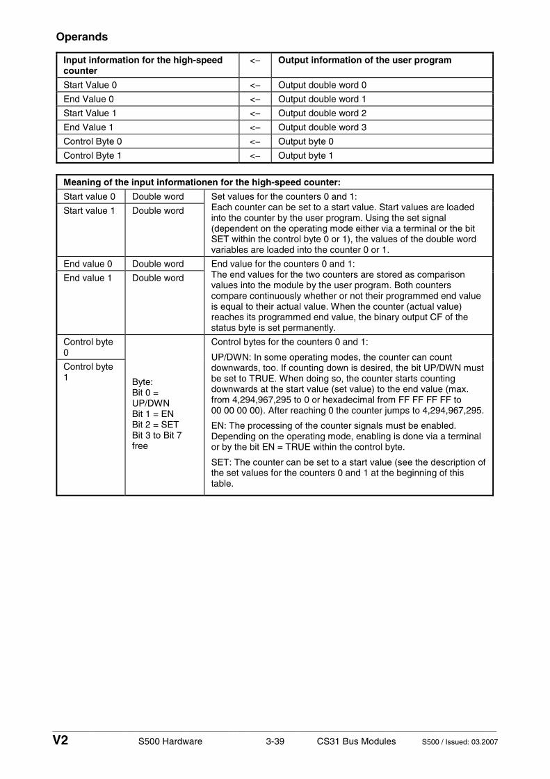
____________________________________________________________________________________________________________
V2 S500 Hardware 3-39 CS31 Bus Modules S500 / Issued: 03.2007
Operands
Input information for the high-speed counter
<− Output information of the user program
Start Value 0 <− Output double word 0
End Value 0 <− Output double word 1
Start Value 1 <− Output double word 2
End Value 1 <− Output double word 3
Control Byte 0 <− Output byte 0
Control Byte 1 <− Output byte 1
Meaning of the input informationen for the high-speed counter:
Start value 0 Double word
Start value 1 Double word
Set values for the counters 0 and 1: Each counter can be set to a start value. Start values are loaded into the counter by the user program. Using the set signal (dependent on the operating mode either via a terminal or the bit SET within the control byte 0 or 1), the values of the double word variables are loaded into the counter 0 or 1.
End value 0 Double word
End value 1 Double word
End value for the counters 0 and 1: The end values for the two counters are stored as comparison values into the module by the user program. Both counters compare continuously whether or not their programmed end value is equal to their actual value. When the counter (actual value) reaches its programmed end value, the binary output CF of the status byte is set permanently.
Control byte 0
Control byte 1 Byte:
Bit 0 = UP/DWN Bit 1 = EN Bit 2 = SET Bit 3 to Bit 7 free
Control bytes for the counters 0 and 1:
UP/DWN: In some operating modes, the counter can count downwards, too. If counting down is desired, the bit UP/DWN must be set to TRUE. When doing so, the counter starts counting downwards at the start value (set value) to the end value (max. from 4,294,967,295 to 0 or hexadecimal from FF FF FF FF to 00 00 00 00). After reaching 0 the counter jumps to 4,294,967,295.
EN: The processing of the counter signals must be enabled. Depending on the operating mode, enabling is done via a terminal or by the bit EN = TRUE within the control byte.
SET: The counter can be set to a start value (see the description of the set values for the counters 0 and 1 at the beginning of this table.

____________________________________________________________________________________________________________
V2 S500 Hardware 3-40 CS31 Bus Modules S500 / Issued: 03.2007
Output information of the high-speed counter
−> Input information for the user program
Actual Value 0 −> Input double word 0
Actual Value 1 −> Input double word 1
Status Byte 0 −> Input byte 0
Status Byte 1 −> Input byte 1
Meaning of the output informationen of the high-speed counter:
Actual Value 0
Double word Actual value of the counter 0
Actual Value 1
Double word Actual value of the counter 1
Status Byte 0
Status Byte 1
Byte: Bit 0 = CF Bit 1 to Bit 7 free
CF: When the counter reaches the programmed end value, the counter output is stored permanently as CF = TRUE (end value reached). Only when the counter is set again (set value), CF is reset to FALSE.
Operating modes
Inputs and outputs which are not used by the counters, are available for other tasks. In the following table, A means Input Channel A, B means Input Channel B and C means Output Channel C (refer also to the table in the "General" chapter.
Opera- ting
mode
Function Used inputs and outputs
Notes
0 No counter none This operating mode is selected, if the integrated high-speed counter is not necessary.
1 One up-counter A = Counting input C = End value reached
The counting input and the output "End value reached) are enabled by the bit EN = TRUE within the control byte.
2 One up-counter with enable input via terminal
A = Counting input B = Enable input C = End value reached
The enable input enables the counting input and the output "end value reached" as well. The counter is only enabled, if the enable input = TRUE (signal 1) AND the bit EN = TRUE within the control byte.
3 Two up/down counters
A = Counting input 0 B = Counting input 1
With this operating mode, two counters, which are independent of each other, exist. The status "End value reached" is only readable from the two status bytes, not from output terminals.
The counting direction is defined by the bit UP/DWN within the control byte.
4 Two up/down counters (1 counting input inverted)
A = Counting input 0 B = Counting input 1
This operating mode equals operating mode 3 with one exception: The counting input B (of counter 1) is inverted. It counts the TRUE/FALSE edges at input B.
5 One up/down counter with a dynamic set input via terminal
A = Counting input B = Dynamic set input
With this operating mode, one up/down counter is available which has a dynamic set input. Dynamic here means, that the set operation is performed at the FALSE/TRUE signal edge (0/1 edge) of the set input and not during the signal is TRUE.
The status "End value reached" is only readable from the status byte, not from an output terminal.

____________________________________________________________________________________________________________
V2 S500 Hardware 3-41 CS31 Bus Modules S500 / Issued: 03.2007
6 One up/down counter with a dynamic set input via terminal
A = Counting input B = Dynamic set input
This operating mode equals operating mode 5 with one exception: The dynamic set input operates at the TRUE/FALSE edge (1-0 edge).
7 One up/down counter for position sensors
A = Trace A of the position sensor B = Trace B of the position sensor
With this operating mode, incremental position sensors can be used which give their counting signals on tracks A and B in a 90° phase sequence to each other. Dependent on the sequence of the signals at A and B, the counter counts up or down. There is no pulse multiplier function (e.g. x2 or x4). The position sensor must provide 24 V signals. Signals of 5 V sensors must be converted. A zero-trace is not processed. The status "End value reached" is only readable from the status byte 0, not from an output terminal.
The bit UP/DWN within the control byte must be FALSE. Otherwise a parameter error is generated.
In this operating mode, the maximum counting frequency is 35 kHz.
8 Reserved
9 One up/down counter for position sensors (pulse multiplier x2)
A = Trace A of the position sensor B = Trace B of the position sensor
This operating mode equals operating mode 7 with one exception: There is a pulse multiplication x2 with the evaluation of the counting inputs. This means, that the counter counts both the positive edges and the negative edges of trace A. This results in the double number of counting pulses. The precision increases correspondingly.
In this operating mode, the maximum counting frequency is 30 kHz.
10 One up/down counter for position sensors (pulse multiplier x4)
A = Trace A of the position sensor B = Trace B of the position sensor
This operating mode equals operating mode 7 with one exception: There is a pulse multiplication x4 with the evaluation of the counting inputs. This means, that the counter counts the positive and negative edges of the traces A and B. This results in the fourfold number of counting pulses. The precision increases correspondingly.
In this operating mode, the maximum counting frequency is 15 kHz.

____________________________________________________________________________________________________________
V2 S500 Hardware 3-42 CS31 Bus Modules S500 / Issued: 03.2007
CS31 Bus Module DC551-CS31 with digital inputs and outputs - 8 digital inputs 24 V DC, 16 configurable digital inputs/outputs - module-wise electrically isolated
Elements of the CS31 Bus ModuleDC551-CS31
1 I/O-Bus (10-pole, female) to electricallyconnect the first expansion module
2 Allocation between terminal No. andsignal name
3 8 yellow LEDs to display the signalstatuses at the inputs I0 to I7
4 16 yellow LEDs to display the signalstatuses at the inputs/outputs C8 to C23
5 1 green LED to display the processvoltage UP
6 3 red LEDs to display errors(CH-ERR1, CH-ERR2 and CH-ERR3)
7 DIN rail
8 4 system LEDs:PWR = Voltage (system)CS31 = CS31 communicationS-ERR = Sum ErrorI/O-Bus = I/O-Bus communication
9 2 rotary switches to set the moduleaddress (00 to 99)
10 CS31 Bus Terminal Unit (TU551 orTU552) with 40 terminals (screw-typeor spring terminals)
1.0
1.1
1.2
1.3
1.4
1.5
1.6
1.7
1.8
1.9
2.0
2.1
2.2
2.3
2.4
2.5
2.6
2.7
2.8
2.9
3.0
3.1
3.2
3.3
3.4
3.5
3.6
3.7
3.8
3.9
4.0
4.1
4.2
4.3
4.4
4.5
4.6
4.7
4.8
4.9
DC551
1.0 R1
1.1 R2
1.2 B1
1.3 B2
1.4 FE
1.5 B1
1.6 B2
1.7 FE
1.8 UP
1.9 ZP
2.0 I0
2.1 I1
2.2 I2
2.3 I3
2.4 I4
2.5 I5
2.6 I6
2.7 I7
2.8 UP
2.9 ZP
3.0 C8
3.1 C9
3.2 C10
3.3 C11
3.4 C12
3.5 C13
3.6 C14
3.7 C15
3.8 UP
3.9 ZP
4.0 C16
4.1 C17
4.2 C18
4.3 C19
4.4 C20
4.5 C21
4.6 C22
4.7 C23
4.8 UP
4.9 ZP
CH-ERR3 CH-ERR4
CS31 8DI 16DCInput 24 V DC
Output 24 V DC 0.5A
CH-ERR2
UP 24VDC 200W
PWR
CS31
I/O-
S-ERR
Bus
ADDRx1
ADDRx103
2
596
4
8
7
1
4
10
Figure: CS31 Bus Module DC551-CS31, plugged on a CS31 Bus Terminal Unit TU552
Contents
Intended purpose...................................................................................................................................... 3-43 Functionality.............................................................................................................................................. 3-43 Electrical connection................................................................................................................................. 3-43 CS31 bus connections.............................................................................................................................. 3-45 Internal data exchange ............................................................................................................................. 3-46 Addressing ................................................................................................................................................ 3-46 DC551 limitations...................................................................................................................................... 3-46 I/O configuration........................................................................................................................................ 3-47 Parameterization....................................................................................................................................... 3-38 Structure of the diagnosis block of the DC551-CS31............................................................................... 3-51 Diagnosis and display............................................................................................................................... 3-51 Technical data........................................................................................................................................... 3-54 - Technical data of the entire module ....................................................................................................... 3-54 - Technical data of the digital inputs ......................................................................................................... 3-55 - Technical data of configurable digital inputs/outputs ............................................................................. 3-55 - Technical data of the high-speed counter .............................................................................................. 3-57 Ordering data ............................................................................................................................................ 3-57

____________________________________________________________________________________________________________
V2 S500 Hardware 3-43 CS31 Bus Modules S500 / Issued: 03.2007
Intended purpose
Important: Currently, the CS31 Bus Module DC551-CS31 can only be used together with the AC500 CPUs and dedicated PS501 Control Builder.
The CS31 Bus Module is used as a decentralized I/O module on CS31 field buses. The bus connection is performed on a RS485 serial interface, which allows the connection of this module to all existing CS31 buses. In addition, the CS31 Bus Module provides 24 I/O channels with the following properties:
• 8 digital inputs 24 V DC in one group (2.0...2.7) • 16 digital inputs/outputs in one group (3.0...4.7), of which each can be used
• as an input, • as a transistor output with short-circuit and overload protection, 0.5 A rated current or • as a re-readable output (combined input/output) with the technical data of the digital inputs and
outputs.
The inputs and output are electrically isolated from the other electronic circuitry of the module.
Functionality
Interface RS485, CS31 protocol
Supply of the module's electronic circuitry
from UP and ZP (power supply)
Supply of the electronic circuitry of the I/O expansion modules attached
through the expansion bus interface (I/O-Bus)
Address switches for setting the CS31 field bus address (0 to 99)
Digital inputs 8 (24 V DC)
Digital inputs/outputs 16 (24 V DC)
High-speed counter integrated, many configurable operating modes
LED displays for system displays, signal statuses, errors and power supply
External supply voltage via the terminals ZP and UP (process voltage 24 V DC)
Electrical connection
The CS31 Bus Module is plugged on the CS31 Terminal Unit TU551 or TU552. Hereby, it clicks in with two mechanical locks. The Terminal Unit is mounted on a DIN rail or with 2 screws plus the additional accessory for wall mounting (TA526).
The electrical connection of the I/O channels is carried out using the 40 terminals of the CS31 Terminal Unit. It is possible, to replace CS31 Bus Modules and I/O modules without loosening the wiring.
Note: Mounting, disassembling and electrical connection for the Terminal Units, the FBP Interface Modules and the I/O modules are described in detail in the S500 system data chapters.
The terminals 1.8 to 4.8 and 1.9 to 4.9 are electrically interconnected within the CS31 Bus Terminal Unit and have always the same assignment, independent of the inserted module:
Terminals 1.8 to 4.8: Process voltage UP = +24 V DC Terminals 1.9 to 4.9: Process voltage ZP = 0 V
The assignment of the other terminals:
Terminals Signal Meaning
1.0 to 1.7 RS485 CS31 bus interface
2.0 to 2.7 I0 to I7 8 digital inputs
3.0 to 4.7 C8 to C23 16 digital inputs/outputs

____________________________________________________________________________________________________________
V2 S500 Hardware 3-44 CS31 Bus Modules S500 / Issued: 03.2007
The supply voltage 24 V DC for the module's electronic circuitry comes from the ZP/UP terminals.
The module provides several diagnosis functions (see chapter "Diagnosis and display").
Caution: Removal of energized modules is not permitted. All power sources (supply and process voltages) must be switched off while working on any AC500 system.
The following figure shows the electrical connection of the CS31 Bus Module DC551-CS31.
1.0
1.1
1.2
1.3
1.4
1.5
1.6
1.7
1.8
1.9
2.0
2.1
2.2
2.3
2.4
2.5
2.6
2.7
2.8
2.9
3.0
3.1
3.2
3.3
3.4
3.5
3.6
3.7
3.8
3.9
4.0
4.1
4.2
4.3
4.4
4.5
4.6
4.7
4.8
4.9
DC551
1.0 R1
1.1 R2
1.2 B1
1.3 B2
1.4 FE
1.5 B1
1.6 B2
1.7 FE
1.8 UP
1.9 ZP
2.0 I0
2.1 I1
2.2 I2
2.3 I3
2.4 I4
2.5 I5
2.6 I6
2.7 I7
2.8 UP
2.9 ZP
3.0 C8
3.1 C9
3.2 C10
3.3 C11
3.4 C12
3.5 C13
3.6 C14
3.7 C15
3.8 UP
3.9 ZP
4.0 C16
4.1 C17
4.2 C18
4.3 C19
4.4 C20
4.5 C21
4.6 C22
4.7 C23
4.8 UP
4.9 ZP
CH-ERR3 CH-ERR4
CS31 8DI 16DCInput 24 V DC
Output 24 V DC 0.5A
CH-ERR2
UP 24VDC 200W
PWR
CS31
I/O-
S-ERR
Bus
ADDRx1
ADDRx10for 24 V DC
1.9 to 4.9 (ZP) are connected to eachother within the CS31 Terminal Unit.
Attention:The process voltage must beincluded in the earthingconcept of the control system(e.g. earthing the minus pole).
I/O-Bus out
Inputs or loads
C15 3.7
C16 4.0
Sw
itch-
gear
cab
inet
ear
th
Note:
Power supply
+24 V 0 V
C19 4.3
C23 4.7
C8 3.0
24 V DC
CS31
to set the CS31bus module
2 rotary switches
address,setting range00 bis 99
bus connections
I7 2.7
I0 2.0
C11 3.3
The terminals 1.8 to 4.8 (UP) and
Figure: Electrical connection of the CS31 Bus Module DC551-CS31

____________________________________________________________________________________________________________
V2 S500 Hardware 3-45 CS31 Bus Modules S500 / Issued: 03.2007
CS31 bus connections
The CS31 bus is connected through the Terminal Unit with the terminals 1.0 to 1.7. The end-of-line resistor can also be activated by using external wire jumpers.
The following figure shows a CS31 Bus module at the end of the CS31 Bus (end-of-line resistor activated).
Figure: CS31 Bus module at the end of the CS31 Bus
The following figure shows a CS31 Bus module in the middle of a CS31 Bus (end-of-line resistor not activated).
Figure: CS31 Bus module in the middle of the CS31 Bus

____________________________________________________________________________________________________________
V2 S500 Hardware 3-46 CS31 Bus Modules S500 / Issued: 03.2007
Internal data exchange
without the high-speed counter
with the high-speed counter (only with AC500)
Digital inputs (bytes) 3 + expansion modules (see obove)
5 + expansion modules (see obove)
Digital outputs (bytes) 2 + expansion modules (see obove)
4 + expansion modules (see obove)
Counter input data (words) 0 5 (16 DI + 4 AI)
Counter output data (words) 0 9 (16 DO + 8 AO)
Addressing
An address must be set at every module so that the field bus coupler can access the specific inputs and outputs.
A detailed description concerning "addressing" can be found in the chapters "Addressing" of the CPUs and couplers.
The address (00 to 99) is set with two rotary switches on the front panel of the module.
Remark: The CS31 Bus Module reads the position of the address switches only during the initialization after power ON, i.e. changes of the setting during operation remain ineffective.
DC551 limitations
Digital I/O:
DC551 is able to manage up to 240 digital I/O channels. It uses 2 digital bus addresses in this case.
address n (switch address) for the 1st module (120 I/O) The physical address to identify the I/O is address n + 7 + bit 8/15 = 1 for the 2nd module
To be compatible with old CPU and EC500 using this physical address, to address I/O in user programm: Use only 6 expansions with 32 DI.
Analog I/O:
Analog limitation to 32AI/AO with 4 bus addresses used.
Case of DC551 with high-speed counter:
An additional bus address is used for "double word" values of the high-speed counter. The maximum configuration is shown in the following table.
DC551 8DI + 16 DC + counter
16 AI 16 AI DC532 DC532 DC532 DC532 DC532
The following configuration uses 7 bus addresses (the high-speed counter needs 16 DI + 16 DO + 4 AI + 8 AO):
2 bus addresses for digital I/O (24 + 16 + 5x32)DI + (16 + 16 + 5x16)DO = 200 DI (>120) + 112 DO 5 bus addresses for analog I/O (4 + 2x16)AI + 8 AO = 36 AI + 8 AO

____________________________________________________________________________________________________________
V2 S500 Hardware 3-47 CS31 Bus Modules S500 / Issued: 03.2007
Small overview of the addressing possibilities
Configuration example with 32 analog inputs with or without 32 analog outputs (high-speed counter not used) = 5 bus addresses by the bus module
DC5518 DI
16 DC16 AI 16 AI 16 AO 16 AOn
DC5518 DI
16 DC16 AI 16 AI 16 AO 16 AOmini n+2
DC5518 DI
16 DC16 AI 16 AI 16 AO 16 AO
DC5518 DI
16 DC16 AI 16 AI 16 AO 16 AO
DC5518 DI
16 DC16 AI 16 AI 16 AO 16 AO
DC5518 DI
16 DC16 AI 16 AI 16 AO 16 AO
Switch
mini n+4
mini n+6
mini n+8
mini n+10
address
If the number of analog outputs is less than the number of analog inputs, no additional address is necessary. Change the type from "analog in" to "analog I/O".
30 bus addresses used, 1 bus address free 192 analog inputs (+ 192 analog outputs) 48DI / 96DC (144 DI / 96 DO for CS31 and user program)
Switch address incremented to avoid control overlap. In CPU table module switch address n will be seen as (idem for AC500 or old CPU):
Address n, type digital I/O, 8 DI/16DC Address n, type analog I or I/O, 8 AI (+ 8 AO) Address n + bit 8/15=1, type analog I or I/O, 8 AI (+ 8 AO) Address n+1, type analog I or I/O, 8 AI (+ 8 AO) Address n+1 + bit 8/15=1, type analog I or I/O, 8 AI (+ 8 AO)
Only difference in old CPU I/O channels are stored/updated according to the switch address. In AC500 according to Codesys configuration table.
I/O Configuration
The DC551-CS31 module does not store configuration data itself. The 16 configurable channels are defined as inputs or outputs by the user program, i.e. each of the configurable channels can be used as input or output (or re-readable output) by interrogation or allocation by the user program.

____________________________________________________________________________________________________________
V2 S500 Hardware 3-48 CS31 Bus Modules S500 / Issued: 03.2007
Parameterization
During system start-up, the master coupler automatically sends parameter data to the slave.
When the module is defined in Codesys: Parameters are in Codesys and can be adapted to application before transfer in PLC. Then parameters will be sent to DC551 when the module connects or re-connects the bus.
By using the PLC Configurator: Definition of CS31 Master communication on COM1, append of the 1st DC551-CS31 slave module:
The DC551-CS31 is now attached to the COM1:
The on-board I/Os are displayed and automatically known by the AC500 Control Builder. The I/O addressing is automatically performed as for any other modules.
The bus address of the module, used after that by AC500 Master CS31, can be adapted to those set on the module rotary switches.
Attention: The AC500 PS501 Control Builder does not control the validity/integrity of the entered CS31 Bus address value during the configuration! The control is done during project compilation, then downloaded into the CPU and after starting the CPU.

____________________________________________________________________________________________________________
V2 S500 Hardware 3-49 CS31 Bus Modules S500 / Issued: 03.2007
The attached expansions modules of the DC551-CS31 are performed as local expansions by clicking with the right mouse button onto the DC551-CS31 bus module and using Append Subelement. See above:
The DC532 is added as a local expansion to the DC551-CS31 Bus module:
Attention: Be careful, the AC500 PS501 Control Builder does not control the validity/integrity of amount of expansions configured (acc. to I/O limitations) during the configuration! The control is done during project compilation, then downloaded into the CPU and after starting the CPU.
Example of a CS31 bus configuration with 2 DC551-CS31 slaves:
• for EC500: Special functions must be added in the user program
• for Series 90: => use old CS31CO (write 4 bytes) or terminal command MAIL (write 4 bytes).
• (for old CPU 1 time configuration have been loaded => a command restore config from EEPROM by CS31CO can be used to avoid resend complete table)
The arrangement of the parameter data is performed by the Control Builder software.
The parameter data directly influences the functionality of modules.
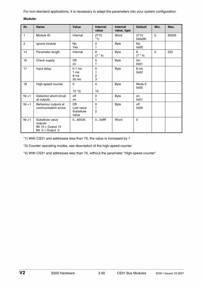
____________________________________________________________________________________________________________
V2 S500 Hardware 3-50 CS31 Bus Modules S500 / Issued: 03.2007
For non-standard applications, it is necessary to adapt the parameters into your system configuration.
Module:
Nr. Name Value Internal value
Internal value, type
Default Min. Max.
1 Module ID Internal 2715 *1)
Word 2715 0x0a9b
0 65535
2 Ignore module No Yes
0 1
Byte No 0x00
14 Parameter length Internal 8 (7 * 4)
Byte 8 (7 * 4)
0 255
16 Check supply Off on
0 1
Byte On 0x01
17 Input delay 0.1 ms 1 ms 8 ms 32 ms
0 1 2 3
Byte 8 ms 0x02
18 High-speed counter 0 : 10 *3)
0 : 10
Byte Mode 0 0x00
Nr.+1 Detection short-circuit at outputs
off on
0 1
Byte on 0x01
Nr.+1 Behaviour outputs at communication errors
Off Last value Substitute value
0 1 2
Byte off 0x00
Nr.+1 Substitute value outputs Bit 15 = Output 15 Bit 0 = Output 0
0...65535 0...0xffff Word 0
*1) With CS31 and addresses less than 70, the value is increased by 1
*3) Counter operating modes, see description of the high-speed counter
*4) With CS31 and addresses less than 70, without the parameter "High-speed counter"

____________________________________________________________________________________________________________
V2 S500 Hardware 3-51 CS31 Bus Modules S500 / Issued: 03.2007
Structure of the diagnosis block of the DC551-CS31
If a DC551-CS31 module is connected via a CS31 bus, then the field bus master receives diagnosis information by an extended diagnosis block. The following table shows the structure of this diagnosis block:
Byte number
Description Possible values
1 Data length (header included) 18
2 Diagnosis byte 0 = Communication with DC551 OK 1 = Communication with DC551 failed
3 DC551 diagnosis byte, module number
0 = DC551 (e.g. error at the integrated 8DI/16DC) 1 = 1st attached S500 I/O module ... 7 = 7th attached S500 I/O module
4 DC551 diagnosis byte, slot According to the I/O-Bus specification passed on by modules to the fieldbus master
5 DC551 diagnosis byte, channel According to the I/O-Bus specification passed on by modules to the fieldbus master
6 DC551 diagnosis byte, error code According to the I/O-Bus specification Bit 7 and bit 6, coded error class 0 = E1 1 = E2 2 = E3 3 = E4 Bit 0 to Bit 5, coded error description passed on by modules to the fieldbus master
7 DC551 diagnosis byte, flags According to the I/O-Bus specification Bit 7: 1 = coming error Bit 6: 1 = leaving error Bit 5: 1 = Diag reset Bit 2 to Bit 4: reserved Bit 1: 1 = explicit acknowledgement Bit 0: 1 = static error passed on by modules to the fieldbus master Value = 0: static message for other systems, which do not have a coming/leaving evaluation
8ff reserved

____________________________________________________________________________________________________________
V2 S500 Hardware 3-52 CS31 Bus Modules S500 / Issued: 03.2007
Diagnosis and display
In case of overload or short-circuit, the outputs switch off automatically and try to switch on again cyclically. Therefore an acknowledgement of the outputs is not necessary. The LED error message, however, is stored.
Diagnosis:
E1..E4 d1 d2 d3 d4 Identifier000..063
AC500 display
Class Comp Dev Mod Ch Err PS501 PLC browser
Byte 6 Bit 6..7
- Byte 3 Byte 4 Byte 5 Byte 6 Bit 0..5
FBP diagnosis block
<− Display in
Class Inter- face
De- vice
Mod- ule
Chan-nel
Error identifier
Error message Remedy
1) 2) 3) 4)
Module error DC551-CS31
3 11 ADR 31 31 19 Checksum error in the I/O module
3 11 ADR 31 31 3 Timeout in the I/O module
3 11 ADR 31 31 40 Different hard-/firmware versions in the module
3 11 ADR 31 31 43 Internal error in the module
3 11 ADR 31 31 36 Internal data exchange failure
Replace I/O module
3 11 ADR 31 31 9 Overflow diagnosis buffer New start
3 11 ADR 31 31 26 Parameter error Check master
3 11 ADR 31 31 11 Process voltage too low Check process voltage
3 11 ADR 1...7 31 17 No communication to the I/O module
Replace I/O module
4 11 ADR 31 31 45 Process voltage ON/OFF Process voltage ON
4 11 ADR 31/1..7 31 34 No reply at initialization of the I/O module
Replace I/O module
4 11 ADR 31/1.7 31 32 Wrong I/O module in the slot
Replace I/O module or check configuration
Channel error DC551-CS31
4 11 ADR 31/1..7 8..23 47 Short-circuit at a digital output
Check connection
Remarks:
1) In AC500the following interface identifier applies: 11 = COM1 (protocol CS31 bus only possible with COM1)
2) With "Device" and CS31 bus master, the hardware address of the DC551 (0...69) is output.
3) With "Module" the following allocation applies: 31 = Module itself, 1...7 = Expansion 1...7
4) In case of module errors, with channel "31 = Module itself" is output.

____________________________________________________________________________________________________________
V2 S500 Hardware 3-53 CS31 Bus Modules S500 / Issued: 03.2007
Displays:
The LEDs are on the front panels of the modules. There are two different groups:
• The 4 system LEDs (PWR, S-ERR, CS31 and I/O-Bus) show the operating status of the module and indicate possible errors.
• The 28 process LEDs (UP, inputs, outputs, CH-ERR2 to CH-ERR4) display the supply voltage and signal statuses of the inputs and outputs and indicate possible errors.
All of the S500 modules have LEDs to display operating statuses and errors.
Status of the LEDs:
LED Status Color LED = OFF LED = ON LED flashes
PWR System voltage green Missing internal system voltage or field bus supply is missing
Internal system voltage is OK
--
CS31 CS31 communication
green No communication at the CS31 bus module
Communication at the CS31 bus OK
Diagnosis mode
S-ERR Sum Error red No error or system voltage is missing
Internal error (storing can be parameterized)
--
I/O-Bus Communication via the I/O-Bus
green No expansion modules connected or data error
Expansion modules connected
Error I/O-Bus
Reserved Not defined
I0...I7 Digital inputs yellow Input = OFF Input = ON (the input voltage is even displayed if the supply voltage is OFF)
C8...C23 Digital inputs/outputs
yellow Input/output = OFF Input/output = ON (the input voltage is even displayed if the supply voltage is OFF)
UP Process supply voltage and initialization
green Process voltage is missing
Process voltage OK and initialization completed
Module was not initialized correctly
CH-ERR2 red
CH-ERR3 red
CH-ERR4
Channel Error, error messages in groups (digital inputs/outputs combined into the groups 2 to 4)
red
No error Serious error within the corresponding group
Error on one channel of the corresponding group (e.g. short-circuit at an output)
CH-ERR *)
Module Error red No error or process voltage is missing
Internal error --
*) All LEDs CH-ERR2 to CH-ERR4 light up together
The status of the LEDs concerning the CS31 Bus Module in connection with the I/O expansion modules is described in detail in the S500 system data.

____________________________________________________________________________________________________________
V2 S500 Hardware 3-54 CS31 Bus Modules S500 / Issued: 03.2007
Technical data
The system data of AC500 and S500 are valid here. Only additional details are therefore documented below.
Technical data of the entire module
Rated supply voltage of the module 24 V DC (UP/ZP)
Current consumption of the module (UP)
15 mA
Process voltage UP
- rated value 24 V DC (for inputs and outputs)
- max. current loadability for the supply terminals
10 A
- Protection against reversed voltage yes
- Rated protection fuse at UP 10 A fast
- Electrical isolation CS31 bus interface from the rest of the module
- Inrush current from UP (at power-up)
0.040 A²s
- Current consumption from UP at normal operation / with outputs
0.1 A + max. 0.008 A per input + max. 0.5 A per output
- Connections Terminals 1.8 - 4.8 for +24 V (UP) and 1.9 - 4.9 for 0 V (ZP)
Max. power dissipation within the module
6 W (outputs unloaded)
Number of digital inputs 8
Number of configurable digital inputs/outputs
16
Reference potential for all digital inputs and outputs
Minus pole of the supply voltage, signal name ZP
Address setting with 2 rotary switches on the front panel
Diagnosis see chapter "Diagnosis and displays"
Operating and error displays 32 LEDs altogether
Weight (without Terminal Unit) ca. 125 g
Mounting position horizontal or vertical with derating (output load reduced to 50 % at 40°C per group)
Cooling The natural convection cooling must not be hindered by cable ducts or other parts in the switch-gear cabinet.
Attention: All I/O channels (digital and analog) are protected against reverse polarity, reverse supply, short circuit and continuous overvoltage up to 30 V DC.

____________________________________________________________________________________________________________
V2 S500 Hardware 3-55 CS31 Bus Modules S500 / Issued: 03.2007
Technical data of the digital inputs
Number of channels per module 8
Distribution of the channels into groups 1 group of 8 channels
Terminals of the channels I0 to I7 2.0 to 2.7
Terminals of the channels C8 to C23 3.0 to 4.7
Reference potential for all inputs terminals 1.9...4.9 (Minus pole of the process supply voltage, signal name ZP)
Electrical isolation from the CS31 system bus
Indication of the input signals one yellow LED per channel, the LED is ON when the input signal is high (signal 1)
Input type acc. to EN 61131-2 Type 1
Input delay (0->1 or 1-> 0) typ. 8 ms, configurable from 0.1 to 32 ms
Input signal voltage 24 V DC
Signal 0 -3 V...+5 V
undefined signal > +5 V...< +15 V
Signal 1 +15 V...+30 V
Ripple with signal 0 within -3 V...+5 V
Ripple with signal 1 within +15 V...+30 V
Input current per channel
- input voltage +24 V typ. 5 mA
- input voltage +5 V > 1 mA
- input voltage +15 V > 2 mA
- input voltage +30 V < 8 mA
Max. cable length
- shielded 1000 m
- unshielded 600 m
Technical data of the configurable digital inputs/outputs
Each of the configurable I/O channels is defined as input or output by the user program. This is done by interrogating or allocating the corresponding channel.
Number of channels per module 16 inputs/outputs (with transistors)
Distributen of the channels into groups 1 group of 16 channels
if the channels are used as inputs
- channels I8...I23 terminals 3.0...4.7
if the channels are used as outputs
- channels Q8...Q23 terminals 3.0...4.7
Indication of the input/output signals one yellow LED per channel, the LED is ON when the input/output signal is high (signal 1)
Electrical isolation from the CS31 system bus

____________________________________________________________________________________________________________
V2 S500 Hardware 3-56 CS31 Bus Modules S500 / Issued: 03.2007
Technical data of the digital inputs/outputs if used as outputs
Number of channels per module max. 16 transistor outputs
Reference potential for all outputs terminals 1.9...4.9 (minus pole of the process supply voltage, signal name ZP)
Common power supply voltage for all outputs: terminals 1.8...4.8 (plus pole of the process supply voltage, signal name UP)
Output voltage for signal 1 UP (-0.8 V)
Output delay (0->1 or 1->0) on request
Output current
- rated value, per channel 500 mA at UP = 24 V
- maximum value (all channels together)
10 A
Leakage current with signal 0 < 0.5 mA
Rated protection fuse on UP 10 A fast
De-magnitization when inductive loads are switched off
with varistors integrated in the module (see figure below)
Switching frequency
- with resistive loads on request
- with inductive loads max. 0.5 Hz
- with lamp loads max. 11 Hz with max. 5 W
Short-circuit proof / overload proof yes
Overload message (I > 0.7 A) yes, after ca. 100 ms
Output current limitation yes, automatic reactivation after short-circuit/overload
Resistance to feedback against 24V signals
yes
Max. cable length
- shielded 1000 m
- unshielded 600 m
The following drawing shows the circuitry of a digital input/output with the varistors for demagnitization when inductive loads are switched off.
UPx (+24 V)
Digitaler Ein-/Ausgang
ZPx (0 V)
zur Entmagnetisierung beimAbschalten induktiver Lasten
Figure: Digital input/output (circuit diagram)

____________________________________________________________________________________________________________
V2 S500 Hardware 3-57 CS31 Bus Modules S500 / Issued: 03.2007
Technical data of the digital inputs/outputs if used as inputs
Number of channels per module max. 16 digital inputs
Reference potential for all inputs terminals 1.9...4.9 (minus pole of the process supply voltage, signal name ZP)
Input current, per channel see "Digital inputs"
Input type acc. to EN 61131-2 Type 1
Input delay (0->1 or 1->0) typ. 8 ms, configurable from 0.1 to 32 ms
Input signal voltage 24 V DC
Signal 0 -3 V...+5 V *
undefined signal > +5 V...< +15 V
Signal 1 +15 V...+30 V
Ripple with signal 0 within -3 V...+5 V *
Ripple with signal 1 within +15 V...+30 V
Max. cable length
- shielded 1000 m
- unshielded 600 m
* Due to the direct connection to the output, the demagnetizing varistor is also effective at the input (see figure) above. This is why the difference between UPx and the input signal may not exceed the clamp voltage of the varistor. The varistor limits the voltage to approx. 36 V. Following this, the input voltage must range from - 12 V to + 30 V when UPx = 24 V and from - 6 V to + 30 V when UPx = 30 V.
Technical data of the high-speed counter
Used inputs C16 / C17
Used outputs C18
Counting frequency max. 50 kHz
Detailed description see chapter "High-speed counter"
Operating modes see chapter "High-speed counter, Operating modes"
Ordering data
Order No. Scope of delivery
1SAP 220 500 R0001 DC551-CS31, CS31 Bus Module, 8 DI / 16 DC
1SAP 210 600 R0001 TU551-CS31, CS31 Bus I/O Terminal Unit, screw-type terminals
1SAP 210 400 R0001 TU552-CS31, CS31 Bus I/O Terminal Unit, spring-type terminals

____________________________________________________________________________________________________________
V2 S500 Hardware 3-58 CS31 Bus Modules S500 / Issued: 03.2007

____________________________________________________________________________________________________________
V2 S500 Hardware 4-1 Digital I/O Modules S500 / Issued: 09.2007
Digital I/O Modules S500, Overview
High-speed counter High-speed counter of S500 modules Page 4-3
DI524 Digital Input Module, 32 DI, 24 V DC 4-8
DC522 Digital Input/Output Module, 16 DC, 24 V DC, 0.5 A 4-16
DC523 Digital Input/Output Module, 24 DC, 24 V DC, 0.5 A 4-16
DC532 Digital Input/Output Module, 16 DI / 16 DC, 24 V DC, 0.5 A 4-30
DX522 Digital Input/Output Module, 8 DI 24 V DC, 8 DO Relay 4-40
DX531 Digital Input/Output Module, 8 DI 230 V AC, 4 DO Relay 4-51

____________________________________________________________________________________________________________
V2 S500 Hardware 4-2 Digital I/O Modules S500 / Issued: 09.2007

____________________________________________________________________________________________________________
V2 S500 Hardware 4-3 Digital I/O Modules S500 / Issued: 09.2007
High-speed counter - integrated in digital S500 I/O modules - integrated in the S500 CS31 Bus Module
Contents
General ....................................................................................................................................................... 4-3 Features...................................................................................................................................................... 4-3 Operands .................................................................................................................................................... 4-4 Operating modes ........................................................................................................................................ 4-6
General
Several of the S500 expansion modules have an integrated high-speed counter. If this counter is used, it uses up to 2 digital inputs and one digital output (provided that it is available). The counter can be deactivated. Is in this case, the inputs and outputs reserved for the counter are usable for other tasks. The counter only works with expansion modules which are mounted at the I/O-Bus of an AC500 CPU. An exception is the CS31 Bus Module DC551-CS31, which contains a high-speed counter that is made operationally by the address setting on the module.
The following table shows, which of the S500 modules contain a high-speed counter and which of the digital inputs and outputs are reserved for the counter.
High-speed counters integrated in S500 modules
assigned inputs 1) assigned output Module integrated high-speed
counter channel
A channel
B channel C 2) or (CF)
Remarks
AI523 / AO523 no - - -
AX521 / AX522
no - - -
DC505-FBP no - - -
DC522 yes C8 C9 C10
DC523 yes C16 C17 C18
DC532 yes C24 C25 C26
DI524 yes I24 I25 no hardware output available
DX522 yes I0 I1 the counter does not activate any relay
output
The counter only works with expansion modules which are mounted at the I/O-Bus of an AC500 CPU.
DC551-CS31 yes C16 C17 C18 Counting function is activated by the address setting on the module 3)
DX531 no - - -
1) The two hardware inputs (channels A and B) are also and always available within the normal process image, independent of the operating mode of the counter.
2) The hardware output channel C is activated by the high-speed counter only in the operating modes 1 and 2. In the other operating modes, this output can be used for other purposes.
3) The counting function of the CS31 Bus Module can only be activated, if a bus address greater than 70 is set on the module by means of the address rotary switches. In this case, the effective bus address equals the set address minus 70 and the counter is ready for operation. An example: A set bus address of 83 means that the effective bus address = (83 - 70) = 13 and that the integrated high-speed counter can be used.

____________________________________________________________________________________________________________
V2 S500 Hardware 4-4 Digital I/O Modules S500 / Issued: 09.2007
Features
The counting function is performed within the expansion module. It works independently of the user program and is therefore able to response quickly to external signals. A simultaneous counting operation of several expansion modules is possible.
Each module counter can be configured for one mode out of 10 possible ones. The desired operating mode is selected in the PLC configuration using module parameters. After that, it is activated during the initialization phase (power-on, cold start, warm start).
The data exchange to and from the user program is performed using input and output operands. While integrating a module containing a high-speed counter in the PLC configuration, the necessary operands are created and reserved immediately. Thus a counter implementation carried out later on does not cause an address shift.
Features independent of the counter operating mode
• The pulses at the counters' inputs or the evaluated signals of the traces A and B in case of incremental position sensors are counted.
• The maximum counting frequency is 50 kHz. In certain operating modes, the maximum counting frequency is lower. If using the modules DC522, DC523, DC532 and DC551, each counting input must externally be circuited in series with a resistor of 470 Ω / 1 W, in order to safely avoid influences from the deactivated module outputs to the connected sensors.
• The positive signal edges are counted, if not noted differently.
• By setting the operating mode 0, the counting function is switched off. In this case, the reserved inputs and outputs can be used for other tasks. Simultaneous use of these terminals for the counter and other signals must be avoided.
• The counter's actual value is provided as a double word (32 bits).
• The counter can count upwards in all operating modes. It counts beginning at the start value (set value) up to the end value (max. from 0 to 4,294,967,295 or hexadecimal from 00 00 00 00 to FF FF FF FF. After reaching 4,294,967,295, the counter jumps with the next pulse to 0. When the counter reaches the programmed end value, the counter output is stored permanently as CF = TRUE (end value reached). Only when the counter is set again (set value), CF is reset to FALSE.
• The high-speed counters cannot be used with expansion modules which are mounted besides the CS31 Bus Module DC551-CS31 or the FBP Interface Module DC505-FBP.

____________________________________________________________________________________________________________
V2 S500 Hardware 4-5 Digital I/O Modules S500 / Issued: 09.2007
Operands
Input information for the high-speed counter
<− Output information of the user program
Start Value 0 <− Output double word 0
End Value 0 <− Output double word 1
Start Value 1 <− Output double word 2
End Value 1 <− Output double word 3
Control Byte 0 <− Output byte 0
Control Byte 1 <− Output byte 1
Meaning of the input informationen for the high-speed counter:
Start value 0 Double word
Start value 1 Double word
Set values for the counters 0 and 1: Each counter can be set to a start value. Start values are loaded into the counter by the user program. Using the set signal (dependent on the operating mode either via a terminal or the bit SET within the control byte 0 or 1), the values of the double word variables are loaded into the counter 0 or 1.
End value 0 Double word
End value 1 Double word
End value for the counters 0 and 1: The end values for the two counters are stored as comparison values into the module by the user program. Both counters compare continuously whether or not their programmed end value is equal to their actual value. When the counter (actual value) reaches its programmed end value, the binary output CF of the status byte is set permanently.
Control byte 0
Control byte 1 Byte:
Bit 0 = UP/DWN Bit 1 = EN Bit 2 = SET Bit 3 to Bit 7 free
Control bytes for the counters 0 and 1:
UP/DWN: In some operating modes, the counter can count downwards, too. If counting down is desired, the bit UP/DWN must be set to TRUE. When doing so, the counter starts counting downwards at the start value (set value) to the end value (max. from 4,294,967,295 to 0 or hexadecimal from FF FF FF FF to 00 00 00 00). After reaching 0 the counter jumps to 4,294,967,295.
EN: The processing of the counter signals must be enabled. Depending on the operating mode, enabling is done via a terminal or by the bit EN = TRUE within the control byte.
SET: The counter can be set to a start value (see the description of the set values for the counters 0 and 1 at the beginning of this table.

____________________________________________________________________________________________________________
V2 S500 Hardware 4-6 Digital I/O Modules S500 / Issued: 09.2007
Output information of the high-speed counter
−> Input information for the user program
Actual Value 0 −> Input double word 0
Actual Value 1 −> Input double word 1
Status Byte 0 −> Input byte 0
Status Byte 1 −> Input byte 1
Meaning of the output informationen of the high-speed counter:
Actual Value 0
Double word Actual value of the counter 0
Actual Value 1
Double word Actual value of the counter 1
Status Byte 0
Status Byte 1
Byte: Bit 0 = CF Bit 1 to Bit 7 free
CF: When the counter reaches the programmed end value, the counter output is stored permanently as CF = TRUE (end value reached). Only when the counter is set again (set value), CF is reset to FALSE.
Operating modes
Inputs and outputs which are not used by the counters, are available for other tasks. In the following table, A means Input Channel A, B means Input Channel B and C means Output Channel C (refer also to the table in the "General" chapter.
Opera- ting
mode
Function Used inputs and outputs
Notes
0 No counter none This operating mode is selected, if the integrated high-speed counter is not necessary.
1 One up-counter A = Counting input C = End value reached
The counting input and the output "End value reached) are enabled by the bit EN = TRUE within the control byte.
2 One up-counter with enable input via terminal
A = Counting input B = Enable input C = End value reached
The enable input enables the counting input and the output "end value reached" as well. The counter is only enabled, if the enable input = TRUE (signal 1) AND the bit EN = TRUE within the control byte.
3 Two up/down counters
A = Counting input 0 B = Counting input 1
With this operating mode, two counters, which are independent of each other, exist. The status "End value reached" is only readable from the two status bytes, not from output terminals.
The counting direction is defined by the bit UP/DWN within the control byte.
4 Two up/down counters (1 counting input inverted)
A = Counting input 0 B = Counting input 1
This operating mode equals operating mode 3 with one exception: The counting input B (of counter 1) is inverted. It counts the TRUE/FALSE edges at input B.
5 One up/down counter with a dynamic set input via terminal
A = Counting input B = Dynamic set input
With this operating mode, one up/down counter is available which has a dynamic set input. Dynamic here means, that the set operation is performed at the FALSE/TRUE signal edge (0/1 edge) of the set input and not during the signal is TRUE.
The status "End value reached" is only readable from the status byte, not from an output terminal.

____________________________________________________________________________________________________________
V2 S500 Hardware 4-7 Digital I/O Modules S500 / Issued: 09.2007
6 One up/down counter with a dynamic set input via terminal
A = Counting input B = Dynamic set input
This operating mode equals operating mode 5 with one exception: The dynamic set input operates at the TRUE/FALSE edge (1-0 edge).
7 One up/down counter for position sensors
A = Trace A of the position sensor B = Trace B of the position sensor
With this operating mode, incremental position sensors can be used which give their counting signals on tracks A and B in a 90° phase sequence to each other. Dependent on the sequence of the signals at A and B, the counter counts up or down. There is no pulse multiplier function (e.g. x2 or x4). The position sensor must provide 24 V signals. Signals of 5 V sensors must be converted. A zero-trace is not processed. The status "End value reached" is only readable from the status byte 0, not from an output terminal.
The bit UP/DWN within the control byte must be FALSE. Otherwise a parameter error is generated.
In this operating mode, the maximum counting frequency is 35 kHz.
8 Reserved
9 One up/down counter for position sensors (pulse multiplier x2)
A = Trace A of the position sensor B = Trace B of the position sensor
This operating mode equals operating mode 7 with one exception: There is a pulse multiplication x2 with the evaluation of the counting inputs. This means, that the counter counts both the positive edges and the negative edges of trace A. This results in the double number of counting pulses. The precision increases correspondingly.
In this operating mode, the maximum counting frequency is 30 kHz.
10 One up/down counter for position sensors (pulse multiplier x4)
A = Trace A of the position sensor B = Trace B of the position sensor
This operating mode equals operating mode 7 with one exception: There is a pulse multiplication x4 with the evaluation of the counting inputs. This means, that the counter counts the positive and negative edges of the traces A and B. This results in the fourfold number of counting pulses. The precision increases correspondingly.
In this operating mode, the maximum counting frequency is 15 kHz.

____________________________________________________________________________________________________________
V2 S500 Hardware 4-8 Digital I/O Modules S500 / Issued: 09.2007
Digital Input Module DI524 - 32 digital inputs 24 V DC, - module-wise electrically isolated
1.0
1.1
1.2
1.3
1.4
1.5
1.6
1.7
1.8
1.9
2.0
2.1
2.2
2.3
2.4
2.5
2.6
2.7
2.8
2.9
3.0
3.1
3.2
3.3
3.4
3.5
3.6
3.7
3.8
3.9
4.0
4.1
4.2
4.3
4.4
4.5
4.6
4.7
4.8
4.9
Elements of thedigital input module DI524
1 I/O-Bus
2 Allocation between terminal No. andsignal name
3 32 yellow LEDs to display the signalstatuses at the inputs I0 to I31
4 1 green LED to display the processvoltage UP
5 4 red LEDs to display errors(CH-ERR1...CH-ERR4)
6 DIN rail
7 Label
8 I/O Terminal Unit (TU515 or TU516)with 40 terminals (screw-type orspring terminals)
DI524
1.0 I0
1.1 I1
1.2 I2
1.3 I3
1.4 I4
1.5 I5
1.6 I6
1.7 I7
1.8 UP
1.9 ZP
2.0 I8
2.1 I9
2.2 I10
2.3 I11
2.4 I12
2.5 I13
2.6 I14
2.7 I15
2.8 UP
2.9 ZP
3.0 I16
3.1 I17
3.2 I18
3.3 I19
3.4 I20
3.5 I21
3.6 I22
3.7 I23
3.8 UP
3.9 ZP
4.0 I24
4.1 I25
4.2 I26
4.3 I27
4.4 I28
4.5 I29
4.6 I30
4.7 I31
4.8 UP
4.9 ZP
32 DIInput 24 V DC
CH-ERR3 CH-ERR4CH-ERR2CH-ERR1
UP 24VDC 1W
8
6
1
2
45
7
3
Figure: Digital input module DI524, plugged on a Terminal Unit TU516
Contents
Intended purpose........................................................................................................................................ 4-9 Functionality................................................................................................................................................ 4-9 Electrical connection................................................................................................................................... 4-9 Internal data exchange ............................................................................................................................. 4-10 I/O configuration........................................................................................................................................ 4-11 Parameterization....................................................................................................................................... 4-11 Diagnosis and display............................................................................................................................... 4-12 Technical data........................................................................................................................................... 4-14 - Technical data of the digital inputs ......................................................................................................... 4-15 - Technical data of the high-speed counter .............................................................................................. 4-15 Ordering data ............................................................................................................................................ 4-15
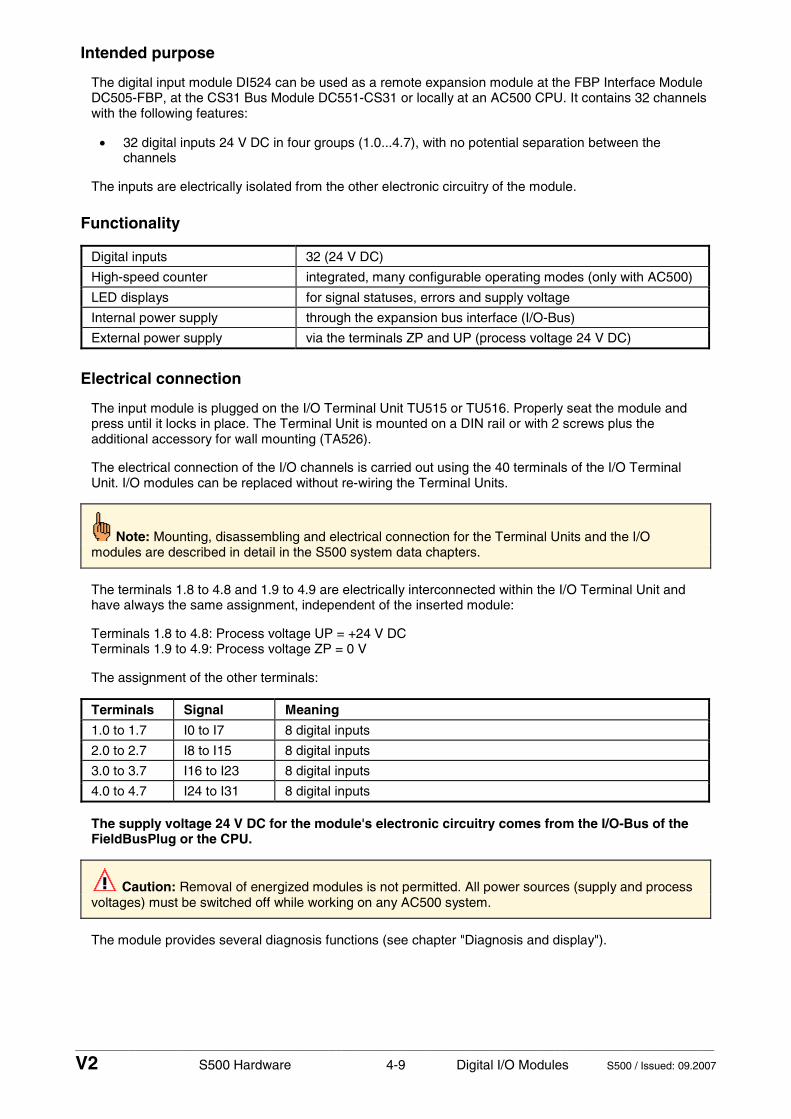
____________________________________________________________________________________________________________
V2 S500 Hardware 4-9 Digital I/O Modules S500 / Issued: 09.2007
Intended purpose
The digital input module DI524 can be used as a remote expansion module at the FBP Interface Module DC505-FBP, at the CS31 Bus Module DC551-CS31 or locally at an AC500 CPU. It contains 32 channels with the following features:
• 32 digital inputs 24 V DC in four groups (1.0...4.7), with no potential separation between the channels
The inputs are electrically isolated from the other electronic circuitry of the module.
Functionality
Digital inputs 32 (24 V DC)
High-speed counter integrated, many configurable operating modes (only with AC500)
LED displays for signal statuses, errors and supply voltage
Internal power supply through the expansion bus interface (I/O-Bus)
External power supply via the terminals ZP and UP (process voltage 24 V DC)
Electrical connection
The input module is plugged on the I/O Terminal Unit TU515 or TU516. Properly seat the module and press until it locks in place. The Terminal Unit is mounted on a DIN rail or with 2 screws plus the additional accessory for wall mounting (TA526).
The electrical connection of the I/O channels is carried out using the 40 terminals of the I/O Terminal Unit. I/O modules can be replaced without re-wiring the Terminal Units.
Note: Mounting, disassembling and electrical connection for the Terminal Units and the I/O modules are described in detail in the S500 system data chapters.
The terminals 1.8 to 4.8 and 1.9 to 4.9 are electrically interconnected within the I/O Terminal Unit and have always the same assignment, independent of the inserted module:
Terminals 1.8 to 4.8: Process voltage UP = +24 V DC Terminals 1.9 to 4.9: Process voltage ZP = 0 V
The assignment of the other terminals:
Terminals Signal Meaning
1.0 to 1.7 I0 to I7 8 digital inputs
2.0 to 2.7 I8 to I15 8 digital inputs
3.0 to 3.7 I16 to I23 8 digital inputs
4.0 to 4.7 I24 to I31 8 digital inputs
The supply voltage 24 V DC for the module's electronic circuitry comes from the I/O-Bus of the FieldBusPlug or the CPU.
Caution: Removal of energized modules is not permitted. All power sources (supply and process voltages) must be switched off while working on any AC500 system.
The module provides several diagnosis functions (see chapter "Diagnosis and display").

____________________________________________________________________________________________________________
V2 S500 Hardware 4-10 Digital I/O Modules S500 / Issued: 09.2007
The following figure shows the electrical connection of the digital input module DI524.
1.0
1.1
1.2
1.3
1.4
1.5
1.6
1.7
1.8
1.9
2.0
2.1
2.2
2.3
2.4
2.5
2.6
2.7
2.8
2.9
3.0
3.1
3.2
3.3
3.4
3.5
3.6
3.7
3.8
3.9
4.0
4.1
4.2
4.3
4.4
4.5
4.6
4.7
4.8
4.9
I0 1.0
I7 1.7
I24 4.0
I/O-Bus in I/O-Bus out
I8 2.0
I15 2.7
I31 4.7
I16 3.0
I23 3.7
and 1.9 to 4.9 (ZP) are connected toeach other within the I/O Terminal Unit
Attention:The process voltage must beincluded in the earthing conceptof the control system(e.g. earthing the minus pole).
Sw
itch-
gear
cab
inet
ear
th
Note: The terminals 1.8 to 4.8 (UP)
DI524
1.0 I0
1.1 I1
1.2 I2
1.3 I3
1.4 I4
1.5 I5
1.6 I6
1.7 I7
1.8 UP
1.9 ZP
2.0 I8
2.1 I9
2.2 I10
2.3 I11
2.4 I12
2.5 I13
2.6 I14
2.7 I15
2.8 UP
2.9 ZP
3.0 I16
3.1 I17
3.2 I18
3.3 I19
3.4 I20
3.5 I21
3.6 I22
3.7 I23
3.8 UP
3.9 ZP
4.0 I24
4.1 I25
4.2 I26
4.3 I27
4.4 I28
4.5 I29
4.6 I30
4.7 I31
4.8 UP
4.9 ZP
32 DIInput 24 V DC
CH-ERR3 CH-ERR4CH-ERR2CH-ERR1
UP 24VDC 1W
+24 V 0 V
Power supply24 V DC
Figure: Electrical connection of the digital input module DI524
Internal data exchange
without the high-speed counter
with the high-speed counter (only with AC500)
Digital inputs (bytes) 4 6
Digital outputs (bytes) 0 2
Counter input data (words) 0 4
Counter output data (words) 0 8

____________________________________________________________________________________________________________
V2 S500 Hardware 4-11 Digital I/O Modules S500 / Issued: 09.2007
I/O configuration
The digital input module DI524 does not store configuration data itself.
Parameterization
The arrangement of the parameter data is performed by your master configuration software SYCON in connection with the S500 GSD files and in conjunction with the Control Builder software.
The parameter data directly influences the functionality of modules.
For non-standard applications, it is necessary to adapt the parameters to your system configuration.
Module: Module slot address: Y = 1...7
Nr. Name Value Internal value
Internal value, type
Default Min. Max. EDS Slot/Index
1 Module ID Internal 1000 *1)
Word 1000 0x03E8
0 65535 0x0Y01
2 *2)
Ignore module No Yes
0 1
Byte No 0x00
not for FBP
3 Parameter length Internal 3-CPU 2-FBP
Byte 3 2
0 255 0x0Y02
4 Check supply Off on
0 1
Byte On 0x01
0 1 0x0Y03
5 Input delay 0.1 ms 1 ms 8 ms 32 ms
0 1 2 3
Byte 8 ms 0x02
0 3 0x0Y04
6 *4)
High-speed counter 0 : 10 *3)
0 : 10
Byte Mode 0 0x00
not for FBP
*1) With CS31 and addresses less than 70 and FBP, the value is increased by 1
*2) Not with FBP
*3) Counter operating modes, see description of the high-speed counter
*4) With FBP or CS31 without the parameter "High-speed counter"
Attention: The high-speed counter of the module can only be used together with the AC500 CPU. The counter does not work, if the module is attached to an FBP Interface Module or to a CS31 Bus Module.
GSD file: Ext_User_Prm_Data_Len = Ext_User_Prm_Data_Const(0) =
5 0x03, 0xe9, 0x02, \ 0x01, 0x02;

____________________________________________________________________________________________________________
V2 S500 Hardware 4-12 Digital I/O Modules S500 / Issued: 09.2007
Diagnosis and display
Diagnosis:
E1..E4 d1 d2 d3 d4 Identifier000..063
AC500 display
Class Comp Dev Mod Ch Err PS501 PLC browser
Byte 6 Bit 6..7
- Byte 3
Byte 4
Byte 5
Byte 6 Bit 0..5
FBP diagnosis block <− Display in
Class Inter- face
De- vice
Mod- ule
Chan-nel
Error identifier
Error message Remedy
1) 2) 3) 4)
Module error DI524
14 1..7 31 3
11 / 12 ADR 1..7 31 19 Checksum error in the I/O
module Replace I/O module
14 1..7 31 3
11 / 12 ADR 1..7 31 3 Timeout in the I/O module Replace I/O
module
14 1..7 31 3
11 / 12 ADR 1..7 31 40 Different hard-/firmware
versions in the module Replace I/O module
14 1..7 31 3
11 / 12 ADR 1..7 31 43 Internal error in the
module Replace I/O module
14 1..7 31 3
11 / 12 ADR 1..7 31 36 Internal data exchange
failure Replace I/O module
14 1..7 31 3
11 / 12 ADR 1..7 31 9 Overflow diagnosis buffer New start
14 1..7 31 3
11 / 12 ADR 1..7 31 26 Parameter error Check
master
14 1..7 31 3 11 / 12 ADR 1..7 31 11 Process voltage too low
Check process voltage
14 1..7 31 4
11 / 12 ADR 1..7 31 45 Process voltage is
switched off (ON −> OFF) Process voltage ON
Remarks:
1) In AC500 the following interface identifier applies: 14 = I/O-Bus, 11 = COM1 (e.g. CS31 bus), 12 = COM2. The FBP diagnosis block does not contain this identifier.
2) With "Device" the following allocation applies: 31 = Module itself, 1..7 = Expansion module 1..7, ADR = Hardware address (e.g. of the DC551)
3) With "Module" the following allocation applies dependent of the master: Module error: I/O-Bus or FBP: 31 = Module itself; COM1/COM2: 1..7 = Expansion 1..7
4) In case of module errors, with channel "31 = Module itself" is output.

____________________________________________________________________________________________________________
V2 S500 Hardware 4-13 Digital I/O Modules S500 / Issued: 09.2007
Displays:
During the power ON procedure, the module initializes automatically. All LEDs (accept the channel LEDs) are ON during this time.
Status of the LEDs (see also section "Diagnosis LEDs" in the S500 system data)
LED Status Color LED = OFF LED = ON LED flashes
Inputs 00...31
digital input yellow Input = OFF Input = ON (the input voltage is even displayed if the supply voltage is OFF).
--
UP Process supply voltage 24 V DC via terminal
green Process supply voltage is missing
Process supply voltage OK and initialization terminated
Module is not initialized correctly
CH-ERR1 red
CH-ERR2 red
CH-ERR3 red
CH-ERR4
Channel Error, error messages in groups (digital inputs combined into the groups 1, 2, 3, 4)
red
No error or process supply voltage is missing
Serious error within the corresponding group
Error on one channel of the corresponding group
CH-ERR *)
Module Error red -- Internal error --
*) All of the LEDs CH-ERR1 to CH-ERR4 light up together

____________________________________________________________________________________________________________
V2 S500 Hardware 4-14 Digital I/O Modules S500 / Issued: 09.2007
Technical data
The system data of AC500 and S500 are valid here. Only additional details are therefore documented below.
Process supply voltage UP
- Connections Terminals 1.8 - 4.8 for +24 V (UP) and 1.9 - 4.9 for 0 V (ZP)
- Rated value 24 V DC
- max. ripple 5 %
- Protection against reversed voltage
yes
Rated protection fuse on UP 10 A fast
- Electrical isolation yes, per module
Current consumption
- internal (via I/O-Bus) about 5 mA at 3.3 V DC
- current consumption from UP at normal operation
0.05 A + max. 0.008 A per input
- inrush current from UP (at power up)
0.008 A²s
Weight (without Terminal Unit)
ca. 105 g
Mounting position horizontal or vertical with derating (output load reduced to 50 % at 40°C per group)
Cooling The natural convection cooling must not be hindered by cable ducts or other parts in the switch-gear cabinet.
Attention: All I/O channels (digital and analog) are protected against reverse polarity, reverse supply, short circuit and continuous overvoltage up to 30 V DC.

____________________________________________________________________________________________________________
V2 S500 Hardware 4-15 Digital I/O Modules S500 / Issued: 09.2007
Technical data of the digital inputs
Number of channels per module 32
Distribution of the channels into groups 1 group of 32 channels
Terminals of the channels I0 to I7 1.0 to 1.7
Terminals of the channels I8 to I15 2.0 to 2.7
Terminals of the channels I16 to I23 3.0 to 3.7
Terminals of the channels I24 to I31 4.0 to 4.7
Reference potential for all inputs terminals 1.9...4.9 (minus pole of the process supply voltage, signal name ZP)
Electrical isolation from the rest of the module (I/O-Bus)
Indication of the input signals one yellow LED per channel, the LED is ON when the input signal is high (signal 1)
Input type acc. to EN 61131-2 Type 1
Input delay (0->1 or 1->0) typ. 8 ms, configurable from 0.1 to 32 ms
Input signal voltage 24 V DC
signal 0 -3 V...+5 V
undefined signal > +5 V...< +15 V
signal 1 +15 V...+30 V
Ripple with signal 0 within -3 V...+5 V
Ripple with signal 1 within +15 V...+30 V
Input current per channel
input voltage +24 V typ. 5 mA
input voltage +5 V > 1 mA
input voltage +15 V > 5 mA
input voltage +30 V < 8 mA
Max. cable length
shielded 1000 m
unshielded 600 m
Technical data of the high-speed counter
Attention: The high-speed counter of the module can only be used together with the AC500 CPU. The counter does not work, if the module is attached to an FBP Interface Module or a CS31 Bus Module.
Used inputs I24 / I25
Used outputs none
Counting frequency max. 50 kHz
Detailed description see chapter "High-speed counter"
Operating modes see "High-speed counter, Operating modes"
Ordering data
Order No. Scope of delivery
1SAP 240 000 R0001 DI524, Digital input module, 32 DI, 24 V DC, 1-wire
1SAP 212 200 R0001 TU515, I/O Terminal Unit, 24 V DC, screw-type terminals
1SAP 212 000 R0001 TU516, I/O Terminal Unit, 24 V DC, spring terminals

____________________________________________________________________________________________________________
V2 S500 Hardware 4-16 Digital I/O Modules S500 / Issued: 09.2007
Digital Input/Output Modules DC522 and DC523 - DC522: 16 configurable digital inputs/outputs - DC523: 24 configurable digital inputs/outputs - module-wise electrically isolated
1.0
1.1
1.2
1.3
1.4
1.5
1.6
1.7
1.8
1.9
2.0
2.1
2.2
2.3
2.4
2.5
2.6
2.7
2.8
2.9
3.0
3.1
3.2
3.3
3.4
3.5
3.6
3.7
3.8
3.9
4.0
4.1
4.2
4.3
4.4
4.5
4.6
4.7
4.8
4.9
Elements of the digital input/output modules DC522 and DC523
1 I/O-Bus
2 Allocation between terminal No. and signal name
3 Sensor power supply 24 V DC / 0.5 A
4 16 yellow LEDs to display the signal statuses at the inputs/outputs C0 to C15 (DC522)
5 24 yellow LEDs to display the signal statuses at the inputs/outputs C0 to C23 (DC523)
6 1 green LED to display the process voltage UP
7 4 red LEDs to display errors (CH-ERR1 to CH-ERR4)
8 DIN rail
9 Label
10 I/O Terminal Unit (TU515/TU516) with 40 terminals (screw-type or spring terminals)
1.0
1.1
1.2
1.3
1.4
1.5
1.6
1.7
1.8
1.9
2.0
2.1
2.2
2.3
2.4
2.5
2.6
2.7
2.8
2.9
3.0
3.1
3.2
3.3
3.4
3.5
3.6
3.7
3.8
3.9
4.0
4.1
4.2
4.3
4.4
4.5
4.6
4.7
4.8
4.9
DC522
1.024V
1.124V
1.224V
1.324V
1.4 0V
1.5 0V
1.6 0V
1.7 0V
1.8 UP
1.9 ZP
2.0 C0
2.1 C1
2.2 C2
2.3 C3
2.4 C4
2.5 C5
2.6 C6
2.7 C7
2.8 UP
2.9 ZP
3.0 24V
3.1 24V
3.2 24V
3.3 24V
3.4 0V
3.5 0V
3.6 0V
3.7 0V
3.8 UP
3.9 ZP
4.0 C8
4.1 C9
4.2 C10
4.3 C11
4.4 C12
4.5 C13
4.6 C14
4.7 C15
4.8 UP
4.9 ZP
CH-ERR3 CH-ERR4
16DCInput 24 V DC
Output 24 V DC 0.5A
CH-ERR2CH-ERR1
UP 24VDC 200W
DC523
1.024V
1.124V
1.224V
1.324V
1.4 0V
1.5 0V
1.6 0V
1.7 0V
1.8 UP
1.9 ZP
2.0 C0
2.1 C1
2.2 C2
2.3 C3
2.4 C4
2.5 C5
2.6 C6
2.7 C7
2.8 UP
2.9 ZP
3.0 C8
3.1 C9
3.2 C10
3.3 C11
3.4 C12
3.5 C13
3.6 C14
3.7 C15
3.8 UP
3.9 ZP
4.0 C16
4.1 C17
4.2 C18
4.3 C19
4.4 C20
4.5 C21
4.6 C22
4.7 C23
4.8 UP
4.9 ZP
CH-ERR3 CH-ERR4
24DCInput 24 V DC
Output 24 V DC 0.5A
CH-ERR2CH-ERR1
UP 24VDC 300W
1
2
67
9
4 4
10
8
2
67
9
5 5
10
33 3
Figure: Digital input/output modules DC522 and DC523, plugged on Terminal Units TU516
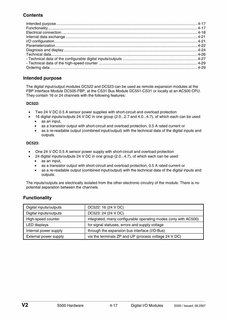
____________________________________________________________________________________________________________
V2 S500 Hardware 4-17 Digital I/O Modules S500 / Issued: 09.2007
Contents
Intended purpose...................................................................................................................................... 4-17 Functionality.............................................................................................................................................. 4-17 Electrical connection................................................................................................................................. 4-18 Internal data exchange ............................................................................................................................. 4-21 I/O configuration........................................................................................................................................ 4-21 Parameterization....................................................................................................................................... 4-22 Diagnosis and display............................................................................................................................... 4-24 Technical data........................................................................................................................................... 4-26 - Technical data of the configurable digital inputs/outputs ....................................................................... 4-27 - Technical data of the high-speed counter .............................................................................................. 4-29 Ordering data ............................................................................................................................................ 4-29
Intended purpose
The digital input/output modules DC522 and DC523 can be used as remote expansion modules at the FBP Interface Module DC505-FBP, at the CS31 Bus Module DC551-CS31 or locally at an AC500 CPU. They contain 16 or 24 channels with the following features:
DC522:
• Two 24 V DC 0.5 A sensor power supplies with short-circuit and overload protection • 16 digital inputs/outputs 24 V DC in one group (2.0...2.7 and 4.0...4.7), of which each can be used
• as an input, • as a transistor output with short-circuit and overload protection, 0.5 A rated current or • as a re-readable output (combined input/output) with the technical data of the digital inputs and
outputs.
DC523:
• One 24 V DC 0.5 A sensor power supply with short-circuit and overload protection • 24 digital inputs/outputs 24 V DC in one group (2.0...4.7), of which each can be used
• as an input, • as a transistor output with short-circuit and overload protection, 0.5 A rated current or • as a re-readable output (combined input/output) with the technical data of the digital inputs and
outputs.
The inputs/outputs are electrically isolated from the other electronic circuitry of the module. There is no potential separation between the channels.
Functionality
Digital inputs/outputs DC522: 16 (24 V DC)
Digital inputs/outputs DC523: 24 (24 V DC)
High-speed counter integrated, many configurable operating modes (only with AC500)
LED displays for signal statuses, errors and supply voltage
Internal power supply through the expansion bus interface (I/O-Bus)
External power supply via the terminals ZP and UP (process voltage 24 V DC)

____________________________________________________________________________________________________________
V2 S500 Hardware 4-18 Digital I/O Modules S500 / Issued: 09.2007
Electrical connection
The input/output modules are plugged on I/O Terminal Units TU515 or TU516. Properly seat the modules and press until they lock in place. The Terminal Units are mounted on a DIN rail or with 2 screws plus the additional accessory for wall mounting (TA526).
The electrical connection of the I/O channels is carried out using the 40 terminals of the I/O Terminal Unit. I/O modules can be replaced without re-wiring the Terminal Units.
Note: Mounting, disassembling and electrical connection for the Terminal Units and the I/O modules are described in detail in the S500 system data chapters.
The terminals 1.8 to 4.8 and 1.9 to 4.9 are electrically interconnected within the I/O Terminal Unit and have always the same assignment, independent of the inserted module:
Terminals 1.8 to 4.8: Process voltage UP = +24 V DC Terminals 1.9 to 4.9: Process voltage ZP = 0 V
The assignment of the other terminals:
DC522:
Terminals Signal Meaning
1.0 to 1.3 +24 V 4 x sensor power supply sources (loadable with 0.5 A in total)
1.4 to 1.7 0 V 0 V (reference potential)
2.0 to 2.7 C0 to C7 8 digital inputs/outputs
3.0 to 3.3 +24 V 4 x sensor power supply sources (loadable with 0.5 A in total)
3.4 to 3.7 0 V 0 V (reference potential)
4.0 to 4.7 C8 to C15 8 digital inputs/outputs
DC523:
Terminals Signal Meaning
1.0 to 1.3 +24 V 4 x sensor power supply sources (loadable with 0.5 A in total)
1.4 to 1.7 0 V 0 V (reference potential)
2.0 to 2.7 C0 to C7 8 digital inputs/outputs
3.0 to 3.7 C8 to C15 8 digital inputs/outputs
4.0 to 4.7 C16 to C23 8 digital inputs/outputs
The supply voltage 24 V DC for the module's electronic circuitry comes from the I/O-Bus of the FieldBusPlug or the CPU.
Caution: Removal of energized modules is not permitted. All power sources (supply and process voltages) must be switched off while working on any AC500 system.
The modules provide several diagnosis functions (see chapter "Diagnosis and display").

____________________________________________________________________________________________________________
V2 S500 Hardware 4-19 Digital I/O Modules S500 / Issued: 09.2007
The following figure shows the electrical connection of the digital input/output module DC522.
1.0
1.1
1.2
1.3
1.4
1.5
1.6
1.7
1.8
1.9
2.0
2.1
2.2
2.3
2.4
2.5
2.6
2.7
2.8
2.9
3.0
3.1
3.2
3.3
3.4
3.5
3.6
3.7
3.8
3.9
4.0
4.1
4.2
4.3
4.4
4.5
4.6
4.7
4.8
4.9
C0 2.0
C8 4.0
loads for 24 V DC
Sw
itch-
gear
cab
inet
ear
th
I/O-Bus in I/O-Bus out
Power supply
+24 V 0 V
C4 2.4
C7 2.7
C11 4.3
C15 4.7
Inputs or
0 V
24 V DC
DC522
1.024V
1.124V
1.224V
1.324V
1.4 0V
1.5 0V
1.6 0V
1.7 0V
1.8 UP
1.9 ZP
2.0 C0
2.1 C1
2.2 C2
2.3 C3
2.4 C4
2.5 C5
2.6 C6
2.7 C7
2.8 UP
2.9 ZP
3.0 24V
3.1 24V
3.2 24V
3.3 24V
3.4 0V
3.5 0V
3.6 0V
3.7 0V
3.8 UP
3.9 ZP
4.0 C8
4.1 C9
4.2 C10
4.3 C11
4.4 C12
4.5 C13
4.6 C14
4.7 C15
4.8 UP
4.9 ZP
CH-ERR3 CH-ERR4
16DCInput 24 V DC
Output 24 V DC 0.5A
CH-ERR2CH-ERR1
UP 24VDC 200W
C12 4.4
3-wiresensor
Outp.+24 V
0 V
3-wiresensor
Outp.+24 V
Two power supplies for sensors:1.0...1.3 = +24V, 1.4...1.7 = 0V,3.0...3.3 = +24V, 3.4...3.7 = 0V,loadability max. 0.5 A each
and 1.9 to 4.9 (ZP) are connected toeach other within the I/O Terminal Unit
Note: The terminals 1.8 to 4.8 (UP)
Attention:The process voltage must beincluded in the earthing conceptof the control system(e.g. earthing the minus pole).
Figure: Electrical connection of the digital input/output module DC522

____________________________________________________________________________________________________________
V2 S500 Hardware 4-20 Digital I/O Modules S500 / Issued: 09.2007
The following figure shows the electrical connection of the digital input/output module DC523.
1.0
1.1
1.2
1.3
1.4
1.5
1.6
1.7
1.8
1.9
2.0
2.1
2.2
2.3
2.4
2.5
2.6
2.7
2.8
2.9
3.0
3.1
3.2
3.3
3.4
3.5
3.6
3.7
3.8
3.9
4.0
4.1
4.2
4.3
4.4
4.5
4.6
4.7
4.8
4.9
C0 2.0
C16 4.0
loads for 24 V DC
Sw
itch-
gear
cab
inet
ear
th
I/O-Bus in I/O-Bus out
Power supply
+24 V 0 V
C4 2.4
C7 2.7
C19 4.3
C23 4.7
Inputs or
24 V DC
0 V
3-wiresensor
Outp.+24 V
Power supply for sensors:1.0...1.3 = +24V, 1.4...1.7 = 0V,
C8 3.0
C11 3.3
C15 3.7
loadability max. 0.5 A
DC523
1.024V
1.124V
1.224V
1.324V
1.4 0V
1.5 0V
1.6 0V
1.7 0V
1.8 UP
1.9 ZP
2.0 C0
2.1 C1
2.2 C2
2.3 C3
2.4 C4
2.5 C5
2.6 C6
2.7 C7
2.8 UP
2.9 ZP
3.0 C8
3.1 C9
3.2 C10
3.3 C11
3.4 C12
3.5 C13
3.6 C14
3.7 C15
3.8 UP
3.9 ZP
4.0 C16
4.1 C17
4.2 C18
4.3 C19
4.4 C20
4.5 C21
4.6 C22
4.7 C23
4.8 UP
4.9 ZP
CH-ERR3 CH-ERR4
24DCInput 24 V DC
Output 24 V DC 0.5A
CH-ERR2CH-ERR1
UP 24VDC 300W
and 1.9 to 4.9 (ZP) are connected toeach other within the I/O Terminal Unit
Note: The terminals 1.8 to 4.8 (UP)
Attention:The process voltage must beincluded in the earthing conceptof the control system(e.g. earthing the minus pole).
Figure: Electrical connection of the digital input/output module DC523

____________________________________________________________________________________________________________
V2 S500 Hardware 4-21 Digital I/O Modules S500 / Issued: 09.2007
Internal data exchange
DC522:
without the high-speed counter
with the high-speed counter (only with AC500)
Digital inputs (bytes) 2 4
Digital outputs (bytes) 2 4
Counter input data (words) 0 4
Counter output data (words) 0 8
DC523:
without the high-speed counter
with the high-speed counter (only with AC500)
Digital inputs (bytes) 3 5
Digital outputs (bytes) 3 5
Counter input data (words) 0 4
Counter output data (words) 0 8
I/O configuration
The modules DC522 and DC523 do not store configuration data themselves. The configurable channels are defined as inputs or outputs by the user program, i.e. each of the configurable channels can used as input or output (or re-readable output) by interrogation or allocation by the user program.

____________________________________________________________________________________________________________
V2 S500 Hardware 4-22 Digital I/O Modules S500 / Issued: 09.2007
Parameterization
The arrangement of the parameter data is performed by your master configuration software SYCON in connection with the S500 GSD files and in conjunction with the Control Builder software.
The parameter data directly influences the functionality of modules.
For non-standard applications, it is necessary to adapt the parameters to your system configuration.
Module DC522: Module slot address: Y = 1...7
Nr. Name Value Internal value
Internal value, type
Default Min. Max. EDS Slot/Index
1 Module ID Internal 1220 *1)
Word 1220 0x04c4
0 65535 0x0Y01
2 *2)
Ignore module No Yes
0 1
Byte No 0x00
not for FBP
3 Parameter length Internal 7 Byte 7-CPU 6-FBP
0 255 0x0Y02
4 Check supply Off on
0 1
Byte On 0x01
0 1 0x0Y03
5 Input delay 0.1 ms 1 ms 8 ms 32 ms
0 1 2 3
Byte 8 ms 0x02
0 3 0x0Y04
6 *4)
High-speed counter 0 : 10 *3)
0 : 10
Byte Mode 0 0x00
not for FBP
7 Short-circuit detection of output or sensor supply
Off On
0 1
Byte On 0x01
0 1 0x0Y05
8 Behaviour of outputs at communication errors
Off Last value Substitute value
0 1+(n*5) 2+(n*5), n <= 2
Byte Off 0x00
0 2 0x0Y06
9 Substitute value at outputs Bit 15 = Output 15 Bit 0 = Output 0
0... 65535
0... 0xffff
Word 0 0x0000
0 65535 0x0Y07
*1) With CS31 and addresses less than 70 and FBP, the value is increased by 1
*2) Not with FBP
*3) Counter operating modes, see description of the high-speed counter
*4) With FBP or CS31 without the parameter "High-speed counter"

____________________________________________________________________________________________________________
V2 S500 Hardware 4-23 Digital I/O Modules S500 / Issued: 09.2007
Module DC523: Module slot address: Y = 1...7
Nr. Name Value Internal value
Internal value, type
Default Min. Max. EDS Slot/Index
1 Module ID Internal 1215 *1)
Word 1215 0x04bf
0 65535 0x0Y01
2 *2)
Ignore module No Yes
0 1
Byte No 0x00
not for FBP
3 Parameter length Internal 9 Byte 9-CPU 8-FBP
0 255 0x0Y02
4 Check supply Off on
0 1
Byte On 0x01
0 1 0x=Y03
5 Input delay 0.1 ms 1 ms 8 ms 32 ms
0 1 2 3
Byte 8 ms 0x02
0 3 0x0Y04
6 *4)
High-speed counter 0 : 10 *3)
0 : 10
Byte Mode 0 0x00
not for FBP
7 Short-circuit detection of output or sensor supply
Off On
0 1
Byte On 0x01
0 1 0x0Y05
8 Behaviour of outputs at communication errors
Off Last value Substitute value
0 1+(n*5) 2+(n*5), n <= 2
Byte Off 0x00
0 2 0x0Y06
9 Substitute value at outputs B23 = Output 23 Bit 0 = Output 0
0... 16777215
0... 0x00ff-ffff
DWord 0 0x0000 -0000
0 224−1 0x0Y07
*1) With CS31 and addresses less than 70 and FBP, the value is increased by 1
*2) Not with FBP
*3) Counter operating modes, see description of the high-speed counter
*4) With FBP or CS31 without the parameter "High-speed counter"
Attention: The high-speed counter of the module can only be used together with the AC500 CPU. The counter does not work, if the module is attached to an FBP Interface Module or to a CS31 Bus Module.
GSD file:
DC522: Ext_User_Prm_Data_Len = Ext_User_Prm_Data_Const(0) =
9 0x04, 0xc5, 0x06, \ 0x01, 0x02, 0x01, 0x00, 0x00, 0x00;
DC523:
Ext_User_Prm_Data_Len = Ext_User_Prm_Data_Const(0) =
11 0x04, 0xc0, 0x08, \ 0x01, 0x02, 0x01, 0x00, 0x00, 0x00, 0x00, 0x00;

____________________________________________________________________________________________________________
V2 S500 Hardware 4-24 Digital I/O Modules S500 / Issued: 09.2007
Diagnosis and display
In case of overload or short-circuit, the outputs switch off automatically and try to switch on again cyclically. Therefore an acknowledgement of the outputs is not necessary. The LED error message, however, is stored.
Diagnosis:
E1..E4 d1 d2 d3 d4 Identifier000..063
AC500 display
Class Comp Dev Mod Ch Err PS501 PLC browser
Byte 6 Bit 6..7
- Byte 3
Byte 4
Byte 5
Byte 6 Bit 0..5
FBP diagnosis block <− Display in
Class Inter- face
De- vice
Mod- ule
Chan-nel
Error identifier
Error message Remedy
1) 2) 3) 4)
Module error DC522 and DC523
14 1..7 31 3
11 / 12 ADR 1..7 31 19 Checksum error in the I/O
module Replace I/O module
14 1..7 31 3
11 / 12 ADR 1..7 31 3 Timeout in the I/O module Replace I/O
module
14 1..7 31 3
11 / 12 ADR 1..7 31 40 Different hard-/firmware
versions in the module Replace I/O module
14 1..7 31 3
11 / 12 ADR 1..7 31 43 Internal error in the
module Replace I/O module
14 1..7 31 3
11 / 12 ADR 1..7 31 36 Internal data exchange
failure Replace I/O module
14 1..7 31 3
11 / 12 ADR 1..7 31 9 Overflow diagnosis buffer New start
14 1..7 31 3
11 / 12 ADR 1..7 31 26 Parameter error Check
master
14 1..7 31 3 11 / 12 ADR 1..7 31 11 Process voltage too low
Check process voltage
14 1..7 31 4
11 / 12 ADR 1..7 31 45 Process voltage is
switched off (ON −> OFF) Process voltage ON
Channel error DC522
14 1..7 2 4
11 / 12 ADR 1..7 0..15 47 Short-circuit at an output Check
connection
Channel error DC523
14 1..7 2 4
11 / 12 ADR 1..7 0..23 47 Short-circuit at an output Check
connection
Remarks:
1) In AC500 the following interface identifier applies: 14 = I/O-Bus, 11 = COM1 (e.g. CS31 bus), 12 = COM2. The FBP diagnosis block does not contain this identifier.
2) With "Device" the following allocation applies: 31 = Module itself, 1..7 = Expansion module 1..7, ADR = Hardware address (e.g. of the DC551)
3) With "Module" the following allocation applies dependent of the master: Module error: I/O-Bus or FBP: 31 = Module itself; COM1/COM2: 1..7 = Expansion 1..7 Channel error: I/O-Bus or FBP = Module type (2 = DO); COM1/COM2: 1..7 = Expansion 1..7
4) In case of module errors, with channel "31 = Module itself" is output.

____________________________________________________________________________________________________________
V2 S500 Hardware 4-25 Digital I/O Modules S500 / Issued: 09.2007
Displays:
During the power ON procedure, the module initializes automatically. All LEDs (accept the channel LEDs) are ON during this time.
Status of the LEDs (see also section "Diagnosis LEDs" in the S500 system data)
LED Status Color LED = OFF LED = ON LED flashes
Inputs/ outputs DC522: 00...15 DC523: 00...23
digital input or digital output
yellow Input/output = OFF Input/output = ON (the input voltage is even displayed if the supply voltage is OFF).
--
UP Process supply voltage 24 V DC via terminal
green Process supply voltage is missing
Process supply voltage OK and initialization terminated
Module is not initialized correctly
CH-ERR1 red
CH-ERR2 red
CH-ERR3 red
CH-ERR4
Channel Error, error messages in groups (digital inputs/outputs combined into the groups 1, 2, 3, 4)
red
No error or process supply voltage is missing
Serious error within the corresponding group
Error on one channel of the corresponding group (e.g. short-circuit at an output)
CH-ERR *)
Module Error red -- Internal error --
*) All of the LEDs CH-ERR1 to CH-ERR4 light up together

____________________________________________________________________________________________________________
V2 S500 Hardware 4-26 Digital I/O Modules S500 / Issued: 09.2007
Technical data
The system data of AC500 and S500 are valid here. Only additional details are therefore documented below.
Process supply voltage UP
- Connections Terminals 1.8 - 4.8 for +24 V (UP) and 1.9 - 4.9 for 0 V (ZP)
- Rated value 24 V DC
- max. ripple 5 %
- Protection against reversed voltage
yes
- Rated protection fuse on UP 10 A fast
- Electrical isolation yes, per module
Current consumption
- internal (via I/O-Bus) ca. 5 mA at 3.3 V DC
- current consumption from UP at normal operation / with outputs
0.05 A + max. 0.008 A per input + max. 0.5 A per output
- inrush current from UP (at power up)
0.008 A²s
Max. power dissipation within the module
6 W (outputs unloaded)
Sensor power supply
- Connections DC522 terminals 1.0...1.3 = +24 V, 1.4...1.7 = 0 V terminals 3.0...3.3 = +24 V, 3.4...3.7 = 0 V
- Connections DC523 terminals 1.0...1.3 = +24 V, 1.4...1.7 = 0 V
- Voltage 24 V DC with short-circuit and overload protection
- Loadability terminals 1.0...1.3, in total max. 0.5 A terminals 3.0...3.3, in total max. 0.5 A (only DC522)
Weight (without Terminal Unit)
ca. 125 g
Mounting position horizontal or vertical with derating (output load reduced to 50 % at 40°C per group)
Cooling The natural convection cooling must not be hindered by cable ducts or other parts in the switch-gear cabinet.
Attention: All I/O channels (digital and analog) are protected against reverse polarity, reverse supply, short circuit and continuous overvoltage up to 30 V DC.

____________________________________________________________________________________________________________
V2 S500 Hardware 4-27 Digital I/O Modules S500 / Issued: 09.2007
Technical data of the configurable digital inputs/outputs
Each of the configurable I/O channels is defined as input or output by the user program. This is done by interrogating or allocating the corresponding channel.
Number of channels per module DC522: 16 inputs/outputs (with transistors) DC523: 24 inputs/outputs (with transistors)
Distribution of the channels into groups DC522: 1 group of 16 channels DC523: 1 group of 24 channels
if the channels are used as inputs
- channels C0...C7 DC522: terminals 2.0...2.7 DC523: terminals 2.0...2.7
- channels C8...C15 DC522: terminals 4.0...4.7 DC523: terminals 3.0...3.7
- channels C16...C23 DC523: terminals 4.0...4.7
if the channels are used as outputs
- channels C0...C7 DC522: terminals 2.0...2.7 DC523: terminals 2.0...2.7
- channels C8 C15 DC522: terminals 4.0...4.7 DC523: terminals 3.0...3.7
- channels C16...C23 DC523: terminals 4.0...4.7
Indication of the input/output signals one yellow LED per channel, the LED is ON when the input/output signal is high (signal 1)
Electrical isolation from the rest of the module
Technical data of the digital inputs/outputs if used as inputs
Number of channels per module DC522: max. 16 digital inputs DC523: max. 24 digital inputs
Reference potential for all inputs terminals 1.9...4.9 (minus pole of the process supply voltage, signal name ZP)
Electrical isolation from the rest of the module
Indication of the input signals one yellow LED per channel, the LED is ON when the input signal is high (signal 1)
Input type acc. to EN 61131-2 Type 1
Input delay (0->1 or 1->0) typ. 8 ms, configurable from 0.1 to 32 ms
Input signal voltage 24 V DC
- signal 0 -3 V...+5 V *
- undefined signal > +5 V...< +15 V
- signal 1 +15 V...+30 V
Ripple with signal 0 within -3 V...+5 V *
Ripple with signal 1 within +15 V...+30 V
Input current per channel
- input voltage +24 V typ. 5 mA
- input voltage +5 V > 1 mA
- input voltage +15 V > 5 mA
- input voltage +30 V < 8 mA
Max. cable length
shielded 1000 m
unshielded 600 m
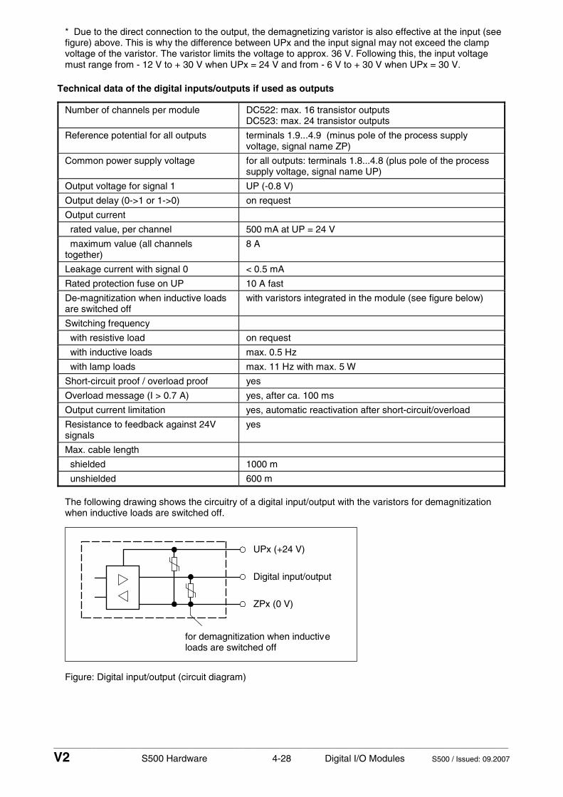
____________________________________________________________________________________________________________
V2 S500 Hardware 4-28 Digital I/O Modules S500 / Issued: 09.2007
* Due to the direct connection to the output, the demagnetizing varistor is also effective at the input (see figure) above. This is why the difference between UPx and the input signal may not exceed the clamp voltage of the varistor. The varistor limits the voltage to approx. 36 V. Following this, the input voltage must range from - 12 V to + 30 V when UPx = 24 V and from - 6 V to + 30 V when UPx = 30 V.
Technical data of the digital inputs/outputs if used as outputs
Number of channels per module DC522: max. 16 transistor outputs DC523: max. 24 transistor outputs
Reference potential for all outputs terminals 1.9...4.9 (minus pole of the process supply voltage, signal name ZP)
Common power supply voltage for all outputs: terminals 1.8...4.8 (plus pole of the process supply voltage, signal name UP)
Output voltage for signal 1 UP (-0.8 V)
Output delay (0->1 or 1->0) on request
Output current
rated value, per channel 500 mA at UP = 24 V
maximum value (all channels together)
8 A
Leakage current with signal 0 < 0.5 mA
Rated protection fuse on UP 10 A fast
De-magnitization when inductive loads are switched off
with varistors integrated in the module (see figure below)
Switching frequency
with resistive load on request
with inductive loads max. 0.5 Hz
with lamp loads max. 11 Hz with max. 5 W
Short-circuit proof / overload proof yes
Overload message (I > 0.7 A) yes, after ca. 100 ms
Output current limitation yes, automatic reactivation after short-circuit/overload
Resistance to feedback against 24V signals
yes
Max. cable length
shielded 1000 m
unshielded 600 m
The following drawing shows the circuitry of a digital input/output with the varistors for demagnitization when inductive loads are switched off.
UPx (+24 V)
Digital input/output
ZPx (0 V)
for demagnitization when inductiveloads are switched off
Figure: Digital input/output (circuit diagram)

____________________________________________________________________________________________________________
V2 S500 Hardware 4-29 Digital I/O Modules S500 / Issued: 09.2007
Technical data of the high-speed counter
Attention: The high-speed counter of the module can only be used together with the AC500 CPU. The counter does not work, if the module is attached to an FBP Interface Module or a CS31 Bus Module.
Used inputs DC522: C8 / C9 DC523: C16 / C17
Used outputs DC522: C10 DC523: C18
Counting frequency max. 50 kHz
Detailed description see chapter "High-speed counter"
Operating modes see chapter "High-speed counter, Operating modes"
Ordering data
Order No. Scope of delivery
1SAP 240 600 R0001 DC522, Digital input/output module, 16 DC, 24 V DC / 0.5 A, 2-wire
1SAP 240 500 R0001 DC523, Digital input/output module, 24 DC, 24 V DC / 0.5 A, 1-wire
1SAP 212 200 R0001 TU515, I/O Terminal Unit, 24 V DC, screw-type terminals
1SAP 212 000 R0001 TU516, I/O Terminal Unit, 24 V DC, spring terminals

____________________________________________________________________________________________________________
V2 S500 Hardware 4-30 Digital I/O Modules S500 / Issued: 09.2007
Digital Input/Output Module DC532 - 16 digital inputs 24 V DC, 16 configurable digital inputs/outputs - module-wise electrically isolated
1.0
1.1
1.2
1.3
1.4
1.5
1.6
1.7
1.8
1.9
2.0
2.1
2.2
2.3
2.4
2.5
2.6
2.7
2.8
2.9
3.0
3.1
3.2
3.3
3.4
3.5
3.6
3.7
3.8
3.9
4.0
4.1
4.2
4.3
4.4
4.5
4.6
4.7
4.8
4.9
Elements of the digitalinput/output module DC532
1 I/O-Bus
2 Allocation between terminal No. andsignal name
3 16 yellow LEDs to display the signalstatuses at the inputs I0 to I15
4 16 yellow LEDs to display the signalstatuses at the inputs/outputsC16 to C31
5 1 green LED to display the processvoltage UP
6 4 red LEDs to display errors(CH-ERR1...CH-ERR4)
7 DIN rail
8 Label
9 I/O Terminal Unit (TU515 or TU516)with 40 terminals (screw-type orspring terminals)
DC532
1.0 I0
1.1 I1
1.2 I2
1.3 I3
1.4 I4
1.5 I5
1.6 I6
1.7 I7
1.8 UP
1.9 ZP
2.0 I8
2.1 I9
2.2 I10
2.3 I11
2.4 I12
2.5 I13
2.6 I14
2.7 I15
2.8 UP
2.9 ZP
3.0 C16
3.1 C17
3.2 C18
3.3 C19
3.4 C20
3.5 C21
3.6 C22
3.7 C23
3.8 UP
3.9 ZP
4.0 C24
4.1 C25
4.2 C26
4.3 C27
4.4 C28
4.5 C29
4.6 C30
4.7 C31
4.8 UP
4.9 ZP
CH-ERR3 CH-ERR4
16 DI 16 DCInput 24 V DC
Output 24 V DC 0.5A
CH-ERR2CH-ERR1
UP 24VDC 200W
9
7
1
2
56
8
3 4
Figure: Digital input/output module DC532, plugged on a Terminal Unit TU516
Contents
Intended purpose...................................................................................................................................... 4-31 Functionality.............................................................................................................................................. 4-31 Electrical connection................................................................................................................................. 4-31 Internal data exchange ............................................................................................................................. 4-32 I/O configuration........................................................................................................................................ 4-33 Parameterization....................................................................................................................................... 4-33 Diagnosis and display............................................................................................................................... 4-34 Technical data........................................................................................................................................... 4-36 - Technical data of the digital inputs ......................................................................................................... 4-37 - Technical data of the configurable digital inputs/outputs ....................................................................... 4-37 - Technical data of the high-speed counter .............................................................................................. 4-39 Ordering data ............................................................................................................................................ 4-39

____________________________________________________________________________________________________________
V2 S500 Hardware 4-31 Digital I/O Modules S500 / Issued: 09.2007
Intended purpose
The digital input/output module DC532 can be used as a remote expansion module at the FBP Interface Module DC505-FBP, at the CS31 Bus Module DC551-CS31 or locally at an AC500 CPU. It contains 32 channels with the following features:
• 16 digital inputs 24 V DC in two groups (1.0...2.7), with no potential separation between the channels • and 16 digital inputs/outputs 24 V DC in two groups (3.0...4.7), of which each can be used
• as an input, • as a transistor output with short-circuit and overload protection, 0.5 A rated current or • as a re-readable output (combined input/output) with the technical data of the digital inputs and
outputs.
The inputs/outputs are electrically isolated from the other electronic circuitry of the module. There is no potential separation between the channels.
Functionality
Digital inputs 16 (24 V DC)
Digital inputs/outputs 16 (24 V DC)
High-speed counter integrated, many configurable operating modes (only with AC500)
LED displays for signal statuses, errors and supply voltage
Internal power supply through the expansion bus interface (I/O-Bus)
External power supply via the terminals ZP and UP (process voltage 24 V DC)
Electrical connection
The input/output module is plugged on the I/O Terminal Unit TU515 or TU516. Properly seat the module and press until it locks in place. The Terminal Unit is mounted on a DIN rail or with 2 screws plus the additional accessory for wall mounting (TA526).
The electrical connection of the I/O channels is carried out using the 40 terminals of the I/O Terminal Unit. I/O modules can be replaced without re-wiring the Terminal Units.
Note: Mounting, disassembling and electrical connection for the Terminal Units and the I/O modules are described in detail in the S500 system data chapters.
The terminals 1.8 to 4.8 and 1.9 to 4.9 are electrically interconnected within the I/O Terminal Unit and have always the same assignment, independent of the inserted module:
Terminals 1.8 to 4.8: Process voltage UP = +24 V DC Terminals 1.9 to 4.9: Process voltage ZP = 0 V
The assignment of the other terminals:
Terminals Signal Meaning
1.0 to 1.7 I0 to I7 8 digital inputs
2.0 to 2.7 I8 to I15 8 digital inputs
3.0 to 3.7 C16 to C23 8 digital inputs/outputs
4.0 to 4.7 C24 to C31 8 digital inputs/outputs
The supply voltage 24 V DC for the module's electronic circuitry comes from the I/O-Bus of the FieldBusPlug or the CPU.
Caution: Removal of energized modules is not permitted. All power sources (supply and process voltages) must be switched off while working on any AC500 system.
The module provides several diagnosis functions (see chapter "Diagnosis and display").

____________________________________________________________________________________________________________
V2 S500 Hardware 4-32 Digital I/O Modules S500 / Issued: 09.2007
The following figure shows the electrical connection of the digital input/output module DC532.
1.0
1.1
1.2
1.3
1.4
1.5
1.6
1.7
1.8
1.9
2.0
2.1
2.2
2.3
2.4
2.5
2.6
2.7
2.8
2.9
3.0
3.1
3.2
3.3
3.4
3.5
3.6
3.7
3.8
3.9
4.0
4.1
4.2
4.3
4.4
4.5
4.6
4.7
4.8
4.9
I0 1.0
I7 1.7
C24 4.0
loads for 24 V DC
I/O-Bus in I/O-Bus out
Power supply
+24 V 0 V
I8 2.0
I15 2.7
C27 4.3
C31 4.7
Inputs or
C16 3.0
C19 3.3
C23 3.7
24 V DC
and 1.9 to 4.9 (ZP) are connected toeach other within the I/O Terminal Unit
Note: The terminals 1.8 to 4.8 (UP) Attention:The process voltage must beincluded in the earthing conceptof the control system(e.g. earthing the minus pole).
Sw
itch-
gear
cab
inet
ear
th
DC532
1.0 I0
1.1 I1
1.2 I2
1.3 I3
1.4 I4
1.5 I5
1.6 I6
1.7 I7
1.8 UP
1.9 ZP
2.0 I8
2.1 I9
2.2 I10
2.3 I11
2.4 I12
2.5 I13
2.6 I14
2.7 I15
2.8 UP
2.9 ZP
3.0 C16
3.1 C17
3.2 C18
3.3 C19
3.4 C20
3.5 C21
3.6 C22
3.7 C23
3.8 UP
3.9 ZP
4.0 C24
4.1 C25
4.2 C26
4.3 C27
4.4 C28
4.5 C29
4.6 C30
4.7 C31
4.8 UP
4.9 ZP
CH-ERR3 CH-ERR4
16 DI 16 DCInput 24 V DC
Output 24 V DC 0.5A
CH-ERR2CH-ERR1
UP 24VDC 200W
Figure: Electrical connection of the digital input/output module DC532
Internal data exchange
without the high-speed counter
with the high-speed counter (only with AC500)
Digital inputs (bytes) 4 6
Digital outputs (bytes) 2 4
Counter input data (words) 0 4
Counter output data (words) 0 8

____________________________________________________________________________________________________________
V2 S500 Hardware 4-33 Digital I/O Modules S500 / Issued: 09.2007
I/O configuration
The DC532 module does not store configuration data itself. The 16 configurable channels are defined as inputs or outputs by the user program, i.e. each of the configurable channels can used as input or output (or re-readable output) by interrogation or allocation by the user program.
Parameterization
The arrangement of the parameter data is performed by your master configuration software SYCON in connection with the S500 GSD files and in conjunction with the Control Builder software.
The parameter data directly influences the functionality of modules.
For non-standard applications, it is necessary to adapt the parameters to your system configuration.
Module: Module slot address: Y = 1...7
Nr. Name Value Internal value
Internal value, type
Default Min. Max. Max.
1 Module ID Internal 1200 *1)
Word 1200 0x04b0
0 65535 0x0Y01
2 *2)
Ignore module No Yes
0 1
Byte No 0x00
not for FBP
3 Parameter length Internal 7 Byte 7-CPU 6-FBP
0 255 0x0Y02
4 Check supply Off on
0 1
Byte On 0x01
0 1 0x0Y03
5 Input delay 0.1 ms 1 ms 8 ms 32 ms
0 1 2 3
Byte 8 ms 0x02
0 3 0x0Y04
6 *4)
High-speed counter 0 : 10 *3)
0 : 10
Byte Mode 0 0x00
not for FBP
7 Output short-circuit detection
Off On
0 1
Byte On 0x01
0 1 0x0Y05
8 Behaviour of outputs at communication errors
Off Last value Substitute value
0 1+(n*5) 2+(n*5), n <= 2
Byte Off 0x00
0 2 0x0Y06
9 Substitute value at outputs Bit 15 = Output 15 Bit 0 = Output 0
0... 65535
0... 0xffff
Word 0 0x0000
0 65535 0x0Y07
*1) With CS31 and addresses less than 70 and FBP, the value is increased by 1
*2) Not with FBP
*3) Counter operating modes, see description of the high-speed counter
*4) With FBP or CS31 without the parameter "High-speed counter"
Attention: The high-speed counter of the module can only be used together with the AC500 CPU. The counter does not work, if the module is attached to an FBP Interface Module or to a CS31 Bus Module.
GSD file: Ext_User_Prm_Data_Len = Ext_User_Prm_Data_Const(0) =
9 0x04, 0xb1, 0x06, \ 0x01, 0x02, 0x01, 0x00, 0x00, 0x00;

____________________________________________________________________________________________________________
V2 S500 Hardware 4-34 Digital I/O Modules S500 / Issued: 09.2007
Diagnosis and display
In case of overload or short-circuit, the outputs switch off automatically and try to switch on again cyclically. Therefore an acknowledgement of the outputs is not necessary. The LED error message, however, is stored.
Diagnosis:
E1..E4 d1 d2 d3 d4 Identifier000..063
AC500 display
Class Comp Dev Mod Ch Err PS501 PLC browser
Byte 6 Bit 6..7
- Byte 3
Byte 4
Byte 5 Byte 6 Bit 0..5
FBP diagnosis block <− Display in
Class Inter- face
De- vice
Mod- ule
Chan-nel
Error- Identifier
Error message Remedy
1) 2) 3) 4)
Module error DC532
14 1..7 31 3
11 / 12 ADR 1..7 31 19 Checksum error in the I/O
module Replace I/O module
14 1..7 31 3
11 / 12 ADR 1..7 31 3 Timeout in the I/O module Replace I/O
module
14 1..7 31 3
11 / 12 ADR 1..7 31 40 Different hard-/firmware
versions in the module Replace I/O module
14 1..7 31 3
11 / 12 ADR 1..7 31 43 Internal error in the
module Replace I/O module
14 1..7 31 3
11 / 12 ADR 1..7 31 36 Internal data exchange
failure Replace I/O module
14 1..7 31 3
11 / 12 ADR 1..7 31 9 Overflow diagnosis buffer New start
14 1..7 31 3
11 / 12 ADR 1..7 31 26 Parameter error Check
master
14 1..7 31 3 11 / 12 ADR 1..7 31 11 Process voltage too low
Check process voltage
14 1..7 31 4
11 / 12 ADR 1..7 31 45 Process voltage is
switched off (ON −> OFF) Process voltage ON
Channel error DC532
14 1..7 2 4
11 / 12 ADR 1..7 16..31 47 Short-circuit at a digital
output Check connection
Remarks:
1) In AC500 the following interface identifier applies: 14 = I/O-Bus, 11 = COM1 (e.g. CS31 bus), 12 = COM2. The FBP diagnosis block does not contain this identifier.
2) With "Device" the following allocation applies: 31 = Module itself, 1..7 = Expansion module 1..7, ADR = Hardware address (e.g. of the DC551)
3) With "Module" the following allocation applies dependent of the master: Module error: I/O-Bus or FBP: 31 = Module itself; COM1/COM2: 1..7 = Expansion 1..7 Channel error: I/O-Bus or FBP = Module type (2 = DO); COM1/COM2: 1..7 = Expansion 1..7
4) In case of module errors, with channel "31 = Module itself" is output.

____________________________________________________________________________________________________________
V2 S500 Hardware 4-35 Digital I/O Modules S500 / Issued: 09.2007
Displays:
During the power ON procedure, the module initializes automatically. All LEDs (accept the channel LEDs) are ON during this time.
Status of the LEDs (see also section "Diagnosis LEDs" in the S500 system data)
LED Status Color LED = OFF LED = ON LED flashes
Inputs 00...15
digital input yellow Input = OFF Input = ON (the input voltage is even displayed if the supply voltage is OFF).
--
Inputs/ outputs 16...31
digital input/output
yellow Input/output = OFF Input/output = ON (the input voltage is even displayed if the supply voltage is OFF).
--
UP Process supply voltage 24 V DC via terminal
green Process supply voltage is missing
Process supply voltage OK and initialization terminated
Module is not initialized correctly
CH-ERR1 red
CH-ERR2 red
CH-ERR3 red
CH-ERR4
Channel Error, error messages in groups (digital inputs/outputs combined into the groups 1, 2, 3, 4)
red
No error or process supply voltage is missing
Serious error within the corresponding group
Error on one channel of the corresponding group (e.g. short-circuit at an output)
CH-ERR *)
Module Error red -- Internal error --
*) All of the LEDs CH-ERR1 to CH-ERR4 light up together

____________________________________________________________________________________________________________
V2 S500 Hardware 4-36 Digital I/O Modules S500 / Issued: 09.2007
Technical data
The system data of AC500 and S500 are valid here. Only additional details are therefore documented below.
Process supply voltage UP
- Connections Terminals 1.8 - 4.8 for +24 V (UP) and 1.9 - 4.9 for 0 V (ZP)
- Rated value 24 V DC
- max. ripple 5 %
- Protection against reversed voltage
yes
- Rated protection fuse on UP 10 A fast
- Electrical isolation yes, per module
Current consumption
- internal (via I/O-Bus) ca. 5 mA at 3.3 V DC
- current consumption from UP at normal operation / with outputs
0.05 A + max. 0.008 A per input + max. 0.5 A per output
- inrush current from UP (at power up)
0.007 A²s
Max. power dissipation within the module
6 W (outputs unloaded)
Weight (without Terminal Unit)
ca. 125 g
Mounting position horizontal or vertical with derating (output load reduced to 50 % at 40°C per group)
Cooling The natural convection cooling must not be hindered by cable ducts or other parts in the switch-gear cabinet.
Attention: All I/O channels (digital and analog) are protected against reverse polarity, reverse supply, short circuit and continuous overvoltage up to 30 V DC.

____________________________________________________________________________________________________________
V2 S500 Hardware 4-37 Digital I/O Modules S500 / Issued: 09.2007
Technical data of the digital inputs
Number of channels per module 16
Distribution of the channels into groups 1 group of 16 channels
Terminals of the channels I0 to I7 1.0 to 1.7
Terminals of the channels I8 to I15 2.0 to 2.7
Reference potential for all inputs terminals 1.9...4.9 (minus pole of the process supply voltage, signal name ZP)
Electrical isolation from the rest of the module (I/O-Bus)
Indication of the input signals one yellow LED per channel, the LED is ON when the input signal is high (signal 1)
Input type acc. to EN 61131-2 Type 1
Input delay (0->1 or 1->0) typ. 8 ms, configurable from 0.1 to 32 ms
Input signal voltage 24 V DC
signal 0 -3 V...+5 V
undefined signal > +5 V...< +15 V
signal 1 +15 V...+30 V
Ripple with signal 0 within -3 V...+5 V
Ripple with signal 1 within +15 V...+30 V
Input current per channel
input voltage +24 V typ. 5 mA
input voltage +5 V > 1 mA
input voltage +15 V > 5 mA
input voltage +30 V < 8 mA
Max. cable length
shielded 1000 m
unshielded 600 m
Technical data of the configurable digital inputs/outputs
Each of the configurable I/O channels is defined as input or output by the user program. This is done by interrogating or allocating the corresponding channel.
Number of channels per module 16 inputs/outputs (with transistors)
Distribution of the channels into groups 1 group of 16 channels
if the channels are used as inputs
- channels I16...I23 terminals 3.0...3.7
- channels I24...I31 terminals 4.0...4.7
if the channels are used as outputs
- channels Q16...Q23 terminals 3.0...3.7
- channels Q24...Q31 terminals 4.0...4.7
Indication of the input/output signals one yellow LED per channel, the LED is ON when the input/output signal is high (signal 1)
Electrical isolation from the rest of the module

____________________________________________________________________________________________________________
V2 S500 Hardware 4-38 Digital I/O Modules S500 / Issued: 09.2007
Technical data of the digital inputs/outputs if used as outputs
Number of channels per module max. 16 transistor outputs
Reference potential for all outputs terminals 1.9...4.9 (minus pole of the process supply voltage, signal name ZP)
Common power supply voltage for all outputs: terminals 1.8...4.8 (plus pole of the process supply voltage, signal name UP)
Output voltage for signal 1 UP (-0.8 V)
Output delay (0->1 or 1->0) on request
Output current
rated value, per channel 500 mA at UP = 24 V
maximum value (all channels together)
8 A
Leakage current with signal 0 < 0.5 mA
Rated protection fuse on UP 10 A fast
De-magnitization when inductive loads are switched off
with varistors integrated in the module (see figure below)
Switching frequency
with resistive load on request
with inductive loads max. 0.5 Hz
with lamp loads max. 11 Hz with max. 5 W
Short-circuit proof / overload proof yes
Overload message (I > 0.7 A) yes, after ca. 100 ms
Output current limitation yes, automatic reactivation after short-circuit/overload
Resistance to feedback against 24V signals
yes
Max. cable length
shielded 1000 m
unshielded 600 m
The following drawing shows the circuitry of a digital input/output with the varistors for demagnitization when inductive loads are switched off.
UPx (+24 V)
Digital input/output
ZPx (0 V)
for demagnitization when inductiveloads are switched off
Figure: Digital input/output (circuit diagram)

____________________________________________________________________________________________________________
V2 S500 Hardware 4-39 Digital I/O Modules S500 / Issued: 09.2007
Technical data of the digital inputs/outputs if used as inputs
Number of channels per module max. 16 digital inputs
Reference potential for all inputs terminals 1.9...4.9 (minus pole of the process supply voltage, signal name ZP)
Input current, per channel see "Digital inputs"
Input type acc. to EN 61131-2 Type 1
Input delay (0->1 or 1->0) typ. 8 ms, configurable from 0.1 to 32 ms
Input signal voltage 24 V DC
Signal 0 -3 V...+5 V *
undefined signal > +5 V...< +15 V
Signal 1 +15 V...+30 V
Ripple with signal 0 within -3 V...+5 V *
Ripple with signal 1 within +15 V...+30 V
Max. cable length
shielded 1000 m
unshielded 600 m
* Due to the direct connection to the output, the demagnetizing varistor is also effective at the input (see figure) above. This is why the difference between UPx and the input signal may not exceed the clamp voltage of the varistor. The varistor limits the voltage to approx. 36 V. Following this, the input voltage must range from - 12 V to + 30 V when UPx = 24 V and from - 6 V to + 30 V when UPx = 30 V.
Technical data of the high-speed counter
Attention: The high-speed counter of the module can only be used together with the AC500 CPU. The counter does not work, if the module is attached to an FBP Interface Module or a CS31 Bus Module.
Used inputs C25 / C26
Used outputs C27
Counting frequency max. 50 kHz
Detailed description see chapter "High-speed counter"
Operating modes see chapter "High-speed counter, Operating modes"
Ordering data
Order No. Scope of delivery
1SAP 240 100 R0001 DC532, Digital input/output module, 16 DI / 16 DC, 24 V DC / 0.5 A, 1-wire
1SAP 212 200 R0001 TU515, I/O Terminal Unit, 24 V DC, screw-type terminals
1SAP 212 000 R0001 TU516, I/O Terminal Unit, 24 V DC, spring terminals

____________________________________________________________________________________________________________
V2 S500 Hardware 4-40 Digital I/O Modules S500 / Issued: 09.2007
Digital Input/Output Module DX522 - 8 digital inputs 24 V DC, module-wise electrically isolated - 8 relay outputs
1.0
1.1
1.2
1.3
1.4
1.5
1.6
1.7
1.8
1.9
2.0
2.1
2.2
2.3
2.4
2.5
2.6
2.7
2.8
2.9
3.0
3.1
3.2
3.3
3.4
3.5
3.6
3.7
3.8
3.9
4.0
4.1
4.2
4.3
4.4
4.5
4.6
4.7
4.8
4.9
Elements of the digitalinput/output module DX522
1 I/O-Bus
2 Allocation between terminal No. andsignal name
3 8 yellow LEDs to display the signalstatuses at the inputs I0 to I7
4 8 yellow LEDs to display the signalstatuses at the relay outputsR0 to R7
5 1 green LED to display the processvoltage UP
6 2 red LEDs to display errors(CH-ERR1...CH-ERR2)
7 DIN rail
8 Label
9 I/O Terminal Unit (TU531 or TU532)with 40 terminals (screw-type orspring terminals)
DX522
8 DI 8 DO-R
1.0 I0
1.1 I1
1.2 I2
1.3 I3
1.4 I4
1.5 I5
1.6 I6
1.7 I7
1.8 UP
1.9 ZP
2.0 R0
2.1 R1
2.2 R2
2.3 R3
2.4 R4
2.5 R5
2.6 R6
2.7 R7
2.8 UP
2.9 ZP
3.0NO0
3.1NO1
3.2NO2
3.3NO3
3.4NO4
3.5NO5
3.6NO6
3.7NO7
3.8 UP
3.9 ZP
4.0NC0
4.1NC1
4.2NC2
4.3NC3
4.4NC4
4.5NC5
4.6NC6
4.7NC7
4.8 UP
4.9 ZP
Input 24 V DCRelay 230 V 3 A
CH-ERR2CH-ERR1
UP 24VDC 2W
9
7
1
2
56
8
3 4
Figure: Digital input/output module DX522, plugged on a Terminal Unit TU532
Contents
Intended purpose...................................................................................................................................... 4-41 Functionality.............................................................................................................................................. 4-41 Electrical connection................................................................................................................................. 4-41 Internal data exchange ............................................................................................................................. 4-43 I/O configuration........................................................................................................................................ 4-43 Parameterization....................................................................................................................................... 4-44 Diagnosis and display............................................................................................................................... 4-45 Technical data........................................................................................................................................... 4-47 Technical data of the digital inputs ........................................................................................................... 4-48 Technical data of the relay outputs........................................................................................................... 4-49 Technical data of the high-speed counter ................................................................................................ 4-50 Ordering data ............................................................................................................................................ 4-50

____________________________________________________________________________________________________________
V2 S500 Hardware 4-41 Digital I/O Modules S500 / Issued: 09.2007
Intended purpose
The digital input/output module DX522 can be used as a remote expansion module at the FBP Interface Module DC505-FBP, at the CS31 Bus Module DC551-CS31 or locally at an AC500 CPU. It contains 16 channels with the following features:
• 8 digital inputs 24 V DC in one group (1.0...1.7), with no potential separation between the channels • 8 digital relay outputs with one switch-over contact each, channels are electrically isolated from each
other
The inputs/outputs are electrically isolated from the other electronic circuitry of the module. There is no potential separation between the input channels.
Functionality
Digital inputs 8 (24 V DC)
Digital outputs 8 relay outputs with one switch-over contact each
High-speed counter integrated, many configurable operating modes (only with AC500)
LED displays for signal statuses, errors and supply voltage
Internal power supply through the expansion bus interface (I/O-Bus)
External power supply via the terminals ZP and UP (process voltage 24 V DC)
Electrical connection
The input/output module is plugged on the I/O Terminal Unit TU531 or TU532. Properly seat the module and press until it locks in place. The Terminal Unit is mounted on a DIN rail or with 2 screws plus the additional accessory for wall mounting (TA526).
The electrical connection of the I/O channels is carried out using the 40 terminals of the I/O Terminal Unit. I/O modules can be replaced without re-wiring the Terminal Units.
Note: Mounting, disassembling and electrical connection for the Terminal Units and the I/O modules are described in detail in the S500 system data chapters.
The terminals 1.8 to 4.8 and 1.9 to 4.9 are electrically interconnected within the I/O Terminal Unit and have always the same assignment, independent of the inserted module:
Terminals 1.8 to 4.8: Process voltage UP = +24 V DC Terminals 1.9 to 4.9: Process voltage ZP = 0 V
The assignment of the other terminals:
Terminals Signal Meaning
1.0 to 1.7 I0 to I7 Input signals of the 8 digital inputs
1.8 to 4.8 UP Process voltage +24 V DC
1.9 to 4.9 ZP Reference potential for the 8 digital inputs and the process voltage
2.0 R0 Common contact of the first relay output
3.0 NO 0 Normally-open contact of the first relay output
4.0 NC 0 Normally-closed contact of the first relay output
2.1 R1 Common contact of the second relay output
3.1 NO 1 Normally-open contact of the second relay output
4.1 NC 1 Normally-closed contact of the second relay output
: : :
2.7 R7 Common contact of the eighth relay output
3.7 NO 7 Normally-open contact of the eighth relay output
4.7 NC 7 Normally-closed contact of the eighth relay output

____________________________________________________________________________________________________________
V2 S500 Hardware 4-42 Digital I/O Modules S500 / Issued: 09.2007
The supply voltage 24 V DC for the module's electronic circuitry comes from the I/O-Bus of the FieldBusPlug or the CPU.
Caution: Removal of energized modules is not permitted. All power sources (supply and process voltages) must be switched off while working on any AC500 system.
Be aware: The module could handle 230 V AC! Make absolutely sure, that all dangerous voltages have been switched off before working at the module and its wiring.
The module provides several diagnosis functions (see chapter "Diagnosis and display").
The following figure shows the electrical connection of the digital input/output module DX522.
1.0
1.1
1.2
1.3
1.4
1.5
1.6
1.7
1.8
1.9
2.0
2.1
2.2
2.3
2.4
2.5
2.6
2.7
2.8
2.9
3.0
3.1
3.2
3.3
3.4
3.5
3.6
3.7
3.8
3.9
4.0
4.1
4.2
4.3
4.4
4.5
4.6
4.7
4.8
4.9
I0 1.0
I7 1.7
NO0 3.0
NC7 4.7
If the relay outputs have to switchinductive AC loads, sparksuppressors are required
Sw
itch-
gear
cab
inet
ear
th
If the relay outputs have to switchinductive DC loads, free-wheelingdiodes must be circuited in parallelto these loads.
I/O-Bus in I/O-Bus out
Power supply
+24 V 0 V
+24 V
NO5 3.5
N
L1
230 V AC
(varistors, RC elements)
24 V DC
and 1.9 to 4.9 (ZP) are connected toeach other within the I/O Terminal Unit
Note: The terminals 1.8 to 4.8 (UP)
Attention:The process voltage must beincluded in the earthing conceptof the control system(e.g. earthing the minus pole).
24 V DC
DX522
8 DI 8 DO-R
1.0 I0
1.1 I1
1.2 I2
1.3 I3
1.4 I4
1.5 I5
1.6 I6
1.7 I7
1.8 UP
1.9 ZP
2.0 R0
2.1 R1
2.2 R2
2.3 R3
2.4 R4
2.5 R5
2.6 R6
2.7 R7
2.8 UP
2.9 ZP
3.0NO0
3.1NO1
3.2NO2
3.3NO3
3.4NO4
3.5NO5
3.6NO6
3.7NO7
3.8 UP
3.9 ZP
4.0NC0
4.1NC1
4.2NC2
4.3NC3
4.4NC4
4.5NC5
4.6NC6
4.7NC7
4.8 UP
4.9 ZP
Input 24 V DCRelay 230 V 3 A
CH-ERR2CH-ERR1
UP 24VDC 2W
Figure: Electrical connection of the digital input/output module DX522

____________________________________________________________________________________________________________
V2 S500 Hardware 4-43 Digital I/O Modules S500 / Issued: 09.2007
Important: The eight switch-over contacts of the relays are electrically isolated from channel to channel. This allows the user to connect loads of 24 V DC and 230 V AC to relay outputs of the same module. In such cases it is necessary that - both supply voltages are grounded to prevent unsafe floating grounds, - all 230 V AC feeds must be single phase from the same supply system. It is possible to connect two or more relay contacts in series; however, voltages above 230 V AC and 3-phase loads are not allowed.
Important: The circuits of the relay contacts must be protected by back-up fuses of max. 6 A (characteristic gG/gL). Fuses can be used for single channels or module-wise, depending on the application).
Internal data exchange
without the high-speed counter
with the high-speed counter (only with AC500)
Digital inputs (bytes) 1 3
Digital outputs (bytes) 1 3
Counter input data (words) 0 4
Counter output data (words) 0 8
I/O configuration
The digital input/output module DX522 does not store configuration data itself.

____________________________________________________________________________________________________________
V2 S500 Hardware 4-44 Digital I/O Modules S500 / Issued: 09.2007
Parameterization
The arrangement of the parameter data is performed by your master configuration software SYCON in connection with the S500 GSD files and in conjunction with the Control Builder software.
The parameter data directly influences the functionality of modules.
For non-standard applications, it is necessary to adapt the parameters to your system configuration.
Module: Module slot address: Y = 1...7
Nr. Name Value Internal value
Internal value, type
Default Min. Max. EDS Slot/Index
1 Module ID Internal 1210 *1)
Word 1210 0x04ba
0 65535 0x0Y01
2 *2)
Ignore module No Yes
0 1
Byte No 0x00
not for FBP
3 Parameter length Internal 5 Byte 5-CPU 4-FBP
0 255 0x0Y02
4 Check supply Off on
0 1
Byte On 0x01
0 1 0x0Y03
5 Input delay 0.1 ms 1 ms 8 ms 32 ms
0 1 2 3
Byte 8 ms 0x02
0 3 0x0Y04
6 *4)
High-speed counter 0 : 10 *3)
0 : 10
Byte Mode 0 0x00
not for FBP
7 Behaviour of outputs at communication errors
Off Last value Substitute value
0 1+(n*5) 2+(n*5), n <= 2
Byte Off 0x00
0 2 0x0Y05
8 Substitute value at outputs) Bit 7 = Output 7 Bit 0 = Output 0
0... 255
0... 0xff
Byte 0 0x00
0 255 0x0Y06
*1) With CS31 and addresses less than 70 and FBP, the value is increased by 1
*2) Not with FBP
*3) Counter operating modes, see description of the high-speed counter
*4) With FBP and without the parameter "High-speed counter"
Attention: The high-speed counter of the module can only be used together with the AC500 CPU. The counter does not work, if the module is attached to an FBP Interface Module.
GSD file: Ext_User_Prm_Data_Len =
Ext_User_Prm_Data_Const(0) = 7 0x04, 0xbb, 0x04, \ 0x01, 0x02, 0x00, 0x00;

____________________________________________________________________________________________________________
V2 S500 Hardware 4-45 Digital I/O Modules S500 / Issued: 09.2007
Diagnosis and display
Diagnosis:
E1..E4 d1 d2 d3 d4 Identifier000..063
AC500 display
Class Comp Dev Mod Ch Err PS501 PLC browser
Byte 6 Bit 6..7
- Byte 3
Byte 4
Byte 5
Byte 6 Bit 0..5
FBP diagnosis block <− Display in
Class Inter- face
De- vice
Mod- ule
Chan-nel
Error- Identifier
Error message Remedy
1) 2) 3) 4)
Module error DX522
14 1..7 31 3
11 / 12 ADR 1..7 31 19 Checksum error in the I/O
module Replace I/O module
14 1..7 31 3
11 / 12 ADR 1..7 31 3 Timeout in the I/O module Replace I/O
module
14 1..7 31 3
11 / 12 ADR 1..7 31 40 Different hard-/firmware
versions in the module Replace I/O module
14 1..7 31 3
11 / 12 ADR 1..7 31 43 Internal error in the
module Replace I/O module
14 1..7 31 3
11 / 12 ADR 1..7 31 36 Internal data exchange
failure Replace I/O module
14 1..7 31 3
11 / 12 ADR 1..7 31 9 Overflow diagnosis buffer New start
14 1..7 31 3
11 / 12 ADR 1..7 31 26 Parameter error Check
master
14 1..7 31 3 11 / 12 ADR 1..7 31 11 Process voltage too low
Check process voltage
14 1..7 31 4
11 / 12 ADR 1..7 31 45 Process voltage is
switched off (ON −> OFF) Process voltage ON
Remarks:
1) In AC500 the following interface identifier applies: 14 = I/O-Bus, 11 = COM1 (e.g. CS31 bus), 12 = COM2. The FBP diagnosis block does not contain this identifier.
2) With "Device" the following allocation applies: 31 = Module itself, 1..7 = Expansion module 1..7, ADR = Hardware address (e.g. of the DC551)
3) With "Module" the following allocation applies dependent of the master: Module error: I/O-Bus or FBP: 31 = Module itself; COM1/COM2: 1..7 = Expansion 1..7 Channel error: I/O-Bus or FBP = Module type (2 = DO); COM1/COM2: 1..7 = Expansion 1..7
4) In case of module errors, with channel "31 = Module itself" is output.

____________________________________________________________________________________________________________
V2 S500 Hardware 4-46 Digital I/O Modules S500 / Issued: 09.2007
Displays:
During the power ON procedure, the module initializes automatically. All LEDs (accept the channel LEDs) are ON during this time.
Status of the LEDs (see also section "Diagnosis LEDs" in the S500 system data)
LED Status Color LED = OFF LED = ON LED flashes
Inputs 00...07
digital input yellow Input = OFF Input = ON (the input voltage is even displayed if the supply voltage is OFF).
--
Outputs 08...15 (relays)
digital output yellow Relay output = OFF
Relay output = ON --
UP Process supply voltage 24 V DC via terminal
green Process supply voltage is missing
Process supply voltage OK and initialization terminated
Module is not initialized correctly
CH-ERR1 red
CH-ERR2
Channel Error, error messages in groups (digital inputs/outputs combined into the groups 1 and 2)
red
No error or process supply voltage is missing
Serious error within the corresponding group
Error on one channel of the corresponding group
CH-ERR *)
Module Error red -- Internal error --
*) All of the LEDs CH-ERR1 to CH-ERR2 light up together

____________________________________________________________________________________________________________
V2 S500 Hardware 4-47 Digital I/O Modules S500 / Issued: 09.2007
Technical data
The system data of AC500 and S500 are valid here. Only additional details are therefore documented below.
Process supply voltage UP
- Connections Terminals 1.8 - 4.8 for +24 V (UP) and 1.9 - 4.9 for 0 V (ZP)
- Rated value 24 V DC
- max. ripple 5 %
- Protection against reversed voltage
yes
Rated protection fuse on UP 10 A fast
- Electrical isolation yes, per module
Current consumption
- internal (via I/O-Bus) ca. 5 mA at 3.3 V DC
- current consumption from UP at normal operation / with outputs
0.05 A + output loads
- inrush current from UP (at power up)
0.010 A²s
Max. power dissipation within the module
6 W (outputs OFF)
Weight (without Terminal Unit)
ca. 300 g
Mounting position horizontal or vertical with derating (output load reduced to 50 % at 40°C per group)
Cooling The natural convection cooling must not be hindered by cable ducts or other parts in the switch-gear cabinet.
Attention: All I/O channels (digital and analog) are protected against reverse polarity, reverse supply, short circuit and continuous overvoltage up to 30 V DC.

____________________________________________________________________________________________________________
V2 S500 Hardware 4-48 Digital I/O Modules S500 / Issued: 09.2007
Technical data of the digital inputs
Number of channels per module 8
Distribution of the channels into groups 1 group of 8 channels
Terminals of the channels I0 to I7 1.0 to 1.7
Reference potential for all inputs terminals 1.9...4.9 (minus pole of the process supply voltage, signal name ZP)
Electrical isolation from the rest of the module (I/O-Bus)
Indication of the input signals one yellow LED per channel, the LED is ON when the input signal is high (signal 1)
Input type acc. to EN 61131-2 Type 1
Input delay (0->1 or 1->0) typ. 8 ms, configurable from 0.1 to 32 ms
Input signal voltage 24 V DC
signal 0 -3 V...+5 V
undefined signal > +5 V...< +15 V
signal 1 +15 V...+30 V
Ripple with signal 0 within -3 V...+5 V
Ripple with signal 1 within +15 V...+30 V
Input current per channel
input voltage +24 V typ. 5 mA
input voltage +5 V > 1 mA
input voltage +15 V > 5 mA
input voltage +30 V < 8 mA
Max. cable length
shielded 1000 m
unshielded 600 m

____________________________________________________________________________________________________________
V2 S500 Hardware 4-49 Digital I/O Modules S500 / Issued: 09.2007
Technical data of the relay outputs
Number of channels per module 8 relay outputs
Distribution of channels into groups 8 groups of 1 channel each
Connection of the channel R0 terminal 2.0 (common), 3.0 (NO) and 4.0 (NC)
Connection of the channel R1 terminal 2.1 (common), 3.1 (NO) and 4.1 (NC)
: :
Connection of the channel R6 terminal 2.6 (common), 3.6 (NO) and 4.6 (NC)
Connection of the channel R7 terminal 2.7 (common), 3.7 (NO) and 4.7 (NC)
Electrical isolation between the channels and from the rest of the module
Indication of the output signals one yellow LED per channel, the LED is ON when the relay coil is energized
Output delay (0->1 or 1->0) on request
Relay power supply by UP process voltage
Relay outputs
- output short-circuit protection should be provided externally with a fuse or circuit breaker
- rated protection fuse 6 A gL/gG per channel
Output switching capacity
- resistive load, max. 3 A; 3 A (230 V AC), 2 A (24 V DC)
- inductive load, max. 1.5 A; 1.5 A (230 V AC), 1.5 A (24 V DC)
- lamp load 60 W (230 V AC), 10 W (24 V DC)
Life time (cycles) mechanical: 300 000; under load: 300 000 (24 V DC at 2 A), 200 000 (120 V AC at 2 A), 100 000 (230 V AC at 3 A)
Spark suppression with inductive AC load
must be performed externally according to driven load specifications
Demagnetization with inductive DC load a free-wheeling diode must be circuited in parallel to the inductive load
Switching frequency
- with resistive load max. 10 Hz
- with inductive load max. 2 Hz
- with lamp load max. xx Hz
Max. cable length
- shielded 1000 m
- unshielded 600 m

____________________________________________________________________________________________________________
V2 S500 Hardware 4-50 Digital I/O Modules S500 / Issued: 09.2007
Technical data of the high-speed counter
Attention: The high-speed counter of the module can only be used together with the AC500 CPU. The counter does not work, if the module is attached to an FBP Interface Module or a CS31 Bus Module.
Used inputs I0 / I1
Used outputs none
Counting frequency 50 kHz max.
Detailed description see chapter "High-speed counter"
Operating modes see chapter "High-speed counter, Operating modes"
Ordering data
Order No. Scope of delivery
1SAP 245 200 R0001 DX522, Digital input/output module, 8 DI, 24 V DC, 8 DO relays
1SAP 217 200 R0001 TU531, I/O Terminal Unit, 230 V AC, relays, screw-type terminals
1SAP 217 000 R0001 TU532, I/O Terminal Unit, 230 V AC, relays, spring terminals

____________________________________________________________________________________________________________
V2 S500 Hardware 4-51 Digital I/O Modules S500 / Issued: 09.2007
Digital Input/Output Module DX531 - 8 digital inputs 120/230 V AC, module-wise electrically isolated - 4 relay outputs
1.0
1.1
1.2
1.3
1.4
1.5
1.6
1.7
1.8
1.9
2.0
2.1
2.2
2.3
2.4
2.5
2.6
2.7
2.8
2.9
3.0
3.1
3.2
3.3
3.4
3.5
3.6
3.7
3.8
3.9
4.0
4.1
4.2
4.3
4.4
4.5
4.6
4.7
4.8
4.9
Elements of the digitalinput/output module DX531
1 I/O-Bus
2 Allocation between terminal No. andsignal name
3 8 yellow LEDs to display the signalstatuses at the inputs I0 to I7
4 4 yellow LEDs to display the signalstatuses at the relay outputsR0 to R3
5 1 green LED to display the processvoltage UP
6 2 red LEDs to display errors(CH-ERR2 and CH-ERR3)
7 DIN rail
8 Label
9 I/O Terminal Unit (TU531 or TU532)with 40 terminals (screw-type orspring terminals)
DX531
8 DI 4 DO-R
1.0
1.1
1.2
1.3
1.4
1.5
1.6
1.7
1.8 UP
1.9 ZP
2.0 I0
2.1 I2
2.2 I4
2.3 I6
2.4 R0
2.5 R1
2.6 R2
2.7 R3
2.8 UP
2.9 ZP
4.0 N01
4.1 N23
4.2 N45
4.3 N67
4.4NC0
4.5NC1
4.6NC2
4.7NC3
4.8 UP
4.9 ZP
Input 115-230 V ACRelay 230 V 3 A
CH-ERR2
3.0 I1
3.1 I3
3.2 I5
3.3 I7
3.4NO0
3.5NO1
3.6NO2
3.7NO3
3.8 UP
3.9 ZP
CH-ERR3
UP 24VDC 2W
9
7
1
2
56
8
3
4
Figure: Digital input/output module DX531, plugged on a Terminal Unit TU532
Contents
Intended purpose...................................................................................................................................... 4-52 Functionality.............................................................................................................................................. 4-52 Electrical connection................................................................................................................................. 4-52 Internal data exchange ............................................................................................................................. 4-55 I/O configuration........................................................................................................................................ 4-55 Parameterization....................................................................................................................................... 4-56 Diagnosis and display............................................................................................................................... 4-57 Technical data........................................................................................................................................... 4-59 Technical data of the digital inputs ........................................................................................................... 4-59 Technical data of the relay outputs........................................................................................................... 4-60 Ordering data ............................................................................................................................................ 4-60

____________________________________________________________________________________________________________
V2 S500 Hardware 4-52 Digital I/O Modules S500 / Issued: 09.2007
Intended purpose
The digital input/output module DX531 can be used as a remote expansion module at the FBP Interface Module DC505-FBP, at the CS31 Bus Module DC551-CS31 or locally at an AC500 CPU. It contains 12 channels with the following features:
• 8 digital inputs 120/230 V AC • 4 digital relay outputs with one switch-over contact each, channels are electrically isolated from each
other
The inputs/outputs are electrically isolated from the other electronic circuitry of the module.
Functionality
Digital inputs 8 (120 V AC / 230 V AC)
Digital outputs 4 relay outputs with one switch-over contact each
LED displays for signal statuses, errors and supply voltage
Internal power supply through the expansion bus interface (I/O-Bus)
External power supply via the terminals ZP and UP (process voltage 24 V DC)
Electrical connection
The input/output module is plugged on the I/O Terminal Unit TU531 or TU532. Properly seat the module and press until it locks in place. The Terminal Unit is mounted on a DIN rail or with 2 screws plus the additional accessory for wall mounting (TA526).
The electrical connection of the I/O channels is carried out using the 40 terminals of the I/O Terminal Unit. I/O modules can be replaced without re-wiring the Terminal Units.
Note: Mounting, disassembling and electrical connection for the Terminal Units and the I/O modules are described in detail in the S500 system data chapters.
The terminals 1.8 to 4.8 and 1.9 to 4.9 are electrically interconnected within the I/O Terminal Unit and have always the same assignment, independent of the inserted module:
Terminals 1.8 to 4.8: Process voltage UP = +24 V DC Terminals 1.9 to 4.9: Process voltage ZP = 0 V

____________________________________________________________________________________________________________
V2 S500 Hardware 4-53 Digital I/O Modules S500 / Issued: 09.2007
The assignment of the other terminals:
Terminals Signal Meaning
1.0 to 1.7 unused
2.0 and 3.0 I0 and I1 Input signals for the digital inputs I0 and I1
4.0 N01 Neutral conductor for the digital inputs I0 and I1
2.1 and 3.1 I2 and I3 Input signals for the digital inputs I2 and I3
4.1 N23 Neutral conductor for the digital inputs I2 and I3
2.2 and 3.2 I4 and I5 Input signals for the digital inputs I4 and I5
4.2 N45 Neutral conductor for the digital inputs I4 and I5
2.3 and 3.3 I6 and I7 Input signals for the digital inputs I6 and I7
4.3 N67 Neutral conductor for the digital inputs I6 and I7
2.4 R0 Common contact of the first relay output
3.4 and 4.4 NO0 and NC0 NO and NC contacts of the first relay output
2.5 R1 Common contact of the second relay output
3.5 and 4.5 NO1 and NC1 NO and NC contacts of the second relay output
2.6 R2 Common contact of the third relay output
3.6 and 4.6 NO2 and NC2 NO and NC contacts of the third relay output
2.7 R3 Common contact of the fourth relay output
3.7 and 4.7 NO3 and NC3 NO and NC contacts of the fourth relay output
The supply voltage 24 V DC for the module's electronic circuitry comes from the I/O-Bus of the FieldBusPlug or the CPU.
Caution: Removal of energized modules is not permitted. All power sources (supply and process voltages) must be switched off while working on any AC500 system.
Be aware: The module could handle 230 V AC! Make absolutely sure, that all dangerous voltages have been switched off before working at the module and its wiring.
The module provides several diagnosis functions (see chapter "Diagnosis and display").

____________________________________________________________________________________________________________
V2 S500 Hardware 4-54 Digital I/O Modules S500 / Issued: 09.2007
The following figure shows the electrical connection of the digital input/output module DX531.
1.0
1.1
1.2
1.3
1.4
1.5
1.6
1.7
1.8
1.9
2.0
2.1
2.2
2.3
2.4
2.5
2.6
2.7
2.8
2.9
3.0
3.1
3.2
3.3
3.4
3.5
3.6
3.7
3.8
3.9
4.0
4.1
4.2
4.3
4.4
4.5
4.6
4.7
4.8
4.9
I1
4.7
If the relay outputs have toswitch inductive AC loads,spark suppressors are
Sw
itch-
gear
cab
inet
ear
th
If the relay outputs have toswitch inductive DC loads,free-wheeling diodes mustbe circuited in parallel to
I/O-Bus in I/O-Bus out
Power supply 24 V DC
+24 V 0 V
3.5NC3NO1
230
VA
C
required (varistors,
24 V DC
3.0
I0 2.0
L1
N
I02.0
I13.0
N014.0
Digital inputs
I22.1
I33.1
N234.1
I42.2
I53.2
N454.2
I62.3
I73.3
N674.3
RC elements)
these loads.
Digital outputs
NC14.5
NO13.5
R12.5
NC24.6
NO23.6
R22.6
NC34.7
NO33.7
R32.7
NC04.4
NO03.4
R02.4
Attention:The process voltage must beincluded in the earthing conceptof the control system(e.g. earthing the minus pole).
and 1.9 to 4.9 (ZP) are connected toeach other within the I/O Terminal Unit
Note: The terminals 1.8 to 4.8 (UP)
DX531
8 DI 4 DO-R
1.0
1.1
1.2
1.3
1.4
1.5
1.6
1.7
1.8 UP
1.9 ZP
2.0 I0
2.1 I2
2.2 I4
2.3 I6
2.4 R0
2.5 R1
2.6 R2
2.7 R3
2.8 UP
2.9 ZP
4.0 N01
4.1 N23
4.2 N45
4.3 N67
4.4NC0
4.5NC1
4.6NC2
4.7NC3
4.8 UP
4.9 ZP
Input 115-230 V ACRelay 230 V 3 A
CH-ERR2
3.0 I1
3.1 I3
3.2 I5
3.3 I7
3.4NO0
3.5NO1
3.6NO2
3.7NO3
3.8 UP
3.9 ZP
CH-ERR3
UP 24VDC 2W
Figure: Electrical connection of the digital input/output module DX531

____________________________________________________________________________________________________________
V2 S500 Hardware 4-55 Digital I/O Modules S500 / Issued: 09.2007
Important: All neutral conductor connections must be common to the same supply system, since the terminals 4.0 to 4.3 are interconnected within the module. Otherwise, accidental energization could occur. All input signals must come from the same phase of the same supply system (together with the used neutral conductor). The module is designed for 120/230 V AC max., not for 400 V AC, even not between two input terminals. The four switch-over contacts of the relays are electrically isolated from channel to channel. This allows the user to connect loads of 24 V DC and 230 V AC to relay outputs of the same module. In such cases it is necessary that - both supply voltages are grounded to prevent unsafe floating grounds, - all 230 V AC feeds must be single phase from the same supply system. It is possible to connect two or more relay contacts in series; however, voltages above 230 V AC and 3-phase loads are not allowed.
Important: The circuits of the relay contacts must be protected by back-up fuses of max. 6 A (characteristic gG/gL). Fuses can be used for single channels or module-wise, depending on the application).
Internal data exchange
Digital inputs (bytes) 1
Digital outputs (bytes) 1
Counter input data (words) 0
Counter output data (words) 0
I/O configuration
The digital input/output module DX531 does not store configuration data itself.

____________________________________________________________________________________________________________
V2 S500 Hardware 4-56 Digital I/O Modules S500 / Issued: 09.2007
Parameterization
The arrangement of the parameter data is performed by your master configuration software SYCON in connection with the S500 GSD files and in conjunction with the Control Builder software.
The parameter data directly influences the functionality of modules.
For non-standard applications, it is necessary to adapt the parameters to your system configuration.
Module: Module slot address: Y = 1...7
Nr. Name Value Internal value
Internal value, type
Default Min. Max. EDS Slot/Index
1 Module ID Internal 1205 *1)
Word 1205 0x04b5
0 65535 0x0Y01
2 *2)
Ignore module No Yes
0 1
Byte No 0x00
not for FBP
3 Parameter length Internal 4 Byte 4-CPU 4-FBP
0 255 0x0Y02
4 Check supply Off on
0 1
Byte On 0x01
0 1 0x0Y03
5 Input delay 20 ms 100 ms
0 1
Byte 20 ms 0x00
0 1 0x0Y04
6 Behaviour of outputs at communication errors
Off Last value Substitute value
0 1+(n*5) 2+(n*5), n <= 2
Byte Off 0x00
0 2 0x0Y05
7 Substitute value at outputs Bit 3 = Output 3 Bit 0 = Output 0
0...15 0... 0x0f
Byte 0 0x00
0 15 0x0Y06
*1) With CS31 and addresses less than 70 and FBP, the value is increased by 1
*2) Not with FBP
GSD file: Ext_User_Prm_Data_Len = Ext_User_Prm_Data_Const(0) =
7 0x04, 0xb6, 0x04, \ 0x01, 0x00, 0x00, 0x00;

____________________________________________________________________________________________________________
V2 S500 Hardware 4-57 Digital I/O Modules S500 / Issued: 09.2007
Diagnosis and display
Diagnosis:
E1..E4 d1 d2 d3 d4 Identifier000..063
AC500 display
Class Comp Dev Mod Ch Err PS501 PLC browser
Byte 6 Bit 6..7
- Byte 3
Byte 4
Byte 5
Byte 6 Bit 0..5
FBP diagnosis block <− Display in
Class Inter- face
De- vice
Mod- ule
Chan-nel
Error- Identifier
Error message Remedy
1) 2) 3) 4)
Module error DX531
14 1..7 31 3
11 / 12 ADR 1..7 31 19 Checksum error in the I/O
module Replace I/O module
14 1..7 31 3
11 / 12 ADR 1..7 31 3 Timeout in the I/O module Replace I/O
module
14 1..7 31 3
11 / 12 ADR 1..7 31 40 Different hard-/firmware
versions in the module Replace I/O module
14 1..7 31 3
11 / 12 ADR 1..7 31 43 Internal error in the
module Replace I/O module
14 1..7 31 3
11 / 12 ADR 1..7 31 36 Internal data exchange
failure Replace I/O module
14 1..7 31 3
11 / 12 ADR 1..7 31 9 Overflow diagnosis buffer New start
14 1..7 31 3
11 / 12 ADR 1..7 31 26 Parameter error Check
master
14 1..7 31 3 11 / 12 ADR 1..7 31 11 Process voltage too low
Check process voltage
14 1..7 31 4
11 / 12 ADR 1..7 31 45 Process voltage is
switched off (ON −> OFF) Process voltage ON
Remarks:
1) In AC500 the following interface identifier applies: 14 = I/O-Bus, 11 = COM1 (e.g. CS31 bus), 12 = COM2. The FBP diagnosis block does not contain this identifier.
2) With "Device" the following allocation applies: 31 = Module itself, 1..7 = Expansion module 1..7, ADR = Hardware address (e.g. of the DC551)
3) With "Module" the following allocation applies dependent of the master: Module error: I/O-Bus or FBP: 31 = Module itself; COM1/COM2: 1..7 = Expansion 1..7 Channel error: I/O-Bus or FBP = Module type (2 = DO); COM1/COM2: 1..7 = Expansion 1..7
4) In case of module errors, with channel "31 = Module itself" is output.

____________________________________________________________________________________________________________
V2 S500 Hardware 4-58 Digital I/O Modules S500 / Issued: 09.2007
Displays:
During the power ON procedure, the module initializes automatically. All LEDs (accept the channel LEDs) are ON during this time.
Status of the LEDs (see also section "Diagnosis LEDs" in the S500 system data)
LED Status Color LED = OFF LED = ON LED flashes
Inputs 00...07
digital input yellow Input = OFF Input = ON (the input voltage is even displayed if the supply voltage is OFF).
--
Outputs 08...11 (relays)
digital output yellow Relay output = OFF
Relay output = ON --
UP Process supply voltage 24 V DC via terminal
green Process supply voltage is missing
Process supply voltage OK and initialization terminated
Module is not initialized correctly
CH-ERR2 red
CH-ERR3
Channel Error, error messages in groups (digital inputs/outputs combined into the groups 2 and 3)
red
No error or process supply voltage is missing
Serious error within the corresponding group
Error on one channel of the corresponding group
CH-ERR *)
Module Error red -- Internal error --
*) All of the LEDs CH-ERR2 to CH-ERR3 light up together

____________________________________________________________________________________________________________
V2 S500 Hardware 4-59 Digital I/O Modules S500 / Issued: 09.2007
Technical data
The system data of AC500 and S500 are valid here. Only additional details are therefore documented below.
Process supply voltage UP
- Connections Terminals 1.8 - 4.8 for +24 V (UP) and 1.9 - 4.9 for 0 V (ZP)
- Rated value 24 V DC
- max. ripple 5 %
- Protection against reversed voltage
yes
- Rated protection fuse on UP 10 A fast
- Electrical isolation yes, per module
Current consumption
- internal (via I/O-Bus) ca. 5 mA at 3.3 V DC
- current consumption from UP at normal operation / with outputs
0.05 A + output loads
- inrush current from UP (at power up)
0.004 A²s
Max. power dissipation within the module
6 W (outputs OFF)
Weight (without Terminal Unit) ca. 300 g
Mounting position Horizontal or vertical with derating (output load reduced to 50 % at 40°C per group)
Cooling The natural convection cooling must not be hindered by cable ducts or other parts in the switch-gear cabinet.
Technical data of the digital inputs
Number of channels per module 8
Distribution of the channels into groups 4 groups of 2 channels each
Terminals of the channels I0 to I7 see figure "Electrical connection"
Electrical isolation 2500 V AC from the rest of the module (I/O-Bus)
Indication of the input signals one yellow LED per channel, the LED is ON when the input signal is high (signal 1)
Input type acc. to EN 61131-2 Type 2
Input delay (0->1 or 1->0) typ. 20 ms
Input signal voltage 230 V AC or 120 V AC
Input signal range 0...265 V AC
Input signal frequency 47...63 Hz
Input characteristic according to EN 61132-2 Type 2
Signal 0 0...40 V AC
undefined signal > 40 V AC...< 74 V AC
Signal 1 74...265 V AC
Input current per channel
input voltage = 159 V AC > 7 mA
input voltage = 40 V AC < 5 mA
Overvoltage protection yes
Max. cable length
Shielded / unshielded 1000 m / 600 m

____________________________________________________________________________________________________________
V2 S500 Hardware 4-60 Digital I/O Modules S500 / Issued: 09.2007
Technical data of the relay outputs
Number of channels per module 4 relay outputs
Distribution of channels into groups 4 groups of 1 channel each
Connection of the four relays see figure "Electrical connection"
Electrical isolation between the channels and from the rest of the module
Indication of the output signals one yellow LED per channel, the LED is ON when the relay coil is energized
Output delay (0->1 or 1->0) on request
Relay power supply by UP process voltage
Relay outputs
- output short-circuit protection should be provided externally with a fuse or circuit breaker
- rated protection fuse 6 A gL/gG per channel
Output switching capacity
- resistive load, max. 3 A; 3 A (230 V AC), 2 A (24 V DC)
- inductive load, max. 1.5 A; 1.5 A (230 V AC), 1.5 A (24 V DC)
- lamp load 60 W (230 V AC), 10 W (24 V DC)
Life time (cycles) mechanical: 300 000; under load: 300 000 (24 V DC at 2 A), 200 000 (120 V AC at 2 A), 100 000 (230 V AC at 3 A)
Spark suppression with inductive AC load
must be performed externally according to driven load specifications
Demagnetization with inductive DC load a free-wheeling diode must be circuited in parallel to the inductive load
Switching frequency
- with resistive load max. 10 Hz
- with inductive load max. 2 Hz
- with lamp load on request
Max. cable length
- shielded 1000 m
- unshielded 600 m
Ordering data
Order No. Scope of delivery
1SAP 245 000 R0001 DX531, Digital input/output module, 8 DI, 230 V AC, 4 DO relays, 2-wire
1SAP 217 200 R0001 TU531, I/O Terminal Unit, 230 V AC, relays, screw-type terminals
1SAP 217 000 R0001 TU532, I/O Terminal Unit, 230 V AC, relays, spring terminals

____________________________________________________________________________________________________________
V2 S500 Hardware 5-1 Analog I/O Modules S500 / Issued: 09.2007
S500 Analog I/O Modules, overview
AI523 Analog input module AI523, configurable Page 5-3
AO523 Analog output module AO523, configurable 5-3
AX521 Analog input/output module AX521, configurable 5-27
AX522 Analog input/output module AX522, configurable 5-27

____________________________________________________________________________________________________________
V2 S500 Hardware 5-2 Analog I/O Modules S500 / Issued: 09.2007

____________________________________________________________________________________________________________
V2 S500 Hardware 5-3 Analog I/O Modules S500 / Issued: 09.2007
Analog Input Module AI523 Analog Output Module AO523 - AI523: 16 configurable analog inputs - AO523: 16 configurable analog outputs - resolution 12 bits plus sign - module-wise electrically isolated
1.0
1.1
1.2
1.3
1.4
1.5
1.6
1.7
1.8
1.9
2.0
2.1
2.2
2.3
2.4
2.5
2.6
2.7
2.8
2.9
3.0
3.1
3.2
3.3
3.4
3.5
3.6
3.7
3.8
3.9
4.0
4.1
4.2
4.3
4.4
4.5
4.6
4.7
4.8
4.9
Elements of the analog modules AI523 and AO523
1 I/O-Bus
2 Allocation between terminal No. and signal names
3 16 yellow LEDs to display the statuses at the inputs I0 to I15 (AI523)
4 16 yellow LEDs to display the statuses at the outputs O0 to O15 (AO523)
5 1 green LED to display the process voltage UP
6 2 red LEDs to display errors (CH-ERR2 and CH-ERR4)
7 DIN rail
8 Label
9 I/O Terminal Unit (TU515/TU516) with 40 terminals (screw-type or spring terminals)
1.0
1.1
1.2
1.3
1.4
1.5
1.6
1.7
1.8
1.9
2.0
2.1
2.2
2.3
2.4
2.5
2.6
2.7
2.8
2.9
3.0
3.1
3.2
3.3
3.4
3.5
3.6
3.7
3.8
3.9
4.0
4.1
4.2
4.3
4.4
4.5
4.6
4.7
4.8
4.9
AO523
1.0O0–
1.1O1–
1.2O2–
1.3O3–
1.4O4–
1.5O5–
1.6O6–
1.7O7–
1.8 UP
1.9 ZP
2.0 O0+
2.1 O1+
2.2 O2+
2.3 O3+
2.4 O4+
2.5 O5+
2.6 O6+
2.7 O7+
2.8 UP
2.9 ZP
3.0 O8-
3.1 O9-
3.2O10-
3.3O11-
3.4O12-
3.5O13-
3.6O14-
3.7O15-
3.8 UP
3.9 ZP
4.0 O8+
4.1 O9+
4.2O10+
4.3O11+
4.4O12+
4.5O13+
4.6O14+
4.7O15+
4.8 UP
4.9 ZP
16AOAnalog Output
CH-ERR4CH-ERR2
UP 24VDC 8W
AI523
1.0 I0–
1.1 I1–
1.2 I2–
1.3 I3–
1.4 I4–
1.5 I5–
1.6 I6–
1.7 I7–
1.8 UP
1.9 ZP
2.0 I0+
2.1 I1+
2.2 I2+
2.3 I3+
2.4 I4+
2.5 I5+
2.6 I6+
2.7 I7+
2.8 UP
2.9 ZP
3.0 I8–
3.1 I9–
3.2 I10–
3.3 I11–
3.4 I12–
3.5 I13–
3.6 I14–
3.7 I15–
3.8 UP
3.9 ZP
4.0 I8+
4.1 I9+
4.2 I10+
4.3 I11+
4.4 I12+
4.5 I13+
4.6 I14+
4.7 I15+
4.8 UP
4.9 ZP
16AIAnalog Input
CH-ERR4CH-ERR2
UP 24VDC 5W
1
2
5 6
8
3 3
9
7
2
5 6
8
4 4
9
Figure: Analog input module AI523 and analog output module AO523, plugged on Terminal Units TU516

____________________________________________________________________________________________________________
V2 S500 Hardware 5-4 Analog I/O Modules S500 / Issued: 09.2007
Contents
Intended purpose........................................................................................................................................ 5-4 Functionality................................................................................................................................................ 5-4 Electrical connection................................................................................................................................... 5-5 Internal data exchange ............................................................................................................................. 5-17 I/O configuration........................................................................................................................................ 5-17 Parameterization....................................................................................................................................... 5-17 Diagnosis and display............................................................................................................................... 5-21 Measuring ranges ..................................................................................................................................... 5-23 Technical data........................................................................................................................................... 5-24 - Technical data of the analog inputs........................................................................................................ 5-25 - Technical data of the analog inputs, if they are used as digital inputs ................................................... 5-25 - Technical data of the analog outputs ..................................................................................................... 5-26 Ordering data ............................................................................................................................................ 5-26
Intended purpose
The analog modules AI523 and AO523 can be used as remote expansion modules at the FBP Interface Module DC505-FBP, at the CS31 Bus Module DC551-CS31 or locally at an AC500 CPU. They contain 16 channels each with the following features:
Analog input module AI523:
• 16 configurable analog inputs in two groups (1.0...2.7 and 3.0...4.7)
Analog output module AO523:
• 8 configurable analog outputs in two groups (1.0...2.7 and 3.0...4.7)
The configuration is performed by software.
The modules are supplied with a process voltage of 24 V DC. The analog inputs and outputs are electrically isolated from the rest of the modules' electronics.
Functionality
unused (default setting)
0...10 V
-10 V...+10 V
0...20 mA
4...20 mA
Pt100, -50 °C...+400 °C (2-wire)
Pt100, -50 °C...+400 °C (3-wire), requires 2 channels
Pt100, -50 °C...+70 °C (2-wire)
Pt100, -50 °C...+70 °C (3-wire), requires 2 channels
Pt1000, -50 °C...+400 °C (2-wire)
Pt1000, -50 °C...+400 °C (3-wire), requires 2 channels
Ni1000, -50 °C...+150 °C (2-wire)
Ni1000, -50 °C...+150 °C (3-wire), requires 2 channels
0...10 V with differential inputs, requires 2 channels
-10 V...+10 V with differential inputs, requires 2 channels
AI523: 16 analog inputs, individually configurable for
digital signals (digital input)

____________________________________________________________________________________________________________
V2 S500 Hardware 5-5 Analog I/O Modules S500 / Issued: 09.2007
unused (default setting)
-10 V...+10 V
0...20 mA
AO523: 8 analog outputs, individually configurable for
4...20 mA
unused (default setting) AO523: 8 analog outputs, individually configurable for
-10 V...+10 V
Resolution of the analog channels
- Voltage -10 V... +10 V 12 bits plus sign
- Voltage 0...10 V 12 bits
- Current 0...20 mA, 4...20 mA 12 bits
- Temperature 0.1 °C
LED displays AI523: 19 LEDs for signals and error messages AO523: 19 LEDs for signals and error messages
Internal power supply through the expansion bus interface (I/O-Bus)
External power supply via the terminals ZP and UP (process voltage 24 V DC)
Electrical connection
The analog modules are plugged on I/O Terminal Units TU515 or TU516. Properly seat the modules and press until they lock in place. The Terminal Units are mounted on a DIN rail or with 2 screws plus the additional accessory for wall mounting (TA526).
The electrical connection of the I/O channels is carried out using the 40 terminals of the I/O Terminal Unit. I/O modules can be replaced without re-wiring the Terminal Units.
Note: Mounting, disassembling and electrical connection for the Terminal Units and the I/O modules are described in detail in the S500 system data chapters.
The terminals 1.8 to 4.8 and 1.9 to 4.9 are electrically interconnected within the I/O Terminal Units and have always the same assignment, independent of the inserted module:
Terminals 1.8 to 4.8: Process voltage UP = +24 V DC Terminals 1.9 to 4.9: Process voltage ZP = 0 V
The assignment of the other terminals:
Analog input module AI523:
Terminals Signal Meaning
1.0 to 1.7 I0- to I7- Minus poles of the first 8 analog inputs
2.0 to 2.7 I0+ to I7+ Plus poles of the first 8 analog inputs
3.0 to 3.7 I8- to I15- Minus poles of the following 8 analog inputs
4.0 to 4.7 I8+ to I15+ Plus poles of the following 8 analog inputs

____________________________________________________________________________________________________________
V2 S500 Hardware 5-6 Analog I/O Modules S500 / Issued: 09.2007
Analog output module AO523:
Terminals Signal Meaning
1.0 to 1.7 O0- to O7- Minus poles of the first 8 analog outputs
2.0 to 2.7 O0+ to O7+ Plus poles of the first 8 analog outputs
3.0 to 3.7 O8- to O15- Minus poles of the following 8 analog outputs
4.0 to 4.7 O8+ to O15+ Plus poles of the following 8 analog outputs
Caution: The minus poles of the analog inputs are electrically connected to each other. They form an "Analog Ground" signal for the module. The minus poles of the analog outputs are also electrically connected to each other to form an "Analog Ground" signal.
Caution: There is no electrical isolation between the analog circuitry and ZP/UP. Therefore, the analog sensors must be electrically isolated in order to avoid loops via the earth potential or the supply voltage.
Caution: Because of their common reference potential, analog current inputs cannot be circuited in series, neither within the module nor with channels of other modules.
Note: For the open-circuit detection (cut wire), each channel is pulled up to "plus" by a high-resistance resistor. If nothing is connected, the maximum voltage will be read in then.
The supply voltage 24 V DC for the modules' electronic circuitry comes from the I/O-Bus of the FieldBusPlug or the CPU.
Caution: Removal of energized modules is not permitted. All power sources (supply and process voltages) must be switched off while working on any AC500 system.
Analog signals are always laid in shielded cables. The cable shields are earthed at both ends of the cables. In order to avoid unacceptable potential differences between different parts of the installation, low resistance equipotential bonding conductors must be laid.
For simple applications (low disturbances, no high requirement on precision), the shielding can also be omitted.

____________________________________________________________________________________________________________
V2 S500 Hardware 5-7 Analog I/O Modules S500 / Issued: 09.2007
The following figures show the electrical connection of the analog modules AI523 and AO523.
2.01.0
I0+I0–
2.11.1
I1+I1–
2.21.2
I2+I2–
2.31.3
I3+I3–
AGND
UPZP
1.8 2.8 3.8 4.8
1.9 2.9 3.9 4.9
+24 V0 V
PTCPTC
8 analog inputsfor 0...10 V–10 V...+10 V0/4... 20 mAPt100 / Pt1000Ni1000digital signals
2.41.4
I4+I4–
2.51.5
I5+I5–
2.61.6
I6+I6–
2.71.7
I7+I7–
4.03.0
I8+I8–
4.13.1
I9+I9–
4.23.2
I10+I10–
4.33.3
I11+I11–
8 analog inputsfor 0...10 V–10 V...+10 V0/4... 20 mAPt100 / Pt1000Ni1000digital signals
4.43.4
I12+I12–
4.53.5
I13+I13–
4.63.6
I14+I14–
4.73.7
I15+I15–
AGND
Attention:By installing equipotentialbonding conductors between
system, it must be made surethat the potential differencebetween ZP and AGND never
the different parts of the
can exceed 1 V.
Attention:The process voltage must beincluded in the earthing conceptof the control system(e.g. earthing the minus pole).
Figure: Terminal assignment of the analog input module AI523

____________________________________________________________________________________________________________
V2 S500 Hardware 5-8 Analog I/O Modules S500 / Issued: 09.2007
O4+O4–
2.41.4
O12+O12–
4.43.4
O5+O5–
2.51.5
O13+O13–
4.53.5
O6+O6–
2.61.6
O14+O14–
4.63.6
O7+O7–
2.71.7
O15+O15–
4.73.7
AGND
UPZP
1.8 2.8 3.8 4.8
1.9 2.9 3.9 4.9
+24 V0 V
4 analogoutputs for–10 V...+10 V0/4... 20 mA
PTCPTC
O0+O0–
2.01.0
O8+O8–
4.03.0
O1+O1–
2.11.1
O9+O9–
4.13.1
O2+O2–
2.21.2
O10+O10–
4.23.2
O3+O3–
2.31.3
O11+O11–
4.33.3
AGND
4 analogoutputs for–10 V...+10 V
4 analogoutputs for–10 V...+10 V0/4... 20 mA
4 analogoutputs for–10 V...+10 V
Attention:By installing equipotentialbonding conductors between
system, it must be made surethat the potential differencebetween ZP and AGND never
the different parts of the
can exceed 1 V.
Attention:The process voltage must beincluded in the earthing conceptof the control system(e.g. earthing the minus pole).
Figure: Terminal assignment of the analog output module AO523
The modules provide several diagnosis functions (see chapter "Diagnosis and display").

____________________________________________________________________________________________________________
V2 S500 Hardware 5-9 Analog I/O Modules S500 / Issued: 09.2007
AI523: Connection of resistance thermometers in 2-wire configuration
When resistance thermometers (Pt100, Pt1000, Ni1000) are used, a constant current must flow through them to build the necessary voltage drop for the evaluation. For this, the module AI523 provides a constant current source which is multiplexed over the 8 analog channels.
The following figure shows the connection of resistance thermometers in 2-wire configuration.
2.0
2.1
2.8
2.9
I0+
I1+
UP
ZP
UP
ZP
Pt100 (2-wire)Pt1000 (2-wire)Ni1000 (2-wire)
1 analog sensorrequires 1 channel
1.0
1.1
1.8
1.9
I0–
I1–
UP
ZP
PTC
Figure: Connection of resistance thermometers in 2-wire configuration
The following measuring ranges can be configured (see also "Parameterization / Channel configuration" and "Measuring ranges / Input ranges of resistances"):
Pt100 -50 °C...+70 °C 2-wire configuration, one channel used
Pt100 -50 °C...+400 °C 2-wire configuration, one channel used
Pt1000 -50 °C...+400 °C 2-wire configuration, one channel used
Ni1000 -50 °C...+150 °C 2-wire configuration, one channel used
The function of the LEDs is described under "Diagnosis and displays / Displays".
The module AI523 performs a linearization of the resistance characteristic.
In order to avoid error messages from unused analog input channels, it is useful to configure them as "unused".

____________________________________________________________________________________________________________
V2 S500 Hardware 5-10 Analog I/O Modules S500 / Issued: 09.2007
AI523: Connection of resistance thermometers in 3-wire configuration
When resistance thermometers (Pt100, Pt1000, Ni1000) are used, a constant current must flow through them to build the necessary voltage drop for the evaluation. For this, the module AI523 provides a constant current source which is multiplexed over the max. 8 (depending on the configuration) analog channels.
The following figure shows the connection of resistance thermometers in 3-wire configuration.
2.0
2.1
2.8
2.9
I0+
I1+
UP
ZP
UP
ZP
Pt100 (3-wire)Pt1000 (3-wire)Ni1000 (3-wire)
1 analog sensorrequires 2 channels
twisted pair within the cable
Return line
If several measuring points are adjacent toeach other, the return line is only necessaryonce. This saves wiring costs!
1.0
1.1
1.8
1.9
I0–
I1–
UP
ZP
PTC
Figure: Connection of resistance thermometers in 3-wire configuration
With 3-wire configuration, two adjacent analog channels belong together (e.g. the channels 0 and 1). In this case, both channels are configured according to the desired operating mode. The lower address must be the even address (channel 0), the next higher address must be the odd address (channel 1).
The constant current of one channel flows through the resistance thermometer. The constant current of the other channel flows through one of the cores. The module calculates the measured value from the two voltage drops and stores it under the input with the higher channel number (e.g. I1).
In order to keep measuring errors as small as possible, it is necessary, to have all the involved conductors in the same cable. All the conductors must have the same cross section.
The following measuring ranges can be configured (see also "Parameterization / Channel configuration" and "Measuring ranges / Input ranges of resistances"):
Pt100 -50 °C...+70 °C 3-wire configuration, two channels used
Pt100 -50 °C...+400 °C 3-wire configuration, two channels used
Pt1000 -50 °C...+400 °C 3-wire configuration, two channels used
Ni1000 -50 °C...+150 °C 3-wire configuration, two channels used
The function of the LEDs is described under "Diagnosis and displays / Displays".
The module AI523 performs a linearization of the resistance characteristic.
In order to avoid error messages from unused analog input channels, it is useful to configure them as "unused".

____________________________________________________________________________________________________________
V2 S500 Hardware 5-11 Analog I/O Modules S500 / Issued: 09.2007
AI523: Connection of active-type analog sensors (voltage) with electrically isolated power supply
The following figure shows the connection of active-type analog sensors (voltage) with electrically isolated power supply.
2.0
2.1
2.8
2.9
I0+
I1+
UP
ZP
UP
ZP
+
–
electrically isolatedpower supply forthe analog sensor
1 analog sensorrequires 1 channel
0...10 V–10 V...+10 V
1.0
1.1
1.8
1.9
I0–
I1–
UP
ZP
By connecting to AGND, the electricallyisolated voltage source of the sensor isreferred to ZP.
AGND
PTC
Figure: Connection of active-type analog sensors (voltage) with electrically isolated power supply
The following measuring ranges can be configured (see also "Parameterization / Channel configuration" and "Measuring ranges / Input ranges of voltage, current and digital input"):
Voltage 0...10 V 1 channel used
Voltage -10 V...+10 V 1 channel used
The function of the LEDs is described under "Diagnosis and displays / Displays".
In order to avoid error messages or long processing times, it is useful to configure unused analog input channels as "unused".

____________________________________________________________________________________________________________
V2 S500 Hardware 5-12 Analog I/O Modules S500 / Issued: 09.2007
AI523: Connection of active-type analog sensors (current) with electrically isolated power supply
The following figure shows the connection of active-type analog sensors (current) with electrically isolated power supply.
electrically isolatedpower supply forthe analog sensor
1 analog sensorrequires 1 channel
2.0
2.1
2.8
2.9
I0+
I1+
UP
ZP
UP
ZP
+
–
0...20 mA4...20 mA
1.0
1.1
1.8
1.9
I0–
I1–
UP
ZP
PTC
Figure: Connection of active-type analog sensors (current) with electrically isolated power supply
The following measuring ranges can be configured (see also "Parameterization / Channel configuration" and "Measuring ranges / Input ranges of voltage, current and digital input"):
Current 0...20 mA 1 channel used
Current 4...20 mA 1 channel used
The function of the LEDs is described under "Diagnosis and displays / Displays".
Unused input channels can be left open-circuited, because they are of low resistance.

____________________________________________________________________________________________________________
V2 S500 Hardware 5-13 Analog I/O Modules S500 / Issued: 09.2007
AI523: Connection of active-type analog sensors (voltage) with no electrically isolated power supply
The following figure shows the connection of active-type sensors (voltage) with no electrically isolated power supply.
1 analog sensorrequires 1 channel
Power supplynot electrically isolated
2.0
2.1
2.8
2.9
I0+
I1+
UP
ZP
UP (remote)
ZP (remote)
0...10 V
AGND
Attention:The potential difference between AGND and ZP at the AX522 module must not be greater than1 V, not even in case of long lines (see the figure ”Terminal assignment of AX522”).
long cable
UP
ZP
1.0
1.1
1.8
1.9
I0–
I1–
UP
ZP
PTC
Figure: Connection of active-type sensors (voltage) with no electrically isolated power supply
Note for the picture: If AGND does not get connected to ZP, the sensor current flows to ZP via the AGND line. The measuring signal is distorted, since it flows a very little current over the voltage line. The total current through the PTC should not exceed 50 mA. This measuring method is therefore only suitable for short lines and small sensor currents. If there are bigger distances, the difference measuring method has to be preferred.
The following measuring ranges can be configured (see also "Parameterization / Channel configuration" and "Measuring ranges / Input ranges of voltage, current and digital input"):
Voltage 0...10 V 1 channel used
Voltage -10 V...+10 V *) 1 channel used
*) if the sensor can provide this signal range
The function of the LEDs is described under "Diagnosis and displays / Displays".
In order to avoid error messages or long processing times, it is useful to configure unused analog input channels as "unused".

____________________________________________________________________________________________________________
V2 S500 Hardware 5-14 Analog I/O Modules S500 / Issued: 09.2007
AI523: Connection of passive-type analog sensors (current)
The following figure shows the connection of passive-type analog sensors (current).
2.0
2.1
2.8
2.9
I0+
I1+
UP
ZP
UP
ZP
1 analog sensorrequires 1 channel
4...20 mA
–
+
1.0
1.1
1.8
1.9
I0–
I1–
UP
ZP
PTC
Figure: Connection of passive-type analog sensors (current)
The following measuring ranges can be configured (see also "Parameterization / Channel configuration" and "Measuring ranges / Input ranges of voltage, current and digital input"):
Current 4...20 mA 1 channel used
The function of the LEDs is described under "Diagnosis and displays / Displays".
Caution: If, during initialization, an analog current sensor supplies more than 25 mA for more than 1 second into an analog input, this input is switched off by the module (input protection). In such cases, it is recommended, to protect the analog input by a 10-volt zener diode (in parallel to I+ and I-). But, in general, it is a better solution to prefer sensors with fast initialization or without current peaks higher than 25 mA.
Unused input channels can be left open-circuited, because they are of low resistance.

____________________________________________________________________________________________________________
V2 S500 Hardware 5-15 Analog I/O Modules S500 / Issued: 09.2007
AI523: Connection of active-type analog sensors (voltage) to differential inputs
Differential inputs are very useful, if analog sensors are used which are remotely non-isolated (e.g. the minus terminal is remotely earthed).
The evaluation using differential inputs helps to considerably increase the measuring accuracy and to avoid earthing loops.
With differential input configurations, two adjacent analog channels belong together (e.g. the channels 0 and 1). In this case, both channels are configured according to the desired operating mode. The lower address must be the even address (channel 0), the next higher address must be the odd address (channel 1). The converted analog value is available at the higher address (channel 1).
The analog value is calculated by subtraction of the input value with the higher address from the input value of the lower address.
The converted analog value is available at the odd channel (higher address).
Important: The earthing potential at the sensors must not have a too big potential difference with respect to ZP (max. ± 1 V within the full signal range). Otherwise problems can occur concerning the common-mode input voltages of the involved analog inputs.
The following figure shows the connection of active-type analog sensors (voltage) to differential inputs.
2.0
2.1
2.8
2.9
I0+
I1+
UP
ZP
UP
ZP
+
–
1 analog sensorrequires 2 channels
Earthing atthe sensor
0...10 V–10 V...+10 V
connected to differential inputs
electrically isolatedpower supply forthe analog sensor
1.0
1.1
1.8
1.9
I0–
I1–
UP
ZP
PTC
Figure: Connection of active-type analog sensors (voltage) to differential inputs
The following measuring ranges can be configured (see also "Parameterization / Channel configuration" and "Measuring ranges / Input ranges of voltage, current and digital input"):
Voltage 0...10 V with differential inputs, 2 channels used
Voltage -10 V...+10 V with differential inputs, 2 channels used
The function of the LEDs is described under "Diagnosis and displays / Displays".
In order to avoid error messages or long processing times, it is useful to configure unused analog input channels as "unused".

____________________________________________________________________________________________________________
V2 S500 Hardware 5-16 Analog I/O Modules S500 / Issued: 09.2007
AI523: Use of analog inputs as digital inputs
Several (or all) analog inputs can be configured as digital inputs (see also "Technical Data / Technical data of the analog inputs, if they are used as digital inputs"). The inputs are not electrically isolated against the other analog channels.
The following figure shows the use of analog inputs as digital inputs.
2.0
2.1
2.8
2.9
I0+
I1+
UP
ZP
UP
ZP
1 digital signalrequires 1 channel
1.0
1.1
1.8
1.9
I0–
I1–
UP
ZP
PTC
Figure: Use of analog inputs as digital inputs
The following operating mode can be configured (see also "Parameterization / Channel configuration" and "Measuring ranges / Input ranges of voltage, current and digital input"):
Digital input 24 V 1 channel used
The function of the LEDs is described under "Diagnosis and displays / Displays".
AO523: Connection of analog output loads (voltage, current)
The following figure shows the connection of analog output loads (voltage, current).
2.0
2.1
2.8
2.9
O0+
O1+
UP
ZP
UP
ZP
–10 V...+10 V
0...20 mA4...20 mA
1.0
1.1
1.8
1.9
Q0–
Q1–
UP
ZP
PTC
1 analog loadrequires 1 channel
Figure: Connection of analog output loads (voltage, current)
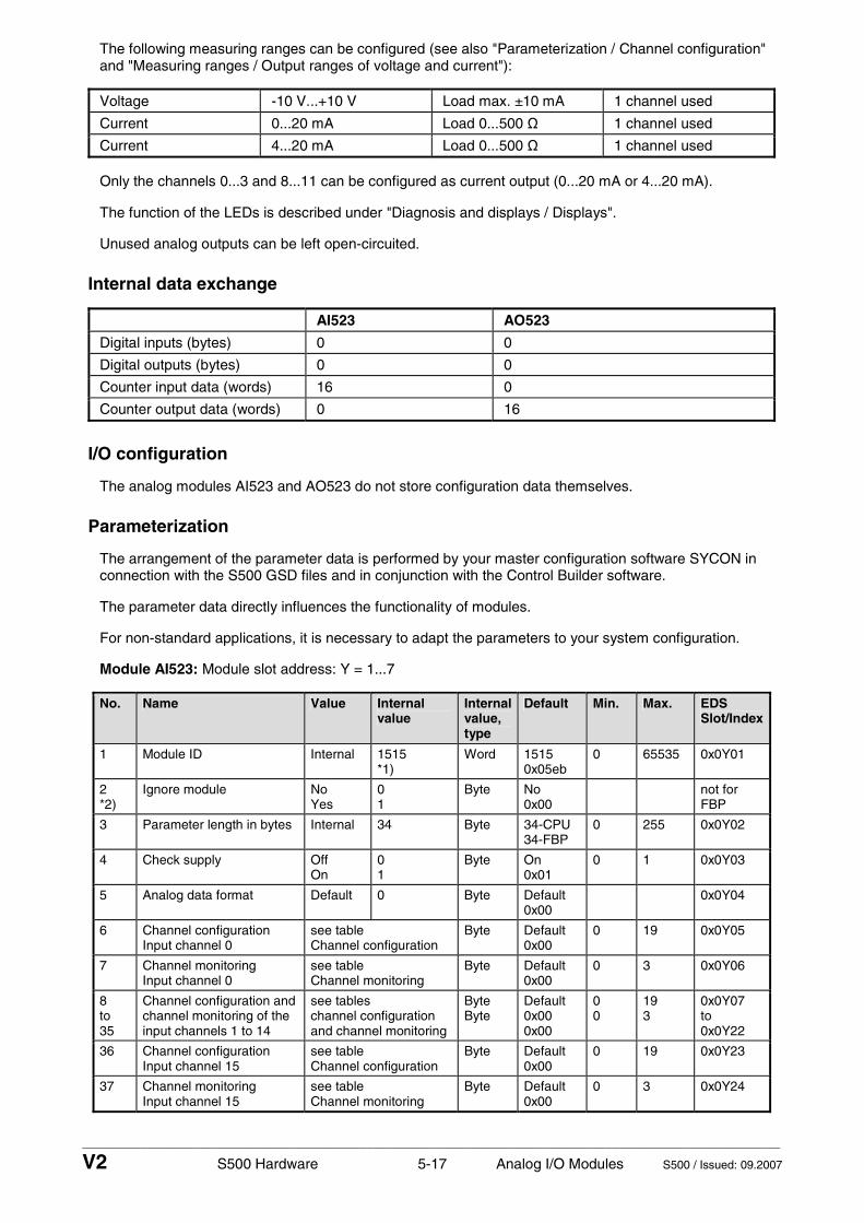
____________________________________________________________________________________________________________
V2 S500 Hardware 5-17 Analog I/O Modules S500 / Issued: 09.2007
The following measuring ranges can be configured (see also "Parameterization / Channel configuration" and "Measuring ranges / Output ranges of voltage and current"):
Voltage -10 V...+10 V Load max. ±10 mA 1 channel used
Current 0...20 mA Load 0...500 Ω 1 channel used
Current 4...20 mA Load 0...500 Ω 1 channel used
Only the channels 0...3 and 8...11 can be configured as current output (0...20 mA or 4...20 mA).
The function of the LEDs is described under "Diagnosis and displays / Displays".
Unused analog outputs can be left open-circuited.
Internal data exchange
AI523 AO523
Digital inputs (bytes) 0 0
Digital outputs (bytes) 0 0
Counter input data (words) 16 0
Counter output data (words) 0 16
I/O configuration
The analog modules AI523 and AO523 do not store configuration data themselves.
Parameterization
The arrangement of the parameter data is performed by your master configuration software SYCON in connection with the S500 GSD files and in conjunction with the Control Builder software.
The parameter data directly influences the functionality of modules.
For non-standard applications, it is necessary to adapt the parameters to your system configuration.
Module AI523: Module slot address: Y = 1...7
No. Name Value Internal value
Internalvalue, type
Default Min. Max. EDS Slot/Index
1 Module ID Internal 1515 *1)
Word 1515 0x05eb
0 65535 0x0Y01
2 *2)
Ignore module No Yes
0 1
Byte No 0x00
not for FBP
3 Parameter length in bytes Internal 34 Byte 34-CPU 34-FBP
0 255 0x0Y02
4 Check supply Off On
0 1
Byte On 0x01
0 1 0x0Y03
5 Analog data format Default 0 Byte Default 0x00
0x0Y04
6 Channel configuration Input channel 0
see table Channel configuration
Byte Default 0x00
0 19 0x0Y05
7 Channel monitoring Input channel 0
see table Channel monitoring
Byte Default 0x00
0 3 0x0Y06
8 to 35
Channel configuration and channel monitoring of the input channels 1 to 14
see tables channel configuration and channel monitoring
Byte Byte
Default 0x00 0x00
0 0
19 3
0x0Y07 to 0x0Y22
36 Channel configuration Input channel 15
see table Channel configuration
Byte Default 0x00
0 19 0x0Y23
37 Channel monitoring Input channel 15
see table Channel monitoring
Byte Default 0x00
0 3 0x0Y24

____________________________________________________________________________________________________________
V2 S500 Hardware 5-18 Analog I/O Modules S500 / Issued: 09.2007
*1) With CS31 and addresses less than 70 and FBP, the value is increased by 1
*2) Not with FBP
Module AO523: Module slot address: Y = 1...7
No. Name Value Internal value
Internal value, type
Default Min. Max. EDS Slot/Index
1 Module ID Internal 1510 *1)
Word 1510 0x05e6
0 65535 0x0Y01
2 *2)
Ignore module No Yes
0 1
Byte No 0x00
not for FBP
3 Parameter length in bytes
Internal 39 Byte 39-CPU 39-FBP
0 255 0x0Y02
4 Check supply Off On
0 1
Byte On 0x01
0 1 0x0Y03
5 Analog data format Default 0 Byte Default 0x00
0x0Y04
6 Behaviour of outputs at communication errors
Off Last value Substitute value
0 1+(n*5) 2+(n*5), n <= 2
Byte Off 0x00
0 2 0x0Y05
7 Channel configuration Output channel 0
see table Channel configuration
Byte Default 0x00
0 130 0x0Y06
8 Channel monitoring Output channel 0
see table Channel monitoring
Byte Default 0x00
0 3 0x0Y07
9 Substitute value Output channel 0
Output channel 0!
0...0xffff Word Default 0x0000
0 65535 0x0Y08
10 to 15
Channel configuration and channel monitoring of the output channels 1 to 3
see tables channel configuration and channel monitoring
Byte Byte
Default 0x00 0x00
0 0
130 3
0x0Y09 to 0x0Y0E
16 to 23
Channel configuration and channel monitoring of the output channels 4 to 7
see tables channel configuration and channel monitoring
Byte Byte
Default 0x00 0x00
0 0
128 3
0x0Y0F to 0x0Y16
24 Channel configuration Output channel 8
see table Channel configuration
Byte Default 0x00
0 130 0x0Y17
25 Channel monitoring Output channel 8
see table Channel monitoring
Byte Default 0x00
0 3 0x0Y18
26 Substitute value Output channel 8
Output channel 8!
0...0xffff Word Default 0x0000
0 65535 0x0Y19
27 to 32
Channel configuration and channel monitoring of the output channels 9 to 11
see tables channel configuration and channel monitoring
Byte Byte
Default 0x00 0x00
0 0
130 3
0x0Y1A to 0x0Y1F
33 to 40
Channel configuration and channel monitoring of the output channels 12 to 15
see tables channel configuration and channel monitoring
Byte Byte
Default 0x00 0x00
0 0
128 3
0x0Y20 to 0x0Y27
*1) With CS31 and addresses less than 70 and FBP, the value is increased by 1
*2) Not with FBP

____________________________________________________________________________________________________________
V2 S500 Hardware 5-19 Analog I/O Modules S500 / Issued: 09.2007
GSD file:
AI523 Ext_User_Prm_Data_Len = Ext_User_Prm_Data_Const(0) =
37 0x05, 0xec, 0x22, \ 0x01, 0x00, \ 0x00, 0x00, 0x00, 0x00, 0x00, 0x00, 0x00, 0x00, \ 0x00, 0x00, 0x00, 0x00, 0x00, 0x00, 0x00, 0x00, \ 0x00, 0x00, 0x00, 0x00, 0x00, 0x00, 0x00, 0x00, \ 0x00, 0x00, 0x00, 0x00, 0x00, 0x00, 0x00, 0x00;
AO523 Ext_User_Prm_Data_Len = Ext_User_Prm_Data_Const(0) =
42 0x05, 0xe7, 0x27, \ 0x01, 0x00, 0x00, \ 0x00, 0x00, 0x00, 0x00, \ 0x00, 0x00, 0x00, 0x00, 0x00, 0x00, \ 0x00, 0x00, 0x00, 0x00, 0x00, 0x00, 0x00, 0x00, \ 0x00, 0x00, 0x00, 0x00, \ 0x00, 0x00, 0x00, 0x00, 0x00, 0x00, \ 0x00, 0x00, 0x00, 0x00, 0x00, 0x00, 0x00, 0x00;
Input channel (16 x with AI523):
No. Name Value Internal value
Internal value, type
Default Min. Max.
1 Channel configuration
see below *2) see below *2)
Byte 0 0x00 see below *3)
2 Channel monitoring
see below *4) see below *4)
Byte 0 0x00 see below *5)
- Channel configuration
*2) Internal value
Operating modes of the analog inputs, individually configurable
*3) 0 Unused (default)
1 Analog input 0...10 V
2 Digital input
3 Analog input 0...20 mA
4 Analog input 4...20 mA
5 Analog input -10 V...+10 V
8 Analog input Pt100, -50 °C...+400 °C (2-wire)
9 Analog input Pt100, -50 °C...+400 °C (3-wire), requires 2 channels *)
10 Analog input 0...10 V via differential inputs, requires 2 channels *)
11 Analog input -10 V...+10 V via differential inputs, requires 2 channels *)
14 Analog input Pt100, -50 °C...+70 °C (2-wire)
15 Analog input Pt100, -50 °C...+70 °C (3-wire), requires 2 channels *)
16 Analog input Pt1000, -50 °C...+400 °C (2-wire)
17 Analog input Pt1000, -50 °C...+400 °C (3-wire), requires 2 channels *)
18 Analog input Ni1000, -50 °C...+150 °C (2-wire)
19 Analog input Ni1000, -50 °C...+150 °C (3-wire), requires 2 channels *)
*) In the operating modes with 3-wire configuration or with differential inputs, two adjacent analog inputs belong together (e.g. the channels 0 and 1). In these cases, both channels are configured in the desired operating mode. The lower address must be the even address (channel 0). The next higher address must be the odd address (channel 1). The converted analog value is available at the higher address (channel 1).

____________________________________________________________________________________________________________
V2 S500 Hardware 5-20 Analog I/O Modules S500 / Issued: 09.2007
- Channel monitoring
*4) Internal value Monitoring
*5) 0 Plausibility, open-circuit (broken wire) and short-circuit
1 Open-circuit and short-circuit
2 Plausibility
3 No monitoring
Output channels 0 and 8 (2 channels, AO523):
No. Name Value Internal value
Internal value, type
Default Min. Max.
1 Channel configuration
see below *6) see below *6)
Byte see below *7)
2 Channel monitoring
see below *8) see below *8)
Byte see below *9)
3 Substitute value *10)
0...65535 0... 0xffff
Word 0
Output channels 1...7 and 9...15 (14 channels, AO523):
No. Name Value Internal value
Internal value, type
Default Min. Max.
1 Channel configuration
see below *6) see below *6)
Byte see below *7)
2 Channel monitoring
see below *8) see below *8)
Byte see below *9)
- Channel configuration
*6) Internal value
Operating modes of the analog outputs, individually configurable
*7) 0 Unused (default)
128 Analog output -10 V...+10 V
129 Analog output 0...20 mA (not with the channels 4...7 and 12...15)
130 Analog output 4...20 mA (not with the channels 4...7 and 12...15)
- Channel monitoring
*8) Internal value
Monitoring
*9) 0 Plausibility, open-circuit (broken wire) and short-circuit (default)
1 Open-circuit (broken wire) and short-circuit
2 Plausibility
3 No monitoring
- Substitute value
*10) Intended behaviour of channel 0 when the control system stops:
Required setting of the module parameter "Behaviour of outputs in case of a communication error"
Required setting of the channel parameter "Substitute value"
Output OFF OFF 0
Last value Last value 0
Substitute value OFF or Last value 1...65535

____________________________________________________________________________________________________________
V2 S500 Hardware 5-21 Analog I/O Modules S500 / Issued: 09.2007
Diagnosis and display
Diagnosis:
E1..E4 d1 d2 d3 d4 Identifier000..063
AC500 display
Class Comp Dev Mod Ch Err PS501 PLC browser
Byte 6 Bit 6..7
- Byte 3
Byte 4
Byte 5
Byte 6 Bit 0..5
FBP diagnosis block <− Display in
Class Inter- face
De- vice
Mod- ule
Chan-nel
Error identifier
Error message Remedy
1) 2) 3) 4)
Module error AI523 / AO523
14 1..7 31 3
11 / 12 ADR 1..7 31 19 Checksum error in the I/O
module Replace I/O module
14 1..7 31 3
11 / 12 ADR 1..7 31 3 Timeout in the I/O module Replace I/O
module
14 1..7 31 3
11 / 12 ADR 1..7 31 40 Different hard-/firmware
versions in the module Replace I/O module
14 1..7 31 3
11 / 12 ADR 1..7 31 43 Internal error in the
module Replace I/O module
14 1..7 31 3
11 / 12 ADR 1..7 31 36 Internal data exchange
failure Replace I/O module
14 1..7 31 3
11 / 12 ADR 1..7 31 9 Overflow diagnosis buffer New start
14 1..7 31 3
11 / 12 ADR 1..7 31 26 Parameter error Check
master
14 1..7 31 3 11 / 12 ADR 1..7 31 11 Process voltage too low
Check process voltage
14 1..7 31 4
11 / 12 ADR 1..7 31 45 Process voltage is
switched off (ON -> OFF) Process voltage ON
Channel error AI523
14 1...7 1 4 11 / 12 ADR 1...7
0...15 48 Analog value overflow or broken wire at an analog input
Check input value or terminal
14 1...7 1 4
11 / 12 ADR 1...7 0...15 7 Analog value underflow at
an analog input Check input value
14 1...7 1 4
11 / 12 ADR 1...7 0...15 47 Short-circuit at an analog
input Check terminal
Channel error AO523
14 1...7 3 4
11 / 12 ADR 1...7 0...15 48 Analog value overflow at
an analog output Check output value
14 1...7 3 4
11 / 12 ADR 1...7 0...15 7 Analog value underflow at
an analog output Check output value

____________________________________________________________________________________________________________
V2 S500 Hardware 5-22 Analog I/O Modules S500 / Issued: 09.2007
Remarks:
1) In AC500 the following interface identifier applies: 14 = I/O-Bus, 11 = COM1 (e.g. CS31 bus), 12 = COM2. The FBP diagnosis block does not contain this identifier.
2) With "Device" the following allocation applies: 31 = Module itself, 1..7 = Expansion module 1..7, ADR = Hardware address (e.g. of the DC551)
3) With "Module" the following allocation applies dependent of the master: Module error: I/O-Bus or FBP: 31 = Module itself; COM1/COM2: 1..7 = Expansion 1..7 Channel error: I/O-Bus or FBP = Module type (2 = DO); COM1/COM2: 1..7 = Expansion 1..7
4) In case of module errors, with channel "31 = Module itself" is output.
Displays:
During the power ON procedure, the module initializes automatically. All LEDs (accept the channel LEDs) are ON during this time.
Status of the LEDs (see also section "Diagnosis LEDs" in the S500 system data)
LED Status Color LED = OFF LED = ON LED flashes
AI523: inputs 00...07 and 08...15
analog input yellow input is OFF input is ON (brightness depends on the value of the analog signal)
--
AO523: outputs 00...07 and 08...15
analog output yellow output is OFF output is ON (brightness depends on the value of the analog signal)
--
UP process voltage 24 V DC via terminal
green process voltage is missing
process voltage OK and initialization successful
module is not initialized correctly
CH-ERR2 red
CH-ERR4
Channel Error, error messages in groups (analog inputs or outputs combined into the groups 2 and 4)
red
no error or process voltage is missing
serious error within the corresponding group
error on one channel of the group
CH-ERR *)
Module Error red -- internal error --
*) Both LEDs (CH-ERR2 and CH-ERR4) light up together

____________________________________________________________________________________________________________
V2 S500 Hardware 5-23 Analog I/O Modules S500 / Issued: 09.2007
Measuring ranges
AI523: Input ranges of voltage, current and digital input
Range 0...10 V
-10...+10 V
0...20 mA
4...20 mA
Digital input
Digital value
decimal hex.
Overflow >11.7589 >11.7589 >23.5178 >22.8142 32767 7FFF
Measured value too high
11.7589 : 10.0004
11.7589 : 10.0004
23.5178 : 20.0007
22.8142 : 20.0006
32511 : 27649
7EFF : 6C01
10.0000 : 0.0004
10.0000 : 0.0004
20.0000 : 0.0007
20.0000 : 4.0006 ON
27648 : 1
6C00 : 0001
0.0000 0.0000 0 4 OFF 0 0000
Normal range Normal range or measured value too low
-0.0004 -1.7593
-0.0004 : : : -10.0000
3.9994 : 0
-1 -4864 -6912 : -27648
FFFF ED00E500 : 9400
Measured value too low
-10.0004 : -11.7589
-27649 : -32512
93FF : 8100
Underflow <0,0000 <-11.7589 <0.0000 <0.0000 -32768 8000
The represented resolution corresponds to 16 bits.
AI523: Input ranges resistance
Range Pt100 / Pt 1000 -50...70 °C
Pt100 / Pt1000 -50...400 °C
Ni1000 -50...150 °C
Digital value
decimal hex.
Overflow > 80.0 °C > 450.0 °C > 160.0 °C 32767 7FFF
450.0 °C : 400.1 °C
4500 : 4001
1194 : 0FA1
160.0 °C : 150.1 °C
1600 : 1501
0640 : 05DD
Measured value too high
80.0 °C : 70.1 °C
800 : 701
0320 : 02BD
70.0 °C : 0.1 °C
400.0 °C : : : 0.1 °C
150.0 °C : : 0.1 °C
4000 1500 700 : 1
0FA0 05DC 02BC : 0001
0.0 °C 0.0 °C 0.0 °C 0 0000
Normal range
-0.1 °C : -50.0 °C
-0.1 °C : -50.0 °C
-0.1 °C : -50.0 °C
-1 : -500
FFFF : FE0C
Measured value too low
-50.1 °C : -60.0 °C
-50.1 °C : -60.0 °C
-50.1 °C : -60.0 °C
-501 : -600
FE0B : FDA8
Underflow < -60.0 °C < -60.0 °C < -60.0 °C -32768 8000

____________________________________________________________________________________________________________
V2 S500 Hardware 5-24 Analog I/O Modules S500 / Issued: 09.2007
AO523: Output ranges voltage and current
Range -10...+10 V 0...20 mA 4...20 mA Digital value
decimal hex.
Overflow 0 V 0 mA 0 mA > 32511 > 7EFF
Measured value too high
11.7589 V : 10.0004 V
23.5178 mA : 20.0007 mA
22.8142 mA : 20.0006 mA
32511 : 27649
7EFF : 6C01
10.0000 V : 0.0004 V
20.0000 mA : 0.0007 mA
20.0000 mA : 4.0006 mA
27648 : 1
6C00 : 0001
0.0000 V 0.0000 mA 4.0000 mA 0 0000
Normal range
-0.0004 V : -10.0000 V
0 mA : 0 mA
3.9994 mA 0 mA 0 mA
-1 -6912 -27648
FFFF E500 9400
Measured value too low
-10.0004 V : -11.7589 V
0 mA : 0 mA
0 mA : 0 mA
-27649 : -32512
93FF : 8100
Underflow 0 V 0 mA 0 mA < -32512 < 8100
The represented resolution corresponds to 16 bits.
Technical data
The system data of AC500 and S500 are valid here. Only additional details are therefore documented below.
Process voltage
- Rated value 24 V DC
- max. ripple 5 %
- Protection against reversed voltage yes
Rated protection fuse on UP 10 A fast
- Electrical isolation yes, per module
- Current consumption from UP at normal operation
0.15 A + output loads (AO523)
- Inrush current from UP (at power up) 0.050 A²s
- Connections Terminals 1.8 - 4.8 for +24 V (UP) and 1.9 - 4.9 for 0 V (ZP)
Max. length of analog cables, conductor cross section > 0.14 mm²
100 m
Conversion error of the analog values caused by non-linearity, adjustment error at factory and resolution within the normal range
typ. 0.5 %, max. 1 %
Weight 300 g
Mounting position horizontal or vertical with derating (output load reduced to 50 % at 40°C per group)
Cooling The natural convection cooling must not be hindered by cable ducts or other parts in the switch-gear cabinet.
Attention: All I/O channels (digital and analog) are protected against reverse polarity, reverse supply, short circuit and continuous overvoltage up to 30 V DC.

____________________________________________________________________________________________________________
V2 S500 Hardware 5-25 Analog I/O Modules S500 / Issued: 09.2007
AI523: Technical data of the analog inputs
Number of channels per module 16
Distribution of channels into groups 2 groups of 8 channels each
Connections of the channels I0- to I7- Connections of the channels I0+ to I7+
Terminals 1.0 to 1.7 Terminals 2.0 to 2.7
Connections of the channels I8- to I15- Connections of the channels I8+ to I15+
Terminals 3.0 to 3.7 Terminals 4.0 to 4.7
Input type bipolar (not with current or Pt100/Pt1000/Ni1000)
Electrical isolation against internal supply and other modules
Configurability 0...10 V, -10...+10 V, 0/4...20 mA, Pt100/1000, Ni1000 (each input can be configured individually)
Channel input resistance Voltage: > 100 kΩ, current: ca. 330 Ω
Time constant of the input filter Voltage: 100 µs, current: 100 µs
Indication of the input signals one LED per channel
Conversion cycle 2 ms (for 8 inputs + 8 outputs), with Pt/Ni... 1 s
Resolution Range 0...10 V: 12 bits
Range -10...+10 V: 12 bits + sign
Range 0...20 mA: 12 bits
Range 4...20 mA: 12 bits
Relationship between input signal and hex code
see tables "Input ranges voltage, current and digital input" and "Input ranges resistance"
Unused voltage inputs are configured as "unused"
Unused current inputs have a low resistance, can be laft open-circuited
Overvoltage protection yes
AI523: Technical data of the analog inputs, if they are used as digital inputs
Number of channels per module max. 16
Distribution of channels into groups 2 groups of 8 channels each
Connections of the channels I0+ to I7+ Connections of the channels I8+ to I15+
Terminals 2.0 to 2.7 Terminals 4.0 to 4.7
Reference potential for the inputs Terminals 1.8 to 4.8 (ZP)
Input signal delay typ. 8 ms, configurable from 0.1 to 32 ms
Indication of the input signals one LED per channel
Input signal voltage 24 V DC
Signal 0 -30 V...+5 V
Signal 1 +13 V...+30 V

____________________________________________________________________________________________________________
V2 S500 Hardware 5-26 Analog I/O Modules S500 / Issued: 09.2007
AO523: Technical data of the analog outputs
Number of channels per module 16, of which channnels O0...O3 and O8...O11 for voltage and current, and channels O4...7 and O12...15 only for voltage
Distribution of channels into groups
2 groups of 8 channels each
- Channels O0-...O7- - Channels O0+...O7+
Terminals 1.0...1.7 Terminals 2.0...2.7
- Channels O8-...O15- - Channels O8+...O15+
Terminals 3.0...3.7 Terminals 4.0...4.7
Output type bipolar with voltage, unipolar with current
Electrical isolation against internal supply and other modules
Configurability -10...+10 V, 0...20 mA, 4...20 mA (each output can be configured individually), current outputs only channels 0...3
Output resistance (load), as current output
0...500 Ω
Output loadability, as voltage output
max. ±10 mA
Indication of the output signals one LED per channel
Resolution 12 bits (+ sign)
Relationship between output signal and hex code
see table "Output ranges voltage and current"
Unused outputs can be left open-circuited
Ordering data
Order No. Scope of delivery
1SAP 250 300 R0001 AI523, Analog input module, 16 AI, U/I/Pt100, 12 Bit + sign, 2-wires
1SAP 250 200 R0001 AO523, Analog output module, 16 AO, U/I, 12 Bit + sign, 2-wires
1SAP 212 200 R0001 TU515, I/O Terminal Unit, 24 V DC, screw-type terminals
1SAP 212 000 R0001 TU516, I/O Terminal Unit, 24 V DC, spring terminals

____________________________________________________________________________________________________________
V2 S500 Hardware 5-27 Analog I/O Modules S500 / Issued: 09.2007
Analog Input/Output Modules AX521 and AX522 - AX521: 4 configurable analog inputs, 4 configurable analog outputs - AX522: 8 configurable analog inputs, 8 configurable analog outputs - resolution 12 bits plus sign - module-wise electrically isolated
1.0
1.1
1.2
1.3
1.4
1.5
1.6
1.7
1.8
1.9
2.0
2.1
2.2
2.3
2.4
2.5
2.6
2.7
2.8
2.9
3.0
3.1
3.2
3.3
3.4
3.5
3.6
3.7
3.8
3.9
4.0
4.1
4.2
4.3
4.4
4.5
4.6
4.7
4.8
4.9
Elements of the analog input/output modules AX521 and AX522
1 I/O-Bus
2 Allocation between terminal No. and signal name
3 4 yellow LEDs to display the signal statuses at the inputs I0 to I3 (AX521)
4 4 yellow LEDs to display the signal statuses at the outputs O0 to O3 (AX521)
5 8 yellow LEDs to display the signal statuses at the inputs I0 to I7 (AX522)
6 8 yellow LEDs to display the signal statuses at the outputs O0 to O7 (AX522)
7 1 green LED to display the process voltage UP
8 2 red LEDs to display errors (CH-ERR2 and CH-ERR4)
9 DIN rail
10 Label
11 I/O Terminal Unit (TU515/TU516) with 40 terminals (screw-type or spring terminals)
AX521
1.0 I0–
1.1 I1–
1.2 I2–
1.3 I3–
1.4
1.5
1.6
1.7
1.8 UP
1.9 ZP
2.0 I0+
2.1 I1+
2.2 I2+
2.3 I3+
2.4
2.5
2.6
2.7
2.8 UP
2.9 ZP
3.0 O0–
3.1 O1–
3.2 O2–
3.3 O3–
3.4
3.5
3.6
3.7
3.8 UP
3.9 ZP
4.0 O0+
4.1 O1+
4.2 O2+
4.3 O3+
4.4
4.5
4.6
4.7
4.8 UP
4.9 ZP
4 AI 4 AOAnalog Input
Analog Output
CH-ERR4CH-ERR2
UP 24VDC 5W
1.0
1.1
1.2
1.3
1.4
1.5
1.6
1.7
1.8
1.9
2.0
2.1
2.2
2.3
2.4
2.5
2.6
2.7
2.8
2.9
3.0
3.1
3.2
3.3
3.4
3.5
3.6
3.7
3.8
3.9
4.0
4.1
4.2
4.3
4.4
4.5
4.6
4.7
4.8
4.9
11
1
2
7 8
10
3 4
11
AX522
1.0 I0–
1.1 I1–
1.2 I2–
1.3 I3–
1.4 I4–
1.5 I5–
1.6 I6–
1.7 I7–
1.8 UP
1.9 ZP
2.0 I0+
2.1 I1+
2.2 I2+
2.3 I3+
2.4 I4+
2.5 I5+
2.6 I6+
2.7 I7+
2.8 UP
2.9 ZP
3.0 O0–
3.1 O1–
3.2 O2–
3.3 O3–
3.4 O4–
3.5 O5–
3.6 O6–
3.7 O7–
3.8 UP
3.9 ZP
4.0 O0+
4.1 O1+
4.2 O2+
4.3 O3+
4.4 O4+
4.5 O5+
4.6 O6+
4.7 O7+
4.8 UP
4.9 ZP
8 AI 8 AOAnalog Input
Analog Output
CH-ERR4CH-ERR2
UP 24VDC 5W
9
2
7 8
10
5 6
Figure: Analog input/output modules AX521 and AX522, plugged on Terminal Units TU516

____________________________________________________________________________________________________________
V2 S500 Hardware 5-28 Analog I/O Modules S500 / Issued: 09.2007
Contents
Intended purpose...................................................................................................................................... 5-28 Functionality.............................................................................................................................................. 5-28 Electrical connection................................................................................................................................. 5-29 Internal data exchange ............................................................................................................................. 5-40 I/O configuration........................................................................................................................................ 5-40 Parameterization....................................................................................................................................... 5-40 Diagnosis and display............................................................................................................................... 5-45 Measuring ranges ..................................................................................................................................... 5-47 Technical data........................................................................................................................................... 5-48 - Technical data of the analog inputs........................................................................................................ 5-49 - Technical data of the analog inputs, if they are used as digital inputs ................................................... 5-49 - Technical data of the analog outputs ..................................................................................................... 5-50 Ordering data ............................................................................................................................................ 5-50
Intended purpose
The analog input/output modules AX521 and AX522 can be used as remote expansion modules at the FBP Interface Module DC505-FBP, at the CS31 Bus Module DC551-CS31 or locally at an AC500 CPU. They contain 8 or 16 channels each with the following features:
AX521:
• 4 configurable analog inputs in one group (1.0...2.3) • 4 configurable analog outputs in one group (3.0...4.3)
AX522:
• 8 configurable analog inputs in one group (1.0...2.7) • 8 configurable analog outputs in one group (3.0...4.7)
The configuration is performed by software.
The modules are supplied with a process voltage of 24 V DC. The analog inputs and outputs are electrically isolated from the rest of the modules' electronics.
Functionality
unused (default setting)
0...10 V
-10 V...+10 V
0...20 mA
4...20 mA
Pt100, -50 °C...+400 °C (2-wire)
Pt100, -50 °C...+400 °C (3-wire), requires 2 channels
Pt100, -50 °C...+70 °C (2-wire)
Pt100, -50 °C...+70 °C (3-wire), requires 2 channels
Pt1000, -50 °C...+400 °C (2-wire)
Pt1000, -50 °C...+400 °C (3-wire), requires 2 channels
Ni1000, -50 °C...+150 °C (2-wire)
Ni1000, -50 °C...+150 °C (3-wire), requires 2 channels
0...10 V with differential inputs, requires 2 channels
-10 V...+10 V with differential inputs, requires 2 channels
AX521: 4 analog inputs, individually configurable for AX522: 8 analog inputs, individually configurable for
digital signals (digital input)

____________________________________________________________________________________________________________
V2 S500 Hardware 5-29 Analog I/O Modules S500 / Issued: 09.2007
unused (default setting)
-10 V...+10 V
0...20 mA
AX521 and AX522: 4 analog outputs, individually configurable for
4...20 mA
unused (default setting) only AX522: 4 analog outputs, individually configurable for
-10 V...+10 V
Resolution of the analog channels
- Voltage -10 V... +10 V 12 bits plus sign
- Voltage 0...10 V 12 bits
- Current 0...20 mA, 4...20 mA 12 bits
- Temperature 0.1 °C
LED displays AX521: 11 LEDs for signals and error messages AX522: 19 LEDs for signals and error messages
Internal power supply through the expansion bus interface (I/O-Bus)
External power supply via the terminals ZP and UP (process voltage 24 V DC)
Electrical connection
The input/output modules are plugged on I/O Terminal Units TU515 or TU516. Properly seat the modules and press until they lock in place. The Terminal Units are mounted on a DIN rail or with 2 screws plus the additional accessory for wall mounting (TA526).
The electrical connection of the I/O channels is carried out using the 40 terminals of the I/O Terminal Unit. I/O modules can be replaced without re-wiring the Terminal Units.
Note: Mounting, disassembling and electrical connection for the Terminal Units and the I/O modules are described in detail in the S500 system data chapters.
The terminals 1.8 to 4.8 and 1.9 to 4.9 are electrically interconnected within the I/O Terminal Units and have always the same assignment, independent of the inserted module:
Terminals 1.8 to 4.8: Process voltage UP = +24 V DC Terminals 1.9 to 4.9: Process voltage ZP = 0 V
The assignment of the other terminals:
AX521:
Terminals Signal Meaning
1.0 to 1.3 I0- to I3- Minus poles of the 4 analog inputs
2.0 to 2.3 I0+ to I3+ Plus poles of the 4 analog inputs
3.0 to 3.3 O0- to O3- Minus poles of the 4 analog outputs
4.0 to 4.3 O0+ to O3+ Plus poles of the 4 analog outputs

____________________________________________________________________________________________________________
V2 S500 Hardware 5-30 Analog I/O Modules S500 / Issued: 09.2007
AX522:
Terminals Signal Meaning
1.0 to 1.7 I0- to I7- Minus poles of the 8 analog inputs
2.0 to 2.7 I0+ to I7+ Plus poles of the 8 analog inputs
3.0 to 3.7 O0- to O7- Minus poles of the 8 analog outputs
4.0 to 4.7 O0+ to O7+ Plus poles of the 8 analog outputs
Caution: The minus poles of the analog inputs are electrically connected to each other. They form an "Analog Ground" signal for the module. The minus poles of the analog outputs are also electrically connected to each other to form an "Analog Ground" signal.
Caution: There is no electrical isolation between the analog circuitry and ZP/UP. Therefore, the analog sensors must be electrically isolated in order to avoid loops via the earth potential or the supply voltage.
Caution: Because of their common reference potential, analog current inputs cannot be circuited in series, neither within the module nor with channels of other modules.
Note: For the open-circuit detection (cut wire), each channel is pulled up to "plus" by a high-resistance resistor. If nothing is connected, the maximum voltage will be read in then.
The supply voltage 24 V DC for the modules' electronic circuitry comes from the I/O-Bus of the FieldBusPlug or the CPU.
Caution: Removal of energized modules is not permitted. All power sources (supply and process voltages) must be switched off while working on any AC500 system.
Analog signals are always laid in shielded cables. The cable shields are earthed at both ends of the cables. In order to avoid unacceptable potential differences between different parts of the installation, low resistance equipotential bonding conductors must be laid.
For simple applications (low disturbances, no high requirement on precision), the shielding can also be omitted.
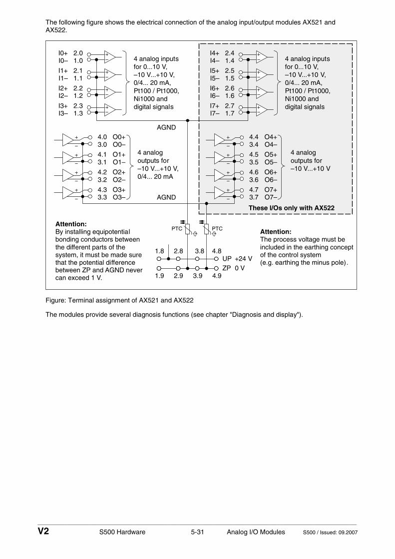
____________________________________________________________________________________________________________
V2 S500 Hardware 5-31 Analog I/O Modules S500 / Issued: 09.2007
The following figure shows the electrical connection of the analog input/output modules AX521 and AX522.
2.01.0
I0+I0–
2.11.1
I1+I1–
2.21.2
I2+I2–
2.31.3
I3+I3–
2.41.4
I4+I4–
2.51.5
I5+I5–
2.61.6
I6+I6–
2.71.7
I7+I7–
O0+O0–
4.03.0
O4+O4–
4.43.4
O1+O1–
4.13.1
O5+O5–
4.53.5
O2+O2–
4.23.2
O6+O6–
4.63.6
O3+O3–
4.33.3
O7+O7–
4.73.7AGND
AGND
UPZP
1.8 2.8 3.8 4.8
1.9 2.9 3.9 4.9
+24 V0 V
4 analog inputsfor 0...10 V,–10 V...+10 V,0/4... 20 mA,Pt100 / Pt1000,Ni1000 anddigital signals
4 analogoutputs for–10 V...+10 V,0/4... 20 mA
4 analogoutputs for–10 V...+10 V
PTCPTC
4 analog inputsfor 0...10 V,–10 V...+10 V,0/4... 20 mA,Pt100 / Pt1000,Ni1000 anddigital signals
These I/Os only with AX522
Attention:By installing equipotentialbonding conductors between
system, it must be made surethat the potential differencebetween ZP and AGND never
the different parts of the
can exceed 1 V.
Attention:The process voltage must beincluded in the earthing conceptof the control system(e.g. earthing the minus pole).
Figure: Terminal assignment of AX521 and AX522
The modules provide several diagnosis functions (see chapter "Diagnosis and display").

____________________________________________________________________________________________________________
V2 S500 Hardware 5-32 Analog I/O Modules S500 / Issued: 09.2007
Connection of resistance thermometers in 2-wire configuration
When resistance thermometers (Pt100, Pt1000, Ni1000) are used, a constant current must flow through them to build the necessary voltage drop for the evaluation. For this, the module AX521/AX522 provides a constant current source which is multiplexed over the 8 analog channels.
The following figure shows the connection of resistance thermometers in 2-wire configuration.
2.0
2.1
2.8
2.9
I0+
I1+
UP
ZP
UP
ZP
Pt100 (2-wire)Pt1000 (2-wire)Ni1000 (2-wire)
1 analog sensorrequires 1 channel
1.0
1.1
1.8
1.9
I0–
I1–
UP
ZP
PTC
Figure: Connection of resistance thermometers in 2-wire configuration
The following measuring ranges can be configured (see also "Parameterization / Channel configuration" and "Measuring ranges / Input ranges of resistances"):
Pt100 -50 °C...+70 °C 2-wire configuration, one channel used
Pt100 -50 °C...+400 °C 2-wire configuration, one channel used
Pt1000 -50 °C...+400 °C 2-wire configuration, one channel used
Ni1000 -50 °C...+150 °C 2-wire configuration, one channel used
The function of the LEDs is described under "Diagnosis and displays / Displays".
The modules AX521 and AX522 perform a linearization of the resistance characteristic.
In order to avoid error messages from unused analog input channels, it is useful to configure them as "unused".

____________________________________________________________________________________________________________
V2 S500 Hardware 5-33 Analog I/O Modules S500 / Issued: 09.2007
Connection of resistance thermometers in 3-wire configuration
When resistance thermometers (Pt100, Pt1000, Ni1000) are used, a constant current must flow through them to build the necessary voltage drop for the evaluation. For this, the module AX521/AX522 provides a constant current source which is multiplexed over the max. 8 (depending on the configuration) analog channels.
The following figure shows the connection of resistance thermometers in 3-wire configuration.
2.0
2.1
2.8
2.9
I0+
I1+
UP
ZP
UP
ZP
Pt100 (3-wire)Pt1000 (3-wire)Ni1000 (3-wire)
1 analog sensorrequires 2 channels
twisted pair within the cable
Return line
If several measuring points are adjacent toeach other, the return line is only necessaryonce. This saves wiring costs!
1.0
1.1
1.8
1.9
I0–
I1–
UP
ZP
PTC
Figure: Connection of resistance thermometers in 3-wire configuration
With 3-wire configuration, two adjacent analog channels belong together (e.g. the channels 0 and 1). In this case, both channels are configured according to the desired operating mode. The lower address must be the even address (channel 0), the next higher address must be the odd address (channel 1).
The constant current of one channel flows through the resistance thermometer. The constant current of the other channel flows through one of the cores. The module calculates the measured value from the two voltage drops and stores it under the input with the higher channel number (e.g. I1).
In order to keep measuring errors as small as possible, it is necessary, to have all the involved conductors in the same cable. All the conductors must have the same cross section.
The following measuring ranges can be configured (see also "Parameterization / Channel configuration" and "Measuring ranges / Input ranges of resistances"):
Pt100 -50 °C...+70 °C 3-wire configuration, two channels used
Pt100 -50 °C...+400 °C 3-wire configuration, two channels used
Pt1000 -50 °C...+400 °C 3-wire configuration, two channels used
Ni1000 -50 °C...+150 °C 3-wire configuration, two channels used
The function of the LEDs is described under "Diagnosis and displays / Displays".
The modules AX521 and AX522 perform a linearization of the resistance characteristic.
In order to avoid error messages from unused analog input channels, it is useful to configure them as "unused".

____________________________________________________________________________________________________________
V2 S500 Hardware 5-34 Analog I/O Modules S500 / Issued: 09.2007
Connection of active-type analog sensors (voltage) with electrically isolated power supply
The following figure shows the connection of active-type analog sensors (voltage) with electrically isolated power supply.
2.0
2.1
2.8
2.9
I0+
I1+
UP
ZP
UP
ZP
+
–
electrically isolatedpower supply forthe analog sensor
1 analog sensorrequires 1 channel
0...10 V–10 V...+10 V
1.0
1.1
1.8
1.9
I0–
I1–
UP
ZP
By connecting to AGND, the electricallyisolated voltage source of the sensor isreferred to ZP.
AGND
PTC
Figure: Connection of active-type analog sensors (voltage) with electrically isolated power supply
The following measuring ranges can be configured (see also "Parameterization / Channel configuration" and "Measuring ranges / Input ranges of voltage, current and digital input"):
Voltage 0...10 V 1 channel used
Voltage -10 V...+10 V 1 channel used
The function of the LEDs is described under "Diagnosis and displays / Displays".
In order to avoid error messages or long processing times, it is useful to configure unused analog input channels as "unused".

____________________________________________________________________________________________________________
V2 S500 Hardware 5-35 Analog I/O Modules S500 / Issued: 09.2007
Connection of active-type analog sensors (current) with electrically isolated power supply
The following figure shows the connection of active-type analog sensors (current) with electrically isolated power supply.
electrically isolatedpower supply forthe analog sensor
1 analog sensorrequires 1 channel
2.0
2.1
2.8
2.9
I0+
I1+
UP
ZP
UP
ZP
+
–
0...20 mA4...20 mA
1.0
1.1
1.8
1.9
I0–
I1–
UP
ZP
PTC
Figure: Connection of active-type analog sensors (current) with electrically isolated power supply
The following measuring ranges can be configured (see also "Parameterization / Channel configuration" and "Measuring ranges / Input ranges of voltage, current and digital input"):
Current 0...20 mA 1 channel used
Current 4...20 mA 1 channel used
The function of the LEDs is described under "Diagnosis and displays / Displays".
Unused input channels can be left open-circuited, because they are of low resistance.

____________________________________________________________________________________________________________
V2 S500 Hardware 5-36 Analog I/O Modules S500 / Issued: 09.2007
Connection of active-type analog sensors (voltage) with no electrically isolated power supply
The following figure shows the connection of active-type sensors (voltage) with no electrically isolated power supply.
1 analog sensorrequires 1 channel
Power supplynot electrically isolated
2.0
2.1
2.8
2.9
I0+
I1+
UP
ZP
UP (remote)
ZP (remote)
0...10 V
AGND
Attention:The potential difference between AGND and ZP at the AX522 module must not be greater than1 V, not even in case of long lines (see the figure ”Terminal assignment of AX522”).
long cable
UP
ZP
1.0
1.1
1.8
1.9
I0–
I1–
UP
ZP
PTC
Figure: Connection of active-type sensors (voltage) with no electrically isolated power supply
Note for the picture: If AGND does not get connected to ZP, the sensor current flows to ZP via the AGND line. The measuring signal is distorted, since it flows a very little current over the voltage line. The total current through the PTC should not exceed 50 mA. This measuring method is therefore only suitable for short lines and small sensor currents. If there are bigger distances, the difference measuring method has to be preferred.
The following measuring ranges can be configured (see also "Parameterization / Channel configuration" and "Measuring ranges / Input ranges of voltage, current and digital input"):
Voltage 0...10 V 1 channel used
Voltage -10 V...+10 V *) 1 channel used
*) if the sensor can provide this signal range
The function of the LEDs is described under "Diagnosis and displays / Displays".
In order to avoid error messages or long processing times, it is useful to configure unused analog input channels as "unused".

____________________________________________________________________________________________________________
V2 S500 Hardware 5-37 Analog I/O Modules S500 / Issued: 09.2007
Connection of passive-type analog sensors (current)
The following figure shows the connection of passive-type analog sensors (current).
2.0
2.1
2.8
2.9
I0+
I1+
UP
ZP
UP
ZP
1 analog sensorrequires 1 channel
4...20 mA
–
+
1.0
1.1
1.8
1.9
I0–
I1–
UP
ZP
PTC
Figure: Connection of passive-type analog sensors (current)
The following measuring ranges can be configured (see also "Parameterization / Channel configuration" and "Measuring ranges / Input ranges of voltage, current and digital input"):
Current 4...20 mA 1 channel used
The function of the LEDs is described under "Diagnosis and displays / Displays".
Caution: If, during initialization, an analog current sensor supplies more than 25 mA for more than 1 second into an analog input, this input is switched off by the module (input protection). In such cases, it is recommended, to protect the analog input by a 10-volt zener diode (in parallel to I+ and I-). But, in general, it is a better solution to prefer sensors with fast initialization or without current peaks higher than 25 mA.
Unused input channels can be left open-circuited, because they are of low resistance.

____________________________________________________________________________________________________________
V2 S500 Hardware 5-38 Analog I/O Modules S500 / Issued: 09.2007
Connection of active-type analog sensors (voltage) to differential inputs
Differential inputs are very useful, if analog sensors are used which are remotely non-isolated (e.g. the minus terminal is remotely earthed).
The evaluation using differential inputs helps to considerably increase the measuring accuracy and to avoid earthing loops.
With differential input configurations, two adjacent analog channels belong together (e.g. the channels 0 and 1). In this case, both channels are configured according to the desired operating mode. The lower address must be the even address (channel 0), the next higher address must be the odd address (channel 1). The converted analog value is available at the higher address (channel 1).
The analog value is calculated by subtraction of the input value with the higher address from the input value of the lower address.
The converted analog value is available at the odd channel (higher address).
Important: The earthing potential at the sensors must not have a too big potential difference with respect to ZP (max. ± 1 V within the full signal range). Otherwise problems can occur concerning the common-mode input voltages of the involved analog inputs.
The following figure shows the connection of active-type analog sensors (voltage) to differential inputs.
2.0
2.1
2.8
2.9
I0+
I1+
UP
ZP
UP
ZP
+
–
1 analog sensorrequires 2 channels
Earthing atthe sensor
0...10 V–10 V...+10 V
connected to differential inputs
electrically isolatedpower supply forthe analog sensor
1.0
1.1
1.8
1.9
I0–
I1–
UP
ZP
PTC
Figure: Connection of active-type analog sensors (voltage) to differential inputs
The following measuring ranges can be configured (see also "Parameterization / Channel configuration" and "Measuring ranges / Input ranges of voltage, current and digital input"):
Voltage 0...10 V with differential inputs, 2 channels used
Voltage -10 V...+10 V with differential inputs, 2 channels used
The function of the LEDs is described under "Diagnosis and displays / Displays".
In order to avoid error messages or long processing times, it is useful to configure unused analog input channels as "unused".

____________________________________________________________________________________________________________
V2 S500 Hardware 5-39 Analog I/O Modules S500 / Issued: 09.2007
Use of analog inputs as digital inputs
Several (or all) analog inputs can be configured as digital inputs (see also "Technical Data / Technical data of the analog inputs, if they are used as digital inputs"). The inputs are not electrically isolated against the other analog channels.
The following figure shows the use of analog inputs as digital inputs.
2.0
2.1
2.8
2.9
I0+
I1+
UP
ZP
UP
ZP
1 digital signalrequires 1 channel
1.0
1.1
1.8
1.9
I0–
I1–
UP
ZP
PTC
Figure: Use of analog inputs as digital inputs
The following operating mode can be configured (see also "Parameterization / Channel configuration" and "Measuring ranges / Input ranges of voltage, current and digital input"):
Digital input 24 V 1 channel used
The function of the LEDs is described under "Diagnosis and displays / Displays".
Connection of analog output loads (voltage, current)
The following figure shows the connection of analog output loads (voltage, current).
1 analog loadrequires 1 channel
4.0
4.1
4.8
4.9
O0+
O1+
UP
ZP
UP
ZP
–10 V...+10 V
0...20 mA4...20 mA
3.0
3.1
3.8
3.9
Q0–
Q1–
UP
ZP
PTC
Figure: Connection of analog output loads (voltage, current)

____________________________________________________________________________________________________________
V2 S500 Hardware 5-40 Analog I/O Modules S500 / Issued: 09.2007
The following measuring ranges can be configured (see also "Parameterization / Channel configuration" and "Measuring ranges / Output ranges of voltage and current"):
Voltage -10 V...+10 V Load max. ±10 mA 1 channel used
Current 0...20 mA Load 0...500 Ω 1 channel used
Current 4...20 mA Load 0...500 Ω 1 channel used
Only the channels 0...3 can be configured as current output (0...20 mA or 4...20 mA).
The function of the LEDs is described under "Diagnosis and displays / Displays".
Unused analog outputs can be left open-circuited.
Internal data exchange
AX521 AX522
Digital inputs (bytes) 0 0
Digital outputs (bytes) 0 0
Counter input data (words) 4 8
Counter output data (words) 4 8
I/O configuration
The analog input/output modules AX521 and AX522 do not store configuration data themselves.

____________________________________________________________________________________________________________
V2 S500 Hardware 5-41 Analog I/O Modules S500 / Issued: 09.2007
Parameterization
The arrangement of the parameter data is performed by your master configuration software SYCON in connection with the S500 GSD files and in conjunction with the Control Builder software.
The parameter data directly influences the functionality of modules.
For non-standard applications, it is necessary to adapt the parameters to your system configuration.
Module AX521: Module slot address: Y = 1...7
No. Name Value Internal value
Internal value, type
Default Min. Max. EDS Slot/Index
1 Module ID Internal 1505 *1)
Word 1505 0x05dc
0 65535 0x0Y01
2 *2)
Ignore module No Yes
0 1
Byte No 0x00
not for FBP
3 Parameter length in bytes
Internal 21 Byte 21-CPU 21-FBP
0 255 0x0Y02
4 Check supply Off On
0 1
Byte On 0x01
0 1 0x0Y03
5 Analog data format Default 0 Byte Default 0x00
0x0Y04
6 Behaviour of outputs at communication errors
Off Last value Substitute value
0 1+(n*5) 2+(n*5), n <= 2
Byte Off 0x00
0 2 0x0Y05
7 Channel configuration Input channel 0
see table Channel configuration
Byte Default 0x00
0 19 0x0Y06
8 Channel monitoring Input channel 0
see table Channel monitoring
Byte Default 0x00
0 3 0x0Y07
9 to 14
Channel configuration and channel monitoring of the input channels 1 to 3
see tables channel configuration and channel monitoring
Byte Byte
Default 0x00 0x00
0 0
19 3
0x0Y08 to 0x0Y0D
15 Channel configuration Output channel 0
see table Channel configuration
Byte Default 0x00
0 130 0x0Y0E
16 Channel monitoring Output channel 0
see table Channel monitoring
Byte Default 0x00
0 3 0x0Y0F
17 Substitute value Output channel 0
only valid for output channel 0
0...0xffff Word Default 0x0000
0 65535 0x0Y10
18 to 21
Channel configuration and channel monitoring of the output channels 1 to 2
see tables channel configuration and channel monitoring
Byte Byte
Default 0x00 0x00
0 0
130 3
0x0Y11 to 0x0Y14
22 Channel configuration Output channel 3
see table Channel configuration
Byte Default 0x00
0 130 0x0Y15
23 Channel monitoring Output channel 3
see table Channel monitoring
Byte Default 0x00
0 3 0x0Y16
*1) With CS31 and addresses less than 70 and FBP, the value is increased by 1
*2) Not with FBP

____________________________________________________________________________________________________________
V2 S500 Hardware 5-42 Analog I/O Modules S500 / Issued: 09.2007
Module AX522: Module slot address: Y = 1...7
No. Name Value Internal value
Internalvalue, type
Default Min. Max. EDS Slot/Index
1 Module ID Internal 1500 *1)
Word 1500 0x05dc
0 65535 0x0Y01
2 *2)
Ignore module No Yes
0 1
Byte No 0x00
not for FBP
3 Parameter length in bytes Internal 37 Byte 37-CPU 37-FBP
0 255 0x0Y02
4 Check supply Off On
0 1
Byte On 0x01
0 1 0x0Y03
5 Analog data format Default 0 Byte Default 0x00
0x0Y04
6 Behaviour of outputs at communication errors
Off Last value Substitute value
0 1+(n*5) 2+(n*5), n <= 2
Byte Off 0x00
0 2 0x0Y05
7 Channel configuration Input channel 0
see table Channel configuration
Byte Default 0x00
0 19 0x0Y06
8 Channel monitoring Input channel 0
see table Channel monitoring
Byte Default 0x00
0 3 0x0Y07
9 to 22
Channel configuration and channel monitoring of the input channels 1 to 7
see tables channel configuration and channel monitoring
Byte Byte
Default 0x00 0x00
0 0
19 3
0x0Y08 to 0x0Y15
23 Channel configuration Output channel 0
see table Channel configuration
Byte Default 0x00
0 130 0x0Y16
24 Channel monitoring Output channel 0
see table Channel monitoring
Byte Default 0x00
0 3 0x0Y17
25 Substitute value Output channel 0
only valid for output channel 0
0...0xffff Word Default 0x0000
0 65535 0x0Y18
26 to 31
Channel configuration and channel monitoring of the output channels 1 to 3
see tables channel configuration and channel monitoring
Byte Byte
Default 0x00 0x00
0 0
130 3
0x0Y19 to 0x0Y1E
32 Channel configuration Output channel 4
see table Channel configuration
Byte Default 0x00
0 128 0x0Y1F
33 Channel monitoring Output channel 4
see table Channel monitoring
Byte Default 0x00
0 3 0x0Y20
34 to 39
Channel configuration and channel monitoring of the output channels 5 to 7
see tables channel configuration and channel monitoring
Byte Byte
Default 0x00 0x00
0 0
128 3
0x0Y21 to 0x0Y26
*1) With CS31 and addresses less than 70 and FBP, the value is increased by 1
*2) Not with FBP
GSD file:
AX521 Ext_User_Prm_Data_Len = Ext_User_Prm_Data_Const(0) =
24 0x05, 0xe2, 0x15, \ 0x01, 0x00, 0x00 \ 0x00, 0x00, 0x00, 0x00, 0x00, 0x00, 0x00, 0x00, \ 0x00, 0x00, 0x00, 0x00, \ 0x00, 0x00, 0x00, 0x00, 0x00, 0x00;
AX522 Ext_User_Prm_Data_Len = Ext_User_Prm_Data_Const(0) =
40 0x05, 0xdd, 0x25, \ 0x01, 0x00, 0x00, \ 0x00, 0x00, 0x00, 0x00, 0x00, 0x00, 0x00, 0x00, \ 0x00, 0x00, 0x00, 0x00, 0x00, 0x00, 0x00, 0x00, \ 0x00, 0x00, 0x00, 0x00, \ 0x00, 0x00, 0x00, 0x00, 0x00, 0x00, \ 0x00, 0x00, 0x00, 0x00, 0x00, 0x00, 0x00, 0x00;

____________________________________________________________________________________________________________
V2 S500 Hardware 5-43 Analog I/O Modules S500 / Issued: 09.2007
Input channel (4x with AX521):
No. Name Value Internal value
Internal value, type
Default Min. Max.
1 Channel configuration
see below *2) see below *2)
Byte 0 0x00 see below *3)
2 Channel monitoring
see below *4) see below *4)
Byte 0 0x00 see below *5)
Input channel (8x with AX522):
No. Name Value Internal value
Internal value, type
Default Min. Max.
1 Channel configuration
see below *2) see below *2)
Byte 0 0x00 see below *3)
2 Channel monitoring
see below *4) see below *4)
Byte 0 0x00 see below *5)
- Channel configuration
*2) Internal value
Operating modes of the analog inputs, individually configurable
*3) 0 Unused (default)
1 Analog input 0...10 V
2 Digital input
3 Analog input 0...20 mA
4 Analog input 4...20 mA
5 Analog input -10 V...+10 V
8 Analog input Pt100, -50 °C...+400 °C (2-wire)
9 Analog input Pt100, -50 °C...+400 °C (3-wire), requires 2 channels *)
10 Analog input 0...10 V via differential inputs, requires 2 channels *)
11 Analog input -10 V...+10 V via differential inputs, requires 2 channels *)
14 Analog input Pt100, -50 °C...+70 °C (2-wire)
15 Analog input Pt100, -50 °C...+70 °C (3-wire), requires 2 channels *)
16 Analog input Pt1000, -50 °C...+400 °C (2-wire)
17 Analog input Pt1000, -50 °C...+400 °C (3-wire), requires 2 channels *)
18 Analog input Ni1000, -50 °C...+150 °C (2-wire)
19 Analog input Ni1000, -50 °C...+150 °C (3-wire), requires 2 channels *)
*) In the operating modes with 3-wire configuration or with differential inputs, two adjacent analog inputs belong together (e.g. the channels 0 and 1). In these cases, both channels are configured in the desired operating mode. The lower address must be the even address (channel 0). The next higher address must be the odd address (channel 1). The converted analog value is available at the higher address (channel 1).
- Channel monitoring
*4) Internal value Monitoring
*5) 0 Plausibility, open-circuit (broken wire) and short-circuit
1 Open-circuit and short-circuit
2 Plausibility
3 No monitoring

____________________________________________________________________________________________________________
V2 S500 Hardware 5-44 Analog I/O Modules S500 / Issued: 09.2007
Output channel 0 (1 channel):
No. Name Value Internal value
Internal value, type
Default Min. Max.
1 Channel configuration
see below *6) see below *6)
Byte see below *7)
2 Channel monitoring
see below *8) see below *8)
Byte see below *9)
3 Substitute value *10)
0...65535 0... 0xffff
Word 0
Output channels 1...3 (3 channels with AX521):
No. Name Value Internal value
Internal value, type
Default Min. Max.
1 Channel configuration
see below *6) see below *6)
Byte see below *7)
2 Channel monitoring
see below *8) see below *8)
Byte see below *9)
Output channels 1...7 (7 channels with AX522):
No. Name Value Internal value
Internal value, type
Default Min. Max.
1 Channel configuration
see below *6) see below *6)
Byte see below *7)
2 Channel monitoring
see below *8) see below *8)
Byte see below *9)
- Channel configuration
*6) Internal value
Operating modes of the analog outputs, individually configurable
*7) 0 Unused (default)
128 Analog output -10 V...+10 V
129 Analog output 0...20 mA (not with the channels 4...7 and 12...15)
130 Analog output 4...20 mA (not with the channels 4...7 and 12...15)
- Channel monitoring
*8) Internal value
Monitoring
*9) 0 Plausibility, open-circuit (broken wire) and short-circuit (default)
1 Open-circuit (broken wire) and short-circuit
2 Plausibility
3 No monitoring
- Substitute value
*10) Intended behaviour of channel 0 when the control system stops:
Required setting of the module parameter "Behaviour of outputs in case of a communication error"
Required setting of the channel parameter "Substitute value"
Output OFF OFF 0
Last value Last value 0
Substitute value OFF or Last value 1...65535

____________________________________________________________________________________________________________
V2 S500 Hardware 5-45 Analog I/O Modules S500 / Issued: 09.2007
Diagnosis and display
Diagnosis:
E1..E4 d1 d2 d3 d4 Identifier000..063
AC500 display
Class Comp Dev Mod Ch Err PS501 PLC browser
Byte 6 Bit 6..7
- Byte 3 Byte 4 Byte 5 Byte 6 Bit 0..5
FBP diagnosis block
<− Display in
Class Inter- face
De- vice
Mod- ule
Chan-nel
Error identifier
Error message Remedy
1) 2) 3) 4)
Module error AX521 / AX522
14 1..7 31 3 11 / 12 ADR 1..7 31 19 Checksum error in the
I/O module
Replace I/O module
14 1..7 31 3 11 / 12 ADR 1..7 31 3 Timeout in the I/O
module
Replace I/O module
14 1..7 31 3 11 / 12 ADR 1..7 31 40 Different hard-/firmware
versions in the module
Replace I/O module
14 1..7 31 3 11 / 12 ADR 1..7 31 43 Internal error in the
module
Replace I/O module
14 1..7 31 3 11 / 12 ADR 1..7 31 36 Internal data exchange
failure
Replace I/O module
14 1..7 31 3
11 / 12 ADR 1..7 31 9 Overflow diagnosis
buffer New start
14 1..7 31 3
11 / 12 ADR 1..7 31 26 Parameter error Check
master
14 1..7 31 3 11 / 12 ADR 1..7 31 11 Process voltage too low
Check process voltage
14 1..7 31 4 11 / 12 ADR 1..7 31 45
Process voltage is switched off (ON −> OFF)
Process voltage ON
Channel error AX521 / AX522
14 1...7 1
4 11 / 12 ADR 1...7
0...3 0...7 48
Analog value overflow or broken wire at an analog input
Check input value or terminal
14 1...7 1 4 11 / 12 ADR 1...7
0...3 0...7 7 Analog value underflow at
an analog input
Check input value
14 1...7 1 4
11 / 12 ADR 1...7
0...3 0...7 47 Short-circuit at an analog
input Check terminal
14 1...7 1 4 11 / 12 ADR 1...7
0...3 0...7 48 Analog value overflow at
an analog output
Check output value
14 1...7 1 4 11 / 12 ADR 1...7
0...3 0...7 7 Analog value underflow at
an analog output
Check output value

____________________________________________________________________________________________________________
V2 S500 Hardware 5-46 Analog I/O Modules S500 / Issued: 09.2007
1) In AC500 the following interface identifier applies: 14 = I/O-Bus, 11 = COM1 (e.g. CS31 bus), 12 = COM2. The FBP diagnosis block does not contain this identifier.
2) With "Device" the following allocation applies: 31 = Module itself, 1..7 = Expansion module 1..7, ADR = Hardware address (e.g. of the DC551)
3) With "Module" the following allocation applies dependent of the master: Module error: I/O-Bus or FBP: 31 = Module itself; COM1/COM2: 1..7 = Expansion 1..7 Channel error: I/O-Bus or FBP = Module type (2 = DO); COM1/COM2: 1..7 = Expansion 1..7
4) In case of module errors, with channel "31 = Module itself" is output.
Displays:
During the power ON procedure, the module initializes automatically. All LEDs (accept the channel LEDs) are ON during this time.
Status of the LEDs (see also section "Diagnosis LEDs" in the S500 system data)
LED Status Color LED = OFF LED = ON LED flashes
inputs 00...03 or 00...07
analog input yellow input is OFF input is ON (brightness depends on the value of the analog signal)
--
outputs 00...03 or 00...07
analog output yellow output is OFF output is ON (brightness depends on the value of the analog signal)
--
UP process voltage 24 V DC via terminal
green process voltage is missing
process voltage OK and initialization successful
module is not initialized correctly
CH-ERR2 red
CH-ERR4
Channel Error, error messages in groups (analog inputs or outputs combined into the groups 2 and 4)
red
no error or process voltage is missing
serious error within the corresponding group
error on one channel of the group
CH-ERR *)
Module Error red -- internal error --
*) Both LEDs (CH-ERR2 and CH-ERR4) light up together
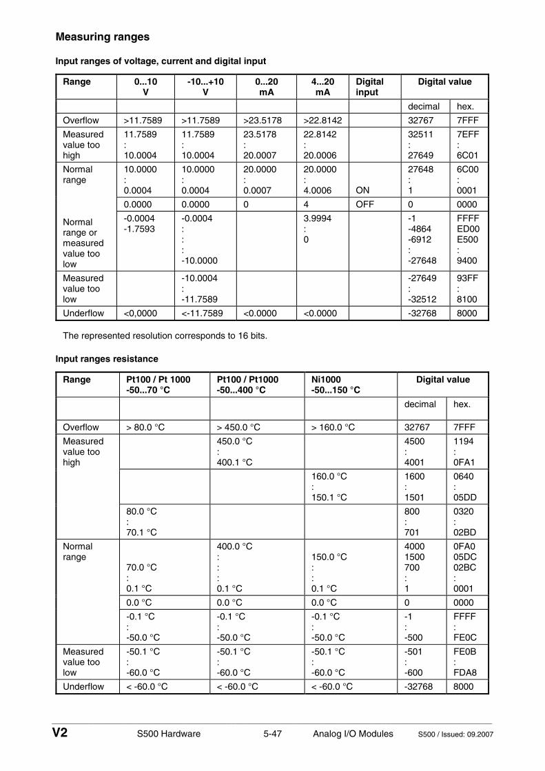
____________________________________________________________________________________________________________
V2 S500 Hardware 5-47 Analog I/O Modules S500 / Issued: 09.2007
Measuring ranges
Input ranges of voltage, current and digital input
Range 0...10 V
-10...+10 V
0...20 mA
4...20 mA
Digital input
Digital value
decimal hex.
Overflow >11.7589 >11.7589 >23.5178 >22.8142 32767 7FFF
Measured value too high
11.7589 : 10.0004
11.7589 : 10.0004
23.5178 : 20.0007
22.8142 : 20.0006
32511 : 27649
7EFF : 6C01
10.0000 : 0.0004
10.0000 : 0.0004
20.0000 : 0.0007
20.0000 : 4.0006 ON
27648 : 1
6C00 : 0001
0.0000 0.0000 0 4 OFF 0 0000
Normal range Normal range or measured value too low
-0.0004 -1.7593
-0.0004 : : : -10.0000
3.9994 : 0
-1 -4864 -6912 : -27648
FFFF ED00E500 : 9400
Measured value too low
-10.0004 : -11.7589
-27649 : -32512
93FF : 8100
Underflow <0,0000 <-11.7589 <0.0000 <0.0000 -32768 8000
The represented resolution corresponds to 16 bits.
Input ranges resistance
Range Pt100 / Pt 1000 -50...70 °C
Pt100 / Pt1000 -50...400 °C
Ni1000 -50...150 °C
Digital value
decimal hex.
Overflow > 80.0 °C > 450.0 °C > 160.0 °C 32767 7FFF
450.0 °C : 400.1 °C
4500 : 4001
1194 : 0FA1
160.0 °C : 150.1 °C
1600 : 1501
0640 : 05DD
Measured value too high
80.0 °C : 70.1 °C
800 : 701
0320 : 02BD
70.0 °C : 0.1 °C
400.0 °C : : : 0.1 °C
150.0 °C : : 0.1 °C
4000 1500 700 : 1
0FA0 05DC 02BC : 0001
0.0 °C 0.0 °C 0.0 °C 0 0000
Normal range
-0.1 °C : -50.0 °C
-0.1 °C : -50.0 °C
-0.1 °C : -50.0 °C
-1 : -500
FFFF : FE0C
Measured value too low
-50.1 °C : -60.0 °C
-50.1 °C : -60.0 °C
-50.1 °C : -60.0 °C
-501 : -600
FE0B : FDA8
Underflow < -60.0 °C < -60.0 °C < -60.0 °C -32768 8000

____________________________________________________________________________________________________________
V2 S500 Hardware 5-48 Analog I/O Modules S500 / Issued: 09.2007
Output ranges voltage and current
Range -10...+10 V 0...20 mA 4...20 mA Digital value
decimal hex.
Overflow 0 V 0 mA 0 mA > 32511 > 7EFF
Measured value too high
11.7589 V : 10.0004 V
23.5178 mA : 20.0007 mA
22.8142 mA : 20.0006 mA
32511 : 27649
7EFF : 6C01
10.0000 V : 0.0004 V
20.0000 mA : 0.0007 mA
20.0000 mA : 4.0006 mA
27648 : 1
6C00 : 0001
0.0000 V 0.0000 mA 4.0000 mA 0 0000
Normal range
-0.0004 V : -10.0000 V
0 mA : 0 mA
3.9994 mA 0 mA 0 mA
-1 -6912 -27648
FFFF E500 9400
Measured value too low
-10.0004 V : -11.7589 V
0 mA : 0 mA
0 mA : 0 mA
-27649 : -32512
93FF : 8100
Underflow 0 V 0 mA 0 mA < -32512 < 8100
The represented resolution corresponds to 16 bits.
Technical data
The system data of AC500 and S500 are valid here. Only additional details are therefore documented below.
Process voltage
- Rated value 24 V DC
- max. ripple 5 %
- Protection against reversed voltage yes
- Rated protection fuse on UP 10 A fast
- Electrical isolation yes, per module
- Current consumption from UP at normal operation
0.10 A + output loads
- Inrush current from UP (at power up) 0.020 A²s
- Connections Terminals 1.8 - 4.8 for +24 V (UP) and 1.9 - 4.9 for 0 V (ZP)
Max. length of analog cables, conductor cross section > 0.14 mm²
100 m
Conversion error of the analog values caused by non-linearity, adjustment error at factory and resolution within the normal range
typ. 0.5 %, max. 1 %
Weight 300 g
Mounting position horizontal or vertical with derating (output load reduced to 50 % at 40°C per group)
Cooling The natural convection cooling must not be hindered by cable ducts or other parts in the switch-gear cabinet.
Attention: All I/O channels (digital and analog) are protected against reverse polarity, reverse supply, short circuit and continuous overvoltage up to 30 V DC.

____________________________________________________________________________________________________________
V2 S500 Hardware 5-49 Analog I/O Modules S500 / Issued: 09.2007
Technical data of the analog inputs
Number of channels per module AX521: 4 AX522: 8
Distribution of channels into groups AX521: 1 group of 4 channels AX522: 1 group of 8 channels
Connections of the channels I0- to I3- Connections of the channels I0- to I7-
AX521: Terminals 1.0 to 1.3 AX522: Terminals 1.0 to 1.7
Connections of the channels I0+ to I3+ Connections of the channels I0+ to I7+
AX521: Terminals 2.0 to 2.3 AX522: Terminals 2.0 to 2.7
Input type bipolar (not with current or Pt100/Pt1000/Ni1000)
Electrical isolation against internal supply and other modules
Configurability 0...10 V, -10...+10 V, 0/4...20 mA, Pt100/1000, Ni1000 (each input can be configured individually)
Channel input resistance Voltage: > 100 kΩ, current: ca. 330 Ω
Time constant of the input filter Voltage: 100 µs, current: 100 µs
Indication of the input signals one LED per channel
Conversion cycle 2 ms (for 8 inputs + 8 outputs), with Pt/Ni... 1 s
Resolution Range 0...10 V: 12 bits
Range -10...+10 V: 12 bits + sign
Range 0...20 mA: 12 bits
Range 4...20 mA: 12 bits
Relationship between input signal and hex code
see tables "Input ranges voltage, current and digital input" and "Input ranges resistance"
Unused voltage inputs are configured as "unused"
Unused current inputs have a low resistance, can be laft open-circuited
Overvoltage protection yes
Technical data of the analog inputs, if they are used as digital inputs
Number of channels per module AX521: max. 4 AX522: max. 8
Distribution of channels into groups AX521: 1 group of 4 channels AX522: 1 group of 8 channels
Connections of the channels I0+ to I3+ Connections of the channels I0+ to I7+
AX521: Terminals 2.0 to 2.3 AX522: Terminals 2.0 to 2.7
Reference potential for the inputs Terminals 1.8 to 4.8 (ZP)
Input signal delay typ. 8 ms, configurable from 0.1 to 32 ms
Indication of the input signals one LED per channel
Input signal voltage 24 V DC
Signal 0 -30 V...+5 V
Signal 1 +13 V...+30 V

____________________________________________________________________________________________________________
V2 S500 Hardware 5-50 Analog I/O Modules S500 / Issued: 09.2007
Technical data of the analog outputs
Number of channels per module AX521: 4, all channels for voltage and current AX522: 8, all channels for voltage, the first 4 channels also for current
Distribution of channels into groups
AX521: 1 group of 4 channels AX522: 1 group of 8 channels
- Channels O0-...O3- - Channels O0-...O7-
AX521: Terminals 3.0...3.3 AX522: Terminals 3.0...3.7
- Channels O0+...O3+ - Channels O0+...O7+
AX521: Terminals 4.0...4.3 AX522: Terminals 4.0...4.7
Output type bipolar with voltage, unipolar with current
Electrical isolation against internal supply and other modules
Configurability -10...+10 V, 0...20 mA, 4...20 mA (each output can be configured individually), current outputs only channels 0...3
Output resistance (load), as current output
0...500 Ω
Output loadability, as voltage output
max. ±10 mA
Indication of the output signals one LED per channel
Resolution 12 bits (+ sign)
Relationship between output signal and hex code
see table "Output ranges voltage and current"
Unused outputs can be left open-circuited
Ordering data
Order No. Scope of delivery
1SAP 250 100 R0001 AX521, Analog input/output module, 4 AI / 4 AO, U/I/Pt100, 12 Bit + sign, 2-wires
1SAP 250 000 R0001 AX522, Analog input/output module, 8 AI / 8 AO, U/I/Pt100, 12 Bit + sign, 2-wires
1SAP 212 200 R0001 TU515, I/O Terminal Unit, 24 V DC, screw-type terminals
1SAP 212 000 R0001 TU516, I/O Terminal Unit, 24 V DC, spring terminals

____________________________________________________________________________________________________________
V2 S500 Hardware 6-1 Accessories S500 / Issued: 05.2006
Accessories S500, overview
TA523 Pluggable Marking Holder Page 6-3
TA525 Set of 10 white Plastic Markers 6-5
TA526 Wall mounting accessory 6-7
CP24… 24 V DC Power supplies CP24... 6-8

____________________________________________________________________________________________________________
V2 S500 Hardware 6-2 Accessories S500 / Issued: 05.2006

____________________________________________________________________________________________________________
V2 S500 Hardware 6-3 Accessories S500 / Issued: 05.2006
Pluggable Marker Holder TA523 - for labelling the channels of S500 I/O modules
1 3
2
DC532
1.0 I0
1.1 I1
1.2 I2
1.3 I3
1.4 I4
1.5 I5
1.6 I6
1.7 I7
1.8 UP
1.9 ZP
2.0 I8
2.1 I9
2.2 I10
2.3 I11
2.4 I12
2.5 I13
2.6 I14
2.7 I15
2.8 UP
2.9 ZP
3.0 C16
3.1 C17
3.2 C18
3.3 C19
3.4 C20
3.5 C21
3.6 C22
3.7 C23
3.8 UP
3.9 ZP
4.0 C24
4.1 C25
4.2 C26
4.3 C27
4.4 C28
4.5 C29
4.6 C30
4.7 C31
4.8 UP
4.9 ZP
CH-ERR3 CH-ERR4
16 DI 16 DCInput 24 V DC
Output 24 V DC 0.5A
CH-ERR2CH-ERR1
UP 24VDC 200W
(1) Pluggable Marking Holder TA523
(2) Marking stripes to be inserted into the holder
(3) Pluggable Marking Holder, snapped on an I/O module
Contents
Purpose Handling instructions Technical data Ordering data
Purpose
The Pluggable Marking Holder is used to hold 4 marking stripes, on which the meaning of the I/O channels of I/O modules can be written down. The holder is transparent so that after snapping it onto the module the LEDs shine through.
Handling instructions
The marking stripes can be printed out from a Word file.
Template: ...\Documentation\2-Hardware-AC500\TA523.doc

____________________________________________________________________________________________________________
V2 S500 Hardware 6-4 Accessories S500 / Issued: 05.2006
Technical data
The system data of AC500 and S500 are valid here. Only additional details are therefore documented below.
Use for labelling channels of I/O modules
Mounting snap-on to the module
Weight 20 g
Dimensions 82 mm x 67 mm x 13 mm
Ordering data
Order No. Scope of delivery
1SAP 180 500 R0001 TA523, Pluggable Marker Holder (10 pieces)

____________________________________________________________________________________________________________
V2 S500 Hardware 6-5 Accessories S500 / Issued: 05.2006
Set of 10 white Plastic Markers TA525 - to label AC500 and S500 modules
DC532
1.0 I0
1.1 I1
1.2 I2
1.3 I3
1.4 I4
1.5 I5
1.6 I6
1.7 I7
1.8 UP
1.9 ZP
2.0 I8
2.1 I9
2.2 I10
2.3 I11
2.4 I12
2.5 I13
2.6 I14
2.7 I15
2.8 UP
2.9 ZP
3.0 C16
3.1 C17
3.2 C18
3.3 C19
3.4 C20
3.5 C21
3.6 C22
3.7 C23
3.8 UP
3.9 ZP
4.0 C24
4.1 C25
4.2 C26
4.3 C27
4.4 C28
4.5 C29
4.6 C30
4.7 C31
4.8 UP
4.9 ZP
CH-ERR3 CH-ERR4
16 DI 16 DCInput 24 V DC
Output 24 V DC 0.5A
CH-ERR2CH-ERR1
TA525
DC532
1.0 I0
1.1 I1
1.2 I2
1.3 I3
1.4 I4
1.5 I5
1.6 I6
1.7 I7
1.8 UP
1.9 ZP
2.0 I8
2.1 I9
2.2 I10
2.3 I11
2.4 I12
2.5 I13
2.6 I14
2.7 I15
2.8 UP
2.9 ZP
3.0 C16
3.1 C17
3.2 C18
3.3 C19
3.4 C20
3.5 C21
3.6 C22
3.7 C23
3.8 UP
3.9 ZP
4.0 C24
4.1 C25
4.2 C26
4.3 C27
4.4 C28
4.5 C29
4.6 C30
4.7 C31
4.8 UP
4.9 ZP
CH-ERR3 CH-ERR4
16 DI 16 DCInput 24 V DC
Output 24 V DC 0.5A
CH-ERR2CH-ERR1
2UP 24VDC 200WUP 24VDC 200W
1
(1) Module without Plastic Marker TA525
(2) Module with Plastic Marker TA525
Contents
Purpose Handling instructions Technical data Ordering data
Purpose
The Plastic Markers are suitable for labelling AC500 and S500 modules (CPUs, couplers and I/O modules). The small plastic parts can be written with a standard waterproof pen.
Handling instructions
The Plastic Markers are inserted under a slight pressure. For disassembly, a small screwdriver is inserted at the lower edge of the module.

____________________________________________________________________________________________________________
V2 S500 Hardware 6-6 Accessories S500 / Issued: 05.2006
Technical data
The system data of AC500 and S500 are valid here. Only additional details are therefore documented below.
Use for labelling AC500 and S500 modules
Mounting insertion under a slight pressure
Disassembly with a small screwdriver
Scope of delivery 10 pieces
Weight 1 g per piece
Dimensions 8 mm x 20 mm x 5 mm
Ordering data
Order No. Scope of delivery
1SAP 180 700 R0001 TA525, Set of 10 white Plastic Markers

____________________________________________________________________________________________________________
V2 S500 Hardware 6-7 Accessories S500 / Issued: 05.2006
Wall Mounting Accessory TA526 - for insertion at the rear side of Terminal Bases and Terminal Units
Figure: Wall mounting accessory TA526
Contents
Purpose Handling instructions Technical data Ordering data
Purpose
If the Terminal Bases TB5xx or Terminal Units TU5xx should be mounted with screws, Wall Mounting Accessories TA526 must be inserted at the rear side first. This plastic parts prevent bending of Terminal Bases and Terminal Units while screwing up.
Handling instructions
The handling of the Wall Mounting Accessories is described in detail under "AC500 system data" and "S500 system data".
Technical data
The system data of AC500 and S500 are valid here. Only additional details are therefore documented below.
Use with wall mounting of Terminal Bases and Terminal Units
Assembly see system data of AC500 and S500
Weight 5 g
Dimensions 67 mm x 35 mm x 5,5 mm
Ordering data
Order No. Scope of delivery
1SAP 180 800 R0001 TA526, Wall Mounting Accessory
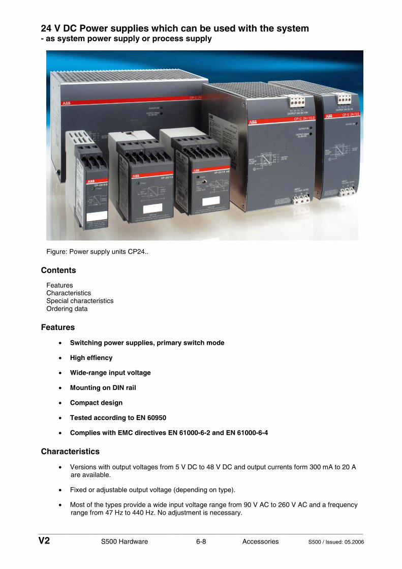
____________________________________________________________________________________________________________
V2 S500 Hardware 6-8 Accessories S500 / Issued: 05.2006
24 V DC Power supplies which can be used with the system - as system power supply or process supply
Figure: Power supply units CP24..
Contents
Features Characteristics Special characteristics Ordering data
Features
• Switching power supplies, primary switch mode
• High effiency
• Wide-range input voltage
• Mounting on DIN rail
• Compact design
• Tested according to EN 60950
• Complies with EMC directives EN 61000-6-2 and EN 61000-6-4
Characteristics
• Versions with output voltages from 5 V DC to 48 V DC and output currents form 300 mA to 20 A are available.
• Fixed or adjustable output voltage (depending on type).
• Most of the types provide a wide input voltage range from 90 V AC to 260 V AC and a frequency range from 47 Hz to 440 Hz. No adjustment is necessary.

____________________________________________________________________________________________________________
V2 S500 Hardware 6-9 Accessories S500 / Issued: 05.2006
• Integrated input fuse.
• Almost all types can also be supplied with DC voltage from 105 V DC to 260 V DC.
• High efficiency of up to 90 %.
• Extended lifetime due to low power dissipation and low heating.
• No-load proof, overload proof, continuous short-circuit proof, automatic restart.
• Fast and easy mounting on DIN rail.
• Compact slim design.
Special characteristics
• Power factor correction (PFC) according to EN 61000-3-2 for CP-24/5.0 and CP-24/5.0 adj.
• Parallel connection possible for CP-24/10 adj. and CP-24/20 adj.
• Redundancy module available.
Ordering data
Ordering data CP Range, switching power supplies
Order No. Type Input Output
1SVR 423 418 R0000 CP-24/1.0 90-260 V AC or 105-260 V DC 24 V DC, 1 A
1SVR 423 417 R0000 CP-24/2.0 90-140 V AC 24 V DC, 2 A
1SVR 423 417 R1000 CP-24/2.0 140-260 V AC 24 V DC, 2 A
1SVR 423 417 R1100 CP-24/2.0 adj. 140-260 V AC or 160-260 V DC 24 V DC, 2 A adj.
1SVR 423 416 R0000 CP-24/5.0 90-260 V AC or 127-260 V DC 24 V DC, 5 A
1SVR 423 416 R0100 CP-24/5.0 adj. 90-260 V AC or 127-260 V DC 24 V DC, 5 A adj.
1SVR 423 416 R1000 CP-24/4.2 90-260 V AC or 127-260 V DC 24 V DC, 4,2 A
Ordering data CP-S Range, switching power supplies
Order No. Type Input Output
1SVR 427 014 R0000 CP-S 24/5.0 110-240 V AC 24 V DC, 5 A
1SVR 427 015 R0100 CP-S 24/10.0 110-120 V AC or 220-240 V AC (with selector switch)
24 V DC, 10 A
1SVR 427 016 R0100 CP-S 24/20.0 110-120 V AC or 220-240 V AC (with selector switch)
24 V DC, 20 A
Ordering data CP-C Range, switching power supplies
Order No. Type Input Output
1SVR 427 024 R0000 CP-C 24/5.0 110-240 V AC 22-28 V DC, 5 A
1SVR 427 025 R0000 CP-C 24/10.0 110-240 V AC 22-28 V DC, 10 A
1SVR 427 026 R0000 CP-C 24/20.0 110-240 V AC 22-28 V DC, 20 A

____________________________________________________________________________________________________________
V2 S500 Hardware 6-10 Accessories S500 / Issued: 05.2006


ABB STOTZ-KONTAKT GmbHEppelheimer Straße 82 69123 Heidelberg, GermanyPostfach 10 16 80 69006 Heidelberg, GermanyTelephone (06221) 701-0Telefax (06221) 701-240Internet http://www.abb.de/stotz-kontaktE-Mail [email protected]
Man
ual N
o.: 2
CD
C 1
25 0
17 M
0201