Embed Size (px)
Citation preview
System Design and Implementation
Author: Martin EckerProject Website: http://xengine.sourceforge.netLast Modified: 5. May 2004 22.49
Please note that this document is a bit out of date, however the basic design of XEnginehasn’t changed much from what is presented here. In particular, there is now a new com-ponent called XEngineUtil and the Mesh class has been moved there. For a current struc-tural design overview of XEngine please see the API reference documentation.
1.1 Introduction
One of the main goals in developing XEngine was to have a clean and object-orienteddesign. Many modern and acknowledged, object-oriented design patterns and guidelines[Land95] have been used in the design of the engine. The next couple of sections willdescribe XEngine’s design in detail with the use of UML diagrams [Hitz99]. First thehigh-level component design is presented. Then the class design of the three main com-ponents, XEngineMath, XEngineCore, and XEngineSceneGraph, will be discussed.Finally, the subsequent section 1.6 reflects on the design patterns used.In addition to a modern design, the engine was also implemented by using modern C++techniques, such as templates and exception handling, as will be discussed in section 1.7.
I would like to note at this point that XEngineSceneGraph is currently not publicly avail-able because it is in a rather messy and unfinished state. Also more features need to beadded and performance optimizations need to be done before the scene graph can bereleased. I still decided to describe the current design here because some people mightfind it interesting. I’m also grateful for any further design ideas or improvements for thescene graph.
1.2 Component Design
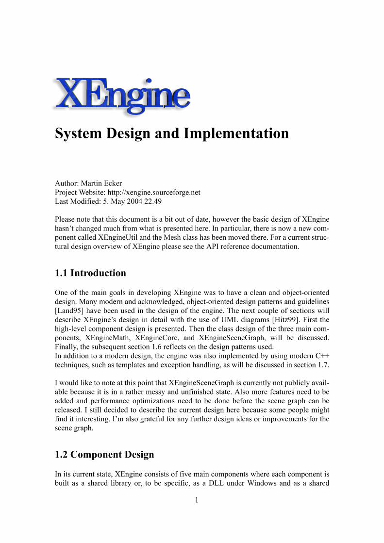
In its current state, XEngine consists of five main components where each component isbuilt as a shared library or, to be specific, as a DLL under Windows and as a shared
1
2
object under Linux. The five components are shown in the UML component diagram infigure 1.1. User applications only have direct access to three of these components, XEn-gineMath, XEngineCore, and XEngineSceneGraph. The other two components are ren-derer libraries for a particular 3D graphics API used only internally by the core rendersystem.
XEngineMath contains all the mathematical routines and classes for handling vectors,matrices, quaternions, and a number of two-dimensional and three-dimensional geomet-ric objects. XEngineCore is the core render system and can be seen as a wrapper of anunderlying 3D graphics API, such as OpenGL or Direct3D. From the point of view of theclient application, XEngineCore actually is a 3D graphics API. XEngineCore defines anabstract interface that needs to be implemented by renderer libraries wrapping an under-lying 3D graphics API. Currently, renderer libraries for two graphics APIs are available,XEngineRendererOGL13 for OpenGL 1.3 and XEngineRendererDX81 for DirectX 8.1.Finally, XEngineSceneGraph contains a flexible scene graph with efficient visibilityculling, a BSP tree, and a scene loader for Quake 3 BSP files. Note that applications arenot required to use this scene graph, but can use their own scene management system ifso desired.
Figure 1.1: UML Component Diagram of the Component Design
The subsequent sections discuss the design of the three main components of the enginein more detail.
1.3 Mathematics Library Design
XEngineMath is the mathematics library of XEngine. It offers a number of stand-aloneclasses for handling vectors, matrices, and quaternions, and a class hierarchy of two-dimensional and three-dimensional geometry objects. All the other components of XEn-
XEngineMath
XEngineCore
XEngineRendererDX81XEngineRendererOGL13
XEngineSceneGraph
3
gine heavily use XEngineMath, and it can be used independently of the other enginecomponents.
1.3.1 Stand-Alone Classes
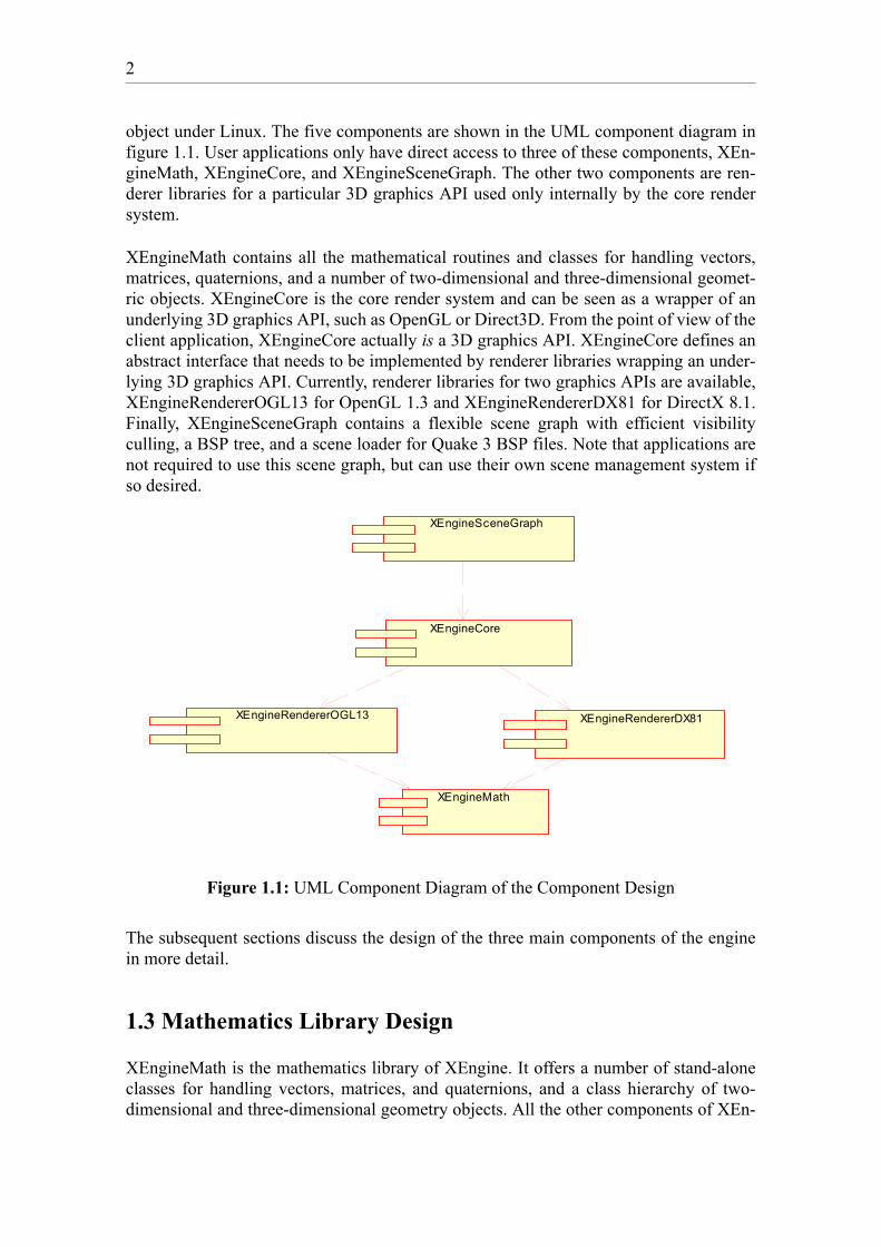
Figure 1.2 shows a high-level UML class diagram of the available stand-alone classes inthe mathematics library. The vector classes offer all expected operations, such as addi-tion, subtraction, multiplication, division, dot product, cross product, normalization, andmany more. Similarly, the matrix classes have a number of useful operations, such asmatrix-vector multiplication, matrix-matrix multiplication, inversion, and a number ofothers. Since mostly homogeneous four-by-four matrices are used in 3D graphics, theMatrix4x4 class has a variety of additional Set-methods, such as SetTranslation,SetRotation, or SetPerspectiveProj, that create special matrices. Note that the engine usesrow-major matrices by convention. Finally, the Math class is a special class that onlycontains static methods for various often required mathematics operations, such as com-puting the absolute value or calculating the square root of a value.
Figure 1.2: UML Class Diagram of the Stand-Alone Mathematics Classes
Currently, none of these classes are optimized with the use of specialized CPU instruc-tion sets, such as the SIMD extensions of Intel processors. However, the design of themathematics library easily allows the integration of specialized versions of these classes.
1.3.2 Two-Dimensional Geometric Objects
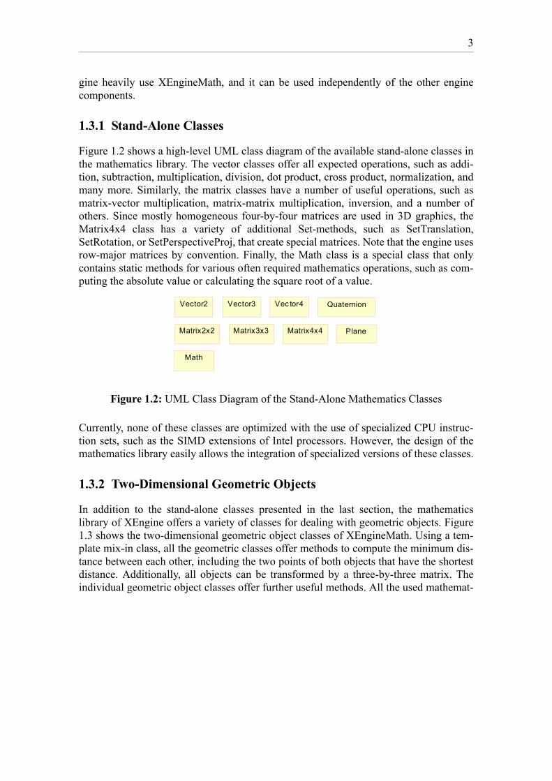
In addition to the stand-alone classes presented in the last section, the mathematicslibrary of XEngine offers a variety of classes for dealing with geometric objects. Figure1.3 shows the two-dimensional geometric object classes of XEngineMath. Using a tem-plate mix-in class, all the geometric classes offer methods to compute the minimum dis-tance between each other, including the two points of both objects that have the shortestdistance. Additionally, all objects can be transformed by a three-by-three matrix. Theindividual geometric object classes offer further useful methods. All the used mathemat-
Vector2 Vector3 Vec tor4
Matrix2x2 Matrix3x3 Matrix4x4
Quaternion
Math
Plane
4
ical algorithms are documented with detailed descriptions in the XEngine API referencedocumentation.
Figure 1.3: UML Class Diagram of Two-Dimensional Geometric Objects
Following object-oriented design patterns, all geometric objects are derived from theabstract base class GeometricObject, including the hierarchy of three-dimensional geo-metric object classes presented in the next section. All two-dimensional geometricobjects are then derived from the base class GeometricObject2. Finally, the classes repre-senting linear components, Line2, Ray2, and Segment2, are derived from a commonbase class called LinearComponent2, and the classes representing an area, Triangle2 andRectangle2, are subclasses of Area2.
These two-dimensional classes are currently only rarely used in other parts of the engine,but can be useful to user applications, for example for developing a two-dimensionaluser interface that is layered on top of a 3D scene, such as a head-up display, using XEn-gine.
1.3.3 Three-Dimensional Geometric Objects
All of the two-dimensional geometric object classes offered by XEngineMath have a cor-responding three-dimensional version. Additionally, a number of volume classes areadded to the class hierarchy, some of which are also used as bounding volumes in thescene graph component. The additional volume classes are Box, which represents an ori-ented box, AxisAlignedBox, Sphere, and Frustum. The latter is used to represent the
Geomet ricObjec t
GeometricObject2
LinearComponent2 Area2Point2
Line2 Ray2 Segment2 Triangle2 Rectangle2
5
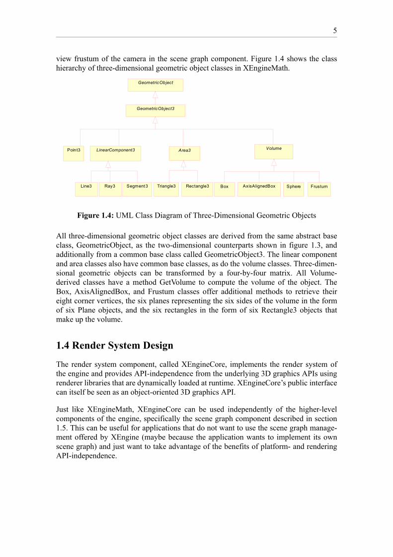
view frustum of the camera in the scene graph component. Figure 1.4 shows the classhierarchy of three-dimensional geometric object classes in XEngineMath.
Figure 1.4: UML Class Diagram of Three-Dimensional Geometric Objects
All three-dimensional geometric object classes are derived from the same abstract baseclass, GeometricObject, as the two-dimensional counterparts shown in figure 1.3, andadditionally from a common base class called GeometricObject3. The linear componentand area classes also have common base classes, as do the volume classes. Three-dimen-sional geometric objects can be transformed by a four-by-four matrix. All Volume-derived classes have a method GetVolume to compute the volume of the object. TheBox, AxisAlignedBox, and Frustum classes offer additional methods to retrieve theireight corner vertices, the six planes representing the six sides of the volume in the formof six Plane objects, and the six rectangles in the form of six Rectangle3 objects thatmake up the volume.
1.4 Render System Design
The render system component, called XEngineCore, implements the render system ofthe engine and provides API-independence from the underlying 3D graphics APIs usingrenderer libraries that are dynamically loaded at runtime. XEngineCore’s public interfacecan itself be seen as an object-oriented 3D graphics API.
Just like XEngineMath, XEngineCore can be used independently of the higher-levelcomponents of the engine, specifically the scene graph component described in section1.5. This can be useful for applications that do not want to use the scene graph manage-ment offered by XEngine (maybe because the application wants to implement its ownscene graph) and just want to take advantage of the benefits of platform- and renderingAPI-independence.
GeometricObject
GeometricObject3
LinearComponent3 Area3 VolumePoint3
Line3 Ray3 Segment3 Triangle3 Rectangle3 Box SphereAxisAlignedBox Frustum

6
1.4.1 Render System Definition
The render system acts as an abstraction layer between the application and the underly-ing rendering API, such as OpenGL, DirectX, or possibly even a software renderer. Itmaps the functionality offered by the underlying rendering API to a well-defined, object-oriented interface that the application uses to render scenes. The application only workswith the interfaces offered by the render system and usually does not have to concernitself much with the peculiarities of the underlying 3D graphics API. Therefore, XEngi-neCore is the component responsible for providing the application with API-independ-ence. To achieve this API-independence the render system defines an abstract interfacethat gets implemented by the specific renderer libraries. The renderer libraries then mapthe functionality of the common application interface of XEngineCore to the underlyingrendering API.
The main functionality of the render system comprises routines to create render contextsand render targets, to begin and end a scene, to swap back with front buffers, to renderprimitives, to create vertex and index buffers, to manage render states and texture sam-pler stages, and to offer support for vertex and fragment shaders using low-level andhigh-level shading languages.
The render system resides in its own shared library called XEngineCore with all the API-dependent code again residing in separate shared libraries. The DirectX 8.1 renderer, forexample, resides in a shared library called XEngineRendererDX81 (see figure 1.1). Theengine provides a special dialog that can be used to let the user choose a renderer at run-time. An application can, of course, also decide which renderer library to use dependingon other criteria. Once a renderer has been chosen, the corresponding shared library isloaded, and the renderer can be used to render a scene. More than one renderer can beused by an application at the same time, which allows using different 3D graphics APIsto render into multiple windows.
1.4.2 Render System Conventions
3D graphics APIs all have their own conventions regarding coordinate systems, vectorand matrix forms, and so on. It is therefore imperative for a 3D engine to have well-defined conventions that are used throughout. This section outlines the conventions usedin XEngine.
XEngine uses a right-handed coordinate system where the x-axis points to the right, they-axis points up, and the z-axis points out of the screen. The vertices of front faces arespecified in counterclockwise winding. Therefore, backface culling will usually be set tocull clockwise-oriented faces.
Just like Direct3D, but unlike OpenGL, XEngine uses row-major matrices and vectors.When addressing an element of a matrix M, M[x][y] refers to the x-th row and the y-thcolumn of the matrix. This is also the way that matrices are stored in the programminglanguage C, which is one of the reasons why the row-major form was chosen for theengine. A homogeneous transformation M is applied to a vector v by pre-multiplying thevector with the matrix, so that the resulting vector is . A nice by-product of thisv' v M⋅=
7
convention is that, when constructing a combined transformation matrix that is the prod-uct of various transformation matrices, the multiplications are done from left to right. Orin other words, transformations are applied in the order they are multiplied together andnot in reverse order, as would be the case with column-major matrices and vectors. Thisis another reason why the author prefers row-major matrices.
Given the homogeneous vertex in clip coordinates, the clipping volume used inXEngine is defined as the axis-aligned space given by the following inequalities
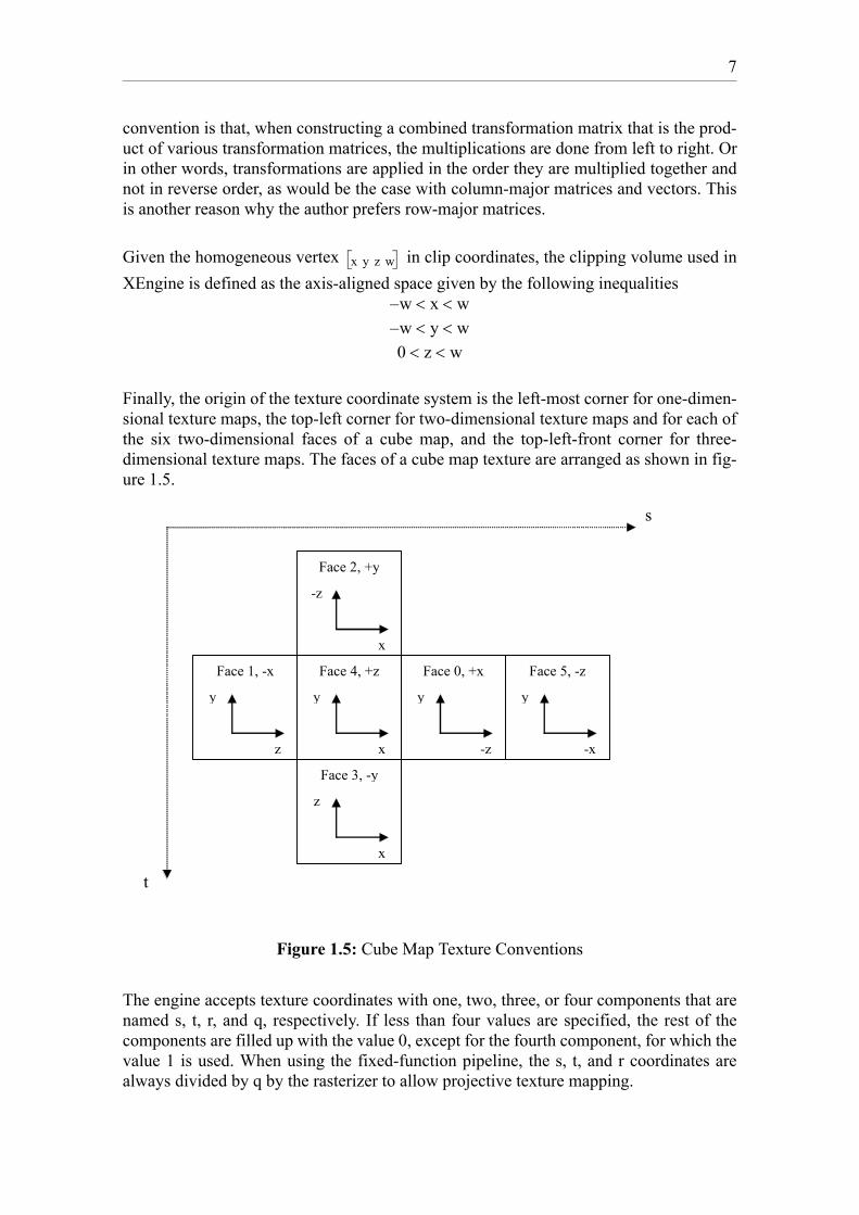
Finally, the origin of the texture coordinate system is the left-most corner for one-dimen-sional texture maps, the top-left corner for two-dimensional texture maps and for each ofthe six two-dimensional faces of a cube map, and the top-left-front corner for three-dimensional texture maps. The faces of a cube map texture are arranged as shown in fig-ure 1.5.
Figure 1.5: Cube Map Texture Conventions
The engine accepts texture coordinates with one, two, three, or four components that arenamed s, t, r, and q, respectively. If less than four values are specified, the rest of thecomponents are filled up with the value 0, except for the fourth component, for which thevalue 1 is used. When using the fixed-function pipeline, the s, t, and r coordinates arealways divided by q by the rasterizer to allow projective texture mapping.
x y z w
w– x w< <w– y w< <0 z w< <
Face 2, +y
-z
x
Face 4, +z
y
x
Face 0, +x
y
-z
Face 5, -z
y
-x
Face 1, -x
y
z
Face 3, -y
z
x
t
s

8
1.4.3 Render System High-Level UML Class Diagram
The following UML class diagram shows a high-level view of the most important classhierarchies in the render system, in particular the hierarchy of render resource and rendertarget classes. The subsequent sections describe the most important classes in moredetail. The diagram only shows the classes that an application built with the engine uses.For this reason certain classes like Renderer or RenderWindow are only shown asabstract base classes. In the specific renderer libraries, classes that implement the con-crete versions for a particular graphics API are derived from these abstract base classes.
Figure 1.6: Render System High-Level UML Class Diagram
1.4.4 The Renderer and RenderContext Classes
The Renderer and RenderContext classes are the main interfaces for an application to therender system. The Renderer class is the first interface the client acquires by calling thestatic member function Renderer::CreateRenderer of the XEngineCore shared library.An instance of the Renderer class represents one of XEngine’s renderer libraries thatimplement the core functionality for a specific 3D graphics API. Using a Renderer
RenderWindow
RenderTexture2D
TextureBase
Texture3D CubeTextureTexture2D VertexBuffer IndexBuffer
RenderBuffer
Curve Surface
BezierCurve NurbsSurfaceBezierSurfaceBSplineCurve BSpl ineSurfaceNurbsCurve
Geometry
Mesh
VertexShader FragmentShader
RenderWindow is also derived from wxWindow from the wxWindows library
RenderFullScreenWindow
Shader ShaderProgram0..* 0..*0..* 0..*
Texture1D
RenderCubeTexture
RenderTexture
RenderTexture1D
ViewportTextureSamplerStageRenderTarget
11 11
Renderer
RenderResource
TextureCoordStage
RenderContext
1..*
1
1..*
11
1..*
1
1..*
0..*
1
0..*
1
1
0..*
1
0..*
9
object, the application can then create a RenderContext object which is logically com-posed of all the available render states and the available texture sampler stages and tex-ture coordinate stages and their associated states. A render context is always bound to aspecific graphics adapter in the system and should only be used from the thread that cre-ated it. Additionally, a render context has a number of associated render resources andrender targets that the application can create. When a render context is created, at leastone render target, a primary render window, must be created. A render window is aninstance of the class RenderWindow or any class derived from it. Render targets will bediscussed in more detail in section 1.4.6.
With the RenderContext interface an application can begin and end a scene, swap backwith front buffers, create render targets (different types of windows and textures) andrender resources, draw primitives and meshes, and set render states. There are also rou-tines to set the world, view and projection matrices and a whole range of other methodsthat usually directly map to the underlying rendering API. One of the most frequentlycalled methods of RenderContext are the two RenderContext::Draw methods used torender primitives to the currently active render target. Primitives supported by XEngineare point lists, line lists, line strips, triangle lists, triangle strips, and triangle fans. Thevertices that compose primitives are stored in one or more vertex buffers. The attributesof a vertex can therefore be split up and stored separately in multiple buffers. The first ofthe two Draw methods of the RenderContext takes a vertex buffer stream mapping asinput parameter and renders the geometry contained in the vertex buffers defined by themapping to the current render target. The second Draw method additionally takes anindex buffer as input parameter and renders indexed primitives to the current render tar-get. It is advisable to use indexed primitives whenever possible, because it reduces theamount of memory sent to the graphics hardware. With indexed primitives, multipleprimitives can use the same vertex by reusing its index in the index buffer without hav-ing to duplicate all the vertex attributes of that vertex in the vertex buffer.
Both the Renderer and the RenderContext classes are actually abstract base classes fromwhich classes are derived in the renderer libraries that implement most of the functional-ity using the underlying rendering API. Most of the time, the deriving classes have tomap the routines to the corresponding routines of the rendering API and not actuallyimplement much. Therefore, implementing a renderer for a new 3D graphics API is usu-ally a task that is tedious, because of the high number of routines to implement, butuncomplicated, since it mostly only involves mapping functions to functions.
1.4.5 States
XEngine differentiates between a variety of state types. A render state is a state thataffects the entire render context. A texture state only affects texture objects, or in otherwords it represents per-texture object state. A texture sampler state affects a texture sam-pler stage and correspondingly a texture coordinate state affects a texture coordinatestage. Examples for render states are the state of the depth buffer or stencil buffer. Exam-ples for texture states are the used filters or addressing modes. Currently XEngine doesnot offer any texture sampler states. Examples for texture coordinate states are the tex-ture matrix and texture coordinate generation modes.

10
Render states, texture states, texture sampler states, and texture coordinate states in XEn-gine are grouped together in classes. For example, all the depth buffer-related states aregrouped together in a class called RSZBuffer. If an application wants to set a particulardepth buffer state, it first creates an instance of RSZBuffer, sets the required state varia-ble in that object, and then actually sets the state by passing the object as parameter to themethod RenderContext::SetState. This design choice was made for better object-orientedencapsulation and ease of extensibility with new render states without breaking thebinary interface of the RenderContext class. It also reduces the interface complexity ofthe RenderContext class, since only one method is required for setting render states andthat method can handle all the available render states. Similar to render states, the texturesampler states and texture coordinate states are grouped together in various classes. Eachtexture sampler stage and texture coordinate stage, respectively, has a distinct set ofstates. These states are set by passing an instance of any of the state classes to the meth-ods TextureSamplerStage::SetState and TextureCoordStage::SetState, respectively. Tex-ture states are also grouped together in classes. Texture states are set by calling Texture-Base::SetState.
Figure 1.7: UML Class Diagram of the State Class Hierarchy
Figure 1.7 shows the class hierarchy of states in XEngine. All render states are derivedfrom an abstract base class RenderState, all texture states are derived from an abstractbase class TextureState, all texture sampler states are derived from an abstract base classTextureSamplerState, and eventually all texture coordinate states are derived from anabstract base class TextureCoordState. Additionally a template mix-in class1 calledStateBase is used, which defines the abstract interface of all types of states. It would alsohave been possible to directly derive the texture sampler states and texture coordinate
1. For details on template mix-in classes, see section 1.7.3.
RenderState
RSZBuffer RSAlphaTest
RSFillMode
RSShadeModeRSBlendMode RSDitheringRSFog
RSStencilBuffer
PointLight DirectionalLight SpotLight
TextureState
TSSFiltering
RSMaterial
TSAddressingMode
Light
RSLighting
*
1
*
1RSNormalization
RSClipPlanes
RSCullMode
TCSTexCoordGeneration
RSClearValues
TSBorderColor
RSCombineConstantColorRSColorMaterial
TCSTextureMatrix
TextureCoordState TextureSamplerState
11
states from the render states which would, however, require that all textures samplerstates and texture coordinate states have a reference to one of the corresponding stages.Since a state should be independent of a specific stage, this option was dropped. Notethat, due to the nature of the programmable pipeline, a lot of these states only apply whenthe fixed-function pipeline is used (for details, see my other paper titled ProgrammableGraphics Pipeline Architectures).
Note that, unlike many other engines, the concepts of materials and lights used in thefixed-function pipeline of OpenGL and Direct3D are also considered to be regular renderstates in XEngine. Another design variation would have been to have separate classes,Light and Material, and corresponding methods, RenderContext::SetMaterial for materi-als and RenderContext::SetLight or RenderContext::AddLight for lights. But since mate-rials and lights can be considered to be general render states, a decision has been made toinclude materials and lights in the render state class hierarchy.In addition to the stateclasses presented so far, the engine offers a StateSet class, which is composed of allavailable render states, all texture sampler states for all texture sampler stages, and alltexture coordinate states for all texture coordinate stages. In addition it contains a refer-ence to a shader program and a reference to a texture object for each texture samplerstage. So a state set can be considered to represent the entire state of the graphics pipe-line. Various operations can be performed on state sets, in particular merging two statesets, computing the difference or intersection of two state sets, and applying an entirestate set to the render context that created it. For details see the XEngine API referencedocumentation.
1.4.6 The RenderTarget Class Hierarchy
A render target is a target for render operations initiated by the two RenderCon-text::Draw methods. XEngine supports two main types of render targets, windows andtextures. Rendering a scene to a texture allows powerful techniques, such as dynamicenvironment mapping, and is the basis for a lot of other techniques involving floatingpoint buffers, since these types of buffers are only supported in the form of textures oncurrent graphics hardware. Each render context can have any number of associatedrender targets, restricted only by the capabilities of the graphics hardware. However, atany time, only one target can be set as the active target to be rendered to.
Render targets cannot be created directly by using a constructor, but are created by a spe-cial constructor function called RenderContext::CreateRenderTarget, which receives adata object describing the type and format of the to-be-created render target. This tech-nique is necessary to give the renderer libraries a chance to return renderer-specificrender targets. A render target is made active by calling RenderContext::SetRenderTar-get passing in the desired render target as parameter. Each render target has an associatedviewport which defines the visible rectangular area of the target that is used for render-
12
ing. All primitives are clipped against this viewport. Therefore, primitives rendered out-side the viewport are discarded.
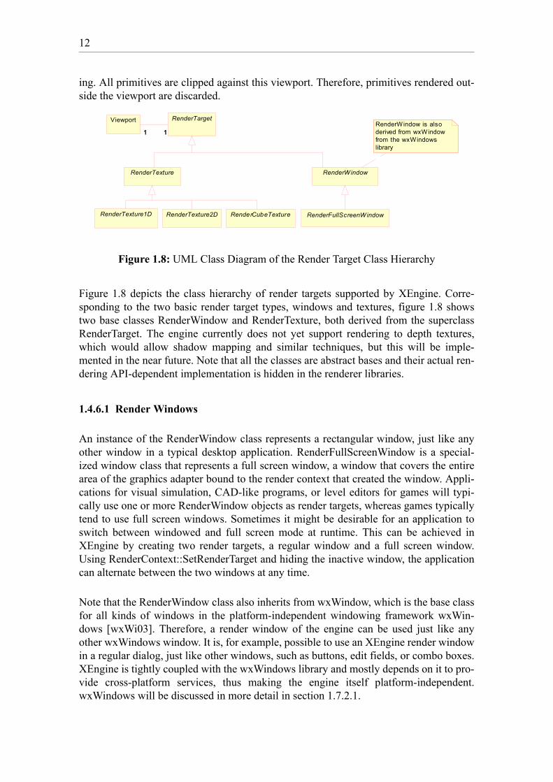
Figure 1.8: UML Class Diagram of the Render Target Class Hierarchy
Figure 1.8 depicts the class hierarchy of render targets supported by XEngine. Corre-sponding to the two basic render target types, windows and textures, figure 1.8 showstwo base classes RenderWindow and RenderTexture, both derived from the superclassRenderTarget. The engine currently does not yet support rendering to depth textures,which would allow shadow mapping and similar techniques, but this will be imple-mented in the near future. Note that all the classes are abstract bases and their actual ren-dering API-dependent implementation is hidden in the renderer libraries.
1.4.6.1 Render Windows
An instance of the RenderWindow class represents a rectangular window, just like anyother window in a typical desktop application. RenderFullScreenWindow is a special-ized window class that represents a full screen window, a window that covers the entirearea of the graphics adapter bound to the render context that created the window. Appli-cations for visual simulation, CAD-like programs, or level editors for games will typi-cally use one or more RenderWindow objects as render targets, whereas games typicallytend to use full screen windows. Sometimes it might be desirable for an application toswitch between windowed and full screen mode at runtime. This can be achieved inXEngine by creating two render targets, a regular window and a full screen window.Using RenderContext::SetRenderTarget and hiding the inactive window, the applicationcan alternate between the two windows at any time.
Note that the RenderWindow class also inherits from wxWindow, which is the base classfor all kinds of windows in the platform-independent windowing framework wxWin-dows [wxWi03]. Therefore, a render window of the engine can be used just like anyother wxWindows window. It is, for example, possible to use an XEngine render windowin a regular dialog, just like other windows, such as buttons, edit fields, or combo boxes.XEngine is tightly coupled with the wxWindows library and mostly depends on it to pro-vide cross-platform services, thus making the engine itself platform-independent.wxWindows will be discussed in more detail in section 1.7.2.1.
RenderWindow
RenderTexture2D RenderFullScreenWindowRenderCubeTexture
RenderTexture
RenderTexture1D
Viewport RenderTarget
11 11RenderWindow is also derived from wxWindow from the wxWindows library

13
1.4.6.2 Render Textures
XEngine offers three different types of texture render targets, one-dimensional, two-dimensional, and cube map render textures. The corresponding classes, such as theRenderTexture2D class, are not only derived from the base class for render textures,RenderTexture, as shown in figure 1.8, but also from the class that represents the corre-sponding render resource using multiple inheritance (see figure 1.6). RenderTexture2D,for example, inherits from RenderTexture and also from Texture2D. Therefore, aRenderTexture2D object can be used just like any other two-dimensional texture, but canadditionally be passed as parameter to RenderContext::SetRenderTarget to be set as theactive render target. The design decision for this easy-to-use solution for render-to-tex-ture was not an easy one, considering the way render-to-texture is implemented inOpenGL using so-called pbuffers, which does not lend itself easily to such a design.However, ease-of-use of the API was one of the main design goals for XEngine, which iswhy the current approach has been chosen, incurring more implementation complexity inthe OpenGL renderer library.
1.4.7 The RenderResource Class Hierarchy
A render resource represents any entity used by the graphics hardware. In particularrender resources are textures, index and vertex buffers, shaders and shader programs, andgeometric objects, such as meshes, curves, and patches. A resource can either be storedin system memory, in local video memory or non-local video memory (AGP memory),which is usually decided by the graphics driver or the underlying rendering API. Usingflags specified during the creation of a render resource, an application can influence thestorage location of a render resource to a certain degree without any guarantee that thespecified type of memory will be used. Furthermore, each resource has an associated pri-ority that indicates the importance of storing it in high-performance memory. The higherthe priority the less the chance that the resource will get removed from video memory.
Figure 1.9 shows the class hierarchy of render resources. RenderResource is the abstractbase class for all render resources in XEngine. Just like render targets, resources cannever be created directly by using the constructor, but only through certain constructor

14
functions in the RenderContext class, such as RenderContext::CreateVertexBuffer orRenderContext::CreateTexture2D.
Figure 1.9: UML Class Diagram of the Render Resource Class Hierarchy
Render resources are reference counted so that ownership of a single resource can beshared by multiple objects. For example, a shader program consists of one or moreshader objects, and none of its associated shaders must be destroyed while it is the activeshader program. Therefore a shader program has shared ownership of all its shaders sothat the application cannot delete a shader while it is being actively used. In order todestroy a render resource, a special method named Release needs to be called to indicatethat the reference to the resource is no longer needed. Once all references to a resourcehave been released, the resource destroys itself. Additionally, the render context that wasused to create a render resource is also responsible for managing the associated memoryof a resource. If any render resources have not yet been destroyed when the context itselfis deleted, the render context will delete any resources it created. In other words, a rendercontext has weak references to all resources it creates. It is also important to note that bydesign resources cannot be directly copied (there is no assignment operator or copy con-structor) because they typically occupy scarce video memory. If a copy of a renderresource is required nevertheless, the application needs to manually recreate an equiva-lent resource.
1.4.7.1 Textures
The engine supports all standard types of textures, specifically one-dimensional, two-dimensional, three-dimensional, and cube map textures. The dimensions for each ofthese texture types must be a power of two, but need not be square. Rectangular textureswhere the dimensions can be of any size, as provided by the NV_texture_rectangle orEXT_texture_rectangle OpenGL extensions, are not yet supported. Nearest neighbour,bilinear, trilinear, and anisotropic filtering is available for textures. Additionally a textureobject can have a chain of mipmaps. A mipmap is a sequence of texture images, each of
TextureBase
Texture3D CubeTextureTexture2D VertexBuffer IndexBuffer
RenderBuffer
Curve Surface
BezierCurve NurbsSurfaceBezierSurfaceBSplineCurve BSpl ineSurfaceNurbsCurve
Geometry
Mesh
VertexShader FragmentShader
Shader ShaderProgram0..* 0..*0..* 0..*
Texture1D
RenderResource
15
which is a progressively lower resolution representation of the same image. The heightand width of each level in the mipmap is a power of two smaller than the previous level.If desired, the engine can automatically and, if possible, in hardware generate mipmaplevels for the entire mipmap chain. A texture is set active in one of the texture samplerstages by calling the method TextureSamplerStage::SetTexture on the desired stage.
1.4.7.2 Vertex and Index Buffers
All geometry data submitted to the render system of XEngine must be stored in vertexand index buffers. A vertex buffer stores vertices where a vertex is a number of vertexattributes, such as position, normal, colour, and so on. An index buffer stores indices intoa vertex buffer. To actually draw the geometry data, one of the two RenderContext::Drawmethods must be called. Both Draw methods take the primitive type, such as line list ortriangle strip, and the number of primitives that are to be rendered as input parameters.The first Draw method additionally requires a vertex buffer stream mapping as parameterwhich specifies the vertex buffers containing all the vertices that define the to-be-drawnprimitives. The vertices in the buffers are used one after the other. If, for example, thegiven primitive type is triangle list, every three vertices of the vertex buffers will be usedto render a triangle.The second Draw method also takes a vertex buffer stream mapping as input parameter,and additionally an index buffer which contains indices into the vertex buffers and adds alevel of indirection. If the specified primitive type is again triangle list, every three indi-ces in the index buffer will be used to retrieve three vertices from the vertex buffers thatare then used to render a triangle. Since both vertex and index buffers are renderresources, they can potentially be stored in video memory.
An important concept in combination with vertex buffers is the concept of vertex for-mats. Each vertex buffer must have an associated vertex format specified using a dataclass called VertexFormat, which describes the format, or layout, of the vertex type of thevertices stored in the buffer. A vertex format defines the number of vertex attributes thattogether compose a vertex or parts of a vertex and their data types. For the fixed-functionpipeline the meaning, order, and type of the vertex attributes is fixed and cannot be mod-ified. For vertex formats that describe vertex types used with the programmable pipelinethe order and data types of the vertex attributes are not pre-defined and can be freelydefined by the application.
The attributes for vertex types used with the fixed-function pipeline must be specified inthe following order with the mentioned data types:
• Position in local object space, three 32-bit IEEE floating point values.
• Normal in local object space, three 32-bit IEEE floating point values.
• Primary colour, one 32-bit unsigned integer value in ARGB order.
• Secondary colour, one 32-bit unsigned integer value in ARGB order. The alpha com-ponent is ignored and should be zero.
• A maximum of n sets of texture coordinates, where each set can consist of one, two,three, or four 32-bit IEEE floating point values. n is the number of available texturesampler stages. Texture coordinate sets must be specified in ascending order of the

16
corresponding texture sampler stage number. It is not necessary to specify a set of tex-ture coordinates for each texture sampler stage since some stages could use automatictexture coordinate generation.
Of course, it is possible to omit certain attributes if they are not used. In fact, theattributes secondary colour and normal are mutually exclusive from a logical point ofview because, if a vertex normal is specified, it will be used for computing fixed-func-tion vertex lighting and any specified secondary colour will be ignored in this case.
To give vertex attributes a meaning, that is, to associate them with vertex shader inputsor the inputs to the fixed-function pipeline, a so-called vertex attribute binding must bedefined by using the VertexAttribBinding class. A vertex attribute binding binds anattribute, specified via its zero-based index in a vertex format, to an input variable name,specified as string, used in the vertex shader or in the fixed-function pipeline. In otherwords, a vertex attribute binding represents and defines the connection between the ver-tex data stored in a vertex buffer and the graphics pipeline. It gives the various vertexattributes a semantic meaning, which is implicitly defined by the input variable name thevertex attribute is bound to. A binding does not necessarily have to bind all the vertexattributes described by a vertex format. The not bound attributes will simply be ignoredand cannot be used by the vertex shader. This allows reuse of vertex buffers with differ-ent vertex shaders, which is especially important for multi-pass rendering.
Vertex attribute bindings for the programmable pipeline can be freely defined by theapplication and must generally match the required input variables used by the vertexshader, since the vertex shader is the first programmable processing stage of the pipeline.Just as with vertex formats, vertex attribute bindings for the fixed-function graphicspipeline must adhere to stricter rules because of the hardwired logic of the fixed-functionpipeline. Firstly, the vertex attributes need to be specified in a certain order and need tobe packed tightly. So it is not permissible to not bind an attribute. Secondly, the data typefor each attribute is pre-determined and cannot be changed by the application. Thirdly,there are default variable names to which the vertex attributes must be bound to. Thedefault bindings for the fixed-function pipeline have the following names and they can-not be bound in any other order than specified here:
• Position
• Normal
• PrimaryColor
• SecondaryColor
• TexCoord[n]
TexCoord[n] specifies n sets of texture coordinates, where n is a zero-based texture sam-pler stage index and cannot be greater than the number of available stages. The texturecoordinate sets do not have to be ordered by stage number. So this would be a perfectlylegal binding for the fixed-function pipeline
Position - Normal - TexCoord[5] - TexCoord[0] - TexCoord[2]
17
but the following would not because of the wrong order of the normal and the primarycolour
Position - PrimaryColor - Normal
The concepts of vertex formats and vertex attribute bindings in XEngine form a verypowerful shading language-independent mechanism to specify input data to the pro-grammable pipeline using any current or future shading language. Since the engineforces applications to use vertex formats and vertex attribute bindings for the fixed-func-tion pipeline as well, it should be noted that the engine treats the fixed-function pipelinejust as a particular shader program and not something separate, as in many other 3Dengines. This will become more evident when the engine’s shader system is discussed insection 1.4.7.4. Additionally, to use fixed-function texture blending XEngine defines asmall fixed-function fragment shader language that is used to configure the fixed-func-tion texture blending stages. See the XEngine API reference documentation for details.
1.4.7.3 Geometry Classes
The hierarchy of geometry classes offers various classes to store geometry data in a moreadvanced way than using vertex and index buffers. The Mesh class represents a general-ized mesh that can store any number of primitive groups, where each group can have anassociated state set which is to be applied when the primitive group is rendered. Addi-tionally, the design provides for various high-order curves and surface classes that areimplemented completely in software in XEngineCore, but can also be inherited from byrenderer libraries to provide hardware-accelerated versions of these classes. High-ordercurves and surfaces get tessellated at runtime where the application can choose from anumber of subdivision algorithms, such as uniform sampling, subdivision by arc length,and various other non-uniform subdivision algorithms. Even though the design includesthem, the current implementation of XEngine does not yet provide curves and surfaces.
1.4.7.4 Shader System
The engine’s shader system supports a variety of shading languages, the most importantbeing the high-level shading language Cg. Most of the supported low-level languagescan even be cross-compiled, making it possible to use shaders written in the Direct3Dlanguages with various languages only available for the OpenGL API and vice versa.This unique feature of the engine will be discussed in more detail in section 1.7.5. Bydesign, before any geometry can be rendered with the engine, a shader program for thegraphics pipeline must be created and set. This even applies to the fixed-function pipe-line which is considered to be a special shader program by the engine.
Shaders and Shader Programs
XEngine differentiates between the notion of shader and the notion of shader program,and it is important to understand these two concepts. Shaders represent programs for acertain stage of the graphics pipeline. Currently, programmable graphics hardware sup-ports two kinds of programmable stages, the vertex processing stage and the fragmentprocessing stage. Correspondingly, as shown in figure 1.9, the engine supports two types
18
of shaders represented by the classes VertexShader and FragmentShader, respectively.Note that these two Shader-derived classes only represent the current state of graphicshardware. In the future, additional classes might be required representing new program-mable stages of the pipeline. Future shading languages might combine vertex and frag-ment shaders (in fact, the Stanford Shading Language already does so), or offer supportfor other computational frequencies, such as per-primitive. By design, it is relativelyeasy to extend the engine to support new shader types by simply deriving a new classfrom the Shader class.
When creating a shader via RenderContext::CreateShader, the application specifies theshader type (per-vertex or per-fragment) and the shading language the shader is going touse, then sets the source code of the shader in the form of a regular character string, andfinally compiles the shader. Shaders by themselves cannot be used directly in a rendercontext, as they only represent a program piece for a particular stage of the graphicspipeline. Instead a shader program, an object of the ShaderProgram class, must be cre-ated, which represents a program for the entire graphics pipeline and can be set as theactive shader program for a render context by calling RenderContext::SetShaderPro-gram. Creating a shader program involves attaching a number of shaders to it, whichneed not necessarily use the same shading language, and, when all necessary shadershave been attached and compiled, linking the shader program. This mechanism is similarto the way a regular program for a CPU is built, where first the separate translation unitsare compiled and then linked together to form an executable program. Similarly, in XEn-gine the shaders are first compiled separately and then linked together to form a shaderprogram, an executable program for the graphics pipeline.
In theory, a shader program can contain any number of shaders for any shader type. Inpractice, because of the limitations of current shading languages and shader executionenvironments, currently only one shader for each shader type can be attached to a shaderprogram. It is, however, possible to attach the same shader object to multiple shader pro-grams. If no shader for a particular shader type is attached to a shader program, theshader program uses the fixed-function pipeline for the processing stage represented bythat shader type. So in order to create a shader program that exclusively uses the fixed-function pipeline, a shader program needs to be created and linked without attaching anyshader objects to it. Another way of creating a fixed-function shader program or a pro-gram where certain potentially programmable stages use fixed functionality is to manu-ally attach special shader objects to the shader program that use a special shading lan-guage called FixedFunction. A shader created with the language FixedFunction alwaysrepresents the fixed-function processing stage described by the shader type of the createdshader. For example, creating a vertex shader object via RenderContext::CreateShaderpassing in the shading language FixedFunction will create a shader representing thefixed-function transform and lighting stage. If an application wants to configure thefixed-function texture blending stages the latter approach must be chosen and a specialfragment shader with the FixedFunction language must be created and attached to theshader program. See the API reference documentation for the EBNF grammar of XEn-gine’s fixed-function fragment shader language.
To sum up, for XEngine a shader is a piece of code that is used to program a certain partof the graphics pipeline. A shader program is a collection of multiple shaders (this
19
includes fixed function shaders and possibly even multiple shaders with the same com-putational frequency) that are linked together to form one single program for the entiregraphics pipeline.
Shader Parameters
Most shader programs also require parameters that remain constant per-primitive, so-called uniform parameters, to be set by the application. This is done by using the methodShaderProgram::SetParameter which accepts the variable name of the uniform parame-ter, as used in the shader, in the form of a character string as input parameter and a valueto set the parameter to. The SetParameter method is overloaded for multiple data types,such as floating point values or various vector and matrix types, to guarantee type safety.SetParameter can be called anytime, even if the shader program has not yet been linkedor there are no attached shaders. However, the validation of the given parameter nameand type might not happen immediately, depending on when ShaderProgram::SetParam-eter is called. The validation also depends on the shading language and shader executionenvironment used. There are a couple of possibilities when the parameter name and typeare validated, in particular:
• immediately when ShaderProgram::SetParameter is called,
• when a shader gets attached to the shader program,
• when an attached shader gets compiled,
• when the shader program is linked,
• when the shader program gets set as active shader program.
Applications should be prepared to catch validation errors in all of these situations.Parameter values set with SetParameter are stored internally by a shader program object,so that they can be reset when a shader program gets activated after having been set inac-tive for a while.
A unique feature of the shader system in XEngine is the fact that it supports automaticstate tracking for every shading language. Automatic state tracking is, similar to the statetracking offered by ARB_vertex_program, the automatic update of various uniformshader variables with the values of a certain render state whenever that render statechanges. Typical render states that a shader might want to have automatically tracked ina shader variable include the world, view, projection, and combined world-view-projec-tion matrix, the lighting render states, such as a light’s ambient, diffuse, or specular col-our, and the fog parameters. Automatic state tracking for a parameter is activated by call-ing ShaderProgram::TrackParameter, passing in the variable name and the to-be-trackedstate in the form of a character string. Examples of strings and their corresponding track-able state are "matrix.world" for the world matrix, "light[0].ambient" for the ambientcolour of the first light, or "fog.color" for the fog colour value. Using character stringsinstead of, for example, an enumeration type for the trackable states was an importantdesign decision which allows for easy extensibility with new trackable states and alsointegrates well with future scripting languages used with the engine. The drawback isthat parsing the string incurs a slight performance penalty.
20
1.5 Scene Graph Design
To provide applications with a high-level scene management system the engine comeswith a scene graph component called XEngineSceneGraph that sits on top of XEngine-Core.
1.5.1 Scene Graph Definition
The scene graph component of the engine provides a tree-like scene graph where eachnode can have at most one parent node. General branch nodes can have any number ofchildren. A design decision has been made to not support nodes with multiple parents, asthis would make caching of accumulated attributes in the nodes impossible, or at leastvery hard and thus inefficient to implement. Sharing of memory-intensive resource datais, however, still possible. Unlike many other engines, applications are not forced to usethe scene graph and can provide their own scene management system or be written byonly using the core render system of XEngine. The scene graph of the engine strictly dis-tinguishes between the data structure of the scene graph and the algorithms performed onit. This is achieved by decoupling scene graph traversals from the scene graph itself,using so-called traversal handler chains. A traversal handler chain is a list of traversalhandler objects which contain the operations to be performed on a particular node whena specific scene graph traversal is initiated. Each node of the scene graph has an attachedtraversal handler chain.
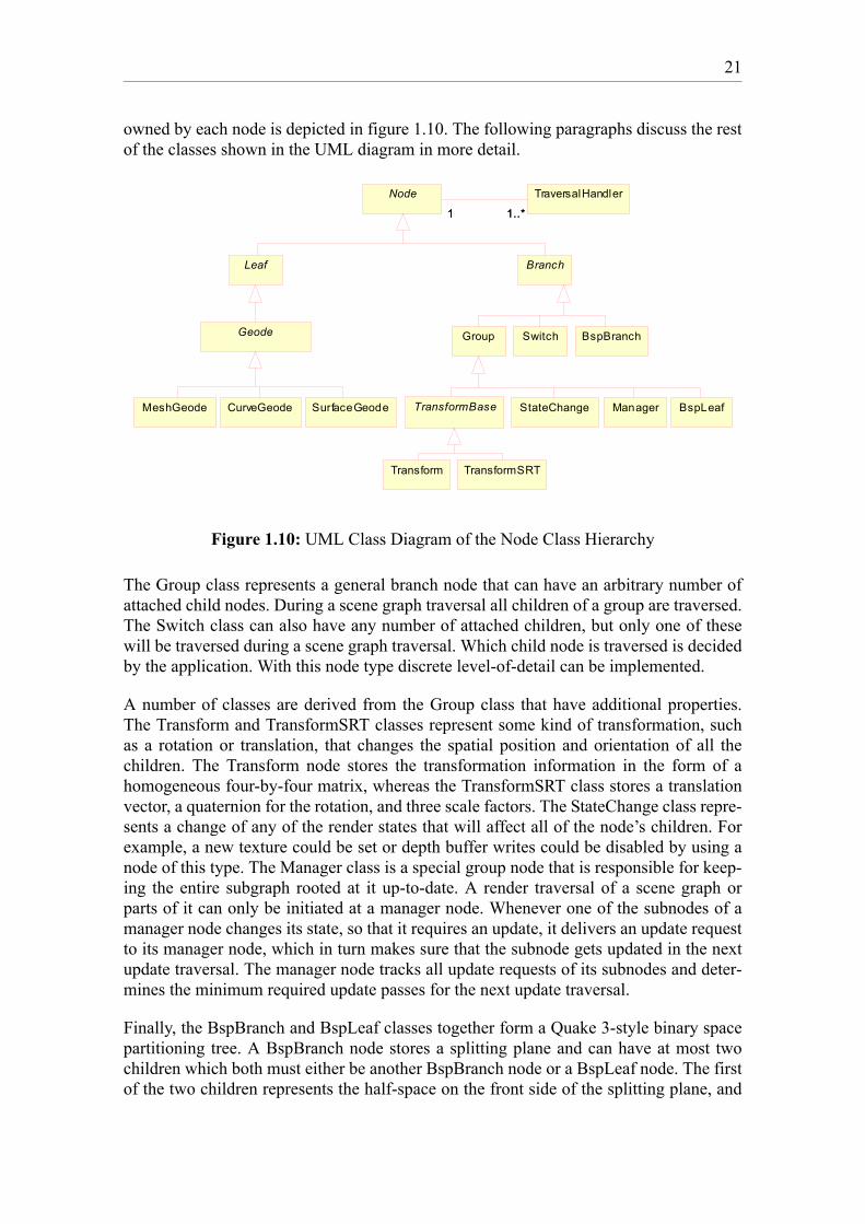
1.5.2 Scene Graph Node Class Hierarchy
Figure 1.10 shows the class hierarchy of the scene graph node classes. In its current state,the scene graph only offers basic node classes that will be further extended with moreadvanced nodes, for example for character animation, in the future. All node classesinherit from the abstract base class Node, and then from one of the two abstract classesLeaf or Branch depending on the type of the node. Also the list of traversal handlers
21
owned by each node is depicted in figure 1.10. The following paragraphs discuss the restof the classes shown in the UML diagram in more detail.
Figure 1.10: UML Class Diagram of the Node Class Hierarchy
The Group class represents a general branch node that can have an arbitrary number ofattached child nodes. During a scene graph traversal all children of a group are traversed.The Switch class can also have any number of attached children, but only one of thesewill be traversed during a scene graph traversal. Which child node is traversed is decidedby the application. With this node type discrete level-of-detail can be implemented.
A number of classes are derived from the Group class that have additional properties.The Transform and TransformSRT classes represent some kind of transformation, suchas a rotation or translation, that changes the spatial position and orientation of all thechildren. The Transform node stores the transformation information in the form of ahomogeneous four-by-four matrix, whereas the TransformSRT class stores a translationvector, a quaternion for the rotation, and three scale factors. The StateChange class repre-sents a change of any of the render states that will affect all of the node’s children. Forexample, a new texture could be set or depth buffer writes could be disabled by using anode of this type. The Manager class is a special group node that is responsible for keep-ing the entire subgraph rooted at it up-to-date. A render traversal of a scene graph orparts of it can only be initiated at a manager node. Whenever one of the subnodes of amanager node changes its state, so that it requires an update, it delivers an update requestto its manager node, which in turn makes sure that the subnode gets updated in the nextupdate traversal. The manager node tracks all update requests of its subnodes and deter-mines the minimum required update passes for the next update traversal.
Finally, the BspBranch and BspLeaf classes together form a Quake 3-style binary spacepartitioning tree. A BspBranch node stores a splitting plane and can have at most twochildren which both must either be another BspBranch node or a BspLeaf node. The firstof the two children represents the half-space on the front side of the splitting plane, and
Branch
Geode
MeshGeode CurveGeode SurfaceGeode
Group Switch
Leaf
Transform
StateChange
TransformSRT
BspBranch
BspLeafTransformBase Manager
TraversalHandlerNode
1..*1 1..*1
22
the second child represents the half-space on the back side. Note that a BspLeaf node isactually a group node because it by itself only represents the leaf of the BSP tree, but notthe leaf of the scene graph. In addition, it does not contain any geometry data, which isinstead stored in the child nodes of the BSP leaf node in form of regular Geode-typenodes.
The leaf classes offered by XEngineSceneGraph are used to store actual geometry datathat gets rendered when a render traversal of the scene graph determines that the leaf isvisible (that is, in the view frustum). Currently, all the Geode-derived classes, MeshGe-ode, CurveGeode, and SurfaceGeode, internally store references to the correspondingrender resources of XEngineCore. However, this must not necessarily be the case, andgeometry nodes could even procedurally generate geometry data, such as a terrain, but atthe moment no such advanced node classes are provided.
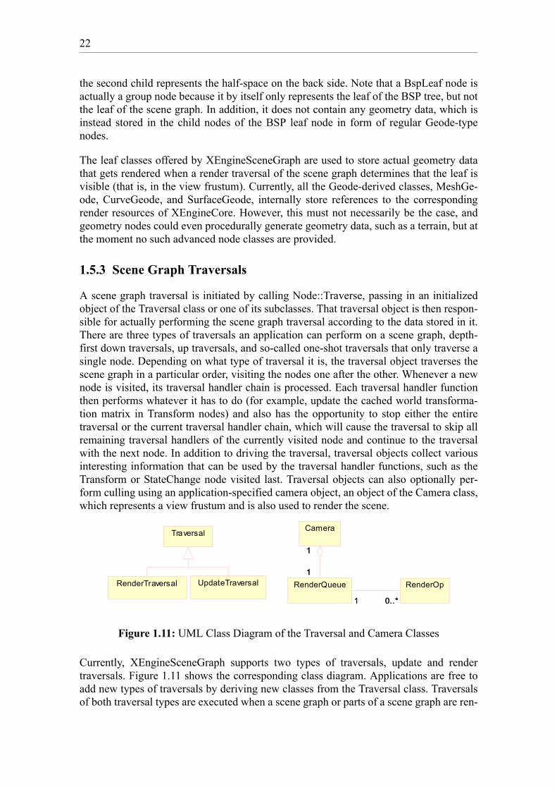
1.5.3 Scene Graph Traversals
A scene graph traversal is initiated by calling Node::Traverse, passing in an initializedobject of the Traversal class or one of its subclasses. That traversal object is then respon-sible for actually performing the scene graph traversal according to the data stored in it.There are three types of traversals an application can perform on a scene graph, depth-first down traversals, up traversals, and so-called one-shot traversals that only traverse asingle node. Depending on what type of traversal it is, the traversal object traverses thescene graph in a particular order, visiting the nodes one after the other. Whenever a newnode is visited, its traversal handler chain is processed. Each traversal handler functionthen performs whatever it has to do (for example, update the cached world transforma-tion matrix in Transform nodes) and also has the opportunity to stop either the entiretraversal or the current traversal handler chain, which will cause the traversal to skip allremaining traversal handlers of the currently visited node and continue to the traversalwith the next node. In addition to driving the traversal, traversal objects collect variousinteresting information that can be used by the traversal handler functions, such as theTransform or StateChange node visited last. Traversal objects can also optionally per-form culling using an application-specified camera object, an object of the Camera class,which represents a view frustum and is also used to render the scene.
Figure 1.11: UML Class Diagram of the Traversal and Camera Classes
Currently, XEngineSceneGraph supports two types of traversals, update and rendertraversals. Figure 1.11 shows the corresponding class diagram. Applications are free toadd new types of traversals by deriving new classes from the Traversal class. Traversalsof both traversal types are executed when a scene graph or parts of a scene graph are ren-
Camera
RenderOpRenderQueue1
1
1
1
0..*1 0..*1
Traversal
RenderTraversal UpdateTraversal
23
dered. In rendering a scene graph the afore-mentioned Camera class is used, which inaddition to representing a camera and its parameters, such as position, orientation, or thefield-of-view, also has an associated render target to which the scene captured by thecamera is rendered. To render a scene graph, Camera::Render must be called a managernode being passed in. As was mentioned before, only parts of a scene graph rooted at amanager node can be rendered. Before the scene graph is rendered, however, an updatetraversal is started which is responsible for updating all the nodes. For example, if theapplication has changed the transformation matrix of a Transform node in the scenegraph, the cached world transformation matrices and cached bounding volumes in worldcoordinates will require an update. All the updates are done in the corresponding traver-sal handler functions of the nodes that are responsible for update traversals. Therefore, itis possible for the application to perform additional processing during an update traver-sal, or any traversal for that matter, by adding an additional traversal handler to thetraversal handler chain of the desired nodes. Additionally, an application could removethe default traversal handler from the chain, completely disabling the default updatetraversal, which generally is not a good idea, however.
After the update traversal has completed successfully, the render traversal is startedwhich first performs view frustum culling and, whenever it reaches a visible geometryleaf node, renders the geometry data stored in the leaf. This is again done in the corre-sponding traversal handler function that reacts to render traversals. Actually, the geome-try is not rendered immediately, but instead the necessary render operations (that is, theprimitives that need to be rendered and their associated render states) are added to therender queue that is part of the camera object (see figure 1.11). Each time a new renderoperation is inserted into it, the render queue is automatically sorted according to themost expensive state changes, such as shader program or texture changes. Additionallytransparent objects are always sorted in at the end of the queue in a furthest-away-firstfashion among themselves, since they should be drawn last and in correct depth order.Once the render traversal is done, the render queue contains all render operations neces-sary to render the currently visible objects. Since the render queue is already sorted, thefinal step to render the scene is to iterate through the queue and perform all the storedrender operations on the render target associated with the camera.
Since the default render traversal also uses traversal handler functions to perform itsduty, an application can add additional traversal handlers to particular nodes to do addi-tional, application-specific operations, as required. It is also possible to completelyreplace the default behaviour of the render traversal handlers, which, as outlined above,is to add the necessary render operations to the render queue. For example, the geometrydata could be rendered immediately or, instead of rendering anything, some kind ofdebug output could be written to a file. Note that changing the traversal handler chain ofa node is possbile at runtime. The traversal handler system makes the traversal scheme ofXEngineSceneGraph flexible, highly customizable, and powerful, and, most importantly,separates the scene graph data structure from the algorithms performed on it.
24
1.6 Used Design Patterns
This section examines which acknowledged, object-oriented design patterns have beenused in the design of the engine. Most of these patterns originate from the infamous"Gang of Four" book [Gamm94] about object-oriented design patterns. Design patternsoffer solutions to common design problems in object-oriented systems. It is good prac-tice to identify situations in the design phase where the use of patterns is appropriate anduse them accordingly. Design patterns also facilitate the communication about a designof a system between many developers because common knowledge of design patternscan be assumed and complex design issues can be easily understood just by naming theapplied design pattern.
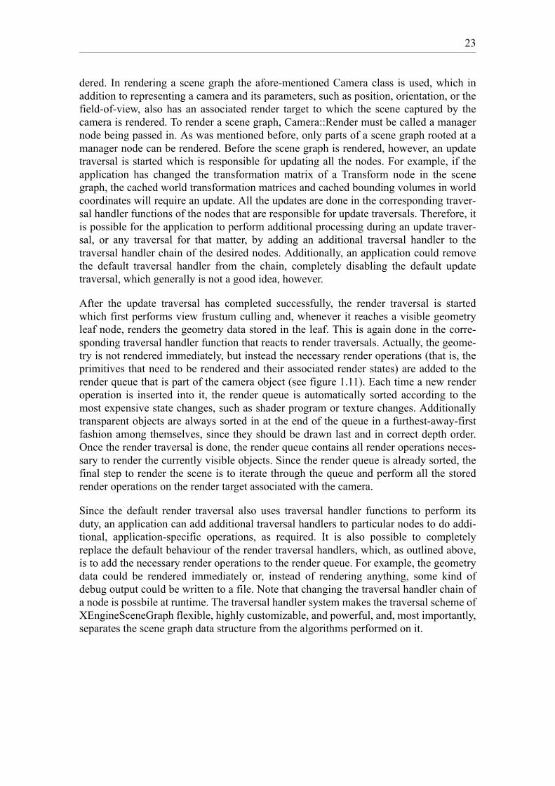
The RenderContext class of XEngineCore follows the Abstract Factory [Gamm94]design pattern. Its interface provides factory methods for creating render resource andrender target objects without specifying their concrete classes. The specific RenderCon-text-derived classes in each renderer library represent specific factories that create con-crete render resource and render target objects specific to the renderer library. Figure1.12 depicts an example of this design pattern. RenderContext::CreateVertexBuffer is thefactory method to create vertex buffer objects. The specific render context,RenderContextDX81, overrides the factory method and creates a concrete vertex bufferobject that is returned to the client as reference to the abstract vertex buffer class. Sincethe Factory Method pattern is related to the Abstract Factory pattern and the factorymethods are also used internally by the RenderContext class, the Factory Method designpattern [Gamm94] also applies to render contexts.Furthermore, the Template Method pattern [Gamm94] is used throughout the Render-Context class, for example for creating render resource objects or setting render states.The Template Method pattern lets subclasses redefine certain tasks by overriding specialhook methods provided by the base class. Additionally, the RenderContext class can beconsidered to use the Collection Object design pattern [Nobl96] because it is a collectionfor texture sampler stages, texture coordinate stages, render targets, and render resources.
Figure 1.12: Abstract Factory Design Pattern Example
All the specific classes derived from the RenderResource and RenderTarget classes ofXEngineCore in the renderer libraries, together with their base classes, represent theObjectifier pattern [Copl95], where an abstract class provides a common interface forspecific implementations for variable behaviour. For example, the execution of the tasksthat can be performed on a vertex buffer varies depending on the used renderer library.However, the client only keeps references to the abstract vertex buffer base class andneed not concern itself with the specifics of the concrete vertex buffer classes in each
RenderContextCreateVertexBuffer()
RenderContextDX81CreateVertexBuffer()
VertexBuffer
VertexBufferDX81

25
renderer library. Thus the different behaviours of the specific vertex buffer classes is wellencapsulated, which results in a highly configurable design required to provide renderingAPI-independence in XEngine.
All the mesh and scene loaders used in XEngineCore and XEngineSceneGraph, respec-tively, correspond to the Builder pattern [Gamm94]. The construction of complex meshobjects or even entire scene graphs, in the case of scene loaders, is separated from its rep-resentation, so that the same construction process can create different representations.The advantage of using this pattern for loading and constructing meshes and scenegraphs is that the code for construction and the code for representation are isolated fromone another. Figure 1.13 shows an example of the Builder design pattern where theMeshLoader3DS class is a builder to load and construct mesh objects from Autodesk 3DStudio files.
Figure 1.13: Builder Design Pattern Example
The Mesh class of XEngineCore uses the Iterator design pattern [Gamm94]. Meshobjects are complex, aggregate objects that consist of multiple primitive groups. Usingthe Iterator pattern, the Mesh class offers a special iterator object that provides a way forclients to iterate over the primitive groups without exposing the more complex underly-ing representation.
The entire scene graph data structure of XEngineSceneGraph follows the Composite pat-tern [Gamm94] which is used to compose complex objects into tree hierarchies. Clientscan treat objects and compositions uniformly. This is exactly how the tree-like scenegraph in XEngine is designed. Each branch node of the scene graph can be considered acomposite of multiple child nodes that in turn can again be composites (that is, branchnodes). Additionally, because nodes can be cloned, XEngine’s scene graph also followsthe Prototype design pattern [Gamm94]. Each node can be considered a prototypicalinstance, and new instances can be created by copying this prototype. This design pat-terns is used because it is typically easier to simply make a deep copy of an entire scenegraph hierarchy than to rebuild it from scratch if a clone of it is required.
The traversal handler chains used in the scene graph are designed according to the Chainof Responsibility pattern [Gamm94] which avoids coupling the scene graph data struc-ture to the algorithms performed upon it. Also multiple handlers get a chance to performtasks when the scene graph is traversed. However, the actual design slightly differs fromthe original Chain of Responsibility design pattern in that each traversal handler can han-dle a traversal, if desired, and the processing of the traversal handler chain of a node isnot stopped when one of the traversal handler functions handled the traversal. In the orig-inal pattern, as soon as a request is handled, the processing of the chain is stopped.
MeshLoader
Mes hLoader3DS
Mesh1
Mesh2

26
Additionally, the traversal handler functions, which can be seen as receivers of traversalevents with the currently visited node being the sender, follow the Sender Argument pat-tern [Nobl96] because they receive a reference to the currently visited node during atraversal as argument.
The Traversal class and its subclasses represent the Strategy design pattern [Gamm94]because these classes encapsulate the scene graph traversal algorithms and each algo-rithm can vary independently from the clients that use it. Each Traversal-derived classrepresents a different traversal algorithm. This pattern allows easy reuse of families ofalgorithms. Inheritance is used to factor out common functionality into the base class(see figure 1.11).
Finally, the RenderQueue and RenderOperation classes represent a simplified form ofthe Command design pattern [Gamm94]. A command, in this case the render operation,is encapsulated into a parameterized object. In theory, different kinds of render opera-tions could be used in the render queue. In the current implementation, however, onlyone type of render operation which consists of a primitive group that is to be renderedand an associated state set is used.
1.7 Implementation
The previous sections outlined the design of the engine. This section shortly discussesthe implementation of the engine, such as the third-party libraries it depends on, and var-ious implementation details of interest.
1.7.1 Implementation Language and Required Tools
XEngine is implemented in ISO/ANSI C++ and uses various advanced features of thelanguage, such as templates, runtime type information, and exception handling. Also theC++ Standard Template Library is used extensively. Since only in recent years C++ com-pilers have managed to fulfil the ISO/ANSI C++ standard to a high degree, a relativelynew compiler is required to compile XEngine, for example Microsoft Visual C++ 6.0 or7.0 or gcc 3.0 and up.
In addition to a C++ compiler, the lexer generator flex++ and the parser generatorbison++ are required to rebuild the lexers and parsers used by the engine for the shadinglanguage cross-compilers. Both tools are C++ versions of the standard C flex and bisontools found on most Linux systems. Both generators take definition files as input whichdescribe the to-be-generated lexer or parser, respectively. Based on templates defined viaspecial skeleton C++ header and implementation files, a lexer and parser class that canbe used in a C++ program are then generated. The skeleton files used in XEngine areheavily modified versions of the files that come with the tools to better suit the needs ofthe engine.
27
1.7.2 Depending Libraries
Since the author strongly believes in the open source idea and software reuse (Why rein-vent the wheel when somebody else already did a better job than you could ever do?),XEngine depends on a rather large number of third-party, open source libraries. The useof some libraries can be prevented with configuration options of the engine’s build sys-tem, effectively reducing the dependencies on other libraries.
1.7.2.1 wxWindows
wxWindows [wxWi03] is a mature, open source, cross-platform C++ framework, mostlyspecializing in the development of GUI applications, that is available on a number ofplatforms. Currently ports for all versions of Microsoft Windows, a number of Unix sys-tems, such as Linux, Irix, and Solaris, MacOS 9 and MacOS X, and OS/2 are available.Additionally a number of language bindings other than C++ can be used, the most prom-inent being the Pyhton binding called wxPython. Other language bindings that are read-ily available or are actively being developed include bindings for Basic, Perl, Eiffel,JavaScript, all .NET languages, and Java. Apart from a variety of GUI-related classes forwindows, dialogs, buttons, and other controls, wxWindows offers a large range of usefulclasses for cross-platform development, for example for file and stream handling,threads and thread synchronization, memory management, image processing, databaseaccess, and networking.
wxWindows is the layer that provides XEngine with platform-independence. Due to thefact that the engine tightly integrates with wxWindows, mostly because a render windowcan be used as a regular wxWindows window, it is very easy for regular wxWindowsGUI applications to use the engine, allowing for quick prototyping and development ofvisualization applications, level editors, CAD-like programs, or other types of applica-tions that use 3D graphics. Although it would theoretically be possible to completelydecouple XEngine from wxWindows and use other cross-platform GUI frameworks suchas Qt, it was never the intention to provide support for any other framework. The deci-sion to use wxWindows as basis for the engine was made after a rather intensive analysisphase of freely available GUI frameworks, where wxWindows emerged as superior can-didate in every respect. It is mature, feature-rich, license and royalty free, and has excel-lent documentation. Furthermore, it is still being actively maintained and developed, andhas a large and helpful user community.
1.7.2.2 STLport
STLport [STLp03] is an open source implementation of the ISO/ANSI-standardized C++Standard Template Library (or STL, for short) that is available on a number of platforms.It features thread and exception safety, a debug mode with rigorous runtime validitychecking, and important, non-standard extensions, such as hash tables and singly-linkedlists. The main reason for using STLport with XEngine, instead of the STL implementa-tions that come with specific compilers, was to have a consistent, solid implementationfor all compilers that are supported by the engine. Furthermore, XEngine makes heavy
28
use of the hash tables provided by STLport (which originate from the SGI STL imple-mentation that was made publicly and freely available by SGI in 1996).
1.7.2.3 Boost
Boost [Boos03] is a collection of free, peer-reviewed, cross-platform C++ libraries thatemphasize good integration with the C++ Standard Template Library. One goal of theBoost project is to establish good practices and provide reference implementations whichare suitable for eventual standardization and inclusion in an upcoming version of theC++ Standard Library by the ISO C++ Standards Committee. XEngine uses only a fewof the Boost libraries, mostly libraries for automatic memory management that help tomake code more exception safe. However, future versions of the engine might use theBoost signal and slots library and possibly the Python-binding library which provides aconvenient way to create a Python language binding.
1.7.2.4 DevIL
DevIL, the Developer’s Image Library [Wood02], is an open source image loading, sav-ing, and processing library that can handle a large variety of image formats. The use ofDevIL with XEngine is optional and can be turned off by using a configuration option ofthe engine’s build system. When DevIL is used, texture objects can be directly createdfrom image files in all the image formats supported by DevIL. Note that even if the useof DevIL is prevented, textures can still be created and loaded from image files directly.However, only the image formats supported by wxWindows are available.
1.7.2.5 lib3ds
lib3ds, the 3D Studio File Format Library [Hoff02], is an open source library to loadgeometry data from files in the widespread Autodesk 3D Studio format. The mesh andscene loaders of the engine use this library to load geometry data from 3DS files andtransform it into engine-internal data structures, such as mesh objects. The use of lib3dsis optional and can be turned off via a configuration option in the build system, in whichcase the engine can no longer load 3DS files directly.
1.7.3 Template Mix-In Classes
In the implementation of the renderer libraries one particular advanced C++ implementa-tion technique is of special interest, so-called template mix-in classes. Template mix-insare special template classes responsible for implementing a common interface which isshared by multiple classes. These classes, however, have nothing in common except forthat interface. To achieve this, the template mix-in inherits from the to-be-implementedinterface and receives a base class as template parameter from which the template inher-its as well by multiple inheritance. This way multiple classes that all derive from differ-ent base classes can use the template mix-in by inheriting from it to derive from and atthe same time implement the interface. In some cases, the template mix-in also immedi-ately defines the interface it implements itself, which gets rid of the multiple inheritance.In the implementation of the renderer libraries template mix-in classes have proven to be
29
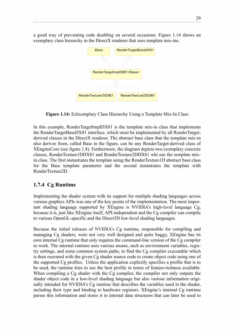
a good way of preventing code doubling on several occasions. Figure 1.14 shows anexemplary class hierarchy in the DirectX renderer that uses template mix-ins.
Figure 1.14: Echxemplary Class Hierarchy Using a Template Mix-In Class
In this example, RenderTargetImplDX81 is the template mix-in class that implementsthe RenderTargetBaseDX81 interface, which must be implemented by all RenderTarget-derived classes in the DirectX renderer. The abstract base class that the template mix-inalso derives from, called Base in the figure, can be any RenderTarget-derived class ofXEngineCore (see figure 1.8). Furthermore, the diagram depicts two exemplary concreteclasses, RenderTexture1DDX81 and RenderTexture2DDX81 whi use the template mix-in class. The first instantiates the template using the RenderTexture1D abstract base classfor the Base template parameter and the second instantiates the template withRenderTexture2D.
1.7.4 Cg Runtime
Implementing the shader system with its support for multiple shading languages acrossvarious graphics APIs was one of the key points of the implementation. The most impor-tant shading language supported by XEngine is NVIDIA’s high-level language Cg,because it is, just like XEngine itself, API-independent and the Cg compiler can compileto various OpenGL-specific and the Direct3D low-level shading languages.
Because the initial releases of NVIDIA’s Cg runtime, responsible for compiling andmanaging Cg shaders, were not very well designed and quite buggy, XEngine has itsown internal Cg runtime that only requires the command-line version of the Cg compilerto work. The internal runtime uses various means, such as environment variables, regis-try settings, and some common system paths, to find the Cg compiler executable whichis then executed with the given Cg shader source code to create object code using one ofthe supported Cg profiles. Unless the application explicitly specifies a profile that is tobe used, the runtime tries to use the best profile in terms of feature-richness available.When compiling a Cg shader with the Cg compiler, the compiler not only outputs theshader object code in a low-level shading language but also various information origi-nally intended for NVIDIA’s Cg runtime that describes the variables used in the shader,including their type and binding to hardware registers. XEngine’s internal Cg runtimeparses this information and stores it in internal data structures that can later be used to
RenderTargetBaseDX81
RenderTargetImplDX81<Base>
Base
RenderTexture1DDX81 RenderTexture2DDX81

30
verify the types specified by the application when it sets shader parameters using Shader-Program::SetParameter or specifies vertex attribute bindings when a shader program iscreated.
Only recently, in December 2002, NVIDIA managed to release a stable version of the Cgruntime, which underwent a complete redesign and was incompatible with olderreleases. At present XEngine supports both its own internal Cg runtime and NVIDIA’sCg runtime, and applications can choose which is to be used. The advantage of usingNVIDIA’s runtime is that even new Cg profiles that might be introduced in futurereleases of the Cg compiler can be used, whereas for the internal Cg runtime support fornew profiles must be explicitly implemented. The disadvantage is that the DLLs ofNVIDIA’s Cg runtime must be distributed with the application and the engine addition-ally depends on the Cg runtime libraries which it must be linked to. Also due to a smalldeficiency in NVIDIA’s runtime, the ColorARGB data type for vertex attributes which isused for colours in ARGB format packed into a 32-bit word is only supported with XEn-gine’s internal Cg runtime.
1.7.5 Shading Language Cross-Compilers
XEngine was designed to not only support Cg as shading language. Instead the engine islanguage-open, which means that it can potentially work together with any shading lan-guage, sometimes at the cost of losing 3D graphics API-independence. In its current stateXEngine supports most of the wide-spread low-level shading languages, such as theDirect3D 8 low-level languages and a number of OpenGL low-level languages. A uniquefeature of the engine is the possibility of transparently cross-compiling the low-level lan-guages from one graphics API to another. This allows the use of, for example, a shaderwritten in the Direct3D vertex shader assembler with the OpenGL API, or the use of thesame shader under Linux where the Direct3D API is not even available since it is Win-dows-only. The ulterior motive to develop such cross-compilers was the idea to be ableto reuse old shaders with newer shading languages and different graphics APIs. Forexample, since Direct3D 8 was the first API to have low-level shading languages, a lot ofshaders written in its low-level shading languages were readily available when similarOpenGL extension began to crop up. Due to the syntactical differences between the lan-guages, the shaders had to be rewritten from scratch, which is a rather tedious and error-prone task. With XEngine, a shader need not be rewritten and can simply be reused as itis as long as a cross-compiler is available.
The shading language cross-compilers are implemented by using the lexer generatorflex++ and the parser generator bison++. At present XEngine has the following inte-grated cross-compilers:
• Direct3D 8 vertex shader assembler versions 1.0 and 1.1 to NV_vertex_program
• Direct3D 8 vertex shader assembler versions 1.0 and 1.1 to ARB_vertex_program
• NV_vertex_program and NV_vertex_program1_1 toDirect3D 8 vertex shader assembler version 1.1
• ARB_vertex_program to Direct3D 8 vertex shader assembler version 1.1
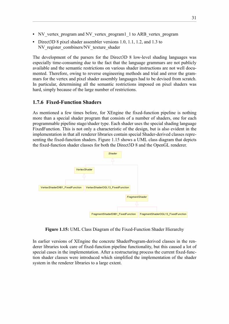
31
• NV_vertex_program and NV_vertex_program1_1 to ARB_vertex_program
• Direct3D 8 pixel shader assembler versions 1.0, 1.1, 1.2, and 1.3 toNV_register_combiners/NV_texture_shader
The development of the parsers for the Direct3D 8 low-level shading languages wasespecially time-consuming due to the fact that the language grammars are not publiclyavailable and the semantic restrictions on various shader instructions are not well docu-mented. Therefore, owing to reverse engineering methods and trial and error the gram-mars for the vertex and pixel shader assembly languages had to be devised from scratch.In particular, determining all the semantic restrictions imposed on pixel shaders washard, simply because of the large number of restrictions.
1.7.6 Fixed-Function Shaders
As mentioned a few times before, for XEngine the fixed-function pipeline is nothingmore than a special shader program that consists of a number of shaders, one for eachprogrammable pipeline stage/shader type. Each shader uses the special shading languageFixedFunction. This is not only a characteristic of the design, but is also evident in theimplementation in that all renderer libraries contain special Shader-derived classes repre-senting the fixed-function shaders. Figure 1.15 shows a UML class diagram that depictsthe fixed-function shader classes for both the Direct3D 8 and the OpenGL renderer.
Figure 1.15: UML Class Diagram of the Fixed-Function Shader Hierarchy
In earlier versions of XEngine the concrete ShaderProgram-derived classes in the ren-derer libraries took care of fixed-function pipeline functionality, but this caused a lot ofspecial cases in the implementation. After a restructuring process the current fixed-func-tion shader classes were introduced which simplified the implementation of the shadersystem in the renderer libraries to a large extent.
VertexShader
FragmentShader
Shader
VertexShaderDX81_FixedFunction VertexShaderOGL13_FixedFunction
FragmentShaderDX81_FixedFunction FragmentShaderOGL13_FixedFunction

32
Bibliography
[Boos03] Boost C++ Libraries, http://www.boost.org
[Copl95] Jim O. Coplien, James O. Coplien, Douglas C. Schmidt: Pattern Languages of Program Design 1, Addison-Wesley, 1995
[Gamm94] Erich Gamma, Richard Helm, John Vlissides, Ralph Johnson: Design Patterns. Elements of Reusable Object Oriented Software, Addison-Wesley, 1994
[Hitz99] Martin Hitz, Gerti Kappel: UML@Work: Von der Analyse zur Realisierung, dpunkt-Verlag, Heidelberg, 1999
[Hoff02] J. E. Hoffmann: The 3D Studio File Format Library Homepage,http://lib3ds.sourceforge.net
[Land95] Niklas Landin, Axel Niklasson: Development of Object-Oriented Frameworks, Department of Communication Systems, Lund Institute of Technology, Lund University, 1995
[Nobl96] James Noble: Some Patterns for Relationships, Proceedings of Technology of Object-Oriented Languages and Systems (TOOLS Pacific 21), Melbourne, 1996
[STLp03] STLport Standard Library Project, http://www.stlport.org
[Wood02] Denton Woods: DevIL, Developer’s Image Library Manual,http://openil.sourceforge.net, 2002
[wxWi03] wxWindows, Cross-Platform GUI Framework,http://www.wxwindows.org


![Untitled-2 [] Center Implementation.pdf · latest technology; superior facility design and layout for car- diovascular service line; implementation of a one-stop CVU unit; high patient,](https://img.pdfslide.net/doc/110x75/5f6391d4c6173e6fa93d34e1/untitled-2-center-implementationpdf-latest-technology-superior-facility.jpg)