Embed Size (px)
Citation preview

VITOSOL
Viessmann solar collectors –the right solution for every application
Using solar energy to heat domestic hot water and toprovide a backup for space heating
Vitosol 200-FFlat plate solar collector for installation on pitchedand flat roofs, and for freestanding installation
Vitosol 300-TVacuum tube solar collector, based on the heat pipeprinciple, for installation on sloped and flat roofs and forfreestanding installation
System Design Guidelines
Vitosol 200-F Vitosol 300-TModel SP3
5167 156 v3.1 05/2008

Safety, Installation and Warranty Requirements
2
Safety, Installation and Warranty Requirements
Please ensure that these instructions are read and understood before commencing installation. Failure to comply with theinstructions listed below and details printed in this manual can cause product/property damage, severe personal injury, and/orloss of life. Ensure all requirements below are understood and fulfilled (including detailed information found in manualsubsections).
H Licensed professional heatingcontractorThe installation, adjustment, service,and maintenance of this equipmentmust be performed by a licensedprofessional heating contractor.
" Please see sectionentitled “ImportantRegulatory andInstallationRequirements”.
H Product documentationRead all applicable documentationbefore commencing installation. Storedocumentation near boiler in a readilyaccessible location for reference inthe future by service personnel.
" For a listing ofapplicable literature,please see sectionentitled “ImportantRegulatory and SafetyRequirements”.
H Advice to ownerOnce the installation work iscomplete, the heating contractor mustfamiliarize the systemoperator/ultimate owner with allequipment, as well as safetyprecautions/requirements, shut-downprocedure, and the need forprofessional service annually.
HWarrantyInformation contained inthis and related productdocumentation must beread and followed. Failureto do so renders warrantynull and void.
H Grounding/lightning protection of thesolar systemIn the lower part of the building,install an electrical conductor on thesolar circuit’s piping system incompliance with local regulations.Connection of the solar system to anew or existing lightning protection orthe provision of local grounding shouldonly be carried out by a licensedprofessional, who must take intoaccount the prevailing conditions onsite.
H ApplicabilityVitosol solar collectors are designedfor use in closed loop heating systemsfor domestic hot water heating, spaceheating and pool heating via a heatexchanger. The use of Viessmannheat transfer medium “Tyfocor-HTL”is strongly recommended.
Pool water or potable water cannot bepumped directly through the Vitosolcollectors. Damage to collectors causedby corrosion, freezing or scaling willvoid warranty.
5167156v3
.1
Observe maximum load and distancefrom edge before installing thesubstructure to the roof. If necessary,consult with a structural engineer todetermine if the structure is suitablefor installing solar collectors. Thecollectors must be securely mountedso that the mountings can withstandintense wind conditions and localsnow loads.
CAUTION
Gloves and eye protection must beworn when handling solar panels.
CAUTION
Solar panel connection pipes andsolar heating fluid can become hotenough to cause severe burns.Extreme caution must be taken ifpanels have been in a stagnantcondition (no flow of fluid).
CAUTION
Avoid scratching or sudden shocks toglass cover of the solar panel.
CAUTION
Never step on collectors or solder inclose proximity to the glass surfaceof the solar panel.
CAUTION
IMPORTANT

Contents
3
Contents Page
Safety Safety InstructionsImportant Regulatory and Installation Requirements
General Information About these InstructionsProduct InformationImportant Regulatory and Installation Requirements
Basic Principles of Solar Technology Subsidies, Permits and Insurance 7. . . . . . . . . . . . . . . . . . . . . . . . . . . . . . . . . . .Solar Energy 7. . . . . . . . . . . . . . . . . . . . . . . . . . . . . . . . . . . . . . . . . . . . . . . . . . . . . .HExploiting solar energy 7. . . . . . . . . . . . . . . . . . . . . . . . . . . . . . . . . . . . . . . . . . . .H Solar radiation 8. . . . . . . . . . . . . . . . . . . . . . . . . . . . . . . . . . . . . . . . . . . . . . . . . . .HGlobal radiation 8. . . . . . . . . . . . . . . . . . . . . . . . . . . . . . . . . . . . . . . . . . . . . . . . . .H Exploiting solar energy with collectors 9. . . . . . . . . . . . . . . . . . . . . . . . . . . . . .H Influence of alignment, inclination and shade on energy yield 10. . . . . . . . .H Inclination and orientation of collectors 11. . . . . . . . . . . . . . . . . . . . . . . . . . . . .HAngle of inclination 11. . . . . . . . . . . . . . . . . . . . . . . . . . . . . . . . . . . . . . . . . . . . . . .Overall System Optimisation 12. . . . . . . . . . . . . . . . . . . . . . . . . . . . . . . . . . . . . . .
Specification Construction and Function of Collectors 13. . . . . . . . . . . . . . . . . . . . . . . . . . . . .HVitosol 200-F – flat panel collector 13. . . . . . . . . . . . . . . . . . . . . . . . . . . . . . . . .HVitosol 300-T – vacuum tube collector based on the heat pipe principle 14Collector Efficiency 16. . . . . . . . . . . . . . . . . . . . . . . . . . . . . . . . . . . . . . . . . . . . . . . .Solar coverage 17. . . . . . . . . . . . . . . . . . . . . . . . . . . . . . . . . . . . . . . . . . . . . . . . . . . .Collector Installation and Mounting Details 18. . . . . . . . . . . . . . . . . . . . . . . . . . .H Installation options for different collector types 18. . . . . . . . . . . . . . . . . . . . .HVitosol 200-F flat panel collector 18. . . . . . . . . . . . . . . . . . . . . . . . . . . . . . . . . .H Support weight requirements - Vitosol 300-T 24. . . . . . . . . . . . . . . . . . . . . . . .General Installation Instructions 26. . . . . . . . . . . . . . . . . . . . . . . . . . . . . . . . . . . . .
Notes on Planning and Operation Calculating the Required Absorber Surface Area 27. . . . . . . . . . . . . . . . . . . . . .HCalculating the absorber surface area and DHW cylinder capacity 27. . . . .HCalculating the absorber surface area for space heating 28. . . . . . . . . . . . . .
Sizing Pipe Diameters and Circulation Pump 31. . . . . . . . . . . . . . . . . . . . . . . . . .H Sizing pipe diameters 34. . . . . . . . . . . . . . . . . . . . . . . . . . . . . . . . . . . . . . . . . . . .H Installation examples for Vitosol 200-F, models SV2 and SH2 35. . . . . . . .HCollector pressure drop information 34. . . . . . . . . . . . . . . . . . . . . . . . . . . . . . . .H Sizing pipe circulation pump 35. . . . . . . . . . . . . . . . . . . . . . . . . . . . . . . . . . . . . .H Technical information on the Solar-Divicon 36. . . . . . . . . . . . . . . . . . . . . . . . . .Safety Equipment 38. . . . . . . . . . . . . . . . . . . . . . . . . . . . . . . . . . . . . . . . . . . . . . . . .H Liquid capacity of solar heating system components 37. . . . . . . . . . . . . . . . .HDiaphragm expansion vessel 39. . . . . . . . . . . . . . . . . . . . . . . . . . . . . . . . . . . . . .H Technical data for the expansion tank 43. . . . . . . . . . . . . . . . . . . . . . . . . . . . . .H Pressure relief valve 41. . . . . . . . . . . . . . . . . . . . . . . . . . . . . . . . . . . . . . . . . . . . .HHigh limit safety cut-out 41. . . . . . . . . . . . . . . . . . . . . . . . . . . . . . . . . . . . . . . . . .H Thermostatic mixing valve 42. . . . . . . . . . . . . . . . . . . . . . . . . . . . . . . . . . . . . . . .Accessories 43. . . . . . . . . . . . . . . . . . . . . . . . . . . . . . . . . . . . . . . . . . . . . . . . . . . . . .
5167156v3
.1

Contents
4
Contents (continued) Page
System Designs General Information 44. . . . . . . . . . . . . . . . . . . . . . . . . . . . . . . . . . . . . . . . . . . . . . . .HHow to implement the installation 44. . . . . . . . . . . . . . . . . . . . . . . . . . . . . . . . .System Design 1 45. . . . . . . . . . . . . . . . . . . . . . . . . . . . . . . . . . . . . . . . . . . . . . . . . .HDual-mode DHW heating with Vitocell-B 100 or Vitocell-B 300DHW tanks 45. . . . . . . . . . . . . . . . . . . . . . . . . . . . . . . . . . . . . . . . . . . . . . . . . . . . .
System Design 2 47. . . . . . . . . . . . . . . . . . . . . . . . . . . . . . . . . . . . . . . . . . . . . . . . . .HDual-mode DHW heating and space heating backupwith heating water storage tank 47. . . . . . . . . . . . . . . . . . . . . . . . . . . . . . . . . . .
System Design 3 50. . . . . . . . . . . . . . . . . . . . . . . . . . . . . . . . . . . . . . . . . . . . . . . . . .HDual-mode DHW heating with two DHW tanks 50. . . . . . . . . . . . . . . . . . . . . .System Design 4 53. . . . . . . . . . . . . . . . . . . . . . . . . . . . . . . . . . . . . . . . . . . . . . . . . .HDual-mode DHW and swimming pool water heating 53. . . . . . . . . . . . . . . . .System Design Extensions 56. . . . . . . . . . . . . . . . . . . . . . . . . . . . . . . . . . . . . . . . . .H System with bypass circuit 56. . . . . . . . . . . . . . . . . . . . . . . . . . . . . . . . . . . . . . .H Bypass circuit with solar cell 56. . . . . . . . . . . . . . . . . . . . . . . . . . . . . . . . . . . . . .H System with energy-saving mode 57. . . . . . . . . . . . . . . . . . . . . . . . . . . . . . . . . .
Appendix Calculation Example Based on the Viessmann ”ESOP” Program 58. . . . . . . .H Solar heating systm with dual-coil DHW tank 58. . . . . . . . . . . . . . . . . . . . . . .Glossary 60. . . . . . . . . . . . . . . . . . . . . . . . . . . . . . . . . . . . . . . . . . . . . . . . . . . . . . . . .
5167156v3
.1

Safety
5
Important Regulatory and Installation Requirements
CodesThe installation of solar heatingsystems might be governed byindividual local rules and regulations forthis type of product, which must beobserved. The installation of this unitshall be in accordance with local codes.Always use latest editions of codes.
Mechanical roomEnsure the mechanical room complieswith the requirements of the systemdesign guideline and/or technical datamanual.The solar storage tank must be installedin a mechanical room which is neversubject to freezing temperatures.If not in use and danger of freezingexists in the mechanical room, ensurewater in tank is drained.
Please carefully read this manual priorto attempting installation. Anywarranty is null and void if theseinstructions are not followed.
This product must be installedobserving not only the necessaryproduct literature (see list), but alsoall local, provincial/state plumbing andbuilding codes, as they apply to thisproduct and all periphery equipment.
For information regarding otherViessmann System Technologycomponentry, please referencedocumentation of the respectiveproduct.
We offer frequent installation andservice seminars to familiarize ourpartners with our products. Pleaseinquire.
Working on the equipmentThe installation, adjustment, service,and maintenance of this equipmentmust be done by a licensed professionalheating contractor who is qualified andexperienced in the installation, service,and maintenance of solar heatingsystems. There are no user serviceableparts on this equipment.
Ensure main power supply toequipment, the heating system, and allexternal controls has been deactivated.Take precautions in both instances toavoid accidental activation of powerduring service work.
The completeness and functionality offield supplied electrical controls andcomponents must be verified by theheating contractor. These includepumps, valves, air vents, thermostats,temperature and pressure reliefcontrols, etc.
Technical literatureLiterature applicable to all aspects ofthe Vitosol:- Technical Data Manual- Installation Instructions- Start-up/Service Instructions- Operating Instructionsand User’s Information Manual
- System Design Guidelines
Leave all literature at the installationsite and advise the systemoperator/ultimate owner where theliterature can be found. ContactViessmann for additional copies.
5167156v3
.1

General Information
6
About these Instructions
Take note of all symbols and notations intended to draw attention to potential hazards or important productinformation. These include ”WARNING”, ”CAUTION”, and ”IMPORTANT”. See below.
Warnings draw your attention to thepresence of potential hazards orimportant product information.
Cautions draw your attention to thepresence of potential hazards orimportant product information.
Helpful hints for installation, operationor maintenance which pertain to theproduct.
This symbol indicates that additional,pertinent information is to be found inthe adjacent column.
This symbol indicates that otherinstructions must be referenced.
Product Information
Vitosol 200-F, Models SV2, SH2Flat panel solar collector with 25 ft.2 /2.3 m2 collector area.
Max. stagnation temperature 430°F /221°C
Max. operating pressure 87 psig /6 bar
Vitosol 300-T, SP3 SeriesVacuum tube solar collector with 22and 32 ft.2 / 2 and 3 m2 collector area.
Max. stagnation temperature 302°F /150°C
Max. operating pressure 87 psig /6 bar
5167156v3
.1
Indicates an imminently hazardoussituation which, if not avoided, couldresult in substantial product/propertydamage, serious injury or loss of life.
WARNING
Indicates an imminently hazardoussituation which, if not avoided, mayresult in minor injury orproduct/property damage.
CAUTION
IMPORTANT

Basic Principles of Solar Technology
7
Subsidies, Permits and Insurance
Solar heating systems for DHW orswimming pool heating are subsidisedby many regional and local authorities.Request information about subsidiesfrom your local authority.Further information is available from oursales offices.
Your local planning office will be able toadvise you about whether solar heatingsystems need planning permission.
Viessmann solar collectors are testedfor impact resistance, incl. hail impact,in accordance with DIN EN 12975-2.Nevertheless, we would recommendyou include the collectors in yourbuilding insurance, to protect you fromlosses arising from any extraordinarynatural phenomenon. Our warrantyexcludes such losses.
Solar Energy
Exploiting solar energy
The sun has provided the earth withlight and heat for billions of years.Without it, our existence on earthwould be impossible.We have been using the sun’s heatsince time immemorial. In summer, itheats our buildings directly, while inwinter we make use of solar energystored in the form of wood, coal, oil andgas, to provide heat for our buildingsand domestic hot water.To protect fuel reserves, the heatingindustry has committed itself to findingmore responsible ways of handlingthese precious resources, which haveaccumulated naturally over millions ofyears.One rational way of achieving this aim isto make direct use of solar energy bymeans of collectors.
Thanks to the use of highlysophisticated collectors and a perfectlymatched overall system, the economicuse of solar energy is no longer afuturistic vision, but a proven everydayreality.Considering that fuel prices willcontinue to rise in the years ahead,investing in a solar heating system canbe viewed as a ”genuine” investment inthe future.
5167156v3
.1

Basic Principles of Solar Technology
RT
S
directradiation
Jan. Feb. March April May June July Aug. Sept. Oct. Nov. Dec.0
1000
2000
3000
4000
5000
6000
Solar
irrad
iation
inW
h/(m
xd)
diffusedradiation2
8
Solar Energy (continued)
Solar radiation
Diffused celestial radiationDirect solar radiationWind, rain, snow, convectionConvection lossesConduction losses
Heat radiation of the absorberHeat radiation of the glass coverUseful collector outputReflection
RT ReturnS Supply
Solar radiation represents a flow ofenergy irradiated uniformly in alldirections by the sun. Of that energy,an output of 429 Btu/h/ft.2 or1.36 kW/m2, the so-called solarconstant, hits the outer earth’satmosphere.
Global radiation
After penetrating the earth’satmosphere, the solar radiation isreduced by reflection, dispersion andabsorption by dust particles andgaseous molecules. That portion of thisradiation which passes unimpededthrough the atmosphere to strike theearth’s surface is known as directradiation.
The portion of the solar radiation whichis reflected and/or absorbed by dustparticles and gas molecules andirradiated back strikes the earth’ssurface indirectly is known as diffusedradiation.
The total radiation striking the earth’ssurface is the global radiation Eg, i.e.,global radiation = direct radiation +diffused radiation.In the latitudes of North America, thetypical global radiation under optimumconditions (clear, cloudless sky at mid-day) amounts to a max. of 317Btu/h/ft.2 or 1 000 W/m2.With solar collectors, as much as 75%of this global radiation can be utilised,depending on the type of collector.
5167156v3
.1

Basic Principles of Solar Technology
9
Solar Energy (continued)
Exploiting solar energy using solar collectors
The useful energy which a collector canabsorb depends on several factors.The main factor is the total solar energyavailable.
The amount of global energy variesfrom location to location (see mapsbelow).
The type of collector, as well as itsinclination and orientation, are also veryimportant (see page 10). If the solarinstallation is to be operatedeconomically, careful dimensioning ofthe system components is alsoessential.
Annual global radiation in Canada
Annual global radiation in the United States
Note: Average mean daily global radiation on a south-facing surface tilted at an angle equal to the latitude of the location.
5167156v3
.1
Btu/ft2/day2.5 - 3 kwh/m2/day 787-945
3 - 3.3 kwh/m2/day 945-1040
3.3 - 3.6 kwh/m2/day 1040-1134
3.6 - 3.9 kwh/m2/day 1134-12283.9 - 4.2 kwh/m2/day 1228-1323
4.2 - 4.4 kwh/m2/day 1323-1386
4.4 - 4.7 kwh/m2/day 1386-1481
> 4.7 kwh/m2/day >1481
Btu/ft2/day3 - 4 kwh/m2/day 945-1260
4 - 5 kwh/m2/day 1260-1575
5 - 6 kwh/m2/day 1575-1890
6 - 7 kwh/m2/day 1890-2205

Basic Principles of Solar Technology
Example:30°; 45° south-west
Annualirradiationin %
Angle ofinclinationSouth
EastWest
North
10
Solar Energy (continued)
Influence of alignment, inclination and shade on energy yield
Optimum alignment and inclination
The solar generator provides the highestannual solar yield for a DHW systemwhen facing south with an inclination ofapprox. 30 to 35 degreesto the horizontal plane. However, theinstallation of a solar heating system isstill viable even when the installationdeviates quite significantly from theabove (south-westerly to south-easterlyalignment, 25 to 55 degreesinclination).
The graph illustrates the loss of yieldresulting from an installation of thecollector array which is less thanperfect. The graph also indicates that ashallower inclination is more favourable,if the collector surface cannot bepointed south. A solar heating systemwith a 30º inclination and an alignmentof 45º south-westerly still achieves95% of its optimum yield. Even with aneast-westerly alignment, you can stillexpect 85% with a roof inclinationbetween 25º and 40º.
A more steeply sloped installationwould be more favourable in winter, butthe system achieves two thirds of itsyield during the summer months. On theother hand, an angle of inclination lessthan 20 degrees should be avoided,otherwise the solar generator willbecome too contaminated, orsnowcovered.
Installing the collector array on differentroofs requires complex hydraulicinterconnections between the individualcollectors.Every array is equipped with a separatecollector temperature sensor and aseparate pump line.The increase in energy yield is thereforeoffset by the higher installation costs,resulting in a significantly reducedcost:benefit ratio.
Shade reduces energy yield
Position and size the collector array sothat the influence of neighbouringstructures, trees, power lines, etc.,which throw shadows over the array, isminimised. Also consider howneighbouring properties will be likely todevelop over a period of 20 years, asregards additional buildings, plants andsaplings.
5167156v3
.1

Basic Principles of Solar Technology
Collector planeAzimuth angle
Example:
Deviation from south: 15º east
The angle of inclination for Vitosol300-T collectors must be at least 25º inorder to guarantee circulation of theevaporator liquid in the heat pipe
IMPORTANT
11
Solar Energy (continued)
Inclination and orientation of collectors
To achieve optimum energy absorption,the collectors must be oriented towardsthe sun.The angle of inclination and the azimuthangle are the dimensions used todetermine the orientation of thecollectors.
Angle of inclination
Angle of inclination α
The angle of inclination a is the anglebetween the horizontal and the collectorplane.For pitched roof installations, the angle ofinclination is determined by the slope of theroof.The largest amount of energy can becaptured by the collector’s absorber whenthe collector plane is aligned at rightangles to the irradiation of the sun.Because the angle of irradiation dependson the time of day and the time of year,the collector plane should be alignedaccording to the position of the sun duringthe phase of maximum energy supply.
In practice, angles of inclination ofbetween 30 and 45º have proven to beideal.For most installations in North America,for example, an angle of inclination ofbetween 25 and 70º is advantageous,depending on the period of use.
Lower angles of inclination are better forapplications where more energy isrequired in the summer months (i.e. poolheating). Higher angles of inclination arebetter for applications where more energyis required in the winter months.Capturing the maximum amount of energythroughout the year can be achieved usingan angle of inclination equal to the latitudeof the building site. This is ideal fordomestic hot water heating applications.
Azimuth angle
The azimuth angle describes the deviationof the collector plane from south; thecollector plane aligned to the south is theazimuth angle = 0º.Because solar irradiation is at its mostintensive at midday, the collector planeshould be oriented as closely as possibleto the south. However, deviations fromsouth up to 45º south-east or south-westhave minimal impact on annual energyproduction.5
167156v3
.1

Basic Principles of Solar Technology
12
Overall System Optimization
A high-quality solar collector cannot byitself guarantee the optimum operationof a solar installation. This dependsmore on the complete system solutionas a whole.Viessmann supplies all the componentsrequired for a solar heating system:
H a control unit that is tailored to theindividual solar heating system,
H a DHW tank incorporating a solar heatexchanger low inside the tank,
H a preassembled pump station with allnecessary hydraulic components,
H design details aimed at achievingfast-responding control and thereforemaximum yields from the solarheating system.
Correctly designed solar heatingsystems with well matched systemcomponents can cover 50 to 80% ofthe annual energy demand for DHWheating in detached and semi-detachedhouses.We will be pleased to assist you withthe design of solar heating systems.The elements of a solar heating systemare shown in the diagram.
Solar collectorSolar-Divicon (pumping station)Overflow containerExpansion vesselSolar manual filling pumpSystem fill manifold valve
Brass elbow c/w sensor wellDual-mode DHW tank
I Tank temperature sensorAir separatorSolar control unitFlexible connection pipe
Collector temperature sensor
Fast air-vent, c/w shutoff valve *1
R Return to collectorS Supply from collector
*1 Install at least one air-vent valve (quick-acting air-vent valve or a manual vent valve, see page 43) at the highest point ofthe system.
5167156v3
.1
S R
TT
T
I
DCW
DHW

Specification
13
Construction and Function of Collectors
Vitosol 200-F flat panel collector
Continuous profiled seal (vulcanised)Solar glass cover, 3.2 mm thickMeander-shaped copper pipeCopper absorberMelamine resin foam
Technical Data Vitosol 200-F, SV2/SH2
Mineral fiberAluminum frame sectionsAluminum-zinc bottom panelConnection pipe
Vitosol 200-F flat plate solar collector isavailable as:
H Vertical version Model SV2 andhorizontal version Model SH2, eachoffering 2.3 m2 / 25 ft2 absorbersurface.
The main component of Vitosol 100 isthe Sol-Titanium coated copperabsorber.It ensures high absorption of solarradiation and low emission of thermalradiation. A copper pipe through whichthe heat transfer medium flows is fittedto the absorber. The heat transfermedium channels the absorber heatthrough the copper pipe.The meander-shaped direct flowabsorber of models SV2 and SH2provides an extremely even flowthrough each individual collector in thecollector arrays.The absorber is surrounded by a highlyinsulated collector housing whichminimises collector heat losses. Thehigh quality thermal insulation providestemperature stability and is free fromgas emissions.The cover comprises a solar glass panel.The glass has a very low iron content,thereby reducing reflection losses.
The collector housing comprises apowder-coated aluminium frame(recycled aluminium), within which thesolar glass panel is permanently sealed.
Model SV2 and SH2Up to twelve collectors can be joined toform a single collector array. For thispurpose, the standard delivery includesflexible connection pipes, sealed withO-rings.
A general connection kit with clampingring connections enables the collectorarray to be readily attached to the pipesof the solar circuit.The collector temperature sensor isinstalled in the solar circuit flow via asensor well set.
Model Gross Area AbsorberArea
ApertureArea
Dimensions Weight
m2 ft2 m2 ft2 m2 ft2 mm in kg lb
SV2 2.51 27.0 2.32 25 2.33 25.1 1056x2380x90
41¾x93¾x3½
52 115
SH2 2.51 27.0 2.32 25 2.33 25.1 2380x90x1056
93¾x41¾xx3½
52 115
5167156v3
.1

Specification
14
Construction and Function of Collectors (continued)
Vitosol 300-T vacuum tube collector
Evacuated glass tubeHeat pipeAbsorber
CondenserDouble pipe heat exchanger
Technical Data Vitosol 300-T, 2m2/3m2
Model Gross Area AbsorberArea
ApertureArea
Dimensions Weight
m2 ft2 m2 ft2 m2 ft2 mm in kg lb
2m2 2.83 30.5 2.05 22 2.11 22.7 1419x1996x122
55¾x78½x4¾
45 99
3m2 4.24 45.6 3.07 33 3.17 34.1 2126x1996x122
83¾x78½x4¾
68 150
5167156v3
.1
Vitosol 300-T vacuum tube collectorsare available in two types:20 tube version,30 tube version
The tube shape gives the collector greatstability and high impact resistence.Re-evacuation of the tubes is notnecessary as the tubes have apermanent airtight seal.
The vacuum in the glass tubes ensuresoptimum heat insulation. Convectionlosses between the glass tube and theabsorber are almost completelyeliminated. This enables the utilisationof even low radiation levels (diffusedradiation). The performance of thecollector does not drop off assignificantly in cold weather as a flatplate collector. On average,approximately 30% to 50% higherannual solar energy gain than flat platecollectors can be expected.Built into each vacuum tube is aSol-Titanium coated copper absorber. Itis a highly selective surface thatensures high absorption of solarradiation and low emission of thermalradiation.
A heat pipe filled with an evaporatorliquid is arranged on the absorber. Theheat pipe is connected to the condenservia a flexible coupling. The condenser ismounted in a double pipe heatexchanger.This involves a so-called ”dryconnection”, i.e. pipes can be rotated orreplaced even when the installation isfilled and under pressure.Heat is transferred from the absorber tothe heat pipe. This lets the liquidevaporate. The vapour then rises to thecondenser.The heat is transferred to the passingheat transfer medium by thedouble-pipe heat exchanger containingthe condenser which causes the vapourto condense. The condensate flowsback into the heat pipe and the processis repeated.
Please note:The angle of inclination must be at least25º to guarantee circulation of theevaporator liquid inside the heatexchanger.

Specification
15
Construction and Function of Collectors (continued)
Vitosol 300-T (continued)
Legend
Groove for retaining clip
Absorber surface areas of up to 6 m2
can be joined to form a single collectorarray. For this purpose, the standarddelivery includes flexible connectionpipes, sealed with O-rings.A connection kit with clamping ringconnections enables the collector arrayto be readily connected to the pipes ofthe solar circuit.The collector temperature sensor isinstalled in a sensor mounting on theflow pipe in the connection housing ofthe collectors.
5167156v3
.1
102mm /4”

Specification
16
Collector Efficiency
Some of the solar radiation striking theglass of the collectors is ”lost” due toreflection and absorption. The opticalefficiency ηo takes these losses intoaccount.
When the collectors heat up, theytransfer heat to the environment as theresult of conduction, radiation andconvection. These thermal losses areallowed for by the heat loss factors k1and k2 .
The heat loss factors and opticalefficiency combine to form the collectorefficiency curve which can becalculated on the basis of the followingformula:
η= ηo− k1 ⋅ ∆TEg− k2 ⋅ ∆T
2
Eg
Eg= radiation intensity (W/m2)∆ T = Temperature difference between
ambient air and collector fluid ºC
If the difference between the collectorand ambient temperature is zero, thecollector loses no heat to theenvironment, and the efficiency η is atits maximum level; this is known as theoptical efficiency ηo.
The thermal capacity is a measure ofthe thermal inertia of the collector, andshows the response behaviour of thecollector when heating and cooling. Alow thermal capacity is of advantagewith wide ranging temparature andweather conditions typical in northerlyclimates.
The table below lists comparativevalues for the optical efficiency and theheat loss factors as tested in Europeancertification labs.Vitosol 200-F and 300-T are bothtested and certified in North America toSRCC OG-100.
Collector type Opt. efficiencylevel
*1 i %
Heat loss factors Spec. thermalcapacitykJ/( 2 K)ηo*1 in % k1 in
W/(m2 · K)k2 inW/(m2 · K2)
p ykJ/(m2 · K)
Vitosol 200-FVitosol 300-T
79.382.5
3.951.19
0.01220.009
6.45.4
*1 ηo based on absorber areaH
Vitosol 300-TVitosol 200-F
5167156v3
.1
0
0.1
0.2
0.3
0.4
0.5
0.6
0.7
0.8
0.9
0 10 20 30 40 50 60 70 80 90 100Temperature difference in degrees C between ambient air and collector fluid
Efficien
cy

Specification
Solar cover rate in %
Freiburg
77*1
0 20 40 60 80
69
55
5645
6145
5276
62
HannoverVacuum tubes
South-west orientation
Collector inclination 60°
Collector inclination 30°
400 litres/day300 litres/day
100 litres/day
Reference system
Westerly orientation
61
DHW consumption
DHW consumption
Abs
orbe
rsu
rfac
ein
m2
Abs
orbe
rsu
rfac
ein
m2
Vitosol 200-F
Vitosol 300-T
Influence of various parameters on solar coverage
ltrs/day
USG/day
0 13 26 40 53 66 79 92 106 USG/day
0 13 26 40 53 66 79 92 106 USG/dayltrs/day
*1 For comparable absorber surface area.
17
Solar Coverage
The solar coverage value indicateswhat percentage of the energy requiredannually for domestic hot waterapplications can be covered by the solarheating system.The absorber surface area should besized so that the ”production” ofsurplus heat is just about avoidedduring the summer months.The higher the solar cover rate, thelower the efficiency, since a high coverrate has the effect of raising thetemperature level of the solar circuit.This results in increased heat lossesand lower seasonal efficiency.
The diagrams show the coverage valuesthat can be achieved with the variouscollector types, based onH the meteorological records for atypical location at 49° latitude,
H south-facing roofs,H a roof pitch of 45º andH a DHW temperature of 113°F / 45ºCin the standby tank.
This data represents approximate guidevalues.
Note:Solar fractions will be higher forlocations in southern parts of the USAdue to higher levels of radiation.
Reference system:
H 4-person household with hot waterconsumption of 53 USG/day / 200litres/day
H 2 Vitosol 200-F collectors, modelSV2 and SH2
H 45º roof inclinationH South-facing roof orientationH Dual-mode DHW cylinder, 300 litresHMeteorological records for a typicallocation at 49° latitude
The bars indicate the expectedcoverage values for deviations from thereference system.
5167156v3
.1

Specification
18
Collector Installation and Mounting
Installation options for different collector types
Viessmann offers universal mountingsystems to simplify installation. Themounting systems are suitable forvirtually all forms of roofs, as well asinstallation on flat roofs or groundmounted free-standing installations.
Fitting Collector typePitched roofs A Vitosol 200-F, model SV2
Vitosol 300-TB Vitosol 200-F, model SH2
Flat roofs C Vitosol 200-F, model SV2, SH2Vitosol 300-T
Freestanding installation D Vitosol 200-F, model SV2, SH2Vitosol 300-T
Sloped roofs - rooftop installation
Required roof area
Collector Type A mm A in B mm B in
Vitosol 200-F,type SV2 2380 93 3/4 1056 + 16*1 41 5/8 + 5/8*1
Vitosol 200-F,type SH2 1056 41 5/8 2380 + 16*1 93 3/4 + 5/8*1
Vitosol 300-T,type SP3, 2m2 2031 80 1418 + 102*1 55 3/4 + 4*1
Vitosol 300-T,type SP3, 3m2 2031 80 2127 + 102*1 83 3/4 + 4*1
5167156v3
.1
*1 Add this value for every additional collector.

Specification
19
Collector Installation and Mounting (continued)
Vitosol 200-F flat panel collector
Flat collectors are ideally suited fordomestic hot water and swimming poolheating applications.
Both vertical and horizontal types aresuitable for installation on pitched roofs.The selection of method of installationis influenced by the structuralcharacteristics of the building.
Model SH2 has been specially designedfor installation on flat roofs and forfreestanding installation.
Viessmann offers a universal fasteningsystem to simplify installation. Thefastening system is suitable for virtuallyall forms of roof and roofing.
Installation kits are available forinstalling collectors on flat roofs.An engineering evaluation is required toestablish additional superimposed loadsfrom wind or snow, as described in thelocal building code. Retain the servicesof a professional structural engineer tocalculate additional live loads due to theinstallation of solar collectors on theroof.
Sloped Roofs Installation Details
CollectorLag boltMounting railRoof bracket
Collector Dimension a b c
Model SV2
Model SH2
inchesmminchesmm
93¾2 38041¾1 138
74¾ - 82½1 900 - 2 10019½ - 35½500 - 900
3½893½89
5167156v3
.1
10
40
a
b
c

Specification
20
Collector Installation and Mounting (continued)
Flat roof installation
The collectors should be installed withan angle of inclination of 35º to 45º ifthe load capacity of the roof allowsthis. Maintain a minimum distance of2m/6ft from the roof edge in allinstallations.Outside of this area you mayexperience significant increases in windturbulance. The system will also behard to access if modifications arerequired. If the roof size dictates amodification of the array distribution,ensure that arrays of the same size arecreated.
Determining the collector row distance“z”
When installing several collector rows insequence, exact dimensions (dimension“z”) must be maintained to preventunwanted shade.Determine angle of the sun β.
Collector row distance ”z” (alldimensions in mm)
A collector system must be secured byadditional weights against slippage andlifting (see table on the following page).Slippage is the movement of thecollectors on the roof surface due towind, because of insufficient frictionbetween the roof surface and thecollector system.
H Collectors secured against slippagerequire more ballast weight, but noadditional attachment to the roof orsubstructure.
This should be chosen so that themidday sun on Dec. 12 can fall onto thecollector without creating shade.In North America, this angle isdependent upon latitude and is between13º (Edmonton) and 41º (Miami).
H Collectors secured against liftingrequire less ballast weight, butadditional attachment to the roof orbuilding structure with wires, cablesor other sufficient means.
ExampleBoston is located approx. 42.5º latitude.Angle of the sun β= 90º-23.5º-latitude(23.5º should be accepted as theconstant)90º-23.5º-42.5º = 24º
l sin (180 - ( + ))z =
sinα β
β
· º
Vitosol 200-F, type SV2
l = 2380mmα= 45º β= 24º (Boston)
2385mm sin (180 - 69 )z =
sin 24
5474mmz =
ººº0
Collector type Vitosol 200-F Vitosol 300-T
Type SV2Angle of inclination α
Type SH2Angle of inclination α Angle of inclination α
Angle of sun β 35º 45º 35º 45º 35º 45º 55º
15.0º 7059 7880 3140 3550 5991 6772 7349
17.5º 6292 7035 2799 3130 5340 5970 6419
20.0º 5712 6320 2541 2812 4848 5363 5716
22.5º 5256 5758 2338 2561 4461 4886 516425.0º 4887 5303 2174 2359 4148 4500 4716
27.5º 4582 4926 2038 2191 3888 4180 4346
5167156v3
.1
z
l l
βαα
z = Collector row distancel = Collector height
(see page 13 and 14)
= Collector angle of inclination= Angle of the sun
αβ
Collectorarray
Roof edgeMin. 6 ft/2 m
Min.6ft/
2m

Specification
A
21
Collector Installation and Mounting (continued)
Vitosol 200-F flat panel collector (continued)
Please refer to Vitosol 200-F Installationinstructions for additional information oncollector mounting on 5285 710.
An evaluation by a professionalstructural engineer is required tocalculate additional live loads due to theinstallation of solar collectors on a roof.
Vitosol 200-F, type SV2 and SH2Collector angle of inclination - 25º or 45º
Ballast to be applied and maximum load on the substructures of flat roofs to DIN 1055
Collector angle of inclination 25º 45º
Ballast against slippage*1 Ballast against lifting*1 Ballast against slippage Ballast against lifting
Installation height above ground m upto8
8to20
20to100
upto8
8to20
20to100
upto8
8to20
20to100
upto8
8to20
20to100
Ballast to be appliedType SV2 kg 315 554 793 144 304 465 508 842 1213 128 224 346
Type SH2 kg 323 561 800 155 315 476 492 845 1198 132 254 375
*1 See description on page 20.
Collector supportsThe collector supports are pre-assembled. They consist of foot support A, bearing supports and adjustment pieces. Theupper adjustment pieces contain holes for adjusting the angle of inclination.Connection cross ties are required for 1 to 6 collectors connected in a series.
A Foot support
80
50
11 751795
100
1620
Type SV2Foot support hole dimensions
5167156v3
.1
IMPORTANT
50
8075
897
100
722
11
50
Type SH2Foot support hole dimensions

Specification
22
Collector Installation and Mounting (continued)
Vitosol 200-F
AInstallation on substructures
*1 For calculating dimension “z”, see page 20
X
X
Y Z*1
A Connection cross ties
AInstallation with ballast
*1 For calculating dimension “z”, see page 20
X
X
YZ*1
A Connection cross ties
Collector type x mm x in y mm y in
SV2 590 23 1/4 481 19
SH2 1920 75 5/8 481 19
5167156v3
.1

Specification
23
Collector Installation and Mounting (continued)
Vitosol 300-T sloped roof installation details
CollectorRoof bracketRoof joistCollector installation rail with tube mountingsRoof sheathing complete with shinglesLag bolt
2m2 version 1419mm/55 3/4” 102mm / 4” 3m2 version 2126mm/83 3/4”
5167156v3
.1
Deviations from southcan be compensated byaxial rotation of thevacuum tubes.
1600mm /63”
1650mm /65”
340mm /13.4”
230mm /9”

Specification
24
Collector Installation and Mounting (continued)
Flat roof support weight requirements - Vitosol 300-T
Collector angle of inclination of 25ºWeight of supports
Secured against slippage*1 Secured against lifting*1
Installation height above ground ft.m
up to 26up to 8
26 to 668 to 20
up to 26up to 8
26 to 668 to 20
Weight of supports
lbs per support Akg per support A
lbs per support Bkg per support B
2m2
Version16876
225102
3m2
Version256116
342155
2m2
Version284129
392178
3m2
Version430195
593269
2m2
Version5726
14164
3m2
Version9041
220100
2m2
Version11251
276125
3m2
Version17680
421191
*1 See description on page 20.
Support ASupport B
Model 2m2 Version 3m2 Version
Dimension X inchesmm
76¼1940
76¼1940
Dimension Y inchesmm
56¾1440
84½2149
Surface area (X x Y) ft.2m2
302.80
44½4.15
Weight of lbscollector kg
9945
15068
5167156v3
.1
A
B

Specification
25
Collector Installation and Mounting (continued)
Flat roof support weight requirements - Vitosol 300-T (continued)
Collector angle of inclination of 45ºWeight of supports
Secured against slippage Secured against liftingInstallation height above ground ft.
mup to 26up to 8
26 to 668 to 20
up to 26up to 8
26 to 668 to 20
Weight of supports
lbs per support Akg per support A
lbs per support Bkg per support B
2m2
VersionH 20225102
377171
3m2
Version344156
564256
2m2
Version390177
633287
3m2
Version586266
948430
2m2
Version----
16173
3m2
Version----
245111
2m2
Version----
302137
3m2
Version----
454206
Support ASupport B
Model 2m2 Version 3m2 Version
Dimension X inchesmm
60¼1530
60¼1530
Dimension Y inchesmm
56¾1440
84½2149
Surface area (X x Y) ft.2m2
242.20
353.27
Weight of lbscollectors kg
9945
15068
5167156v3
.1
A
B

Specification
26
General Installation Instructions
H Vitosol solar collectors are hailproof.Nevertheless we recommend toinclude bad weather and hail damagecoverage into your home ownersinsurance package. Our warranty doesnot cover such damages.
H Please observe local building codeguidelines for maximum loadrestrictions on the substructure andfor necessary distance to roof edge.
HMake sure to remove snow offcollectors if more than 20” / 50 cmhave accumulated.
HMount collectors carefully, so thateven during storm and bad weathermounting clamps can absorb anytension.
H An access door or skylight should beprovided in the roof in the vicinity ofthe collectors to facilitate inspectionand maintenance work.
HWhen there is a relatively largedistance between the collector paneland the roof ridge, a snow board mustbe installed above the collector panelin regions where heavy snowfalls canbe expected.
H Filling the solar heating systems withViessmann “Tyfocor-HTL” heattransfer medium is highlyrecommended. Other heat transferfluids may be suitable if they have thesame temperature range (-35ºC /-31ºF to 170ºC / 338ºF) and arenon-toxic.
H Use high temperature insulationmaterials. In pump idle mode and withstrong solar irradiation, collectorscould reach an idle temperature ofover 200ºC / 392ºF. Protect pipeinsulation and sensor cables againstattack by birds and animals.
H Grounding and lightning protection ofthe solar heating systemAn electrically conductive connectionof the pipework system of the solarcircuit should be implemented in thelower part of the building inaccordance with local regulations.Connection of the collector system toa new or existing lightning protectionsystem or the provision of localgrounding should only be carried outby a licensed professional, taking localconditions into account.
5167156v3
.1

Notes on Planning and Operation
27
Calculating the Required Absorber Surface Area
Calculating the absorber surface area and DHW tank capacity
Absorber surface areaEstimates based on meteorologicalconditions such as annual globalradiation, cloud cover etc. aresufficiently accurate for practicalpurposes. In order to obtain acomprehensive summary of the solarcoverage for domestic hot waterheating, it is recommended that thisestimate should form the basis of acalculation carried out using a solarcomputer simulation. Viessmann canprovide design support and computersimulations upon request. Contact yourlocal Viessmann sales representative.The cover rate determined by thisprogram should be 50 to 60% forrelatively small systems (detachedhouse), and at least 40% for largersystems (apartment block).Guide values for estimating the requiredabsorber surface area can be drawnfrom the table on page 30.The absorber surface area calculated onthe basis of this table has proved to beaccurate in practice.
The basis for designing a solar DHWheating system is the DHW dailydemand. It can be estimated based onthe following table:
DHW DemandVplitres/(d · person)For DHW tempstemps.45ºC 60ºC
Residentialproperties*1High demandsAverage demandsLow demands
50 - 80 35-5630- 50 21-3515 - 30 11-21
DHW tank capacity (solar storage)The following values can be used as abasis for calculating the cylinderstorage capacity:The total available solar DHW tankcapacity (dual-coil tank or preheatingtank) should be sized on the basis of1.5 to 2 times the daily requirements.For fluctuating DHW demand use largerstorage (daily demand x2). For relativelyconstant demand use value 1.5.The minimum solar storage tank volumeshould be based on 50 liter/m2/1.25gal/ft2 collector absorber area.
Typical Solar Storage and Collector Selection
# Peoplein household
Daily DHW Demand@ 50ºC/120ºF
Solar TankCapacity
Vitosol 200-F Flat PlateCollectors SH2/SV2
Vitosol 300-TTube Collectors
2 120L32 gal.
200L53 gal. 1 1x2m2
3-4 180-240L48-63 gal.
300L79 gal. 2 1x3m2
5-6 300-360L79-95 gal.
450L120 gal. 3 1x2m2 + 1x3m2
5167156v3
.1

Notes on Planning and Operation
A Space heating requirement for one house (typical construction)B Space heating requirement for one low energy houseC Hot water requirementD Solar energy yield at 5 m2 absorber surface (2 flat collectors)E Solar energy yield at 15 m2 absorber surface (6 flat collectors)
Jan.
Feb.
Mar.
Apr.
Aug
.
May
Jun.
Jul.
Sep
.
Oct.
Nov
.
Dec
.
Energy
requ
iremen
tor
gain
(%)
A
B
C
E
D
100
75
50
25
0
28
Calculating the Required Absorber Surface Area
System for space heating backup - DHW cylinder and collector
Concentrating exclusively on the centralheating demand can lead to problematicoversizing of the system.For low energy houses (heat demandless than 50 kWh/(m2p.a.), solarcoverage of 20 to 25% refers to thetotal energy demand, incl. provision forDHW heating.
For buildings with a higher energydemand the coverage drops lower.Use the Viessmann ESOP calculationprogram when making sizingcalculations.Max. connectable collector area whenusing Vitocell tanks must follow thechart on page 31.
The period when the greatest amount ofsolar energy is available does notcoincide with the time when the mostheat is required.While the heat consumption for DHWheating is relatively constantthroughout the year, only very littlesolar energy is available at the timeswhen the heat demand for centralheating is at its highest (see diagram).A relatively large absorber area isrequired to provide central heatingbackup. In summer, this can result instagnation in the solar circuit. Systemsfor heating backup require additionalstorage tanks and controls.The basis for sizing a solar heatingsystem for central heating backup is thespace heating demand of the buildingduring spring, autumn and in winter, aswell as the heating demand in summer(i.e. the demand for DHW heating).Heat demand in summer, e.g to avoidcondensation in cellars, to useunderfloor heating in bathrooms,increases the demand. For efficientoperation of a solar central heatingbackup, the collector area should be 2to 2.5 times larger than the DHW heatdemand in summer requires.To avoid excessive summer timetemperature stagnation avoid usingcollector areas greater than 3 timeswhat would be used for DHWrequirements only.
5167156v3
.15167156v3
.1

Notes on Planning and Operation
29
Calculating the Required Absorber Surface Area (continued)
Swimming pool water heating system - heat exchanger and collector
Open-air swimming pools
Open-air swimming pools are mainlyused between May and September [innorthern USA]. The energy demandrequired depends mainly on the leakagerate, evaporation, loss (water must bereplenished cold) and the transmissionheat loss. Through using a cover, theevaporation and consequently theenergy demand of the pool is reducedto a minimum. The largest energy inputcomes direct from the sun, whichshines onto the pool surface. Thereforethe pool has a ”natural” basetemperature which can be shown in theadjacent diagram as an average pooltemperature over the operating time.
A solar heating system in no way altersthis typical temperature pattern. Thesolar application leads to a definiteincrease in the base temperature.Subject to the ratio between the poolsurface and the collector area, adifferent temperature can be reached.
The adjacent diagram shows withwhich ratio of aperture or absorber areato the pool surface what averagetemperature increase can be reached.This ratio is independent of the collectortype used due to the comparably lowcollector temperatures and theoperating period (summer). For thisreason, unglazed collectors are mostoften used for outdoor pools.
NoteRevising and maintaining the pooltemperature at a higher base level usinga conventional heating system does notalter this ratio. However, the pool willbe heated up much more quickly.
Indoor swimming pools
Indoor swimming pools generally have ahigher target temperature than open-airpools and are used throughout the year.If, over the course of the year, aconstant pool temperature is required,indoor swimming pools must be heatedin dual-mode. To avoid sizing errors, theenergy demand of the pool must bemeasured. For this, suspend heating thewater for 48 hours and determine thetemperature at the beginning and end ofthe test period. The daily energydemand can therefore be calculatedfrom the temperature difference and thecapacity of the pool. For new builds,the heat demand of the swimming poolmust be calculated.
On a summer day (clear skies), acollector system used to heat aswimming pool in northern USAproduces energy of approx. 4.5kWh/m2absorber area.
Calculation example for Vitosol 200-FPool surface: 36 m2
Average pool depth: 1.5mPool capacity: 54m3
Temperature losson 2 days: 2ºCDaily energy demand:
This corresponds to 6 collectors.
For a first approximation (costestimate), an average temperature lossof 1C/day can be used. With an averagepool depth of 1.5m an energy demandof 1.74kWh/day is required to maintainthe base temperature. It is thereforesensible to use approx. 0.4m2 absorberarea per m2 of pool surface.
5167156v3
.15167156v3
.1
0
5
10
15
Jan FebMarAprMayJun JulAug SepOct Nov Dec
Ave
rage
pool
tempe
rature
in0C
25
20
Location Boston40m2 Upper surface1.5m deepprotected positioncovered at night
0
1
0.1
Ratio-absorber area to the pool surface
Ave
rage
tempe
rature
increa
ses
2
3
4
5
6
7
8
0.2 0.3 0.4 0.5 0.6 0.7 0.8 0.9 1.0 1.1 1.2
(open-air swimmimg pool)
inde
gree
sC/day
kWh54m3 1K 1.16 =62.6kWh
K m3⋅⋅
62.6 kWhCollector area:
4.5 kWh/m2=13.9m2

Notes on Planning and Operation
30
Calculating the Required Absorber Surface Area (continued)
Guide values for sizing solar heating systems (continued)
H Absorber surface area (data based on meteorological records for a site at 49° latitude)
Application Required absorbersurface area A 60% 40 up to 50%for coverage of Vitosol 200-F Vitosol 300-T Vitosol 200-F Vitosol 300-T
DHW heatingDetached & semi-detachedhousesMulti-occupancy dwellings
ft.2/personm2/personft.2/personm2/person
13 - 161.2 - 1.5
8.6 - 11.80.8 - 1.1
8.6 - 10.80.8 - 1.06.5 - 8.60.6 - 0.8
10.8 - 131.0 - 1.26.5 - 8.60.6 - 0.8
6.5 - 8.60.6 - 0.84.3 - 6.50.4 - 0.6
Information regarding the DHW cylinder
When sizing the solar heating system,observe the max. aperture area whichmay be connected to the different DHWcylinders.At a design output of 600W/m2 and atemperature difference between DHWtemperature (at the height of the solar
heat exchanger, lower indirect coil) andsolar circuit return (lower than 10ºC),the max. number of collectorsmentioned in the table (values apply toall Viessmann collectors) should not beexceeded.
If a higher system temperature range isacceptable, then the number ofcollectors can be no more than doubled.
DHW Tank Capacity Max. connectable number of collectors
Vitosol 200-F Vitosol 300-T 2m2 Vitosol 300-T 3m2
Vitocell-B100/300
300 L/79 gal. 4 5 3
Vitocell-B100/300
450 L/120 gal. 7 7 5
Vitocell-V100/300
200 L/53 gal.300 L/79 gal.450 L/120 gal.
347
457
335
5167156v3
.15167156v3
.1

Notes on Planning and Operation
31
Sizing Pipe Diameters and Circulation Pump
Solar heating system operating modes
Volume flow in the collector array
Generally, very low flow rates arerequired for Vitosol collectors. Thisresults in small pipe and pumprequirements. There are differentoperating modes, which depend on thetotal area of collectors installed, andpiping requirements.At the same irradiation level, andconsequently the same collector output,a higher flow rate means a lowertemperature spread in the collectorcircuit; a lower flow rate means ahigher temperature spread. With a hightemperature spread, the averagecollector temperature increases, i.e theoperating efficiency of the collectordrops accordingly. Therefore, withlower flow rates the use of electricalenergy (pump size) reduces and asmaller size connection pipe is possible.To safeguard a safe flow rate and aturbulent flow, Vitosol flat-platecollectors require a flow rate of at least15 liters/(h.m2). Vitosol tube collectorsrequire at least 25 liters/(h.m2).Generally, when setting the collectorvolume flow, the necessary volumeflow of the connected heat exchangershould also be taken into account.
1. High-flow modeFor solar heating systems up to270º ft.2 / 25 m2 absorber surfacearea, we recommend the high flowoperation. This reduces the temperaturespread between supply and return.The higher flow rate requires a slightlylarger pipework size, and larger pumpsizes.
In the high-flow operating mode, thepipes can be sized on the basis of aflowrate ofH Vitosol 200-F: approx. 40 liters/h perm2 absorber surface area (approx.0.18 gpm/m2 absorber surface area).
H Vitosol 300-T: 60 liters/h per m2
absorber surface area(0.27 gpm/m2 absorber surface area).
2. Low-flow modeFor large solar installations (larger than270 ft.2 / 25 m2 absorber surface area),low flow mode operation can be used..Advantages of the low-flow mode:H A high temperature level is reachedquickly in the collector circuit.
H The low flow rate in the collectorcircuit means that much smaller pipesizes are required.
H A smaller pump capacity is requiredresulting in lower electricalconsumption.
In the low-flow operating mode, thepipes can be sized on the basis of aflowrate ofH Vitosol 200-F: approx. 15 liters/h perm2 absorber surface area (approx.0.07 gpm/m2 absorber surface area).
H Vitosol 300-T: approx. 25 litrers/h perm2 absorbed surface area (approx.0.11gpm/m2 absorber surface area).
With both collector models, a uniformflow rate through all collectors isguaranteed if the Viessmann pipinglayout drawings are followed. To reducethe amount of installation work requiredfor the piping, it is advisable to connecttwo rows of collectors with all pipingconnections on one side of the array.
Pipe installation information
To minimise the pressure drop throughthe piping of the solar heating systems,the flow velocity in the copper pipeshould not exceed 3.5ft/s. Werecommend flow velocities between 1.3and 2.3ft/s. At these flow velocities,pressure drops of between 1 and 2.5mbar/m pipe length occur.
For the installation of the collectors, werecommend the use of commercialcopper pipe and red bronze fittings orstainless steel pipe. The cross-sectionsshould be sized as for a conventionalheating system on the basis of flowrate and velocity (see the tables below).
Do not use galvanized pipes, galvanizedfittings or graphitised gaskets. Hempshould be used only in conjunction withpressure and temperature-resistantsealant.
The components used must be resistantto the heat transfer medium (forcomposition, see the datasheet for thespecific collector).
The thermal insulation of external pipingmust be resistant to temperature, UVradiation and to attack by birds oranimals.
Insulate internal ”hot” pipeworkaccording to current practice (fireprotection, touch protection), e.g. usinghigh-temperature resistant insulation,as offered by Armacell.
5167156v3
.1
IMPORTANT
IMPORTANT
IMPORTANT

Notes on Planning and Operation
32
Sizing Pipe Diameters and Circulation Pump (continued)
Sizing pipe diameters (continued)
Vitosol 200-F (high-flow operating mode), 40 liters/(h.m2) or 0.18gpm/m2
Number ofcollectors
2 3 4 5 6 8 10 12
Model SV2 and SH2Volume flow gpm
liters/min0.83.1
1.24.6
1.66.2
2.17.8
2.59.3
3.312.4
4.115.5
4.918.6
Flow velocity ft./sm/s
1.3 to 2.30.4 to 0.7
Pressure drop in thepipework
ft. ofhead/ft.mbar/m
0.11 to 0.271.0 to 2.5
Vitosol 300-T (high-flow operating mode), 60 liters/(h.m2) or 0.3gpm/m2
Absorbersurface area
m2 2 3 4 5 6 8 10 12 15
Volume flow gpmliters/min
0.532
0.83
1.14
1.35
1.66
2.18
2.610
3.212
4.015
Flow velocity ft./sm/s
1.3 to 2.30.4 to 0.7
Pressure dropin thepipework
ft. ofhead/ft.mbar/m
0.11 to 0.271.0 to 2.5
Vitosol 200-F (low-flow operating mode), 15 liters/(h.m2) or 0.07gpm/m2
Number ofcollectors
2 3 4 5 6 8 10 12
Model SV2 and SH2Volume flow
gpmliters/min
0.31.2
0.51.8
0.62.3
0.82.9
0.923.5
1.254.7
1.535.8
1.857.0
Flow velocity ft./sm/s
0.7 to 1.30.2 to 0.4
Pressure drop in thepipework
ft. ofhead/ft.mbar/m
0.11 to 0.271.0 to 2.5
Vitosol 300-T (low-flow operating mode), 25 liters/(h.m2) or 0.11gpm/m2
Absorbersurface area
m2 2 3 4 5 6 8 10 12 15
Volume flow gpmliters/min
0.210.8
0.31.2
0.451.7
0.62.1
0.72.5
0.93.3
1.14.2
1.35.0
1.646.2
Flow velocity ft./sm/s
0.7 to 1.30.2 to 0.4
Pressure dropin thepipework
ft. ofhead/ft.mbar/m
0.11 to 0.271.0 to 2.5
5167156v3
.1

Notes on Planning and Operation
33
Sizing Pipe Diameters and Circulation Pump (continued)
Installation examples (hydraulic connection)
Vitosol 200-F, type SV2/SH2
High -flow operation
Installation of collectors, connection onalternate sides, max. 12collectors.
max. 12B
A
CØ 28x1
Ø 28x1
Installation of collectors, single-sidedconnection, max. 10 collectors.
max. 10B
AC
Ø 28x1
Ø 28x1
Supply (hot)ReturnAir vent valve (shut-off type)
Low-flow operation
Installation of collectors, connection onalternate sides, max. 10collectors.
max. 10B
A
CØ 18x1
Ø 18x1
Installation of collectors, single-sidedconnection, max. 8 collectors.
max. 8B
AC
Ø 18x1
Ø 18x1
Supply (hot)ReturnAir vent valve (shut-off type)
Vitosol 300-T, type SP3
Installation on pitched roofs (max. 6 perarray)
Connection from the left (preferredoption)
Connection from the right
Supply (hot)ReturnAir vent valve (shut-off type)
5167156v3
.1
B
CA
Ø 18x1
B
CA
Ø 18x1

Notes on Planning and Operation
34
Sizing Pipe Diameters and Circulation Pump (continued)
Collector pressure drop information (relative to water, approx. 30% higher for Tyfocor HTL @ 40ºC)
Vitosol 200-F, flat plate collector Vitosol 300-T vacuum tube collectormodel SV2 and SH2
1 x 2m2
1 x 3m2
2 x model 2m2
1 x model 2m2 and 1 x model 3m2
2 x model 3m2
Calculating pressure dropThe total pressure drop of the solarheating system consists of:H collector resistance values,H pipe resistance values,H individual resistance values of thefittings and
H individual resistance values of thefittings and
H resistance values of the heatexchanger in the DHW tank.
For calculation of total pressure dropH Collectors connected in series:Total pressure drop = sum of theindividual resistance values
H Collectors connected in parallel:Total pressure drop = individualpressure drop (assuming all individualresistance values are equal).
5167156v3
.1
40 100
20 5040
12 30
400 1000
200 500160 400
120 300
80 200
800 2000
0.5 1 2 3 4 5
Waterflow
Pres
sure
drop
l/mingpm0.3 0.5 0.8 1.11.3
” w.c. mbar
Pres
sure
drop
Waterflow
ltr/h
GPM
“w.c.
mba
r
12 30
16 40
40 100
80 200
1
0.8 2
1.2 3
1.6 4
2 5
4 10
8 20
2.4 6
3.2 8
20 5024 60
32 80
1
0.3
2
0.5
3
0.8
5
1.3
4
1.1
6
1.6
10
2.6

Notes on Planning and Operation
35
Sizing Pipe Diameters and Circulation Pump (continued)
Sizing the circulation pump
If the flowrate and pressure drop of theentire system are known, the pump isselected on the basis of the pumpcharacteristics.Variable-speed pumps which can bematched to the system by switchingare the most suitable.
To simplify the installation and selectionof the pumps and safety equipment,Viessmann supplies the Solar-Divicon.The Solar-Divicon comprisesH pre-assembled and sealed valves andsafety assembly,
H flow regulating valve with meter tocontrol the solar heating systemduring commissioning and operation,
H flow check valves,H system pump (2 sizes available),H pressure gage,H 2 thermometers,H 2 isolation valves,H pressure relief valve, 87 psig / 6 bar.
Two models of Solar-Divicon areavailable:Model DN 20H up to 12 Vitosol 200-F collectorsH up to 20 m2 absorber surface areawith Vitosol 300-T,
Model DN 25H up to 18 Vitosol 200-F collectorsH up to 30 m2 absorber surface areawith Vitosol 300-T.
Final determination of whichSolar-Divicon model to use must bebased on system layout and pipe sizesused.
The Solar-Divicon and the solar pumpline are not suitable for direct contactwith swimming pool water or potablewater.
Always install Solar-Divicon at a lowerheight than the collectors to preventsteam from entering the expansionvessel in the event of stagnation.
For systems which are installed in theroof space or involve short pipe lengths,a preliminary vessel should be providedif necessary.
VL FlowRL Return
Shut-off valveThermometerNon-return valveSolar circuit circulation pumpFlow rate indicator
The solar circuit pump line is constructed as the pump line of the Solar-Divicon.5167156v3
.1
IMPORTANT
IMPORTANT
IMPORTANT
1 Pressure relief valve, 87 psig/6 bar2 Expansion tank connection3 Pressure gage, 0-6 bar/0-87 psig4 Temperature gage c/w integrated
shut-off valves and flow checkvalves
5 Pump6 Flow meter7 Insulation door8 Flush and fill manifold9 Air separator (locked under
insulation)
VL RL
B
C
A
A
E
D

Notes on Planning and Operation
36
Sizing Pipe Diameters and Circulation Pump (continued)
Technical information on the Solar-Divicon
Solar-Divicon Model DN 20 DN 25
Circulation pump (Model: Wilo) STAR S 16 U 15 STAR S 21 U 25Rated voltage V AC 115 AC 115Maximum delivery GPM 16 16.7
Maximum head ft. 20.7 21.1
Flow meter (setting range) USG/min 0.5 to 5 1 to 10Flow meter (setting range) ltrs/min 1 to 20 5 to 40Pressure relief valve psig,
bar876
876
Maximum operating temperature °F,°C
248120
248120
Maximum operating pressure psig,bar
876
876
Connections (Compression fittings Ø):Solar circuit
Solar expansion tank
Safety relief valve
inchesmminchesmminchesmm
1/2
223/4223/422
3/4223/4223/422
Characteristics
Pump model DN 20 Pump model DN 25
5167156v3
.1

Notes on Planning and Operation
37
Safety Equipment
Liquid capacity of solar heating system components
Vitosol 200-F, model SV2
Vitosol 200-F, model SH2
Vitosol 300-T, model 2m2
model 3m2
USGlitersUSGlitersUSGlitersUSGliters
0.481.830.652.480.321.200.471.80
Solar-Divicon (pumping station for thecollector circuit)
USGliters
0.080.30
Vitocell-B 100 Tank capacity USGliters
79300
120450
Heating water capacity of bottom coil USGliters
2.610
3.312.5
Vitocell-B 300 Tank capacity USGliters
79300
79300
Heating water capacity of bottom coil USGliters
2.911
3.915
Vitocell-V 300, Tank capacity(with indirect coil/s)
USGliters
53200
79300
120450
Heating water capacity of coil USGliters
3.211.9
2.911
415
Copper pipe, type M Dimension 3/8” ½” ¾” 1” 1¼” 1½”Water content USG/ft. pipe
0.0083 0.013 0.027 0.045 0.068 0.095
5167156v3
.1
Notes on Planning and Operation
T
h
T
VL RL
KW
B
A
C
E
F
DHW
G
D
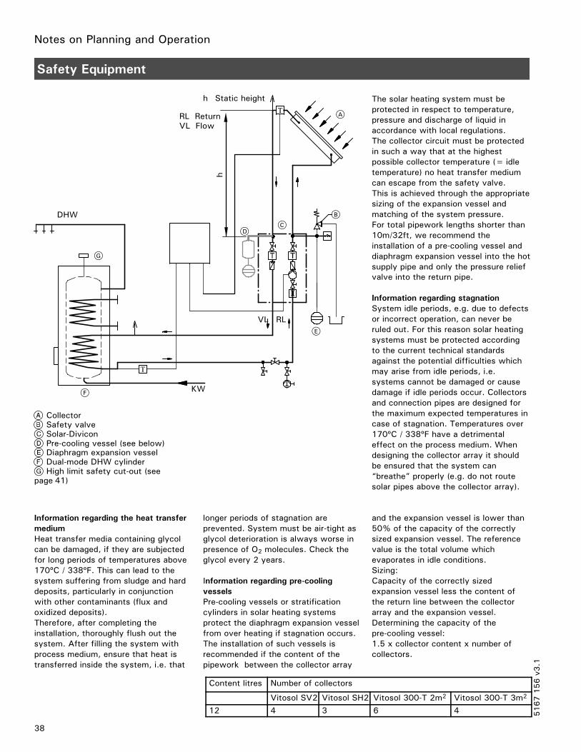
RL ReturnVL Flow
38
Safety Equipment
CollectorSafety valveSolar-DiviconPre-cooling vessel (see below)Diaphragm expansion vesselDual-mode DHW cylinderHigh limit safety cut-out (see
page 41)
h Static height The solar heating system must beprotected in respect to temperature,pressure and discharge of liquid inaccordance with local regulations.The collector circuit must be protectedin such a way that at the highestpossible collector temperature (= idletemperature) no heat transfer mediumcan escape from the safety valve.This is achieved through the appropriatesizing of the expansion vessel andmatching of the system pressure.For total pipework lengths shorter than10m/32ft, we recommend theinstallation of a pre-cooling vessel anddiaphragm expansion vessel into the hotsupply pipe and only the pressure reliefvalve into the return pipe.
Information regarding stagnationSystem idle periods, e.g. due to defectsor incorrect operation, can never beruled out. For this reason solar heatingsystems must be protected accordingto the current technical standardsagainst the potential difficulties whichmay arise from idle periods, i.e.systems cannot be damaged or causedamage if idle periods occur. Collectorsand connection pipes are designed forthe maximum expected temperatures incase of stagnation. Temperatures over170ºC / 338ºF have a detrimentaleffect on the process medium. Whendesigning the collector array it shouldbe ensured that the system can“breathe” properly (e.g. do not routesolar pipes above the collector array).
Information regarding the heat transfermediumHeat transfer media containing glycolcan be damaged, if they are subjectedfor long periods of temperatures above170ºC / 338ºF. This can lead to thesystem suffering from sludge and harddeposits, particularly in conjunctionwith other contaminants (flux andoxidized deposits).Therefore, after completing theinstallation, thoroughly flush out thesystem. After filling the system withprocess medium, ensure that heat istransferred inside the system, i.e. that
longer periods of stagnation areprevented. System must be air-tight asglycol deterioration is always worse inpresence of O2 molecules. Check theglycol every 2 years.
Information regarding pre-coolingvesselsPre-cooling vessels or stratificationcylinders in solar heating systemsprotect the diaphragm expansion vesselfrom over heating if stagnation occurs.The installation of such vessels isrecommended if the content of thepipework between the collector array
and the expansion vessel is lower than50% of the capacity of the correctlysized expansion vessel. The referencevalue is the total volume whichevaporates in idle conditions.Sizing:Capacity of the correctly sizedexpansion vessel less the content ofthe return line between the collectorarray and the expansion vessel.Determining the capacity of thepre-cooling vessel:1.5 x collector content x number ofcollectors.
Content litres Number of collectors
Vitosol SV2 Vitosol SH2 Vitosol 300-T 2m2 Vitosol 300-T 3m2
12 4 3 6 4 5167156v3
.1

Notes on Planning and Operation
Construction and operationA diaphragm expansion tank is asealed expansion vessel whose gasspace (nitrogen filling) is separatedfrom the liquid space (heat transfermedium) by a diaphragm and whoseinlet pressure is subject to the systemheight.To safely prevent steam beingcreated during the operating stage,collectors must indicate a pressure ofat least 15 psig / 1 bar in their coldstate.The expansion tank inlet pressure isthen higher by an amount of0.45 psig x static height (h) in ft.or 0.1 bar x static height (h) in m.In hot conditions, the system pressurerises by approx. 15 to 30 psig/1 to2 bar.
Maximum idle temperature ofcollectors:Vitosol 200-F, Models SV2, SH2Flat panel solar collector with 25 ft.2 /2.3 m2 collector area.Max. shutdown temperature430°F / 221°CMax. operating pressure87 psig /6 bar
Vitosol 300-T, SP3 SeriesVacuum tube solar collector with 22and 32 ft.2 / 2 and 3 m2 collectorarea.Max. shutdown temperature302°F / 150 °CMax. operating pressure87 psig /6 bar
To ensure that no heat transfermedium can escape from the pressurerelief valve, the expansion tank mustbe sufficiently large to accommodatethe liquid content of the collectorwhen steam forms (stagnation).
The cold fill inlet pressure (gas space)must be adjusted on site as follows:15 psig + 0.45 psig x static height inft1 bar + 0.1 bar x static height in mThe system operating pressure mustbe 4.5 to 7.5 psig/0.3 to 0.5 barhigher than the inlet pressure of thediaphragm expansion tank. Thewaterseal should be 0.005x the totalliquid content of the system but notless than 3 liters.
IMPORTANT
39
Safety Equipment (continued)
Diaphragm expansion tank
A
C
E
A
C
D
B
A
Deliveredcondition(3 bar/45 psigpressure)
Solar heatingsystem filledwithoutheat effect
Under max.pressure at thehighest processmedium temperature
Process mediumNitrogen filling
Nitrogen bufferSafety water seal, min. 3l/0.8gal
Specification - Viessmann expansion tankA B
b
b
a aØ Ø
Expansiontank
Contentlitres
Operatingpressurebar
Ø amm
bmm
ConnectionR
Weightkg
A 182540
101010
280280354
370490520
¾”¾”¾”
7.59.19.9
B 50 10 409 505 1” 12.3B 5080
1010
409480
505566
11”
12.318.4
5167156v3
.1

Notes on Planning and Operation
40
Safety Equipment (continued)
Technical data for the expansion tank (continued)
The nominal capacity of the expansionvessel is calculated according to theequation
VN = (Vv+V2+ z ⋅ Vk) ⋅ (pe+ 1)pe− pst
WherebyVN= nominal capacity of the
diaphragm expansion tankin liters
Vv = safety water seal (here heattransfer medium) in litresVv = 0.005 · VA in litres(min. 3 litres)
VA= liquid capacity of the entiresystem (see page 42).
pst= nitrogen inlet pressure ofexpansion vessel in bar
pst =1 bar + 0.1 · hh =static head of the system in
m (see drawing on page NO TAG)z = number of collectorsVk = collector capacity in litres
(see page 37).V2= volume increase when the
system heats up
V2 = VA · βb =expansion quotient ( β=0.13
for Viessmann heat transfermedium from –20 to 120ºC)
pe = permissible end pressure in barpe =psi – 0.1 · psipsi =safety valve blow off
pressure
Calculation exampleSolar heating system with:2 Vitosol 200-F, type SV2 @ 1.83 litresLiquid capacity: VA = 25 litresStatic head: h = 5 mPermissible final pressure: pe = 5.4 bar(ü)(Safety valve blow off pressure: 6 bar)
VN =(Vv+V2+ z ⋅ Vk) ⋅ (pe+ 1)
pe− pst
Vv =VA · 0.005Vv =0.125 litres, selected 3 litres
(see previoys page).V2 =VA · bV2 =3.25 litrespst =1.5 bar + 0.1 bar/m · 5 mpst =2.0 bar
VN =(3+ 3.25+ 2 ⋅ 1.83) ⋅ (5.4+ 1)5.4− 1.5
VN =16.3 litres
Due to the possibility of steamcollecting in the solar circuit pipe, werecommend multiplying the calculatedvalue VN by a safety factor of 1.5.Select a 25 liter expansion vessel.
Selection table for expansion tanks,subject to collector model (inconjunction with a 6 bar safety valve)These details provide only guide values;a final calculation must be carried out.
Vitosol 200-F, model SV2Number ofcollectors
SystemcapacityVAliters
Staticheadh (m)
Expansiontankcapacityliters
2 20 5 2510
3 25 5 2510 40
4 32 5 4010
5 35 5 4010 50
Vitosol 200-F, model SH2Number ofcollectors
SystemcapacityVAliters
Staticheadhm
Expansiontankcapacityliters
2 20 5 2510 40
3 30 5 4010
4 35 5 4010 50
5 40 5 5010 80
Vitosol 300-TAbsorbersurfaceaream2
SystemcapacityVAliters
Staticheadh (m)
Expansiontankcapacityliters
3 16 5 1810
4 18 5 1810
5 23 5 1810 25
6 25 5 2510
9 35 5 4010
5167156v3
.1
Do not use expansion tanks that arenot designed for solar heatingsystems. Temperatures duringstagnation periods can reachextremely high levels, which couldresult in serious injuries from hotsystem fluid discharging frompressure relief valve.
WARNING
Do not undersize expansion tank.
WARNING

Notes on Planning and Operation
41
Safety Equipment (continued)
Pressure relief valve
The operating pressure of the pressurerelief valve is the maximum systempressure +10%.The pressure relief valve must complywith all local codes.
The pressure relief valve must bematched to the output of the collectoror the collector assembly and be able tohandle their maximum output of900w/m2.
When use is made of water containingantifreeze or synthetic heat transfermedia which are miscible with water(e.g. Viessmann heat transfer medium)and whose boiling point is higher thanthat of water, the blow off anddischarge pipes must be run to an opencontainer capable of accommodatingthe total capacity of the collectors.
Use only pressure relief valves designedfor a maximum of 87 psig / 6 bar and248ºF / 120ºC bearing the markings”S” (solar) as part of the productidentification.
Solar-Divicon is equipped with a pressurerelief valve for max. 87 psig / 6 bar and248ºF / 120ºC.
High limit safety cut-out
The Vitosolic 200 solar control unit isequipped with an electronic limitthermostat which is preset in thefactory to 167ºF / 75ºC and can beadjusted.For systems with a sufficiently largeDHW capacity, this protection isadequate, as the maximum operatingtemperature does not exceed 23ºF /11ºC.
An additional mechanical high limitsafety cut-out is required, if the DHWtank capacity is less than 40 liters/m2
collector surface area.
Example:Vitosol 200-F flat collector x 4=,approx. 7 m2 absorber surface areaDHW cylinder with 300 litres capacity
3007.5
=40 litres/m2,
e.g. no high limit safety cut-outrequired.
5167156v3
.1
IMPORTANT
IMPORTANT

Notes on Planning and Operation
DCW
DHW
42
Safety Equipment (continued)
Thermostatic mixing valve
Solar storage tankThermostatic anti-scald mixingvalve
A thermostatic mixing valve is requiredfor all solar systems to preventdomestic hot water temperatures higherthan 140 ºF / 60 ºC (local codes mayrequire different temperature settings).
Install an anti-scald mixing valvedesigned for potable domestic hotwater systems.
5167156v3
.1
The domestic hot water temperaturemust be limited to 140 °F / 60 °C byinstalling a mixing device, e.g. athermostatic anti-scald mixing valve.
WARNING
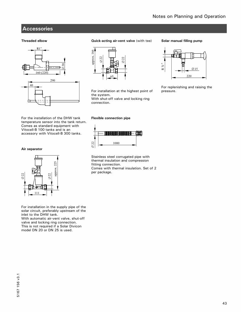
Notes on Planning and Operation
43
Accessories
Threaded elbow
For the installation of the DHW tanktemperature sensor into the tank return.Comes as standard equipment withVitocell-B 100 tanks and is anaccessory with Vitocell-B 300 tanks.
Air separator
For installation in the supply pipe of thesolar circuit, preferably upstream of theinlet to the DHW tank.With automatic air-vent valve, shut-offvalve and locking ring connection.This is not required if a Solar Diviconmodel DN 20 or DN 25 is used.
Quick-acting air-vent valve (with tee)
For installation at the highest point ofthe system.With shut-off valve and locking ringconnection.
Flexible connection pipe
Stainless steel corrugated pipe withthermal insulation and compressionfitting connection.Comes with thermal insulation. Set of 2per package.
Solar manual filling pump
For replenishing and raising thepressure.
5167156v3
.1
290
R1”
40
38
160 (220)
.
111
2222 approx.225
2222
approx.166
65
22 1000
220
15R½
”

System Designs
44
General Information
For our climatic zone: dual systems
In our climatic zone, solar radiation isinsufficient to cover the entirerequirements for domestic hot water orswimming pool heating as well as spaceheating by means of solar energy.
Therefore, a solar heating system forDHW or swimming pool water heatingand/or central heating should always becombined with another heat generator.
In dual systems, for example, an oil orgas-fired boiler supplies the additionalheat required.
How to implement the installation
Over the following pages, we havedescribed methods of operation andused design suggestions to illustratevarious installation ideas involvingdifferent equipment specifications. Asummary is provided which listsessential control equipment.The temperatures stated are guidevalues; other values may be set to meetparticular requirements.The circulation pumps referred to inthese examples (standard delivery withSolar-Divicon) are AC pumps.
DHW tank backup by the boiler issuppressed by the Vitosolic, when theanticipated heat requirement for DHWheating is expected to be covered bythe solar heating system. This mayrequire the use of the optionalexpansion boards.When connection between the Vitosolicand the boiler control (Vitodensprogramming unit, Vitotronic 300 orDekamatik) is made via the KM-BUS,the setpoint temperature for boilerbackup of DHW is reduced, stoppingthe boiler from coming on.
Abbreviations used in the examples:
DCW Domestic cold waterDHW Domestic hot waterR ReturnS Supply
5167156v3
.1
With temperatures over 140°F /60°C, the DHW temperature must belimited to 140°F / 60°C by installinga mixing device, e.g. a thermostaticmixing valve (DHW tank accessory).
WARNING

System Designs
45
System Design 1
Dual-mode DHW heating with Vitocell-B100 or Vitocell-B 300 DHW tanks- with Vitosolic 200 or GL 30 control
DHW heating without solar energy
The top part of the DHW tank is heatedby the boiler.The DHW tank temperature sensorof the boiler control unit switches tankheating circulation pump .
DHW heating with solar energy
When a temperature difference higherthan the value set in control unit ismeasured between collectortemperature sensor and tanktemperature sensor , solar circuitcirculation pump is switched ONand the DHW tank is heated up.The temperature in the DHW tank islimited by the electronic limitthermostat in control unit or byhigh limit safety cut-out (ifrequired).
When the preset temperature isexceeded, these devices switch OFFsolar circuit circulation pump . Theelectronic temperature limit is set at thefactory.
Installation diagram
Solar collectorSolar-DiviconTaps
DHW circulationDHW circulation output of the boilercontrol unit or timer installed on site
Heating circuitOil/gas-fired boilerDHW cylinder
*1 High limit safety cut-out, see page 41.
5167156v3
.1
A
G H
2
4
5
6
7
C
B
S R
3
D
5
28 E
21
F
1
DHW
DCW

System Designs
46
System Design 1 (continued)
Dual-mode DHW heating with Vitocell-B100 or Vitocell-B 300 DHW tanks- with Vitosolic 200 or GL 30 control (continued)
Control equipment required
Item Description Number Part no.Control of DHW cylinder loading by solar energy
1 Vitosolic 200orGL 30 control
1 7134 552
7134 4502 Collector temperature sensor 1 Included in
standardequipment foritem 1
3 DHW tank temperature sensor*1 1 Included instandardequipment foritem 1
4 Solar circuit circulation pump(standard equipment of Solar-Divicon, see page 35)
1 7133 454or7133 455
5 High limit safety cut-out (see page 41)*2 1 Supplied on siteControl of DHW tank loading by the boiler
6 DHW tank temperature sensor 1 Included instandardequipment of boilercontrol unit*2
7 Circulation pump for DHW tank loading 1 DHW tankaccessory
*1Installation requires a threaded elbow (standard delivery for Vitocell-B 100, accessory for Vitocell-B 300 ).*2Accessory with Vitodens.
5167156v3
.1
The domestic hot water temperaturemust be limited to 140 °F / 60 °C byinstalling a mixing device, e.g. athermostatic anti-scald mixing valve.
WARNING

System Designs
47
System Design 2
Dual-mode DHW heating and space heating backup with heating water storage tank- with Vitosolic 200
DHW heating without solar energy
The upper indirect coil of the DHW tankis heated by a boiler. The DHW tanktemperature sensor of the boilercontrol unit switches circulation pump
to heat up the DHW tank.
DHW heating with solar energy
Solar circuit circulation pump isswitched ON and the DHW is heatedup, when a temperature differencehigher than the value set in control unit
is measured between collectortemperature sensor and DHWtemperature sensor .The temperature in the DHW is limitedby the electronic limit thermostat incontrol unit or by high limit safetycut-out (if required).When the preset temperature isexceeded, these devices switch OFFsolar circuit circulation pump .The electronic temperature limit is setat the factory.
Space heating without solar energy
Diverter valve remains at zero volts(setting ”AB-B”), if the differentialtemperature between heating waterstorage tank temperature sensor(discharge) and space heating returntemperature sensor falls below thevalue set at control unit . No flowthrough the heating water storage tanktakes place.The boiler provides heat to the heatingcircuit according to the heating curveset at the boiler control unit.
Space heating with solar energy
Heating water storage tank circuitcirculation pump and circulationpump for storage tank heating areswitched ON and the heating waterstorage tank is heated up, when atemperature difference higher than thedifferential temperature preset incontrol unit is measured betweencollector temperature sensor andstorage tank temperature sensor(re-loading) . The temperature insidethe heating water storage tank will belimited by the electronic limitthermostat in control unit .When the preset temperature isexceeded, this device switches thestorage tank circuit circulation pump
and OFF.Circulation pump is switched OFFfor approx. 2 minutes, roughly every15 minutes (adjustable time), to checkwhether the temperature at thecollector temperature sensor is highenough to change over to DHW tankloading.
Control unit switches diverter valveto position ”AB-A” and the space
heating return water will be channelledinto the boiler via the storage tank, ifthe temperature differential betweenstorage tank temperature sensor(discharge) and space heating returntemperature sensor exceeds that setat control unit . If the temperature ofthe pre-heated return water isinsufficient, the boiler re-heats thewater to the necessary flowtemperature level.
5167156v3
.1

System Designs
48
System Design 2 (continued)
Installation diagram
Solar collectorSolar-DiviconSolar pump lineTaps
DHW circulationDHW circulation output of the boilercontrol unit or timer installed on site
Heating water storage tankOil/gas-fired boilerDHW tank
*1High limit safety cut-out, see page 41.
5167156v3
.1
2
A
B
1
C
4
qE
D
9
qP
qQG
qT
qR AB
BA
H
55
21
3
DHW
S R
DCWqW
7
K
6
Refer to Viessmann sample layout drawing #5 foralternate layout. (contact Viessmann sales rep. fordetails)

System Designs
49
System Design 2 (continued)
Dual-mode DHW heating and space heating backup with heating water storage tank- with Vitosolic 200 (continued)
Control equipment required
Item Description Number Part no.Control of DHW tank loading by solar energy
1 Vitosolic 200 1 7134 4502 Collector temperature sensor 1 Included in
standardequipment foritem 1
3 DHW tank temperature sensor*1 1 Included instandardequipment foritem 1
4 Solar circuit circulation pump(standard equipment of Solar-Divicon, see page 35)
1 7133 454or7133 455
5 High limit safety cut-out (see also page 41) 1 Supplied on site8 Circulation pump (relayering) 1 Supplied on site
Control of DHW tank loading by the boiler6 DHW tank temperature sensor 1 Included in
standardequipment of theboiler control unit
7 Circulation pump for DHW tank loading 1 DHW tankaccessory
Space heating control with solar energy9 Return temperature sensor (heating circuit) 1 7170 965qP Temperature sensor (storage tank), discharge 1 7170 965qQ Temperature sensor (storage tank, re-loading) 1 Included in
standardequipment foritem 1
qW Three-way diverter valve 1 Supplied on siteqE Solar circuit circulation pump for storage tank heating
(part of the solar pump line, see page 35)1 Supplied on site
qR Circulation pump for storage tank heating 1 Supplied on siteqT Heat exchanger 1 Supplied on site*1A threaded elbow (standard delivery for Vitocell-B 100, accessory for Vitocell-B 300 ) is recommended for this installation.
Note:Heating water storage tank , circulation pump for storage tank and heat exchanger can all be replaced with anindirect-fired storage tank, c/w internal heat exchanger coil (e.g. Vitocell-V 100).
5167156v3
.1
The domestic hot water temperaturemust be limited to 140 °F / 60 °C byinstalling a mixing device, e.g. athermostatic anti-scald mixing valve.
WARNING

System Designs
50
System Design 3
Dual-mode DHW heating with two DHW tanks- with Vitosolic 200
DHW heating without solar energy
DHW tank 2 is heated by the boiler. TheDHW tank thermostat with connectedtank temperature sensor of theboiler control unit switches circulationpump to heat up the DHW tank.DHW circulation pump 8b (if installed)is switched ON and circulation pump8a is switched OFF, so that the DHWcirculation only affects DHW tank .
DHW heating with solar energy
Solar circuit circulation pump isswitched ON and DHW tank 1 is heatedup, when a temperature differencehigher than the value set in control unit
is measured between collectortemperature sensor and tanktemperature sensor .The temperature in DHW tank 1 islimited by the electronic limitthermostat in control unit or byhigh limit safety cut-out (ifrequired).When the preset temperature isexceeded, this device switches OFFsolar circuit circulation pump . Theelectronic temperature limit is set at thefactory.
Circulation pump 8a is switched ON,when the temperature at sensor inDHW tank 1 exceeds that at sensorin DHW tank 2.
The DHW circulation covers both DHWtanks. This feeds the water heated inDHW tank 1 into DHW tank 2. Thisway, DHW tank 2 is also heated bysolar energy.DHW circulation pump 8b (if installed)for DHW tank 2 is controlled by theboiler control unit.
Circulation pump 8a will be switchedOFF if the temperature in DHW tank 2rises above that in DHW tank 1.
5167156v3
.1The domestic hot water temperaturemust be limited to 140 °F / 60 °C byinstalling a mixing device, e.g. athermostatic anti-scald mixing valve.
WARNING

System Designs
51
System Design 3 (continued)
Installation diagram (system with two DHW cylinders with indirect coils)
Solar collectorSolar-DiviconTapsDHW circulation
DHW circulation output of the boilercontrol unit or timer installed on siteHeating circuit
Oil/gas-fired boilerDHW tank 2DHW tank 1
*1High limit safety cut-out, see page 41.
5167156v3
.1
S R
7
G H K
3
2 1
4
2
A
D
5
96
qP
F
C
1
B
5
28
21
E
DCW
DHW
8b
8a
DCW

System Designs
52
System Design 3 (continued)
Dual-mode DHW heating with two DHW tanks- with Vitosolic 200 (continued)
Control equipment required
Item Description Number Part no.
Control of DHW tank 1 loading by solar energy1 Vitosolic 200 1 7134 5522 Collector temperature sensor 1 Included in
standardequipment foritem 1
3 DHW tank temperature sensor*1 1 Included instandardequipment foritem 1
4 Solar circuit circulation pump(standard equipment of Solar-Divicon, see page 35)
1 7133 454or7133 455
5 High limit safety cut-out (see also page 41) 1 Supplied on site
Control of DHW tank 2 loading by the boiler6 DHW tank temperature sensor 1 Included in
standardequipment of boilercontrol unit *2
7 Circulation pump for DHW tank loading*3 1 AccessoriesDHW tank
DHW circulation changeover8 DHW circulation pump or circulation pump (relayering) 1 Supplied on site
9 Temperature sensor tank 1 1 Included instandardequipment foritem 1
qP Temperature sensor tank 2 1 7170 965
*1The screw-in elbow which is available as an accessory for the DHW cylinder is recommended for installation purposes.*2Accessory with Vitodens.*3Part of the standard delivery with Vitodens (for types with DHW heating).
5167156v3
.1
The domestic hot water temperaturemust be limited to 140 °F / 60 °C byinstalling a mixing device, e.g. athermostatic anti-scald mixing valve.
WARNING

System Designs
53
System Design 4
Dual-mode DHW and swimming pool water heating- with Vitosolic 200
DHW heating without solar energy
The top part of the DHW tank is heatedby the boiler.The DHW tank temperature sensorof the boiler control unit switches tankheating circulation pump .
DHW heating with solar energy
Solar circuit circulation pump for DHWheating is switched ON and theDHW tank is heated up, when atemperature difference higher than thevalue set in control unit is measuredbetween collector temperature sensor
and DHW tank temperaturesensor .
Solar circuit circulation pump for DHWheating is switched OFF, and solarcircuit circulation pump for swimmingpool heating is switched ON (see”Swimming pool water heating”), if thetemperature at DHW tank temperaturesensor is so high that the actualtemperature difference falls below theset differential temperature.
The temperature in the DHW tank islimited by the electronic limitthermostat in control unit or byhigh limit safety cut-out (ifrequired).When the preset temperature isexceeded, these devices switch OFFsolar circuit circulation pump . Theelectronic temperature limit is set at thefactory.
Swimming pool water heating
Solar circuit circulation pump for DHWheating is switched OFF, and solarcircuit circulation pump forswimming pool heating is switched ON,if the temperature at DHW tanktemperature sensor is so high, thatthe temperature difference falls belowthe set differential temperature forDHW heating.The temperature at collectortemperature sensor must then behigher by the temperature difference forswimming pool water heating set incontrol unit than the temperature attemperature sensor (swimming pool)
.Swimming pool water limit thermostat(max. limit) switches circulationpump OFF when the desired setwater temperature has been reached.Circulation pump is switched OFFfor approx. 2 minutes roughly every15 minutes (adjustable time), to checkwhether the temperature at thecollector temperature sensor is highenough to change over to DHW tankloading.
When the solar energy is insufficient toheat the swimming pool water, theheating of the swimming pool water willbe taken over by the oil/gas-fired boilervia temperature sensor in heatexchanger 2.
The filter time and any boiler backupshould fall outside those times whenheating by solar energy can beexpected.
5167156v3
.1

System Designs
54
System Design 4 (continued)
Installation diagram
Solar collectorSolar-DiviconSolar pump lineTapsDHW circulation
DHW circulation output of the boilercontrol unit or timer installed on siteHeating circuitOil/gas-fired boilerDual-mode DHW tank
Swimming poolHeat exchanger 2Heat exchanger 1Filter system with pump
*1High limit safety cut-out, see page 41.
5167156v3
.1L
DCW
S R
2 1
28
5
21
O
M N
qT
9
qP
E
6
8
5
7
G
F
D
H K
DHW
B C
A
1
3
4
qEqR
2

System Designs
55
System Design 4 (continued)
Dual-mode DHW and swimming pool water heating- with Vitosolic 200 (continued)
Control equipment required
Item Description Number Part no.Control of DHW tank loading by solar energy
1 Vitosolic 200 1 7134 5522 Collector temperature sensor 1 Included in
standardequipment foritem 1
3 DHW tank temperature sensor*1 1 Included instandardequipment foritem 1
4 Circulation pump for the solar circuit(standard equipment of Solar-Divicon, see page 35)
1 7133 454or7133 455
5 High limit safety cut-out (see also page 41) 1 Supplied on site8 Circulation pump 1 Supplied on site
Control of DHW tank loading by the boiler6 DHW tank temperature sensor 1 Included in
standardequipment of theboiler control unit
7 Circulation pump for DHW tank loading 1 DHW tankaccessory
Control of swimming pool heating by solar energy9 Temperature sensor (swimming pool) 1 Included in
standardequipment foritem 1
qP Solar circuit circulation pump for swimming pool heating(part of the solar pump line, see page 35)
1 Supplied on site
qQ Swimming pool limit thermostat (max. limit) 1 Supplied on siteControl of swimming pool heating by the boiler
qE Temperature sensor (heat exchanger 2) 1 7170 965qR Limit thermostat (max. limit) 1 Supplied on siteqT Circulation pump for swimming pool water heating 1 Supplied on site*1A threaded elbow (standard delivery for Vitocell-B 100, accessory for Vitocell-B 300) is recommended for this installation.
5167156v3
.1
The domestic hot water temperaturemust be limited to 140 °F / 60 °C byinstalling a mixing device, e.g. athermostatic anti-scald mixing valve.
WARNING

System Designs
56
System Design Extensions
Bypass circuit
To improve the start-up characteristicsof the system or for systems withseveral collector arrays, operation witha bypass circuit is feasible.
Version 1 - bypass circuit with collector temperature sensor and bypass sensor
The Vitosolic 200 records the collectortemperature via the collectortemperature sensor. If the settemperature difference between thecollector temperature sensor and the
cylinder sensor is exceeded, the bypasspump is switched ON.If the temperature difference betweenthe bypass sensor and the cylinder
temperature sensor is exceeded by 2.5K the solar circuit pump is switched ONand the bypass pump is switched OFF.
R1R5
VL
S3
RL
NoteThe pump of the Solar-Divicon is usedas the bypass pump and the pump ofthe solar circuit pump line is used asthe solar circuit pump.
R1 Solar circuit pumpR3 Bypass pumpS1 Collector temperature sensorS3 Bypass sensor
S1
Version 2 - bypass circuit with solar cell (e.g. with an external heat exchanger)
For this system version, the solar circuitpump takes on this additional function.The Vitosolic 200 records the solarintensity via the solar cell.
The solar circuit pump will be switchedON, if the set irradiation threshold isexceeded.
The pump will be switched OFF, if theirradiation falls below the set switchingthreshold (shutdown delay approx.2 min).
R1
VL
CS
RL
S1CS Solar cellR1 Solar circuit pumpS1 Collector temperature sensor
5167156v3
.1

System Designs
57
System Design Extensions (continued)
System with energy-saving mode
Version 3 - bypass circuit with solar cell and collector temperature sensor
The Vitosolic 200 records the solarintensity via the solar cell.If the set irradiation threshold isexceeded, the bypass pump is switchedON. The bypass pump is switched OFF
and the solar circuit pump will beswitched ON, if the set temperaturedifference between the collectortemperature sensor and cylindertemperature sensor is exceeded.
The bypass pump will also be switchedOFF if the irradiation falls below the setswitching threshold (shutdown delayapprox. 2.5 min).
R1R5
VL
S1
RL
CS
CS Solar cellR1 Solar circuit pumpR5 Bypass pumpS1 Collector temperature sensor
NoteThe pump of the Solar-Divicon is usedas the bypass pump and the pump ofthe solar circuit pump line is used asthe solar circuit pump.
5167156v3
.1

Appendix
200 litres/day45 °C
Azimuth: 0°Inclination: 45°
300 litres
2 x Vitosol 200-F
11 kW
58
Calculation Example Based on the Viessmann “ESOP” Program
Solar heating system with dual-coil DHW tank
Results of simulation over a one-year period
DHW solar fraction 59.8 %System efficiency 36.2 %Heat yield of collector circuit 2 214 kWhIrradiation on reference surface 6.12 MWhHeat requirement for DHW heating 2 975 kWhNatural gas savings 274 m3
CO2 emissions avoided 520 kg
5167156v3
.1

Appendix
Coverage 59.8%
Jan Feb Mar Apr May Jun Jul Aug Sep Oct Nov Dec
Period: 1.1. – 31.12.
59
Calculation Example Based on the Viessmann “ESOP” Program (continued)
Solar heating system with dual-coil DHW tank (continued)
System parameters
Collector circuit details2 collectors Model: Vitosol 200-FTotal surface area, gross: 5.42 m2 Net: 4.99 m2
Angle of inclination: 45º Azimuth: 0º
DHW cylinder with two indirect coilsCapacity: 300 l Model: Vitocell-B 100 (300 litres)
DHW consumerType: Detached house 200 l per day at 45 ºC set temperature, 365 days
Cold waterFebruary: 8 ºC August: 12 ºC
Weather statisticsA location at 49º latitude Total annual global radiation: 1101.08 kWh/m2
5167156v3
.1

Appendix
60
Glossary
AbsorberDevice contained inside a solar collectorfor absorbing radiation energy andtransferring this as heat to a liquid.
AbsorptionAbsorption of radiation.
CondenserDevice in which vapour is precipitatedas liquid.
ConvectionTransfer of heat by a flowing medium.Convection creates energy lossescaused by a difference in temperature,e.g. between the glass plate of thecollector and the hot absorber.
DispersionInteraction of radiation with matter bywhich the radiation direction is altered;total energy and wavelength remainunchanged.
EfficiencyThe efficiency of a solar collector is theinput/output ratio of the collector.Relevant variables are, for example, theambient and absorber temperatures.
EmissionRadiation of beams, e.g. light orparticles.
EvacuationEvacuating air from a container. Thisreduces the air pressure and creates avacuum.
Heat loss coefficients k1 and k2k1 is the constant component of theheat loss of a collector and is usuallydesignated as k value (unit: W/(m2 · K)).k2 is the quadratic component of thetemperature-dependent heat loss(unit: W/(m2 · K2)).Any informative statement about theheat losses of a collector requires bothvalues to be quoted.
Heat pipeClosed, capillary container whichcontains a small quantity of highlyvolatile liquid.
Heat transfer mediumFluid which picks up the useful heat inthe absorber of the collector andtransfers it to a user (heat exchanger).
Photovoltaic effectGaining electrical energy from solarenergy.
Radiation energyQuantity of energy transmitted byradiation.
Radiation level (irradiation)Radiation power, impacting per unitsurface, expressed in W/m2, orBtu/h/ft.2.
Selective surfaceThe absorber in the solar collector hasbeen given a highly selective coating toimprove its efficiency. This speciallyapplied coating enables the absorptionto be maintained at a very high level forthe incident sunlight spectrum(approx.94%). The emission of thelong-wave heat radiation is largelyavoided.The high-selectivity black chromiumcoating is very durable.
StagnationCondition of a collector when no heat isbeing conducted away by the heattransfer medium.
VacuumA space devoid of air.
5167156v3
.1

61
5167156v3
.1

62
5167156v3
.1

63
5167156v3
.1

Viessmann Manufacturing Company Inc.750 McMurray RoadWaterloo, Ontario • N2V 2G5 • CanadaTel. (519) 885-6300 • Fax (519) 885-0887www.viessmann.ca • [email protected]
Viessmann Manufacturing Company (U.S.) Inc.45 Access RoadWarwick, Rhode Island • 02886 • USATel. (401) 732-0667 • Fax (401) 732-0590www.viessmann-us.com • [email protected]
64
5167156v3
.1Printedon
environm
entally
friend
ly(rec
ycledan
drecy
clab
le)pa
per.
Tec
hnical
inform
ationsu
bjec
tto
chan
gewith
outno
tice.