Embed Size (px)
Citation preview
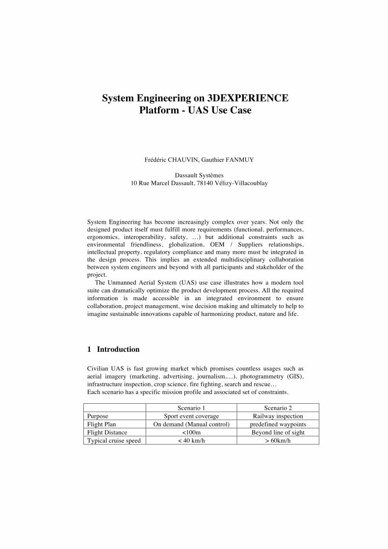
System Engineering on 3DEXPERIENCE Platform - UAS Use Case
Frédéric CHAUVIN, Gauthier FANMUY
Dassault Systèmes 10 Rue Marcel Dassault, 78140 Vélizy-Villacoublay
System Engineering has become increasingly complex over years. Not only the designed product itself must fulfill more requirements (functional, performances, ergonomics, interoperability, safety, …) but additional constraints such as environmental friendliness, globalization, OEM / Suppliers relationships, intellectual property, regulatory compliance and many more must be integrated in the design process. This implies an extended multidisciplinary collaboration between system engineers and beyond with all participants and stakeholder of the project.
The Unmanned Aerial System (UAS) use case illustrates how a modern tool suite can dramatically optimize the product development process. All the required information is made accessible in an integrated environment to ensure collaboration, project management, wise decision making and ultimately to help to imagine sustainable innovations capable of harmonizing product, nature and life.
1 Introduction
Civilian UAS is fast growing market which promises countless usages such as aerial imagery (marketing, advertising, journalism,…), photogrammetry (GIS), infrastructure inspection, crop science, fire fighting, search and rescue… Each scenario has a specific mission profile and associated set of constraints. Scenario 1 Scenario 2 Purpose Sport event coverage Railway inspection Flight Plan On demand (Manual control) predefined waypoints Flight Distance <100m Beyond line of sight Typical cruise speed < 40 km/h > 60km/h
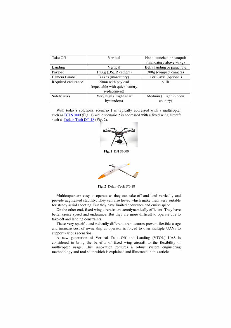
Take Off Vertical Hand launched or catapult (mandatory above ~3kg)
Landing Vertical Belly landing or parachute Payload 1.5Kg (DSLR camera) 300g (compact camera) Camera Gimbal 3 axes (mandatory) 1 or 2 axis (optional) Required endurance 20mn with payload
(repeatable with quick battery replacement)
> 1h
Safety risks Very high (Flight near bystanders)
Medium (Flight in open country)
With today’s solutions, scenario 1 is typically addressed with a multicopter
such as DJI S1000 (Fig. 1) while scenario 2 is addressed with a fixed wing aircraft such as Delair-Tech DT-18 (Fig. 2).
Fig. 1 DJI S1000
Fig. 2 Delair-Tech DT-18
Multicopter are easy to operate as they can take-off and land vertically and provide augmented stability. They can also hover which make them very suitable for steady aerial shooting. But they have limited endurance and cruise speed.
On the other end, fixed wing aircrafts are aerodynamically efficient. They have better cruise speed and endurance. But they are more difficult to operate due to take-off and landing constraints.
These very specific and radically different architectures prevent flexible usage and increase cost of ownership as operator is forced to own multiple UAVs to support various scenarios.
A new generation of Vertical Take Off and Landing (VTOL) UAS is considered to bring the benefits of fixed wing aircraft to the flexibility of multicopter usage. This innovation requires a robust system engineering methodology and tool suite which is explained and illustrated in this article.
2 System Engineering on the 3DEXPERIENCE Platform
2.1 The Systems Engineering promise: early decision makings to build cost-effective solutions
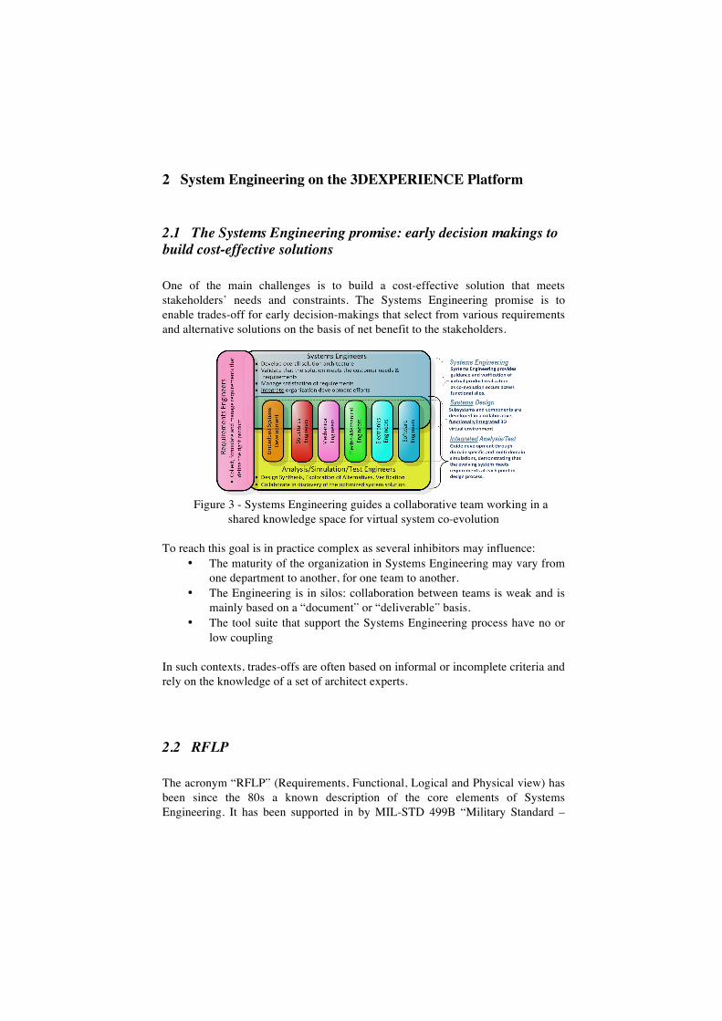
One of the main challenges is to build a cost-effective solution that meets stakeholders’ needs and constraints. The Systems Engineering promise is to enable trades-off for early decision-makings that select from various requirements and alternative solutions on the basis of net benefit to the stakeholders.
Figure 3 - Systems Engineering guides a collaborative team working in a
shared knowledge space for virtual system co-evolution To reach this goal is in practice complex as several inhibitors may influence:
• The maturity of the organization in Systems Engineering may vary from one department to another, for one team to another.
• The Engineering is in silos: collaboration between teams is weak and is mainly based on a “document” or “deliverable” basis.
• The tool suite that support the Systems Engineering process have no or low coupling
In such contexts, trades-offs are often based on informal or incomplete criteria and rely on the knowledge of a set of architect experts.
2.2 RFLP
The acronym “RFLP” (Requirements, Functional, Logical and Physical view) has been since the 80s a known description of the core elements of Systems Engineering. It has been supported in by MIL-STD 499B “Military Standard –
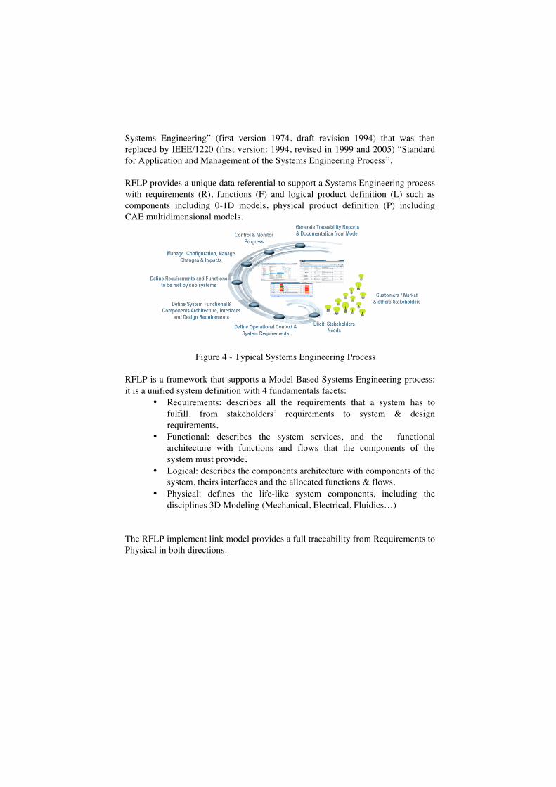
Systems Engineering” (first version 1974, draft revision 1994) that was then replaced by IEEE/1220 (first version: 1994, revised in 1999 and 2005) “Standard for Application and Management of the Systems Engineering Process”. RFLP provides a unique data referential to support a Systems Engineering process with requirements (R), functions (F) and logical product definition (L) such as components including 0-1D models, physical product definition (P) including CAE multidimensional models.
Figure 4 - Typical Systems Engineering Process
RFLP is a framework that supports a Model Based Systems Engineering process: it is a unified system definition with 4 fundamentals facets:
• Requirements: describes all the requirements that a system has to fulfill, from stakeholders’ requirements to system & design requirements,
• Functional: describes the system services, and the functional architecture with functions and flows that the components of the system must provide,
• Logical: describes the components architecture with components of the system, theirs interfaces and the allocated functions & flows.
• Physical: defines the life-like system components, including the disciplines 3D Modeling (Mechanical, Electrical, Fluidics…)
The RFLP implement link model provides a full traceability from Requirements to Physical in both directions.
2.3 The 3DExperience Platform for Systems Engineering
The 3DEXPERIENCE Platform is a business experience platform available on premise and in public or private cloud, and whose purpose is to enable 3DS’ customers to create experiences for their ultimate customers or consumers. It is a new generation of platform that enables all disciplines in a company and its ecosystem.
The 3DEXPERIENCE Platform is built upon the applications from different
brands that are connected through a common database backplane: • Social and Collaborative applications. • Model Based Systems Engineering and 3D Modeling applications
Content & Simulation Applications • Information Intelligence Applications
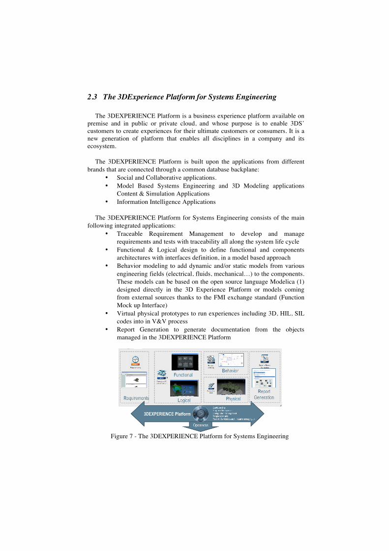
The 3DEXPERIENCE Platform for Systems Engineering consists of the main
following integrated applications: • Traceable Requirement Management to develop and manage
requirements and tests with traceability all along the system life cycle • Functional & Logical design to define functional and components
architectures with interfaces definition, in a model based approach • Behavior modeling to add dynamic and/or static models from various
engineering fields (electrical, fluids, mechanical…) to the components. These models can be based on the open source language Modelica (1) designed directly in the 3D Experience Platform or models coming from external sources thanks to the FMI exchange standard (Function Mock up Interface)
• Virtual physical prototypes to run experiences including 3D, HIL, SIL codes into in V&V process
• Report Generation to generate documentation from the objects managed in the 3DEXPERIENCE Platform
Figure 7 - The 3DEXPERIENCE Platform for Systems Engineering
3 UAS Use Case
This UAS use case has been developed mainly by a single engineer who had initially none to limited skills on UAS technologies, RFLP and Modelica language.
This represents an effort of:- - 2 months on training mainly on RFLP and Modelica based behavior
modeling Apps. - 2 months on UAS documentary research, mainly on autopilot,
aerodynamics, propellers, brushless motors and controllers, MAVLink Ground Control Station communication protocol.
- 8 months of dynamic behavior and 3D modeling on various tradeoffs. Additional engineers have contributed a cumulated effort of 3 months, mainly
on FMU (2) development (UDP communication), 3D Styling and 3D virtual environment creation.
3.1 Introduction
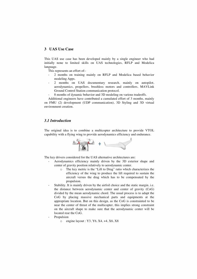
The original idea is to combine a multicopter architecture to provide VTOL capability with a flying wing to provide aerodynamics efficiency and endurance.
The key drivers considered for the UAS alternative architectures are:
- Aerodynamics efficiency mainly driven by the 3D exterior shape and center of gravity position relatively to aerodynamic center.
o The key metric is the “Lift to Drag” ratio which characterizes the efficiency of the wing to produce the lift required to sustain the aircraft versus the drag which has to be compensated by the propulsion.
- Stability. It is mainly driven by the airfoil choice and the static margin, i.e. the distance between aerodynamic center and center of gravity (CoG) divided by the mean aerodynamic chord. The usual process is to adapt the CoG by placing massive mechanical parts and equipments at the appropriate location. But on this design, as the CoG is constrainted to be near the center of thrust of the multicopter, this implies strong constraint on the aircraft shape to make sure that the aerodynamic center will be located rear the CoG.
- Propulsion o engine layout : Y3, Y6, X4, +4, X6, X8
o Propeller size and pitch o Maximum continuous power o Thrust to weight ratio. It is generally admitted that is must range
from 1.5 to 2 for provide safe multicopter handling. - Use of a maximum of components on the shelf (COTS) to reduce costs.
3.2 RFLP
Within 3DEXPERIENCE integrated environment, the RFLP referential is instantiated to support the end to end design process.
3.3 Models
Multi dimensional (0..3D) models are developed in parallel to provide the required information to evaluate most critical key performance indicators (KPIs) on:
- Aerodynamics efficiency - Thrust to weight ratio - Mechanical Design feasibility - Equipments and payload space allocation - Mission capabilities - Total cost of ownership
3.3.1 3D Design
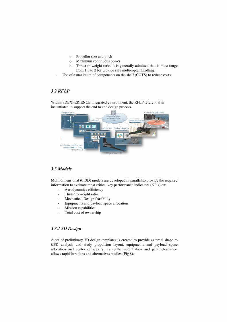
A set of preliminary 3D design templates is created to provide external shape to CFD analysis and study propulsion layout, equipments and payload space allocation and center of gravity. Template instantiation and parameterization allows rapid iterations and alternatives studies (Fig 8).
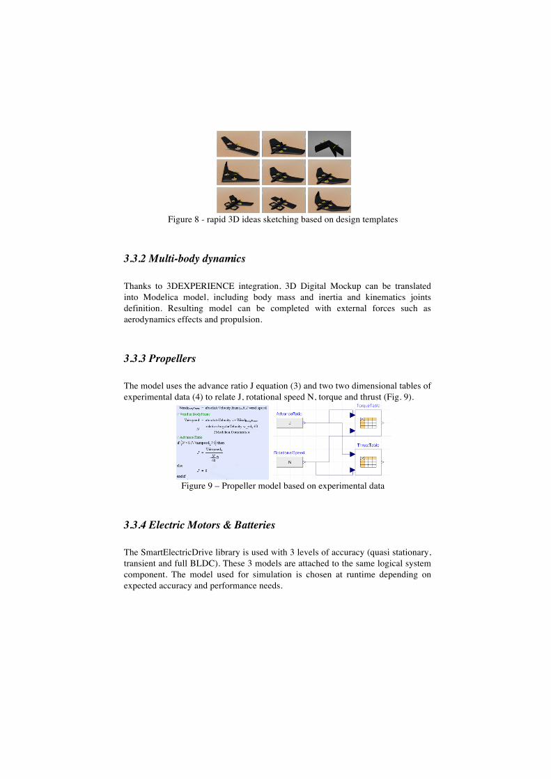
Figure 8 - rapid 3D ideas sketching based on design templates
3.3.2 Multi-body dynamics
Thanks to 3DEXPERIENCE integration, 3D Digital Mockup can be translated into Modelica model, including body mass and inertia and kinematics joints definition. Resulting model can be completed with external forces such as aerodynamics effects and propulsion.
3.3.3 Propellers
The model uses the advance ratio J equation (3) and two two dimensional tables of experimental data (4) to relate J, rotational speed N, torque and thrust (Fig. 9).
Figure 9 – Propeller model based on experimental data
3.3.4 Electric Motors & Batteries
The SmartElectricDrive library is used with 3 levels of accuracy (quasi stationary, transient and full BLDC). These 3 models are attached to the same logical system component. The model used for simulation is chosen at runtime depending on expected accuracy and performance needs.
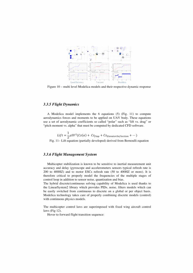
Figure 10 – multi level Modelica models and their respective dynamic response
3.3.5 Flight Dynamics
A Modelica model implements the 6 equations (5) (Fig. 11) to compute aerodynamics forces and moments to be applied on UAV body. These equations use a set of aerodynamic coefficients so called “polar” such as “lift vs. drag” or “pitch moment vs. alpha” that must be computed by dedicated CFD software.
𝐿𝑖𝑓𝑡 =12𝜌𝑆𝑉!(𝐶𝑧 𝛼 + 𝐶𝑧!"#$ + 𝐶𝑧!"#$%&'()#*"#+&,'- +⋯ )
Fig. 11– Lift equation (partially developed) derived from Bernoulli equation
3.3.6 Flight Management System
Multicopter stabilization is known to be sensitive to inertial measurement unit accuracy and delay (gyroscope and accelerometers sensors typical refresh rate is 200 to 400HZ) and to motor ESCs refresh rate (50 to 400HZ or more). It is therefore critical to properly model the frequencies of the multiple stages of control loop in addition to sensor noise, quantization and bias. The hybrid discrete/continuous solving capability of Modelica is used thanks to the LinearSystem2 library which provides PIDs, noise, filters models which can be easily switched from continuous to discrete on a global or per object basis. Modelica technology takes care of properly combining discrete models (control) with continuous physics models. The multicopter control laws are superimposed with fixed wing aircraft control laws (Fig 12).
Hover to forward flight transition sequence:
1. rear engines are tilted in an fixed duration arbitrary chosen to leave the aircraft enough time to accelerate to minimum flight speed
2. When aircraft exceeds stall speed, forward engines are stopped 3. Then engines doors are closed.
Forward flight to hover transition sequence: 1. rear engines are tilted to horizontal position 2. When aircraft approaches stall speed, forward engine doors are opened. 3. Once the doors are opened, the forward engines are started.
Fig 12.Overview of hybrid multicopter – fixed wing stabilization control laws
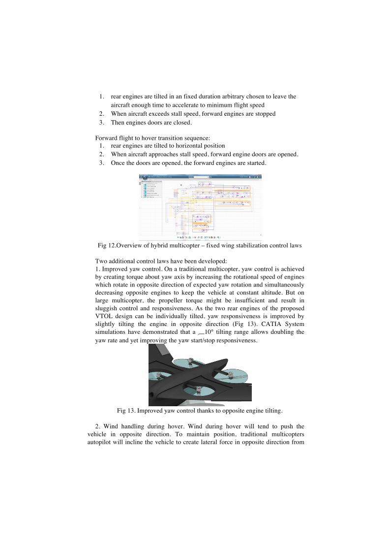
Two additional control laws have been developed: 1. Improved yaw control. On a traditional multicopter, yaw control is achieved by creating torque about yaw axis by increasing the rotational speed of engines which rotate in opposite direction of expected yaw rotation and simultaneously decreasing opposite engines to keep the vehicle at constant altitude. But on large multicopter, the propeller torque might be insufficient and result in sluggish control and responsiveness. As the two rear engines of the proposed VTOL design can be individually tilted, yaw responsiveness is improved by slightly tilting the engine in opposite direction (Fig 13). CATIA System simulations have demonstrated that a !10° tilting range allows doubling the yaw rate and yet improving the yaw start/stop responsiveness.
Fig 13. Improved yaw control thanks to opposite engine tilting.
2. Wind handling during hover. Wind during hover will tend to push the
vehicle in opposite direction. To maintain position, traditional multicopters autopilot will incline the vehicle to create lateral force in opposite direction from
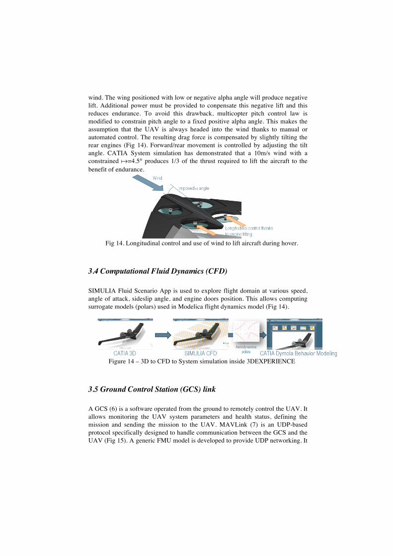
wind. The wing positioned with low or negative alpha angle will produce negative lift. Additional power must be provided to conpensate this negative lift and this reduces endurance. To avoid this drawback, multicopter pitch control law is modified to constrain pitch angle to a fixed positive alpha angle. This makes the assumption that the UAV is always headed into the wind thanks to manual or automated control. The resulting drag force is compensated by slightly tilting the rear engines (Fig 14). Forward/rear movement is controlled by adjusting the tilt angle. CATIA System simulation has demonstrated that a 10m/s wind with a constrained "=4.5° produces 1/3 of the thrust required to lift the aircraft to the benefit of endurance.
Fig 14. Longitudinal control and use of wind to lift aircraft during hover.
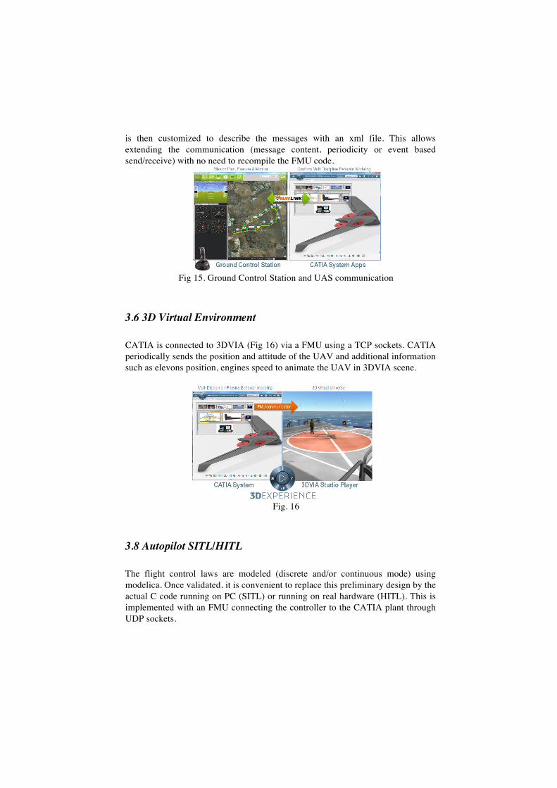
3.4 Computational Fluid Dynamics (CFD)
SIMULIA Fluid Scenario App is used to explore flight domain at various speed, angle of attack, sideslip angle, and engine doors position. This allows computing surrogate models (polars) used in Modelica flight dynamics model (Fig 14).
Figure 14 – 3D to CFD to System simulation inside 3DEXPERIENCE
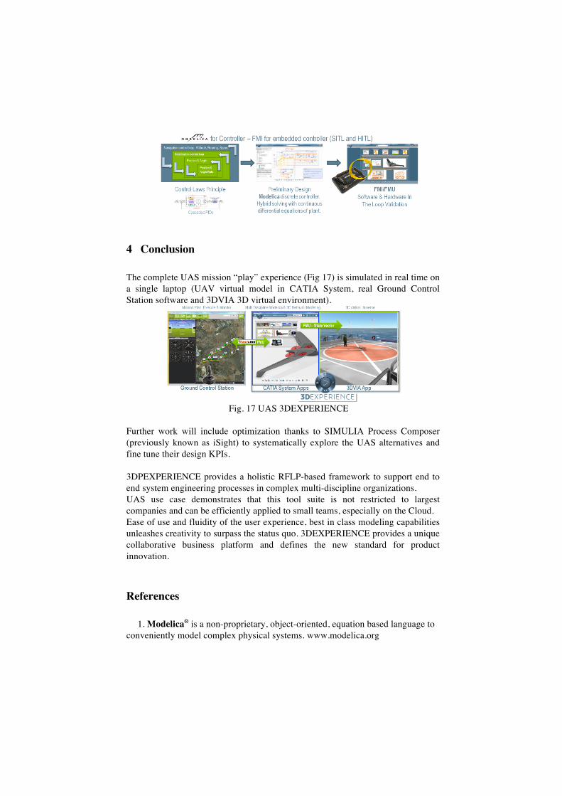
3.5 Ground Control Station (GCS) link
A GCS (6) is a software operated from the ground to remotely control the UAV. It allows monitoring the UAV system parameters and health status, defining the mission and sending the mission to the UAV. MAVLink (7) is an UDP-based protocol specifically designed to handle communication between the GCS and the UAV (Fig 15). A generic FMU model is developed to provide UDP networking. It
is then customized to describe the messages with an xml file. This allows extending the communication (message content, periodicity or event based send/receive) with no need to recompile the FMU code.
Fig 15. Ground Control Station and UAS communication
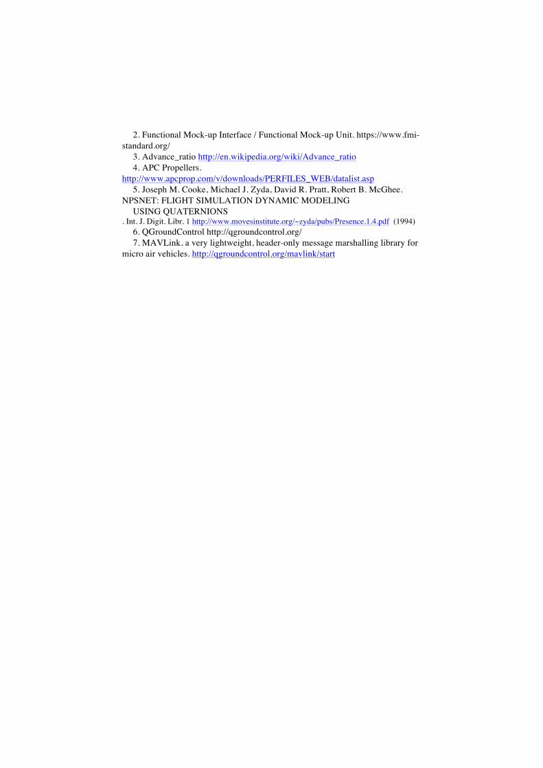
3.6 3D Virtual Environment
CATIA is connected to 3DVIA (Fig 16) via a FMU using a TCP sockets. CATIA periodically sends the position and attitude of the UAV and additional information such as elevons position, engines speed to animate the UAV in 3DVIA scene.
Fig. 16
3.8 Autopilot SITL/HITL
The flight control laws are modeled (discrete and/or continuous mode) using modelica. Once validated, it is convenient to replace this preliminary design by the actual C code running on PC (SITL) or running on real hardware (HITL). This is implemented with an FMU connecting the controller to the CATIA plant through UDP sockets.
4 Conclusion
The complete UAS mission “play” experience (Fig 17) is simulated in real time on a single laptop (UAV virtual model in CATIA System, real Ground Control Station software and 3DVIA 3D virtual environment).
Fig. 17 UAS 3DEXPERIENCE
Further work will include optimization thanks to SIMULIA Process Composer (previously known as iSight) to systematically explore the UAS alternatives and fine tune their design KPIs. 3DPEXPERIENCE provides a holistic RFLP-based framework to support end to end system engineering processes in complex multi-discipline organizations. UAS use case demonstrates that this tool suite is not restricted to largest companies and can be efficiently applied to small teams, especially on the Cloud. Ease of use and fluidity of the user experience, best in class modeling capabilities unleashes creativity to surpass the status quo. 3DEXPERIENCE provides a unique collaborative business platform and defines the new standard for product innovation.
References
1. Modelica® is a non-proprietary, object-oriented, equation based language to conveniently model complex physical systems. www.modelica.org
2. Functional Mock-up Interface / Functional Mock-up Unit. https://www.fmi-standard.org/
3. Advance_ratio http://en.wikipedia.org/wiki/Advance_ratio 4. APC Propellers.
http://www.apcprop.com/v/downloads/PERFILES_WEB/datalist.asp 5. Joseph M. Cooke, Michael J. Zyda, David R. Pratt, Robert B. McGhee.
NPSNET: FLIGHT SIMULATION DYNAMIC MODELING USING QUATERNIONS
. Int. J. Digit. Libr. 1 http://www.movesinstitute.org/~zyda/pubs/Presence.1.4.pdf (1994) 6. QGroundControl http://qgroundcontrol.org/ 7. MAVLink, a very lightweight, header-only message marshalling library for
micro air vehicles. http://qgroundcontrol.org/mavlink/start