Embed Size (px)
DESCRIPTION
controlling an exoskeleton haptic device
Citation preview

7/18/2019 System for Controlling an Exoskeleton Haptic Device
http://slidepdf.com/reader/full/system-for-controlling-an-exoskeleton-haptic-device 1/39
Printed by Jouve, 75001 PARIS (FR)
(19)
E P
2 2 3 8 8 9 4 A 1
(Cont. next page)
*EP002238894A1*(11) EP 2 238 894 A1
(12) EUROPEAN PATENT APPLICATION
(43) Date of publication:
13.10.2010 Bulletin 2010/41
(21) Application number: 09425130.3
(22) Date of filing: 07.04.2009
(51) Int Cl.:
A61B 5/00 (2006.01) A61H 1/00 (2006.01)
B25J 9/00 (2006.01)
(84) Designated Contracting States:
AT BE BG CH CY CZ DE DK EE ES FI FR GB GR
HR HU IE IS IT LI LT LU LV MC MK MT NL NO PL
PT RO SE SI SK TR
Designated Extension States:
AL BA RS
(71) Applicant: Syco Di Hedvig Haberl & C. S.A.S.
Torino (IT)
(72) Inventor: Menga, Giuseppe
10090 Villarbasse (IT)
(74) Representative: Bongiovanni, Simone et al
STUDIO TORTA
Via Viotti 9
10121 Torino (IT)
(54) System for controlling an exoskeleton haptic device for rehabilitation purposes, andcorresponding exoskeleton haptic device
(57) Disclosedherein is a control system (20, 60) for
an exoskeleton haptic device (1), having: a frame struc-
ture (3), to be coupled to the body of a subject (2); actu-
ators(10),carriedby theframe structure(3) andoperable
to cause movement of a number of joints (7, 8, 9) of the
body; and sensors (14), coupled to the body to detect
first signals (yo) indicative of an intention of movement
of the subject (2). The control system is provided with: afeedback stage (24), controlling a position of the joints
(7, 8, 9) based on a reference position (θref); a feedfor-
ward stage (21), controlling a compliance presented by
theexoskeleton hapticdevice (1)to thesubject(2) based
on the detected first signals (yo); and a combining block
(22), combining outputs from the feedback stage (24)
and feedforward stage (21) in order to generatea driving
signal (um) for the actuators (10), thereby imposing a
controlled position (θ) to the joints (7, 8, 9). This primary
control actionmayalso be integrated with a posture equi-librium control, for controlling postural equilibrium of the
subject (2) during the movement.

7/18/2019 System for Controlling an Exoskeleton Haptic Device
http://slidepdf.com/reader/full/system-for-controlling-an-exoskeleton-haptic-device 2/39
2
EP 2 238 894 A1
7/18/2019 System for Controlling an Exoskeleton Haptic Device
http://slidepdf.com/reader/full/system-for-controlling-an-exoskeleton-haptic-device 3/39
EP 2 238 894 A1
3
5
10
15
20
25
30
35
40
45
50
55
Description
[0001] Thepresent invention relates ingeneral to a system forcontrollinganexoskeletonhapticdevice for rehabilitation
purposes, in particular for use in lower limb rehabilitation, to which the following treatment will make specific reference
without however this implying any loss of generality.
[0002] As is known, rehabilitation is an important practice to assist an infirm patient to recover full or partial neuromus-
cular or muscular control of a part of the body, limb or organ, such as the arms or legs and related joints, such as hips,
knees, elbow, etc. It has long been shown that, even in patients who have lost the ability to autonomously performmovements, the execution of assisted movements of the part of the body to be rehabilitated allows to recover first a
neural control and then a muscular control on that part of the body. For example, rehabilitation of the lower limbs is
required for recovery of patients with post-stroke injuries or parkinsonian syndromes, in order to regain or improve
posture control and postural equilibrium.
[0003] Rehabilitation requires in general execution of a number of repetitive physical exercises involving the affected
limb, and assistance to the patient is needed during execution of these exercises, particularly at the early stages of
rehabilitation (when the patient has little control of the affected part of the body). Assistance to the patient is often
provided manually by one or more therapists, but it is not always possible to perform all the required exercises with the
correct procedure.
[0004] Accordingly, rehabilitation systems and apparatuses have been designed, in the form of more or less complex
harnesses, for example adapted to be placed hanging from the ceiling, that allow to support the weight of the patient
and thus help thesame patient in theexecutionof the rehabilitation exercises. However, these apparatuses arecomplex
and expensive and offer a limited amount of flexibility and modularity in adapting to the specific needs of the variouspatients, and, even more importantly, do not involve neurologically, as well as physically the patient.
[0005] Recently, designing of exoskeleton devices has been proposed as a promising solution for assisting patients
during rehabilitation treatments. Exoskeleton devices, including supporting frames of motorized segments to be applied
to the patient, have indeed the potentiality to offer a versatile solution to be used by the patient in the execution of the
different repetitive rehabilitation exercises. However, designing of such exoskeleton devices poses a serious challenge
in terms of their control logic, and reliable exoskeleton devices for rehabilitation have not yet been designed and are
still not currently available.
[0006] Indeed, research in the field of exoskeleton devices has been focused mainly on strength augmentation in
order to boost the performances of the wearer, for example for military or heavy work applications. These devices do
not address the problem of providing patient support and postural stability, since they imply the presence of an able-
bodied wearer.
[0007] In spite of many results in the field of postural equilibrium of biped robotics, fewer studies in the field of reha-
bilitation have tackled the joint aspects of postural stability (instead of strength) augmentation and patient compliance,and the fewexoskeletonsproposed have shown evident limitations and failed to address all the requirements andneeds
for patient recovery, among which: an accurate position control, in order to maintain the exoskeleton (and wearer)
dynamically stable or constrain it to follow a planned reference trajectory; a controlled patient "compliance" (i.e. the
capability to control the resistance perceived by the patient to voluntary movements), in order to involve the patient in
the rehabilitation exercises and tutoring the improvements in the patient abilities; and, either whenever dynamical ex-
ercises are performed or quiet standing is maintained, a controlled postural equilibrium, in order to interact with the
patient for maintaining or timely regaining equilibrium and correcting any erroneous patient posture. In particular, the
control systems that have been proposed for the known exoskeletons have not proven sufficiently robust and reliable
to accommodate all the above requirements.
[0008] Theaim of thepresent inventionis thus to provide an improved exoskeletondevice control systemand a related
exoskeleton device, overcoming the limitations of known exoskeleton devices for rehabilitation purposes and allowing
the various and different requirements and needs of a rehabilitation treatment to be satisfied.
[0009] This aim is achieved by the present invention in that it relates to a system for controlling an exoskeleton hapticdevice for rehabilitation purposes, and to a related exoskeleton haptic device, as defined in the appended claims.
[0010] For a better understanding of the present invention, preferred embodiments, which are intended purely by way
ofexampleand arenot tobeconstrued as limiting,willnowbedescribed with referenceto theattacheddrawings,wherein:
- Figure 1 is a schematic representation of an exoskeleton haptic device and of a related control system, according
to an embodiment of the invention;
- Figures 2, 3a and 3b show the dynamic model of the exoskeleton of Figure 1, respectively in the sagittal plane, in
the frontal plane, and in a third configuration (step machine) where the two planes are intermixed;
- Figure 4 shows the general block diagram of a primary closed loop of the control system: a control module for
position tracking and patient compliance;
- Figure 5 shows a schematic block diagram of a general closed loop extended system in the presence of uncertainty
7/18/2019 System for Controlling an Exoskeleton Haptic Device
http://slidepdf.com/reader/full/system-for-controlling-an-exoskeleton-haptic-device 4/39
EP 2 238 894 A1
4
5
10
15
20
25
30
35
40
45
50
55
for robust H-infinite design, on which control module of Figure 4 is based;
- Figure 6 shows a block diagram of the extended system embedding the requirements for the design of the primary
closed loop of Figure 4 in the sagittal plane, according to a first embodiment of the invention;
- Figure 7 shows a block diagram of the extended system of the primary closed loop of Figure 4 in the sagittal plane,
according to a second embodiment of the invention;
- Figures 8-11 show plot related to the achievable performance of the primary closed loop in the control system;
- Figure 12 shows a block diagram of the extended system for the primary closed loop of Figure 4 in the frontal plane;
- Figures 13a and 13b are schematic representations of the model of the patient body in different postures in thefrontal plane;
- Figure 14-16 show further plots related to the performance of the control system in the frontal plane;
- Figure 17 is a schematic representation of the model of the patient body in still a different posture involving both
frontal and sagittal planes;
- Figures 18a-18f show further plots related to the performance of the control system in the frontal plane;
- Figure 19 shows a block diagram of a secondary closed loop, a control module for postural equilibrium control,
superimposed to the primary closed loop of the control system;
- Figures 20-29 show still further plots related to the performance of the whole control system with the module for
posture control enabled; and
- Figure 30 is a flow chart relating to operations for designing the control system according to the invention.
[0011] In the following discussion, the expression "number of mechanical degree of freedoms" will be used to denote
the number of independent generalized coordinates in a multi-body system; with the expression "two degree of freedomcontrol" it will be referred to a closed loop control where both disturbance insensitivity and reference signal tracking
characteristics for the outputs are independently specified and achieved; the expression "mechanical impedance" will
refer to the linear transfer function between reaction forces/torques returned by a mechanical system by imposing
velocities/angular velocities; and the expression "mechanical admittance" will be used to denote the inverse of the
mechanical impedance.
[0012] As shown in Figure 1, an embodiment of the present invention provides an exoskeleton haptic device 1,
designed for rehabilitation of the lower limbs.
[0013] The exoskeleton haptic device 1 is adapted to be worn by a patient 2 undergoing a rehabilitation treatment
and comprises a frame structure 3 (shown schematically) to be coupled to the trunk and lower limbs of the patient 2
(Figure 1 shows only the part to be coupled to the right leg of the patient, but an altogether similar part is intended to
be coupled to the left leg of the patient).
[0014] The frame structure3 includes: an upper arm4, coupled to the thigh of thepatient 2 and extending substantially
parallel to the femur; a lower arm 5 coupled to the leg of the patient and extending substantially parallel to the tibia; anda back support element 6a coupled to the trunk of the patient 2. The lower arm 5 is coupled to a foot rest 6b, supporting
the foot and sole of the patient, via an ankle joint 7 and to the upper arm 4 via a knee joint 8; the upper arm 4 ends at
a hip joint 9, connected to the back support of the trunk. The ankle, kneeand hip joints7,8, 9 allow the relative movement
between the foot rest 6b, lower arm 5, upper arm 4 and back support; in particular the ankle and hip joints 7, 9 have two
degrees of freedom, for rotations in the sagittal and frontal plane, while the knee joint 8 has a single degree of freedom,
for rotation in the sagittal plane. Actuators, e.g. electric motors 10, are coupled to each one of the ankle, knee and hip
joints 7, 8, 9, and are operable to control their movements in the sagittal plane; electric motors 10 on either left and right
hips are also operable to control movements in the frontal plane (as will be described in more details in the following).
[0015] A control unit 12 is coupled to the exoskeleton haptic device 1 and implements a control algorithm for driving
the electric motors 10 at the various joints, thus controlling the exoskeleton movement. Preferably, the control unit is
implemented by a processing unit (such as a microprocessor, a DSP unit, or a similar unit provided with processing and
computing capabilities), executing a suitable set of software instructions.
[0016] The control unit 12 is supplied by a suitable power supply unit 13 (e.g. including rechargeable batteries) andreceives at its input: bioelectrical signals, in particular EMG (Electromyographic) signals (more specifically surface EMG
signal, i.e. detected on the skin surface), indicative of the patient intention and strength of movement, from bioelectric
sensors 14 coupled to the patient lower limbs and placed on the muscles involved in lower limb movement (in Figure 1,
for reasons of simplicity of depiction only a sensor is shown, placed on the thigh); position and velocity signals from
position/velocity sensors 16, for detection of angles of the ankle, knee and hip joints 7, 8, 9; reaction force sensors 17,
positioned on the exoskeleton foot rests 6b and configured to detect the reaction forces imparted by the ground and the
center of these reaction forces; and, during single stance, the coordinate of the free foot derived from the kinematics
that links the foot rest 6b to the ground.
[0017] Control unit 12 processes the input signals and, based on the implemented control algorithm, outputs suitable
driving commands for the electric motors 10, in particular indicative of the torque that is to be applied to the ankle, knee
and hip joints 7, 8, 9.

7/18/2019 System for Controlling an Exoskeleton Haptic Device
http://slidepdf.com/reader/full/system-for-controlling-an-exoskeleton-haptic-device 5/39
EP 2 238 894 A1
5
5
10
15
20
25
30
35
40
45
50
55
[0018] Advantageously, the control unit 12 and power supply 13 are designed to be light-weight and to be carried by
the patient; for example, suitable electronics circuitry implementing the control unit 12 is housed in a belt around the
waist of the patient.
[0019] However, in a first embodiment of the present invention, the exoskeleton haptic device 1 is a substantially
stationary exoskeleton not intended forwalking exercises, as the feet areconnected to the ground through a kinematical
linkage, with limited freedom, so that they can be slightly lifted, but otherwise are not allowed to exit from the frontal
plane or rotate, to avoid the fall of the patient.
[0020] Specifically, the exoskeleton is configured to perform three kind of exercises:
- sagittal plane coordination: with both feet on the ground, left and right ankles, knees and hips are activated in pairs
in the sagittal plane; it allows postural exercises like sit-to-stand and stand-to-sit transitions;
- frontal plane coordination: transitions from double to single stance posture, with fixed knees, by shifting the weight
of the patient from one foot to the other and then raising the free foot activating in the frontal plane the two hips; and
- intermixing sagittal and frontal plane coordination (like a step machine): similar to the previous exercise, but, con-
temporaneously to the hips in the frontal plane, a partially constrained free foot of a free leg is raisedactivating knee
and hip in the sagittal plane (with three degrees of freedom).
[0021] The first two exercises can also be activated contemporaneously and independently, such as maintaining
equilibrium during a quiet posture standing, or reaching limits of equilibrium in the sagittal or frontal plane, or recovering
from externally imposed disturbances.
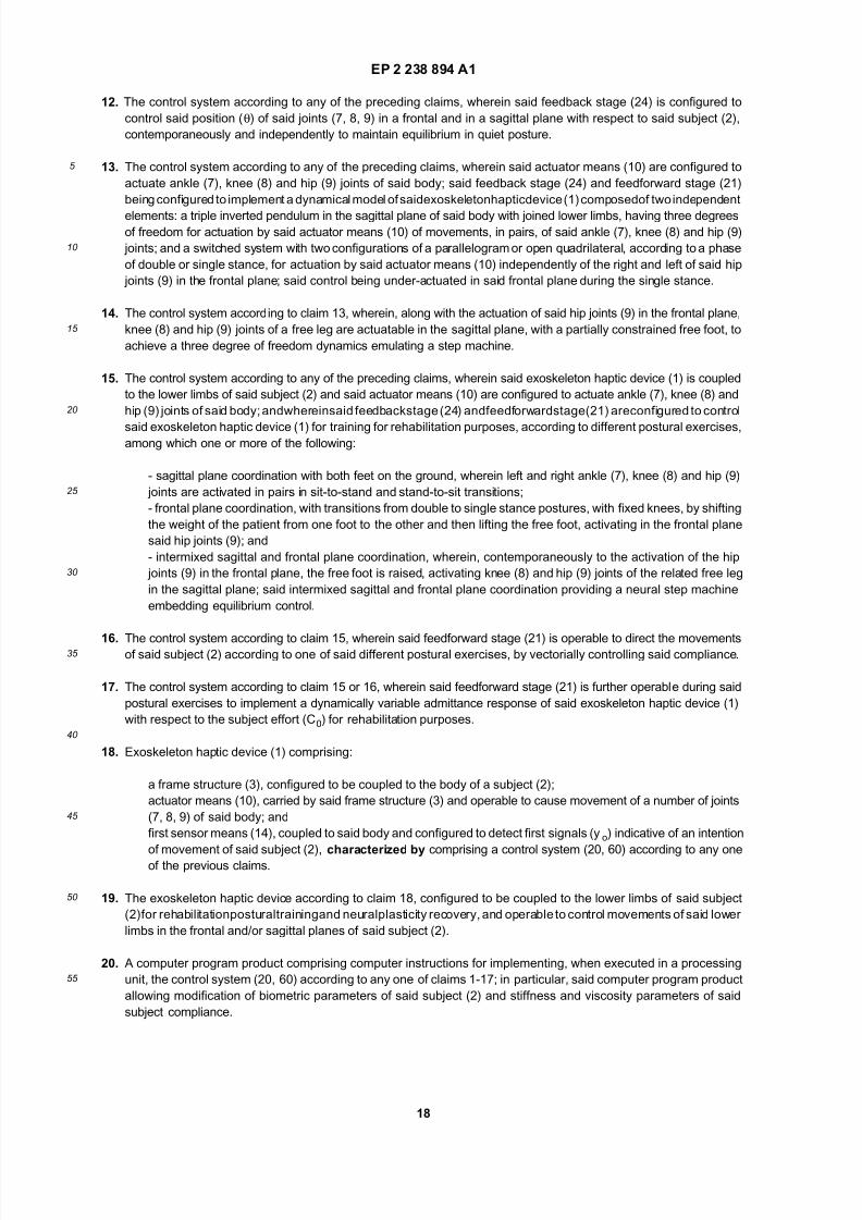
[0022] Figures 2, 3a and 3b show a link-segment representation for modeling the mechanical behaviour of the lower limbs of the patient, represented as a skeleton with rigid fixed-length limbs and perfect pivot joints, respectively in the
sagittal and frontal planes; the control algorithm that will be discussed in detail in the following is based on this dynamic
model.
[0023] The dynamic model possesses up to six degrees of freedom and is composed of two independent elements:
a triple inverted pendulum in the sagittal plane, having three degrees of freedom, actuating the movement, in pairs, of
ankles, knees and hips of the patient; and a switched system in the frontal plane with two configurations of a multiple
pendulum in the form of a parallelogram or open quadrilateral, according to the phase of double or single stance, having
one to three degrees of freedom, actuating both right and left hips and, in the single stance position, eventually also the
ankle of the sustaining foot. Activities on the two planes can operate contemporaneously independently, but they can,
also, be partially intermixed, lifting the coupling between the two legs, as in the case (step machine) when the free foot
knee and hip of the sagittal plane are activated during frontal plane exercises. The control approach is common for the
two planes, however sagittal and frontal planes have peculiarities that will be specifically dealt with by the control. The
mixed case belongs to the realm of the frontal plane control.[0024] In detail, Figure 2 shows the ankle, knee and hip joints 7, 8, 9, considered in pairs; joint angles, as measured
by the position/velocity sensors 16, are denoted with θi (θ1 for the ankle joints 7, θ2 for the knee joints 8 and θ3 for the
hip joints 9), while qi denotes the generalized coordinates of the links, related to the joint angles θi (θ1 = θ1 is associated
to the leg, q2 = θ1 + θ2 to the thigh and q3 = θ1 + θ2 + θ3 to the trunk of the patient 2). Moreover, Cm denotes the motor
torques applied by the electric motors and C0 the patient torques exerted at the three joints (for reasons of simplicity,
Figure 2 only shows the torque applied at the ankle joints 7); ZMP represents the position of the so-called Zero Moment
Point (i.e. the coordinate along the x axis at which the sum of all reaction torques acting on the soles of the feet are
zero), COG represents the x-axis coordinate of the center of gravity of the patient body and Fz denotes the ground
reaction force directed along the z axis.
Figure 3a only shows the ankle joints 7 and hip joints 9, since knee joints 8, have not freedom in the frontal plane;
θ1 still denotes the angle for the ankle joint 6, while θ2 and θ3 here indicate the joint angles at the left and right hip
joints 9, respectively. As in Figure 2, the position of the Zero Moment Point ZMP, center of gravity COG on the yaxis and reaction force Fz are also depicted.
Figure 3b adds, with respect to figure 3a, freedom of the hip and ankle joints of the free foot in the sagittal plane,
whose respective joint angles are denoted with θ4 and θ5.
[0025] The control unit 12 is configured to implement a feedback position control to maintain the exoskeleton haptic
device 1 dynamically stable in a vertical steady state position, or to constrain it to track a planned reference trajectory
like a sit-to-stand transition in the sagittal plane, or a "waving" movement in the frontal plane involving shifting the weight
of the patient from one foot to the other, followed by lifting the free foot, acting, either, on the left and right hips alone or
involving also knee and hip of the free foot on the sagittal plane.
[0026] Independently from this position control, by exerting an effort with his leg muscles the patient is able to move
the exoskeleton joints, in so doing, experiencing an elastic reaction from the position imposed by the feedback position

7/18/2019 System for Controlling an Exoskeleton Haptic Device
http://slidepdf.com/reader/full/system-for-controlling-an-exoskeleton-haptic-device 6/39
EP 2 238 894 A1
6
5
10
15
20
25
30
35
40
45
50
55
control, with stiffness dynamically and directionally controlled by the control unit 12 exploiting the EMG signals detected
fromthe legmusclesby thebioelectricsensors14.This controlled"compliance" isusedto obtainneurologicalinvolvement
of the patient in the exercises and for tutoring the improvements in the patient abilities (the control will be set stiffer at
the beginning, and softer at the end of the training, and progressively varied along these two limits), for helping the
patient to maintain postural equilibrium or for addressing the patient movements directionally. In particular, vectorial
control of the compliance allows to select one of the previous exercise configurations for rehabilitation.
[0027] Furthermore, according to a further aspect of the present invention, the control unit 12 will also implement a
postural equilibrium module, superimposed to the position with compliance control module, interacting with the patientto maintain equilibrium or to regain equilibrium correcting any erroneous patient posture.
[0028] The control unit 12 will address the whole issues of position tracking, operator compliance, dynamical stability
and postural equilibrium augmentation in a bipedal exoskeleton. In particular, if the above elastic reaction is soft, the
patient will achieve whole compliance and he will be able to move substantially at pleasure - just having his gravity load
alleviated by the control - until he reaches the limits of postural equilibrium, where the postural equilibrium module will
intervene to stop him/her. On the other side, if a stiff reaction is imposed, the patient will be bounded to any reference
position/trajectory that is applied to theexoskeleton haptic device1 and his/hers actions will be considered by thecontrol
as a pure disturbance. By properly adjusting the control properties between these two limit conditions, it will be possible
to closely follow the patient recovery during the rehabilitation treatment.
[0029] As will be discussed in detail in the following, the control unit 12 achieves the above results implementing: a
first closed loop control for position and/or trajectory control (and patient compliance) based on joint angle position and
velocity measures, computed with a H-infinite linear, fixed parameter or gain scheduling, multivariable robust control
design with two degrees of freedom, using EMG signals from the lower limb muscles as measures of the intention of movement and strength of effort of the patient to offer compliance; and a second closed loop control superimposed to
the first one for postural equilibrium, controlling the Zero Moment Point ZMP based on Lyapunov stability theory and
the Jacobian function of the Center of Gravity (COG), based on the reaction forces detected from the reaction force
sensors 17 on the foot rest 6b of the exoskeleton haptic device 1.
[0030] Figure 4 shows a general block diagram of the first closed loop control (hereinafter defined as primary closed
loop control and denoted with 20) implemented by the control unit 12. Its structure generally applies independently to
eithersagittal, frontal planes ormixedsolutions. Forclarity,the sagittal plane, asanexample, isdisclosedin thefollowing.
[0031] The primary control loop 20 receives at input a vector of EMG signals y0 (detected by the bioelectric sensors
14) as a measure of the patient torques C0 (in particular including the torques exerted by thepatient at each of the ankle,
knee and hip joints 7, 8, 9) and thus indicative of the efforts measured from the patient, and a vector of reference joint
angles θref , indicative of the desired position and/or trajectory imposed by the control to the ankle, knee and hip joints
7, 8, 9 (according to the rehabilitation exercise to be performed).
[0032] The EMG signals y0, as a measure of the patient torques C0, acts as a Feed-Forward control within the primarycontrol loop 20 and is thus fed to a feedforward block 21, whose output enters a combiner block 22 (in particular an
adder block).
[0033] The vector of reference joint angles θref is instead exploited for position tracking in the feedback loop within
the primary control loop 20 and accordingly enters a further combiner block 23 (in particular a subtractor), also receiving
at its input (in particular the subtractive input) a vector of measures y, in particular a six dimensional vector of joint angle
(θ) and velocity (θ.) measures associated to the ankle, knee and hip joints 7, 8, 9, and outputs a combination thereof (in
particular a subtraction between the reference joint angles θref and the measured joint angles in the measure vector y).
[0034] This combination entersa feedbackcontrol block24, whoseoutput is fed to thecombiner block 22, to be added
to the output of the feedforward block 21.
[0035] Theoutputof thecombiner block22represents theinput signalsum (inparticulardrivingvoltages) to be supplied
to the electric motors 10 in order to generate motor torques Cm, and enters the joint patient and exoskeleton non-linear
dynamic system 25. The output of the non-linear dynamic system 25 is the vector of measures y, which, as previously
discussed, is feedback towards the combiner block 23.[0036] Joint angles θ and joint velocities θ. are directly obtained from measures y; moreover, from measures y and
from the reaction forces measured by reaction force sensors 17, center of gravity COG and zero moment point ZMP for
the patient-exoskeleton system (in particular their movement along the x axis with reference to the sagittal plane, or y
axis for the frontal plane) are jointly estimated and provided as output (as shown schematically in Figure 4).
[0037] Within the control algorithm, the primary control loop 20 guarantees robust stability in the presence of nonlin-
earities,unmodeled dynamics, parameter mismatching, andoffers compliance to the operatorwhile allowing joint angles
tracking capability, as well as disturbance rejection. Reference joint angles θref drive the joint angles so that they track
desired position trajectories,while EMGsignalsy0, asa measure of the patient torques C0, enable controlled compliance
with respect to the patient; in fact they allow to move the exoskeleton joint angles in the neighbors of the desired
references (θref ) with a desired and controllable visco-elastic impedance felt by the patient (the controlled compliance).
In particular, the possibility to act independently on the compliance at the various (ankle, knee and hip) joints allows to

7/18/2019 System for Controlling an Exoskeleton Haptic Device
http://slidepdf.com/reader/full/system-for-controlling-an-exoskeleton-haptic-device 7/39
EP 2 238 894 A1
7
5
10
15
20
25
30
35
40
45
50
55
achieve a vectorial control of the compliance in order to direct the patient to execute the desired exercise (and prevent
spurious movements): for example, during frontal plane coordination exercises, knee movements will be blocked by
stiffening the elastic impedance felt by the patient.
[0038] In general, control designis achieved through Hinfinite control theory: thecompliance, in theform of admittance
or impedance control with position feedback, is approached as a two degree of freedom control design with the EMG
signals (representing a measure of the patient effort) as an input, and joint angle position and velocity as measured
output. Basically, patient efforts are treated as measured disturbances to be accounted for by the control loop according
to the desired compliance.[0039] In a per-seknown manner (asdiscussed forexample in K. Zhou, J.C. Doyle,and K. Glover"Robustand Optimal
Control", Prentice Hall, 1996), and as shown in the schematic block diagram of Figure 5, in the Hinfinite approach the
whole control problem is represented as a four gates (two inputs and two outputs) system, with disturbances (w) and
commands (u) at the inputs, and objectives (z) and measures (y) at the outputs. This model is usually referred to as the
"extended system" (ES) of the control design. The Hinfinite norm from disturbances w to objectives z of the closed loop
(in the presence of a controller Gc(s)) offers a measure of achievement of the specifications, of robust stability and of
the performances in the presence of uncertainties (represented by ∆). The design technique synthesizes the closed
loop controller Gc(s), graphically depicted in Figure 4, from measures y that maximize or guarantee the required per-
formance and robustness.
[0040] The configuration in the sagittal plane is now described in detail.
[0041] The linearized model dynamics in the sagittal plane (as represented in Figure 2) at the equilibrium point is
given by the expression:
wherein:
q is the three dimensional vector of generalizedcoordinates (the inertial or attitude rotational coordinates at the exoskel-
eton joints) related to the vector of measured joint angles θ by:
[0042] B is the input torque matrix, defined by:
[0043] Jisthe3x3inertialmatrix,β thedampingmatrix,mgbrepresentsthe gravity forces,w isa noise vectoraccounting
for the unmodeled Coriolis forces, Cm are the motor torques applied by the electric motors 12 and C0 the patient torques.[0044] Moreover, thedesired visco-elastic reaction offered by the controlled exoskeleton haptic device1 to the patient
2 at each joint is of the type (desired stiffness and viscosity):
i.e. having stable dynamics with elastic behavior of desired stiffness koi and viscosity βoi decoupled between each joint.
[0045] Based on the above models, the extended system for designing the Hinfinite two degree of freedom control of
the exoskeleton haptic device 1 providing admittance control is obtained; the schematic block diagram of this extended
system is shown in Figure 6.

7/18/2019 System for Controlling an Exoskeleton Haptic Device
http://slidepdf.com/reader/full/system-for-controlling-an-exoskeleton-haptic-device 8/39
EP 2 238 894 A1
8
5
10
15
20
25
30
35
40
45
50
55
[0046] In detail, the extended system receives at input the following disturbances (denoted with w in the generalized
Hinfinite system model depicted in Figure 5): the vector of patient torques C0 (that are measured by the EMG signals
y0 detected by the bioelectric sensors 14); measurement noises no, n, respectively associated to EMG noise and joint
angle position and velocity measure noises; noise w1, representing the uncertainty introduced by the non-linearities of
the system; and torque disturbances t. In particular, the various disturbances enter the extended system directly or
multiplied by suitable multiplicative factors (as is shown in detail by the block diagram in Figure 6), which are chosen
according to the characteristics of the specific exoskeleton haptic device 1 that is being controlled.
[0047] The input signals um to be supplied to the electric motors 10 (in order to generate the motor torques Cm) arereceived at input as controls (denoted with u in the system model depicted in Figure 5).
[0048] The extended system provides at output the vector of measures y from the exoskeleton, the vector of the EMG
signalsy0, andthe followingobjectives(denotedwith z in thesystem model depictedin Figure5):anadmittance sensitivity
objectiveze, penalizing the error between desired and achieved angular jointpositions resulting from the patient torques
C0 (it thus sets the sensitivity to modeling errors of the admittance perceived by the patient); a disturbance sensitivity
objective Ze1, relative to the sensitivity of the controlled outputs to torque noises t and operable to set the loop gain (i.e.
the capability to reject disturbances and track reference signals); a non-linearity objective z1, which takes into account
the robustness of the control in face of system non-linearities; and noise objectives Z u1, zu2, Zu3, penalizing control
activities in face of the respective measurement noises no, n (EMG noise, joint position and velocity noises).
[0049] According to the extended system, the vector of patient torques C0 is first processed in a patient dynamics
block 30, containing time constants of the patient muscle response, and then fed to a visco-elasticity block 31, where it
is multiplied by a diagonal matrix of the desired visco-elastic reaction to be experienced by the patient at each joint:
ko and βo being the desired stiffness and viscosity, respectively, in the patient admittance.
[0050] Thevisco-elasticityblock31thusrepresentstheintegral ofmechanicaladmittances,and compliance isachieved
as an admittance control, where the viscoElasticity matrix sets the desired transfer function between patient torques C0
and desired patient joint angles, denoted with θ0.
[0051] The vector of patient desired joint angles θ0 is input to a combiner block 32, which also receives at input the
difference between the vector of measured joint angles θ and the vector of reference joint angles θref (this subtraction
being computed in combiner block 33). The output from combiner block 32 is then fed to a weighting block 34, where it
ismultiplied bya diagonalmatrixW ofweightingfunctionssetting thedesiredloopgain, disturbancesensitivity,admittancetracking and frequency bandwidth for the feedback loop:
wherein h sets the loop gain and its inverse the steady state sensitivity, and λ (rad/sec) the loop bandwidth (i.e. an
indication of the frequency up to which the control performances are guaranteed).
[0052] Admittance sensitivity objective ze and disturbance sensitivity objective ze1 are obtained at the output of the
weighting block 34.
[0053] The vector of motor torques Cm is first processed by a motor dynamics block 35 starting from the input signals
um, containing time constants of the electric motors 10, and then fed to a combiner block 36 where it is added to thevector of patient torques C0, as outputted by the patient dynamics block 30.
[0054] The result of this combination enters the model of linearized dynamics in the sagittal plane of the patient-
exoskeleton system.
[0055] In particular, the output of combiner block 36 (i.e. the total mechanical torque) is multiplied, in a processing
block 37, by the input torque matrix B (previously defined), and the result of this multiplication enters a combiner block
38, whose subtracting inputs receive the expression βq.-mgbq computed in processing block 39, and, respectively, the
non-linearity noise w1 multiplied, in processing block 40, by a matrix Jd accounting for the variation of the inertial matrix
J due to nonlinearities, according to the model of inverse multiplicative uncertainty:

7/18/2019 System for Controlling an Exoskeleton Haptic Device
http://slidepdf.com/reader/full/system-for-controlling-an-exoskeleton-haptic-device 9/39
EP 2 238 894 A1
9
5
10
15
20
25
30
35
40
45
50
55
wherein is the inverse of the inertial matrix J in nominal conditions, Jd∆ represents the uncertainty in the inertial
matrix, and I is the identity matrix. In this respect, the present Applicant has experimentally shown that uncertainty on
the sole inertial matrix J is sufficient to guarantee the desired robust stability of the controller and desired trackingprecision of joint angles in all nonlinearity conditions.
[0056] The output from combiner block 38 is then multiplied by the matrix in processing block 41, and then
integrated twice (in integrator blocks 42 and 43, series connected) in order to obtain the first derivative of the vector of
generalized coordinates q, at output from integrator block 42, and the vector of generalized coordinates q, at output
from integrator block 43.
[0057] Through multiplication by the previously defined matrix M, the vector of measured joint angles θ and the vector
of measured joint velocities θ.
are obtained, respectively in processing block 44 and in processing block 45, which are
then combined through a multiplexer 46 to obtain at output the vector of measures y.
[0058] Theobjectiveof thecontroldesignis a feedbackcontrolof themotor torquesCm, from measuresy andmeasured
EMG signals y0, such that for arbitrary patient torques C0 the error between desired and achieved angular positions is
maintained small, according to an Hinfinite operator norm, in face of the uncertainty (represented by ∆ in the previous
expressions). In particular, the double result is achieved to impose angle position and/or trajectory and to control patientcompliance. This will force the controlled system to behave between the two limit conditions (set by the value assigned
to the parameter ko in the design) represented by a full compliance to the patient torque C0 and a full tracking of the
reference joint angle θref , according to the desired viscoElasticity (defined in the visco-elasticity block 31) that will be
physically perceived by the patient as a visco-elastic reaction.
[0059] Advantageously, a control minimizing the closed loop Hinfinite norm of the extended system of Figure 6 can
easily be computed through mu-synthesis (in a per-se known manner, here not described in detail).
[0060] An altogether similar approach can be adopted to design an extended system with impedance control, as
shown in the schematic block diagram of Figure 7.
[0061] The extended system of the primary control loop (here denoted with 20’) differs from the one previously dis-
cussed only in that the visco-elasticity (admittance) block 31 is replaced by an impedance block 48, which receives at
input the difference between the vector of measured joint angles θ and the vector of reference joint angles θref from
combinerblock 33 and thevector ofmeasured joint velocitiesθ., andoutputsa resultanttorque. In this case, thedifference
between the torque applied by the patient and the torque resulting from the desired impedance is kept small by thecontrol system.
[0062] Figures 8-11 show the results (obtained via simulations) achievable with the primary control loop control 20 in
term of theclosedloop transfer functions. Theresults arebasedon a realistic case study where the following parameters
were used:
[0063] In particular,Figure8 shows theachieved closed loop admittance in reaction to thepatient torque. It is possible
to achieve a very high gain (20 rad/N·m) in the ratio between patient torques and joint angles, i.e. the patient will
experience a very soft reaction from the exoskeleton haptic device 1. The closed loop behavior follows very closely the
desired curve (dashed line) in the frequency band where the control is active (set by the above defined λ parameter),

7/18/2019 System for Controlling an Exoskeleton Haptic Device
http://slidepdf.com/reader/full/system-for-controlling-an-exoskeleton-haptic-device 10/39
EP 2 238 894 A1
10
5
10
15
20
25
30
35
40
45
50
55
in spite of the uncertainties and nonlinearities. In other words, a desired admittance (or impedance) is specified and
substantially achieved based on the physical limits of the control and the bandwidth of the feedback loop that can be
realistically obtained. Indeed, the achieved admittance diverges from the desired one only outside the loop bandwidth,
while inside this frequency band the result is fairly insensitive to modeling errors.
[0064] Figure9 shows theplotof theoutputsensitivity to externaltorquedisturbancest. Varioussourcesof disturbance,
as well as undesired tilting movements of the patient, are strongly rejected, so that the desired posture position is
preserved also in the presence of external disturbance actions (it compares very favorably to patient compliance, shown
in dotted line).[0065] Figures 10 and11 show, respectively, theclassical loop sensitivity to outputdisturbancesad referencetracking
transfer functions, underlying again that the loop gain related to the joint angles has a good insensitivity to disturbances
and a good tracking capability on any configuration of nonlinearity (whose spread is represented in the figures).
[0066] The control model in the frontal plane will now be discussed in greater details.
[0067] The main feature of the frontal plane model is that of switching between two configurations, according to the
single or double stance phase. For this purpose, a gain scheduling technique is adopted (as discussed for example in
Geromel, Colaneri, Bolzern "Dynamic Output Feedback Control of Switched Linear Systems", IEEE Transactions on
Automatic Control, Vol. 53, No. 3, April 2008).
[0068] During thedoublestance phase, theexoskeletonhapticdevice 1 canbeconsideredasa parallelogram modeled
by an inverted pendulum, with a single degree of freedom.
[0069] In this phase, thecontrol schemeenvisages controlling theZMP/COG y coordinate,or better the rate of vertical
reaction forces on the two feet. Starting from a perfect balance with the y coordinate of COG at the mid-point between
the two feet, by controlling both hip torques (as shown in figure 2) the COG is moved on either the left or right foot, andaccordingly the ground reaction forces on the other foot are brought to zero. At this point the control switches from
double to single stance.
[0070] As for the sagittal plane, the admittance of the patient at the hip joints 9 is controlled. When vertical reaction
forces are zeroed on one foot and this is freed from the ground, the control model switches to an open quadrilateral with
up to three degree of freedom dynamics.
[0071] In double stance the control problem is trivial and it is not further detailed. Single stance, vice versa deserves
greater attention.
[0072] In this case, if the supporting ankle joint 7 is actuated together with the two hip joints 9, the control scheme for
the frontal plane becomes similar to the one in the sagittal plane, previously discussed.
[0073] However, the Applicant has observed that: differently from the sagittal plane, where equilibrium has to be
preserved all the time, the exercise in the frontal plane is such that the patient is not expected to maintain equilibrium
on single stance for a long time, but simply to briefly lift the free foot. Given the small width of the foot, the ZMP position
is not expected to move along the y axis, as it does for the x axis, and can be simply kept at the foot center (anklecoordinate).
[0074] For this reasons, the Applicant has realized that an under-actuated control using the two hip torques as the
sole controls can be implemented, leaving the supporting ankle free. The Applicant has shown that the system is
controllable by the torques at the two hip joints 9, and dynamical stability can be guaranteed by state feedback.
[0075] As discussed for the frontal plane, a two degree of freedom control is again implemented, in order to allow the
patient, based on the detected EMG signals, to move the free foot along desired vertical and horizontal coordinates.
Thepatient will fill thefree foot elasticallyattractedto itsstandingposition, beingable, nevertheless, to move it (according
to the stiffness imposed by compliance control).
[0076] The Applicant has also noted that in this case dynamical stability is equivalent to postural stability, as the COG
andZMP areautomatically imposed by dynamicalstabilityof the feedback not to leave theankle abscissa,and a module
for postural control (as will be described in the following with reference to the sagittal plane) is not strictly needed. In
particular, in this case a postural control module is absent with the exception of an inhibitor function (as explained
hereinafter) that freezes compliance when an erroneous action of the patient sends the state dynamics to the limits of equilibrium.
[0077] Figure 12 shows the extended system (here denoted with 20") for the robust control in the case of the under-
actuated solution in the frontal plane, adopting a two degree of freedom control design. The same reference numerals
are used to denote elements similar to others previously defined. It is underlined that there are some structural (but not
conceptual) difference in the extended system with respect to the sagittal plane, as a variant of the extended system
has been tested here.
[0078] It is immediately apparent that an approach altogether similar to the one discussed with reference to Figure 6
is implemented for controlling compliance towards the patient through the bioelectric EMG signals. The measured EMG
signalsy0 are indeedusedto evaluatethe vector ofpatient torques,here constitutedofonlytwo components (representing
the left and right hip joints 9), still denoted with C0, which is then fed to the patient dynamics blocks 30 and to a desired
admittance block 50 (altogether similar to the viscoElasticity block 31 of Figure 6); the desired admittance block 50

7/18/2019 System for Controlling an Exoskeleton Haptic Device
http://slidepdf.com/reader/full/system-for-controlling-an-exoskeleton-haptic-device 11/39
EP 2 238 894 A1
11
5
10
15
20
25
30
35
40
45
50
55
models the admittance of the exoskeleton haptic device 1 and provides at output the desired y and z coordinates for
the patient free foot, denoted with yz0. The vector of desired patient y and z coordinates yz0 is input to combiner block
32, which also receives at input the difference between the measured coordinates yz (estimated from the kinematics
linking foot rest to the ground and the joint angles) and the reference coordinates yz ref for the same free foot, in turn
computed in combiner block 33. The output from combiner block 32 is then fed to the weighting block 34, where it is
multiplied by the diagonal matrix W of weighting functions, imposing the desired requirements for the sensitivity of the
tracking error on the position of the free foot and on the admittance control.
[0079] Uncertainties enter the extended system in the form of both gain and dynamics multiplicative uncertainties,described by the pairs z2, w2 and z1, w1.
[0080] The vector of coordinates yz is the output of the linearized exoskeleton model. In particular, controls u to the
model are here represented by driving velocities of the electric motors 10 of the hip joints 9. Indeed, the two electric
motors 10 at both hip joints 9 are preliminarily closed in a local velocity loop, where velocity gain block 52 represents
the velocity controller.
[0081] The output of the velocitygain block52 is processedby a state variable model 53, linearization of thenonlinear
system, with the following states: the supporting ankle, left and right hip joint angles, the two legs and trunk angular
velocities. In this model, B (block 54) is the input torque matrix, A (block 55) is the coefficient matrix, related to the
integrator block 56 (including six integrator blocks 1/s). From the states, block 57 (denoted with C2) derives the hip joint
angles velocities for closing the internal velocity loop feedback. Block 58 (denoted with Cyz2) offers, instead, the y and
z coordinates of the free foot, that, after comparison with the reference coordinate yzref originate the admittance control
requirements, setting the difference with the desired admittance.
[0082] Again, the controller is synthesized with mu-synthesis applied to the described extended system.[0083] Figures 13a and 13b show, respectively, a single stance position on the right foot with COG on the sustaining
foot, and the position resulting from a command to raise and move externally the free foot of about 4 cm along both the
z and y axes.
[0084] Figures 14-16 show time plots of quantities related to a transition from double to single stance, occurring after
second 3, followed, after second 4, by the command to raise and move externally the free foot; afterwards, the system
automatically compensates an external bell-shaped disturbance corresponding to a maximum torque of 10 Nm on the
standing ankle at about second 8. This shows the robustness of the stability (postural equilibrium) in face of external or
internal disturbances.
[0085] In particular, Figure 14 shows the time plot of the hip joint angles (the continuous line corresponding to the
right hip joint 9 and the dashed line to the left one); Figure 15 shows the time plot of the displacement of the free foot
along the z axis (continuous line) and the y axis (dashed line); and Figure 16 shows the time plot of the COG (continuous
line) and ZMP (dashed line) position (along the y axis) taking as reference the coordinate of the standing foot.
[0086] From Figures 14-16, the transition from double to single stance (COG and ZMP moving from the center pointbetween the two feet to the center of the sustaining foot, conventionally assumed at coordinate 0), the switching of the
control after second 4 with a displacement of the free foot from its original position along the y and z axes, and the
perturbation introduced by the automatic control for compensating the ankle torque disturbance may all be noted.
[0087] The possibility of acting on the knee joint 8 and hip joint 9 to raise the free foot during single stance enters in
the realm of the frontal plane control. The extended system of figure 12 also applies for this configuration. Inputs u now
control the two hips on the frontal plane to maintain equilibrium and the hip and knee of the free foot on the sagittal plane
to raise the foot.
[0088] According to thefreedom allowedby thekinematicsadoptedforbindingthe foot to theground,severalsituations
can occur, in which the foot is free to: shift in all three coordinates x, y and z; translate along the z coordinate, only;
rotate on the tip, only. The dynamical models change slightly but the substance remains invariant with respect to the
extended system of figure 12, the model ranging from five to three degrees of freedom according to the binding of the
foot. Figure 17 schematically shows the body model in a single stance equilibrium, with the elevation of the free foot
being controlled by the knee joint 8.[0089] Figure 18a shows the x, y, and z coordinates of the free foot, in the case in which the free foot can translate
along all three coordinates x, y and z (and the control has five degrees of freedom). In particular, the z coordinate is
represented with a dotted line, the x coordinate with a continuous line and the y coordinate with a dashed line. Starting
from second 2, theexoskeleton is in single stance; afterwards, starting from second 3, lifting of the free foot is performed.
[0090] Figure 18b shows the plots (obtained via simulation) of the COG (continuous line) and ZMP (dashed line)
position along they axis during the transition from doubleto singlestance, followed by theperturbation introduced during
lifting of the free foot.
[0091] Figures 18c-18f relates to the case in which the free foot is constrained to move along the z axis, only (and
the control has only three degrees of freedom).
[0092] In detail, Figure 18c shows the behaviour in the frontal plane of the ankle (dashed-dotted line), left hip (dashed
line) and right hip (continuous line). After a transition from double to single stance, the free foot is raised vertically of

7/18/2019 System for Controlling an Exoskeleton Haptic Device
http://slidepdf.com/reader/full/system-for-controlling-an-exoskeleton-haptic-device 12/39
EP 2 238 894 A1
12
5
10
15
20
25
30
35
40
45
50
55
about0.1m aftersecond3; then, thecontrolcompensates a bell shapedtorque disturbanceat second6 on thesustaining
ankle.
[0093] Figure 18d shows the behaviour in the sagittal plane of the hip (dashed line) and knee (continuous line).
[0094] Figure18e shows theplot of thez coordinate of thefree foot after therequestof raising; theeffect ofdisturbance
after second 6 is evident.
[0095] Figure 18f shows the plots of the COG (continuous line) and ZMP (dashed line) position along the y axis, and
in particular their perturbation as a consequence of the disturbance.
[0096] According to a further aspect of the present invention, that will now be described in detail, a second closedloop control may be superimposed to the primary control loop 20, in order to achieve postural equilibrium. This is
discussed specifically, as an example, for the sagittal plane.
[0097] In fact, in order to guarantee postural equilibrium not only the primary closed loop dynamical system must be
stable, but also the vertical force reaction of the pavement on the feet must remain inside the section of the supporting
sole, during any postural transition or in response to external disturbances; otherwise the equilibrium is lost.
[0098] In steady state, the point at which the pavement reaction is applied is located at the x coordinate of the COG,
which in turn is a nonlinear function of the joint coordinates and can be reliably computed therefrom. In dynamical
condition, this reaction point is displaced from the COG by a nonlinear function mostly dependent on the COG acceler-
ations. The reaction point is the above defined Zero Moment Point, ZMP, i.e. the x coordinate where the sum of all
reaction torques acting on the soles of the feet is zero.
[0099] In order to guarantee postural equilibrium during a postural transition obtained as a result of the action of the
primary control loop 20 (for position tracking and operator compliance), the body joints (and as a consequence the COG
position) have to be controlled in order to maintain the ZMP (whose position is denoted with pZMP) in a region of posturalequilibrium; for example, in the sagittal plane this region is in the range -0.05m<pZMP<0.25m along the x axis, assuming
the ankle x coordinate as the origin.
[0100] The control technique adopted to achieve postural equilibrium control is based on three elements, each of
which will be discussed in detail: the linearized inverted pendulum dynamics; a control law to preview or maintain in real
time the ZMP on a given trajectory; and the Jacobian function of the COG, linking joint angle velocities θ.
to the velocity
of the COG along the x axis.
[0101] Theexpression,adoptingthe linearized invertedpendulumto represent COGandZMP positions, is thefollowing
(a pure triple integrator from the COG jerk as input (the jerk being the third derivative of the position):
where zc is the approximate z coordinate of the COG, g is the acceleration of gravity, x is the position of the COG along
the x axis, v is the COG jerk in the x direction that steers the COG evolution, and pZMP is the above defined position of
the ZMP.[0102] Actual COG position is obtained from measured joint angles θ (using kinematics in a per-se known manner,
here not described in detail), and the ZMP coordinates are measured from the pavement reaction force on the sole.
Alternatively the position of the ZMP can be obtained through the following expression:
where the expression Cm1+C01 represents the total torque on the ankle joints 7, i.e. the sum of the measured motor
torque Cm1 at the electric motor 10 and the patient torque C 01; and Fz is the vertical reaction force on the sole measured

7/18/2019 System for Controlling an Exoskeleton Haptic Device
http://slidepdf.com/reader/full/system-for-controlling-an-exoskeleton-haptic-device 13/39
EP 2 238 894 A1
13
5
10
15
20
25
30
35
40
45
50
55
by the force sensors 17.
[0103] In order to impose a desired reference trajectory PZMPr to the ZMP during a planned postural transition, the
COG trajectory:
must be computed in advance using a preview controller (see e.g. Shuuji KAJITA, Fumio KANEHIRO, Kenji KANEKO,
Kiyoshi FUJIWARA, Kensuke HARADA, Kazuhito YOKOIand Hirohisa HIRUKAWA"Biped Walking Pattern Generation
by using Preview Control of Zero-Moment Point", Proceedings of the 2003 IEEE International Conference on Robotics
& Automation Taipei, Taiwan, September 14-19, 2003); instead, in a stationary position both pZMPr and xr are set to
zero or to a fixed value. In particular, in order to guarantee correct tracking of the ZMPposition, the COGmust anticipate
theZMPresponse; this is thereason why a preview control is envisaged. In any case,preview is practical in rehabilitation
exercises, as these are preplanned or periodic.
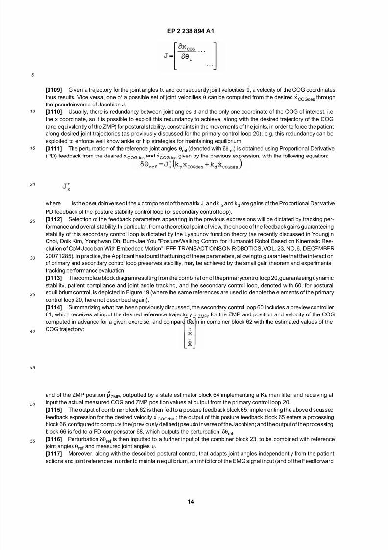
[0104] Accordingly, estimated values for the COG trajectory:
and for the ZMP position p̂ZMP are estimated in real time using a Kalman filter from actual COG and ZMP positions
measuredfrom thesensorsassociated to the exoskeleton haptic device 1, using the linearized invertedpendulum model.
[0105] Starting from these estimates, a velocity control of the COG is computed through the following feedback
expression:
where x.COGdes is the desired velocity of the COG set by the control. The desired position xCOGdes is obtained by time
integration of the previous expression.
[0106] According to an aspect of the present invention, this desired position xCOGdes is translated into a perturbation
of the reference joint angles θref in the primary control loop 20 to guarantee ZMP tracking and consequent postural
equilibrium. This is obtained using the Jacobian of the COG.
[0107] In particular, the coordinates of the COG are linked to joint angles θ by a nonlinear function f:
[0108] The Jacobian of the COG is defined as the linear relationship between measured joint velocities θ. and COG
coordinate velocities:
where J is the matrix of partial derivatives of function f with respect to θ:
7/18/2019 System for Controlling an Exoskeleton Haptic Device
http://slidepdf.com/reader/full/system-for-controlling-an-exoskeleton-haptic-device 14/39

7/18/2019 System for Controlling an Exoskeleton Haptic Device
http://slidepdf.com/reader/full/system-for-controlling-an-exoskeleton-haptic-device 15/39
EP 2 238 894 A1
15
5
10
15
20
25
30
35
40
45
50
55
control) is provided, based on the measured ZMP, in order to bind the freedom of the patient when equilibrium limits
arereached. In particular, an inhibition block69 is includedin theprimary control loop 20, receivingat input themeasured
ZMP position and outputting an inhibition command for the feedforward block 21, in order to temporarily inhibit the role
of the EMG signals y0 (and patient torques C0) in the overall control system. This inhibitor temporarily increases the
stiffness in the desired admittance present in the compliance control. This action allows to dynamically control patient
compliance.
[0118] Figures20-29 showsimulationresultswhere theexoskeletonhapticdevice 1,modeledby a threelinksnonlinear
dynamics in the sagittal plane (see Figure 2), is controlled for a transition from stand-to-sit and sit-to-stand and, in sodoing, the center of weight is shifted from the ankle to the tip of the feet coordinate, and then back to the ankle.
[0119] In particular, Figure 20 shows the plots of the generalized coordinates q (link attitude angles measured in
degree) during a transition from a standing to a sitting position on a chair and back to the standing position, for the ankle
joints 7 (continuous line), the knee joints 8 (dashed line) and hip joints 9 (dotted line).
[0120] Figure21 showsthe effectof theposturalequilibrium moduleand in particularthe time plots of theCOG position
(continuous line), ZMP position (dashed line) and reference (desired) trajectory for the ZMP (dotted line); the zero
corresponds to the position of the ankle abscissa. During the transitions, the postural control operates to bring the ZMP
from the ankle abscissa to the center of the foot and back, and proper perturbations by the postural control are added
to the reference angle trajectories (as it is evident from the ZMP behavior that tracks fairly accurately the reference).
The trajectory of the COG anticipates, through the preview control, the actual path followed by the ZMP, so as to
guarantee a correct tracking.
[0121] Figures 22 and 23 show plots similar to those of Figure 20 and, respectively, Figure 21: the same transitions
are shown, but where postural control is inhibited.[0122] While thegeneralized coordinates q associated to the limb movements (Figure 22)show small differenceswith
respect to the case of Figure 20, Figure 23 clearly evidences that equilibrium is lost (the patient falling on his back)
because of unaccounted swings of the ZMP position (which exceeds the inferior equilibrium threshold, shown at -0.05
m from the ankle abscissa).
[0123] In a second example, the joint references for the transition are erroneously chosen.
[0124] Figure 24 shows the resulting COG and ZMP plots when postural control is deactivated, and the fact that
equilibrium is lost (the patient falling down in front of him/her), due to the ZMP position exceeding the upper equilibrium
threshold, shown at 0.25 m from the ankle abscissa.
[0125] On the contrary, Figure 25 shows that also in this case the action of the postural control allows to maintain the
equilibrium, operating to correct the improper joint trajectories.
[0126] In a third example, during the imposed transitions, an erroneous patient action is simulated, in particular the
action of pushing the ankle forward.
[0127] Asshown in Figures26and27,withoutposturecontrol, thepatientclearly looses theequilibrium(the equilibriumthreshold is clearly exceeded).
[0128] On the contrary, as shown in Figures 28 and 29, the action of the postural control intervenes to recover and
preserve postural equilibrium controlling the knee and hip joints 8, 9 to automatically correct the erroneous angle at the
ankle joints 7 imposed by the patient.
[0129] Thesteps fordesigning thecontrolof the lower limbexoskeletonhapticdevice 1,guaranteeingdynamicstability,
compliance with the patient and postural equilibrium are synthesized in Figure 30.
[0130] In a first step, denoted with 70, the three linearized dynamical models of a triple inverted pendulum in the
sagittal plane, an open/closed quadrilateral in the frontal plane and the mixed (frontal-sagittal plane) solution are dimen-
sioned according to the anthropometric data of the patient and the mechanical data of the exoskeleton haptic device 1.
As it has been shown previously, this step is not critical, as the described robust control design easily accommodates
approximations.
[0131] In a second step, denoted with 72, the desired performance requirements of the control system are specified,
among which:viscoelasticity of the reaction(andthe associated properties of thecompliance experiencedby thepatient),sensitivity to disturbances,trackingcapabilities, allowable controlactivity (inparticular,by regulating thecontrol weighting
functions it is also possible to enforce ankle or hip strategy for posture control, as it is well know by physiotherapists to
happen to human beings). All these data are synthesized in the resulting extended system for robust control design.
The compliance properties of the control may advantageously be adjusted as the physiotherapy treatment proceeds, in
order to follow the recovery and the improvements of the patient.
[0132] In a third step, denoted with 74, the closed loop control is synthesized with a technique of mu-synthesis from
the extended system, and satisfaction of the specifications is tested through the resulting Hinfinite norm of the extended
system in closed loop.
[0133] The preview controller and feedback control for posture control of the ZMP position are precomputed, as they
only depend (ina per-se known manner) on theheight of thebarycenterof thepatient.However, in a fourthstep, denoted
with 76, a tuning is performed of the feedback parameters of the equilibrium module, along with the PD controller

7/18/2019 System for Controlling an Exoskeleton Haptic Device
http://slidepdf.com/reader/full/system-for-controlling-an-exoskeleton-haptic-device 16/39
EP 2 238 894 A1
16
5
10
15
20
25
30
35
40
45
50
55
parameters, in order to fit to the primary control loop 20; this tuning is done using Lyapunov theory and the small gain
theorem to avoid interferences between the internal and external control loops and guarantee stability.
[0134] In a fifth step, denoted with 78, exercises according to the protocol defined by a physiotherapist are pre-
programmed, and the exoskeleton haptic device 1 and the associated control system are ready to be applied to the
patient for rehabilitation.
[0135] From the foregoing description, the advantages that the exoskeleton haptic device and the related control
system allow to achieve may be immediately appreciated.
[0136] In particular, it is again underlined that a dynamically stable system is provided, which is able to track desiredpositions and trajectories, to maintain postural equilibrium and to interact with the operator/patient, offering a controlled
compliance,usinga twodegreeof freedomcontroldesign. Thedesiredmechanicalreaction feltby thepatientis accurately
controlled, via the direct detection of bioelectrical signals, in particular EMG signals. Since the patient torques act as an
additive input disturbance with respect to the exoskeleton position control, it is possible to adjust the control design from
a stiff control (where disturbance is strongly rejected, i.e. the operator is strictly bounded by the control) to a relaxed
control (where the patient experiences a very little constriction from the exoskeleton). The possibility to statically and
dynamically control patient compliance advantageously allows to stimulate neural plasticity for patient recovery.
[0137] The architecture of the exoskeleton and the rehabilitation exercises are conceived to guarantee parsimony in
the design; in particular, each control configuration handles an average of only three degrees of freedom, reaching at
most five degrees of freedom.
[0138] Theadvantage of thedisclosed control approach is that of fully exploiting thepower of feedback.Once a control
loop robustly stabilizes a non-linear system with a proper frequency band, it greatly reduces nonlinearity effects and the
sensitivity on parameter uncertainty and unknown disturbances. An unreliable inverse dynamics, as generally done inother known approaches, to evaluate patient torques or even gravity contributions is not any more needed to activate
the joints under action of reference signals or patient efforts, since this is naturally achieved by the feedback action.
[0139] Hinfinite robust control theory, through the definition of the extended system, offers a systematic way to pose
requirements for the control problem and, once admissibility has been tested through Hinfinite norm for the given class
of problems, to generate with a straightforward algorithm (mu-synthesis) a solution for a specific set of parameters.
[0140] Moreover, the solution of exploiting an exoskeleton for postural training with a dynamically controlled vectorial
compliance (in particular with legs moving jointly in the sagittal plane, or movements on the frontal plane, or finally
emulating a step machine, as previously discussed) has proven to be particularly advantageous for rehabilitation pur-
poses.
[0141] Finally, it is clear that numerous modifications and variants can be made to the present invention, all falling
within the scope of the invention, as defined in the appended claims.
[0142] In particular, it is clear that the exoskeleton haptic device may also be used (with suitable modifications) for
position control and compliance in controlling the movement of the upper limbs or other parts of the body, withoutrequiring substantial modifications in the control system.
[0143] Indeed, the disclosed control system may be employed for a number of different exoskeleton haptic devices
with different degrees of freedom. For example, a similar control design, but controlling independently the two legs and
freeing the feet from the ground, may be extended for walking exercises (in this case the exoskeleton will have up to
twelve degrees of freedom).
[0144] As it has been previously underlined, the secondary control loop for postural equilibrium may not be present,
in all the situations in which equilibrium is not an issue during the execution of the desired rehabilitation exercises.
[0145] Moreover, the intention of movement of the patient may also be determined from other output measures; for
example, it may be determined directly or indirectly based on measures of joint angles and forces exchanged between
the patient and the exoskeleton frame structure.
[0146] Clearly, modifications maybe made to the exoskeleton device as shown in Figure1. Forexample, the exoskel-
eton haptic device1 could be of themonoleg-type, i.e. havingboth legs coupled to a same (one-piece) support structure.
This simple arrangement may be useful to perform transitions between fixed positions, such as the sit-to-stand andstand-to sit transitions in the sagittal plane.
Claims
1. Control system (20, 60) for an exoskeleton haptic device (1), said exoskeleton haptic device (1) having:
a frame structure (3), configured to be coupled’ to the body of a subject (2);
actuator means (10), carried by said frame structure (3) and operable to cause movement of a number of joints
(7, 8, 9) of said body; and
first sensor means (14), coupled to said body and configured to detect first signals (yo) indicative of an intention

7/18/2019 System for Controlling an Exoskeleton Haptic Device
http://slidepdf.com/reader/full/system-for-controlling-an-exoskeleton-haptic-device 17/39
EP 2 238 894 A1
17
5
10
15
20
25
30
35
40
45
50
55
of movement of said subject (2), characterized by comprising:
a feedback stage (24), configured to control a position of said joints (7, 8, 9) based on a reference position
(θref ) and joint position and velocity measures (θ,θ.);
a feedforward stage (21), configured to control a compliance presented by said exoskeleton haptic device
(1) to said subject (2) based on the detected first signals (yo); and
combining means (22), configured to combine outputs fromsaid feedbackstage(24) and feedforward stage
(21) in order to generate a driving signal (um) for said actuator means (10), thereby imposing a controlledposition (θ) to said joints (7, 8, 9).
2. The control system according to claim 1, wherein said feedback stage (24) and feedforward stage (21) are operable
to generate an elastic reaction felt by said subject (2) starting from said controlled position ( θ), and to modify a
stiffnessand/ora viscosityof said elastic reaction to achieve a control of said compliance for rehabilitationpurposes.
3. The control system according to claim 1 or 2, wherein said feedback stage (24) and feedforward stage (21) are
operable to implement a primary closed loop (20) according to a two degree of freedom control design for position
andcompliancecontrol;said twodegreeof freedomcontroldesignbeing solvedwithan H-infinite approach, whereby,
measuring" a subject effort (C0) through said first signals (yo), subject compliance is embedded inside a position
control loop.
4. The control system according to claim 3, wherein said feedforward stage (21) includes an admittance/impedanceblock (31; 48) configured to control the admittance/impedance response of said exoskeleton haptic device (1) with
respect to the subject effort (C0); said compliance being achieved through said admittance/impedance control.
5. The control system according to any of the preceding claims, wherein said first signals (yo) are bioelectrical signals,
in particular EMG signals, detected from muscles of said patient involved for the movement of said joints (7, 8, 9).
6. The control system according to any of the preceding claims, wherein said feedback stage (24) and feedforward
stage (21) are configured to implement a primary closed loop (20) for control of said position of said joints (7, 8, 9)
and of said compliance; further comprising a secondaryclosed loop (60), operatively coupled to said primary closed
loop (20) for control of postural equilibrium of said subject (2) during said movement.
7. The control system according to claim 6, wherein said secondary closed loop (60) is configured to generate a
perturbation (δθref ) of said reference position (θref ) at input of said feedback stage (24) such as to maintain saidpostural equilibrium.
8. The control system according to claim 7, wherein said exoskeleton haptic device (1) is further provided with second
sensor means (17) configured to detect reaction forces imparted by the ground to said subject (2); wherein said
secondary closed loop (60) is configured to: implement an inverted pendulum model of said exoskeleton haptic
device (1); estimate, through a Kalman filter, the position of the ZMP - zero moment point - of said body, i.e. the
point at which the resultant of the torques associated to said reaction forces is zero, and the position of the COG -
center of gravity - of said body, based on the signals detected by said second sensor means (17); and determine
a value of said perturbation (δθref ) based on Lyapunov stability theory, such that said ZMP position is maintained
in a region of postural stability controlling said COG position.
9. The control system according to claim 8, wherein said secondary closed loop (60) includes an estimator block (64)
configured to determine said estimates of the ZMP and COG positions based on an actual determined COG andZMP positions, and a processing block (65, 66, 68) configured to determine said perturbation (δθref ) as a function
of the Jacobian of said estimated COG position.
10. The control system according to claim 8 or 9, further comprising an inhibitor block (69) configured to perform a
determination whether equilibrium limits have been reached, based on a determined ZMP position, and to inhibit
the operation of said feedforward stage (21) based on said determination.
11. Thecontrol system according to claim 10,wherein said inhibitor block (69) is configured to stiffen an elastic reaction
felt by said subject (2) starting from said controlled position (θ), thereby implementing a dynamic control of said
subject compliance.
7/18/2019 System for Controlling an Exoskeleton Haptic Device
http://slidepdf.com/reader/full/system-for-controlling-an-exoskeleton-haptic-device 18/39
EP 2 238 894 A1
18
5
10
15
20
25
30
35
40
45
50
55
12. The control system according to any of the preceding claims, wherein said feedback stage (24) is configured to
control said position (θ) of said joints (7, 8, 9) in a frontal and in a sagittal plane with respect to said subject (2),
contemporaneously and independently to maintain equilibrium in quiet posture.
13. The control system according to any of the preceding claims, wherein said actuator means (10) are configured to
actuate ankle (7), knee (8) and hip (9) joints of said body; said feedback stage (24) and feedforward stage (21)
being configured to implement a dynamical model ofsaidexoskeletonhapticdevice(1)composedof twoindependent
elements: a triple inverted pendulum in the sagittal plane of said body with joined lower limbs, having three degreesof freedom for actuation by said actuator means (10) of movements, in pairs, of said ankle (7), knee (8) and hip (9)
joints; and a switched system with two configurations of a parallelogram or open quadrilateral, according to a phase
of double or single stance, for actuation by said actuator means (10) independently of the right and left of said hip
joints (9) in the frontal plane; said control being under-actuated in said frontal plane during the single stance.
14. The control system according to claim 13, wherein, along with the actuation of said hip joints (9) in the frontal plane,
knee (8) and hip (9) joints of a free leg are actuatable in the sagittal plane, with a partially constrained free foot, to
achieve a three degree of freedom dynamics emulating a step machine.
15. The control system according to any of the preceding claims, wherein said exoskeleton haptic device (1) is coupled
to the lower limbs of said subject (2) and said actuator means (10) are configured to actuate ankle (7), knee (8) and
hip (9) joints of said body;andwhereinsaid feedbackstage(24) andfeedforwardstage(21) areconfigured to control
said exoskeleton haptic device (1) for training for rehabilitation purposes, according to different postural exercises,among which one or more of the following:
- sagittal plane coordination with both feet on the ground, wherein left and right ankle (7), knee (8) and hip (9)
joints are activated in pairs in sit-to-stand and stand-to-sit transitions;
- frontal plane coordination, with transitions from double to single stance postures, with fixed knees, by shifting
the weight of the patient from one foot to the other and then lifting the free foot, activating in the frontal plane
said hip joints (9); and
- intermixed sagittal and frontal plane coordination, wherein, contemporaneously to the activation of the hip
joints (9) in the frontal plane, the free foot is raised, activating knee (8) and hip (9) joints of the related free leg
in the sagittal plane; said intermixed sagittal and frontal plane coordination providing a neural step machine
embedding equilibrium control.
16. The control system according to claim 15, wherein said feedforward stage (21) is operable to direct the movementsof said subject (2) according to one of said different postural exercises, by vectorially controlling said compliance.
17. The control system according to claim 15 or 16, wherein said feedforward stage (21) is further operable during said
postural exercises to implement a dynamically variable admittance response of said exoskeleton haptic device (1)
with respect to the subject effort (C0) for rehabilitation purposes.
18. Exoskeleton haptic device (1) comprising:
a frame structure (3), configured to be coupled to the body of a subject (2);
actuator means (10), carried by said frame structure (3) and operable to cause movement of a number of joints
(7, 8, 9) of said body; and
first sensor means (14), coupled to said body and configured to detect first signals (yo) indicative of an intention
of movement of said subject (2), characterized by comprising a control system (20, 60) according to any oneof the previous claims.
19. The exoskeleton haptic device according to claim 18, configured to be coupled to the lower limbs of said subject
(2)for rehabilitationposturaltrainingand neuralplasticity recovery,and operable to control movements of said lower
limbs in the frontal and/or sagittal planes of said subject (2).
20. A computer program product comprising computer instructions for implementing, when executed in a processing
unit, the control system (20, 60) according to any one of claims 1-17; in particular, said computer program product
allowing modification of biometric parameters of said subject (2) and stiffness and viscosity parameters of said
subject compliance.

7/18/2019 System for Controlling an Exoskeleton Haptic Device
http://slidepdf.com/reader/full/system-for-controlling-an-exoskeleton-haptic-device 19/39
EP 2 238 894 A1
19
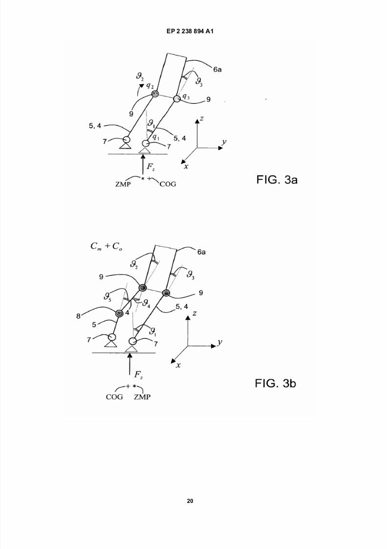
7/18/2019 System for Controlling an Exoskeleton Haptic Device
http://slidepdf.com/reader/full/system-for-controlling-an-exoskeleton-haptic-device 20/39
EP 2 238 894 A1
20

7/18/2019 System for Controlling an Exoskeleton Haptic Device
http://slidepdf.com/reader/full/system-for-controlling-an-exoskeleton-haptic-device 21/39
EP 2 238 894 A1
21

7/18/2019 System for Controlling an Exoskeleton Haptic Device
http://slidepdf.com/reader/full/system-for-controlling-an-exoskeleton-haptic-device 22/39

7/18/2019 System for Controlling an Exoskeleton Haptic Device
http://slidepdf.com/reader/full/system-for-controlling-an-exoskeleton-haptic-device 23/39
EP 2 238 894 A1
23

7/18/2019 System for Controlling an Exoskeleton Haptic Device
http://slidepdf.com/reader/full/system-for-controlling-an-exoskeleton-haptic-device 24/39
EP 2 238 894 A1
24

7/18/2019 System for Controlling an Exoskeleton Haptic Device
http://slidepdf.com/reader/full/system-for-controlling-an-exoskeleton-haptic-device 25/39
EP 2 238 894 A1
25

7/18/2019 System for Controlling an Exoskeleton Haptic Device
http://slidepdf.com/reader/full/system-for-controlling-an-exoskeleton-haptic-device 26/39
EP 2 238 894 A1
26

7/18/2019 System for Controlling an Exoskeleton Haptic Device
http://slidepdf.com/reader/full/system-for-controlling-an-exoskeleton-haptic-device 27/39
EP 2 238 894 A1
27

7/18/2019 System for Controlling an Exoskeleton Haptic Device
http://slidepdf.com/reader/full/system-for-controlling-an-exoskeleton-haptic-device 28/39
EP 2 238 894 A1
28
7/18/2019 System for Controlling an Exoskeleton Haptic Device
http://slidepdf.com/reader/full/system-for-controlling-an-exoskeleton-haptic-device 29/39
EP 2 238 894 A1
29
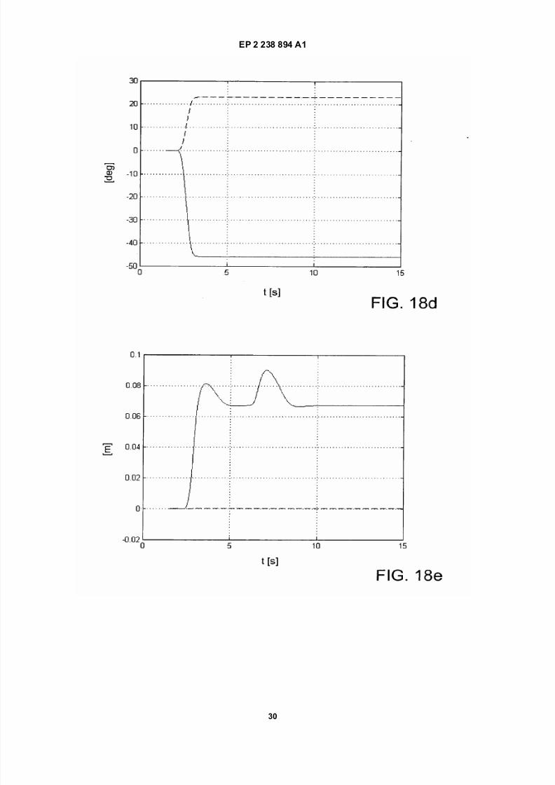
7/18/2019 System for Controlling an Exoskeleton Haptic Device
http://slidepdf.com/reader/full/system-for-controlling-an-exoskeleton-haptic-device 30/39
EP 2 238 894 A1
30

7/18/2019 System for Controlling an Exoskeleton Haptic Device
http://slidepdf.com/reader/full/system-for-controlling-an-exoskeleton-haptic-device 31/39
EP 2 238 894 A1
31
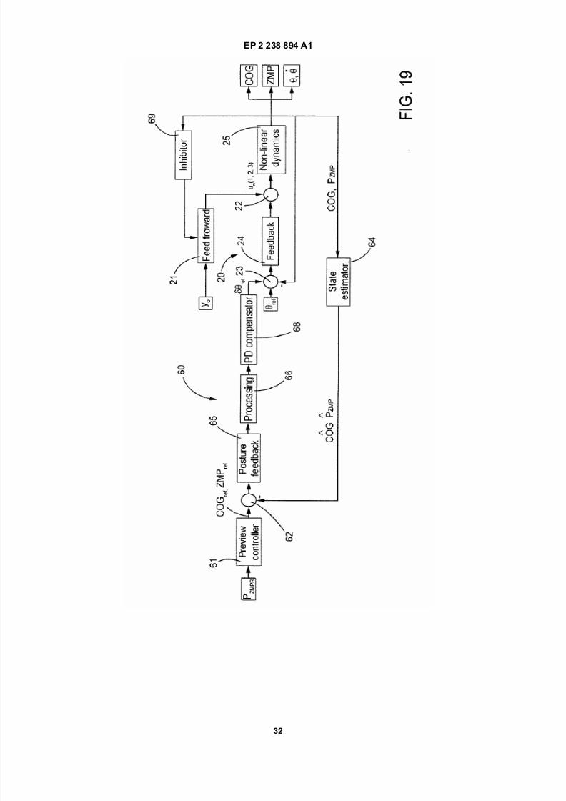
7/18/2019 System for Controlling an Exoskeleton Haptic Device
http://slidepdf.com/reader/full/system-for-controlling-an-exoskeleton-haptic-device 32/39
EP 2 238 894 A1
32

7/18/2019 System for Controlling an Exoskeleton Haptic Device
http://slidepdf.com/reader/full/system-for-controlling-an-exoskeleton-haptic-device 33/39
EP 2 238 894 A1
33
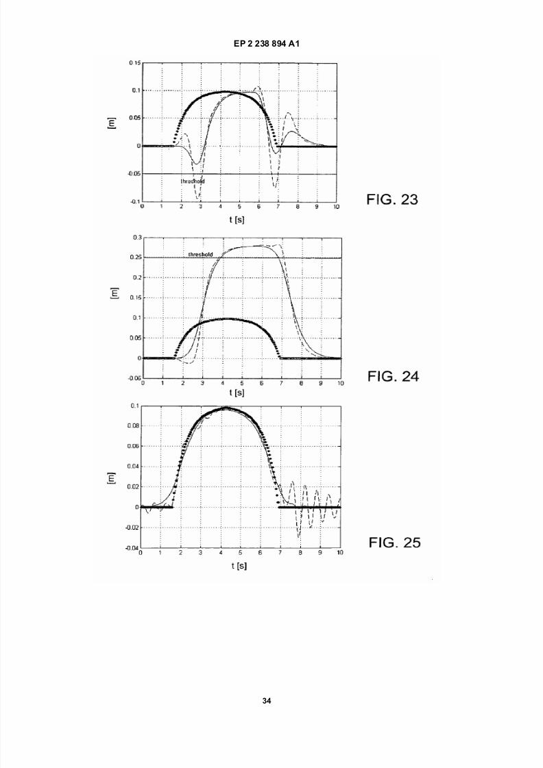
7/18/2019 System for Controlling an Exoskeleton Haptic Device
http://slidepdf.com/reader/full/system-for-controlling-an-exoskeleton-haptic-device 34/39
EP 2 238 894 A1
34

7/18/2019 System for Controlling an Exoskeleton Haptic Device
http://slidepdf.com/reader/full/system-for-controlling-an-exoskeleton-haptic-device 35/39
EP 2 238 894 A1
35

7/18/2019 System for Controlling an Exoskeleton Haptic Device
http://slidepdf.com/reader/full/system-for-controlling-an-exoskeleton-haptic-device 36/39
EP 2 238 894 A1
36

7/18/2019 System for Controlling an Exoskeleton Haptic Device
http://slidepdf.com/reader/full/system-for-controlling-an-exoskeleton-haptic-device 37/39
EP 2 238 894 A1
37

7/18/2019 System for Controlling an Exoskeleton Haptic Device
http://slidepdf.com/reader/full/system-for-controlling-an-exoskeleton-haptic-device 38/39
EP 2 238 894 A1
38

7/18/2019 System for Controlling an Exoskeleton Haptic Device
http://slidepdf.com/reader/full/system-for-controlling-an-exoskeleton-haptic-device 39/39
EP 2 238 894 A1
REFERENCES CITED IN THE DESCRIPTION
This list of references cited by the applicant is for the reader’s convenience only. It does not form part of the European
patent document. Even though great care has been taken in compiling the references, errors or omissions cannot be
excluded and the EPO disclaims all liability in this regard.
Non-patent literature cited in the description
• K. Zhou ; J.C. Doyle ; K. Glover. Robust and Opti-
mal Control. Prentice Hall, 1996 [0039]
• Geromel ; Colaneri ; Bolzern. Dynamic Output
FeedbackControlof SwitchedLinear Systems. IEEE
Transactions on Automatic Control, April 2008, vol.
53 (3 [0067]
• Shuuji KAJITA ; Fumio KANEHIRO ; Kenji
KANEKO ; Kiyoshi FUJIWARA ; Kensuke
HARADA ; Kazuhito YOKOI ; Hirohisa HIRU-
KAWA. Biped Walking Pattern Generation by using
Preview Control of Zero-Moment Point. Proceedings
of the 2003 IEEE International Conference on Ro-botics & Automation Taipei, 14 September 2003
[0103]
• Youngjin Choi ; Doik Kim ; Yonghwan Oh ;
Bum-Jae You. Posture/Walking Control for Human-
oid Robot Based on Kinematic Resolution of CoM
Jacobian With Embedded Motion. IEEE TRANSAC-
TIONS ON ROBOTICS, December 2007, vol. 23 (6),
1285 [0112]