Embed Size (px)
Citation preview
System Information: C-SGSN Overview
© 31-Aug-2004 Motorola,Inc.
68P02904W51-B
All Rights Reserved CONTROLLED INTRODUCTION 31-Aug-2004
Copyrights
The Motorola products described in this document may include copyrighted Motorola computer programs stored in semiconductor memories or other media.Laws in the United States and other countries preserve for Motorola certain exclusive rights for copyright computer programs, including the exclusive right tocopy or reproduce in any form the copyright computer program. Accordingly, any copyright Motorola computer programs contained in the Motorola productsdescribed in this document may not be copied or reproduced in any manner without the express written permission of Motorola. Furthermore, the purchaseof Motorola products shall not be deemed to grant either directly or by implication, estoppel or otherwise, any license under the copyrights, patents or patentapplications of Motorola, except for the rights that arise by operation of law in the sale of a product.
Restrictions
The software described in this document is the property of Motorola. It is furnished under a license agreement and may be used and/or disclosed only inaccordance with the terms of the agreement. Software and documentation are copyright materials. Making unauthorized copies is prohibited by law. No part ofthe software or documentation may be reproduced, transmitted, transcribed, stored in a retrieval system, or translated into any language or computer language,in any form or by any means, without prior written permission of Motorola.
Accuracy
While reasonable efforts have been made to assure the accuracy of this document, Motorola assumes no liability resulting from any inaccuracies or omissionsin this document, or from the use of the information obtained herein. Motorola reserves the right to make changes to any products described herein to improvereliability, function, or design, and reserves the right to revise this document and to make changes from time to time in content hereof with no obligation tonotify any person of revisions or changes. Motorola does not assume any liability arising out of the application or use of any product or circuit described herein;neither does it convey license under its patent rights of others.
Trademarks
Motorola and the Motorola logo are registered trademarks of Motorola Inc.
Intelligence Everywhere, M-Cell and Taskfinder are trademarks of Motorola Inc.
All other brands and corporate names are trademarks of their respective owners.
CONTROLLED INTRODUCTION 31-Aug-2004
Tableof
Contents
Contents■ ■ ■ ■ ■ ■ ■ ■ ■ ■ ■ ■ ■ ■ ■ ■ ■ ■ ■ ■ ■ ■ ■ ■ ■ ■ ■ ■ ■ ■ ■ ■ ■ ■ ■ ■ ■ ■ ■ ■ ■ ■ ■ ■ ■ ■
■
■
■
■
System Information: C-SGSN OverviewIssue status of this manual . . . . . . . . . . . . . . . . . . . . . . . . . . . . . . . . . . . . . . . 2
Version information . . . . . . . . . . . . . . . . . . . . . . . . . . . . . . . . . . . . . . . . 2Resolution of service requests . . . . . . . . . . . . . . . . . . . . . . . . . . . . . . . . . . . 2
General information . . . . . . . . . . . . . . . . . . . . . . . . . . . . . . . . . . . . . . . . . . 3Purpose . . . . . . . . . . . . . . . . . . . . . . . . . . . . . . . . . . . . . . . . . . . . . 3Feature references . . . . . . . . . . . . . . . . . . . . . . . . . . . . . . . . . . . . . . . . . 3Cross references . . . . . . . . . . . . . . . . . . . . . . . . . . . . . . . . . . . . . . . . . 4Data encryption . . . . . . . . . . . . . . . . . . . . . . . . . . . . . . . . . . . . . . . . . . 4Text conventions . . . . . . . . . . . . . . . . . . . . . . . . . . . . . . . . . . . . . . . . . 5
Reporting safety issues . . . . . . . . . . . . . . . . . . . . . . . . . . . . . . . . . . . . . . . . 6Procedure . . . . . . . . . . . . . . . . . . . . . . . . . . . . . . . . . . . . . . . . . . . . 6
Warnings and cautions . . . . . . . . . . . . . . . . . . . . . . . . . . . . . . . . . . . . . . . . . 7Warnings . . . . . . . . . . . . . . . . . . . . . . . . . . . . . . . . . . . . . . . . . . . . . 7Failure to comply with warnings . . . . . . . . . . . . . . . . . . . . . . . . . . . . . . . . . . 7Cautions . . . . . . . . . . . . . . . . . . . . . . . . . . . . . . . . . . . . . . . . . . . . . 7
General warnings . . . . . . . . . . . . . . . . . . . . . . . . . . . . . . . . . . . . . . . . . . . 9Warning labels . . . . . . . . . . . . . . . . . . . . . . . . . . . . . . . . . . . . . . . . . . 9Specific warnings . . . . . . . . . . . . . . . . . . . . . . . . . . . . . . . . . . . . . . . . . 9
General cautions . . . . . . . . . . . . . . . . . . . . . . . . . . . . . . . . . . . . . . . . . . . 13Caution labels. . . . . . . . . . . . . . . . . . . . . . . . . . . . . . . . . . . . . . . . . . . 13Specific cautions . . . . . . . . . . . . . . . . . . . . . . . . . . . . . . . . . . . . . . . . . 13
Devices sensitive to static . . . . . . . . . . . . . . . . . . . . . . . . . . . . . . . . . . . . . . . 14Special handling techniques . . . . . . . . . . . . . . . . . . . . . . . . . . . . . . . . . . . . 14
Motorola manual set . . . . . . . . . . . . . . . . . . . . . . . . . . . . . . . . . . . . . . . . . . 15Ordering manuals and CD-ROMs . . . . . . . . . . . . . . . . . . . . . . . . . . . . . . . . . 15
GMR amendment . . . . . . . . . . . . . . . . . . . . . . . . . . . . . . . . . . . . . . . . . . . 16GMR availability . . . . . . . . . . . . . . . . . . . . . . . . . . . . . . . . . . . . . . . . . 16GMR instructions . . . . . . . . . . . . . . . . . . . . . . . . . . . . . . . . . . . . . . . . . 16GMR amendment record. . . . . . . . . . . . . . . . . . . . . . . . . . . . . . . . . . . . . . 17
Chapter 1: Introduction
Chapter 2: System CharacteristicsOverview . . . . . . . . . . . . . . . . . . . . . . . . . . . . . . . . . . . . . . . . . . . . . . . 2-2Hardware Features . . . . . . . . . . . . . . . . . . . . . . . . . . . . . . . . . . . . . . . . . . 2-3Interface Features . . . . . . . . . . . . . . . . . . . . . . . . . . . . . . . . . . . . . . . . . . . 2-4Services and Functions Features . . . . . . . . . . . . . . . . . . . . . . . . . . . . . . . . . . . . 2-5
68P02904W51-B i31-Aug-2004 CONTROLLED INTRODUCTION
Contents
Easy Operation and Maintenance . . . . . . . . . . . . . . . . . . . . . . . . . . . . . . . . . . . . 2-8High Reliability . . . . . . . . . . . . . . . . . . . . . . . . . . . . . . . . . . . . . . . . . . . . 2-9
Chapter 3: System ArchitectureOverview . . . . . . . . . . . . . . . . . . . . . . . . . . . . . . . . . . . . . . . . . . . . . . . 3-2Hardware Architecture. . . . . . . . . . . . . . . . . . . . . . . . . . . . . . . . . . . . . . . . . 3-3Software Architecture . . . . . . . . . . . . . . . . . . . . . . . . . . . . . . . . . . . . . . . . . 3-6Logical Architecture . . . . . . . . . . . . . . . . . . . . . . . . . . . . . . . . . . . . . . . . . . 3-7Hardware Configuration . . . . . . . . . . . . . . . . . . . . . . . . . . . . . . . . . . . . . . . . 3-8
2.5G Configuration . . . . . . . . . . . . . . . . . . . . . . . . . . . . . . . . . . . . . . . . 3-83G Configuration . . . . . . . . . . . . . . . . . . . . . . . . . . . . . . . . . . . . . . . . . 3-92.5G-3G-Combined Configuration . . . . . . . . . . . . . . . . . . . . . . . . . . . . . . . . . 3-10
Chapter 4: Services and FunctionsOverview . . . . . . . . . . . . . . . . . . . . . . . . . . . . . . . . . . . . . . . . . . . . . . . 4-2Mobility Management . . . . . . . . . . . . . . . . . . . . . . . . . . . . . . . . . . . . . . . . . 4-3Session Management . . . . . . . . . . . . . . . . . . . . . . . . . . . . . . . . . . . . . . . . . 4-4Packet Routing and Transfer Functions . . . . . . . . . . . . . . . . . . . . . . . . . . . . . . . . . 4-5Charging Functions . . . . . . . . . . . . . . . . . . . . . . . . . . . . . . . . . . . . . . . . . . 4-7Short Message Service. . . . . . . . . . . . . . . . . . . . . . . . . . . . . . . . . . . . . . . . . 4-8Location Services . . . . . . . . . . . . . . . . . . . . . . . . . . . . . . . . . . . . . . . . . . . 4-9CAMEL Phase 3 . . . . . . . . . . . . . . . . . . . . . . . . . . . . . . . . . . . . . . . . . . . 4-11Lawful Interception . . . . . . . . . . . . . . . . . . . . . . . . . . . . . . . . . . . . . . . . . . 4-12QoS Management . . . . . . . . . . . . . . . . . . . . . . . . . . . . . . . . . . . . . . . . . . . 4-13
Chapter 5: Operation and MaintenanceOverview . . . . . . . . . . . . . . . . . . . . . . . . . . . . . . . . . . . . . . . . . . . . . . . 5-2Database Management . . . . . . . . . . . . . . . . . . . . . . . . . . . . . . . . . . . . . . . . . 5-6Equipment Management . . . . . . . . . . . . . . . . . . . . . . . . . . . . . . . . . . . . . . . . 5-7Tracing Management . . . . . . . . . . . . . . . . . . . . . . . . . . . . . . . . . . . . . . . . . 5-8Performance Management . . . . . . . . . . . . . . . . . . . . . . . . . . . . . . . . . . . . . . . 5-9Motorola C-SGSN Alarm Management . . . . . . . . . . . . . . . . . . . . . . . . . . . . . . . . . 5-12
Abundant alarm contents and detailed and accurate alarm location . . . . . . . . . . . . . . . . . . 5-12Online Help. . . . . . . . . . . . . . . . . . . . . . . . . . . . . . . . . . . . . . . . . . . . . . 5-15
Chapter 6: ReliabilityOverview . . . . . . . . . . . . . . . . . . . . . . . . . . . . . . . . . . . . . . . . . . . . . . . 6-2Hardware Reliability Measures . . . . . . . . . . . . . . . . . . . . . . . . . . . . . . . . . . . . . 6-3
Power Supply Reliability . . . . . . . . . . . . . . . . . . . . . . . . . . . . . . . . . . . . . 6-3Board Hot Backup . . . . . . . . . . . . . . . . . . . . . . . . . . . . . . . . . . . . . . . . 6-3ASIC Technique . . . . . . . . . . . . . . . . . . . . . . . . . . . . . . . . . . . . . . . . . 6-3High-Quality Components . . . . . . . . . . . . . . . . . . . . . . . . . . . . . . . . . . . . . 6-4Mutual Assistance Working Mode . . . . . . . . . . . . . . . . . . . . . . . . . . . . . . . . . 6-4
Software Reliability Measures . . . . . . . . . . . . . . . . . . . . . . . . . . . . . . . . . . . . . 6-5Protection Function . . . . . . . . . . . . . . . . . . . . . . . . . . . . . . . . . . . . . . . . 6-5Error Tolerance Capability . . . . . . . . . . . . . . . . . . . . . . . . . . . . . . . . . . . . . 6-5
Charging Reliability Measures . . . . . . . . . . . . . . . . . . . . . . . . . . . . . . . . . . . . . 6-7Reliability Indices . . . . . . . . . . . . . . . . . . . . . . . . . . . . . . . . . . . . . . . . . . . 6-8
Chapter 7: Technical SpecificationsOverview . . . . . . . . . . . . . . . . . . . . . . . . . . . . . . . . . . . . . . . . . . . . . . 7-2
ii 68P02904W51-BCONTROLLED INTRODUCTION 31-Aug-2004
Contents
Performance Specifications . . . . . . . . . . . . . . . . . . . . . . . . . . . . . . . . . . . . . . 7-3Interface parameters . . . . . . . . . . . . . . . . . . . . . . . . . . . . . . . . . . . . . . . . . . 7-4Power consumption . . . . . . . . . . . . . . . . . . . . . . . . . . . . . . . . . . . . . . . . . . 7-5Mechanical parameters . . . . . . . . . . . . . . . . . . . . . . . . . . . . . . . . . . . . . . . . 7-6Environmental Conditions . . . . . . . . . . . . . . . . . . . . . . . . . . . . . . . . . . . . . . . 7-7
Storage conditions . . . . . . . . . . . . . . . . . . . . . . . . . . . . . . . . . . . . . . . . 7-7
Chapter 8: Installation
68P02904W51-B iii31-Aug-2004 CONTROLLED INTRODUCTION

Contents
This page intentionally left blank.
iv 68P02904W51-BCONTROLLED INTRODUCTION 31-Aug-2004
Listof
Figures
List of Figures■ ■ ■ ■ ■ ■ ■ ■ ■ ■ ■ ■ ■ ■ ■ ■ ■ ■ ■ ■ ■ ■ ■ ■ ■ ■ ■ ■ ■ ■ ■ ■ ■ ■ ■ ■ ■ ■ ■ ■ ■ ■ ■ ■ ■
■
■
■
■
Figure 1-1: Motorola mobile communication network. . . . . . . . . . . . . . . . . . . . . . . . . . . 1-2Figure 3-1: Appearance and dimension of the Motorola C-SGSN cabinet. . . . . . . . . . . . . . . . . . 3-4Figure 3-2: Logical structure of Motorola C-SGSN. . . . . . . . . . . . . . . . . . . . . . . . . . . . 3-7Figure 3-3: Configuration of 30,000 2.5G users. . . . . . . . . . . . . . . . . . . . . . . . . . . . . . 3-8Figure 3-4: Configuration of 60,000 3G users.. . . . . . . . . . . . . . . . . . . . . . . . . . . . . . 3-9Figure 3-5: 2.5G-3G-combined configuration. . . . . . . . . . . . . . . . . . . . . . . . . . . . . . . 3-10Figure 4-1: Forwarding of data in 2.5G network. . . . . . . . . . . . . . . . . . . . . . . . . . . . . 4-5Figure 4-2: Forwarding function of SGSN in 3G network. . . . . . . . . . . . . . . . . . . . . . . . . 4-6Figure 4-3: Short message system networking. . . . . . . . . . . . . . . . . . . . . . . . . . . . . . 4-8Figure 4-4: General arrangement of LCS. . . . . . . . . . . . . . . . . . . . . . . . . . . . . . . . . 4-9Figure 4-5: Networking structure supporting intelligent network services. . . . . . . . . . . . . . . . . . 4-11Figure 4-6: Lawful Interception. . . . . . . . . . . . . . . . . . . . . . . . . . . . . . . . . . . . . 4-12Figure 4-7: QoS processing on downlink data.. . . . . . . . . . . . . . . . . . . . . . . . . . . . . . 4-14Figure 5-1: Motorola C-SGSN O&M system architecture. . . . . . . . . . . . . . . . . . . . . . . . . 5-2Figure 5-2: GUI maintenance interface. . . . . . . . . . . . . . . . . . . . . . . . . . . . . . . . . . 5-3Figure 5-3: MML maintenance interface. . . . . . . . . . . . . . . . . . . . . . . . . . . . . . . . . 5-4Figure 5-4: OMC-S/T 2.0 network management system. . . . . . . . . . . . . . . . . . . . . . . . . . 5-5Figure 5-5: Tracing result interface. . . . . . . . . . . . . . . . . . . . . . . . . . . . . . . . . . . 5-8Figure 5-6: View measurement result. . . . . . . . . . . . . . . . . . . . . . . . . . . . . . . . . . 5-11Figure 5-7: View alarms.. . . . . . . . . . . . . . . . . . . . . . . . . . . . . . . . . . . . . . . . 5-13Figure 5-8: GM12ALMZ alarm box. . . . . . . . . . . . . . . . . . . . . . . . . . . . . . . . . . . 5-14Figure 5-9: MML help. . . . . . . . . . . . . . . . . . . . . . . . . . . . . . . . . . . . . . . . . 5-15
68P02904W51-B v31-Aug-2004 CONTROLLED INTRODUCTION

List of Figures
This page intentionally left blank.
vi 68P02904W51-BCONTROLLED INTRODUCTION 31-Aug-2004
Listof
Tables
List of Tables■ ■ ■ ■ ■ ■ ■ ■ ■ ■ ■ ■ ■ ■ ■ ■ ■ ■ ■ ■ ■ ■ ■ ■ ■ ■ ■ ■ ■ ■ ■ ■ ■ ■ ■ ■ ■ ■ ■ ■ ■ ■ ■ ■ ■
■
■
■
■
Table 1: Manual version history . . . . . . . . . . . . . . . . . . . . . . . . . . . . . . . . . . . . 2Table 2: Service requests resolved in this manual . . . . . . . . . . . . . . . . . . . . . . . . . . . . 2Table 3-1: Boards in the BNET subrack. . . . . . . . . . . . . . . . . . . . . . . . . . . . . . . . . 3-5Table 3-2: Boards in the PSM subrack. . . . . . . . . . . . . . . . . . . . . . . . . . . . . . . . . . 3-5Table 3-3: 2.5G configurations in different capacities. . . . . . . . . . . . . . . . . . . . . . . . . . . 3-9Table 3-4: 3G configurations in different capacities. . . . . . . . . . . . . . . . . . . . . . . . . . . . 3-10Table 4-1: UMTS QoS classes. . . . . . . . . . . . . . . . . . . . . . . . . . . . . . . . . . . . . . 4-13Table 6-1: Reliability indices of Motorola C-SGSN. . . . . . . . . . . . . . . . . . . . . . . . . . . . 6-8
68P02904W51-B vii31-Aug-2004 CONTROLLED INTRODUCTION

List of Tables
This page intentionally left blank.
viii 68P02904W51-BCONTROLLED INTRODUCTION 31-Aug-2004
AboutThisManual
System Information: C-SGSN Overview■ ■ ■ ■ ■ ■ ■ ■ ■ ■ ■ ■ ■ ■ ■ ■ ■ ■ ■ ■ ■ ■ ■ ■ ■ ■ ■ ■ ■ ■ ■ ■ ■ ■ ■ ■ ■ ■ ■ ■ ■ ■ ■ ■ ■
■
■
■
■
68P02904W51-B 131-Aug-2004 CONTROLLED INTRODUCTION
Issue status of this manual
Issue status of this manual■ ■ ■ ■ ■ ■ ■ ■ ■ ■ ■ ■ ■ ■ ■ ■ ■ ■ ■ ■ ■ ■ ■ ■ ■ ■ ■ ■ ■ ■ ■ ■ ■ ■ ■ ■ ■ ■ ■ ■ ■ ■ ■ ■ ■
■
■
The following shows the issue status of this manual since it was first released.
Version information
The following table lists the versions of this manual in order of issue:
Table 1 Manual version history
Manualissue Date of issue Remarks
A 02 Jul 2004 This is a new manual.
Resolution of service requests
The following Service Requests are now resolved in this manual:
Table 2 Service requests resolved in this manual
ServiceRequest
GMRNumber Remarks
N/A N/A Original issue - Preliminary
2 68P02904W51-BCONTROLLED INTRODUCTION 31-Aug-2004
General information
General information■ ■ ■ ■ ■ ■ ■ ■ ■ ■ ■ ■ ■ ■ ■ ■ ■ ■ ■ ■ ■ ■ ■ ■ ■ ■ ■ ■ ■ ■ ■ ■ ■ ■ ■ ■ ■ ■ ■ ■ ■ ■ ■ ■ ■
■
■
• Motorola disclaims all liability whatsoever, implied or express, for any risk of damage, lossor reduction in system performance arising directly or indirectly out of the failure of thecustomer, or anyone acting on the customers behalf, to abide by the instructions, systemparameters or recommendations made in this manual
• If this manual was obtained when attending a Motorola training course, it will not be updatedor amended by Motorola. It is intended for TRAINING PURPOSES ONLY. If it was suppliedunder normal operational circumstances, to support a major software release, then correctionswill be supplied automatically by Motorola in the form of General Manual Revisions (GMRs).
Purpose
Motorola cellular communications manuals are intended to instruct and assist personnel in the operation,installation and maintenance of the Motorola cellular infrastructure equipment and ancillary devices. It isrecommended that all personnel engaged in such activities be properly trained by Motorola.
Failure to comply with Motorola's operation, installation and maintenanceinstructions may, in exceptional circumstances, lead to serious injury or death.
These manuals are not intended to replace the system and equipment training offered by Motorola, althoughthey can be used to supplement and enhance the knowledge gained through such training.
Feature references
Most of the manuals in the set, of which this manual is part, are revised to accommodate features releasedat Motorola General System Releases (GSRn) or GPRS Support Node (GSNn) releases. In these manuals,new and amended features are tagged to help users to assess the impact on installed networks. The tags arethe appropriate Motorola Roadmap DataBase (RDB) numbers or Research and Development Prioritization(RDP) numbers. The tags include index references which are listed in the manual Index. The Index includesthe entry feature which is followed by a list of the RDB or RDP numbers for the released features, withpage references and hot links in electronic copy.
68P02904W51-B 331-Aug-2004 CONTROLLED INTRODUCTION
General information
The tags have the format: 'nnnn' or 'nnnnn'
Where: is:
'nnnn' the RDB number
'nnnnn' the RDP number
The tags are positioned in text as follows:
New and amended feature information Tag position in textNew sentence/s or new or amended text. Immediately before the affected text.
Complete new blocks of text as follows:
• Full sections under a main heading
• Full paragraphs under subheadings
Immediately after the headings as follows:
• Main heading
• Subheading
New or amended complete Figures and Tables After the Figure or Table number and beforethe title text.
Warning, Caution and Note boxes. Immediately before the affected text in the box.
General command syntax, operator input ordisplays (in special fonts).
On a separate line immediately above theaffected item.
For a list of Roadmap numbers and the RDB or RDP numbers of the features included in this softwarerelease, refer to the manualSystem Information: GSM Overview (68P02901W01), or to the manual SystemInformation: GPRS Overview (68P02903W01).
Cross references
Throughout this manual, references are made to external publications, chapter numbers and section names.The references to external publications are shown in italics, chapter and section name cross referencesare emphasised blue in text.
This manual is divided into uniquely identified and numbered chapters that, in turn, are divided intosections. Sections are not numbered, but are individually named at the top of each page and are listed inthe table of contents.
Data encryption
To avoid electronic eavesdropping, data passing between certain elements in the GSM and GPRS networkis encrypted. To comply with the export and import requirements of particular countries, this encryptionoccurs at different levels as individually standardised, or may not be present at all in some parts of the networkin which it is normally implemented. The manual set, of which this manual is a part, covers encryptionas if fully implemented. Because the rules differ in individual countries, limitations on the encryptionincluded in the particular software being delivered, are covered in the Release Notes that accompany theindividual software release.
4 68P02904W51-BCONTROLLED INTRODUCTION 31-Aug-2004
General information
Text conventions
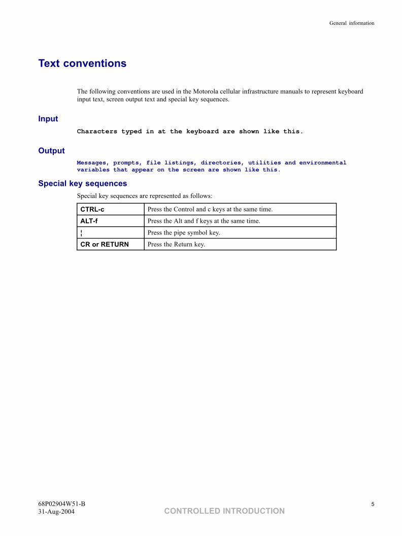
The following conventions are used in the Motorola cellular infrastructure manuals to represent keyboardinput text, screen output text and special key sequences.
InputCharacters typed in at the keyboard are shown like this.
OutputMessages, prompts, file listings, directories, utilities and environmentalvariables that appear on the screen are shown like this.
Special key sequencesSpecial key sequences are represented as follows:
CTRL-c Press the Control and c keys at the same time.
ALT-f Press the Alt and f keys at the same time.
¦ Press the pipe symbol key.
CR or RETURN Press the Return key.
68P02904W51-B 531-Aug-2004 CONTROLLED INTRODUCTION
Reporting safety issues
Reporting safety issues■ ■ ■ ■ ■ ■ ■ ■ ■ ■ ■ ■ ■ ■ ■ ■ ■ ■ ■ ■ ■ ■ ■ ■ ■ ■ ■ ■ ■ ■ ■ ■ ■ ■ ■ ■ ■ ■ ■ ■ ■ ■ ■ ■ ■
■
■
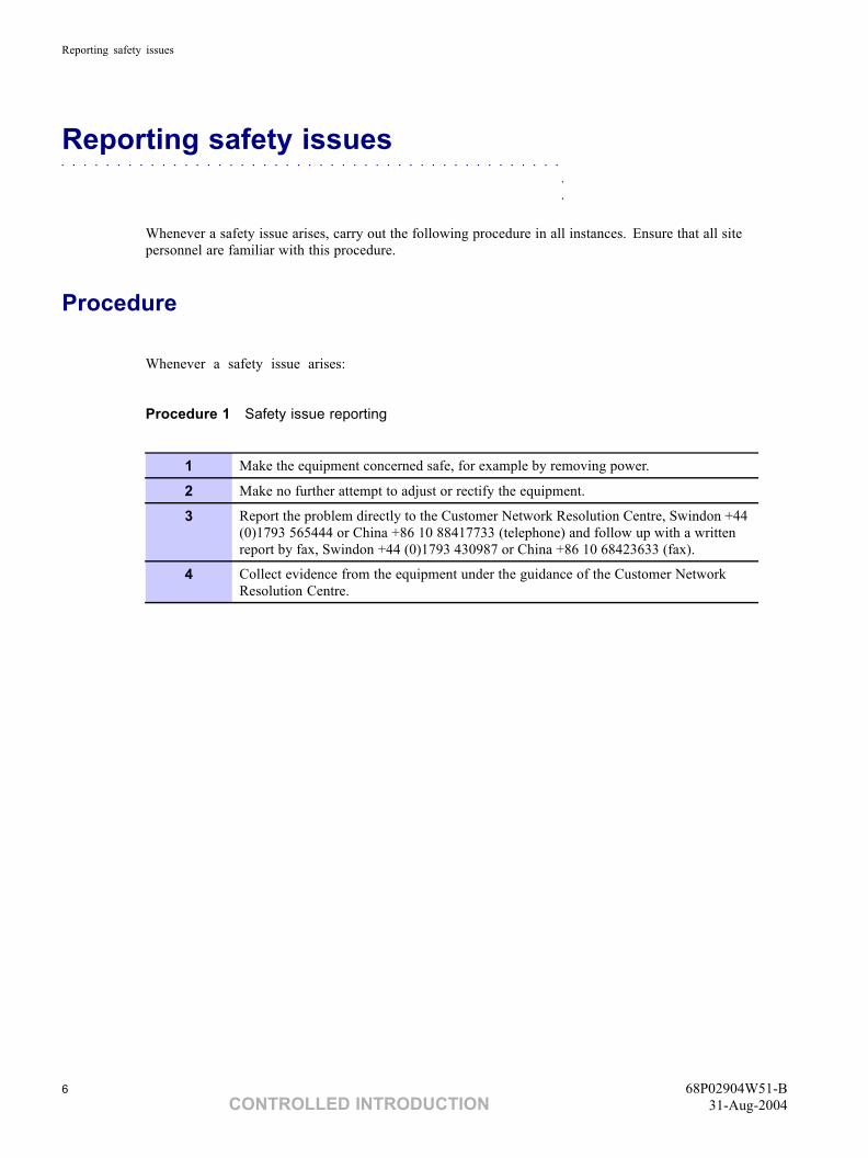
Whenever a safety issue arises, carry out the following procedure in all instances. Ensure that all sitepersonnel are familiar with this procedure.
Procedure
Whenever a safety issue arises:
Procedure 1 Safety issue reporting
1 Make the equipment concerned safe, for example by removing power.
2 Make no further attempt to adjust or rectify the equipment.
3 Report the problem directly to the Customer Network Resolution Centre, Swindon +44(0)1793 565444 or China +86 10 88417733 (telephone) and follow up with a writtenreport by fax, Swindon +44 (0)1793 430987 or China +86 10 68423633 (fax).
4 Collect evidence from the equipment under the guidance of the Customer NetworkResolution Centre.
6 68P02904W51-BCONTROLLED INTRODUCTION 31-Aug-2004
Warnings and cautions
Warnings and cautions■ ■ ■ ■ ■ ■ ■ ■ ■ ■ ■ ■ ■ ■ ■ ■ ■ ■ ■ ■ ■ ■ ■ ■ ■ ■ ■ ■ ■ ■ ■ ■ ■ ■ ■ ■ ■ ■ ■ ■ ■ ■ ■ ■ ■
■
■
The following describes how warnings and cautions are used in this manual and in all manuals of thisMotorola manual set.
Warnings
A definition and example follow below:
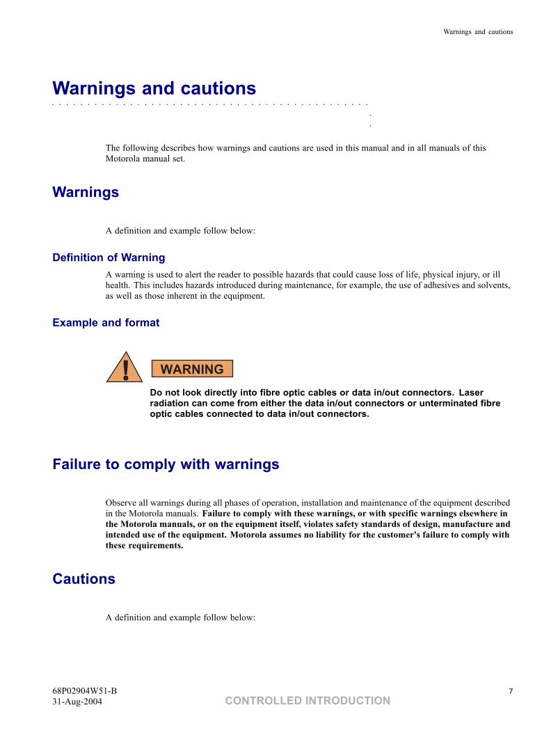
Definition of WarningA warning is used to alert the reader to possible hazards that could cause loss of life, physical injury, or illhealth. This includes hazards introduced during maintenance, for example, the use of adhesives and solvents,as well as those inherent in the equipment.
Example and format
Do not look directly into fibre optic cables or data in/out connectors. Laserradiation can come from either the data in/out connectors or unterminated fibreoptic cables connected to data in/out connectors.
Failure to comply with warnings
Observe all warnings during all phases of operation, installation and maintenance of the equipment describedin the Motorola manuals. Failure to comply with these warnings, or with specific warnings elsewhere inthe Motorola manuals, or on the equipment itself, violates safety standards of design, manufacture andintended use of the equipment. Motorola assumes no liability for the customer's failure to comply withthese requirements.
Cautions
A definition and example follow below:
68P02904W51-B 731-Aug-2004 CONTROLLED INTRODUCTION
Warnings and cautions
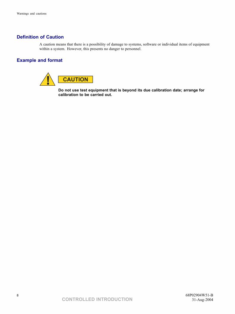
Definition of CautionA caution means that there is a possibility of damage to systems, software or individual items of equipmentwithin a system. However, this presents no danger to personnel.
Example and format
Do not use test equipment that is beyond its due calibration date; arrange forcalibration to be carried out.
8 68P02904W51-BCONTROLLED INTRODUCTION 31-Aug-2004
General warnings
General warnings■ ■ ■ ■ ■ ■ ■ ■ ■ ■ ■ ■ ■ ■ ■ ■ ■ ■ ■ ■ ■ ■ ■ ■ ■ ■ ■ ■ ■ ■ ■ ■ ■ ■ ■ ■ ■ ■ ■ ■ ■ ■ ■ ■ ■
■
■
Observe the following specific warnings during all phases of operation, installation and maintenance ofthe equipment described in the Motorola manuals:
• Potentially hazardous voltage.
• Electric shock.
• RF radiation.
• Laser radiation.
• Heavy equipment.
• Parts substitution.
• Battery supplies.
• Lithium batteries,
Failure to comply with these warnings, or with specific warnings elsewhere in the Motorola manuals, violatessafety standards of design, manufacture and intended use of the equipment. Motorola assumes no liability forthe customer's failure to comply with these requirements.
Warning labels
Warnings particularly applicable to the equipment are positioned on the equipment. Personnel working withor operating Motorola equipment must comply with any warning labels fitted to the equipment. Warninglabels must not be removed, painted over or obscured in any way.
Specific warnings
Specific warnings used throughout the GSM manual set are shown below and will be incorporated intoprocedures as applicable.
These must be observed by all personnel at all times when working with the equipment, as must any otherwarnings given in text, in the illustrations and on the equipment.
68P02904W51-B 931-Aug-2004 CONTROLLED INTRODUCTION
General warnings
Potentially hazardous voltage
This equipment operates from a potentially hazardous voltage of 230 V a.c. singlephase or 415 V a.c. three phase supply. To achieve isolation of the equipment fromthe a.c. supply, the a.c. input isolator must be set to off and locked.
When working with electrical equipment, reference must be made to the Electricity at Work Regulations 1989(UK), or to the relevant electricity at work legislation for the country in which the equipment is used.
Motorola GSM equipment does not utilise high voltages.
Electric shock
Do not touch the victim with your bare hands until the electric circuit is broken.Switch off. If this is not possible, protect yourself with dry insulating material andpull or push the victim clear of the conductor.ALWAYS send for trained first aid or medical assistance IMMEDIATELY.
In cases of low voltage electric shock (including public supply voltages), serious injuries and even death, mayresult. Direct electrical contact can stun a casualty causing breathing and even the heart, to stop. It can alsocause skin burns at the points of entry and exit of the current.
In the event of an electric shock it may be necessary to carry out artificial respiration. ALWAYS send fortrained first aid or medical assistance IMMEDIATELY.
If the casualty is also suffering from burns, flood the affected area with cold water to cool, until trainedfirst aid or medical assistance arrives.
10 68P02904W51-BCONTROLLED INTRODUCTION 31-Aug-2004
General warnings
RF radiation
High RF potentials and electromagnetic fields are present in this equipmentwhen in operation. Ensure that all transmitters are switched off when anyantenna connections have to be changed. Do not key transmitters connectedto unterminated cavities or feeders.
Relevant standards (USA and EC), to which regard should be paid when working with RF equipment are:
• ANSI IEEE C95.1-1991, IEEE Standard for Safety Levels with Respect to Human Exposure toRadio Frequency Electromagnetic Fields, 3 kHz to 300 GHz
• CENELEC 95 ENV 50166-2, Human Exposure to Electromagnetic Fields High Frequency (10kHz to 300 GHz).
Laser radiation
Do not look directly into fibre optic cables or optical data in/out connectors. Laserradiation can come from either the data in/out connectors or unterminated fibreoptic cables connected to data in/out connectors.
Lifting equipment
When dismantling heavy assemblies, or removing or replacing equipment, acompetent responsible person must ensure that adequate lifting facilities areavailable. Where provided, lifting frames must be used for these operations.
When dismantling heavy assemblies, or removing or replacing equipment, the competent responsible personmust ensure that adequate lifting facilities are available. Where provided, lifting frames must be used forthese operations. When equipment has to be manhandled, reference must be made to the Manual Handlingof Loads Regulations 1992 (UK) or to the relevant manual handling of loads legislation for the country inwhich the equipment is used.
68P02904W51-B 1131-Aug-2004 CONTROLLED INTRODUCTION
General warnings
Parts substitution
Do not install substitute parts or perform any unauthorized modification ofequipment, because of the danger of introducing additional hazards. ContactMotorola if in doubt to ensure that safety features are maintained.
Battery supplies
Do not wear earth straps when working with stand-by battery supplies. Useonly insulated tools.
Lithium batteries
Lithium batteries, if subjected to mistreatment, may burst and ignite. Defectivelithium batteries must not be removed or replaced. Any boards containingdefective lithium batteries must be returned to Motorola for repair.
Contact your local Motorola office for how to return defective lithium batteries.
12 68P02904W51-BCONTROLLED INTRODUCTION 31-Aug-2004
General cautions
General cautions■ ■ ■ ■ ■ ■ ■ ■ ■ ■ ■ ■ ■ ■ ■ ■ ■ ■ ■ ■ ■ ■ ■ ■ ■ ■ ■ ■ ■ ■ ■ ■ ■ ■ ■ ■ ■ ■ ■ ■ ■ ■ ■ ■ ■
■
■
Observe the following cautions during operation, installation and maintenance of the equipment describedin the Motorola manuals. Failure to comply with these cautions or with specific cautions elsewhere in theMotorola manuals may result in damage to the equipment. Motorola assumes no liability for the customer'sfailure to comply with these requirements.
Caution labels
Personnel working with or operating Motorola equipment must comply with any caution labels fitted to theequipment. Caution labels must not be removed, painted over or obscured in any way.
Specific cautions
Cautions particularly applicable to the equipment are positioned within the text of this manual. These must beobserved by all personnel at all times when working with the equipment, as must any other cautions givenin text, on the illustrations and on the equipment.
Fibre optics
Fibre optic cables must not be bent in a radius of less than 30 mm.
Static discharge
Motorola equipment contains CMOS devices. These metal oxide semiconductor(MOS) devices are susceptible to damage from electrostatic charge. See thesection Devices sensitive to static in the preface of this manual for furtherinformation.
68P02904W51-B 1331-Aug-2004 CONTROLLED INTRODUCTION
Devices sensitive to static
Devices sensitive to static■ ■ ■ ■ ■ ■ ■ ■ ■ ■ ■ ■ ■ ■ ■ ■ ■ ■ ■ ■ ■ ■ ■ ■ ■ ■ ■ ■ ■ ■ ■ ■ ■ ■ ■ ■ ■ ■ ■ ■ ■ ■ ■ ■ ■
■
■
Certain metal oxide semiconductor (MOS) devices embody in their design a thin layer of insulation that issusceptible to damage from electrostatic charge. Such a charge applied to the leads of the device couldcause irreparable damage.
These charges can be built up on nylon overalls, by friction, by inserting the hands into high insulationpacking material or by use of unearthed soldering irons.
MOS devices are normally despatched from the manufacturers with the leads short circuited together, forexample, by metal foil eyelets, wire strapping, or by inserting the leads into conductive plastic foam. Providedthe leads are short circuited it is safe to handle the device.
Special handling techniques
In the event of one of these devices having to be replaced, observe the following precautions when handlingthe replacement:
• Always wear an earth strap which must be connected to the electrostatic point (ESP) on theequipment.
• Leave the short circuit on the leads until the last moment. It may be necessary to replace theconductive foam by a piece of wire to enable the device to be fitted.
• Do not wear outer clothing made of nylon or similar man made material. A cotton overallis preferable.
• If possible work on an earthed metal surface or anti-static mat. Wipe insulated plastic worksurfaces with an anti-static cloth before starting the operation.
• All metal tools should be used and when not in use they should be placed on an earthed surface.
• Take care when removing components connected to electrostatic sensitive devices. Thesecomponents may be providing protection to the device.
When mounted onto printed circuit boards (PCBs), MOS devices are normally less susceptible to electrostaticdamage. However PCBs should be handled with care, preferably by their edges and not by their tracks andpins, they should be transferred directly from their packing to the equipment (or the other way around) andnever left exposed on the workbench.
14 68P02904W51-BCONTROLLED INTRODUCTION 31-Aug-2004
Motorola manual set
Motorola manual set■ ■ ■ ■ ■ ■ ■ ■ ■ ■ ■ ■ ■ ■ ■ ■ ■ ■ ■ ■ ■ ■ ■ ■ ■ ■ ■ ■ ■ ■ ■ ■ ■ ■ ■ ■ ■ ■ ■ ■ ■ ■ ■ ■ ■
■
■
The Motorola manual sets provide the information needed to operate, install and maintain the Motorolaequipment. Manuals for the GSM, GPRS and UMTS products are available on the following media:
• Printed hard copy.
• Electronic, as fully navigable PDF files on:◦ The Motorola customer support web site at:
(https://mynetworksupport.motorola.com/index.asp).
◦ CD-ROM produced in support of a major system software release.
Each CD-ROM includes all manuals related to a specified main GSM, GPRS or UMTS software release,together with current versions of appropriate hardware manuals and has additional navigation facilities. Asnapshot copy of on-line documentation is also included, though it will not be updated in line with subsequentpoint releases.
The CD-ROM does not include Release Notes or documentation supporting specialist products such asMARS or COP.
Ordering manuals and CD-ROMs
Use the Motorola 68Pxxxxxxxx order (catalogue) number to order hard copy manuals or CD-ROMs.
All orders must be placed with your Motorola Local Office or Representative.
68P02904W51-B 1531-Aug-2004 CONTROLLED INTRODUCTION
GMR amendment
GMR amendment■ ■ ■ ■ ■ ■ ■ ■ ■ ■ ■ ■ ■ ■ ■ ■ ■ ■ ■ ■ ■ ■ ■ ■ ■ ■ ■ ■ ■ ■ ■ ■ ■ ■ ■ ■ ■ ■ ■ ■ ■ ■ ■ ■ ■
■
■
Changes to a manual that occur after the printing date are incorporated into the manual using General ManualRevisions (GMRs). GMRs are issued to correct Motorola manuals as and when required. A GMR has thesame identity as the target manual. Each GMR is identified by a number in a sequence that starts at 01for each manual at each issue.
GMR availability
GMRs are published as follows:
• Printed hard copy - Complete replacement content or loose leaf pages with amendment list.◦ Remove and replace pages in this manual, as detailed on the GMR instruction sheet.
• Motorola service web - Updated at the same time as hard copies.
• CD-ROM - Updated periodically as required.
GMR instructions
When a GMR is inserted in this manual, the amendment record below is completed to record the GMR.Retain the instruction sheet that accompanies each GMR and insert it in a suitable place in this manual forfuture reference.
16 68P02904W51-BCONTROLLED INTRODUCTION 31-Aug-2004
GMR amendment
GMR amendment record
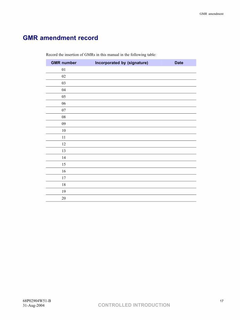
Record the insertion of GMRs in this manual in the following table:
GMR number Incorporated by (signature) Date01
02
03
04
05
06
07
08
09
10
11
12
13
14
15
16
17
18
19
20
68P02904W51-B 1731-Aug-2004 CONTROLLED INTRODUCTION

GMR amendment
This page intentionally left blank.
18 68P02904W51-BCONTROLLED INTRODUCTION 31-Aug-2004
Chapter
1Introduction■ ■ ■ ■ ■ ■ ■ ■ ■ ■ ■ ■ ■ ■ ■ ■ ■ ■ ■ ■ ■ ■ ■ ■ ■ ■ ■ ■ ■ ■ ■ ■ ■ ■ ■ ■ ■ ■ ■ ■ ■ ■ ■ ■ ■ ■
■
■
■
■
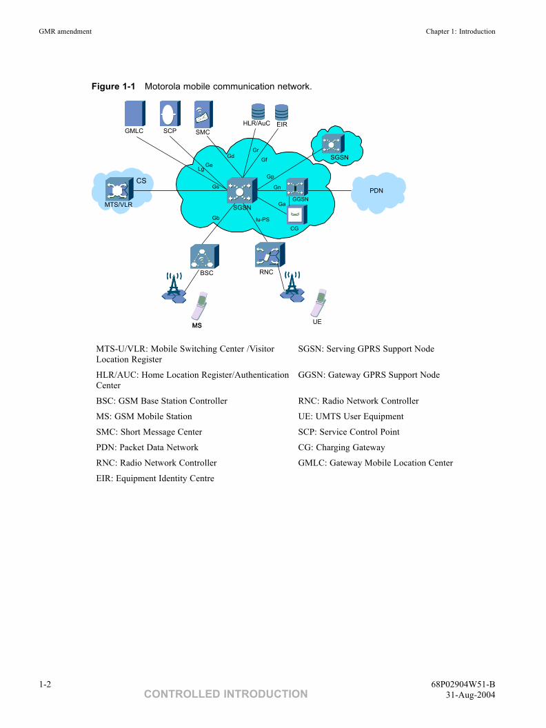
Motorola C-SGSN Serving GPRS Support Node (C-SGSN) is the GPRS/UMTS PS equipment of the CoreNetwork (CN). Its main functions include mobility management, session management, packet routing andtransfer, CDR generation and output, SMS, CAMEL, Legal Interception and QoS management.
Figure 1-1 illustrates the position of C-SGSN in Motorola's mobile communication network.
68P02904W51-B 1-131-Aug-2004 CONTROLLED INTRODUCTION
GMR amendment Chapter 1: Introduction
Figure 1-1 Motorola mobile communication network.
Iu-PS
Ga
Gn
Gp
Gf
GrGd
Gb
Gs
GeLg
GMLC SCP SMC
EIRHLR/AuC
SGSN
PDN
GGSN
SGSN
CG
MTS/VLR
CS
BSC RNC
MSMSUE
MTS-U/VLR: Mobile Switching Center /VisitorLocation Register
SGSN: Serving GPRS Support Node
HLR/AUC: Home Location Register/AuthenticationCenter
GGSN: Gateway GPRS Support Node
BSC: GSM Base Station Controller RNC: Radio Network Controller
MS: GSM Mobile Station UE: UMTS User Equipment
SMC: Short Message Center SCP: Service Control Point
PDN: Packet Data Network CG: Charging Gateway
RNC: Radio Network Controller GMLC: Gateway Mobile Location Center
EIR: Equipment Identity Centre
1-2 68P02904W51-BCONTROLLED INTRODUCTION 31-Aug-2004
System Information: C-SGSN Overview GMR amendment
The interfaces are described as follows.
• Gb interface (SGSN-BSC).
The Gb interface connects the BSS and the SGSN, allowing the exchange of signalinginformation and user data. The protocol stack consists of BSSGP, NS including FrameRelay (FR), and L1.
• Iu interface (SGSN-UTRAN).
The Iu interface connects the UTRAN and the Core Network packet domain, allowing theexchange of signaling information and user data. The user plane of Iu interface allowsthe user data from different subscribers to share the same physical resource. Resourcesare given to a subscriber upon activity (when data is sent or received) and are reallocatedimmediately thereafter.
In UMTS only subscriber data is transmitted on the shared physical medium. Signalingdata is transferred using SCCP connection.
• Gn/Gp interface (SGSN-GPRS Backbone).
The Gn/Gp interface allows the SGSN to communicate with the GSNs of the HPLMN (Gn)and VPLMN (Gp). Gn/Gp interface protocol stack consists of GPRS tunnelling protocol, UserDatagram Protocol (UDP), and Internet Protocol version 4 (IPv4).
• Gr interface (SGSN-HLR).
The Gr interface is a standard MAP interface between the SGSN and the HLR. The protocolstack of the Gr interface consists of MAP, TCAP, SCCP, and MTP.
The Gr interface is a MAP-based interface to the HLR. In the Gr interface, MAP version 3is supported.
• Gd interface (SGSN-SMS-MTS-G).
The Gd interface is a standard MAP interface between the SGSN and the SMS-MTS-G and theSMS-IWMSC. The protocol stack of the Gd interface consists of MAP, TCAP, SCCP, and MTP.
• Ge Interface(SGSN-SCP).
The Ge interface is a standard MAP interface between the SGSN and the SCP. The protocolstack of the Ge interface consists of CAP, TCAP, SCCP, and MTP.
• Gs interface (SGSN-MTS-U).
The Gs interface is a BSSAP+ based interface between the SGSN and the MTS-U/VLR.BSSAP+ runs on top of SCCP and MTP.
• Gf interface (SGSN-EIR).
The Gf interface is a standard MAP interface between the SGSN and the EIR. The protocolstack of the Gf interface consists of MAP, TCAP, SCCP, and MTP.
• SNMP interface (SGSN-NMS).
The Motorola C-SGSN provides the SNMP interface to the NMS which supports the SNMP.The physical port is Ethernet port.
68P02904W51-B 1-331-Aug-2004 CONTROLLED INTRODUCTION
GMR amendment Chapter 1: Introduction
• Ga Interface (SGSN-CG).
Ga interface is the charging data collection interface between a SGSN and a CDR receivingfunctionality (CGF). Ga interface protocol stack consists of GTP' protocol, User DatagramProtocol (UDP), and Internet Protocol version 4 (IPv4).GTP' is based on GTP withenhancements and additional message types.
• Lg Interface(SGSN-GMLC).
The Lg interface is a standard MAP interface between the SGSN and the GMLC. The protocolstack of the Lg interface consists of MAP, TCAP, SCCP, and MTP.
1-4 68P02904W51-BCONTROLLED INTRODUCTION 31-Aug-2004

Chapter
2System Characteristics■ ■ ■ ■ ■ ■ ■ ■ ■ ■ ■ ■ ■ ■ ■ ■ ■ ■ ■ ■ ■ ■ ■ ■ ■ ■ ■ ■ ■ ■ ■ ■ ■ ■ ■ ■ ■ ■ ■ ■ ■ ■ ■ ■ ■ ■
■
■
■
■
68P02904W51-B 2-131-Aug-2004 CONTROLLED INTRODUCTION
Overview Chapter 2: System Characteristics
Overview■ ■ ■ ■ ■ ■ ■ ■ ■ ■ ■ ■ ■ ■ ■ ■ ■ ■ ■ ■ ■ ■ ■ ■ ■ ■ ■ ■ ■ ■ ■ ■ ■ ■ ■ ■ ■ ■ ■ ■ ■ ■ ■ ■ ■ ■
■
■
Motorola C-SGSN is developed on Motorola's mature packet switched platform and is compliant withTL9000 and CE. It is a high-performance, highly reliable system, which is easy to operate and maintain. Thefollowing sections describe the features of Motorola C-SGSN hardware, interfaces, services and functions,operation and maintenance, and reliability.
2-2 68P02904W51-BCONTROLLED INTRODUCTION 31-Aug-2004
System Information: C-SGSN Overview Hardware Features
Hardware Features■ ■ ■ ■ ■ ■ ■ ■ ■ ■ ■ ■ ■ ■ ■ ■ ■ ■ ■ ■ ■ ■ ■ ■ ■ ■ ■ ■ ■ ■ ■ ■ ■ ■ ■ ■ ■ ■ ■ ■ ■ ■ ■ ■ ■ ■
■
■
Motorola C-SGSN has the following hardware features:
• Mature Wideband Packet Switching Platform.
Motorola C-SGSN adopts Motorola's mature wideband Packet Switching Platform, which canprovide IP/ATM integrated switching, with a capacity of 25 Gbit/s.
• Large Capacity and High Integrity.
Motorola C-SGSN can support 800,000 attached subscribers simultaneously. To support800,000 subscribers, it requires only three racks in the case of 3G system and only fourracks in the case of 2.5G system.
In this manual, GSM GPRS system is referred as 2.5G system and UMTS GPRS as3G system here after.
• High Speed Hardware Forwarding.
The user plane data of Motorola C-SGSN is forwarded using hardware, which improves theprocessing efficiency and integration of the system. It can support 480 Mbit/s traffic in caseof 2.5G system or 1.44 Gbit/s traffic in case of 3G system.
• Advanced Clock System.
Motorola C-SGSN clock synchronization system provides an enhanced 3-stratum clock tothe external network. It supports multiple synchronization modes including synchronizationthrough SDH optical interface, by BITS clock and by upper signaling network clock.Synchronization modes can be flexibly configured according to the actual networking situation.
68P02904W51-B 2-331-Aug-2004 CONTROLLED INTRODUCTION
Interface Features Chapter 2: System Characteristics
Interface Features■ ■ ■ ■ ■ ■ ■ ■ ■ ■ ■ ■ ■ ■ ■ ■ ■ ■ ■ ■ ■ ■ ■ ■ ■ ■ ■ ■ ■ ■ ■ ■ ■ ■ ■ ■ ■ ■ ■ ■ ■ ■ ■ ■ ■ ■
■
■
Motorola C-SGSN has the following interface features:
• Standard Network Interfaces.
Motorola C-SGSN supports standard network interfaces, including Iu-PS interface, Gsinterface, Gn/Gp interface, Gr interface, Gd interface, Ge interface, Gf interface, Ga interface,Gb interface and Lg interface.
• Abundant Physical Ports.
The lu-PS interface can be realized with ATM STM-1/STM-4. The Gn/Gp/Ga interfaces can berealized with ATM STM-1/STM-4, POS STM-4 and 10 M/100 M/1000 M Ethernet ports. TheGb/Gr/Gs/Gd/Ge/Lg interfaces can be realized with E1/T1 ports.
2-4 68P02904W51-BCONTROLLED INTRODUCTION 31-Aug-2004
System Information: C-SGSN Overview Services and Functions Features
Services and Functions Features■ ■ ■ ■ ■ ■ ■ ■ ■ ■ ■ ■ ■ ■ ■ ■ ■ ■ ■ ■ ■ ■ ■ ■ ■ ■ ■ ■ ■ ■ ■ ■ ■ ■ ■ ■ ■ ■ ■ ■ ■ ■ ■ ■ ■ ■
■
■
Motorola C-SGSN supports the following functions:
• Access for both 2.5G and 3G Subscribers.
Motorola C-SGSN supports the access for both 2.5G and 3G subscribers, as well as inter-RATroaming and handover and smooth transition between 2.5G and 3G.
• Multiple CAMEL triggering modes.
Motorola C-SGSN supports IMSI/MSISDN segment-based and CSI-based CAMEL servicetriggering modes.
• 2 Mbit/s signaling link.
In one 2 Mbit/s signaling link, N (N<=31) adjacent available timeslots can be used to transmitsignaling messages, which hence implements wider SS7 transmission bandwidth.
• Multiple signaling points.
Motorola C-SGSN can be configured with up to 16 Original Signaling Points (OSP). In thisway, up to 256 links can be configured between Motorola C-SGSN and one peer OSP. TheseOSPs can automatically share signaling loads.
• IP packet compression on Gb interface.
Motorola C-SGSN supports the IP header compression rules RFC1144 and RFC2507 as wellas the IP payload compression rule V.42bis.
• Gc interface signaling transfer.
Motorola C-SGSN supports the GTP-MAP protocol on Gn/Gp interface, and transfers Gcinterface messages from GGSN thus to implement the message exchange between GGSNand HLR.
• Multiple GGSN routes.
Motorola C-SGSN supports GGSN routes in the active/standby mode, those in the loadsharing mode and IMSI-based GGSN routes.
• MIP
Motorola C-SGSN can select the GGSN supporting Mobile IP (MIP) according to APNs.
• IPv6 PDP contexts.
Motorola C-SGSN supports the activation, deactivation and modification of IPv6 PDP contextsthat are carried on the GPRS and UMTS IPv4 backbone networks. It also supports CAMELswith IPv6 PDP addresses and lawful intercept.
• Multiple HPLMNs.
Motorola C-SGSN supports multiple HPLMNs, enabling the service providers with multiplePLMNs to reduce investment.
68P02904W51-B 2-531-Aug-2004 CONTROLLED INTRODUCTION
Services and Functions Features Chapter 2: System Characteristics
• Peer PLMN function.
Motorola C-SGSN can send a peer PLMN list to a terminal so that the terminal can select onePLMN from the list for access.
• IPSec function.
Motorola C-SGSN provides IPSec function for GTP-C signaling and supports ESP, AHand IKE protocols.
• Dynamic route protocols.
Motorola C-SGSN supports the dynamic route protocols Open Shortest Path First (OSPF) andRouting Information Protocol (RIP-2), implementing automatic Gn/Gp interface routing.
• Access Control List (ACL)-based packet filtering function.
Motorola C-SGSN can differentiate and process IP packets and control the access to it based onthe IP protocol quintuple, namely, source address, source port, destination address, destinationport and protocol type.
• Automatic detachment of inactive subscribers.
When a subscriber does not activate any PDP context in a specified duration, MotorolaC-SGSN detaches the subscriber and releases the resource occupied by it.
• Deactivation of idle PDP contexts.
If there is no traffic for a PDP context in a specified duration, Motorola C-SGSN deactivatesthe idle PDP context and releases the resource occupied by the subscriber.
• SuperCharger function.
The SuperCharger function is that Motorola C-SGSN does not delete the subscription dataof detached subscribers unless there is no space for new subscribers to access provided thatHLR does not modify the data.
• Roaming restriction.
Motorola C-SGSN can restrict subscribers' roaming in some areas according to IMSIs orarea codes.
• TOM
Tunnelling Of Messages (TOM) is an optional protocol layer between MS and SGSN, usedto transmit non-GSM signaling messages.
• EDGE
Enhanced Data Rate for GSM Evolution (EDGE) is a transition wireless network technologybetween 2.5G (GSM/GPRSS) and 3G (WCDMA). It enhances existing network technologiesand supports the maximum of 100 kbit/s data flows.
2-6 68P02904W51-BCONTROLLED INTRODUCTION 31-Aug-2004
System Information: C-SGSN Overview Services and Functions Features
• Setting of daylight savings time.
Motorola C-SGSN supports the setting of daylight savings time, satisfying the requirements onsystem time in different areas.
• NTP
Motorola C-SGSN realizes the Network Time Protocol (NTP) function. It periodically obtainsstandard time from the specified NTP Server and synchronizes its system time with thestandard time, thus to implement the synchronization between the system time and externalstandard time and to prevent great time difference.
68P02904W51-B 2-731-Aug-2004 CONTROLLED INTRODUCTION
Easy Operation and Maintenance Chapter 2: System Characteristics
Easy Operation and Maintenance■ ■ ■ ■ ■ ■ ■ ■ ■ ■ ■ ■ ■ ■ ■ ■ ■ ■ ■ ■ ■ ■ ■ ■ ■ ■ ■ ■ ■ ■ ■ ■ ■ ■ ■ ■ ■ ■ ■ ■ ■ ■ ■ ■ ■ ■
■
■
Motorola C-SGSN provides easy operation and maintenance.
• Multiple and flexible management methods.
Network management system can be flexibly constructed according to network architecture,management requirement and investment amount. Multiple maintenance interfaces aresupported, such as Local Manager (LM) interface, SNMP interface, Motorola centralized NMsystem OMC-S/T 2.0 interface and CORBA interface with OMC-S/T 2.0 supporting.
• Friendly GUI.
It provides O&M interfaces with unique navigation tree technology, which combines the meritsof both MML and GUI. It also provides real and graphic equipment panel for visual operations.
• Signaling tracing, interface tracing and message explanation function.
It provides standard interface tracing, such as the tracing of Iu, Gb, Gs and Gr interfaces, andsingle subscriber tracing, including tracing the data packet sent by the subscriber. It canflexibly filter messages. For example, it can trace only the MTP3 message from certainsignaling point, and provide detailed explanations of tracing result.
• Software Patching Function
Most software problems can be solved online without affecting system services throughsoftware patching function. Software patching can be remotely performed and software can beeasily recovered to the state before software patching is made if necessary, therefore, softwareupdating cost and risks can be greatly reduced.
2-8 68P02904W51-BCONTROLLED INTRODUCTION 31-Aug-2004
System Information: C-SGSN Overview High Reliability
High Reliability■ ■ ■ ■ ■ ■ ■ ■ ■ ■ ■ ■ ■ ■ ■ ■ ■ ■ ■ ■ ■ ■ ■ ■ ■ ■ ■ ■ ■ ■ ■ ■ ■ ■ ■ ■ ■ ■ ■ ■ ■ ■ ■ ■ ■ ■
■
■
Motorola C-SGSN introduces high reliability design.
• Backup of important data.
For example, the equipment operation parameters, performance measurement information,operator information, administrator information and operation logs can be backed up tohard disk.
• Operation security management.
Different equipment management authorities are assigned for different users. Strict useridentity check is performed upon user's login and comprehensive operation log is recordedafter user's login to ensure system security.
• Supporting CG redirecting and CDR cache function.
When there are communication faults between Motorola C-SGSN and CG, Motorola C-SGSNwill automatically send CDRs to the backup CG. In this case, if the backup CG is alsoabnormal, Motorola C-SGSN will store CDRs in the hard disk.
• Supporting hardware redundancy design to guarantee the system reliability.
The wideband packet switched platform of Motorola C-SGSN provides hardware redundancybackup for the critical components, such as important boards, clocks, optical interfaces andlinks. And most system resources are also shared and backed up by system software.
• Automatic fault detection and self-recovery mechanism.
Motorola C-SGSN can automatically detect hardware and software faults. When importantcomponents get faulty, alarm information will be generated, and active/standby switchoveris executed.
• Supporting protection function from exceptions.
Motorola C-SGSN supports system power-off protection, system power switch misoperationprotection, system power anti-lightning protection, high-voltage and under-voltage protection,power short-circuit protection, system E1 link lightning protection, power and interfaceover-current and high-voltage protection and so on.
• Supporting system overload control.
The traffic can be adjusted smoothly to prevent system failure when CPU overload andresource congestion occur.
• Supporting the function of locking boards and shutting down the system
This function ensures that services being processed by a board or the system can be stoppedunhurriedly if necessary, thus preventing the services from being interrupted abruptly.
68P02904W51-B 2-931-Aug-2004 CONTROLLED INTRODUCTION

High Reliability Chapter 2: System Characteristics
This page intentionally left blank.
2-10 68P02904W51-BCONTROLLED INTRODUCTION 31-Aug-2004
Chapter
3System Architecture■ ■ ■ ■ ■ ■ ■ ■ ■ ■ ■ ■ ■ ■ ■ ■ ■ ■ ■ ■ ■ ■ ■ ■ ■ ■ ■ ■ ■ ■ ■ ■ ■ ■ ■ ■ ■ ■ ■ ■ ■ ■ ■ ■ ■ ■
■
■
■
■
68P02904W51-B 3-131-Aug-2004 CONTROLLED INTRODUCTION

Overview Chapter 3: System Architecture
Overview■ ■ ■ ■ ■ ■ ■ ■ ■ ■ ■ ■ ■ ■ ■ ■ ■ ■ ■ ■ ■ ■ ■ ■ ■ ■ ■ ■ ■ ■ ■ ■ ■ ■ ■ ■ ■ ■ ■ ■ ■ ■ ■ ■ ■ ■
■
■
This chapter describes the hardware, software and logical structures of the Motorola C-SGSN system.
3-2 68P02904W51-BCONTROLLED INTRODUCTION 31-Aug-2004
System Information: C-SGSN Overview Hardware Architecture
Hardware Architecture■ ■ ■ ■ ■ ■ ■ ■ ■ ■ ■ ■ ■ ■ ■ ■ ■ ■ ■ ■ ■ ■ ■ ■ ■ ■ ■ ■ ■ ■ ■ ■ ■ ■ ■ ■ ■ ■ ■ ■ ■ ■ ■ ■ ■ ■
■
■
The Motorola C-SGSN hardware system comprises cabinets, subracks and boards. Figure 3-1 illustrates theappearance and dimension of the Motorola C-SGSN cabinet.
68P02904W51-B 3-331-Aug-2004 CONTROLLED INTRODUCTION
Hardware Architecture Chapter 3: System Architecture
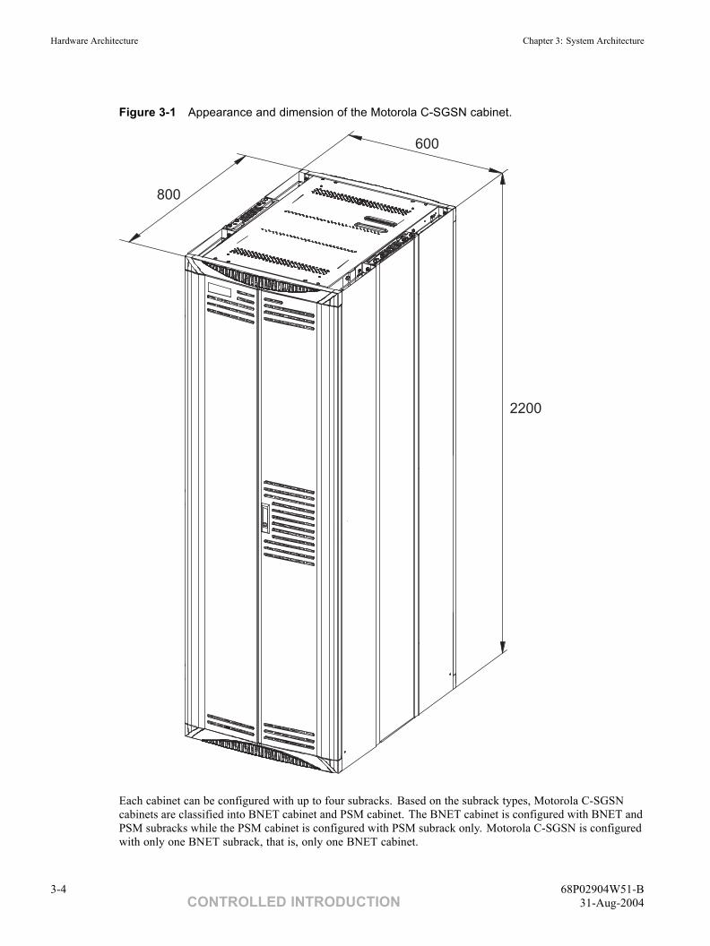
Figure 3-1 Appearance and dimension of the Motorola C-SGSN cabinet.
800
600
2200
Each cabinet can be configured with up to four subracks. Based on the subrack types, Motorola C-SGSNcabinets are classified into BNET cabinet and PSM cabinet. The BNET cabinet is configured with BNET andPSM subracks while the PSM cabinet is configured with PSM subrack only. Motorola C-SGSN is configuredwith only one BNET subrack, that is, only one BNET cabinet.
3-4 68P02904W51-BCONTROLLED INTRODUCTION 31-Aug-2004
System Information: C-SGSN Overview Hardware Architecture
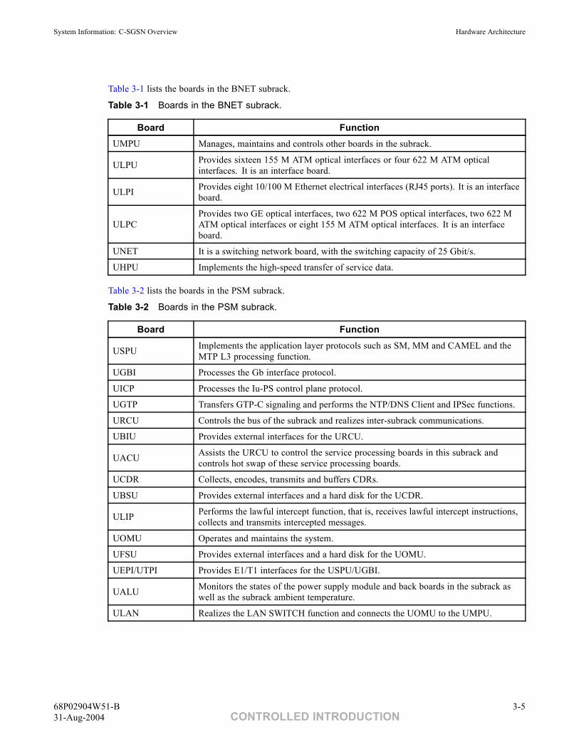
Table 3-1 lists the boards in the BNET subrack.
Table 3-1 Boards in the BNET subrack.
Board FunctionUMPU Manages, maintains and controls other boards in the subrack.
ULPU Provides sixteen 155 M ATM optical interfaces or four 622 M ATM opticalinterfaces. It is an interface board.
ULPI Provides eight 10/100 M Ethernet electrical interfaces (RJ45 ports). It is an interfaceboard.
ULPCProvides two GE optical interfaces, two 622 M POS optical interfaces, two 622 MATM optical interfaces or eight 155 M ATM optical interfaces. It is an interfaceboard.
UNET It is a switching network board, with the switching capacity of 25 Gbit/s.
UHPU Implements the high-speed transfer of service data.
Table 3-2 lists the boards in the PSM subrack.
Table 3-2 Boards in the PSM subrack.
Board Function
USPU Implements the application layer protocols such as SM, MM and CAMEL and theMTP L3 processing function.
UGBI Processes the Gb interface protocol.
UICP Processes the Iu-PS control plane protocol.
UGTP Transfers GTP-C signaling and performs the NTP/DNS Client and IPSec functions.
URCU Controls the bus of the subrack and realizes inter-subrack communications.
UBIU Provides external interfaces for the URCU.
UACU Assists the URCU to control the service processing boards in this subrack andcontrols hot swap of these service processing boards.
UCDR Collects, encodes, transmits and buffers CDRs.
UBSU Provides external interfaces and a hard disk for the UCDR.
ULIP Performs the lawful intercept function, that is, receives lawful intercept instructions,collects and transmits intercepted messages.
UOMU Operates and maintains the system.
UFSU Provides external interfaces and a hard disk for the UOMU.
UEPI/UTPI Provides E1/T1 interfaces for the USPU/UGBI.
UALU Monitors the states of the power supply module and back boards in the subrack aswell as the subrack ambient temperature.
ULAN Realizes the LAN SWITCH function and connects the UOMU to the UMPU.
68P02904W51-B 3-531-Aug-2004 CONTROLLED INTRODUCTION
Software Architecture Chapter 3: System Architecture
Software Architecture■ ■ ■ ■ ■ ■ ■ ■ ■ ■ ■ ■ ■ ■ ■ ■ ■ ■ ■ ■ ■ ■ ■ ■ ■ ■ ■ ■ ■ ■ ■ ■ ■ ■ ■ ■ ■ ■ ■ ■ ■ ■ ■ ■ ■ ■
■
■
The Motorola C-SGSN system software is designed following software engineering requirements, and adoptsthe hierarchical modular programming method. The protocol software adopts the protocol engineeringmethods. Its development procedures include protocol description, inspection, implementation and testingphases. The Specification and Description Language (SDL) recommended by ITU-T is adopted to support thehierarchical, modular and structural software development. The strict and standard software developmentprocess makes it easy to understand and maintain the codes of the software.
The Motorola C-SGSN software refers to the programs running on the processing boards in the PSM subrackand the BNET subrack. Physically, Motorola C-SGSN is a distributed system with each board running adifferent software system. Each of the board software is a part of the platform software and the GPRSspecific protocol software.
The Motorola C-SGSN software adopts the modular structure. Each function is enabled by an independentmodule. The software includes two parts, the platform software module and GPRS software module. Theformer is built up by the following functional parts: TCP/IP protocol processing module, operating systemmodule, database management module, system maintenance module, alarm management module, equipmentmanagement module and system error tolerance module. The latter comprises interface protocol processing,such as Iu-Ps,Gb,Gn/Gp, and so on, and service processing , such as MM/SM, SMS, CAMEL, LCS and so on.
3-6 68P02904W51-BCONTROLLED INTRODUCTION 31-Aug-2004
System Information: C-SGSN Overview Logical Architecture
Logical Architecture■ ■ ■ ■ ■ ■ ■ ■ ■ ■ ■ ■ ■ ■ ■ ■ ■ ■ ■ ■ ■ ■ ■ ■ ■ ■ ■ ■ ■ ■ ■ ■ ■ ■ ■ ■ ■ ■ ■ ■ ■ ■ ■ ■ ■ ■
■
■
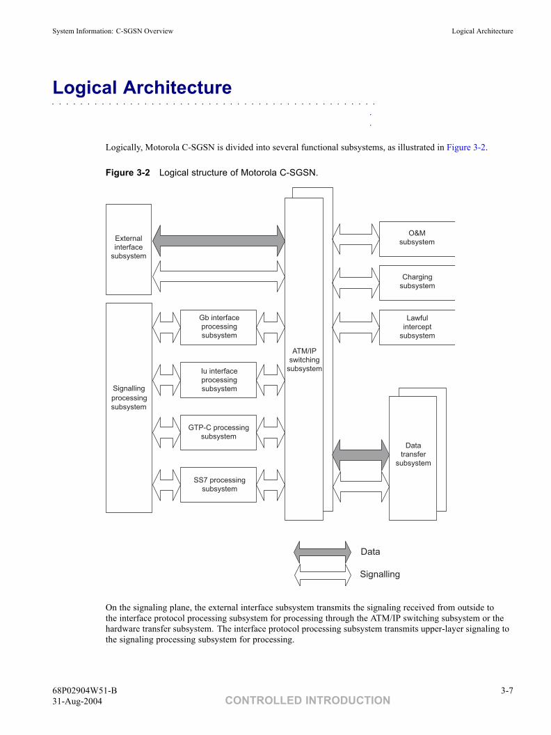
Logically, Motorola C-SGSN is divided into several functional subsystems, as illustrated in Figure 3-2.
Figure 3-2 Logical structure of Motorola C-SGSN.
ATM
/
IP
Signalling
processing
subsystem
External
interface
subsystem
Gb interface
processing
subsystem
Iu interface
processing
subsystem
GTP-C processing
subsystem
SS7 processing
subsystem
ATM/IP
switching
subsystem
O&M
subsystem
Charging
subsystem
Lawful
intercept
subsystem
Data
transfer
subsystem
Data
Signalling
On the signaling plane, the external interface subsystem transmits the signaling received from outside tothe interface protocol processing subsystem for processing through the ATM/IP switching subsystem or thehardware transfer subsystem. The interface protocol processing subsystem transmits upper-layer signaling tothe signaling processing subsystem for processing.
68P02904W51-B 3-731-Aug-2004 CONTROLLED INTRODUCTION
Hardware Configuration Chapter 3: System Architecture
Hardware Configuration■ ■ ■ ■ ■ ■ ■ ■ ■ ■ ■ ■ ■ ■ ■ ■ ■ ■ ■ ■ ■ ■ ■ ■ ■ ■ ■ ■ ■ ■ ■ ■ ■ ■ ■ ■ ■ ■ ■ ■ ■ ■ ■ ■ ■ ■
■
■
Depending on the service requirement and user number, Motorola C-SGSN delivers various cabinet layoutsand subrack configurations. As these service board slots are compatible with each other, the hardware parts ofMotorola C-SGSN can be configured flexibly. This section describes several typical configurations.
2.5G Configuration
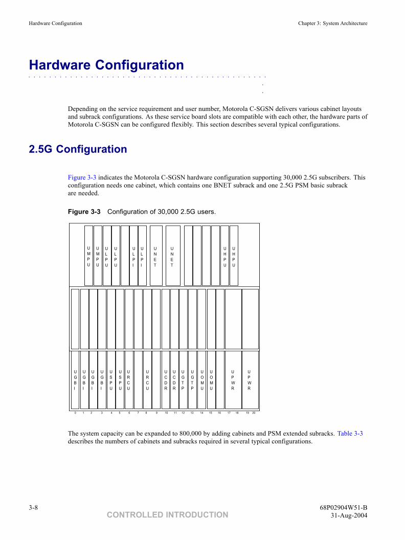
Figure 3-3 indicates the Motorola C-SGSN hardware configuration supporting 30,000 2.5G subscribers. Thisconfiguration needs one cabinet, which contains one BNET subrack and one 2.5G PSM basic subrackare needed.
Figure 3-3 Configuration of 30,000 2.5G users.
PWS
0 1 2 3 4 5 6 7 8 9 10 11 12 13 14 15 16 17 18 19 20
UGBI
UGBI
UGBI
UGBI
URCU
URCU
UCDR
UGTP
UGTP
UOMU
UOMU
UCDR
UPWR
UPWR
USPU
USPU
PWS
UMPU
UMPU
ULPU
ULPU
ULPI
UHPU
ULPI
UHPU
UNET
UNET
The system capacity can be expanded to 800,000 by adding cabinets and PSM extended subracks. Table 3-3describes the numbers of cabinets and subracks required in several typical configurations.
3-8 68P02904W51-BCONTROLLED INTRODUCTION 31-Aug-2004
System Information: C-SGSN Overview Hardware Configuration
Table 3-3 2.5G configurations in different capacities.
30,000 100,000 200,000 400,000 800,000Cabinet 1 2 2 3 4
Subrack 2 4 5 9 15
3G Configuration
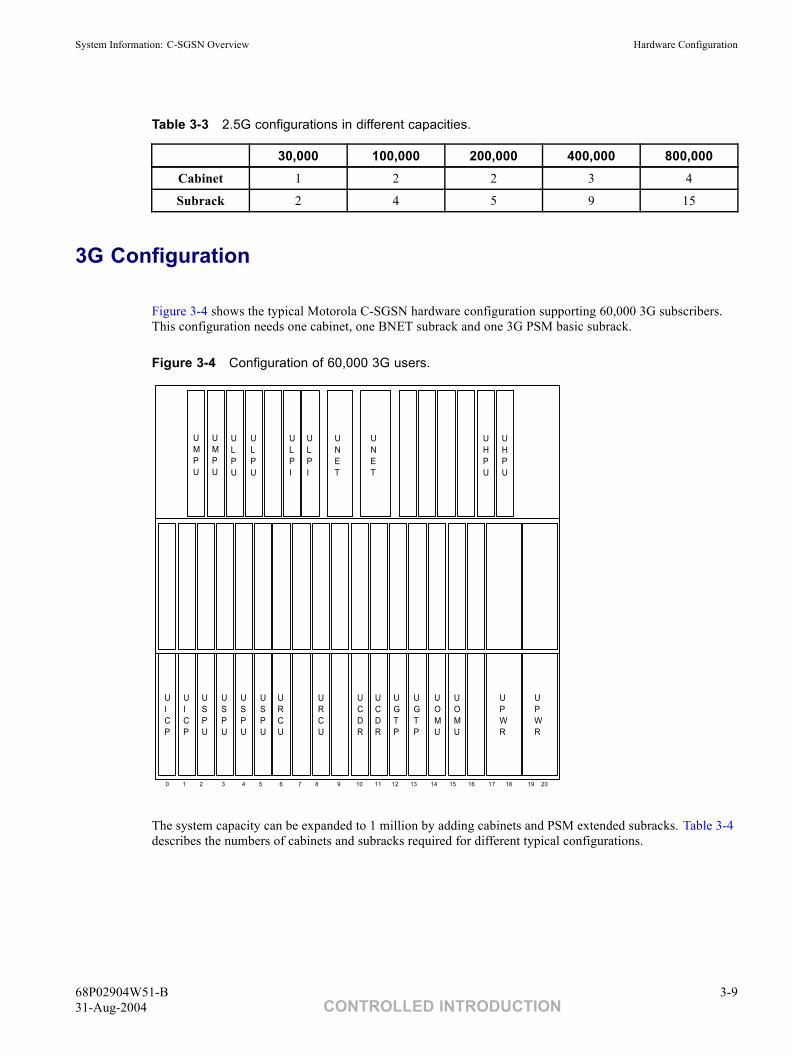
Figure 3-4 shows the typical Motorola C-SGSN hardware configuration supporting 60,000 3G subscribers.This configuration needs one cabinet, one BNET subrack and one 3G PSM basic subrack.
Figure 3-4 Configuration of 60,000 3G users.
PWS
0 1 2 3 4 5 6 7 8 9 10 11 12 13 14 15 16 17 18 19 20
UICP
UICP
USPU
USPU
URCU
URCU
UCDR
UGTP
UGTP
UOMU
UOMU
UCDR
UPWR
UPWR
USPU
USPU
PWS
UMPU
UMPU
ULPU
ULPU
ULPI
UHPU
ULPI
UHPU
UNET
UNET
The system capacity can be expanded to 1 million by adding cabinets and PSM extended subracks. Table 3-4describes the numbers of cabinets and subracks required for different typical configurations.
68P02904W51-B 3-931-Aug-2004 CONTROLLED INTRODUCTION
Hardware Configuration Chapter 3: System Architecture
Table 3-4 3G configurations in different capacities.
60,000 100,000 200,000 400,000 800,000Cabinet 1 1 2 2 3
Subrack 2 3 4 5 9
2.5G-3G-Combined Configuration
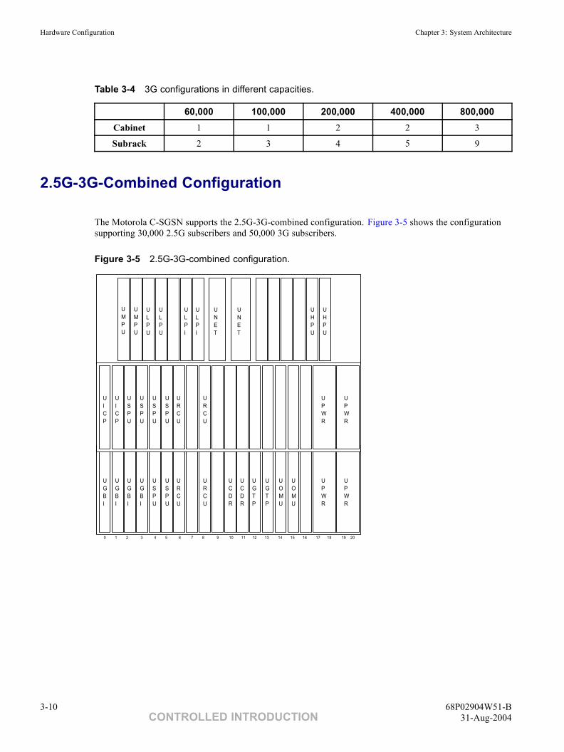
The Motorola C-SGSN supports the 2.5G-3G-combined configuration. Figure 3-5 shows the configurationsupporting 30,000 2.5G subscribers and 50,000 3G subscribers.
Figure 3-5 2.5G-3G-combined configuration.
PWS
0 1 2 3 4 5 6 7 8 9 10 11 12 13 14 15 16 17 18 19 20
UGBI
UGBI
UGBI
UGBI
URCU
URCU
UCDR
UGTP
UGTP
UOMU
UOMU
UCDR
UPWR
UPWR
USPU
USPU
PWS
UMPU
UMPU
ULPU
ULPU
ULPI
UHPU
ULPI
UHPU
UNET
UNET
UICP
UICP
USPU
USPU
URCU
URCU
UPWR
UPWR
USPU
USPU
3-10 68P02904W51-BCONTROLLED INTRODUCTION 31-Aug-2004
Chapter
4Services and Functions■ ■ ■ ■ ■ ■ ■ ■ ■ ■ ■ ■ ■ ■ ■ ■ ■ ■ ■ ■ ■ ■ ■ ■ ■ ■ ■ ■ ■ ■ ■ ■ ■ ■ ■ ■ ■ ■ ■ ■ ■ ■ ■ ■ ■ ■
■
■
■
■
68P02904W51-B 4-131-Aug-2004 CONTROLLED INTRODUCTION
Overview Chapter 4: Services and Functions
Overview■ ■ ■ ■ ■ ■ ■ ■ ■ ■ ■ ■ ■ ■ ■ ■ ■ ■ ■ ■ ■ ■ ■ ■ ■ ■ ■ ■ ■ ■ ■ ■ ■ ■ ■ ■ ■ ■ ■ ■ ■ ■ ■ ■ ■ ■
■
■
This chapter describes the services and functions provided by Motorola C-SGSN, including mobilitymanagement, session management, packet routing and transfer, charging, lawful intercept and QoSmanagement functions as well as Short Message (SM) and CAMEL services.
4-2 68P02904W51-BCONTROLLED INTRODUCTION 31-Aug-2004
System Information: C-SGSN Overview Mobility Management
Mobility Management■ ■ ■ ■ ■ ■ ■ ■ ■ ■ ■ ■ ■ ■ ■ ■ ■ ■ ■ ■ ■ ■ ■ ■ ■ ■ ■ ■ ■ ■ ■ ■ ■ ■ ■ ■ ■ ■ ■ ■ ■ ■ ■ ■ ■ ■
■
■
The Mobility Management (MM) activities related to a subscriber are characterized by one of three differentMM states. In GSM, the MM states for a GPRS subscriber are IDLE, STANDBY, and READY. In UMTS, theMM states for a GPRS subscriber are PMM-DETACHED, PMM-IDLE, and PMM-CONNECTED. Eachstate describes a certain level of functionality and information allocated. The information sets in the MSand the SGSN are denoted MM context.
Motorola C-SGSN supports the following by MM functions:
GPRS Attach Function
• Detach Function.
• Location Management Function.
• Paging Function.
• Purge Function.
• MS Information Function.
• Security Management Function.
• Subscriber Management Function.
• Supercharger Function.
• GSM/UMTS Inter-RAT Change Function.
• Service Request Function (3G).
68P02904W51-B 4-331-Aug-2004 CONTROLLED INTRODUCTION
Session Management Chapter 4: Services and Functions
Session Management■ ■ ■ ■ ■ ■ ■ ■ ■ ■ ■ ■ ■ ■ ■ ■ ■ ■ ■ ■ ■ ■ ■ ■ ■ ■ ■ ■ ■ ■ ■ ■ ■ ■ ■ ■ ■ ■ ■ ■ ■ ■ ■ ■ ■ ■
■
■
Session Management (SM) function manages the PDP context of MS.
Motorola C-SGSN supports the following SM procedures:
• PDP context activation procedure.
• PDP context deactivation procedure.
• PDP context modification procedure.
• PDP context preservation procedure (3G).
4-4 68P02904W51-BCONTROLLED INTRODUCTION 31-Aug-2004
System Information: C-SGSN Overview Packet Routing and Transfer Functions
Packet Routing and Transfer Functions■ ■ ■ ■ ■ ■ ■ ■ ■ ■ ■ ■ ■ ■ ■ ■ ■ ■ ■ ■ ■ ■ ■ ■ ■ ■ ■ ■ ■ ■ ■ ■ ■ ■ ■ ■ ■ ■ ■ ■ ■ ■ ■ ■ ■ ■
■
■
SGSN performs routing and forwarding of service data between MS and GGSN.
• Routing.
For SGSN, routing is to confirm the IP address of GGSN. SGSN resolves the IP address ofGGSN according to the APN in a PDP context activation.
Motorola C-SGSN performs resolutions through a DNS Server, HOST FILE or the localCACHE. In addition, Motorola C-SGSN can search the IP address of the GGSN supportingMIP and DHCP according to configuration information.
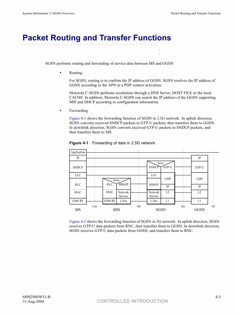
• Forwarding.
Figure 4-1 shows the forwarding function of SGSN in 2.5G network. In uplink direction,SGSN converts received SNDCP packets to GTP-U packets, then transfers them to GGSN.In downlink direction, SGSN converts received GTP-U packets to SNDCP packets, andthen transfers them to MS.
Figure 4-1 Forwarding of data in 2.5G network.
Relay
NetworkService
GTP-U
Application
IP
SNDCP
LLC
RLC
MAC
GSM RF
SNDCP
LLC
BSSGP
L1bis
RLC
MAC
GSM RF
BSSGP
L1bis
Relay
L2
L1
IP
L2
L1
IP
GTP-U
IP
Um Gb Gn GiMS BSS SGSN GGSN
NetworkService
UDPUDP
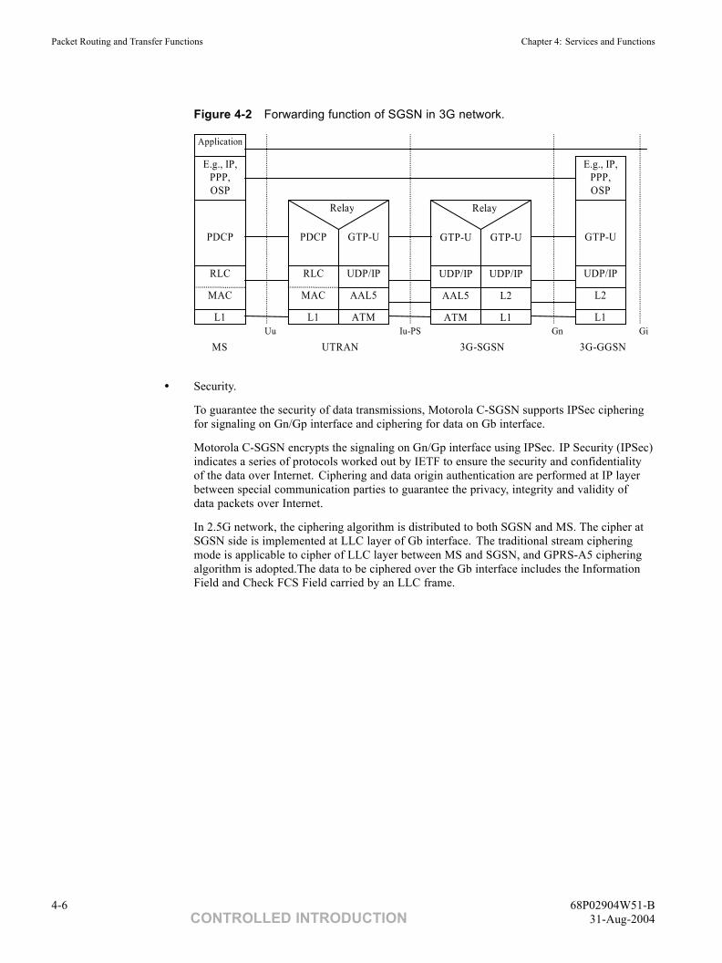
Figure 4-2 shows the forwarding function of SGSN in 3G network. In uplink direction, SGSNreceives GTP-U data packets from RNC, then transfers them to GGSN. In downlink direction,SGSN receives GTP-U data packets from GGSN, and transfers them to RNC.
68P02904W51-B 4-531-Aug-2004 CONTROLLED INTRODUCTION
Packet Routing and Transfer Functions Chapter 4: Services and Functions
Figure 4-2 Forwarding function of SGSN in 3G network.
L1
RLC
PDCP
MAC
E.g., IP,PPP,OSP
Application
L1
RLC
PDCP
MAC
ATM
UDP/IP
GTP-U
AAL5
Relay
L1
UDP/IP
L2
GTP-U
E.g., IP,PPP,OSP
3G-SGSNUTRANMSIu-PSUu Gn Gi
3G-GGSN
ATM
UDP/IP
GTP-U
AAL5
L1
UDP/IP
GTP-U
L2
Relay
• Security.
To guarantee the security of data transmissions, Motorola C-SGSN supports IPSec cipheringfor signaling on Gn/Gp interface and ciphering for data on Gb interface.
Motorola C-SGSN encrypts the signaling on Gn/Gp interface using IPSec. IP Security (IPSec)indicates a series of protocols worked out by IETF to ensure the security and confidentialityof the data over Internet. Ciphering and data origin authentication are performed at IP layerbetween special communication parties to guarantee the privacy, integrity and validity ofdata packets over Internet.
In 2.5G network, the ciphering algorithm is distributed to both SGSN and MS. The cipher atSGSN side is implemented at LLC layer of Gb interface. The traditional stream cipheringmode is applicable to cipher of LLC layer between MS and SGSN, and GPRS-A5 cipheringalgorithm is adopted.The data to be ciphered over the Gb interface includes the InformationField and Check FCS Field carried by an LLC frame.
4-6 68P02904W51-BCONTROLLED INTRODUCTION 31-Aug-2004
System Information: C-SGSN Overview Charging Functions
Charging Functions■ ■ ■ ■ ■ ■ ■ ■ ■ ■ ■ ■ ■ ■ ■ ■ ■ ■ ■ ■ ■ ■ ■ ■ ■ ■ ■ ■ ■ ■ ■ ■ ■ ■ ■ ■ ■ ■ ■ ■ ■ ■ ■ ■ ■ ■
■
■
Charging information is collected for the GPRS subscriber.
Motorola C-SGSN shall collect the following charging information for MSs and/or individual PDP contextsthat are subject to charging:
• Usage of the radio interface.
The charging information shall describe the amount of data transmitted in MO and MTdirections categorised with QoS and user protocols;
• Usage of the packet data protocol addresses.
The charging information shall describe how long the MS has used the packet data protocoladdresses;
• Usage of the general packet domain resources.
The charging information shall describe the usage of other packet domain-related resourcesand the MS's network activity (for example, mobility management); and
• Location of MS.
HPLMN, VPLMN, plus optional higher-accuracy location information.
68P02904W51-B 4-731-Aug-2004 CONTROLLED INTRODUCTION
Short Message Service Chapter 4: Services and Functions
Short Message Service■ ■ ■ ■ ■ ■ ■ ■ ■ ■ ■ ■ ■ ■ ■ ■ ■ ■ ■ ■ ■ ■ ■ ■ ■ ■ ■ ■ ■ ■ ■ ■ ■ ■ ■ ■ ■ ■ ■ ■ ■ ■ ■ ■ ■ ■
■
■
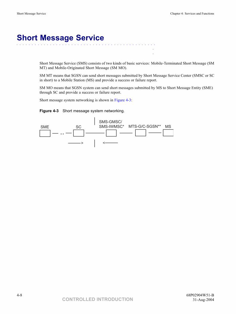
Short Message Service (SMS) consists of two kinds of basic services: Mobile-Terminated Short Message (SMMT) and Mobile-Originated Short Message (SM MO).
SM MT means that SGSN can send short messages submitted by Short Message Service Center (SMSC or SCin short) to a Mobile Station (MS) and provide a success or failure report.
SM MO means that SGSN system can send short messages submitted by MS to Short Message Entity (SME)through SC and provide a success or failure report.
Short message system networking is shown in Figure 4-3:
Figure 4-3 Short message system networking.
SME SC
SMS-GMSC/
SMS-IWMSC* MTS-G/C-SGSN** MS
<>
4-8 68P02904W51-BCONTROLLED INTRODUCTION 31-Aug-2004
System Information: C-SGSN Overview Location Services
Location Services■ ■ ■ ■ ■ ■ ■ ■ ■ ■ ■ ■ ■ ■ ■ ■ ■ ■ ■ ■ ■ ■ ■ ■ ■ ■ ■ ■ ■ ■ ■ ■ ■ ■ ■ ■ ■ ■ ■ ■ ■ ■ ■ ■ ■ ■
■
■
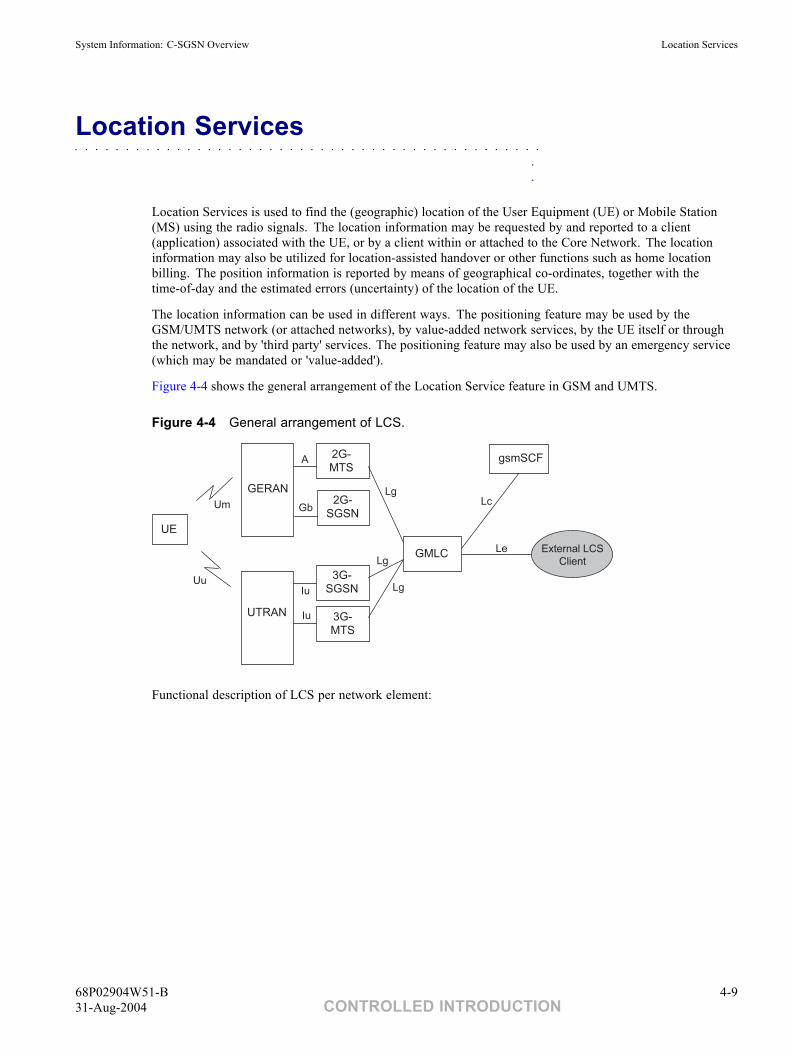
Location Services is used to find the (geographic) location of the User Equipment (UE) or Mobile Station(MS) using the radio signals. The location information may be requested by and reported to a client(application) associated with the UE, or by a client within or attached to the Core Network. The locationinformation may also be utilized for location-assisted handover or other functions such as home locationbilling. The position information is reported by means of geographical co-ordinates, together with thetime-of-day and the estimated errors (uncertainty) of the location of the UE.
The location information can be used in different ways. The positioning feature may be used by theGSM/UMTS network (or attached networks), by value-added network services, by the UE itself or throughthe network, and by 'third party' services. The positioning feature may also be used by an emergency service(which may be mandated or 'value-added').
Figure 4-4 shows the general arrangement of the Location Service feature in GSM and UMTS.
Figure 4-4 General arrangement of LCS.
Gb
2G-
MTS
GERAN
UE
Lg
A
Lc
Le
Iu
Iu
Lg
Um
Uu
2G-
SGSN
3G-
SGSN
3G-
MTS
External LCS
Client
Lg
UTRAN
GMLC
gsmSCF
Functional description of LCS per network element:
68P02904W51-B 4-931-Aug-2004 CONTROLLED INTRODUCTION
Location Services Chapter 4: Services and Functions
• Gateway Mobile Location Center (GMLC).
The Gateway Mobile Location Center (GMLC) serves to support LCS. In one PLMN, theremay be more than one GMLC.
The GMLC is the first node an external LCS client accesses in a PLMN (that is the Lereference point is supported by the GMLC). The GMLC may request routing informationfrom the HLR. After performing registration authorization, it sends positioning requests toVMTS, SGSN or MTS-U Server and receives final location estimates from the correspondingentity using Lg interface.
• LCS Client.
There are two classes of LCS Applications: Internal applications and External applications.
The internal applications represent entities in the GSM/UMTS that make use of locationinformation for the (improved) operation of the network. Internal LCS client can be identifiedusing LCS client internal ID. LCS client Internal ID distinguishes the following classes: (LCSclient broadcasting location related information, O&M LCS client in the HPLMN, O&M LCSclient in the VPLMN, LCS client recording anonymous location information, LCS Clientsupporting a bearer service, teleservice or supplementary service to the target UE).
The external applications represent entities (such as Commercial or Emergency services) thatmake use of location information for operations external to the mobile communicationsnetwork. External LCS client can be identified by LCS client external ID. The LCSApplications interface to the LCS entities through their Location Client Functions (LCF).
• LCS support in the UE.
The UE interacts with the measurement co-ordination functions to transmit the needed signalsfor uplink-based LCS measurements and to make measurements of downlink signals. Themeasurements to be made will be determined by the chosen location method.
The UE may also contain LCS applications, or access a LCS application throughcommunication with a network accessed by the UE or an application in the UE. Thisapplication may include the needed measurement and calculation functions to determine theUE's location with or without assistance of the GSM/UMTS LCS entities.
The UE may also have an independent location function (for example Global SatellitePositioning Service GPS) and thus be able to report its location, independent of the RANtransmissions. The UE with an independent location function may also make use ofinformation broadcast by the RAN that assists the function.
• SGSN
In UMTS, the 3G-SGSN needs to implement UE subscription authorization and managepositioning requests of LCS. The 3G-SGSN is accessible to the GMLC using the Lg interface.The LCS functions of 3G-SGSN are related to charging and billing, LCS co-ordination,location request, authorization and operation of the LCS services.
4-10 68P02904W51-BCONTROLLED INTRODUCTION 31-Aug-2004
System Information: C-SGSN Overview CAMEL Phase 3
CAMEL Phase 3■ ■ ■ ■ ■ ■ ■ ■ ■ ■ ■ ■ ■ ■ ■ ■ ■ ■ ■ ■ ■ ■ ■ ■ ■ ■ ■ ■ ■ ■ ■ ■ ■ ■ ■ ■ ■ ■ ■ ■ ■ ■ ■ ■ ■ ■
■
■
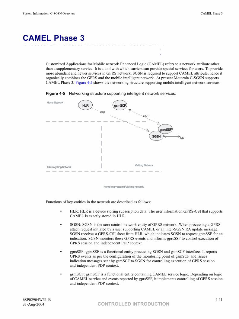
Customized Applications for Mobile network Enhanced Logic (CAMEL) refers to a network attribute otherthan a supplementary service. It is a tool with which carriers can provide special services for users. To providemore abundant and newer services in GPRS network, SGSN is required to support CAMEL attribute, hence itorganically combines the GPRS and the mobile intelligent network. At present Motorola C-SGSN supportsCAMEL Phase 3. Figure 4-5 shows the networking structure supporting mobile intelligent network services.
Figure 4-5 Networking structure supporting intelligent network services.
HLR gsmSCF
MS
Visiting NetworkInterrogating Network
Home Network
CAP
Home/Interrogating/Visiting Network
SGSN
gprsSSF
MAP
Functions of key entities in the network are described as follows:
• HLR: HLR is a device storing subscription data. The user information GPRS-CSI that supportsCAMEL is exactly stored in HLR.
• SGSN: SGSN is the core control network entity of GPRS network. When processing a GPRSattach request initiated by a user supporting CAMEL or an inter-SGSN RA update message,SGSN receives a GPRS-CSI sheet from HLR, which indicates SGSN to request gprsSSF for anindication. SGSN monitors these GPRS events and informs gprsSSF to control execution ofGPRS session and independent PDP context.
• gprsSSF: gprsSSF is a functional entity processing SGSN and gsmSCF interface. It reportsGPRS events as per the configuration of the monitoring point of gsmSCF and issuesindication messages sent by gsmSCF to SGSN for controlling execution of GPRS sessionand independent PDP context.
• gsmSCF: gsmSCF is a functional entity containing CAMEL service logic. Depending on logicof CAMEL service and events reported by gprsSSF, it implements controlling of GPRS sessionand independent PDP context.
68P02904W51-B 4-1131-Aug-2004 CONTROLLED INTRODUCTION
Lawful Interception Chapter 4: Services and Functions
Lawful Interception■ ■ ■ ■ ■ ■ ■ ■ ■ ■ ■ ■ ■ ■ ■ ■ ■ ■ ■ ■ ■ ■ ■ ■ ■ ■ ■ ■ ■ ■ ■ ■ ■ ■ ■ ■ ■ ■ ■ ■ ■ ■ ■ ■ ■ ■
■
■
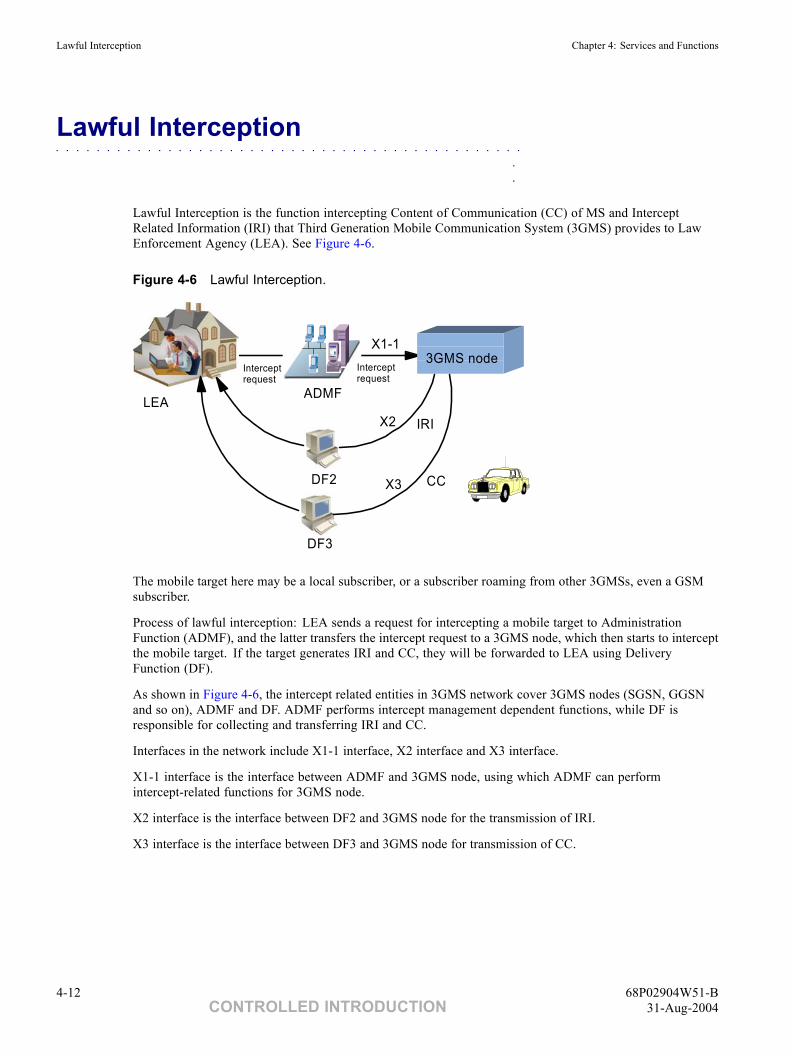
Lawful Interception is the function intercepting Content of Communication (CC) of MS and InterceptRelated Information (IRI) that Third Generation Mobile Communication System (3GMS) provides to LawEnforcement Agency (LEA). See Figure 4-6.
Figure 4-6 Lawful Interception.
3GMS node
ADMF
DF2
DF3
X1-1
X2
X3
LEA
Intercept request
Intercept request
IRI
CC
The mobile target here may be a local subscriber, or a subscriber roaming from other 3GMSs, even a GSMsubscriber.
Process of lawful interception: LEA sends a request for intercepting a mobile target to AdministrationFunction (ADMF), and the latter transfers the intercept request to a 3GMS node, which then starts to interceptthe mobile target. If the target generates IRI and CC, they will be forwarded to LEA using DeliveryFunction (DF).
As shown in Figure 4-6, the intercept related entities in 3GMS network cover 3GMS nodes (SGSN, GGSNand so on), ADMF and DF. ADMF performs intercept management dependent functions, while DF isresponsible for collecting and transferring IRI and CC.
Interfaces in the network include X1-1 interface, X2 interface and X3 interface.
X1-1 interface is the interface between ADMF and 3GMS node, using which ADMF can performintercept-related functions for 3GMS node.
X2 interface is the interface between DF2 and 3GMS node for the transmission of IRI.
X3 interface is the interface between DF3 and 3GMS node for transmission of CC.
4-12 68P02904W51-BCONTROLLED INTRODUCTION 31-Aug-2004
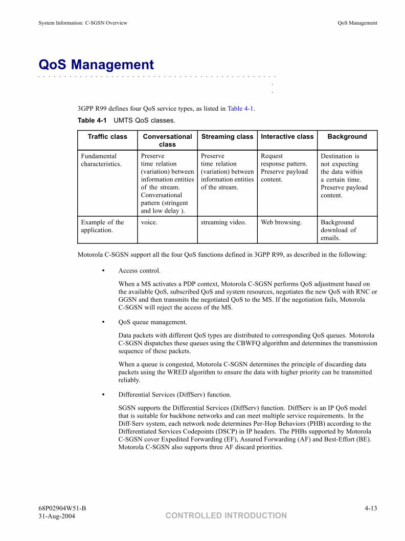
System Information: C-SGSN Overview QoS Management
QoS Management■ ■ ■ ■ ■ ■ ■ ■ ■ ■ ■ ■ ■ ■ ■ ■ ■ ■ ■ ■ ■ ■ ■ ■ ■ ■ ■ ■ ■ ■ ■ ■ ■ ■ ■ ■ ■ ■ ■ ■ ■ ■ ■ ■ ■ ■
■
■
3GPP R99 defines four QoS service types, as listed in Table 4-1.
Table 4-1 UMTS QoS classes.
Traffic class Conversationalclass
Streaming class Interactive class Background
Fundamentalcharacteristics.
Preservetime relation(variation) betweeninformation entitiesof the stream.Conversationalpattern (stringentand low delay ).
Preservetime relation(variation) betweeninformation entitiesof the stream.
Requestresponse pattern.Preserve payloadcontent.
Destination isnot expectingthe data withina certain time.Preserve payloadcontent.
Example of theapplication.
voice. streaming video. Web browsing. Backgrounddownload ofemails.
Motorola C-SGSN support all the four QoS functions defined in 3GPP R99, as described in the following:
• Access control.
When a MS activates a PDP context, Motorola C-SGSN performs QoS adjustment based onthe available QoS, subscribed QoS and system resources, negotiates the new QoS with RNC orGGSN and then transmits the negotiated QoS to the MS. If the negotiation fails, MotorolaC-SGSN will reject the access of the MS.
• QoS queue management.
Data packets with different QoS types are distributed to corresponding QoS queues. MotorolaC-SGSN dispatches these queues using the CBWFQ algorithm and determines the transmissionsequence of these packets.
When a queue is congested, Motorola C-SGSN determines the principle of discarding datapackets using the WRED algorithm to ensure the data with higher priority can be transmittedreliably.
• Differential Services (DiffServ) function.
SGSN supports the Differential Services (DiffServ) function. DiffServ is an IP QoS modelthat is suitable for backbone networks and can meet multiple service requirements. In theDiff-Serv system, each network node determines Per-Hop Behaviors (PHB) according to theDifferentiated Services Codepoints (DSCP) in IP headers. The PHBs supported by MotorolaC-SGSN cover Expedited Forwarding (EF), Assured Forwarding (AF) and Best-Effort (BE).Motorola C-SGSN also supports three AF discard priorities.
68P02904W51-B 4-1331-Aug-2004 CONTROLLED INTRODUCTION
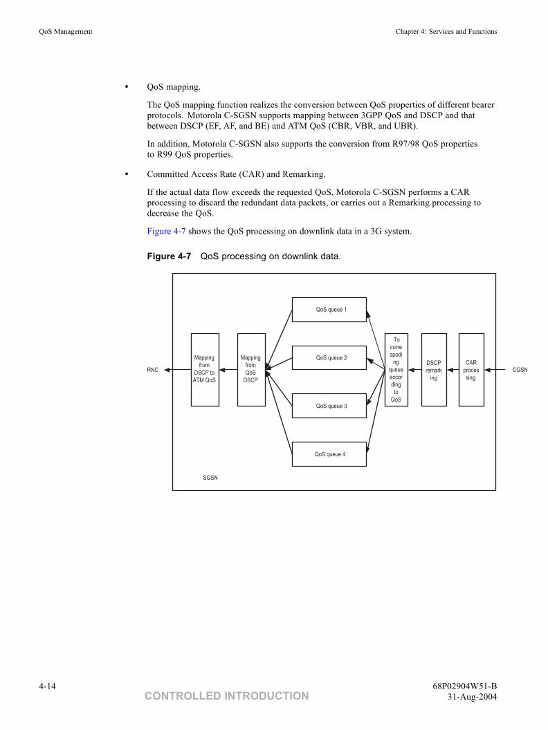
QoS Management Chapter 4: Services and Functions
• QoS mapping.
The QoS mapping function realizes the conversion between QoS properties of different bearerprotocols. Motorola C-SGSN supports mapping between 3GPP QoS and DSCP and thatbetween DSCP (EF, AF, and BE) and ATM QoS (CBR, VBR, and UBR).
In addition, Motorola C-SGSN also supports the conversion from R97/98 QoS propertiesto R99 QoS properties.
• Committed Access Rate (CAR) and Remarking.
If the actual data flow exceeds the requested QoS, Motorola C-SGSN performs a CARprocessing to discard the redundant data packets, or carries out a Remarking processing todecrease the QoS.
Figure 4-7 shows the QoS processing on downlink data in a 3G system.
Figure 4-7 QoS processing on downlink data.
CAR proces sing
To corre spodi
ng queue accor ding to
QoS
QoS queue 1
QoS queue 2
QoS queue 3
QoS queue 4
CGSN
Mapping from QoS
DSCP
Mapping from
DSCP to ATM QoS
DSCP remark
ingRNC
SGSN
4-14 68P02904W51-BCONTROLLED INTRODUCTION 31-Aug-2004
Chapter
5Operation and Maintenance■ ■ ■ ■ ■ ■ ■ ■ ■ ■ ■ ■ ■ ■ ■ ■ ■ ■ ■ ■ ■ ■ ■ ■ ■ ■ ■ ■ ■ ■ ■ ■ ■ ■ ■ ■ ■ ■ ■ ■ ■ ■ ■ ■ ■ ■
■
■
■
■
68P02904W51-B 5-131-Aug-2004 CONTROLLED INTRODUCTION
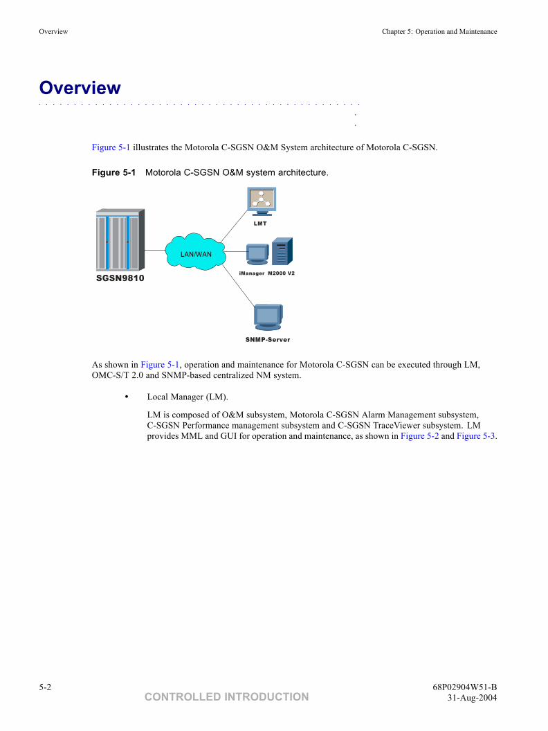
Overview Chapter 5: Operation and Maintenance
Overview■ ■ ■ ■ ■ ■ ■ ■ ■ ■ ■ ■ ■ ■ ■ ■ ■ ■ ■ ■ ■ ■ ■ ■ ■ ■ ■ ■ ■ ■ ■ ■ ■ ■ ■ ■ ■ ■ ■ ■ ■ ■ ■ ■ ■ ■
■
■
Figure 5-1 illustrates the Motorola C-SGSN O&M System architecture of Motorola C-SGSN.
Figure 5-1 Motorola C-SGSN O&M system architecture.
SGSN9810iManager M2000 V2
LMT
SNMP-Server
LAN/WAN
As shown in Figure 5-1, operation and maintenance for Motorola C-SGSN can be executed through LM,OMC-S/T 2.0 and SNMP-based centralized NM system.
• Local Manager (LM).
LM is composed of O&M subsystem, Motorola C-SGSN Alarm Management subsystem,C-SGSN Performance management subsystem and C-SGSN TraceViewer subsystem. LMprovides MML and GUI for operation and maintenance, as shown in Figure 5-2 and Figure 5-3.
5-2 68P02904W51-BCONTROLLED INTRODUCTION 31-Aug-2004
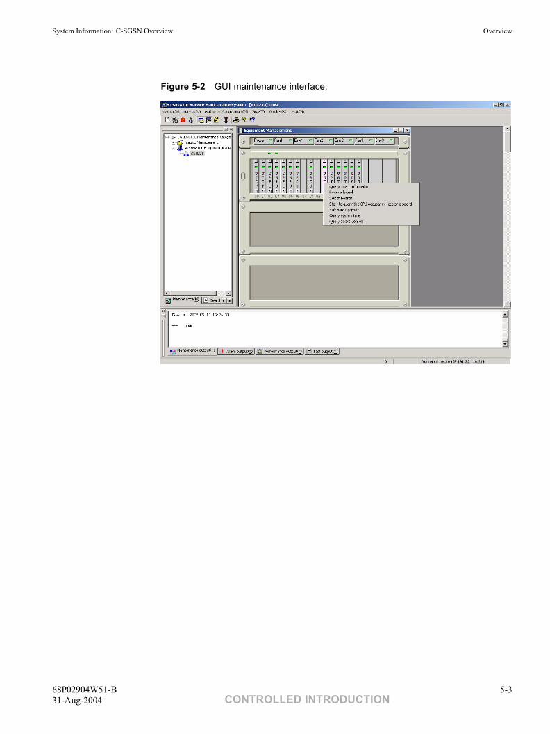
System Information: C-SGSN Overview Overview
Figure 5-2 GUI maintenance interface.
68P02904W51-B 5-331-Aug-2004 CONTROLLED INTRODUCTION
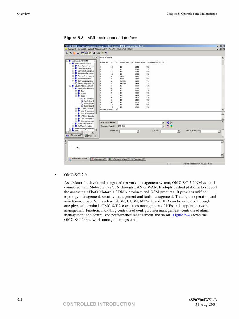
Overview Chapter 5: Operation and Maintenance
Figure 5-3 MML maintenance interface.
• OMC-S/T 2.0.
As a Motorola-developed integrated network management system, OMC-S/T 2.0 NM center isconnected with Motorola C-SGSN through LAN or WAN. It adopts unified platform to supportthe accessing of both Motorola CDMA products and GSM products. It provides unifiedtopology management, security management and fault management. That is, the operation andmaintenance over NEs such as SGSN, GGSN, MTS-U, and HLR can be executed throughone physical terminal. OMC-S/T 2.0 executes management of NEs and supports networkmanagement function, including centralized configuration management, centralized alarmmanagement and centralized performance management and so on. Figure 5-4 shows theOMC-S/T 2.0 network management system.
5-4 68P02904W51-BCONTROLLED INTRODUCTION 31-Aug-2004
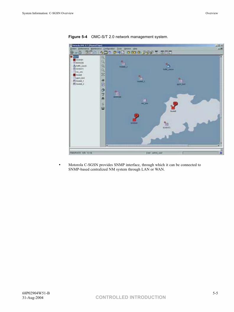
System Information: C-SGSN Overview Overview
Figure 5-4 OMC-S/T 2.0 network management system.
• Motorola C-SGSN provides SNMP interface, through which it can be connected toSNMP-based centralized NM system through LAN or WAN.
68P02904W51-B 5-531-Aug-2004 CONTROLLED INTRODUCTION
Database Management Chapter 5: Operation and Maintenance
Database Management■ ■ ■ ■ ■ ■ ■ ■ ■ ■ ■ ■ ■ ■ ■ ■ ■ ■ ■ ■ ■ ■ ■ ■ ■ ■ ■ ■ ■ ■ ■ ■ ■ ■ ■ ■ ■ ■ ■ ■ ■ ■ ■ ■ ■ ■
■
■
The database is the basis for system operation. It stores the configuration of various parameters for systemoperation. Database management refers to operations such as adding, deleting, modifying and queryingsystem data. In Motorola C-SGSN, the data that needs to be configured includes hardware data, systeminformation, Gb interface, Iu interface, Gn interface, layer 3 parameters and SS7 signaling, and so on.
Motorola C-SGSN provides dynamic and static data configuration. The dynamic configuration means that themodification to the system data takes effect immediately without interrupting system operation. While thestatic configuration means that the modification is done by editing MML.TXT file off-line and restarts thesystem to make the modification effective. Not all data can be configured dynamically.
5-6 68P02904W51-BCONTROLLED INTRODUCTION 31-Aug-2004
System Information: C-SGSN Overview Equipment Management
Equipment Management■ ■ ■ ■ ■ ■ ■ ■ ■ ■ ■ ■ ■ ■ ■ ■ ■ ■ ■ ■ ■ ■ ■ ■ ■ ■ ■ ■ ■ ■ ■ ■ ■ ■ ■ ■ ■ ■ ■ ■ ■ ■ ■ ■ ■ ■
■
■
Equipment management is the function to monitor, control and test system entities such as hardware, link,and so on.
• Monitor function.
Motorola C-SGSN supports the state query of board, optical interface, E1 port, SS7 link, FRlink, SAAL link, GTP path, BC, NSVC, destination signaling point, subsystem, PTPBVC,SIGBVC, and so on. The operation information of the queried entity can be obtainedthrough the state query.
• Control function.
The control function includes the resetting and switchover of board, the optical interface,E1 port, SS7 link, FR link, SAAL link, GTP path, blocking/unblocking and reset of BC,destination signaling point, disabling/enabling of subsystem, and so on.
• Test function.
Test function is the major means to locate and find faults. Motorola C-SGSN supports self-looptest of E1 port and SAAL link, as well as GTP path test.
68P02904W51-B 5-731-Aug-2004 CONTROLLED INTRODUCTION
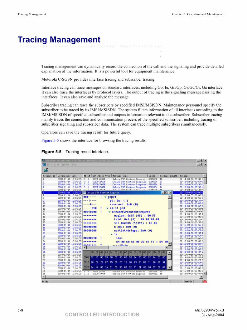
Tracing Management Chapter 5: Operation and Maintenance
Tracing Management■ ■ ■ ■ ■ ■ ■ ■ ■ ■ ■ ■ ■ ■ ■ ■ ■ ■ ■ ■ ■ ■ ■ ■ ■ ■ ■ ■ ■ ■ ■ ■ ■ ■ ■ ■ ■ ■ ■ ■ ■ ■ ■ ■ ■ ■
■
■
Tracing management can dynamically record the connection of the call and the signaling and provide detailedexplanation of the information. It is a powerful tool for equipment maintenance.
Motorola C-SGSN provides interface tracing and subscriber tracing.
Interface tracing can trace messages on standard interfaces, including Gb, Iu, Gn/Gp, Gs/Gd/Gr, Ga interface.It can also trace the interfaces by protocol layers. The output of tracing is the signaling message passing theinterfaces. It can also save and analyze the message.
Subscriber tracing can trace the subscribers by specified IMSI/MSISDN. Maintenance personnel specify thesubscriber to be traced by its IMSI/MSISDN. The system filters information of all interfaces according to theIMSI/MSISDN of specified subscriber and outputs information relevant to the subscriber. Subscriber tracingmainly traces the connection and communication process of the specified subscriber, including tracing ofsubscriber signaling and subscriber data. The system can trace multiple subscribers simultaneously.
Operators can save the tracing result for future query.
Figure 5-5 shows the interface for browsing the tracing results.
Figure 5-5 Tracing result interface.
5-8 68P02904W51-BCONTROLLED INTRODUCTION 31-Aug-2004
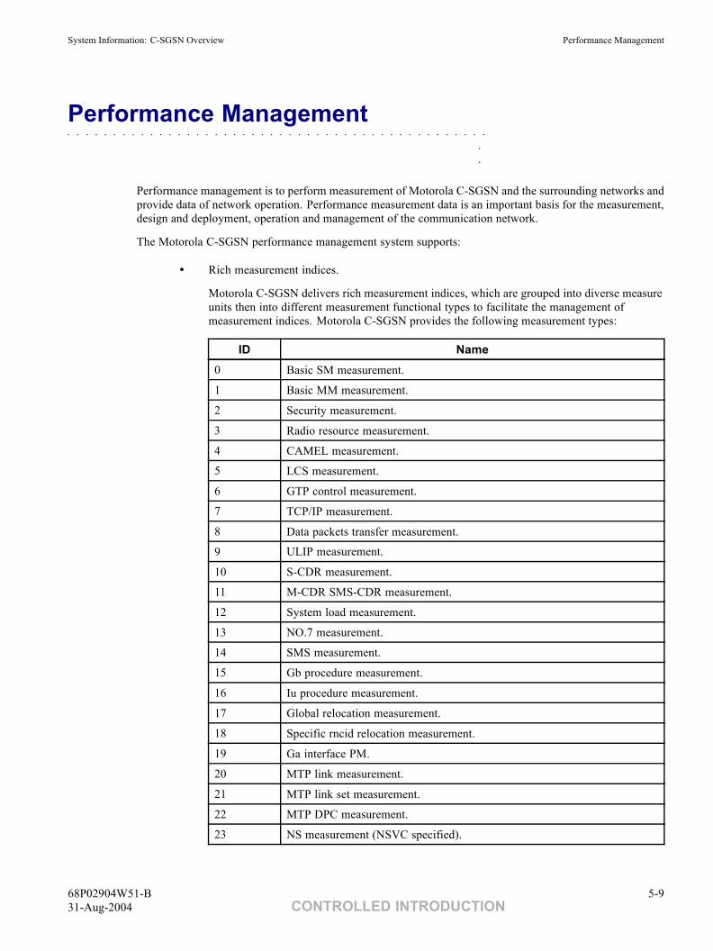
System Information: C-SGSN Overview Performance Management
Performance Management■ ■ ■ ■ ■ ■ ■ ■ ■ ■ ■ ■ ■ ■ ■ ■ ■ ■ ■ ■ ■ ■ ■ ■ ■ ■ ■ ■ ■ ■ ■ ■ ■ ■ ■ ■ ■ ■ ■ ■ ■ ■ ■ ■ ■ ■
■
■
Performance management is to perform measurement of Motorola C-SGSN and the surrounding networks andprovide data of network operation. Performance measurement data is an important basis for the measurement,design and deployment, operation and management of the communication network.
The Motorola C-SGSN performance management system supports:
• Rich measurement indices.
Motorola C-SGSN delivers rich measurement indices, which are grouped into diverse measureunits then into different measurement functional types to facilitate the management ofmeasurement indices. Motorola C-SGSN provides the following measurement types:
ID Name0 Basic SM measurement.
1 Basic MM measurement.
2 Security measurement.
3 Radio resource measurement.
4 CAMEL measurement.
5 LCS measurement.
6 GTP control measurement.
7 TCP/IP measurement.
8 Data packets transfer measurement.
9 ULIP measurement.
10 S-CDR measurement.
11 M-CDR SMS-CDR measurement.
12 System load measurement.
13 NO.7 measurement.
14 SMS measurement.
15 Gb procedure measurement.
16 Iu procedure measurement.
17 Global relocation measurement.
18 Specific rncid relocation measurement.
19 Ga interface PM.
20 MTP link measurement.
21 MTP link set measurement.
22 MTP DPC measurement.
23 NS measurement (NSVC specified).
68P02904W51-B 5-931-Aug-2004 CONTROLLED INTRODUCTION
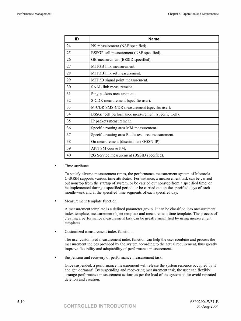
Performance Management Chapter 5: Operation and Maintenance
ID Name24 NS measurement (NSE specified).
25 BSSGP cell measurement (NSE specified).
26 GB measurement (BSSID specified).
27 MTP3B link measurement.
28 MTP3B link set measurement.
29 MTP3B signal point measurement.
30 SAAL link measurement.
31 Ping packets measurement.
32 S-CDR measurement (specific user).
33 M-CDR SMS-CDR measurement (specific user).
34 BSSGP cell performance measurement (specific Cell).
35 IP packets measurement.
36 Specific routing area MM measurement.
37 Specific routing area Radio resource measurement.
38 Gn measurement (discriminate GGSN IP).
39 APN SM course PM.
40 2G Service measurement (BSSID specified).
• Time attributes.
To satisfy diverse measurement times, the performance measurement system of MotorolaC-SGSN supports various time attributes. For instance, a measurement task can be carriedout nonstop from the startup of system, or be carried out nonstop from a specified time, orbe implemented during a specified period, or be carried out on the specified days of eachmonth/week and at the specified time segments of each specified day.
• Measurement template function.
A measurement template is a defined parameter group. It can be classified into measurementindex template, measurement object template and measurement time template. The process ofcreating a performance measurement task can be greatly simplified by using measurementtemplates.
• Customized measurement index function.
The user customized measurement index function can help the user combine and process themeasurement indices provided by the system according to the actual requirement, thus greatlyimprove flexibility and adaptability of performance measurement.
• Suspension and recovery of performance measurement task.
Once suspended, a performance measurement will release the system resource occupied by itand get 'dormant'. By suspending and recovering measurement task, the user can flexiblyarrange performance measurement actions as per the load of the system so for avoid repeateddeletion and creation.
5-10 68P02904W51-BCONTROLLED INTRODUCTION 31-Aug-2004
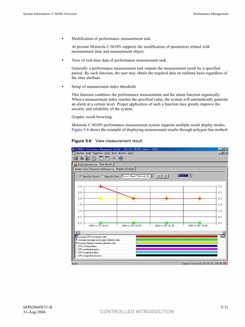
System Information: C-SGSN Overview Performance Management
• Modification of performance measurement task.
At present Motorola C-SGSN supports the modification of parameters related withmeasurement time and measurement object.
• View of real-time data of performance measurement task.
Generally a performance measurement task outputs the measurement result by a specifiedperiod. By such function, the user may obtain the required data on realtime basis regardless ofthe time attribute.
• Setup of measurement index threshold.
This function combines the performance measurement and the alarm function organically.When a measurement index reaches the specified value, the system will automatically generatean alarm at a certain level. Proper application of such a function may greatly improve thesecurity and reliability of the system.
Graphic result browsing.
Motorola C-SGSN performance measurement system supports multiple result display modes.Figure 5-6 shows the example of displaying measurement results through polygon line method.
Figure 5-6 View measurement result.
68P02904W51-B 5-1131-Aug-2004 CONTROLLED INTRODUCTION
Motorola C-SGSN Alarm Management Chapter 5: Operation and Maintenance
Motorola C-SGSN Alarm Management■ ■ ■ ■ ■ ■ ■ ■ ■ ■ ■ ■ ■ ■ ■ ■ ■ ■ ■ ■ ■ ■ ■ ■ ■ ■ ■ ■ ■ ■ ■ ■ ■ ■ ■ ■ ■ ■ ■ ■ ■ ■ ■ ■ ■ ■
■
■
The Motorola C-SGSN alarm system is responsible for monitoring the running status of the system andreporting the detected faults to the maintenance personnel. It has the following features:
Abundant alarm contents and detailed and accurate alarmlocation
Motorola C-SGSN provides more than 400 types of alarms covering all software functions, hardware partsand surroundings of the system. Rich alarm types ensure various failures can be detected and handled in time.To facilitate management, Motorola C-SGSN classifies these alarms into failure alarm, recovery alarm andevent alarm with different levels. Alarm level serves to identify the severity of an alarm. Motorola C-SGSNprovides four alarm severity levels: critical, major, minor and warning. The user may adjust the severity levelof an alarm according to the actual requirement.
Whenever an alarm is generated, the system will report the detailed information of the alarm to facilitatethe location and handling of the failure.
The user is authorized to shield the alarm if the user think it unnecessary to report it.
5-12 68P02904W51-BCONTROLLED INTRODUCTION 31-Aug-2004
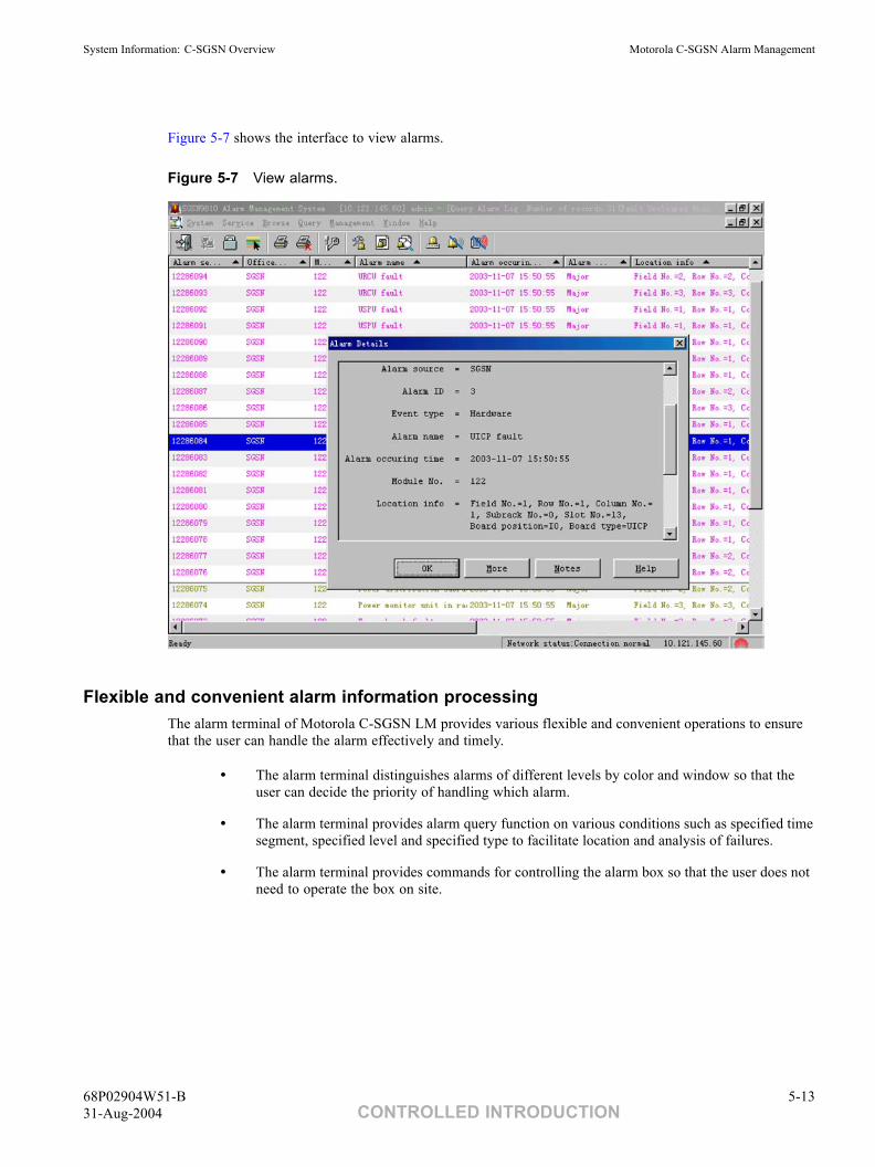
System Information: C-SGSN Overview Motorola C-SGSN Alarm Management
Figure 5-7 shows the interface to view alarms.
Figure 5-7 View alarms.
Flexible and convenient alarm information processingThe alarm terminal of Motorola C-SGSN LM provides various flexible and convenient operations to ensurethat the user can handle the alarm effectively and timely.
• The alarm terminal distinguishes alarms of different levels by color and window so that theuser can decide the priority of handling which alarm.
• The alarm terminal provides alarm query function on various conditions such as specified timesegment, specified level and specified type to facilitate location and analysis of failures.
• The alarm terminal provides commands for controlling the alarm box so that the user does notneed to operate the box on site.
68P02904W51-B 5-1331-Aug-2004 CONTROLLED INTRODUCTION
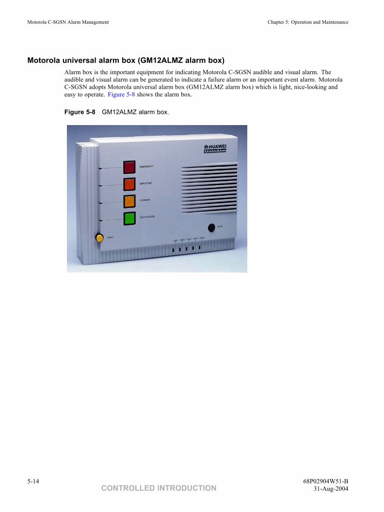
Motorola C-SGSN Alarm Management Chapter 5: Operation and Maintenance
Motorola universal alarm box (GM12ALMZ alarm box)Alarm box is the important equipment for indicating Motorola C-SGSN audible and visual alarm. Theaudible and visual alarm can be generated to indicate a failure alarm or an important event alarm. MotorolaC-SGSN adopts Motorola universal alarm box (GM12ALMZ alarm box) which is light, nice-looking andeasy to operate. Figure 5-8 shows the alarm box.
Figure 5-8 GM12ALMZ alarm box.
5-14 68P02904W51-BCONTROLLED INTRODUCTION 31-Aug-2004
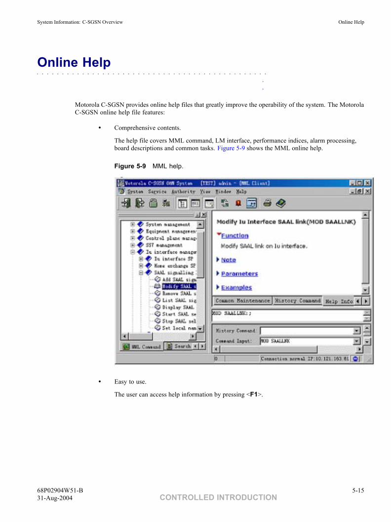
System Information: C-SGSN Overview Online Help
Online Help■ ■ ■ ■ ■ ■ ■ ■ ■ ■ ■ ■ ■ ■ ■ ■ ■ ■ ■ ■ ■ ■ ■ ■ ■ ■ ■ ■ ■ ■ ■ ■ ■ ■ ■ ■ ■ ■ ■ ■ ■ ■ ■ ■ ■ ■
■
■
Motorola C-SGSN provides online help files that greatly improve the operability of the system. The MotorolaC-SGSN online help file features:
• Comprehensive contents.
The help file covers MML command, LM interface, performance indices, alarm processing,board descriptions and common tasks. Figure 5-9 shows the MML online help.
Figure 5-9 MML help.
• Easy to use.
The user can access help information by pressing <F1>.
68P02904W51-B 5-1531-Aug-2004 CONTROLLED INTRODUCTION

Online Help Chapter 5: Operation and Maintenance
This page intentionally left blank.
5-16 68P02904W51-BCONTROLLED INTRODUCTION 31-Aug-2004
Chapter
6Reliability■ ■ ■ ■ ■ ■ ■ ■ ■ ■ ■ ■ ■ ■ ■ ■ ■ ■ ■ ■ ■ ■ ■ ■ ■ ■ ■ ■ ■ ■ ■ ■ ■ ■ ■ ■ ■ ■ ■ ■ ■ ■ ■ ■ ■ ■
■
■
■
■
68P02904W51-B 6-131-Aug-2004 CONTROLLED INTRODUCTION
Overview Chapter 6: Reliability
Overview■ ■ ■ ■ ■ ■ ■ ■ ■ ■ ■ ■ ■ ■ ■ ■ ■ ■ ■ ■ ■ ■ ■ ■ ■ ■ ■ ■ ■ ■ ■ ■ ■ ■ ■ ■ ■ ■ ■ ■ ■ ■ ■ ■ ■ ■
■
■
This chapter introduces the reliability of Motorola C-SGSN from a view of hardware, software and charging.
6-2 68P02904W51-BCONTROLLED INTRODUCTION 31-Aug-2004
System Information: C-SGSN Overview Hardware Reliability Measures
Hardware Reliability Measures■ ■ ■ ■ ■ ■ ■ ■ ■ ■ ■ ■ ■ ■ ■ ■ ■ ■ ■ ■ ■ ■ ■ ■ ■ ■ ■ ■ ■ ■ ■ ■ ■ ■ ■ ■ ■ ■ ■ ■ ■ ■ ■ ■ ■ ■
■
■
Motorola C-SGSN adopts various reliability designs such as active/standby mode, load-sharingand redundancy configuration. It also improves the system maintainability by optimizing the faultdetection/isolation technology of the boards and the system.
Power Supply Reliability
• Motorola C-SGSN adopts distributed power supply. The subracks or functional modules usehigh frequency DC/DC secondary power supply, which features high efficiency and stability.
• Secondary power supply adopts redundancy design of active/standby hot backup to ensurereliability of the power system.
• High-voltage and excess-current protection. Both the power input and external interface (forexample E1 interface) of the boards adopt overvoltage and excess-current protection. Themeasures meet the ITU-T recommendation G.703 (Appendix B) and relevant specifications.
Board Hot Backup
To improve system reliability in large equipment, board hot backup is the commonly used method. Theactual effect can be measured by the switchover success ratio. The key to the switchover success ratio isthe board fault detection ratio and the switchover mechanism. The design of Motorola C-SGSN takesthese two aspects into consideration.
Board fault detectionMotorola C-SGSN requires self-check of memory and key external chips (such as network chips, and so on)after the board is powered on. The key signals (for example 8k clock signal) used by boards are monitoredonline. Loopback check of service code flow is realized when the board is idle.
Switchover mechanismActive/standby board switchover is performed by the two signals cross-connected between boards. The twosignals are the valid signal (output signal) of the board and the valid signal (input signal) of the peer board.
ASIC Technique
All the network chips of Motorola C-SGSN boards adopt customized ASIC, which provide effective internalfault detection measures at the chip level and report mechanism.
68P02904W51-B 6-331-Aug-2004 CONTROLLED INTRODUCTION
Hardware Reliability Measures Chapter 6: Reliability
High-Quality Components
Motorola C-SGSN adopts high-quality components, which have passed burning test and are selected bystrict requirements. The assembly of hardware is also under strict control to ensure the high reliabilityand stability for long term operation.
Mutual Assistance Working Mode
Mutual assistance, also termed load sharing, means that two or more boards perform relevant functions whenthey all work normally, and that when one of the boards is faulty, other boards perform the task of the faultyboard under the precondition of satisfying certain performance indices (for example call loss). Mutualassistance is applied to secondary power module, signaling link and STM-1 interface.
6-4 68P02904W51-BCONTROLLED INTRODUCTION 31-Aug-2004
System Information: C-SGSN Overview Software Reliability Measures
Software Reliability Measures■ ■ ■ ■ ■ ■ ■ ■ ■ ■ ■ ■ ■ ■ ■ ■ ■ ■ ■ ■ ■ ■ ■ ■ ■ ■ ■ ■ ■ ■ ■ ■ ■ ■ ■ ■ ■ ■ ■ ■ ■ ■ ■ ■ ■ ■
■
■
The Software Reliability Measures are:
Protection Function
The key to improve software reliability is to reduce software defects. Motorola C-SGSN ensures the softwarereliability at various phases, from system requirement analysis, system design to test.
From the requirement analysis phase, software development is carried out under the guidance of variousCapability Maturity Model (CMM) specifications. It reduces errors at the beginning phase.
During the software design phase, modular design is adopted for the software, and the design of each softwaremodule is based on loose coupling. That is, the fault of one module will not affect the performance ofother modules. Additionally, important measures such as error check, error isolation and recovery areadded to improve system reliability. Code walkthrough, inspection and test in every phase are effectivemeans to improve reliability.
Testing of various software is a necessary way to improve software reliability. From the beginning of softwareproject, testing stuff fully participate in the software development process. They make plans for tests,including unit test and system test, by strictly following process requirements. Detailed test plans ensure theimprovement of software reliability. Furthermore, testing plans are further bettered during testing.
Error Tolerance Capability
Error tolerance of software system means that the system should not break down when a minor softwarefault occurs, that is, the system has self-healing ability when error occurs. Error tolerance of softwarecontains the following aspects:
68P02904W51-B 6-531-Aug-2004 CONTROLLED INTRODUCTION
Software Reliability Measures Chapter 6: Reliability
• Regular check of key resources.
For various software resources in the system (for example network board resources), long-timeseizure check mechanism is added between modules. If the resource is deadlocked due tosoftware abnormality, check mechanism will release the deadlocked resources and outputlogs and alarms.
• Task monitoring.
During the running of software, output channels, that is, the monitoring process, for softwareinternal faults and part of hardware faults, are provided. They monitor the task running stateand report system abnormalities to the external.
• Storage protection.
Software system adopts segment and page protection mechanism of CPU Memory ManagementUnit (MMU) to protect the storage of code and important data segment. It provides functionsof online query, modification of variables and data in the system and memory monitoring.
• Data check.
To check the consistency of the data on the UOMU and various service processing boards, thesystem can perform regular or event-triggered consistency check. It can also recover the dataconsistency selectively or preferably and output corresponding logs and alarms.
• Operation log storage.
The UOMU records user's operation of a certain period and stores them to the system log.For unknown errors in the system, faults can be located by analyzing the operation log orrecovering the data to normal status.
6-6 68P02904W51-BCONTROLLED INTRODUCTION 31-Aug-2004
System Information: C-SGSN Overview Charging Reliability Measures
Charging Reliability Measures■ ■ ■ ■ ■ ■ ■ ■ ■ ■ ■ ■ ■ ■ ■ ■ ■ ■ ■ ■ ■ ■ ■ ■ ■ ■ ■ ■ ■ ■ ■ ■ ■ ■ ■ ■ ■ ■ ■ ■ ■ ■ ■ ■ ■ ■
■
■
Motorola C-SGSN generates CDRs on various service boards and sends them to Ga interface board that is theUCDR board, on which there is a hard disk for information buffer) that can communicate with the ChargingGateway (CG) through board communication. Then CDRs are sent to the CG using the Ga interface. Whenthe CG or the network is faulty, the CDRs in the CDR pool can be saved to the hard disk on the UCDR board.And the CDRs can be read back to the CDR pool and then sent to the CG when the CG recovers.
68P02904W51-B 6-731-Aug-2004 CONTROLLED INTRODUCTION
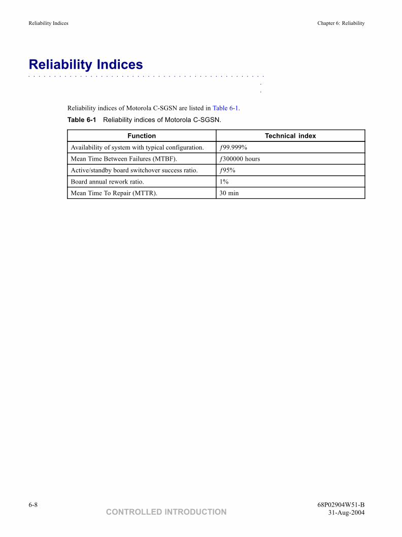
Reliability Indices Chapter 6: Reliability
Reliability Indices■ ■ ■ ■ ■ ■ ■ ■ ■ ■ ■ ■ ■ ■ ■ ■ ■ ■ ■ ■ ■ ■ ■ ■ ■ ■ ■ ■ ■ ■ ■ ■ ■ ■ ■ ■ ■ ■ ■ ■ ■ ■ ■ ■ ■ ■
■
■
Reliability indices of Motorola C-SGSN are listed in Table 6-1.
Table 6-1 Reliability indices of Motorola C-SGSN.
Function Technical indexAvailability of system with typical configuration. ƒ99.999%
Mean Time Between Failures (MTBF). ƒ300000 hours
Active/standby board switchover success ratio. ƒ95%
Board annual rework ratio. 1%
Mean Time To Repair (MTTR). 30 min
6-8 68P02904W51-BCONTROLLED INTRODUCTION 31-Aug-2004
Chapter
7Technical Specifications■ ■ ■ ■ ■ ■ ■ ■ ■ ■ ■ ■ ■ ■ ■ ■ ■ ■ ■ ■ ■ ■ ■ ■ ■ ■ ■ ■ ■ ■ ■ ■ ■ ■ ■ ■ ■ ■ ■ ■ ■ ■ ■ ■ ■ ■
■
■
■
■
68P02904W51-B 7-131-Aug-2004 CONTROLLED INTRODUCTION
Overview Chapter 7: Technical Specifications
Overview■ ■ ■ ■ ■ ■ ■ ■ ■ ■ ■ ■ ■ ■ ■ ■ ■ ■ ■ ■ ■ ■ ■ ■ ■ ■ ■ ■ ■ ■ ■ ■ ■ ■ ■ ■ ■ ■ ■ ■ ■ ■ ■ ■ ■ ■
■
■
This chapter lists performance, engineering, reliability and physical interface parameters of Motorola C-SGSN.
7-2 68P02904W51-BCONTROLLED INTRODUCTION 31-Aug-2004
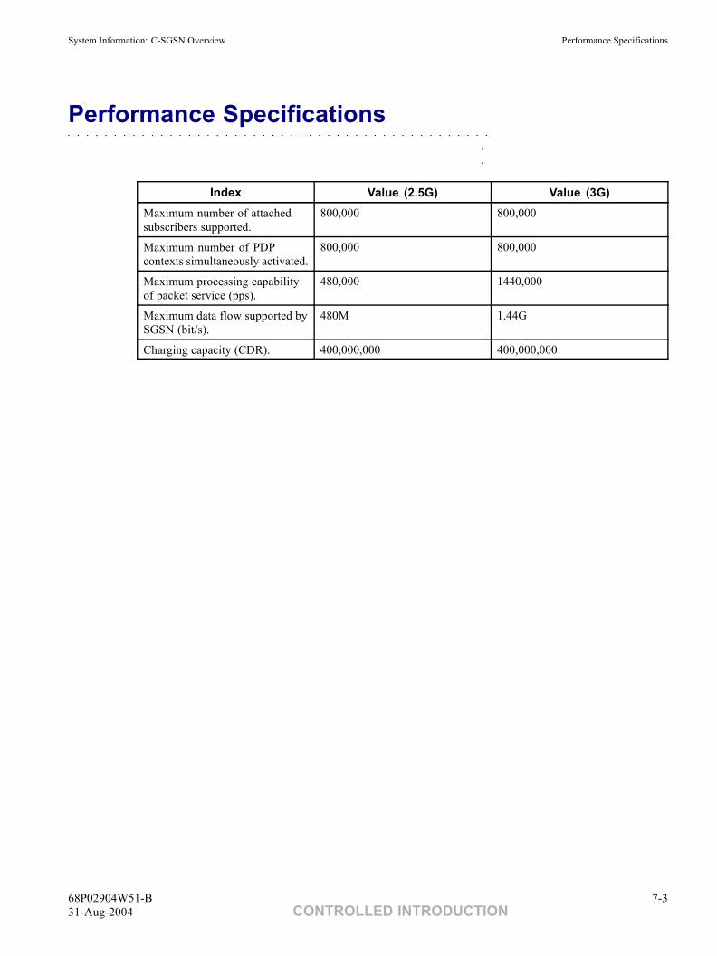
System Information: C-SGSN Overview Performance Specifications
Performance Specifications■ ■ ■ ■ ■ ■ ■ ■ ■ ■ ■ ■ ■ ■ ■ ■ ■ ■ ■ ■ ■ ■ ■ ■ ■ ■ ■ ■ ■ ■ ■ ■ ■ ■ ■ ■ ■ ■ ■ ■ ■ ■ ■ ■ ■ ■
■
■
Index Value (2.5G) Value (3G)Maximum number of attachedsubscribers supported.
800,000 800,000
Maximum number of PDPcontexts simultaneously activated.
800,000 800,000
Maximum processing capabilityof packet service (pps).
480,000 1440,000
Maximum data flow supported bySGSN (bit/s).
480M 1.44G
Charging capacity (CDR). 400,000,000 400,000,000
68P02904W51-B 7-331-Aug-2004 CONTROLLED INTRODUCTION
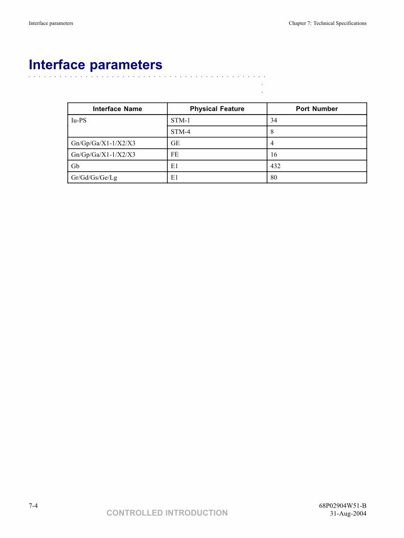
Interface parameters Chapter 7: Technical Specifications
Interface parameters■ ■ ■ ■ ■ ■ ■ ■ ■ ■ ■ ■ ■ ■ ■ ■ ■ ■ ■ ■ ■ ■ ■ ■ ■ ■ ■ ■ ■ ■ ■ ■ ■ ■ ■ ■ ■ ■ ■ ■ ■ ■ ■ ■ ■ ■
■
■
Interface Name Physical Feature Port NumberSTM-1 34Iu-PS
STM-4 8
Gn/Gp/Ga/X1-1/X2/X3 GE 4
Gn/Gp/Ga/X1-1/X2/X3 FE 16
Gb E1 432
Gr/Gd/Gs/Ge/Lg E1 80
7-4 68P02904W51-BCONTROLLED INTRODUCTION 31-Aug-2004
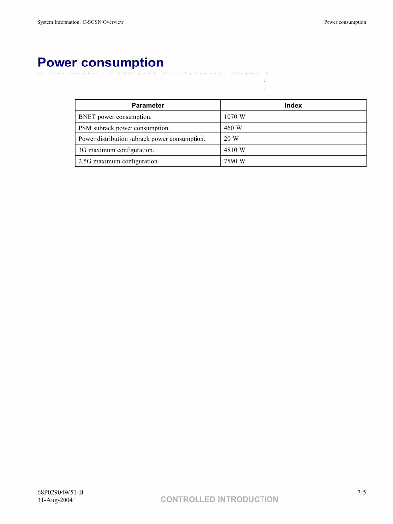
System Information: C-SGSN Overview Power consumption
Power consumption■ ■ ■ ■ ■ ■ ■ ■ ■ ■ ■ ■ ■ ■ ■ ■ ■ ■ ■ ■ ■ ■ ■ ■ ■ ■ ■ ■ ■ ■ ■ ■ ■ ■ ■ ■ ■ ■ ■ ■ ■ ■ ■ ■ ■ ■
■
■
Parameter IndexBNET power consumption. 1070 W
PSM subrack power consumption. 460 W
Power distribution subrack power consumption. 20 W
3G maximum configuration. 4810 W
2.5G maximum configuration. 7590 W
68P02904W51-B 7-531-Aug-2004 CONTROLLED INTRODUCTION
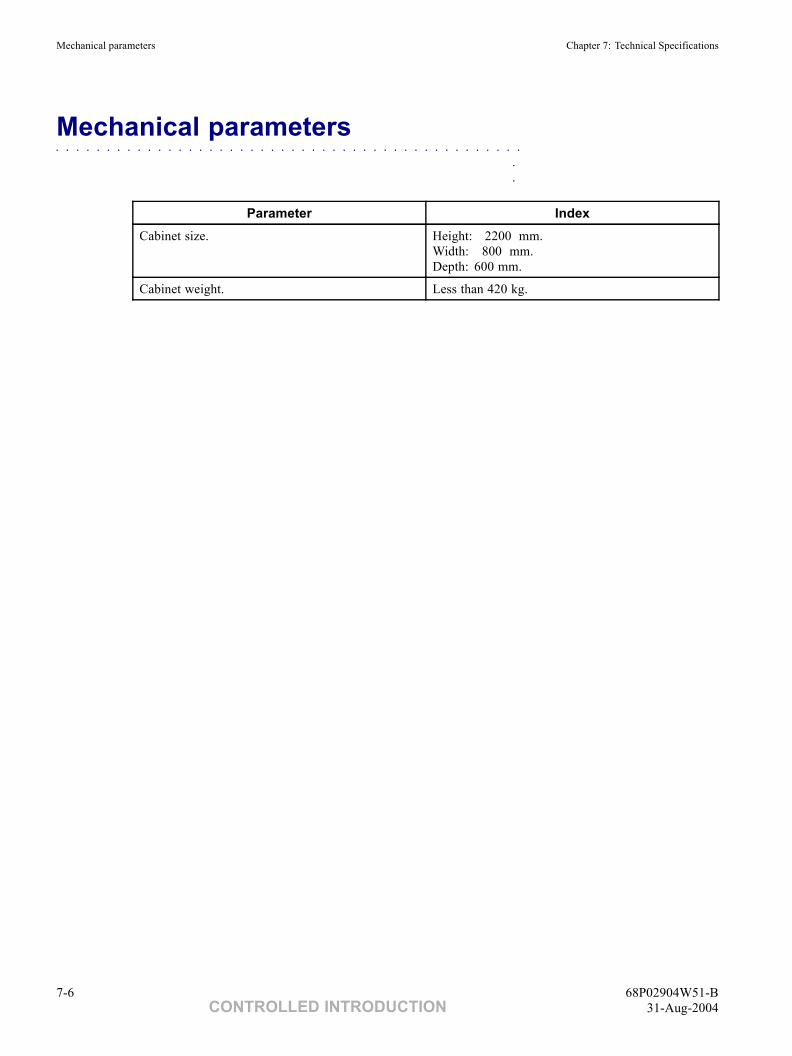
Mechanical parameters Chapter 7: Technical Specifications
Mechanical parameters■ ■ ■ ■ ■ ■ ■ ■ ■ ■ ■ ■ ■ ■ ■ ■ ■ ■ ■ ■ ■ ■ ■ ■ ■ ■ ■ ■ ■ ■ ■ ■ ■ ■ ■ ■ ■ ■ ■ ■ ■ ■ ■ ■ ■ ■
■
■
Parameter IndexCabinet size. Height: 2200 mm.
Width: 800 mm.Depth: 600 mm.
Cabinet weight. Less than 420 kg.
7-6 68P02904W51-BCONTROLLED INTRODUCTION 31-Aug-2004
System Information: C-SGSN Overview Environmental Conditions
Environmental Conditions■ ■ ■ ■ ■ ■ ■ ■ ■ ■ ■ ■ ■ ■ ■ ■ ■ ■ ■ ■ ■ ■ ■ ■ ■ ■ ■ ■ ■ ■ ■ ■ ■ ■ ■ ■ ■ ■ ■ ■ ■ ■ ■ ■ ■ ■
■
■
Storage conditions
The SGSN complies with the storage conditions of 1.3E-class equipment specified in ETS 300 019-1-1, thatis, it is to be stored at relative humidity of 10% to 100% and at the temperature of -45°C to +70°C.
Transport conditionsThe SGSN complies with the transport conditions of 3.2-class equipment specified in ETS 300 019-1-2, thatis, it is transported at relative humidity of 5% to 100% and at the ambient temperature of -40°C to +70°C.
Operating environmentThe SGSN complies with EUROPEAN ETS 300 019-1-3 'TEMPERATURE-controlled locations'.
• Normal working condition: temperature (0 to +45°C), humidity (5% to 85%)
• Safe working condition: temperature (-5 to +55°C), humidity (5% to 95%)
(Safe working indicates a working mode in which the continuous working duration cannotexceed 96 hours, and the number of working days cannot be greater than 15).
EMCElectroMagnetic Compatibility (EMC) and electronic security comply with GR-1089-CORE standard.
Power supply requirementPower voltage range: -42V to -57V DC
Input current (one rack): 50A
68P02904W51-B 7-731-Aug-2004 CONTROLLED INTRODUCTION

Environmental Conditions Chapter 7: Technical Specifications
This page intentionally left blank.
7-8 68P02904W51-BCONTROLLED INTRODUCTION 31-Aug-2004
Chapter
8Installation■ ■ ■ ■ ■ ■ ■ ■ ■ ■ ■ ■ ■ ■ ■ ■ ■ ■ ■ ■ ■ ■ ■ ■ ■ ■ ■ ■ ■ ■ ■ ■ ■ ■ ■ ■ ■ ■ ■ ■ ■ ■ ■ ■ ■ ■
■
■
■
■
Rack, subrack and internal cables have been installed before the Motorola C-SGSN delivery; therefore,engineers have to install only external cables and boards in the field.
For board installation, Motorola C-SGSN provide coding slots so that engineers can insert boards in properslots without any damage.
For installation of terminal software, Motorola C-SGSN adopts standard Windows program installationwizard. Users can finish the installation by inputting corresponding information according to the prompts.
For board software installation, Motorola C-SGSN adopts MML command mode to accomplish softwareinstallation of all boards or specified boards.
The enclosed customer documentation provides detailed instruction to help engineers with the installation.
68P02904W51-B 8-131-Aug-2004 CONTROLLED INTRODUCTION

Environmental Conditions Chapter 8: Installation
This page intentionally left blank.
8-2 68P02904W51-BCONTROLLED INTRODUCTION 31-Aug-2004
Index
Index■ ■ ■ ■ ■ ■ ■ ■ ■ ■ ■ ■ ■ ■ ■ ■ ■ ■ ■ ■ ■ ■ ■ ■ ■ ■ ■ ■ ■ ■ ■ ■ ■ ■ ■ ■ ■ ■ ■ ■ ■ ■ ■ ■ ■
■
■
■
■
C■ ■ ■ ■ ■ ■ ■ ■ ■ ■ ■ ■ ■ ■ ■ ■ ■ ■ ■ ■ ■ ■ ■ ■ ■ ■ ■ ■ ■ ■ ■ ■ ■ ■ ■ ■ ■ ■ ■ ■ ■ ■ ■ ■ ■ ■ ■ ■ ■ ■ ■ ■ ■ ■ ■ ■ ■ ■ ■ ■ ■ ■ ■ ■ ■
CAMEL Phase 3 . . . . . . . . . . . . . . . . 4-11Charging Functions . . . . . . . . . . . . . . . 4-7
Charging Reliability Measures . . . . . . . . . 6-7
D■ ■ ■ ■ ■ ■ ■ ■ ■ ■ ■ ■ ■ ■ ■ ■ ■ ■ ■ ■ ■ ■ ■ ■ ■ ■ ■ ■ ■ ■ ■ ■ ■ ■ ■ ■ ■ ■ ■ ■ ■ ■ ■ ■ ■ ■ ■ ■ ■ ■ ■ ■ ■ ■ ■ ■ ■ ■ ■ ■ ■ ■ ■ ■ ■
Database Management . . . . . . . . . . . . . 5-6Devices sensitive to static . . . . . . . . . . . . . 14
Devices sensitive to static (contd.)Special handling techniques. . . . . . . . . . . 14
E■ ■ ■ ■ ■ ■ ■ ■ ■ ■ ■ ■ ■ ■ ■ ■ ■ ■ ■ ■ ■ ■ ■ ■ ■ ■ ■ ■ ■ ■ ■ ■ ■ ■ ■ ■ ■ ■ ■ ■ ■ ■ ■ ■ ■ ■ ■ ■ ■ ■ ■ ■ ■ ■ ■ ■ ■ ■ ■ ■ ■ ■ ■ ■ ■
Easy Operation and Maintenance . . . . . . . . 2-8Environmental Conditions . . . . . . . . . . . 7-7
Storage conditions . . . . . . . . . . . . . . 7-7EMC . . . . . . . . . . . . . . . . . . . 7-7Operating environment . . . . . . . . . . . 7-7
Environmental Conditions (contd.)Storage conditions (contd.)
Power supply requirement . . . . . . . . . 7-7Transport conditions . . . . . . . . . . . . 7-7
Equipment Management . . . . . . . . . . . . 5-7
G■ ■ ■ ■ ■ ■ ■ ■ ■ ■ ■ ■ ■ ■ ■ ■ ■ ■ ■ ■ ■ ■ ■ ■ ■ ■ ■ ■ ■ ■ ■ ■ ■ ■ ■ ■ ■ ■ ■ ■ ■ ■ ■ ■ ■ ■ ■ ■ ■ ■ ■ ■ ■ ■ ■ ■ ■ ■ ■ ■ ■ ■ ■ ■ ■
General cautions . . . . . . . . . . . . . . . . . 13Caution labels . . . . . . . . . . . . . . . . . 13Specific cautions . . . . . . . . . . . . . . . . 13
Fibre optics . . . . . . . . . . . . . . . . . 13Static discharge . . . . . . . . . . . . . . . 13
General information . . . . . . . . . . . . . . . 3Cross references . . . . . . . . . . . . . . . . 4Data encryption . . . . . . . . . . . . . . . . 4Feature references . . . . . . . . . . . . . . . 3Purpose . . . . . . . . . . . . . . . . . . . . 3Text conventions . . . . . . . . . . . . . . . . 5
Input . . . . . . . . . . . . . . . . . . . . 5Output . . . . . . . . . . . . . . . . . . . 5Special key sequences . . . . . . . . . . . . 5
General warnings. . . . . . . . . . . . . . . . . 9
General warnings (contd.)Specific warnings . . . . . . . . . . . . . . . 9
Battery supplies . . . . . . . . . . . . . . . 12Electric shock . . . . . . . . . . . . . . . . 10Laser radiation . . . . . . . . . . . . . . . 11Lifting equipment . . . . . . . . . . . . . . 11Lithium batteries . . . . . . . . . . . . . . 12Parts substitution . . . . . . . . . . . . . . 12Potentially hazardous voltage . . . . . . . . . 10RF radiation . . . . . . . . . . . . . . . . . 11
Warning labels . . . . . . . . . . . . . . . . . 9GMR amendment . . . . . . . . . . . . . . . . 16
GMR amendment record . . . . . . . . . . . . 17GMR availability . . . . . . . . . . . . . . . 16GMR instructions . . . . . . . . . . . . . . . 16
H■ ■ ■ ■ ■ ■ ■ ■ ■ ■ ■ ■ ■ ■ ■ ■ ■ ■ ■ ■ ■ ■ ■ ■ ■ ■ ■ ■ ■ ■ ■ ■ ■ ■ ■ ■ ■ ■ ■ ■ ■ ■ ■ ■ ■ ■ ■ ■ ■ ■ ■ ■ ■ ■ ■ ■ ■ ■ ■ ■ ■ ■ ■ ■ ■
Hardware Architecture . . . . . . . . . . . . . 3-3Hardware Configuration . . . . . . . . . . . . 3-8
Hardware Configuration (contd.)2.5G Configuration. . . . . . . . . . . . . . 3-8
68P02904W51-B IX-131-Aug-2004 CONTROLLED INTRODUCTION
Index
Hardware Configuration (contd.)2.5G-3G-Combined Configuration . . . . . . 3-103G Configuration . . . . . . . . . . . . . . 3-9
Hardware Features . . . . . . . . . . . . . . . 2-3Hardware Reliability Measures . . . . . . . . . 6-3
ASIC Technique . . . . . . . . . . . . . . . 6-3Board Hot Backup . . . . . . . . . . . . . . 6-3
Board fault detection . . . . . . . . . . . . 6-3
Hardware Reliability Measures (contd.)Board Hot Backup (contd.)
Switchover mechanism. . . . . . . . . . . 6-3High-Quality Components . . . . . . . . . . 6-4Mutual Assistance Working Mode. . . . . . . 6-4Power Supply Reliability . . . . . . . . . . . 6-3
High Reliability . . . . . . . . . . . . . . . . 2-9
I■ ■ ■ ■ ■ ■ ■ ■ ■ ■ ■ ■ ■ ■ ■ ■ ■ ■ ■ ■ ■ ■ ■ ■ ■ ■ ■ ■ ■ ■ ■ ■ ■ ■ ■ ■ ■ ■ ■ ■ ■ ■ ■ ■ ■ ■ ■ ■ ■ ■ ■ ■ ■ ■ ■ ■ ■ ■ ■ ■ ■ ■ ■ ■ ■
Interface Features . . . . . . . . . . . . . . . 2-4Interface parameters . . . . . . . . . . . . . . 7-4Issue status of this manual . . . . . . . . . . . . 2
Issue status of this manual (contd.)Resolution of service requests. . . . . . . . . . 2Version information . . . . . . . . . . . . . . 2
L■ ■ ■ ■ ■ ■ ■ ■ ■ ■ ■ ■ ■ ■ ■ ■ ■ ■ ■ ■ ■ ■ ■ ■ ■ ■ ■ ■ ■ ■ ■ ■ ■ ■ ■ ■ ■ ■ ■ ■ ■ ■ ■ ■ ■ ■ ■ ■ ■ ■ ■ ■ ■ ■ ■ ■ ■ ■ ■ ■ ■ ■ ■ ■ ■
Lawful Interception. . . . . . . . . . . . . . . 4-12Location Services . . . . . . . . . . . . . . . 4-9
Logical Architecture . . . . . . . . . . . . . . 3-7
M■ ■ ■ ■ ■ ■ ■ ■ ■ ■ ■ ■ ■ ■ ■ ■ ■ ■ ■ ■ ■ ■ ■ ■ ■ ■ ■ ■ ■ ■ ■ ■ ■ ■ ■ ■ ■ ■ ■ ■ ■ ■ ■ ■ ■ ■ ■ ■ ■ ■ ■ ■ ■ ■ ■ ■ ■ ■ ■ ■ ■ ■ ■ ■ ■
Mechanical parameters . . . . . . . . . . . . . 7-6Mobility Management . . . . . . . . . . . . . 4-3Motorola C-SGSN Alarm Management . . . . . 5-12
Abundant alarm contents and detailed and accuratealarm location . . . . . . . . . . . . . . . . 5-12
Flexible and convenient alarm informationprocessing. . . . . . . . . . . . . . . . . 5-13
Motorola C-SGSN Alarm Management (contd.)Abundant alarm contents and detailed and accuratealarm location (contd.)
Motorola universal alarm box (GM12ALMZ alarmbox) . . . . . . . . . . . . . . . . . . . 5-14
Motorola manual set . . . . . . . . . . . . . . . 15Ordering manuals and CD-ROMs . . . . . . . . 15
O■ ■ ■ ■ ■ ■ ■ ■ ■ ■ ■ ■ ■ ■ ■ ■ ■ ■ ■ ■ ■ ■ ■ ■ ■ ■ ■ ■ ■ ■ ■ ■ ■ ■ ■ ■ ■ ■ ■ ■ ■ ■ ■ ■ ■ ■ ■ ■ ■ ■ ■ ■ ■ ■ ■ ■ ■ ■ ■ ■ ■ ■ ■ ■ ■
Online Help . . . . . . . . . . . . . . . . . . 5-15 Overview . . . . . . . . . 2-2, 3-2, 4-2, 5-2, 6-2, 7-2
P■ ■ ■ ■ ■ ■ ■ ■ ■ ■ ■ ■ ■ ■ ■ ■ ■ ■ ■ ■ ■ ■ ■ ■ ■ ■ ■ ■ ■ ■ ■ ■ ■ ■ ■ ■ ■ ■ ■ ■ ■ ■ ■ ■ ■ ■ ■ ■ ■ ■ ■ ■ ■ ■ ■ ■ ■ ■ ■ ■ ■ ■ ■ ■ ■
Packet Routing and Transfer Functions. . . . . . 4-5Performance Management . . . . . . . . . . . 5-9
Performance Specifications . . . . . . . . . . . 7-3Power consumption. . . . . . . . . . . . . . . 7-5
Q■ ■ ■ ■ ■ ■ ■ ■ ■ ■ ■ ■ ■ ■ ■ ■ ■ ■ ■ ■ ■ ■ ■ ■ ■ ■ ■ ■ ■ ■ ■ ■ ■ ■ ■ ■ ■ ■ ■ ■ ■ ■ ■ ■ ■ ■ ■ ■ ■ ■ ■ ■ ■ ■ ■ ■ ■ ■ ■ ■ ■ ■ ■ ■ ■
QoS Management . . . . . . . . . . . . . . . 4-13
IX-2 68P02904W51-BCONTROLLED INTRODUCTION 31-Aug-2004
Index
R■ ■ ■ ■ ■ ■ ■ ■ ■ ■ ■ ■ ■ ■ ■ ■ ■ ■ ■ ■ ■ ■ ■ ■ ■ ■ ■ ■ ■ ■ ■ ■ ■ ■ ■ ■ ■ ■ ■ ■ ■ ■ ■ ■ ■ ■ ■ ■ ■ ■ ■ ■ ■ ■ ■ ■ ■ ■ ■ ■ ■ ■ ■ ■ ■
Reliability Indices . . . . . . . . . . . . . . . 6-8Reporting safety issues . . . . . . . . . . . . . . 6
Reporting safety issues (contd.)Procedure . . . . . . . . . . . . . . . . . . . 6
S■ ■ ■ ■ ■ ■ ■ ■ ■ ■ ■ ■ ■ ■ ■ ■ ■ ■ ■ ■ ■ ■ ■ ■ ■ ■ ■ ■ ■ ■ ■ ■ ■ ■ ■ ■ ■ ■ ■ ■ ■ ■ ■ ■ ■ ■ ■ ■ ■ ■ ■ ■ ■ ■ ■ ■ ■ ■ ■ ■ ■ ■ ■ ■ ■
Services and Functions Features . . . . . . . . . 2-5Session Management . . . . . . . . . . . . . . 4-4Short Message Service . . . . . . . . . . . . . 4-8Software Architecture . . . . . . . . . . . . . 3-6
Software Reliability Measures. . . . . . . . . . 6-5Error Tolerance Capability . . . . . . . . . . 6-5Protection Function . . . . . . . . . . . . . 6-5
T■ ■ ■ ■ ■ ■ ■ ■ ■ ■ ■ ■ ■ ■ ■ ■ ■ ■ ■ ■ ■ ■ ■ ■ ■ ■ ■ ■ ■ ■ ■ ■ ■ ■ ■ ■ ■ ■ ■ ■ ■ ■ ■ ■ ■ ■ ■ ■ ■ ■ ■ ■ ■ ■ ■ ■ ■ ■ ■ ■ ■ ■ ■ ■ ■
Tracing Management . . . . . . . . . . . . . . 5-8
W■ ■ ■ ■ ■ ■ ■ ■ ■ ■ ■ ■ ■ ■ ■ ■ ■ ■ ■ ■ ■ ■ ■ ■ ■ ■ ■ ■ ■ ■ ■ ■ ■ ■ ■ ■ ■ ■ ■ ■ ■ ■ ■ ■ ■ ■ ■ ■ ■ ■ ■ ■ ■ ■ ■ ■ ■ ■ ■ ■ ■ ■ ■ ■ ■
Warnings and cautions . . . . . . . . . . . . . . 7Cautions. . . . . . . . . . . . . . . . . . . . 7
Definition of Caution . . . . . . . . . . . . 8Example and format . . . . . . . . . . . . . 8
Failure to comply with warnings . . . . . . . . 7
Warnings and cautions (contd.)Warnings . . . . . . . . . . . . . . . . . . . 7
Definition of Warning . . . . . . . . . . . . 7Example and format . . . . . . . . . . . . . 7
68P02904W51-B IX-331-Aug-2004 CONTROLLED INTRODUCTION


![LORC Subscriber Overcharging Protection for S4-SGSN · SGSN Administration Guide, StarOS Release 20 1. ... Presentsapromptsimilartothefollowing:[local]sgsn-test(ranap-cause-code)](https://img.pdfslide.net/doc/110x75/5b8618c87f8b9a3a608c0f9e/lorc-subscriber-overcharging-protection-for-s4-sgsn-sgsn-administration-guide.jpg)


![SGSN-MME Combo Optimization - Cisco - Global Home …€¦ · lte-policy [no]sgsn-mmesubscriber-data-optimization end ... SGSN-MME Combo Optimization Monitoring Commands for the MME](https://img.pdfslide.net/doc/110x75/5acb94f17f8b9aa1518b52f6/sgsn-mme-combo-optimization-cisco-global-home-lte-policy-nosgsn-mmesubscriber-data-optimization.jpg)

![SGSN-MME Combo OptimizationComboOptimizationisnotenabled.ThiscommandbothenablesordisablesComboOptimization onanSGSN-MMEcombonode. config lte-policy [no]sgsn-mmesubscriber-data-optimization](https://img.pdfslide.net/doc/110x75/5afdaccd7f8b9a256b8bf080/sgsn-mme-combo-optimization-comboopti-onansgsn-mmecombonode-config-lte-policy-nosgsn-mmesubscriber-data-optimization.jpg)