Embed Size (px)
Citation preview
Published in IEEE Transactions on Computer-Aided Design of Circuits and Systems, Vol. 19, No. 12, December 2000.
System Level Design: Orthogonalization of Concerns and Platform-Based Design
K. Keutzer, S. Malik, R. Newton, J. Rabaey and A. Sangiovanni-Vincentelli Department of EECS, University of California at Berkeley
Department of EE, Princeton University
Abstract: System-level design issues become critical as implementation technology evolves towards increasingly complex integrated circuits and the time-to-market pressure continues relentlessly. To cope with these issues, new methodologies that emphasize re-use at all levels of abstraction are a “must”, and this is a major focus of our work in the Gigascale Silicon Research Center (GSRC). We present some important concepts for system design that are likely to provide at least some of the gains in productivity postulated above. In particular, we focus on a method that separates parts of the design process and makes them nearly independent so that complexity could be mastered. In this domain, architecture-function co-design and communication-based design are introduced and motivated. Platforms are essential elements of this design paradigm. We define system platforms and we argue about their use and relevance. Then we present an application of the design methodology to the design of wireless systems. Finally, we present a new approach to platform-based design called MESCAL, based on highly concurrent and software-programmable architectures and associated design tools.
1. Introduction
By the year 2002, it is estimated that more information appliances will be sold to consumers than PCs (Business Week, March 1999). This new market includes small, mobile, and ergonomic devices that provide information, entertainment, and communications capabilities to consumer electronics, industrial automation, retail automation, and medical markets. These devices require complex electronic design and system integration, delivered in the short time frames of consumer electronics. The system design challenge of the next decades is the dramatic expansion of this spectrum of diversity. The introduction of small, low-power, embedded devices will accelerate, as microelectronic mechanical system (MEMS) technology becomes available. Microscopic devices, powered by ambient energy in their environment, will be able to sense numerous fields, position, velocity, and acceleration, and communicate with substantial bandwidth in the near area. Larger, more powerful systems within the infrastructure will be driven by the continued improvements in storage density, memory density, processing capability, and system-area interconnects as single board systems are eclipsed by complete systems on a chip.
Data movement and transformation is of central importance in such applications. Future devices will be network-
connected, channeling streams of data into the infrastructure, with moderate processing on the fly. Others will have narrow, application-specific User Interfaces. They will be highly adaptable and configured automatically, and yet provide strong guarantees of availability and performance. Applications will not be centered within a single device, but stretched over several, forming a path through the infrastructure. In such applications, the ability of the system designer to specify, manage, and verify the functionality and performance of concurrent behaviors, is essential.
The overall goal of electronic embedded system design is to balance production costs with development time and cost in view of performance and functionality considerations. Manufacturing cost depends mainly on the hardware components of the product. Minimizing production cost is the result of a balance between competing criteria. If one considers an integrated circuit implementation, the size of the chip is an important factor in determining production cost. Minimizing the size of the chip implies tailoring the hardware architecture to the functionality of the product.
The NRE costs associated with the design and tooling of complex chips are growing rapidly. The ITRS predicts that
while manufacturing complex System-on-Chip designs will be practical, at least down to 50nm minimum feature sizes, the production of practical masks and exposure systems will likely be a major bottleneck for the development of such chips. That is, the cost of masks will grow even more rapidly for these fine geometries, adding even more to the up-front NRE for a new design. A single mask set and probe card cost for a state-of-the-art chip is over $.5M for a complex part today [1], up

Published in IEEE Transactions on Computer-Aided Design of Circuits and Systems, Vol. 19, No. 12, December 2000.
from less than $100K a decade ago (note: this does not include the design cost). At 0.15µm technology SEMATECH estimates we will be entering the regime of the "million dollar mask set." In addition, the cost of developing and implementing a comprehensive test set for such complex designs will continue to represent an increasing fraction of a total design cost unless new approaches are developed. These increasing costs are strongly prejudicing manufacturers towards parts that have guaranteed high-volume production form a single mask set (or that are likely to have high volume production, if successful). Such parts also translate to better response time and higher priorities at times when global manufacturing resources are in short supply.
As a consequence of this evolution of the Integrated Circuit world, if one could determine a common “hardware”
denominator (which we refer to as a hardware platform) that could be shared across multiple applications in a given application domain, production volume increases and overall costs may eventually be (much) lower than in the case when the chip is customized for the application.
Of course, while production volume will drive overall cost down by amortizing NRE, it is important to consider the
final size of the implementation as well since a platform that can support the functionality and performance required for a “high-end” product may end up being too expensive for other lower-complexity products. Today the choice of a platform architecture and implementation is much more an art than a science. We believe that a next-generation, successful system design methodology must assist designers in the process of designing, evaluating, and programming such platform architectures, with metrics and with early assessments of the capability of a given platform to meet design constraints
As the complexity of the products under design increases, the development efforts increase dramatically. At the same
time, the market dynamics for electronics systems push for shorter and shorter development times. It will be soon imperative to keep to a strict design time budget, no matter how complex the design problem, with as little as six months from initial specification to a final and correct implementation. To keep these efforts in check and at the same time meet the design time requirements, a design methodology that favors reuse and early error detection is essential. The use of programmability as a mechanism for making low-cost, in situ design iterations is also very important in these situations. In this regard, we expect the majority of high-volume platforms developed to be programmable, either at the logic/interconnect level (e.g. via FPGA) or at the instruction level. However, as explained in more detail later, conventional uni-processor Von Neumann architectures are unlikely to be sufficient to meet the power, performance and cost targets of this next generation of electronic systems. Fundamental, new approaches to the programming of silicon-based systems must be developed and deployed.
Both reuse and early error detection imply that the design activity must be defined rigorously, so that all phases are
clearly identified and appropriate checks are enforced. To be effective, a design methodology that addresses complex systems must start at high levels of abstraction. In most of the embedded system design companies as well as IC design companies, designers are familiar with working at levels of abstraction that are too close to implementation so that sharing design components and verifying designs before prototypes are built is nearly impossible. Today, most IC designers think of the highest level of abstraction for their design as an RTL language description. For embedded system designers, assembly language or at best C language is the way to capture and to implement the design. These levels are clearly too low for complex system design. The productivity offered by the expressive power of RTL languages is way below critical, lacking a support for software implementations. In particular, we believe that the lack of appropriate methodology and tool support for modeling of concurrency in its various forms is an essential limiting factor in the use of both RTL and commonly used programming languages to express design complexity.
Design reuse is most effective in reducing cost and development time when the components to be shared are close to the
final implementation. On the other hand, it is not always possible or desirable to share designs at this level, since minimal variations in specification can result in different, albeit similar, implementations. However, moving higher in abstraction can eliminate the differences among designs, so that the higher level of abstraction can be shared and only a minimal amount of work needs to be carried out to achieve final implementation. The ultimate goal in this regard is to create a library of functions, along with associated hardware and software implementations, that can be used for all new designs. It is important to have a multiple levels of functionality supported in such a library, since it is often the case that the lower levels that are closer to the physical implementation change because of the advances in technology, while the higher levels tend to be stable across product versions.
Published in IEEE Transactions on Computer-Aided Design of Circuits and Systems, Vol. 19, No. 12, December 2000.
We believe that it is most likely that the preferred approaches to the implementation of complex embedded systems will include the following aspects:
• Design time and cost are likely to dominate the decision-making process for system designers. Therefore, design
reuse in all its shapes and forms, as well as just-in-time, low-cost design-debug techniques, will be of paramount importance. Flexibility is essential to be able to map an ever-growing functionality onto a continuously evolving problem domain and set of associated hardware implementation options.
• Designs must be captured at the highest level of abstraction to be able to exploit all the degrees of freedom that are
available. Such a level of abstraction should not make any distinction between hardware and software, since such a distinction is the consequence of a design decision.
• The implementation of efficient, reliable, and robust approaches to the design, implementation, and programming
of concurrent systems is essential. In essence, whether the silicon is implemented as a single, large chip or as a collection of smaller chips interacting across a distance, the problems associated with concurrent processing and concurrent communication must be dealt with in a uniform and scaleable manner. In any large-scale embedded systems program, concurrency must be considered as a first class citizen at all levels of abstraction and in both hardware and software.
• Concurrency implies communication among components of the design. Communication is too often intertwined
with the behavior of the components of the design so that it is very difficult to separate out the two domains. Separating communication and behavior is essential to dominate system design complexity. In particular, if in a design component behaviors and communications are intertwined, it is very difficult to re-use components since their behavior is tightly dependent on the communication with other components of the original design. In addition, communication can be described at various levels of abstraction, thus exposing the potential of implementing communication behavior in many different forms according to the available resources. Today this freedom is often not exploited.
• Next-generation systems will most likely use a few highly complex (Moore’s Law Limited) part-types, but many
more energy/power-cost-efficient, medium-complexity (O(10M-100M) gates in 50nm technology) chips, working concurrently to implement solutions to complex sensing, computing, and signaling/actuating problems.
• These chips will most likely be developed as an instance of a particular platform. That is, rather than being
assembled from a collection of independently developed blocks of silicon functionality, they will be derived from a specific “family” of micro-architectures, possibly oriented toward a particular class of problems, that can be modified (extended or reduced) by the system developer. These platforms will be extended mostly through the use of large blocks of functionality (for example, in the form of co-processors), but they will also likely support extensibility in the memory/communication architecture as well. When selecting a platform, cost, size, energy consumption, flexibility must be taken into account. Since a platform has much wider applicability than ASICs, design decisions are crucial. A less than excellent choice may result in economic debacle. Hence, design methods and tools that optimize the platform-selection process are very important.
• These platforms will be highly programmable, at a variety of levels of granularity. Because of this feature, mapping
an application into a platform efficiently will require a set of tools for software design that resemble more and more logic synthesis tools. We believe this to be a very fruitful research area.
The perspective outlined above has evolved to form one of the major emphases in the research agenda of the DARPA/MARCO Gigascale Silicon Research Center (GSRC)[2]. In this paper, we first present the basic tenet of a high-level design methodology based on separation or orthogonalization of concerns (Section 2). Then, in Section 3, we introduce the concept of platform-based design. In Section 4, we show applications of the system design ideas presented in the previous sections, and, in particular, we demonstrate how the methodology can be used to select a platform for next generation radios. In Section 5, a particular approach to platform-based design being developed within the GSRC (the MESCAL approach) is presented in detail. The MESCAL project aims at defining a system platform and the related tools and methodologies based on a configurable highly concurrent, platform architecture. Finally, concluding remarks and future work are described.
Published in IEEE Transactions on Computer-Aided Design of Circuits and Systems, Vol. 19, No. 12, December 2000.
2. System Design Methodology
An essential component of a new system design paradigm is the orthogonalization1 of concerns, i.e., the separation of the various aspects of design to allow more effective exploration of alternative solutions. An example of this paradigm is the orthogonalization between functionality and timing exploited in the synchronous design methodology that has been so successful in digital design. In this case, provided that the signal propagation delays in combinational blocks are all within the clock cycle, verifying the correct behavior of the design is restricted to the functionality of the combinational blocks thus achieving a major design speed-up factor versus the more liberal asynchronous design methodology. Others more powerful paradigms must be applied to system design to make the problem solvable, let alone efficiently so. One pillar of a design methodology that we have proposed over the years [3,4,5] is the separation between:
• Function (what the system is supposed to do) and architecture (how it does it); • Communication and computation.
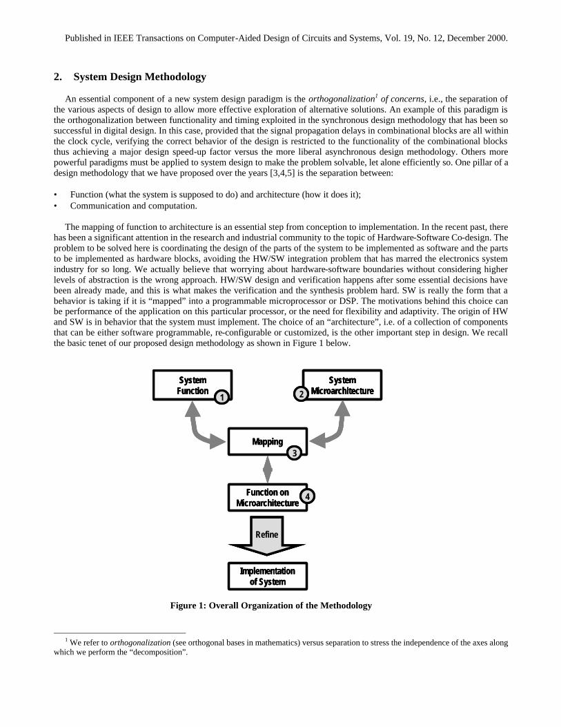
The mapping of function to architecture is an essential step from conception to implementation. In the recent past, there
has been a significant attention in the research and industrial community to the topic of Hardware-Software Co-design. The problem to be solved here is coordinating the design of the parts of the system to be implemented as software and the parts to be implemented as hardware blocks, avoiding the HW/SW integration problem that has marred the electronics system industry for so long. We actually believe that worrying about hardware-software boundaries without considering higher levels of abstraction is the wrong approach. HW/SW design and verification happens after some essential decisions have been already made, and this is what makes the verification and the synthesis problem hard. SW is really the form that a behavior is taking if it is “mapped” into a programmable microprocessor or DSP. The motivations behind this choice can be performance of the application on this particular processor, or the need for flexibility and adaptivity. The origin of HW and SW is in behavior that the system must implement. The choice of an “architecture”, i.e. of a collection of components that can be either software programmable, re-configurable or customized, is the other important step in design. We recall the basic tenet of our proposed design methodology as shown in Figure 1 below.
1 We refer to orthogonalization (see orthogonal bases in mathematics) versus separation to stress the independence of the axes along
which we perform the “decomposition”.
SystemFunction
SystemMicroarchitecture
Mapping
Function onMicroarchitecture
Implementation of System
Refine
1 2
3
4
SystemFunction
SystemMicroarchitecture
Mapping
Function onMicroarchitecture
Implementation of System
Refine
SystemFunction
SystemMicroarchitecture
SystemFunction
SystemMicroarchitecture
Mapping
Function onMicroarchitecture
Implementation of System
Refine
1 2
3
4
Figure 1: Overall Organization of the Methodology

Published in IEEE Transactions on Computer-Aided Design of Circuits and Systems, Vol. 19, No. 12, December 2000.
2.1. Function and Communication-based Design
We say that a system implements a set of functions, where a function is an abstract view of the behavior of an aspect of the system. This set of functions is the input/output characterization of the system with respect to its environment. It has no notion of implementation associated with it. For example, “when the engine of a car starts (input), the display of the number of revolutions per minute of the engine (output)” is a function, while “when the engine starts, the display in digital form of the number of revolutions per minute on the LCD panel” is not a function. In this case, we already decided that the display device is an LCD and that the format of the data is digital. Similarly, “when the driver moves the direction indicator (input), the display of a sign that the direction indicator is used until it is returned in its base position” is a function, while “when the driver moves the direction indicator, the emission of an intermittent sound until it is returned to its base position” is not a function.
The notion of function depends very much on the level of abstraction at which the design is entered. For example, the
decision whether to use sound or some other visual indication about the direction indicator may not be a free parameter of the design. Consequently, the second description of the example is indeed a function since the specification is in terms of sound. However, even in this case, it is important to realize that there is a higher level of abstraction where the decision about the type of signal is made. This may uncover new designs that were not even considered because of the entry level of the design. Our point is that no design decision should ever be made implicitly and that capturing the design at higher levels of abstraction yields better designs in the end.
The functions to be included in a product may be left to the decision of the designer or may be imposed by the customer.
If there are design decisions involved, then the decisions are grouped in a design phase called function (or sometimes feature) design. The decisions may be limited or range quite widely.
The description of the function the system has to implement is captured using a particular language that may or may not
be formal. In the past, natural language was the most used form of design capture. The language used for capturing functional specifications is often application dependent. For example, for control applications, Matlab is used to capture algorithms. For several applications, computer languages such as C are used. However, these languages often lack the semantic constructs to be able to specify concurrency. We believe that the most important point for functional specification is the underlying mathematical model, often called model of computation.
As opposed to the informal nature of component-based design often used to design software today [6], we promote the
use of formal models and transformations in system design so that verification and synthesis can be applied to advantage in the design methodology. In fact, verification is effective if complexity is handled by formalization, abstraction and decomposition [7]. Further, the concept itself of synthesis can be applied only if the precise mathematical meaning of a description of the design is applied. It is then important to start the design process from a high-level abstraction that can be implemented in a wide variety of ways. The implementation process is a sequence of steps that remove choice from the formal model. In other words, the abstract representation of the design should “contain” all the correct implementations in the sense that the behavior of the implementation should be consistent with the abstract model behavior. Whenever a behavior is not specified in the abstract model, the implicit assumption is that such behavior is a “don’t-care” in the implementation space. In the implementation domain, the abstract model is source of non-deterministic behavior. The implementation process progresses towards a deterministic system. It is important to underline that way too often system design starts with a system specification that is burdened by unnecessary references to implementations resulting in over-determined representations with respect to designer intent that obviously yield under-optimized designs.
In the domain of formal model of system behavior, it is common to find the term “Model of Computation”, a concept
that has its roots in language theory. This term refers more appropriately to mathematical models that specify the semantics of computation and of concurrency. In fact, concurrency models are the most important differentiating factors among models of computation. Edward Lee has correctly stressed the importance of allowing the designer to express designs making use of any such models of computation, or at least of the principal ones, thus yielding a so-called heterogeneous environment for system design. In his approach to simulation and verification, assembling a system description out of modules represented in different models of computation yields the problem of arbitrating communication among the different models. The concept of communication among different models of computation must be carefully explored and understood [8] and this is a central aspect of our research program in the GSRC.
Published in IEEE Transactions on Computer-Aided Design of Circuits and Systems, Vol. 19, No. 12, December 2000.
This difficulty has actually motivated our approach to communication-based design, where communication takes the driver’s seat in the overall system design methodology. In this approach, communication can be specified somewhat independently of the modules that compose the design. In fact, two approaches can be applied here. In the first case, we are interested in communication mechanisms that “work” in any environment, i.e., independent of the formal models and specifications of the behavior of the components. This is a very appealing approach if one emphasizes ease of component assembly. However, it is rather obvious that the designer may end up with an implementation that is quite inefficient, especially for high-volume embedded systems applications where production cost is very important. The other approach is to specify the communication behavior and then to use a successive refinement process for optimizing the communication, where the refinement process can leverage all that is known about the modules to interconnect. In this case, the correctness of the overall behavior is not insured by the communication mechanism but by the design process of the communication itself. In this case, a synthesis approach is most appealing since it reduces the risk of making mistakes and it may use powerful optimization techniques to reduce design cost and time.
The most important models of computation that have been proposed to date are based on three basic models: Finite
State Machines, Data Flow and Discrete Event [8]. All models have their strengths and weaknesses. It is an important differentiating factor to be able to use these models at their best. Note that each model is composable (can be assembled) in a particular way that guarantees that some properties of the single components are maintained in the overall system. Communication and time representation in each model of computation are strictly intertwined. In fact, in a synchronous system, communication can take place only at precise “instants of time” thus reducing the risk of unpredictable behavior. Synchronous systems are notoriously more expensive to implement and often less performing thus opening the door to asynchronous implementations. In this latter case, that is often the choice for large system design, particular care has to be exercised to avoid undesired and unexpected behaviors. The balance between synchronous and asynchronous implementations is possibly the most challenging aspect of system design. Globally-asynchronous-locally-synchronous (GALS) communication mechanisms are probably a good compromise in the implementation space [3].
The view of communication in these models of computation is sometimes at a level of abstraction that is too low. We
would like to be able to specify abstract communication patterns with high-level constraints that are not implying yet a particular model of communication. For example, it is our opinion that an essential aspect of communication is loss-lessness. We argue that there must exist a level of abstraction that is high enough to require that communication take place with no losses. The synchronous-asynchronous mechanism, the protocols used and so on, are just implementation choices that either guarantee loss-lessness or that have a good chance of ensuring that no data is lost where it matters but that needs extensive verification to make sure that this is indeed the case. For example, Kahn process networks [8] are important Data Flow models that guarantee lossless communication at the highest level of abstraction by assuming an ideal buffering scheme that has unbounded buffer size. Clearly, the unbounded buffer size is a “non-implementable” way of guaranteeing loss-lessness. When moving towards implementable designs, this assumption has to be removed. A buffer can be provided to store temporarily data that are exchanged among processes but it must be of finite size. The choice of the size of the buffer is crucial. Unfortunately deciding whether a finite buffer implementation exists that guarantees loss-lessness is not theoretically feasible in the general case, but there are cases for which the optimal buffer size can be found. In others, one has to hope for the best for buffer overwrite not to occur or has to provide additional mechanism that composed with the finite buffer implementation still guarantees that no loss takes place. For example, a send-receive protocol can be put in place to prevent buffer over-write to occur. Note that in this case the refinement process is quite complex and involves the use of composite processes. Today, there is little that is known about a general approach to communication design that has some of the feature that we have exposed, even though we have proposed a family of models that are related to each other as successive refinements [9].
Approaches to the isolation of communication and computation, and how to refine the communication specification
towards an implementation [10] have been presented elsewhere. In some cases, we have been able to determine a synthesis procedure for the communication that guarantees some properties. In our opinion, this formalism and the successive refinement process opens a very appealing window to system design with unexplored avenues in component-based software design. It is our opinion that the latest advances in component-based software design and in software engineering are converging, albeit slowly and probably unconsciously towards a more formal model of communication among modules.
Published in IEEE Transactions on Computer-Aided Design of Circuits and Systems, Vol. 19, No. 12, December 2000.
2.2. Micro-architecture
In most design approaches, the next stage of the design process involves the evaluation of tradeoffs across what we refer to as the architecture/micro-architecture boundary, and at this point in our presentation, the class of structural compositions that implement the architecture is of primary concern. While the word architecture is used in many meanings and contexts, we adhere to the definitions put forward in [11]: the architecture defines an interface specification that describes the functionality of an implementation, while being independent of the actual implementation. The micro-architecture, on the other hand, defines how this functionality is actually realized as a composition of modules and components, along with their associated software.
The instruction-set architecture of a microprocessor is a good example of an architecture: it defines what functions the
processor supports, without defining how these functions are actually realized. The micro-architecture of the processor is defined by the “organization” and the “hardware” of the processor. These terms can easily be extended to cover a much wider range of implementation options. At this point, the design decisions are made concerning what will eventually be implemented as software or as hardware.
Consistent with the above definitions, in our work we describe a micro-architecture as a set of interconnected
components (either abstract or with a physical dimension) that is used to implement a function. For example, an LCD, a physical component of a micro-architecture, can be used to display the number of revolutions per minute of an automotive engine. In this case, the component has a concrete, physical representation. In other cases, it may have a more abstract representation. In general, a component is an element with specified interfaces and explicit context dependency. The micro-architecture determines the final hardware implementation and hence it is strictly related to the concept of platform [12,13] that will be presented in greater detail later on.
The most important micro-architecture for the majority of embedded designs consists of microprocessors, peripherals,
dedicated logic blocks and memories. For some products, this micro-architecture is completely or in part fixed. In the case of automotive body electronics, the actual placement of the electronic components inside the body of the car and their interconnections is kept mostly fixed, while the single components, i.e., the processors, may vary to a certain extent. A fixed micro-architecture simplifies the design problem a great deal—especially the software part today—but limits design optimality. The trade-off is not easy to achieve.
In addition, the communication among micro-architecture blocks must be handled with great care. Its characteristics
make the composition of blocks easy or difficult to achieve. Standards are useful to achieve component re-use. Busses are typical interconnection structures intended to favor re-use. Unfortunately, the specification of standard busses such as the PCI bus is hardly formal. This makes the design of the interfaces at best haphazard. In our GSRC activities [14], we have a strong research program in formal methods to specify and verify such interfaces. Ultimately, we believe the verification of such interconnection interfaces will be the limiting factor in design productivity. In addition, we are experimenting with different interconnect structures such as on-chip networks [15].
2.3. Mapping
The essential design step that allows moving down the levels of the design flow is the mapping process, where the
functions to be implemented are assigned (mapped) to the components of the micro-architecture. For example, the computations needed to display a set of signals may all be mapped to the same processor or to two different components of the micro-architecture (e.g., a microprocessor and a DSP). The mapping process determines the performance and the cost of the design. To measure exactly the performance of the design and its cost in terms of used resources, it is often necessary to complete the design, leading to a number of time-consuming design cycles. This is a motivation for using a more rigorous design methodology. When the mapping step is carried out, our choice is dictated by estimates of the performance of the implementation of that function (or part of it) onto the micro-architecture component. Estimates can be provided either by the manufacturers of the components (e.g., IC manufacturers) or by system designers. Designers use their experience and some analysis to develop estimation models that can be easily evaluated to allow for fast design exploration and yet are accurate enough to choose a good micro-architecture. Given the importance of this step in any
Published in IEEE Transactions on Computer-Aided Design of Circuits and Systems, Vol. 19, No. 12, December 2000.
application domain, automated tools and environments should support effectively the mapping of functions to micro-architectures.
The mapping process is best carried out interactively in the design environment. The output of the process is either:
• A mapped micro-architecture iteratively refined towards the final implementation with a set of constraints on each mapped component (derived from the top-level design constraints) or
• A set of diagnostics to the micro-architecture and function selection phase in case the estimation process signals that design constraints may not be met with the present micro-architecture and function set. In this case, if possible, an alternative micro-architecture is selected. Otherwise, we have to work in the function space by either reducing the number of functions to be supported or their demands in terms of performance.
2.4. Link to Implementation
This phase is entered once the mapped micro-architecture has been estimated as capable of meeting the design
constraints. The next major issue to be tackled is implementing the components of the micro-architecture. This requires the development of an appropriate hardware block or of the software needed to make the programmable components perform the appropriate computations. This step brings the design to the final implementation stage. The hardware block may be found in an existing library or may need a special purpose implementation as dedicated logic. In this case, it may be further decomposed into sub-blocks until either we find what we need in a library or we decide to implement it by “custom” design. The software components may exist already in an appropriate library or may need further decomposition into a set of sub-components, thus exposing what we call the fractal (self-similar) nature of design, i.e., the design problem repeats itself at every level of the design hierarchy into a sequence of nested function-(architecture)-micro-architecture-mapping processes.
3. Platform-based Design [12]
When mapping the functionality of the system to an integrated circuit, the economics of chip design and manufacturing are essential to determine the quality and the cost of the system. Since the mask set and design cost for Deep Sub-Micron implementations is predicted to be overwhelming, it is important to find common architectures that can support a variety of applications as well as the future evolutions of a given application2. To reduce design costs, re-use is a must. In particular, since system designers will use more and more frequently software to implement their products, there is a need for design methodologies that allow the substantial re-use of software. This implies that the basic micro-architecture of the implementation is essentially “fixed”, i.e., the principal components should remain the same within a certain degree of parameterization. For embedded systems, which we believe are going to be the dominant share of the electronics market, the “basic” micro-architecture consists of programmable cores, I/O subsystem and memories. A family of micro-architectures that allow substantial re-use of software is what we call a hardware platform. We believe that hardware platforms will take the lion’s share of the IC market. However, the concept of hardware platform by itself is not enough to achieve the level of application software re-use we are looking for. To be useful, the hardware platform has to be abstracted at a level where the application software sees a high-level interface to the hardware that we call Application Program Interface or API. There is a software layer that is used to perform this abstraction. This layer wraps the different parts of the hardware platform: the programmable cores and the memory subsystem via a Real-Time Operating System (RTOS), the I/O subsystem via the Device Drivers, and the network connection via the network communication subsystem. This layer is called the software platform. The combination of the hardware and the software platforms is called the system platform.
2 It is important to stress that future evolutions of a given application are very important. If indeed there is enough capacity in the
platform, then adding or modifying the functionality of a product requires only a minor effort as compared to a totally new implementation. This points to the importance of selecting the “right” platform. A platform with limited spare capability may be a bad choice even though its manufacturing cost for the present version of the product may be better than one with more room to spare.
Published in IEEE Transactions on Computer-Aided Design of Circuits and Systems, Vol. 19, No. 12, December 2000.
3.1. Hardware Platforms
Seen from the application domain, the constraints that determine the hardware platform are often given in terms of performance and “size”. To sustain a set of functions for a particular application, a CPU should be able to run at least at a given speed and the memory system should be of at least a given number of bytes. Since each product is characterized by a different set of functions, the constraints identify different hardware platforms where more complex applications yield stronger architectural constraints. Coming from the hardware space, production and design costs imply adding hardware platform constraints and consequently reducing the number of choices. The intersection of the two sets of constraints defines the hardware platforms that can be used for the final product. Note that, as a result of this process, we may have a hardware platform instance that is over-designed for a given product, that is, some of the power of the micro-architecture is not used to implement the functionality of that product. Over-design is very common for the PC platform. In several applications, the over-designed micro-architecture has been a perfect vehicle to deliver new software products and extend the application space. We believe that some degree of over-design will be soon accepted in the embedded system community to improve design costs and time-to-market. Hence, the “design” of a hardware platform is the result of a trade-off in a complex space that includes:
• The size of the application space that can be supported by the micro-architectures belonging to the hardware platform.
This represents the flexibility of the hardware platform; • The size of the micro-architecture space that satisfies the constraints embodied in the hardware platform definition.
This represents the degrees of freedom that micro-architecture providers have in designing their hardware platform instances.
Once a hardware platform has been selected, then the design process consists of exploring the remaining design space
with the constraints set by the hardware platform. These constraints cannot only be on the components themselves but also on their communication mechanism. When we march towards implementation by selecting components that satisfy the architectural constraints defining a platform, we perform a successive refinement process where details are added in a disciplined way to produce a hardware platform instance.
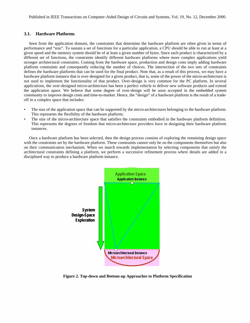
Figure 2. Top-down and Bottom-up Approaches to Platform Specification
SystemDesign-Space
Exploration
Microarchitectural SpaceMicroarchitectural Instance
Application InstanceApplication Space
SystemDesign-Space
Exploration
Microarchitectural SpaceMicroarchitectural Instance
Application InstanceApplication Space
Published in IEEE Transactions on Computer-Aided Design of Circuits and Systems, Vol. 19, No. 12, December 2000.
Ideally the design process in this framework starts with the determination of the set of constraints that defines the hardware platform for a given application. In the case of a particular product, we advocate to start the design process before splitting the market into high-end and low-end products. The platform thus identified can then be refined towards implementation by adding the missing information about components and communication schemes. If indeed we keep the platform unique at all levels, we may find that the cost for the low-end market is too high. At this point then we may decide to introduce two platform instances differentiated in terms of peripherals, memory size and CPU power for the two market segments. On the other hand, by defining the necessary constraints in view of our approach, we may find that a platform exists that covers both the low-end and the high-end market with great design cost and time-to-market improvements.
Hardware platform-based design optimizes globally the various design parameters including, as a measure of optimality,
NRE costs in both production and design. Hardware platform-based design is neither a top-down nor a bottom-up design methodology. Rather, it is a “meet-in-the-middle” approach. In a pure top-down design process, application specification is the starting point for the design process. The sequence of design decisions drives the designer toward a solution that minimizes the cost of the micro-architecture. Figure 2 shows the single application approach, the bottom of the figure shows the set of micro-architectures that could implement that application. The design process selects the most attractive solution as defined by a cost function. In a bottom-up approach, a given micro-architecture (instance of the architectural space) is designed to support a set of different applications that are often vaguely defined and is in general much based on designer intuition and marketing inputs. In general, this is the approach taken by IC companies that try to maximize the number of applications (hence, the production volume) of their platforms.
3.2. Software Platform
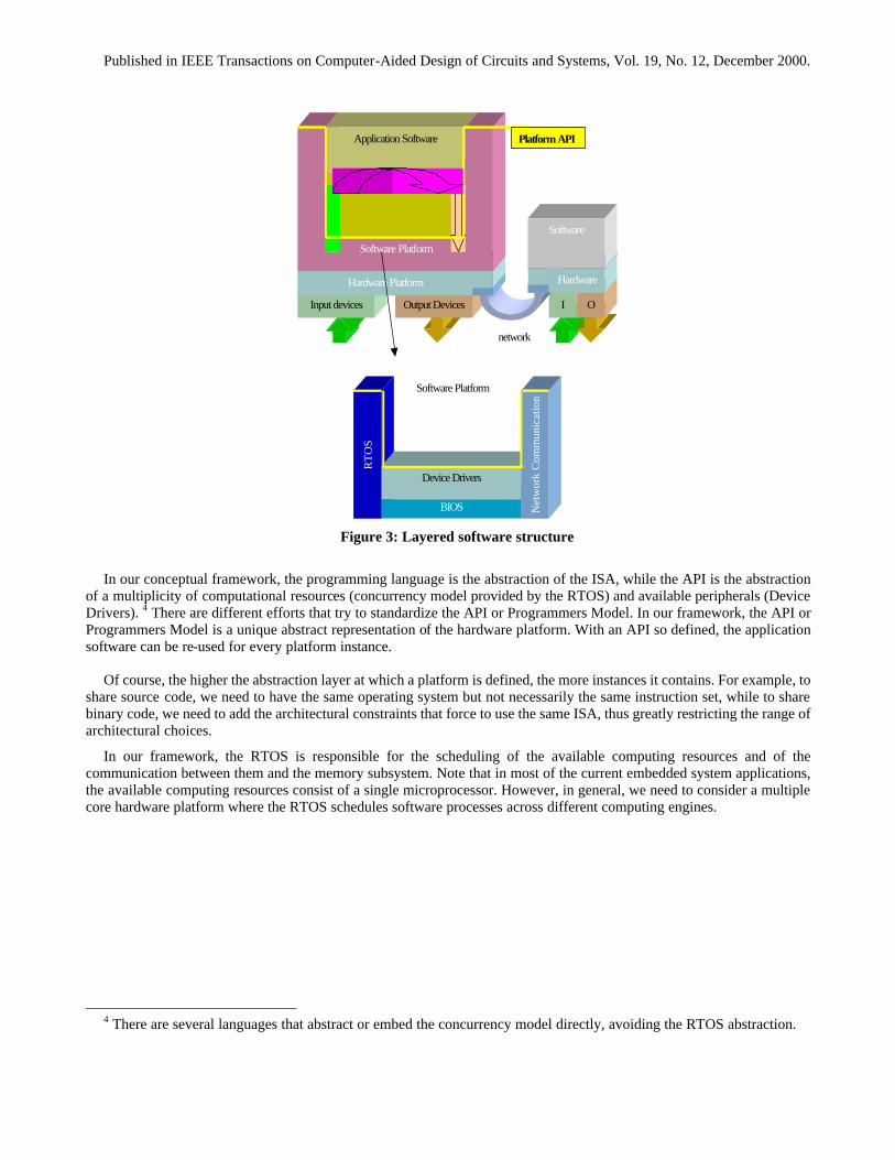
The concept of hardware platform by itself is not enough to achieve the level of application software re-use we are looking for. To be useful, the hardware platform has to be abstracted at a level where the application software “sees” a high-level interface to the hardware that we call Application Program Interface (API) or Programmers Model. There is a software layer that is used to perform this abstraction (Figure 3). This layer wraps the essential parts of the hardware platform:
• The programmable cores and the memory subsystem via a Real Time Operating System (RTOS), • The I/O subsystem via the Device Drivers, and • The network connection via the network communication subsystem3.
This layer is called the software platform.
3 In some cases, the entire software layer, including the Device Drivers and the network communication subsystem is called RTOS.
Published in IEEE Transactions on Computer-Aided Design of Circuits and Systems, Vol. 19, No. 12, December 2000.
Output DevicesInput devices
Hardware Platform
I O
Hardware
Software
network
Software Platform
Application Software Platform API
RT
OS
BIOS
Device Drivers
Net
wor
k C
omm
unic
atio
n
Software Platform
Figure 3: Layered software structure
In our conceptual framework, the programming language is the abstraction of the ISA, while the API is the abstraction
of a multiplicity of computational resources (concurrency model provided by the RTOS) and available peripherals (Device Drivers). 4 There are different efforts that try to standardize the API or Programmers Model. In our framework, the API or Programmers Model is a unique abstract representation of the hardware platform. With an API so defined, the application software can be re-used for every platform instance.
Of course, the higher the abstraction layer at which a platform is defined, the more instances it contains. For example, to
share source code, we need to have the same operating system but not necessarily the same instruction set, while to share binary code, we need to add the architectural constraints that force to use the same ISA, thus greatly restricting the range of architectural choices.
In our framework, the RTOS is responsible for the scheduling of the available computing resources and of the communication between them and the memory subsystem. Note that in most of the current embedded system applications, the available computing resources consist of a single microprocessor. However, in general, we need to consider a multiple core hardware platform where the RTOS schedules software processes across different computing engines.
4 There are several languages that abstract or embed the concurrency model directly, avoiding the RTOS abstraction.
Published in IEEE Transactions on Computer-Aided Design of Circuits and Systems, Vol. 19, No. 12, December 2000.
There is a battle that is taking place in this domain to establish a standard RTOS for embedded applications. For example, traditional embedded software vendors such as ISI and WindRiver are now competing with Microsoft that is trying to enter this domain by offering Windows CE, a stripped down version of the API of its Windows operating system. In our opinion, if the conceptual framework we offer here is accepted, the precise definition of the hardware platform and that of the API should allow us to synthesize automatically and in an optimal way most of the software layer. This is a radical departure from the standard models borrowed from the PC world. Software re-use, i.e. platform re-targetability, can be extended to these layers (middle-ware) hopefully providing higher levels of compatibility than binary compatibility. This aspect is further highlighted in the MESCAL approach described in Section 5.4.
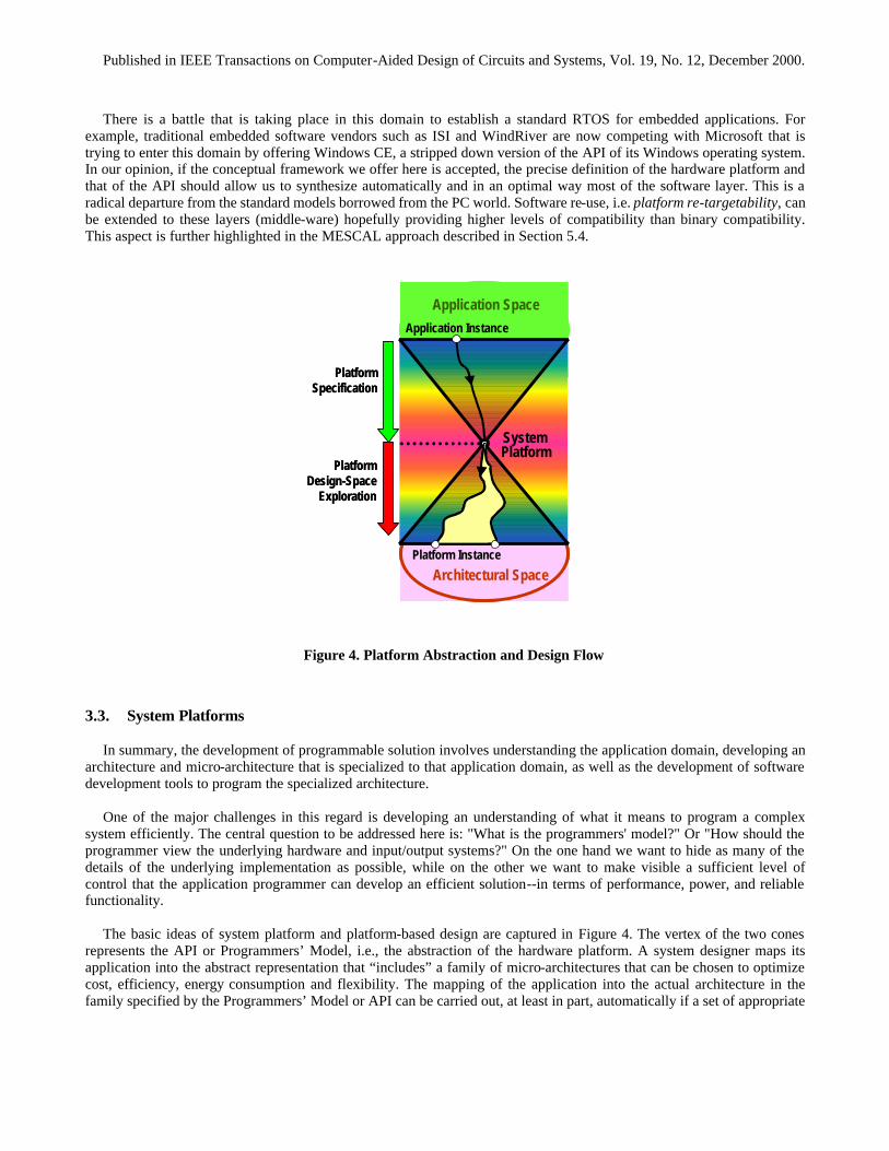
Figure 4. Platform Abstraction and Design Flow
3.3. System Platforms
In summary, the development of programmable solution involves understanding the application domain, developing an architecture and micro-architecture that is specialized to that application domain, as well as the development of software development tools to program the specialized architecture.
One of the major challenges in this regard is developing an understanding of what it means to program a complex
system efficiently. The central question to be addressed here is: "What is the programmers' model?" Or "How should the programmer view the underlying hardware and input/output systems?" On the one hand we want to hide as many of the details of the underlying implementation as possible, while on the other we want to make visible a sufficient level of control that the application programmer can develop an efficient solution--in terms of performance, power, and reliable functionality.
The basic ideas of system platform and platform-based design are captured in Figure 4. The vertex of the two cones
represents the API or Programmers’ Model, i.e., the abstraction of the hardware platform. A system designer maps its application into the abstract representation that “includes” a family of micro-architectures that can be chosen to optimize cost, efficiency, energy consumption and flexibility. The mapping of the application into the actual architecture in the family specified by the Programmers’ Model or API can be carried out, at least in part, automatically if a set of appropriate
PlatformDesign-Space
Exploration
PlatformSpecification
Architectural Space
Application Space
Application Instance
Platform Instance
SystemPlatform
PlatformDesign-Space
Exploration
PlatformSpecification
Architectural Space
Application Space
Application Instance
Platform Instance
SystemPlatform
Published in IEEE Transactions on Computer-Aided Design of Circuits and Systems, Vol. 19, No. 12, December 2000.
software tools (e.g., software synthesis, RTOS synthesis, device-driver synthesis) is available. It is clear that the synthesis tools have to be aware of the architecture features as well as of the API.
In the design space, there is an obvious trade-off between the level of abstraction of the Programmers’ Model and the
number and diversity of the platform instances covered. The more abstract the Programmers’ Model the richer is the set of platform instances but the more difficult it is to choose the “optimal” platform instance and map automatically into it. Hence we envision a number of system platforms that will be handled with somewhat different abstractions and tools. For example, more traditional platforms that include a small number of standard components such as microprocessors and DSPs will have an API that is simpler to handle than reconfigurable architectures. In the next section, we will show examples of application of the concepts exposed so far. One is related to the design of next generation wireless systems; the other to a class of reconfigurable architectures, their Programmers’ Model and tools to map applications onto an architecture.
4. Case Studies
The system-design concepts introduced in the previous sections — orthogonalization of concerns, communication/component and platform-based design — are best illustrated with the aid of real-life case studies. In this section, we describe applications from industrial domains and from the Berkeley Wireless Research Center. Of the two industrial applications, one is related to consumer electronics and the other to automotive electronics. The BWRC case is related to the design of ad-hoc wireless networks.
4.1. Industrial Applications
The methodology presented in this paper is not “empty rhetoric”, as often is the case of methodologies tested only on paper, but it has been already tested in advanced industrial environments. In particular, complex system designs have been cast in this framework and implemented in the field of automotive electronic subsystems [16,17] and consumer electronics [18]. Its basic aspects have been incorporated in POLIS [3], Ptolemy [19] and in an at least an industrial product [4, 5,20,21], Virtual Component Composer, and we know of other tools that are being developed based on these concepts.
4.1.1 Philips VideoTop COSY is a European Community project on system design and verification involving industry (Cadence, Philips,
Siemens) and academia (University of Paris Marie-Curie, Politecnico di Torino, University of Tubingen)[18]. The main goal was to apply the methodology outlined above (and modifying it whenever necessary) to industrial system design. The main driver was VideoTop, a subsystem that incorporates the main functionality of a digital video broadcast system.
The system receives an MPEG2 transport stream, where the user selects the channels to be decoded. The associated video streams are then unscrambled, de-multiplexed, and decoded. The user may also define post-processing operations on the decoded streams, such as zooming and composition (picture-in-picture). The functional specifications required the following components:
• An MPEG2 (ISO/IEC 13818-2) de-multiplexer. • An MPEG2 parser. • An MPEG2 decoder (H.262 compliant up to main profile and high level). • A video re-sizer with a zoom factor from 0.16 to 10. (Controlled by the user.) • A video mixer for a number of arbitrary sized video images. (Positions controlled by the user.) • A User interface
The functional specifications were captured using a formal model of computation (YAPI [22]) derived from Kahn
process networks. The model consisted of • 62 processes • 206 communication arcs
Published in IEEE Transactions on Computer-Aided Design of Circuits and Systems, Vol. 19, No. 12, December 2000.
• 25,000 C/C++ lines5
According to our methodology, the functional specifications were analyzed and simulated executing the Y-API program. The simulation time on a Linux Pentium 450Mhz was about 80 times slower than real-time behavior. The micro-architecture selection started with the following basic blocks: a MIPS PR39K with 1 SRAM block and PSOS as Real-Time Operating System (RTOS). We tried a full software implementation and one with a number of functions mapped in hardware resulting in a system with 4 busses, 14 application-specific co-processors and 17 software tasks running on the microprocessor [23]. The all-software solution had an estimated running time, using the methods described above, that was 160 times slower than the mixed hardware-software solution. The most relevant hardware blocks were identified by performance analysis. Top of the list was the Frame-Buffer Memory-Manager (T-memory). Some additional mappings are under study now to see whether a different micro-architecture with fewer co-processors could be safely used. Rather surprisingly, given the complexity of the system, the estimation results obtained with Virtual Component Composer of Cadence were within 5% of the performance measurement obtained with a cycle accurate simulator developed at Philips, TSS, thus demonstrating that estimation is feasible and a real help in quick architectural evaluations. The modeling of the micro-architecture and of the functional part of the design kept the communication part of the design separate from the computation part [24]. This resulted in an accurate analysis of the communication performance of the system. A major design effort at Philips is to apply the principles of Platform-based design and rapid prototyping to their most important new generation products.
4.1.2 Magneti-Marelli Automotive Engine Control This design [16,25,26] had many different features than the previous one: it has a strong control component and tight
safety constraints. In addition, the application had a large part of legacy design. The functionality of the engine-control automotive electronic subsystem consists of the following components:
• Failure detection and recovery of input sensors • Computation of engine phase, status and angle, crankshaft revolution speed and acceleration • Injection and ignition control law • Injection and ignition actuation drivers
The existing implementation had 135,000 line of source C code without comments. The first task was to extract the
precise functionality from the implementation. This was done by using a CFSM-based representation [3,25] resulting in 89 CFSMs and 56 timers. The behavior of the actuators and of part of the sensors was completely re-written in the formal model. For the ignition and injection control law, we encapsulated the legacy C code into 18 CFSMs representing concurrent processes.
The software was re-designed using the architecture of Figure 2 so that the mapping into different micro-architecture could be done with relative ease. In particular, we were able to test three different CPUs and, for each, two different software partitions to verify functionality and real-time behavior. In addition, we explored three different architectures for the I/O subsystem: one with a full software implementation, one with the use of a particular peripheral for timing functions (provided by the CPU vendor) and one with a highly optimized full hardware peripheral of new design.
The performance estimation was carried out with VCC and resulted in an error with respect to a prototype board with real hardware of only 11%. The implementation of the functionality on the three platforms is under way. For two of them it is almost completed resulting in software re-usability of more than 86%.
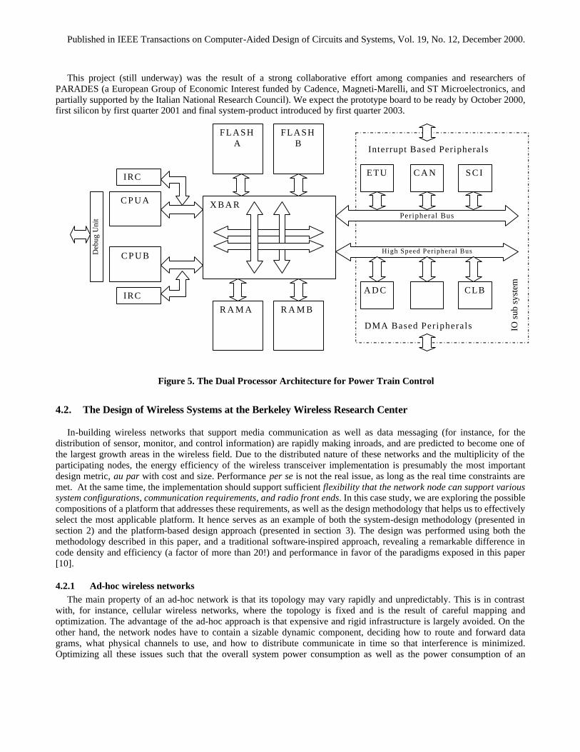
We also used the functionality captured in semi-formal terms to design a new dual processor architecture that is under design at ST Microelectronics [26]. This micro-architecture is presented in Figure 5. We estimated with VCC that about 40% of the compute power was still available after present direct injection control algorithms and semi-automatic gearbox control derived from the one available for Formula 1 racing car, were included. Note that it was not clear that a single processor solution would have been capable of supporting even this application. One could argue the cost of the dual processor architecture could be much higher than its single processor counter-part. Not so! We were able to fit the additional processor and the corresponding communication hardware utilizing only 4-6% of the total area of the chip that is dominated by the embedded flash memory.
5 The number of lines of code in a functional specification corresponds in general to MANY more lines of actual implementation
code. This is a sizable example!
Published in IEEE Transactions on Computer-Aided Design of Circuits and Systems, Vol. 19, No. 12, December 2000.
This project (still underway) was the result of a strong collaborative effort among companies and researchers of PARADES (a European Group of Economic Interest funded by Cadence, Magneti-Marelli, and ST Microelectronics, and partially supported by the Italian National Research Council). We expect the prototype board to be ready by October 2000, first silicon by first quarter 2001 and final system-product introduced by first quarter 2003.
Interrupt Based Peripherals
C P U A
C P U B
Peripheral Bus
High Speed Peripheral Bus
ETU C A N S C I
A D C CLB
DMA Based Peripherals
R A M A R A M B
FLASH A
FLASH B
X B A R
IO s
ub s
yste
m
IRC
Deb
ug U
nit
IRC
Figure 5. The Dual Processor Architecture for Power Train Control
4.2. The Design of Wireless Systems at the Berkeley Wireless Research Center
In-building wireless networks that support media communication as well as data messaging (for instance, for the distribution of sensor, monitor, and control information) are rapidly making inroads, and are predicted to become one of the largest growth areas in the wireless field. Due to the distributed nature of these networks and the multiplicity of the participating nodes, the energy efficiency of the wireless transceiver implementation is presumably the most important design metric, au par with cost and size. Performance per se is not the real issue, as long as the real time constraints are met. At the same time, the implementation should support sufficient flexibility that the network node can support various system configurations, communication requirements, and radio front ends. In this case study, we are exploring the possible compositions of a platform that addresses these requirements, as well as the design methodology that helps us to effectively select the most applicable platform. It hence serves as an example of both the system-design methodology (presented in section 2) and the platform-based design approach (presented in section 3). The design was performed using both the methodology described in this paper, and a traditional software-inspired approach, revealing a remarkable difference in code density and efficiency (a factor of more than 20!) and performance in favor of the paradigms exposed in this paper [10].
4.2.1 Ad-hoc wireless networks The main property of an ad-hoc network is that its topology may vary rapidly and unpredictably. This is in contrast
with, for instance, cellular wireless networks, where the topology is fixed and is the result of careful mapping and optimization. The advantage of the ad-hoc approach is that expensive and rigid infrastructure is largely avoided. On the other hand, the network nodes have to contain a sizable dynamic component, deciding how to route and forward data grams, what physical channels to use, and how to distribute communicate in time so that interference is minimized. Optimizing all these issues such that the overall system power consumption as well as the power consumption of an

Published in IEEE Transactions on Computer-Aided Design of Circuits and Systems, Vol. 19, No. 12, December 2000.
individual network node is minimized (< 100 µW) is the focus of the PicoRadio project at UC Berkeley, which addresses ubiquitous wireless sensor and monitor networks.
To study the desirable composition of an implementation platform for PicoRadio and to understand the impact of the architectural tradeoffs, we have selected a somewhat simplified application, the Intercom, for an initial case study. The Intercom is a single-cell wireless network supporting full-duplex voice communication among up to twenty mobile users located in a small geographical area (100 m2). The network includes a number of units, called remote terminals that operate in one of the following three modes: idle (the remote is switched on but has not subscribed to the network and cannot participate to a conference with other remotes), active (the remote has subscribed to the network and is enabled to participate in a conference), communicating (the remote is participating in a conference). Each remote can request one of the following services: subscription to enter active mode, un-subscription to return to idle mode, query of active users, conference with one or multiple remotes, or broadcast communication. The system specification includes also requirements on the performance of the transmission of voice samples, like max latency (below 100 ms) and min throughput (64 kbps). Minimizing power consumption is a key requirement of the system. At the same time, the design has to be such that the hardware should support different versions of the protocol stack (physical, link, media-access, and transport), as well as the application. For instance, the same node should be able to support data communications instead of voice (application layer), or to use CSMA (collision-sense multiple access) instead of TDMA (time-division multiple access) for the media-access scheme.
In the following sections, we will briefly describe the function and micro-architecture description, the platform exploration, and some results.
4.2.2 Protocol Design When attempting to explore different implementation platforms for a given set of applications, it is instrumental that the
functions are expressed using a clearly defined model-of-computation. This not only enables the function-micro-architecture mapping approach described in this paper, but also opens the door for formal verification of the correctness of the described protocol, which is a major challenge in this world of concurrent, distributed and real-time fine state machines. Hence, rather than following the traditional approach of describing the protocol in C, the function of the system was described using co-design finite state machines (CFSM) [3], amended with a set of performance constraints.
The protocol stack was designed by applying communication refinement to the initial specifications, and involved four
designers, each of which focused on particular aspect of the stack. Using this strategy, we identified the functionality of the layers, defined the interfaces between layers, and derived constraints for each layer in a top-down fashion from the system requirements. Due to the novelty of the CFSM model and the specification/analysis environment, it took these designers approximately 1 month to derive a fully functional description with crisp and well-defined interfaces between layers (Figure 4).
The network topology includes a unit, called base-station that coordinates the network operation. The base-station
provides control functionality only, while communication channels are set up as peer-to-peer connections between remotes. This configuration helps to reduce the overall bandwidth requirements, compared to the star-connected network configuration typical in cellular environments. The base-station keeps track of the evolution of the network configuration using an internal database that stores information about the active users and the IDs of the physical channels. In general, all Intercom units have identical capabilities, i.e. each unit can take on the function of base-station (on top of being a remote) (the mode of a unit is set on power-on). This design choice makes the protocol more robust in case of failures, as it enables active reconfiguration should the base-station fail.
The protocol stack has two interfaces with the external world: one with the user, providing a voice channel and service
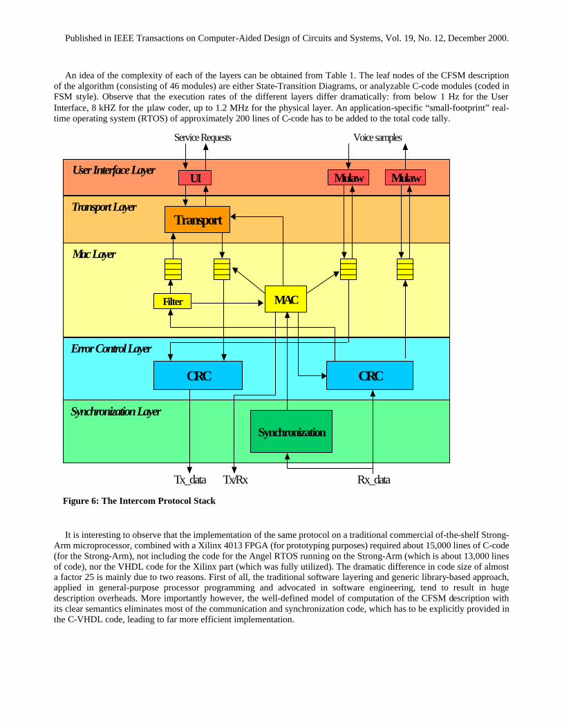
requests (e.g. Subscribe, StartConference, EndConference), and one with the radio that forms the RF link. Error! Reference source not found. shows the structure of the protocol stack, which is composed of the following layers: the User-Interface Layer, Transport Layer, Mac Layer, Data Link Layer (supporting Error Control and Synchronization) and the Physical Layer. While a crisp definition of these layers is advantageous from a design verification process, and enables a clear decomposition of design constraints, it also forms a logical basis for the design partitioning process that will take place during the architecture mapping process. It furthermore enables the adaptation of the protocol to different radio-front ends (by just replacing the physical layer), different media access approaches (CSMA versus TDMA), and applications (data versus voice).
Published in IEEE Transactions on Computer-Aided Design of Circuits and Systems, Vol. 19, No. 12, December 2000.
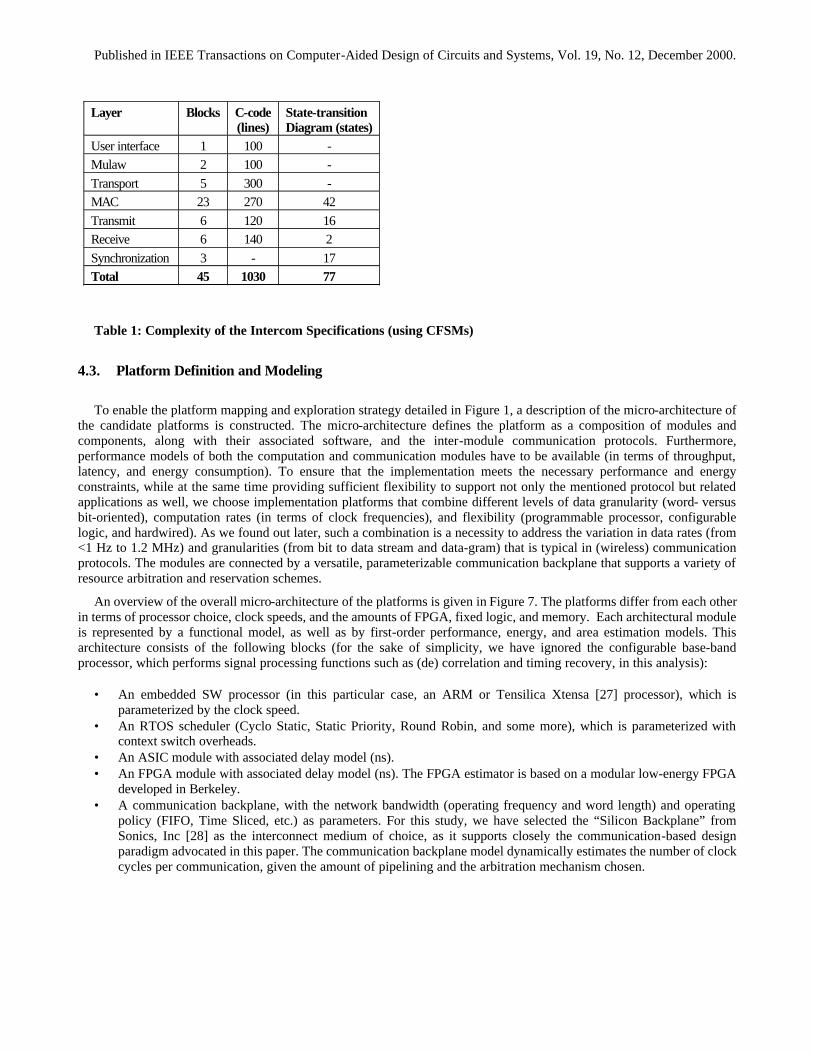
An idea of the complexity of each of the layers can be obtained from Table 1. The leaf nodes of the CFSM description of the algorithm (consisting of 46 modules) are either State-Transition Diagrams, or analyzable C-code modules (coded in FSM style). Observe that the execution rates of the different layers differ dramatically: from below 1 Hz for the User Interface, 8 kHZ for the µlaw coder, up to 1.2 MHz for the physical layer. An application-specific “small-footprint” real-time operating system (RTOS) of approximately 200 lines of C-code has to be added to the total code tally.
It is interesting to observe that the implementation of the same protocol on a traditional commercial of-the-shelf Strong-Arm microprocessor, combined with a Xilinx 4013 FPGA (for prototyping purposes) required about 15,000 lines of C-code (for the Strong-Arm), not including the code for the Angel RTOS running on the Strong-Arm (which is about 13,000 lines of code), nor the VHDL code for the Xilinx part (which was fully utilized). The dramatic difference in code size of almost a factor 25 is mainly due to two reasons. First of all, the traditional software layering and generic library-based approach, applied in general-purpose processor programming and advocated in software engineering, tend to result in huge description overheads. More importantly however, the well-defined model of computation of the CFSM description with its clear semantics eliminates most of the communication and synchronization code, which has to be explicitly provided in the C-VHDL code, leading to far more efficient implementation.
UI
MAC
CRC CRC
Synchronization
Filter
Tx_data Rx_data
Mulaw Mulaw
Transport
User Interface Layer
Transport Layer
Mac Layer
Error Control Layer
Synchronization Layer
Voice samples
Tx/Rx
Service Requests
Figure 6: The Intercom Protocol Stack
Published in IEEE Transactions on Computer-Aided Design of Circuits and Systems, Vol. 19, No. 12, December 2000.
Layer Blocks C-code (lines)
State-transition Diagram (states)
User interface 1 100 - Mulaw 2 100 - Transport 5 300 - MAC 23 270 42 Transmit 6 120 16 Receive 6 140 2 Synchronization 3 - 17 Total 45 1030 77
Table 1: Complexity of the Intercom Specifications (using CFSMs)
4.3. Platform Definition and Modeling
To enable the platform mapping and exploration strategy detailed in Figure 1, a description of the micro-architecture of the candidate platforms is constructed. The micro-architecture defines the platform as a composition of modules and components, along with their associated software, and the inter-module communication protocols. Furthermore, performance models of both the computation and communication modules have to be available (in terms of throughput, latency, and energy consumption). To ensure that the implementation meets the necessary performance and energy constraints, while at the same time providing sufficient flexibility to support not only the mentioned protocol but related applications as well, we choose implementation platforms that combine different levels of data granularity (word- versus bit-oriented), computation rates (in terms of clock frequencies), and flexibility (programmable processor, configurable logic, and hardwired). As we found out later, such a combination is a necessity to address the variation in data rates (from <1 Hz to 1.2 MHz) and granularities (from bit to data stream and data-gram) that is typical in (wireless) communication protocols. The modules are connected by a versatile, parameterizable communication backplane that supports a variety of resource arbitration and reservation schemes.
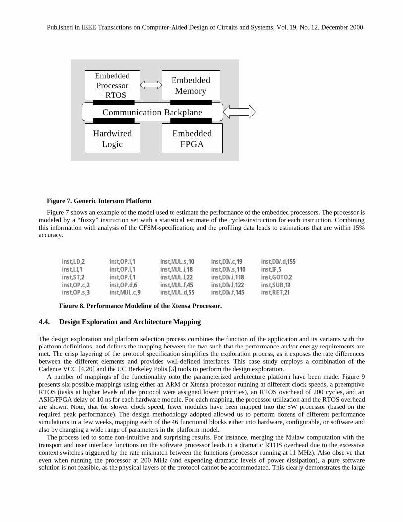
An overview of the overall micro-architecture of the platforms is given in Figure 7. The platforms differ from each other in terms of processor choice, clock speeds, and the amounts of FPGA, fixed logic, and memory. Each architectural module is represented by a functional model, as well as by first-order performance, energy, and area estimation models. This architecture consists of the following blocks (for the sake of simplicity, we have ignored the configurable base-band processor, which performs signal processing functions such as (de) correlation and timing recovery, in this analysis):
• An embedded SW processor (in this particular case, an ARM or Tensilica Xtensa [27] processor), which is
parameterized by the clock speed. • An RTOS scheduler (Cyclo Static, Static Priority, Round Robin, and some more), which is parameterized with
context switch overheads. • An ASIC module with associated delay model (ns). • An FPGA module with associated delay model (ns). The FPGA estimator is based on a modular low-energy FPGA
developed in Berkeley. • A communication backplane, with the network bandwidth (operating frequency and word length) and operating
policy (FIFO, Time Sliced, etc.) as parameters. For this study, we have selected the “Silicon Backplane” from Sonics, Inc [28] as the interconnect medium of choice, as it supports closely the communication-based design paradigm advocated in this paper. The communication backplane model dynamically estimates the number of clock cycles per communication, given the amount of pipelining and the arbitration mechanism chosen.
Published in IEEE Transactions on Computer-Aided Design of Circuits and Systems, Vol. 19, No. 12, December 2000.
Figure 7. Generic Intercom Platform
Figure 7 shows an example of the model used to estimate the performance of the embedded processors. The processor is modeled by a “fuzzy” instruction set with a statistical estimate of the cycles/instruction for each instruction. Combining this information with analysis of the CFSM-specification, and the profiling data leads to estimations that are within 15% accuracy.
4.4. Design Exploration and Architecture Mapping
The design exploration and platform selection process combines the function of the application and its variants with the platform definitions, and defines the mapping between the two such that the performance and/or energy requirements are met. The crisp layering of the protocol specification simplifies the exploration process, as it exposes the rate differences between the different elements and provides well-defined interfaces. This case study employs a combination of the Cadence VCC [4,20] and the UC Berkeley Polis [3] tools to perform the design exploration.
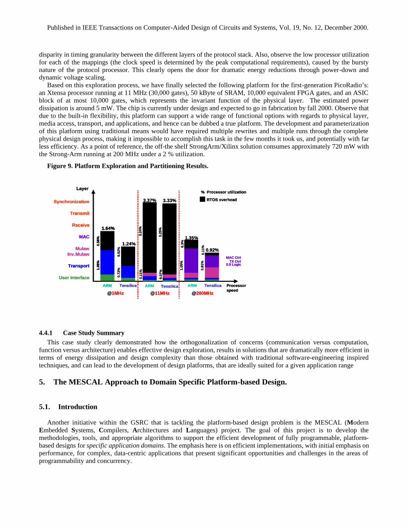
A number of mappings of the functionality onto the parameterized architecture platform have been made. Figure 9 presents six possible mappings using either an ARM or Xtensa processor running at different clock speeds, a preemptive RTOS (tasks at higher levels of the protocol were assigned lower priorities), an RTOS overhead of 200 cycles, and an ASIC/FPGA delay of 10 ns for each hardware module. For each mapping, the processor utilization and the RTOS overhead are shown. Note, that for slower clock speed, fewer modules have been mapped into the SW processor (based on the required peak performance). The design methodology adopted allowed us to perform dozens of different performance simulations in a few weeks, mapping each of the 46 functional blocks either into hardware, configurable, or software and also by changing a wide range of parameters in the platform model.
The process led to some non-intuitive and surprising results. For instance, merging the Mulaw computation with the transport and user interface functions on the software processor leads to a dramatic RTOS overhead due to the excessive context switches triggered by the rate mismatch between the functions (processor running at 11 MHz). Also observe that even when running the processor at 200 MHz (and expending dramatic levels of power dissipation), a pure software solution is not feasible, as the physical layers of the protocol cannot be accommodated. This clearly demonstrates the large
EmbeddedProcessor+ RTOS
EmbeddedMemory
Communication Backplane
HardwiredLogic
EmbeddedFPGA
EmbeddedProcessor+ RTOS
EmbeddedMemory
Communication Backplane
HardwiredLogic
EmbeddedFPGA
inst,LD,2inst,LI,1inst,ST,2inst,OP.c,2inst,OP.s,3
inst,DIV.c,19inst,DIV.s,110inst,DIV.i,118inst,DIV.l,122inst,DIV.f,145
inst,OP.i,1inst,OP.l,1inst,OP.f,1inst,OP.d,6inst,MUL.c,9
inst,DIV.d,155inst,IF,5inst,GOTO,2inst,SUB,19inst,RET,21
inst,MUL.s,10inst,MUL.i,18inst,MUL.l,22inst,MUL.f,45inst,MUL.d,55
Figure 8. Performance Modeling of the Xtensa Processor.
Published in IEEE Transactions on Computer-Aided Design of Circuits and Systems, Vol. 19, No. 12, December 2000.
disparity in timing granularity between the different layers of the protocol stack. Also, observe the low processor utilization for each of the mappings (the clock speed is determined by the peak computational requirements), caused by the bursty nature of the protocol processor. This clearly opens the door for dramatic energy reductions through power-down and dynamic voltage scaling.
Based on this exploration process, we have finally selected the following platform for the first-generation PicoRadio’s: an Xtensa processor running at 11 MHz (30,000 gates), 50 kByte of SRAM, 10,000 equivalent FPGA gates, and an ASIC block of at most 10,000 gates, which represents the invariant function of the physical layer. The estimated power dissipation is around 5 mW. The chip is currently under design and expected to go in fabrication by fall 2000. Observe that due to the built-in flexibility, this platform can support a wide range of functional options with regards to physical layer, media access, transport, and applications, and hence can be dubbed a true platform. The development and parameterization of this platform using traditional means would have required multiple rewrites and multiple runs through the complete physical design process, making it impossible to accomplish this task in the few months it took us, and potentially with far less efficiency. As a point of reference, the off-the shelf StrongArm/Xilinx solution consumes approximately 720 mW with the Strong-Arm running at 200 MHz under a 2 % utilization.
Figure 9. Platform Exploration and Partitioning Results.
4.4.1 Case Study Summary This case study clearly demonstrated how the orthogonalization of concerns (communication versus computation,
function versus architecture) enables effective design exploration, results in solutions that are dramatically more efficient in terms of energy dissipation and design complexity than those obtained with traditional software-engineering inspired techniques, and can lead to the development of design platforms, that are ideally suited for a given application range
5. The MESCAL Approach to Domain Specific Platform-based Design.
5.1. Introduction
Another initiative within the GSRC that is tackling the platform-based design problem is the MESCAL (Modern Embedded Systems, Compilers, Architectures and Languages) project. The goal of this project is to develop the methodologies, tools, and appropriate algorithms to support the efficient development of fully programmable, platform-based designs for specific application domains. The emphasis here is on efficient implementations, with initial emphasis on performance, for complex, data-centric applications that present significant opportunities and challenges in the areas of programmability and concurrency.
User Interface
MulawInv.Mulaw
Transport
ARM
% Processor utilization
Processorspeed
Layer
1.35%MAC
MAC Ctrl
0.5 LogicTX Ctrl
Synchronization
Transmit
Receive
ARM
3.37% RTOS overhead
3.24
%
0.3%
1.05
%
0.11
%
ARM
1.64%
0.56
%1.
08%
Tensilica
1.24%
0.52
%0.
72%
Tensilica
3.33%
3.25
%0.
07%
Tensilica
0.92%
0.11
%0.
81%
@1MHz @11MHz @200MHz
User Interface
MulawInv.Mulaw
Transport
ARM
% Processor utilization
Processorspeed
Layer
1.35%MAC
MAC Ctrl
0.5 LogicTX Ctrl
Synchronization
Transmit
Receive
ARM
3.37% RTOS overhead
3.24
%
0.3%
1.05
%
0.11
%
ARM
1.64%
0.56
%1.
08%
ARM
1.64%
0.56
%1.
08%
Tensilica
1.24%
0.52
%0.
72%
Tensilica
3.33%
3.25
%0.
07%
Tensilica
0.92%
0.11
%0.
81%
@1MHz @11MHz @200MHz
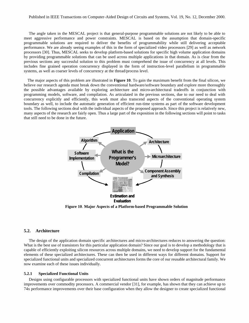
Published in IEEE Transactions on Computer-Aided Design of Circuits and Systems, Vol. 19, No. 12, December 2000.
The angle taken in the MESCAL project is that general-purpose programmable solutions are not likely to be able to meet aggressive performance and power constraints. MESCAL is based on the assumption that domain-specific programmable solutions are required to deliver the benefits of programmability while still delivering acceptable performance. We are already seeing examples of this in the form of specialized video processors [29] as well as network processors [30]. Thus, MESCAL seeks to develop platform-based solutions for specific high volume application domains by providing programmable solutions that can be used across multiple applications in that domain. As is clear from the previous sections any successful solution to this problem must comprehend the issue of concurrency at all levels. This includes fine grained operation concurrency displayed in the form of instruction-level parallelism in programmable systems, as well as coarser levels of concurrency at the thread/process level.
The major aspects of this problem are illustrated in Figure 10. To gain the maximum benefit from the final silicon, we believe our research agenda must break down the conventional hardware/software boundary and explore more thoroughly the possible advantages available by exploring architecture and micro-architectural tradeoffs in conjunction with programming models, software, and compilation. As articulated in the previous sections, due to our need to deal with concurrency explicitly and efficiently, this work must also transcend aspects of the conventional operating system boundary as well, to include the automatic generation of efficient run-time systems as part of the software development tools. The following sections deal with the individual aspects of the proposed approach. Since this project is relatively new, many aspects of the research are fairly open. Thus a large part of the exposition in the following sections will point to tasks that still need to be done in the future.
Figure 10. Major Aspects of a Platform-based Programmable Solution
5.2. Architecture
The design of the application domain specific architectures and micro-architectures reduces to answering the question: What is the best use of transistors for this particular application domain? Since our goal is to develop a methodology that is capable of efficiently exploiting silicon resources across multiple domains, we need to develop support for the fundamental elements of these specialized architectures. These can then be used in different ways for different domains. Support for specialized functional units and specialized concurrent architectures forms the core of our reusable architectural family. We now examine each of these issues individually.
5.2.1 Specialized Functional Units Designs using configurable processors with specialized functional units have shown orders of magnitude performance
improvements over commodity processors. A commercial vendor [31], for example, has shown that they can achieve up to 74x performance improvements over their base configuration when they allow the designer to create specialized functional
Component Assemblyand Synthesis
Microarchitecture
Architecture
Estimation andEvaluation
Algorithm
SoftwareImplementation
Compilation
Application
What is theProgrammer’s
Model?Component Assembly
and Synthesis
Microarchitecture
Architecture
Estimation andEvaluation
Algorithm
SoftwareImplementation
Compilation
Application
What is theProgrammer’s
Model?
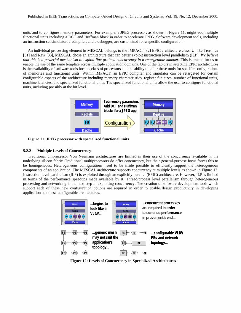
Published in IEEE Transactions on Computer-Aided Design of Circuits and Systems, Vol. 19, No. 12, December 2000.
units and to configure memory parameters. For example, a JPEG processor, as shown in Figure 11, might add multiple functional units including a DCT and Huffman block in order to accelerate JPEG. Software development tools, including an instruction set simulator, a compiler, and a debugger, are customized for a specific configuration.
An individual processing element in MESCAL belongs to the IMPACT [32] EPIC architecture class. Unlike Tensilica
[31] and Raw [33], MESCAL chose an architecture that can better exploit instruction level parallelism (ILP). We believe that this is a powerful mechanism to exploit fine-grained concurrency in a retargetable manner. This is crucial for us to enable the use of the same template across multiple application domains. One of the factors in selecting EPIC architectures is the availability of software tools for this class of processors and the ability to tailor these tools for specific configurations of memories and functional units. Within IMPACT, an EPIC compiler and simulator can be retargeted for certain configurable aspects of the architecture including memory characteristics, register file sizes, number of functional units, machine latencies, and specialized functional units. The specialized functional units allow the user to configure functional units, including possibly at the bit level.
FU
RegFile
Memory
ICache
FU
RegFile
Memory
ICache
FUFU
RegFile
Memory
ICache
HUFDCT FUConfiguration
Set memory parametersAdd DCT and Huffmanblocks for a JPEG app
FUFU
RegFile
Memory
ICache
HUFDCT FUFUFU
RegFile
Memory
ICache
HUFDCT FUConfiguration
Set memory parametersAdd DCT and Huffmanblocks for a JPEG app
Figure 11. JPEG processor with specialized functional units
5.2.2 Multiple Levels of Concurrency Traditional uniprocessor Von Neumann architectures are limited in their use of the concurrency available in the
underlying silicon fabric. Traditional multiprocessors do offer concurrency, but their general-purpose focus forces this to be homogeneous. Heterogeneous configurations need to be made possible to efficiently support the heterogeneous components of an application. The MESCAL architecture supports concurrency at multiple levels as shown in Figure 12. Instruction level parallelism (ILP) is exploited through an explicitly parallel (EPIC) architecture. However, ILP is limited in terms of the performance speedups made available by it. Thread/process level parallelism through heterogeneous processing and networking is the next step in exploiting concurrency. The creation of software development tools which support each of these new configuration options are required in order to enable design productivity in developing applications on these configurable architectures.
FUFU
RegFile
Memory
ICache
HUFDCT FUFUFU
RegFile
Memory
ICache
HUFDCT FU
PE PE
PE PE
PE
PE
PE PE PE
FUFU FU
RegFile
Memory
ICache
DCT HUF
PE PE
PE PE
PE
PE
PE PE PE
PE PE
PE PE
PE
PE
PE PE PE
FUFU FU
RegFile
Memory
ICache
DCT HUF
...begins tolook like aVLIW...
PE PE
PE PE
PE
PE
PE PE PE
PE PE
PE PE
PE
PE
PE PE PE
...concurrent processesare required in orderto continue performanceimprovement trend...
...generic meshmay not suit theapplication’stopology...
PE PE
PE PE
PE
PE PE PE
...configurable VLIWPEs and network topology...
PE PE
PE PE
PE
PE PE PE
PE PE
PE PE
PE
PE PE PE
...configurable VLIWPEs and network topology...
Figure 12: Levels of Concurrency in Specialized Architectures
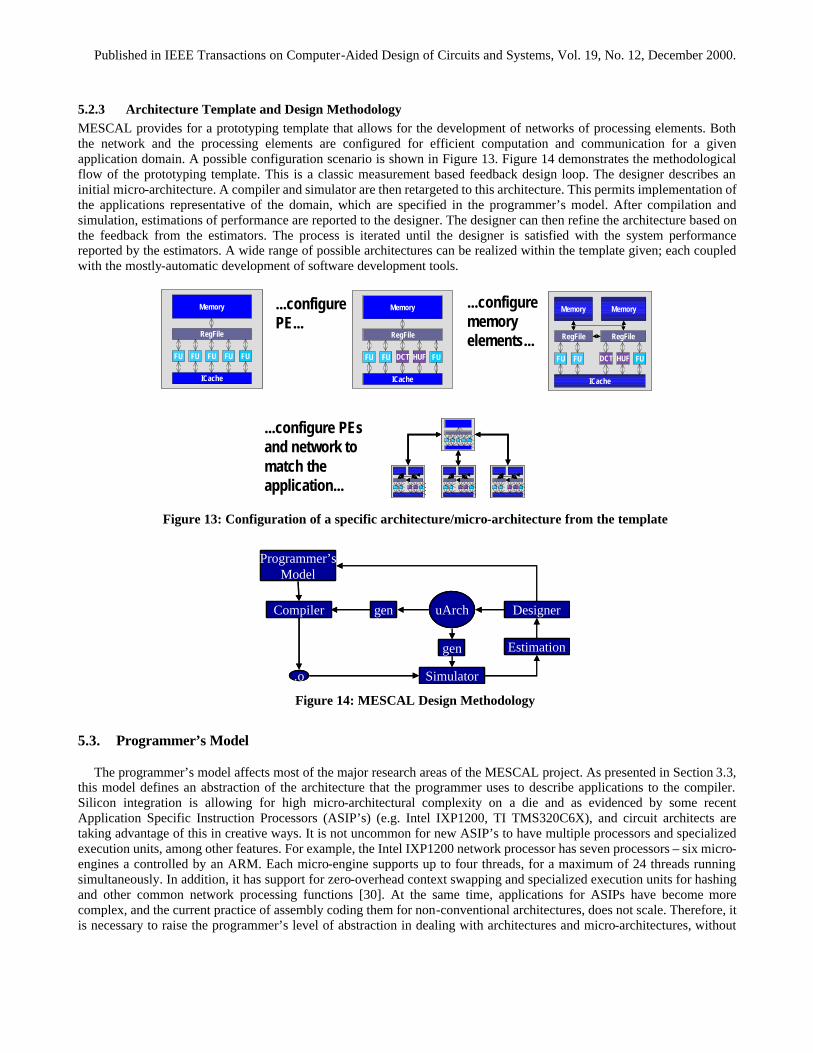
Published in IEEE Transactions on Computer-Aided Design of Circuits and Systems, Vol. 19, No. 12, December 2000.
5.2.3 Architecture Template and Design Methodology MESCAL provides for a prototyping template that allows for the development of networks of processing elements. Both the network and the processing elements are configured for efficient computation and communication for a given application domain. A possible configuration scenario is shown in Figure 13. Figure 14 demonstrates the methodological flow of the prototyping template. This is a classic measurement based feedback design loop. The designer describes an initial micro-architecture. A compiler and simulator are then retargeted to this architecture. This permits implementation of the applications representative of the domain, which are specified in the programmer’s model. After compilation and simulation, estimations of performance are reported to the designer. The designer can then refine the architecture based on the feedback from the estimators. The process is iterated until the designer is satisfied with the system performance reported by the estimators. A wide range of possible architectures can be realized within the template given; each coupled with the mostly-automatic development of software development tools.
FUFU FU
RegFile
Memory
ICache
DCT HUFFUFU FU
RegFile
Memory
ICache
DCT HUFFUFU FU
RegFile
Memory
ICache
FU FUFUFU FU
RegFile
Memory
ICache
FU FU FUFU FU
RegFile
Memory
ICache
DCT HUF
Memory
RegFile
FUFU FU
RegFile
Memory
ICache
DCT HUF
Memory
RegFile
...configurePE...
...configurememoryelements...
...configure PEsand network tomatch the application...
Figure 13: Configuration of a specific architecture/micro-architecture from the template
.o Simulator
gen uArch Designer
gen
Compiler
Estimation
Programmer’sModel
.o Simulator
gen uArch Designer
gen
Compiler
Estimation
Programmer’sModel
Figure 14: MESCAL Design Methodology
5.3. Programmer’s Model
The programmer’s model affects most of the major research areas of the MESCAL project. As presented in Section 3.3, this model defines an abstraction of the architecture that the programmer uses to describe applications to the compiler. Silicon integration is allowing for high micro-architectural complexity on a die and as evidenced by some recent Application Specific Instruction Processors (ASIP’s) (e.g. Intel IXP1200, TI TMS320C6X), and circuit architects are taking advantage of this in creative ways. It is not uncommon for new ASIP’s to have multiple processors and specialized execution units, among other features. For example, the Intel IXP1200 network processor has seven processors – six micro-engines a controlled by an ARM. Each micro-engine supports up to four threads, for a maximum of 24 threads running simultaneously. In addition, it has support for zero-overhead context swapping and specialized execution units for hashing and other common network processing functions [30]. At the same time, applications for ASIPs have become more complex, and the current practice of assembly coding them for non-conventional architectures, does not scale. Therefore, it is necessary to raise the programmer’s level of abstraction in dealing with architectures and micro-architectures, without

Published in IEEE Transactions on Computer-Aided Design of Circuits and Systems, Vol. 19, No. 12, December 2000.
sacrificing design efficiency. The goal of the MESCAL programmer’s model is to present the programmer with an abstraction of the architecture while helping the compiler generate efficient code for new architectural platforms.
Our approach to the programmer’s model is to combine the bottom-up and top-down views. The bottom-up view
exposes only the relevant features of the architecture and hides the details. From the top-down, our model should be expressive eenough for the programmer to relay all the information he/she knows about the program to the compiler. This combination of views is in sharp contrast to existing parallel programming models. Most parallel languages only embody the top down view. Often, the target architecture for these languages is a network of general-purpose processors. As a result, they are often concerned with general-purpose usage and portability. Thus, the compiler and operating system perform a majority of the work. In addition, high inter-process communication cost often forces the application to be programmed in a very decoupled fashion. Until recently, a majority of the applications that run on multi-processor frameworks have relatively similar types of computation on large input data sets, e.g. adaptive mesh refinement, matrix multiply, analysis of large graphs, FFT. Like compilation for general-purpose single processors, the goal of general-purpose multi-processor systems is only performance averaged over a set of benchmarks. In contrast, our target applications have heterogeneous, often complex computation, on a streaming data set. The only performance that matters, is the performance of the specific applications in the application domain that is was designed for.
5.3.1 Bottom Up View The goal of the bottom up view is to provide the programmer with a powerful abstraction of the architecture. Our target
programmers will be aware of the underlying architecture while coding the application. It will be difficult for a compiler to automatically make use of user designed architectural features without help from the programmer. The bottom up view of the programming model provides this assistance by presenting an abstraction of the architecture that exposes only the relevant features, while hiding the details.
Clearly, there is a spectrum of how much of the architecture to expose to the programmer. Assembly language is the
least abstract view of a processor since it exposes every way the software interacts with the physical resources of the architecture. The C language, for example, provides a little higher abstraction of a processor. While registers and memory locations are merged into the concept of a variable for ease of programming, the concept of a pointer and the register keyword provide the programmer with facilities to break this abstraction. This allows programmers to describe their application at a higher level, yet retain their ability to “tweak” their code for higher performance. Java can be viewed as an even higher abstraction of the underlying machine. In fact, this abstraction is specified in great detail via the Java Virtual Machine.
Since the MESCAL target architecture has not yet been completely defined, the first step in specifying the bottom up
view is to define the hardware/software interface of elements of MESCAL’s architectural platforms. This will define the entire set of architecture features that can be accessed in the programmer’s model. The next step will be to choose a subset of these features that provide the programmer with a powerful abstraction of the architecture. The three main elements of the architecture we will abstract are the communication architecture, computing resources, and memory.
5.3.2 Top-Down View From the top-down, the model should be expressive eenough for the programmer to relay all the information he/she
knows about the program to the compiler. In addition, the model should not require the programmer to specify what the compiler can already effectively compute. One key to generating efficient code is exploiting concurrency at multiple levels. Since VLIW compilers tackle the problem of instruction level parallelism (ILP), our model requires the programmer to specify concurrency at the task and bit level. To define tasks, we use a Single Program Multiple Data (SPMD) specification, as is commonly used in message passing systems. We are currently in the process of determining how to specify bit level parallelism within our existing model.
In multi-processor systems, the operating system often plays a crucial role in overall system performance. While the
compiler largely affects performance, all of its analyses are static. The dynamic behavior of the OS allows it to perform task level scheduling, binding, and synchronization. Often, the programmer knows how to best implement these features. We need to provide language features for the programmer to specify how to carry out these capabilities. This will require compiling part of the operating system based on the programmer’s hints. For example, the Intel IXP1200 provides an
Published in IEEE Transactions on Computer-Aided Design of Circuits and Systems, Vol. 19, No. 12, December 2000.
instruction to perform a zero-overhead context swap [30]. Examining the real time behavior of our target programs on our architectural platforms will expose those operating system functions that will benefit from programmer guidance.
5.4. MESCAL Compiler
Given the tremendous amount of available concurrency afforded by the multiple PEs and FUs in the target micro-architecture, it is unreasonable to expect that such a machine can be optimally hand-programmed in assembly language by a group of programmers. Such a process will surely be very time-consuming and highly error-prone. In order to increase productivity and satisfy time-to-market pressures, a compilation process must be utilized in order to automate the mapping of applications to such a complex machine.
The goal of the MESCAL compiler project is to perform this automation. Specifically, the objective is to develop a
highly optimizing, retargetable compiler infrastructure that enables a set of interesting source applications to be efficiently mapped onto a family of fully programmable architectures and micro-architectures, in particular the one that we have described in this document. Before delving into the details of what we need to do to compile for MESCAL architectures, it is useful to compare what we want in a compiler for our embedded applications and architecture versus what is traditionally done in general-purpose compilation and software development.
Since computer performance is difficult to gauge in the absence of the particular program of interest, benchmarks are
usually used to give users an idea of how fast a processor runs. As a result, optimizing compiler developers aim to improve the performance of a suite of benchmarks, with the idea that improved performance for these benchmarks will yield improved performance for most applications. While this notion usually holds true, the final performance numbers are usually some type of average across the set of programs in the benchmark. This means that compiler writers will sacrifice performance of one benchmark application if it yields significant speedups for others, such that the overall performance number increases. When developing embedded systems, cost and performance constraints are often so tight that such a compromise is undesirable. If the compiler isn't aggressive enough, a more expensive processor may be required, and in some cases, code may have to be written by hand. It would be truly unfortunate to suffer increased system or design costs simply because the compiler sacrificed our applications’ performance for the sake of some unrelated benchmark. The MESCAL compiler should be able to adapt the optimization parameters and be tuned to the application at hand. This allows designers to take the best advantage of the hardware without resorting to tedious and error-prone design techniques such as assembly language programming.
The MESCAL compiler needs to be easily retargetable to a variety of PEs and yet preserve aggressive optimization.
General-purpose compilers are tuned for a specific general-purpose microprocessor. This allows designers to aggressively optimize optimization algorithms for the target micro-architecture. On the other hand, the MESCAL compiler needs to be able to target a family of architectures, in which each PE may be a different application-specific processor and the network may be tuned to the application domain as well. Of course, due to the cost and performance constraints we still need to preserve aggressive optimization. In addition, the MESCAL compiler faces constraints that are typically associated with embedded compilation, but not general-purpose compilation. These include code density constraints, hard real-time constraints, and power dissipation constraints.
The traditional software design methodology assumes a given set of services offered by libraries and an operating
system (OS). When designing embedded systems, the designer often hand-selects general-purpose OS components that are needed by the application. If a new target architecture is used, the designer also hand-writes device driver and memory management routines, as well as other code that is necessary to port the OS to the new architecture. When compiling software for an embedded system, the designer is often aware of the entire set of code that needs to be executed. A compiler armed with this knowledge and sophisticated analysis capability can automatically select real-time OS (RTOS) components as well as synthesize custom components to improve application performance and resource utilization as discussed in Section 3.2. These custom components can include a scheduler, as well as custom synchronization primitives. Finally, to allow fully retargetable compilation for the family of MESCAL architectures, we need to adapt the RTOS for the architecture at hand. Thus, we would like the MESCAL compiler to synthesize the device drivers, memory management routines, and other hardware-specific code from a machine description.

Published in IEEE Transactions on Computer-Aided Design of Circuits and Systems, Vol. 19, No. 12, December 2000.
The MESCAL compiler project presents many interesting and challenging research issues. These research issues include: the automatic synthesis of RTOS components within the compilation framework, the ability to achieve automatically retargetable compilation while preserving optimization, the effective partitioning of an application onto the multiple PEs and FUs of the target architecture, and the development of effective visualization tools for the family of MESCAL architectures.
Since the MESCAL compiler is focused on compiling embedded applications for the target architecture, there are many opportunities to optimize RTOS functionality based on the characteristics of the application itself. Additionally, the tight integration of the RTOS with the application, together with an on-chip low-latency network, will allow the MESCAL compiler to exploit parallelism unavailable in the traditional parallel computing community.
The compiler has much information about the communication that must occur between various threads of a process. The
compiler may also analyze multiple processes and extract inter-process dependencies. Since the compiler is also responsible for scheduling on a VLIW machine, the compiler also has knowledge of the relative latencies between various send and receive operations. This information places the compiler in a nearly ideal position to synthesize a schedule or scheduling hints for the application being compiled.
Of course, in order to produce good schedules for the concurrent code in the application, the compiler needs to have a
good model of the underlying communication network so it can generate schedules that avoid network congestion and avoid resource under-utilization due to network delay. Furthermore, very low-latency networks may require static switch schedules, which the compiler will need to generate. Efficient utilization of this type of network will require additional compiler sophistication.
Unfortunately, a compiler cannot know all the dynamic characteristics of an application, and the RTOS may still need to
manage portions of the application. On the other hand, the compiler does have enough information to guide the dynamic decisions an RTOS makes. As a result, we need to develop an RTOS that can be guided at run-time by code inserted into the application by the compiler.
The compiler attributes of retargetability and optimization generally do not go hand-in-hand. In particular, the enabling of retargetability in a compiler usually involves a compromise in the quality of generated code. Many research efforts have been devoted to the development of a retargetable compiler infrastructure that is still capable of aggressive optimization [34]. Although several research efforts have resulted in compilation infrastructures that are both retargetable and highly optimizing, these infrastructures have not exhibited automatic retargetability -- an optimizing compiler is automatically retargetable if it has the ability to generate high-quality code for a new architecture from a unified description of the target machine. In particular, existing automatically retargetable compilers lack the sophisticated machine-dependent code optimization algorithms that are necessary to generate high-quality code. Furthermore, existing highly optimizing retargetable compilers possibly require the compiler developer to write a significant amount of new source code; thus increasing the time required generating a new compiler. Using the lessons learned from previous research efforts in embedded compilation, the MESCAL compiler project aims to fully understand what is involved in developing an automatically retargetable compiler that still preserves optimization.
In order to exploit the huge amounts of coarse-grained and fine-grained parallelism offered by our family of
architectures, we will need to develop advanced visualization tools that enable us to determine how effectively the architectural resources are utilized. These tools must be able to dynamically visualize the current state of each PE, i.e. the status of each process/task that has been bound to each PE, and the various inter-PE communications that have completed or are in the process of being performed.
5.5. Evaluation Strategy
Design-drivers serve both to focus our research efforts and as a tool to quantitatively measure the effectiveness of our proposed methodology. Given the importance of the driver to our research goals, we have given substantial effort to choosing an appropriate real-world application for MESCAL: the Virtual Private Network. In this evaluation, we are quantifying where the performance is coming from, either from micro-architectural improvements or from software technology. We also aim to precisely measure aspects of the concurrency achieved via a variety of approaches so that we can answer some basic questions about concurrency across a system:
Published in IEEE Transactions on Computer-Aided Design of Circuits and Systems, Vol. 19, No. 12, December 2000.
• Where is the concurrency available? • How much can be achieved by exploiting instruction-level parallelism versus more general concurrency? • How much “rewriting” of the application is needed to extract it? • How well were we able to predict the performance achieved a priori?
5.6. Summary of the MESCAL Approach
Domain specific platforms are becoming an increasingly important, and in many cases, the only practical way to meet the performance requirements of compute intensive applications with the flexibility of software programmability. Currently the design of such platforms requires significant engineering effort, and even then the software development tools for such platforms are typically found lacking. The MESCAL project focuses on all aspects of the design of these platforms and the associated software development tools. Concurrency at both the application and the implementation level is the key focus of this approach – the goal is to develop suitable platforms with concurrent computation, and map concurrency in the computation to these platforms.
The architecture exploits concurrency at all levels – bit level concurrency implemented in specialized functional units, instruction level parallelism implemented through concurrent functional units and thread/process level concurrency implemented through multiple PEs. An important part of the architecture is the development of the communication network tailored to the application domain. As highlighted in Section 3.1, there is a clear distinction between the architecture and the micro-architecture, as well as a clear separation between the computation and the communication aspects of the platform development.
Software development tools involve the compiler, simulator, debugger and visualization aids. The compiler is the most sophisticated of these – requiring retargetable capabilities for compiling down to different PEs within the family, as well as synthesizing the communication and synchronization code for thread/process level concurrency. This aspect of the MESCAL compiler blurs the boundary between traditional compilers and real time operating systems. Again, the clean separation between computation and communication is crucial in developing easy to manage code.
The programmer’s model exports the platform to the programmer. It serves the dual function of capturing enough of the application domain to pass down to the compiler, as well as exporting just enough of the architecture to enable the programmer to efficiently program the hardware platform.
6. Conclusions
We have presented the basic tenets of a comprehensive design methodology for system design centered on the concepts of orthogonalization of concerns, such as function and architecture, computation and communication, and platform-based design. The methodology has been successfully tested on wireless system design and on some industrial application including automotive electronics and video processing. Our work is now focused on the abstractions and the mathematical foundations needed to deal with communication at all levels of the design process including network protocol design. In addition, we are more and more concerned with the software implementation aspects since the viability of platform-based design impinges on the automatic generation of performing and error-free software. In this effort, we are going to leverage our knowledge of mathematical foundations, applications and novel software design methods based on the concept of components. An important application of the methodology is the development of a comprehensive approach to highly programmable and configurable platform design. The MESCAL project is aimed at the definition of this platform and at the development of tools for the mapping of complex functionality onto the programmable architecture for a given domain. We believe that the development of these platforms and the associated software development tools is significantly different from general-purpose solutions and have outlined the research problems associated with this development.
7. Acknowledgements
We would like to thank MARCO, DARPA and their respective constituents for supporting the development of the unique research community that makes up the GSRC. The ideas presented above are the result of many hours of collaborative discussion within the GSRC, Berkeley Wireless Research Center, PARADES (a European Group of

Published in IEEE Transactions on Computer-Aided Design of Circuits and Systems, Vol. 19, No. 12, December 2000.
Economic Interest funded by Cadence, Magneti-Marelli and ST Microelectronics), Cadence Research Laboratories, the MADESS research project of the Italian National Council and all of the people listed below, as well as the many students, postdoctoral researchers, and industrial collaborators working within the GSRC, share the credit for the ideas presented in this paper. In particular, we would like to thank:
• Dr. Alberto Ferrari for his contributions to platform-based design and for the pivotal role in the design of the dual-processor platform for automotive applications
• Dr. Luciano Lavagno and Dr. Jim Rowson for their contributions to the development of some of the system-level design methodology components presented here.
• Prof. Ed Lee for his many contributions to system-level design • Dr. Kees Vissers of Philips for his contributions to firming up our design methodology and for the many
discussions on orthogonalization of concerns (he and his research team came up with a notion of function-architecture co-design called Y-chart[35]
• Dr. J.Y. Brunel of Philips National Research Lab for his contributions to COSY and the design of the video application
• Niraj Shah, Michael Shilman, Manish Vachharajani and Scott Weber for their input on the MESCAL project
8. Bibliography
[1] M. Pinto, CTO Lucent Microelectronics, private communication, June 1999. [2] The GSRC web site can be found at: http://www.gigascale.org [3] F. Balarin et al., Hardware-Software Co-Design of Embedded Systems: The POLIS Approach, Kluwer Publishing Co.,
1998. [4] J. Rowson and A. Sangiovanni-Vincentelli, System Level Design, EE Times, 1996. [5] J. Rowson and A. Sangiovanni-Vincentelli, Interface-based Design, Proceedings of the 34th Design Automation
Conference (DAC-97). pp. 178-183, Las Vegas, June 1997. [6] C. Szyperski, Component Software: Beyond Object-Oriented Software, ACM Press, Addison-Wesley 1998. [7] A. Sangiovanni-Vincentelli, R. McGeer and A. Saldanha, Verification of Integrated Circuits and Systems, Proc. Of
1996 Design Automation Conference, June 1996. [8] E. Lee and A. Sangiovanni-Vincentelli, A Unified Framework for Comparing Models of Computation, IEEE Trans. on Computer Aided Design of Integrated Circuits and Systems, Vol. 17, N. 12, pp. 1217-1229, December 1998. [9] M.Sgroi, L.Lavagno, A.Sangiovanni-Vincentelli, Formal Models for Embedded System Design, to appear in IEEE
Design & Test of Computers. Special Issue on System Design, 2000. [10] J.L. da Silva Jr., M. Sgroi, F. De Bernardinis, S.F. Li, A. Sangiovanni-Vincentelli, J. Rabaey Wireless Protocols
Design: Challenges and Opportunities, 8th International Workshop on Hardware/Software Co-Design Codes/CASHE '00, Diego, CA May 2000.
[11] C. G. Bell and A. Newell, "Computer Structures: Readings and Examples," McGraw-Hill, New York, 1971. [12] A. Ferrari and A. Sangiovanni-Vincentelli, System Design: Traditional Concepts and New Paradigms, Proceedings of
the 1999 Int. Conf. On Comp. Des., Austin, Oct. 1999. [13] H. Chang et al., Surviving the SOC Revolution: Platform-based Design, Kluwer Academic Publishing, 1999. [14] R. Bryant, E. Clarke and D. Dill, GSRC Formal Verification Effort, Annual Presentation of the GSRC Activities, Dec.
1999. [15] B. Dally and J. Rabaey, Presentation at GSRC quarterly meeting, March 2000. [16] G. Bombarda, G. Gaviani and P. Marceca, Power-train System Design: Functional and Architectural Specifications, Proc. Of Convergence 2000, Detroit, Oct. 2000. [17] A. Sangiovanni-Vincentelli, “Automotive Electronics: Trends and Challenges”, Proc. Of Convergence 2000, Detroit, Oct. 2000. [18] J.Y. Brunel, A. Sangiovanni-Vincentelli and Rainer Kress, “COSY: a methodology for system design based on reusable hardware & software IP's”, in: J-Y. Roger (ed.), Technologies for the Information Society, IOS Press, pp. 709-716, June 1998.
[19] J. Davis II, M. Goel, C. Hylands, B. Kienhuis, E. A. Lee, Jie Liu, X. Liu, L. Muliadi, S. Neuendorffer, J. Reekie, N. Smyth, J. Tsay and Y. Xiong, "Overview of the Ptolemy Project," ERL Technical Report UCB/ERL No. M99/37, Dept. EECS, University of California, Berkeley, CA 94720, July 1999.

Published in IEEE Transactions on Computer-Aided Design of Circuits and Systems, Vol. 19, No. 12, December 2000.
[20] J. Rowson and A. Sangiovanni-Vincentelli, “Felix initiative pursues new co-design methodology”, Electronic Engineering Times, June 15, 1998, p.50, 51,74. [21] http://www.cadence.com/whitepapers/vcc.html [22] E.A. de Kock, G. Essink, W. Smits, van der Wolf, J-Y. Brunel, W. Kruijtzer, P. Lieverse and K. Vissers, “YAPI: Application Modeling for Signal Processing Systems”, Proc. of Design Automation Conference’2000, Los Angeles, June 2000. [23] H. Kenter, C. Passerone, W. Smits, Y. Watanabe and A. Sangiovanni-Vincentelli, “Designing Digital Video Systems: Modeling and Scheduling,” Proc. of CODES’99, Rome, May 1999.
[24] J.Y. Brunel, W. Kruijtzer, H. Kenter, F. Pétrot, L. Pasquier, E. de Kock and W. Smits, “COSY Communication IP’s”, Proc. of Design Automation Conference 2000, Los Angeles, June 2000. [25] M. Baleani, A. Ferrari, A. Sangiovanni-Vincentelli and C. Turchetti, “Hardware-Software Co-design of an Engine Management System”, Proc. of Design Automation and Test Europe Conf. 2K, Paris, March 2000. [26]A. Ferrari, S. Garue, M. Peri, S. Pezzini, L. Valsecchi, F. Andretta, and W. Nesci, Design and Implementation of a Dual-Processor Platform for Power-train Systems, Proc. Of Convergence 2K, Detroit, Oct. 2000. [27] Tensilica, “The Xtensa Processor Generator”, http://www.tensilica.com/technology.html [28] Sonics, Inc., “The Silicon Backplane”, http://www.sonicsinc.com [29] A listing of commercial Video Processors may be found at http://wad.www.media.mit.edu/people/wad/vsp/node1.html. [30] Tom R. Halfhill, “ Intel Network Processor Targets Routers,” Microprocessor Report, Volume 13, Number 12,
September 13, 1999, pages 1, 5-10. [31] R. Gonzalez, “Configurable/Extensible Processors Change System Design,” Hot Chips 99. [32] “The IMPACT Research Group,” http://www.crhc.uiuc.edu/IMPACT [33] Elliot Waingold, Michael Taylor, Devabhaktuni Srikrishna, Vivek Sarkar, Walter Lee, Victor Lee, Jang Kim, Matthew Frank, Peter Finch, Rajeev Barua, Jonathan Babb, Saman Amarasinghe, and Anant Agarwal, “Baring it all to Software: Raw Machines,” IEEE Computer, September 1997, pp. 86-93. [34] A. Sudarsanam, Code Optimization Libraries for Retrgetable Compilation for Embedded Digital Signal Processors,
PhD thesis, Princeton University, November 1998. [35] B. Kienhuis, E. Deprettere, K. Vissers and P. van der Wolf, ``An Approach for Quantitative Analysis of Application-Specific Dataflow Architectures'', In Proc. 11-th Int. Conf. on Application-specific Systems, Architectures and Processors, Zurich, Switzerland, July 14-16 1997