Embed Size (px)
Citation preview

E8.4401 System Manager
Operating instructions
Please observe the safety instructions and read through this manual carefully before commissioning the equipment.

Safety information General information
2
General information Safety information
Power connection regulations Please note the connection conditions specified by your local electrical power supply company and the VDE regulations. Your heating control system may only be installed and serviced by appropriately authorised specialists.
E For fixed devices, a facility for mains disconnection in accordance with EN 60335 must be installed in compliance with the installation specifications (e.g. switch).
E The mains lines insulation must be protected against damage caused by overheating (e.g. insulation hose).
E The minimum distance to installation objects in the vicinity must be chosen so that the permitted ambient temperature is not exceed during operation (see table - Technical Data).
E If the system is not installed properly, persons using it are at put at risk of fatal or serious injury (electric shock). Ensure the controller is de-energized prior to performing any work on the controller!
Warranty conditions If the system is not installed, commissioned, serviced and repaired properly, it will render the manufacturer's warranty null and void.
Important text passages ! Important notes are denoted by an exclamation
mark.
E This attention symbol is used to point out dangers in this manual.

General information Description
3
Description
Declaration of conformity
This device corresponds to the requirements of the relevant guidelines and standards, if the
corresponding regulations and the manufacturer's instructions are complied with.
Function The following functions are mapped in the cascade manager: Cascades with up to 8 different HS, of which 4 stages
directly via relay Water heating 1 direct heating circuit or header pump 1 mixed heating circuit Demand-related circulation pump control Automatic toggle between summer and winter time Activation by means of a timer possible

Contents General information
4
Contents
General information 2 Safety information 2
Power connection regulations 2 Warranty conditions 2 Important text passages 2
Description 3 Declaration of conformity 3 Function 3
Contents 4
Part 1: Operation 7 Operation in normal mode 7
Operating elements 7 Ç Operating mode selection 7 Effect of the operating mode 8 Display in normal operation 9
Changing the settings 10 Operating elements 10 Operating level 11 Areas 12
General 12 Display 12 Users 12 Time programs 12 Expert 12
Levels 12 Installation 12 Hot water 12 Heating circuit I / II 12
Part 2: Overview of display values and settings 13 General area 13
Date/Time/Holiday 13 Service 15
Code number Entry 15 RELAY TEST 15 SENSOR TEST 16 SW NO XXX-XX 17 CASCADE MANU (only with code no.) 17 BURNER TIME and BURNER START 17 LIMITER TEST 18 SERVICE 18 RESET … 18
Display Range 19 Installation 19
T-OUTSIDE 19 T-COLL DES ((heat request) 19
Hot water 20 T-DHW DES (hot water set temperature) 20 T-ROOM DES A (current value for set room temperature) 20 T-ROOM (room temperature) 20
User Area 21 Installation 21
GERMAN => Language 21 CONTRAST 21 DISPLAY SEL 21 SELEC-PROG 21
Hot water 22
General information Contents
5
1X DHW (1x Hot water) 22 T-DHW 1-3 DES (Hot water temperature setting) 22 ANTILEGION (Hot water short time heating function) 22
Heating circuit I / II 23 MODE 23 T-ROOM DES 1-3 23 T-REDUCED 23 T-ABSENCE 23 T-LIMIT DAY/T-LIMIT N (Day/Night) 24 HEATSLOPE 24 ADAPTION (heat slope adaptation) 25 ROOMS-INFL (Room sensor influence) 25 ADAP ROOM-T (room sensor adaptation) 25 OPTIM HEAT (Heating optimisation) 26 MAX OPT-TIME (maximum bringing forward) 26 ECONO OPTI (Reduction optimisation) 26 PC-ENABLE 26 RETURN 26
Timer Program Area 27 List of available time programs 27 Selecting a timer program 27 Timer/heating program adjustment 28
Expert area 31 Installation 31
CODE-NO 31 BUS ID 1 / 2 (heating circuit number) 31 TIME MASTER 31
MAX T-COLL (max. header temperature) 31 MIN T-COLL (min. header temperature) 31 HYST BOILER (dyn. switching hysteresis stage 1) 32 with HYST TIME (Hysteresis time) 32 CAP/MODULE (boiler output for each stage) 33 MIN MOD CASC (min. modulation cascade) 33 HW-BOILER (number of stages for HW operation) 33 CONTR DEVIAT (header control variance) 34 DES OUTPUT (required system output [in %]) 34 SWITCH VAL (-99 – +99) 34 BLOCK TIME (currently remaining value) 34 RESET TIME (resetting time for I-Controller) 35 SEQUENCE 1 (Boiler sequence 1 35 SEQUENCE 2 (heat generator sequence 2) 35 BOILER SEQ (time to sequence change) 35 LOCK TIME (delay time for next stage) 35 Screed program 36 SCREED (activation of screed drying process) 36
Hot water 37 DHW RELIEF(charging pump lock) 37 PARALLEL (Pump parallel running) 37 T-BOILER DHW (increase during HW operation) 38 HYST DHW (hot water hysteresis) 38 DHW FOLLOWUP (pump run-down time) 38 THERM INPUT (storage tank with thermostat) 38 WALL HUNG (for modulating HS) 38
Heating circuit I / II 39

Contents General information
6
HC FUNCTION (heating circuit function selection) 39 PUMP MODE (pump operating mode) 40 MIXER OPEN (open mixer dynamic) 41 MIXER CLOSE (close mixer dynamic) 41 MAX T-FLOW (max. flow temperature) 41 MIN T-FLOW (min. flow temperature) 41 T-FROST PROT (frost protection temperature) 41 OUT-TEMP-DEL (outside temperature delay) 41 SLOPE OFFSET (heating slope distance) 42 B-HEAT SINK (circuit enable) 42
Part 3: General function description 43 Heat circuit control 43
Weather-dependent control 43 Room sensor influence 43
Hot water generation 43 Frost protection function 43 EEPROM check 44 Circulation pump control 44
Switched according to heating requirement 44 Switched according to heating limits 44
Delayed pump switch-off 45 Pump blocking protection 45 Mixer motor blocking protection 45
Part 4: Installation and Start-up 46 Installation 46
Assembly / Dismantling 46 Connecting instructions 47 System diagram with direct heating circuit 48
System diagram with header pump 49 Connection diagram 50
Terminal assignment 50
Remote controls 51 Operation-control module Merlin BM, BM 8, Lago FB 51 Remote control FBR2 51 Sensor resistances FBR 52 DCF receiver 52 PC 52 Maximum delimiter 53 Telephone switch 53 Sensor values / characteristic curve 54 Outdoor sensor AF (AFS) S 55 Boiler sensor KF (KFS) H 55 Flow sensor VF (VFAS) v 55 Storage tank sensor SPF (SPFS) F 55
Commissioning 56 Commissioning procedure 56
System bus 57 The heating system 57 Bus ID 57 Error messages 58
Troubleshooting 59 Technical data 60

Part 1: Operation Operation in normal mode
7
Part 1: Operation
Part 1: Operation For initial start-up, please read the chapter "Installation and Start-up“ Operation in normaal modus Operation in normal mode
(operating flap closed)
Operating elements
Ç Change the set operating mode
Ç Operating mode selection Turn the knob to select the operating mode required. The operating mode selected is indicated by a symbol at the bottom of the display. It takes effect when the setting is not changed for 5 s.
The following operating modes are available for selection:
i Standby / OFF (Heating OFF and hot water preparation OFF, only frost protection mode)
F1 Automatic mode 1 (Heating according to timer program 1; HW according to HW program)
F2 Automatic mode 2 (Heating according to timer program 2; HW according to HW program)
h Day mode (24 h heating with comfort temperature 1; HW according to HW program)
C Night mode (24 h heating with reduced temperature; HW according to program)
F Summer mode (Heating OFF, HW according to HW program)

Operation in normal mode Part 1: Operation
8
W Service (automatic reset after 15 min) heat generator regulates to HS set temperature = maximum HS temperature => as soon as a HS temperature of 65°C is reached, the consumers regulate to their maximum flow temperature for heat removal (cooling function).
! The cooling function must be explicitly enabled in the consumer circuits by means of a set value.
Effect of the operating mode The operating mode set here affects the boiler regulation and the integrated heating circuits of the controller.
Each heating circuit can be assigned a separate operating mode from the one set by means of the "operating mode" parameter in the user level of the corresponding heating circuit.
When the "i = Standby/OFF", and "F = Summer mode" operating modes are set, they have a reducing effect on system controllers with respect to all heating circuits and consumer circuits in the entire system.
! For mixer controllers the reduction of operating mode is only effective for internal heating circuits.
Part 1: Operation Operation in normal mode
9
Display in normal operation
18 6
12
24
F2
A B
E F H
I
GD
CD
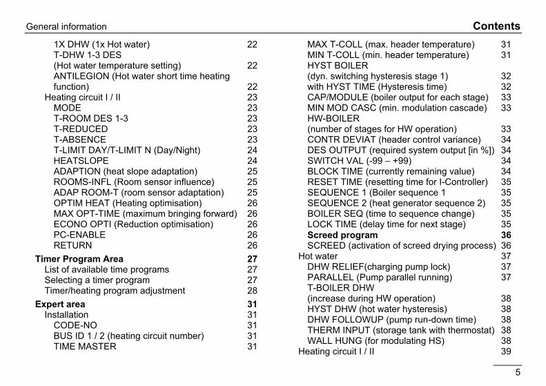
! Due to the tolerances of sensors, deviations of
+/- 2K (2°C) are normal between various temperature displays. Temperatures which change rapidly can have higher deviations for short periods due to the different time-related behaviour of various sensors.
! The display of the current heating program applies to the device's first heating circuit. In case of having two heating circuits the display can be set to the 2nd circuit
Explanations
A Current time
B Freely selectable display (refer to "DISPLAY SEL" parameter)
C DCF reception OK (only with receiver connected)
D Bus symbol (when this symbol does not appear, check the data line to the CAN controllers connected )
E Display of the active heating program for the first heating circuit (here: 6:00 to 08:00 hrs and 16:00 to 22:00 hrs)
F Status display: D heating mode; F hot water preparation
G Mode selector switch, the display applies to all internal heating circuits for which a separate operating mode has been selected via the "MODE" set value (here: F 2 => Heating according to timer program 2).
H Display of current temperature of HS 1 or header temperature in the case cascades
I Display for number of active heat generators

Changing the settings Part 1: Operation
10
Changing the settings
The operating flap must be opened first in order to change or request set values.
=> Controller switches to Operation mode
a Display indicating the current level
b Holes to unlock the controller fixation. Insert a thin screwdriver deep into the holes and then lift up the controller.
Operating elements
Ç A => Shaft encoder Search for value/level or adjust value
Ä B => Programming key
Select a value level Select a value level to change Save a new value
C => Change display LED ON => The value in the display can be changed by actuating the shaft encoder (A).
x F D => Manual-Automatic switch.
In Manual mode, all the pumps and first burner stage are switched on. The mixer motors are not adjusted / controlled (display: "EMERG-MODE“).
Limitation (switch-of with 5K hysteresis): Burner => MAX T-MODUL (expert) Heating circuit pumps => MAX T-FLOW (expert) Cylinder charging pump => T-DHW I (user) E Caution, overheating, e.g. with floor or wall heating! =>
Set mixer by hand!
E => PC connection via optical adapter

Part 1: Operation Changing the settings
11
Operating level
SERVICE
General DATE/TIME/HOLIDAY
Ç Turn anticlockwise Open operating flap Ç Turn clockwise INSTALLATION HOT WATER HEAT CIRCUIT I
Display
HEAT CIRCUIT II INSTALLATION HOT WATER HEAT CIRCUIT I
User
HEAT CIRCUIT II HOTW-PROG HEAT-PROG ID 1
Time programs
etc... INSTALLATION HOT WATER HEAT CIRCUIT I
Expert
HEAT CIRCUIT II
Operation is divided into different areas:
General - Display - User - Time programs – Expert. Opening the hinged control panel cover automatically takes you to the display and indicator area.
The current area "DISPLAY" appears in the display for a short time (1 clock circuit).
After the clock circuit the display switches to the current operating level "INSTALLATION".
This is displayed for a short time (1 clock circuit) when you switch to a new area.
Ç Select the level in which the value to be adjusted or displayed can be found using the rotary knob.
Ä Press Prog button! => Open / select level
Ç Search for value using rotary knob Ä Press Prog button! => Select value
LED lights up => adjustment can now be made Ç Modify value using rotary knob Ä Press Prog button! => Store value - LED goes off When the operating flap is first opened after voltage is applied, the level INSTALLATION is displayed once only. Once the values grouped here have been set the controller is operable.

Changing the settings Part 1: Operation
12
Areas General Value selection summary Service => for service engineers Date/Time/Holiday => for users
Display System value display (e.g. sensor values and setpoints). No adjustments can be made. Operating errors are therefore excluded in this area.
Users Summary of settings that can be made by the operator.
Time programs Summary of time programs for heating circuits, the hot water circuit and extra functions where applicable
Expert Summary of values for which expert knowledge is required to make settings (installation technician).
E Values in the expert level are protected by a code no. (damage/malfunction possible).
Levels The settings in the different areas are sorted into operating levels
Installation Hot water Heating circuit I Heating circuit II
Installation All display values and settings that relate to the heat generator or the entire system and cannot be assigned to a consumer circuit.
Hot water All display values and settings that affect central hot water preparation and circulation.
Heating circuit I / II All indicator and set values that relate to the corresponding consumer circuit (also, for example, as decentral hot-water circuit). ! An overview of all settings can be found on the
following pages.

Part 2: Overview of display values and settings General area
13
~ Hinged cover OPEN search for level to the left with Ç, open with Ä
Part 2: Overview of display values and settings
Part 2: Overview of display values and settings General area General area
(Select main level using Ç and open with Ä) Date/Time/Holiday This area contains a series of different values in order to provide rapid access.
(Select values/value group using Ç and open with Ä) Date/time => Value group (General -> Date/Time/Holiday level) All the values in this group are set in sequence => adjust using Ç => continue with Ä TIME (Minutes)
Current minutes blink and can be adjusted
TIME (Hours)
Current hours blink and can be adjusted (seconds are set to "00" when stored)
YEAR Adjust current year MONTH Adjust current month DAY Adjust current day (date)
! If a heating system controller has been set to be the TIME MASTER (time setting for all controllers, see EXPERT/INSTALLATION) or a DCF (Radio time receiver) has been installed in the system, the time is blanked out on all the other controllers in the system.
! There may be a time difference of up to 2 minutes per month (correct time if necessary). If a DCF receiver is connected the correct time is always displayed.
The current weekday is calculated automatically. Checking can take place using the selectable additional display in the standard display => set to "Day"
It is possible to change from summer to winter time by entering the date.

General area Part 2: Overview of display values and settings
14
! Please do not enter the day of travel as the start date, but the first day of the holiday (no more heating from this day).
! Please do not enter the day of travel as the end date, but the last day on which there is to be no heating. When you arrive home the house should be warm and there should be hot water.
! Stop holiday function => e.g. for early return by pressing the program switch.
! Not with Time Master or DCF
! The default setting is valid for Central European time zones. A modification is only required if the date for the time change is changed by political decree.
! The earliest date on which the change will occur must be set. The controller performs the time change on the Sunday following this date at 2.00 am or 3.00 am.
! If no time change is required, please set MONTH STOP to the same value as MONTH START and DAY STOP to the same value as DAY START.
Holiday => Value group (General -> Date/Time/Holiday level) All the values in this level are set in sequence => adjust using Ç => continue with Ä YEAR START Set current holiday start year MONTH START Set current holiday start month DAY START Set current holiday start day YEAR STOP Set current holiday end year MONTH STOP Set current holiday end month DAY STOP Set current holiday end day
Summer time => Value group (General -> Date/Time/Holiday level) All the values in this level are set in sequence => adjust using Ç => continue with Ä MONTH START Set month for start of summer time DAY START Set earliest day for start of summer
time MONTH STOP Set month for start of winter time DAY STOP Set earliest day for start of winter time

Part 2: Overview of display values and settings General area
15
~ Hinged cover OPEN search for level to the left with Ç, open with Ä
Service This area contains values for the customer service engineers in order to provide rapid access.
(Select operating level using Ç and open with Ä)
Relay test => Value group (code no. required) (General -> Service level) Select relay using Ç => relay switches 00 No relay 01 A1: Pump, heating circuit 1 / header pump 02 A2: Pump, heating circuit 2 03 A3: Hot water charging pump 04 A4: Mixer OPEN, heating circuit 2 05 A5: Mixer CLOSED, heating circuit 2 06 A6: HS1 ON 07 A7: HS2 ON 08 A8: HS3 ON 09 A9: HS4 ON
A code number must be entered for this function.
Ä Select Relay Test => "Code number" level
Code number Entry
Ä Start code number entry => [LED] Ç Select 1st digit Ä Confirm entry Ç Select 2nd digit Ä Confirm entry Ç Select 3rd digit Ä Confirm entry Ç Select 4th digit Ä Confirm entry
=> "Relay Test" RELAY TEST Ä Start relay test Ç Select relay => Relay switches Ç Select next relay or use Ä to stop relay test

General area Part 2: Overview of display values and settings
16
SENSOR TEST Sensor test => Value group (General -> Service level) Select sensor using Ç => value is displayed T-OUTSIDE Outside temperature
T-COLLECTOR Boiler temperature
T-DHW Hot water temperature
T-ROOM D 1 Room temperature, heating circuit 1 (only with remote control)
T-FLOW D 2 Flow temperature, heating circuit 2
T-ROOM D 2 Room temperature, heating circuit 2 (only with remote control)
Start sensor test with Ä, use Ç to select sensor => temperature is displayed; Use Ä to stop sensor test
Part 2: Overview of display values and settings General area
17
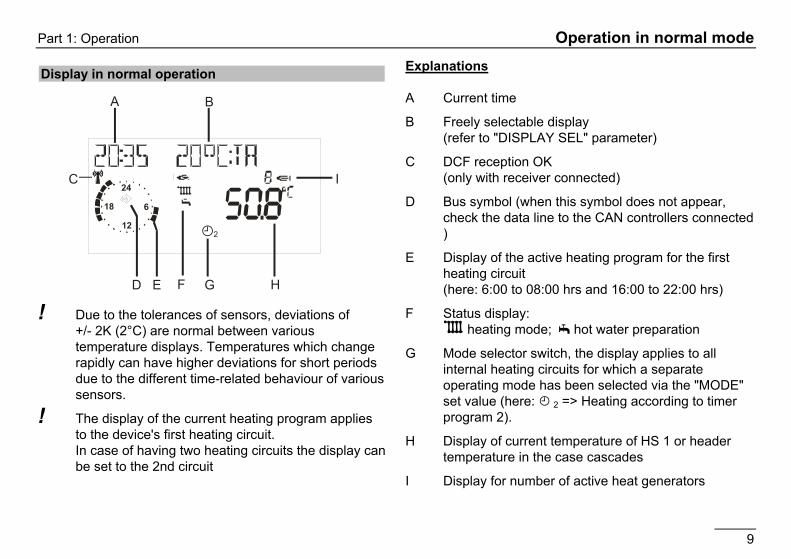
Other entries (General -> Service level) Select value using Ç => value is displayed SW NO XXX-XX Software number with index CASCADE MANU (1-8; only with code no.)
Starting different burner stages of the cascade
BURNER TIME (1-8) Ä Burner time for all stages BURNER START (1-8) Ä Burner start for all stages LIMITER TEST (1-8) Safety temperature limiter test
with heat generator temperature display Start with Ä (hold down)!
SERVICE (only with code no.)
Input of date or operating hours for service messages
RESET USER 00 Load user parameter factory settings (except language)
RESET EXPERT 00 (only with code no.)
Load expert parameter factory settings (except sensors)
RESET T-PRG 00 Load time program factory settings
RETURN Exit level using Ä
SW NO XXX-XX
Display software number with index (please specify if you experience problems or have questions about the controller)
CASCADE MANU (only with code no.)
(only for cascades => Service mode) With Ä open level and select burner stage using Ç.
After the heat generator Ä has been selected the output for this heat generator can be set.
With respect to multi-stage heat generators, the second stage can be activated by means of presetting an output value > 50%.
After closing the service functions the entries are reset automatically.
BURNER TIME and BURNER START
Ä => Display of current value ÄReturn Hold down Ä until indicator "RESET" goes out => Reset display

General area Part 2: Overview of display values and settings
18
LIMITER TEST Use Ä to open level and select heat generator with Ç.
=> Display heat generator temperature.
Ä Hold down prog. button until LIMITER activates Burner I ON all pumps OFF all mixers CLOSE
The temperature can be observed in the display. SERVICE
Input of values for the yearly service message or operating hours. Delete active maintenance display: Open control panel cover, press prog. button ÄÄ, set repeat value to "00" using Ç and confirm with Ä. Delete programmed annual message: In the General/Service level, set value for SERVICE=>DAY or SERVICE => OPERATNG HOURS to hyphens.
RESET … The three value groups can be reset to the factory setting using the Reset function. Select function using Ä, set to "01" using Ç and confirm with Ä.

Part 2: Overview of display values and settings Display Range
19
Display Range ! Display only - no adjustment possible. Display only
appears if the sensor is connected and the value is present in the system, otherwise "----" or no display.
Installation (WE => BOILER) use Ç to select parameters T-OUTSIDE Outside temperature T-COLL DES HS / Header set value (cascade) T-COLLECTOR HS / Header temperature (cascade) RETURN Exit level using Ä
T-OUTSIDE The measured outside temperature is smoothed for control purposes. The smoothed value is displayed here.
T-COLL DES ((heat request) Corresponds to the maximum requested temperature of the consumer circuits from the heating system (incl. hot water preparation). The mixer circuits request the required temperature + heating slope distance (expert value)

Display Range Part 2: Overview of display values and settings
20
Hot water T-DHW DES Current hot water set temperature
according to heating program and operating mode
T-DHW Current hot water temperature RETURN Exit level using Ä
Heating circuit I / II
T-ROOM DES A Current room set temperature according to heating program and operating mode
T-ROOM Current room temperature
HUMIDITY ***) Display of ambient air humidity (if value is available)
T-POOL DES *) Swimming pool temperature setting
T-POOL*) Current swimming pool temperature
T-DHW DES **) Hot water temperature setting
T-DHW **) Current hot water temperature
T-FLOW RATED Current flow temperature setting T-FLOW Current flow temperature N-OPT-TIME Previous time required to heat up
with heat-up optimisation activated RETURN Exit level using Ä
! Display only appears if the sensor is connected and the value is present in the system. If the set value is not present it is masked out, or hyphens appear in the display (- - - -).
T-DHW DES (hot water set temperature) Display of the currently valid value for control.
T-ROOM DES A (current value for set room temperature) If a control unit is connected there will be no display "- - - -" => display on control unit
T-ROOM (room temperature) Only if a sensor or a FBR is connected.
*) These values only appear if the heating circuit is programmed as a controller for the pool.
**)These values only appear if the heating circuit is programmed as a hot water circuit.
***) These values only appear if an operating device is connected and parameters have been set for the corresponding heating circuit. “- - - -„ => no humidity sensor available in control device

Part 2: Overview of display values and settings User Area
21
~ Hinged cover OPEN search for level to the right with Ç, open with Ä
User Area
User Area All the settings that can be made by the operator of the system.
Installation All settings that cannot be assigned to a consumer circuit (consumer circuits: heating circuits and HW).
Ä Select value, Ç adjust and Ä save Designation Value range Default IV*) GERMAN Acc. to version GERMAN CONTRAST (-20) – (20) 00 DISPLAY SEL Sensor, weekday, ... - - - - SELEC-PROG
Heating circuit 01, Heating circuit 02
01
RETURN Exit level using Ä *) IV = Internal Values: Space for entering the parameters stored in the system!
GERMAN => Language Select controller language
CONTRAST Adjust intensity of display
DISPLAY SEL Select additional display in standard operation
- - - - => no additional display DAY => Weekday (Mo, Tue, Wed, ....) T-OUTSIDE => Outside temperature T-FLOW D 2 => Flow temperature heating circuit 2 T-DHW => hot water temperature (upper) T-BOIL => Temp. of heat generator T-ROOM D 1 => Room temperature heating circuit 1=> *) T-ROOM D 2 => Room temperature heating circuit 2=> *) *) only when remote control is connected SELEC-PROG Select heating circuit whose heating program is shown in the standard display.

User Area Part 2: Overview of display values and settings
22
Hot water Designation Value range Default IV 1X DHW 00, 01 (OFF/ON) 00 = OFF T-DHW 1 DES 10°C - 70°C 60°C T-DHW 2 DES 10°C - 70°C 60°C T-DHW 3 DES 10°C - 70°C 60°C ANTILEGION 00, 01 (OFF/ON) 00 = OFF RETURN Exit level using Ä
Hot water short time heating function
ANTILEGION = 01 => Every 20th time that heating takes place or once per week on Saturday at 01:00 hrs the storage tank is heated up to 65°C.
It is possible to set up your own hot water short time heating function using the third hot water enable facility.
1X DHW (1x Hot water) 01 => The storage tank is enabled for charging (e.g. for showering outside hot water times). Charging starts when the temperature falls below "temperature setting 1" by the switching hysteresys. After charging, the value is automatically set to "00“ .
T-DHW 1-3 DES (Hot water temperature setting) Required hot water temperature setting T-DHW 1 DES => used in first enable time, T-DHW 2 DES => used in second enable time , T-DHW 3 DES => used in third enable time of hot water program.
ANTILEGION (Hot water short time heating function) 01 => Activation of hot water short time heating function

Part 2: Overview of display values and settings User Area
23
*) or, depending on function selected, heating circuit T-POOL, T-DHW, T-FLOW DAY or T-FLOW NIGHT (see page 39)
MODE - - - - => The controller programming switch applies in this case. When setting an alternative operating mode this only applies to the assigned heating circuit.
When the "i = Standby/OFF", and "F = Summer mode" controller programming switch operating modes are set, this has a reducing effect on all heating circuits and consumer circuits in the entire system.
T-ROOM DES 1-3 Required room temperature setting T-ROOM DES 1 => used in first enable time, T-ROOM DES 2 => used in second enable time, T-ROOM DES 3 => used in third enable time of active heating program for this heating circuit.
T-REDUCED Required room temperature setting during night reduction
T-ABSENCE Required room temperature setting during holidays
Heating circuit I / II Designation Value range Default IV MODE ----
,i,F1,F2,B,B - - - -
T-ROOM DES 1*) 5°C - 40°C 20°C T-ROOM DES 2 5°C - 40°C 20°C T-ROOM DES 3 5°C - 40°C 20°C T-REDUCED*) 5°C - 40°C 10°C T-ABSENCE 5°C - 40°C 15°C T-LIMIT DAY ----, (-5)°C–40°C 19°C T-LIMIT N ----, (-5)°C–40°C 10°C HEATSLOPE 0.00 – 3.00 1,20 ADAPTION 00, 01 (OFF/ON) 00 = OFF ROOMS-INFL 00 – 20 10 ADAP ROOM-T (-5.0)K – (5.0)K 0,0 K OPTIM HEAT 00, 01, 02 00 MAX OPT-TIME 0:00 – 3:00 [h] 2:00 [h] ECONO OPTI 0:00 – 2:00 [h] 0:00 [h] PC-ENABLE 0000 - 9999 0000 RETURN Exit level using Ä

User Area Part 2: Overview of display values and settings
24
T-LIMIT DAY/T-LIMIT N (Day/Night) Only valid if the function is activated => Set value "Expert/Heating circuit/PUMP MODE= 01=> Pump switching according to heating limit"
If the outside temperature that is measured and calculated by the controller exceeds the heating limit specified here by 1K (= 1°C), heating is disabled, the pumps switch off and the mixers are closed. The heating is enabled again when the outside temperature drops below the set heating limit.
T-LIMIT DAY => applies during heating times T-LIMIT N => applies during reduction times
"----" => The heating limit is deactivated. The circulation pump is switched in accordance with the standard function (see chapter entitled "Circulation pump control")
HEATSLOPE The gradient of the heat slope indicates by how many degrees the flow temperature changes if the outside temperature rises or drops by 1 K.
Setting tip:
At cold outside temperatures, room temperature too low => Increase heat slope (and vice-versa)
At high outside temperature (e.g.16°C) room temperature too low => correction via set room temperature
Flow temperature [°C] Outside temperature [°C]
Heat slope diagram (setting aid)
Setting 0 => Room control only
! The heat slope can best be set at outside temperatures below 5°C. The change in heat slope setting must be made in small steps and at long intervals (min. 5 to 6 hours) because the system must first adjust to the new values each time the heat slope is changed.
Guideline values
Underfloor heating S = 0.4 to 0.6 Radiator heating S = 1.0 to 1.5
0,20,40,60,8
1
1,2
1,5
2
2,53
20
40
60
80
100
20 16 12 8 4 0 -4 -8 -12 -16

Part 2: Overview of display values and settings User Area
25
ADAPTION (heat slope adaptation) Only active if an FBR analogue room device is connected (room sensor + operating mode selection) and an outdoor sensor.
Function for automatic heat slope setting
Starting Conditions:
External temperature < 8°C Operating mode is automatic (I or II) Duration of lowering phase at least 6 hours
At the beginning of the lowering period, the current room temperature is measured. During the next four hours, this temperature is used as the set point for the room regulator. The heating curve is calculated from the values determined during this time by the regulator for the flow pipe nominal temperature and the external temperature.
! If the adaptation is interrupted, e.g. by a start-up discharge or the hot water demand from an external heating circuit, then the warning triangle will appear in the display until the function is carried out successfully the next day or is ended, e.g. by adjusting the operating mode switch.
! During the adaptation, the water heating and the heating optimisation of the regulator are blocked.
ROOMS-INFL (Room sensor influence) Only active if an FBR analogue room device is connected (room sensor + operating mode selection).
Heat generator temperature is increased by the defined value as soon as the room temperature drops below the desired room temperature by 1K. => High values lead to fast control and large boiler temperature fluctuations.
- - - - => pure weather-dependent control 0 => pure weather-dependent control *) 20 => pure room temperature control
*) Special function with ROOMS-INFL = 0
For one-off heating requirements during the night reduction the heating pump continues to run until the next heating period is reached (see chapter entitled "Circulation pump control").
ADAP ROOM-T (room sensor adaptation) In the case of room control (e.g. with FBR) the measurement can be corrected using this setting if the room sensor is not measuring correctly.

User Area Part 2: Overview of display values and settings
26
OPTIM HEAT (Heating optimisation) Activation of function for automatically bringing forward the start of heating.
Example: Heating program 6.00 hrs – 22.30 hrs
OFF: Building starts to be heated at 6.00 hrs.
ON: Depending on weather and room temperature, heating starts soon enough so that building just reaches the set room temperature at 6.00 hrs.
00 => start of heating not brought forward 01 => brought forward depending on weather 02 => brought forward depending on room temperature *)
*) Only active if an FBR analogue room device is connected (room sensor + operating mode selection).
! Warm-up optimisation occurs only if the reduced time of the heating circuit is at least 6 hours.
MAX OPT-TIME (maximum bringing forward) Only active with "OPTIM HEAT = 01 or 02" The start of heating is brought forward by no more than this time.
ECONO OPTI (Reduction optimisation) Automatic reduction of burner disabling to end of set heating time.
The burner is not restarted before the end of the heating period during the set time period (last heating time only) if it not already in operation.
This function prevents short-term heating of the heat generator to the end of the heating period.
PC-ENABLE Code number for enabling access to heating circuit data from a PC "0000" => access is blocked.
RETURN Exit heating circuit level => Return to "User" area.
Part 2: Overview of display values and settings Timer Program Area
27
~ Hinged cover OPEN search for level to the right with Ç, open with Ä
Timer Program Area
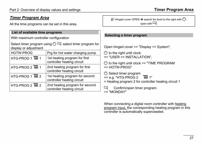
Timer Program Area All the time programs can be set in this area.
List of available time programs With maximum controller configuration
Select timer program using Ç Ä select timer program for display or adjustment HOTW-PROG Prg for hot water charging pump HTG-PROG 1 D 1 1st heating program for first
controller heating circuit HTG-PROG 2 D 1 2nd heating program for first
controller heating circuit HTG-PROG 1 D 2 1st heating program for second
controller heating circuit HTG-PROG 2 D 2 2nd heating program for second
controller heating circuit
Selecting a timer program
Open hinged cover => "Display => System",
Ç to the right until clock => "USER => INSTALLATION",
Ç to the right until clock => "TIME PROGRAM => HOTW-PROG"
Ç Select timer program => e.g. "HTG-PROG 2 D 1" = Heating program 2 for controller heating circuit 1
Ä Confirm/open timer program => "MONDAY"
When connecting a digital room controller with heating program input, the corresponding heating program in this controller is automatically superceeded.

Timer Program Area Part 2: Overview of display values and settings
28
F2 D
D I
F2 B
D I
Symbols:
I ON = First switch-on time (I OFF = first switch-off time)
20 °C = Set room temperature for displayed heating time
Clock = Approximate program display [full hours]
D 1 = Program for heating circuit 1
F2 = Heating program 2, F1 = Heating program 1
DI = Start time 1, IB = Stop time 1, DII = Start time 2, IIB = Stop time 2, DIII = Start time 3, IIIB = Stop time 3
Timer/heating program adjustment
Ç Select weekday (Mo-Su) or block (MO-FR => Monday-Friday, SA-SU => Saturday-Sunday, MO-SU => Monday-Sunday)
Ä Open weekday/block (see left) => "I ON 20°C" First switch-on time – set value I = 20°C Ç Set first switch-on time => for example 6:00 hrs Ä Confirm first switch-on time
=> „I OFF 20°C" First switch-off time – set value I = 20°C Ç Set first switch-off time => for example 8:00 hrs Ä Confirm first switch-off time => „II ON 20°C" Second switch-on time – set value II = 20°C Ç Ä Switch-on and switch-off times 2 and 3 are entered in the same way - please enter all values!
Ç Select another weekday/block for entry or exit heating program 2 with "RETURN" and set another program.
! The heating times are not saved until all the times for a weekday/block have been entered.
"- - - -" for a switch-on/switch-off time => The relevant heating timer is deactivated.

Part 2: Overview of display values and settings Timer Program Area
29
Heat circuit 1 Heating program 1 => factory setting:
Mo. to Fr.: 06:00 to 22.00 Sa. and Su.: 07:00 to 23:00
Heating time 1 Heating time 2 Heating time 3
Mo. Tu. We. Th. Fr. Sa. Su.
Heating program 2 => factory setting:
Mo. to Fr.: 06:00 to 08.00, 16:00 to 22:00 Sa. and So.: 07:00 to 23:00
Heating time 1 Heating time 2 Heating time 3Mo. Tu. We. Th. Fr. Sa. Su.
Heat circuit 2 Heating program 1 => factory setting:
Mo. to Fr.: 06:00 to 22.00 Sa. and Su.: 07:00 to 23:00
Heating time 1 Heating time 2 Heating time 3Mo. Tu. We. Th. Fr. Sa. Su.
Heating program 2 => factory setting:
Mo. to Fr.: 06:00 to 08.00, 16:00 to 22:00 Sa. and So.: 07:00 to 23:00
Heating time 1 Heating time 2 Heating time 3Mo. Tu. We. Th. Fr. Sa. Su.
Timer Program Area Part 2: Overview of display values and settings
30
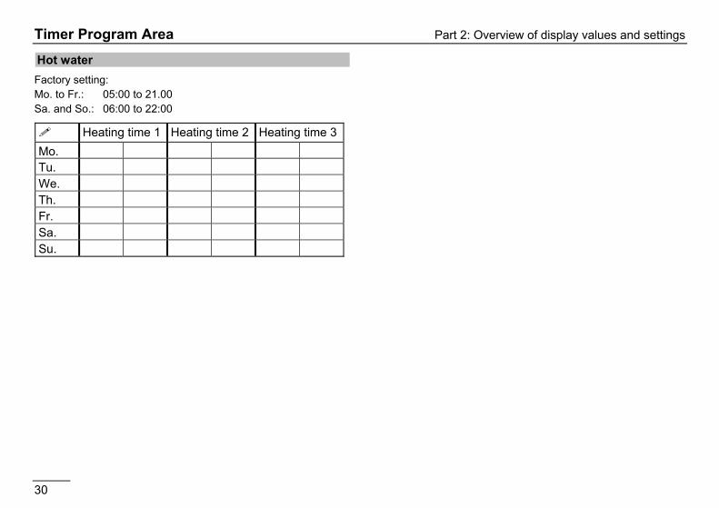
Hot water Factory setting: Mo. to Fr.: 05:00 to 21.00 Sa. and So.: 06:00 to 22:00
Heating time 1 Heating time 2 Heating time 3Mo. Tu. We. Th. Fr. Sa. Su.

Part 2: Overview of display values and settings Expert area
31
Expert area
Expert area These settings can only be changed if the code no. is entered (see page 15).
E If these values are set incorrectly, they may cause malfunctions or damage to the system.
Installation
Designation Value range Default IV CODE-NO 0000 - 9999 Entry ->CODE-NO Adjustment 0000 BUS ID 1 (00), 01-15 01 BUS ID 2 (00), 01-15 02 TIME MASTER 00, 01 (OFF/ON) 00 = OFF MAX T-COLL 30°C - 110°C 85°C MIN T-COLL 10°C - 80°C 40°C See following pages for continuation
CODE-NO Entering the code number (see page 15) allows all of the expert settings to be modified => including the code number itself (first parameter)
(Ç on right => CODE-NO 0000 Ä=> Ç 1st digit Ä=> Ç 2nd digit Ä=> Ç 3rd digit Ä=> Ç 4th digit Ä=> Ç)
BUS ID 1 / 2 (heating circuit number) The heating circuits are sequentially numbered starting with "01". Heat circuit numbers must not be assigned twice. For replacement controllers however, please enter exactly the same heating circuit numbers as the ones of the replaced controller.
TIME MASTER (Only without or TIME MASTER in system)
00 no time master => each heating circuit has its own time 01 controller is time master => all controllers and remote controls take over the time settings of this controller.
! No more than 1 TIME MASTER is permitted in the system!
MAX T-COLL (max. header temperature) The maximum heating requirements of the heating circuit is defined on the boiler. When selecting this parameter, ensure that the boiler is capable of generating the defined temperature (see TR, STB and MAX T-MODUL). ! Caution: Also works with hot water preparation.
MIN T-COLL (min. header temperature) The control function ensures that the header temperature does not drop below the set value during the heating times.

Expert area Part 2: Overview of display values and settings
32
Installation
Designation Value range Default IV HYST BOILER 5K – 20K 5 K HYST TIME 00 min – 30 min 00 min See following pages for continuation
HYST BOILER (dyn. switching hysteresis stage 1) with HYST TIME (Hysteresis time) Function for optimising heat generator operation with differing heat generator loads.
The effective switching hysteresis is reduced linearly after the burner is switched on from the set HYST BOILER to the minimum hysteresis (= 5K) during the hysteresis time "HYST TIME".
Low heat consumption In this case the higher HYSTERESIS setting takes effect. Short run-times and frequent burner operation are prevented.
High heat consumption During longer periods of burner operation (high heating load) the hysteresis is automatically reduced to 5K. This prevents the boiler from heating to unnecessary high temperatures.
Part 2: Overview of display values and settings Expert area
33
Installation (only for cascades via BUS)
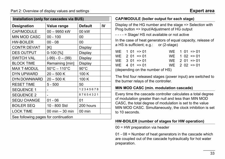
Designation Value range Default IV CAP/MODULE 00 – 9950 kW 00 kW MIN MOD CASC 00 - 100 00 HW-BOILER 00 - 08 00 CONTR DEVIAT [K] Display DES OUTPUT 0-100 [%] Display SWITCH VAL (-99) - 0 – (99) Display BLOCK TIME Remaining [min] Display MAX T-MODUL 50°C – 110°C 90°C DYN UPWARD 20 – 500 K 100 K DYN DOWNWARD 20 – 500 K 100 K RESET TIME 5 - 500 50 SEQUENCE 1 - 1 2 3 4 5 6 7 8 SEQUENCE 2 - 8 7 6 5 4 3 2 1 SEQU CHANGE 01 - 06 01 BOILER SEQ 10 - 800 Std 200 hours LOCK TIME 00 min – 30 min 00 min See following pages for continuation
CAP/MODULE (boiler output for each stage) Display of the HG number and the stage => Selection with Prog button => Input/Adjustment of HG output - - - - = Stage/ HS not available or not active In the case of heat generators of equal capacity, release of a HS is sufficient; e.g.: or (2-stage)
WE 1 01 => 01 WE 1 01 => 01 WE 2 01 => 01 WE 1 02 => 01 WE 3 01 => 01 WE 2 01 => 01 WE 4 01 => 01 WE 2 02 => 01 (depending on the number of HS)
The first four released stages (power input) are switched to the burner relays of the controller.
MIN MOD CASC (min. modulation cascade) Every time the cascade controller calculates a total degree of modulation greater than null and less than MIN MOD CASC, the total degree of modulation is set to the value MIN MOD CASC. Simultaneously, the clock inhibition is set to 10 seconds.
HW-BOILER (number of stages for HW operation) 00 = HW preparation via header
01 - 08 = Number of heat generators in the cascade which are coupled out of the cascade hydraulically for hot water preparation.

Expert area Part 2: Overview of display values and settings
34
! It is essential that the HW STAGES are at the beginning of the BUS ID sequence => 01 - xx.
CONTR DEVIAT (header control variance) Display of the header control variance (set temperature – actual temperature).
DES OUTPUT (required system output [in %]) Display of currently required total output % (0-100)
=> Calculated set value from control system = System load in per cent. The value is calculated, floating, and does not take any skips caused by the switching operation into account.
SWITCH VAL (-99 – +99) Internal control value
If this value reaches "0", the next heat generator is also connected (only after the delay time has elapsed). If the switching value reaches "-0", the last heat generator is switched off. If the desired temperature is exceeded by 1K the last heat generator is also switched off.
BLOCK TIME (currently remaining value) Display of current delay time. Only if "delay = 0“ is it possible to operate the next heat generator.
MAX T-MODUL (maximum temperature of the heat generator) Protects individual heat generators in the cascade from overheating / prevents triggering LIMITER (limiter value).
This parameter is used to set a temperature at which the different heat generators switch themselves off, or - in the case of modulating heat generators - modulate themselves down. The HS switch themselves on again as soon as the temperature drops below the set temperature by 5K (only for HS via BUS)
! The temperature selected for MAX T-MODUL must be higher than the maximum header temperature.
DYN UPWARD (dynamic heat generator connection [K]) Small value = fast connection Large value = slow connection
E Values set too low can lead to overheating or short-term connection of a heat generator.
Calculation: If the cumulative system deviation in Kelvin reaches the set value A, this results in connection of all heat generator stages.

Part 2: Overview of display values and settings Expert area
35
DYN DOWNWARD (dynamic heat generator deactivation [K]) Small value = fast deactivation Large value = slow deactivation E Values set to high can lead to overheating and
triggering the STB Calculation: If the cumulative system deviation in Kelvin reaches the set value A, this results in deactivation of all heat generators. RESET TIME (resetting time for I-Controller) E Control value: Changing this value can cause the
control system to overshoot. The recommended default settings should be retained.
! Small values cause a fast regulatory behavior and could cause to a oscillation of the boiler temperature.
SEQUENCE 1 (Boiler sequence 1 Entry of the sequence in which the heat generators are set into operation in sequence 1. => Selection of start no. => Prog. button => Entry of the HS number SEQUENCE 2 (heat generator sequence 2) Entry of the sequence in which the heat generators are set into operation in sequence 2. => Selection of start no. => Prog. button => Entry of the heat generator number
! With respect to two-stage heat generators, the second stage is always switched after the first stage.
SEQU CHANGE (sequence change mode)
01 = Only heat generator sequence 1 02 = Only heat generator sequence 2 03 = Change between sequence 1 and 2 according to operating hours of the first heat generator of the active sequence 04 = 1/3 - 2/3 Switching for heat generators with a different nominal power: When the second HS is activated, the first HS is put out of operation until activated again. 05 = Rotating heat generator sequence; the first HS of the sequence is placed in last position of the current sequence after the sequence switching time has elapsed. 06 = New heat generator sequence by means of automatic sorting according to operating hours in the event of sequence change (sequence change according to operating hours of the first heat generator of the active sequence). BOILER SEQ (time to sequence change) For operation with at least 2 heat generators there is the option to swap the HS sequence after the operating hours specified here of the first heat generator of the active sequence. LOCK TIME (delay time for next stage) Min. delay time for switching on the next stage after a stage has been switched on or is being switched off.

Expert area Part 2: Overview of display values and settings
36
DAY 1 2 3 4 5 6 7 8 9 10 11 12 13 14 15 16 17 18 19 20 21 22 23 24 25 26 27 28VT 25 25 25 55 55 55 55 25 40 55 55 55 55 55 55 55 55 55 55 40 25 --- --- --- --- --- --- ---=>
SCREED PROGR (Program setting) Ä => Screed program; Ç Select day; Ä => Activate adjustment date; Ç Set flow temperature; Ä => Save setting; Ç Select next day or exit screed program using "RETURN" + Ä.
Installation
Designation Value range Default SCREED 00, 01 (OFF/ON) 00 = OFF SCREED PROGR See explanation! RETURN Exit level using Ä
! Start day is not included:
The screed program starts with the "Day 1" temperature setting and switches to "Day 1" at 00.00 hrs and then to the next day at 00.00 hrs and so on. The current day is marked with an "x" in the "SCREED PROGR" program.
! After the function has been cancelled/terminated the controller continues heating using the set operating mode. If no heating is required, set the operating mode to i = Standby / OFF.
Screed program SCREED (activation of screed drying process) The screed program can be used for function heating in accordance with DIN EN 1264 – 4 and for heating freshly laid screed ready for flooring.
! Screed drying can only be carried out for mixer circuits.
After starting, the program runs through the set flow temperatures. The integrated mixer circuits control to the set flow temperature. The heat generator provides this temperature irrespective of the operating mode that has been selected. This is marked in the standard display by the entry "SCREED" and a display of the current flow temperature.
The freely adjustable program runs for a maximum of 28 days. The flow temperatures can be set to a value of between 10°C and 60°C for each day. The entry "----" stops the program (also during operation for the following day).

Part 2: Overview of display values and settings Expert area
37
Hot water
Designation Value range Default IV DHW RELIEF 00, 01
(OFF/ON) 01 = ON
PARALLEL 00, 01, 02, 03 01 T-BOILER DHW 00K – 50K 20K HYST DHW 5K – 30K 5 K DHW FOLLOWUP 00 min – 30
min 00 min
THERM INPUT 00, 01 (OFF/ON)
00 = OFF
WALL HUNG 00, 01 (OFF/ON)
00 = OFF
RETURN Exit level using Ä
DHW RELIEF(charging pump lock) The charging pump is not switched until the heat generator temperature exceeds the storage tank temperature by 5K. It is switched off when the HS temperature drops below the storage tank temperature. This prevents the storage tank from being cooled by the boiler when hot water preparation starts.
PARALLEL (Pump parallel running) 00 => Hot water priority operation: The heating circuits are blocked during hot water preparation. The mixers close and the heating circuit pumps switch off.
01 => HW partial priority: The heating circuits are blocked during hot water preparation. The mixers close and the heating circuit pumps switch off. The mixer circuits are enabled again when the HS has reached the temperature of hot water temperature setting + HS superheating [T-DHW + T-BOILER DHW]. If the HS temperature drops below the enable temperature by the switching hysteresis [HYST DHW] again, the mixer circuits are blocked again.
02 => Pump parallel running: Only the direct heating circuits are blocked during hot water preparation. The mixer circuits continue to be heated. The hot water preparation is extended by this function.
03 => Pump parallel running also for the direct heating circuit: During hot water preparation all heater circuits continue to be heated. The hot water preparation is extended by this function. When the HS temperature exceeds the maximum flow temperature of the direct heating circuit by 8K, the heating circuit pump for this circuit is switched off (overheating protection). The heating circuit pump is switched on again when the HS temperature drops below the temperature [maximum flow temperature + 5K].

Expert area Part 2: Overview of display values and settings
38
T-BOILER DHW (increase during HW operation) HS set temperature with hot water preparation = hot water set temperature + T-BOILER DHW
! The heat generator must be run at a higher temperature during hot water preparation so that the hot water temperature in the storage tank can be reached via the heat exchanger.
HYST DHW (hot water hysteresis) Hot water preparation is started when the temperature of the hot water storage tank drops below the temperature setting by the hysteresis [HYST DHW]. The hot water preparation stops when the storage tank reaches the temperature setting (the temperature setting is set to 65°C during hot water short time heating operation).
DHW FOLLOWUP (pump run-down time) 00 min => Standard function: The charging pump continues to run for 5 minutes after the burner has switched off. If heat is requested by a heating circuit the run-down is cancelled. The charge pump blocking kicks in and can also cause the run-down function to be cancelled.
greater than 00 min => The charge pump runs down by the set time when storage tank charging is complete. The after-run can only be cancelled by the activated charge pump blocking.
THERM INPUT (storage tank with thermostat) 00 => Hot water preparation via storage tank sensor
01 => Hot water preparation via thermostat: The hot water preparation is started by a short circuit at the storage tank sensor connecting terminals. It stops when the short circuit is removed.
If this parameter is modified the controller is restarted. "RESET" briefly appears in the display.
WALL HUNG (for modulating HS) HS temperature setting with hot water preparation = hot water actual temperature + T-BOILER DHW
With this function the exhaust gas losses occurring during hot water preparation can be reduced with modulating heat generator using the adapted HS set temperature.

Part 2: Overview of display values and settings Expert area
39
The parameters in this level change in accordance with the heating circuit function that has been selected [HC FUNCTION]
Heating circuit I / II
Designation Value range Default IV HC FUNCTION 00 - 05 00 PUMP MODE 00 - 03 00 MIXER OPEN (not for HW circuit)
5-25 18
MIXER CLOSE (not for HW circuit)
5-25 12
See following pages for continuation
HC FUNCTION (heating circuit function selection) If this parameter is modified the controller is restarted. "RESET" briefly appears in the display.
00 => Standard heating circuit
01 => Control to fixed flow temperatures During the heating periods (see heating program ) the heating circuit is operated with a fixed preset flow temperature [T-FLOW-DAY], and during reduced mode operation with a fixed preset flow temperature [T-FLOW-NIGHT] accordingly.
02 => Swimming pool control (only for heating circuit II) This function can be used to heat a swimming pool. The mixer controls the flow temperature for the swimming pool heat exchanger. The swimming pool water temperature sensor is connected to the room sensor connection for the heating circuit (see FBR). [Plug III; 1+2] The flow temperature control operates like normal room control [ROOMS-INFL]. The set value for the water temperature can be entered in the user area of the associated heating circuit level [T-POOL1/2/3]. The heating program operates. No heating takes place during the reduction period (frost protection only). The water temperature and the current set value are displayed in the display level [T-POOL / T-POOL DES].
03 => Swimming pool control (only for heating circuit II) This function can be used to operate additional hot water circuits. The heating circuit flow sensor is located in the hot water storage tank. The hot water temperature set value can be entered in the user area of the associated heating circuit level [T-DHW 1/2/3]. The heating program for the heating circuit acts as an enable program for the storage tank. The storage tank set value is set to 10°C during the reduction period. The HS controller hot water priority function can be used (partial priority acts like priority).

Expert area Part 2: Overview of display values and settings
40
04 => Return flow temperature increase via mixer motor (only for HC2) The heating circuit flow sensor is used as a heat generator return flow sensor. The mixer motor controls to the heating circuit set value for 24 hours [MIN T-FLOW]. Installation tip: Mixer motor OPEN => boiler flow is fed into the return (=> return flow temperature increase) Mixer motor CLOSED => heating circuit return is passed through. When the mixer motor is open it must be ensured that there is circulation through the HS (boiler pump). 05 => Header pump (only for HC1) The pump relay for the direct circuit is used as the header pump for the cascade. The pump switches ON as soon as heat is requested from the cascade. The pump switches OFF when there is no longer a heat request and the follow-up time has elapsed. PUMP MODE (pump operating mode) The circulation pumps are switched off if heating is not required. The mixer motors are closed at the same time => "The heating circuit is switched off". (Switch on with 1K hysteresis) This adjustment concerns the weather dependent shut-down. If room temperature regulation is enabled (ROOMS-INFL > 0) the "thermostat function" takes effect in addition. Room temperature > room set value + 1K 00 => Standard circulation pump control Heating time:
Outside temperature > room set value + 1K Reduction period: ROOMS-INFL = 0 The switch-off occurs during the transition to reduction
operation. Switch on with: Room temperature < room set value
The pump runs continuously after switching on. ROOMS-INFL ="--": Flow temperature setting < 20°C. 01 => Pump switching in accordance with heating limits Heating time OFF: Outside temperature > set heating limit day +1K ON: Outside temperature < set heating limit day
Reduction period OFF: Outside temperature > set heating limit night +1K ON: Outside temperature < set heating limit night
02 => Pump switching in accordance with heating program Heating time: Pump is ON; Heat circuit is enabled Reduction period: Pump is OFF; Heat circuit is blocked 03 => Continuous operation The runs continuously for 24 hrs.! The heating circuit is permanently enabled.

Part 2: Overview of display values and settings Expert area
41
MIXER OPEN (open mixer dynamic) Speed setting at which the mixer motor opens when a control difference occurs. The control difference at which the mixer motor opens without interruption is entered in Kelvin. ! Small values cause the mixer motor to adjust quickly
and can lead to oscillation. MIXER CLOSE (close mixer dynamic) Speed setting at which the mixer motor closes when a control difference occurs. The control difference at which the mixer motor closes without interruption is entered in Kelvin. ! Small values cause the mixer motor to adjust quickly
and can lead to oscillation.
Heating circuit I/II
Designation Value range Default IV MAX T-FLOW 20°C - 110°C 80°C MIN T-FLOW 10°C - 110°C 10°C T-FROST PROT ----;
(-15)°C – (5)°C 0°C
OUT-TEMP-DEL 0:00 – 24:00 0:00 SLOPE OFFSET 0K – 50K 5 K B-HEAT SINK 00, 01
(OFF/ON) 01 = ON
RETURN Exit level using Ä
MAX T-FLOW (max. flow temperature)
The measured temperature setting for the heating circuit flow is limited to the maximum flow temperature setting (overheating protection).
E The pump of the direct heating circuit is not switched off until the HS temperature exceeds the set maximum flow temperature by 8K. The heating circuit pump is already switched on again when the HS temperature drops below the temperature [maximum flow temperature + 5K].
MIN T-FLOW (min. flow temperature)
The measured temperature setting of the heating circuit flow is increased to the minimum flow temperature setting (e.g. with air heating).
T-FROST PROT (frost protection temperature)
If the outside temperature drops below the programmed value, the system switches to frost protection mode (pumps are switched on). "----" Frost protection mode is deactivated!
OUT-TEMP-DEL (outside temperature delay)
The selected outside temperature delay must be matched to the type of construction of the building. In the case of heavy structures (thick walls), a long delay must be selected since a change in outside temperature affects the

Expert area Part 2: Overview of display values and settings
42
room temperature later accordingly. With light structures (walls have no storage effect) the delay should be set (0 hrs.).
SLOPE OFFSET (heating slope distance) The HS temperature that is required for a mixer circuit is calculated by adding the calculated temperature setting for the heating circuit flow to the heating curve distance. The heating curve distance compensates for sensor tolerances and heat loss up to the mixer.
B-HEAT SINK (circuit enable) 00 => OFF
01 => The heating circuit can be used by higher-order functions (e.g. cooling function of a heat generator to protect from overheating; heat removal during service mode) as a heat sink/consumer. The heating circuit is heated at the maximum flow temperature setting for the duration of the function.

Part 3: General function description Expert area
43
Part 3: General function description
Part 3: General function description Heat circuit control Weather-dependent control The HS or flow temperature is determined via the set heat slope to suit the measured outside temperature in such a way that the set value for the room is approximately set if the heating system is configured correctly.
=> Exact setting of the heat slope is extremely important for weather-dependent control.
The circulation pump is controlled weather-dependently. The circulation pump is switched on if there is a heating demand and in Frost-protection mode.
Room sensor influence The current room temperature can be included in computation of the required flow temperature via a present room temperature sensor.
The influence factor (parameter list) can be set between 0 (fully weather-dependent regulation) and 20 (room temperature regulation with minimal outdoor temperature influence). Position "----" deactivates room temperature control. Positions "----" and "0" indicate differences for demand-dependent circulation pump control.
Hot water generation The programmed hot water temperature is stabilised by switching the hot-water cylinder charging pump and the burner. Storage tank charging starts when the storage tank temperature drops below the temperature setting by 5K. Storage tank charging stops when the temperature setting is reached.
Frost protection function The frost protection circuit prevents the heating system from freezing by automatically switching heating operation on.
Outdoor sensor frost protection
If the measured outside temperature drops below the set frost protection temperature the room temperature setting is set to 5°C for the relevant heating circuit. The heating circuit is enabled:
the pumps are switched on the heat request is sent to the HS
"----" => outdoor sensor frost protection deactivated
The function stops when the outside temperature increases to 1K above the frost protection temperature setting.
HS frost protection / header frost protection

Expert area Part 3: General function description
44
Header frost protection is activated when the header temperature drops below 5°C. The cascade is switched on until the header temperature exceeds "MIN T-COLL“.
Flow or storage tank sensor frost protection
The sensor frost protection is activated when the flow or storage tank temperature drops below 7°C. Only the relevant pump is switched on.
The sensor frost protection is deactivated when the flow or storage tank temperature increases to above 9°C.
Frost protection via room sensor
If the room temperature drops below 5°C the frost protection function is activated.
The room temperature setting for the relevant heating circuit is set to 5°C. The heating circuit is enabled:
the pumps are switched on the heat request is sent to the boiler EEPROM check Every 10 minutes, a check is conducted automatically in order to establish whether the settings of the controller lie within the specified limits. If a value is found to be out-of-range, it is substituted by the related default value. The range transgression is indicated by the blinking E and the error number 81.
In this case, the user should check the important settings of the controller. The warning symbol is cleared after the unit is restarted (RESET). Circulation pump control Switched according to heating requirement Demand-dependent circulation pump control (automatic summertime switchover) switches the circulation pumps off if there is no heating demand. The mixers are closed at the same time.
Conditions for switch-off:
Room temperature-dependent control
The room temperature exceeds the set desired temperature.
Weather-dependent control
Outside temperature exceeds room temperature set value or flow temperature set value drops below 20°C.
! If the room temperature factor is "0", the pump continues to run during the reduced operation period after a one-off heating demand.
Switched according to heating limits If the outside temperature that is measured and calculated by the controller exceeds the heating limit specified here, heating is disabled, the pumps switch off and the mixers

Part 3: General function description Expert area
45
are closed. The heating is enabled again when the outside temperature drops below the set heating limit by 1K (= 1°C).
T-LIMIT DAY => applies during heating times T-LIMIT N => applies during reduction times
Delayed pump switch-off In the case of switch-off of the circulation pumps, the circulation pumps are not switched off until 5 minutes later if one of the burners was on during the last 5 minutes before the switch-off instant.
Pump blocking protection The controller effectively prevents blocking of the pumps if they are not switched on for long periods. The integrated protection function switches on all pumps which have not been in operation during the past 24 hours for 5 seconds at 12.00 h ours every day.
Mixer motor blocking protection If the mixer motor has not moved for 24 hours it is fully opened at approximately 03:00 hrs. (once only). The heating circuit pump is switched off during this time. The maximum flow temperature is monitored. Cancelled at maximum flow temperature – 5K.

Installation Part 4: Installation and Start-up
46
Part 4: Installation and Start-up
Part 4: Installation and Start-up Installation
Installation Assembly / Dismantling
Sketch showing basic mode of operation:
A Controller, side view, cutaway view B Control panel plate C Mounting clamp D Unlocking holes (see Chapter Changing set values) E Sharp-pointed tool
Installing the controller:
1. Set the mounting clamp to the wall thickness of the control panel (at the left and right-hand side of the unit):
a. Pull the mounting clamp at the low away from the controller wall (toothing).
b. In this condition, slide the mounting clamp down or up until the distance from the edge of the unit corresponds to the thickness of the control panel wall. Detent position 1 0.5-1.0 mm wall thickness Detent position 5 5.0 mm wall thickness
c. Press the mounting clamp against the controller wall at the low.
2. Press the controller into the control panel recess and check that it is firmly secure. If the controller wobbles: Remove the controller and move the mounting clamps up.

Part 4: Installation and Start-up Installation
47
Removing the controller:
E Disconnect the unit from the power supply before removing it.
d) Insert a sharp-pointed tool at an angle with respect to the exterior wall into one of the unlocking holes (the tool must be slid between mounting clamp and control panel wall).
e) Lever the tool with respect to the unit exterior wall. This causes the mounting clamp to release the control panel wall.
Raise the unit slightly at the corresponding side and repeat the procedure on the other side of the unit.
The unit can now be removed.
Connecting instructions E The controller is designed for an operating current of
230 V AC at 50 Hz. The burner contact is potential-free and must always be connected in series with the mechanical heat generator thermostat (if present).
E Important: Bus lines and sensor lines must be laid separately, away from mains cables!
! After connecting or modifying the connections of sensors and remote controls the controller must be briefly switched off (mains switch/fuse). The function
of the controller is reconfigured in accordance with the connected sensors the next time the controller is switched on.
Note for installation in connection with digital room device
When installing a digital room device, the heating circuit-specific set values are adjusted at the room device. These values are automatically superceeded inside the controller.
! If during operation the digital room device is separated from the BUS for a longer time period (>5min), the heating controller will continue to work with its own set values.
In order to avoid damages in case of errors - for deviations from relevant set values (such as maximum flow temperature for floor heaters) - we suggest the following procedure:
1. Installing the new heating controller
2. Set all values for heating controller
3. Install one digital room device
4. Set all values for digital room device

Installation Part 4: Installation and Start-up
48
System diagram with direct heating circuit

Part 4: Installation and Start-up Installation
49
System diagram with header pump

Installation Part 4: Installation and Start-up
50
Connection diagram 230 V Relay switching capacity 2(2)A, 250V
Terminal assignment ST7 (1+2): DCF antenna I (1-3): FBR2 (FBR1) for heating circuit 1 ST1 (2+3): Telephone switch, heating circuit 1 ST1 (4+5): Flow sensor, heating circuit 2 ST1 (6+7): Storage tank sensor ST1 (7+8): Header sensor ST1 (9+10): Outdoor sensor III (1-3): FBR2 (FBR1) for heating circuit 2 ST3 (2+3): Telephone switch, heating circuit 2 ST9 (1+2): Data line CAN bus ST9 (3+4): Power supply CAN bus II (1): Neutral conductor, mains II (2): Power supply, unit II (3): Power supply, relay II (4): Pump, heating circuit 1 / header pump II (5): Pump, heating circuit 2 II (6): Cylinder charging pump / Switching valve Hot water heat generator II (7): Mixer, heating circuit, open II (8): Mixer, heating circuit, closed II (10) + VI (1): HS stage 1 VI (2) + IV (1): HS stage 2 IV (2+3): HS stage 3 IV (4+5): HS stage 4

Part 4: Installation and Start-up Remote controls
51
Remote controls
Operation-control module Merlin BM, BM 8, Lago FB (Only for controller models with CAN-Bus connection)
Electrical connection: Connector IX; 1-4 The controller permits connection of an operation-control module BM for each heating circuit via a bus line. The operation-control module allows various operation-control functions and monitoring functions for the system values to be relocated to the main controlled zone – i.e. the living room. This achieves maximum comfort and convenience. Please refer to the technical description of the BM for a precise description of the overall scope of functions.
Display of the system parameters Entry of the heating circuit parameters Room temperature control Automatic adaptation of the heat slope (not Lago FB)
Remote control FBR2 Electrical connection: Connector I; 1-3 and connector III; 1-3
Rotating switch for modifying room temperature setting Adjusting range: (±5 K)
Room control via the integrated room sensor
Rotating switch for selecting operating mode
i Standby/OFF (frost protection only) q1 Automatic mode (according to timer program 1 in controller) q2 Automatic mode (according to timer program 2 in controller) C 24-hour night operation (reduction temperature) B 24-hour daytime operation (comfort temperature) F Summer mode (heating OFF, hot water only)
Depending on the version, your FBR supports a portion of the following operating modes.
! The heating program switch on the controller must be set to q.
Re set

Remote controls Part 4: Installation and Start-up
52
Installation location:
In reference / main living room of the heating circuit (on an inside wall of the room).
Not in the vicinity of radiators or other heat dissipating units.
Any, if the room sensor influence is switched off.
Installation:
Remove cap from underside of pedestal. Secure the base at the installation location. Connect the electrical connection cables. Press the cap back on.
Sensor resistances FBR
DCF receiver Electrical connection: Connector VII; 1,2 The controller is equipped with a connection option for a DCF receiver.
When the DCF receiver is connected, the controller's clock is updated daily at 3:20 a.m. and also 5 minutes after switching on the power supply.
If the time is not automatically corrected from the specified time, select a different installation site for the DCF (e.g. another wall) and restart the controller (switch off the power supply briefly).
PC All system-specific parameters can be set and interrogated using the ComfortSoft parameterisation software. The parameters can be saved, displayed graphically and evaluated on the PC at predefined intervals. T connect to a PC you need the optical adapter or CoCo PC active, which also supports the sending of error messages by SMS and the remote interrogation of controller data.
Temperature FBR1 terminals 1-2 Switch in position q
FBR2 terminals 1-2 Room sensor
+10 °C 680 Ω 9.950 Ω
+15 °C 700 Ω 7.855 Ω
+20 °C 720 Ω 6.245 Ω
+25 °C 740 Ω 5.000 Ω
+30 °C 760 Ω 4.028 Ω

Part 4: Installation and Start-up Remote controls
53
Maximum delimiter If a maximum delimiter is required it must be connected between the heating circuit pump and the pump controller switch output.
Connector I, terminals 4 and 5
Telephone switch
The heating system can be switched to Heating mode h with a telephone switch. The connection terminals of the controller for the remote control FBR (see connection diagram) are used for installation. As soon as a short circuit is detected at terminals 2 and 3 of the corresponding connector, the heating circuit assigned switches to heating operation. In Hot water preparation is also activated. (boiler controller ) When the short-circuit is eliminated, the controller once again heats on the basis of the set heating program.
E If the heating circuit is controlled remotely by an operating module, the telephone switch must be connected at the operating module.

Remote controls Part 4: Installation and Start-up
54
Sensor values / characteristic curve
Temperature 5KOhm NTC 1KOhm PTC -60°C 698961 470 -50°C 333908 520 -40°C 167835 573 -30°C 88340 630 -20°C 48487 690 -10°C 27648 755
0°C 16325 823 10°C 9952 895 20°C 6247 971 25°C 5000 1010 30°C 4028 1050 40°C 2662 1134 50°C 1801 1221 60°C 1244 1312 70°C 876 1406 80°C 628 1505 90°C 458 1607
100°C 339 1713 110°C 255 1823 120°C 194 1936
5KOhm NTC: AF, KF, SPF, VF
1KOhm PTC: AFS, KFS, SPFS, VFAS
The controller can be operated with 5KOhm NTC (standard) or 1KOhm PTC sensors. The sensor type is selected in the start-up level during start-up.
The start-up level is displayed when the operating cover is opened after the supply voltage has been switched on (once only). It can be reactivated again by briefly switching the supply voltage off.
The sensor switchover affects all sensors.
Exceptions:
Attaching an analogue remote control is detected automatically. This means that the previous and new versions can be connected to the controller [connector I; 1-3 and connector III; 1-3].
The controller has a facility for connecting a room sensor to terminals [connector I; 1+2 and plug III; 1+2] and performing room temperature-dependent control. In this case only a 5KOhm NTC sensor can be used, irrespective of the sensor type that has been selected.
Part 4: Installation and Start-up Remote controls
55
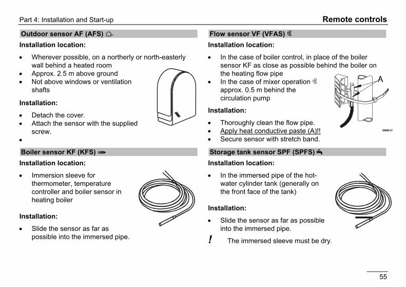
Outdoor sensor AF (AFS) S Installation location:
Wherever possible, on a northerly or north-easterly wall behind a heated room
Approx. 2.5 m above ground Not above windows or ventilation
shafts
Installation:
Detach the cover. Attach the sensor with the supplied
screw.
Boiler sensor KF (KFS) H Installation location:
Immersion sleeve for thermometer, temperature controller and boiler sensor in heating boiler
Installation:
Slide the sensor as far as possible into the immersed pipe.
Flow sensor VF (VFAS) v Installation location:
In the case of boiler control, in place of the boiler sensor KF as close as possible behind the boiler on the heating flow pipe
In the case of mixer operation v approx. 0.5 m behind the circulation pump
Installation:
Thoroughly clean the flow pipe. Apply heat conductive paste (A)!! Secure sensor with stretch band.
Storage tank sensor SPF (SPFS) F Installation location:
In the immersed pipe of the hot-water cylinder tank (generally on the front face of the tank)
Installation:
Slide the sensor as far as possible into the immersed pipe.
! The immersed sleeve must be dry.

Commissioning Part 4: Installation and Start-up
56
Commissioning
Commissioning level Enter all values one after the other
Ä Open level, Ç adjust value, Ä save value and activate next value GERMAN Set language
Minute Set current time:
Hour Set current time:
YEAR Set current date
MONTH Set current date
DAY Set current date
HC FUNCTION D1 00, 01, 03, 05 (see page 39)
HC FUNCTION D2 00 - 04 (see pg. 39) CAP/MODULE 00 – 1000 KW (see pg. 33) BUS ID I (see pg. 57)
Enter number for heating circuit "1": 00-15 => Standard 01
BUS ID 2 (see pg. 57)
Enter number for heating circuit "2": 00-15 => Standard 02
5K SENSOR (code number)
00 = 5KOhm NTC sensor 01 = 1kOhm PTC sensor
Commissioning procedure 1. Please read this guide carefully before commissioning
2. Fit controller, make electrical connections and switch on heat generator and supply voltage
3. Wait until standard display appears on controller
4. Open hinged operating cover
When the hinged operating flap is opened for the first time after switching on, the "INSTALLATION" is shown on the display.
5. Ä Start INSTALLATION
6. Ç Set value
7. Ä Save value and next value
8. Close hinged operating flap (end of INSTALLATION)
9. Move program switch to required operating mode, e.g. automatic 1 (see page 7)
Bus ID (heating circuit number):
The heating circuits are sequentially numbered starting with "01". Heat circuit numbers must not be assigned twice. Please only use "00" for replacement controllers (see page 57).

Part 4: Installation and Start-up System bus
57
System bus
The heating system This controller can be expanded in a modular fashion using additional modules that are connected via the integrated bus. In its maximum configuration, the system can be used to control the following heating system components
1-8 HS (switching)
1-15 Mixed weather-dependent heating circuits
0-15 Room controller (digital or analogue)
1 Solar system (2 collectors, 2 storage tanks)
The various components are simply coupled to the system bus. The modules log on to the system automatically and search for their communication partners via the defined bus IDs (heating circuit number or HS number).
Bus ID For mixer motor controllers and control units
The bus ID (00-15; expert level parameter) is used to number the heating circuits in the system. Each operating module and each mixer motor module is given the number of the assigned heating circuit as its bus ID.
Heating circuit numbers (00-15) may not be assigned twice.
Heating circuit numbers 00 and 01 may not be used simultaneously.
The heating circuits are sequentially numbered starting with "01".
Please only use heating circuit number 00 for replacement controllers if "00" was used in the replaced controller.
Pre-settings heating circuit 1 01 heating circuit 2 02
! After setting all the bus IDs the system must be re-energised (once only).
For heat generators via BUS
The heat generators HS are numbered in ascending order. Here it needs to be taken into account that the first four HS are controlled directly via the internal relay => Addresses via BUS: 05 – 08.
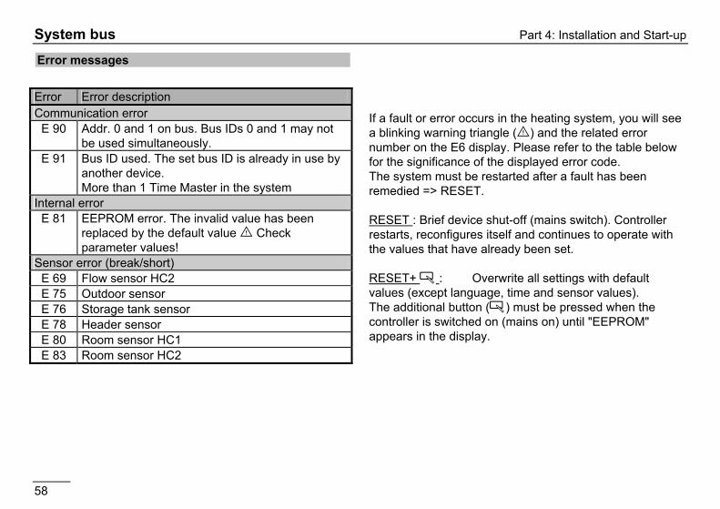
System bus Part 4: Installation and Start-up
58
Error messages
If a fault or error occurs in the heating system, you will see a blinking warning triangle (E) and the related error number on the E6 display. Please refer to the table below for the significance of the displayed error code. The system must be restarted after a fault has been remedied => RESET.
RESET : Brief device shut-off (mains switch). Controller restarts, reconfigures itself and continues to operate with the values that have already been set.
RESET+ Ä : Overwrite all settings with default values (except language, time and sensor values). The additional button (Ä) must be pressed when the controller is switched on (mains on) until "EEPROM" appears in the display.
Error Error description Communication error
E 90 Addr. 0 and 1 on bus. Bus IDs 0 and 1 may not be used simultaneously.
E 91 Bus ID used. The set bus ID is already in use by another device. More than 1 Time Master in the system
Internal error E 81 EEPROM error. The invalid value has been
replaced by the default value E Check parameter values!
Sensor error (break/short) E 69 Flow sensor HC2 E 75 Outdoor sensor E 76 Storage tank sensor E 78 Header sensor E 80 Room sensor HC1 E 83 Room sensor HC2
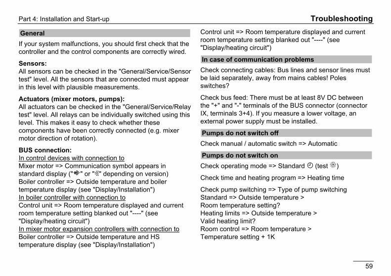
Part 4: Installation and Start-up Troubleshooting
59
Troubleshooting
General If your system malfunctions, you should first check that the controller and the control components are correctly wired.
Sensors: All sensors can be checked in the "General/Service/Sensor test" level. All the sensors that are connected must appear in this level with plausible measurements.
Actuators (mixer motors, pumps): All actuators can be checked in the "General/Service/Relay test" level. All relays can be individually switched using this level. This makes it easy to check whether these components have been correctly connected (e.g. mixer motor direction of rotation).
BUS connection: In control devices with connection to Mixer motor => Communication symbol appears in standard display (" " or "v" depending on version) Boiler controller => Outside temperature and boiler temperature display (see "Display/Installation") In boiler controller with connection to Control unit => Room temperature displayed and current room temperature setting blanked out "----" (see "Display/heating circuit") In mixer motor expansion controllers with connection to Boiler controller => Outside temperature and HS temperature display (see "Display/Installation")
Control unit => Room temperature displayed and current room temperature setting blanked out "----" (see "Display/heating circuit")
In case of communication problems Check connecting cables: Bus lines and sensor lines must be laid separately, away from mains cables! Poles switches?
Check bus feed: There must be at least 8V DC between the "+" and "-" terminals of the BUS connector (connector IX, terminals 3+4). If you measure a lower voltage, an external power supply must be installed.
Pumps do not switch off Check manual / automatic switch => Automatic
Pumps do not switch on Check operating mode => Standard F (test B)
Check time and heating program => Heating time
Check pump switching => Type of pump switching Standard => Outside temperature > Room temperature setting? Heating limits => Outside temperature > Valid heating limit? Room control => Room temperature > Temperature setting + 1K

Technical data
60
Burner does not switch of at correct time Check HS minimum temperature and type of minimum limitation => Corrosion protection
Burner will not switch on Check HS set temperature => The set temperature must be greater than the HS temperature.
Check operating mode => Standard F (test B)
With solar: check burner blocking
Technical data
Supply voltage to IEC 38 AC 230 V 10% Power consumption max 8 W Switching capacity of the relays AC 250V 2 (2) A Maximum current on terminal L1' 10 A Enclosure to EN 60529 IP 40 Safety class II to EN 60730 Totally insulated Switch panel installation in acc. with DIN IEC 61554
Recess 138x92
Power reserve of the timer > 10 hours Permitted room temperature during operation
0 to 50°C
Permitted room temperature during storage
- 20 to 60 °C
Permissible humidity non condensing
%95 r.H.
Sensor resistances Tolerance in ohms Temperature tolerance Tolerance in ohms Temperature tolerance
NTC 5 k (AF,KF,SPF,VF) +/- 1% at 25°C +/- 0.2K at 25°C PTC 1010 (AFS,KFS,SPFS,VFAS) +/- 1% at 25°C +/- 1.3K at 25°C
EN
051
1
6.67
01.9
61-0
5 P
rinte
d in
Ger
man
y, S
ubje
ct to
mod
ifica
tion
Malfunctions due to improper operation or settings are not covered by the warranty.