Embed Size (px)
Citation preview
More than safety.
System ManualNon-Contact Safety System
CES-AZ-AES-01B-EX (Unicode)
System Manual Safety System CES-AZ-AES-01B-EX
�
ContentsCorrect use 3Possible combinations for CES components 4
Safety precautions 5
System description 6Block diagram CES-AZ-AES-01B-EX 7
Installation 8
Electrical connection 9Connection example CES-AZ-AES-01B-EX 10
LED displays 11
Setup 11
System status table 13
Inspection and service 14
Function test (self-test) 14
Exclusion of liability 14
Technical data 15Evaluation unit CES-AZ-AES-01B-EX 15Read head CES-A-LNA-SC-EX 17Read head CES-A-LMN-SC-EX 19Read head CEM-A-LE05K-S�-EX �1Actuator CES-A-BBA-EX �3Actuator CES-A-BMB-EX �4Actuator CEM-A-BE05-EX �5
Ordering information and accessories 26
Declaration of conformity 27
System Manual Safety System CES-AZ-AES-01B-EX
3
Correct useThe Coded Electronic Safety systems CES are safety devices for monitoring mov-able safety guards so that:
Dangerous work on machines can only be carried out if the safety guards are closed.
A stop command is triggered if a safety guard is opened while the machine is running.
Before safety switches are used, a risk assessment must be performed on the machine in accordance with:
EN 13849-1, Safety of machinery. Safety related parts of control systems. General principles for design, Annex B
EN ISO 141�1, Safety of machinery. Principles for risk assessment
The following applies additionally for evaluation units, read heads and actuators of the type CES-...-EX and CEM-...-EX :
EN 60079-15, Electrical apparatus for explosive gas atmospheres. Construc-tion, test and marking of type of protection “n” electrical apparatus
ATEX ratings
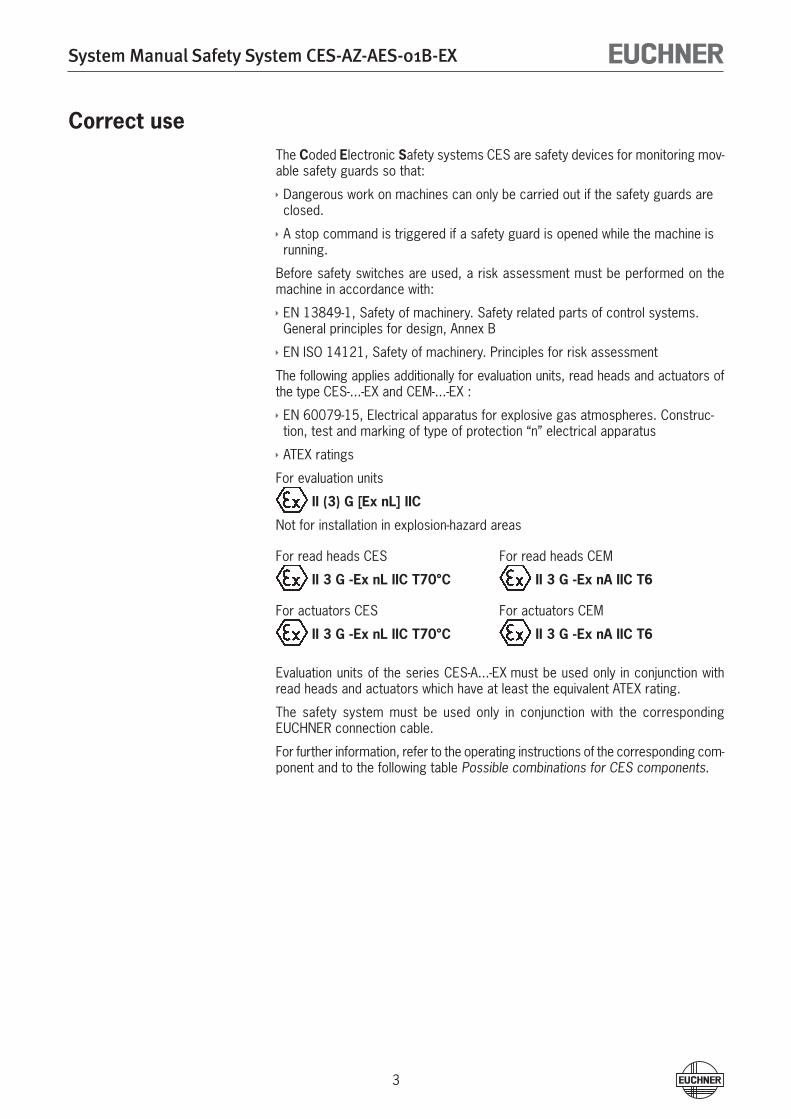
For evaluation units
II (3) G [Ex nL] IIC
Not for installation in explosion-hazard areas
For read heads CES For read heads CEM
II 3 G -Ex nL IIC T70°C II 3 G -Ex nA IIC T6
For actuators CES For actuators CEM
II 3 G -Ex nL IIC T70°C II 3 G -Ex nA IIC T6
Evaluation units of the series CES-A...-EX must be used only in conjunction with read heads and actuators which have at least the equivalent ATEX rating.
The safety system must be used only in conjunction with the corresponding EUCHNER connection cable.
For further information, refer to the operating instructions of the corresponding com-ponent and to the following table Possible combinations for CES components.
System Manual Safety System CES-AZ-AES-01B-EX
4
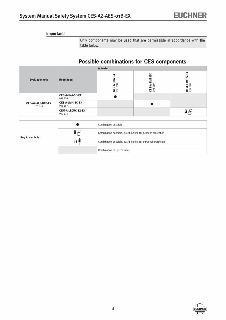
Important!
Only components may be used that are permissible in accordance with the table below.
Possible combinations for CES components
Evaluation unit Read head
Actuator
CES
-A-B
BA-
EX09
8 15
8
CES
-A-B
MB
-EX
098
159
CEM
-A-B
E05-
EX09
7 17
8
CES-AZ-AES-01B-EX105 14�
CES-A-LNA-SC-EX098 156
CES-A-LMN-SC-EX098 157
CEM-A-LE05K-S2-EX097 176
Key to symbols
Combination possible
Combination possible, guard locking for process protection
Combination possible, guard locking for personal protection
Combination not permissible
System Manual Safety System CES-AZ-AES-01B-EX
5
Safety precautionsThe safety system CES-AZ-AES-01B-EX complies with the following safety require-ments:
Proximity device with self-monitoring type PDF-M according to EN 60947-5-3.
Performance level e according to EN 13849-1: �007-07
In relation to the structural requirements, category 4 in accordance with EN 13849-1: �007-07, comparable to category 4 in accordance with EN 954-1, is achieved.
Redundant design of the circuit in the evaluation unit with self-monitoring. As a result, the safety system is still effective even if a component fails.
When the safety guard is opened and closed, it is checked whether the safety system relays open and close correctly.
Monitoring output O1 must not be used as a safety output.
Safety switches fulfill personal protection functions. Incorrect installation or tamper-ing can lead to severe injuries to personnel.
The number of teach-in and switching operations is saved in the internal memory in the evaluation unit. If necessary, this memory can be read by the manufacturer.
Check the safe function of the safety guard particularly
after any setup work
after the replacement of a CES component
after an extended period without use
Independent of these checks, the safe function of the safety guard should be checked at suitable intervals as part of the maintenance schedule.
The year of manufacture of the device can be derived from the serial number on the rating plate.
Important!
The evaluation unit must be replaced with a new device after 5 years of opera-tion.
Important!
Prior to use, read the operating instructions and the system manual of the CES components used, and keep these in a safe place. Ensure the operat-ing instructions and the system manual are always available during mounting, setup and servicing. EUCHNER cannot provide any warranty in relation to the readability of the CD for the storage period required. For this reason you should archive a printed copy of the system manual. If you should lose the operating instructions or the system manual, you can download these documents from www.EUCHNER.de.
System Manual Safety System CES-AZ-AES-01B-EX
6
System descriptionThe CES non-contact safety system consists of three components:
Coded actuator
Read head
Evaluation unit
1 read head may be connected to the evaluation unit CES-AZ-AES-01B.
It is also possible to connect a start button (monitored start) and a feedback loop for monitoring external relays and contactors.
The individual configuration is defined by a setup procedure.
Each delivered actuator possesses a unique electronic coding and so is a unique element in the system used. The code in an actuator cannot be reprogrammed.
The read heads are fastened to the fixed part of the safety guard and are each connected to the evaluation unit via a two-core screened cable.
The actuator fastened to the movable part of the safety guard is moved towards the read head by closing the door. When the switch-on distance is reached, power is supplied to the actuator by the inductive read head and data can be transferred.
The bit pattern read is compared with the code saved in the evaluation unit. If the data match, the door monitoring output O1 (semiconductor output) on the read head is set HIGH and the safety outputs (relay outputs) are then enabled. The OUT LED illuminates.
Optionally, a feedback loop can be connected to the evaluation unit. Then the evalu-ation unit can only be started with the feedback loop closed. A welded contactor contact in the release path will thus be detected when a start request is made.
Due to the combination of dynamic polling of the actuators and the redundant, diverse design of the safety electronics with two safety outputs, the evaluation unit will enter the safe state with every detectable fault.
When a safety guard is opened, the safety outputs switch off the safety circuit and the OUT LED goes out. The state of the safety outputs is monitored internally by positively driven NC contacts (relay output).
Independent of the switching state of the safety circuit, the position of the safety door can be polled via the output O1.
If an internal fault occurs in the evaluation unit, the safety circuit is switched off, the diagnostic output (DIA) is set HIGH and the DIA LED illuminates red.
System Manual Safety System CES-AZ-AES-01B-EX
7
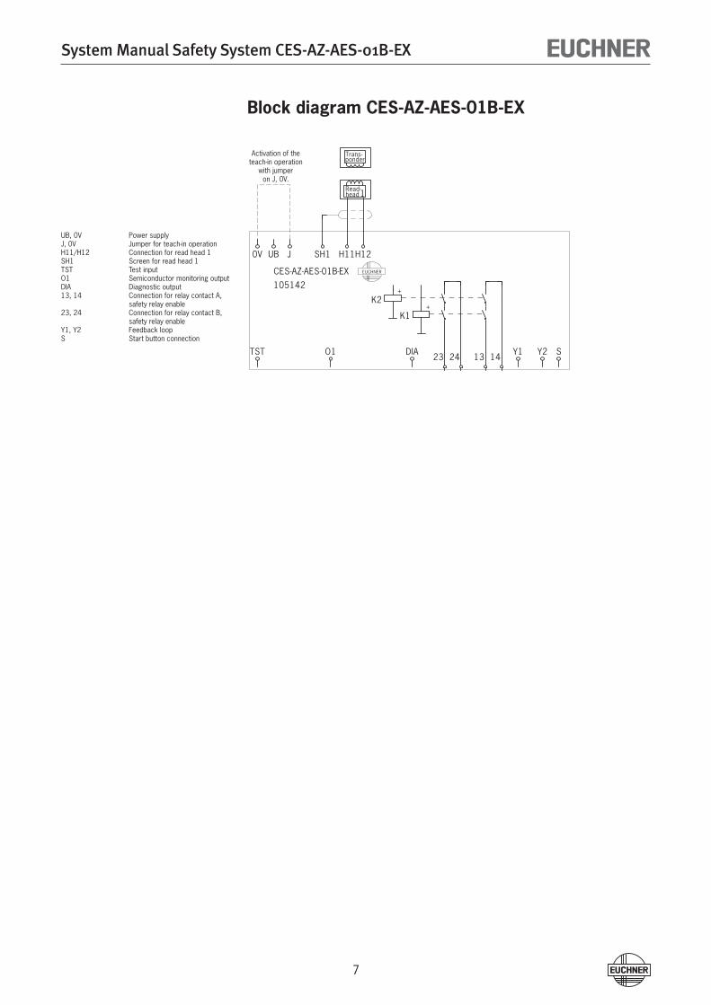
Block diagram CES-AZ-AES-01B-EX
0V
TST
UB
CES-AZ-AES-01B-EX
105142
J SH1
O1
Read-head1
H11
Trans-ponder
H12
EUCHNER
DIA 23 24 13 14 Y1 Y2 S
K2+
K1+
Activation of theteach-in operation
with jumperon J, 0V.
UB, 0V Power supplyJ, 0V Jumper for teach-in operationH11/H1� Connection for read head 1SH1 Screen for read head 1TST Test inputO1 Semiconductor monitoring outputDIA Diagnostic output13, 14 Connection for relay contact A,
safety relay enable�3, �4 Connection for relay contact B,
safety relay enableY1, Y� Feedback loopS Start button connection
System Manual Safety System CES-AZ-AES-01B-EX
8
InstallationWarning!
Mounting must be performed only by authorized personnel.Carry out the work only if there is no ignitable atmosphere and the system is switched off.
Actuator and read head must be easily accessible for inspection and replace-ment.
The switching operation must only be triggered by the specific actuator desig-nated for this purpose.
Actuator and read head must be fitted so thatthe front faces are at the minimum switch-on distance 0.8 x Sao or closer (see technical data) with the safety guard closed.when the safety guard is opened to the assured switch-off distance Sar, a haz-ard is excluded. Note: From the assured switch-off distance Sar, the relay outputs are safely switched off.they are positively mounted on the safety guard, e.g. using the safety screws included (cube-shaped design) or adhesive (cylindrical design M1�).they are not used as a mechanical end stop. Note: Fit an additional end stop for the movable part of the safety guard.
Pay attention to the maximum tightening torque for the read head or safety switch and actuator mountings of 1 Nm.
If installed flush, the switching distance changes as a function of the installation depth and the safety guard material.
The evaluation unit must be mounted in a control cabinet with a minimum de-gree of protection of IP 54. A snap-in element on the rear of the device is used for fastening to standard rails.
If several evaluation units are mounted side by side in a control cabinet without air circulation (e.g. fan), a minimum distance of 10 mm must be maintained between the evaluation units. The distance enables heat from the evaluation unit to dissipate.
When mounting several read heads, observe following minimum distance to avoid mutual interference: - for CES-A-LNA-SC-EX min. 50 mm - for CES-A-LMN-SC-EX min. �0 mm - for CEM-A-LE05K-S� -EX min. 50 mm
System Manual Safety System CES-AZ-AES-01B-EX
9
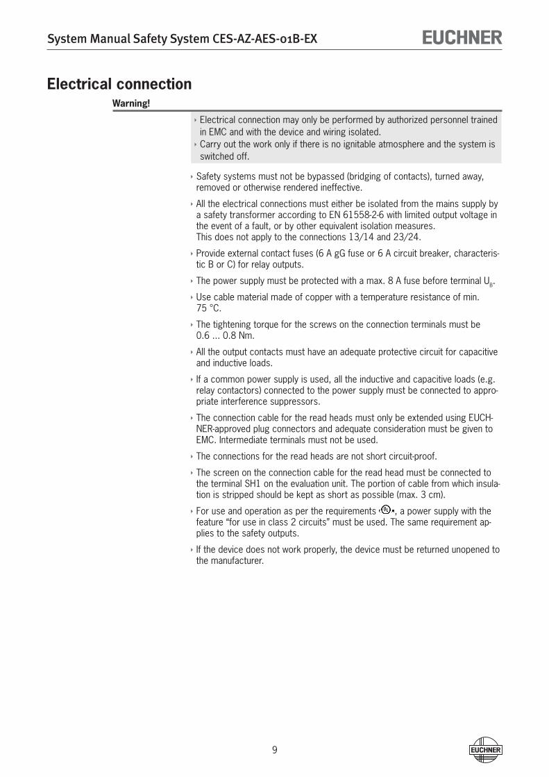
Electrical connectionWarning!
Electrical connection may only be performed by authorized personnel trained in EMC and with the device and wiring isolated.Carry out the work only if there is no ignitable atmosphere and the system is switched off.
Safety systems must not be bypassed (bridging of contacts), turned away, removed or otherwise rendered ineffective.
All the electrical connections must either be isolated from the mains supply by a safety transformer according to EN 61558-�-6 with limited output voltage in the event of a fault, or by other equivalent isolation measures. This does not apply to the connections 13/14 and �3/�4.
Provide external contact fuses (6 A gG fuse or 6 A circuit breaker, characteris-tic B or C) for relay outputs.
The power supply must be protected with a max. 8 A fuse before terminal UB.
Use cable material made of copper with a temperature resistance of min. 75 °C.
The tightening torque for the screws on the connection terminals must be 0.6 ... 0.8 Nm.
All the output contacts must have an adequate protective circuit for capacitive and inductive loads.
If a common power supply is used, all the inductive and capacitive loads (e.g. relay contactors) connected to the power supply must be connected to appro-priate interference suppressors.
The connection cable for the read heads must only be extended using EUCH-NER-approved plug connectors and adequate consideration must be given to EMC. Intermediate terminals must not be used.
The connections for the read heads are not short circuit-proof.
The screen on the connection cable for the read head must be connected to the terminal SH1 on the evaluation unit. The portion of cable from which insula-tion is stripped should be kept as short as possible (max. 3 cm).
For use and operation as per the requirements , a power supply with the feature “for use in class � circuits” must be used. The same requirement ap-plies to the safety outputs.
If the device does not work properly, the device must be returned unopened to the manufacturer.
System Manual Safety System CES-AZ-AES-01B-EX
10
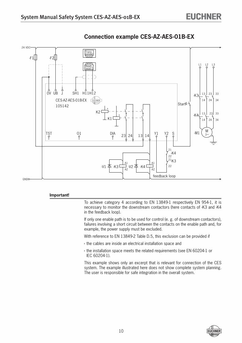
Connection example CES-AZ-AES-01B-EX
Important!
To achieve category 4 according to EN 13849-1 respectively EN 954-1, it is necessary to monitor the downstream contactors (here contacts of -K3 and -K4 in the feedback loop).
If only one enable path is to be used for control (e. g. of downstream contactors), failures involving a short circuit between the contacts on the enable path and, for example, the power supply must be excluded.
With reference to EN 13849-� Table D.5, this exclusion can be provided if
the cables are inside an electrical installation space and
the installation space meets the related requirements (see EN 60�04-1 or IEC 60�04-1).
This example shows only an excerpt that is relevant for connection of the CES system. The example illustrated here does not show complete system planning. The user is responsible for safe integration in the overall system.
24 VDC
GND
-F1
0V
TST
-F2
UB
CES-AZ-AES-01B-EX
105142
J SH1
O1
Read-head1
H11
Trans-ponder
H12
EUCHNER
-V1
DIA
-K3A1
A2
23 24
-V2
13 14
-K4A1
A2
feedback loop
Y1 Y2
-K421
22
-K321
22
S
Start
L1
-K3 13
14
-K4 13
14
M3~-M1
L2
23
24
23
24
L3
33
34
33
34
K2+
K1+
System Manual Safety System CES-AZ-AES-01B-EX
11
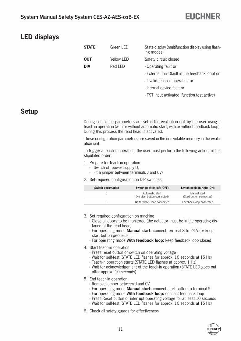
LED displaysSTATE Green LED State display (multifunction display using flash-
ing modes)
OUT Yellow LED Safety circuit closed
DIA Red LED - Operating fault or
- External fault (fault in the feedback loop) or
- Invalid teach-in operation or
- Internal device fault or
- TST input activated (function test active)
Setup During setup, the parameters are set in the evaluation unit by the user using a teach-in operation (with or without automatic start, with or without feedback loop). During this process the read head is activated.
These configuration parameters are saved in the non-volatile memory in the evalu-ation unit.
To trigger a teach-in operation, the user must perform the following actions in the stipulated order:
Prepare for teach-in operation Switch off power supply UB Fit a jumper between terminals J and 0V)
Set required configuration on DIP switches
Switch designation Switch position left (OFF) Switch position right (ON)
5 Automatic start(No start button connected)
Manual start(Start button connected)
6 No feedback loop connected Feedback loop connected
Set required configuration on machineClose all doors to be monitored (the actuator must be in the operating dis-tance of the read head)For operating mode Manual start: connect terminal S to �4 V (or keep start button pressed)For operating mode With feedback loop: keep feedback loop closed
Start teach-in operationPress reset button or switch on operating voltageWait for self-test (STATE LED flashes for approx. 10 seconds at 15 Hz)Teach-in operation starts (STATE LED flashes at approx. 1 Hz)Wait for acknowledgement of the teach-in operation (STATE LED goes out after approx. 10 seconds)
End teach-in operationRemove jumper between J and 0VFor operating mode Manual start: connect start button to terminal SFor operating mode With feedback loop: connect feedback loopPress Reset button or interrupt operating voltage for at least 10 secondsWait for self-test (STATE LED flashes for approx. 10 seconds at 15 Hz)
Check all safety guards for effectiveness
1.
�.
3.
4.
5.
6.
System Manual Safety System CES-AZ-AES-01B-EX
1�
Notes
During the teach-in operation the following conditions must be met:
There must be no state change, e.g. opening the safety guard or a change in the signal on the terminals for the start button and the feedback circuit.
The power supply must not be switched off.
If these conditions are not met, the evaluation unit switches to the safe fault state (diagnostics LED illuminates) and signals this operating fault with the STATE LED by 3 short flashes that are repeated every second. The teach-in operation must be repeated.
The number of teach-in operations is unlimited. The evaluation unit can be re-configured as often as required.
Actuators cannot be interchanged without a renewed teach-in operation.
An actuator that has not been subjected to teach-in will not be detected by the read head.
Even if only one new actuator needs to be taught, a complete new teach-in operation must be carried out as described in the section Setup.
Do not change DIP switches during operation.
Changing the configuration / new actuatorThe evaluation unit can be re-configured as often as required. For this purpose you must proceed as per the first teach-in operation according to the Setup procedure section.
Faulty actuators can be replaced. Then a complete teach-in operation must be per-formed as per the section Setup. The number of teach-in operations is unlimited.
System Manual Safety System CES-AZ-AES-01B-EX
13
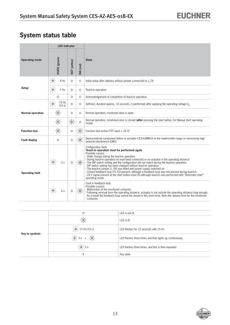
System status table
Operating mode
LED indicator
StateST
ATE
(gre
en)
OU
T (y
ello
w)
DIA
(red
)
Setup
4 Hz Initial setup after delivery without jumper connected to J, 0V.
1 Hz Teach-in operation
Acknowledgement of completion of teach-in operation.
Normal operation
15 Hz(10 s) Self-test, duration approx. 10 seconds, is performed after applying the operating voltage UB
Normal operation, monitored door is open.
Normal operation, monitored door is closed (after pressing the start button, for Manual start operating mode)
Function test Function test active (TST input = �4 V)
Fault display Device-internal component failure or actuator CES-A-BMB-EX in the inadmissible range or excessively high external interference (EMC)
Operating fault
3 x
Configuration fault:Teach-in operation must be performed againPossible causes:- State change during the teach-in operation- During teach-in operation no read head connected or no actuator in the operating distance- The DIP switch setting and the configuration did not match during the teach-in operation- DIP switch setting has been changed without teach-in operation- The teach-in jumper (J, 0V) was fitted with power supply switched on- Closed feedback loop (Y1,Y�) present, although a feedback loop was not present during teach-in- �4 V signal present at the start button input (S) although teach-in was performed with “Automatic start” operating mode.
4 x
Fault in feedback loopPossible causes:- Malfunction of the monitored contactor- Following removal from the operating distance, actuator is not outside the operating distance long enough. As a result the feedback loop cannot be closed in this short time. Note the release time for the monitored contactor.
Key to symbols
LED is not lit
LED is lit
15 Hz (10 s) LED flashes for 10 seconds with 15 Hz
3 x + LED flashes three times and then lights up continuously
3 x LED flashes three times, and this is then repeated
X Any state
System Manual Safety System CES-AZ-AES-01B-EX
14
Inspection and serviceImportant!
The evaluation unit must be replaced with a new device after 5 years of opera-tion.
Regular inspection of the following is necessary to ensure trouble-free long-term operation:
Secure fastening of the actuator and read head (use of safety screws included)
Sealing of cable entry or plug connector on the read head
Loose cable connections on the evaluation unit
Switch-off distance check
No servicing work is required on the battery-less actuator, providing the user with service-free operation.
Function test (self-test)On electromechanical safety switches or magnetic switches, the function test can be performed by cyclically opening the safety guard.
From category � as defined in EN 13849-1 respectively EN 954-1 and according to EN 60�0�-1 : 1997 (section 9.4.�.4), a function test must be performed on the entire safety system on start-up or after defined intervals.
Testing of the internal function of the safety switch CES is not necessary because the device monitors itself in real time. Welding of an output contact (relay output) is detected by the device at the latest the next time the safety guard is opened. A short circuit in the output cable is not detected by the device.
In addition, the entire safety circuit can be tested without opening the safety guard. For this purpose, opening of the safety guard can be simulated by applying �4 V DC to the test input.
The safety outputs are switched off, enabling testing of the complete safety circuit. The diagnostic output DIA of the evaluation unit is also set HIGH as a monitoring function.
When the test input is reset, the evaluation unit resets the diagnostic output DIA to LOW, the red LED switches off and normal operation is continued.
In Manual start operating mode, the start button must be pressed again to start the system.
This permits self-testing of the safety system without opening the safety guard.
Exclusion of liabilityExclusion of liability under the following conditions:
incorrect use
non-compliance with safety regulations
installation and electrical connection are carried out by unauthorized personnel
if modifications are made
System Manual Safety System CES-AZ-AES-01B-EX
15
Technical data
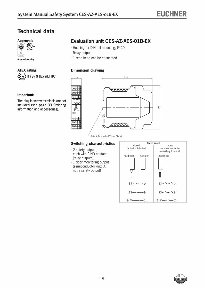
Evaluation unit CES-AZ-AES-01B-EXHousing for DIN rail mounting, IP �0Relay output1 read head can be connected
Dimension drawing
Switching characteristics� safety outputs, each with � NO contacts (relay outputs)1 door monitoring output (semiconductor output, not a safety output)
Approvals
Approval pending
Approvals
Approval pending
ATEX rating
II (3) G [Ex nL] IIC
ATEX rating
II (3) G [Ex nL] IIC
Important:
The plug-in screw terminals are not included (see page 33 Ordering information and accessories).
Important:
The plug-in screw terminals are not included (see page 33 Ordering information and accessories).
Safety guardclosed
(actuator detected)open
(actuator not in the operating distance)
Read head Actuator Read head
V O1
13 14
23 24
24
13 14
23 24
24 V O1
11422,5
99
Safety Unit
CES-AZ
H11
+UBH12
0V
SH1
STATE OUT DIA
13 O1 Y1 23
14 DIA Y2 24
Unicode
RESET
TST
J S
SY
56
Suitable for standard 35 mm DIN rail
System Manual Safety System CES-AZ-AES-01B-EX
16
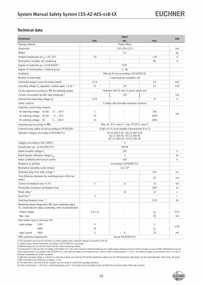
Technical data
ParameterValue
Unitmin. typ. max.
Housing material Plastic PA6.6
Dimensions 114 x 99 x ��.5 mm
Weight 0.� kg
Ambient temperature at UB = DC �4 V -�0 - +55 °C
Atmospheric humidity, not condensing - - 80 %
Degree of protection acc. to EN 605�9 1) IP�0
Degree of contamination / material group � / IIIa
Installation DIN rail 35 mm according to EN 500��-35
Number of read heads 1 read head per evaluation unit
Connection (plug-in screw terminals/coded) 0.14 - �.5 mm²
Operating voltage UB (regulated, residual ripple < 5 %) �) �1 �4 �7 V DC
For the approval according to the following applies Operation with UL-class � power supply only
Current consumption IB (with relay energized) 3) - 150 - mA
External fuse (operating voltage UB) 0.�5 - 8 A
Safety contacts � (relays with internally monitored contacts)
Switching current (relay outputs)
mA- At switching voltage AC/DC �1 ... 60 V 1 - 300
- At switching voltage AC/DC 5 ... 30 V 10 - 4000
- At switching voltage AC 5 ... 160 V 10 - �000
Switching load according to Max. AC 30 V, class � / max. DC 60 V, class �
External fusing (safety circuit) according to EN 60�69-1 6 AgG or 6 A circuit breaker (characteristic B or C)
Utilization category according to EN 60947-5-1 AC-1� 60V 0.3A / DC-1� 60V 0.3AAC-1� 30V 4A / DC-1� 30V 4AAC-15 160V �A / DC-13 �4V 3A
Category according to EN 13849-1 4
Classification acc. to EN 60947-5-3 PDF-M
Rated insulation voltage Ui �50 V
Rated impulse withstand voltage Uimp 4 kV
Rated conditional short-circuit current 100 A
Resilience to vibration According to EN 60947-5-�
Mechanical operating cycles (relays) 10 x 106
Switching delay from state change 4) - - �10 ms
Time difference (between the switching points of the two relays)
- - �5 ms
Current via feedback loop Y1/Y� 5 8 10 mA
Permissible resistance via feedback loop - - 600 W
Ready delay 5) - 10 1� s
Dwell time 6) 3 - - s
Switching frequency max. 7) - - 0.�5 Hz
Monitoring outputs (diagnostics DIA, door monitoring output O1, semiconductor output, p-switching, short circuit-protected)
- Output voltage 0.8 x UB - UB V DC
- Max. load - - �0 mA
Start button input S, test input TST
- Input voltage LOW 0 - �V DC
HIGH 15 - UB
- Input current HIGH 5 8 10 mA
EMC protection requirements As per EN 60947-5-3
1) The evaluation unit must be mounted in a control cabinet with a minimum degree of protection of IP 54.�) Supply using a safety transformer according to EN 61558-�-6 is necessary.3) Without taking into account the load currents on the monitoring outputs.4) Corresponds to the risk time according to EN 60947-5-3. This is the maximum switch-off delay for the safety outputs following removal of the actuator. In case of EMC interference in excess of the requirements in accordance with EN 60947-5-3, the switch-off delay can increase to max. �50 ms. After a brief actuation < 0.�5 s, the switch-on delay can increase to max. 3 s if this is followed immediately by further actuation.5) After the operating voltage is switched on, the relay outputs are switched off and the monitoring outputs are set LOW during the ready delay. For the visual indication of the delay, the green STATE LED flashes at a frequency of approx. 15 Hz.6) The dwell time is the time that the actuator must be inside or outside the operating distance.7) If the current load is > 100 mA, a switching frequency of 0.1 Hz should not be exceeded as this will affect the mechanical life of the relay contacts.
System Manual Safety System CES-AZ-AES-01B-EX
17
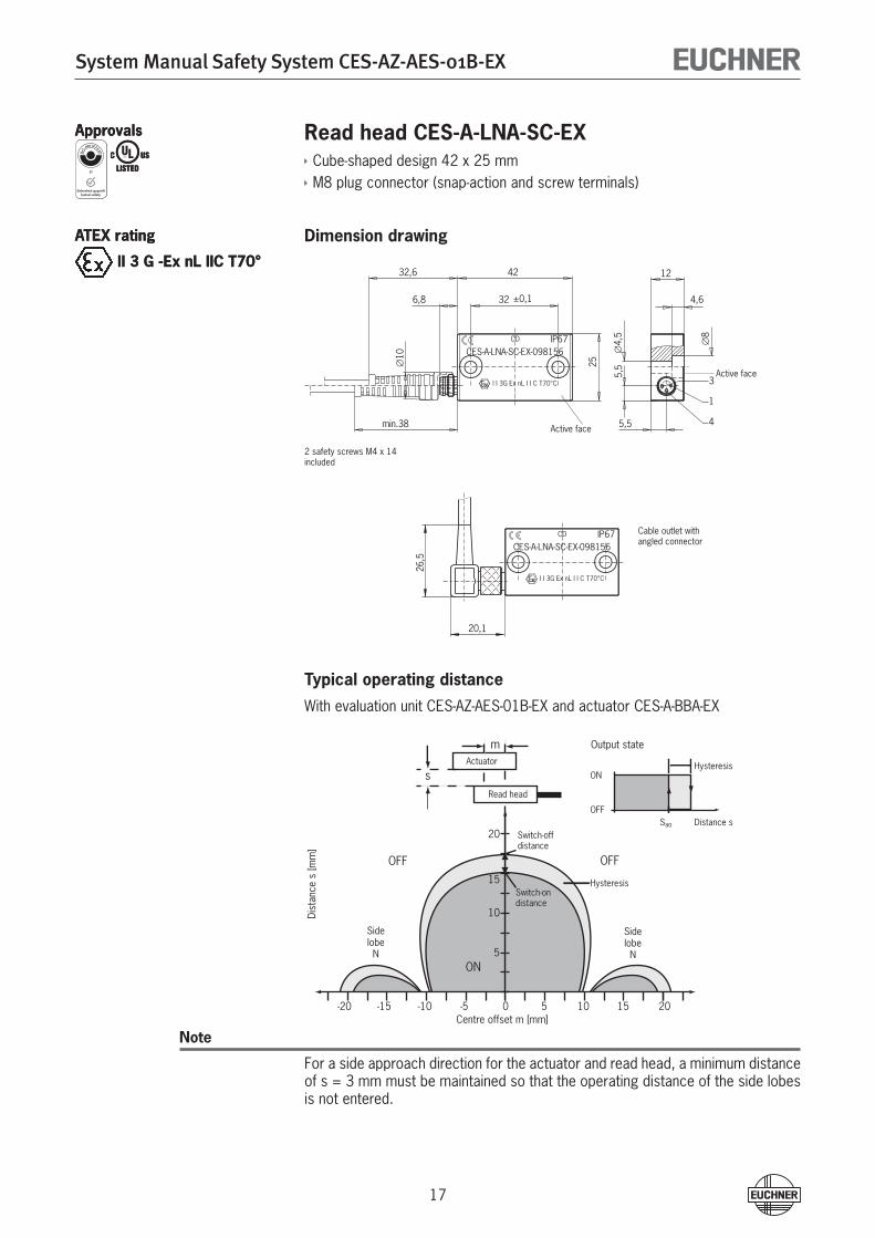
Read head CES-A-LNA-SC-EXCube-shaped design 4� x �5 mmM8 plug connector (snap-action and screw terminals)
Dimension drawing
Typical operating distanceWith evaluation unit CES-AZ-AES-01B-EX and actuator CES-A-BBA-EX
Note
For a side approach direction for the actuator and read head, a minimum distance of s = 3 mm must be maintained so that the operating distance of the side lobes is not entered.
ApprovalsApprovals
ATEX rating
II 3 G -Ex nL IIC T70°
ATEX rating
II 3 G -Ex nL IIC T70°
� safety screws M4 x 14included
Cable outlet withangled connector
Active face
Active face
SidelobeN
-10-15 -5 0Centre offset m [mm]
Dist
ance
s [m
m]
OFF
ON
Switch-ondistance
ON
OFF
Hysteresis
Distance sSao
Output state
Switch-offdistance
OFF
Hysteresis
-20 5 201510
5
10
15
20
SidelobeN
Actuator
Read head
s
m
5,5
10
6,8
8
4,5
4,6
12
25
min.38
32 ±0,1
4232,6
3
4
1
5,5
CD
I I 3G Ex nL I I C T70°C
IP67CES-A-LNA-SC-EX-098156
20 1,
26,5
CD
I I 3G Ex nL I I C T70°C
IP67CES-A-LNA-SC-EX-098156
System Manual Safety System CES-AZ-AES-01B-EX
18
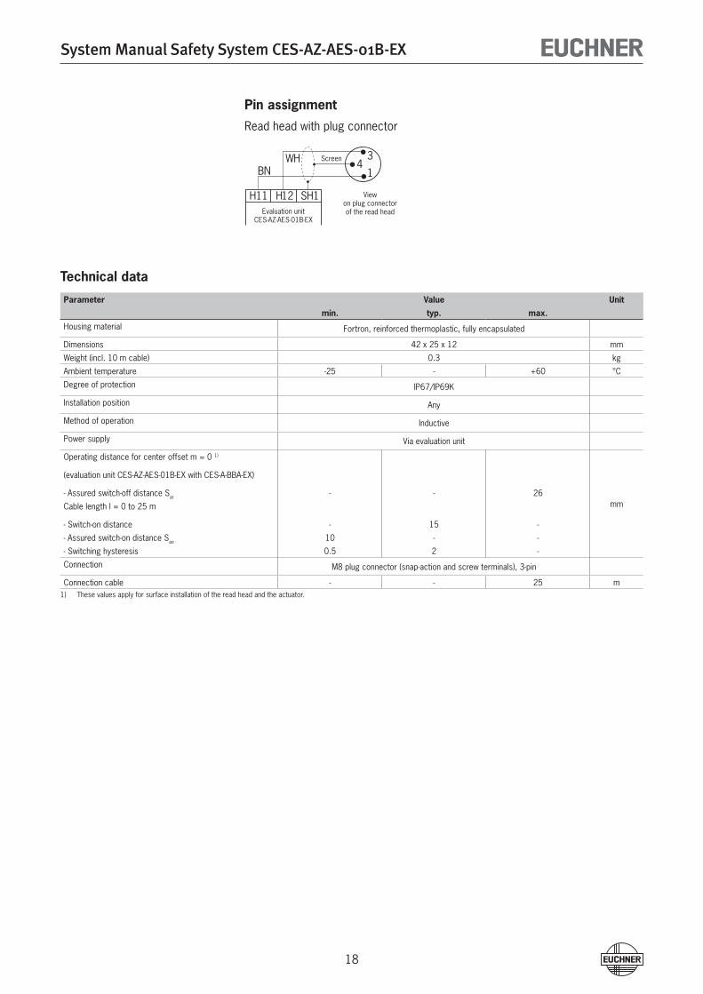
Pin assignmentRead head with plug connector
Technical data
Parameter Value Unit
min. typ. max.
Housing material Fortron, reinforced thermoplastic, fully encapsulated
Dimensions 4� x �5 x 1� mm
Weight (incl. 10 m cable) 0.3 kg
Ambient temperature -�5 - +60 °C
Degree of protection IP67/IP69K
Installation position Any
Method of operation Inductive
Power supply Via evaluation unit
Operating distance for center offset m = 0 1)
mm
(evaluation unit CES-AZ-AES-01B-EX with CES-A-BBA-EX)
- Assured switch-off distance Sar - - �6
Cable length l = 0 to �5 m
- Switch-on distance - 15 -
- Assured switch-on distance Sao 10 - -
- Switching hysteresis 0.5 � -
Connection M8 plug connector (snap-action and screw terminals), 3-pin
Connection cable - - �5 m1) These values apply for surface installation of the read head and the actuator.
H11 H12 SH1
1
34
BNWH Screen
Viewon plug connectorof the read headEvaluation unit
CES-AZ-AES-01B-EX
System Manual Safety System CES-AZ-AES-01B-EX
19
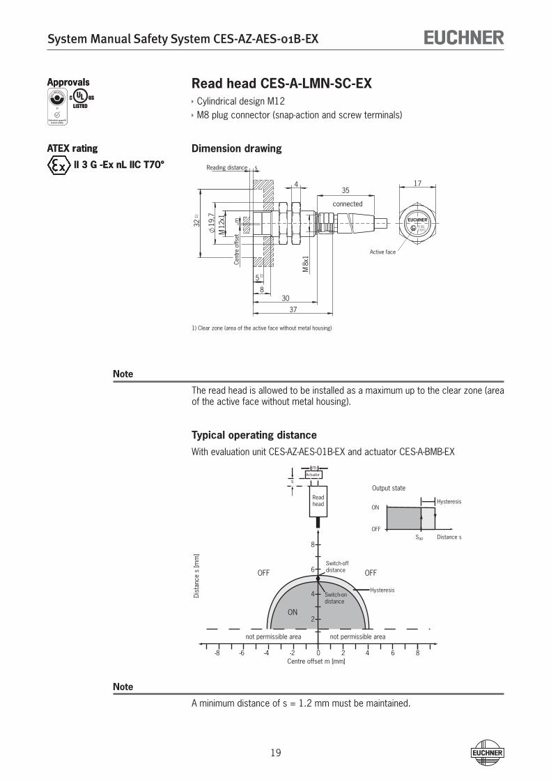
Read head CES-A-LMN-SC-EXCylindrical design M1�M8 plug connector (snap-action and screw terminals)
Dimension drawing
Note
The read head is allowed to be installed as a maximum up to the clear zone (area of the active face without metal housing).
Typical operating distanceWith evaluation unit CES-AZ-AES-01B-EX and actuator CES-A-BMB-EX
Note
A minimum distance of s = 1.� mm must be maintained.
ApprovalsApprovals
ATEX rating
II 3 G -Ex nL IIC T70°
ATEX rating
II 3 G -Ex nL IIC T70°
17
5
32 19,7
s
m
354
830
M12
x1
M8x
137
1)
1)
Reading distance
Cent
re o
ffset
connected
EUCHNERI I 3GT70°C
Active face
1) Clear zone (area of the active face without metal housing)
-4-6 -2 0Centre offset m [mm]
Dist
ance
s [m
m]
OFF
ON
Switch-ondistance
ON
OFF
Hysteresis
Distance sSao
Output state
Switch-offdistance OFF
-8 2 864
2
4
6
8
Actuator
Readhead
s
m
not permissible area not permissible area
Hysteresis
System Manual Safety System CES-AZ-AES-01B-EX
�0
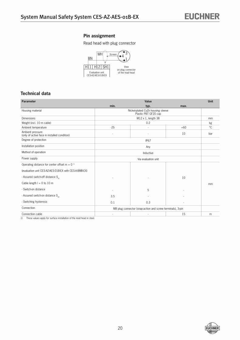
Pin assignmentRead head with plug connector
Technical data
Parameter Value Unit
min. typ. max.
Housing material Nickel-plated CuZn housing sleevePlastic PBT GF�0 cap
Dimensions M1� x 1, length 38 mm
Weight (incl. 10 m cable) 0.� kg
Ambient temperature -�5 - +60 °C
Ambient pressure(only of active face in installed condition) - - 10 bar
Degree of protection IP67
Installation position Any
Method of operation Inductive
Power supply Via evaluation unit
Operating distance for center offset m = 0 1)
(evaluation unit CES-AZ-AES-01B-EX with CES-A-BMB-EX)
- Assured switch-off distance Sar - - 10
Cable length l = 0 to 10 m mm
- Switch-on distance - 5 -
- Assured switch-on distance Sao 3.5 - -
- Switching hysteresis 0.1 0.3 -
Connection M8 plug connector (snap-action and screw terminals), 3-pin
Connection cable - - 15 m1) These values apply for surface installation of the read head in steel.
H11 H12 SH1
1
34
BNWH Screen
Viewon plug connectorof the read headEvaluation unit
CES-AZ-AES-01B-EX
System Manual Safety System CES-AZ-AES-01B-EX
�1
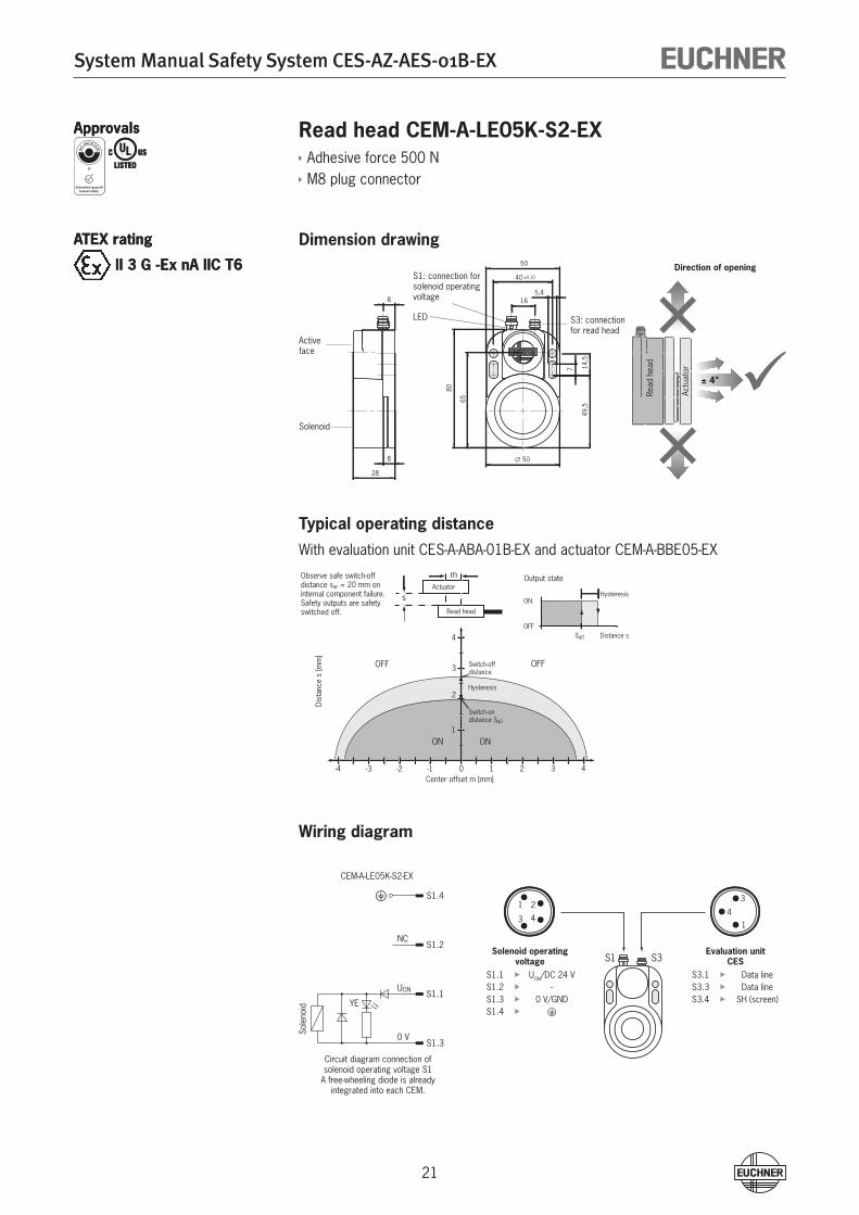
Read head CEM-A-LE05K-S2-EXAdhesive force 500 NM8 plug connector
Dimension drawing
Typical operating distanceWith evaluation unit CES-A-ABA-01B-EX and actuator CEM-A-BBE05-EX
Wiring diagram
ApprovalsApprovals
ATEX rating
II 3 G -Ex nA IIC T6
ATEX rating
II 3 G -Ex nA IIC T6
21
43
S1 S3
14
3
YE
0 V
UON
NC
S1.4
S1.2
S1.1
S1.3
16
∅ 50
40 ±0,10
5,4
49,5
7 14,5
80
65
50
8
8
28
Read
hea
d
Actu
ator
± 4°
-4 -2-3 -1 1 32 40
1
2
3
4
Center offset m [mm]
Dist
ance
s [m
m]
OFF
ON
Hysteresis
Switch-ondistance Sa0
ON
OFF
Hysteresis
Distance sSa0
Output state
Switch-offdistance
OFF
Actuator
Read head
s
m
ON
Observe safe switch-off distance sar = 20 mm on internal component failure.Safety outputs are safety switched off.
Activeface
Solenoid
S3: connection for read head
S1: connection forsolenoid operatingvoltage
Direction of opening
CEM-A-LE05K-S�-EX
Circuit diagram connection of solenoid operating voltage S1
A free-wheeling diode is already integrated into each CEM.
Sole
noid
Solenoid operating voltage
S1.1 UON/DC �4 VS1.� -S1.3 0 V/GNDS1.4 y
Evaluation unitCES
S3.1 Data lineS3.3 Data lineS3.4 SH (screen)
LED
System Manual Safety System CES-AZ-AES-01B-EX
��
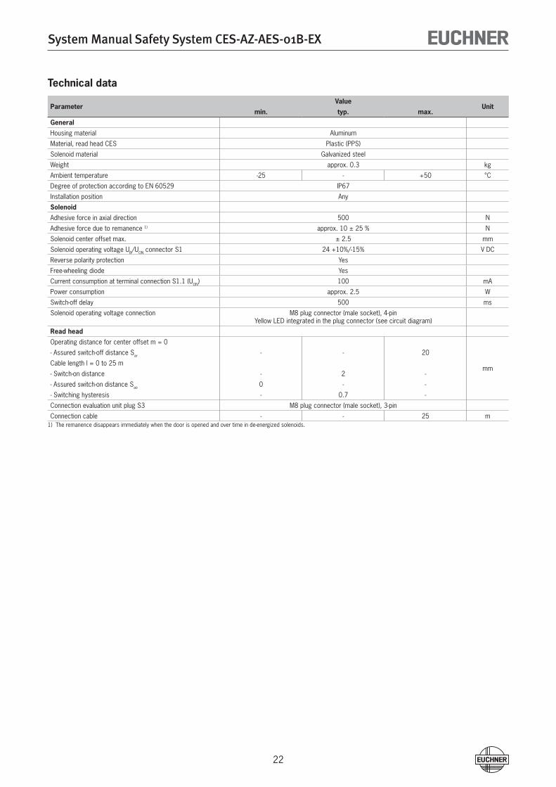
Technical data
ParameterValue
Unitmin. typ. max.
General
Housing material Aluminum
Material, read head CES Plastic (PPS)
Solenoid material Galvanized steel
Weight approx. 0.3 kg
Ambient temperature -�5 - +50 °C
Degree of protection according to EN 605�9 IP67
Installation position Any
Solenoid
Adhesive force in axial direction 500 N
Adhesive force due to remanence 1) approx. 10 ± �5 % N
Solenoid center offset max. ± �.5 mm
Solenoid operating voltage UB/UON connector S1 �4 +10%/-15% V DC
Reverse polarity protection Yes
Free-wheeling diode Yes
Current consumption at terminal connection S1.1 (UON) 100 mA
Power consumption approx. �.5 W
Switch-off delay 500 ms
Solenoid operating voltage connection M8 plug connector (male socket), 4-pinYellow LED integrated in the plug connector (see circuit diagram)
Read head
Operating distance for center offset m = 0
mm
- Assured switch-off distance Sar - - �0
Cable length l = 0 to �5 m
- Switch-on distance - � -
- Assured switch-on distance Sao 0 - -
- Switching hysteresis - 0.7 -
Connection evaluation unit plug S3 M8 plug connector (male socket), 3-pin
Connection cable - - �5 m1) The remanence disappears immediately when the door is opened and over time in de-energized solenoids.
System Manual Safety System CES-AZ-AES-01B-EX
�3
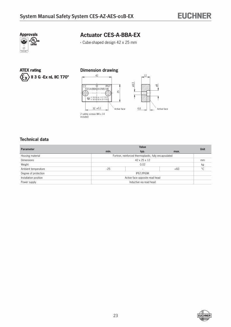
Actuator CES-A-BBA-EXCube-shaped design 4� x �5 mm
Dimension drawing
Technical data
ParameterValue
Unitmin. typ. max.
Housing material Fortron, reinforced thermoplastic, fully encapsulated
Dimensions 4� x �5 x 1� mm
Weight 0.0� kg
Ambient temperature -�5 - +60 °C
Degree of protection IP67/IP69K
Installation position Active face opposite read head
Power supply Inductive via read head
ApprovalsApprovals
ATEX rating
II 3 G -Ex nL IIC T70°
ATEX rating
II 3 G -Ex nL IIC T70°
25
ø8ø4,5
42
32 ±0,1
12
4,6
CD IP67CES-A-BBA-EX-098158
I I 3G Ex nL I I C T70°CI I 3D Ex tD A 22 T70°C
Active face Active face
� safety screws M4 x 14included
System Manual Safety System CES-AZ-AES-01B-EX
�4
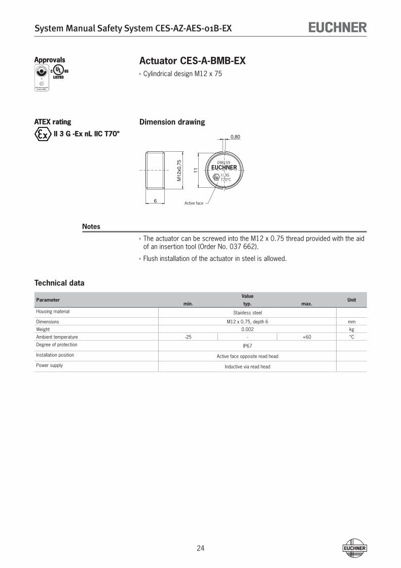
Actuator CES-A-BMB-EXCylindrical design M1� x 75
Dimension drawing
Notes
The actuator can be screwed into the M1� x 0.75 thread provided with the aid of an insertion tool (Order No. 037 66�).
Flush installation of the actuator in steel is allowed.
Technical data
ParameterValue
Unitmin. typ. max.
Housing material Stainless steel
Dimensions M1� x 0.75, depth 6 mm
Weight 0.00� kg
Ambient temperature -�5 - +60 °C
Degree of protection IP67
Installation position Active face opposite read head
Power supply Inductive via read head
ApprovalsApprovals
ATEX rating
II 3 G -Ex nL IIC T70°
ATEX rating
II 3 G -Ex nL IIC T70°
Active face
11
0,80
6
M12
x0,7
5
EUCHNER098159
I I 3GT70°C
System Manual Safety System CES-AZ-AES-01B-EX
�5
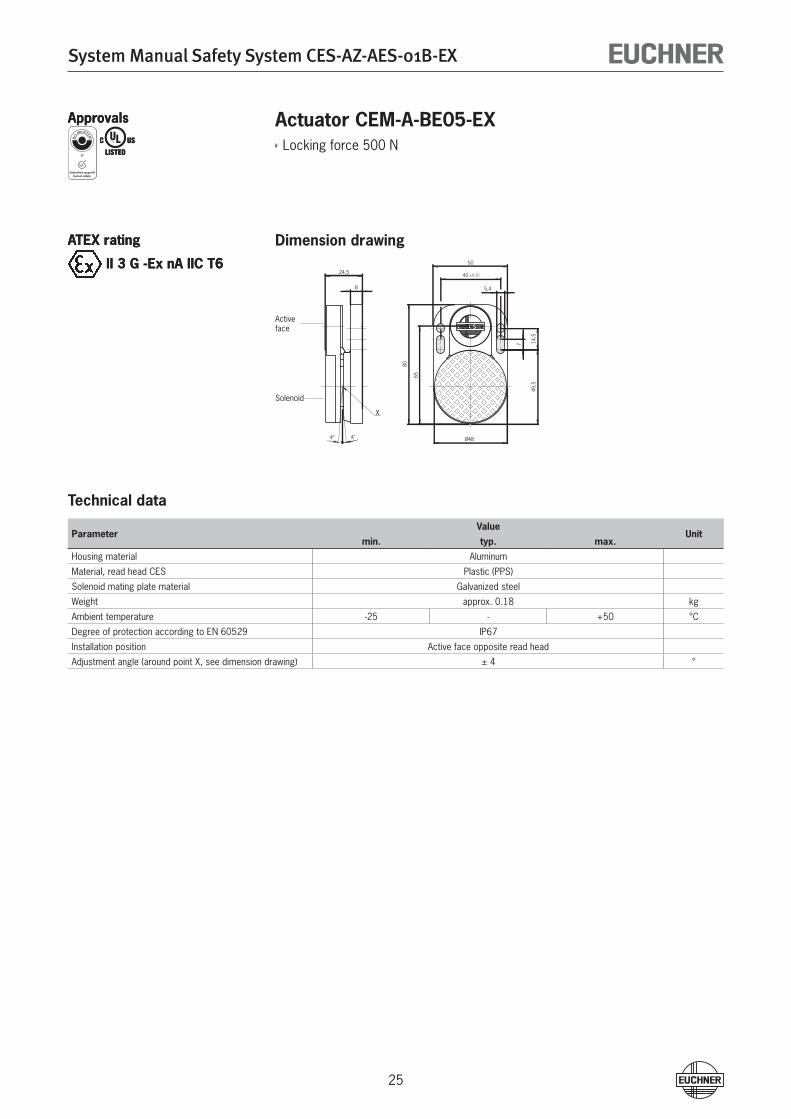
Actuator CEM-A-BE05-EXLocking force 500 N
Dimension drawing
Technical data
ParameterValue
Unitmin. typ. max.
Housing material Aluminum
Material, read head CES Plastic (PPS)
Solenoid mating plate material Galvanized steel
Weight approx. 0.18 kg
Ambient temperature -�5 - +50 °C
Degree of protection according to EN 605�9 IP67
Installation position Active face opposite read head
Adjustment angle (around point X, see dimension drawing) ± 4 °
ApprovalsApprovals
ATEX rating
II 3 G -Ex nA IIC T6
ATEX rating
II 3 G -Ex nA IIC T6 50
40 ±0,10
5,4
80
65
Ø48
49,5
7 14,5
4° 4°
8
24,5
X
Activeface
Solenoid
System Manual Safety System CES-AZ-AES-01B-EX
�6
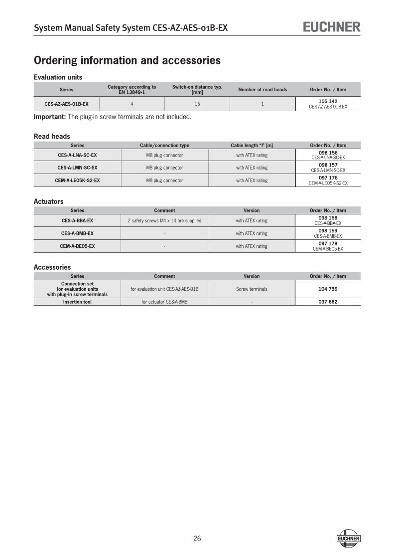
Ordering information and accessoriesEvaluation units
Series Category according to EN 13849-1
Switch-on distance typ. [mm] Number of read heads Order No. / Item
CES-AZ-AES-01B-EX 4 15 1 105 142CES-AZ-AES-01B-EX
Important: The plug-in screw terminals are not included.
Read headsSeries Cable/connection type Cable length “l” [m] Order No. / Item
CES-A-LNA-SC-EX M8 plug connector with ATEX rating 098 156CES-A-LNA-SC-EX
CES-A-LMN-SC-EX M8 plug connector with ATEX rating 098 157CES-A-LMN-SC-EX
CEM-A-LE05K-S2-EX M8 plug connector with ATEX rating 097 176CEM-A-LE05K-S�-EX
ActuatorsSeries Comment Version Order No. / Item
CES-A-BBA-EX � safety screws M4 x 14 are supplied with ATEX rating 098 158CES-A-BBA-EX
CES-A-BMB-EX - with ATEX rating 098 159CES-A-BMB-EX
CEM-A-BE05-EX - with ATEX rating 097 178CEM-A-BE05-EX
AccessoriesSeries Comment Version Order No. / Item
Connection set for evaluation units
with plug-in screw terminalsfor evaluation unit CES-AZ-AES-01B Screw terminals 104 756
Insertion tool for actuator CES-A-BMB - 037 662
System Manual Safety System CES-AZ-AES-01B-EX
�7
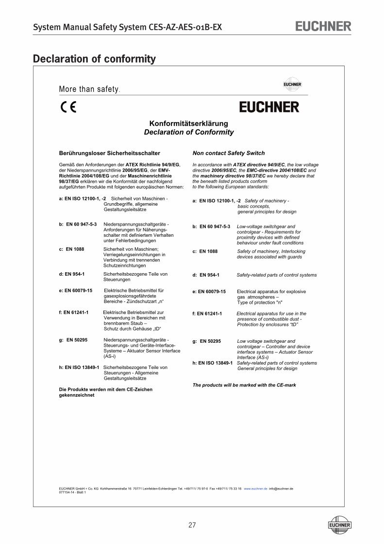
Declaration of conformity
More than safety.
EUCHNER GmbH + Co. KG Kohlhammerstraße 16 70771 Leinfelden-Echterdingen Tel. +49/711/ 75 97-0 Fax +49/711/ 75 33 16 www.euchner.de [email protected] 077154-14 - Blatt 1
KonformitätserklärungDeclaration of Conformity
Berührungsloser Sicherheitsschalter
Gemäß den Anforderungen der ATEX Richtlinie 94/9/EG,der Niederspannungsrichtlinie 2006/95/EG, der EMV-Richtlinie 2004/108/EG und der Maschinenrichtlinie 98/37/EG erklären wir die Konformität der nachfolgend aufgeführten Produkte mit folgenden europäischen Normen:
a: EN ISO 12100-1, -2 Sicherheit von Maschinen - Grundbegriffe, allgemeine Gestaltungsleitsätze
b: EN 60 947-5-3 Niederspannungsschaltgeräte -Anforderungen für Näherungs- schalter mit definiertem Verhalten unter Fehlerbedingungen
c: EN 1088 Sicherheit von Maschinen; Verriegelungseinrichtungen in Verbindung mit trennenden Schutzeinrichtungen
d: EN 954-1 Sicherheitsbezogene Teile von Steuerungen
e: EN 60079-15 Elektrische Betriebsmittel für gasexplosionsgefährdete Bereiche - Zündschutzart „n“
f: EN 61241-1 Elektrische Betriebsmittel zur Verwendung in Bereichen mit
brennbarem Staub – Schutz durch Gehäuse „tD“
g: EN 50295 Niederspannungsschaltgeräte - Steuerungs- und Geräte-Interface-Systeme – Aktuator Sensor Interface (AS-i)
h: EN ISO 13849-1 Sicherheitsbezogene Teile von Steuerungen - Allgemeine Gestaltungsleitsätze
Die Produkte werden mit dem CE-Zeichen gekennzeichnet
Non contact Safety Switch
In accordance with ATEX directive 94/9/EC, the low voltage directive 2006/95/EC, the EMC-directive 2004/108/EC andthe machinery directive 98/37/EC we hereby declare that the beneath listed products conformto the following European standards:
a: EN ISO 12100-1, -2 Safety of machinery - basic concepts, general principles for design
b: EN 60 947-5-3 Low-voltage switchgear and controlgear - Requirements for proximity devices with defined behaviour under fault conditions
c: EN 1088 Safety of machinery, Interlocking devices associated with guards
d: EN 954-1 Safety-related parts of control systems
e: EN 60079-15 Electrical apparatus for explosive gas atmospheres – Type of protection "n"
f: EN 61241-1 Electrical apparatus for use in the presence of combustible dust -
Protection by enclosures “tD”
g: EN 50295 Low voltage switchgear and controlgear – Controller and device interface systems – Actuator Sensor Interface (AS-i)
h: EN ISO 13849-1 Safety-related parts of control systems General principles for design
The products will be marked with the CE-mark
System Manual Safety System CES-AZ-AES-01B-EX
�8
More than safety.
EUCHNER GmbH + Co. KG Kohlhammerstraße 16 70771 Leinfelden-Echterdingen Tel. +49/711/ 75 97-0 Fax +49/711/ 75 33 16 www.euchner.de [email protected] 077154-14 - Blatt 2
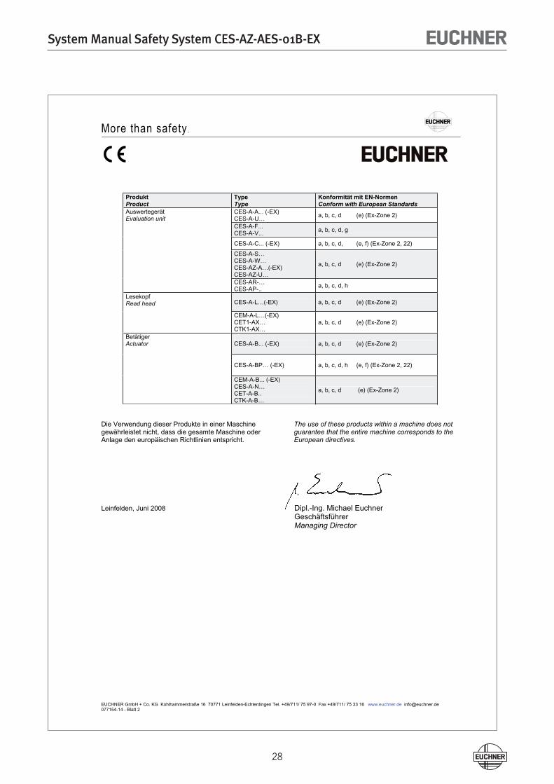
ProduktProduct
Type Type
Konformität mit EN-NormenConform with European Standards
Auswertegerät Evaluation unit
CES-A-A... (-EX) CES-A-U… a, b, c, d (e) (Ex-Zone 2)
CES-A-F...CES-A-V... a, b, c, d, g
CES-A-C... (-EX) a, b, c, d, (e, f) (Ex-Zone 2, 22)
CES-A-S…CES-A-W…CES-AZ-A…(-EX)CES-AZ-U…
a, b, c, d (e) (Ex-Zone 2)
CES-AR-…CES-AP-.. a, b, c, d, h
LesekopfRead head CES-A-L…(-EX) a, b, c, d (e) (Ex-Zone 2)
CEM-A-L…(-EX)CET1-AX…CTK1-AX…
a, b, c, d (e) (Ex-Zone 2)
BetätigerActuator CES-A-B... (-EX) a, b, c, d (e) (Ex-Zone 2)
CES-A-BP… (-EX) a, b, c, d, h (e, f) (Ex-Zone 2, 22)
CEM-A-B... (-EX) CES-A-N…CET-A-B..CTK-A-B…
a, b, c, d (e) (Ex-Zone 2)
Die Verwendung dieser Produkte in einer Maschine gewährleistet nicht, dass die gesamte Maschine oder Anlage den europäischen Richtlinien entspricht.
The use of these products within a machine does not guarantee that the entire machine corresponds to the European directives.
Leinfelden, Juni 2008 Dipl.-Ing. Michael Euchner Geschäftsführer Managing Director
System Manual Safety System CES-AZ-AES-01B-EX
�9
More than safety.
Euchner GmbH + Co. KGKohlhammerstraße 16D-70771 [email protected]
Issue:105313-0�-04/09Title: System Manual Safety System CES-AZ-AES-01B-EX(Translation of the original operating instructions)Copyright:© EUCHNER GmbH + Co. KG, 04/�009
Subject to technical modifications, all data supplied without liability.