Embed Size (px)
Citation preview
X2
VDR / S-VDR Voyage Data Recorder
System Operation Guide
www.amimarine.com

Page 2 of 33
08011 - X2 VDR and S-VDR System Operation Guide Iss01 Rev03
CONFORMITY STATEMENT
This equipment has been designed to comply with IMO regulations and IEC standards.
COPYRIGHT
Copyright AMI Marine Limited 2019
All rights reserved. No part of this publication may be reproduced, transmitted, transcribed, translated or stored
in any form or by any means, without the written permission of AMI Marine Limited
Technical details contained in this publication are subject to
change without prior notice

Page 3 of 33
08011 - X2 VDR and S-VDR System Operation Guide Iss01 Rev03
CONTENTS
Important Notices ................................................................................................................. 4 USB Warning ........................................................................................................................ 4
Terms and definitions ........................................................................................................... 6 Abbreviations ........................................................................................................................ 8 Product Introduction and Overview ....................................................................................... 9 Main Application and User Interface ....................................................................................11
Switching ON ................................................................................................................................................. 11 HOME Screen ............................................................................................................................................... 13 VIDEO Screen ............................................................................................................................................... 14 AUDIO Screen ............................................................................................................................................... 16 NMEA Screen ................................................................................................................................................ 18 CAPSULE Screen ......................................................................................................................................... 20 POWER Screen ............................................................................................................................................ 22
System Test .................................................................................................................24 EVENT LOG Screen ..................................................................................................................................... 25
Incident Marker .............................................................................................................26
Consumables Notifications ..................................................................................................27 Consumables Due ......................................................................................................................................... 27 Consumables Over Due ................................................................................................................................ 28 System Maintenance Schedule ..................................................................................................................... 29
Document Issue Details .......................................................................................................30 Warranty Form .....................................................................................................................32
Page 4 of 33
08011 - X2 VDR and S-VDR System Operation Guide Iss01 Rev03
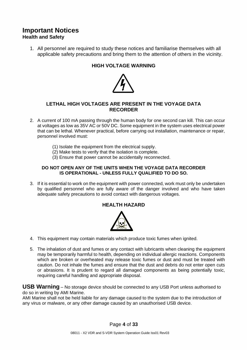
Important Notices Health and Safety
1. All personnel are required to study these notices and familiarise themselves with all applicable safety precautions and bring them to the attention of others in the vicinity.
HIGH VOLTAGE WARNING
LETHAL HIGH VOLTAGES ARE PRESENT IN THE VOYAGE DATA
RECORDER
2. A current of 100 mA passing through the human body for one second can kill. This can occur at voltages as low as 35V AC or 50V DC. Some equipment in the system uses electrical power that can be lethal. Whenever practical, before carrying out installation, maintenance or repair, personnel involved must:
(1) Isolate the equipment from the electrical supply. (2) Make tests to verify that the isolation is complete. (3) Ensure that power cannot be accidentally reconnected.
DO NOT OPEN ANY OF THE UNITS WHEN THE VOYAGE DATA RECORDER
IS OPERATIONAL - UNLESS FULLY QUALIFIED TO DO SO.
3. If it is essential to work on the equipment with power connected, work must only be undertaken by qualified personnel who are fully aware of the danger involved and who have taken adequate safety precautions to avoid contact with dangerous voltages.
HEALTH HAZARD
4. This equipment may contain materials which produce toxic fumes when ignited.
5. The inhalation of dust and fumes or any contact with lubricants when cleaning the equipment
may be temporarily harmful to health, depending on individual allergic reactions. Components which are broken or overheated may release toxic fumes or dust and must be treated with caution. Do not inhale the fumes and ensure that the dust and debris do not enter open cuts or abrasions. It is prudent to regard all damaged components as being potentially toxic, requiring careful handling and appropriate disposal.
USB Warning – No storage device should be connected to any USB Port unless authorised to
do so in writing by AMI Marine. AMI Marine shall not be held liable for any damage caused to the system due to the introduction of any virus or malware, or any other damage caused by an unauthorised USB device.

Page 5 of 33
08011 - X2 VDR and S-VDR System Operation Guide Iss01 Rev03

Page 6 of 33
08011 - X2 VDR and S-VDR System Operation Guide Iss01 Rev03
Terms and definitions Alert Announcement of abnormal situations and conditions requiring attention. Alerts are divided in four priorities: emergency alarms, alarms, warnings and cautions. ! Note: the VDR is only ever required to raise a ‘caution’ for any condition that may arise. Therefore, any mention of an ‘alert’ in this document should be considered a ‘caution’ state. Bridge work station The position at which a person is expected to be when performing normal bridge duties, For example:
Centre line conning; Bridge wing(s); Main radar; Chart table; Helm; Communication console
Caution The lowest priority of an alert. A condition which does not warrant an alarm or warning condition, but still requires attention and out of the ordinary consideration of the situation or of given information A caution is indicated by a steady visual indication with a message of sufficient detail to enable the bridge team to identify and address the caution condition. No acknowledgement is required and the caution should be automatically removed after the condition is rectified. Combined EPIRB/VDR capsule Single unit which meets all the requirements of a satellite EPIRB (as required by the carriage requirements of SOLAS IV) and all the requirements of a VDR (as required by the carriage requirements of SOLAS V) Configuration data Describes the vessel's equipment, its installation on the vessel and its relation to the VDR. The storage and playback software uses this data to store the data record and to convert the data record into information that assists casualty investigation during playback. Data Any item of information received by the VDR for recording, including numerical values, text and audio or radar signals and including all configuration data, except where specifically stated or where the context dictates otherwise Dedicated reserve power source A battery, with suitable automatic charging arrangements, dedicated solely to the VDR, of sufficient capacity to operate it for a minimum of 2 hours.

Page 7 of 33
08011 - X2 VDR and S-VDR System Operation Guide Iss01 Rev03
Final recording medium The items of hardware on which the data is recorded such that access to any one of them would enable the data to be recovered and played back by use of suitable equipment. The combination of a fixed recording medium, float-free recording medium and long-term recording medium, together, is recognised as the final recording medium. Fixed recording medium / Fixed Capsule Part of the Final Recording Medium which is protected against fire, shock, penetration and a prolonged period on the ocean floor. It remains fixed to the vessel in the event of an incident and has an acoustic beacon indicating location for recovery by the authorities. Float-free recording medium / Float Free Capsule Part of the Final Recording Medium which is designed to float free from the vessel once submerged. It has an EPRIB indicating location for recovery by the authorities. Long-term recording medium (LTRM) Permanently installed part of the Final Recording Medium. It provides the longest record duration and has a readily accessible interface for downloading the stored data. Playback equipment Any data medium with the playback software, the operational instructions and any special parts required for connecting a commercial-off-the-shelf laptop computer to the VDR. Playback software Copy of the software program to provide the capability to download the stored data and play back the information. The software should be compatible with an operating system available with commercial-off-the-shelf laptop computers and where non-standard or proprietary formats are used for storing the data in the VDR, the software should convert the stored data into open industry standard formats Playback system System including the playback equipment that is capable of downloading and playing back the recorded data Recorder Complete system, including any items required to interface with the sources of input signals, their processing and encoding, the final recording medium, the playback equipment, the power supply and dedicated reserve power source. Resolution Smallest detectable increment between two values Signal source Any sensor or device external to the VDR, to which the VDR is connected and from which it obtains signals and data to be recorded
Page 8 of 33
08011 - X2 VDR and S-VDR System Operation Guide Iss01 Rev03
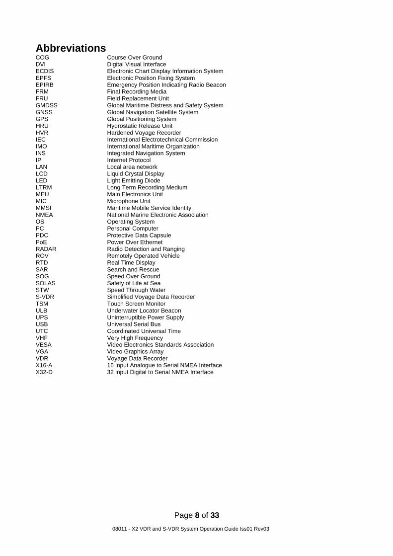
Abbreviations COG Course Over Ground DVI Digital Visual Interface ECDIS Electronic Chart Display Information System EPFS Electronic Position Fixing System EPIRB Emergency Position Indicating Radio Beacon FRM Final Recording Media FRU Field Replacement Unit GMDSS Global Maritime Distress and Safety System GNSS Global Navigation Satellite System GPS Global Positioning System HRU Hydrostatic Release Unit HVR Hardened Voyage Recorder IEC International Electrotechnical Commission IMO International Maritime Organization INS Integrated Navigation System IP Internet Protocol LAN Local area network LCD Liquid Crystal Display LED Light Emitting Diode LTRM Long Term Recording Medium MEU Main Electronics Unit MIC Microphone Unit MMSI Maritime Mobile Service Identity NMEA National Marine Electronic Association OS Operating System PC Personal Computer PDC Protective Data Capsule PoE Power Over Ethernet RADAR Radio Detection and Ranging ROV Remotely Operated Vehicle RTD Real Time Display SAR Search and Rescue SOG Speed Over Ground SOLAS Safety of Life at Sea STW Speed Through Water S-VDR Simplified Voyage Data Recorder TSM Touch Screen Monitor ULB Underwater Locator Beacon UPS Uninterruptible Power Supply USB Universal Serial Bus UTC Coordinated Universal Time VHF Very High Frequency VESA Video Electronics Standards Association VGA Video Graphics Array VDR Voyage Data Recorder X16-A 16 input Analogue to Serial NMEA Interface X32-D 32 input Digital to Serial NMEA Interface

Page 9 of 33
08011 - X2 VDR and S-VDR System Operation Guide Iss01 Rev03
Product Introduction and Overview AMI’s new “X2” VDR / S-VDR and the associated interfaces have been developed using expertise gained over two decades in marine electronics design, interfacing and retransmission. The result is a system designed and built in the UK that not only meets the mandatory regulations, but offers more flexibility, functionality and features to the end user than ever before. The system is in compliance with MSC.333(90), and approved to IEC 61996-1 Ed 2.0 relevant to voyage data recorders installed on or after 1 July 2014, and conforming to performance standards not inferior to those specified in the annex to resolution A.861(20), as amended by resolution MSC.214(81) for systems installed prior to 1st July 2014 Main Electronics Unit (MEU) MEU-0017
The MEU has a key-locked front door for secure access and a tamper switch ensure that any access to the internal circuitry of the MEU is logged. The Key Switch Board has LEDs to indicate the VDR status and a key switch for switching the system on and shutting the system down. Features
• 10 x Audio inputs
• 20 x NMEA inputs (Variable baud rates)
• Up to 4 x RADAR DVI/VGA capture inputs
• Dedicated Network connections for ECDIS Image capture via IEC 61162-450.
• Ethernet port at TSM for convenient, high speed data download

Page 10 of 33
08011 - X2 VDR and S-VDR System Operation Guide Iss01 Rev03
Uninterruptible Power Supply PSU-0014
Provides a minimum of 2 hours continuous power to the VDR to ensure data is collected at the most critical time in the event of the vessel losing power. Long life batteries allowing 4 years between replacement. Easy access for convenient battery replacement. AC Fail and Battery Fail are present as visual indications on the TSM
Microphones MIC-0005 - External MIC-0006 - Internal
The X2 microphones have been designed with high quality audio and easy installation in mind. Using noise reducing 600Ω balanced audio for the clearest possible recording the audio clarity is second to none. The built-in auto test ensures all microphones are functioning correctly, giving a visual indication on the TSM in the event of a failure. External microphones have been built and tested to function in the harshest of outdoor environments without deterioration. External microphones are IP67 rated for external use to protect against the harsh elements experienced on a vessel’s bridge wing.

Page 11 of 33
08011 - X2 VDR and S-VDR System Operation Guide Iss01 Rev03
Main Application and User Interface
Switching ON The MEU has a key switch in the top left of the enclosure. This is for security purposes and ensures that only the designated key holder may switch OFF the system when required. Other Indications: Power LED – This will illuminate when the key is turned to the ON position. Recording LED – This will illuminate when the X2 application is running. Fault LED – Only illuminates when there is a hardware fault or the door is open. Download – Indicates when a Download has been initiated.
Turning the key switch from the vertical ON position through 90 degrees clockwise, to the horizontal position the system will boot up after a few seconds. The display panel will show the boot screen and the start-up sequence will begin.

Page 12 of 33
08011 - X2 VDR and S-VDR System Operation Guide Iss01 Rev03
Once the system has completed the boot sequence the HOME screen will be displayed as below
Pressing one of the tabs on the navigation menu at the left of the screen will open the corresponding screens.

Page 13 of 33
08011 - X2 VDR and S-VDR System Operation Guide Iss01 Rev03
HOME Screen The HOME screen is a general information page which shows the system and vessel information. On this and all other pages, the UTC date and time are displayed along with System Uptime and incident marker button. Unique to the HOME page are the following:
• Image of the vessel (if not available the AMI logo will be shown as below)
• System Type - VDR or S-VDR.
• Serial Number – The MEU Serial number
• Software Version - Currently installed software version
• Install Date - Date of system installation/commissioning
• Last Survey - Date of last successful Annual Performance Test
• Vessel name – Vessel’s current name
• IMO number – Vessel’s IMO number
• MMSI number – Vessel’s IMO number
• Service contact details – Contact details for the manufacturer
The UTC date and time will be automatically updated from the received GPS data. If the GPS data is not received, or is lost, then the time and date at the top of the home screen will be displayed in red characters.
User Control:
Tapping the Keyboard icon will bring up the on-screen keyboard Tapping the ‘Incident Marker’ (twice) will add a line into the log file for quick reference during data analysis Both of these controls are available on under all tabs

Page 14 of 33
08011 - X2 VDR and S-VDR System Operation Guide Iss01 Rev03
VIDEO Screen By default, two image capture cards are installed for both S-Band and X-Band Radar capture. Two more capture cards are available on request for additional image capture, such as ECDIS where the ship’s ECDIS does not have an option for image over Ethernet.
Within the Video page thumbnails of the RADAR/ECDIS video can be seen showing the current images being captured.
User Control: Tapping the individual thumbnail will allow the chosen image to fill the window.

Page 15 of 33
08011 - X2 VDR and S-VDR System Operation Guide Iss01 Rev03
If a RADAR or ECDIS is switched OFF the video input is no longer present, a caution is raised, the message ‘NO VIDEO DETECTED’ will be displayed and the VIDEO status side bar itself will flash YELLOW. Once acknowledged the VIDEO status side bar will stop flashing but remain YELLOW, the thumbnail frame will remain YELLOW until the issue is cleared.
If there is a fault with a capture card, a caution is raised, the message ‘NO CAPTURE CARD’ will be displayed the VIDEO status side bar itself will flash YELLOW. Once acknowledged the VIDEO status side bar will stop flashing but remain YELLOW, the alert panel will remain YELLOW until the issue is cleared. The red FAULT LED on the MEU door will also illuminate until the fault is cleared.
If an ECDIS which is connected by IEC 61162-450 and is switched OFF a caution is raised, the message ‘RECEIVE TIMEOUT’ will be displayed and the VIDEO status side bar itself will flash YELLOW. Once acknowledged the VIDEO status side bar will stop flashing but remain YELLOW, the thumbnail frame will remain YELLOW until the issue is cleared.
Page 16 of 33
08011 - X2 VDR and S-VDR System Operation Guide Iss01 Rev03
AUDIO Screen
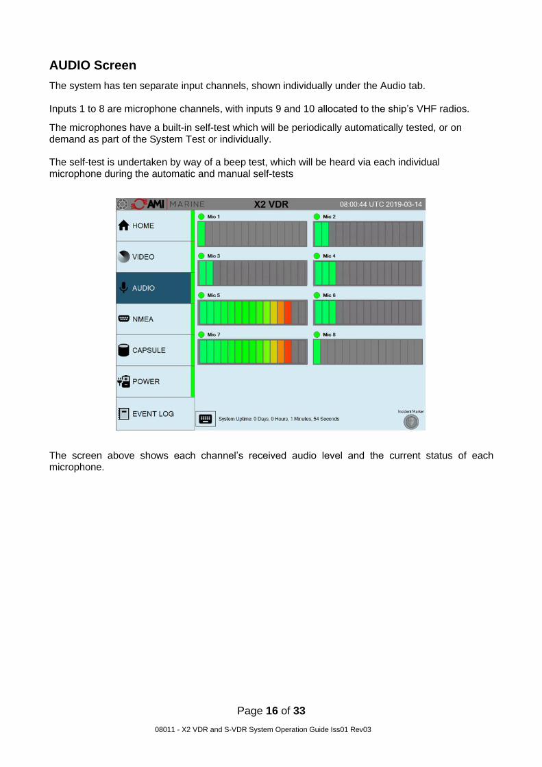
The system has ten separate input channels, shown individually under the Audio tab. Inputs 1 to 8 are microphone channels, with inputs 9 and 10 allocated to the ship’s VHF radios.
The microphones have a built-in self-test which will be periodically automatically tested, or on demand as part of the System Test or individually. The self-test is undertaken by way of a beep test, which will be heard via each individual microphone during the automatic and manual self-tests
The screen above shows each channel’s received audio level and the current status of each microphone.

Page 17 of 33
08011 - X2 VDR and S-VDR System Operation Guide Iss01 Rev03
Above each audio channel there is an indicator that will show as green or yellow. A GREEN indication means all is well, YELLOW indicates that there has been a prolonged low audio level or that the audio test has failed. There is no self-test for the VHF audio so the indication will always be GREEN.
Once the audio level has been tested and is an acceptable level the indication will revert to green.
User Control: Tapping the microphone status indicator will run a test on that individual channel.

Page 18 of 33
08011 - X2 VDR and S-VDR System Operation Guide Iss01 Rev03
NMEA Screen The system has 20 individual NMEA inputs. 14x 4,800 Baud, 2x 9,600Baud, 2x 19,200Baud and 2x 38,400 Baud. The system can be configured to monitor up to 50 NMEA sentences simply adding the expected NMEA sentence header into the respective channel of the configuration program.
By tapping an NMEA sentence header the monitor window will now only display the sentence with that specific header. The selected NMEA header will turn bold and the description of the NMEA being monitored is now displayed. The below example the $VDVBW sentence is selected.

Page 19 of 33
08011 - X2 VDR and S-VDR System Operation Guide Iss01 Rev03
The NMEA sentence being monitored may be adjusted with the onscreen keypad by either removing or adding characters in the filter box. Below the example has been changed to $VD and will now display all $VD - - - sentences.
If one of the monitored NMEA sentence header is lost, invalid or the checksum is wrong, a caution will be raised (as per IMO 333(90)), and the associated icon will turn YELLOW.
Once acknowledged the NMEA status side bar will stop flashing but remain YELLOW, the header icon will remain YELLOW until the issue is cleared Only when the data is received again will the header icon will revert back to GREEN.
User Control:
Tapping on an individual NMEA header (found in the top window) will filter the incoming data to show only the chosen NMEA data in the streaming window. The selected NMEA header will turn bold to indicate selection. Tapping the header again will remove the filter. NMEA data may also be filtered by typing the desired filter information into the “Filter” text box on the right of the screen. The streaming data will only show the data with the chosen characters.

Page 20 of 33
08011 - X2 VDR and S-VDR System Operation Guide Iss01 Rev03
CAPSULE Screen The CAPSULE Screen is where the status of the Final Recording Medium may be found. In the event of an error with any of these the status of the image background will turn YELLOW and, on the MEU, the red FAULT LED will illuminate. If either the Fixed Capsule or the Float Free Capsule give a caution the option of trying to re-map the capsule by tapping the relevant icon. If after a few attempts then there may be a more serious issue requiring authorised attendance. The X2 system has three final storage devices – a Fixed Capsule, a Float Free Capsule and a 1TB SSD Long Term Recording Medium (LTRM) The fixed and float free capsules operate in the same manner as a network hard disc drive. They are connected to the system’s internal network via the six-way connector on the Terminal Board. Each capsule will store a minimum of 48 hours data on their internal memory which will overwrite itself on a first in first out basis (FIFO). The LTRM will store a minimum of 30 days of data and the regulations state that it should be located such that access to the drive is not possible without the use of tools.
Also displayed within this page are the ULB (Underwater Locator Beacon) expiry date and the float free capsule’s HRU (Hydrostatic Release Unit) expiry date. If the ‘Only One Capsule’ option is selected then only the selected capsule will be displayed

Page 21 of 33
08011 - X2 VDR and S-VDR System Operation Guide Iss01 Rev03
Tapping any of the icons will open the ‘Disk Usage Information’ screen showing the Size, Used and Free space for each device.
Tapping any of the pie charts returns to the main capsule screen. If the ‘External Storage’ optional extra has been purchased and installed, then an External Graphic will be displayed.
User Control:
Tapping the screen will open the “Disk Usage Information” display. Should either capsule show loss of connection, tapping the capsule icon will remap the capsule to resume correct operation

Page 22 of 33
08011 - X2 VDR and S-VDR System Operation Guide Iss01 Rev03
POWER Screen On this screen the Mains Power and UPS are monitored in the event of a failure.
If the Mains Power should fail the indication will turn YELLOW and the system will start a 2-hour countdown to switch OFF. Note that on the MEU, the red FAULT LED will illuminate.

Page 23 of 33
08011 - X2 VDR and S-VDR System Operation Guide Iss01 Rev03
If the BATTERIES icon shows a caution then this indicates that the batteries are not charging and a service centre should be notified.
User Control:
Pressing the System Test will bring up a prompt ‘Press Again for System Test”.
Pressing the System Test a second time will begin the full system test sequence.

Page 24 of 33
08011 - X2 VDR and S-VDR System Operation Guide Iss01 Rev03
System Test Also, on the POWER Screen this is where a system test is initiated.
Tap the button and the System Test will pop up, tap again to initiate the System Test.
The test function will be inhibited for 2 minutes.

Page 25 of 33
08011 - X2 VDR and S-VDR System Operation Guide Iss01 Rev03
EVENT LOG Screen
The above screen shot shows the event log. Results of a system test will be highlighted in blue.
On this page you can review all events. You can select the search parameters by Date, Hour or Priority by selecting the relevant drop-down box.
Page 26 of 33
08011 - X2 VDR and S-VDR System Operation Guide Iss01 Rev03
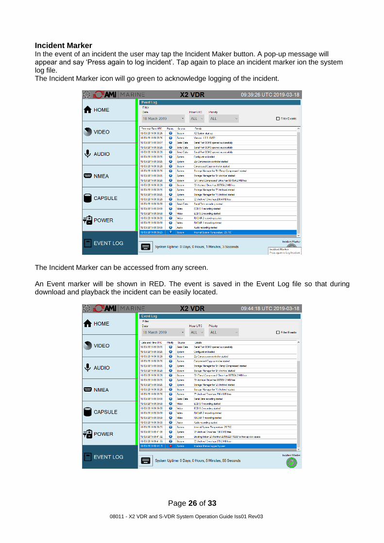
Incident Marker In the event of an incident the user may tap the Incident Maker button. A pop-up message will appear and say ‘Press again to log incident’. Tap again to place an incident marker ion the system log file. The Incident Marker icon will go green to acknowledge logging of the incident.
The Incident Marker can be accessed from any screen. An Event marker will be shown in RED. The event is saved in the Event Log file so that during download and playback the incident can be easily located.

Page 27 of 33
08011 - X2 VDR and S-VDR System Operation Guide Iss01 Rev03
Consumables Notifications
Consumables Due If any of the consumables are due within 3 months the relevant box will turn YELLOW.

Page 28 of 33
08011 - X2 VDR and S-VDR System Operation Guide Iss01 Rev03
Consumables Over Due If any of the consumables are overdue the relevant box will turn RED.
If any of the consumables have gone past their due date the Side indication bar will also flash YELLOW and the event will be added to the Log File.
Page 29 of 33
08011 - X2 VDR and S-VDR System Operation Guide Iss01 Rev03
System Maintenance Schedule Weekly - Recommended
MEU Ensure the POWER ON and RECORDING LEDs are illuminated. Check fan and inlet vents are clean of dust and debris.
TSM: Check that the Touch Screen Monitor cycles through the various tabs. UPS: Ensure indictor LEDs are in operation
Monthly
Conduct Full System Test using ‘System Test’ feature within the POWER tab. 1 Year Check The following must be conducted by an AMI authorised inspector/engineer:
Annual Performance Test (APT) including: Reserve power source check Reserve power source shut down check Battery expiry dates check Acoustic beacon test Float free EPIRB self-test Physical condition of equipment Check interfaces are operational and being recorded Initial analysis of downloaded data
2 Year Check The following must be conducted by an AMI authorised inspector/engineer.
Annual Performance Test (APT) Replace MEU system fan
Replace hydrostatic release unit (HRU) 3 Year Check The following must be conducted by an AMI authorised inspector/engineer.
Annual Performance Test (APT) Replace fixed capsule acoustic beacon battery
4 Year Check The following must be conducted by an AMI authorised inspector/engineer.
Annual Performance Test (APT) Replace MEU system fan Replace reserve batteries. Replace float free capsule hydrostatic release unit (HRU).
5 Year Check The following must be conducted by an AMI authorised inspector/engineer. Annual Performance Test (APT)
Replace the float free capsule Replace motherboard BIOS battery
Recommended - Replace 1Tb Long Term Recording Medium Drive Recommended - Replace 32Gb mSATA
6 Year Check The following must be conducted by an AMI authorised inspector/engineer.
Annual Performance Test (APT) Replace MEU system fan Replace fixed capsule acoustic beacon.

Page 30 of 33
08011 - X2 VDR and S-VDR System Operation Guide Iss01 Rev03
Document Issue Details
NOTICE This manual is for informational use only. AMI Marine Limited continually strives to improve their products and therefor may be changed without prior notice. This manual should not be construed as a commitment of AMI Marine Limited. Under no circumstances does AMI Marine Limited assume any responsibility or liability for any errors or inaccuracies that may appear in this document. The equipment should only be used for the purposes intended by the manufacturer; any deviation from this will void the warranty of the product.
NOTE: All alterations must be verified by re-authorisation and approval of the complete document.
Document Issue Date
Modification Number (where applicable) Brief Record of Change and Reason for Change
Iss01 Rev00 23.01.19 Original Issue
Iss01 Rev01 18.03.19 Update of Model Number (X2) and correction of some wording
Iss01 Rev02 28.06.19 Addition of the Maintenance Schedule, User Control Notifications and USB Warning
Iss01 Rev03 19.08.19 Rewording and formatting update
AMI MARINE LIMITED
Unit 9 Crosshouse Centre Crosshouse Road Southampton Hampshire SO14 5GZ UK
Tel No: Email:
Web:
+44 (0) 23 8048 0450 [email protected] www.amimarine.com

Page 31 of 33
08011 - X2 VDR and S-VDR System Operation Guide Iss01 Rev03
This page
Intentionally Blank

Page 32 of 33
08011 - X2 VDR and S-VDR System Operation Guide Iss01 Rev03
Warranty Form AMI Marine Warranty; (abbreviated, full version on request) The Warranty Period is 24 months from date of dispatch, unless an alternative period has been otherwise agreed in writing. The first 12 months covers parts and on-board labour (travel and accommodation is not covered), the second 12 months covers parts only. Warranty covers parts that have failed due to a manufacture defect and does not cover shipping or associated charges This warranty shall only apply where the REGISTRATION CARD supplied with the goods has been properly completed and returned to AMI within the period of 21 days from installation. The registration form can also be downloaded from the AMI Marine website www.amimarine.com Returns Procedure; Send an email RE: REQUEST FOR RETURN AUTHORISATION to [email protected] . Please do NOT return items until a Return Authorisation Number has been issued. Documents to be included; A copy of the original INSTALLATION REPORT and a print out of your RETURN MATERIAL AUTHORISATION INFORMATION EMAIL, and enclose both in the return package. Be sure to pack the returning product securely and according to carrier instructions. Damage incurred during return shipping due to inadequate protection will render the item ineligible for return, repair, or exchange under the Warranty Terms. Items not received by AMI Marine, will not be credited. MOST authorised returns should be returned to the address below - however there are some exceptions, so DO NOT ship to this address without first reviewing your RETURN AUTHORISATION INFORMATION EMAIL for applicable return instructions: AMI Marine Limited Unit 9 Crosshouse Centre Crosshouse Road Southampton Hants SO14 5GZ UK A full explanation of AMI Marine Limited warranty conditions can be found on our web site or requested via email. * Terms of Service and Policies are subject to change without notice.
------------------------------------------------------------------------------------------------------------------------------------------------------------------
Please complete and return to AMI Marine either by post to the above address or by email to [email protected]
Warranty Registration Form
Model Number
Serial Number
Date of Purchase
Vessel Name
IMO Number

Page 33 of 33
08011 - X2 VDR and S-VDR System Operation Guide Iss01 Rev03
This page Intentionally Blank