Embed Size (px)
Citation preview

SYSTEM OPERATION MANUAL
MINE SITE TECHNOLOGIES PTY LIMITED
WWW.MINESITE.COM.AU
Sydney: PO BOX 156 ARTARMON NSW 1570 AUSTRALIA Tel: 02-9437 4399 Fax: 02-9437 5688 Email: [email protected]
Mt Isa: PO BOX 2436 MT ISA QLD 4825 AUSTRALIA Tel: 07-4749 4922 Fax: 07-4749 4933 Email: [email protected]
Kalgoorlie: PO BOX 4200 KALGOORLIE WA 6430 AUSTRALIA Tel: 08-9022 2300 Fax: 08-9022 2311 Email: [email protected]
System Operation Manual Contents 2
CONTENTS INTRODUCTION 6
What is PED?......................................................................................................... 6 Information Icons.................................................................................................... 6 Warranty................................................................................................................. 7 Contacting Minesite Technologies ......................................................................... 7
Australia........................................................................................................... 7 International: .................................................................................................... 8
CHAPTER 1: OVERVIEW 9 Transmission System............................................................................................. 9 Software ................................................................................................................. 9 The PED Paging Receivers - Covering all possibilities ....................................... 10
CHAPTER 2: THE PED TRANSMISSION SYSTEM 11 Introduction .......................................................................................................... 11 The System Elements .......................................................................................... 12
PEDCall Computer - The operator interface ................................................. 12 External Modulator ........................................................................................ 12 PED ULF Transmitter .................................................................................... 12 Transmitter Specifications ............................................................................. 13
Protecting the Transmitter.................................................................................... 13 Antenna Safety Unit....................................................................................... 14 ASU Specifications ........................................................................................ 14 Set/re-set operation ....................................................................................... 15 Loop Antenna ................................................................................................ 16 Signal Propagation ........................................................................................ 16 Cable Specifications ...................................................................................... 17 Loop Antenna Installation .............................................................................. 17 Quality Loop Antenna Joints.......................................................................... 17 Earth Burial .................................................................................................... 17 Suspended / Pole Hung Antenna .................................................................. 18 Underground Loop Antenna .......................................................................... 18
Precautions with an Underground Loop Antenna ................................................ 18 Clearance from Data Cables ......................................................................... 18 Clearance and testing of Firing Cables ......................................................... 18 Voltage Limitations on Underground Loop Antennae ................................... 19 Induced Voltages ........................................................................................... 19
PED Loop Matching Transformer ........................................................................ 19 The PED Protector ............................................................................................... 20 Uninterruptible Power Supply * Optional.............................................................. 20 PED Marshalling Unit ........................................................................................... 21 Harness Wiring..................................................................................................... 22 Part Number Assignment for Transmission System ............................................ 24
CHAPTER 3: INSTALLING THE PED TRANSMISSION SYSTEM 25 Introduction .......................................................................................................... 25 The PEDCall Computer........................................................................................ 25 Modifying the External Modulator ........................................................................ 25
Examples: ...................................................................................................... 26 External Modulator Pin Connections.................................................................... 27 Connecting the External Modulator...................................................................... 27 Installing PEDCall on the Master PC ................................................................... 27 Configuring PEDCall ............................................................................................ 28
System Operation Manual Contents 3
Configure PEDCall communications ports .................................................... 28 Configure the Master PC INI File................................................................... 29 Scheduling a backup ..................................................................................... 29 Remote Access ............................................................................................. 30
The Twisted Pair & System connections ............................................................. 30 PED ULF Transmitter........................................................................................... 31
Multiple Transmitter Systems ........................................................................ 31
CHAPTER 4: SERVICING THE PED HEADEND 32 Overview .............................................................................................................. 32 Procedure for Fault Finding ................................................................................. 32
CHAPTER 5: PEDCALL - OPERATOR INTERFACE 37 The PEDCall Main Screen ................................................................................... 37
The Message Queue Window ....................................................................... 38 Message being Sent and History Window..................................................... 38 Software Version ........................................................................................... 38 Time Readout ................................................................................................ 39
Creating a Pager Message .................................................................................. 39 Selecting the Destination............................................................................... 39 Deleting Messages ........................................................................................ 40 RE-Sending Messages.................................................................................. 40
Emergency Messages.......................................................................................... 40 Printing the PEDCall stored files.......................................................................... 41 Password Protection ............................................................................................ 41 Assigning Names and Groups to BeltPEDs......................................................... 41 Assigning Names to BeltPEDs............................................................................. 41
Adding a Name.............................................................................................. 41 Changing a Name.......................................................................................... 42 Deleting a Name............................................................................................ 42
Groups.................................................................................................................. 43 Editing Group Names .................................................................................... 43
ControlPED .......................................................................................................... 44 Assign ControlPED Names and Colours....................................................... 44
BlastPED.............................................................................................................. 44 Assign BlastPED ID....................................................................................... 44
Reoccurring Messages ........................................................................................ 44 Adding Reoccurring Messages...................................................................... 45 Deleting Reoccurring Messages.................................................................... 45 Changing Reoccurring Messages ................................................................. 45
Fixed Messages ................................................................................................... 45 Adding Fixed Messages ................................................................................ 46 Changing Fixed Messages ............................................................................ 46 Deleting Fixed Messages .............................................................................. 46
Reprogram ID....................................................................................................... 46 BeltPED ......................................................................................................... 46 ControlPED.................................................................................................... 47
Sending messages............................................................................................... 48 Selecting Individual PEDs ............................................................................. 48 Selecting Groups ........................................................................................... 49 Selecting All PEDs......................................................................................... 49
Selecting the Message Type................................................................................ 49 Custom Message........................................................................................... 49 Fixed Message .............................................................................................. 50 Phone Message............................................................................................. 50
Re-sending a message ........................................................................................ 50 ControlPED .......................................................................................................... 50

System Operation Manual Contents 4
Send operating commands to individual ControlPEDs ................................. 51 Send operating commands to groups of ControlPEDs ................................. 51
BlastPED.............................................................................................................. 51 Arming BlastPED........................................................................................... 52 Blasting a single BlastPED............................................................................ 52 Invalid Disk .................................................................................................... 52 Group Arming BlastPEDs .............................................................................. 52 Group Blasting ............................................................................................... 53 Arm All BlastPEDs......................................................................................... 53 Blast All BlastPEDs ....................................................................................... 53
CHAPTER 6: REMOTE PEDCALL ACCESS 54 Introduction .......................................................................................................... 54 Connecting over a LAN........................................................................................ 54
Configure Master PC for LAN Access ........................................................... 55 Configure the Network PC for LAN Access................................................... 55
Connecting over a Dial-up Modem ...................................................................... 56 Configuring the Master PC for Dial-up Access.............................................. 56 Configuring the Remote PC for Dial-up Access ............................................ 56
Manually Editing the Configuration File ............................................................... 57
CHAPTER 7: MINE MONITORING - LINKING SYSTEMS 58 Introduction .......................................................................................................... 58 Potential situations where Mine Monitoring is ideal ............................................. 58 Installation of Mine Monitoring ............................................................................. 58
CHAPTER 8: BELTPED - PERSONAL RECEIVER 60 Introduction .......................................................................................................... 60 BeltPED Specifications ........................................................................................ 60 Operation of the BeltPED..................................................................................... 61
Receiving a Standard Message..................................................................... 61 Receiving an Emergency Message............................................................... 61
The Push Button .................................................................................................. 62 Backlighting of the LCD ................................................................................. 62 Recalling of stored messages ....................................................................... 62 The Setup Mode ............................................................................................ 62
Installing the BeltPED Receiver ........................................................................... 63 BeltPED Maintenance.......................................................................................... 65
BeltPED/Caplamp Dismantling...................................................................... 65 Assembling BeltPED ..................................................................................... 66 Testing ........................................................................................................... 67
Parts List for BeltPED Receiver ........................................................................... 67
CHAPTER 9: AUTOPED - VEHICLE PAGING RECEIVER 69 Introduction .......................................................................................................... 69 AutoPED Specifications ....................................................................................... 69 Operation of the AutoPED ................................................................................... 70
Receiving a Standard Message..................................................................... 70 Receiving an Emergency Message............................................................... 70
The Push Button .................................................................................................. 71 Backlighting of the LCD ................................................................................. 71 Recalling of stored messages ....................................................................... 71 The Setup Mode ............................................................................................ 71
Installation of the AutoPED .................................................................................. 72 The External Antenna.................................................................................... 72 The Display/Receiver Box ............................................................................. 72 Wiring connections for the AutoPED ............................................................. 72
System Operation Manual Contents 5
Parts List for AutoPED Receiver ................................................................... 73
CHAPTER 10: CONTROLPED - REMOTE CONTROL 75 Introduction .......................................................................................................... 75 ControlPED Specifications ................................................................................... 75 Operation of the ControlPED ............................................................................... 76 Installation of the ControlPED.............................................................................. 76
The Antenna .................................................................................................. 76 The Control/Receiver Box ............................................................................. 76 Connecting the ControlPED .......................................................................... 76
CHAPTER 11: BLASTPED - REMOTE BLASTING 78 Introduction .................................................................................................... 78
BlastPED Specifications....................................................................................... 79 BlastPED Approvals............................................................................................. 79 Understanding the BlastPED ............................................................................... 79
Security Access Disk ..................................................................................... 79 Safety Key ..................................................................................................... 80 Firing Output .................................................................................................. 80 The BlastPED firing process.......................................................................... 80 Connecting to the BlastPED.......................................................................... 81 Recharging the Battery.................................................................................. 81 Replacing the Battery .................................................................................... 82 Testing BlastPED Firing Capacity ................................................................. 82 Servicing ........................................................................................................ 82
APPENDIX 83

System Operation Manual Introduction 6
INTRODUCTION What is PED?
The PED System is an Ultra Low Frequency "Through-the-Earth" paging, control and blasting system. PED is an acronym for Personal Emergency Device. The system was originally developed to provide a fast and reliable method of informing underground miners in emergency situations. Due to the system enhancements and the inherent ability to readily contact personnel, PED has also come to stand for Productivity Enhancement Device. The combination of Ultra Low Frequency (ULF) and a high power transmission system enables the PED signal to propagate through the rock strata. The signal can therefore be received at any location throughout the mine. The PED system can communicate with any, or all of the following receivers: ¡ BeltPED personal receivers worn by miners ¡ AutoPED vehicle mounted receiving units ¡ ControlPED remote control of underground equipment ¡ BlastPED remote centralised blasting system
Information Icons Throughout this guide key text is ranked by importance and presented alongside appropriate icons. The following icons and text give an example and explanation these:
~ DANGER Warnings contain important safety instructions. Failure to follow danger warnings may result in injury, or even death. Please ensure you have read and understand all relevant warnings before proceeding.
ê ATTENTION Warnings highlight important information concerning the correct operation of your system and equipment. Not following these warnings may result in product damage or degradation.
4 NOTE blocks like this one appear through out the text to highlight useful information and recommendations.
System Operation Manual Introduction 7
Warranty If a problem arises, always consult your warranty before proceeding. Standard Terms and Conditions of sale for PED systems state that: Mine Site Technologies will replace, repair, or refund any component that is found to be defective in materials or manufacture within 12 months of receipt of goods. The customer should provide written notification to Mine Site Technologies within 14 days of discovering any issue they feel is to be covered under warranty. Mine Site Technologies is not liable for any damage or loss incurred through use of their products.
4 Information presented here does not represent a legal agreement. Always refer to your documentation received at point of sale as it may differ.
ê Mine Site Technologies provides no warranty with regard to this manual or any information contained within. Mine Site Technologies accepts no responsibility for any error or omissions in the manual, or discrepancies between the product and the manual.
Contacting Minesite Technologies Information about Mine Site Technology and their products is available online at: www.minesite.com.au
Australia Sydney MINE SITE TECHNOLOGIES PTY LIMITED PO BOX 97 BEACONSFIELD NSW 2014 AUSTRALIA Tel: 02-9693 1599 Fax: 02-9693 1693 Email: [email protected]
Kalgoorlie MINE SITE TECHNOLOGIES PTY LIMITED PO BOX 4200 KALGOORLIE WA 6430 AUSTRALIA Tel: 08-9022 2300 Fax: 08-9022 2311 Email: [email protected]
Mt Isa MINE SITE TECHNOLOGIES PTY LIMITED PO BOX 2436 MT ISA QLD 4825 AUSTRALIA Tel: 07-4749 4922 Fax: 07-4749 4933 Email: [email protected]

System Operation Manual Introduction 8
International: Canada Mine Site Technologies Canada Inc. 1085 Kelly Lake Road Sudbury Ontario P3E 5P5 Tel: 705-675 7468 Fax: 705-675 7818 Email: [email protected]
Nova Scotia Carter Kosick Torrox International PO BOX 38084 Dartmouth Nova Scotia B3B 1X2 Tel: 902-468 7666 Fax: 902-468 1939 Email: [email protected]
USA Mine site Technologies USA Inc. Jerry Bennett 10520 Research Drive Rolla Missouri 65401 Tel: 573-364 1356 Fax: 573-364 0059 Email: [email protected]
UT Region David Hinkins Industrial Mine Supply 225 West 500 South Orangeville Utah 84537 Tel: 435-748 2088 Fax: 435-748 2089 Email: [email protected]
VA Region Jim Ball Bradford Stuart Industries PO BOX 509 Bland Virginia 24315 Tel: 276-688 4921 Fax: 276-688 3984 Email: [email protected]
South America Chile José Ojados NLT Chile Ltda. San Pascual No. 17, Los Condes Santiago Chile Tel: +56-2-263 4262 Fax: +56-2-263 2098 Email: [email protected]
Mexico Thomas J. Baker TOPO Machinery, Inc. P.O. Box 2487 9 Tanglewood Dr. Durango, Colorado 81302 Tel: (970) 259-5770 Fax: (970) 385-4794 Email: [email protected] Webl: www.topomachinery.com
China Yan Dun Amfex China Tel: 10-6498 7776 Fax: 10-6493 4368 Email: [email protected] Web: www.amfex-china.com
System Operation Manual Chapter1: Overview 9
CHAPTER 1: OVERVIEW Transmission System
The PED Transmission System, in its simplest form, consists of the following: ü A Windows PC with available serial port ü PEDCall software package ü A proprietary External Modulator ü A PED Transmission Head End ü A Loop Antenna
For most mines, transmission from the surface provides mine wide coverage. For deeper mines, the Transmitter and Loop Antenna can be placed underground. The PED system may have several Transmitters and Loop Antennae, providing ample coverage to the largest of mines. Multiple Transmitters can be connected by a variety of means; typically this is via a twisted pair, however radio links and optic fibre may also be utilised.
ê Lightning protection is recommended to guard the PED Transmission System from induced voltages. Similarly, Uninterruptible Power Supplies are also recommended to ensure clean and constant AC power to the computer and transmitters at all times.
The Antenna Safety Unit (ASU) included in the PED Transmission Headend provides protection to personnel from potential electrical hazards, which could occur due to abnormal antenna conditions. The ASU can be linked to the PEDCall Computer to advise of any transmission failure. The ASU monitors the Loop Antenna impedance and earth leakage (ground fault). In the event of a fault all power is removed from the Loop Antenna.
Software PEDCall is a simple, efficient and intelligent message generation package. PEDCall software enables messages to be sent to individuals, predefined groups, or broadcasted simultaneously to all receiving units. PEDCall can be accessed using configured clients over a local area network, enabling messages to be sent from multiple computers. PEDCall also has the ability to operate ControlPEDs and BlastPED Receivers. PEDCall uses an ODBC compliant database, allowing third party applications to directly connect to PEDCall and send messages. PEDCall REMOTE ACCESS software allows a remote instance of PEDCall to connect directly to a master PC over dial-up modem. MINE MONITORING provides automatic message generation in response to an alarm condition. The alarms can be directly connected or linked to existing monitoring equipment. The system can monitor virtually an unlimited number of inputs. The
System Operation Manual Chapter1: Overview 10
messages that are generated can be pre-programmed by mine personnel. This could be used to immediately warn all personnel of unsafe gas levels or inform maintenance staff of breakdowns or failures. BlastPED software allows remote centralised blasting via the BlastPED exploder. The software is provided as an extension to PEDCall, retaining the same user friendly interface and keeping training to a minimum. The BlastPED software, like the receiver, is designed to ensure a high level of security is maintained for blasting operations.
The PED Paging Receivers - Covering all possibilities The PED System, as a paging device, has the ability to contact individuals, groups of personnel or provide a general broadcast to all PED receivers. This could be: ¡ To make contact with another person. ¡ To give an instruction to evacuate. ¡ A request to go to a different location. ¡ An instruction to attend to a breakdown. ¡ A request to bring equipment to a particular location
The PED system will enhance the total effectiveness of the underground communications network. Specifically, the ability to immediately contact individuals, regardless of their location will increase the efficiency and safety of underground operations. BeltPED units are mounted on the miners caplamp battery. The BeltPED receiver will display any message up to 32 characters in length. On reception of a valid message the cap lamp will flash (full to half brightness) and a buzzer will sound. The message is displayed on a backlit Liquid Crystal Display (LCD). The BeltPED stores the last two (2) messages that have been received. AutoPED units are installed on mine vehicles. Due to the shielding effect of a solid steel cabin, the AutoPED is separated into an external antenna unit and an internal display/receiver unit. The external antenna removes any limitations imposed by the surrounding cabin. The AutoPED has similar features to the BeltPED and can be connected to the horn or lights to indicate message reception. ControlPED units allow the remote control of devices, such as fans and pumps underground. More precise time management of these devices will reduce energy consumption. BlastPED units are utilised for remote, centralised blasting. The BlastPED unit utilises a capacitor to discharge into the firing line, therefore initiating electric detonators. The BlastPED system has several levels of security to ensure safe operation.
System Operation Manual Chapter 2: The PED Transmission System 11
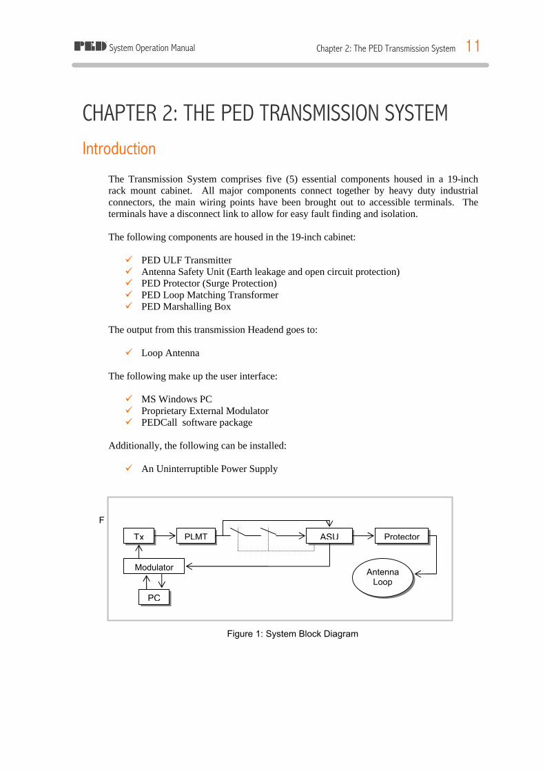
PC
Modulator
Tx PLMT ASU Protector
Antenna Loop
CHAPTER 2: THE PED TRANSMISSION SYSTEM Introduction
The Transmission System comprises five (5) essential components housed in a 19-inch rack mount cabinet. All major components connect together by heavy duty industrial connectors, the main wiring points have been brought out to accessible terminals. The terminals have a disconnect link to allow for easy fault finding and isolation. The following components are housed in the 19-inch cabinet: ü PED ULF Transmitter ü Antenna Safety Unit (Earth leakage and open circuit protection) ü PED Protector (Surge Protection) ü PED Loop Matching Transformer ü PED Marshalling Box
The output from this transmission Headend goes to: ü Loop Antenna
The following make up the user interface: ü MS Windows PC ü Proprietary External Modulator ü PEDCall software package
Additionally, the following can be installed: ü An Uninterruptible Power Supply
F
Figure 1: System Block Diagram
System Operation Manual Chapter 2: The PED Transmission System 12
The System Elements
PEDCall Computer - The operator interface The computer, a Windows PC running PEDCall, controls the PED transmission system. The PEDCall software provides the interface from the operator to the PED system in a simple and efficient manner. The operator inputs information, such as the destination and the message content, then PEDCall will encode this information. Encoding of the destination and message utilises advanced encryption methods to eliminate any chance of invalid information being transmitted. These encryption methods also ensure the receivers can decode the information in adverse signal conditions.
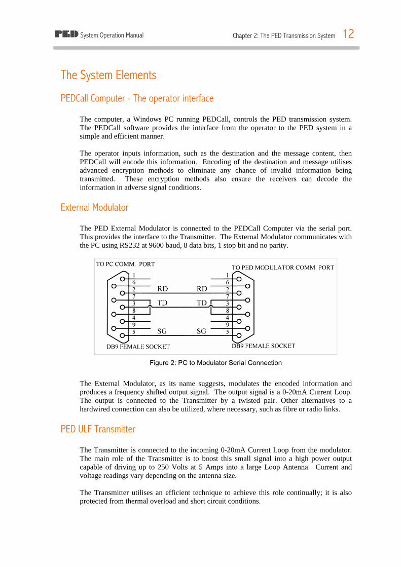
External Modulator The PED External Modulator is connected to the PEDCall Computer via the serial port. This provides the interface to the Transmitter. The External Modulator communicates with the PC using RS232 at 9600 baud, 8 data bits, 1 stop bit and no parity.
Figure 2: PC to Modulator Serial Connection
The External Modulator, as its name suggests, modulates the encoded information and produces a frequency shifted output signal. The output signal is a 0-20mA Current Loop. The output is connected to the Transmitter by a twisted pair. Other alternatives to a hardwired connection can also be utilized, where necessary, such as fibre or radio links.
PED ULF Transmitter The Transmitter is connected to the incoming 0-20mA Current Loop from the modulator. The main role of the Transmitter is to boost this small signal into a high power output capable of driving up to 250 Volts at 5 Amps into a large Loop Antenna. Current and voltage readings vary depending on the antenna size. The Transmitter utilises an efficient technique to achieve this role continually; it is also protected from thermal overload and short circuit conditions.
System Operation Manual Chapter 2: The PED Transmission System 13
Each Transmitter can drive one Loop Antenna, therefore if a large mine has two loops, then two Transmitters will be connected. The External Modulator can effectively drive up to four Transmitters. The Transmitter has a maximum output of 1.2 kVA, hence requires locating in a cool ambient environment, it should also be relatively dust-free. The PED ULF Transmitter amplifies the modulated signal to power the Loop Antenna. The Transmitter is designed to perform this task continually and reliably. The Transmitter is normally set to supply up to 5 Amps; the output voltage will vary depending on the size of the Loop Antenna. Typically, the Transmitter will supply 200 Vac (this varies depending on the actual length of the loop antenna).
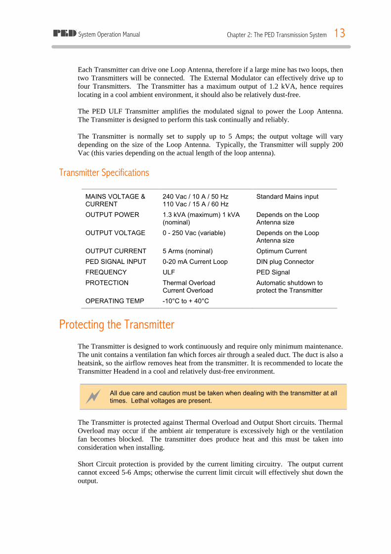
Transmitter Specifications
MAINS VOLTAGE & CURRENT
240 Vac / 10 A / 50 Hz 110 Vac / 15 A / 60 Hz
Standard Mains input
OUTPUT POWER 1.3 kVA (maximum) 1 kVA (nominal)
Depends on the Loop Antenna size
OUTPUT VOLTAGE 0 - 250 Vac (variable) Depends on the Loop Antenna size
OUTPUT CURRENT 5 Arms (nominal) Optimum Current
PED SIGNAL INPUT 0-20 mA Current Loop DIN plug Connector
FREQUENCY ULF PED Signal
PROTECTION Thermal Overload Current Overload
Automatic shutdown to protect the Transmitter
OPERATING TEMP -10°C to + 40°C
Protecting the Transmitter The Transmitter is designed to work continuously and require only minimum maintenance. The unit contains a ventilation fan which forces air through a sealed duct. The duct is also a heatsink, so the airflow removes heat from the transmitter. It is recommended to locate the Transmitter Headend in a cool and relatively dust-free environment.
~ All due care and caution must be taken when dealing with the transmitter at all times. Lethal voltages are present.
The Transmitter is protected against Thermal Overload and Output Short circuits. Thermal Overload may occur if the ambient air temperature is excessively high or the ventilation fan becomes blocked. The transmitter does produce heat and this must be taken into consideration when installing. Short Circuit protection is provided by the current limiting circuitry. The output current cannot exceed 5-6 Amps; otherwise the current limit circuit will effectively shut down the output.
System Operation Manual Chapter 2: The PED Transmission System 14
Both protection circuits have light indicators on the front panel, which allow operators to locate the cause of the fault. The thermal breakers are located on the front panel of the Transmitter. Should a breaker trip continually the Transmitter should be checked and serviced. For test purposes a built in oscillator (when select switch on Transmitter front panel is set to Tx) allows the Transmitter to be operated in the absence of the External Modulator signal. This allows the operator to determine if the Loop Antenna is functional.
ê Turn power off at the mains and remove the plug from its wall socket before removing any leads from either the transmitter or the computer.
~ THERE ARE DANGEROUS VOLTAGES (up to 250 Vac) PRESENT AT THE OUTPUT TERMINALS OF THE TRANSMITTER.
Antenna Safety Unit The Antenna Safety Unit (ASU) provides protection to personnel from the potentially lethal voltages present on the PED Antenna Loop. It also monitors the output voltage. Should a fault occur the software will detect it and display a message on the PC, during a fault the messaging system is disabled. The ASU offers selectable Earth Leakage (Ground Fault) protection and also Impedance Monitoring. In this way, some unsafe condition that may occur will result in the shutdown of the system. Any voltages will be completely removed from the Loop Antenna. That is, the ASU is designed to detect Earth Leakage and Open Circuit conditions. Should a fault develop the ASU will detect it and isolate the Loop Antenna from the Transmitter. The ASU is connected between the PLMT and the surge protection on the Loop Antenna. The ASU is powered from the mains supply. The ammeter and voltmeter give the actual loop current and voltage, the difference between the transmitter and ASU meter readings is due to the PLMT optimising the output power.
ASU Specifications The ASU has two independent detection circuits, each connects to its own shunt trip circuit breaker, the breakers are wired in series. The ASU features a selectable Earth leakage trip point, so that any natural leakage can be taken into consideration. The voltage set point for the impedance testing is also selectable from 24 or 48 Volts. Earthleakage protection uses two core balance detectors, each detector has its own circuitry and shunt trip relay, thus giving fully redundant protection. ASU monitors PLMT output voltage and Antenna Loop current. If PLMT voltage is above a threshold (24 or 48 V, selected with jumpers on ASU board) and there is no output current going into the loop

System Operation Manual Chapter 2: The PED Transmission System 15
then the shunt trip breakers will open removing power from the loop and “Open Circuit” alarm will be indicated. Contacts on the auxiliary relays are wired in series, this is then wired to the external modulator. The external modulator continually monitors this contact and if it opens a fault is registered on the PEDCall software. The front panel of the ASU (figure.2) has eight indicating LED’s, they are in two banks of four ( 4 for each detection circuit). They indicate:
1. Power ON 2. Open circuit 3. Earth Leakage 4. Under voltage
Figure 3: ASU Front Panel
Set/re-set operation Only attempt a reset after a trip once the fault has been found and repaired. Isolation of the loop should be carried out as per the companies’ or operator’s procedures. Resetting the ASU: 1. Find and repair the fault. 2. Make sure the power to the system is turned ON. 3. Press and hold the reset button for 1 second then release. 4. Turn each shunt trip relay. 5. Ensure there is an output voltage and current reading on the meters on the ASU Rated residual current (6 or 30 or 100 or 200 mA) is selected via clearly marked jumpers on the ASU board. ASU is provided with a test facility by which the correct operation of the Earth Leakage Device may be checked. The test facility ensures that all components of the said device and integrity of the Earth Leakage protection system (such as trip relays) are tested. When the ASU detects a fault and trips the circuit, the cause of the fault, either Earth Leakage or Open Circuit is shown via the LEDs. If tripping is constantly occurring, the Loop should be checked for the relevant fault.
System Operation Manual Chapter 2: The PED Transmission System 16
Loop Antenna The Loop Antenna layout is critical to system performance. The layout will determine the range of signal transmission. Generally, the larger the loop the better the coverage will be. A standard Loop Antenna carries 4.5 Amps of current, however this may vary depending on loop size and PLMT monitoring. Due to this current flow an electromagnetic field is created around the Loop Antenna. This field appears as concentric bands radiating off the cable. The concentric pattern ensures that signal is present inside, above, below and off the edge of the loop. Due to the signal radiation pattern, a centrally located loop can cover an average size mine. Where multiple loops are utilised the polarity must be correct, this will ensure both loops work together and the signal is boosted rather than cancelled. Surface Loops are most desirable, due to the infrastructure being above ground. Underground Loops can also be utilised in areas where surface access is not possible. Underground loops work as effectively as a surface loop and are usually smaller, as the signal does not have to travel as far.
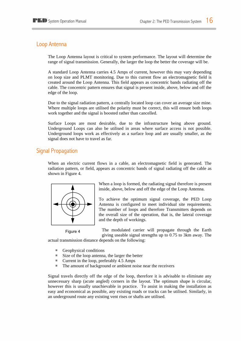
Signal Propagation When an electric current flows in a cable, an electromagnetic field is generated. The radiation pattern, or field, appears as concentric bands of signal radiating off the cable as shown in Figure 4.
When a loop is formed, the radiating signal therefore is present inside, above, below and off the edge of the Loop Antenna.
To achieve the optimum signal coverage, the PED Loop Antenna is configured to meet individual site requirements. The number of loops and therefore Transmitters depends on the overall size of the operation, that is, the lateral coverage and the depth of workings.
The modulated carrier will propagate through the Earth giving useable signal strengths up to 0.75 to 3km away. The
actual transmission distance depends on the following: ¡ Geophysical conditions ¡ Size of the loop antenna, the larger the better ¡ Current in the loop, preferably 4.5 Amps ¡ The amount of background or ambient noise near the receivers
Signal travels directly off the edge of the loop, therefore it is advisable to eliminate any unnecessary sharp (acute angled) corners in the layout. The optimum shape is circular, however this is usually unachievable in practice. To assist in making the installation as easy and economical as possible, any existing roads or tracks can be utilised. Similarly, in an underground route any existing vent rises or shafts are utilised.
Figure 4

System Operation Manual Chapter 2: The PED Transmission System 17
Cable Specifications The cable utilised for the PED Loop Antenna should meet or exceed the following requirements: ü 10mm2 single core, preferably double insulated, multi stranded copper flex cable ü The insulation should be rated 1kV or more ü The cable should have a resistance of less than 1.9 Ohms per kilometre ü In extremely cold climates the antenna type should be confirmed by MST
It is advisable that any cable used for the antenna installation be confirmed by Mine Site Technologies.
Loop Antenna Installation The Loop Antenna is best treated as a power cable; similar regulations that apply to running power cables should be adhered to when installing the Loop Antenna.
Quality Loop Antenna Joints The Loop Antenna joints are critical to ensuring reliable operation of the PED System over time. The joints should be made in suitable junction boxes, to allow easy locating and testing. The joints should also be made to the highest standards to prevent the entry of water and therefore corrosion. For example, joints should be soldered and sealed with a Scotchcast kit or equivalent (particularly on surface loops). The joints, when made correctly, will also keep the overall Loop resistance to a minimum. There should be NO stress placed on the joints at all. Junction boxes should be used and clearly marked, where the cable is buried, the boxes should be brought to the surface wherever possible.
Earth Burial If the Loop Antenna is buried on the surface, conduit or specially made heavily insulated direct earth burial cable is recommended. In some locations it is mandatory to install the cable in conduit. Generally, a heavy duty conduit is required when buried underground. All joints in the conduit should be made with adhesive cement to ensure that water cannot enter. All cable joins should be made in either a pit or a pillar, this will give the joint maximum protection. Poorly made or damaged joints will reduce the effectiveness of the system.
ê The conduit, where used or required, should meet local electrical requirements.
System Operation Manual Chapter 2: The PED Transmission System 18
Suspended / Pole Hung Antenna Where it is necessary to utilise poles for the Loop Antenna, the method of mounting should remove all stress from the cable. The Loop Antenna can be suspended from a catenary wire, or alternatively, a suitable HARD DRAWN copper cable could be utilised. The hard drawn cable should have the same or less resistance as the normal cable. The cable being strung on poles does not affect signal propagation.
ê The method of suspending the cable should conform to all applicable electrical standards.
Underground Loop Antenna An underground Loop Antenna is usually suspended, and it is advisable to use conduit or specially made heavily insulated cable for protection of the cable. If a cable is not enclosed in conduit then a suitable hard-drawn cable is recommended. The objective is to remove any stress that is placed on the cable. Whether a conduit or hard drawn cable is used, it is also advisable to run a catenary wire on all or part of the installation.
ê The catenary should be broken into no more then 100 metre lengths to limit any chance of signal induction.
Precautions with an Underground Loop Antenna
Clearance from Data Cables It is recommended that the PED Loop Antenna be installed in separate drives or headings to where other data cables, such as telephone lines or radio antenna, are installed. If it is necessary to install the PED Loop Antenna with other data cables, always maintain the maximum achievable clearance distance between these cables and the PED Loop Antenna.
Clearance and testing of Firing Cables When installing the Loop Antenna, consideration should be given to the location of the Loop Antenna with reference to any detonator firing cable already installed in the mine.
System Operation Manual Chapter 2: The PED Transmission System 19
The following points should be taken into account: ü Where possible, install the PED Loop Antenna in drives or headings where there is
no firing cable present. ü Where the PED Loop Antenna and the firing cable are in the same area always
maintain the maximum distance possible between the two cables. The distance should never be less than 1.7 metres.
ü When installing new firing cable nearby the PED Loop Antenna, utilise shielded cable.
ü Before commissioning the PED Loop Antenna and on a regular basis, measurements should be made and recorded on the firing cable at various locations throughout the mine as follows:
§ Using a calibrated RMS Multimeter, measure the AC Voltage and Current
present on the firing line between each wire and Ground and then across both wires. § The PED Loop Antenna should then be powered up to the recommended
output and a repeat of the tests above should be carried out. § It should be noted that in any of the above tests that a current in excess of
30mA should not be measured. § Should a higher reading then 30 mA appear, then the PED System should be
powered down and a full Practical Site Test be carried out to ensure compliance with the above requirements (see BS 6657:1991 for method of undertaking a practical site test).
ü It is recommended to check with the local Mines Department or relevant authority
for any local installation conditions.
Voltage Limitations on Underground Loop Antennae Should standards or regulations applicable require the voltage in the Loop Antenna to be kept below a certain level, the PED System should be set up as to utilise a Centre Tapped Transformer on the output. This effectively halves the voltage to Ground reading, allowing more signal to be radiated while not exceeding regulations.
Induced Voltages Measurements should be taken upon first power up of the antenna to ensure there are no dangerous voltages induced in existing infrastructure, such as pipe work and data cabling. Where phone cabling is of poor quality the PED system may introduce line noise.
PED Loop Matching Transformer The PED Loop Matching Transformer (PLMT) is designed to allow a higher current to flow in smaller Loop Antennae. Some mines are limited in the size loop that can be installed, to increase the signal that is radiated off this loop; it is necessary to increase the loop current above the normal 4.5 Amps.

System Operation Manual Chapter 2: The PED Transmission System 20
The PLMT is installed to:
§ Compensate reactive power required by the loop antenna § Match loop antenna and transmitter § Limit earth-fault current
Although a small loop with higher current does not provide as much signal as a larger loop, the additional signal achieved with a PLMT is very beneficial. The PLMT is connected between the Transmitter and the Loop Antenna. The PLMT matches the Loop Antenna to the Transmitter; this allows a higher current to flow in the cable. The higher current translates to a higher signal strength. The PLMT also has a centre tap to earth, this references the antenna to earth/ground.
The PED Protector The PED Protector is a Surge protection device. The unit is installed immediately before the Loop, hence any voltage induced by lightning strikes on the Loop Antenna will be diverted and therefore minimise the risk of damage to the Transmission System. The PED Transmission System can have a significant amount of cable on the surface. Like other cables, the Loop Antenna can get high induced voltages and therefore cause damage to both the cable and the Transmission System. The PED Protector will absorb several surges, basically sacrificing itself while protecting the PED System. The PED Protector MUST be the last element connected before the Loop Antenna. Only equipment that precedes the PED Protector will be protected. The PED Protector is installed in the 19” rack cabinet. To install the PED Protector the Loop Antenna cables are wired into a terminal block on the PED Protector. The output from the Transmission System is wired into the input of the PED Protector. It is important to ensure that Ground is also connected to the input terminal block. Keep in mind, the enormous amount of energy involved in a direct lightning strike may still cause damage beyond the PED Protector.
Uninterruptible Power Supply * Optional An Uninterruptible Power Supply (UPS) protects the Transmission System from power fluctuations on the incoming mains. The UPS will ensure a clean and constant AC power supply to the computer and external modulator. An UPS is highly recommended when the PED System is installed as a Mine Wide Warning System. During power blackouts, it is critical that the PED System remains operational, this is achieved by a UPS.
System Operation Manual Chapter 2: The PED Transmission System 21
An Uninterruptible Power Supply (UPS) provides a clean supply to the PED Transmission System and in the event of a mains failure will continue to provide power to the System for a specified period of time. The UPS will also negate fluctuations in the AC mains, which could adversely affect the PED Transmission System. It is not uncommon for mains power to fluctuate significantly, any electronic equipment, such as the PED System, can suffer damage. To ensure the PED System remains operational in the event of a power blackout BOTH the Transmitter and the PEDCall Computer must be connected to the UPS. The UPS should have a minimum capacity of 3kVA; otherwise the operating time may be insufficient. The load on the UPS is significant when a PED Transmitter is operating near maximum.
ê Ferro-resonant power conditioners must not be used.
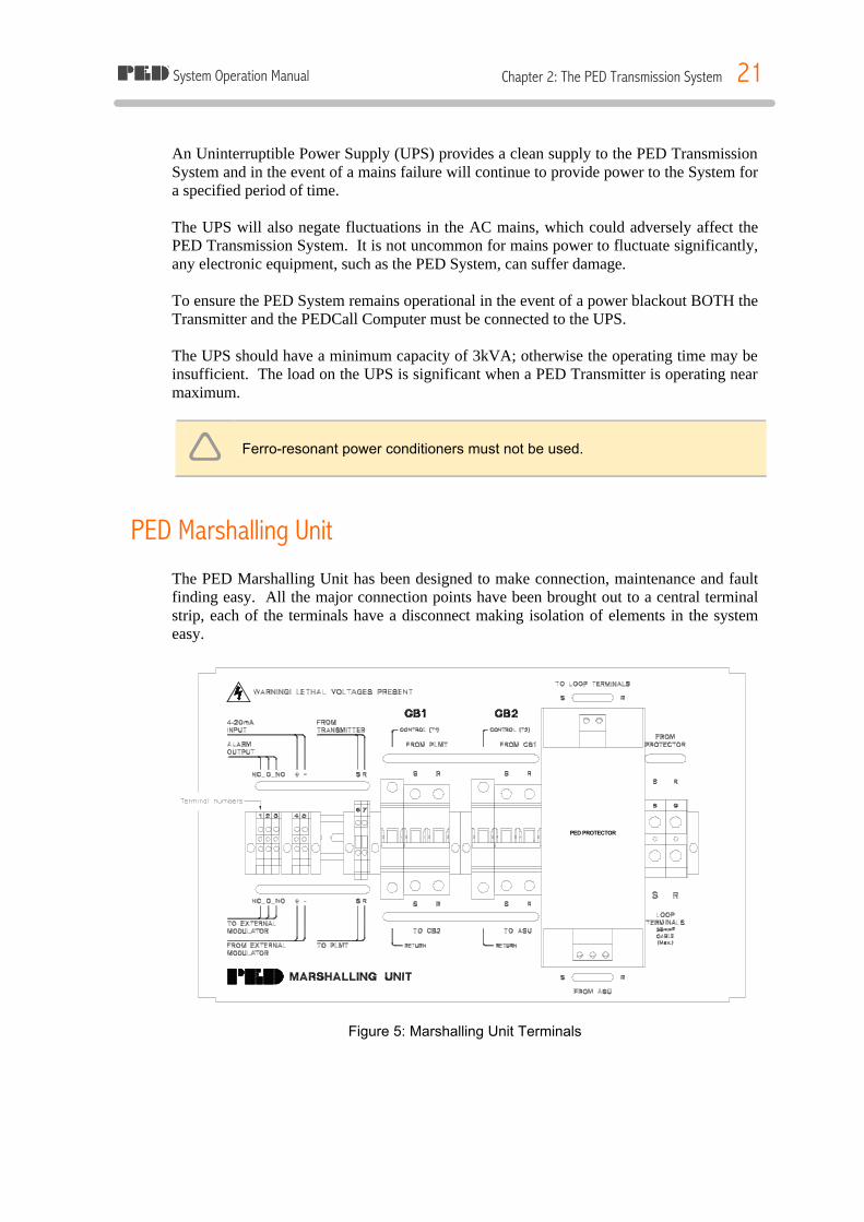
PED Marshalling Unit The PED Marshalling Unit has been designed to make connection, maintenance and fault finding easy. All the major connection points have been brought out to a central terminal strip, each of the terminals have a disconnect making isolation of elements in the system easy.
Figure 5: Marshalling Unit Terminals
PED PROTECTOR
System Operation Manual Chapter 2: The PED Transmission System 22
Terminals 2, 3, 4, 5, 8 & 9 are the only external connections required. 1. Normally closed – Not used 2. Common – To external modulator 3. Normally Open – To external modulator 4. Positive 0-20mA – From transmitter 5. Negative 0-20mA – From transmitter 8. To the Loop Antenna 9. To the Loop Antenna
The terminals listed below are factory wired :
6 & 7 From transmitter CB1 – Earth Leakage Shunt Trip Relay 1 CB2 – Earth Leakage Shunt Trip Relay 2
Harness Wiring Prefabricated interconnecting wiring as marked on Figure 6:
A. Fan Power output from Marshalling Unit. B. Power Distribution from Marshalling Unit to Transmitter. (IEC Male to Female - 3
pin) C. Distributed Modulator Signal from Marshalling Unit to Transmitter. (DIN
Connector, Male to Male - 5 Pin) D. Alarm Output from Antenna Safety Unit to Marshalling Unit. (DIN connector,
Male to Male - 3 Pin) E. Transmitter Output to Marshalling Unit. (IEC Male - 3 Pin to HAN Female - 4
Pin) F. Antenna Safety Unit in/ outs to Marshalling Unit. (HAN Male to Female - 16 Pin) G. PLMT in/ outs to Marshalling Unit. (HAN Male to Female - 6 Pin)
4 A shorting plug is supplied on systems not running a PLMT.

System Operation Manual Chapter 2: The PED Transmission System 23
Figure 6: Prefabricated Interconnecting Wiring
System Operation Manual Chapter 2: The PED Transmission System 24
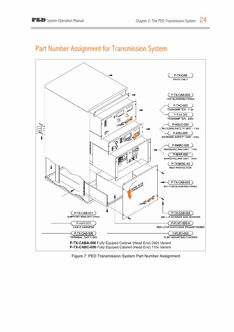
Part Number Assignment for Transmission System
Figure 7: PED Transmission System Part Number Assignment

System Operation Manual Chapter 3: Installing the PED Transmission System 25
CHAPTER 3: INSTALLING THE PED TRANSMISSION SYSTEM Introduction
The following sections detail the installation procedure:
§ The PEDCall Computer § Modifying & Installing the External Modulator § Loading the PEDCall Software § Configuring the PEDCall Computer § The Twisted Pair & System connections § PED ULF Transmission System
The PEDCall Computer The Computer utilised for PEDCall constantly transmits information to ALL receivers to ensure they remain synchronised. This computer needs to be continually running the PEDCall software; however it may run as a background task. Networked computers are also able to send PED messages. The Computer must meet, or exceed the following requirements: ü IBM compatible PC, 233MHz ü MS Windows OS (98/XP/NT/2000) ü SVGA Monitor @ 800x600 resolution ü 64M RAM Memory ü Available Serial Port ü 400Mb Hard Disk ü CD-ROM ü 1.44Mb Floppy Disk (BlastPED) ü Network Card (Optional)
Modifying the External Modulator The External Modulator contains jumpers, which allow external inputs for Emergency messaging and transmitter status monitoring. There are a total of four (4) external inputs. Three (3) require a Normally Closed contact, when opened the appropriate Emergency Message will be generated. The fourth input is usually connected to the Antenna Safety Unit and informs the operator of the Transmission System status.
System Operation Manual Chapter 3: Installing the PED Transmission System 26
There are an additional 3 Emergency switches on the front panel of the External modulator. These switches are in series with the corresponding external emergency switches. Jumpers are used to disable all emergency messaging or only allow the front panel switches to be active. The table below indicates the role of each jumper set.
Jumper Role
JEM1 Remove to enable External Emergency Switch 1 JEM2 Remove to enable External Emergency Switch 2 JEM3 Remove to enable External Emergency Switch 3
J30 Install jumper to allow monitoring of TX Fault feedback. (ASU Fault)
J40 Install this jumper to enable Emergency Message 1 from Front Panel J50 Install this jumper to enable Emergency Message 2 from Front Panel J60 Install this jumper to enable Emergency Message 3 from Front Panel
J101 Install this jumper for North American versions and remove for Australian (for 110 volt and 240 volt operation)
Examples: J40 inserted and JEM1 inserted means that EMERGANCY MESSAGE 1 push button on the Modulator Board front panel will trigger Emergency Message 1, but external switch is disabled and thus pins 19 and 7 can be left open circuit. J40 inserted and JEM1 removed means that the external switch between pins 19 and 7 must be kept normally closed not to interfere with the EMERGENCY MESSAGE 1 pushbutton on the Modulator Board front panel. J40 removed disables triggering of EMERGANCY MESSAGE 1 with the pushbutton on the front panel or the external switch.
System Operation Manual Chapter 3: Installing the PED Transmission System 27
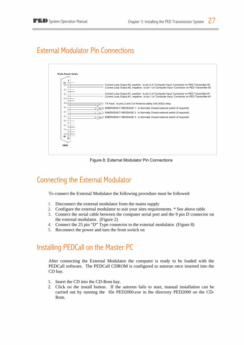
External Modulator Pin Connections
Figure 8: External Modulator Pin Connections
Connecting the External Modulator To connect the External Modulator the following procedure must be followed: 1. Disconnect the external modulator from the mains supply 2. Configure the external modulator to suit your sites requirements. * See above table 3. Connect the serial cable between the computer serial port and the 9 pin D connector on
the external modulator. (Figure 2) 4. Connect the 25 pin “D” Type connector to the external modulator. (Figure 8) 5. Reconnect the power and turn the front switch on
Installing PEDCall on the Master PC After connecting the External Modulator the computer is ready to be loaded with the PEDCall software. The PEDCall CDROM is configured to autorun once inserted into the CD bay. 1. Insert the CD into the CD-Rom bay. 2. Click on the install button. If the autorun fails to start, manual installation can be
carried out by running the file PED2000.exe in the directory PED2000 on the CD-Rom.
Current Loop Output #2, positive: to pin 2 of ‘Computer Input’ Connector on PED Transmitter #2 Current Loop Output #2, negative: to pin 1 of ‘Computer Input’ Connector on PED Transmitter #2 Current Loop Output #1, positive: to pin 2 of ‘Computer Input’ Connector on PED Transmitter #1 Current Loop Output #1, negative: to pin 1 of ‘Computer Input’ Connector on PED Transmitter #1
TX Fault: to pins 2 and 3 of Antenna safety Unit (ASU) relay
EMERGENCY MESSAGE 1: to Normally Closed external switch (if required)
EMERGENCY MESSAGE 2: to Normally Closed external switch (if required)
EMERGENCY MESSAGE 3: to Normally Closed external switch (if required)
System Operation Manual Chapter 3: Installing the PED Transmission System 28
4 The default install directory is C:\Program Files\PEDCall2000
If you are installing over a previous version the install program will create a backup of the old files and store the in the Backup folder in the PEDCall2000 folder.
Configuring PEDCall
ê PEDCall setup files can only be accessed on the master computer and when the external modulator is turned on. If the program fails to detect the modulator and error screen will be displayed. From here the INI file and communications setup can be accessed.
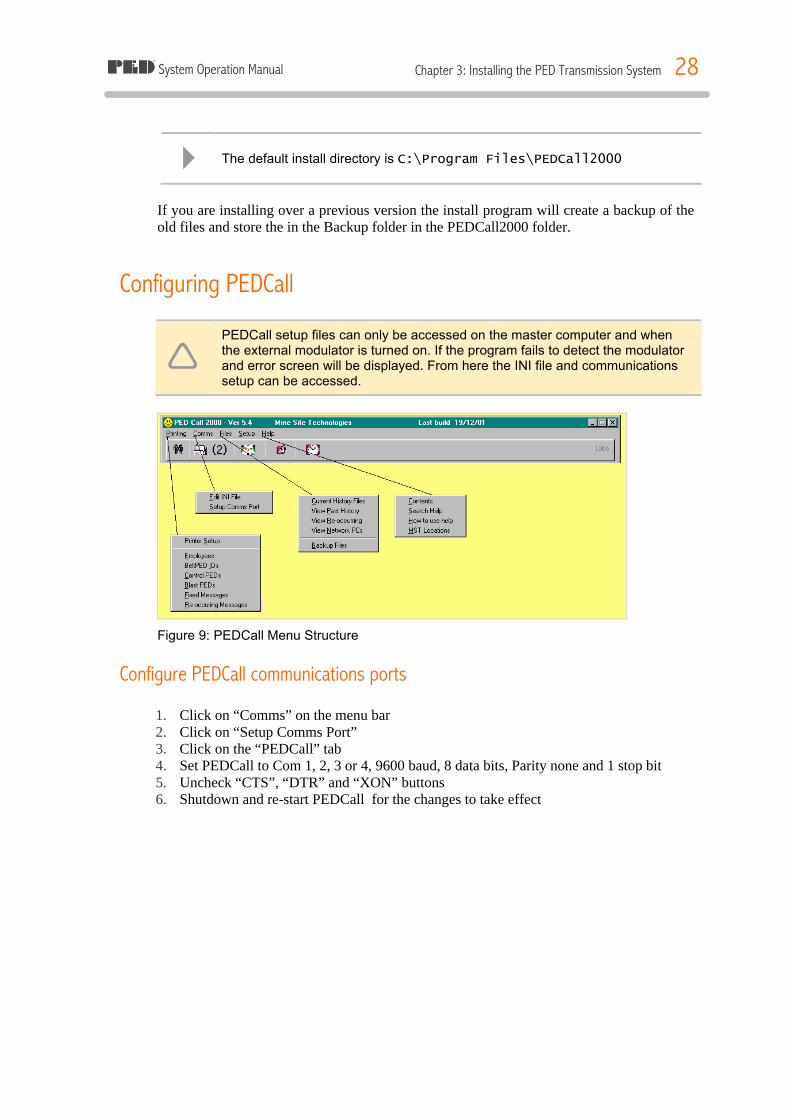
Figure 9: PEDCall Menu Structure
Configure PEDCall communications ports 1. Click on “Comms” on the menu bar 2. Click on “Setup Comms Port” 3. Click on the “PEDCall” tab 4. Set PEDCall to Com 1, 2, 3 or 4, 9600 baud, 8 data bits, Parity none and 1 stop bit 5. Uncheck “CTS”, “DTR” and “XON” buttons 6. Shutdown and re-start PEDCall for the changes to take effect

System Operation Manual Chapter 3: Installing the PED Transmission System 29
Configure the Master PC INI File
Figure 10: Edit Include File Window
1. Click on “Comms” on the menu bar 2. Click on “Edit INI” 3. Enter the computer name, any name is possible 4. The master PC has two options, the Dial In option is for remote access via a telephone
system 5. Initialisation time can be set to 0 6. Specify a backup schedule if required. * See note below 7. Options – Single blast commands, this option will only allow one blasting/arm
command to be generated at a time
Scheduling a backup If the PEDCall PC is not included in your company’s backup process, we recommend that you create a backup schedule. The backup makes a copy of all the data files and stores these file in the location specified. To create a backup schedule: 1. Check the “Schedule a daily backup” 2. Specify the time to do the backup in 24 hour format. 3. Type in the path, this may be across the network via a mapped drive.
4 The INI file can also be edited manually. This plane text file is named pedw.ini and is located in your root Windows directory.
System Operation Manual Chapter 3: Installing the PED Transmission System 30
Remote Access PEDCall may be accessed and controlled from a remote terminal. For detailed instructions on how to configure and use PEDCall remotely please refer to Chapter 6.
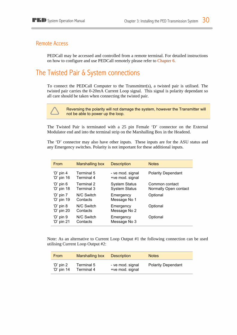
The Twisted Pair & System connections To connect the PEDCall Computer to the Transmitter(s), a twisted pair is utilised. The twisted pair carries the 0-20mA Current Loop signal. This signal is polarity dependant so all care should be taken when connecting the twisted pair.
ê Reversing the polarity will not damage the system, however the Transmitter will not be able to power up the loop.
The Twisted Pair is terminated with a 25 pin Female ‘D’ connector on the External Modulator end and into the terminal strip on the Marshalling Box in the Headend. The ‘D’ connector may also have other inputs. These inputs are for the ASU status and any Emergency switches. Polarity is not important for these additional inputs.
From Marshalling box Description Notes
‘D’ pin 4 Terminal 5 - ve mod. signal Polarity Dependant ‘D’ pin 16 Terminal 4 +ve mod. signal
‘D’ pin 6 Terminal 2 System Status Common contact ‘D’ pin 18 Terminal 3 System Status Normally Open contact
‘D’ pin 7 N/C Switch Emergency Optional ‘D’ pin 19 Contacts Message No 1
‘D’ pin 8 N/C Switch Emergency Optional ‘D’ pin 20 Contacts Message No 2
‘D’ pin 9 N/C Switch Emergency Optional ‘D’ pin 21 Contacts Message No 3
Note: As an alternative to Current Loop Output #1 the following connection can be used utilising Current Loop Output #2:
From Marshalling box Description Notes
‘D’ pin 2 Terminal 5 - ve mod. signal Polarity Dependant ‘D’ pin 14 Terminal 4 +ve mod. signal

System Operation Manual Chapter 3: Installing the PED Transmission System 31
PED ULF Transmitter To install the PED ULF Transmission Headend (the Head End) proceed as follows: 1. Locate a suitable area to place the Head End as follows: ü Cool temperature with good air circulation ü Dust free environment ü Away from people due to the noise (a low hum) ü Available power source (240VAC/10amp or 110VAC/15amp)
2. The twisted pair cable from the external modulator uses 2 pairs, 1 for the 0-20mA
signal the other for the ASU monitoring. Connect the signal pair to terminals 4 and 5 (take care with polarity, 4 being positive). The other pair are connected between terminals 2 and 3 (common and normally open contacts)
3. Connect the two loop tails into the end terminals (large terminals), check that the loop
circuit breakers CB1 and CB2 are “OFF”. Check the loop by measuring the resistance to ensure continuity and megger the loop to earth to insure its integrity. Turn the loop circuit breakers “ON”
4. With the Transmitter turned off, connect the Transmitter power cord to a single phase
240V/10A (or 110V/15A) power outlet and then to the Transmitter Power Input socket. 5. Ensure the Mode Select Switch is turned to the COMPUTER position and turn the
output potentiometer fully counter-clockwise, until it stops 6. Ensure all personnel are clear of the Loop Antenna and then turn the main switch ON.
The green light adjacent to the power switch should illuminate 7. Press and hold the ASU reset button for 1 second 8. Turn on both Shunt Trip Relays 9. Slowly increase the reading on the output meters by rotating the knob (potentiometer)
clockwise. Increase the output current until 4.5 Amps is reached
Multiple Transmitter Systems The 0-20 mA Current loop signal is supplied to ALL Transmitters in a multiple Transmitter system. In such systems, it is important to test and ensure that correct loop polarity is achieved. Generally a BeltPED receiver is utilised to test signal coverage. In areas where signal from two loops would be present, the receiver should remain synchronised.
System Operation Manual Chapter 4: Servicing the PED Headend 32
CHAPTER 4: SERVICING THE PED HEADEND Overview
The PED Transmission System is relatively simple to service and if necessary, fault-find. The design of the system is predominantly modular; hence isolating the various elements is achievable. The hardware is designed for the task, providing some precautions are taken, the system is very reliable. The precautions mainly involve the location of the equipment that is a cool, dust-free environment.
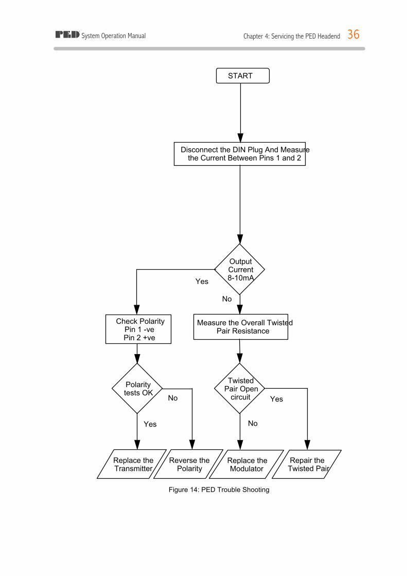
Procedure for Fault Finding In the event of a failure, it is important to check each point of the following flowcharts carefully. To test the system requires only a quality multimeter and an insulation resistance tester (megger). In installations where the Transmitter is remotely located from the PEDCall computer, the twisted pair should be thoroughly checked. The polarity of the twisted pair is critical, the system will not operate if reversed. The following four flowcharts (Figure 9-12) provide solutions for most PED System faults. Depending on the diagnosis, the fault guides will usually recommend replacing a module or repairing a cable. Some faults identify a particular component, which is faulty; this may be serviced onsite or returned for repairs.
ê Before making internal board repairs always check your warranty
4 Remember: most faults are simple. Check connections & cables first.

System Operation Manual Chapter 4: Servicing the PED Headend 33
Figure 11: PED Trouble Shooting
START
Check the Transmitter Output Meters
Change the Modulator
Sheet 2 Sheet 3
No
Yes
No
Yes
No
Yes
Test Output Voltage with Another Meter
Yes
No
Yes
No
Signal Strength is
too low
Measure the loop resistance
Remove Short Circuit
Replace Transmitter
Meter
Replace Transmitter
Output Current
>0
Output Voltage correct
Output Voltage correct
All units in No
Service
Loop short
circuit?
Output Voltage correct Yes
No
System Operation Manual Chapter 4: Servicing the PED Headend 34
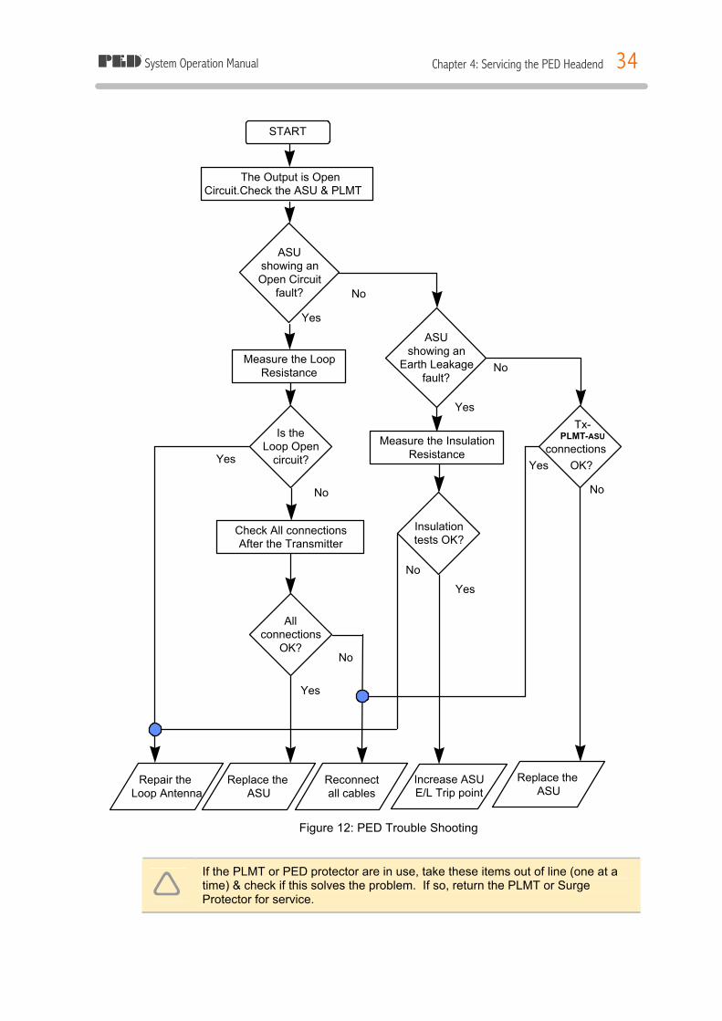
The Output is Open Circuit.Check the ASU & PLMT
Measure the Loop Resistance
Measure the Insulation Resistance Yes
No
Check All connections After the Transmitter
ASU showing an Open Circuit
fault?
ASU showing an
Earth Leakage fault?
No
Yes
No
Yes
Yes
START
Is the Loop Open
circuit?
Insulation tests OK?
All connections
OK?
Reconnect all cables
Replace the ASU
Increase ASU E/L Trip point
Replace the ASU
Tx- PLMT-ASU connections
OK?
Repair the Loop Antenna
Yes
No
Yes
No
No
Figure 12: PED Trouble Shooting
ê If the PLMT or PED protector are in use, take these items out of line (one at a time) & check if this solves the problem. If so, return the PLMT or Surge Protector for service.
System Operation Manual Chapter 4: Servicing the PED Headend 35
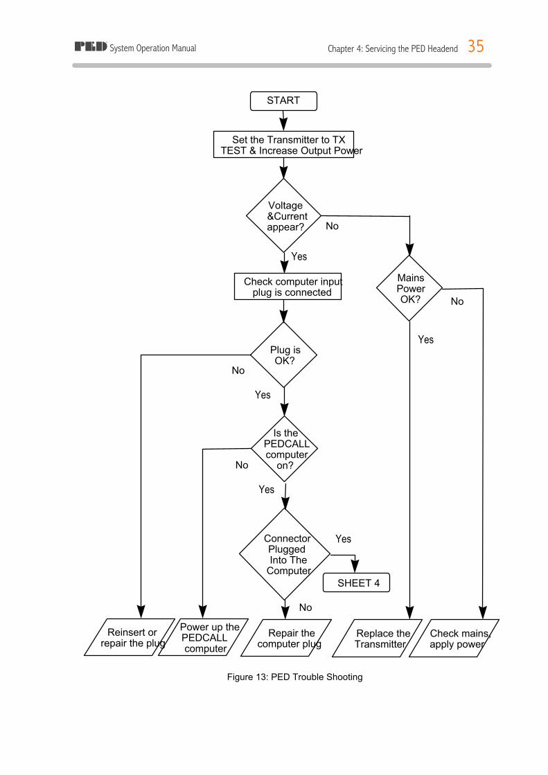
Figure 13: PED Trouble Shooting
Set the Transmitter to TX TEST & Increase Output Power
No
Check computer input plug is connected
No
Connector Plugged Into The
Computer
START
Voltage &Current appear?
Plug is OK?
Reinsert or repair the plug
Power up the PEDCALL computer
Is the PEDCALL computer
on?
Mains Power OK?
Replace the Transmitter
Check mains, apply power
No
Yes
Yes
SHEET 4
Yes
Yes
No
No
Yes
Repair the computer plug
System Operation Manual Chapter 4: Servicing the PED Headend 36
Figure 14: PED Trouble Shooting
Disconnect the DIN Plug And Measure the Current Between Pins 1 and 2
Measure the Overall Twisted Pair Resistance
No
Yes
Check Polarity Pin 1 -ve Pin 2 +ve
Yes
START
Output Current 8-10mA
Polarity tests OK
Replace the Transmitter
Reverse the Polarity
Twisted Pair Open
circuit
Replace the Modulator
Repair the Twisted Pair
No
No
Yes
System Operation Manual Chapter 5: PEDCall - Operator Interface 37
CHAPTER 5: PEDCALL - OPERATOR INTERFACE The PEDCall Main Screen
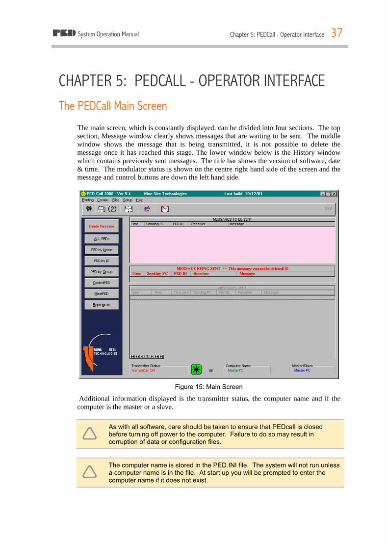
The main screen, which is constantly displayed, can be divided into four sections. The top section, Message window clearly shows messages that are waiting to be sent. The middle window shows the message that is being transmitted, it is not possible to delete the message once it has reached this stage. The lower window below is the History window which contains previously sent messages. The title bar shows the version of software, date & time. The modulator status is shown on the centre right hand side of the screen and the message and control buttons are down the left hand side.
Figure 15: Main Screen
Additional information displayed is the transmitter status, the computer name and if the computer is the master or a slave.
ê As with all software, care should be taken to ensure that PEDcall is closed before turning off power to the computer. Failure to do so may result in corruption of data or configuration files.
ê The computer name is stored in the PED.INI file. The system will not run unless a computer name is in the file. At start up you will be prompted to enter the computer name if it does not exist.
System Operation Manual Chapter 5: PEDCall - Operator Interface 38
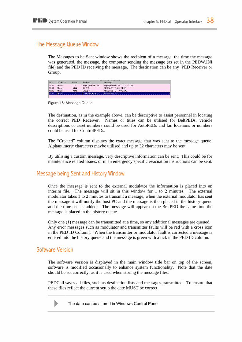
The Message Queue Window The Messages to be Sent window shows the recipient of a message, the time the message was generated, the message, the computer sending the message (as set in the PEDW.INI file) and the PED ID receiving the message. The destination can be any PED Receiver or Group.
Figure 16: Message Queue
The destination, as in the example above, can be descriptive to assist personnel in locating the correct PED Receiver. Names or titles can be utilised for BeltPEDs, vehicle descriptions or asset numbers could be used for AutoPEDs and fan locations or numbers could be used for ControlPEDs. The “Created” column displays the exact message that was sent to the message queue. Alphanumeric characters maybe utilised and up to 32 characters may be sent. By utilising a custom message, very descriptive information can be sent. This could be for maintenance related issues, or in an emergency specific evacuation instructions can be sent.
Message being Sent and History Window Once the message is sent to the external modulator the information is placed into an interim file. The message will sit in this window for 1 to 2 minutes. The external modulator takes 1 to 2 minutes to transmit a message, when the external modulator has sent the message it will notify the host PC and the message is then placed in the history queue and the time sent is added. The message will appear on the BeltPED the same time the message is placed in the history queue. Only one (1) message can be transmitted at a time, so any additional messages are queued. Any error messages such as modulator and transmitter faults will be red with a cross icon in the PED ID Column. When the transmitter or modulator fault is corrected a message is entered into the history queue and the message is green with a tick in the PED ID column.
Software Version The software version is displayed in the main window title bar on top of the screen, software is modified occasionally to enhance system functionality. Note that the date should be set correctly, as it is used when storing the message files. PEDCall saves all files, such as destination lists and messages transmitted. To ensure that these files reflect the current setup the date MUST be correct.
4 The date can be altered in Windows Control Panel

System Operation Manual Chapter 5: PEDCall - Operator Interface 39
Time Readout The time is utilised by PEDCall extensively, and the time displayed on the BeltPED & AutoPED is updated from the PC time, therefore it should be accurate. The time can be altered through Windows Control Panel. The time is used for the Create / Sent columns, which are also stored by the software, files created by PEDCall are time stamped.
Creating a Pager Message Generating a message involves selecting the receiver(s), entering the message and placing the message on the queue. The software is designed to allow personnel without previous computer experience to access the system.
Selecting the Destination The PEDCall software can individually page 911 destinations. Select the destination by high-lighting the name or number, you can either double left mouse click or click on the button “Select this person” on the bottom of the screen. To ensure names can be easily searched for, a naming system should be initially chosen and followed.
Figure 17: PED Message Screen
4 To search by Surname click on the “By Name” tab. Click the mouse in the Surname list and start typing the surname. The highlight bar will start moving towards the name.
4 To search by PED ID click on the “By PED ID” tab. Click the mouse in the PED ID list and start typing the PED number. The highlight bar will start moving towards the PED.
System Operation Manual Chapter 5: PEDCall - Operator Interface 40
The software will automatically place spaces between numbers and letters and will warn the operator of an invalid key stroke by sounding the beeper. The message is entered in 1 line and the actual message display is displayed below the entry line.
ê The line will only accept A to Z, 1 to 9 and , (comma) keys. The back space key is the only editing key available, you can not use the mouse to jump around the message. This is required to ensure the message is formatted correctly.
Deleting Messages To select the Delete function:
1. Highlight the message shown in the “Message to be Sent” window you want to delete.
2. Click on the “Delete message” with the left mouse button. 3. The message will be removed from the system.
RE-Sending Messages Custom and fixed messages may be re-sent by double clicking the left mouse button on the message in the History window. A prompt will ask you to confirm the action. The message is then sent back to the message queue.
Emergency Messages Emergency Messages are pre-configured in the software of the BeltPED and the Receivers. Due to this, the content cannot be modified.
~ Emergency Messages should only be used for Mine Wide warnings.
The advantage of an Emergency Message is the ability to transmit the message in only 15 seconds. To access the Emergency Messages the External Modulator must have been installed with the correct jumper settings. (Please refer to Chapter 6) By pressing one of the 3 buttons on the front of the external modulator (or the remote switches if fitted) and holding in for 2 seconds, one of three Emergency Messages will be generated. Immediately upon pressing the button, any current messages being transmitted, or queued, are deleted. A message is displayed in the Modulator Status text window to inform the operator of the Emergency Message; 15 seconds later ALL receivers will display the message. The box will display which Emergency Message was activated, either Procedure 1, 2 or 3. Any messages waiting to be sent will be automatically deleted.
System Operation Manual Chapter 5: PEDCall - Operator Interface 41
~ It is the responsibility of the mine to develop the procedures related to each Emergency Message.
Normal operation resumes after the Emergency Message has been sent, other messages can then be transmitted as per normal. Should two Emergency Messages be accessed together, they will be transmitted sequentially, with a slight delay between the two messages.
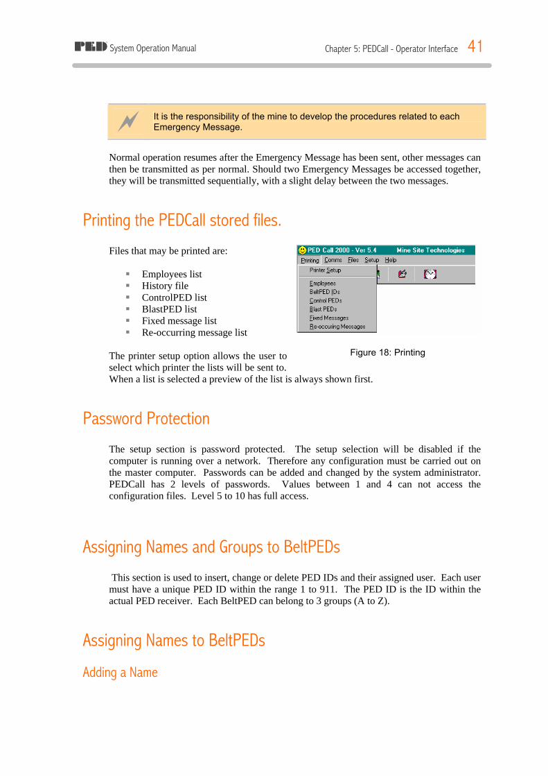
Printing the PEDCall stored files. Files that may be printed are: § Employees list § History file § ControlPED list § BlastPED list § Fixed message list § Re-occurring message list
The printer setup option allows the user to select which printer the lists will be sent to. When a list is selected a preview of the list is always shown first.
Password Protection The setup section is password protected. The setup selection will be disabled if the computer is running over a network. Therefore any configuration must be carried out on the master computer. Passwords can be added and changed by the system administrator. PEDCall has 2 levels of passwords. Values between 1 and 4 can not access the configuration files. Level 5 to 10 has full access.
Assigning Names and Groups to BeltPEDs This section is used to insert, change or delete PED IDs and their assigned user. Each user must have a unique PED ID within the range 1 to 911. The PED ID is the ID within the actual PED receiver. Each BeltPED can belong to 3 groups (A to Z).
Assigning Names to BeltPEDs
Adding a Name
Figure 18: Printing
System Operation Manual Chapter 5: PEDCall - Operator Interface 42
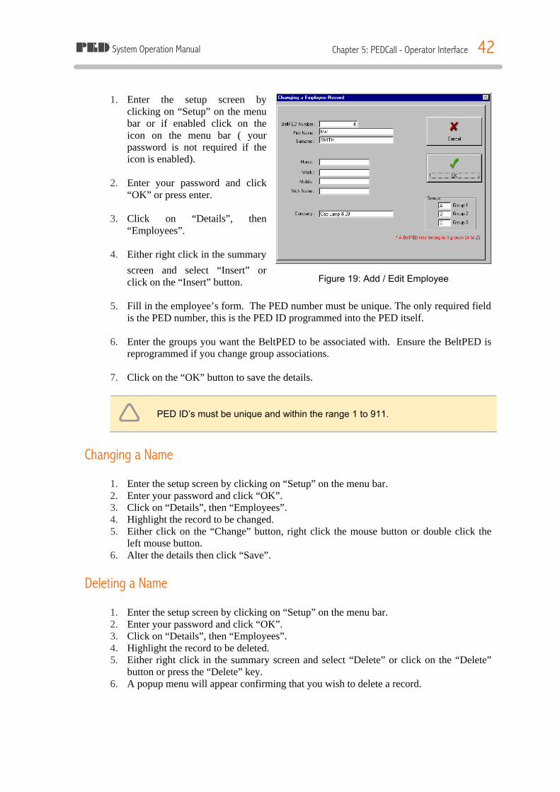
1. Enter the setup screen by clicking on “Setup” on the menu bar or if enabled click on the icon on the menu bar ( your password is not required if the icon is enabled).
2. Enter your password and click
“OK” or press enter. 3. Click on “Details”, then
“Employees”. 4. Either right click in the summary
screen and select “Insert” or click on the “Insert” button.
5. Fill in the employee’s form. The PED number must be unique. The only required field
is the PED number, this is the PED ID programmed into the PED itself. 6. Enter the groups you want the BeltPED to be associated with. Ensure the BeltPED is
reprogrammed if you change group associations. 7. Click on the “OK” button to save the details.
ê PED ID’s must be unique and within the range 1 to 911.
Changing a Name 1. Enter the setup screen by clicking on “Setup” on the menu bar. 2. Enter your password and click “OK”. 3. Click on “Details”, then “Employees”. 4. Highlight the record to be changed. 5. Either click on the “Change” button, right click the mouse button or double click the
left mouse button. 6. Alter the details then click “Save”.
Deleting a Name 1. Enter the setup screen by clicking on “Setup” on the menu bar. 2. Enter your password and click “OK”. 3. Click on “Details”, then “Employees”. 4. Highlight the record to be deleted. 5. Either right click in the summary screen and select “Delete” or click on the “Delete”
button or press the “Delete” key. 6. A popup menu will appear confirming that you wish to delete a record.
Figure 19: Add / Edit Employee

System Operation Manual Chapter 5: PEDCall - Operator Interface 43
Groups
ê If you change the group you will need to re-program the BeltPED to reflect the changes in the groups.
Each PED has an individual ID and can belong to three (3) groups. Each group is represented by a letter. (PED 25 Group A, B & C). When sending a message to Group A, only the PED receivers programmed with group A will receive the message. ** It is only possible to send to 1 group at a time. * Employees are assigned groups in the employee details file.
Editing Group Names 1. Enter the setup screen by clicking on “Setup” on the menu bar. 2. Enter your password and click “OK”. 3. Click on “Details”, then “Groups”. 4. Highlight the Group you want to edit. 5. Type the new group name and click on the “Save” button.
Figure 20: Edit View Groups

System Operation Manual Chapter 5: PEDCall - Operator Interface 44
ControlPED
Assign ControlPED Names and Colours 1. Enter the setup screen by clicking on “Setup” on
the menu bar. 2. Enter your password and click “OK”. 3. Click on “Details”, then “ControlPEDs”. 4. Highlight the ControlPED you want to assign a
name. 5. Click on the “Change” button or right click the
mouse button and select “Change” from the menu or double click the left mouse button.
6. Enter the name you want to assign to the ControlPED.
7. Click on the “Colour” button. 8. Select the colour for the background.
9. Click “OK” to accept the colour 10. Click on “Save” when you are finished.
BlastPED
Assign BlastPED ID 1. Enter the setup screen by clicking on “Setup” on the menu bar. 2. Enter your password and click “OK”. 3. Click on “Details”, then “BlastPED”. 4. Highlight the BlastPED you want to assign an ID. 5. Click on the “Change” button or right click the mouse button and select “Change” from
the menu or double click the left mouse button. 6. Enter the ID you want to assign to the BlastPED. 7. Click on “Save” when you are finished.
Reoccurring Messages Reoccurring Messages are user pre-defined messages to be automatically entered by the computer, for example test and safety messages can be programmed to occur at certain times on certain days, hence the operator need not enter this information continually. The schedule may be blank if there are no current entries, alternatively you may need to scan through the list with the cursor keys when there are numerous entries.
Figure 21: ControlPED Edit
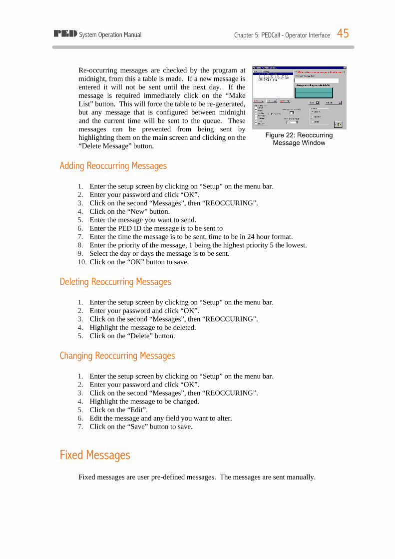
System Operation Manual Chapter 5: PEDCall - Operator Interface 45
Figure 22: Reoccurring Message Window
Re-occurring messages are checked by the program at midnight, from this a table is made. If a new message is entered it will not be sent until the next day. If the message is required immediately click on the “Make List” button. This will force the table to be re-generated, but any message that is configured between midnight and the current time will be sent to the queue. These messages can be prevented from being sent by highlighting them on the main screen and clicking on the “Delete Message” button.
Adding Reoccurring Messages 1. Enter the setup screen by clicking on “Setup” on the menu bar. 2. Enter your password and click “OK”. 3. Click on the second “Messages”, then “REOCCURING”. 4. Click on the “New” button. 5. Enter the message you want to send. 6. Enter the PED ID the message is to be sent to 7. Enter the time the message is to be sent, time to be in 24 hour format. 8. Enter the priority of the message, 1 being the highest priority 5 the lowest. 9. Select the day or days the message is to be sent. 10. Click on the “OK” button to save.
Deleting Reoccurring Messages 1. Enter the setup screen by clicking on “Setup” on the menu bar. 2. Enter your password and click “OK”. 3. Click on the second “Messages”, then “REOCCURING”. 4. Highlight the message to be deleted. 5. Click on the “Delete” button.
Changing Reoccurring Messages 1. Enter the setup screen by clicking on “Setup” on the menu bar. 2. Enter your password and click “OK”. 3. Click on the second “Messages”, then “REOCCURING”. 4. Highlight the message to be changed. 5. Click on the “Edit”. 6. Edit the message and any field you want to alter. 7. Click on the “Save” button to save.
Fixed Messages Fixed messages are user pre-defined messages. The messages are sent manually.

System Operation Manual Chapter 5: PEDCall - Operator Interface 46
Adding Fixed Messages 1. Enter the setup screen by clicking on
“Setup” on the menu bar. 2. Enter your password and click “OK”. 3. Click on the second “Messages”, then
“Fixed”. 4. Click on the “New” button. 5. Enter the message. 6. Click on “Save” to save the message.
Changing Fixed Messages 1. Enter the setup screen by clicking on “Setup” on the menu bar. 2. Enter your password and click “OK”. 3. Click on the second “Messages”, then “Fixed”. 4. Highlight the message to change. 5. Click on the “Edit” button. 6. Edit the message. 7. Click on “Save” to save the message.
Deleting Fixed Messages 1. Enter the setup screen by clicking on “Setup” on the menu bar. 2. Enter your password and click “OK”. 3. Click on the second “Messages”, then “Fixed”. 4. Highlight the message to delete. 5. Click on the “Delete” button or right click the mouse button and select “Delete” from
the menu or press the “Delete” key.
Reprogram ID
BeltPED 1. Ensure the BeltPED is receiving. 2. Click on “Reprogram” button. 3. Enter the current BeltPED ID number. 4. Enter the new BeltPED ID number. 5. Enter the group letters to be associated with the new BeltPED ID. 6. Click on “Reprogram a BeltPED”. 7. The employees details screen will pop-up with the details from the old PED ID
number, either click on “OK” or edit the details then click on “OK”. 8. Message will then be processed and sent as a normal message.
Figure 23: Fixed Message
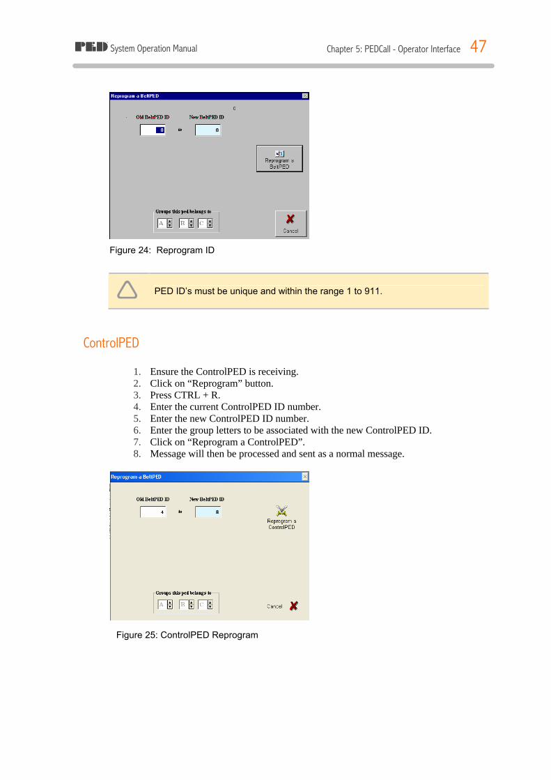
System Operation Manual Chapter 5: PEDCall - Operator Interface 47
Figure 24: Reprogram ID
ê PED ID’s must be unique and within the range 1 to 911.
ControlPED
1. Ensure the ControlPED is receiving. 2. Click on “Reprogram” button. 3. Press CTRL + R. 4. Enter the current ControlPED ID number. 5. Enter the new ControlPED ID number. 6. Enter the group letters to be associated with the new ControlPED ID. 7. Click on “Reprogram a ControlPED”. 8. Message will then be processed and sent as a normal message.
Figure 25: ControlPED Reprogram
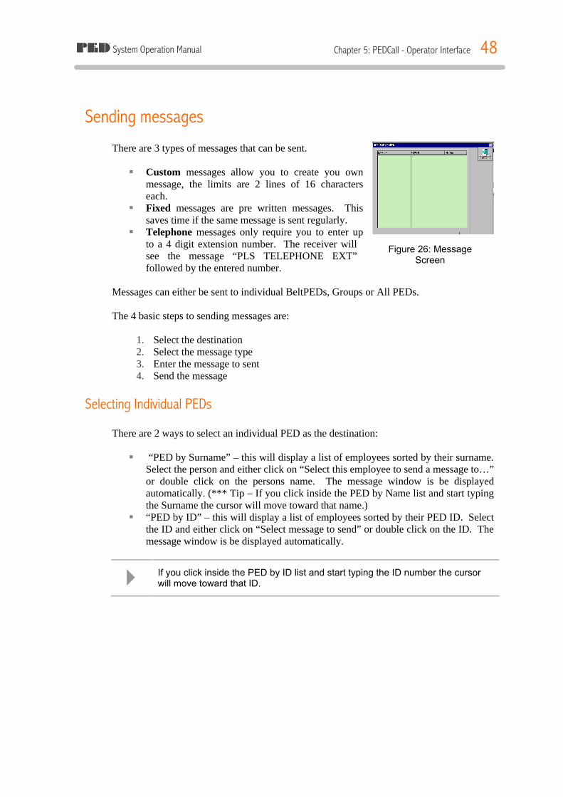
System Operation Manual Chapter 5: PEDCall - Operator Interface 48
Sending messages There are 3 types of messages that can be sent. § Custom messages allow you to create you own
message, the limits are 2 lines of 16 characters each.
§ Fixed messages are pre written messages. This saves time if the same message is sent regularly.
§ Telephone messages only require you to enter up to a 4 digit extension number. The receiver will see the message “PLS TELEPHONE EXT” followed by the entered number.
Messages can either be sent to individual BeltPEDs, Groups or All PEDs. The 4 basic steps to sending messages are:
1. Select the destination 2. Select the message type 3. Enter the message to sent 4. Send the message
Selecting Individual PEDs There are 2 ways to select an individual PED as the destination: § “PED by Surname” – this will display a list of employees sorted by their surname.
Select the person and either click on “Select this employee to send a message to…” or double click on the persons name. The message window is be displayed automatically. (*** Tip – If you click inside the PED by Name list and start typing the Surname the cursor will move toward that name.)
§ “PED by ID” – this will display a list of employees sorted by their PED ID. Select the ID and either click on “Select message to send” or double click on the ID. The message window is be displayed automatically.
4 If you click inside the PED by ID list and start typing the ID number the cursor will move toward that ID.
Figure 26: Message Screen
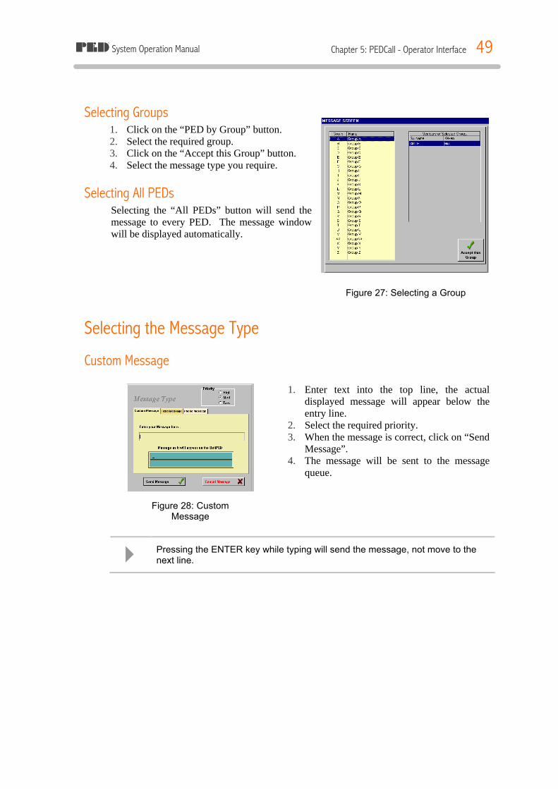
System Operation Manual Chapter 5: PEDCall - Operator Interface 49
Selecting Groups 1. Click on the “PED by Group” button. 2. Select the required group. 3. Click on the “Accept this Group” button. 4. Select the message type you require.
Selecting All PEDs Selecting the “All PEDs” button will send the message to every PED. The message window will be displayed automatically.
Selecting the Message Type
Custom Message
1. Enter text into the top line, the actual displayed message will appear below the entry line.
2. Select the required priority. 3. When the message is correct, click on “Send
Message”. 4. The message will be sent to the message
queue.
4 Pressing the ENTER key while typing will send the message, not move to the next line.
Figure 27: Selecting a Group
Figure 28: Custom Message
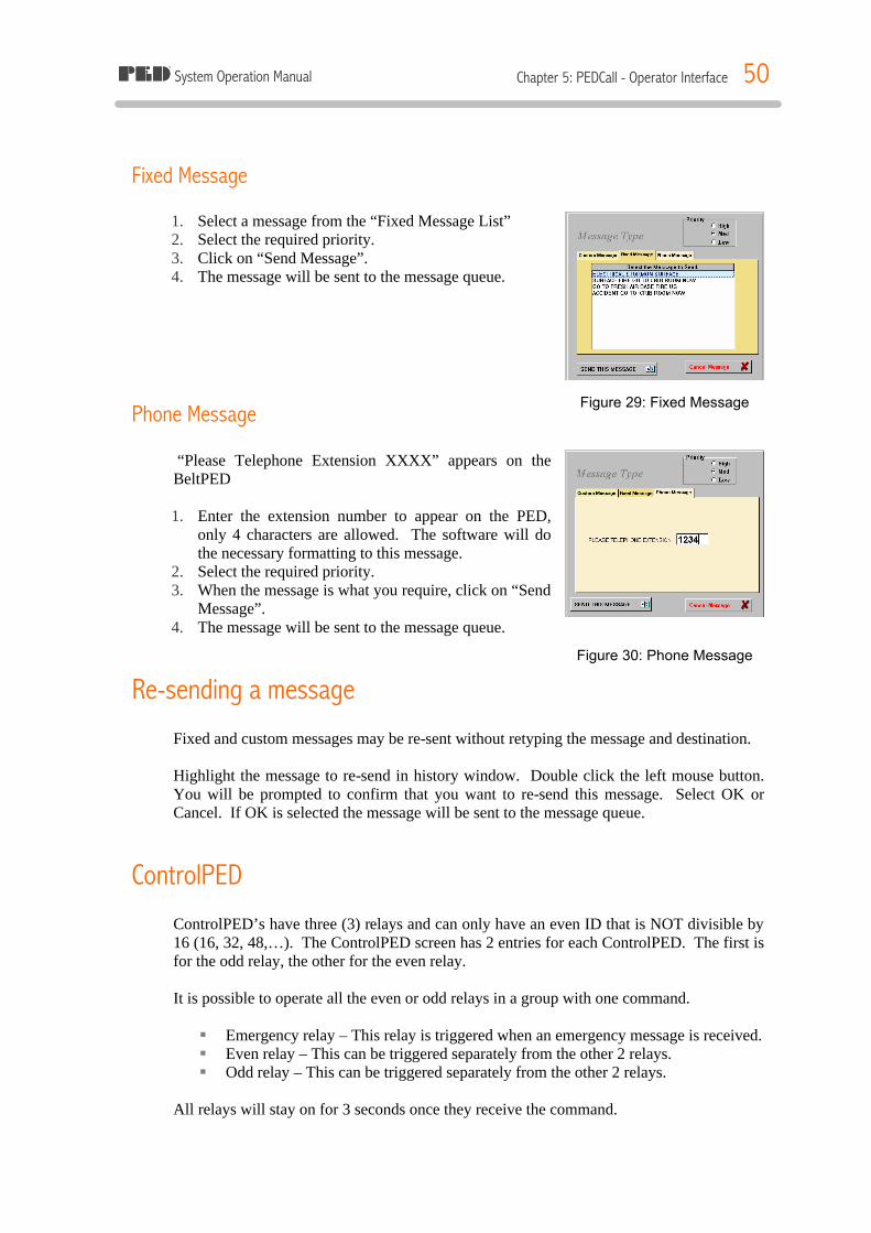
System Operation Manual Chapter 5: PEDCall - Operator Interface 50
Fixed Message 1. Select a message from the “Fixed Message List” 2. Select the required priority. 3. Click on “Send Message”. 4. The message will be sent to the message queue.
Phone Message “Please Telephone Extension XXXX” appears on the BeltPED 1. Enter the extension number to appear on the PED,
only 4 characters are allowed. The software will do the necessary formatting to this message.
2. Select the required priority. 3. When the message is what you require, click on “Send
Message”. 4. The message will be sent to the message queue.
Re-sending a message Fixed and custom messages may be re-sent without retyping the message and destination. Highlight the message to re-send in history window. Double click the left mouse button. You will be prompted to confirm that you want to re-send this message. Select OK or Cancel. If OK is selected the message will be sent to the message queue.
ControlPED ControlPED’s have three (3) relays and can only have an even ID that is NOT divisible by 16 (16, 32, 48,…). The ControlPED screen has 2 entries for each ControlPED. The first is for the odd relay, the other for the even relay. It is possible to operate all the even or odd relays in a group with one command. § Emergency relay – This relay is triggered when an emergency message is received. § Even relay – This can be triggered separately from the other 2 relays. § Odd relay – This can be triggered separately from the other 2 relays.
All relays will stay on for 3 seconds once they receive the command.
Figure 29: Fixed Message
Figure 30: Phone Message
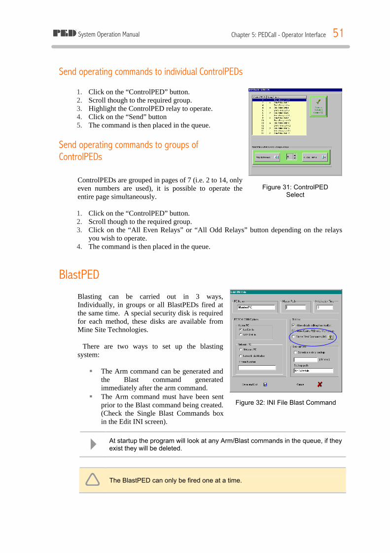
System Operation Manual Chapter 5: PEDCall - Operator Interface 51
Send operating commands to individual ControlPEDs 1. Click on the “ControlPED” button. 2. Scroll though to the required group. 3. Highlight the ControlPED relay to operate. 4. Click on the “Send” button 5. The command is then placed in the queue.
Send operating commands to groups of ControlPEDs
ControlPEDs are grouped in pages of 7 (i.e. 2 to 14, only even numbers are used), it is possible to operate the entire page simultaneously. 1. Click on the “ControlPED” button. 2. Scroll though to the required group. 3. Click on the “All Even Relays” or “All Odd Relays” button depending on the relays
you wish to operate. 4. The command is then placed in the queue.
BlastPED Blasting can be carried out in 3 ways, Individually, in groups or all BlastPEDs fired at the same time. A special security disk is required for each method, these disks are available from Mine Site Technologies. There are two ways to set up the blasting system:
§ The Arm command can be generated and
the Blast command generated immediately after the arm command.
§ The Arm command must have been sent prior to the Blast command being created. (Check the Single Blast Commands box in the Edit INI screen).
ê The BlastPED can only be fired one at a time.
4 At startup the program will look at any Arm/Blast commands in the queue, if they exist they will be deleted.
Figure 31: ControlPED Select
Figure 32: INI File Blast Command
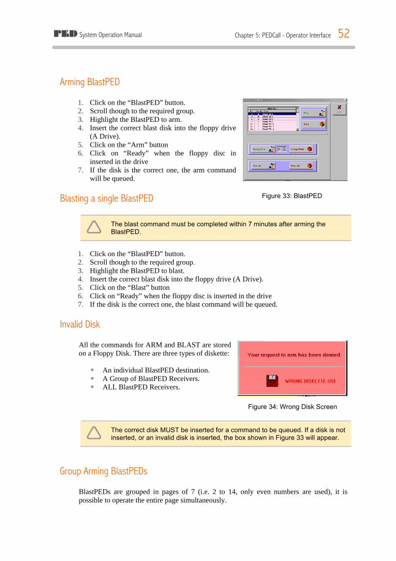
System Operation Manual Chapter 5: PEDCall - Operator Interface 52
Arming BlastPED 1. Click on the “BlastPED” button. 2. Scroll though to the required group. 3. Highlight the BlastPED to arm. 4. Insert the correct blast disk into the floppy drive
(A Drive). 5. Click on the “Arm” button 6. Click on “Ready” when the floppy disc in
inserted in the drive 7. If the disk is the correct one, the arm command
will be queued.
Blasting a single BlastPED
ê The blast command must be completed within 7 minutes after arming the BlastPED.
1. Click on the “BlastPED” button. 2. Scroll though to the required group. 3. Highlight the BlastPED to blast. 4. Insert the correct blast disk into the floppy drive (A Drive). 5. Click on the “Blast” button 6. Click on “Ready” when the floppy disc is inserted in the drive 7. If the disk is the correct one, the blast command will be queued.
Invalid Disk All the commands for ARM and BLAST are stored on a Floppy Disk. There are three types of diskette: § An individual BlastPED destination. § A Group of BlastPED Receivers. § ALL BlastPED Receivers.
ê The correct disk MUST be inserted for a command to be queued. If a disk is not inserted, or an invalid disk is inserted, the box shown in Figure 33 will appear.
Group Arming BlastPEDs BlastPEDs are grouped in pages of 7 (i.e. 2 to 14, only even numbers are used), it is possible to operate the entire page simultaneously.
Figure 33: BlastPED
Figure 34: Wrong Disk Screen
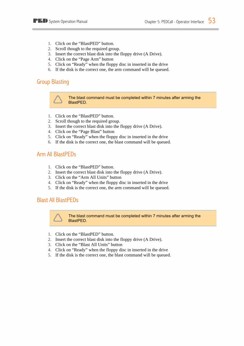
System Operation Manual Chapter 5: PEDCall - Operator Interface 53
1. Click on the “BlastPED” button. 2. Scroll though to the required group. 3. Insert the correct blast disk into the floppy drive (A Drive). 4. Click on the “Page Arm” button 5. Click on “Ready” when the floppy disc in inserted in the drive 6. If the disk is the correct one, the arm command will be queued.
Group Blasting
ê The blast command must be completed within 7 minutes after arming the BlastPED.
1. Click on the “BlastPED” button. 2. Scroll though to the required group. 3. Insert the correct blast disk into the floppy drive (A Drive). 4. Click on the “Page Blast” button 5. Click on “Ready” when the floppy disc in inserted in the drive 6. If the disk is the correct one, the blast command will be queued.
Arm All BlastPEDs 1. Click on the “BlastPED” button. 2. Insert the correct blast disk into the floppy drive (A Drive). 3. Click on the “Arm All Units” button 4. Click on “Ready” when the floppy disc in inserted in the drive 5. If the disk is the correct one, the arm command will be queued.
Blast All BlastPEDs
ê The blast command must be completed within 7 minutes after arming the BlastPED.
1. Click on the “BlastPED” button. 2. Insert the correct blast disk into the floppy drive (A Drive). 3. Click on the “Blast All Units” button 4. Click on “Ready” when the floppy disc in inserted in the drive 5. If the disk is the correct one, the blast command will be queued.
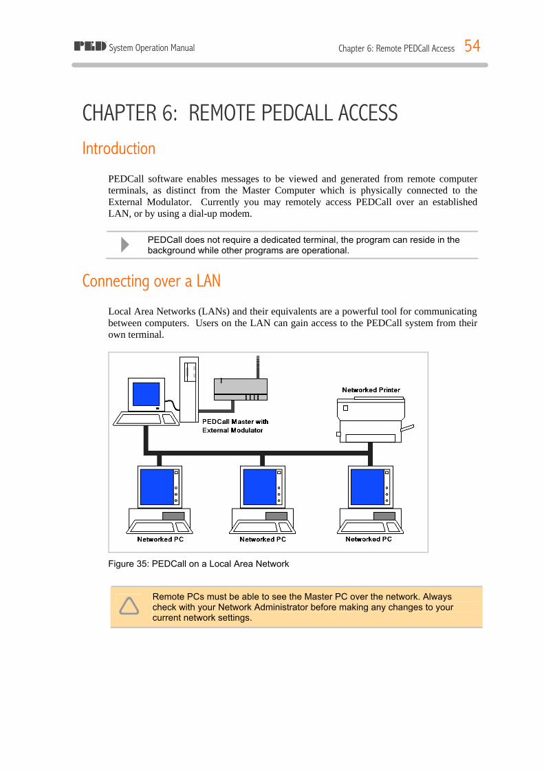
System Operation Manual Chapter 6: Remote PEDCall Access 54
CHAPTER 6: REMOTE PEDCALL ACCESS Introduction
PEDCall software enables messages to be viewed and generated from remote computer terminals, as distinct from the Master Computer which is physically connected to the External Modulator. Currently you may remotely access PEDCall over an established LAN, or by using a dial-up modem.
4 PEDCall does not require a dedicated terminal, the program can reside in the background while other programs are operational.
Connecting over a LAN Local Area Networks (LANs) and their equivalents are a powerful tool for communicating between computers. Users on the LAN can gain access to the PEDCall system from their own terminal.
Figure 35: PEDCall on a Local Area Network
ê Remote PCs must be able to see the Master PC over the network. Always check with your Network Administrator before making any changes to your current network settings.
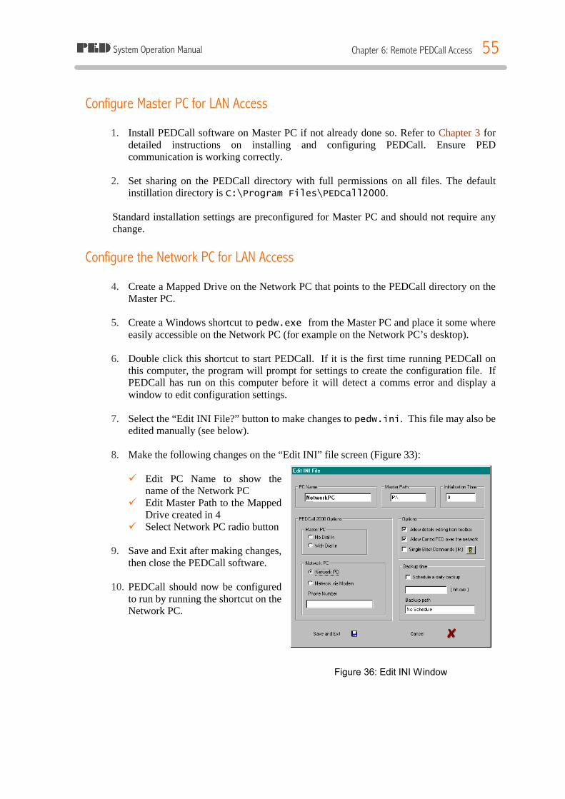
System Operation Manual Chapter 6: Remote PEDCall Access 55
Configure Master PC for LAN Access 1. Install PEDCall software on Master PC if not already done so. Refer to Chapter 3 for
detailed instructions on installing and configuring PEDCall. Ensure PED communication is working correctly.
2. Set sharing on the PEDCall directory with full permissions on all files. The default
instillation directory is C:\Program Files\PEDCall2000. Standard installation settings are preconfigured for Master PC and should not require any change.
Configure the Network PC for LAN Access 4. Create a Mapped Drive on the Network PC that points to the PEDCall directory on the
Master PC. 5. Create a Windows shortcut to pedw.exe from the Master PC and place it some where
easily accessible on the Network PC (for example on the Network PC’s desktop). 6. Double click this shortcut to start PEDCall. If it is the first time running PEDCall on
this computer, the program will prompt for settings to create the configuration file. If PEDCall has run on this computer before it will detect a comms error and display a window to edit configuration settings.
7. Select the “Edit INI File?” button to make changes to pedw.ini. This file may also be
edited manually (see below). 8. Make the following changes on the “Edit INI” file screen (Figure 33): ü Edit PC Name to show the
name of the Network PC ü Edit Master Path to the Mapped
Drive created in 4 ü Select Network PC radio button
9. Save and Exit after making changes,
then close the PEDCall software. 10. PEDCall should now be configured
to run by running the shortcut on the Network PC.
Figure 36: Edit INI Window

System Operation Manual Chapter 6: Remote PEDCall Access 56
Connecting over a Dial-up Modem PEDCall can be accessed remotely from a PC connected directly to the Master PC via a dial-up Modem.
Configuring the Master PC for Dial-up Access 1. Install PEDCall software on Master PC if not already done so. Refer to Chapter 3 for
detailed instructions on installing and configuring PEDCall. Ensure PED communication is working correctly.
2. Install and configure a modem to the Master PC. Refer to you modem and operating
system user manual for instructions. 3. Modify your INI file in the Configuration Menu of PEDCall. You may need to select
Setup from the menu and enter the system password before the Configuration Menu is available.
4. Change the Master PC so that “MasterPC with dial-in” is selected. Save changes. 5. Modify Comms from the Configuration Menu. 6. Select the Modem tab at the top of the Comms Edit Window. 7. Select the appropriate ComPort that your modem is installed on. All other settings
should be acceptable, only change if needed. Select OK to confirm and exit the Coms Edit Menu.
8. Restart PEDCall to allow changes to take affect.
Configuring the Remote PC for Dial-up Access 9. Install PEDCall Software on Remote PC from CD-ROM provided.
10. Install and configure a modem to the Remote PC. Refer to you modem and operating
system user manual for instructions.
11. Modify your INI file in the Configuration Menu of PEDCall. You may need to select Setup from the menu and enter the system password before the Configuration Menu is available.
12. Change the Master PC so that “Networked via Modem” is selected. Save changes. 13. Modify Comms from the Configuration Menu.
14. Select the Modem tab at the top of the Comms Edit Window.
15. Select the appropriate ComPort that your modem is installed on. All other settings
should be acceptable, only change if needed. Select OK to confirm and exit the Coms Edit Menu.
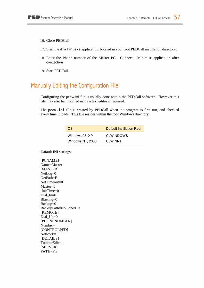
System Operation Manual Chapter 6: Remote PEDCall Access 57
16. Close PEDCall
17. Start the dialin.exe application, located in your root PEDCall instillation directory.
18. Enter the Phone number of the Master PC. Connect. Minimise application after
connection
19. Start PEDCall.
Manually Editing the Configuration File Configuring the pedw.ini file is usually done within the PEDCall software. However this file may also be modified using a text editor if required. The pedw.ini file is created by PEDCall when the program is first run, and checked every time it loads. This file resides within the root Windows directory.
OS Default Instillation Root
Windows 98, XP C:/WINDOWS
Windows NT, 2000 C:/WINNT
Dafault INI settings: [PCNAME] Name=Master [MASTER] NetLog=0 NetPath=F NetTimeout=0 Master=1 iInitTime=0 Dial_In=0 Blasting=0 Backup=0 BackupPath=No Schedule [REMOTE] Dial_Up=0 [PHONENUMBER] Number= [CONTROLPED] Network=1 [DETAILS] ToolbarEdit=1 [SERVER] PATH=P:\

System Operation Manual Chapter 7: Mine Monitoring - Linking Systems 58
CHAPTER 7: MINE MONITORING - LINKING SYSTEMS
Introduction Mine Monitoring is a very powerful and flexible software system designed to provide message generation in response to an alarm conditions. Mine Monitoring can be configured to monitor an unlimited number of inputs or, alternatively, only monitor a handful of alarms. The interface operates in the background, thus allowing operators to perform other duties while PEDCall monitors the alarms. The messages that are generated when an alarm condition occurs are all programmable by mine personnel. The destinations of the messages are also programmable. This allows Mine Monitoring to inform certain relevant people to the alarm condition. If the alarm was indicative of a dangerous situation then ALL PEDs could be informed.
Potential situations where Mine Monitoring is ideal MINE MONITORING variations are unlimited, some examples are below: § Surface Fan failure § Conveyor belt failure § Gas level detection alert § Water level detection alert § Total monitoring of all mine sensors
Installation of Mine Monitoring The hardware requirements for Mine Monitoring vary depending on the quantity of inputs required to monitor. For small applications, the hardware would typically consist of a Board installed in the PEDCall computer, it would monitor relay contacts. The messages would be generated when the relay contacts changed status. The internal board can handle approximately 16 inputs, on larger installations. When monitoring detects an abnormal condition, a message is sent to PEDCall. PEDCall accepts the message and sends it out to the designated receiver exactly as a person had entered it.
4 UNDER DEVELOPMENT

System Operation Manual Chapter 7: Mine Monitoring - Linking Systems 59
PEDCall allows a range of sophisticated interfaces to alarms to be undertaken, such as through Citect’s SCADA software. This can offer a powerful management and safety tool to ensure monitored information is relayed underground, where it needs to be available. The software also has the capability of generating Control PED messages. The advantage of this is that if certain alarm conditions occur, apart from notifying PED users, equipment can also be turned ON or OFF.
4 Mine Monitoring closes the information loop, by connecting the PED system , key personnel can be notified within minutes of a failure or dangerous situation. The time savings from this system can be enormous.
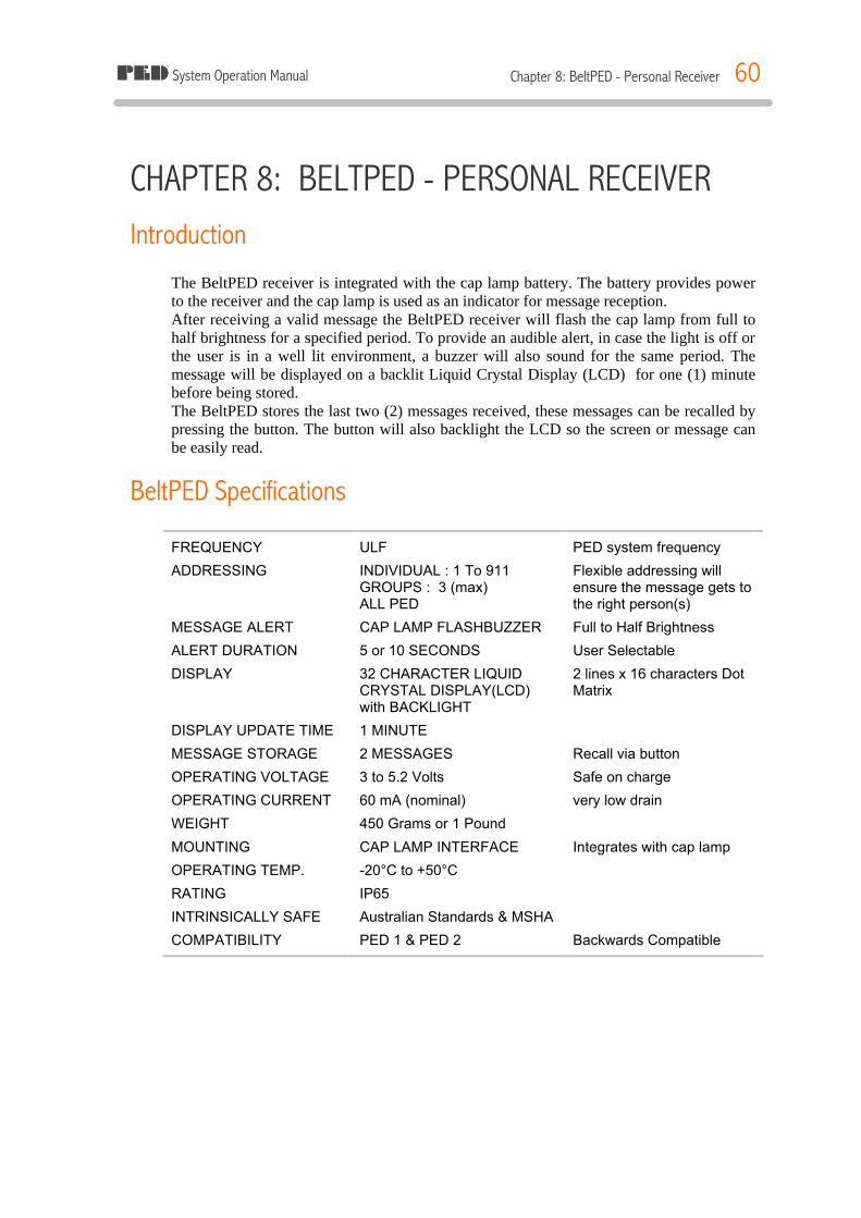
System Operation Manual Chapter 8: BeltPED - Personal Receiver 60
CHAPTER 8: BELTPED - PERSONAL RECEIVER Introduction
The BeltPED receiver is integrated with the cap lamp battery. The battery provides power to the receiver and the cap lamp is used as an indicator for message reception. After receiving a valid message the BeltPED receiver will flash the cap lamp from full to half brightness for a specified period. To provide an audible alert, in case the light is off or the user is in a well lit environment, a buzzer will also sound for the same period. The message will be displayed on a backlit Liquid Crystal Display (LCD) for one (1) minute before being stored. The BeltPED stores the last two (2) messages received, these messages can be recalled by pressing the button. The button will also backlight the LCD so the screen or message can be easily read.
BeltPED Specifications
FREQUENCY ULF PED system frequency
ADDRESSING INDIVIDUAL : 1 To 911 GROUPS : 3 (max) ALL PED
Flexible addressing will ensure the message gets to the right person(s)
MESSAGE ALERT CAP LAMP FLASHBUZZER Full to Half Brightness
ALERT DURATION 5 or 10 SECONDS User Selectable
DISPLAY 32 CHARACTER LIQUID CRYSTAL DISPLAY(LCD) with BACKLIGHT
2 lines x 16 characters Dot Matrix
DISPLAY UPDATE TIME 1 MINUTE
MESSAGE STORAGE 2 MESSAGES Recall via button
OPERATING VOLTAGE 3 to 5.2 Volts Safe on charge
OPERATING CURRENT 60 mA (nominal) very low drain
WEIGHT 450 Grams or 1 Pound
MOUNTING CAP LAMP INTERFACE Integrates with cap lamp
OPERATING TEMP. -20°C to +50°C
RATING IP65
INTRINSICALLY SAFE Australian Standards & MSHA
COMPATIBILITY PED 1 & PED 2 Backwards Compatible
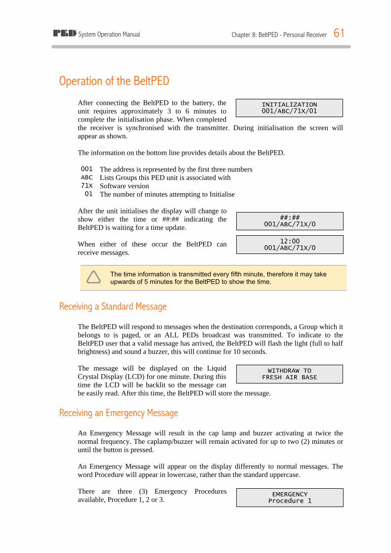
System Operation Manual Chapter 8: BeltPED - Personal Receiver 61
INITIALIZATION 001/ABC/71X/01
##:## 001/ABC/71X/0
12:00 001/ABC/71X/0
WITHDRAW TO FRESH AIR BASE
EMERGENCY Procedure 1
Operation of the BeltPED After connecting the BeltPED to the battery, the unit requires approximately 3 to 6 minutes to complete the initialisation phase. When completed the receiver is synchronised with the transmitter. During initialisation the screen will appear as shown. The information on the bottom line provides details about the BeltPED. 001 The address is represented by the first three numbers ABC Lists Groups this PED unit is associated with 71X Software version 01 The number of minutes attempting to Initialise
After the unit initialises the display will change to show either the time or ##:## indicating the BeltPED is waiting for a time update. When either of these occur the BeltPED can receive messages.
ê The time information is transmitted every fifth minute, therefore it may take upwards of 5 minutes for the BeltPED to show the time.
Receiving a Standard Message The BeltPED will respond to messages when the destination corresponds, a Group which it belongs to is paged, or an ALL PEDs broadcast was transmitted. To indicate to the BeltPED user that a valid message has arrived, the BeltPED will flash the light (full to half brightness) and sound a buzzer, this will continue for 10 seconds. The message will be displayed on the Liquid Crystal Display (LCD) for one minute. During this time the LCD will be backlit so the message can be easily read. After this time, the BeltPED will store the message.
Receiving an Emergency Message An Emergency Message will result in the cap lamp and buzzer activating at twice the normal frequency. The caplamp/buzzer will remain activated for up to two (2) minutes or until the button is pressed. An Emergency Message will appear on the display differently to normal messages. The word Procedure will appear in lowercase, rather than the standard uppercase.
There are three (3) Emergency Procedures available, Procedure 1, 2 or 3.
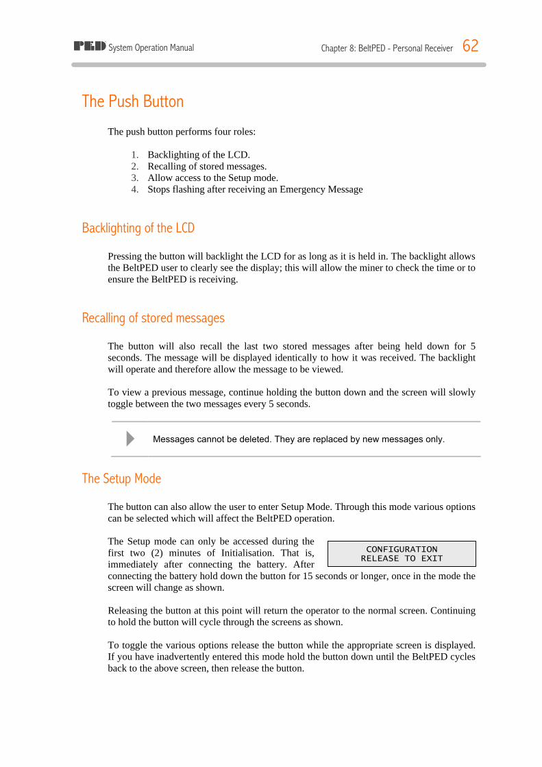
System Operation Manual Chapter 8: BeltPED - Personal Receiver 62
CONFIGURATION RELEASE TO EXIT
The Push Button The push button performs four roles:
1. Backlighting of the LCD. 2. Recalling of stored messages. 3. Allow access to the Setup mode. 4. Stops flashing after receiving an Emergency Message
Backlighting of the LCD Pressing the button will backlight the LCD for as long as it is held in. The backlight allows the BeltPED user to clearly see the display; this will allow the miner to check the time or to ensure the BeltPED is receiving.
Recalling of stored messages The button will also recall the last two stored messages after being held down for 5 seconds. The message will be displayed identically to how it was received. The backlight will operate and therefore allow the message to be viewed. To view a previous message, continue holding the button down and the screen will slowly toggle between the two messages every 5 seconds.
4 Messages cannot be deleted. They are replaced by new messages only.
The Setup Mode The button can also allow the user to enter Setup Mode. Through this mode various options can be selected which will affect the BeltPED operation. The Setup mode can only be accessed during the first two (2) minutes of Initialisation. That is, immediately after connecting the battery. After connecting the battery hold down the button for 15 seconds or longer, once in the mode the screen will change as shown. Releasing the button at this point will return the operator to the normal screen. Continuing to hold the button will cycle through the screens as shown. To toggle the various options release the button while the appropriate screen is displayed. If you have inadvertently entered this mode hold the button down until the BeltPED cycles back to the above screen, then release the button.

System Operation Manual Chapter 8: BeltPED - Personal Receiver 63
FLASH TIME = 10 S RELEASE TO ALTER
SERVICE WARN = OFF RELEASE TO ALTER
PED 3 MODE = ON RELEASE TO ALTER
Flash time can be toggled between 5 seconds or 10 seconds. Flash Time determines the length of time the unit will flash the light and sound the buzzer when a message is received. Service Warn(ing) toggles the BeltPEDs feature that alerts the user that the BeltPED has lost synchronisation for longer than 10 minutes. Normally the words NO SERVICE are displayed on a BeltPED in the event it has lost signal, but if the option is set to ON, the flash / buzzer will also operate after 10 minutes.
4 The Service Warning feature is set to off by default.
PED 3 Mode will cause the BeltPED to alter the internal software version. This option is normally set to ON. For mines gradually implementing BeltPEDs it is set to OFF, that is it should only be used at mines that still maintain a mixture of old style Receivers (PED2 or less).
Installing the BeltPED Receiver Tools required:
ü 1 off 2.5 mm "T" Bar Hex key ü 1 off 2.0 mm Hex Key ü 1 off 150mm straight Screwdriver ü 1 off Oldham terminal Key ü Liquid detergent ü Degreaser ü Anti-Static Mat ü Stiff Bristled Brush ü Wiper Cloth ü PED Transmission Reception
The BeltPED Receiver is designed to be fully integrated with the cap lamp and battery. The BeltPED circuitry is arranged so that it offers no resistance to the charging of the battery. The method of charging and connection to the charger remain the same. To install the BeltPED proceed as follows: 1. Read the Assembly Instructions on the inside of the carton lid.
2. Disconnect the existing Cap Lamp and Battery arrangement. Remove the Top Cover from Cap Lamp Cord. The battery and cap lamp should be in good condition, if they are suspect, replace them.
3. Clean the battery terminals and degrease the positive terminal side of the battery. 4. Remove the cover strip off the Adaptor Plate adhesive.
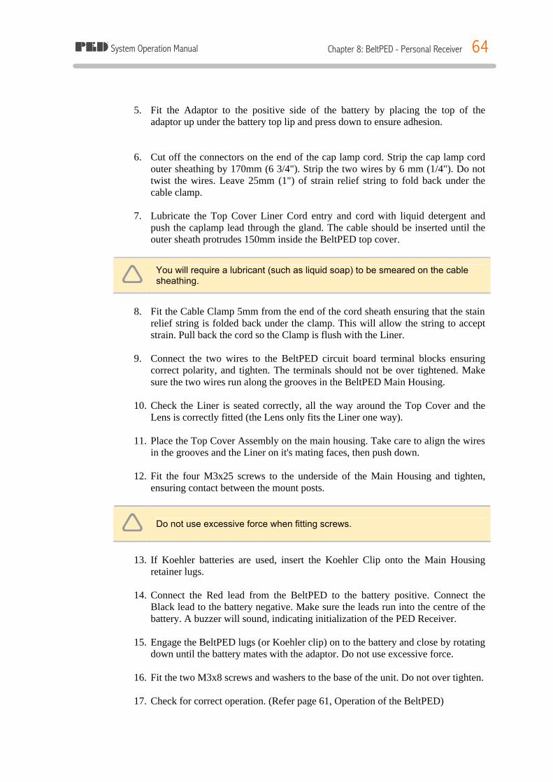
System Operation Manual Chapter 8: BeltPED - Personal Receiver 64
5. Fit the Adaptor to the positive side of the battery by placing the top of the
adaptor up under the battery top lip and press down to ensure adhesion.
6. Cut off the connectors on the end of the cap lamp cord. Strip the cap lamp cord
outer sheathing by 170mm (6 3/4"). Strip the two wires by 6 mm (1/4"). Do not twist the wires. Leave 25mm (1") of strain relief string to fold back under the cable clamp.
7. Lubricate the Top Cover Liner Cord entry and cord with liquid detergent and
push the caplamp lead through the gland. The cable should be inserted until the outer sheath protrudes 150mm inside the BeltPED top cover.
ê You will require a lubricant (such as liquid soap) to be smeared on the cable sheathing.
8. Fit the Cable Clamp 5mm from the end of the cord sheath ensuring that the stain
relief string is folded back under the clamp. This will allow the string to accept strain. Pull back the cord so the Clamp is flush with the Liner.
9. Connect the two wires to the BeltPED circuit board terminal blocks ensuring
correct polarity, and tighten. The terminals should not be over tightened. Make sure the two wires run along the grooves in the BeltPED Main Housing.
10. Check the Liner is seated correctly, all the way around the Top Cover and the
Lens is correctly fitted (the Lens only fits the Liner one way).
11. Place the Top Cover Assembly on the main housing. Take care to align the wires in the grooves and the Liner on it's mating faces, then push down.
12. Fit the four M3x25 screws to the underside of the Main Housing and tighten,
ensuring contact between the mount posts.
ê Do not use excessive force when fitting screws.
13. If Koehler batteries are used, insert the Koehler Clip onto the Main Housing
retainer lugs.
14. Connect the Red lead from the BeltPED to the battery positive. Connect the Black lead to the battery negative. Make sure the leads run into the centre of the battery. A buzzer will sound, indicating initialization of the PED Receiver.
15. Engage the BeltPED lugs (or Koehler clip) on to the battery and close by rotating
down until the battery mates with the adaptor. Do not use excessive force.
16. Fit the two M3x8 screws and washers to the base of the unit. Do not over tighten.
17. Check for correct operation. (Refer page 61, Operation of the BeltPED)
System Operation Manual Chapter 8: BeltPED - Personal Receiver 65
BeltPED Maintenance Maintenance of the BeltPED Receiver is limited by the relevant Approval conditions (for Coal Mines) and the competency of repair staff to repair at PCA level in Metal Mines. These instructions enable trained staff to complete the following operations. § Replace Headpiece cord. § Replace Lens. § Replace Liner Assembly. § Replace Top Cover. § Replace LCD PCA. § Replace Receiver PCA. § Replace Main Housing.
Tools required:
ü 1 off 2.5mm "T" Bar Hex Key. ü 1 off 2.0mm Hex Key. ü 1 off 150mm Straight Screwdriver. ü 1 off Oldham Terminal Key. ü Liquid Detergent. ü Degreaser. (Methylated Spirit) ü Anti static mat. ü Stiff Bristled Brush. ü Wiper cloth. ü PED transmission reception at the work area.
BeltPED/Caplamp Dismantling 1. Battery Removal 1.1. Brush the unit to remove any accumulated dirt. 1.2. Remove the two M2.5 x 8 button head screws and washers from under the Main
Housing near the bottom of the battery. 1.3. Pull the housing from the bottom of the battery and swing away. Loosen the battery
wires and remove. 1.4. Lever the Koehler Clip off the underside of the Main Housing (strain relief end) if
attached. 2. BeltPED Dismantling 2.1. Remove the four M3 x 25 Capscrews from under the BeltPED Main Housing. The
Top Cover is now free to lift off. Undo the terminal screws of the cap lamp wires on the Receiver PCA.
2.2. To remove the cord from the Top Cover, undo the two Phillips head screws retaining the cable clamp and lift off the cord.
2.3. Pull the cord through the Liner strain relief. 2.4. Pull the Liner assembly from the top cover. Remove the "O" Ring, Diaphragm and
Lens from the Liner. 2.5. To remove the printed circuit assemblies loosen the two remaining terminal block
screws and dislodge the wires. Lift the LCD Assembly, Buzzer and Receiver PCA out of the Main Housing.
2.6. Disconnect the LCD Ribbon cable from the Receiver PCA.

System Operation Manual Chapter 8: BeltPED - Personal Receiver 66
Assembling BeltPED 1. Liner Assembly 4.1. Inspect the Liner and clean or replace if necessary. 4.2. Inspect Lens and replace if necessary by fitting with wide end away from the Liner
strain relief. 4.3. Fit Diaphragm with glue side down in Buzzer aperture and place "O"Ring on top.
Ensure "O"Ring is seated. 4.4. Clean and inspect Top Cover for damage, in particular, the Liner seal area. 4.5. Feed the Liner strain relief through the hole in the Top Cover and press into place
around the four screw columns . Make sure the Liner fits the sealing area properly, with no kinks.
4.6. Lubricate the cord sheath and bore of the Liner strain relief and push/pull the cord through about 150mm. Wipe the cord and fit the cord clamp 5mm from the end of the cord. Make sure the screws pull the mating faces together. Pull the cord back until the cord clamp is flush with the liner. Check the Lens for cleanliness.
2. Housing Assembly 4.1. Clean and inspect the housing for damage. Should the Decal Approval information
be damaged, replace the decal ensuring correct alignment in the groove provided. 4.2. Plug the LCD assembly into the Receiver PCA and insert both into the housing. 4.3. Align the buzzer wires in the channels of the housing and press the Buzzer into its
mount. 4.4. Fit the larger red and black wires into the correct terminal blocks at the outer edge of
the Receiver PCA. Tighten firmly. Ensure the LCD Assembly is seated on it's posts. 3. Fitting Top Cover Assembly 4.1. Attach the positive (red or brown) wire to the inner terminal block so marked and the
negative (black or blue) wire to the terminal so marked. Lay the wires in the side channels.
4.2. Place the Top Cover assembly onto the Main Housing, making sure that the Liner is seated correctly and that the internal wires are not caught between the Top Cover and Main Housing.
4.3. BeltPED Maintenance. 4.4. Fit the four M3x25 capscrews and tighten until the columns are touching. Do not
force. Check that the Liner is evenly clamped all around the BeltPED assembly. 4.5. Fit the Koehler clip onto the housing retainer lugs (large flange to the top) 4. Fitting Battery 4.1. Clean the battery terminals and attach the BeltPED red wire to the positive and the
black to the negative terminal. Direct the clamps so the wires face toward the centre of the battery.
4.2. The BeltPED Buzzer will sound. 4.3. Ensure wires will not be trapped between the main housing and battery terminals. 4.4. Place the lugs at the strain relief end of the Main Housing under the battery lip and
rotate the housing down until it clicks into place. 4.5. Fit the two M2.5 Button head screws and washers, and tighten. (do not force)
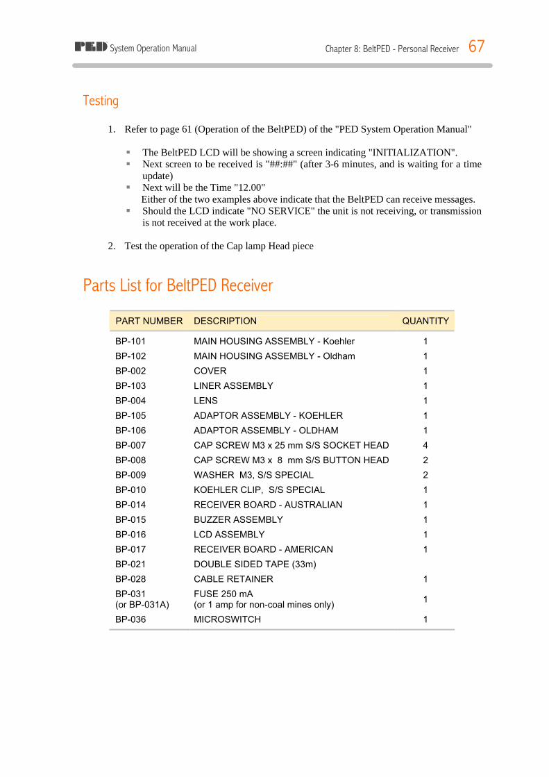
System Operation Manual Chapter 8: BeltPED - Personal Receiver 67
Testing 1. Refer to page 61 (Operation of the BeltPED) of the "PED System Operation Manual" § The BeltPED LCD will be showing a screen indicating "INITIALIZATION". § Next screen to be received is "##:##" (after 3-6 minutes, and is waiting for a time
update) § Next will be the Time "12.00"
Either of the two examples above indicate that the BeltPED can receive messages. § Should the LCD indicate "NO SERVICE" the unit is not receiving, or transmission
is not received at the work place. 2. Test the operation of the Cap lamp Head piece
Parts List for BeltPED Receiver
PART NUMBER DESCRIPTION QUANTITY
BP-101 MAIN HOUSING ASSEMBLY - Koehler 1
BP-102 MAIN HOUSING ASSEMBLY - Oldham 1
BP-002 COVER 1
BP-103 LINER ASSEMBLY 1
BP-004 LENS 1
BP-105 ADAPTOR ASSEMBLY - KOEHLER 1
BP-106 ADAPTOR ASSEMBLY - OLDHAM 1
BP-007 CAP SCREW M3 x 25 mm S/S SOCKET HEAD 4
BP-008 CAP SCREW M3 x 8 mm S/S BUTTON HEAD 2
BP-009 WASHER M3, S/S SPECIAL 2
BP-010 KOEHLER CLIP, S/S SPECIAL 1
BP-014 RECEIVER BOARD - AUSTRALIAN 1
BP-015 BUZZER ASSEMBLY 1
BP-016 LCD ASSEMBLY 1
BP-017 RECEIVER BOARD - AMERICAN 1
BP-021 DOUBLE SIDED TAPE (33m)
BP-028 CABLE RETAINER 1
BP-031 (or BP-031A)
FUSE 250 mA (or 1 amp for non-coal mines only) 1
BP-036 MICROSWITCH 1

System Operation Manual Chapter 8: BeltPED - Personal Receiver 68
Figure 37: BeltPED
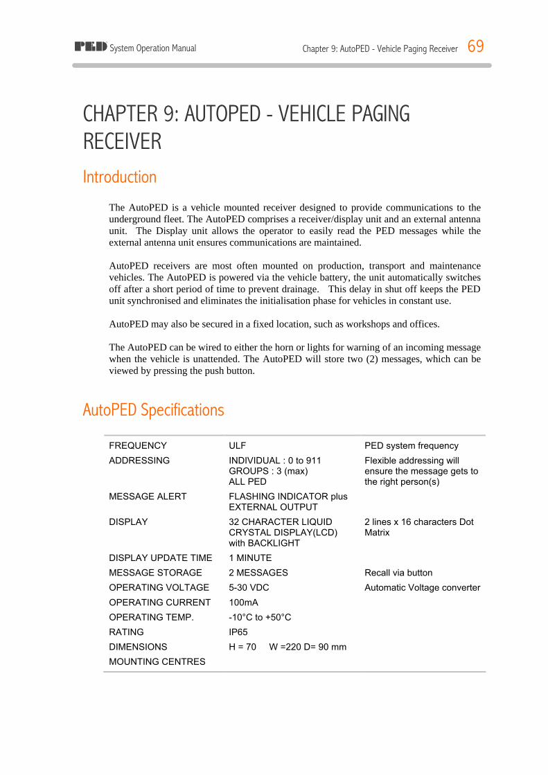
System Operation Manual Chapter 9: AutoPED - Vehicle Paging Receiver 69
CHAPTER 9: AUTOPED - VEHICLE PAGING RECEIVER Introduction
The AutoPED is a vehicle mounted receiver designed to provide communications to the underground fleet. The AutoPED comprises a receiver/display unit and an external antenna unit. The Display unit allows the operator to easily read the PED messages while the external antenna unit ensures communications are maintained. AutoPED receivers are most often mounted on production, transport and maintenance vehicles. The AutoPED is powered via the vehicle battery, the unit automatically switches off after a short period of time to prevent drainage. This delay in shut off keeps the PED unit synchronised and eliminates the initialisation phase for vehicles in constant use. AutoPED may also be secured in a fixed location, such as workshops and offices. The AutoPED can be wired to either the horn or lights for warning of an incoming message when the vehicle is unattended. The AutoPED will store two (2) messages, which can be viewed by pressing the push button.
AutoPED Specifications
FREQUENCY ULF PED system frequency
ADDRESSING INDIVIDUAL : 0 to 911 GROUPS : 3 (max) ALL PED
Flexible addressing will ensure the message gets to the right person(s)
MESSAGE ALERT FLASHING INDICATOR plus EXTERNAL OUTPUT
DISPLAY 32 CHARACTER LIQUID CRYSTAL DISPLAY(LCD) with BACKLIGHT
2 lines x 16 characters Dot Matrix
DISPLAY UPDATE TIME 1 MINUTE
MESSAGE STORAGE 2 MESSAGES Recall via button
OPERATING VOLTAGE 5-30 VDC Automatic Voltage converter
OPERATING CURRENT 100mA
OPERATING TEMP. -10°C to +50°C
RATING IP65
DIMENSIONS H = 70 W =220 D= 90 mm
MOUNTING CENTRES
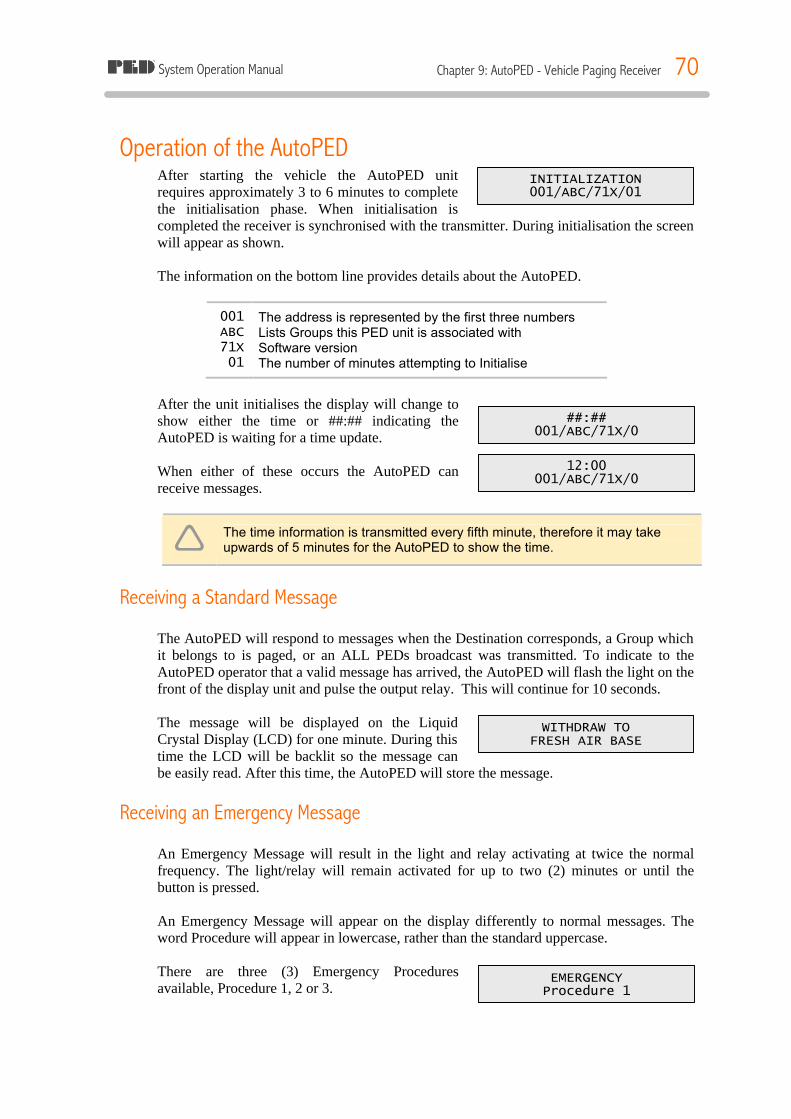
System Operation Manual Chapter 9: AutoPED - Vehicle Paging Receiver 70
INITIALIZATION 001/ABC/71X/01
##:## 001/ABC/71X/0
12:00 001/ABC/71X/0
WITHDRAW TO FRESH AIR BASE
EMERGENCY Procedure 1
Operation of the AutoPED After starting the vehicle the AutoPED unit requires approximately 3 to 6 minutes to complete the initialisation phase. When initialisation is completed the receiver is synchronised with the transmitter. During initialisation the screen will appear as shown. The information on the bottom line provides details about the AutoPED.
001 The address is represented by the first three numbers ABC Lists Groups this PED unit is associated with 71X Software version 01 The number of minutes attempting to Initialise
After the unit initialises the display will change to show either the time or ##:## indicating the AutoPED is waiting for a time update. When either of these occurs the AutoPED can receive messages.
ê The time information is transmitted every fifth minute, therefore it may take upwards of 5 minutes for the AutoPED to show the time.
Receiving a Standard Message The AutoPED will respond to messages when the Destination corresponds, a Group which it belongs to is paged, or an ALL PEDs broadcast was transmitted. To indicate to the AutoPED operator that a valid message has arrived, the AutoPED will flash the light on the front of the display unit and pulse the output relay. This will continue for 10 seconds. The message will be displayed on the Liquid Crystal Display (LCD) for one minute. During this time the LCD will be backlit so the message can be easily read. After this time, the AutoPED will store the message.
Receiving an Emergency Message An Emergency Message will result in the light and relay activating at twice the normal frequency. The light/relay will remain activated for up to two (2) minutes or until the button is pressed. An Emergency Message will appear on the display differently to normal messages. The word Procedure will appear in lowercase, rather than the standard uppercase.
There are three (3) Emergency Procedures available, Procedure 1, 2 or 3.
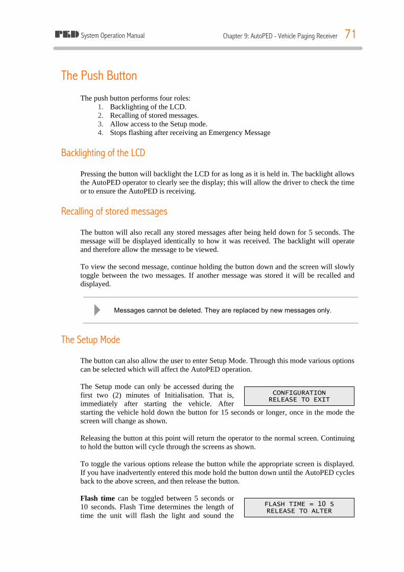
System Operation Manual Chapter 9: AutoPED - Vehicle Paging Receiver 71
CONFIGURATION RELEASE TO EXIT
FLASH TIME = 10 S RELEASE TO ALTER
The Push Button The push button performs four roles:
1. Backlighting of the LCD. 2. Recalling of stored messages. 3. Allow access to the Setup mode. 4. Stops flashing after receiving an Emergency Message
Backlighting of the LCD Pressing the button will backlight the LCD for as long as it is held in. The backlight allows the AutoPED operator to clearly see the display; this will allow the driver to check the time or to ensure the AutoPED is receiving.
Recalling of stored messages The button will also recall any stored messages after being held down for 5 seconds. The message will be displayed identically to how it was received. The backlight will operate and therefore allow the message to be viewed. To view the second message, continue holding the button down and the screen will slowly toggle between the two messages. If another message was stored it will be recalled and displayed.
4 Messages cannot be deleted. They are replaced by new messages only.
The Setup Mode The button can also allow the user to enter Setup Mode. Through this mode various options can be selected which will affect the AutoPED operation. The Setup mode can only be accessed during the first two (2) minutes of Initialisation. That is, immediately after starting the vehicle. After starting the vehicle hold down the button for 15 seconds or longer, once in the mode the screen will change as shown. Releasing the button at this point will return the operator to the normal screen. Continuing to hold the button will cycle through the screens as shown. To toggle the various options release the button while the appropriate screen is displayed. If you have inadvertently entered this mode hold the button down until the AutoPED cycles back to the above screen, and then release the button. Flash time can be toggled between 5 seconds or 10 seconds. Flash Time determines the length of time the unit will flash the light and sound the
System Operation Manual Chapter 9: AutoPED - Vehicle Paging Receiver 72
SERVICE WARN = OFF RELEASE TO ALTER
PED 3 MODE = ON RELEASE TO ALTER
buzzer when a message is received. Service Warn(ing) toggles the AutoPEDs feature that alerts the user the AutoPED has lost synchronisation for longer than 10 minutes. The words NO SERVICE are displayed on a AutoPED in the event it has lost signal, and if this option is set to ON, the flash / buzzer will operate after 10 minutes.
4 The Service Warning feature is set to off by default.
PED 3 Mode will cause the AutoPED to alter the internal software version. This option is normally set to ON, for mines gradually implementing AutoPEDs it is set to OFF. It should only be used at mines that still maintain a mixture of old style Receivers (PED2 or less).
Installation of the AutoPED
The External Antenna The external Antenna is located outside the cabin area; this overcomes any shielding effect which may occur when surrounded by the solid steel cabin. The antenna should be mounted in the following manner for optimum performance:
ü Vertically aligned, this provides the best signal for the antenna. ü Relatively open space, to prevent signal attenuation from solid steel. ü Away from the noise of the engine bay or motors. ü In a position where personnel or rock falls will not cause concern.
The Display/Receiver Box The display box should be mounted as follows:
ü Easily viewable by the operator ü Protected from falling objects ü Situated where the vehicle operation is not hindered.
Wiring connections for the AutoPED The wiring should be located where there is minimum risk of damage. The use of cable ties and supports is recommended, this avoids cables becoming loose or falling near the operator. Any joints made to the cables should be soldered and covered with heat shrink. The joints should be of good quality and made to endure the mining environment. The AutoPED has a power cable and a coaxial cable connected to the external antenna. The AutoPED has the following connections for the main cables:
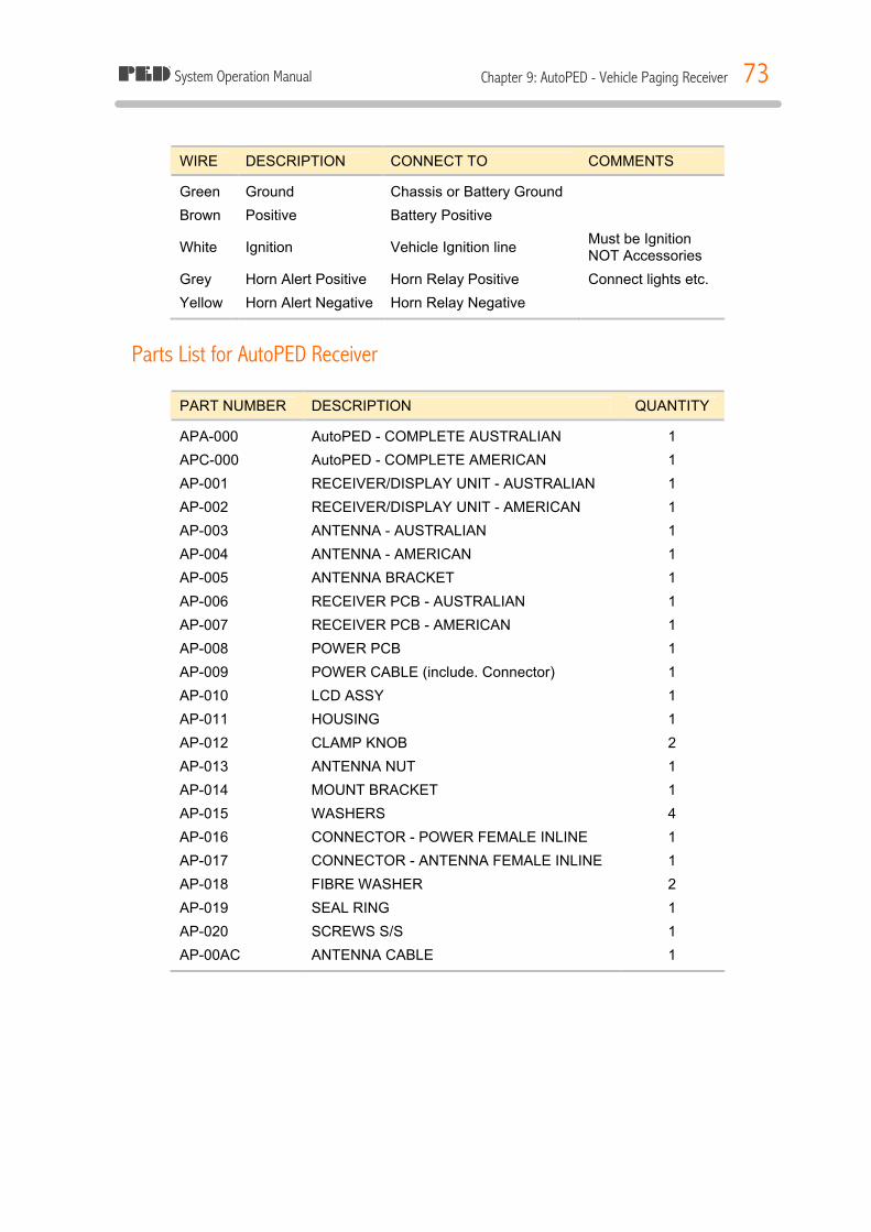
System Operation Manual Chapter 9: AutoPED - Vehicle Paging Receiver 73
WIRE DESCRIPTION CONNECT TO COMMENTS
Green Ground Chassis or Battery Ground
Brown Positive Battery Positive
White Ignition Vehicle Ignition line Must be Ignition NOT Accessories
Grey Horn Alert Positive Horn Relay Positive Connect lights etc.
Yellow Horn Alert Negative Horn Relay Negative
Parts List for AutoPED Receiver PART NUMBER DESCRIPTION QUANTITY
APA-000 AutoPED - COMPLETE AUSTRALIAN 1
APC-000 AutoPED - COMPLETE AMERICAN 1
AP-001 RECEIVER/DISPLAY UNIT - AUSTRALIAN 1
AP-002 RECEIVER/DISPLAY UNIT - AMERICAN 1
AP-003 ANTENNA - AUSTRALIAN 1
AP-004 ANTENNA - AMERICAN 1
AP-005 ANTENNA BRACKET 1
AP-006 RECEIVER PCB - AUSTRALIAN 1
AP-007 RECEIVER PCB - AMERICAN 1
AP-008 POWER PCB 1
AP-009 POWER CABLE (include. Connector) 1
AP-010 LCD ASSY 1
AP-011 HOUSING 1
AP-012 CLAMP KNOB 2
AP-013 ANTENNA NUT 1
AP-014 MOUNT BRACKET 1
AP-015 WASHERS 4
AP-016 CONNECTOR - POWER FEMALE INLINE 1
AP-017 CONNECTOR - ANTENNA FEMALE INLINE 1
AP-018 FIBRE WASHER 2
AP-019 SEAL RING 1
AP-020 SCREWS S/S 1
AP-00AC ANTENNA CABLE 1

System Operation Manual Chapter 9: AutoPED - Vehicle Paging Receiver 74
Figure 38: AutoPED
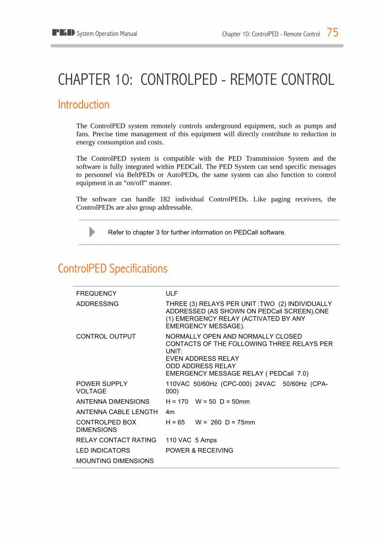
System Operation Manual Chapter 10: ControlPED - Remote Control 75
CHAPTER 10: CONTROLPED - REMOTE CONTROL Introduction
The ControlPED system remotely controls underground equipment, such as pumps and fans. Precise time management of this equipment will directly contribute to reduction in energy consumption and costs. The ControlPED system is compatible with the PED Transmission System and the software is fully integrated within PEDCall. The PED System can send specific messages to personnel via BeltPEDs or AutoPEDs, the same system can also function to control equipment in an “on/off” manner. The software can handle 182 individual ControlPEDs. Like paging receivers, the ControlPEDs are also group addressable.
4 Refer to chapter 3 for further information on PEDCall software.
ControlPED Specifications
FREQUENCY ULF
ADDRESSING THREE (3) RELAYS PER UNIT :TWO (2) INDIVIDUALLY ADDRESSED (AS SHOWN ON PEDCall SCREEN),ONE (1) EMERGENCY RELAY (ACTIVATED BY ANY EMERGENCY MESSAGE).
CONTROL OUTPUT NORMALLY OPEN AND NORMALLY CLOSED CONTACTS OF THE FOLLOWING THREE RELAYS PER UNIT: EVEN ADDRESS RELAY ODD ADDRESS RELAY EMERGENCY MESSAGE RELAY ( PEDCall 7.0)
POWER SUPPLY VOLTAGE
110VAC 50/60Hz (CPC-000) 24VAC 50/60Hz (CPA-000)
ANTENNA DIMENSIONS H = 170 W = 50 D = 50mm
ANTENNA CABLE LENGTH 4m
CONTROLPED BOX DIMENSIONS
H = 65 W = 260 D = 75mm
RELAY CONTACT RATING 110 VAC 5 Amps
LED INDICATORS POWER & RECEIVING
MOUNTING DIMENSIONS
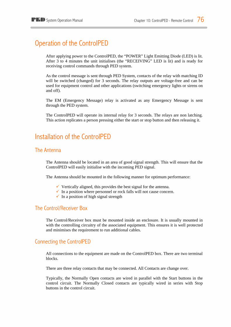
System Operation Manual Chapter 10: ControlPED - Remote Control 76
Operation of the ControlPED After applying power to the ControlPED, the “POWER” Light Emitting Diode (LED) is lit. After 3 to 4 minutes the unit initialises (the “RECEIVING” LED is lit) and is ready for receiving control commands through PED system. As the control message is sent through PED System, contacts of the relay with matching ID will be switched (changed) for 3 seconds. The relay outputs are voltage-free and can be used for equipment control and other applications (switching emergency lights or sirens on and off). The EM (Emergency Message) relay is activated as any Emergency Message is sent through the PED system. The ControlPED will operate its internal relay for 3 seconds. The relays are non latching. This action replicates a person pressing either the start or stop button and then releasing it.
Installation of the ControlPED
The Antenna The Antenna should be located in an area of good signal strength. This will ensure that the ControlPED will easily initialise with the incoming PED signal. The Antenna should be mounted in the following manner for optimum performance:
ü Vertically aligned, this provides the best signal for the antenna. ü In a position where personnel or rock falls will not cause concern. ü In a position of high signal strength
The Control/Receiver Box The Control/Receiver box must be mounted inside an enclosure. It is usually mounted in with the controlling circuitry of the associated equipment. This ensures it is well protected and minimises the requirement to run additional cables.
Connecting the ControlPED All connections to the equipment are made on the ControlPED box. There are two terminal blocks. There are three relay contacts that may be connected. All Contacts are change over. Typically, the Normally Open contacts are wired in parallel with the Start buttons in the control circuit. The Normally Closed contacts are typically wired in series with Stop buttons in the control circuit.
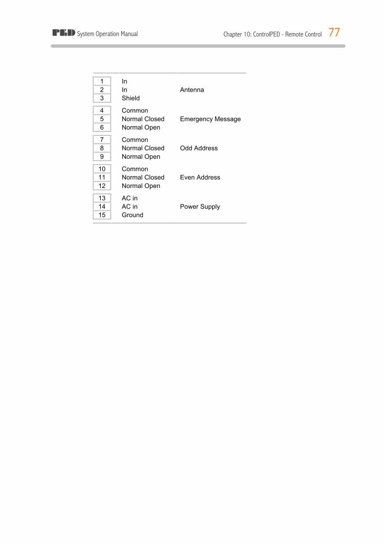
System Operation Manual Chapter 10: ControlPED - Remote Control 77
1 In 2 In Antenna 3 Shield
4 Common 5 Normal Closed Emergency Message 6 Normal Open
7 Common 8 Normal Closed Odd Address 9 Normal Open
10 Common 11 Normal Closed Even Address 12 Normal Open
13 AC in 14 AC in Power Supply 15 Ground
System Operation Manual Chapter 11: BlastPED - Remote Blasting 78
CHAPTER 11: BLASTPED - REMOTE BLASTING Introduction
The BlastPED system allows remote, centralised blasting with the PED System. The BlastPED System works off the existing PED Transmission System and only requires a software upgrade to operate. BlastPED has been developed to eliminate the high cost of maintaining the integrity of underground blasting cables. By eliminating these cables, costs are reduced on maintenance and lost production due to misfires. BlastPED has been designed with safety as a prime criteria. The BlastPED system has several levels of security. While the system is extremely secure, it is also simple to operate for the authorised personnel. The software is similar to PEDCall, therefore personnel do not need to learn a new system. The actual BlastPED Receiver is easy to connect and operate. The user turns the BlastPED ON, with the key, connects the firing cable, and ensures the BlastPED has synchronised to the signal. It is then up to the PEDCall operator to enter the ARM & BLAST command from disk and transmit the messages.
~ LETHAL VOLTAGE PRESENT AT OUTPUT TERMINALS WHEN BLASTING AND TESTING
ê Prior to implementing the BlastPED system, the mine should establish procedures for blasting utilising BlastPED.
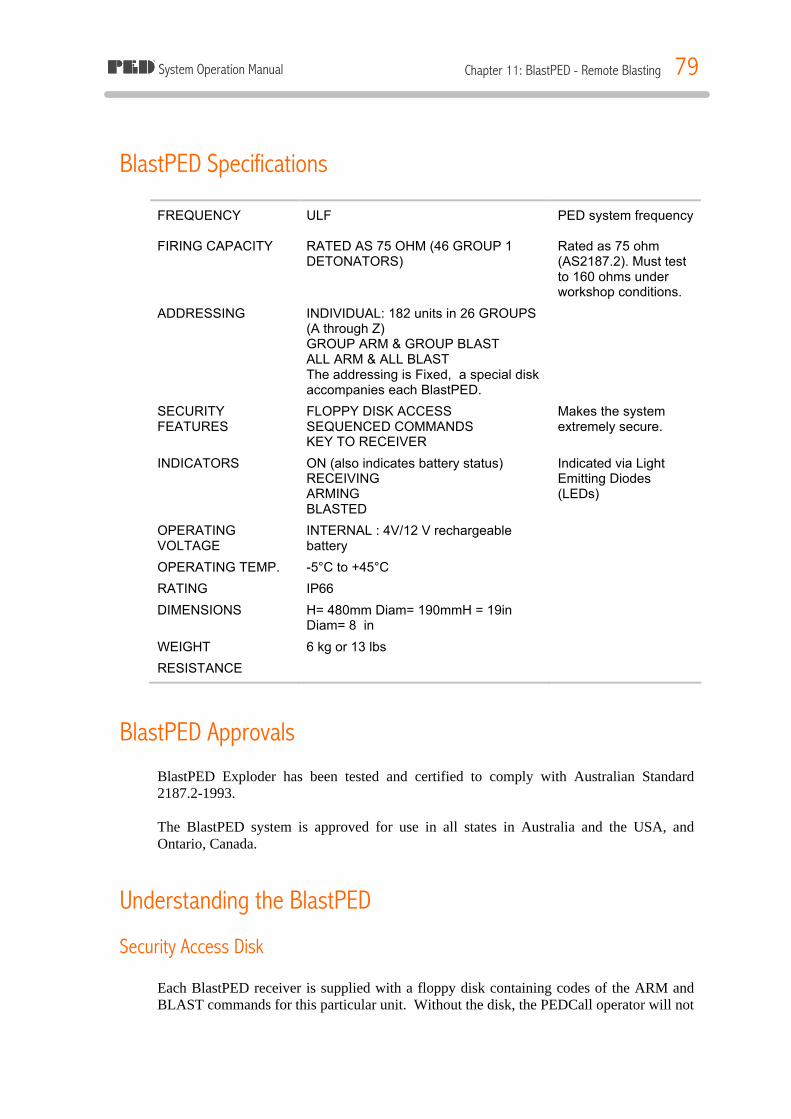
System Operation Manual Chapter 11: BlastPED - Remote Blasting 79
BlastPED Specifications
FREQUENCY ULF PED system frequency FIRING CAPACITY RATED AS 75 OHM (46 GROUP 1
DETONATORS) Rated as 75 ohm (AS2187.2). Must test to 160 ohms under workshop conditions.
ADDRESSING INDIVIDUAL: 182 units in 26 GROUPS (A through Z) GROUP ARM & GROUP BLAST ALL ARM & ALL BLAST The addressing is Fixed, a special disk accompanies each BlastPED.
SECURITY FEATURES
FLOPPY DISK ACCESS SEQUENCED COMMANDS KEY TO RECEIVER
Makes the system extremely secure.
INDICATORS ON (also indicates battery status) RECEIVING ARMING BLASTED
Indicated via Light Emitting Diodes (LEDs)
OPERATING VOLTAGE
INTERNAL : 4V/12 V rechargeable battery
OPERATING TEMP. -5°C to +45°C
RATING IP66
DIMENSIONS H= 480mm Diam= 190mmH = 19in Diam= 8 in
WEIGHT 6 kg or 13 lbs
RESISTANCE
BlastPED Approvals BlastPED Exploder has been tested and certified to comply with Australian Standard 2187.2-1993. The BlastPED system is approved for use in all states in Australia and the USA, and Ontario, Canada.
Understanding the BlastPED
Security Access Disk Each BlastPED receiver is supplied with a floppy disk containing codes of the ARM and BLAST commands for this particular unit. Without the disk, the PEDCall operator will not
System Operation Manual Chapter 11: BlastPED - Remote Blasting 80
be able to transmit commands to the BlastPED. The disk therefore should be kept in a very secure location.
Safety Key The output terminals are short-circuited while the safety key is in the SAFE position. The safety key may only be removed while in the safe position.
Firing Output BlastPED is a capacitor type exploder suitable for series firing. The output capacity of the BlastPED is up to 75 Ohms.
ê BlastPED is to be used for firing simple series circuits only. Series-in-parallel circuits are not to be fired using BlastPED.
The output terminals can accept all cables up to a maximum of 4 mm diameter. When the safety key is in ON position the BlastPED has the output short-circuited. The short circuit is not removed until the ARM command is received by the unit. The electrical energy necessary to initiate the detonators is made available from internal capacitors. These capacitors are short circuited until the ARM command is received, they will then commence charging. After blasting the short circuit is automatically applied across output terminals.
The BlastPED firing process The operator connects the BlastPED as indicated in the following section. Once connected, the BlastPED will remain synchronised, the output terminals and the internal capacitors are short circuited. The PEDCall operator transmits the ARM command. After ARM command is received, the BlastPED ARMING LED will light and the short on the capacitors will be removed. The capacitors will commence charging. The BlastPED unit will remain armed for up to 10 minutes. The firing process will be automatically aborted after 10 minutes should blasting not be performed during this time. When the process is aborted it will require another ARM command before blasting can be proceeded. The PEDCall operator sends the BLAST command to the unit which has been armed. As the BLAST command is received by the armed unit the charged capacitors are connected to the output terminals. The capacitors discharge into the firing line, initiating the detonators. Two (2) seconds after blasting the BlastPED unit automatically locks out:
System Operation Manual Chapter 11: BlastPED - Remote Blasting 81
§ The unit's output is isolated from the battery and firing capacitors, § Firing cables (connected to output terminals) are short circuited, § Subsequent ARM and BLAST commands are ignored, § Red LED labelled BLASTED shows that the unit is locked out.
After blasting the unit remains locked until it is manually reset by the safety key returned to SAFE position. BlastPED unit must be reset (unlocked) before another firing output can be produced.
~ LETHAL VOLTAGE PRESENT AT OUTPUT TERMINALS WHEN FIRING
Connecting to the BlastPED To connect the BlastPED receiver proceed as follows:
1. Make sure the BlastPED key is in the SAFE position.
2. Turn the key to the ON position. The Liquid Crystal Display (LCD) will be activated and, after 20 seconds, the Green ON Light will come on indicating the unit has tested OK (including battery capacity).
3. After 2 to 5 minutes the RECEIVING light comes on indicating the system is
functional for remote signalling (i.e. it has synchronised with the signal).
4. Connect the firing cables to the firing (output) terminals.
5. The Line Resistance is continuously shown in ohms on the liquid crystal display.
6. The unit is now ready to receive commands through the PED Transmission System.
7. After firing the key should be returned to the SAFE position and the key
removed.
ê Before leaving the site, two GREEN lights must be on for the unit to be ready for firing.
4 See also the PEDCall software instructions for sending the ARM and BLAST commands to the receiver/exploders.
Recharging the Battery The BlastPED is powered by a rechargeable battery. The battery is internal to the unit and is recharged via a charging port. A battery charger is included with each unit. If required, the battery pack is easily exchanged, enabling a fully charged battery to be placed in the unit so it is ready for immediate use. A battery charging holder is available for re-charging

System Operation Manual Chapter 11: BlastPED - Remote Blasting 82
the battery pack only. The Charger has three indicator lights. Power ON – RED Light; Charging – AMBER light; Charge Complete – GREEN light. If a battery has been completely discharged then it takes about 2 hours to recharge.
ê Proper and adequate charging is the single most important factor in obtaining optimum life from a battery.
Replacing the Battery
4 MST Battery Pack P-EX2-105 as a replacement.
To change the battery:
1. Make sure the BlastPED safety switch is in the SAFE position. 2. Undo the bottom cover by unscrewing anti-clockwise. 3. The existing battery pack is simply pulled out and the new battery pack slid in
(take care it is lined up with the internal guide slots).
Testing BlastPED Firing Capacity BlastPED Tester is provided for the purpose of testing BlastPED firing capacity. The tester consists of a calibrated160 Ohm resistor which is connected in series with two detonators across the BlastPED firing terminals. Three pairs of terminals are provided: one for connecting to the BlastPED unit and two for connecting test detonators. Both detonators must be shielded separately, so that one will not initiate the other, and no injury can result to any person in the vicinity. The BlastPED is operated according to instruction. Both detonators must fire. The BlastPED unit shall be tested: § Regularly per operator's schedule § Before any blast that may require the maximum output. § When a loss of efficiency is suspected § After an interval of non-use during operations
Servicing Return the BlastPED to distributor for service or repair.

System Operation Manual Appendix 83
APPENDIX
A. Commissioning Report Sheet B. Audit Report Sheet C. BeltPED Assembly and Maintenance D. Training Assessment and Confirmation E. Periodic Maintenance Record Sheet
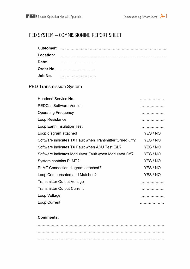
System Operation Manual - Appendix Commissioning Report Sheet A-1
PED SYSTEM – COMMISSIONING REPORT SHEET
Customer: ………………………………………………………………………..
Location: ………………………………………………………………………..
Date: ……………………….
Order No. ……………………….
Job No. ……………………….
PED Transmission System
Headend Service No. ……………….
PEDCall Software Version ……………….
Operating Frequency ……………….
Loop Resistance ……………….
Loop Earth Insulation Test ……………….
Loop diagram attached YES / NO
Software indicates TX Fault when Transmitter turned Off? YES / NO
Software indicates TX Fault when ASU Test E/L? YES / NO
Software indicates Modulator Fault when Modulator Off? YES / NO
System contains PLMT? YES / NO
PLMT Connection diagram attached? YES / NO
Loop Compensated and Matched? YES / NO
Transmitter Output Voltage ……………….
Transmitter Output Current ……………….
Loop Voltage ……………….
Loop Current ……………….
Comments:
………………………………………………………………………………………
………………………………………………………………………………………
………………………………………………………………………………………

System Operation Manual - Appendix Commissioning Report Sheet A-2
PED Signal Coverage
PED Receiver Levels Taken? YES / NO
Analyser Signal Levels taken? YES / NO
Loop Signal Level diagram attached? YES / NO
Mine Areas with Low Signal:
………………………………………………………………………………………
………………………………………………………………………………………
………………………………………………………………………………………
………………………………………………………………………………………
………………………………………………………………………………………
………………………………………………………………………………………
………………………………………………………………………………………
………………………………………………………………………………………
………………………………………………………………………………………
………………………………………………………………………………………
………………………………………………………………………………………
………………………………………………………………………………………
Comments:
………………………………………………………………………………………
………………………………………………………………………………………
………………………………………………………………………………………
………………………………………………………………………………………
………………………………………………………………………………………
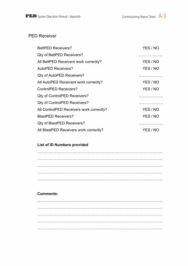
System Operation Manual - Appendix Commissioning Report Sheet A-3
PED Receiver
BeltPED Receivers? YES / NO
Qty of BeltPED Receivers? ……………….
All BeltPED Receivers work correctly? YES / NO
AutoPED Receivers? YES / NO
Qty of AutoPED Receivers? ……………….
All AutoPED Receivers work correctly? YES / NO
ControlPED Receivers? YES / NO
Qty of ControlPED Receivers? ……………….
Qty of ControlPED Receivers? ……………….
All ControlPED Receivers work correctly? YES / NO
BlastPED Receivers? YES / NO
Qty of BlastPED Receivers? ……………….
All BlastPED Receivers work correctly? YES / NO
List of ID Numbers provided
………………………………………………………………………………………
………………………………………………………………………………………
………………………………………………………………………………………
………………………………………………………………………………………
………………………………………………………………………………………
Comments:
………………………………………………………………………………………
………………………………………………………………………………………
………………………………………………………………………………………
………………………………………………………………………………………
………………………………………………………………………………………

System Operation Manual - Appendix Commissioning Report Sheet A-4
PED Training
Trainees ……………………………………………………………………….
……………………………………………………………………….
……………………………………………………………………….
……………………………………………………………………….
……………………………………………………………………….
Generic Training completed? YES / NO
Comments:
………………………………………………………………………………………
………………………………………………………………………………………
………………………………………………………………………………………
………………………………………………………………………………………
………………………………………………………………………………………
Receiver Maintenance Training completed? YES / NO
Comments:
………………………………………………………………………………………
………………………………………………………………………………………
………………………………………………………………………………………
………………………………………………………………………………………
………………………………………………………………………………………
PED System Maintenance Training completed? YES / NO
Comments:
………………………………………………………………………………………
………………………………………………………………………………………
………………………………………………………………………………………
………………………………………………………………………………………
………………………………………………………………………………………

System Operation Manual - Appendix Commissioning Report Sheet A-5
Commissioning Date: ……………………………………
Commissioning Technician : ……………………………………
Transmission System Installation by: ……………………………………
Loop Installation By: ……………………………………
Receiver Installation By: ……………………………………
Training Technician: ……………………………………
Acceptance. The above PED Communication System is as per specification and fulfils the requirements of the issued Customer Order. Mine Site Technologies Representative ……………………………………
Signature: ……………………………………
Customer Representative ……………………………………
Signature: ……………………………………
Recommendations:
………………………………………………………………………………………
………………………………………………………………………………………
………………………………………………………………………………………
………………………………………………………………………………………
………………………………………………………………………………………
………………………………………………………………………………………
………………………………………………………………………………………
………………………………………………………………………………………
………………………………………………………………………………………
………………………………………………………………………………………
………………………………………………………………………………………
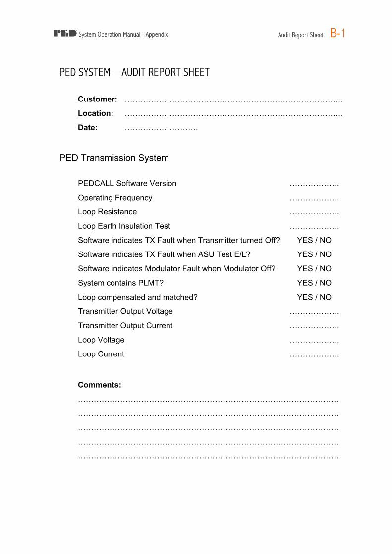
System Operation Manual - Appendix Audit Report Sheet B-1
PED SYSTEM – AUDIT REPORT SHEET
Customer: ………………………………………………………………………..
Location: ………………………………………………………………………..
Date: ……………………….
PED Transmission System
PEDCALL Software Version ……………….
Operating Frequency ……………….
Loop Resistance ……………….
Loop Earth Insulation Test ……………….
Software indicates TX Fault when Transmitter turned Off? YES / NO
Software indicates TX Fault when ASU Test E/L? YES / NO
Software indicates Modulator Fault when Modulator Off? YES / NO
System contains PLMT? YES / NO
Loop compensated and matched? YES / NO
Transmitter Output Voltage ……………….
Transmitter Output Current ……………….
Loop Voltage ……………….
Loop Current ……………….
Comments:
………………………………………………………………………………………
………………………………………………………………………………………
………………………………………………………………………………………
………………………………………………………………………………………
………………………………………………………………………………………

System Operation Manual - Appendix Audit Report Sheet B-2
PED Signal Coverage
PED Receiver Levels Taken? YES / NO
Analyser Signal Levels taken? YES / NO
Loop Signal Level diagram attached? YES / NO
Areas of Low Signal:
………………………………………………………………………………………
………………………………………………………………………………………
………………………………………………………………………………………
………………………………………………………………………………………
………………………………………………………………………………………
………………………………………………………………………………………
………………………………………………………………………………………
………………………………………………………………………………………
………………………………………………………………………………………
………………………………………………………………………………………
………………………………………………………………………………………
………………………………………………………………………………………
………………………………………………………………………………………
Comments:
………………………………………………………………………………………
………………………………………………………………………………………
………………………………………………………………………………………
………………………………………………………………………………………
………………………………………………………………………………………
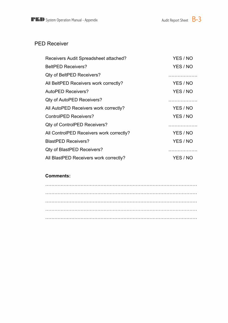
System Operation Manual - Appendix Audit Report Sheet B-3
PED Receiver
Receivers Audit Spreadsheet attached? YES / NO
BeltPED Receivers? YES / NO
Qty of BeltPED Receivers? ……………….
All BeltPED Receivers work correctly? YES / NO
AutoPED Receivers? YES / NO
Qty of AutoPED Receivers? ……………….
All AutoPED Receivers work correctly? YES / NO
ControlPED Receivers? YES / NO
Qty of ControlPED Receivers? ……………….
All ControlPED Receivers work correctly? YES / NO
BlastPED Receivers? YES / NO
Qty of BlastPED Receivers? ……………….
All BlastPED Receivers work correctly? YES / NO
Comments:
………………………………………………………………………………………
………………………………………………………………………………………
………………………………………………………………………………………
………………………………………………………………………………………
………………………………………………………………………………………

System Operation Manual - Appendix Audit Report Sheet B-4
PED Training
Trainees ……………………………………………………………………….
……………………………………………………………………….
……………………………………………………………………….
……………………………………………………………………….
……………………………………………………………………….
Generic Training completed? YES / NO
Comments:
………………………………………………………………………………………
………………………………………………………………………………………
………………………………………………………………………………………
………………………………………………………………………………………
………………………………………………………………………………………
Receiver Maintenance Training completed? YES / NO
Comments:
………………………………………………………………………………………
………………………………………………………………………………………
………………………………………………………………………………………
………………………………………………………………………………………
………………………………………………………………………………………
PED System Maintenance Training completed? YES / NO
Comments:
………………………………………………………………………………………
………………………………………………………………………………………
………………………………………………………………………………………
………………………………………………………………………………………
………………………………………………………………………………………

System Operation Manual - Appendix Audit Report Sheet B-5
Audit Date: ……………………………………..
Previous Audit Date: ……………………………………..
Audit Technician: ……………………………………..
Training Technician: ……………………………………..
Recommendations:
………………………………………………………………………………………
………………………………………………………………………………………
………………………………………………………………………………………
………………………………………………………………………………………
………………………………………………………………………………………
………………………………………………………………………………………
………………………………………………………………………………………
………………………………………………………………………………………
………………………………………………………………………………………
………………………………………………………………………………………
………………………………………………………………………………………
………………………………………………………………………………………
………………………………………………………………………………………
………………………………………………………………………………………
………………………………………………………………………………………
………………………………………………………………………………………

System Operation Manual - Appendix BeltPED - Assembly and Maintenance C-1
BeltPED – ASSEMBLY and MAINTENANCE
Competency Assessment
To confirm the competency of a trainee in performing the following task: To assemble and maintain a BeltPED, and to fit to an approved cap lamp (Head piece, cord and battery).
NOTE: All new BeltPEDs are supplied as a kit, in a carton, with a printed pictorial display of assembly instructions printed inside the lid. Basic competency required before training: Cap lamp Fitter, Mine Electrician Circle the correct answer (may be more than one).
1. UNDERSTANDING
What is understood as "IS"? A. Instant satisfaction B. Intrinsically safe - explosion protected C. Is safe to use in underground mines D. Dust and waterproof
What is understood as "IP" rating? A. Internal Protection B. International Protection C. Intellectual Property D. A numerical scale indicating protection
against the ingression of objects or liquids into an enclosure
What is a BeltPED? A. A paging system receiver B. An approved paging receiver C. A two way radio
Will the BeltPED adapt to any Cap lamp? A. Yes B. Only approved cap lamps advised in
PED System Operation Manual 2. ASSEMBLY
2.1. Before commencing assembly, A. Wash your hands B. Obtain correct tools C. Read instructions D. All of the above
2.2. Before attaching Battery Adaptor, A. Clean and degrease battery positive terminal side
B. Clean battery C. Unpack from carton D. Read fitting instructions E. All of the above
2.3. When stripping wires, cord strain relief is cut to....
A. 20mm B. 23mm C. 25mm D. All of the above
2.4. Are prepared wires... A. Soldered

System Operation Manual - Appendix BeltPED - Assembly and Maintenance C-2
B. Twisted C. Left as straight D. Bent back double
2.4.1. Do you fit the lens A. Narrow end away from the liner strain relief
B. Wide end away from the liner stain relief C. With the hollow side of the lens upwards
2.4.2. The "O" Ring is fitted A. Under the diaphragm B. On top of the diaphragm C. Around the buzzer
2.4.3. The Liner should A. Automatically align with the top cover B. Be proud of top cover C. Be free of kinks around the top cover
sealing area
2.5. When fitting cord to liner, A. Lubricate cord and liner with liquid detergent
B. Pull through dry C. Pull through approximately 150mm D. Pull through 170mm
2.6. Cable clamp should be set at what length from the end of the cord?
A. 5mm B. 50mm C. 10mm
2.6.1. Cable clamp mating faces... A. Should be 2mm apart B. Should be touching C. Should be lubricated
2.6.2. Damaged Approval Information... A. Requires replacement of decal B. Is not a problem C. Renders the unit unavailable for use
2.6.3. The LCD Assembly ... A. Will self align with it's mount posts B. Mounts to the top cover window C. Must be seated on it's posts
2.7. Cap lamp wires are connected... A. Positive to red terminal B. Brown wire to negative terminal C. Green wire to negative terminal
2.8 What will happen when the wires are both connected?
A. The LCD will light up B. The buzzer will sound C. The BeltPED will vibrate
2.9 Top Cover should be... A. Forced into place B. Fitted down carefully to ensure correct
gasket alignment
2.10 When tightening cover screws... A. Torque to 30Nm B. Tighten firmly making sure mount pillars
are contacting C. Ensure liner alignment D. All of the above E.
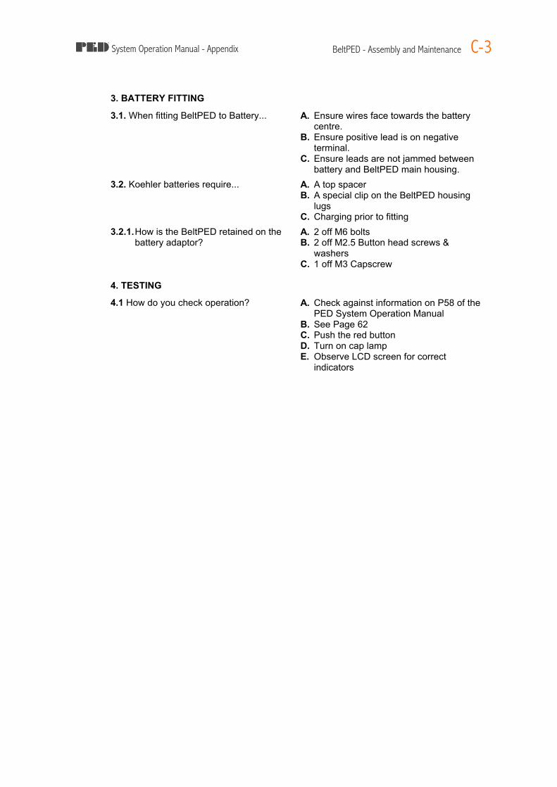
System Operation Manual - Appendix BeltPED - Assembly and Maintenance C-3
3. BATTERY FITTING
3.1. When fitting BeltPED to Battery... A. Ensure wires face towards the battery centre.
B. Ensure positive lead is on negative terminal.
C. Ensure leads are not jammed between battery and BeltPED main housing.
3.2. Koehler batteries require... A. A top spacer B. A special clip on the BeltPED housing
lugs C. Charging prior to fitting
3.2.1. How is the BeltPED retained on the battery adaptor?
A. 2 off M6 bolts B. 2 off M2.5 Button head screws &
washers C. 1 off M3 Capscrew
4. TESTING
4.1 How do you check operation? A. Check against information on P58 of the PED System Operation Manual
B. See Page 62 C. Push the red button D. Turn on cap lamp E. Observe LCD screen for correct
indicators

System Operation Manual - Appendix BeltPED - Assembly and Maintenance C-4
Competency Assessment Answers
This document for assessors use only. Not to be made available to trainee. Note: Assessor must be accepted by Mine Site Technologies as Original Equipment Manufacturer of PED Product.
Question Correct Answer(s) 1.1 B 1.2 B, D 1.3 A, B 1.4 B 2.1 D 2.2 E 2.3 C 2.4 B 2.4.1 B 2.4.2 B 2.4.3 C 2.5 A, C 2.6 A 2.6.1 B 2.6.2 A 2.6.3 C 2.7 A 2.8 A 2.9 B 2.10 B, C 3.1 A, C 3.2 B 3.2.1 B 4.1 A, E

System Operation Manual - Appendix Training Assessment / Confirmation D-1
PED SYSTEM – TRAINING ASSESSMENT/CONFIRMATION Trainee Name (Please Print) ………………………………………………………………
Company ………………………………………………………………
Date: ……………………….
PED Transmission System
I have been trained in the operation of the PEDCall Software YES / NO
I understand how to operate the PEDCall Software YES / NO I understand the message screen layout Including: § The Message queue § The Message being sent notation § Message History
YES / NO
I can send all types of messages using the PEDCall Software Including : § Emergency messages § Re-Occurring Messages § Fixed Messages § Telephone Messages § Custom Messages
YES / NO
I understand the meaning of the following fault conditions that may appear on the PEDCall Screen, and the action required to fix the fault : § Communications Fault § Transmitter Fault
YES / NO
I can reprogram BeltPED IDs using the PEDCall Software YES / NO
I have received training on maintenance of the PED system YES / NO
I have a basic knowledge of how to fault-find the system YES / NO
I am aware that detailed information on maintenance issues contained in the PED Operators manual, a copy of which is available at the Mine.
YES / NO
I am aware that the PED Transmission System contains Lethal Voltages and that care must be taken by licensed / qualified personnel servicing / fault-finding the system.
YES / NO

System Operation Manual - Appendix Training Assessment / Confirmation D-2
TRAINING ASSESSMENT/CONFIRMATION - Continued Trainee Name (Please Print) ………………………………………………………………
Company ………………………………………………………………
Date: ………………………. I have been trained in, and understand the operation and basic maintenance of the following equipment which comprises the PED Transmission System : § PED Transmitter YES / NO § PED External Modulator Board YES / NO § PEDCall Software YES / NO § PED Antenna Safety Unit YES / NO § PED Loop Matching Transformer YES / NO § PED Protector Unit YES / NO
I have been trained in, and understand the operation of the following receivers in relation to the PED Transmission System: § BeltPED Receiver YES / NO § AutoPED Receiver YES / NO § ControlPED Receiver YES / NO
§ BlastPED Receiver YES / NO
Trainee Signature …………………………………………………………..
Date: ……………………….
Instructor Signature
…………………………………………………………..
Instructor Name …………………………………………………………..
Date: ……………………….

System Operation Manual - Appendix Training Assessment / Confirmation D-3
PED SYSTEM – TRAINING ASSESSMENT / CONFIRMATION Trainee Name (Please Print) ………………………………………………………………
Company ………………………………………………………………
Date: ……………………….
BeltPED & AutoPED Receiver Operating Principles I have been trained in, and understand the operation of the following receivers:
§ BeltPED Receiver YES / NO § AutoPED Receiver YES / NO
I understand that the BeltPED Buzzer will sound and my Caplamp will flash (if the light is turned on) upon receipt of a PED Message.
YES / NO
I understand that the button on top of the BeltPED (and on the front of the AutoPED) has two (2) functions:
§ To backlight the LCD display YES / NO § To scroll through the last two (2) messages received YES / NO
I am aware that when an Emergency Message is received by the BeltPED, the unit’s buzzer will sound at twice the usual frequency/speed and the caplamp will flash at twice the usual frequency/speed
YES / NO
I know that at least one person in each vehicle must keep their caplamp on low beam at all times, so that in the event of an Emergency Message being sent, all passengers can be advised.
YES / NO
I fully understand the meaning of all characters on the BeltPED and AutoPED display, including : § The time § ID and Group allocation § Error Count
YES / NO
Trainee Signature …………………………………………………………..
Date: ……………………….
Instructor Signature
…………………………………………………………..
Instructor Name …………………………………………………………..
Date: ……………………….
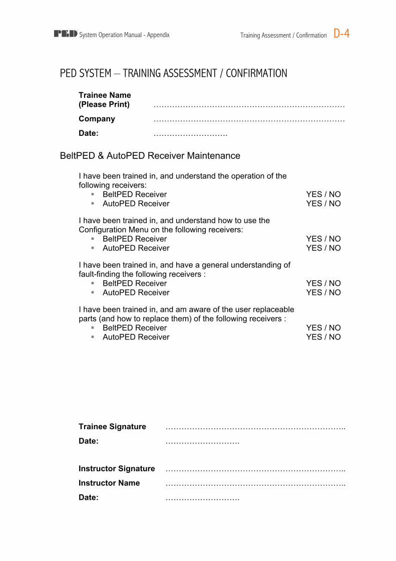
System Operation Manual - Appendix Training Assessment / Confirmation D-4
PED SYSTEM – TRAINING ASSESSMENT / CONFIRMATION
Trainee Name (Please Print) ………………………………………………………………
Company ………………………………………………………………
Date: ……………………….
BeltPED & AutoPED Receiver Maintenance I have been trained in, and understand the operation of the following receivers:
§ BeltPED Receiver YES / NO § AutoPED Receiver YES / NO
I have been trained in, and understand how to use the Configuration Menu on the following receivers:
§ BeltPED Receiver YES / NO § AutoPED Receiver YES / NO
I have been trained in, and have a general understanding of fault-finding the following receivers :
§ BeltPED Receiver YES / NO § AutoPED Receiver YES / NO
I have been trained in, and am aware of the user replaceable parts (and how to replace them) of the following receivers :
§ BeltPED Receiver YES / NO § AutoPED Receiver YES / NO
Trainee Signature …………………………………………………………..
Date: ……………………….
Instructor Signature
…………………………………………………………..
Instructor Name …………………………………………………………..
Date: ……………………….
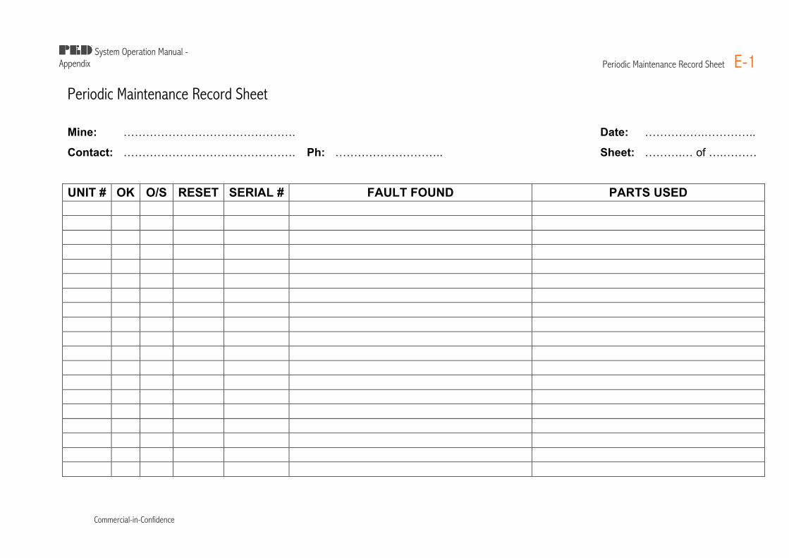
System Operation Manual -
Appendix Periodic Maintenance Record Sheet E-1
Commercial-in-Confidence
Periodic Maintenance Record Sheet
Mine: ………………………………………. Date: …………….…………..
Contact: ………………………………………. Ph: ……………………….. Sheet: ……….… of ….……… UNIT # OK O/S RESET SERIAL # FAULT FOUND PARTS USED


![[DEMOKRASI] - eprints.uad.ac.ideprints.uad.ac.id/9437/1/DEMOKRASI dwi.pdf · sebagai asas kenegaraan secara esensial telah memberikan arah bagi peranan masyarakat untuk menyelenggarakan](https://img.pdfslide.net/doc/110x75/5c7e960109d3f2aa3f8b67a5/demokrasi-dwipdf-sebagai-asas-kenegaraan-secara-esensial-telah-memberikan.jpg)