Embed Size (px)
Citation preview
MIR2 System Operations Manual
P/N 270676 • Rev 1.5 • OCT98
DEVELOPED BY Mirtone, Inc. 90 Fieldstone Court Cheshire, CT USA 06410-1212 Tel: 1-(888) 649-9827 Fax: 203-250-1931
COPYRIGHT NOTICE Copyright © 1998 Mirtone, Inc.
This manual and the products it describes are copyrighted by Mirtone, Inc. You may not reproduce, translate, transcribe, or transmit any part of this manual without express, written permission from Mirtone.
This manual contains proprietary information intended for distribution to authorized persons or companies for the sole purpose of conducting business with Mirtone, Inc. If you distribute any information contained in this manual to unauthorized persons, you have violated all distributor agreements and we may take legal action.
DOCUMENT HISTORY
Date Revision Reason for change
OCT96 1.0 Initial release.
OCT98 1.5 Revised: Address table; editorial corrections
Add: Audio Information
MIR2 System Operations Manual i
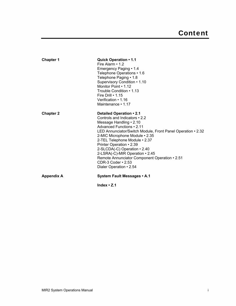
Content
Chapter 1 Quick Operation • 1.1 Fire Alarm • 1.2 Emergency Paging • 1.4 Telephone Operations • 1.6 Telephone Paging • 1.8 Supervisory Condition • 1.10 Monitor Point • 1.12 Trouble Condition • 1.13 Fire Drill • 1.15 Verification • 1.16 Maintenance • 1.17
Chapter 2 Detailed Operation • 2.1 Controls and Indicators • 2.2 Message Handling • 2.10 Advanced Functions • 2.11 LED Annunciator/Switch Module, Front Panel Operation • 2.32 2-MIC Microphone Module • 2.35 2-TEL Telephone Module • 2.37 Printer Operation • 2.39 2-SLCDA(-C) Operation • 2.40 2-LSRA(-C)-MIR Operation • 2.45 Remote Annunciator Component Operation • 2.51 CDR-3 Coder • 2.53 Dialer Operation • 2.54
Appendix A System Fault Messages • A.1
Index • Z.1
Content
ii MIR2 System Operations Manual
Important information
Limitation of liability This product has been designed to meet the requirements of NFPA Standard 72, 1996 Edition; Underwriters Laboratories, Inc., Standard 864, 7th Edition; and Underwriters Laboratories of Canada, Inc., Standard ULC S527. Installation in accordance with this manual, applicable codes, and the instructions of the Authority Having Jurisdiction is mandatory. Honeywell, Inc. shall not under any circumstances be liable for any incidental or consequential damages arising from loss of property or other damages or losses owing to the failure of Honeywell, Inc. products beyond the cost of repair or replacement of any defective products. Honeywell, Inc. reserves the right to make product improvements and change product specifications at any time.
While every precaution has been taken during the preparation of this manual to ensure the accuracy of its contents, Honeywell assumes no responsibility for errors or omissions.
FCC warning This equipment can generate and radiate radio frequency energy. If this equipment is not installed in accordance with this manual, it may cause interference to radio communications. This equipment has been tested and found to comply within the limits for Class A computing devices pursuant to Subpart B of Part 15 of the FCC Rules. These rules are designed to provide reasonable protection against such interference when this equipment is operated in a commercial environment. Operation of this equipment is likely to cause interference, in which case the user at his own expense, is required to take whatever measures may be required to correct the interference.
Content
MIR2 System Operations Manual iii
About this Manual Chapter 1, Quick Operation, provides simple, easy to understand instructions and procedures for common fire alarm functions.
Chapter 2, Detailed Operation, covers detailed system operating instructions and procedures for system operation and maintenance functions. This information is designed for technically qualified personnel.
Appendix A, System Fault Messages, contains a table of explanations for the messages which appear on the 2-LCD.
Content
iv MIR2 System Operations Manual
Fire
Ala
rm C
ontr
ol P
anel
Ope
ratin
g In
stru
ctio
nsN
orm
al C
ondi
tion:
Ala
rm C
ondi
tion:
Supe
rvis
ory
Con
ditio
n:
Trou
ble
Con
ditio
n:
Mon
itor C
ondi
tion:
Fire
Dril
l:
The
Pow
er L
ED
(gre
en) i
s on
. All
othe
r LE
Ds
are
off.
The
Ala
rm L
ED
(red
) tur
ns o
n, th
e di
spla
y sh
ows
the
alar
m lo
catio
n an
d zo
ne, a
nd th
e in
tern
al b
uzze
r pul
ses.
To v
iew
add
ition
al a
larm
s: P
ress
the
ALA
RM
revi
ew s
witc
h (d
own
arro
w).
To s
ilenc
e au
dibl
e de
vice
s: P
ress
the
Alar
m S
ilenc
e sw
itch
to tu
rn th
e au
dibl
e si
gnal
s of
f. To
reso
und
audi
ble
devi
ces:
Pre
ss th
e A
larm
Sile
nce
switc
h a
seco
nd ti
me.
To re
set t
he s
yste
m: A
fter i
nves
tigat
ing
the
alar
m c
ondi
tion,
pre
ss t
he R
eset
sw
itch.
The
Sup
ervi
sory
LE
D (y
ello
w) t
urns
on,
the
disp
lay
show
s th
e su
perv
isor
y co
nditi
on, l
ocat
ion,
and
zon
e, a
nd th
e in
tern
al b
uzze
r pul
ses.
To v
iew
add
ition
al s
uper
viso
ry m
essa
ges:
Pre
ss th
e S
UP
VR
revi
ew s
witc
h (d
own
arro
w).
To s
ilenc
e bu
zzer
: P
ress
Loc
al S
ilenc
e sw
itch.
Inve
stig
ate
the
caus
e.To
cle
ar s
yste
m: P
ress
the
Res
et s
witc
h.
The
syst
em T
roub
le L
ED
(yel
low
) tur
ns o
n, th
e di
spla
y sh
ows
the
troub
le lo
catio
n an
d zo
ne, a
nd th
e in
tern
al b
uzze
r pul
ses.
To v
iew
add
ition
al tr
oubl
e m
essa
ges:
Pre
ss th
e TR
BLE
revi
ew s
witc
h (d
own
arro
w).
To s
ilenc
e th
e bu
zzer
: Pre
ss th
e Lo
cal S
ilenc
e sw
itch.
Inv
estig
ate
the
caus
e of
the
troub
leTo
cle
ar th
e sy
stem
: The
sys
tem
will
clea
r its
elf a
utom
atic
ally
upo
n co
rrec
tion
of tr
oubl
e co
nditi
on.
The
Mon
itor L
ED
(yel
low
) tur
ns o
n, th
e di
spla
y sh
ows
mon
itor c
ondi
tions
, and
the
inte
rnal
buz
zer p
ulse
s du
ring
a no
n-fir
e al
arm
con
ditio
n.
To v
iew
add
ition
al m
onito
r con
ditio
ns: P
ress
the
MO
NTR
revi
ew s
witc
h ( d
own
arro
w).
To c
lear
sys
tem
: The
sys
tem
will
cle
ar it
self
auto
mat
ical
ly u
pon
rest
orat
ion
of m
onito
r con
ditio
n.
Not
ify th
e fir
e de
partm
ent o
f the
test
.
To d
rill a
nd s
ound
all
audi
ble
devi
ces:
Pre
ss th
e D
rill s
witc
h. A
ll au
dibl
e/vi
sibl
e si
gnal
s w
ill op
erat
e.To
end
the
drill:
Pre
ss th
e D
rill s
witc
h a
seco
nd ti
me,
or p
ress
Ala
rm S
ilenc
e.
Not
e: N
ew a
larm
s w
ill re
soun
d th
e au
dibl
e si
gnal
s.
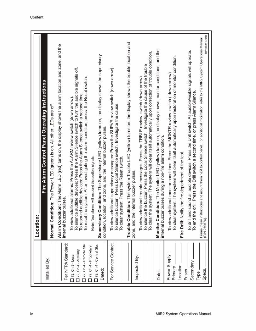
Fram
e th
ese
inst
ruct
ions
and
mou
nt th
em n
ext t
o co
ntro
l pan
el. F
or a
dditi
onal
info
rmat
ion,
refe
r to
the
MIR
2 S
yste
m O
pera
tions
Man
ual
(P/N
270
676)
.
Inst
alle
d By
:
Per
NFP
A St
anda
rd:
For S
ervi
ce C
onta
ct:
Insp
ecte
d B
y:
Pow
er S
uppl
y:P
rimar
yLo
catio
nFu
ses
Sec
onda
ryTy
peSp
ecs.
72, C
h 3
- Loc
al72
, Ch
4 - A
uxili
ary
72, C
h 4
- Rem
ote
Sta.
72, C
h 4
- Pro
prie
tary
72, C
h 4
- Cen
tral S
ta.
Dat
ed:
Dat
e:
OPE
R00
01.C
DR
Loca
tion:
Content
MIR2 System Operations Manual v
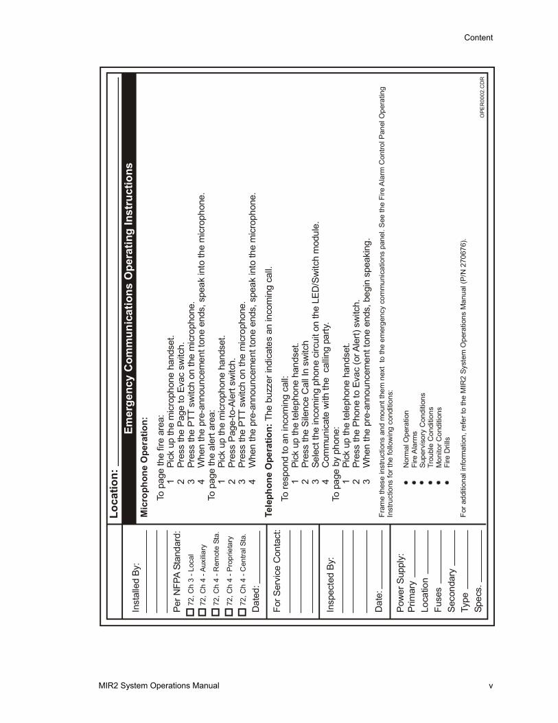
Mic
roph
one
Ope
ratio
n:
Tele
phon
e O
pera
tion:
To p
age
the
fire
area
:1
Pick
up
the
mic
roph
one
hand
set.
2Pr
ess
the
Pag
e to
Eva
c sw
itch.
3Pr
ess
the
PTT
sw
itch
on th
e m
icro
phon
e.4
Whe
n th
e pr
e-an
noun
cem
ent t
one
ends
, spe
ak in
to th
e m
icro
phon
e.To
pag
e th
e al
ert a
rea:
1Pi
ck u
p th
e m
icro
phon
e ha
ndse
t.2
Pres
s P
age-
to-A
lert
switc
h.3
Pres
s th
e P
TT s
witc
h on
the
mic
roph
one.
4W
hen
the
pre-
anno
unce
men
t ton
e en
ds, s
peak
into
the
mic
roph
one.
The
buzz
er in
dica
tes
an in
com
ing
call.
To re
spon
d to
an
inco
min
g ca
ll:1
Pick
up
the
tele
phon
e ha
ndse
t.2
Pres
s th
e S
ilenc
e C
all I
n sw
itch
3Se
lect
the
inco
min
g ph
one
circ
uit o
n th
e LE
D/S
witc
h m
odul
e.4
Com
mun
icat
e w
ith th
e c
allin
g pa
rty.
To p
age
by p
hone
:1
Pick
up
the
tele
phon
e ha
ndse
t.2
Pres
s th
e P
hone
to E
vac
(or A
lert)
sw
itch.
3W
hen
the
pre-
anno
unce
men
t ton
e en
ds, b
egin
spe
akin
g.Fr
ame
thes
e in
stru
ctio
ns a
nd m
ount
them
nex
t to
the
emer
genc
y co
mm
unic
atio
ns p
anel
. See
the
Fire
Ala
rm C
ontro
l Pan
el O
pera
ting
Inst
ruct
ions
for t
he fo
llow
ing
cond
ition
s:
Nor
mal
Ope
ratio
nFi
re A
larm
sS
uper
viso
ry C
ondi
tions
Trou
ble
Con
ditio
nsM
onito
r Con
ditio
nsFi
re D
rills
For a
dditi
onal
info
rmat
ion,
refe
r to
the
MIR
2 S
yste
m O
pera
tions
Man
ual (
P/N
270
676)
.
Loca
tion:
Emer
genc
y C
omm
unic
atio
ns O
pera
ting
Inst
ruct
ions
Inst
alle
d By
:
Per
NFP
A St
anda
rd:
For S
ervi
ce C
onta
ct:
Insp
ecte
d B
y:
Pow
er S
uppl
y:P
rimar
yLo
catio
nFu
ses
Sec
onda
ryTy
peSp
ecs.
72, C
h 3
- Loc
al72
, Ch
4 - A
uxili
ary
72, C
h 4
- Rem
ote
Sta.
72, C
h 4
- Pro
prie
tary
72, C
h 4
- Cen
tral S
ta.
Dat
ed:
Dat
e:
OPE
R00
02.C
DR

Content
vi MIR2 System Operations Manual
MIR2 System Operations Manual 1.1
Chapter 1 Quick Operation
Summary
This chapter shows you how to operate the system in response to common fire alarm events.
Content
Fire Alarm • 1.2
Emergency Paging • 1.4
Telephone Operations • 1.6
Telephone Paging • 1.8
Supervisory Condition • 1.10
Monitor Point • 1.12
Trouble Condition • 1.13
Fire Drill • 1.15
Verification • 1.16
Maintenance • 1.17
Chapter1
Chapter1
Quick Operation
MIR2 System Operations Manual 1.2
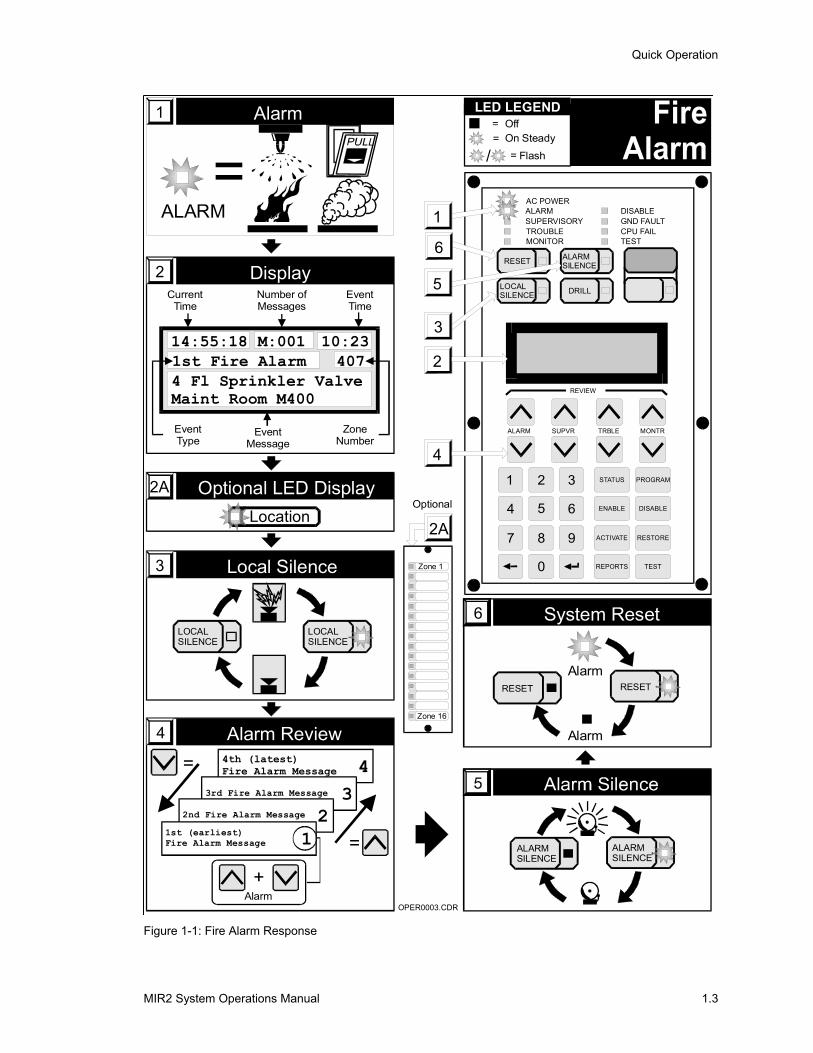
Fire Alarm Refer to Figure 1-1.
A fire alarm is indicated by the ALARM LED (item 1). Alarms may be caused by smoke and heat detectors, fire alarm stations, or the sprinkler system.
To respond to a fire alarm:
1 Read the alarm location from the display (item 2) or LED panel (item 2A).
2 Press the LOCAL SILENCE switch (item 3) to silence the internal buzzer.
3 Review the alarm messages by pressing the ALARM Review Switch (item 4). This will display any additional alarm locations. The most recent location is at the top of the list.
4 Investigate the cause of the alarm after the fire has been extinguished and the facility is safe to re-occupy.
5 Press the ALARM SILENCE switch (item 5) to silence the alarm bells, horns, and speakers.
Note: The ALARM SILENCE LED will flash for a predetermined amount of time inhibiting the silencing of the bells, horns, and speakers. After the inhibit period has elapsed, the LED will go off and the Alarm Silence switch will then be able to silence the bells, horns, and speakers.
6 Press the RESET Switch (item 6) to restore the panel to normal. Smoke detectors must be clear of smoke, fire alarm stations must be manually reset, and the sprinkler system must be restored to normal before the panel will reset. If the panel also shows Supervisory, Monitor, or Trouble conditions these messages may be reviewed after the Fire Alarms.
Note: The RESET LED will flash for a predetermined amount of time inhibiting the reset of the panel. After the inhibit period has elapsed, the LED will go off and the Reset switch will then be able to reset the panel.
Quick Operation
MIR2 System Operations Manual 1.3
=ALARM
Alarm1
Optional LED Display2A
Location
Alarm Review44th (latest)Fire Alarm Message 4
3rd Fire Alarm Message 32nd Fire Alarm Message 2
1st (earliest)Fire Alarm Message 1
Alarm+
=
=
Display2
14:55:181st Fire Alarm4 Fl Sprinkler ValveMaint Room M400
M:001 10:23407
CurrentTime
EventType
EventMessage
ZoneNumber
Number ofMessages
EventTime
System Reset6
RESET RESET
Alarm
Alarm
Local Silence3
LOCALSILENCE
LOCALSILENCE
= Off= On Steady
= Flash/
LED LEGEND
2
4
1
1
4
7
2
5
8
0
3
6
9
6
3
LOCALSILENCE
RESET ALARMSILENCE
DRILL
STATUS PROGRAM
ENABLE DISABLE
ACTIVATE RESTORE
REPORTS TEST
REVIEW
ALARM SUPVR TRBLE MONTR
AC POWERALARMSUPERVISORYTROUBLEMONITOR
DISABLEGND FAULTCPU FAILTEST
5
Optional
2A
Zone 1
Zone 16
OPER0003.CDR
ALARMSILENCE
ALARMSILENCE
Figure 1-1: Fire Alarm Response
Quick Operation
MIR2 System Operations Manual 1.4
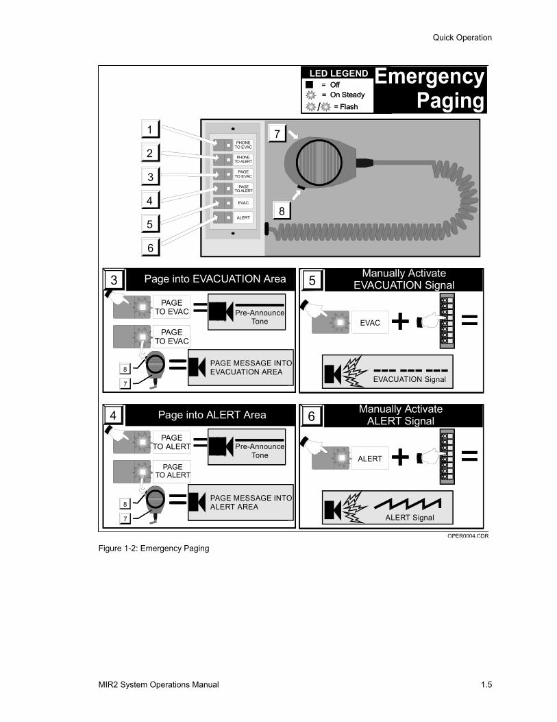
Emergency Paging Refer to Figure 1-2.
Emergency pages are used to issue instructions to occupants in the facility.
To issue an emergency page:
1 Remove the microphone (item 7) from its compartment.
2a Press the PAGE TO EVAC switch (item 3) to direct the page to the evacuation area. The LED in the switch lights, indicating the switch is active.
2b Press the PAGE TO ALERT switch (item 4) to direct the page to the alert area. The LED in the switch lights, indicating the switch is active.
3 Press the Push-To-Talk switch (item 8), wait for the preannounce tone to end (approximately 3 seconds) and speak into the microphone.
Note: Refer to site specific information to determine the definition of the evacuation and alert areas.
To manually sound the evacuation signal:
1 Press the EVAC switch (item 5). The LED in the switch lights, indicating the switch is active.
2 Operate the zone switches of those areas which are to receive the evacuation signal. Refer to your specific panel instructions for specific zone selection information.
To manually sound the alert signal:
1 Press the ALERT switch (item 6). The LED in the switch lights, indicating the switch is active.
2 Operate the zone switches of those areas which are to receive the alert signal. Refer to your specific panel instructions for specific zone selection information.
Quick Operation
MIR2 System Operations Manual 1.5
= Off= On Steady
= Flash/
LED LEGEND
2
4
1
6
3
5
PHONETO EVAC
PHONETO ALERT
PAGETO EVAC
PAGETO ALERT
EVAC
ALERT8
7
= Off= On Steady
= Flash/
LED LEGEND
2
4
1
6
3
5
PHONETO EVAC
PHONETO ALERT
PAGETO EVAC
PAGETO ALERT
EVAC
ALERT8
7
OPER0004.CDR
=Page in EVACUATION Area3
PAGE MESSAGE INEVACUATION AREA=8
7
Page into EVACUATION Area3PAGE
TO EVAC
PAGE MESSAGE INTOEVACUATION AREA
Pre-AnnounceTone
=8
7
PAGETO EVAC
PAGETO EVAC
=
PAGE MESSAGE INEVACUATION AREA=
PAGETO EVAC
8
7
PAGE MESSAGE INTOALERT AREA
Pre-AnnounceTone
PAGETO ALERT
=PAGE
TO ALERT
8
7
Page in ALERT Area4 Page into ALERT Area4
=
Manually ActivateEVACUATION Signal5
EVACUATION Signal
=
Manually ActivateEVACUATION Signal5
EVAC
EVACUATION Signal
=
Manually ActivateALERT Signal
ALERT Signal
6
=
Manually ActivateALERT Signal
ALERT
ALERT Signal
6
Figure 1-2: Emergency Paging

Quick Operation
MIR2 System Operations Manual 1.6
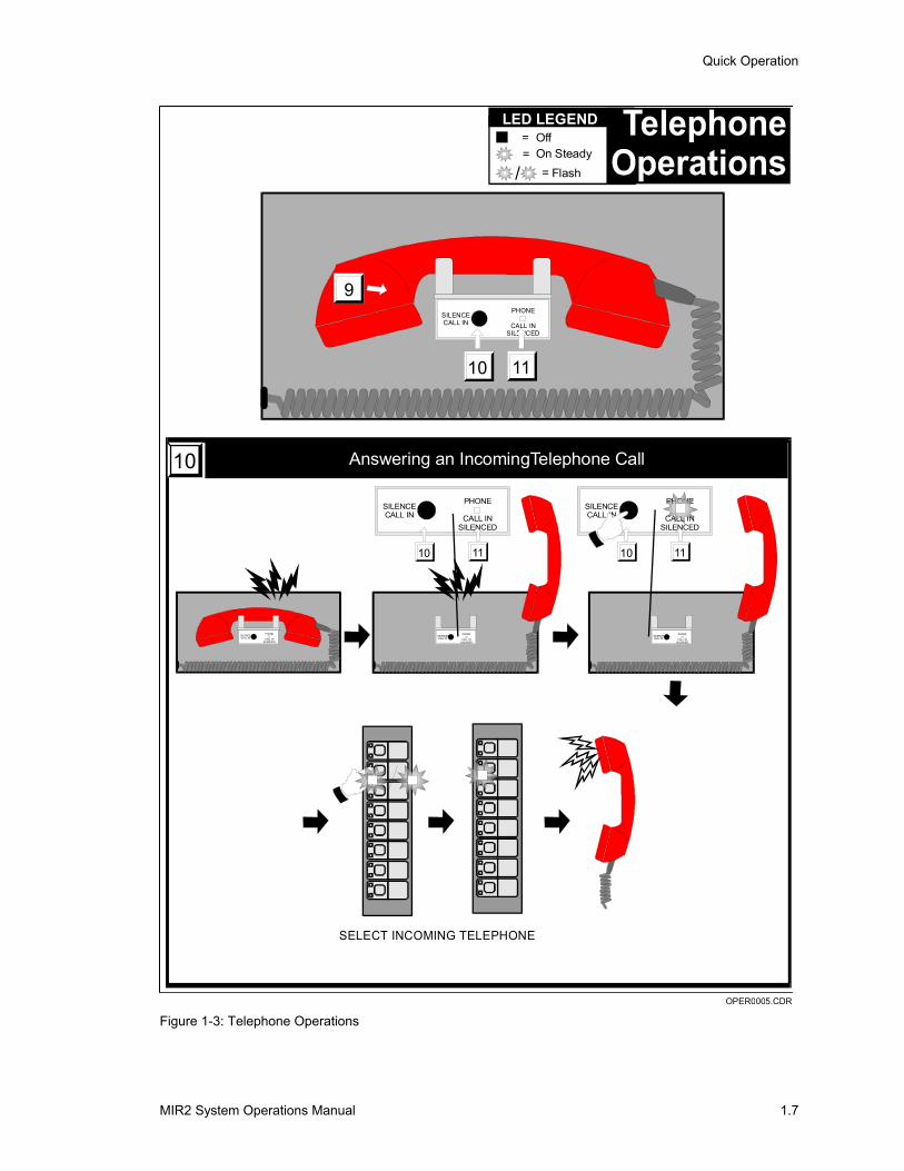
Telephone Operations
Refer to Figure 1-3.
To use the firefighter’s telephone:
1 Buzzer indicates incoming call.
2 Remove handset (item 9) and press the SILENCE CALL IN switch (item 10). The CALL IN SILENCED LED (item 11) will light.
3 Operate the telephone circuit select switch to connect the incoming call. Refer to your specific panel instructions for telephone selection information.
Quick Operation
MIR2 System Operations Manual 1.7
SILENCECALL IN
PHONE
CALL INSILENCED
SILENCECALL IN
PHONE
CALL INSILENCED
= Off= On Steady
= Flash/
LED LEGEND
10 11
SILENCECALL IN
PHONE
CALL INSILENCED
10 11
SILENCECALL IN
PHONE
CALL INSILENCED
10 11
9
Answering an IncomingTelephone Call10
SILENCECALL IN
PHONE
CALL INSILENCED
SILENCECALL IN
PHONE
CALL INSILENCED
SELECT INCOMING TELEPHONE
OPER0005.CDR Figure 1-3: Telephone Operations
Quick Operation
MIR2 System Operations Manual 1.8
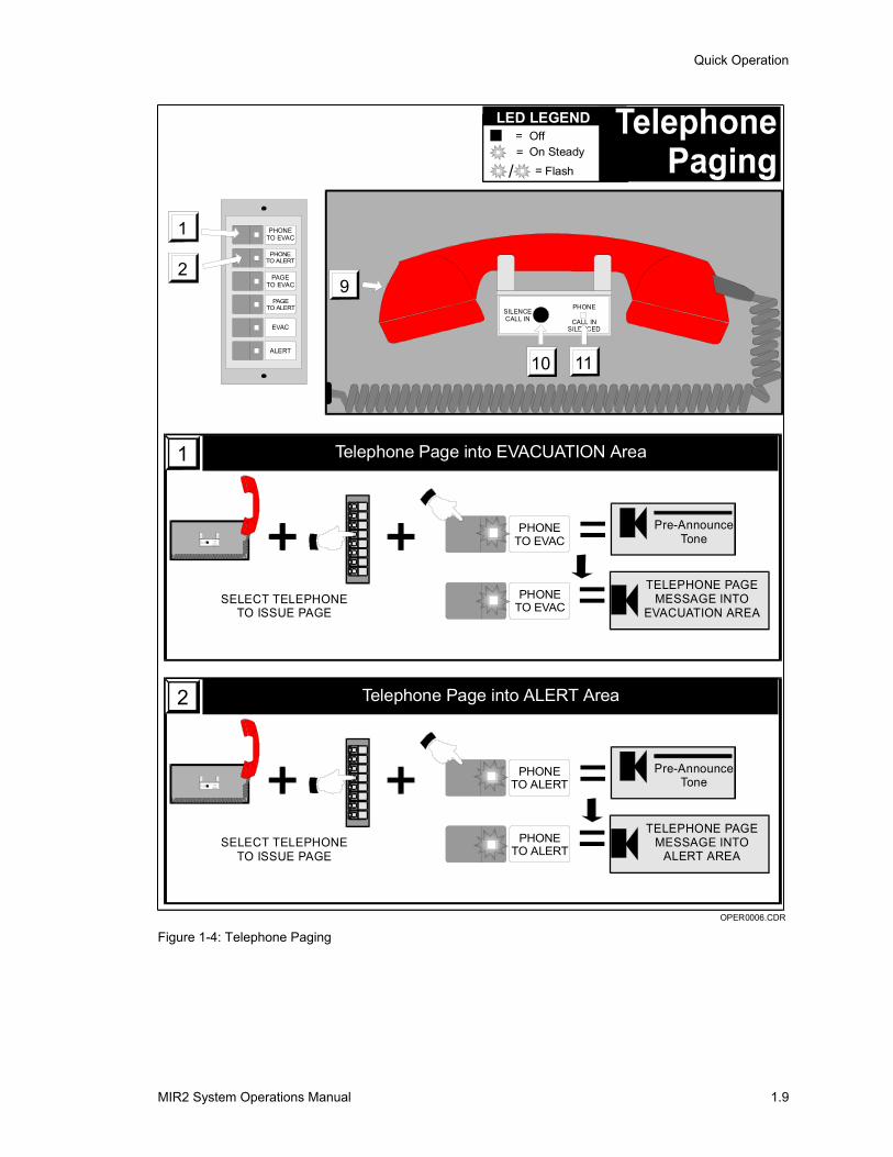
Telephone Paging Refer to Figure 1-4.
To page using the firefighter’s telephone:
1 Establish communications with the telephone circuit which is to make the page. (See previous page.)
2a Press the PHONE TO EVAC switch (item 1) to direct the telephone page to the evacuation area. The LED in the switch lights, indicating the switch is active.
2b Press the PHONE TO ALERT switch (item 2) to direct the telephone page to the alert area. The LED in the switch lights, indicating the switch is active.
3 The calling party must wait for the pre-announce tone to end (approximately 3 seconds), then page by speaking into his telephone.
Note: Refer to site specific information to determine the definition of the evacuation and alert areas.
Quick Operation
MIR2 System Operations Manual 1.9
SILENCECALL IN
PHONE
CALL INSILENCED
= Off= On Steady
= Flash/
LED LEGEND
10 11
92
1
2
1 PHONETO EVAC
PHONETO ALERT
PAGETO EVAC
PAGETO ALERT
EVAC
ALERT
OPER0006.CDR
Telephone Page into EVACUATION Area1
PHONETO EVAC
==S IL E N C E
C A LL I N
P H O N E
C A L L I NS I LE N C E D
Pre-AnnounceTone
TELEPHONE PAGEMESSAGE INTO
EVACUATION AREASELECT TELEPHONE
TO ISSUE PAGEPHONE
TO EVAC
Telephone Page into ALERT Area2
PHONETO ALERT
==S IL E N C E
C A LL I N
P H O N E
C A L L I NS I LE N C E D
Pre-AnnounceTone
TELEPHONE PAGEMESSAGE INTO
ALERT AREASELECT TELEPHONE
TO ISSUE PAGEPHONE
TO ALERT
Figure 1-4: Telephone Paging
Quick Operation
MIR2 System Operations Manual 1.10
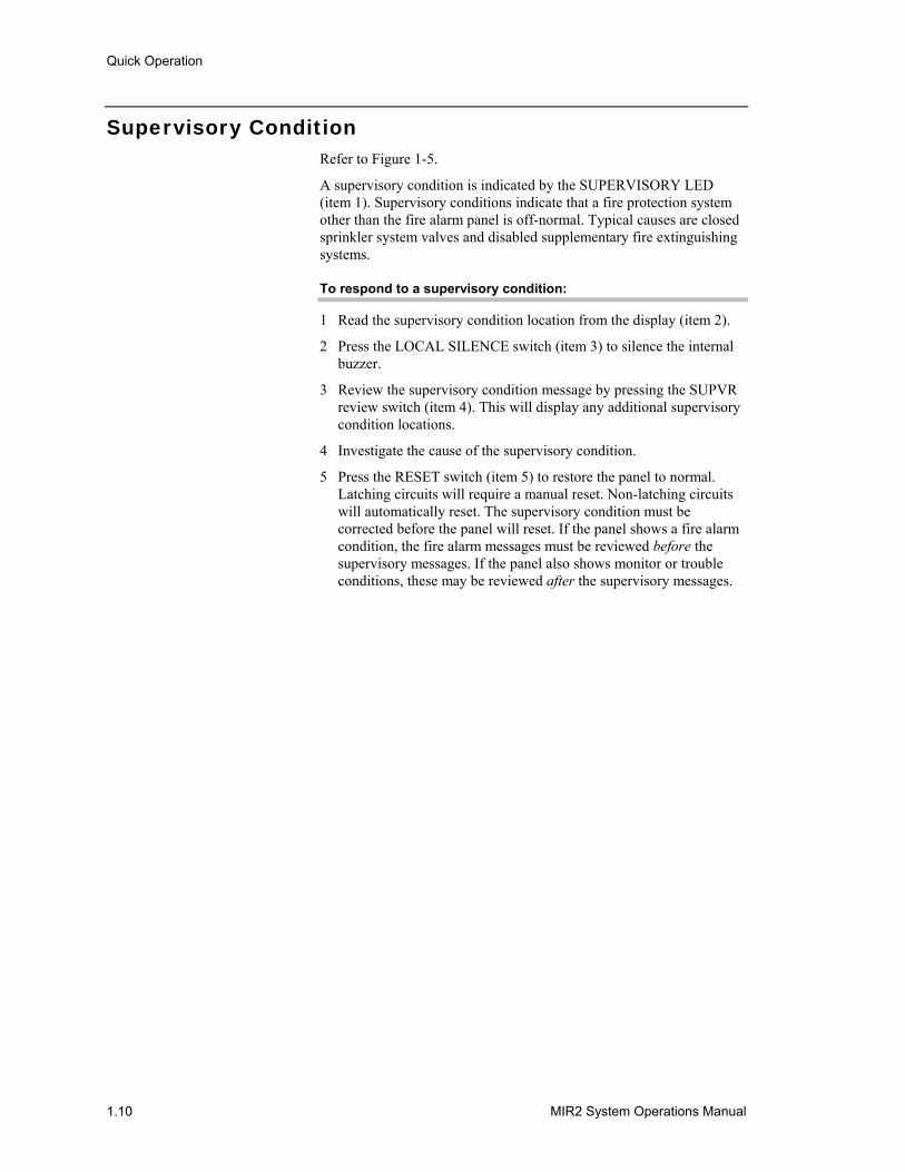
Supervisory Condition Refer to Figure 1-5.
A supervisory condition is indicated by the SUPERVISORY LED (item 1). Supervisory conditions indicate that a fire protection system other than the fire alarm panel is off-normal. Typical causes are closed sprinkler system valves and disabled supplementary fire extinguishing systems.
To respond to a supervisory condition:
1 Read the supervisory condition location from the display (item 2).
2 Press the LOCAL SILENCE switch (item 3) to silence the internal buzzer.
3 Review the supervisory condition message by pressing the SUPVR review switch (item 4). This will display any additional supervisory condition locations.
4 Investigate the cause of the supervisory condition.
5 Press the RESET switch (item 5) to restore the panel to normal. Latching circuits will require a manual reset. Non-latching circuits will automatically reset. The supervisory condition must be corrected before the panel will reset. If the panel shows a fire alarm condition, the fire alarm messages must be reviewed before the supervisory messages. If the panel also shows monitor or trouble conditions, these may be reviewed after the supervisory messages.
Quick Operation
MIR2 System Operations Manual 1.11
System Reset5
RESET RESET
Supervisory
Supervisory
2
4
1
1
4
7
2
5
8
0
3
6
9
5
3 LOCALSILENCE
RESET ALARMSILENCE
DRILL
STATUS PROGRAM
ENABLE DISABLE
ACTIVATE RESTORE
REPORTS TEST
REVIEW
ALARM SUPVR TRBLE MONTR
AC POWERALARMSUPERVISORYTROUBLEMONITOR
DISABLEGND FAULTCPU FAILTEST
OPER0007.CDR
Supervisory Condition1
=Supervisory
Display2
14:55:18Supervisory4 Fl Sprinkler ValveMaint Room M400
M:001 10:23407
CurrentTime
EventType
EventMessage
ZoneNumber
Number ofMessages
EventTime
Local Silence3
LOCALSILENCE
LOCALSILENCE
= Off= On Steady
= Flash/
LED LEGEND
Supervisory Review44th (latest)Supervisory Message 4
3rd Supervisory Message 32nd Supervisory Message 2
1st (earliest)Supervisory Message 1
=
=
SUPVR+
Figure 1-5: Supervisory Condition Response
Quick Operation
MIR2 System Operations Manual 1.12
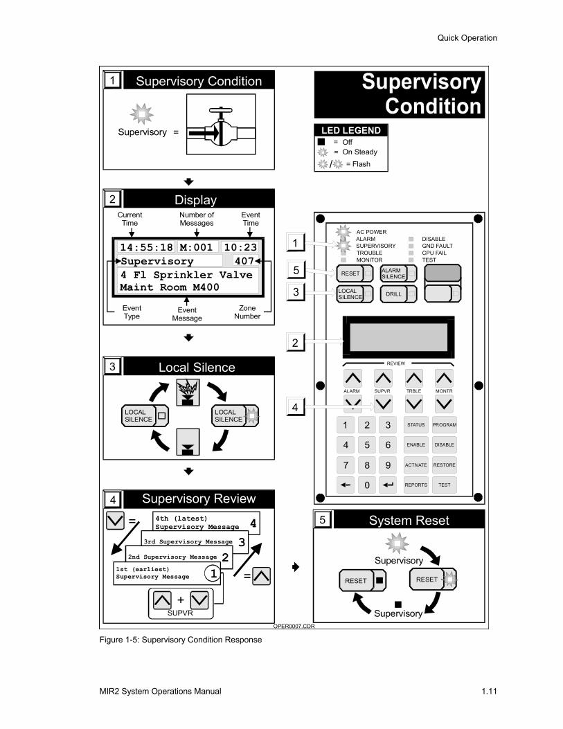
Monitor Point Refer to Figure 1-6.
An active monitor point is indicated by a steady MONITOR LED (item 1), but the LCD will not display a message unless the panel is in alarm. Monitor points indicate that equipment monitored by the fire alarm panel is in an off-normal condition. A typical cause of a monitor condition might be to signal the status of the fan systems
During the event which causes the active monitor point:
• A steady MONITOR LED (item 1) will illuminate to indicate an active monitor point, but the internal buzzer will NOT sound.
• The Active Point counter will increment.
• If the panel goes into alarm, the monitor message will be in the queue. In the alarm mode, active monitor messages will also be displayed on the LCD.
Display2
14:55:18
Headquarters Building
AP001 DP000
CurrentTime
ActivePoints
Counter
DisabledPoints
Counter
Project Description
2
31
4
7
2
5
8
0
3
6
9
LOCALSILENCE
RESET ALARMSILENCE
DRILL
STATUS PROGRAM
ENABLE DISABLE
ACTIVATE RESTORE
REPORTS TEST
REVIEW
ALARM SUPVR TRBLE MONTR
AC POWERALARMSUPERVISORYTROUBLEMONITOR
DISABLEGND FAULTCPU FAILTEST
OPER0008.CDR
Monitor1
OFF
=Monitor1
= Off= On Steady
= Flash/
LED LEGEND
Figure 1-6: Monitor Point Response
Quick Operation
MIR2 System Operations Manual 1.13
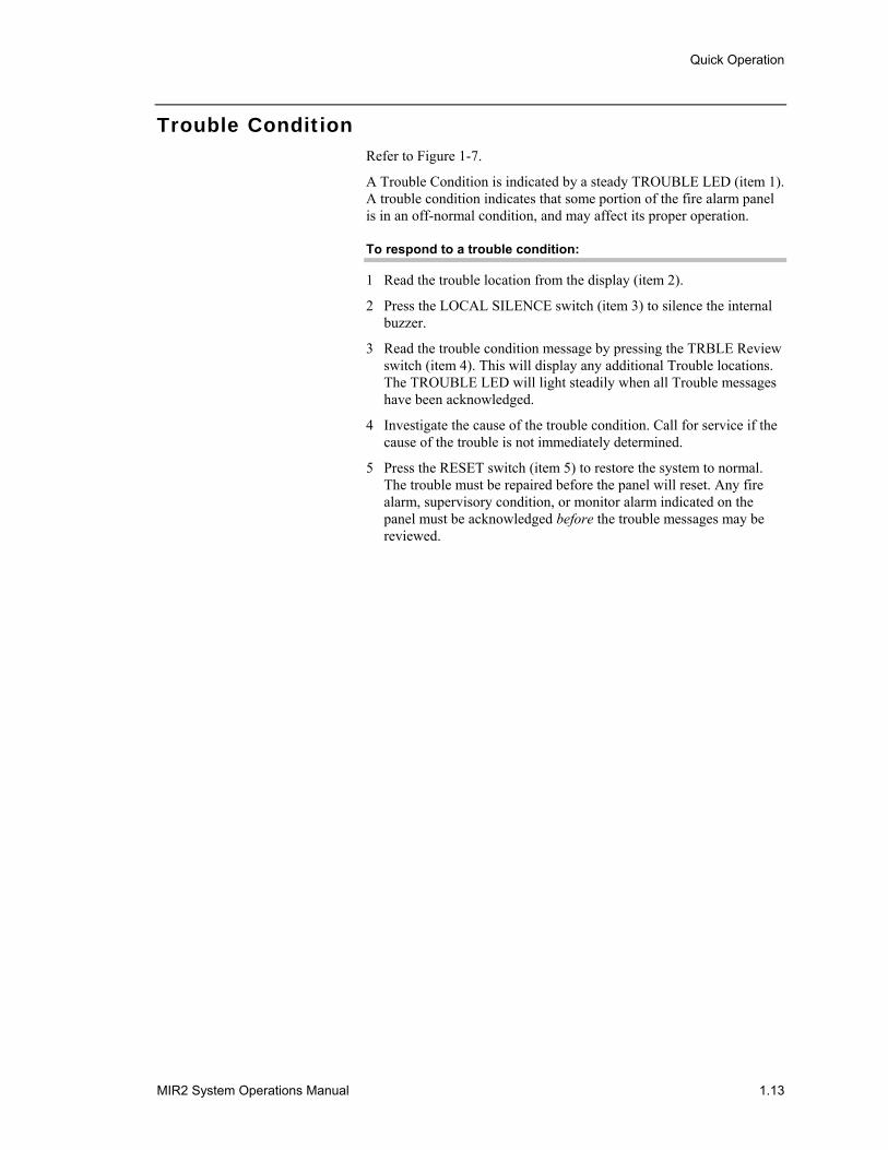
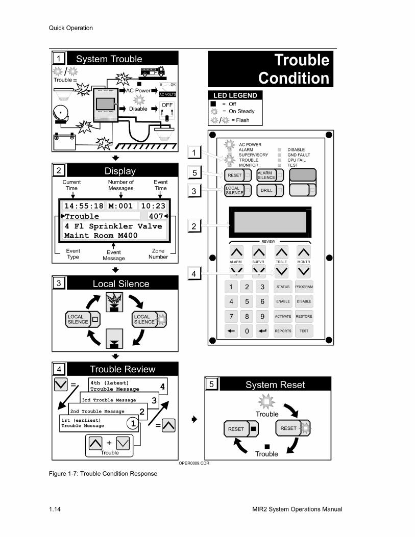
Trouble Condition Refer to Figure 1-7.
A Trouble Condition is indicated by a steady TROUBLE LED (item 1). A trouble condition indicates that some portion of the fire alarm panel is in an off-normal condition, and may affect its proper operation.
To respond to a trouble condition:
1 Read the trouble location from the display (item 2).
2 Press the LOCAL SILENCE switch (item 3) to silence the internal buzzer.
3 Read the trouble condition message by pressing the TRBLE Review switch (item 4). This will display any additional Trouble locations. The TROUBLE LED will light steadily when all Trouble messages have been acknowledged.
4 Investigate the cause of the trouble condition. Call for service if the cause of the trouble is not immediately determined.
5 Press the RESET switch (item 5) to restore the system to normal. The trouble must be repaired before the panel will reset. Any fire alarm, supervisory condition, or monitor alarm indicated on the panel must be acknowledged before the trouble messages may be reviewed.
Quick Operation
MIR2 System Operations Manual 1.14
System Reset5
RESET RESET
Trouble
Trouble
OPER0009.CDR
2
41
4
7
2
5
8
0
3
6
9
5
LOCALSILENCE
RESET ALARMSILENCE
DRILL
STATUS PROGRAM
ENABLE DISABLE
ACTIVATE RESTORE
REPORTS TEST
REVIEW
ALARM SUPVR TRBLE MONTR
AC POWERALARMSUPERVISORYTROUBLEMONITOR
DISABLEGND FAULTCPU FAILTEST
1
3
SYSTEM TROUBLE
E DWA R D S SY S TE MS TE C HN OLOGY
=Trouble/
System Trouble1
AC PowerAC VOLTS
OK0
DisableOFF
Display2
14:55:18Trouble4 Fl Sprinkler ValveMaint Room M400
M:001 10:23407
CurrentTime
EventType
EventMessage
ZoneNumber
Number ofMessages
EventTime
Trouble Review44th (latest)Trouble Message 4
3rd Trouble Message 32nd Trouble Message 2
1st (earliest)Trouble Message 1
Trouble+
=
=
Local Silence3
LOCALSILENCE
LOCALSILENCE
= Off= On Steady
= Flash/
LED LEGEND
Figure 1-7: Trouble Condition Response
Quick Operation
MIR2 System Operations Manual 1.15
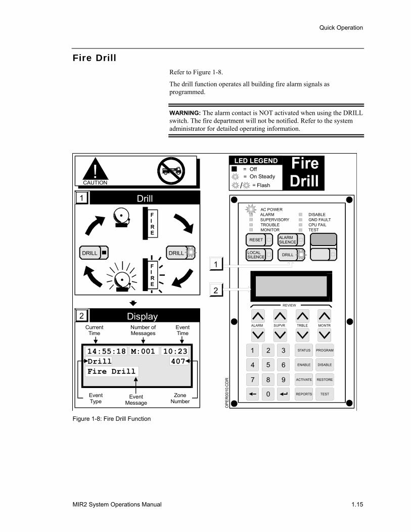
Fire Drill Refer to Figure 1-8.
The drill function operates all building fire alarm signals as programmed.
WARNING: The alarm contact is NOT activated when using the DRILL switch. The fire department will not be notified. Refer to the system administrator for detailed operating information.
OP
ER
0010
.CD
R
2
1
4
7
2
5
8
0
3
6
9
LOCALSILENCE
RESET ALARMSILENCE
DRILL
STATUS PROGRAM
ENABLE DISABLE
ACTIVATE RESTORE
REPORTS TEST
REVIEW
ALARM SUPVR TRBLE MONTR
AC POWERALARMSUPERVISORYTROUBLEMONITOR
DISABLEGND FAULTCPU FAILTEST
1
Drill1
DRILL DRILL
FIRE
FIRE
!CAUTION
14:55:18DrillFire Drill
M:001 10:23407
Display2Current
Time
EventType
EventMessage
ZoneNumber
Number ofMessages
EventTime
= Off= On Steady
= Flash/
LED LEGEND
Figure 1-8: Fire Drill Function
Quick Operation
MIR2 System Operations Manual 1.16
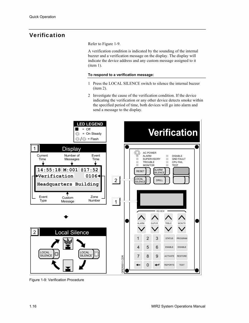
Verification Refer to Figure 1-9.
A verification condition is indicated by the sounding of the internal buzzer and a verification message on the display. The display will indicate the device address and any custom message assigned to it (item 1).
To respond to a verification message:
1 Press the LOCAL SILENCE switch to silence the internal buzzer (item 2).
2 Investigate the cause of the verification condition. If the device indicating the verification or any other device detects smoke within the specified period of time, both devices will go into alarm and send a message to the display.
1
4
7
2
5
8
0
3
6
9
1
2 LOCALSILENCE
RESET ALARMSILENCE
DRILL
STATUS PROGRAM
ENABLE DISABLE
ACTIVATE RESTORE
REPORTS TEST
REVIEW
ALARM SUPVR TRBLE MONTR
AC POWERALARMSUPERVISORYTROUBLEMONITOR
DISABLEGND FAULTCPU FAILTEST
OP
ER
0011
.CD
R
14:55:18Verification
Headquarters Building
M:001 @17:520106
Display1Current
Time
EventType
CustomMessage
ZoneNumber
Number ofMessages
EventTime
Local Silence2
LOCALSILENCE
LOCALSILENCE
= Off= On Steady
= Flash/
LED LEGEND
Figure 1-9: Verification Procedure
Quick Operation
MIR2 System Operations Manual 1.17
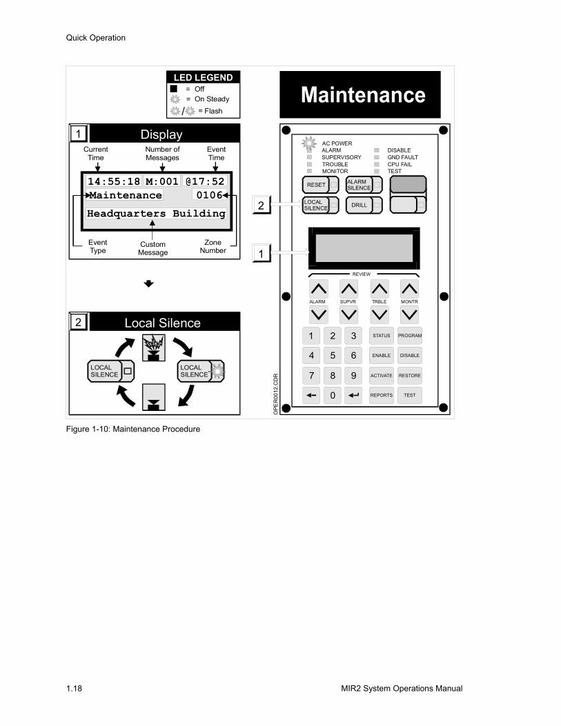
Maintenance Refer to Figure 1-10.
A maintenance condition is indicated by the sounding of the internal buzzer and a maintenance message on the display. The display will indicate the device address and any custom message assigned to that device (item 1).
To respond to a maintenance message:
1 Press the LOCAL SILENCE switch to silence the internal buzzer (item 2).
2 Investigate the device indicating the Maintenance message.
3 Clean the device when a problem is indicated.
The maintenance messages can be viewed on the Sensitivity Report via the 2-LCD or a printer.
Quick Operation
MIR2 System Operations Manual 1.18
1
4
7
2
5
8
0
3
6
9
1
2 LOCALSILENCE
RESET ALARMSILENCE
DRILL
STATUS PROGRAM
ENABLE DISABLE
ACTIVATE RESTORE
REPORTS TEST
REVIEW
ALARM SUPVR TRBLE MONTR
AC POWERALARMSUPERVISORYTROUBLEMONITOR
DISABLEGND FAULTCPU FAILTEST
OPE
R00
12.C
DR
14:55:18Maintenance
Headquarters Building
M:001 @17:520106
Display1Current
Time
EventType
CustomMessage
ZoneNumber
Number ofMessages
EventTime
Local Silence2
LOCALSILENCE
LOCALSILENCE
= Off= On Steady
= Flash/
LED LEGEND
Figure 1-10: Maintenance Procedure
MIR2 System Operations Manual 2.1
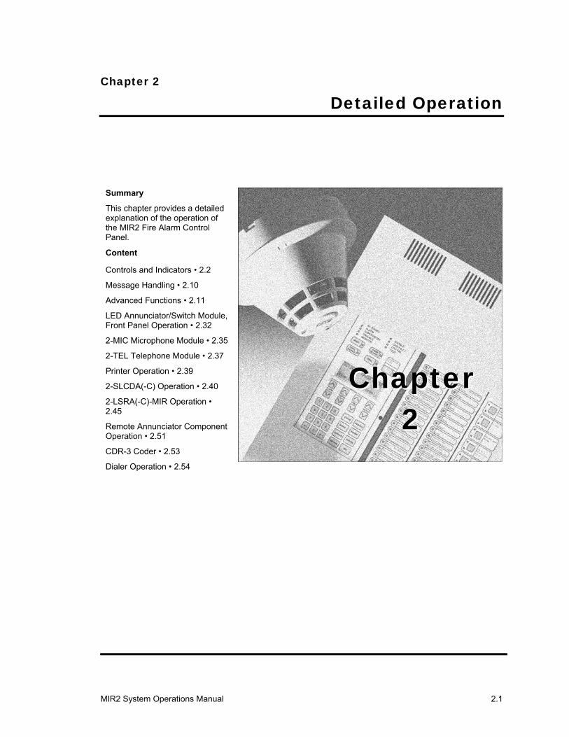
Chapter 2 Detailed Operation
Summary
This chapter provides a detailed explanation of the operation of the MIR2 Fire Alarm Control Panel.
Content
Controls and Indicators • 2.2
Message Handling • 2.10
Advanced Functions • 2.11
LED Annunciator/Switch Module, Front Panel Operation • 2.32
2-MIC Microphone Module • 2.35
2-TEL Telephone Module • 2.37
Printer Operation • 2.39
2-SLCDA(-C) Operation • 2.40
2-LSRA(-C)-MIR Operation • 2.45
Remote Annunciator Component Operation • 2.51
CDR-3 Coder • 2.53
Dialer Operation • 2.54
Chapter2
Chapter2
Detailed Operation
2.2 MIR2 System Operations Manual
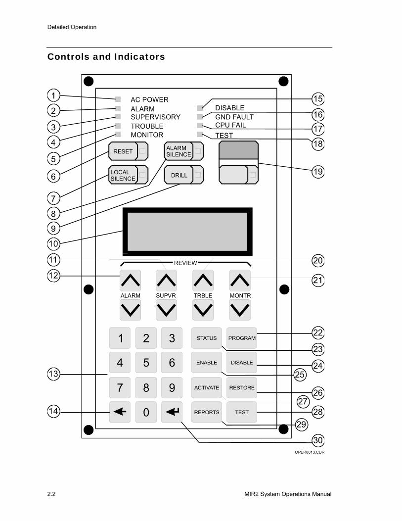
Controls and Indicators
1
2
3
4
5
6
7
8
9
10
11
12
13
14
15
16
17
18
19
20
21
22
23
24
2627
2829
30
25
AC POWERALARMSUPERVISORYTROUBLEMONITOR
RESET ALARMSILENCE
LOCALSILENCE
ALARM
STATUS
ENABLE
ACTIVATE
REPORTS
PROGRAM
DISABLE
RESTORE
TEST
SUPVR
REVIEW
MONTRTRBLE
DRILL
DISABLEGND FAULTCPU FAILTEST
3
4 5 6
7 8 9
0
1 2
OPER0013.CDR
Detailed Operation
MIR2 System Operations Manual 2.3
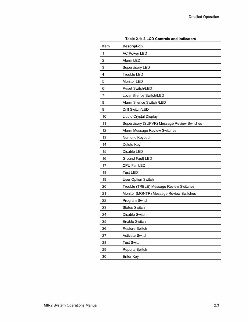
Table 2-1: 2-LCD Controls and Indicators
Item Description
1 AC Power LED
2 Alarm LED
3 Supervisory LED
4 Trouble LED
5 Monitor LED
6 Reset Switch/LED
7 Local Silence Switch/LED
8 Alarm Silence Switch /LED
9 Drill Switch/LED
10 Liquid Crystal Display
11 Supervisory (SUPVR) Message Review Switches
12 Alarm Message Review Switches
13 Numeric Keypad
14 Delete Key
15 Disable LED
16 Ground Fault LED
17 CPU Fail LED
18 Test LED
19 User Option Switch
20 Trouble (TRBLE) Message Review Switches
21 Monitor (MONTR) Message Review Switches
22 Program Switch
23 Status Switch
24 Disable Switch
25 Enable Switch
26 Restore Switch
27 Activate Switch
28 Test Switch
29 Reports Switch
30 Enter Key
Detailed Operation
2.4 MIR2 System Operations Manual
Description
AC Power LED (Item 1)
The AC Power LED, which is green, indicates that AC power is available. When the AC Power LED is off, there is an AC power failure.
Alarm LED (Item 2)
The Alarm LED, which is red, indicates that there is an active fire alarm condition on the panel. Use the ALARM REVIEW switch to determine the active alarm points.
Supervisory LED (Item 3)
The Supervisory LED, which is yellow, indicates that there is an active Supervisory condition on the panel. Use the SUPVR REVIEW switch to determine the active supervisory points.
Trouble LED (Item 4)
The Trouble LED, which is yellow, indicates that there is an active trouble condition on the panel. Use the TRBLE REVIEW switch to determine the active trouble points.
Monitor LED (Item 5)
The Monitor LED, which is yellow, indicates that there is an active monitor condition on the panel. Use the MONTR REVIEW switch to determine the active monitor points.
Reset Switch/LED (Item 6)
The RESET Switch returns the system to normal if all the initiating devices are capable of being reset (i.e., no smoke in smoke detectors).
The Reset switch has an integral yellow LED, which is lit when a reset is in progress. A flashing LED indicates that the inhibit timer is active, which disables the ability to reset the panel for a pre-determined amount of time.
Non-latching monitor and supervisory circuits will reset automatically.
Local Silence Switch/LED (Item 7)
Pushing the LOCAL SILENCE Switch quiets the panel’s internal buzzer and permits scrolling through the message queues. The buzzer will automatically resound if a new alarm, supervisory, or trouble condition is received after it has been silenced.
The Local Silence switch has an integral yellow LED, which is lit when the buzzer has been silenced.
Detailed Operation
MIR2 System Operations Manual 2.5
Lamp Test (Items 7 and 8)
Pushing the LOCAL SILENCE and the ALARM SILENCE switches simultaneously activates the LAMP TEST function.
Alarm Silence Switch/LED (Item 8)
Pushing the ALARM SILENCE Switch silences the audible alarm notification appliances.
The Alarm Silence switch, which has an integral yellow LED, indicates that an alarm has been silenced. A flashing LED indicates that the inhibit timer is active. Inhibit disables the ability to Alarm Silence the system for a pre-determined amount of time.
Drill Switch/LED (Item 9)
Pushing The DRILL Switch activates all audible and visual alarm notification appliances.
The Drill switch has an integral yellow LED, which when lit, indicates that there is an active drill condition.
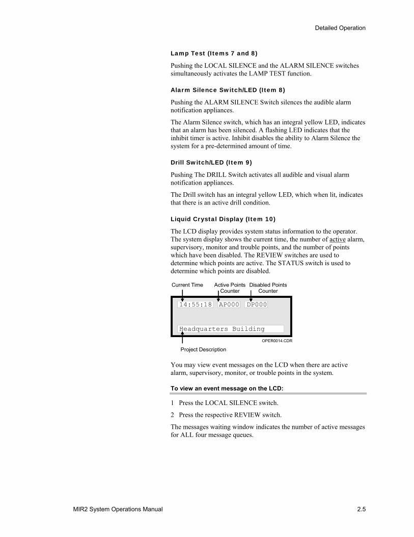
Liquid Crystal Display (Item 10)
The LCD display provides system status information to the operator. The system display shows the current time, the number of active alarm, supervisory, monitor and trouble points, and the number of points which have been disabled. The REVIEW switches are used to determine which points are active. The STATUS switch is used to determine which points are disabled.
Current Time Active PointsCounter
Disabled PointsCounter
Project Description
14:55:18 AP000 DP000
Headquarters Building
OPER0014.CDR
You may view event messages on the LCD when there are active alarm, supervisory, monitor, or trouble points in the system.
To view an event message on the LCD:
1 Press the LOCAL SILENCE switch.
2 Press the respective REVIEW switch.
The messages waiting window indicates the number of active messages for ALL four message queues.
Detailed Operation
2.6 MIR2 System Operations Manual
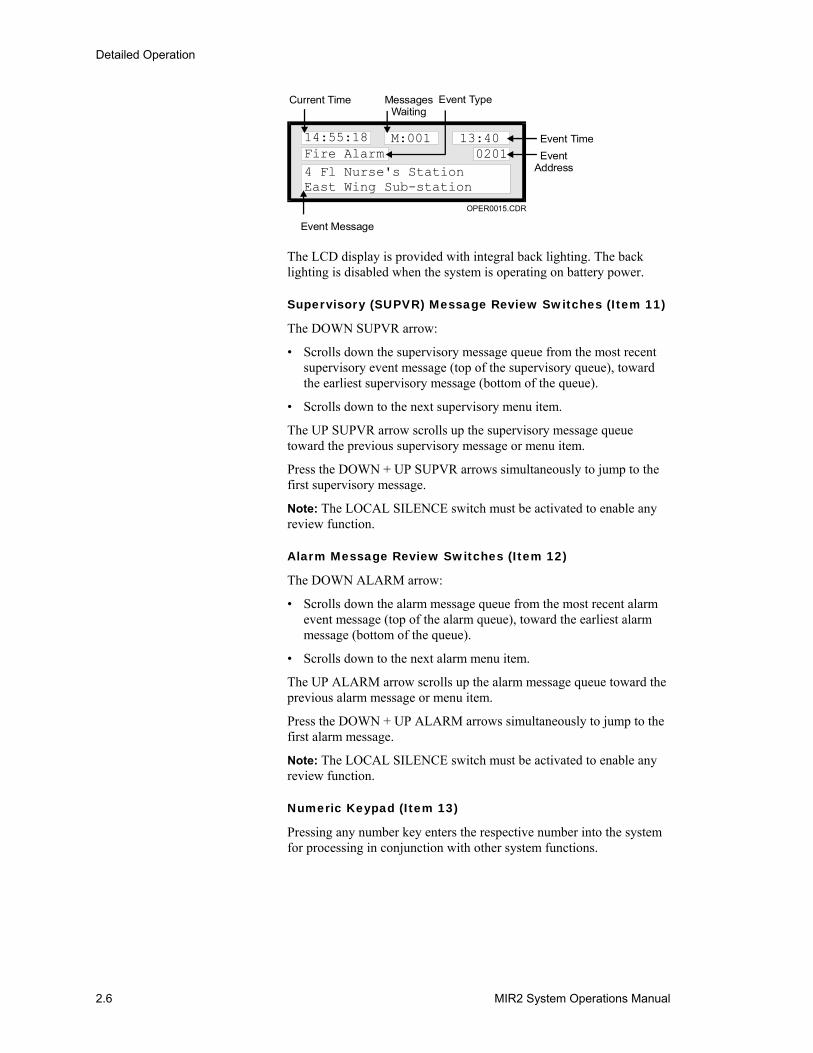
Current Time MessagesWaiting
Event Time
Event Type
EventAddress
Event Message
OPER0015.CDR
Fire Alarm14:55:18 M:001 13:40
4 Fl Nurse's StationEast Wing Sub-station
0201
The LCD display is provided with integral back lighting. The back lighting is disabled when the system is operating on battery power.
Supervisory (SUPVR) Message Review Switches (Item 11)
The DOWN SUPVR arrow:
• Scrolls down the supervisory message queue from the most recent supervisory event message (top of the supervisory queue), toward the earliest supervisory message (bottom of the queue).
• Scrolls down to the next supervisory menu item.
The UP SUPVR arrow scrolls up the supervisory message queue toward the previous supervisory message or menu item.
Press the DOWN + UP SUPVR arrows simultaneously to jump to the first supervisory message.
Note: The LOCAL SILENCE switch must be activated to enable any review function.
Alarm Message Review Switches (Item 12)
The DOWN ALARM arrow:
• Scrolls down the alarm message queue from the most recent alarm event message (top of the alarm queue), toward the earliest alarm message (bottom of the queue).
• Scrolls down to the next alarm menu item.
The UP ALARM arrow scrolls up the alarm message queue toward the previous alarm message or menu item.
Press the DOWN + UP ALARM arrows simultaneously to jump to the first alarm message.
Note: The LOCAL SILENCE switch must be activated to enable any review function.
Numeric Keypad (Item 13)
Pressing any number key enters the respective number into the system for processing in conjunction with other system functions.
Detailed Operation
MIR2 System Operations Manual 2.7
Delete Key (Item 14)
Pressing the delete key on the numeric keypad backspaces the cursor to the left and removes the character from the display. The delete key is also used to cancel a function in some menus.
Disable LED (Item 15)
The Disable LED, which is yellow, indicates that one or more zones have been disabled. The Disabled Points (DP) counter indicates the number of disabled points. Additionally, the STATUS switch can also be used to determine which points are disabled.
Ground Fault LED (Item 16)
The Ground Fault LED, which is yellow, indicates that a ground fault condition on internal or field wiring.
CPU Fail LED (Item 17)
The CPU Fail LED, which is yellow, indicates that there is a failure of the main microprocessor.
Test LED (Item 18)
The Test LED, which is yellow, indicates that the panel is in test mode.
User Option Switch (Item 19)
The function of the user option switch is dependent upon the option installed. When customized, refer to the specific information furnished by the installer.
Trouble (TRBLE) Message Review Switches (Item 20)
The DOWN TRBLE arrow:
• Scrolls down the trouble message queue from the most recent trouble event message (top of the trouble queue), toward the earliest trouble message (bottom of the queue).
• Scrolls down to the next trouble menu item.
The UP TRBLE arrow scrolls up the trouble message queue toward the previous trouble message or menu item.
Press the DOWN + UP TRBLE arrows simultaneously to jump to the first trouble message.
Note: The LOCAL SILENCE switch must be activated to enable any review function.
Monitor (MONTR) Message Review Switches (Item 21)
The DOWN MONTR arrow:
• Scrolls down the monitor message queue from the most recent monitor event message (top of the monitor queue), toward the earliest monitor message (bottom of the queue).
Detailed Operation
2.8 MIR2 System Operations Manual
• Scrolls down to the next monitor menu item.
The UP MONTR arrow scrolls up the monitor message queue toward the previous monitor message or menu item.
Press the DOWN + UP MONTR arrows simultaneously to jump to the first monitor message.
Note: The LOCAL SILENCE switch must be activated to enable any review function.
Verification: Verification is an option that forces a detector to verify any detected smoke for a specified period of time (5 to 55 seconds). When smoke is initially detected, a verification message will be displayed on the 2-LCD. If smoke is again detected by the initial detector or by any other detector within the specified period of time, the detector will go into alarm. If no smoke is detected within the specified period of time, the verification message will go away. The alarm verification time period must be set-up in the Data Entry Program. Press the Monitor review switches to scroll through the verification message queue.
Maintenance: A maintenance message indicates that a particular device is in need of cleaning. The message will give the device address and any custom message assigned to that device.
Note: It is important to clean a device once this message is received.
Program Switch (Item 22)
Pressing the PROGRAM switch activates the program menu. Pressing the switch a second time exits the program menu. The program mode is used to configure the system date, time, passwords, and communication configuration. The program mode is also used to restart and reconfigure (autoprogram) the system. A level 3 password is required to access all program menu functions, except restart, which requires a level 2 or 3 password.
Status Switch (Item 23)
Pressing the STATUS switch activates the status menu. Pressing the switch a second time exits the status menu. Available status information includes: critical system functions, Signature Data Circuit status, relay/LED states, and disabled devices. A level 1, 2, or 3 password is required to access status functions.
Disable Switch (Item 24)
Pressing the DISABLE switch activates the disable menu. Pressing the switch a second time exits the disable menu. The following system functions may be manually disabled: actions, data lines, messages, panels, sequences, time controls, the laptop connection, zones, and mapping. Disabling a point will increment the Disabled Points (DP) counter on the LCD display. The STATUS switch may be used to determine which points are disabled. A level 2 or 3 password is required to access disable functions. Also, any time a manual disable is done, a trouble condition is indicated.
Detailed Operation
MIR2 System Operations Manual 2.9
Enable Switch (Item 25)
Pressing the ENABLE switch activates the enable menu. Pressing the switch a second time exits the enable menu. The following system functions may be manually enabled: actions, data lines, messages, panels, sequences, time controls, the laptop connection, zones, and mapping. Enabling a point will decrement the Disabled Points (DP) counter on the LCD display. A level 2 or 3 password is required to access enable functions.
Restore Switch (Item 26)
Pressing the RESTORE Switch activates the restore menu. Pressing the switch a second time exits the restore menu. Functions available for restoration include: actions, outputs, and sequences. A level 2 or 3 password is required access restore functions.
Activate Switch (Item 27)
Pressing the ACTIVATE Switch brings up the activate menu. Pressing the switch a second time exits the Activate menu. Functions available for activation include: actions, outputs, sequences, smoke level 1, and smoke level 2. A level 1, 2, or 3 password is required to access activate functions.
Test Switch (Item 28)
Pressing the TEST Switch puts the panel in test mode. The test mode permits the functional testing of individual initiating devices without operating the notification appliances (silent test mode). Alternately, the test mode can be configured to send a short pulse over the notification circuits, indicating initiation device operation (audible test mode). A level 2 or 3 password is required to access test functions.
Reports Switch (Item 29)
Pressing the REPORTS Switch activates the reports menu. Available reports are: sensitivity, and history. A level 1, 2, or 3 password is required to access report functions.
Enter Key (Item 30)
Pressing the ENTER key on the numeric keypad causes the system to start processing the information shown in the display.
Detailed Operation
2.10 MIR2 System Operations Manual
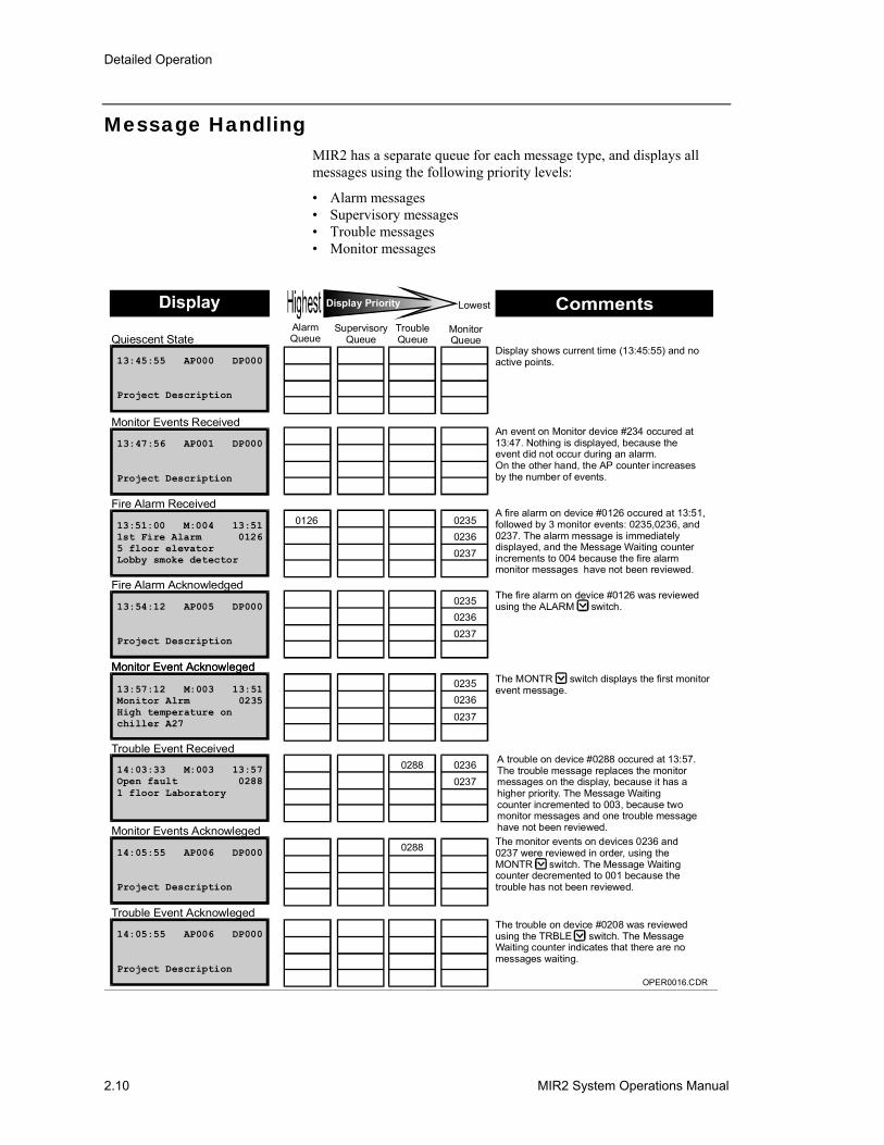
Message Handling MIR2 has a separate queue for each message type, and displays all messages using the following priority levels:
• Alarm messages • Supervisory messages • Trouble messages • Monitor messages
13:45:55 AP000 DP000
Project Description
Quiescent State
13:47:56 AP001 DP000
Project Description
Monitor Events Received
13:51:00 M:004 13:511st Fire Alarm 01265 floor elevatorLobby smoke detector
Fire Alarm Received
13:54:12 AP005 DP000
Project Description
Fire Alarm Acknowledged
14:03:33 M:003 13:57Open fault 02881 floor Laboratory
Trouble Event Received
14:05:55 AP006 DP000
Project Description
Trouble Event Acknowleged
14:05:55 AP006 DP000
Project Description
Monitor Events Acknowleged
13:57:12 M:003 13:51Monitor Alrm 0235High temperature onchiller A27
Monitor Event AcknowlegedMonitor Event Acknowleged
Display shows current time (13:45:55) and noactive points.
An event on Monitor device #234 occured at13:47. Nothing is displayed, because theevent did not occur during an alarm.On the other hand, the AP counter increases by the number of events.
A fire alarm on device #0126 occured at 13:51,followed by 3 monitor events: 0235,0236, and0237. The alarm message is immediatelydisplayed, and the Message Waiting counterincrements to 004 because the fire alarmmonitor messages have not been reviewed.
The fire alarm on device #0126 was reviewedusing the ALARM switch.
The MONTR switch displays the first monitor event message.
The monitor events on devices 0236 and0237 were reviewed in order, using theMONTR switch. The Message Waitingcounter decremented to 001 because thetrouble has not been reviewed.
The trouble on device #0208 was reviewedusing the TRBLE switch. The Message Waiting counter indicates that there are nomessages waiting.
Display Priority Lowest
AlarmQueue
SupervisoryQueue
TroubleQueue
MonitorQueue
0126 023502360237
023502360237
02350236
0237
02360237
0288
0288
OPER0016.CDR
A trouble on device #0288 occured at 13:57.The trouble message replaces the monitormessages on the display, because it has ahigher priority. The Message Waitingcounter incremented to 003, because twomonitor messages and one trouble messagehave not been reviewed.
Detailed Operation
MIR2 System Operations Manual 2.11
Advanced Functions
Status Switch
STATUS PROGRAM
ENABLE DISABLE
ACTIVATE RESTORE
REPORTS TEST
OPER0017.CDR
1 2 3
4 5 6
7 8 9
0
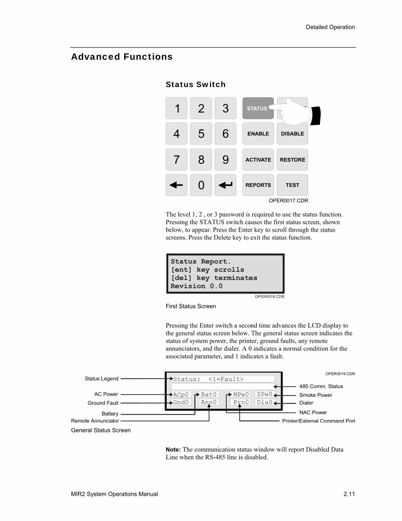
The level 1, 2 , or 3 password is required to use the status function. Pressing the STATUS switch causes the first status screen, shown below, to appear. Press the Enter key to scroll through the status screens. Press the Delete key to exit the status function.
Status Report.[ent] key scrolls[del] key terminatesRevision 0.0
OPER0018.CDR First Status Screen
Pressing the Enter switch a second time advances the LCD display to the general status screen below. The general status screen indicates the status of system power, the printer, ground faults, any remote annunciators, and the dialer. A 0 indicates a normal condition for the associated parameter, and 1 indicates a fault.
OPER0019.CDRStatus Legend
Battery
AC Power
Ground Fault
Remote Annunciator
485 Comm. Status
Smoke PowerDialer
NAC PowerPrinter/External Command Port
Status: <1=Fault>
ACp0 Bat0 MPw0 SPw0Gnd0 Ann0 Prn0 Dia0
General Status Screen
Note: The communication status window will report Disabled Data Line when the RS-485 line is disabled.
Detailed Operation
2.12 MIR2 System Operations Manual
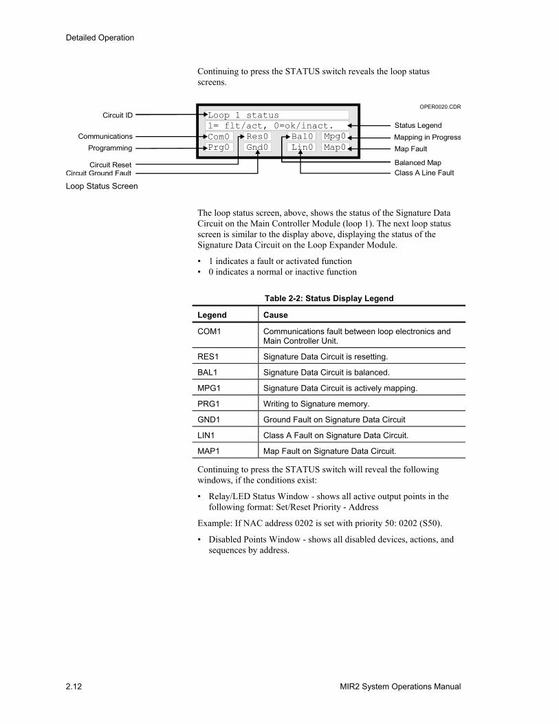
Continuing to press the STATUS switch reveals the loop status screens.
Circuit ID
CommunicationsProgramming
Circuit ResetCircuit Ground Fault
Status LegendMapping in ProgressMap Fault
Balanced MapClass A Line Fault
Loop 1 status1= flt/act, 0=ok/inact.Com0 Res0 Bal0 Mpg0Prg0 Gnd0 Lin0 Map0
OPER0020.CDR
Loop Status Screen
The loop status screen, above, shows the status of the Signature Data Circuit on the Main Controller Module (loop 1). The next loop status screen is similar to the display above, displaying the status of the Signature Data Circuit on the Loop Expander Module.
• 1 indicates a fault or activated function • 0 indicates a normal or inactive function
Table 2-2: Status Display Legend
Legend Cause
COM1 Communications fault between loop electronics and Main Controller Unit.
RES1 Signature Data Circuit is resetting.
BAL1 Signature Data Circuit is balanced.
MPG1 Signature Data Circuit is actively mapping.
PRG1 Writing to Signature memory.
GND1 Ground Fault on Signature Data Circuit
LIN1 Class A Fault on Signature Data Circuit.
MAP1 Map Fault on Signature Data Circuit.
Continuing to press the STATUS switch will reveal the following windows, if the conditions exist:
• Relay/LED Status Window - shows all active output points in the following format: Set/Reset Priority - Address
Example: If NAC address 0202 is set with priority 50: 0202 (S50).
• Disabled Points Window - shows all disabled devices, actions, and sequences by address.
Detailed Operation
MIR2 System Operations Manual 2.13
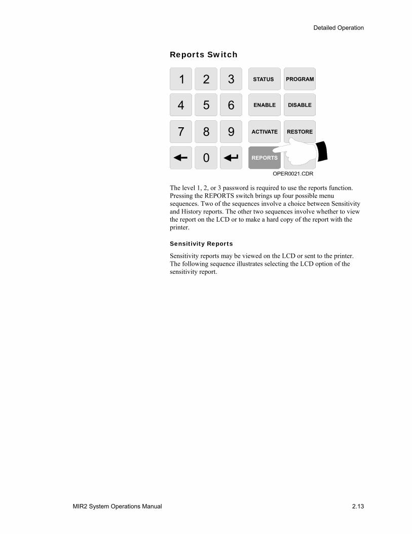
Reports Switch
STATUS PROGRAM
ENABLE DISABLE
ACTIVATE RESTORE
REPORTS TEST
OPER0021.CDR
1 2 3
4 5 6
7 8 9
0
The level 1, 2, or 3 password is required to use the reports function. Pressing the REPORTS switch brings up four possible menu sequences. Two of the sequences involve a choice between Sensitivity and History reports. The other two sequences involve whether to view the report on the LCD or to make a hard copy of the report with the printer.
Sensitivity Reports
Sensitivity reports may be viewed on the LCD or sent to the printer. The following sequence illustrates selecting the LCD option of the sensitivity report.

Detailed Operation
2.14 MIR2 System Operations Manual
Report Type:1) Sensitivity2) History Enter Choice ->
Send Report To: 1) LCD Screen 2) Printer Enter Choice ->
For All Press [ENT]For Range ppaa [ENT][DEL] will terminateEnter Choice ->
Press [ENT] for moreAdd: 101 Type 3DAlarm Level: 3.5%Maint Level: 00%
OPER0022.CDR
1
1
Reports Menu Screens
Press [ENT] for moreAdd: 101Alarm Level: 3.5%Maint. Level: 00%
Type: 3D
Detector Address Device Type
Maintenance Level Alarm Level
OPER0023.CDR
Panel Display Sensitivity Report Format
Detailed Operation
MIR2 System Operations Manual 2.15
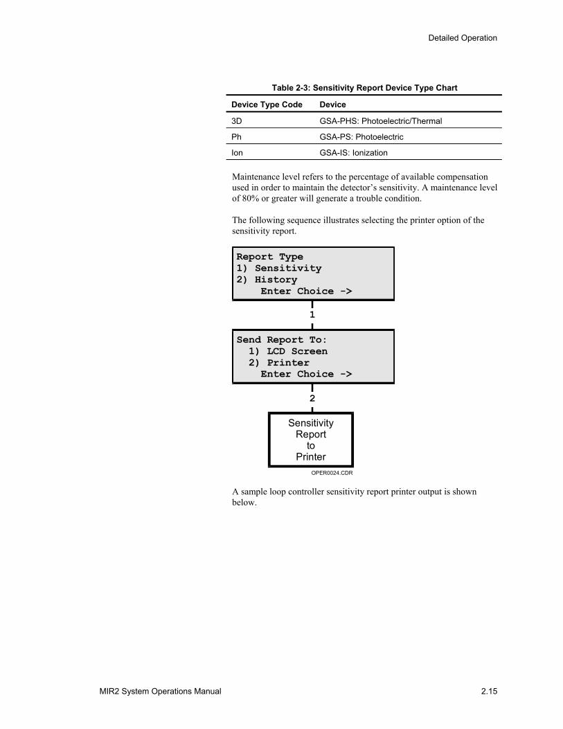
Table 2-3: Sensitivity Report Device Type Chart
Device Type Code Device
3D GSA-PHS: Photoelectric/Thermal
Ph GSA-PS: Photoelectric
Ion GSA-IS: Ionization
Maintenance level refers to the percentage of available compensation used in order to maintain the detector’s sensitivity. A maintenance level of 80% or greater will generate a trouble condition.
The following sequence illustrates selecting the printer option of the sensitivity report.
Report Type1) Sensitivity2) History Enter Choice ->
Send Report To: 1) LCD Screen 2) Printer Enter Choice ->
SensitivityReport
toPrinter
OPER0024.CDR
1
2
A sample loop controller sensitivity report printer output is shown below.
Detailed Operation
2.16 MIR2 System Operations Manual
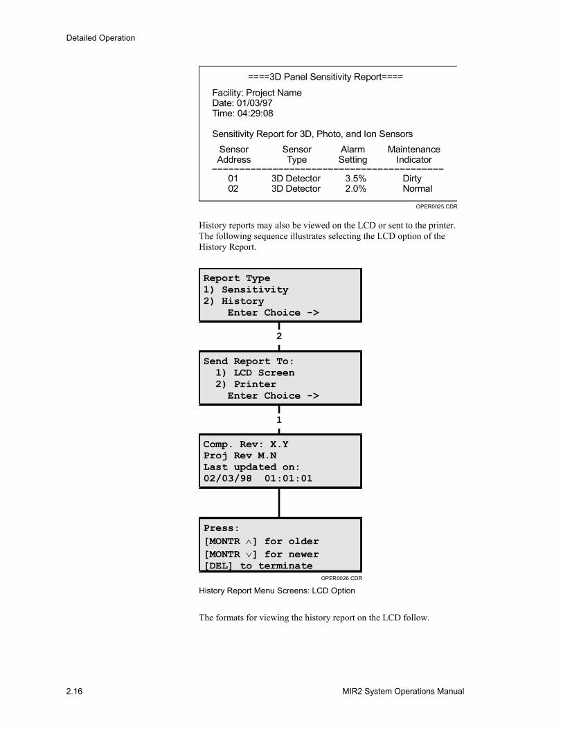
====3D Panel Sensitivity Report====
Facility: Project NameDate: 01/03/97Time: 04:29:08
Sensitivity Report for 3D, Photo, and Ion Sensors
SensorAddress
SensorType
AlarmSetting
MaintenanceIndicator
0102
3D Detector3D Detector
3.5%2.0%
OPER0025.CDR
DirtyNormal
History reports may also be viewed on the LCD or sent to the printer. The following sequence illustrates selecting the LCD option of the History Report.
Report Type1) Sensitivity2) History Enter Choice ->
Send Report To: 1) LCD Screen 2) Printer Enter Choice ->
Comp. Rev: X.YProj Rev M.NLast updated on:02/03/98 01:01:01
Press:[MONTR ] for older[MONTR ] for newer[DEL] to terminate
∧∨
OPER0026.CDR
2
1
History Report Menu Screens: LCD Option
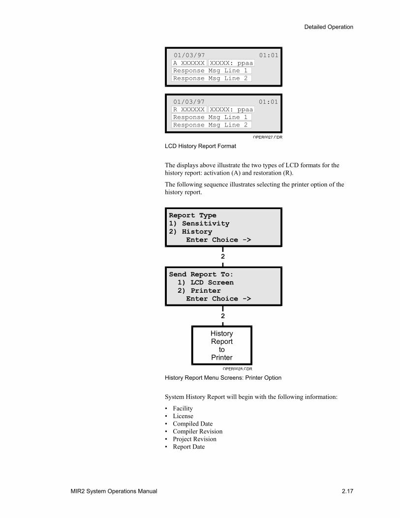
The formats for viewing the history report on the LCD follow.
Detailed Operation
MIR2 System Operations Manual 2.17
OPER0027.CDR
01/03/97R XXXXXXResponse Msg Line 1Response Msg Line 2
XXXXX: ppaa01:01
01/03/97A XXXXXXResponse Msg Line 1Response Msg Line 2
XXXXX: ppaa01:01
LCD History Report Format
The displays above illustrate the two types of LCD formats for the history report: activation (A) and restoration (R).
The following sequence illustrates selecting the printer option of the history report.
Report Type1) Sensitivity2) History Enter Choice ->
Send Report To: 1) LCD Screen 2) Printer Enter Choice ->
HistoryReport
toPrinter
OPER0028.CDR
2
2
History Report Menu Screens: Printer Option
System History Report will begin with the following information:
• Facility • License • Compiled Date • Compiler Revision • Project Revision • Report Date
Detailed Operation
2.18 MIR2 System Operations Manual
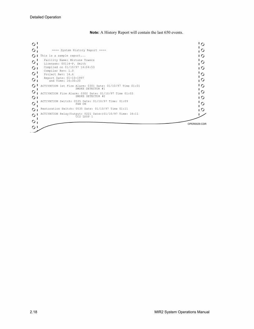
Note: A History Report will contain the last 650 events.
OPER0029.CDR
==== System History Report ====
This is a sample report...
Facility Name: Mirtone TowersLicensee: 00114-P. SmithCompiled on 01/10/97 14:04:53Compiler Rev: 1.0Project Rev: 14.6
ACTIVATION 1st Fire Alarm: 0301 Date: 01/10/97 Time 01:01 SMOKE DETECTOR #1
ACTIVATION Fire Alarm: 0302 Date: 01/10/97 Time 01:03 SMOKE DETECTOR #2
ACTIVATION Switch: 0535 Date: 01/10/97 Time: 01:09 FAN ON
Restoration Switch: 0535 Date: 01/10/97 Time 01:11
ACTIVATION Relay/Output: 0221 Date:)01/10/97 Time: 16:11 CC2 LOOP 1
Report Date: 01-10-1997 and Time: 16:30:20
Detailed Operation
MIR2 System Operations Manual 2.19
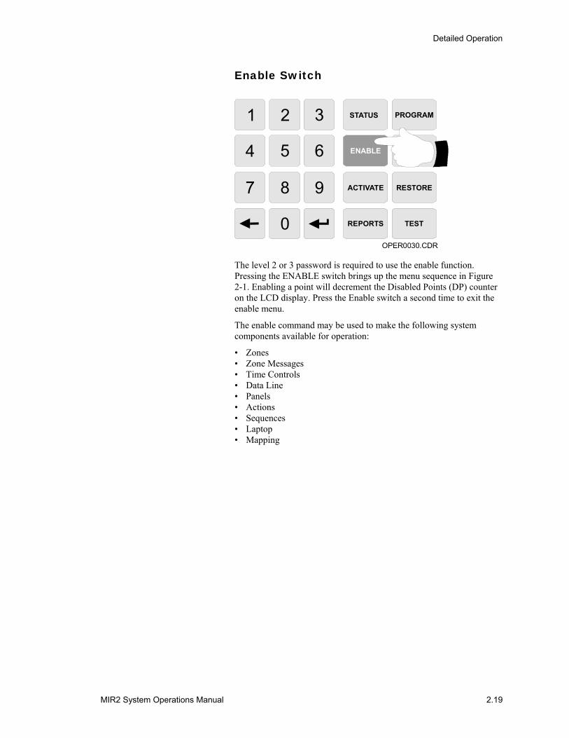
Enable Switch
STATUS PROGRAM
ENABLE DISABLE
ACTIVATE RESTORE
REPORTS TEST
OPER0030.CDR
1 2 3
4 5 6
7 8 9
0
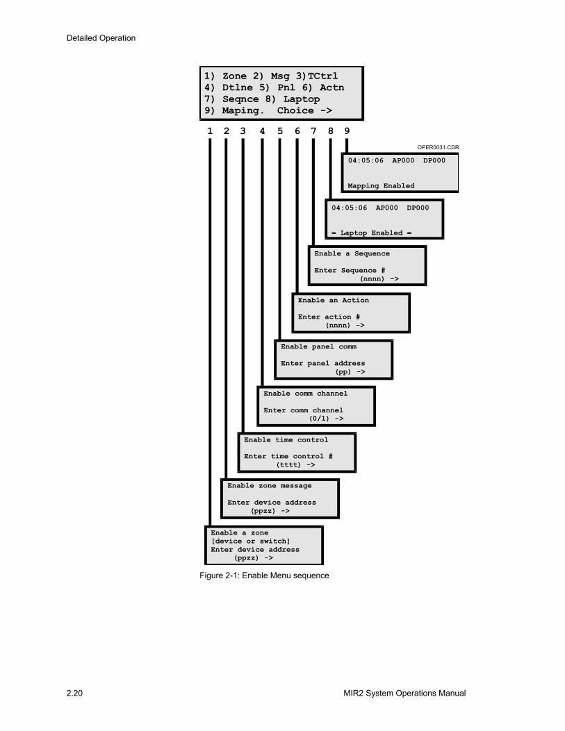
The level 2 or 3 password is required to use the enable function. Pressing the ENABLE switch brings up the menu sequence in Figure 2-1. Enabling a point will decrement the Disabled Points (DP) counter on the LCD display. Press the Enable switch a second time to exit the enable menu.
The enable command may be used to make the following system components available for operation:
• Zones • Zone Messages • Time Controls • Data Line • Panels • Actions • Sequences • Laptop • Mapping
Detailed Operation
2.20 MIR2 System Operations Manual
1) Zone 2) Msg 3)TCtrl4) Dtlne 5) Pnl 6) Actn7) Seqnce 8) Laptop9) Maping. Choice ->
OPER0031.CDR
1 2 3 4 5 6 7 8 9
04:05:06 AP000 DP000
Mapping Enabled
04:05:06 AP000 DP000
= Laptop Enabled =
Enable a Sequence
Enter Sequence # (nnnn) ->
Enable an Action
Enter action # (nnnn) ->
Enable panel comm
Enter panel address (pp) ->
Enable comm channel
Enter comm channel (0/1) ->
Enable time control
Enter time control # (tttt) ->
Enable zone message
Enter device address (ppzz) ->
Enable a zone[device or switch]Enter device address (ppzz) ->
Figure 2-1: Enable Menu sequence
Detailed Operation
MIR2 System Operations Manual 2.21
Disable Switch
STATUS PROGRAM
ENABLE DISABLE
ACTIVATE RESTORE
REPORTS TEST
OPER0032.CDR
1 2 3
4 5 6
7 8 9
0
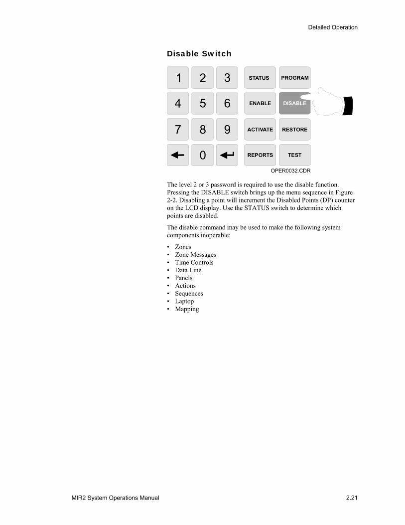
The level 2 or 3 password is required to use the disable function. Pressing the DISABLE switch brings up the menu sequence in Figure 2-2. Disabling a point will increment the Disabled Points (DP) counter on the LCD display. Use the STATUS switch to determine which points are disabled.
The disable command may be used to make the following system components inoperable:
• Zones • Zone Messages • Time Controls • Data Line • Panels • Actions • Sequences • Laptop • Mapping

Detailed Operation
2.22 MIR2 System Operations Manual
1) Zone 2) Msg 3)TCtrl4) Dtlne 5) Pnl 6) Actn7) Seqnce 8) Laptop9) Maping. Choice ->
OPER0033.CDR
1 2 3 4 5 6 7 8 9
04:05:06 AP000 DP000
Mapping Disabled
04:05:06 AP000 DP000
Laptop Disabled
Disable a Sequence
Enter Sequence # (nnnn) ->
Disable an Action
Enter action # (nnnn) ->
Disable panel comm
Enter panel address (pp) ->
Disable comm channel
Enter comm channel (0/1) ->
Disable time control
Enter time control # (tttt) ->
Disable zone message
Enter device address (ppzz) ->
Disable a zone[device or switch]Enter device address (ppzz) ->
Figure 2-2: Disable Menu Sequence
Detailed Operation
MIR2 System Operations Manual 2.23
Activate Switch
STATUS PROGRAM
ENABLE DISABLE
ACTIVATE RESTORE
REPORTS TEST
OPER0034.CDR
1 2 3
4 5 6
7 8 9
0
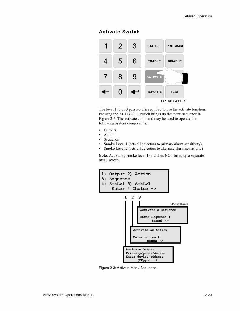
The level 1, 2 or 3 password is required to use the activate function. Pressing the ACTIVATE switch brings up the menu sequence in Figure 2-3. The activate command may be used to operate the following system components:
• Outputs • Action • Sequence • Smoke Level 1 (sets all detectors to primary alarm sensitivity) • Smoke Level 2 (sets all detectors to alternate alarm sensitivity)
Note: Activating smoke level 1 or 2 does NOT bring up a separate menu screen.
1) Output 2) Action3) Sequence4) SmkLvl 5) SmkLvl Enter # Choice ->
OPER0035.CDR
1 2 3
Activate a Sequence
Enter Sequence # (nnnn) ->
Activate an Action
Enter action # (nnnn) ->
Activate OutputPriority/panel/deviceEnter device address (PPppdd) ->
Figure 2-3: Activate Menu Sequence
Detailed Operation
2.24 MIR2 System Operations Manual
Restore Switch
STATUS PROGRAM
ENABLE DISABLE
ACTIVATE RESTORE
REPORTS TEST
OPER0036.CDR
1 2 3
4 5 6
7 8 9
0
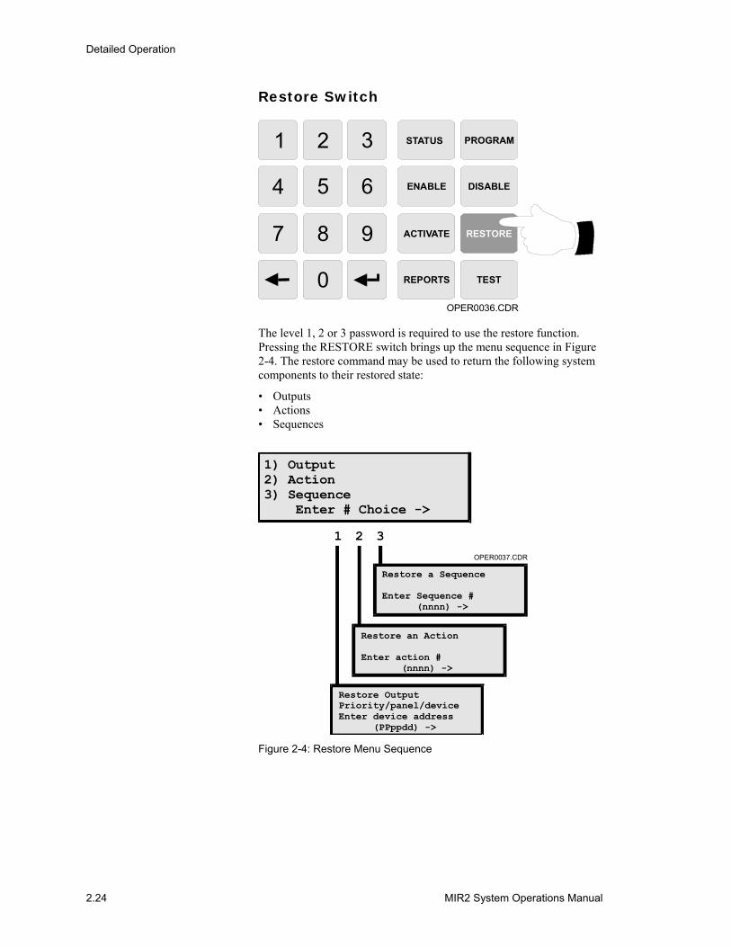
The level 1, 2 or 3 password is required to use the restore function. Pressing the RESTORE switch brings up the menu sequence in Figure 2-4. The restore command may be used to return the following system components to their restored state:
• Outputs • Actions • Sequences
1) Output2) Action3) Sequence Enter # Choice ->
OPER0037.CDR
1 2 3
Restore a Sequence
Enter Sequence # (nnnn) ->
Restore an Action
Enter action # (nnnn) ->
Restore OutputPriority/panel/deviceEnter device address (PPppdd) ->
Figure 2-4: Restore Menu Sequence
Detailed Operation
MIR2 System Operations Manual 2.25
Program Switch
STATUS PROGRAM
ENABLE DISABLE
ACTIVATE RESTORE
REPORTS TEST
OPER0038.CDR
1 2 3
4 5 6
7 8 9
0
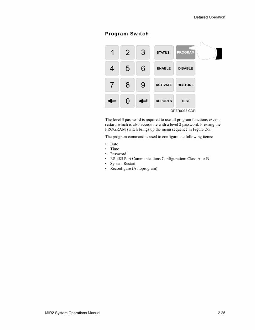
The level 3 password is required to use all program functions except restart, which is also accessible with a level 2 password. Pressing the PROGRAM switch brings up the menu sequence in Figure 2-5.
The program command is used to configure the following items:
• Date • Time • Password • RS-485 Port Communications Configuration: Class A or B • System Restart • Reconfigure (Autoprogram)
Detailed Operation
2.26 MIR2 System Operations Manual
OPER0039.CDR
1 2 3 4 5 6
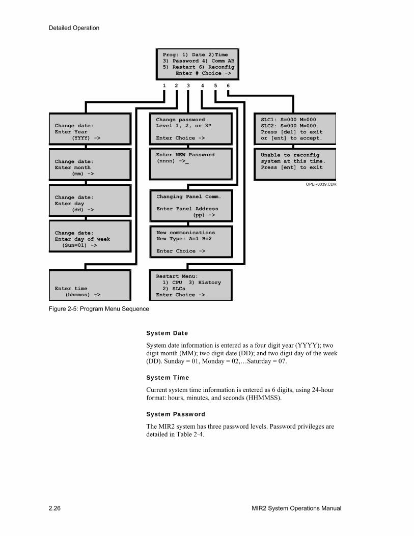
Prog: 1) Date 2)Time3) Password 4) Comm AB5) Restart 6) Reconfig Enter # Choice ->
Unable to reconfigsystem at this time.Press [ent] to exit
SLC1: S=000 M=000SLC2: S=000 M=000Press [del] to exitor [ent] to accept.
Restart Menu: 1) CPU 3) History 2) SLCsEnter Choice ->
Change passwordLevel 1, 2, or 3?
Enter Choice ->
Enter NEW Password(nnnn) ->_
Change date:Enter Year (YYYY) ->
Change date:Enter month (mm) ->
Change date:Enter day (dd) ->
Change date:Enter day of week (Sun=01) ->
Enter time (hhmmss) ->
Changing Panel Comm.
Enter Panel Address (pp) ->
New communicationsNew Type: A=1 B=2
Enter Choice ->
Figure 2-5: Program Menu Sequence
System Date
System date information is entered as a four digit year (YYYY); two digit month (MM); two digit date (DD); and two digit day of the week (DD). Sunday = 01, Monday = 02,…Saturday = 07.
System Time
Current system time information is entered as 6 digits, using 24-hour format: hours, minutes, and seconds (HHMMSS).
System Password
The MIR2 system has three password levels. Password privileges are detailed in Table 2-4.

Detailed Operation
MIR2 System Operations Manual 2.27
Table 2-4: System Passwords
Level Personnel Default Access Privileges
1 Operators 1111 All activate, restore reports, and status functions
2 Supervisors 2222 All level 1 privileges and
All disable, enable, test, and system restart functions
3 Administrators 3333 All level 1 and 2 privileges and
All program functions
Note: The system installer should change all passwords after the system has been installed.
Reconfigure (Autoprogram)
The autoprogramming feature of the MIR2 panel is used to automatically identify all Signature Series devices properly connected to the MIR2 panel
Prior to Activating Autoprogram
With a new system and new devices, the panel initiates certain operations prior to activating autoprogram. Mapping is disabled as the default. Once the system is powered up and connected to the loop, the loop controllers begin a search for all of the device serial numbers and device default personalities.
Note: You can monitor the progress of the loop controllers from the LCD by pressing the program switch and selecting the Reconfig option. DO NOT PRESS ENTER AT THIS TIME.
The counters will increase as the loop controllers find devices.
Once the process is finished:
1 Compare the number of devices the system found to the actual number of devices on the loop.
2 If the numbers match, press Enter to start reconfiguring devices.
The system will reset and accept the devices found. If the system is not ready to reconfigure, a message will be displayed on the 2-LCD.
After Activating Autoprogram
If no device address exists, the loop controller will assign it one based on available addresses and the value of the serial number. If the personality for a device has been set prior to reconfiguring, and is valid, the personality will not be set to a default. If no personality exists or the personality is incorrect, the loop controller will set a default value according to the specifications in Table 2-5.
Detailed Operation
2.28 MIR2 System Operations Manual
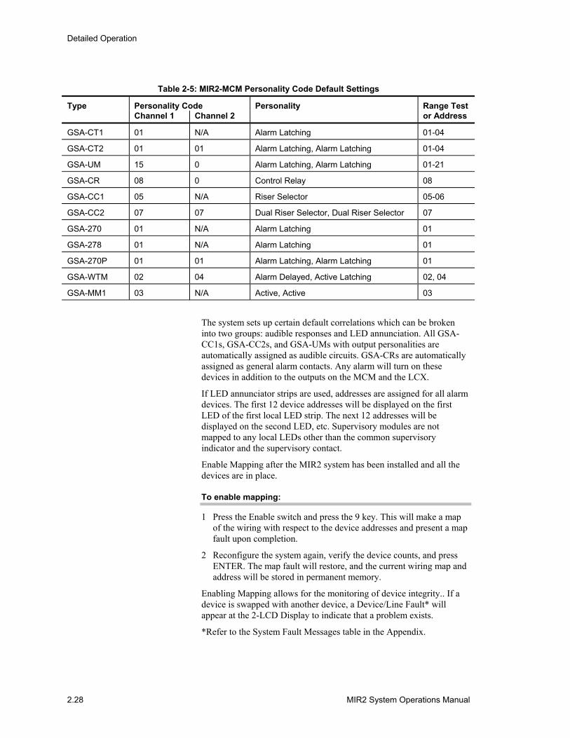
Table 2-5: MIR2-MCM Personality Code Default Settings
Type Personality Code Personality Range Test Channel 1 Channel 2 or Address
GSA-CT1 01 N/A Alarm Latching 01-04
GSA-CT2 01 01 Alarm Latching, Alarm Latching 01-04
GSA-UM 15 0 Alarm Latching, Alarm Latching 01-21
GSA-CR 08 0 Control Relay 08
GSA-CC1 05 N/A Riser Selector 05-06
GSA-CC2 07 07 Dual Riser Selector, Dual Riser Selector 07
GSA-270 01 N/A Alarm Latching 01
GSA-278 01 N/A Alarm Latching 01
GSA-270P 01 01 Alarm Latching, Alarm Latching 01
GSA-WTM 02 04 Alarm Delayed, Active Latching 02, 04
GSA-MM1 03 N/A Active, Active 03
The system sets up certain default correlations which can be broken into two groups: audible responses and LED annunciation. All GSA-CC1s, GSA-CC2s, and GSA-UMs with output personalities are automatically assigned as audible circuits. GSA-CRs are automatically assigned as general alarm contacts. Any alarm will turn on these devices in addition to the outputs on the MCM and the LCX.
If LED annunciator strips are used, addresses are assigned for all alarm devices. The first 12 device addresses will be displayed on the first LED of the first local LED strip. The next 12 addresses will be displayed on the second LED, etc. Supervisory modules are not mapped to any local LEDs other than the common supervisory indicator and the supervisory contact.
Enable Mapping after the MIR2 system has been installed and all the devices are in place.
To enable mapping:
1 Press the Enable switch and press the 9 key. This will make a map of the wiring with respect to the device addresses and present a map fault upon completion.
2 Reconfigure the system again, verify the device counts, and press ENTER. The map fault will restore, and the current wiring map and address will be stored in permanent memory.
Enabling Mapping allows for the monitoring of device integrity.. If a device is swapped with another device, a Device/Line Fault* will appear at the 2-LCD Display to indicate that a problem exists.
*Refer to the System Fault Messages table in the Appendix.
Detailed Operation
MIR2 System Operations Manual 2.29
Note: If the loop controller is mapping or re-setting, a message will appear to indicate that the system is not ready to autoprogram.
Adding Devices to an Autoprogrammed System
When a Signature Series device is added to the device data circuit, the MIR2 processor detects a discrepancy between the expected electrical map information and the map of the devices actually installed. This causes a map error. Mapping errors may be permanently corrected by re-autoprogramming the panel, allowing the loop controller to see the new device on the loop.
Note: You may keep mapping enabled while adding a device to the system.
Changing or Removing Devices from an Autoprogrammed System
A device type trouble will be generated when a Signature Series device type is replaced with a device of a different type (i.e. replacing a GSA-IS Ionization Detector with a GSA-PS Photoelectric detector).
When clearing such trouble states, you need to determine the correct number of devices.
Note: The correct number of devices is achieved when:
• The number of devices after a change equals the number of devices before the change
• A new lower number of devices equals the number devices removed
To remove the device trouble or open:
1 Disable mapping by pressing the disable switch and the 9 key. The system will reinitialize after mapping is disabled.
2 Press the Program switch and the 6 key to reconfigure the system.
3 Monitor the reconfigure screen and note the device counters.
4 Press ENTER to activate Reconfig if the correct number of devices is displayed.
The system will reset and accept the devices found.
5 Monitor the Reconfig display to make sure all the devices are counted on the loop counters.
6 Re-enable mapping after the system has reset.
Modifying the Autoprogram
You may use a personal computer equipped with the MIR2 Data Entry Program to modify the characteristics and responses of any device on the MIR2 panel. Please refer to the Data Entry Program section of the MIR2 System Programming Manual P/N 270675.
Detailed Operation
2.30 MIR2 System Operations Manual
Test Switch
OPER0040.CDR
STATUS PROGRAM
ENABLE DISABLE
ACTIVATE RESTORE
REPORTS TEST
1 2 3
4 5 6
7 8 9
0
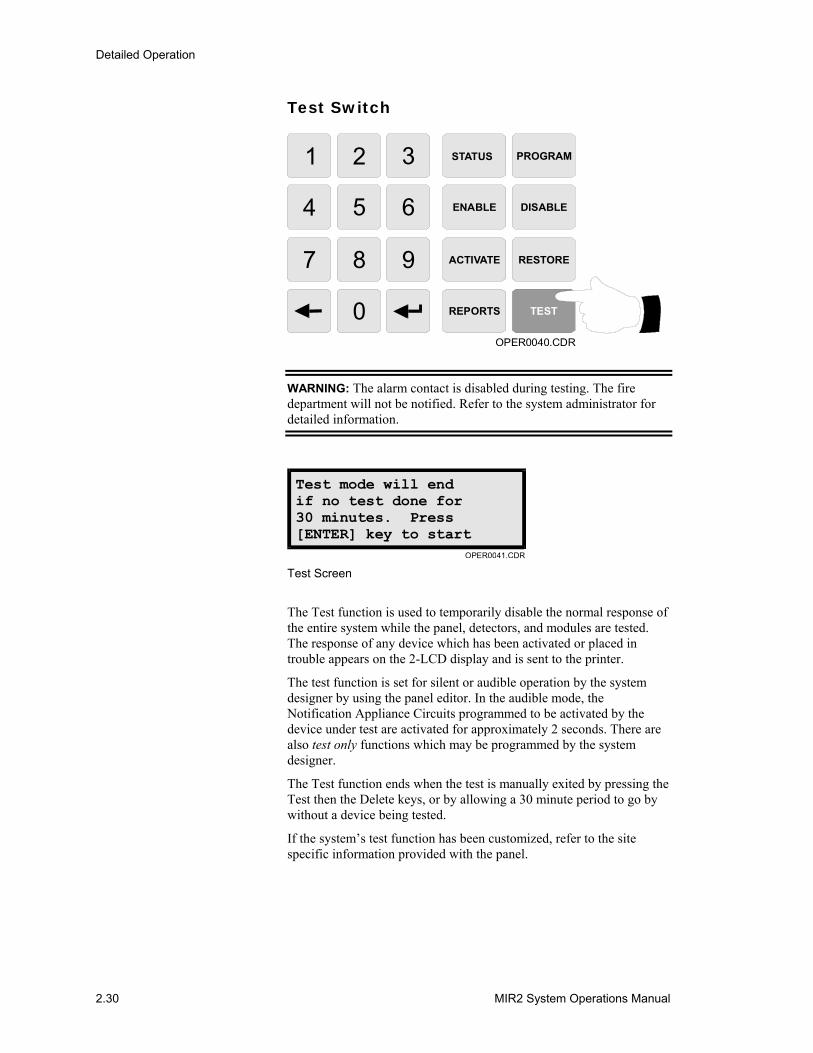
WARNING: The alarm contact is disabled during testing. The fire department will not be notified. Refer to the system administrator for detailed information.
Test mode will endif no test done for30 minutes. Press[ENTER] key to start
OPER0041.CDR Test Screen
The Test function is used to temporarily disable the normal response of the entire system while the panel, detectors, and modules are tested. The response of any device which has been activated or placed in trouble appears on the 2-LCD display and is sent to the printer.
The test function is set for silent or audible operation by the system designer by using the panel editor. In the audible mode, the Notification Appliance Circuits programmed to be activated by the device under test are activated for approximately 2 seconds. There are also test only functions which may be programmed by the system designer.
The Test function ends when the test is manually exited by pressing the Test then the Delete keys, or by allowing a 30 minute period to go by without a device being tested.
If the system’s test function has been customized, refer to the site specific information provided with the panel.
Detailed Operation
MIR2 System Operations Manual 2.31
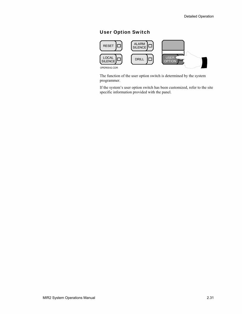
User Option Switch
RESET ALARMSILENCE
LOCALSILENCE DRILL USER
OPTION
OPER0042.CDR
The function of the user option switch is determined by the system programmer.
If the system’s user option switch has been customized, refer to the site specific information provided with the panel.
Detailed Operation
2.32 MIR2 System Operations Manual
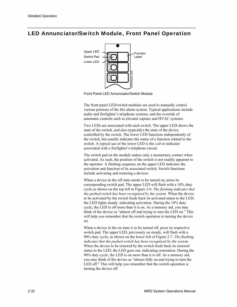
LED Annunciator/Switch Module, Front Panel Operation
Upper LED FunctionLabel
OP
ER
0043
.CD
R
Switch PadLower LED
Front Panel LED Annunciator/Switch Module
The front panel LED/switch modules are used to manually control various portions of the fire alarm system. Typical applications include audio and firefighter’s telephone systems, and the override of automatic controls such as elevator capture and HVAC systems.
Two LEDs are associated with each switch. The upper LED shows the state of the switch, and also (typically) the state of the device controlled by the switch. The lower LED functions independently of the switch, but usually indicates the status of a function related to the switch. A typical use of the lower LED is the call-in indicator associated with a firefighter’s telephone circuit.
The switch pad on the module makes only a momentary contact when activated. As such, the position of the switch is not readily apparent to the operator. A flashing sequence on the upper LED indicates the activation and function of its associated switch. Switch functions include activating and restoring a devices
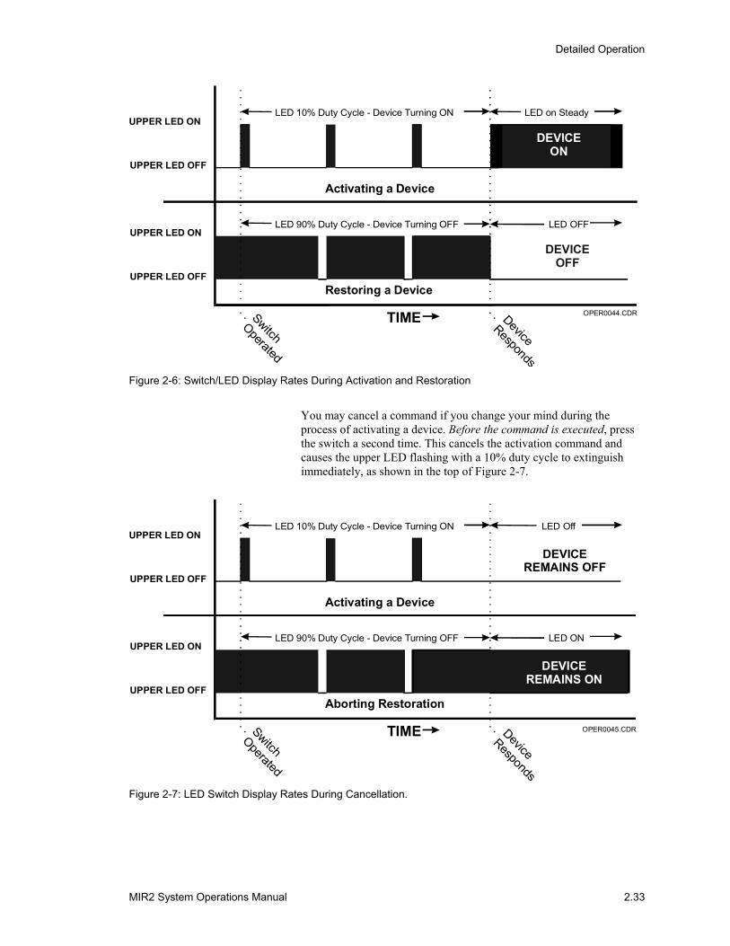
When a device in the off state needs to be turned on, press its corresponding switch pad. The upper LED will flash with a 10% duty cycle as shown on the top left in Figure 2-6. The flashing indicates that the pushed switch has been recognized by the system. When the device to be activated by the switch feeds back its activated status to the LED, the LED lights steady, indicating activation. During the 10% duty cycle, the LED is off more than it is on. As a memory aid, you may think of the device as “almost off and trying to turn the LED on.” This will help you remember that the switch operation is turning the device on.
When a device in the on state is to be turned off, press its respective switch pad. The upper LED, previously on steady, will flash with a 90% duty cycle, as shown on the lower left of Figure 2-7. The flashing indicates that the pushed switch has been recognized by the system. When the device to be restored by the switch feeds back its restored status to the LED, the LED goes out, indicating restoration. During the 90% duty cycle, the LED is on more than it is off. As a memory aid, you may think of the device as “almost fully on and trying to turn the LED off.” This will help you remember that the switch operation is turning the device off.
Detailed Operation
MIR2 System Operations Manual 2.33
LED 10% Duty Cycle - Device Turning ON LED on Steady
LED OFF
UPPER LED ON
UPPER LED ON
TIME
DEVICEON
DEVICEOFF
UPPER LED OFF
Activating a Device
Restoring a DeviceUPPER LED OFF
LED 90% Duty Cycle - Device Turning OFF
SwitchOperated
DeviceResponds
OPER0044.CDR
Figure 2-6: Switch/LED Display Rates During Activation and Restoration
You may cancel a command if you change your mind during the process of activating a device. Before the command is executed, press the switch a second time. This cancels the activation command and causes the upper LED flashing with a 10% duty cycle to extinguish immediately, as shown in the top of Figure 2-7.
LED 10% Duty Cycle - Device Turning ON LED Off
LED ON
UPPER LED ON
UPPER LED ON
TIME
DEVICEON
UPPER LED OFF
Activating a Device
Aborting RestorationUPPER LED OFF
LED 90% Duty Cycle - Device Turning OFF
SwitchOperated
DeviceResponds
OPER0045.CDR
DEVICEREMAINS ON
DEVICEREMAINS OFF
Figure 2-7: LED Switch Display Rates During Cancellation.

Detailed Operation
2.34 MIR2 System Operations Manual
You may also cancel a command if you change your mind during the process of turning off a device. Before the command is executed, press the switch a second time. This cancels the command to turn the device off, and causes the upper LED flashing with a 90% duty cycle to extinguish immediately, as shown in the lower half of Figure 2-7.
Detailed Operation
MIR2 System Operations Manual 2.35
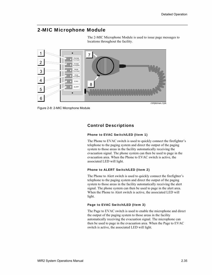
2-MIC Microphone Module The 2-MIC Microphone Module is used to issue page messages to locations throughout the facility.
2
4
1
6
3
5
PHONETO EVAC
PHONETO ALERT
PAGETO EVAC
PAGETO ALERT
EVAC
ALERT8
7
2
4
1
6
3
5
PHONETO EVAC
PHONETO ALERT
PAGETO EVAC
PAGETO ALERT
EVAC
ALERT8
7
OPER0046.CDR Figure 2-8: 2-MIC Microphone Module
Control Descriptions
Phone to EVAC Switch/LED (Item 1)
The Phone to EVAC switch is used to quickly connect the firefighter’s telephone to the paging system and direct the output of the paging system to those areas in the facility automatically receiving the evacuation signal. The phone system can then be used to page in the evacuation area. When the Phone to EVAC switch is active, the associated LED will light.
Phone to ALERT Switch/LED (Item 2)
The Phone to Alert switch is used to quickly connect the firefighter’s telephone to the paging system and direct the output of the paging system to those areas in the facility automatically receiving the alert signal. The phone system can then be used to page in the alert area. When the Phone to Alert switch is active, the associated LED will light.
Page to EVAC Switch/LED (Item 3)
The Page to EVAC switch is used to enable the microphone and direct the output of the paging system to those areas in the facility automatically receiving the evacuation signal. The microphone can then be used to page in the evacuation area. When the Page to EVAC switch is active, the associated LED will light.
Detailed Operation
2.36 MIR2 System Operations Manual
Page to ALERT Switch/LED (Item 4)
The Page to Alert switch is used to enable the microphone and direct the output of the paging system to those areas in the facility automatically receiving the alert signal. The microphone can then be used to page in the alert area. When the Page to Alert switch is active, the associated LED will light.
EVAC Switch/LED (Item 5)
The EVAC switch is used to manually activate the evacuation signal. The areas of the facility which you want to receive the evacuation signal must also be manually selected using the LED Switch/Annunciator modules. Please refer to your site specific instructions for information as to how to select specific areas within your facility. When the EVAC switch is active, the associated LED will light.
Alert Switch/LED (Item 6)
The Alert switch is used to manually activate the alert signal. The areas of the facility which you want to receive the alert signal must also be manually selected using the LED Switch/Annunciator modules. Please refer to your site specific instructions for information as to how to select specific areas within your facility. When the Alert switch is active, the associated LED will light.
Microphone (Item 7)
The microphone is used to issue a page message. To page, remove the microphone from its bracket. Hold the microphone near your mouth and push the PTT switch (item 8). When the pre-announcement tone ends, speak in a normal voice.
Push-To-Talk [PTT] Switch (ITEM 8)
The PTT switch is used to activate the pre-announcement tone and the microphone. The microphone will not transmit any messages until the PTT switch has been operated and the pre-announcement tone has ended.
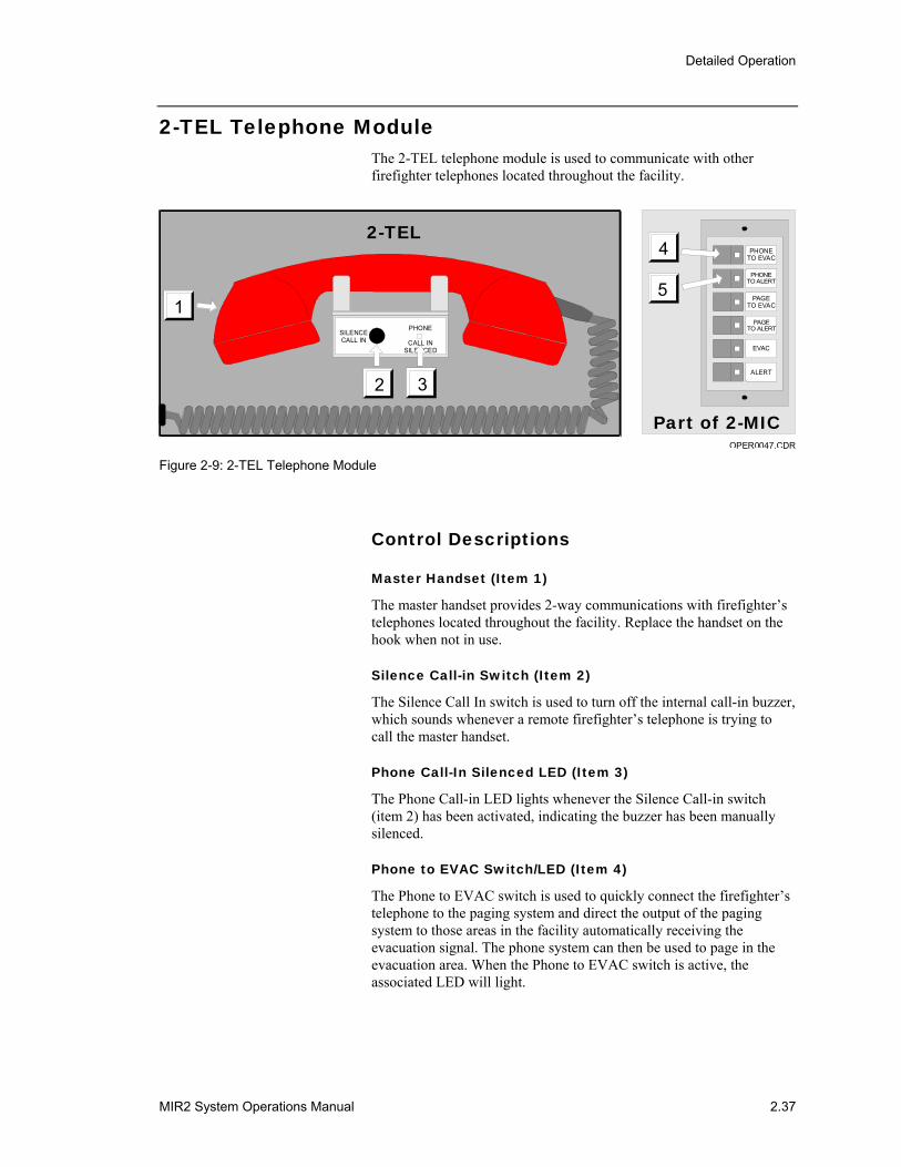
Detailed Operation
MIR2 System Operations Manual 2.37
2-TEL Telephone Module The 2-TEL telephone module is used to communicate with other firefighter telephones located throughout the facility.
OPER0047.CDR
2
1
5
4 PHONETO EVAC
PHONETO ALERT
PAGETO EVAC
PAGETO ALERT
EVAC
ALERT
Part of 2-MIC
2-TEL
SILENCECALL IN
PHONE
CALL INSILENCED
2 3
1
Figure 2-9: 2-TEL Telephone Module
Control Descriptions
Master Handset (Item 1)
The master handset provides 2-way communications with firefighter’s telephones located throughout the facility. Replace the handset on the hook when not in use.
Silence Call-in Switch (Item 2)
The Silence Call In switch is used to turn off the internal call-in buzzer, which sounds whenever a remote firefighter’s telephone is trying to call the master handset.
Phone Call-In Silenced LED (Item 3)
The Phone Call-in LED lights whenever the Silence Call-in switch (item 2) has been activated, indicating the buzzer has been manually silenced.
Phone to EVAC Switch/LED (Item 4)
The Phone to EVAC switch is used to quickly connect the firefighter’s telephone to the paging system and direct the output of the paging system to those areas in the facility automatically receiving the evacuation signal. The phone system can then be used to page in the evacuation area. When the Phone to EVAC switch is active, the associated LED will light.

Detailed Operation
2.38 MIR2 System Operations Manual
Phone to ALERT Switch/LED (item 5)
The Phone to Alert switch is used to quickly connect the firefighter’s telephone to the paging system and direct the output of the paging system to those areas in the facility automatically receiving the alert signal. The phone system can then be used to page in the alert area. When the Phone to Alert switch is active, the associated LED will light.

Detailed Operation
MIR2 System Operations Manual 2.39
Printer Operation The printer provides a hard copy record of all system activity. The printer may also be used to generate permanent copies of sensitivity and history reports.
The printer is always active unless the printer connection is being used for system maintenance purposes. If the printer runs out of paper or is taken off-line for maintenance, a trouble condition is generated.
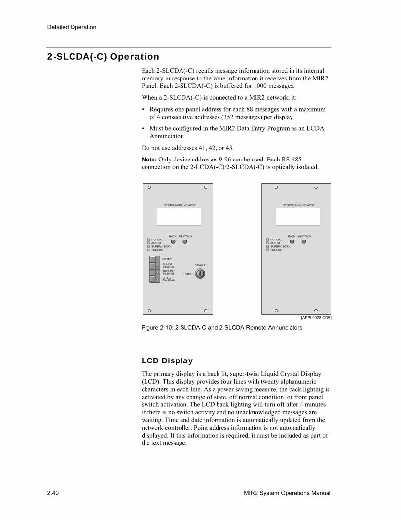
Detailed Operation
2.40 MIR2 System Operations Manual
2-SLCDA(-C) Operation
Each 2-SLCDA(-C) recalls message information stored in its internal memory in response to the zone information it receives from the MIR2 Panel. Each 2-SLCDA(-C) is buffered for 1000 messages.
When a 2-SLCDA(-C) is connected to a MIR2 network, it:
• Requires one panel address for each 88 messages with a maximum of 4 consecutive addresses (352 messages) per display
• Must be configured in the MIR2 Data Entry Program as an LCDA Annunciator
Do not use addresses 41, 42, or 43.
Note: Only device addresses 9-96 can be used. Each RS-485 connection on the 2-LCDA(-C)/2-SLCDA(-C) is optically isolated.
[APPL0028.CDR]
NORMALALARM
BACK
RESET
DISABLE
SYSTEM ANNUNCIATOR
ENABLE
ALARMSILENCETROUBLESILENCEDRILL/ALL CALL
NEXT/ACK
SUPERVISORYTROUBLE
NORMALALARM
BACK
SYSTEM ANNUNCIATOR
NEXT/ACK
SUPERVISORYTROUBLE
Figure 2-10: 2-SLCDA-C and 2-SLCDA Remote Annunciators
LCD Display The primary display is a back lit, super-twist Liquid Crystal Display (LCD). This display provides four lines with twenty alphanumeric characters in each line. As a power saving measure, the back lighting is activated by any change of state, off normal condition, or front panel switch activation. The LCD back lighting will turn off after 4 minutes if there is no switch activity and no unacknowledged messages are waiting. Time and date information is automatically updated from the network controller. Point address information is not automatically displayed. If this information is required, it must be included as part of the text message.
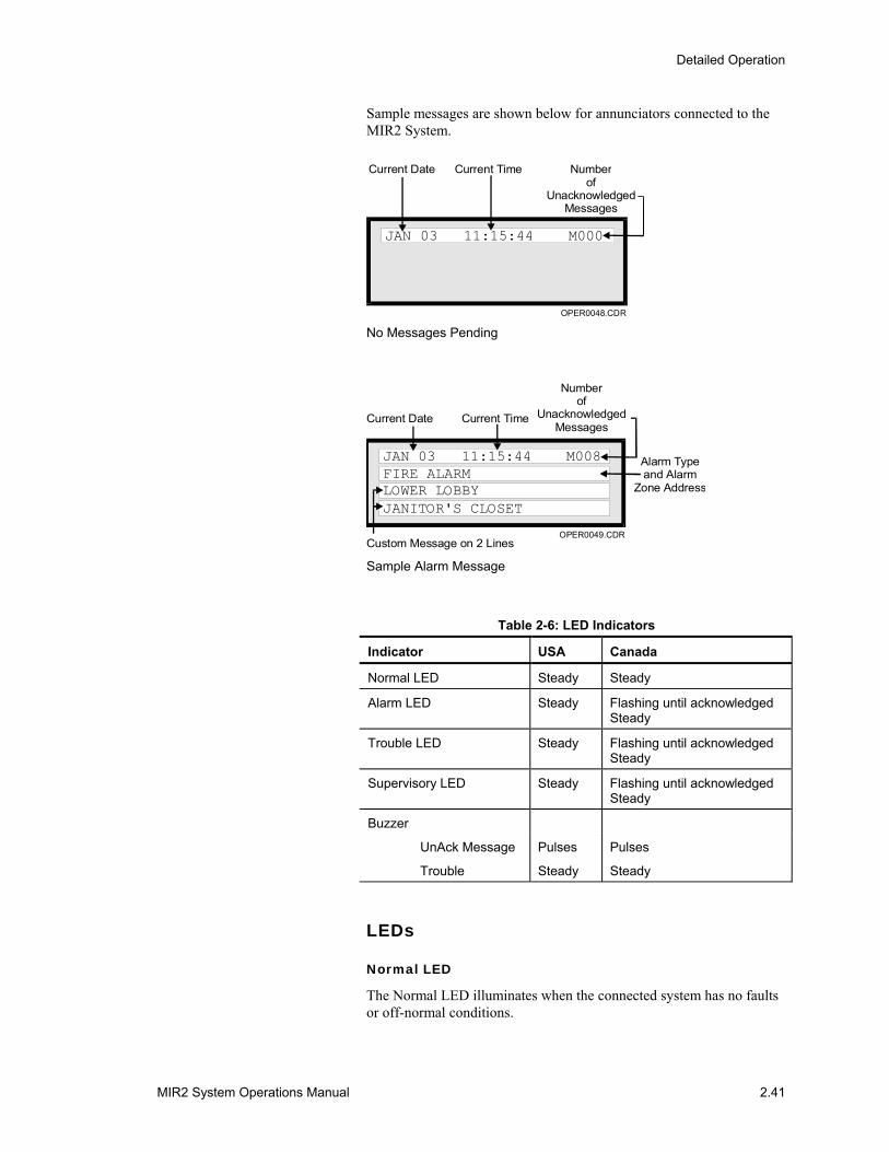
Detailed Operation
MIR2 System Operations Manual 2.41
Sample messages are shown below for annunciators connected to the MIR2 System.
JAN 03 11:15:44 M000
Current Date Current Time Numberof
UnacknowledgedMessages
OPER0048.CDR No Messages Pending
Current Date Current Time
Numberof
UnacknowledgedMessages
Alarm Typeand Alarm
Zone Address
Custom Message on 2 Lines
JAN 03 11:15:44 M008FIRE ALARMLOWER LOBBYJANITOR'S CLOSET
OPER0049.CDR
Sample Alarm Message
Table 2-6: LED Indicators
Indicator USA Canada
Normal LED Steady Steady
Alarm LED Steady Flashing until acknowledged Steady
Trouble LED Steady Flashing until acknowledged Steady
Supervisory LED Steady Flashing until acknowledged Steady
Buzzer
UnAck Message
Trouble
Pulses
Steady
Pulses
Steady
LEDs
Normal LED
The Normal LED illuminates when the connected system has no faults or off-normal conditions.
Detailed Operation
2.42 MIR2 System Operations Manual
Alarm LED
The Alarm LED illuminates when the host system is in an alarm condition.
Supervisory LED
The Supervisory LED illuminates when the 2-LCDA(-C)/2-SLCDA(-C) receives a supervisory alarm which is in its database or in the MIR2-MCM database. A common supervisory (no message in display) turns on the supervisory LED but does not require silencing.
Trouble LED
The Trouble LED illuminates when the 2-LCDA(-C)/2-SLCDA(-C) receives a trouble which is in the database. A common trouble (no message in display) turns on the trouble LED but does not require silencing.
Tx0 (On PC Board)
The Tx0 LED on the circuit board indicates the 2-LCDA(-C)/2-SLCDA(-C) is transmitting on RS-485 channel 0.
Tx1 (On PC Board)
The Tx1 LED on the circuit board indicates the 2-LCDA(-C)/2-SLCDA(-C) is transmitting on RS-485 channel 1
The following indicators are available ONLY on the 2-LCDA-C/2-SLCDA-C annunciators:
Alarm Silence LED
The Alarm Silence LED lights when the system-wide alarm silence function has been initiated.
Local Silence LED
The Trouble Silence LED lights when the system-wide trouble silence function has been initiated.
Drill LED
The Drill LED lights when the system-wide drill/general evacuation function has been initiated.
Front Panel Switches
Next/Acknowledge Switch
Acknowledges the receipt of new messages at the 2-LCDA(-C)/2-SLCDA(-C) and automatically advances to the next unacknowledged message. When there are no unacknowledged messages, the NEXT/ACKNOWLEDGE switch is used to scroll forward through the
Detailed Operation
MIR2 System Operations Manual 2.43
review buffer. The review buffer only displays active points. Should a point go active then restore, it will not appear in the review buffer.
Note: All messages are capable of being acknowledged through the MIR2 Panel. It is NOT a requirement to manually acknowledge messages at the 2-LCDA(-C)/2-SLCDA(-C). The MIR2 System will automatically acknowledge/silence any message via the Local Silence switch. Once the message (alarm, trouble, supervisory, etc) has been restored, the MIR2 Panel will restore the 2-LCDA(-C)/2-SLCDA(-C).
The last message acknowledged via the MIR2 Panel will stay on the 2-LCDA(-C)/2-SLCDA(-C). To remove this message from the display, press the BACK and NEXT/ACKNOWLEDGE simultaneously.
Back Switch
When there are no unacknowledged messages, the BACK switch may be used to scroll in reverse through the review buffer. When the BACK and NEXT/ACKNOWLEDGE switches are operated simultaneously after all messages have been acknowledged, the LCD display is cleared.
The following switches are available ONLY on the LCDA-C/SLCDA-C annunciators:
Enable/Disable Key Switch
Either the Enable or Disable position of the Key switch may be configured to enable or disable any combination of the front panel RESET, ALARM SILENCE, TROUBLE SILENCE, and DRILL switches.
Reset Switch
Reset directs the MIR2 Panel to issue a system wide reset command after all system wide status points have been acknowledged.
Alarm Silence Switch
Directs the MIR2 Panel to issue a system wide alarm silence command. Operating the Alarm Silence switch generates a trouble LED on the display and activates the internal trouble buzzer. Pressing the Alarm Silence and Trouble Silence switches simultaneously starts a 15 second LED test sequence.
Trouble Silence Switch
Silences the LOCAL 2-LCDA(-C)/2-SLCDA(-C) trouble buzzer after all messages have been acknowledged. This is a network wide function.
Drill Switch
Directs the MIR2 Panel to issue a drill command.

Detailed Operation
2.44 MIR2 System Operations Manual
Audible Indicators The 2-LCDA(-C)/2-SLCDA(-C) will pulse its internal buzzer when there are unacknowledged messages in its message buffer. Trouble conditions cause the buzzer to sound continuously until silenced. The 2-LCDA/2-SLCDA (without a trouble silence switch) buzzers sound ONLY for unacknowledged messages in the message buffer.
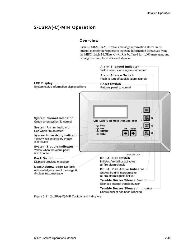
Detailed Operation
MIR2 System Operations Manual 2.45
2-LSRA(-C)-MIR Operation
Overview Each 2-LSRA(-C)-MIR recalls message information stored in its internal memory in response to the zone information it receives from the MIR2. Each 2-LSRA(-C)-MIR is buffered for 1,000 messages, and messages require local acknowledgment.
OPER0050.CDR
LCD DisplaySystem status information displayed here
Life Safety Remote Annunciator
Reset SwitchReturns panel to normal
Back SwitchDisplays previous message
Next/Acknowledge SwitchAcknowledges current message &displays next message
Alarm Silence SwitchPush to turn off audible alarm signals
Drill/All Call SwitchInitiates fire drill or activatesall fire alarm signals
Trouble Buzzer Silence SwitchSilences internal trouble buzzer Trouble Buzzer Silenced IndicatorShows buzzer has been silenced
Drill/All Call Active IndicatorShows fire drill in progress orall fire alarm signals active
Alarm Silenced IndicatorYellow when alarm signals turned off
System Normal IndicatorGreen when system is normal
System Alarm IndicatorRed when fire detectedSystem Supervisory IndicatorYellow when an ancillary systemis in trouble
System Trouble IndicatorYellow when fire alarm panelis in trouble
Figure 2-11: 2-LSRA(-C)-MIR Controls and Indicators
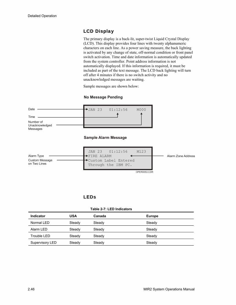
Detailed Operation
2.46 MIR2 System Operations Manual
LCD Display The primary display is a back-lit, super-twist Liquid Crystal Display (LCD). This display provides four lines with twenty alphanumeric characters on each line. As a power saving measure, the back lighting is activated by any change of state, off-normal condition or front panel switch activation. Time and date information is automatically updated from the system controller. Point address information is not automatically displayed. If this information is required, it must be included as part of the text message. The LCD back lighting will turn off after 4 minutes if there is no switch activity and no unacknowledged messages are waiting.
Sample messages are shown below:
JAN 23 01:12:56 M000
OPER0053.CDR
FIRE ALARMCustom Label EnteredThrough the IBM PC.
JAN 23 01:12:56 M123
Date
Time
Number ofUnacknowledgedMessages
Alarm TypeCustom Messageon Two Lines
Alarm Zone Address
No Message Pending
Sample Alarm Message
LEDs
Table 2-7: LED Indicators
Indicator USA Canada Europe
Normal LED Steady Steady Steady
Alarm LED Steady Steady Steady
Trouble LED Steady Steady Steady
Supervisory LED Steady Steady Steady
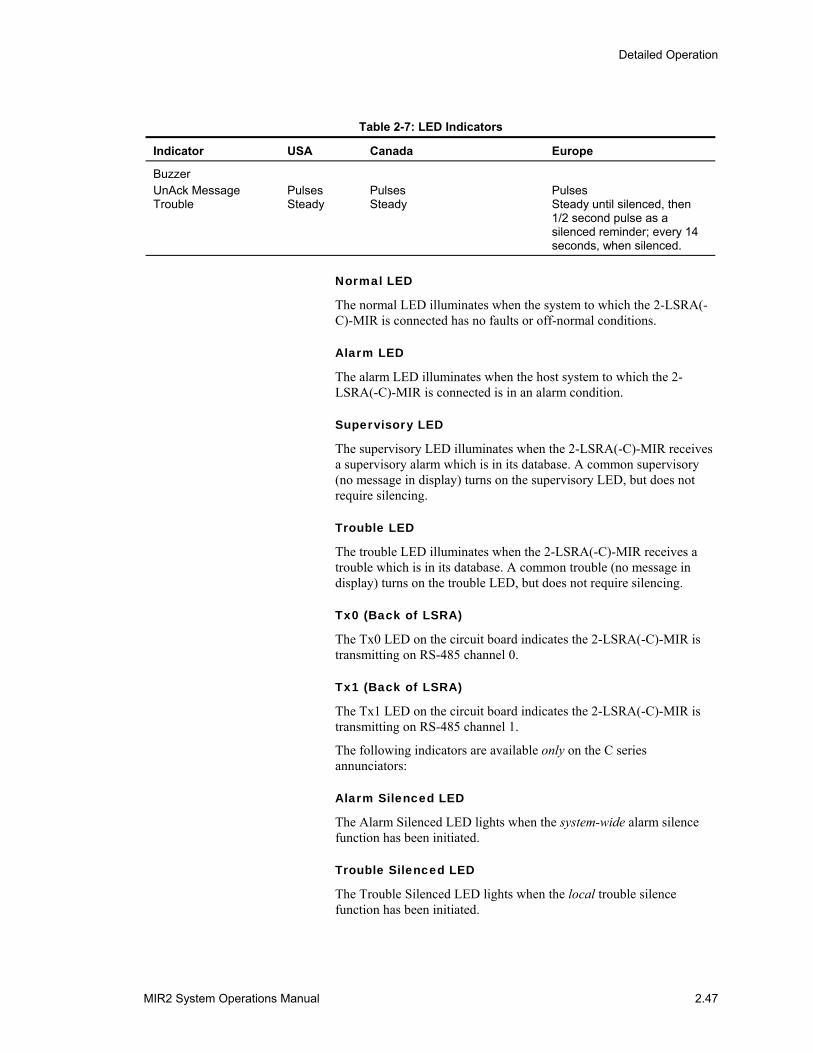
Detailed Operation
MIR2 System Operations Manual 2.47
Table 2-7: LED Indicators
Indicator USA Canada Europe
Buzzer UnAck Message Trouble
Pulses Steady
Pulses Steady
Pulses Steady until silenced, then 1/2 second pulse as a silenced reminder; every 14 seconds, when silenced.
Normal LED
The normal LED illuminates when the system to which the 2-LSRA(-C)-MIR is connected has no faults or off-normal conditions.
Alarm LED
The alarm LED illuminates when the host system to which the 2-LSRA(-C)-MIR is connected is in an alarm condition.
Supervisory LED
The supervisory LED illuminates when the 2-LSRA(-C)-MIR receives a supervisory alarm which is in its database. A common supervisory (no message in display) turns on the supervisory LED, but does not require silencing.
Trouble LED
The trouble LED illuminates when the 2-LSRA(-C)-MIR receives a trouble which is in its database. A common trouble (no message in display) turns on the trouble LED, but does not require silencing.
Tx0 (Back of LSRA)
The Tx0 LED on the circuit board indicates the 2-LSRA(-C)-MIR is transmitting on RS-485 channel 0.
Tx1 (Back of LSRA)
The Tx1 LED on the circuit board indicates the 2-LSRA(-C)-MIR is transmitting on RS-485 channel 1.
The following indicators are available only on the C series annunciators:
Alarm Silenced LED
The Alarm Silenced LED lights when the system-wide alarm silence function has been initiated.
Trouble Silenced LED
The Trouble Silenced LED lights when the local trouble silence function has been initiated.
Detailed Operation
2.48 MIR2 System Operations Manual
Drill LED
The Drill LED lights when the system-wide drill/general evacuation function has been initiated.
Front Panel Switches
Next/Acknowledge Switch
Acknowledges the receipt of new messages at the 2-LSRA(-C)-MIR and automatically advances to the next unacknowledged message. When there are no unacknowledged messages, the NEXT/ACKNOWLEDGE switch is used to scroll forward through the review buffer. The review buffer only displays active points. Should a point go active then restore, it will not appear in the review buffer.
Back Switch
When there are no unacknowledged messages, the BACK switch may be used to scroll in reverse through the review buffer. When the BACK and NEXT/ACKNOWLEDGE switches are operated simultaneously after all messages have been acknowledged, the LCD display is cleared.
The following switches are available only on the C series annunciators. These switches may require a password in order to operate. If the annunciator switch has been configured to require a password, the password will automatically be requested AFTER the switch is activated. Once a password has been entered, it is valid for approximately 2 minutes.
Reset Switch
Reset directs the MIR2-MCM to issue a system wide reset command after all system wide status points have been acknowledged.
Alarm Silence Switch
Directs the MIR2-MCM to issue a system wide alarm silence command. Operating the ALARM SILENCE switch generates a trouble LED in the display and activates the internal trouble buzzer. Pressing the ALARM SILENCE and TROUBLE SILENCE switches simultaneously starts a 15 second LED test sequence.
Trouble Silence Switch
Silences the local annunciator's 2-LSRA(-C)-MIR trouble buzzer after all messages have been acknowledged. This is not a network-wide function.
Drill Switch
Directs the MIR2-MCM to issue a system-wide drill command.
Detailed Operation
MIR2 System Operations Manual 2.49
User Password
Entering the annunciator enables or disables any combination of the front panel RESET, ALARM SILENCE, TROUBLE SILENCE, and DRILL switches.
Audible Indicators The 2-LSRA(-C)-MIR will pulse its internal buzzer when there are unacknowledged messages in its message buffer. Trouble conditions cause the buzzer to sound continuously, until silenced. The 2-LSRA(-C)-MIR (without a trouble silence switch) buzzer sounds only for unacknowledged messages in its message buffer.
Auto-Acknowledge/Internal Buzzer Silence
Auto-Acknowledge
The auto-acknowledge mode automatically acknowledges messages waiting without operator intervention. In auto-acknowledge operation, the 2-LSRA(-C)-MIR will display activated that have not restored.
In auto-acknowledge mode, when the MIR2-MCM system sees a TROUBLE, SUPERVISORY, or ALARM condition, the MW (message waiting) counter will display the total number of messages waiting to be acknowledged. If desired, the operator can manually acknowledge each of message waiting. Once the system returns to a normal condition, the messages in the 2-LSRA(-C)-MIR will be automatically acknowledged.
The messages waiting will acknowledge in the order in which they came in. ALARM messages, because of their priority, will always be first to be acknowledged. Should non-alarm events restore before the ALARM conditions, the 2-LSRA(-C)-MIR will not auto-acknowledge any MWs until the ALARM conditions are either manually acknowledged or restored. If the operator acknowledges any of the TROUBLE, SUPERVISORY, or ALARM conditions, and the system returns to a normal condition, the LSRA will automatically acknowledge the restored conditions. Any messages that have not been restored will remain. Once the MWs are acknowledged, they are removed from the active point buffer.
Note: With the 2-LSRA(-C)-MIR in the auto-acknowledge mode, the printer functions are not available.
Internal Buzzer Silence
The 2-LSRA’s internal buzzer sounds when there are any unacknowledged trouble conditions that are not silenced. In the internal buzzer silence mode, the buzzer can be completely disabled for silent operation in areas sensitive to high noise.
With the buzzer disabled, the following conditions can be expected. When the MIR2 system reports a TROUBLE or SUPERVISORY

Detailed Operation
2.50 MIR2 System Operations Manual
condition, the trouble silence LED will light, reporting that the buzzer is silenced. The trouble silence LED will also stay illuminated after the final message is acknowledged. When the system reports an ALARM, the buzzer will not sound and the trouble silence LED will not light even after the final message is acknowledged.
Note: Refer to the installation section for proper dip switch setup for enabling auto-acknowledge or disabling the internal buzzer.

Detailed Operation
MIR2 System Operations Manual 2.51
Remote Annunciator Component Operation
SAN-CPU Remote Annunciator Controller The SAN-CPU is the interface between the network data lines and the remote annunciator modules.
LEDs
LD1 (LINE): ON indicates data line #1 is active, OFF indicates data line #2 is active.
LD2 (TXD): ON indicates the SAN-CPU is transmitting data on either channel 1 or 2.
2-SANCOM Remote Annunciator Control Module The 2-SANCOM provides basic network indicators and controls in a remote annunciator package.
LEDs
Power: Steady green LED that indicates 24 VDC power is applied to the annunciator.
Alarm: Steady red LED that indicates a system alarm condition.
Supervisory: Steady yellow LED that indicates a supervisory condition.
Trouble: Steady yellow LED that indicates system a trouble condition.
Security: Steady yellow LED that indicates a security condition.
Alarm Silence: Steady yellow LED that indicates audible devices have been silenced.
Trouble Silence: Steady yellow LED that indicates the system-wide trouble buzzer has been silenced.
Drill/All Call: Steady yellow LED that indicates a drill/all call function is active.
Switches
Reset: Momentary toggle switch resets the system.
Alarm Silence: Momentary toggle switch that silences audible circuits.
Trouble Silence: Momentary toggle switch that silences the system-wide trouble buzzer.
Drill/All Call: Momentary toggle switch that activates all audible/visual circuits.
Lamp Test: Momentary toggle switch that tests all indicators on remote annunciator option modules.
Detailed Operation
2.52 MIR2 System Operations Manual
Enable/Disable: Key switch that disables 2-SANCOM controls.
Sounders
Trouble Buzzer: Operates on system trouble, and when the trouble silence is in the off-normal position when no trouble exists on the system
SLU-16 Remote Annunciator Lamp Module The SLU-16 has 16 LEDs for remote annunciator applications when using the SAN-CPU.
LEDs
All LEDs are individually controlled by the system software. When a pre-defined input exists on the system, the appropriate LED will illuminate reporting the condition.
SWU-8 (/3) Remote Annunciator Lamp and Switch Module The SWU-8(/3) has 8 toggle switches and 16 yellow LEDs for remote switching and annunciator applications when using the SAN-CPU.
LEDs and Switches
All LEDs and switches are individually controlled by the system software. When a pre-defined input exists on the system, the appropriate LED will illuminate reporting the condition. Each switch can be programmed for a specific operating function on the system.
SHO-4 Remote Annunciator Lamp and Switch Module The SHO-4 provides four 3 position rotary switches and 12 LEDs for remote switching and annunciator applications when using the SAN-CPU.
LEDs and Switches
The LEDs and switches are individually controlled by the system software. When a pre-defined input exists on the system, the appropriate LED will illuminate reporting the condition. The four green LEDs are illuminated directly by the adjacent switch when in the center position, all other LEDs are controlled by the system software. Each switch can be programmed for a specific operating function on the system.
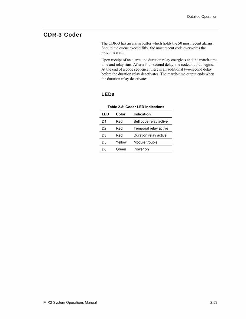
Detailed Operation
MIR2 System Operations Manual 2.53
CDR-3 Coder The CDR-3 has an alarm buffer which holds the 50 most recent alarms. Should the queue exceed fifty, the most recent code overwrites the previous code.
Upon receipt of an alarm, the duration relay energizes and the march-time tone and relay start. After a four-second delay, the coded output begins. At the end of a code sequence, there is an additional two-second delay before the duration relay deactivates. The march-time output ends when the duration relay deactivates.
LEDs
Table 2-8: Coder LED Indications
LED Color Indication
D1 Red Bell code relay active
D2 Red Temporal relay active
D3 Red Duration relay active
D5 Yellow Module trouble
D8 Green Power on
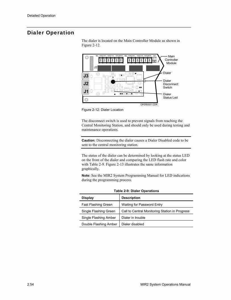
Detailed Operation
2.54 MIR2 System Operations Manual
Dialer Operation The dialer is located on the Main Controller Module as shown in Figure 2-12.
MainControllerModule
Dialer
DialerDisconnectSwitch
DialerStatus Led
OPER0051.CDR
J2
+NAC1/B -TB1 TB2 +NAC2/B -+NAC1/A- +NAC2/A-+SOURCE- +SOURCE- 2WMODE+ -
S1
J1
J3J2
Figure 2-12: Dialer Location
The disconnect switch is used to prevent signals from reaching the Central Monitoring Station, and should only be used during testing and maintenance operations.
Caution: Disconnecting the dialer causes a Dialer Disabled code to be sent to the central monitoring station.
The status of the dialer can be determined by looking at the status LED on the front of the dialer and comparing the LED flash rate and color with Table 2-9. Figure 2-13 illustrates the same information graphically.
Note: See the MIR2 System Programming Manual for LED indications during the programming process.
Table 2-9: Dialer Operations
Display Description
Fast Flashing Green Waiting for Password Entry
Single Flashing Green Call to Central Monitoring Station in Progress
Single Flashing Amber Dialer in trouble
Double Flashing Amber Dialer disabled
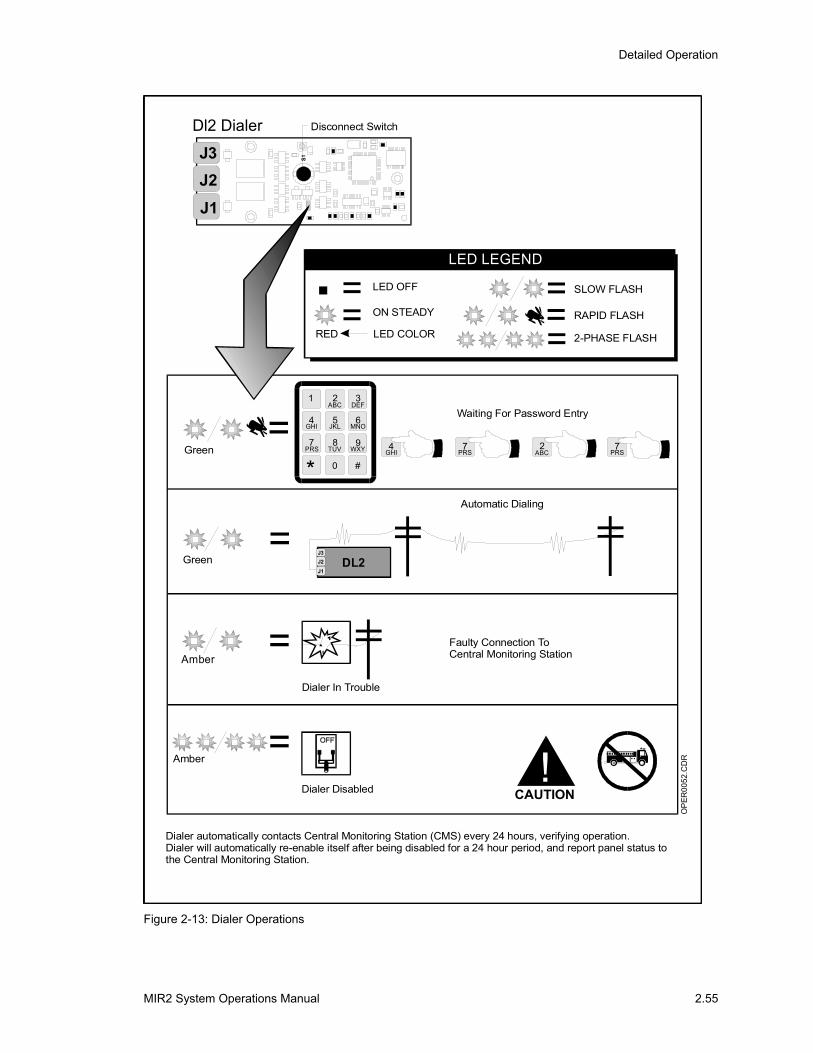
Detailed Operation
MIR2 System Operations Manual 2.55
OP
ER00
52.C
DR!
CAUTION
Faulty Connection ToCentral Monitoring Station=
Amber
Dialer In Trouble
== =
==
LED OFF
ON STEADY
LED COLORRED
SLOW FLASH
2-PHASE FLASH
RAPID FLASH
LED LEGEND
Disconnect SwitchDl2 Dialer
Green= Waiting For Password Entry
2ABC
7PRS
7PRS
4GHI
1
4 5
8
0
3
WXYTUV7
PRS
MNOJKLGHI
DEF2
ABC
6
9
#*
=Green
Automatic Dialing
J1
J3J2 DL2
Amber =Dialer Disabled
Dialer automatically contacts Central Monitoring Station (CMS) every 24 hours, verifying operation.Dialer will automatically re-enable itself after being disabled for a 24 hour period, and report panel status tothe Central Monitoring Station.
S1
J1
J3J2
Figure 2-13: Dialer Operations
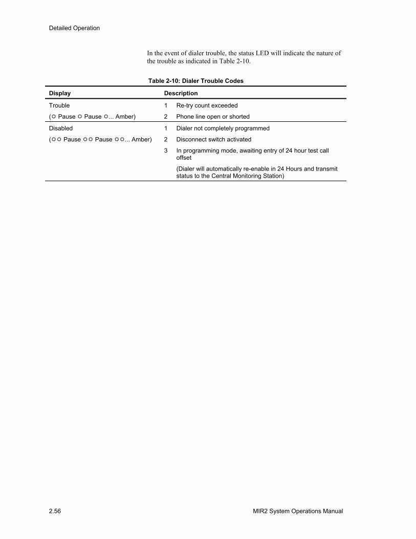
Detailed Operation
2.56 MIR2 System Operations Manual
In the event of dialer trouble, the status LED will indicate the nature of the trouble as indicated in Table 2-10.
Table 2-10: Dialer Trouble Codes
Display Description
Trouble 1 Re-try count exceeded
( Pause Pause ... Amber) 2 Phone line open or shorted
Disabled 1 Dialer not completely programmed
( Pause Pause ... Amber) 2 Disconnect switch activated
3 In programming mode, awaiting entry of 24 hour test call offset
(Dialer will automatically re-enable in 24 Hours and transmit status to the Central Monitoring Station)
MIR2 System Operations Manual A.1
Appendix A System Fault Messages
Summary
This appendix contains descriptions of system fault messages.
Content
System Fault Messages Table • A.2
AppendixA
AppendixA
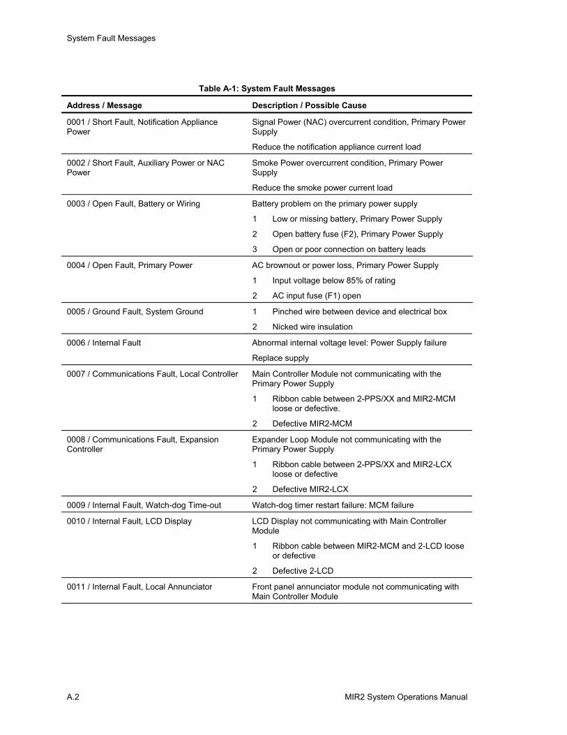
System Fault Messages
A.2 MIR2 System Operations Manual
Table A-1: System Fault Messages
Address / Message Description / Possible Cause
0001 / Short Fault, Notification Appliance Power
Signal Power (NAC) overcurrent condition, Primary Power Supply
Reduce the notification appliance current load
0002 / Short Fault, Auxiliary Power or NAC Power
Smoke Power overcurrent condition, Primary Power Supply
Reduce the smoke power current load
0003 / Open Fault, Battery or Wiring Battery problem on the primary power supply
1 Low or missing battery, Primary Power Supply
2 Open battery fuse (F2), Primary Power Supply
3 Open or poor connection on battery leads
0004 / Open Fault, Primary Power AC brownout or power loss, Primary Power Supply
1 Input voltage below 85% of rating
2 AC input fuse (F1) open
0005 / Ground Fault, System Ground 1 Pinched wire between device and electrical box
2 Nicked wire insulation
0006 / Internal Fault Abnormal internal voltage level: Power Supply failure
Replace supply
0007 / Communications Fault, Local Controller Main Controller Module not communicating with the Primary Power Supply
1 Ribbon cable between 2-PPS/XX and MIR2-MCM loose or defective.
2 Defective MIR2-MCM
0008 / Communications Fault, Expansion Controller
Expander Loop Module not communicating with the Primary Power Supply
1 Ribbon cable between 2-PPS/XX and MIR2-LCX loose or defective
2 Defective MIR2-LCX
0009 / Internal Fault, Watch-dog Time-out Watch-dog timer restart failure: MCM failure
0010 / Internal Fault, LCD Display LCD Display not communicating with Main Controller Module
1 Ribbon cable between MIR2-MCM and 2-LCD loose or defective
2 Defective 2-LCD
0011 / Internal Fault, Local Annunciator Front panel annunciator module not communicating with Main Controller Module
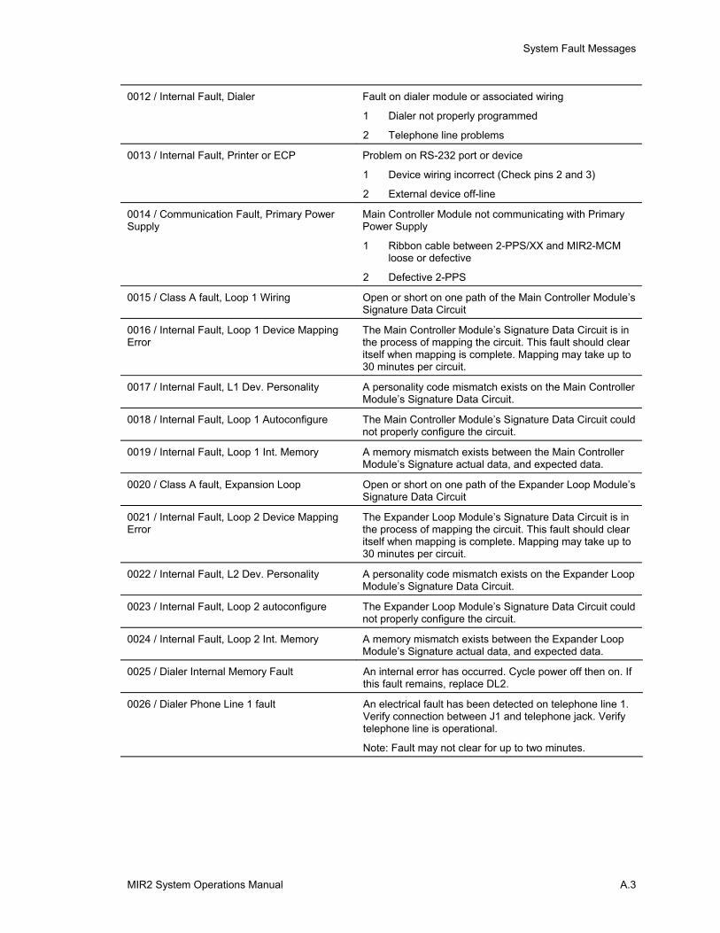
System Fault Messages
MIR2 System Operations Manual A.3
0012 / Internal Fault, Dialer Fault on dialer module or associated wiring
1 Dialer not properly programmed
2 Telephone line problems
0013 / Internal Fault, Printer or ECP Problem on RS-232 port or device
1 Device wiring incorrect (Check pins 2 and 3)
2 External device off-line
0014 / Communication Fault, Primary Power Supply
Main Controller Module not communicating with Primary Power Supply
1 Ribbon cable between 2-PPS/XX and MIR2-MCM loose or defective
2 Defective 2-PPS
0015 / Class A fault, Loop 1 Wiring Open or short on one path of the Main Controller Module’s Signature Data Circuit
0016 / Internal Fault, Loop 1 Device Mapping Error
The Main Controller Module’s Signature Data Circuit is in the process of mapping the circuit. This fault should clear itself when mapping is complete. Mapping may take up to 30 minutes per circuit.
0017 / Internal Fault, L1 Dev. Personality A personality code mismatch exists on the Main Controller Module’s Signature Data Circuit.
0018 / Internal Fault, Loop 1 Autoconfigure The Main Controller Module’s Signature Data Circuit could not properly configure the circuit.
0019 / Internal Fault, Loop 1 Int. Memory A memory mismatch exists between the Main Controller Module’s Signature actual data, and expected data.
0020 / Class A fault, Expansion Loop Open or short on one path of the Expander Loop Module’s Signature Data Circuit
0021 / Internal Fault, Loop 2 Device Mapping Error
The Expander Loop Module’s Signature Data Circuit is in the process of mapping the circuit. This fault should clear itself when mapping is complete. Mapping may take up to 30 minutes per circuit.
0022 / Internal Fault, L2 Dev. Personality A personality code mismatch exists on the Expander Loop Module’s Signature Data Circuit.
0023 / Internal Fault, Loop 2 autoconfigure The Expander Loop Module’s Signature Data Circuit could not properly configure the circuit.
0024 / Internal Fault, Loop 2 Int. Memory A memory mismatch exists between the Expander Loop Module’s Signature actual data, and expected data.
0025 / Dialer Internal Memory Fault An internal error has occurred. Cycle power off then on. If this fault remains, replace DL2.
0026 / Dialer Phone Line 1 fault An electrical fault has been detected on telephone line 1. Verify connection between J1 and telephone jack. Verify telephone line is operational.
Note: Fault may not clear for up to two minutes.
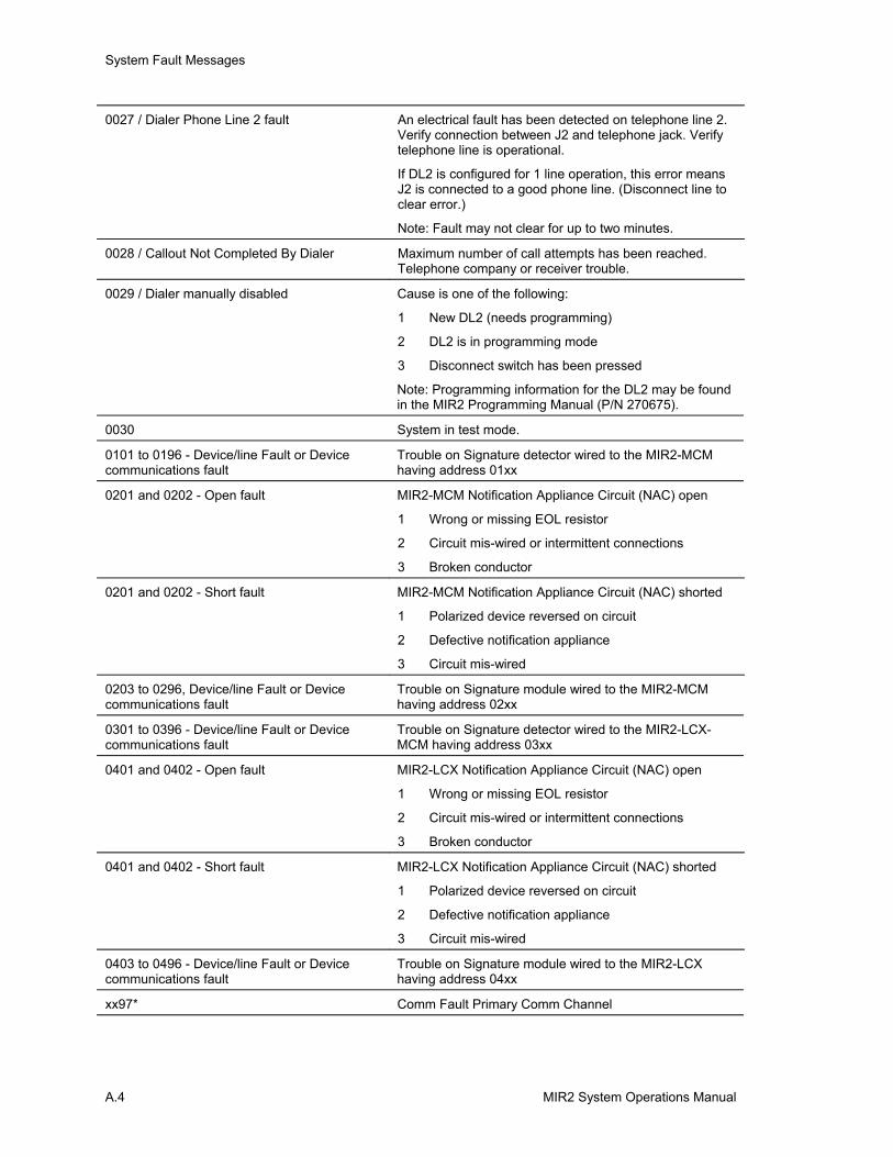
System Fault Messages
A.4 MIR2 System Operations Manual
0027 / Dialer Phone Line 2 fault An electrical fault has been detected on telephone line 2. Verify connection between J2 and telephone jack. Verify telephone line is operational.
If DL2 is configured for 1 line operation, this error means J2 is connected to a good phone line. (Disconnect line to clear error.)
Note: Fault may not clear for up to two minutes.
0028 / Callout Not Completed By Dialer Maximum number of call attempts has been reached. Telephone company or receiver trouble.
0029 / Dialer manually disabled Cause is one of the following:
1 New DL2 (needs programming)
2 DL2 is in programming mode
3 Disconnect switch has been pressed
Note: Programming information for the DL2 may be found in the MIR2 Programming Manual (P/N 270675).
0030 System in test mode.
0101 to 0196 - Device/line Fault or Device communications fault
Trouble on Signature detector wired to the MIR2-MCM having address 01xx
0201 and 0202 - Open fault MIR2-MCM Notification Appliance Circuit (NAC) open
1 Wrong or missing EOL resistor
2 Circuit mis-wired or intermittent connections
3 Broken conductor
0201 and 0202 - Short fault MIR2-MCM Notification Appliance Circuit (NAC) shorted
1 Polarized device reversed on circuit
2 Defective notification appliance
3 Circuit mis-wired
0203 to 0296, Device/line Fault or Device communications fault
Trouble on Signature module wired to the MIR2-MCM having address 02xx
0301 to 0396 - Device/line Fault or Device communications fault
Trouble on Signature detector wired to the MIR2-LCX-MCM having address 03xx
0401 and 0402 - Open fault MIR2-LCX Notification Appliance Circuit (NAC) open
1 Wrong or missing EOL resistor
2 Circuit mis-wired or intermittent connections
3 Broken conductor
0401 and 0402 - Short fault MIR2-LCX Notification Appliance Circuit (NAC) shorted
1 Polarized device reversed on circuit
2 Defective notification appliance
3 Circuit mis-wired
0403 to 0496 - Device/line Fault or Device communications fault
Trouble on Signature module wired to the MIR2-LCX having address 04xx
xx97* Comm Fault Primary Comm Channel
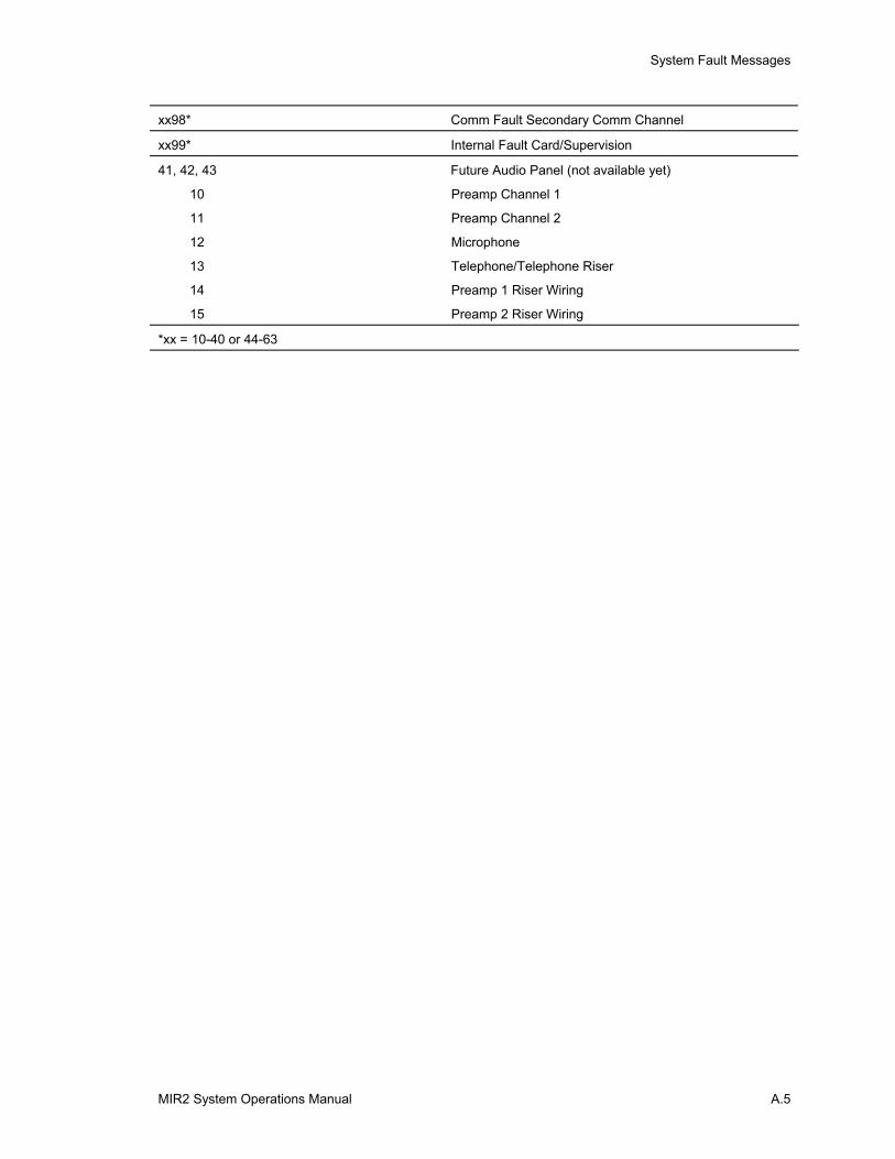
System Fault Messages
MIR2 System Operations Manual A.5
xx98* Comm Fault Secondary Comm Channel
xx99* Internal Fault Card/Supervision
41, 42, 43 Future Audio Panel (not available yet)
10 Preamp Channel 1
11 Preamp Channel 2
12 Microphone
13 Telephone/Telephone Riser
14 Preamp 1 Riser Wiring
15 Preamp 2 Riser Wiring
*xx = 10-40 or 44-63

System Fault Messages
A.6 MIR2 System Operations Manual