Embed Size (px)
Citation preview
SAG584622100, SAG584622200 SAG584622300, SAG584622400
System Application Guide Spec. Nos. 584622100, 584622200,
584622300, 584622400 (Model DCS48375) Revision F, September 27, 2017
Page 1 of 31
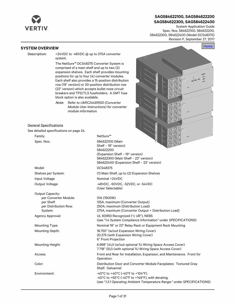
SYSTEM OVERVIEW Description: +24VDC to -48VDC @ up to 375A converter
system.
The NetSure™ DCS48375 Converter System is comprised of a main shelf and up to two (2) expansion shelves. Each shelf provides mounting positions for up to four (4) converter modules. Each shelf also provides a 15-position distribution row (19” version) or 20-position distribution row (23” version) which accepts bullet nose circuit breakers and TPS/TLS fuseholders. A GMT fuse block option is also available.
Note: Refer to UM1C24481500 (Converter Module User Instructions) for converter module information.
General Specifications
See detailed specifications on page 24.
Family: NetSure™
Spec. Nos.: 584622100 (Main Shelf – 19” version) 584622200 (Expansion Shelf – 19” version) 584622300 (Main Shelf – 23” version) 584622400 (Expansion Shelf – 23” version)
Model: DCS48375
Shelves per System: (1) Main Shelf, up to (2) Expansion Shelves
Input Voltage Nominal +24VDC
Output Voltage: -48VDC, -50VDC, -52VDC, or -54VDC (User Selectable)
Output Capacity: per Converter Module: 31A (1500W) per Shelf: 125A, maximum (Converter Output) per Distribution Row: 250A, maximum (Distribution Load) System: 375A, maximum (Converter Output + Distribution Load)
Agency Approval: UL 60950 Recognized (“c UR”), NEBS (see “1.4 System Compliance Information” under SPECIFICATIONS)
Mounting Type: Nominal 19” or 23” Relay Rack or Equipment Rack Mounting
Mounting Depth: 18.750” (w/out Expansion Wiring Cover) 20.375 (with Expansion Wiring Cover) 6” Front Projection
Mounting Height: 6.968” (4U) (w/out optional 1U Wiring Space Access Cover) 7.718” (5U) (with optional 1U Wiring Space Access Cover)
Access: Front and Rear for Installation, Expansion, and Maintenance. Front for Operation.
Color: Distribution Door and Converter Module Faceplates: Textured Gray Shelf: Galvannel
Environment: -40°C to +40°C (-40°F to +104°F). -40°C to +65°C (-40°F to +149°F), with derating. (see “1.3.1 Operating Ambient Temperature Range:” under SPECIFICATIONS)
Home
SAG584622100, SAG584622200 System Application Guide SAG584622300, SAG584622400 Spec. Nos. 584622100, 584622200 Revision F, September 27, 2017 584622300, 584622400 (Model DCS48375)
Page 2 of 31
TABLE OF CONTENTS
SYSTEM OVERVIEW ............................................................................................................................................................................................................. 1 MAIN COMPONENTS ILLUSTRATIONS .......................................................................................................................................................................... 3
584622100 (19” Main Shelf), 584622300 (23” Main Shelf), 584622200 (19” Expansion Shelf), 584622400 (23” Expansion Shelf) ............................................................................................................................................................................................................. 3
ORDERING INFORMATION .................................................................................................................................................................................................4 584622100 Main Shelf and 584622200 Expansion Shelves – 19” Version ......................................................................................................4 584622300 Main Shelf and 584622400 Expansion Shelves – 23” Version .....................................................................................................4 DC-DC Converter Module (P/N 1C24481500).........................................................................................................................................................4 Distribution Devices ....................................................................................................................................................................................................... 5
Bullet Nose Circuit Breakers and Bullet Nose Fuseholders e/w TPS/TLS Fuses ..................................................................................................... 5 Optional Bullet Nose 6-Position GMT Distribution Fuse Block (P/N 545333) ............................................................................................................ 9 Bullet Nose Bypass Busbar (P/N 535015) ........................................................................................................................................................................................10 Replacement Alarm, Reference, and Control Fuses ..................................................................................................................................................................10
Special Application Crimp Lugs, Busbar Adapter Kits, and Hardware Kits .................................................................................................. 10 Special Application Crimp Lugs .............................................................................................................................................................................................................10 Busbar Adapter and Hardware Kits ...................................................................................................................................................................................................... 11
Wiring Notes .................................................................................................................................................................................................................. 13 Recommended Frame Ground Wire Size and Lug Selection ............................................................................................................................................... 13 Recommended DC Inputs Wire Sizes and Lugs Selection .................................................................................................................................................... 13 Recommended Load Distribution Wire Sizes and Lugs Selection ................................................................................................................................... 15 Recommended External Alarm, Reference, Monitoring, and Control Wire Sizes .................................................................................................... 17
Wiring Illustrations ....................................................................................................................................................................................................... 18 DC Inputs and Frame Ground .................................................................................................................................................................................................................. 18 Load Distribution (TPS/TLS Fuses and Bullet Nose Circuit Breakers) ......................................................................................................................... 19 Load Distribution (Optional Bullet Nose 6-Position GMT Fuse Block) ........................................................................................................................ 20 External Alarm, Reference, Monitoring, and Control ................................................................................................................................................................. 21 Shelf Interconnections ................................................................................................................................................................................................................................ 22
SPECIFICATIONS ................................................................................................................................................................................................................ 24 1.1 System Output Ratings ........................................................................................................................................................................................ 24 1.2 System Input Ratings ........................................................................................................................................................................................... 24 1.3 System Environmental Ratings .......................................................................................................................................................................... 24 1.4 System Compliance Information ....................................................................................................................................................................... 24 1.5 System Standard Features .................................................................................................................................................................................. 25
MECHANICAL SPECIFICATIONS ................................................................................................................................................................................... 26 Overall Dimensions – 584622100 Main Shelf ....................................................................................................................................................... 26 Overall Dimensions – 584622200 Expansion Shelf ............................................................................................................................................ 27 Overall Dimensions – 584622300 Main Shelf ...................................................................................................................................................... 28 Overall Dimensions – 584622400 Expansion Shelf ............................................................................................................................................ 29
RELATED DOCUMENTATION ........................................................................................................................................................................................ 30

System Application Guide SAG584622100, SAG584622200 Spec. Nos. 584622100, 584622200, SAG584622300, SAG584622400 584622300, 584622400 (Model DCS48375) Revision F, September 27, 2017
Page 3 of 31
584622100 / 584622200 shown. 584622300 / 584622400 similar.
Front View(door removed in illustration for clarity only)
MAIN COMPONENTS ILLUSTRATIONS 584622100 (19” Main Shelf), 584622300 (23” Main Shelf), 584622200 (19” Expansion Shelf), 584622400 (23” Expansion Shelf)
Mounting Angles
P/N 1C24481500 Converter Modules. Four (4) per Shelf.
Home
15-Position (19” version) 20-Position (23” version) Distribution Panel
Optional 1U Wiring Space Access Cover (if space permits). Allows greater access to load distribution return connection points.
One (1) Main Shelf Up to Two (2) Expansion Shelves
Expansion Wiring Access Cover
(extra cover supplied with Expansion Shelf, to be installed on Main Shelf)
Dual Input Feed Adapter Busbars

SAG584622100, SAG584622200 System Application Guide SAG584622300, SAG584622400 Spec. Nos. 584622100, 584622200 Revision F, September 27, 2017 584622300, 584622400 (Model DCS48375)
Page 4 of 31
ORDERING INFORMATION 584622100 Main Shelf and 584622200 Expansion Shelves – 19” Version
Features
♦ Includes reversible mounting angles for nominal 19” or 23” rack mounting.
♦ Includes the optional 1U wiring space access cover.
♦ Includes two (2) P/N 552506 optional dual input feed busbars.
♦ Accepts up to four (4) DC-DC converter modules.
♦ Includes a 15-position load distribution fuse / circuit breaker panel which accepts... 3A to 100A TPS/TLS fuses, 1A to 250A bullet nose circuit breakers, and “Optional Bullet Nose 6-Position GMT Distribution Fuse Block (P/N 545333)”.
Ordering Notes
1) Order one (1) Spec. No. 584622100 Main Shelf and up to two (2) Spec. No. 584622200 Expansion Shelves per system.
2) Order DC-DC converter modules (P/N 1C24481500) as required.
3) Refer also to “Distribution Devices”, “Special Application Crimp Lugs, Busbar Adapter Kits, and Hardware Kits”, and “Wiring Notes” under ORDERING INFORMATION.
584622300 Main Shelf and 584622400 Expansion Shelves – 23” Version Features
♦ Includes the optional 1U wiring space access cover.
♦ Includes two (2) P/N 552506 optional dual input feed busbars.
♦ Accepts up to four (4) DC-DC converter modules.
♦ Includes a 20-position load distribution fuse / circuit breaker panel which accepts... 3A to 100A TPS/TLS fuses, 1A to 250A bullet nose circuit breakers, and “Optional Bullet Nose 6-Position GMT Distribution Fuse Block (P/N 545333)”.
Ordering Notes
1) Order one (1) Spec. No. 584622300 Main Shelf and up to two (2) Spec. No. 584622400 Expansion Shelves per system.
2) Order DC-DC converter modules (P/N 1C24481500) as required.
3) Refer also to “Distribution Devices”, “Special Application Crimp Lugs, Busbar Adapter Kits, and Hardware Kits”, and “Wiring Notes” under ORDERING INFORMATION.
DC-DC Converter Module (P/N 1C24481500) Features
♦ Provides one (1) Model C24/48-1500, Spec. No. 1C24481500, 1500 watt / 24 to 48 volt DC-DC converter module.
♦ Refer to UM1C24481500 (Converter Module User Instructions) for converter module information.
Restrictions
Each shelf accepts up to four (4) DC-DC converter modules.
Ordering Notes
1) Order by P/N 1C24481500 as required.
Home
System Application Guide SAG584622100, SAG584622200 Spec. Nos. 584622100, 584622200, SAG584622300, SAG584622400 584622300, 584622400 (Model DCS48375) Revision F, September 27, 2017
Page 5 of 31
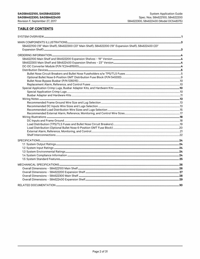
Distribution Devices Bullet Nose Circuit Breakers and Bullet Nose Fuseholders e/w TPS/TLS Fuses
Features
♦ A single fuseholder provides for installation of a 3A to 100A Bussmann TPS or Littelfuse TLS fuse (as listed in Table 1). This fuseholder plugs into a single distribution row mounting position. This fuseholder provides a GMT-A alarm fuse, which operates open to provide an alarm indication if the associated distribution fuse opens.
♦ Each circuit breaker (as listed in Table 2 and Table 3) plugs into one, two, or three distribution row mounting position(s).
Restrictions
Load should not exceed 80% of device rating.
Unless otherwise specified, fuses and/or circuit breakers are mounted from left to right, starting with the highest capacity and working to the lowest capacity.
125A, 150A, 175A, and 200A circuit breakers occupy two mounting positions. 225A and 250A circuit breakers occupy three mounting positions.
Caution: For ambient temperatures at or below +40°C (+104°F), overcurrent devices rated 100A or greater MUST HAVE an empty mounting position between it and any other overcurrent protective device. Maximum size circuit breakers that can be used are 100A single pole, 200A double pole, and 250A triple pole. Maximum size fuse is 100A. The distribution row is rated for a maximum of 250A. For ambient temperatures between +40°C (+104°F) and +65°C (+149°F), overcurrent devices rated 60A or greater MUST HAVE an empty mounting position between it and any other overcurrent protective device. Maximum size circuit breakers that can be used are 70A single pole. No double pole or triple pole circuit breakers can be used. Maximum size fuse 70A. The distribution row is rated for a maximum of 250A.
Ordering Notes
1) Order distribution fuses as required per Table 1. Also order one (1) P/N 117201 bullet nose fuseholder per fuse ordered. Order replacement alarm fuses (18/100A) per Table 5.
2) Order distribution circuit breakers as required per Table 2 or Table 3.
3) See Table 11 for recommended load distribution wire sizes and to order lugs.
• Distribution devices requiring a single distribution position require a two hole lug with 1/4” bolt clearance holes on 5/8” centers (order per Table 11, order hardware kits per Table 7).
• Distribution devices requiring two (2) or three (3) distribution positions require special application lugs (order per Table 11 and Table 6) or busbar adapter kits (order per Table 7) and two hole lugs with 3/8” bolt clearance holes on 1” centers (order per Table 8).
Home

SAG584622100, SAG584622200 System Application Guide SAG584622300, SAG584622400 Spec. Nos. 584622100, 584622200 Revision F, September 27, 2017 584622300, 584622400 (Model DCS48375)
Page 6 of 31
Ampere Rating
Part Number
Bussmann P/N Littelfuse P/N
3 248230900 TPS-3 TLS003
5 248231000 TPS-5 TLS005
6 248231200 TPS-6 TLS006
10 248231500 TPS-10 TLS010
15 248231800 TPS-15 TLS015
20 248232100 TPS-20 TLS020
25 248232400 TPS-25 TLS025
30 248232700 TPS-30 TLS030
40 248233300 TPS-40 TLS040
50 248233900 TPS-50 TLS050
60 248234200 TPS-60 TLS060
70 248234500 TPS-70 TLS070
80 118413 -- TLS080
90 118414 -- TLS090
100 118415 -- TLS100
Bullet Nose Fuseholder
P/N 117201 (Includes Fuseholder, 18/100A GMT-A Alarm Fuse, and GMT-X Safety Fuse Cover)
See Table 11 for recommended load distribution wire sizes and lugs.
Table 1 Bullet Nose Fuseholders and TPS/TLS Fuses
Home

System Application Guide SAG584622100, SAG584622200 Spec. Nos. 584622100, 584622200, SAG584622300, SAG584622400 584622300, 584622400 (Model DCS48375) Revision F, September 27, 2017
Page 7 of 31
Ampere Rating
Number of Poles
Number of Mounting Positions
Part Number
Electrical Trip1 (White Handle)
Electrical/ Mechanical Trip2 (Black Handle)
1 1 1 102272 101596
3 1 1 102273 101597
5 1 1 102274 101598
10 1 1 102275 101599
15 1 1 102276 101600
20 1 1 102277 101601
25 1 1 102278 101602
30 1 1 102279 101603
35 1 1 102280 101604
40 1 1 102281 101605
45 1 1 121998 121997
50 1 1 102282 101606
60 1 1 102283 101607
70 1 1 102284 101608
75 1 1 102285 101609
80 1 1 121996 121995
100 1 1 102286 101610
125 2 2 516991 516838
150 2 2 516993 516839
175 2 2 144883 144884
200 2 2 121831 121832
225 3 3 144885 144886
250 3 3 121835 121836
See Table 11 for recommended load distribution wire sizes and lugs.
For 2-pole devices; either order lugs from Table 6 or adapter kit 545404 and lugs from Table 8.
For 3-pole devices; either order lugs from Table 6 or adapter kit 545571 and lugs from Table 8.
Circuit Breaker Alarm Operation: 1 Provides an alarm during an electrical trip condition only. 2 Provides an alarm during an electrical or manual trip condition.
Table 2 Toggle Handle Bullet Nose Circuit Breakers
Home

SAG584622100, SAG584622200 System Application Guide SAG584622300, SAG584622400 Spec. Nos. 584622100, 584622200 Revision F, September 27, 2017 584622300, 584622400 (Model DCS48375)
Page 8 of 31
Ampere Rating
Number of Poles (and Mounting
Positions)
Number of Mounting Positions
Part Number
Electrical Trip1 (White Handle)
Electrical/ Mechanical Trip2 (Black Handle)
1 1 1 142856 142878
3 1 1 142857 142879
5 1 1 142858 142880
10 1 1 142859 142881
15 1 1 142861 142882
20 1 1 142862 142883
25 1 1 142863 142884
30 1 1 142864 142885
35 1 1 142865 142886
40 1 1 142866 142887
45 1 1 142867 142888
50 1 1 142868 142889
60 1 1 142869 142890
70 1 1 142870 142891
75 1 1 142871 142892
80 1 1 142872 142901
100 1 1 142873 142902
125 2 2 142874 142903
150 2 2 142875 142904
200 2 2 142876 142905
250 3 3 142877 142906
See Table 11 for recommended load distribution wire sizes and lugs.
For 2-pole devices; either order lugs from Table 6 or adapter kit 545404 and lugs from Table 8.
For 3-pole devices; either order lugs from Table 6 or adapter kit 545571 and lugs from Table 8.
Circuit Breaker Alarm Operation: 1 Provides an alarm during an electrical trip condition only. 2 Provides an alarm during an electrical or manual trip condition.
Table 3 Rocker Handle Bullet Nose Circuit Breakers
Home
System Application Guide SAG584622100, SAG584622200 Spec. Nos. 584622100, 584622200, SAG584622300, SAG584622400 584622300, 584622400 (Model DCS48375) Revision F, September 27, 2017
Page 9 of 31
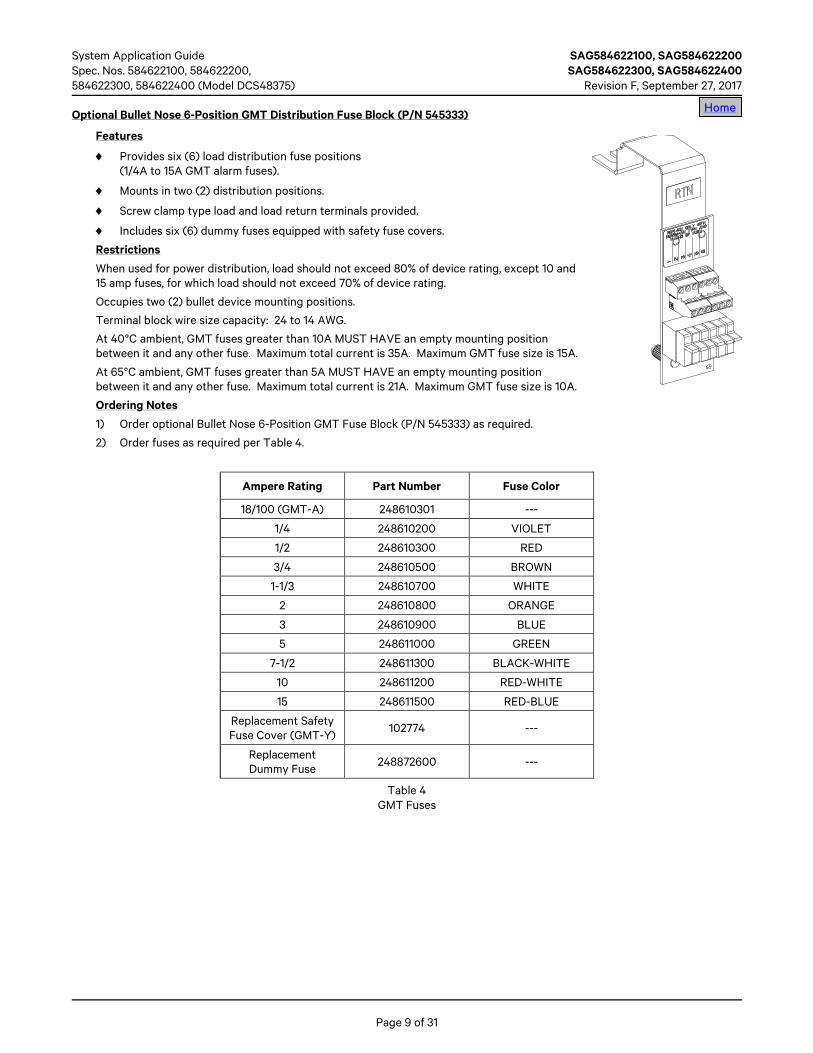
Optional Bullet Nose 6-Position GMT Distribution Fuse Block (P/N 545333)
Features
♦ Provides six (6) load distribution fuse positions (1/4A to 15A GMT alarm fuses).
♦ Mounts in two (2) distribution positions.
♦ Screw clamp type load and load return terminals provided.
♦ Includes six (6) dummy fuses equipped with safety fuse covers.
Restrictions
When used for power distribution, load should not exceed 80% of device rating, except 10 and 15 amp fuses, for which load should not exceed 70% of device rating.
Occupies two (2) bullet device mounting positions.
Terminal block wire size capacity: 24 to 14 AWG.
At 40°C ambient, GMT fuses greater than 10A MUST HAVE an empty mounting position between it and any other fuse. Maximum total current is 35A. Maximum GMT fuse size is 15A.
At 65°C ambient, GMT fuses greater than 5A MUST HAVE an empty mounting position between it and any other fuse. Maximum total current is 21A. Maximum GMT fuse size is 10A.
Ordering Notes
1) Order optional Bullet Nose 6-Position GMT Fuse Block (P/N 545333) as required.
2) Order fuses as required per Table 4.
Ampere Rating Part Number Fuse Color
18/100 (GMT-A) 248610301 ---
1/4 248610200 VIOLET
1/2 248610300 RED
3/4 248610500 BROWN
1-1/3 248610700 WHITE
2 248610800 ORANGE
3 248610900 BLUE
5 248611000 GREEN
7-1/2 248611300 BLACK-WHITE
10 248611200 RED-WHITE
15 248611500 RED-BLUE
Replacement Safety Fuse Cover (GMT-Y) 102774 ---
Replacement Dummy Fuse 248872600 ---
Table 4 GMT Fuses
Home
SAG584622100, SAG584622200 System Application Guide SAG584622300, SAG584622400 Spec. Nos. 584622100, 584622200 Revision F, September 27, 2017 584622300, 584622400 (Model DCS48375)
Page 10 of 31
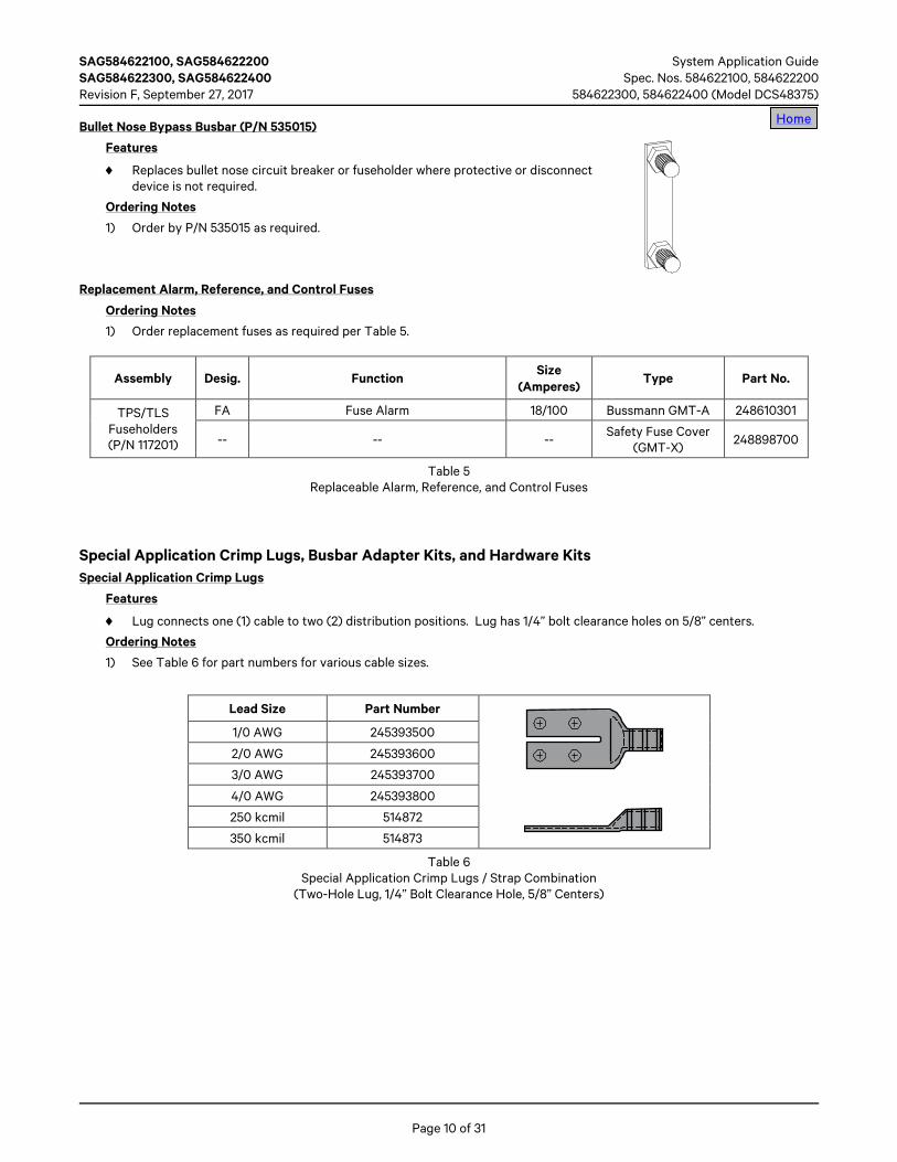
Bullet Nose Bypass Busbar (P/N 535015)
Features
♦ Replaces bullet nose circuit breaker or fuseholder where protective or disconnect device is not required.
Ordering Notes
1) Order by P/N 535015 as required.
Replacement Alarm, Reference, and Control Fuses
Ordering Notes
1) Order replacement fuses as required per Table 5.
Assembly Desig. Function Size
(Amperes) Type Part No.
TPS/TLS Fuseholders (P/N 117201)
FA Fuse Alarm 18/100 Bussmann GMT-A 248610301
-- -- -- Safety Fuse Cover
(GMT-X) 248898700
Table 5 Replaceable Alarm, Reference, and Control Fuses
Special Application Crimp Lugs, Busbar Adapter Kits, and Hardware Kits Special Application Crimp Lugs
Features
♦ Lug connects one (1) cable to two (2) distribution positions. Lug has 1/4” bolt clearance holes on 5/8” centers.
Ordering Notes
1) See Table 6 for part numbers for various cable sizes.
Lead Size Part Number
1/0 AWG 245393500
2/0 AWG 245393600
3/0 AWG 245393700
4/0 AWG 245393800
250 kcmil 514872
350 kcmil 514873
Table 6 Special Application Crimp Lugs / Strap Combination
(Two-Hole Lug, 1/4” Bolt Clearance Hole, 5/8” Centers)
Home

System Application Guide SAG584622100, SAG584622200 Spec. Nos. 584622100, 584622200, SAG584622300, SAG584622400 584622300, 584622400 (Model DCS48375) Revision F, September 27, 2017
Page 11 of 31
Busbar Adapter and Hardware Kits
Features
♦ Kits include hardware shown in Table 7.
♦ Unless otherwise specified, busbar adapter kits are factory installed when ordered with shelf(s).
Ordering Notes
1) See Table 7 for part numbers and descriptions of available kits. For kits that provide 3/8-16 on 1” lug landings, order lugs from Table 8 as required.
Part Number Description
545404 Busbar Adapter Kit – Converts (2) load positions (1/4-20 on 5/8” centers) to (1) landing (3/8-16 on 1” centers). Right-angle load busbar & straight return busbar for rear wiring egress.
545405 Busbar Adapter Kit – Converts (1) load position (1/4-20 on 5/8” centers) to (1) load landing (1/4-20 on 5/8” centers), right angle.
545571 Busbar Adapter Kit – Converts (3) load positions (1/4-20 on 5/8” centers) to (1) landing (3/8-16 on 1” centers). Right-angle load busbar & straight return busbar for rear wiring egress.
552876 Lug Hardware Kit – (32) 1/4-20 nuts, lock washers and flat washers.
Table 7 Busbar Adapter and Hardware Kits
545404
545405
552876
545571
Home

SAG584622100, SAG584622200 System Application Guide SAG584622300, SAG584622400 Spec. Nos. 584622100, 584622200 Revision F, September 27, 2017 584622300, 584622400 (Model DCS48375)
Page 12 of 31
Wire Size Part Number
6 AWG 245349900
4 AWG 245350000
2 AWG 245348200
1/0 AWG 245347100
2/0 AWG 245347200
3/0 AWG 245347300
4/0 AWG 245347400
250 kcmil 245347500
300 kcmil 245347600
350 kcmil 245347700
400 kcmil 245347800
500 kcmil 245347900
600 kcmil 245348000
750 kcmil 245348100
Table 8 Crimp Lugs
(Two-Hole Lug, 3/8” Bolt Clearance Hole, 1” Centers)
Home
System Application Guide SAG584622100, SAG584622200 Spec. Nos. 584622100, 584622200, SAG584622300, SAG584622400 584622300, 584622400 (Model DCS48375) Revision F, September 27, 2017
Page 13 of 31
Home Wiring Notes
Refer also to the next section, Wiring Illustrations.
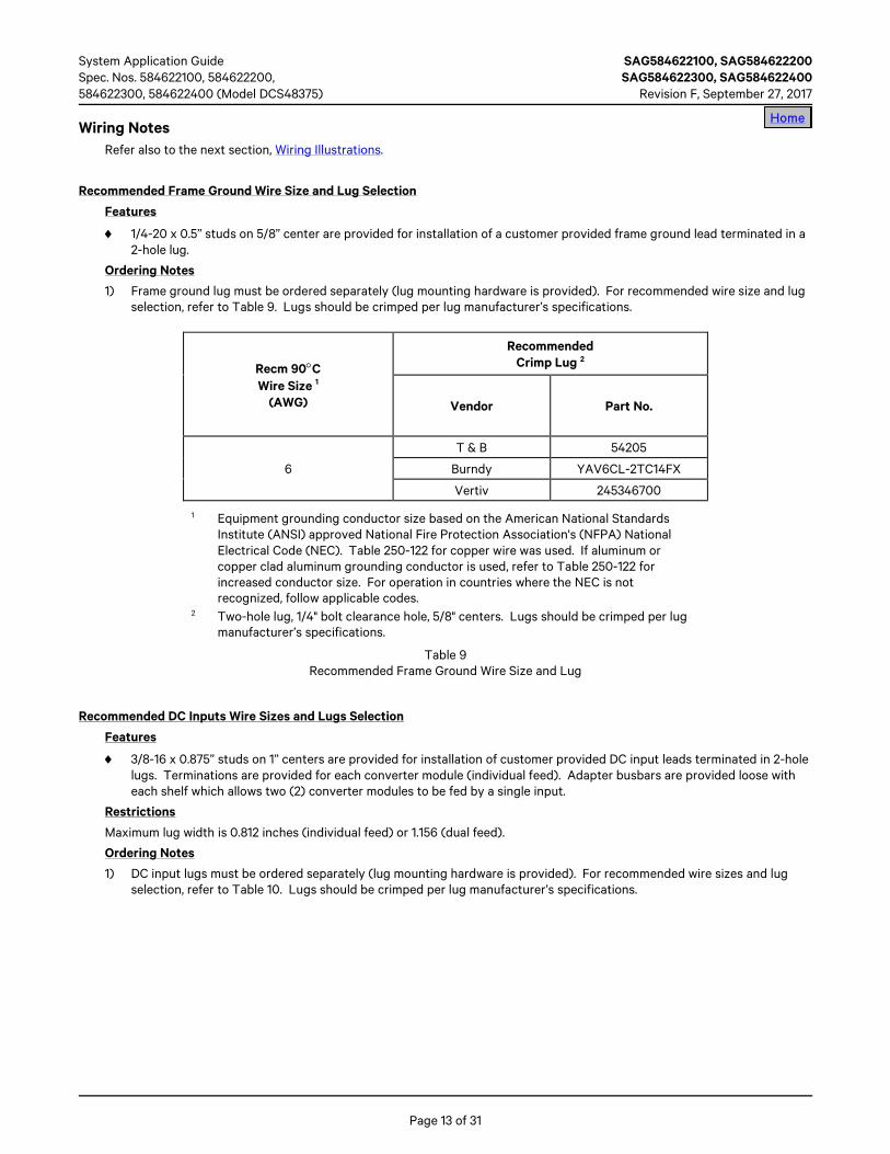
Recommended Frame Ground Wire Size and Lug Selection
Features
♦ 1/4-20 x 0.5” studs on 5/8” center are provided for installation of a customer provided frame ground lead terminated in a 2-hole lug.
Ordering Notes
1) Frame ground lug must be ordered separately (lug mounting hardware is provided). For recommended wire size and lug selection, refer to Table 9. Lugs should be crimped per lug manufacturer’s specifications.
Recm 90°C Wire Size 1
(AWG)
Recommended Crimp Lug 2
Vendor Part No.
6
T & B 54205
Burndy YAV6CL-2TC14FX
Vertiv 245346700
1 Equipment grounding conductor size based on the American National Standards Institute (ANSI) approved National Fire Protection Association's (NFPA) National Electrical Code (NEC). Table 250-122 for copper wire was used. If aluminum or copper clad aluminum grounding conductor is used, refer to Table 250-122 for increased conductor size. For operation in countries where the NEC is not recognized, follow applicable codes.
2 Two-hole lug, 1/4" bolt clearance hole, 5/8" centers. Lugs should be crimped per lug manufacturer’s specifications.
Table 9 Recommended Frame Ground Wire Size and Lug
Recommended DC Inputs Wire Sizes and Lugs Selection
Features
♦ 3/8-16 x 0.875” studs on 1” centers are provided for installation of customer provided DC input leads terminated in 2-hole lugs. Terminations are provided for each converter module (individual feed). Adapter busbars are provided loose with each shelf which allows two (2) converter modules to be fed by a single input.
Restrictions
Maximum lug width is 0.812 inches (individual feed) or 1.156 (dual feed).
Ordering Notes
1) DC input lugs must be ordered separately (lug mounting hardware is provided). For recommended wire sizes and lug selection, refer to Table 10. Lugs should be crimped per lug manufacturer’s specifications.
Home
SAG584622100, SAG584622200 System Application Guide SAG584622300, SAG584622400 Spec. Nos. 584622100, 584622200 Revision F, September 27, 2017 584622300, 584622400 (Model DCS48375)
Page 14 of 31
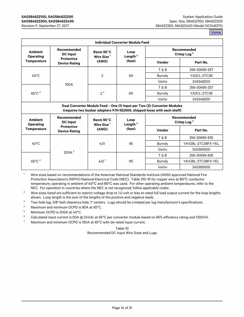
Individual Converter Module Feed
Ambient Operating
Temperature
Recommended DC Input
Protective Device Rating
Recm 90°C Wire Size 1
(AWG)
Loop Length 2
(feet)
Recommended Crimp Lug 3
Vendor Part No.
40°C
100A
2 60
T & B 256-30695-257
Burndy YA2CL-2TC38
Vertiv 245348200
65°C 6 2 4 60
T & B 256-30695-257
Burndy YA2CL-2TC38
Vertiv 245348200
Dual Converter Module Feed – One (1) Input per Two (2) Converter Modules (requires two busbar adapters P/N 552506, shipped loose with each shelf)
Ambient Operating
Temperature
Recommended DC Input
Protective Device Rating
Recm 90°C Wire Size 1
(AWG)
Loop Length 2
(feet)
Recommended Crimp Lug 3
Vendor Part No.
40°C
200A 5
4/0 95
T & B 256-30695-835
Burndy YAV28L-2TC38FX-YEL
Vertiv 245390500
65°C 6 4/0 7 95
T & B 256-30695-835
Burndy YAV28L-2TC38FX-YEL
Vertiv 245390500
1 Wire sizes based on recommendations of the American National Standards Institute (ANSI) approved National Fire Protection Association's (NFPA) National Electrical Code (NEC). Table 310-16 for copper wire at 90°C conductor temperature, operating in ambient of 40°C and 65°C was used. For other operating ambient temperatures, refer to the NEC. For operation in countries where the NEC is not recognized, follow applicable codes.
2 Wire sizes listed are sufficient to restrict voltage drop to 1.0 volt or less at rated full load output current for the loop lengths shown. Loop length is the sum of the lengths of the positive and negative leads.
3 Two-hole lug, 3/8" bolt clearance hole, 1" centers. Lugs should be crimped per lug manufacturer’s specifications. 4 Maximum and minimum OCPD is 80A at 65°C. 5 Minimum OCPD is 200A at 40°C. 6 Calculated input current is 60A @ 24Vdc at 65°C per converter module based on 85% efficiency rating and 1200VA. 7 Maximum and minimum OCPD is 150A at 65°C with de-rated input current.
Table 10 Recommended DC Input Wire Sizes and Lugs
Home

System Application Guide SAG584622100, SAG584622200 Spec. Nos. 584622100, 584622200, SAG584622300, SAG584622400 584622300, 584622400 (Model DCS48375) Revision F, September 27, 2017
Page 15 of 31
Recommended Load Distribution Wire Sizes and Lugs Selection
Features
♦ 1/4-20 x 0.625” studs on 5/8” centers are provided for installation of customer provided load distribution leads terminated in 2-hole lugs.
Restrictions
Maximum lug width, 0.625 inches.
Maximum size of wire to be connected to a single fuseholder or circuit breaker position is 2 AWG.
Ordering Notes
1) Load distribution lugs must be ordered separately. Customer must provide (or order) lug mounting hardware. The rating of the distribution device determines the load lead wire size requirement. For recommended wire sizes and lug selection for various loop lengths per fuse/circuit breaker ampere rating, refer to Table 11. Lugs should be crimped per lug manufacturer’s specifications.
• Maximum size of wire to be connected to a single fuseholder or circuit breaker position is 2 AWG. For wiring up to 350 kcmil, see “Special Application Crimp Lugs” under ORDERING INFORMATION.
• Distribution devices requiring a single distribution position require a two hole lug with 1/4” bolt clearance holes on 5/8” centers (order per Table 11, order hardware kits per Table 7).
• Distribution devices requiring two (2) or three (3) distribution positions require special application lugs (order per Table 11 and Table 6) or busbar adapter kits (order per Table 7) and two hole lugs with 3/8” bolt clearance holes on 1” centers (order per Table 8).
Notes to Table 11: 1 Wire sizes are based on recommendations of the American National Standards Institute (ANSI) approved National Fire
Protection Association's (NFPA) National Electrical Code (NEC). Table 310-16 for wire rated at 90°C conductor temperature operating in ambient temperatures of 40°C, 50°C, and 65°C was used. For other operating ambient temperatures, refer to the NEC. For operation in countries where the NEC is not recognized, follow applicable codes.
2 Recommended wire sizes are sufficient to restrict voltage drop to 1.0 volt or less at listed branch current for the loop lengths shown. Loop length is the sum of the lengths of the positive and negative leads.
3 Wire Size / Loop Length Combination Calculated using 40°C Ambient Operating Temperature. 4 Wire Size / Loop Length Combination Calculated using 50°C Ambient Operating Temperature. 5 Wire Size / Loop Length Combination Calculated using 65°C Ambient Operating Temperature. 6 These lugs are two-hole for 1/4" bolt clearance on 5/8" centers. Lugs should be crimped per lug manufacturer’s
specifications. 7 Special application crimp lug / strap combination.
Table 11 (cont'd on next page) Recommended Load Distribution Wire Sizes and Lugs
Home

SAG584622100, SAG584622200 System Application Guide SAG584622300, SAG584622400 Spec. Nos. 584622100, 584622200 Revision F, September 27, 2017 584622300, 584622400 (Model DCS48375)
Page 16 of 31
Fuse/Circuit Breaker Amperage
Recm 90°C Wire Size (1)
14 AWG 12 AWG 10 AWG 8 AWG 6 AWG 4 AWG 2 AWG
Loop Length (feet) (2)
1, 3, 5, 6, 10A 37 (3, 4, 5) 58 (3, 4, 5) 93 (3, 4, 5) 148 (3, 4, 5) 236 (3, 4, 5) 376 (3, 4, 5) 597 (3, 4, 5)
15A 24 (3, 4) 39 (3, 4, 5) 62 (3, 4, 5) 99 (3, 4, 5) 157 (3, 4, 5) 250 (3, 4, 5) 398 (3, 4, 5)
20A -- 29 (3, 4) 46 (3, 4, 5) 74 (3, 4, 5) 118 (3, 4, 5) 188 (3, 4, 5) 298 (3, 4, 5)
25A -- -- 37 (3, 4,) 59 (3, 4, 5) 94 (3, 4, 5) 150 (3, 4, 5) 239 (3, 4, 5)
30A -- -- 31 (3, 4) 49 (3, 4, 5) 78 (3, 4, 5) 125 (3, 4, 5) 199 (3, 4, 5)
35A -- -- -- 42 (3, 4) 67 (3, 4, 5) 107 (3, 4, 5) 170 (3, 4, 5)
40A -- -- -- 37 (3, 4) 59 (3, 4, 5) 94 (3, 4, 5) 149 (3, 4, 5)
45A -- -- -- 33 (3, 4) 52 (3, 4) 83 (3, 4) 132 (3, 4)
50A -- -- -- 29 (3) 47 (3, 4,) 75 (3, 4) 119 (3, 4)
60A -- -- -- -- 39 (3, 4) 62 (3, 4) 99 (3, 4)
70A -- -- -- -- -- 53 (3, 4) 85 (3, 4)
75A -- -- -- -- -- 50 (3, 4) 79 (3, 4)
80A -- -- -- -- -- 47 (3) 74 (3, 4)
Recommended Crimp Lug (6)
Lug 245342300 245342300 245342300 245390200 245346700 245346800 245346900
Fuse/Circuit Breaker
Amperage
Recm 90°C Wire Size (1)
2 AWG 1/0 AWG 2/0 AWG 3/0 AWG 4/0 AWG 250 kcmil 350 kcmil
Loop Length (feet) (2)
90A 66 (3, 4) 105 (3) 133 (3) -- -- -- --
100A 59 (3, 4) 95 (3) 119 (3) -- -- -- --
125A 47 (3) 76 (3) 95 (3) 120 (3) -- -- --
150A -- 63 (3) 79 (3) 100 (3) -- -- --
175A -- -- 68 (3, 4) 86 (3, 4) 108 (3, 4) -- --
200A -- -- -- 75 (3) 95 (3) 112 (3) --
225A -- -- -- -- 67 (3) 84 (3, 4) 100 (3, 4)
250A -- -- -- -- 76 (3,8) 90 (3, 8) 126 (3,8)
Recommended Crimp Lug
Lug 245346900 (6) 245393500 (7) 245393600 (7) 245393700 (7) 245393800 (7) 514872 (7) 514873 (7)
Table 11 (cont'd from previous page) Recommended Load Distribution Wire Sizes and Lugs
Home

System Application Guide SAG584622100, SAG584622200 Spec. Nos. 584622100, 584622200, SAG584622300, SAG584622400 584622300, 584622400 (Model DCS48375) Revision F, September 27, 2017
Page 17 of 31
Home Recommended External Alarm, Reference, Monitoring, and Control Wire Sizes
Features
♦ The system interface circuit card is mounted on the inside of the main shelf’s front door. This circuit card provides four (4) sets of Form C relay contacts for external alarms, reference and monitoring inputs, plus an ESTOP input. Terminal blocks are provided on the circuit card for customer connections. Refer to Paragraphs 1.5.3 and 1.5.4 under “Specifications” for details.
Restrictions
Terminal block wire size capacity is 12 to 22 AWG.
Relay contacts are rated for 1A at 30VDC or 0.3A at 110VDC.
Ordering Notes
1) Recommended Wire Size: 22 AWG for Loop Lengths Up to 200 ft. 18-20 AWG for Loop Lengths Over 200 ft.

SAG584622100, SAG584622200 System Application Guide SAG584622300, SAG584622400 Spec. Nos. 584622100, 584622200 Revision F, September 27, 2017 584622300, 584622400 (Model DCS48375)
Page 18 of 31
Wiring Illustrations DC Inputs and Frame Ground
DC Input Connections* 3/8-16 x 0.875” studs on 1” centers
for installation of leads with 2-hole lugs.* Provide separate inputs for each converter.* Maximum lug width 0.812”.* Torque to 240 in-lbs.
+24VDCConverter #1 (top)Converter #2Converter #3Converter #4 (bottom)
DC Input LeadsEnter Here Return
Converter #1 (top)Converter #2Converter #3Converter #4 (bottom)Frame Ground
* 1/4-20 x 0.5” studs on 5/8” centerfor installation of lead with 2-hole lug.
* Torque to 84 in-lbs.
Rear panels removed in illustration.
Rear
Dual Converter Module Feedwith Adapter BusbarsP/Ns 552506
Feed Two
Feed One
+24VDCConverter #3Converter #4
ReturnConverter #3Converter #4
+24VDCConverter #1Converter #2
ReturnConverter #1Converter #2
DC Input Connections* 3/8-16 x 0.875” studs on 1” centers
for installation of leads with 2-hole lugs.* Provide one input for two converters.* Maximum lug width 1.156”.* Torque to 240 in-lbs.
Discard Extra Hardware
BusbarsP/Ns 552506
584622100 / 584622200 shown.584622300 / 584622400 similar.
Home
System Application Guide SAG584622100, SAG584622200 Spec. Nos. 584622100, 584622200, SAG584622300, SAG584622400 584622300, 584622400 (Model DCS48375) Revision F, September 27, 2017
Page 19 of 31
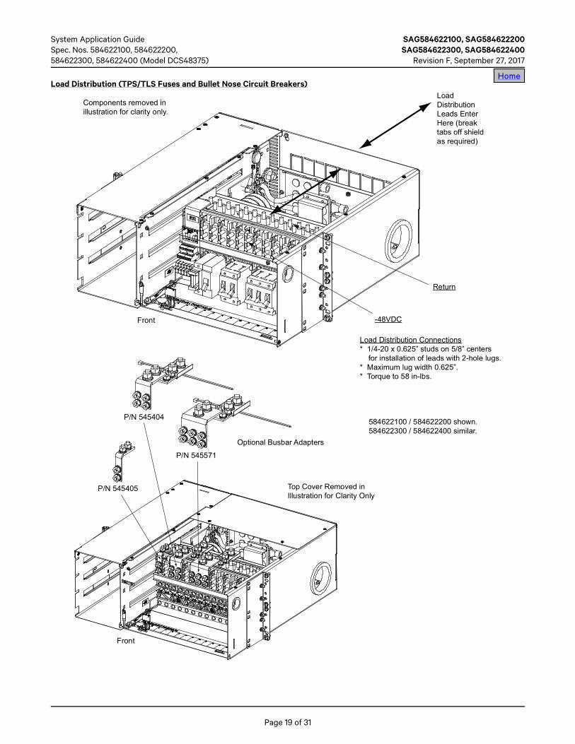
Load Distribution (TPS/TLS Fuses and Bullet Nose Circuit Breakers)
Load Distribution Connections* 1/4-20 x 0.625” studs on 5/8” centers
for installation of leads with 2-hole lugs.* Maximum lug width 0.625”.* Torque to 58 in-lbs.
-48VDC
Return
Front
Front
Components removed inillustration for clarity only.
LoadDistributionLeads EnterHere (breaktabs off shieldas required)
P/N 545405
P/N 545404
P/N 545571
Top Cover Removed inIllustration for Clarity Only
Optional Busbar Adapters
584622100 / 584622200 shown.584622300 / 584622400 similar.
Home

SAG584622100, SAG584622200 System Application Guide SAG584622300, SAG584622400 Spec. Nos. 584622100, 584622200 Revision F, September 27, 2017 584622300, 584622400 (Model DCS48375)
Page 20 of 31
Load Distribution (Optional Bullet Nose 6-Position GMT Fuse Block)
Load Leads
Load Return Leads
Wire Size Capacity: 26-14 AWG.Recommended Torque: 4.5 in-lbs.
Home

System Application Guide SAG584622100, SAG584622200 Spec. Nos. 584622100, 584622200, SAG584622300, SAG584622400 584622300, 584622400 (Model DCS48375) Revision F, September 27, 2017
Page 21 of 31
External Alarm, Reference, Monitoring, and Control
Note: External FA/CBA Alarm Input: An external FA/CBA alarm signal can be connected to the system as shown in the “Shelf Interconnections” section.
Inside View of Main Shelf’s Front Door
TB11 9 1 12
TB2P2P1
TB1
1 9 1 12
TB2ConvMajor
ConvCriticalFuse / CB
Low InputVoltage
NC C NONC C NONC C NONC C NO
ESTOP+VO-VO+IO-IO+BT-BT
CANHCANL
CANTERM
P2Recommended Torque is 5.0 in-lbs. Recommended Torque is 5.0 in-lbs.
Low Input Voltage, Conv Critical, and Conv Major relays are energizedfor normal operating conditions and de-energized for an alarm condition.
Fuse / CB relay is de-energized for normal operating conditionsand energized for an alarm condition.
Relay contacts shown represent normal system operation.
Home

SAG584622100, SAG584622200 System Application Guide SAG584622300, SAG584622400 Spec. Nos. 584622100, 584622200 Revision F, September 27, 2017 584622300, 584622400 (Model DCS48375)
Page 22 of 31
Shelf Interconnections
Output Paralleling Leads
Cable, lugs, and labels are providedloose with the Expansion Shelf toassemble a Return and a -48Vparalleling cable.
ExpansionWiring Covers
Hardware providedon terminals.
RETURNPARALLELINGCABLE
-48VPARALLELINGCABLE
584622100 / 584622200 shown.584622300 / 584622400 similar.
Home
System Application Guide SAG584622100, SAG584622200 Spec. Nos. 584622100, 584622200, SAG584622300, SAG584622400 584622300, 584622400 (Model DCS48375) Revision F, September 27, 2017
Page 23 of 31
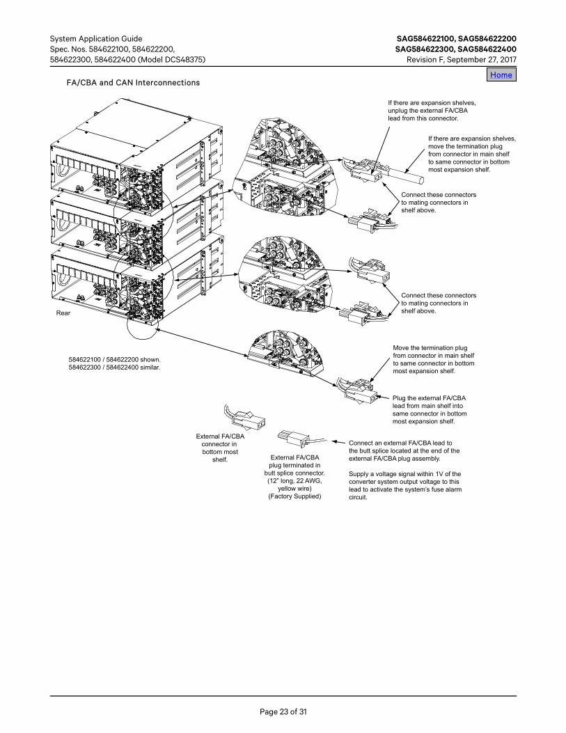
FA/CBA and CAN Interconnections
Connect these connectorsto mating connectors inshelf above.
Connect these connectorsto mating connectors inshelf above.
If there are expansion shelves,move the termination plugfrom connector in main shelfto same connector in bottommost expansion shelf.
If there are expansion shelves,unplug the external FA/CBAlead from this connector.
Move the termination plugfrom connector in main shelfto same connector in bottommost expansion shelf.
Plug the external FA/CBAlead from main shelf intosame connector in bottommost expansion shelf.
Connect an external FA/CBA lead tothe butt splice located at the end of theexternal FA/CBA plug assembly.
Supply a voltage signal within 1V of theconverter system output voltage to thislead to activate the system’s fuse alarmcircuit.
Rear
External FA/CBAconnector inbottom most
shelf. External FA/CBAplug terminated in
butt splice connector.(12” long, 22 AWG,
yellow wire)(Factory Supplied)
584622100 / 584622200 shown.584622300 / 584622400 similar.
Home
SAG584622100, SAG584622200 System Application Guide SAG584622300, SAG584622400 Spec. Nos. 584622100, 584622200 Revision F, September 27, 2017 584622300, 584622400 (Model DCS48375)
Page 24 of 31
SPECIFICATIONS Note: For DC-DC converter module specifications, refer to UM1C24481500 (Converter Module User Instructions).
1.1 System Output Ratings
1.1.1 Voltage: Nominal -48 volts DC, positive ground. User adjustable for either -48VDC, -50VDC, -52VDC, or -54VDC.
1.1.2 Current: 375A, maximum (Converter Output + Distribution. Load). 125A, maximum (Converter Output) per shelf. 250A, maximum (Distribution Load) per distribution row.
1.2 System Input Ratings
1.2.1 Input Voltage: Nominal +24 volts DC.
1.2.2 Nameplate Rating:
(A) Individual Feed: +20.5 to +30 volts DC, 87 to 59A.
(B) Dual Feed (one input per two converters): +20.5 to +30 volts DC, 175 to 120A.
1.2.3 Filtering: Noise reflected back to the central office battery is within the parameters set forth in Telcordia Technical Reference TR-TSY-000009, paragraph 5.0, using test measurements in Telcordia Technical Reference PUB 43802, pages 5 and 6.
1.3 System Environmental Ratings
1.3.1 Operating Ambient Temperature Range:
(A) -40°C to +40°C (-40°F to +104°F).
Overcurrent devices rated 100A or greater MUST HAVE a space adjacent to it. Maximum size circuit breakers that can be used are 100A single pole, 200A double pole, and 250A triple pole. Maximum size fuse is 100A.
(B) -40°C to +65°C (-40°F to +149°F), with derating.
For ambient temperatures between +40°C (+104°F) and +65°C (+149°F), overcurrent devices rated 60A or greater MUST HAVE a space adjacent to it. Maximum size circuit breakers that can be used are 70A single pole. No double pole or triple pole circuit breakers can be used. Maximum size fuse 70A.
1.3.2 Storage Ambient Temperature Range: -40°C to +85°C (-40°F to +185°F).
1.3.3 Humidity: Capable of operating in an ambient relative humidity range of 0% to 95%, non-condensing.
1.3.4 Altitude: Capable of operating in an altitude range of -200 feet to 10,000 feet. The maximum operating ambient temperature should be derated by 3°C per 1000 feet above 5000 feet.
1.3.5 Ventilation Requirements:
(A) Ventilation: A shelf must be mounted so ventilating openings are not blocked and temperature of the air entering the shelf does not exceed the Operating Ambient Temperature Range stated above.
(B) Stacking Considerations: This system is designed for front to back ventilation to facilitate stacking of shelves, one above the other, in a relay rack. There is no spacing requirement between stacked shelves of a single system.
1.3.6 Audible Noise (System): With four converter modules installed and operating, the audible noise at any point 5 feet from any vertical surface of the mounting shelf does not exceed 68 dBA when measured with a sound level meter conforming to ANSI S1.4.
1.3.7 Mounting:
(A) The shelf is designed for mounting in a 19-inch or 23-inch wide relay rack with 1-3/4 inch multiple drilling.
(B) This product is intended only for installation in a Restricted Access Location on or above a non-combustible surface.
(C) This product must be located in a Controlled Environment with access to Craftspersons only.
(D) This product is intended for installation in Network Telecommunication Facilities (CO, vault, hut, or other environmentally controlled electronic equipment enclosure).
(E) This product is intended to be connected to the common bonding network in a Network Telecommunication Facility (CO, vault, hut, or other environmentally controlled electronic equipment enclosure).
(F) Typical industry standards recommend minimum aisle space clearance of 2'6" for the front of the relay rack and 2' for the rear of the relay rack.
1.4 System Compliance Information
1.4.1 Safety Compliance: This unit meets the requirements of UL 60950, Standard for Information Technology Equipment, and is UL Recognized as a power supply for use in Telephone, Electronic Data Processing or
Home Home

System Application Guide SAG584622100, SAG584622200 Spec. Nos. 584622100, 584622200, SAG584622300, SAG584622400 584622300, 584622400 (Model DCS48375) Revision F, September 27, 2017
Page 25 of 31
Information Processing Equipment. This unit meets the requirements of CAN/CSA 22.2, No. 60950-00 and is tested and Certified by UL ("c UR") as a Component Type Power Supply.
1.4.2 NEBS Compliance: Compliance verified by a Nationally Recognized Testing Laboratory (NRTL) per GR-1089-CORE and GR-63-CORE. Contact Vertiv for NEBS compliance reports.
Converter Modules: In order to remain compliant during a fan failure condition, the system must operate with a redundant module installed.
1.5 System Standard Features
1.5.1 Local Indicators: The following local indicators are provided on the front of the main shelf’s front door.
(A) Circuit Breaker or Fuse Open (Red LED)
(B) Input Voltage OK (Green LED)
(C) Converter Critical (Red LED)
(D) Converter Major (Yellow LED)
1.5.2 Test Points: The following test points are provided on the front of the main shelf’s front door.
(A) Output Voltage: Provided for measuring system output voltage.
(B) Output Current: Provided for measuring system output current. Scale is User selectable for 400A/50mV or 1A/1mV. Current measurement is User selectable to be referenced to plus battery, minus battery, or no reference.
1.5.3 Emergency Shutdown Input (ESTOP): The converter modules can be inhibited by applying an external ground signal (24V Return). Converter modules automatically restart upon removal of the ground signal.
1.5.4 External Alarm Circuits: A set of Form-C relay contacts, rated for 1 ampere at 30 volts DC or 0.3 ampere at 110VDC, is provided for each of the following alarms.
(A) Converter Major Alarm: Alarms if one converter module fails. Alarm conditions are as follows.
(1) A converter module reports a high voltage shutdown condition (HVSD).
(2) A converter module reports a fan failure.
(3) A converter module reports an EEPROM failure.
(4) A converter module reports a converter failure.
(5) A converter module reports a low input voltage condition.
(6) A converter module reports a high temperature condition.
(7) A converter module reports a thermal derating condition.
(B) Converter Critical Alarm: Alarms if more than one converter module fails (or if only one converter module is installed in the system and it fails). Alarm conditions are as stated in (A) above.
(C) FA/CB Alarm: Alarms if any distribution fuse or circuit breaker opens.
(D) Low Input Voltage: Alarms if the input voltage to the system falls to 20.5Vdc ±0.5Vdc. Alarm clears and the Input Voltage OK indicator illuminates when input voltage reaches 22.5Vdc ±0.5Vdc.
Home

SAG584622100, SAG584622200 System Application Guide SAG584622300, SAG584622400 Spec. Nos. 584622100, 584622200 Revision F, September 27, 2017 584622300, 584622400 (Model DCS48375)
Page 26 of 31
MECHANICAL SPECIFICATIONS Overall Dimensions – 584622100 Main Shelf
1. All dimensions are in inchesunless otherwise specified.
2. Weight (in lbs): Net ShippingShelf: 40 50Converter Module: 5.5 7
3. Finish:Shelf and Converter Module Bodies:Galvanneal
Distribution Door and ConverterModule Faceplates:Textured Gray
Notes:
Front View
Bottom View
Right Side View
Left Side View
Rear View
See Mounting Angle Detail
Optional ExpansionWiring Cover
Optional ExpansionWiring Cover
Optional WiringAccess Panel
Optional ExpansionWiring Cover
19.00022.31223.000
17.37518.312
6.00018.750
6.968
1.75012.06
3.0” Diam. Hole
Top View
MountingAngle Detail
6.968
3.234
3.734
6.234
6.734
0.734
0.234
0.234
1.625
OptionalExpansionWiring Cover
OptionalExpansionWiring Cover
Home

System Application Guide SAG584622100, SAG584622200 Spec. Nos. 584622100, 584622200, SAG584622300, SAG584622400 584622300, 584622400 (Model DCS48375) Revision F, September 27, 2017
Page 27 of 31
Overall Dimensions – 584622200 Expansion Shelf
1. All dimensions are in inchesunless otherwise specified.
2. Weight (in lbs): Net ShippingShelf: 41 51Converter Module: 5.5 7
3. Finish:Shelf and Converter Module Bodies:Galvanneal
Distribution Door and ConverterModule Faceplates:Textured Gray
Notes:
Front View
Bottom View
Right Side View
Left Side View
Rear View
See Mounting Angle DetailOptional WiringAccess Panel
19.00022.31223.000
17.37518.312
6.000 1.62518.750
6.968
1.75012.06
3.0” Diam. Hole
Top View
MountingAngle Detail
6.968
3.234
3.734
6.234
6.734
0.734
0.234
0.234
ExpansionWiring Cover
ExpansionWiring Cover
ExpansionWiring Cover
ExpansionWiring Cover
ExpansionWiring Cover
Home

SAG584622100, SAG584622200 System Application Guide SAG584622300, SAG584622400 Spec. Nos. 584622100, 584622200 Revision F, September 27, 2017 584622300, 584622400 (Model DCS48375)
Page 28 of 31
Overall Dimensions – 584622300 Main Shelf
1. All dimensions are in inchesunless otherwise specified.
2. Weight (in lbs): Net ShippingShelf: 51 59Converter Module: 5.5 7
3. Finish:Shelf and Converter Module Bodies:Galvanneal
Distribution Door and ConverterModule Faceplates:Textured Gray
Notes:
Front View
Bottom View
Right Side View
Left Side View
Rear View
See Mounting Angle Detail
Optional ExpansionWiring Cover
Optional ExpansionWiring Cover
Optional WiringAccess Panel
Optional ExpansionWiring Cover
22.31223.000
21.375 6.00018.750
6.968
1.75012.06
3.0” Diam. Hole
Top View
MountingAngle Detail
6.968
3.234
3.734
6.234
6.734
0.734
0.234
0.234
1.625
OptionalExpansionWiring Cover
OptionalExpansionWiring Cover
Home

System Application Guide SAG584622100, SAG584622200 Spec. Nos. 584622100, 584622200, SAG584622300, SAG584622400 584622300, 584622400 (Model DCS48375) Revision F, September 27, 2017
Page 29 of 31
Overall Dimensions – 584622400 Expansion Shelf
1. All dimensions are in inchesunless otherwise specified.
2. Weight (in lbs): Net ShippingShelf: 52 60Converter Module: 5.5 7
3. Finish:Shelf and Converter Module Bodies:Galvanneal
Distribution Door and ConverterModule Faceplates:Textured Gray
Notes:
Front View
Bottom View
Right Side View
Left Side View
Rear View
See Mounting Angle Detail Optional WiringAccess Panel
21.37522.31223.000
6.000 1.62518.750
6.968
1.75012.06
3.0” Diam. Hole
Top View
MountingAngle Detail
6.968
3.234
3.734
6.234
6.734
0.734
0.234
0.234
ExpansionWiring Cover
ExpansionWiring Cover
ExpansionWiring Cover
ExpansionWiring Cover
ExpansionWiring Cover
Home

SAG584622100, SAG584622200 System Application Guide SAG584622300, SAG584622400 Spec. Nos. 584622100, 584622200 Revision F, September 27, 2017 584622300, 584622400 (Model DCS48375)
Page 30 of 31
RELATED DOCUMENTATION System Installation and User Instructions: UM584622100
Converter Module Instructions: UM1C24481500
System Schematic Diagram: SD584622100 / SD584622300 SD584622200 / SD584622400
System Wiring Diagram: T584622100 / T584622300 T584622200 / T584622400
Home

System Application Guide SAG584622100, SAG584622200 Spec. Nos. 584622100, 584622200, SAG584622300, SAG584622400 584622300, 584622400 (Model DCS48375) Revision F, September 27, 2017
Page 31 of 31
REVISION RECORD
Revision Change Number (ECO)
Description of Change Date Approved
AA LLP215922 New 09/20/2011 John Jasko
AB LLP216279 Optional external FA/CBA plug assembly added. 11/09/2011 John Jasko
AC LLP217215 Added new toggle-handle circuit breakers (175A and 225A) information. Added 584622300 and 584622400. 07/03/2012 John Jasko
AD LLP218490 Alarm relay functionality revised. 03/25/2013 John Jasko
E LLP223817 Rebranded Vertiv. 04/25/2017 John Jasko
F LLP224352 Document converted to latest Vertiv format. 09/27/2017 John Jasko
Home
VertivCo.com | Vertiv Headquarters, 1050 Dearborn Drive, Columbus, OH, 43085, USA © 2017 Vertiv Energy Systems, Inc. All rights reserved. Vertiv and the Vertiv logo are trademarks or registered trademarks of Vertiv Group Corporation. NetPerform™, NetReach™, NetSure™ and NetXtend™ are trademarks of Vertiv Energy Systems, Inc. All other trademarks are the property of their respective owners. While every precaution has been taken to ensure accuracy and completeness of this document, Vertiv Group Corporation assumes no responsibility and disclaims all liability for damages resulting from use of this information or for any errors or omissions. Specifications are subject to change without notice.
This document may contain confidential and/or proprietary information of Vertiv Group Corporation, and its receipt or possession does not convey any right to reproduce, disclose its contents, or to manufacture or sell anything that it may describe. Reproduction, disclosure, or use without specific authorization from Vertiv Group Corporation is strictly prohibited.
John JaskoOct 9, 2017Mike SmithOct 18, 2017