Embed Size (px)
Citation preview
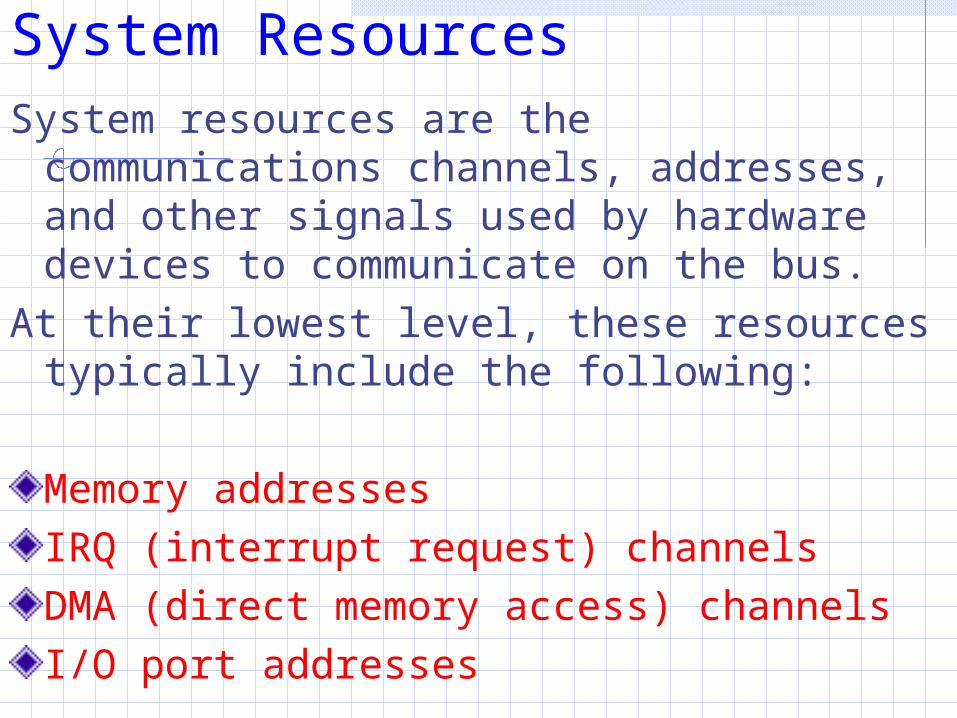
System Resources
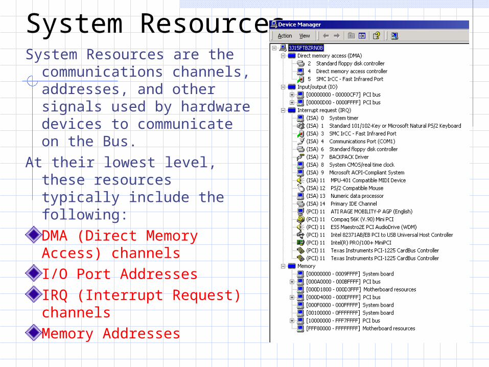
System ResourcesSystem Resources are the
communications channels, addresses, and other signals used by hardware devices to communicate on the Bus.
At their lowest level, these resources typically include the following:DMA (Direct Memory Access) channels I/O Port Addresses IRQ (Interrupt Request) channelsMemory Addresses
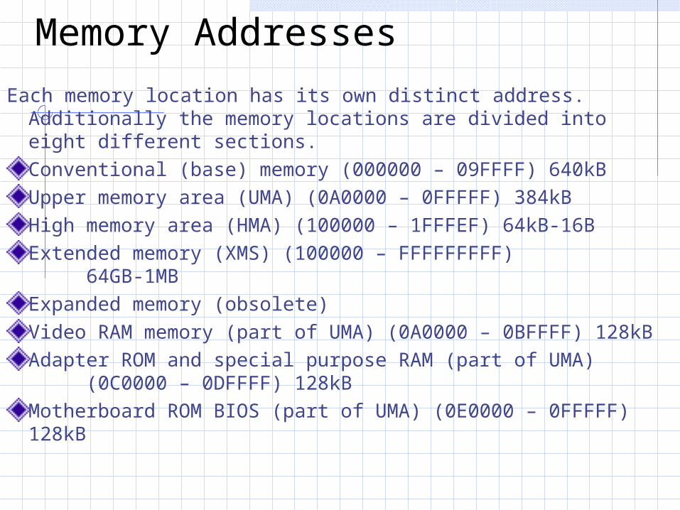
Memory Addresses
Each memory location has its own distinct address. Additionally the memory locations are divided into eight different sections.Conventional (base) memory (000000 – 09FFFF) 640kBUpper memory area (UMA) (0A0000 – 0FFFFF) 384kBHigh memory area (HMA) (100000 – 1FFFEF) 64kB-16BExtended memory (XMS) (100000 – FFFFFFFFF)
64GB-1MBExpanded memory (obsolete)Video RAM memory (part of UMA) (0A0000 – 0BFFFF) 128kBAdapter ROM and special purpose RAM (part of UMA)
(0C0000 – 0DFFFF) 128kBMotherboard ROM BIOS (part of UMA) (0E0000 – 0FFFFF)
128kB
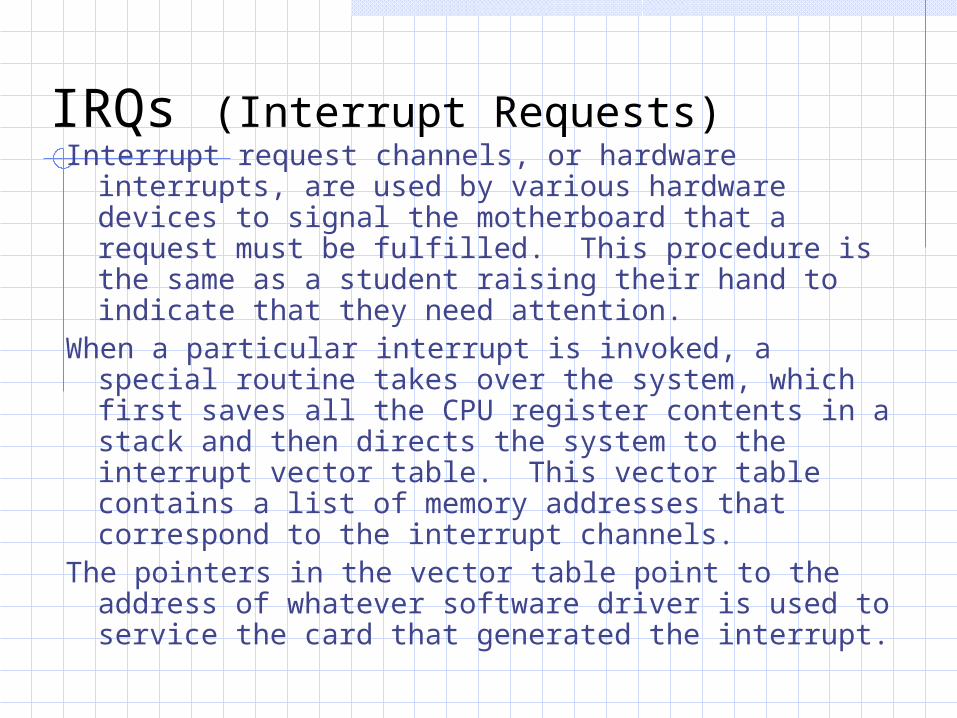
IRQs (Interrupt Requests)Interrupt request channels, or hardware interrupts,
are used by various hardware devices to signal the motherboard that a request must be fulfilled. This procedure is the same as a student raising their hand to indicate that they need attention.
When a particular interrupt is invoked, a special routine takes over the system, which first saves all the CPU register contents in a stack and then directs the system to the interrupt vector table. This vector table contains a list of memory addresses that correspond to the interrupt channels.
The pointers in the vector table point to the address of whatever software driver is used to service the card that generated the interrupt.
IRQs (Interrupt Requests)After the particular software routine finishes
performing whatever function the card needed, the interrupt control software returns the stack contents to the CPU registers, and the system then resumes whatever it was doing before the interrupt occurred.
Hardware interrupts are generally prioritized by their numbers; with some exceptions, the highest priority interrupts have the lowest numbers.
The original PC and XT interrupt controller chip could handle eight IRQ’s at once. The AT motherboard (by daisy chaining two chips) can handle 15 IRQ’s at once. There are 16 IRQ lines.
AT controllers began using interrupts 9-15, leaving the XT controllers the 0-8 lines. Because of this, the old IRQ 2 is often borrowed by the new IRQ 9 using something called “cascading”
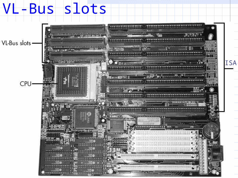
VL-Bus slots
ISA
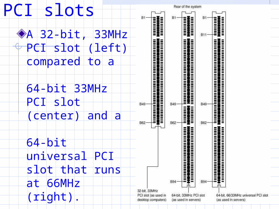
PCI slotsA 32-bit, 33MHz PCI slot (left) compared to a
64-bit 33MHz PCI slot (center) and a
64-bit universal PCI slot that runs at 66MHz (right).
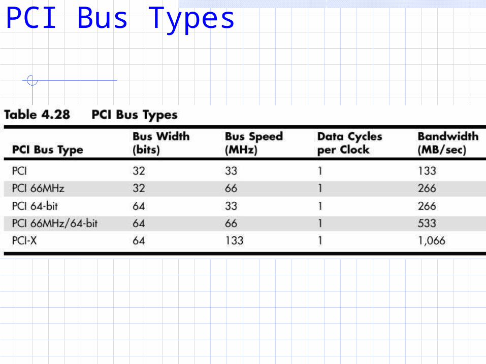
PCI Bus Types
ISA
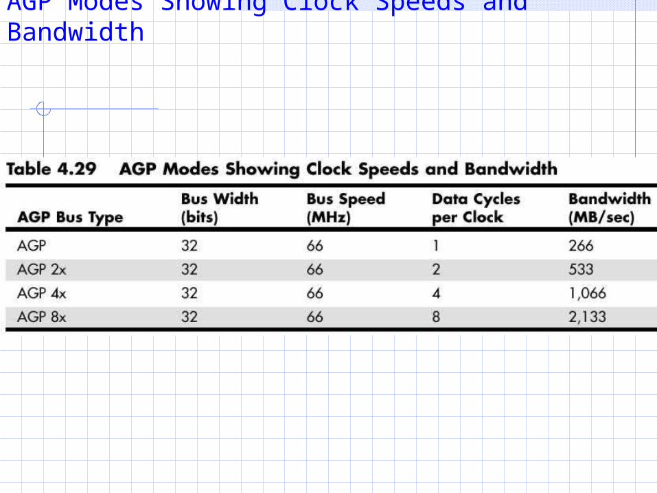
AGP Modes Showing Clock Speeds and Bandwidth
ISA
System ResourcesSystem resources are the communications
channels, addresses, and other signals used by hardware devices to communicate on the bus.
At their lowest level, these resources typically include the following:
Memory addressesIRQ (interrupt request) channelsDMA (direct memory access) channelsI/O port addresses
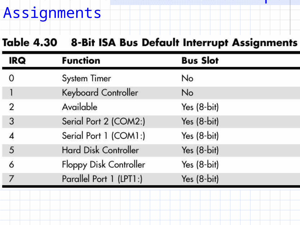
8-Bit ISA Bus Default Interrupt Assignments
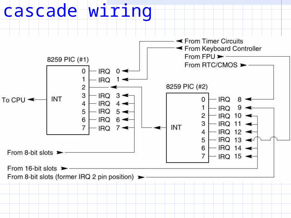
Interrupt controller cascade wiring
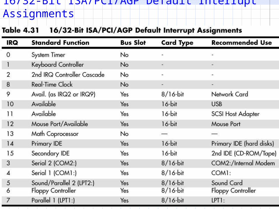
16/32-Bit ISA/PCI/AGP Default Interrupt Assignments
PCI InterruptsThe PCI bus supports hardware interrupts (IRQs) that can be used by PCI devices to signal to the bus that they need attention. The four PCI interrupts are called INTA#, INTB#, INTC#, and INTD#. These INTx# interrupts are level-sensitive, which means that the electrical signaling enables them to be shared among PCI cards. In fact, all single device or single function PCI chips or cards that use only one interrupt must use INTA#. This is one of the rules in the PCI specification. If additional devices are within a chip or onboard a card, the additional devices can use INTB# through INTD#. Because there are very few multifunction PCI chips or boards, practically all the devices on a given PCI bus will be sharing INTA#.
PCI InterruptsFor the PCI bus to function in a PC, the PCI interrupts must be mapped to ISA interrupts. Because ISA interrupts cannot be shared, in most cases each PCI card using INTA# on the PCI bus must be mapped to a different nonshareable ISA interrupt. For example, you could have a system with four PCI slots and four PCI cards installed, each using PCI interrupt INTA#. These cards would be each mapped to a different available ISA interrupt request, such as IRQ9, IRQ10, IRQ11, or IRQ5 in most cases.
Sharing Interrupts on PCINewer system BIOS as well as plug-and-play operating systems, such as Windows 95B (OSR- 2) or later, Windows 98, and Windows 2000, all support a function known as PCI IRQ Steering. For this to work, both your system BIOS and operating system must support IRQ Steering. Older system BIOS and Windows 95 or 95A do not have support for PCI IRQ Steering.
Sharing Interrupts on PCIGenerally, the BIOS assigns unique IRQs to PCI devices. If your system supports PCI IRQ Steering and it is enabled, Windows assigns IRQs to PCI devices. Even when IRQ Steering is enabled, the BIOS still initially assigns IRQs to PCI devices. Although Windows has the capability to change these settings, it generally does not do so automatically, except where necessary to eliminate conflicts. If there are insufficient free IRQs to go around, IRQ Steering allows Windows to assign multiple PCI devices to a single IRQ, thus enabling all the devices in the system to function properly. Without IRQ Steering, Windows begins to disable devices after it runs out of free IRQs to assign.
PCI IRQ SteeringThe solution to the fewer interrupts problem is interrupts sharing.PCI IRQ Steering allows a plug-and-play operating system such as Windows to dynamically map or “steer” PCI cards (which almost all use PCI INTA#) to standard PC interrupts and allows several PCI cards to be mapped to the same interrupt.
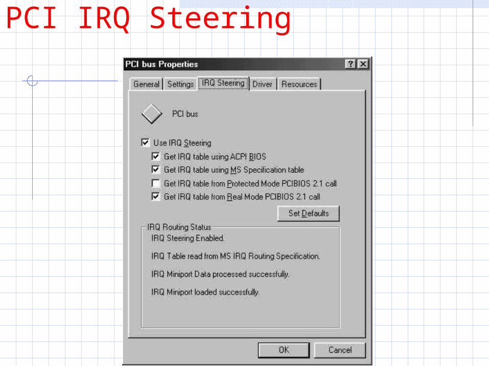
PCI IRQ SteeringTo determine whether your system is using
IRQ Steering, you can follow these steps:1. Right Click My Computer, and choose
Properties.2. Click the Device Manager tab.3. Double-click the System Devices branch.4. Double-click PCI Bus, and then click the IRQ
Steering tab. There will be a check that displays IRQ Steering as either Enabled or Disabled. If enabled, it also specifies where the IRQ table has been read from.
PCI IRQ Steering
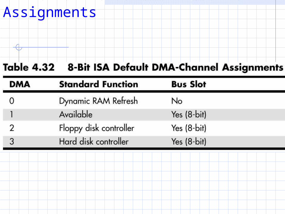
8-Bit ISA Default DMA-Channel Assignments
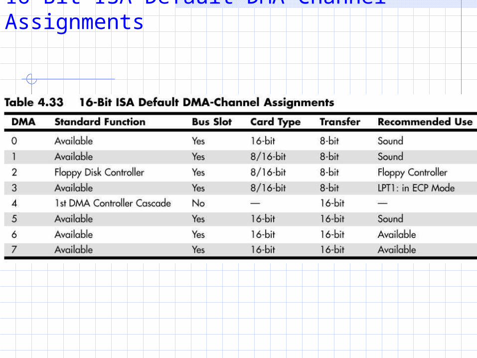
16-Bit ISA Default DMA-Channel Assignments
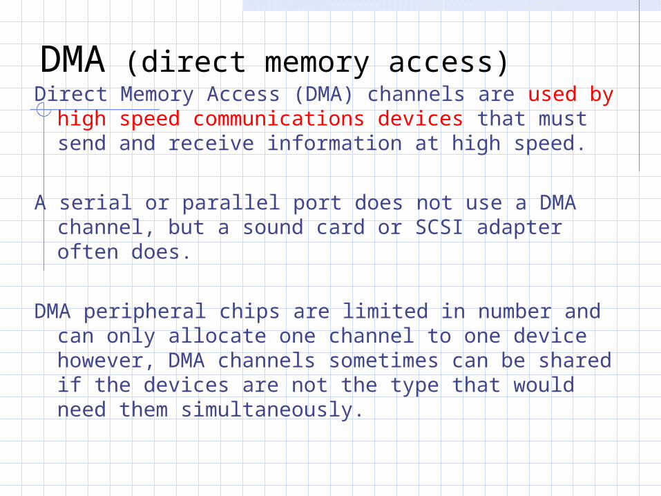
DMA (direct memory access)Direct Memory Access (DMA) channels are used by
high speed communications devices that must send and receive information at high speed.
A serial or parallel port does not use a DMA channel, but a sound card or SCSI adapter often does.
DMA peripheral chips are limited in number and can only allocate one channel to one device however, DMA channels sometimes can be shared if the devices are not the type that would need them simultaneously.
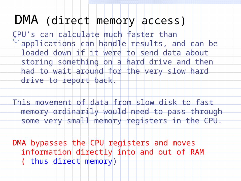
DMA (direct memory access)CPU’s can calculate much faster than applications
can handle results, and can be loaded down if it were to send data about storing something on a hard drive and then had to wait around for the very slow hard drive to report back.
This movement of data from slow disk to fast memory ordinarily would need to pass through some very small memory registers in the CPU.
DMA bypasses the CPU registers and moves information directly into and out of RAM ( thus direct memory)
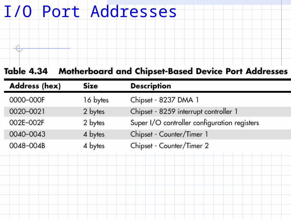
I/O Port Addresses
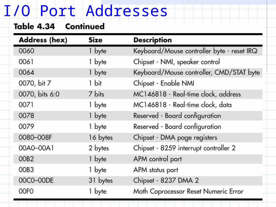
I/O Port Addresses
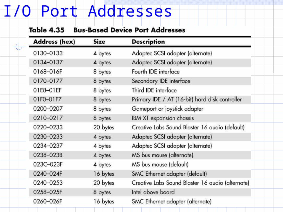
I/O Port Addresses
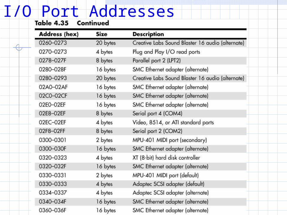
I/O Port Addresses
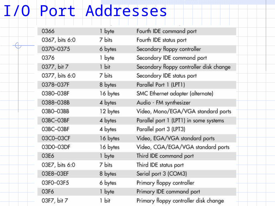
I/O Port Addresses
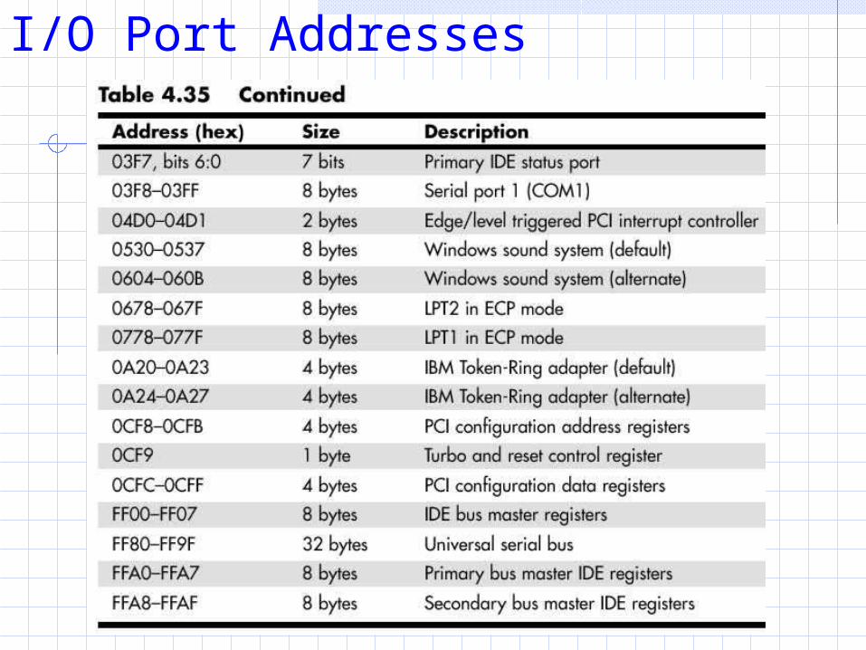
I/O Port Addresses
I/O Port AddressYour computer’s I/O ports enable communications
between devices and software in your system. They are equivalent to two-way radio channels.
If you want to talk to your serial port, you need to know on which I/O port it is listening. Similarly, if you want to receive data from the serial port, you need to listen on the same channel.
There are 65,535 ports, numbered from 0000 h to FFFF h
I/O Port AddressOne confusing issue is that I/O ports are designated
by hexadecimal addresses similar to memory addresses. The difference is that when you send data to memory address 1000 h, it gets stored in your DIMM. If you send data to I/O port address 1000 h, it gets sent out on the bus on that “channel,” and anybody listening in would then hear it. If nobody was listening to that port address, the data would reach the end of the bus and be absorbed by the bus terminating resistors.
Virtually all devices on your system buses use I/O port addresses. Most of these are fairly standardized.
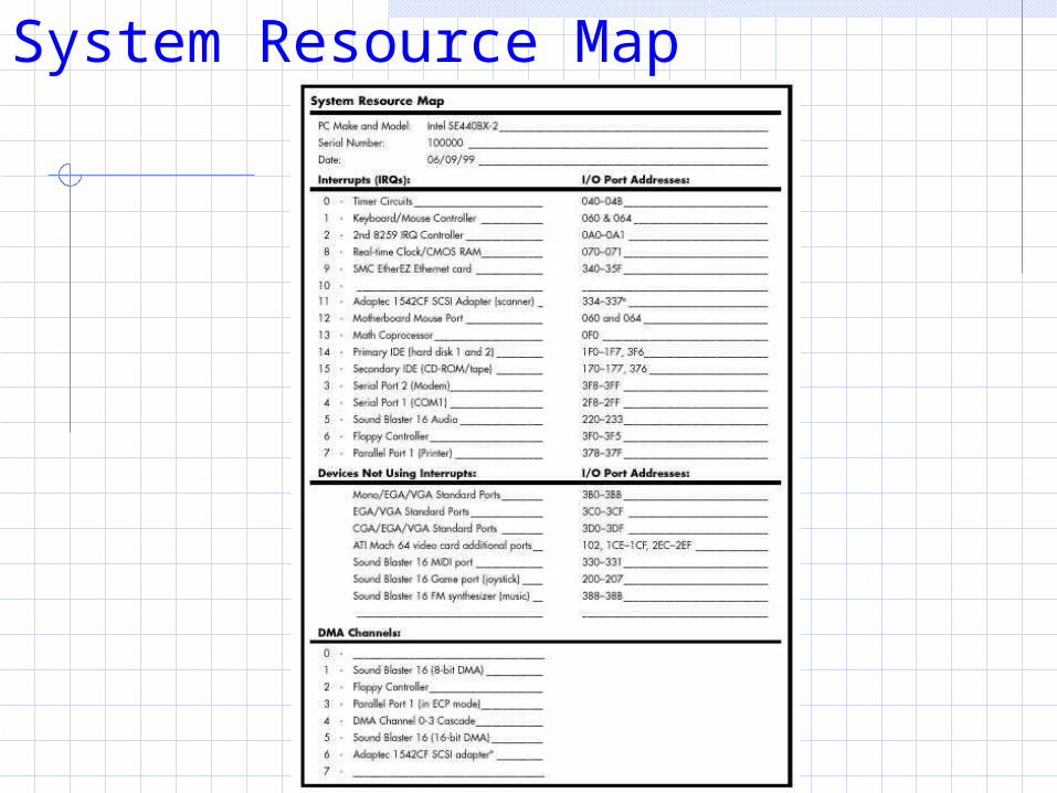
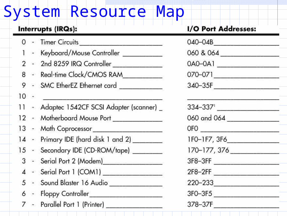
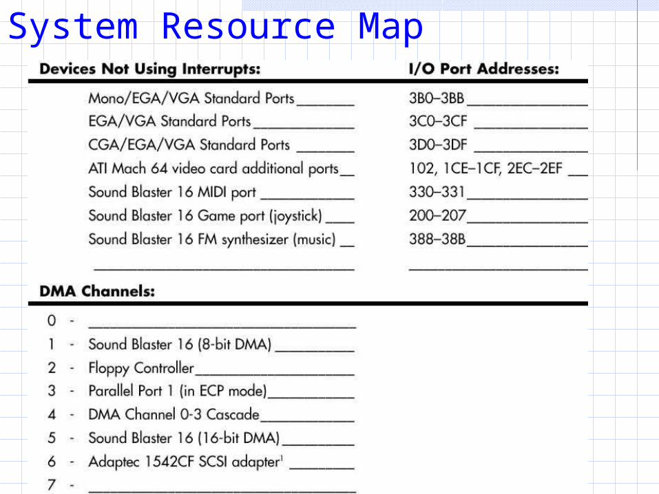
System Resource Map
System Resource Map
System Resource Map
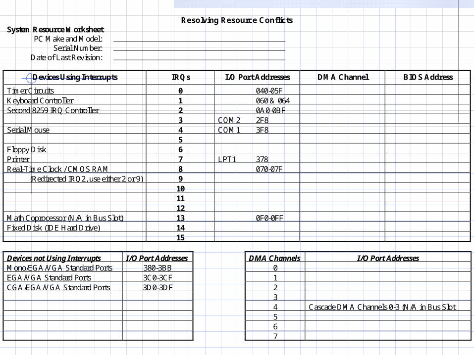
Resolving Resource ConflictsSystem Resource Worksheet
PC Make and Model: Serial Number:
Date of Last Revision:
Devices Using Interrupts IRQs I/O Port Addresses DMA Channel BIOS Address
Timer Circuits 0 040-05FKeyboard Controller 1 060 & 064Second 8259 IRQ Controller 2 0A0-0BF
3 COM2 2F8Serial Mouse 4 COM1 3F8
5Floppy Disk 6Printer 7 LPT1 378Real-Time Clock / CMOS RAM 8 070-07F
(Redirected IRQ2, use either 2 or 9) 9101112
Math Coprocessor (N/A in Bus Slot) 13 0F0-0FFFixed Disk (IDE Hard Drive) 14
15
Devices not Using Interrupts I/O Port AddressesMono/EGA/VGA Standard Ports 380-3BBEGA/VGA Standard Ports 3C0-3CFCGA/EGA/VGA Standard Ports 3D0-3DF
DMA Channels I/O Port Addresses01234 Cascade DMA Channels 0-3 (N/A in Bus Slot567
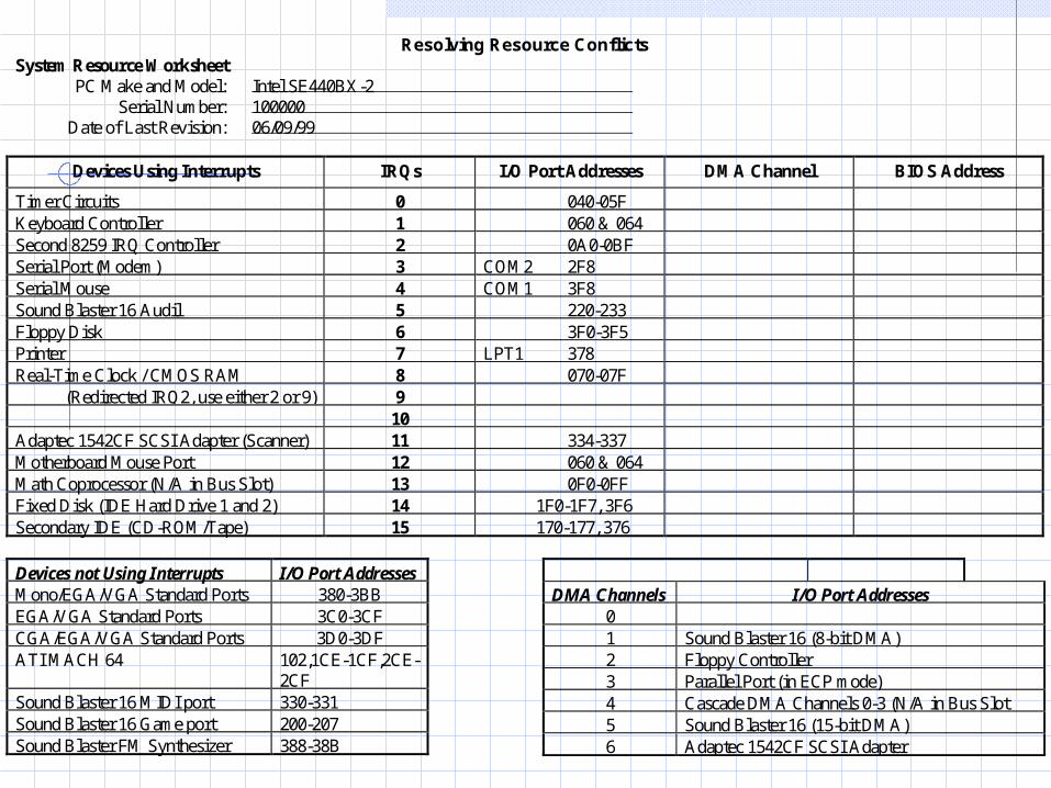
Resolving Resource ConflictsSystem Resource Worksheet
PC Make and Model: Intel SE440BX-2 Serial Number: 100000
Date of Last Revision: 06/09/99
Devices Using Interrupts IRQs I/O Port Addresses DMA Channel BIOS Address
Timer Circuits 0 040-05FKeyboard Controller 1 060 & 064Second 8259 IRQ Controller 2 0A0-0BFSerial Port (Modem) 3 COM2 2F8Serial Mouse 4 COM1 3F8Sound Blaster 16 Audil 5 220-233Floppy Disk 6 3F0-3F5Printer 7 LPT1 378Real-Time Clock / CMOS RAM 8 070-07F
(Redirected IRQ2, use either 2 or 9) 910
Adaptec 1542CF SCSI Adapter (Scanner) 11 334-337Motherboard Mouse Port 12 060 & 064Math Coprocessor (N/A in Bus Slot) 13 0F0-0FFFixed Disk (IDE Hard Drive 1 and 2) 14 1F0-1F7, 3F6Secondary IDE (CD-ROM/Tape) 15 170-177, 376
Devices not Using Interrupts I/O Port AddressesMono/EGA/VGA Standard Ports 380-3BBEGA/VGA Standard Ports 3C0-3CFCGA/EGA/VGA Standard Ports 3D0-3DFATI MACH 64 102,1CE-1CF,2CE-
2CFSound Blaster 16 MIDI port 330-331Sound Blaster 16 Game port 200-207Sound Blaster FM Synthesizer 388-38B
DMA Channels I/O Port Addresses01 Sound Blaster 16 (8-bit DMA)2 Floppy Controller3 Parallel Port (in ECP mode)4 Cascade DMA Channels 0-3 (N/A in Bus Slot5 Sound Blaster 16 (15-bit DMA)6 Adaptec 1542CF SCSI Adapter
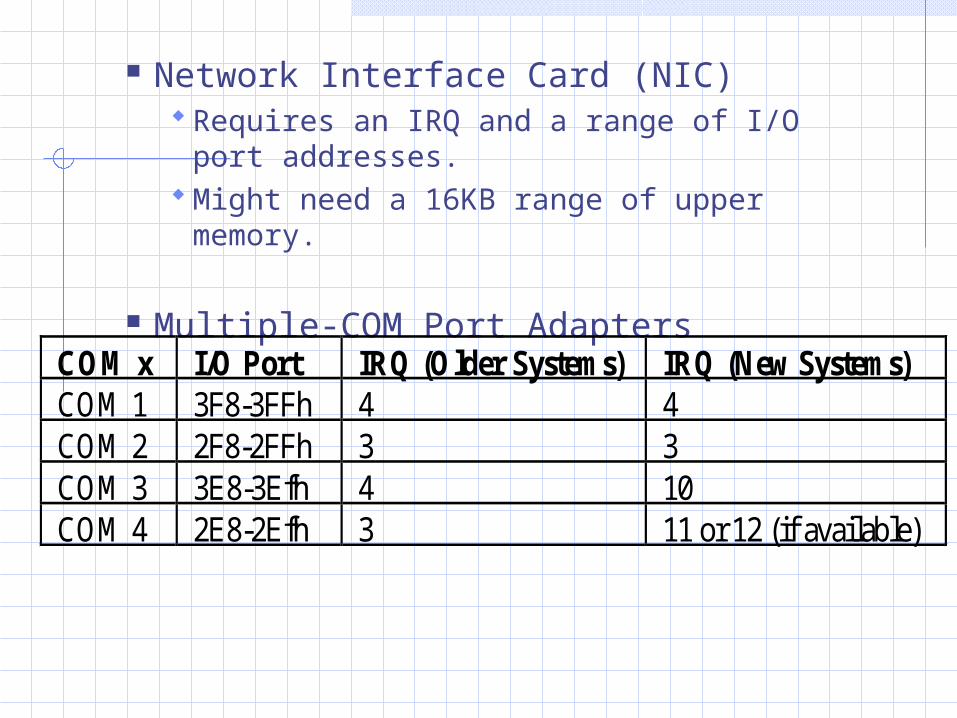
Network Interface Card (NIC) Requires an IRQ and a range of I/O port
addresses. Might need a 16KB range of upper memory.
Multiple-COM Port Adapters
COM x I/O Port IRQ (Older Systems) IRQ (New Systems)COM 1 3F8-3FFh 4 4COM 2 2F8-2FFh 3 3COM 3 3E8-3Efh 4 10COM 4 2E8-2Efh 3 11 or 12 (if available)
Plug-and-Play Systems
For PnP to work, the following components are desired:PnP hardwarePnP BIOSPnP operating system