Embed Size (px)
Citation preview

Randy Horton, Ph.D., P.E.Senior Project Manager
EPRI/NERC GMD WorkshopApril 20, 2012
System Response to GIC Flow

2© 2012 Electric Power Research Institute, Inc. All rights reserved.
Agenda
• Other impacts of GMDs (overview of industry experience)• Transformer Electrical Response (Review)• System Response
– Power Quality– System Protection and Instrument Transformers– Generators

3© 2012 Electric Power Research Institute, Inc. All rights reserved.
Industry Experience(Overview)

4© 2012 Electric Power Research Institute, Inc. All rights reserved.
Other Impacts of GMDs
• Impacts of GMDs to power transformers is a widely publicized and hotly debated topic in the industry
• Less known are the impacts of GMDs to other T&G assets and the system. Documented impacts include:– Degradation of system voltage (including voltage stability).– Capacitor bank tripping and alarming (typ. neutral unbalance)– Harmonic filter bank tripping SVC tripping– Line protection scheme mis-operation (negative sequence,
overvoltage)– Generator tripping (negative sequence, loss of excitation) and
alarming (negative sequence)– Power line carrier low signal alarm (only one case
documented)

5© 2012 Electric Power Research Institute, Inc. All rights reserved.
Transformer Electrical Response(Review)

6© 2012 Electric Power Research Institute, Inc. All rights reserved.
Basic Transformer Response - Review
• Half-cycle saturation causes transformers to behave like large harmonic current sources (with direct connection to the HV or EHV grid).
• Increase in 60 Hz component of the exciting current causes var demand of transformer to increase significantly.
• Both effects (var demand and harmonic generation) tend to increase linearly with GIC.
Transformer Model
(Electrical)
GIC
vars
HarmonicsPower Quality
System ProtectionG&T Assets
System Stabilityvar Reserves
Transfer Capability
GIC
Ih

7© 2012 Electric Power Research Institute, Inc. All rights reserved.
Harmonic Current Flow
• Transformers that are experiencing half-cycle saturation can be thought of from a power quality point of view as a harmonic current source.
• Unlike “typical” non-linear loads, transformers that are experiencing half-cycle saturation generate both odd and even harmonics.
G
I(h)

8© 2012 Electric Power Research Institute, Inc. All rights reserved.
System Response(Overview)

9© 2012 Electric Power Research Institute, Inc. All rights reserved.
System Response
• The direct injection of harmonic current into the HV and EHV grid can have impacts on:– Power Quality– System Protection– Generators
• Increased 60 Hz exciting current results in an increase in var demand which can affect:– Voltage Stability– Reactive Reserves– Transfer Capability
More on this later by Tom Overbye

10© 2012 Electric Power Research Institute, Inc. All rights reserved.
System Response(Power Quality)

11© 2012 Electric Power Research Institute, Inc. All rights reserved.
Power Quality Impacts
• During GMDs, transformers that are half-cycle saturated appear as large harmonic sources to the HV or EHV grid.
• Large harmonic voltages can result, particularly in the case of parallel resonance.
V(h) = Z(h)I(h)• Harmonics add to the 60 Hz fundamental frequency and
can cause significant waveform distortion in both current and voltage resulting in:– Increased rms value– Increased peak value
• The injection of harmonic current into the HV and EHV system is what drives all other PQ related impacts!
12© 2012 Electric Power Research Institute, Inc. All rights reserved.
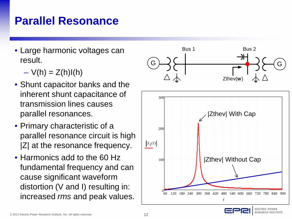
Parallel Resonance
• Large harmonic voltages can result.– V(h) = Z(h)I(h)
• Shunt capacitor banks and the inherent shunt capacitance of transmission lines causes parallel resonances.
• Primary characteristic of a parallel resonance circuit is high |Z| at the resonance frequency.
• Harmonics add to the 60 Hz fundamental frequency and can cause significant waveform distortion (V and I) resulting in: increased rms and peak values.
GG
Bus 1 Bus 2
Zthev(w)
60 120 180 240 300 360 420 480 540 600 660 720 780 840 9000
100
200
300
Z1 f( )
f
|Zthev| With Cap
|Zthev| Without Cap

13© 2012 Electric Power Research Institute, Inc. All rights reserved.
Harmonic Components – Fourier Techniques
·
+
+
+
+
+
+
··
+
60 Hz(h = 1)
300 Hz(h = 5)
420 Hz(h = 7)
540 Hz(h = 9)
660 Hz(h = 11)
780 Hz(h = 13)
180 Hz(h = 3)
From Dugan, Electrical Power Systems Quality
FourierTransform

14© 2012 Electric Power Research Institute, Inc. All rights reserved.
Example of Waveform Distortion
• Waveform distortion causes the rms and peak value of the waveform to increase.– THDv = 10%
0 0.01 0.021.5−
1.2−
0.9−
0.6−
0.3−
0
0.3
0.6
0.9
1.2
1.5
Vol
tage
(Per
-Uni
t)
v1 t( )
v2 t( )
t
Peak Voltage ofdistorted waveform is 1.2 p.u.!
60 Hz voltage (1.0 p.u.)

15© 2012 Electric Power Research Institute, Inc. All rights reserved.
Symmetrical Component Sequence of Harmonic Currents and Voltages
• Symmetrical component sequence of harmonics
• Negative sequence harmonics cause excess heating and negative (reverse) torques in electric machines.
• Zero sequence harmonics can flow in the neutral of grounded wye transformers and capacitor banks.
Harmonic Order
Sequence Harmonic Order
Sequence Harmonic Order
Sequence
1 Positive 6 Zero 11 Negative
2 Negative 7 Positive 12 Zero
3 Zero 8 Negative 13 Positive
4 Positive 9 Zero 14 Negative
5 Negative 10 Positive 15 Zero

16© 2012 Electric Power Research Institute, Inc. All rights reserved.
Effect of Transformer Connections
What impact does the transformer connection have on the flow of harmonic current flow?
Balanced harmonics that are divisible by 3 can not exit
delta windings (zero sequence). All others flow freely.
All harmonics flow freely.
Grounded Wye - Delta
Grounded Wye – Grounded Wye

17© 2012 Electric Power Research Institute, Inc. All rights reserved.
Capacitor Bank Example
• Assume GIC=10,50,100 Amps/Phase– Plot |Z(f)| with and without capacitor bank– Compare resulting voltage and current waveforms for all
three GIC values and compare with base case (no GIC).
G
500 MW
Sys
240 Mvar345 kV
Isc = 10 kA
For illustration purposes: modeled transformer response as harmonic current
source (2nd thru 7th harmonics). Assumed |Ih| = GIC

18© 2012 Electric Power Research Institute, Inc. All rights reserved.
Capacitor Bank Example
• |Z(f)| at 345 kV bus with and without capacitor bank
60 120 180 240 300 360 420 480 540 600 660 720 780 840 9000
100
200
Frequency (Hz)
Impe
danc
e M
agni
tude
(Ohm
s)
Z1 f( )
Z2 f( )
Z3 f( )
f
Capacitor bank on-line
Capacitor bank off-line(with load)
Capacitor bank off-line(without load)

19© 2012 Electric Power Research Institute, Inc. All rights reserved.
Capacitor Bank Example
• 345 kV Bus (Van with GIC = 10 Amps/phase)

20© 2012 Electric Power Research Institute, Inc. All rights reserved.
Capacitor Bank Example
• 345 kV Bus (Van with GIC = 50 Amps/phase)
1.09 p.u.1.01 p.u.

21© 2012 Electric Power Research Institute, Inc. All rights reserved.
Capacitor Bank Example
• 345 kV Bus (Van with GIC = 100 Amps/phase)
1.23 p.u.1.12 p.u.
22© 2012 Electric Power Research Institute, Inc. All rights reserved.
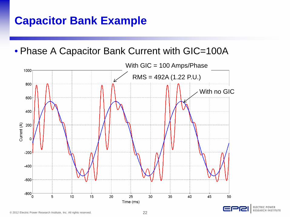
Capacitor Bank Example
• Phase A Capacitor Bank Current with GIC=100AWith GIC = 100 Amps/Phase
RMS = 492A (1.22 P.U.)
With no GIC
23© 2012 Electric Power Research Institute, Inc. All rights reserved.
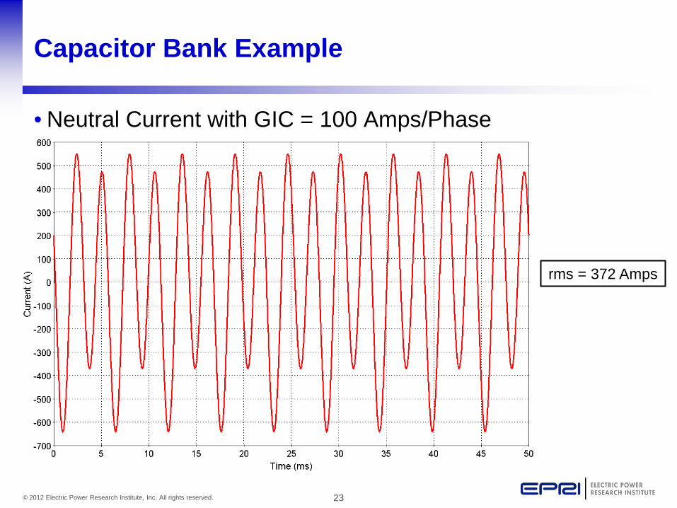
Capacitor Bank Example
• Neutral Current with GIC = 100 Amps/Phase
rms = 372 Amps

24© 2012 Electric Power Research Institute, Inc. All rights reserved.
Shunt Capacitor Maximum Operating Conditions
• IEEE Std. 18-2002

25© 2012 Electric Power Research Institute, Inc. All rights reserved.
Line Current
• Line Current with GIC = 100 Amps/Phase

26© 2012 Electric Power Research Institute, Inc. All rights reserved.
Line Current
• 3I0 with GIC = 100 Amps/Phase

27© 2012 Electric Power Research Institute, Inc. All rights reserved.
System Response(System Protection)

28© 2012 Electric Power Research Institute, Inc. All rights reserved.
System Protection
• There are several protection schemes that are potentially vulnerable to the effects of GIC.– Transformer Differential– Capacitor Bank Unbalance– Overvoltage– Overcurrent

29© 2012 Electric Power Research Institute, Inc. All rights reserved.
Transformer Percentage Differential Scheme
• To provide high sensitivity to light internal faults with high security (high restraint) for external faults, most differential relays are of the percentage differential type.– Fixed– Variable
IOP
IR1 IR2
50%
40%
25%
10%
Restraint Current (IR)
Ope
rate
Cur
rent
(I O
P)
Slope
Variable Restraint
TRIP Region

30© 2012 Electric Power Research Institute, Inc. All rights reserved.
Transformer Percentage Differential Scheme
Source: J. Lewis Blackburn, Protective Relaying: Principles and Applications, 2nd Edition
1.0 p.u. 1.0 p.u.OP = Operate Winding
R = Restraint Winding

31© 2012 Electric Power Research Institute, Inc. All rights reserved.
Transformer Differential Relay (Harmonic Restraint)
• Generally, harmonic restraint is employed in order to minimize mis-operations due to transformer energization.– Harmonic Restraint de-sensitizes the differential
elements to keep them from operating when harmonics are sensed (indicating an inrush condition).
– Typical harmonics that are used are: 2nd and/or 5th

32© 2012 Electric Power Research Institute, Inc. All rights reserved.
Transformer Differential Relay (Harmonic Restraint)
• Example electromechanical scheme (restrains relay if 2nd
harmonic content is above 15% of the fundamental)
Source: Westinghouse Protective Relaying Theory and Applications
Remains closed if 120 Hz < 15% of 60 Hz

33© 2012 Electric Power Research Institute, Inc. All rights reserved.
Capacitor Bank Unbalance Protection Mis-operations
• Over the course of the last 40+ years there have been numerous documented cases of capacitor bank trips due to neutral unbalance relay mis-operation.
• The following papers and reports are just a few that describe these numerous events.
– EPRI TR-102621, Solar Magnetic Disturbances/Geomagnetically Induced Current and Protective Relaying, August 1993.
– Russell Patterson, “Mathcad Analysis of Davidson Capacitor Bank Misoperation”, Proceedings of 2001 Georgia Tech Fault and Disturbance Conference.
– IEEE Working Group K11, “The Effects of Solar Magnetic Disturbances on Protective Relaying”, IEEE Transactions on Power Delivery, 1990.
– Albertson, Thorson, “Power System Disturbances During a K-8 Geomagnetic Storm: August 4, 1972”, IEEE Transactions on Power Apparatus and Systems, PAS-93, July 1974.

34© 2012 Electric Power Research Institute, Inc. All rights reserved.
Capacitor Bank Unbalance Protection Mis-operations
• Saturday, July 15, 2000 -Simultaneous loss of approximately 800 Mvar of capacitors across the System.
1Russell Patterson, “Mathcad Analysis of Davidson Capacitor Bank Misoperation”, Proceedings of 2001 Georgia Tech Fault and Disturbance Conference.

35© 2012 Electric Power Research Institute, Inc. All rights reserved.
Neutral Unbalance Protection Scheme
• Grounded wye (fused Capacitors)
R 59 MOV
SEL351
CONTACT FROM AUX RELAYTO SHORT NEUTRAL CT
INDIVIDUAL CAPACITOR FUSE
CS
36© 2012 Electric Power Research Institute, Inc. All rights reserved.
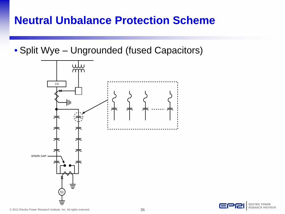
Neutral Unbalance Protection Scheme
• Split Wye – Ungrounded (fused Capacitors)
SEL351
51
SPARK GAP
CS

37© 2012 Electric Power Research Institute, Inc. All rights reserved.
Neutral Unbalance Protection Scheme
• Split Wye – Grounded (fuseless Capacitors)
SEL351
INDIVIDUAL CAN
59CONTACT FROM AUX RELAY TOSHORT NEUTRAL CT
MOV
CS
R

38© 2012 Electric Power Research Institute, Inc. All rights reserved.
Neutral Unbalance Protection Schemes
• Capacitor bank neutral unbalance protection schemes are potentially vulnerable to mis-operation during GMDs.– Balanced harmonic currents that are divisible by 3 can
flow in the neutral of capacitor banks (zero sequence).• Electromechanical and static type relays are most
sensitive.– Electromechanical relays often operate on rms
quantities.– Static type relays often operate on the peak of waveform.
• Modern microprocessor relays are practically immune to harmonics (digital filtering).

39© 2012 Electric Power Research Institute, Inc. All rights reserved.
Digital Signal Processing in µP Based Relays
• Basic components– Low Pass Analog Filter– Digital/Analog Conversion– Digital Filter
0.015 0.02 0.025 0.03 0.035 0.04-100
-80
-60
-40
-20
0
20
40
60
80
100
Time (Seconds)
Sec
onda
ry V
olta
ge (V
olts
)
AnalogDigital
DigitalAnalog
4th order Butterworth LP fc=540Hz
16 samples/cycle
Zero-Order Hold
Analog Low Pass
1 Cycle Cosine
Digital FilterDiscrete FIR Filter
Gain0.25
Cycle Delay
Phasor
Phasor Conversion
Real
ImagInput
Signal
Example DSP in a microprocessor based relay
40© 2012 Electric Power Research Institute, Inc. All rights reserved.
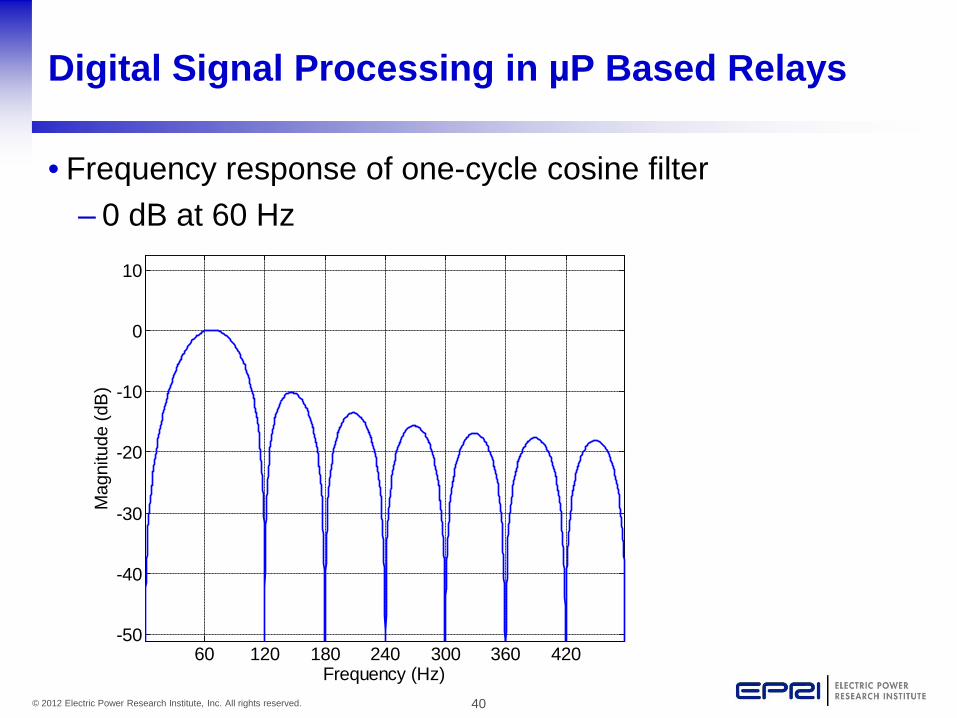
Digital Signal Processing in µP Based Relays
• Frequency response of one-cycle cosine filter– 0 dB at 60 Hz
60 120 180 240 300 360 420-50
-40
-30
-20
-10
0
10
Frequency (Hz)
Mag
nitu
de (d
B)

41© 2012 Electric Power Research Institute, Inc. All rights reserved.
Overvoltage Relays
• Generally, overvoltage relays are applied to protect EHV systems against damaging overvoltage conditions that can occur during normal operation, e.g. Ferranti Effect.
• Typically, overvoltage relays are connected to the secondary of a CCVT, and are set to trip the local and/or remote breaker (usually remote breaker tripped via remote trip scheme) after a pre-defined time delay.
• Electromechanical and microprocessor based overvolagerelays are susceptible to mis-operation due to harmonics.– Electromechanical relays often operate on rms quantities.– Static type relays often operate on peak of waveform.– Frequency response of CCVTs can exacerbate the effects
particularly for low frequency harmonics.

42© 2012 Electric Power Research Institute, Inc. All rights reserved.
Frequency Response of CCVTs
• CCVTs have very poor frequency response, and are susceptible to large measurement error at all harmonic frequencies.
Frequency Response of a Typical CCVT
BUS
FS
C1
C2
Cs
LsCt
Rp Lp
Ld
Equivalent Circuit of a Typical CCVT
1143% error at 300 Hz

43© 2012 Electric Power Research Institute, Inc. All rights reserved.
Frequency Response of PTs
• Frequency response of wound PTs is better than CCVTs, but still has limitations.
Source: Meliopoulos, et al, “Transmission Level Instrument Transformers and Transient Event Recorders Characterization for Harmonic Measurements”, IEEE Transactions on Power Delivery, Vol. 8, No. 3, July 1993.
~22nd harmonic

44© 2012 Electric Power Research Institute, Inc. All rights reserved.
Current Transformer Saturation
• Current transformers (CTs) generally have adequate frequency response for measuring harmonics, but are prone to saturation during GMDs.
• Saturation can cause additional harmonic content in the secondary of the CT which can result in significant measurement error.

45© 2012 Electric Power Research Institute, Inc. All rights reserved.
CT Saturation Example
CT 1

46© 2012 Electric Power Research Institute, Inc. All rights reserved.
CT Saturation Example
• Secondary current with and without GIC flow.
Without GIC

47© 2012 Electric Power Research Institute, Inc. All rights reserved.
Surge Arresters
• A surge arrester is a device that is designed to protect electric apparatus from high transient overvoltages.
• Typically connected line-to-ground.
• Can be sensitive to voltages that contain high harmonic content, i.e. voltages that have higher peak voltages “spiky”.
• Documented failure of arrester on 9/20/91 due to harmonic induced overvoltage.

48© 2012 Electric Power Research Institute, Inc. All rights reserved.
Surge Arresters
• Protective Characteristics– Behave like a non-linear resistor connected line-to-
ground.

49© 2012 Electric Power Research Institute, Inc. All rights reserved.
Capacitor Bank Example (with surge arrester)
• Assume GIC=100 Amps/Phase– Plot Arrester voltage and energy absorption as a function
of time.
G
500 MW
Sys
240 Mvar345 kV
Isc = 10 kA
MOV258 kV

50© 2012 Electric Power Research Institute, Inc. All rights reserved.
Surge Arresters
• Arrester energy absorption with GIC = 100 Amps/Phase
Energy (rate ~ 51 kJ/min)
Van
( )dttpet
0∫=

51© 2012 Electric Power Research Institute, Inc. All rights reserved.
System Response(Generators)

52© 2012 Electric Power Research Institute, Inc. All rights reserved.
Turbine Generator (T/G) Response to Harmonic Current
• Harmonic current flow in the stator of a T/G will:– Induce harmonic current in the rotor windings, and– Generate harmonic torque.
GEN LP2 LP1 IP HPJ5 J4 J3 J2 J1
K4 K3 K2 K1
TeTLP2 TLP1 TIP THP
StatorWindings
Rotor is rotating at 60 Hz
Ih
Harmonic current, Ih, will create torque at a frequencyequal to 60 ± fh Hz depending on the sequence of the stator current.

53© 2012 Electric Power Research Institute, Inc. All rights reserved.
Normal Operation (60 Hz)
N
S
StatorBr (fr = 0 Hz)
dc field
Bs (fs = 60 Hz)
frot = 60 Hz
δ
Stator Currents
Ia(t) = I⋅cos(2π60t)
Ib(t) = I⋅cos(2π60t - 120º)
Ic(t) = I⋅cos(2π60t + 120º)
• During “normal” 60 Hz operation Br and Bs are constant and stationary with respect to one another. Thus, a constant torque is created.
( )ind r sKB B sinτ δ=

54© 2012 Electric Power Research Institute, Inc. All rights reserved.
Abnormal Operation (Harmonic Currents)
• When a harmonic current is injected into the stator, Br and Bsare no longer stationary with respect to one another. Now the angle δ is a function of time. As a result, the torque that is created is oscillatory with frequency equal to 60 ± fh Hz depending on the sequence of the stator current.– Pos sequence: 60 - fh Hz – Neg sequence: 60 + fh Hz
N
S
Stator Br
Bs (fs = 180 Hz)
Stator Currents (assume pos. seq.)
Ia(t) = I⋅cos(2π180t)
Ib(t) = I⋅cos(2π180t - 120º)
Ic(t) = I⋅cos(2π180t + 120º)
δ(t)
frot = 60 Hz

55© 2012 Electric Power Research Institute, Inc. All rights reserved.
Abnormal Operation (Harmonic Currents)
• In this case, 120 Hz current is induced into the rotor winding. Also, a 120 Hz torque is created.
N
S
Stator
Br (fr = 120 Hz)
Bs (stationary w.r.t. rotor)
δ(t)
( )( ) ( )ind r s r sKB B sin Kt B B sin tδ ωτ = =

56© 2012 Electric Power Research Institute, Inc. All rights reserved.
T/G Example
• Example using two different saturation curves for the GSU.– Rotor current was computed using EMTP for various
values of GIC.

57© 2012 Electric Power Research Institute, Inc. All rights reserved.
T/G Example
• Simulation Results– Note impact of transformer modeling assumptions.
C50.13-1989 Limit (2 min.)

58© 2012 Electric Power Research Institute, Inc. All rights reserved.
Turbine Generator (T/G) Response to Harmonic Current
• Harmonic current flow in the stator of a T/G can be problematic.– Causes harmonic current to flow in the rotor circuit
heating.– Generates harmonic torque. Can be an issue if the
turbine has a mechanical resonance at a low harmonic frequency, e.g. 120 Hz.
– IEEE Std. C50.13 and IEC 60034 provide limits for rotor and stator currents.

59© 2012 Electric Power Research Institute, Inc. All rights reserved.
Together…Shaping the Future of Electricity