Embed Size (px)
Citation preview
1Note: This document is based on the recommendations of BS5839 Part 1: 2002. It is intended only as a guide to the application of fire detection systems.
Reference must be made to relevant national and local standards.
Advanced Ideas. Advanced Solutions
SYSTEM SENSOR EUROPE
guide to intelligentfire systems

2 Note: This document is based on the recommendations of BS5839 Part 1: 2002. It is intended only as a guide to the application of fire detection systems.
Reference must be made to relevant national and local standards.
Guid
e to
Inte
llige
nt F
ire
Alar
m S
yste
ms CONTENTS
1. INTELLIGENT FIRE ALARM SYSTEMS ............................................................ 41.1. INTRODUCTION ............................................................................................................................................................... 4
1.2. INTELLIGENT SYSTEM TYPES ........................................................................................................................................ 4
1.3. COMMUNICATION PROTOCOL ......................................................................................................................................... 4
1.4. ADDRESSING METHODS ................................................................................................................................................. 5
1.5. SYSTEM FAULT TOLERANCE .......................................................................................................................................... 5
1.6. DRIFT COMPENSATION AND MAINTENANCE ALARM ..................................................................................................... 6
1.7. PRE-ALARM FACILITY .................................................................................................................................................... 6
1.8. FIRE ALARMS ................................................................................................................................................................ 6
1.9. FIRE SYSTEM ZONES ...................................................................................................................................................... 6
1.10. REMOTE LEDS .............................................................................................................................................................. 7
1.11. INTERFACE MODULES ................................................................................................................................................... 7
1.12. PROGRAMMING OF INTELLIGENT FIRE ALARM PANELS .............................................................................................. 7
1.13. ADVANTAGES OF INTELLIGENT SYSTEMS .................................................................................................................... 7
2. DETECTOR APPLICATION GUIDE ..................................................................... 82.1. FIRE SYSTEM CATEGORIES. ............................................................................................................................................ 8
2.2. MANUAL CALL POINTS ................................................................................................................................................. 10
2.3. SELECTION OF AUTOMATIC FIRE DETECTORS ............................................................................................................... 11
2.4. LOCATION AND SPACING OF AUTOMATIC FIRE DETECTORS ......................................................................................... 13
2.5. ALARM SIGNALS .......................................................................................................................................................... 16
2.6 MAINTENANCE OF FIRE DETECTORS ............................................................................................................................. 17
2.7 ROUTINE FUNCTIONAL TESTING OF FIRE DETECTORS ................................................................................................... 17
SERIES 200 PLUS ANALOGUE ADDRESSABLE DETECTOR RANGE ..................... 18INTRODUCTION .................................................................................................................................................................... 18
SERIES 200 PLUS FEATURES ............................................................................................................................................... 18
GENERAL SPECIFICATIONS .................................................................................................................................................. 18
2251EM PHOTOELECTRIC SMOKE SENSOR .......................................................................................................................... 19
2251TEM PHOTO–THERMAL SENSOR .................................................................................................................................. 19
DRIFT COMPENSATION AND SMOOTHING ............................................................................................................................ 20
5251REM, 5251EM AND 5251HTEM HEAT SENSORS ........................................................................................................... 20
6500 AND 6500S BEAM DETECTOR ..................................................................................................................................... 21
7251 LASER DETECTOR ....................................................................................................................................................... 22
2251EIS INTRINSICALLY SAFE DETECTOR AND IST200 INTERFACE .................................................................................... 23
B500 SERIES BASES ............................................................................................................................................................ 24
M200 SERIES MODULE RANGE ........................................................................ 26INTRODUCTION .................................................................................................................................................................... 26
M200XE SHORT CIRCUIT ISOLATOR MODULE ...................................................................................................................... 26
M210E SINGLE CHANNEL INPUT MODULE, M220E DUAL CHANNEL INPUT MODULE AND M221E DUAL CHANNEL INPUT, SINGLE CHANNEL OUTPUT MODULE ..................................................................................................................................... 26
M201E OUTPUT MODULE ..................................................................................................................................................... 27
M201E-240 AND M201E-240-DIN 240VAC RELAY MODULES .............................................................................................. 27
M210E-CZ CONVENTIONAL ZONE MODULE .......................................................................................................................... 27

3Note: This document is based on the recommendations of BS5839 Part 1: 2002. It is intended only as a guide to the application of fire detection systems.
Reference must be made to relevant national and local standards.
Guide to Intelligent Fire Alarm System
s5. CALL POINTS ..............................................................................................28INDOOR ................................................................................................................................................................................ 28
OUTDOOR ............................................................................................................................................................................. 28
WATERPROOF ....................................................................................................................................................................... 28
SWITCHES ............................................................................................................................................................................ 28
ACCESSORIES ...................................................................................................................................................................... 28
6. AUDIO VISUAL PRODUCTS ..........................................................................29SOUNDERS ........................................................................................................................................................................... 29
DETECTOR BASE SOUNDERS ................................................................................................................................................ 29
STROBES .............................................................................................................................................................................. 29
SOUNDER STROBES ............................................................................................................................................................. 29
BASES .................................................................................................................................................................................. 29
7. OTHER INFORMATION .................................................................................307.1. STANDARDS .................................................................................................................................................................. 30
7.2. APPROVAL BODIES FOR FIRE DETECTION PRODUCTS ................................................................................................... 31
4 Note: This document is based on the recommendations of BS5839 Part 1: 2002. It is intended only as a guide to the application of fire detection systems.
Reference must be made to relevant national and local standards.
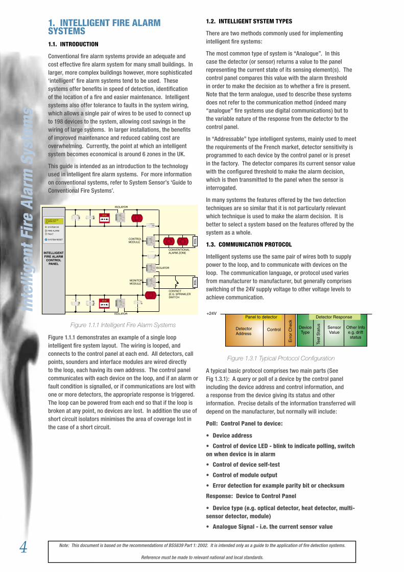
1. INTELLIGENT FIRE ALARM SYSTEMS1.1. INTRODUCTION
Conventional fire alarm systems provide an adequate and cost effective fire alarm system for many small buildings. In larger, more complex buildings however, more sophisticated ‘intelligent’ fire alarm systems tend to be used. These systems offer benefits in speed of detection, identification of the location of a fire and easier maintenance. Intelligent systems also offer tolerance to faults in the system wiring, which allows a single pair of wires to be used to connect up to 198 devices to the system, allowing cost savings in the wiring of large systems. In larger installations, the benefits of improved maintenance and reduced cabling cost are overwhelming. Currently, the point at which an intelligent system becomes economical is around 6 zones in the UK.
This guide is intended as an introduction to the technology used in intelligent fire alarm systems. For more information on conventional systems, refer to System Sensor’s ‘Guide to Conventional Fire Systems’.
Figure 1.1.1 Intelligent Fire Alarm Systems
Figure 1.1.1 demonstrates an example of a single loop intelligent fire system layout. The wiring is looped, and connects to the control panel at each end. All detectors, call points, sounders and interface modules are wired directly to the loop, each having its own address. The control panel communicates with each device on the loop, and if an alarm or fault condition is signalled, or if communications are lost with one or more detectors, the appropriate response is triggered. The loop can be powered from each end so that if the loop is broken at any point, no devices are lost. In addition the use of short circuit isolators minimises the area of coverage lost in the case of a short circuit.
INTELLIGENTFIRE ALARM
CONTROLPANEL
EO
LE
OL
ISOLATOR
CONTROLMODULE
MONITORMODULE
ISOLATOR
ISOLATOR
CONVENTIONALALARM ZONE
CONTACT(E.G. SPRINKLERSWITCH
FIRE ALARM SYSTEM OK28 January 200414:01
SYSTEM OK
SYSTEM RESET
FIRE ALARM
FAULT
1.2. INTELLIGENT SYSTEM TYPES
There are two methods commonly used for implementing intelligent fire systems:
The most common type of system is “Analogue”. In this case the detector (or sensor) returns a value to the panel representing the current state of its sensing element(s). The control panel compares this value with the alarm threshold in order to make the decision as to whether a fire is present. Note that the term analogue, used to describe these systems does not refer to the communication method (indeed many “analogue” fire systems use digital communications) but to the variable nature of the response from the detector to the control panel.
In “Addressable” type intelligent systems, mainly used to meet the requirements of the French market, detector sensitivity is programmed to each device by the control panel or is preset in the factory. The detector compares its current sensor value with the configured threshold to make the alarm decision, which is then transmitted to the panel when the sensor is interrogated.
In many systems the features offered by the two detection techniques are so similar that it is not particularly relevant which technique is used to make the alarm decision. It is better to select a system based on the features offered by the system as a whole.
1.3. COMMUNICATION PROTOCOL
Intelligent systems use the same pair of wires both to supply power to the loop, and to communicate with devices on the loop. The communication language, or protocol used varies from manufacturer to manufacturer, but generally comprises switching of the 24V supply voltage to other voltage levels to achieve communication.
Figure 1.3.1 Typical Protocol Configuration
A typical basic protocol comprises two main parts (See Fig 1.3.1): A query or poll of a device by the control panel including the device address and control information, and a response from the device giving its status and other information. Precise details of the information transferred will depend on the manufacturer, but normally will include:
Poll: Control Panel to device:
• Device address
• Control of device LED - blink to indicate polling, switch on when device is in alarm
• Control of device self-test
• Control of module output
• Error detection for example parity bit or checksum
Response: Device to Control Panel
• Device type (e.g. optical detector, heat detector, multi-sensor detector, module)
• Analogue Signal - i.e. the current sensor value
Inte
llige
nt F
ire
Alar
m S
yste
ms
Panel to detector Detector Response
Control
Err
or C
heck
DetectorAddress
DeviceType
Test
Sta
tus
SensorValue
Other Infoe.g. driftstatus
+24V
5Note: This document is based on the recommendations of BS5839 Part 1: 2002. It is intended only as a guide to the application of fire detection systems.
Reference must be made to relevant national and local standards.
• Alarm Signal if appropriate
• Status of module output
• Remote test status
• Manufacturer code
Most commonly, each device on the loop will be polled in turn, however to increase speed around a loop, some protocols allow polling of groups of devices on a single communication.
Note that since different manufacturers have their own protocols, it is important to ensure compatibility between the detectors and control panel you intend to use. Some detector manufacturers produce intelligent detectors with different communication protocols for different customers, so two detectors which look virtually identical in appearance may not be compatible. Always check with the manufacturer of the control panel.
1.4. ADDRESSING METHODS
Different manufacturers of intelligent systems use a number of different methods of setting the address of a device, including:
• 7-bit binary or hexadecimal DIL switch
• Dedicated address programmer
• Automatic, according to physical position on the loop
• Binary ‘address card’ fitted in the detector base
• Decimal address switches
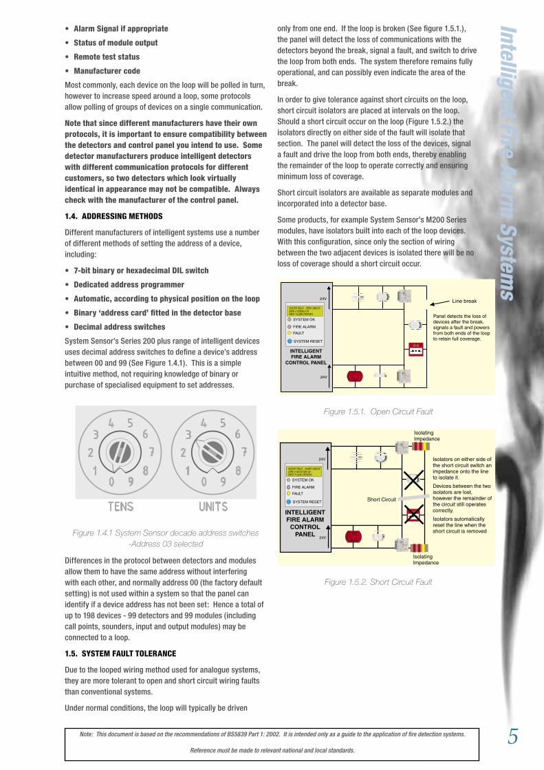
System Sensor’s Series 200 plus range of intelligent devices uses decimal address switches to define a device’s address between 00 and 99 (See Figure 1.4.1). This is a simple intuitive method, not requiring knowledge of binary or purchase of specialised equipment to set addresses.
Figure 1.4.1 System Sensor decade address switches -Address 03 selected
Differences in the protocol between detectors and modules allow them to have the same address without interfering with each other, and normally address 00 (the factory default setting) is not used within a system so that the panel can identify if a device address has not been set: Hence a total of up to 198 devices - 99 detectors and 99 modules (including call points, sounders, input and output modules) may be connected to a loop.
1.5. SYSTEM FAULT TOLERANCE
Due to the looped wiring method used for analogue systems, they are more tolerant to open and short circuit wiring faults than conventional systems.
Under normal conditions, the loop will typically be driven
Intelligent Fire Alarm System
sonly from one end. If the loop is broken (See figure 1.5.1.), the panel will detect the loss of communications with the detectors beyond the break, signal a fault, and switch to drive the loop from both ends. The system therefore remains fully operational, and can possibly even indicate the area of the break.
In order to give tolerance against short circuits on the loop, short circuit isolators are placed at intervals on the loop. Should a short circuit occur on the loop (Figure 1.5.2.) the isolators directly on either side of the fault will isolate that section. The panel will detect the loss of the devices, signal a fault and drive the loop from both ends, thereby enabling the remainder of the loop to operate correctly and ensuring minimum loss of coverage.
Short circuit isolators are available as separate modules and incorporated into a detector base.
Some products, for example System Sensor’s M200 Series modules, have isolators built into each of the loop devices. With this configuration, since only the section of wiring between the two adjacent devices is isolated there will be no loss of coverage should a short circuit occur.
Figure 1.5.1. Open Circuit Fault
Figure 1.5.2. Short Circuit Fault
1 12
TENS UNITS
23 3
4 45 56 67 7
8 80 09 9
INTELLIGENTFIRE ALARM
CONTROL PANEL
24V
24V
Panel detects the loss ofdevices after the break,signals a fault and powersfrom both ends of the loopto retain full coverage.
Line breakSYSTEM FAULT: OPEN CIRCUIT:Zone 2 Module 01FIRST FLOOR CANTEEN
SYSTEM OK
SYSTEM RESET
FIRE ALARM
FAULT
IsolatingImpedance
IsolatingImpedance
Short Circuit
Isolators on either side ofthe short circuit switch animpedance onto the lineto isolate it.
Devices between the twoisolators are lost,however the remainder ofthe circuit still operatescorrectly.
Isolators automaticallyreset the line when theshort circuit is removed
INTELLIGENTFIRE ALARM
CONTROLPANEL
24V
24V
SYSTEM FAULT: SHORT CIRCUIT:Zone 2 DETECTOR 03FIRST FLOOR CANTEEN
SYSTEM OK
SYSTEM RESET
FIRE ALARM
FAULT
6 Note: This document is based on the recommendations of BS5839 Part 1: 2002. It is intended only as a guide to the application of fire detection systems.
Reference must be made to relevant national and local standards.
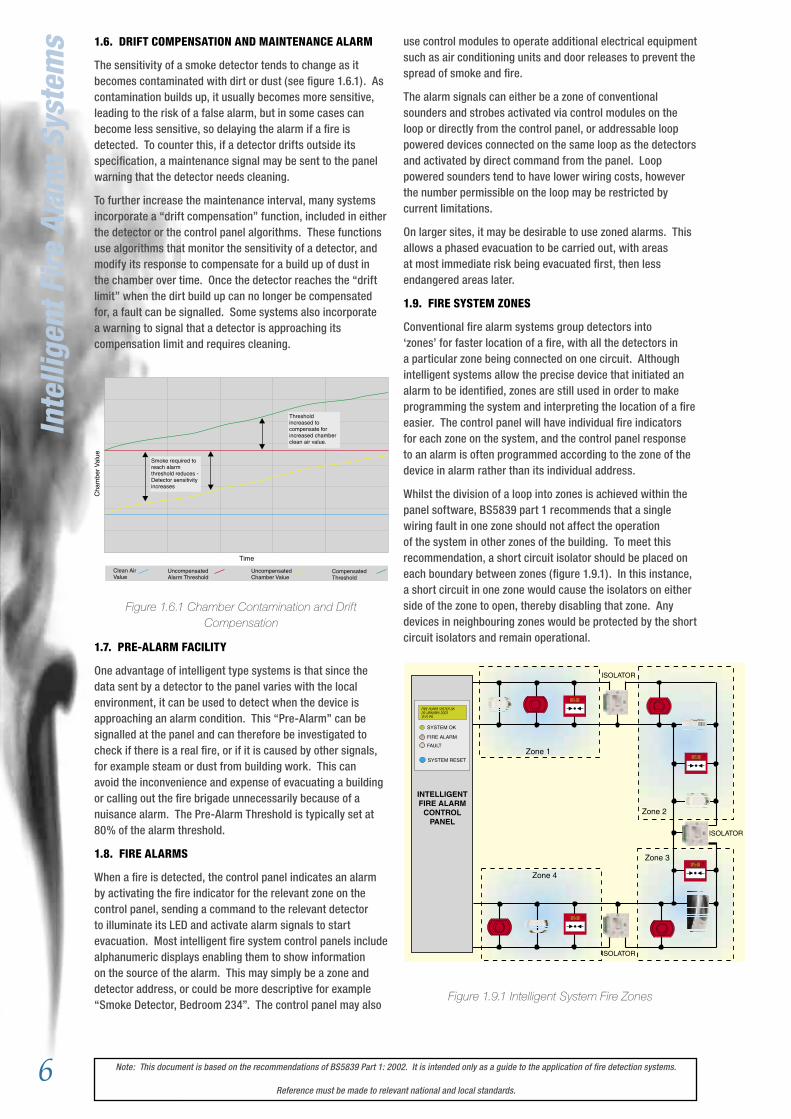
1.6. DRIFT COMPENSATION AND MAINTENANCE ALARM
The sensitivity of a smoke detector tends to change as it becomes contaminated with dirt or dust (see figure 1.6.1). As contamination builds up, it usually becomes more sensitive, leading to the risk of a false alarm, but in some cases can become less sensitive, so delaying the alarm if a fire is detected. To counter this, if a detector drifts outside its specification, a maintenance signal may be sent to the panel warning that the detector needs cleaning.
To further increase the maintenance interval, many systems incorporate a “drift compensation” function, included in either the detector or the control panel algorithms. These functions use algorithms that monitor the sensitivity of a detector, and modify its response to compensate for a build up of dust in the chamber over time. Once the detector reaches the “drift limit” when the dirt build up can no longer be compensated for, a fault can be signalled. Some systems also incorporate a warning to signal that a detector is approaching its compensation limit and requires cleaning.
Figure 1.6.1 Chamber Contamination and Drift Compensation
1.7. PRE-ALARM FACILITY
One advantage of intelligent type systems is that since the data sent by a detector to the panel varies with the local environment, it can be used to detect when the device is approaching an alarm condition. This “Pre-Alarm” can be signalled at the panel and can therefore be investigated to check if there is a real fire, or if it is caused by other signals, for example steam or dust from building work. This can avoid the inconvenience and expense of evacuating a building or calling out the fire brigade unnecessarily because of a nuisance alarm. The Pre-Alarm Threshold is typically set at 80% of the alarm threshold.
1.8. FIRE ALARMS
When a fire is detected, the control panel indicates an alarm by activating the fire indicator for the relevant zone on the control panel, sending a command to the relevant detector to illuminate its LED and activate alarm signals to start evacuation. Most intelligent fire system control panels include alphanumeric displays enabling them to show information on the source of the alarm. This may simply be a zone and detector address, or could be more descriptive for example “Smoke Detector, Bedroom 234”. The control panel may also
use control modules to operate additional electrical equipment such as air conditioning units and door releases to prevent the spread of smoke and fire.
The alarm signals can either be a zone of conventional sounders and strobes activated via control modules on the loop or directly from the control panel, or addressable loop powered devices connected on the same loop as the detectors and activated by direct command from the panel. Loop powered sounders tend to have lower wiring costs, however the number permissible on the loop may be restricted by current limitations.
On larger sites, it may be desirable to use zoned alarms. This allows a phased evacuation to be carried out, with areas at most immediate risk being evacuated first, then less endangered areas later.
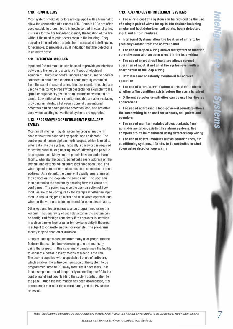
1.9. FIRE SYSTEM ZONES
Conventional fire alarm systems group detectors into ‘zones’ for faster location of a fire, with all the detectors in a particular zone being connected on one circuit. Although intelligent systems allow the precise device that initiated an alarm to be identified, zones are still used in order to make programming the system and interpreting the location of a fire easier. The control panel will have individual fire indicators for each zone on the system, and the control panel response to an alarm is often programmed according to the zone of the device in alarm rather than its individual address.
Whilst the division of a loop into zones is achieved within the panel software, BS5839 part 1 recommends that a single wiring fault in one zone should not affect the operation of the system in other zones of the building. To meet this recommendation, a short circuit isolator should be placed on each boundary between zones (figure 1.9.1). In this instance, a short circuit in one zone would cause the isolators on either side of the zone to open, thereby disabling that zone. Any devices in neighbouring zones would be protected by the short circuit isolators and remain operational.
Figure 1.9.1 Intelligent System Fire Zones
Inte
llige
nt F
ire
Alar
m S
yste
ms
Cha
mbe
r Val
ue
Time
Clean AirValue
UncompensatedAlarm Threshold
UncompensatedChamber Value
CompensatedThreshold
Smoke required toreach alarmthreshold reduces -Detector sensitivityincreases
Thresholdincreased tocompensate forincreased chamberclean air value.
ISOLATOR
ISOLATOR
ISOLATOR
Zone 1
Zone 2
Zone 3
Zone 4
INTELLIGENTFIRE ALARM
CONTROLPANEL
FIRE ALARM SYSTEM OK28 January 200312:15 pm
SYSTEM OK
SYSTEM RESET
FIRE ALARM
FAULT
7Note: This document is based on the recommendations of BS5839 Part 1: 2002. It is intended only as a guide to the application of fire detection systems.
Reference must be made to relevant national and local standards.
Intelligent Fire Alarm System
s1.10. REMOTE LEDS
Most system smoke detectors are equipped with a terminal to allow the connection of a remote LED. Remote LEDs are often used outside bedroom doors in hotels so that in case of a fire, it is easy for the fire brigade to identify the location of the fire without the need to enter every room in the building. They may also be used where a detector is concealed in loft space, for example, to provide a visual indication that the detector is in an alarm state.
1.11. INTERFACE MODULES
Input and Output modules can be used to provide an interface between a fire loop and a variety of types of electrical equipment. Output or control modules can be used to operate sounders or shut down electrical equipment by command from the panel in case of a fire. Input or monitor modules are used to monitor volt-free switch contacts, for example from a sprinkler supervisory switch or an existing conventional fire panel. Conventional zone monitor modules are also available, providing an interface between a zone of conventional detectors and an analogue fire detection loop, and are often used when existing conventional systems are upgraded.
1.12. PROGRAMMING OF INTELLIGENT FIRE ALARM PANELS
Most small intelligent systems can be programmed with ease without the need for any specialised equipment. The control panel has an alphanumeric keypad, which is used to enter data into the system. Typically a password is required to set the panel to ‘engineering mode’, allowing the panel to be programmed. Many control panels have an ‘auto-learn’ facility, whereby the control panel polls every address on the system, and detects which addresses have been used, and what type of detector or module has been connected to each address. As a default, the panel will usually programme all the devices on the loop into the same zone. The user can then customise the system by entering how the zones are configured. The panel may give the user an option of how modules are to be configured - for example whether an input module should trigger an alarm or a fault when operated and whether the wiring is to be monitored for open circuit faults.
Other optional features may also be programmed using the keypad. The sensitivity of each detector on the system can be configured for high sensitivity if the detector is installed in a clean smoke-free area, or for low sensitivity if the area is subject to cigarette smoke, for example. The pre-alarm facility may be enabled or disabled.
Complex intelligent systems offer many user-programmable features that can be time-consuming to enter manually using the keypad. In this case, many panels have the facility to connect a portable PC by means of a serial data link. The user is supplied with a specialised piece of software, which enables the entire configuration of the system to be programmed into the PC, away from site if necessary. It is then a simple matter of temporarily connecting the PC to the control panel and downloading the system configuration to the panel. Once the information has been downloaded, it is permanently stored in the control panel, and the PC can be removed.
1.13. ADVANTAGES OF INTELLIGENT SYSTEMS
• The wiring cost of a system can be reduced by the use of a single pair of wires for up to 198 devices including smoke and heat detectors, call points, beam detectors, input and output modules.
• Intelligent Systems allow the location of a fire to be precisely located from the control panel
• The use of looped wiring allows the system to function normally even with an open circuit in the loop wiring
• The use of short circuit isolators allows correct operation of most, if not all of the system even with a short circuit in the loop wiring
• Detectors are constantly monitored for correct operation
• The use of a ‘pre-alarm’ feature alerts staff to check whether a fire condition exists before the alarm is raised
• Different detector sensitivities can be used for diverse applications
• The use of addressable loop-powered sounders allows the same wiring to be used for sensors, call points and sounders
• The use of monitor modules allows contacts from sprinkler switches, existing fire alarm systems, fire dampers etc. to be monitored using detector loop wiring
• The use of control modules allows sounder lines, air conditioning systems, lifts etc. to be controlled or shut down using detector loop wiring
8 Note: This document is based on the recommendations of BS5839 Part 1: 2002. It is intended only as a guide to the application of fire detection systems.
Reference must be made to relevant national and local standards.
2. DETECTOR APPLICATION GUIDE2.1. FIRE SYSTEM CATEGORIES.
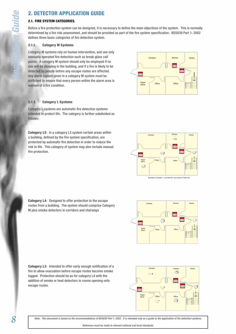
Before a fire protection system can be designed, it is necessary to define the main objectives of the system. This is normally determined by a fire risk assessment, and should be provided as part of the fire system specification. BS5839 Part 1: 2002 defines three basic categories of fire detection system.
2.1.1. Category M Systems
Category M systems rely on human intervention, and use only manually operated fire detection such as break glass call points. A category M system should only be employed if no one will be sleeping in the building, and if a fire is likely to be detected by people before any escape routes are affected. Any alarm signals given in a category M system must be sufficient to ensure that every person within the alarm area is warned of a fire condition.
2.1.2. Category L Systems
Category L systems are automatic fire detection systems intended to protect life. The category is further subdivided as follows:
Category L5: In a category L5 system certain areas within a building, defined by the fire system specification, are protected by automatic fire detection in order to reduce the risk to life. This category of system may also include manual fire protection.
Category L4: Designed to offer protection to the escape routes from a building. The system should comprise Category M plus smoke detectors in corridors and stairways
Category L3: Intended to offer early enough notification of a fire to allow evacuation before escape routes become smoke logged. Protection should be as for category L4 with the addition of smoke or heat detectors in rooms opening onto escape routes.
dow
n
Canteen Kitchen Pantry
PaperStore Office Office
dow
n
PantryKitchenCanteen
Office OfficePaperStore
dow
n
Canteen Kitchen Pantry
PaperStore Office Office
dow
n
Canteen Kitchen Pantry
PaperStore
Office Office
Example L5 System: L4 protection plus areas of high risk
Appl
icat
ion
Guid
e
9Note: This document is based on the recommendations of BS5839 Part 1: 2002. It is intended only as a guide to the application of fire detection systems.
Reference must be made to relevant national and local standards.
dow
n
Electric Plant MaterialsStorage
ComputerEquipment
dow
n
Electrical Plant MaterialsStorage
ComputerEquipment
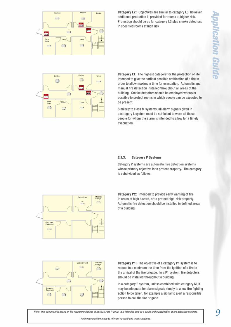
Category L2: Objectives are similar to category L3, however additional protection is provided for rooms at higher risk. Protection should be as for category L3 plus smoke detectors in specified rooms at high risk
Category L1: The highest category for the protection of life. Intended to give the earliest possible notification of a fire in order to allow maximum time for evacuation. Automatic and manual fire detection installed throughout all areas of the building. Smoke detectors should be employed wherever possible to protect rooms in which people can be expected to be present.
Similarly to class M systems, all alarm signals given in a category L system must be sufficient to warn all those people for whom the alarm is intended to allow for a timely evacuation.
2.1.3. Category P Systems
Category P systems are automatic fire detection systems whose primary objective is to protect property. The category is subdivided as follows:
Category P2: Intended to provide early warning of fire in areas of high hazard, or to protect high-risk property. Automatic fire detection should be installed in defined areas of a building.
Category P1: The objective of a category P1 system is to reduce to a minimum the time from the ignition of a fire to the arrival of the fire brigade. In a P1 system, fire detectors should be installed throughout a building.
In a category P system, unless combined with category M, it may be adequate for alarm signals simply to allow fire fighting action to be taken, for example a signal to alert a responsible person to call the fire brigade.
Application Guide
dow
n
Canteen Kitchen Pantry
PaperStore
Office Office
dow
n
Canteen Kitchen Pantry
PaperStore
Office Office
10 Note: This document is based on the recommendations of BS5839 Part 1: 2002. It is intended only as a guide to the application of fire detection systems.
Reference must be made to relevant national and local standards.
Appl
icat
ion
Guid
e 2.2. MANUAL CALL POINTS
People can often still detect a fire long before automatic fire detectors; hence manual call points are important components of fire detection systems in occupied buildings to ensure timely evacuation in the case of fire. All call points should be approved to EN54-11, and should be of type A, that is once the frangible element is broken or displaced the alarm condition is automatic.
Manual call points should be mounted on all escape routes, and at all exit points from the floors of a building and to clear air. It should not be possible to leave the floor of a building without passing a manual call point, nor should it be necessary to deviate from any escape route in order to operate a manual call point. Call points mounted at the exits from a floor may be mounted within the accommodation or on the stairwell. In multiple storey buildings where phased evacuation is to be used call points should be mounted within the accommodation to avoid activation of call points on lower levels by people leaving the building.
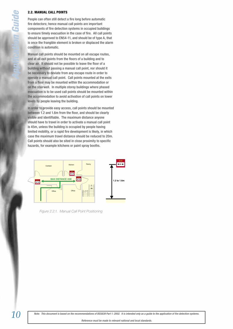
In order to provide easy access, call points should be mounted between 1.2 and 1.6m from the floor, and should be clearly visible and identifiable. The maximum distance anyone should have to travel in order to activate a manual call point is 45m, unless the building is occupied by people having limited mobility, or a rapid fire development is likely, in which case the maximum travel distance should be reduced to 20m. Call points should also be sited in close proximity to specific hazards, for example kitchens or paint spray booths.
Figure 2.2.1. Manual Call Point Positioning
CanteenKitchen Pantry
Office Office
MAX DISTANCE 45M1.2 to 1.6m
11Note: This document is based on the recommendations of BS5839 Part 1: 2002. It is intended only as a guide to the application of fire detection systems.
Reference must be made to relevant national and local standards.
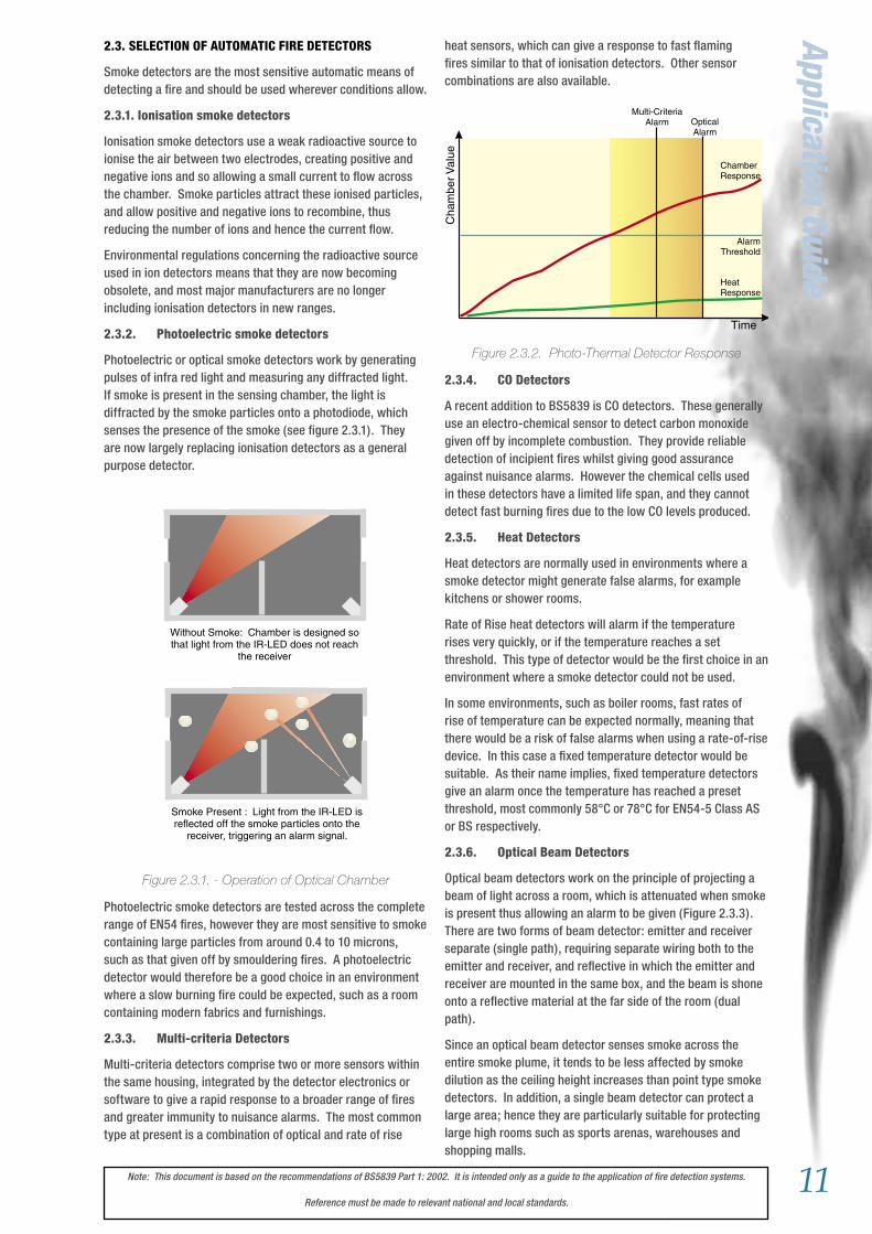
Application Guideheat sensors, which can give a response to fast flaming fires similar to that of ionisation detectors. Other sensor combinations are also available.
Figure 2.3.2. Photo-Thermal Detector Response
2.3.4. CO Detectors
A recent addition to BS5839 is CO detectors. These generally use an electro-chemical sensor to detect carbon monoxide given off by incomplete combustion. They provide reliable detection of incipient fires whilst giving good assurance against nuisance alarms. However the chemical cells used in these detectors have a limited life span, and they cannot detect fast burning fires due to the low CO levels produced.
2.3.5. Heat Detectors
Heat detectors are normally used in environments where a smoke detector might generate false alarms, for example kitchens or shower rooms.
Rate of Rise heat detectors will alarm if the temperature rises very quickly, or if the temperature reaches a set threshold. This type of detector would be the first choice in an environment where a smoke detector could not be used.
In some environments, such as boiler rooms, fast rates of rise of temperature can be expected normally, meaning that there would be a risk of false alarms when using a rate-of-rise device. In this case a fixed temperature detector would be suitable. As their name implies, fixed temperature detectors give an alarm once the temperature has reached a preset threshold, most commonly 58°C or 78°C for EN54-5 Class AS or BS respectively.
2.3.6. Optical Beam Detectors
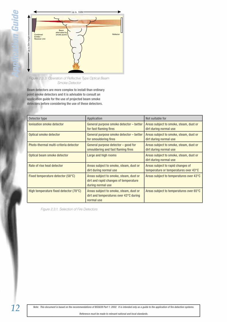
Optical beam detectors work on the principle of projecting a beam of light across a room, which is attenuated when smoke is present thus allowing an alarm to be given (Figure 2.3.3). There are two forms of beam detector: emitter and receiver separate (single path), requiring separate wiring both to the emitter and receiver, and reflective in which the emitter and receiver are mounted in the same box, and the beam is shone onto a reflective material at the far side of the room (dual path).
Since an optical beam detector senses smoke across the entire smoke plume, it tends to be less affected by smoke dilution as the ceiling height increases than point type smoke detectors. In addition, a single beam detector can protect a large area; hence they are particularly suitable for protecting large high rooms such as sports arenas, warehouses and shopping malls.
2.3. SELECTION OF AUTOMATIC FIRE DETECTORS
Smoke detectors are the most sensitive automatic means of detecting a fire and should be used wherever conditions allow.
2.3.1. Ionisation smoke detectors
Ionisation smoke detectors use a weak radioactive source to ionise the air between two electrodes, creating positive and negative ions and so allowing a small current to flow across the chamber. Smoke particles attract these ionised particles, and allow positive and negative ions to recombine, thus reducing the number of ions and hence the current flow.
Environmental regulations concerning the radioactive source used in ion detectors means that they are now becoming obsolete, and most major manufacturers are no longer including ionisation detectors in new ranges.
2.3.2. Photoelectric smoke detectors
Photoelectric or optical smoke detectors work by generating pulses of infra red light and measuring any diffracted light. If smoke is present in the sensing chamber, the light is diffracted by the smoke particles onto a photodiode, which senses the presence of the smoke (see figure 2.3.1). They are now largely replacing ionisation detectors as a general purpose detector.
Figure 2.3.1. - Operation of Optical Chamber
Photoelectric smoke detectors are tested across the complete range of EN54 fires, however they are most sensitive to smoke containing large particles from around 0.4 to 10 microns, such as that given off by smouldering fires. A photoelectric detector would therefore be a good choice in an environment where a slow burning fire could be expected, such as a room containing modern fabrics and furnishings.
2.3.3. Multi-criteria Detectors
Multi-criteria detectors comprise two or more sensors within the same housing, integrated by the detector electronics or software to give a rapid response to a broader range of fires and greater immunity to nuisance alarms. The most common type at present is a combination of optical and rate of rise
Without Smoke: Chamber is designed sothat light from the IR-LED does not reach
the receiver
Smoke Present : Light from the IR-LED isreflected off the smoke particles onto the
receiver, triggering an alarm signal.
Without Smoke: Chamber is designed sothat light from the IR-LED does not reach
the receiver
Smoke Present : Light from the IR-LED isreflected off the smoke particles onto the
receiver, triggering an alarm signal.
Time
Cha
mbe
rVal
ue
AlarmThreshold
OpticalAlarm
ChamberResponse
HeatResponse
Multi-CriteriaAlarm
12 Note: This document is based on the recommendations of BS5839 Part 1: 2002. It is intended only as a guide to the application of fire detection systems.
Reference must be made to relevant national and local standards.
Detector type Application Not suitable for
Ionisation smoke detector General purpose smoke detector – better for fast flaming fires
Areas subject to smoke, steam, dust or dirt during normal use
Optical smoke detector General purpose smoke detector – better for smouldering fires
Areas subject to smoke, steam, dust or dirt during normal use
Photo-thermal multi-criteria detector General purpose detector – good for smouldering and fast flaming fires
Areas subject to smoke, steam, dust or dirt during normal use
Optical beam smoke detector Large and high rooms Areas subject to smoke, steam, dust or dirt during normal use
Rate of rise heat detector Areas subject to smoke, steam, dust or dirt during normal use
Areas subject to rapid changes of temperature or temperatures over 43°C
Fixed temperature detector (58°C) Areas subject to smoke, steam, dust or dirt and rapid changes of temperature during normal use
Areas subject to temperatures over 43°C
High temperature fixed detector (78°C) Areas subject to smoke, steam, dust or dirt and temperatures over 43°C during normal use
Areas subject to temperatures over 65°C
Figure 2.3.3. Operation of Reflective Type Optical Beam Smoke Detector
Beam detectors are more complex to install than ordinary point smoke detectors and it is advisable to consult an application guide for the use of projected beam smoke detectors before considering the use of these detectors.
Figure 2.3.1. Selection of Fire Detectors
Up to 100M
Up
to 2
5m h
eigh
t
CombinedEmitter /Receiver Unit
Reflector
Beamattenuated bysmoke plume
Appl
icat
ion
Guid
e
13Note: This document is based on the recommendations of BS5839 Part 1: 2002. It is intended only as a guide to the application of fire detection systems.
Reference must be made to relevant national and local standards.
Application Guide2.4.2. Ceiling Height
Smoke or heat detectors can only detect fires once a certain amount of smoke or heat has reached the sensor. As the height of a ceiling increases, the time taken for smoke or heat to reach a sensor will increase, and it will become diluted with clean, cool air. As a result, maximum ceiling heights are limited as indicated in table 2.4.1 below.
Table 2.4.1: Maximum ceiling height for different types of detector
Often, a boundary layer can form close to the ceiling, which is free of smoke and remains cool. To avoid this, and maximise the probability of detection, smoke detectors should normally be mounted with their smoke entry 25mm-600mm below the ceiling, and heat detectors should be mounted with their heat element 25mm-150mm below the ceiling. Detector design normally ensures that the minimum requirement is met, but care needs to be taken if the detectors are to be stood away from the roof, for example mounting on an open lattice suspended ceiling.
Another problem that should be considered is the possibility of stratification of the air in a room into hot and cold layers, causing the smoke or heat to stop at the boundaries. This particularly affects high rooms or atria, where beam detectors are often used. Stratification is very difficult to predict, and can vary, even within the same room as environmental conditions change.
2.4.3. Ceiling Obstructions
Ceiling obstructions such as beams greater than 10% of the ceiling height should be treated as a wall, and will thus divide a room. Detectors should not be mounted within 500mm of such an obstruction.
If the depth an obstruction such as a beam is less than 10% of the height of the ceiling, but greater than 250mm deep, then detectors should not be mounted any closer than 500mm to the obstruction.
Where an obstruction such as a beam or a light fitting is less than 250mm in depth, detectors should not be mounted any closer to the obstruction than twice its depth (see figure 2.4.3 below)
Where a ceiling comprises a series of small cells, for example a honeycomb ceiling, or a series of closely spaced beams, for example floor of ceiling joists, the recommended spacing and siting of detectors changes further, dependant on the ceiling height and the depth and spacing of the beams. Reference should be made to relevant standards for details (in the UK BS5839 Part 1: 2002, 22.3.k Tables 1 and 2).
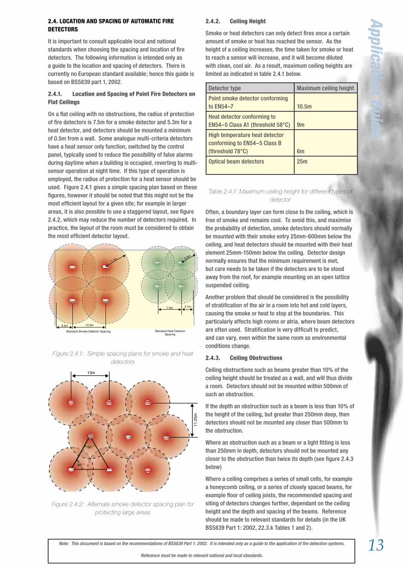
2.4. LOCATION AND SPACING OF AUTOMATIC FIRE DETECTORS
It is important to consult applicable local and national standards when choosing the spacing and location of fire detectors. The following information is intended only as a guide to the location and spacing of detectors. There is currently no European standard available; hence this guide is based on BS5839 part 1, 2002.
2.4.1. Location and Spacing of Point Fire Detectors on Flat Ceilings
On a flat ceiling with no obstructions, the radius of protection of fire detectors is 7.5m for a smoke detector and 5.3m for a heat detector, and detectors should be mounted a minimum of 0.5m from a wall. Some analogue multi-criteria detectors have a heat sensor only function, switched by the control panel, typically used to reduce the possibility of false alarms during daytime when a building is occupied, reverting to multi-sensor operation at night time. If this type of operation is employed, the radius of protection for a heat sensor should be used. Figure 2.4.1 gives a simple spacing plan based on these figures, however it should be noted that this might not be the most efficient layout for a given site; for example in larger areas, it is also possible to use a staggered layout, see figure 2.4.2, which may reduce the number of detectors required. In practice, the layout of the room must be considered to obtain the most efficient detector layout.
Figure 2.4.1: Simple spacing plans for smoke and heat detectors
Figure 2.4.2: Alternate smoke detector spacing plan for protecting large areas
Standard Smoke Detector Spacing Standard Heat DetectorSpacing
10.5m5.3m
7.5m
3.7m
5.3m
7.5m
60 °
60 °
11.2
5m
13m
Detector type Maximum ceiling height
Point smoke detector conforming to EN54–7
10.5m
Heat detector conforming to EN54–5 Class A1 (threshold 58°C)
9m
High temperature heat detector conforming to EN54–5 Class B (threshold 78°C)
6m
Optical beam detectors 25m
14 Note: This document is based on the recommendations of BS5839 Part 1: 2002. It is intended only as a guide to the application of fire detection systems.
Reference must be made to relevant national and local standards.
Appl
icat
ion
Guid
e
Figure 2.4.3: Detector Spacing around isolated ceiling obstructions
2.4.4. Partitions and Racking
Where the gap between the top of a partition or section of racking and the ceiling is greater than 300mm, it may be ignored. If the gap is less than 300mm it should be treated as a wall.
To maintain a free flow of smoke and heat to the detector, a clear space should be maintained for 500mm in all directions below the detector.
Figure 2.4.4. Partitions
2.4.5. Sloping Ceilings
Where the ceiling is pitched or sloping, the slope of the roof tends to speed the rise of smoke or heat to the apex, hence reducing the delay before the detectors are triggered. For sloped roofs with a pitch height greater than 600mm for smoke detectors, or 150mm for heat detectors, a row of detectors should be placed within a maximum vertical distance of 600mm or 150mm for smoke or heat detectors respectively from the roof apex. Sloped roofs rising less than 600mm for smoke detectors or 150mm for heat detectors may be treated as a flat ceiling.
Since the smoke or heat tends to rise faster up the slope, it is permissible to use a greater spacing for the row of detectors mounted in the apex of the roof: For each degree of slope of the roof, the spacing may be increased by 1% up to a maximum of 25%. Where, as in figure 2.4.5, the roof slopes are unequal the spacing down the slopes can be unequal,
however along the roof apex spacing the lesser of the two figures should be used, in this example 10.5m +18%. Where the slope finishes within the adjusted detection radius, the standard distance to the next row of detectors, 10.5m, should be used. Care must be taken when placing the next row that no gaps are left in detection coverage.
Figure 2.4.5. Spacing of Smoke Detectors under a Pitched Roof
2.4.6. Corridors
In corridors less than 2m wide, detectors should be spaced at a distance of 15m for smoke detectors and 10.6m for heat detectors, with the maximum dimension to a wall at the end of the corridor being 7.5m and 5.3m respectively.
In narrow rooms and corridors greater than 2m wide, due to the way that the coverage radii of detectors intersect with the walls of the corridor, the spacing between detectors will increase. Figure 2.4.6 shows how, for a room 6m wide, the spacing for smoke detectors can be increased from the standard 10.5m.
Figure 2.4.6. Smoke detector spacing in corridors greater than 2m wide
>300mm : No effect<300mm :Treat as wall
Minimum500mmClear
Par
titio
n Racking /Shelving
18°
15mMax 600mm
10.5
m
12.3
9m=
10.5
+ 1
8%
7.5m
8.85
m
=7.5
+ 1
8%
9.35
m
= 7.
5 +
25%
40°
Minimum500mm
Minimum500mm
Minimum 2 xheight
>250mm<10% of Ceiling Height
>10% of Ceiling Height
Height < 250mm
Normal Detector Spacing, eg. 10.5m maxfor “simple” layout.
Normal Detector Spacing, eg. 10.5m maxfor “simple” layout.
Treat as separate room
Note: Detectors are mounted in the centre line of the room
6.88m 13.75m
7.5m
6m
15Note: This document is based on the recommendations of BS5839 Part 1: 2002. It is intended only as a guide to the application of fire detection systems.
Reference must be made to relevant national and local standards.
Application Guide2.4.7. Stairwells and Lift Shafts
Internal stairwells and lift shafts and other vertical service ducts through a building provide a clear path for smoke to pass between floors of a building as if they were chimneys. It is therefore important to protect these, preferably using smoke detectors.
All vertical shafts through a building must be protected by a smoke or heat detector at the top of the shaft, and by a detector within 1.5m of each opening onto the shaft.
In internal stairways, a detector should be mounted on each main landing (Figure 2.4.7). In addition, if the detectors on the landings are separated by more than 10.5m, intermediate detectors should be mounted on the underside of the stairs.
Detectors should also be fitted into any room opening directly onto a stairway other than a WC cubicle.
Figure 2.4.7. Detector in Stairwells
Figure 2.4.8. Protection of Vertical Shafts
2.4.8. Voids and False Ceilings
Detectors need not normally be installed in voids less than 800mm deep, unless on the basis of a fire risk assessment it is thought that fire or smoke could spread extensively through the voids before detection, or unless the fire risk in the void is such as to warrant protection. Use of heat and smoke detectors in voids greater than 800mm high is dependant on the protection category, and fire risk assessment.
Where they are installed into voids, a detector's sensing element should be mounted either in the top 10% or the top 125mm of the void space whichever is greater. Although it can be difficult to install detectors the correct way up in void spaces, care should be taken as incorrect orientation of a detector can lead to increased ingress of dirt and dust, leading to reduced maintenance intervals, and possible nuisance alarms.
Detectors above a false ceiling may be used to protect the area below it, if the false ceiling is perforated uniformly across the complete area of the ceiling, with the holes making up over 40% of the ceiling surface area, having a minimum size of 10mm and the false ceiling having a thickness of less than three times the dimensions of the perforations.
In all other cases, the areas above and below a false ceiling should be treated as separate, and thus should be protected separately with detectors below the ceiling, and if necessary in the void above the ceiling.
2.4.9. Lantern Lights
A detector should be mounted in any lantern light used for ventilation or having a height exceeding 800mm. The temperature in lantern lights can change rapidly owing to heating by sunlight, which means that rate-of-rise heat detectors should not be used and heat detectors should be protected from direct sunlight.
2.4.10. Location and Spacing of Optical Beam Detectors
Generally, for an optical beam detector mounted within 600mm of a ceiling, the fire detection coverage is up to 7.5m either side of the beam (Figure 2.4.9). The beam of the detector should not be closer than 500mm to any obstruction. Similar recommendations to above apply to the application of beam detectors with sloped ceilings, voids, false ceilings, walls and partitions and ceiling obstructions.
Figure 2.4.9: Standard Beam Detector Layout
Where it is likely that people will be present in an area protected by beam detectors, the detectors must be mounted at a minimum height of 2.7m, and consideration must also be given to the possibility of other temporary obstructions to the beam such as forklift trucks.
For further information on the use and mounting of beam detectors, see System Sensor Europe's Guide to Projected Beam Detectors.
< 1
0.5M
1.5M1.5M
Maximum7.5m
Maximum15m
Transmitter orTransmitter/Receiver Receiver or
Reflector
Receiver orReflector
Transmitter orTransmitter/Receiver
Maximum 100m
Minimum500mm
16 Note: This document is based on the recommendations of BS5839 Part 1: 2002. It is intended only as a guide to the application of fire detection systems.
Reference must be made to relevant national and local standards.
2.5. ALARM SIGNALS
2.5.1. Audible Alarm Signals
Audible fire alarm signals must provide a clear warning of a fire to all those for whom the signal is intended. For category M and L systems this would normally imply all occupants of a building, however in some sites this may not apply, for example in hospitals or rest homes, residents might need assistance to evacuate, in which case it may be sufficient to alert staff.
The general requirement for the volume of audible alarm signals is that they should provide a Sound Pressure Level (SPL) of at least 65dB(A), but not more than 120dB(A) throughout all accessible areas of a building. See figure 2.5.1.
Figure 2.5.1. General Fire Alarm Sound Pressure Levels
Exceptions to this general rule are as follows:
• In stairways the SPL may be reduced to 60dB(A)• Enclosures less than 60m² may be reduced to 60dB(A)• There is no minimum for enclosed areas less than 1m²• At specific points of limited extent the SPL may be reduced to 60dB(A)
Where a continuous background noise level greater than 60dB(A) is present the fire alarm signal should be 5dB above the ambient, but not greater than 120dB(A).
Where the alarm is intended to wake people, an SPL of 75dB(A) is required at the bed head. Generally this will require a sounder to be placed within the room.
Where it is not possible to place a sounder within a room, there will be a loss of approximately 20dB(A) through a standard door, and 30dB(A) through a fire door.
Warning: Volumes greater than 120dB(A) will cause damage to hearing.
In open space, as the distance from a sounder doubles, the sound level will be reduced by 6dB(A), as shown.
It is preferable to use multiple quieter sounders to achieve the required sound level, rather than a smaller number of loud devices. This is to prevent points of excessive volume, which may lead to disorientation or damage to hearing. Two sounders providing equal sound levels will combine to add 3dB(A) to the SPL.
2.5.2. Visual Alarm Signals
Visual alarms are normally used only as a supplement to audible alarms where they are likely to be ineffective, for example in areas of high background noise levels where hearing protection is likely to be worn. They can however be used alone where audible warnings are undesirable for example operating theatres and recording studios.
Visual alarms should be clearly distinguishable from other warning lights, preferably red and should flash at a rate of 30 to 130 flashes per minute. The recommended mounting height is above 2.1m, however they should not be mounted closer than 150mm from the ceiling. They should be positioned so that any alarm is clearly visible from all locations within the area protected.
dow
n
Are
a <
60m
²M
in 6
0dB
(A)
Minimum65dB(A)
Minimum65dB(A)
Minimum65dB(A)
Minimum65dB(A)
Minimum65dB(A)
Minimum65dB(A)
StairwellMin 60dB(A)
SOUND REDUCTION AGAINST DISTANCEBased on a sounder rated at 1m
-30
-25
-20
-15
-10
-5
0
0 5 10 15 20Distance (Metres)
Soundreduction(dB(A
) dB(A) Reduction
69dB(A)
69dB(A)
63 + 3= 66dB(A)
62 + 3= 65dB(A)
14m
12.6
m
-16dB -23dB
-16dB
0dB
Note: dB(A) figures are for example only.Left side represents attenuation; right side
indicates typical sound pressure level
25m
14m
85dB(A)MachineryGenerating
80dB(A)
SounderMinimum85dB(A)
Volume atBed Head75dB(A)
SounderVolume
115dB(A)
Standard DoorReduces by
20dB(A)
85 - 20 =65dB(A)
Fire DoorReduces by
30dB(A)
115 - 30 =85dB(A)
Appl
icat
ion
Guid
e

17Note: This document is based on the recommendations of BS5839 Part 1: 2002. It is intended only as a guide to the application of fire detection systems.
Reference must be made to relevant national and local standards.
Application Guide2.6 MAINTENANCE OF FIRE DETECTORS
Caution: Prior to carrying out any maintenance or testing on a fire alarm system, the relevant authorities and staff should be notified.
Over time, the sensitivity of a smoke detector can change owing to a build-up of dirt in the detector chamber. In most modern detectors this effect is slowed by the inclusion of drift compensation functions, however the build up can still lead to a risk of false alarms or change in the detector sensitivity.
The frequency of maintenance requirements on a detector will depend on site conditions, obviously the dirtier the site the more frequent maintenance will be required. The optimum frequency for a given site should be determined over a period of time after the commissioning of the fire system.
All System Sensor detectors (smoke, heat, or multi-criteria) are designed such that they can be easily dismantled for maintenance. Instructions are given for maintenance in the instruction manual supplied with each detector. Normally it is sufficient to use compressed air or a vacuum cleaner to remove dust from the detector chamber.
Once maintenance on a fire detection system has been completed, it should be re-tested.
2.7 ROUTINE FUNCTIONAL TESTING OF FIRE DETECTORS
BS5839 Part 1: 2002 gives a range of recommendations regarding routine testing of a fire detection system.
A weekly test should be carried out on a fire detection system by activating a manual call point to ensure that all fire alarm signals operate correctly, and that the appropriate alarm signals are clearly received. This test should be carried out at approximately the same time each week, using a different call point in rotation.
In order to comply with BS5839 Part 1: 2002, periodic inspections, servicing and functional tests of the fire alarm system should be carried out at intervals determined by an assessment of the site and type of system installed, not normally greater than six months.
It is recommended to perform regular functional tests on all fire detectors annually. These annual tests may be carried out over the course of two or more service visits during the twelve-month period.
System Sensor detectors include various means of testing the system without using smoke, dependent on the detector range being tested, including magnet switches and laser test tools.
Codes and standards (in the UK BS5839 Part 1:2002, Section 6) now require functional tests to introduce smoke through the smoke detector vents and into the sensing chamber. It also calls for heat detectors to be tested by means of a suitable heat source, and not by a live flame. CO fire detectors now also need to be functionally tested by a method that confirms that carbon monoxide can enter the chamber.
Many installers use a set of equipment that consists of a complete range of test tools that locate on the end of the pole such as those available from No Climb Products Ltd. (www.noclimb.com) in order to aid compliance with codes. Tools exist for testing smoke, heat, and CO fire detectors, whilst also enabling them to be accessed and removed at heights up to 9 meters from the ground.
Using functional test equipment, along with those maintenance tools available from System Sensor, should ensure that the system remains at its optimum operation for many years.

18 Note: This document is based on the recommendations of BS5839 Part 1: 2002. It is intended only as a guide to the application of fire detection systems.
Reference must be made to relevant national and local standards.
SERIES 200 PLUS ANALOGUE ADDRESSABLE DETECTOR RANGEINTRODUCTION
System Sensor’s Series 200 plus range of plug in smoke detectors are a family of analogue addressable smoke detectors combining state of the art design with micro-processor control and sophisticated processing circuitry to provide fast, efficient fire detection in a wide range of applications.
All Series 200 plus detectors have two integral LEDs, which provide local visual indication of the sensor status. These LEDs provide a dual function. In the event of an alarm, they are switched ON continuously, and can also be programmed to either blink when polled by the panel or remain off during normal conditions. In addition to their integral LEDs, Series 200 plus detectors can be connected to a remote LED indicator.
The individual loop address of each Series 200 plus detector can be easily set and read, using the rotary decade address switches located on the rear of each sensor. The use of decimal address codes significantly reduces the potential for incorrect address selection.
Each sensor base includes a tamper resistant option which, when activated, prevents the removal of the sensor from its base without the use of a tool.
Full circuit functionality can be easily confirmed on site by use of the sensor test switch. This comprises a switch operated by a magnet near the side of the detector. Operation of this magnetic switch simulates the effect of smoke or heat on the detector, and will generate an alarm response to the fire alarm control panel, making system testing both convenient and simple.
Syst
em S
enso
r In
telli
gent
Pro
duct
Ran
ge
SERIES 200 PLUS FEATURES
• Microprocessor precision control
• Automatic drift compensation.
• Enhanced signal processing for improved stability.
• Extended Temperature Range
• Twin LED indicators providing 360° visibility
• Rotary Decade Address Switches
• Stable communication with high noise immunity
• Tamper-Resistant (standard feature)
• Built in test switch
• Third party certified to the latest EN54 standards with multiple alarm thresholds
GENERAL SPECIFICATIONS
Electrical
Voltage Range: 15 to 32VDCStandby Current: 200µA at 24VDC (No communications)Alarm Current: 7mA at 24VDC
Environmental
Temperature Range: -20°C to 60°CHumidity: 10% to 93% Relative Humidity (Non-condensing)Mechanical:
Diameter: 102mmMaximum Wire Gauge: 2.5mm²Colour: Pantone Warm Grey 1CMaterial: Bayblend FR110
19Note: This document is based on the recommendations of BS5839 Part 1: 2002. It is intended only as a guide to the application of fire detection systems.
Reference must be made to relevant national and local standards.
2251EM PHOTOELECTRIC SMOKE SENSOR
The 2251EM photoelectric smoke detector combines a state of the art sensing chamber with microprocessor control and sophisticated processing to eliminate transient noise conditions thereby giving reliable fire detection whilst minimising unwanted alarms. It is approved to a range of sensitivities, permitting the detector to be configured to match the application environment.
The 2251EM includes algorithms, which compensate for a slow build up of contamination such as dust, within the sensing chamber. Once the detector has reached its maximum compensation level, a signal can be sent to the control panel to indicate the need for maintenance.
Tested and approved to EN54-7: 2000 by LPCB
Specifications
Height: 45mm in B501 BaseWeight: 102g excluding base
2251TEM PHOTO–THERMAL SENSOR
The 2251TEM multi-criteria fire sensor incorporates an optical smoke-sensing chamber and thermal-sensing elements combined with microprocessor control and sophisticated processing to eliminate transient noise conditions thereby giving reliable fire detection whilst minimising unwanted alarms. It can respond either as a smoke detector, or a rate of rise heat detector or, using special algorithms combining both elements to provide improved reliability of detection.
The 2251TEM is an environmentally friendly replacement for an ionisation detector, providing rapid detection of fast, flaming fires without incurring the significant end-of-life disposal costs associated with products containing radioactive material.
The 2251TEM is approved to a number of sensitivity settings: Three Photo-Thermal and two Auto-Adjusting, which slowly adjust the detector’s sensitivity to match short term changes in its environment, thus reducing the potential for nuisance alarms. In addition, it is possible to detect an alarm from heat only, for day/night operation for example.
Similarly to the 2251EM, the 2251TEM includes algorithms, which compensate for a slow build up of contamination, such as dust, within its optical sensing chamber. Once the detector has reached its maximum compensation level, a signal can be sent to the control panel to indicate a the need for maintenance.
Tested and approved to CEA 4021, EN54-7: 2000 and EN54-5: 2000 (Class A1R) by LPCB
Specifications
Height: 45mm in B501 BaseWeight: 115g excluding base
System Sensor Intelligent Product Range
20 Note: This document is based on the recommendations of BS5839 Part 1: 2002. It is intended only as a guide to the application of fire detection systems.
Reference must be made to relevant national and local standards.
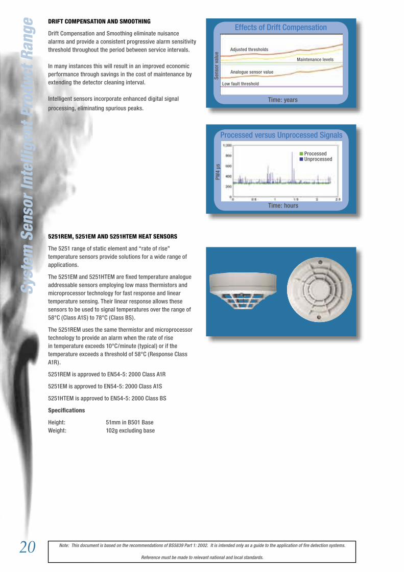
DRIFT COMPENSATION AND SMOOTHING
Drift Compensation and Smoothing eliminate nuisance alarms and provide a consistent progressive alarm sensitivity threshold throughout the period between service intervals.
In many instances this will result in an improved economic performance through savings in the cost of maintenance by extending the detector cleaning interval.
Intelligent sensors incorporate enhanced digital signal
processing, eliminating spurious peaks.
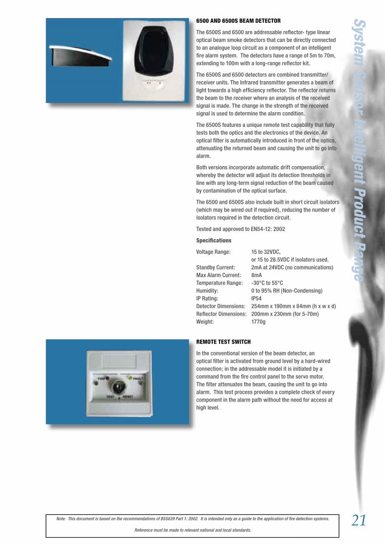
5251REM, 5251EM AND 5251HTEM HEAT SENSORS
The 5251 range of static element and “rate of rise” temperature sensors provide solutions for a wide range of applications.
The 5251EM and 5251HTEM are fixed temperature analogue addressable sensors employing low mass thermistors and microprocessor technology for fast response and linear temperature sensing. Their linear response allows these sensors to be used to signal temperatures over the range of 58°C (Class A1S) to 78°C (Class BS).
The 5251REM uses the same thermistor and microprocessor technology to provide an alarm when the rate of rise in temperature exceeds 10°C/minute (typical) or if the temperature exceeds a threshold of 58°C (Response Class A1R).
5251REM is approved to EN54-5: 2000 Class A1R
5251EM is approved to EN54-5: 2000 Class A1S
5251HTEM is approved to EN54-5: 2000 Class BS
Specifications
Height: 51mm in B501 BaseWeight: 102g excluding base
Syst
em S
enso
r In
telli
gent
Pro
duct
Ran
ge
Processed versus Unprocessed Signals
Time: hours
ProcessedUnprocessed
PW4
µs
Effects of Drift Compensation
Time: years
Sens
or v
alue
Low fault threshold
Analogue sensor value
Maintenance levels
Adjusted thresholds
21Note: This document is based on the recommendations of BS5839 Part 1: 2002. It is intended only as a guide to the application of fire detection systems.
Reference must be made to relevant national and local standards.
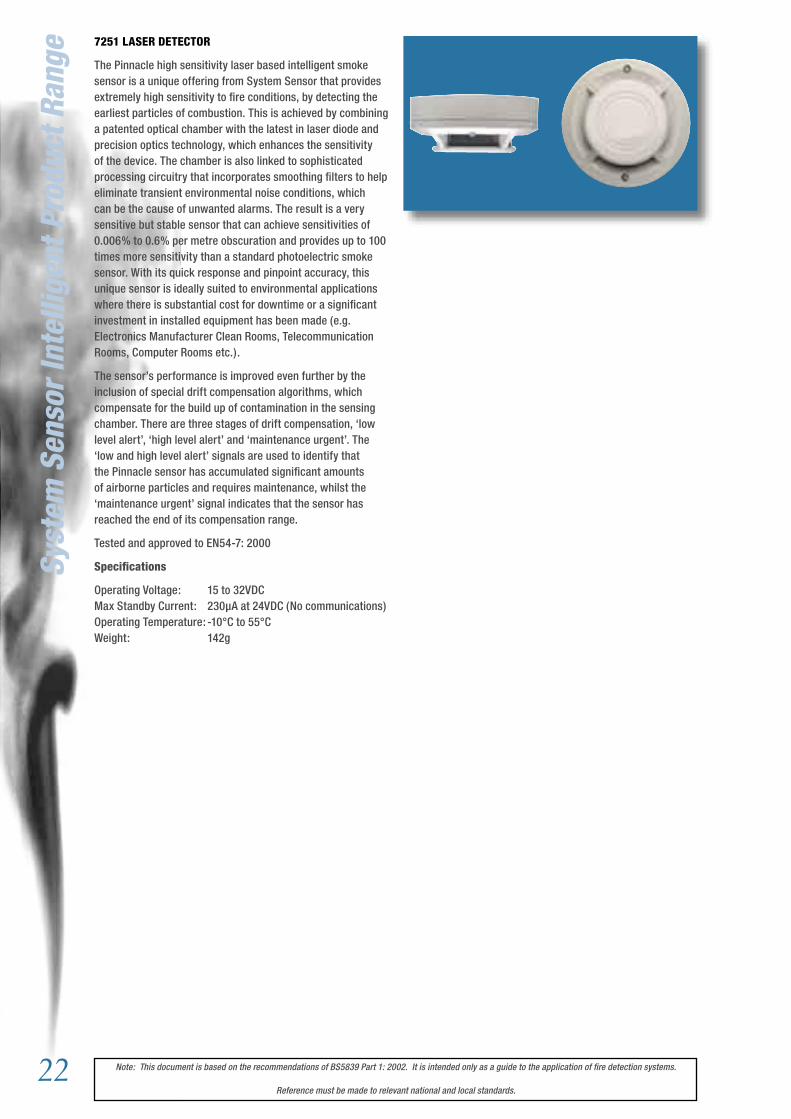
6500 AND 6500S BEAM DETECTOR
The 6500S and 6500 are addressable reflector- type linear optical beam smoke detectors that can be directly connected to an analogue loop circuit as a component of an intelligent fire alarm system. The detectors have a range of 5m to 70m, extending to 100m with a long-range reflector kit.
The 6500S and 6500 detectors are combined transmitter/receiver units. The Infrared transmitter generates a beam of light towards a high efficiency reflector. The reflector returns the beam to the receiver where an analysis of the received signal is made. The change in the strength of the received signal is used to determine the alarm condition.
The 6500S features a unique remote test capability that fully tests both the optics and the electronics of the device. An optical filter is automatically introduced in front of the optics, attenuating the returned beam and causing the unit to go into alarm.
Both versions incorporate automatic drift compensation, whereby the detector will adjust its detection thresholds in line with any long-term signal reduction of the beam caused by contamination of the optical surface.
The 6500 and 6500S also include built in short circuit isolators (which may be wired out if required), reducing the number of isolators required in the detection circuit.
Tested and approved to EN54-12: 2002
Specifications
Voltage Range: 15 to 32VDC, or 15 to 28.5VDC if isolators used.Standby Current: 2mA at 24VDC (no communications)Max Alarm Current: 8mATemperature Range: -30°C to 55°CHumidity: 0 to 95% RH (Non-Condensing)IP Rating: IP54Detector Dimensions: 254mm x 190mm x 84mm (h x w x d)Reflector Dimensions: 200mm x 230mm (for 5-70m)Weight: 1770g
System Sensor Intelligent Product Range
REMOTE TEST SWITCH
In the conventional version of the beam detector, an optical filter is activated from ground level by a hard-wired connection; in the addressable model it is initiated by a command from the fire control panel to the servo motor. The filter attenuates the beam, causing the unit to go into alarm. This test process provides a complete check of every component in the alarm path without the need for access at high level.
22 Note: This document is based on the recommendations of BS5839 Part 1: 2002. It is intended only as a guide to the application of fire detection systems.
Reference must be made to relevant national and local standards.
Syst
em S
enso
r In
telli
gent
Pro
duct
Ran
ge7251 LASER DETECTOR
The Pinnacle high sensitivity laser based intelligent smoke sensor is a unique offering from System Sensor that provides extremely high sensitivity to fire conditions, by detecting the earliest particles of combustion. This is achieved by combining a patented optical chamber with the latest in laser diode and precision optics technology, which enhances the sensitivity of the device. The chamber is also linked to sophisticated processing circuitry that incorporates smoothing filters to help eliminate transient environmental noise conditions, which can be the cause of unwanted alarms. The result is a very sensitive but stable sensor that can achieve sensitivities of 0.006% to 0.6% per metre obscuration and provides up to 100 times more sensitivity than a standard photoelectric smoke sensor. With its quick response and pinpoint accuracy, this unique sensor is ideally suited to environmental applications where there is substantial cost for downtime or a significant investment in installed equipment has been made (e.g. Electronics Manufacturer Clean Rooms, Telecommunication Rooms, Computer Rooms etc.).
The sensor’s performance is improved even further by the inclusion of special drift compensation algorithms, which compensate for the build up of contamination in the sensing chamber. There are three stages of drift compensation, ‘low level alert’, ‘high level alert’ and ‘maintenance urgent’. The ‘low and high level alert’ signals are used to identify that the Pinnacle sensor has accumulated significant amounts of airborne particles and requires maintenance, whilst the ‘maintenance urgent’ signal indicates that the sensor has reached the end of its compensation range.
Tested and approved to EN54-7: 2000
Specifications
Operating Voltage: 15 to 32VDCMax Standby Current: 230µA at 24VDC (No communications)Operating Temperature: -10°C to 55°CWeight: 142g
23Note: This document is based on the recommendations of BS5839 Part 1: 2002. It is intended only as a guide to the application of fire detection systems.
Reference must be made to relevant national and local standards.
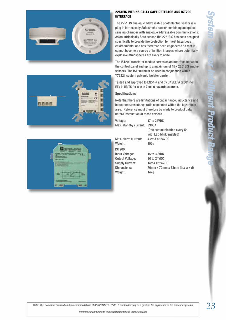
2251EIS INTRINSICALLY SAFE DETECTOR AND IST200 INTERFACE
The 2251EIS analogue addressable photoelectric sensor is a plug in Intrinsically Safe smoke sensor combining an optical sensing chamber with analogue addressable communications. As an Intrinsically Safe sensor, the 2251EIS has been designed specifically to provide fire protection for most hazardous environments, and has therefore been engineered so that it cannot become a source of ignition in areas where potentially explosive atmospheres are likely to arise.
The IST200 translator module serves as an interface between the control panel and up to a maximum of 15 x 2251EIS smoke sensors. The IST200 must be used in conjunction with a Y72221 custom galvanic isolator barrier.
Tested and approved to EN54-7 and by BASEEFA (2001) toEEx ia IIB T5 for use in Zone 0 hazardous areas.
Specifications
Note that there are limitations of capacitance, inductance and inductance/resistance ratio connected within the hazardous area. Reference must therefore be made to product data before installation of these devices.
Voltage: 17 to 24VDCMax. standby current: 330µA (One communication every 5s with LED blink enabled)Max. alarm current: 4.2mA at 24VDCWeight: 102g
IST200Input Voltage: 15 to 32VDCOutput Voltage: 20 to 24VDCSupply Current: 14mA at 24VDCDimensions: 70mm x 70mm x 32mm (h x w x d)Weight: 142g
System Sensor Intelligent Product Range

24 Note: This document is based on the recommendations of BS5839 Part 1: 2002. It is intended only as a guide to the application of fire detection systems.
Reference must be made to relevant national and local standards.
B500 SERIES BASES
A range of detector bases and accessories are available for use with Series 200 plus plug in detectors to suit the requirements of varying applications. All bases are 102mm in diameter.
B501 Standard Base:
For normal applications.
Height: 20mm Weight: 53g
B501DG Deep Base:
For use when cabling in surface mounted conduit.
Height: 26mm Weight: 57g
B524HTR Heater Base:
Includes an anti-condensation heater for use in cold applications where condensation may be expected. The B524HTR uses heater resistors to provide an element of heating to reduce condensation.
Height: 36mmWeight: 92gPower supply: Up to 125mA; up to 32VDCTemperature: -30°C to 60°C
B524RTE Relay Base:
Relay base which follows alarm status of detector, used to control external devices such as fire shutters.
Height: 36mmWeight: 100gContact Rating: 2A at 30VDC no/ncTemperature: -10°C to 60°C
B524IEFT-1 ISOLATOR BASE
The B524IEFT-1 isolator base monitors the loop on either side of the base, and if it detects a short circuit, it isolates that side. As a result, when used in conjunction with other isolator bases or modules, short circuits can be isolated from the remainder of the loop, thus minimising the effect of the fault. Once the short circuit is removed, the isolator will automatically restore the loop.
Height: 26mmOperating Temperature: -30°C to 70°C Standby Current: 100µAMax ON resistance: 0.2 Ohms at 24V
Syst
em S
enso
r In
telli
gent
Pro
duct
Ran
ge
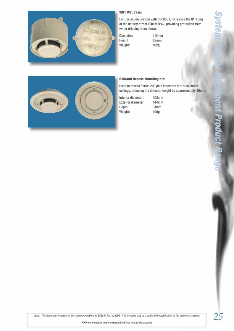
25Note: This document is based on the recommendations of BS5839 Part 1: 2002. It is intended only as a guide to the application of fire detection systems.
Reference must be made to relevant national and local standards.
System Sensor Intelligent Product Range
WB1 Wet Base:
For use in conjunction with the B501, increases the IP rating of the detector from IP40 to IP42, providing protection from water dripping from above.
Diameter: 110mmHeight: 69mmWeight: 102g
RMK400 Recess Mounting Kit:
Used to recess Series 200 plus detectors into suspended ceilings, reducing the detector height by approximately 20mm.
Interior diameter: 102mmExterior diameter: 144mmDepth: 31mmWeight: 100g

26 Note: This document is based on the recommendations of BS5839 Part 1: 2002. It is intended only as a guide to the application of fire detection systems.
Reference must be made to relevant national and local standards.
M200 SERIES MODULE RANGEINTRODUCTION
The family of input/output modules form part of System Sensor Europe’s Series 200 plus family. Single and multi-way models are available within the same mechanical package, reducing both the cost of installation and the mounting space required.
Their unique mechanical design allows each module to be mounted in either a wall box, on a DIN rail or within any type of enclosure. Irrespective of the mounting method chosen, the address switches and indicator LED’s are visible and accessible. To help engineers in the maintenance and fault-finding process, the LEDs, are multi-colour, providing diagnostic information regarding the status of each individual input/output.
Each module has built-in short circuit protection for the communications loop; however, to increase application flexibility, the isolators can be selected/deselected on an individual module basis.
For ease of installation, testing and maintenance, the field wiring terminals are of plug-in design.
Specifications
Operating Voltage: 15 to 30VDCOperating Temperature: -20C to 60°CHumidity Range: 0 to 95% Relative HumidityDimensions: 23mm x 93mm x 94mm (h x w x d) (including terminal block)Maximum Wire Gauge: 2.5mm²
M200-SMB Surface Mount Box Dimensions: 134mm x 139mm x 40mm (h x w x d)
Syst
em S
enso
r In
telli
gent
Pro
duct
Ran
ge
M200XE SHORT CIRCUIT ISOLATOR MODULE
The M200XE Isolator Module monitors the loop on either side of the module, and if it detects a short circuit will isolate that side. As a result, when used in conjunction with other isolator bases or modules, short circuits can be isolated from the remainder of the loop, thus minimising the effect of the fault. Once the short circuit is removed, the isolator will automatically restore the loop.
Specifications
Max standby current: 200µA at 24VDCMax ON resistance: 0.13 Ohms at 15V
M210E SINGLE CHANNEL INPUT MODULE, M220E DUAL CHANNEL INPUT MODULE AND M221E DUAL CHANNEL INPUT, SINGLE CHANNEL OUTPUT MODULE
The M210E and M220E provide supervision of one or two input circuits from external devices; the M221E also provides an un-monitored single pole volt-free changeover contact for external devices. Input channels are capable of both latched and analogue supervision: There are three separate latched states, normal, open circuit and combined alarm/short. The analogue supervision continuously monitors the supervised circuit, returning a signal proportional to the circuit resistance.
Specifications
M210EMax Standby current 310µA at 24VDC (No communications)M220EMax Standby Current: 340µA at 24VDC (No communications)M221EMax Standby Current: 340µA at 24VDC (No communications)Output Relay Rating: 2A at 30VDC, resistive load.

27Note: This document is based on the recommendations of BS5839 Part 1: 2002. It is intended only as a guide to the application of fire detection systems.
Reference must be made to relevant national and local standards.
System Sensor Intelligent Product Range
M201E OUTPUT MODULE
The M201E optionally supervises the wiring to the load devices and, upon command from the control panel, switches an external power supply to operate these devices. It also has built-in short circuit isolation capability. In normal supervised mode, the device switches out the load supervision and switches in the external power supply through a double pole relay. The external power supply is monitored and raises an unlatched fault condition if the voltage falls below the fixed threshold. In the unsupervised mode, the device provides neither load nor power supply supervision and can be used to switch a single form C set of changeover contacts.
A field selectable DIL switch allows the module to be used to fully meet the VdS 2489 requirements (subject to panel support). Note: selecting this option imposes an additional restriction on the load that can be switched.
Specifications
Max Standby Current: 310µA at 24VDC (No communications)Relay Contact Ratings: Unsupervised form C: 2A at 30VDC Supervised form C: 1.5A at 30VDC
M201E-240 AND M201E-240-DIN 240VAC RELAY MODULES
The M201E-240 is a loop-powered device controlling an unsupervised double pole (one normally open, one normally closed) output suitable for managing 240VAC loads. The output relay is a bi-stable device, latching in the on or off state on command from the control panel. The module is supplied in a wall-mounting box as standard with a grounding terminal provided.
The M201E-240-DIN has the same features and capabilities as the M201E-240 but is designed to mount directly on to a standard 35mm ‘Top Hat’ DIN rail. The module is supplied unboxed for installation in a suitable enclosure.
Specifications
Max Standby Current: 275µA at 24VDC (No communications)Relay Contact Ratings: 5A at 250VAC Temperature Range: -20C to 60°CHumidity Range: 0 to 95% Relative Humidity
M210E-CZ CONVENTIONAL ZONE MODULE
The M210E-CZ provides an interface between a zone of conventional detectors and an intelligent signalling loop. The module monitors the convention zone and transmits the zone state (normal, open or short fault and alarm) to the panel.
Specifications
Max Standby Current, externally powered zone: 288µA at 24VDC (No communications) 500µA at 24VDC (One communication every 5s) Max Standby Current, loop powered zone: 1.5mA at 24VDC (One communication every 5s)Max Current Available for Detectors: 1.5mA additional to above

28 Note: This document is based on the recommendations of BS5839 Part 1: 2002. It is intended only as a guide to the application of fire detection systems.
Reference must be made to relevant national and local standards.
Syst
em S
enso
r In
telli
gent
Pro
duct
Ran
ge 5. CALL POINTSKAC’s range of Call Points comprise indoor, outdoor and special environment products suitable for all applications. They are available in a variety of colour and marking options for a wide range of applications, including red for use in fire systems.
An extensive range of adaptor trays is available, allowing easy installation anywhere in the world.
The majority of the KAC product range is certified to EN54 Part 11, and other approvals are available.
INDOOR
KAC Indoor Call Points are available to satisfy all system types from conventional switch only manual systems, through to intelligent addressable systems.
Products are surface mounted using the fixings in the rear enclosure. The back-box is supplied punched with centres to assist drilling of cable entries.
Indoor products are generally rated at IP24D.
OUTDOOR
KAC Outdoor Call Points are available to satisfy all system types from conventional switch only manual systems, through to intelligent addressable systems.
Products are surface mounted using the fixings in the rear enclosure. The back-box is supplied punched with centres to assist drilling of cable entries.
Outdoor products are generally rated at IP55.
WATERPROOF
KAC Waterproof Call Points are available to satisfy all system types from conventional switch only manual systems, through to intelligent addressable systems. Waterproof products are rated at IP67.
Waterproof products for Marine Applications are certified with Lloyds Register.
Products of this type are available which are certified for use in Hazardous Areas.
SWITCHES
KAC Call Point Switching Devices provide alternative methods of manual activation of systems, rather than the traditional break glass principle. There are both indoor and outdoor models available in the familiar KAC housings.
A variety of different colours and switch types can be chosen, key-switches and push buttons being the most popular. There is also a large choice of text markings to identify the purpose of the device.
ACCESSORIES
An extensive range of accessories supports KAC calls points, including a number of mounting accessories, allowing easy installation throughout the world.
More information about call points and their accessories is available on the KAC website.

29Note: This document is based on the recommendations of BS5839 Part 1: 2002. It is intended only as a guide to the application of fire detection systems.
Reference must be made to relevant national and local standards.
System Sensor Intelligent Product Range
6. AUDIO VISUAL PRODUCTSKAC Sounders and Strobes from simple tone set conventional products to fully featured fourteen-tone intelligent units, a range of sounders, strobes and combined sounder-strobe products suitable for all applications.
The range meets the requirements of EN54 Part 3; key products are LPCB and VdS Approved. All are fully tested under simulated climatic conditions to ensure “real-world” conformance to the published specifications.
SOUNDERS
KAC Sounders are available in four or fourteen-tone versions. They operate at 9-33VDC, optimised for use at 12 and 24 volts. Four tone sounders have a high, medium and low volume selection, whilst the fourteen tone sounder has a volume control.
The sounders have a distinctive, acoustically efficient low profile shape, producing high sound output at low current levels. The shape provides a wide-angle uniform sound distribution providing good audibility in all directions.
The sounders are of rugged construction with solid-state electronics providing high reliability and stable performance. Three bases are available: low profile IP44, IP55 or IP66.
DETECTOR BASE SOUNDERS
KAC Detector Base Sounders are for use either underneath smoke detectors or fitted with a red or white lid as a low profile wall mounted sounder. They are available in four or fourteen tone versions. They operate at 9-33VDC (nominally 12 and 24 volt). Four tone sounders have a high, medium and low volume selection, whilst the fourteen tone sounder has a volume control.
The package is acoustically very efficient, producing omni-directional high sound output with low current levels. The detector base sounder can be used under any smoke detector with 60mm mounting centres and an external diameter of up to 102mm.
STROBES
The KAC Range of stand-alone Strobes is designed to provide visual signalling for use in a wide range of applications. There are both standard and high intensity output strobes available. A variety of different coloured strobe lenses are available. This variety of colours provides a range of products for different applications.
SOUNDER STROBES
The KAC Sounder Strobe combines a full feature fourteen-tone sounder with an integral strobe mounted on the horn. The design provides an efficient combination of audible and visual warning, in a package taking up no more surface area than a standard sounder.
A variety of different coloured strobe lenses are available and the product housing is available in either red or white.
BASES
Three bases are available for KAC Sounders and Sounder Strobes. The standard base is an IP44 rated low profile unit. The base has rear and side cable access suitable for use with standard trunking and has mounting holes suitable for the
majority of back box formats.
A deeper profile base with knockouts and marked drilling positions for rear and side entry allows for an IP55 rating, when used with appropriate glands.
The IP66 base has the same features as the IP55, but includes a sealing kit to increase the protection rating.

30 Note: This document is based on the recommendations of BS5839 Part 1: 2002. It is intended only as a guide to the application of fire detection systems.
Reference must be made to relevant national and local standards.
Syst
em S
enso
r In
telli
gent
Pro
duct
Ran
ge 7. OTHER INFORMATION7.1. STANDARDS
To ensure that a fire alarm system provides adequate protection, it is advisable to ensure that it meets all relevant standards. The system should be designed in accordance with relevant national and local standards. Useful standards and references include:
British Standard Code of Practice for fire detection systems BS 5839 part 1: 2002
European Standard for Fire Detection and Alarm Systems:
Control and Indicating Equipment BS EN54 part 2: 1998
SoundersBS EN54 part 3: 2001
Point Heat DetectorsBS EN54 part 5: 2001
Point Smoke DetectorsBS EN54 part 7: 2001
Manual Call PointsBS EN54 part 11: 2001
Optical Beam Detectors
BS EN54 part 12: 2002
These are all available from:
British Standards Institution389 Chiswick High RoadLondonW4 4AL

31Note: This document is based on the recommendations of BS5839 Part 1: 2002. It is intended only as a guide to the application of fire detection systems.
Reference must be made to relevant national and local standards.
Other Information
7.2. APPROVAL BODIES FOR FIRE DETECTION PRODUCTS
All components of the fire alarm system should be certified to a European standard by an independent certification body that specialise in the certification of fire and security systems. These include:
BRE - LPCBBuilding 3, Bucknalls Lane, Garston, Watford, WD25 9XX, EnglandTel: (+44) (0) 1923 66400
VdS Amsterdamerstrasse 174, 50732 Köln, GermanyTel: +49 221 77 66 00
ANPIParc Scientific Fleming, 1348 Louvain-la Neuve Sud, BelgiumTel: +32 10 47 52 73
CNMIS16 Avenue Hoch, 75008 Paris, FranceTel: +33 1 53 89 00 40
DIFTJernholmen 12, DK-2650 Hvidovre, DenmarkTel: +45 36 349 000

SYSTEM SENSOR EUROPE15 – 19 Trescott Road
Trafford ParkSmallwoodRedditchB98 7AH
United Kingdom
Telephone: + 44 (0)1527 406700Fax: + 44 (0)1527 406699
ITALYSystem Sensor EuropeVia Caboto 19/334147 TriesteItaly
Telephone: + 39 040 9490111Fax: + 39 040 382137
INDIASystem Sensor India
Pace city 2, Sector 36Gurgaon -122004
Haryana, India
Telephone: + 91 124 6371770Fax: + 91 124 6373118
WORLD HEADQUARTERSSystem Sensor
3825 Ohio AvenueSt. Charles
IL-60174United States of America
Telephone: + 1 630 377 6580Fax: + 1 630 377 6495
manufacturing and support centres
November 2004
Other operations in Australia, Canada, China, Hong Kong, Mexico and United States of America
Advanced ideas. Advanced Solutions
RUSSIASystem Sensor Fire DetectorsVolochaevskaya Str 40, Bld 2
Moscow 109033Russia
Telephone: + 7 (095) 937-7982Fax: + 7 (095) 937-7983