Embed Size (px)
Citation preview

Patrick R. Badgley, Michael R. Smith, and Cedric O. GouldAdvanced Technologies, Inc., Starkville, Mississippi
System Study for Axial Vane Engine Technology
NASA/CR—2008-215175
July 2008
https://ntrs.nasa.gov/search.jsp?R=20080032599 2018-05-26T21:50:29+00:00Z

NASA STI Program . . . in Profi le
Since its founding, NASA has been dedicated to the advancement of aeronautics and space science. The NASA Scientifi c and Technical Information (STI) program plays a key part in helping NASA maintain this important role.
The NASA STI Program operates under the auspices of the Agency Chief Information Offi cer. It collects, organizes, provides for archiving, and disseminates NASA’s STI. The NASA STI program provides access to the NASA Aeronautics and Space Database and its public interface, the NASA Technical Reports Server, thus providing one of the largest collections of aeronautical and space science STI in the world. Results are published in both non-NASA channels and by NASA in the NASA STI Report Series, which includes the following report types: • TECHNICAL PUBLICATION. Reports of
completed research or a major signifi cant phase of research that present the results of NASA programs and include extensive data or theoretical analysis. Includes compilations of signifi cant scientifi c and technical data and information deemed to be of continuing reference value. NASA counterpart of peer-reviewed formal professional papers but has less stringent limitations on manuscript length and extent of graphic presentations.
• TECHNICAL MEMORANDUM. Scientifi c
and technical fi ndings that are preliminary or of specialized interest, e.g., quick release reports, working papers, and bibliographies that contain minimal annotation. Does not contain extensive analysis.
• CONTRACTOR REPORT. Scientifi c and
technical fi ndings by NASA-sponsored contractors and grantees.
• CONFERENCE PUBLICATION. Collected
papers from scientifi c and technical conferences, symposia, seminars, or other meetings sponsored or cosponsored by NASA.
• SPECIAL PUBLICATION. Scientifi c,
technical, or historical information from NASA programs, projects, and missions, often concerned with subjects having substantial public interest.
• TECHNICAL TRANSLATION. English-
language translations of foreign scientifi c and technical material pertinent to NASA’s mission.
Specialized services also include creating custom thesauri, building customized databases, organizing and publishing research results.
For more information about the NASA STI program, see the following:
• Access the NASA STI program home page at http://www.sti.nasa.gov
• E-mail your question via the Internet to help@
sti.nasa.gov • Fax your question to the NASA STI Help Desk
at 301–621–0134 • Telephone the NASA STI Help Desk at 301–621–0390 • Write to:
NASA Center for AeroSpace Information (CASI) 7115 Standard Drive Hanover, MD 21076–1320

Patrick R. Badgley, Michael R. Smith, and Cedric O. GouldAdvanced Technologies, Inc., Starkville, Mississippi
System Study for Axial Vane Engine Technology
NASA/CR—2008-215175
July 2008
National Aeronautics andSpace Administration
Glenn Research CenterCleveland, Ohio 44135
Prepared under Cooperative Agreement NNC–04VN19P

Available from
NASA Center for Aerospace Information7115 Standard DriveHanover, MD 21076–1320
National Technical Information Service5285 Port Royal RoadSpringfi eld, VA 22161
Available electronically at http://gltrs.grc.nasa.gov
Trade names and trademarks are used in this report for identifi cation only. Their usage does not constitute an offi cial endorsement, either expressed or implied, by the National Aeronautics and
Space Administration.
This work was sponsored by the Fundamental Aeronautics Program at the NASA Glenn Research Center.
Level of Review: This material has been technically reviewed by NASA technical management.
This report contains preliminary fi ndings, subject to revision as analysis proceeds.

NASA/CR—2008-215175 iii
Contents 1.0 Introduction ............................................................................................................................. 1 2.0 Description of Axial Vane Mechanism .................................................................................... 2 3.0 Design of Axial Vane Diesel Cycle Engine ............................................................................ 4
3.1 Description of the Axial Vane Rotary Diesel Cycle Engine .............................................. 4 3.2 Diesel Cycle Modeling...................................................................................................... 4
3.2.1 Design of Axial Vane Diesel Engines at Sea Level Conditions................................ 5 3.2.2 PAX 50 Diesel Core Engine at Sea Level Conditions .............................................. 8 3.2.3 PAX 150 Diesel Core Engine at Sea Level Conditions .......................................... 12
3.3 Evaluation of Axial Versus Radial Intake and Exhaust Porting on Rotary Devices........ 15 3.4 Design of Diesel Core Engine Using Turbofan Pressure Boost...................................... 17 3.5 Minimum Size PAX 50 and PAX 150 Engines with Fan Boosted Pressure .................... 20
4.0 Design of Axial Vane Hybrid Turbine Engine........................................................................ 23 4.1 Compressor for Hybrid Turbine Engine........................................................................... 24
4.1.1 Modeling Hybrid Compressors............................................................................... 24 4.1.2 Design of Compressors for Hybrid Turbine Engine................................................ 24
4.2 Expanders for Hybrid Turbine Engines ........................................................................... 27 4.2.1 Modeling the Hybrid Expanders for Hybrid Turbine Engines ................................. 28 4.2.2 Design of Hybrid Expanders for Hybrid Turbine Engines....................................... 29 4.2.3 Discussion of PAX 50 Expander and PAX 150 Expander...................................... 32
4.3 Thermodynamic Model of Hybrid Turbine Engine........................................................... 32 5.0 Summary and Conclusion....................................................................................................34
5.1 Comparison of PAX 50 Engines...................................................................................... 34 5.2 Comparison of PAX 150 Engines.................................................................................... 34 5.3 General Comments ......................................................................................................... 34 5.4 Recommendations for Future Work ................................................................................ 36 5.5 Materials.......................................................................................................................... 36 5.6 Tribology ......................................................................................................................... 36
Reference ................................................................................................................................... 36 Appendix A—Baseline PAX 50 and PAX 150 Turbofan Specifications ....................................A–1 Appendix B—Instruction Manual for Axial Vane Mechanism Design Program Version 2.0..... B–iii INSTRUCTION MANUAL .........................................................................................................B–1


NASA/CR—2008-215175 v
List of figures Figure 1.—Cut-away of typical axial vane rotary device. ..............................................................2 Figure 2.—Cut-away of ATI winged rotor axial vane device. ........................................................3 Figure 3.—Schematic of axial vane rotary diesel engine..............................................................4 Figure 4.—AV-PDG analysis for PAX 50 diesel engine analysis. (Note: BMEP = 138.34 psi.) ....6 Figure 5.—AV-PDQ analysis for PAX 150 diesel engine. (Note: BMEP = 145.13 psi.) ................6 Figure 6.—Preliminary analysis of the effect of engine rotor diameter and BMEP on power
output at sea level conditions. .....................................................................................7 Figure 7.—Cross-section of PAX 50 engine with 3-rotor diesel core engine. ...............................8 Figure 8.—Performance analysis for PAX 50 rotary diesel core engine.......................................9 Figure 9.—Exploded view of axial vane rotary diesel engine. ....................................................10 Figure 10.—Transparent model of PAX 50 engine with 3-rotor diesel core engine. ...................10 Figure 11.—Rendering of the PAX 50 engine with a 3-rotor diesel core engine.........................11 Figure 12.—Cross-section of PAX 150 engine with diesel core engine......................................12 Figure 13.—Performance analysis for PAX 150 rotary diesel core engine.................................13 Figure 14.—Rendering of PAX 150 engine with 2-rotor diesel core engine. ..............................14 Figure 15.—Example of radial intake and exhaust ports on diesel engine. ................................15 Figure 16.—Cross-section PAX 150 diesel core engine with radial porting................................16 Figure 17.—Solid model of PAX 150 diesel core engine with radial porting. ..............................16 Figure 18.—Performance analysis of PAX 50 diesel engine with fan boost pressure. ...............18 Figure 19.—Performance analysis for PAX 150 diesel core engine with fan boost. ...................19 Figure 20.—Minimum size PAX 50 diesel engine with fan boost to meet specifications. ...........21 Figure 21.—Minimum size PAX150 diesel engine with fan boost to meet specifications. ..........22 Figure 22.—Schematic of hybrid turbine engine with axial vane compressors and expanders. .23 Figure 23.—Model of axial vane compressor and expander with axial intake
and exhaust ports...................................................................................................23 Figure 24.—Schematic of axial vane compressor cycle. ............................................................24 Figure 25.—Summary of compressor design for PAX 50 hybrid turbine engine ........................25 Figure 26.—Summary of compressor design for PAX 150 hybrid turbine engine.......................26 Figure 27.—Exploded view of typical axial vane compressor. ....................................................27 Figure 28.—Schematic of axial vane expander. .........................................................................27 Figure 29.—Exploded view of axial vane expander....................................................................28 Figure 30.—Sectioned compressor or expander showing split-vanes and ports. .........................28 Figure 31.—Paired compressor and expander with space for burner between units. ................29 Figure 32.—Performance analysis of PAX 50 expander for hybrid turbine engine.....................30 Figure 33.—Performance analysis of PAX 150 expander for hybrid turbine engine...................31 Figure 34.—Solid model of PAX 50 axial vane hybrid engine assembly. ...................................32 Figure 35.—Solid model of PAX 50 axial vane hybrid engine assembly. ...................................32 Appendix A figures Figure 1–1.—Specifications for PAX 50 baseline 8,132 BHP turbofan engine.............................1 Figure 2–1.—Specifications for PAX 150 baseline 23,664 BHP turbofan engine. ........................2 Appendix B figures Figure 1–1.—Illustration of typical axial vane mechanism. ...........................................................2 Figure 2–1.—Cutaway of ATI winged rotor axial vane mechanism. .............................................3 Figure 3–1.—Components of ATI “Winged Rotor” axial-vane mechanism. ..................................4 Figure 5.1–1.—Sample of INPUT SECTION of Axial-Vane Design Program...............................7 Figure 7.1.1-1.—Vane Pressure Differential versus Vane Travel ...............................................20 Figure 7.1.1-2.—Vane Bending Stress versus Vane Travel .......................................................21

NASA/CR—2008-215175 vi
Figure 7.1.1-3.—Vane Bending Stress vs. Vane Thickness and Vane Stroke ...........................22 Figure 7.1.2-1.—Estimated Vane Stroke vs. Brake Horsepower................................................23 Figure 7.1.3-1.—Estimated Vane Height versus Brake Horsepower..........................................24 Figure 7.1.7-1.—Rotor Outer Diameter versus Power................................................................25 Figure 7.1.12-1 Estimated Chamber Minimum Volume versus Power .......................................26 Figure 8–1.—Sample of PRINTOUT from Axial-Vane Design Program .....................................30
List of tables Table 1.—Weight Estimate and Bill of Materials for PAX 50 Diesel Core Engine .....................11 Table 2.—Weight Estimate and Bill of Materials and for PAX 50 & PAX 150 Diesel Engines...14 Table 3.—Comparison of Engine Performance at Sea-Level versus Fan Boosted Pressure....17 Table 4.—Comparison of Minimum-Size Boosted Engine with Sea-Level Engines ...................20 Table 5.—Weight Schedule for PAX 50 and PAX 150 Compressors and Expanders ................29 Table 6.—Engine Cycle Analysis for Hybrid and Turbomachine Engines ..................................33 Table 7.—Comparison of Performance and Weight of Analyzed Engine Configurations ...........35
NASA/CR—2008-215175 1
System Study for Axial Vane Engine Technology
Patrick R. Badgley, Michael R. Smith, and Cedric O. Gould Advanced Technologies, Inc. Starkville, Mississippi 39760
1.0 Introduction The purpose of this engine feasibility study was to determine the benefits that can be
achieved by incorporating positive displacement axial vane compression and expansion stages into high bypass turbofan engines. These positive-displacement stages would replace some or all of the conventional compressor and turbine stages in the turbine engine, but not the fan. The study considered combustion occurring internal to an axial vane component (i.e., Diesel engine replacing the standard turbine engine combustor, burner, and turbine); and an axial vane compressor and axial vane turbine replacing conventional turbine engine inline continuous flow combustors.
Advanced Technologies Inc. (ATI) examined two engine sizes; a 10,000 lb Sea-Level-Static (SLS) thrust class engine and a 25,000 lb SLS thrust class engine. These Baseline Engines (appendix A) are referred to as the PAX 50 and PAX 150 engines respectively. The 10,000 lb thrust class engine was examined with both a conventional turbine engine combustor and within-vane-component-combustion. The 25,000 lb thrust class engine was examined with a conventional turbine engine combustor. NASA provided ATI with the turbofan engine data generated by the NPSS cycle analysis code for each baseline turbofan engine. All initial analyses were conducted for standard sea level conditions as specified in the contract. The final analyses were performed at engine inlet pressures equal to fan downstream pressures.
ATI developed thermodynamic analytical and mechanical models of axial vane compressors, expanders and internal axial vane combustion systems appropriate for the engines analyzed in this effort. The thermodynamic model accounts for inlet losses, exhaust losses and other flow pressure losses, heat losses, friction losses, and internal leakage losses. ATI has provided NASA with the thermodynamic analytic models (analytic descriptions, computational flow charts and input/output parameters) for the compressor, expander and internal axial vane combustion system in a form suitable for translating the analytic model into computer code that will interface with the NPSS code. The analytic models provide for output of pressures, temperatures, and velocity profiles at different locations in each device. Using the thermodynamic analytic models provided by ATI, NASA can code the thermodynamic computational component models that interface with the NPSS cycle analysis code. The mechanical model of each configuration consists of a three-dimensional drawing of the converged component, a listing of weight values, and a bill of material listing the component’s materials and specifications.
ATI performed analysis of axial vane turbine hybrid engine cycles in each thrust class using the NPSS data and the AV-Design Program developed by ATI. A series of different engine configurations at different operating conditions were analyzed and modeled to yield an optimized engine to match the sea-level thrust ratings of each baseline turbofan engine. Solid models and engine weights were generated for each of the optimized engines. The results of this feasibility study revealed slight specific weight advantages for the axial vane components in turbofan engines, but significant specific fuel consumption advantages for the Diesel engine and hybrid engine using axial vane technology.

NASA/CR—2008-215175 2
2.0 Description of Axial Vane Mechanism A simplified cut-away model of an axial vane machine is shown in figure 1. The axial vane
mechanism is unique in that a multiplicity of straight vanes, contained in a cylindrical rotor, travel parallel to the axis of rotation and compress or expand fluids in the same manner as reciprocating piston mechanisms. Since the vanes move parallel to the axis of rotation, the mechanism is always dynamically balanced and there are minimum energy losses due to reciprocating motion and accelerations typical of piston mechanisms.
The vanes in the axial vane mechanism, shown in figure 1, follow the cam surfaces in the end housings, alternately compressing and/or expanding fluids depending upon the application of the mechanism. In this particular mechanism, the exterior portion of the vane at the outer edge of the rotor travels on the exterior housing such that both the axial motion of the vane and the rotational motion of the rotor create friction. The resultant rubbing velocity limits the maximum rotational speed of the mechanism due to limitations on the rubbing velocity of the vane/housing and/or the vane/rotor materials. In addition, leakage of compressed fluids can occur at the tip of the vanes and along both the top (exterior) and bottom (interior) edges of the vanes.
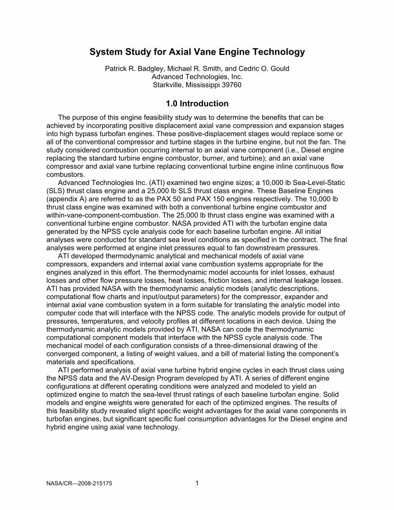
The “Winged Rotor” concept developed by ATI eliminates or greatly minimizes leakage along the top and bottom of the vanes and de-couples the vane rubbing velocity from the effects of rotational speed. An illustration of the ATI Winged Rotor Concept (Patent Pending) is shown in figure 2. In the Winged Rotor device a cylindrical sleeve is attached to the outer periphery of the rotor and grooves in the sleeve and a similar “Wing” on the main shaft minimize leakage
Figure 1.—Cut-away of typical axial vane rotary device.
NASA/CR—2008-215175 3
over the top and under the bottom of the vane. A major advantage of the Winged Rotor Concept is that it decouples the vanes from the rubbing velocity caused by rotation of the rotor and permits much higher rotational speeds that yield much higher specific power density. The maximum allowable rubbing velocity between the vanes and rotor or the vanes and outer sleeve determines the limiting rotational speed of the ATI Winged Rotor device. The decoupling of the vanes from the rotational rubbing velocity permits the maximum rotational speed to be increased by about five-fold in engine applications. More detailed explanations of the construction and operation of the ATI Axial Vane Engine and AV-components are provided in appendix B.
The higher rotational speeds made possible with the ATI Winged Rotor Mechanism permit the design of weight sensitive devices with significantly increased specific power density. This feature is especially important in weight-critical aviation applications such as compressors, expanders, or Diesel engines. The design programs discussed in the instruction manual (appendix B) and in the design programs are based on utilization of the ATI Winged Rotor Concept to minimize friction losses, leakage, heat losses, and installed weight and to maximize power density, reliability, and life of the engine/device. These analysis and design programs were used in this feasibility study to analyze the performance of the various axial vane devices.
Figure 2.—Cut-away of ATI winged rotor axial vane device.

NASA/CR—2008-215175 4
3.0 Design of Axial Vane Diesel Cycle Engine 3.1 Description of the Axial Vane Rotary Diesel Cycle Engine
A schematic of a twelve-vane rotary Diesel engine showing the cylindrical outer diameter surface of the rotor unwrapped onto a plane surface is shown in figure 3. The vanes are shown in their slots in the moving rotor. The fixed pin track is shown in the outer housing. The combustion clearance volumes are shown schematically by the two parallel lines on the face of the rotor and are better seen as the pockets on the face of the rotor in figure 1.
The main and auxiliary intake ports are used to effect the Miller cycle. When the auxiliary intake port is kept closed, the intake is shut off early in the cycle before the chamber achieves maximum volume. This lowers the effective compression ratio while leaving the expansion ratio unchanged. There are twelve chambers on each side of the diesel engine for a total of 24 chambers. The standard four-stroke cycle is completed in each chamber every engine revolution which gives the engine twenty-four widely overlapping power strokes per revolution. Each chamber is 30° wide and the power stroke occurs over 60°. This is equivalent to a four-stroke reciprocating engine with 48 cylinders. The engine torque and exhaust flow are almost steady which results in the low noise levels of the engine.
The ATI Axial Vane Rotary Diesel Engine employs a true compression ignition diesel cycle running at an extremely lean fuel/air ratio and compression ratios of 15:1 or higher. The engine utilizes continuous fuel injection and extended duration combustion. Both of these concepts are unique to this engine design and account for the extraordinary thermal efficiency. This cycle also approximates constant volume combustion, which has been a goal in internal combustion engines since Sadi Carnot first identified the constant volume cycle as having the highest possible theoretical efficiency.
3.2 Diesel Cycle Modeling
The first task in this project was to develop a cycle simulation for the Axial Vane Diesel Engine. It was decided that a “Spreadsheet” type simulation would be written to include the effects of leakage, combustion, and heat transfer using physical geometry, cam shape and ambient conditions as inputs. To provide additional background on the operation of the axial
Figure 3.—Schematic of axial vane rotary diesel engine.

NASA/CR—2008-215175 5
vane devices, the simulation tools, and to make it easy to select inputs, an “Instruction Manual for Axial Vane Mechanism Design Program” was prepared and is attached as appendix B to this report. This simulation tool was used to design Diesel engines suitable of serving as core engines for the PAX 50 and PAX 150 turbofan engines. A sample run for a Diesel engine is included in the "Instruction Manual" (appendix B) along with details of how the computational model was constructed and the detailed printout for each 1° of rotation of the engine. Due to the large size of the spreadsheet program (24 letter-size sheets), a Summary Sheet was included in the program to document all program inputs and the results of the engine sizing analysis. A printout of the Summary Sheet is obtained by selecting sheet "2 PRINOUT” of the spreadsheet and printing out the displayed information.
3.2.1 Design of Axial Vane Diesel Engines at Sea Level Conditions
The axial vane design program was used to design axial vane Diesel engines with the same fan power as the current baseline PAX 50 and PAX 150 high bypass ratio turbofan engines at sea level conditions. To assure these designs were conservative; it was assumed the leakage flow was always sonic despite the fact that for a large portion of the cycle time the pressure ratio would have warranted a lower leakage flow rate. Also, the wall temperature for the heat transfer was fixed at 500 °R. This assumption results in heat transfer losses that are higher than they would have been if higher wall temperatures had been used and results in a conservative estimate of net power output. The major constraint on the engine designs was to maintain the existing turbofan nacelle size. This limited the rotor diameter of the PAX 50 Diesel Core Engines to 20 in. and the PAX 150 engines to 40 in.
Axial Vane PDQ, a “Microsoft Visual Basic” program developed by ATI, was used to identify possible engine configurations that would meet the above constraints. The AV-PDQ Program is based on thermodynamic analysis and does not include the effects of friction, leakage, or cooling losses. However, the program is useful for quickly conducting preliminary analyses of multiple configurations that may meet the design constraints. The AV-PDQ program can be used for sizing axial vane Diesel engines, compressors or expanders.
The AV-PDQ program was used in a preliminary analysis of rotary Diesel engine configurations that could be candidates for use in the PAX 50 and PAX 150 engines. This analysis was run to determine the effect of engine rotor diameter and BMEP on the power output of various size rotary diesel units. Examples of the output from the AV-PDQ Program are shown in figures 4 and 5 for the PAX 50 and PAX 150 engines. The results of this preliminary analysis are presented in figure 6. The specifications for the baseline PAX 50 and PAX 150 turbofan engines are listed in the table. In this analysis engine RPM is limited by the maximum rubbing velocity of the vanes on the wings of the rotor and assuming the use of conventional materials for the vane and the wings. The Vane Velocity shown in the output from the AV-PDQ Program is based on the assumption the vanes are running on the cam surface and the resultant velocity is the vectorial sum of the rotor peripheral velocity and the vane transverse velocity. The use of low-friction coatings and/or thermal barrier coatings could increase the operating speed substantially.
The range of BMEP analyzed varied from 100 psi to 300 psi. Based on prior experience, it was estimated that BMEP of 140 to 170 could be obtained in a normally aspirated AV-Diesel Engine and that turbocharging or super charging will be required to obtain pressures in the 200 to 300 psi range. At the outset of this study, it was anticipated that multiple diesel engine units would likely be required to produce the required power while keeping the engine diameter within the prescribed limits. The maximum rotor diameter was limited to about 80 percent of the diameter of the Low Pressure Compressor (LPC) in the turbofan engine to provide space for induction and exhaust manifolds along the sides of the engines.

NASA/CR—2008-215175 6
Using a conservative 140 BMEP, there appear to be two potential engine configurations that could be candidate configurations for the PAX 50 and PAX 150 Diesel engines. For the PAX-50 engine, a 20 in. and a 25 in. rotor diameter could provide the required 8200 BHP by using three 20-in.-diameter rotor engine units or two 25 in. units. Since the 25 in. diameter exceeds 80 percent of the LPC diameter, the 20-in. diameter unit was selected for further analysis using the AV-Design Program. Similarly, the 40-in. diameter engine unit was selected for further analysis for the PAX 150 core engine.
Figure 4.—AV-PDG analysis for PAX 50 diesel engine analysis. (Note: BMEP = 138.34 psi.)
Figure 5.—AV-PDQ analysis for PAX 150 diesel engine. (Note: BMEP = 145.13 psi.)

NASA/CR—2008-215175 7
Figure 6.—Preliminary analysis of the effect of engine rotor diameter and BMEP on power output at sea level conditions.
Axi
al-V
ane
Die
sel E
ngin
e A
naly
sis
usin
g A
V-PD
Q P
rogr
amA
V-P
DQ
, Ver
sion
#5,
050
531
Per
form
ed B
y: M
ike
Sm
ith16
-Jun
-05
Pur
pose
of A
nal y
sis:
To
Det
erm
ine
the
Effe
ct o
f Eng
ine
Rot
or D
iam
eter
& B
ME
P o
n P
ower
Out
put
at S
ea L
evel
Con
ditio
ns
Estim
ated
Bra
ke H
orse
pow
er N
ASA
GR
C S
PEC
S FO
R P
AX B
ASEL
INE
ENG
INES
Rot
or D
iam
eter
RPM
BM
EP =
100
BM
EP =
140
BM
EP =
170
BM
EP =
200
BM
EP =
300
PAX
50 E
quiv
.PA
X 15
0 Eq
uiv.
inch
es8,
200
BH
P23
,700
BH
P
Fan
& L
PT =
18,
000
RPM
Fan
& L
PT
= 14
,500
RP
M3
33,3
0067
81H
PC
& H
PT
= 7,
000
RPM
HP
Com
p.&
HP
T =
5,38
05
20,0
0015
426
5Fa
n M
ax. D
ia =
38.
5 in
.Fa
n M
ax.D
ia. =
68.
3 in
.10
10,0
0077
01,
055
Max
.Eng
.Len
gth
= 10
9 in
M
ax.E
ng.L
engt
h =
170.
9 in
.15
6,67
01,
030
P
OTE
NTI
AL E
NG
INE
CO
NFI
GU
RAT
ION
S @
BM
EP=1
42
205,
000
3,02
44,
260
3 - 2
0" O
D x
15.
4" L
ong
25
4,00
04,
779
2 - 2
5" O
D x
18.
8" L
ong
303,
330
4,77
96,
786
7,12
49,
558
14,3
374
- 30"
OD
x 2
2" L
ong
352,
860
9,26
51
- 35"
OD
x 2
5.4"
Lon
g,3
- 35"
OD
x 2
5.4"
Lon
g40
2,50
012
,059
17,0
132
- 40"
OD
x 2
8.8"
Lon
g45
2,22
015
,269
502,
000
13,2
9819
,004
22,6
0726
,597
39,8
9655
1,82
022
,910
601,
670
27,2
2638
,347
Max
. LPC
Dia
. = 2
4 in
. M
ax. L
PC D
ia. =
45
in.
To b
e co
nsid
ered
as
a Po
tent
ial P
AX E
ngin
e C
onfig
urat
ion
Lig
ht B
lue
indi
cate
s po
tent
ial P
AX 5
0 en
gine
con
figur
atio
n.M
ax. R
otor
OD
mus
t be
= or
< 0
.80
Max
.LPC
.Dia
. on
Spe
c D
wg.
Lig
ht O
rang
e in
dica
tes
pote
ntia
l PAX
150
eng
ine
conf
igur
atio
n.

NASA/CR—2008-215175 8
3.2.2 PAX 50 Diesel Core Engine at Sea Level Conditions
The AV-Design Program was used to compute the performance of the Diesel engines to be used as the core engine for the PAX 50 Engine. The results of the final analysis are presented in figure 8 for a normally aspirated engine at sea level conditions. To meet the by-pass fan power requirement for 8132 hp, it was necessary to use three diesel units producing 2764 hp each and a total of 8293 hp. The engine rotor diameter of 20-in. resulted in a unit engine length of 15-in. A cross-section drawing of the PAX 50 engine with the three Diesel units is shown in figure 7.
Solid models of the components of the PAX 50 engine were constructed and assembled into a single rotor power module and into the complete three rotor core engine. An exploded view of a typical diesel engine module is shown in figure 9.
The single Diesel engine illustrated in figure 9 employs a slot-and-rail system of driving the vanes so the vanes do not actually rub on the cam surface. The green track incorporates an internal rail that has the same geometry as the cam surface while each vane has a slot that rides on an internal rail. The purpose of the slot-and-rail feature is to assure the vane tips do not rub on the cam surfaces that may be coated with thermal barrier materials or cause wear or galling of the cam surface. The wing components attach to the periphery of the rotor and extend over the cams to minimize gas leakage. The end cams attach to the outer housing to produce a leak-proof outer seal.
The assembly of the three Diesel engine units for the PAX 50 core engine is presented in figure 10. The three engines are mounted on a single splined shaft and the fan or gear box will mount to the extended shaft. The intake ports and exhaust ports are shown in the ends of the cams. Induction and exhaust ducts will be required to connect the engines axial ports. The space allocated between the engine units should provide space for the required ducts and accessories can be mounted on the rear unit.
A rendering of the three rotor core engine installed in the PAX 50 nacelle is shown as figure 11. A weight schedule and bill-of-materials for the engine is shown in table 1 including weights for each component and the assembly. For the weight estimate, it was assumed that the entire engine would be constructed of titanium alloys. It should be noted that no attempt has been made to weight reduce any of the components. This along with the fact that the final engine would likely incorporate ceramic and ceramic composite components means that the included weight estimate is conservative.
Figure 7.—Cross-section of PAX 50 engine with 3-rotor diesel core engine.

NASA/CR—2008-215175 9
SUMMARY OF PERFORMANCE ANALYSIS
DESIGN PROGRAM FOR AXIAL VANE MACHINESDeveloped by Advanced Technologies Inc.
March 2005
8,200 Horsepower 3 Rotor Diesel Engine {Title of Design: From Sheet 1 AV DESIGN)
PARAMETER VALUE COMMENTS & NOTES
PHYSICAL DIMENSIONS & DESIGN VARIABLESNUMBER OF VANES 12 12-Vane Diesel EngineNUMBER OF CAMS 2
ANGLE BETWEEN VANES 30VANE THICKNESS (inches) 0.50 Estimated = 0.10 x Vane Stroke
VANE STROKE (inches) 3.30 Estimated from Chart: Vane Stroke vs. BHPVANE HEIGHT (inches) 6.70 Estimated as 2 x Vane StrokeLIFT ANGLE (degrees) 75
DWELL ANGLE (degrees) 15EVENT ANGLE (degrees) 90
ROTOR OUTER DIAMETER (inches) 20.00 Estimated based on Chart: OD vs. BHPROTOR INNER DIAMETER (inches) 6.60 Estimated = OD -2 Vane Height ROTOR MEAN DIAMETER (inches) 13.30
INPUT DESIGN VALUESSPEED (RPM) 5,000 Limited by Vane Rubbing Velocity
OMEGA (radians/sec) 524
ROTOR CLEARANCE (inches) 0.005 Minimum clearance between Rotor & CamTIP CLEARANCE (inches) 0.005 Clearance between Vane Tip and Cam
DIAMETRAL CLEARANCE (inches) 0.010 Total radial clearance between vane & Inner & Outer Wings
INITIAL PRESSURE (psia) 14.70 Inlet PressureINITIAL TEMPERATURE (deg R) 530.00 Inlet Temperature
Gas Constant, R = 53.30Ratio of Specific Heat, k = 1.3937
HEAT VALUE (BTU/lb) 18,600EFFECTIVE HEAT VALUE (BTU/lb) 15,711 Computed in Cell FB6 based on cooling Heat Loss that
FUEL/AIR RATIO 0.0390 varies with Chamber Pressure & Temperature.AIR/FUEL RATIO 25.64
COMPUTED VALUESDISLACEMENT/CHAMBER (cu. in.) 65.94 Adjust Displacement/Chamber to change Comp. Ratio
POCKET VOLUME (cu.in.) 4.88 Pocket Volume is automatically adjusted when Disp. PerROTOR CLEARANCE VOLUME (cu.in.) 0.1166 Chamber is changed.
TOTAL DISPLACEMENT (cu. in.) 1,583 Total Displacement of 24 chambers.COMPRESSION RATIO 14.21 Ratio of Max. Real Vol. / Min. Real Vol.(Col.
COMPUTED PERFORMANCE
AIR FLOW (lbs/min 343.16 FUEL FLOW (lbs/min) 13.38
BRAKE MEAN EFFECTIVE PRESSURE (BMEP)(psi) 138.34INDICATED POWER (hp) 3,409
FRICTION POWER (hp) 644HEAT LOSS POWER (hp) 529
BRAKE HORSEPOWER OUTPUT (Bhp) 2,764 8,293.2 Bhp for 3 Rotary Diesel UnitsBRAKE SPECIFIC FUEL CONSUMPTION (lbs/Bhp/hr) 0.2905
EXHAUST TEMPERATURE ( deg. F.) 1643
Performed By: Pat Badgley Date Performed: June 28, 2005
Figure 8.—Performance analysis for PAX 50 rotary diesel core engine.

NASA/CR—2008-215175 10
Figure 9.—Exploded view of axial vane rotary diesel engine.
Figure 10.—Transparent model of PAX 50 engine with 3-rotor diesel core engine.

NASA/CR—2008-215175 11
Figure 11.—Rendering of the PAX 50 engine with a 3-rotor diesel core engine.
TABLE 1.—WEIGHT ESTIMATE AND BILL OF MATERIALS FOR PAX 50 DIESEL CORE ENGINE
Engine Weight for PAX 50 3-Rotor Diesel Core Engine PAX 50 ENGINE with 3-20" x 15" Axial Vane Diesel Engines
Part Number/ Weight/ Weight/Module Part Module
Cam 2 45.8 91.6Rotor 1 81.2 81.2Vane 12 5 60Wing 2 16 32Rail 1 20 20Rail Support 1 21 21Outer Housing 1 103 103
Bare Weight One Diesel Unit 408.8 lbs
Bare Weight 3-Rotor Diesel Core Engine 1,226.4 LbsEstimated Accessory Weight (7% Bare Wt.) 85.8 LbsEstimate Total Weight PAX 50 3-Rotor Diesel 1,312.2 Lbs
Assuming all parts are made of titanium

NASA/CR—2008-215175 12
3.2.3 PAX 150 Diesel Core Engine at Sea Level Conditions
The AV-Design Program was also used to compute the performance of the Diesel engines to be used as the core engine for the PAX 150 Engine. The results of the final analysis are presented in figure 13 for a normally aspirated Diesel core engine at sea level conditions. To meet the by-pass fan power requirement for 23,664 hp, it was necessary to use two diesel units producing 12,560 hp each and a total of 25,120 hp. A cross-section drawing of the PAX 150 engine with the two Diesel core units is shown in figure 12. The 2-rotor Diesel core engine is slightly longer than the nacelle of the baseline PAX 150 turbofan engine. The 40-in. diameter of the rotor also results in an overall diameter of the engine (about 48 in.) that may restrict airflow from the turbofan when induction and exhaust ducts are added to the engine.
Turbocharging the engine could reduce the diameter of the engine, but would not significantly reduce the length of the engine or the space between engine units to connect the required ducts and accessories. To reduce the length of the core engine, it was suggested by the project COTR that the use of radial induction and exhaust porting be investigated to reduce the overall length of multi-unit core engines. This analysis was conducted and is discussed in section 3.4.
Figure 12.—Cross-section of PAX 150 engine with diesel core engine.

NASA/CR—2008-215175 13
SUMMARY OF PERFORMANCE ANALYSIS
DESIGN PROGRAM FOR AXIAL VANE MACHINESDeveloped by Advanced Technologies Inc.
March 2005
25,000 Horsepower 2 Rotor Diesel Engine {Title of Design: From Sheet 1 AV DESIGN)
PARAMETER VALUE COMMENTS & NOTES
PHYSICAL DIMENSIONS & DESIGN VARIABLESNUMBER OF VANES 12 12-Vane Diesel EngineNUMBER OF CAMS 2
ANGLE BETWEEN VANES 30VANE THICKNESS (inches) 0.50 Estimated = 0.10 x Vane Stroke
VANE STROKE (inches) 6.60 Estimated from Chart: Vane Stroke vs. BHPVANE HEIGHT (inches) 13.40 Estimated as 2 x Vane StrokeLIFT ANGLE (degrees) 75
DWELL ANGLE (degrees) 15EVENT ANGLE (degrees) 90
ROTOR OUTER DIAMETER (inches) 40.00 Estimated based on Chart: OD vs. BHPROTOR INNER DIAMETER (inches) 13.20 Estimated = OD -2 Vane Height ROTOR MEAN DIAMETER (inches) 26.60
INPUT DESIGN VALUESSPEED (RPM) 2,500 Limited by Vane Rubbing Velocity
OMEGA (radians/sec) 262
ROTOR CLEARANCE (inches) 0.005 Minimum clearance between Rotor & CamTIP CLEARANCE (inches) 0.005 Clearance between Vane Tip and Cam
DIAMETRAL CLEARANCE (inches) 0.010 Total radial clearance between vane & Inner & Outer Wings
INITIAL PRESSURE (psia) 14.70 Inlet PressureINITIAL TEMPERATURE (deg R) 530.00 Inlet Temperature
Gas Constant, R = 53.30Ratio of Specific Heat, k = 1.3937
HEAT VALUE (BTU/lb) 18,600EFFECTIVE HEAT VALUE (BTU/lb) 16,400 Computed in Cell FB6 based on cooling Heat Loss that
FUEL/AIR RATIO 0.0390 varies with Chamber Pressure & Temperature.AIR/FUEL RATIO 25.64
COMPUTED VALUESDISLACEMENT/CHAMBER (cu. in.) 571.20 Adjust Displacement/Chamber to change Comp. Ratio
POCKET VOLUME (cu.in.) 44.53 Pocket Volume is automatically adjusted when Disp. PerROTOR CLEARANCE VOLUME (cu.in.) 0.4666 Chamber is changed.
TOTAL DISPLACEMENT (cu. in.) 13,709 Total Displacement of 24 chambers.COMPRESSION RATIO 13.63 Ratio of Max. Real Vol. / Min. Real Vol.(Col.
COMPUTED PERFORMANCE
AIR FLOW (lbs/min 1,486.18 FUEL FLOW (lbs/min) 57.96
BRAKE MEAN EFFECTIVE PRESSURE (BMEP)(psi) 145.13INDICATED POWER (hp) 15,170
FRICTION POWER (hp) 2,610HEAT LOSS POWER (hp) 1,774
BRAKE HORSEPOWER OUTPUT (Bhp) 12,560 25,120 BHP for 2-Rotor Core EngineBRAKE SPECIFIC FUEL CONSUMPTION (lbs/Bhp/hr) 0.2769
EXHAUST TEMPERATURE ( deg. F.) 1597
Performed By: Mike Smith Date Performed: June 20, 2005
Figure 13.—Performance analysis for PAX 150 rotary diesel core engine.

NASA/CR—2008-215175 14
Figure 14.—Rendering of PAX 150 engine with 2-rotor diesel core engine.
TABLE 2.—WEIGHT ESTIMATE AND BILL OF MATERIALS AND FOR PAX 50 & PAX 150 DIESEL ENGINES
Weight Estimates for PAX 50 and PAX 150 Axial Vane Diesel Core EnginesAssumes All Parts are Made of Titanium
Weight Units are Pounds
PAX 50 Axial Vane PAX 150 Axial Vane Diesel Engine Diesel Engine
Part Number/ Weight/ Weight/ Weight/ Weight/Module Part Module Part Module
Cam 2 46 92 210 421 Rotor 1 81 81 373 373 Vane 12 5 60 23 276 Wing 2 16 32 74 147 Rail 1 20 20 92 92 Rail Support 1 21 21 96 96 Outer 1 103 103 473 473
Total per Unit 408.8 Total per Unit 1,878
Total Weight Per Unit 3 Rotors 1,226 2 Rotors 3,757Accessories 7% 86 8% 301TOTAL WEIGHT CORE ENGINE 1,312 4,057

NASA/CR—2008-215175 15
3.3 Evaluation of Axial Versus Radial Intake and Exhaust Porting on Rotary Devices The project COTR suggested investigation of the potential use of radial intake and exhaust
porting on the axial vane components in an attempt to reduce the overall diameter and length of the engine units. Investigation of this concept revealed that radial porting could be used on axial vane Diesel engines, compressors and expanders. An example of radial porting on the PAX 150 Diesel core engine unit is shown in figure 15.
Radial porting permits the axial vane units to be connected directly to each other which makes the Diesel core engine unit shorter and stiffer on the single drive shaft. In addition, the ducts for intake air and exhaust gases are shorter and have one less 90° bend at each port thereby increasing the aerodynamic efficiencies of the induction and exhaust systems. The radial ports also provide for easier assembly and disassembly of the ducts. The diameter of the engine housing is increased slightly in order to connect the engine units at the periphery of the cam end housings. Accessories can be mounted on the rear of the core engine.
Use of radial ports on the axial vane devices reduces the complexity of assembly and disassembly of the core engine units and should increase the reliability of the engine units due to the simpler system connections. A cross-section of the PAX 150 Diesel core engine with radial ports is presented in figure 16 and a solid model of the engine mounted in the original PAX 150 nacelle is shown in figure 17.
Figure 15.—Example of radial intake and exhaust ports on diesel engine.

NASA/CR—2008-215175 16
Figure 16.—Cross-section PAX 150 diesel core engine with radial porting.
Figure 17.—Solid model of PAX 150 diesel core engine with radial porting.

NASA/CR—2008-215175 17
3.4 Design of Diesel Core Engine Using Turbofan Pressure Boost The statement of work for this feasibility study called for the analysis of the axial vane devices to
be conducted for sea level conditions and this was accomplished in section 3.3. However; in analyzing the design of the PAX 50 and PAX 150 engines it was noted that the inlet for the turbofan core engines operated downstream of the by-pass fan and in an area of significantly increased pressure (23 psi versus 14.7 psi). Recognizing the increased air induction pressure would increase the specific power density and/or reduce the core engine size, it was decided to conduct performance analyses for the PAX 50 and PAX 150 engines using the higher pressure downstream of the fan section. These analyses are presented in figures 18 and 19 for core rotor diameters equal to the configurations evaluated at sea level. A comparison of the size, weight, and performance characteristics of the diesel core engines at sea-level and at the fan boosted pressure is presented in table 3.
TABLE 3.—COMPARISON OF ENGINE PERFORMANCE AT SEA-LEVEL VERSUS FAN BOOSTED PRESSURE
PERFORMANCE COMPARISON FOR SEA-LEVEL vs. FAN BOOSTED PRESSURES
PARAMETER UNITS PAX 50 ENGINE PAX 150 ENGINE
DIESEL DIESEL DIESEL DIESELSea Level BOOSTED Sea Level BOOSTED
ROTOR DIAMETER Inches 20.0 20.0 40.0 40.0 NUMBER ROTOR UNITS --- 3 2 2 2 ENGINE SPEED RPM 5000 5000 2500 2500 INLET PRESSURE Psia 14.70 23.30 14.70 23.05
POWER BHP 8,293 10,117 25,120 32,870Increase --- 122% --- 131%
FUEL/AIR RATIO --- 0.03900 0.03900 0.03900 0.03900 AIR/FUEL RATIO --- 25.64 25.64 25.64 25.64
AIRFLOW RATE Lb./Min 1,029 1,356 2,972 3,896
EXHAUST GAS TEMP Deg. F 1643 2199 1597 2136
BSFC Lb/BHP/Hr. 0.2903 0.3140 0.2769 0.2773
NUMBER ROTOR UNITS --- 3 3 2 2 BARE ENGINE WEIGHT Lb. 1,226 1,226 3,757 3,757 ACCESSORIES WT. Lb. 86 86 301 301 TOTAL CORE ENGINE WT. Lb. 1,312 1,312 4,058 4,058
POWER DENSITY BHP/Lb. 6.32 7.71 6.19 8.10
IMPROVEMENT BOOSTED vs. Sea Level Pressure 122% --- 131%
Note 1: DIESEL configuration is computed at Standard Sea Level Pressure (14.7 psia) and Temperature (530 Deg. Rankine).
Note 2: DIESEL BOOSTED is computed at Turbofan exit condition [inlet pressure (23.045/23.05 psig) and temperature (634-638 R)].
Note 3: Estimated Accessories Weight for DIESEL & DIESEL BOOSTED Configuration [PAX 50 = 0.7x Bare Wt.; PAX 150 = 0.08x Bare Wt.]

NASA/CR—2008-215175 18
SUMMARY OF PERFORMANCE ANALYSIS
DESIGN PROGRAM FOR AXIAL VANE MACHINESDeveloped by Advanced Technologies Inc.
March 2005
Fan Boosted 3-Rotor Axial-Vane Diesel Engine for 8,200 BHP PAX-50 Turbofan Engine {Title of Design: From Sheet 1 AV DESIGN)
PARAMETER VALUE COMMENTS & NOTES
PHYSICAL DIMENSIONS & DESIGN VARIABLESNUMBER OF VANES 12 12-Vane Diesel EngineNUMBER OF CAMS 2
ANGLE BETWEEN VANES 30VANE THICKNESS (inches) 0.50 Estimated = 0.10 x Vane Stroke
VANE STROKE (inches) 3.30 Estimated from Chart: Vane Stroke vs. BHPVANE HEIGHT (inches) 6.70 Estimated as 2 x Vane StrokeLIFT ANGLE (degrees) 75
DWELL ANGLE (degrees) 15EVENT ANGLE (degrees) 90
ROTOR OUTER DIAMETER (inches) 20.00 Estimated based on Chart: OD vs. BHPROTOR INNER DIAMETER (inches) 6.60 Estimated = OD -2 Vane Height ROTOR MEAN DIAMETER (inches) 13.30
INPUT DESIGN VALUESSPEED (RPM) 5,000 Limited by Vane Rubbing Velocity
OMEGA (radians/sec) 524
ROTOR CLEARANCE (inches) 0.005 Minimum clearance between Rotor & CamTIP CLEARANCE (inches) 0.005 Clearance between Vane Tip and Cam
DIAMETRAL CLEARANCE (inches) 0.010 Total radial clearance between Vane & Inner & Outer Wings
INITIAL PRESSURE (psia) 23.30 Inlet Pressure behind TurbofanINITIAL TEMPERATURE (deg R) 637.00 Inlet Temperature
Gas Constant, R = 53.30Ratio of Specific Heat, k = 1.3937
HEAT VALUE (BTU/lb) 18,600EFFECTIVE HEAT VALUE (BTU/lb) 14,378 Computed in Cell FB6 based on cooling Heat Loss that
FUEL/AIR RATIO 0.0390 varies with Chamber Pressure & Temperature.AIR/FUEL RATIO 25.64
COMPUTED VALUESDISLACEMENT/CHAMBER (cu. in.) 65.94 Adjust Displacement/Chamber to change Comp. Ratio
POCKET VOLUME (cu.in.) 4.88 Pocket Volume is automatically adjusted when Disp. PerROTOR CLEARANCE VOLUME (cu.in.) 0.1166 Chamber is changed.
TOTAL DISPLACEMENT (cu. in.) 1,583 Total Displacement of 24 chambers.COMPRESSION RATIO 14.21 Ratio of Max. Real Vol. / Min. Real Vol.(Col.
COMPUTED PERFORMANCE
AIR FLOW (lbs/min 452.55 FUEL FLOW (lbs/min) 17.65
BRAKE MEAN EFFECTIVE PRESSURE (BMEP)(psi) 168.75INDICATED POWER (hp) 4,016
FRICTION POWER (hp) 644HEAT LOSS POWER (hp) 912
BRAKE HORSEPOWER OUTPUT (Bhp) 3,372 3 Units = 10,117BRAKE SPECIFIC FUEL CONSUMPTION (lbs/Bhp/hr) 0.3140
EXHAUST TEMPERATURE ( deg. F.) 2199
Performed By: Mike Smith Date Performed: 12-18-05
Figure 18.—Performance analysis of PAX 50 diesel engine with fan boost pressure.

NASA/CR—2008-215175 19
SUMMARY OF PERFORMANCE ANALYSIS
DESIGN PROGRAM FOR AXIAL VANE MACHINESDeveloped by Advanced Technologies Inc.
March 2005
Fan Boosted PAX 150 2-Rotor Diesel Core Engine (40"@2500) {Title of Design: From Sheet 1 AV DESIGN)
PARAMETER VALUE COMMENTS & NOTES
PHYSICAL DIMENSIONS & DESIGN VARIABLESNUMBER OF VANES 12 12-Vane Diesel EngineNUMBER OF CAMS 2
ANGLE BETWEEN VANES 30VANE THICKNESS (inches) 0.50 Estimated = 0.10 x Vane Stroke
VANE STROKE (inches) 6.60 Estimated from Chart: Vane Stroke vs. BHPVANE HEIGHT (inches) 13.40 Estimated as 2 x Vane StrokeLIFT ANGLE (degrees) 75
DWELL ANGLE (degrees) 15EVENT ANGLE (degrees) 90
ROTOR OUTER DIAMETER (inches) 40.00 Estimated based on Chart: OD vs. BHPROTOR INNER DIAMETER (inches) 13.20 Estimated = OD -2 Vane Height ROTOR MEAN DIAMETER (inches) 26.60
INPUT DESIGN VALUESSPEED (RPM) 2,500 Limited by Vane Rubbing Velocity
OMEGA (radians/sec) 262
ROTOR CLEARANCE (inches) 0.005 Minimum clearance between Rotor & CamTIP CLEARANCE (inches) 0.005 Clearance between Vane Tip and Cam
DIAMETRAL CLEARANCE (inches) 0.010 Total radial clearance between vane & Inner & Outer Wings
INITIAL PRESSURE (psia) 23.05 Inlet PressureINITIAL TEMPERATURE (deg R) 634.00 Inlet Temperature
Gas Constant, R = 53.30Ratio of Specific Heat, k = 1.3937
HEAT VALUE (BTU/lb) 18,600EFFECTIVE HEAT VALUE (BTU/lb) 15,494 Computed in Cell FB6 based on cooling Heat Loss that
FUEL/AIR RATIO 0.0390 varies with Chamber Pressure & Temperature.AIR/FUEL RATIO 25.64
COMPUTED VALUESDISLACEMENT/CHAMBER (cu. in.) 571.20 Adjust Displacement/Chamber to change Comp. Ratio
POCKET VOLUME (cu.in.) 44.53 Pocket Volume is automatically adjusted when Disp. PerROTOR CLEARANCE VOLUME (cu.in.) 0.4666 Chamber is changed.
TOTAL DISPLACEMENT (cu. in.) 13,709 Total Displacement of 24 chambers.COMPRESSION RATIO 13.63 Ratio of Max. Real Vol. / Min. Real Vol.(Sht 1, Col. Q)
COMPUTED PERFORMANCE
AIR FLOW (lbs/min 1,947.68 FUEL FLOW (lbs/min) 75.96
BRAKE MEAN EFFECTIVE PRESSURE (BMEP)(psi) 189.90INDICATED POWER (hp) 18,444
FRICTION POWER (hp) 2,009HEAT LOSS POWER (hp) 3,079
BRAKE HORSEPOWER OUTPUT (Bhp) 16,435 32,870 BHP for 2-Rotor Core EngineBRAKE SPECIFIC FUEL CONSUMPTION (lbs/Bhp/hr) 0.2773
EXHAUST TEMPERATURE ( deg. F.) 2136
Performed By: Mike Smith Date Performed: Dec. 21, 2005
Figure 19.—Performance analysis for PAX 150 diesel core engine with fan boost.

NASA/CR—2008-215175 20
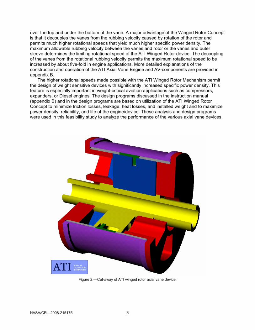
3.5 Minimum Size PAX 50 and PAX 150 Engines with Fan Boosted Pressure A second alternative with the availability of the higher fan boosted pressure is to reduce the
diameter of the axial vane engines while producing the specified power for each installation. The performance analysis for the minimum size PAX 50 engine is presented in figure 20. The rotor diameter of the PAX 50 Diesel engine was reduced from 20.0 in. at sea-level pressure to 17.0 in. at the boosted pressure of 23.3 psig. The 15 percent reduction in diameter also permitted an 18 percent increase in engine speed and a 39 percent increase in specific power density to 8.80 BHP/lb while decreasing engine weight by 22 percent.
The performance analysis for the minimum size PAX 150 engine is presented in figure 21. The rotor diameter was reduced from 40.0 to 36.5 in. for a 9 percent reduction while increasing the specific power density 40 percent to 8.72 BHP/lb and reducing the engine weight by 34 percent.
The engine size reductions permitted by utilizing the fan boosted pressure is significant in that it makes the overall diameter of the Diesel engines with accessories more likely to fit within the limits of the existing nacelles and the engine weight reductions are highly significant. A summary of the engine analysis for the minimum size engines is presented in table 4.
TABLE 4.—COMPARISON OF MINIMUM-SIZE BOOSTED ENGINE WITH SEA-LEVEL ENGINES COMPARISON OF CORE ENGINE TYPES FOR PAX 50 AND PAX 150 TURBOFAN ENGINES
PARAMETER UNITS PAX 50 ENGINE PAX 150 ENGINE
DIESEL DIESEL MIN.SIZE DIESEL DIESEL MIN.SIZECORE BOOSTED BOOSTED CORE BOOSTED BOOSTED
ROTOR DIAMETER Inches 20.0 20.0 17.0 40.0 40.0 30.5 NUMBER ROTOR UNITS --- 3 3 3 2 2 2 ENGINE SPEED RPM 5000 5000 5900 2500 2500 3600 INLET PRESSURE Psia 14.70 23.30 23.30 14.70 23.05 23.05
POWER BHP 8,293 10,117 8,352 25,120 32,870 23,340
FUEL/AIR RATIO --- 0.03900 0.03900 0.03900 0.03900 0.03900 0.03900 AIR/FUEL RATIO --- 25.64 25.64 25.64 25.64 25.64 25.64
AIRFLOW RATE Lb./Min 1,029 905 1,088 2,972 3,896 2,734
EXHAUST GAS TEMP Deg. F 1643 2199 2125 1597 2136 1992
BSFC Lb/BHP/Hr. 0.2903 0.3140 0.2983 0.2769 0.2773 0.2742
IMPROVEMENT BSFC vs. Sea-Level Engi --- 92.47% 97.33% --- 99.84% 100.97%
NUMBER ROTOR UNITS --- 3 3 3 2 2 2 BARE ENGINE WEIGHT Lb. 1,226 1,226 857 3,757 3,757 2,480 ACCESSORIES WT. Lb. 86 86 92 301 301 198 TOTAL CORE ENGINE WT. Lb. 1,312 1,312 949 4,058 4,058 2,678
POWER DENSITY BHP/Lb. 6.32 7.71 8.80 6.19 8.10 8.72
IMPROVEMENT BHP/Lb vs. Sea-Level --- 122.0% 139.2% --- 130.9% 140.8%
Note 1: DIESEL configuration is computed at Standard Sea Level Pressure (14.7 psia) and Temperature (530 Deg. Rankine).Note 2: DIESEL BOOSTED is computed at Turbofan exit condition [inlet pressure (23.3/23.05 psig) and temperature (637/634 R)].Note 3: HYBRID configuration is computed for Axial-Vane Compressor and AV-Expander operating at Turbofan exit condition.Note 4: Estimated Accessories Weight for DIESEL & DIESEL BOOSTED, [PAX 50 = 0.7x Bare Wt.; PAX 150 = 0.08x Bare Wt.]
NASA/CR—2008-215175 21
SUMMARY OF PERFORMANCE ANALYSIS
DESIGN PROGRAM FOR AXIAL VANE MACHINESDeveloped by Advanced Technologies Inc.
March 2005
Minimum Size Fan Boosted 3-Rotor Axial-Vane Diesel Engine for PAX-50 Turbofan Engine {Title of Design: From Sheet 1 AV DESIGN)
PARAMETER VALUE COMMENTS & NOTES
PHYSICAL DIMENSIONS & DESIGN VARIABLESNUMBER OF VANES 12 12-Vane Diesel EngineNUMBER OF CAMS 2
ANGLE BETWEEN VANES 30VANE THICKNESS (inches) 0.50 Estimated = 0.10 x Vane Stroke
VANE STROKE (inches) 3.20 Estimated from Chart: Vane Stroke vs. BHPVANE HEIGHT (inches) 6.10 Estimated as 2 x Vane StrokeLIFT ANGLE (degrees) 75
DWELL ANGLE (degrees) 15EVENT ANGLE (degrees) 90
ROTOR OUTER DIAMETER (inches) 17.00 Estimated based on Chart: OD vs. BHPROTOR INNER DIAMETER (inches) 4.80 Estimated = OD -2 Vane Height ROTOR MEAN DIAMETER (inches) 10.90
INPUT DESIGN VALUESSPEED (RPM) 5,900 Limited by Vane Rubbing Velocity
OMEGA (radians/sec) 618
ROTOR CLEARANCE (inches) 0.005 Minimum clearance between Rotor & CamTIP CLEARANCE (inches) 0.005 Clearance between Vane Tip and Cam
DIAMETRAL CLEARANCE (inches) 0.010 Total radial clearance between Vane & Inner & Outer Wings
INITIAL PRESSURE (psia) 23.30 Inlet Pressure behind TurbofanINITIAL TEMPERATURE (deg R) 637.00 Inlet Temperature
Gas Constant, R = 53.30Ratio of Specific Heat, k = 1.3937
HEAT VALUE (BTU/lb) 18,600EFFECTIVE HEAT VALUE (BTU/lb) 14,484 Computed in Cell FB6 based on cooling Heat Loss that
FUEL/AIR RATIO 0.0390 varies with Chamber Pressure & Temperature.AIR/FUEL RATIO 25.64
COMPUTED VALUESDISLACEMENT/CHAMBER (cu. in.) 45.98 Adjust Displacement/Chamber to change Comp. Ratio
POCKET VOLUME (cu.in.) 3.36 Pocket Volume is automatically adjusted when Disp. PerROTOR CLEARANCE VOLUME (cu.in.) 0.0870 Chamber is changed.
TOTAL DISPLACEMENT (cu. in.) 1,103 Total Displacement of 24 chambers.COMPRESSION RATIO 14.39 Ratio of Max. Real Vol. / Min. Real Vol.(Col. Q, Sheet 1)
COMPUTED PERFORMANCE
AIR FLOW (lbs/min 372.31 FUEL FLOW (lbs/min) 14.52
BRAKE MEAN EFFECTIVE PRESSURE (BMEP)(psi) 169.35INDICATED POWER (hp) 3,356
FRICTION POWER (hp) 571HEAT LOSS POWER (hp) 743
BRAKE HORSEPOWER OUTPUT (Bhp) 2,784 3 Units = 8,352BRAKE SPECIFIC FUEL CONSUMPTION (lbs/Bhp/hr) 0.3129
EXHAUST TEMPERATURE ( deg. F.) 2125
Performed By: Mike Smith Date Performed: May 14, 2006
Figure 20.—Minimum size PAX 50 diesel engine with fan boost to meet specifications.

NASA/CR—2008-215175 22
SUMMARY OF PERFORMANCE ANALYSIS
DESIGN PROGRAM FOR AXIAL VANE MACHINESDeveloped by Advanced Technologies Inc.
March 2005
Minimum Size Fan Boosted PAX 150 2-Rotor Diesel Core Engine (30.5"@3600) {Title of Design: From Sheet 1 AV DESIGN)
PARAMETER VALUE COMMENTS & NOTES
PHYSICAL DIMENSIONS & DESIGN VARIABLESNUMBER OF VANES 12 12-Vane Diesel EngineNUMBER OF CAMS 2
ANGLE BETWEEN VANES 30VANE THICKNESS (inches) 0.50 Estimated = 0.10 x Vane Stroke
VANE STROKE (inches) 5.50 Estimated from Chart: Vane Stroke vs. BHPVANE HEIGHT (inches) 11.00 Estimated as 2 x Vane StrokeLIFT ANGLE (degrees) 75
DWELL ANGLE (degrees) 15EVENT ANGLE (degrees) 90
ROTOR OUTER DIAMETER (inches) 30.50 Estimated based on Chart: OD vs. BHPROTOR INNER DIAMETER (inches) 8.50 Estimated = OD -2 Vane Height ROTOR MEAN DIAMETER (inches) 19.50
INPUT DESIGN VALUESSPEED (RPM) 3,600 Limited by Vane Rubbing Velocity
OMEGA (radians/sec) 377
ROTOR CLEARANCE (inches) 0.005 Minimum clearance between Rotor & CamTIP CLEARANCE (inches) 0.005 Clearance between Vane Tip and Cam
DIAMETRAL CLEARANCE (inches) 0.010 Total radial clearance between vane & Inner & Outer Wings
INITIAL PRESSURE (psia) 23.05 Inlet PressureINITIAL TEMPERATURE (deg R) 634.00 Inlet Temperature
Gas Constant, R = 53.30Ratio of Specific Heat, k = 1.3937
HEAT VALUE (BTU/lb) 18,600EFFECTIVE HEAT VALUE (BTU/lb) 15,875 Computed in Cell FB6 based on cooling Heat Loss that
FUEL/AIR RATIO 0.0390 varies with Chamber Pressure & Temperature.AIR/FUEL RATIO 25.64
COMPUTED VALUESDISLACEMENT/CHAMBER (cu. in.) 278.48 Adjust Displacement/Chamber to change Comp. Ratio
POCKET VOLUME (cu.in.) 21.72 Pocket Volume is automatically adjusted when Disp. PerROTOR CLEARANCE VOLUME (cu.in.) 0.2808 Chamber is changed.
TOTAL DISPLACEMENT (cu. in.) 6,684 Total Displacement of 24 chambers.COMPRESSION RATIO 13.62 Ratio of Max. Real Vol. / Min. Real Vol.(Sht 1, Col. Q)
COMPUTED PERFORMANCE
AIR FLOW (lbs/min 1,367.37 FUEL FLOW (lbs/min) 53.33
BRAKE MEAN EFFECTIVE PRESSURE (BMEP)(psi) 192.07INDICATED POWER (hp) 13,346
FRICTION POWER (hp) 1,676 12.6% of Indicated PowerHEAT LOSS POWER (hp) 1,955 14.7% of Indicated Power
BRAKE HORSEPOWER OUTPUT (Bhp) 11,670 23,340 BHP for 2-Rotor Core EngineBRAKE SPECIFIC FUEL CONSUMPTION (lbs/Bhp/hr) 0.2742
EXHAUST TEMPERATURE ( deg. F.) 1992
Performed By: Mike Smith Date Performed: Dec. 21, 2005
Figure 21.—Minimum size PAX150 diesel engine with fan boost to meet specifications.

NASA/CR—2008-215175 23
4.0 Design of Axial Vane Hybrid Turbine Engine The basic axial vane mechanism has been explained in previous sections on the Axial Vane
Diesel Engine. This section pertains to the use of the axial vane mechanism as a replacement for axial flow turbomachinery such as the compressor and turbine sections of high bypass ratio turbofan engines. The objective of the study of this application of axial vane technology was to determine size implications and efficiency implications of the compressor and expander for such a hybrid engine. A schematic of the hybrid turbine engine is shown in figure 22. The compressors and expanders of the hybrid engine are mounted on a common shaft that connects the fan, compressors, and expanders. The compressors and expanders would be attached to the shaft so individual units could be removed for servicing or replacement.
The above schematic represents a hybrid engine with the compressor intakes operating at sea level ambient conditions. By mounting the compressor intake behind the fan, the compressor inlet pressure could be increased from 14.7 psia to about 23 psia for the PAX 50 engine. The combustor section could be mounted inline with the compressors and expanders or in parallel outside of the engine nacelle. Similarly, the exhaust from the expanders could be used to drive a turbo charger that could further increase inlet pressure to the compressors and significantly increase the power output and specific power density of the hybrid engine. Figure 23 is a picture of a hybrid axial vane unit consisting of a compressor and an expander section showing the axial direction of airflow into and out of each component. It also shows that the compressor and expander can be different sizes to fit the application. Note there are four inlet ports and four outlet ports on each compressor and each expander.
Figure 22.—Schematic of hybrid turbine engine with axial vane compressors and expanders.
Figure 23.—Model of axial vane compressor and
expander with axial intake and exhaust ports.

NASA/CR—2008-215175 24
Figure 24.—Schematic of axial vane compressor cycle.
4.1 Compressor for Hybrid Turbine Engine
The axial vane compressor is basically the same as the axial vane Diesel engine except that it does not use fuel injection and has two intake and two outlet ports on each cam end-housing of the device. A schematic of the axial vane compressor operation is shown in figure 24. The compression cycle occurs twice for each chamber on each revolution and the two cycles occur on both sides of the rotor. This means that the displacement of the mechanism is twice as large as a compressor (or expander) as it is for a 4-stroke cycle rotary engine. It should also be noted that the pressure distribution on the two sides of the rotor are exactly 90° out of phase which means that there are no net axial or radial loads on the rotor and; therefore, no loads on the bearings other than the weight of the rotor, shaft, and vanes.
4.1.1 Modeling Hybrid Compressors
To provide a design tool for analysis and design of the hybrid compressor, the Diesel engine cycle simulation spreadsheet was modified to model the axial vane compressor. Because the compressor operates at much lower pressure than a Diesel engine, it was decided to omit the leakage calculations to simplify the model.
4.1.2 Design of Compressors for Hybrid Turbine Engine
The NASA furnished data for the baseline PAX 50 and PAX 150 engines were used to design axial vane compressors to duplicate the burner inlet pressure and airflow rates. The maximum diameter of the compressors was also restricted to the existing nacelle sizes limits of the project specification. To meet the flow requirements, the PAX 50 required three compressor modules whereas two modules could meet the PAX 150 power requirement. The outlet ports were located at the point in the compression cycle where the internal pressure met the burner inlet pressure requirement. The design geometries and predicted performance of the respective PAX 50 and PAX 150 compressors are presented in figures 25 and 26. An exploded view of a typical axial vane compressor is shown in figure 27.

NASA/CR—2008-215175 25
SUMMARY OF PERFORMANCE ANALYSIS
DESIGN PROGRAM FOR AXIAL VANE MACHINESDeveloped by Advanced Technologies Inc.
March 2005
Pax 50 Compressor Design 3 Rotors {Title of Design: From Sheet 1 AV DESIGN)
PARAMETER VALUE COMMENTS & NOTES
PHYSICAL DIMENSIONS & DESIGN VARIABLESNUMBER OF VANES 12 12-Vane Diesel EngineNUMBER OF CAMS 2
ANGLE BETWEEN VANES 30VANE THICKNESS (inches) 0.50 Estimated = 0.10 x Vane Stroke
VANE STROKE (inches) 3.30 Estimated from Chart: Vane Stroke vs. BHPVANE HEIGHT (inches) 6.70 Estimated as 2 x Vane StrokeLIFT ANGLE (degrees) 75
DWELL ANGLE (degrees) 15EVENT ANGLE (degrees) 90
ROTOR OUTER DIAMETER (inches) 20.00 Estimated based on Chart: OD vs. BHPROTOR INNER DIAMETER (inches) 6.60 Estimated = OD -2 Vane Height ROTOR MEAN DIAMETER (inches) 13.30
INPUT DESIGN VALUESSPEED (RPM) 5,000 Limited by Vane Rubbing Velocity
OMEGA (radians/sec) 524
ROTOR CLEARANCE (inches) 0.005 Minimum clearance between Rotor & CamTIP CLEARANCE (inches) 0.005 Clearance between Vane Tip and Cam
DIAMETRAL CLEARANCE (inches) 0.010 Total radial clearance between vane & Inner & Outer Wings
INITIAL PRESSURE (psia) 14.70 Inlet PressureINITIAL TEMPERATURE (deg R) 545.00 Inlet Temperature
Gas Constant, R = 53.30Ratio of Specific Heat, k = 1.3937
FUEL/AIR RATIO 0.0000 varies with Chamber Pressure & Temperature.
COMPUTED VALUESDISLACEMENT/CHAMBER (cu. in.) 65.94 Adjust Displacement/Chamber to change Comp. Ratio
POCKET VOLUME (cu.in.) 4.88 Pocket Volume is automatically adjusted when Disp. PerROTOR CLEARANCE VOLUME (cu.in.) 0.1166 Chamber is changed.
TOTAL DISPLACEMENT (cu. in.) 1,583 Total Displacement of 24 chambers.COMPRESSION RATIO 14.21 Ratio of Max. Real Vol. / Min. Real Vol.(Col.
COMPUTED PERFORMANCE
AIR FLOW (lbs/min 667.42 FUEL FLOW (lbs/min) 0.00
BRAKE MEAN EFFECTIVE PRESSURE (BMEP)(psi) -196.46INDICATED POWER (hp) -3,565
FRICTION POWER (hp) 360HEAT LOSS POWER (hp) 66
BRAKE HORSEPOWER OUTPUT (Bhp) -3,926 3 Compressors x 3926 = 11,778 BhpBRAKE SPECIFIC FUEL CONSUMPTION (lbs/Bhp/hr) 0.0000
EXHAUST TEMPERATURE ( deg. F.) 0
Performed By: Pat Badgley Date Performed: July 28, 2005
Figure 25.—Summary of compressor design for PAX 50 hybrid turbine engine .

NASA/CR—2008-215175 26
SUMMARY OF PERFORMANCE ANALYSIS
DESIGN PROGRAM FOR AXIAL VANE MACHINESDeveloped by Advanced Technologies Inc.
March 2005
PAX 150 Compressor Design 2 Rotors {Title of Design: From Sheet 1 AV DESIGN)
PARAMETER VALUE COMMENTS & NOTES
PHYSICAL DIMENSIONS & DESIGN VARIABLESNUMBER OF VANES 12 12-Vane CompressorNUMBER OF CAMS 2
ANGLE BETWEEN VANES 30VANE THICKNESS (inches) 0.50 Estimated = 0.10 x Vane Stroke
VANE STROKE (inches) 6.00 Estimated from Rotor Diameter / 6VANE HEIGHT (inches) 12.00 Estimated as 2 x Vane StrokeLIFT ANGLE (degrees) 75
DWELL ANGLE (degrees) 15EVENT ANGLE (degrees) 90
ROTOR OUTER DIAMETER (inches) 36.00 Estimated based on Chart: OD vs. BHPROTOR INNER DIAMETER (inches) 12.00 Estimated = OD -2 Vane Height ROTOR MEAN DIAMETER (inches) 24.00
INPUT DESIGN VALUESSPEED (RPM) 2,778 Limited by Vane Rubbing Velocity
OMEGA (radians/sec) 291
ROTOR CLEARANCE (inches) 0.005 Minimum clearance between Rotor & CamTIP CLEARANCE (inches) 0.005 Clearance between Vane Tip and Cam
DIAMETRAL CLEARANCE (inches) 0.010 Total radial clearance between vane & Inner & Outer W ings
INITIAL PRESSURE (psia) 23.05 Inlet PressureINITIAL TEMPERATURE (deg R) 634.55 Inlet Temperature
Gas Constant, R = 53.30Ratio of Specific Heat, k = 1.3937
COMPUTED VALUESDISLACEMENT/CHAMBER (cu. in.) 416.09 Adjust Displacement/Chamber to change Comp. Ratio
POCKET VOLUME (cu.in.) 0.02 Pocket Volume is automatically adjusted when Disp. PerROTOR CLEARANCE VOLUME (cu.in.) 0.3770 Chamber is changed.
TOTAL DISPLACEMENT (cu. in.) 19,972 Total Displacement of 48 chambers.COMPRESSION RATIO 760.22 Ratio of Max. Real Vol. / Min. Real Vol.(Col.
COMPUTED PERFORMANCE
AIR FLOW (lbs/min 3,150.41 FUEL FLOW (lbs/min) 0.00
BRAKE MEAN EFFECTIVE PRESSURE (BMEP)(psi) -274.73INDICATED POWER (hp) -17,945
FRICTION POWER (hp) 1,302HEAT LOSS POWER (hp) 360
BRAKE HORSEPOWER OUTPUT (Bhp) -19,246 2 Compressors = -38,492 BhpBRAKE SPECIFIC FUEL CONSUMPTION (lbs/Bhp/hr) 0.0000
EXHAUST TEMPERATURE ( deg. F.) 721
Performed By: Pat Badgley Date Performed: July 31, 2005
Figure 26.—Summary of compressor design for PAX 150 hybrid turbine engine.

NASA/CR—2008-215175 27
Figure 27.—Exploded view of typical axial vane compressor.
Figure 28.—Schematic of axial vane expander.
An exploded view of a typical compressor design (fig. 27) shows a two-piece vane design that
allows the vanes to ride on the cam surface to reduce leakage. This design will be used if a material pair can be found for the vane and cam to allow long life using only self-lubrication. An alternative design using the pin and pin track or rail and slot can also be used. With the alternative designs, a thick thermal barrier coating can be applied to both the cam face and the face of the rotor to reduce heat losses and improve volumetric efficiency by allowing the surface temperatures to follow the gas temperature history continuously.
4.2 Expanders for Hybrid Turbine Engines The axial vane expander is almost identical to the compressor with the exception that the inlet and
exhaust ports are repositioned as shown in the expander schematic (fig. 28). Note that the expansion cycle occurs twice each revolution for each chamber and that there are no pressure induced bearing

NASA/CR—2008-215175 28
loads. Like the compressor, the expander with 12 vanes has 48 expansion cycles each revolution of the rotor and produces intake and exhaust pressure pulses at very high frequency.
4.2.1 Modeling the Hybrid Expanders for Hybrid Turbine Engines
Similar to the compressor, an expander model was developed from the basic Axial Vane Diesel Engine Design Spreadsheet. A very sensitive part of the modeling turned out to be the location of the inlet ports. The ports had to close at a position that would provide a volume large enough to hold the entire mass flow (per chamber) at the burner outlet density. The port closure position also directly controls the expansion ratio. This means that moving the port to an earlier position would reduce the mass flow and moving it to a later position would reduce the expander power output. An exploded view of a typical expander unit is shown in figure 29 and a cutaway view is shown in figure 30 illustrating the split-vanes and ports.
Figure 29.—Exploded view of axial vane expander.
Figure 30.—Sectioned compressor or expander showing split-vanes and ports.

NASA/CR—2008-215175 29
4.2.2 Design of Hybrid Expanders for Hybrid Turbine Engines
The rotor diameter of the hybrid expander was assumed to be 20 in., the same as the sea-level Diesel engine. The performance analysis for the axial vane expanders on the PAX 50 and PAX 150 Hybrid Turbine Engines are shown in figures 32 and 33. The weight schedule for the hybrid compressors, expanders, and the complete hybrid engine are presented in table 5.
Figure 31 is a solid model illustrating the compressor and expander construction by making the external components transparent. In this picture the compressor and expander are shown as being the same diameter.
TABLE 5.—WEIGHT SCHEDULE FOR PAX 50 AND PAX 150 COMPRESSORS AND EXPANDERS WEIGHT SCHEDULE FOR HYBRID TURBINE ENGINES
HYBRID COMPRESSOR AND EXPANDER FOR PAX 50 & PAX 150 ENGINES PAX 50 Axial Vane PAX 150 Axial Vane
COMPRESSOR Hybrid Engine Hybrid EnginePart Number/ Weight/ Weight/ Weight/ Weight/
Module Part Module Part ModuleCam 2 33.39 66.78 153.41 306.82Rotor 1 59.19 59.19 271.99 271.99Vane 12 3.65 43.74 16.75 200.98Wing 2 11.66 23.33 53.59 107.19Rail 1 14.58 14.58 66.99 66.99Rail Support 1 15.31 15.31 70.34 70.34Outer 1 75.09 75.09 345.01 345.01
Total 298.02 Total 1,369.32
Total Weight Compressors 3 Rotors 894 2 Rotors 2,739
EXPANDERPart Number/ Weight/ Weight/ Weight/ Weight/
Module Part Module Part ModuleCam 2 33.39 66.78 153.41 306.82Rotor 1 59.19 59.19 271.99 271.99Vane 12 3.65 43.74 16.75 200.98Wing 2 11.66 23.33 53.59 107.19Rail 1 14.58 14.58 66.99 66.99Rail Support 1 15.31 15.31 70.34 70.34Outer 1 75.09 75.09 345.01 345.01
Total 298.02 Total 1369.32
Total Weight Expanders 3 Rotors 894 2 Rotors 2,739
TOTAL WEIGHT OF HYBRID CORE 1,788 5,477 ACESSORIES 125 438TOTAL HYBRID TURBINE WEIGHT,lb. 1,913 5,915
Assuming all parts are made of titanium
Figure 31.—Paired compressor and expander with space for burner between units.

NASA/CR—2008-215175 30
SUMMARY OF PERFORMANCE ANALYSIS
DESIGN PROGRAM FOR AXIAL VANE MACHINESDeveloped by Advanced Technologies Inc.
March 2005
PAX 50 Expander Design 3-Rotors {Title of Design: From Sheet 1 AV DESIGN)
PARAMETER VALUE COMMENTS & NOTES
PHYSICAL DIMENSIONS & DESIGN VARIABLESNUMBER OF VANES 12 12-Vane ExpanderNUMBER OF CAMS 2
ANGLE BETWEEN VANES 30VANE THICKNESS (inches) 0.50 Estimated = 0.10 x Vane Stroke
VANE STROKE (inches) 3.50 Estimated as Rotor Diameter / 6VANE HEIGHT (inches) 7.00 Estimated as 2 x Vane StrokeLIFT ANGLE (degrees) 75
DWELL ANGLE (degrees) 15EVENT ANGLE (degrees) 90
ROTOR OUTER DIAMETER (inches) 20.00 Estimated based on Chart: OD vs. BHPROTOR INNER DIAMETER (inches) 6.00 Estimated = OD -2 Vane Height ROTOR MEAN DIAMETER (inches) 13.00
INPUT DESIGN VALUESSPEED (RPM) 5,000 Limited by Vane Rubbing Velocity
OMEGA (radians/sec) 524
ROTOR CLEARANCE (inches) 0.005 Minimum clearance between Rotor & CamTIP CLEARANCE (inches) 0.005 Clearance between Vane Tip and Cam
DIAMETRAL CLEARANCE (inches) 0.010 Total radial clearance between vane & Inner & Outer Wings
INITIAL PRESSURE (psia) 345.00 Inlet PressureINITIAL TEMPERATURE (deg R) 2,500.00 Inlet Temperature
Gas Constant, R = 53.30Ratio of Specific Heat, k = 1.3937
COMPUTED VALUESDISLACEMENT/CHAMBER (cu. in.) 71.15 Adjust Displacement/Chamber to change Comp. Ratio
POCKET VOLUME (cu.in.) 0.00 Pocket Volume is automatically adjusted when Disp. PerROTOR CLEARANCE VOLUME (cu.in.) 0.1191 Chamber is changed.
TOTAL DISPLACEMENT (cu. in.) 3,415 Total Displacement of 24 chambers.COMPRESSION RATIO 644.28 Ratio of Max. Real Vol. / Min. Real Vol.(Col. Q, Sheet 1)
COMPUTED PERFORMANCE
AIR FLOW (lbs/min 742.83 FUEL FLOW (lbs/min)
BRAKE MEAN EFFECTIVE PRESSURE (BMEP)(psi) 377.91INDICATED POWER (hp) 8,550
FRICTION POWER (hp) 402HEAT LOSS POWER (hp) 452
BRAKE HORSEPOWER OUTPUT (Bhp) 7,696 X 3 = 3 EXPANDERS = 23,087BRAKE SPECIFIC FUEL CONSUMPTION (lbs/Bhp/hr) 0.0000
EXHAUST TEMPERATURE ( deg. F.) 1270
Performed By: Pat Badgley Date Performed: 8/8/2005
Figure 32.—Performance analysis of PAX 50 expander for hybrid turbine engine.

NASA/CR—2008-215175 31
SUMMARY OF PERFORMANCE ANALYSIS
DESIGN PROGRAM FOR AXIAL VANE MACHINESDeveloped by Advanced Technologies Inc.
March 2005
Pax 150 Expander Design 2 Rotors (36-in OD@2778) {Title of Design: From Sheet 1 AV DESIGN)
PARAMETER VALUE COMMENTS & NOTES
PHYSICAL DIMENSIONS & DESIGN VARIABLESNUMBER OF VANES 12 12-Vane ExpanderNUMBER OF CAMS 2
ANGLE BETWEEN VANES 30VANE THICKNESS (inches) 0.50 Estimated = 0.10 x Vane Stroke
VANE STROKE (inches) 6.00 Estimated from Rotor Diameter / 6VANE HEIGHT (inches) 12.00 Estimated as 2 x Vane StrokeLIFT ANGLE (degrees) 75
DWELL ANGLE (degrees) 15EVENT ANGLE (degrees) 90
ROTOR OUTER DIAMETER (inches) 36.00 Estimated based on Chart: OD vs. BHPROTOR INNER DIAMETER (inches) 12.00 Estimated = OD -2 Vane Height ROTOR MEAN DIAMETER (inches) 24.00
INPUT DESIGN VALUESSPEED (RPM) 2,778 Limited by Vane Rubbing Velocity
OMEGA (radians/sec) 291
ROTOR CLEARANCE (inches) 0.005 Minimum clearance between Rotor & CamTIP CLEARANCE (inches) 0.005 Clearance between Vane Tip and Cam
DIAMETRAL CLEARANCE (inches) 0.010 Total radial clearance between vane & Inner & Outer Wings
INITIAL PRESSURE (psia) 399.00 Inlet PressureINITIAL TEMPERATURE (deg R) 2,960.00 Inlet Temperature
Gas Constant, R = 53.30Ratio of Specific Heat, k = 1.3937
COMPUTED VALUESDISLACEMENT/CHAMBER (cu. in.) 416.09 Adjust Displacement/Chamber to change Comp. Ratio
POCKET VOLUME (cu.in.) 0.12 Pocket Volume is automatically adjusted when Disp. PerROTOR CLEARANCE VOLUME (cu.in.) 0.3770 Chamber is changed.
TOTAL DISPLACEMENT (cu. in.) 19,972 Total Displacement of 48 chambers.COMPRESSION RATIO 643.07 Ratio of Max. Real Vol. / Min. Real Vol.(Col.
COMPUTED PERFORMANCE
AIR FLOW (lbs/min 3,324.73 X 2 = 6649AIR FLOW (lbs/min) X 2 = 6,649.46
BRAKE MEAN EFFECTIVE PRESSURE (BMEP)(psi) 508.53INDICATED POWER (hp) 36,927
FRICTION POWER (hp) 1,302HEAT LOSS POWER (hp) 2,156
BRAKE HORSEPOWER OUTPUT (Bhp) 33,470 X 2 = 66939BRAKE SPECIFIC FUEL CONSUMPTION (lbs/Bhp/hr) 0.0000
EXHAUST TEMPERATURE ( deg. F.) 1685
Performed By: Pat Badgley Date Performed: July 31, 2005
Figure 33.—Performance analysis of PAX 150 expander for hybrid turbine engine.

NASA/CR—2008-215175 32
Figure 34.—Solid model of PAX 50 axial vane hybrid engine assembly.
Figure 35.—Solid model of PAX 50 axial vane hybrid engine assembly.
Figures 34 and 35, respectively, are solid models of the assembled PAX 50 and PAX 150 axial
vane hybrid engines including the combustors (burners), fans and nacelles. These axial vane components have radial inlet and outlet ports and mounting flanges to couple the modules together to make a rigid assembly.
4.2.3 Discussion of PAX 50 Expander and PAX 150 Expander The solid models of the Axial Vane PAX 50 and PAX 150 hybrid engines are shown in
figures 34 and 35, respectively. The PAX 50 hybrid engine has three compressors operating in parallel and three expanders operating in parallel. Located between the compressor outlets and the expander inlets will be a combustor, which can be an identical design and construction as the combustor (burner) on the current PAX 50 and PAX 150 engines. All of the rotating components share a common shaft, which runs the length of the engine and also drives the fan (with or without a gearbox). The shaft will have an external spline that fits a mating internal spline in each rotating component allowing the components and shaft to move axially relative to each other due to thermal expansion. The PAX 150 hybrid engine has two compressors operating in parallel and two expanders operating in parallel.
4.3 Thermodynamic Model of Hybrid Turbine Engine As a check on the spreadsheet design programs, a thermodynamic analysis of the complete
cycle for both the hybrid engines and also for the baseline turbomachinery type PAX 50 and PAX 150 engines was performed. This analysis is shown in table 6. This analysis relies on the
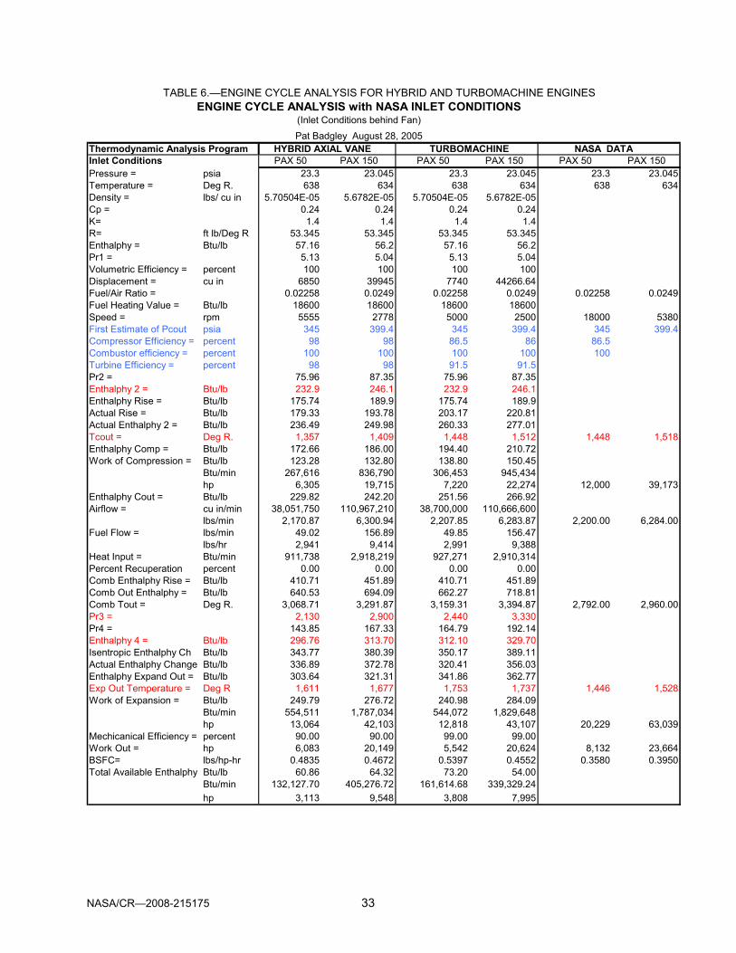
NASA/CR—2008-215175 33
TABLE 6.—ENGINE CYCLE ANALYSIS FOR HYBRID AND TURBOMACHINE ENGINES ENGINE CYCLE ANALYSIS with NASA INLET CONDITIONS
(Inlet Conditions behind Fan)Pat Badgley August 28, 2005
Thermodynamic Analysis Program HYBRID AXIAL VANE TURBOMACHINE NASA DATAInlet Conditions PAX 50 PAX 150 PAX 50 PAX 150 PAX 50 PAX 150Pressure = psia 23.3 23.045 23.3 23.045 23.3 23.045Temperature = Deg R. 638 634 638 634 638 634Density = lbs/ cu in 5.70504E-05 5.6782E-05 5.70504E-05 5.6782E-05Cp = 0.24 0.24 0.24 0.24K= 1.4 1.4 1.4 1.4R= ft lb/Deg R 53.345 53.345 53.345 53.345Enthalphy = Btu/lb 57.16 56.2 57.16 56.2Pr1 = 5.13 5.04 5.13 5.04Volumetric Efficiency = percent 100 100 100 100Displacement = cu in 6850 39945 7740 44266.64Fuel/Air Ratio = 0.02258 0.0249 0.02258 0.0249 0.02258 0.0249Fuel Heating Value = Btu/lb 18600 18600 18600 18600Speed = rpm 5555 2778 5000 2500 18000 5380First Estimate of Pcout psia 345 399.4 345 399.4 345 399.4Compressor Efficiency = percent 98 98 86.5 86 86.5Combustor efficiency = percent 100 100 100 100 100Turbine Efficiency = percent 98 98 91.5 91.5Pr2 = 75.96 87.35 75.96 87.35Enthalphy 2 = Btu/lb 232.9 246.1 232.9 246.1Enthalphy Rise = Btu/lb 175.74 189.9 175.74 189.9Actual Rise = Btu/lb 179.33 193.78 203.17 220.81Actual Enthalphy 2 = Btu/lb 236.49 249.98 260.33 277.01Tcout = Deg R. 1,357 1,409 1,448 1,512 1,448 1,518Enthalphy Comp = Btu/lb 172.66 186.00 194.40 210.72Work of Compression = Btu/lb 123.28 132.80 138.80 150.45
Btu/min 267,616 836,790 306,453 945,434hp 6,305 19,715 7,220 22,274 12,000 39,173
Enthalphy Cout = Btu/lb 229.82 242.20 251.56 266.92Airflow = cu in/min 38,051,750 110,967,210 38,700,000 110,666,600
lbs/min 2,170.87 6,300.94 2,207.85 6,283.87 2,200.00 6,284.00Fuel Flow = lbs/min 49.02 156.89 49.85 156.47
lbs/hr 2,941 9,414 2,991 9,388Heat Input = Btu/min 911,738 2,918,219 927,271 2,910,314Percent Recuperation percent 0.00 0.00 0.00 0.00Comb Enthalphy Rise = Btu/lb 410.71 451.89 410.71 451.89Comb Out Enthalphy = Btu/lb 640.53 694.09 662.27 718.81Comb Tout = Deg R. 3,068.71 3,291.87 3,159.31 3,394.87 2,792.00 2,960.00Pr3 = 2,130 2,900 2,440 3,330Pr4 = 143.85 167.33 164.79 192.14Enthalphy 4 = Btu/lb 296.76 313.70 312.10 329.70Isentropic Enthalphy Ch Btu/lb 343.77 380.39 350.17 389.11Actual Enthalphy Change Btu/lb 336.89 372.78 320.41 356.03Enthalphy Expand Out = Btu/lb 303.64 321.31 341.86 362.77Exp Out Temperature = Deg R 1,611 1,677 1,753 1,737 1,446 1,528Work of Expansion = Btu/lb 249.79 276.72 240.98 284.09
Btu/min 554,511 1,787,034 544,072 1,829,648hp 13,064 42,103 12,818 43,107 20,229 63,039
Mechicanical Efficiency = percent 90.00 90.00 99.00 99.00Work Out = hp 6,083 20,149 5,542 20,624 8,132 23,664BSFC= lbs/hp-hr 0.4835 0.4672 0.5397 0.4552 0.3580 0.3950Total Available Enthalphy Btu/lb 60.86 64.32 73.20 54.00
Btu/min 132,127.70 405,276.72 161,614.68 339,329.24hp 3,113 9,548 3,808 7,995

NASA/CR—2008-215175 34
thermodynamic properties of air as tabulated in reference 1. The inlet pressure for the hybrid and turbomachine engines was assumed to be 23.3 psia that was the same as the computed pressure for the NASA analysis of the baseline PAX 50 and PAX 150 engines. The fuel/air ratios for the hybrid and turbomachine engines were assumed to be the same as used in the NASA analysis of the baseline engines. Table 6 shows that the predicted performance of the hybrid and turbomachinery engines are very close, but that the computed performance data supplied by NASA shows much better performance for the turbofan engine. The major difference between the model and the real turbomachinery type engines is that the current model does not account for bleeds and reintroduction of cooling air. Also this model does not account for the presence of combustion products and the additional mass flow that they introduce, nor does it account for the changed gas properties in the calculations.
5.0 Summary and Conclusion This project generated several analysis and design tools for axial vane rotary compressors,
expanders, and Diesel engines. The project also generated specific technical data on the design of axial vane machinery for high specific output Diesel and positive displacement Brayton cycle engines for aircraft applications. Table 7 is a compilation of the Diesel, Hybrid and turbomachinery engines for the PAX 50 and PAX 150 applications. As the table clearly shows, the Axial Vane Diesel Engine shows the most promise for application in turbofan engines because the specific weight and specific volume match that of turbomachines while the specific fuel consumption is much lower. Another significant advantage for the Diesel engines is the fact that the specific fuel consumption of Diesel engines at reduced load and reduced speed changes very little as compared to turbomachinery engines. The engine weight reduction obtainable with the axial vane components is highly significant.
5.1 Comparison of PAX 50 Engines Using the data shown in table 7, the Axial Vane Diesel Engine, the Axial Vane Hybrid Engine,
and the Turbomachinery Engine have specific power density of 8.8, 4.29, and 4.98 hp/lb, respectively, when all are operating at the turbine inlet pressure behind the fan. The brake specific fuel consumption (lb/hp-hr) of the Diesel is 0.2983, the Hybrid is 0.3010 and the Turbomachine is 0.3665. It is also significant that the airflow in the Diesel engine is less than one half that of the hybrid and turbomachinery engines. This means that the net efficiency of the fan will increase because less air is bled off for the engine.
5.2 Comparison of PAX 150 Engines Table 7 also shows the performance and weight estimates for the PAX 150 engines. The
minimum size Axial Vane Diesel Engine has a specific power density of 8.72, the Axial Vane Hybrid Engine 4.69, and the Turbofan Engine 3.38 hp/lb, respectively. The brake specific fuel consumption (lb/hp-hr) of the Diesel is 0.2742, the Hybrid 0.3394 and the Turbofan 0.3945. Like the PAX 50, the airflow through the Diesel engine is roughly one-half that of the Turbofan engine which means that the actual thrust output of the engine’s fan will be greater and the overall efficiency further improved.
5.3 General Comments It should be noted that these analyses of axial vane components all are based on the
assumption the wall temperature is equal to ambient temperature which is highly conservative. Optimization of specific component designs should be based on thermal modeling and analysis.

TAB
LE 7
.—C
OM
PA
RIS
ON
OF
PE
RFO
RM
ANC
E A
ND
WE
IGH
T O
F A
NA
LYZE
D E
NG
INE
CO
NFI
GU
RA
TIO
NS
C
OM
PAR
ISO
N O
F C
OR
E EN
GIN
E TY
PES
FOR
PAX
50
AND
PAX
150
TU
RB
OFA
N E
NG
INES
PAR
AMET
ERU
NIT
S
PAX
50 E
NG
INE
PAX
150
ENG
INE
DIE
SEL
DIE
SEL
MIN
.SIZ
EH
YBR
IDTU
RB
OD
IESE
LD
IESE
L M
IN.S
IZE
HYB
RID
TUR
BO
CO
RE
BO
OST
EDB
OO
STED
RO
TAR
YFA
NC
OR
EB
OO
STED
BO
OST
EDR
OTA
RY
FAN
RO
TOR
DIA
MET
ERIn
ches
20.0
20.0
17.0
20.0
24.4
40.0
40.0
30.5
36.0
44.5
NU
MB
ER R
OTO
R U
NIT
S --
-3
33
6 --
-2
22
4 --
- E
NG
INE
SPEE
DR
PM50
0050
0059
0050
0018
000
2500
2500
3600
2778
1450
0 I
NLE
T PR
ESSU
RE
Psia
14.7
023
.30
23.3
023
.30
23.3
014
.70
23.0
523
.05
23.0
523
.05
PO
WER
BHP
8,29
310
,117
8,35
29,
902
8,13
225
,120
32,8
7023
,340
27,7
2923
,664
FU
EL/A
IR R
ATIO
---
0.03
900
0.03
900
0.03
900
0.02
258
0.02
258
0.03
900
0.03
900
0.03
900
0.02
490
0.02
490
AIR
/FU
EL R
ATIO
---
25.6
425
.64
25.6
444
.29
44.2
925
.64
25.6
425
.64
40.1
640
.16
AIR
FLO
W R
ATE
Lb./M
in1,
029
905
1,08
82,
200
2,20
02,
972
3,89
62,
734
6,30
06,
248
EXH
AUST
GAS
TEM
PD
eg. F
1643
2199
2125
2032
1103
1597
2136
1992
1685
1068
BSF
CLb
/BH
P/H
r.0.
2903
0.31
400.
2983
0.30
100.
3665
0.27
690.
2773
0.27
420.
3394
0.39
45
IM
PRO
VEM
ENT
BSF
C v
s. T
UR
BO
126.
24%
116.
73%
122.
87%
121.
77%
---
142.
48%
142.
25%
143.
86%
122.
61%
---
NU
MB
ER R
OTO
R U
NIT
S --
-3
33
6 --
-2
22
4 --
- B
ARE
ENG
INE
WEI
GH
TLb
.1,
226
1,22
685
72,
142
1,49
13,
757
3,75
72,
480
5,47
76,
135
AC
CES
SOR
IES
WT.
Lb.
8686
9216
814
130
130
119
843
886
4 T
OTA
L C
OR
E EN
GIN
E W
T.Lb
.1,
312
1,31
294
92,
310
1,63
24,
058
4,05
82,
678
5,91
56,
999
PO
WER
DEN
SITY
BH
P/L
b.6.
327.
718.
804.
294.
986.
198.
108.
724.
693.
38
IM
PRO
VEM
ENT
BH
P/Lb
vs.
TU
RB
O
126.
9%12
4.6%
176.
6%86
.0%
---
183.
1%23
9.6%
257.
8%13
8.6%
---
Not
e 1:
DIE
SE
L co
nfig
urat
ion
is c
ompu
ted
at S
tand
ard
Sea
Lev
el P
ress
ure
(14.
7 ps
ia) a
nd T
empe
ratu
re (5
30 D
eg. R
anki
ne).
Not
e 2:
DIE
SE
L B
OO
STE
D is
com
pute
d at
Tur
bofa
n ex
it co
nditi
on [i
nlet
pre
ssur
e (2
3.3/
23.0
5 ps
ig) a
nd te
mpe
ratu
re (6
37/6
34 R
)].N
ote
3: H
YBR
ID c
onfig
urat
ion
is c
ompu
ted
for A
xial
-Van
e C
ompr
esso
r and
AV-
Exp
ande
r ope
ratin
g at
Tur
bofa
n ex
it co
nditi
on.
Not
e 4:
Est
imat
ed A
cces
sorie
s W
eigh
t for
DIE
SE
L, D
IES
EL
BO
OST
ED
, & H
YBR
ID C
onfig
urat
ion
[PA
X 50
= 0
.7x
Bar
e W
t.; P
AX 1
50 =
0.0
8x B
are
Wt.]
Not
e 5:
TU
RB
OFA
N is
Bas
elin
e Tu
rbof
an E
ngin
e, D
ata
by N
ASA
GR
C, P
ropu
lsio
n B
ranc
h.
NASA/CR—2008-215175 35

NASA/CR—2008-215175 36
5.4 Recommendations for Future Work While this project has made significant progress in understanding the Axial Vane Machine
for this application, and has shown that the axial vane engine has genuine promise, unanswered questions remain concerning the potential for axial vane components in a turbofan engine. Several of these issues are discussed in the following paragraphs:
5.5 Materials Perhaps the biggest challenge to successful development of an axial vane Diesel engine is
researching and optimizing materials for each of the axial vane parts. In no particular order, the key parameters that must be analyzed are strength, density, stiffness, thermal conductivity, thermal expansion, castability, machinability, and cost. Another family of properties will include the compatibility with thermal barrier coatings and/or tribological coatings. This effort could rely heavily on NASA’s past and present work in these two areas. For the initial design of the Diesel and Hybrid engines, it was assumed for weight estimation purposes that titanium would be used exclusively. It is realized that it is likely that no titanium would be used in the final engine as other materials such as ceramic composites and some of the newer materials such as aluminides may prove better. Perhaps the largest improvement that will result from advanced materials will be a reduction in heat losses which will result in increased power output and reduced fuel consumption.
5.6 Tribology The second key question regards friction and wear. If the engines were to be designed
today, with minimal risks taken, they would use conventional liquid lubrication of the vane guide mechanism with the associated sealing and leakage problems. However, if the latest solid lubrication and air bearing technologies can be incorporated, the engines could be made oil-less. This would dramatically simplify the design, lower production costs, and reduce maintenance costs while improving life and reliability. The reduction in friction will also improve the power output and reduce fuel consumption. The previous and current work on tribology at NASA will be invaluable in guiding further development of the axial vane engine.
Reference 1. “Thermodynamic Properties of Air,” by Joseph H. Keenan and Joseph Kaye, 1945

NASA/CR—2008-215175 A–1
Appendix A Baseline PAX 50 and PAX 150 Turbofan Specifications
Figure 1–1.—Specifications for PAX 50 baseline 8,132 BHP turbofan engine.

NASA/CR—2008-215175 A–2
Figure 2–1.—Specifications for PAX 150 baseline 23,664 BHP turbofan engine.

NASA/CR—2008-215175 B–iii
Appendix B Instruction Manual for Axial Vane Mechanism Design Program
Version 2.0
TABLE OF CONTENTS
SECTION TITLE PAGE
SECTION 1: OVERVIEW B–1
SECTION 2: INTRODUCTION TO AXIAL VANE MECHANISMS B–2
SECTION 3: EXPLANATION OF DESIGN PROGRAMS FOR AXIAL VANE DEVICES B–4
SECTION 4: EXECUTION OF PRELIMINARY DESIGN PROGRAM FOR AV-DEVICES B–5
SECTION 5: EXECUTION OF THE AXIAL VANE DESIGN PROGRAM B–5
SECTION 6: PROGRAM OUTPUTS & CELL-BY-CELL DESCRIPTION OF EQUATIONS B–8
SECTION 7: DESIGN CONSIDERATIONS & DATA FOR DESIGN OF AV-DEVICES B–20
SECTION 8: INSTRUCTIONS FOR DESIGN OF AXIAL VANE DIESEL CYCLE ENGINE B–28

NASA/CR—2008-215175 B–1
DESIGN PROGRAM FOR AXIAL VANE MACHINES Developed by
Advanced Technologies Inc.
INSTRUCTION MANUAL
SECTION 1: OVERVIEW
This manual is a guide to effectively utilizing the “Design Program for Axial Vane Machines”
to perform design analyses on such machines including parametric optimizations of geometry and performance. The spreadsheet program can be used to evaluate and design compressors, expanders, and Diesel engines based on the ATI Winged Rotor Axial-Vane Mechanism. The Microsoft Excel (Microsoft Corporation) spreadsheet program provides (within the limitations of a spreadsheet type program) both numerical and graphical outputs of the following design and performance parameters:
• Cam Design including lift and velocity and comparisons of performance to Piston and Wankel type engines.
• Chamber Volume as a function of shaft angle for each chamber. • Leakage Analysis for the flow over and under the sliding vanes and between the vanes
and the cam surface. • Temperature, Pressure, and Gas Weight histories in each chamber of the device
through a complete 360° rotation. • Heat Transfer through the Rotor, Outer Wing, Inner Wing and Cam along with overall
heat transfer per degree of rotation of the rotor. • Heat Release from the injection and burning of fuel. • Friction Estimate and Power Loss due to vane sliding friction. • Indicated Horsepower and Brake Horsepower Output. • Exhaust Gas Temperature • Fuel Consumption including Brake Specific Fuel Consumption
This manual includes a description of each working cell in the spreadsheet including the
formula used in computing each cell value and the rationale behind each formula. In addition, the manual provides guidance in determining estimates of each input value and finally a step-by-step sequence to operating the program to obtain correct results.

NASA/CR—2008-215175 B–2
SECTION 2: INTRODUCTION TO AXIAL VANE MECHANISMS A simplified cutaway model of an axial vane machine is shown below. The Axial Vane
Mechanism is unique in that a multiplicity of straight vanes, contained in a cylindrical rotor, travel parallel to the axis of rotation and compress or expand fluids in the same manner as reciprocating piston mechanisms. Since the vanes move parallel to the axis of rotation, the mechanism is always dynamically balanced and there are no large energy losses due to reciprocating motion and accelerations typical of piston mechanisms.
Figure 1–1.—Illustration of typical axial vane mechanism.
The vanes in the axial vane mechanism, shown in figure 1, follow the cam surfaces in the end
housings, alternately compressing and/or expanding fluids depending upon the application of the mechanism. In this particular mechanism, the top edge of the vane at the outer edge of the rotor travels on the exterior housing such that both the axial motion of the vane and the rotational speed of the rotor create friction between the outer vane surface and the housing. The resultant rubbing velocity limits the maximum rotational speed of the mechanism due to limitations on the rubbing velocity of the vane/housing and/or the vane/rotor materials. In addition, leakage of compressed fluids can occur at the tip of the vanes and along both the top (exterior) and bottom (interior) edges of the vanes.
The vane shown in figure 1 illustrates a pin-and-track mechanism that drives the vane and absorbs dynamic vane loads such that the tip of the vane does not actually rub on the cam surface. Combustion pockets are shown in the face of the rotor in figure 1. The volume of the pockets is adjusted in the design process to obtain the desired compression ratio in diesel engines.

NASA/CR—2008-215175 B–3
The “Winged Rotor” concept developed by ATI eliminates or greatly minimizes leakage along
the top and bottom of the vanes and de-couples the vane from the frictional effects of rotational speed. An illustration of the ATI Winged Rotor Concept (Patent Pending) is shown in figures 2 and 3. In the Winged Rotor device, a cylindrical sleeve is attached to the outer periphery of the rotor and grooves in the sleeve ("Outer Wing") and a similar “Inner Wing” on the main shaft minimize leakage over the top and bottom of the vane. In some designs the groove in the outer wing may not be necessary due to centrifugal force of the vane being adequate to prevent major leakage over the top of the vane.
A major advantage of the Winged Rotor Concept is that it decouples the vanes from the rubbing velocity caused by rotation of the rotor and permits much higher rotational speeds (i.e., higher Specific Power Density). The maximum allowable rubbing velocity between the vanes and rotor or the vanes and outer housing of the original axial vane mechanism determined the limiting rotational speed. Decoupling of the vanes from the rotational rubbing velocity in the ATI Winged Rotor Mechanism permits the maximum rotational speed to be increased by about five-fold in engine applications.
The higher rotational speed made possible with the ATI Winged Rotor Mechanism permits the design of weight sensitive devices with significantly increased specific power density. This feature is especially important in aviation applications such as compressors, expanders, or diesel engines. The design programs discussed in this instruction manual and in the design programs are based on utilization of the ATI Winged Rotor Concept to minimize friction losses, leakage, heat losses, and installed weight; and to maximize specific power density, reliability, and life of the engine/device.
Figure 2–1.—Cutaway of ATI winged rotor axial vane mechanism.

NASA/CR—2008-215175 B–4
Figure 3–1.—Components of ATI “Winged Rotor” axial-vane mechanism.
The vanes and housings illustrated in figure 3, demonstrate a slot-and-rail system for driving the vane. This slot-and-rail system is designed to prevent the tip of the vane from rubbing on the cam. The vane clearance should be as small as possible to prevent rubbing on the cam and to minimize leakage across the vane tip. It should be noted that the effect of leakage in a chamber is minimized by the fact that any mass leakage moves into a trailing chamber and is swept forward, thereby minimizing mass loss as compared to a piston-type device.
SECTION 3: EXPLANATION OF AXIAL VANE DESIGN PROGRAMS
Two programs have been developed by Advanced Technologies Inc. to aid in the analysis and design of axial vane devices based on the “Winged Rotor” concept developed by ATI. The first program is a preliminary analysis and design tool, Axial-Vane PDQ, (AV-PDQ) that can be used to size an axial vane mechanism prior to conducting a detailed analysis of the mechanism using the Spreadsheet Design Program. The Axial-Vane PDQ program is based on fundamental thermodynamic modeling and does not include the effects of leakage, friction, and heat losses. The Axial-Vane PDQ program is written in Microsoft Visual Basic and permits the preliminary analysis and sizing of compressors, expanders, pumps, and diesel engines.
The second program, Axial Vane Design, includes a series of Microsoft Excel (Microsoft Corporation) spreadsheet programs have been developed by ATI to design and predict the performance of axial vane engines, compressors and expanders. These programs are stand-alone spreadsheets with all of the inputs, calculations, and outputs totally contained within the respective

NASA/CR—2008-215175 B–5
spreadsheet. The design program includes the effects of rotation of the rotor and vanes on the quantity and weight of air within each vane-chamber, the pressure and temperature within each chamber as it moves through the P-V cycle, leakage around the vanes, friction losses, the effects of fuel flow rates for diesel engines, and the resulting horsepower that is generated.
The current version of the Axial Vane Design Program is capable of designing Diesel engines and includes the effect of friction and heat losses. The program computes Indicated Horsepower (IHP) based on the Thermodynamic Power and then adjusts for friction and heat losses to compute Brake Horsepower (BHP). The spreadsheet program can also be used to predict the performance of Compressors, Expanders, and Pumps.
SECTION 4: EXECUTION OF PRELIMINARY DESIGN PROGRAM
The Axial-Vane Preliminary Design Program, AV-PDQ, is used for analysis of various design
options and for approximate sizing of AV-devices prior to performing a detailed design using the Axial Vane Design Program. AV-PDQ is a Visual Basic program that requires Visual Basic_98 or a later version for execution.
The AV-PDQ program is started by implementing the RUN command in MS Windows. A window will appear giving options to analyze Axial Vane Devices such as Compressors, Expanders, Pumps, or Diesel Engines. The User selects the desired option and a new window appears requesting input for the device to be analyzed. As design variables are entered, the program provides prompts indicating reasonable input values that are based on prior design experience and operational limitations such as the maximum vane sliding velocity. The User may select the prompted values or input User defined values.
After all input variables are entered, the User selects the "Compute" option and the estimated power input or output is computed. The User may select the Print Option to obtain a copy of all input and computed values. When the User is satisfied with the preliminary sizing of the device, the results can be input into the Axial Vane Design Program for detailed analysis and design.
SECTION 5: EXECUTION OF THE AXIAL VANE DESIGN PROGRAM
The Axial-Vane Design Program has been constructed as a single large spreadsheet in the
Excel program. The program includes an INPUT section that contains the design, operational variables, and the operating conditions. The program computes the properties in a typical chamber of the axial vane device as it rotates through 360°. The program computes the fluid mass, internal pressure, fluid temperature, combustion and heat loss, leakage, and friction losses in the chamber during the cycle. The output from the program is a listing of power input or output depending on the type of rotary device and related design information. For rotary Diesel engines, the program is capable of computing the Thermodynamic Horsepower, power losses due to friction and heat losses, the resultant Indicated Horsepower, Brake Horsepower, Brake Specific Fuel Consumption, and exhaust gas temperature.
5.1 User Inputs
All of the user inputs in the spreadsheet are have RED characters and are highlighted in YELLOW. A sample of the User Input section of the program is shown in Figure 5.1–1. Complete descriptions of all user inputs are listed in the following table:

NASA/CR—2008-215175 B–6
Cell Description Units
J6 Vane Thickness – Width of Slot in Rotor inches J7 Vane Stroke – Maximum Distance Vane Moves Out of Rotor inches J8 Vane Height – Distance From Inner to Outer Diameter inches J9 Lift Angle – Angle on Cam From Minimum to Maximum Lift degrees J11 Event Angle – Angle on Cam From Start of Lift in One Direction to the Start of Lift in the Other Direction degrees
J12 Speed – Rotation Speed of Shaft and Rotor RPM J15 Outer Diameter – Diameter of Rotor inches O4 Rotor Clearance – Axial Distance between Rotor and Cam inches M6 BMEP – Estimate of Brake Mean Effective Pressure psi O8 No. of Cam Lifts – Number of Cam Lifts per Revolution O9 No. of Vanes – Number of Vanes per Rotor O13 Minimum Volume per Chamber – Rotor Clearance Volume Per Chamber Plus Pocket Volume cubic inches
O17 Pocket Length – Length of Pocket in Rotor Face inches W7 Tip Clearance – Distance From Tip of Vane to Cam inches W8 Diametral Clearance – Total Diametral Clearance Between Vane and Inner and Outer Wing inches
BE6 Initial Pressure – Pressure in Chamber at Closure of the Intake Port psia
BE7 Initial Temp – Temperature in Chamber at Closure of the Intake Port °R.
CR5 R – Gas Constant .Rlb
lbft°−
−
CR6 k – Ratio of Specific Heats Cp/Cv
CU5 Discharge Coefficient for Leakage Calculation EJ4 F/A Ratio – Fuel Flow Divided By Air Flow Estimate EO2 Fuel Lower Heating Value Btu/lb EO4 Effective Heating Value – Heating Value Reduced By Heat Transfer to Account for Heat Loss During Cycle Btu/lb

Figu
re 5
.1–1
.—S
ampl
e of
INP
UT
SE
CTI
ON
of A
xial
-Van
e D
esig
n P
rogr
am
TI
TLE
OF
AN
ALY
SIS
or
DE
SIG
N:
25,0
00 H
orse
pow
er D
iese
l Eng
ine
U
SE
R N
AM
E:
Mik
e S
mith
D
ATE
PE
RFO
RM
ED
:M
ay 2
6, 2
005
RO
TO
R C
LEA
RA
NC
E =
0.00
5in
ches
Est
imat
ed D
ispl
acem
ent
(cu.
in.)
41,6
72 (B
ased
on
Use
r Inp
uts)
RO
TO
R C
LEA
R V
OL/
CH
AM
B =
0.96
9cu
. In.
(Bas
ed o
n R
otor
Cle
aran
ce)
VA
NE
TH
ICK
NE
SS
(inc
hes)
1.00
25.4
0m
mE
ST
IMA
TE
D B
ME
P12
0.00
0ps
i(U
ser P
relim
. Est
.) V
AN
E S
TR
OK
E (i
nche
s)10
.00
ES
TIM
AT
ED
BH
P21
,092
BH
P(B
ased
on
Est
. Dis
p. &
Est
. BV
AN
E H
EIG
HT
(inc
hes)
20.0
0N
o. O
F C
AM
LIF
TS
=2
180
Cam
Cyc
le A
nLI
FT A
NG
LE (d
egre
es)
75.0
01.
31ra
dian
sN
UM
BE
R O
F V
AN
ES
=12
(Lim
ited
to 1
2 in
Spr
eads
hee
DW
ELL
AN
GLE
(deg
rees
)15
.00
0.26
radi
ans
AN
GLE
BE
TW
EE
N V
AN
ES
=30
(Cen
terli
ne o
f Van
e to
C.L
. V E
VE
NT
AN
GLE
(deg
rees
)90
.00
SP
EE
D (R
PM
)A
uto
Est
. =17
541,
670
( U
ser I
nput
RP
M, M
ajor
BH
P V
aria
ble)
OM
EG
A (r
ev/s
ec)
174.
88M
INIM
UM
VO
L./C
HA
MB
ER
=
128.
000
cu. I
n. R
OT
OR
PE
RIP
HE
RA
L V
ELO
CIT
Y (f
t/min
)24
,921
RO
TO
R C
LEA
RA
NC
E V
OL.
=0.
969
cu. I
n.P
isto
n V
olum
eO
UT
ER
DIA
ME
TE
R O
F R
OT
OR
(in.
)57
.00
(Maj
or c
ontro
l of B
HP
)P
OC
KE
T V
OLU
ME
=12
7.03
1cu
. In.
3,47
3.29
IN
NE
R D
IAM
ET
ER
OF
RO
TO
R (i
n.)
17.0
0
868.
32M
EA
N D
IAM
ET
ER
OF
RO
TO
R (i
n.)
37.0
0P
OC
KE
T L
EN
GT
H =
8.00
0in
ches
VO
LUM
E F
AC
TO
R6.
46C
RO
SS
SE
CT
AR
EA
=15
.879
CO
MP
RE
SS
ION
RA
TIO
14.5
3R
AT
IO =
2W
IDT
H =
5.63
5D
EP
TH
=2.
8177
0455
21,
736.
65 D
ISP
LAC
EM
EN
T/C
HA
MB
(cu.
in.)
1,73
6.65
CO
MP
UTE
D P
OW
ER
RA
TIO
= 3
WID
TH
=6.
902
DE
PT
H =
2.30
0646
133
128.
33T
OT
AL
DIS
PLA
CE
ME
NT
(cu
in)
41,6
79.5
1B
HP
=
25,0
29R
AT
IO =
4W
IDT
H =
7.97
0D
EP
TH
=1.
9924
1799
6-4
5.00
R P
OS
ITIO
NV
AN
E 1
VA
NE
2RD
egre
esR
adia
nsLI
FTV
ELO
CIT
YV
OLU
ME
1V
OLU
ME
2N
ET
VO
LLI
FTV
AN
E V
OL
RE
AL
VO
LUM
AX
IAL
VA
NE
SIN
E W
AV
E0
0.00
00.
000
0.00
0.0
165.
716
5.7
3.1
30.6
026
3.0
382.
71
0.01
70.
000
0.39
0.0
186.
218
6.2
3.3
33.1
128
1.1
404.
52
0.03
50.
001
1.56
0.0
208.
420
8.4
3.6
35.6
230
0.8
427.
03
0.05
20.
004
3.50
0.0
232.
223
2.2
3.8
38.2
332
2.0
450.
24
0.07
00.
010
6.19
0.1
257.
725
7.6
4.1
40.8
434
4.8
474.
15
0.08
70.
019
9.63
0.2
284.
828
4.7
4.3
43.6
536
9.1
498.
66
0.10
50.
033
13.7
70.
331
3.7
313.
44.
646
.36
395.
052
3.7
70.
122
0.05
318
.60
0.6
344.
334
3.7
4.9
49.2
742
2.5
549.
48
0.14
00.
078
24.0
81.
037
6.5
375.
55.
152
.18
451.
457
5.7
NASA/CR—2008-215175 B–7

NASA/CR—2008-215175 B–8
SECTION 6.0: PROGRAM OUTPUTS AND CELL BY CELL DESCRIPTIONS
A listing of each active cell in the spreadsheet is explained in the following section, with the exception of the input cells previously described in Section 5. Each cell includes a description and the formula used to calculate the value in the cell: CELL DESCRIPTION
J5 A simple estimation of the Total Displacement of the axial vane device per one
revolution (OD is Outer Diameter, ID is Inner Diameter): Estimated Total Displacement Volume (cubic inches) =
( )
2
24
222
××−
××××−××π×−
nesNumberOfVaamberolumePerChClearanceV
nesNumberOfVaHeightStrokeessVaneThicknStrokeIDOD
J10 Dwell Angle is an angular measurement in degrees of the length of the flat portion of
the cam between rising and falling events: Dwell Angle (degrees) = LiftAngleEventAngle − J13 Rotational speed of the device in radians per second:
Ω = OMEGA =60
2)( π××rpmSpeed
J14 Peripheral Velocity is the velocity at the Outer Diameter:
Peripheral Velocity (ft/min) = 12
π××SpeedterOuterDiame
J16 The Inner Diameter (ID) is the diameter of the innermost radius of the cam Inner Diameter (inches) = VaneHeightterOuterDiame ×− 2 J17 The Mean Diameter is simply the mean of the Outer and Inner Diameter:
Mean Diameter = 2
terInnerDiameterOuterDiame +
J18 The Volume Factor is the area of the cam face axially exposed for 1° of rotation. This
number is used in calculating the volume of the chamber:
Volume Factor (square inches) = ( )3604
22
×−×π IDOD

NASA/CR—2008-215175 B–9
J19 Compression Ratio is the Maximum Volume in a chamber divided by the Minimum Volume in the chamber: Maximum and Minimum Volumes refer to the Real Volumes in Column Q.
Compression Ratio = umeMinimumVolumeMaximumVol
J20 Displacement per Chamber is the volume displaced by each chamber calculated by
subtracting the minimum volume from the maximum volume: Displacement per Chamber = umeMinimumVolumeMaximumVol − J21 Total Displacement of the device per revolution. This number should be very close to
the value in cell J5, but is an accurate calculation of Total Displacement. It is used in all 4-stroke cycle engine calculations requiring the displacement of the device. When the device is a compressor or expander with more than one cam lift per revolution, the Displacement per Chamber must be multiplied by the number of cam lifts and number of vanes per revolution:
Total Displacement (cu. In.) =
2××× nesNumberofVamLiftsNumberOfCaerntPerChambDisplaceme A25:H564 The cells in this area of the spreadsheet are cam angles measured in both degrees
and radians as noted and are used in calculating the vane travel (lift) for vanes one and two and the velocity of vane one.
I25:I564 This column is the lift of vane one. The formula used to calculate lift is a modified
sine function as follows:
Lift (inches) = ( )⎟⎟⎠
⎞⎜⎜⎝
⎛π×
×π×−×
2/2 LiftAngleAngleSin
LiftAngleAngleVaneStroke
J25:J564 The velocity of Vane One is shown in this column:
Velocity (ft/min) = ⎟⎟⎠
⎞⎜⎜⎝
⎛⎟⎟⎠
⎞⎜⎜⎝
⎛ ×π×−×
×Ω×LiftAngle
AngleCosLiftAngleVaneStroke 2112
K25:K564 Column K along with column L is used to calculate the instantaneous volume of
chamber one (chamber one is located between vane one and vane two). It is calculated by adding the volume created by the mean movement (lift) of vanes one and two times the volume factor of the previous volume.
Volume 1 (cubic inches) = ( ) meeviousVoluorVolumeFactLiftLift Pr2
21+
×+
L25:L386 Volume 2 is shown in this column and is simply Volume 1 offset by 30° (this limits
this spreadsheet to designing only a twelve vane device).

NASA/CR—2008-215175 B–10
M25:M386 Column M is Volume 2 minus Volume 1 and is referred to as Net Volume measured in cubic inches. This is the net volume created by the vane motion and is used in column Q to create the Real Volume.
N25:N386 The Lift of Vane 2 is shown in Column N. It is calculated by offsetting the Lift on
Vane 1 by 30°. O25:O386 The volume displaced by the vanes is accounted for in this column. The vane
displacement volume is shown in cubic inches:
Vane Volume (cu in) = ( )2
21 VaneHeightessVaneThicknLiftLift ××+
O5 This Cell is the Rotor Clearance Volume per Chamber in cubic inches, which
consists of the minimum space between the face of the rotor and the cam:
Rotor Clearance Volume/Chamber = ( )nesNumberOfVa
anceRotorClearIDOD×
×−×π4
22
O7 Estimated brake horsepower is computed in this cell based upon the assumed
BMEP as a means of quickly sizing the device or engine. The actual brake horsepower is calculated in the spreadsheet program based upon factors including fuel air ratio, friction and heat losses:
BHP = 396000
ntDisplacemeSpeedBMEP ××
O16 Pocket Volume is the volume of the pocket in the face of the rotor that provides
space for combustion when the rotor face is close to the face of the cam. The magnitude of the Pocket Volume is adjusted to control compression ratio:
Pocket Volume = anceVolumeRotorClearolumeClearanceV − O18 Cross Section Area is the average cross sectional area of the pocket in the face of
the rotor calculated in square inches:
Cross Sect Area = thPocketLeng
mePocketVolu
O19:O21 These three cells contain the average width of the pocket for three different ratios of
width to depth of the pocket, two, three and four:
Width (inches) = Ratio
reaCrossSectA
Q19:Q21 These cells contain the depth of the pocket for the same three ratios of Pocket width
to depth:

NASA/CR—2008-215175 B–11
Depth (inches) = Ratio
reaCrossSectA
Q25:Q386 The Real Volume is the actual instantaneous volume of Chamber One that is used
for all of the performance calculations in units of cubic inches. The following two columns show the volumes for equivalent sine wave engines (Wankel) and piston type engines (with a stroke to length of connecting rod ratio of 2) using the same maximum and minimum volumes as the axial vane:
Real Volume (Axial Vane) = olumeClearanceVVaneVolumeNetVolume +− R19 Maximum Real Volume of the axial vane chamber used in calculating the volume of
the sine and piston type engines. R20 Minimum Real Volume of the axial vane chamber used in calculating the volume of
the sine and piston type engines. R16 Maximum Real Volume divided by two. Related to computed volume of Piston
Engine. R15 Maximum Real Volume multiplied by two. Related to computed volume of Piston
Engine. Z6 Leakage area between the tip of the vane and the face of the cam: Tip Area = VaneHeightceTipClearan × V13:AG373 Chamber Volume in cubic inches for all twelve chambers on one side of the rotor.
These values are simply transferred from the Real Volume column (Q) and offset by the appropriate angle.
AH13:AS373 Vane Travel (lift) in inches for all twelve vanes. AT13:BE373 Leakage Area around each of the twelve vanes including the Tip Area and the stroke
times the diametral clearance: Leakage Area (sq in) = learanceDiametralCStrokeceTipClearan ×+ BG8 Initial Density of the air in the chamber at the initial pressure and initial temperature
conditions:
Initial Density (lbs/cu ft) = peratureInitialTemR
essureInitial×
×144Pr
BI8 Initial Density in lbs per cubic inch

NASA/CR—2008-215175 B–12
BJ7 Initial weight of air in each chamber with the air at Initial Density: Air Weight = alVolumeMaxsityInitialDen Re× BF13:BQ373 Weight of Air in Each Chamber calculated by taking the initial weight and
subtracting the leakage thru the leading and trailing vanes. BR13:CC373 Absolute Temperature of the Air in Each Chamber set to Initial Temperature while
the intake port is open and calculated based on chamber pressure from that point on:
Air Temperature (°R.) = ( )1
PrPrPr
−
⎟⎠⎞
⎜⎝⎛×
k
esentVoleviousVoleviousTemp
CD13:CO373 Absolute Pressure of the Air in Each Chamber set to Initial Pressure while the
intake port is open and calculated from that point on:
Chamber Pressure (psia) = ⎟⎟⎠
⎞⎜⎜⎝
⎛×⎟
⎠⎞
⎜⎝⎛×
evTempesTemp
esVolevVolessevious
k
PrPr
PrPrPrPr
CP13:DA373 These columns calculate the leakage across each vane. To err on the conservative
side, the flow calculation used is for choked or sonic flow realizing that some of the time the flow will actually be subsonic and produce less leakage:
Leakage Flow (lbs) =
mpUpstreamTe
essRatioessRatio
essDownAreaCTime
kk
kk
d
⎟⎟⎟
⎠
⎞
⎜⎜⎜
⎝
⎛−×
××××
−−
1PrPr
Pr05.2deg/
11
CB13:DM373 The Pressure Ratios for the Leakage Flow equation are contained in these
columns for each angle of rotation. The Pressure Ratio value is simply the larger of the upstream or downstream pressure divided by the smaller pressure value.
DN13:DY373 The cells in Column DN to DY contain the value of the downstream pressure for
the leakage flow equation including the sign as to which direction the flow is going. DZ13:EK373 The Upstream Temperature for the leakage flow calculation is contained in these
columns. EK6 The weight of fuel injected per chamber per revolution is calculated in this cell:
Fuel Weight (lbs) = AirWeight
ratioAirFuel )(/

NASA/CR—2008-215175 B–13
EK7 The weight of fuel injected per degree is the fuel weight per chamber divided by 30. EK8 The amount of heat injected per degree is the Weight of Fuel Injected per Degree
times the Effective Heating Value of the fuel times the ratio of injection duration (30°) to heat release duration (50°). This last ratio can be adjusted for faster or slower burning (heat release).
EL5 The Flow Rate of Air in lbs/min is presented: Total Air Weight (lbs/min) = 2)( ××× SpeednesNumberOfValbsAirWeight EM5 The Flow Rate of Air in lbs/hr is the rate in lbs/min times 60. EL6 The Flow Rate of Fuel in lbs/min is presented: Total Fuel Flow Rate (lbs/min) = 2.)( ××× SpeedOfVanesNolbsFuelWt EM6 The Flow Rate of Fuel in lbs/hr is the rate in lbs/min times 60. EP6 The Temperature Rise per degree due to fuel burning times the weight of air is:
Delta T (deg. R) = 1725.0
rDegreeFuelHeatPe
EO8 The power equivalent for the total fuel flow is the fuel flow rate (lbs/min) times the
heating value (Btu/lb)divided by (0.7068 times 60):
Fuel Power (HP) = 607068.0 ×
×HeatValueFuelFlow
EM13:EX373 The weight of fuel injected per degree is shown in these columns for the 30° period
in which the chamber is rotating past the injector. The timing of the injection (injection location in the face of the cam) can be varied by moving these events.
EZ13:FK373 The Temperature Rise Per Degree Due to Fuel Burning is calculated by multiplying
(Delta T) times the weight of air in one chamber. FM13:FM373 This column contains the value for absolute pressure times the change in volume
for each degree of rotation. The sum of the values in this column effectively integrate to give the value shown as follows:
FM375 P-V or the integral of pressure and volume are presented:
P-V (in-lbs) = ∫ ∑=360
0
373:13 FMFMPdV

NASA/CR—2008-215175 B–14
FM376 The Indicated Horsepower per chamber is the integrated value of P-V times speed divided by 396,000.
FM377 The Total Indicated Horsepower is the power per chamber multiplied by the
number of chambers (24). FH1,FH2,FH3 These are three constants (F1,F2,F3) used in fitting a curve to model the engine
friction:
F1 = ( )0443.0
2000377.35
−
⎟⎠⎞
⎜⎝⎛×
eTotalVolum
F2 = ( )3316.0
20005000
−
⎟⎠⎞
⎜⎝⎛×
eTotalVolum
F3 = 2F
Speed
FG5 Friction Mean Effective Pressure (FMEP) is calculated in this cell using the three constants shown above with dimensions of psi:
FMEP = ( )432 3715.03575.136.23987.024531.031 FFFF
FF
×+×−×+×−×
FH6 Friction Horsepower (FHP) is calculated in this cell:
FHP = 396000
eTotalVolumSpeedFMEP ××
FH8 Brake Mean Effective Pressure is the mean pressure that when multiplied by the
speed and displacement and divided by a constant yields Brake Horsepower (net usable shaft power):
BMEP (psi) = eTotalVolumSpeed
powerBrakeHorse×
×396000
FO13:FR373 These four columns give the exposed area for each chamber in which heat transfer
takes place:
Rotor (sq in) = ( )nesNumberOfVa
IDOD×
−×π4
2

NASA/CR—2008-215175 B–15
Outer Wing (sq in) = ( )2360
12Pr×
−××π+
LiftLiftODevValue
Inner Wing (sq in) = ( )2360
12Pr×
−××π+
LiftLiftIDevValue
Cam (sq in) = ( )2360
12Pr×
−×+
LiftLiftRotorAreaevValue
FT13:FW373 The heat transfer coefficient for each surface area for each degree of rotation is
calculated using heat transfer data from a NASA report titled “THERMAL AND STRUCTURAL ANALYSIS OF A LOW HEAT REJECTION ROTARY ENGINE COMBUSTION CHAMBER” under Contract NAS3-24344 prepared by ADAPCO, May 8, 1997. Two Figures from this report, Figure 1: “Engine Cycle Simulation Chamber Pressure”, and Figure 3: “Engine Cycle Simulation Heat Transfer Coefficient”, are presented below to show that the heat transfer coefficient is basically proportional to chamber pressure. Figure 1 shows a peak chamber pressure of 700 psi and Figure 3 shows a peak Heat Transfer Coefficient of about 3.4 BTU/IN2-HR-°F. These referenced data were used to establish the following empirical equation to estimate heat transfer coefficients at the chamber pressures within the axial vane engine during a specific design cycle.
Heat Transfer Coefficient (BTU/IN2-HR-°F) = essurePr×700
4.3

NASA/CR—2008-215175 B–16

NASA/CR—2008-215175 B–17

NASA/CR—2008-215175 B–18
FY13:GB373 The Heat Transfer (BTU/degree) through each of the four surfaces is calculated in these cells using the heat transfer coefficient (HTC), the temperature of the gas, the temperature of the wall and the exposed areas:
Heat Transfer (BTU/deg.) = ( )36060××−××
SpeedWallTempGasTempAreaHTC
To make the heat transfer computations very conservative, a very cold wall
temperature of 500 °R. was used for all walls. It is known that the walls will run hotter which will reduce the heat transfer significantly. To obtain realistic temperature profiles for each of the walls will require finite element modeling of the heat transfer processes across each wall.
GD13:GD373 The sum of the heat transfer through the four wall surfaces yields the total heat
transfer in BTU/Degree). This is the instantaneous heat transfer per degree for the rotor, outer wing, inner wing and cam.
FY375:GB375 These cells contain the sums of the heat transfer per degree for the rotor, outer
wing, inner wing and cam and have the units of BTU/revolution.
GB377 This cell contains the sum total of the heat transfer per revolution of the rotor, outer wing, inner wing and cam combined per chamber.
GB378 This cell is simply GB377 times speed and yields units of BTU/min per chamber. GB379 This cell is GB378 times 60 to give BTU/hour per chamber. GB380 This cell is GB378 divided by 60 to give BTU/sec per chamber. GB381 The heat energy equivalent horsepower per chamber is GB380 divided by 0.706. GB383:GB387 These cells are like the preceding five cells except that they represent all of the
chambers in the device and simply multiply the cell (per chamber) by the number of chambers (No. of vanes X 2).
FV1:FV5 These five cells contain the equivalent heat flow (Btu/min) for the fuel input, the
power output, friction, heat rejection and exhaust temperature. The only unknown quantity is the heat flow in the exhaust and it is calculated by subtracting the power output, friction power loss, and the heat rejection from the fuel input heat value.
FQ3 This cell is the specific heat for the exhaust mixture assuming an exhaust
temperature of 1800 °F. and has a value of 0.275 Btu/lb/°F. FQ4 This is the same heat flow number as calculated in FV5 and is calculated in the
identical way. FQ5 The engine exhaust temperature is calculated by the following equation:

NASA/CR—2008-215175 B–19
Exhaust Temp (°R) = ( ) peratureInitialTemWeightFuelWeightAirC
rgyExhaustEne
p+
+×
FQ6 Exhaust Temp (°F) = 460)( −°RpExhaustTem

NASA/CR—2008-215175 B–20
SECTION 7: DESIGN CONSIDERATIONS FOR DESIGN OF AXIAL VANE DEVICES
7.1 Discussion of Design Input Parameters and Design Aids:
Designing an axial vane device is an iterative process involving estimates of basic size and performance parameters followed by refinements to the design inputs after each design iteration. As a guide to refining displacement and power estimates: displacement is roughly proportional the cube of linear dimensions and power is roughly proportional to the square of linear dimensions in all axial vane devices.
7.1.1 Vane Thickness: The Vane Thickness is determined by vane mounting and support criteria, vane material properties, and two design parameters; vane stroke and chamber differential pressure . The peak stress in a vane is bending stress due to the pressure differential between the leading and trailing chambers surrounding the vane. Figure 7.1.1-1 is a plot of Vane Pressure Differential versus Vane Travel for a large Diesel type Axial Vane Engine (approx. 25,000 bhp) with a vane thickness of 3 inches and a vane stroke of 11 inches.
Figure 7.1.1-1.—Vane Pressure Differential versus Vane Travel
The Differential Pressure data in Figure 7.1.1-1 was generated using the ATI Axial Vane Analysis Program wherein the pressure in each chamber was computed for each 1° of rotation of the rotor. The pressure differential across the vane (“Vane Differential Pressure”) is computed as the difference in chamber pressure on the rear face of the subject vane less the chamber pressure on the advancing face of the advancing vane. Thus, during the intake stroke the chamber pressure on the rear vane face is less than the pressure on the advancing face and the Vane Pressure Differential (VDP) is considered to be negative (This sign convention is arbitrary; however, maximum bending stress occurs during the combustion/expansion stroke). Conversely, during the combustion/expansion stroke, the VDP is considered positive with the VDP producing positive vane bending stresses that tend to “bend” the vane toward the direction of rotation.
-2000
-1500
-1000
-500
0
500
1000
1500
2000
2500
0 2 4 6 8 10 12
Vane Travel (inches)
Vane
Pre
ssur
e D
iffer
entia
l (ps
i) .

NASA/CR—2008-215175 B–21
The term “Vane Stroke” refers to the maximum extension of the vane beyond the face of the rotor and is one of the most important parameters in the design of axial vane devices. Minimum vane extension occurs at the beginning of the intake cycle when the tip of the vane is nearly flush with the face of the rotor (i.e., Vane Travel = 0). The term “Vane Travel” refers to the instantaneous position of the tip of the vane with respect to the lateral face of the rotor. The maximum “Vane Travel” is equal to the “Vane Stroke” when the vane is fully cantilevered from the rotor.
In an axial vane Diesel engine, the 4-stroke Cycle is accomplished in one revolution of the rotor. Therefore, the vane reaches maximum stroke twice in each revolution of the rotor. For example, referring to Figure 7.1.1-1, the intake cycle begins with the vane tip nearly flush with the rotor (i.e., Vane Travel = 0). As the vane extends to maximum travel (i.e. Vane Stroke = 11 inches), the vane pressure differential remains approximately zero throughout the intake cycle. During the compression stroke, the Vane Pressure Differential increases from about zero to a negative value of about -1700 psi (i.e., chamber pressure on front face of the advancing vane is greater than pressure on the rear face). As the vane approaches the position of maximum compression and minimum vane extension (i.e., Vane Travel = 0), the VDP suddenly becomes positive with the chamber pressure on the vane rear face exceeding that of the front face. As the combustion/expansion stroke occurs, the Vane Travel moves from a position of minimum value to a position of maximum Vane Travel or the Vane Stroke length. During the exhaust stroke, the VDP is approximately zero as the vane moves from the position of maximum vane travel to the position of zero vane travel.
Figure 7.1.1-2 shows typical Vane Bending Stress (VBS) versus Vane Travel for the aforementioned large Axial Vane Diesel Engine. These data indicate the point in the vane travel history where the vane bending stress is maximized. As shown, the bending stress peaks at about 50% of the maximum Vane Travel (i.e, about 5.5 inches), also being about 50% of the design Vane Stroke. The VBS during the Intake Stroke and the Exhaust Stroke is approximately zero as the vane travels from positions of minimum travel to maximum travel and positions of maximum travel to minimum travel respectively.
Vane Bending Stress vs. Vane Travel
(3-inch Thick Vane)
-3,000-2,000-1,000
01,0002,0003,0004,0005,0006,0007,000
0 2 4 6 8 10 12Vane Travel (inches)
Vane
Ben
ding
Str
ess
(psi
) .
Figure 7.1.1-2.—Vane Bending Stress versus Vane Travel

NASA/CR—2008-215175 B–22
Some generalizations and design guidelines are offered to expedite preliminary design of axial vane devices:
1. Maximum Vane Bending Stress occurs at approximately 50% of the design Vane Stroke
(Ref. Figure 7.1.1.2). 2. At 50% Vane Stroke, the Vane Pressure Differential is approximately 30% of the
maximum VDP computed by the Axial Vane Analysis Program (i.e., 560/2000 = 28% in Figure 7.1.1-1).
3. Vane Bending Stresses for non-cantilevered vanes should be evaluated using more sophisticated analysis tools such as finite element analysis.
Vane Thickness for a simple cantilevered vane can be estimated assuming uniform Vane
Pressure Differential (VPD) across the vane and the vane at a position of 50% of design Vane Stroke. This leads to Figure 7.1.1-3 showing Vane Bending Stress versus Vane Thickness for different values of Vane Travel, per 1000 psi of VPD. The pressure at the midpoint in the vane stroke is about 30% of the peak pressure computed by the ATI Axial Vane Design Program (Fig. 7.1.1-1). It should be noted that the bending stresses discussed in this section are for vanes cantilevered from the rotor. Vane stresses in ATI Winged Rotor designs with grooves in the wings should be analyzed using finite element analysis codes based on the actual vane mounting configuration and the vane thicknesses should be adjusted accordingly.
Bending Stress vs Vane Thickness per 1000 psi VPD
010,00020,00030,00040,00050,00060,00070,00080,00090,000
100,000
0 0.5 1 1.5 2 2.5 3 3.5 4 4.5Vane Thickness (inches)
Ref
eren
ce B
endi
ng S
tres
s (p
si)
Vane Travel
3.0
7.0
11.09.0
5.0
Figure 7.1.1-3.—Vane Bending Stress vs. Vane Thickness and Vane Stroke
Computing Vane Thickness To estimate a preliminary vane thickness, use the total vane stroke and the allowable stress
of the vane material in conjunction with Figure 7.1.1-3. To compute the vane thickness, first compute 30% of the peak VDP (0.30 x 2000 = 600 psi reference VDP). Secondly, the proposed material allowable must be adjusted by the ratio of the adjusted reference pressure (600 psi) to

NASA/CR—2008-215175 B–23
the chart baseline pressure of 1000 psi (i.e., 70,000 x 600/1000 = 42,000 psi Reference Bending Stress). Entering into the Reference Bending Stress chart at 42,000 psi, draw a horizontal line to intersect the Vane Travel plots at the half vane stroke point (5.5 inches). Then from that intersection, draw a vertical line to intersect the abscissa (Vane Thickness) at approximately 1.5 inches.
The assumption that chamber DP pressure is 30% of the peak chamber pressure is conservative as shown in Figure 7.1.1-2 where the chamber pressure at 50% of Vane Stroke is about 550 psi (27.5%). As the design is refined through several iterations, the vane thickness should be adjusted to reflect the computed maximum DP pressure for the design article.
7.1.2 Vane Stroke – Figure 7.1.2-1 is presented as a means of roughly predicting the required stroke of the vane as a function of desired power output for a naturally aspirated (non-turbocharged) engine with a BMEP of 120 psi. For turbocharged engines at higher BMEP’s reduce the desired power by the ratio of the BMEP’s.
Estimated Vane Stroke vs Brake Horse Power
0
2
4
6
8
10
12
14
0 5,000 10,000 15,000 20,000 25,000 30,000 35,000 40,000 45,000
BHP
Vane
Str
oke
(in) .
AV-PDQ PROGRAM
AV-DESIGN PROGRAM
Figure 7.1.2-1.—Estimated Vane Stroke vs. Brake Horsepower
7.1.3 Vane Height – Vane Height is the radial dimension of the vane as it is installed in the rotor. Figure 7.1.3-1 is a graph that can be used to make a first estimate of vane height. Another way to make an initial guess is to make an estimate of the amount of device diameter that is needed for the shaft and bearings, subtract that value from the outer diameter of the rotor and divide the answer by two. For large displacement axial-vane devices the optimal vane height will be about twice the vane stroke. For devices with displacements below 100 cubic inches, the vane height to vane stroke ratio should be reduced to prevent vane to cam interference.
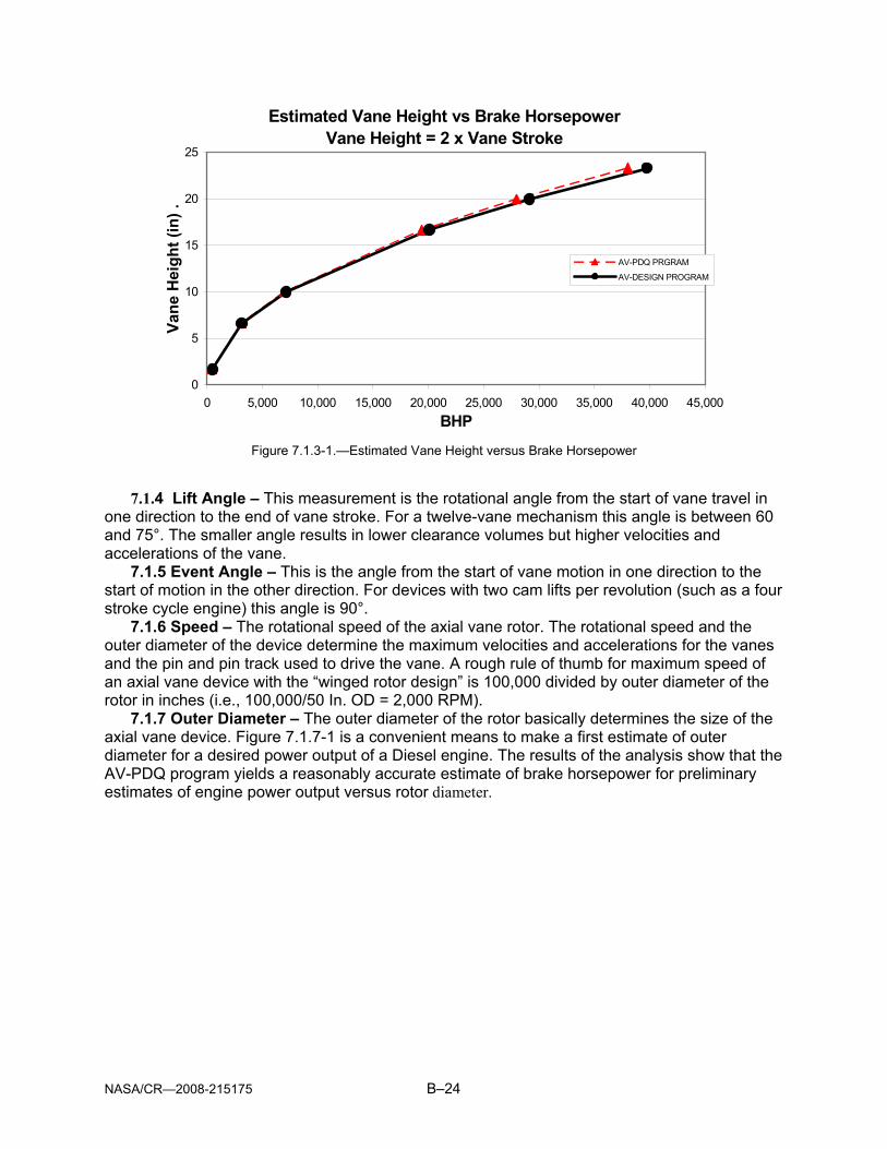
NASA/CR—2008-215175 B–24
Estimated Vane Height vs Brake Horsepower Vane Height = 2 x Vane Stroke
0
5
10
15
20
25
0 5,000 10,000 15,000 20,000 25,000 30,000 35,000 40,000 45,000BHP
Vane
Hei
ght (
in) .
AV-PDQ PRGRAM
AV-DESIGN PROGRAM
Figure 7.1.3-1.—Estimated Vane Height versus Brake Horsepower
7.1.4 Lift Angle – This measurement is the rotational angle from the start of vane travel in
one direction to the end of vane stroke. For a twelve-vane mechanism this angle is between 60 and 75°. The smaller angle results in lower clearance volumes but higher velocities and accelerations of the vane.
7.1.5 Event Angle – This is the angle from the start of vane motion in one direction to the start of motion in the other direction. For devices with two cam lifts per revolution (such as a four stroke cycle engine) this angle is 90°.
7.1.6 Speed – The rotational speed of the axial vane rotor. The rotational speed and the outer diameter of the device determine the maximum velocities and accelerations for the vanes and the pin and pin track used to drive the vane. A rough rule of thumb for maximum speed of an axial vane device with the “winged rotor design” is 100,000 divided by outer diameter of the rotor in inches (i.e., 100,000/50 In. OD = 2,000 RPM).
7.1.7 Outer Diameter – The outer diameter of the rotor basically determines the size of the axial vane device. Figure 7.1.7-1 is a convenient means to make a first estimate of outer diameter for a desired power output of a Diesel engine. The results of the analysis show that the AV-PDQ program yields a reasonably accurate estimate of brake horsepower for preliminary estimates of engine power output versus rotor diameter.

NASA/CR—2008-215175 B–25
Estimated Rotor Outer Diameter vs Brake Horsepower
0
10
20
30
40
50
60
70
80
0 5,000 10,000 15,000 20,000 25,000 30,000 35,000 40,000 45,000
BHP
Rot
or O
uter
Dia
met
er -
(in.)
. AV-PDQ PROGRAM
AV-DESIGN PROGRAM
Figure 7.1.7-1.—Rotor Outer Diameter versus Power
7.1.8 Rotor Clearance – This is the axial clearance between the face of the rotor and the
face of the cam when they are closest together at minimum vane stroke. This dimension should be as small as possible to minimize rotor clearance volume, which does not participate in the fuel burning process. A practical value for the clearance dimension is 0.005 inch when essentially zero axial motion is permitted by the bearings selected. If larger axial motions are allowed, then larger dimensions for rotor clearance are required.
7.1.9 BMEP – Brake Mean Effective Pressure (BMEP) measured in psi is a cycle averaged value that when multiplied by the displacement and the speed of an engine (times a constant) results in net, or brake power output. For naturally aspirated engines a typical BMEP is 120 psi. For turbocharged engines this value can be as high as 300 psi, but is more typically around 200 psi.
7.1.10 Number of Cam Lifts – This is the number of cam lifts per revolution. For four stroke cycle engines this value is 2. The number of cam lifts can be more than 2 for compressors and expanders.
7.1.11 Number of Vanes – Input the number of vanes per rotor. As a rule of thumb the minimum number of vanes is 8. Any number of vanes, odd or even, can be used making certain that the minimum distance between vanes (at the inner diameter) results in sufficient rotor strength and stiffness. The number is usually 12 vanes for Diesel engines less than 15 inches in diameter; however, large devices with diameters over 15 to 20 inches will be more efficient with an even larger number of vanes.
7.1.12 Minimum Volume – Minimum Volume is a measurement of the rotor clearance volume plus the combustion pocket volume. It is used to determine the compression ratio of the device and the required volume of the pocket (as the clearance volume is calculated and not input). The Minimum Volume is manipulated to change the Pocket Volume and produce the desired compression ratio. This ratio is typically around 15:1 for a Diesel cycle engine. Figure 7.1.12-1 provides a means to make an initial estimate of the required Minimum Volume.

NASA/CR—2008-215175 B–26
Chamber Minimum Volume vs. Power
020406080
100120140160180
0 5,000 10,000 15,000 20,000 25,000 30,000Power (Bhp)
Min
imum
Vol
ume
(cu.
in.)
.
Figure 7.1.12-1 Estimated Chamber Minimum Volume versus Power
7.1.13 Pocket Length – This measurement is the arc length of the combustion pocket in the
face of the rotor in each chamber. In the case of a Compressor or expander, the Pocket Length is zero. An easy means to set this value is to take the mean diameter between the inner and outer diameters and multiply this value by “π” to find the mean circumference. Subtract from this product the number of vanes times the thickness of the vanes. The result will be the maximum arc length available for construction of combustion pockets in the rotor. Divide the maximum arc length by the number of vanes to find the total maximum pocket lengths. Reduce this length by about an amount sufficient to support of the vanes on both ends of the pocket.
7.1.14 Tip Clearance – This dimension is the clearance between the tip of the vane and the face of the cam. This clearance is maintained by the mechanism used to position the vane. A typical value for this dimension is 0.005 inches with a larger dimension required for large devices to account for larger manufacturing tolerances and increased tolerances in the pin- and-pin track or slot-and-rail mechanism.
7.1.16 Diametral Clearance – Diametral Clearance is the Outer Diameter minus the Inner Diameter minus the Vane Height. This dimension needs to vary with engine size, materials, and detailed design of the engine. A value of 0.010 inch for a 10-inch diameter engine is typical. It should be noted that centrifugal force will cause the outer edge of the vane to have zero clearance at the outer wing and that most of the Diametral Clearance will occur at the inner edge of the vane where it travels in the slot of the inner wing.
7.1.17 Initial Pressure – The absolute pressure in the chamber at the point that the intake port is closed. A good approximation of this value for a naturally aspirated engine is to use atmospheric pressure. The value of atmospheric pressure will of course vary with altitude. In the case of a turbocharged engine, the turbocharger will increase the initial pressure depending on the pressure ratio of the turbocharger compressor.
7.1.18 Initial Temperature – This is an absolute temperature value determined in exactly the same way as initial pressure.
7.1.19 R – Gas Constant – This is also referred to as the Universal Gas Constant.
For air, R has a value of 53.3 .Rlb
lbft°−
−

NASA/CR—2008-215175 B–27
7.1.20 k – Ratio of Specific Heats – The Ratio of Specific Heats, symbolized as a lower
case k, is the ratio of CvCp . For air at normal sea level conditions k has a value of about 1.4.
7.1.21 C – Discharge Coefficient – A discharge coefficient is required in calculating leakage of air across the vane. A typical value to use for this calculation is 0.70.
7.1.22 F/A Ratio – F/A is an abbreviation for fuel air ratio, which is the mass flow rate of air divided by the flow rate of fuel with both measurements in pounds. A value of 0.04 to 0.05 should be used for naturally aspirated engines and a value of 0.025 to 0.030 for turbocharged axial vane engines. The larger this number, the richer the mixture, which results in higher combustion temperatures.
7.1.23 Fuel Heating Value – This is a measurement of the energy available in a pound of fuel measured in Btu/lb. A typical value for Diesel fuel is 18,600 Btu/lb.
7.1.24 Effective Lower Heating Value – This value is used as a means to circumvent a problem inherent in spreadsheets known as “circular references”. The only way to get around this problem is to use manual iteration. In this case the heat losses are calculated using the chamber pressure as one of the variables. Unfortunately, chamber pressure is dependant upon the amount of heat loss. To get around this problem the percentage of input fuel energy, which is lost because of heat transfer, is calculated and displayed in cell FB6. This value is automatically input into cell EO5 to reduce the total fuel heat input by the amount of heat lost. The Effective Heating Value should be adjusted for each change of parameters in the design as the optimal sizing of the engine is achieved. The computed ratio will vary with each change of parameters in the design and should be re-entered into cell EO5 until the output values converge. This process should typically not require more than three iterations.

NASA/CR—2008-215175 B–28
SECTION 8: INSTRUCTIONS FOR DESIGN OF AXIAL-VANE DIESEL CYCLE ENGINE A Diesel engine is the most complex device that can be analyzed or designed using the
Axial Vane Design Program. Therefore, design of a Diesel engine has been used in the attached Axial Vane Design Program to illustrate use of the spreadsheets and interpretation of the results. The program was designed to operate using Microsoft Windows 2000 or a comparable operating system and Microsoft Excel. Initial User Input values for the program can be obtained from a preliminary analysis using the associated Axial-Vane Preliminary Design Program, AV-PDQ, or may be estimated from the charts provided in Section 7. Listed below is a guide for use of the Axial Vane Design Program.
A. Open the spreadsheet file titled “Axial Vane Design.xls” B. The spreadsheet analysis can be started by pressing the first spreadsheet, 1 AV
Design, in the Excel Workbook. C. Each design parameter and spreadsheet cell location is listed below. Fill in the input
values, which have red text and yellow background as follows:
I Vane Thickness (inches) J6
ii Vane Stroke (inches) J7
iii Vane Height (inches) J8
iv Lift Angle (degrees) J9
v Event Angle (degrees) J11
vi Speed (RPM) J12
vii Outer Diameter (inches) J15
viii Number of Cam Lifts O8
ix Rotor O.D. Clearance (inches) O4
x Estimated Brake Mean Effective Pressure (psi) O6
xi Number of Vanes O12
xii Minimum Volume/Chamber (cubic inches) O13
xiii Pocket Length (inches) O17
xiv Tip Clearance (inches) W7
xv Diametral Clearance (inches) W8
xvi Initial Pressure (psia) BE6
xvii Initial Temperature (Degrees R.) BE7
D. When values for all parameters have been input, the spreadsheet computations are automatically processed. The Effective Heat Value of the fuel (Cells EO5 & FB6) MUST BE MANUALLY ITERATED until the effective heat values in the two cells converge. The results of the analysis, including User Inputs and Outputs are listed in the PRINTOUT on Sheet 2 of the Spreadsheet
E. The results of the computations are also presented in graphical form at the bottom of the spreadsheet. Graphs of the various outputs for all chambers are shown in charts located at the bottom of the spreadsheet. Each chart is located immediately below the
NASA/CR—2008-215175 B–29
section of the spreadsheet where the related values were computed. The spreadsheet program computes values for each 1° of rotation of each chamber in the AV-device. Each chart shows a plot of the related values for all chambers through a 360° revolution of the rotor.
F. The spreadsheet also contains detailed graphs of the parameters for a single chamber as it moves through one complete revolution. Each of the graphs can be called up via the tabs on the bottom of the spreadsheet as follows: Sheet 2: PRINTOUT - Summary of Performance Analysis (Inputs & Outputs) Sheet 3: Engine Types -Volume vs. Shaft Angle for Three Engine Types Sheet 4: Vane Travel Sheet 5: Chamber Volume Sheet 6: Leakage Area Sheet 7: Weight of Gas in Chamber Sheet 8: Temperature of Gas in Chamber Sheet 9: Pressure of Gas in Chamber Sheet 10: P-V Diagram
G. A summary of the input variables and the results of the computations are presented in the "Summary of Performance Analysis" table contained in Sheet 2 of the Spreadsheet Program (2 PRINTOUT).
H. The graph "Three Engine Types" (Worksheet 3) compares the cylinder/chamber volume relationships versus shaft angle for a Piston Engine, a Wankel Engine, and an ATI Axial Vane Device. The graph illustrates the volumetric superiority of the ATI Axial Vane Device.
I. Repetitive analyses can be conducted by adjusting the dimensions of the axial-vane device to produce the desired output. In the case of Diesel engines, the Minimum Volume per Chamber (Cell O13) should be changed as required to adjust the Compression Ratio by changing the Combustion Pocket Volume (Cell O16). The Brake Horsepower is most effectively changed by adjusting the Outer Diameter of the Rotor and re-scaling the sizing of vanes and compression ratio as explained above.

NASA/CR—2008-215175 B–30
SUMMARY OF PERFORMANCE ANALYSIS
DESIGN PROGRAM FOR AXIAL VANE MACHINESDeveloped by Advanced Technologies Inc.
March 2005
25,000 Horsepower Diesel Engine {Title of Design: From Sheet 1 AV DESIGN)
PARAMETER VALUE COMMENTS & NOTES
PHYSICAL DIMENSIONS & DESIGN VARIABLESNUMBER OF VANES 12 12-Vane Diesel EngineNUMBER OF CAMS 2
ANGLE BETWEEN VANES 30VANE THICKNESS (inches) 1.00 Estimated = 0.10 x Vane Stroke
VANE STROKE (inches) 10.00 Estimated from Chart: Vane Stroke vs. BHPVANE HEIGHT (inches) 20.00 Estimated as 2 x Vane StrokeLIFT ANGLE (degrees) 75
DWELL ANGLE (degrees) 15EVENT ANGLE (degrees) 90
ROTOR OUTER DIAMETER (inches) 57.00 Estimated based on Chart: OD vs. BHPROTOR INNER DIAMETER (inches) 17.00 Estimated = OD -2 Vane Height ROTOR MEAN DIAMETER (inches) 37.00
INPUT DESIGN VALUESSPEED (RPM) 1,670 Limited by Vane Rubbing Velocity
OMEGA (radians/sec) 175
ROTOR CLEARANCE (inches) 0.005 Minimum clearance between Rotor & CamTIP CLEARANCE (inches) 0.005 Clearance between Vane Tip and Cam
DIAMETRAL CLEARANCE (inches) 0.010 Total radial clearance between vane & Inner & Outer Wings
INITIAL PRESSURE (psia) 14.70 Inlet PressureINITIAL TEMPERATURE (deg R) 530.00 Inlet Temperature
Gas Constant, R = 53.30Ratio of Specific Heat, k = 1.3937
HEAT VALUE (BTU/lb) 18,600EFFECTIVE HEAT VALUE (BTU/lb) 15,693 Computed in Cell FB6 based on cooling Heat Loss that
FUEL/AIR RATIO 0.0390 varies with Chamber Pressure & Temperature.AIR/FUEL RATIO 25.64
COMPUTED VALUESDISLACEMENT/CHAMBER (cu. in.) 1,736.65 Adjust Displacement/Chamber to change Comp. Ratio
POCKET VOLUME (cu.in.) 127.03 Pocket Volume is automatically adjusted when Disp. PerROTOR CLEARANCE VOLUME (cu.in.) 0.9687 Chamber is changed.
TOTAL DISPLACEMENT (cu. in.) 41,680 Total Displacement of 24 chambers.COMPRESSION RATIO 14.53 Ratio of Max. Real Vol. / Min. Real Vol.(Col.
COMPUTED PERFORMANCE
AIR FLOW (lbs/min 3,018.37 FUEL FLOW (lbs/min) 117.72
BRAKE MEAN EFFECTIVE PRESSURE (BMEP)(psi) 142.40INDICATED POWER (hp) 29,857
FRICTION POWER (hp) 4,829HEAT LOSS POWER (hp) 3,830
BRAKE HORSEPOWER OUTPUT (Bhp) 25,029BRAKE SPECIFIC FUEL CONSUMPTION (lbs/Bhp/hr) 0.2822
EXHAUST TEMPERATURE ( deg. F.) 1738
Performed By: Mike Smith Date Performed: May 26, 2005
Figure 8–1.—Sample of PRINTOUT from Axial-Vane Design Program

REPORT DOCUMENTATION PAGE Form Approved OMB No. 0704-0188
The public reporting burden for this collection of information is estimated to average 1 hour per response, including the time for reviewing instructions, searching existing data sources, gathering and maintaining the data needed, and completing and reviewing the collection of information. Send comments regarding this burden estimate or any other aspect of this collection of information, including suggestions for reducing this burden, to Department of Defense, Washington Headquarters Services, Directorate for Information Operations and Reports (0704-0188), 1215 Jefferson Davis Highway, Suite 1204, Arlington, VA 22202-4302. Respondents should be aware that notwithstanding any other provision of law, no person shall be subject to any penalty for failing to comply with a collection of information if it does not display a currently valid OMB control number. PLEASE DO NOT RETURN YOUR FORM TO THE ABOVE ADDRESS. 1. REPORT DATE (DD-MM-YYYY) 01-07-2008
2. REPORT TYPE Final Contractor Report
3. DATES COVERED (From - To)
4. TITLE AND SUBTITLE System Study for Axial Vane Engine Technology
5a. CONTRACT NUMBER
5b. GRANT NUMBER
5c. PROGRAM ELEMENT NUMBER
6. AUTHOR(S) Badgley, Patrick, R.; Smith, Michael, R.; Gould, Cedric, O.
5d. PROJECT NUMBER NNC-04VN19P
5e. TASK NUMBER
5f. WORK UNIT NUMBER WBS 984754.02.07.03.11.02
7. PERFORMING ORGANIZATION NAME(S) AND ADDRESS(ES) Advanced Technologies, Inc. P.O. Box 850 Starkville, Mississippi 39760
8. PERFORMING ORGANIZATION REPORT NUMBER E-16418
9. SPONSORING/MONITORING AGENCY NAME(S) AND ADDRESS(ES) National Aeronautics and Space Administration Washington, DC 20546-0001
10. SPONSORING/MONITORS ACRONYM(S) NASA
11. SPONSORING/MONITORING REPORT NUMBER NASA/CR-2008-215175
12. DISTRIBUTION/AVAILABILITY STATEMENT Unclassified-Unlimited Subject Category: 07 Available electronically at http://gltrs.grc.nasa.gov This publication is available from the NASA Center for AeroSpace Information, 301-621-0390
13. SUPPLEMENTARY NOTES
14. ABSTRACT The purpose of this engine feasibility study was to determine the benefits that can be achieved by incorporating positive displacement axial vane compression and expansion stages into high bypass turbofan engines. These positive-displacement stages would replace some or all of the conventional compressor and turbine stages in the turbine engine, but not the fan. The study considered combustion occurring internal to an axial vane component (i.e., Diesel engine replacing the standard turbine engine combustor, burner, and turbine); and external continuous flow combustion with an axial vane compressor and an axial vane turbine replacing conventional compressor and turbine systems. 15. SUBJECT TERMS Internal combustion engines; Diesel engines; Turbomachinery; Thermodynamic cycles
16. SECURITY CLASSIFICATION OF: 17. LIMITATION OF ABSTRACT UU
18. NUMBER OF PAGES
78
19a. NAME OF RESPONSIBLE PERSON STI Help Desk (email:[email protected])
a. REPORT U
b. ABSTRACT U
c. THIS PAGE U
19b. TELEPHONE NUMBER (include area code) 301-621-0390
Standard Form 298 (Rev. 8-98)Prescribed by ANSI Std. Z39-18