Embed Size (px)
Citation preview
SYSTEMS MANUAL
AVALON TOWERS BELLEVUE
This manual describes ideas and procedures to help the maintenance team keep the facility running
efficiently and cost‐effectively. The top maintenance and energy efficiency guidelines are listed below, in
order of importance:
1. Apartment Thermostat Programming
Section 1 – Heat PumpsAppendix A – Thermostat Instructions
2. Central Plant Temperature Cooling Valve
Section 1.1 – Cooling ValveAppendix C – Water Loop Description of Operations Appendix D – Cooling Valve Commissioning Results
3. Variable Frequency Drives Section 6 – Garage Exhaust SystemAppendix C – Water Loop Description of Operations
4. Common Areas Section 2 – Table 1
5. Electric Heaters Section 4 – Table 2
Avalon Towers Bellevue Systems Manual January 7, 2013 Page 1
TABLE OF CONTENTS
Section 1 Residential Water Loop Heat Pumps 2
Section 2 Common Area Water Loop Heat Pumps 6
Section 3 Residential Water 7
Section 4 Electric Heating 8
Section 5 Lighting 9
Section 6 Garage Exhaust System 10
Section 7 Tracking Electricity and Natural Gas Usage 11
Section 8 On‐going Commissioning Plan 12
8.1 JCI System Trends 12
8.2 List of Efficiency Checks and Recommended Settings 13
8.3 Natural Gas Usage of Specific Equipment 14
8.4 Electricity Usage of Specific Equipment 15
8.5 Bill Tracking Tool 16
8.6 Functional Test Procedures 16
8.7 Additional Energy Efficiency Opportunities 16
Section 9 Ongoing Training Opportunities 19
Section 10 Appendices 20
Appendix A Thermostat Programming Instructions 21
Appendix B Mechanical Room Diagrams 25
Appendix C Heat Pump Water Loop Description of Operations 29
Appendix D Cooling Valve Operation 31
Appendix E Accessing Electricity and Natural Gas Bills 34
Appendix F Historical Trend Logs 35
Appendix G PSE Bill Tracking Tool 38
Appendix H Functional Test Procedures 39
Avalon Towers Bellevue Systems Manual January 7, 2013 Page 2
SECTION 1. RESIDENTIAL WATER LOOP HEAT PUMPS
Apartments are not connected to the central Johnson Controls (JCI) building controls; instead, each
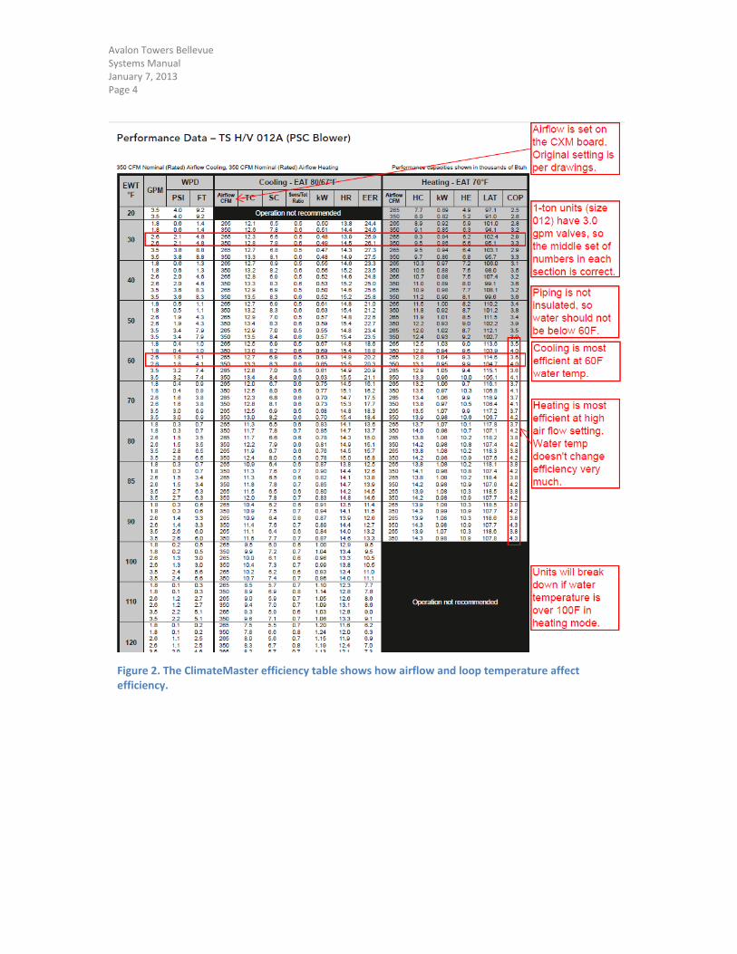
apartment has a single heat pump controlled by a thermostat. Figure 2 shows typical heat pump
efficiencies, with notes that describe the factors that are important to heat pump efficiency and illustrate
the importance of monitoring the water loop temperature. To help avoid high loop temperatures, alarms
are programmed into the JCI system.
Another important maintenance procedure is programming the thermostats. For the first two years, the
apartment thermostats were reset to factory default whenever a tenant moved out. This procedure was
changed to include a custom thermostat program designed to increase the tenant’s comfort and decrease
the wear and tear on the heat pumps. The instruction page for the thermostat program is provided in
Appendix A.
The HVAC system is divided into two water loops, the West Tower and the East Tower. Each system has a
central indirect evaporative fluid cooler and a bank of modulating natural gas heaters to moderate the
water loop (see Appendix B for diagrams of the mechanical rooms). One pump in each loop circulates
water to apartments and common area units. The pumps switch operation on Monday mornings. On very
hot or very cold days, the standby pump turns on to maintain pressure.
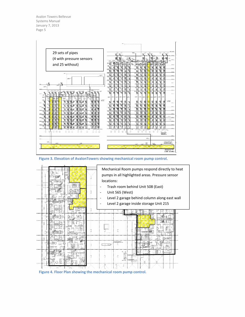
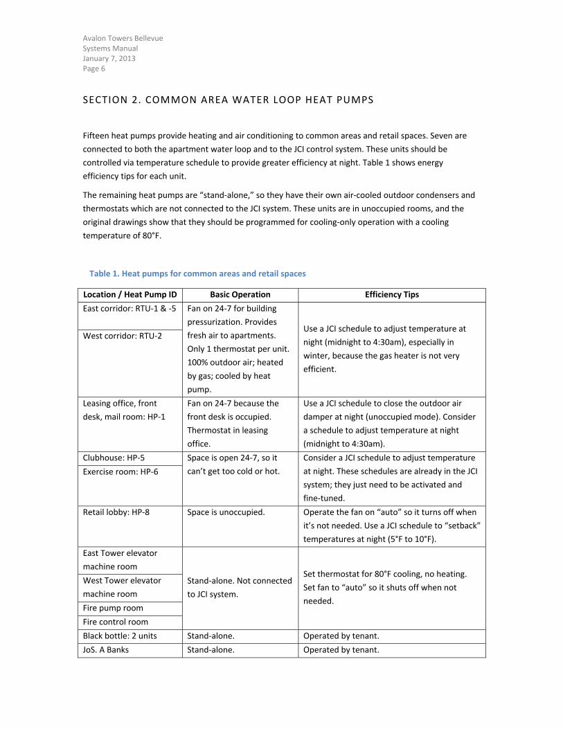
Each loop extends down to Level 1 where it serves common areas and retail spaces. Figures 3 and 4 show
how the central plants are connected to each heat pump. Appendix C includes a detailed description of
operations.
1.1 COOLING DIVERTING VALVE
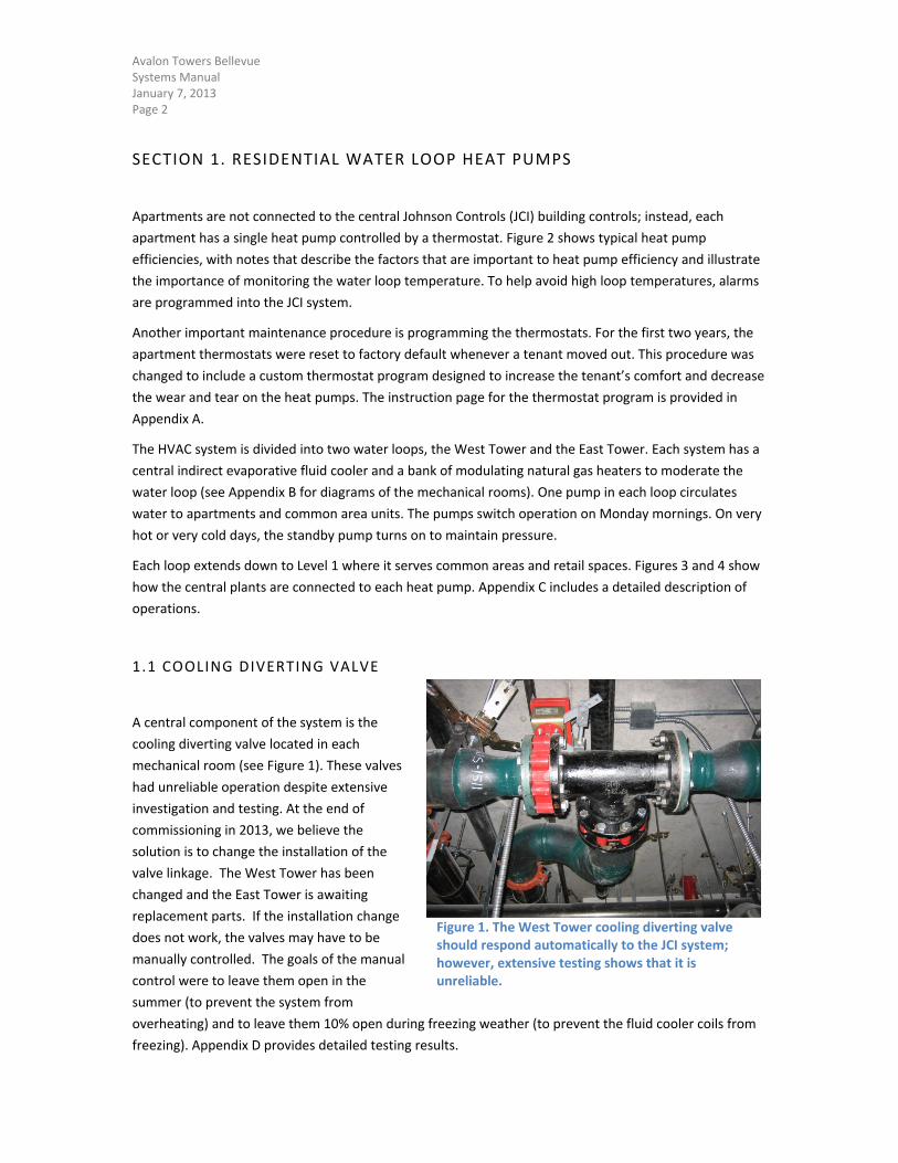
A central component of the system is the
cooling diverting valve located in each
mechanical room (see Figure 1). These valves
had unreliable operation despite extensive
investigation and testing. At the end of
commissioning in 2013, we believe the
solution is to change the installation of the
valve linkage. The West Tower has been
changed and the East Tower is awaiting
replacement parts. If the installation change
does not work, the valves may have to be
manually controlled. The goals of the manual
control were to leave them open in the
summer (to prevent the system from
overheating) and to leave them 10% open during freezing weather (to prevent the fluid cooler coils from
freezing). Appendix D provides detailed testing results.
Figure 1. The West Tower cooling diverting valve should respond automatically to the JCI system; however, extensive testing shows that it is unreliable.
Avalon Towers Bellevue Systems Manual January 7, 2013 Page 3
1.2 WATER LOOP OPERATING GOALS
This equipment should be reliable as long as the loop temperature follows the guidelines in Figure 2 and
the apartment thermostats are programmed per Appendix A. System corrections will be needed if the
goals below are not being met:
No more than one call per month is due to failed heat pump components.
There are no hot or cold calls from apartments after tenant orientation is provided.
Condenser water heaters do not operate May to September.
During the winter, the condenser water heaters run twice as long as they are OFF. The minimum
OFF time should be 30 minutes.
Avalon Towers Bellevue Systems Manual January 7, 2013 Page 4
Figure 2. The ClimateMaster efficiency table shows how airflow and loop temperature affect efficiency.
Avalon Towers Bellevue Systems Manual January 7, 2013 Page 5
Figure 3. Elevation of AvalonTowers showing mechanical room pump control.
Figure 4. Floor Plan showing the mechanical room pump control.
Mechanical Room pumps respond directly to heat
pumps in all highlighted areas. Pressure sensor
locations:
‐ Trash room behind Unit 508 (East)
‐ Unit 565 (West)
‐ Level 2 garage behind column along east wall
‐ Level 2 garage inside storage Unit 215
29 sets of pipes
(4 with pressure sensors
and 25 without)
Avalon Towers Bellevue Systems Manual January 7, 2013 Page 6
SECTION 2. COMMON AREA WATER LOOP HEAT PUMPS
Fifteen heat pumps provide heating and air conditioning to common areas and retail spaces. Seven are
connected to both the apartment water loop and to the JCI control system. These units should be
controlled via temperature schedule to provide greater efficiency at night. Table 1 shows energy
efficiency tips for each unit.
The remaining heat pumps are “stand‐alone,” so they have their own air‐cooled outdoor condensers and
thermostats which are not connected to the JCI system. These units are in unoccupied rooms, and the
original drawings show that they should be programmed for cooling‐only operation with a cooling
temperature of 80°F.
Table 1. Heat pumps for common areas and retail spaces
Location / Heat Pump ID Basic Operation Efficiency Tips
East corridor: RTU‐1 & ‐5
Fan on 24‐7 for building
pressurization. Provides
fresh air to apartments.
Only 1 thermostat per unit.
100% outdoor air; heated
by gas; cooled by heat
pump.
Use a JCI schedule to adjust temperature at
night (midnight to 4:30am), especially in
winter, because the gas heater is not very
efficient.
West corridor: RTU‐2
Leasing office, front
desk, mail room: HP‐1
Fan on 24‐7 because the
front desk is occupied.
Thermostat in leasing
office.
Use a JCI schedule to close the outdoor air
damper at night (unoccupied mode). Consider
a schedule to adjust temperature at night
(midnight to 4:30am).
Clubhouse: HP‐5 Space is open 24‐7, so it
can’t get too cold or hot.
Consider a JCI schedule to adjust temperature
at night. These schedules are already in the JCI
system; they just need to be activated and
fine‐tuned.
Exercise room: HP‐6
Retail lobby: HP‐8 Space is unoccupied. Operate the fan on “auto” so it turns off when
it’s not needed. Use a JCI schedule to “setback”
temperatures at night (5°F to 10°F).
East Tower elevator
machine room
Stand‐alone. Not connected
to JCI system.
Set thermostat for 80°F cooling, no heating.
Set fan to “auto” so it shuts off when not
needed.
West Tower elevator
machine room
Fire pump room
Fire control room
Black bottle: 2 units Stand‐alone. Operated by tenant.
JoS. A Banks Stand‐alone. Operated by tenant.
Avalon Towers Bellevue Systems Manual January 7, 2013 Page 7
SECTION 3. RESIDENTIAL WATER
Cold water is pumped to each apartment using booster pumps located in the northeast corner of Level P2.
The system operates automatically to maintain a pressure of 150 psi (pounds per square inch), or
approximately 350 feet of water head. Since the building is 250 feet tall, the water pressure on the
Penthouse floor should be more than adequate. The pumps are programmed to switch each time more
pressure is needed. Each pump typically runs for 8 minutes, then the system is off for 2 minutes before
the next pump cycles on.
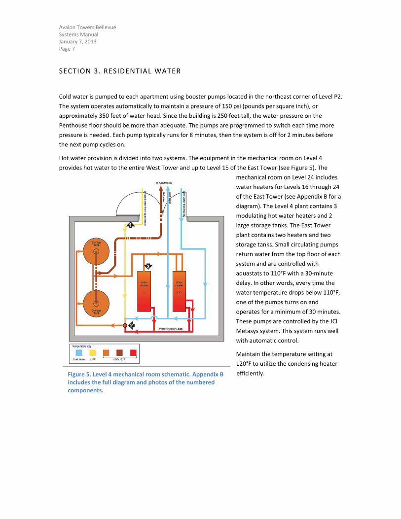
Hot water provision is divided into two systems. The equipment in the mechanical room on Level 4
provides hot water to the entire West Tower and up to Level 15 of the East Tower (see Figure 5). The
mechanical room on Level 24 includes
water heaters for Levels 16 through 24
of the East Tower (see Appendix B for a
diagram). The Level 4 plant contains 3
modulating hot water heaters and 2
large storage tanks. The East Tower
plant contains two heaters and two
storage tanks. Small circulating pumps
return water from the top floor of each
system and are controlled with
aquastats to 110°F with a 30‐minute
delay. In other words, every time the
water temperature drops below 110°F,
one of the pumps turns on and
operates for a minimum of 30 minutes.
These pumps are controlled by the JCI
Metasys system. This system runs well
with automatic control.
Maintain the temperature setting at
120°F to utilize the condensing heater
efficiently.
Figure 5. Level 4 mechanical room schematic. Appendix B includes the full diagram and photos of the numbered components.
Avalon Towers Bellevue Systems Manual January 7, 2013 Page 8
SECTION 4. ELECTRIC HEATING
A number of small electric heaters are installed throughout the garage. These heaters total almost 50 kW,
which could account for more than 1/3 of the building’s winter electricity use. Table 2 lists the location of
each heater, its basic operation, and energy efficiency tips. This is a key area for energy efficiency since
the garage does not need significant heating.
Table 2. Garage heating operation and efficiency tips
Location / Heat Pump ID Basic Operation Efficiency Tips
Garage elevator lobbies: Electric Duct Heaters ‐3, ‐4, ‐5, ‐8, ‐9, ‐10, ‐11, ‐12, ‐13
Fan on 24‐7 for building pressurization. Provides fresh air to elevator lobbies.
Program thermostats for 65°F heating, no cooling. Make sure thermostat is set to “run,” not “program” mode (dip switch is behind cover). See Appendix A for instructions.
Maintenance shop: Electric Duct Heaters ‐6, ‐7
Fan cycles with thermostat. Needs to be warm when maintenance team is working.
Install programmable thermostats so temperature can be adjusted at night (10°F lower).
Stairwell heaters (1 per stair, at bottom level)
Operates at 100%, 24 hours a day if dial turned to high. Unoccupied, unused.
Keep units on low or off. Remove dials to prevent tampering.
Baseboard heaters in storage rooms (2 in P203*, and 1 each in P208, P109, 229, & 322)
Controlled by tamper‐resistant thermostat. Unoccupied, unheated storage.
Turn thermostats to mid‐range (~65°F) or lower. See Figure 6 for illustration.
Baseboard heaters in bike storage rooms (2 in East, 1 in West)
Controlled by tamper‐resistant thermostat.
Turn thermostats to mid‐range (~65°F) or lower. See Figure 6 for illustration.
Baseboard heater in main electrical room
Controlled by tamper‐resistant thermostat.
Heater should remain off: electrical room is always above 65°F.
*The heaters in P203 do not have thermostats. Since the storage is intended to be unheated, the wiring was disconnected as part of commissioning. Unless the wiring is reconnected, these heaters will not turn on.
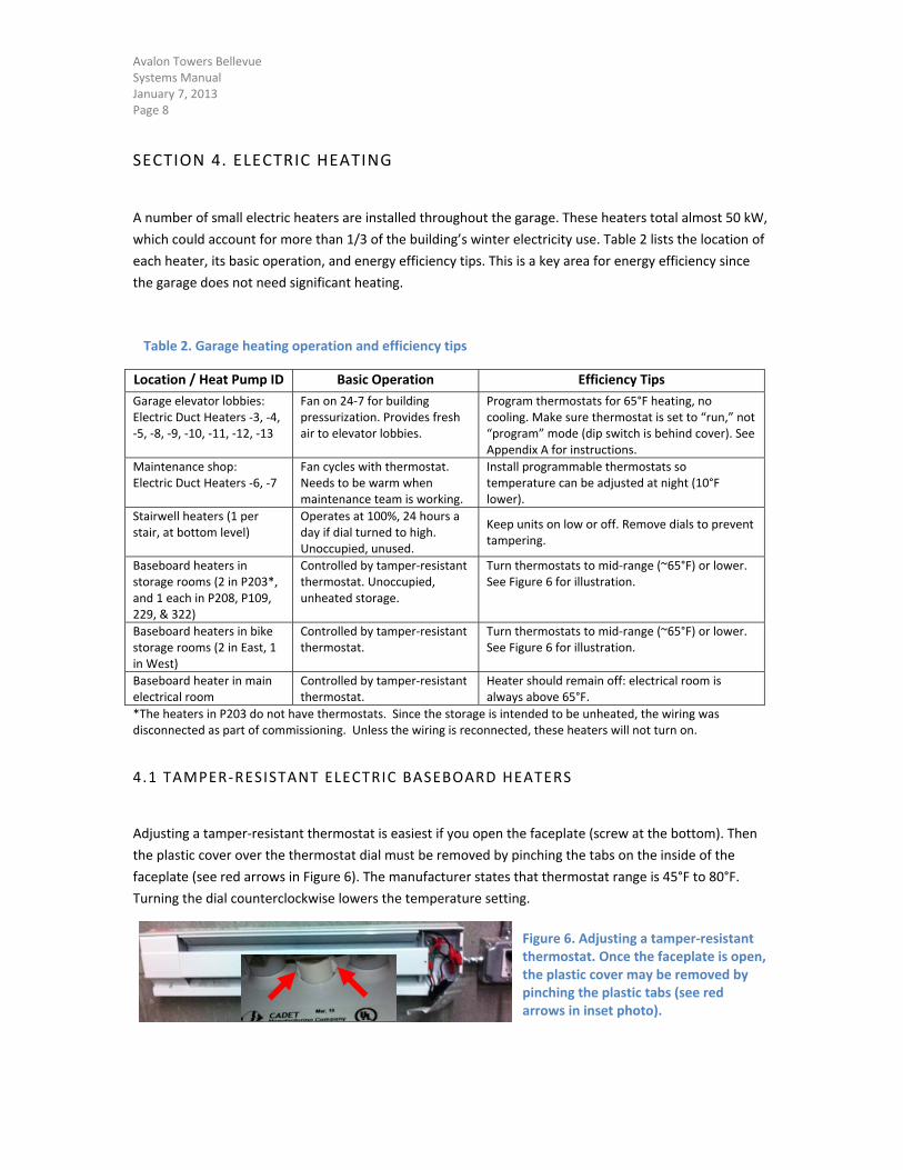
4.1 TAMPER‐RESISTANT ELECTRIC BASEBOARD HEATERS
Adjusting a tamper‐resistant thermostat is easiest if you open the faceplate (screw at the bottom). Then
the plastic cover over the thermostat dial must be removed by pinching the tabs on the inside of the
faceplate (see red arrows in Figure 6). The manufacturer states that thermostat range is 45°F to 80°F.
Turning the dial counterclockwise lowers the temperature setting.
Figure 6. Adjusting a tamper‐resistant thermostat. Once the faceplate is open, the plastic cover may be removed by pinching the plastic tabs (see red arrows in inset photo).
Avalon Towers Bellevue Systems Manual January 7, 2013 Page 9
SECTION 5. LIGHTING
The building’s lighting is relatively efficient and runs automatically. Occupancy sensors are located in
every residential corridor, stairwell landing, and common area. The sensors appear to work well and have
correct timeouts according to their location and use. The exterior lighting is controlled by Intermatic
astronomical time clocks that account for the amount of daylight on any given day of the year. These
clocks are programmed with Bellevue’s location as well as the day and time. Table 3 shows the location
and basic operation of each clock.
Although lights are burning out and being replaced by maintenance staff, this appears to be normal wear
and tear.
Table 3. Control of exterior lighting
Location / Area of Control Basic Operation Efficiency Tips
Main electrical room: Controls ground floor façade, main lobby entrance, Level 4 façade.
Lights stay on all night. Consider turning Level 4 lights off at midnight. Other lighting needs to stay on for safety.
Level 2, 3, & 4 (1 clock per level): Controls interior lighting which shine onto translucent panels over the main lobby
On at dusk, off at 11pm.
None. These lights are working great. Level 5, East Tower electrical room: Controls landscape lighting on the Level 5 patio, including the BBQ area
On all night, every night.
Garage On 24‐7 for safety. Based on normal lamp life for these bulbs, replacement should be needed in 2014.
This is the single largest electricity use in the building; however, the lighting fixtures are the most efficient, cost‐effective technology available in 2010. Be sure to replace burned‐out lamps with the exact same type. Switching manufacturers or wattages can cause excess energy use and/or premature ballast failure.
Avalon Towers Bellevue Systems Manual January 7, 2013 Page 10
SECTION 6. GARAGE EXHAUST SYSTEM
The garage exhaust system includes two large axial fans (located on Level P2 and Level 1) as well as many
smaller fans connected to ductwork. The system is controlled by the JCI using several car exhaust (carbon
monoxide) sensors. Per building code, the main exhaust fans run on low speed (20%) 24 hours a day. At
this speed, the fans use very little energy. When any of the exhaust sensors gets above 25 ppm (parts per
million), all of the smaller fans turn on and the large fans increase their speed to 50%.1 When the system
is in this mode, it uses about 10 times more energy. Alarms are programmed into the JCI system to alert
maintenance staff when the system is running inefficiently (e.g. when the system is in “hand” rather than
“auto” mode).
On a normal day, the system runs in high for about three hours. Typically, a car will get close to one of the
sensors and send it above the high limit (150 ppm) for a few minutes. As long as the sensor returns to
normal within 35 minutes, the system is working
fine.2
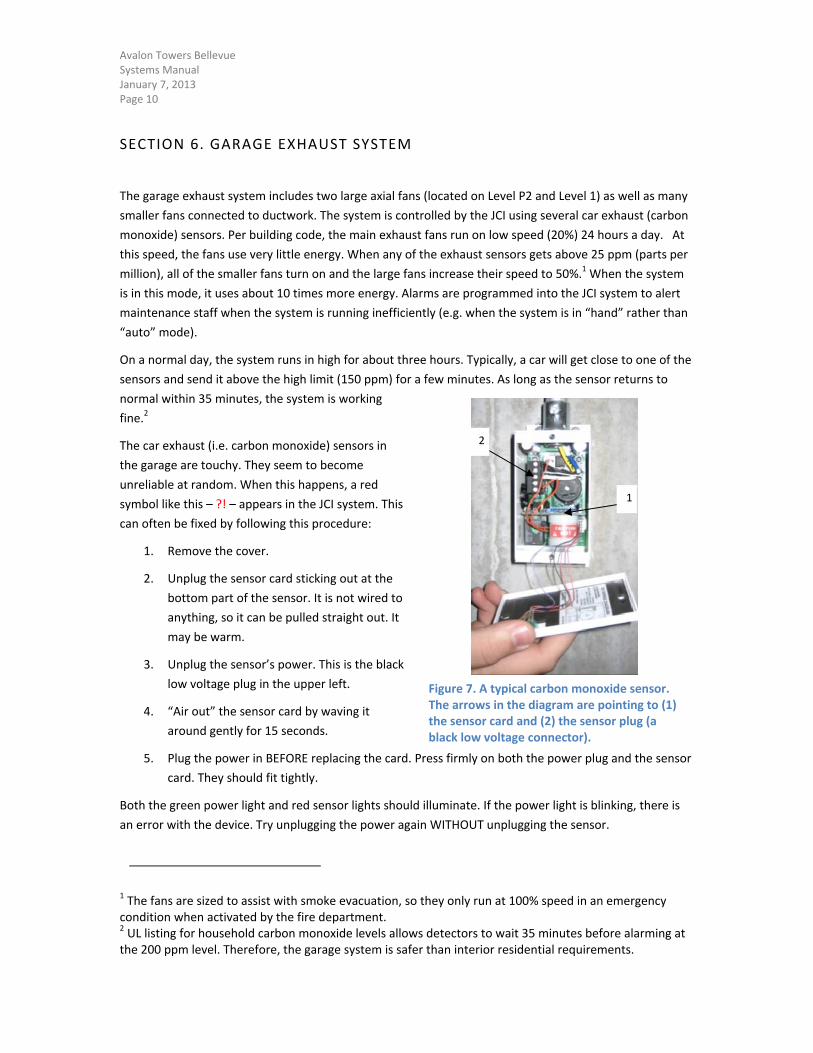
The car exhaust (i.e. carbon monoxide) sensors in
the garage are touchy. They seem to become
unreliable at random. When this happens, a red
symbol like this – ?! – appears in the JCI system. This
can often be fixed by following this procedure:
1. Remove the cover.
2. Unplug the sensor card sticking out at the
bottom part of the sensor. It is not wired to
anything, so it can be pulled straight out. It
may be warm.
3. Unplug the sensor’s power. This is the black
low voltage plug in the upper left.
4. “Air out” the sensor card by waving it
around gently for 15 seconds.
5. Plug the power in BEFORE replacing the card. Press firmly on both the power plug and the sensor
card. They should fit tightly.
Both the green power light and red sensor lights should illuminate. If the power light is blinking, there is
an error with the device. Try unplugging the power again WITHOUT unplugging the sensor.
1 The fans are sized to assist with smoke evacuation, so they only run at 100% speed in an emergency condition when activated by the fire department. 2 UL listing for household carbon monoxide levels allows detectors to wait 35 minutes before alarming at the 200 ppm level. Therefore, the garage system is safer than interior residential requirements.
Figure 7. A typical carbon monoxide sensor. The arrows in the diagram are pointing to (1) the sensor card and (2) the sensor plug (a black low voltage connector).
1
2
Avalon Towers Bellevue Systems Manual January 7, 2013 Page 11
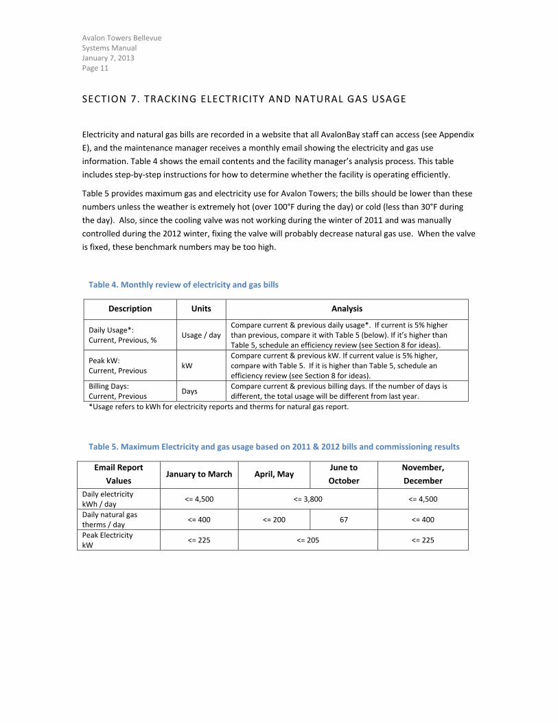
SECTION 7. TRACKING ELECTRICITY AND NATURAL GAS USAGE
Electricity and natural gas bills are recorded in a website that all AvalonBay staff can access (see Appendix
E), and the maintenance manager receives a monthly email showing the electricity and gas use
information. Table 4 shows the email contents and the facility manager’s analysis process. This table
includes step‐by‐step instructions for how to determine whether the facility is operating efficiently.
Table 5 provides maximum gas and electricity use for Avalon Towers; the bills should be lower than these
numbers unless the weather is extremely hot (over 100°F during the day) or cold (less than 30°F during
the day). Also, since the cooling valve was not working during the winter of 2011 and was manually
controlled during the 2012 winter, fixing the valve will probably decrease natural gas use. When the valve
is fixed, these benchmark numbers may be too high.
Table 4. Monthly review of electricity and gas bills
Description Units Analysis
Daily Usage*: Current, Previous, %
Usage / day Compare current & previous daily usage*. If current is 5% higher than previous, compare it with Table 5 (below). If it’s higher than Table 5, schedule an efficiency review (see Section 8 for ideas).
Peak kW: Current, Previous
kW Compare current & previous kW. If current value is 5% higher, compare with Table 5. If it is higher than Table 5, schedule an efficiency review (see Section 8 for ideas).
Billing Days: Current, Previous
Days Compare current & previous billing days. If the number of days is different, the total usage will be different from last year.
*Usage refers to kWh for electricity reports and therms for natural gas report.
Table 5. Maximum Electricity and gas usage based on 2011 & 2012 bills and commissioning results
Email Report
Values January to March April, May
June to
October
November,
December
Daily electricity kWh / day
<= 4,500 <= 3,800 <= 4,500
Daily natural gas therms / day
<= 400 <= 200 67 <= 400
Peak Electricity kW
<= 225 <= 205 <= 225
Avalon Towers Bellevue Systems Manual January 7, 2013 Page 12
SECTION 8. ON‐GOING COMMISSIONING PLAN
This section provides tools for maintenance staff to perform ongoing procedures, maintain efficient
operation, and fine‐tune the building for greater energy efficiency.
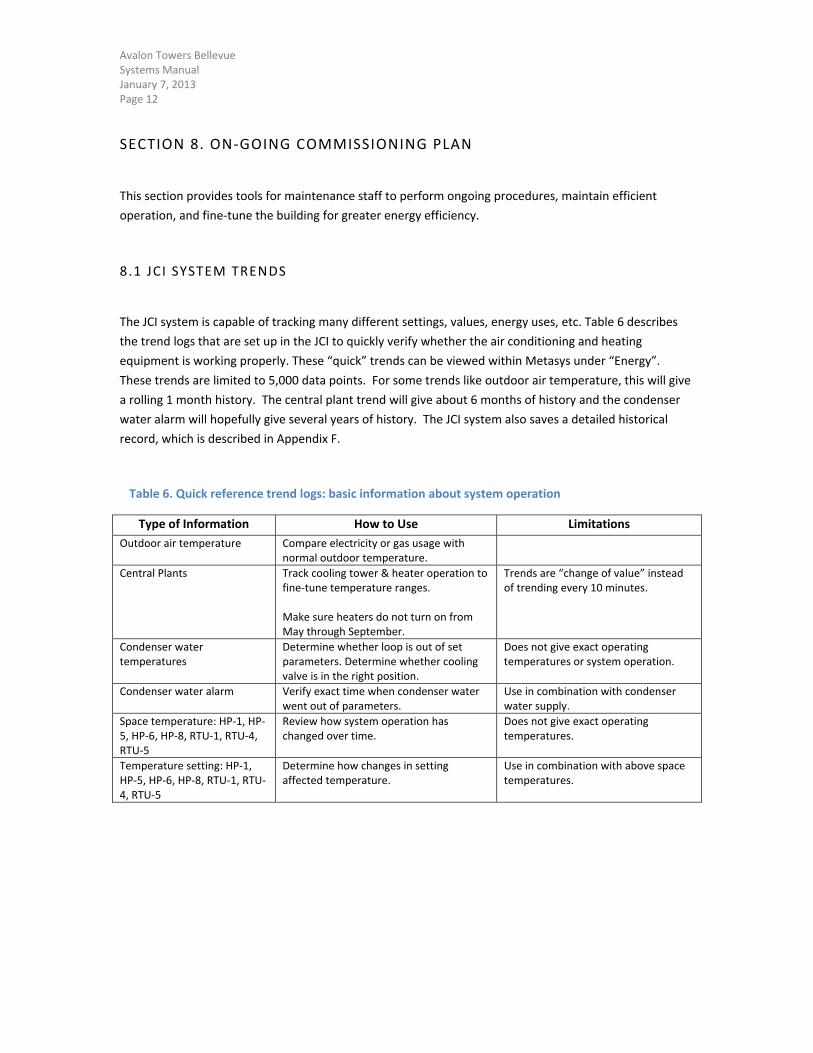
8.1 JCI SYSTEM TRENDS
The JCI system is capable of tracking many different settings, values, energy uses, etc. Table 6 describes
the trend logs that are set up in the JCI to quickly verify whether the air conditioning and heating
equipment is working properly. These “quick” trends can be viewed within Metasys under “Energy”.
These trends are limited to 5,000 data points. For some trends like outdoor air temperature, this will give
a rolling 1 month history. The central plant trend will give about 6 months of history and the condenser
water alarm will hopefully give several years of history. The JCI system also saves a detailed historical
record, which is described in Appendix F.
Table 6. Quick reference trend logs: basic information about system operation
Type of Information How to Use Limitations
Outdoor air temperature Compare electricity or gas usage with normal outdoor temperature.
Central Plants Track cooling tower & heater operation to fine‐tune temperature ranges. Make sure heaters do not turn on from May through September.
Trends are “change of value” instead of trending every 10 minutes.
Condenser water temperatures
Determine whether loop is out of set parameters. Determine whether cooling valve is in the right position.
Does not give exact operating temperatures or system operation.
Condenser water alarm Verify exact time when condenser water went out of parameters.
Use in combination with condenser water supply.
Space temperature: HP‐1, HP‐5, HP‐6, HP‐8, RTU‐1, RTU‐4, RTU‐5
Review how system operation has changed over time.
Does not give exact operating temperatures.
Temperature setting: HP‐1, HP‐5, HP‐6, HP‐8, RTU‐1, RTU‐4, RTU‐5
Determine how changes in setting affected temperature.
Use in combination with above space temperatures.
Avalon Towers Bellevue Systems Manual January 7, 2013 Page 13
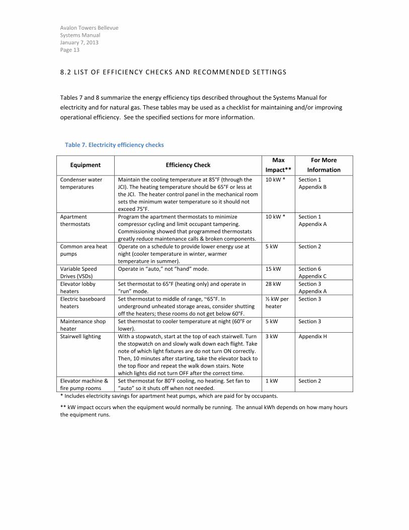
8.2 LIST OF EFFICIENCY CHECKS AND RECOMMENDED SETTINGS
Tables 7 and 8 summarize the energy efficiency tips described throughout the Systems Manual for
electricity and for natural gas. These tables may be used as a checklist for maintaining and/or improving
operational efficiency. See the specified sections for more information.
Table 7. Electricity efficiency checks
Equipment Efficiency Check Max
Impact**
For More
Information
Condenser water temperatures
Maintain the cooling temperature at 85°F (through the JCI). The heating temperature should be 65°F or less at the JCI. The heater control panel in the mechanical room sets the minimum water temperature so it should not exceed 75°F.
10 kW * Section 1 Appendix B
Apartment thermostats
Program the apartment thermostats to minimize compressor cycling and limit occupant tampering. Commissioning showed that programmed thermostats greatly reduce maintenance calls & broken components.
10 kW * Section 1 Appendix A
Common area heat pumps
Operate on a schedule to provide lower energy use at night (cooler temperature in winter, warmer temperature in summer).
5 kW Section 2
Variable Speed Drives (VSDs)
Operate in “auto,” not “hand” mode. 15 kW Section 6 Appendix C
Elevator lobby heaters
Set thermostat to 65°F (heating only) and operate in “run” mode.
28 kW Section 3 Appendix A
Electric baseboard heaters
Set thermostat to middle of range, ~65°F. In underground unheated storage areas, consider shutting off the heaters; these rooms do not get below 60°F.
½ kW per heater
Section 3
Maintenance shop heater
Set thermostat to cooler temperature at night (60°F or lower).
5 kW Section 3
Stairwell lighting With a stopwatch, start at the top of each stairwell. Turn the stopwatch on and slowly walk down each flight. Take note of which light fixtures are do not turn ON correctly. Then, 10 minutes after starting, take the elevator back to the top floor and repeat the walk down stairs. Note which lights did not turn OFF after the correct time.
3 kW Appendix H
Elevator machine & fire pump rooms
Set thermostat for 80°F cooling, no heating. Set fan to “auto” so it shuts off when not needed.
1 kW Section 2
* Includes electricity savings for apartment heat pumps, which are paid for by occupants.
** kW impact occurs when the equipment would normally be running. The annual kWh depends on how many hours the equipment runs.
Avalon Towers Bellevue Systems Manual January 7, 2013 Page 14
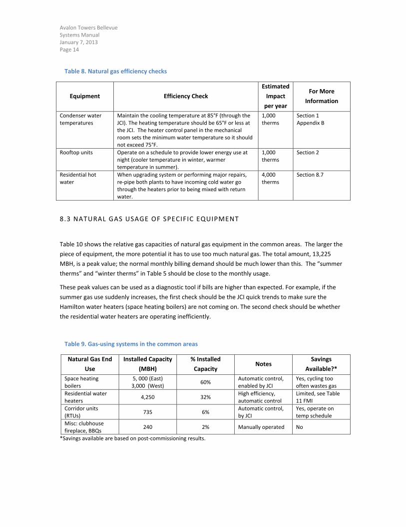
Table 8. Natural gas efficiency checks
Equipment Efficiency Check
Estimated
Impact
per year
For More
Information
Condenser water temperatures
Maintain the cooling temperature at 85°F (through the JCI). The heating temperature should be 65°F or less at the JCI. The heater control panel in the mechanical room sets the minimum water temperature so it should not exceed 75°F.
1,000 therms
Section 1 Appendix B
Rooftop units Operate on a schedule to provide lower energy use at night (cooler temperature in winter, warmer temperature in summer).
1,000 therms
Section 2
Residential hot water
When upgrading system or performing major repairs, re‐pipe both plants to have incoming cold water go through the heaters prior to being mixed with return water.
4,000 therms
Section 8.7
8.3 NATURAL GAS USAGE OF SPECIFIC EQUIPMENT
Table 10 shows the relative gas capacities of natural gas equipment in the common areas. The larger the
piece of equipment, the more potential it has to use too much natural gas. The total amount, 13,225
MBH, is a peak value; the normal monthly billing demand should be much lower than this. The “summer
therms” and “winter therms” in Table 5 should be close to the monthly usage.
These peak values can be used as a diagnostic tool if bills are higher than expected. For example, if the
summer gas use suddenly increases, the first check should be the JCI quick trends to make sure the
Hamilton water heaters (space heating boilers) are not coming on. The second check should be whether
the residential water heaters are operating inefficiently.
Table 9. Gas‐using systems in the common areas
Natural Gas End
Use
Installed Capacity
(MBH)
% Installed
Capacity Notes
Savings
Available?*
Space heating boilers
5, 000 (East) 3,000 (West)
60% Automatic control, enabled by JCI
Yes, cycling too often wastes gas
Residential water heaters
4,250 32% High efficiency, automatic control
Limited, see Table 11 FMI
Corridor units (RTUs)
735 6% Automatic control, by JCI
Yes, operate on temp schedule
Misc: clubhouse fireplace, BBQs
240 2% Manually operated No
*Savings available are based on post‐commissioning results.
Avalon Towers Bellevue Systems Manual January 7, 2013 Page 15
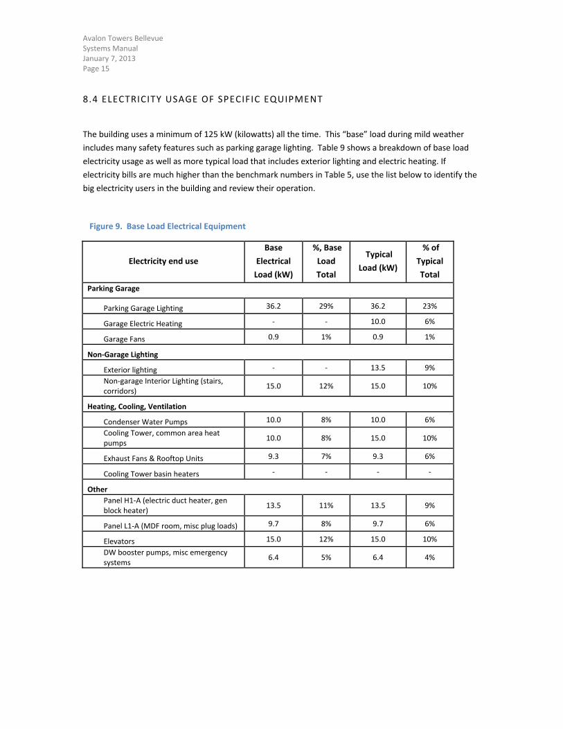
8.4 ELECTRICITY USAGE OF SPECIFIC EQUIPMENT
The building uses a minimum of 125 kW (kilowatts) all the time. This “base” load during mild weather
includes many safety features such as parking garage lighting. Table 9 shows a breakdown of base load
electricity usage as well as more typical load that includes exterior lighting and electric heating. If
electricity bills are much higher than the benchmark numbers in Table 5, use the list below to identify the
big electricity users in the building and review their operation.
Figure 9. Base Load Electrical Equipment
Electricity end use
Base
Electrical
Load (kW)
%, Base
Load
Total
Typical
Load (kW)
% of
Typical
Total
Parking Garage
Parking Garage Lighting 36.2 29% 36.2 23%
Garage Electric Heating ‐ ‐ 10.0 6%
Garage Fans 0.9 1% 0.9 1%
Non‐Garage Lighting
Exterior lighting ‐ ‐ 13.5 9%
Non‐garage Interior Lighting (stairs, corridors)
15.0 12% 15.0 10%
Heating, Cooling, Ventilation
Condenser Water Pumps 10.0 8% 10.0 6%
Cooling Tower, common area heat pumps
10.0 8% 15.0 10%
Exhaust Fans & Rooftop Units 9.3 7% 9.3 6%
Cooling Tower basin heaters ‐ ‐ ‐ ‐
Other
Panel H1‐A (electric duct heater, gen block heater)
13.5 11% 13.5 9%
Panel L1‐A (MDF room, misc plug loads) 9.7 8% 9.7 6%
Elevators 15.0 12% 15.0 10%
DW booster pumps, misc emergency systems
6.4 5% 6.4 4%
Avalon Towers Bellevue Systems Manual January 7, 2013 Page 16
8.5 BILL TRACKING TOOL
The benchmark information in Table 5 was created based on 2011 and 2012. If future years are
particularly hot or cold, the electricity and/or natural gas use will change, and the benchmark information
will need to be normalized to the actual weather conditions. Puget Sound Energy provides a free bill‐
tracking tool for use with Microsoft Excel. This tool can perform weather correction to help AvalonBay
verify whether changes in energy use are due to variations in weather. The PSE bill‐tracking tool is
provided with the CD of this Systems Manual, and is saved in the “Systems Manual 2013” folder on the JCI
computer’s desktop. Additional information is in Appendix G.
8.6 FUNCTIONAL TEST PROCEDURES
Commissioning tests from the construction phase and the post‐occupancy phase are provided in Appendix
H These tests could be used as guidelines for future commissioning; however, some of them are outdated
with regard to the current facility operation. Functional testing should be conducted if the information in
Sections 8.1 through 8.5 does not provide the desired efficiency improvements.
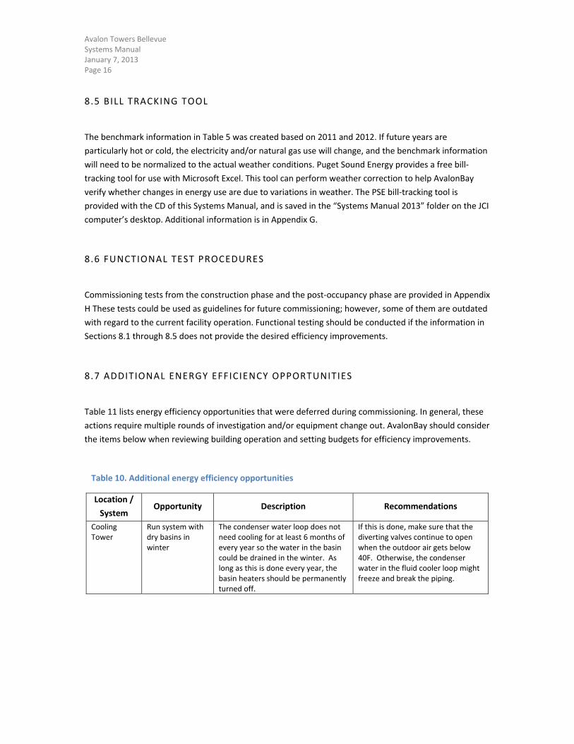
8.7 ADDITIONAL ENERGY EFFICIENCY OPPORTUNITIES
Table 11 lists energy efficiency opportunities that were deferred during commissioning. In general, these
actions require multiple rounds of investigation and/or equipment change out. AvalonBay should consider
the items below when reviewing building operation and setting budgets for efficiency improvements.
Table 10. Additional energy efficiency opportunities
Location /
System Opportunity Description Recommendations
Cooling Tower
Run system with dry basins in winter
The condenser water loop does not need cooling for at least 6 months of every year so the water in the basin could be drained in the winter. As long as this is done every year, the basin heaters should be permanently turned off.
If this is done, make sure that the diverting valves continue to open when the outdoor air gets below 40F. Otherwise, the condenser water in the fluid cooler loop might freeze and break the piping.
Avalon Towers Bellevue Systems Manual January 7, 2013 Page 17
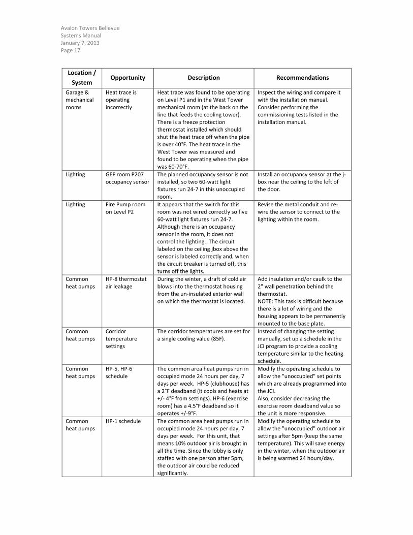
Location /
System Opportunity Description Recommendations
Garage & mechanical rooms
Heat trace is operating incorrectly
Heat trace was found to be operating on Level P1 and in the West Tower mechanical room (at the back on the line that feeds the cooling tower). There is a freeze protection thermostat installed which should shut the heat trace off when the pipe is over 40°F. The heat trace in the West Tower was measured and found to be operating when the pipe was 60‐70°F.
Inspect the wiring and compare it with the installation manual. Consider performing the commissioning tests listed in the installation manual.
Lighting GEF room P207 occupancy sensor
The planned occupancy sensor is not installed, so two 60‐watt light fixtures run 24‐7 in this unoccupied room.
Install an occupancy sensor at the j‐box near the ceiling to the left of the door.
Lighting Fire Pump room on Level P2
It appears that the switch for this room was not wired correctly so five 60‐watt light fixtures run 24‐7. Although there is an occupancy sensor in the room, it does not control the lighting. The circuit labeled on the ceiling jbox above the sensor is labeled correctly and, when the circuit breaker is turned off, this turns off the lights.
Revise the metal conduit and re‐wire the sensor to connect to the lighting within the room.
Common heat pumps
HP‐8 thermostat air leakage
During the winter, a draft of cold air blows into the thermostat housing from the un‐insulated exterior wall on which the thermostat is located.
Add insulation and/or caulk to the 2" wall penetration behind the thermostat. NOTE: This task is difficult because there is a lot of wiring and the housing appears to be permanently mounted to the base plate.
Common heat pumps
Corridor temperature settings
The corridor temperatures are set for a single cooling value (85F).
Instead of changing the setting manually, set up a schedule in the JCI program to provide a cooling temperature similar to the heating schedule.
Common heat pumps
HP‐5, HP‐6 schedule
The common area heat pumps run in occupied mode 24 hours per day, 7 days per week. HP‐5 (clubhouse) has a 2°F deadband (it cools and heats at +/‐ 4°F from settings). HP‐6 (exercise room) has a 4.5°F deadband so it operates +/‐9°F.
Modify the operating schedule to allow the "unoccupied" set points which are already programmed into the JCI. Also, consider decreasing the exercise room deadband value so the unit is more responsive.
Common heat pumps
HP‐1 schedule The common area heat pumps run in occupied mode 24 hours per day, 7 days per week. For this unit, that means 10% outdoor air is brought in all the time. Since the lobby is only staffed with one person after 5pm, the outdoor air could be reduced significantly.
Modify the operating schedule to allow the "unoccupied" outdoor air settings after 5pm (keep the same temperature). This will save energy in the winter, when the outdoor air is being warmed 24 hours/day.
Avalon Towers Bellevue Systems Manual January 7, 2013 Page 18
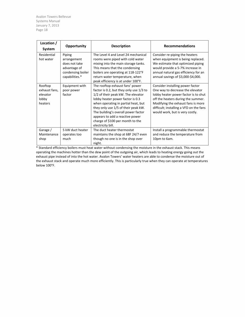
Location /
System Opportunity Description Recommendations
Residential hot water
Piping arrangement does not take advantage of condensing boiler capabilities.*
The Level 4 and Level 24 mechanical rooms were piped with cold water mixing into the main storage tanks. This means that the condensing boilers are operating at 118‐122°F return water temperature, when peak efficiency is at under 100°F.
Consider re‐piping the heaters when equipment is being replaced. We estimate that optimized piping would provide a 5‐7% increase in annual natural gas efficiency for an annual savings of $3,000‐$4,000.
Rooftop exhaust fans, elevator lobby heaters
Equipment with poor power factor
The rooftop exhaust fans’ power factor is 0.2, but they only use 1/3 to 1/2 of their peak kW. The elevator lobby heater power factor is 0.3 when operating in partial heat, but they only use 1/5 of their peak kW. The building’s overall power factor appears to add a reactive power charge of $100 per month to the electricity bill.
Consider installing power factor One way to decrease the elevator lobby heater power factor is to shut off the heaters during the summer. Modifying the exhaust fans is more difficult; installing a VFD on the fans would work, but is very costly.
Garage / Maintenance shop
5 kW duct heater operates too much
The duct heater thermostat maintains the shop at 68F 24/7 even though no one is in the shop over night.
Install a programmable thermostat and reduce the temperature from 10pm to 6am.
* Standard efficiency boilers must heat water without condensing the moisture in the exhaust stack. This means operating the machines hotter than the dew point of the outgoing air, which leads to heating energy going out the exhaust pipe instead of into the hot water. Avalon Towers’ water heaters are able to condense the moisture out of the exhaust stack and operate much more efficiently. This is particularly true when they can operate at temperatures below 100°F.
Avalon Towers Bellevue Systems Manual January 7, 2013 Page 19
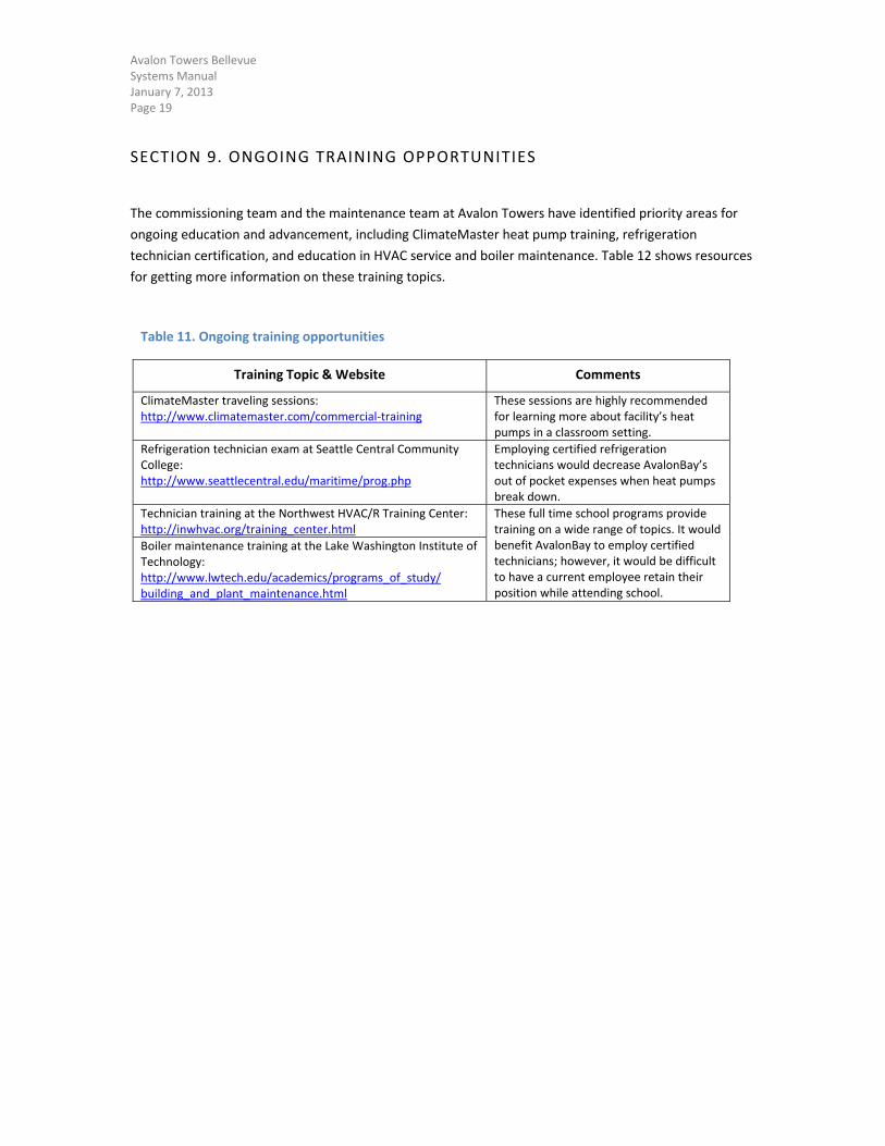
SECTION 9. ONGOING TRAINING OPPORTUNITIES
The commissioning team and the maintenance team at Avalon Towers have identified priority areas for
ongoing education and advancement, including ClimateMaster heat pump training, refrigeration
technician certification, and education in HVAC service and boiler maintenance. Table 12 shows resources
for getting more information on these training topics.
Table 11. Ongoing training opportunities
Training Topic & Website Comments
ClimateMaster traveling sessions: http://www.climatemaster.com/commercial‐training
These sessions are highly recommended for learning more about facility’s heat pumps in a classroom setting.
Refrigeration technician exam at Seattle Central Community College: http://www.seattlecentral.edu/maritime/prog.php
Employing certified refrigeration technicians would decrease AvalonBay’s out of pocket expenses when heat pumps break down.
Technician training at the Northwest HVAC/R Training Center: http://inwhvac.org/training_center.html
These full time school programs provide training on a wide range of topics. It would benefit AvalonBay to employ certified technicians; however, it would be difficult to have a current employee retain their position while attending school.
Boiler maintenance training at the Lake Washington Institute of Technology: http://www.lwtech.edu/academics/programs_of_study/ building_and_plant_maintenance.html
Avalon Towers Bellevue Systems Manual January 7, 2013 Page 20
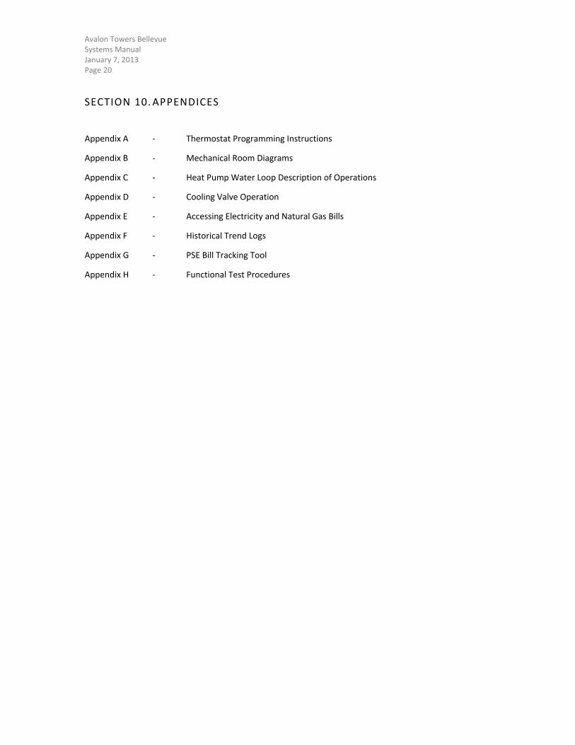
SECTION 10. APPENDICES
Appendix A ‐ Thermostat Programming Instructions
Appendix B ‐ Mechanical Room Diagrams
Appendix C ‐ Heat Pump Water Loop Description of Operations
Appendix D ‐ Cooling Valve Operation
Appendix E ‐ Accessing Electricity and Natural Gas Bills
Appendix F ‐ Historical Trend Logs
Appendix G ‐ PSE Bill Tracking Tool
Appendix H ‐ Functional Test Procedures
Avalon Towers Bellevue Appendix A. Thermostat Programming Instructions January 2013 Page 21
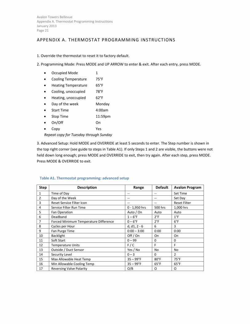
APPENDIX A. THERMOSTAT PROGRAMMING INSTRUCTIONS
1. Override the thermostat to reset it to factory default.
2. Programming Mode: Press MODE and UP ARROW to enter & exit. After each entry, press MODE.
Occupied Mode 1
Cooling Temperature 75°F
Heating Temperature 65°F
Cooling, unoccupied 78°F
Heating, unoccupied 62°F
Day of the week Monday
Start Time 4:00am
Stop Time 11:59pm
On/Off On
Copy Yes
Repeat copy for Tuesday through Sunday
3. Advanced Setup: Hold MODE and OVERRIDE at least 5 seconds to enter. The Step number is shown in
the top right corner (see guide to steps in Table A1). If only Steps 1 and 2 are visible, the buttons were not
held down long enough; press MODE and OVERRIDE to exit, then try again. After each step, press MODE.
Press MODE & OVERRIDE to exit.
Table A1. Thermostat programming: advanced setup
Step Description Range Default Avalon Program
1 Time of Day ‐‐ ‐‐ Set Time
2 Day of the Week ‐‐ ‐‐ Set Day
3 Reset Service Filter Icon ‐‐ ‐‐ Reset Filter
4 Service Filter Run Time 0 ‐ 1,950 hrs 500 hrs 1,000 hrs
5 Fan Operation Auto / On Auto Auto
6 Deadband 1 – 6°F 2°F 1°F
7 Forced Minimum Temperature Difference 0 – 6°F 2°F 6°F
8 Cycles per Hour d, d1, 2 ‐ 6 6 3
9 Fan Purge Time 0:00 – 3:00 0:00 0:00
10 Backlight Off / On On On
11 Soft Start 0 – 99 0 0
12 Temperature Units F / C F F
13 Outside / Duct Sensor Yes / No No No
14 Security Level 0 – 3 0 2
15 Max Allowable Heat Temp 35 – 99°F 80°F 75°F
16 Min Allowable Cooling Temp 35 – 99°F 65°F 65°F
17 Reversing Valve Polarity O/B O O
Avalon Towers Bellevue Appendix A. Thermostat Programming Instructions January 2013 Page 22
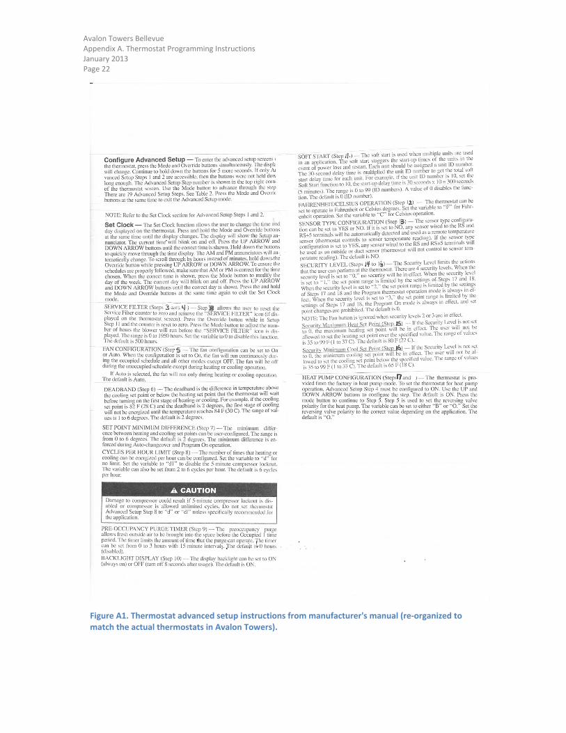
Figure A1. Thermostat advanced setup instructions from manufacturer's manual (re‐organized to match the actual thermostats in Avalon Towers).