Embed Size (px)
Citation preview

1
Systems of Technology - Robotics: Section 5 Instructions/Build Plans
Observing Sensors(Digital vs. Analog)
Team Members:
1. ________________________ 3. ________________________
2. ________________________ 4. ________________________
Assemble 3-Motor BuildPlace a check in each box as each step is completed.
1. Assemble: 3-Motor Build (Build Plans on pages 3-5).
2. Connect: ROKduino to a computer using the USB cable.
Example Sketch: Digital vs. AnalogPlace a check in each box as each step is completed.
1. On your computer, Open: Arduino, and then Ardublock.
2. In Ardublock, Click: Open.
3. Find and Select: Example Sketch #1: Digital vs. Analog Sensors. (It will be in the downloaded folder)
4. In Ardublock, review the sketch and Click: Upload to Arduino.
5. Navigate and Select: the Arduino IDE Window.
6. Find and Select: the Serial Print Monitor.
7. Power ON: the ROKduino.
8. Press: the Bump Sensor.
9. Observe: Motor Module #1 & Bump Sensor Value on the Serial Print Monitor. In this example, the speed of the motor module on output 1 is determined by the value of the bump sensor. The bump sensor is a digital sensor. This means it will return a value of 0 or 1023. As you observe the serial print monitor, you will notice when the bump sensor is not pressed, it returns a value of 0, and the motor module is completely stopped. When the bump sensor is pressed, it returns a value of 1023, and the motor module rotates at full speed.
v2.0
2
10. Flip back: the block separating the Low Power IR Transmitter & IR Sensing Receiver.
11. Observe: Motor Module # 2 & Light Gate Value on the Serial Print Monitor. In this example, the speed of the motor module on output 2 is determined by the value of the light gate. A light gate uses a transmitter to transmit a constant signal to a receiver. A light gate is a digital sensor. This means it will return a value of 0 or 1023. As you observe the serial print monitor, you will notice whentheblockisflippedbetweenthetransmitterandreceiver(lightgate),itreturnsavalueof0,andthe motor module is completely stopped. The block prevents the transmitter from being able to transmit a signaltothereceiver.Whentheblockisflippedbackwards,thelightgatereturnsavalueof1023,andthe motor module rotates at full speed. Since the block is no longer between the transmitter and receiver, the transmitter can successfully transmit a constant signal to the receiver.
12. Cover: the Light Sensor with your hand.
13. Observe: Motor Module # 3 & Light Sensor Value on the Serial Print Monitor. In this example, the speed of the motor module on output 3 is determined by the value of the light sensor. The light sensor is an analog sensor. This means it will return a value anywhere between 0 and 1023. As you cover up the light sensor, you will notice the value of the light sensor and the speed of the motor module are both reduced. As you uncover the light sensor, you will notice the value of the light sensor and the speed of the motor module both increase.
14. Replace: the Light Sensor with the Angle Sensor. 15. Rotate: the Angle Sensor with your hand.
16. Observe: Angle Sensor Value on the Serial Print Monitor. In this example, the speed of the motor module on output 3 is determined by the value of the angle sensor. The angle sensor is an analog sensor. This means it will return a value anywhere between 0 and 1023. As you rotate the angle sensor clockwise, you will notice the value of the sensor and the speed of the motor module both increase. As you rotate the angle sensor counter-clockwise, you will notice the value of the sensor and the speed of the motor module both decrease. Note: The angle sensor rotates 360°. The value of the angle sensor will increase as it is rotated clockwise until it reaches a value of 1023. Once the angle sensor is rotated past 360°, the value will return to 0.
Disassembly & CleanupPlace a check in each box as each step is completed.
1. Close out: Arduino & Ardublock.
2. Disassemble: 3-Motor Build.
3. Organize: Components back into Programmable Robotics Module.

3
Build & Modify
InstructionsFollow the step-by-step instructions to assemble the 3-Motor Build.
1 2
3x Beam
3x Block
3 4
2x Riser
3x Single Snap Block
2x Single Snap Block
4x Half Beam
1x Double-Snap Block
6x Block
6x Half Beam
1xROK-duino SmartBlock
4x Block
4x 30° Block
3x Motor Module
4x Corbel
8x Pulley

4
Build & ModifyBuild & Modify
5 6
4x Riser
7
1x Hinge Block
1x Pulley
1x Block
1x Light Sensor
1x Bump Sensor
1x Low Power IR TX
1x IR Receiver
5
Build & ModifyBuild & Modify
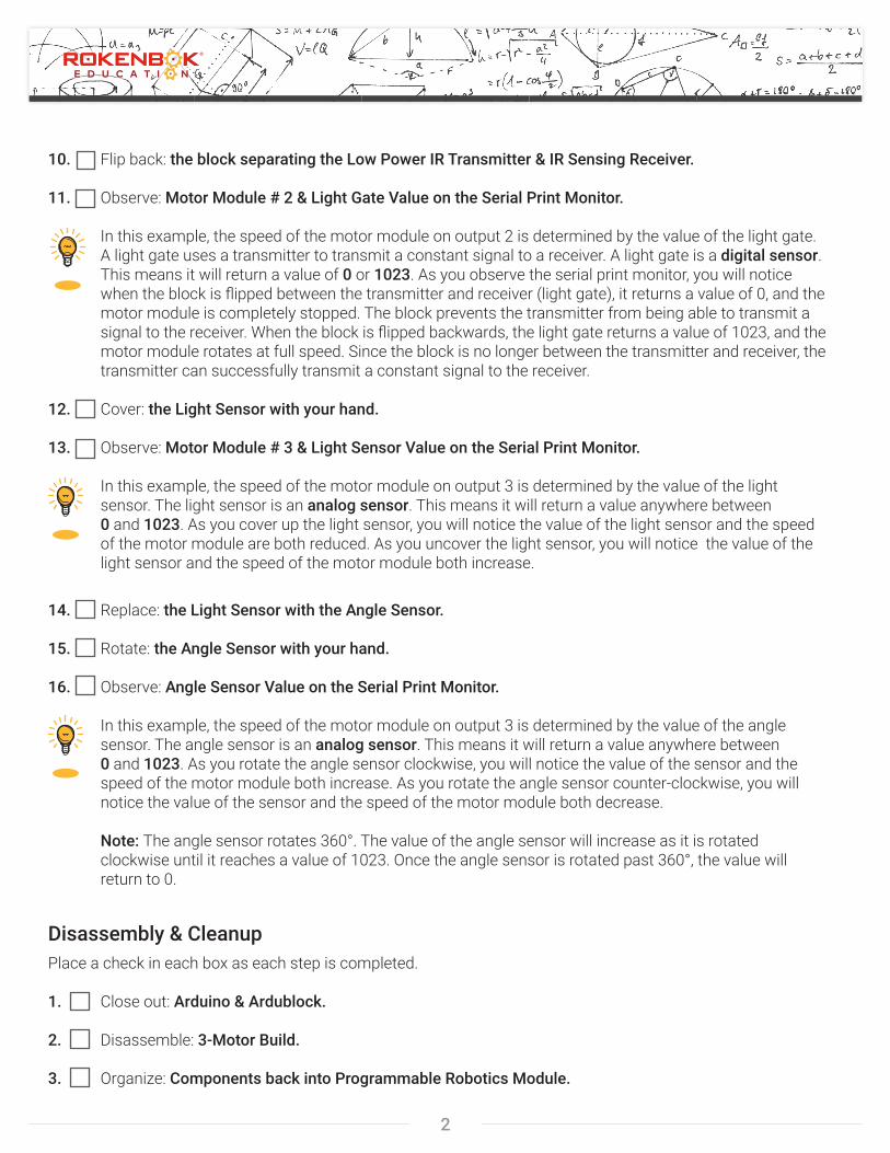
Cable DiagramUse the diagram below to connect sensor and motor/output cables to the 3-Motor Build.
Inputs
Outputs
Bump Sensor
Low Power IR Transmitter IR Receiver Sensor
Light Sensor Angle Sensor
Inputs
Outputs
6
Build & ModifyBuild & ModifyROKduino Basics
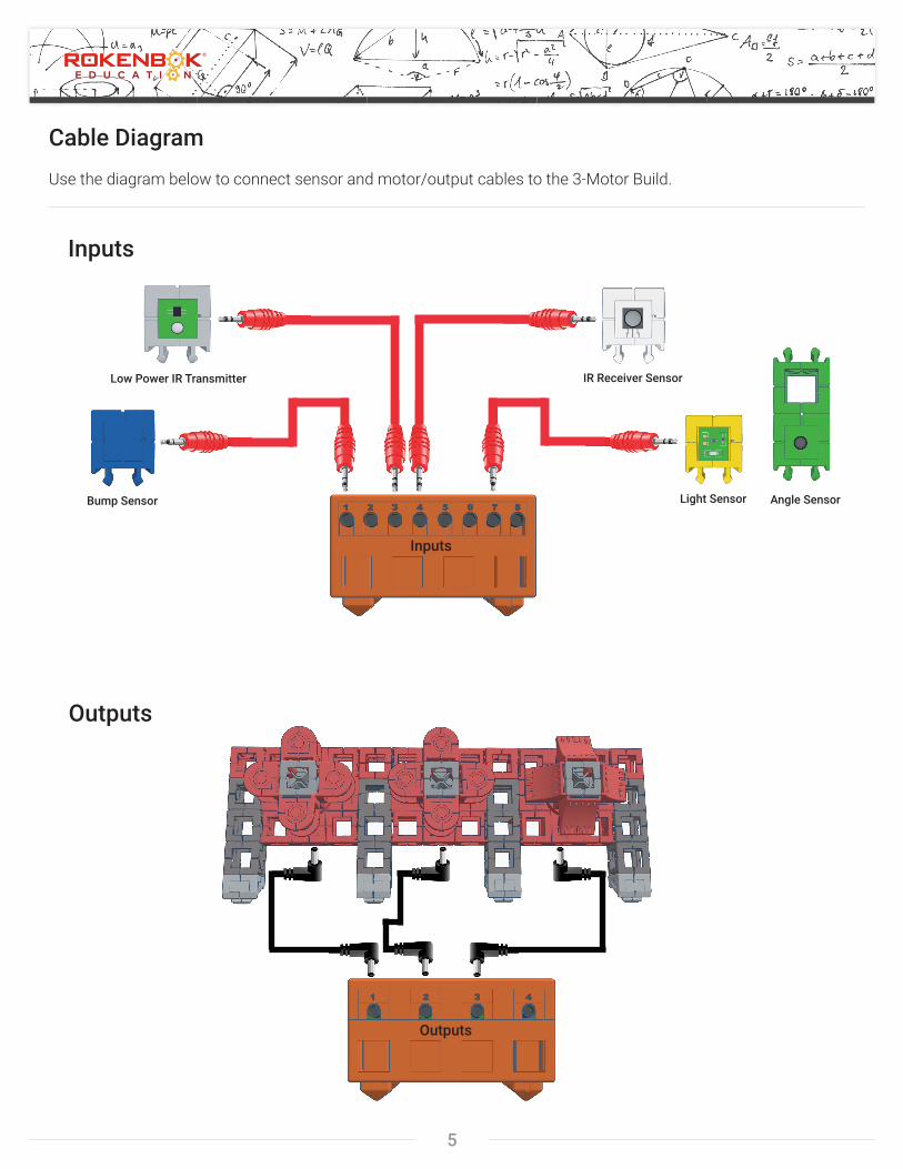
ROKduino BasicsTo download all necessary ROKduino software, visit: www.rokenbokeducation.org/rokduino.
ROKduino SmartBlock:
The ROKduino is a programmable smartblock that can be used to create different types of robots. It is powered by (3) AA batteries that can be replaced by removing the cover on the bottom of the block. A bright green LED on the top of the block indicates if the ROKduino is ON or OFF. Make sure to power OFF the ROKduino when finished using it to prevent the batteries from running out of power.
Power Indicator ON/OFF Switch
Sensors:
There are a variety of sensors that can be connected to the input ports on the ROKduino. The ROKduino can be programmed to read information from sensors connected to input ports, process that information into relevant commands, and send those commands to modules connected to the output ports.
Light Sensor
Quantity Included: 1(Input Ports 1-8)
Bump Sensor
Quantity Included: 2(Input Ports 1-8)
Angle Sensor
Quantity Included: 1(Input Ports 1-8)
Low PowerIR Transmitter
Quantity Included: 1(Input Ports 1-8)
High PowerIR Transmitter
Quantity Included: 2(Input Ports 1-8)
IR ReceiverSensor
Quantity Included: 2(Input Ports 1-8)
ROK-StarSensor
Quantity Included: 1(Input Port 8)
8 Input Ports
Modules:
There are two modules that can be connected to the output ports on the ROKduino. The ROKduino can be programmed to send out specificcommandstothemodulestoperform different functions. Light Module
Quantity Included: 2(Output Ports 1-4)
Motor Module
Quantity Included: 4(Output Ports 1-4)
Cables:
There are six types of cables that are included with the ROKduino. These cables are used to connect sensors and modules, as well as to connect the ROKduino to a computer so it can be programmed. Make sure cables are pressed all theway into connecting ports to ensure a good connection.
USB Cable
Quantity Included: 1Length: 18”
Sensor Cable
Quantity Included: 8Length: 18”
Sensor Cable Extender
Quantity Included: 2Length: 18”
Motor/Output Cable
Quantity Included: 2Length: 12”
Motor/Output Cable
Quantity Included: 3Length: 18”
Motor/Output Cable Extender
Quantity Included: 2Length: 12”
4 Output Ports
Inputs
Outputs
USB Port
55-02030-200