Embed Size (px)
Citation preview

SYVAuser manual (EN)

Document reference: Syva user manual (EN) version 1.0Distribution date: June 7, 2017© 2017 L-Acoustics. All rights reserved.No part of this publication may be reproduced or transmitted in anyform or by any means without the express written consent of thepublisher.

Contents
Safety................................................................................................................................................................ 4
Instructions................................................................................................................................................4
Symbols................................................................................................................................................... 4
Welcome........................................................................................................................................................... 5
System components.............................................................................................................................................6
Technical description........................................................................................................................................... 8
Loudspeaker configurations..................................................................................................................................9
Syva colinear source.................................................................................................................................9
Syva colinear source with LF extension..................................................................................................... 10
Syva colinear source with LF extension and subwoofer............................................................................... 12
Loudspeaker connection.................................................................................................................................... 14
Connectors............................................................................................................................................. 14
Connection to LA4X................................................................................................................................ 16
Connection to LA8.................................................................................................................................. 18
Connection to LA12X.............................................................................................................................. 18
Preset description..............................................................................................................................................22
Recommendation for speaker cables...................................................................................................................23
Maintenance.................................................................................................................................................... 24
Syva...................................................................................................................................................... 24
Syva Low............................................................................................................................................... 30
Syva Sub............................................................................................................................................... 33
Acoustical check..................................................................................................................................... 36
APPENDIX A: Cabling Syva.............................................................................................................................. 40
Specifications................................................................................................................................................... 41
Syva specifications..................................................................................................................................41
Syva Low specifications...........................................................................................................................43
Syva on Syva Low specifications..............................................................................................................44
Syva Sub specifications........................................................................................................................... 45
3

Safety
Safety
Instructions
Inspect the product before operation.If any sign of defect or damage is detected, immediately withdraw the product from use for maintenance.
Never incorporate equipment or accessories not approved by L-Acoustics.
Read all the related PRODUCT INFORMATION documents shipped with the products beforeexploiting the system.
Do not store the product on an unstable cart, stand, tripod, bracket, or table.
Beware of sound levels.Do not stay within close proximity of loudspeakers in operation.Loudspeaker systems are capable of producing very high sound pressure levels (SPL) which can instantaneouslylead to permanent hearing damage to performers, production crew and audience members. Hearing damagecan also occur at moderate level with prolonged exposure to sound.Check the applicable laws and regulations relating to maximum sound levels and exposure times.
This system is intended for professional use.
Read the RIGGING MANUAL before installing the system.Use the rigging accessories described in the rigging manual and follow the associated procedures.
Read the maintenance section of this document before servicing the product.
Do not expose the product to extreme conditions.Do not expose the product to rain or sea spray.Do not expose the product to moisture (mist, steam, humidity, condensation…) or excessive heat (direct sun,radiator…) for a long period of time.
Contact L-Acoustics for advanced maintenance.Any unauthorized maintenance operation will void the product warranty.
Symbols
The following symbols are used in this document:
This symbol indicates a potential risk of harm to an individual or damage to the product.It can also notify the user about instructions that must be strictly followed to ensure safe installation or operation ofthe product.
This symbol indicates a potential risk of electrical injury.It can also notify the user about instructions that must be strictly followed to ensure safe installation or operation ofthe product.
This symbol notifies the user about instructions that must be strictly followed to ensure proper installation oroperation of the product.
This symbol notifies the user about complementary information or optional instructions.
Syva user manual (EN) version 1.0 4

Welcome
Welcome
Thank you for purchasing the L-Acoustics Syva.
This document contains essential information on using the system properly.
As part of a continuous evolution of techniques and standards, L-Acoustics reserves the right tochange the specifications of its products and the content of its document without prior notice. Pleasecheck www.l-acoustics.com on a regular basis to download the latest document and software updates.
Syva Colinear Source
Syva is a Colinear Source system (patent pending) suited to medium throw applications. It is designed for professionalsound reinforcement and high-end residential applications requiring high fidelity and SPL with minimum visual impact.
The Syva enclosure features six 5" MF speakers providing usable bandwidth down to 87 Hz and three 1.75" HFdiaphragm compression drivers, loaded by DOSC waveguides in a J-shaped progressive curvature. This transducerarrangement, called Colinear Source, produces an H/V 140° x 26° (+5°/-21°) directivity pattern, optimized for ultra-wide horizontal coverage with extended throw capability.
The Syva Low enclosure features two K2 12" drivers and is designed to provide low frequency contour and extendedbandwidth to the Syva system (9 dB contour with a low frequency limit at 40 Hz).
The Syva Sub enclosure features one high excursion 12" driver equipped with a KS28 woofer motor and is designed tofurther extend the bandwidth of the system in the sub frequency domain down to 27 Hz.
Both feature a bass-reflex cabinet equipped with L-Vents, reducing turbulence and port noise at high levels whileincreasing LF efficiency.
L-Acoustics amplified controllers ensure advanced crossover functions, time alignment, linearization and L-Drive protectionof the transducers.
Syva combines the directivity benefits of line length and the coupling of HF DOSC waveguides to achieve a narrowvertical beam that is perfectly controlled down to 300 Hz. Syva focuses energy toward the back of the audience whileproviding smooth down-fill coverage to the front. Throw and SPL consistency are ensured from front, to back. Thecombination of extended 35 m throw and ultrawide horizontal dispersion provides exceptional surface coverage for flataudiences.
The cabinet combines the remarkable acoustic properties of birch and beech plywood. Its slim elegance makes for easyintegration. RAL colors allow it to blend into any architecture. Syva Low and Syva Sub provide a stable podium base forSyva. The plug-and-play AutoConnect provides a rapid and secure audio and physical link.
In fixed installations Syva is particularly suited to sound reinforcement in architectural settings and acousticallychallenging environments where a combination of high intelligibility, high SPL and extended bandwidth are required. Itshigh fidelity sonic signature and elegant lines can satisfy high-end residential projects as well as L-ISA immersive multi-channel systems.
For rental events, Syva is fast to deploy and simple to rig. Its outstanding throw capability can satisfy production needs inlarge spaces and ballrooms where elegance and discretion are a must.
Syva can be stacked as a standalone system or secured onto one of its LF extensions. Wall-mounting and flying are alsopossible.
5 Syva user manual (EN) version 1.0

System components
System components
Loudspeaker enclosures
Syva 2-way-passive enclosure: 6 x 5'' LF + 3 x 1.75'' HF diaphragm
Syva Low High power low frequency subwoofer: 2 x 12'' LF
Syva Sub Infra low frequency subwoofer: 1 x 12'' LF
Powering and driving system
LA4X / LA8 / LA12X Amplified controller with DSP, preset library and networking capabilities
LA-RAK Touring rack containing three LA8 and power, audio and network distribution
LA-RAK II Touring rack containing three LA12X, LA-POWER II for power distribution and LA-PANEL II foraudio and network distribution
L-CASE 2U Electronics transport and protection case
Refer to the LA4X / LA8 / LA12X user manual for operating instructions.
Loudspeaker cables
DO 8-point PA-COM loudspeaker cables (4 mm² gauge)
DO cables come in three sizes: DO.7 (0.7 m/2.3 ft), DO10 (10 m/32.8 ft) and DO25(25 m/82 ft)
DO3WFILL breakout cable for one 2-way active enclosure and two passive enclosures (4 mm² gauge)
8-point PA-COM to 1 x 4-point speakON and 2 x 2-point speakON
DOFILL-LA8 breakout cable for two 2-way active enclosures (4 mm² gauge)
8-point PA-COM to 2 x 4-point speakON
DOSUB-LA8 breakout cable for four passive enclosures (4 mm² gauge)
8-point PA-COM to 4 × 2-point speakON
SP-Y1 breakout cable for two passive enclosures (2.5 mm² gauge) provided with a CC4FP adapter
4-point speakON to 2 × 2-point speakON
SP cables 4-point speakON loudspeaker cables (4 mm² gauge)
SP cables come in four sizes: SP.7 (0.7 m/2.3 ft), SP5 (5 m/16.4 ft), SP10 (10 m/32.8 ft) andSP25 (25 m/82 ft)
Information about the connection of the enclosures to the LA amplifiers is given in thisdocument.Refer to the LA4X / LA8 / LA12X user manual for detailed instructions about the whole cabling scheme, includingmodulation cables and network.
Rigging elements
Rigging elements or procedures are not presented in this document.Refer to the Syva rigging manual.
Syva user manual (EN) version 1.0 6

System components
Software applications
Soundvision 3D acoustical and mechanical modeling software
LA Network Manager Software for remote control and monitoring of amplified controllers
Refer to the Soundvision help.
Refer to the LA Network Manager video tutorial.
Loudspeaker cables
0.7 m / 5 m / 10 m / 25 m
CH(1)
CH(2)
1 m
SP.7 / SP5 / SP10 / SP25 SP-Y1
0.7 m / 10 m / 25 m
SPK1
SPK2
SPK3
SPK4
5 m
DO.7 / DO10 / DO25 DOSUB-LA8
2W CH(A)
2W CH(B)
3.5 m
2WAY
SUB1
SUB2
3.5 m
DOFILL-LA8 DO3WFILL
7 Syva user manual (EN) version 1.0

Technical description
Technical description
Directivity
Syva generates a horizontal directivity pattern of 140° (>1 kHz) and a vertical directivity pattern between +5° and -21°in J-shape (> 1 kHz).
−180
−160
−140
−120
−100
100 1 000 10 000
−80
−60
−40
−20
0
20
40
60
80
100
120
140
160
180
Angl
e (°
)
Frequency (Hz)−180
−160
−140
−120
−100
100 1 000 10 000−180
−160
−140
−120
−100
−80
−60
−40
−20
0
20
40
60
80
100
120
140
160
180
Angl
e (°
)
Frequency (Hz)
Dispersion angle diagram of a single enclosure, using lines of equal sound pressure at -3 dB, -6 dB, -12 dB.
Syva user manual (EN) version 1.0 8

Loudspeaker configurations
Loudspeaker configurations
Syva colinear source
In this configuration the system operates over the nominal bandwidth of the enclosure.
The [SYVA] preset allows for a reference frequency response in medium throw applications.
Syva is driven by the LA4X / LA8 / LA12X amplified controllers.
Preset [SYVA]
Frequency range (-10 dB) 87 Hz - 20 kHz
9 Syva user manual (EN) version 1.0

Loudspeaker configurations
Syva colinear source with LF extension
In hybrid configuration with Syva Low, the Syva system bandwidth is extended down to 40 Hz and the system contour isreinforced by 9 dB.
Syva and Syva Low are driven by the LA4X / LA8 / LA12X amplified controllers.
Coupled
The [SYVA LOW SYVA] hybrid preset enables acoustic coupling when Syva is on top of Syva Low (AutoConnect) orwithin a 60 cm (24 in) distance.
To use [SYVA LOW SYVA], connect Syva and Syva Low to the same amplified controller output.Use Autoconnect or an SP-Y1 cable. Refer to Connecting hybrid configurations (p.17) for LA4X andConnecting hybrid configurations (p.19) for LA8 or LA12X.
< 60 cm / 24 in
with AutoConnect without AutoConnect
Enclosures Syva Syva Low
Preset [SYVA LOW SYVA]
Frequency range (-10 dB) 40 Hz - 20 kHz
No pre-alignement delay values are required for the Syva system.
Syva user manual (EN) version 1.0 10
Loudspeaker configurations
Separated
The [SYVA] preset allows for a reference frequency response in medium throw applications.
The [SYVA LOW_100] preset provides Syva Low with an upper frequency limit at 100 Hz.
> 60 cm / 24 in
Enclosures Syva Syva Low
Preset [SYVA] [SYVA LOW_100]
Frequency range (-10 dB) 40 Hz - 20 kHz
Do not forget to add the geometric delays depending on the configuration.
No pre-alignement delay values are required for the Syva system.
11 Syva user manual (EN) version 1.0

Loudspeaker configurations
Syva colinear source with LF extension and subwoofer
With Syva Sub, the Syva system bandwidth is extended down to 27 Hz.
Syva, Syva Low and Syva Sub are driven by the LA4X / LA8 / LA12X amplified controllers.
Coupled
The [SYVA LOW SYVA] hybrid preset enables acoustic coupling when Syva is on top of Syva Low (AutoConnect) orwithin a 60 cm (24 in) distance.
To use [SYVA LOW SYVA], connect Syva and Syva Low to the same amplified controller output.Use Autoconnect or an SP-Y1 cable. Refer to Connecting hybrid configurations (p.17) for LA4X andConnecting hybrid configurations (p.19) for LA8 or LA12X.
The [SYVA SUB_100] preset provides Syva Sub with an upper frequency limit at 100 Hz.
[SYVA SUB_100] polarity is reversed to optimize Syva Sub acoustic summation withSyva/Syva Low.
< 60 cm / 24 in
Enclosures Syva Syva Low Syva Sub
Presets [SYVA LOW SYVA] [SYVA SUB_100]
Frequency range (-10 dB) 27 Hz - 20 kHz
Grouping subwoofersPlace the subwoofer enclosures side by side. If not possible, the maximum distance between two adjacentacoustic centers must be 1.7 m if the upper frequency limit of the subwoofer system is at 100 Hz.
Do not forget to add the geometric delays depending on the configuration.
No pre-alignement delay values are required for the Syva system.
Syva user manual (EN) version 1.0 12

Loudspeaker configurations
Separated
The [SYVA] preset allows for a reference frequency response in medium throw applications.
The [SYVA LOW_100] and [SYVA SUB_100] presets provide Syva Low and Syva Sub with an upper frequency limit at100 Hz.
[SYVA SUB_100] polarity is reversed to optimize Syva Sub acoustic summation withSyva/Syva Low.
> 60 cm / 24 in
Enclosures Syva Syva Low Syva Sub
Presets [SYVA] [SYVA LOW_100] [SYVA SUB_100]
Frequency range (-10 dB) 27 Hz - 20 kHz
Grouping subwoofersPlace the subwoofer enclosures side by side. If not possible, the maximum distance between two adjacentacoustic centers must be 1.7 m if the upper frequency limit of the subwoofer system is at 100 Hz.
Do not forget to add the geometric delays depending on the configuration.
No pre-alignement delay values are required for the Syva system.
13 Syva user manual (EN) version 1.0

Loudspeaker connection
Loudspeaker connection
Connectors
Syva
Syva offers multiple types of connectors. Use one type of connector at a time.
Use the speakON connector to connect the enclosure with an SP cable.
The speakON connector is only accessible if Syva Wall is used with a wedge.Refer to the Syva rigging manual.
IN
Use the screw terminal to connect the enclosure with speaker wire.
Put the cover back on the connector once the wire is installed.
IN +IN -
When the screw terminal is not in use, put the gasket back to avoid leaks.
Internal pinout for L-Acoustics 2-way passive enclosures
screw terminal points IN + IN - / /
speakON points 1 + 1 - 2 + 2 -
transducer connectors + - Not linked Not linked
Syva user manual (EN) version 1.0 14

Loudspeaker connection
Syva Low and Syva Sub
Syva Low and Syva Sub are equipped with one 4-point speakON connector.
Use the labels to differentiate the subwoofers.
IN IN
Syva Low Syva Sub
Internal pinout for L-Acoustics subwoofers
speakON points 1 + 1 - 2 + 2 -
Transducer connectors LF + LF - Not linked Not linked
Syva combined with Syva Low
Amplified controller damageDo not use the speakON connector or screw terminals on Syva when using AutoConnect.
With Syva on top of Syva Low, AutoConnect is enabled and power is routed through the subwoofer connector plate tothe enclosure.
AutoConnect internal pinout
AutoConnect points 1 + 1 - 2 + 2 -
Transducer connectors LF + LF - MF/HF+ MF/HF-
15 Syva user manual (EN) version 1.0

Loudspeaker connection
Connection to LA4X
Maximum number of enclosures per LA4X
enclosure max enclosures in parallel max enclosures per controller
Syva 1 4
Syva Low 1 4
Syva Sub 1 4
Impedance load
Syva Syva Sub
1 enclosure: 8 Ω
Syva Low
1 enclosure: 4 Ω
Connecting 2-way passive enclosures or subwoofers
SP on speakON output
SP
SP
SP
SP
OUT1
OUT2
OUT3
OUT4
SP and SP-Y1 on speakON output
OUT1/OUT2 OUT3/OUT4
same as OUT1/OUT2
SP SP-Y1
CC4FP
CH(1) (OUT1)
CH(2) (OUT2)
Syva user manual (EN) version 1.0 16

Loudspeaker connection
Connecting hybrid configurations
Use [SYVA LOW SYVA] with these cabling schemes.
SP on speakON output
SP
OUT1/OUT2 OUT3/OUT4
same as OUT1/OUT2
Autoconnect
SP and SP-Y1 on speakON output
Risk of damaging the Syva drivers.Connect CH(1) to Syva Low and CH(2) to Syva.
OUT1/OUT2 OUT3/OUT4
same as OUT1/OUT2
SP SP-Y1
CC4FP
CH(1) (OUT1)
CH(2) (OUT2)
17 Syva user manual (EN) version 1.0

Loudspeaker connection
Connection to LA8
Maximum number of enclosures per LA8
enclosure max enclosures in parallel max enclosures per controller
Syva 2 8
Syva Low 1 4
Syva Sub 2 8
Impedance load
Syva Syva Sub
1 enclosure: 8 Ω2 enclosures in parallel: 4 Ω
Syva Low
1 enclosure: 4 Ω
Connection to LA12X
Maximum number of enclosures per LA12X
enclosure max enclosures in parallel max enclosures per controller
Syva 3 12
Syva Low 2 6
Syva Sub 3 12
Make sure the total number of connected enclosures does not exceed the maximum numberof enclosures per controller.LA12X can drive up to two Syva Low per output, but no more than six per controller.
Impedance load
Syva Syva Sub
1 enclosure: 8 Ω2 enclosures in parallel: 4 Ω3 enclosures in parallel: 2.7 Ω
Syva Low
1 enclosure: 4 Ω2 enclosures in parallel: 2 Ω
Syva user manual (EN) version 1.0 18

Loudspeaker connection
Connecting 2-way passive enclosures or subwoofers
SP and SP-Y1 on speakON output
OUT1/OUT2 OUT3/OUT4
same as OUT1/OUT2
SP SP-Y1
CC4FP
CH(1) (OUT1)
CH(2) (OUT2)
SP
SP
(custom adapter)
DO and DOSUB-LA8 on CA-COM output
CA-COM
DO
DO
SUB-
LA8
SPK1 (OUT1)
SPK2 (OUT2)
SPK3 (OUT3)
SPK4 (OUT4)
SP
(custom adapter)
Connecting hybrid configurations
Use [SYVA LOW SYVA] with these cabling schemes.
SP on speakON output
Autoconnect
SP
OUT1/OUT2 OUT3/OUT4
same as OUT1/OUT2
19 Syva user manual (EN) version 1.0

Loudspeaker connection
SP and SP-Y1 on speakON output
Risk of damaging the Syva drivers.Connect CH(1) to Syva Low and CH(2) to Syva.
OUT1/OUT2 OUT3/OUT4
same as OUT1/OUT2
SP SP-Y1
CC4FP
CH(1) (OUT1)
CH(2) (OUT2)
DO and DOFILL-LA8 on CA-COM output
Autoconnect
CA-COM
DO
DO
FILL
-LA8
2W CH(A) (OUT1/OUT2)
2W CH(B) (OUT3/OUT4)
Syva user manual (EN) version 1.0 20

Loudspeaker connection
Connecting a hybrid configuration with subwoofers
DO and DO3WFILL on CA-COM output
Autoconnect
CA-COM
DO
DO
3WFI
LL
2WAY (OUT3/4)
SUB1 (OUT1)
SUB2 (OUT2)
SP
SP
(custom adapter)
21 Syva user manual (EN) version 1.0

Preset description
Preset description
[SYVA]
outputs channels routing gain delay polarity mute
OUT 1 PA IN A 0 dB 0 ms + ON
OUT 2 PA IN A 0 dB 0 ms + ON
OUT 3 PA IN A 0 dB 0 ms + ON
OUT 4 PA IN A 0 dB 0 ms + ON
[SYVA LOW_100] [SYVA SUB_100]
outputs channels routing gain delay polarity mute
OUT 1 SB IN A 0 dB 0 ms + ON
OUT 2 SB IN A 0 dB 0 ms + ON
OUT 3 SB IN A 0 dB 0 ms + ON
OUT 4 SB IN A 0 dB 0 ms + ON
[SYVA LOW SYVA]
outputs channels routing gain delay polarity mute
OUT 1 LF ON
OUT 2 PAIN A 0 dB 0 ms +
ON
OUT 3 LF ON
OUT 4 PAIN B 0 dB 0 ms +
ON
Syva user manual (EN) version 1.0 22

Recommendation for speaker cables
Recommendation for speaker cables
Follow the recommended maximum length for loudspeaker cables to ensure minimal SPL attenuation.
Cable quality and resistanceOnly use high-quality fully insulated speaker cables made of stranded copper wire.Use cables with a gauge offering low resistance per unit length and keep the cables as short as possible.
The table below provides the recommended maximum length for loudspeaker cables depending on the cable gauge andon the impedance load connected to the amplifier.
recommended maximum lengthcable gauge
8 Ω load 4 Ω load 2.7 Ω load
mm 2 SWG AWG m ft m ft m ft
2.5 15 13 30 100 15 50 10 33
4 13 11 50 160 25 80 17 53
6 11 9 74 240 37 120 25 80
For your installation projects, you can use the more detailed L-ACOUSTICS calculation tool to evaluate cable length andgauge based on the type and number of enclosures connected. The calculation tool is available on our website:
http://www.l-acoustics.com/installation-outils-de-calcul-137.html
23 Syva user manual (EN) version 1.0
Maintenance
Maintenance
Syva
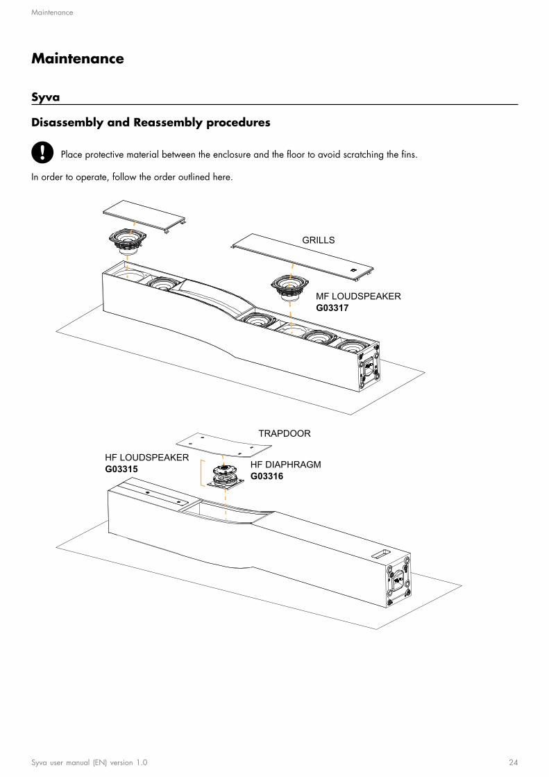
Disassembly and Reassembly procedures
Place protective material between the enclosure and the floor to avoid scratching the fins.
In order to operate, follow the order outlined here.
GRILLS
MF LOUDSPEAKERG03317
TRAPDOOR
HF DIAPHRAGMG03316
HF LOUDSPEAKERG03315
Syva user manual (EN) version 1.0 24

Maintenance
D/R - Grills
Tools
— torque screwdriver— T20 Torx bit— lever
Repair kits
G03317
KR medium loudspeaker 5'' Syva
×2
S337
M4x20 Torx
For safety reasons, always use the new screws and spare parts provided in the KR.If no new screws are available, use blue threadlocker.
Exploded view
Use a lever to remove the grill.
x4
1 N.m
T20
25 Syva user manual (EN) version 1.0

Maintenance
D/R - MF loudspeaker
Tools
— torque screwdriver— 3 mm hex bit
Repair kits
G03317
KR medium loudspeaker 5'' Syva
×1 ×4
17664 S100145
5" MF speaker - 8 ohms M4x20 hex
Pre-requisite
Grill disassembled. See Grills (p.25).
For safety reasons, always use the new screws and spare parts provided in the KR.If no new screws are available, use blue threadlocker.
Exploded view
Gradually tighten the screws following a star pattern.
Place the connectors toward the vents.
x4
1.8 N.m
3 mm
+-
+-
+-+
-+-
+-
What to do next
Perform the Acoustical check (p.36) procedures.
Syva user manual (EN) version 1.0 26

Maintenance
D/R - Trapdoor
Tools
— torque screwdriver— T25 Torx bit— lever
Repair kits
G03316 - KR diaphragm 1.75'' Syva
or G03315 - KR compression driver 1.75'' Syva
×4
S100086
M5x16 Torx
Pre-requisite
The enclosure is placed on its front face.
Place protective material between the enclosure and the floor to avoid scratching the fins.
For safety reasons, always use the new screws and spare parts provided in the KR.If no new screws are available, use blue threadlocker.
Exploded view
Use a lever to remove the trapdoor.
x4
3 N.m
T25
27 Syva user manual (EN) version 1.0

Maintenance
D/R - HF loudspeaker
Tools
— torque screwdriver— 4 mm hex bit - spherical head— screwdriver extension
Repair kits
G03315*
KR compression driver 1.75'' Syva
×1 ×2
G100087 S342
1" HF speaker assembly - 16 ohms M5x20 hex
* The screws are also available in G03316 - KR diaphragm 1.75'' Syva .
Pre-requisite
Trapdoor removed. See Trapdoor (p.27).
For safety reasons, always use the new screws and spare parts provided in the KR.If no new screws are available, use blue threadlocker.
Exploded view
Use a spherical head bit to access the screws of the lateral speakers.
If necessary, unplug the cables to remove the speakers. Refer to Connecting cables to the filter (HF area) (p.40).
Position the positive (red) connector toward the filter.
x2
3 N.m
4 mm
For each speaker, make sure the driver exit and the waveguide mouth fit together.The speaker plate must be level with the cabinet.
What to do next
Perform the Acoustical check (p.36) procedures.
Syva user manual (EN) version 1.0 28

Maintenance
D/R - HF diaphragm
Tools
— torque screwdriver— T20 Torx bit— compressed air blower— double face adhesive tape
Repair kits
G03316
KR diaphragm 1.75'' Syva
×1 ×6
17736 S17736
diaphragm kit for 1.75" driver - 16 Ω M4x8 Torx
Pre-requisite
Trapdoor removed. See Trapdoor (p.27).
HF loudspeaker disassembled. See HF loudspeaker (p.28)
For safety reasons, always use the new screws and spare parts provided in the KR.If no new screws are available, use blue threadlocker.
Exploded view
Make sure the air gap is perfectly clean before reassembly.Use a blower or double face adhesive to remove any particle.
Position the diaphragm assembly with the positive (red) connector aligned with the red mark.
Gradually tighten the screws following a star pattern.
T20
x6
1.7 N.m
What to do next
Perform the Acoustical check (p.36) procedures.
29 Syva user manual (EN) version 1.0

Maintenance
Syva Low
Disassembly and Reassembly procedures
In order to operate, follow the order outlined here.
GRILL
LF LOUDSPEAKERG03319
Syva user manual (EN) version 1.0 30

Maintenance
D/R - Grill
Tools
— torque screwdriver— T20 Torx bit— lever
Repair kits
G03319
KR LF loudspeaker 12'' Syva Low
×2
S337
M4x20 Torx
For safety reasons, always use the new screws and spare parts provided in the KR.If no new screws are available, use blue threadlocker.
Exploded view
Use a lever to remove the grill.
x2
1 N.m
T20
31 Syva user manual (EN) version 1.0

Maintenance
D/R - LF loudspeaker
Tools
— torque screwdriver— 5 mm hex bit
Repair kits
G03319
KR LF loudspeaker 12'' Syva Low
×1 ×8 ×4
1277 S100054 1250
12" LF speaker M6x30 hex 12" speaker gasket
Pre-requisite
Grill disassembled. See Grill (p.31).
For safety reasons, always use the new screws and spare parts provided in the KR.If no new screws are available, use blue threadlocker.
Exploded view
Gradually tighten the screws following a star pattern.
If the speaker gasket is damaged, remove and replace it.
Position the connectors toward the vent.
x8
5 N.m
5 mm
What to do next
Perform the Acoustical check (p.36) procedures.
Syva user manual (EN) version 1.0 32

Maintenance
Syva Sub
Disassembly and Reassembly procedures
In order to operate, follow the order outlined here.
GRILL
LF LOUDSPEAKERG03320
33 Syva user manual (EN) version 1.0

Maintenance
D/R - Grill
Tools
— torque screwdriver— T20 Torx bit— lever
Repair kits
G03320
KR LF loudspeaker 12'' Syva Sub
×2
S337
M4x20 Torx
For safety reasons, always use the new screws and spare parts provided in the KR.If no new screws are available, use blue threadlocker.
Exploded view
Use a lever to remove the grill.
x2
1 N.m
T20
Syva user manual (EN) version 1.0 34

Maintenance
D/R - LF loudspeaker
Tools
— torque screwdriver— 5 mm hex bit
Repair kits
G03320
KR LF loudspeaker 12'' Syva Sub
×1 ×8 ×4
17760 S100054 1250
12" LF speaker - 8 ohms M6x30 hex 12" speaker gasket
Pre-requisite
Grill disassembled. See Grill (p.34).
For safety reasons, always use the new screws and spare parts provided in the KR.If no new screws are available, use blue threadlocker.
Exploded view
Gradually tighten the screws following a star pattern.
If the speaker gasket is damaged, remove and replace it.
Position the connectors toward the top of the enclosure.
x8
5 N.m
5 mm
What to do next
Perform the Acoustical check (p.36) procedures.
35 Syva user manual (EN) version 1.0

Maintenance
Acoustical check
Enclosure check
This feature is available on:LA4XLA12X
ENCLOSURE CHECK measures impedance at the reference frequencies for the connected loudspeaker family. Themeasured impedance is compared to the expected range allowing for fast detection of loudspeakers presenting circuitcontinuity issues.
The results can be used for preliminary diagnosis but cannot replace a comprehensive quality control.
Pre-requisite
ENCLOSURE CHECK measurements can only be reliable if the following requirements are met:
Environment and temperature:— Ambient temperature must be comprised between 0 °C / 32 °F and 40 °C / 104 °F. Ideal temperature is 20 °C /
68 °F.— Enclosures must be at room temperature. If warm from a recent high level use or recently moved from a cold
environment, let the loudspeakers reach room temperature before starting.
Enclosures:— Enclosures must be included in the embedded factory preset library.— Enclosures must be in nominal operating conditions:
— Remove covers or dollies obstructing the loudspeakers or the vents.— Check for obvious physical damage or air leak: visually inspect the grill, gasket, cabinet, and connector plate
for loose, missing or damaged parts.
Connection:— Use only 10 m / 30 ft 4 mm² / AWG 11 speaker cables.— Do not connect enclosures in parallel.
Amplified controllers:— LA4X must run at least firmware version 1.1.0.— LA4X load sensors must be calibrated. Refer to the Load Sensor Calibration Tool technical bulletin for more
information.— LA4X must warm up for at least 10 minutes after power up. Do not power off, reboot or switch to standby mode to
avoid resetting the countdown.— Load a preset corresponding to the connected loudspeaker's family. Presets from the user memories may be used on
condition they are made of presets supported in the embedded factory preset library.
Procedure
1. Power up the amplified controller. Let LA4X warm up for at least 10 minutes.2. Connect the loudspeaker enclosures to the amplified controller.3. Load a preset from or built from the embedded library corresponding to the connected loudspeaker family.4. On the amplified controller, use the encoder wheel to select MONITORING & INFO. Press the OK key or the
encoder wheel to validate.5. Use the encoder wheel to select ENCLOSURE CHECK.
Beware of sound levels.Although the sound pressure levels generated for the ENCLOSURE CHECK are moderate, do not stay withinclose proximity of the loudspeakers and consider wearing ear protection.
6. Press the OK key or the encoder wheel to launch the ENCLOSURE CHECK.
The amplified controller generates short sinusoidal signals simultaneously for each connected output.
The amplified controller displays the results for each output.
Syva user manual (EN) version 1.0 36

Maintenance
7. Depending on the displayed results, follow the instructions in the table.
result interpretation instructions
OK measured impedance is within expected range enclosure is in working order electrically
? unsupported preset family only supported enclosures should be tested
NC Not Connected if cables are connected:
1. inspect the cables and connections2. go to step 8 (p.37)
NOK measured impedance is not within expected range
UNDEF measured impedance is undefined
1. check that all the prerequisites are met, inparticular that the loaded preset correspondsto the connected speaker's family
2. inspect the cables and connections3. go to step 8 (p.37)
8. Under NC, NOK and UNDEF results, press and hold the corresponding OUT key.
The amplified controller displays:— the tested frequencies,— information on the measured impedance:
— OPEN for open circuit (found in NC results),— SHORT for short circuit (found in NOK results), or— a percentage of variation from the expected range (found in NOK and UNDEF results)
— the number of operational transducers out of the total
Low variations from the expected range are acceptable: displayed percentage can be different from 0 and alltransducers considered operational.
37 Syva user manual (EN) version 1.0

Maintenance
Listening test
Enclosure Preset Usable bandwidth
Syva [SYVA] 87 Hz - 20 kHz
Syva Low [SYVA LOW_100] 40 Hz - 130 Hz
Syva Sub [SYVA SUB_100] 27 Hz - 120 Hz
Procedure
1. Load the preset on an LA4X / LA8 / LA12X amplified controller.2. Connect a sinus generator to the amplified controller.
Risk of hearing damageSet a low sound level to start and use ear protection to adjust before testing.
3. Scan the bandwidth focusing on the usable range.The sound should remain pure and free of unwanted noise.
Troubleshooting for HF speakers
One or more HF loudspeaker produces high-frequency harmonic distortions, strange vibrations or weak sound.
Possible causes
— There are foreign particles on the air gap.— The screws used for reassembly are too loose.— The diaphragm is damaged.— The speaker and the waveguide are not aligned.
Procedure
1. Remove the trapdoor and check the HF speakers.
For each speaker, make sure the driver exit and the waveguide mouth fit together.The speaker plate must be level with the cabinet.
2. Perform the HF speaker disassembly procedure.3. Perform the diaphragm disassembly procedure.4. Visually inspect the diaphragm and the voice coil.
If any damage is visible, replace the diaphragm.5. Clean the air gap thoroughly.6. Perform the reassembly procedure.
Pay close attention to the position of the diaphragm.Apply the recommended torque.
7. Repeat the listening test.
If the problem persists, replace the loudspeaker.
Syva user manual (EN) version 1.0 38

Maintenance
Troubleshooting for LF/MF speakers
One or more LF/MF loudspeaker produces distorted, buzzing, rubbing, muffled or weak sound.
Possible causes
— The screws used for reassembly are too loose.— There is an air leak in the gasket.— There is dust on the cone.— The cone is damaged.— The voice coil and/or the spider is damaged.
Procedure
1. Perform the loudspeaker disassembly procedure.2. Visually inspect the loudspeaker and the cables.
If any damage is visible, replace the loudspeaker.3. Carefully clean the loudspeaker with a dry cloth.4. Repeat the reassembly procedure.
Replace the loudspeaker gasket and the screws.Apply the recommended torque.
5. Repeat the listening test.6. If a buzzing sound is still audible, repeat the test on the loudspeaker outside of the enclosure.
If the problem persists, replace the loudspeaker.
39 Syva user manual (EN) version 1.0
APPENDIX A: Cabling Syva
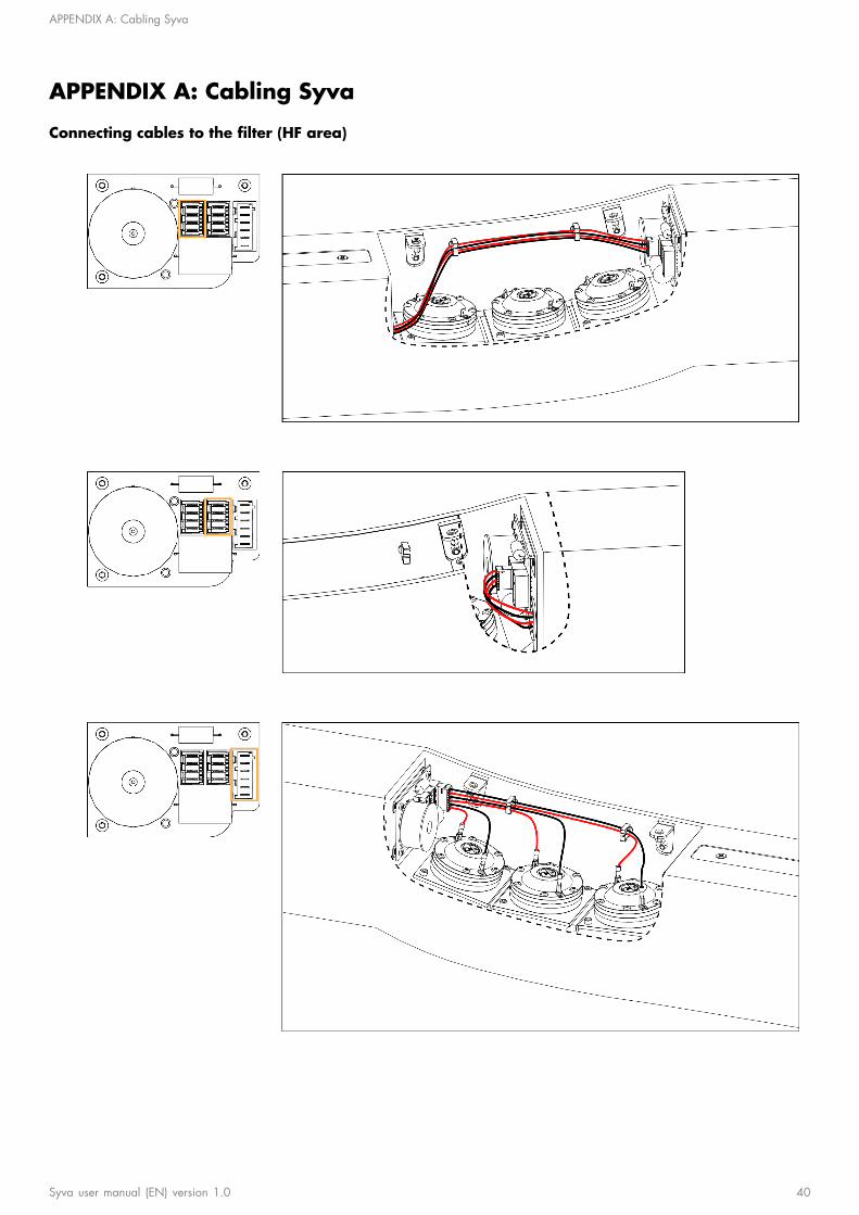
APPENDIX A: Cabling Syva
Connecting cables to the filter (HF area)
Syva user manual (EN) version 1.0 40

Specifications
Specifications
Syva specifications
Description 2-way-passive enclosure: 6 x 5'' LF + 3 x 1.75'' HF diaphragm, amplified byLA4X / LA8 / LA12X
Usable bandwidth (-10 dB) 87 Hz - 20 kHz ([SYVA])
Maximum SPL1 137 dB ([SYVA])
Nominal directivity vertical: +5°/-21° in J shape (> 1 kHz)
horizontal: 140° (>1 kHz)
Transducers MF: 6 × 5"
HF: 3 × 1.75", compression driver
Acoustical load MF: bass-reflex, L-Vents
HF: DOSC, L-Fins
Nominal impedance 8 Ω
Connectors IN: 4-point speakON and screw terminal
AutoConnect
Rigging and handling DIN580-compatible M8 threaded insert for secondary safety
2 integrated inserts for rigging accessory
Weight (net) 21 kg / 46 lb
Cabinet first grade Baltic beech and birch plywood
Front steel grill with anti-corrosion coating
acoustically neutral 3D fabric
Finish fine grain dark grey brown Pantone 426C
pure white RAL 9010
custom RAL code on special order
IP IP54
1 Peak level measured at 1 m under free field conditions using pink noise with crest factor 4 (preset specified in brackets).
41 Syva user manual (EN) version 1.0

Specifications
Syva dimensions
144 mm / 5.7 in
1301
mm
/ 51.
2 in
170 mm / 6.7 in
209 mm / 8.2 in
1304
mm
/ 51.
3 in
Syva user manual (EN) version 1.0 42

Specifications
Syva Low specifications
Description High power low frequency subwoofer: 2 x 12'' LF, amplified by LA4X / LA8 /LA12X
Low frequency limit (-10 dB) 40 Hz ([SYVA LOW_100])
Maximum SPL1 137 dB ([SYVA LOW_100])
Transducers LF: 2 × 12"
Acoustical load bass-reflex, L-Vents
Nominal impedance 4 Ω
Connectors IN: 4-point speakON
AutoConnect
Weight (net) 29 kg / 64 lb
Cabinet first grade Baltic beech and birch plywood
Front steel grill with anti-corrosion coating
acoustically neutral 3D fabric
Finish fine grain dark grey brown Pantone 426C
pure white RAL 9010
custom RAL code on special order
IP IP55
1 Peak level at 1 m under half space conditions using pink noise with crest factor 4 (preset specified in brackets).
Syva Low dimensions
334 mm / 13.1 in 350 mm / 13.8 in
849
mm
/ 33.
4 in
43 Syva user manual (EN) version 1.0

Specifications
Syva on Syva Low specifications
Description hybrid configuration, amplified by LA4X / LA8 / LA12X
Usable bandwidth (-10 dB) 40 Hz - 20 kHz ([SYVA LOW SYVA])
Maximum SPL1 142 dB ([SYVA LOW SYVA])
Connectors IN: 4-point speakON
Weight (net) 50 kg / 110 lb
1 Peak level at 1 m under half space conditions using pink noise with crest factor 4 (preset specified in brackets).
Syva on Syva Low dimensions
334 mm / 13.1 in
350
mm
/ 13.
8 in
144 mm / 5.7 in90 mm / 3.5 in
2128
mm
/ 83.
8 in
Syva user manual (EN) version 1.0 44

Specifications
Syva Sub specifications
Description Infra low frequency subwoofer: 1 x 12'' LF, amplified by LA4X / LA8 / LA12X
Low frequency limit (-10 dB) 27 Hz ([SYVA SUB_100])
Maximum SPL1 128 dB ([SYVA SUB_100])
Transducers LF: 1 × 12"
Acoustical load bass-reflex, L-Vents
Nominal impedance 8 Ω
Connectors IN: 4-point speakON
AutoConnect
Weight (net) 27 kg / 60 lb
Cabinet first grade Baltic beech and birch plywood
Front steel grill with anti-corrosion coating
acoustically neutral 3D fabric
Finish fine grain dark grey brown Pantone 426C
pure white RAL 9010
custom RAL code on special order
IP IP55
1 Peak level at 1 m under half space conditions using pink noise with crest factor 4 (preset specified in brackets).
Syva Sub dimensions
334 mm / 13.1 in 350 mm / 13.8 in
849
mm
/ 33.
4 in
45 Syva user manual (EN) version 1.0

L-Acoustics, an L-Group Company13 rue Levacher Cintrat - 91460 Marcoussis - France
+33 1 69 63 69 63 - [email protected]
L-Acoustics GmbHSteiermärker Str. 3-5
70469 StuttgartGermany
+49 7 11 89660 323
L-Acoustics Ltd.PO. Box Adler Shine - Aston HouseCornwall Avenue - London N3 1LF
United Kingdom+44 7224 11 234
L-Acoustics Inc.2645 Townsgate Road, Suite 600
Westlake Village, CA 91361USA
+1 805 604 0577
www.l-group.com