Embed Size (px)
Citation preview
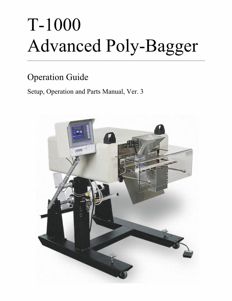
T-1000 Advanced Poly-Bagger______________________________________________________________________________
Operation Guide Setup, Operation and Parts Manual, Ver. 3
AcknowledgmentsManual written by: Stuart Baker
Copyright1995 (Ver 1), 2001 (Ver 2), 2003 (Ver 3), Advanced Poly-Packaging, Inc. (APPI). All rights reserved.
This manual and the program operating the equipment described in it are copyrighted. You may not copy this manual in wholeor part without the consent of Advanced Poly-Packaging, Inc.
All information pertaining to the promotion, sale, distribution, operation and maintenance of the T-1000 ADVANCEDPOLY-BAGGER including this manual, drawings, schematic, wiring diagrams, VHF video tapes, brochures, specificationsheets, figures, charts, or any other information, due to its proprietary design and manufacture remain the property of AdvancedPoly Packaging, Inc. Unauthorized duplication, distribution or disclosure to third parties without the expresses permission ofAdvanced Poly-Packaging, Inc. is strictly prohibited.
TrademarksT-1000 is a trademark of Advanced Poly-Packaging, Inc. Advanced Poly-Packaging, Inc. owns also the following trademarks:Advanced Poly-Bags, Advanced Poly-Bagger, Seal-a-Print, Roll-a-Print, Twin-Seal, Teflon Shield, Advanced Poly-Pack,Advanced Poly-Bag.
Limited Warranty & DisclaimerWarranty period is 12 months or 1,000,000 cycles whichever comes first. The warranty commences on the date of delivery ofthe equipment to the Purchaser.
APPI warrants to the Purchaser that the equipment is free from defects in workmanship or material under normal use and service.During the warranty period, APPI agrees to repair or replace, at its sole option, without charge to Purchaser, any defectivecomponent part of the equipment. To obtain service, Purchaser must return the equipment or component to APPI or anauthorized APPI distributor or service representative in an adequate container for shipping. Any shipping charges, insurance, o rother fees must be paid by Purchaser and all risk for the equipment shall remain with Purchaser until such time as APPI takesreceipt of the equipment. Upon receipt, APPI, the authorized distributor or service representative will promptly repair or repl acethe defective component and then return the equipment or component to Purchaser, shipping charges, insurance and additionalfees prepaid. APPI may use reconditioned or like new parts or units, at its sole option, when repairing any component orequipment. Repaired products shall carry the same amount of outstanding warranty as from original purchase. Any claim underthe warranty must include a dated proof of delivery. In any event, APPI's liability for defective components or equipment islimited to repairing or replacing the components.
This warranty is contingent upon proper use of the equipment by Purchaser and does not cover: expendable component part suchas Teflon, thermocouple wire, heater cartridge, rollers, bushings, and the like; or if damage is due to accident, unusual physical,electrical or electromechanical stress, neglect, misuse, failure of electric power, water damage (from airlines), improperenvironmental conditions, transportation, tampering with or altering of the equipment, packaging of corrosive or contaminatingproducts or other products damaging to components, and equipment or components not owned or in the possession of originalPurchaser.
APPI will not be liable for loss of production, profits, lost savings, special, incidental, consequential, indirect or other sim ilardamages arising from breach of warranty, breach of contract, negligence, or their legal action even if APPI or its agent has bee nadvised of the possibility of such damages or for any claim brought against the Purchaser by another party.
This warranty allocates risks of equipment failure between Purchaser and APPI. APPI's pricing reflects this allocation of riskand the limitations of liability contained in this warranty. The warranty set forth above is in lieu of all other express warra nties,whether oral or written. The agents, employees, distributors and dealers of APPI are not authorized to make modifications tothis warranty, or additional warranties binding on APPI. Accordingly, additional statements such as dealer advertising orpresentations, whether oral or written, do not constitute warranties by APPI and should not be relied upon.
Warranty on equipment is considered void when outstanding balances become delinquent (over 30 days late - 60 days after shipdate).
Equipment Integration to other Equipment: APPI assumes no responsibility for the integration of its products to other productsor within a system unless APPI performs the integration, testing and provides the results of the tests to the purchaser in writi ng. Furthermore, APPI assumes no responsibility for bag sizing whether suggested or recommended.
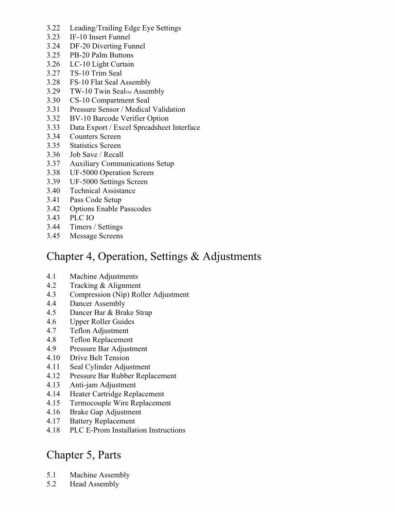
3.22 Leading/Trailing Edge Eye Settings3.23 IF-10 Insert Funnel 3.24 DF-20 Diverting Funnel 3.25 PB-20 Palm Buttons3.26 LC-10 Light Curtain3.27 TS-10 Trim Seal3.28 FS-10 Flat Seal Assembly 3.29 TW-10 Twin SealTM Assembly 3.30 CS-10 Compartment Seal 3.31 Pressure Sensor / Medical Validation3.32 BV-10 Barcode Verifier Option3.33 Data Export / Excel Spreadsheet Interface3.34 Counters Screen3.35 Statistics Screen3.36 Job Save / Recall3.37 Auxiliary Communications Setup3.38 UF-5000 Operation Screen3.39 UF-5000 Settings Screen3.40 Technical Assistance3.41 Pass Code Setup3.42 Options Enable Passcodes3.43 PLC IO3.44 Timers / Settings3.45 Message Screens
Chapter 4, Operation, Settings & Adjustments4.1 Machine Adjustments 4.2 Tracking & Alignment 4.3 Compression (Nip) Roller Adjustment 4.4 Dancer Assembly 4.5 Dancer Bar & Brake Strap 4.6 Upper Roller Guides 4.7 Teflon Adjustment 4.8 Teflon Replacement 4.9 Pressure Bar Adjustment 4.10 Drive Belt Tension 4.11 Seal Cylinder Adjustment 4.12 Pressure Bar Rubber Replacement 4.13 Anti-jam Adjustment 4.14 Heater Cartridge Replacement4.15 Termocouple Wire Replacement 4.16 Brake Gap Adjustment 4.17 Battery Replacement4.18 PLC E-Prom Installation Instructions
Chapter 5, Parts5.1 Machine Assembly5.2 Head Assembly
5.3 Flat Load Shelf Sub-Assembly5.4 Main Frame Assembly5.5 Main Frame Assembly5.6 Inner Main Frame Assembly5.7 Upper Roller Finger Assembly5.8 Air Knife Assembly5.9 Outer Main Frame Assembly5.10 Pneumatics Mntg. Valve5.11 Electrical Panel Assembly5.12 Sealer Frame Assembly5.13 Seal Frame Manifold Sub-Assembly5.14 Pressure Bar Sub-Assembly5.15 Heater Bar Sub-Assembly5.16 Teflon Guide Sub-Assembly5.17 Grooved Roller Mounting Sub-Assembly5.18 Bag Finger Grounding Assembly5.19 Stand Assembly5.20 Base Assembly5.21 Upper Column Assembly5.22 Dancer Assembly5.23 Dancer Guide Sub-Assembly5.24 Touch Screen Assembly5.25 SP-10 Spare Parts Kit (Level 1)5.26 SP-20 Spare Parts Kit
Chapter 6, Preventive Maintenance & Scheduled Maintenance6.1 Preventative Maintenance & Schedule Maintenance 6.2 P.M. Checklist 6.3 Scheduled Maintenance Chart
Chapter 7, Troubleshooting7.1 Troubleshooting 7.2 Troubleshooting Checklist 7.3 Interface PCB Voltage Table7.4 Wiring Tab List7.5 Circuit Boards7.6 Pneumatic Valves / Cylinders7.7 Wiring Diagram7.8 Notes
Contents______________________________________________________________________________
Chapter 1, Introduction1.1 Welcome1.2 Overview1.3 Special Features 1.4 System Integration 1.5 Options Available1.6 Using This Manual 1.7 Registration Information
Chapter 2, Getting Started2.1 Installation Procedures2.2 Air & Power Requirements 2.3 Assembly2.4 Air & Power Hookup 2.5 Main Power 2.6 Bag Threading 2.7 Cycle Operation 2.8 Note on Adjustments 2.9 Energy Conservation & Component Saver
Chapter 3, Touch Screen Operation
3.1 Touch Screen Front Panel 3.2 Touch Screen Back Panel 3.3 Specifications 3.4 Contrast Adjustments 3.5 Touch Screen Program / Overview3.6 Intro Screen 3.7 Main Menu 3.8 Bag Setup Menu 3.9 Operation Screen3.10 Seal Time3.11 Seal Temperature3.12 Seal Point3.13 Note on Seal Quality 3.14 Air Pulse 3.15 Blower 3.16 Fill Time 3.17 Options - Overview 3.18 AF-10 Accumulating Funnel 3.19 LS-10 Load Shelf 3.20 Ti-1000 Inline Printer 3.21 CF-10 Counting Funnel

This page intentionally left blank.

Chapter 1, Introduction__________________________________________________________________
WelcomeOverviewSpecial FeaturesSystem IntegrationOptions AvailableUsing This ManualRegistration Information
1.1 IntroductionNow that you've decided to upgrade your packaging facilities with the T-1000 Advanced Poly-Baggerfrom Advanced Poly-Packaging, Inc., we thank you for selecting our equipment, materials and service.Where labor reduction and fast changeover is important, the T-1000 uses Advanced Poly-Bags(pre-opened bags on rolls), manufactured by Advanced Poly-Packaging, Inc. Extensively equipped withseveral "built-in", ready-to-use options, the T-1000 can package various industrial, medical, molded andfood products. With a wide range of bag sizes (2" x 3" to 14" x 30") and mil thickness (1 mil to 5 mil),we hope the T-1000 will meet all of your bagging needs.
1.2 OverviewThe T-1000 ADVANCED POLY-BAGGERTM is a system designed to lower your packaging costs withhigh speeds, versatility, reliability, and simplicity.
High Speeds - Indexes, opens, seals and tears off a bag at rates over 100 cycles per minute, dependentupon bag size and product characteristics.
Versatility - Mobile on rugged castors for packaging at any production station throughout your facility.Ideal for numerous short runs with virtually no production loss for job changeovers since all that isrequired is a roll change and recalling the bag settings from memory.
Reliability - Crafted from the highest quality components and materials to withstand the most rigorousmanufacturing environment; sturdy mounts with castors, and rugged frame guarantee long life andusefulness with minimal maintenance.
Simplicity - A "user-friendly" menu-driven touch screen program allows operators to setup the bag,options and auxiliary equipment, save the settings in memory, and recall those settings for repeat runs.
1.3 Special FeaturesEnergy Conservation & Component Saver - To extend its life and conserve energy in your plant, theT-1000 is programmed to sequentially shut components down when not in use for extended periods.First, the motor will shut off until the foot switch is pressed or a signal is received to initiate operation.Later, current to the heater bar will discontinue and place the T-1000 in the stop mode. Shortly thereafter,air flow will be shut off preserving compressed air. A screen saver is also provided.
Pass code Protection - As an option, setting screens can be protected from being altered by unauthorizedindividuals. Once turned on, this function acts as a “screen save” feature whereas a timer causes the passcode screen to be displayed, from the Operations Menu.
Predetermined Counter - Preset the T-1000 to stop after a predetermined number of bags have beenpackaged. Set the quantity of finished bags to complete a work order or fill a shipping container. Oncethe work order is complete or the container is full, the T-1000 stops to alert the operator to begin the nextwork order or to push aside the box to begin filling another. Pressing anywhere on the screen resets thecounter and starts the bagging operation with minimum delay.
Totalizing Counter - Reset this counter at the beginning of each shift or day to record packagingproduction over a period of time.
Maintenance Counter/Chart - Periodically check this counter (total machine cycles) to determinepreventative maintenance / component inspection intervals for inspection / maintenance criteria andintervals.
Continuous Strip Option - Leave bags connected in an "endless" strip or a predetermined number of stripsof sealed bags.
Communications Port/Modem - Allows for auxiliary communications.
Anti-Jam Device - During the loading and sealing operation, this device will detect obstructions andautomatically reverse the pressure bar and discontinue the cycle operation.
Castors Assembly - Rugged castors are standard for plant mobility.
1.4 System Integration The T-1000 is preprogrammed to integrate automatically to major brand vibratory counters and feeders,weigh scales, volumetric fillers, auger fillers and infeed conveyors. As an OEM for numerous equipmentmanufacturers of infeed systems, we can offer the best available system, with the T-1000 AdvancedPoly-Bagger as the integral packaging component. However, APPI cannot be responsible for thesuccessful integration of third party equipment, unless approved and integrated by APPI.
FREE CONSULTATION AND PRODUCT EVALUATION: We invite you to call to discuss yourpackaging requirements and our free product packaging analysis.
1.5 Additional Options AvailableAlthough the T-1000 is extensively equipped with many "built-in" options described above, variousauxiliary options and equipment can easily be added for special purpose packaging. The followingoptions may be purchased from Advanced Poly-Packaging, Inc.
AF-10 Accumulating Funnel - Increase production by allowing a continuous infeed of product into thefunnel without regard for the operation of the T-1000. The Accumulating Funnel will collect the productwhile the bag is sealing. Once another bag is in position and blown open, the funnel discharges theproduct into the bag without stopping the flow of product into the funnel.
BB-10 Bag Blow-off Assembly - Allows for faster packaging of lighter products by stripping bags fromseal bar. Also used when bags stick to Teflon or seal bar.
BF-10 Bag Deflator (sponge or rubber loop) - Flattens package by removing air from bag before sealing.
CF-10 Counting Funnel - Preprogrammed, the T-1000 Counting Funnel counts product entering thefunnel or bag and signals the T-1000 to seal the bag when the preset quantity has been reached. TheCounting Funnel may operate in conjunction with the Accumulating Funnel for fully automaticoperations.
DF-10 Diverting Funnel - Mounts to bagger beneath the seal bar or the end of a takeaway conveyor tocount bags into one of two boxes. When the final bag count is reached, a diverter redirects from Box A toBox B.
FS-10 Flat Seal Assembly - Helps decrease / eliminate wrinkles in the seal by pulling sides of bag.Increase bag integrity.
LS-10 Load / Support Shelf - Provides support for heavier packages when dropped into bag. Sizes: 10",15", or 20" long.
LSV-10 Load Shelf Vibrator Kit - Settles product to bottom of bag to increase volume of product in bag.(LS-10 back plate required).
PB-20 Dual Palm Buttons - Decrease the possibility of injury to hands and fingers. Operator must pushtwo buttons simultaneously to actuate seal bar.
LC-10 Light Safety Curtain - Safety feature that prohibits seal operation when there are obstructions inlight screen. Also, toggle on the “auto cycle” feature and the seal bar automatically activates when thelight curtain field is unobstructed (trailing edge of signal).

Printpad Terminal & Scanner - No longer is a PC required to operate a thermal transfer printer.Alphanumeric keypad with programmable function keys, printer controls, easy-to-read display, scannedinput, and stored databases. Data can be imported directly from external devices such as scales or othertest and measurement equipment. Designed for an industrial environment, this compact unit is sealed forprotection and costs less than most PCs.
TS-10 Trim Seal Assembly - Trims excess film from bag above seal to enhance the appearance of thepackage (retail products).
Ti-1000 Thermal Transfer Inline Printer - Print bar codes, graphics, etc. by downloading pre-formattedlabels, generated via label software. (PC or Terminal & software required)
Ti-2000 Dual Thermal Inline Printers - Print bar codes, graphics, etc. on both front and back of bag,directly to the surface of the bag, simultaneously with a "top & bottom" printer. (PC or terminal &software required)
DF-20 Loose Parts Diverter - For kit bagging, parts may fall out of the funnel, out of an infeed machine,or outside of the bag. When this occurs, loose parts mixed with the bagged parts may cause check weighscales to read the kit as being accepted. With the loose parts diverter, loose parts will be deflected into areject tote.
DF-10 Diverting Funnel - This option enables a two box system to be incorporated. Finished bags arecounted and directed into Box A; when the final count has been reached, the diverter moves, directingbags into Box B and the operator is alerted each incident to replace the full box.
AC-10 Air Checker - For medical validation or when plant air frequently fails, the Air Checker optioncauses the machine to stop operation when air pressure fall below acceptable limits.
OFS-10 Output Fault Signal w/ SL-10 Stack Light - For automatic bagging operations with third party orproduction equipment, this signal provides a fault when the bagger is inoperative (due to out of bagconditions or other fault conditions).
Twin-SealTM - Seal the bag a second time, 3/4" from the first seal for additional bag integrity.
UF-2000 Takeaway Conveyor - Remove the packaged product to a packing station or directly feed acarton or table, conveying the product from floor level. The conveyor perfectly fits underneath theT-1000 and takes the product away. Small, lightweight and equipped with castors, use this conveyoranywhere in the plant. Designed for 24 hour / 7 days a week operation.
UF-5000 Infeed Conveyor - Kit packaging infeed conveyor. Instead of loading parts directly into thebag, load parts into compartments on the conveyor. Packaging kits loading the compartments by hand orautomatically with parts counters or scales.
UC-2400 Vibratory Parts Counter - Automatic parts counter feeds fasteners, electronic components,injected molded parts and many other types of products, then drop the final count into the bag, carton orinfeed conveyor.
US-3000/4000 Check Weigh Scales - When you must guarantee the contents of the bags or kits, APPIoffers check weigh scales with incredible accuracy, speeds and reliability. A history of weighments isstandard along with job/recipe saves. US-5000/7000/9000 - Semi automatic (US-5000) or automatic scale (US-7000 & US-9000) feeds a weigh/ counted batch of product into bags.

Other options may have been added since the date this list was printed. Please call for additional orcustom options pricing.
1.6 Using this Manual - Typographical ConventionsThe following manual conventions are frequently used to assist in understanding important information,alerting the operator of potentially dangerous or damaging practices, and the normal functions of theT-1000 Advanced Poly-BaggerTM.
text Normal text
<ENTER> Used to show Touch Screen keys
Italics Used for emphasis
CAUTION: Warning messages: To avoid physical harm, damage to equipment or damage to the product. Be sure to read these messages carefully.
1.7 REGISTRATION INFORMATION:
(This section must be completed and returned to Advanced Poly Packaging, Inc. to register theT-1000 for Warranty Protection)
Serial Number of Machine(s): ____________________________________________________
Company Name & Address Contact Name(s) / Title(s) / Phone Number
________________________________________
________________________________________
________________________________________
________________________________
________________________________
________________________________

This page intentionally left blank.

Chapter 2, Getting Started__________________________________________________________________
Installation ProceduresAssembly InstructionsHeight AdjustmentAir & Power HookupBag Threading
2. Getting StartedThis chapter describes in detail procedures to receive and setup the T-1000, including uncrating,environmental, air and power requirements, assembly, and height adjustments. Additionally, this chapterdescribes how to turn on power to the T-1000 and properly thread bags through the machine.
2.1 Installation Procedures The T-1000 is transported as a single unit in a custom crate designed to protect the machine duringshipment. It is shipped completely assembled except for a few items which are easily attached duringinstallation with final adjustment for proper placement of touch screen, dancer assembly, foot switch,funnel and guards.
Unpacking: After removing the stretch wrapping, remove the outer crate from the skid which containsthe T- 1000. Unfasten the base support brace from the skid. Carefully lower the T-1000 from the skid.Transport the T-1000 to the operating location prior to placing the Touch Screen in position andunfastening the dancer assembly.
Operating Environment: The T-1000 should be placed in an area free of excessive heat, moisture, dirtand dust. Operating room temperature should range from 50 to 100 degrees Fahrenheit.
2.2 Air & Power Requirements Power Requirements: Provisions must be made for 115 VAC, 50/60 Hz line current with ground. FullLoad Current for T-1000: 12 AMPS.
CAUTION: A qualified electrician should ensure that the T-1000 power outlet is properly grounded,voltages are as required and amperage capacity is sufficient. Note: APPI recommends a dedicated 20Amp circuit for the T-1000.
Air Requirements: At least 2 CFM free air is required, regulated to 80 PSI. Note: Air should be dry andoil-free.
2.3 Assembly Instructions Choose an operating location considering traffic flow, availability of bag supplies, supply of product to bepackaged, takeaway of finished packages, placement of auxiliary infeed equipment and placement oftakeaway conveyor(s). Operating location, the first step is to remove any inner packaging, banding orwires.
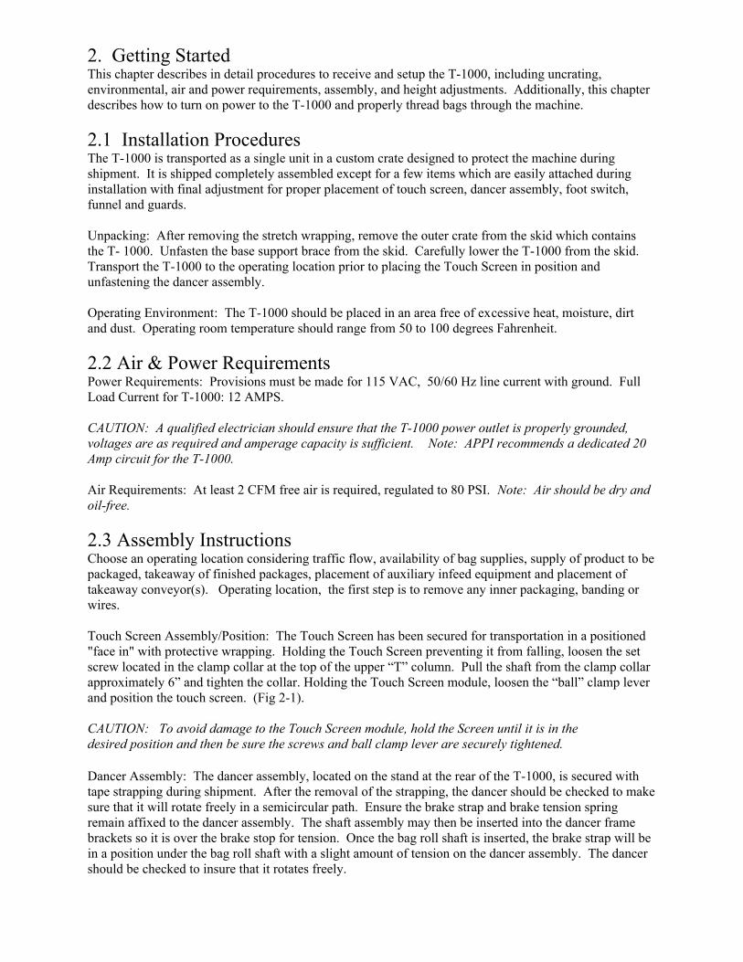
Touch Screen Assembly/Position: The Touch Screen has been secured for transportation in a positioned"face in" with protective wrapping. Holding the Touch Screen preventing it from falling, loosen the setscrew located in the clamp collar at the top of the upper “T” column. Pull the shaft from the clamp collarapproximately 6” and tighten the collar. Holding the Touch Screen module, loosen the “ball” clamp leverand position the touch screen. (Fig 2-1).
CAUTION: To avoid damage to the Touch Screen module, hold the Screen until it is in the desired position and then be sure the screws and ball clamp lever are securely tightened.
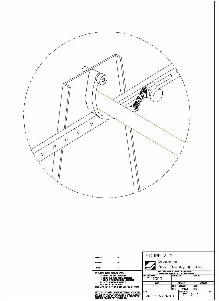
Dancer Assembly: The dancer assembly, located on the stand at the rear of the T-1000, is secured withtape strapping during shipment. After the removal of the strapping, the dancer should be checked to makesure that it will rotate freely in a semicircular path. Ensure the brake strap and brake tension springremain affixed to the dancer assembly. The shaft assembly may then be inserted into the dancer framebrackets so it is over the brake stop for tension. Once the bag roll shaft is inserted, the brake strap will bein a position under the bag roll shaft with a slight amount of tension on the dancer assembly. The dancershould be checked to insure that it rotates freely.

2.9 Energy Conservation & Component SaverThe T-1000 is programmed to automatically shut down components after various periods of nonuse topreserve components and conserve energy.
Motor shut off: After two minutes of nonuse (or the amount of time set in the Technical Assistance /Timers screen), the motor will stop. To resume packaging, press the foot switch or other input signal.When the foot switch is pressed, the motor immediately runs, the bag in position is sealed, torn off andanother bag indexed into position.
Touch Screen shut off: The touch screen backlight will shut off after 60 minutes of nonuse, preservingthe life of the LCD and back light. To turn the screen back on, touch the screen.
Heater bar shut off: After 40 minutes of nonuse (or the amount of time set in the Technical Assistance /Timers Screen), electrical current to the heater bar cartridge will stop. To resume packaging, press the<START> key. You may have to wait until the heater bar is up to temperature depending upon thetemperature of the bar.
Air shut off: 10 minutes after the heater bar current has shut down, air will be shut off disconnecting airflow to the blower. To resume packaging, press the <START> key.
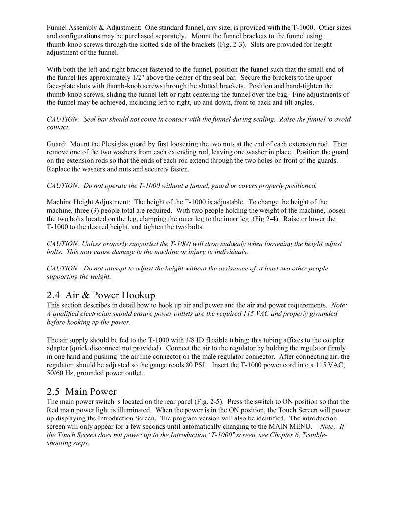
Funnel Assembly & Adjustment: One standard funnel, any size, is provided with the T-1000. Other sizesand configurations may be purchased separately. Mount the funnel brackets to the funnel usingthumb-knob screws through the slotted side of the brackets (Fig. 2-3). Slots are provided for heightadjustment of the funnel.
With both the left and right bracket fastened to the funnel, position the funnel such that the small end ofthe funnel lies approximately 1/2" above the center of the seal bar. Secure the brackets to the upperface-plate slots with thumb-knob screws through the slotted brackets. Position and hand-tighten thethumb-knob screws, sliding the funnel left or right centering the funnel over the bag. Fine adjustments ofthe funnel may be achieved, including left to right, up and down, front to back and tilt angles.
CAUTION: Seal bar should not come in contact with the funnel during sealing. Raise the funnel to avoidcontact.
Guard: Mount the Plexiglas guard by first loosening the two nuts at the end of each extension rod. Thenremove one of the two washers from each extending rod, leaving one washer in place. Position the guardon the extension rods so that the ends of each rod extend through the two holes on front of the guards.Replace the washers and nuts and securely fasten.
CAUTION: Do not operate the T-1000 without a funnel, guard or covers properly positioned.
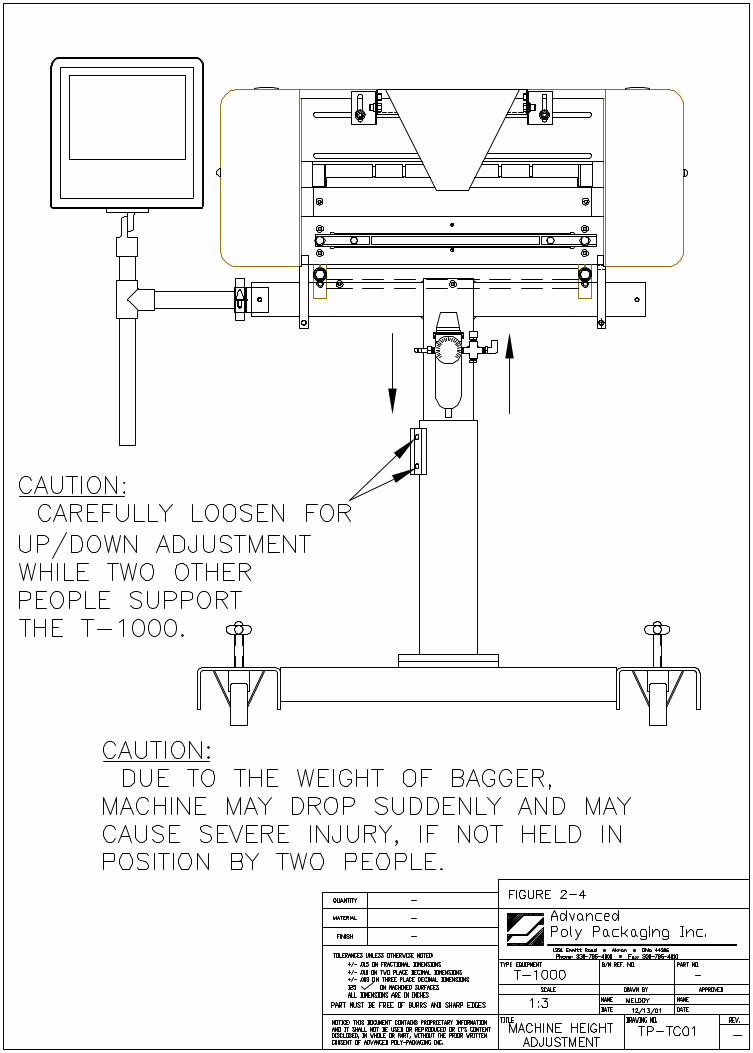
Machine Height Adjustment: The height of the T-1000 is adjustable. To change the height of themachine, three (3) people total are required. With two people holding the weight of the machine, loosenthe two bolts located on the leg, clamping the outer leg to the inner leg (Fig 2-4). Raise or lower theT-1000 to the desired height, and tighten the two bolts.
CAUTION: Unless properly supported the T-1000 will drop suddenly when loosening the height adjustbolts. This may cause damage to the machine or injury to individuals.
CAUTION: Do not attempt to adjust the height without the assistance of at least two other peoplesupporting the weight.
2.4 Air & Power HookupThis section describes in detail how to hook up air and power and the air and power requirements. Note: A qualified electrician should ensure power outlets are the required 115 VAC and properly groundedbefore hooking up the power.
The air supply should be fed to the T-1000 with 3/8 ID flexible tubing; this tubing affixes to the coupleradapter (quick disconnect not provided). Connect the air to the regulator by holding the regulator firmlyin one hand and pushing the air line connector on the male regulator connector. After connecting air, theregulator should be adjusted so the gauge reads 80 PSI. Insert the T-1000 power cord into a 115 VAC,50/60 Hz, grounded power outlet.
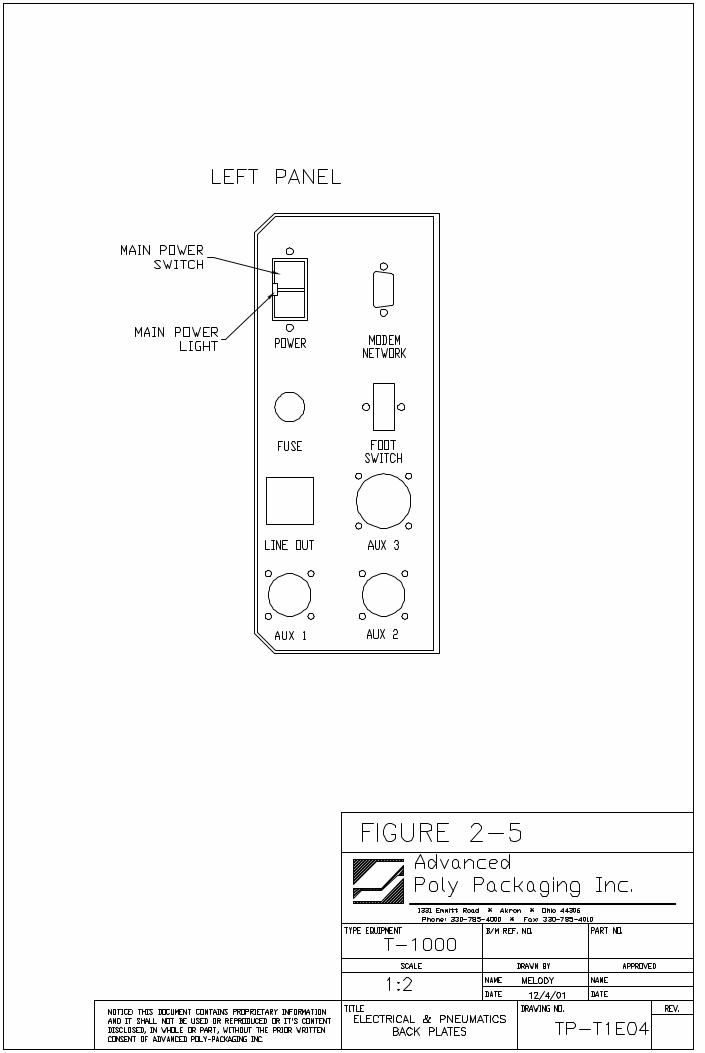
2.5 Main PowerThe main power switch is located on the rear panel (Fig. 2-5). Press the switch to ON position so that theRed main power light is illuminated. When the power is in the ON position, the Touch Screen will powerup displaying the Introduction Screen. The program version will also be identified. The introductionscreen will only appear for a few seconds until automatically changing to the MAIN MENU. Note: Ifthe Touch Screen does not power up to the Introduction "T-1000" screen, see Chapter 6, Trouble-shooting steps.
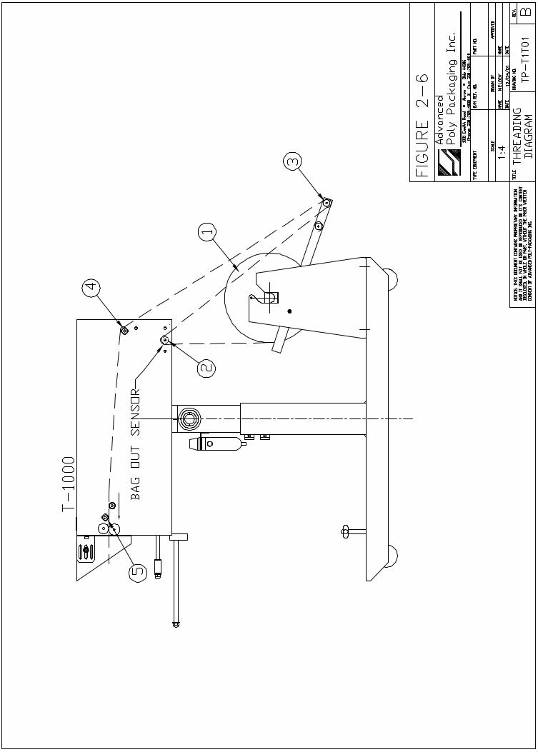
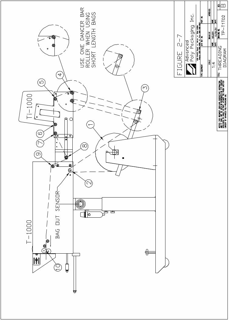
2.6 Bag Threading (Fig. 2-6 & 2-7, Threading Diagrams)The first step to threading the machine is to place a roll of bags on the shaft. Remove one of the chucksfrom the shaft by loosening the chuck knob and slide the roll of bags over the shaft, locking the chuck pinin the small hole in the core plug. Tighten the knob. Replace the second chuck also locking the chuck pinto the core plug. Remove the tape from the bags so that the bags fall freely and hang down from the topof the roll towards the back of the machine. Insert the right side of the roll shaft in the right side of theshaft holder (circular holder). Then drop the roll shaft in the slot located on the left side of the dancerassembly.
Center the bags on the shaft by loosening the chuck knobs and sliding the roll of bags along with thechucks to the desired location. Ensure the chuck pins remain in the core plug holes when sliding left orright. Pull the bags over the roller immediately above the dancer assembly, then down between the roll ofbags and the outer dancer roller. Pull the bags around the outer dancer roller, over the rear "guide" rollerand into the back of the T-1000. Push the bags at least half way through the machine.
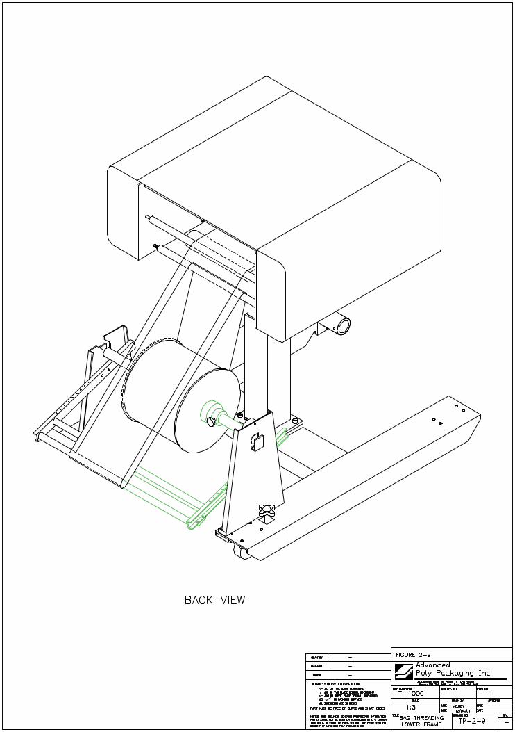
From the front of the T-1000, lower the frame by slowly pulling the frame handle forward and downward.See Fig. 2-9. Carefully reach inside and pull the bags through the front of the T-1000 so that one bag iscentered on the roller. Ensure only one (1) bag extends through the front of the machine. Slowly raisethe frame by pulling forward and upward on the handle while holding the bag in position. Holding theguide roller shaft, slide the Roller Guides within approximately 1/8" from the sides of the bag to assist thetracking of the web of bags.Caution: Roller "Fingers" may be sharp. To avoid injury when reaching into the T-1000, ensure thatyou do not come in contact with the roller "fingers."
Note: The Roller Guides are for fine adjustments only, after proper tracking has been achieved. If theweb of bags are not properly tracking, make proper adjustments. If not tracking properly, the web ofbags may "ride" up the side of the guides causing the bags to fold over.
2.7 Cycle Operation of the T-1000If all prior installation procedures have been performed properly, the T-1000 should be in its operatinglocation with air and power connected. All guards, funnels and covers should be in position and securelyfastened.
Locate the foot switch and plug the foot switch in the rear foot switch connector (Fig. 2-5). Press the footswitch to index one bag through the "nip" rollers. One bag should index, blow open and stop between thepressure bar and the heater bar. If the T-1000 is not up to temperature, the machine will not cycle unlessthe <Run> button is toggled to the Setup position.
If the web of bags breaks prematurely, further adjustments will be required. See Chapter 7, Troubleshooting. If one bag indexed through the machine, press the foot switch a few times more. Eachpreviously indexed bag should detach completely from the web of bags. If the bag is not indexing and/orstopping or not tearing off properly, see Chapter 7, Trouble shooting.
Note: Web of bags may track left or right for a few feet until "settled" on the web path. The roll of bagsor the roller guides may require readjustment or realignment after the first few feet of bags are indexed.
Note: If bags were delivered with the T-1000 or the size of the bags were known to APPI, the T-1000 maybe ready to run. Therefore, few changes to BAG SET UP may be required.
2.8 Note on Adjustments to the T-1000Upon receipt, it is not unusual for the T-1000 to be out of alignment due to shipping and excessivehandling. Unless physically damaged, the T-1000 will function properly after minor adjustments areaccomplished. Read Chapter 4 for information on adjustments of the T-1000.

Chapter 3, Touch Screen Operation______________________________________________________________________________
Touch Screen Part NamesSpecificationsContrast AdjustmentTouch Screen Program
3. Touch Screen OperationThis section describes in detail, the identification, operation and adjustments of the Touch ScreenProgram.
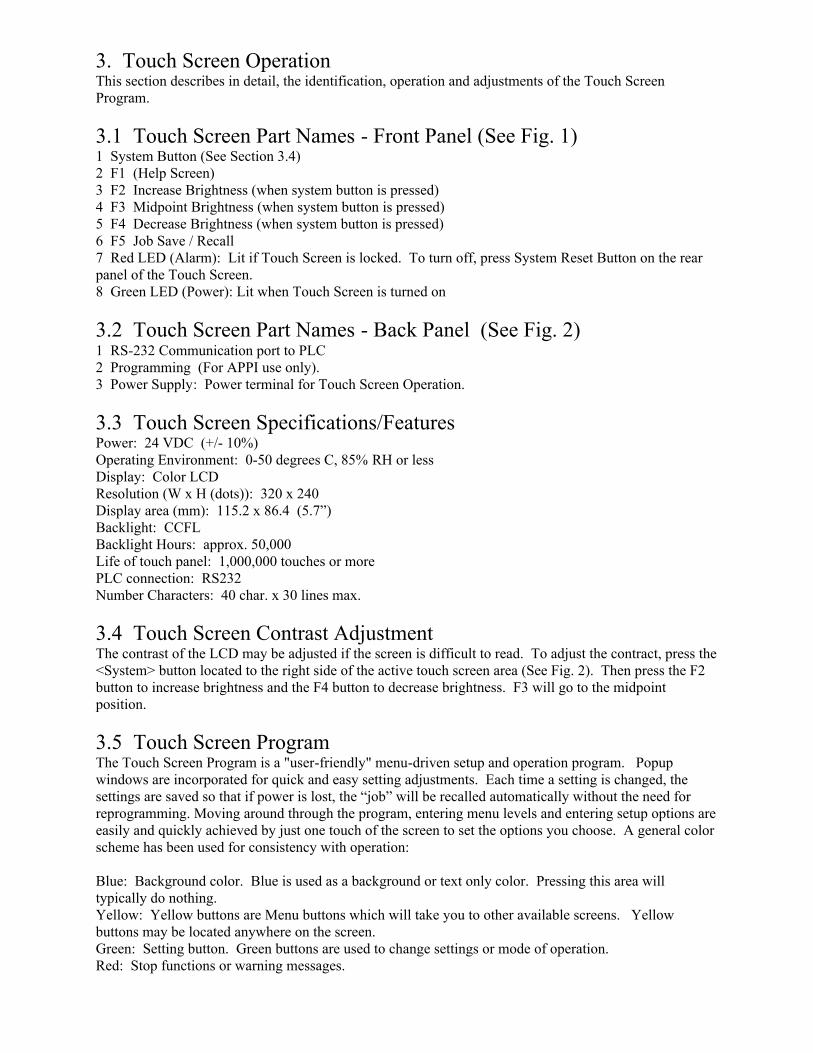
3.1 Touch Screen Part Names - Front Panel (See Fig. 1)1 System Button (See Section 3.4)2 F1 (Help Screen)3 F2 Increase Brightness (when system button is pressed)4 F3 Midpoint Brightness (when system button is pressed)5 F4 Decrease Brightness (when system button is pressed)6 F5 Job Save / Recall 7 Red LED (Alarm): Lit if Touch Screen is locked. To turn off, press System Reset Button on the rearpanel of the Touch Screen.8 Green LED (Power): Lit when Touch Screen is turned on
3.2 Touch Screen Part Names - Back Panel (See Fig. 2)1 RS-232 Communication port to PLC 2 Programming (For APPI use only).3 Power Supply: Power terminal for Touch Screen Operation.
3.3 Touch Screen Specifications/FeaturesPower: 24 VDC (+/- 10%)Operating Environment: 0-50 degrees C, 85% RH or lessDisplay: Color LCDResolution (W x H (dots)): 320 x 240Display area (mm): 115.2 x 86.4 (5.7”)Backlight: CCFLBacklight Hours: approx. 50,000Life of touch panel: 1,000,000 touches or morePLC connection: RS232Number Characters: 40 char. x 30 lines max.
3.4 Touch Screen Contrast AdjustmentThe contrast of the LCD may be adjusted if the screen is difficult to read. To adjust the contract, press the<System> button located to the right side of the active touch screen area (See Fig. 2). Then press the F2button to increase brightness and the F4 button to decrease brightness. F3 will go to the midpointposition.
3.5 Touch Screen ProgramThe Touch Screen Program is a "user-friendly" menu-driven setup and operation program. Popupwindows are incorporated for quick and easy setting adjustments. Each time a setting is changed, thesettings are saved so that if power is lost, the “job” will be recalled automatically without the need forreprogramming. Moving around through the program, entering menu levels and entering setup options areeasily and quickly achieved by just one touch of the screen to set the options you choose. A general colorscheme has been used for consistency with operation:
Blue: Background color. Blue is used as a background or text only color. Pressing this area willtypically do nothing.Yellow: Yellow buttons are Menu buttons which will take you to other available screens. Yellowbuttons may be located anywhere on the screen. Green: Setting button. Green buttons are used to change settings or mode of operation.Red: Stop functions or warning messages.
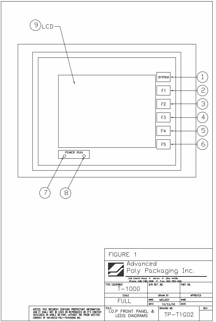
3.6 Introductory Screen When the T-1000 is turned on, an Introductory screen is displayed (Fig. 3-1). The Introduction screen isa welcome screen and has a button to take you to the Main Menu.
3.7 Main MenuThe Main Menu (Fig. 3-2) is the first menu screen displayed after the Introduction is flashed on the screenand allows you to go to all screens available in the T-1000.
Start / Stop: Toggle button controls operation mode; mode which enables T-1000 to cycle.Manual/Auto: Toggle button to enter Automatic (paced rate) or Auxiliary Cycle mode.Pause/Setup: Temporarily deactivates Predetermining Counter and Totalizing Counter until reset.Temporarily deactivates signal to auxiliary equipment. Allows cycle operation when heater bar is not upto temperature.Ready / Waiting: Indicator LED. Displays Ready when heater bar is at the temperature set point.Waiting flashes when the machine is not at temperature.
3.8 Operation ScreenThe Operation Screen is provided to function with Pass code Protection function of the machine. If thepass code function is enabled in the Technical Assistance Screen, the touch screen will default to theOperation Screen after a preset time has elapsed. This function prevents unauthorized operators frommaking setting changes that could affect the operation or performance of the unit. Since no settings aredisplayed on the Operations Screen, the operator cannot change settings unless a pass code is enabled.See Fig. 3-3.
The Operation Screen also displays a Totalizing Counter and Production Time that can be reset by theoperator.
Note: The Totalizing Counter feature must be turned ON from the Counters Screen to track cycleoperations. See Fig. 3-35.
Note: For more information regarding the pass code function, refer to Section 3.41, Pass Code Setup,later in this chapter.
3.9 Bag Setup Menu The Bag Set Up Menu prompts the operator to input bag timer settings which change seal point,temperature, fill time (paced rate) and air pulse time. Bag thickness, length, width and productcharacteristics affect these settings. Once set, the operator may save the bag settings along with optionssettings and auxiliary settings for later recall (Fig. 3-4).
The bag set up menu is the menu where most entries and machine operation setting will occur. When anew bag size or thickness is introduced, the T-1000 must be set up to properly run the bags.
3.10 Seal TimeDisplays, in seconds, the time the pressure (rubber) bar will remain touching the surface of the bag forproper sealing. Sometimes referred to as "dwell time", seal time is one of three critical components toobtain a strong seal (other critical factors include seal temperature and seal pressure). To adjust the SealTime value, touch the highlighted <Seal Time> menu option to display a number pad. To change thesetting, press the number (decimal point first, if less than 1) and then press <Enter>. To clear anincorrectly pressed value, press the highlighted <Clear> button and retype the correct value. Pressing<Enter> will return you to the Bag Setup Screen. Test and further adjust if necessary.
Fig. 3-1 Fig. 3-2
Fig. 3-3 Fig. 3-4
Fig. 3-5 Fig. 3-6
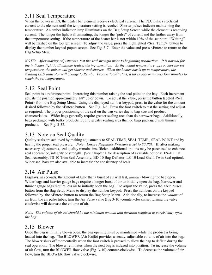
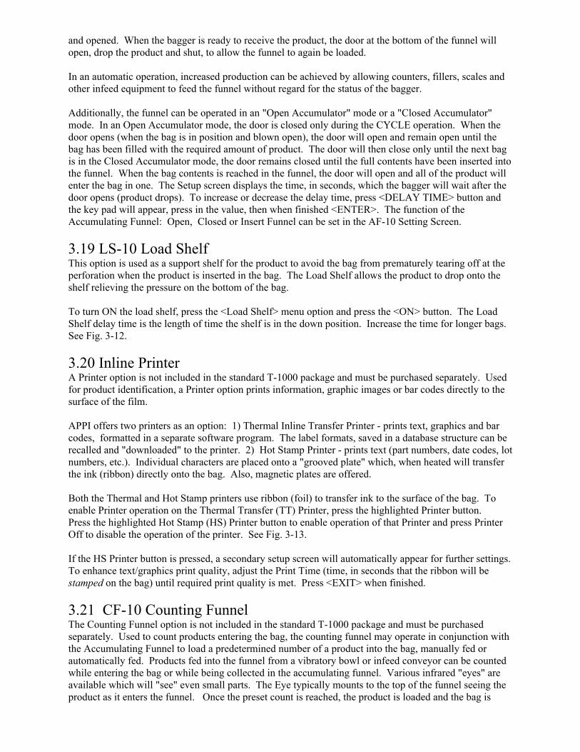
3.11 Seal Temperature When the power is ON, the heater bar element receives electrical current. The PLC pulses electricalcurrent to the element until the temperature setting is reached. Shorter pulses indicate maintaining thetemperature. An amber indicator lamp illuminates on the Bag Setup Screen while the element is receivingcurrent. The longer the light is illuminating, the longer the "pulse" of current and the further away fromthe temperature setting. If the temperature of the heater bar is not within 10% of the set point, “Waiting”will be flashed on the top left screen. To adjust the value, press the highlighted <Seal Temp> button todisplay the number keypad popup screen. See Fig. 3-7. Enter the value and press <Enter> to return to theBag Setup Menu.
NOTE: After making adjustments, test the seal strength prior to beginning production. It is normal forthe indicator light to illuminate (pulse) during operation. As the actual temperature approaches the settemperature, the pulses will get shorter and shorter. When the heater bar is up to temperature, theWaiting LED indicator will change to Ready. From a "cold" start, it takes approximately four minutes toreach the set temperature.
3.12 Seal PointSeal point is a reference point. Increasing this number raising the seal point on the bag. Each incrementadjusts the position approximately 1/8" up or down. To adjust the value, press the button labeled <SealPoint> from the Bag Setup Menu. Using the displayed number keypad, press in the value for the amountdesired followed by the <Enter> button. See Fig. 3-6. Press the foot switch to test the setting and adjustas required. The proper positioning of the seal on the bag varies due to bag size and productcharacteristics. Wider bags generally require greater sealing area than do narrower bags. Additionally,bags packaged with bulky products require greater sealing area than do bags packaged with thinnerproducts. See Fig. 3-32.
3.13 Note on Seal Quality Quality seals are achieved by making adjustments to SEAL TIME, SEAL TEMP., SEAL POINT and byhaving the proper seal pressure. Note: Ensure Regulator Pressure is set to 80 PSI. If, after makingnecessary adjustments, seal quality remains insufficient, additional options may be purchased to enhanceseal appearance, integrity or strength. (See Chapter 1 for description of available options: FS-10 FlatSeal Assembly, TS-10 Trim Seal Assembly, BD-10 Bag Deflator, LS-10 Load Shelf, Twin Seal option).Wider seal bars are also available to increase the consistency of seals.
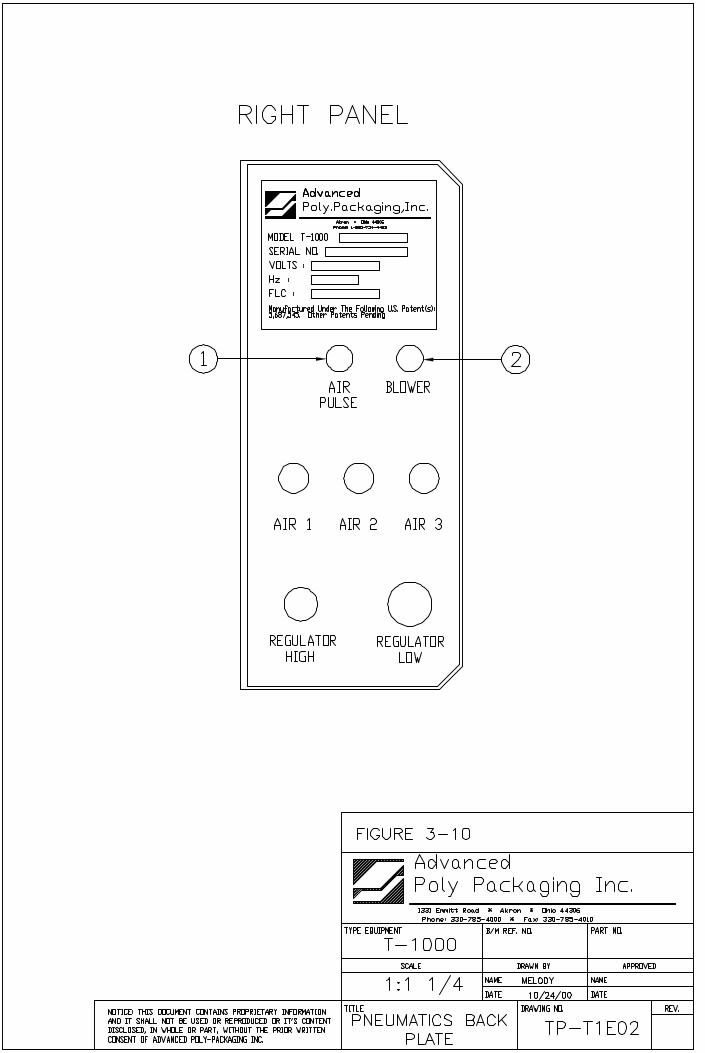
3.14 Air Pulse Displays, in seconds, the amount of time that a burst of air will last, initially blowing the bag open.Wider bags and heavier gauge bags require a longer burst of air to initially open the bag. Narrower andthinner gauge bags require less air to initially open the bag. To adjust the value, press the <Air Pulse>button from the Bag Setup Menu to display the number keypad. Press the numbers on the keypadfollowed by the <Enter> button to return the Bag Setup Menu. Additionally, to increase the volume ofair from the air pulse tubes, turn the Air Pulse valve (Fig 3-10) counter-clockwise; turning the valveclockwise will decrease the volume of air.
Note: The volume of air set should be the minimum amount and duration required to consistently openthe bag.
3.15 BlowerOnce the bag is initially blown open, the bag opening must be maintained while the product is beingloaded into the bag. The BLOWER (Air Knife) provides a steady, adjustable volume of air into the bag.The blower shuts off momentarily when the foot switch is pressed to allow the bag to deflate during theseal operation. The blower reinitiates when the next bag is indexed into position. To increase the volumeof air flow, turn the BLOWER flow valve (Fig. 3-10) counter-clockwise. To decrease the volume of airflow, turn the BLOWER flow valve clockwise.
3.16 Fill TimeThe <Fill Time> button functions differently dependent upon the MODE in which the T-1000 isoperating: 1) MANUAL, 2) AUTOMATIC (<AUTO>) mode or AUXILIARY mode.
1) In the Manual mode with NO accumulating funnel, Fill Time will do nothing. However, when theT-1000 is equipped with an accumulating funnel, Fill Time will affect the delay time before sealing, afterthe door has closed on the accumulating funnel.
2) In the AUTO cycle mode with no auxiliary infeed equipment, Fill Time affects the paced rateoperation. The bagger will automatically cycle with the Fill Time delaying the seal bar after the bag hasbeen blown open. In the AUTO mode, no foot switch or other actuator is used. CAUTION: To avoidphysical harm, DO NOT cycle the T-1000 in the AUTOMATIC mode when funnel(s), guard(s) or coversare removed. Caution: Since the seal bar actuates automatically, operators must keep fingers, handsand other parts of the body well away from the sealing mechanism and all other moving parts at all times. AUXILIARY cycle mode, FILL TIME displays, in seconds, the time for which a product, automaticallyfilled by auxiliary equipment, has to be completely settled in the bag before the seal bar is actuated. Thistime is typically referred to as the DELAY TIME.
CAUTION: To avoid physical harm, DO NOT cycle the T-1000 in the AUXILIARY mode without thefunnel(s), funnel extension(s), guard(s) and covers in proper position. Since the seal bar actuatesautomatically, operators must keep fingers, hands and other parts of the body well away from the sealingmechanism and all other moving parts at all times.
To adjust the value, press the highlighted <Fill Time> button to display the number keypad. See Fig. 3-8.Then enter the value on the number keypad followed by the <Enter> button to return to the Bag SetupScreen.
NOTE: Auxiliary mode is further described in Appendix B, if Auxiliary options or components wereprovided by APPI.
3.17 Options MenuOptions that have been added to the T-1000 at the factory can be setup from the Options Screen (Fig.3-9). If options were not installed at the factory, then N/A (Not available) will be displayed to the left ofeach options button. Otherwise, the button will display ON or OFF.
If the option is not available, you may press the button for a description of the option’s use. See Fig. 3-10for an example of the information provided for the AF-10 option.
Note: If options are added in the field, a pass code is required to Enable use of the option. ContactAPPI for pass codes. Options which have been purchased separately must be installed by APPI or byqualified maintenance personnel.
The following sections describe how to setup optional equipment on the T-1000. If your T-1000 is notequipped with these options, please disregard these sections. Most of the listed options are not standardand must be purchased separately.
3.18 AF-10 Accumulating FunnelThis special purpose funnel has several functions: 1) to collect (accumulate) a product before droppingthe full contents of the Accumulator into the bag, 2) to contain a product while the bagger is in a CYCLEoperation (sealing, tearing off, and indexing a bag into position), 3) to insert the funnel into the bag andkeep the product away from the sealing portion of the bag (Insert Funnel) and 4) to physically open thebag with a gate that enter into the bag while the product exits the funnel. See Fig. 3-11.
Increased production can be achieved in manual load or automatic load operations. In a manualoperation, the operator can insert the product into the funnel without waiting for the bag to be in position
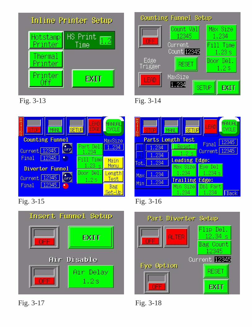
Fig. 3-13 Fig. 3-14
Fig. 3-15 Fig. 3-16
Fig. 3-17 Fig. 3-18
and opened. When the bagger is ready to receive the product, the door at the bottom of the funnel willopen, drop the product and shut, to allow the funnel to again be loaded.
In an automatic operation, increased production can be achieved by allowing counters, fillers, scales andother infeed equipment to feed the funnel without regard for the status of the bagger.
Additionally, the funnel can be operated in an "Open Accumulator" mode or a "Closed Accumulator"mode. In an Open Accumulator mode, the door is closed only during the CYCLE operation. When thedoor opens (when the bag is in position and blown open), the door will open and remain open until thebag has been filled with the required amount of product. The door will then close only until the next bagis in the Closed Accumulator mode, the door remains closed until the full contents have been inserted intothe funnel. When the bag contents is reached in the funnel, the door will open and all of the product willenter the bag in one. The Setup screen displays the time, in seconds, which the bagger will wait after thedoor opens (product drops). To increase or decrease the delay time, press <DELAY TIME> button andthe key pad will appear, press in the value, then when finished <ENTER>. The function of theAccumulating Funnel: Open, Closed or Insert Funnel can be set in the AF-10 Setting Screen.
3.19 LS-10 Load ShelfThis option is used as a support shelf for the product to avoid the bag from prematurely tearing off at the perforation when the product is inserted in the bag. The Load Shelf allows the product to drop onto theshelf relieving the pressure on the bottom of the bag.
To turn ON the load shelf, press the <Load Shelf> menu option and press the <ON> button. The LoadShelf delay time is the length of time the shelf is in the down position. Increase the time for longer bags.See Fig. 3-12.
3.20 Inline Printer A Printer option is not included in the standard T-1000 package and must be purchased separately. Usedfor product identification, a Printer option prints information, graphic images or bar codes directly to thesurface of the film.
APPI offers two printers as an option: 1) Thermal Inline Transfer Printer - prints text, graphics and barcodes, formatted in a separate software program. The label formats, saved in a database structure can berecalled and "downloaded" to the printer. 2) Hot Stamp Printer - prints text (part numbers, date codes, lotnumbers, etc.). Individual characters are placed onto a "grooved plate" which, when heated will transferthe ink (ribbon) directly onto the bag. Also, magnetic plates are offered.
Both the Thermal and Hot Stamp printers use ribbon (foil) to transfer ink to the surface of the bag. Toenable Printer operation on the Thermal Transfer (TT) Printer, press the highlighted Printer button. Press the highlighted Hot Stamp (HS) Printer button to enable operation of that Printer and press PrinterOff to disable the operation of the printer. See Fig. 3-13. If the HS Printer button is pressed, a secondary setup screen will automatically appear for further settings.To enhance text/graphics print quality, adjust the Print Time (time, in seconds that the ribbon will bestamped on the bag) until required print quality is met. Press <EXIT> when finished.
3.21 CF-10 Counting FunnelThe Counting Funnel option is not included in the standard T-1000 package and must be purchasedseparately. Used to count products entering the bag, the counting funnel may operate in conjunction withthe Accumulating Funnel to load a predetermined number of a product into the bag, manually fed orautomatically fed. Products fed into the funnel from a vibratory bowl or infeed conveyor can be countedwhile entering the bag or while being collected in the accumulating funnel. Various infrared "eyes" areavailable which will "see" even small parts. The Eye typically mounts to the top of the funnel seeing theproduct as it enters the funnel. Once the preset count is reached, the product is loaded and the bag is
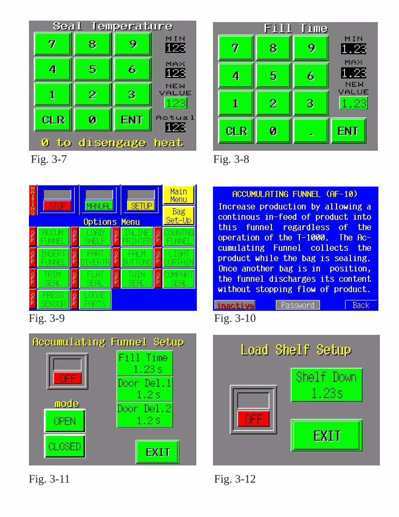
Fig. 3-7 Fig. 3-8
Fig. 3-9 Fig. 3-10
Fig. 3-11 Fig. 3-12
sealed and torn off automatically. Once another bag is in position, the Eye continues to detect productentering the bag or funnel.
To turn the Counting Funnel ON, press the <Count Funnel> menu option to bring up the Counting FunnelSetup screen. The Fill Delay setting is the amount of time between the point the final count is reachedand the bagger begins the seal operation. To adjust the Fill Delay value, press the <Fill Delay> button, then use the key pad to type in the number of parts to be counted. Set the value of parts to be counted bypressing the <Count Value> button. See Fig. 3-14.
To count the product when it first enters the detection field, choose the LEADING EDGE option. Tocount the product when it exits the detection field, choose the TRAILING EDGE option. The LEADINGEDGE setting is typically used for shorter components in an automatic operation whereas the TRAILINGEDGE setting is used for components that are longer or that vary in length. Additionally, scrap parts canbe filtered in the Trailing Edge mode.
3.22 Part Length Test Screen / Leading & Trailing Edge SettingsOnce Leading or Trailing Edge mode has been selected, you must make further settings to accuratelycount parts, from the Leading edge settings.
Leading edge settings: while in the Parts Length Test screen, drop a part manually through the photoeyes or have your infeed system feed one part. You will notice a measurement which is the amount oftime that the part was passing through the photo array. If the part was counted as two pieces, both the 1and 2 LEDs will be lit. To increase the time that the LEDs are lit, increase the timer located to the rightof the 1, 2 LEDs and immediately below the Reset button. See Fig. 3-16.
One at a time, feed or drop a part through the eye and notice the MAX setting fluctuate. Continuedropping or feeding parts individually until the MAX setting does not increase any further. Then set theMAX Size setting slightly higher than the tested MAX setting. For instance, if the MAX tested figuredisplayed is 1.2, then your MAX setting could be 1.8. This setting represents the amount of time that theeye will “ignore” the part, once it has initially been detected. Once the time has elapsed, then the eye willbegin looking for another part.
Note: If the MAX setting is too high, additional parts may pass through the eye undetected, causing overcounts.
Trailing edge settings: while in the Parts Length Test screen, drop a part manually through the photoeye or have your infeed system feed one part. You will notice a measurement which is the amount oftime that the part was passing through the photo array. If the part was counted as two pieces, both the 1and 2 LEDs will be lit. If the part is counted as two pieces, then the Leading Edge mode should be used.To increase the time that the LEDs are lit, increase the timer located to the right of the 1, 2 LEDs andimmediately below the Reset button. See Fig. 3-16.
IN setting fluctuate. Continuedropping or feeding parts individually until the MIN setting does not increase any further. Then set theMIN Size setting slightly lower than the tested MIN setting. For instance, if the MIN tested figuredisplayed is 1.9, then your MIN setting could be 1.4.
To test whether the settings are correct so that the eye “ignores” scrap, drop a parts that is consideredscrap through the eye and see whether the Current value changes. If it does, then you may need toincrease the MIN setting. However, if the scrap part size is too close to the “good” part, then scrap partsmay be counted.
Double Part (DBL Part) setting is used in the trailing edge mode if longer parts overlap. When partsoverlap, there is no gap caused and the eye output remains on. However, since overlapping parts are inthe eye longer than a single part typically, then setting the double part setting may cause the single eye
output to count the parts as two parts. Test by feeding overlapped parts through the eye to measure theMAX time. Then set the value to slightly less than the MAX time.
Note: If the MIN setting is too high, additional parts may pass through the eye undetected, causing overcounts. If set too low, scrap will be counted, causing undercounts.
Note: If the DBL part setting is too low, then one part may be counted as two, causing undercounts.
Part Del. setting is the amount of time AFTER the final count has been reached before signaling thebagger to cycle or funnel to close (if equipped with an AF-10 option).
In summary, the Parts Length Test Screen is provided to assist setup personnel with the complex settingsof leading and trailing edge modes, and the delay times that cause correct counts. For additionalassistance with these settings, please don’t hesitate to contact our service department for assistance.Sample parts may be required at our plant for further testing to determine the anticipated accuracy level ofcounting the parts.
3.23 IF-10 Insert FunnelThe Insert Funnel option is used for flowing products whereas the product may contaminate the sealingarea or when air flow to the bag must be turned off during bag filling. The funnel enters the bag andremains in the bag until signaled with a foot switch or automatically by a filler. See Fig. 3-17.
To turn the Insert Funnel ON, press the toggle button. To disable the air, press the Air Delay, type in theamount of time the funnel is filling up the bag before the air should shut off.
provided and the system will be halted.
3.24 DF-20 Diverting FunnelThe Diverting Funnel option is used to signal a diverting mechanism, located either beneath the seal barof the T-1000 or at the end of a conveyor, to direct product one way or another (or into Box A or Box B)To turn the option ON, press the toggle button. Then set the value of bags (Part Count) that will be ineach batch quantity. A delay time is also provided to allow the last bag in the count to clear the diverterbefore it cycles. To adjust the delay time, press the <Flip Delay> button, enter the value in the keypadand press <Enter>. Fig. 3-18.
3.25 PB-20 Palm ButtonsThe Palm Buttons option (Dual Palm Buttons) is not included in the standard T-1000 package and mustbe purchased separately. This option is used as a safety device to avoid personal injury by ensuring thatfingers or hands are not in the seal area during the cycle operation of the T-1000.
Caution: To avoid personal injury, do not operate the T-1000 when funnels are removed. AdvancedPoly-Packaging, Inc. recommends either the Palm Button or Light Screen options to safeguard operators.
The Palm Button option operates in lieu of a foot switch. Two buttons, positioned on opposite (left andright) sides on the top of the T-1000 covers, must be pressed or touched simultaneously to cycle thebagger. If both buttons are not pressed at the same time, or if one of the buttons are held while the otherbutton is pressed, the T-1000 will not cycle. As an additional safety function, the Automatic cycle modeis disabled when the Palm Button option is turned ON. The foot switch input is also disabled when thePalm Button option is turned ON. To turn ON this option, press the <Palm Button> menu option andpress the toggle ON button.
3.26 LC-10 Light Curtain Assembly
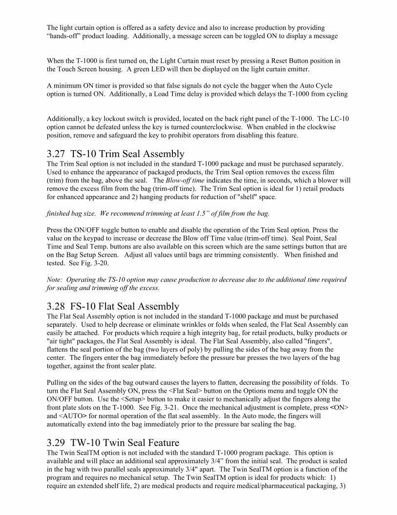
The light curtain option is offered as a safety device and also to increase production by providing“hands-off” product loading. Additionally, a message screen can be toggled ON to display a message
When the T-1000 is first turned on, the Light Curtain must reset by pressing a Reset Button position inthe Touch Screen housing. A green LED will then be displayed on the light curtain emitter.
A minimum ON timer is provided so that false signals do not cycle the bagger when the Auto Cycleoption is turned ON. Additionally, a Load Time delay is provided which delays the T-1000 from cycling
Additionally, a key lockout switch is provided, located on the back right panel of the T-1000. The LC-10option cannot be defeated unless the key is turned counterclockwise. When enabled in the clockwiseposition, remove and safeguard the key to prohibit operators from disabling this feature.
3.27 TS-10 Trim Seal AssemblyThe Trim Seal option is not included in the standard T-1000 package and must be purchased separately.Used to enhance the appearance of packaged products, the Trim Seal option removes the excess film(trim) from the bag, above the seal. The Blow-off time indicates the time, in seconds, which a blower willremove the excess film from the bag (trim-off time). The Trim Seal option is ideal for 1) retail productsfor enhanced appearance and 2) hanging products for reduction of "shelf" space.
finished bag size. We recommend trimming at least 1.5” of film from the bag.
Press the ON/OFF toggle button to enable and disable the operation of the Trim Seal option. Press thevalue on the keypad to increase or decrease the Blow off Time value (trim-off time). Seal Point, SealTime and Seal Temp. buttons are also available on this screen which are the same settings button that areon the Bag Setup Screen. Adjust all values until bags are trimming consistently. When finished andtested. See Fig. 3-20.
Note: Operating the TS-10 option may cause production to decrease due to the additional time requiredfor sealing and trimming off the excess.
3.28 FS-10 Flat Seal AssemblyThe Flat Seal Assembly option is not included in the standard T-1000 package and must be purchasedseparately. Used to help decrease or eliminate wrinkles or folds when sealed, the Flat Seal Assembly caneasily be attached. For products which require a high integrity bag, for retail products, bulky products or"air tight" packages, the Flat Seal Assembly is ideal. The Flat Seal Assembly, also called "fingers",flattens the seal portion of the bag (two layers of poly) by pulling the sides of the bag away from thecenter. The fingers enter the bag immediately before the pressure bar presses the two layers of the bagtogether, against the front sealer plate.
Pulling on the sides of the bag outward causes the layers to flatten, decreasing the possibility of folds. Toturn the Flat Seal Assembly ON, press the <Flat Seal> button on the Options menu and toggle ON theON/OFF button. Use the <Setup> button to make it easier to mechanically adjust the fingers along thefront plate slots on the T-1000. See Fig. 3-21. Once the mechanical adjustment is complete, press <ON>and <AUTO> for normal operation of the flat seal assembly. In the Auto mode, the fingers willautomatically extend into the bag immediately prior to the pressure bar sealing the bag. 3.29 TW-10 Twin Seal FeatureThe Twin SealTM option is not included with the standard T-1000 program package. This option isavailable and will place an additional seal approximately 3/4” from the initial seal. The product is sealedin the bag with two parallel seals approximately 3/4" apart. The Twin SealTM option is a function of theprogram and requires no mechanical setup. The Twin SealTM option is ideal for products which: 1)require an extended shelf life, 2) are medical products and require medical/pharmaceutical packaging, 3)
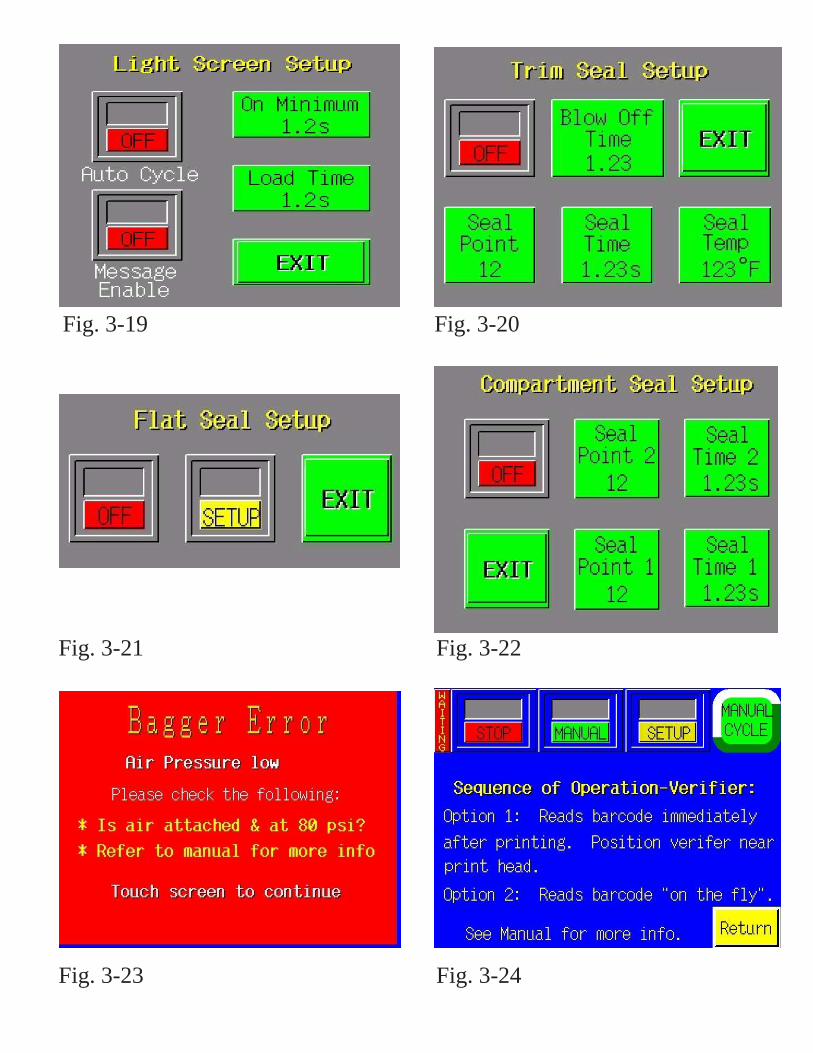
Fig. 3-19 Fig. 3-20
Fig. 3-21 Fig. 3-22
Fig. 3-23 Fig. 3-24
are heavy or bulky and difficult to seal and 5) require high integrity seals. To turn on the Twin SealTM
Note: You may need to decrease the Seal Point value on the Bag Setup Screen to allow space for twoseals on the same bag.
3.30 CS-10 Compartment SealThe Compartment Seal option is offered to allow for two different products in the same bag to bepackaged, separated by a seal. For instance, it may be necessary to segregate a sharper object (screw)from a plastic component (mounting plate). Both seal points can be adjusted by the operator to increaseor decrease the size of each compartment. However, the larger object should be placed into the bag first.
First set Seal Point 1 by pressing the <Seal Point 1> button and typing in the value on the number keypad.Adjust the first seal point until the desired location is achieved. Then, turn the option ON by togglingON the ON/OFF button. Adjust the second seal point by pressing <Seal Point 2> and entering a value inthe number keypad. Adjust the value of the second seal point until the desired position is achieved. Eachseal time may be adjusted if you wish the Trim Seal after the second seal has been placed on the bag. SeeFig. 3-22.
3.31 Pressure Sensor OptionA pressure sensor may be added to the T-1000 to validate that the pressure is sufficient to cause aconsistent seal. For applications requiring this validation, the bagger will not operate unless the sensorprovides an output indicated that the pressure is above a minimum allowable setting. See Fig. 3-27.
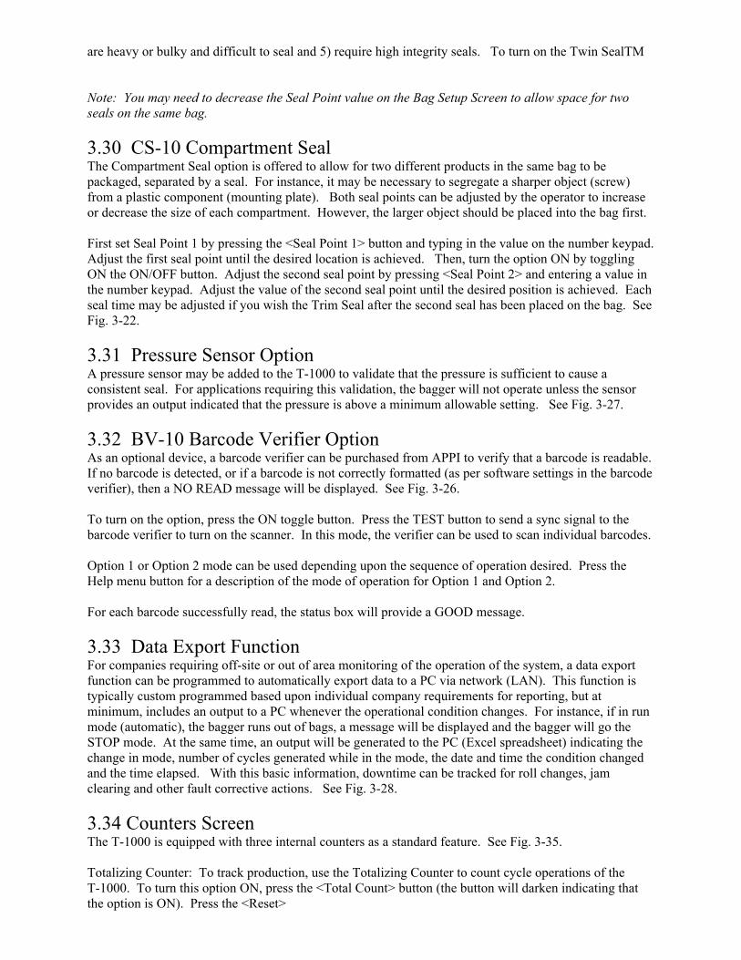
3.32 BV-10 Barcode Verifier OptionAs an optional device, a barcode verifier can be purchased from APPI to verify that a barcode is readable.If no barcode is detected, or if a barcode is not correctly formatted (as per software settings in the barcodeverifier), then a NO READ message will be displayed. See Fig. 3-26.
To turn on the option, press the ON toggle button. Press the TEST button to send a sync signal to thebarcode verifier to turn on the scanner. In this mode, the verifier can be used to scan individual barcodes.
Option 1 or Option 2 mode can be used depending upon the sequence of operation desired. Press theHelp menu button for a description of the mode of operation for Option 1 and Option 2.
For each barcode successfully read, the status box will provide a GOOD message.
3.33 Data Export FunctionFor companies requiring off-site or out of area monitoring of the operation of the system, a data exportfunction can be programmed to automatically export data to a PC via network (LAN). This function istypically custom programmed based upon individual company requirements for reporting, but atminimum, includes an output to a PC whenever the operational condition changes. For instance, if in runmode (automatic), the bagger runs out of bags, a message will be displayed and the bagger will go theSTOP mode. At the same time, an output will be generated to the PC (Excel spreadsheet) indicating thechange in mode, number of cycles generated while in the mode, the date and time the condition changedand the time elapsed. With this basic information, downtime can be tracked for roll changes, jamclearing and other fault corrective actions. See Fig. 3-28. 3.34 Counters ScreenThe T-1000 is equipped with three internal counters as a standard feature. See Fig. 3-35.
Totalizing Counter: To track production, use the Totalizing Counter to count cycle operations of theT-1000. To turn this option ON, press the <Total Count> button (the button will darken indicating thatthe option is ON). Press the <Reset>
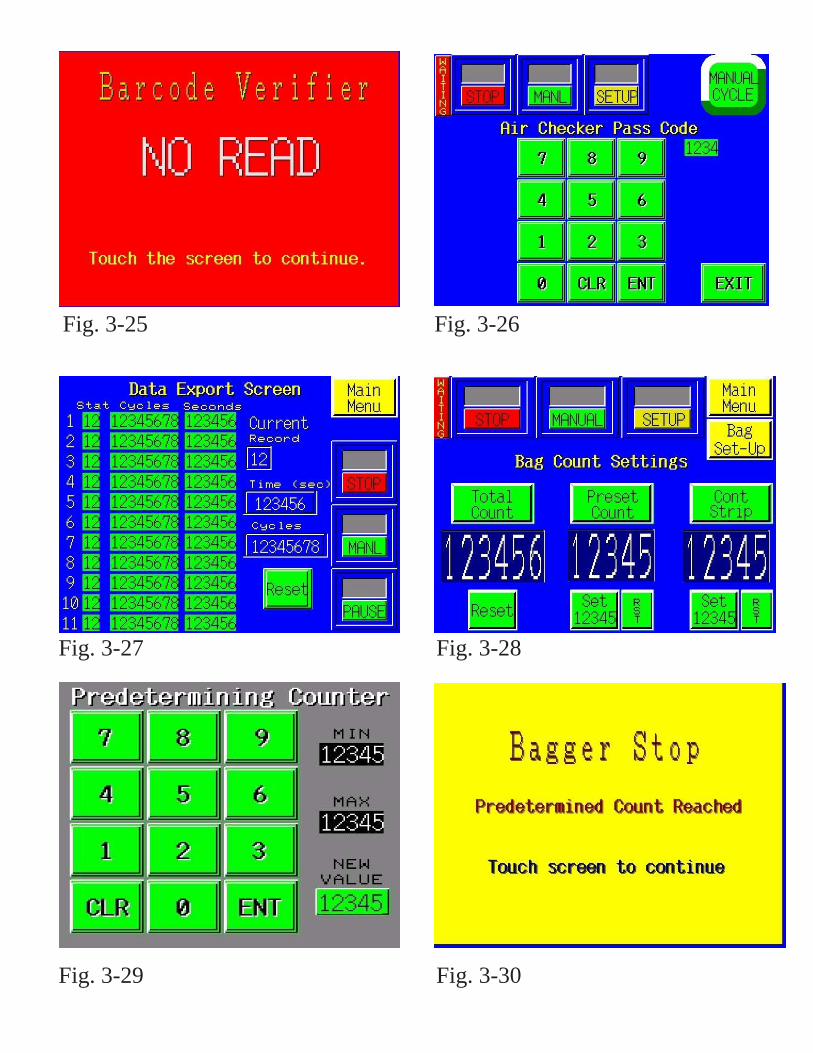
Fig. 3-25 Fig. 3-26
Fig. 3-27 Fig. 3-28
Fig. 3-29 Fig. 3-30
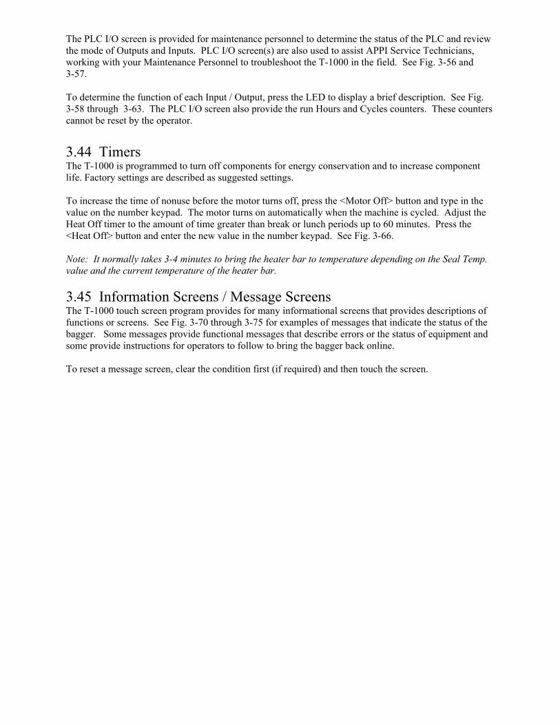
When the Auxiliary setup procedures are complete, toggle the T-1000 from <Manual> to <AUTO> bypressing the <Manual/Auto> toggle button. This will place the T-1000 in the Automatic / Auxiliarymode.
3.38 UF-5000 Operation Screen The T-1000 is programmed to also control the UF-5000 Infeed Conveyor. This screen allows theoperator to setup the conveyor to run standalone, with the T-1000 or with parts counters. See Fig. 3-48.
CONV CYCLE button manually cycles the conveyor and also toggles OFF auxiliary mode buttons andbagger Run buttons.
SETUP/RUN button toggles ON the conveyor to operate with the T-1000.
ON/OFF Bagger Auxiliary button sets up the communication with T-1000.
ON/OFF Counter Auxiliary button sets up the communication with counters (UC-2400).
PART SENSOR turns on photo eyes mounted in the discharge funnel of the UF-5000 (CE-10) option, ifequipped.
Index Count value is the number of compartments that will be indexed before providing an output signalto the bagger.
The UF-5000 is equipped with an emergency stop (ESTOP) switch, either a push button or pull cord.When the button is pressed, a screen will appear indicating this condition. See Fig. 3-50. 3.39 UF-5000 Settings Screen The UF-5000 settings screen provides all the settings to control production speeds and timing of theintegration components of a system. See Fig. 3-49.
Fill Time is the amount of time from the time the conveyor cycles to the point that the bagger cycles.
Flight Delay is the delay time that the flight sensor is active when the flight (cleat) passes through theoptical eye (normally set a .2 sec.). Light/Dark setting is determined by the type of sensor used to detectthe cleats (typically set at Light).
Input Delay is the amount of time from the point the conveyor receives a signal to index before theconveyor indexes.
Output Delay is the amount of time after the conveyor indexes before the conveyor signals the bagger thatit has cycled.
Sensor Delay is the amount of time after the conveyor indexes that the photo eyes (CE-10 option) “looks”for a parts before indexing another compartment of the conveyor.
Funnel Delay is the amount of time after the conveyor indexes to the point that an accumulating funnel(AF-10 option) cycles (if equipped).
Adjust each timer by pressing the associated timer and entering the value on the number keypad. Aftereach value, test the settings by cycling the conveyor. Press the UF-5000 Mode button to return to theUF-5000 Operation Screen.
3.40 Technical Assistance
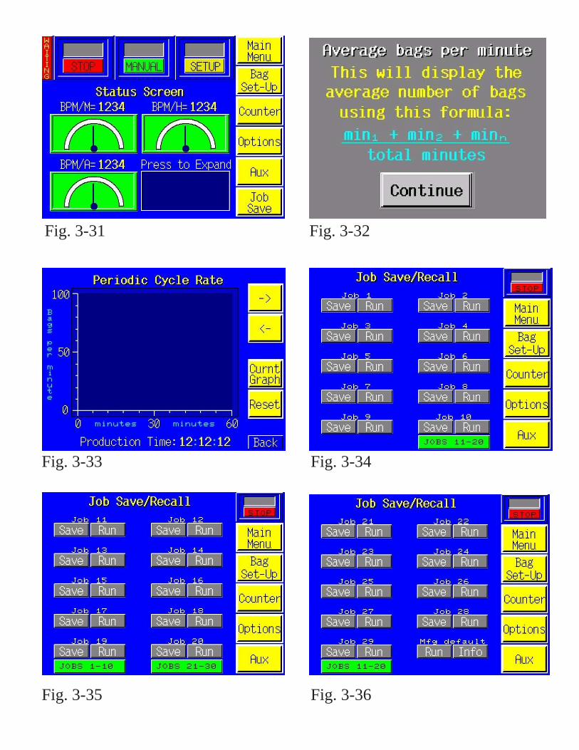
Fig. 3-31 Fig. 3-32
Fig. 3-33 Fig. 3-34
Fig. 3-35 Fig. 3-36

Press F1 or press the <Tech Assist> menu option from the Main Menu to obtain APPI phone number anddetermine Program Versions. See Fig. 3-51. Program Versions are required for telephone support fromAdvanced Poly-Packaging, Inc service technicians.
Several menu options are available from the Tech Assist. menu which will assist with troubleshooting theT-1000 and also change settings that affect the operation of the equipment.
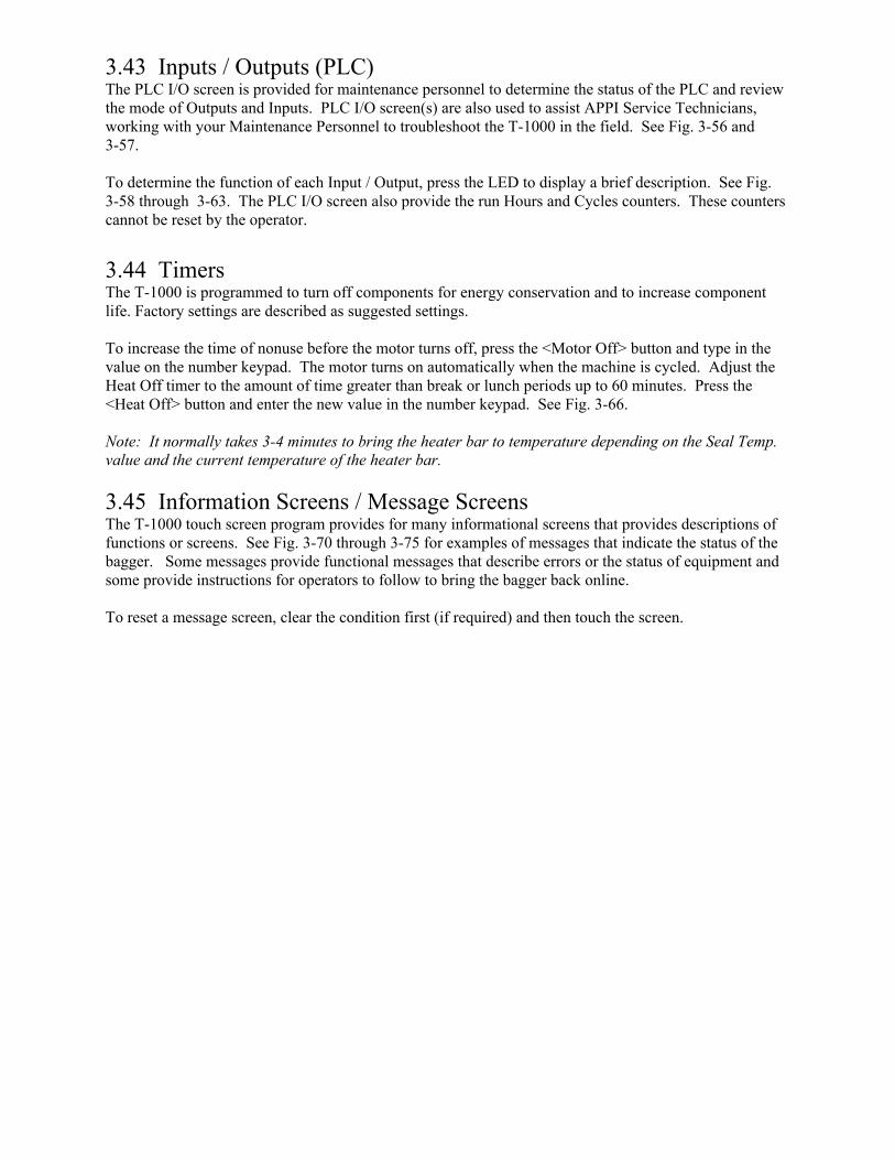
However, before the Technical Assistance screen is displayed, a Level 1 Pass code must be entered. Thispass code protects unauthorized individuals from changing settings that may affect the operation of theequipment. Many settings in the Tech Assist screens are set at the factory and should not be altered by anunknowledgeable individual.
3.41 Pass code Setup ScreenAdvanced Poly-Packaging, Inc. (APPI) has included a pass code function in all touch screen equipmentto prevent operators from changing settings. (Available on program versions 4.08 and higher). See Fig.3-52.
There are two pass code levels described as follows:1. Level 1: This is the highest level pass code which prevents operators from accessing the TechnicalAssistance functions of the machine. Additionally, the pass codes are maintained in this area. See Fig.3-53.2. Level 2: This level pass code, when the pass code function is enabled, prevents the operator fromaccessing settings screens that affect the operation of the equipment. See Fig. 3-54.
Pass codes prevent unauthorized individuals from tampering with settings. When equipment is shipped,APPI uses the following codes which can be changed by the customer at any time:1. Level 1 pass code: 10012. Level 2 pass code: 1002 To enable the pass code function, press the Tech Assist button from the Main Menu. Type in theLevel 1 pass code (1001 by default from APPI). Then press the ON toggle button to toggle thepass code function ON. If you change the pass codes, ensure that these codes are written down.
Once the pass code function is enabled, the operator will have a programmed amount of time(time-out time) to make changes. Once this time has elapsed, the Operation Screen willautomatically be displayed. This time can be changed by accessing the Pass Code setup screen.By default, the time is set to 5 minutes.
If you misplace or forget the pass codes, contact APPI Service Dept for assistance. APPI willprove a “factory code” so that the current pass codes can be displayed. Once you receive thefactory code, press F5 function key, located to the right of the touch screen, to enter the factorycode and your current pass codes will be displayed.
3.42 Options Enable Pass Codes The Options Enable Screen is used at the factory to “enable” options for use by the operator. A status boxis located to the left of the option to indicate if the option is available to operator. If OFF, the optionsettings screen will not be displayed for use by the operator. See Fig. 3-55.
Options must be purchased from Advanced Poly-Packaging, Inc. to obtain the pass code. ContactAdvanced Poly-Packaging, Inc. Service Dept. for more information regarding options available for theT-1000.
3.43 Inputs / Outputs (PLC)
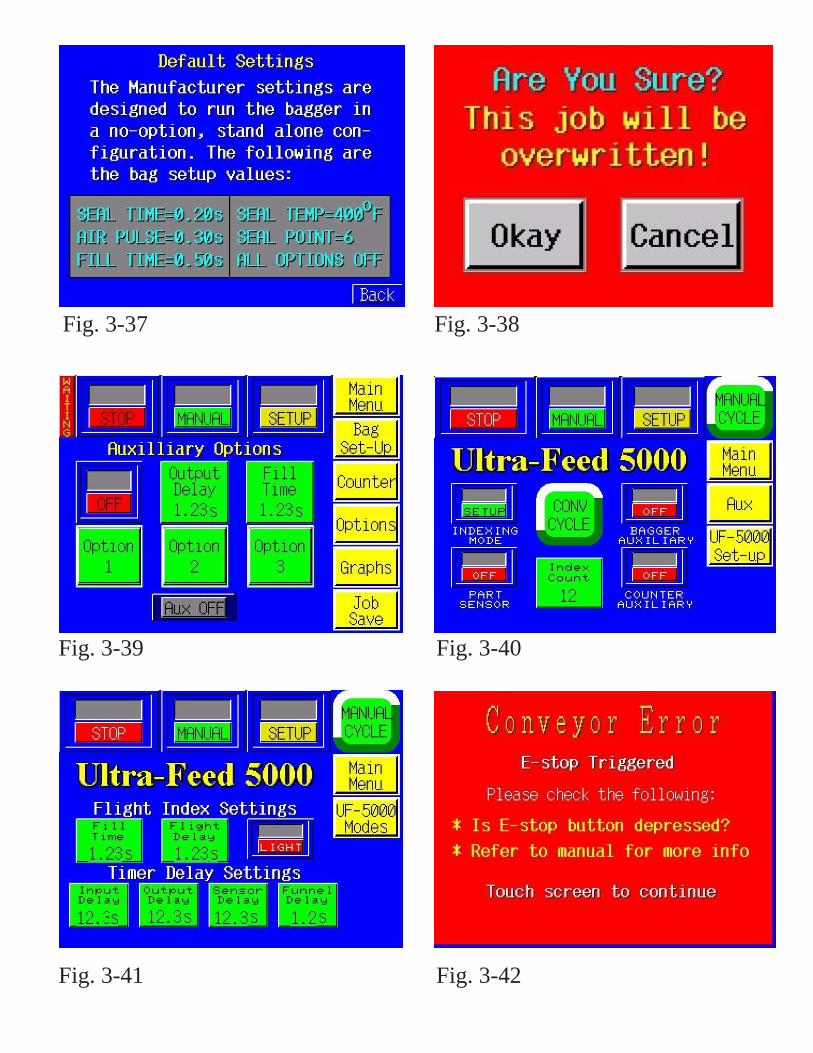
Fig. 3-37 Fig. 3-38
Fig. 3-39 Fig. 3-40
Fig. 3-41 Fig. 3-42
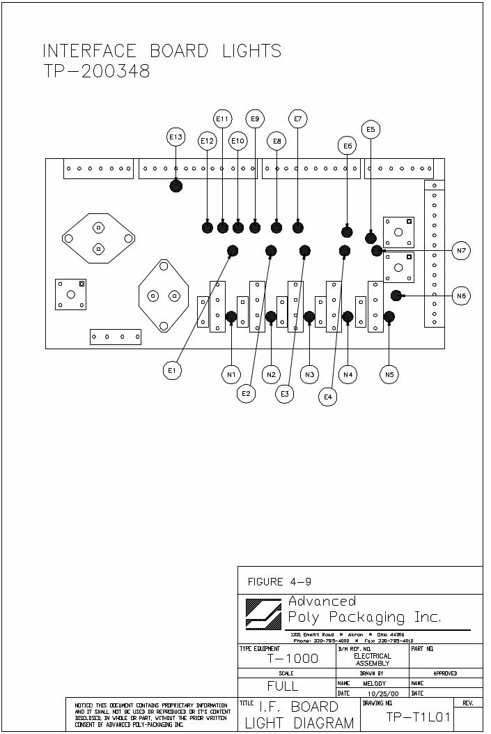
The PLC I/O screen is provided for maintenance personnel to determine the status of the PLC and reviewthe mode of Outputs and Inputs. PLC I/O screen(s) are also used to assist APPI Service Technicians,working with your Maintenance Personnel to troubleshoot the T-1000 in the field. See Fig. 3-56 and3-57.
To determine the function of each Input / Output, press the LED to display a brief description. See Fig.3-58 through 3-63. The PLC I/O screen also provide the run Hours and Cycles counters. These counterscannot be reset by the operator.
3.44 TimersThe T-1000 is programmed to turn off components for energy conservation and to increase componentlife. Factory settings are described as suggested settings.
To increase the time of nonuse before the motor turns off, press the <Motor Off> button and type in thevalue on the number keypad. The motor turns on automatically when the machine is cycled. Adjust theHeat Off timer to the amount of time greater than break or lunch periods up to 60 minutes. Press the<Heat Off> button and enter the new value in the number keypad. See Fig. 3-66.
Note: It normally takes 3-4 minutes to bring the heater bar to temperature depending on the Seal Temp.value and the current temperature of the heater bar.
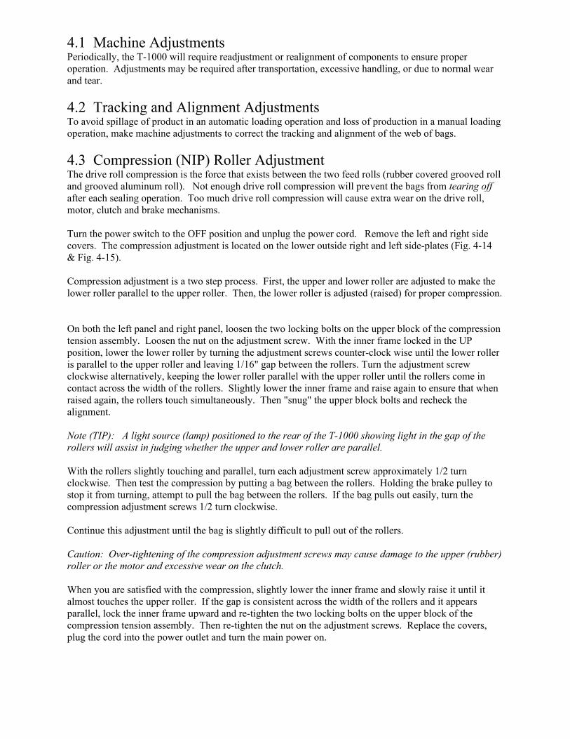
3.45 Information Screens / Message ScreensThe T-1000 touch screen program provides for many informational screens that provides descriptions offunctions or screens. See Fig. 3-70 through 3-75 for examples of messages that indicate the status of thebagger. Some messages provide functional messages that describe errors or the status of equipment andsome provide instructions for operators to follow to bring the bagger back online.
To reset a message screen, clear the condition first (if required) and then touch the screen.
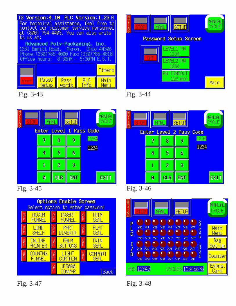
Fig. 3-43 Fig. 3-44
Fig. 3-45 Fig. 3-46
Fig. 3-47 Fig. 3-48
3.43 Inputs / Outputs (PLC)The PLC I/O screen is provided for maintenance personnel to determine the status of the PLC and reviewthe mode of Outputs and Inputs. PLC I/O screen(s) are also used to assist APPI Service Technicians,working with your Maintenance Personnel to troubleshoot the T-1000 in the field. See Fig. 3-56 and3-57.
To determine the function of each Input / Output, press the LED to display a brief description. See Fig.3-58 through 3-63. The PLC I/O screen also provide the run Hours and Cycles counters. These counterscannot be reset by the operator.
3.44 TimersThe T-1000 is programmed to turn off components for energy conservation and to increase componentlife. Factory settings are described as suggested settings.
To increase the time of nonuse before the motor turns off, press the <Motor Off> button and type in thevalue on the number keypad. The motor turns on automatically when the machine is cycled. Adjust theHeat Off timer to the amount of time greater than break or lunch periods up to 60 minutes. Press the<Heat Off> button and enter the new value in the number keypad. See Fig. 3-66.
Note: It normally takes 3-4 minutes to bring the heater bar to temperature depending on the Seal Temp.value and the current temperature of the heater bar.
3.45 Information Screens / Message ScreensThe T-1000 touch screen program provides for many informational screens that provides descriptions offunctions or screens. See Fig. 3-70 through 3-75 for examples of messages that indicate the status of thebagger. Some messages provide functional messages that describe errors or the status of equipment andsome provide instructions for operators to follow to bring the bagger back online.
To reset a message screen, clear the condition first (if required) and then touch the screen.
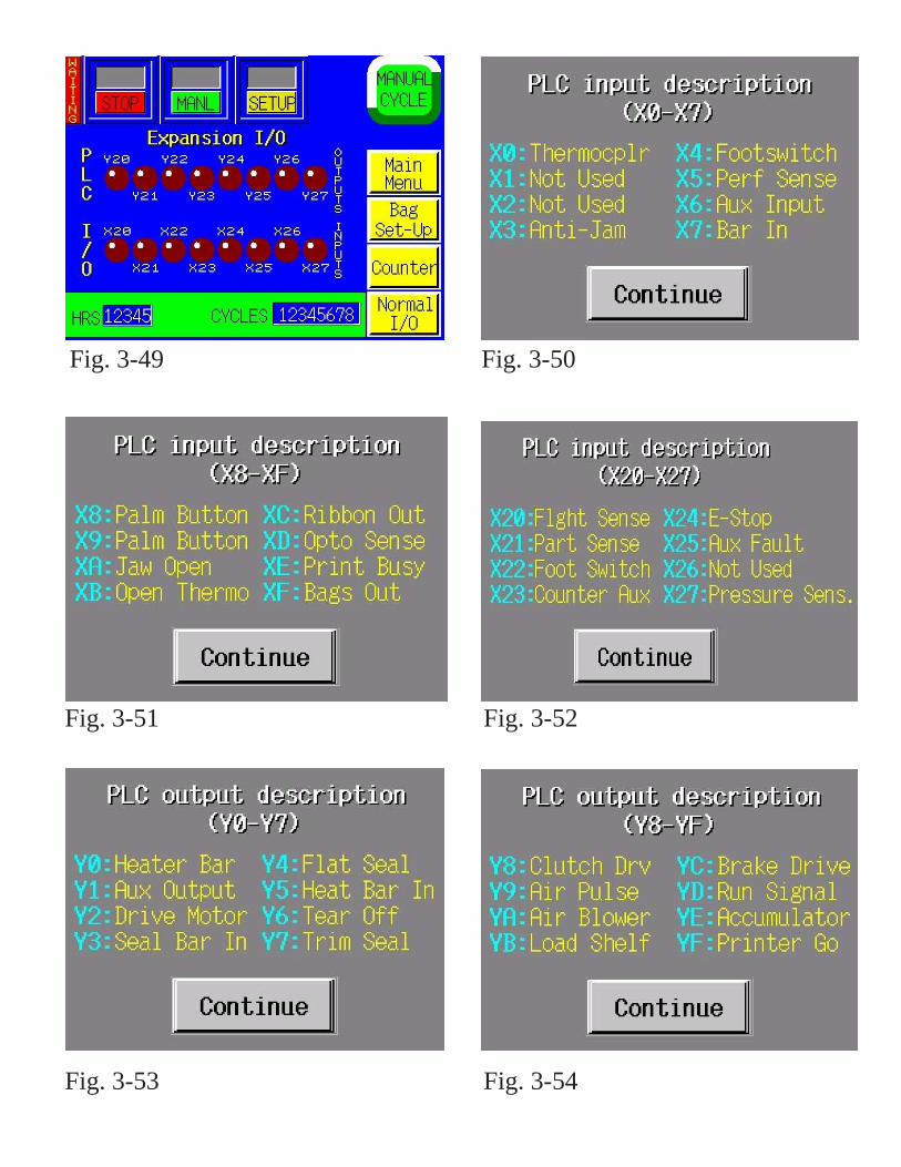
Fig. 3-49 Fig. 3-50
Fig. 3-51 Fig. 3-52
Fig. 3-53 Fig. 3-54
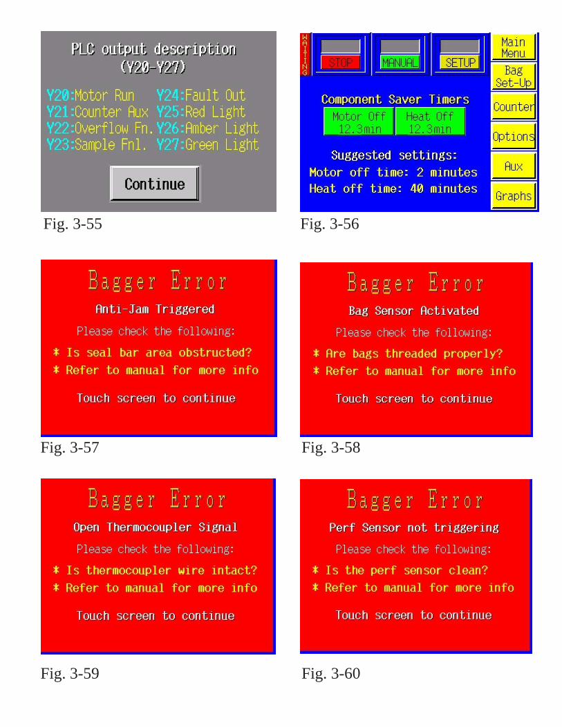
Fig. 3-55 Fig. 3-56
Fig. 3-57 Fig. 3-58
Fig. 3-59 Fig. 3-60
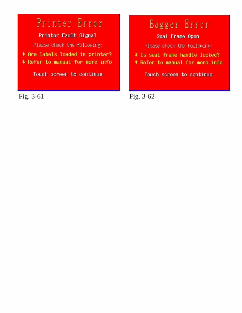
Fig. 3-61 Fig. 3-62

Chapter 4, Settings & Adjustments____________________________________________________
Machine AdjustmentsComponent Replacement
4.1 Machine AdjustmentsPeriodically, the T-1000 will require readjustment or realignment of components to ensure properoperation. Adjustments may be required after transportation, excessive handling, or due to normal wearand tear.
4.2 Tracking and Alignment AdjustmentsTo avoid spillage of product in an automatic loading operation and loss of production in a manual loadingoperation, make machine adjustments to correct the tracking and alignment of the web of bags.
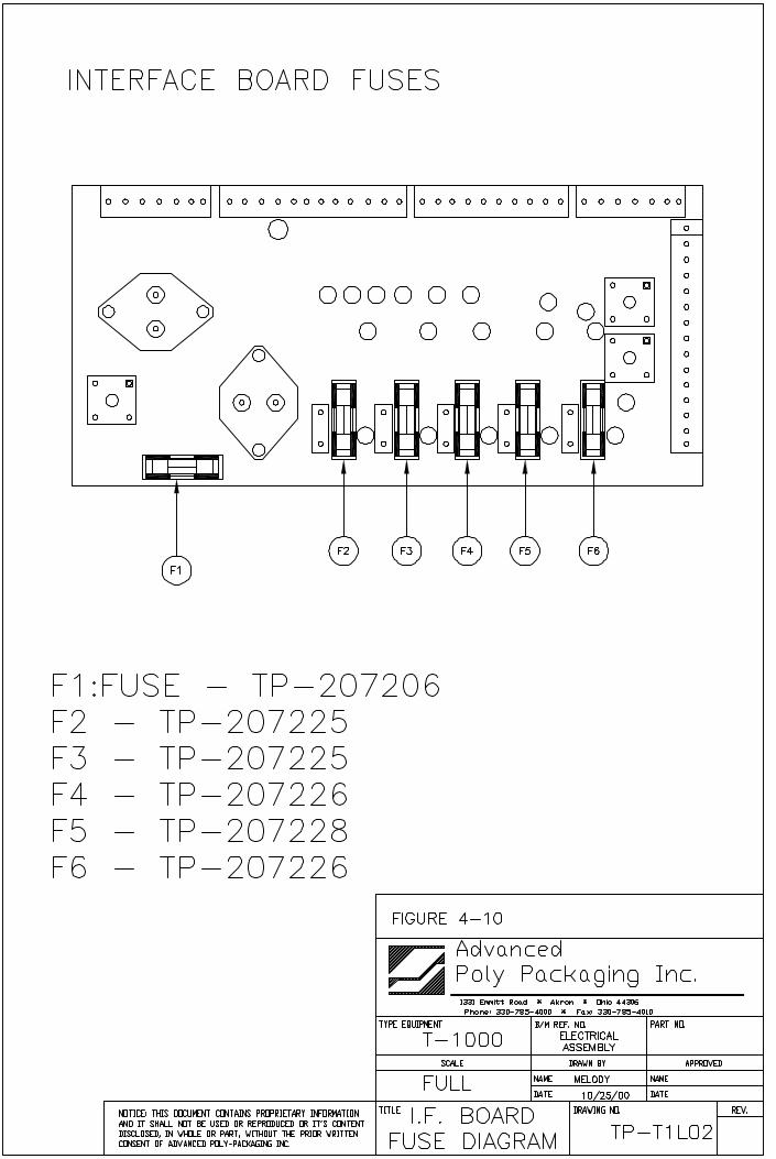
4.3 Compression (NIP) Roller AdjustmentThe drive roll compression is the force that exists between the two feed rolls (rubber covered grooved rolland grooved aluminum roll). Not enough drive roll compression will prevent the bags from tearing offafter each sealing operation. Too much drive roll compression will cause extra wear on the drive roll,motor, clutch and brake mechanisms.
Turn the power switch to the OFF position and unplug the power cord. Remove the left and right sidecovers. The compression adjustment is located on the lower outside right and left side-plates (Fig. 4-14 & Fig. 4-15).
Compression adjustment is a two step process. First, the upper and lower roller are adjusted to make thelower roller parallel to the upper roller. Then, the lower roller is adjusted (raised) for proper compression.
On both the left panel and right panel, loosen the two locking bolts on the upper block of the compressiontension assembly. Loosen the nut on the adjustment screw. With the inner frame locked in the UPposition, lower the lower roller by turning the adjustment screws counter-clock wise until the lower rolleris parallel to the upper roller and leaving 1/16" gap between the rollers. Turn the adjustment screwclockwise alternatively, keeping the lower roller parallel with the upper roller until the rollers come incontact across the width of the rollers. Slightly lower the inner frame and raise again to ensure that whenraised again, the rollers touch simultaneously. Then "snug" the upper block bolts and recheck thealignment.
Note (TIP): A light source (lamp) positioned to the rear of the T-1000 showing light in the gap of therollers will assist in judging whether the upper and lower roller are parallel. With the rollers slightly touching and parallel, turn each adjustment screw approximately 1/2 turnclockwise. Then test the compression by putting a bag between the rollers. Holding the brake pulley tostop it from turning, attempt to pull the bag between the rollers. If the bag pulls out easily, turn thecompression adjustment screws 1/2 turn clockwise.
Continue this adjustment until the bag is slightly difficult to pull out of the rollers.
Caution: Over-tightening of the compression adjustment screws may cause damage to the upper (rubber)roller or the motor and excessive wear on the clutch.
When you are satisfied with the compression, slightly lower the inner frame and slowly raise it until italmost touches the upper roller. If the gap is consistent across the width of the rollers and it appearsparallel, lock the inner frame upward and re-tighten the two locking bolts on the upper block of thecompression tension assembly. Then re-tighten the nut on the adjustment screws. Replace the covers,plug the cord into the power outlet and turn the main power on.
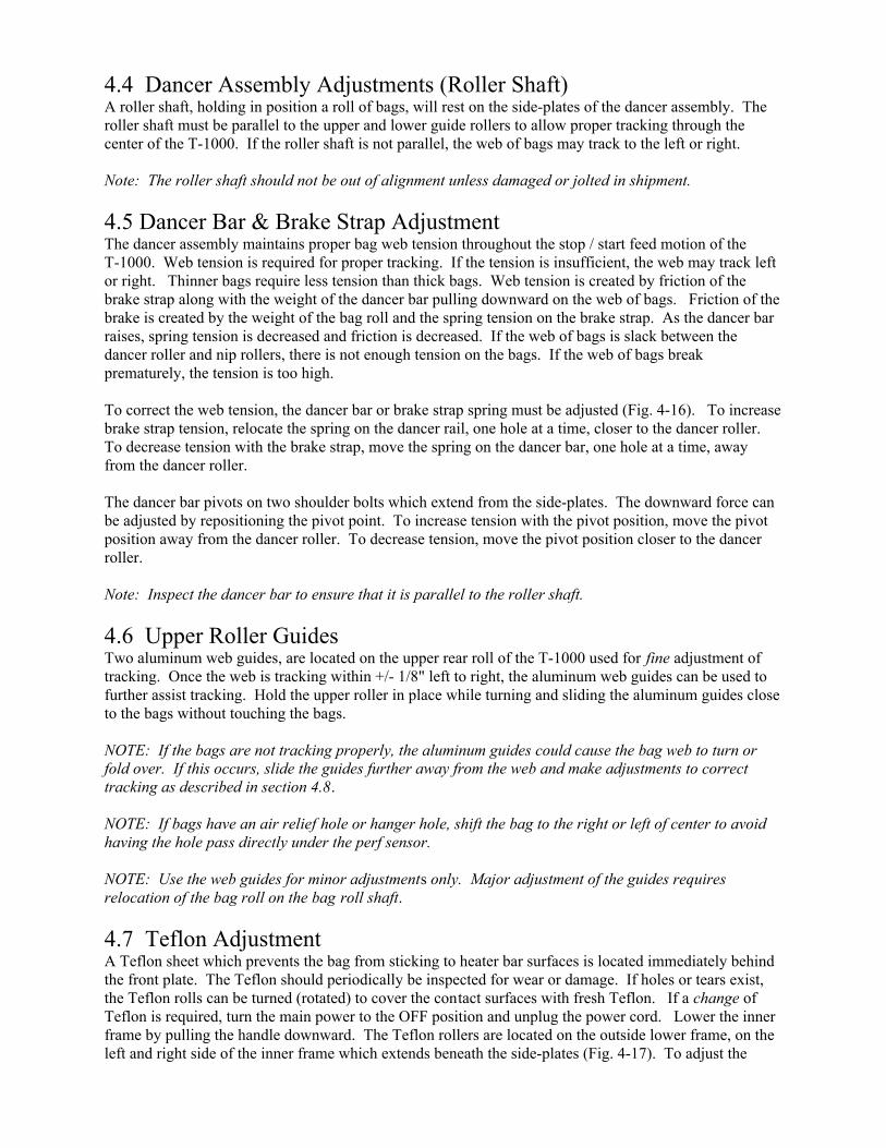
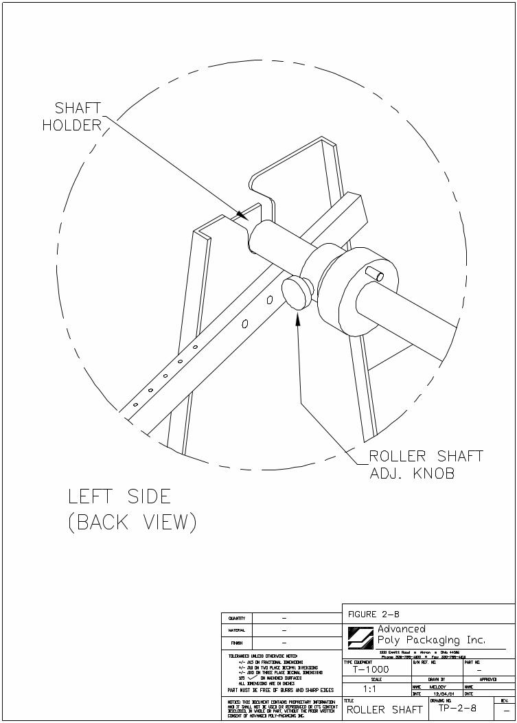
4.4 Dancer Assembly Adjustments (Roller Shaft)A roller shaft, holding in position a roll of bags, will rest on the side-plates of the dancer assembly. Theroller shaft must be parallel to the upper and lower guide rollers to allow proper tracking through thecenter of the T-1000. If the roller shaft is not parallel, the web of bags may track to the left or right.
Note: The roller shaft should not be out of alignment unless damaged or jolted in shipment.
4.5 Dancer Bar & Brake Strap Adjustment The dancer assembly maintains proper bag web tension throughout the stop / start feed motion of theT-1000. Web tension is required for proper tracking. If the tension is insufficient, the web may track leftor right. Thinner bags require less tension than thick bags. Web tension is created by friction of thebrake strap along with the weight of the dancer bar pulling downward on the web of bags. Friction of thebrake is created by the weight of the bag roll and the spring tension on the brake strap. As the dancer barraises, spring tension is decreased and friction is decreased. If the web of bags is slack between thedancer roller and nip rollers, there is not enough tension on the bags. If the web of bags breakprematurely, the tension is too high.
To correct the web tension, the dancer bar or brake strap spring must be adjusted (Fig. 4-16). To increasebrake strap tension, relocate the spring on the dancer rail, one hole at a time, closer to the dancer roller.To decrease tension with the brake strap, move the spring on the dancer bar, one hole at a time, awayfrom the dancer roller.
The dancer bar pivots on two shoulder bolts which extend from the side-plates. The downward force canbe adjusted by repositioning the pivot point. To increase tension with the pivot position, move the pivotposition away from the dancer roller. To decrease tension, move the pivot position closer to the dancerroller.
Note: Inspect the dancer bar to ensure that it is parallel to the roller shaft.
4.6 Upper Roller GuidesTwo aluminum web guides, are located on the upper rear roll of the T-1000 used for fine adjustment oftracking. Once the web is tracking within +/- 1/8" left to right, the aluminum web guides can be used tofurther assist tracking. Hold the upper roller in place while turning and sliding the aluminum guides closeto the bags without touching the bags.
NOTE: If the bags are not tracking properly, the aluminum guides could cause the bag web to turn orfold over. If this occurs, slide the guides further away from the web and make adjustments to correcttracking as described in section 4.8.
NOTE: If bags have an air relief hole or hanger hole, shift the bag to the right or left of center to avoidhaving the hole pass directly under the perf sensor.
NOTE: Use the web guides for minor adjustments only. Major adjustment of the guides requiresrelocation of the bag roll on the bag roll shaft.
4.7 Teflon AdjustmentA Teflon sheet which prevents the bag from sticking to heater bar surfaces is located immediately behindthe front plate. The Teflon should periodically be inspected for wear or damage. If holes or tears exist,the Teflon rolls can be turned (rotated) to cover the contact surfaces with fresh Teflon. If a change ofTeflon is required, turn the main power to the OFF position and unplug the power cord. Lower the innerframe by pulling the handle downward. The Teflon rollers are located on the outside lower frame, on theleft and right side of the inner frame which extends beneath the side-plates (Fig. 4-17). To adjust the
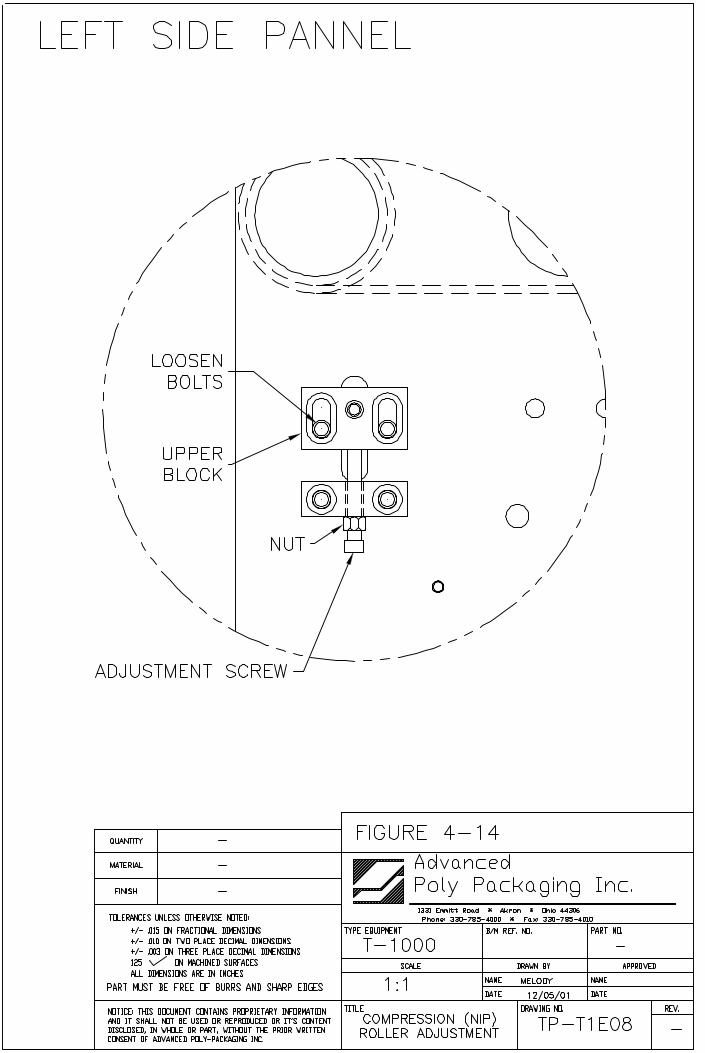
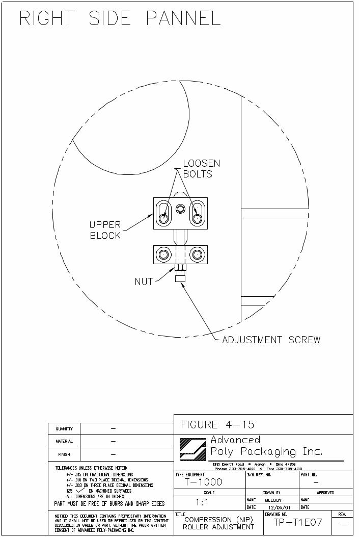
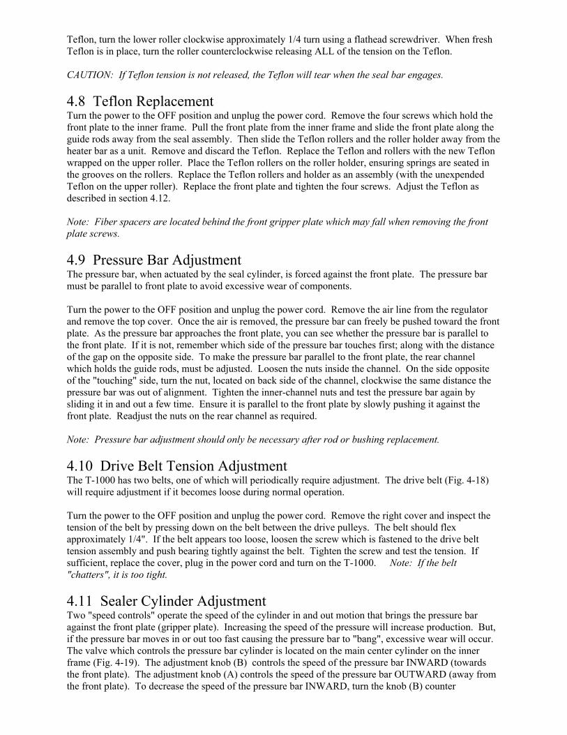
Teflon, turn the lower roller clockwise approximately 1/4 turn using a flathead screwdriver. When freshTeflon is in place, turn the roller counterclockwise releasing ALL of the tension on the Teflon.
CAUTION: If Teflon tension is not released, the Teflon will tear when the seal bar engages.
4.8 Teflon Replacement Turn the power to the OFF position and unplug the power cord. Remove the four screws which hold thefront plate to the inner frame. Pull the front plate from the inner frame and slide the front plate along theguide rods away from the seal assembly. Then slide the Teflon rollers and the roller holder away from theheater bar as a unit. Remove and discard the Teflon. Replace the Teflon and rollers with the new Teflonwrapped on the upper roller. Place the Teflon rollers on the roller holder, ensuring springs are seated inthe grooves on the rollers. Replace the Teflon rollers and holder as an assembly (with the unexpendedTeflon on the upper roller). Replace the front plate and tighten the four screws. Adjust the Teflon asdescribed in section 4.12.
Note: Fiber spacers are located behind the front gripper plate which may fall when removing the frontplate screws.
4.9 Pressure Bar AdjustmentThe pressure bar, when actuated by the seal cylinder, is forced against the front plate. The pressure barmust be parallel to front plate to avoid excessive wear of components.
Turn the power to the OFF position and unplug the power cord. Remove the air line from the regulatorand remove the top cover. Once the air is removed, the pressure bar can freely be pushed toward the frontplate. As the pressure bar approaches the front plate, you can see whether the pressure bar is parallel tothe front plate. If it is not, remember which side of the pressure bar touches first; along with the distanceof the gap on the opposite side. To make the pressure bar parallel to the front plate, the rear channelwhich holds the guide rods, must be adjusted. Loosen the nuts inside the channel. On the side oppositeof the "touching" side, turn the nut, located on back side of the channel, clockwise the same distance thepressure bar was out of alignment. Tighten the inner-channel nuts and test the pressure bar again bysliding it in and out a few time. Ensure it is parallel to the front plate by slowly pushing it against thefront plate. Readjust the nuts on the rear channel as required.
Note: Pressure bar adjustment should only be necessary after rod or bushing replacement.
4.10 Drive Belt Tension AdjustmentThe T-1000 has two belts, one of which will periodically require adjustment. The drive belt (Fig. 4-18)will require adjustment if it becomes loose during normal operation.
Turn the power to the OFF position and unplug the power cord. Remove the right cover and inspect thetension of the belt by pressing down on the belt between the drive pulleys. The belt should flexapproximately 1/4". If the belt appears too loose, loosen the screw which is fastened to the drive belttension assembly and push bearing tightly against the belt. Tighten the screw and test the tension. Ifsufficient, replace the cover, plug in the power cord and turn on the T-1000. Note: If the belt"chatters", it is too tight.
4.11 Sealer Cylinder AdjustmentTwo "speed controls" operate the speed of the cylinder in and out motion that brings the pressure baragainst the front plate (gripper plate). Increasing the speed of the pressure will increase production. But,if the pressure bar moves in or out too fast causing the pressure bar to "bang", excessive wear will occur.The valve which controls the pressure bar cylinder is located on the main center cylinder on the innerframe (Fig. 4-19). The adjustment knob (B) controls the speed of the pressure bar INWARD (towardsthe front plate). The adjustment knob (A) controls the speed of the pressure bar OUTWARD (away fromthe front plate). To decrease the speed of the pressure bar INWARD, turn the knob (B) counter
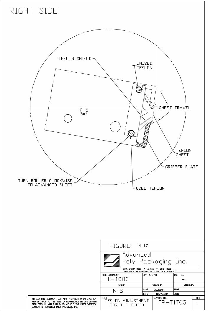
clockwise. To decrease the speed of the pressure bar INWARD, turn the knob (B) clockwise. Toincrease the speed of the pressure bar OUTWARD, turn the knob (A) counter clockwise. To decrease thespeed of the pressure bar OUTWARD, turn the knob (A) clockwise. Adjust the speed of the pressure barso that it moves in and out rapidly, in a fluid manner, without causing the pressure bar to "bang" in or out.
4.12 Pressure Bar (Rubber) ReplacementLocated along the inside of the pressure bar is a strip of rubber, held on the pressure bar by a channel,pressing on the edges of the rubber. The rubber compresses against the front (gripper) plate holding thebag in place during sealing and during bag tear off. If the rubber becomes brittle, torn, gouged orotherwise worn, it should be replaced to assure strong seals.
To replace the pressure bar rubber, simply pull one end of the rubber from the channel. The rubber willcome out of the channel quickly and easily. To install a fresh piece of rubber, press one edge of therubber into the channel then the other edge. Work the rubber into the channel in small increments alongthe length of the channel (Fig. 4-20). If you used Teflon tape to cover the surface of the rubber, place theTeflon on the rubber along its length. If the Teflon extends beyond the rubber, cut off the excess.Note: Teflon may be added to the pressure bar rubber if the bag sticks to the rubber after loading andsealing. The bag may stick to the rubber if the product and bag is light in weight and if the rubber isdirty.
Note: Frequently clean the rubber with alcohol to remove buildup of dirt or other contaminants.
4.13 Anti-Jam AdjustmentThe anti-jam device is designed to protect the T-1000 from damage when an obstruction is encountered inthe seal area (area between the pressure bar and front (gripper) plate). If properly adjusted, the pressurebar will retract if an obstruction is encountered in the seal area. The pressure bar houses springs whichcause the rubber and holder to compress. When the rubber holder compresses, a sensor is activatedcausing the pressure bar to retract. The sensor is defeated when the pressure bar is approximately 1/8"from the gripper plate (Fig. 4-21). The anti-jam can quickly be tested while the T-1000 is operating usingcare, but should be thoroughly tested by disconnecting air and power and removing covers.
To quickly test the anti-jam device, place a 3/8" diameter flexible poly tube against the front (gripper)plate perpendicular to the seal bar opening. Press the foot switch allowing the pressure bar to compressthe poly tube against the front plate. If the pressure bar does not immediately retract and place theT-1000 in the STOP mode, the anti-jam device is not properly adjusted. Test the anti-jam device alongthe entire length of the pressure bar using the 3/8" poly tubing as a test device.
CAUTION: To avoid personal injury, do not place fingers or hands into the seal area of the T-1000 while power is ON or air is attached. Do not test the anti-jam device with hands or fingers.Ensure the poly tube which is used for testing is long enough to keep fingers or hands away from the sealarea of the T-1000.
To thoroughly test and adjust the anti-jam device, you must first turn the power to the OFF position,disconnect the air line from the T-1000 and remove the top and left side cover. With the covers removedand air disconnected, turn the power to the ON position.
To test the pressure bar sensor, locate the "X3" LED on the PLC Board (Fig. 4-8) and ensure the light isilluminated (ON). Then, compress the rubber and holder into the pressure bar (nylon holder). As soon asthe rubber is pressed into the nylon holder, the "X3" LED should turn OFF. The LED should remain OFFwhile the rubber is held compressed into the nylon holder. If the "X3" LED shuts OFF while the rubberbar is pressed into the nylon holder, the pressure bar sensor is functioning properly.
To test the anti-jam override sensor, locate the "X7" LED on the PLC board (Fig. 4-8) and ensure that thelight is OFF. Then, standing in front of the T-1000, push the pressure bar slowly towards the front plate,
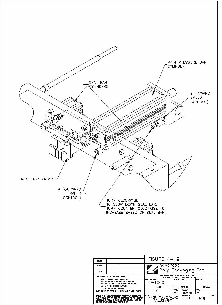
keeping hands and fingers out of the seal area. While pushing the pressure bar towards the front plate donot compress the rubber into the nylon holder or touch the round nuts on the pressure bar (Fig. 4-21).
When the pressure bar rubber is approximately 1/8" from the front plate, "X7" LED should illuminate(ON).
If the LED illuminates prematurely (when the rubber is farther than 1/8" from the front plate), theanti-jam override sensor must be adjusted. An aluminum block, located on the right guide rod in theinner frame, houses a magnet (Fig. 4-22). The anti-jam override sensor detects the magnetic field sendingthe signal to the PLC. If illuminated prematurely, the "magnetic block" should be moved toward the frontof the T-1000 along the guide rod.
If the LED illuminates when the rubber is closer than 1/8" to the front plate or when the rubber istouching the rubber plate (illuminates late), the magnetic block should be adjusted by moving themagnetic block toward the rear of the T-1000 along the guide rod.
To move the magnetic block, loosen the screw on the block which secures it to the guide rod. Loosen thescrew just enough to allow the magnet block to slide along the guide rod without pivoting.
After moving the magnetic block, pull the pressure bar away from the front plate and check theillumination of "X7" LED by pushing the pressure bar slowly toward the front plate. If out of alignment,move the magnetic block in 1/8" increments until properly positioned. In its final position along theguide rod, the magnetic block should be parallel to the side plate.
If the magnetic block, when parallel to the side plate and adjacent to the override sensor, does not causethe LED to illuminate, adjust the override sensor so that the sensor is closer to the magnetic block.
The override sensor is secured to the side-plate with two plastic nuts, one on either side of the side-plate.To bring the sensor closer to the magnetic block, loosen the nuts and turn the sensor counter clockwise,from inside the frame. Turn the sensor 1/2 turn at a time or until the "X7" LED is illuminated. Whenilluminated, turn 1/4 turn more.
CAUTION: To avoid damaging the plastic override sensor, position the sensor so that it does not contactthe magnetic block when the pressure bar is moving. To avoid "stripping" the threads of the sensor, donot over tighten the securing nuts.
When properly positioned, secure the sensor by tightening the securing nuts. When properly adjusted andthoroughly tested, tighten the screw on the magnetic block, replace covers and connect the air line to theregulator.
4.14 Heater Cartridge ReplacementA cylinder-shaped cartridge (element), located inside the heater bar, heats the bronze bars which containit. This cartridge is considered a normal wear item and will infrequently fail, requiring replacement.
To determine if the heater cartridge is bad, follow the following troubleshooting steps: 1) Locate "Y0"LED (Heater Circuit) on the PLC Board (Fig. 4-8) or the Heater Status Light on the Touch Screen FrontCabinet, beneath the Touch Screen (if installed on the T-1000). Press the <START> key if the T-1000 isin the Stop mode. If "Y0" illuminates in long pulses without increasing the Temperature on the BagSetup Screen (page 32, Fig. 3-3) proceed to step two. 2) Check the heater fuse (F5), on the InterfaceBoard (Fig. 4-10). If the fuse is good, proceed to step three. 3) Locate "N4" Neon Light (Heater PulseAC) on the Interface Board (Fig. 4-9).
If the neon remains ON continuously, but at "half brightness", proceed to the final test. 4) Disconnect theheater connector labeled "Heater" in the inner frame and check the resistance with an Ohms meter. If themeter reads greater than 17-18 ohms, replace the newer style 800 watt cartridge. If the meter readsgreater than 13 ohms, replace the older style 1200 watt cartridge.
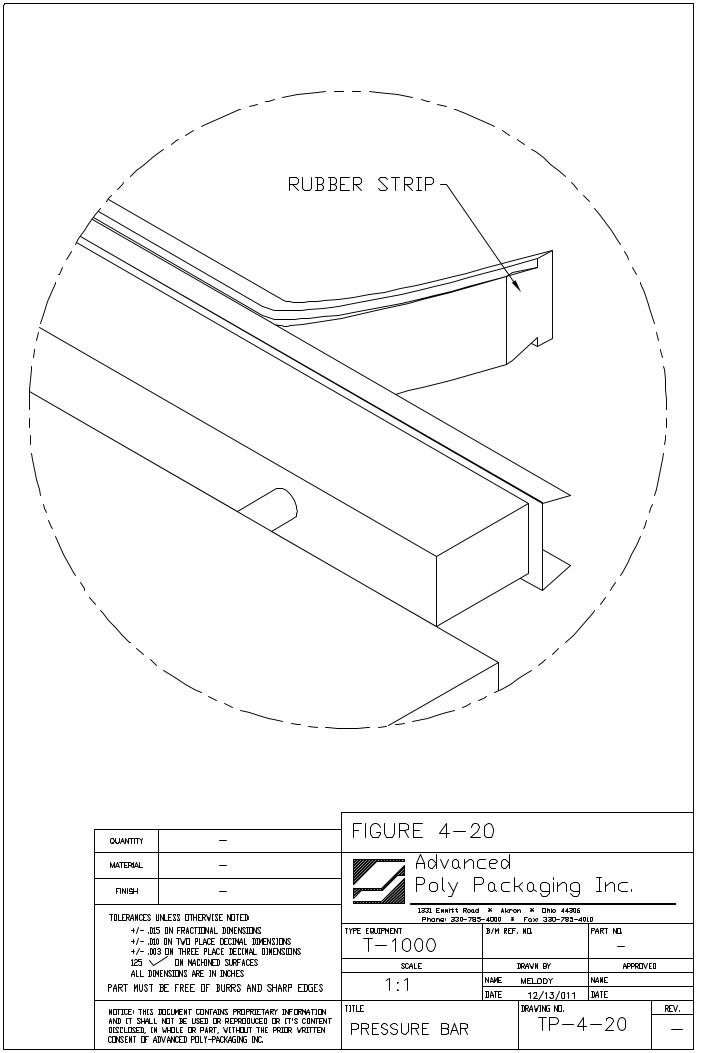
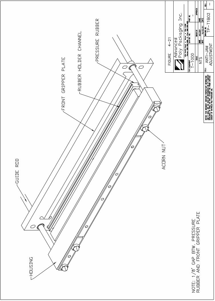
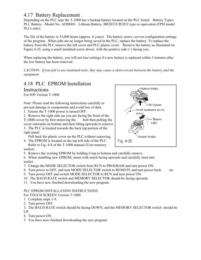
4.17 Battery Replacement .Depending on the PLC type the T-1000 has a backup battery located on the PLC board. Battery Types: PLC Battery - Model No. AFB8801. Lithium Battery, BR2032/CR2032 type or equivalent (FPM modelPLCs only).
The life of the battery is 53,000 hours (approx. 6 years). The battery stores current configuration settingsof the program. When jobs are no longer being saved in the PLC, replace the battery. To replace thebattery from the PLC remove the left cover and PLC plastic cover. Remove the battery as illustrated onFigure 4-25, using a small insulated screw driver, with the positive side (+) facing you.
When replacing the battery, you will not lose settings if a new battery is replaced within 3 minutes afterthe low battery has been removed.
CAUTION: If you fail to use insulated tools, they may cause a short-circuit between the battery and theequipment.
4.18 PLC EPROM InstallationInstructions For IOP Version T-1000
Note: Please read the following instructions carefully toprevent damage to components and avoid loss of data.1. Ensure the T-1000 power is turned OFF.2. Remove the right side (as you are facing the front of theT-1000) cover by first removing the bolt then pulling thecover outwards on bottom and then lifting upwards to remove.3. The PLC is located towards the back top portion of theright panel. Pull back the plastic cover on the PLC without removing.4. The EPROM is located on the top left side of the PLC. Refer to Fig. 4-8 of the T-1000 manual (User memorysocket).5. Remove the existing EPROM by holding it top to bottom and carefully remove.6. When installing new EPROM, insert with notch facing upwards and carefully inset into socket.7. Change the MODE SELECTOR switch from RUN to PROGRAM and turn power ON.8. Turn power to OFF, and turn MODE SELECTOR switch to REMOTE and turn power back on.9. Turn power OFF and switch MODE SELECTOR to RUN and turn power ON.10. The BAUD RATE switch and MEMORY SELECTOR should be facing upwards.11. You have now finished downloading the new program.
PLC EPROM INSTALLATION INSTRUCTIONSFor TOUCH SCREEN Version T-10001. Complete steps 1-9. 2. Turn power OFF.3. The BAUD RATE switch should be facing DOWN, and the MEMORY SELECTOR switch should beUP.4. Turn power ON.5. You have now finished downloading the new program.
Note: If you do not have an Ohms meter, replace the heater cartridge after step three.
To replace the heater cartridge, turn the main power to the OFF position, unplug the power cord anddisconnect the air line.
Disconnect the heater cartridge wire at the connector. From underneath the inner frame, loosen andremove the screws which holds the wire clamp and lower heater bar plate to the upper heater bar plate(Fig. 4-23). Then remove the two remaining screws which hold the lower heater bar plate to the upperheater bar plate. Remove the heater cartridge wires from the wire clamp. Place a new cartridge into theheater bar slot and replace the lower heater bar plate. Place the wires into the wire clamp and secure tothe lower heater bar plate. Reconnect the heater cartridge wires ensuring that the heater bar can extendfully without stretching the heater cartridge wires. Plug the cord into the outlet, turn the power to the ONposition and connect the air line to the regulator. Press <START> on the Touch Screen and verify thatthe temperature increases.
4.15 Replace Thermocouple WireA thermocouple wire, brazed to a ring terminal and secured to the top of the upper heater bar, detects theamount of heat the heater bar is emitting. The thermocouple wire is considered a normal wear item andwill infrequently fail, requiring replacement.
To determine if the thermocouple is bad, follow these trouble shooting steps: 1) Locate the "E13" light(Open Thermocouple Alarm) on the Interface Board (Fig. 4-9). If the light is ON, proceed to step two. 2) Another indicator that the thermocouple wire is bad is the "XO" (Heater Bar Temp. Readout) LED on theP.C. Board (Fig. 4-8) will flash slowly. 3) Additionally, the "Y0" (Heater Circuit) LED (Fig. 4-8) willnot be illuminated (unless the Energy Saver has shut off the heater bar after 25 minutes).
If the above conditions are met, the thermocouple is bad and the current to the heater bar has been turnedOFF.
To replace the thermocouple wire, turn the main power to the OFF position, unplug the power cord anddisconnect the air line.
Remove the front plate and Teflon assembly, as described in Chapter 4.13. Remove the screws whichhold the ring terminal and the jacketed wire clamp. Disconnect the connector and remove the wire.Reverse these steps to replace the wire.
CAUTION: To avoid stretching or breaking the wire during heater cylinder extension, ensure that thewire is looped and free to bend during heater bar movement.
Replace the Teflon assembly and front plate as described in Chapter 4.13.
4.16 Brake Gap AdjustmentOnce the brake is adjusted (at the factory), it should not require adjustment. But, if the brake is notfunctioning properly, adjustment may be required.
To check the brake gap, turn the power to the OFF position, disconnect air and remove the left panelcover. Using a .014 Feeler Gauge, insert the gauge between the outer plate and the second plate. If thegauge is "snug", the gap is properly set.
If the gauge is too loose or cannot be inserted between the plates, loosen the two set screws located on thebrake collar (Fig. 4-24). Place the Feeler Gauge between the plates and press the outer plate against thefeeler gauge. Press the brake collar against the outer plate and tighten the set screws. Replace the leftcover, plug in the power cord, connect the air line and turn the main power to the ON position.
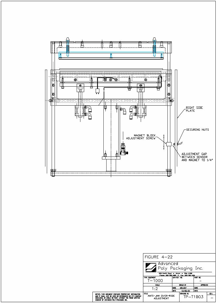
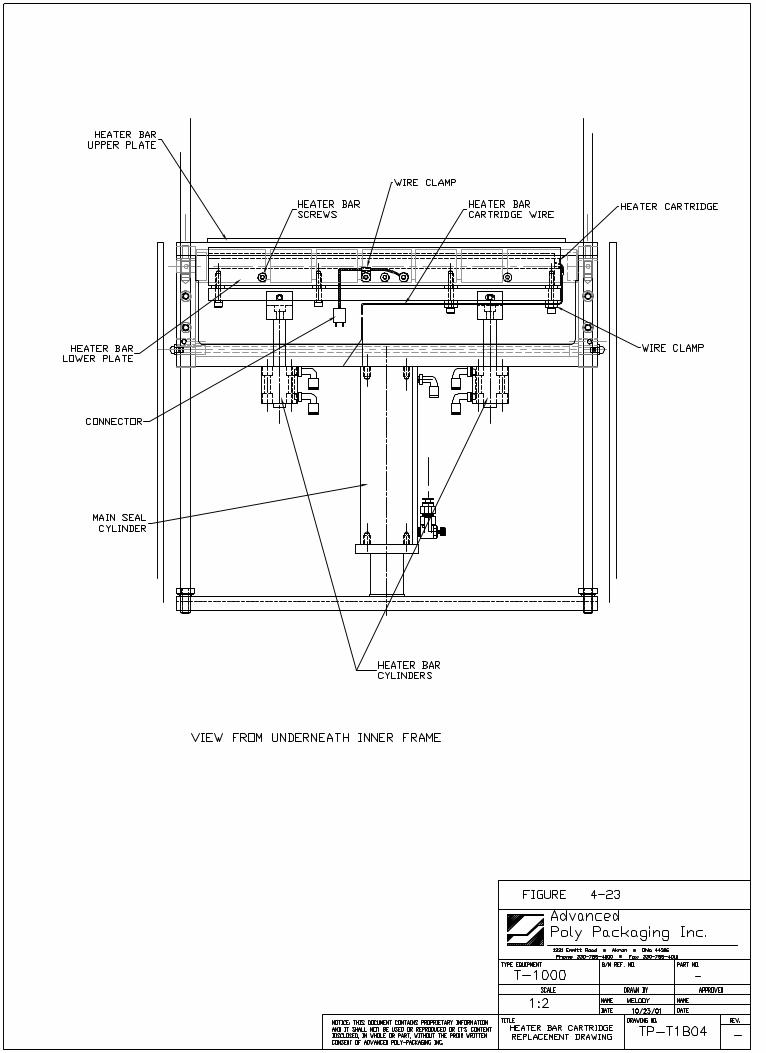
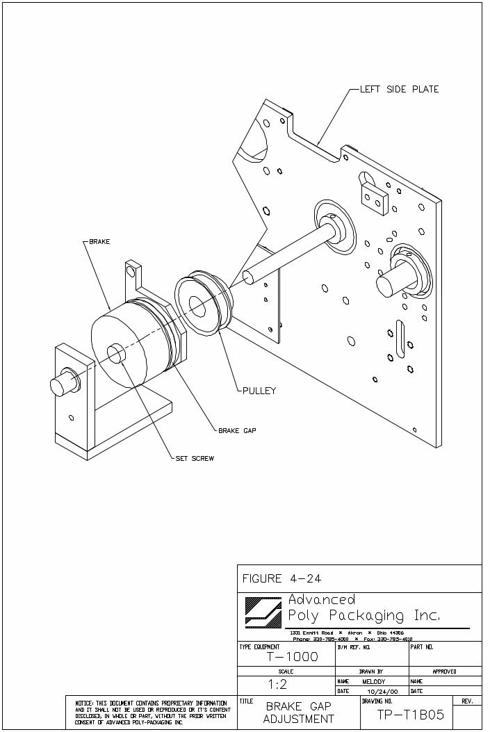

Chapter 5, Parts Identification______________________________________________________________________________
Parts DwgsSpare Parts Kits

5.1 Main Assembly, T-1000 T-1000 Advanced Poly-BaggerSee Dwg #T-T1000
1 TA-T10100 Head Assembly, T-1000 2 TA-T10199 Stand Assembly, T-1000 3 TA-T10240 Touch Screen Control Case Assembly
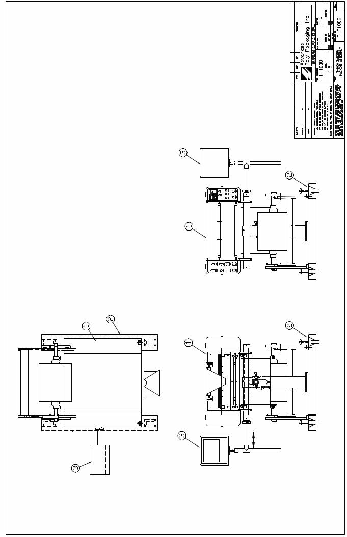
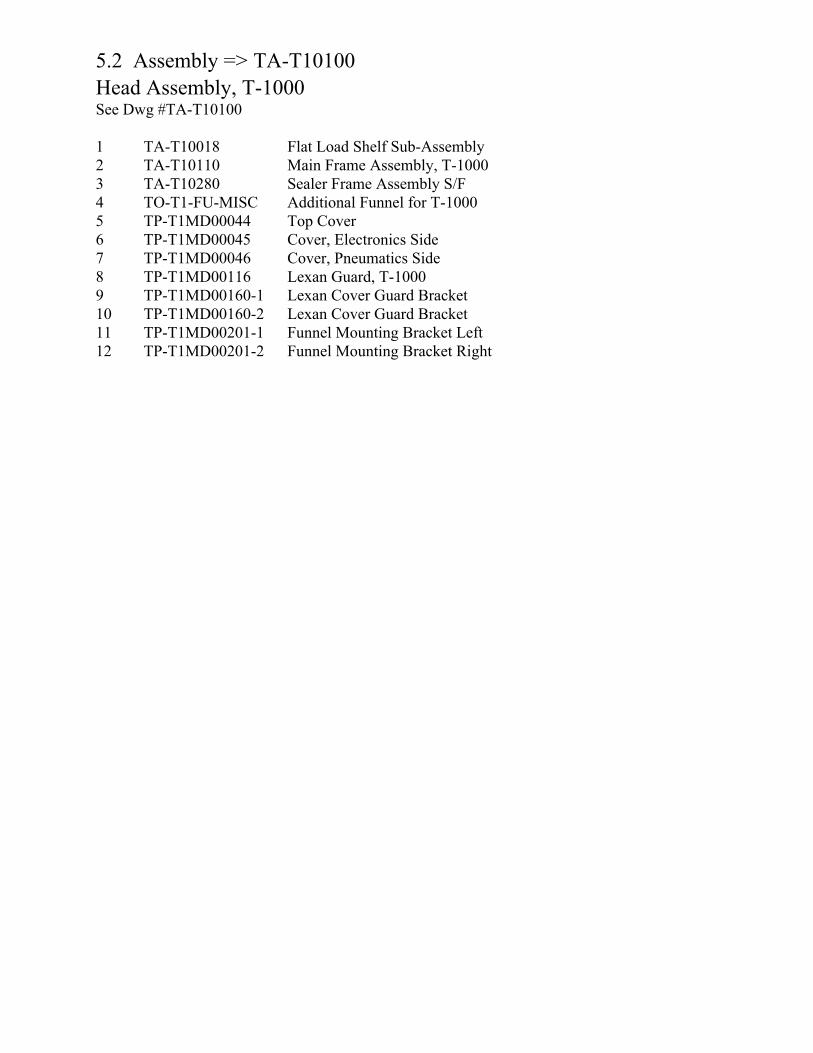
5.2 Assembly => TA-T10100 Head Assembly, T-1000 See Dwg #TA-T10100
1 TA-T10018 Flat Load Shelf Sub-Assembly 2 TA-T10110 Main Frame Assembly, T-1000 3 TA-T10280 Sealer Frame Assembly S/F 4 TO-T1-FU-MISC Additional Funnel for T-1000 5 TP-T1MD00044 Top Cover 6 TP-T1MD00045 Cover, Electronics Side 7 TP-T1MD00046 Cover, Pneumatics Side 8 TP-T1MD00116 Lexan Guard, T-1000 9 TP-T1MD00160-1 Lexan Cover Guard Bracket 10 TP-T1MD00160-2 Lexan Cover Guard Bracket 11 TP-T1MD00201-1 Funnel Mounting Bracket Left 12 TP-T1MD00201-2 Funnel Mounting Bracket Right
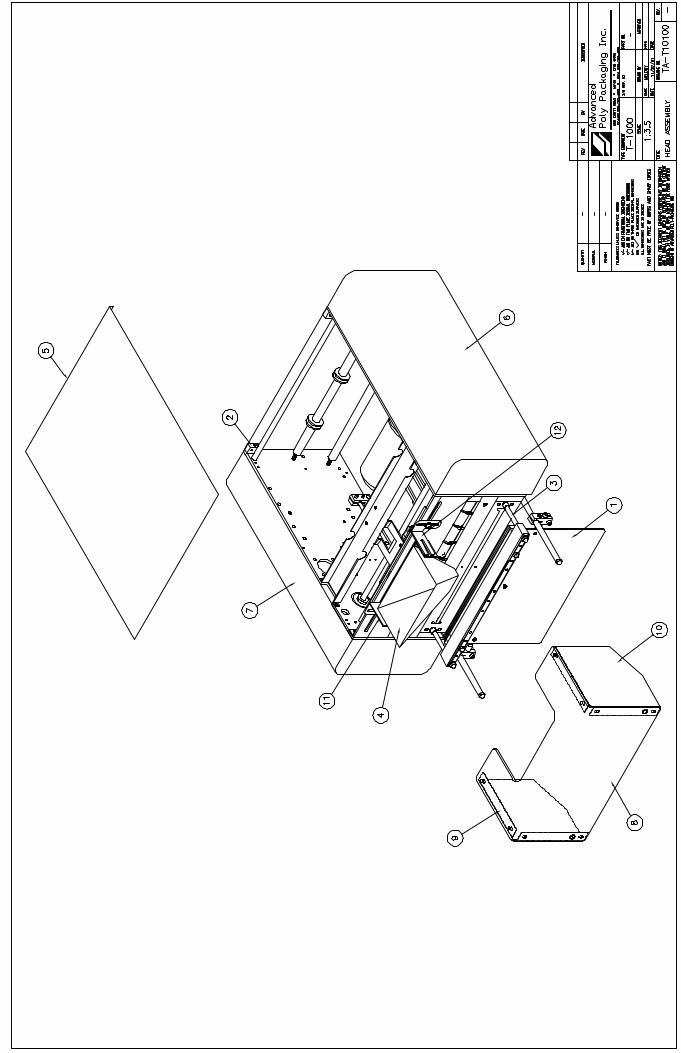
5.3 Assembly => TA-T10018 Flat Load Shelf Sub-Assembly See Dwg #TA-T10018
1 TP-T1MB00074-1 Load Shelf Bracket (Left) 2 TP-T1MB00074-2 Load Shelf Bracket (Right) 3 TP-T1MB00075 Fixed Load Shelf 9" (Fixed) 4 TP-T1MB00076 Fixed Load Shelf Rod 5 TP-101102 Nut, 6-32 Hex Mach Screw 6 TP-102152 Washer, #6 Med Split Lock 7 TP-102155 Washer, 1/4 Med Split Lock8 TP-103137 Screw, SHCS 1/4-20 x 1/29 TP-103224 Screw, BHCS 1/4-20 x 1/210 TP-103407 Screw, FHCS 6-32 x 3/4
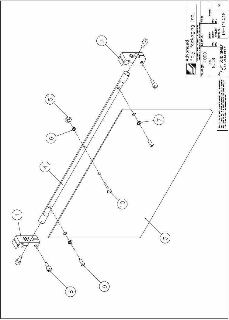

5.4 Assembly => TA-T10110Main Frame Assembly,T-1000 See Dwg # TA-T10110 1 TA-T10230 Main Frame Assembly 2 TA-T10250 Inner Main Frame Assembly 3 TA-T10255 Outer Main Frame Assembly4 TA-T10275 Electrical Panel Assembly
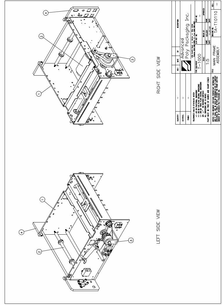
5.5 Assembly => TA-T10230 Main Frame Assembly See Dwg #TA-T10230
1 TP-T1MC00001-1 Main Frame Plate (left) 2 TP-T1MC00001-2 Main Frame Plate (right) 3 TP-T1MC00017 Vulcanized Rubber Roller 4 TP-T1MC00042 Face Plate 5 TP-T1MC00056 Belt Drive Rear Support Shelf6 TP-T1MC00079 Shaft, Cylinder Pivot 7 TP-504113 Bearing, 7612 DLG (2/M) 8 TP-504114 Bearing, 7608 DLG
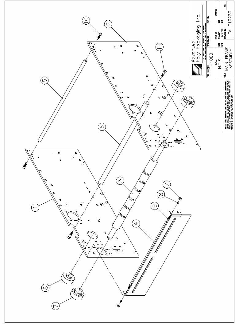
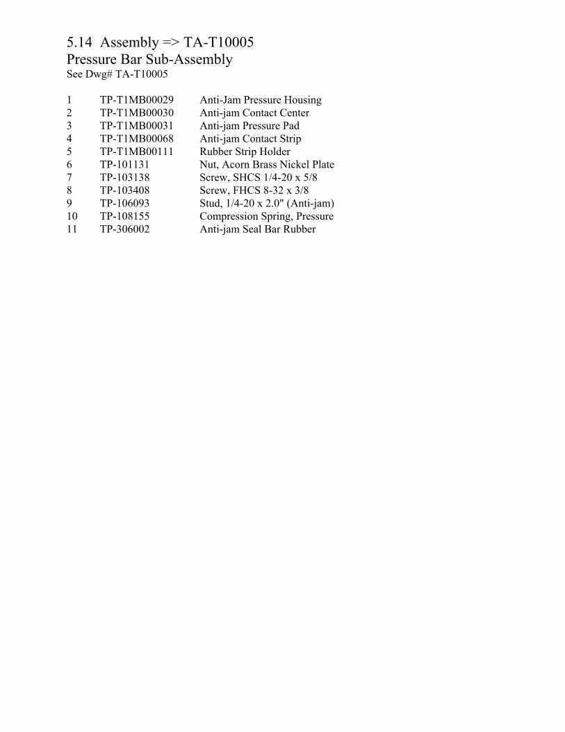
5.14 Assembly => TA-T10005Pressure Bar Sub-Assembly See Dwg# TA-T10005
1 TP-T1MB00029 Anti-Jam Pressure Housing2 TP-T1MB00030 Anti-jam Contact Center 3 TP-T1MB00031 Anti-jam Pressure Pad 4 TP-T1MB00068 Anti-jam Contact Strip 5 TP-T1MB00111 Rubber Strip Holder 6 TP-101131 Nut, Acorn Brass Nickel Plate 7 TP-103138 Screw, SHCS 1/4-20 x 5/8 8 TP-103408 Screw, FHCS 8-32 x 3/8 9 TP-106093 Stud, 1/4-20 x 2.0" (Anti-jam) 10 TP-108155 Compression Spring, Pressure 11 TP-306002 Anti-jam Seal Bar Rubber
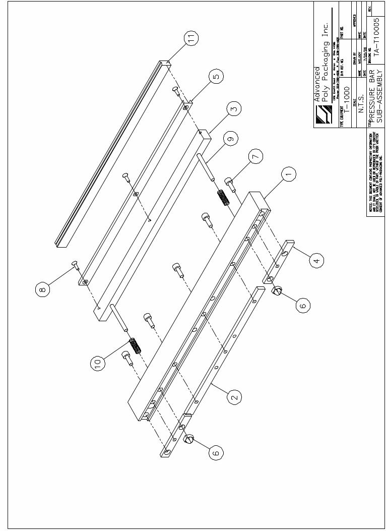
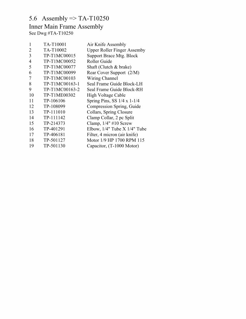
5.6 Assembly => TA-T10250 Inner Main Frame Assembly See Dwg #TA-T10250
1 TA-T10001 Air Knife Assembly 2 TA-T10002 Upper Roller Finger Assemby3 TP-T1MC00015 Support Brace Mtg. Block 4 TP-T1MC00052 Roller Guide 5 TP-T1MC00077 Shaft (Clutch & brake) 6 TP-T1MC00099 Rear Cover Support (2/M) 7 TP-T1MC00103 Wiring Channel 8 TP-T1MC00163-1 Seal Frame Guide Block-LH 9 TP-T1MC00163-2 Seal Frame Guide Block-RH 10 TP-T1ME00302 High Voltage Cable 11 TP-106106 Spring Pins, SS 1/4 x 1-1/412 TP-108099 Compression Spring, Guide13 TP-111010 Collars, Spring Closure 14 TP-111142 Clamp Collar, 2 pc Split15 TP-214373 Clamp, 1/4" #10 Screw 16 TP-401291 Elbow, 1/4" Tube X 1/4" Tube 17 TP-406181 Filter, 4 micron (air knife) 18 TP-501127 Motor 1/9 HP 1700 RPM 11519 TP-501130 Capacitor, (T-1000 Motor)
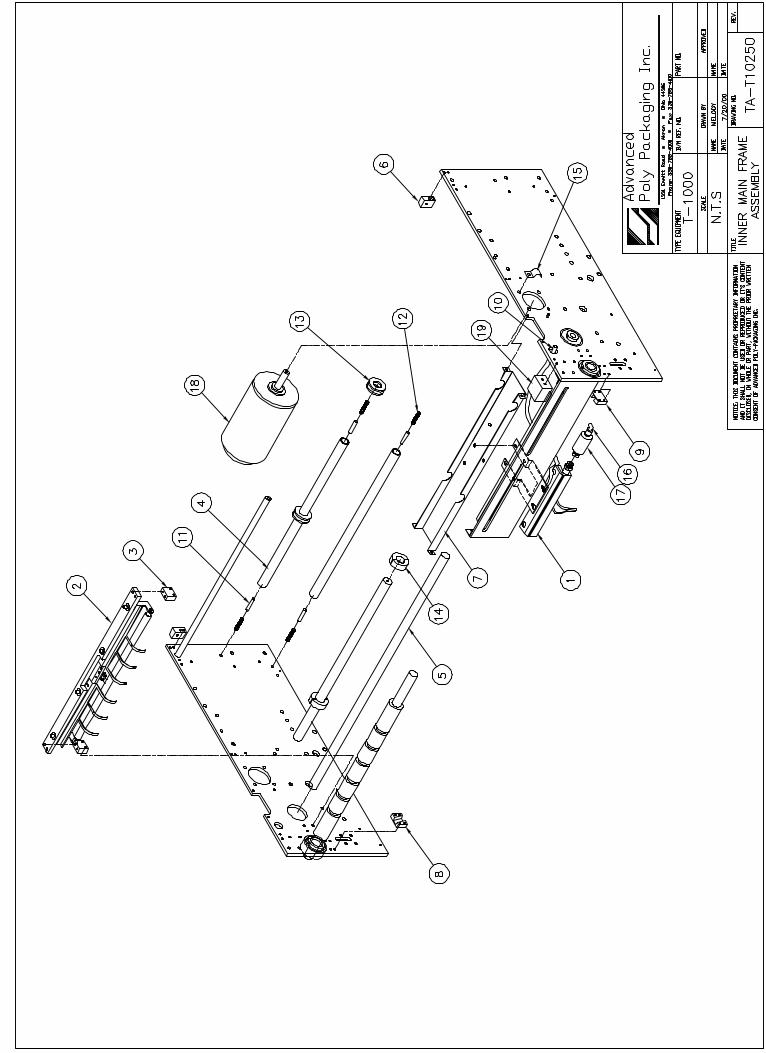
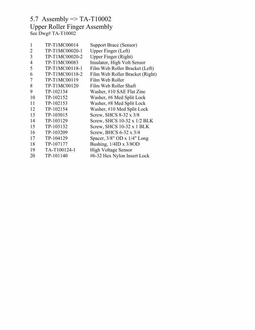
5.7 Assembly => TA-T10002 Upper Roller Finger Assembly See Dwg# TA-T10002
1 TP-T1MC00014 Support Brace (Sensor)2 TP-T1MC00020-1 Upper Finger (Left) 3 TP-T1MC00020-2 Upper Finger (Right) 4 TP-T1MC00083 Insulator, High Volt Sensor 5 TP-T1MC00118-1 Film Web Roller Bracket (Left) 6 TP-T1MC00118-2 Film Web Roller Bracket (Right)7 TP-T1MC00119 Film Web Roller 8 TP-T1MC00120 Film Web Roller Shaft 9 TP-102134 Washer, #10 SAE Flat Zinc 10 TP-102152 Washer, #6 Med Split Lock 11 TP-102153 Washer, #8 Med Split Lock 12 TP-102154 Washer, #10 Med Split Lock13 TP-103015 Screw, SHCS 8-32 x 3/8 14 TP-103129 Screw, SHCS 10-32 x 1/2 BLK15 TP-103132 Screw, SHCS 10-32 x 1 BLK 16 TP-103209 Screw, BHCS 6-32 x 3/4 17 TP-104129 Spacer, 3/8" OD x 1/4" Long 18 TP-107177 Bushing, 1/4ID x 3/8OD 19 TA-T100124-1 High Voltage Sensor 20 TP-101140 #6-32 Hex Nylon Insert Lock
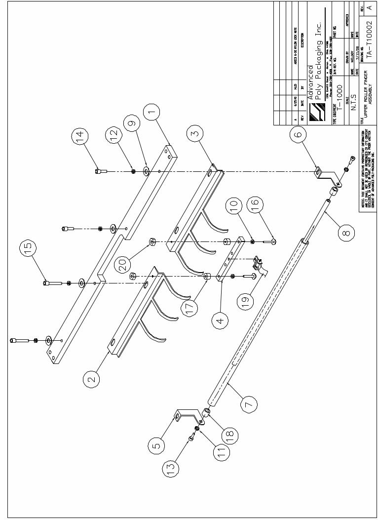

5.8 Assembly => TA-T10001 Air Knife Assembly See Dwg# TA-T10001
1 TP-T1MC00080 Venturi / Air Pulse Bracket2 TP-T1MC00108 Air Pulse Manifold Assembly 3 TP-102154 Washer, #10 Med Split Lock4 TP-103129 Screw, SHCS 10-32 x 1/2 5 TP-401134 Hex Plug, 1/8"x 3/4 Brass 6 TP-401258 Straight, 1/4" Tube x 1/8 7 TP-401292 Straight 1/4 poly x 1/4 np 8 TP-405268 Air knife (Venturi) 6"
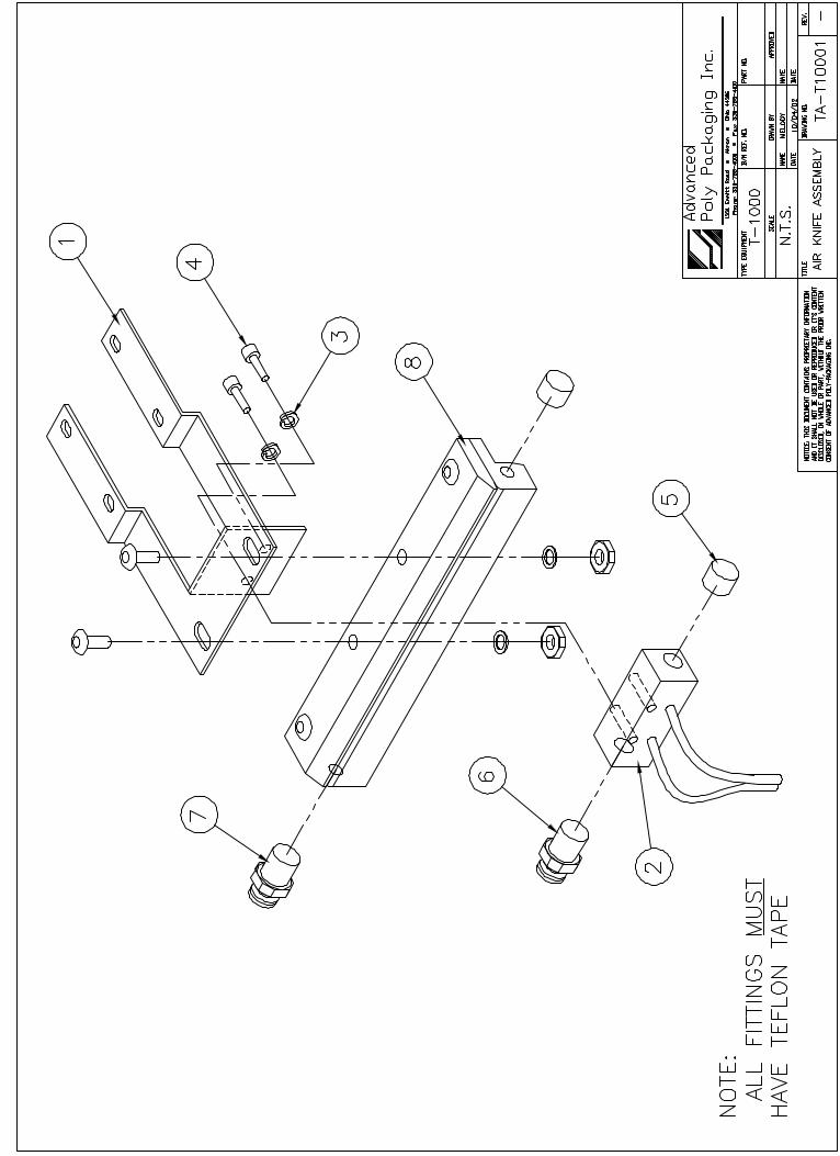
5.9 Assembly => TA-T10255Outer Main Frame Assembly See Dwg# TA-T10255
1 TA-T10025 Pneumatic Mntg. Valve Assembly 2 TA-T10702 Clutch-Timing Belt Pulley 3 TA-T10703 Tear Off Clutch Assembly 4 TP-T1MC00054 Cover Support Clamp (4/M) 5 TP-T1MC00058 Latch Adjuster Block (2/M) 6 TP-T1MC00059 Latch Lock Block (2/M) 7 TP-T1MC00082 Cover Stand-off (2/M) 8 TP-T1MC00084 Clutch Bearing Support 9 TP-T1MC00085 Support Block 10 TP-T1MC00091 Bracket, Belt Tensioner 11 TP-T1MC00097 Cylinder Standoff 12 TP-T1MC00114 Pulley, Roller/Brake 13 TP-T1MC00161 Pulley, Brake 14 TP-T1MC00162 Pulley, Motor 15 TP-T1MC00176 Belt Shroud (Right Hand) 16 TP-T1MD00153 Pneumatics Mtg Panel Assembly 17 TP-107121 Bushing, Flange 1/2ID X 5/ 18 TP-205108 Filter, 120/250VAC 50/60 HZ 19 TP-215200 Switch, Magnetic (Threaded) 20 TP-401258 Straight, 1/4" Tube x 1/8 21 TP-402107 Flow Control Valve (panel) 22 TP-402187 Flow Control (Flat Seal & Assembly) 23 TP-403243 Cylinder, 1.06" Bore x 3" 24 TP-404251 Rod Clevis 1.06" Bore Size 25 TP-503102 Belt, Brake 26 TP-503182 Belt, Clutch 27 TP-504132 Cam Follower
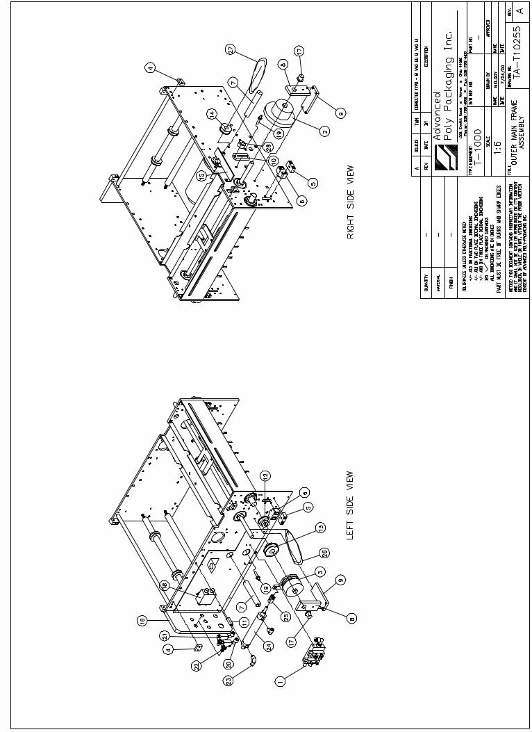

5.10 Assembly => TA-T10025 Pneumatic Mounting Valve Assembly See Dwg# TA-T10025
1 TP-401134 Hex Plug, 1/8"x 3/4 Brass 2 TP-401275 Elbow, 3/8" tube x 1/8" np 3 TP-401288 2 Pin SY S.ValveCon.Housin4 TP-402252 5 Station Manifolds Assembly 5 TP-404262 Muffler, Sintered Bronze 1
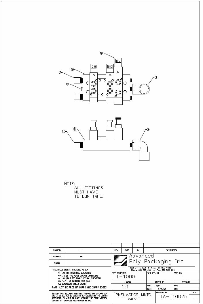
5.11 Assembly => TA-T10275 Electrical Panel Assembly See Dwg# TA-T10275
1 TC-T1-HARNESS Wiring Harness, T-1000 2 TP-T1MD00113 Electronics Back Plate3 TP-T1MD00149 Electronics Mtg Panel Assembly 4 TP-T1ME00301 PCB, High Voltage Board Figure5 TP-200348 PCB, T-1000 IF Bd. Comp.6 TP-202116 6,000uF 40V Comp Capacitor 7 TP-206146 Triac, 400v, 25amp, Q4025P8 TP-207216 Fuse Holder(110v/220v) 9 TP-211384 Transformer, High Volt W/RF 10 TP-211391 Triad Dual Pri. Transformer 11 TP-212166 6 pin circular Male Conn 12 TP-212167 6 pin Circular Fem Conn 13 TP-212247 9 pin D-sub female (solder) 14 TP-212338 10 pin circular Fem Conn 15 TP-212342 Terminal, Fem.Insul 12-10(5)16 TP-212400 Receptacle, Black 17 TP-214270 Standoff, 2"Round Alum 6-32 18 TP-214273 Standoff, Nylon Hex Threader 19 TP-215383 Switch, 250V@10A 20 TP-220367 PLC, T-1000 (FPM series PLC) 20 TP-220504 PLC, T-1000 (FP0 series PLC)21 TP-203010 IC, 27C256 32K x 8 (256K) (not required for FP0)
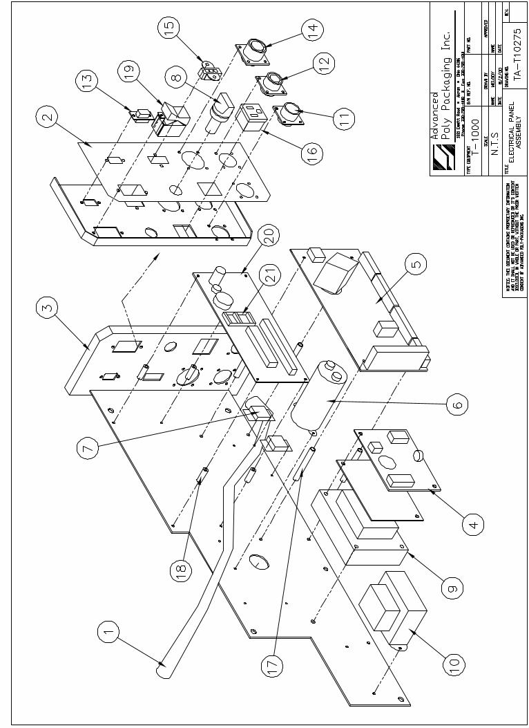

5.12 Assembly => TA-T10280 Sealer Frame Assembly (Standard Frame) See Dwg# TA-T10280
1 TA-T10003 Seal Frame Manifold Sub-Assembly2 TA-T10004 Main Seal Cylinder Sub-Assembly3 TA-T10005 Pressure Bar Sub-Assembly4 TA-T10006 Heater Bar Sub-Assembly5 TA-T10009 Teflon Guide Sub-Assembly6 TA-T10012 Grooved Roller Mounting Sub-Assembly7 TA-T10013 Heater Bar Cylinder Sub-Assembly8 TA-T10017 Bag Finger Grounding Assembly9 TA-T10019 Latch Sub-Assembly10 TP-T1MB00005 Gripper Plate (Standard)11 TP-T1MB00010 Seal Rod Tie 12 TP-T1MB00016 Seal Cylinder Mtg Block13 TP-T1MB00022 Guard Rod Mounting Block14 TP-T1MB00026 Gripper Plate Spacer 15 TP-T1MB00033 Seal Rod (2/M)16 TP-T1MB00041 Main Seal Cylinder Cushion17 TP-T1MB00057 Heater Bar Yoke (2/M)18 TP-T1MB00062 Latch Handle19 TP-T1MB00063 Latch Shaft 20 TP-T1MB00107 Magnetic Sensor Housing21 TP-T1MB00144 Shield Mounting Rods (2/M)22 TP-T1MB00164 Pivot Clamp23 TP-T1MB00200 Sealer Frame Machined 24 TP-T1ME00209 Seal Bar Coiled Cable Harness25 TP-101123 Nut, Hex Jam Zinc 3/8-1626 TP-101132 Nut, Acorn Steel Zinc Pltd27 TP-101133 Nut, Acorn Zinc Pltd 3/8-128 TP-102103 Lockwasher, #8 Int Tooth Pltd 29 TP-102105 Lockwasher, Int Tooth Pltd 30 TP-102106 Lockwasher, Int Tooth Pltd 31 TP-102133 Washer,#8 SAE Flat Zinc32 TP-102143 Washer, SAE Flat Zinc 5/16 33 TP-102144 Washer, SAE Flat Zinc 3/834 TP-102154 Washer, #10 Med Split Lock35 TP-102155 Washer, 1/4 Med Split Lock36 TP-102254 Washer, Fender 3/8 x 1-1/237 TP-103006 Screw, SHCS 3/8-24 x 3/438 TP-103014 Screw, SHCS 10-32 x 1-3/439 TP-103116 Screw, SHCS 8-32 x 1/2 40 TP-103129 Screw, SHCS 10-32 x 1/2 BLK41 TP-103137 Screw, SHCS 1/4-20 x 1/242 TP-103139 Screw, SHCS 1/4-20 x 3/443 TP-103140 Screw, SHCS 1/4-20 x 144 TP-103141 Screw, SHCS 1/4-20 x 1-1/445 TP-103142 Screw, SHCS 1/4-20 x 1-1/246 TP-103186 Screw, Shoulder 47 TP-103210 Screw, BHCS 8-32 x 1/4 BLK 48 TP-103225 Screw, BHCS 1/4-20 x 3/449 TP-103261 Set-screw, 10-32 x 1/4 50 TP-106109 Spring Pins, SS 1/8 x 3/451 TP-106110 Spring Pins, SS 1/8 x 1/252 TP-107160 Bushing,Teflon Coated53 TP-107227 Bushing,Thrust Nylon 1/2ID54 TP-107228 Bushing,Nylon Flange 3/8ID55 TP-211374 Magnets 56 TP-214373 Clamp, 1/4" #10 Screw 57 TP-401254 Union Tee Fitting, 1/4" Tube
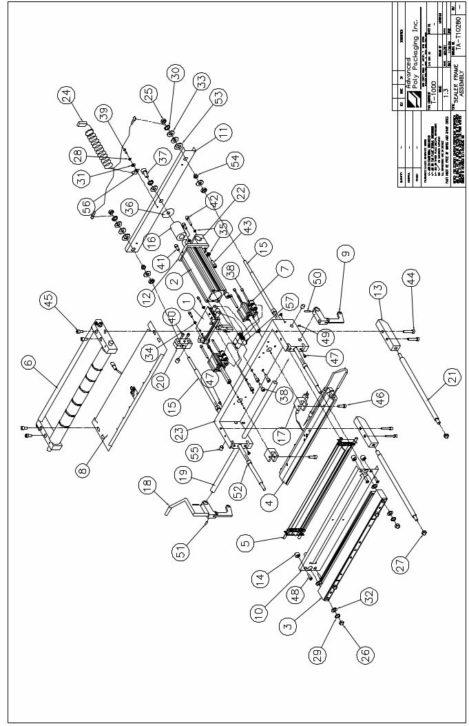

5.13 Assembly => TA-T10003Seal Frame Manifold Sub-Assembly See Dwg# TA-T10003
1 TP-T1MB00021 Valve Manifold Mtg Bracket2 TP-101103 Nut,8-32 Hex Mach Screw Plate3 TP-102103 Lockwasher,#8 Int Tooth Plate4 TP-103118 Screw, SHCS 8-32 x 15 TP-401134 Hex Plug,1/8"x 3/4 Brass6 TP-401275 Elbow, 3/8" tube x 1/8" np7 TP-401288 2 Pin SY S.ValveCon.Housin8 TP-402253 5 Station Valve Manifold9 TP-404262 Muffler, Sintered Bronze 1
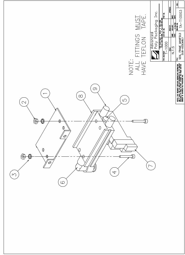
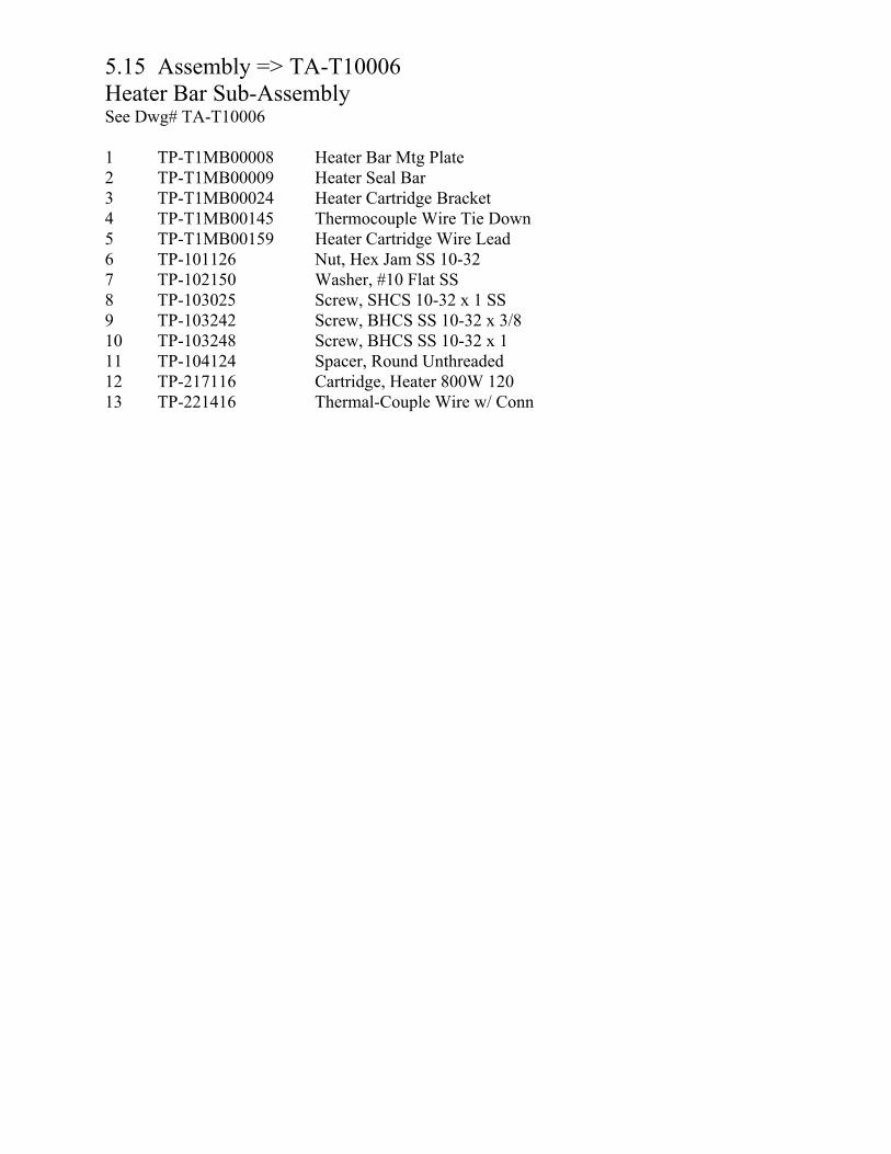
5.15 Assembly => TA-T10006 Heater Bar Sub-Assembly See Dwg# TA-T10006
1 TP-T1MB00008 Heater Bar Mtg Plate2 TP-T1MB00009 Heater Seal Bar 3 TP-T1MB00024 Heater Cartridge Bracket4 TP-T1MB00145 Thermocouple Wire Tie Down 5 TP-T1MB00159 Heater Cartridge Wire Lead6 TP-101126 Nut, Hex Jam SS 10-327 TP-102150 Washer, #10 Flat SS 8 TP-103025 Screw, SHCS 10-32 x 1 SS9 TP-103242 Screw, BHCS SS 10-32 x 3/810 TP-103248 Screw, BHCS SS 10-32 x 1 11 TP-104124 Spacer, Round Unthreaded 12 TP-217116 Cartridge, Heater 800W 120 13 TP-221416 Thermal-Couple Wire w/ Conn
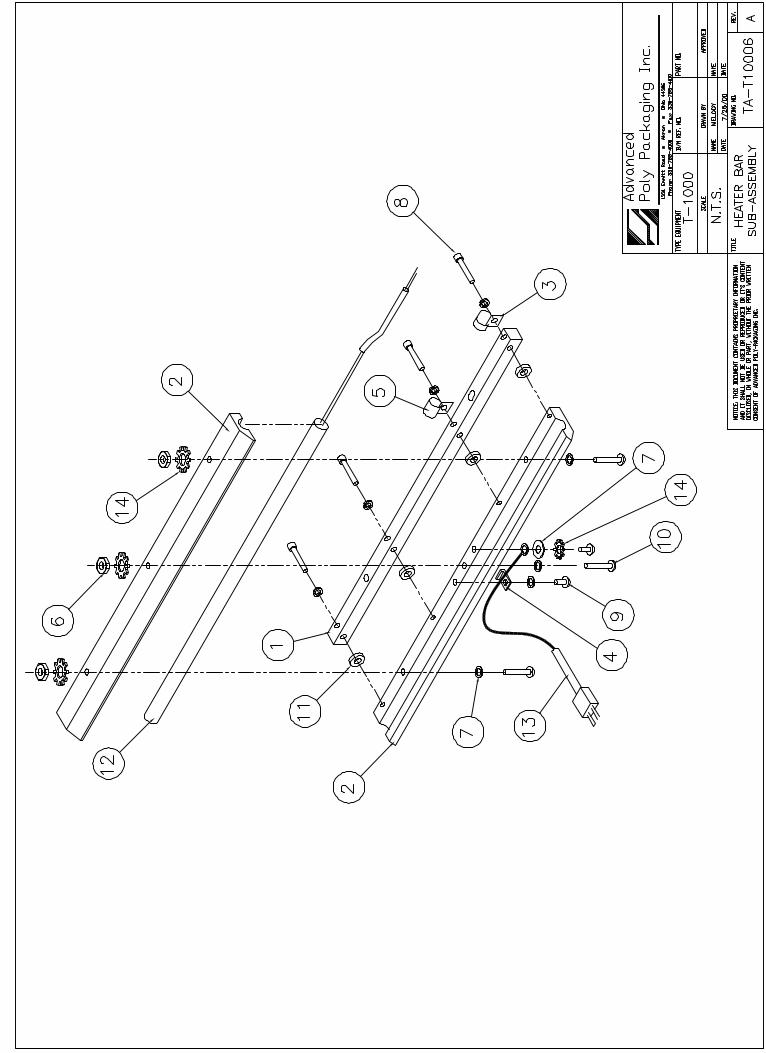

5.16 Assembly => TA-T10009Teflon Guide Sub-Assembly See Dwg# TA-T10009
1 TP-T1MB00034 Bracket Plate Finger (Teflon)2 TP-T1MB00040 Rod, Teflon (2/M) 3 TP-108156 Extension Spring, Teflon Roll4 TP-300500 Teflon Sheet (T-1000)
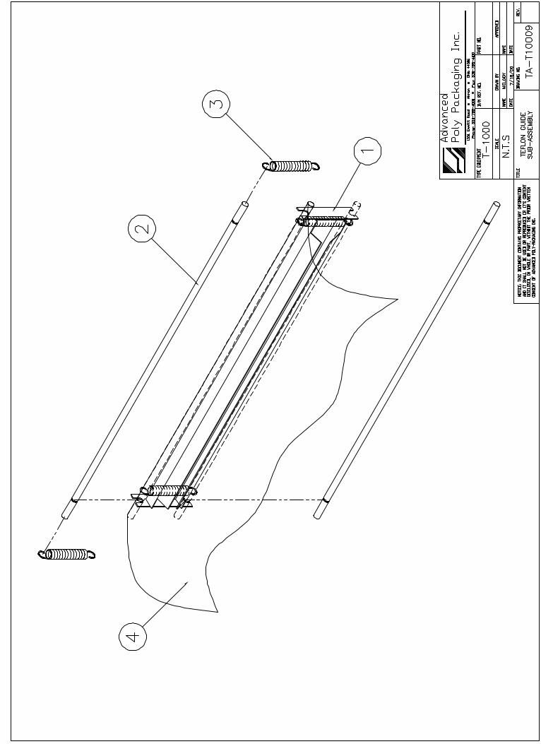
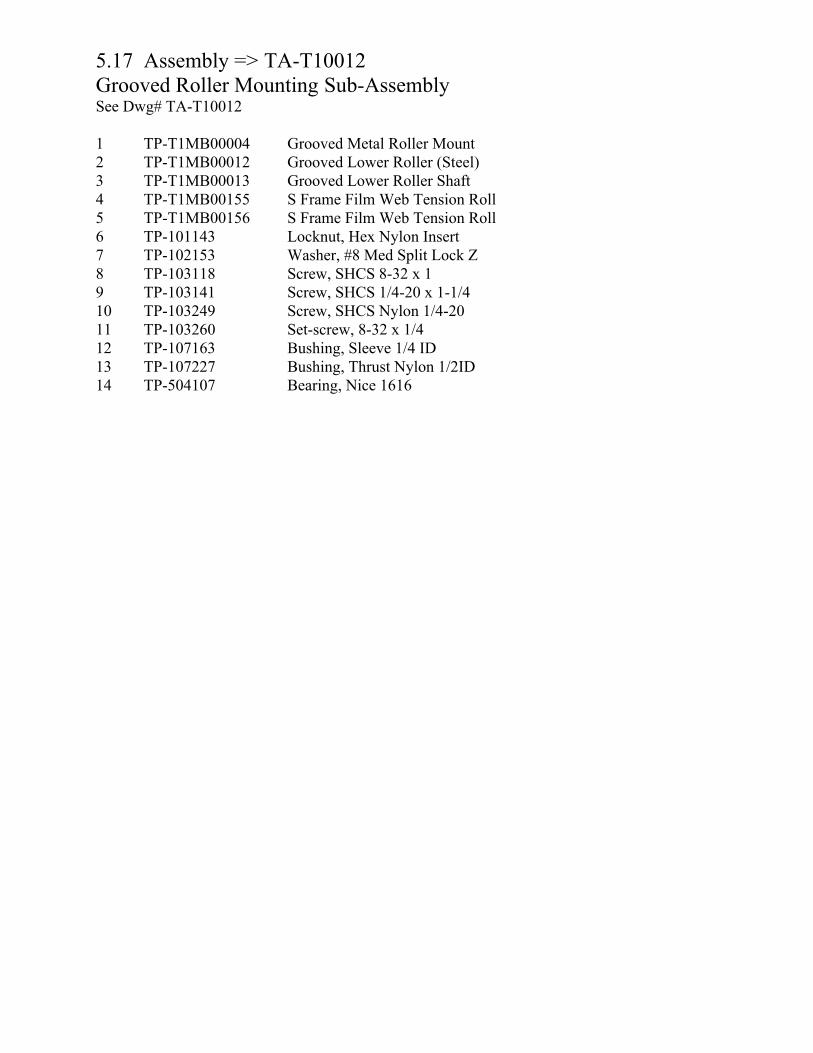
5.17 Assembly => TA-T10012Grooved Roller Mounting Sub-Assembly See Dwg# TA-T10012
1 TP-T1MB00004 Grooved Metal Roller Mount2 TP-T1MB00012 Grooved Lower Roller (Steel)3 TP-T1MB00013 Grooved Lower Roller Shaft4 TP-T1MB00155 S Frame Film Web Tension Roll5 TP-T1MB00156 S Frame Film Web Tension Roll6 TP-101143 Locknut, Hex Nylon Insert7 TP-102153 Washer, #8 Med Split Lock Z8 TP-103118 Screw, SHCS 8-32 x 19 TP-103141 Screw, SHCS 1/4-20 x 1-1/410 TP-103249 Screw, SHCS Nylon 1/4-2011 TP-103260 Set-screw, 8-32 x 1/412 TP-107163 Bushing, Sleeve 1/4 ID 13 TP-107227 Bushing, Thrust Nylon 1/2ID14 TP-504107 Bearing, Nice 1616
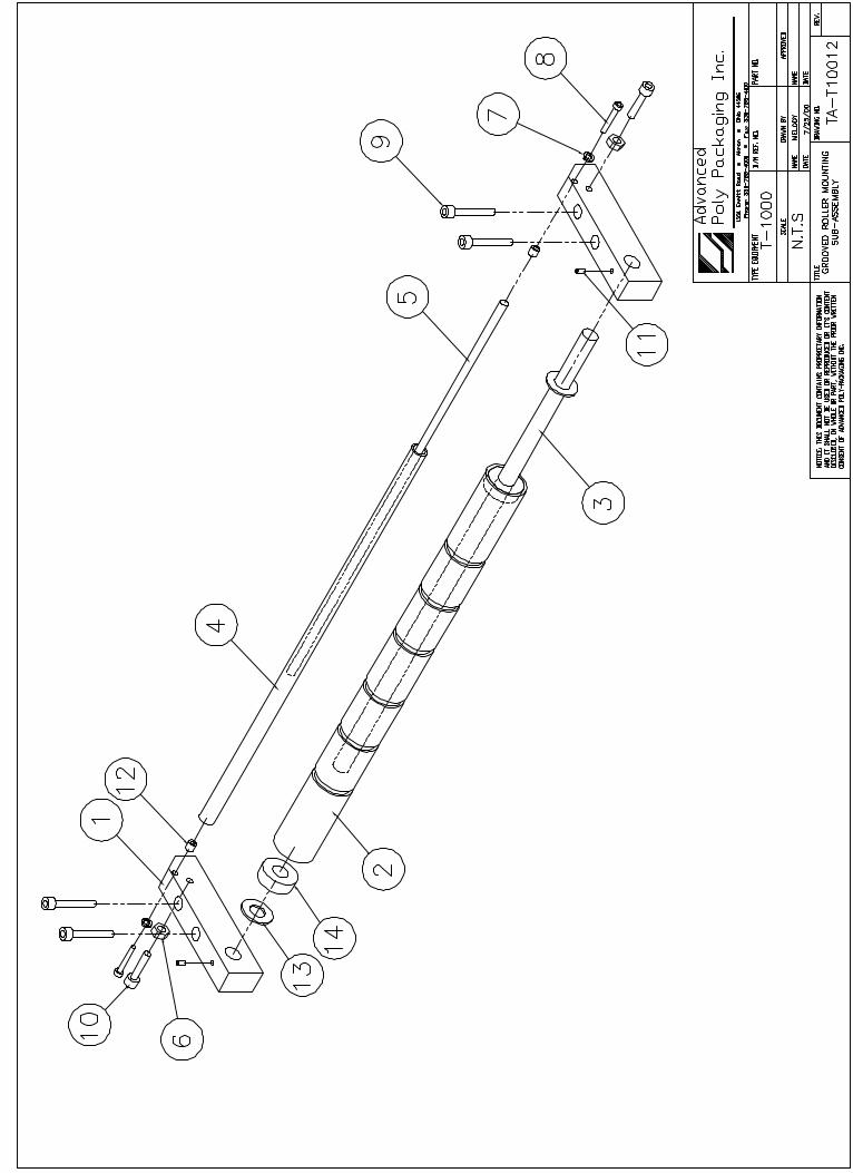
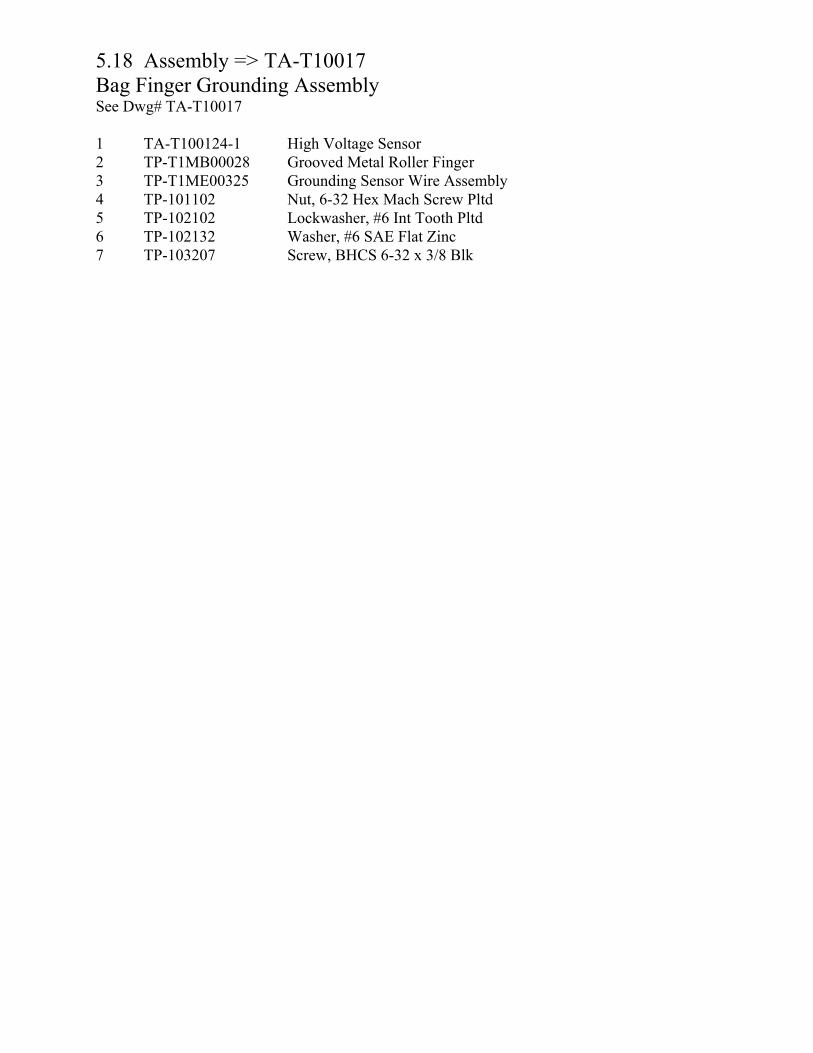
5.18 Assembly => TA-T10017Bag Finger Grounding Assembly See Dwg# TA-T10017
1 TA-T100124-1 High Voltage Sensor2 TP-T1MB00028 Grooved Metal Roller Finger3 TP-T1ME00325 Grounding Sensor Wire Assembly4 TP-101102 Nut, 6-32 Hex Mach Screw Pltd 5 TP-102102 Lockwasher, #6 Int Tooth Pltd 6 TP-102132 Washer, #6 SAE Flat Zinc 7 TP-103207 Screw, BHCS 6-32 x 3/8 Blk
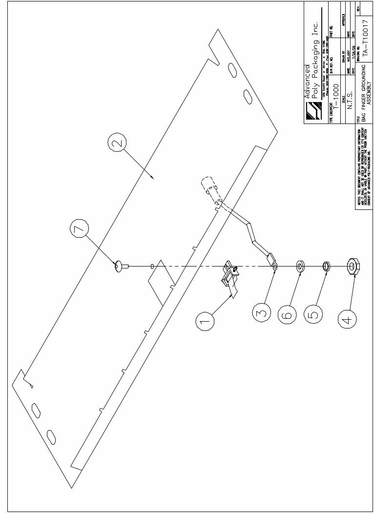

5.19 Assembly => TA-T10199Stand Assembly, T-1000 See Dwg# TA-T10199
1 TA-T10200 Base Assembly2 TA-T10210 Upper Column Assembly 3 TA-T10220 Dancer Assembly
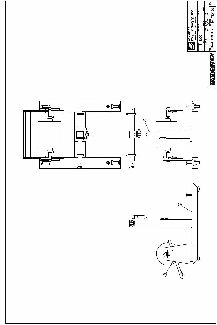
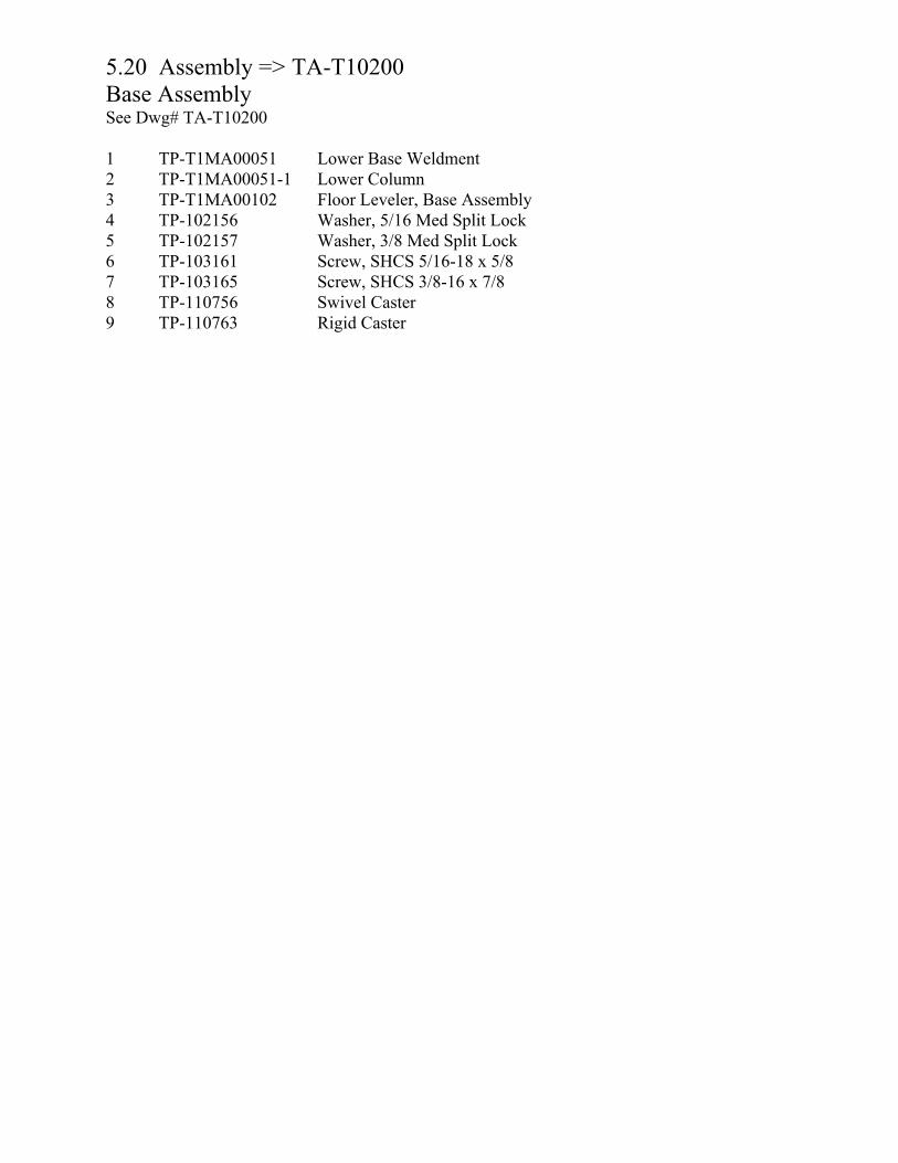
5.20 Assembly => TA-T10200Base Assembly See Dwg# TA-T10200
1 TP-T1MA00051 Lower Base Weldment2 TP-T1MA00051-1 Lower Column 3 TP-T1MA00102 Floor Leveler, Base Assembly 4 TP-102156 Washer, 5/16 Med Split Lock 5 TP-102157 Washer, 3/8 Med Split Lock 6 TP-103161 Screw, SHCS 5/16-18 x 5/8 7 TP-103165 Screw, SHCS 3/8-16 x 7/8 8 TP-110756 Swivel Caster 9 TP-110763 Rigid Caster
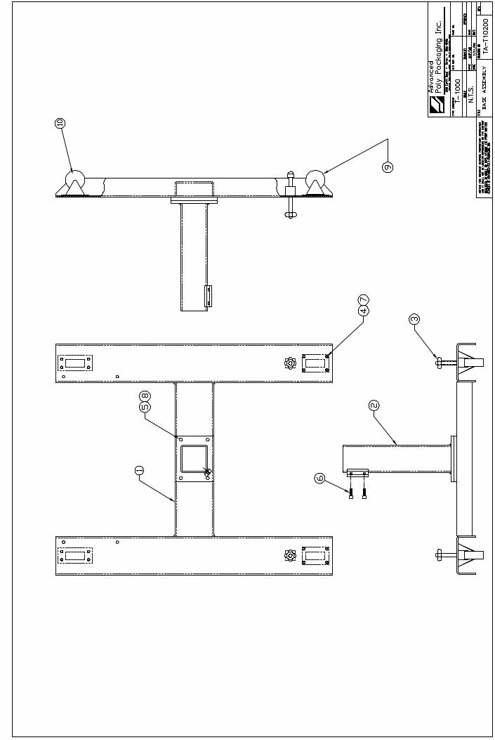

5.21 Assembly => TA-T10210Upper Column Assembly See Dwg# TA-T10210
1 TP-T1MA00087 Cross Pipe Weldment2 TP-T1MC00019-1 Base Clamp Block (Left) 3 TP-T1MC00019-2 Base Clamp Block (right) 4 TP-102154 Washer, #10 Med Split Lock 5 TP-102156 Washer, 5/16 Med Split Lock 6 TP-103012 Screw, SHCS 5/16-18 x 2-1/27 TP-103129 Screw, SHCS 10-32 x 1/2 BLK8 TP-103137 Screw, SHCS 1/4-20 x 1/29 TP-401222 Nipple, 1/4 NPT Quick Conn 10 TP-401224 Nipple, 1/4" Hex Nipple11 TP-401267 Double Universal Elbow 1/412 TP-406005 Air Dryer, AD-10 13 TP-406246 Regulator / Filter / Bracket
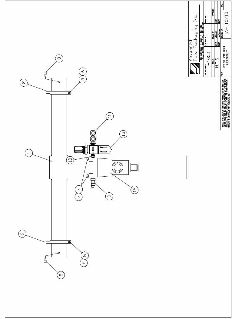

5.22 Assembly => TA-T10220Dancer Assembly See Dwg# TA-T10220
1 TA-T10010 Film Tension Hub Sub-Assembly2 TA-T10011 Dancer Guide Sub-Assembly3 TP-T1MA00069-1 Dancer Side Frame Plate (Left)4 TP-T1MA00069-2 Dancer Side Frame Plate (Right)5 TP-T1MA00073 Shaft, Bag Roll (T-1000) 6 TP-T1MA00115 Brake Tension Strap (Dance)7 TP-101141 Locknut, Hex Nylon Insert 8 TP-102143 Washer, SAE Flat Zinc 5/16 9 TP-102156 Washer, 5/16 Med Split Lock10 TP-103144 Screw, SHCS 5/16-18 x 3/411 TP-103237 Screw, BHCS 5/16-18 x 1 12 TP-103307 Screw, Sock Shldr 1/4x1-1/213 TP-504132 Cam Follower
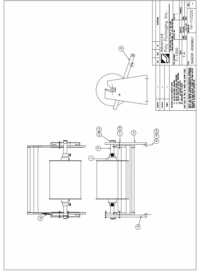

5.23 Assembly => TA-T10011Dancer Guide Sub-Assembly See Dwg# TA-T10011
1 TP-T1MA00072 Dancer Tension Bar2 TP-T1MA00081 Dancer Tension Bar Cross B3 TP-T1MA00089 Dancer Roller 1.101.A21.004 TP-T1MA00090 Dancer Guide Roller Shaft 5 TP-T1MA00186 Tension Adjuster & Spacer6 TP-101144 Nut, Hex Mach Screw 7 TP-102153 Washer, #8 Med Split Lock Z 8 TP-102154 Washer, #10 Med Split Lock9 TP-102155 Washer, 1/4 Med Split Lock10 TP-103116 Screw, SHCS 8-32 x 1/2 11 TP-103170 Screw, SHCS 10-32 x 5/812 TP-109212 Knob, Torque 1/4-20 x 113 TP-504101 Roller Bearing, Nylon Intel
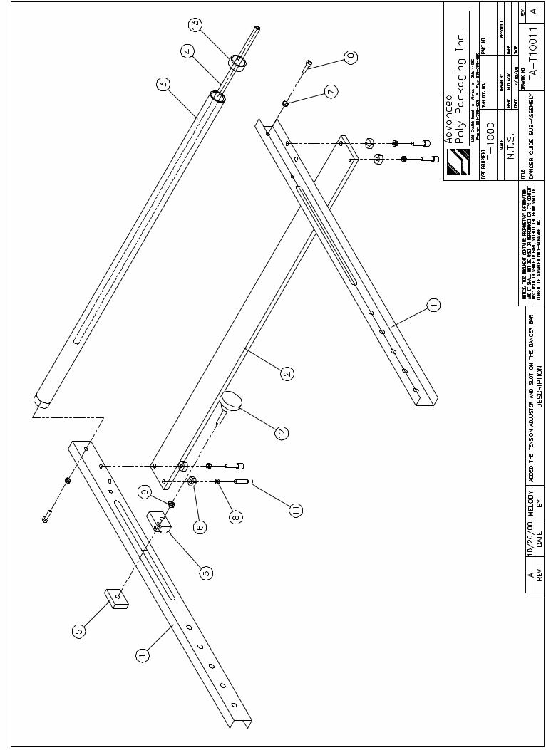
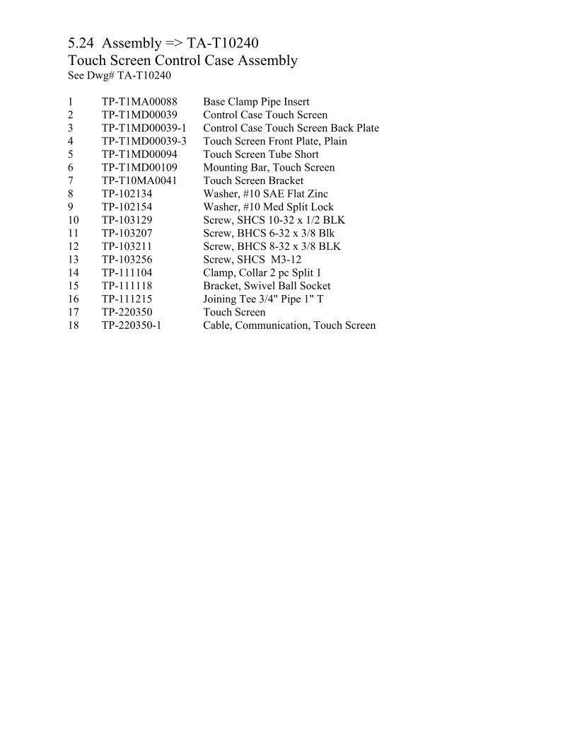
5.24 Assembly => TA-T10240Touch Screen Control Case Assembly See Dwg# TA-T10240
1 TP-T1MA00088 Base Clamp Pipe Insert 2 TP-T1MD00039 Control Case Touch Screen 3 TP-T1MD00039-1 Control Case Touch Screen Back Plate 4 TP-T1MD00039-3 Touch Screen Front Plate, Plain5 TP-T1MD00094 Touch Screen Tube Short 6 TP-T1MD00109 Mounting Bar, Touch Screen7 TP-T10MA0041 Touch Screen Bracket 8 TP-102134 Washer, #10 SAE Flat Zinc9 TP-102154 Washer, #10 Med Split Lock10 TP-103129 Screw, SHCS 10-32 x 1/2 BLK11 TP-103207 Screw, BHCS 6-32 x 3/8 Blk12 TP-103211 Screw, BHCS 8-32 x 3/8 BLK13 TP-103256 Screw, SHCS M3-12 14 TP-111104 Clamp, Collar 2 pc Split 115 TP-111118 Bracket, Swivel Ball Socket16 TP-111215 Joining Tee 3/4" Pipe 1" T 17 TP-220350 Touch Screen 18 TP-220350-1 Cable, Communication, Touch Screen
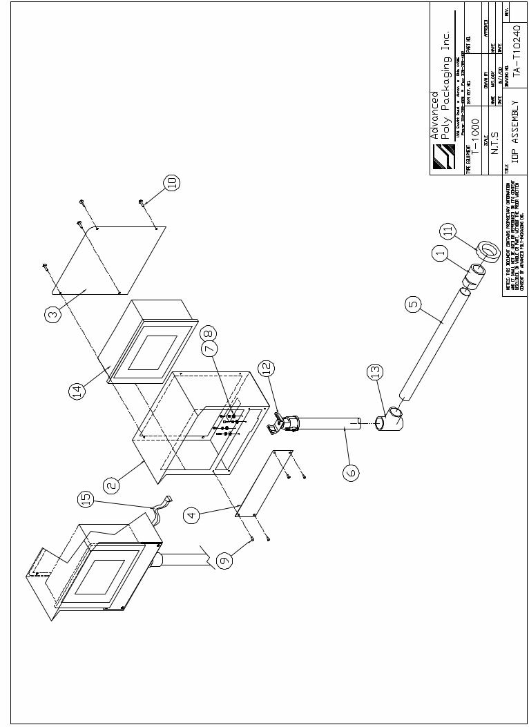

5.25 SP-10 Spare Parts Kit (Level 1) (P/N T-SP-10)
APPI Part Number Quantity Description
Belt, Clutch 1TP-503182
Belt, Brake 1TP-503102
Filters (Micron Blower) 2TP-406181
Poly Tubing, 3/8" Blue5'TP-404267
Poly Tubing, 1/4" Blue10'TP-404266
Anti-jam Seal Bar Rubber1TP-306002
Teflon Sheets 2TP-300500
Cartridge Heater 1TP-217116
Thermo Coupler Wire 2TP-221416
Fuse (10 Amp)3TP-207228
Fuse, (5 Amp)3TP-207227
Fuse, (3.15 Amp)6TP-207226
Fuse, Fast Act (1 Amp)3TP-207225
Fuse, (2.5 Amp)3TP-207206
Spring Closure Collars (Web Guides)4TP-111010
Compression Spring, Pressure Bar2TP-108155
High Voltage Sensor1TP-T1MC00124-1
Brake Tension Strap1TP-T1MA00115
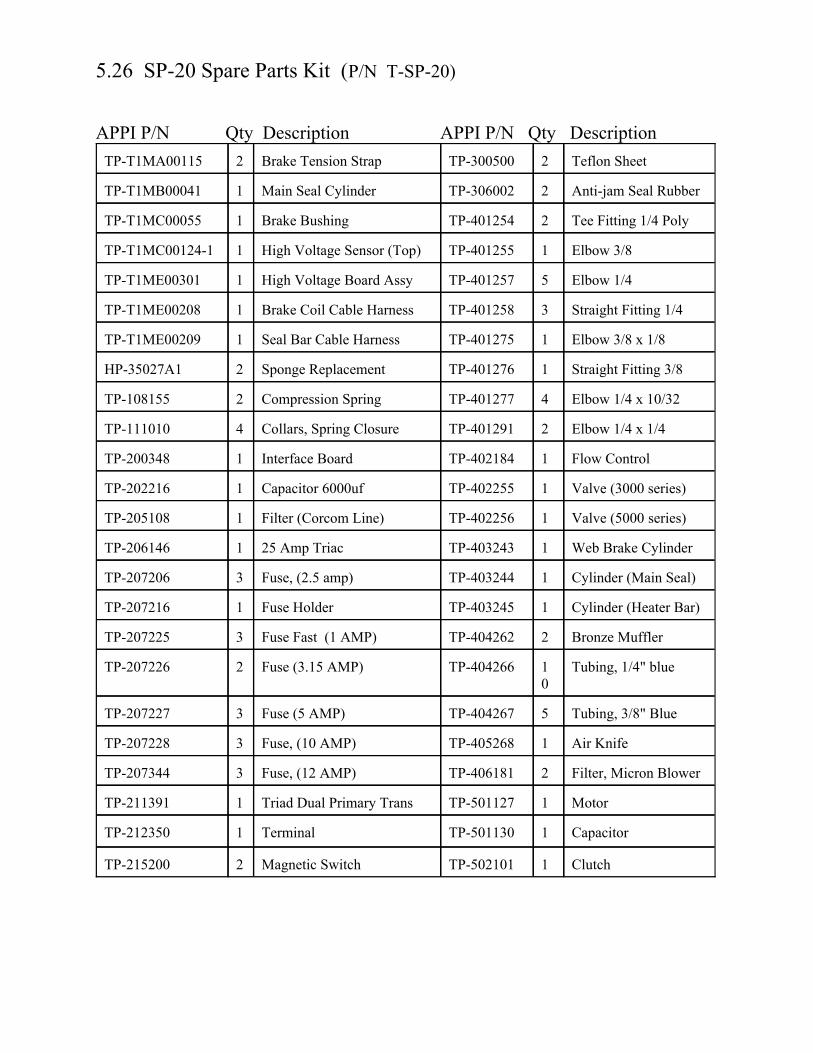
5.26 SP-20 Spare Parts Kit (P/N T-SP-20)
APPI P/N Qty Description APPI P/N Qty Description
Clutch1TP-502101Magnetic Switch 2TP-215200
Capacitor1TP-501130Terminal1TP-212350
Motor1TP-501127Triad Dual Primary Trans1TP-211391
Filter, Micron Blower2TP-406181Fuse, (12 AMP)3TP-207344
Air Knife1TP-405268Fuse, (10 AMP)3TP-207228
Tubing, 3/8" Blue5TP-404267Fuse (5 AMP)3TP-207227
Tubing, 1/4" blue10
TP-404266Fuse (3.15 AMP)2TP-207226
Bronze Muffler2TP-404262Fuse Fast (1 AMP)3TP-207225
Cylinder (Heater Bar)1TP-403245Fuse Holder1TP-207216
Cylinder (Main Seal)1TP-403244Fuse, (2.5 amp)3TP-207206
Web Brake Cylinder 1TP-40324325 Amp Triac1TP-206146
Valve (5000 series)1TP-402256Filter (Corcom Line)1TP-205108
Valve (3000 series)1TP-402255Capacitor 6000uf1TP-202216
Flow Control1TP-402184Interface Board1TP-200348
Elbow 1/4 x 1/42TP-401291Collars, Spring Closure4TP-111010
Elbow 1/4 x 10/324TP-401277Compression Spring2TP-108155
Straight Fitting 3/81TP-401276Sponge Replacement2HP-35027A1
Elbow 3/8 x 1/81TP-401275Seal Bar Cable Harness1TP-T1ME00209
Straight Fitting 1/43TP-401258Brake Coil Cable Harness1TP-T1ME00208
Elbow 1/45TP-401257High Voltage Board Assy1TP-T1ME00301
Elbow 3/8 1TP-401255High Voltage Sensor (Top)1TP-T1MC00124-1
Tee Fitting 1/4 Poly2TP-401254Brake Bushing1TP-T1MC00055
Anti-jam Seal Rubber2TP-306002Main Seal Cylinder1TP-T1MB00041
Teflon Sheet2TP-300500Brake Tension Strap 2TP-T1MA00115

APPI P/N Qty Description APPI P/N Qty Description
Clutch/Brake Bearing2TP-504114Cam Follower (CYR 1S)2TP-504132
Roller Bearings2TP-504113Thermocouple Wire2TP-221416
Bearing2TP-503108Touch Screen1TP-220368
Belt, Brake2TP-503182PLC Controller1TP-220367
Clutch/Brake Bearing2TP-503102Cartridge Heater1TP-217116

Chapter 6, Preventive Maintenance &Scheduled Maintenance______________________________________________________________________________
PM ChecklistSchedule Maintenance (CHART)
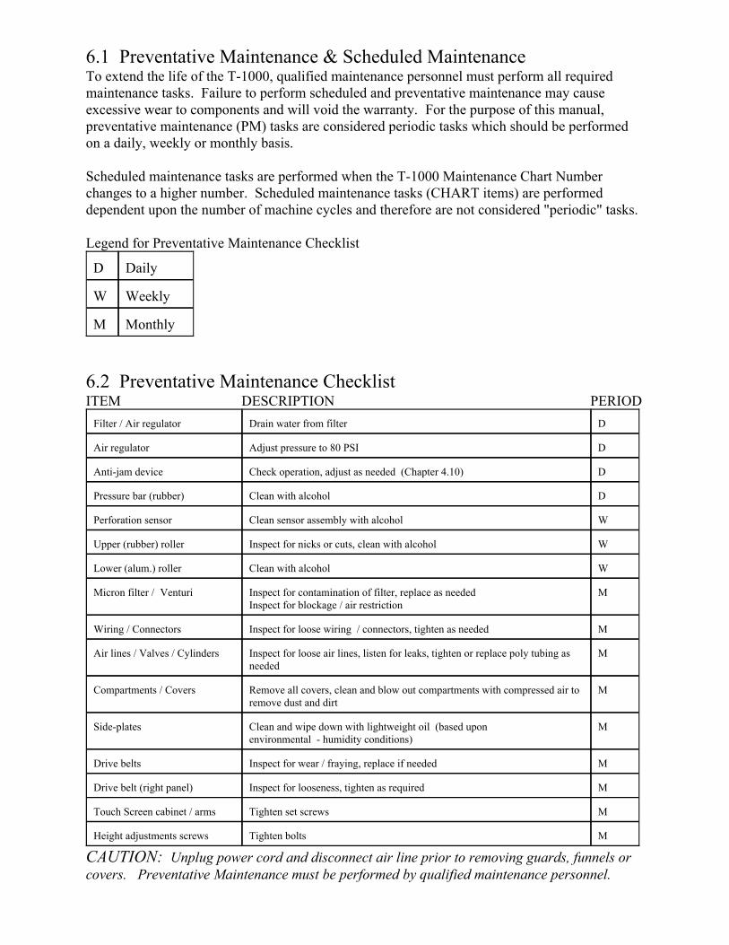
6.1 Preventative Maintenance & Scheduled MaintenanceTo extend the life of the T-1000, qualified maintenance personnel must perform all requiredmaintenance tasks. Failure to perform scheduled and preventative maintenance may causeexcessive wear to components and will void the warranty. For the purpose of this manual,preventative maintenance (PM) tasks are considered periodic tasks which should be performedon a daily, weekly or monthly basis.
Scheduled maintenance tasks are performed when the T-1000 Maintenance Chart Numberchanges to a higher number. Scheduled maintenance tasks (CHART items) are performeddependent upon the number of machine cycles and therefore are not considered "periodic" tasks.
Legend for Preventative Maintenance Checklist
MonthlyM
WeeklyW
DailyD
6.2 Preventative Maintenance ChecklistITEM DESCRIPTION PERIOD
MTighten boltsHeight adjustments screws
MTighten set screwsTouch Screen cabinet / arms
MInspect for looseness, tighten as requiredDrive belt (right panel)
MInspect for wear / fraying, replace if neededDrive belts
MClean and wipe down with lightweight oil (based uponenvironmental - humidity conditions)
Side-plates
MRemove all covers, clean and blow out compartments with compressed air toremove dust and dirt
Compartments / Covers
MInspect for loose air lines, listen for leaks, tighten or replace poly tubing asneeded
Air lines / Valves / Cylinders
MInspect for loose wiring / connectors, tighten as neededWiring / Connectors
MInspect for contamination of filter, replace as neededInspect for blockage / air restriction
Micron filter / Venturi
WClean with alcoholLower (alum.) roller
WInspect for nicks or cuts, clean with alcoholUpper (rubber) roller
WClean sensor assembly with alcoholPerforation sensor
DClean with alcoholPressure bar (rubber)
DCheck operation, adjust as needed (Chapter 4.10)Anti-jam device
DAdjust pressure to 80 PSIAir regulator
DDrain water from filterFilter / Air regulator
CAUTION: Unplug power cord and disconnect air line prior to removing guards, funnels orcovers. Preventative Maintenance must be performed by qualified maintenance personnel.
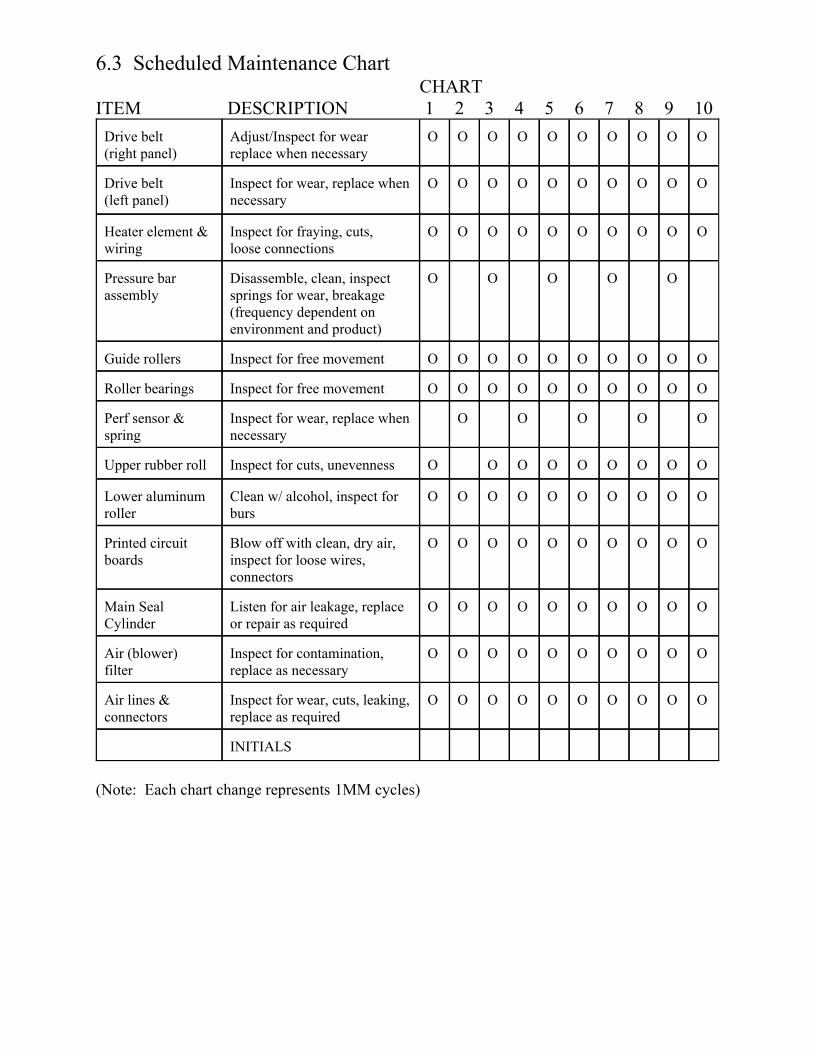
6.3 Scheduled Maintenance Chart CHART
ITEM DESCRIPTION 1 2 3 4 5 6 7 8 9 10
INITIALS
OOOOOOOOOOInspect for wear, cuts, leaking,replace as required
Air lines &connectors
OOOOOOOOOOInspect for contamination,replace as necessary
Air (blower) filter
OOOOOOOOOOListen for air leakage, replaceor repair as required
Main SealCylinder
OOOOOOOOOOBlow off with clean, dry air,inspect for loose wires,connectors
Printed circuitboards
OOOOOOOOOOClean w/ alcohol, inspect forburs
Lower aluminumroller
OOOOOOOOOInspect for cuts, unevennessUpper rubber roll
OOOO OInspect for wear, replace whennecessary
Perf sensor &spring
OOOOOOOOOOInspect for free movementRoller bearings
OOOOOOOOOOInspect for free movementGuide rollers
OO OO ODisassemble, clean, inspectsprings for wear, breakage (frequency dependent onenvironment and product)
Pressure barassembly
OOOOOOOOOOInspect for fraying, cuts,loose connections
Heater element &wiring
OOOOOOOOOOInspect for wear, replace whennecessary
Drive belt(left panel)
OOOOOOOOOOAdjust/Inspect for wearreplace when necessary
Drive belt(right panel)
(Note: Each chart change represents 1MM cycles)

6.3 Preventative Maintenance (PM) Chart, Continued...(Options / Auxiliary Equipment)
CHARTITEM DESCRIPTION 1 2 3 4 5 6 7 8 9 10
Inspected by: (Initials)
(Note: Each chart change represents 1MM cycles)

Chapter 7______________________________________________________________________________
Trouble Shooting
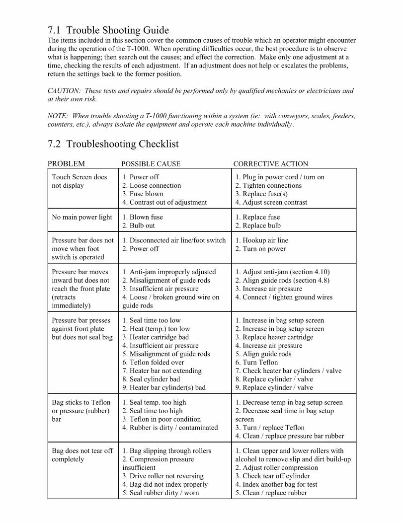
7.1 Trouble Shooting GuideThe items included in this section cover the common causes of trouble which an operator might encounterduring the operation of the T-1000. When operating difficulties occur, the best procedure is to observewhat is happening; then search out the causes; and effect the correction. Make only one adjustment at atime, checking the results of each adjustment. If an adjustment does not help or escalates the problems,return the settings back to the former position.
CAUTION: These tests and repairs should be performed only by qualified mechanics or electricians andat their own risk.
NOTE: When trouble shooting a T-1000 functioning within a system (ie: with conveyors, scales, feeders,counters, etc.), always isolate the equipment and operate each machine individually.
7.2 Troubleshooting Checklist
PROBLEM POSSIBLE CAUSE CORRECTIVE ACTION
1. Clean upper and lower rollers withalcohol to remove slip and dirt build-up2. Adjust roller compression3. Check tear off cylinder4. Index another bag for test5. Clean / replace rubber
1. Bag slipping through rollers2. Compression pressureinsufficient3. Drive roller not reversing 4. Bag did not index properly5. Seal rubber dirty / worn
Bag does not tear offcompletely
1. Decrease temp in bag setup screen2. Decrease seal time in bag setupscreen3. Turn / replace Teflon4. Clean / replace pressure bar rubber
1. Seal temp. too high2. Seal time too high3. Teflon in poor condition4. Rubber is dirty / contaminated
Bag sticks to Teflonor pressure (rubber)bar
1. Increase in bag setup screen2. Increase in bag setup screen3. Replace heater cartridge4. Increase air pressure5. Align guide rods6. Turn Teflon7. Check heater bar cylinders / valve8. Replace cylinder / valve9. Replace cylinder / valve
1. Seal time too low2. Heat (temp.) too low3. Heater cartridge bad4. Insufficient air pressure5. Misalignment of guide rods6. Teflon folded over7. Heater bar not extending8. Seal cylinder bad9. Heater bar cylinder(s) bad
Pressure bar pressesagainst front platebut does not seal bag
1. Adjust anti-jam (section 4.10)2. Align guide rods (section 4.8)3. Increase air pressure4. Connect / tighten ground wires
1. Anti-jam improperly adjusted2. Misalignment of guide rods3. Insufficient air pressure4. Loose / broken ground wire on guide rods
Pressure bar movesinward but does notreach the front plate(retractsimmediately)
1. Hookup air line2. Turn on power
1. Disconnected air line/foot switch2. Power off
Pressure bar does notmove when footswitch is operated
1. Replace fuse2. Replace bulb
1. Blown fuse2. Bulb out
No main power light
1. Plug in power cord / turn on2. Tighten connections3. Replace fuse(s)4. Adjust screen contrast
1. Power off2. Loose connection3. Fuse blown4. Contrast out of adjustment
Touch Screen doesnot display
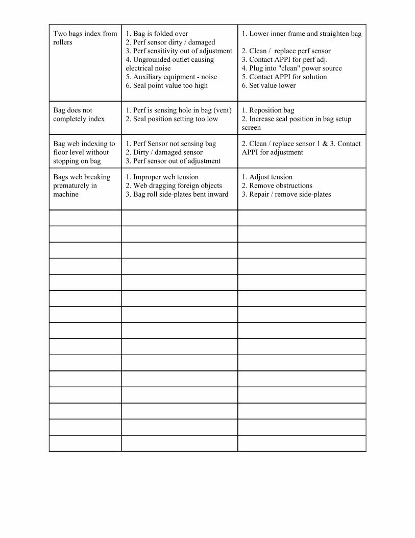
1. Adjust tension 2. Remove obstructions 3. Repair / remove side-plates
1. Improper web tension 2. Web dragging foreign objects 3. Bag roll side-plates bent inward
Bags web breakingprematurely inmachine
2. Clean / replace sensor 1 & 3. ContactAPPI for adjustment
1. Perf Sensor not sensing bag 2. Dirty / damaged sensor 3. Perf sensor out of adjustment
Bag web indexing tofloor level withoutstopping on bag
1. Reposition bag 2. Increase seal position in bag setupscreen
1. Perf is sensing hole in bag (vent)2. Seal position setting too low
Bag does notcompletely index
1. Lower inner frame and straighten bag
2. Clean / replace perf sensor3. Contact APPI for perf adj.4. Plug into "clean" power source5. Contact APPI for solution 6. Set value lower
1. Bag is folded over2. Perf sensor dirty / damaged3. Perf sensitivity out of adjustment4. Ungrounded outlet causing electrical noise5. Auxiliary equipment - noise6. Seal point value too high
Two bags index fromrollers
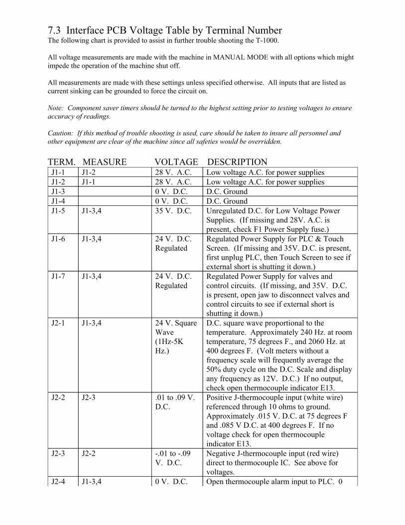
7.3 Interface PCB Voltage Table by Terminal NumberThe following chart is provided to assist in further trouble shooting the T-1000.
All voltage measurements are made with the machine in MANUAL MODE with all options which mightimpede the operation of the machine shut off.
All measurements are made with these settings unless specified otherwise. All inputs that are listed ascurrent sinking can be grounded to force the circuit on.
Note: Component saver timers should be turned to the highest setting prior to testing voltages to ensureaccuracy of readings.
Caution: If this method of trouble shooting is used, care should be taken to insure all personnel andother equipment are clear of the machine since all safeties would be overridden.
TERM. MEASURE VOLTAGE DESCRIPTION
Open thermocouple alarm input to PLC. 00 V. D.C.J1-3,4J2-4
Negative J-thermocouple input (red wire)direct to thermocouple IC. See above forvoltages.
-.01 to -.09V. D.C.
J2-2J2-3
Positive J-thermocouple input (white wire)referenced through 10 ohms to ground.Approximately .015 V. D.C. at 75 degrees Fand .085 V D.C. at 400 degrees F. If novoltage check for open thermocoupleindicator E13.
.01 to .09 V.D.C.
J2-3J2-2
D.C. square wave proportional to thetemperature. Approximately 240 Hz. at roomtemperature, 75 degrees F., and 2060 Hz. at400 degrees F. (Volt meters without afrequency scale will frequently average the50% duty cycle on the D.C. Scale and displayany frequency as 12V. D.C.) If no output,check open thermocouple indicator E13.
24 V. SquareWave(1Hz-5KHz.)
J1-3,4J2-1
Regulated Power Supply for valves andcontrol circuits. (If missing, and 35V. D.C.is present, open jaw to disconnect valves andcontrol circuits to see if external short isshutting it down.)
24 V. D.C.Regulated
J1-3,4J1-7
Regulated Power Supply for PLC & TouchScreen. (If missing and 35V. D.C. is present,first unplug PLC, then Touch Screen to see ifexternal short is shutting it down.)
24 V. D.C.Regulated
J1-3,4J1-6
Unregulated D.C. for Low Voltage PowerSupplies. (If missing and 28V. A.C. ispresent, check F1 Power Supply fuse.)
35 V. D.C.J1-3,4J1-5D.C. Ground0 V. D.C.J1-4D.C. Ground0 V. D.C.J1-3Low voltage A.C. for power supplies28 V. A.C.J1-1J1-2Low voltage A.C. for power supplies28 V. A.C.J1-2J1-1
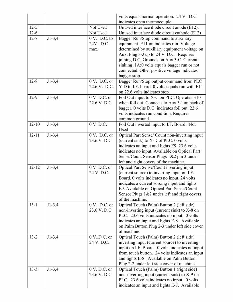
Optical Touch (Palm) Button 1 (right side)non-inverting input (current sink) to X-9 onPLC. 23.6 volts indicates no input. 0 voltsindicates an input and lights E-7. Available
0 V. D.C. or23.6 V. D.C.
J1-3,4J3-3
Optical Touch (Palm) Button 2 (left side)inverting input (current source) to invertinginput on I.F. Board. 0 volts indicates no inputfrom touch button. 24 volts indicates an inputand lights E-8. Available on Palm ButtonPlug 2-2 under left side cover of machine.
0 V..D.C. or24 V. D.C.
J1-3,4J3-2
Optical Touch (Palm) Button 2 (left side)non-inverting input (current sink) to X-8 onPLC. 23.6 volts indicates no input. 0 voltsindicates an input and lights E-8. Availableon Palm Button Plug 2-3 under left side coverof machine.
0 V. D.C. or23.6 V. D.C.
J1-3,4J3-1
Optical Part Sense/Count inverting input(current source) to inverting input on I.F.Board. 0 volts indicates no input. 24 voltsindicates a current sorcing input and lightsE9. Available on Optical Part Sense/CountSensor Plugs 1&2 under left and right coversof the machine.
0 V D.C. or24 V D.C.
J1-3,4J2-12
Optical Part Sense/ Count non-inverting input(current sink) to X-D of PLC. 0 voltsindicates an input and lights E9. 23.6 voltsindicates no input. Available on Optical PartSense/Count Sensor Plugs 1&2 pin 3 underleft and right covers of the machine.
0 V. D.C. or23.6 V D.C.
J1-3,4J2-11
Foil Out inverted input to I.F. Board. NotUsed
0 V D.C.J1-3,4J2-10
Foil Out input to X-C on PLC. Operates E10when foil out. Connects to Aux.3-I on back ofbagger. 0 volts D.C. indicates foil out. 22.6volts indicates run condition. Requirescommon ground.
0 V D.C. or22.6 V D.C.
J1-3,4J2-9
Bagger Run/Stop output command from PLCY-D to I.F. board. 0 volts equals run with E11on 22.6 volts indicates stop.
0 V. D.C. or22.6 V. D.C.
J1-3,4J2-8
Bagger Run/Stop command to auxiliaryequipment. E11 on indicates run. Voltagedetermined by auxiliary equipment voltage onAux. Plug 3-J up to 24 V D.C.. Requiresjoining D.C. Grounds on Aux.3-C. Currentsinking .1A;0 volts equals bagger run or notconnected. Other positive voltage indicatesbagger stop.
0 V. D.C. to24V. D.C.max.
J1-3,4J2-7Unused interface diode circuit cathode (E12)Not UsedJ2-6Unused interface diode circuit anode (E12).Not UsedJ2-5
volts equals normal operation. 24 V. D.C.indicates open thermocouple.
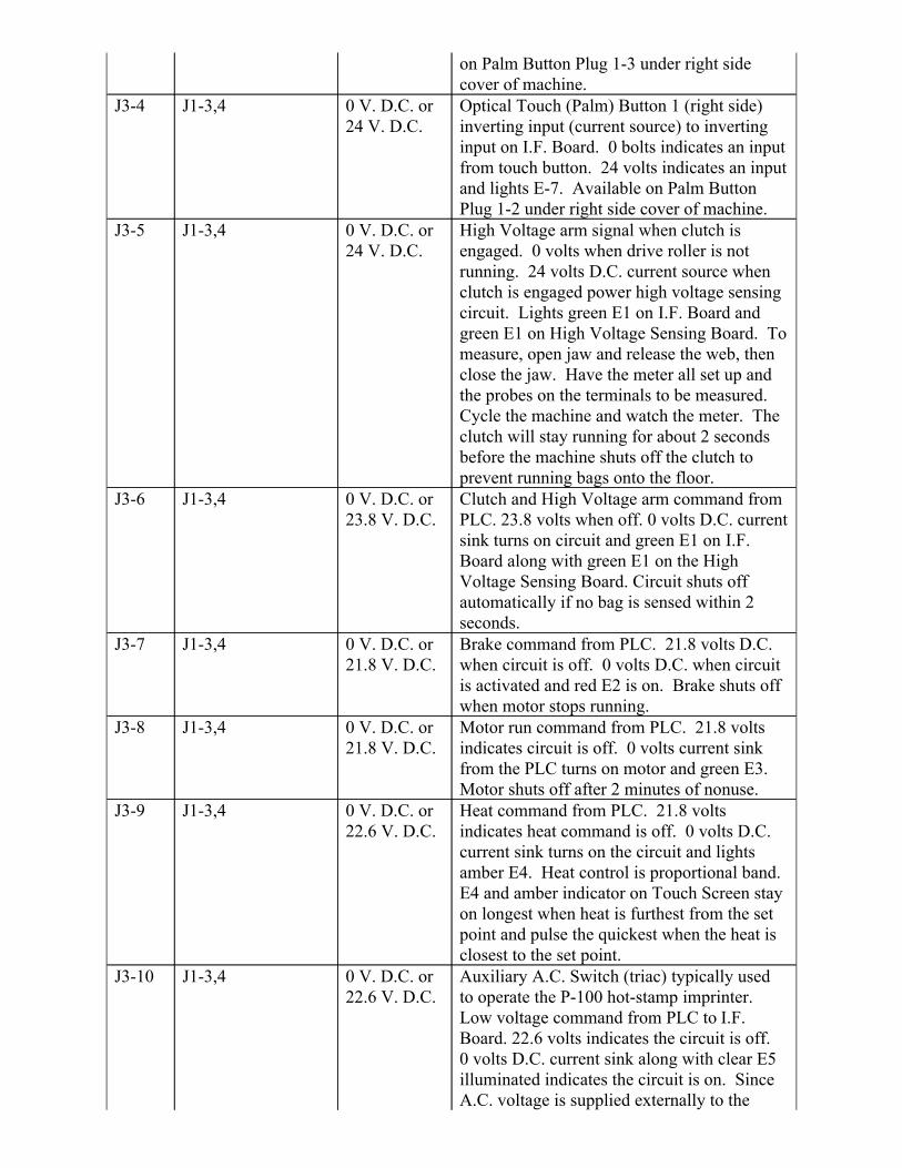
Auxiliary A.C. Switch (triac) typically usedto operate the P-100 hot-stamp imprinter.Low voltage command from PLC to I.F.Board. 22.6 volts indicates the circuit is off.0 volts D.C. current sink along with clear E5illuminated indicates the circuit is on. SinceA.C. voltage is supplied externally to the
0 V. D.C. or22.6 V. D.C.
J1-3,4J3-10
Heat command from PLC. 21.8 voltsindicates heat command is off. 0 volts D.C.current sink turns on the circuit and lightsamber E4. Heat control is proportional band.E4 and amber indicator on Touch Screen stayon longest when heat is furthest from the setpoint and pulse the quickest when the heat isclosest to the set point.
0 V. D.C. or22.6 V. D.C.
J1-3,4J3-9
Motor run command from PLC. 21.8 voltsindicates circuit is off. 0 volts current sinkfrom the PLC turns on motor and green E3.Motor shuts off after 2 minutes of nonuse.
0 V. D.C. or21.8 V. D.C.
J1-3,4J3-8
Brake command from PLC. 21.8 volts D.C.when circuit is off. 0 volts D.C. when circuitis activated and red E2 is on. Brake shuts offwhen motor stops running.
0 V. D.C. or21.8 V. D.C.
J1-3,4J3-7
Clutch and High Voltage arm command fromPLC. 23.8 volts when off. 0 volts D.C. currentsink turns on circuit and green E1 on I.F.Board along with green E1 on the HighVoltage Sensing Board. Circuit shuts offautomatically if no bag is sensed within 2seconds.
0 V. D.C. or23.8 V. D.C.
J1-3,4J3-6
High Voltage arm signal when clutch isengaged. 0 volts when drive roller is notrunning. 24 volts D.C. current source whenclutch is engaged power high voltage sensingcircuit. Lights green E1 on I.F. Board andgreen E1 on High Voltage Sensing Board. Tomeasure, open jaw and release the web, thenclose the jaw. Have the meter all set up andthe probes on the terminals to be measured.Cycle the machine and watch the meter. Theclutch will stay running for about 2 secondsbefore the machine shuts off the clutch toprevent running bags onto the floor.
0 V. D.C. or24 V. D.C.
J1-3,4J3-5
Optical Touch (Palm) Button 1 (right side)inverting input (current source) to invertinginput on I.F. Board. 0 bolts indicates an inputfrom touch button. 24 volts indicates an inputand lights E-7. Available on Palm ButtonPlug 1-2 under right side cover of machine.
0 V. D.C. or24 V. D.C.
J1-3,4J3-4
on Palm Button Plug 1-3 under right sidecover of machine.
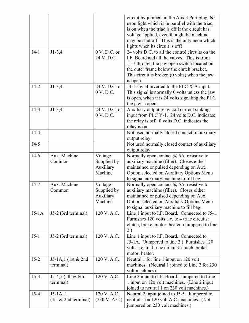
Neutral 2 input joined to J5-5. Jumpered toneutral 1 on 120 volt A.C. machines. (Notjumpered on 230 volt machines.)
120 V. A.C.(230 V. A.C.)
J5-1A, 1 (1st & 2nd terminal)
J5-4
Line 2 input to I.F. Board. Jumpered to Line1 input on 120 volt machines. (Line 2 inputjoined to neutral 1 on 230 volt machines.)
120 V. A.C.J5-4,5 (5th & 6thterminal)
J5-3
Neutral 1 for line 1 input on 120 voltmachines. (Neutral 1 joined to Line 2 for 230volt machines).
120 V. A.C.J5-1A,1 (1st & 2ndterminal)
J5-2
Line 1 input to I.F. Board. Connected toJ5-1A. (Jumpered to line 2.) Furnishes 120volts a.c. to 4 triac circuits: clutch, brake,motor, heater.
120 V. A.C.J5-2 (3rd terminal)J5-1
Line 1 input to I.F. Board. Connected to J5-1.Furnishes 120 volts a.c. to 4 triac circuits:clutch, brake, motor, heater. (Jumpered to line2.)
120 V. A.C.J5-2 (3rd terminal)J5-1A
Normally open contact @ 5A. resistive toauxiliary machine (filler). Closes eithermaintained or pulsed depending on Aux.Option selected on Auxiliary Options Menuto signal auxiliary machine to fill bag.
VoltageSupplied byAuxiliaryMachine
Aux. MachineCommon
J4-7
Normally open contact @ 5A. resistive toauxiliary machine (filler). Closes eithermaintained or pulsed depending on Aux.Option selected on Auxiliary Options Menuto signal auxiliary machine to fill bag.
VoltageSupplied byAuxiliaryMachine
Aux. MachineCommon
J4-6
Not used normally closed contact of auxiliaryoutput relay.
J4-5
Not used normally closed contact of auxiliaryoutput relay.
J4-4
Auxiliary output relay coil current sinkinginput from PLC Y-1. 24 volts D.C. indicatesthe relay is off. 0 volts D.C. indicates therelay is on.
24 V. D.C. or0 V. D.C.
J1-3,4J4-3
J4-1 signal inverted to the PLC X-A input.This signal is normally 0 volts unless the jawis open, when it is 24 volts signaling the PLCthe jaw is open.
24 V. D.C. or0 V. D.C.
J1-3,4J4-2
24 volts D.C. to all the control circuits on theI.F. Board and all the valves. This is fromJ1-7 through the jaw open switch located onthe outer frame below the clutch bracket.This circuit is broken (0 volts) when the jawis open.
0 V. D.C. or24 V. D.C.
J1-3,4J4-1
circuit by jumpers in the Aux.3 Port plug, N5neon light which is in parallel with the triac,is on when the triac is off if the circuit hasvoltage applied, even though the machinemay be shut off. This is the only neon whichlights when its circuit is off!
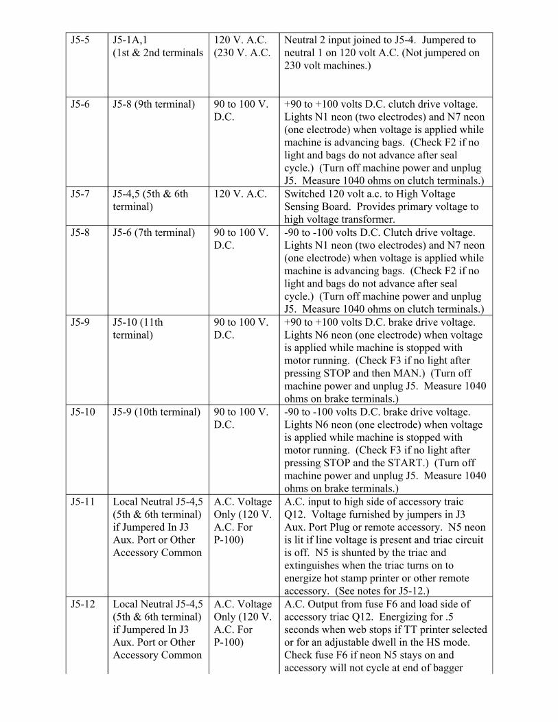
A.C. Output from fuse F6 and load side ofaccessory triac Q12. Energizing for .5seconds when web stops if TT printer selectedor for an adjustable dwell in the HS mode.Check fuse F6 if neon N5 stays on andaccessory will not cycle at end of bagger
A.C. VoltageOnly (120 V.A.C. ForP-100)
Local Neutral J5-4,5(5th & 6th terminal)if Jumpered In J3Aux. Port or OtherAccessory Common
J5-12
A.C. input to high side of accessory traicQ12. Voltage furnished by jumpers in J3Aux. Port Plug or remote accessory. N5 neonis lit if line voltage is present and triac circuitis off. N5 is shunted by the triac andextinguishes when the triac turns on toenergize hot stamp printer or other remoteaccessory. (See notes for J5-12.)
A.C. VoltageOnly (120 V.A.C. ForP-100)
Local Neutral J5-4,5(5th & 6th terminal)if Jumpered In J3Aux. Port or OtherAccessory Common
J5-11
-90 to -100 volts D.C. brake drive voltage.Lights N6 neon (one electrode) when voltageis applied while machine is stopped withmotor running. (Check F3 if no light afterpressing STOP and the START.) (Turn offmachine power and unplug J5. Measure 1040ohms on brake terminals.)
90 to 100 V.D.C.
J5-9 (10th terminal)J5-10
+90 to +100 volts D.C. brake drive voltage.Lights N6 neon (one electrode) when voltageis applied while machine is stopped withmotor running. (Check F3 if no light afterpressing STOP and then MAN.) (Turn offmachine power and unplug J5. Measure 1040ohms on brake terminals.)
90 to 100 V.D.C.
J5-10 (11thterminal)
J5-9
-90 to -100 volts D.C. Clutch drive voltage.Lights N1 neon (two electrodes) and N7 neon(one electrode) when voltage is applied whilemachine is advancing bags. (Check F2 if nolight and bags do not advance after sealcycle.) (Turn off machine power and unplugJ5. Measure 1040 ohms on clutch terminals.)
90 to 100 V.D.C.
J5-6 (7th terminal)J5-8
Switched 120 volt a.c. to High VoltageSensing Board. Provides primary voltage tohigh voltage transformer.
120 V. A.C.J5-4,5 (5th & 6thterminal)
J5-7
+90 to +100 volts D.C. clutch drive voltage.Lights N1 neon (two electrodes) and N7 neon(one electrode) when voltage is applied whilemachine is advancing bags. (Check F2 if nolight and bags do not advance after sealcycle.) (Turn off machine power and unplugJ5. Measure 1040 ohms on clutch terminals.)
90 to 100 V.D.C.
J5-8 (9th terminal)J5-6
Neutral 2 input joined to J5-4. Jumpered toneutral 1 on 120 volt A.C. (Not jumpered on230 volt machines.)
120 V. A.C.(230 V. A.C.
J5-1A,1(1st & 2nd terminals
J5-5
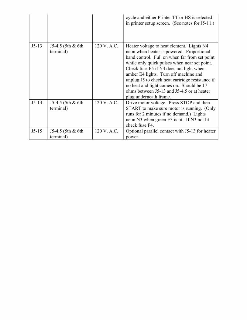
Optional parallel contact with J5-13 for heaterpower.
120 V. A.C.J5-4,5 (5th & 6thterminal)
J5-15
Drive motor voltage. Press STOP and thenSTART to make sure motor is running. (Onlyruns for 2 minutes if no demand.) Lightsneon N3 when green E3 is lit. If N3 not litcheck fuse F4.
120 V. A.C.J5-4,5 (5th & 6thterminal)
J5-14
Heater voltage to heat element. Lights N4neon when heater is powered. Proportionalband control. Full on when far from set pointwhile only quick pulses when near set point.Check fuse F5 if N4 does not light whenamber E4 lights. Turn off machine andunplug J5 to check heat cartridge resistance ifno heat and light comes on. Should be 17ohms between J5-13 and J5-4,5 or at heaterplug underneath frame.
120 V. A.C.J5-4,5 (5th & 6thterminal)
J5-13
cycle and either Printer TT or HS is selectedin printer setup screen. (See notes for J5-11.)
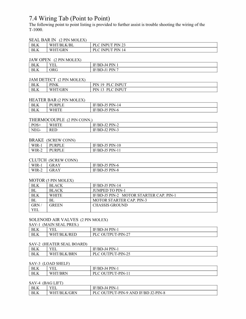
7.4 Wiring Tab (Point to Point) The following point to point listing is provided to further assist is trouble shooting the wiring of theT-1000.
SEAL BAR IN (2 PIN MOLEX)
PLC INPUT PIN 14WHT/GRNBLKPLC INPUT PIN 23WHT/BLK/BLBLK
JAW OPEN (2 PIN MOLEX)
IF/BD-J1 PIN 7ORGBLKIF/BD-J4 PIN 1YELBLK
JAM DETECT (2 PIN MOLEX)
PIN 13 PLC INPUTWHT/GRNBLKPIN 19 PLC INPUTPINKBLK
HEATER BAR (2 PIN MOLEX)
IF/BD-J5 PIN-6WHITEBLKIF/BD-J5 PIN-14PURPLEBLK
THERMOCOUPLE (2 PIN CONN.)
IF/BD-J2 PIN-3REDNEG-IF/BD-J2 PIN-2WHITEPOS+
BRAKE (SCREW CONN)
IF/BD-J5 PIN-11PURPLEWIR-2IF/BD-J5 PIN-10PURPLEWIR-1
CLUTCH (SCREW CONN)
IF/BD-J5 PIN-8GRAYWIR-2IF/BD-J5 PIN-6GRAYWIR-1
MOTOR (5 PIN MOLEX)
CHASSIS GROUNDGREENGRN /YEL
MOTOR STARTER CAP. PIN-3BLBLIF/BD-J5 PIN-2 MOTOR STARTER CAP. PIN-1WHITEBLKJUMPED TO PIN-1BLACKBLIF/BD-J5 PIN-14BLACKBLK
SOLENOID AIR VALVES (2 PIN MOLEX)SAV-1 (MAIN SEAL PRES.)
PLC OUTPUT-PIN-27WHT/BLK/REDBLKIF/BD-J4 PIN-1YELBLK
SAV-2 (HEATER SEAL BOARD)
PLC OUTPUT-PIN-25WHT/BLK/BRNBLKIF/BD-J4 PIN-1YELBLK
SAV-3 (LOAD SHELF)
PLC OUTPUT-PIN-11WHT/BRNBLKIF/BD-J4 PIN-1YELBLK
SAV-4 (BAG LIFT)
PLC OUTPUT-PIN-9 AND IF/BD J2-PIN-8WHT/BLK/GRNBLKIF/BD-J4 PIN-1YELBLK
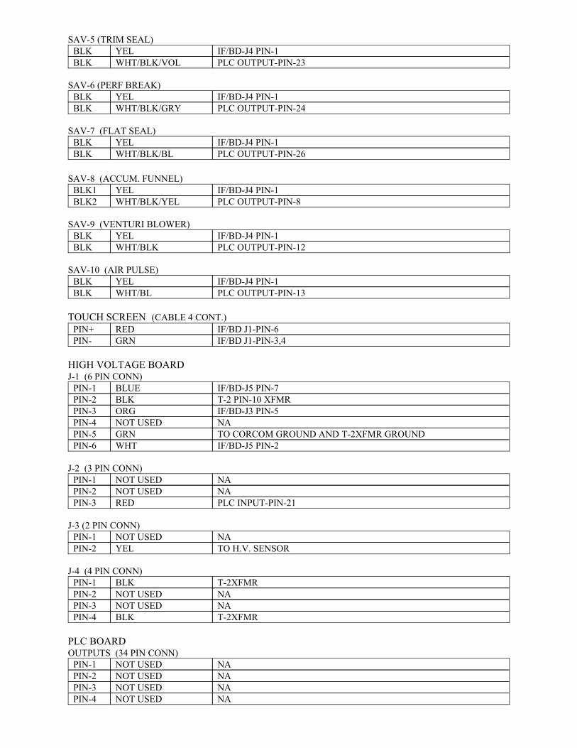
SAV-5 (TRIM SEAL)
PLC OUTPUT-PIN-23WHT/BLK/VOLBLKIF/BD-J4 PIN-1YELBLK
SAV-6 (PERF BREAK)
PLC OUTPUT-PIN-24WHT/BLK/GRYBLKIF/BD-J4 PIN-1YELBLK
SAV-7 (FLAT SEAL)
PLC OUTPUT-PIN-26WHT/BLK/BLBLKIF/BD-J4 PIN-1YELBLK
SAV-8 (ACCUM. FUNNEL)
PLC OUTPUT-PIN-8WHT/BLK/YELBLK2IF/BD-J4 PIN-1YELBLK1
SAV-9 (VENTURI BLOWER)
PLC OUTPUT-PIN-12WHT/BLKBLKIF/BD-J4 PIN-1YELBLK
SAV-10 (AIR PULSE)
PLC OUTPUT-PIN-13WHT/BLBLKIF/BD-J4 PIN-1YELBLK
TOUCH SCREEN (CABLE 4 CONT.)
IF/BD J1-PIN-3,4GRNPIN-IF/BD J1-PIN-6REDPIN+
HIGH VOLTAGE BOARDJ-1 (6 PIN CONN)
IF/BD-J5 PIN-2WHTPIN-6TO CORCOM GROUND AND T-2XFMR GROUNDGRNPIN-5NANOT USEDPIN-4IF/BD-J3 PIN-5ORGPIN-3T-2 PIN-10 XFMRBLKPIN-2IF/BD-J5 PIN-7BLUEPIN-1
J-2 (3 PIN CONN)
PLC INPUT-PIN-21REDPIN-3NANOT USEDPIN-2NANOT USEDPIN-1
J-3 (2 PIN CONN)
TO H.V. SENSORYELPIN-2NANOT USEDPIN-1
J-4 (4 PIN CONN)
T-2XFMRBLKPIN-4NANOT USEDPIN-3NANOT USEDPIN-2T-2XFMRBLKPIN-1
PLC BOARDOUTPUTS (34 PIN CONN)
NANOT USEDPIN-4NANOT USEDPIN-3NANOT USEDPIN-2NANOT USEDPIN-1
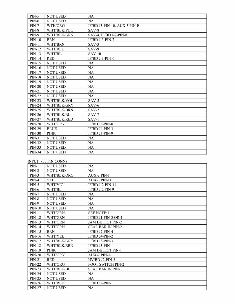
NANOT USEDPIN-34NANOT USEDPIN-33NANOT USEDPIN-32NANOT USEDPIN-31IF/BD J3-PIN-9PINKPIN-30IF/BD J4-PIN-3BLUEPIN-29IF/BD J3-PIN-8WHT/GRYPIN-28SAV-1WHT/BLK/REDPIN-27SAV-7WHT/BLK/BLPIN-26SAV-2WHT/BLK/BRNPIN-25SAV-6WHT/BLK/GRYPIN-24SAV-5WHT/BLK/VOLPIN-23NANOT USEDPIN-22NANOT USEDPIN-21NANOT USEDPIN-20NANOT USEDPIN-19NANOT USEDPIN-18NANOT USEDPIN-17NANOT USEDPIN-16NANOT USEDPIN-15IF/BD J-3-PIN-6REDPIN-14SAV-10WHT/BLPIN-13SAV-9WHT/BLKPIN-12SAV-3WHT/BRNPIN-11IF/BD J-3-PIN-7BRNPIN-10SAV-4, IF/BD J-2-PIN-8WHT/BLK/GRNPIN-9SAV-8WHT/BLK/YELPIN-8IF/BD J3-PIN-10, AUX-3 PIN-EWTH/ORGPIN-7NANOT USEDPIN-6NANOT USEDPIN-5
INPUT (30 PIN CONN)
NANOT USEDPIN-27IF/BD J2-PIN-1WHT/REDPIN-26NANOT USEDPIN-25NANOT USEDPIN-24SEAL BAR IN PIN-1WHT/BLK/BLPIN-23FOOT SWITCH PIN-2WHT/ORGPIN-22HV/BD J2-PIN-3REDPIN-21AUX-2 PIN-AWHT/GRYPIN-20JAM DETECT PIN-1PINKPIN-19IF/BD J3-PIN-1WHT/BLK/BRNPIN-18IF/BD J3-PIN-3WHT/BLK/GRYPIN-17IF/BD J4-PIN-2WHT/YELPIN-16IF/BD J2-PIN-4BRNPIN-15SEAL BAR IN PIN-2WHT/GRNPIN-14JAM DETECT PIN-2WHT/GRNPIN-13IF/BD J1-PIN-3 OR 4WHT/GRNPIN-12SEE NOTE:1WHT/GRNPIN-11NANOT USEDPIN-10NANOT USEDPIN-9NANOT USEDPIN-8NANOT USEDPIN-7IF/BD J-2 PIN-9WHT/BLPIN-6IF/BD J-2-PIN-11WHT/VIOPIN-5AUX-3 PIN-HYELPIN-4AUX-3 PIN-IWHT/BLK/ORGPIN-3NANOT USEDPIN-2NANOT USEDPIN-1
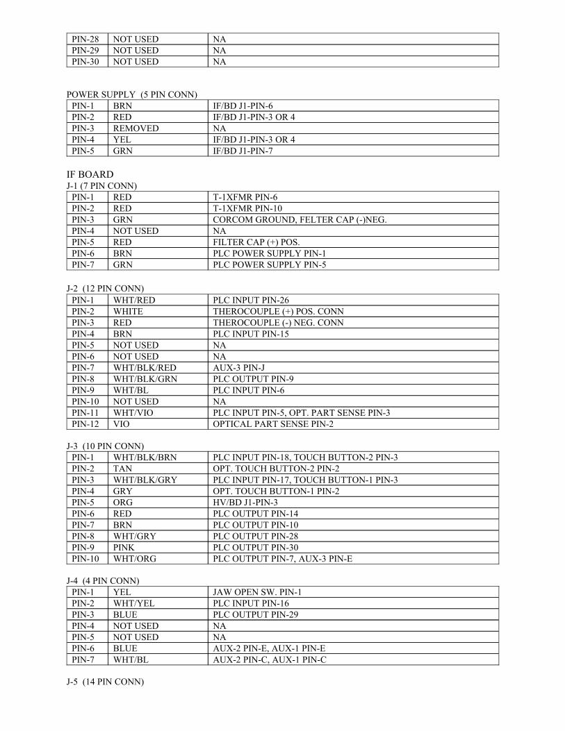
NANOT USEDPIN-30NANOT USEDPIN-29NANOT USEDPIN-28
POWER SUPPLY (5 PIN CONN)
IF/BD J1-PIN-7GRNPIN-5IF/BD J1-PIN-3 OR 4YELPIN-4NAREMOVEDPIN-3IF/BD J1-PIN-3 OR 4REDPIN-2IF/BD J1-PIN-6BRNPIN-1
IF BOARDJ-1 (7 PIN CONN)
PLC POWER SUPPLY PIN-5GRNPIN-7PLC POWER SUPPLY PIN-1BRNPIN-6FILTER CAP (+) POS.REDPIN-5NANOT USEDPIN-4CORCOM GROUND, FELTER CAP (-)NEG.GRNPIN-3T-1XFMR PIN-10REDPIN-2T-1XFMR PIN-6REDPIN-1
J-2 (12 PIN CONN)
OPTICAL PART SENSE PIN-2VIOPIN-12PLC INPUT PIN-5, OPT. PART SENSE PIN-3WHT/VIOPIN-11NANOT USEDPIN-10PLC INPUT PIN-6WHT/BLPIN-9PLC OUTPUT PIN-9WHT/BLK/GRNPIN-8AUX-3 PIN-JWHT/BLK/REDPIN-7NANOT USEDPIN-6NANOT USEDPIN-5PLC INPUT PIN-15BRNPIN-4THEROCOUPLE (-) NEG. CONNREDPIN-3THEROCOUPLE (+) POS. CONNWHITEPIN-2PLC INPUT PIN-26WHT/REDPIN-1
J-3 (10 PIN CONN)
PLC OUTPUT PIN-7, AUX-3 PIN-EWHT/ORGPIN-10PLC OUTPUT PIN-30PINKPIN-9PLC OUTPUT PIN-28WHT/GRYPIN-8PLC OUTPUT PIN-10BRNPIN-7PLC OUTPUT PIN-14REDPIN-6HV/BD J1-PIN-3ORGPIN-5OPT. TOUCH BUTTON-1 PIN-2GRYPIN-4PLC INPUT PIN-17, TOUCH BUTTON-1 PIN-3WHT/BLK/GRYPIN-3OPT. TOUCH BUTTON-2 PIN-2TANPIN-2PLC INPUT PIN-18, TOUCH BUTTON-2 PIN-3WHT/BLK/BRNPIN-1
J-4 (4 PIN CONN)
AUX-2 PIN-C, AUX-1 PIN-CWHT/BLPIN-7AUX-2 PIN-E, AUX-1 PIN-EBLUEPIN-6NANOT USEDPIN-5NANOT USEDPIN-4PLC OUTPUT PIN-29BLUEPIN-3PLC INPUT PIN-16WHT/YELPIN-2JAW OPEN SW. PIN-1YELPIN-1
J-5 (14 PIN CONN)
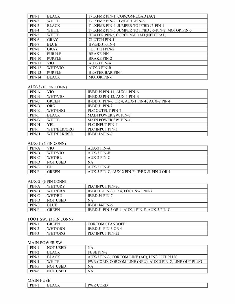
MOTOR PIN-1BLACKPIN-14HEATER BAR PIN-1PURPLEPIN-13AUX-3 PIN-BWHT/VIOPIN-12AUX-3 PIN-AVIOPIN-11BRAKE PIN-2PURPLEPIN-10BRAKE PIN-1PURPLEPIN-9CLUTCH PIN-2GRAYPIN-8HV/BD J1-PIN-1BLUEPIN-7CLUTCH PIN-1GRAYPIN-6HEATER PIN-2, CORCOM-LOAD (NEUTRAL)WHITEPIN-5T-1XFMR PIN-5, JUMPER TO IF/BD J-5-PIN-2, MOTOR PIN-3WHITEPIN-4T-1XFMR PIN-4, JUMPER TO IF/BD J5-PIN-1BLACKPIN-2T-1XFMR PIN-2, HV/BD J1-PIN-6WHITEPIN-2T-1XFMR PIN-1, CORCOM-LOAD (AC)BLACKPIN-1
AUX-3 (10 PIN CONN)
IF/BD J2-PIN-7WHT/BLK/REDPIN-HPLC INPUT PIN-3WHT/BLK/ORGPIN-IPLC INPUT PIN-4YELPIN-HMAIN POWER SW. PIN-4WHITEPIN-GMAIN POWER SW. PIN-3BLACKPIN-FPLC OUTPUT PIN-7WHT/ORGPIN-EIF/BD J1 PIN-7ORGPIN-DIF/BD J1 PIN--3 OR 4, AUX-1 PIN-F, AUX-2 PIN-FGREENPIN-CIF/BD J5 PIN-12, AUX-1 PIN-BWHT/VIOPIN-BIF/BD J5 PIN-11, AUX-1 PIN-AVIOPIN-A
AUX-1 (6 PIN CONN)
AUX-3 PIN-C, AUX-2 PIN-F, IF/BD J1 PIN-3 OR 4GREENPIN-FAUX-2 PIN-EBLPIN-ENANOT USEDPIN-DAUX-2 PIN-CWHT/BLPIN-CAUX-3 PIN-BWHT/VIOPIN-BAUX-3 PIN-AVIOPIN-A
AUX-2 (6 PIN CONN)
IF/BD J1 PIN-3 OR 4, AUX-1 PIN-F, AUX-3 PIN-CGREENPIN-FIF/BD J4-PIN-6BLUEPIN-ENANOT USEDPIN-DIF/BD J4-PIN-7WHT/BUPIN-CIF/BD J1-PIN-3 OR 4, FOOT SW. PIN-3WHT/GRNPIN-BPLC INPUT PIN-20WHT/GRYPIN-A
FOOT SW. (3 PIN CONN)
PLC INPUT PIN-22WHT/ORGPIN-3IF/BD J1-PIN-3 OR 4 WHT/GRNPIN-2CORCOM STANDOFFGREENPIN-1
MAIN POWER SW.
NANOT USEDPIN-6NANOT USEDPIN-5PWR CORD, CORCOM LINE (NEU), AUX-3 PIN-G,LINE OUT PLUGWHITEPIN-4AUX-3 PIN-3, CORCOM LINE (AC), LINE OUT PLUGBLACKPIN-3FUSE PIN-2BLACKPIN-2NANOT USEDPIN-1
MAIN FUSEPWR CORDBLACKPIN-1
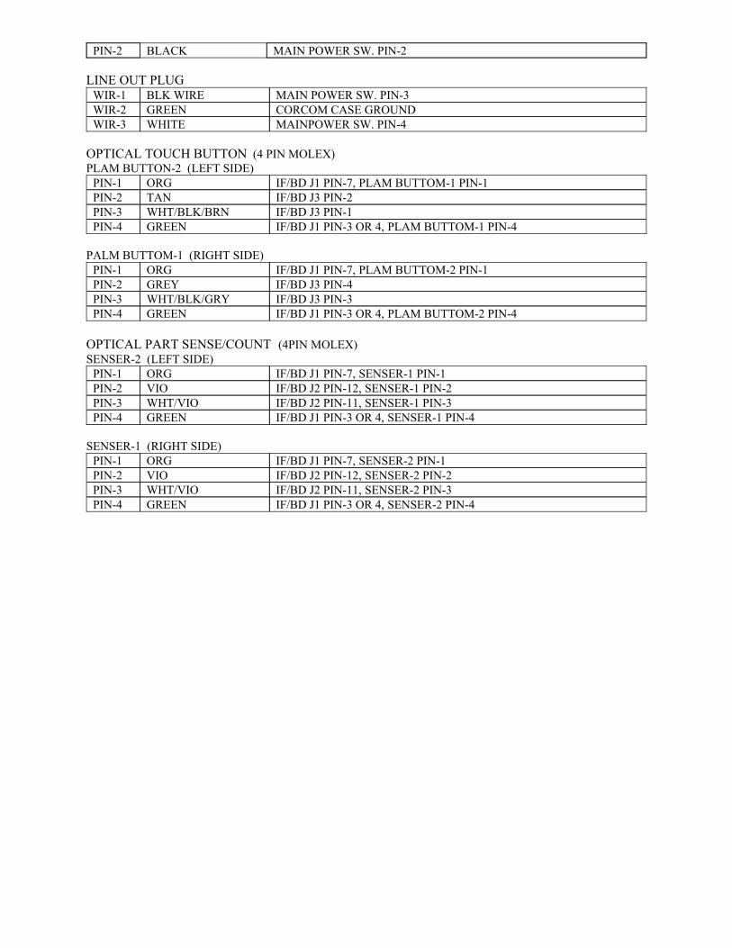
MAIN POWER SW. PIN-2BLACKPIN-2
LINE OUT PLUG
MAINPOWER SW. PIN-4WHITEWIR-3CORCOM CASE GROUNDGREENWIR-2MAIN POWER SW. PIN-3BLK WIREWIR-1
OPTICAL TOUCH BUTTON (4 PIN MOLEX) PLAM BUTTON-2 (LEFT SIDE)
IF/BD J1 PIN-3 OR 4, PLAM BUTTOM-1 PIN-4GREENPIN-4IF/BD J3 PIN-1WHT/BLK/BRNPIN-3IF/BD J3 PIN-2TANPIN-2IF/BD J1 PIN-7, PLAM BUTTOM-1 PIN-1ORGPIN-1
PALM BUTTOM-1 (RIGHT SIDE)
IF/BD J1 PIN-3 OR 4, PLAM BUTTOM-2 PIN-4GREENPIN-4IF/BD J3 PIN-3WHT/BLK/GRYPIN-3IF/BD J3 PIN-4GREYPIN-2IF/BD J1 PIN-7, PLAM BUTTOM-2 PIN-1ORGPIN-1
OPTICAL PART SENSE/COUNT (4PIN MOLEX)SENSER-2 (LEFT SIDE)
IF/BD J1 PIN-3 OR 4, SENSER-1 PIN-4GREENPIN-4IF/BD J2 PIN-11, SENSER-1 PIN-3WHT/VIOPIN-3IF/BD J2 PIN-12, SENSER-1 PIN-2VIOPIN-2IF/BD J1 PIN-7, SENSER-1 PIN-1ORGPIN-1
SENSER-1 (RIGHT SIDE)
IF/BD J1 PIN-3 OR 4, SENSER-2 PIN-4GREENPIN-4IF/BD J2 PIN-11, SENSER-2 PIN-3WHT/VIOPIN-3IF/BD J2 PIN-12, SENSER-2 PIN-2VIOPIN-2IF/BD J1 PIN-7, SENSER-2 PIN-1ORGPIN-1
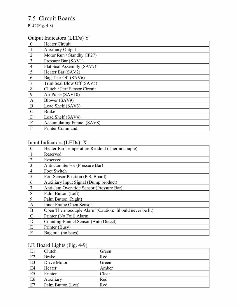
7.5 Circuit BoardsPLC (Fig. 4-8)
Output Indicators (LEDs) Y
Air Pulse (SAV10)9Clutch / Perf Sensor Circuit8Trim Seal Blow Off (SAV5)7Bag Tear Off (SAV6)6Heater Bar (SAV2)5Flat Seal Assembly (SAV7)4Pressure Bar (SAV1)3Motor Run / Standby (IF27)2Auxiliary Output1Heater Circuit0
Printer CommandFAccumulating Funnel (SAV8)ELoad Shelf (SAV4)DBrakeCLoad Shelf (SAV3)BBlower (SAV9)A
Input Indicators (LEDs) X
Bag out (no bags)FPrinter (Busy)ECounting-Funnel Sensor (Auto Detect)DPrinter (No Foil) Alarm COpen Thermocouple Alarm (Caution: Should never be lit)BInner Frame Open SensorAPalm Button (Right)9Palm Button (Left)8Anti-Jam Over-ride Sensor (Pressure Bar)7Auxiliary Input Signal (Dump product)6Perf Sensor Position (P.S. Board)5Foot Switch4Anti-Jam Sensor (Pressure Bar)3Reserved2Reserved1Heater Bar Temperature Readout (Thermocouple)0
I.F. Board Lights (Fig. 4-9)
RedPalm Button (Left)E7RedAuxiliaryE6Clear PrinterE5AmberHeaterE4GreenDrive MotorE3RedBrakeE2GreenClutchE1
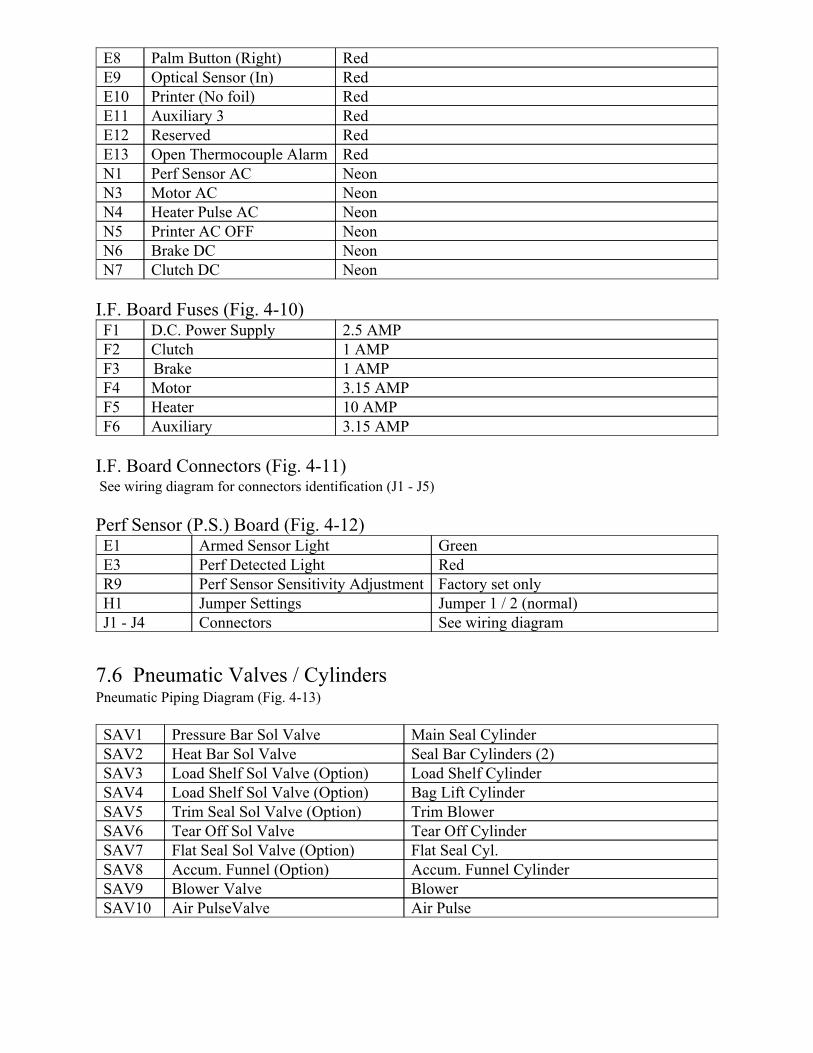
NeonClutch DCN7NeonBrake DCN6NeonPrinter AC OFFN5NeonHeater Pulse ACN4NeonMotor ACN3NeonPerf Sensor ACN1RedOpen Thermocouple AlarmE13RedReservedE12RedAuxiliary 3E11RedPrinter (No foil)E10RedOptical Sensor (In)E9RedPalm Button (Right)E8
I.F. Board Fuses (Fig. 4-10)
3.15 AMPAuxiliaryF610 AMPHeaterF53.15 AMPMotorF41 AMPBrakeF31 AMPClutchF22.5 AMPD.C. Power SupplyF1
I.F. Board Connectors (Fig. 4-11) See wiring diagram for connectors identification (J1 - J5)
Perf Sensor (P.S.) Board (Fig. 4-12)
See wiring diagramConnectorsJ1 - J4Jumper 1 / 2 (normal)Jumper SettingsH1Factory set onlyPerf Sensor Sensitivity AdjustmentR9RedPerf Detected LightE3GreenArmed Sensor LightE1
7.6 Pneumatic Valves / CylindersPneumatic Piping Diagram (Fig. 4-13)
Air Pulse Air PulseValveSAV10BlowerBlower ValveSAV9Accum. Funnel Cylinder Accum. Funnel (Option)SAV8Flat Seal Cyl.Flat Seal Sol Valve (Option)SAV7Tear Off CylinderTear Off Sol ValveSAV6Trim BlowerTrim Seal Sol Valve (Option)SAV5Bag Lift CylinderLoad Shelf Sol Valve (Option)SAV4Load Shelf CylinderLoad Shelf Sol Valve (Option)SAV3Seal Bar Cylinders (2)Heat Bar Sol ValveSAV2Main Seal CylinderPressure Bar Sol ValveSAV1
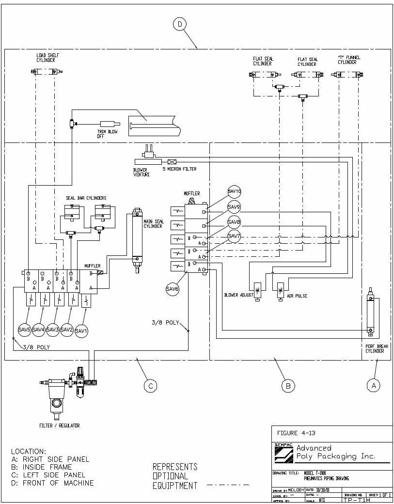
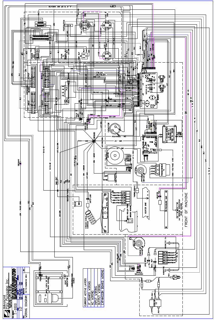

7.8 NOTES
Date Notes