Embed Size (px)
Citation preview

t
(}- 29015
A SYSTEM ARCHITECTURE FOR A
PLANETARY ROVER
D.B. Sm|th and J.R. HatiJev|c
Jet Propu[s|on Laboratory, California Institute of Technology4800 Oak Grove Drive
H/S 198-105 end 303-308, Pasadena, California 91109
ABSTRACT
Each planetary mission requires a complex space vehicle uhlch Integrates several functions to accomplish themission sad science objectives. A Hsrs Rover Is one of these vehicles, and extends the normal spacecraft
function•Lily with two additional functions: surface mobility sad sample acquisition.
This paper assembles ell functions into a hlersrchlcst and structured format to understand the complexitiesof interactions between functions during different mission times. It can graphically •how data flow between
function•, sad moat Import•atty, the necessary control flow to •void unambiguous results.
Diagrams are presented organizing the function• into • structured, block format where each block representsa major function at the system Level. As such, there are six (6) block• repress•tin9 TeLecomm, Power,
Thermal, Science, Hobitlty and Sampling under a supervisory block called Date Hanogement/Executtv•. Eachblock is a simple collection of state machines arranged into a hierarchical order very close to the NASREN
m_let for Teterobottcs.
Each Layer u|thin • block represents • Level of control for • set of state machines that do the three
primary Interface functions: Command, Telemetry, Fault Protection. This tatter function Is expanded toInclude automatic reactions to the environment as uett ms Internal faults.
Lastly, diagrams are presented that trace the system operations Involved In moving from site to •Its aftersite selection. The diagrams clearly illustrate both the data and control ftoua. They else ILlustrate inter-
block data transfers and a hierarchical approach to fault protection. This systems architecture can be usedto determine functional requirements, interface specifications and be used as a mechanism for grouping
subsystems (i.e., collecting groups of machines 8or blocks consistent with good and testable
implementations).
1. |HTROOUCTION
The history of operational planetary rovers begins with the USSR Lunokhod-1 mission on the moon, s nearly one
year mission beginning In November, 1970. The Lunokhods were intersctlvety controlled, starting and stopping
according to planned sequences created by s ground mission team receiving TV imsges.
An advancement on this design principle is the JPL's Computer-Aided Remote Driving or (CARD) system
Implemented on a mix-wheeled test vehicle. This system was developed under sponsorship of the U.S. Army Tank-Automotive command and demonstrated the capability of on-board execution of a human operator selected path drawn
on • frozen image of the Local terrain (Reference 8).
Current rover concepts vary from advanced concepts of this design (CARO) to highly sutometed vehiclesperforming automatic collision avoidance (for example, JPL's Semlautonomoua Navigation or (SAN), Reference 1).Unlike the Lunokhods, concepts under study for • Hers rover misston (Reference 9) must accommodate In-sttu
sampling, very much Like an automated geologist. 1his complexity dictates a flexible systems architecturetnvsrlant to different level• of automation.
Because of the nature of the mission, the architecture must combine the functionality of planetary spacecraftwith the additional functions of mobility and sampling. Inclusion of these Last two major functions
dramatically expands traditionally layered architectural structures for spacecraft systems.
An architecture which incorporates a mobility function, must provide • structure for accommodating simple to
complex walkers as Matt as the more traditional wheeled carriage vehicles. One of the simplest walker conceptsis Brooks' 1 kg rover consisting of fifty-six (56) state machines cycled individually In s particular pattern to
produce • "gait" (Reference 2). A more complex walker concept is the Carnegie Hello• University -ambler"(Reference 3). In between may be considered the etegsnt "beam" walker concept of Hartln Narletts Corporation(Reference 4). in each case, • multi-layered architectural structure is suggested where co•trot of Individual
walker Link motors or wheels are coordinated at higher Levels to produce the desired motions.
The addition of s sampling function Introduces the added coaq)lexity of control of manipulations. As recent
studies suggest (see for exempts the architectural concepts for teLerobotics proposed for the Goddard SpaceFLight Center (GSFC) FLight Teterobotlcs Servicer (FTS) (Reference 10) and for the NASA/OAST Tsterobot lestbed(Reference 11)) multi-Layered control structures ere required to coordinate manipulator end end-effactor/tootLink controllers. Precursor missions such as s Hare Sample return concept require a high Level of automation of
the sampling function. But Later manned missions, with associated human Interaction with the rover, requireconsideration of • range of supervisory control options for the sampling function. Consequently, human
interactions must be smoothly integrated into a control architecture for the rover.
163
. _,.)
Of pOOR QUALI'I"Y

In this paper, s single architectural concept integrating art of the above is proposed for the general class
of planetary rover concepts in the 1990's. The architecture is a loosely coupled, state-machine conceptincorporating the hierarchical control concepts of NASREM (NASA/Nas Standard Reference Model for TelerobotControl System Architectures, Reference 5).
The foltoutng describes the architectural concept end provides a mobility scenario, trsctng the sequentialexecution of several functions within the control layers of the architecture. A sampling scenario has also beendone for comptetenes_ but Is not presented here for the sake of brevity. Both scenarios validate thearchitecture's flexibility and accuracy.
Lastly, some final thoughts are presented on the uses of the architecture. These observations should apply toany good architecture, not just this one. For example, a typical systems design task is the mapping of the
system functions into an implementation by e number of subsystems, defining boundary interfaces st simplejunctions (e.g., functional levels). This architecture naturally decomposes into the standard subsystems forplanetary spacecraft and provides a _tructure for the evaluation of alternate decompositions.
2. PLARETARY MISSIONS
Before discussing details of the architecture, we introduce some of the basic functions and subsystems of anyplanetary spacecraft. A Mars Rover, after all, is at least a planetary spacecraft and much more.
Basic subsystems of any planetary spacecraft include TelPcommunicstion, Power, Thermal, Attitude Control, and
Science. Common to these subsystems are three activities: receipt end/or processing of commands, telemetryoutput and fault protection. Due to the delays in transmission to e ground station, these subsystems must at a
minimum fail safe, and the spacecraft as s uhote must fail operational, albeit in a degraded mode. Consequently,each subsystem must detect errors and take local action such as the use of a redundant string. Once the error
correction is accomplished the subsystem notifies a command and control subsystem (if available) of the
configuration change. Of course, this information is passed on to ground command as soon as possible forevaluation and further corrective action.
No planetary spacecraft has been designed to be fully autonomous. Instead, these spacecraft are semi-
autonomous (in the sense of the above discussion), relying heavily on ground control for mission commanding,analysis, end planning. Therefore, any general architecture for spacecraft control wit[ include • significant
ground segment. Functions may move from the ground to the spacecraft if more risk is assumed or capability madeavailable. An example of this enabled the extended Viking mission. After the primary mission end with suitable
confidence in the spacecraft capability, the Viking program reduced its operations[ ground staff significantly,by reprogrammlng the flight computers on the orbiters with automatic routines for fault protection.
The MRSR (Mars Rover and Sample Return) mission contains ell the subsystems and functions of s planetaryspacecraft except for the classics( Attitude Control subsystem. Attitude of the Rover is monitored as a part of
mobility but not controlled until some limit is exceeded. For example, an inclinometer may detect s dangeroustipping-over attitude which requires system action for correction.
The additional rover-specific subsystems are Mobility and Sampling. Mobility contains the [scat navigation
function vital to semi-autonomous traverse. This local navigation function is very important, requiring
interactions among other functions. Some architectures for s rover represent only this viewpoint. For example,Kovtunenko (Reference 6) represents the local navigation function as the main interface to the Earth and centre|
to all other functions within the rover. This view is useful for describing control principles, but neglectsother major rover functions.
3. NRSR NISSIOll
A NRSR mission has many variations (including some without s separate rover vehicle). The following summarizesmain mission and operational requirements for s rover in the HRSR mission.
The rover greatly extends the number and types of samples which can be returned from Mars (Reference 7). A
nominal rover operation entails • sequence of local traversing segments end sampling, constrained by on-board
resources end ground Interactions. Prolonged or extensive decision time by the ground operations can severelylimit the rover's integrated range (from • goal of 40 km-lO0 km).
After each traverse, • sample may or may not be collected, depending on science value as determined by an on-board evaluation or ground mission team decision. Some strategies attou collection of samples without in aitu
discrimination. After s collecting tour, the rover locates the MAV (Mars Ascent Vehicle) for • rendezvous andsample hand*over. (The HAY may have resulted from an integrated rover or separate launch).
For the purpose of this paper, consider that each traverse segment is using semi-autonomous navigation.
Figure 3-1 is s functional diagram of the activities. At I certain point, the ground up-links a topographic mapfrom s ground-based Global Route Planner. This map contains a first-order ground swath for the rover,s traverses
and s designated path(s) avo|ding obstacles and dead-ends that rema|ns scientifically interesting.
The rover takes • panoramic view of the local scene using stereo cameras, loser scanning, or structured light,linked to machine vision end image processing functions. The rover computes • local map from the processed viewand matches this map to the local portion of the global topographic map sent from Earth. Using the results of
the match, constraints of previous rover positions and output of any other navigational devices, the rover
determines an accurate position of itself. A revised (fused) map is formed from the two sources (ground/global
and rover/local) to produce • high resolution map in the vicinity. A new path then is computed via simulation,revising the approximate path sent from Earth by including (end thus excluding from the path) small obstacles
not detected by the tow resolution images of the global map. The original global resolution ts required to beaccurate to 1 meter. The fused map could be accurate to lOcm. The rover then traverses the path.
in planning the route, the simulation of the traverse of the path is used to compute slope changes and tiltexpectations. These are used in s predictive _sy to set limits on inclinometer and local proximity sensors.These predictions control the rover's reflex actions in the event an errant path is followed.
164

Terrain/Vehicle
Interaction
Current
Position
Quad Tree _
v I
fi
Global Route
Planner
Local Path
Planner
Traverse
Simulator
I
Path Segment
Analysis
User
Vehicle !Kinematics
Sensor lScheduler
i Landmark Selector I
t
I e"ex1Assignment
Plan w/expectation
model, sensor commands,reflexes
FIGURE 3-1
165

[f enough computational resources exist, the cycle of globel map up-Link(as needed) - fused map development-path planning - traverse can be repeated every few minutes, for s resultant average speed of 10cm/sec (see
Reference 1). Typically a Local pnth is computed for about thirty (30) meters, with the rover pausing every ten(10) meters or so to re-evaluate its condition.
4. RASREM
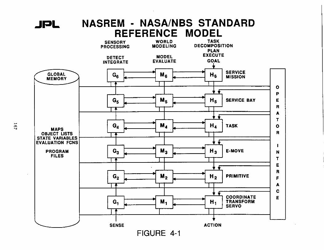
NASREN is a standard teterobotic architecture now adopted by the FTS, its contractors end many othersassociated with the Space Station program (Reference 5).
The NASREN is s modular, hierarchical conceptual architecture for telerobotic system control (see Figure 4-1).The main feature of HASREN are six layers of control:
(0) the world: hardware elements, being controlled by the telerobot and the environment of operation(1) the servo level: coordinates are transformed and outputs servo the arms/end-effectors
(2) the primitive Level: telerobot dynamics are computed and coordinated arm commands issued
(3) the E-move level: obstacles (including those inherent to nrm operation) are observed and commends issuedto avoid them
(4) the task level: tasks to be performed on objects are transformed into movements of effectors
(5) the service bay level: task on groups of objects in the vicinity of the teterobot are sequenced andscheduled
(6) the mission level: objects are collected into groups, resources are assigned between teterobots andparts/toots are routed and scheduled
Each NASREN layer is partitioned into three modules: sensory processing, world modeling and taskdecomposition. Additional features include a global memory to support the flow of information and coordination
between levels in the hierarchy and an operator interface to support operator input and display capabilities stall levels of the hierarchy.
Since the control levels are welt ordered, unambiguous commands flow from the top of the hierarchy down to thetowost Level of the servomechanism. This is role of the task decomposition elements of the architecture. At
each level in task decomposition, a job assignment manager partitions task commands into distinct jobs to beperformed by one or more planner/executor modules. As such, each planner is responsible for decomposing m job
command into m temporal sequence of planned subtesks. The executor evaluates the sequence prior to execution.
Data or status flows in reverse from the lowest levels of the hierarchy to the top Levels. This data isavailable from three sources. The data may be fed back from one level to the next through the hierarchy in taskdecomposition. Alternately, depending on the use/need, the data may be read from the global memory. This globalmemory is a data base where knowledge about the state of the task space, task environment and internal state of
control system is stored. Each Layer of the hierarchy and all processing modules within a Layer contribute to
global memory. Lastly, data may be received through the interaction of the telerobot system with theenvironment. This data is obtained through the sensory processing elements of the architecture. Sensor
information is read and processed in a hierarchy which allows the system to recognize patterns, detect events,fitter and integrate information over space and time.
The processinq of the data or status is performed using models of the effectors, sensors or envtror_nt of thetelerobot. This is the role of the world model elements of the architecture. These models include estimates and
evaluations of the history, current state and possible future state of the telerobot system and task space.These models help maintain the data in global memory, offering confidence levels/statistics of model predictorsand sensory observation.
The last elements of the archttect_lre are contained in the operator interface. The functtop¢ in these elements
enable interface to each Level of the hierarchy. The operator can enter the control flow to monitor a process,
insert information, interrupt automatic operation, take over, and spply human intelligence to the processing.Feedback ranges from force reflection at the lowest levels to displays for interactive scheduling at the highestlevels.
In guiding functional partitioning, this architecture constrains functions to a given layer by processing rateor bandwidth. At the lowest levels, the processing is severely time dependent in stabilizing servo control
loops. As such, rates of execution may be as high as 1000 times per second (or lO00Hz). At each higher level therates decrease generally by a factor of 10 or more.
in implementing the architecture, the available technology and operational priorities dictate additional
constraints. The processing toad at the toNest levels lead to optimization of communication paths. Thus, thedata in global memory which serves inter-process communication at these Levels may be kept separate from data atother levels, with access prtoritlzed by need for the control loops. The need for verification of commend
sequences at the higher Levels of the architecture lead to the inclusion of simplified (though correct) modelsof specific hardware in the world models at these levels.
5. HOVEl SYSTEM ARCRITECTURE
The system architecture for the rover discussed in this section is based on the HASREH model. We generalizethis model in two Nays. We unify treatment of rover subsystems and specific functions such as command andtelemetry by modeling each in a two-dimensional NASREH architecture. We collect the elements in a four
dimensional array space, allowing a simple mechanism for sorting elements by like function and processing. Inaddition, we generalize the definition of the intermediate layers (Levels 1 through 3) of the architecture
allowing expansion to such functions as mobility and telecommunications, white maintaining the spirit of thedefinition of these levels for a telerobot.
In considering then the definition of a NASREN model for use in a rover system, we utilize the concept ofsmall state machines introduced by Brooks (Reference 2). Level 1 functions can simply be interpreted as thosestate machines which implement the settings of dynamical systems or the states to be controlled. In the Brooks'
walker, these states are the different positions of the legs. In the control of a robotic arm the states are the
various settings of the joints of the arm. Level 2 functions set permissible states as represented by a control
law, constrained by various dynamic and kinematic models. At the next level, a sequence or function of
permissible states implements a subtask or operational process for the rover. At this level, for exempts, themovement of a walker along a path is a sequential execution of repositfons, with each repositton itself a
166O_tC!T;::-_.t. PAGE !S
JPL NASREM - NASA/NBS STANDARDREFERENCE MODEL
+G6 - " M6 _ - H6
I' I ]
h.. _-
G5 .. _ Ms .. - H5
I I I
G 4 .. " M4 .. " H4MAPS - -
OBJECT LISTS I J ISTATE VARIABLESEVALUATION FCNS r _"
HPROGRAMFILES
SENSORY WORLD TASKPROCESSING MODELING DECOMPOSITION
PLAN
DETECT MODEL EXECUTEINTEGRATE EVALUATE GOAL
L
G3 - M3.,d -_
I
G 2 " M 2 " H
I I
l=. =_-
G1 .. - M1 .. - H1
_r
SERVICEMISSION
FIGURE 4-1SENSE ACTION
SERVICE BAY
TASK
3 E-MOVE
2 PRIMITIVE
COORDINATETRANSFORMSERVO
sequence of leg motions in a controlled, coordinated (or gaited) move. For an arm, a cartesian-space referenced
path is achieved by moving the arm joints to achieve a series of end-points. Task planning at the highest level
generates collections of sequences which accomplish a task. For example, movement of an arm or rover from pointA to B is achieved by the execution of • set of commandcd path segments.
Figure 5-1 is a generalized version of the _A_REM model where this new state-definition terminology isapplied, in another change from Figure 4-1, we have re-ordered the columns adding s slice so that a d|stinction
is made between world models of the environment being sensed and world models of devices being commanded. Theglobal data base becomes the middle slice and contains the constants and parameters of the world models as weltas the data comprising the state of the overall system.
To the functional processing machines, we have added a third dimension to the architecture: a stack of command
and a stack of telemetry machines. Commands flow down and telemetry flows up. In between is a separate stackof fault protection machines which can be excited and alter commands and telemetry at any given time. Fault
protection machines execute as a result of a detected error read through tetemetry. They implement recovery
actions through commanding of the functional processing elements to assume a new state. As an example for amobility subsystem, an inclinometer may sense an excess tilt angle. A corresponding fault protection machinewill detect the error based on the telemetry and then act by issuing a command to cease forward motion. In
addition, an appropriate routine may be executed such as carefully retracing the last series of commands until
acceptable tilt angtes are achieved (i.e., beck-up). Once completed and the vehicle is saTed, a route reptsnningwill be commanded.
Notice that in the above example command end telemetry machines interact with the fault protection machines.The fault protection machine orchestrates the actions of the functional processing machine(a) implementing
recovery. In detail then for the above example, an inctlnometer at Level 1 registers excessive tilt causing aLevel 1 fault machine to interrupt commends from Level 2 thereby halting the systPm. Telemetry is then sent to
the Level 4 fault machines which have been receiving some subset of the last successfulty commanded states. TheLevel & fault machine then calla for the task execution of a traverse beck to a point along the route. Commandsthen flow normally downward until this previous state is achieved. When this happens, system control is then
passed back to the task planner which knows its path ptan has been altered end must replan a new path, which has
a prescribed set of greater margins of expected tilt angles along its simulated path.
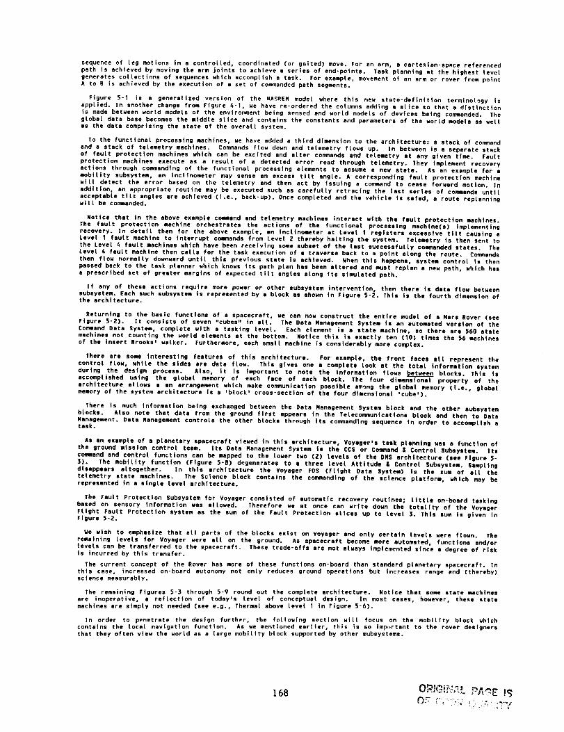
If any of these actions require more power or other subsystem intervention, then there is data ftow betweensubsystem. Each such subsystem is represented by a block as shown in Figure 5-2. This is the fourth dimension ofthe architecture.
Returning to the basic functions of a spacecraft, we can now construct the entire modet of a Nars Rover (seeFigure 5-2). It consists of seven "cubes" in all. The Data Nanagement System is an automated version of the
Command Data System, complete with a tasking level. Each element is a state machine, so there are 560 statemachines not counting the world elements at the bottom. Notice this is exactly ten (10) times the S6 machines
of the insert Brooks _ walker. Furthermore, each small machine is considerably more complex.
There ere some interesting features of this architecture. For example, the front faces all represent thecontrot flow, white the sides ere data flow. This gives one a complete took at the totet information system
during the design process. Also, it is important to note the information flows between blocks. This is
accomplished using the globat memory of each face of each block. The four dimensional property of thearchitecture allows a an arrangement which make communication possible among the gtobat memory (I.e., globalmemory of the system architecture is a 'block' cross-section of the four dimensional 'cube').
There is much information being exchanged between the Data Nanagement System block and the other subsystembtocka. Atso note that data from the ground first appears in the Telecommunications block and then to Data
Nanagement. Data Nanagement controls the other blocks through its commanding sequence in order to acco,q_llsh atask.
As an example of a planetary spacecraft viewed in this architecture, Voyager's task planning was a function of
the ground mission control team. its Data Nanagement System is the CCS or Command & Control Subsystem. Its
command and controt functions can be mapped to the lower two (2) levels of the DNS architecture (see Figure 5-
3). The mobility function (Figure 5-8) degenerates to a three level Attitude & Control Subsystem. Samptlngdisappears altogether. In this architecture the Voyager FDS (Flight Data System) Is the sum of att the
telemetry state machines. The Science block contains the commanding of the science platform, which may berepresented in a single level architecture.
The Fault Protection Subsystem for Voyager consisted of automatic recovery routines; little on-board tasking
based on sensory information was allowed. Therefore we at once can write down the totality of the VoyagerFttght Fault Protection system as the sum of the Fault Protection slices up to level 3. This sum is given inFigure 5-2.
Ue wish to e_hastze that all parts of the blocks exist on Voyager and only certain levels were flown. Theremaining levels for Voyager were all on the ground. As spacecraft become more automated, functions and/or
|avers can be transferred to the spacecraft. These trade-oTis are not always implemented since a degree of riskis incurred by thts transfer.
The current concept of the Rover has more of these functions on-board than standard planetary spacecraft. Inthis case, increased on-board autonomy not only reduces ground operations but increases range and (thereby)science measurably.
The remaining Figures 5-3 through 5-9 round out the complete architecture. Notice that some state machines
are inoperative, a reflection of today's level of conceptual design, in most cases, however, these statemachines are simply not needed (see e.g., Thermal above level 1 in Figure 5-6).
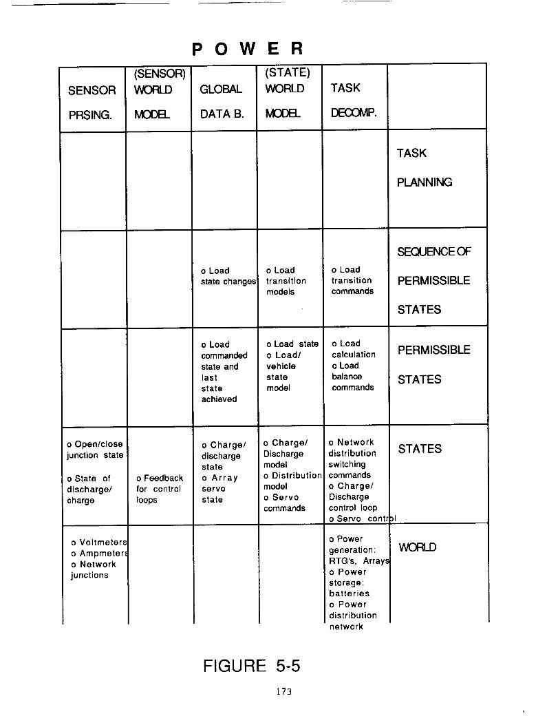
In order to penetrate the design further, the following section wilt focus on the mobility block which
contains the local navigation function. As we mentioned earlier, this is so imp_rtant to the rover designersthat they often view the world as a |arge mobility block supported by other subsystems.
168

I-0iiiI-
0re
=EILl
i--
Of)
>..(f)
D:
I11
>,0I:Z:
(D(..)C
Ca)C
°--
"(3CEl
r-
"r
Q)7O:30
\\\\
q) w z _) _3 n" nn-O ._wq) q)- z L9
_Z
W
169
7"u')
W
CC
(9
LL

ROVER SYSTEM ARCHITECTURE
EXAMPLE" ( VOYAGER FAULT PROTECTION)
= M (3)
k=l i=1 j=l ij
I-.-=
oI = 1..... 4 = faces
k = 1..... 7 -- cubes (subsystems)i= 1 ..... 5 = columns (proc. categories)j = 0 ..... 4 = rows (hierarchy)
kELEMENT M (I)
DATA MANAGEMENT (EXECUTIVE)
TELECOMM POWER THERMAL SCIENCE MOBILITY SAMPUNG
FIGURE 5-2

DATA MANAGEMENT (EXECUTIVE)
SENSOR
PRSING.
o Task
progress
reports
o s/s
operationalcondition
o sis state
condition
o Data reportsfrom s/s
o Reportingfunctions of
subsystems
(SENSOR)
WORLD
lvlCE)B_
o Task
error models
o sis
operationerror models
o sis state
error models
o Command
acceptancefeedback
'o Emergency
sating conditiormodel
GLOBAL
DATA B.
o Samplinglocations and
constraints
o Science
tasks
o Emergencystate
condition
(STATE)
WORLD
MODEL
o Simplifiedtask execution
models
o Task con-
straint and
resource
models
o Simplified
sis operationamodels
o Simplifiedsis constraint
and resources
models
o Simplifiedsis state
model
o sis state
constraint
and resourcemodels
o Last
commanded
state in
s/s's
command
table
TASK
DECOMP.
o Planner
for task
execution
o Task
commands
o Planningfor sis
operationo Sequencingof s/s
operations
o Organizatiorof s/s states
o sis state
commands
o Decomp.of state
commands
o Commands
to subsystems;
o s/s's of
TELECOM,POWER
THERMAL,
MOBILITY,
SCIENCE,SAMPLING
TASK
PLANNING
SEQUENCEOF
PERMISSIBLE
STATES
PERMISSIBLE
STATES
STATES
WORLD
FIGURE 5-3171

SENSOR
PRSING.
o Decoded
signalo Location of
antenna in
vehicle
coordinates
o Decommu-
tation signal
o Changein encoder
counts
o Encoders/
motors
o Receivers
TELECOMMUNICATIONS
(SENSOR)
WORLD
MODE]_
GLOBAL
DATA B.
(STATE)
WORLD
MOOB_
TASK
DEEXDMP.
TASK
PLANNING
o Decodingscheme
i o Decommu-
;tation scheme
o Readouts
for feedback
to motors
and antenna
configuration
o Transmissio
point in inertia
space
o Vehiclelocation in
inertial space
o Data for/
from
transmission
o Vehiclelocation
o En/Decoded
data for
transmission
o Servo
state
condition
o Trans-
mission
models
o Trans-
formations
o Encodingscheme
o Transforms
o Commuta-
tion scheme
o Servo
gains
o Configura-tion model
o Timing andtransmission
sequence
o Direction in
inertial
coordinates
o Direction
for pointingm veh. coord.o Trans. to
servo cmds.
o Transmitter
configurationo Coded data
o Commutatior
signals fortransmissions
o Servo
motor controlo Transmitter
configurationcommands
o Antennas
and motors
o TWT's
and trans-
mitters
o Trans-
ponders
SEQUENCEOF
PERMISSIBLE
STATES
PERMISSIBLE
STATES
STATES
WORLD
FIGURE 5-4172
SENSOR
PRSING.
o Open/close
junction state
o State of
discharge/
charge
o Voltmeters
o Ampmeter,,o Network
junctions
POWER
(SENSOR)
WORLD GLOBAL
DATA B.
(STATE)
WORLD
o Feedbackfor control
loops
o Load
state changes
o Load
commanded
state and
last
stateachieved
o Charge/
dischargestate
o Arrayservo
state
o Loadtransition
models
o Load state
o Load/
vehicle
state
model
o Charge/
Dischargemodel
o Distribution
model
o Servo
commands
TASK
_P.
o Load
transitioncommands
o Load
calculation
o Load
balance
commands
o Network
distribution
switchingcommands
o Charge/
Discharge
control loopo Servo contr
o Power
generation:RTG's, Array-_o Power
storage:batteries
o Power
distribution
network
TASK
PLANNING
SEQUENCEOF
PERMISSIBLE
STATES
PERMISSIBLE
STATES
STATES
WORLD
FIGURE 5-5
173

THERMAL
SENSOR
PRSING.
o Heater
state
,o Temperature
o Change incounts
o Rheostats
o Thermostats
o Encoderon louvers
(SENSOR)
WORLD
MOOEL
o Temperaturefeedback
GLOBAL
DATA B.
o Heater
commands
(STATE)
WORLD
o Heater
statemodel
o Vehicle
thermal
model
TASK
DECOMP.
o Heating
control loopo Heaterstate
commands
o Louvers
o Heaters
TASK
PLANNING
SEQUENCEOF
PERMISSIBLE
STATES
PERMISSIBLE
STATES
STATES
WORLD
FIGURE 5-6]74

SENSOR
PRSING.
o Features
correlated
with expect.o Locations
of inst. in
inertial
coordinates
o Science/
Samplingfeatures
extracted
o Locations
of inst. in
vehiclecoord.
o Spectral
and signal
processing
o Digitized
imagery
o Change inencoder count.,
o Encoders
for the motor.,
o Imaging
Spectrometero Sounder/
Antenna
SCIENCE
(SENSOR)
WORLD
MOOEL
GLOBAL
DATA B.
(STATE)
WORLD
MODEL
o Expectationmodels:
geology form.mineral conten
o Geometric
and spectral
processing
parameterso Feedback
of inst. pos.in vehicle
coordinates
o Sounder
parameters
o Spectral
band param.
o Feedback
for servos
o Terrain-
map-basedfeatures of
interest
o Vehicleinertial
location
o Vehicle
location
o Commanded
state
o Servo
state condition
o Samplingor science
constraint/
locales
o Transforms
o Transforms
o Last
servo cmd.
o Servo
gains
TASK
DECOMP.
o Planning of
science imagine
for samplingo Inertial
coord, directior
o Directions
for imagingo Coordinate
transforms
o Processinginto statecommands
o Servo
command
o Servo/moto
control law
o Motors
for Imaging
Spectrometer
scan platformo Motors for
Sounder,Antenna
articulation
TASK
PLANNING
SEQUENCEOF
PERMISSIBLEs
STATES
PERMISSIBLE
STATES
STATES
WORLD
FIGURE 5-7t75
MOBILITY
SENSOR
PRSING.
o map for usein correlations,
_o feature
determination
o vehicle
state
progress
o feature mapo vehicle
inclination and
heading
o ground speed
(SENSOR)WORLD
o vehicle
state model
o sensed
state of
vehicle and
terrain
o sum.'d/
GLOBAL
DATA
BASE
o route
commanded
o fused
terrain mapo commanded
local path
o commanded
vehicle
state
o readouts
from sensors
(STATE)WORLD
MODEL
o expecta-tions model
o sampling
objectives
o simplifiedvehicle models
o simplifiedvehicle model
with con-
straints
o last cmd.'d
patho obstacle
model
o commanded
states
o vehicle
kinematics
and dynamics
TASK
DECOMP.
o updated
expectations
o path planningo correlation
of features witl
constraints
o local path inthe terrain
oway points c finterest to
achieve
o obstacle
detection/avoi
o local
path calculatioand commands
o commanded
turns, moves
up/downo coordinated
commands to
TASK
PLANNING
SEQUENCE OF
PERMISSIBLE
STATES
PERMISSIBLE
STATES
o distance
traversed
o digitized
local map
o range cnts.
o angular cntso abs./rel.
change in}osition in
diff.'d
readouts
o range readso cameramodels
o encoder, gyfreadouts
o digitized
imagery
)
O servo
state cmds
o servo
gains
o gear stateo last cmd.'d
wheels and
steering
o servocommands
o servo/moto
STATES
veh. coord.
!o Encoders
o Cameraso Lasers
o Inclinometer
o Gyros/IMUo Acceleromel )rs
o Satellite
cameraso Odometers/
speed sensors
servo state control laws
o wheel
motors
o gearso drive
train
o steeringmotors
o motors for
_anltilt head
WORLD
FIGURE 5-8
176

SENSOR
PRSING.
o Fusion offeatures with
terrain
o Fusion of
;_osition,force with
data base of
objects sample¢
o Ranges
o Edges, Vert.centroids
o Features
extracted
o Positions,forces in cart.
coords., of veh
o Stereo
correlation
o Digitized
images andsensor readout_
o Change in
counts of pos.
rate, range,_nr.Al_r_tinn
o Encoders
o Sensors
of force/torqu,
3 Cameras
o Lasers
(SENSOR)
WORLD
MODEL
o Task error
models
o Local
terrain models
o Feedback
of sequencestates
o Samplingerror models
o Sensor-based feedback
o Positionand force
control loopfeedback
o Servo
loop feedback
SAMPLING
GLOBAL
DATA B.
o Sampling
site mapso Commanded
sequences
o Manipulation
sequenceo Samplingstates, site
data
o Commanded
state of links
and end-
effectors
o Servo
state condition,
(STATE)
WORLD
o Simplifiedkinematic
models
o Spatialmodels of
sampling siteso Resource
models
o Kinematics
and dynamicsof sets of
links, end-eft.
o Samplingsite data base
of positionsand sizes
o Kinematics
and dynamicsof sets of
links
o Tool and
end-effectorsizes/char.
models
o Last
servo state
o Servo
gains
TASK
DECOMP.
o Planning of
sampling tasko Commanded
sequences of
grasps,manipulations
and placement
o Inertial
coordinate
transforms
o Collision
detection/avoidance
o Cmd.'d pos.forces, way pt
o Reference
coordinatetransformation
o Trajectorycalculations
o Coordinatedlink/motor/era
effector cmds.
o Servo cmd.
o Servo/motor control
o Mechanical
links
o Motors
o Tools and
end-effectors:
samplingdevices
TASK
PLANNING
SEQUENCEOF
PERMISSIBLE
.STATES
PERMISSIBLE
STATES
STATES
WORLD
FIGURE 5-9177

The mobiLity block is shown in Figure 5-8. The highest Level is focused on the task of developing then
utilizing a Local terrain map in route planning as the discussed under Section 3. After a 30 meter planned pathts selected, the vehicle can begin to roll. The rover executes this 30 meters 10 meters at a time. Theexecution of this 10 meter traverse is detailed below.
The presented exampL_ shows the interaction between the blocks as well as control Loops within the Layers ofgiven blocks. As we mentioned before, sampling is not presented for the sake of brevity. However, it should be
noted that a sampling example was easily constructed since sampling ta (assumed) implemented using telerobotlcsand the basic model was derived from NASREM, an architecture for teLerobotics.
6. NOBILITY
In this section we will give an example of an operation of the rover vehicle and the accommodation provided bythe functional architecture. Ln this operation, a command has been received by the rover from the mission team
to move to a new location, based on the transmitted views of the site. The rover system must evaluate the
surrounding terrain and generate a detailed route which reaches the commanded location. Ln arriving at a
decision that the route so generated is suitable for traverse, the rover system must evaluate tts state anddetermine on-board the feasibility of execution of the route. If so feasible, the rover begins the traverse.Periodic evaluation of progress to the goal state (i.e., the commanded location) during the traverse allows the
rover system to determine the end of the operation as well as to proceed within available resources and withinlimits of safe operation.
In summary fashion the steps executed by the rover system in accomplishing the traverse include:(1) tasks performed by the ground support team in determining the new location for the rover(2) the up-L|nk and
(3] on-board processing of command sequences which result in receipt by the rover of new goal state(6) the determination of a feasible route to the goat state by the rover system(5) the planning necessary to determine a route
(6) the execution of a traverse along the planned route.
In performing these steps several subsystems within the architecture interact to execute the requiredfunctions. Particular capabilities of these subsystems In accomplishing these functions are Identified insummary fashion:
(1) EXECUTIVE: sequencing of subsystem support in the determination of a feasible route;collection/evaluation of periodic reports of progress during execution of the traversefinal acceptance of reaching of the goal state
(2) TELECONNUNLCATION:
commutation and de-commutation of commands and telemetry
(]) POWER: determination of available power resources in support to route planning
(6) MOBILITY: provide imaging data of the near vicinity of the rover;perform route planning;
execute rover movements which effect the traverse along the route
(5) SCIENCE: provide instrument data products which support evaluation of the site
The following is a detailed discussion of the example of execution of a traverse. The flow of activity follows
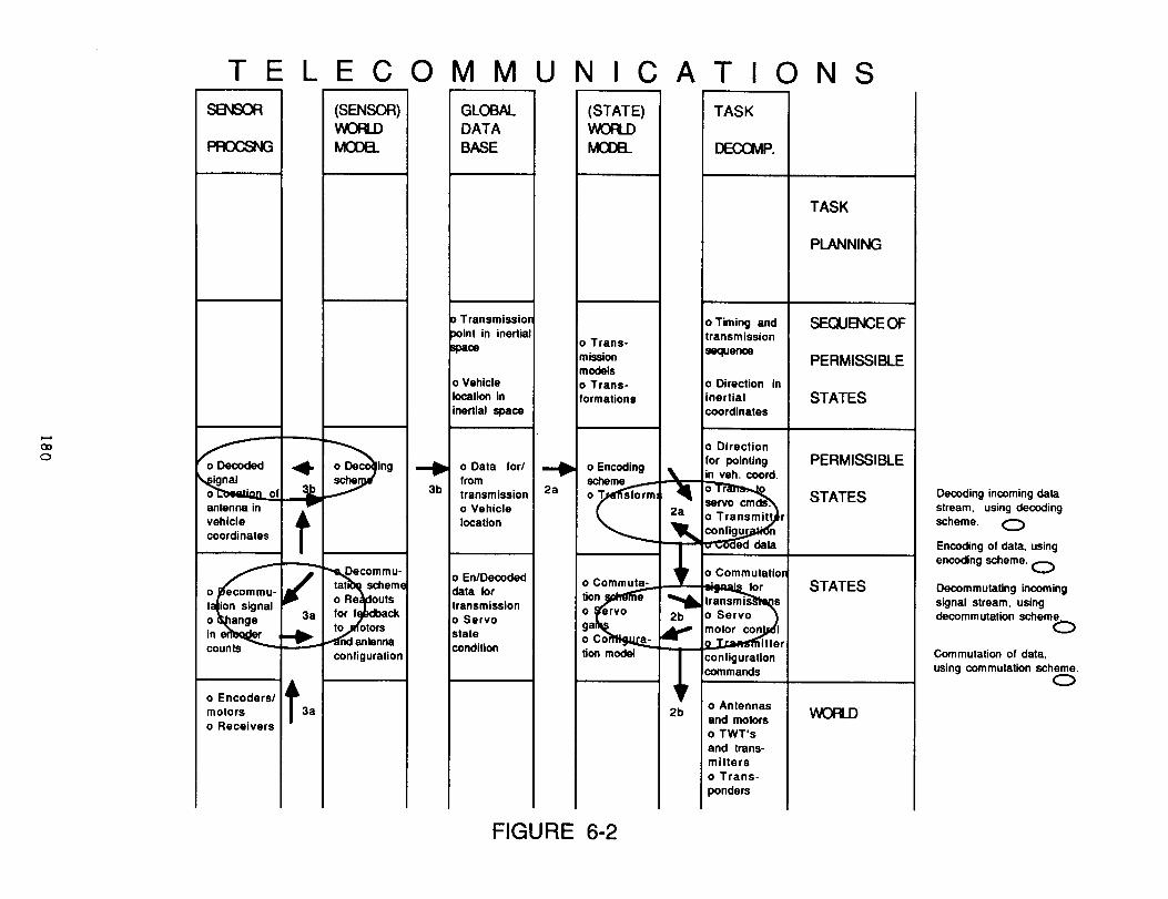
the 'exploded I pictorial representation of the subsystems given in Figures 6-1 to 6-4 . Lnterspersed In thediscussion is bracketed ([...]) references to specific steps shown as a flow of activity in the architecture onthese figures.
6.1 GOAL DEFINITION
The mission science team evaluates the latest data concerning the geoLogicaL and mineralogical properties of
the site surrounding the rover. This data ts a compilation of over-flight imaging taken by the companionorbiter, data available from past missions (e.g., Viking), observations by the on-board rover science
instruments (possibly an imaging spectrometer and sounder), and range and feature data provided by the Imagingcomponents of the on-board rover mobility system. A new Location (or set of Locations) of interest ta selectedand registered as a (set of) mission objective. In this exar;pLe a Location lOm from the current a|te of thevehicle is identified [la of Figure 6-1].
The vehicle team in mission control evaluates the selected Locations based on models of (recent) past roverperformance. An evaluation of feasibility in terms of vehicle health state and resource availability ta
performed Llb of Figure 6-1]. Simulations of the vehicle traverse over the terrain (available from over-flightand on-board rover imaging) assist in providing the feasibility check [interactive loop of Figure 6-1 between
world model and task decomposition at the Mission PLanning Level of the executive]. A recommendation is provided
to a mission director [the mission planner of task decomposition at the Mission Planning level of Figure 6-I],
who in turn weighs the science return/objective(s) _gainst the vehicle utilization. Conflicts (if any) areresolved and a new location (or set of Locations) are identified for the rover [lc of Figure 6-1].
6.2 UP-LINK
The new Location (in an appropriate inertial frame) along with related route information, including the
expected Length of the traverse (time, distance) and points of interest along the route (for collateral Imaging
and science instrument observation), is passed to Telecommunicatior.s for encodLng 12a of Figure 6-2],commutation and up-link transmission I2b of Figure 6-2]. [N.B., These steps are performed by a separate thoughsimilar Telecommunications subsystem tncated on earth. For purposes of illustration these steps are shown onFigure 6-2.]
In addition, appropriate support data is commended to other systems which will provide the Latest update to
the rover. This includes a topographic map generated as a result of over-flight by the planetary orbiter and anew reference location in inertial space for the rover developed by interferometry from tracking data.
178

DATA MANAGEMENT (EXECUTIVE)
_O
SENSOR
PROCSNG
o Mission
progress
reports
o Task
progressreports
o sis
operationalcondition
o sis state
condition
Data report=from s/s
Reportinginctlons of
ubsystems
(SENSOR)WORLDM3OE_
GLOBALDATABASE
(STATE)WORLD
MODEL
TASK
o Objectives t ao Goal Directo Mission
success 0 Mission "_ models of _omodels state: includir g constraints Mission
estimates of and resource: • Planner
progresso Mission
o Mission _ Commandcommand "1c
o Sampling _ o Simplified execuJno°Pl_a
locations and task executio erconstraints models
o Task lot IF• eXOC n
error models ..,_:.;,Vtasks 4 "q atria"T-- n- /_Task
o Task repol S4_.- resource co_nds.,status, comm Lnds models
o Simplified
s/s operation== o Planningo s/s models for s/s
operation o Simplified operationerror models s/s constraint o Sequencing
and resources of s/s
models operations
o s/s state o sis state
error models reports
o Emergencystatecondition
o Simplifieds/e state
model
o sis stateconstraint
and re,,ource
models
o Last
commandedstate In
s/s's
command
table
0 Command
acceptancefeedback
o Emergency
satingmodel
o Organizatior,of s/s states
o s/s state
commands
o Decomp.of state
commands
o Commands
to subsystems
o sls's of
TELECOM,_R.THERMAL,
MOBILITY.
SCIENCE,SAMPLING
on
MISSION
PLANNING
TASK
PLANNING
SEQUENCE OF
PERMISSIBLE
STATES
PERMISSIBLE
STATES
STATES
WORLD
Goals/Objectivas: 10 m from current
location with constraints X.
Evaluate objectives with mission rnodel and mission
status, ganecata mission commands. O
Mission commands: destination,
length of traverse, points of interest ininertial coordinates.
Plan a sequence for Mobility planning andexecution of a traverse task.
Task commands to Mobility to simulate
and I_n a travemal against the given objectives.
Receivas report from Mobility, compares expected
resource utilization with that available and gives
a gocommand.O
Receives report on progress/completion of traverse.
Logs/monitors. _)
Current power state report for use in mobility planevaluation.
FIGURE 6-1
<:3
TELECOMMUNICATIONS
ignal
talion signal
o _ange 3a
o Encoders_ _k
motors 3a
o Receivers
(SENSOR)WORLDMCEEL
lng
"_ecommu-
tatib_, schem,
o Re_)idouls
for f_pbdback
t?._otors..."Znd antenna
configuration
GLCE3ALDATABASE
Transmissior
_oint in inertial
_0ace
o Vehicle
location in
inertial space
,_ o Data for/
from
3b transmission
o Vehicle
location
o En/Decoded
data for
transmission
o Servo
state
condition
2a
(STATE)WORLDMCEEL
o Trans-
mission
models
o Trans-
formations
o Encoding
scheme........
o Commuta-
tion model
TASK
DECCMP.
o Timing andtransmission
sequerce
o Direction in
inertial
coordinates
o Direction
for pointingin veh. coord.
r
o Commutatior
transm is_'te_s
o Servo )
motorcon_l,9,_itter
configuration
commands
o Antennas
and motors
o TWT's
and trans-
mitters
o Trans-
ponders
TASK
PLANNING
SEOJENCE OF
PERMISSIBLE
STATES
PERMISSIBLE
STATES
STATES
WORD
Decoding incoming data
stream, using decoding
scheme. (_
Encoding of data, using
encoding scheme. O
Decommutating incoming
signal stream, usingdecorum utalion scheme.
Commutation of data,
using commutation scheme.C)
FIGURE 6-2

Correlation with
topographic map
Fused data used in
,-.. feature determinationoo
Slereo correlated
ranges determined
Images and pulsed laser
range readouts collected
SENSOR
o vehicle
path progres_
o map for usin correlation
o feature/
daterm in.ion
o vehiJde
state/"
I_ feature mapfo vehicle
I inclinat_n and
heading
o ground apee¢
o distance
traversed
m_
o digitized
local map
range cnts.
gular cnts
Irel. I
l o= n":nrd.
I o inclinomet!I o gyros/IMU
I o accelerom_
I o odometers
I speed sensI o satellite
cameras
(SENSOR)WOFLDIVK3[:)B.
o vehicle
execution
5a(v)
o vehicle
t state model
5a(iv sensed
of
and
terrain
o sum.'d/
diff.'d
;a(_ii)o range read
o camera
models
o encoder,
readouts
o digitized
imagery
MOBILITYGLOBALDATABASE
position
o uplinkedconstraints
O route
_ route _L,_Lv
0 top. map
:dI!:
5d
o fused
terrain map
o commanded
local path
o commande¢
vehicle
state
o readouts
from sensors
o serve
state cmds.
FIGURE 6-3
(STATE)WORDMCOB.
o expecta-tions model
o sampling 51
objectives
o simplifl_
.,y,_le modeb
o sim_
vehicle model
with con-
straints
o last cmd.'d
)ath
o obstacle
model
o commande¢
states
o vehicle
kinematics
and dynamics
o servo
gains
o gear state
o last cmd.'d
servo state
TASK
_P.
'o updated
expectations
_ff cf_ plannin!
elation
lurescon-
straints
o path in
the terrain
o points ofinterest to
achieve
_obstacle
a'_ction/avok
o Io'b(_l
path _iculatior
land cor_anda
o corn ma_d_
turns, m ottes
up/downo coordinat_ )q
commands t,
wheels and
steering
o servo/
_ml_
o serv_/moto
icont? laws
Iheel
otors
o gearso drive
train
o steeringmotors
o motors for
pan/tilt head
TASK
PLANNING
SEQUB_ICEOF
PERMISSIBLE
STATES
PERMISSIBLE
STATES
STATES
WORLD
Receives command to plan
for lraversal using latest
constraint models.
Collects data from cameras
and lasers,through
commanding a pan/tilt 0
I"
0When data is collected,
plan a path.
Pan/tilt sequence comd.'d
in vehicle coordinates.
Commands in the form of
steps to the motors
of the pan/tilt head and
laser scanning apparatus
given
Servo command sequenceexecuted
p.i
GO
SENSOR
o vehicle
path progras=
o map for u_
in correlation
o feature
determination
o vehicle
state
progress
o feature ms
o vehicle
inclination anq
o accelerom(
o odometer/
speed sensorso satellite
cameras
6d
&
6c
-----I&
(SENSOR)WORDMODEL
o vehicle patlexecution
error model
o vehicle
state model
o sensed
MOB
6d
6c
GLOBALDATABASE
o Exec. Rpts.
o VLBI derive
position
o uplinkod
constraints
o route
commanded
o route state
o fused
terrain mapo commanded
_.= path
I L!I
6a
6d
6d
6c
ITY(STATE)WORLDMODB_
o expecta-tions model
o sampling
objectives
o simplified
vehicle
o simplified
vehicle model
with con-
straints
o last cmd.'d
patho obstacle
model
o command 5b(iv)
vehicle states
slate o vehicle
;b(ii)
FIGURE 6-4
servo
o gear stateo last cmd.'d
6b(I)
TASK
DECCMP.
o updated
expectations TASKo path plannin(o correlation
of features wit PLANNINGconstraints
o path in
the terrain
_)paints of SEQUI_ICE OFinterest to
achieve
o obstacle PERMISSIBLEdetection/avoi J
o local
path caiculatioi STATESand commands
i'i'.)O commandec PERMISSIBLEturns, moves
_ STATES
commands to
wheels and
(iii) __/
STA "X_
0 servo
commands
motors
o motors fo_
pan/tilt head
After receiving go-ahead
to executive route, path
points in inertia� coords
commanded.
Inertial coords transformed
into vehicle coord. Local
terrain map processed for
commanding detailed route
free of collisions�obstacles.
Path calculated in turns
and moves. Path way pointscommanded
Coordinated collections of
servo motor control
commands generated.
D
A B

6.3 RECEIVE COMMAND
The commanded position and associated data are received through Telecommunications. The data is de-comuteted
[3a of Figure 6-23, decoded [3b of Figure 6-23 and stored [through the use of the global data base connecting
the subsystems] for use in subsequent operations [3c in Figure 6-1 for the commend and associated constraints,
and 3c in Figure 6-3 for the topographic map and reference location].
6.4 ROUTE PLANNING
The receipt of • command for a traverse to s new location at the Executive (3c of Figure 6-1] begins a
planning activity which leads to the generation of a fessib[e route. The executive calls upon the subsystems lieof Figure 6-1] to report the current state of resources available for the traverse (4c of Figure 6-1]. These
status reports become • part of the constraint space used by the route pisnnlng function (As of Figure 6-1]. A
major portion of this function is located in the Mobility subsystem [Figure 6-3]. Hera the current state datagathered from the Imaging systems on-board the rover are evaluated sgelnst the models of the terrain todetermine the route to the new location (see 6.4.1 below). Once the route is generated (with an expectedresource utilization) a final go/no go evaluation Is performed by the executive [4d of Figure 6-1] using the
data in any subsystem or other reports received during route planning. A 'go' from the executive to Mobttity
begins the traverse to the new Location.
6.4.1 MOBILITY: ROUTE PLANNING
Route planning begins with the gathering of the Latest Imaging data of the site surrounding the presentposition of the rover. A panoramic view of the site is developed through the execution of a sequence of moves of
(for example) a pan and tilt mounted camera system on the rover. The precise sequence, based on the currentvehicle state, is developed (at the task planning level of Mobility) and commanded for execution (ha(I) of
Figure 6-3]. The commands, Initially in |nertiat coordinates, are transformed into specific motor drive commandsto the motor mechanisms supporting the camera system [the hierarchical flow of commands through the levels of
the Mobility subsystem, labelled 5a(t)]. At each position in the sequence, an Image pair (for stereo) is
captured and digitized for further processing [5s(ll) of Figure 6-3]. The application of camera models,correlation of multiple images end image processing result in developing range end dimension of specificfeatures [hal|it) of FiGure 6-3]. A correlation of image features to models of terrain features (e.g., boulders,
ravines) across several image pairs results in a list of position- end dimension-registered objects (or
obstacles) for use in route planning [he(iv) of Figure 6-3]. A final correlation to an on-board topographic map
allows computation of rover position in the terrain and • selection (based on the commanded new position) of the
portion of the map for use by the route planner [ha(v) of Figure 6-31. These results are stored (in the globaldata base] in the form of a fused map of the route Locale of greater resolution than available from the up-
Linked topographic map alone for use in subsequent route planning.
The route planner generates a path to the goal state (the commanded location of the rover) which satisfies theIntermediate view point criteria (if any), the vehicle physical constraints (e.g., clearance, power utilization)and local obstacle avoidance [5b of Figure 6-3]. As part of the verification of the suitability of the path, themovement of the vehicle in the terrain is simulated. In addition, during the simulation expectation models of
vehicle performance are generated for use in monitoring the actual traverse of the rover along the path [5c of
Figure 6-3]. Only a portion of the planned path is slated for execution, ms the errors in planning increase as afunction of range. In the case of goat of lOm nominally the entire path can be executed. A report to this effect
is generated for final go/no go disposition by the executive [hd of Figure 6-3].
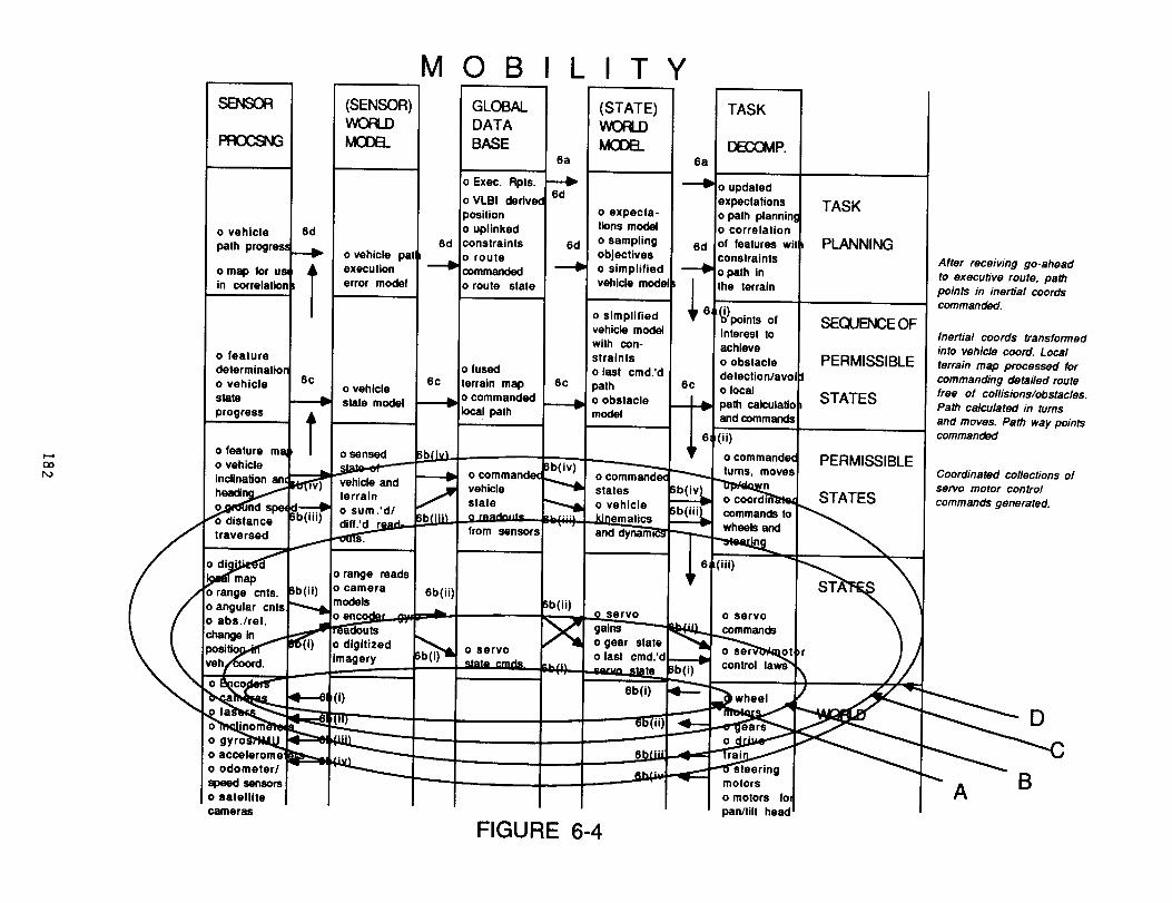
6.5 MOBILITY: PATH TRAVERSE
The ptanned path is executed tn Mobility upon receiving • go ahead commend (6a of Figure 6-4]. The planned
path in inertial coordinates is transformed into vehfcte coordinates (6a(i) of FiGure 6-4], specific coordinatedmoves and turns by the vehicle carriage [6a(it) of Figure 6-4] and servo commands to the motors [6atilt) of
Figure 6-4].
Each command type represents the output command of different type of control taw used tn the execution ofvehicle motion. At the lowest level [State Level of Mobility] • loop is closed around the servo command using
the feedback from motor encoders [6b(t) and the innermost Loop A in Figure 6-4]. At the next level •
heading/dead reckoning Loop is closed around the turn or move commands as measured through the feedback of
gyros/IMU or compass [6b(ii) end loop R in Figure 6-4]. A control loop around the distance traversed command isclosed through feedback measurements from acce[erometers and over-the-ground sensor (6b(lli) end the loop C in
Figure 6-4]. A final control loop is centered around the constraint of providing a stable platform during thetraverse. The feedback for this loop is provided by Inclinometer end Integration of the readouts of gyros/iMU
[6b(iv) and Loop D of Figure 6-4]. Each loop stores feedback data, commands and state estimates for evaluation
of vehicle performance during the traverse.
Other processing during the traverse monitors and performs the veh|cte state evaluation based on the progress
reported by touer Levels of the hierarchy, in particular, the progress of the traverse ts compared agstnst themodel of performance along the path. Corrections in the form of commanded turns and moves ensure compttsnce to
way point and obstacle avoidance constraints [6c of Figure 6-4]. Lastly, progress to the goat state is monitoredxith periodic reports i_sued to the executive [6d of Figure 6-4 end Figure 6-1]. A final report of reaching theneu location ends the traverse end monitoring loop In the executive.
7. UTILITY ANO APPLICATION
The architecture a_ it is laid out forms the basis of a complete Rover Architecture. When completed it should
contain eli of the functions both on the ground and in flight. It is st once a complete description of both the
control end information flows. Step by step sequences end Loops can be worked out for various strategies so the
designer can see the interface complexities directly.
EvaLuating the rate of execution of these loops can aid in identifying technology alternatives to achieve s
greater mission capability. As was discussed at the end of section 4, execution rate is one factor indetermining where functions sit in the architecture. If a mission planner wtshes to increase the range of the
rover, more functions must be 'pushed further down' in the hierarchy or greater processing technology brought to
bear to achieve the required performance,
183

In addition to basic design strategies, detailed fault protection scenarios can be worked out,making sure control loops are continuous and unbroken. Often, tn fault protection design, therequired elements of the design are difficult to identify. This architecture shows that s faultprotection machine must be considered for each state machine in each subsystem. The architectureaids in identifying communication paths (commands and telemetry) needed to achieve the faultprotectlon capability. Tracing scenarios of recovery (as was done in section 5 in brief) revealthe communication paths required.
Finally, by computerizing this model, representing each state machine by the convention Mkii(I)for each element and including these elements in e date base, control loops can be easilydescribed by strings of execution of elements. Strings repeatedly used in these control loops canbe identified end represent the state machines which must be developed end tested first.
8. CONCLUSION
A general architectural concept for a planetary rover is presented, based on an expansion ofthe NASREM concept for telerobotic control. A mapping of this architecture with the functionsfor a rover In a MRSR mission has been performed. An example of a mobility scenario executedwithin this architecture validates the concept. This example and associated discussion illus-trate the capability of the architecture to serve as a tool for design and functional trade-offanalysis.
The research described in this paper was carried out by the Jet Propulsion Laboratory,California Institute of Technology, under a contract with the Office of Aeronautics and SpaceTechnology, National Aeronautics and Space Administration.
REFERENCES
I. Wilcox, B.H., Gennery, D.B., Mishkin, A.H., "Mars Rover Local Navigation and HazardAvoidance," Mobile Robots I I I, Proceedings of SPIE (to be publ Ished).
2. Brooks, R., "k Robot That Walks; Emergent Behaviors from a Carefully Evolved Network,"Computation, Volume 1, December I, Spring, 1989.
3. "Carnegle-Nel Ion Mars Rover", NASA Review held October 14, 1988.
4. '_4ars Rover�Sample Return (NRSR) Rover Nobility and Surface Rendezvous Studies", FinalReport, JPL Contract 958073, Martin Marietta Space Systems Company, Denver Colorado, July,1988.
5, Albus, J.S., McCain, W.G., Lumia, R., "NASA/NBS Standard Reference Model for TelerobotControl System Architecture (NASREM)," National Bureau of Standards Robot Systems Division,12/4/86.
6. Kovtunenko, V.M., Kemudzian, A,L., Sukhanov, K.G., "Mars Rover: Fundamental ControlPrinciples," Babakin Engineering and Research Centre, IAF-88-397.
7. Dies, "Revised Rover Surface Operations Scenarios Baseline," JPL IOM (internal document)dated 29 June 1988.
8. "Robotic Vehicle Computer Aided Remote Driving", JPL D-3282 (internal document), June, 1986.
9. K_:)k, J.H., "MRSR Reference Missions Summary," Version 23. (internal proJect document)September 14, 1988.
tO. "Final Report: Flight Telerobotic Servicer (FTS) Tinman Concept; In-House Phase B Study",SS-GSFC-O042, Volumes I, II, Godderd Space Flight Center, September 9, 1988.
11. "Functional Requirements for the Telerobotic Testbed," JPL D-369] (internal document)Revision 3 December, 1988.
184