Embed Size (px)
Citation preview

ION t . ...... orm Approved
AD-A2 055 I OMB NO 0704,0188-_.
n, 'I,01
F3 REPLPO$, TYPtt AND DATES COVERED
. JSpepember 1991 Final Report 4/89 - 4/91j 1"' At5 FUNDING NUMBERS
Studies of Gas Turbine Heat Transfer: 61102 FAirfoil Surfaces and End-Wall Cooling Effects 2307
~-. T ,-. D S
E.R.G. Eckert, R. 3. Goldstein, S. V. Patankar andl ~T. W. Simon A0R "UT. W. i PERIORMING ORGANIZATION
Heat Transfer Laboratory REPOR! NUMBERI
Department of Mechanical Engineering F49620-89-C-0060University of Minnesota
111 Church St. S.E.Minneapolis, MN 55455 !MG
i MOUIORIN
Air Force Office of Scientific Research AG['jY REPORT NUMBER
Bolling Air Force Base, D.C. F49620-89-C-0060- D-TT
~DTI-___ ,, .. - -... .. .. ...._ _ _ _ __.. ... . . .. .. . .. . . . .;
f ELCTE
:!. Unclassified/Unlimited D
lon:I will be 4:, b idi v~~~wite',-.. ...
The report documents accomplishments made toward understanding the fluid flow atid heattransfer processes in gas turbines at the University of Minnesota over the past two years. Theresearch is divided into three subtopics: studies of film cooling, airfoil surface heat transferand endwall flow and heat transfer. Film cooling experiments show the effects of interaction
* ' among jets on curved surfaces and calculations show that parabolic techniques give accurateeffectiveness predictions in regions away from injection holes. The surface heat transferprogram showed that. tripping the flow or roughening the wall has a clear effect near airfoiltransition and separation points and that recovery from concave curvature is surprisingly slow.Endwall studies show flow visualization on the cascade endwall and the value of a fence on theendwall for rerouting the horseshoe vortex away from the suction wall.
'fhi3 ct'yument bas boon approvedI '' public releaso and sale; its
diztributiorl is unlimited, U
/ " S P, C TIP. • . . NUMB R OF PAG S
114Gas Turbines, Film Cooling, Heat Transfer, Turbulence, Endwalls 421,6 PRICE COO
' *• ' *1 . jy--.S1' .. ,-N 20 LIMI&ATION OF ABSTRACT
u u u unlimited
• 0 F I I , iii l * i
• 4-4
- oJ
Final Report
to
The Air Force Office of Scientific Research
Studies of Gas Turbine Heat Transfer:Airfoil Surfaces and End-Wall Coolkng Effects
AFOSR Grant No. F49620-89-C-006015 April 1989 - 30 April 1991
E.R.G. Eckert, R.J. Goldstein, S.V. Patankar and T.W. SimonCo-Principal Investigators
September 1991

FOREWORD
The following report documents accomplishments made toward understanding thefluid flow and heat transfer processes in gas turbines. It covers the period of contractnumber F49620-89-C-0060 which has now come to a close. Papers which present majorfindings from the Heat Transfer Laboratory on gas turbine heat transfer are listed inAppendix I. This list is restricted to papers published, during and later than, 1988.Progress reports, proposals and abstracts which have given the details of work in progress,for their respective periods, are listed in Appendix II. This submittal emphasizes theaccomplishments since the most recent progress report submitted in June, 1990.
The research is divided into three subtopics: film cooling studies, airfoil surfaceheat transfer studies, and endwall flow and heat transfer.
A-1 .-- " " " - -I
tI, * ,.s;
ii
TABLE OF CONTENTSForeword iiTable of Contents ii
I. Film Cooling Studies 1A. Interpretation of Effectiveness 1B. Experiments IC. Computation 2
I I Airfoil Surface Heat Transfer Studies 10A. Turbine Blades 10B. Recovery from Curvature 10
III Endwall Flow and Heat Transfer 11A. Flow Visualization 11B. The Two-half-blade Simulator 12
C. The New Wind Tunnel and Cascade Section 13
References 15Figures 18Appendices 38
I. Recent Publications 38
II List of Progress and Final Reports and Proposals 41
o°°!1

I. FILM COOLING STUDIES
A. Interpretation of EffectivenessA study investigated our present ability to predict the thermal performance of film
cooling arrangements used to protect the hot components of gas turbines. The requiredinformation is usually obtained by model experiments carried out at near room temperature
as opposed to the high temperature encountered in the gas turbines. Dimensional or
similarity analysis is used to develop the functional relationships between film effectiveness
and convective heat transfer. The use of mass transfer experiments with foreign gasinjection and naphthalene sublimation based on the heat-mass transfer analogy is discussed.
The law of superposition is used to describe the combined effects of film cooling, surfaceconvection or radiation and frictional heating. An order of magnitude estimate indicates to
what extent local temperature gradients are alleviated in the cooled walls by internal heat
conduction.
B. Experiments
Effectiveness measurements and flow visualization of injection through a row-of-holes on curved surfaces were completed. The range of parameters include density ratios
of one and two, blowing rates from 0.25 to 2.50, injection angles of 15, 25, and 45
degrees to the mainstream, and wall curvatures 2r/D = ±90.In terms of laterally-averaged effectiveness the injection angle is found to be of
secondary significance compared to three dominating, independent variables: wallcurvature, density ratio, and blowing rate. If these three, dominating variables are
specified, the laterally-averaged film cooling effectiveness can be found to within ±0.05
over most of the data set, from graphs such as Figure 1 a-f.
Lateral profiles of effectiveness, however, are strong functions of injection angleand blowing rate. Perhaps the most interesting finding of this experiment is that, althoughlow injection angles yield somewhat higher film cooling effectiveness values at moderate
blowing rates (since the resulting jet trajectories are closer to the wall), at high blowingrates the steeper jets can yield higher laterally-averaged effectiveness values. The nature
of this role reversal is related to differences in lateral spreading rates, hence interactionsamong the jets, and the resulting occurrence of coolant touchdown between the jets for
steep injection and high blowing rates. Thus, a short distance downstream of injection,
under such conditions, effectiveness is low along the centerline of injection, due to lift-off,
but high midway between the holes where coolant touches down (Fig. 2). These results
are being prepared for publication.

C. Computation
Injection of cold secondary fluid into a hot mainstream results in a complex flow andheat transfer problem. The discrete hole cooling configuration is a common method
employed in modem gas turbines and combustion chambers to shield metal surfaces fromhot gases. The effectiveness of such systems is governed by a number of geometric and
flow parameters viz. angle of injection, blowing rates, spacings between the holes, andthe characteristics of the mainstream and injected jet turbulence. Experimental evidence alsoindicates the influence of pressure gradient and curvature of the wall on the cooling
performance. Developing methods to predict the performance of the various cooling
configurations has been the goal of several researchers for more than a decade.The three dimensional computational procedure developed by Patankar and Spalding
(1972) was used by Patankar et al. (1973) to predict the slot film cooling effectiveness.
Bergeles et al. (1976, 1978) used the partially parabolic three dimensional procedure of
Pratap and Spalding (1976) to predict the performance of discrete hole cooling situations.
In the present report, the results of computations performed using the fully-parabolicapproach are presented. The aim of the current research is to establish the zone ofapplicability of the computationally efficient fully-parabolic solution procedure in predictingthe flow and heat transfer in the injection cooling systems. Comparisons with the available
experimental data and with the results of partially-parabolic and locally-elliptic methods arereported. The present report is also concerned with the situation where the injected jets are
directed lateral to the mainstream flow. A significant aspect of this problem is the periodicboundary condition prescription at the lateral boundaries of the computational domain. Thisallows the fluxes to leave and enter the domain from the lateral edges. The flow is assumed
to be parabolic in the mainstream direction. The turbulent transport quantities are calculated
with the two-equation, k-e turbulence model.
1) The Physical and Computational ProblemThe injection cooling situations considered in this paper are shown in Fig. 3
consisting of hot gases flowing over an adiabatic flat plate with a free-stream velocity ofWin. The injection is achieved through a row of holes of diameter D and spaced by a
distance of s. The injected jet is directed at an angle P to the plate and its value is varied inthe course of the investigation. The effect of blowing rate, M, on the cooling performanceis studied using different velocities of the injected, jet Vinj. The density ratio of the jet fluid
to the main-stream fluid is kept constant at unity throughout this study. Owing to thesymmetry of the flow and the heat transfer for the streamwise injection case, the
2

computational domain in the x direction is shown by the region between the dotted lines inFig. 3a. The domain extends to ten hole-diameters in the y direction. The inlet plane forthis three-dimensional problem is placed 20 hole-diameters upstream of the injection holesand since a marching procedure is used to analyze the problem, the outflow planedownstream of the hole is not prescribed. Injection though a single hole is also investigatedin this paper. As the spacing between the holes s is increased, a single hole configuration isobtained as a limiting case of a row of holes geometry. A spacing between the holes of 10hole-diameters provided a computational domain significantly free of interactions between
the neighboring jets across the planes of symmetry.In the lateral injection, the jets are inclined at angles 03 to the plate and 0 to the main
stream. Figure 3b shows the details of the problem along with the essential geometricparameters. When the lateral angle 0 =0 the streamwise injection problem is obtained whilea purely lateral injection situation results when 0 = 900. In the present paper the injectionangle 13 is kept constant at 300, while the lateral angle, 0, is given three values of 0, 450 ,and 90 . In addition the spacing between the holes, s, and the blowing rate, M, are varied.Because of periodicity in the x-direction, the computational domain is restricted to theregion between the dotted lines shown in Fig. 3b. The top boundary is extended to 5 hole-diameters in the y-direction. The placement of the upper boundary at 10 and 15 hole-diameters did not alter the results in the region c,," i.terest. The cross-sectional plane isdiscretized into rectangular control volumes in a Cartesian grid. The control-volume sizesare chosen to be nonuniform with finer control volumes near the wall boundary at y = 0 andaround the hole location in the x direction. The elliptic cross-section of the injection hole isapproximated by rectangular control-volumes in the x-z plane. The forward steps Az in themarching direction are also nonuniform; particularly small steps are used at stations around
the injection holes.
2) Governing Equations and Turbulence ModelThe governing equations for steady, three-dimensional turbulent flow in terms of
the time-averaged quantities are equations of conservation of mass, momentum and energy.The Reynolds stress terms in the momentum equations are expressed in terms of turbulentviscosity .tt (in the conventional isotropic model) and gradients of mean velocities.
Bergeles, Gosman and Launder (1978) proposed an anisotropic modification to the stressterms, which increased the cross-stream diffusion based on an experimental correlationfrom Quark and Quarmby. According to this model if Ptx and l.tty are the diffusivities in
the x and y directions then the two diffusivities are related by
3

i9ty
where, a= 3.5 (1 - y /A) if y< A,
a= 0 if y>Awith A denoting the local boundary layer thickness and Jtty is assumed to be equal to the
isotropic eddy viscosity estimated by the turbulence closure model used. The anisotropic
diffusion model is extended to the scalar energy transport in a manner similar to themomentum transport. Therefore, the ratio of the x direction turbulent diffusivity to the y
direction turbulent diffusivity is 1+ a, where a is defined as in the momentum equations.
The k-e turbulence model
The standard k-E model developed by Launder and Spalding (1974) is used to
formulate an expression for the turbulent viscosity. The model involves the transportequations for the turbulent kinetic energy k and the rate of dissipation E. The empirical
constants of the regular k-s model are used. The turbulent viscosity is much greater than themolecular viscosity for most of the flow, but near the wall the two viscosities are
comparable. The wall functions (Launder and Spalding, 1974) are used to deduce the
effective diffusivities in the near-wall region. The k-E turbulence model has beensuccessfully tested for many problems in two dimensions and a few three dimensional
cases.
The transport equations for the momentum, energy and turbulence quantities are
elliptic in nature. In this analysis, however, the flow is assumed parabolic in themainstream direction (z-direction ), hence the streamwise diffusion is neglected and the
reverse flow precludud. In addition, the mainstream velocity is assumed to be governed by
a cross-sectionally uniform average pressure gradient.
Boundary and Inlet Conditions
The boundary conditions need to be specified at the four boundaries of thc cross-
sectional plane and at the inlet plane. The top boundary is treated as a no-flux boundary. At
the bottom wall, the wall function approach is adopted and the thermal condition on the wall
is adiabatic.
The inlet boundary is placed ten diameters upstream of the hole-plane and uniformw-velocity Win, k and , are prescribed. Uniform profiles are also assumed for velocities atthe jet exits. The thermal boundary condition at the inlet is that of uniform temperature T,
and the temperature of the coolant jet at the injection hole is Tc. The boundary conditions
for k and s at the injection hole are evaluated from the injection velocity.
4

In the streamwise injection case, symmetry conditions are employed at x/D = 0 andx/D = 1.5 by setting the normal velocity, U, and the normal gradients of all other variables
equal to zero. The lateral boundaries of the lateral injection case, on the other hand, mustaccount for the fluxes leaving and entering the domain in the lateral direction. Theseboundaries are treated as periodic boundaries; the details of this treatment are discussed in
the next section.
In the parabolic procedure, the outflow plane and the conditions on it need not beprescribed. The computations are simply terminated at the desired z/D location.
3) The Calculation Procedure
The Three Dimensional Parabolic Procedure
The equations governing the transport of mass and momentum are a set of nonlinearcoupled partial differential equations. The differential equations are integrated over thecontrol volumes to give a set of algebraic discretization equations. The power-law schemeof Patankar (1980) is used for the formulation of the combined convection-diffusion fluxes.The details of the algebraic equations are discussed by Patankar (1980) for a general ellipticproblem and by Patankar and Spalding (1972) and Pratap and Spalding (1976) for the
parabolic-type problems.
A marching scheme is employed in which the momentum, continuity, turbulence
and energy equations are solved on each plane starting from the inlet. The overall procedureremains the same as presented by Patankar and Spalding (1972); and therefore will not bedescribed in detail here. Only the salient features will be mentioned. The cross-streamvelocity-pressure coupling is treated by the SIMPLER algorithm of Patankar (1980). The
streamwise pressure gradient, assumed constant for each cross section in the solution of thestreamwise momentum equation, is obtained from the integral mass conservation assuggested by Raithby and Schneider (1979). The discretized energy equation is solved onlyonce at each cross-stream plane after a converged solution for the flow equations isobtained. The converged solution of the previous step is used as the initial guess for theiterative solution of the current step.
The algebraic set of equations for each variable is solved in a segregated manner and
a Tri-Diagonal Matrix Algorithm (TDMA) is employed as the basic solver. A block-correction procedure, in which uniform corrections are applied for strips in the x and v
directions, is used to enhance the convergence of the TDMA procedure; details of theprocedure are given by Settari and Aziz (1973).
The discretization of the domain, in which the governing equations are solved, is
done in the x-y plane using rectangular grids. The cross-sectional plane is discretized into a
5
22 x 22 grid for the single hole geometry and 17 x 22 for the row of holes geometry for thestreamwise injection case whereas 22 x 22 grid was used for the lateral injection problem.The grid structure, in both the cases, is non-uniform especially in the y-directicn wherefiner grids are used near the wall. The marching step Az is also non-uniform with smallervalues in the region around the hole. A typical number of forward steps in this study is
100, though in certain cases different numbers have been used to obtain data at anexperiment conforming z/D location.
Exploratory runs were also made with 32 x 32 and 44 x 44 grids in the x - y plane.Doubling the number of grids resulted in less than 2% difference in the values oftemperatures and streamwise velocities at corresponding locations in the post-injectionregion. The typical CPU time for the cases evaluated in this work is approximately 9.5s for
a 22x22x75 grid on the CRAY-2. The maximum difference in the values of temperatureand streamwise velocity at the same z/D location was found to be less than 2 % for a 40x40grid compared with a 22x22 grid in the cross-sectional plane.
Implementation of the Periodic Boundary ConditionThe incorporation of the periodic nature of the lateral boundaries is done at the level
of formulating the discretization equations. If the grid points are numbered 1, 2, 3, ... N,then the periodic boundary implies that, for grid point 1, the neighboring points in acomputational sense are 2 and N. Similarly, for grid point N, the neighboring points are(N-I) and 1. The solution of such a cyclic system of equations is discussed in detail byPatankar et al. (1977) and is called the Cyclic-TDMA procedure. A block-corrected form of
the CTDMA is applied to enhance the convergence.
4) Results and Discussion
Numerous cases were studied in the course of this work, most of them matching theconditions under which the experiments were performed. Since, the number and the detailare too many, a comprehensive summary of the cases is not included, instead the details
are quoted along with the relevant figures.
Many comparisons of effectiveness, local and laterally averaged, with experiments
and other numerical approaches are discussed in this section. Firstly, we discuss theperformance of the method for the single hole geometry and subsequently the results ofinjection through a single row of holes with streamwise injection and lateral injection are
presented.
6

Single Hole Streamwise Injection
The results in this subsection are compared with those of Bergeles et al. (1978).
Figures 4a - 4d show the variation of the effectiveness, at four lateral locations, with the
non-dimensionalized z-direction. Figures 4a and 4b show the present predictions for theblowing rates of 0.1 and 0.2 to agree with the experiments as well as the numericalpredictions, in Fig. 4b, of a partially-parabolic approach. When the blowing rate isincreased to 0.3, in Fig. 4c, a discrepancy in the prediction of effectiveness is observed in
the experimental and numerical results. However, this discrepancy is confined to abouteight diameters downstream of the injection port and the results are in good agreement with
the experiments further downstream. This suggests that the local ellipticity in pressure (andvelocity) does not significantly affect the performance of the solution procedure in the
regions away from the injection hole. This point is further confirmed in the Fig. 4d where a
similar trend is observed for a high blowing rate of M = 1.0. It is noticeable that thepartially-parabolic procedure is also incapable of handling the elliptic characteristic of thevelocity at high blowing rates, but the far field (beyond 10 diameters) results show a
reasonable agreement.
Single Row of Holes Streamwise Injection
Figures 5a and 5b compare the results, obtained for the injection through a row of
holes separated by a distance of s/D = 3 and at an angle of 350 to the plate, with the
experimental data of Kadotani (1975). The numerical predictions are in good agreementwith the experimental findings for both the blowing rates of M = 0.5 and M = 0.2
considered. It is noteworthy that the anisotropic turbulence augmentation is successful in
estimating the lateral cooling performance, showing reasonable agreement at the midplane
between the holes (x/D = 1.5) with the experimental results. This enhanced performance
can be seen in a greater detail in Fig. 6, where the results of the present computation arecompared with the experimentai data due to Kadotani and Goldstein (1977) and the
numerical predictions using the locally-elliptic procedure by Demuren and Rodi (1983). Thenumerical predictions are not in good agreement with the experiments at z/D = 6.65
downstream of the injection port, but the agreement improves further downstream, as seen
at a distance of z/D = 15.8 and 37.37. This result is analogous to the observations in the
single hole study, but the noticeable feature is the competitive performance of the fully-parabolic procedure with the locally-elliptic procedure.
7

Single Row of Holes Lateral Injection
The computed result for the blowing rate of M = 0.5 and spacing of s/D = 5 is
compared with the measurements of Honami and Fukagawa (1987). The experiment study
included the measurements of lateral injection (0 = 90) over a flat surface and is the basis of
this comparison. The matching with the experiment is done to the extent of the available
information viz. inlet velocity, injection hole diameter, the temperature difference between
the mainstream and the secondary stream, turbulence intensity. Figure 7 shows a good
agreement in the lateral distribution of cooling effectiveness at two location downstream of
the injection hole. The fully-parabolic model is thus found to be adequate for this blowing
rate. The effect of blowing rate on the distribution of the local effectiveness is also observed
in Fig. 7 for M values of 0.1, 0.2, 0.5, and 1.0. The increased interaction between the jets
and the improved cooling performance at higher blowing rates is the subject of the
subsequent discussion. Since there is a lack of extensive experimental data for the lateral
injection, we use this comparison and the experience of the authors with the model as the
basis for the following analysis.
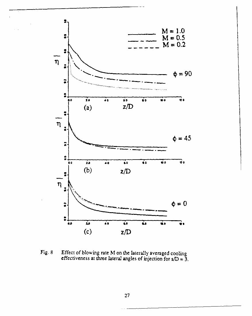
The motivation to study the lateral injection is to study the interaction of the injected
jets with each otner and its effect on the full coverage cooling. The parametric study of the
effects of the blowing rate, spacing between the holes and the lateral angles of injection is
reported by Sathyamurthy and Patankar (1990). When the blowing rate is increased in the
case of lateral injection, the cooling effectiveness tends to increase monotonically. On the
other hand, the trend for the streamwise injection (0 = 0) is that the cooling increases up to a
blowing rate of 0.5 and then decreases. This is clearly seen in Fig. 8. The implication of
this finding is that the lateral cooling configuration does not suffer from the blowing rate
ceiling. The reason for such a behavior is that in the streamwise injection, there is a pair of
counter-rotating vortices whose strength is proportional to the blowing rate. This causes the
injected jet to be lifted off the surface at higher blowing rates and penetrate the boundary
layer. As a result, the cold jet mixes with the I ot mainstream and the cooling performance
suffers. The lifting of the injected jet also allows the hot mainstream to flow under the jet
thus decreasing the effectiveness. The lateral injection, on the other hand, generates a single
dominant vortex structure (per hole) downstream of the injection. In spite of the increase in
the strength of the secondary flow (vortex) with blowing rate, the secondary flow has larger
tendency to push the jet in the lateral direction. Thus, the jet remains closer to the surface
and leads to its higher cooling potential. Figure 9 shows the two different secondary flows
resulting from the injections in the streamwise and lateral directions. Figure 10 shows the
effect of the blowing rate on the local cooling of the surface and the higher blowing rate of
M = 1 is seen to have a better coverage than the lower blowing rates.
8

5) Concluding RemarksNumerical results of the film cooling by injection from a row of holes and a single
hole are presented. Comparisons with the experiments and other numerical investigations
demonstrate that the fully parabolic procedure is competitive in the quality of predictioncompared with both the partially-parabolic and the locally-elliptic methods, while superioi
in terms of computing time and resources required. The computed results are in good
agreement with the measurements of Honami and Fukagawa (1987) for the case of lateralinjection. Furthermore, the following may be concluded from the present investigation:
a) The cases with angular injections and medium blowing rates are not dominated by
strong elliptic effect- (both pressure and velocity).
b) The elliptic effects in the higher end of medium blowing rate spectrum (around M
= 1.0) are localized to a small region aft of the hole and most importantly when considerednegligible, as in the current procedure, does not affect the performance of the procedure in
estimating the cooling effectiveness further downstream.
c) The anisotropic turbulence model enhances the prediction of the effectiveness to
the extent that the current procedure is competitive with the other methods employing the
d) A turbulence model accurately accounting for the non-equilibrium nature of the jetand boundary layer interaction is expecLed ,o farther enhance the prediction capability of the
current and also tite other numerical methods.e) The lateral injection can be operated at much higher blowing rates to achieve a
better coverage of film cooling than the streamwise injection at comparable blowing rates.The lateral injection does not have the blowing rate ceiling of M = 0.5 as in the case of
streamwise injection.f) An increase in the blowing rate increases the film cooling effectiveness on the
surface when the jets dre injected lateral to the mainstream.
Finally, as result of the current research, the fully-parabolic procedure is shown to
be an effective tool in the field of analysis and design of film cooling systems when appliedin conjunction with improved turbulence models. In addition, these findings warrant a
more intense investigation of the lateral injection film cooling situation.
9

II. AIRFOIL SURFACE HEAT TRANSFER STUDIES
A. Turbine BladesThe influence of the turbine blade's leading edge roughness on the blade's heat
(mass) transfer is investigated. The roughness, which renders the boundary layer turbulentimmediately downstream of the leading edge, is simulated by placing a tripping wire on theblade's surface near it's leading edge (Sp/C=0.0375 on the pressure side andSs/C--0.0616 on the suction side). The trip wire, 1 mm in diameter and 15 cm in length,spans the mass transfer active (naphthalene coated) height of the test blade. Thus, insuringa measurement region on the blade that is not affected by the trip's ends. A strip of sandpaper (#320) is also employed to simulate the leading edge roughness. The strip covers
the leading edge and terminates to Sp/C=0.0375 on the pressure side.The influence of the boundary layer tripping on mass transfer rates (expressed as
Sherwood number) is summarized in Fig. 11. On the suction side, there is a very sharpincrease followed by a decrease in Sherwood number just downstream of the trip wire.This is probably due to the flow separation-reattachment created by the presence of the trip.Downstream of the flow reattachment point, the growth of the boundary layer appears tobe coupled with a gradual decay of the induced turbulence to a location where the trippedand the untripped boundary layers produce the same Sherwood number. Fartherdownstream, however, the tripped boundary layer seems to experience an earlier andweaker (inducing less increase in mass transfer) transition than the untripped one.
On the pressure side, mass transfer does not show a rapid change behind the tripwire as it did on the suction side. It appears that the separated flow behind the trip wire andthe naturally occurring separation bubble of the untripped layer merge to form an earlier,shorter, but stronger separated region. From the reattachment point downstream to thetrailing edge, the tripping of the boundary layer produces only a slight increase in masstransfer. This increase will gradually diminish further do,,ristream. The sand papertripping of the boundary layer acts similar to the trip wire with a slight reduction in thelength of the separated region and an increase in mass transfer at the reatt-chment point.These results, together with the response of the near endwall heat transfer to boundarylayer tripping, will shortly be submitted for publication.
B. Recovery from CurvatureThe purpose of this study is to document the manner ,n which momentum and
thermal boundary layers recover from sustained concave curvature on a downstream flat-wall. Questions to be resolved include whether and where straight-wall relationships,
10

including turbulence models, can be applied downstream of a curved section. The study isconducted with a negligible streamwise pressure gradient in order to isolate the curvatureeffect. The effect of free stream turbulence is also examined.
The case with negligible free-stream turbulence intensity is now almost complete.The results of this study are reported in the attached paper by Kestoras and Simon (1991).Turbulent shear stresses have already being acquired (Fig. 12) and appear to support theconclusions of Kestoras and Simon (1991). Measurements are now being taken using thetriple-wire probe built and used in previous studies in the heat transfer laboratories of theUniversity of Minnesota. This will document for the first time, to the best of the authors'knowledge, the behavior of turbulent heat fluxes on the recovery wall downstream of a
concave curvature.The quadrant analysis (Lu and Willmarth (1973), and octant analysis (Kawaguchi et
al. (1984)) will be performed on the instantaneous measurements of velocity andtemperature. This is a technic that classifies the instantaneous turbulent fluctuationsaccording to quadrants depending on the signs of instantaneous velocities and temperatureswhich make up the turbulent shear stress and turbulent heat flux. These quadrants arefurther subdivided to cold and hot motions, depending on the sign of the associatedtemperature fluctuations. This analysis will be helpful in determining which motions areenhanced or suppressed by the introduction and the removal of curvature, giving moreinsight on the associated response of mean quantities like friction coefficients and Stanton
numbers.
In the very near future the high free stream turbulence generator (8% turbulenceintensity) will be installed in the tunnel. Similar measurements to those taken with thenegligible free stream turbulence intensity case will be performed and the two cases will becompared. The study of recovery of a boundary layer from concave curvature is to becompleted by the end of the calendar year.
III. ENDWALL FLOW AND HEAT TRANSFERA. Flow Visualization
A visualization study of the surface flow over the endwall was accomplished. Thisstudy was initiated to obtain more information about the number and the origin of the near-endwall vortices which were detected through previous mass transfer measurements. Themeasurements, were done on the endwall and the suction surface near the endwall (Chenand Goldstein (1988) and Goldstein and Spores (1988). The earlier results of thevisualization study are compared with the results of mass transfer measurements in Jabbari
II

et al. (1991)) (manuscript is attached). The later results are shown in Figs. 13a and 13b.
These figures show the origin and the path of some of the vortices.
B. The Two-half Blade Simulator
In the first stage of this study, a large-scale, two half-blade facility that simulates a
turbine cascade flow was introduced. The simulator consists of two, large, half-blade
sections, one wall simulating the pressure surface and the other wall simulating the suction
surface. Two parallel endwalls constitute the third and fourth walls of the channel. Fig. 14
shows the geometry and configuration of the test blade. The advantage of this configuration
is that the features of the secondary flow are large because of the relatively large test section,
and the flow is easily accessible with probes. This is all done with a small delivery section
compared to that of a true cascade of equal blade size. Also one can easily change the
cascade geometry, such as the incidence angle, pitch, aspect ratio, and the blade shape in
this simple experiment. The disadvantage is that one must verify that such a simulator
replicates the features observed in a cascade. Qualification of the simulator was discussed
by Chung and Simon (1990). It was shown that the cascade simulator in this investigation
displayed all the essential features of a turbine cascade flow: (1) the horseshoe vortex (2) the
passage vortex (3) endwall crossflow and the saddle point due to flow separation and (4)
reattachment line on the suction wall, even though its geometry is very simple.
Once qualified, the facility became available for studies of the three-dimensional
endwall flow with great opportunity for access and better resolution. An investigation into
flow control with a fence in the endwall region was initiated first (Chung and Simon, 1991).
The fence was designed to reduce some harmful effects of secondary flow on the blade
surfaces It is shown to prevent the pressure-side leg of the horseshoe vortex from
crossing to the suction surface and impinging on the wall. Instead, the vortex lifts and is
swept downstream by the freestream as shown in Fig. 15. The vortex is weakened and
decreased in size after being deflected by the fence. Such diversion of the vortex prevents it
from removing the film cooling flow, allowing the flow to perform its cooling function.
Other studies will be initiated to investigate effects of various conditions which are
representative of gas turbine flow. A high-turbulence generator section which is simulating
the flow field from the combustor of a real gas turbine was developed. It was designed to
have similar features to a combustor, such as the large scale recirculation, penetration and
mixing of jets and contraction of the flow (Fig. 16). The combustor simulator, which will
be located ahead of the large-scale cascade simulator, will aid in the study of the flow field
and heat transfer in a cascade passage under more realistic conditions. Heat transfer
visualization study is now underway with foil heaters and liquid crystal displays to observe
12

the mixing phenomena due to the secondary flow near the endwall and the suction wall.Before long, a new test section, which has a modern blade profile, will be fabricated. The
airfoil shape will probably be similar to the C3X vane profile, as presented by Hylton, et al.
(1988).
C. The New Wind Tunnel and Cascade SectionTo prepare for further studies of flow and heat transfer in gas turbine engines a new
cascade/wind-tunnel combination has been installed. The new tunnel is designed to
produce flow velocities up to 38 m/s uniform within 0.5% over the central 90% of the
cross-section of the contraction exit area (18 x 18 in.). The turbulence intensity is below
0.5%.A literature survey was conducted to aid in the design and specification of the wind
tunnel. It was concluded that a blower type tunnel with a honeycomb flow straightener,
three turbulence damping screens, and a contraction ratio on the order of 6 to 9 would be
sufficient to meet the goals. These parameters were sent to outside vendors and a design
and cost estimate was made for in-house construction as well. Comparison of thevendor's bids, based on cost and quality of the product with the in-house estimate favored
the outside vendor's proposal. Consequently, proposal of the Engineering Laboratory
Design, Inc. in Lake City Minnesota, was chosen.
The purchased tunnel is a blown open jet configuration. It is equipped with a cent-axial type blower, a 30Hp induction motor, and a transistor-inverter variable-frequency
speed controller. This produces flow velocities in the range of 3 - 40 m/s in the 18 x 18inch contraction exit leading to the test section.
The walls of the tunnel are made of a laminated fiberglass reinforced plastic with a
rigid foam core. The interior and exterior surfaces of the tunnel are coated with polyestergel-coat. The tunnel includes a heat exchanger to maintain uniform temperature flow and
an aluminum honeycomb and three graduated damping screens to straighten the flow andreduce free stream turbulence levels. A 6.25 contraction ratio accelerates the flow between
the 45x45 inch upstream section and the 18x18 inch downstream section. The wind tunnel
is delivered and it is installed so that it can be operated either on a closed or an open loop
configuration.
Qualification of the tunnel's performance is underway. Testing has been conducted
on the uniformity of exit velocity and free stream turbulence levels are being measured.The exit flow uniformity meets our specifications, with a uniformity within 0.5% over
50% of the exit cross-section and within 1% over 90% of the cross-section. Tests also
13

show a slight over-shoot of the velocity near the sidewalls outside the boundary layer
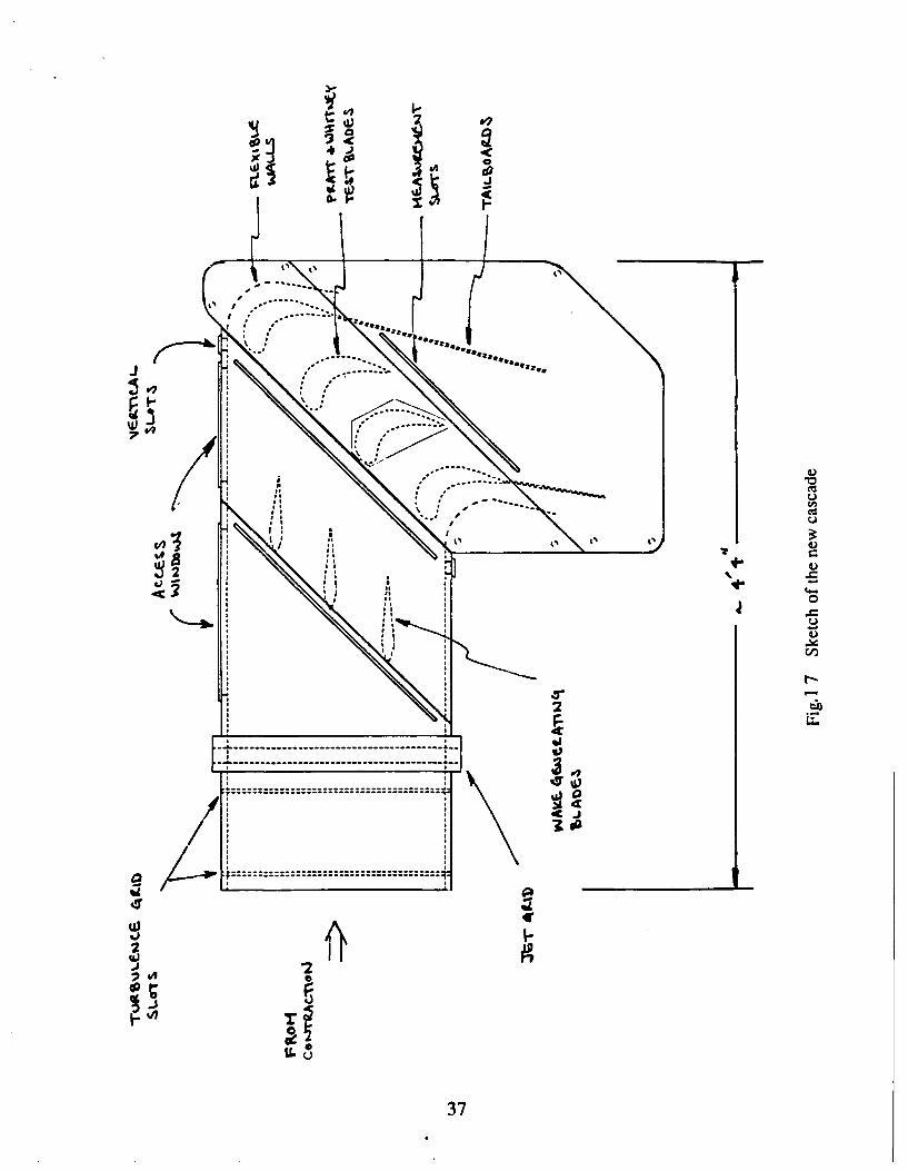
ranging from 2-3% depending on the mean flow velocity.A new test section (cascade) is being designed for construction. A high visibility,
acrylic test section, incorporated in the design, will facilitate flow visualization studies.The test section design also allows for easy access and quick installation of naphthalene
coated, or otherwise instrumented, test blade sections. The design includes an upstream
section for turbulence generation using cross-bar grids and/or jet grids, and a section for
adding upstream wake generating blades ahead of the linear cascade test section, Fig. 17.The test section will contain four blades in a central passage arrangement. The
outer blades and the sidewalls will be separated by half a pitch. A flexible sidewall will be
used in this region. Two tailboards will be added to the outer test blades as well.Adjustments will be made to the outer flexible wall shapes and the orientations of the two
blade tailboards to produce a uniform flow within the three cascade passages.
The blades will initially have a 7.5 inch chord length, with a pitch-to-chord ratio of
0.9. All blades will be machined from aluminum. The test blade will be made from three
interchangeable pieces (two spacers at 5.125 inch each and a naphthalene or pressure test
blade at 7.750 inch) spanning the 18 inch test section height. The test region of the test
blade can be placed in the central span of the tunnel or near the top or bottom edges for
endwall measurements.The test section is designed to allow easy access and modification. Variations of
the inlet flow conditions are planned using turbulence grids, jet grids and wake-generating
upstream blades. In addition, variations in the blade pitch-to-chord ratio are possible, orvariations in the blade profiles can be accommodated with the open, sectional, test section
design.
The new cascade test section should prove to be quite versatile for both flow
visualization and mass transfer studies in countless flow conditions and test blade
arrangements. The test section design is near completion and test blade manufacturing will
soon be underway.
14

REFERENCES
Bergeles, G., Gosman, A.D., and Launder, B.E., (1975) "The Near-field Character of a Jet
Discharged through a Wall at 90 deg. to a Mainstream", ASME paper 75-WAIHT-108.
Bergeles, G., Gosman, A.D., and Launder, B.E., (1976) "The Prediction of Three-
Dimensional Discrete-Hole Cooling Processes. Part 1 - Laminar Flow", ASME J. Heat
Transfer, Vol. 98c, p. 379-386.
Bergeles, G., Gosman, A.D., and Launder, B.E., (1978) "The Turbulen- Jet in a Cross
Stream at Low Injection Rates : A Three Dimensional Treatment", Numerical Heat Transfer,
Vol. 1, p. 217-242.
Chen, P.H. and Goldstein, R.J., (1988) "Convective transport phenomena on a turbine
blade," Proc. of the 3rd Int. Symp. on Transport Phenomena in Thermal Control, Taipei,
August 14-18
Chung, J.T. and Simon, T.W., (1990) "Three-Dimensional Flow near the Blade/Endwall
Junction of a Gas Turbine: Visualization in a Large-Scale Cascade Simulator," ASME Paper
90-WA/HT-4, Presented at the 1990 ASME Winter Annual Meeting, Dallas, Texas.
Chung, J.T. and Simon, T.W., (1991) "Three-Dimensional Flow near the Blade/Endwall
Junction of a Gas Turbine: Application of a Boundary Layer Fence," ASME Paper 91 -GT-
45, Presented at the 36th International Gas Turbine and Aeroengine Congress, Orlando,
Florida.
Demuren, A.O. and Rodi, W., (1983) "Three-Dimensional Calculation of Film Cooling by
a Row of Jets", Notes in Numerical Fluid Mechannics, Vol. 7, p. 49-56.
Goldstein, R.J. and Spores, R.A., (1988) "Turbulent transport on the endwall in the region
between adjacent blades," J. of Heat Transfer, Vol. 110(4A), p. 862-869.
Honami, S. and Fukagawa, M., (1987) "A Study of Film Cooling Behavior of Cooling Jet
over a Concave Surface", Proc. of the Joint ASME/JSME Gas Turbine Conference, p. 1-8.
15

Hylton, L. D., Nirmalan, V., Sultanian, B. K. and Kaufman, R. M., (1988) "The Effects
of Leading Edge and Downstream Film Cooling on Turbine Vane Heat Transfer," NASA
CR-182133, 1988.
Jabbari, M.Y., Goldstein, R.J., Marston, K.C., and Eckert, E.R.G., (1991) "Three
dimensional flow at the junction between a turbine blade and end-wall," To appear in the J.
of Thermo-and Fluid Dynamics, Warme-und Stoffubertragung, 1992.
Kadotani, K. and Goldstein, R.J., (1977) "On the Nature of Jets Entering a Turbulent Flow
- Part B: Film Cooling Performance", Proceedings of the 1977 Tokyo Joint Gas Turbine
Congress, p. 55-59.
Kadotani, K., (1975) "Effects of Mainstream Variables on Heated and Unheated Jets
Issuing from a Row of Holes", Ph.D Thesis, University of Minnesota.
Kawaguchi, Y., Matsumori, Y., and Suzuki K., (1984) "Structural Study of Momentum
and Heat Transport in the Neat Wall Region of a Disturbed Turbulent Boundary Layer",
Proc. of the 9th Biennial Symposium on Turbulence, Missouri-Rolla.
Kestoras, M.D. and Simon, T.W., (1991) "Hydrodynamic and Thermal Measurements in a
Turbulent Boundary Layer Recovering from Concave Curvature," ASME Winter Annual
Meeting, Atlanta, Georgia.
Launder, B.E. and Spalding, D.B., (1974) "The Numerical Computation of Turbulent
Flows", Computer Methods in Applied Mechanics and Engineering, Vol. 3, p. 269-289.
Lu, S.S., and Willmarth, W. W., (1973) "Measurements on the Structure of the Reynolds
Stress in a Turbulent Boundary Layer", J. Fluid Mech., Vol. 60-3, p. 481.
Patankar, S.V. and Spalding, D.B., (1972) "A Calculation Procedure for Heat, Mass and
Momentum Transfer in Three-Dimensional Parabolic Flows", International Journal of Heat
and Mass Transfer, Vol. 15, p. 1787-1806.
Patankar, S.V., (1980), Numerical Heat Transfer and Fluid Flow, Hemisphere.
16

Patankar, S.V., Liu, C.H., and Sparrow, E.M., (1977) "Fully Developed Flow and Heat
Transfer in Ducts Having Streamwise-Periodic Variations of Cross-sectional Area", ASME
J. Heat Transfer, Vol. 99, p. 180-186.
Patankar, S.V., Rastogi, A.K., and Whitelaw, J.H., (1973) "The Effectiveness of Three-
Dimensional Film-Cooling Slots - II. Predictions", International Journal of Heat and Mass
Transfer, Vol. 16, p. 1665-1681.
Pratap, V.S. and Spalding, D.B., (1976) "Fluid Flow and Heat Transfer in Three-
Dimensional Duct Flows", International Journal of Heat and Mcs Transfer, Vol. 19, p.
1183-1188.
Raithby, G.D. and Schneider, D.B, (1979) "Numerical Solution of Problems in
Incompressible Fluid Flow : Treatment of Velocity-Pressure Coupling", Numerical tteat
Transfer, Vol. 2, p. 417-440.
Sathyamurthy, P. and Patankar, S.V., (1990) "Prediction of Film cooling with Lateral
Injection", Fifth AIAA/ASME Thermophysics and Heat Transfer Conference, Seattle.
Washington, June 1990, ASME HTD-vol. 138, p. 61-70.
Settari, A. and Aziz, K., (1973) "A Generalization of Additive Correction Methods for theIterative Solution of Matrix Equations", SIAM Journal of Numerical Analysis, Vol. 10, p.
501-521.
17

0.5-;-P2/P-=l o X= 15'
0.4- ..... p2/p- 2 ot=25
0.3-
fi0.2-
0.1 .
0-
0 0.5 1 1.5 2 2.5M
(a) x ID =4.84
0.5 - _______________________________
0.4-
0.3-*
0.2-
0.1-
0-0 0.5 1 1.5 2 2.5
M(b) xID= 17.75
0.5-
0.4-
0.3-
0.2
0.1- 4
0-
0 0.5 1 1.5 2 2.5M
(c) xID =45.19
Figure 1. Row-of-Holes Film Cooling on a Convex Wall: Effect of Density Ratio, Injection Angle,and Blowing Rate on Laterally-Averaged Effectiveness
18

P2 1P-=1 o a= 150
0.4- .... p2/p-= 2 a az=250
0.3-
0.2 - .....
0.1-
0 0.5 1 1.5 2 2-5M
(d) x/ID =7.74
0.5-
0.4-
0.3-
0.2 - ..
0.1-
0-0 0.5 1 1.5 2 2.5
M(e) x ID= 19.4 8
0.5-
0.4-
0.3-
0.2-
0.1-
0-0 0.5 1 1.5 2 2.5
M(f) x/D=46.42
Figure 1. Row-of-Holes Film Cooling on a Concave Wall: Effect of Density Ratio, Injection Angle,and Blowing Rate on Laterally-Averaged Effectiveness
19

IIS
C-0 0 0
II
o 0 000
CU
U
0
6C
N E
Cd~U
6 -
0
0
L.0
U
U
6LL~
0
I-UCu
-o -~
'I, e - 0
0 6 6 0 6
20

In d
wl)
yD
zo 1
W(a
Fii. 3 o m e r oft e r bl m
21puaioa

?reseflt predlct'Ofls
- -. ~ ergees 11 '1 pedic TP
400
00
........
, .n d h P r td i t P OL5 yie C s ej al ( I~ 9 75 a n d 1 B
fig.4 copal ctins b 22

10
40
C
0.0 2.5 507.5 10.0 12k 15.0 1.
S(d)
1.
C
005.0 10.0 15.0Z/d
Fig. 4 Comparison of the present predictions of single hole cooling with
measurements and predictions by Bergeles et al. (1975 and 1978).
23

(a) ________ Present predictions
Kadotani (exp.)
C;
M =0.5
0 x/D
0.
c1.5
C (b)
M 0.2
x/D0 0.0
C1.5
0J
0.0 7.5 15.0 225 30.0 37.5
77/D
Fig. 5 Performance of the present predicnons of a single row of holes coolingwith measurements of Kadotani (1975).
24

* Present predictionsto Kadotani (exp.)
------ Demuren and Rodi (predictions)
C,
0 z/D = 37.36
0.00 0.25 0.50 0.75 L.oa.2
Fig. 6 Comparison of cooling effectiveness in the lateral direction at different
downsteamn locations with, measurements of Kadotani (1975) and
predictions of Demnuren and Rodi (1983).
25

M* z/D =1.5 0.1
*Present Predictions 0.2Honami and Fukagawa (exp.) 0.5
*1.
0 .0 0 .5 1.0 V .S 2-0 .5 .0 3-S 4 .0 4 .5 .) D
0
C M, z/D =6.5 "0.1
wI
.0.2
/0.5
-1.0
bI
0. I~T
0.0 0.5 1.0 .5 2.0 2. 3.0 3.5 4.0 4.5 5.0
Fig. 7 Comparison of the cooling effectiveness Ti with themeasurements at two z/D locations downstream of the
injection hole.
26
SM
-~ - - M 0.5
-~ ~ - 0.2
U(a) z/D
=45
(b) z/D
(C) z/D
Fig. 8 Effect of blowing rate MIon the laterally averaged coolingeffectiveness at three lateral angles of injection for sf1D 3
27

a & f 9 V I % % 0 & J 0 6 ad
9~~4 1 a off,, ~ ~S d
04 or t.,
z/D= 2
0 . . .1,0° . . . . . a 4° ° . .. .. ......
-ON .%V V V. *o 4, q
I.',,lI /I.
S.W. 5 kI
z/D= 10
(a) (b)
Fig. 9 Secondary flow patterns in the cross-sectional planes for M I ands/D = 3
(a) streamnwise injection and the resulting counter rotatingvortices(b) lateral injection and the dominant single vortex
28
.j~~~N~... ....... .~*s

.29

C/)
060
C6
o 2
00
Lbl
--
00- C4
300

V LO ID I - M In
zzzzzzz0000000 4 IL,
-k4 1-4 1- 4
U>En EnLn U En f) 4
* a a
C-3 -4
0*
0
cu 'o 0 0o o
md
31

- , "
Grain structure of the lamp-black visualization of the flow over the endwall suggests that theflow is consisted of several distinct regions which may end up forming various vortices in thecomer of blade/endwall junction. To verify this a color visualization was developed and appliedto the different regions of the flow.
Figure 13a
32

Color visualization shows that pa-1 of the near surface flow ahead of the leading edge (the flowout of the separation bubble are the suction-side leg of the horseshoe vortex, blue paint) willenter the passage, but soc- -., pushed to converge toward the blade/endwall comer. This floweventually is pushed tr : - ap over the suction surface (start of the rise of blue paint is seen butnot enough paint, or rwojientum in the flow, to carry it further).
Flow between the dividing stream lines (red paint) will all enter the passage. The stream comingfrom the separation bubble of the neighboring blade forces this flow to converge to a smallregion along the blade/endwall junction. This flow converges from a larger span to a muchsmaller one , and initially has higher momentum , so it moves up the suction surface (in form of avortex) and carries the red paint with it all the way to the trailing edge. The pressure-side leg ofthe horseshoe vortex of the neighboring blade breaks this vortex into two smaller ones; onecontinues above the endwall in touch with the suction surface, the other remains in the comer.The green and the blue paints downstream of the red are carried by the wash down flow from thepressure surface into the comer to form distinct vortices.
Figure 13b
33

0
N
Cr
00
340

400vA
.CU
jc1
ARA
460
35

778 ,17 H.j1 -60
I ,2 5
I I -
S29 0
~-- -- - . ..,-.-,=,.[1J [1 ',._-
/ Li UL2- 0
30
Fig. 16 Back view of turbulence generator
36
-4I
---- ---- ---- ---- ---- ---- ---- ---
----- ---- ----
dcU
P7a
37C
APPENDIX I: Recent Publications on Gas Turbine Heat Transfer from
the Heat Transfer Laboratory
[1] Chen, P.H. and Goldstein, R.J., (1988) "Convective transport phenomena on a turbine
blade," Proc. of the 3rd Int. Symp. on Transport Phenomena in Thermal Control, Taipei,August 14-18
[2] Goldstein, R.J. and Spores, R.A., (1988) "Turbulent transport on the endwall in the
region between adjacent blades," J. of Heat Transfer, Vol. 110(4A), p. 862-869.
[3] Kim, J., Simon, T.W., (1988) "Measurements of the Turbulent Transport of Heat andMomentum in Convexly Curved Boundary Layers: Effects of Curvature, Recovery and
Free-Stream Turbulence," J. Turbomachinery, Vol. 110, No. 1, p. 80-87.
[4] Karni, J. and Goldstein, R.J., (1989) " Surface injection effect on mass transfer from acylinder in crossflow: A simulation of film cooling in the leading edge region of a turbine
blade' ASME Paper 89-GT-276.
[5] Schwarz, S.G. and Goldstein, R.J., (1989) " The two-dimensional behavior of film
cooling jets on concave surfaces," J. of Turbomachinery, Vol. 111, p. 124-130.
[6] Wang, T. and Simon, T.W. (1989) "Development of a Special-Purpose Test SurfaceGuided by Uncertainty Analysis: Introduction of a New Uncertainty Analysis Step," AIAA
J. of Thermophysics and Heat Transfer, Vol. 3, No. 1, pp. 19-26, 1989.
[7] Chung, J.T. and Simon, T.W., (1990) "Three-Dimensional Flow near theBlade/Endwall Junction of a Gas Turbine: Visualization in a Large-Scale Cascade
Simulator," ASME Paper # 90-WA/HT-4, Presented at the 1990 ASME Winter Annual
Meeting, Dallas Texas.
[81 Goldstein, R.J., Kami 1., and Zhu, Y., (1990) "Effect of boundary condition on mass
transfer near the base of a cylinder in cross flow," Journal of Heat Transfer, Vol. 112, p.
501-504.
38

[9] Goldstein, R.J., Yoo, S.Y., and Chung, M.K., (1990) "Mass transfer from a square
cylinder and its endwall in crossflow" To appear in the Int. J. of Heat and Mass Transfer
Vol. 33, p 9-18.
[10] Russ, S. and Simon, T.W., (1990) "Signal Processing Using the Orthogonal Triple-
wire Equations," Flowlines. the TSI quarterly magazine, Winter.
[111 Chen, P.H. and Goldstein, R.J., (1991) "Convective transport phenomena on the
suction surface of a turbine blade including the influence of secondary Flows Near the
Endwall," ASME Paper 91-GT-35.
[12] Chung, J.T. and Simon, T.W., (1991) "Three-Dimensional Flow near the
Blade/Endwall Junction of a Gas Turbine: Application of a Boundary Layer Fence," ASME
91-GT-45, presented at the 36th International Gas Turbine and Aeroengine Congress,
Orlando, Florida, 1991.
[131 Hain, R.C., Wang, H.P., Chen, P.H., and Goldstein, R.J., (1989) "A
microcomputer-controlled data acquisition system for naphthalene sublimation
measurement," Presented at the 11 th ABCM Mech. Eng. Conf., Sao Paulo, Brazil, Dec.
1991.
[ 141 Kestoras, M.D. and Simon, T.W., (1991) "Hydrodynamic and Thermal Measurements
in a Turbulent Boundary Layer Recovering from Concave Curvature," ASME Winter
Annual Meeting.
[151 Schwarz, S.G., Goldstein, R.J., and Eckert, E.R.G., (1991), "The influence of
curvature on film cooling performance," J. of Turbomachinery, Vol. 113, p. 472-478.
[16] Yoo, S.Y., Goldstein, R.J., and Chung, M.K., (1991) "Effects of Angle of Attack on
Mass Transfer From a Square Cylinder and It's Base Plate," to appear in the Int. J. of Heat
and Mass Transfer.
[17] Jabbari, M.Y., Goldstein, R.J., Marston, K.C., and Eckert, E.R.G., (1991) "Three
dimensional flow at the junction between a turbine blade and end-wall," To appear in the J.
of Thermo-and Fluid Dynamics, Warne-und Stoffubertragung, 1992.
39

[18] Kim, J., Simon, T.W., and Kestoras, M.D., (1990) "Fluid Mechanics and HeatTransfer Measurements in Transitional Boundary Layers Conditionally Sampled onIntermittency," submitted to the Journal of Turbomachinery.
[19] Kim, J., Simon, T.W., and Russ, S., (1990) "Free-Stream Turbulence and ConcaveCurvature Effects on Heated, Transitional Boundary Layers," Accepted for the Journal ofHeat Transfer.
[20] Russ, S. and Simon, T.W. "Clarification and Improvements on the Rotating, Slanted,Hot-wire Technique," Accepted by Experiments in Fluids.
[21] Sathyamurthy, P. and Patankar, S.V., (1990a) "Film cooling Studies with a Three-
Dimensional Parabolic Procedure", to be published.
Sathyamurthy, P. and Patankar, S.V., (1990) "Prediction of Film cooling with LateralInjection", Fifth AIAA/ASME Thermophysics and Heat Transfer Conference, Seattle,Washington, June 1990, ASME HTD-vol. 138, p. 61-70.
40

APPENDIX II - Proposal and Past Progress Report.
Research on Heat Transfer Related to Development of High temperature Gas Turbines:
Proposed Period 1 March 1986 - 28 February 1989.
Studies of Gas Turbine Heat Transfer, Airfoil Surface and End-Wall: Annual Progress
Peport: 1 March 1985 - 28 February 1986, April 1986.
Research on Fluid Flow and Heat Transfer Relating to Development of High Temperature
Gas Turbines; Proposal and Progress Report, November 1986.
Studies of Gas Turbine Heat Transfer, Airfoil Surface and End Wall: Annual Progress
Report: 15 April 1986 - 15 March 1987, April 1987.
Review of Major Findings on AFOSR-sponsored Research, August 1987.
Studies of Gas Turbine Heat Transfer Airfoil Surface and End-Wall Cooling Effects Annual
Progress and Forecast Report: 15 April 1987 - 1 December 1987, January 1988 (a budget
for the period 3/1/88 - 2/28/89 was attached).
Studies of Gas Turbine Heat Transfer Airfoil Surface and End-Wall Cooling Effects Annual
Progress Report: 1 March 1987 - 30 April 1988, March 1988.
Proposal to Air Force Office of Scientific Research--Research on Fluid Flow Relating to
Development of High Temperature Gas Turbines, November 1988.
Studies of Gas Turbine Heat Transfer Airfoil Surfaces and End-Wall Cooling Effects. Final
Report: 1 March 1986 - 28 February 1989, July 1989.
Research Progress and Forecast Report to The Air Force Office of Scientific Research,
January 1990.
Research on Fluid Flow Relative to Development of High Temperature Gas Turbines;
Progress Report, June 1990.
41

Fluid Mechanics and Heat Transfer Research Related to High Temperature Gas Turbines.
Proposal, November 1990.
Fluid Mechanics and Heat Transfer Research Related to High Temperature Gas Turbines.
Abstract, August 1991.
42


![bipold.aotm.gov.plbipold.aotm.gov.pl/assets/files/zlecenia_mz/2017/055/AW/055_AW_OT_4351... · prob]kohch Koordynacyjnego ds. Leczenia w Chorobach Reumatycznych. tych danych, ad poczatku](https://img.pdfslide.net/doc/110x75/5e5f42d3397a39798b7397f8/probkohch-koordynacyjnego-ds-leczenia-w-chorobach-reumatycznych-tych-danych.jpg)

![AD-A2 3 217,,.- AD-A2' · In the Marcus treatment of thermally activated electron transfer [ 1], the Gibbs energy of activation is broken up into two components, an inner sphere activation](https://img.pdfslide.net/doc/110x75/60f76e5912953120c309e5ee/ad-a2-3-217-ad-a2-in-the-marcus-treatment-of-thermally-activated-electron-transfer.jpg)

![Home []...Matteo Peluso VIA F.LLI CERVI N. 13- 50065 PONTASSIEVE (Fl) 055 8367114 055 8367174 m.peluso@stapontassieve.net Italiana 05/11/1966 DAL 1992 ad oggi STUDIO TECNICO ASSOCIATO](https://img.pdfslide.net/doc/110x75/609bcdfe17772368b603b1c0/home-matteo-peluso-via-flli-cervi-n-13-50065-pontassieve-fl-055-8367114.jpg)