Embed Size (px)
Citation preview
ED 319 917
AUTHORTITLEINSTITUTION
PUB DATENOTEAVAILABLE FROM
PUB TYPE
EDRS PRICEDESCRIPTORS
IDENTIFIERS
ABSTRACT
DOCUMENT RESUME
CE 054 859
Hennessy, Stephen S.; Conrad, RexSnowmobile Repair. Teacher Edition.Mid-America Vocational Curriculum Consortium,Stillwater, Okla.87380p.; For a related report, see CE 053 901.Mid-America Vocational Curriculum Consortium, 1500West Seventh Avenue, Stillwater, OK 74074 (order no.CN100412, $17.00).Guides - Classroom Use - Guides (For Teachers) (052)
MFO1 Plus Postage. PC Not Available from EDRS.Competency Based Education; *Engines; First Aid; HandTools; High Schools; Measurement Equipment; *MotorVehicles; *Occupational Information; OccupationalSafety and Health; Postsecondary Education; Repair;Skilled Occupations; *Small Engine MechanicsPower Tools; *Snowmobiles
This teacher's guide contains 14 units on snowmobilerepair: (1) introduction to snowmobile repair; (2) skis, frontsuspension, and steering; (3) drive clutch; (4) drive belts; (5)driven clutch; (6) chain drives; (7) jackshafts and axles; (8) rearsuspension; (9) tracks; (10) shock absorbers; (11) brakes; (12)engines; (13) ignition and electrical systems; and (14) storage. Eachunit includes all or some of the following: performance objectives,suggested activities for teachers -nd students, information sheets,assignment sheets, job sheets, transparency masters, tests, andanswers to the tests. Units are planned for more than one lesson orclass period of instruction. An instructional task analysis provideslistings of cognitive and psychomotor tasks for each of the 14 units.A listing is provided of the needed hand tools, shop tools, safetyand first odd equipment, miscellaneous tools and supplies, testequipment, and special tools and supplies. A 24-item reference listis included. (CML)
*********-************************************************************t* Reproductions supplied by EDRS are the best that can be made *
* from the original document. *
***********************************************************************
&
US. DEPARTMENT OF EDUCATIONOffice of Educabonel Research end Inpro- 'atmEDUCA ORAL. RESOURCES INFORMARON
CENTER (EFI'qIs is document has been reproduced as
received from the person or orrrarozaboRongulahng .1.
C Minor chanpes have been made to i.mproeereproduction Quality
Rousts°, raw or ocueons stated .n thts docu-ment do not necessanIs represent OctalOERI position or softy
"PERMISSION TO REPRODUCE THISMATERIAL IN MICROFICHE ONLYHAS BEEN GRANTED BY
'/y4,TO THE EDUCATIONAL RESOURCESINFORMATION CENTER (ERIC)."
MID-AMERICAVOCATIONALCURRICULUMCONSORTIUM
".7.-Evers47,Reee,,,
I.
_ ..- Dt
...
.
J
V.
BEST COPY AVAILABLE
North Dakota
South Dakota
Missouri
Arkansas
3
SNOWMOBILE REPAIR
Written by
Stephen S. Hennessy
and
Rex Conrad
Edited by
Dan Fulkarson
Developed by
The Mid-America Vocational Curriculum Consortium, Inc.
Board of Directors
Bob Patton, Oklahoma, ChairmanLarry Lyngstad, South Dakota, Vice ChairmanHarley Schlichting, Missouri, Parliamentarian
James Dasher, ArkansasBob Wilmoth, Colorado
John Van Ast, IowaDavid Poston, LouisianaAnn Masters, Nebraska
Ron Mehrer, North DakotaRobert Patterson, Texas
Greg Pierce, Executive Director
r4
CN100412
0 1987 by the Mid-America Vocational Curriculum Consortium, Inc.
All rights reserved. No part of this bookmay be reproduced in any form or by anymeans without written permission from the publisher.
Printed in the United States of America by theOklahoma State Department of Vocational-Technical EducationStillwater, OK 74074
Mid-America Vocational Curriculum Consortium, Inc.1500 West SeventhStillwater, Oklahoma 74074-4364
SNOWMOBILE REPAIR
TABLE OF CONTENTS
Unit I: Introduction to Snowmobile Ropair 1
Unit II: Skis, Front Suspension, and Steering 29
Unit III: Drive Clutch 65
Unit 1V: Drive Belts 9?
Unit V: Driven Clutch 127
Unit VI: Chain Drives 171
Unit VII: Jackshafts and Axles 201
Unit VIII: Rear Suspension 225
Unit IX: Tracks 251
Unit X: Shock Absorbers 287
Unit XI: Brakes 313
Unit XII: Engines 343
Unit XIII: Ignition and Electrical Systems 385
Unit XIV: Storage 441
6Hi
FOREWORD
This text set out to be a revision of MAVCC's 1976 publication, Snowmobile Repair, and quicklysnowballed (no pun intended) into a brand new book. We say brand new because of the addi-tion of many materials that did not appear in the original text. Materials covering engine serv-ice, ignition and electrical troubleshot, Zing, and storage help make this new text a much morecomprehensive effort. The expanded treatment of the unique variable clutch in snowmobilesis another welcome addition, and the entire text has significant graphic additions such asexploded views and photographs to enhance its usefulness.
We naturally thank Wayne Helbling of Mandan, North Dakota, for the original text, but wepoint with pride to this new book and thank Stephen Hennessey of Alaska, and Rex Conrad ofSouth Dakota, for helping write these materials. Stephen teaches small engine repair atWasilla High School in Wasilla, Alaska, and Rex teaches motorcycle technology and snowmo-bile repair at Western Area Vo-Tech Institute in Rapid City, South Dakota. Needless to say, bothinstructors live in the snowbelt and know their snowmobiles.
The snowmobile serves many purposes; for many it's a recreation vehicle. Others race snow-mobiles while some people put them to work. But in the heavy snow areas where winter pas-sage is denied other vehicles, the snowmobile is a life saver. In short, the snowmobile is amulti-purpose vehicle that requires special service, and that is what Snowmobile Repair isdedicated to.
Bob Patton, ChairmanBoard of DirectorsMid-America Vocational
Curriculum Consortium
PREFACE
MAVCC's constant attention to format improvement is evident in every unit of SnowmobileRepair. The use of exploded views in transparency masters help show students important rela-tionships that other types of line art would not accomplish. The use of photographs toenhance the step-by-step procedures is another effort to add work-place realism to the instruc-tional process. We think the added graphic impact will make this book more interesting forstudents and enhance the teaching value of the text for instructors.
We might mention too that Snowmobile Repair has some other fine texts for company inMAVCC's small engine repair series. These texts include Small En,c,..ie Repair: Two-Stroke andFour-Stoke Cycle, Chain Saw Repair Outdoor Power Equipment Repair, Outboard Repair, anda brand new Motorcycle Repair. In other words, MAVCC's big on small engines. Keep us inmind.
I vii
Greg PierceExecutive DirectorMid-Ame 'ca Vocational
Curriculum Consortium
td3:20-1th=====cs=m1:101===ar..
ACKNOWLEDGEMENTS
In addition to writers and editors, it takes many other people to help develop a good text book.Snowmobile Repair owes a thank you to many people, especially the committee that helpedplan and validate the text. This group includes:
Mike EmbertyKenneth Powers
Al GosleeJohn SheddStephen S. HennessyRandy LoweNorm McDonaldMickey BaugusLyle SweeterKevin HartleyJerry JohnsonKen Lizotte
Ft. Collins Cycle Center, Ft. Collins, ColoradoVocational Curriculum Development and Research Center,
Natchitoches, LouisianaSoutheast Community College, Lincoln, NebraskaHolmes High School, San Antonio, TexasWasilla High School, Wasilla, AlaskaIndian Capital AVTS, Sallisaw, OklahomaK & N Motorcycles, Tulsa, OklahomaCentral AVTS, Drumright, OklahomaAmerican Honda Motor Company, Inc., Gardena, CaliforniaAmerican Honda Motor Company, Inc., Irving, TexasAmerican Suzuki, Dallas, TexasKawasaki Motors Corp., U.S.A., Irvine, California
The writers, Stephen S. Hennessy of Alaska, and Rex Conrad of South Dakota deserve specialthanks for their dedication to the project. For assistance with writing and research, thanks toRob Dean, and for photography, thanks to Dan Fulkerson.
Special appreciation is extended to Kawasaki Motors Corp., U.S.A., and their National TrainingManager, Ken Lizotte. Although Kawasaki no longer markets snowmobiles, their shop man-uals provided many of the illustrations that have helped enhance this text.
Appreciation is also extended to Yamaha Motor Corporation, U.S.A., and their Service TrainingManager, Dennis Hendrix for sending valuable reference materials, and to those from othercompanies who contributed their time in telephone consultations and also provided excellentreference materials: Bryce Abrhamson from Arctic Cat in Thief River Falls, Minnesota; D. Royof Bombardier, Ltd., in Valcourt, Quebec, Canada; and Dick Arneson and Norm Berg of Polarisin Roseau, Minnesota.
-v
A special not6 of appreciation is also extended to the Department of Education, State ofAlaska, for supplemental development funding, and to the Coordinator of Career and Voca-tional Education, Verde!! Jackson, for his personal attention to paperwork matters that madeeverything happen.
A final thank you goes to Leslie Mathis, the phototypesetter who put it all together, and to theOklahoma Vo-Tech Print Shop personnel for the fine job of printing the text.
9ix
USE OF THIS PUBLICATION
Instructional Units
Snowmobile Repair contains fourteen units. Each instructional unit includes some or all ofthe basic components of a unit of instruction; performance objectives, suggested activitiesfor teachers and students, information sheets, assignment sheets, job sheets, visual aids,tests, and answers to the tests. Units are planned for more than one lesson or class period ofinstruction.
Careful study of each instructional unit by the teacher will help to determine:
A. The amount of material that can be covered in each class periodB. The skills which must be demonstrated
1. Supplies needed2. Equipment needed3. Amount of practice needed4. Amount of class time needed for demonstrations
C. Supplementary materials such as pamphlets or filmstrips that must be orderedD. Resource people who must be contacted
Objectives
Each unit of instruction is based on performance objectives. These objectives state thegoals of the course, thus providing a sense of direction and accomplishment for the student.
Performance objectives are stated in two forms: unit objectives, stating the subject matterto be covered in a unit of instruction; and specific objectives, stating the student performancenecessary to reach the unit objective.
Since the objectives of the unit provide direction for the teaching-learning process, it isimportant for the teacher and students to have a common understanding of the intent of theobjectives. A r 'ted number of performance terms have been used in the objectives for thiscurriculum to assist in promoting the effectiveness of the communication among all individ-uals using the materials.
Reading of the objectives by the student should be followed by a class discussion toanswer any questions concerning performance requirements for each instructional unit.
Teachers should feel free to add objectives,which will fit the material to the needs of the stu-dents and community. When teachers add objectives, they should remember to supply theneeded information, assignment and/or job sheets, and criterion tests.
Suggested Activities for the instructor
Each unit of instruction has a suggested activities sheet outlining steps to follow in accom-plishing specific objectives. Duties of instructors will vary according to the particular unit;however, for best use of the material they should include the following: provide students withobjective sheet, information sheet, assignment sheets, and job sheets; preview filmstrips,make transparencies, and arrange for resource materials and people; discuss unit and spe-cific objectives and information sheet; give test. Teachers are encouraged to use any addi-tional instructional activities and teaching methods to aid students in accomplishing theobjectives. '6
Information Sheets
Information sheets provide content essential for meeting the cognitive (knowledge) objec-tives in the unit. The teacher will find that the information sheets serve as an excellent guidefor presenting the background knowledge necessary to develop the skill specified in the unitobjective.
Students should read the information sheets before the information is discussed in class.Students may take additional notes on the information sheets.
Transparency Masters
Transparency masters provide information in a special way. The students may see as wellas hear the material being presented, thus reinforcing the learning process. Transparenciesmay present new information or they may reinforce information presented in the informationsheets. They are particularly effective when identification is necessary.
Transparencies should be made and placed in the notebook where they will be immediatelyavailable for use. Transparencies direct the class's atte.:tion to the topic of discussion. Theyshould be left on the screen only when topics shown are under discussion.
Assignment Sheets
Assignment sheets give direction to study and furnish practice for paper and pencil activi-ties to develop the knowledge which is a necessary prerequisite to skill development. Theserray be given to the student for completion in class or used for homework assignments.Answer sheets are provided which may be used by the student and/or teacher for checkingstudent progress.
Job Sheets
Job sheets are an important segment of each unit. The instructor should be able to demon-strate the skills outlined in the job sheets. Procedures outlined in the jot' sheets give directionto the skill being taught and allow both student and teacher to checkstudent progress towardthe accomplishment of the skill. Job sheets provide a ready outline for students to follow ifthey have missed a demonstration. Job sheets also furnish potential employers with a pictureof the skills being taught and the performances which might reasonably be expected from aperson who has had this training.
11xii
Test and Evaluation
Paper-pencil and performance tests have been constructed to measure student achieve-ment of each objective listed in, the unit of instruction. Individual test items may be pulled outand used as a short test to determine student acl lievement of a particular objective. This kindof testing may be used as a daily quiz and will help the teacher spot difficulties being encountered by students in their efforts to accomplish the unit objective. Test items for objectivesadded by the teacher should be constructed and added to the test.
Test Answers
Test answers are provided for each unit. These may be used by the teacher and/or studentfor checking student achievement of the objectives.
J2
SNOWMOBILE REPAIR
INSTRUCTIONAL TASK ANALYSIS
JOB TRAINING: What the RELATED INFORMATION: WhatWorker Should Be Able to Do the Worker Should Know
(Psychomotor) (Cognitive)
UNIT I: INTRODUCTION TO SNOWMOBILE REPAIR
1. Terms and definitions
2. Snowmobile history
3. Contemporary snowmobiles
4. Snowmobile types and their uses
5. Modern snowmobile components
6. Snowmobile chassis systems
7. Snowmobile engine systems
8. Snowmobile drive systems
9. Snowmobile track systems
10. Snowmobile suspension systems
11. General snowmobile operator safety
12. Solve problems related to snowmobileoperator and repair safety (AssignmentSheet #1)
UNIT II: STEERING, FRONT SUSPENSION, AND SKIS
1. Terms and definitions
2. Steering mechanisms
3. Ski alignment
4. Front suspensions
5. Leafspring front suspension
6. Independent front suspension
7. Strut suspension
13 xv
JOB TRAINING: What the RELATED INFORMATION: WhatWorker Should Be Able to Do the Worker Should Know
(Psychomotor) (Cognitive)
8. Comparisons of front suspension sys-tems
9. Skis
10. Ski inspection
11. Solve problems related to skis andsteering (Assignment Sheet #1)
12. Remove, inspect, and replace tie rods(Job Sheet #1)
13. Remove and replace ski skegs (JobSheet #2)
14. Adjust ski alignment on a snowmobile(Job Sheet #3)
UNIT III: DRIVE CLUTCH
1. Terms and definitions
2. Drive clutch components
3. Power theory
4. Clutch wear
5. Lubricating and cleaning
6. Clutch adjustment
7. Troubleshooting
8. Special tools
9. Clutch timing
10. Solve problems related to clutch wear(Assignment Sheet #1)
11. Remove, inspect, and replace a driveclutch (Job Sheet #1)
xvi14
JOB TRAINING: What the RELATED INFORMATION: WhatWorker Should Be Able to Do the Worker Should Know
(Psychomotor) (Cognitive)
UNIT IV: DRIVE BELTS
1. Term.. and definitions
2. Drive belt principles
3. Drive belt installation
4. Causes of drive belt failure
5. Transmission and drive belt relation-ship*.
6. Drive belt alignment
7. Drive belt manufacturers
8. Troubleshooting belt failures
9. Solve problems related to drive beltsand transmissions (Assignment Sheet#1)
10. Remove and install a drive belt (JobSheet #1)
'I
UNIT V: DRIVEN CLUTCH
1. Terms and definitions
2. Parts of a driven clutch
3. Transmission principles
4. Driven clutch principles
5. Driven clutch operations
6. Clutch types
7. Drive clutch/driven clutch relationships
8. Adjusting offset
9. Adjusting center distance
10. Adjusting parallelism
xviiI
JOB TRAINING: What the RELATED INFORMATION: WhatWoi!e.ar Should Be Able to Do the Worker Should Know
(Psychomotor) (Cognitive)
11. Solve problems related to transmissionprinciples (Assignment Sheet #1)
12. Disassemble a driven clutch (JobSheet #1)
13. Reassemble a driven clutch (Job Sheet#2)
UNIT VI: CHAIN DRIVES
1. Terms and definitions
2. Parts of a chain case
3. Silent chains
4. Detachable drive chains
5. Causes of chain failure
6. Chain drive troubleshooting
7. Solve problems related to chain drives(Assignment Sheet #1)
8. Remove, inspect, and replace a drivechain (Job Sheet #1)
9. Repair a detachable chain (Job Sheet#2)
UNIT VII: JACKSHAFTS AND AXLES
1. Terms and definitions
2. Components of a drive axle assembly
3. Types of axles
4. Axle repair
5. Solve problems related to axle repairand maintenance (Assignment Sheet#1)
xviii 16
JOB TRAINING: What the RELATED INFORMATION: WhatWorker Should Be , 5le to Do the Worker Should Know
(Psychomotor) (Cognitive)
6. Remove and install a jackshaft (JobSheet #1)
7. Disassemble a drive axle assembly(Job Sheet #2)
8. Reassemble a drive axle assembly (JobSheet #3)
UNIT VIII: REAR SUSPENSION
1. Terms and definitions
Slide rail suspension systems
3. Components of a slide rail suspension
4. Maintenance
5. Solve problems related to rear suspen-sion maintenance (Assignment SHeet#1)
6. Disassemble and reassemble a sliderail suspension (Job Sheet #1)
7. Replace wear strips (Job Sheet #2)
UNIT IX: TRACKS
1. Terms and definitions
2. Types of tracks
3. Causes of track failure
4. Track tension and alignment
5. Steps in track tension alignment
6. Singeing a track
7. Solve problems related to track mainte-nance (Assignment Sheet #1)
JOB TRAINING: What the RELATED INFORMATION: WhatWorker anould Be Able to Do the Worker Should Know
(Psychomotor) (Cognitive)
8. Remove and replace a track (Job Sheet#1)
9. Adjust track tension and alignment(Job Sheet #2)
10. Singe a track (Job Sheet #3)
11. Replace track guide clips (Job Sheet#4)
UNIT X: SHOCK ABSORBERS
6. Solve problems related to snowmobileshock absorbers:(Assignment Sheet#1)
7. Remove and replace an oil-filled shockabsorber (Job Sheet #1) .
8. Adjust spring preload (Job Sheet #2)4
1. Terms and definitions
2. Location of shock absorbers
3. Purposes of shock absorbers
4. Types of shock absorbers
5. Shock absorber inspection
UNIT XI: BRAKES
1. Terms and definitions
2. Parts of a typical disc brake unit
3. Parts of a typical hydraulic brake unit
4. Types of snowmobile brakes
5. Maintenance
6. Brake fluid
xx
18
JOB TRAINING: What the RELATED INFORMATION: WhatWorker Should Be Able to Do the Worker Should Know
(Psychomotor) (Cognitive)
7. Solve problems related to maintenanceof brake systems (Assignment Sheet#1)
8. Disassemble and reassemble a discbrake (Job Sheet #1)
9. Adjust a disc brake (Job Sheet #2)
10. Bleed a hydraulic brake unit (Job Sheet#3)
UNIT XII: ENGINES
1. Terms and definitions
2. Engine history
3. Two-stroke engine design
4. Snowmobile cooling systems
5. Components of a liquid-cooled system
6. Advantages of a liquid-cooled system
7. Lubrication systems
8. Types of carburetors
9. Fuel pumps
10. Cold start methods
11. Coolant/antifreeze
12. Guidelines for engine service
13. Solve problems related to engine main-'tenance (Assignment Sheet #1)
14. Service a float-type carburetor (JobSheet #1)
15. Synchronize an oil pump with a carbu-retor (Job Sheet #2)
xxi 1 9
JOB TRAINING: What theWorker Should Be Able to Do
(Psychomotor)
RELPrz.:D INFORMATION: Whatthe oiorker Should Know
(Cognitive)
UNIT XIII: IGNITION AND ELECTRICAL SYSTEMS
14. Remove, inspect, service, and replacea snowmobile battery (Job Sheet #1)
15. Remove and inspect ignition coil leads(Job Sheet #2)
16. Remove, inspect, and test spark plugs(Job Sheet #3)
17. Troubleshoot a snowmobile electricalsystem (Job Sheet #4)
18. Service a recoil starter (Job Sheet #5)
1.
2.
3.
4.
5.
6.
7.
8.
9.
10.
11.
12.
Terms and definitions
Snowmobile electrical requirements
Battery ignition systems
Battery service
Magneto ignition systems
Capacitor discharge ignition systems
Components and their functions
CDI operations
Safety features in a CDI system
Spark plug service
How to use spark plug wear as trouble-shooting guidelines
Recoil starter service
13. Servicing the electrical system
UNIT XIV: STORAGE
1. Terms and definitions
2. Cleaning
xxii
20
JOB TRAINING: What the RELATED INFORMATION: WhatWorker Should Be Able to Do the Worker Should Know
(Psychomotor) (Cognitive)
8. Solve problems related to snowmobilestorage
9. Prepare a snowmobile for summerstorage (Job Sheet #1)
3. Engine preparation
4. Battery preparation
5. Drive train preparation
6. Lubrication and storage
7. Removing a snowmobile from storage
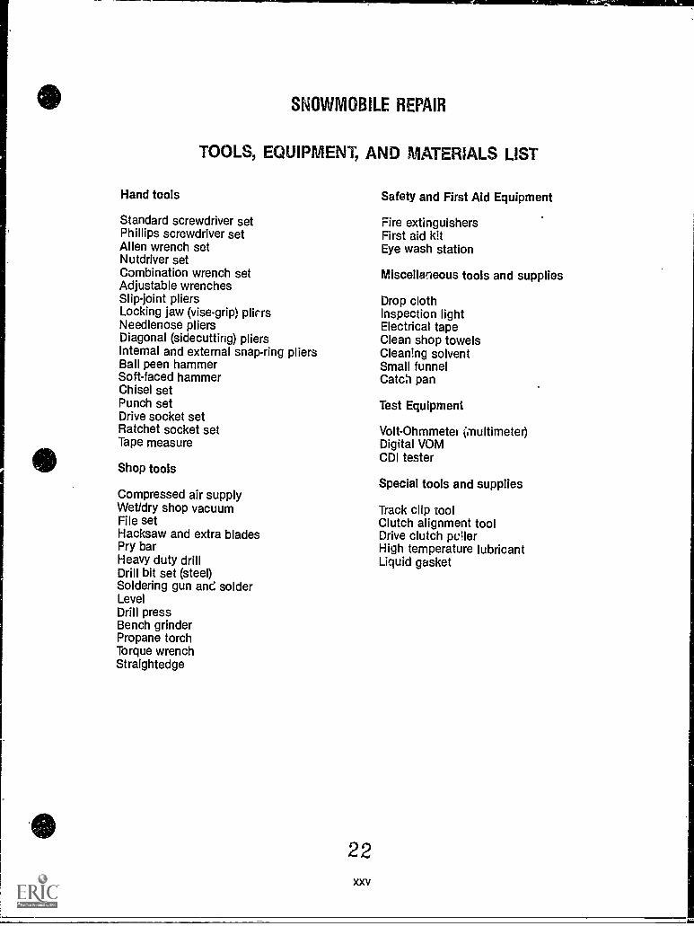
Hand tools
SNOWMOBILE REPAIR
TOOLS, EQUIPMENT, AND MATERIALS LIST
Safety and First Aid Equipment
Fire extinguishersFirst aid kitEye wash station
Standard screwdriver setPhillips screwdriver setAllen wrench setNutdriver setCombination wrench setAdjustable wrenchesSlip-joint pliersLocking jaw (vise-grip) pliersNeedlenose pliersDiagonal (sidecutting) pliersInternal and external snap-ring pliersBall peen hammerSoft-faced hammerChisel setPunch setDrive socket setRatchet socket setTape measure
Shop tools
Compressed air supplyWet/dry shop vacuumFile setHacksaw and extra bladesPry barHeavy duty drillDrill bit set (steel)Soldering gun and solderLevelDrill pressBench grinderPropane torchTorque wrenchStraightedge
22xxv
Miscellaneous tools and supplies
Drop clothInspection lightElectrical tapeClean shop towelsCleaning solventSmall funnelCatch pan
Test Equipment
Volt-Ohmmeter (multimeter)Digital VOMCDI tester
Special tools and supplies
Track clip toolClutch alignment toolDrive clutch pullerHigh temperature lubricantLiquid gasket
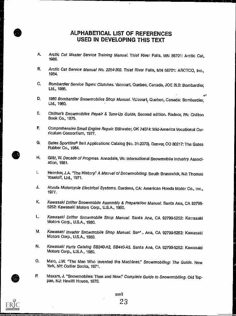
ALPHABETICAL LIST OF REFERENCESUSED IN DEVELOPING THIS TEXT
A. Arctic Cat Master Service Training ManuaL Thief River Falls, MN 56701: Arctic Cat,1986.
B. Arctic Cat Service Manual No. 2254-302. Thief River Falls, MN 56701: ARCTCO, Inc.,1984.
C. Bombardier Service Tapes: Clutches. Valcourt, Quebec, Canada, JOE 2L0: Bombardier,Ltd., 1985.
D. 1980 Bombardier Snowmobiles Shop Manual. Valcourt, Quebec, Canada: Bombardier,Ltd., 1980.
E. Chilton's Snowmobiles Repair & Tune-Up Guide, Second edition. Radnor, PA: ChiltonBook Co., 1975.
F. Comprehensive Small Engine Repair. Stillwater, OK 74074: Mid-America Vocational Cur-riculum Consortium, 1977.
G. Gates Sportline© Belt Applications Catalog (No. 31-2070). Denver, CO 80217: The GatesRubber Co., 1984.
H. Glitz, W. Decade of Progress. Annadale, VA: International Snowmobile Industry Associ-ation, 1981.
I. Helmker, J.A. "The History!' A MaiNal of Snowmobiling. South Brunswick, NJ: ThomasYoseloff, Ltd., 1971.
J. Honda Motorcycle Electrical Systems. Gardena, CA: American Honda Motor Co., Inc.,1977.
K. Kawasaki Drifter Snowmobile Assembly & Preparation Manual. Santa Ana, CA 92799-5252: Kawasaki Motors Corp., U.S.A., 1980.
L. Kawasaki Drifter Snowmobile Shop Manual. Santa Ana, CA 92799-5252: KawasakiMotors Corp., U.S.A., 1980.
M. Kawasaki Invader Snowmobile Shop ManuaL SW., Ana, CA 92799-5252: KawasakiMotors Corp., U.S.A., 1980.
N. Kawasaki Parts Catalog SB340-A2, SB440-A5. Santa Ana, CA 92799-5252: KawasakiMotors Corp., U.S.A., 1980.
0. Malo, J.W. "The Men Who Invented the Machines." SnowmobIlIng: The Guide. NewYork, NY: Collier Books, 1971.
R Maxam, J. "Snowmobiles: Then and Now!' Complete Guide to SnowmobIling. Old Tap-pan, NJ: Hewitt House, 1970.
xxvii
23
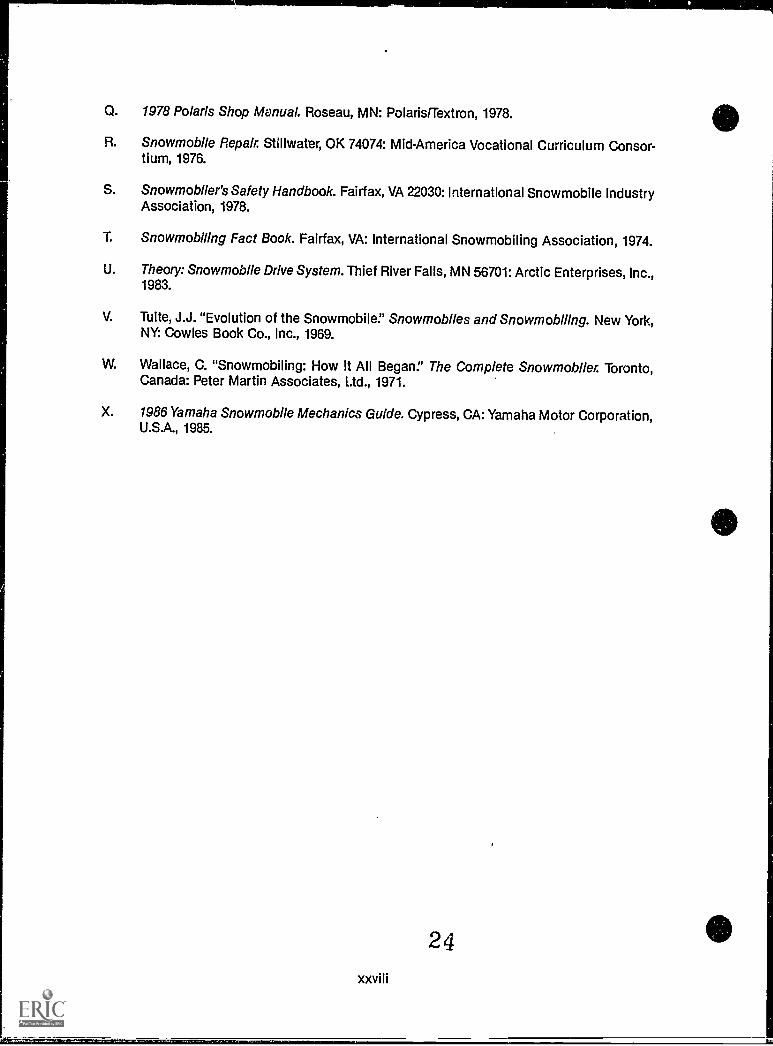
Q. 1978 Polaris Shop Manual. Roseau, MN: Polaris/Textron, 1978.
R. Snowmobile Repair. Stillwater, OK 74074: MidAmerica Vocational Curriculum Consor-tium, 1976.
S. Snowmobiler's Safety Handbook. Fairfax, VA 22030: International Snowmobile IndustryAssociation, 1978.
T. Snowmobiling Fact Book. Fairfax, VA: International Snowmobiling Association, 1974.
U. Theory: Snowmobile Drive System. Thief River Falls, MN 56701: Arctic Enterprises, Inc.,1983.
V. Tuite, J.J. "Evolution of the Snowmobile." Snowmobiles and Snowmobiling. New York,NY: Cowles Book Co., Inc., 1969.
W. Wallace, C. "Snowmobiling: How It All Began:' The Complete Snowmobiler. Toronto,Canada: Peter Martin Associates, Ltd., 1971.
X. 1986 Yamaha Snowmobile Mechanics Guide. Cypress, CA: Yamaha Motor Corporation,U.S.A., 1985.
IV
./' ............,_:.....
\
SR-1
INTRODUCTION TOSNOWMOBILE REPAIR
UNIT I
UNIT OBJECTIVE
After completion of this unit, the student should be able to discuss highlights in snowmobilehistory, identif! components of modern snowmobiles, and discuss systems and their func-tions on a snowmobile. The student should also be able to list guidelines for operator andrepair safety and solve problems related to snowmobile safety. These competencies will beevidenced by correctly performing the procedures outlined in the assignment sheet and byscoring 85 percent on the unit test.
SPECIFIC OBJECTIVES
After completion of this unit, the student should be able to:
1. Match terms related to snowmobile repair with their correct definitions.
2. Complete statements concerning snowmobile history.
3. Select true statements concerning contemporary snowmobiles.
4. Match snowmobile types with their uses.
5. Identify modern snowmobile components.
6. Select true statements concerning snowmobile chassis systems.
7. Complete statements concerning snowmobile engine systems.
8. Complete statements concerning snowmobile drive systems.
9. Select true statements concerning snowmobile track systems.
10. Complete statements concerning snowmobile suspension systems.
11. Complete statements concerning general snowmobile operator safety.
12. Select true statements concerning general snowmobile repair safety.
13. Solve problems related to snowmobile operator and repair safety. (AssignmentSheet #1)
25
INTRODUCTION TO SNOWMOBILE REPAIRUNIT I
SUGGESTED ACTIVITIES
A. Provide students with objective sheet.
B. Provide students with information sheet.
C. Make transparency.
D. Discuss unit and specific objectives.
E. Dicuss information sheet.
F. Invite a local snowmobile dealer to talk to the class about dealerships, the seasonalnature of snowmobiling and how it affects repair work, and generally the opportunitiesin snowmobile repair.
G. Invite a local snowmobile repair person to talk to the class about skills required to besuccessful in the business, what other activities are required to make up for the off sea-son, and generally the gc3d and bad parts of the business.
H. Invite the president or a member o.7 a local snowmobile club to talk to the class aboutlocal snowmobile trails and cther activities that are taking place to promote safe snow-mobiling in the area.
I. Give test.
CONTENTS OF THIS UNIT
A. Objective sheet
B. Information sheet
C. Transparency Master 1 Parts of a Snowmobile
D. Assignment Sheet #1 Solve Problems Related to Snowmobile Operator and RepairSafety
E. Answers to assignment sheets
E Test
G. Answers to test
26
SR-3
4
REFERENCES USED IN DEVELOPING THIS UNIT
A. Glitz, W Decade of Progress. Annadale, VA: International Snowmobile Industry Associ-ation, 1981.
B. Snowmobiling Fact Book. Fairfax, VA: International Snowmobiling Association, 1974.
C. Wallace, C. "Snowmobiling: How It All Began:' The Complete Snowmobrler. Toronto,Canada: Peter Martin Associates, Ltd., 1971.
D. Tuite, J.J. "Evolution of the Snowmobile:' Snowmobiles and Snowmobiling. New York,NY: Cowles Book Co., Inc., 1969.
E. Maxam, J. "Snowmobiles: Then and Now." Complete Guide to Snowmobiling. Old Tap-pan, NJ: Hewitt House, 1970.
F. Helmker, J.A. "The History' A Manual of Snowmobiling. South Brunswick, NB: ThomasYoseloff, Ltd., 1971.
G. Ma lo, J.W. "The Men Who Invented the Machines." Snowmobiling: The Guide. New York,NY: Collier Books, 1971.
H. Snowmobiler's Safety Handbook. Fairfax, VA 22030: International Snowmobile IndustryAssociation, 1978.
(NOTE: Copies of the Snowmobiler's Safety Handbook are available for a nominal pricefrom the ISIA at the address listed below, and the association can be reached by tele-phone at 703-273-9606.)
International Snowmobile Industry Association3975 University DriveSuite 310Fairfax, VA 22030
27
r°
SR-5
INTRODUCTION TO SNOWMOBILE REPAIRUNIT I
INFORMATION SHEET
1. Terms and definitions
A. ISIA (International Snowmobile Industry Association) A group dedicatedto promoting the safe manufacture and use of snowmobiles all over theworld
B. ISC (International Snowmobile Club) A group dedicated to promoting theownership and enjoyment of snowmobiles for recreational purposes
C. SSCC (Snowmobil 1 Safety and Certification Committee) A group thatmaintains manufacturing standards to assure that snowmobiles meet mini-mum safety standards
D. North America The geographical area that makes up the United Statesand Canada
E. Prototype The first thing of its kind, or a model that serves as a guide forbuilding other things like it
F. Toboggan A long flat sled with curved boards at the front; it has no run-ners and is usually used for coasting down snow-covered inclines
11. Snowmobile history
A. The technology that inspired snowmobiles began in the early 20th centurywhen Americans and Canadians in snowbelt areas adapted automobiles totravel in the snow.
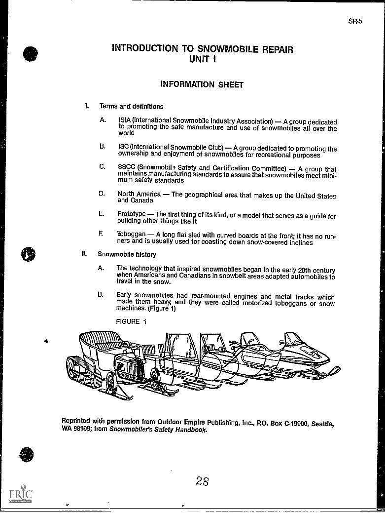
B. Early snowmobiles had rear-mounted engines and metal tracks whichmade them heavy, and they were called motorized toboggans or snowmachines. (Figure 1)
FIGURE 1
Reprinted with permission from Outdoor Empire Publishing, Inc., P.O. Box C-19000, Seattle,WA 98109; from Snowmobller's Safety Handbook.
28
6
INFORMATION SHEET
C. Carl J. Eliason built and marketed the first snow machine in Wisconsin in1917.
D. Eliason's first motorized toboggan went into production in 1922, and 40such machines were built from 1922 to 1926 with 2.5 horsepower outboardengines.
E. During the 1920's, E.M. Tucker designed and built the first Sno-Cat.
(NOTE: A variation of this machine was used by the British Trans-AtlanticExpedition during 1957 and 1958.)
F. In 1928, the Ford Motor Company built a special snowmobile for AdmiralByrd's polar expedition.
G. In 1926, Joseph Bombardier of Quebec, Canada, built a wind sled that useda Ford engine and a large propeller, and skis were used to steer themachine.
(NOTE: A few years later, Bombardier replaced the propeller with a singletrack.)
H. In 1932, Eliason produced the first snowmobile powered by a convertedmotorcycle engine, and it attained speeds of 40 miles per hour.
I. In 1936, Bombardier produced an over-snow vehicle that was steered withskis, looked like an army tank, and could hold 30 people.
J. In the late 30's, Bombardier introduced the first snowmobile that ran on rub-ber tracks driven by a sprocket, a design that became a standard for theindustry.
K. In 1954, Allan Hetteen and David Johnson marketed a two-passenger Sno-Traveler, the first snowmobile in the Polaris line.
L In 1958, Bombardier built the first modern snowmobile with a lightweightmotorcycle engine and the first centrifugal clutch; the entire designbecame an industry standard and the centrifugal clutch revolutionizedsnowmobiles.
(NOTE: That prototype machine was called a "Ski Doe but when the 500 -
pound machine went into production, the name was changed to "Ski-Doo"and 225 Ski -boo's were sold in 1959.)
M. By the mid-1960's, forty thousand snowmobiles had been sold in the USAand Canad and by 1970, half a million snowmobiles had been sold.
N. In 1969, the International Snowmobile Industry Association listed 21 manu-facturers of snowmobiles, but by the mid-1970's the number of manufactur-ers had risen to more than 75.
29
INFORMATION SHEET
0. The manufacturing glut of the mid-70's oversupplied the market, but eventu-ally, only four major manufacturers survived, and the snowmobile continuesto gain in popularity.
(NOTE: Those manufacturers are: ARTCO which produces the Artic Cat,Bombardier which produces Ski-Doo, Polaris which produces Polaris, andYamaha which produces Yamaha snowmobiles.)
III. Contemporary snowmobiles
A. Today there are over 10 million active snowmobilers in the United Statesand Canada.
B. Snowmobilers spend more than two billion dollars a year.
C. An i :portant element in snowmobile popularity is that 80 percent of snow-mot.:3 owners consider the sport a family activity.
D. The snowmobile industry is promoted around the world by the InternationalSnowmobile Industry Association (ISIA).
E. The ISIA has distributed more than one million copies of the Snowmobiler'sSafety Handbook.
(NOTE: According to the ISIA, more than 800,000 snowmobilers havereceived formal safety training)
F. There are 10,000 snowmobile clubs in North America.
G. There are an estimated 190,000 miles of established snowmobile trails inthe USA and Canada.
IV. Snowmobile types and their uses
A. Sport models Designed for general recreational use and racing
(NOTE: These snowmobiles have medium-size frames and medium to largeengines and account for about 80% of snowmobiles in use.)
B. Utility models Designed for people in heavy snow areas who use themfor a primary means of transportation during the snow months.
(NOTE: These models generally have small or moderate size two-strokeengines, and sacrifice speed for dependability.)
C. Workhorse models Designed for hauling people and materials, and usu-ally have multiple seating capacities and rugged engine and larger framesto take harder service.
(NOTE: Workhorse models are used by law officers, civil defense people,ski-touring centers, and winter recreation areas where trails have to becared for.)
3 0
SR-7
8
INFORMATION SHEET
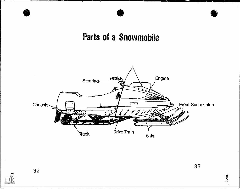
V. Modem snowmobile components and their functions (Transparency 1)
A. Chassis The frame of the snowmobile which supports all other systems
B. Engine The source of power generation, frequently a two-stroke motor
C. Drive train The system that transfers energy from the engine to the trackthrough a variable clutch system
D. Track The system that contacts the snow or ice surface and propels thesnowmobile
E. Front suspension The shock absorbing system which provides safe,comfortable handling of a snowmobile
F Skis The long, slender pieces of metal at the front of the snowmobilewhich allow it to glide on snow, ice, and frozen terrain
(NOTE: The skis are also part of the front suspension.)
G. Steering The system which permits a driver to move the snowmobile in aselected direction
VI. Snowmobile chassis systems
A. The chassis is the body or frame of a snowmobile and may be made fromaluminum to enhance lightweight characteristics or spot-welded iron fordurability.
B. The chassis supports the weight of other snowmobile systems and pro-vides space and seating support for an operator.
C. The chassis also includes the hood, skid frame, storage compartments,gas tank, front and rear bumpers, foot rests, and options such as snowflaps and console.
D. The console contains instruments such as the speedometer, tachometer,fuel gauge, and temperature gauge.
E. The console also houses the choke lever and cable, the heating coil for thehandlebar warmer, the ignition switch, a fuse box, and may also house thehandlebars.
VII. Snowmobile engine systems
A. Most snowmobile engines are two-stroke (two-cycle) engines with basiccomponents that include:
1. Piston
2. Crankshaft
3. Connecting rod
31 Es
1
INFORMATION SHEET
B. Other systems and components of a snowmobile engine include:
1. The carburetor
2. The cooling system
3. Ignition system and spark plugs
4. Carburetion and fuel system
5. Lubrication system (pre-mix or injection system)
6. An exhaust system
VIII. Snowmobile drive systems
A. The drive system transfers energy from the engine to the track through avariable-speed clutch and belt assembly That works like an automatic trans-mission in a car.
B. The variable-speed clutch is unique to snowmobiles and has greatlyenhanced performance by reducing the loss of inertia produced by shiftingmechanical gears.
C. The drive clutch is sometimes called the centrifugal clutch, and the drivenclutch is sometimes called the torque converter.
D. The drive clutch and the driven clutch are connected by a belt whichrequires special alignment.
(NOTE: The drive system is an essential element in the process of fine tun-ing a snowmobile.)
IX. Snowmobile track systems
A. The track system propels the snowmobile over ice, snow, or what have you,and must be rugged.
B. Tracks are made of rubber or polyurethane arranged in a wide, flat bandwith cross bars that dig into the running surface.
C. The track may also be fitted with studs or drive lugs to provide better trac-tion.
D. The rear suspension system with its slide rail or bogie wheels is usuallyconsidered a part of the track system.
(NOTE: Bogie wheels appear mostly on older model sleds.)
32
SR-9
10
INFORMATION SHEET
X. Snowmobile suspension systems
A. Suspension, skis, and steering make up the front suspension, and all threecomponents work together to provide safe, comfortable handling of asnowmobile.
B. There are three types of suspensions:
1. Independent front suspensions
2. Front strut suspensions
3. Conventional leafspring front suspensions
Xl. General snowmobile operator safety
A. Operator safety has bccome the prime concern of all snowmobile manufac-turers, and is treated in several different publications.
B. Two outstanding publications from ISIA are the Snowmobiler's SafetyHandbook and the Snowmobile Operator's Training Program.
(NOTE: Your instructor has an address where you can write ISIA if You'reinterested in either publication for your personal use or as a gift for a snow-mobiling friend.)
C. States offer operator training programs, but local snowmobile clubs are thebest source for general operator training and safety advice pertinent tolocal conditions.
D. Two major problem areas confront snowmobilers:
1. Inadequate or dangerous trails
2. Difficult or dangerous riding conditions
E. Injuries to snowmobilers have been caused by:
1. Cables and guy wires
2. Fences
3. Tree stumps, rocks, and other obstacles hidden under snow cover
4. Low hanging tree branches
5. Unsafe ice conditions
3 3
SR-11
INFORMATION SHEET
F. Since the major goal of most snowmobile clubs is to establish and main-tain safe, well-marked trails, local clubs contribute significantly to snowmo-bile safety.
(NOTE: Some clubs do publish important safety material especially forlocal conditions.)
XII. General snowmobile repair safety
A. Standards covering safe manufacture of all systems ;n a snowmobile areestablished by the Snowmobile Safety and Certification Committee.
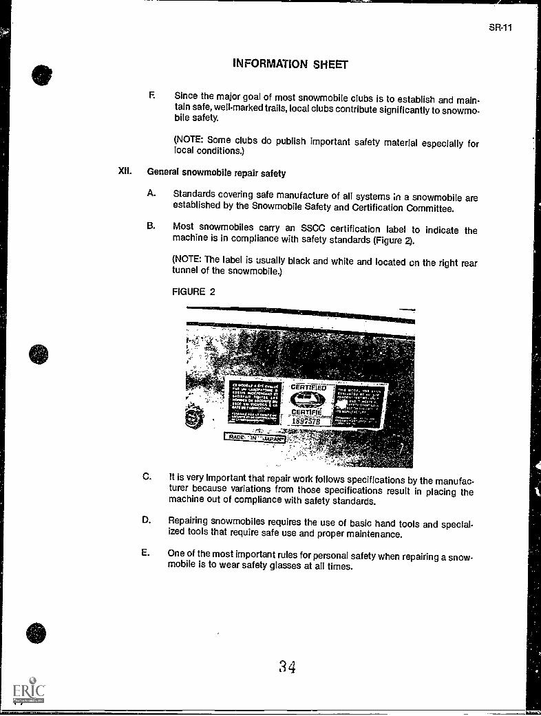
B. Most snowmobiles carry an SSCC certification label to indicate themachine is in compliance with safety standards (Figure 2).
(NOTE: The label is usually black and white and located on the right reartunnel of the snowmobile.)
FIGURE 2
< 4,4
C. it is very Important that repair work follows specifications by the manufac-turer because variations from those specifications result in placing themachine out of compliance with safety standards.
D. Repairing snowmobiles requires the use of basic hand tools and special-ized tools that require safe use and proper maintenance.
E. One of the most important rules for personal safety when repairing a snow-mobile is to wear safety glasses at all times.
34
Chassis
35
Parts of a Snowmobile
Front Suspension
Track Drive TrainSkis
36
INTRODUCTION TO SNOWMOBILE REPAIRUNIT I
ASSIGNMENT SHEET #1 - SOLVE PROBLEMS RELATED TOSNOWMOC,L.E OPERATOR AND REPAIR SAFETY
Directions: Read the following problems carefully and recommend the best solution.
A. You have been called upon to talk to a group of new owners of snowmobiles aboutsnowmobile safety in general, but what two problem areas should you address first?
B. A friend repairing a snowmobile says that the specifications in the manufacturers serv-ice manual don't have to be followed closely. What should you say to your friend?
C. A group of people who want to start a local snowmobile club want advice about theirobjectives. What would you tell them is the major goal of a local snowmobile club?
D. Local snowmobilers are planning a trail and have asked you about the types of hazardsthey should look for. What would you tell them?
E. Someone wants to know if there is any written information about snowmobile safetyand operation beyond the materials published by the manufacturer. What would yourecommend to that person?
37
SR-17
INTRODUCTION TO SNOWMOBILE REPAIRUNIT I
ANSWERS TO ASSIGNMENT SHEET #1
A. The problems posed by inadequate or dangerous trails, and the other hazards posed bydifficult or dangerous riding conditions
B. Failure to follow the manufacturer's specifications may lead to a violation of safetystandards
C. To establish and maintain safe, well-marked trails
D. Watch out for and mark cables and guy wires and fences; mark or remove tree stumps,rocks, or other obstacles that can be hidden by snow; remove low hanging treebranches, and flag or mark unsafe ice conditions
E. The Snowmobiler's Safety Handbook and the Snowmobile Operator's Trai ling Program,or any materials that may be available about special local safety needs
38
SR-19
INTRODUCTION TO SNOWMOBILE REPAIRUNIT I
NAME
TEST
1. Match each term on the right with its 'Correct definition.
a A group dedicated to promoting the safemanufacture and use of snowmobiles allover the world
b A group dedicated to promoting the owner-ship and enjoyment of snowmobiles for rec-reational purposes
c. A group that maintains manufacturingstandards to assure that snowmobiles meetminimum safety standards
__A. The geographical area that makes up theUnited States and Canada
e The first thing of its kind, or a model thatserves as a guide for building other thingslike it
f A long flat sled with curved boards at thefront; it has no runners and is usually usedfor coasting down snow-covered inclines
1. SSCC
2. Prototype
3. North America
4. ISIA
5. Toboggan
6. iSC
2. Complete statements concerning snowmobile history by circling the word(s) or num-ber(s) that best completes each statement.
a. The technology that inspired snowmobiles began in the early (19th, 20th) centurywhen Americans and Canadians in snowbeit areas adapted automobiles to tra-vel In the snow.
b. Early snowmobiles had rear-mounted engines and metal tracks which madethem heavy, and they were called motorized (toboggans, sleds) or snowmachines.
c. Can J. Ellason built and marketed the first snow machine In (Minnesota, Wiscon-sin) in 1917.
d. Eliason's first motorized toboggan went into production in 1922, and 40 suchmachines were built from 1922 to 1926 with 2.5 horsepower (outboard, motorcy-cle) engines.
e. During the (1920's, 1930's), E.M. Tucker designed and built the first Sno-Cat.
f. In 1928, the (Ford, Chrysler) Motor Company built a special snowmobile for Admi-ral Byrd's polar expedition.
39
TEST
g. In 1926, Joseph Bombardier of Quebec, Canada, built a wind sled that used aFord engine and a large propeller, and (skis, tracks) were used to steer themachine.
h. In 1932, Eliason produced the first snowmobile powered by a converted (motor-cycle, outboard) engine, and it attained speeds of 40 miles per hour.
I. In 1936, Bombardier produced an over-snow vehicle that was steered with skis,looked like (a bus, an army tank), and could hold 30 people.
j. In the late 30's, Bombardier introduced the first snowmobile that ran on rubbertracks, driven by a (worm gear, sprocket), a design that became a standard for theindustry.
k. In 1954, Allan Hetteen and David Johnson marketed a two-passenger Sno-Trav-eler, the first snowmobile in the (Polaris, John Deere) line.
I. In 1958, Bombardier built the first modern snowmobile with a lightweight motor-cycle engine and the first centrifugal clutch; the entire design became an indus-try standard and the (motorcycle engine, centrifugal clutch) revolutionizedsnowmobiles.
m. By the mid-1960's, forty thousand snowmobiles had been sold in the USA andCanada, and by 1970, (half a million, two million) snowmobiles had been sold.
n. In 1969, the International Snowmobile Industry Association listed 21 manufactur-ers of snowmobiles, but by the mid-1970's the number of manufacturers hadrisen to more than (50, 75).
0. The manufacturing glut of the mid-70's oversupplied the market, but eventually,only (four, six) major manufacturers survived, and the snowmobile continues togain in popularity.
3. Select true statements concerning contemporary snowmobiles by placing an "X"beside each statement that is true.
a Today there are over 50 million active snowmobilers in the United Statesand Canada.
_..b. Snowmobilers spend more than two billion dollars a year.
c An important element In snowmobile popularity Is that 80 percent of snow-mobile owners consider the sport a family activity.
d The snowmobile industry is promoted around the world by the Interna-tional Snowmobile Industry Association.
e The ISIA has distributed more than one million copies of the Snowmobll-er's Safety Handbook.
f. There are 5,000 snowmobile clubs in North America.
g. There are an estimated 190,000 miles of established snowmobile trails inthe USA and Canada.
40
-...-11711M
TEST
4. Match snowmobile types with their uses.
a Designed for general recreational use and 1. Utility modelsracing
2. Workhorse modelsb Designed for people in heavy snow areas
who use them for a primary means of trans- 3. Sport modelsportation during the now months.
c Designed for hauling people and materials,and usually have multiple seating capaci-ties and rugged engine and larger frames totake harder service.
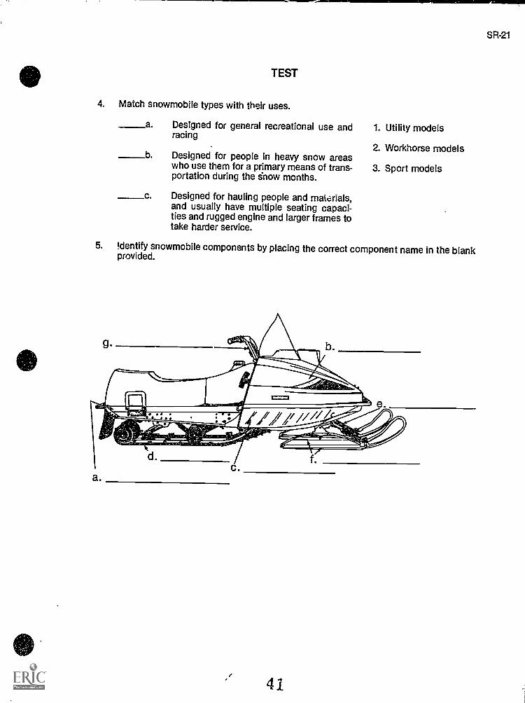
5. Identify snowmobile components by placing the correct component name in the blankprovided.
a.
41
SR-21
22
TEST
6. Select true statements concerning snowmobile chassis systems by placing an "X"beside each statement that is true.
a. The chassis is the body or frame of a snowmobile and may be made fromaluminum to enhance lightweight characteristics or spot-welded iron fordurability.
..____.b The chassis supports the weight of other snowmobile systems and pro-vides space and seating support for an operator.
c. The chassis also includes the hood, skid frame, storage compartments,gas tank, front and rear bumpers, foot rests, and options such as a roll barand snow flaps, and console.
d. The console contains instruments such as the speedometer, tachometer,fuel gauge, and variable clutch.
e The console also houses the choke lever and cable, the heating coil for thehandlebar warmer, the ignition switch, a fuse box, and may also house thehandlebars.
7. Complete statements concerning snowmobile engine systems by inserting the word(s)that best completes each statement.
a. Most snowmobile engines are two-stroke engines with basic components thatinclude:
1)
2) Crankshaft
3) Connecting
b. Other systems and components of a snowmobile engine include:1. The
2. The cooling system
3. systems and spark plugs
4. Carburetion and system
5. system (pre-nix or injectionsystem)
6. An system
42
SR-23
TEST
8. Complete statements concerning snowmobile drive systems by inserting the word(s)that best completes each statement.
a. The drive system transfers energy from the engine to the througha variable-speed clutch and belt assembly that works like an automtic transmis-sion in a car.
b. The variable-speed clutch is unique to snowmobiles and has greatly enhancedperformance by the loss of inertia produced by shifting mechani-cal gears.
c. The drive clutch is sometimes called the clutch, and the drivenclutch is sometimes called the torque converter.
d. The drive clutch and the driven clutch are connected by a belt which requiresspecial
9. Select true statements concerning snowmobile track systems by placing an "X" besideeach statement that is true.
a. The track system propels the snowmobile over ice, snow, or what haveyou, and must be rugged.
b Tracks are made of rubber or polyurethane arranged in a wide, flat bandwith cross bars that dig into the running surface.
c. The track may also be fitted with studs or drive lugs to provide better trac-tion.
d The rear suspension system with its slide rail or bogie wheels is not usu-ally considered a part of the track system.
10. Complete statements concerning snowmobile suspension systems by inserting theword(s) that best completes each .3tatement.
a. Suspension, skis, and make up the front suspension, and allthree components work together to provide safe, comfortable handling of asnowmobile.
b. There are three types of suspensions:
1) front suspensions
2) strut suspensions
3) Conventional front suspensions
43
24
TEST
11. Complete statements concerning general snowmobile operator safety by inserting theword(s) that best completes each statement.
a. Operator has become the prime concern of all snowmobile man-ufacturers, and is treated in several different publications.
b. Two outstanding publications from ISIA are the Snowmobiler'sHandbook and the Snowmobile Training Program.
c. States offer operator training programs, but local snowmobileare the best source for ge-soral operator training and safety advice pertinent tolocal conditions.
d. Two major problem areas confront snowmobilers:
1) Inadequate or trails
2) Difficult or riding conditions
e. Injuries to snowmobilers have been caused by:
1) Cables and wires
2) Fences
3) Tree stumps, rocks, and other
4) Low hanging
5) Unsafe conditions
hidden under snow cover
f. Since the major goal of most snowmobile clubs is to establish and maintainsafe, well-marked , local clubs contribute significantly to snow-mobile safety.
12. Select true statements concerning general snowmobile repair safety by placing an "X"beside each statement that is true.
a. Standards covering safe manufacture of all systems in a snowmobile areestablished by the Snowmobile Safety and Certification Committee.
b Most snowmobiles do not carry an SSCC certification label to indicate themachine is in compliance with safety standards.
c It is very important that repair work follows specifications by the manufac-turer because variations from those specifications result in placing themachine out of compliance with safety standards.
d Repairing snowmobiles requires the use of basic hand tools and special-ized tools that require safe use and proper maintenance.
e One of the most important rules for personal safety when repairing asnowmobile is to wear sun glasses at all times.
44
SR-25
TEST
(NOTE: If the following activity has not been accomplished prior to the test, ask your instruc-tor when it should be completed.)
13. Solve problems related to snowmobile operator and repair safety. (Assignment Sheet#1)
45
INTRODUCTION TO SNOWMOBILE REPAIRUNIT I
1. a. 4b. 6c. 1
d. 3e. 2f. 5
2. a. 20thb. Toboggansc. Wisconsind. Outboarde. 1920'sf. Fordg. Skish. Motorcyclei. An army tankj. Sprocketk. PolarisI. Centrifugal clutchm. Half a millionn. 75o. Four
3. b, c, d, e, g
4. a. 3b. 1
c. 2
5. a. Chassisb. Enginec. Drive traind. Tracke. Front suspensionf. Skisg. Steering
6. a, b, 0, e
7. a. 1) Piston3) Rod
b. 1) Carburetor3) Ignition4) Fuel5) Lubrication6) Exhaust
ANSWERS TO TEST
46
SR -27
28
ANSWERS TO TEST
8. a. Trackb. Reducingc. Centrifugald. Alignment
9. a, b, c
10. a. Steeringb. 1) Independent
2) Front3) Leafspring
11. a. Safetyb. Safety, operator'sc. Clubsd. 1) Dangerous
2) Dangerouse. 1) Guy
3) Obstacles4) Tree branches5) Ice
f. Trails
12. a, c, d
13. Evaluated to the satisfaction of the instructor
47
STEERING, FRONT SUSPENSION,AND SKIS
UNIT 11
UNIT OBJECTIVE
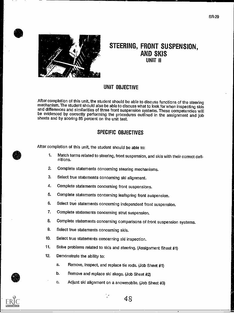
After completion of this unit, the student should be able to discuss functions of the steeringmechanism. The student should also be able to discuss what to look for when inspecting skisand differences and similarities of three front suspension systems. These competencies willbe evidenced by correctly performing the procedures outlined in the assignment and jobsheets and by scoring 85 percent on the unit test.
SPECIFIC OBJECTIVES
After completion of this unit, the student should be able to:
1. Match terms related to steering, front suspension, and skis with their correct defi-nitions.
2. Complete statements concerning steering mechanisms.
3. Select true statements concerning ski alignment.
4. Complete statements concerning front suspensions.
5. Complete statements concerning leafspring front suspension.
6. Select true statements concerning independent front suspension.
7. Complete statements concerning strut suspension.
8. Complete statements concerning comparisons of front suspension systems.
9. Select true statements concerning skis.
10. Select true statements concerning ski inspection.
11. Solve problems related to skis and steering. (Assignment Sheet #1)
12. Demonstrate the ability to:
a. Remove, inspect, and replace tie rods. (Job Sheet #1)
b. Remove and replace ski skegs. (Job Sheet #2)
c. Adjust ski alignment on a snowmobile. (Job Sheet #3)
SR-29
SR-31
STEERING, FRONT SUSPENSION, AND SKISUNIT II
SUGGESTED ACTIVITIES
A. Provide students with objective sheet.
B. Provide students with information sheet.
C. Make transparencies.
D. Discuss unit and specific objectives.
E. Discuss information sheet.
F. Demonstrate and discuss procedures outlined in the job sheets.
G. Visit a dealership and have students writs a written report for class.
H. Disassemble, clean, inspect, and reassemble a steering system.
I. Have students discuss the three types of front suspensions.
J. Check a sled for steering play.
K. Give test.
CONTENTS OF THIS UNIT
A. Objective sheet
B. Information sheet
C. Transparency masters
1. TM 1 Independent Front Suspension
2. TM 2 Yamaha Telescopic Strut Suspension
D. Assignment Sheet #1 Solve Problems Related to Skis and Steering
E. Answers to assignment sheet
F. Job sheets
1. Job Sheet #1 Remove, Inspect, and Replace Tie Rods
2. Job Sheet #2 Remove and Replace Ski Skegs
3. Job Sheet #3 Adjust Ski Alignment on a Snowmobile
G. Test
H. Answers to test
49
32
REFERENCES USED IN DEVELOPING THIS UNIT
A. Snowmobile Repair. Stillwater, OK 74074: Mid-America Vocational Curriculum Consor-tium, 1976.
B. Chilton's Snowmobiles Repair & Tune-Up Guide, Second edition. Radnor, PA: ChiltonBook Co., 1975.
C. Arctic Cat Service Manual No. 2254-302. Thief River Falls, MN 56701: ARCTCC, Inc.,1984.
D. 1980 Bombardier Snowmobiles Shop Manual. Valcourt, Quebec, Canada: Bombardier,Ltd., 1980.
E. Kawasaki Drifter Snowmobile Shop Manual. Santa Ana, CA 92799.5252: KawasakiMotors Corp., U.S.A., 1980.
F. Kawasaki Parts Catalog SB340-A2, 513440-A5. Santa Ana, CA 92799-5252: KawasakiMotors Corp., U.S.A., 1980.
50
STEERING, FRONT SUSPENSION, AND SKISUNIT II
INFORMATION SHEET
I. Terms and definitions
A. Handlebars The steering control apparatus which is rotated right or leftto turn the skis in the direction of intended travel
B. Grip A cylindrical piece of rubber which is glued to the handlebars to givehand comfort to the operator and to aid the hands from slipping off the han-dlebars
C. Steering post A long cylindrical piece of metal which extends from thehandlebars through the chassis to the tie rods
D. Tie rods Rods which link the steering column to the steering arm.
E. Spindle arm The ski leg which is connected to the tie rods and connectsthe skis to the steering assembly.
F. Toe out A ski position where the front of each ski points outward
G. Toe in A ski position where the front of each ski points inward
H. Play The nature of a mechanism to be free to move or to move too muchafter wear
I. Skis Long, slender pieces of metal which extend outward from under asnowmobile to its front which allow the vehicle to glide over snow and to besteered
J. Skeg -- A ski wear rod or runner used tc reduce wear on the ski and toimprol e directional control
K. Shock absoroer A round cylinder filled with gas or lubricant and con-nected to the skis and spindle arm to absorb the impact of bumpy surfaceson the snowmobile chassis
L Flotation The relationship between snowmobile weight and the amountof surface area of the skis and track supporting it on the snow
M. Saddle iA mounting bracket which accepts the main leafspring allowingit to ride and connect with the ski
51
SR-33
34
INFORMATION SHEET
II. Steering mechanisms
A. The steering assembly controls the direction of travel of the snowmobile.
B. The handlebars serve as the assembly control which, when rotated left orright, turn the skis in the direction of travel.
C. Attached to the handlebars is a lever-type throttle control, an emergencystop switch and the headlight hi-lo beam switch.
D. The skis are turned in the direction of intended travel from the handlebars,through a system of tie rods and linkages to the skis.
E. The tie rods transfer movement to the spindle which, in turn, causes move-ment to the left or right of the entire ski.
F. The steering system should be checked periodically to be sure its move-ment is not restricted, and also to be sure there is not excessive play.
G. The steering post should be examined occasionally for cracks or bendswhich could adversely affect steering.
H. Tie rods, tie rod ends, and bushings should be checked regularly for wear,breakage, or signs of excer sive stress.
III. Ski alignment
A. The proper positioning of the skis is essential to the function of the steeringsystem.
B. Most manufacturers require that skis be aligned parallel to each other.
C. Bombardier recommends that their Ski-Doo snowmobiles be alignedslightly toe out.
Example: Bombardier recommends measuring the distance betweeneach ski at the front and the rear of the spring leaves. The frontdistance should be 3 mm, or 1/8 inch, more than the rear whenthe skis are pointed straight ahead.
D. Align skis by adjusting the tie rod ends while the front skis are pointedstraight ahead and the handlebars are in the normal, straight ahead drivingposition.
E. Make sure the skis do not bind on any surface obstruction to assure aproper adjustment, and always follow manufacturer's recommendations foradjustment measurement and torque specifications.
52
SR-35
INFORMATION SHEET
IV. Front suspensions
A. The major purpose of the front suspension on a snowmobile is to supportthe steering system.
B. The suspension system cushions the front of the sled from bumps to helpimprove control of the vehicle and cushion the ride.
C. Modern snowmobiles use three types of front suspensions:
1. Conventional leafspring suspension
2. Independent front suspension
3. Strut suspension
V. Leafspring front suspension
A. Leafsprings are pieces of flat steel which extend down from the spindle tobrace the skis.
B. A shock absorber may be attached to a set of leafsprings.
C. Some snowmobiles have several leafsprings.
D. To check the tension on a shock absorber:
1. Hold the body of the shock firmly.
2. Quickly compress and extend the plunger.
3. Resistance should be felt in both directions.
4. If the shock is leaking lubricant, it should be replaced.
VI. Independent front suspension (Transparency 1)
A. Many later model snowmobiles have independent front suspension asstandard equipment.
B. Independent suspension systems are not tied directly to the steering postassembly; each ski is allowed to take shocks separately.
C. Each ski has its own shock absorbing mechanism which is either a shockabsorber inside a spring, or separate spindle arms each supported by astrut.
D. Some snowmobiles have an A-frame independent suspension similar indesign to many modern automobile suspensions.
INFORMATION SHEET
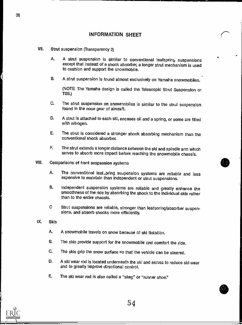
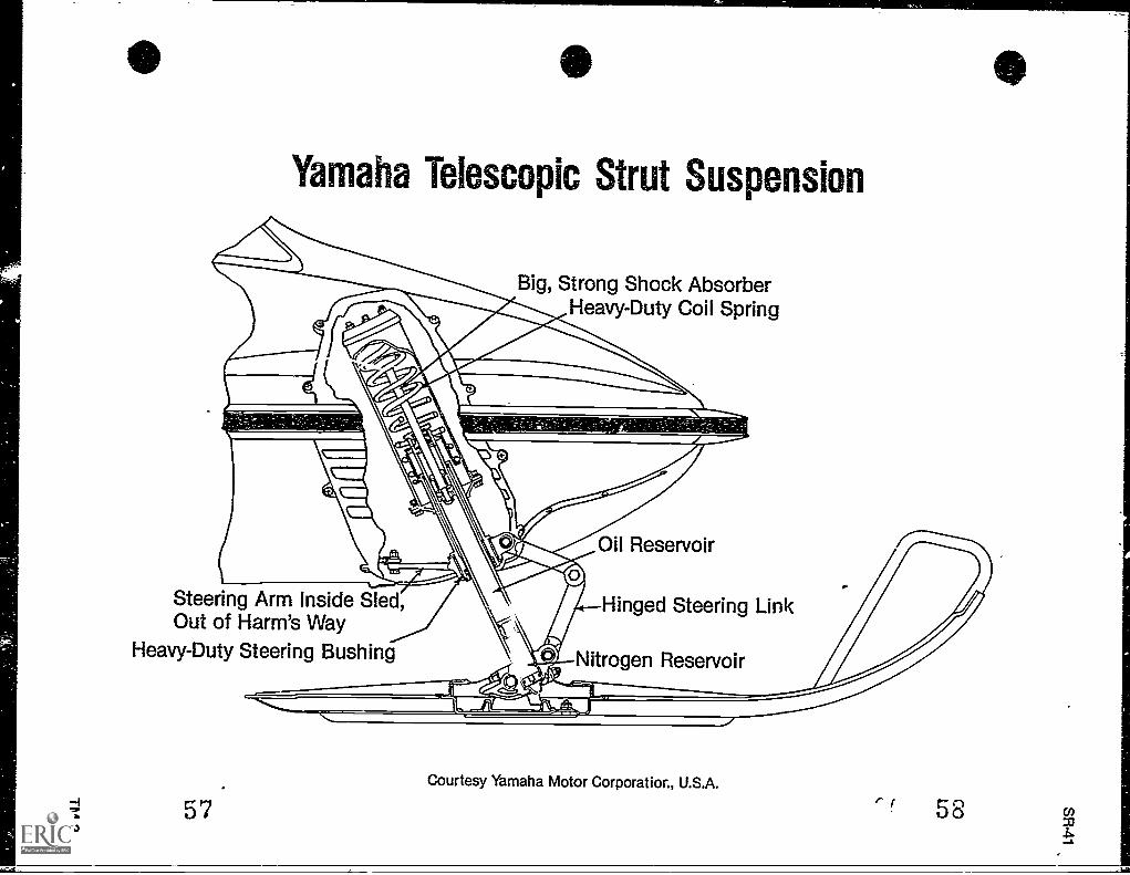
VII. Strut suspension (Transparency 2)
A. A strut suspension is similar to conventional ieafspri% suspensionsexcept that instead of a shock absorber, a longer strut mechanism is usedto cushion and support the snowmobile.
B. A strut suspension is found almost exclusively on Yamaha snowmobiles.
(NOTE: The Yamaha design is called the Telescopic Strut Suspension orTSS.)
rs%,. The strut suspension on snowmobiles is similar to the strut suspension
found in the nose gear of aircraft.
D. A strut is attached to each ski, encases oil and a spring, or some are filledwith nitrogen.
E. The strut is considered a stronger shock absorbing mechanism than theconventional shock absorber.
F. The strut extends a longer distance between the ski and spindle arm whichserves to absorb more impact before reaching the snowmobile chassis.
VIII. Comparisons of front suspension systems
A. The conventional leat...pring suspension systems are reliable and lessexpensive to maintain than independent or strut suspensions.
B. Independent suspension systems are reliable and greatly enhance thesmoothness of the ride by absorbing the shock to the individual skis ratherthan to the entire chassis.
C Strut suspensions are reliable, stronger than leafsoring/absorber suspen-sions, and absorb shocks more efficiently.
IX. Skis
A. A snowmobile travels on snow because of ski flotation.
B. The skis provide support for the snowmobile and comfort the ride.
C. The skis grip the snow surface so that the vehicle can be steered.
D. A ski wear rod is located underneath the ski and serves to reduce ski wearand to greatly improve directional control.
E. The ski wear rod is also called a "skeg" or "runner shoe."
54
SR-37
INFORMATION SHEET
F. Skis and ski skegs should be inspected frequently for excessive wear, andskegs should be replaced in pairs.
G. A rubber rebound bumper connected to the underside of the mainspringleaf serves to prevent chafing of the skis by the leafspring.
H. The rebound bumper should be inspected for signs of wear, an indicationthat the shock absorbers may need to be replaced or that there are othersuspension problems.
X. Ski inspection
A. Always inspect welded areas for cracks or deterioration.
B. Inspect bolts for stripped or damaged threads.
C. Inspect the holes where the springs are mounted to the skis for damage orelongation.
D. Inspect the ski for abnormal bends or cracks.
E. Inspect ski springleaves for wear or cracks.
F Inspect the shock-absorber body and plunger for nicks, cracks, and bends.
G. Check ski alignment at the beginning of each season.
55
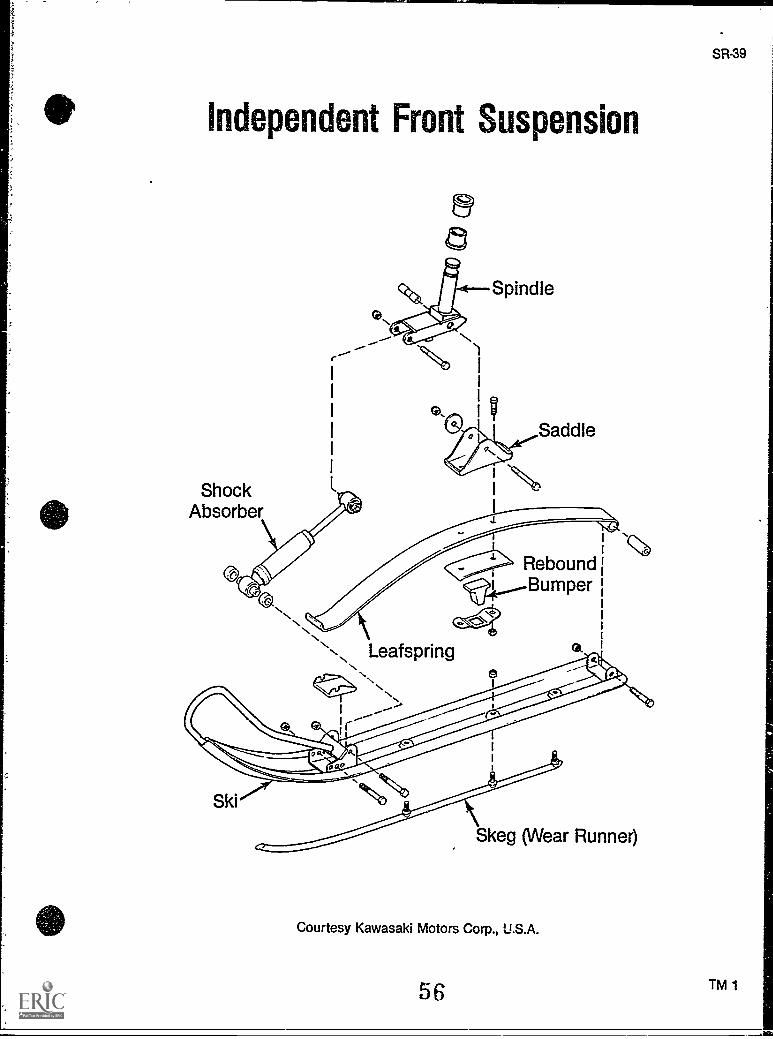
Independent Front Suspension
ShockAbsorber
@a
Spindle
Saddle
1 N
Rebound
j4,..._--BumperN
N.\ . LeafspringN.t,'...N.
N.
I....--"....'i '.-
Qt.
Ski
Skeg (Wear Runner)
Courtesy Kawasaki Motors Corp., U.S.A.
56
SR-39
TM 1
JIM
6
Yamaha Telescopic Strut Suspension
Big, Strong Shock AbsorberHeavy-Duty Coil Spring
Oil Reservoir
Steering Arm Inside Sled,Out of Harm's Way
Heavy-Duty Steering Bushing
57
Hinged Steering Link
Nitrogen Reservoir
Courtesy Yamaha Motor Corporation., U.S.A.
STEERING, FRONT SUSPENSION, AND SKISUNIT II
ASSIGNMENT SHEET #1 - SOLVE PROBLEMS RELATED TOSKIS AND STEERING
Directions: Read the following problems carefully and recommend the best solution.
A. Where would you find reliable guidelines for steering adjustment and maintenance?
B. A friend is thinking about buying a snowmobile for the first time and he asks your opin-ion about types of front suspension systems. How would you respond?
C. You are assembling the front suspension and skis on a new snowmobile. How do youalign the skis?
D. You are about to purchase a three-year-old snowmobile from someone. During yourinspection of the steering, front suspension, and skis, what trouble signs should youlook for?
SR-43
SR-45
STEERING, FRONT SUSPENSION, AND SKISUNIT II
ANSWERS TO ASSIGNMENT SHEET #1
A. The specific manufacturer's service manual
--:B. Describe to him the kind of ride, reliability factors and cost associated with each of the
three types of suspensions.
C. Consult the specific manufacturer's manual for specifications for proper alignment,and understand the concept of toe in and toe out.
D. Examine steering post, tie rod and tie ride ends for signs of breakage, excess stress orbends; examine skis and ski runner for bends and excess wear, examine shock absorb-ers for leakage and for proper tension.
60
STEERING, FRONT SUSPENSION, AND SKISUNIT II
JOB SHEET #1 - REMOVE, INSPECT, AND REPLACE TIE RODS
A. Tools and equipment
1, Snowmobile ski as selected by instructor
2. Appropriate service manual
3. Basic hand tools
4. Replacement parts as required
5. Safety glasses
R. Torque wrench
B. Procedure
1. Put on safety glasses.
2. Remove the engine, if required, for access to the tie rods.
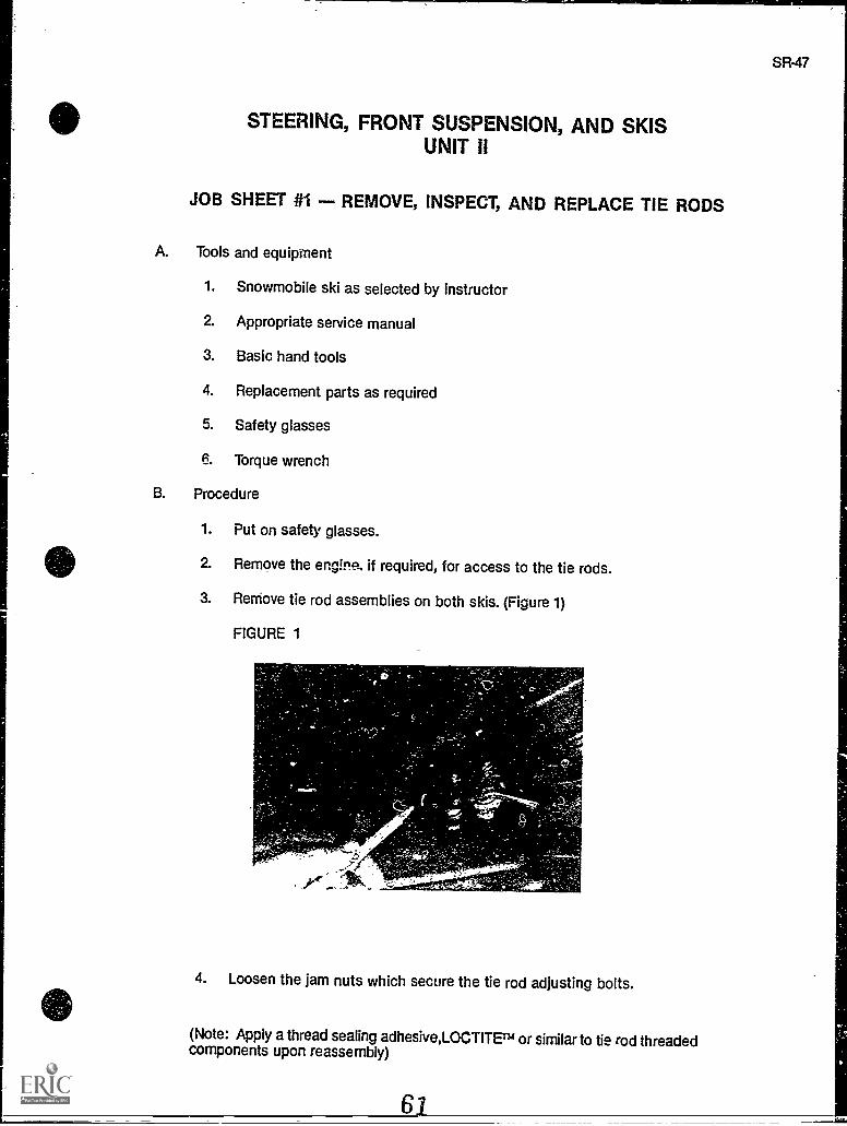
3. Remove tie rod assemblies on both skis. (Figure 1)
FIGURE 1
I,
4. Loosen the jam nuts which secure the tie rod adjusting bolts.
(Note: Apply a thread sealing adhesive,LOCTITErm or similar to tie rod threadedcomponents upon reassembly)
48
JOB SHEET #1
5. Remove the tie rod ends from the adjusting bolts.
6. Remove the adjusting bolts with their jam nuts.
7. Remove the jam nuts from the adjusting bolts.
8. Inspect the tie rods for damaged threads.
9. Inspect the tie rods for cracks or bushing wear.
10. Replace worn components as required.
11. Replace the tie rods by reversing the disassembly procedure.
Have your instructor check your work.
12. Complete a ski alignment as outlined in Job Sheet #3 of this unit, and alwayscomplete a ski alignment after adjusting tie rods.
13. Clean up area and return tools and materials to proper storage.
=1.4.71=1,5
STEERING, FRONT SUSPENSION, AND SKISUNIT II
JOB SHEET #2 - REMOVE AND REPLACE SKI SKEGS
A. Tools and equipment
1. Snowmobile as selected by instructor
2. Appropriate service manual
3. Hand tools
4. Replacement skegs as required
5. Torque wrench
6. Safety glasses
B. Routine #1 Removing old skegs
1. Put on safety glasses.
2. Block the machine up or tip it onto its side to provide easy access to the ski or;ids, and if you tip the machine over, make sure no gas leaks from the gas tank.
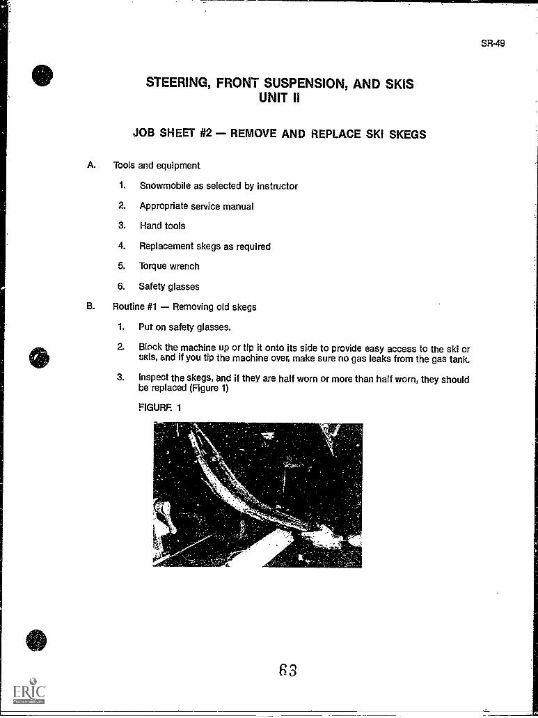
3. Inspect the skegs, and if they are half worn or more than half worn, they shouldbe replaced (Figure 1)
FIGURF. 1
A.
63
SR-49
JOB SHEET #2
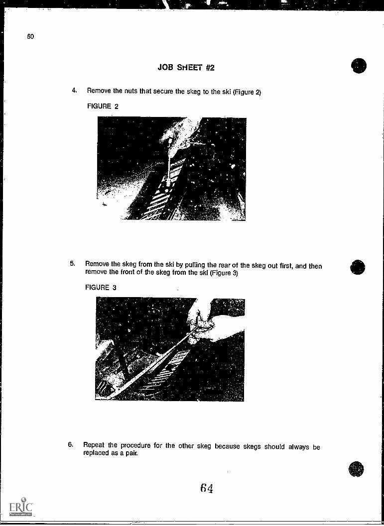
4. Remove the nuts that secure the skeg to the ski (Figure 2)
FIGURE 2
A'
5. Remove the skeg from the ski by pulling the rear of the skeg out first, and thenremove the front of the skeg from the ski (Figure 3)
FIGURE 3
..-..,
6. Repeat the procedure for the other skeg because skegs should always bereplaced as a pair.
64
SR-51
JOB SHEET #2
C. Routine #2 Installing new skegs
1. Insert the front of one skeg into the hole at the front of one of the skis
2. Align the studs on the skeg with the mounting holes on the ski and push thestuds into place in the ski
3. Install nuts on skeg studs and torque to manufacturer's specifications
4. Repeat the procedure for the other ski and skeg
Have your instructor check your work
5. Follow skeg replacement with ski alignment, and always align skis after skegreplacement.
6. Clean up area and return tools and materials to proper storage.
65
SR53
STEERING, FRONT SUSPENSION, AND SKISUNIT II
JOB SHEET #3 - ADJUST SKI ALIGNMENT ON A SNOWMOBILE
A. Tools and materials
1. Snowmobile as selected by instructor
2. Appropriate service manual
3. Basic hand tools
4. Measuring tape
5. Straight edge or long straight board
6. Torque wrench
7. Safety glasses
B. Procedure
1. Put on safety glasses
2. Place the snowmobile on a level hard surface, and make sure the skis are notbound
3. Inspect the skis and steering linkage for wear and excessive play
4. Replace any damaged or worn components before completing ski alignment
5. Turn the handlebar to the straight ahead position, and if the handlebar requirescentering, adjust tie rod ends as required
6. Place a straight edge or board along the outside edge of the track so that itextends along the inside of one ski
66
JOB SHEET #3
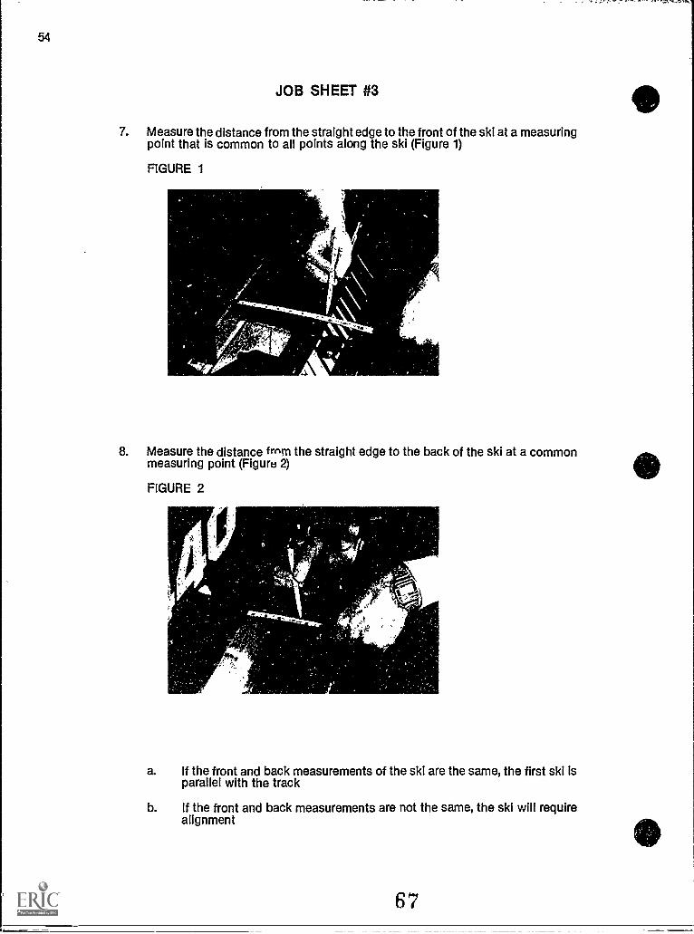
7. Measure the distance from the straight edge to the front of the ski at a measuringpoint that is common to all points along the ski (Figure 1)
FIGURE 1
8. Measure the distance frnm the straight edge to the back of the ski at a commonmeasuring point (Figure 2)
FIGURE 2
a. If the front and back measurements of the ski are the same, the first ski isparallel with the track
b. If the front and back measurements are not the same, the ski will requirealignment
67
4)]
SR-55
JOB SHEET #3
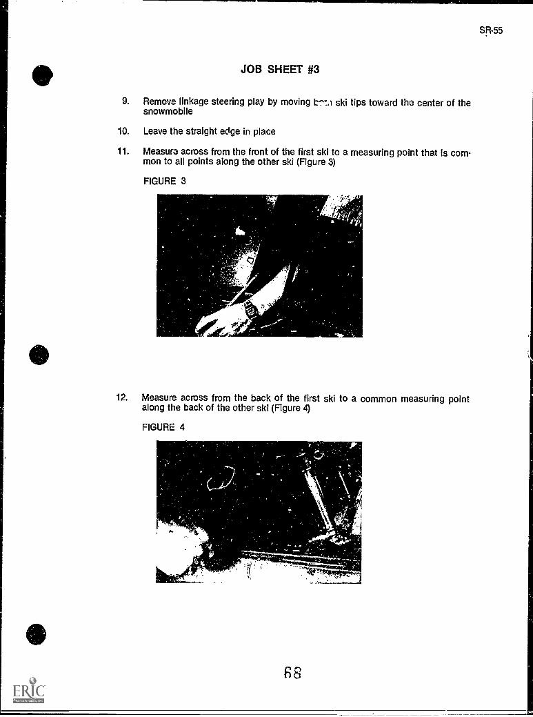
9. Remove linkage steering play by moving ski tips toward the center of thesnowmobile
10. Leave the straight edge in place
11. Measure across from the front of the first ski to a measuring point that is com-mon to all points along the other ski (Figure 3)
FIGURE 3
1;1
12. Measure across from the back of the first ski to a common measuring pointalong the back of the other ski (Figure 4)
FIGURE 4
F8
.-- ,7T-7.:".."--"7--.7..^....
JOB SHEET #3
13. Loosen tie rod jam nuts and turn tie rods as required to complete ski alignment
14. Retighten tie rod jam nuts to manufacturer's torque specifications
(CAUTION: Make sure that the tie rod end is threaded into the tie rod with enoughthread length to prevent steering linkage failure, and check manufacturer's speci-fications if you have any doubts at all.)
Have your instructor check your work
15. Discuss with your instructor the adjustments required to complete the toe-outalignment required on a Ski-Doo
16. Clean up area and return tools and materials to proper storage
(Note: Apply a thread sealing adhesive,LOCTITem or similar to tie rod threadedcomponents upon reassembly)
STEERING, FRONT SUSPENSION, AND SKISUNIT II
NAME
TEST
1. Match each term on the right with its correct definition.
a. The steering control apparatus which isrotated right or left AO turn the skis in thedirection of intendeu travel
b. A cylindrical piece of rubber which is gluedto the handlebars to give hand comfort tothe operator and to aid the hands from slip-ping off the handlebars
c A long cylindrical piece of metal whichextends from the handlebars through thechassis to the tie rods
_____d Rods which link the steering column to thesteering arm
e The ski leg which is connected to the tierods and connects the skis to the steeringassembly
f. A ski position where the front of each skipoints outward
g A ski position where the front of each skipoints inward
h The nature of a mechanism to be free tomove or to move too much after wear
i i.ong, slender pieces of metal which extendoutward from under a snowmobile to itsfront which allow the vehicle to glide oversnow and to be steered
i
k
A ski wear rod or runner used to reduce wearon the ski and to improve directional control
A round cylinder filled with gas or lubricantand connected to the skis and spind - armto absorb the impact of bumpy surfaces onthe snowmobile chassis
70
1. Play
2. Toe in
3. Handlebars
4. Flotation
5. Spindle arm
6. Shock absorber
7. Tie rods
8. Toe out
9. Skeg
10. Steering post
11. Saddle
12. Grip
13. Skis
SR57
58
TEST
I. The relationship between the snowmobileweight and the amount of surface area ofthe skis and track supporting it on the snow
m. A mounting bracket which accepts the mainleafspring allowing it to ride and connectwith the ski
2. Complete statements concerning steering mechanisms by circling the word(s) that bestcompletes each statement.
a. The steering assembly (impedes, controls) the direction of travel of the snowmo-bile.
b. The (throttle, handlebars) serve as the assembly control which, when rotated leftor right, turn the skis in the direction of travel.
c. Attached to the (steering wheel, handlebars) is a lever-type throttle control, anemergency stop switch and the headlight hi-lo beam switch.
d. The (skis, track) are turned in the direction of intended travel from the handle-bars, through a system of tie rods and linkages to the skis.
e. The tie rods transfer (movement, shocks) to the spindle which, in turn, causesmovement to the left or right of the entire ski.
f. The steering system should be checked periodically to be sure its movement is(restricted, not restricted) and also to be sure there is not excessive play.
g. The steering post should be examined occasionally for cracks or bends whichcould (adversely, positively) affect steering.
h. Tie rods, tie rod ends and bushings should be (ignored, checked) regularly folwear, breakage or signs of excessive stress.
3. Select true statements concerning ski alignment by placing an "X" beside each state-ment that is true.
a The proper positioning of the skis is essential to the function of the steer-ing system.
b Most manufacturers require that skis be aligned toe in to each other.
c. Bombardier recommends that their Ski-Doo snowmobiles be alignedslightly toe out.
d Alignment is accomplished by adjusting the tie end rod clearings, or jamnuts, as the handlebars are in a vertical position and the snowmobile islifted off the ground.
e. In ski adjustment, measurement and torque specifications can usually beguessed close enough to be right.
71
1
4. Complete statements concerning front suspensions by inserting the word(s) that bestcompletes each statement.
a. The major purpose of the front suspension on a snowmobile is to support thesystem.
b. The suspension systr.n cushions the front of the sled from bumps to helpimprove control of the vehicle and the ride.
c. Modern snowmobiles use three types of front suspensions:
1) Conventional suspension
2) front suspension
3) suspension
5. Complete statements concerning leafspring front suspension by inserting the word(s)that best completes each statement.
a. Leafsprings are pieces of flat which extend down from the spin-dle to brace the skis.
b. A may be attached to a set of leafsprings.
c. Some snowmobiles have several
d. To check the tension on a shock absorber:
1) Hold the of the shock firmly
2) Quickly compress and extend the
3) should be felt in both directions.
4) If the shock is leaking it should be replaced.
6. Select true statements concerning independent front suspension by placing an "X"beside each statement that is true.
a Since 1965, most snowmobiles have independent front suspension asstandard equipment.
b Independent suspension systems are not tied directly to the steering postassembly; each ski is allowed to take shocks separately.
c Each ski has its own shock absorbing mechanism which is either a shockabsorber inside a spring, or separate spindle arms each supported by astrut.
__A Some snowmobiles have a T-frame independent suspension similar indesign to many modern automobile suspensions.
72
SR-59
60
TEST
7. Complete statements concerning strut suspension by inserting the word(s) that bestcompletes each statement.
a. A strut suspension is similar to conventional suspensionsexcept that instead of a shock absorber, a longer strut mechanism is used tocushion and support the snowmobile.
b. A strut suspension is found almost exclusively on snowmobiles.c. The strut suspension on snowmobiles is similar to the strut suspension found in
the nose gear of
d. A strut is attached to each ski, encases oil and a spring, or some are filled with
e. The strut is considered a stronger shock absorbing mechanism than the conven-tional
f. The strut extends a distance between the ski and spindle armwhich serves to absorb more impact before reaching the snowmobile chassis.
8. Complete statements concerning comparisons of front suspension systems by insert-ing the word(s) that best completes each statement.
a. The conventional suspension systems are reliable and lessexpensive to maintain than independent or strut suspensions.
b. suspension systems are reliable and greatly enhance thesmoothness of 'Ale ride by absorbing the shock to the individual skis rather thanto the entire chassis.
c. suspensions are reliable, stronger than leaf springfabsorber sus-pensions, and absorb shocks more efficiently.
9. Select true statements concerning skis by placing an "X" beside each statement that istrue.
a. A snowmobile travels on snow because of ski flotation.
b The skis provide support for the snowmobile and comfort the ride.
c. The skis grip the snow surface so that the vehicle can be steered.
d The ski wear rod is located above the ski and serves to reduce ski wearand to greatly improve directional control.
e The ski wear rod is also called a "skeg" or "runner shoe!'
f Skis and skegs should never be inspected frequently for excessive wear.
73
TEST
g A rubber rebound bumper connected to the underside of the mainspringleaf serves to prevent chafing of the skis by the leafspring.
h. The rebound bumper should be inspected for signs of wear, an indicationthat the track may need to be replaced, or that there are other suspensionproblems.
10. Select true statements concerning ski inspection by placing an "X" beside each state-ment that is true.
a Never inspect welded areas for cracks of deterioration.
b Inspect bolts for stripped or damaged threads.
c Inspect the holes where the springs are mounted tothe skis for damage orelongation.
._._d Inspect the ski for abnormal bends or cracks.
e Never inspect ski springleaves for bends or cracks.
f. Inspect the shock-absorber body and plunger for nicks, cracks, and bends.
g. Check ski alignment at the beginning of each season.
(NOTE: If the following activities have not been completed prior to the test, ask your instructorwhen they should be completed.)
11. Solve problems related to skis and steering. (Assignment Sheet #1)
12. Demonstrate the ability to:
a. Remove, inspect, and replace tie rods. (Job Sheet #1)
b. Remove and replace ski skegs. (Job Sheet #2)
c. Adjult ski alignment on a snowmobile. (Job Sheet #3)
74
SR-61
STEERING, FRONT SUSPENSION AND SKISUNIT II
ANSWERS TO TEST
1. a. 3 h. 1
b. 12 i. 13c. 10 j. 9d. 7 k. 6e. 5 I. 4f. 8 m. 11g. 2
2. a. Controlsb. Handlebarsc. Handlebarsd. Skise. Movementf. Not restrictedg. Adverselyh. Checked
3. a, c
4. a. Steeringb. Cushionc. 1) Leafspring
2) independent3) Strut
5. a. Steelb. Shock absorberc. Leafspringsd. 1) Body
2) Plunger3) Resistance4) Lubricant
6. b, c
7. a. Leafspringb. Yamahac. Aircraftd. Nitrogene. Shock absorberf. Longer
75
SR-63
64
ANSWERS TO TEST
8. a. Leafspringb. Independentc. Strut
9. a,b,c,e,g
10. b, c, d, f, g
11. Evaluated to the satisfaction of the instructor
12. Performance skills evaluated according to procedures written in the job sheets
. DRIVE CLUTCHUNIT III
UNIT OBJECTIVE
After completion of this unit, the student should be able to discuss the power theory and otherunique elements of snowmobile transmissions. The student should also be able to remove,inspect, and replace a drive clutch. These competencies will be evidenced by correctly per-forming the procedures outlined in the assignment and job sheets and by scoring 85 percenton the unit test.
SPECIFIC OBJECTIVES
After completion of this unit, the student should be able to:
1. Match terms related to the drive clutch with their correct definitions.
2. Identify drive clutch components.
3. Complete statements concerning power theory.
4. Select true statements concerning clutch wear.
5. Complete statements concerning lubrication and cleaning.
6. Complete statements concerning clutch adjustment.
7. Select true statements concerning troubleshooting.
8. Complete statements concerning special tools.
9. Select true statements concerning clutch timing.
10. Solve problems related to drive clutch wear. (Assignment Sheet #1).
11. Demonstrate the ability to remove, inspect, and replace a drive ,Ilutch. (Job Sheet#1)
77
SR-65
0 DRIVE CLUTCHUNIT III
SUGGESTED ACTIVITIES
A. Provide students with objective sheet.
B. Provide students with information sheet.
C. Make transparency.
D. Discuss unit and specific objectives.
E. Discuss information sheet.
F. Demonstrate and discuss the procedures outlined in the job sheets.
G. Have a disassembled clutch available so students can examine components.
H. Explain to students the relationships of the drive clutch, drive belt, and driven clutch,and explain why job sheets for adjusting offset, Lcnter distance, and parallelism will notbe assigned until they have finished the r.ext two units which cover drive belts anddriven clutches.
I. Mount a snowmobile on a safety stand and conduct a quick-check inspection for trans-mission engagement, idle disengagement, ani discuss possible causes of poor per-formance.
J. Demonstrate how springs, weights, and ramps affect clutch timing.
K. Give test.
CONTENTS OF THIS UNIT
A. Objective sheet
B. Information sheet
C. Transparency Master 1 Drive Clutch
D. Assignment Sheet #1 Solve Problems RelE ad to Drive Clutui Wear
E. Answers to assignment sheet
F. Job Sheet #1 Remove, Inspect, and Replace a Drive Clutch
G. Test
H. Answers to test
.1.........
78
SR-67
68
REFERENCES USED IN DEVELOPING THIS UNIT
A. 1986 Yamaha Snowmobile Mechanics Guide. Cypress, CA: Yamaha Motor Corporation,U.S.A., 1985.
B. Arctic Cat Master Service Training Manual. Thief River Falls, MN 56701: Arctic Cat, 1986.
C. Chilton's Snowmobiles Repair & TuneUp Guide, Second Edition. Radnor, PA: ChiltonBook Company, 1975.
D. Bombardier Service Tapes: Clutches. Valcourt, Quebec, Canada, JOE 2L0: Bombardier,Ltd, 1985.
E. Kawasaki Drifter Snowmobile Shop Manual. Santa Ana, CA 92799-5252: KawasakiMotors Corp., U.S.A., 1980.
F. Kawasaki Parts Catalog SB340-A2, S8440-A5. Santa Ana, CA 92799-5252: KawasakiMotors Corp., U.S.A., 1980.
79
SR-69
DRIVE CLUTCHUNIT III
INFORMATION SHEET
I. Terms and definitions
A. Drive dutch The primary clutch attached to the engine crankshaft whichcontrols he upshift in acceleration (also called the centrifugal drive clutchor drive converter)
B. Driven clutch The variable ratio clutch or torque converter that ismounted to the driven shaft where its torque-sensing capabilities transferspower to the track
C. Drive assembly The drive clutch, the drive belt, and the driven clutch thatwork together to transfer power from the engine to the track
D. Stationary sheave The clutch sheave that remains in one position duringoperation of the drive or driven clutch
E. Movable sheave The clutch face that moves inward or outward to createvariable ratios in the drive and driven clutches
r. Centrifugal weights Moving clutch parts that force the movable sheaveof the drive clutch inward to increase the diameter of the drive clutch
a Centrifugal force The force that tends to pull mass outward from the cen-ter when the mass is rotating rapidly around a center
H. Offset The positioning of the drive and driven clutch so that the belt willrun straight between the clutches when the transmission ratio is at or near1 to 1 (1:1)
I. Spider The assembly to which the weight-assembly ramps or rollers areattached and which in turn is fixed onto the clutch shaft
J. Spring A wire coil that exerts a force which is countered by the centrifu-gal force of the weights in the drive clutch
K. Roller The surface which receives the force exerted by the weight-assembly ramp
L. Spring free length The length of a spring as meagured when the spring isunloaded
M. Spring preload The creation of a given amount of tension on a spring,achieved by compressing the spring
N. Center distance The distance from the center of the engine crankshaft tothe center of the driven shaft.
80
70
INFORMATION SHEET
0. Parallelism A straight or parallel relationship between the engine crank-shaft and the driven shaft.
P Shim A metal-type washer.
II. Drive clutch components (Transparency 1)
A. Stationary sheave
B. Movable sheave
C. Weight ramp assemblies (usually 3)
D. Ramp
E. Spring
F. Cover assembly
G. Spider
H. Roller (ard bearing)
I. Bushing
HI. Power theory
A. A centrifugal clutch system engages or disengages the engine from thetrack with centrifugal force.
B. The centrifugal force is the source of the automatic action of a snowmo-bile's transmission.
C. A system of levers and cams are located inside the drive clutch'souter half,the movable sheave.
D. The levers and cams move the movable sheave of the drive clutch inwardwhen the engine reaches a predetermined speed.
(NOTF: This point of activation is determined and set at the factory for max-imum efficiency of the drive system; altering or inattention to the indexmarks which denote alignment of this point can alter the efficiency of thedrive system.)
E. The inner half of the drive clutch, the stationary sheave, rotates with theengine's crankshaft.
F. The outer half of the drive clutch, the movable sheave, includes the outerhalf of the pulley on the engine which drives the drive belt.
81
SR-71
INFORMATION SHEET
G. At low rpm's, the stationary and movable sheaves are forced apart by theclutch spring and the clutch spins freely and does not engage the drive belt.
H. When engine rpm's increase, the stationary and movable sheaves arepressed together because of the centrifugal force of the clutch weights,and the sheaves grip the sides of the drive belt to engage the drive systemand set the sled in motion
I. Some slippage of the drive belt can be expected as the two drive clutchsheaves come together, but the slight delay of engagement gives a fluid-likepower flow and avoids jerky starts.
J. The combination of weights, spring tension, and rpm's control the amountof pressure exerted between the clutch sheaves, and consequently, theamount of power transmitted to the track.
IV. Clutch wear
A. Before disassembling a clutch, note all index marks, and if no index marksare present, mark the clutch sheaves with a magic marker to assure properreassembly
B. The drive clutch should be inspected at least annually.
C. Always inspect the spring which separates the stationary and movablesheaves, and if its length is not as specified, it should be replaced.
D. General maintenance of the drive clutch should include an inspection ofthe sheaves for burrs 0: obstructions which could cause premature beltwear.
E. Bush..igs are the most susceptible to wear since they ar3 in constant fric-tion with other moving parts.
F. Bushings should be checked for wear by measuring the inside diameter ofthe bushing with the outside diameter of the part it contacts.
G. Always Inspect the two sheaves for cracks and replace them if necessary.
H. The weights are susceptible to damage and wear.
I. All threads on the drive clutch and its components should be inspected forstripping and for cracks.
J. All rollers and pins, washers, and shims should be inspected for damage orwear.
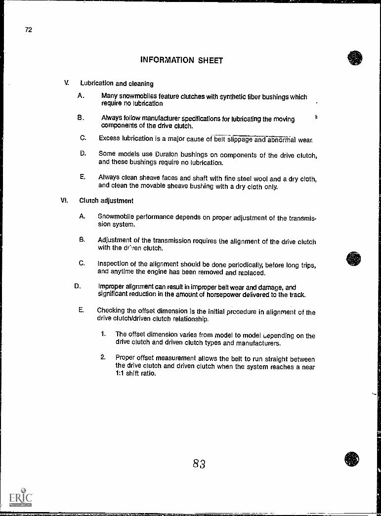
72
INFORMATION SHEET
V. Lubrication and cleaning
A. Many snowmobiles feature clutches with synthetic fiber bushings whichrequire no lubrication
B. Always follow manufacturer specifications for lubricating the movingcomponents of the drive clutch.
C. Excess lubrication is a major cause of belt slippage iFIC1 abrinal wear.
D. Some models use Duralon bushings on components of the drive clutch,and these bushings require no lubrication.
E. Always clean sheave faces and shaft with fine steel wool and a dry cloth,and clean the movable sheave bushing with a dry cloth only.
VI. Clutch adjustment
A. Snowmobile performance depends on proper adjustment of the transmis-sion system.
B. Adjustment of the transmission requires the alignment of the drive clutchwith the driven clutch.
C. Inspection of the alignment should be done periodically, before long trips,and anytime the engine has been removed and replaced.
D. Improper alignment can result in improper belt wear and damage, andsignificant reduction in the amount of horsepower delivered to the track.
E. Checking the offset dimension is the initial procedure in alignment of thedrive clutch/driven clutch relationship,
1. The offset dimension varies from model to model uepending on thedrive clutch and driven clutch types and manufacturers.
2. Proper offset measurement allows the belt to run straight betweenthe drive clutch and driven clutch when the system reaches a near1:1 shift ratio.
83
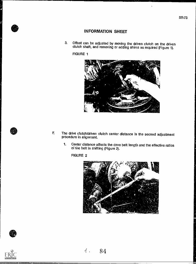
SR-73
INFORMATION SHEET
3. Offset can be adjusted by moving the driven clutch on the drivenclutch shaft, and removing or adding shims as required (Figure 1).
FIGURE 1
F The drive clutch/driven clutch center distance is the second adjustmentprocedure in alignment.
1. Center distance affects the drive belt length and the effective ratiosof the belt in shifting (Figure 2).
FIGURE 2
84
74
INFORMATION SHEET
2. Center distance is set at the factory, and in most cases, no adjust-ments are possible.
3. Center distance adjustments may be possible by adding or reducingthe number of shims on the motor mounting system, or by slightadjustment of chain case components
G. When the crankshaft to which the drive clutch is attached, and the drivenclutch are parallel, the drive clutch and driven clutch sheaves also will beparallel.
1. Parallelism allows for efficient power transfer to the track.
2. Engine torque can cause misalignment of the two clutch sheavesbecause the engine is cushion mounted.
3. Some intentional misalignment is acceptable because under power,engine torque will tend to bring the sheaves into parallel
4. Manufacturer's service manuals provide details on how to inspectand adjust for parallelism.
H. Higher altitude operation requires adjustments to the transmission system.
1. Engines lose about three percent of their horsepower for every 1,000foot rise in elevation from sea level because of a decrease in the den-sity of oxygen.
2. Higher altitude operation requires adjustments to both the carbu-retor and the transmission.
3. Consult service manuals for the specific drive system adjustmentswhich should be made while operating in higher altitude environ-ments.
VII. Troubleshooting
A. A thorough understanding of each component of the drive system is essen-tial in troubleshooting to discover the causes of malfunctions.
S. Troubleshooting requires a rational and systematic approach to the diagno-sis and repair of drive system malfunctions.
C. There are five precautions which must be taken in troubleshooting:
1
1. Never allow anyone to stand behind or in front of the sncwciobilewhen running the engine and testing the drive system.
2. Always raise: the track off the ground so the track nen rotate freely.
85
SR-75
INFORMATION SHEET
3. Never run the engine while the drive belt is removed.
4. Always wait for all moving parts to stop after stopping the enginebefore making any drive clutch adjustments.
5. Keep all safety shields or covers in place and securely fastened.
D. Develop a troubleshooting list which should include:
1. Check for proper argnment of the drive clutch and driven clutch foroffset, center distance, and parallelism.
2. Inspect the stationary and movable sheave faces and clean off alldirt, oil, grease, and belt dust buildup.
3. Gouges, scratches, nicks or corrosion on the sheave faces should beremoved by sanding with 400 grit wet-or-dry sandpaper.
4. With the track raised off the floor and the engine idling, the trackshould not move, or if the track does move, slight pressure on thebrake lever should stop it.
5. Run the engine with the drive system engaged for 30 seconds thenrelease the throttle lever; the drive clutch should disengage immedi-ately.
E. The idle speed of the snowmobile may be too high if the drive clutch doesnot disengage upon release of the throttle lever, or the drive clutch springmay be weak, or the drive clutch may be dirty.
F. If the drive clutch does not engage, or engages at too high rpm, the wrongdrive clutch spring may have been installed or weights too light may havebeen installed.
VIII. Special tools
A. Each model and make of snowmobile may require special tools for assem-bling and disar-embling and aligning components of the drive system.
B. Always use the specified puller to remove the sheaves of the drive clutch orelse serious damage could result to the sheave.
C. Use callipers for measuring wear on bushings and other components.
D. Heating may be necessary to remove lugs or nuts held with LOCKTITEadhesive.
E. Some models have special tools for measuring center distance, offset, andparallelism.
86
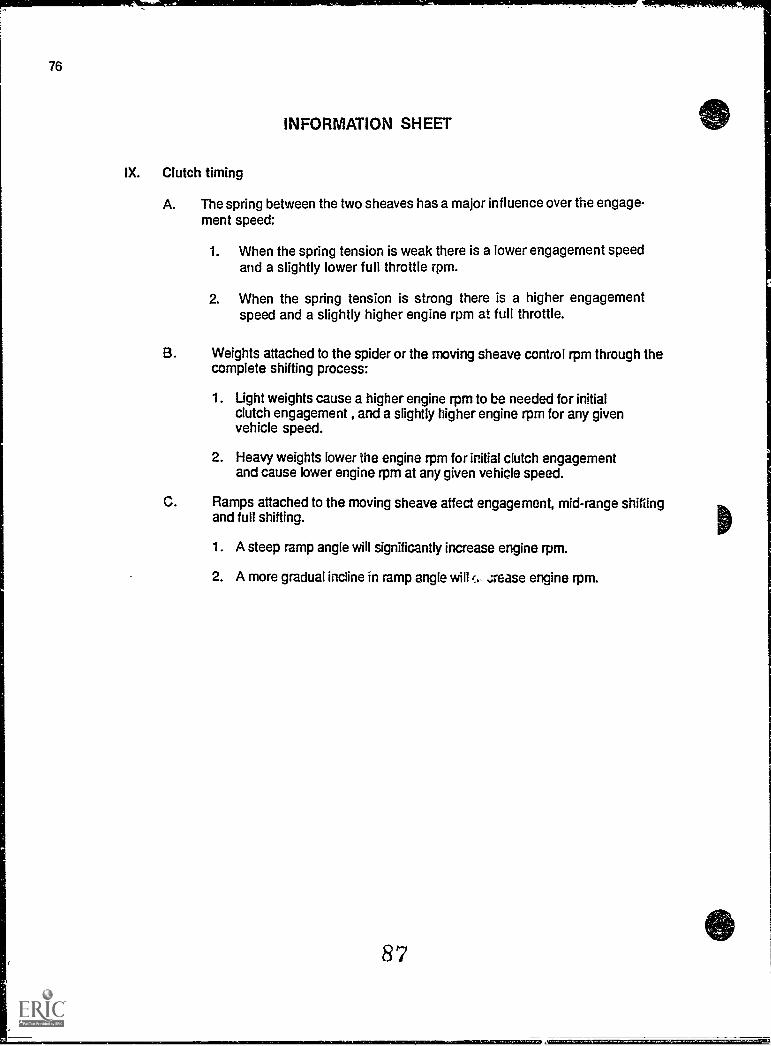
76
INFORMATION SHEET
IX. Clutch timing
A. The spring between the two sheaves has a major influence over the engage-ment speed:
1. When the spring tension is weak there is a lower engagement speedand a slightly lower full throttle rpm.
2. When the spring tension is strong there is a higher engagementspeed and a slightly higher engine rpm at full throttle.
B. Weights attached to the spider or the moving sheave control rpm through thecomplete shifting process:
1. Light weights cause a higher engine rpm to be needed for initialclutch engagement , and a slightly higher engine rpm for any givenvehicle speed.
2. Heavy weights lower the engine rpm for initial clutch engagementand cause lower engine rpm at any given vehicle speed.
C. Ramps attached to the moving sheave affect engagement, mid-range shiftingand full shifting.
1. A steep ramp angle will significantly increase engine rpm.
2. A more gradual incline in ramp angle will i., zrease engine rpm.
87
AZZEMISSELON
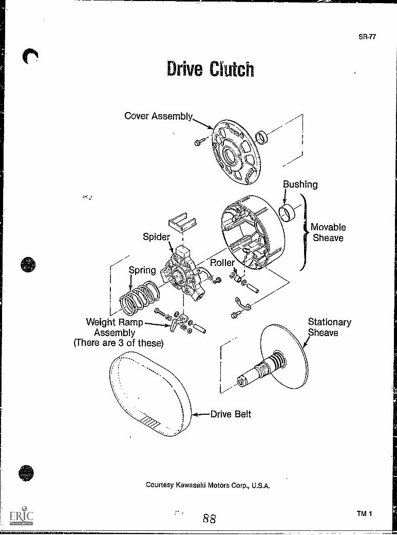
Drive Clutch
Cover Assembly
Weight RampAssembly
(There are 3 of these)
MovableSheave
StationarySheave
Drive Belt
Courtesy Kawasaki Motors Corp., U.S.A.
88
SR-77
TM 1

SR-79
DRIVE CLUTCHUNIT ill
ASSIGNMENT SHEET #1 - SOLVE PROBLEMS RELATED TODRIVE CLUTCH WEAR
Directions: Read the following problems carefully and recommend th , best solution.
A. You have been directed to disassemble a drive clutch to inspe'.. for signs of wear;what specific, critical items, are most important in this inspection?
B. You have d;fficulty in removing nuts during disassembly; what might you suspect andwhat should you look for'?
C. customer enters the repair shop where you work and complains that the transmissionengages at too high an rpm, what source of wear might be the cause of the problem?
89
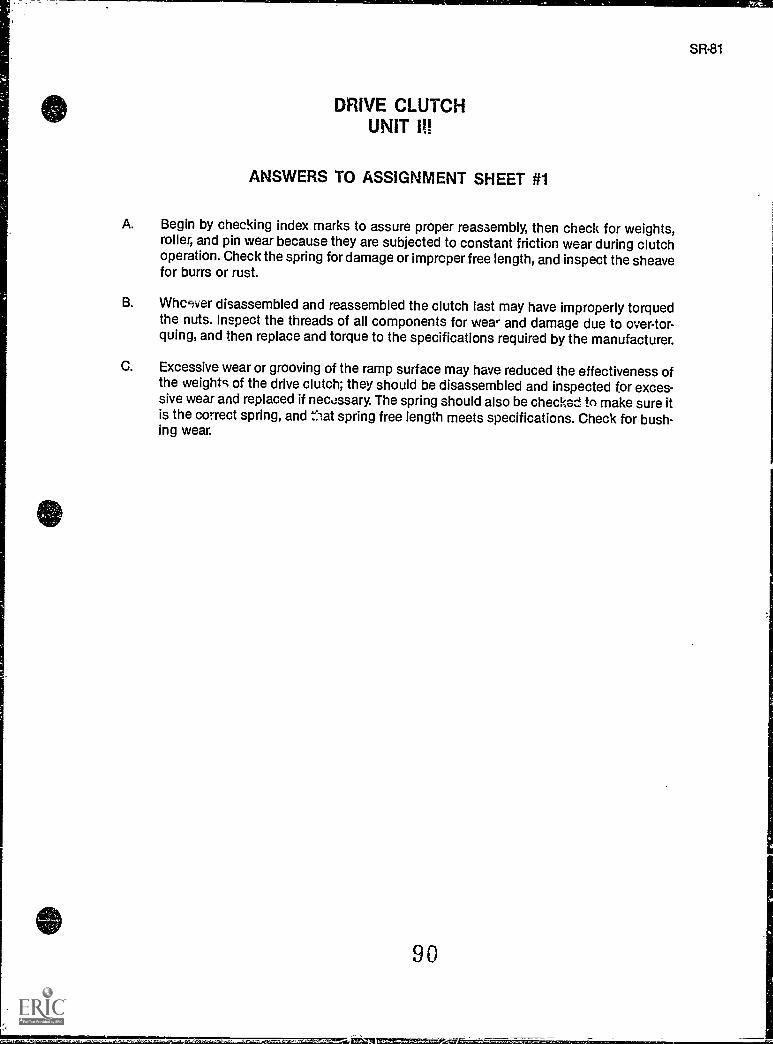
DRIVE CLUTCHUNIT
ANSWERS TO ASSIGNMENT SHEET #1
A. Begin by checking index marks to assure proper reassembly, then check for weights,roller, and pin wear because they are subjected to constant friction wear during clutchoperation. Check the spring for damage or improper free length, and inspect the sheavefor burrs or rust.
B. Whccfver disassembled and reassembled the clutch last may have improperly torquedthe nuts. Inspect the threads of all components for wear and damage due to over-tor-quing, and then replace and torque to the specifications required by the manufacturer.
C. Excessive wear or grooving of the ramp surface may have reduced the effectiveness ofthe weights of the drive clutch; they should be disassembled and inspected for exces-sive wear and replaced if nec%:ssary. The spring should also be checked to make sure itis the correct spring, and fiat spring free length meets specifications. Check for bush-ing wear.
90
SR-81
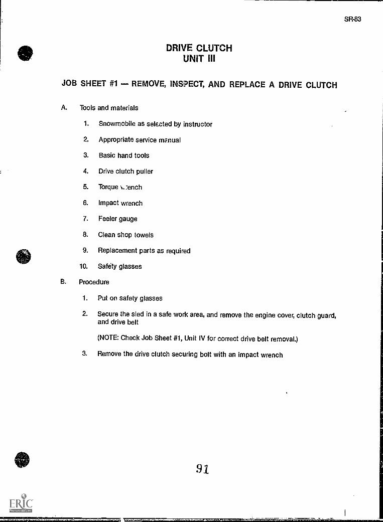
I
DRIVE CLUTCHUNIT III
JOB SHEET #1 REMOVE, INSPECT, AND REPLACE A DRIVE CLUTCH
A. Tools and materials
1. Snowmobile as selected by instructor
2. Appropriate service manual
3. Basic hand tools
4. Drive clutch puller
5. Torque N..:ench
6. Impact wrench
7. Feeler gauge
8. Clean shop towels
9. Replacement parts as required
10. Safety glasses
B. Procedure
1. Put on safety glasses
2. Secure the sled in a safe work area, and remove the engine cover, clutch guard,and drive belt
(NOTE: Check Job Sheet #1, Unit IV for correct drive belt removal.)
3. Remove the drive clutch securing bolt with an impact wrench
91
SR-83
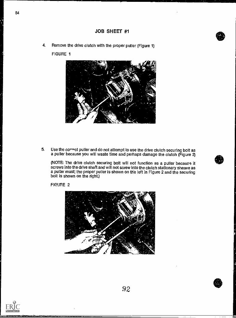
84
JOB SHEET #1
4. Remove the drive clutch with the proper puller (Figure 1)
FIGURE 1
-4^
5. Use the corroct puller and do not attempt to use the drive clutch securing bolt asa puller because you will waste time and perhaps damage the clutch (Figure 2)
(NOTE: The drive clutch securing bolt will not function as a puller because itscrews into the drive shaft and will not screw into the clutch stationary sheave asa puler must; the proper puller is shown on the left in Figure 2 and the securingbolt is shown on the right.)
Fle.URE 2
92
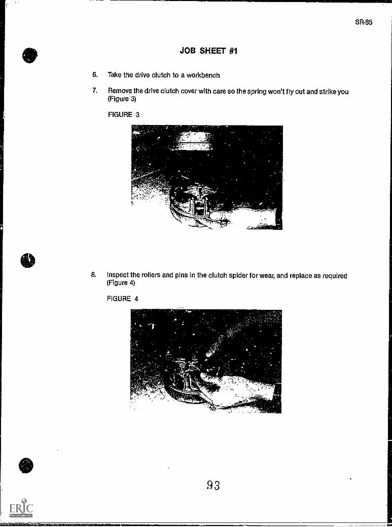
JOB SHEET #1
6. Take the drive clutch to a workbench
7. Remove the drive clutch cover with care so the spring won't fly out and strike you(Figure 3)
FIGURE 3
8. Inspect the rollers and pins in the clutch spider for wear, and replace as required(Figure 4)
FIGURE 4
SR-85
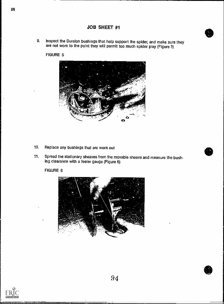
86
JOB SHEET #1
9. Inspect the Duralon bushings that help support the spider, and make sure theyare not worn to the point they will permit too much spider play (Figure 5)
FIGURE 5
10. Replace any bushings that are worn out
11. Spread the stationary sheaves from the movable sheave and measure the bush-ing clearance with a feeler gauge (Figure 6)
FIGURE 6
94
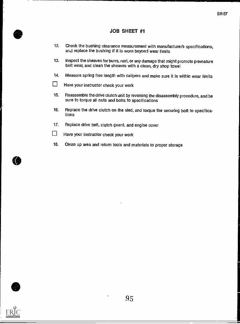
SR87
JOB SHEET #1
12. Check the bushing clearance measurement with manufacturer's specifications,and replace the bushing if it is worn beyond wear limits
13. Inspect the sheaves for burrs, rust, or any damage that might promote prematurebelt wear, and clean the sheaves with a clean, dry shop towel
14. Measure spring free length with calipers and make sure it is within wear limits
Have your instructor check your work
15. Reassemble the drive clutch unit by reversing the disassembly procedure, and besure to torque all nuts and bolts to specifications
16. Replace the drive clutch on the sled, and torque the securing bolt to specifica-tions
17. Replace drive belt, clutch guard, and engine cover
Have your instructor check your work
18. Clean up area and return tools and materials to proper storage
95
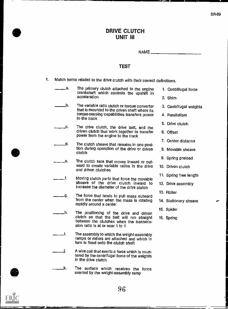
DRIVE CLUTCHUNIT ill
NAME
TEST
1. Match terms related to the drive clutch with their correct definitions.
a The primary clutch attached to the enginecrankshaft which controls the upshift inacceleration
13 The variable ratio clutch or torque converterthat is mounted to the driven shaft where itstorque - sensing capabilities transfers powerto the track
c The drive clutch, the drive belt, and thedriven clutch that work together to transferpower from the engine to the track
d The clutch sheave that remains in one posi-tion during operation of the drive or drivenclutch
e The clutc:1 face that moves inward or out-ward to create variable ratios in the driveand driven clutches
f. Mov !rig clutch parts that force the movablesheave of the drive clutch inward toincrease the diameter of the drive clutch
g The force that tends to pull mass outwardfrom the center when the mass is rotatingrapidly around a center
h. The positioning of the drive and drivenclutch so that the belt will run straightbetween the clutches when the transmis-sion ratio is at or near 1 to 1
i The assembly to which the weight-assemblyramps or rollers are attached and which inturn is fixed onto the clutch shaft
A wire coil that exerts a force which is coun-tered by the centrifugal force of the weightsin the drive clutch
k The surface which receives the forceexerted by the weight-assembly ramp
1. Centrifugal force
2. Shim
3. Centrifugal weights
4. Parallelism
5. Drive clutch
6. Offset
7. Center distance
8. Movable sheave
9. Spring preload
10. Driven clutch
11. Spring free length
12. Drive assembly
13. Roller
14. Stationary sheave
15. Spider
16. Spring
SR-89
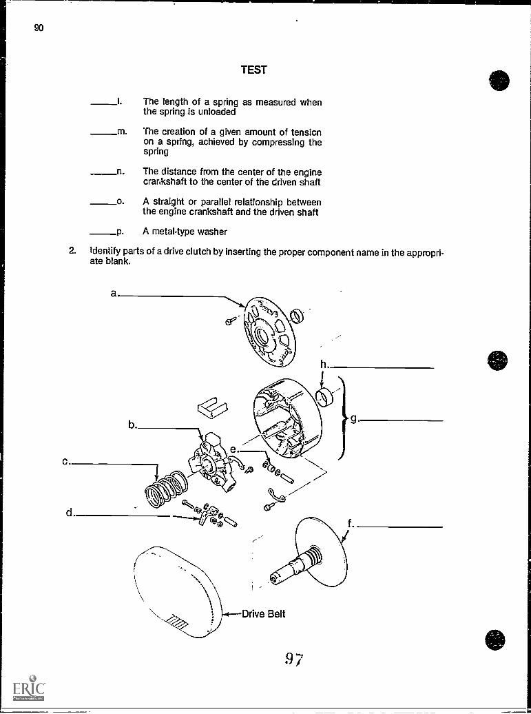
90
TEST
i The length of a spring as measured whenthe spring is unloaded
m The creation of a given amount of tensionon a spring, achieved by compressing thespring
n The distance from the center of the enginecrankshaft to the center of the driven shaft
o. A straight or parallel relationship betweenthe engine crankshaft and the driven shaft
P A metal-type washer
2. Identify parts of a drive clutch by inserting the proper component name in the appropri-ate blank.
h
97
TEST
3. Complete statements concerning power theory by circling the word(s) that best com-pletes each statement.
a. A centrifugal clutch system engages or disengages the (steering, engine) fromthe track with centrifugal force.
b. The centrifugal force is the source of the (manual, automatic) action of a snow-mobile's transmission.
c. A system of levers ant.: cams are located inside the drive clutch's outer half, the(movable, stationary) sheave.
d. The levers and cams move the movable sheave of the drive clutch (outward,inward) when the engine reaches a predetermined speed.
e. The inner half of the drive clutch, the stationary sheave, rotates with the engine's(pistons, crankshaft).
f. The outer half of the drive clutch, the movable sheave, includes the outer half ofthe pulley on the (engine, clutch) which drives the drive belt.
g. At low rpm's, the stationary and movable sheaves are forced apart by the clutchspring and the clutch spins freely and (does, does not) engage the drive belt.
h. When engine rpm's increase, the stationary and movable sheaves are pressedtogether because of the centrifugal force of the clutch weights, and the sheavesgrip the (bottom, sides) of the drive belt to engage the drive system and set thesled in motion.
i. Some slippage of the drive belt (can, cannot) be expected as the two drive clutchsheaves come together, but the slight delay of engagement gives a fluid-likepower flow and avoids jerky starts.
The combination of weights, spring tension, and rpm's control the amount ofpressure exerted between the clutch sheaves, and consequently, the amount ofpower transmitted to the (drive clutch, track).
4. Select true statements concerning clutch wear by placing an "X" beside each state-ment that is true.
a The drive clutch should be inspected at least annually.
_____b Always inspect the spring which separates the stationary and movablesheaves, and if its length is not as specified, it should be replaced.
General maintenance of the drive clutch should not include an inspectionof the sheaves for burrs or obstructions which could cause premature beltwear.
98
92
TEST
______d Bushings are the least susceptible to wear since they are not in constantfriction with other moving parts.
e Bushings should be checked for wear by measuring the inside diameter ofthe bushing with the outside diameter of the part it contacts.
f. Always inspect the two sheaves for cracks and replace them if necessary.
g The weights are not susceptible to damage and wear.
h All threads on the drive clutch and its components should be inspected forstripping and for cracks.
i All rollers and pins, washers, and shims should be inspected for damageor wear.
I There are na index marks to worry about on a drive clutch.
5. Complete statements concerning lubrication and cleaning by inserting the word(s) that bescompletes each statement.
a. Many snowmobiles feature clutches with bushings whichrequire no lubrication
b. Atways foBow specifications for lubricating the movingcomponents of the drive clutch.
c. lubrication is a major cause of belt slippage and abnormal wear.
d. Most models use bushings on components of the drive clutch,and these bushings require no lubrication.
e. Always clean clutch faces and shaft withand a dry cloth, and clean the movable sheave bushing with a dry
cloth only.
6. Complete statements concerning clutch adjustment by circling the word(s) that bestcompletes each statement.
a. Snowmobile performance depends on proper adjustment of the (transmission,brake) system.
b. Adjustment of the transmission requires the alignment of the (jack shaft, driveclutch) with the driven clutch.
c. Inspection of the alignment should be done periodically, (after, before) long trips,and anytime the engine has been removed and replaced.
d. Improper alignment can result in improper belt wear and damage, and significant(increase, reduction) in the amount of horsepower from the engine.
99
1
TEST
e. Checking the offset dimension is the (final, initial) procedure in alignment of thedrive clutch/driven clutch relationship.
1) The offset dimension (varies, never varies) from model to model depend-ing on tne drive clutch and driven clutch types and manufacturers.
2) ?roper offset measurement allows the (belt, crankshaft) to run straightbetween the drive clutch and driven clutch when the system reaches anear 1:1 shift ratio.
3) Offset can be adjusted by moving the driven clutch on the driven clutchshaft, and removing or adding (washers, shims) as required.
f. The drive clutch/driven clutch center distance is the (first, second) adjustmentprocedure in alignment.
1) Center distance affects the drive belt (length, width) and the effectiveratios of the belt in shifting.
g.
2) Center distance is set at the factory and, in most cases, (adjustments, noadjustments) are possible.
3) Center distance adjustments may be possible by adding or reducing thenumber of shims on the motor mounting system or by slight adjustmentof (chain case components, drive clutch components).
When the crankshaft to which the drive clutch is attached, and the driven clutchare parallel, the drive clutch and driven clutch sheaves (will not be, also will be)parallel.
1) Parallelism allows for (rapid, efficient) power transfer to the track.
2) Torque by the engine can cause (alignment, misalignment) of the twoclutch sheaves.
3) Some misalignment is (acceptable, not acceptable) because underpower the engine torque will tend to bring the sheaves into parallelism.
4) Manufacturer's service manuals provide (details, no details) on how toinspect and adjust for parallelism.
h. Higher altitude operation requires (adjustments, no adjustments) to the transmis-sion system.
1) Engines (gain, lose) about three percent of their horsepower for every1,000 foot rise in elevation from sea level because of a decrease in thedensity of oxygen.
2) Higher altitude operation requires (adjustments, no adjustments) to boththe carburetor and the transmission.
3) Consult service manuals for the specific drive system adjustmentswhich'`could be made while operating in (higher altitude, all) environments,.
100
I
1
1
94
TEST
7. Select true statements concerning troubleshooting by placing an "X" beside eachstatement that is true.
(NOTE: For a statement to be true, all parts of the statement must be true.)
a. A minimum understanding of each component of the drive system isessential in troubleshooting to discover the causes of malfunctions.
b Troubleshooting requires a rational and systematic approach to the diag-nosis and repair of drive system malfunctions.
c There are six precautions which must be taken in troubleshooting:
1) Never allow anyone to stand behind or in front of the snowmobile whenrunning the engine and testing the drive system.
21 Never raise the track off the ground so the track can rotate freely
3) Occasionally run the engine while the drive belt is removed.
4) Always wait for all moving parts to stop after stopping the enginebefore making any drive clutch adjustments.
5) Keep all safety shields or covers in place and securely fastened.
d Develop a troubleshooting list which should include:
1) Check for proper alignment of the drive clutch and driven clutch for off-set, center distance, and parallelism.
2) inspect the stationary and movable sheave faces and clean off all dirt,oil, grease, and belt dust buildup.
3) Gouges, scratches, nicks or corrosion on the sheave faces should notbe removed by sanding with 400 grit wet-or-dry sandpaper.
4) Dc not raise the track off the floor and allow it to idle.
5) Run the engine with the drive system engaged for 30 seconds thenrelease the throttle lever; the drive system should disengage immedi-ately.
e. The idle speed of the snowmobile may be too low if the drive system doesnot disengage upon release of the throttle lever, or the drive clutch springmay be weak, or the drive clutch may be dirty.
f. If the drive system does not engage, or engages at too high rpm, the wrongclutch spring may have been installed, or weights too light may have beeninstalled.
10 1
TEST
8. Complete statements about special tools by inserting the word(s) that best completeseach statement.
a. Each model and make of snowmobile may require special forassembling and disassembling and aligning components of the drive system.
b. Always use the puller to remove the sheaves of the drive clutchor else serious damage could result to the sheave.
c. Use for measuring wear on bushings and other components.
d. may be necessary to remove lugs or nuts held with LOCTITEadhesive.
e. Some models have special tools for measuring , offset, and par-allelism.
9. Select true statements concerning clutch timing by placing an "X" beside each state-ment that is true.
(NOTE: For a statement to be true, all parts of the statement must be true.)
a. The spring between the two sheaves has a major influence over theengagement speed.
1) When the spring tension is weak there is a lower engagement speedand a slightly lower full throttle rpm.
2) When the spring tension is strong there is a lower engagement speedand a slightly higher engine rpm at full throttle.
b. Weights attached to the spider of the moving sheave control rpm throughthe complete shifting process.
1) Light weights cause a lower rpm and a slightly higher engagementspeed.
2) Heavy weights lower the engine rpm and create a slightly lower engage-ment.
c. Ramps attached to the moving sheave affect engagement, mid-ranoeshifting and full shifting.
1) A steep ramp angle will significantly increase rpms.
2) A more gradual decline in ramp angle will decrease rpms.
(NOTE: If the following activities have not been accomplished prior to the test, ask yourinstructor when they should be completed.)
10. Solve problems related to drive clutch wear. (Assignment Sheet #1)
11. Demonstrate the ability to remove, inspect, and replace a drive clutch. (Job Sheet #1)
102
SR-95
d
1. a.b.c.d.e.f.g.h.
SR-97
DRIVE CLUTCHUNIT HI
ANSWERS TO TEST
5 i. 1510 j. 1612 k. 1314 I. 11
8 m. 93 n. 71 0. 46 p. 2
2. a. Cover assemblyb. Spider0. Springd. Weight ramp assemblye. Rollerf. Stationary sheaveg. Movable sheaveh. Bushing
3. a. Engineb. Automaticc. Movabled. Inwarde. Crankshaftf. Engineg. Does noth. Sidesi. Canj. Track
4. a, b, e, f, h,
5. a. Synthetic fiberb. Manufacturer'sc. Excessd. Duralone. Fine steel wool
6. a. Transmissionb. Drive clutchc. Befored. Reductione. Initial
1) Varies2) Belt3) Shims
103
98
ANSWERS TO TEST
f. second1) Length2) No adjustments3) Chain case components
g. Also will be1) Efficient2) Misalignment3) Acceptable4) Details
h. Adjustments1) Lose2) Adjustments3) Higher altitude
7. b, f
8. a. Toolsb. Specifiedc. Calipersd. Heatinge. Center distance
9. c
10. Evaluated to the satisfaction of the instructor
11. Performance skills evaluated according to procedures written in the job sheet
104
SR-99
DRIVE BELTSUNIT IV
UNIT OBJECTIVE
After completion of this unit, the student should be able to discuss drive belt operations andhow a drive belt functions in a transmission system. The student should also be able toremove and install a drive belt. These competencies will be evidenced by correctly performingthe procedures outlined in the assignment and job sheets and by scoring 85 percent on theunit test.
SPECIFIC OBJECTIVES
After completion of this unit, the student should be able to:
1. Match terms related to drive belts with their correct definitions.
2. Complete statements concerning drive belt principles.
3. Complete statements concerning drive belt installation.
4. Match common causes of drive belt failure with ways to avoid them.
5. Complete statements concerning transmission and drive belt relationships.
6. Select true statements concerning drive belt alignment.
7. Select true statements concerning drive belt manufacturers.
8. Complete statements concerning troubleshooting belt failures.
9. Solve problems related to drive belts and transmissions. (Assignment Sheet #1)
10. Demonstrate the ability to remove and install a drive belt. (Job Sheet #1)
DRIVE BELTSUNIT IV
SUGGESTED ACTIVITIES
A. Provide students with objective sheet.
B. Provide students with information sheet.
C. Make transparencies.
D. Discuss unit and specific objectives.
E. Discuss information sheet.
F. Demonstrate and discuss the procedures outlined in the job sheet.
G. Job sheets for checking offset, center distance, and parallelism appear in the DrivenClutch unit that follows this one, but you may want to review those procedures at thistime, or have the students perform those jobs sheets with this unit.
H. Remove the belt guard from a snowmobile and check for belt wear, and talk about howbelt wear can be a clue to other problems.
I. Give test.
CONTENTS OF THIS UNIT
SR-101
A. Objective sheet
B. Information sheet
C. Assignment Sheet #1 Solve Problems Related to Drive Clutch Wear
D. Answers to assignment sheet
E. Job Sheet #1 ..emove and Install a Drive Belt
F. Test
G. Answers to test
REFERENCES USED IN DEVELOPING THIS UNIT
A Gates Sportline® Belt Applications Catalog (No. 31-2070). Denver, CO 80217; The Gates RubberCo., 1984.
B. Theory: Snowmobile Drive System. Thief River Falls, MN 56701: Arctic Enterprises, Inc., 1985.
C. 1989 Bombardier Snowmobiles Shop Manual. Valcourt, Quebec, Canada: Bombardier, Ltd.,1979.
D. 1986 Yamaha Snowmobile Mechanics Guide. Cypress, CA. Yamaha Motor Corporation, U.S.A.,1985.
106
DRIVE BELTSUNIT IV
INFORMATION SHEET
I. Terms and definitions
A. Drive belt Rubber and fabric belt used to transfer power from the driveclutch to the driven clutch
B. Belt disintegration The deterioration of a drive belt to the point whereexcessive belt speed or dirty sheaves will cause the belt to come apartwhile the snowmobile is in operation
C. Cords Heavy reinforcement material molded into the drive belt to givethe belt strength and long life
D. Cogs Ridge-like indentations on the underside of a belt which allow flexi-bility in wrapping the belt on the sheaves
E. Belt ride out When the belt overrides the clutch sheaves because the beltis too long or the clutches are too close together
F. Sidewalls The sides of the drive belt through which torque is transmitted
II. Drive belt p:Inciples
A. Drive belts have two components which affect drive system performance.
1. Drive belt dimensions must be matched to the snowmobile at thefactory, both width and circumference.
2. Drive belt construction influences the way the clutches shift, and theamount of power that will be transmitted through the drive system.
B. In addition to the construction of the drive belt, the length of the belt playsan important part in drive system performance.
C. A drive belt too long will not have a full shift ratio available to the clutches,and will cause poor acceleration and a loss in top speed.
D. A drive belt too thin will have the same effect as a belt that is too long.
E. A drive belt which is too short will influence shifting and the amount ofpower transmitted through the drive system, causing different shift pat-terns than specified for the machine.
F. There is no specific time or mileage at which a drive belt suddenly wearsout or fails.
107
SR-103
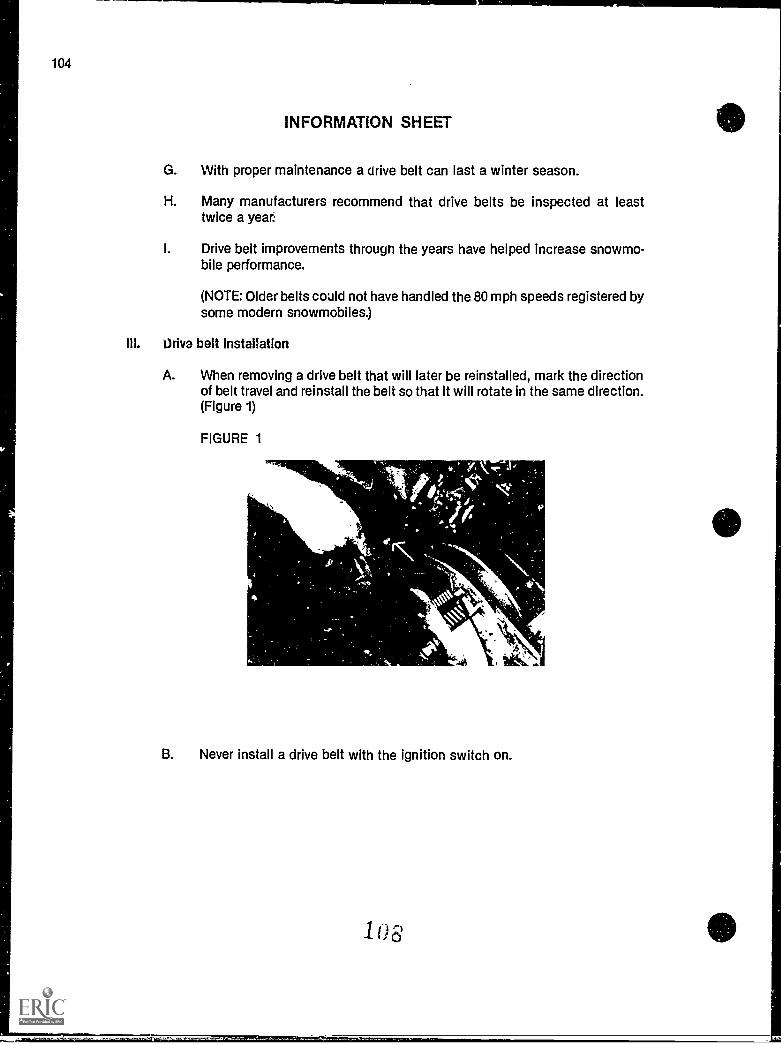
104
INFORMATION SHEET
G. With proper maintenance a drive belt can last a winter season.
H. Many manufacturers recommend that drive belts be inspected at leasttwice a year.
I. Drive belt improvements through the years have helped increase snowmo-bile performance.
(NOTE: Older belts could not have handled the 80 mph speeds registered bysome modern snowmobiles.)
III. Uriva belt installation
A. When removing a drive belt that will later be reinstalled, mark the directionof belt travel and reinstall the belt so that it will rotate in the same direction.(Figure 1)
FIGURE 1
B. Never install a drive belt with the ignition switch on.
103
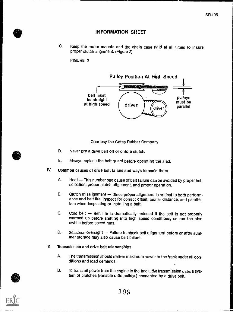
SR-105
INFORMATION SHEET
C. Keep the motor mounts and the chain case rigid at all times to insureproper clutch alignment. (Figure 2)
FIGURE 2
Pulley Position At High Speed
belt mustbe straight
at high speed
Courtesy the Gates Rubber Company
D. Never pry a drive belt off or onto a clutch.
E. Always replace the belt guard before operating the sled.
IV. Common causes of drive belt failure and ways to avoid them
pulleysmust beparallel
A. Heat This number one cause of belt failure can be avoided by proper beltselection, proper clutch alignment, and proper operation.
B. Clutch misalignment since proper alignment is critical to both perform-ance and belt lite, inspect for correct offset, center distance, and parallel-ism when inspecting or installing a belt.
C. Cold belt Belt life is dramatically reduced if the belt is not properlywarmed up before shifting into high speed conditions, so run the sledawhile before speed runs.
D. Seasonal oversight Failure to check belt alignment before or after sum-mer storage may also cause belt failure.
V. Transmission and drive belt relationships
A. The transmission should deliver maximum power to the track under all con-ditions and load demands.
B. To transmit power from the engine to the track, the transmission uses a sys-tem of clutches (variable ratio pulleys) connected by a drive belt.
109
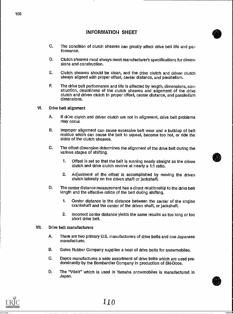
106
INFORMAT1014 SHEET
C. The condition of clutch sheaves can greatly affect drive belt life and peiformance.
D. Clutch sheaves must always meet manufacturer's specifications for dimen-sions and construction.
E. Clutch sheaves should be clean, and the drive clutch and driven clutchalways aligned with proper offset, center distance, and parallelism.
F The drive belt performance and life is affected by length, dimensions, con-struction, cleanliness of the clutch sheaves and alignment of the driveclutch and driven clutch to proper offset, center distance, and parallelismdimensions.
VI. Drive belt alignment
A. If dr:ve clutch and driven clutch are not in alignment, drive belt problemsmay occur.
B. Improper alignment can cause excessive bell wear and a buildup of beltresidue which can cause the belt to squeal, become too hot, or ride thesides of the clutch sheaves.
C. The offset dimension determines the alignment of the drive belt during thevarious stages of shifting.
1. Offset is set so that the bell is running nearly straight as the drivenclutch and drive clutch revolve at nearly a 1:1 ratio.
2. Adjustment of the offset is accomplished by moving the drivenclutch laterally on the driven shaft or jackshaft.
D. The center distance measurement has a direct relationship to the drive beltlength and the effective ratios of the belt during shifting.
1. Center distance is the distance between the center of the enginecrankshaft and the center of the driven shaft, or jackshaft.
2. Incorrect center distance yields the same results as too long or tooshort drive belt.
VII. Drive belt manufacturers
A. There are two primary U.S. manufacturers of drive belts and one Japanesemanufacturer.
B. Gates Rubber Company supplies a host of drive belts for snowmobiles.
C. Dayco manufactures a wide assortment of drive belts which are used pre-dominantly by the Bombardier Company in production of Ski-Doos.
D. The "V-belt" which is used in Yamaha snowmobiles is manufactured inJapan.
110
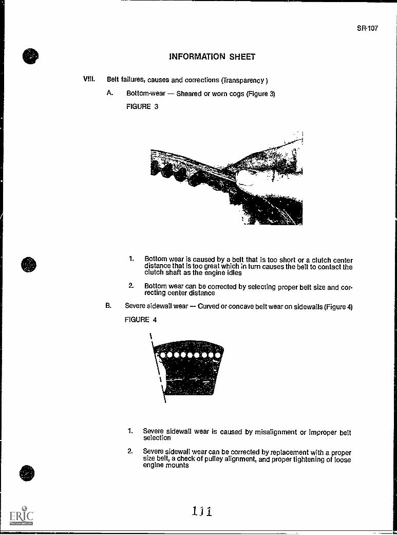
SR-107
INFORMATION SHEET
VIII. Belt failures, causes and corrections (Transparency )
A. Bottom-wear Sheared or worn cogs (Figure 3)
FIGURE 3
1. Bottom wear is caused by a belt that is too short or a clutch centerdistance that is too great which in turn causes the belt to contact theclutch shaft as the engine idles
2. Bottom wear can be corrected by selecting proper belt size and cor-recting center distance
B. Severe sidewall wear Curved or concave belt wear on sidewalls (Figure 4)
FIGURE 4
1
1. Severe sidewall wear is caused by misalignment or improper beltselection
2. Severe sidewall wear can be corrected by replacement with a propersize belt, a check of pulley alignment, and proper tightening of looseengine mounts
1
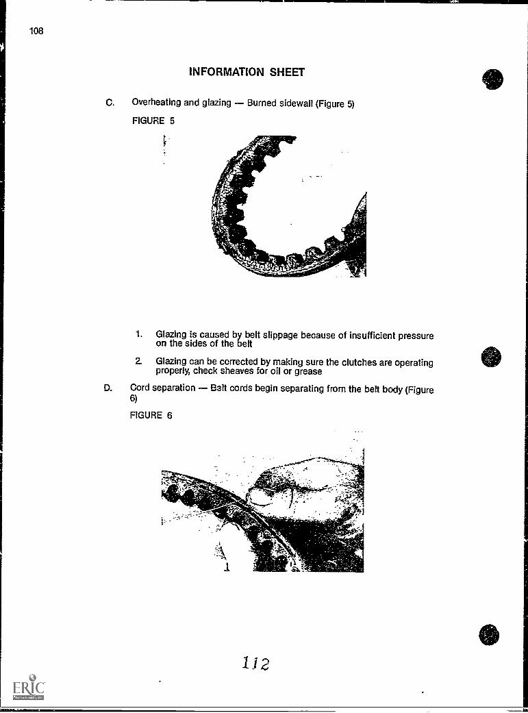
108
C.
INFORMATION SHEET
Overheating and glazing Burned sidewall (Figure 5)
FIGURE 5
1. Glazing is caused by belt slippage because of insufficient pressureon the sides of the belt
2. Glazing can be corrected by making sure the clutches are operatingproperly, check sheaves for oil or grease
D. Cord separation Belt cords begin separating from the belt body (Figure6)
FIGURE 6
1) 2
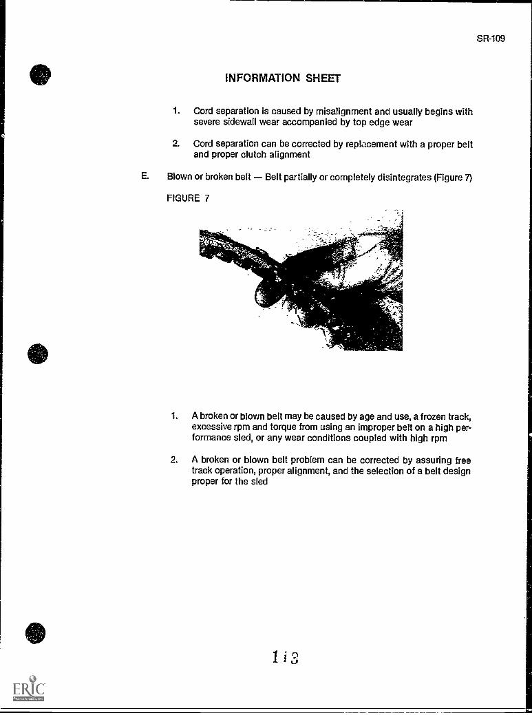
SR-109
INFORMATION SHEET
1. Cord separation is caused by misalignment and usually begins withsevere sidewall wear accompanied by top edge wear
2. Cord separation can be corrected by replacement with a proper beltand proper clutch alignment
E. Blown or broken belt Belt partially or completely disintegrates (Figure 7)
FIGURE 7
1. A broken or blown belt may be caused by age and use, a frozen track,excessive rpm and torque from using an improper belt on a high per-formance sled, or any wear conditions coupled with high rpm
2. A broken or blown belt problem can be corrected by assuring freetrack operation, proper alignment, and the selection of a belt designproper for the sled
1 i 3
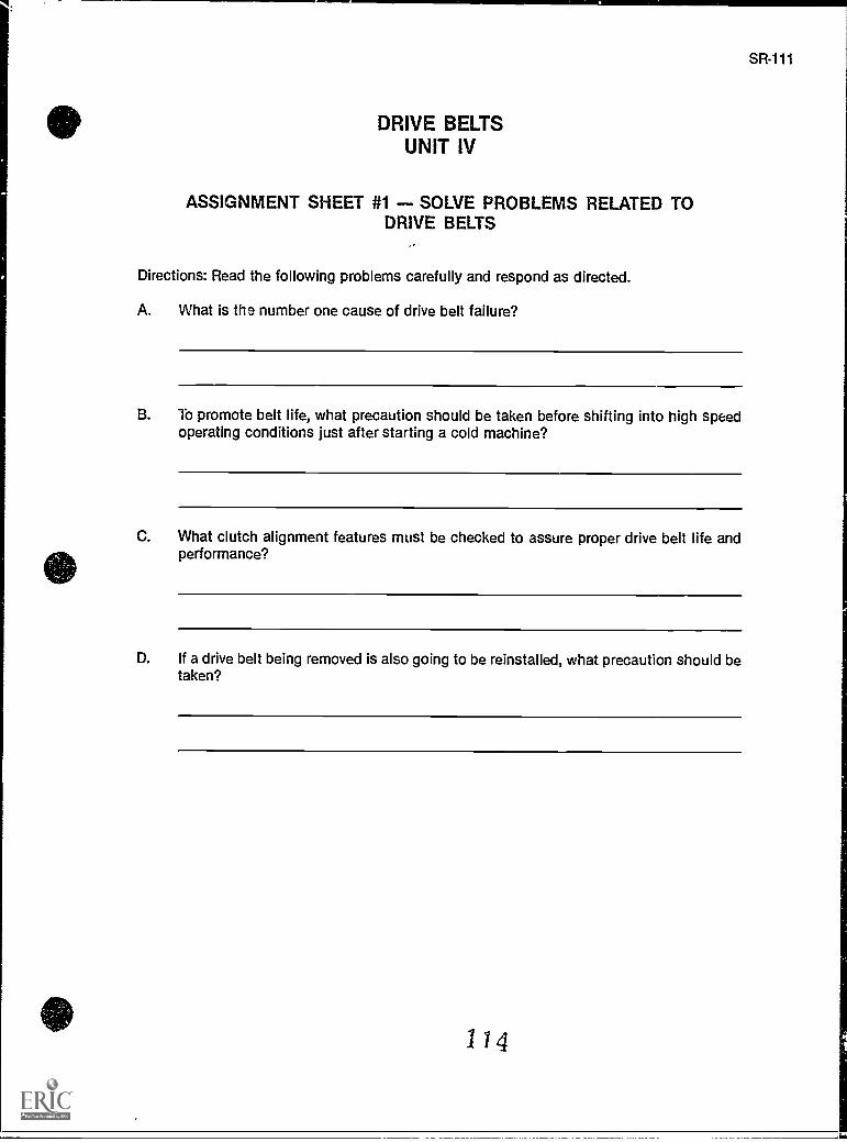
SR-111
DRIVE BELTSUNIT IV
ASSIGNMENT SHEET #1 - SOLVE PROBLEMS RELATED TODRIVE BELTS
Directions: Read the following problems carefully and respond as directed.
A. What is the number one cause of drive belt failure?
B. To promote belt life, what precaution should be taken before shifting into high speedoperating conditions just after starting a cold machine?
C. What clutch alignment features must be checked to assure proper drive belt life andperformance?
D. If a drive belt being removed is also going to be reinstalled, what precaution should betaken?
I 14
SR-113
DRIVE BELTSUNIT IV
ANSWERS TO ASSIGNMENT SHEET #1
A. Heat
B. Allow the machine to warm up
C. Offset, center distance, and parallelism
D. Mark the direction of belt travel and reinstall the belt so it will travel in the same direc-tion
115
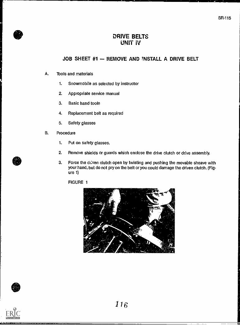
DRIVE BELTSUNIT IV
JOB SHEET #1 REMOVE AND INSTALL A DRIVE BELT
A. Tools and materials
1. Snowmobile as selected by instructor
2. Appropriate service manual
3. Basic hand tools
4. Replacement belt as required
5. Safety glasses
B. Procedure
1. Put on safety glasses.
2. Remove shields or guards which enclose the drive clutch or drive assembly.
3. Force the ¥ clutch open by twisting and pushing the movable sheave withyour hand, but do not pry on the belt or you could damage the driven clutch. (Fig-ure 1)
FIGURE 1
116
SR-115
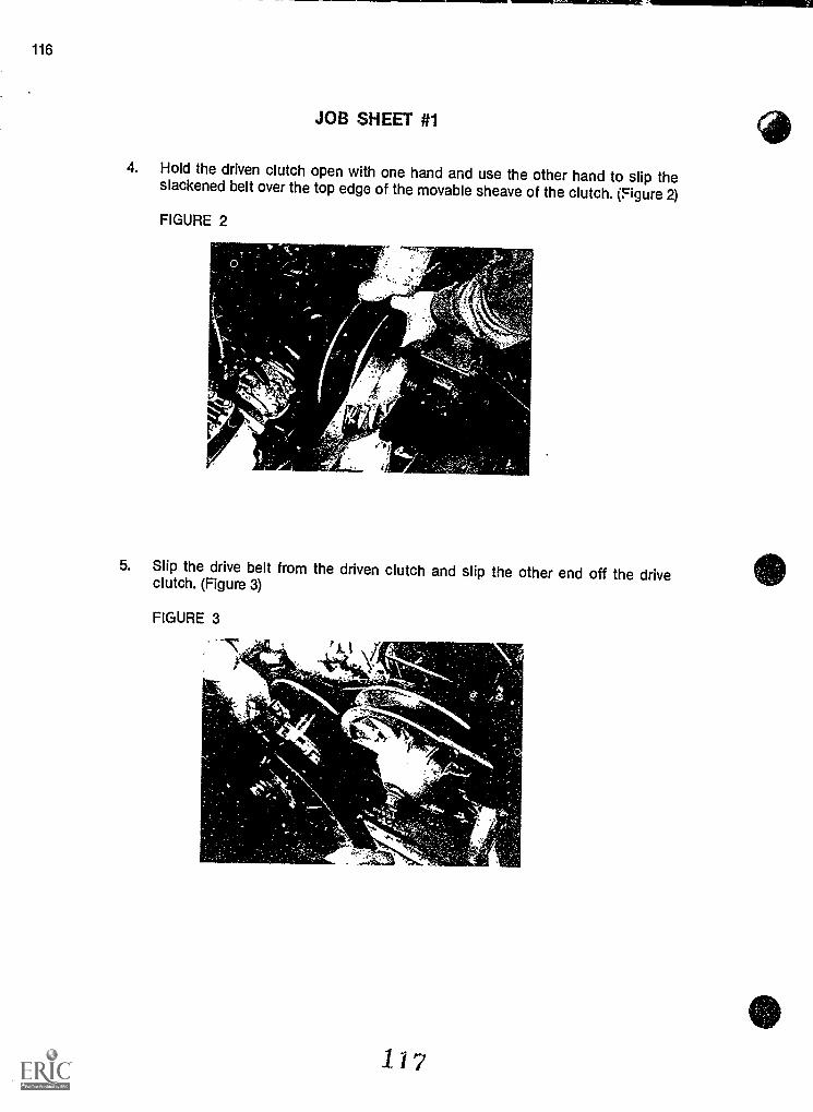
116
JOB SHEET #1
4. Hold the driven clutch open with one hand and use the other hand to slip theslackened belt over the top edge of the movable sheave of the clutch. (Figure 2)
FIGURE 2
5. Slip the drive belt from the driven clutch and slip the other end off the driveclutch. (Figure 3)
FIGURE 3
117
SR-117
JOB SHEET #1
6. Install the drive belt by reversing the procedure, make certain that offset, centerdistance, and parallelism are correct, and if the original belt is used, make surethe direction of travel is the same as when the belt was removed.
7. Reinstall shields or guards properly.
Haw, yow instructor check your work.
8. Test the sled for proper performance.
9. Clean up area and return tools and materials to proper storage.
11 El,
SR-119
DRIVE BELTSUNIT IV
NAME
TEST
1. Match terms related to drive belts with their correct definitions.
a Rubber and fabric belt used to transfer 1. Cogspower from the drive clutch to the drivenclutch 2. Sidewalls
____13 The deterioration of the drive belt to the 3. Belt disintegrationpoint where excessive belt speed or dirtysheaves will cause the belt to come apart 4. Belt ride outwhile the snowmobile is in operation
5. Drive beltc Heavy reinforcement material molded into
the drive belt to give the belt strength and 6. Cordslong life
d. Ridge-like indentations on the underside ofa belt which allow flexibility in wrapping thebelt on the sheaves
e When the belt overrides the clutch sheavesbecause the belt is too long or the clutchesare too close together
f The sides of the drive belt
2. Complete statements concerning drive belt principles by circling the word(s) or figure(s)that best completes each statement.
a. Drive belts have (two, three) components which affect drive system performance.
1) The drive belt (cogs, dimensions) must be matched to the snowmobile atthe factory, both width and circumference.
2) Drive belt construction influences the way thP .,iutches shift, and theamount of power that will be transmitted Citough the (drive, engine) sys-tem.
b. In addition to the construction of the drive belt, the (depth, length) of the beltplays an important part in drive system performance.
c. A drive belt too long will not have a full shift ratio available to the clutches, andwill cause (poor, rapid) acceleration and a loss in top speed.
119
120
TEST
d. A drive belt too thin will have the same effect as a belt that is too (long, short).
e. A drive belt which is too short will influence shift and the amount of power trans-mitted through the drive system, causing (different, similar) shift patterns thanspecified for the machine.
f. There is no specific time or (mileage, place) at which a drive belt suddenly wearsout or fails.
g. With proper maintenance a drive belt can last (a winter season, half a winter sea-son).
h. Many manufacturers recommend that drive belts be inspected at least (twice,three times) a year.
i. Drive belt improvements through the years have (helped, not helped) increasesnowmobile performance.
3. Complete statements concerning drive belt installation by circling the word(s) that bestcompletes each statement.
a. When removing a drive belt that will later be reinstalled, mark the direction of tra-vel and reinstall the belt so that it will rotate in (the same, the opposite) direction.
b. Never install a drive belt with the (ignition switch, emergency switch) on.
c. Keep the motor mounts and the chain case (loose, rigid) at all times to insureproper clutch alignment.
d. Never (work, pry) a drive belt off or onto a clutch.
e. Always replace the (belt guard, cowling) before operating the sled.
4. Match common causes of drive belt failure with ways to avoid them.
a This number one cause of belt failure can be 1. Cold beltavoided by proper belt selection, properclutch alignment, and proper operation. 2. Heat
b Since proper alignment is critical to both 3. Seasonal oversightperformance and belt life, inspect for cor-rect offset, center distance, and parallelism 4. Clutch misalignmentwhen inspecting or installing a belt.
c Belt life is dramatically reduced if the belt isnot properly warmed up before shifting intohigh speed conditions, so run the sledawhile before speed runs.
d Failure to check belt alignment before orafter summer storage may also cause beltfailure.
120
TEST
5. Complete statements concerning transmission and drive belt relationships by insertingthe word(s) that best completes each statement.
a. The transmission should deliver maximum power to the under allconditions and load demands.
b. To transmit power from the engine to the track, the transmission uses a systemof connected by a drive belt.
c. The condition of clutch can greatly affect drive belt life and per-formance.
d. Clutch sheaves must always meet manufacturer's specifications forand construction.
e. Clutch sheaves should be clean, and the drive clutch and driven clutch alwaysaligned with proper , center distance, and parallelism.
f. The drive belt performance and life is affected by length, dimensions, construc-tion, of the clutch sheaves, and alignment of the drive clutch anddriven clutch to proper offset, center distance, and parallelism dimensions.
6. Select true statements concerning drive belt alignment by placing an "X" beside eachstatement that is true.
(NOTE: For a statement to be true, all parts of the statement must be true.)
a If drive clutch and driven clutch are not in alignment, drive belt problemsmay occur.
b Improper alignment can cause excessive belt wear and a buildup of beltresidue which can cause the belt to squeal, become too hot, or ride thesides of tr a clutch sheaves.
c The center distance dimension determines the alignment of the drive beltduring the various stages of shifting.
1) Offset is set so that the belt is running nearly straight as thedriven clutch and drive clutch revolve at nearly a 1:2 ratio
.2) Adjustment of the offset is accomplished by moving the drivenclutch laterally on the driven shaft or jackshaft.
d The center distance measurement has a direct relationship to the drivebelt length and the effective ratios of the belt during shifting.
1) Center distance is the distance between the center of theengine crankshaft and the center of the driven shaft, or jack-shaft.
21 Incorrect center distance yields the opposite results as too longor too short drive belt.
121
SR-121
122
TEST
7. Select true statements concerning drive belt manufacturers by placing an "X" besideeach statement that is true.
a
b
c
d
8. Match
a
There are three primary U.S. manufacturers of drive belts and one Japa-nese manufacturer.
Gates Rubber Company supplies a host of drive belts for snowmobiles.
Dayco manufactures a wide assortment of drive belts which are used pre-dominantly by the Rupp Company in production of Ski-Doos.
The "V-belt" which is used in Yamaha snowmobiles is manufactured inJapan.
belt failures with their causes and corrections.
1) Caused by a belt that is too short or aclutch center distance that is too greatwhich in turn causes the belt to contactthe clutch shaft as the engine idles
2) Can be corrected by selecting proper beltsize and correcting center distance
b 1) Caused by misalignment or improper beltselection
2) Can be corrected by replacement with aproper size belt, a check of pulley align-ment, and proper tightening of looseengine mounts
c. 1) Caused by belt slippage because ofinsufficient pressure on the sides of thebelt
2) Can be corrected by making sure theclutches are operating properly, checksheaves for oil or grease
d 1) Caused by misalignment and usuallybegins with severe sidewall wear accom-panied by top edge wear
2) Can be corrected by replacement with aproper belt and proper clutch alignment
122
1. Cord separationBelt cords begin sep-arating from the beltbody
2. Overheating and glaz-ing Burned side-wall
3. Severe sidewall wearCurved or concave
belt wear on side -walls
4. Blown or broken beltBelt partially or
completely disinte-grates
5. Bottom-wearSheared or worn cogs
SR-123
TEST
e. 1) May be caused by age and use, a frozentrack, excessive rpm and torque fromusing an improper belt on a high perform-ance sled, or any wear conditions coup-led with high rpm
2) Can be corrected by assuring free trackoperation, proper alignment, and theselection of a belt design proper for thesled
(NOTE: If the following activities have not been accomplished prior to the test, ask yourinstructor when they should be completed.)
9. Solve problems related to drive belts and transmissions. (Assignment Sheet #1)
10. Demonstrate the ability to remove and install a drive belt. (Job Sheet #1)
123
1. a. 5b. 3c. 6d. 1
e. 4f. 2
2. a. Two1) Dimensions2) Drive
b. Lengthc. Poord. Longe. Differentf. Mileageg. A winter seasonh. Twicei. Helped
3. a. The sameb. Ignition switchc. Rigidd. Prye. Belt guard
4. a. 2b. 4c. 1
d. 3
5. a. Trackb. Clutchesc. Sheavesd. Dimensionse. Offsetf. Cleanliness
6. a, b
7. b, d
e
DRIVE BELTSUNIT IV
ANSWERS TO TEST
124
126
ANSWERS TO TEST
8. a. 5b. 3c. 2d. 1
e. 4
9. Evaluated to the satisfaction of the instructor
10. Performance skills evaluated according to procedures written in the job sheets
125
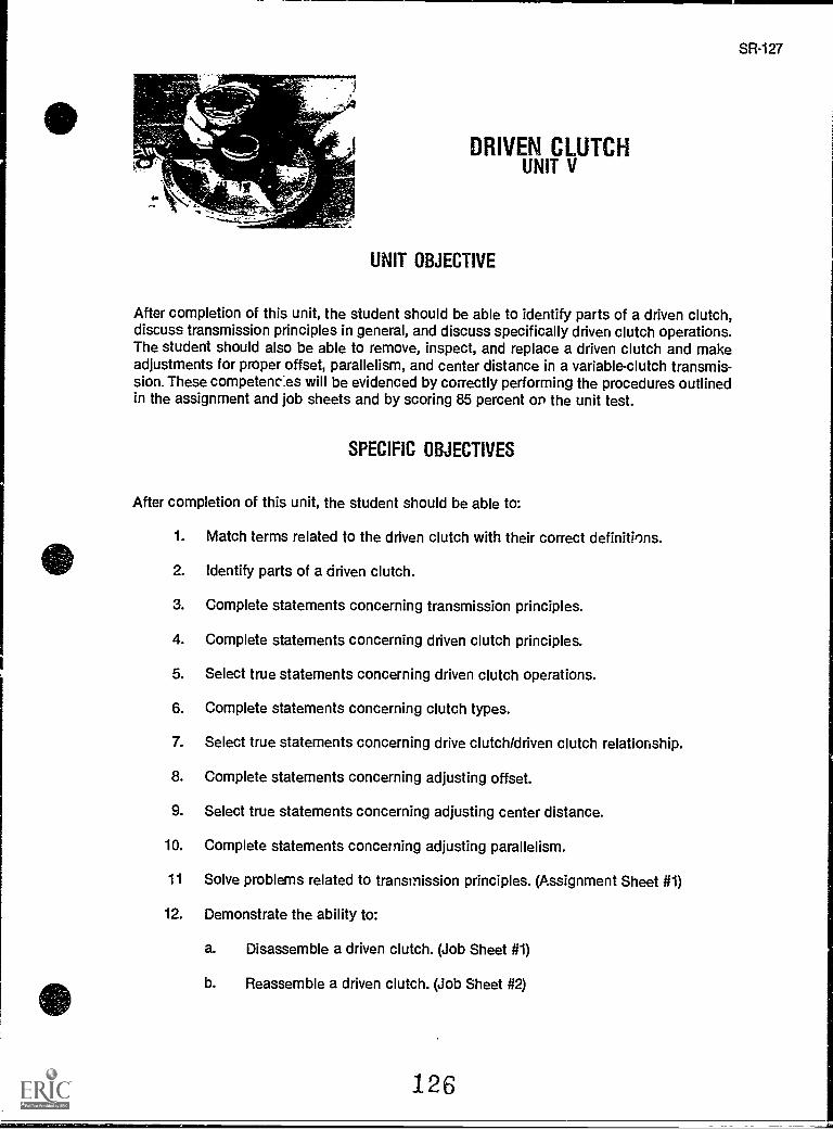
NO"
SR-127
DRIVEN CLUTCHUNIT V
UNIT OBJECTIVE
After completion of this unit, the student should be able to identify parts of a driven clutch,discuss transmission principles in general, and discuss specifically driven clutch operations.The student should also be able to remove, inspect, and replace a driven clutch and makeadjustments for proper offset, parallelism, and center distance in a variable-clutch transmis-sion. These competencies will be evidenced by correctly performing the procedures outlinedin the assignment and job sheets and by scoring 85 percent on the unit test.
SPECIFIC OBJECTIVES
After completion of this unit, the student should be able to:
1. Match terms related to the driven clutch with their correct definitions.
2. Identify parts of a driven clutch.
3. Complete statements concerning transmission principles.
4. Complete statements concerning driven clutch principles.
5. Select true statements concerning driven clutch operations.
6. Complete statements concerning clutch types.
7. Select true statements concerning drive clutch/driven clutch relationship.
8. Complete statements concerning adjusting offset.
9. Select true statements concerning adjusting center distance.
10. Complete statements concerning adjusting parallelism.
11 Solve problems related to transmission principles. (Assignment Sheet #1)
12. Demonstrate the ability to:
a. Disassemble a driven clutch. (Job Sheet #1)
b. Reassemble a driven clutch. (Job Sheet #2)
126
SR-129
DRIVEN CLUTCHUNIT V
SUGGESTED ACTIVITIES
A. Provide students with objective sheet.
B. Provide students with information sheet.
C. Make transparencies.
D. Discuss unit and specific objectives.
E. Discuss information sheet.
F. Demonstrate and discuss the procedures outlined in the job sheets.
G. Have students identify all the components following driven clutch disassembly.
H. Impress upon students the importance of exact measurements in measuring offset,center distance, and parallelism.
I. Give test.
CONTENTS OF THIS UNIT
A. Objective sheet
B. Information sheet
C. Transparency masters
1. TM 1 Driven Clutch
2. TM 2 Measuring Offset
3. TM 3 Measuring Center Distance and Parallelism
D. Assignment Sheet #1 Solve Problems Related to Transmission Principles
E. Answers to assignment sheet
F. Job sheets
1. Job Sheet #1 - Remove, inspect, and replace a driven clutch
2.. Job Sheet #2 - Check and actust offset, center distance and parallelism on asnowmobile transmission
127
130
CONTENTS OF THIS UNIT
G. Test
H. Answers to test
REFERENCES USED IN DEVELOPING THIS UNIT
A. Snowmobile Repair. Stillwater, OK, 74074: The Mid-America Vocational Curriculum Con-sortium. 1976.
B. Chilton's Snowmobiles Repair & Tune-Up Guide, Second edition. Radnor, PA: ChiltonBook Co., 1975.
C. Arctic Cat Service Manual No. 2254-302. Thief River Falls, MN 56701: ARCTCO, Inc.,1984.
D. 1980 Bombardier Snowmobiles Shop Manual. Valcourt, Quebec, Canada: Bombardier,Ltd., 1980.
E. Kawasaki Drifter Snowmobile Shop Manual. Santa Ana, CA 92799-5252: KawasakiMotors Corp., U.S.A., 1980.
F. Kawasaki Parts Catalog SB340-A2, SB440-A5. Santa Ana, CA 92799-5252: KawasakiMotors Corp., U.S.A., 1980.
DRIVEN CLUTCHUNIT V
INFORMATION SHEET
I. Terms and definitions
A. Driven clutch Often referred to as a torque converter; it is mounted to thejackshaft, or sometimes to the chaincase, and transfers power to the track
B. Torque sensing A feature of the driven clutch which measures resistanceon the track so the correct shift sequence can be determined for enginetorque output
C. Load Resistance to power
D. Stationary sheave The nonmoving part of the driven clutch which con-tains the shaft and is coupled to the jackshaft or chain case
E. Movable sheave The part of the driven clutch which moves back andforth in response to varying loads and rpm's
F. Downshift A shift in ratio between the drive clutch and driven clutch todecrease snowmobile speed and increase torque
G. Driven shaft Also called the jackshaft on which the driven clutch, brakedisc, and upper sprocket are all mounted
H. Spring A metal coil preloaded with tension to keep pressure on the drivebelt
I. Variable ratio The number of revolutions made by the drive clutch com-pared to the revolutions made by the driven clutch in response to sled loadand engine rpm's
J. Cam torque bracket Also called a ramp; enables the movable sheave toslide so that the drive belt can move freely up and down the driven clutch inresponse to vehicle load
H. Parts of a driven clutch (Transparency 1)
A. Retaining ring
B. Cam torque bracket
C. Spring
D. Ramp slide
E. Movable sheave
129
SR-131
INFORMATION SHEET
F. Bushing
G. Stationary sheave
III. Transmission principles
A. In snowmobiles, a variable ratio transmission is used to transmit enginepower to the track.
B. Engine torque and rpm must be increased because snowmobile engines donot have a wide enough power band to meet a variety of load demands atvarying rpm's.
C. The variable ratio transmission in a snowmobile has three primary compo-nents:
1. The drive clutch
2. The driven clutch
3. The drive belt
D. The transmission in a snowmobile multiplies engine torque to the track justas a lever with a fulcrum allows small weights to lift large weights.
E. Changing the drive clutch to driven clutch ratio has the same effect as mov-ing the fulcrum on a lever to raise or lower heavy weights.
F. The drive clutch and driven clutch are like gears, but instead of heavingteeth, a drive belt rotates between the sheaves of the two clutches to trans-mit power.
G. The sheaves of the two clutches are moved laterally to change the effectivediameter of the clutch.
H. Snowmobile speed is controlled by the ratio the belt seeks between thedrive clutch sheaves and the driven clutch sheaves.
I. The ratio of 3.8:1 (about 20 mph) means that the sheave diameter of thedrive clutch must revolve 3.8 times to match one revolution of the drivenclutch.
IV. Driven clutch principles
A. The criven clutch is load sensing and transfers power to the jackshaft andto the track.
B. The purpose of the driven clutch is to sense the amount of load on thesnowmobile and to keep the proper tension on the drive belt.
13(i
SR-133
INFORMATION SHEET
C. The driven clutch senses the amount of resistance from the track, andshifts to the highest possible ratio to attain the maximum speed and powerneeded to move the snowmobile.
D. When resistance on the driven clutch is great, the driven clutch becomesdominant and overrides the drive clutch by downshifting into a ratio thatwill supply the torque needed to move the increased load.
E. As downshifting occurs, the engine rpm remains at peak output.
V. Driven clutch operations
A. Spring tension and cam angle both affect the shift pattern in the drivenclutch.
B. Spring tension determines the rpm of the engine during the shift pattern.
C. Spring tension adjustment matclies the sled load to the engine power band
D. Increasing spring tension increases engines rpm, while decreasing the ten-sion decreases engine rpm.
E. Cam angle works in conjunction with spring tension to control the upshiftof the driven clutch.
F. On almost all modern snowmobiles, the correct cams are installed at thefactory and should not be altered.
VI. Driven clutch types
A. Driven clutch types are identified by their location in relation to the chainmechanism which drives the track.
B. The chain case type of driven clutch is mounted to the chain case.
C. The jackshaft type of driven clutch is mounted onto the jackshaft.
D. The drive axle type of driven clutch is mounted onto the drive axle.
E. With most manufacturers, the location of the driven clutch does not alter itspurpose, the way it functions, or even the construction of the driven clutch.
VII. Drive chitch/driven clutch relationship (Transparency 2)
A. Alignment of the two clutches is essential to maximize the efficient transferof power from the engine to the track.
B. Improper alignment can cause excessive drive belt residue buildup, exces-sive belt temperature, belt squeal, or total belt failure.
131
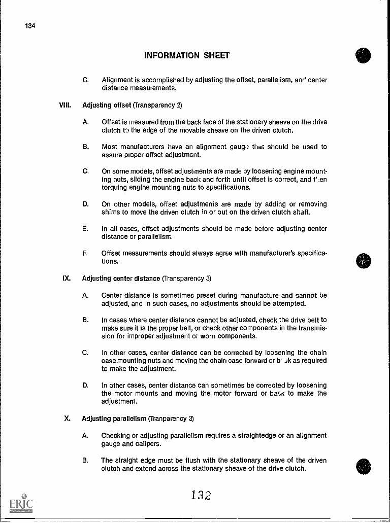
134
INFORMATION SHEET
C. Alignment is accomplished by adjusting the offset, parallelism, anr' centerdistance measurements.
VIII. Adjusting offset (Transparency 2)
A. Offset is measured from the back face of the stationary sheave on the driveclutch to the edge of the movable sheave on the driven clutch.
B. Most manufacturers have an alignment gaug,) that should be used toassure proper offset adjustment.
C. On some models, offset adjustments are made by loosening engine mount-ing nuts, sliding the engine back and forth until offset is correct, and t' ,entorquing engine mounting nuts to specifications.
D. On other models, offset adjustments are made by adding or removingshims to move the driven clutch in or out on the driven clutch shaft.
E. In all cases, offset adjustments should be made before adjusting centerdistance or parallelism.
F. Offset measurements should always agree with manufacturer's specifica-tions.
IX. Adjusting center distance (Transparency 3)
A. Center distance is sometimes preset during manufacture and cannot beadjusted, and in such cases, no adjustments should be attempted.
B. In cases where center distance cannot be adjusted, check the drive belt tomake sure it is the proper belt, or check other components in the transmis-sion for improper adjustment or worn components.
C. In other cases, center distance can be corrected by loosening the chaincase mounting nuts and moving the chain case forward or b- ,;k as requiredto make the adjustment.
D. In other cases, center distance can sometimes be corrected by looseningthe motor mounts and moving the motor forward or bar,K to make theadjustment.
X. Adjusting parallelism (Tranparency 3)
A. Checking or adjusting parallelism requires a straightedge or an alignmentgauge and calipers.
B. The straight edge must be flush with the stationary sheave of the drivenclutch and extend across the stationary sheave of the drive clutch.
122
SR-135
INFORMATION SHEET
C. Two measurements must be taken from the back side of the stationarysheave on the drive clutch to the straightedge:
1. The first measurement should be at a point on the drive clutchsheave closest to the driven clutch.
2. The second measurement should be at a point on the drive clutchsheave farthest from the driven clutch.
D. The measurement at the second point should be more than the measure-ment at the first point by about 1.6 mm or 1/16th of an inch.
(NOTE: Always check manufacturer's specifications for the exact distance.)
E. If adjustment is required, loosen the engine mounting nuts and move theengine into a position that will correct the parallelism.
F. When parallelism cannot be corrected by engine mounting adjustment, theadjustment can be completed on some models by installing shims underthe chain case mounting nuts.
1 2 3
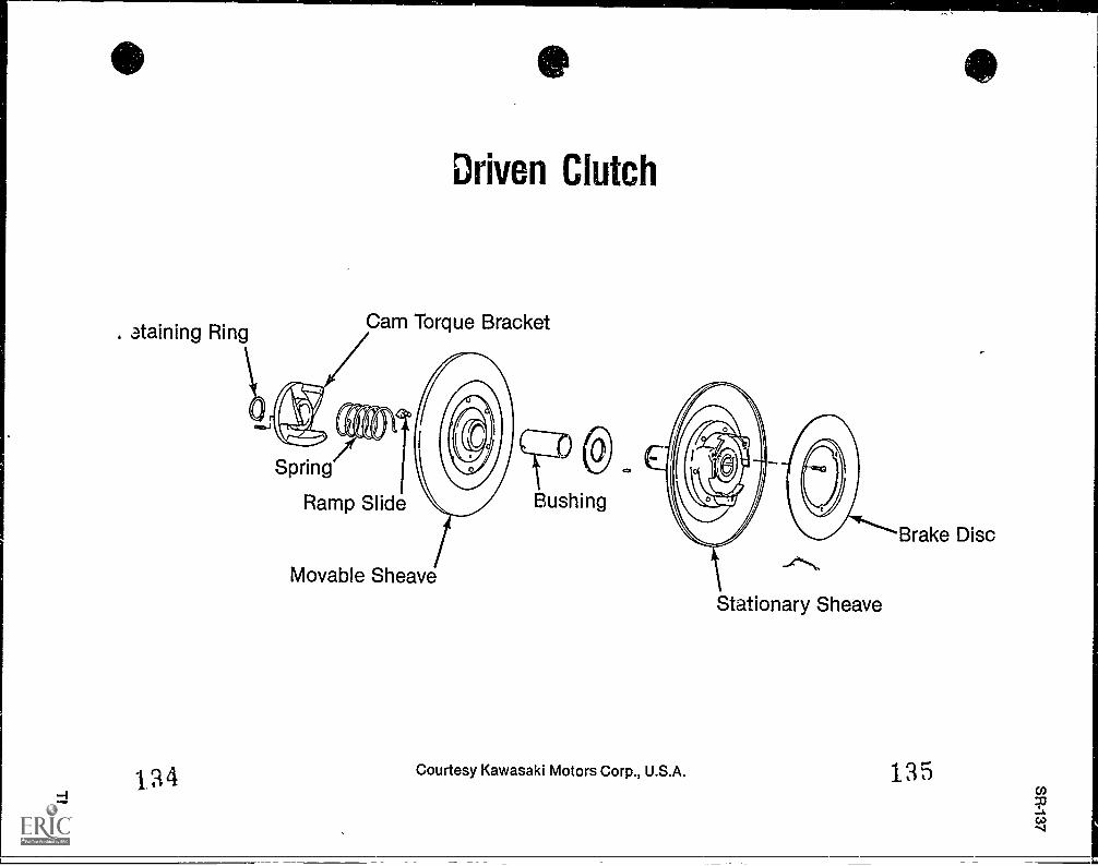
. staining Ring
e
Driven Clutch
Cam Torque Bracket
)Spring
Ramp Slide
Movable Sheave
Bushing
Courtesy Kawasaki Motors Corp., U.S.A.
_1"......,,
Stationary Sheave
Brake Disc
135
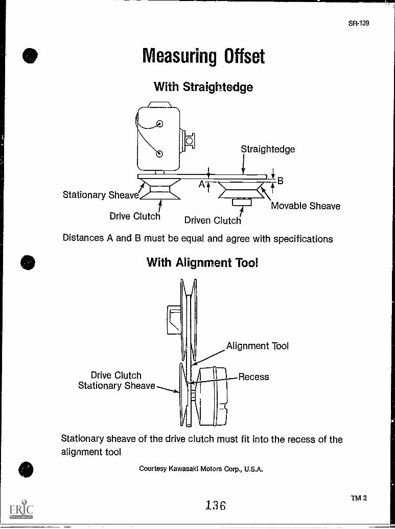
SR-139
Measuring Offset
With Straightedge
Straightedge
Stationary Sheave
Drive Clutch Driven Clutch
Movable Sheave
Distances A and B must be equal and agree with specifications
With Alignment Tool
.111
Drive Clutch 11n RecessStationary Sheave
Alignment Tool
Stationary sheave of the drive clutch must fit into the recess of thealignment tool
Courtesy Kawasaki Motors Corp., U.S.A.
TM 2136
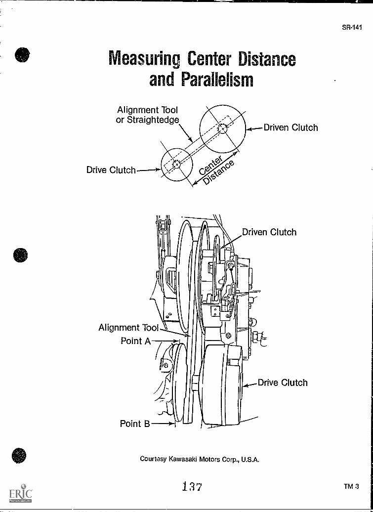
Measuring Center Distanceand Parallelism
Alignment Toolor Straightedge
Drive Clutchci`
e
Driven Clutch
Driven Clutch
Alignment Tool
Point A
Point B
Courtesy Kawasaki Motors Corp., U.S.A.
137
4...-Drive Clutch
SR-141
TM 3
SR-143
DRIVEN CLUTCHUNIT V
ASSIGNMENT SHEET #1 SOLVE PROBLEMS RELATEdTOTRANSMISSION PRINCIPLES
Directions: Read the following problems carefully and answer as directed.
A. Describe what is meant by a 3.8:1 shift ratio.
B. You have been asked to explain to a friend how the transmission in a snowmobile trans-mits power from the engine to the track. Explain how the clutch assembly acts to carryheavier loads with the same engine rpm.
C. Explain what can happen to a drive belt if the two clutches are not aligned.
D. Explain why center distance is a measurement which allows only minor alterations.
1 38
SR-145
DRIVEN CLUTCHUNIT V
ANSWERS TO ASSIGNMENT SHEET
A. A ratio is the relation of the number of revolutions a drive clutch must make to matchthe diameter and revolutions of the driven clutch. Consequently, the drive clutch mustmake 3.8 revolutions to match one revolution of the driven clutch.
B. The transmission acts to move power as a lever is used to allow small weights to carrylarge weights. By changing the fulcrum (pivot point), adjustments can be made for car-rying smaller or heavier loads. A snowmobile transmission with a torque sensing drivenclutch makes those adjustments automatically.
C. Improper alignment can cause excess drive belt residue buildup, foul the belt, causeexcessive heating and belt squeal, and ultimately destroy the belt.
D. Center distance is set at the factory in almost all snowmobiles. Tampering with the set-tings can alter the center distance and cause misalignment.
139
SR-147
DRIVEN CLUTCHUNIT V
JOB SHEET #1 REMOVE, INSPECT, AND REPLACEA DRIVEN CLUTCH
A. Tools and materials
1. Snowmobile as selected by instructor
2. Appropriate service manual
3. Basic hand tools
4. Solvent
5. Clean shop towels
6. Magic marker
7. Snap-ring pliers
8. Hand-held fish scale
9. High temperature lubricant
10. Feeler gauge
11. Torque wrench
12. Replacement parts as required
13. Safety glasses
B. Routine #1 Removing the driven clutch
1.' Put on safety glasses
2. Remove the clutch guard
3. Place a clean shop towel over the face of the movable sheave, and clamp a pairof locking pliers to the sheave (Figure 1)
140
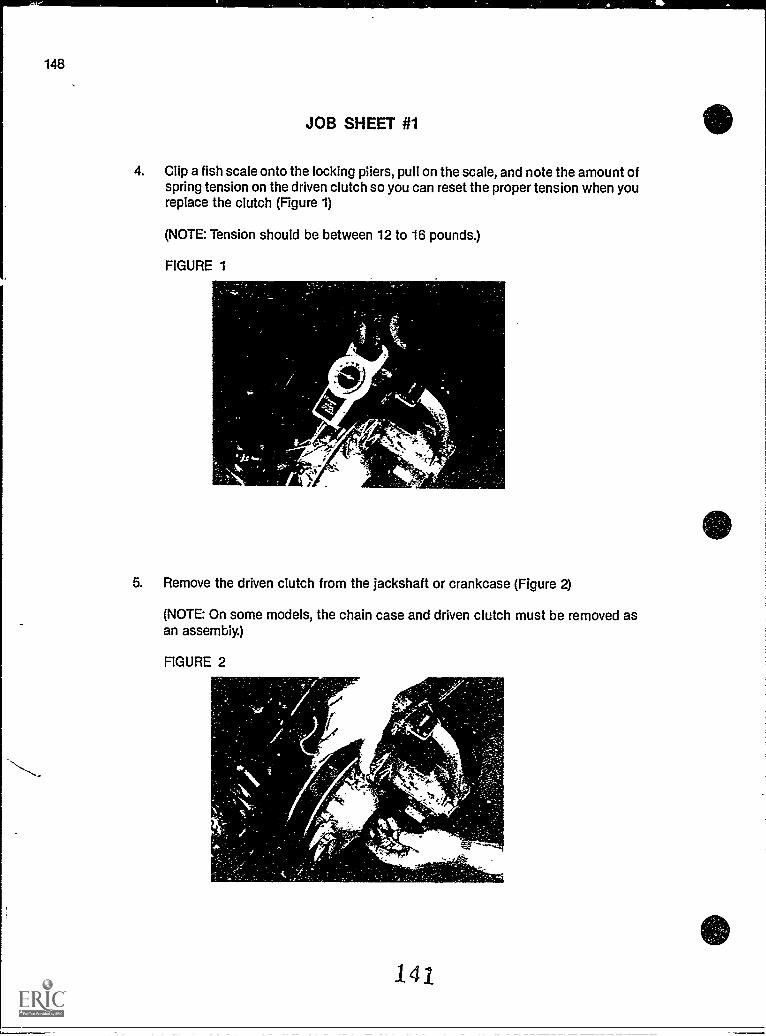
148
JOB SHEET #1
4. Clip a fish scale onto the locking pliers, pull on the scale, and note the amount ofspring tension on the driven clutch so you can reset the proper tension when youreplace the clutch (Figure 1)
(NOTE: Tension should be between 12 to 16 pounds.)
FIGURE 1
5. Remove the driven clutch from the jackshaft or crankcase (Figure 2)
(NOTE: On some models, the chain case and driven clutch must be removed asan assembly.)
FIGURE 2
I
141
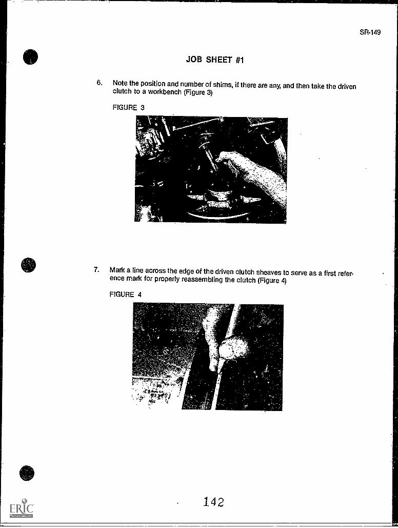
JOB SHEET #1
6. Note the position and number of shims, if there are any, and then take the drivenclutch to a workbench (Figure 3)
FIGURE 3
7. Mark a line across the edge of the driven clutch sheaves to serve as a first refer-ence mark for properly reassembling the clutch (Figure 4)
FIGURE 4
Ak
142
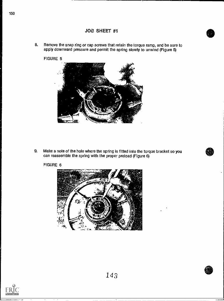
150
JOE! SHEET #1
8. Remove the snap ring or cap screws that retain the torque ramp, and be sure toapply downward pressure and permit the spring slowly to unwind (Figure 5)
FIGURE 5
9. Make a note of the hole where the spring is fitted into the torque bracket so youcan reassemble the spring with the proper preload (Figure 6)
FIGURE 6
143
1
_i
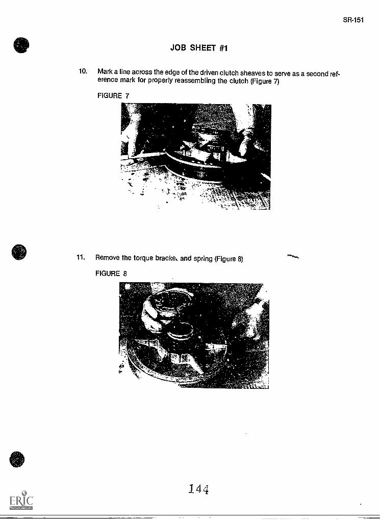
JOB SHEET #1
10. Mark a line across the edge of the driven clutch sheaves to serve as a second ref-erence mark for properly reassembling the clutch (Figure 7)
FIGURE 7
r;.
,
11. Remove the torque bracke, and spring (Figure 8)
FIGURE 8r
144
SR-151
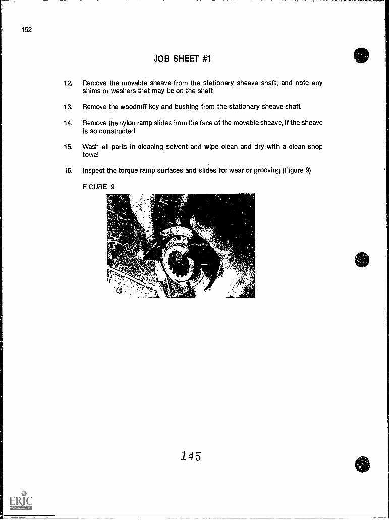
152
JOB SHEET #1
12. Remove the movable sheave from the stationary sheave shaft, and note anyshims or washers that may be on the shaft
13. Remove the woodruff key and bushing from the stationary sheave shaft
14. Remove the nylon ramp slides from the face of the movable sheave, if the sheaveis so constructed
15. Wash all parts in cleaning solvent and wipe clean and dry with a clean shoptowel
16. Inspect the torque ramp surfaces and slides for wear or grooving (Figure 9)
FIGURE 9
145
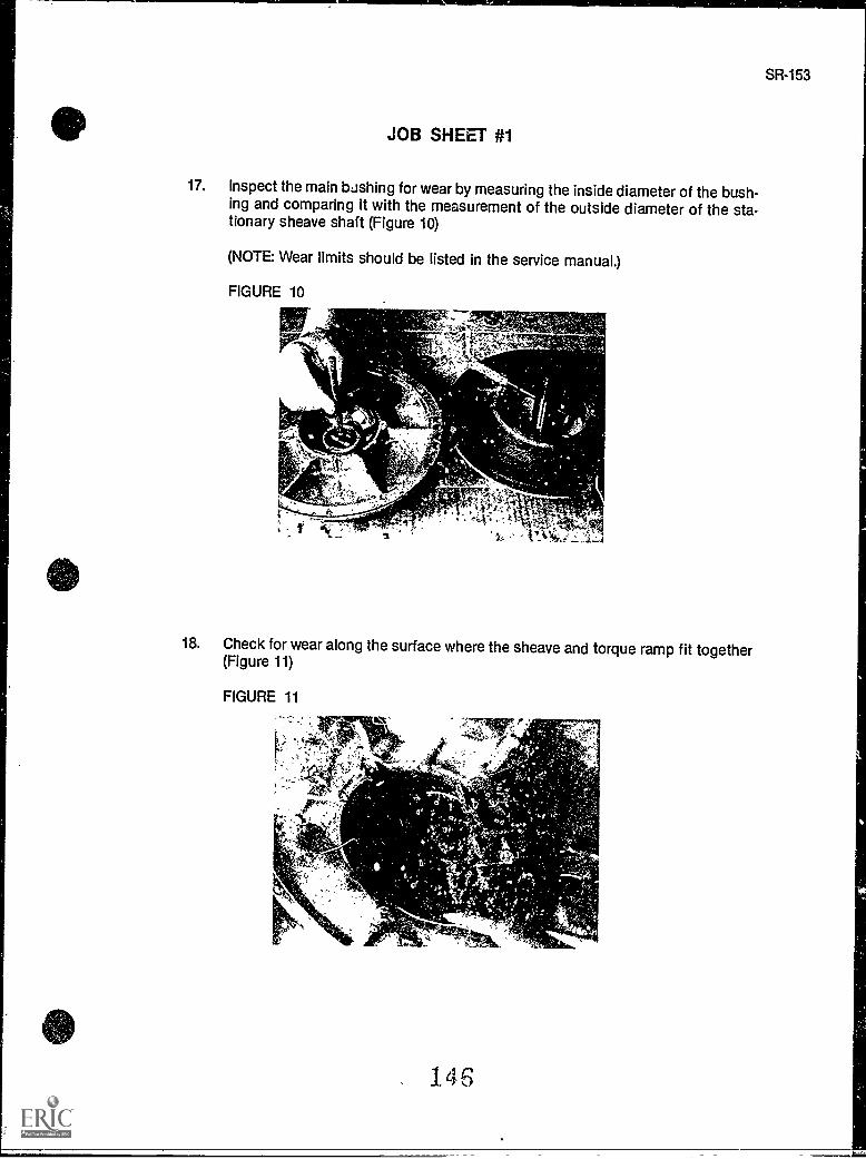
JOB SHEET #1
17. Inspect the main bashing for wear by measuring the inside diameter of the bush-ing and comparing it with the measurement of the outside diameter of the sta-tionary sheave shaft (Figure 10)
(NOTE: Wear limits should be listed in the service manual.)
FIGURE 10
18. Check for wear along the surface where the sheave and torque ramp fit together(Figure 11)
FIGURE 11
146
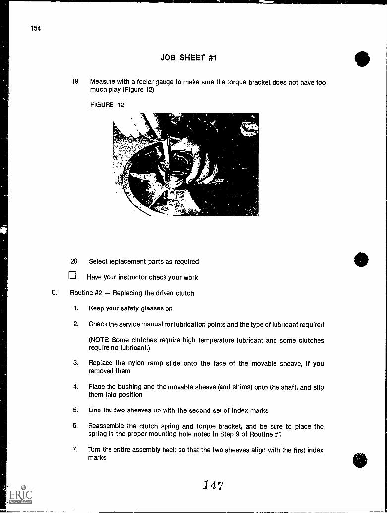
154
JOB SHEET #1
19. Measure with a feeler gauge to make sure the torque bracket does not have toomuch play (Figure 12)
FIGURE 12
20. Select replacement parts as required
Have your instructor check your work
C. Routine #2 Replacing the driven clutch
1. Keep your safety glasses on
2. Check the service manual for lubrication points and the type of lubricant required
(NOTE: Some clutches require high temperature lubricant and some clutchesrequire no lubricant.)
3. Replace the nylon ramp slide onto the face of the movable sheave, if youremoved them
4. Place the bushing and the movable sheave (and shims) onto the shaft, and slipthem into position
5. Line the two sheaves up with the second set of index marks
6. Reassemble the clutch spring and torque bracket, and be sure to place thespring in the proper mounting hole noted in Step 9 of Routine #1
7. Turn the entire assembly back so that the two sheaves align with the first indexmarks
147
SR-155
JOB SHEET #1
8. Apply downward pressure on the torque bracket and compress the spring inorder to install the snap ring or cap screw
Have your instructor check your work
9. Put shims back in place on the jackshaft to insure proper offset
10. Replace the driven clutch onto the jackshaft or chain case shaft, and torque allmounting nuts to manufacturer's specifications
11. Repeat the fish scale test to make sure the driven clutch has the proper springtension
Have your instructor check your work
12. Clean up area and return tools and materials to proper storage
148
DRIVEN CLUTCHUNIT V
JOB SHEET #2 - CHECK AND ADJUST OFFSET, CENTER DISTANCE,AND PARALLELISM ON A SNOWMOBILE TRANSMISSION
A. Tools and materials
1. Snowmobile as selected by instructor
2. Appropriate service manual
3. Basic hand tools
4. Straightedge or alignment tool
5. Steel measuring tape
6. Torque wrench
7. Shims as required
8. Safety glasses
B. Routine #1 Checking and adjusting offset
(NOTE: Remember that offset adjustments should always be made first before anyadjustments to center distance or parallelism.)
1. Put on safety glasses.
2. Remove the clutch guard.
149
SR157
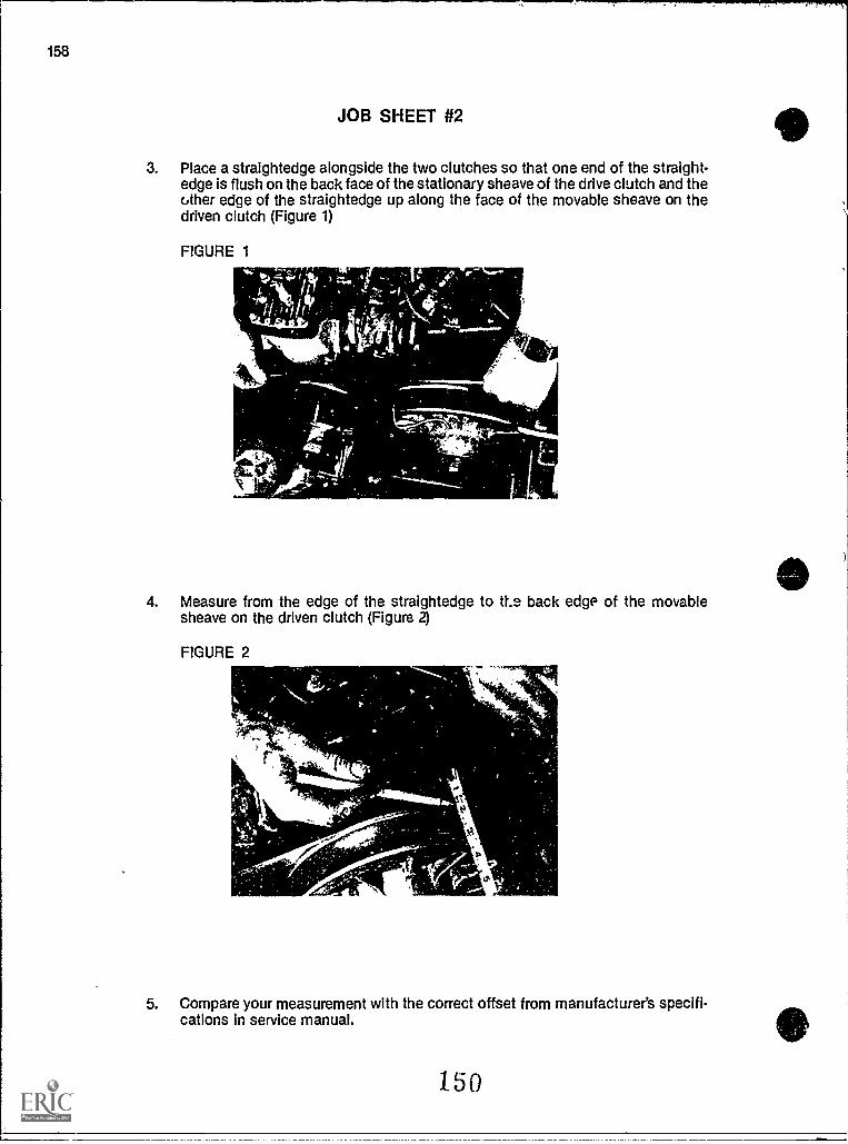
158
JOB SHEET #2
3. Place a straightedge alongside the two clutches so that one of the straight-edge
Pw]is flush on the back face of the stationary sheave of the drive clutch and the
other edge of the straightedge up along the face of the movable sheave on thedriven clutch (Figure 1)
FIGURE 1
4. Measure from the edge of the straightedge to 11.2 back edge of the movablesheave on the driven clutch (Figure 2)
FIGURE 2
Is%
5. Compare your measurement with the correct offset from manufacturer's specifi-cations in service manual.
150
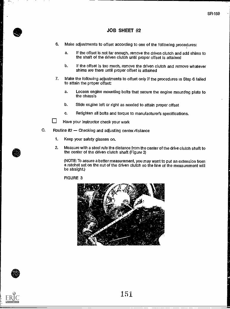
SR-159
JOB SHEET #2
6. Make adjustments to offset according to one of the following procedures:
a. If the offset is not far enough, remove the driven clutch and add shims tothe shaft of the driven clutch until proper offset is attained
b. If the offset is too much, remove the driven clutch and remove whatevershims are there until proper offset is attained
7. Make the following adjustments to offset only if the procedures in Step 6 failedto attain the proper offset:
a. Loosen engine mounting bolts that secure the engine mounting plate tothe chassis
b. Slide engine left or right as needed to attain proper offset
c. Retighten all bolts and torque to manufacturer's specifications.
Have your instructor check your work
C. Routine #2 Checking and adjusting centerrlistance
1. Keep your safety glasses on.
2. Measure with a steel rule the distance from the center of the drive clutch shaft tothe center of the driven clutch shaft (Figure 3)
(NOTE: To assure a better measurement, you may want to put an extension froma ratchet set on the nut of the driven clutch so the line of the measurement willbe straight.)
FIGURE 3
151
160
JOB SHEET #2
3. Compare measurement with specifications from service manual, and if adjust-ment is required, make the adjustment according to the following procedure:
(NOTE: if you're working with a sled that has center distance preset, make noattempt to correct the problem; check with your instructor.)
a. If the manufacturer recommends, loosen the chain case mounting nutsand move the chain case forward or back as required to adjust center dis-tance
b. If the manufacturer recommends, loosen the motor mounts and move themotor forward or back to correct center distance
4. Torque all fasteners to specifications
5. Remeasure and check center distance again
Have your instructor check your work
D. Routine #3 Checking and adjusting parallelism
1. Keep your safety glasses on
2. Place a straightedge flush with the stationary sheave of the driven clutch so thatit extends past the stationary sheave of the driven cit. .:.'h
3. Measure from the straight edge to a point on the drive clutch sheave closest tothe driven clutch and record your measurement here call thispoint A
4. Measure from the straight edge to a point on the drive clutch sheave farthestfrom the driven clutch and record your measurement here callthis point B
5. Determine if parallelism needs adjustment according to the following:
a. If the measurement at B is more than the measurement at A, but does notexceed the A measurement by more than 1.6 mm or 1 /l6th of an inch, thenparallelism is okay
(NOTE: Check your service manual for the correct distance; the distancegiven above is typical.)
b. If the B measurement is less than the A measurement or exceeds the Ameasurement by more than 1.6 mm or 1/16th of an inch, then parallelismshould be corrected
6. Correct parallelism with the following procedure:
a. Loosen the engine mounting bolts and move the engine into a positionfiat will correct parallelism
152
SR-161
JOB SHEET #2
b. If readjusting the engine mounting does not correct parallelism, theadjustment can, perhaps, be completed by installing shims under thechain case mounting nuts
(NOTE: In all cases, follow manufacturer's recommended procedure.)
7. Torque all fasteners to specifications
Have your instructor check your work
8. Replace the chain guard
9. Clean up area and return tools and materials to proper storage
153
DRIVEN CLUTCHUNIT V
NAME
TEST
1. Match terms related to the driven clutch with their correct definitions.
a. Often referred to as a torque converter; it ismounted to the jackshaft, or sometimes tothe chain case, and transfers power to thetrack
_._b A feature of the driven clutch which mea-sures resistance on the track so the correctshift sequence can be determined forengine torque output
c Resistance to power
d. The nonmoving part of the driven clutchwhich contains the shaft and is coupled tothe jackshaft or chain case
e. The part of the driven clutch which movesback and forth in response to varying loadsand rpm's
f. A shift in ratio between the drive clutch anddriven clutch to decrease snowmobilespeed and increase torque
9. Also called the jackshaft on which thedriven clutch, brake disc, and uppersprocket are all mounted
h. A metal coil preloaded with tension to keeppressure on the drive belt
i. The number of revolutions made by the driveclutch compared to the revolutions made bythe driven clutch in response to sled loadand engine rpm's
i- Also called a ramp; enables the movablesheave to slide so that the drive belt canmove freely up and down the driven clutch inresponse to vehicle load
154
1. Cam torque bracket
2. Spring
3. Downshift
4. Stationary sheave
5. Torque sensing
6. Variable ratio
7. Driven shaft
8. Movable sheave
9. Load
10. Criven clutch
SR-163
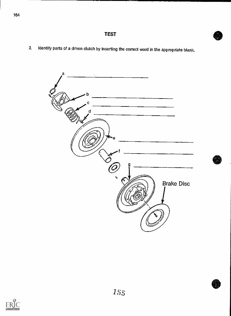
TEST
2. Identify parts of a driven clutch by inserting the correct word in the appropriate blank.
1 s
SR-165
T EST
3. Complete statements concerning transmission principles by circling the word(s) thatbest completes each statement.
a. In snowmobiles, a (static, variable) ratio transmission is used to transmit enginepower to the track.
b. Engine torque and rpm must be increased because snowmobile engines do nothave a (wide, narrow) enough power band to meet a variety of load demands atvarying rpm's.
c. The variable ratio transmission in a snowmobile has three primary components:
1) The drive clutch
2) The (driven clutch, jackshaft)
3) The drive belt
d. The transmission in a snowmobile (divides, multiplies) engine torque to the trackjust as a lever with a fulcrum allows small weights to lift large weights.
e. Changing the drive clutch to driven clutch ratio has (the same, a different) effectas moving the fulcrum on a lever to raise or lower heavy weights.
f. The drive clutch and driven clutch are like gears, but instead of having teeth, a(chain, drive belt) rotates between the sheaves of the two clutches to transmitpower.
The sheaves of the two clutches are moved laterally to change the effective(angle, diameter) of the clutch.
h. Snowmobile (direction, speed) is controlled by the ratio the belt seeks betweenthe drive clutch sheaves and the driven clutch sheaves.
g -
i. The ratio of 3.8:1 means that the sheave diameter of the drive clutch must revolve3.8 times to match one revolution of the (crankshaft, driven clutch).
4. Complete statements concerning driven clutch principles by inserting the word(s) thatbest completes each statement.
a. The driven clutch is load sensing and power to the jackshaft andto the track.
b. The purpose of the driven clutch is to the amount of load on thesnowmobile and to keep the proper tension on the drive belt.
c. The driven clutch senses the amount of from the track, andshifts to the highest possible ratio to attain the maximum speed and powerneeded to move the snowmobile.
d. When resistance on the driven chile' is , the driven clutchbecomes dominant and overrides thG drive clutch by downshifting into a ratiothat will supply the torque needed to move the increased load.
e. As downshifting occurs the engine rpm remains at output.
156
166
TEST
5. Select true statements concerning driven clutch operations by placing an X" besideeach statement that is true.
a Spring tension and cam angle both affect the shift pattern in the drivenclutch.
b. Belt tension determines the rpm of the engine during the shift pattern.
c. Increasing spring tension decreases engines rpm, while decreasing thetension increases engine rpm.
d Cam angle works in conjunction with spring tension to control the upshiftof the driven clutch.
e. Spring tension adjustment matches the sled load to the engine powerband.
f. On almost all modern snowmobiles, the correct cams are installed at thefactory and should not be altered.
6- Complete statements concerning driven clutch types by inserting the word(s) that bestcompletes each statement.
a. Driven clutch types are identified Liy their in relation to the chainmechanism which drives the track.
b. The chain case type of driven clutch is mounted to the
c. The jackshaft type of driven clutch is mounted onto the
d. The drive axle type of driven clutch is mounted onto the
e. With most manufacturers, the of the driven clutch does not alterits purpose, the way it functions, or even the construction of the driven clutch.
7 Select true statements concerning the drive clutch/driven clutch relationship by placingan "X" beside each statement that is true.
a. Alignment of the two clutches is not essential to maximize the efficienttransfer of power from the engine to the track.
b Alignment is accomplished by adjusting the offset, parallelism, and centerdistance measurements.
c. Improper alignment can cause excessive drive belt residue buildup, exces-sive belt temperature, belt squeal, or total belt failure.
157
TEST
SR-167
8. Complete statements concerning adjusting offset by circling the word(s) that best com-pletes each statement.
a. Offset is measured from the (front, back) face of the stationary sheave on thedrive clutch to the edge of the movable sheave on the driven clutch.
b. Most manufacturers have (an alignment gauge, a straightedge) that should beused to assure proper offset adjustment.
c. On some models, offset adjustments are made by (shimming, loosening) enginemounting nuts, sliding the engine back and forth until offset is correct. and thentorquing engine mounting nuts to specifications.
d. On other models, offset adjustments are made by adding or removing shims tomove the driven clutch (in or out, up or down) on the driven clutch shaft.
e. In all cases, offset adjustments should be made (after, before) adjusting centerdistance or parallelism.
f. Offset measurements should always (agree, be approximate) with manufactur-er's specifications.
9. Complete statements concerning adjusting center distance by inserting the word(s)that best completes each statement.
a. Center distance is sometimes during manufacture and cannotbe adjusted, and in such cases, no adjustments should be attempted.
b. In cases where center distp-ce cannot be adjusted, check the drive belt to makesure it is the proper belt, or check other components in the transmission forimproper or worn components.
c. In other cases, center distance can be corrected by loosening themounting nuts and moving the
forward or back as required to make the adjustment.
d. In other cases, center distance can sometimes be corrected by loosening themounts and moving the forward or back to make
the adjustment.
10. Select true statements concerning adjusting parallelism by placing an "X" beside eachstatement that is true.
(NOTE: For a statement to be true, all parts of the statement must be true.)
a Checking or adjusting parallelism requires a straightedge or an alignmentgauge and calipers or a rule.
______b The straight edge must be flush with the stationary sheave of the drivenclutch and extend across the stationary sheave of the drive clutch.
158
168
TEST
c. Two measurements must be taken from the back side of the stationarysheave on the drive clutch to the straightedge:
1) The first measurement should be at a point on the drive clutch sheaveclosest to the driven clutch.
2) The second measurement should be at a point on the drive clutchsheave farthest from the driven clutch.
d. The measurement at the second point should be more than the measure-ment at the first point by about 1.6 mm or 1/16th of an inch.
e. If adjustment is required, loosen the engine mounting nuts and move theengine into a position that will correct the parallelism.
f. When parallelism cannot be corrected by engine mounting adjustment,the adjustment can be completed on some models by installing shimsunder the chain case mounting nuts.
(NOTE: If the following activities have not been accomplished prior to the test, ask yourinstructor when they should be completed.)
11. Solve problems related to transmission principles. (Assignment Sheet #1)
12. Demonstrate the ability to:
a. Remove, inspect, and replace a driven clutch. (Job Sheet #1)
b. Check and adjust offset, center distance, and parallelism on a snowmobile trans-missicn. (Job Sheet #2)
1S9
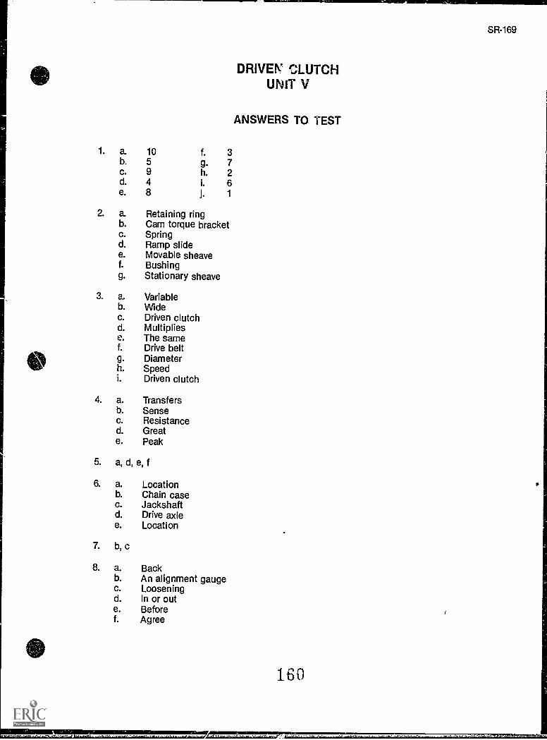
so
0
1. a. 10 f. 3b. 5 g. 7c. 9 h. 2d. 4 i. 6e. 8 j. 1
2. a. Retaining ringb. Cam torque bracketc. Springd. Ramp slidee. Movable sheavef. Bushingg. Stationary sheave
3. a. Variableb. Widec. Driven clutchd. Multipliese. The samef. Drive beltg. Diameterh. Speedi. Driven clutch
4. a. Transfersb. Sensec. Resistanced. Greate. Peak
5. a, d, e, f
6. a. Locationb. Chain casec. Jackshaftd. Drive axlee. Location
7. b, c
8. a. Backb. An alignment gaugec. Looseningd. In or oute. Beforef. Agree
DRIVEL' CLUTCHUNIT V
ANSWERS TO TEST
SR-169
170
ANSWERS TO TEST
9. a. Presetb. Adjustmentc. Chain case, chain cased. Motor, motor
10. a, b, c, d, e, f
11. Evaluated to the satisfaction of the instructor
12. Performance skills evaluated according to procedures written in the job sheets
1E1
SR171
f ,
..
/_ 1 r .e,,..
CHAIN DRIVESUNIT VI
UNIT OBJECTIVE
After completion of this unit, the student should be able to discuss the chain drive system andlist common maintenance procedures and causes of chain problems. The student should alsobe able to disassemble and reassemble a chain case assembly, and remove, repair, and installa drive chain. These competencies will be evidenced by correctly performing the proceduresoutlined in the assignment and job sheets and by scoring 85 percent on the unit test.
SPECIFIC OBJECTIVES
After completion of this unit, the student should be able to:
1. Match terms related to chain drives with their correct definitions.
2. Identify parts of a chain case.
3. Complete statements concerning silent chains.
4. Select true statements concerning detachable drive chains.
5. Complete statements concerning causes of chain failure.
6. Select true statements concerning chain drive troubleshooting.
7. Solve problems related to chain drives. (Assignment Sheet #1)
8. Demonstrate the ability to:
a. Remove, inspect, and replace a chain drive. (Job Sheet #1)
b. Repair a detachable chain. (Job Sheet #2)
SR-173
CHAIN DRIVESUNIT VI
SUGGESTED ACTIVITIES
A. Provide students with objective sheet.
B. Provide students with information sheet.
C. Make transparencies.
D. Discuss unit and specific objectives.
E. Discuss information sheet.
F. Demonstrate and discuss the procedures outlined in the job sheets.
G. Invite a local snowmobile repairman to discuss the different types of chains, comparingand contrasting each type, and advantages and disadvantages of each type.
H. Give test.
CONTENTS OF THIS UNIT
A. Objective sheet
B. Information sheet
C. Transparency masters
1. TM 1 Parts of a Chain Case Assembly
2. TM 2 Detachable Chain
D. Assignment Sheet #1 Solve Problems Related to Chain Drives
E. Answers to assignment sheet
F Job sheets
1. Job Sheet #1 Remove, Inspect, and Replace a Chain Drive
2. Job Sheet #2 Repair a Detachable Chain
G. Test
H. Answers to test
163
174
i
A.
B.
C.
D.
E.
REFERENCES USED IN DEVELOPING THIS UNIT
Snowmobile Repair. Stillwater, OK 74074: Mid-America VocaZ:,nal Curriculum Consor-tium, 1976.
1980 Bombardier Snowmobiles Shop Manual. Valcourt, Quebec, Cane ua: Bombardier,Ltd., 1980.
Master Service Training Manual. Thief River Falls, MN 56701: Arctic Cat, Inc., 1986.
Kawasaki Drifter Snowmobile Shop Manual.Motors Corp, U.S.A., 1980.
Kawasaki Parts Catalog SB340-A2, SB440-A5.Motors Corp., U.S.A., 1980.
Santa Ana, CA 92799.5252: Kawasaki
Santa Ana, CA 92799-5252: Kawasaki
164
CHAIN DRIVESUNIT VI
INFORMATION SHEET
I. Terms and definitions
A. Drive chain The chain which links the driven clutch shaft with the driveaxle, and is used to transfer the engine power from the driven clutch assem-bly to the drive axle and track
B. Chain case A steel or aluminum molded case in which oil is held to lubri-cate the drive chain and the bearings which support the driven clutchassembly and drive axle
C. Chain tensioner Automatic or manually adjusted device used to main-tain a specified tension on the drive chain
D. Sprocket A round wheel with plastic or metal teeth that is attached tothe driven clutch shaft and drive axle on which the drive chain connects; isused to turn the drive chain and track
E. Oil seals Used to prevent oil leaking from the chain case where the driveaxle and driven clutch shaft enter
F. Plug Used to check for proper oil level within the chain case or isremoved to drain oil
G. Master link Used to connect a detachable chain together
H. Endless chain Chain having no master link
I. Detachable chain Chain that has a master link
J. Silent chain A chain like the timing-gear chain on an automobile, and themost commonly used chain on modern snowmobiles
II. Parts of a chain case (Transparency 1)
A. Drive clutch shaft
B. Chain case
C. Upper sprocket
D. Chain tensioner assembly
E. Chain tensioner spring
F. Chain
I F; 5
SR-175
176
INFORMATION SHEET
G. Lower sprocket
H. Drive axle
III. Silent chains (Figure 1)
A. Silent chains are e,idless chains and are the most frequently used chainson snowmobiles
B. As the name implies, silent chains are popular because they run quieterand generally have a longer servine life
C. Silent chains are rated by pitch, the distance between adjacent links on achain, and must be replaced by the correct pitch number or they will not fitthe sprockets properly
D. Silent chains usually have to be removed with their sprockets as a singleassembly (Figure 1)
FIGURE 1
IV. Detachable drive chains (Transparency 1)
ab.
A. Detachable drive chains will be found on some older model snowmobiles,but they have generally been replaced with silent chains
B. Detachable chains are held together with master links that are secured byclips and cotter pins
C. When a master link is used, the opening of the securing clip must face inthe opposite direction of chain rotation
INFORMATION SHEET
D. Half links were once used with detachable chains, but they are no longerused with snowmobile drive chains
V. Causes of chain failure
A. Failure to keep chain well lubricated
B. Improper tension applied to the chain
C. Worn bearings within the chain case
D. Rapid acceleration; fast starts
E. Locking the track
VI. Chain drive troubleshooting (Transparency 6)
A. Modern snowmobiles rarely need repairs to the chain drive and chain caseassembly.
B. Chain repair or replacement is most often needed when owners do notinspect the chain case regularly to insure there is sufficient oil in the oilpan.
C. Owners should inspect the chain case for oil leakage and other problemsonce a month.
D. Manufacturers suggest that the oil in the chain case be changed each sea-son.
1 il 7
SR-177
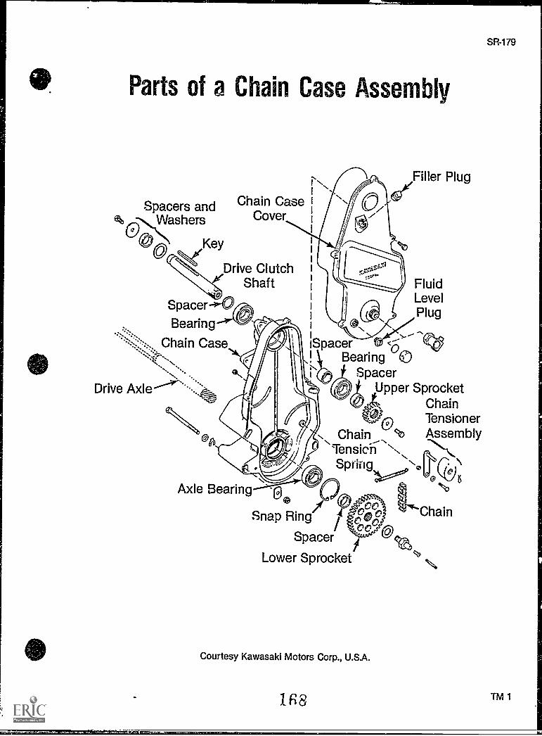
Parts of a Chain Case Assembly
Spacers and Chain Case
tbciNWashers Cover
Key
Drive ClutchShaft
Spacer-4-0Bearing
Chain Case-ss.
Drive Axles.".--.
Spacer <6Bearing
SpacerUpper Sprocket
ChainTensioner
Chain AssemblyTensichSpring No
0
Filler Plug
FluidLevelPlug
Axle Bearing ntv
Snap Ring
Spacer
Lower Sprocket
Chain
Courtesy Kawasaki Motors Corp., U.S.A.
1E8 TM 1
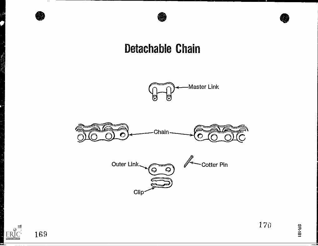
0
Detachable Chain
Master Link
Chain
A--Cotter Pin
170
CHAIN DRIVESUNIT VI
ASSIGNMENT SHEET #1 - SOLVE PROBLEMS RELATED TOCHAIN DRIVE
Directions: Read the following problems carefully and respond as directed.
A. Chain drive assemblies rarely require repairs. Describe the routine maintenance tochain drive assemblies which helps prevent problems.
B. What impact does the way the operator uses the saowmobtle have on the chain drive?
1 71
SR-183
CHAIN DRIVESUNIT VI
ANSWERS TO ASSIGNMENT SHEET
A. The most critical items is assuring that the chain and bearings are properly lubricated.So, make sure there is always sufficient oil in the chain case, make sure there are noleaks from the chain case assembly, and change the oil in the case once each season.Also, check chain tension.
B. Rapid acceleration from too fast starts car, wear the bearings down faster. Also, lockingthe track creates unnecessary tension on the chain and links.

SR-187
CHAIN DRIVESUNIT VI
JOB SHEET #1 REMOVE, INSPECT, AND REPLACE A CHAIN DRIVE
A. Tools and materials
1. Snowmobile as selected by instructor
2. Appropriate service manual
3. Basic hand tools
4. Empty container for oil
5. Clean shop towels
6. Solvent
7. Replacement chain and/or sprockets as required
8. Torque wrench
9. Safety glasses
B. Routine #1 Removing the chain drive
1. Put on safety glasses
2. Remove the chain case guard, if required
173
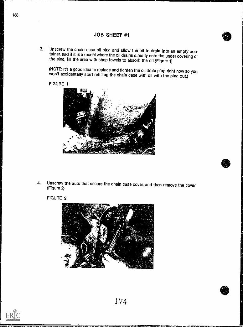
188
JOB SHEET #1
3. Unscrew the chain case oil plug and allow the oil to drain into an empty con-tainer, and if it is a model where the oil drains directly onto the under covering ofthe sled, fill the area with shop towels to absorb the oil (Figure 1)
(NOTE: It's a good idea to replace and tighten the oil drain plug right now so youwon't accidentally start refilling the chain case with oil with the plug out.)
FIGURE 1
As, ANp 'A
4. Unscrew the nuts that secure the chain case cover, and then remove the cover(Figure 2)
FIGURE 2
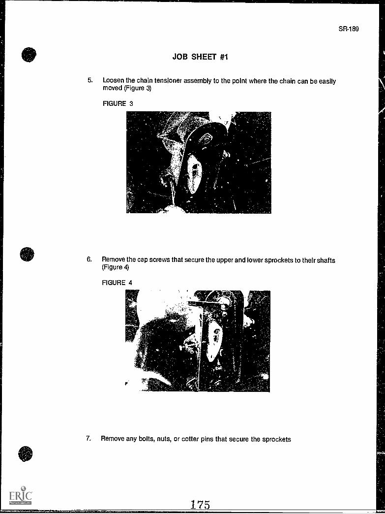
JOB SHEET #1
5. Loosen the chain tensioner assembly to the point where the chain can be easilymoved (Figure 3)
FIGURE 3
6. Remove the cap screws that secure the upper and lower sprockets to their shafts(Figure 4)
FIGURE 4
7. Remove any bolts, nuts, or cotter pins that secure the sprockets
175
SR-189
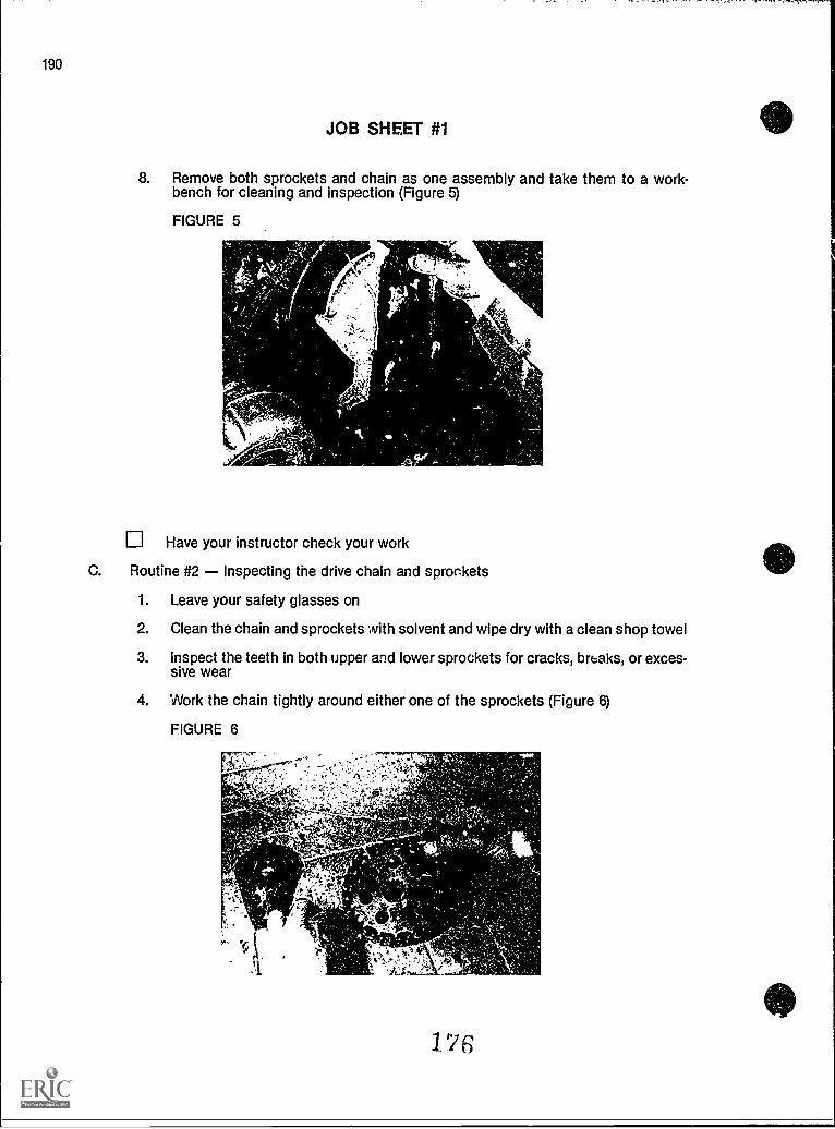
190
JOB SHEET #1
8. Remove both sprockets and chain as one assembly and take them to a work-bench for cleaning and inspection (Figure 5)
FIGURE 5
Have your instructor check your work
C. Routine #2 Inspecting the drive chain and sprockets
1. Leave your safety glasses on
2. Clean the chain and sprockets with solvent and wipe dry with a clean shop towel
3. Inspect the teeth in both upper and lower sprockets for cracks, breaks, or excessive wear
4. Work the chain tightly around either one of the sprockets (Figure 6)
FIGURE 6
176to
I
1
JOB SHEET #1
5. Use your thumb and forefinger to pull on the chain with moderate pressure, and ifhalf of any sprocket tooth can be uncovered, both the chain and the sprocketshould be replaced
6. Repeat the chain/sprocket test for the other sprocket
Have your instructor check your work, and arrange for a replacement chain orsprocket(s) as needed
D. Routine #3 Replacing the drive chain and sprockets
1. Leave your safety glasses on
2. Replace the chain and sprockets as an assembly and secure the sprockets inplace
3. Adjust the chain tension
4. Replace the chain case cover
5. Check the chain case oil plug to make sure it is tight
6. Fill the chain ease with new oil as specified by the manufacturer
7. Replace the chain case guard
Have your instructor check your work
8. Clean up area and return tools and materials to proper storage
1 77
SR191
SR-193
CHAIN DRIVESUNIT VI
JOB SHEET #2 - REPAIR A DETACHABLE CHAIN
A. Tools and materials
1. Snowmobile as selected by instructor
2. Appropriate service manual
3. Basic hand tools
4. Master link and outer link
5. Clip and cotter pin
6. Pin punch
7. Ball peen hammer
8. Bench grinder
9. Safety glasses
B. Procedure
1. Put on safety glasses
2. Remove the drive chain from the snowmobile as outlined in Job Sheet #1, thisunit
3. Clean all broken chain parts, chips, and mJtal shavings from the chain case
4. Locate the master link to make sure you are working with a detachable chain
5. Determine the number of damaged links that will have to be replaced
6. Make sure that the chain is worth repairing, and if the chain is worn excessivelyin places other than where it broke, the chain should be replaced
7. Grind off what is left of parts of the link(s) that broke
8. Replace with as many full links as needed
9. Rivet all link pins with a ball peen hammer
(NOTE: The circlips should face the outer side of the chain case.)
1 78
194
JOB SHEET #2
10. Install the master link with the clip opening facing the opposite direction thechain rotates
Have your instructor check your work
11. Reinstall the chain, sprockets, and chain case assembly as outlined in Job Sheet#1
12. Clean up area and return tools and materials to proper storage
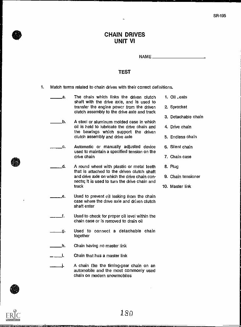
CHAIN DRIVESUNIT VI
NAME
TEST
1. Match terms related to chain drives with their correct definitions.
a. The chain which links the driven clutch 1. Oilshaft with the drive axle, and is used totransfer the engine power from the driven 2. Sprocketclutch assembly to the drive axle and track
3. Detachable chainb A steel or aluminum molded case in which
oil is held to lubricate the drive chain and 4. Drive chainthe bearings which support the drivenclutch assembly and drive axle 5. Endless chain
c. Automatic or manually adjusted device 6. Silent chainused to maintain a specified tension on thedrive chain 7. Chain case
d. A round wheel with plastic or metal teeth 8. Plugthat is attached to the driven clutch shaftand drive axle on which the drive chain con- 9. Chain tensionernects; it is used to turn the drive chain andtrack 10. Master link
e Used to prevent oil leaking from the chaincase where the drive axle and driven clutchshaft enter
__f. Used to check for proper oil level within thechain case or is removed to drain oil
g. Used to connect a detachable chaintogether
h. Chain having no master link
i. Chain that has a master link
j. A chain Re the timing-gear chain on anautomobile and the most commonly usedchain on modern snowmobiles
1S0
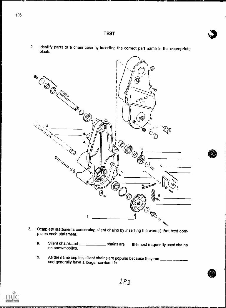
TEST
2. Identify parts of a chain case by inserting the correct part name in the appropriateblank.
3. Ccmplete statements concerning silent chains by inserting the word(s) that best com-pletes each statement.
a. Silent chains and chains are the most frequently used chainson snowmobiles.
b. As the name implies, silent chains are popular because they runand generally have a longer service life
18
ig,grcg=sgcr==.5reILwdmmsrhcarrurrii
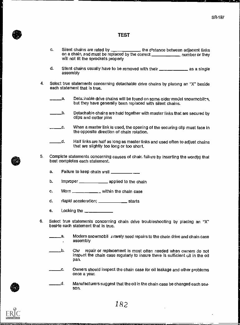
611EMMIMI.
TEST
c. Silent chains are rated by , the distance between adjacent linkson a chain, end must be replaced by the correct number or theywill not fit the sprockets properly
d. Silent chains usually have to be removed with their as a singleassembly
4. Select true statements concerning detachable drive chains by placing an "X" besideeach statement that is true.
a Detazhable drive chains will be found on some older model snowmobik's,but they have generally been replaced with silent chains.
b Detachable chains are held together with master links that are secured byclips and cotter pins
c. When a master link is used, the opening of the securing clip must face inthe opposite direction of chain rotation.
d. Half links are half as long as master links and used often to adjust chainsthat are slightly too long or too short.
5. Complete statements concerning causes of chair. failure by inserting the word(s) thatbest completes each statement.
a. Failure to keep chain well
b. !mproper applied to the chain
c. Worn within the chain case
d. Rapid acceleration; starts
e. Locking the
6. Select true statements concerning chain drive troubleshooting by placing an "X"beside each statement that is true.
a. Modern snowmobil s rarely need repairs to the chain drive and chain caseassembly
b Che repair or replacement is most often needed when owners do notinspect the chain case regularly to insure there is sufficient oil in the oilpan.
c Owners should inspect the chain case for oil leakage and other problemsonce a year.
d Manufacturers suggest that the oil in the chain case be changed each sea-son.
1 R 2
977SR-1
198
TEST
(NOTE: If the following activities have not been accomplished prior to the test, ask yourinstructor when they should be completed.)
7. Solve problems related to chain drives. (Assignment Sheet #1)
8. Demonstrate the ability to:
a. Remove, inspect, and replace a chain drive. (Job Sheet #1)
b. Repair a detachable chain. (Job Sheet #2)
1 R
CHAIN DRIVESUNIT Vi
ANSWERS TO TRiT
1. a. 4 f. 8b. 7 g. 10c. 9 h. 5d. 2 i. 3e. 1 j. 6
2. a. Chain caseb. Upper sprocketc. Chain tensioner assemblyd. Chain tensioner springe. Chainf. Lower sprocket
3. a. Endlessb. Quieterc. Pitch, pitchd. Sprockets
4. a, b, c
5. a. Lubricatedb. Tendonc. Paringsd. Faste. Track
6. a, b, d
7. Evaluated to the satisfaction of the instructor
8. Performance skills evaluated according to procedures written in the job sheets
SR-199
fam,1016.1471Miorl
SR-201
JACKSHAFTS AND AXLESUNIT VP
UNIT OBJECTIVE
After completion of this unit, the student should be able to identify components of a drive axleand discuss the basic functions of axles arc.' jackshafts. The student should also be able toremove and install a jackshaft and disassemble and reassemble a drive axle assembly. Thesecompetencies will be evidenced by correctly performing the procedures outlined in the assign-ment and job sheets and by scoring 85 percent on the unit test.
SPECIFIC OBJECTIVES
After completion of this unit, the student should be able to:
1. Match terms related to jackshafts and axles with their correct definitions.
2. Identify components of a drive axle assembly.
3. Complete statements concerning types of axles.
4. Select true statements concerning axle repair.
5. Solve problems related to axle repair and maintenance. (Assignment Sheet #1)
6. Demonstrate the ability to:
a. Remove and install a jackshaft. (Job Sheet #1)
b. Disassemble a drive axle assembly. (Job Sheet #2)
c. Reassemble a drive axle assembly. (Job Sheet #3)
1S5
JACKSHAFTS AND AXLESUNIT VII
SUGGESTED ACTIVITIES
A. Provide students with objective sheet.
B. Provide students with information sheet.
C. Make transparency.
D. Discuss unit and specific objectives.
E. Discuss information sheet.
F. Demonstrate and discuss the procedures outlined in the job sheets.
G. Examine a jackshaft and explain its function and advantages to the class.
H. Give test.
CONTENTS OF THIS UNIT
A. Objective sheet
B. Information sheet
C. Transparency Master 1 Parts of a Drive Axle
D. Assignment Sheet #1 Solve Problems Related to Axle Repair and Maintenance
E. Answers to assignment sheet
F. Job sheets
1. Job She at #1 Remove and Install a Jackshaft
2. Job Sheet #2 Disassemble a Drive Axle Assembly
3. Job Sheet #3 Reassemble a Drive Axle Assembly
G. Test
Answis to test
REFERENCES USED IN DEVELOPING THIS UNIT
H.
A. Snowmobile Repair. Ftillwater, OK 74074: Mid-America Vocational Curriculum Consor-tium, 1976.
18
SR-203
204
REFERENCES USED IN DEVELOPING THIS UNIT
B. 1980 Bombardier Snowmobiles Shop Manual. Valcourt, Quebec, Canada: Bombardier,Ltd., 1975.
C. 1978 Polaris Shop Manual. Roseau, MN: Po laris/Textron, 1978.
D. Kawasaki Drifter Snowmobile Shop Manual. Santa Ana, CA 92799-5252: KawasakiMotors Corp., U.S.A., 1980.
E. Kawasaki Parts Catalog SB340-A2, SB440-A5. Santa Ana, CA 92799-5252: KawasakiMotors Corp., U.S.A., 1980.
187
1
JACKSHAFTS AND AXLESUNIT VII
INFORMATION SHEET
I, Terms and definitions
A. Drive axle - A solid or semi-solid shaft of steel which connects to the drivechain by a sprocket and drives the track.
B. Jackshaft A shaft which extends across the chassis from the drivenclutch and down to the chain case serving to transfer power from one sideof the snowmobile to the other; found on most high performance models
C. Drive sprockets Large wheels connected to the drive axle used to turnthe track; virtually all snowmobiles use internal drive sprockets
D. Teeth The portion of the drive sprocket that inserts into or receives araised portion of track to turn the track
E. Seal Rubber washer used '.o seal the chain case where the drive axle orjacksriaft enters into the case; used to eliminate oil leakage
F. Flange A plate used to secure the drive sprockets to the drive axle
G. Rear axle The rear shaft with sprockets to allow the track to rotate on thesnowmobile
II. Mcijor components of a drive axle assembly (Transparency 1)
A. Axle
B. Bearing(s)
C. Bearing housing
D. Retaining collar
E. Seal (0-ring)
F. Sprocket(s)
0. Spacer
H. Was hers
SR-205
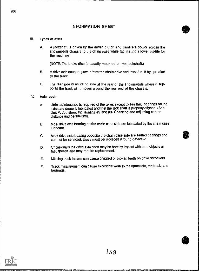
206
INFORMATION SHEET
Ill. Types of axles
A. A jackshaft is driven by the driven clutch and transfers power across thesnowmobile chassis to the chain case while facilitating a lower piofile forthe machine
(NOTE: The brake disc is usually mounted on the jackshaft.)
B. A drive axle accepts power from the chain drive and transfers it by sprocketto the track.
The rear axle is an idling axle at the rear of the snowmobile where it sup-ports the track as it moves around the rear end of the chassis.
IV Axle repair
A. Little maintenance is required of the axles except to see that bearings on theaxles are properly lubricated and that the jack shaft is properly aligned. (SeeUnit V, Job sheet #2, Routine #2 and #3- Checking and adjusting centerdistance and parallelism).
B. Most drive axle bearing on the chain case side are lubricated by the chain caselubricant.
C. Most drive axle bearing opposite the chain case side are sealed bearings andcan not be serviced, these must be replaced if found defective.
D. C-sasionally the drive axle shaft may be bent by impact with hard objects atfast speeds and may require replacement.
E. Missing track inserts can cause cilipped or broken teeth on drive sprockets.
F. Track misalignment can cause excessive wear to the sprockets, the track, andbearings.
1 R9
a
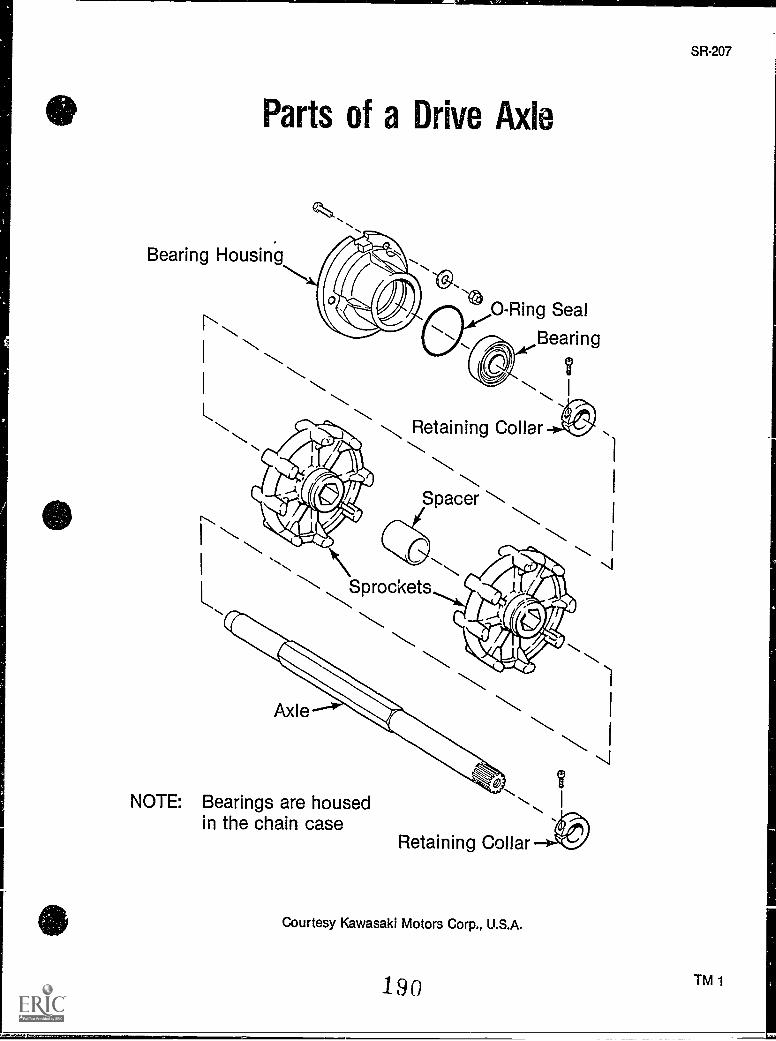
Parts of a Drive Axle
Bearing Housing
'CI:.a.....
0-Ring Seal
Bearing
Q
I
Retaining Collar
Spacer
1
\ ..Sprockets
Axle
NOTE: Bearings are housed ..in the chain case
Retaining Collar
Courtesy Kawasaki Motors Corp., U.S.A.
190
1
1
1
il1
SR-207
TM 1
SR-209
JACKSHAFTS AND AXLESUNIT VII
ASSIGNMENT SHEET #1 - SOLVE PROBLEMS RELATED TOAXLE REPAIR AND MAINTENANCE
Directions: Read the following problems carefully and respond as directed.
A. You have been asked to conduct routine inspection and maintenance of a snowmobile.What routine inspection should you do regarding the axle?
B. During your inspection you find that there are some missing inserts on the track. Whatmight you expect the affect to be on the axle sprocket(s)?
C. The efficient transfer of power from the engine to the track is partly accomplishedthrough the use of shafts. What are those shafts, and in what order do they function inpower transfer from the engine to the track?
D. The owner tells you that his snowmobile struck a hidden tree trunk when traveling atabout 30 mph. What damage to the axle could be possible?
19i
JACKSHAFTS AND AXLESUNIT VII
ANSWERS TO ASSIGNMENT SHEET
A. First, inspect the bearings on the axle. If they are the non-lubricating type, examinethem for excessive wear. If they are lubricated by oil from the chain case, inspect thechain case pan to see if it contains sufficient oil for lubricating. Inspect the alignmentof the track. Inspect sprockets for wear.
B. Missing track inserts can cause chipped or broken teeth on the drive sprockets. Theinserts should be replaced and the sprockets replaced if necessary.
C. The main shafts are the crankshaft to which the drive clutch is attached, power is thentransmitted to the jackshaft which in turn transmits power through the chain drive tothe drive axle which transmits power finally to the track.
D. You might suspect a bent front or rear axle which may have to be replaced.
192
SR-211
JACKSHAFTS AND AXLESUNIT VII
JOB SHEET #1 - REMOVE AND INSTALL A JACKSHAFT
A. Tools and materials needed
1. Snowmobile as selected by instructor
2. Appropriate service manual
3. Basic hand tools
4. Shim kit (if applicable)
5. Bearing puiler (as per manufacturer's specifications)
6. Alignment tool
7. Lubricant as required
8. Safety glasses
B. Routine #1 Removing the jacLihaft
-I Put on safety glasses.
2. Remove the chain case cover and sprockets, and the chain case.
(NOTE: Refer to UNIT VI if necessary.)
3. Remove the driven clutch.
4. Lcosen the lock collar, and remove the flange and bearing on the left side of thejackshaft.
5. Remove the jackshaft and disc whit,: the sled sits on the ground.
Have your instructor check your work.
C. Routine #2 Installing the jackshaft
1. Install the chaincase to the chassis with the jackshaft, but do not instal: thesprockets.
2. Install the alignment tool according to manufacturer's specifications./
193
214
JOB SHEET #1
3. Install flange into the left bearing support hole.
a. The shaft should center in the flange.
b. If the shaft does not center in flange, use a shim kit to position the shafton center by placing shims in the chain case between the tunnel and case.
4. Grease the left bearing and flange.
5. Slide the bearing onto the shaft.
6. Rotate the flanges to inspect for binding which can cause misalignment.
7. Tighten flanges.
(NOTE: Always torque nuts and bolts to specifications.)
8. Use a straight edge on the support plate to check for movement of the plate byrotating the shaft.
9. Correct any movement by loosening the flange mounting bolts slightly and gen-tly tap the flange while rotating the shaft until no movement exists.
Have your instructor check your work.
10. Clean up area and return tools and materials to proper storage.
194
SR-215
JACKSHAFTS AND AXLESUNIT VII
JOB SHEET #2 - DISASSEMBLE A DRIVE AXLE ASSEMBLY
A. Tools and materials needed
1. Snowmobile as selected by instructor
2. Appropriate service manual
3. Basic hand tools
4. Bearing puller
5. Vise
6. Large snap-ring pliers
7. Empty container to catch oil
8. Clean shop towels
9. Solvent
10. Safety glasses
B. Procedure
1. Put on safety glasses.
2. Drain oil from chain case.
3. Remove chain case or chain case inspection cover from snowmobile to exposesprockets.
4. Remove nut, bolt or cotter pin holding sprocket onto drive axle.
5. Remove sprocket from spline of drive axle.
6. Support back end of snowmobile so that the track can be loosened or removed.
7. Loosen all bolts supporting the track.
8. Remove slide rail or bogie wheel assembly.
9. Remove bearing support opposite chain case.
195
216
JOB SHEET #2
10. Slide axle opposite chain case and remove from frame.
(NOTE: Some models may locate a speedometer drive or brake assembly on thisend of the drive shaft, and these components may have to be removed.)
11. Clamp axl9 into vise and pull off bearings with appropriate puller.
12. Remove seals.
13. Remove sprockets from drive axle.
14. Clean all parts with solvent and wipe dry with a clean shop towel.
15. Inspect bearings, seals, and sprockets for damage.
Have your instructor check your work.
16. Clean up area and return tools and materials to proper stcrage or prepare fornext jib sheet as directed by your instructor.
(Note: Do not clean sealed bearings in 'olvent. If the bearing is useable, the solvent mayleak into the bearing and compromise the lubricating grease installed during manufacture.If the sealed bearing does not turn freely and smoothly, it is defective and must bereplaced).
196
JACKSHAFT'S AND AXLESUNIT VII
JOB SHEET #3 - REASSEMBLE A DRIVE AXLE ASSEMBLY
A. Tools and materials needed
1. Snowmobile as selected by instructor
2. Appropriate service manual
3. Bearing driver set
4. Seals as required
5. Sprockets as required
6. Vise
7. Large snap-ring pliers
8. Oil per specifications
9. Clean shop towels
10. Safety gasses
B. Procedure
1. Put on safety glasses.
2. Install sprockets onto drive axle.
3. Install seals.
4. Drive bearings onto drive axle with bearing driver.
5. Insert drive axle into frame with track in place.
6. Install bearing support on side opposite chain case, and reinstall speedometerdrive or brake assembly as required.
7. Install slide suspension system and rear axle.
8. Slip drive chain sprocket onto spline of axle.
197
SR-217
218
9. Reinstall drive chain.
(NOTE: Chain may have to be installed with sprockets.)
Install chain case cover.
Fill chain case with oil to the proper level.
Align and adjust track.
Check operation.
Have your instructor check your work.
Clean up area and return tools and materials to proper storage.
10.
11.
12.
13.
El
14.
JOB SKEET #3
1...... ............I.
198
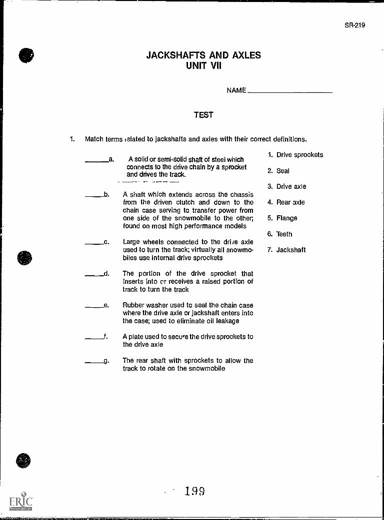
JACKSHAFTS AND AXLESUNIT VII
NAME
TEST
1. Match terms (elated to jackshafts and axles with their correct definitions.
a. A solid or semi-solid shaft of steel which1. Drive sprockets
connects to the drive chain by a sprocket 2. Sealand drives the track.
3. Drive axleb A shaft which extends across the chassis
from the driven clutch and down to the 4. Rear axlechain case serving to transfer power fromone side of the snowmobile to the other; 5. Flangefound on most high performance models
6. Teethc Large wheels connected to the dri te axle
used to turn the track; virtually all snowmo- 7. Jackshaftbiles use internal drive sprockets
d The portion of the drive sprocket thatinserts into or receives a raised portion oftrack to turn the track
e Rubber washer used to seal the chain casewhere the drive axle or jackshaft enters intothe case; used to eliminate oil leakage
f A plate used to secure the drive sprockets tothe drive axle
g. The rear shaft with sprockets to allow thetrack to rotate on the snowmobile
199
SR-219
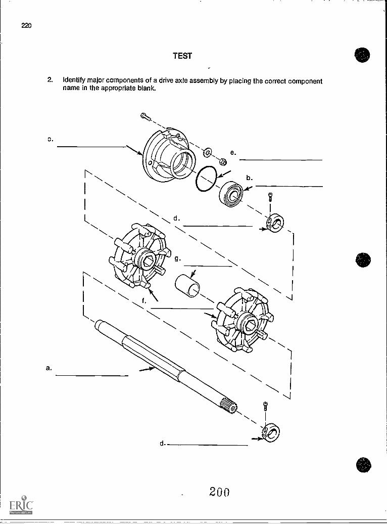
220
TEST
2. Identify major components of a drive axle assembly by placing the correct componentname in the appropriate blank.
a.
200
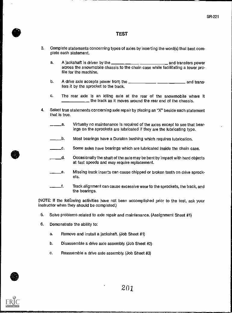
SR-221
TEST
3. Complete statements concerning types of axles by inserting the word(s) that best com-plete each statement.
a. A jackshaft is driven by the and transfers poweracross the snowmobile chassis to the chain case while facilitating a lower pro-file for the machine.
b. A drive axle accepts power from the and trans-fers it by the sprocket to the track.
c. The rear axle is an idling axle at the rear of the snowmobile where itthe track as it moves around the rear end of the chassis.
4. Select true statements concerning axle repair by placing an "X" beside each statementthat is true.
a. Virtually no maintenance is required of the axles except to see that bear-ings on the sprockets are lubricated if they are the lubricating type.
b Most bearings have a Duralon bushing which requires lubrication.
c. Some axles have bearings which are lubricated inside the chain case.
d.
e.
f.
Occasionally the shaft of the axle may be bent by irnpact with hard objectsat fast speeds and may require replacement.
Missing track inserts can cause chipped or broken teeth on drive sprock-ets.
Track alignment can cause excessive wear to the sprockets, the track, andthe bearings.
(NOTE: If the following activities have not been accomplished prior to the test, ask yourinstructor when they should be completed.)
5. Solve problems related to axle repair and maintenance. (Assignment Sheet #1)
6. Demonstrate the ability to:
a. Remove and install a jackshaft. (Job Sheet #1)
b. Disassemble a drive axle assembly. (Job Sheet #2)
c. Reassemble a drive axle assembly. (Job Sheet #3)
201
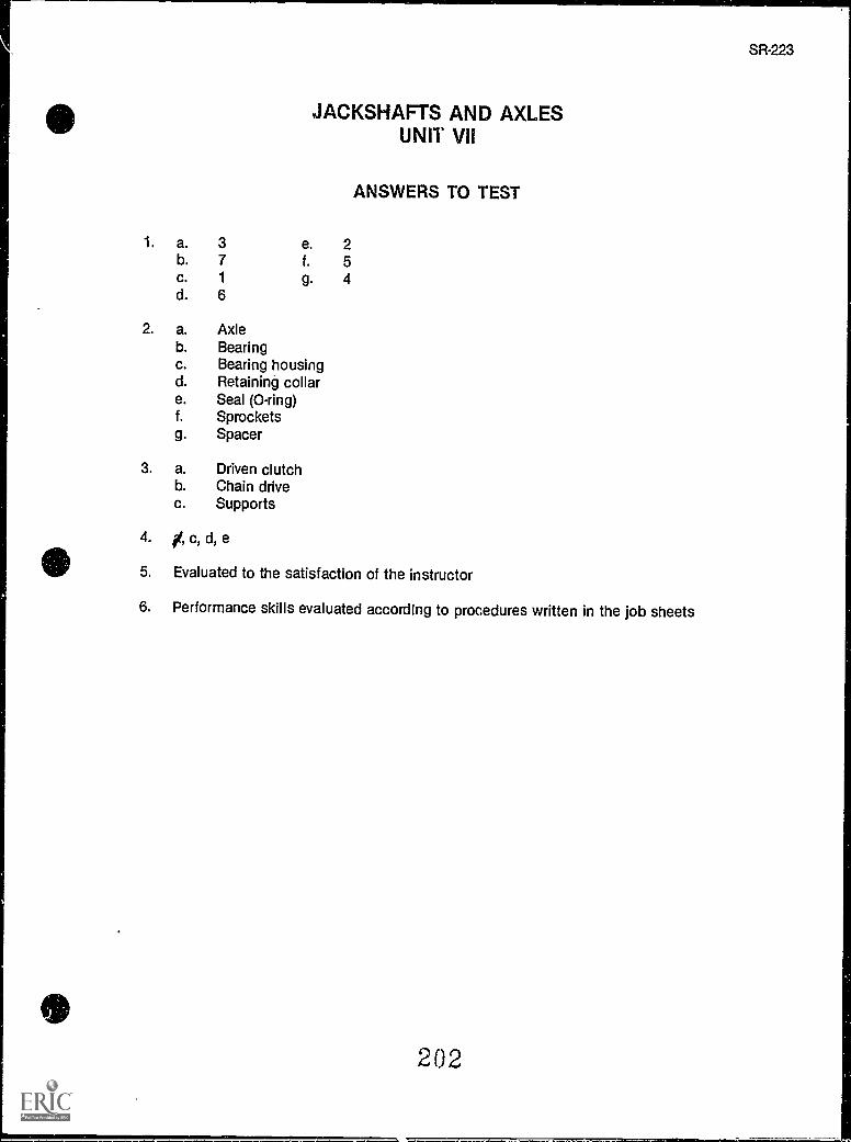
JACKSHAFTS AND AXLESUNIT VII
ANSWERS TO TEST
1. a. 3 e. 2b. 7 f. 5c. 1 g. 4d. 6
2. a. Axleb. Bearingc. Bearing housingd. Retaining collare. Seal (0-ring)f. Sprocketsg. Spacer
3. a. Driven clutchb. Chain drivec. Supports
4. A c, d, e
5. Evaluated to the satisfaction of the instructor
6. Performance skills evaluated according to procedures written in the job sheets
202
SR-223
-111 mt.'
REAR SUSPENSIONUNIT VIII
UNIT OBJECTIVE
After completion of this unit, the student should be able to discuss the purpose and functionof the rear suspension system and be able to identify the components of a rear suspension.The student should also be able to perform simple maintenance on a slide rail system, disas-semble and reassemble a slide rail suspension, and replace wear strips. There competencieswill be evidenced by correctly performing the procedures outlined in the assignment and jobsheets and by scoring 85 percent on the unit test.
SPECIFIC OBJECTIVES
After completion of this unit, the student should be able to:
1. Match terms related to rear suspension with their correct definitions.
2. Complete statements concerning ttr) slide rail suspension system.
3. Identify components of a slide rail suspension.
4. Select true statements concerning maintenance.
5. Solve problems related to rear suspension maintenance. (Assignment Sheet #1)
6. Demonstrate the ability to:
a. Disassemble and reassemble a slide rail suspension. (Job Sheet #1)
b. Replace wear strips. (Job Sheet #2)
203
SR-225
SR-227
REAR SUSPENSIONUNIT VIII
SUGGESTED ACTIVITIES
A. Provide students with objective sheet.
B. Provide students with information sheet.
C. Make transparency.
D. Discuss unit and specific objectives.
E. Discuss information sheet.
F. Demonstrate and discuss the procedures outlined in the job sheets.
G. Have available to students an old model snowmobile featuring the bogie wheel suspen-sion system, and a new model snowmobile featuring the slide rail suspension, and havethe students compare the two systems.
H. Give test.
CONTENTS OF THIS UNIT
A. Objective sheet
.,B. Information sheet
C. Transparency Master 1 Parts of a Slide Rail Suspension
D. Assignment Sheet #1 Solve Problems Related to Rear Suspension Maintenance
E. Answers to assignment sheet
F. Job sheets
1. Job Sheet #1 Disassemble and Reassemble a Slide Rail Suspension
2. Job Sheet #2 Replace a Wear Strip
G. Test
H. Answers to test
204
228
REFERENCES USED IN DEVELOPING THIS UNIT
A. Snowmobile Repair. Stillwater, OK 74074: Mid-America Vocational Curriculum Consor-tium, 1976.
B. Chilton's Snowmobiles Repair & Turn-Up Guide, Second edition. Radnor, PA: ChiltonBook Co., 1975.
C. Arctic Cat Service Manual No. 2254-302. Thief River Falls, MN 56701: ARCTCO, Inc.,1984.
D. 1980 Bombardier Snowmobiles Shop ManuaL Valcourt, Quebec, Canada: Bombardier,Ltd., 1980.
E. Kawasaki Invader Snowmobile Shop ManuaL Santa Ana, CA 92799-5252: KawasakiMotors Corp., U.S.A., 1930.
205 e
SR-229
REAR SUSPENSIONUNIT VIII
INFORMATION SHEET
I. Terms and definitions
A. Cross shaft Used to mount the slide rail suspension onto the snowmo-bile chassis
B. Idler wheels Wheel assemblies used to apply tension to the track andkeep the slide rail from hitting the track
C. Suspension springs Used to give the slide rail suspension action
D. Slider Usuan made of nylon and guided by inserts in the track
(NOTE: This rail is lubricated by snow.)
E. Runner bars Used to attach the nylon slide rail.
F. Wear strip An under ,ib attached to the bottom of the slide rail to protectthe slide rail from track friction
G. Fear axle A solid or hollow shaft which connects the link plates and isused to control track tension and also to guide the track alignment
H. Link plates Used to connect the rear axle to the frame and allow the sus-pension to flex with the weight of the rider
I. Rear spring Used to apply pressure to the link plate to stiffen and lightenthe flexibility of the suspension
J. Rear sprockets Connect to the rear axle and are used as idlers to controltrack tension and track alignment
K. Rear bearings Inserted into the link plates and are used to eliminate fric-tion on the rear axle
L Rear seal Used to hold grease in the rear link plates so that the bearingswill remain lubricated
M. Bogie wheel assembly An assembly of wheels mounted to a snowmobileframe between the top and bottom of the track to support the weight of therider and to absorb shock caused by hitting objects; mostly outdated andreplaced by the slide rail suspension system
II. The slide rail suspension system (Figure 1)
A. Uses a plastic-lined rail to press against the inside of the track to guide thetrack over snow
B. The snowmobile's weig!.c is carried by the slide rail.
206
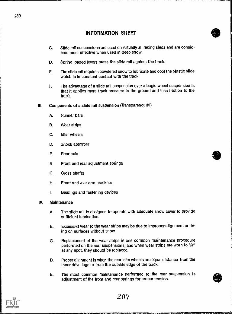
230
INFORMATION SHEET
C. Slide rail suspensions are used on virtually all racing sleds and are consid-ered most effective when used indeep snow.
D. Spring loaded levers press the slide rail against the track.
E. The slide rail requires powdered snow to lubricate and cool the plastic slidewhich is in constant contact with the track.
F. The advantage of a slide rail suspension over a bogie wheel suspension isthat it applies more track pressure to the ground and less friction to thetrack.
Components of a slide rail suspension (Transparency #1)
A. Runner bars
B. Wear strips
C. Idler wheels
D. Shock absorber
E. Rear axle
E Front and rear adjustment springs
G. Cross shafts
H. Front and rear arm brackets
I. Bearings and fastening devices
IV. Maintenance
A. The slide rail is designed to operate with adequate snow cover to providesufficient lubrication.
B. Excessive wear to the wear strips may be due to improper alignment or rid-ing on surfaces without snow.
C. Replacement of the wear strips is one common maintenance procedureperformed on the rear suspensions, and when wear strips are worn to 1 /a"at any spot, they should be replaced.
D. Proper alignment is when the rear idler wheels are equal distance from theinner drive lugs or from the outside edge of the track.
E. The most common maintenance performed to the rear suspension isadjustment of the front and rear springs for proper tension.
207
,:=5P121=2212212=27=3112EISSES22j
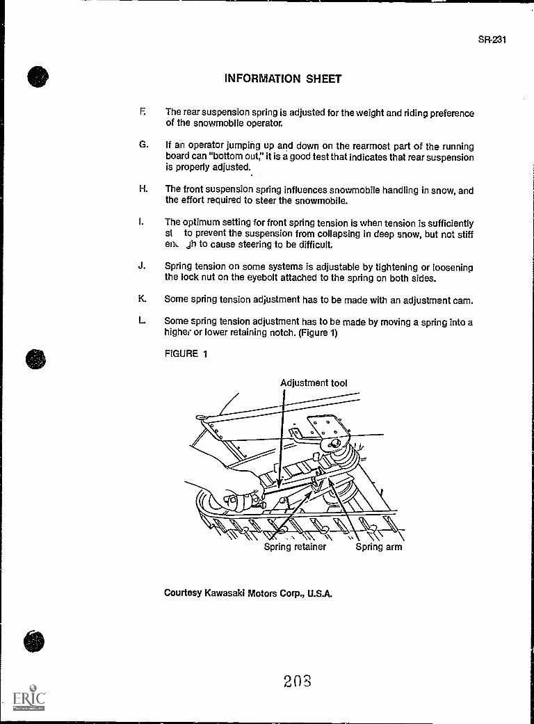
INFORMATION SHEET
F. The rear suspension spring is adjusted for the weight and riding preferenceof the snowmobile operator.
G. If an operator jumping up and down on the rearmost part of the runningboard can "bottom out," it is a good test that indicates that rear suspensionis properly adjusted.
H. The front suspension spring influences snowmobile handling in snow, andthe effort required to steer the snowmobile.
I. The optimum setting for front spring tension is when tension is sufficientlysi to prevent the suspension from collapsing in deep snow, but not stiffelk jh to cause steering to be difficult.
J. Spring tension on some systems is adjustable by tightening or looseningthe lock nut on the eyebolt attached to the spring on both sides.
K. Some spring tension adjustment has to be made with an adjustment cam.
L Some spring tension adjustment has to be made by moving a spring into ahigher or lower retaining notch. (Figure 1)
FIGURE 1
Adjustment tool
Spring retainer
Courtesy Kawasaki Motors Corp., U.S.A.
20S
Spring arm
SR-231
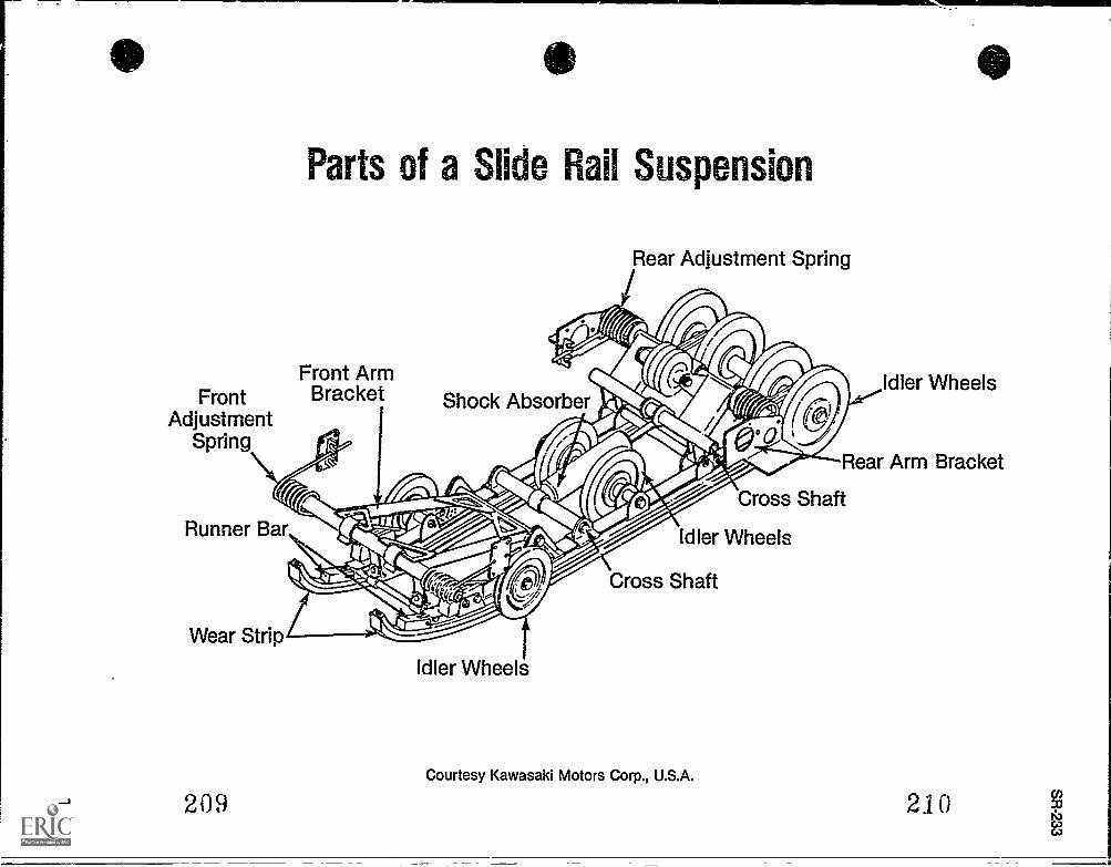
FrontAdjustment
Spring
Parts of a Slide Rail Suspension
Front ArmBracket
Rear Adjustment Spring
Shock Absorber
Runner Bar
Wear Strip
209
Idler Wheels
Idler Wheels
Rear Arm Bracket
Cross Shaft
Idler Wheels
Cross Shaft
Courtesy Kawasaki Motors Corp., U.S.A.
210
REAR SUSPENSIONUNIT VIII
ASSIGNMENT SHEET #1 - SOLVE PROBLEMS RELATED TOREAR SUSPENSION MAINTENANCE
Directions: Read the following problems carefully and respond as directed.
A. You have been asked by your instructor to explain to the rest of the class the purpose ofthe rear suspension system, and why the slide rail suspension system has beenadopted over the bogie wheel system. How would you respond?
B. Why is a slide rail suspension system most efficient on surfaces with powdered snow?
C. The operator of a snowmobile with slide rail suspension complains to you about theride being too springy. What would you suspect is the problem and how would you cor-rect it?
D. On routine inspection of a slide rail you notice the wear strip becoming thin. At whatpoint should the wear strip be replaced?
2ii
SR-235
SR-237
REAR SUSPENSIONUNIT VIII
ANSWERS TO ASSIGNMENT SHEET
A. The rear suspension carries the weight of the snowmobile and operator and serves topress against the inside of the track to guide the track over the snow. Its advantagesover the bogie wheel system are that it applies greater pressure from the track onto theground, and creates less friction with the track.
B. The slide rail requires powdered snow to lubricate and to cool the plastic slide which isin contact constantly with the track.
C. The rear spring is responsible for carrying the weight of the operator. In this case it isprobably not adjusted properly; there is too little tension in the spring, and the problemcan be corrected by increasing spring tension.
D. When the slide rail wear strip is worn down to Ye" in any portion of the material, itshould be replaced.
212
........... .......
SR-239
REAR SUSPENSIONUNIT VIII
JOB SHEET #1 REMOVE AND REINSTALLA SLIDE RAIL SUSPENSION
A. Tools and materials
1. Snowmobile as selected by instructor
2. Appropriate service manual
3. Pry bar
4. Ball peen hammer
5. Cardboard or protective material
6. Service stand
7. Manufacturer's specified spring tool
8. LOCTITE (if specified by manufacturer)
9. Torque wrench
10. Safety glasses
B. Routine #1 Removing the slide rail
1. Put on safety glasses
2. Tilt the snowmobile on its side onto a sheet of cardboard to protect the cowling,or lift the rear of the sled onto a service stand.
3. Loosen track tension by loosening the adjuster bolts located on the Inner side ofthe rear idler wheels. (Some models will vary.)
(CAUTION: Release tension on front and rear suspension adjustmentsprings by unhooking springs from rear and forward arm brackets. Useappropriate tool to hold spring and release tension gradually keepinghands and fingers away from spring ends and suspension parts untilspring tension is released.)
213
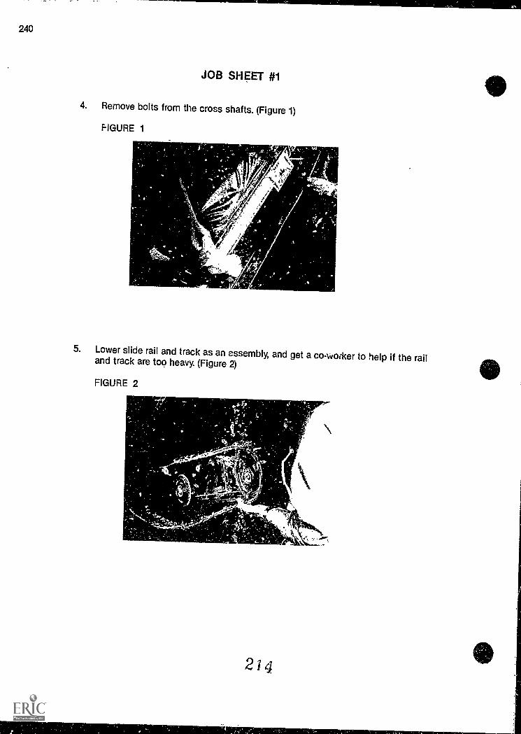
240
JOB SHEET #1
4. Remove bolts from the cross shafts. (Figure 1)
FIGURE 1
5. Lower slide rail and track as an assembly, and get a co- worker to help if the railand track are too heavy. (Figure 2)
FIGURE 2
a
214
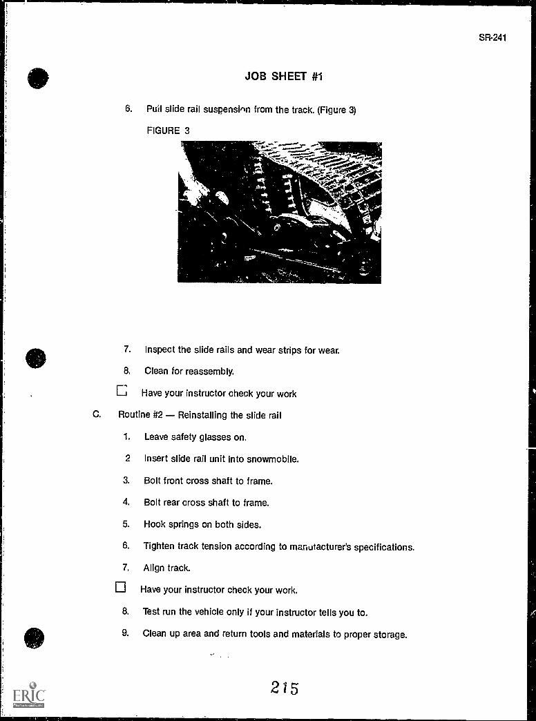
SR-241
JOB SHEET #1
6. Puil slide rail suspension from the track. (Figure 3)
FIGURE 3
7. Inspect the slide rails and wear strips for wear.
8. Clean for reassembly.
Have your instructor check your work
C. Routine #2 Reinstalling the slide rail
1. Leave safety glasses on.
2 Insert slide rail unit into snowmobile.
3. Bolt front cross shaft to frame.
4. Bolt rear cross shaft to frame.
5. Hook springs on both sides.
6. Tighten track tension according to manufacturer's specifications.
7. Align track.
Have your instructor check your work.
8. Test run the vehicle only if your instructor tells you to.
9. Clean up area and return tools and materials to proper storage.
215
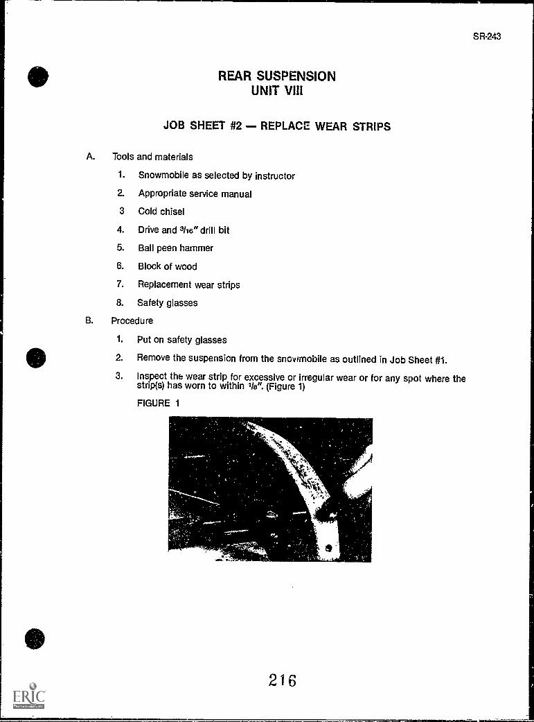
REAR SUSPENSIONUNIT VIII
JOB SHEET #2 - REPLACE WEAR STRIPS
A. Tools and materials
1. Snowmobile as selected by instructor
2. Appropriate service manual
3 Cold chisel
4. Drive and 3/16" drill bit
5. Ball peen hammer
6. Block of wood
7. Replacement wear strips
8. Safety glasses
B. Procedure
1. Put on safety glasses
2. Remove the suspension from the snowmobile as outlined in Job Sheet #1.
3. Inspect the wear strip for excessive or irregular wear or for any spot where thestrip(s) has worn to within 1 /s ". (Figure 1)
FIGURE 1
216
S
SR-243
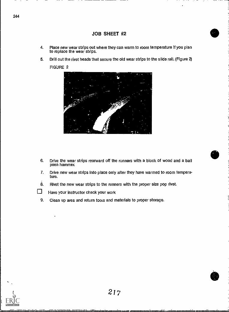
244
i
JOB SHEET #2
4. Place new wear strips out where they can warm to room temperature if you planto replace the wear strips.
5. Drill out the rivet heads that secure the old wear strips to the slide rail. (Figure 2)
FIGURE 2
6. Drive the wear strips rearward off the runners with a block of wood and a ballpeen hammer.
7. Drive new wear strips into place only after they have warmed to room tempera-ture.
8. Rivet the new wear strips to the runners with the proper size pop rivet.
Have your instructor check your work
9. Clean up area and return tools and materials to proper storage.
217
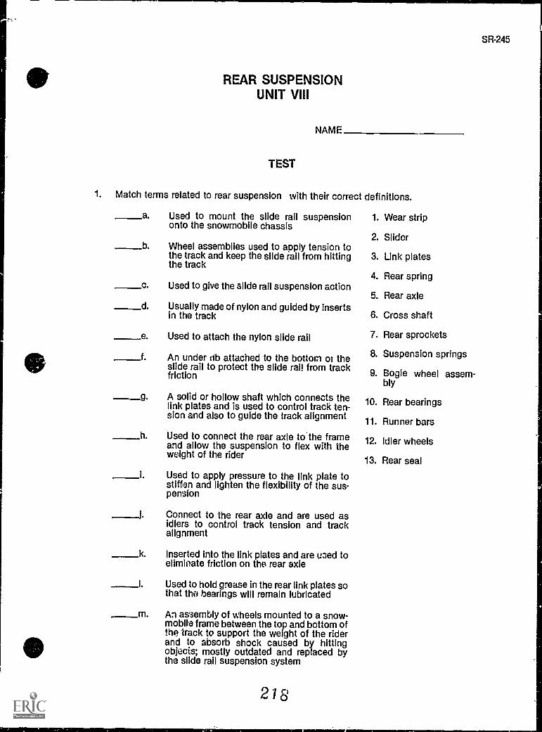
REAR SUSPENSIONUNIT VIII
NAME
TEST
1. Match terms related to rear suspension with their correct definitions.
a. Used to mount the slide rail suspensiononto the snowmobile chassis
b Wheel assemblies used to apply tension tothe track and keep the slide rail from hittingthe track
c. Used to give the slide rail suspension action
d. Usually made of nylon and guided by insertsin the track
e. Used to attach the nylon slide rail
f An under rib attached to the bottom of theslide rail to protect the slide rai! from trackfriction
A solid or hollow shaft which connects thelink plates and is used to control track ten-sion and also to guide the track alignment
h. Used to connect the rear axle to'the frameand allow the suspension to flex with theweight of the rider
Used to apply pressure to the link plate tostiffen and lighten the flexibility of the sus-pension
j. Connect to the rear axle and are used asidlers to control track tension and trackalignment
k
m
Inserted into the link plates and are uoed toeliminate friction on the rear axle
Used to hold grease in the rear link plates sothat the bearings will remain lubricated
An assembly of wheels mounted to a snow-mobile frame between the top and bottom ofthe track to support the weight of the riderand to absorb shock caused by hittingobjects; mostly outdated and replaced bythe slide rail suspension system
2 8
1. Wear strip
2. Slider
3. Link plates
4. Rear spring
5. Rear axle
6. Cross shaft
7. Rear sprockets
8. Suspension springs
9. Bogie wheel assem-bly
10. Rear bearings
11. Runner bars
12. Idler wheels
13. Rear seal
NINImMIR
SR-245
246
TEST
2. Complete statements concerning the slide rail suspension system by inserting theword(s) that best completes each statement.
a. Uses a -lined rail to press against the inside of the track to guidethe track over snow.
b. The snowmobile's is carried by the slide rail.
c. Slide rail suspensions are used on virtually ali sleds and are con-sidered most effective when used in deep snow.
d. Spring loaded levers the slide rail against the track.
e. The slide rail requires snow to lubricate and cool the plastic slidewhich is in constant contact with the track.
f. The advantage of a slide rail suspension over a bogie wheel suspension is that itapplies track pressure to the ground and less friction to thetrack.
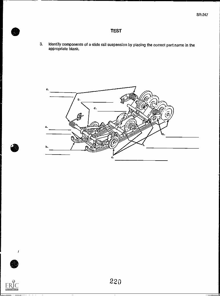
SR-247
TEST
3. Identify components of a slide rail suspension by placing the correct part name in theappropriate blank.
220
4. Select true statements concerning maintenance by placing an "X" beside each state-ment that is true.
a The slide rail is designed to operate with adequate snow cover to providesufficient lubrication.
b Excessive wear to the wear strips may be due to proper alignment or ridingon surfaces with snow.
c. Replacement of the wear strips is one common maintenance procedureperformed on the rear suspensions, and when wear strips are worn to 1/8"at any spot, they should be replaced.
d Proper alignment is when the rear idler wheels are equal distance from theinner drive lugs or from the outside edge of the track.
e The most common maintenance performed to the rear suspension isadjustment of the front idler wheel for proper tension.
f The rear suspension spring is adjusted for the weight and riding prefer-ence of the snowmobile operator.
g. If an operator jumping up and down on the rearmost part of the runningboard can "bottom out;' it is a good test that indicates that rear suspen-sion is improperly adjusted.
h The front suspension spring influences snowmobile handling in snow, andthe effort required to steer the snowmobile.
i The optimum setting for front spring tension is when tension is sufficientlystiff to prevent the suspension from collapsing in deep snow, but not stiffenough to cause steering to be difficult.
j Spring tension is not adjustable by tightening or loosening the lock nut onthe eyebolt attached to the spring on both sides.
____1( Some spring tension adjustment has to be made with an adjustment cam.
I. Some spring tension adjustment has to be made by moving a spring into ahigher or lower retaining match.
(NOTE: If the following activities have not been accomplished prior to the test, ask yourinstructor when they should be completed.)
5. Solve problems relatt `o rear suspension maintenance. (Assignment Sheet #1)
6. Demonstrate the ability to:
a. Disassemble and reassemble a slide rail suspension. (Job Sheet #1)
b. Replace wear strips. (Job Sheet #2)
221
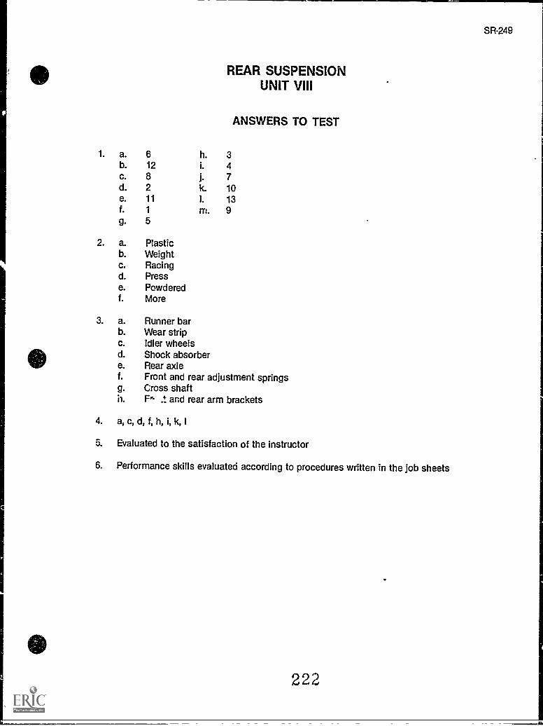
SR-249
REAR SUSPENSIONUNIT VIII
ANSWERS TO TEST
1. a. 6 h. 3b. 12 i. 4c. 8 j. 7d. 2 k. 10e. 11 I. 13f. 1 m. 9g. 5
2. a. Plasticb. Weightc. Racingd. Presse. Powderedf. More
3. a. Runner barb. Wear stripc. Idler wheelsd. Shock absorbere. Rear axlef. Front and rear adjustment springsg. Cross shaftn. Fn .t and rear arm brackets
4. a, c, d, f, h, i, k, I
Evaluated to the satisfaction of the instructor
6. Performance skills evaluated according to procedures written in the job sheets
222
111..--_
SR-251
UNIT OBJECTIVE
TRACKSUNIT IX
After completion of this unit, the student should be able to identify types of track and discussthe procedures required for track maintenance. The student should also be able to remove andreplace a track, adjust track tension and alignment, singe a track, and replace track guideclips. These competencies will be evidenced by correctly performing the procedures outlinedin the assignment and job sheets and by scoring 85 percent on the unit test.
SPECIFIC OBJECTIVES
After completion of this unit, the student should be able to:
1. Match terms related to tracks with their correct definitions.
2. Identify types of tracks.
3. Select true statements concerning causes of track failure.
4. Complete statements concerning track tension and alignment.
5. Arrange in order the steps in track tension alignment.
6. Complete statements concerning singeing a track.
7. Solve problems related to track maintenance. (Assignment Sheet #1)
8. Demonstrate the ability to:
a. Remove and replace a track. (Job Sheet #1)
b. Adjust track tension and alignment. (Job Sheet #2)
c. Singe a track. (Job Sheet #3)
d. Replace track guide clips. (Job Sheet #4)
22.7
411MIMEIZEI
:1
SR-253
TRACKSUNIT IX
SUGGESTED ACTIVITIES
A. Provide students with objective sheet.
B. Provide students with information sheet.
C. Make transparencies.
D. Discuss unit and specific objectives.
E. Discuss information sheet.
F. Demonstrate and discuss the ptue;edures outlined in the job sheets.
G. Ask a snowmobile manufacturer, or a manufacturer of tracks, to supply you with audiovisuals which describe how tracks are made, their composition, types, and their mainte-nance requirements.
H. Visit different snowmobile deal=rs to examine the various types of tracks which areavailable for different makes and models of snowmobiles.
I. Give test.
CONTENTS OF THIS UNIT
A. Objective sheet
B. Information sheet
C. Transparency masters
1. TM 1 Internal Drive Track
2. TM 2 Rubber Track with Reinforcement
3. TM 3 Cleated Track
D. Assignment Sheet #1 Solve Problems Related to Track Maintenance
E. Answers to assignment sheet
F. Job sheets
1. Job Sheet #1 Remove and Replace a Track
2. Job Sheet #2 Adjust Track Tension and Alignment
224
254
CONTENTS OF THIS UNIT
F. Job sheets
1. Job Sheet #1 Remove and Replace a Track
2. Job Sheet #2 Adjust Track Tension and Alignment
3. Job Sheet #3 Singe a Track
4. Job Sheet 44 Replace Track Guide Clips
G. Test
H. Answers to test
REFERENCES USED IN DEVELOPING THIS UNIT
A. Snowmobile Repair. Stillwater, OK 74074: Mid-America Vocational Curriculum Consor-tium, 1976.
B. Arctic Cat Service Manual No. 2254-302. Thief River Falls, MN 56701: ARCTCO, 1984.
C. 1980 Bombardier Snowmobiles Shop Manual. Valcourt, Quebec, Canada: Bombardier,Ltd., 1980.
225
SR-255
TRACKSUNIT IX
INFORMATION SHEET
I. Terms and definitions
A. Track A rubberized belt with metal guide clips that transfer power fromthe axle sprockets to the entire belt which has exterior molded cleats tograb the snow and help keep a snowmobile moving
B. Guide clips Metal clips inserted into the track to eliminate wear to thetrack by the sprockets
C. Track tension The tightness or looseness of the track
D. Track alignment Equal track distance on both sides of the snowmobileframe
E. Cords Nylon cords molded into the track to giv.. It strength
F. Singeing Burning or melting frayed ends which occur as the track beginsto wear
G. Rods - Steel rods (early models) or fiberglass rods (latter models) molded intothe track to make it rigid and give the track strength.
II. Types of tracks
A. Internal drive track (Transparency 1)
B. Rubber track with steel or fiberglass rods molded into it (Transparency2)
C. Cleated track found only on older model snowmobiles (Transparency 3)
III. Causes of track failure
A. Cuts caused by running over sharp objects are the most frequent cause oftrack failure.
B. The track not being aligned for a long period of time is a common cause oftrack failure.
C. Broken cleats, on older models, if not repaired, can damage the track.
D. Worn sprockets on the axle can damage the track.
E. Normal wear will eventually require track replacement.
F. Tension on the track must be correct or abnormal wear can occur.
226
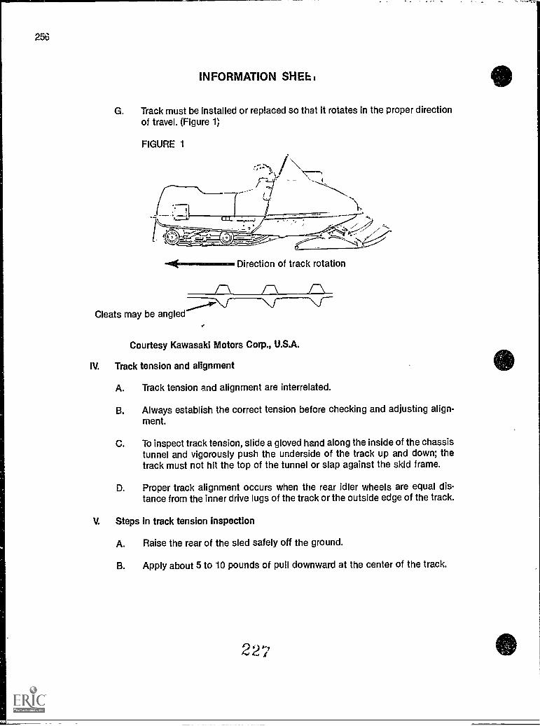
256
INFORMATION SHEET
G. Track must be installed or replaced so that it rotates in the proper directionof travel. (Figure 1)
FIGURE 1
-44,-----,. Direction of track rotation
Cleats may be angled
1-\ /-"\ ________
..
Courtesy Kawasaki Motors Corp., U.S.A.
IV. Track tension and alignment
A. Track tension and alignment are interrelated.
B. Always establish the correct tension before checking and adjusting align-ment.
C. To inspect track tension, slide a gloved hand along the inside of the chassistunnel and vigorously push the underside of the track up and down; thetrack must not hit the top of the tunnel or slap against the skid frame.
D. Proper track alignment occurs when the rear idler wheels are equal dis-tance from the inner drive lugs of the track or the outside edge of the track.
V. Steps in track tension inspection
A. Raise the rear of the sled safely off the ground.
B. Apply about 5 to 10 pounds of pull downward at the center of the track.
22'
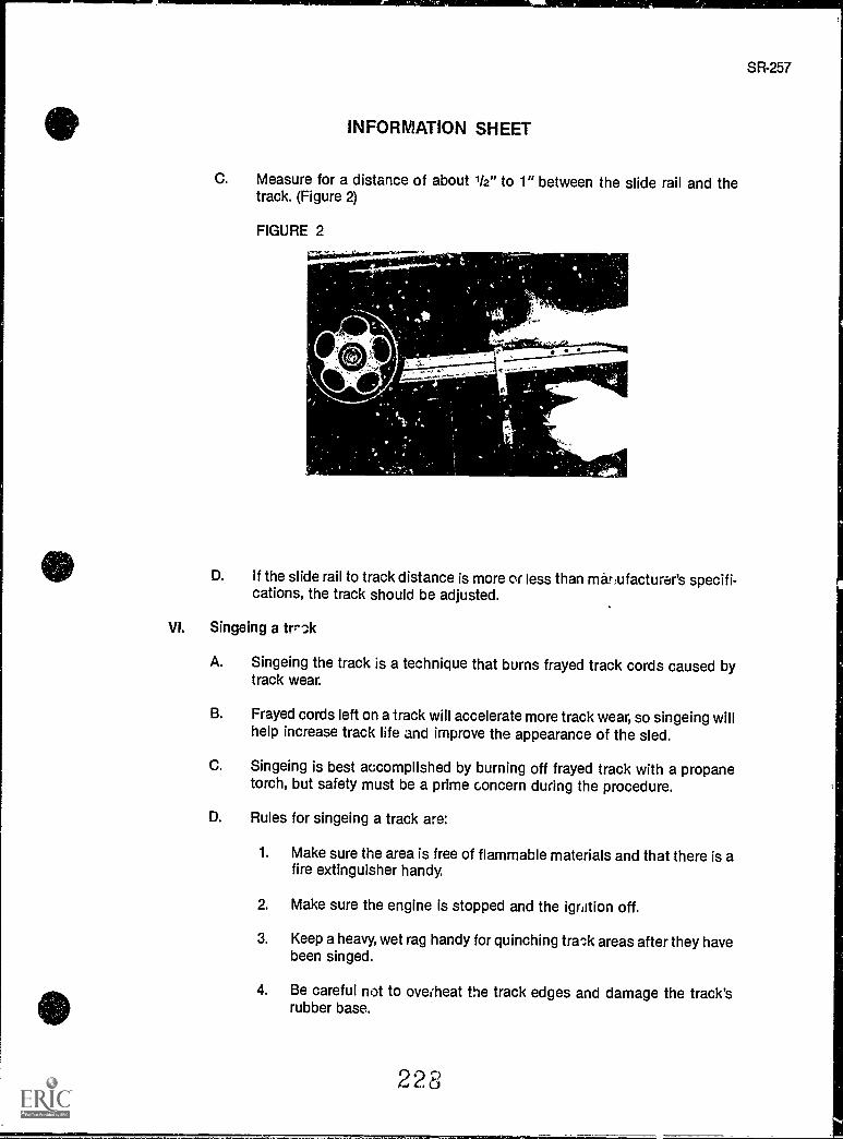
INFORMATION SHEET
C. Measure for a distance of about 1/2" to 1" between the slide rail and thetrack. (Figure 2)
FIGURE 2
D. If the slide rail to track distance is more or less than manufacturer's specifi-cations, the track should be adjusted.
VI. Singeing a trr-.1k
A. Singeing the track is a technique that burns frayed track cords caused bytrack wear.
B. Frayed cords left on a track will accelerate more track wear, so singeing willhelp increase track life and improve the appearance of the sled.
C. Singeing is best accomplished by burning off frayed track with a propanetorch, but safety must be a prime concern during the procedure.
D. Rules for singeing a track are:
1. Make sure the area is free of flammable materials and that there isafire extinguisher handy.
2. Make sure the engine is stopped and the ignition off.
3. Keep a heavy, wet rag handy for quinching tra?,k areas after they havebeen singed.
4. Be careful not to overheat the track edges and damage the track'srubber base.
228
SR-257
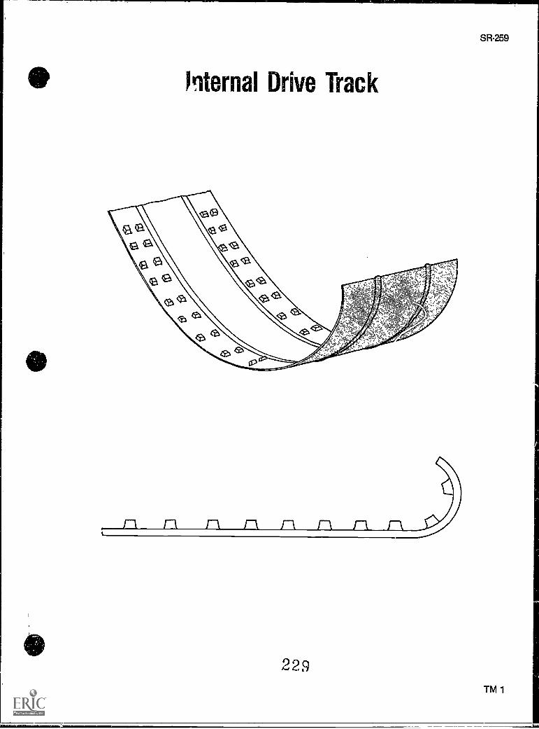
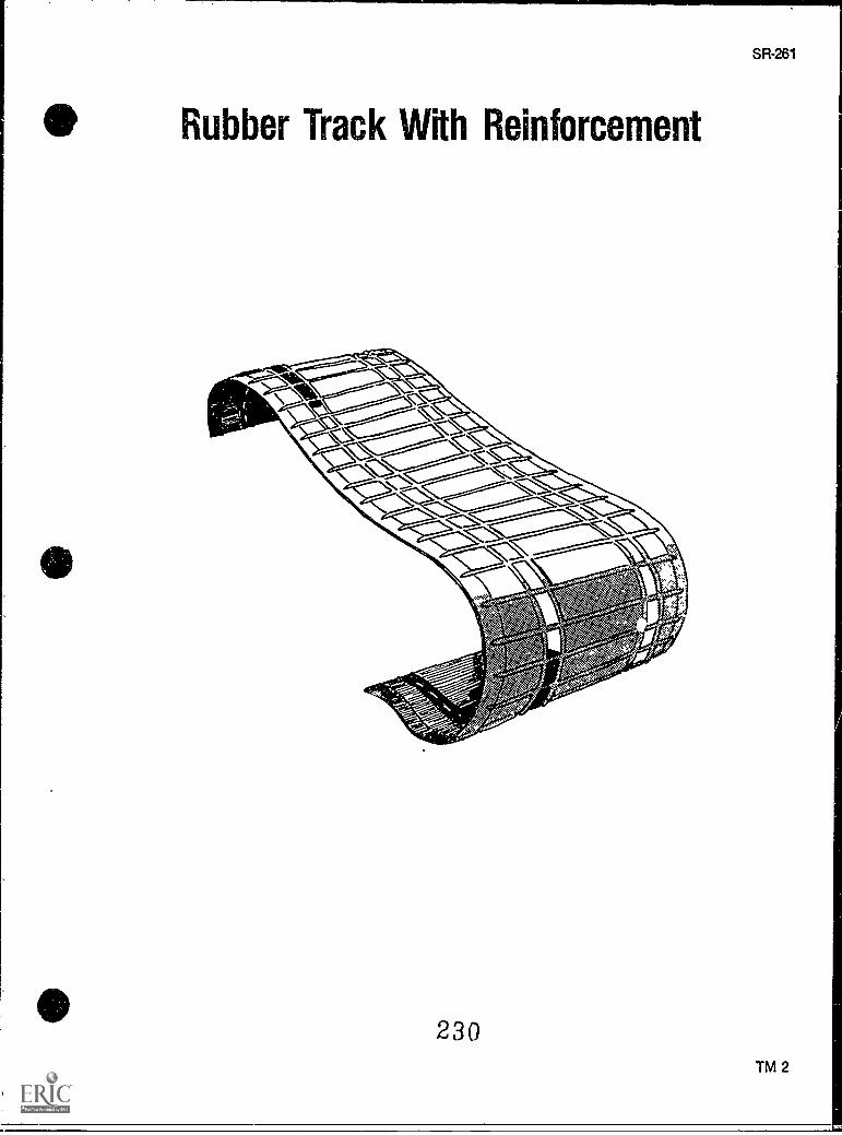
abet
lock
ikekiliotteraeut
Sfk-20
230
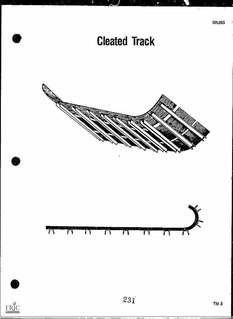
SR-263
Cleated Track
TRACKSUNIT IX
ASSIGNMENT SHEET #1 - SOLVE PROBLEMS RELATED TOTRACK MAINTENANCE
Directions: Read the following problems carefully and respond as directed.
A. Describe briefly what track alignment is and its importance to the functionof the track.
B. What safety precautions must always be taken when checking for alignment of thetrack?
C. What is singeing, and why should a track be singed?
D. What safety precautions must be taken when singeing the track?
232
SR265
TRACKSUNIT IX
ANSWERS TO ASSIGNMENT SHEET
A. Track alignment is when the rear idler wheels are equal distance from the inner drivelugs or the outside edge of the track. Alignment provides for the axle sprockets to insertinto the guide clips smoothly so that the efficient transfer of power from the drive sys-tem is transmitted to the track.
B. Always inspect the track for particles of dirt or rocks which might be thrown from thetrack when it is rotating. Always use safe procedures and always see that the tips of theskis are positioned against a wall. Never allow anyone to stand in front or behind thetrack while it is revolving.
C. Singeing burns frayed cords off a track. Singeing promotes track life and makes a sledlook better.
D. Always keep a wet, heavy rag available to douse any fires on the track. Always checkthe snowmobile and the area around the snowmobile for any flammable materials.Always keep the engine stopped and ignition off.
233
SR-267
I
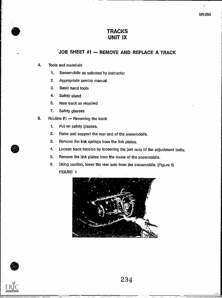
TRACKSUNIT IX
JOB SHEET #1 - REMOVE AND REPLACE A TRACK
A. Tools and materials
1. Snowmobile as selected by instructor
2. Appropriate service manual
3. Basic hand tools
4. Safety stand
5. New track as required
7. Safety glasses
B. Routine #1 Removing the track
1. Put on safety glasses.
2. Raise and support the rear end of the snowmobile.
3. Remove the link springs from the link plates.
4. Loosen track tension by loosening the jam nuts of the adjustment bolts.
5. Remove the link plates from the frame of the snowmobile.
6. Using caution, lower the rear axle from the snowmobile. (Figure 1)
FIGURE 1
234
SR-269
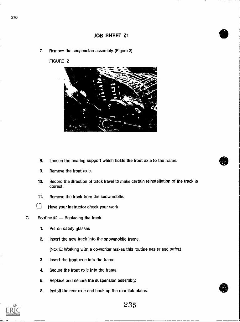
270
JOB SHEET 01
7. Remove the suspension assembly. (Figure 2)
FIGURE 2
- -.77; _7
- 'VACS
8. Loosen the bearing support which holds the front axle to the frame.
9. Remove the front axle.
10. Record the direction of track travel to make certain reinstallation of the track iscorrect.
11. Remove the track from the snowmobile.
Have your instructor check your work
C. Routine #2 Replacing the track
1. Put on safety glasses
2. Insert the new track into the snowmobile frame.
(NOTE: Working with a co-worker makes this routine easier and safer.)
3. Insert the front axle into the frame.
4. Secure the front axle into the frame.
5. Replace and secure the suspension assembly.
6. Install the rear axle and hook up the rear link plates.
2.'5
SR-271
JOB SHEET #1
7. Install all seals to the front and rear axles.
8. Tighten the track tension and check for alignment. (Refer to Job Sheet #2.)
Have your instructor check your work.
9. Clean up area and return tools and materials to proper storage.
236
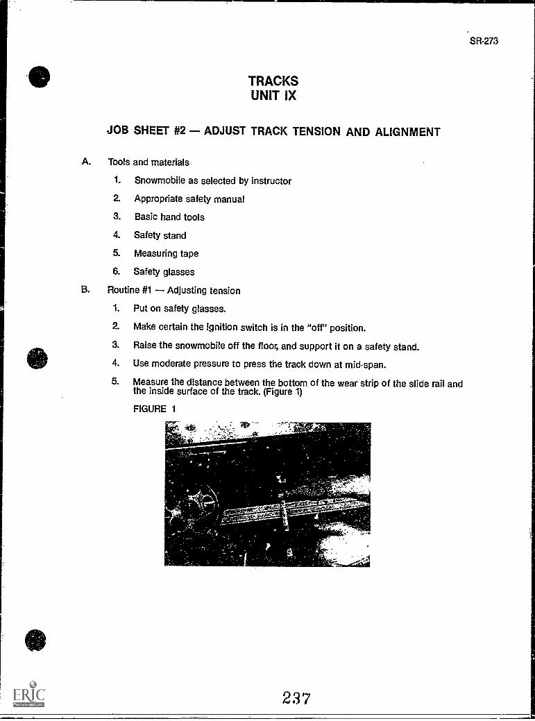
TRACKSUNIT IX
JOB SHEET #2 - ADJUST TRACK TENSION AND ALIGNMENT
A. Tools and materials
1. Snowmobile as selected by instructor
2. Appropriate safety manual
3. Basic hand tools
4. Safety stand
5. Measuring tape
6. Safety glasses
B. Routine #1 Adjusting tension
1. Put on safety glasses.
2. Make certain the ignition switch is in the "off" position.
3. Raise the snowmobile off the floor, and support it on a safety stand.
4. Use moderate pressure to press the track down at mid-span.
5. Measure the distance between the bottom of the wear strip of the slide rail andthe inside surface of the track. (Figure 1)
FIGURE 1
,..., ..,e.
237
,..
SR-273
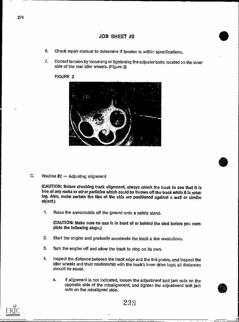
274
JOB SHEET #2
6. Check repair manual to determine if tension is within specifications.
7. Correct tension by loosening or tightening the adjuster bolts located on the innerside of the rear idler wheels. (Figure 2)
FIGURE 2
C. Routine #2 Adjusting alignment
(CAUTION: Before checking track alignment, always check the track to see that it isfree of any rocks or other particles which could be thrown off the track while it is rotat-ing. Also, make certain the tips of the skis are positioned against a wall or similarobject.)
1. Raise the snowmobile off the ground onto a safety stand.
(CAUTION: Make sure no one Is in front of or behind the sled before you com-plete the following steps.)
2. Start the engine and gradually accelerate the track a few revolutions.
3. Turn the engine off and allow the track to stop on its own.
4. Inspect the distance between the track edge and the link plates, and inspect theidler wheels and their relationship with the track's inner drive lugs; all distancesshould be equal.
a. If alignment is not indicated, loosen the adjustment bolt jam nuts on theopposite side of the misalignment, and tighten the adjustment bolt jamnuts on the misaligned side.
Q c-)..,,,
41
SR-275
JOB SHEET #2
b. Again, start engine and rotate the track a few times, then stop the engineand allow it to stop without braking.
c. If alignment is correct, then check the track tension again, making tensionadjustment if necessary, tighten adjuster bolt jam nuts.
Have your instructor check your work.
5. Clean up area and return tools and materials to proper storage.
(NOTE: On a properly tensioned track, the track should be able to be rotated by hand. Ifthe track can not be moved by hand, the tension is too tight or other drive componentsare not functioning properly.)
239
TRACKSUNIT IX
JOB SHEET #3 - SINGE A TRACK
A. Tools and materials
1. Snowmobile as selected by instructor
2. Basic hand tools
3. Small propane torch and lighter
4. Safety stand
5. Heavy wet rag
6. Safety glasses
B. Procedure
1. Put on safety glasses.
2. Support the snowmobile by placing it on the safety stand.
3. Make certain the engine is not running, ignition is off, and that there are no flam-mable substances on the snowmobile or in the area.
4. Light the torch.
5. Burn frayed edges off, and be sure to keep the flame moving as much as possibleto avoid damaging the rubber base of the track.
6. Use the wet rag to put out any track fires.
7. Make certain both sides of the track are singed as needed.
8. Reinspect for overlooked frayed edges.
Have your instructor check your work.
9. Clean up area and return tools and materials to proper storage.
240
SR-277
SR-279
TRACKSUNIT IX
JOB SHEET #4 REPLACE TRACK GUIDE CLIPS
A. Tools and materials
1. Snowmobile as selected by instructor
2. Appropriate service manual
3. Track guide clips (or inserts)
4. Track insert tool (if applicable)
5. Two medium-size hammers
6. Adjustable locking pliers (vise grip)
7. Basic hand tools
8. Drill and steel bit
9. Safety glasses
B. Procedure
1. Put on safety glasses.
2. Loosen the track tension on the snowmobile.
3. Tilt the snowmobile on its side, placing it on a piece of cardboard to protect itfrom scratches or scuffing.
4. Locate all guide clips or inserts that are severely worn and note if any are miss-ing.
5. Remove worn clips by drilling a series of indentations across each clip orgrinding an indentation with a die grinder, and splitting the clips open with ahammer and chisel.
(NOTE: There is no need to drill all the way through the clip: short holes will besufficient to cause the clips to split.)
6. Compress new clips onto the track with the manufacture's special installationtool.
(NOTE: Installation of new clips without the use of the manufacturers recommendedtool is not advised, as proper installation can not be achieved without it.
7. Rotate the track until all worn or missing clips have been replaced.
(NOTE: If there is inadequate clearance to perform the above procedure with thesuspension in place, the suspension should be removed.)
241

280
J08 SHEET #4
Have your instructor check your work.
8. Readjust tension and align the track as previously outlined.9. Clean up area and return tools and equipment to proper storage.
242
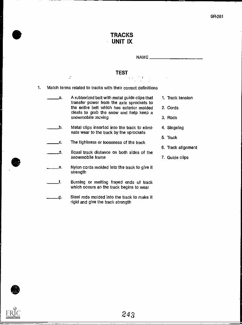
TRACKSUNIT IX.
NAME
TEST
1. Match terms related to tracks with their correct definitions
a. A rubberized belt with metal guide clips thattransfer power from the axle sprockets tothe entire belt which has exterior moldedcleats to grab the snow and help keep asnowmobile moving
b Metal clips inserted into the track to elimi-nate wear to the track by the sprockets
c The tightness or looseness of the track
d Equal track distance on both sides of thesnowmobile frame
e Nylon cords molded into the track to give itstrength
f. Burning or melting frayed ends of trackwhich occurs as the track begins to wear
g Steel rods molded into the track to make itrigid and give the track strength
243
1. Track tension
2. Cords
3. Rods
4. Singeing
5. Track
6. Track alignment
7. Guide clips
SR-281
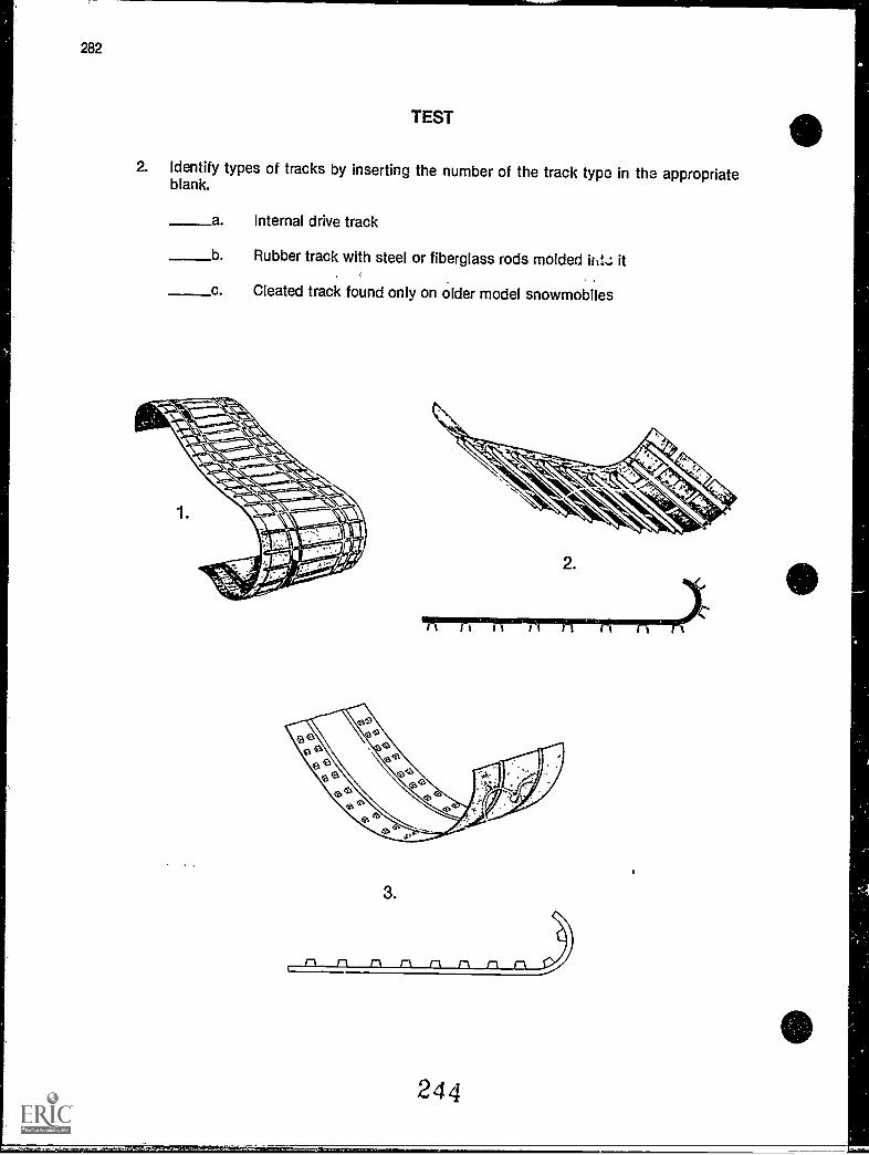
282
TEST
2. Identify types of tracks by inserting the number of the track type in the appropriateblank.
a Internal drive track
____b Rubber track with steel or fiberglass rods molded ihts; it
c. Cleated track found only on older model snowmobiles
2.
/A rt 11 nn n n r
3.
)
SR-283
3. Select true statements concerning causes of track failure by placing an "X" in front ofeach true statement.
a. The track not being aligned for a isng period of time is a common cause oftrack failure.
Cuts caused by running over sharp objects are the least frequent cause oftrack failure.
c. Broken cleats, on older models, if not repaired, can damage the track.
d. Worn sprockets on the axle can damage the track.
e. Normal wear will eventually require track replacement.
f. Tension on the track must be correct or abnormal wear can occur.
g. Track may be installed so that it rotates in either direction.
4. Complete statements concerning track tension and alignment by circling the word(s)that best completes each statement.
a. Track tension and alignment (are, are not) interrelated.
b. Always establish the correct tension (before, after) checking and adjusting align-ment.
c. To inspect track tension, slide a gloved hand along the inside of the chassis tun-nel and vigorously push the underside of the track up and down; the track (must,must not) hit the top of the tunnel or slap against the skid frame.
d. Proper track alignment occurs when the rear idler wheels are equal distancefrom the inner drive lugs of the track or the (outside, inside) edge of the track.
5. Arrange in order the steps in track tensio,i Inspection by placing the correct sequencenumber in the appropriate blank.
a. Measure for a distance of about 1/2" to 1" between the slide rail and thetrack.
b Apply about 5 to 10 pounds of pull downward at the center of the track.
c. If the slide rail to track distance is more or less than manufacturer's speci-fication, the track should be adjusted.
d. Raise the rear of the sled safely off the ground.
245
284
TEST
6. Complete statements concerning singeing a track by inserting the word(s) that bestcompletes each statement.
a. Singeing the track is a technique that frayed track cords causedby track wear.
b. Frayed cords left on a track will accelerate more track wear, so singeing will helptrack life and improve the appearance of the sled.
c. Singeing Is best accomplished by burning off frayed track with a propane torch,but must be a prime concern during the procedure.
d. Rules for singeing a track are:
1) Make sure the area Is free of flammable materials and that there Is ahandy.
2) Make sure the engine is stopped and the ignition
3) Keep a heavy, wet rag for track areas after they havebeen singed.
4) Be careful not to overheat the track edges and damage the trackbase.
(NOTE: If the following activities have not been rccomplished prior to the test, ask yourinstructor when they should be com,,leted.)
7. Solve problems related to track maintenance. (Assignment Sheet #1)
8. Demonstrate the ability to:
a Remove and replace a track. (Job Sheet #1)
b. Adjust track tension and alignment. (Job Sheet #2)
c. Singe a track. (Job Sheet #3)
d. Replace track guide clips. (Job Sheet #4)
246
TRACKSUNIT IX
ANSWERS TO TEST
1. a. 5 e. 2b. 7 f. 4c. 1 g. 3d. 6
2. a. 3
b. 1
c. 2
3. a, c, d, e, f
4. a. Areb. Beforec. Must notd. Outside
5. a. 3b. 2c. 4d. 1
6. a. Burnsb. Increasec. Safetyd. 1) Fire extinguisher
2) Off3) Quinching4) Rubber
7. Evaluated to the satisfaction of the instructor
8. Performance skills evaluated according to procedures written in the job sheets
247
SR-285
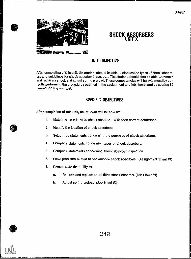
SR-287
tivisers
SHOCK ABSORBERSUNIT X
UNIT OBJECTIVE
After completion of this unit, the student should be able to discuss the types of shock absorb-ers and guidelines for shock absorber inspection. The student should also be able to removeand replace a shock and adjust spring preload. These competencies will be evidenced by cor-rectly performing the procedures outlined in the assignment and job sheets and by scoring 85percent on the unit test.
SPECIFIC OBJECTIVES
After completion of this unit, the student will be able to:
1. Match terms related to shock absorbe- with their correct definitions.
2. Identify the location of shock absorbers.
3. Select true statements concerning the purposes of shock absorbers.
4. Complete statements concerning types of shock absorbers.
5. Complete statements concerning shock absorber inspection.
6. Solve problems related to snowmobile shock absorbers. (Assignment Sheet #1)
7. Demonstrate the ability to:
a. Remove and replace an oil-filled shock absorber. (Job Sheet #1)
b. Adjust spring preload. (Job Sheet #2)
248
SR-289
SHOCK ABSORBERSUNIT X
SUGGESTED ACTIVITIES
A. Provide students with objective sheet.
B. Provide students with information sheet.
C. Make transparencies.
D. Discuss unit and specific objectives.
E. Discuss information sheet.
E Demonstrate and discuss the procedures outlined in the job sheets.
G. Visit a local Yamaha dealership to inspect the struts on the front suspension of Yamahasnowmobiles.
H. Discuss nitrogen-filled shocks and special safety requirements for their replacement.
I. Give test.
CONTENTS OF TIES UNIT
A. Objective sheet
B. Information sheet
C. Transparency masters
1. TM 1 Front Shock Absorbers
2. TM 2 Rear Shock Absorbers
D. Assignment Sheet #1 So!ve Problems Related to Snowmobile Shock Absorbers
E. Answers to assignment sheet
F. Job sheets
1. Job Sheet #1 Remove and Replace a Shock Absorber
2. Job Sheet #2 Adjust Spring Preload
G. Test
H. Answers to test
249
290
REFERENCES USED IN DEVELOPING THIS UNIT
A. Snowmobile Repair. Stil Meter, OK 74074: Mid-America Vocational Curriculum Consor-tium, 1976.
B. 1986 Yamaha Snowmobile Mechanics Guide. Cypress, CA: Yamaha Motor Corporation,U.S.A., 1985.
C. Arctic 0,at Service Manual No. 2254-302. Thief River Falls, MN 56701: ARCTCO, Inc.,1984.
D. Kawasaki Drifter Snowmobile Shop Manual. Santa Ana, CA 92799-5252: KawasakiMotors Corp., U.S.A., 1980.
E. Kawasaki Parts Catalog 5B340 -A2, SB440-A5. Santa Ana, CA 92799-5252: KawasakiMotors Corp., U.S.A., 1980.
250
)
SHOCK ABSORBERSUNIT X
INFORMATION SHEET
I. Terms and definitions
A. Shock absorber A component of a snowmobile suspension systemdesigned to absorb the impact from bumps and to help stabilize the movingchassis
B. Oil-filled shock absorber A shock absorber which uses oil and a valvesystem to dampen shock absorber piston movement and absorb shock
C. Gas-filled shock absorber A shock absorber which uses nitrogen gasand a valve system to dampen piston movement and absorb shock
D. Strut A large cylinder mechanism which serves as an entire suspensionassembly to support the snowmobile chassis and absorb shocks
E. Preload The amount of tension built into a shock alxnrber which estab-lishes the compression and rebound characteristics
F. Compression The amount of pressure exerted on a shock as it absorbsthe force of impact
G. Rebound The amount of pressure the shock absorber gives back as thevalve inside the shock reacts to compression
H. Dual-acting valving A shock absorber which has a valve action t..) acceptcompression and return rebound pressure
II. Location of shock absorbers
A. Front shock absorbers are part of the front suspension system and areattached to the ski skeg and to the ski. (Transparency 1)
B. The front suspension may be a strut-type suspension system.
C. Rear shock absorbers are part of the rear suspension system which sup-ports the entire chassis and are usually attached to cross shafts of theslide rail suspension system. (Transparency 2)
III. Purposes of shock absorbers
A. Rear shock absorbers stiffen the ride within a slide rail suspension system.
B. Front shock absorbers apply down pressure to the ski for better steeringcontrol.
251
SR-291
292
INFORMATION SHEET
C. All shock absorbers serve to protect the operator and the chassis byabsorbing impact energy which may be strong enough to damage compo-nents of the snowmobile.
IV. Types of shock absorbers
A. Most snowmobiles use non-adjustable, oil-filled shock absorbers in whichpreload is already set.
B. Some snowmobiles which operate on a variety of surface conditions useadjustable oil-filled shock absorbers in which the preload can be set by theoperator to contend with changing riding conditions.
C. As part of the rear suspension, some high performance snowmobiles usegas-filled shock absorbers which withstand greater stress and shock.
D. Yamaha first introduced the front strut suspension, and many of theirmodels use the strut as the shock absorbing mechanism.
V. Shock absorber inspection
A. Since shock absorbers require no maintenance, they do require inspectionfrom time to time to see if they need to be replaced.
B. Anytime regular maintenance is performed on a sled, the shocks should beinspected.
0. If the chassis feels springy when it is bounced up and down, the shockabsorbers probably need to be replaced.
D. When there is evidence that oil is leaking from a shock absorber, it shouldbe replaced.
E. Shock mounting bushings should be checked for wear and replaced asrequired.
F. Shock absorbers filled with nitroger gas sometimes have to have holesdrilled in them to release pressure, and require special handling.
(CAUTION: Nitrogen filled shocks do have a potential to explode.)
1. Always wear safety glasses when drilling on nitrogen-filled shocks.
2. Put a shop towel close to the drill to catch bits of steel that might beblown out by escaping gas.
252
i
1
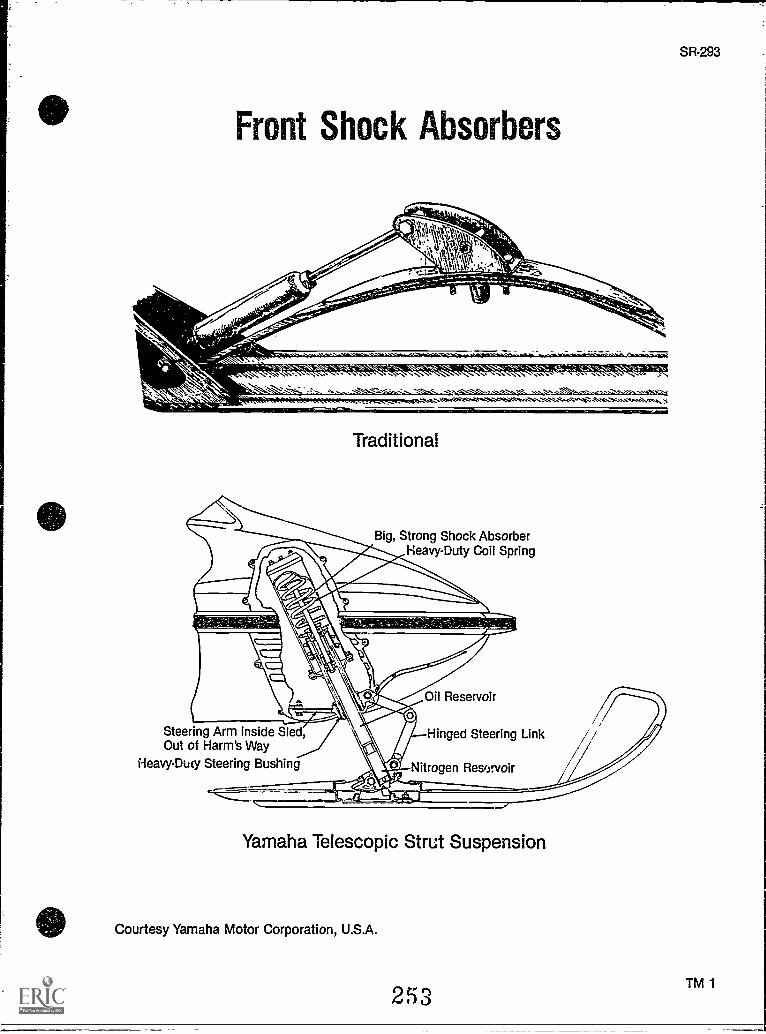
Front Shock Absorbers
,-- M' ?.
Traditional
Big, Strong Shock AbsorberHeavy-Duty Coil Spring
Steering Arm Inside Sled,Out of Harm's Way
Heavy-Duty Steering Bushing
Oil Reservoir
Hinged Steering Link
Nitrogen Reservoir
Yamaha Telescopic Strut Suspension
Courtesy Yamaha Motor Corporation, U.S.A.
253
1
SR-293
TM 1
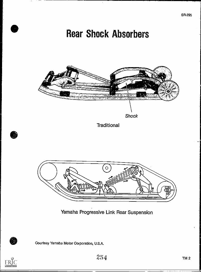
Rear Shock Absorbers
Traditional
Yamaha Progressive Link Rear Suspension
Courtesy Yamaha Motor Corporation, U.S.A.
254
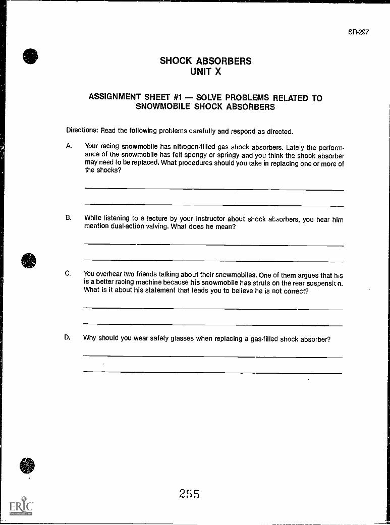
SHOCK ABSORBERSUNIT X
ASSIGNMENT SHEET #1 - SOLVE PROBLEMS RELATED TOSNOWMOBILE SHOCK ABSORBERS
Directions: Read the following problems carefully and respond as directed.
A. Your racing snowmobile has nitrogen-filled gas shock absorbers. Lately the perform-ance of the snowmobile has felt spongy or springy and you think the shock absorbermay need to be replaced. What procedures shoUld you take in replacing one or more ofthe shocks?
B. While listening to a lecture by your instructor about shock absorbers, you hear himmention dual-action valving. What does he mean?
C. You overhear two friends talking about their snowmobiles. One of them argues that hisis a better racing machine because his snowmobile has struts on the rear suspension.What is it about his statement that leads you to believe he is not correct?
D. Why should you wear safety glasses when replacing a gas-filled shock absorber?
255
SR-297
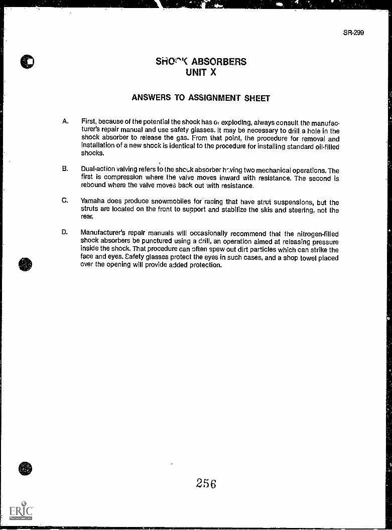
SR-299
SitiOe"( ABSORBERSUNIT X
ANSWERS TO ASSIGNMENT SHEET
A. First, because of the potential the shock has of exploding, always consult the manufac-turer's repair manual and use safety glasses. It may be necessary to drill a hole in theshock absorber to release the gas. From that point, the procedure for removal andinstallation of a new shock is identical to the procedure for installing standard oil-filledshocks.
B. Dual-action valving refers to the shcuk absorber h-..ving two mechanical operations. Thefirst is compression where the valve moves inward with resistance. The second isrebound where the valve moves back out with resistance.
C. Yamaha does produce snowmobiles for racing that have strut suspensions, but thestruts are located on the front to support and stabilize the skis and steering, not therear.
D. Manufacturer's repair manuals will occasionally recommend that the nitrogen-filledshock absorbers be punctured using a drill, an operation aimed at releasing pressureinside the shock. That procedure can often spew out dirt particles which can strike theface and eyes. Safety glasses protect the eyes in such cases, and a shop towel placedover the opening will provide added protection.
256
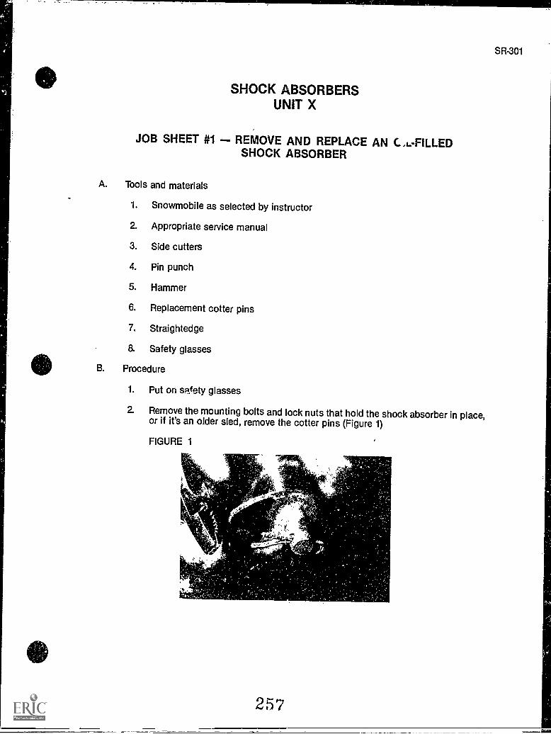
SHOCK ABSORBERSUNIT X
JOB SHEET #1 - REMOVE AND REPLACE AN C.L.-FILLEDSHOCK ABSORBER
A. Tools and materials
1. Snowmobile as selected by instructor
2. Appropriate service manual
3. Side cutters
4. Pin punch
5. Hammer
6. Replacement cotter pins
7, Straightedge
8. Safety glasses
B. Procedure
1. Put on safety glasses
2. Remove the mounting bolts and lock nuts that hold the shock absorber in place,or if it's an older sled, remove the cotter pins (Figure 1)
FIGURE 1
.,.
257
SR-301
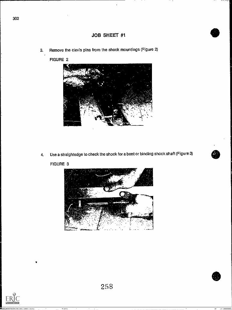
302
JOB SHEET #1
3. Remove the clevis pins from the shock mountings (Figure 2)
FIGURE 2
4. Use a straightedge to check the shock for a bent or binding shock shaft (Figure 3)
FIGURE 3
28
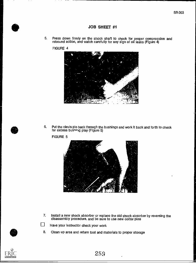
JOB SHEET #1
5. Press down firmly on the shock shaft to check for proper compression andrebound action, and watch carefully for any sign of oil leaks (Figure 4)
FIGURE 4
SR-303
6. Put the clevis pin back through the bushings and work It back and forth to checkfor excess bushing play (Figure 5)
FIGURE 5
,
7. Install a new shock absorber or replace the old shock absorber by reversing thedisassembly procedure, and be sure to use new cotter pins
Have your instructor check your work
8. Clean up area and return tool and materials to proper storage
259
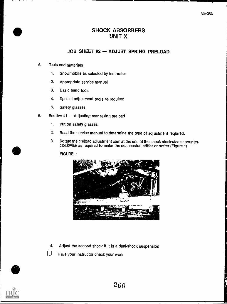
-11MMIIMMIII=1
SR-305
SHOCK ABSORBERSUNIT X
JOB SHEET #2 - ADJUST SPRING PRELOAD
A. Tools and materials
1. Snowmobile as selected by instructor
2. Appropriate service manual
3. Basic hand tools
4. Special adjustment tools as required
5. Safety glasses
B. Routine #1 Adjusting rear sping preload
1. Put on safety glasses.
2. Read the service manual to determine the type of adjustment required.
3. Rotate the preload adjustment cam at the end of the shock clockwise or counter-clockwise as required to make the suspension stiffer or softer (Figure 1)
FIGURE 1
4. Adjust the second shock if it is a dual-shock suspension
Have your instructor check your work
260
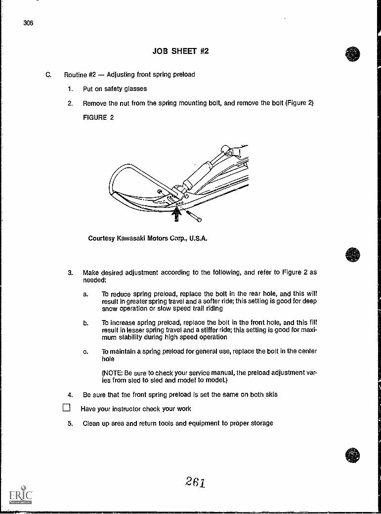
306
JOB SHEET #2
C. Routine #2 Adjusting front spring preload
1. Put on safety glasses
2. Remove the nut from the spring mounting bolt, and remove the bolt (Figure 2)
FIGURE 2
Courtesy Kawasaki Motors Corp., U.S.A.
3. Make desired adjustment according to the following, and refer to Figure 2 asneeded:
a. To reduce spring preload, replace the bolt in the rear hole, and this willresult in greater spring travel and a softer ride; this setting is good for deepsnow operation or slow speed trail riding
b. To increase spring preload, replace the bolt in the front hole, and this fillresult in lesser spring travel and a stiffer ride; this setting is good for maxi-mum stability during high speed operation
c. To maintain a spring preload for general use, replace the bolt in the centerhole
(NOTE: Be sure to check your service manual, the preload adjustment var-ies from sled to sled and model to model.)
4. Be sure that the front spring preload is set the same on both skis
Have your instructor check your work
5. Clean up area and return tools and equipment to proper storage
261
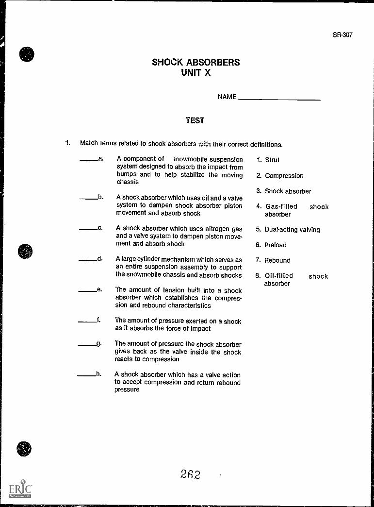
SR-307
SHOCK ABSORBERSUNIT X
NAME
TEST
1. Match terms related to shock absorbers with their correct definitions.
a A component of >nowmobile suspension 1. Strutsystem designed to absorb the impact frombumps and to help stabilize the moving 2. Compressionchassis
3. Shock absorberb A shock absorber which uses oil and a valve
system to dampen shock absorber piston 4. Gas-filled shockmovement and absorb shock absorber
c A shock absorber which uses nitrogen gas 5. Dual-acting valvingand a valve system to dampen piston move-ment and absorb shock 6. Preload
d A large cylinder mechanism which serves as 7. Reboundan entire suspension assembly to supportthe snowmobile chassis and absorb shocks 8. Oil-filled shock
absorbere The amount of tension built into a shock
absorber which establishes the compres-sion and rebound characteristics
f. The amount of pressure exerted on a shockas it absorbs the force of impact
_____g The amount of pressure the shock absorbergives back as the valve inside the shockreacts to compression
h A shock absorber which has a valve actionto accept compression and return reboundpressure
262
308
TEST
2. Complete statements concerning location of shock absorbers by inserting the word(s)that best completes each statement.
a. Front shock absorbers are part of the front suspension system and are attachedto the ski and to the ski.
b. The front suspension may be a suspension sys-tem.
c. Rear shock absorbers are part of the rear suspension system which supports theentire chassis and are usually attached to of theslide rail suspension system.
3. Select true statements concerning the purposes of shock absorbers by placing an "X"beside each statement that is true.
a Rear shock absorbers soften the ride within a slide rail suspension sys-tem.
b Front shock absorbers apply aown pressure to the ski for better steeringcontrol.
c All shock absorbers serve to protect the operator and the chassis byabsorbing impact energy which may be strong enough to damage compo-nents of the snowmobile.
4. Complete statements concerning the types of shock absorbers by inserting the word(s)that best completes each statement.
a. Most snowmobiles use non-adjustable, oil-filled shock absorbers in whichis already set.
b. Some snowmobiles which operate on a variety of surface conditions use adjustable shock absorbers in which the preload can be set by the opei-ator to contend with changing riding conditions.
c. As part of the suspension, some high performance snowmobilesuse gas-filled shock absorbers which withstand greater stress and shock.
d. first introduced the front strut suspension, and many of theirmodels use the strut as the shock absorbing mechanism.
5. Complete statements concerning shock absorber inspection by inserting the word(s)that best completes each statement.
a. Since shock absorbers require no maintenance, they do requirefrom time to time to see if they need to be replaced.
b. Anytime regular is performed on a sled, the shocks should beinspected.
2 G 3
TEST
c. If the chassis feels when it is bounced up and down, the shockabsorbers probably need to be replaced.
d. When there is evidence that is leaking from a shock absorber, itshould be replaced.
e. Shockas required.
should be checked for wear and replaced
f. Shock absorbers filled with nitrogen gas sometimes have to have holes drilled inthem to release pressure, and require special handling.
1 Always wear when drilling on nitrogen-filled shocks.
2) Put a shop towel close to the drill to catch bits of steel that might beblown out by gas.
(NOTE: If the following activities have not been completed prior to the test, ask your instructorwhen they should be completed.)
6. Solve problems related to snowmobile shock absorbers. (Assignment Sheet #1)
7. Demonstrate the ability to:
a. Remove and replace an oil-filled shock absorber. (Job Sheet #1)
b. Adjust spring preload. (Job Sheet #2)
2I 4
SR-309
SHOCK ABSORBERSUNIT X
ANSWERS TO TEST
1. a. 3 e.b. 8 f. 2c. 4 g. 7d. 1 h. 5
2. a Skegb. Struttypec. Cross shafts
3. b, c
4. a. Preloadb. Oil-filledc. Reard. Yamaha
5. a. Inspectionb. Maintenancec. Springyd. Oile. Mounting bushingsf. 1) Safety glasses
2) Escaping
6. Evaluated to the satisfaction of the instructor
7. Performance skills evaluated according to procedures written in the job sheets.
2H5
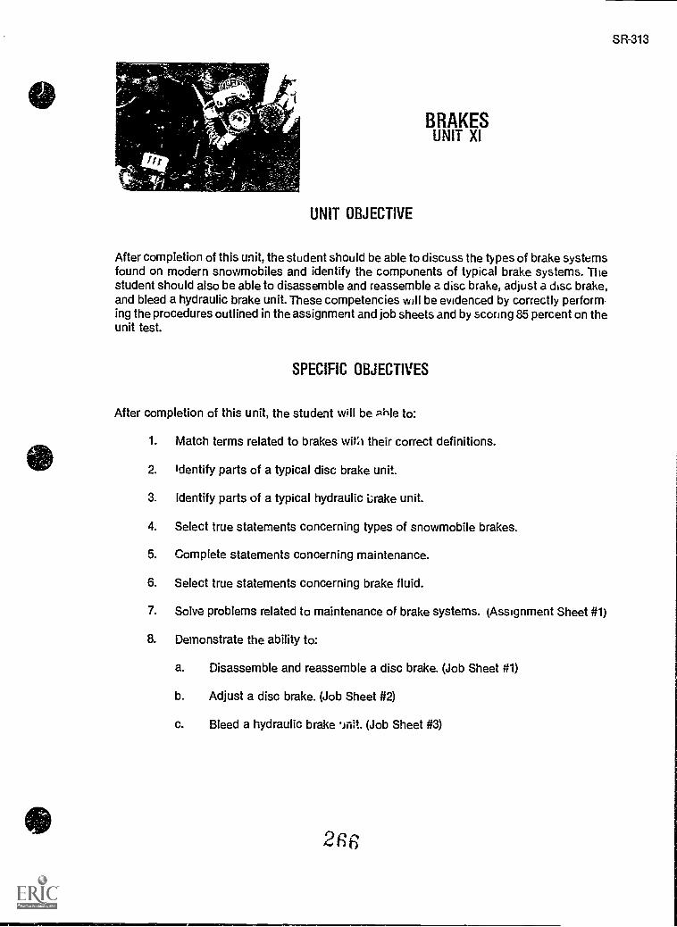
0
so
- bErTn%
Ks
I 1 r
1
UNIT OBJECTIVE
BRAKESUNIT XI
After completion of this unit, the student should be able to discuss the types of brake systemsfound on modern snowmobiles and identify the components of typical brake systems. Thestudent should also be able to disassemble and reassemble a disc brake, adjust a disc brake,and bleed a hydraulic brake unit. These competencies will be evidenced by correctly perform-ing the procedures outlined in the assignment and job sheets and by scoring 85 percent on theunit test.
SPECIFIC OBJECTIVES
After completion of this unit, the student will be Pile to:
1. Match terms related to brakes with their correct definitions.
2. Identify parts of a typical disc brake unit.
3. Identify parts of a typical hydraulic Lrake unit.
4. Select true statements concerning types of snowmobile brakes.
5. Complete statements concerning maintenance.
6. Select true statements concerning brake fluid.
7. Solve problems related to maintenance of brake systems. (Assignment Sheet #1)
8. Demonstrate the ability to:
a. Disassemble and reassemble a disc brake. (Job Sheet #1)
b. Adjust a disc brake. (Job Sheet #2)
c. Bleed a hydraulic brake 'init. (Job Sheet #3)
2R(
SR-313
SR-315
BRAKESUNIT XI
SUGGESTED ACTIVITIES
A. Provide students with objective sheet.
B. Provide students with information sheet.
C. Make transparencies.
D. Discuss unit and specific objectives.
E. Discuss information sheet.
F. Demonstrate and discuss the procedures outlined in the job sheets.
G. impress upon students the importance of selecting proper brake fluid and the equalimportance of handling brake fluid with care.
H. Give test.
CONTENTS OF THIS UNIT
A. Objective sheet
B. Information sheet
C. Transparency masters
1. TM 1 Manual Disc Brake
2. TM 2 Hydraulic Disc Brake
D. Assignment Sheet #1 Solve Problems Related 'x Maintenance of Brake Systems
E. Answers to assignment sheet
F. Job sheets
1. Job Sheet #1 Disassemble and Reassemble a Disc Brake
2. Job Sheet #2 Adjust a Disc Brake
3. Job Sheet #3 Bleed a Hydraulic Brake Unit
G. Test
H. Answers to test
2f7
316
REFERENCES USED IN DEVELOPING THIS UNIT
A. Snowmobile Repair. Stillwater, OK 74074: Mid-America Vocational Curriculum Consor-tium, 1976.
B. Chilton's Snowmobiles Repair & Tune-Up Guide, Second Edition. Radnor, PA: ChiltonBook Co., 1975.
C. 1980 Bombardier Snowmobiles Shop Manual. Valcourt, Quebec, Canada: Bombardier,Ltd. 1980.
D. 1978 Polaris Shop Manual. Roseau, MN: Polaris/Textron, 1978.
E. Arctic Cat Service Manual No. 2254-302. Thief River Falls, MN 56701: ARCTCO, Inc.1984.
E Kawasaki Drifter Snowmobile Shop Manual. Santa Ana, CA 92799-5252: KawasakiMotors Corp., U.S.A., 1980.
G. Kawasaki Parts Catalog SB340-A2, SB440-A5. Santa Ana, CA 92799-5252: KawasakiMotors Corp., U.S.A., 1980.
2R 3
BRAKESUNIT XI
INFORMATION SHEET
I. Terms and definitions
A. Disc brakes A brake system which uses. calipers, fiber pads, and a discto stop movement of the track
B. Hydraulic brakes A brake system which uses hydraulic fluid to applybraking force
C. Pad The friction material forged against the disc to produce braking fric-tion
D. Calipers In disc brake systems, an assembly which holds the pads andapplies mechanical or hydraulic pressure to the brake disc
E. Brake cable A cable which transfers braking action from a lever on thehandlebar to the brake
F. Cable housing The housing used to guide the brake cable so friction orsticking of the cable will be eliminated
G. Self-adjusting bra'ce caliper A ratcheting-type gear found on disc brakes;used to maintain proper clearance between the pad and the disc
H. Hydraulic calipers On hydraulic brake systems, the assembly whichhouses pads, hydraulic piston, and bleeder valve
I. Master cylinder Attached to the handlebars of a hydraulic brake system,and used as a reservoir for the brake fluid
J. Plunger On hydraulic brake systems, the mechanism which forceshydraulic fluid from the master cylinder through the hose to the calipers tosupply pressure to the pads
K. Hand lever On hydraulic brake systems, it is used to actuate the plunger,forcing fluid to the calipers
L. Bleeder valve A small outlet in the caliper used to release air trapped inthe system
M. Brake fluid Hydraulic fluid used to transfer pressure from the master cyl-inder to the calipers
269
SR-317
1
INFORMATION SHEET
II. Parts of a typical disc brake unit (Transparency 1)
A. Brake disc plate
B. Pads
C. Caliper
D. Plunger
E. Actuator lever
F. Brake support bracket
G. Cable and housing
III. Parts of a typical hydraulic brake unit (Transparency 2)
A. Fluid reservoir
B. Master cylinder
C. Master cylinder piston
D. Return spring
E. Hand lever
F. Brake support bracket
G. Brake disc plate
H. Caliper
I. Pads
J. Piston
K. Bleeder valve (screw)
IV. Types of snowmobile brakes
A. Manual disc brakes use discs attached directly or indirectly to the drivenclutch to stop movement of the track, and are manually adjusted. (Transpar-ency 1)
Self-adjusting cable-operated disc brakes are similar to the manual disc brakesexcept the system uses ratcheting-type gear to maintain proper clearancebetwaen the pad and the disc as the pad ,ears.
C. Hydraulic brake systems also use pads but the pads are activated by hydraulicpressure. The hydraulic pressure is developed by movement of the brake handlever which pressurizes hydraulic fluid in the master cylinder. The hydraulicpressure is transferred via the brake tubing to the caliper housing, causing thecaliper piston to move and the pads to contact the disk.
270
SR- 319
INFORMATION SHEET
V. Maintenance
A. The most common maintenance which must be performed on both discand hydraulic brake systems is brake adjustment, primarily adjusting thebrake cables and the pad to disc clearance.
B. On most disc brake systems, the brake should be fully applied when thebrake control lever on the handle bars is depressed about one-half inch.
C. Self- adjusting disc brakes use a ratchet mechanism to maintain proper padclearance. ----.(NOTE: The ratchet mechanism is activated by normal braking operation, andthe only other adjustment usually needed is cable tree play.)
D. A spongy action on the hand brake lever on hydraulic brakes may indicateair in the system which requires that the system be bled of all trapped air.
E. During routine maintenance inspections, the brake system should beinspected for worn brake pads which must be replaced if less than 1/8"remains (or as manufacturer specifies).
F. During disassembly of the brake system it should be a routine operation toclean all metal components using a general purpose solvent and a car'clean cloth.
G. When hydraulic brake fluid is not reaching the plunger mechanism to acti-vate the brakes, it may be caused by a malfunctioning master cylinder or anair lock, if the system has been recently drained.
H. Never allow oil, grease, or brake fluid to contaminate the pads.
VI. Brake fluid
A. Before putting brake fluid into a system, always check the service manualfor the type of fluid the system requires, and use only that fluid.
B. Brake fluid will damage a painted surface almost instantly, and painted sur-faces on a snowmobile should be protected with nonabsorbent coverings.
C. Old brake fluids should never be reused and should be disposed of in anapproved manner.
271
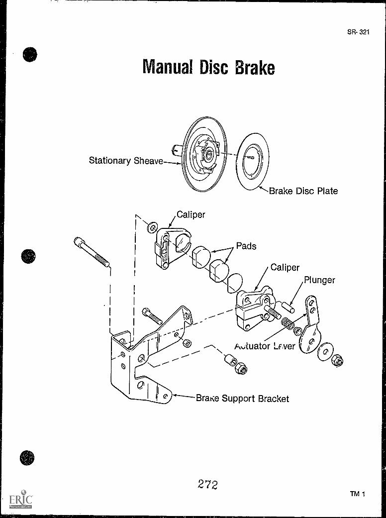
Manual Disc Brake
Stationary Sheave--..
Caliper
Pads
Brake Disc Plate
CaliperPlunger
ftwtuator LE,ver
Brake Support Bracket
272
SR- 321
TM 1
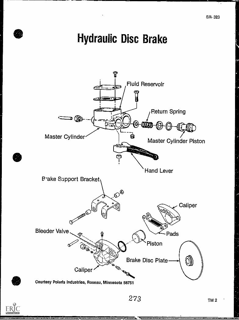
Hydraulic Disc Brake
IFluid Reservoir
Return Spring
Master CylinderMaster Cylinder Piston
Rake Support Bracket
Bleeder Valve
Brake Disc Plate
Courtesy Polaris industries, Roseau, Minnesota 56751
273
SR- 323
'TM 2
BRAKESUNIT XI
ASSIGNMENT SHEET #1 - SOLVE PROBLEMS RELATED TOMAINTENANCE OF BRAKE SYSTEMS
Directions: Read the following problems carefully and respond as directed.
A. A friend complains to you that there is too much play in the hand lever of a manua; discbrake unit. As you examine it and adjust the brakes you discover that the unit is alreadyadjusted. Consequently, what might you expect to be the problem?
B. Another friend who owns a snowmobile with a hydraulic disc brake system complainsto you that the hand lever feels "spongy." What would you suspect the trouble to be?
C. After inspecting a hydraulic brake system and bleeding it of air, the system functionswell momentarily, but then the brakes fail to grab with any pressure. What might theproblem be then?
D. In bleeding a hydraulic brake unit it is necessary that none of the fluid spill onto thesnowmobile. "shy?
274
SR- 325

SR- 327
BRAKESUNIT XI
ANSWERS TO ASSIGNMENT SHEET
A. If the brakes are adjusted and there is still too much play in the system, the problem isprobably that the disc brake pads are extensively worn and need to be replaced.
B. There is probably air in the hydraulic fluid and it will probably have to be bled out.
C. The brakes are probably not getting any or enough brake fluid because of low fluidlevel. It is possible that there may be a leak in the line or the master cylinder is malfunc-tioning and may need to be replaced.
D. The hydraulic brake fluid contains an element which will destroy paint.
27
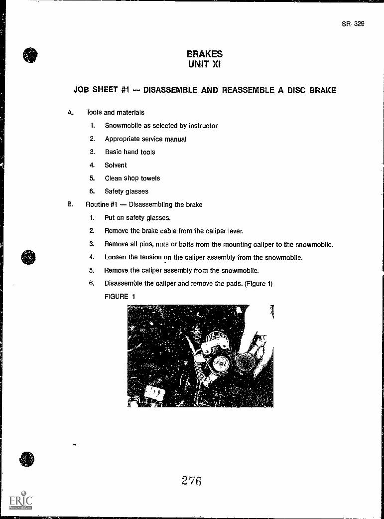
BRAKESUNIT XI
JOB SHEET #1 - DISASSEMBLE AND REASSEMBLE A DISC BRAKE
A. Tools and materials
1. Snowmobile as selected by instructor
2. Appropriate service manual
3. Basic hand tools
4. Solvent
5. Clean shop towels
6. Safety glasses
B. Routine #1 Disassembling the brake
1. Put on safety glasses.
2. Remove the brake cable from the caliper lever.
3. Remove all pins, nuts or bolts from the mounting caliper to the snowmobile.
4. Loosen the tension on the caliper assembly from the snowmobile.
5. Remove the caliper assembly from the snowmobile.
6. Disassemble the caliper and remove the pads. (Figure 1)
FIGURE 1
276
I1
SR- 329
330
JOB SHEET #1
7. Clean all metal parts with a general solvent and dry cloth, but keep solvent awayfrom pad surfaces.
8. Inspect all parts for wear.
9. Replace parts excessively worn or damaged.
(NOTE: Consult the service manual to determine if a part has excessive wear.)
C. Routine #2 Reassembling the brake
1. Reverse procedure for disassembly.
2. Apply low temperature grease on threads and spring seat.
3. Tighten all nuts and bolts according to torque specifications in service manual.
4. Adjust the brake (refer to Job Sheet #2).
Have your instructor check your work.
5. Clean up area and return tools and materials to proper storage.
277
SR- 331
BRAKESUNIT XI
JOB SHEET #2 - ADJUST A DISC BRAKE
A. Tools and materials
1. Snowmobile as selected by instructor
2. Appropriate service manual
3. Basic hand tools
4. Safety glasses
B. Procedure
1. Put on safety glasses.
2. Apply pressure to the brake lever.
(NOTE: If the handle moves freely for 112 to 3/4 of an inch without applying pres-sure to the disc brake, the brake must be adjusted.)
3. Make adjustment at the brake caliper assembly, if needed, by loosening theadjustor bolt jam nut and screwing the adjustor bolt in or out to obtain properpad to disc clearance.
(NOTE: Check manufacturer's specifications for clearance distance.)
4. Retighten the jam nut to proper torque specs.
5. Adjust brake. lever travel (cable free play) to manufacturer's specifications byloosening the jam nut(s) and turn the cable adjustor in or out as required.
6. Retighten the jam nut(s).
7. Compress the hand lever and double check clearances and proper operation.
8. Clean up area and return tools and materials to proper storage.
273
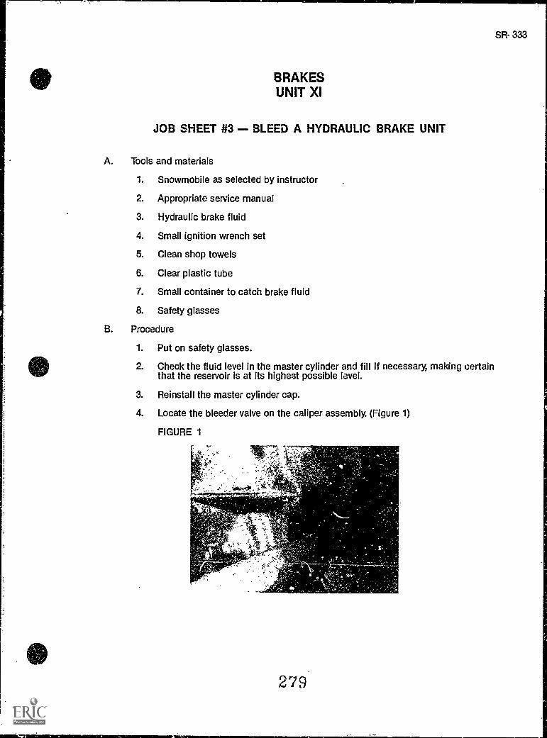
BRAKESUNIT XI
JOB SHEET #3 - BLEED A HYDRAULIC BRAKE UNIT
A. Tools and materials
1. Snowmobile as selected by instructor
2. Appropriate service manual
3. Hydraulic brake fluid
4. Small ignition wrench set
5. Clean shop towels
6. Clear plastic tube
7. Small container to catch brake fluid
8. Safety glasses
B. Procedure
1. Put on safety glasses.
2. Check the fluid level in the master cylinder and fill if necessary, making certainthat the reservoir is at its highest possible level.
3. Reinstall the master cylinder cap.
4. Locate the bleeder valve on the caliper assembly. (Figure 1)
FIGURE 1
,-.
279
SR- 333
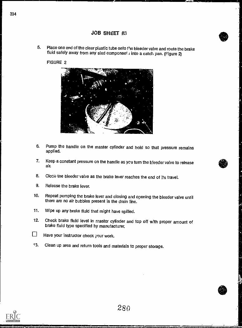
JOB SHEET MI
5. Place one end of the clear plastic tube onto the bleeder valve and route the brakefluid safely away from any sled componenic; into a catch pan. (Figure 2)
FIGURE 2
41111111kb..
6. Pump the handle on the master cylinder and hold so that pressure remainsapplied.
7. Keep a constant pressure on the handle as yeti turn the bleeder valve to releaseair.
8. Cloe:,a the bleeder valve as the brake lever reaches the end of its travel.
9. Release the brake lever.
10. Repeat pumping the brake lever and closing and opening the bleeder valve untilthere are no air bubbles present in the drain line.
11. Wipe up any brake fluid that might have spilled.
12. Check brake fluid level in master cylinder and top off w'th proper amount ofbrake fluid type specified by manufacturer.
Have your instructor check your work.
13. Clean up area and return tools and materials to proper storage.
280
BRAKESUNIT XI
NAME
TEST
1. Match terms related to brakes with their correct definitions.
a A brake system which uses calipers, fiberpads, and a disc to stop movement of thetrack
b A brake system which uses hydraulic fluidto apply braking force
c. The friction material forced against the discto produce braking friction
d In disc brake systems, an assembly whichholds the pads and applies mechanical orhydraulic pressure to the brake disc
e A cable which transfers braking action froma lever on the handlebar to the brake
f. The houzIng used to guide the brake cableso friction or sticking of the cable will beeliminated
9
h
A ratcheting-type gear found on disc brakes;used to maintain proper clearance betweenthe pad ano the dIsc
On hydraulic brake systems, the assemblywhich houses pads, hydraulic piston, andbleeder valve
__i. Attachcd to the handlebars of a hydraulicbrake system, and used as a reservoir to thebrake fluid
i On hydraulic brake systems, the mecha-nism which forces hydraulic fluid from themaster cylinder through the hose to the cali-pers to supply pressure to the pucks
k On hydraulic brake systems, it is used toactuate the plunger, forcing fluid to the cali-pers
281
....1...
1.
2.
3.
4.
5.
6.
7.
8.
9.
10.
11.
12.
Plunger
Pad
Brake fluid
Hydraulic calipers
Disc brakes
Bleeder valve
Hydraulic brakes
Hand lever
Calipers
Master cylinder
Brake cable
Self-adjustir.;) brakecaliper
13. Cable housing
SR-335
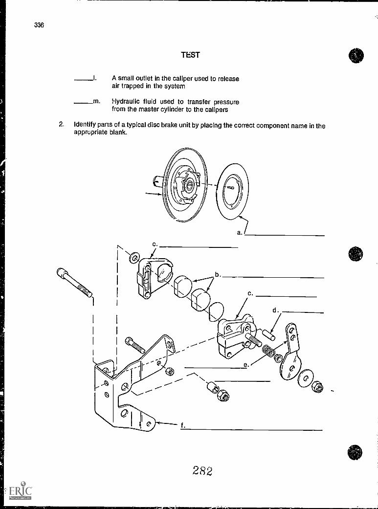
TEST
I. A small outlet in the caliper used to releaseair trapped in the system
m. Hydraulic fluid used to transfer pressurefrom the master cylinder to the calipers
.O.M11.71
2. Identify parts of a typical disc brake unit by placing the correct component name in theappropriate blank.
c.
282
aw_taz-asisimorms
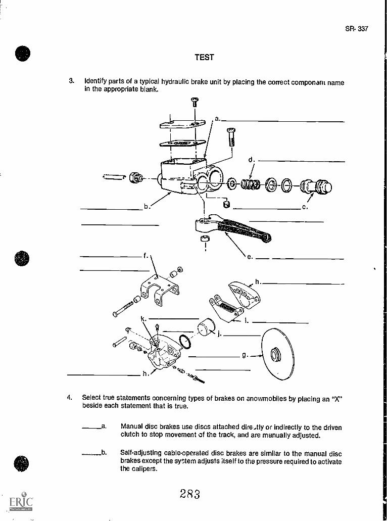
TEST
SR- 337
3. Identify parts of a typical hydraulic brake unit by placing the correct component namein the appropriate blank.
4. Select true statements concerning types of brakes on snowmobiles by placing an "X"beside each statement that is true.
a Manual disc brakes use discs attached dire,tly or indirectly to the drivenclutch to stop movement of the track, and are manually adjusted.
b Self-adjusting cable-operated disc brakes are similar to the manual discbrakes except the srtem adjusts itself to the pressure required to activatethe calipers.
2 R 3
338
TEST
c. Hydraulic brake systems also use discs but the discs are activated bypressure on the hand lever which compresses fluid activating a plungerand creating a pressure chamber in which a coil spring pressure holds thepiston assembly against the face of the brake lever.
5. Complete statements concerning maintenance by inserting the word(s) that best com-pletes each statement.
a. The most common maintenance which must be pertormAd on both disc andhydraulic brake systems is , primarily adjustingthe brake cables so that the system activates to the correct pressure.
b. On most disc brake systems, the brake should be fully applied when the brakecontrol lever on the handlebars is depressed about inch.
c. Self-adjusting disc brakes use a ratchet mechanism to maintain properclearance.
d. A action on the hand brake lever on hydraulic brakes may indi-cate air in the system which requires the system to be bled of all trapped air.
e. During routine maintenance inspecticns, the brake system should be inspectedfor worn brake pads which must be replaced if less thanremains.
f. During disassembly of the brake system it should be a routine operation to cleanall metal components using a general purpose and a dry clean
. cloth.
g. When hydraulic fluid is not reaching the plunger mechanism to activate thebrakes, it may be caused by a malfunctioning oran air lock, if the system has been recently drained.
h. Never allow oil, grease, or to contaminate thepads.
6. Select true statements concerning brake fluid by placing an "X" beside each statementthat is true.
a Before putting brake fluid into a system, always check the service manualfor the type of fluid the system requires, and use only that fluid
b Brake fluid will damage a painted surface almost instantly, anc painteasurfaces on a snowmobile should be protected with nonabsorbent cover-ings.
c Old brake fluids should never be reused and should be disposed of ain anapproved manner.
2R4
SR- 339
TEST
(NOTE: If the following activities have not been completed prior to the test, ask your instructorwhen they should be completed.)
7. Solve problems related to maintenance of brake systems. (Assignment Sheet #1)
8. Demonstrate the ability to:
a. Disassemble and reassemble a disc brake. (Job Sheet #1)
b. Adjust a disc brake. (Job Sheet #2)
c. Bleed a hydraulic brake unit. (Job Sheet #3)
SR-341
BRAKESUNIT XI
ANSWERS TO TEST
1. a. 5 f. 13 j. 1
b. 7 g. 12 k. 8c. 2 h. 4 I. 6d. 9 i. 10 m. 3e. 11
2. a. Brake disc plateb. Padsc. Caliperd. Plungere. Actuator leverf. Brake support bracket
3. a. Fluid reservoirb. Master cylinderc. Master cylinder pistond. Return springe. Hand leverf. Brake support bracketg. Brake disc plateh. Caliper
Padsj. Pistonk. Bleeder valve
4. a, b,
5. a. Brake adjustmentb. One-halfc. Padd. Spongye. 1/8"f. Solventg. Master cylinderh. Brake fluid
6. a, b, c
7. Evaluated to the satisfaction of the instructor
8. Performance skills evaluated according to procedures written in the job sheets
-2F36
,
g
SR-343
UNIT OBJECTIVE
ENGINESUNIT XII
After completion of this unit, the student should be able to discuss basic principles of snowmobile engines and identify the types of engine cooling systems. The student should also beable to service a float-type carburetor and synchronize an oil pump with a carburetor. Thesecompetencies will be evidenced by correctly performing the procedures outlined in the assign-ment and job sheets and by scoring 85 percent on the unit test.
SPECIFIC OBJECTIVES
After completion of this unit, the student will be able to:
1. Match terms related to engines with their correct definitions.
2. Complete statements concerning engine hist°. y.
3. Select true statements concerning two-stroke engine design.
4. Complete statements concerning snowmobile cooling systems.
5. Match components of a liquid-cooled system with their functions.
6. Complete a list of advantages of liquidcooled systems.
7 Complete statements concerning lubrication systems.
8. Complete statements concerning types of carburetors.
9. Select true statements concerning fuel pumps.
10. Complete statements concerning cold start methods.
11. Select true statements concerning coolant/anti-freeze.
12. Complete statements concerning guidelines for engine service.
13. Solve problems related to engine maintenance. (Assignment Sheet #1)
14. Demonstrate the ability to:
a. Service a float-type carburetor. Ow Sheet #1)
b. Synchronize an oil pump with a carburetor. (Job Sheet #2)
2R7
SR-345
ENGINESUNIT XII
SUGGESTED li,...TIVITIES
A. Provide students with objective sheet.
B. Provide students with information sheet.
C. Make transparencies.
D. Discuss unit and specific objectives.
E. Discuss information sheet.
F. Demonstrate and discuss procedures outlined in the job sheets.
G. Invite a local snowmobile dealer or salesman to talk to the class about the variousengine sizes and designs which are available or today's snowmobiles.
H. Demonstrate how to synchronize carburetors.
I. Give test.
CONTENTS OF THIS UNIT
A. Objective sheet
B. Information sheet
C. Transparency masters
1. TM 1 Two-Stroke Engine Components and Power Cycle
2. TM 2 LiquidCooled Engine
3. TM 3 Slide-Throttle Carburetor
D. Assignment Sheet #1 Solve Problems Related to Engine Maintenance
E. Answers to assignment sheet
F. Job sheets
1. Job Sheet #1 Service a Float-Type Carburetor
2. Job Sheet #2 Synchronize an Oil Pump With a Carburetor
G. Test
410 H. Answers to test
2R8
346
REFERENCES USED IN DEVELOPING THIS UNIT
A. Comprehensive Small Engine Repair. Stillwater, OK 74074: Mid-America Vocational Cur-riculum Consortium, 1977.
B. Chi Itim's Snowmobiles Repair and Tune-Up Guide, Second edition. Radnor, PA: ChiltonBook Co., 1975.
C. Arctic Cat Service Manual No. 2254-302. Thief River Falls, MN 56701: ARCTCO, Inc.1984.
D. 1980 Bombardier Snowmobiles Shop Manual. Valcourt, Quebec, Canada: Bombardier,Ltd., 1980.
E. 1978 Polaris Shop Manual. Roseau, MN: Polaris/Textron. 1978.
E Kawasaki Drifter Snowmobile Shop Manual. Santa Ana, CA 92799-5252: KawasakiMotors Corp., U.S.A., 1980.
G. Kawasaki Parts Catalog SB340-A2, SB440-A5. Santa Ana, CA 92799-5252: KawasakiMotors Corp., U.S.A., 1980.
SR-347
ENGINESUNIT XII
INFORMATION SHEET
I. Terms and definitions
A. Two-stroke engine A small but powerful motor used on most modernsnowmobiles
B. 1.41.`ankel rotary engine A fan cooled, single rotary motor formerly used onsome snowmobiles
C. Piston A component that rides in a cylinder and receives the force ofcombustion in an engine and transfers the energy to the connecting rod
D. Connecting rod The linkage between the piston and the crankshaft; thestraightline movement of the piston is converted to rotating power at thecrankshaft through the connecting rod
E. Crankshaft The backbone of the engine, it receives power from the con-necting rod
F. Carburetion The system which provides an internal combustion enginewith a controlled mixture of atomized fuel and air
G. Cooling Either by air, water or a combination of the two, it is a system forcooling the engine block
H. Ignition timing The point in the movement of the piston in which thespark plug fires in relation to the vertical travel of the piston
I. Cylinder The straight bore which encloses the piston
J. Port An opening in the cylinder which allows air and fuel into the engineor combuston chamber or allows exhaust gases to escape
ii. Engine history
A. The first vehicles which ran on snow were powered by four-cylinderengines, tsually the engines used on cars like the Ford Model-T.
B. In 1939, J.A. Bombardier designed a snow vehicle which was powered by apowerful 85 horsepower V8 engine.
C. As the size of snowmobiles became smaller and more suited to pe:conaltravel, engine size dropped too, and by the mid-1950's snowmobile designsincluded 7 horsepower air-cooled outboard motors.
D. During the 1950's, as designs for personal snowmobiles were being devel-oped, two-stroke motorcycle engines became popular as the source ofpower for the vehicles.
290
348
INFORMATION SHEET
E. In the early 1970's the rotary engine was developed and several snowmobilemodels were designed with the rotary engine as a source of power.
F. Modern snowmobiles employ two-stroke engines which may be air or watercooled
III. Two-stroke engine design
A. Two-stroke engines are so named because the power cycle is accom-plished in two strokes of the engine.
B. Modern snowmobile two-stroke engines have common components: (Trans-parency 1)
1. Piston
2 Connecting rod
3. Crankshaft
4. Crankcase
5. Cylinder
6. Cylinder head
7. Flywheel
C. Two-stroke engines must: (Transparency 1)
1. Intake the fuel/air mixture into the crankcase
2. Transfer the fuel /air mixture into the combustion chamber
3. Compress the mixture for combustion and ignition
4. Exhaust burned gases out of the combustion chamber
(NOTE: In engine terminology, activities take place in relation of thepiston's relationship to TDC, Top Dead Center, and BDC, BottomDead Center, and whether the activity takes place before or aftereither of the MC or BDC positions.)
D. Modern two-stroke snowmobile engines use one of three different types ofvalving:
1. Piston port valves
2. Reed valves
3. Rotary
29i
SR-349
INFORMATION SHEET
IV. Snowmobile cooling systems
A. Cooling the engine on a snowmobile is necessary to prevent engine compo-nents from being destroyed by heat and to help maintain the most efficienttemperature for correct engine performance.
B. Many snowmobile engines use air cooling from an engine driven fan or freeair flow from outside the chassis.
C. Many high performance snowmobiles use a liquid cooling system to main-tain safe engine temperatures.
V. Components of a liquid-cooled system and their functions (Transparency 2)
A. Radiator Serves as the basic reservoir for the water/antifreeze mixture
B. Overflow tank Catches boilover liquid
C. Reservoir tank Backs up the radiator
D. Thermostat Maintains coolant temperature
E. Cooling jacket Distributes coolant around the cylinder and cylinder head
F. Cooling pump Circulates coolant throughout the system
G. Heat exchanger Located in the chassis tunnel so that the track willThrow snow on it and help dissipate heat and enhance system cooling
VI. Advantages of liquid-cooled systems
A. The liquid reduces noise.
B. Liquid cooling permits operation at full throttle for longer periods of time.
C. Liquid cooling maintains a more constant engine temperature which per-mits higher horsepower outputs and increased engine reliability.
VII. Lubrication systems
A. All two-stroke engines require that oil be mixed with the fuel.
B. The oil serves two primary purposes: to lubricate the moving parts in theengine, and to enhance the internal cooling.
C. Since virtually all two-stroke engine oils contain additives, the oil alsoserves to clean the internal engine parts, prevent corrosion, and enhanceanti-wear.
292
INFORMATION SHEET
D. Some snowmobiles require that the fuel and oil be mixed manually andadded directly into the fuel tank.
E. Many contemporary snowmobiles inject the oil into the fuel or intake portas the snowmobile is operating.
VIII. Typss of carburetors (Transparency 3)
A. Snowmobile carburetors are identified as either a float type or diaphragm type andby throttle valve design.
B. Throttle valve design may be:
1. Butterfly throttle valve
2. Slide valve throttle
C. Float bowl carburetors have either a slide throttle valve or a butterfly throt-tle valve.
D. Diaphragm type carburetors usually have a butterfly throttle valve.
IX. Fuel pumps
A. Fuel pumps deliver fuel from the fuel tank to the carburetor.
B. Fuel pumps may be integratvd with the carburetor or mounted separately.
C. Most modern fuel pumps are a diaphragm type operated by crankcase pres-sure.
X. Cold start methods
A. A cold snowmobile engine will not vaporize droplets of fuel, and a richermixture is required to start the engine.
B. Cold starting systems are called starter circuits or enrichment systems,anc3 may be one of three types:
1. A manual pump or primer
2. An enrichment valve which opens a passageway direct from the floatbowl to the carburetor throat
3. A choke plate
XI. Coolant/Antifreeze
A. Liquid-cooled snowmobiles require the use of a mixture of water and ethylene-glycol antifreeze which protects the mixture from boiling up to 2640F and fromfreezing down to 34°F.
9 ciI's si t )
SR-351
INFORMATION SHEET
B. The antifreeze is mixed with water in a pre-mix solution before adding to theradiator, usually two quarts of antifreeze to two quarts water.
C. Manufacturers warn never to mix a concentration with more than 60 per-cent antifreeze and manufacturer's mixing directions should be carefullyfollowed.
XII. Guidelines for ,ngine service
A. Fuel filters may be located in the gas tank or in-line between the tank andthe carburetor, -'d both filters and any screens should be checked andcleaned or replaced each season.
B. Some models equipped with in-line oil filters require purging air from the oilsupply tube to avoid engine damage.
C. After carburetor replacement/adjustment, always synchronize the oil pumpand carburetor to assure proper engine performance and proper lubrica-tion.
D. In emergencies, a B.I.A. (Boating Industry of America) oil with a TC-W ratingon the container may be used, but otherwise, use only oil recommended bythe manufacturer.
E. Cure-all tune-up tonics and super oils are not recommended.
F. Synthetic oils are not recommended for most engines, but some manufac-turers do recommend their use, so always check specifications.
G. Add gasoline antifreeze each time the fuel tank is filled so that moisturetrapped in fuel system components will not freeze and cause engine mal-function or damage.
H. Liquid-cooled snowmachine engines should have the cooling system andreservoir tank cap pressure tested. Do not exceed recommendedpressure, usually equal to pressure rating stamped on the tank cap.
I Inspect exhaust system for proper mounting, sealing, cracks or damageto exhaust system components.
(NOTE: Do not leave ethylene-glycol in open containers where pets orsmall children may drink the solution. A few sips can be deadly.)
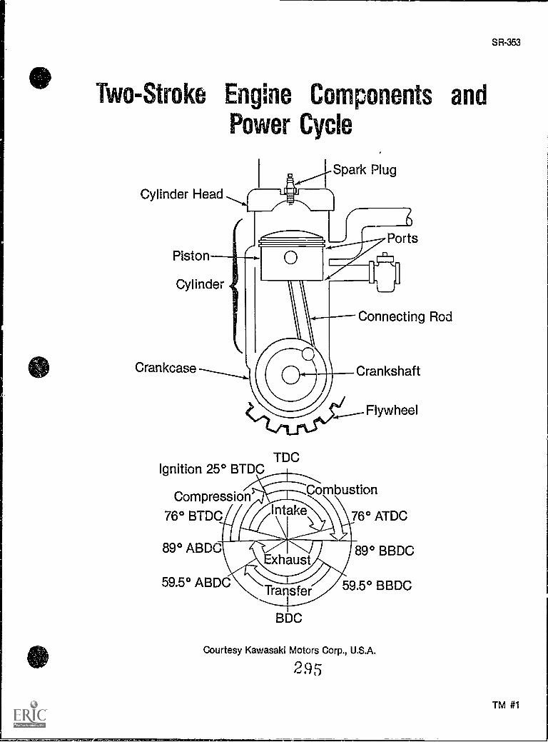
Two-Stroke Engine Components andPower Cycle
Spark Plug
Cylinder Head
Piston
Cylinder
Crankcase
SR-353
Ignition 25° BTDCTDC
Compression
76° BTDC
PortsIni
Connecting Rod
Crankshaft
Flywheel
Combustion
76° ATDC
89° BBDC
59.5° BBDC
BDC
Courtesy Kawasaki Motors Corp., U.S.A.
295
TM #1
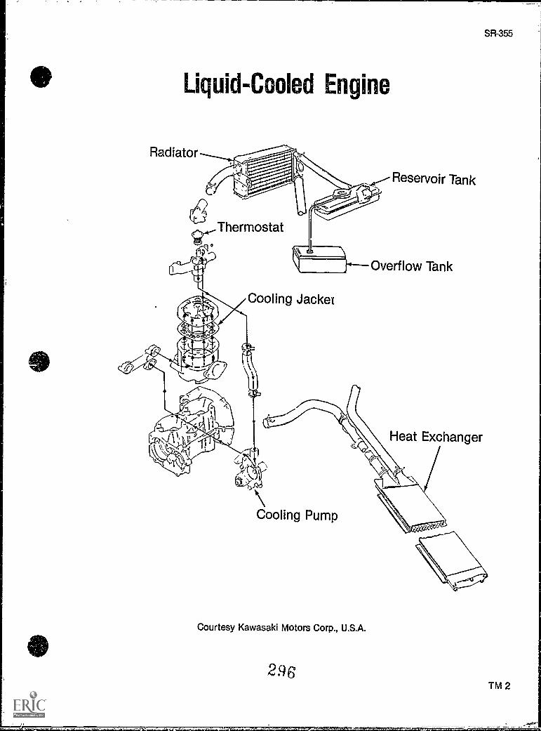
Liquid-Cooled Engine
Radiator
Thermostat)11=6
Cooling Jacket
Reservoir Tank
Overflow Tank
SR-355
Heat Exchanger
Cooling Pump
Courtesy Kawasaki Motors Corp., U.S.A.
296TM 2
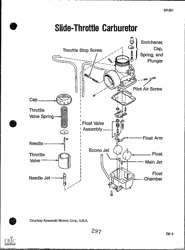
Cap
ThrottleValve Spring
Slide-Throttle Carburetor
Throttle Stop Screw
Enrichener,
Cap,
Spring, andt) Plunger
I t
Pilot Air Screw
Needle
ThrottleValve
Needle Jet
Float ValveAssembly °
Courtesy Kawasaki Motors Corp., U.S.A.
Econo Jet
297
Float
Main Jet
FloatChamber
SR-357
TM 3
ENGINESUNIT XII
ASSIGNMENT SHEET #1 SOLVE PROBLEMS RELATED TOENGINE MAINTENANCE
A. There are three systems for starting a cold snowmobile engine. What is the purpose ofeach system?
B. What purposes does the introduction of oil into the crankcase serve?
C. What precaution must be taken in adding anti-freeze to a snowmobile's liquid-cooledengine system?
D. What distinguishes the three types of carburetors found on modern snowmobiles?
298
SR-361
ENGINESUNIT XII
ANSWERS TO ASSIGNMENT SHEET
A. All three systems inject extra raw gas to enrich the fuel to air ratio.
B. Oil serves the primary purpose of reducing friction of the engine parts by lubricatingthem, and by controlling temperature. Additionally, oil contains additives which cleanengine parts, prevent rust, and enhance anti-wear.
C. The anti-freeze must be pre-mixed with water before introducing it into the coolant sys-tem, and that water/coolant mixture should not contain more than 60 percent anti-freeze.
D. The three types of carburetors are identifiable as a iloat type with a butterfly throttlevalve, a float type with a slide valve throttle, and a diaphragm type carburetor.
299
SR-363
ENGINESUNIT XII
JOB SHEET #1 -- SERVICE A FLOAT-TYPE CARBURETOR
A. Tools and materials
1. Snowmobile ns selected by instructor
2. Appropriate service manual
3. Basic hand tools
4. Clean shop towels
5. Carburetor cleaner
6. Float level gauge
7. Compressed air supply
8. Drain pan
9. Safety glasses
B. Routine #1 Removing the carburetor
1. Put on safety glasses.
2. Secure the sled with ignition off.
3. Disconnect and ground spark plug wire.
4. Turn the gas valve off and disconnect the fuel line.
5. Loosen the clamp on the air filter boot and remove the air ft ter boot from the car-buretor.
6. Remove the throttle cable from the carburetor.
300
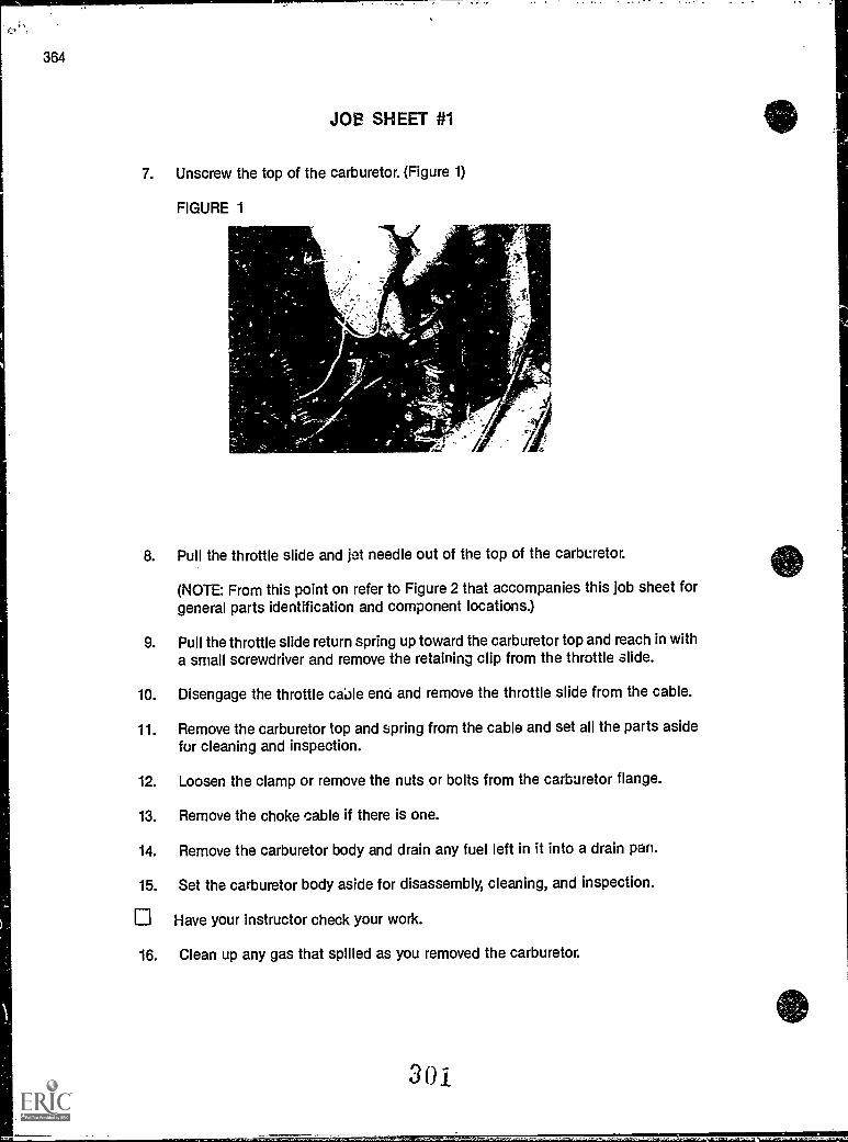
364
JOB SHEET #1
7. Unscrew the top of the carburetor. (Figure 1)
FIGURE 1
8. Pull the throttle slide and jet needle out of the top of the carburetor.
(NOTE: From this point on refer to Figure 2 that accompanies this job sheet forgeneral parts identification and component locations.)
9. Pull the throttle slide return spring up toward the carburetor top and reach in witha small screwdriver and remove the retaining clip from the throttle slide.
10. Disengage the throttle cable enci and remove the throttle slide from the cable.
11. Remove the carburetor top and spring from the cable and set all the parts asidefor cleaning and inspection.
12. Loosen the clamp or remove the nuts or bolts from the carburetor flange.
13. Remove the choke cable if there is one.
14. Remove the carburetor body and drain any fuel left in it into a drain pan.
15. Set the carburetor body aside for disassembly, cleaning, and inspection.
Have your instructor check your work.
16. Clean up any gas that spilled as you removed the carburetor.
301
SR-365
JOB SHEET #1
C. Routine #2 Disassembling the carburetor
1. Leave your safety glasses on.
2. Remove the float chamber attaching screws and remove the float chamber fromthe carburetor.
(NOTE: Make a sketch of where the float chamber hose guides come from so youcan put them back in the right places.)
3. Use a pair of needlenose pliers to remove the float pin, and be sure it comes outfrom the correct side and in the right direction.
(NOTE: If the pin is stuck, a punch can be used to free it, but proper support ofthe mounting boss is absolutely required, so if you can't get the pin out freely,ask your instructor for assistance.)
4. Remove the float and float valve and set them aside.
5. Remove the main jet, main jet holder, needle jet, baffle, and slow jet and set themaside.
6. Remove the limiter cap or the air screw plug.
7. Remove the throttle stop screw and set it aside with the air screw.
8. Unscrew the lock nut and remove the starter valve or enrichener.
9. Remove all 0-rings that are on the air screw and enrichener valve, and remove thegasket from the mounting flange.
10. Place all metal parts and screws into a carburetor cleaner basket.
Have your instructor check your work.
D. Routine #3 Cleaning and inspecting carburetor parts
1. Leave your safety glasses on.
2. Place the basket of parts slowly into the carburetor cleaner to keep cleaner fromsplashing out.
3. Leave parts in the cleaner for fifteen to thirty minutes as specified on the cleanerdirections.
4. Remove the carburetor basket from the cleaner, hook it over the side of the clean-ing station, and permit it to drain.
302
366
JOB SHEET #1
5. Move the parts around with a screwdriver to make sure all the carburetor cleanerdrains back into the tank.
6. Place the carburetor cleaning basket in a large drain pan and take it to the sink.
7. Rinse all parts thoroughly in cold water.
8. Take the parts back to the disassembly area and blow out all passages and thor-oughly dry all parts with compressed air.
(CAUTION: Small springs and screws are cagy to lose when drying them withcompressed air, so hang on tight.)
9. Lay the parts out on a clean shop towel as you dry them so they'll be ready forinspection.
10. Hold all jets' co the liglit and look through them to make sure the jet passage isunobstructed.
11. Clean obstructed jet passages with compressed air or an aerosol contactcleaner, but do not clean the jet with a wire or drill bit.
12. Replace any obstructed jets that cannot be cleaned with new ones.
13. Inspect the float needle for damage or wear which will appear as a circle that isworn around the seating surface of the needle.
14. Replace the needle and needle seat if the needle is worn.
15. Inspect he float pin for wear which will appear on the pin where the float worksup and down the pin, and usually in the middle of the pin.
16. Replace the float pin if the old one is worn.
17. Inspect the float to make sure it hasn't collapsed, that it is securely soldered tothe flat arms, and that there is no evident damage.
18. Shake the float close to your ear and listen for the presence of any fuel in thefloat.
19. Replace the float if the old one is bad.
20. Inspect the throttle slide for wear that usually appears as deep scratches orgouges.
21. Install the throttle slide into the carburetor body and make sure it slides freely.
22. Look down the throttle slide bore In the body of the carburetor, check for wear,and make sure the throttle slide guide pin is not worn or damaged.
303
SR-367
JOB SHEET #1
23. Replace the throttle slide as required, but if the guide pin is damaged or missingthe entire carburetor will have to be replaced.
(NOTE A new guide pin can be made from a proper size pin, but it's a job for anexperienced technician.)
24. Inspect the jet needle for straightness and for wear which will appear along thebody and at the point where the jet needle clip fits over it.
25. Inspect the jet needle clip to make sure it fits snugly in the appropriate groove onthe jet needle.
26. Replace jet needle or clip as required.
27. Check the float bowl for damage caused by corrosion, and if the low specd jet isa part of the float bowl, squirt some contact cleaner on it to make sure it is open.
28. Clean the low speed jet with compressed air or otherwise replace the float bowlas required.
0 Have your instructor check your work.
E. Routine #4 Reassembling the carburetor
1. Leave your safety glasses on.
2. Install the float needle seat.
3. Install the starter valve or enrichener.
4. Install the main jet holder, needle jet, baffle, main jet, and slow jet in propersequence and in their proper places.
(NU :i: Do not overtighten these parts because they twist off easily, but be surethey are well seated.)
5. Install the air screw, turn it in until it is lightly seated, and then turn it out thesame number or turns noted at disassembly
6. Install the throttle stop screw, turn it in until it is lightly seated, and then turn itout the same number of turns noted at disassembly but screw it out one extrafull turn.
(NOTE: The extra full turn will help prevent the possibility of over revving theengine at start up.)
7. Install the float needle and the float, and you will probably have to install them asan assembly because there is a small wire clip that fastens them together.
304
JOB SHEET #1
8 Install the float pin.
9. Check the f;.,at level with a float level gauge and adji'st to the specifications inthe service manual.
(NOTE: Float level adjustment varies from model to model and it's important tofollow the specific procedure.)
1C. Install the gasket or 0-ring on the float bowl and install the float bowl.
11. Install the float chamber hose guides and float chamber screws, and snug thescrews down lightly before tightening, but don't damage the fuel bowl by over-tightening the screws.
12. Install the jet needle clip in its original groove.
13. Install the Jet needle into the carburetor slide valve.
14. Install the throttle cable into the carburetor top.
15. Install the spring into the carburetor top and compress it with your hand so youcan engage the throttle cable end into the throttle valve.
16. Install the retaining clip and let the spring go to allow it to seat into the throttleslide.
(CAUTION: Make certain that the slide is installed In the correct position so thatthe groove along the throttle slide engages the guide pin in the throttle slidebore.)
17. Check to make sure that the cutaway at the bottom of the throttle slide faces theinlet side of the carburetor.
18. Puch the throttle slide down into the bore.
19. Put the carburetor top back on, make sure it is straight, and screw it on carefullybecause it's very easy to cross thread and ruin the carburetor.
20. Look into the bore of the carburetor as you turn the throttle to make certain thatthe throttle slide operates smoothly and does not stick or bind.
Have your instructor check your work.
F. Routine #5 Installing and adjusting tne camuretor
1. Leave your safety glasses on.
2. Look inside the carburetor flange and inside the air boot to make sure they areboth free of dirt, pieces of old gasket, or foreign matter of any kind.
305
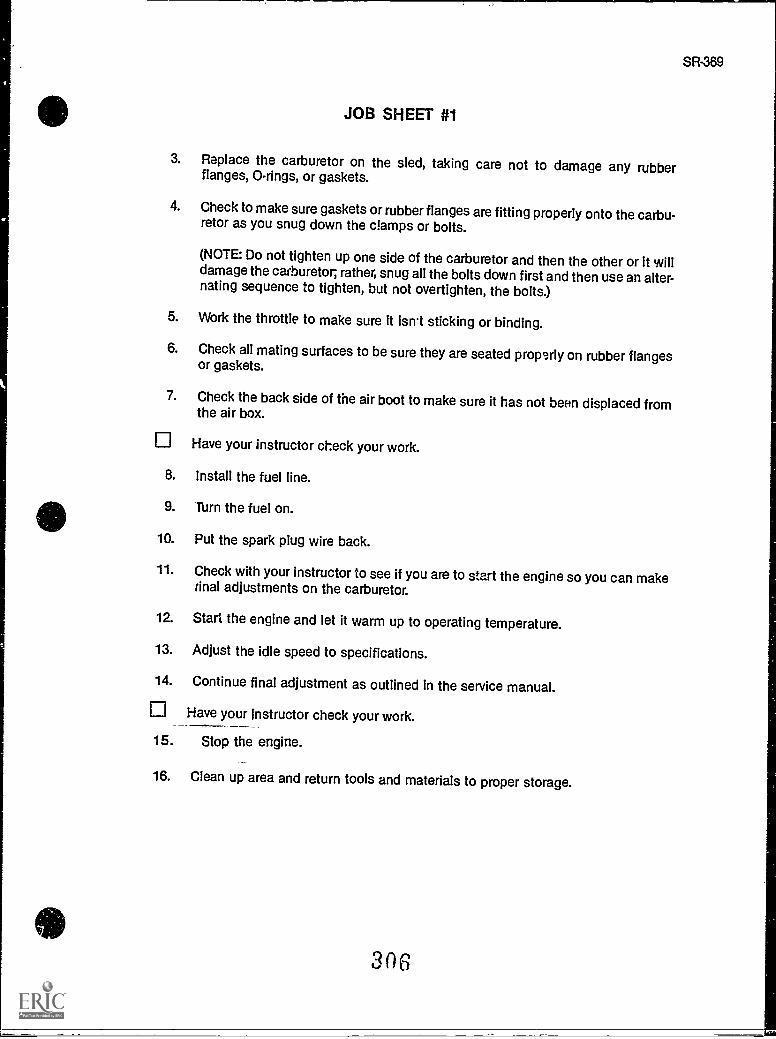
JOB SHEET #1
3. Replace the carburetor on the sled, taking care not to damage any rubberflanges, 0-rings, or gaskets.
4. Check to make sure gaskets or rubber flanges are fitting properly onto the carbu-retor as you snug down the clamps or bolts.
(NOTE: Do not tighten up one side of the carburetor and then the other or it willdamage the carburetor; rather, snug all the bolts down first and then use an alter-nating sequence to tighten, but not overtighten, the bolts.)
5. Work the throttle to make sure It isn't sticking or binding.
6. Check all mating surfaces to be sure they are seated properly on rubber flangesor gaskets.
7. Check the back side of the air boot to make sure it has not been displaced fromthe air box.
Have your instructor check your work.
8. Install the fuel line.
9. Turn the fuel on.
10. Put the spark plug wire back.
11. Check with your instructor to see if you are to start the engine so you can makerinel adjustments on the carburetor.
12. Start the engine and let it warm up to operating temperature.
13. Adjust the idle speed to specifications.
14. Continue final adjustment as outlined in the service manual.
Have your instructor check your work.
15. Stop the engine.
16. Clean up area and return tools and materials to proper storage.
306
SR-369
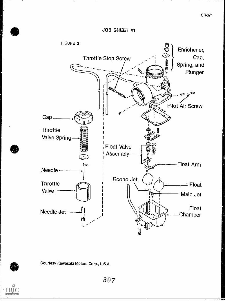
FIGURE 2
JOB SHEET #1
Throttle Stop Screw
SR-371
0 Enrichener,C> Cap,
1 Spring, and$ Plunger
...
Cap _
ThrottleValve Spring
Needle-¢,
c,:ce
Pilot Air Screw
Float Valve 11;AssemblyA
Econo JetThrottleValve
Needle Jet
I-
Courtesy Kawasaki Motors Corp., U.S.A.
307
Float Arm
Float
Main Jet
FloatChamber
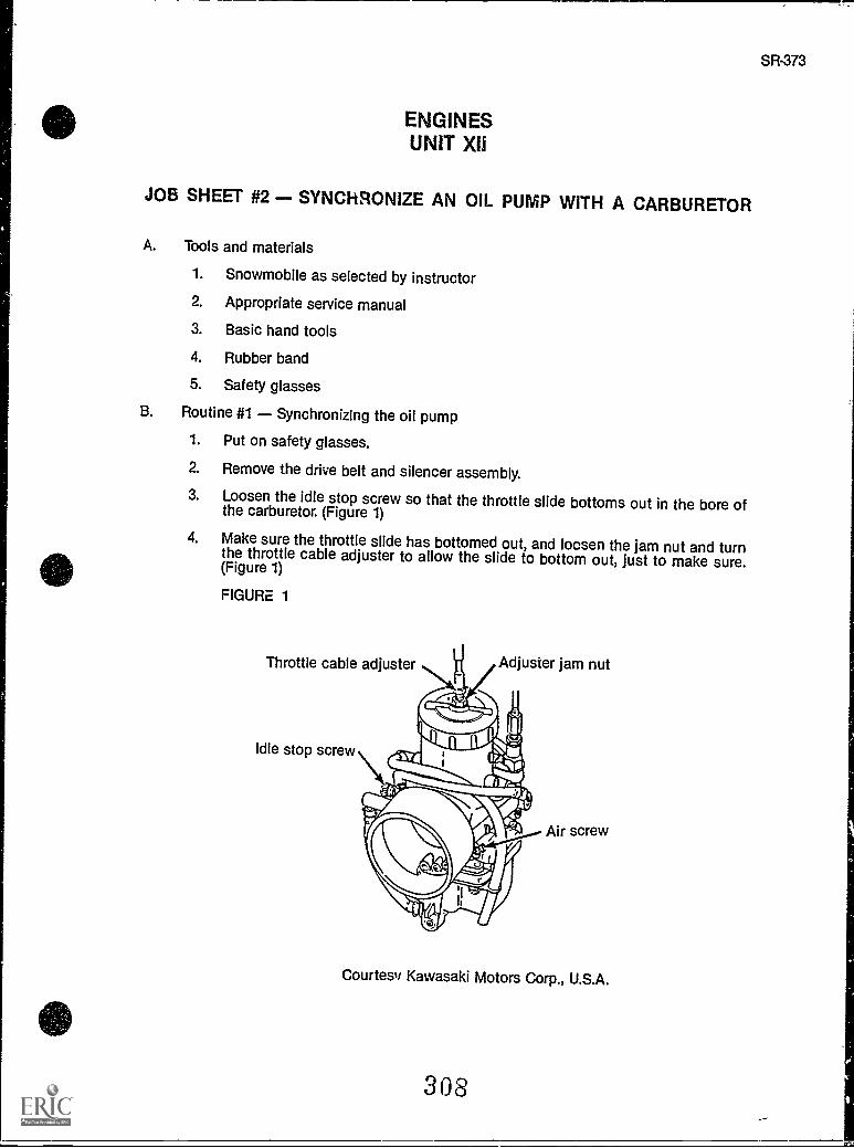
SR-373
ENGINESUNIT XII
JOB SHEET #2 - SYNCHRONIZE AN OIL PUMP WITH A CARBURETOR
A. Tools and materials
1. Snowmobile as selected by instructor
2. Appropriate service manual
3. Basic hand tools
4. Rubber band
5. Safety glasses
B. Routine #1 Synchronizing the oil pump
1. Put on safety glasses.
2. Remove the drive belt and silencer assembly.
3. Loosen the idle stop screw so that the throttle slide bottoms out in the bore ofthe carburetor. (Figure 1)
4. Make sure the throttle slide has bottomed out, and locsen the jam nut and turnthe throttle cable adjuster to allow the slide to bottom out, just to make sure.(Figure 1)
FIGURE 1
Throttle cable adjuster
Idle stop screw
Adjuster jam nut
Air screw
Courtesy Kawasaki Motors Corp., U.S.A.
308
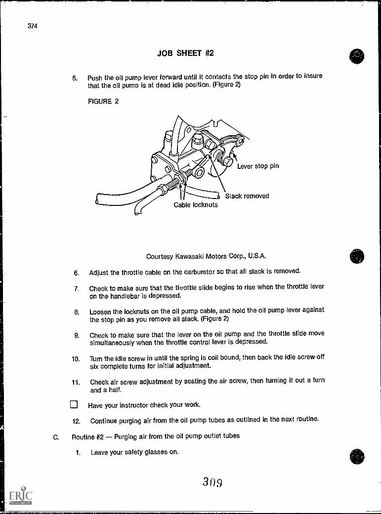
374
JOB SHEET #2
5. Push the oil pump lever forward until it contacts the stop pin in order to insurethat the oil pump is at dead idle position. (Figure 2)
FIGURE 2
Lever stop pin
.., Slack removedCable locknuts
Courtesy Kawasaki Motors Corp., U.S.A.
6. Adjust the throttle cable on the carburetor so that all slack is removed.
7. Check to make sure that the thiottle slide begins to rise when the throttle leveron the handlebar is depressed.
8. Loosen the locknuts on the oil pump cable, and hold the oil pump lever against
the stop pin as you remove all slack. (Figure 2)
9. Check to make sure that the lever on the oil pump and the throttle slide movesimultaneously when the throttle control lever is depressed.
10. Turn the idle screw in until the spring is coil bound, then back the idle screw offsix complete turns for initial adjustment.
11. Check air screw adjustment by seating the air screw, then turning it out a turnand a half.
Have your instructor check your work.
12. Continue purging air from the oil pump tubes as outlined in the next routine.
C. Routine #2 Purging air from the oil pump outlet tubes
1. Leave your safety glasses on.
309
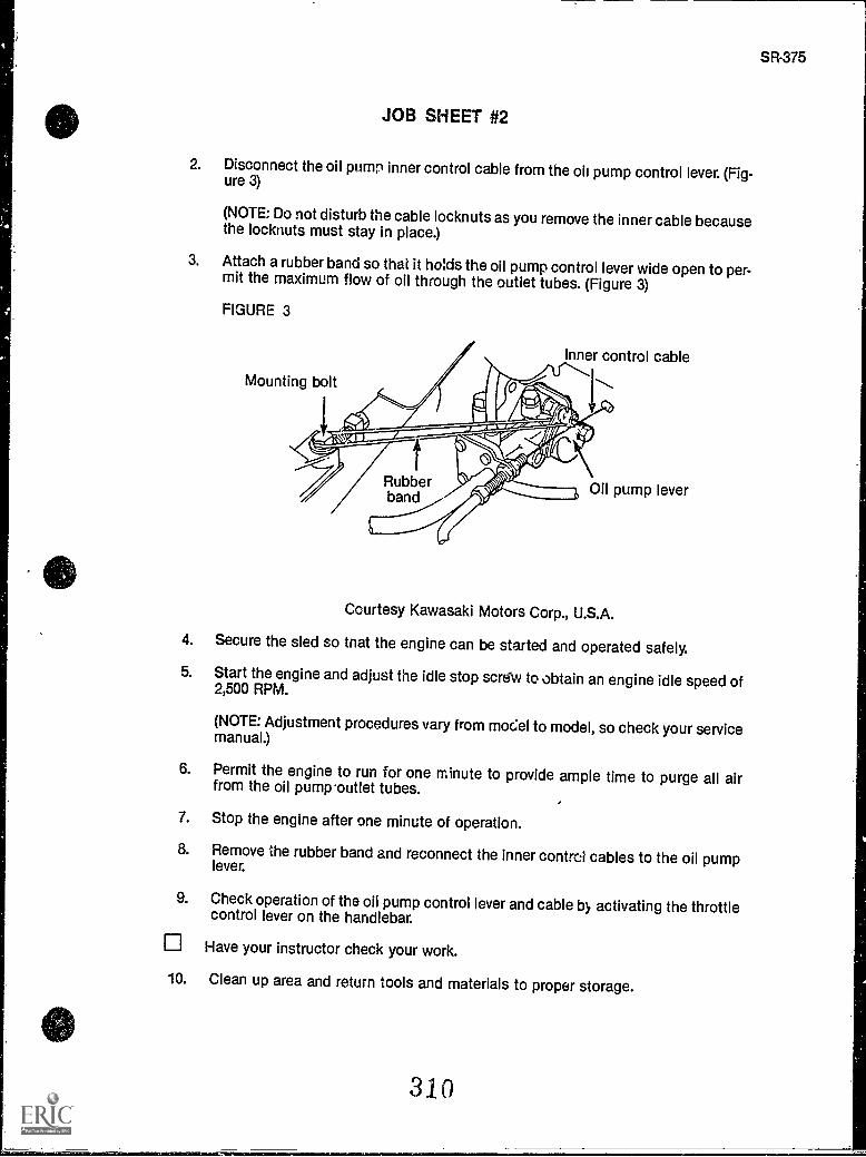
JOB SHEET #2
2. Disconnect the oil pump inner control cable from the oil pump control lever. (Fig-ure 3)
(NOTE: Do not disturb the cable locknuts as you remove the inner cable becausethe locknuts must stay in place.)
3. Attach a rubber band so that it holds the oil pump control lever wide open to per-mit the maximum flow of oil through the outlet tubes. (Figure 3)
FIGURE 3
Mounting bolt
Inner control cable
Rubberband Oil pump lever
Courtesy Kawasaki Motors Corp., U.S.A.
4. Secure the sled so that the engine can be started and operated safely.
5. Start the engine and adjust the idle stop screw to obtain an engine idle speed of2,500 RPM.
(NOTE: Adjustment procedures vary from model to model, so check your servicemanual.)
6. Permit the engine to run for one minute to provide ample time to purge all airfrom the oil pump 'outlet tubes.
7. Stop the engine after one minute of operation.
8. Remove the rubber band and reconnect the inner control cables to the oil pumplever.
9. Check operation of the oil pump control lever and cable by activating the throttlecontrol lever on the handlebar.
Have your instructor check your work.
10. Clean up area and return tools and materials to proper storage.
31 0
SR-375
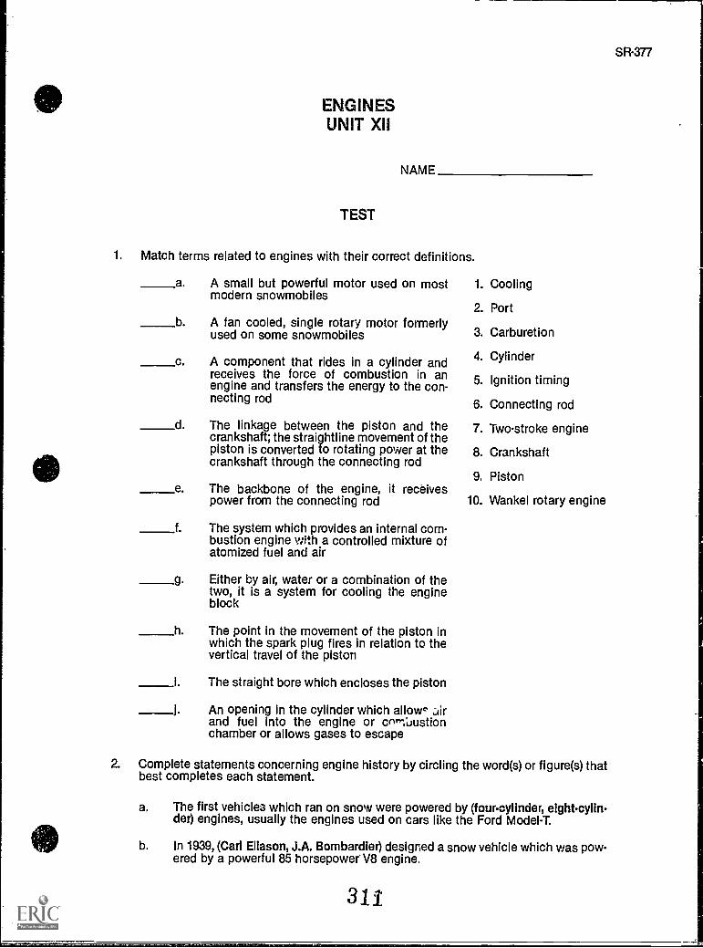
SR-377
ENGINESUNIT XII
NAME
TEST
1. Match terms related to engines with their correct definitions.
a. A small but powerful motor used on mostmodern snowmobiles
b. A fan cooled, single rotary motor formerlyused on some snowmobiles
c. A component that rides in a cylinder andreceives the force of combustion in anengine and transfers the energy to the con-necting rod
d The linkage between the piston and thecrankshaft; the straightline movement of thepiston is converted to rotating power at thecrankshaft through the connecting rod
e. The backbone of the engine, it receivespower from the connecting rod
f. The system which provides an internal com-bustion engine with a controlled mixture ofatomized fuel and air
g. Either by air, water or a combination of thetwo, it is a system for cooling the engineblock
h. The point in the movement of the piston inwhich the spark plug fires in relation to thevertical travel of the piston
i. The straight bore which encloses the piston
An opening in the cylinder which allow' airand fuel into the engine or com:Laustionchamber or allows gases to escape
1. Cooling
2. Port
3. Carburetion
4. Cylinder
5. Ignition timing
6. Connecting rod
7. Two-stroke engine
8. Crankshaft
9. Piston
10. Wankel rotary engine
2. Complete statements concerning engine history by circling the word(s) or figure(s) thatbest completes each statement.
a. The first vehicles which ran on snow were powered by (four-cylinder, eightcylin-der) engines, usually the engines used on cars like the Ford Model-T.
b. In 1939, (Carl Eliason, J.A. Bombardier) designed a snow vehicle which was pow-ered by a powerful 85 horsepower' V8 engine.
311
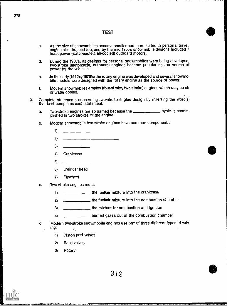
378
TEST
c. As the size of snowmobiles became smaller and more suited to personal travel,engine size dropped too, and by the mid-1950's snowmobile designs included 7horsepower (water-cooled, air-cooled) outboard motors.
d. During the 1950's, as designs for personal snowmobiles were being developed,two-stroke (motorcycle, outboard) engines became popular as the source ofpower for the vehicles.
e. in the early (1960's; 19707s) the rotary. engine was developed and several snowmo-bile models were designed with the rotary engine as the source of power.
f. Modern snowmobiles employ (four-stroke, two-stroke) engines which may be airor water cooled.
3. Complete statements concerning two-stroke engine design by inserting the word(s)that best completes each statement.
a. Two-stroke engines are so named because the cycle is accom-plished in two strokes of the engine.
b. Modern snowmobile two-stroke engines have common components:
1)
2)
3)
4) Crankcase
5)
6) Cylinder head
7) Flywheel
c. Two-stroke engines must:
1) the fuel/air mixture into the crankcase
2) the fuel/air mixture into the combustion chamber
3) the mixture for combustion and ignition
4) burned gases out of the combustion chamber
d. Modern two-stroke snowmobile engines use one cf three different types of valv-ing:
1) Piston port valves
2) Reed valves
3) Rotary
312
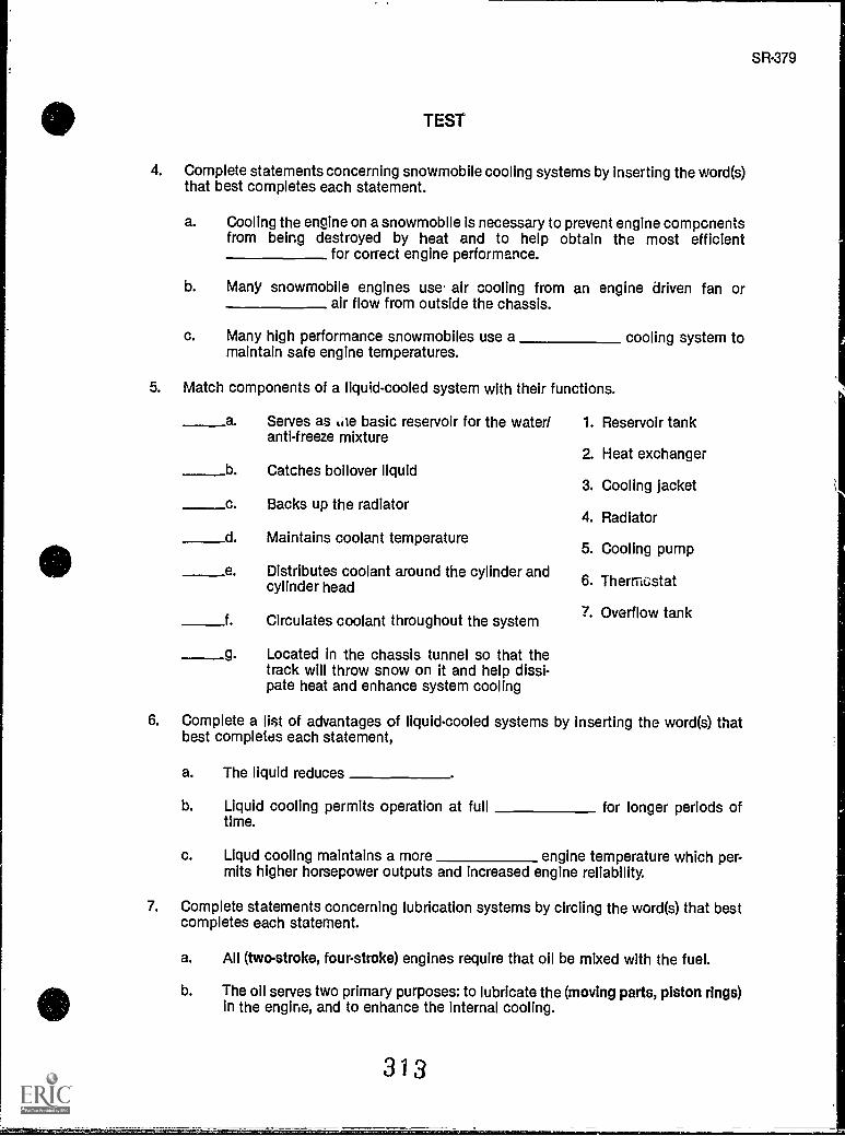
SR-379
TEST
4. Complete statements concerning snowmobile cooling systems by inserting the word(s)that best completes each statement.
a. Cooling the engine on a snowmobile is necessary to prevent engine compcnentsfrom being destroyed by heat and to help obtain the most efficient
for correct engine performance.
b. Many snowmobile engines use air cooling from an engine driven fan orair flow from outside the chassis.
c. Many high performance snowmobiles use a cooling system tomaintain safe engine temperatures.
5. Match components of a liquid-cooled system with their functions.
a Serves as Liie basic reservoir for the water/anti-freeze mixture
b Catches boilover liquid
c Backs up the radiator
d. Maintains coolant temperature
e Distributes coolant around the cylinder andcylinder head
f. Circulates coolant throughout the system
g. Located in the chassis tunnel so that thetrack will throw snow on it and help dissi-pate heat and enhance system cooling
1. Reservoir tank
2. Heat exchanger
3. Cooling jacket
4. Radiator
5. Cooling pump
6. Thermostat
7. Overflow tank
6. Complete a list of advantages of liquid-cooled systems by inserting the word(s) thatbest completes each statement,
a. The liquid reduces
b. Liquid cooling permits operation at full for longer periods oftime.
c. Liqud cooling maintains a more engine temperature which per-mits higher horsepower outputs and increased engine reliability.
7. Complete statements concerning lubrication systems by circling the word(s) that bestcompletes each statement.
a. All (two-stroke, fourstroke) engines require that oil be mixed with the fuel.
b. The oil serves two primary purposes: to lubricate the (moving parts, piston rings)in the engine, and to enhance the internal cooling.
313
TEST
u. Since virtually all two-stroke engine oils contain additives, the oil also serves toclean the (internal, external) engine parts, prevent corrosion, and enhance anti-wear.
d. Some snowmobiles require that the fuel and oil be mixed manually and addeddirectly into the (crankcase, fuel tank).
e. Many contemporary snowmobiles inject the oil into the fuel or (intake, exhaust)port as the snowmobile is operating.
8. Complete statements concerning types of carburetors by inse.ling the word(s) thatbest completes each statement.
a. Snowmobile carburetors are identified as either atype Sr type and by throttle valve design.
b. Throttle valve design may be:
1. valve
2. throttle
c. Float bowl carburetors have either a slide throttle valve or athrottle valve.
d. Diaphragm type carburetors usually have a throttle valve.
9. Select true statements concerning fuel pumps by placing an "X" beside each state-ment that is true.
a Fuel pumps deliver fuel from the fuel tank to the carburetor.
b Fuel pumps are always integrated with the carburetor.
c. Most modern fuel pumps are a diaphragm type operated by crankcasepressure.
10. Complete statements concerning cold start methods by inserting the word(s) that bestcompletes each statement.
a. A cold snowmobile engine will not droplets of fuel, and a richermixture is required to start the engine.
b. Cold starting systems are called starter circuits or enrichment s.::',ems, and maybe one of three types:
1) A pump or primer
2) An enrichment which opens a passageway direct fromThe float bowl to the carburetor throat
3) A plate
3 1 4
SR-381
TEST
11. Select true statements concerning coolant/antifreeze by placing an "X" beside eachstatement that is true.
a. Liquid-cooled snowmobiles require the use of a mixture of water andethylene-glycol antifreeze which protects the mixture from boiling up to 264°Fand from freezing down to -34°F.
The antifreeze is mixed with water in a premix solution before adding tothe radiator, usually two quarts of antifreeze to two quarts water.
c. Manufacturers warn never to mix a concentration with more than 60 per-cent antifreeze and manufacturer's mixing directions should be carefullyfollowed.
12. Complete statements concerning guidelines for engine service by inserting he word(s)that best completes each statement.
a. Fuel filters may be located in the gas tank orbetween the tank and the carburetor, and both filters and any screens should bechecked and cleaned or replaced each season.
b. Some models equipped with in-line oil filters require air from theoil supply tube to avoid engine damage.
c. After carburetor replacement/adjustment, always the oil pumpand carburetor to assure proper engine performance and proper lubrication.
d. In emergencies, a B.1.A. oil with a TC-W ratingmay be used, but otherwise, use only oil recommended by the
manufacturer.
e. Cure-all tune-up tonics and oils are not recommended.
f. oils are not recommended for most engines, but some manufac-turers do recommend their use, so always check specifications.
g. Add gasoline each time the fuel tank is filled so that moisturetrapped in fuel system components will not freeze and cause engine malfunctionor damage.
(NOTE: If the following activities have not been accomplished prior to the test, ask yourinstructor when they should be completed.)
13. Solve problems related to engine maintenance. (Assignment Sheet #1)
14. Demonstrate the ability to:
a. Service a float-type carburetor. (Job Sheet #1)
b. Synchronize an oil pump with a carburetor. (Job Sheet #2)
315
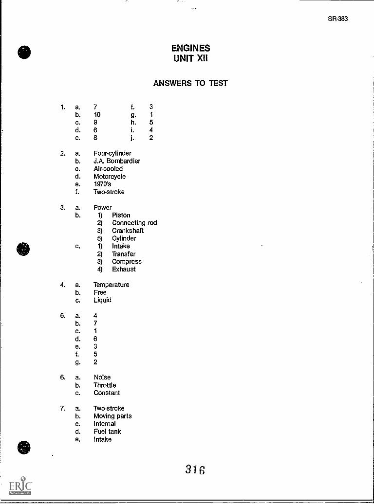
ENGINESUNIT XII
ANSWERS TO TEST
1. a. 7 f. 3b. 10 g. 1
c. 9 h. 5d. 6 i. 4e. 8 j. 2
2. a. Four-cylinderb. J.A. Bombardierc. Air-cooledd. Motorcyclee. 1970'sf. Two-stroke
3. a. Powerb. 1) Piston
2) Connecting rod3) Crankshaft
CylinderIntakeTransferCompressExhaust
4. a. Temperatureb. Freec. Liquid
5. a. 4b. 7c. 1
d. 6e. 3f. 5g. 2
6. a. Noiseb. Throttlec. Constant
7. a. Two-strokeb. Moving partsc. Internald. Fuel tanke. Intake
316
SR-383
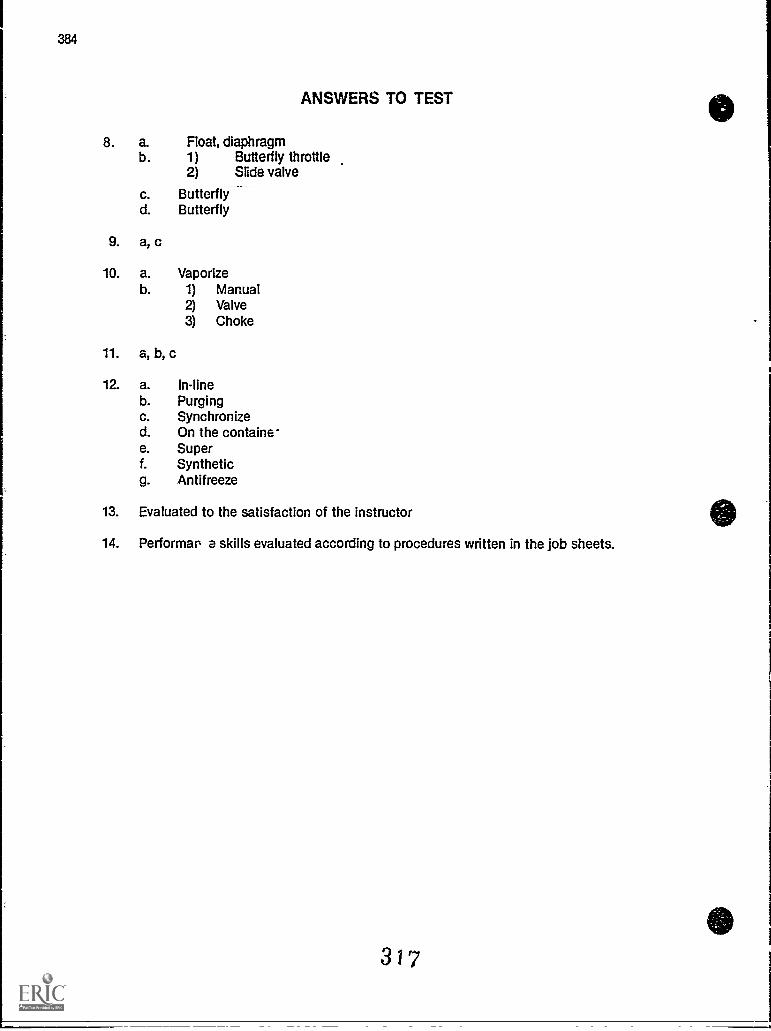
384
ANSWERS TO TEST
8. a. Float, diaphragmb. 1) Butterfly throttle
2) Slide valve
c. Butterflyd. Butterfly
9. a, c
10. a. Vaporizeb. 1) Manual
2) Valve3) Choke
11. a, b, c
12. a. In-lineb. Purgingc. Synchronized. On the containe-e. Superf. Syntheticg. Antifreeze
13. Evaluated to the satisfaction of the instructor
14. Performa a skills evaluated according to procedures written in the job sheets.
317
IGNITION AND ELECTRICALSYSTEMS
UNIT XIII
UNIT OBJECTIVE
After completion of this unit, the student should be able to discuss types of ignition systemsand identify components of a capacitor discharge ignition systems. The student should alsobe able to discuss procedures for servicing components of ignition systems, service a batteryand spark plugs, troubleshoot a CDI system, and service a recoil starter. These competencieswill be evidenced by correctly performing the procedures outlined in the job sheets and byscoring 85 percent on the unit test.
SPECIFIC OBJECTIVES
After completion of this unit, the student will be able to:
1. Match terms related to ignition and electrical systems with their correct defini-tions.
2. Select true statements concerning snowmobile electrical requirements.
3. Complete statements concerning battery ignition systems.
4. Solve problems concerning battery service.
5. Select true statements concerning magneto ignition systems.
6. Complete statements concerning capacitor discharge systems.
7. Identify components of a CDI system.
8. Complete statements concerning CDI operations.
9. Complete statements concerning safety features in a CDI system.
10. Solve problems concerning spark plug service.
11. Complete statements concerning how to use spark plug wear as troubleshootingguidelines.
12. Select true statements concerning recoil starter service.
318
SR-385
386
OBJECTIVE SHEET
13. Comp let, statements concerning servicing the electrical system.
14. Demonstrate the ability to:
a. Remove, inspect, service, and replace a snowmobile battery. (Job Sheet #1)
b. Remove and inspect ignition coil leads. (Job Sheet #2)
c. Remove, inspect, and replace spark plugs. (Job Sheet #3)
d. Check ignition timing. (Job Sheet #4)
e. Troubleshoot a capacitor discharge ignition system. (Job Sheet #5)
f. Service a recoil starter. (Job Sheet #6)
3i9
SR-387
IGNITION AND ELECTRICAL SYSTEMSUNIT XIII
SUGGESTED ACTIVITIES
A. Provide students with objective sheet.
B. Provide students with information sheet.
C. Make transparencies.
D. Discuss unit and specific objectives.
E. Discuss information sheet.
F. Demonstrate and discuss procedures outlined in the job sheets.
G. Provide students with samples of common electrical problems and have students dis-cuss how they would solve them.
H. Give test.
CONTENTS OF THIS UNIT
411) A. Objective sheet
B. Information sheet
C. Transparency masters
1. TM 1 Capacitor Discharge Ignition System
2. TM 2 Parts of a Spark Plug
3. TM 3 Parts of a Recoil Starter
D. Job sheets
1. Job Sheet #1 Remove, Inspect, Service, and Replace a Snowmobile,Battery
2. Job Sheet #2 Remove, Inspect, and Replace Spark Plugs
3. Job Sheet #3 Check Ignition Timing
4. Job Sheet #4 Troubleshoot a Capacitor Discharge Ignition System
5. Job Sheet #5 Service a Recoil Starter
E. Test
F. Answers to test
320
388
REFERENCES USED IN DEVELOPING THIS UNIT
A. Arctic Cat Service Manual #2254-302. Thief River Falls, MN 56701: ARTCO, Inc., 1984.
B. 1980 Bombardier Snowmobiles Shop Manual. Valcourt, Quebec, Canada: Bombardier,Ltd., 1980.
C. Chilton's Snowmobiles Repair and Tune-Up Guide. Radnor, PA: Chilton Book Co., 1975.
D. Kawasaki Drifter Snowmobile Shop Manual. Santa Ana, CA 92799-5252: KawasakiMotors Corp., U.S.A., 1980.
E. Kawasaki Parts Catalog SB340-A2, SB440-A5. Santa Ana, CA 92799-5252: KawasakiMotors Corp., U.S.A., 1980.
E Honda Motorcycle Electrical Systems. Gardena, CA: American Honda Motor Co., Inc.,1977.
SR-389
IGNITION AND ELECTRICAL SYSTEMSUNIT XIII
INFORMATION SHEET
I. Terms and definitions
A. Alternating current Electric current which reverses its direction of flow atregular intervals
B. Direct current Electric current which flows in only one direction
C. Ampere The unit of measurement for current flow
D. Volt The unit of measurement of electrical pressure
E. Ohm The unit of measurement of resistance to electrical flow
F. Alternator A generator which produces alternating current
G. Capacitor A device capable of storing limited amounts of electricalpower for discharge at a predetermined time or on a predetermined signal
H. Rectifier A device that changes alternating current into direct current
I. Induction The process of charging an object by bringing it into the mag-netic field of an electromagnet or permanent magnet
II. Snowmobile electrical requirements
A. The two basic electrical needs on a snowmobile are:
1. An ignition system to ignite the fuel/air mixture
2. An electrical system to operate lights and other accessories
B. Starting a snowmobile engine can be accomplished with a battery-basedelectric start unit or with a re:oil starter that is manually operated.
C. Electrical demands for ignition and for lighting and accessories are twoseparate functions, and although the two systems are related, they operateas individual systems.
D. An ignition system produces high voltage required to Jump the gap of thespark plug electrodes and ignite the air/fuel mixture in the combustionchamber of the engine.
E. Lower voltage alternating current is used for lights and accessories, andAC output is stabilized through a voltage regulator.
322
390
INFORMATION SHEET
III. Battery Ignition systems
A. Battery ignition systems are found mostly on older sleds.
B. In a battery ignition system, the battery supplies electrical current to the
starter or cranking motor which is a DC motor that works with brushes and
a commutator.
C. The battery supplies power for the primary ignition circuit, and timing is
accomplished with breaker points and a condenser.
D. When breaker points are replaced in this type system, the condenser
should also be replaced.
E. A battery ignition system may produce up to 10,000 volts to fire the spark
plugs, and AC electricity for lights and accessories are on a separate alter-
nate circuit.
F. Alternator output is also used to charge the battery.
(NOTE: A rectifier is used to convert AC from the alternator into DC for bat-
tery charging, but the majority of alternator output is used for AC lights and
accessories.)
G. Cranking motors or starters should not be operated continuously for more
than 30 seconds, and a cool-down period of 30 seconds or more should be
observed at starting intervals.
H. Demands of cold weather, vibration, and frequent stopping/starting require
that batteries be inspected frequently for proper electrolyte level, corrosion-
free connections, and proper venting.
IV. Battery service
A. The most important element of battery service is safety because batteries
have a potential to explode, and battery electrolyte contains an acid that
can quickly eat through clothes and burn skin.
B. The battery should always be inspected after long storage periods or after
the sled has been subjected to high vibrations.
C. When servicing a battery, ALWAYS WEAR SAFETY GLASSES.
D. Always start battery service by first removing the negative battery cable,
and replace the negative battery cable last.
E. Clean dirty battery cases with a soda solution.
F. Clean battery posts and cable connectors with soda and water, and then
use a wire brush to make posts and connectors shine so they will make
good contact.
323
SR-391
INFORMATION SHEET
G. When battery electrolyte is low, it should be brought up to normal by add-ing distilled water, but never overfill a battery.
H. After adding distilled water, charge the battery at a rate equal to 10% of thebattery amp hour rating so the water will mix thoroughly and until theelectrolyte specific gravity is 1.260+, to keep the electrolyte fromfreezing. A higher charging rate could damage the battery.A battery with a cracked or worn ease or one that evidences other abuseshould be replaced.
J. After charging, a battery shoulu be checked cell by cell with a hydrometerto determine if the specific gravity of each cell is okay.
(NOTE: The procedure for using a hydrometer to check f-,r specific gravity isoutlined in Job Sheet #1 of this unit.)
V. Magneto ignition systems
A. Magneto ignition systems use rotating magnets to induce current in the pri-mary ignition circuit.
B. Magneto ignition systems may be an energy transfer type. Timing isaccomplished with breaker points and a condenser, and are serviced like otherbreaker point/condenser systems.
C. A magneto ignition system may produce up to 10,000 volts to fire the sparkplugs, and uses an alternator to provide AC electricity for lights and acces-s, ies.
VI. Capacitor discharge ignition systems (Transparency 1)
A. Capacitor discharge ignitions systems are the most common ignition sys-tems found on modern snowmobiles.
B. CDI systems are popular because they do not use breaker points and areeasy to service.
C. CDI systems use rotating magnets to induce current into a capacitor whichstores the current until another impulse causes the capacitor to dischargeand fire the spark plugs.
D. A CDI system may produce as high as 40,000 volts to fire the spark plugs,and this gives the CDI system an extra punch that aiso makes it more popu-lar than other ignition systems.
E. A CDI system has a lighting coil to provide AC electricity to the voltage reg-ulator for operating lights and accessories.
324
392
INFORMATION SHEET
VII. Components and their functions in a CDI system (Transparency 1)
A. Flywheel Houses four permanent magnets which provide a moving mag-
netic field as the flywheel rotates around the coils in the stator assembly.
B. Stator assembly Houses the exciter, pulsing, and lighting coils.
C. Exciter coil Charges the capacitor in the CDI igniter.
D. Pulser coil Signals the capacitor in the CDI igniter when to release its
charge to the ignition coil.
E. Ignition coil A coil with primary and secondary windings that induce thehigh voltage needed to jump the air gap on the spark plugs.
F. Lighting coil Provides alternating current for the lights and instruments
in the electrical system.
VIII. CDI operations
A. As the flywheel rotates, alternating current is induced in the coils mounted
on the stator.
B. The exciter coil sends a charge to the capacitor which stores the charge,and the amount of charge the exciter coil gives the capacitor affects theintensity of the spark.
C. The pulser coil causes the capacitor in the CDI igniter to release its storedenergy, but the pulser coil is only a signaling device and it has no effect onthe intensity of the spark.
D. The primary winding in the ignition coil induces a high voltage in the sec-ondary winding of the ignition coil, and causes a spark to jump across the
spark plug electrodes.
E. The igniter coil fires high voltage charges to the spark plugs twice eachtime the flywheel makes one complete rotation.
;X. Safety features in a CDI system
A. For both safety and convenience, a snowmobile engine needs to stop andstart at the turn of a switch, but the sled also needs to stop if the ridershould lose control and fall off.
B. The key switch on a snowmobile permits the engine to be started orstopped with the turn of a key and services both safety and convenience.
C. The emergency stop switch is strictly a safety device that will stop theengine if the rider is thrown off and the throttle handle is suddenly released.
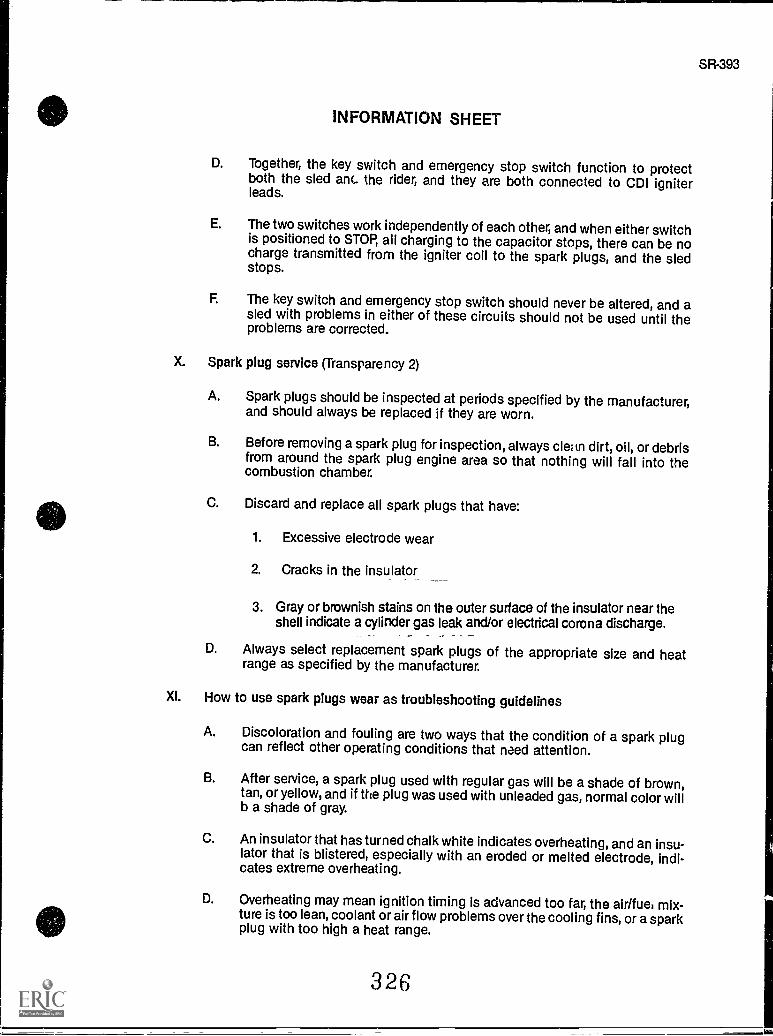
SR-393
INFORMATION SHEET
D. Together, the key switch and emergency stop switch function to protectboth the sled anc the rider, and they are both connected to CDI igniterleads.
E. The two switches work independently of each other, and when either switchis positioned to STOP, all charging to the capacitor stops, there can be nocharge transmitted from the igniter coil to the spark plugs, and the sledstops.
F. The key switch and emergency stop switch should never be altered, and asled with problems in either of these circuits should not be used until theproblems are corrected.
X. Spark plug service (Transparency 2)
A. Spark plugs should be inspected at periods specified by the manufacturer,and should always be replaced if they are worn.
B. Before removing a spark plug for inspection, always cle;tn dirt, oil, or debrisfrom around the spark plug engine area so that nothing will fall into thecombustion chamber.
C. Discard and replace all spark plugs that have:
1. Excessive electrode wear
2. Cracks in the insulator
3. Gray or brownish stains on the outer surface of the insulator near theshell indicate a cylinder gas leak and/or electrical corona discharge.
D. Always select replacement spark plugs of the appropriate size and heatrange as specified by the manufacturer.
Xl. How to use spark plugs wear as troubleshooting guidelines
A. Discoloration and fouling are two ways that the condition of a spark plugcan reflect other operating conditions that need attention.
B. After service, a spark plug used with regular gas will be a shade of brown,tan, or yellow, and if the plug was used with unleaded gas, normal color willb a shade of gray.
C. An insulator that has turned chalk white indicates overheating, and an insu-lator that is blistered, especially with an eroded or melted electrode, indi-cates extreme overheating.
D. Overheating may mean ignition timing is advanced too far, the air/fue, mix-ture is too lean, coolant or air flow problems over the cooling fins, or a sparkplug with too high a heat range.
326
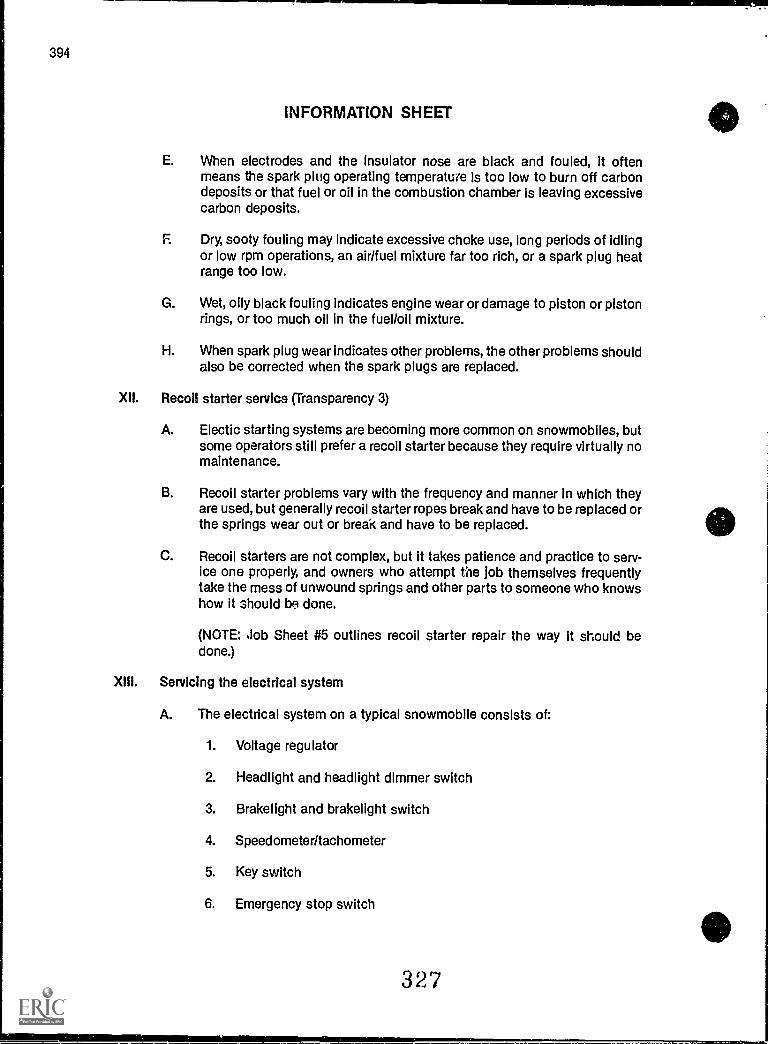
394
INFORMATION SHEET
E. When electrodes and the insulator nose are black and fouled, it oftenmeans the spark plug operating temperature is too low to burn off carbondeposits or that fuel or oil in the combustion chamber is leaving excessivecarbon deposits.
F. Dry, sooty fouling may indicate excessive choke use, long periods of idlingor low rpm operations, an airlfuel mixture far too rich, or a spark plug heatrange too low.
G. Wet, oily black fouling indicates engine wear or damage to piston or pistonrings, or too much oil in the fuel/oil mixture.
H. When spark plug wear indicates other problems, the other problems shouldalso be corrected when the spark plugs are replaced.
XII. Recoil starter service (Transparency 3)
A. Electic starting systems are becoming more common on snowmobiles, butsome operators still prefer a recoil starter because they require virtually nomaintenance.
B. Recoil starter problems vary with the frequency and manner in which theyare used, but generally recoil starter ropes break and have to be replaced orthe springs wear out or break and have to be replaced.
C. Recoil starters are not complex, but it takes patience and practice to serv-ice one properly, and owners who attempt the Job themselves frequentlytake the mess of unwound springs and other parts to someone who knowshow it should be done.
(NOTE: Job Sheet 415 outlines recoil starter repair the way it should bedone.)
XIII. Servicing the electrical system
A. The electrical system on a typical snowmobile consists of:
1. Voltage regulator
2. Headlight and headlight dimmer switch
3. Brake light and brakelight switch
4. Speedometer/tachometer
5. Key switch
6. Emergency stop switch
327
INFORMATION SHEET
B. Although some ignition testing requires special instruments, most of thecomponents in the electrical system can be tested with a muttimeter thatwill measure AC and DC voltages and resistance In ohms.
C. Electrical system troubleshooting should be systematic so that potentialtrouble spots can be quickly eliminated in a logical order before going on toproblems that require more time.
Example: Intermittent spark or no spark at all may be caused by a faultyground wire which can be checked in about two minutes.
328
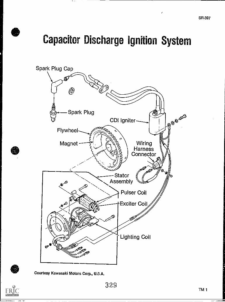
Capacitor Discharge Ignition System
Spark Plug Cap
\ire
Spark Plug
CD' Igniter--,Flywheel
Magnet WiringHarness
Connector
StatorAssembly
Pulser Coil
Exciter Coil
111111
Courtesy Kawasaki Motors Corp., U.S.A.
329
Lighting Coil
SR-397
TM 1
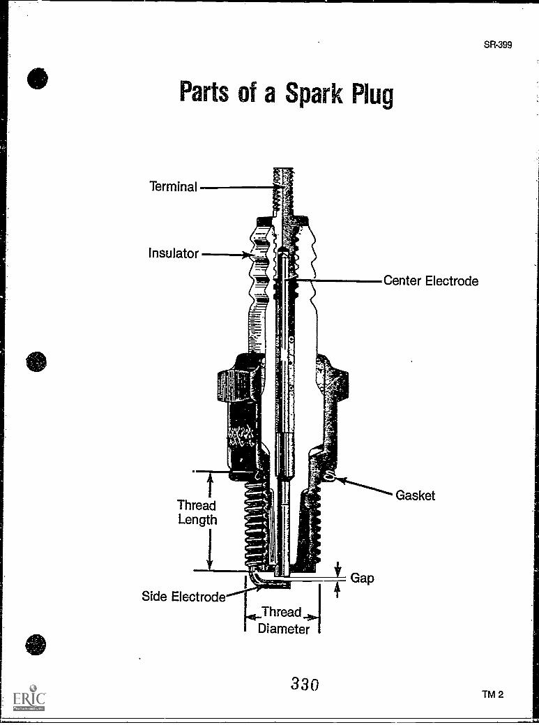
Parts of a Spark Plug
Center Electrode
ThreadLength
Side ElectrodeThreadDiameter
330
Gasket
SR-399
TM 2
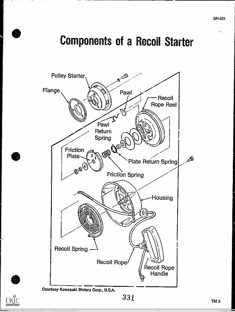
Components of a Recoil Starter
Pulley Starter
FlangeRecoil
Rope Reel
------'Pawl
j ReturnSpring
/'
riction /I Plate 7l R /
Plate Return Spring
Friction Spring
Housing
rRecoil Spring
Recoil Rope
Courtesy Kawasaki Motors Corp., U.S.A.
331
Recoil RopeHandle
SR-401
TM 3
IGNITION AND ELECTRICAL SYSTEMSUNIT XIII
JOB SHEET #1 - REMOVE, INSPECT, SERVICE, AND REPLACEA SNOWMOBILE BATTERY
A. Tools and materials
1. Snowmobile as selected by instructor
2. Appropriate service manual
3. Basic hand tools
4. Clean shop towels
5. Soda for cleaning
6. Wire brush
7. Hydrometer
8. Battery charger
9. Distilled water
10. Small funnel
11. Safety glasses
B. Routine #1 Removing the battery
1. Put on safety glasses.
2. Secure the sled and make sure the ignition is off.
3. Remove equipment as required to reach the battery compartment, and note howthe vent tube is routed.
4. Remove the negative cable from the battery post.
5. Remove the positive cable from the battery post.
6. Remove support brackets, and take battery from the snowmobile.
7. Place the battery in a well ventilated area away from any flammables or openflames.
Have your instructor check your work
332
SR- 403
404
JOB SHEET #1
C. Routine #2 Cleaning and inspecting the battery
1. Put on safety glasses.
2. Check the battery case to see if it is cracked or badly worn, and if it is, it shouldbe replaced.
(NOTE: Make the overall inspection first because there is no need to waste timecleaning a battery that has to be replaced.)
3. Wash the battery off with water and dry it with a shop towel so you can see intothe battery.
4. Look at the battery cells carefully to see if there is a whitish build-up between theplates or if the plates appear to be corroded, and if such wear is present, the bat-tery should be replaced.
5. Check for the presence of a whitish color around cells; if the whitish color ispresent, it indicates sulfation, and even if sulfation is present on only one cell,the battery should be replaced.
6. Inspect the case again for hairline cracks that would indicate the battery hasbeen frozen, and if cracks are present, the battery should be replaced.
7. Wash the battery posts with a soda solution, dry them, then clean them with awire brush.
8. Inspect the battery posts to see if there is damage from corrosion or crackscaused by overtightening, and if there is severe damage such as a loose post,the battery should be replaced.
Have your instructor check your work
D. Routine #3 Servicing the battery
1. Leave your safety glasses on.
2. Remove the filler caps from the battery.
3. Top off each cell with the right amount of distilled water, and be sure not to over-fill the cells.
4. Replace the filler caps.
5. Make sure the battery charger is OFF, and hook the battery up to the charger,positive cable first, negative cable last.
(NOTE: Even though the battery charger is off, develop the habit of always remov-ing the negative cable first and the positive cable last, and installing the positivecable first and negative cable last when working around any battery.)
6. Check the battery ampere-hour rating on the battery case, and charge thebattery at a rate of 10% of that rating. A higher charge rate could damage thebattery.
30r).)
SR- 405
JOB SHEET #1
7. Turn the battery charger OFF, and disconnect the cables, negative first, positivelast.
8. Remove the filler caps from the battery cells.
9. Use the hydrometer to draw electrolyte samples from each cell, and record yourfindings on the Battery Service Log that accompanies this job sheet.
10. Evaluate your hydrometer readings according to the following:
a. If specific gravity readings are within the range of 1.260 to 1.280, it indi-cates a fully charged battery.
b. If the readings from cell to cell vary more than .025, it usually means thereis internal battery deterioration and the battery should be replaced.
c. If the readings are less than 1.260, it indicates the battery needs charging.
11. Replace the filler caps.
12. Check the battery ampere-hour rating on the battery case, and charge the batteryat a rate of 10% of that rating.
13. Check the manufacture date on the battery and charge accordingly:
a. If the battery is less than 12 months old, charge 3 hours.
b. If the battery is 12 to 18 months old, charge 5 hours.
c. If the battery is 18 to 24 months old, charge 10 hours.
d. If the battery is more than 23 months old, charge 15 to 20 hours.
Have your instructor check your work
E. Routine #4 Making a battery voltage test
1. Put on safety glasses.
2. Set your multimeter to test DC voltage at 20V or 25V.
(NOTE: Sometimes a hydrometer test will show that a battery has proper specificgravity, but the battery may still be the problem; this test is the best way to dou-ble check the battery and also find out if the starter or cranking motor is thecause of the problem)
3. Make sure filler caps are all in place.
4. Place the red test lead from the test meter onto the positive (+) battery terminal.
334
406
JOB SHEET #1
5. Place the black test lead from the test meter onto the negative () battery termi-
nal.
6. Check the meter for a reading of 11 to 13 volts.
7. Watch your meter as you crank the engine for about 15 seconds.
a. If the meter drops to 9 volts or less while cranking the engine, the problem
is likely to be in the starter (cranking motor).
b. If the meter reading remains at 11 to 13 volts about 15 seconds after thecranking test, the battery is okay.
c. If the meter reading is lower than 11 volts after the cranking test, the bat-
tery should be replaced.
8. Recommend putting the battery back in place or replacing it according to your
findings.
Have your instructor check your work
F. Routine #5 Replacing the battery
1. Put on safety glasses.
2. Clean the battery compartment.
3. Check all battery cable connections to chassis ground and to the starting motor,
and clean and tighten as needed.
4. Coat the battery posts with light oil or petroleum jelly.
5. Put the battery in place and secure the support brackets.
6. Make sure the vent tube is in place and properly routed.
7. Replace and tighten the positive cable first, and then replace the negative cable.
8. Replace any equipment removed to reach the starter.
Have your instructor check your work
9. Clean up area and return tools and materials to proper storage.
3:45
. ,
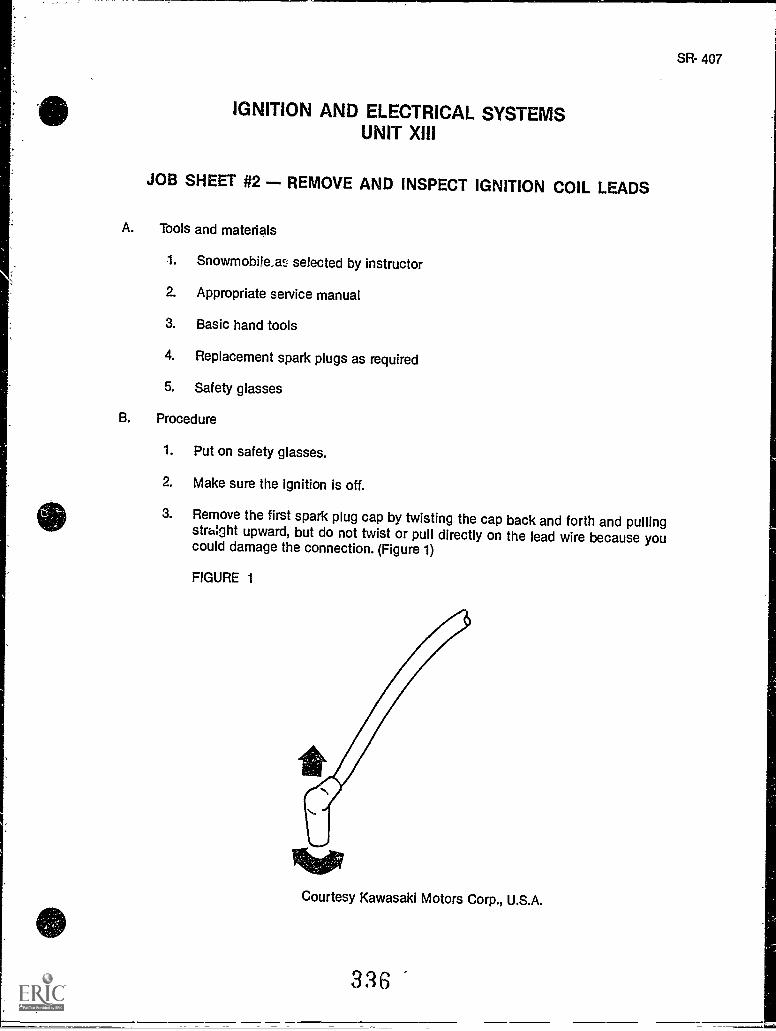
IGNITION AND ELECTRICAL SYSTEMSUNIT XIII
JOB SHEET #2 - REMOVE AND INSPECT IGNITION COIL LEADS
A. Tools and materials
1. Snowmobile,as selected by instructor
2. Appropriate service manual
3. Basic hand tools
4. Replacement spark plugs as required
5. Safety glasses
B. Procedure
1. Put on safety glasses.
2. Make sure the ignition is off.
3. Remove the first spark plug cap by twisting the cap back and forth and pullingstraight upward, but do not twist or pull directly on the lead wire because youcould damage the connection. (Figure 1)
FIGURE 1
Courtesy Kawasaki Motors Corp., U.S.A.
SR- 407
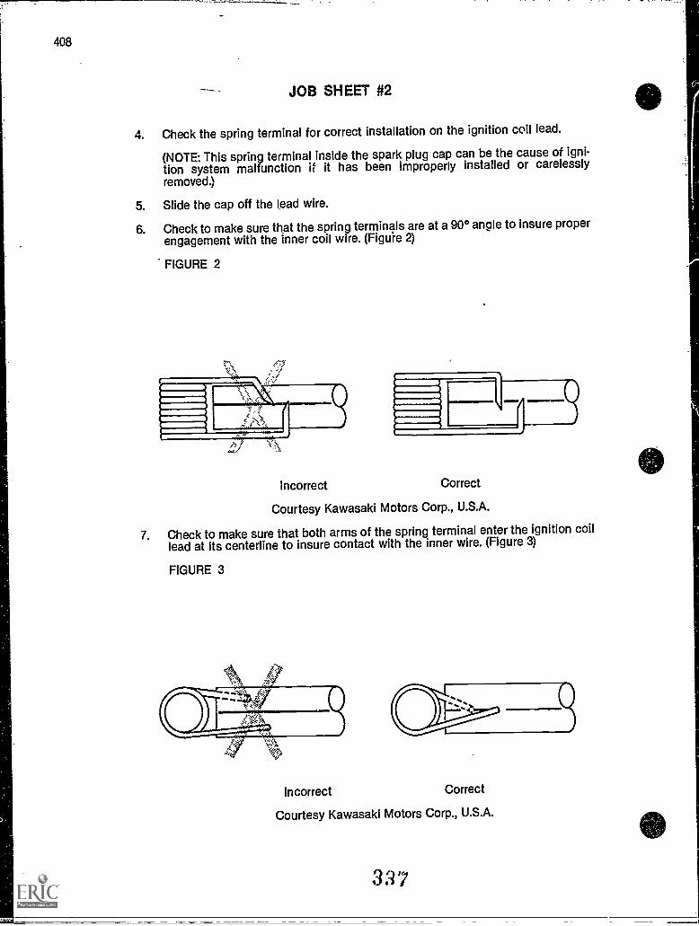
408
JOB SHEET #2
4. Check the spring terminal for correct installation on the ignition coil lead.
(NOTE: This spring terminal inside the spark plug cap can be the cause of igni-tion system malfunction if it has been improperly installed or carelessly
removed.)
5. Slide the cap off the lead wire.
6. Check to make sure that the spring terminals are at a 90° angle to insure properengagement with the inner coil wire. (Figure 2)
FIGURE 2
incorrect Correct
Courtesy Kawasaki Motors Corp., U.S.A.
7. Check to make sure that both arms of the spring terminal enter the ignition coillead at its centerline to insure contact with the inner wire. (Figure 3)
FIGURE 3
Incorrect Correct
Courtesy Kawasaki Motors Corp., U.S.A.
317
SR- 409
JOB SHEET #2
8. Correct spring terminal problems as required.
Have your instructor check your work
9. Slide the spark plug cap back onto the ignition coil lead so that it properly coversthe spring terminal.
10. Clean up area and return tools and materials to proper storage.
3 28
IGNITION AND ELECTRICAL SYSTEMSUNIT XIII
JOB SHEET #3 - REMOVE, INSPECT, AND TEST SPARKS PLUGS
A. Tools and materials
1. Snowmobile as selected by instructor
2. Appropriate service manual
3. Basic hand tools
4. Wire brush
5. Compressed air supply
6. Clean shop towels
7. Spark plug tester
8. Replacement spark plugs as required
9. Safety glasses
B. Routine #1 Removing and cleaning the spark plugs
1. Put on safety glasses.
2. Use compressed air to clean the area around the spark plugs.
3. Loosen the spark plugs one full turn, then clean the spark plug area with com-pressed air again to remove bits of dirt released from the spark plug threads.
4. Remove both plugs and inspect them for signs of electrode wear, discolorationthat would indicate other engine or timing problems, and for sooty or oily fouling.
5. Check the electrode gap with a feeler gauge.
SR- 411
(NOTE: It is not recommended to use sand-blast type abrasive spark plug cleaners.Some manufactures will void the warranty on their engine if a sand -blasted spark plug isinstalled in it. It has been shown that it is difficult to remove all of the sand in the plug andan engine can be ruined by only a little sand.
329
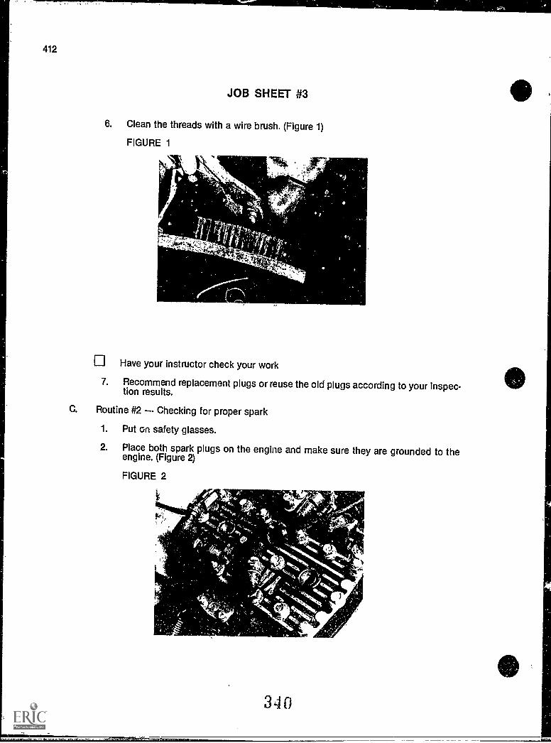
412
JOB SHEET #3
6. Clean the threads with a wire brush. (Figure 1)
FIGURE 1
Have your instructor check your work
7. Recommend replacement plugs or reuse the old plugs according to your inspec-tion results.
C. Routine #2 Checking for proper spark
1. Put on safety glasses.
2. Place both spark plugs on the engine and make sure they are grounded to theengine. (Figure 2)
FIGURE 2
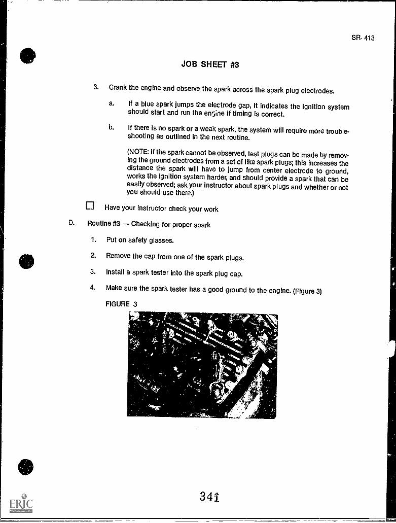
JOB SHEET #3
3. Crank the engine and observe the spark across the spark plug electrodes.
a. If a blue spark jumps the electrode gap, it indicates the ignition systemshould start and run the engine if timing is correct.
b. If there is no spark or a' weak spark, the system will require more trouble-shooting as outlined in the next routine.
(NOTE: if the spark cannot be observed, test plugs can be made by remov-ing the ground electrodes from a set of like spark plugs; this increases thedistance the spark will have to jump from center electrode to ground,works the ignition system harder, and should provide a spark that can beeasily observed; ask your instructor about spark plugs and whether or notyou should use them.)
Have your instructor check your work
D. Routine #3 Checking for proper spark
1. Put on safety glasses.
2. Remove the cap from one of the spark plugs.
3. Install a spark tester into the spark plug cap.
4. Make sure the spark tester has a good ground to the engine. (Figure 3)
FIGURE 3
341
SR- 413
414
JOB SHEET #3
5. Crank the engine one or two turns.
(CAUTION: Do not touch the spark tester as you are conducting this test becausethe high voltage can produce a severe shock.)
6. Observe the spark across the tester.
a. If the spark jumps the gap in the tester, the ignition system is okay and thespark plugs need to be replaced.
b. If there is no spark through the tester, the problem is elsewhere in the igni-tion system and will require further troubleshooting.
7. Remove the spark tester.
Have your instructor check your work
8. Replace old plugs or install new plugs.
9. Clean up area and return tools and materials to proper storage.
342
40
)
SP.- 415
IGNITION AND ELECTRICAL SYSTEMSUNIT XIII
JOB SHEET #4 - TROUBLESHOOT A SNOWMOBILEELECTRICAL SYSTEM
A. Tools and materials
1. Snowmobile as selected by instructor
2. Appropriate service manual
3. Basic hand tools
4. Multitester
5. Safety-glasses
B. Routine #1 Troubleshooting the stop circuit
1. Put on safety glasses.
(NOTE: It's easy to waste time with ignition problems if you perform elaboratetroubleshooting first; the routines that follow show you how to do the easy rou-tines first so you will save time.)
2. Check for good spark plugs and proper spark as outlined in a previous job sheet.
3. Trace the key switch and emergency stop switch circuits to the wiring harnessconnector on the engine.
4. Remove the key switch and emergency stop switch circuits from the system.
5. Make sure the sled is properly secured so the engine can be started.
6. Crank the engine.
a. If spark occurs with the key switch and emergency stop circuits discon-nected, the ignition components on the engine are okay, and the keyswitch, emergency stop switch, or the wiring (or a combination of these) isprobably defective.
b. If there is no spark at all, test ignition components mounted on the engine.
Have your instructor check your work
C. Routine #2 Troubleshooting the ground wire
1. Put on safety glasses.
343
416
JOB SHEET #4
2. Check the ground wire connections at the main engine terminals to make surethey are in good shape and securely mounted.
(NOTE: A loose ground wire connection can be the cause of an intermittentspark, and a broken connection will result in no spark at all.)
3. Find the ground wire between the terminal on the engine and the terminal on the
primary of the ignition coil.
(NOTE: Check your wiring schematic or ask your instructor for help if you havetrouble finding the proper ground wire.)
4. Remove the screws that secure the ground wire at all terminals.
5. Set the multimeter to read ohms on the lowest scale.
6. Connect one ohmmeter lead to the terminal end of the ground wire that youremoved from the ignition coil.
7. Connect the other ohmmeter lead to the terminal end of the ground wire that you
removed from the engine.
a. If the ohmmeter shows a 0 to indicate a closed circuit, the ground wirebetween the engine and the ignition coil is okay.
b. If the ohmmeter shows co to indicate an open circuit or high resistance,the ground wire is defective and should be replaced.
8. Find the ground wire between the CD igniter and the ignition coil And check itwith the procedure previously outlined.
a. If the wire is not okay, replace it and test again.
b. If the wire is okay, then the DC igniter is malfunctioning and should be
replaced.
Have your instructor check your work
D. Routine #3 Troubleshooting the key switch
1. Put on safety glasses.
2. Remove components as required to gain access to the terminals on the keyswitch.
3. Remove the main wiring harness connector from the key switch terminals.
4. Set the multitester to read ohms on the X100 scale.
344
JOB SHEET #4
5. Check the manufacturer's schematic to determine which terminals control theRUN and OFF circuit of the ignition system and which terminals control thelights and accessories.
6. Connect one ohmmeter lead to one terminal of the RUN/OFF circuit and theother ohmmeter lead to the other terminal of the RUN/OFF circuit.
7. Turn the key switch to the OFF position and watch the ohmmeter for a reading of0 to indicate a closed circuit, and if the ohmmeter does not move to 0, replace thekey switch.
8. Stu the ohnd.leter scale on XI and connect one ohmmeter lead to one of the lightcircuit terminals on the key switch and the other ohmmeter lead to the other lightcircuit terminal.
9. Turn the key switch to the RUN/LIGHTS position and watch the ohmmeter for areading of 0 to indicate a closed circuit, and if the ohmmeter does not move to 0,replace the key switch.
10. Leave test leads connected and turn the key switch to the RUN or OFF positionand look for a co to indicate an open circuit, and if the co is not there, replace thekey switch.
E. Routine #4 Troubleshooting the emergency stop switch
1. Put on safety glasses.
2. Disconnect the connector betwe 1 the key switch and the emergency stopswitch.
3. Set the multimeter to read ohms on the X100 scale.
4. Connect one ohmmeter lead to one terminal in the stop switch half of the con-nector and the other ohmmeter lead to the other terminal in the stop switch halfof the connector.
5. Turn the stop switch to the ON position, and watch the ohmmeter for a reading ofco which indicates an open circuit, and if the needle moves off the co reading,replace the stop switch.
6. Turn the stop switch to the STOP position and watch the ohmmeter for a readingof 0 to indicate a closed circuit, and if the needle does not indicate0, replace ti aemergency stop switch.
Have your instructor check your work
7. Replace the old switch or put in a new switch as required and reconnect the con-nector.
345
SR- 417
418
JOB SHEET #4
E Routine #5 Troubilshooting the voltage regulator
1. Put on safety glasses.
2. Raise the rear of the sled and make sure the track can be safely rotated.
(CAUTION: Place the ski tips against a stationary object to Insure the sled can-not move.)
3. Set the multimeter to read 25 volts AC.
(NOTE: The following tests should always be conducted if bulbs consistentlyburn out or if the lights are too dim, and remember that melted filaments in ahdib indicate over-voltage out of the regulator, and broken filaments indicate
vibration or other problems.)
4. Attach one test lead to one of the wires in the main harness half of the engineconnector, and the other lead to the other wire, but be sure you are not puttingeither lead on the ground wire.
(NOTE: Check a schematic to be sure, but both wires should be the same color,
and the ground wire will be a different color.)
5. Turn the key switch to the RUN position, start the engine, and allow it to idle butdo not run it over 2,000 RPM, and do not activate the brake light during the volt-
age regulator test.
6. Watch the needle on the test meter for a reading of 8 to 11 volts which will indi-cate that the lighting coil and the voltage regulator are both okay.
a. If the reading is less than 8 volts go on to Step 8.
b. If the reading is more than 11 volts, go on to Step 7.
7. Increase the engine RPM slowly, but do not exceed 3,000 RPM, and if the voltagereading doesn't stabilize at 8 to 11 volts, or if the voltage exceeded 22volts, thevoltage regulator should be replaced.
8. Disconnect the voltage regulator from the main wiring harness while the engineis running at about 2,000 RPM, and watch for the meter needle to move to some-where between 14 and 20 volts.
a. If the voltage does not increase, the problem is in the magneto lightingcoil circuit.
b. If the voltage does increase, it could mean a shorted voltage regulator, ashorted tachometer, or a short in the main harness wiring.
346
SR -419
JOB SHEET #4
9. Unplug the tachometer connector from the main wiring harness and repeat thetest to confirm whether it is or is not a tachometer short.
10. Replace or repair the main wiring harness to determine if the wiring harness isthe source of the trouble.
11. Replace the voltage regulator if it is shorted, and be sure the connection to themain harness is good and tight and that the regulator case is properly grounded.
Have your instructor check your work
12. Clean up area and return tools and materials to proper storage.
347
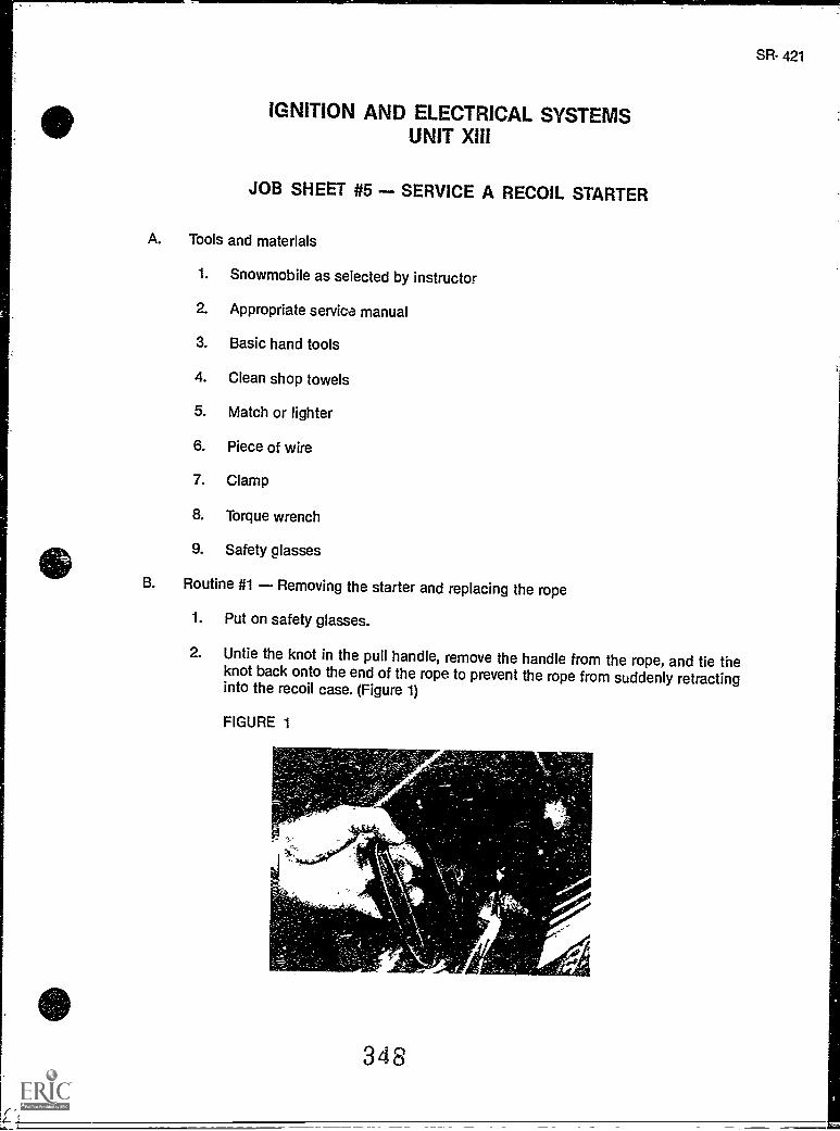
z
IGNITION AND ELECTRICAL SYSTEMSUNIT XIII
JOB SHEET #5 - SERVICE A RECOIL STARTER
A. Tools and materials
1. Snowmobile as selected by instructor
2. Appropriate service manual
3. Basic hand tools
4. Clean shop towels
5. Match or lighter
6. Piece of wire
7. Clamp
8. Torque wrench
9. Safety glasses
B. Routine #1 Removing the starter and replacing the rope
1. Put on safety glasses.
2. Untie the knot in the pull handle, remove the handle from the rope, and tie theknot back onto the end of the rope to prevent the rope from suddenly retractinginto the recoil case. (Figure 1)
FIGURE 1
348
SR- 421
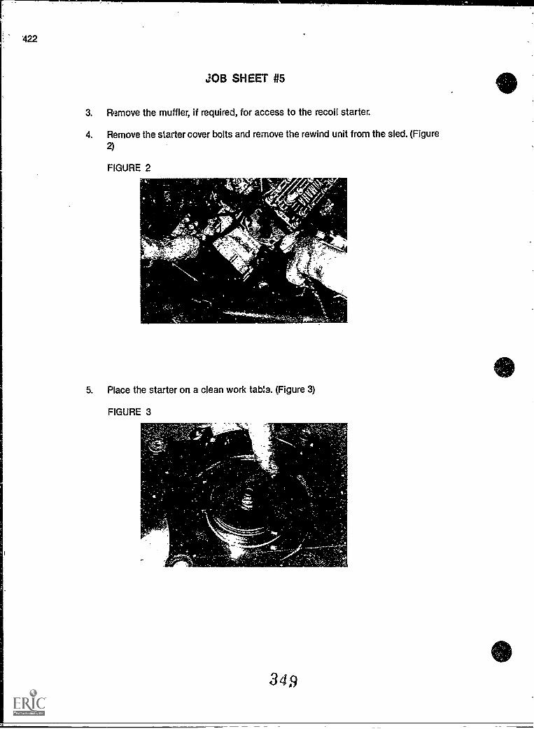
422
JOB SHEET #5
3. Remove the muffler, if required, for access to the recoil starter.
4. Remove the starter cover bolts and remove the rewind unit from the sled. (Figure2)
FIGURE 2T.
'c,
5. Place the starter on a clean work table. (Figure 3)
FIGURE 3
.......,--
349
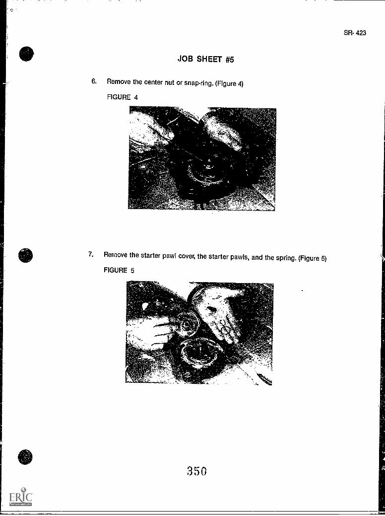
JOB SHEET #5
6. Remove the center nut or snap-ring. (Figure 4)
FIGURE 4
SR- 423
7. Remove the starter pawl cover, the starter pawls, and the spring. (Figure 5)
FIGURE 5
350
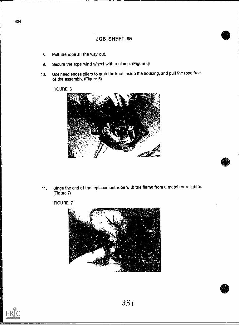
424
JOB SHEET #5
8. Pull the rope all the way out.
9. Secure the rope wind wheel with a clamp. (Figure 6)
10. Use needlenose pliers to grab the knot inside the housing, and pull the rope free
of the assembly. (Figure 6)
11. Singe the end of the replacement rope with the flame from a match or a lighter.
(Figure 7)
FIGURE 7
351
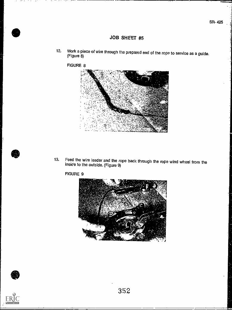
JOB SHEET #5
SR- 425
12. Work a piece of wire through the prepared end of the rope to service as a guide.(Figure 8)
FIGURE 8
13. Feed the wire leader and the rope back through the rope wind wheel from theinside to the outside. (Figure 9)
FIGURE 9
352
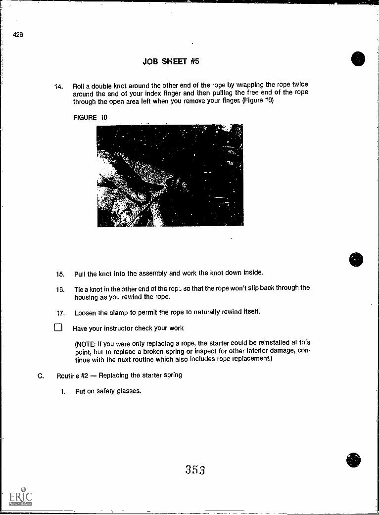
JOB SHEET #5
14. Roil a double knot around the other end of the rope by wrapping the rope twicearound the end of your index finger and then pulling the free end of the ropethrough the open area left when you remove your finger. (Figure 10)
FIGURE 10
15. Pull the knot into the assembly and work the knot down inside.
16. Tie a knot in the other end of the rap:, so that the rope won't slip back through thehousing as you rewind the rope.
17. Loosen the clamp to permit the rope to naturally rewind itself.
Have your instructor check your work
(NOTE: If you were only replacing a rope, the starter could be reinstalled at thispoint, but to replace a broken spring or inspect for other interior damage, con-tinue with the mxt routine which also includes rope replacement.)
C. Routine #2 Replacing the starter spring
1. Put on safety glasses.
353
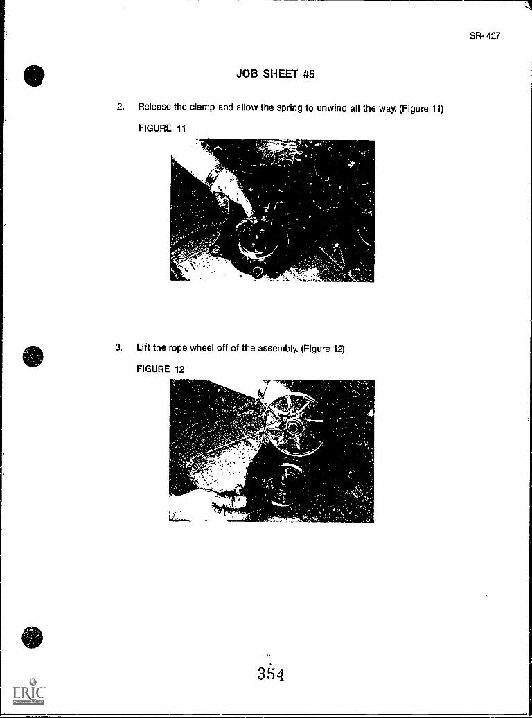
JOB SHEET #5
2. Release the clamp and allow the spring to unwind all the way. (Figure 11)
FIGURE 11
e,
3. Lift the rope wheel off of the assembly. (Figure 12)
FIGURE 12
354
SR- 427
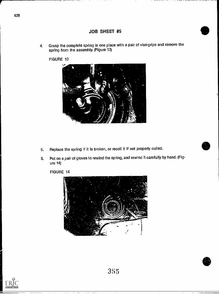
428
JOB SHEET #5
4. Grasp the complete spring in one place with a pair of vise-grips and remove thespring from the assembly. (Figure 13)
FIGURE 13p
...!...v4
5. Replace the spring if it is broken, or recoil it if not properly coiled.
6. Put on a pair of gloves to rewind the spring, and rewind it carefully by hand. (Fig-
ure 14)
FIGURE 14
1
4
./....""sk
1 355
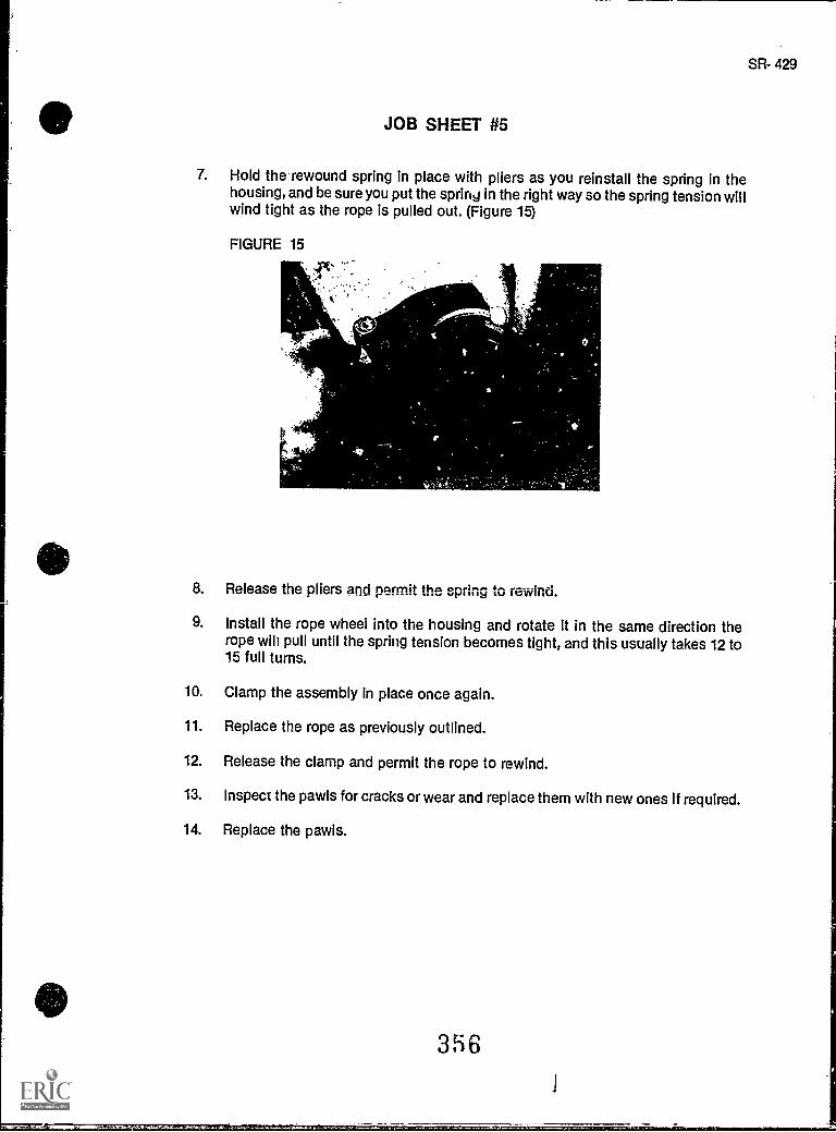
SR- 429
JOB SHEET #5
7. Hold the rewound spring in place with pliers as you reinstall the spring in thehousing, and be sure you put the spring in the right way so the spring tension willwind tight as the rope is pulled out. (Figure 15)
FIGURE 15
,
8. Release the pliers and permit the spring to rewind.
9. Install the rope wheel into the housing and rotate it in the same direction therope will pull until the spring tension becomes tight, and this usually takes 12 to15 full turns.
10. Clamp the assembly In place once again.
11. Replace the rope as previously outlined.
12. Release the clamp and permit the rope to rewind.
13. Inspect the pawls for cracks or wear and replace them with new ones if required.
14. Replace the pawls.
3i6
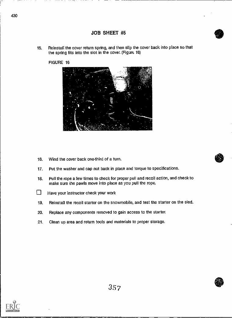
430
JOB SHEET #5
15. Reinstall the cover return spring, and then slip the cover back into place so thatthe spring fits into the slot in the cover. (Figure 16)
FIGURE 16
16. Wind the cover back one-third of a turn.
17. Put the washer and cap nut back in place and torque to specifications.
18. Pull the rope a few times to check for proper pull and recoil action, and check tomake sure the pawls move into place as you pull the rope.
Have your instructor check your work
19. Reinstall the recoil starter on the snowmobile, and test the starter on the sled.
20. Replace any components removed to gain access to the starter.
21. Clean up area and return tools and materials to proper storage.
357
IGNITION AND ELECTRICAL SYSTEMSUNIT XIII
NAME
TEST
1. Match the terms on the right with their correct definitions.
a Electric current which reverses its direction 1. Ohmof flow at r lular intervals
2. Inductionb Electric current which flows in only one
direction 3. Alternator
c The unit of measurement for current flow 4. Alternating current
d The unit of measurement of electrical pres- 5. Rectifiersure
6. Amperee The unit of measurement of resistance to
electrical flow 7. Direct current
f A generator which produce alternating cur- 8. Capacitorrent
9. Voltg A device capable of storing limited amounts
of electrical power for discharge at a prede-termined time or on a predetermined signal
h A device that changes alternating currentinto direct current
i The process of changing an object by bring-ing it into the magnetic field of an electro-magnet or permanent magnet
2. Select true statements concerning snowmobile electrical requirements by placing an"X" beside each statement that is true.
(NOTE: For a statement to be true, all parts of the statement must be true.)
a The three basic electrical needs on a snowmobile are:
1) An ignition system to stet the engine
2) An electrical system to operate lights
3) An alternator to operate accessories
358
4.
SR- 431
432
TEST
b Starting a snowmobile engine can be accomplished with a battery-basedelectric start unit or with a recoil starter that is c",sanually operated.
c Electrical demands for ignition and for lighting and accessories are twoseparate functions, and although the two systems are related, they oper-ate as individual systems.
d An ignition system produces high voltage required to jump the gap of thespark plug electrodes and ignite the air/fuel mixture in the combustionchamber of the engine.
e Lower voltage alternating current is used for lights and accessories, andAC output is stabilized through a voltage regulator.
3. Complete a statement concerning battery ignition systems by insekling the word(s) orfigure(s) that best completes each statement.
a. Battery ignition systems are found mostly on sleds.
b. In a battery ignitioi system, the battery supplies electrical current to the starteror cranking motor which is a motor that works with brushes anda commutator.
c. The battery supplies power for the primary ignition circuit, and timing is accom-plished with and a condenser.
d. When are replaced in this type system, the con-denser should also be replaced.
e. A battery ignition system may produce up to 10,000 volts to fire the spark plugs,and electricity for lights and accessories are on a separate cir-cuit.
f. Alternator output is also used to
g. Cranking motors or starters should not be operated continuously for more thanseconds, and a cool-down period of 30 seconds or more should
be observed at starting intervals.
h. Demands of cold weather, vibration, and frequent stopping/starting require thatbatteries be inspected frequently for proper electrolyte level, corrosion-free con-nections, and proper
SR- 423
TEST
4. Solve the following problems concerning battery service.
a. What is the very first step in all battery service?
Answer
b. Which cable should be removed first when performing battery service and whenshould it be replaced?
Answer
c. Name at least two times when a battery should be inspected.
Answer
5. Select tn.?. statements concerning magneto ignition systems by placing an "X" besideeach statement that is true.
a Magneto ignition systems use rotating magnets to induce current in theprimary ignition circuit.
b Magneto ignition systems are energy transfer systems, accomplish timingwith breaker points and a condenser, and are serviced like other breakerpoint/condenser systems.
c A magneto ignition system may produce up to 10,000 volts to fire the sparkplugs, and uses an alternator to provide AC electricity for lights and acces-sories.
6. Complete statements concerning capacitor discharge systems by inserting the word(s)or figure(s) that best completes each statement.
a. Capacitor discharge ignitions systems are the most ignition sys-tems found on modern snowmobiles.
b. CD! systems are popular because they do not useand are easy to service.
c. CDI systems use rotating magnets to induce current into awhich stores the current until another impulse causes the to dis-charge and fire the spark plugs.
d. A CDI system may produce as high as volts to fire the sparkplugs, anc this gives the CDI system an extra punch that also makes it more pop-ular than other ignition systems.
e. A CDI system has a lighting coil to provide AC electricity to thefor operating lights and accessories.
360
434
TEST
7. Match components with their functions in a CDI system.
a Houses four permanent magnets which pro- 1. Ignition coilvide a moving magnetic field as the flywheelrotates around the coils in the stator assem- 2. Lighting coilbly.
3. Flywheelb Houses the exciter, pulsing, and lighting
coils. 4. Pulser coil
c. Charges the capacitor in the CDI igniter. 5. Stator assembly
d. Signals the capacitor in the CDI igniter 6. Exciter coilwhen to release its charge to the ignitioncoil.
e. A coil with primary and secondary windingsthat induce the high voltage needed to jumpthe air gap on the spark plugs.
f. Provides alternating current for the lightsand instruments in the electrical system.
8. Complete statements concerning CDI operations by inserting the word(s) that bestcompletes each statement.
a. As the flywheel rotates, alternating current is induced in themounted on the stator.
b. The coil sends a charge to the capacitor which stores the charge, and theamount of charge the coil gives the capacitor affects the inten-sity of the spark.
c. The coil causes the capacitor in the CDI igniter to release itsstored energy, but the coil is only a signaling device and it has noaffect on the intensity of the spark.
d. The primary winding in theondary winding of thethe spark plug electrodes.
coil induces a high voltage in the sec-coil, and causes a spark to jump across
e. The ignition coil fires high voltage charges to the spark plugseach time the flywheel makes one complete rotation.
361
SR- 435
TEST
9. Complete statements concerning safety features in a CDI system by inserting theword(s) that best completes each statement.
a. For both safety and , a snowmobile engine needs to stop andstart at the turn of a switch, but the sled also needs to stop if the rider shouldlose control and fall off.
b. The on a snowmobile permits the engine to bestarted or stopped with the turn of a key and services both safety and conven-ience.
c. The is strictly a safety devicethat will stop the engine if the rider is thrown off and the throttle handle is sud-denly released.
d. Together, the andfunction to protect both the sled and the rider,
and they are both connected to CDI igniter leads.
e. The two switches work independently of each other, and when either switch ispositioned to , all charging to the capacitor stops, there can beno charge transmitted from the igniter coil to the spark plugs, and the sle-i. stops.
f. The andshould never be , and a sled with problems in
either of these circuits sho'Ad not ba used until the problems are corrected.
10. Solve problems concerning spark plug service.
a. Why should the engine area around a spark plug be cleaned before the plug isremoved?
Answer
5. A replacement spark plug should be the same size as the original, but what otherrequirement must a replacement plug meet?
Answer
11. Complete statements concerning how to use spark plug wear as troubleshooting guide-lines by inserting the word(s) that best completes each statement.
a. Discoloration and are two ways that the condition of a sparkplug can reflect MCher operating conditions that need attention.
b. After service, a spark plug used with regular gas will be a shade of, tan or yellow, and if the plug was dsed with unleaded gas, nor-
mal color will be a shade of .
382
436
TEST
c. An insulator that has turned indicates overheat-ing, and an insulator that is blistered, especially with an eroded or melted elec-trode, indicates overheating.
d. Overheating may mean ignition timing is advanced too far, the air/fuel mixture istoo lean, coolant or air flow problems over the cooling fins, or a spark plug with
a heat range.
e. When electrodes and the insulator nose are black and fouled, it often means thespark plug operating temperature is to burn offcarbon deposits or that fuel or oil in the combustion chamber is leaving exces-sive carbon deposits.
f. Dry, sooty foulings may indicate excessive use, long periods ofidling or RPM operations, and air/fuel mixture far too rich, or aspark plug heat range too lov..r.
9. Wet, oily black fouling indicates engine wear or damage to or, or too much oil in the fuel/oil mixture.
h. When spark plug wear indicates other problems, the other problems should alsobe when the spark plugs are replaced.
12. Select true statements concerning recoil starter service by placing an "X" beside eachstatement that is true.
a Electric starting systems are becoming more common on snowmobiles,but some operators still prefer a recoil starter because they require virtu-ally no maintenance.
b Recoil starter problems vary with the frequency and manner in which theyare used, but generally recoil starter ropes break and have to be replacedor the springs wear out or break and have to be replaced.
c Recoil starters are not complex, but it takes patience and practice to serv-ice one properly, and owners who attempt the job themselves frequentlytake the mess of unwound springs and other parts to someone who knowshow it should be done.
13. Complete the statements concerning the electrical system by insertingthe word(s) that best completes each statement.
a. The electrical system on a typical snowmobile consists of:
1) Voltage
2) Headlight and headlight dimmer
3) Brakelight and brakelight
4) Speedometer!
5) switch
6) switch3 (-33
TEST
SR- 437
b. Although some ignition testing requires special instruments, most of the compo-nents in the electrical system can be tested with a multimeter that will measure
and v)Itages and in ohms.
c. Electrical system troubleshooting should be so that potentialtrouble spots can be quickly eliminatc... in a logical order before going on to prob-lems that require more time.
(NOTE: If the following activities have not been accomplished prior to the test, ask yourinstructor when they should be completed.)
14. Demonstrate the ability to:
a. Remove, inspect, service, and replace a snowmobile battery. (Job Sheet #1)
b. Remove and inspect ignition coil leads. (Job Sheet #3)
c. Remove, inspect, and test spark plugs. (Job Sheet #3)
d. Troubleshoot a snowmobile electrical system. (Job Sheet #4)
e. Service a recoil starter. (Job Sheet #5)
364
IGNITION AND ELECTRICAL SYSTEMSUNIT XIII
ANSWERS TO TEST
1. a. 4 f. 3b. 7 g. 8c. 6 h. 5d. 9 i. 2e. 1
2. b, d, d, e
I a. Olderb. DCc. Breaker pointsd. Breaker pointse. ACf. Charge the batteryg. 30h. Venting
4. a. Put on safety glasses.b. Remove the negative cable first, replace it lastc. After long periods of storage or after the sled has been subjected to high vibra-
tions
5. a, b, c
6. a. Commonb. Breaker pointsc. Capacitor, capacitord. 40,000e. Voltage regulator
7. a. 3b. 5c. 6d. 4e. 1
f. 2
8. a. Coilsb. Exciter, exciterc. Pulse; pulserd. Ignition, ignitione. Twice
365
SR- 439
II
A
440
ANSWERS TO TEST
9. a. Convenienceb. Key switchc. Emergency stop switchd. Key switch, emergency atop switche. STOPf. Key switch, emergency stop switch, altered
10. a. To keep dirt or debris from falling in the combustion chamberb. It must have the proper heat range
11. a. Foulingb. Brown, grayc. Chalk white, extremed. Too highe. Too lowf. Choke, lowg. Piston, piston ringsh. Corrected
12. a, b, c
13. a. 1) Regulator2) Switch3) Switch4) Tachometer5) Key6) Emergency stop
b. AC, DC, resistancec. Systematic
14. Performance skills evaluated according to procedures written in the job sheets
3 R6
aUCIIIMMINIIIIMMIIIMINIII11W
te1;--"'"
UNIT OBJECTIVE
STORAGEUNIT XIV
After completion of this unit, the student should be able to discuss procedures for storing asnowmobile and removing a snowmobile from storage. The student should also be able to !istcommercial products available to aid in storage preparation and be able to prepare a snowmo-bile for summer storage. These competencies will be evidenced by correctly performing theprocedures outlined in the assignment and job sheets and by scoring 85 percent on the unittest.
SPECIFIC OBJECTIVES
After completion of this unit, the student will be able to:
1. Match terms related to storage with their correct definitions.
2. Select true statements concerning cleaning.
3. Complete statements concerning engine preparation.
4. Select true statements concerning battery preparation.
5. Select true statements concerning drive drain preparation.
6. Complete statements concerning lubrication and storage.
7. Solve problems related to snowmobile storage. (Assignment Sheet #1)
8. Demonstrate the ability to prepare a snowmobile for summer storage. (Job Sheet#1)
3(37
SR- 441
SR- 443
STORAGEUNIT XIV
SUGGESTED ACTIVITIES
A. Provide students with objective sheet.
B. Provide students with information sheet.
C. Discuss unit and specific objectives.
D. Discuss information sheet.
E. Demonstrate and discuss the procedures outlined in the job sheet.
F. Impress upon students the care that should be exercised when taking a sled out of stor-age.
G Give test.
CONTENTS OF THIS UNIT
A. Objective sheet
B. Information sheet
C. Assignment Sheet #1 Solve Problems Related to Snowmobile Storage
D. Answers to assignment sheet
E. Job Sheet #1 Prepare a Snowmobile for Summer Storage
F Test
G. Answers to test
REFERENCES USED IN DEVELOPING THIS UNIT
A. Chilton's Snowmobile Repair & Tune-Up Guide, Second edition. Radnor, 0A; ChiltonBook Co., 1975.
B. Arctic Cat Service Manual No. 2254-302. Thief River Falls, MN 56701: ARTCO, Inc., 1984.
C. 1986 Yamaha Snowmobile Mechanics Guide. Cypress, CA. Yamaha Motor Corporation,U.S.A., 1985.
D. Kawasaki Drifter Snowmobile Assembly & Preparation Manual. Santa Ana, CA 92799-5252: Kawasaki Motors Corp., U.S.A., 1980.
SR- 445
STORAGEUNIT XIV
INFORMATION SHEET
I. Terms and definitions
A. Humidity Moisture in the Jr
B. Fogging The process of filling an engine with an oil and air mixture toprotect it from corrosion during summer storage
C. Varnishing The formation of gum in the carburetor from the residue offuel and oil
D. Polish A wax product used to give the chassis of a vehicle a high lusterand protection from the elements
E. Fuel conditioner An additive to the fuel/oil mixture which helps protectthe engine and internal parts from corrosion
F. Engine corrosion inhibitors Chemicals sprayed or applied to the internalengine components to protect the engine from rust
II. Cleaning
A. Corrosion and rust probably damage more snowmobiles in summer storagethan in winter use.
B. Foreign material, dirt, grime, grass, and oil which collects on a snowmobileduring winter use can serve to attract and hold humidity which causes rust.
C. An essential procedure to prevent rust during summer storage is to cleanthe entire snowmobile thoroughly of all foreign material.
D. A thorough washing is required under the seat cushion, in the tunnel, theskid frame, hood and belly pan, as well as the track and suspension sys-tem.
(NOTE: Do not allow any water to spill onto the engine or its componentparts.)
E. The snowmobile must be allowed to dry thoroughly before storage.
F. Always use an available automotive-type polish, or one recommended bythe sno",mobile manufacturer, to wax the hood, console, and exterior.
3f9
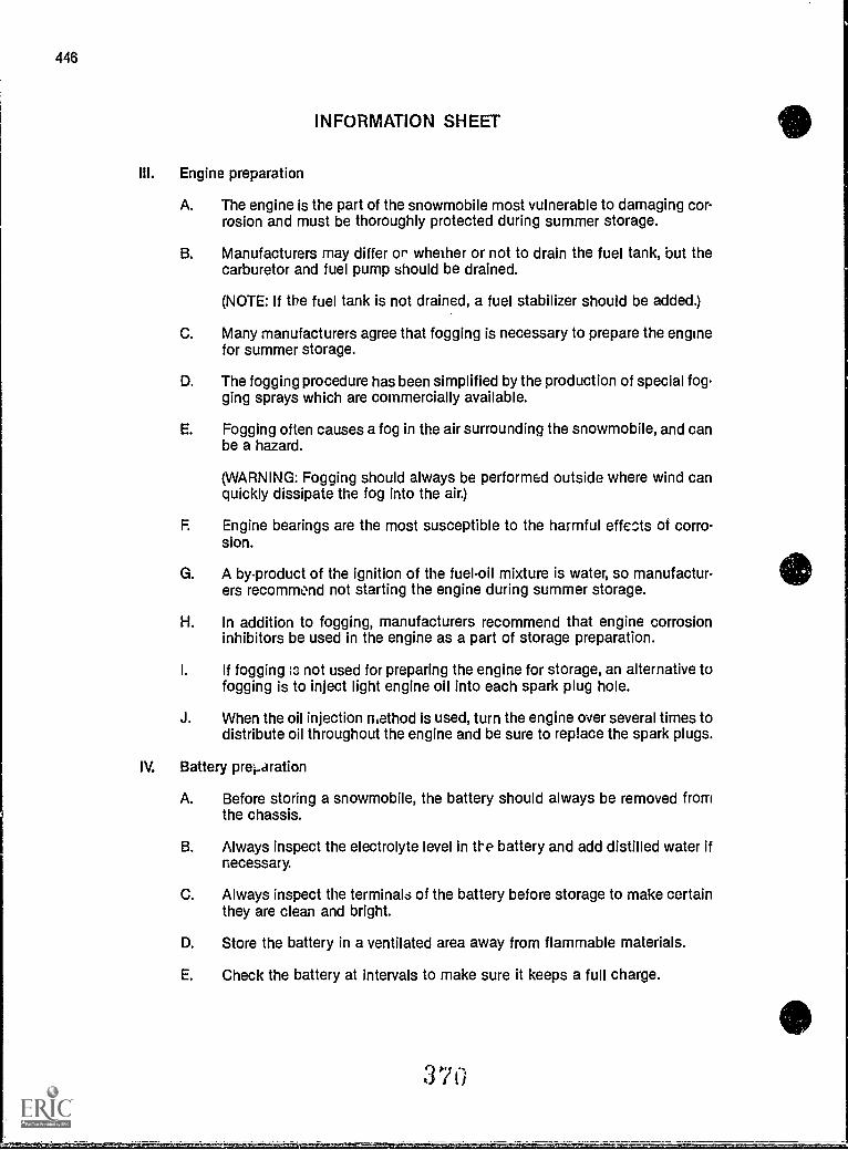
446
INFORMATION SHEET
III. Engine preparation
A. The engine is the part of the snowmobile most vulnerable to damaging cor-rosion and must be thoroughly protected during summer storage.
B. Manufacturers may differ or whether or not to drain the fuel tank, but thecarburetor and fuel pump should be drained.
(NOTE: If the fuel tank is not drained, a fuel stabilizer should be added.)
C. Many manufacturers agree that fogging is necessary to prepare the enginefor summer storage.
D. The fogging procedure has been simplified by the production of special fog-ging sprays which are commercially available.
E. Fogging often causes a fog in the air surrounding the snowmobile, and canbe a hazard.
(WARNING: Fogging should always be performed outside where wind canquickly dissipate the fog into the air.)
F. Engine bearings are the most susceptible to the harmful effects of corro-sion.
G. A by-product of the ignition of the fuel-oil mixture is water, so manufacturers recommend not starting the engine during summer storage.
H. In addition to fogging, manufacturers recommend that engine corrosioninhibitors be used in the engine as a part of storage preparation.
I. If fogging :c not used for preparing the engine for storage, an alternative tofogging is to inject light engine oil into each spark plug hole.
J. When the oil injection method is used, turn the engine over several times todistribute oil throughout the engine and be sure to replace the spark plugs.
IV. Battery preparation
A. Before storing a snowmobile, the battery should always be removed fromthe chassis.
B. Always inspect the electrolyte level in the battery and add distilled water ifnecessary.
C. Always inspect the terminals of the battery before storage to make certainthey are clean and bright.
D. Store the battery in a ventilated area away from flammable materials.
E. Check the battery at intervals to make sure it keeps a full charge.
370
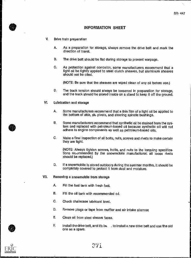
SR- 447
INFORMATION SHEET
V. Drive train preparation
A. As a preparation for storage, always remove the drive belt and mark thedirection of travel.
B. The drive belt should be flat during storage to prevent warpage.
C. As protection against corrosion, some manufacturers recommend that alight oil be lightly applied to steel clutch sheaves, but aluminum sheavesshould not be oiled.
(NOTE: Be sure that the sheaves are wiped clean of any oil betore use.)
D. The track tension should always be loosened in preparation for storage,and the track should be stored inside on a stand to keep it off the ground.
VI. Lubrication and storage
A. Some manufacturers recommend that a thin film of a light oil be applied tothe bottom of skis, ski pivots, and steering spindle bushings.
B. Some manufacturers recommend that synthetic oil be drained from the sys-tem and replaced with petroleum-based oil because synthetic oil will notadhere to engine components as well as petroleum-based oils.
C. Make a final inspection of all bolts, nuts, screws and rivets to make certainthey are tight.
(NOTE: Always tighten screws, bolts, and nuts to the torquing specifica-tions recommended by the snowmobile manufacturer; all loose rivetsshould be replaced.)
D. If a snowmobile is stored outdoors during the summer months, it should becompletely covered to protect it from dust and moisture.
VII. Removing a snowmobile from storage
A. Fill the fuel tank with fresh fuel.
B. Fill the oil tank with recommended oil.
C. Check chaincase lubricant level.
D. Remove plugs or tape from muffler and air intake silencer.
E. Clean oil from steel sheave faces.
F. Install the drive belt, and it's bb . to install a new drive belt and use the oldone as a spare.
INFORMATION SHEET
G. Inspect all control wires and cables for proper operation.
H. Adjust track to proper tension and alignment.
I. Inspect spark plugs, replace, gap, or clean as required.
(NOTE: After first starting the engine after storage, leave the old sparkplugs in awhile so they will collect oil used in storage, and then put in thenew plugs.)
J. Start the engine and let the track rotate at low speed.
K. Stop engine and check track alignment and adjust as required.
L. Lower the vehicle from blocks.
372
0 STORAGEUNIT XIV
ASSIGNMENT SHEET #1 - SOLV.:: PROBLEMS RELATED TOSNOWMOBILE STORAGE
A. A friend who owns a snowmobile Zi.J9S that he doesn't have enough time to preparehis snowmobile for summer storage, and time is money as far as he is concerned. Whycould it be much more expene!ve for him not to properly prepare his snowmobile forstorage?
B. Why is it so important to clean the snowmobile of dirt, grime, and grass?
C. What purpose does fogging have in the preparation for summer storage?
D. What precaution must be taken when performing fogging?
E. You have no facility for storing your snowmobile indoors. What alternative do you haveavailable?
373
STORAGEUNIT XIV
ANSWERS TO ASSIGNMENT SHEET
A. Improper storage and failure to protect the engine from corm )n during the long stor-age period could have a very costly effect. Corrosion inside the engine crankcase, espe-cially to bearings, can destroy the engine over time i, not corrected. Even if corrected,repairs to a crankcase can cost into the hundreds of dollars.
B. Dirt, grime, grass, and other foreign matter act as collecting agents for moisture in theair. That moisture serves as the agent for producing rust which can destroy the chassisand all metal components of the snowmobile.
C. Fogging provides a protective lubricating coating to the internal parts of the engine andcarburetor from the harmful effects of any moisture which could easiiy be trapped asresidue from combustion.
D. Fogging creates a hazardous mist which can enshroud the snowmobile and immediatearea. Always perform fog out outdoors where fog can be easily dissipated by winds.
E. The only alternative is to use a heavy tarpaulin or snowmobile cove, and to raise thesnowmobile off the ground making certain no components of the snowmobile areexposed to rain or dust.
374
SR- 451
SR- 453
STORAGEUNIT XIV
JOB SHEET #1 - PREPARE A SNOWMOBILE FOR SUMMER STORAGE
A. Tools and materials
1. Snowmobile as selected by instructor
2. Appropriate service manual
3. Polish, cleaner, and clean rags
4. Engine oil
5. A light petroleum-based oil
6. Spark plug remover
7. Safety stand
8. Fuel stabilizer
9. Engine corrosion inhibitor
10. Chaincase lubricant
11. Safety glasses
B. Procedure
1. Put on safety glasses.
2. Remove the seat cushion from the tunnel and clean it with a damp cloth; store itin a dry place.
3. Wash the snowmobile thoroughly by hosing dirt, oil, grass and other foreign mat-tt..r from the skid frame, tunnel, hood, and belly pan being very cautious not togetwater into any part of the engine.
4. Move the sled outside and drain the fuel tank or add fuel stabilizer if you don'tdrain the tank.
5. Start the engine and allow it to idle.
6. Spray a two-stroke petroleum-based oil rapidly into the carburetor air intake forup to 20 to 30 seconds or until the engine stops.
(WARNING: Since this fogging procedure creates a hazardous mist, It shouldonly be performed outdoors.)
375
Entivemmorommtauhavair
JOB SHEET #1
7. Drain carburetor and fuel lines.
8. Plug holes in the muffler and air-intake silencer with clean cloths or tape.
9. Use the following procedure as an alternative to fogging:
a. Put the ignition key in the "OFF" position, disconnect the high tensionwires from the spark plugs-and remove the plugs.
b. Pour an ounce of petroleum-based oil into the spark-plug holes and pullthe recoil rope slowly about 10 times.
c. Reinstall tne spark plugs and connect the high tension wires.
d. Drain carburetor and fuel lines.
10. Drain the chaincase lubricant, but always reinstall the chaincase cover with seal,and pour in new chaincase lubricant.
11. Remove the drive belt and lay it on a flat surface or slide it into a cardboardsleeve for storage.
12. Clean and inspect the drive clutch and driven clutch.
13. Apply oil to the steering post bushings, ski spindle(s), and the front and rear arm-pivot bushings of the skid frame.
14. Tighten all nuts, bolts, and screws making sure all are torqued to manufacturer'sspecifications.
15. Inspect all rivets and replace loose ones.
16. Clean and polish the hood, console, and exterior.
17. Raise the track off the floe, by blocking up the back end and make sure the snow-mobile is secure on a safety stand.
18. Loosen adjectment bolts to loosen track tension.
19. Cover the snov,,siobile with a machine cover or heavy tarpaulin,
Have your instructor check your work.
20. Clean up area and return tools and materials to proper storage.
SR- 455
STORAGEUNIT XIV
NAME
TEST
1. Match terms related to storage with their correct de:initions.
a Moisture in the air
_b. The process of filling the engine with an oiland air mixture to protect it from corrosionduring summer storage
c. The formation of gum in the carburetor fromthe residue of fuel and oil
d. A wax product used to give the chassis of avehicle a high luster and protection from toeeisments
e. An additive to the fuel/oil mixture whichhelps protect the engine and internal partsfrom corrosion
f. Any chemicals sprayed or applied to theinternal engine components to protect 'heengine from rust
1. Fuel conditioner
P. Varnishing
3. Fogging
4. Engine corrosioninhibitors
5. Polish
6. Humidity
2. Select true statements concerning cleaning by placing an "X" besi,..: each statementthat is hue.
a. Corrosion and rust probably damage more snowmobiles in summer stor-age than in winter use.
_____b Foreign material, dirt, grime, grass, and oil which collects on a snowmo-bile during winter use can serve to attract and hold humidity whichcausesrust.
c An essential procedure to prevent rust during summer storage is to cleanthe entire snowmobile thoroughly of all lubricating material.
d. A thorough washing is required under the seat cushion, in the tunnel, theskid frame, hood and belly pan, as well as the track and suspension sys-tem.
e The snowmobile must not be allowed to dry thoroughly before storage.
_f Always Us3 an available automotive -type polish, or one rersommended bythe snowmobile manufacturer, to wax the hood, console, and exterior.
377
456
is
TEST
3. Complete statements concerning engine preparation by circling the word(s) that bestcompletes each statement.
a. The (engine, skis) is the part of the snowmobile most vulnerable to damaging cor-rosion and must be thoroughly protected during summer storage.
b. Manufacturers may differ on whether or not to drain the fuel tank, but the carbu-retor and (oil, fuel) pump should be drained.
c. Many manufacturers agree that fogging (is, is not) necessary to prepare theengine for summer storage.
d. The foggir: procedure has been (complicated, simplified) by the production ofspecial fogging sprays which are commercially available.
e. Fogging often causes a fog in the air surrounding the snowmobile, and can be a(nuisance, health hazard).
f. Engine bearings are the (least, most) susceptible to the harmful effects of corro-sion.
g. A byproduct of the ignition of the fuel-oil mixture is (alcohol, water), so manufac-turers recommend not starting the engine during summer storage.
h. In addition to fogging, manufacturers recommend that engine (oil, corrosion)inhibitors be used in the engine as a part of storage preparation.
i. If fogging is not used for preparing the engine for storage, an alternative to fog-ging is to inject light engine oil into each (engine port, spark plug hole).
When the oil injection method is used, turn the engine over several times to dis-tribute oil throughout the engine and be sure to replace the (spark plugs, fueltank cap).
4. Select true statements concerning battery preparation by placing an "X" beside eachstatement that is true.
a Before storing a snowmobile, the battery should never be removed fromthe chassis.
_13 Always inspect the electrolyte level in the battery and add distilled water ifnecessary.
c Always inspect ti.i terminals of the battery before storage to make certainthey are clean and bright.
d Store the battery in any dark, cool place.
Check the battery at intervals to make sure it keeps a full charge.
3 7 8
TEST
SR- 457
5. Select true statements concerning drive train preparation by placing an "X" besideeach statement that is true.
a As a preparation for storage, always remove the drive belt, and mark thedirection of travel.
b The drive belt should be flat during storage to prevent warpage.
c As protection against corrosion, some manufacturers recommend that alight oil be lightly applied to all clutch sheaves.
d The track tension should always be loosened in preparation for storage,and the track should be stored on a wooden floor.
6. Complete statements concerning lubrication and storage by inserting the word(s) thatbest completes each statement.
a. Some manufacturers recommend that a thin film of a Pght beapplied to the bottom of skis, ski pivots, and steering spindle bushings.
b. Some manufacturers recommend that oil be drained from thesystem and replaced with petroleum-based oil because oil willnot adhere to engine components as well as petroleum - based oil.
c. Make a final inspection of all bolts, nuts, screws and I., dets to make certain theyare
d. If a snowmobile is to be stored outdoors during the summer months, it should becompletely covered to protect it from and
7. Solve problems concerning removing a snowmobile from storage.
a. What is an alternative to installing the old drive belt after summer storage, andwhat benefit would the alternative offer the operator?
Answer
b What is the proceLure for proper adjustment of track tension and alignment aftersummer storage?
Answer
(NOTE: If the following activities have not been accomplished prior to the test, ask yourinstructor when they should be completed.)
8. Solve problems related to snowmobile storage. (Asugnment Sheet #1)
9. Demonstrate the ability to prepare a snowmobile for summer storage. (Job Sheet #1)
379
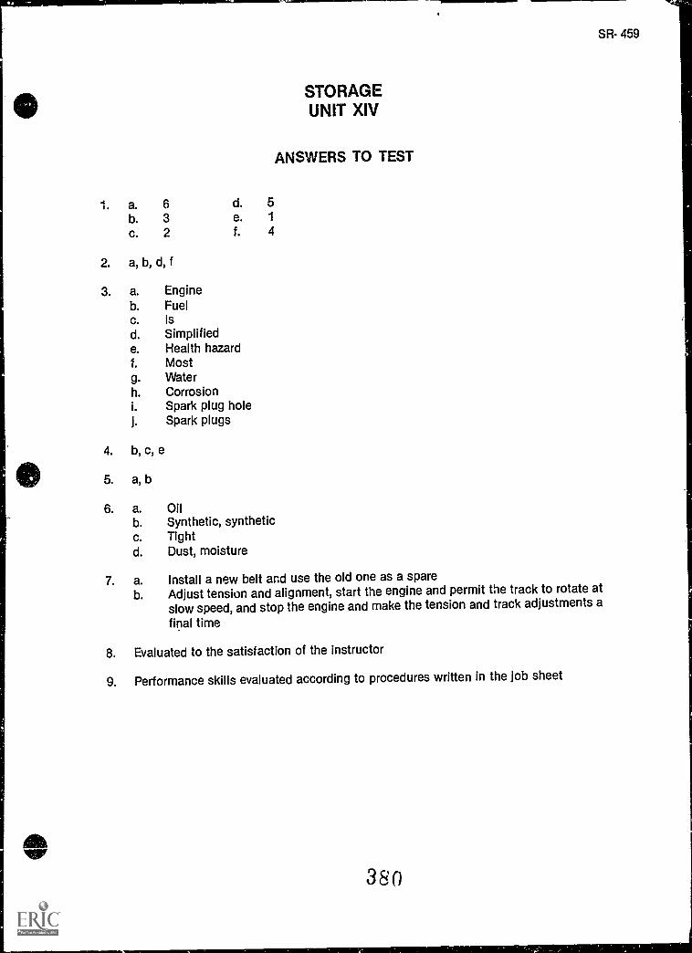
SR- 459
STORAGEUNIT XIV
ANSWERS TO TEST
1. a. 6 d. 5
b. 3 e. 1
c. 2 f. 4
2. a, b, d, f
3. a. Engineb. Fuelc. Isd. Simplifiede. Health hazardf. Mostg. Waterh. Corrosioni. Spark plug holej. Spark plugs
4. b, c, e
5. a, b
6. a. Oilb. Synthetic, syntheticc. Tightd. Dust, moisture
7. a. Install a new belt and use the old one as a spareb. Adjust tension and alignment, start the engine and permit the track to rotate at
slow speed, and stop the engine and make the tension and track adjustments a
final time
8. Evaluated to the satisfaction of the instructor
9. Performance skills evaluated according to procedures written in the job sheet
380