Embed Size (px)
Citation preview
T. Gorski, et al., U. Wisconsin, October 4, 2010 Calorimeter Trigger Upgrade Hardware R&D Program - 1
Calorimeter Trigger R&DCalorimeter Trigger R&DCalorimeter Trigger R&DCalorimeter Trigger R&D
Calorimeter Trigger Upgrade Hardware R&D Program
T. Gorski, W. H. Smith, S. Dasu, A. Farmahini-Farahani, P. Klabbers, R. Fobes, D. Seemuth, I. Ross, M. Bachtis,
M. Grothe, M. Schulte, K. Compton, T. Gregerson
University of Wisconsin
October 4, 2010
T. Gorski, et al., U. Wisconsin, October 4, 2010 Calorimeter Trigger Upgrade Hardware R&D Program - 2
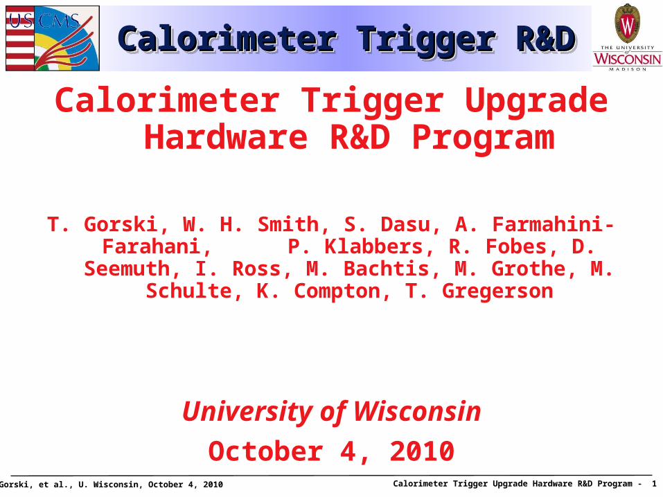
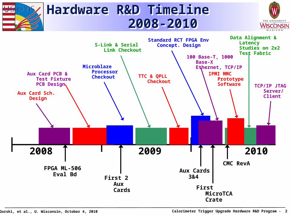
Hardware R&D Timeline 2008-2010
Hardware R&D Timeline 2008-2010
2008 2009 2010
Aux Card Sch. Design
Aux Card PCB & Test Fixture PCB Design
Microblaze Processor Checkout
S-Link & Serial Link Checkout
TTC & QPLL Checkout
Standard RCT FPGA Env Concept. Design
Data Alignment & Latency Studies on 2x2 Test Fabric
100 Base-T, 1000 Base-X Ethernet, TCP/IP
First 2 Aux Cards
First MicroTCA Crate
Aux Cards 3&4
CMC RevA
IPMI MMC Prototype Software TCP/IP JTAG
Server/ Client
FPGA ML-506 Eval Bd
T. Gorski, et al., U. Wisconsin, October 4, 2010 Calorimeter Trigger Upgrade Hardware R&D Program - 3
Part 1: Hardware R&D Building Blocks
Part 1: Hardware R&D Building Blocks
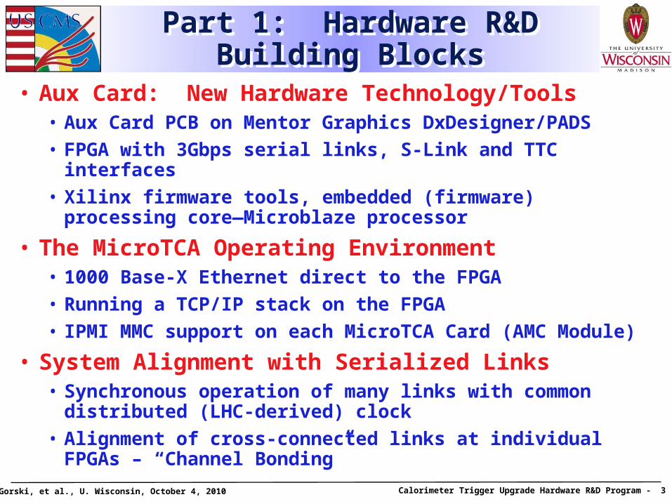
• Aux Card: New Hardware Technology/Tools• Aux Card PCB on Mentor Graphics DxDesigner/PADS
• FPGA with 3Gbps serial links, S-Link and TTC interfaces
• Xilinx firmware tools, embedded (firmware) processing core—Microblaze processor
• The MicroTCA Operating Environment• 1000 Base-X Ethernet direct to the FPGA
• Running a TCP/IP stack on the FPGA
• IPMI MMC support on each MicroTCA Card (AMC Module)
• System Alignment with Serialized Links• Synchronous operation of many links with common distributed
(LHC-derived) clock
• Alignment of cross-connected links at individual FPGAs – “Channel Bonding”
T. Gorski, et al., U. Wisconsin, October 4, 2010 Calorimeter Trigger Upgrade Hardware R&D Program - 4
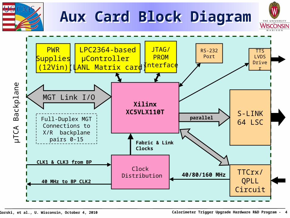
Aux Card Block Diagram Aux Card Block Diagram
S-LINK 64 LSC
LPC2364-basedµController
(LANL Matrix card)
PWRSupplies(12Vin)
JTAG/PROM
Interface
XilinxXC5VLX110T
parallel
40/80/160 MHz
MGT Link I/O
Full-Duplex MGT Connections to X/R backplane pairs 0-15
Clock Distribution
µT
CA
Bac
kpla
ne
TTCrx/ QPLL Circuit
TTS LVDS Driver
40 MHz to BP CLK2
CLK1 & CLK3 from BP
Fabric & Link Clocks
RS-232Port
T. Gorski, et al., U. Wisconsin, October 4, 2010 Calorimeter Trigger Upgrade Hardware R&D Program - 5
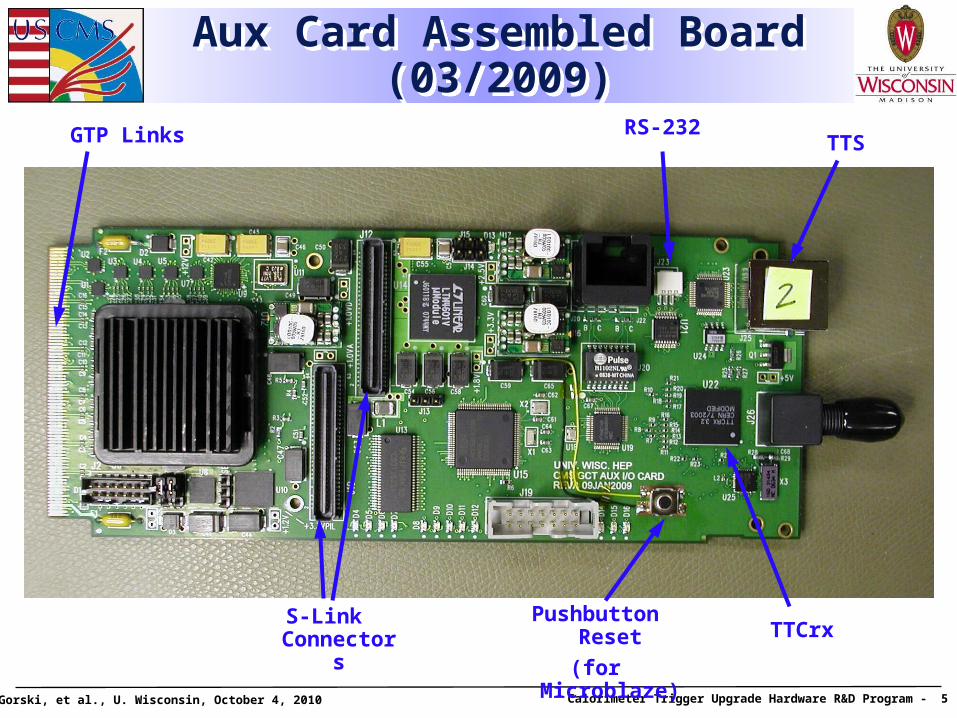
Aux Card Assembled Board (03/2009)
Aux Card Assembled Board (03/2009)
Pushbutton Reset
(for Microblaze)S-Link
Connectors
TTS
TTCrx
RS-232GTP Links
T. Gorski, et al., U. Wisconsin, October 4, 2010 Calorimeter Trigger Upgrade Hardware R&D Program - 6
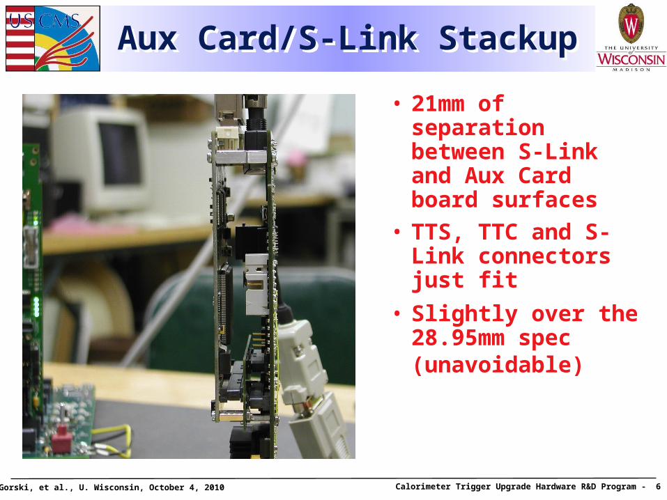
Aux Card/S-Link StackupAux Card/S-Link Stackup
• 21mm of separation between S-Link and Aux Card board surfaces
• TTS, TTC and S-Link connectors just fit
• Slightly over the 28.95mm spec (unavoidable)
T. Gorski, et al., U. Wisconsin, October 4, 2010 Calorimeter Trigger Upgrade Hardware R&D Program - 7
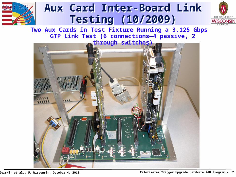
Aux Card Inter-Board Link Testing (10/2009)
Aux Card Inter-Board Link Testing (10/2009)
Two Aux Cards in Test Fixture Running a 3.125 Gbps GTP Link Test (6 connections—4 passive, 2 through switches)
T. Gorski, et al., U. Wisconsin, October 4, 2010 Calorimeter Trigger Upgrade Hardware R&D Program - 8
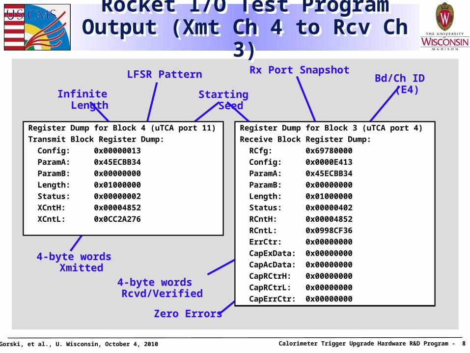
Rocket I/O Test Program Output (Xmt Ch 4 to Rcv Ch 3)
Rocket I/O Test Program Output (Xmt Ch 4 to Rcv Ch 3)
LFSR Pattern
Infinite Length Starting Seed
Bd/Ch ID (E4)
Zero Errors
4-byte words Xmitted
4-byte words Rcvd/Verified
Register Dump for Block 4 (uTCA port 11)
Transmit Block Register Dump:
Config: 0x00000013
ParamA: 0x45ECBB34
ParamB: 0x00000000
Length: 0x01000000
Status: 0x00000002
XCntH: 0x00004852
XCntL: 0x0CC2A276
Register Dump for Block 3 (uTCA port 4)
Receive Block Register Dump:
RCfg: 0x69780000
Config: 0x0000E413
ParamA: 0x45ECBB34
ParamB: 0x00000000
Length: 0x01000000
Status: 0x00000402
RCntH: 0x00004852
RCntL: 0x0998CF36
ErrCtr: 0x00000000
CapExData: 0x00000000
CapAcData: 0x00000000
CapRCtrH: 0x00000000
CapRCtrL: 0x00000000
CapErrCtr: 0x00000000
Rx Port Snapshot
T. Gorski, et al., U. Wisconsin, October 4, 2010 Calorimeter Trigger Upgrade Hardware R&D Program - 9
Aux Card R&D SummaryAux Card R&D Summary
• 4 boards built
• Subsection tests:• Rocket I/O—all links tested/verified 100% functional at
3.125 Gbps, using local/off-board 125 MHz oscillators
• S-Link—tested & verified at burst rates up to 80 MHz
• TTS output—tested & verified
• TTC input—QPLLs lock, TTCrx broadcast frame decoding tested & verified
• Successful demonstration of hybrid Microblaze/HDL design approach
• Cards being used as platform for system alignment R&D
T. Gorski, et al., U. Wisconsin, October 4, 2010 Calorimeter Trigger Upgrade Hardware R&D Program - 10
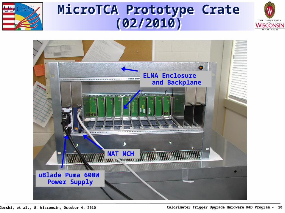
MicroTCA Prototype Crate (02/2010)
MicroTCA Prototype Crate (02/2010)
uBlade Puma 600W Power Supply
NAT MCH
ELMA Enclosure and Backplane
T. Gorski, et al., U. Wisconsin, October 4, 2010 Calorimeter Trigger Upgrade Hardware R&D Program - 11
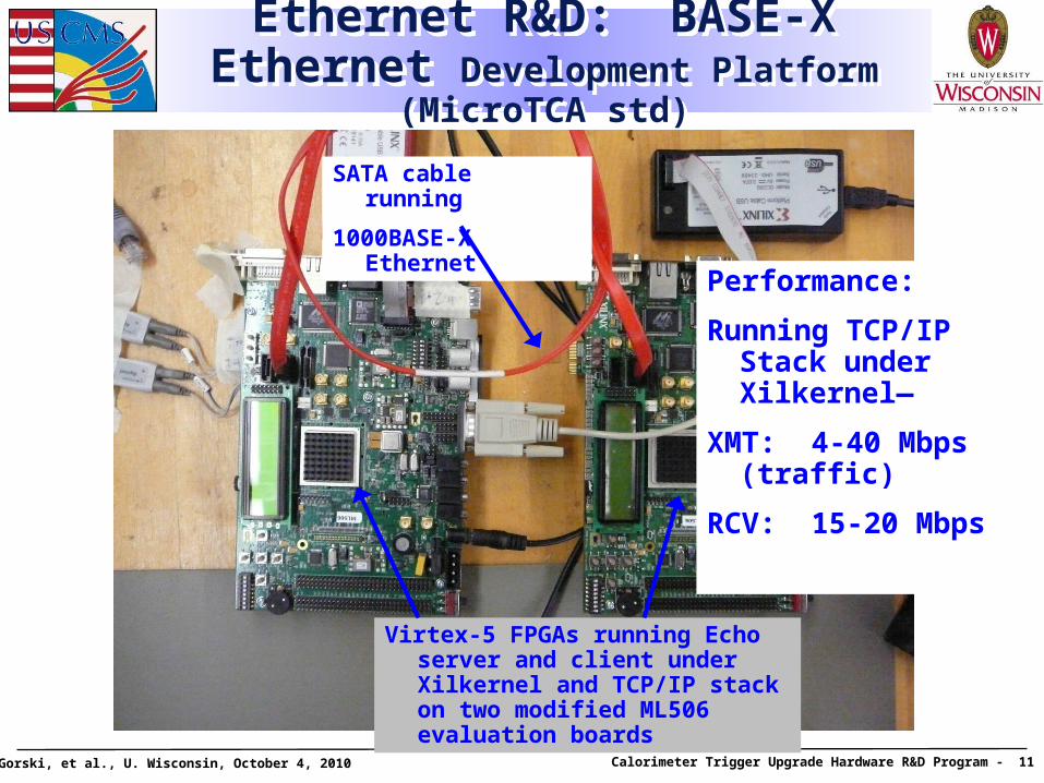
Ethernet R&D: BASE-X Ethernet Development Platform (MicroTCA std)
Ethernet R&D: BASE-X Ethernet Development Platform (MicroTCA std)
SATA cable running
1000BASE-X Ethernet
Virtex-5 FPGAs running Echo server and client under Xilkernel and TCP/IP stack on two modified ML506 evaluation boards
Performance:
Running TCP/IP Stack under Xilkernel—
XMT: 4-40 Mbps (traffic)
RCV: 15-20 Mbps
T. Gorski, et al., U. Wisconsin, October 4, 2010 Calorimeter Trigger Upgrade Hardware R&D Program - 12
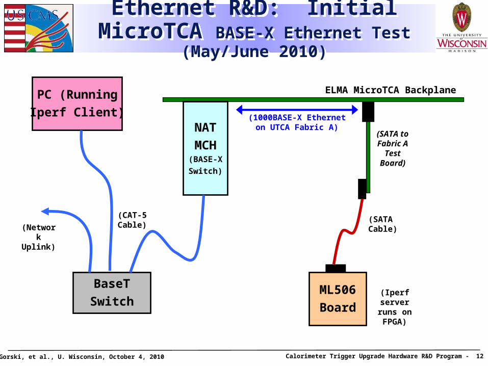
Ethernet R&D: Initial MicroTCA BASE-X Ethernet Test (May/June 2010)
Ethernet R&D: Initial MicroTCA BASE-X Ethernet Test (May/June 2010)
ELMA MicroTCA Backplane
NAT
MCH(BASE-X
Switch)
BaseT
SwitchML506
Board
(SATA Cable)
(SATA to Fabric A
Test Board)
(1000BASE-X Etherneton UTCA Fabric A)
(Iperf server runs on FPGA)
PC (Running
Iperf Client)
(CAT-5Cable)(Network
Uplink)
T. Gorski, et al., U. Wisconsin, October 4, 2010 Calorimeter Trigger Upgrade Hardware R&D Program - 13
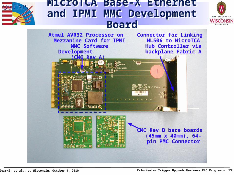
MicroTCA Base-X Ethernet and IPMI MMC Development BoardMicroTCA Base-X Ethernet and IPMI MMC Development Board
CMC Rev B bare boards (45mm x 40mm), 64-pin
PMC Connector
Atmel AVR32 Processor on Mezzanine Card for IPMI MMC Software Development
(CMC Rev A)
Connector for Linking ML506 to MicroTCA Hub Controller via backplane Fabric A
T. Gorski, et al., U. Wisconsin, October 4, 2010 Calorimeter Trigger Upgrade Hardware R&D Program - 14
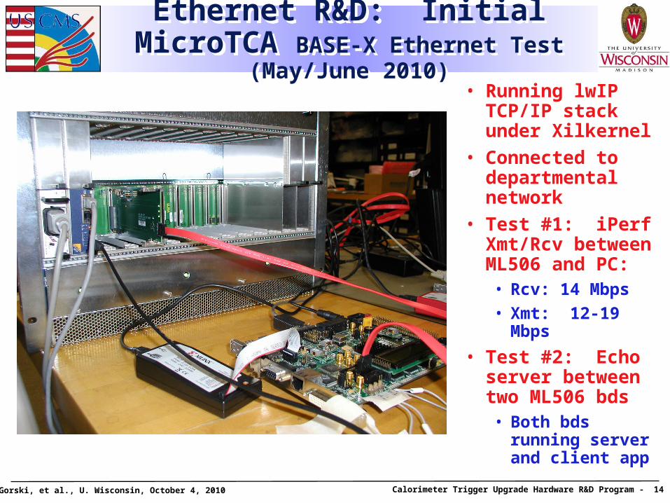
Ethernet R&D: Initial MicroTCA BASE-X Ethernet Test (May/June 2010)
Ethernet R&D: Initial MicroTCA BASE-X Ethernet Test (May/June 2010)
• Running lwIP TCP/IP stack under Xilkernel
• Connected to departmental network
• Test #1: iPerf Xmt/Rcv between ML506 and PC:• Rcv: 14 Mbps
• Xmt: 12-19 Mbps
• Test #2: Echo server between two ML506 bds• Both bds running
server and client app
T. Gorski, et al., U. Wisconsin, October 4, 2010 Calorimeter Trigger Upgrade Hardware R&D Program - 15
MicroTCA R&D SummaryMicroTCA R&D Summary
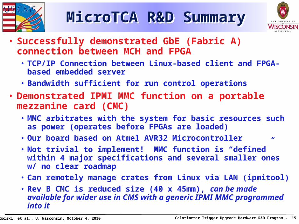
• Successfully demonstrated GbE (Fabric A) connection between MCH and FPGA• TCP/IP Connection between Linux-based client and FPGA-based
embedded server
• Bandwidth sufficient for run control operations
• Demonstrated IPMI MMC function on a portable mezzanine card (CMC)• MMC arbitrates with the system for basic resources such as
power (operates before FPGAs are loaded)
• Our board based on Atmel AVR32 Microcontroller
• Not trivial to implement! MMC function is “defined” within 4 major specifications and several smaller ones w/ no clear roadmap
• Can remotely manage crates from Linux via LAN (ipmitool)
• Rev B CMC is reduced size (40 x 45mm), can be made available for wider use in CMS with a generic IPMI MMC programmed into it
T. Gorski, et al., U. Wisconsin, October 4, 2010 Calorimeter Trigger Upgrade Hardware R&D Program - 16
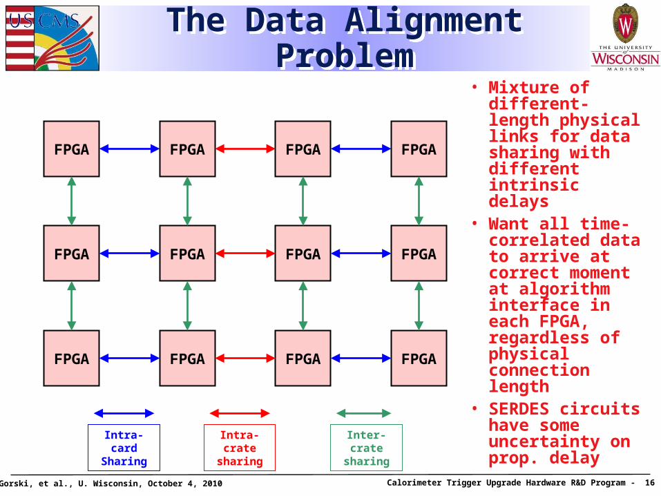
The Data Alignment ProblemThe Data Alignment Problem• Mixture of
different-length physical links for data sharing with different intrinsic delays
• Want all time-correlated data to arrive at correct moment at algorithm interface in each FPGA, regardless of physical connection length
• SERDES circuits have some uncertainty on prop. delay
FPGA FPGA FPGA FPGA
FPGA FPGA FPGA FPGA
FPGA FPGA FPGA FPGA
Inter-crate sharing
Intra-cratesharing
Intra-cardSharing
T. Gorski, et al., U. Wisconsin, October 4, 2010 Calorimeter Trigger Upgrade Hardware R&D Program - 17
System Alignment R&DSystem Alignment R&D
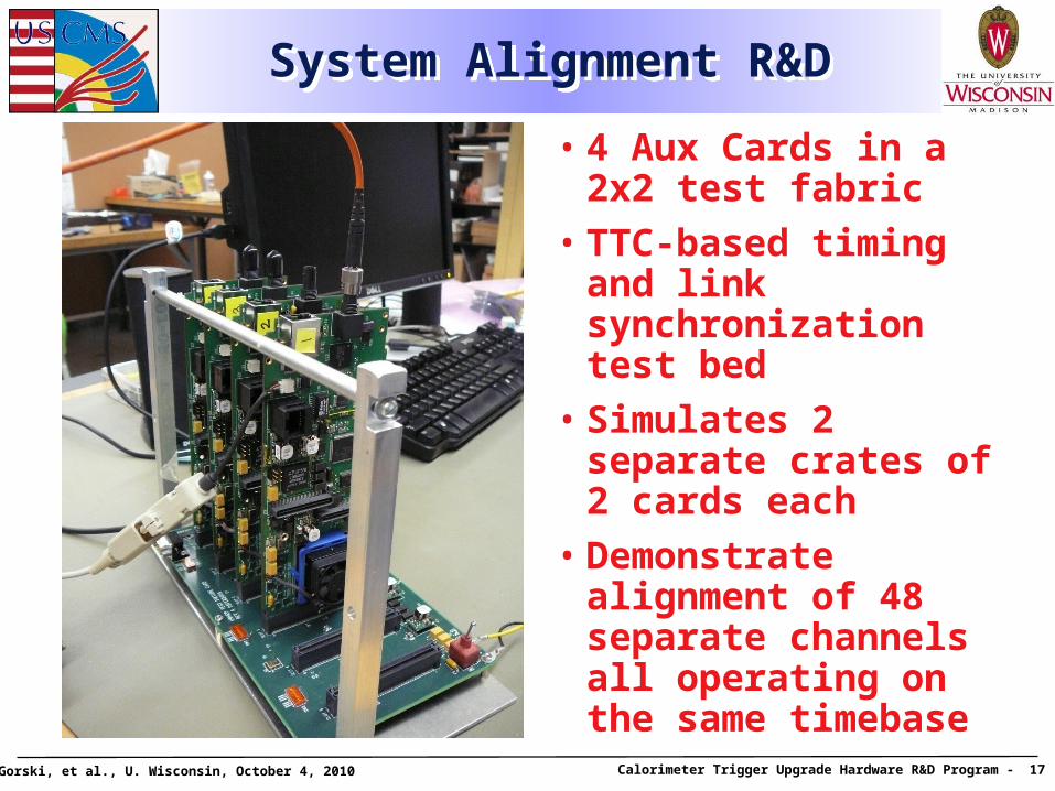
• 4 Aux Cards in a 2x2 test fabric
• TTC-based timing and link synchronization test bed
• Simulates 2 separate crates of 2 cards each
• Demonstrate alignment of 48 separate channels all operating on the same timebase
T. Gorski, et al., U. Wisconsin, October 4, 2010 Calorimeter Trigger Upgrade Hardware R&D Program - 18
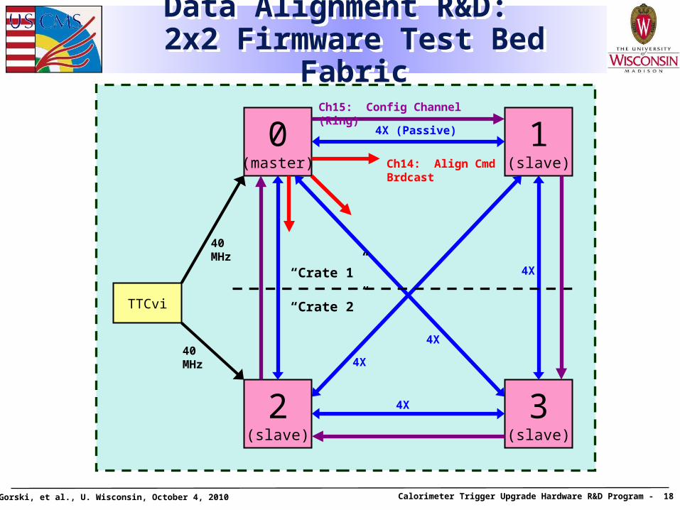
Data Alignment R&D: 2x2 Firmware Test Bed Fabric
Data Alignment R&D: 2x2 Firmware Test Bed Fabric
2(slave)
0(master)
1(slave)
3(slave)
TTCvi
4X (Passive)
4X
40 MHz
4X
4X
4X40 MHz
“Crate 2”
“Crate 1”
Ch14: Align CmdBrdcast
Ch15: Config Channel (Ring)
T. Gorski, et al., U. Wisconsin, October 4, 2010 Calorimeter Trigger Upgrade Hardware R&D Program - 19
Data Alignment R&D (A. Farahani-Farmahini)
Data Alignment R&D (A. Farahani-Farmahini)
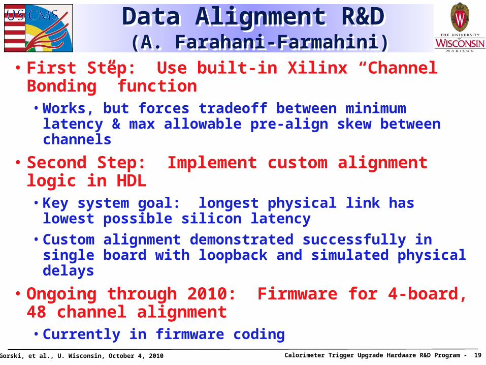
• First Step: Use built-in Xilinx “Channel Bonding” function• Works, but forces tradeoff between minimum latency &
max allowable pre-align skew between channels
• Second Step: Implement custom alignment logic in HDL• Key system goal: longest physical link has lowest
possible silicon latency
• Custom alignment demonstrated successfully in single board with loopback and simulated physical delays
• Ongoing through 2010: Firmware for 4-board, 48 channel alignment• Currently in firmware coding
T. Gorski, et al., U. Wisconsin, October 4, 2010 Calorimeter Trigger Upgrade Hardware R&D Program - 20
System R&D: FPGA Firmware Standard Environment Block Diagram
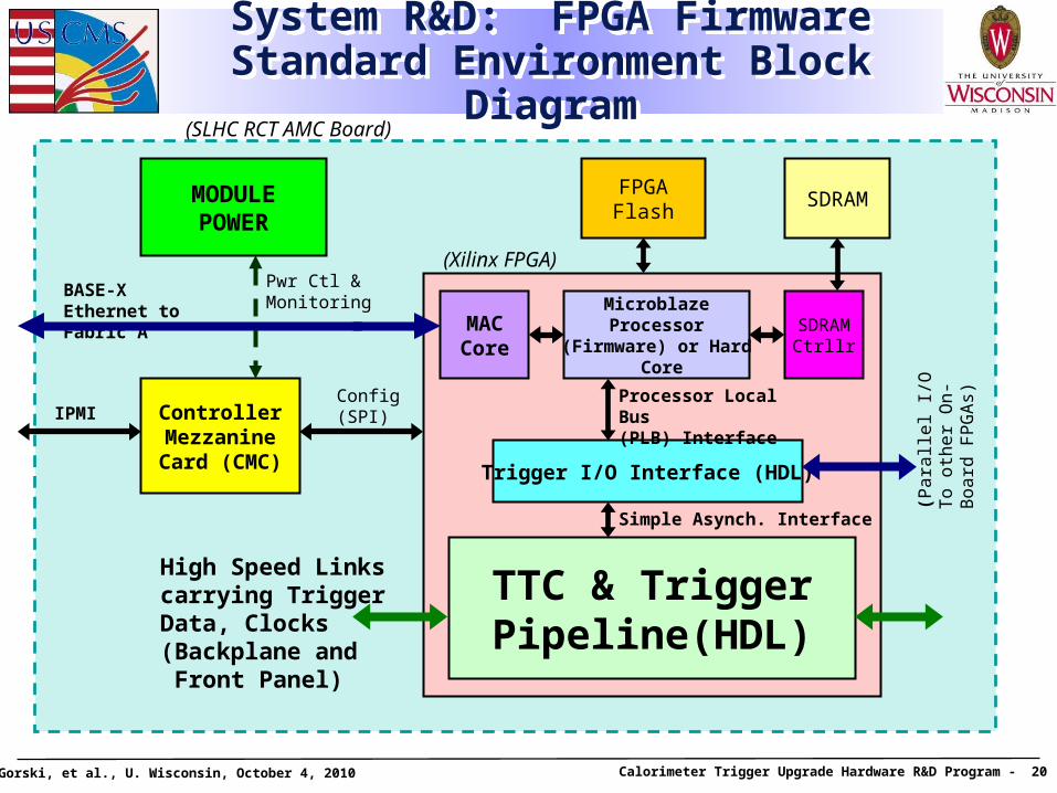
System R&D: FPGA Firmware Standard Environment Block Diagram
ControllerMezzanineCard (CMC)
BASE-X Ethernet to Fabric A
(SLHC RCT AMC Board)
FPGAFlash
(Xilinx FPGA)
TTC & TriggerPipeline(HDL)
High Speed Links carrying Trigger Data, Clocks(Backplane and Front Panel)
MACCore
MicroblazeProcessor
(Firmware) or Hard Core
Trigger I/O Interface (HDL)
Processor Local Bus(PLB) Interface
Simple Asynch. Interface
(Pa
ralle
l I/O
To
oth
er
On
-B
oa
rd F
PG
As)
SDRAM
SDRAMCtrllr
IPMIConfig(SPI)
MODULEPOWER
Pwr Ctl &Monitoring
T. Gorski, et al., U. Wisconsin, October 4, 2010 Calorimeter Trigger Upgrade Hardware R&D Program - 21
System R&D: SLHC RCT Functional Hierarchy
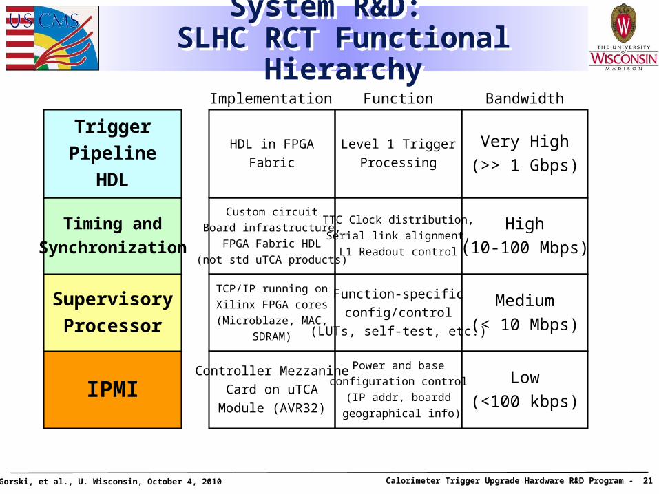
System R&D: SLHC RCT Functional Hierarchy
IPMI
Supervisory
Processor
Timing and
Synchronization
Trigger
Pipeline
HDL
Controller Mezzanine
Card on uTCA
Module (AVR32)
TCP/IP running on
Xilinx FPGA cores
(Microblaze, MAC,
SDRAM)
Custom circuit
Board infrastructure,
FPGA Fabric HDL
(not std uTCA products)
HDL in FPGA
Fabric
Power and base
configuration control
(IP addr, boardd
geographical info)
Function-specific
config/control
(LUTs, self-test, etc.)
TTC Clock distribution,
Serial link alignment,
L1 Readout control
Level 1 Trigger
Processing
Low
(<100 kbps)
Medium
(< 10 Mbps)
High
(10-100 Mbps)
Very High
(>> 1 Gbps)
Implementation Function Bandwidth
T. Gorski, et al., U. Wisconsin, October 4, 2010 Calorimeter Trigger Upgrade Hardware R&D Program - 22
System R&D: Design Constraint Space
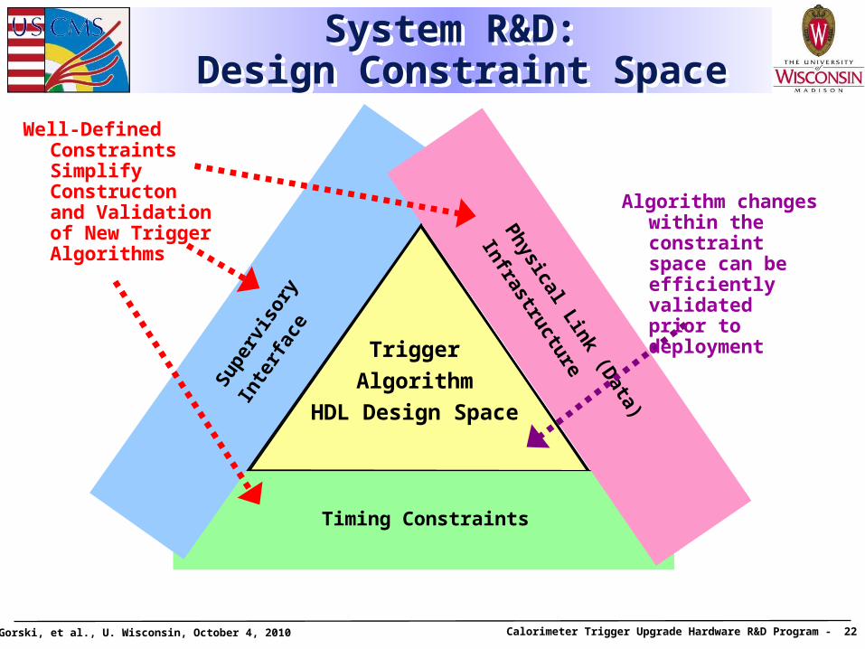
System R&D: Design Constraint Space
Physical Link (Data)
Infrastructure
Timing Constraints
Supe
rvis
ory
Inte
rfac
e
Trigger
Algorithm
HDL Design Space
Well-Defined Constraints Simplify Constructon and Validation of New Trigger Algorithms
Algorithm changes within the constraint space can be efficiently validated prior to deployment
T. Gorski, et al., U. Wisconsin, October 4, 2010 Calorimeter Trigger Upgrade Hardware R&D Program - 23
TCP/IP JTAG Server/Client R&D (D. Seemuth)
TCP/IP JTAG Server/Client R&D (D. Seemuth)
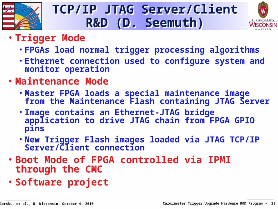
• Trigger Mode• FPGAs load normal trigger processing algorithms• Ethernet connection used to configure system and
monitor operation
• Maintenance Mode• Master FPGA loads a special maintenance image from
the Maintenance Flash containing JTAG Server• Image contains an Ethernet-JTAG bridge application to
drive JTAG chain from FPGA GPIO pins• New Trigger Flash images loaded via JTAG TCP/IP
Server/Client connection
• Boot Mode of FPGA controlled via IPMI through the CMC
• Software project
T. Gorski, et al., U. Wisconsin, October 4, 2010 Calorimeter Trigger Upgrade Hardware R&D Program - 24
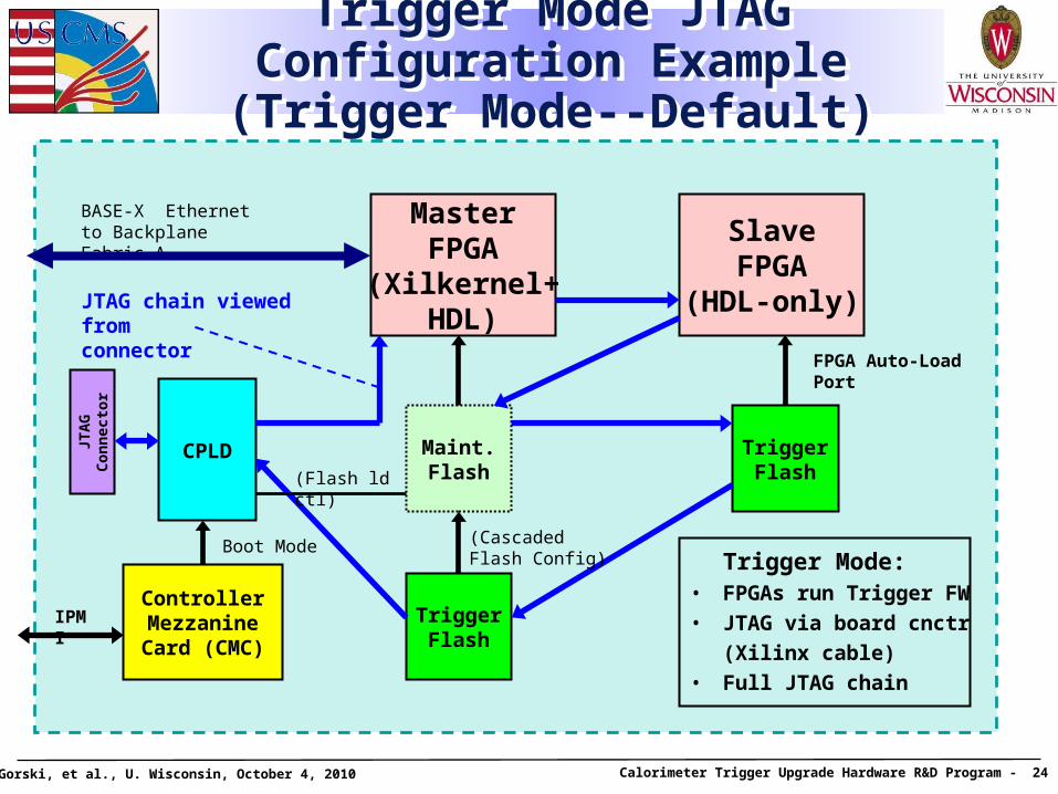
Trigger Mode JTAG Configuration Example (Trigger Mode--Default)
Trigger Mode JTAG Configuration Example (Trigger Mode--Default)
ControllerMezzanineCard (CMC)
MasterFPGA
(Xilkernel+HDL)
CPLDJTA
GC
on
nec
tor
BASE-X Ethernet to Backplane Fabric A Slave
FPGA(HDL-only)
IPMI
Boot Mode
Maint.Flash
TriggerFlash
TriggerFlash
JTAG chain viewed fromconnector
(Cascaded Flash Config)
(Flash ld ctl)
Trigger Mode:• FPGAs run Trigger FW
• JTAG via board cnctr
(Xilinx cable)
• Full JTAG chain
FPGA Auto-Load Port
T. Gorski, et al., U. Wisconsin, October 4, 2010 Calorimeter Trigger Upgrade Hardware R&D Program - 25
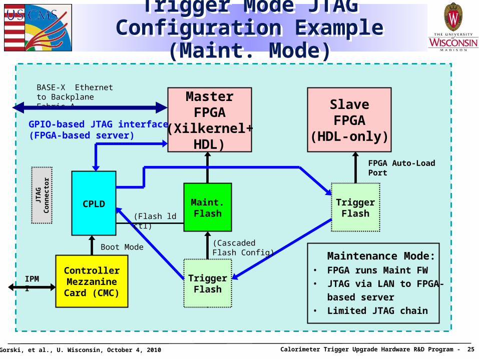
Trigger Mode JTAG Configuration Example (Maint. Mode)
Trigger Mode JTAG Configuration Example (Maint. Mode)
ControllerMezzanineCard (CMC)
MasterFPGA
(Xilkernel+HDL)
CPLDJTA
GC
on
nec
tor
BASE-X Ethernet to Backplane Fabric A
SlaveFPGA
(HDL-only)
IPMI
Boot Mode
Maint.Flash
TriggerFlash
TriggerFlash
FPGA Auto-Load Port
GPIO-based JTAG interface(FPGA-based server)
(Cascaded Flash Config)
(Flash ld ctl)
Maintenance Mode:• FPGA runs Maint FW
• JTAG via LAN to FPGA-
based server
• Limited JTAG chain
T. Gorski, et al., U. Wisconsin, October 4, 2010 Calorimeter Trigger Upgrade Hardware R&D Program - 26
Hardware R&D Part 1 SummaryHardware R&D Part 1 Summary
Activities Focus on 3 General Areas:
1. Designing & building boards with large FPGAs and high speed serial links
2. Aligning a system built of cross-connected serial links to support Calorimeter Trigger Algorithms
3. Understanding how to effectively operate, maintain and reprogram this system in the MicroTCA crate context
Our goals in these areas have been met, allowing us to take the next step….
T. Gorski, et al., U. Wisconsin, October 4, 2010 Calorimeter Trigger Upgrade Hardware R&D Program - 27
Hardware R&D Part 2: Calorimeter Trigger Prototypes
Hardware R&D Part 2: Calorimeter Trigger Prototypes
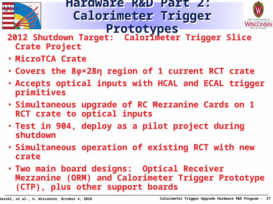
2012 Shutdown Target: Calorimeter Trigger Slice Crate Project
• MicroTCA Crate
• Covers the 8φ×28η region of 1 current RCT crate
• Accepts optical inputs with HCAL and ECAL trigger primitives
• Simultaneous upgrade of RC Mezzanine Cards on 1 RCT crate to optical inputs
• Test in 904, deploy as a pilot project during shutdown
• Simultaneous operation of existing RCT with new crate
• Two main board designs: Optical Receiver Mezzanine (ORM) and Calorimeter Trigger Prototype (CTP), plus other support boards
T. Gorski, et al., U. Wisconsin, October 4, 2010 Calorimeter Trigger Upgrade Hardware R&D Program - 28
RCT
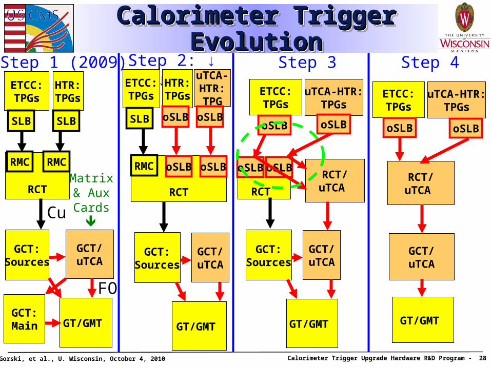
Calorimeter Trigger EvolutionCalorimeter Trigger EvolutionCalorimeter Trigger EvolutionCalorimeter Trigger Evolution
RCT
GCT:Sources
GCT:Main GT/GMT
GCT/uTCA
ETCC:TPGs
HTR:TPGs
Cu
FO
RCT
GCT:Sources
GT/GMT
GCT/uTCA
uTCA-HTR:TPG
oSLBRCT/
uTCA
GCT/uTCA
GT/GMT
ETCC:TPGs
uTCA-HTR:TPGs
oSLB
Step 1 (2009) Step 2: ↓ OR ↓
RCT/uTCA
ETCC:TPGs
uTCA-HTR:TPGs
oSLB
Step 3 Step 4
oSLBoSLB
GCT:Sources
GT/GMT
GCT/uTCA
RMCRMCRMC
SLB SLB
ETCC:TPGs
SLB
Matrix& AuxCards
oSLBoSLB oSLB
HTR:TPGs
oSLB
oSLB
T. Gorski, et al., U. Wisconsin, October 4, 2010 Calorimeter Trigger Upgrade Hardware R&D Program - 29
RCT-side Optical Receiver Mezzanine (in collaboration with LIP)
RCT-side Optical Receiver Mezzanine (in collaboration with LIP)
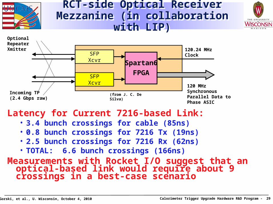
Spartan6
FPGASFPXcvr
SFPXcvr
Incoming TP(2.4 Gbps raw)
120.24 MHz Clock
Latency for Current 7216-based Link:• 3.4 bunch crossings for cable (85ns)• 0.8 bunch crossings for 7216 Tx (19ns)• 2.5 bunch crossings for 7216 Rx (62ns)• TOTAL: 6.6 bunch crossings (166ns)
Measurements with Rocket I/O suggest that an optical-based link would require about 9 crossings in a best-case scenario
(from J. C. De Silva)
120 MHz Synchronous Parallel Data to Phase ASIC
Optional RepeaterXmitter
T. Gorski, et al., U. Wisconsin, October 4, 2010 Calorimeter Trigger Upgrade Hardware R&D Program - 30
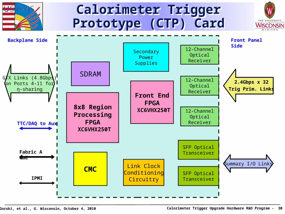
Calorimeter Trigger Prototype (CTP) Card
Calorimeter Trigger Prototype (CTP) Card
CMC
Front EndFPGA
XC6VHX250T
Link ClockConditioning
Circuitry
SDRAM
Summary I/O Links
2.4Gbps x 32
Trig Prim. Links
12-Channel Optical
Receiver
SecondaryPower
Supplies
GTX Links (4.8Gbps)on Ports 4-11 for
η-sharing
SFP OpticalTransceiver
SFP OpticalTransceiver
12-Channel Optical
Receiver
12-Channel Optical
Receiver
8x8 RegionProcessing
FPGA XC6VHX250T
Front Panel SideBackplane Side
Fabric A GbE
IPMI
TTC/DAQ to Aux
T. Gorski, et al., U. Wisconsin, October 4, 2010 Calorimeter Trigger Upgrade Hardware R&D Program - 31
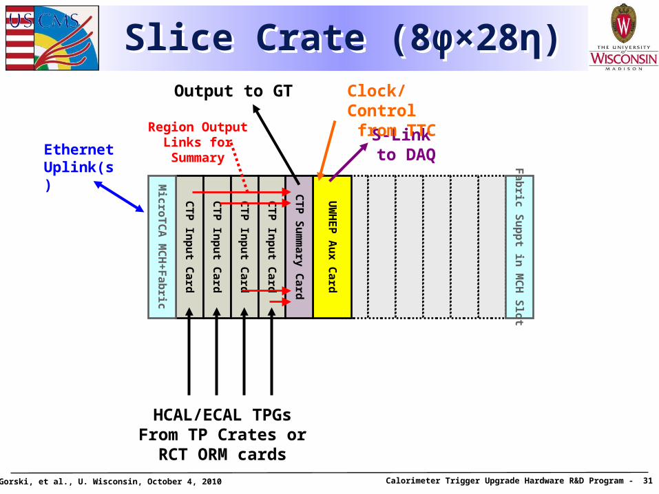
Slice Crate (8φ×28η)Slice Crate (8φ×28η)
CT
P In
pu
t Ca
rd
UW
HE
P A
ux
Ca
rd
CT
P In
pu
t Ca
rd
CT
P In
pu
t Ca
rd
CT
P In
pu
t Ca
rd
CT
P S
um
ma
ry C
ard
Output to GT
HCAL/ECAL TPGsFrom TP Crates or
RCT ORM cards
Region Output Links for Summary
S-Link to DAQ
Clock/Control from TTC
Mic
roT
CA
MC
H+
Fa
bric
Ethernet Uplink(s)
Fa
bric
Su
pp
t in M
CH
Slo
t
T. Gorski, et al., U. Wisconsin, October 4, 2010 Calorimeter Trigger Upgrade Hardware R&D Program - 32
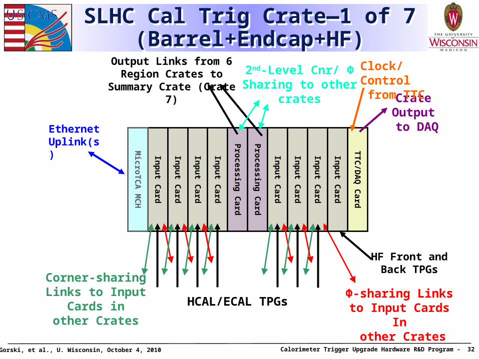
SLHC Cal Trig Crate—1 of 7 (Barrel+Endcap+HF)
SLHC Cal Trig Crate—1 of 7 (Barrel+Endcap+HF)
Inp
ut C
ard
TT
C/D
AQ
Ca
rd
Pro
ce
ss
ing
Ca
rd
Inp
ut C
ard
Inp
ut C
ard
Inp
ut C
ard
Inp
ut C
ard
Inp
ut C
ard
Pro
ce
ss
ing
Ca
rd
Inp
ut C
ard
Output Links from 6 Region Crates to Summary Crate
(Crate 7)
HCAL/ECAL TPGsΦ-sharing Linksto Input Cards In
other Crates
Corner-sharingLinks to Input
Cards inother Crates
Crate Output to DAQ
Clock/Control from TTC
Mic
roT
CA
MC
H
Inp
ut C
ard
HF Front and Back TPGs
2nd-Level Cnr/ Φ Sharing to other
crates
Ethernet Uplink(s)
T. Gorski, et al., U. Wisconsin, October 4, 2010 Calorimeter Trigger Upgrade Hardware R&D Program - 33
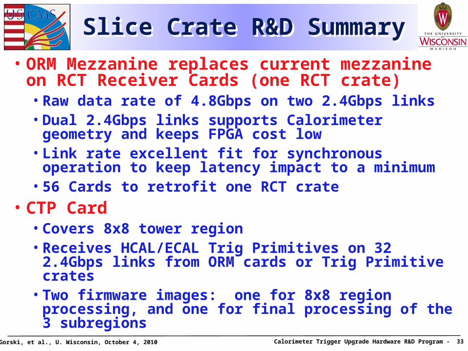
Slice Crate R&D SummarySlice Crate R&D Summary
• ORM Mezzanine replaces current mezzanine on RCT Receiver Cards (one RCT crate)• Raw data rate of 4.8Gbps on two 2.4Gbps links• Dual 2.4Gbps links supports Calorimeter geometry and
keeps FPGA cost low• Link rate excellent fit for synchronous operation to
keep latency impact to a minimum• 56 Cards to retrofit one RCT crate
• CTP Card• Covers 8x8 tower region• Receives HCAL/ECAL Trig Primitives on 32 2.4Gbps
links from ORM cards or Trig Primitive crates• Two firmware images: one for 8x8 region processing,
and one for final processing of the 3 subregions
T. Gorski, et al., U. Wisconsin, October 4, 2010 Calorimeter Trigger Upgrade Hardware R&D Program - 34
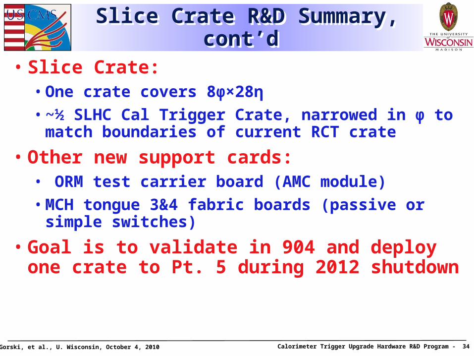
Slice Crate R&D Summary, cont’d Slice Crate R&D Summary, cont’d
• Slice Crate:• One crate covers 8φ×28η
• ~½ SLHC Cal Trigger Crate, narrowed in φ to match boundaries of current RCT crate
• Other new support cards:• ORM test carrier board (AMC module)
• MCH tongue 3&4 fabric boards (passive or simple switches)
• Goal is to validate in 904 and deploy one crate to Pt. 5 during 2012 shutdown
T. Gorski, et al., U. Wisconsin, October 4, 2010 Calorimeter Trigger Upgrade Hardware R&D Program - 35
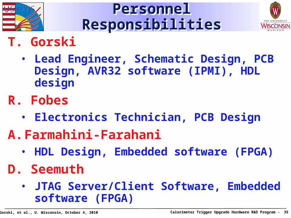
Personnel ResponsibilitiesPersonnel Responsibilities
T. Gorski• Lead Engineer, Schematic Design, PCB
Design, AVR32 software (IPMI), HDL design
R. Fobes• Electronics Technician, PCB Design
A. Farmahini-Farahani• HDL Design, Embedded software (FPGA)
D. Seemuth• JTAG Server/Client Software, Embedded
software (FPGA)