Embed Size (px)
Citation preview

T-Mobile Northeast, LLC
Ryan Clark Real Estate Consultant 750 W. Center St, Suite 301 W. Bridgewater, MA 02379
Phone: (203) 300-7310 [email protected] August 27, 2021 Members of the Connecticut Siting Council Connecticut Siting Council 10 Franklin Square New Britain, Connecticut 06051 Re: Request for Tower Share
T-Mobile Northeast, LLC (“T-Mobile”) Request for Approval of the Shared Use of an Existing Tower at 147 Baltic Hanover Road, Sprague/Baltic, CT 06330 T-Mobile site: CTNL123A
Dear Members of the Council: T-Mobile proposes to share an existing telecommunications tower located at 147 Baltic Hanover Road Sprague/Baltic, CT 06330 (the facility). The subject parcel is identified by the Town of Sprague as Map 9, Block 4, Lot 3. The property is owned by the Town of Sprague. The tower is owned by Wireless Solutions, LLC. The property is roughly 239.5± acres and accommodates an existing telecommunication compound with two shelters and one concrete pad with telecommunications carriers’ cabinets and a generator, as well as the lattice tower within the fenced compound. The facility is and will continue to be owned and operated by Wireless Solutions, LLC. Pursuant to Connecticut General Statues Section 16-50aa (the Statute), T-Mobile requests a finding from the Connecticut Siting Council that the shared use of this facility is technically, legally, environmentally and economically feasible, will meet safety concerns, will avoid the unnecessary proliferation of towers and is in the public interest. It further requests an order approving the shared use of this facility. The purpose of this request is to use an existing tower to develop T-Mobile’s wireless network to provide high speed wireless data and wireless service within the State of Connecticut and in this part of Baltic/Sprague: avoiding the need for an additional tower in Baltic/Sprague. T-Mobile is licensed by the Federal Communications Commission (“FCC”) to provide multiple technologies, including LTE, NR 5G and GSM including (600,700,1900, 2100, 2500 MHz frequencies) in New London County. T-Mobile is building and enhancing its network to take advantage of its licensed spectrum and improve its broadband high speed wireless voice and data services.

Existing Facility & Proposed Modification The existing facility is and will continue to be a 175’ lattice tower located at 147 Baltic Hanover Road Baltic, CT. Site coordinates (NAD83) are N 41.62417000” and W -72.07806000”. Currently there are two other major commercial wireless carriers located on this tower, whereby T-Mobile now intends to use the vacant space on the lowest part of the tower, beneath Verizon and AT&T. The site plan of the facility is included in the proposed Modifications drawings and Construction drawings, prepared by Centerline Communications dated August 11, 2021, respectively, and enclosed herewith. T-Mobile intends to install three (3) RFS-APX16DWV, three (3) RFS- APXVAALL24 (3) AIR6449 antennas, three (3) 4460 B25+B66 and three (3) 4480 B71+B85 RRUs, as shown in the construction drawing, to be attached to the lattice tower at the 155’ mount level. T-Mobile will also install three (3) hybrid fiber cable on the tower. In order to enable this installation, the tower will be reinforced per the Modifications drawings. Inside the existing fenced compound, T-Mobile will add a 15’ x 15’ lease area with one (1) concrete pad and one (1) H-frame. T-Mobile intends to enter into a new agreement, at this tower height, in order to license the portion of space within the existing and proposed compound for the new 15’-0” x 15’-0” concrete pad with four (4) new cabinets and (1) 35 KW diesel generator. Consistent with the requirements of the Statute, it is feasible for T-Mobile to collocate at this facility. T-Mobile is proposing to collocate on the existing lattice tower that will continue to remain in the ownership of Wireless Solutions, LLC. Included with this application is a Structural Analysis Report from Centerline Communications dated July 23, 2021, that shows that the existing tower can support T-Mobile’s proposed equipment once modified and a Structural Mount Assessment Letter dated August 26, 2021 that shows the mounting hardware can support the proposed antennas. The Proposal is Legally Feasible. The Council has authority, pursuant to statute, to issue an order approving of the shared use of this tower. By issuing an order approving T-Mobile’s shared use of this tower, T-Mobile will be able to proceed with obtaining a building permit for the proposed installation. Wireless Solutions, LLC has executed a Letter of Authorization that approved T-Mobile’s Request for Tower Share filing, which approval is included with this application. T-Mobile’s proposal is legally feasible. T-Mobile is a telecommunication provider licensed by the FCC to provide service in the State of Connecticut, including but not limited to New London County. T-Mobile will enter into an agreement with the owner of this facility, Wireless Solutions, LLC, for the location of this proposed equipment on the existing tower so that it may provide telecommunications services to the surrounding community. Consequently, the proposal is legally feasible. The Proposal is Environmentally Feasible. Pursuant to the Statute, the proposal will be environmentally feasible for the following reasons:
The overall impact on the Sprague/Baltic will be decreased with the sharing of a single
tower versus the proliferation of multiple towers.
There will be no material increase in the visibility of the tower with the addition of the antennas and associated equipment on the tower.
There will be no increased impact on air quality because no air pollutants will be generated during normal operation of the facility.
There will only be a brief, slight increase in noise pollution while the site is under
construction.
During construction, the proposed project will generate a small amount of traffic as construction takes place. Upon completion, traffic will be limited to an average of one trip per month for maintenance and inspections.
There will be no adverse impact to the health and safety of the surrounding community or
workers at the facility due to the addition of T-Mobile’s new antennas to the tower. T-Mobile has performed an analysis of the radio frequency field emanating from the transmitting antennas on the tower to ensure compliance with the National Council on Radiation Protection and measurements (NCRP) standard for maximum permissible exposure (MPE) adopted by the FCC. The analysis indicates that T-Mobile and other antennas on the tower will cumulatively emit 4.83% of the NCRP standard for maximum permissible exposure. The report indicates that maximum level of exposure will be well below the FCC’s mandated radio frequency exposure limits. The report is enclosed herewith.
T-Mobile expects to enhance safety in this portion in the Town of Sprague/Baltic by
improving wireless telecommunications for local residents and travelers. T-Mobile is currently developing its network to provide its customers with quality and reliable coverage to comply with their FCC license, the site is a necessary part of T-Mobile’s network development.
Specifically, this proposal is designed to provide reliable wireless coverage for this section of Sprague/Baltic.
Conclusions: For the reasons stated above, the attachment of T-Mobile’s antennas and associated equipment to the tower would meet all the requirements set forth in the Statute. The proposal is legally, technically, economically and environmentally feasible and meets all public safety concerns. Therefore, T-Mobile respectfully requests that the Council approve this request for the shared use of this tower located at 147 Baltic Hanover Road Sprague/Baltic, CT 06330.
Respectfully yours, Ryan Clark Real Estate Consultant – Site Acquisition c/o T-Mobile Northeast, LLC. Centerline Communications, LLC 750 West Center Street, Floor 3 / Suite 301 West Bridgewater, MA 02379 Mobile: (203) 300-7310 [email protected] cc: Wireless Solutions, LLC, tower owner Town of Sprague, property owner Cheryl A. Blanchard, chief elected official, Town of Sprague Philip Chester, Town Planner, Town of Sprague T-Mobile Northeast, LLC, carrier

Exhibit A
Letter of Authorization


Exhibit B
Original Facility Approval


Exhibit C
Property Card

Location 0 BALTIC-HANOVER RD Mblu 9/ 4/ 3/ /
Acct# B0001200 Owner SPRAGUE TOWN OF
PBN Assessment $658,080
Appraisal $940,100 PID 12
Building Count 1 Utility
Owner SPRAGUE TOWN OFCo-OwnerAddress 1 MAIN ST
BALTIC, CT 06330
Sale Price $0Certificate 1Book & Page 0022/0013
Sale Date 01/29/1968Instrument 00
Year Built:Living Area: 0Replacement Cost: $0Building Percent Good:
Building Photo
Building Photo(http://images.vgsi.com/photos2/SpragueCTPhotos//default.jpg)
0 BALTIC-HANOVER RD
Current Value
Appraisal
Valuation Year Improvements Land Total
2017 $207,720 $732,380 $940,100
Assessment
Valuation Year Improvements Land Total
2017 $145,410 $512,670 $658,080
Owner of Record
Ownership History
Ownership History
Owner Sale Price Certificate Book & Page Instrument Sale Date
SPRAGUE TOWN OF $0 1 0022/0013 00 01/29/1968
Building Information
Building 1 : Section 1

Replacement Cost Less Depreciation: $0
Building Attributes
Field Description
Style Vacant Land
Model
Grade:
Stories
Occupancy
Exterior Wall 1
Exterior Wall 2
Roof Structure
Roof Cover
Interior Wall 1
Interior Wall 2
Interior Flr 1
Interior Flr 2
Heat Fuel
Heat Type:
AC Type:
Total Bedrooms:
Total Bthrms:
Total Half Baths:
Extra Fixtures
Total Rooms:
Bath Style:
Kitchen Style:
Num kitchens
Xtra Openings
Gas Fireplaces
Wood/Pellet Stv
Finished Bsmt
Usrfld 106
Bsmt Gar
Num Park
Fireplaces
Rec Room
Usrfld 101
Usrfld 102
Usrfld 100
Usrfld 300
Legend
Building Layout
(http://images.vgsi.com/photos2/SpragueCTPhotos//Sketches/12_12.jpg)
Building Sub-Areas (sq ft)
No Data for Building Sub-Areas

Usrfld 301
Legend
Use Code 9030Description Municipal - Vac Deeded Acres 239.5
Land Use
Use Code 9030Description Municipal - Vac Zone BDAlt Land Appr NoCategory
Land Line Valuation
Size (Acres) 239.5FrontageDepthAssessed Value $512,670Appraised Value $732,380
Legend
Extra Features
Extra Features
No Data for Extra Features
Parcel Information
Land
Outbuildings
Outbuildings
Code Description Sub Code Sub Description Size Value Bldg #
FGR1 Garage 864.00 S.F. $26,440 1
SHD1 Shed 2850.00 S.F. $25,650 1
SHD1 Shed 625.00 S.F. $5,630 1
TWR1 Cell Tower 1.00 UNITS $150,000 1
Valuation History
Appraisal
Valuation Year Improvements Land Total
2019 $207,720 $732,380 $940,100
2018 $207,720 $732,380 $940,100
2018 $207,720 $732,380 $940,100
Assessment
Valuation Year Improvements Land Total
2019 $145,410 $512,670 $658,080
2018 $145,410 $512,670 $658,080
2018 $145,410 $512,670 $658,080
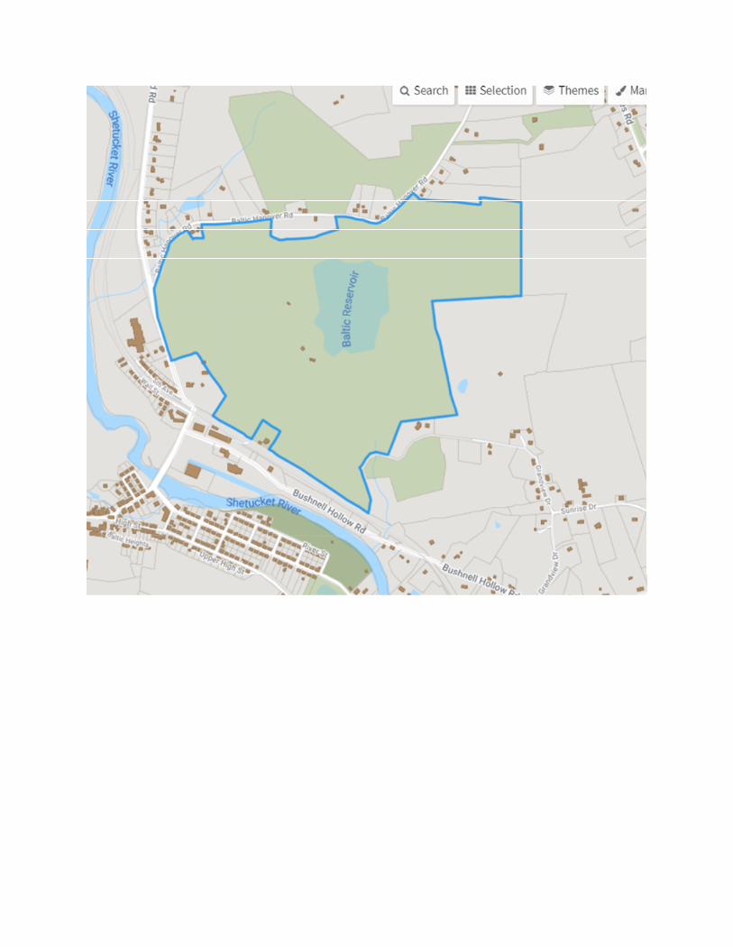

Exhibit D
Construction Drawings
- MobileTNORTHEAST LLC
PROJECT INFORMATION
PROJECT DIRECTORY
Know what's below. Call before you dig.
R
GENERAL NOTES
THESE DRAWINGS ARE FORMATTED TO BE FULL SIZE AT 22"x34". CONTRACTORSHALL VERIFY ALL PLANS & EXISTING DIMENSIONS & CONDITIONS ON THE JOBSITE & SHALL IMMEDIATELY NOTIFY THE ENGINEER IN WRITING OF ANYDISCREPANCIES BEFORE PROCEEDING WITH THE WORK OR BE RESPONSIBLEFOR SAME.
DRAWING SCALE NOTES:
N
PROJECTLOCATION
PROJECTLOCATION
SITE NAME:
SITE NUMBER:
SITE ADDRESS:
COUNTY
MUNICIPALITY:
ZONING:
LATITUDE:
LONGITUDE:
TYPE OF SITE:
STRUCTURE HEIGHT:
ANTENNA CENTER:
GROUND ELEVATION:
BUILDING OWNER NAME:
BUILDING OWNERADDRESS:
APPLICANT:
APPLICANT PHONE:
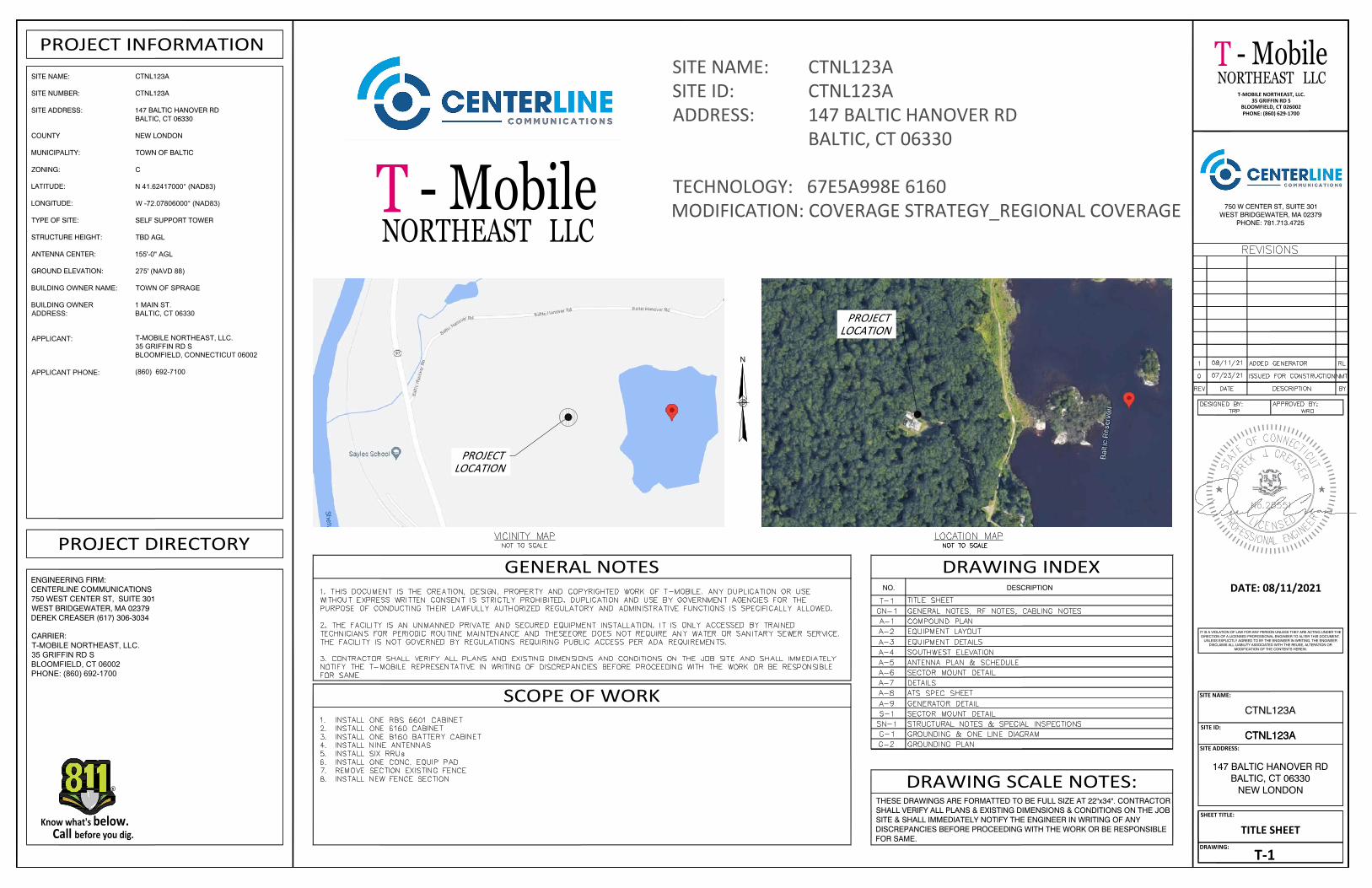
SITE NAME: CTNL123ASITE ID: CTNL123AADDRESS: 147 BALTIC HANOVER RD
BALTIC, CT 06330
TECHNOLOGY: 67E5A998E 6160MODIFICATION: COVERAGE STRATEGY_REGIONAL COVERAGE
SCOPE OF WORK
CTNL123A
CTNL123A
147 BALTIC HANOVER RDBALTIC, CT 06330
NEW LONDON
TOWN OF BALTIC
C
N 41.62417000° (NAD83)
W -72.07806000° (NAD83)
SELF SUPPORT TOWER
TBD AGL
155'-0" AGL
275' (NAVD 88)
TOWN OF SPRAGE
1 MAIN ST.BALTIC, CT 06330
ENGINEERING FIRM:CENTERLINE COMMUNICATIONS750 WEST CENTER ST, SUITE 301WEST BRIDGEWATER, MA 02379DEREK CREASER (617) 306-3034
NO. DESCRIPTION
DRAWING INDEX
NORTHEAST LLC
750 W CENTER ST, SUITE 301WEST BRIDGEWATER, MA 02379
PHONE: 781.713.4725
- MobileT
SITE NAME:
SITE ID:
SITE ADDRESS:
SHEET TITLE:
DRAWING:
CTNL123A
CTNL123A
147 BALTIC HANOVER RDBALTIC, CT 06330
NEW LONDON
CTNL123A
T-1
DATE: 08/11/2021
IT IS A VIOLATION OF LAW FOR ANY PERSON UNLESS THEY ARE ACTING UNDER THEDIRECTION OF A LICENSED PROFESSIONAL ENGINEER TO ALTER THIS DOCUMENT.
UNLESS EXPLICITLY AGREED TO BY THE ENGINEER IN WRITING, THE ENGINEERDISCLAIMS ALL LIABILITY ASSOCIATED WITH THE REUSE, ALTERATION OR
MODIFICATION OF THE CONTENTS HEREIN.
T-MOBILE NORTHEAST, LLC.35 GRIFFIN RD S
BLOOMFIELD, CT 026002PHONE: (860) 629-1700
TITLE SHEET
CARRIER:T-MOBILE NORTHEAST, LLC.35 GRIFFIN RD SBLOOMFIELD, CT 06002PHONE: (860) 692-1700
T-MOBILE NORTHEAST, LLC.35 GRIFFIN RD SBLOOMFIELD, CONNECTICUT 06002
(860) 692-7100

NORTHEAST LLC
750 W CENTER ST, SUITE 301WEST BRIDGEWATER, MA 02379
PHONE: 781.713.4725
- MobileT
SITE NAME:
SITE ID:
SITE ADDRESS:
SHEET TITLE:
DRAWING:
CTNL123A
CTNL123A
147 BALTIC HANOVER RDBALTIC, CT 06330
NEW LONDON
CTNL123A
GN-1
DATE: 08/11/2021
IT IS A VIOLATION OF LAW FOR ANY PERSON UNLESS THEY ARE ACTING UNDER THEDIRECTION OF A LICENSED PROFESSIONAL ENGINEER TO ALTER THIS DOCUMENT.
UNLESS EXPLICITLY AGREED TO BY THE ENGINEER IN WRITING, THE ENGINEERDISCLAIMS ALL LIABILITY ASSOCIATED WITH THE REUSE, ALTERATION OR
MODIFICATION OF THE CONTENTS HEREIN.
T-MOBILE NORTHEAST, LLC.35 GRIFFIN RD S
BLOOMFIELD, CT 026002PHONE: (860) 629-1700
RF NOTES
ABBREVIATIONS
EQUIPMENT GROUND
EQUIPMENT GROUND RING
AMERICAN WIRE GAUGE MASTER GROUND BUS
SEE
N.T.S.
RADIO FREQUENCY
TO BE REMOVED
SEEERENCE
NOT TO SCALE
REQTYP TYPICAL
REQUIRED
RF
TBR
BARE COPPER WIRE
PROPOSED NEW
EGR
AWG MGB
EG
BCW
AGL ABOVE GRADE LEVEL
BTS BASE TRANSCEIVER STATION
EXISTING EXISTING
MIN MINIMUM TBD TO BE DETERMINED
G.C. GENERAL CONTRACTOR
TO BE REMOVEDTBRRAND REPLACED
1. ACTUAL LENGTHS SHALL BE DETERMINED PER SITE CONDITION BYSUBCONTRACTOR
2. THE DESIGN IS BASED ON RF DATA SHEETS, SIGNED AND APPROVED.
3. RADIO SIGNAL CABLE AND RACEWAY SHALL COMPLY WITH THEREQUIREMENTS OF THE NATIONAL ELECTRICAL CODE (NEC, NFPA 70),CHAPTER 8.
4. ALL SPECIFIED MATERIAL FOR EACH LOCATION (E.G. OUT DOORS-OCCUPIED,INDOORS-UNOCCUPIED, PLENUMS, RISER SHAFTS, ETC.) SHALL BEAPPROVED, LISTED, OR LABELED AS REQUIRED BY THE NEC.
5. RADIO SIGNAL CABLE SHALL BE SUPPORTED AT MINIMUM OF EVERY THREE (3)FEET EXCEPT INSIDE MONOPOLES OR MONOPOLES WHERE CABLE ANDCONNECTOR MANUFACTURERS SUPPORT RECOMMENDATIONS SHALL BEFOLLOWED. MANUFACTURER RECOMMENDATION CABLES SUPPORTACCESSORIES SHALL BE USED.
6. THE OUTDOOR CABLE SUPPORT SYSTEM SHALL BE PROVIDED WITH AN ICESHIELD TO SUPPORT AND PROTECT ANTENNA CABLE RUNS.
7. DRIP LOOPS SHALL BE REQUIRED ON ALL OUTSIDE CABLES. CABLES SHALLBE SLOPED AWAY FROM BUILDING OR OUTDOOR BTS CABINETS TO PREVENTWATER FROM ENTERING THROUGH THE COAXIAL CABLE PORT.
8. ALL FEEDER LINE AND JUMPER CONNECTORS SHALL BE 7/16 DIN CABLECONNECTORS THAT MEET IP68 STANDARDS.
9. 7/16 DIN CONNECTORS REQUIRE NO ADDITIONAL WEATHER PROOFING ININDOOR APPLICATIONS IF INSTALLED AND TORQUED PROPERLY. IN OUTDOORAPPLICATIONS WEATHER PROOFING IS REQUIRED AND THE FOLLOWINGPROCEDURE SHOULD BE FOLLOWED.
10. USING WEATHERPROOFING KIT APPROVED BY CABLE MANUFACTURER ANDCONTRACTOR START TAPE APPROXIMATELY 5 INCHES FROM THECONNECTOR, AND WRAP 2 INCHES TOWARD THE CONNECTOR, THENREVERSE THE TAPE SO THAT THE STICKY SIDE IS UP. TAPE OVER THECONNECTOR OR SURGE ARRESTOR UNTIL THREE (3) TO FOUR (4) INCHESBEYOND THE CONNECTOR AND REVERSE AGAIN WITH THE STICKY SIDE DOWNFOR ANOTHER INCH OR TWO. PASS THE BUTYL RUBBER AND FINISH WITH AFINAL LAYER OF TAPE.
11. ANTENNAS SHALL BE PAINTED,WHEN REQUIRED, BY THE LANDLORD ORAUTHORITY OF HAVING JURISDICTION IN ACCORDANCE WITH ANTENNAMANUFACTURERS' SURFACES PREPARATION AND PAINTING REQUIREMENTS.
12. CABLE SHIELDS AND TOWER CONDUITS SHALL BE GROUNDED AT THE TOP OFTHE TOWER WITHIN 10 FEET OF THEIR CONNECTORS, AND AT THE BOTTOMOF THE TOWER ABOUT 6 INCHES BEFORE THEY TURN TOWARD THE FACILITY.THEY SHALL BE GROUNDED AT THE MIDPOINT OF THE TOWERS THAT AREBETWEEN 60 FEET AND 200 FEET HIGH, AND AT INTERVALS OF 60 FEET ORLESS ON TOWERS THAT ARE HIGHER THAN 200 FEET.
1. SUBCONTRACTOR SHALL VERIFY THE ACTUAL LENGTH IN THE FIELD BEFOREINSTALLATION.
2. TAG AND COLOR CODE ALL MAIN CABLES AT LOCATIONS PER T-MOBILEANTENNA CABLE MARKING STANDARD:
· TOP OF TOWER END OF MAIN COAX· BOTTOM OF TOWER END OF MAIN COAX· DIRECTLY BEFORE AND AFTER RF EQUIPMENT· END OF JUMPERS AT BTS EQUIPMENT
3. ANTENNAS SHALL BE PROCURED AND INSTALLED WITH DOWN TILT MOUNTINGBRACKETS SUPPLIED BY ANTENNA MANUFACTURER.
4. PRIOR APPROVAL IS REQUIRED BEFORE PERFORMING ANY WORK ON EXISTINGCELL SITE EQUIPMENT.
1. FOR THE PURPOSE OF CONSTRUCTION DRAWING, THE FOLLOWINGDEFINITIONS SHALL APPLY: CONTRACTOR - CENTERLINE COMMUNICATIONS SUBCONTRACTOR - GENERAL CONTRACTOR (CONSTRUCTION) OWNER - T-MOBILE MOBILITY
2. PRIOR TO THE SUBMISSION OF BIDS, THE BIDDING SUBCONTRACTORSHALL VISIT THE CELL SITE TO FAMILIARIZE WITH THE EXISTING CONDITIONSAND TO CONFIRM THAT THE WORK CAN BE ACCOMPLISHED AS SHOWN ONTHE CONSTRUCTION DRAWINGS. ANY DISCREPANCY FOUND SHALL BEBROUGHT TO THE ATTENTION OF CONTRACTOR.
3. ALL MATERIALS FURNISHED AND INSTALLED SHALL BE IN STRICTACCORDANCE WITH ALL APPLICABLE CODES, REGULATIONS, ANDORDINANCES. SUBCONTRACTOR SHALL ISSUE ALL APPROPRIATE NOTICESAND COMPLY WITH ALL LAWS, ORDINANCES, RULES, REGULATIONS, ANDLAWFUL ORDERS OF ANY PUBLIC AUTHORITY REGARDING THEPERFORMANCE OF THE WORK. ALL WORK CARRIED OUT SHALL COMPLY WITHALL APPLICABLE MUNICIPAL AND UTILITY COMPANY SPECIFICATIONS ANDLOCAL JURISDICTIONAL CODES, ORDINANCES AND APPLICABLEREGULATIONS.
4. DRAWINGS PROVIDED HERE ARE NOT TO BE SCALED AND ARE INTENDEDTO SHOW OUTLINE ONLY.
5. UNLESS NOTED OTHERWISE, THE WORK SHALL INCLUDE FURNISHINGMATERIALS, EQUIPMENT, APPURTENANCES, AND LABOR NECESSARY TOCOMPLETE ALL INSTALLATIONS AS INDICATED ON THE DRAWINGS.
6. "KITTING LIST" SUPPLIED WITH THE BID PACKAGE IDENTIFIES ITEMS THATWILL BE SUPPLIED BY CONTRACTOR. ITEMS NOT INCLUDED IN THE BILL OFMATERIALS AND KITTING LIST SHALL BE SUPPLIED BY THE SUBCONTRACTOR.
7. THE SUBCONTRACTOR SHALL INSTALL ALL EQUIPMENT AND MATERIALS INACCORDANCE WITH MANUFACTURER'S RECOMMENDATIONS UNLESSSPECIFICALLY STATED OTHERWISE.
8. IF THE SPECIFIED EQUIPMENT CANNOT BE INSTALLED AS SHOWN ONTHESE DRAWINGS, THE SUBCONTRACTOR SHALL PROPOSE AN ALTERNATIVEINSTALLATION SPACE FOR APPROVAL BY THE CONTRACTOR.
9. SUBCONTRACTOR SHALL DETERMINE ACTUAL ROUTING OF CONDUIT,POWER AND T1 CABLES, GROUNDING CABLES AS SHOWN ON THE POWER,GROUNDING AND TELCO PLAN DRAWING. SUBCONTRACTOR SHALL UTILIZEEXISTING TRAYS AND/OR SHALL ADD NEW TRAYS AS NECESSARY.SUBCONTRACTOR SHALL CONFIRM THE ACTUAL ROUTING WITH THECONTRACTOR.
10. THE SUBCONTRACTOR SHALL PROTECT EXISTING IMPROVEMENTS,PAVEMENTS, CURBS, LANDSCAPING AND STRUCTURES. ANY DAMAGED PARTSHALL BE REPAIRED AT SUBCONTRACTOR'S EXPENSE TO THE SATISFACTIONOF OWNER.
11. SUBCONTRACTOR SHALL LEGALLY AND PROPERLY DISPOSE OF ALLSCRAP MATERIALS SUCH AS COAXIAL CABLES AND OTHER ITEMS REMOVEDFROM THE EXISTING FACILITY. ANTENNAS REMOVED SHALL BE RETURNEDTO THE OWNER'S DESIGNATED LOCATION.
12. SUBCONTRACTOR SHALL LEAVE PREMISES IN CLEAN CONDITION.
13. ALL CONCRETE REPAIR WORK SHALL BE DONE IN ACCORDANCE WITHAMERICAN CONCRETE INSTITUTE (ACI) 301.
14. ANY NEW CONCRETE NEEDED FOR THE CONSTRUCTION SHALL BEAIR-ENTRAINED AND SHALL HAVE 4000 PSI STRENGTH AT 28 DAYS. ALLCONCRETE WORK SHALL BE DONE IN ACCORDANCE WITH ACI 318 CODEREQUIREMENTS.
GENERAL NOTESANTENNA CABLE &SCHEDULING NOTES
BUILDING CODE: IBC 2015 & CONNECTICUT STATE BUILDING CODE 2018 ELECTRICAL CODE: 2017 NATIONAL ELECTRICAL CODE LIGHTNING CODE: NFPA 70-2017
15. ALL STRUCTURAL STEEL WORK SHALL BE DETAILED, FABRICATED ANDERECTED IN ACCORDANCE WITH AISC SPECIFICATIONS. ALL STRUCTURALSTEEL SHALL BE ASTM A36 (Fy = 36 ksi) UNLESS OTHERWISE NOTED. PIPESSHALL BE ASTM A53 TYPE E (Fy = 36 ksi). ALL STEEL EXPOSED TO WEATHERSHALL BE HOT DIPPED GALVANIZED. TOUCHUP ALL SCRATCHES AND OTHERMARKS IN THE FIELD AFTER STEEL IS ERECTED USING A COMPATIBLE ZINCRICH PAINT.
16. CONSTRUCTION SHALL COMPLY WITH SPECIFICATIONS AND "GENERALCONSTRUCTION SERVICES FOR CONSTRUCTION OF T-MOBILE MOBILITYSITES."
17. SUBCONTRACTOR SHALL VERIFY ALL EXISTING DIMENSIONS ANDCONDITIONS PRIOR TO COMMENCING ANY WORK. ALL DIMENSIONS OFEXISTING CONSTRUCTION SHOWN ON THE DRAWINGS MUST BE VERIFIED.SUBCONTRACTOR SHALL NOTIFY THE CONTRACTOR OF ANY DISCREPANCIESPRIOR TO ORDERING MATERIAL OR PROCEEDING WITH CONSTRUCTION.
18. THE EXISTING CELL SITE IS IN FULL COMMERCIAL OPERATION. ANYCONSTRUCTION WORK BY SUBCONTRACTOR SHALL NOT DISRUPT THEEXISTING NORMAL OPERATION. ANY WORK ON EXISTING EQUIPMENT MUSTBE COORDINATED WITH CONTRACTOR. ALSO, WORK SHOULD BESCHEDULED FOR AN APPROPRIATE MAINTENANCE WINDOW USUALLY IN LOWTRAFFIC PERIODS AFTER MIDNIGHT.
19. SINCE THE CELL SITE IS ACTIVE, ALL SAFETY PRECAUTIONS MUST BETAKEN WHEN WORKING AROUND HIGH LEVELS OF ELECTROMAGNETICRADIATION. EQUIPMENT SHOULD BE SHUTDOWN PRIOR TO PERFORMINGANY WORK THAT COULD EXPOSE THE WORKERS TO DANGER. PERSONAL RFEXPOSURE MONITORS ARE ADVISED TO BE WORN TO ALERT OF ANYDANGEROUS EXPOSURE LEVELS.
20. APPLICABLE BUILDING CODES:SUBCONTRACTOR'S WORK SHALL COMPLY WITH ALL APPLICABLE NATIONAL,STATE, AND LOCAL CODES AS ADOPTED BY THE LOCAL AUTHORITY HAVINGJURISDICTION (AHJ) FOR THE LOCATION. THE EDITION OF THE AHJ ADOPTEDCODES AND STANDARDS IN EFFECT ON THE DATE OF CONTRACT AWARDSHALL GOVERN THE DESIGN.
SUBCONTRACTOR'S WORK SHALL COMPLY WITH THE LATEST EDITION OF THEFOLLOWING STANDARDS:
AMERICAN CONCRETE INSTITUTE (ACI) 318; BUILDING CODE REQUIREMENTS FOR STRUCTURAL CONCRETE;
AMERICAN INSTITUTE OF STEEL CONSTRUCTION (AISC)
MANUAL OF STEEL CONSTRUCTION, ASD, FOURTEENTH EDITION;
TELECOMMUNICATIONS INDUSTRY ASSOCIATION (TIA) 222-G, STRUCTURAL STANDARDS FOR STEEL
ANTENNA TOWER AND ANTENNA SUPPORTING STRUCTURES; SEEER TO ELECTRICAL DRAWINGS FOR SPECIFIC ELECTRICAL STANDARDS.
FOR ANY CONFLICTS BETWEEN SECTIONS OF LISTED CODES ANDSTANDARDS REGARDING MATERIAL, METHODS OF CONSTRUCTION, OROTHER REQUIREMENTS, THE MOST RESTRICTIVE REQUIREMENT SHALLGOVERN. WHERE THERE IS CONFLICT BETWEEN A GENERAL REQUIREMENTAND A SPECIFIC REQUIREMENT, THE SPECIFIC REQUIREMENT SHALLGOVERN.
GENERAL NOTES, RF NOTES,CABLING NOTES
E
E
X
X
X
X
X
X
X
X
X
X
X
X
X
X
X
X
X
X
X
X
X
X
X
X
X
X
X
X
X
F
F
F
F
F
F
F
F
UE
UE
UE
UE
UE
UE
UE
UE
UE
UE
UE
UE
UE
UE
UE
UE
UE
UE
UE
UE
UE
UE
UE
UE
UE
UE
UE UE UE UE UE UE UE UE UE
UGF
UGF
UGF
UGF
UGF
UGF
UGF
UGF
UGF
UGF
UGF
UGF
UGF
UGF
UGF
UGF
UGF
UGF
UGF
UGF
UGF
UGF
UGF
UGF
UGF
UGF
UGF
UGF
UGF
UGF
UGF
UGF
UGF
UGF
UGF
UGF
UGF
UGF
UGF
UGF
UGF
UGF
UGF
UGF
UGF UGF UGF UGF UGF UGF UGF UGF UGF UGF UGF UGF UGF
X
X
X
X
X
X
XX
X
X
X
E
NORTHEAST LLC
750 W CENTER ST, SUITE 301WEST BRIDGEWATER, MA 02379
PHONE: 781.713.4725
- MobileT
SITE NAME:
SITE ID:
SITE ADDRESS:
SHEET TITLE:
DRAWING:
CTNL123A
CTNL123A
147 BALTIC HANOVER RDBALTIC, CT 06330
NEW LONDON
CTNL123A
A-1
DATE: 08/11/2021
IT IS A VIOLATION OF LAW FOR ANY PERSON UNLESS THEY ARE ACTING UNDER THEDIRECTION OF A LICENSED PROFESSIONAL ENGINEER TO ALTER THIS DOCUMENT.
UNLESS EXPLICITLY AGREED TO BY THE ENGINEER IN WRITING, THE ENGINEERDISCLAIMS ALL LIABILITY ASSOCIATED WITH THE REUSE, ALTERATION OR
MODIFICATION OF THE CONTENTS HEREIN.
T-MOBILE NORTHEAST, LLC.35 GRIFFIN RD S
BLOOMFIELD, CT 026002PHONE: (860) 629-1700
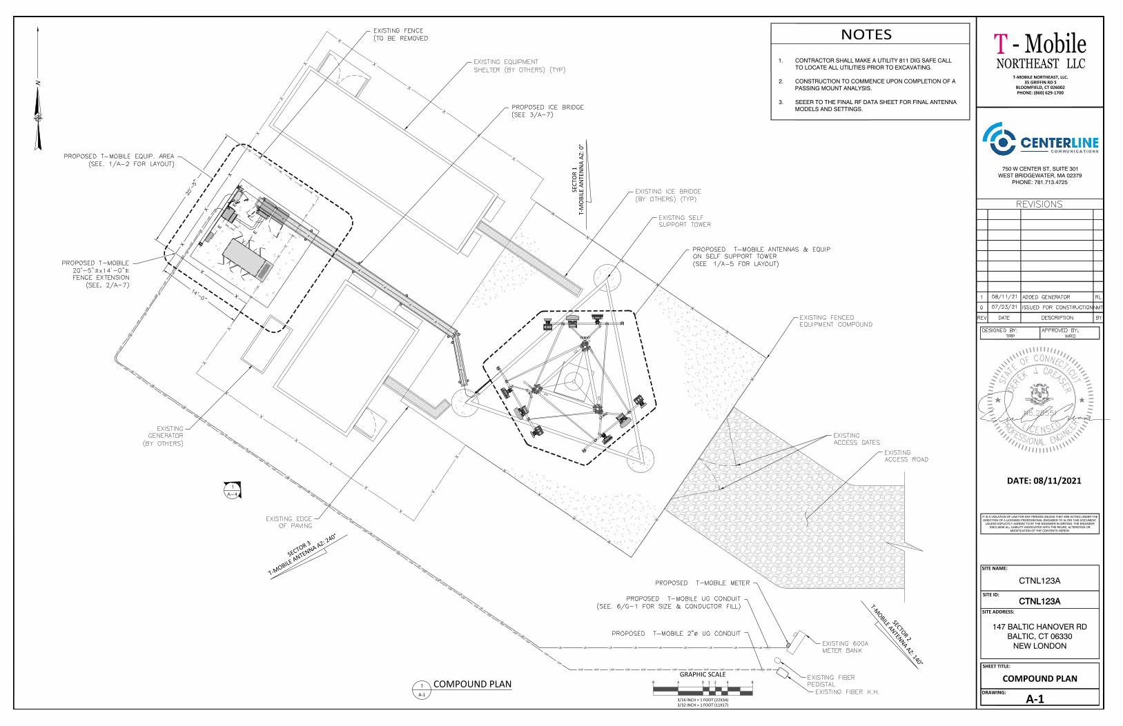
COMPOUND PLAN
NOTES1. CONTRACTOR SHALL MAKE A UTILITY 811 DIG SAFE CALL
TO LOCATE ALL UTILITIES PRIOR TO EXCAVATING.
2. CONSTRUCTION TO COMMENCE UPON COMPLETION OF APASSING MOUNT ANALYSIS.
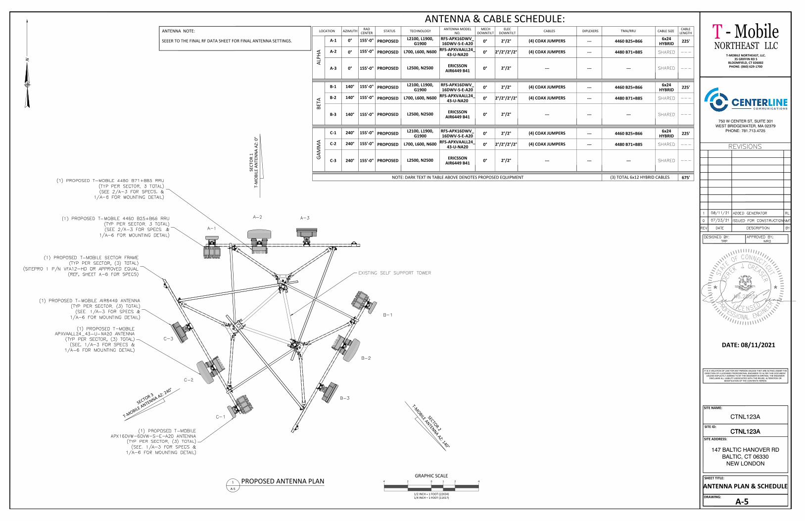
3. SEEER TO THE FINAL RF DATA SHEET FOR FINAL ANTENNAMODELS AND SETTINGS.
GRAPHIC SCALE
3/16 INCH = 1 FOOT (22X34)3/32 INCH = 1 FOOT (11X17)
0 4 848 211
A-1
COMPOUND PLAN
SECTOR 3
T-MOBILE ANTENNA AZ: 240°
SECT
OR
1T-
MO
BILE
AN
TEN
NA
AZ: 0
°
SECTOR 2
T-MOBILE ANTENNA AZ: 140°
N

E
E
E
E
E
E
E
E
E
E
E
E
EF
F
F
F
E
E
UT
UT
F
F
F
F
F
X
X
X
X
X
X
X
X
X
X
X
X
X
X
X
X
X
X
X
XX
X
E
E
E
E
E
NORTHEAST LLC
750 W CENTER ST, SUITE 301WEST BRIDGEWATER, MA 02379
PHONE: 781.713.4725
- MobileT
SITE NAME:
SITE ID:
SITE ADDRESS:
SHEET TITLE:
DRAWING:
CTNL123A
CTNL123A
147 BALTIC HANOVER RDBALTIC, CT 06330
NEW LONDON
CTNL123A
A-2
DATE: 08/11/2021
IT IS A VIOLATION OF LAW FOR ANY PERSON UNLESS THEY ARE ACTING UNDER THEDIRECTION OF A LICENSED PROFESSIONAL ENGINEER TO ALTER THIS DOCUMENT.
UNLESS EXPLICITLY AGREED TO BY THE ENGINEER IN WRITING, THE ENGINEERDISCLAIMS ALL LIABILITY ASSOCIATED WITH THE REUSE, ALTERATION OR
MODIFICATION OF THE CONTENTS HEREIN.
T-MOBILE NORTHEAST, LLC.35 GRIFFIN RD S
BLOOMFIELD, CT 026002PHONE: (860) 629-1700
EQUIPMENT LAYOUTGRAPHIC SCALE
3/4 INCH = 1 FOOT (22X34)3/8 INCH = 1 FOOT (11X17)
0 1 2 424
1
A-2
PROPOSED EQUIPMENT PLAN
N

NORTHEAST LLC
750 W CENTER ST, SUITE 301WEST BRIDGEWATER, MA 02379
PHONE: 781.713.4725
- MobileT
SITE NAME:
SITE ID:
SITE ADDRESS:
SHEET TITLE:
DRAWING:
CTNL123A
CTNL123A
147 BALTIC HANOVER RDBALTIC, CT 06330
NEW LONDON
CTNL123A
A-3
DATE: 08/11/2021
IT IS A VIOLATION OF LAW FOR ANY PERSON UNLESS THEY ARE ACTING UNDER THEDIRECTION OF A LICENSED PROFESSIONAL ENGINEER TO ALTER THIS DOCUMENT.
UNLESS EXPLICITLY AGREED TO BY THE ENGINEER IN WRITING, THE ENGINEERDISCLAIMS ALL LIABILITY ASSOCIATED WITH THE REUSE, ALTERATION OR
MODIFICATION OF THE CONTENTS HEREIN.
T-MOBILE NORTHEAST, LLC.35 GRIFFIN RD S
BLOOMFIELD, CT 026002PHONE: (860) 629-1700
EQUIPMENT DETAILS
2
A-3
RADIO DETAILS
1
A-3
ANTENNA DETAILS
3
A-3
PROPOSED EQUIPMENT CABINET SPECIFICATIONS
RFS APX16DWV-16DWVS-E-A20 RFS APXVAALL24_43-U-NA20 ERICSSON AIR 6449 B41
AAV CABINET
SIDEFRONT
PLAN
4
A-3
AAV CABINET DETAIL
SIDEFRONT
PLAN
SIDEFRONT
PLAN
RADIO DIMENSIONS
SIDEFRONT
PLAN
RADIO DIMENSIONS
SIDEFRONT
PLAN
RADIO DIMENSIONS
5
A-3
PROPOSED EQUIPMENT CONDUIT DETAIL
F F
FF
FF
FF
FF
FF
FF
F
NORTHEAST LLC
750 W CENTER ST, SUITE 301WEST BRIDGEWATER, MA 02379
PHONE: 781.713.4725
- MobileT
SITE NAME:
SITE ID:
SITE ADDRESS:
SHEET TITLE:
DRAWING:
CTNL123A
CTNL123A
147 BALTIC HANOVER RDBALTIC, CT 06330
NEW LONDON
CTNL123A
A-4
DATE: 08/11/2021
IT IS A VIOLATION OF LAW FOR ANY PERSON UNLESS THEY ARE ACTING UNDER THEDIRECTION OF A LICENSED PROFESSIONAL ENGINEER TO ALTER THIS DOCUMENT.
UNLESS EXPLICITLY AGREED TO BY THE ENGINEER IN WRITING, THE ENGINEERDISCLAIMS ALL LIABILITY ASSOCIATED WITH THE REUSE, ALTERATION OR
MODIFICATION OF THE CONTENTS HEREIN.
T-MOBILE NORTHEAST, LLC.35 GRIFFIN RD S
BLOOMFIELD, CT 026002PHONE: (860) 629-1700
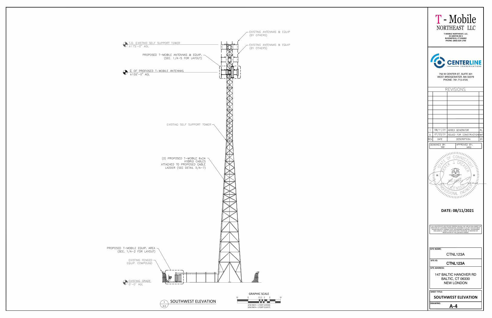
SOUTHWEST ELEVATIONGRAPHIC SCALE
3/32 INCH = 1 FOOT (22X34)3/64 INCH = 1 FOOT (11X17)
0 4 8 16816 21
1
A-4
SOUTHWEST ELEVATION
NORTHEAST LLC
750 W CENTER ST, SUITE 301WEST BRIDGEWATER, MA 02379
PHONE: 781.713.4725
- MobileT
SITE NAME:
SITE ID:
SITE ADDRESS:
SHEET TITLE:
DRAWING:
CTNL123A
CTNL123A
147 BALTIC HANOVER RDBALTIC, CT 06330
NEW LONDON
CTNL123A
A-5
DATE: 08/11/2021
IT IS A VIOLATION OF LAW FOR ANY PERSON UNLESS THEY ARE ACTING UNDER THEDIRECTION OF A LICENSED PROFESSIONAL ENGINEER TO ALTER THIS DOCUMENT.
UNLESS EXPLICITLY AGREED TO BY THE ENGINEER IN WRITING, THE ENGINEERDISCLAIMS ALL LIABILITY ASSOCIATED WITH THE REUSE, ALTERATION OR
MODIFICATION OF THE CONTENTS HEREIN.
T-MOBILE NORTHEAST, LLC.35 GRIFFIN RD S
BLOOMFIELD, CT 026002PHONE: (860) 629-1700
ANTENNA PLAN & SCHEDULEGRAPHIC SCALE
1/2 INCH = 1 FOOT (22X34)1/4 INCH = 1 FOOT (11X17)
0 1 2 4241
A-5
PROPOSED ANTENNA PLAN
SECTOR 3
T-MOBILE ANTENNA AZ: 240°
SECT
OR
1T-
MO
BILE
AN
TEN
NA
AZ: 0
°
SECTOR 2
T-MOBILE ANTENNA AZ: 140°
ANTENNA NOTE:
SEEER TO THE FINAL RF DATA SHEET FOR FINAL ANTENNA SETTINGS.
ANTENNA & CABLE SCHEDULE:LOCATION AZIMUTH RAD
CENTER STATUS TECHNOLOGY ANTENNA MODELNO.
MECHDOWNTILT
ELECDOWNTILT TMA/RRU CABLE SIZE CABLE
LENGTH
ALPH
ABE
TA
NOTE: DARK TEXT IN TABLE ABOVE DENOTES PROPOSED EQUIPMENT
155'-0"A-1 0° 225'6x24HYBRID
A-3 0° 155'-0"
CABLES DIPLEXERS
155'-0"A-2 0°
155'-0"B-1 140°
B-3 140° 155'-0"
155'-0"B-2 140°
GAM
MA
155'-0"C-1 240°
C-3 240° 155'-0" PROPOSED
PROPOSED
155'-0"C-2 240° PROPOSED
PROPOSED
PROPOSED
PROPOSED
RFS-APXVAALL24_43-U-NA20L700, L600, N600
4460 B25+B66
ERICSSONAIR6449 B41L2500, N2500PROPOSED 0° 2°/2° ---
2°/2°RFS-APX16DWV_16DWV-S-E-A20PROPOSED 0° ---(4) COAX JUMPERS
------
---2°/2°/2°/2°0°PROPOSED
(3) TOTAL 6x12 HYBRID CABLES 675'
L2100, L1900,G1900
(4) COAX JUMPERS 4480 B71+B85
225'6x24HYBRID
RFS-APXVAALL24_43-U-NA20L700, L600, N600
4460 B25+B66
ERICSSONAIR6449 B41L2500, N2500 0° 2°/2° ---
2°/2°RFS-APX16DWV_16DWV-S-E-A20 0° ---(4) COAX JUMPERS
------
---2°/2°/2°/2°0°
L2100, L1900,G1900
(4) COAX JUMPERS 4480 B71+B85
225'6x24HYBRID
RFS-APXVAALL24_43-U-NA20L700, L600, N600
4460 B25+B66
ERICSSONAIR6449 B41L2500, N2500 0° 2°/2° ---
2°/2°RFS-APX16DWV_16DWV-S-E-A20 0° ---(4) COAX JUMPERS
------
---2°/2°/2°/2°0°
L2100, L1900,G1900
(4) COAX JUMPERS 4480 B71+B85
N

NORTHEAST LLC
750 W CENTER ST, SUITE 301WEST BRIDGEWATER, MA 02379
PHONE: 781.713.4725
- MobileT
SITE NAME:
SITE ID:
SITE ADDRESS:
SHEET TITLE:
DRAWING:
CTNL123A
CTNL123A
147 BALTIC HANOVER RDBALTIC, CT 06330
NEW LONDON
CTNL123A
A-6
DATE: 08/11/2021
IT IS A VIOLATION OF LAW FOR ANY PERSON UNLESS THEY ARE ACTING UNDER THEDIRECTION OF A LICENSED PROFESSIONAL ENGINEER TO ALTER THIS DOCUMENT.
UNLESS EXPLICITLY AGREED TO BY THE ENGINEER IN WRITING, THE ENGINEERDISCLAIMS ALL LIABILITY ASSOCIATED WITH THE REUSE, ALTERATION OR
MODIFICATION OF THE CONTENTS HEREIN.
T-MOBILE NORTHEAST, LLC.35 GRIFFIN RD S
BLOOMFIELD, CT 026002PHONE: (860) 629-1700
SECTOR MOUNT DETAIL
PARTS LIST
ANTENNA MOUNTING PIPESORDERED SEPARATELY
1
C A
ITEM QTY PART NO.123456789
5B
D
2 E
1011121314151617181920212223242526272829
2282242112
32323296888816844866628484
X-VFAWP30150
SCX2X-127594
P2126X-UB5300X-VFAPL3
X-LPBX-UPB
X-HDPMWG58LW
G58NUTX-UB1300
G12FWG12LW
G12NUTX-UB1212X-100064
G1204G12065A582114A34212G34LW
G34NUTX-HDPMBPG58R-18X-LLTBG12045G12R-15
PART DESCRIPTIONSUPPORT ARM
2-7/8'' O.D. X 150" SCH. 40 PIPECROSSOVER PLATE
FLAT DISK CLAMP PLATE 4" CENTERS (GALV.)2-3/8" OD X 126" SCH 40 GALVANIZED PIPE
5/8" X 3" X 5-1/4" X 2-1/2" U-BOLT (HDG.)VFA-HD PIVOT PLATE
LOWER PIVOT BRACKETUPPER PIVOT BRACKET
HEAVY DUTY PIPE MOUNT WELDMENT5/8" HDG LOCKWASHER
5/8'' HDG HEAVY 2H HEX NUT1/2" X 3" X 5" X 2" GALV U-BOLT
1/2" HDG USS FLATWASHER1/2" HDG LOCKWASHER
1/2'' HDG HEAVY 2H HEX NUT1/2" X 2-1/2" X 4-1/2" X 2" U-BOLT (HDG.)CLAMP (S) (4" V-CLAMP) GALVANIZED
1/2'' x 4" HDG HEX BOLT GR5 FULL THREAD1/2'' x 6-1/2" HDG HEX BOLT GR5 FULL THREAD
5/8'' x 2-1/4" HDG A325 HEX BOLT3/4" x 2-1/2" UNC HEX BOLT (A325)
3/4" HDG LOCKWASHER3/4'' HDG HEAVY 2H HEX NUT
HEAVY DUTY PIPE MOUNT BACKING PLATE5/8" x 18" THREADED ROD (HDG.)
ANGLE BRACKET FOR LLTB1/2'' x 4.5" HDG HEX BOLT GR5 FULL THREAD
1/2" x 15" THREADED ROD (HDG.)
28
14
15
16
182
29
14
15
16
418
X2
X2
X2
DETAIL A 27 16 15 14 20 DETAIL BDETAIL C
26
11
12
TOLERANCE NOTESTOLERANCES ON DIMENSIONS, UNLESS OTHERWISE NOTED ARE:
SAWED, SHEARED AND GAS CUT EDGES (± 0.030")DRILLED AND GAS CUT HOLES (± 0.030") - NO CONING OF HOLESLASER CUT EDGES AND HOLES (± 0.010") - NO CONING OF HOLESBENDS ARE ± 1/2 DEGREEALL OTHER MACHINING (± 0.030")ALL OTHER ASSEMBLY (± 0.060")PROPRIETARY NOTE:THE DATA AND TECHNIQUES CONTAINED IN THIS DRAWING ARE PROPRIETARY INFORMATION OF VALMONTINDUSTRIES AND CONSIDERED A TRADE SECRET. ANY USE OR DISCLOSURE WITHOUT THE CONSENT OFVALMONT INDUSTRIES IS STRICTLY PROHIBITED.
X2
X2
DETAIL D13
14
15
16
DESCRIPTION12'-6" HEAVY DUTY
V-FRAME ASSEMBLYWITH TWO STIFF ARMS
valmont
CPD NO.
CLASS SUB
81 02
DRAWN BY
CEK 6/2/2015DRAWING USAGE
CUSTOMERCHECKED BY
ENG. APPROVAL
BMC 6/22/2015
PART NO.
DWG. NO.VFA12-HD
VFA12-HD
EngineeringSupport Team:
1-888-753-7446
X2
X2
X2
6DETAIL E 11
12
X2
X2
Locations:New York, NYAtlanta, GALos Angeles, CAPlymouth, INSalem, ORDallas, TX
8
X2
18 19
14
15
16
21
11
12
22
23
2410
3
917
14
15
16
12 in
16 1/2 in4 1/2 in
4 in6 1/2 in2 1/4 in2 1/2 in
LENGTH
150 in7 in
126 in
24 in
UNIT WT.66.8076.944.802.4840.751.159.698.848.84
18.520.030.130.740.030.010.070.260.910.270.410.310.480.040.21
13.440.407.060.300.40
NET WT.133.59153.8738.374.97
81.504.60
19.388.848.84
37.040.834.16
23.643.271.226.304.117.301.081.642.502.870.261.2826.893.19
28.252.381.60
TOTAL WT. # 630.79
X2
X2
X2
OR 13
PAGE
1 OF 2
NORTHEAST LLC
750 W CENTER ST, SUITE 301WEST BRIDGEWATER, MA 02379
PHONE: 781.713.4725
- MobileT
SITE NAME:
SITE ID:
SITE ADDRESS:
SHEET TITLE:
DRAWING:
CTNL123A
CTNL123A
147 BALTIC HANOVER RDBALTIC, CT 06330
NEW LONDON
CTNL123A
A-7
DATE: 08/11/2021
IT IS A VIOLATION OF LAW FOR ANY PERSON UNLESS THEY ARE ACTING UNDER THEDIRECTION OF A LICENSED PROFESSIONAL ENGINEER TO ALTER THIS DOCUMENT.
UNLESS EXPLICITLY AGREED TO BY THE ENGINEER IN WRITING, THE ENGINEERDISCLAIMS ALL LIABILITY ASSOCIATED WITH THE REUSE, ALTERATION OR
MODIFICATION OF THE CONTENTS HEREIN.
T-MOBILE NORTHEAST, LLC.35 GRIFFIN RD S
BLOOMFIELD, CT 026002PHONE: (860) 629-1700
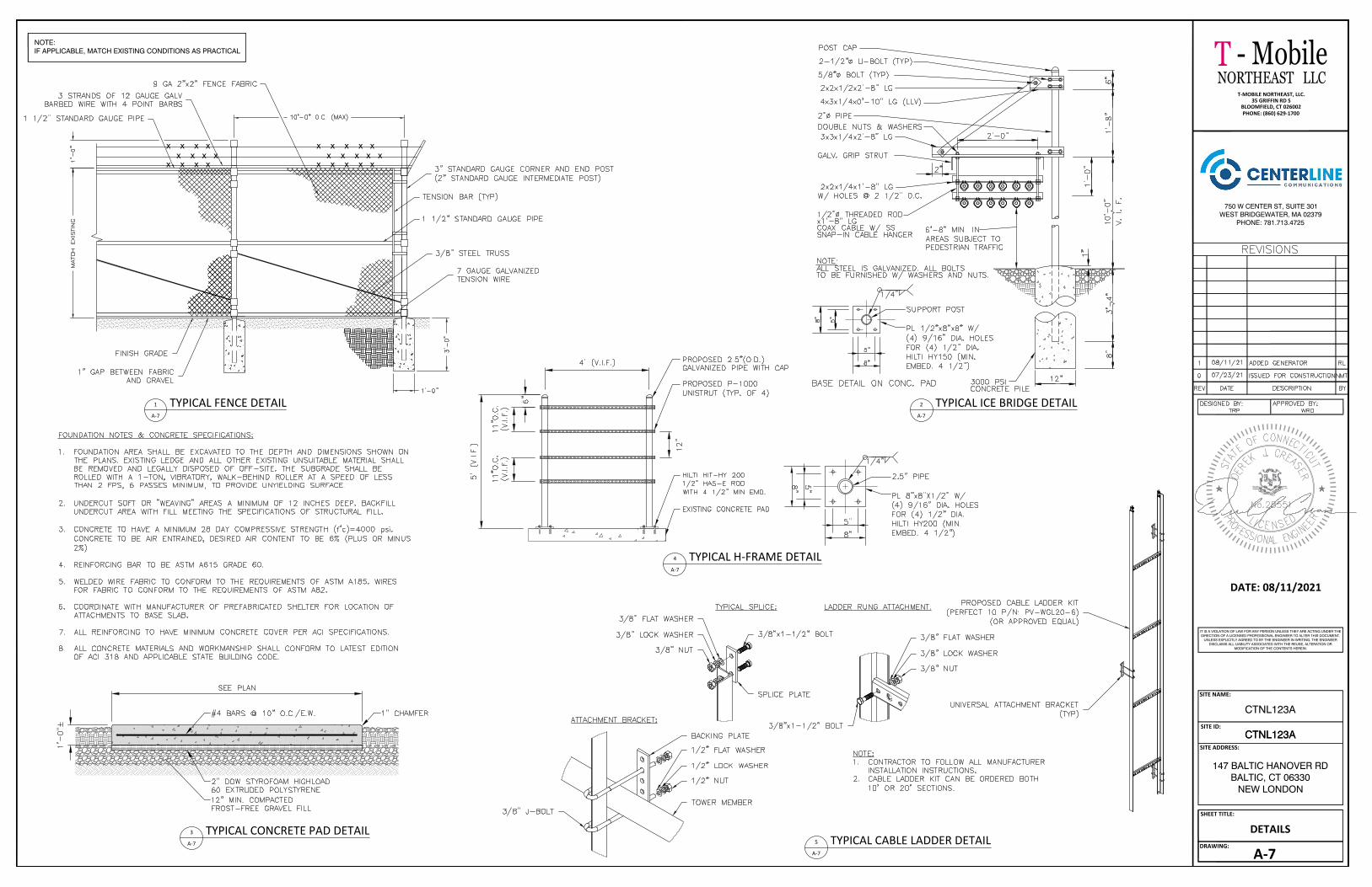
DETAILS
1
A-7
TYPICAL FENCE DETAIL
x x x x x x x x
x x x x
x x x x x x x x x x
x x x x x
NOTE:IF APPLICABLE, MATCH EXISTING CONDITIONS AS PRACTICAL
3
A-7
TYPICAL CONCRETE PAD DETAIL
2
A-7
TYPICAL ICE BRIDGE DETAIL
4
A-7
TYPICAL H-FRAME DETAIL
5
A-7
TYPICAL CABLE LADDER DETAIL

NORTHEAST LLC
750 W CENTER ST, SUITE 301WEST BRIDGEWATER, MA 02379
PHONE: 781.713.4725
- MobileT
SITE NAME:
SITE ID:
SITE ADDRESS:
SHEET TITLE:
DRAWING:
CTNL123A
CTNL123A
147 BALTIC HANOVER RDBALTIC, CT 06330
NEW LONDON
CTNL123A
A-8
DATE: 08/11/2021
IT IS A VIOLATION OF LAW FOR ANY PERSON UNLESS THEY ARE ACTING UNDER THEDIRECTION OF A LICENSED PROFESSIONAL ENGINEER TO ALTER THIS DOCUMENT.
UNLESS EXPLICITLY AGREED TO BY THE ENGINEER IN WRITING, THE ENGINEERDISCLAIMS ALL LIABILITY ASSOCIATED WITH THE REUSE, ALTERATION OR
MODIFICATION OF THE CONTENTS HEREIN.
T-MOBILE NORTHEAST, LLC.35 GRIFFIN RD S
BLOOMFIELD, CT 026002PHONE: (860) 629-1700
ATS SPEC SHEET
NORTHEAST LLC
750 W CENTER ST, SUITE 301WEST BRIDGEWATER, MA 02379
PHONE: 781.713.4725
- MobileT
SITE NAME:
SITE ID:
SITE ADDRESS:
SHEET TITLE:
DRAWING:
CTNL123A
CTNL123A
147 BALTIC HANOVER RDBALTIC, CT 06330
NEW LONDON
CTNL123A
A-9
DATE: 08/11/2021
IT IS A VIOLATION OF LAW FOR ANY PERSON UNLESS THEY ARE ACTING UNDER THEDIRECTION OF A LICENSED PROFESSIONAL ENGINEER TO ALTER THIS DOCUMENT.
UNLESS EXPLICITLY AGREED TO BY THE ENGINEER IN WRITING, THE ENGINEERDISCLAIMS ALL LIABILITY ASSOCIATED WITH THE REUSE, ALTERATION OR
MODIFICATION OF THE CONTENTS HEREIN.
T-MOBILE NORTHEAST, LLC.35 GRIFFIN RD S
BLOOMFIELD, CT 026002PHONE: (860) 629-1700
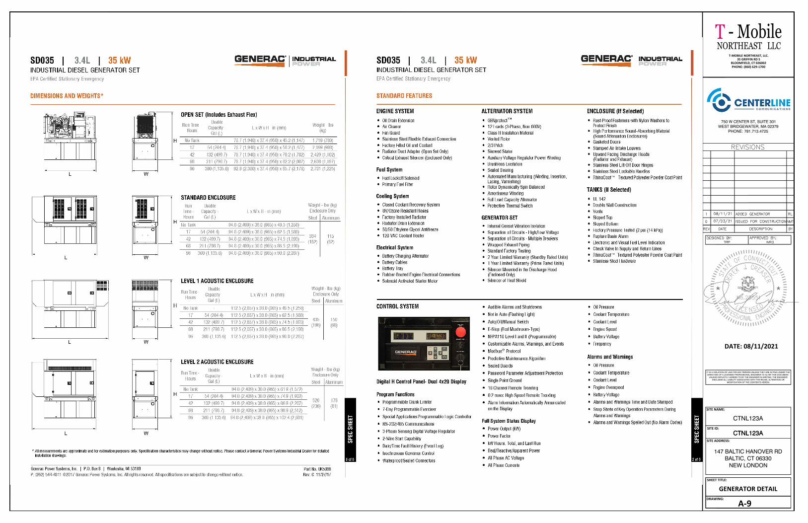
GENERATOR DETAIL

NORTHEAST LLC
750 W CENTER ST, SUITE 301WEST BRIDGEWATER, MA 02379
PHONE: 781.713.4725
- MobileT
SITE NAME:
SITE ID:
SITE ADDRESS:
SHEET TITLE:
DRAWING:
CTNL123A
CTNL123A
147 BALTIC HANOVER RDBALTIC, CT 06330
NEW LONDON
CTNL123A
SN-1
DATE: 08/11/2021
IT IS A VIOLATION OF LAW FOR ANY PERSON UNLESS THEY ARE ACTING UNDER THEDIRECTION OF A LICENSED PROFESSIONAL ENGINEER TO ALTER THIS DOCUMENT.
UNLESS EXPLICITLY AGREED TO BY THE ENGINEER IN WRITING, THE ENGINEERDISCLAIMS ALL LIABILITY ASSOCIATED WITH THE REUSE, ALTERATION OR
MODIFICATION OF THE CONTENTS HEREIN.
T-MOBILE NORTHEAST, LLC.35 GRIFFIN RD S
BLOOMFIELD, CT 026002PHONE: (860) 629-1700
STRUCTURAL NOTES &SPECIAL INSPECTIONS
STRUCTURAL NOTES:SPECIAL INSPECTIONS (SEEERENCE IBC CHAPTER 17):
NOTES:
NOTES:
BEFORE CONSTRUCTION
DURING CONSTRUCTION
REQUIRED
4
5
AFTER CONSTRUCTION
REQUIRED MODIFICATION INSPECTOR REDLINEOR RECORD DRAWINGS 6
REQUIRED PHOTOGRAPHS

NORTHEAST LLC
750 W CENTER ST, SUITE 301WEST BRIDGEWATER, MA 02379
PHONE: 781.713.4725
- MobileT
SITE NAME:
SITE ID:
SITE ADDRESS:
SHEET TITLE:
DRAWING:
CTNL123A
CTNL123A
147 BALTIC HANOVER RDBALTIC, CT 06330
NEW LONDON
CTNL123A
S-1
DATE: 08/11/2021
IT IS A VIOLATION OF LAW FOR ANY PERSON UNLESS THEY ARE ACTING UNDER THEDIRECTION OF A LICENSED PROFESSIONAL ENGINEER TO ALTER THIS DOCUMENT.
UNLESS EXPLICITLY AGREED TO BY THE ENGINEER IN WRITING, THE ENGINEERDISCLAIMS ALL LIABILITY ASSOCIATED WITH THE REUSE, ALTERATION OR
MODIFICATION OF THE CONTENTS HEREIN.
T-MOBILE NORTHEAST, LLC.35 GRIFFIN RD S
BLOOMFIELD, CT 026002PHONE: (860) 629-1700
ANTENNA & RRU MOUNTINGDETAILS
ANTENNA MOUNT NOTES:
1. APX16DWV-16DWV-S-E-A20: APM40-5E PIPE MOUNT KIT2. APXVAARR24-43-U-NA20: APM40-5E PIPE MOUNT KIT3. AIR6449: ERICSSON R2A PIPE MOUNT KIT
1
S-1
ANTENNA & RRU MOUNTING DETAIL

NORTHEAST LLC
750 W CENTER ST, SUITE 301WEST BRIDGEWATER, MA 02379
PHONE: 781.713.4725
- MobileT
SITE NAME:
SITE ID:
SITE ADDRESS:
SHEET TITLE:
DRAWING:
CTNL123A
CTNL123A
147 BALTIC HANOVER RDBALTIC, CT 06330
NEW LONDON
CTNL123A
G-1
DATE: 08/11/2021
IT IS A VIOLATION OF LAW FOR ANY PERSON UNLESS THEY ARE ACTING UNDER THEDIRECTION OF A LICENSED PROFESSIONAL ENGINEER TO ALTER THIS DOCUMENT.
UNLESS EXPLICITLY AGREED TO BY THE ENGINEER IN WRITING, THE ENGINEERDISCLAIMS ALL LIABILITY ASSOCIATED WITH THE REUSE, ALTERATION OR
MODIFICATION OF THE CONTENTS HEREIN.
T-MOBILE NORTHEAST, LLC.35 GRIFFIN RD S
BLOOMFIELD, CT 026002PHONE: (860) 629-1700
GROUNDING & ONE LINEDIAGRAM4
G-1
ANTENNA/RRU GROUNDING DETAIL
3
G-1
GROUND WIRE SCHEDULE2
G-1
GROUND BAR DETAIL
5
G-1
GROUND LUG DETAIL
DETAIL#
SHEET#
TITLE
1
G-1
GROUNDING RISER DIAGRAM

E E
E E
E
F FF
F
E
E
UT
UT
F F F F F
XXXXXXXX
XX
XX
XX
XX
XX
X
XX
XX
X
1
G-2
GROUNDING PLAN
NORTHEAST LLC
750 W CENTER ST, SUITE 301WEST BRIDGEWATER, MA 02379
PHONE: 781.713.4725
- MobileT
SITE NAME:
SITE ID:
SITE ADDRESS:
SHEET TITLE:
DRAWING:
CTNL123A
CTNL123A
147 BALTIC HANOVER RDBALTIC, CT 06330
NEW LONDON
CTNL123A
G-2
DATE: 08/11/2021
IT IS A VIOLATION OF LAW FOR ANY PERSON UNLESS THEY ARE ACTING UNDER THEDIRECTION OF A LICENSED PROFESSIONAL ENGINEER TO ALTER THIS DOCUMENT.
UNLESS EXPLICITLY AGREED TO BY THE ENGINEER IN WRITING, THE ENGINEERDISCLAIMS ALL LIABILITY ASSOCIATED WITH THE REUSE, ALTERATION OR
MODIFICATION OF THE CONTENTS HEREIN.
T-MOBILE NORTHEAST, LLC.35 GRIFFIN RD S
BLOOMFIELD, CT 026002PHONE: (860) 629-1700
GROUNDING PLAN
NOTES:
1. EXISTING GROUND WIRES TO BE RELOCATED AS NEEDED.

Exhibit E
Structural Analysis Report
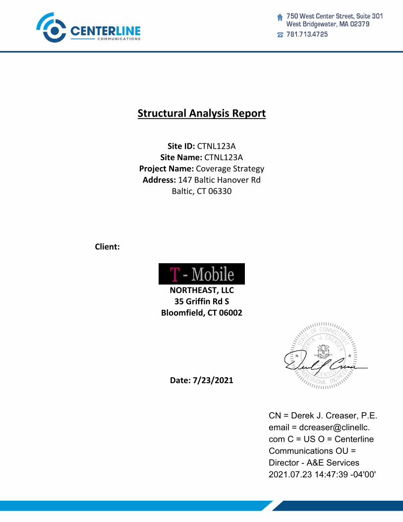
s���������@a�������@r�����@
s���@idZ@ctnlQRSa@
s���@n���Z@ctnlQRSa@
p������@n���Z@c�������@s�������@
a������Z@QTW@b�����@h������@r�@
b�����L@ct@PVSSP@
c�����Z
northeastL@llc@
SU@g������@r�@s@
b���������L@ct@PVPPR@
d���Z@WORSORPRQ@
CN = Derek J. Creaser, P.E.
email = dcreaser@clinellc.
com C = US O = Centerline
Communications OU =
Director - A&E Services
2021.07.23 14:47:39 -04'00'
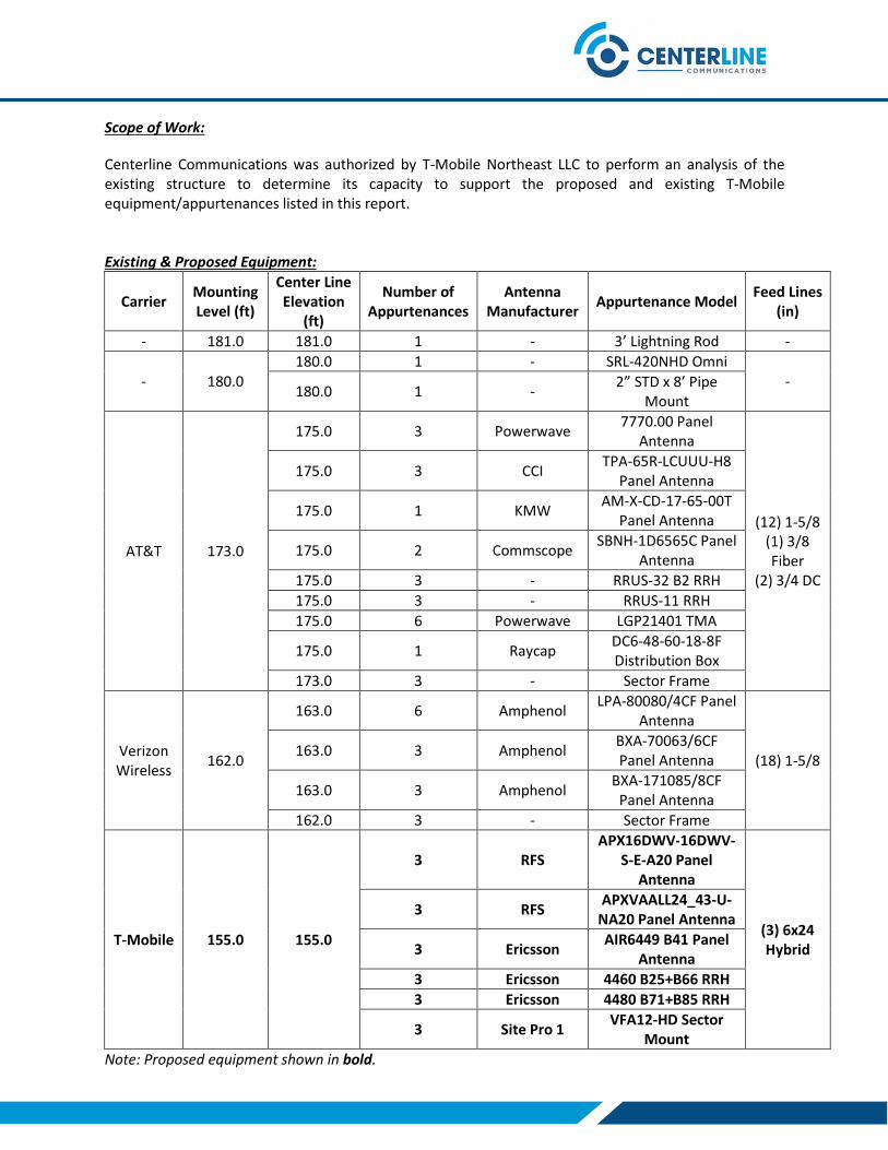
Scope of Work:
Centerline Communications was authorized by T-Mobile Northeast LLC to perform an analysis of the existing structure to determine its capacity to support the proposed and existing T-Mobile equipment/appurtenances listed in this report.
Existing & Proposed Equipment:
Carrier Mounting Level (ft)
Center Line Elevation
(ft)
Number of Appurtenances
Antenna Manufacturer
Appurtenance ModelFeed Lines
(in)
- 181.0 181.0 1 - 3’ Lightning Rod -
- 180.0 180.0 1 - SRL-420NHD Omni
- 180.0 1 -
2” STD x 8’ Pipe Mount
AT&T 173.0
175.0 3 Powerwave 7770.00 Panel
Antenna
(12) 1-5/8 (1) 3/8 Fiber
(2) 3/4 DC
175.0 3 CCI TPA-65R-LCUUU-H8
Panel Antenna
175.0 1 KMW AM-X-CD-17-65-00T
Panel Antenna
175.0 2 Commscope SBNH-1D6565C Panel
Antenna
175.0 3 - RRUS-32 B2 RRH
175.0 3 - RRUS-11 RRH
175.0 6 Powerwave LGP21401 TMA
175.0 1 Raycap DC6-48-60-18-8F Distribution Box
173.0 3 - Sector Frame
Verizon Wireless
162.0
163.0 6 Amphenol LPA-80080/4CF Panel
Antenna
(18) 1-5/8 163.0 3 Amphenol
BXA-70063/6CF Panel Antenna
163.0 3 Amphenol BXA-171085/8CF
Panel Antenna
162.0 3 - Sector Frame
T-Mobile 155.0 155.0
3 RFS APX16DWV-16DWV-
S-E-A20 Panel Antenna
(3) 6x24 Hybrid
3 RFS APXVAALL24_43-U-
NA20 Panel Antenna
3 Ericsson AIR6449 B41 Panel
Antenna
3 Ericsson 4460 B25+B66 RRH
3 Ericsson 4480 B71+B85 RRH
3 Site Pro 1 VFA12-HD Sector
Mount
Note: Proposed equipment shown in bold.

Design Criteria:
Design Codes:
2018 Connecticut State Building Code 2015 International Building Code ASCE 7-10 TIA-222-G Standards
Ultimate Design Wind Speed (Vult) 130 mph
Wind Speed with Ice 50 mph
Ice Thickness 0.75 in.
Exposure Category C
Topographic Category 1
Risk Category II
Site Soil Class (Assumed) D – Stiff Soil
Seismic Design Category B
Spectral Response Acceleration Parameter at a Short Periods, SS 0.171 g
Spectral Response Acceleration Parameter at a Period of 1 Second, S1 0.061 g
Short Period Site Coefficient, Fa 1.60
Long Period Site Coefficient, Fv 2.40*Refer to calculations for additional design criteria.
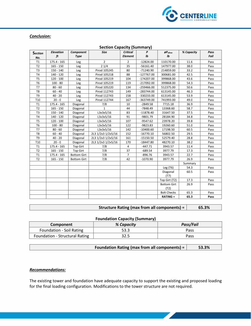
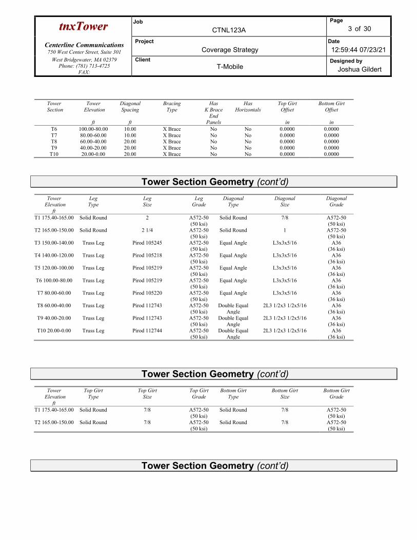
Conclusion:
Section Capacity (Summary)
Section
No.
Elevationft
ComponentType
Size CriticalElement
Plb
øPallow
lb% Capacity Pass
Fail
T1 175.4 - 165 Leg 2 2 -12824.00 110170.00 11.6 Pass
T2 165 - 150 Leg 2 1/4 35 -56161.40 147977.00 38.0 Pass
T3 150 - 140 Leg Pirod 105245 80 -71240.90 214859.00 33.2 Pass
T4 140 - 120 Leg Pirod 105218 88 -127767.00 300681.00 42.5 Pass
T5 120 - 100 Leg Pirod 105219 104 -174207.00 399868.00 43.6 Pass
T6 100 - 80 Leg Pirod 105219 119 -217092.00 399868.00 54.3 Pass
T7 80 - 60 Leg Pirod 105220 134 -259466.00 512375.00 50.6 Pass
T8 60 - 40 Leg Pirod 112743 149 -283744.00 613145.00 46.3 Pass
T9 40 - 20 Leg Pirod 112743 158 -330233.00 613145.00 53.9 Pass
T10 20 - 0 Leg Pirod 112744 167 -363749.00 741993.00 49.0 Pass
T1 175.4 - 165 Diagonal 7/8 10 -2849.58 7715.18 36.9 Pass
T2 165 - 150 Diagonal 1 44 -7848.49 13368.60 58.7 Pass
T3 150 - 140 Diagonal L3x3x5/16 83 -11878.40 31647.50 37.5 Pass
T4 140 - 120 Diagonal L3x3x5/16 91 -9801.79 28184.90 34.8 Pass
T5 120 - 100 Diagonal L3x3x5/16 107 -9547.62 23978.20 39.8 Pass
T6 100 - 80 Diagonal L3x3x5/16 122 -9823.83 19260.60 51.0 Pass
T7 80 - 60 Diagonal L3x3x5/16 142 -10400.60 17198.50 60.5 Pass
T8 60 - 40 Diagonal 2L3 1/2x3 1/2x5/16 152 -16770.10 56802.50 29.5 Pass
T9 40 - 20 Diagonal 2L3 1/2x3 1/2x5/16 161 -15150.50 52579.40 28.8 Pass
T10 20 - 0 Diagonal 2L3 1/2x3 1/2x5/16 170 -18447.80 48270.10 38.2 Pass
T1 175.4 - 165 Top Girt 7/8 4 -447.71 3943.57 11.4 Pass
T2 165 - 150 Top Girt 7/8 37 -689.54 3977.79 17.3 Pass
T1 175.4 - 165 Bottom Girt 7/8 7 -896.76 3943.57 22.7 Pass
T2 165 - 150 Bottom Girt 7/8 42 -1070.90 3977.79 26.9 Pass
Summary
Leg (T6) 54.3 Pass
Diagonal (T7)
60.5 Pass
Top Girt (T2) 17.3 Pass
Bottom Girt (T2)
26.9 Pass
Bolt Checks 65.3 Pass
RATING = 65.3 Pass
Structure Rating (max from all components) = 65.3%
Foundation Capacity (Summary)
Component % Capacity Pass/Fail
Foundation - Soil Rating 53.3 Pass
Foundation - Structural Rating 32.5 Pass
Foundation Rating (max from all components) = 53.3%
Recommendations:
The existing tower and foundation have adequate capacity to support the existing and proposed loading for the final loading configuration. Modifications to the tower structure are not required.

Reference Documents:
T-Mobile RFDS CTNL123A_Coverage Strategy_1, dated May 18, 2021
Site Photos and Notes by Centerline Communications, dated May 20, 2021
Structural Analysis by Centek Engineering, dated June 15, 2015
Structural Analysis by Fullerton Engineering, dated December 7, 2017
Structural Analysis by Centek Engineering, dated October 5, 2011
Tower Drawings by Valmont, dated September 25, 2006
Assumptions and Limitations:
The tower and structures were built and maintained with the manufacturer’s specifications.
The configuration of antennas, transmission cables, mounts and other appurtenances are as specified in this report and the referenced drawings.
Design Calculations

ASCE 7 Hazards ReportAddress:147 Baltic Hanover RdBaltic, Connecticut06330
Standard: ASCE/SEI 7-10
Risk Category: II
Soil Class: D - Stiff Soil
Elevation: 281.67 ft (NAVD 88)
Latitude:Longitude:
41.626917
-72.077616
Wind
Results:
Wind Speed: 131 Vmph
10-year MRI 79 Vmph
25-year MRI 89 Vmph
50-year MRI 97 Vmph
100-year MRI 106 Vmph
Data Source: ASCE/SEI 7-10, Fig. 26.5-1A and Figs. CC-1–CC-4, and Section 26.5.2, incorporating errata of March 12, 2014
Date Accessed: Fri Jul 23 2021
Value provided is 3-second gust wind speeds at 33 ft above ground for Exposure C Category, based on linear interpolation between contours. Wind speeds are interpolated in accordance with the 7-10 Standard. Wind speeds correspond to approximately a 7% probability of exceedance in 50 years (annual exceedance probability = 0.00143, MRI = 700 years).
Site is in a hurricane-prone region as defined in ASCE/SEI 7-10 Section 26.2. Glazed openings need not be protected against wind-borne debris.
Page 1 of 4https://asce7hazardtool.online/ Fri Jul 23 2021

SS : 0.17
S1 : 0.061
Fa : 1.6
Fv : 2.4
SMS : 0.273
SM1 : 0.146
SDS : 0.182
SD1 : 0.098
TL : 6
PGA : 0.085
PGA M : 0.137
FPGA : 1.6
Ie : 1
Design Response Spectrum
S (g) vs T(s)a
MCE Response SpectrumR
S (g) vs T(s)a
Seismic
Site Soil Class:
Results:
Seismic Design Category
D - Stiff Soil
B
Data Accessed:
Date Source:
Fri Jul 23 2021USGS Seismic Design Maps based on ASCE/SEI 7-10, incorporating Supplement 1 and errata of March 31, 2013, and ASCE/SEI 7-10 Table 1.5-2. Additional data for site-specific ground motion procedures in accordance with ASCE/SEI 7-10 Ch. 21 are available from USGS.
Page 2 of 4https://asce7hazardtool.online/ Fri Jul 23 2021

Ice
Results:
Data Source:
Date Accessed:
Ice Thickness: 0.75 in.
Concurrent Temperature: 15 F
Gust Speed: 50 mph
Standard ASCE/SEI 7-10, Figs. 10-2 through 10-8
Fri Jul 23 2021
Ice thicknesses on structures in exposed locations at elevations higher than the surrounding terrain and in valleys and gorges may exceed the mapped values.
Values provided are equivalent radial ice thicknesses due to freezing rain with concurrent 3-second gust speeds, for a 50-year mean recurrence interval, and temperatures concurrent with ice thicknesses due to freezing rain. Thicknesses for ice accretions caused by other sources shall be obtained from local meteorological studies. Ice thicknesses in exposed locations at elevations higher than the surrounding terrain and in valleys and gorges may exceed the mapped values.
Snow
Results:
Ground Snow Load, p : 30 lb/ftg
2
Elevation: 281.7 ft
Data Source: ASCE/SEI 7-10, Fig. 7-1.
Date Accessed: Fri Jul 23 2021
Values provided are ground snow loads. In areas designated "case study required," extreme local variations in ground snow loads preclude mapping at this scale. Site-specific case studies are required to establish ground snow loads at elevations not covered.
Page 3 of 4https://asce7hazardtool.online/ Fri Jul 23 2021
The ASCE 7 Hazard Tool is provided for your convenience, for informational purposes only, and is provided “as is” and without warranties of any kind. The location data included herein has been obtained from information developed, produced, and maintained by third party providers; or has been extrapolated from maps incorporated in the ASCE 7 standard. While ASCE has made every effort to use data obtained from reliable sources or methodologies, ASCE does not make any representations or warranties as to the accuracy, completeness, reliability, currency, or quality of any data provided herein. Any third-party links provided by this Tool should not be construed as an endorsement, affiliation, relationship, or sponsorship of such third-party content by or from ASCE.
ASCE does not intend, nor should anyone interpret, the results provided by this Tool to replace the sound judgment of a competent professional, having knowledge and experience in the appropriate field(s) of practice, nor to substitute for the standard of care required of such professionals in interpreting and applying the contents of this Tool or the ASCE 7 standard.
In using this Tool, you expressly assume all risks associated with your use. Under no circumstances shall ASCE or its officers, directors, employees, members, affiliates, or agents be liable to you or any other person for any direct, indirect, special, incidental, or consequential damages arising from or related to your use of, or reliance on, the Tool or any information obtained therein. To the fullest extent permitted by law, you agree to release and hold harmless ASCE from any and all liability of any nature arising out of or resulting from any use of data provided by the ASCE 7 Hazard Tool.
Page 4 of 4https://asce7hazardtool.online/ Fri Jul 23 2021
Centerline Communications 750 West Center Street, Suite 301
West Bridgewater, MA 02379 Phone: (781) 713-4725
FAX:
Job: CTNL123A
Project: Coverage Strategy Client: T-Mobile Drawn by: Joshua Gildert App'd:
Code: TIA-222-G Date: 07/23/21 Scale: NTS Path:
C:\Users\Joshua Gildert\Box\Projects\New England Projects\T-Mobile\SITES\CT\CTNL123A - 147 BALTIC HANOVER RD - SST\ANCHOR\Structural\Working Files\Analysis\tnx\CTNL123A.eri
Dwg No. E-1
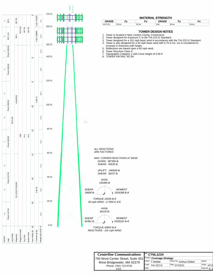
175.4 ft
165.0 ft
150.0 ft
140.0 ft
120.0 ft
100.0 ft
80.0 ft
60.0 ft
40.0 ft
20.0 ft
0.0 ft
REACTIONS - 101 mph WINDTORQUE 43855 lb-ft
60381 lbSHEAR
6328181 lb-ftMOMENT
66105 lb
AXIAL
50 mph WIND - 0.7500 in ICE
TORQUE 15035 lb-ft
18689 lb
SHEAR
1924288 lb-ft
MOMENT
165485 lb
AXIAL
SHEAR: 36237 lb
UPLIFT: -340646 lb
SHEAR: 40635 lbDOWN: 387366 lb
MAX. CORNER REACTIONS AT BASE:
ARE FACTOREDALL REACTIONS
S
ect
ion
T1
T2
T3
T4
T5
T6
T7
T8
T9
T10
L
eg
sS
R 2
SR
2 1
/4P
iro
d 1
05
24
5P
iro
d 1
05
21
8P
iro
d 1
05
21
9P
iro
d 1
05
22
0P
iro
d 1
12
74
3P
iro
d 1
12
74
4
L
eg
Gra
de
A5
72
-50
D
iag
on
als
SR
7/8
SR
1L
3x3
x5/1
62
L3
1/2
x3 1
/2x5
/16
D
iag
on
al G
rad
eA
57
2-5
0A
36
T
op
Gir
tsS
R 7
/8N
.A.
B
otto
m G
irts
SR
7/8
N.A
.
F
ace
Wid
th (
ft)
56
81
01
21
41
61
82
0
#
Pa
ne
ls @
(ft)
4 @
2.4
33
33
6 @
2.3
88
89
9 @
10
3 @
20
W
eig
ht (l
b)
701.4
1263.5
1452.5
3199.7
3864.9
3972.6
4621.2
7317.3
7429.2
8195.1
42
01
7.4
MATERIAL STRENGTHGRADE GRADEFy FyFu Fu
A572-50 50 ksi 65 ksi A36 36 ksi 58 ksi
TOWER DESIGN NOTES1. Tower is located in New London County, Connecticut.2. Tower designed for Exposure C to the TIA-222-G Standard.3. Tower designed for a 101 mph basic wind in accordance with the TIA-222-G Standard.4. Tower is also designed for a 50 mph basic wind with 0.75 in ice. Ice is considered to
increase in thickness with height.5. Deflections are based upon a 60 mph wind.6. Tower Structure Class II.7. Topographic Category 1 with Crest Height of 0.00 ft8. TOWER RATING: 65.3%

Centerline Communications 750 West Center Street, Suite 301
West Bridgewater, MA 02379 Phone: (781) 713-4725
FAX:
Job: CTNL123A
Project: Coverage Strategy Client: T-Mobile Drawn by: Joshua Gildert App'd:
Code: TIA-222-G Date: 07/23/21 Scale: NTS Path:
C:\Users\Joshua Gildert\Box\Projects\New England Projects\T-Mobile\SITES\CT\CTNL123A - 147 BALTIC HANOVER RD - SST\ANCHOR\Structural\Working Files\Analysis\tnx\CTNL123A.eri
Dwg No. E-1
175.4 ft
165.0 ft
150.0 ft
140.0 ft
120.0 ft
100.0 ft
80.0 ft
60.0 ft
40.0 ft
20.0 ft
0.0 ft
S
ect
ion
T1
T2
T3
T4
T5
T6
T7
T8
T9
T10
L
eg
sS
R 2
SR
2 1
/4P
iro
d 1
05
24
5P
iro
d 1
05
21
8P
iro
d 1
05
21
9P
iro
d 1
05
22
0P
iro
d 1
12
74
3P
iro
d 1
12
74
4
L
eg
Gra
de
A5
72
-50
D
iag
on
als
SR
7/8
SR
1L
3x3
x5/1
62
L3
1/2
x3 1
/2x5
/16
D
iag
on
al G
rad
eA
57
2-5
0A
36
T
op
Gir
tsS
R 7
/8N
.A.
B
otto
m G
irts
SR
7/8
N.A
.
F
ace
Wid
th (
ft)
56
81
01
21
41
61
82
0
#
Pa
ne
ls @
(ft)
4 @
2.4
33
33
6 @
2.3
88
89
9 @
10
3 @
20
W
eig
ht (l
b)
701.4
1263.5
1452.5
3199.7
3864.9
3972.6
4621.2
7317.3
7429.2
8195.1
42
01
7.4
Lightning Rod 1/2"x3' on 12' Pipe 181SRL-420NHD Omni 1802" STD x 8' Pipe Mount 180Powerwave 7770.00 175Powerwave 7770.00 175Powerwave 7770.00 175KMW AM-X-CD-17-65-00T 175Commscope SBNH-1D6565C 175Commscope SBNH-1D6565C 175RRUS-11 175RRUS-11 175RRUS-11 175(2) Powerwave LGP21401 TMA 175(2) Powerwave LGP21401 TMA 175(2) Powerwave LGP21401 TMA 175Raycap DC6-48-60-18-8F 175CCI TPA-65R-LCUUUU-H8 175CCI TPA-65R-LCUUUU-H8 175CCI TPA-65R-LCUUUU-H8 175RRUS-32 B2 175RRUS-32 B2 175RRUS-32 B2 175Pirod 15' T-Frame 173Pirod 15' T-Frame 173Pirod 15' T-Frame 173Amphenol BXA-70063/6CF 163Amphenol BXA-70063/6CF 163Amphenol BXA-70063/6CF 163Amphenol BXA-171085/8CF 163Amphenol BXA-171085/8CF 163Amphenol BXA-171085/8CF 163(2) Amphenol LPA-80080/4CF 163(2) Amphenol LPA-80080/4CF 163(2) Amphenol LPA-80080/4CF 163Pirod 15' T-Frame 162Pirod 15' T-Frame 162Pirod 15' T-Frame 162APX16DWV-16DWV-S-E-A20 (T-MOBILE)
155APX16DWV-16DWV-S-E-A20 (T-MOBILE)
155APX16DWV-16DWV-S-E-A20 (T-MOBILE)
155APXVAALL24_43-U-NA20 (T-MOBILE) 155APXVAALL24_43-U-NA20 (T-MOBILE) 155APXVAALL24_43-U-NA20 (T-MOBILE) 155AIR 6449 B41 (T-MOBILE) 155AIR 6449 B41 (T-MOBILE) 155AIR 6449 B41 (T-MOBILE) 155RADIO 4480 B66 (T-MOBILE) 155RADIO 4480 B66 (T-MOBILE) 155RADIO 4480 B66 (T-MOBILE) 155RADIO 4460 B25_B66 (T-MOBILE) 155RADIO 4460 B25_B66 (T-MOBILE) 155RADIO 4460 B25_B66 (T-MOBILE) 155Site Pro 1 VFA12-HD (T-MOBILE) 155Site Pro 1 VFA12-HD (T-MOBILE) 155Site Pro 1 VFA12-HD (T-MOBILE) 155(4) PIPE MOUNT (8'X2.375" (T-MOBILE)
155(4) PIPE MOUNT (8'X2.375" (T-MOBILE)
155(4) PIPE MOUNT (8'X2.375" (T-MOBILE)
155DESIGNED APPURTENANCE LOADING
TYPE TYPEELEVATION ELEVATIONLightning Rod 1/2"x3' on 12' Pipe 181
SRL-420NHD Omni 180
2" STD x 8' Pipe Mount 180
Powerwave 7770.00 175
Powerwave 7770.00 175
Powerwave 7770.00 175
KMW AM-X-CD-17-65-00T 175
Commscope SBNH-1D6565C 175
Commscope SBNH-1D6565C 175
RRUS-11 175
RRUS-11 175
RRUS-11 175
(2) Powerwave LGP21401 TMA 175
(2) Powerwave LGP21401 TMA 175
(2) Powerwave LGP21401 TMA 175
Raycap DC6-48-60-18-8F 175
CCI TPA-65R-LCUUUU-H8 175
CCI TPA-65R-LCUUUU-H8 175
CCI TPA-65R-LCUUUU-H8 175
RRUS-32 B2 175
RRUS-32 B2 175
RRUS-32 B2 175
Pirod 15' T-Frame 173
Pirod 15' T-Frame 173
Pirod 15' T-Frame 173
Amphenol BXA-70063/6CF 163
Amphenol BXA-70063/6CF 163
Amphenol BXA-70063/6CF 163
Amphenol BXA-171085/8CF 163
Amphenol BXA-171085/8CF 163
Amphenol BXA-171085/8CF 163
(2) Amphenol LPA-80080/4CF 163
(2) Amphenol LPA-80080/4CF 163
(2) Amphenol LPA-80080/4CF 163
Pirod 15' T-Frame 162
Pirod 15' T-Frame 162
Pirod 15' T-Frame 162
APX16DWV-16DWV-S-E-A20 (T-MOBILE)
155
APX16DWV-16DWV-S-E-A20 (T-MOBILE)
155
APX16DWV-16DWV-S-E-A20 (T-MOBILE)
155
APXVAALL24_43-U-NA20 (T-MOBILE) 155
APXVAALL24_43-U-NA20 (T-MOBILE) 155
APXVAALL24_43-U-NA20 (T-MOBILE) 155
AIR 6449 B41 (T-MOBILE) 155
AIR 6449 B41 (T-MOBILE) 155
AIR 6449 B41 (T-MOBILE) 155
RADIO 4480 B66 (T-MOBILE) 155
RADIO 4480 B66 (T-MOBILE) 155
RADIO 4480 B66 (T-MOBILE) 155
RADIO 4460 B25_B66 (T-MOBILE) 155
RADIO 4460 B25_B66 (T-MOBILE) 155
RADIO 4460 B25_B66 (T-MOBILE) 155
Site Pro 1 VFA12-HD (T-MOBILE) 155
Site Pro 1 VFA12-HD (T-MOBILE) 155
Site Pro 1 VFA12-HD (T-MOBILE) 155
(4) PIPE MOUNT (8'X2.375" (T-MOBILE)
155
(4) PIPE MOUNT (8'X2.375" (T-MOBILE)
155
(4) PIPE MOUNT (8'X2.375" (T-MOBILE)
155
MATERIAL STRENGTHGRADE GRADEFy FyFu Fu
A572-50 50 ksi 65 ksi A36 36 ksi 58 ksi
Centerline Communications 750 West Center Street, Suite 301
West Bridgewater, MA 02379 Phone: (781) 713-4725
FAX:
Job: CTNL123A
Project: Coverage Strategy Client: T-Mobile Drawn by: Joshua Gildert App'd:
Code: TIA-222-G Date: 07/23/21 Scale: NTS Path:
C:\Users\Joshua Gildert\Box\Projects\New England Projects\T-Mobile\SITES\CT\CTNL123A - 147 BALTIC HANOVER RD - SST\ANCHOR\Structural\Working Files\Analysis\tnx\CTNL123A.eri
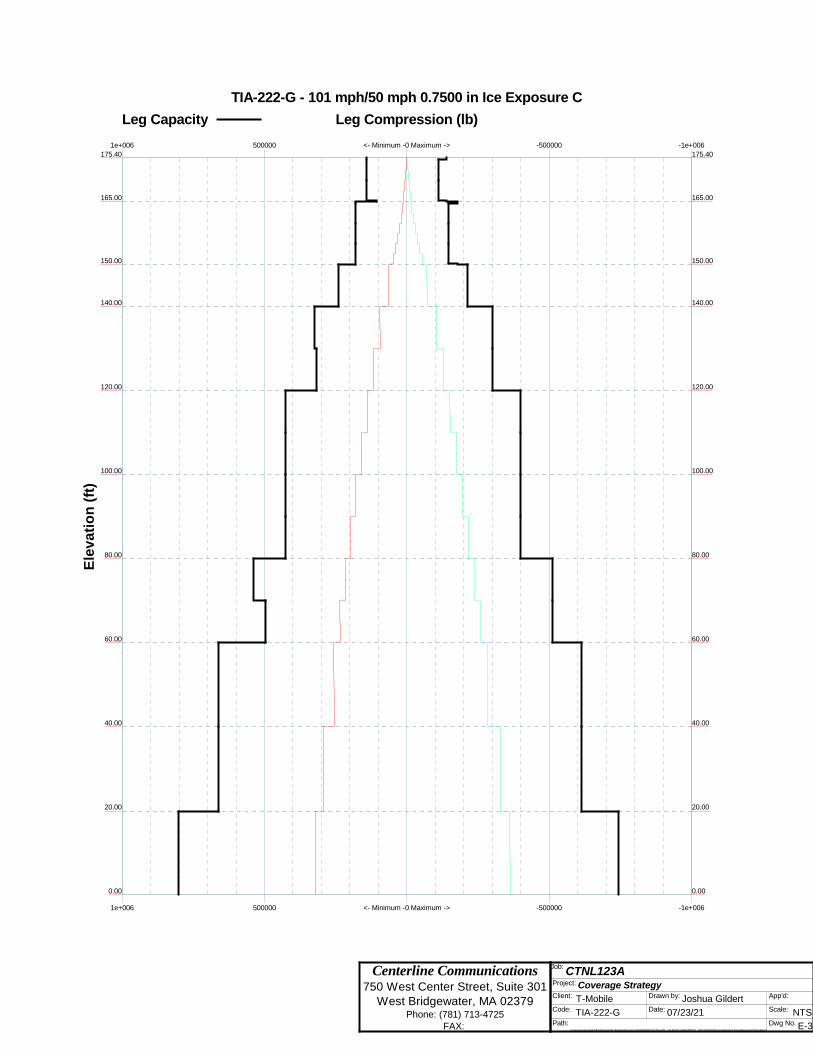
Dwg No. E-3
<- Minimum -0 Maximum ->
<- Minimum -0 Maximum ->
-500000
-500000
-1e+006
-1e+006
500000
500000
1e+006
1e+006
TIA-222-G - 101 mph/50 mph 0.7500 in Ice Exposure C
Leg Capacity Leg Compression (lb)
175.40 175.40
165.00 165.00
150.00 150.00
140.00 140.00
120.00 120.00
100.00 100.00
80.00 80.00
60.00 60.00
40.00 40.00
20.00 20.00
0.00 0.00
Ele
va
tio
n (
ft)
Centerline Communications 750 West Center Street, Suite 301
West Bridgewater, MA 02379 Phone: (781) 713-4725
FAX:
Job: CTNL123A
Project: Coverage Strategy Client: T-Mobile Drawn by: Joshua Gildert App'd:
Code: TIA-222-G Date: 07/23/21 Scale: NTS Path:
C:\Users\Joshua Gildert\Box\Projects\New England Projects\T-Mobile\SITES\CT\CTNL123A - 147 BALTIC HANOVER RD - SST\ANCHOR\Structural\Working Files\Analysis\tnx\CTNL123A.eri
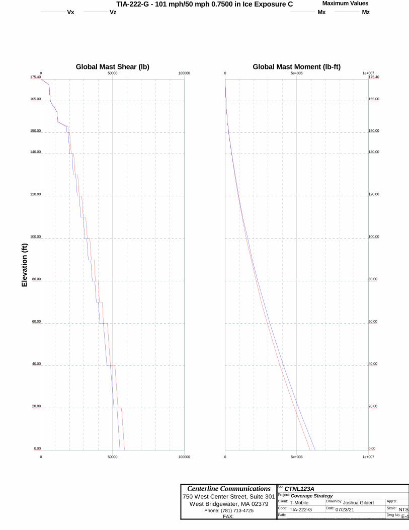
Dwg No. E-4
0
0
50000
50000
100000
100000
Global Mast Shear (lb)
175.40
165.00
150.00
140.00
120.00
100.00
80.00
60.00
40.00
20.00
0.00
Ele
va
tio
n (
ft)
0
0
5e+006
5e+006
1e+007
1e+007
Global Mast Moment (lb-ft)
175.40
165.00
150.00
140.00
120.00
100.00
80.00
60.00
40.00
20.00
0.00
TIA-222-G - 101 mph/50 mph 0.7500 in Ice Exposure C Maximum Values
Vx Vz Mx Mz
Centerline Communications 750 West Center Street, Suite 301
West Bridgewater, MA 02379 Phone: (781) 713-4725
FAX:
Job: CTNL123A
Project: Coverage Strategy Client: T-Mobile Drawn by: Joshua Gildert App'd:
Code: TIA-222-G Date: 07/23/21 Scale: NTS Path:
C:\Users\Joshua Gildert\Box\Projects\New England Projects\T-Mobile\SITES\CT\CTNL123A - 147 BALTIC HANOVER RD - SST\ANCHOR\Structural\Working Files\Analysis\tnx\CTNL123A.eri
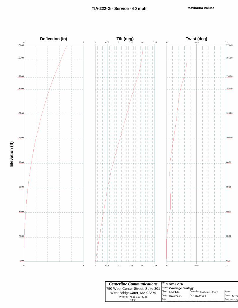
Dwg No. E-5
TIA-222-G - Service - 60 mph Maximum Values
0
0
5
5
Deflection (in)
175.40
165.00
150.00
140.00
120.00
100.00
80.00
60.00
40.00
20.00
0.00
Ele
va
tio
n (
ft)
0
0
0.05
0.05
0.1
0.1
0.15
0.15
0.2
0.2
0.25
0.25
Tilt (deg)0
0
0.05
0.05
0.1
0.1
Twist (deg)
175.40
165.00
150.00
140.00
120.00
100.00
80.00
60.00
40.00
20.00
0.00

Centerline Communications 750 West Center Street, Suite 301
West Bridgewater, MA 02379 Phone: (781) 713-4725
FAX:
Job: CTNL123A
Project: Coverage Strategy Client: T-Mobile Drawn by: Joshua Gildert App'd:
Code: TIA-222-G Date: 07/23/21 Scale: NTS Path:
C:\Users\Joshua Gildert\Box\Projects\New England Projects\T-Mobile\SITES\CT\CTNL123A - 147 BALTIC HANOVER RD - SST\ANCHOR\Structural\Working Files\Analysis\tnx\CTNL123A.eri
Dwg No. E-7
Feed Line Plan
Round Flat App In Face App Out Face Truss-Leg
AB
C
(2) LDF7-50A (1-5/8 FOAM) (ATT)(2) LDF7-50A (1-5/8 FOAM) (ATT)
(2) LDF7-50A (1-5/8 FOAM) (ATT)(2) LDF7-50A (1-5/8 FOAM) (ATT)
(2) LDF7-50A (1-5/8 FOAM) (ATT)(2) LDF7-50A (1-5/8 FOAM) (ATT)
3/8 FIBER (ATT)(2) 3/4 DC POWER (ATT)
(2) L
DF7-
50A (1
-5/8
FOAM
) (VZW
)
(2) L
DF7-
50A (1
-5/8
FOAM
) (VZW
)
(2) L
DF7-
50A (1
-5/8
FOAM
) (VZW
)
(2) L
DF7-
50A (1
-5/8
FOAM
) (VZW
)
(2) L
DF7-
50A (1
-5/8
FO
AM) (
VZW)
(2) L
DF7-
50A (1
-5/8
FOAM
) (VZW
)
(2) L
DF7-
50A (1
-5/8
FOAM
) (VZW
)
(2) L
DF7-
50A (1
-5/8
FOAM
) (VZW
)
(2) L
DF7-
50A (1
-5/8
FO
AM) (
VZW)
6X24 (T-MOBILE)6X24 (T-MOBILE)6X24 (T-MOBILE)
Centerline Communications 750 West Center Street, Suite 301
West Bridgewater, MA 02379 Phone: (781) 713-4725
FAX:
Job: CTNL123A
Project: Coverage Strategy Client: T-Mobile Drawn by: Joshua Gildert App'd:
Code: TIA-222-G Date: 07/23/21 Scale: NTS Path:
C:\Users\Joshua Gildert\Box\Projects\New England Projects\T-Mobile\SITES\CT\CTNL123A - 147 BALTIC HANOVER RD - SST\ANCHOR\Structural\Working Files\Analysis\tnx\CTNL123A.eri
Dwg No. E-8
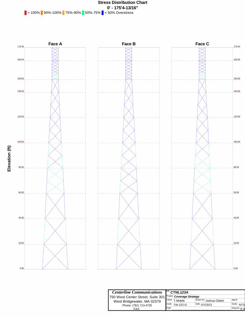
Stress Distribution Chart0' - 175'4-13/16"
> 100% 90%-100% 75%-90% 50%-75% < 50% Overstress
Face A Face B Face C
165.00
150.00
140.00
120.00
100.00
80.00
60.00
40.00
20.00
0.00
175.40
Ele
va
tio
n (
ft)
165.00
150.00
140.00
120.00
100.00
80.00
60.00
40.00
20.00
0.00
175.40
Centerline Communications 750 West Center Street, Suite 301
West Bridgewater, MA 02379 Phone: (781) 713-4725
FAX:
Job: CTNL123A
Project: Coverage Strategy Client: T-Mobile Drawn by: Joshua Gildert App'd:
Code: TIA-222-G Date: 07/23/21 Scale: NTS Path:
C:\Users\Joshua Gildert\Box\Projects\New England Projects\T-Mobile\SITES\CT\CTNL123A - 147 BALTIC HANOVER RD - SST\ANCHOR\Structural\Working Files\Analysis\tnx\CTNL123A.eri
Dwg No. E-9
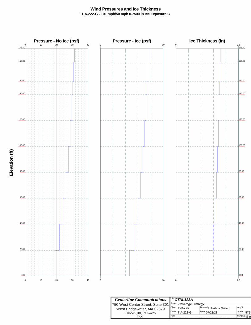
Wind Pressures and Ice ThicknessTIA-222-G - 101 mph/50 mph 0.7500 in Ice Exposure C
0
0
10
10
20
20
30
30
40
40
Pressure - No Ice (psf)
175.40
165.00
150.00
140.00
120.00
100.00
80.00
60.00
40.00
20.00
0.00
Ele
va
tio
n (
ft)
0
0
10
10
Pressure - Ice (psf)0
0
2.5
2.5
Ice Thickness (in)
175.40
165.00
150.00
140.00
120.00
100.00
80.00
60.00
40.00
20.00
0.00

ttnnxxTToowweerr Job
CTNL123A
Page
1 of 30
Centerline Communications
750 West Center Street, Suite 301
Project
Coverage Strategy Date
12:59:44 07/23/21 West Bridgewater, MA 02379
Phone: (781) 713-4725 FAX:
Client T-Mobile
Designed by
Joshua Gildert
Tower Input Data The main tower is a 3x free standing tower with an overall height of 175.40 ft above the ground line. The base of the tower is set at an elevation of 0.00 ft above the ground line. The face width of the tower is 5.00 ft at the top and 20.00 ft at the base. This tower is designed using the TIA-222-G standard. The following design criteria apply:
Tower is located in New London County, Connecticut. ASCE 7-10 Wind Data is used (wind speeds converted to nominal values). Basic wind speed of 101 mph. Structure Class II. Exposure Category C. Topographic Category 1. Crest Height 0.00 ft. Nominal ice thickness of 0.7500 in. Ice thickness is considered to increase with height. Ice density of 56 pcf. A wind speed of 50 mph is used in combination with ice. Temperature drop of 50 °F. Deflections calculated using a wind speed of 60 mph. A non-linear (P-delta) analysis was used. Pressures are calculated at each section. Stress ratio used in tower member design is 1. Local bending stresses due to climbing loads, feed line supports, and appurtenance mounts are not considered.
Options
Consider Moments - Legs Distribute Leg Loads As Uniform Use ASCE 10 X-Brace Ly Rules Consider Moments - Horizontals Assume Legs Pinned Calculate Redundant Bracing Forces Consider Moments - Diagonals √ Assume Rigid Index Plate Ignore Redundant Members in FEA Use Moment Magnification √ Use Clear Spans For Wind Area √ SR Leg Bolts Resist Compression
√ Use Code Stress Ratios √ Use Clear Spans For KL/r All Leg Panels Have Same Allowable √ Use Code Safety Factors - Guys Retension Guys To Initial Tension Offset Girt At Foundation Escalate Ice √ Bypass Mast Stability Checks √ Consider Feed Line Torque Always Use Max Kz √ Use Azimuth Dish Coefficients √ Include Angle Block Shear Check Use Special Wind Profile √ Project Wind Area of Appurt. Use TIA-222-G Bracing Resist. Exemption Include Bolts In Member Capacity Autocalc Torque Arm Areas Use TIA-222-G Tension Splice Exemption Leg Bolts Are At Top Of Section Add IBC .6D+W Combination Poles Secondary Horizontal Braces Leg √ Sort Capacity Reports By Component √ Include Shear-Torsion Interaction Use Diamond Inner Bracing (4 Sided) Triangulate Diamond Inner Bracing Always Use Sub-Critical Flow SR Members Have Cut Ends Treat Feed Line Bundles As Cylinder Use Top Mounted Sockets SR Members Are Concentric Ignore KL/ry For 60 Deg. Angle Legs Pole Without Linear Attachments Pole With Shroud Or No Appurtenances Outside and Inside Corner Radii Are
Known

ttnnxxTToowweerr Job
CTNL123A
Page
2 of 30
Centerline Communications
750 West Center Street, Suite 301
Project
Coverage Strategy Date
12:59:44 07/23/21 West Bridgewater, MA 02379
Phone: (781) 713-4725 FAX:
Client T-Mobile
Designed by
Joshua Gildert
Leg B Leg C
Leg A
Face
A Face B
Face C
Triangular To wer
Wind Norma l
Wind 90
Wind 180
Z
X
Tower Section Geometry
Tower Section
Tower Elevation
ft
Assembly Database
Description Section Width
ft
Number of
Sections
Section Length
ft
T1 175.40-165.00 5.00 1 10.40 T2 165.00-150.00 5.00 1 15.00 T3 150.00-140.00 5.00 1 10.00 T4 140.00-120.00 6.00 1 20.00 T5 120.00-100.00 8.00 1 20.00 T6 100.00-80.00 10.00 1 20.00 T7 80.00-60.00 12.00 1 20.00 T8 60.00-40.00 14.00 1 20.00 T9 40.00-20.00 16.00 1 20.00
T10 20.00-0.00 18.00 1 20.00
Tower Section Geometry (cont’d)
Tower Section
Tower Elevation
ft
Diagonal Spacing
ft
Bracing Type
Has K Brace
End Panels
Has Horizontals
Top Girt Offset
in
Bottom Girt Offset
in
T1 175.40-165.00 2.43 X Brace No No 4.0000 4.0000 T2 165.00-150.00 2.39 X Brace No No 4.0000 4.0000 T3 150.00-140.00 10.00 X Brace No No 0.0000 0.0000 T4 140.00-120.00 10.00 X Brace No No 0.0000 0.0000 T5 120.00-100.00 10.00 X Brace No No 0.0000 0.0000
ttnnxxTToowweerr Job
CTNL123A
Page
3 of 30
Centerline Communications
750 West Center Street, Suite 301
Project
Coverage Strategy Date
12:59:44 07/23/21 West Bridgewater, MA 02379
Phone: (781) 713-4725 FAX:
Client T-Mobile
Designed by
Joshua Gildert
Tower Section
Tower Elevation
ft
Diagonal Spacing
ft
Bracing Type
Has K Brace
End Panels
Has Horizontals
Top Girt Offset
in
Bottom Girt Offset
in
T6 100.00-80.00 10.00 X Brace No No 0.0000 0.0000 T7 80.00-60.00 10.00 X Brace No No 0.0000 0.0000 T8 60.00-40.00 20.00 X Brace No No 0.0000 0.0000 T9 40.00-20.00 20.00 X Brace No No 0.0000 0.0000
T10 20.00-0.00 20.00 X Brace No No 0.0000 0.0000
Tower Section Geometry (cont’d)
Tower Elevation
ft
Leg Type
Leg Size
Leg Grade
Diagonal Type
Diagonal Size
Diagonal Grade
T1 175.40-165.00 Solid Round 2 A572-50 (50 ksi)
Solid Round 7/8 A572-50 (50 ksi)
T2 165.00-150.00 Solid Round 2 1/4 A572-50 (50 ksi)
Solid Round 1 A572-50 (50 ksi)
T3 150.00-140.00 Truss Leg Pirod 105245 A572-50 (50 ksi)
Equal Angle L3x3x5/16 A36 (36 ksi)
T4 140.00-120.00 Truss Leg Pirod 105218 A572-50 (50 ksi)
Equal Angle L3x3x5/16 A36 (36 ksi)
T5 120.00-100.00 Truss Leg Pirod 105219 A572-50 (50 ksi)
Equal Angle L3x3x5/16 A36 (36 ksi)
T6 100.00-80.00 Truss Leg Pirod 105219 A572-50 (50 ksi)
Equal Angle L3x3x5/16 A36 (36 ksi)
T7 80.00-60.00 Truss Leg Pirod 105220 A572-50 (50 ksi)
Equal Angle L3x3x5/16 A36 (36 ksi)
T8 60.00-40.00 Truss Leg Pirod 112743 A572-50 (50 ksi)
Double Equal Angle
2L3 1/2x3 1/2x5/16 A36 (36 ksi)
T9 40.00-20.00 Truss Leg Pirod 112743 A572-50 (50 ksi)
Double Equal Angle
2L3 1/2x3 1/2x5/16 A36 (36 ksi)
T10 20.00-0.00 Truss Leg Pirod 112744 A572-50 (50 ksi)
Double Equal Angle
2L3 1/2x3 1/2x5/16 A36 (36 ksi)
Tower Section Geometry (cont’d)
Tower Elevation
ft
Top Girt Type
Top Girt Size
Top Girt Grade
Bottom Girt Type
Bottom Girt Size
Bottom Girt Grade
T1 175.40-165.00 Solid Round 7/8 A572-50 (50 ksi)
Solid Round 7/8 A572-50 (50 ksi)
T2 165.00-150.00 Solid Round 7/8 A572-50 (50 ksi)
Solid Round 7/8 A572-50 (50 ksi)
Tower Section Geometry (cont’d)

ttnnxxTToowweerr Job
CTNL123A
Page
4 of 30
Centerline Communications
750 West Center Street, Suite 301
Project
Coverage Strategy Date
12:59:44 07/23/21 West Bridgewater, MA 02379
Phone: (781) 713-4725 FAX:
Client T-Mobile
Designed by
Joshua Gildert
Tower Elevation
ft
Gusset Area
(per face)
ft2
Gusset Thickness
in
Gusset Grade Adjust. Factor Af
Adjust. Factor
Ar
Weight Mult.
Double Angle Stitch Bolt Spacing
Diagonals in
Double Angle Stitch Bolt Spacing
Horizontals in
Double Angle Stitch Bolt Spacing
Redundants in
T1 175.40-165.00
0.00 0.6250 A36 (36 ksi)
1 1 1.05 36.0000 36.0000 36.0000
T2 165.00-150.00
0.00 0.6250 A36 (36 ksi)
1 1 1.05 36.0000 36.0000 36.0000
T3 150.00-140.00
0.00 0.6250 A36 (36 ksi)
1 1 1.05 36.0000 36.0000 36.0000
T4 140.00-120.00
0.00 0.6250 A36 (36 ksi)
1 1 1.05 36.0000 36.0000 36.0000
T5 120.00-100.00
0.00 0.6250 A36 (36 ksi)
1 1 1.05 36.0000 36.0000 36.0000
T6 100.00-80.00
0.00 0.6250 A36 (36 ksi)
1 1 1.05 36.0000 36.0000 36.0000
T7 80.00-60.00 0.00 0.6250 A36 (36 ksi)
1 1 1.05 36.0000 36.0000 36.0000
T8 60.00-40.00 0.00 0.6250 A36 (36 ksi)
1 1 1.05 36.0000 36.0000 36.0000
T9 40.00-20.00 0.00 0.6250 A36 (36 ksi)
1 1 1.05 36.0000 36.0000 36.0000
T10 20.00-0.00 0.00 0.6250 A36 (36 ksi)
1 1 1.05 36.0000 36.0000 36.0000
Tower Section Geometry (cont’d)
K Factors1
Tower Elevation
ft
Calc K
Single Angles
Calc K
Solid Rounds
Legs X Brace Diags
X Y
K Brace Diags
X Y
Single Diags
X Y
Girts
X Y
Horiz.
X Y
Sec. Horiz.
X Y
Inner Brace
X Y
T1 175.40-165.00
Yes Yes 1 1 1
1 1
1 1
1 1
1 1
1 1
1 1
T2 165.00-150.00
Yes Yes 1 1 1
1 1
1 1
1 1
1 1
1 1
1 1
T3 150.00-140.00
Yes Yes 1 1 1
1 1
1 1
1 1
1 1
1 1
1 1
T4 140.00-120.00
Yes Yes 1 1 1
1 1
1 1
1 1
1 1
1 1
1 1
T5 120.00-100.00
Yes Yes 1 1 1
1 1
1 1
1 1
1 1
1 1
1 1
T6 100.00-80.00
Yes Yes 1 1 1
1 1
1 1
1 1
1 1
1 1
1 1
T7 80.00-60.00
Yes Yes 1 1 1
1 1
1 1
1 1
1 1
1 1
1 1
T8 60.00-40.00
Yes Yes 1 1 1
1 1
1 1
1 1
1 1
1 1
1 1
T9 40.00-20.00
Yes Yes 1 1 1
1 1
1 1
1 1
1 1
1 1
1 1
T10 20.00-0.00
Yes Yes 1 1 1
1 1
1 1
1 1
1 1
1 1
1 1
1Note: K factors are applied to member segment lengths. K-braces without inner supporting members will have the K factor in the out-of-plane direction applied to the overall length.

ttnnxxTToowweerr Job
CTNL123A
Page
5 of 30
Centerline Communications
750 West Center Street, Suite 301
Project
Coverage Strategy Date
12:59:44 07/23/21 West Bridgewater, MA 02379
Phone: (781) 713-4725 FAX:
Client T-Mobile
Designed by
Joshua Gildert
Tower Section Geometry (cont’d)
Truss-Leg K Factors
Truss-Legs Used As Leg Members Truss-Legs Used As Inner Members Tower
Elevation ft
Leg Panels
X Brace
Diagonals
Z Brace
Diagonals
Leg Panels
X Brace
Diagonals
Z Brace
Diagonals T3
150.00-140.00 1 0.5 0.85 1 0.5 0.85
T4 140.00-120.00
1 0.5 0.85 1 0.5 0.85
T5 120.00-100.00
1 0.5 0.85 1 0.5 0.85
T6 100.00-80.00
1 0.5 0.85 1 0.5 0.85
T7 80.00-60.00
1 0.5 0.85 1 0.5 0.85
T8 60.00-40.00
1 0.5 0.85 1 0.5 0.85
T9 40.00-20.00
1 0.5 0.85 1 0.5 0.85
T10 20.00-0.00
1 0.5 0.85 1 0.5 0.85
Tower Section Geometry (cont’d)
Tower Elevation
ft
Leg Diagonal Top Girt Bottom Girt Mid Girt Long Horizontal Short Horizontal
Net Width Deduct
in
U
Net Width Deduct
in
U
Net Width Deduct
in
U
Net Width
Deduct in
U
Net Width
Deduct in
U
Net Width
Deduct in
U
Net Width
Deduct in
U
T1 175.40-165.00
0.0000 1 0.0000 0.75 0.0000 0.75 0.0000 0.75 0.0000 0.75 0.0000 0.75 0.0000 0.75
T2 165.00-150.00
0.0000 1 0.0000 0.75 0.0000 0.75 0.0000 0.75 0.0000 0.75 0.0000 0.75 0.0000 0.75
T3 150.00-140.00
0.0000 1 0.0000 0.75 0.0000 0.75 0.0000 0.75 0.0000 0.75 0.0000 0.75 0.0000 0.75
T4 140.00-120.00
0.0000 1 0.0000 0.75 0.0000 0.75 0.0000 0.75 0.0000 0.75 0.0000 0.75 0.0000 0.75
T5 120.00-100.00
0.0000 1 0.0000 0.75 0.0000 0.75 0.0000 0.75 0.0000 0.75 0.0000 0.75 0.0000 0.75
T6 100.00-80.00
0.0000 1 0.0000 0.75 0.0000 0.75 0.0000 0.75 0.0000 0.75 0.0000 0.75 0.0000 0.75
T7 80.00-60.00 0.0000 1 0.0000 0.75 0.0000 0.75 0.0000 0.75 0.0000 0.75 0.0000 0.75 0.0000 0.75 T8 60.00-40.00 0.0000 1 0.0000 0.75 0.0000 0.75 0.0000 0.75 0.0000 0.75 0.0000 0.75 0.0000 0.75 T9 40.00-20.00 0.0000 1 0.0000 0.75 0.0000 0.75 0.0000 0.75 0.0000 0.75 0.0000 0.75 0.0000 0.75 T10 20.00-0.00 0.0000 1 0.0000 0.75 0.0000 0.75 0.0000 0.75 0.0000 0.75 0.0000 0.75 0.0000 0.75

ttnnxxTToowweerr Job
CTNL123A
Page
6 of 30
Centerline Communications
750 West Center Street, Suite 301
Project
Coverage Strategy Date
12:59:44 07/23/21 West Bridgewater, MA 02379
Phone: (781) 713-4725 FAX:
Client T-Mobile
Designed by
Joshua Gildert
Tower Elevation
ft
Redundant Horizontal
Redundant Diagonal
Redundant Sub-Diagonal
Redundant Sub-Horizontal
Redundant Vertical Redundant Hip Redundant Hip Diagonal
Net Width Deduct
in
U
Net Width Deduct
in
U
Net Width Deduct
in
U
Net Width
Deduct in
U
Net Width
Deduct in
U
Net Width
Deduct in
U
Net Width
Deduct in
U
T1 175.40-165.00
0.0000 0.75 0.0000 0.75 0.0000 0.75 0.0000 0.75 0.0000 0.75 0.0000 0.75 0.0000 0.75
T2 165.00-150.00
0.0000 0.75 0.0000 0.75 0.0000 0.75 0.0000 0.75 0.0000 0.75 0.0000 0.75 0.0000 0.75
T3 150.00-140.00
0.0000 0.75 0.0000 0.75 0.0000 0.75 0.0000 0.75 0.0000 0.75 0.0000 0.75 0.0000 0.75
T4 140.00-120.00
0.0000 0.75 0.0000 0.75 0.0000 0.75 0.0000 0.75 0.0000 0.75 0.0000 0.75 0.0000 0.75
T5 120.00-100.00
0.0000 0.75 0.0000 0.75 0.0000 0.75 0.0000 0.75 0.0000 0.75 0.0000 0.75 0.0000 0.75
T6 100.00-80.00
0.0000 0.75 0.0000 0.75 0.0000 0.75 0.0000 0.75 0.0000 0.75 0.0000 0.75 0.0000 0.75
T7 80.00-60.00 0.0000 0.75 0.0000 0.75 0.0000 0.75 0.0000 0.75 0.0000 0.75 0.0000 0.75 0.0000 0.75 T8 60.00-40.00 0.0000 0.75 0.0000 0.75 0.0000 0.75 0.0000 0.75 0.0000 0.75 0.0000 0.75 0.0000 0.75 T9 40.00-20.00 0.0000 0.75 0.0000 0.75 0.0000 0.75 0.0000 0.75 0.0000 0.75 0.0000 0.75 0.0000 0.75 T10 20.00-0.00 0.0000 0.75 0.0000 0.75 0.0000 0.75 0.0000 0.75 0.0000 0.75 0.0000 0.75 0.0000 0.75
Tower Section Geometry (cont’d)
Tower Elevation
ft
Leg Connection
Type
Leg Diagonal Top Girt Bottom Girt Mid Girt Long Horizontal Short Horizontal
Bolt Size in
No. Bolt Size in
No. Bolt Size in
No. Bolt Size in
No. Bolt Size in
No. Bolt Size in
No. Bolt Size in
No.
T1 175.40-165.00
Sleeve DS 0.7500 A325N
5 0.6250 A325N
0 0.6250 A325N
0 0.6250 A325N
0 0.6250 A325N
0 0.6250 A325N
0 0.6250 A325N
0
T2 165.00-150.00
Flange 1.0000 A325N
6 0.6250 A325N
0 0.6250 A325N
0 0.6250 A325N
0 0.6250 A325N
0 0.6250 A325N
0 0.6250 A325N
0
T3 150.00-140.00
Flange 1.0000 A325N
6 1.0000 A325N
1 0.6250 A325N
0 0.6250 A325N
0 0.6250 A325N
0 0.6250 A325N
0 0.6250 A325N
0
T4 140.00-120.00
Flange 1.0000 A325N
6 1.0000 A325N
1 0.6250 A325N
0 0.6250 A325N
0 0.6250 A325N
0 0.6250 A325N
0 0.6250 A325N
0
T5 120.00-100.00
Flange 1.2500 A325N
6 1.2500 A325N
1 0.6250 A325N
0 0.6250 A325N
0 0.6250 A325N
0 0.6250 A325N
0 0.6250 A325N
0
T6 100.00-80.00
Flange 1.2500 A325N
6 1.2500 A325N
1 0.6250 A325N
0 0.6250 A325N
0 0.6250 A325N
0 0.6250 A325N
0 0.6250 A325N
0
T7 80.00-60.00 Flange 1.2500 A325N
6 1.2500 A325N
1 0.6250 A325N
0 0.6250 A325N
0 0.6250 A325N
0 0.6250 A325N
0 0.6250 A325N
0
T8 60.00-40.00 Flange 1.2500 A325N
12 1.0000 A325N
2 0.6250 A325N
0 0.6250 A325N
0 0.6250 A325N
0 0.6250 A325N
0 0.6250 A325N
0
T9 40.00-20.00 Flange 1.2500 A325N
12 1.0000 A325N
2 0.6250 A325N
0 0.6250 A325N
0 0.6250 A325N
0 0.6250 A325N
0 0.6250 A325N
0
T10 20.00-0.00 Flange 1.2500 A687
12 1.0000 A325N
2 0.6250 A325N
0 0.6250 A325N
0 0.6250 A325N
0 0.6250 A325N
0 0.6250 A325N
0
Feed Line/Linear Appurtenances - Entered As Round Or Flat
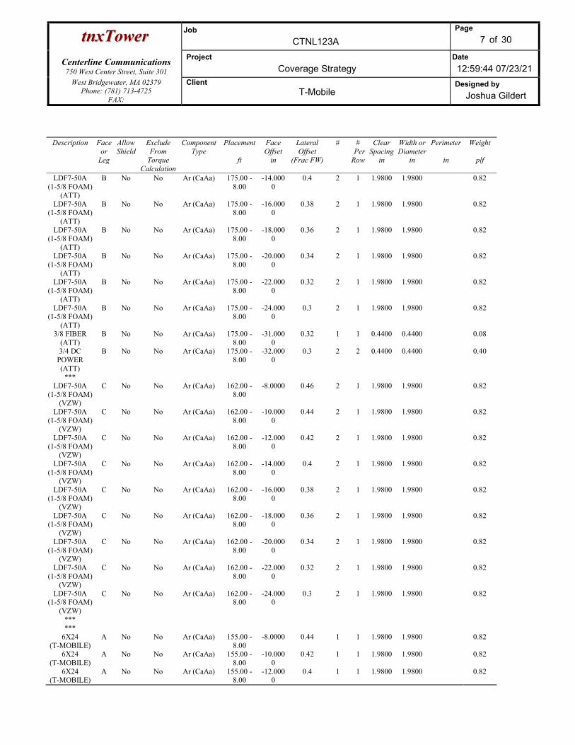
ttnnxxTToowweerr Job
CTNL123A
Page
7 of 30
Centerline Communications
750 West Center Street, Suite 301
Project
Coverage Strategy Date
12:59:44 07/23/21 West Bridgewater, MA 02379
Phone: (781) 713-4725 FAX:
Client T-Mobile
Designed by
Joshua Gildert
Description Face or
Leg
Allow Shield
Exclude From
Torque Calculation
Component Type
Placement
ft
Face Offset
in
Lateral Offset
(Frac FW)
# # Per Row
Clear Spacing
in
Width or Diameter
in
Perimeter
in
Weight
plf
LDF7-50A (1-5/8 FOAM)
(ATT)
B No No Ar (CaAa) 175.00 - 8.00
-14.0000
0.4 2 1 1.9800 1.9800 0.82
LDF7-50A (1-5/8 FOAM)
(ATT)
B No No Ar (CaAa) 175.00 - 8.00
-16.0000
0.38 2 1 1.9800 1.9800 0.82
LDF7-50A (1-5/8 FOAM)
(ATT)
B No No Ar (CaAa) 175.00 - 8.00
-18.0000
0.36 2 1 1.9800 1.9800 0.82
LDF7-50A (1-5/8 FOAM)
(ATT)
B No No Ar (CaAa) 175.00 - 8.00
-20.0000
0.34 2 1 1.9800 1.9800 0.82
LDF7-50A (1-5/8 FOAM)
(ATT)
B No No Ar (CaAa) 175.00 - 8.00
-22.0000
0.32 2 1 1.9800 1.9800 0.82
LDF7-50A (1-5/8 FOAM)
(ATT)
B No No Ar (CaAa) 175.00 - 8.00
-24.0000
0.3 2 1 1.9800 1.9800 0.82
3/8 FIBER (ATT)
B No No Ar (CaAa) 175.00 - 8.00
-31.0000
0.32 1 1 0.4400 0.4400 0.08
3/4 DC POWER (ATT)
B No No Ar (CaAa) 175.00 - 8.00
-32.0000
0.3 2 2 0.4400 0.4400 0.40
*** LDF7-50A
(1-5/8 FOAM) (VZW)
C No No Ar (CaAa) 162.00 - 8.00
-8.0000 0.46 2 1 1.9800 1.9800 0.82
LDF7-50A (1-5/8 FOAM)
(VZW)
C No No Ar (CaAa) 162.00 - 8.00
-10.0000
0.44 2 1 1.9800 1.9800 0.82
LDF7-50A (1-5/8 FOAM)
(VZW)
C No No Ar (CaAa) 162.00 - 8.00
-12.0000
0.42 2 1 1.9800 1.9800 0.82
LDF7-50A (1-5/8 FOAM)
(VZW)
C No No Ar (CaAa) 162.00 - 8.00
-14.0000
0.4 2 1 1.9800 1.9800 0.82
LDF7-50A (1-5/8 FOAM)
(VZW)
C No No Ar (CaAa) 162.00 - 8.00
-16.0000
0.38 2 1 1.9800 1.9800 0.82
LDF7-50A (1-5/8 FOAM)
(VZW)
C No No Ar (CaAa) 162.00 - 8.00
-18.0000
0.36 2 1 1.9800 1.9800 0.82
LDF7-50A (1-5/8 FOAM)
(VZW)
C No No Ar (CaAa) 162.00 - 8.00
-20.0000
0.34 2 1 1.9800 1.9800 0.82
LDF7-50A (1-5/8 FOAM)
(VZW)
C No No Ar (CaAa) 162.00 - 8.00
-22.0000
0.32 2 1 1.9800 1.9800 0.82
LDF7-50A (1-5/8 FOAM)
(VZW)
C No No Ar (CaAa) 162.00 - 8.00
-24.0000
0.3 2 1 1.9800 1.9800 0.82
*** ***
6X24 (T-MOBILE)
A No No Ar (CaAa) 155.00 - 8.00
-8.0000 0.44 1 1 1.9800 1.9800 0.82
6X24 (T-MOBILE)
A No No Ar (CaAa) 155.00 - 8.00
-10.0000
0.42 1 1 1.9800 1.9800 0.82
6X24 (T-MOBILE)
A No No Ar (CaAa) 155.00 - 8.00
-12.0000
0.4 1 1 1.9800 1.9800 0.82

ttnnxxTToowweerr Job
CTNL123A
Page
8 of 30
Centerline Communications
750 West Center Street, Suite 301
Project
Coverage Strategy Date
12:59:44 07/23/21 West Bridgewater, MA 02379
Phone: (781) 713-4725 FAX:
Client T-Mobile
Designed by
Joshua Gildert
Feed Line/Linear Appurtenances - Entered As Area
Description Face or
Leg
Allow Shield
Exclude From
Torque Calculation
Component Type
Placement
ft
Total Number
CAAA
ft2/ft
Weight
plf
***
Feed Line/Linear Appurtenances Section Areas Tower Section
Tower Elevation
ft
Face AR
ft2
AF
ft2
CAAA
In Face ft2
CAAA
Out Face ft2
Weight
lb T1 175.40-165.00 A
B C
0.000 0.000 0.000
0.000 0.000 0.000
0.000 25.080 0.000
0.000 0.000 0.000
0.00 107.20 0.00
T2 165.00-150.00 A B C
0.000 0.000 0.000
0.000 0.000 0.000
2.970 37.620 42.768
0.000 0.000 0.000
12.30 160.80 177.12
T3 150.00-140.00 A B C
0.000 0.000 0.000
0.000 0.000 0.000
5.940 25.080 35.640
0.000 0.000 0.000
24.60 107.20 147.60
T4 140.00-120.00 A B C
0.000 0.000 0.000
0.000 0.000 0.000
11.880 50.160 71.280
0.000 0.000 0.000
49.20 214.40 295.20
T5 120.00-100.00 A B C
0.000 0.000 0.000
0.000 0.000 0.000
11.880 50.160 71.280
0.000 0.000 0.000
49.20 214.40 295.20
T6 100.00-80.00 A B C
0.000 0.000 0.000
0.000 0.000 0.000
11.880 50.160 71.280
0.000 0.000 0.000
49.20 214.40 295.20
T7 80.00-60.00 A B C
0.000 0.000 0.000
0.000 0.000 0.000
11.880 50.160 71.280
0.000 0.000 0.000
49.20 214.40 295.20
T8 60.00-40.00 A B C
0.000 0.000 0.000
0.000 0.000 0.000
11.880 50.160 71.280
0.000 0.000 0.000
49.20 214.40 295.20
T9 40.00-20.00 A B C
0.000 0.000 0.000
0.000 0.000 0.000
11.880 50.160 71.280
0.000 0.000 0.000
49.20 214.40 295.20
T10 20.00-0.00 A B C
0.000 0.000 0.000
0.000 0.000 0.000
7.128 30.096 42.768
0.000 0.000 0.000
29.52 128.64 177.12
Feed Line/Linear Appurtenances Section Areas - With Ice Tower Section
Tower Elevation
ft
Face or
Leg
Ice Thickness
in
AR
ft2
AF
ft2
CAAA
In Face ft2
CAAA
Out Face ft2
Weight
lb T1 175.40-165.00 A 1.767 0.000 0.000 0.000 0.000 0.00

ttnnxxTToowweerr Job
CTNL123A
Page
9 of 30
Centerline Communications
750 West Center Street, Suite 301
Project
Coverage Strategy Date
12:59:44 07/23/21 West Bridgewater, MA 02379
Phone: (781) 713-4725 FAX:
Client T-Mobile
Designed by
Joshua Gildert
Tower Section
Tower Elevation
ft
Face or
Leg
Ice Thickness
in
AR
ft2
AF
ft2
CAAA
In Face ft2
CAAA
Out Face ft2
Weight
lb B C
0.000 0.000
0.000 0.000
94.040 0.000
0.000 0.000
1186.55 0.00
T2 165.00-150.00 A B C
1.754 0.000 0.000 0.000
0.000 0.000 0.000
8.231 140.526 147.495
0.000 0.000 0.000
132.30 1761.18 1905.11
T3 150.00-140.00 A B C
1.739 0.000 0.000 0.000
0.000 0.000 0.000
16.376 93.308
122.468
0.000 0.000 0.000
261.70 1161.05 1570.21
T4 140.00-120.00 A B C
1.720 0.000 0.000 0.000
0.000 0.000 0.000
32.525 185.634 243.775
0.000 0.000 0.000
515.87 2288.11 3095.23
T5 120.00-100.00 A B C
1.692 0.000 0.000 0.000
0.000 0.000 0.000
32.183 184.152 242.024
0.000 0.000 0.000
504.61 2237.29 3027.64
T6 100.00-80.00 A B C
1.658 0.000 0.000 0.000
0.000 0.000 0.000
31.780 182.404 239.959
0.000 0.000 0.000
491.47 2178.07 2948.83
T7 80.00-60.00 A B C
1.617 0.000 0.000 0.000
0.000 0.000 0.000
31.286 180.266 237.433
0.000 0.000 0.000
475.62 2106.61 2853.70
T8 60.00-40.00 A B C
1.564 0.000 0.000 0.000
0.000 0.000 0.000
30.644 177.488 234.151
0.000 0.000 0.000
455.37 2015.44 2732.25
T9 40.00-20.00 A B C
1.486 0.000 0.000 0.000
0.000 0.000 0.000
29.709 173.450 229.382
0.000 0.000 0.000
426.67 1886.26 2560.00
T10 20.00-0.00 A B C
1.331 0.000 0.000 0.000
0.000 0.000 0.000
16.713 99.271
131.964
0.000 0.000 0.000
223.39 985.27
1340.32
Feed Line Center of Pressure
Section Elevation
ft
CPX
in
CPZ
in
CPX
Ice in
CPZ
Ice in
T1 175.40-165.00 5.1912 10.2961 4.0058 8.3494 T2 165.00-150.00 -2.4722 6.1748 -2.4209 5.3099 T3 150.00-140.00 -2.1935 3.9973 -1.7766 2.9223 T4 140.00-120.00 -1.7646 5.5383 -1.6551 4.9405 T5 120.00-100.00 -1.2504 7.3788 -1.2406 7.7270 T6 100.00-80.00 -0.8126 9.1761 -0.6745 10.4292 T7 80.00-60.00 -0.4074 10.7237 -0.0375 12.7607 T8 60.00-40.00 -0.0431 11.8636 0.5866 14.1971 T9 40.00-20.00 0.2877 13.4212 1.2479 16.1742
T10 20.00-0.00 0.3751 10.4594 1.4262 13.2406
Shielding Factor Ka
Tower Section
Feed Line Record No.
Description Feed Line Segment Elev.
Ka No Ice
Ka Ice
T1 1 LDF7-50A (1-5/8 FOAM) 165.00 - 0.6000 0.4903

ttnnxxTToowweerr Job
CTNL123A
Page
10 of 30
Centerline Communications
750 West Center Street, Suite 301
Project
Coverage Strategy Date
12:59:44 07/23/21 West Bridgewater, MA 02379
Phone: (781) 713-4725 FAX:
Client T-Mobile
Designed by
Joshua Gildert
Tower Section
Feed Line Record No.
Description Feed Line Segment Elev.
Ka No Ice
Ka Ice
175.00 T1 2 LDF7-50A (1-5/8 FOAM) 165.00 -
175.00 0.6000 0.4903
T1 3 LDF7-50A (1-5/8 FOAM) 165.00 - 175.00
0.6000 0.4903
T1 4 LDF7-50A (1-5/8 FOAM) 165.00 - 175.00
0.6000 0.4903
T1 5 LDF7-50A (1-5/8 FOAM) 165.00 - 175.00
0.6000 0.4903
T1 6 LDF7-50A (1-5/8 FOAM) 165.00 - 175.00
0.6000 0.4903
T1 7 3/8 FIBER 165.00 - 175.00
0.6000 0.4903
T1 8 3/4 DC POWER 165.00 - 175.00
0.6000 0.4903
T2 1 LDF7-50A (1-5/8 FOAM) 150.00 - 165.00
0.6000 0.4896
T2 2 LDF7-50A (1-5/8 FOAM) 150.00 - 165.00
0.6000 0.4896
T2 3 LDF7-50A (1-5/8 FOAM) 150.00 - 165.00
0.6000 0.4896
T2 4 LDF7-50A (1-5/8 FOAM) 150.00 - 165.00
0.6000 0.4896
T2 5 LDF7-50A (1-5/8 FOAM) 150.00 - 165.00
0.6000 0.4896
T2 6 LDF7-50A (1-5/8 FOAM) 150.00 - 165.00
0.6000 0.4896
T2 7 3/8 FIBER 150.00 - 165.00
0.6000 0.4896
T2 8 3/4 DC POWER 150.00 - 165.00
0.6000 0.4896
T2 10 LDF7-50A (1-5/8 FOAM) 150.00 - 162.00
0.6000 0.4896
T2 11 LDF7-50A (1-5/8 FOAM) 150.00 - 162.00
0.6000 0.4896
T2 12 LDF7-50A (1-5/8 FOAM) 150.00 - 162.00
0.6000 0.4896
T2 13 LDF7-50A (1-5/8 FOAM) 150.00 - 162.00
0.6000 0.4896
T2 14 LDF7-50A (1-5/8 FOAM) 150.00 - 162.00
0.6000 0.4896
T2 15 LDF7-50A (1-5/8 FOAM) 150.00 - 162.00
0.6000 0.4896
T2 16 LDF7-50A (1-5/8 FOAM) 150.00 - 162.00
0.6000 0.4896
T2 17 LDF7-50A (1-5/8 FOAM) 150.00 - 162.00
0.6000 0.4896
T2 18 LDF7-50A (1-5/8 FOAM) 150.00 - 162.00
0.6000 0.4896
T2 21 6X24 150.00 - 155.00
0.6000 0.4896
T2 22 6X24 150.00 - 155.00
0.6000 0.4896
T2 23 6X24 150.00 - 155.00
0.6000 0.4896
T3 1 LDF7-50A (1-5/8 FOAM) 140.00 - 150.00
0.6000 0.3188
T3 2 LDF7-50A (1-5/8 FOAM) 140.00 - 150.00
0.6000 0.3188
T3 3 LDF7-50A (1-5/8 FOAM) 140.00 - 150.00
0.6000 0.3188
T3 4 LDF7-50A (1-5/8 FOAM) 140.00 - 0.6000 0.3188

ttnnxxTToowweerr Job
CTNL123A
Page
11 of 30
Centerline Communications
750 West Center Street, Suite 301
Project
Coverage Strategy Date
12:59:44 07/23/21 West Bridgewater, MA 02379
Phone: (781) 713-4725 FAX:
Client T-Mobile
Designed by
Joshua Gildert
Tower Section
Feed Line Record No.
Description Feed Line Segment Elev.
Ka No Ice
Ka Ice
150.00 T3 5 LDF7-50A (1-5/8 FOAM) 140.00 -
150.00 0.6000 0.3188
T3 6 LDF7-50A (1-5/8 FOAM) 140.00 - 150.00
0.6000 0.3188
T3 7 3/8 FIBER 140.00 - 150.00
0.6000 0.3188
T3 8 3/4 DC POWER 140.00 - 150.00
0.6000 0.3188
T3 10 LDF7-50A (1-5/8 FOAM) 140.00 - 150.00
0.6000 0.3188
T3 11 LDF7-50A (1-5/8 FOAM) 140.00 - 150.00
0.6000 0.3188
T3 12 LDF7-50A (1-5/8 FOAM) 140.00 - 150.00
0.6000 0.3188
T3 13 LDF7-50A (1-5/8 FOAM) 140.00 - 150.00
0.6000 0.3188
T3 14 LDF7-50A (1-5/8 FOAM) 140.00 - 150.00
0.6000 0.3188
T3 15 LDF7-50A (1-5/8 FOAM) 140.00 - 150.00
0.6000 0.3188
T3 16 LDF7-50A (1-5/8 FOAM) 140.00 - 150.00
0.6000 0.3188
T3 17 LDF7-50A (1-5/8 FOAM) 140.00 - 150.00
0.6000 0.3188
T3 18 LDF7-50A (1-5/8 FOAM) 140.00 - 150.00
0.6000 0.3188
T3 21 6X24 140.00 - 150.00
0.6000 0.3188
T3 22 6X24 140.00 - 150.00
0.6000 0.3188
T3 23 6X24 140.00 - 150.00
0.6000 0.3188
T4 1 LDF7-50A (1-5/8 FOAM) 120.00 - 140.00
0.6000 0.4114
T4 2 LDF7-50A (1-5/8 FOAM) 120.00 - 140.00
0.6000 0.4114
T4 3 LDF7-50A (1-5/8 FOAM) 120.00 - 140.00
0.6000 0.4114
T4 4 LDF7-50A (1-5/8 FOAM) 120.00 - 140.00
0.6000 0.4114
T4 5 LDF7-50A (1-5/8 FOAM) 120.00 - 140.00
0.6000 0.4114
T4 6 LDF7-50A (1-5/8 FOAM) 120.00 - 140.00
0.6000 0.4114
T4 7 3/8 FIBER 120.00 - 140.00
0.6000 0.4114
T4 8 3/4 DC POWER 120.00 - 140.00
0.6000 0.4114
T4 10 LDF7-50A (1-5/8 FOAM) 120.00 - 140.00
0.6000 0.4114
T4 11 LDF7-50A (1-5/8 FOAM) 120.00 - 140.00
0.6000 0.4114
T4 12 LDF7-50A (1-5/8 FOAM) 120.00 - 140.00
0.6000 0.4114
T4 13 LDF7-50A (1-5/8 FOAM) 120.00 - 140.00
0.6000 0.4114
T4 14 LDF7-50A (1-5/8 FOAM) 120.00 - 140.00
0.6000 0.4114
T4 15 LDF7-50A (1-5/8 FOAM) 120.00 - 140.00
0.6000 0.4114
T4 16 LDF7-50A (1-5/8 FOAM) 120.00 - 0.6000 0.4114
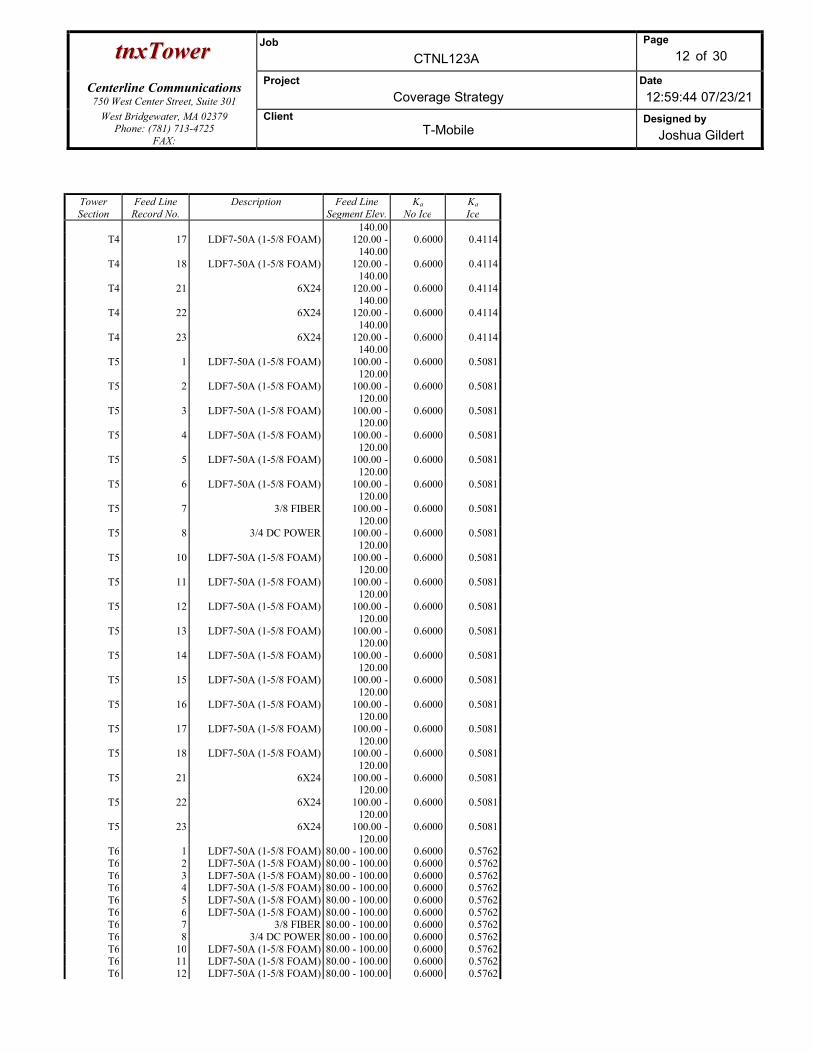
ttnnxxTToowweerr Job
CTNL123A
Page
12 of 30
Centerline Communications
750 West Center Street, Suite 301
Project
Coverage Strategy Date
12:59:44 07/23/21 West Bridgewater, MA 02379
Phone: (781) 713-4725 FAX:
Client T-Mobile
Designed by
Joshua Gildert
Tower Section
Feed Line Record No.
Description Feed Line Segment Elev.
Ka No Ice
Ka Ice
140.00 T4 17 LDF7-50A (1-5/8 FOAM) 120.00 -
140.00 0.6000 0.4114
T4 18 LDF7-50A (1-5/8 FOAM) 120.00 - 140.00
0.6000 0.4114
T4 21 6X24 120.00 - 140.00
0.6000 0.4114
T4 22 6X24 120.00 - 140.00
0.6000 0.4114
T4 23 6X24 120.00 - 140.00
0.6000 0.4114
T5 1 LDF7-50A (1-5/8 FOAM) 100.00 - 120.00
0.6000 0.5081
T5 2 LDF7-50A (1-5/8 FOAM) 100.00 - 120.00
0.6000 0.5081
T5 3 LDF7-50A (1-5/8 FOAM) 100.00 - 120.00
0.6000 0.5081
T5 4 LDF7-50A (1-5/8 FOAM) 100.00 - 120.00
0.6000 0.5081
T5 5 LDF7-50A (1-5/8 FOAM) 100.00 - 120.00
0.6000 0.5081
T5 6 LDF7-50A (1-5/8 FOAM) 100.00 - 120.00
0.6000 0.5081
T5 7 3/8 FIBER 100.00 - 120.00
0.6000 0.5081
T5 8 3/4 DC POWER 100.00 - 120.00
0.6000 0.5081
T5 10 LDF7-50A (1-5/8 FOAM) 100.00 - 120.00
0.6000 0.5081
T5 11 LDF7-50A (1-5/8 FOAM) 100.00 - 120.00
0.6000 0.5081
T5 12 LDF7-50A (1-5/8 FOAM) 100.00 - 120.00
0.6000 0.5081
T5 13 LDF7-50A (1-5/8 FOAM) 100.00 - 120.00
0.6000 0.5081
T5 14 LDF7-50A (1-5/8 FOAM) 100.00 - 120.00
0.6000 0.5081
T5 15 LDF7-50A (1-5/8 FOAM) 100.00 - 120.00
0.6000 0.5081
T5 16 LDF7-50A (1-5/8 FOAM) 100.00 - 120.00
0.6000 0.5081
T5 17 LDF7-50A (1-5/8 FOAM) 100.00 - 120.00
0.6000 0.5081
T5 18 LDF7-50A (1-5/8 FOAM) 100.00 - 120.00
0.6000 0.5081
T5 21 6X24 100.00 - 120.00
0.6000 0.5081
T5 22 6X24 100.00 - 120.00
0.6000 0.5081
T5 23 6X24 100.00 - 120.00
0.6000 0.5081
T6 1 LDF7-50A (1-5/8 FOAM) 80.00 - 100.00 0.6000 0.5762 T6 2 LDF7-50A (1-5/8 FOAM) 80.00 - 100.00 0.6000 0.5762 T6 3 LDF7-50A (1-5/8 FOAM) 80.00 - 100.00 0.6000 0.5762 T6 4 LDF7-50A (1-5/8 FOAM) 80.00 - 100.00 0.6000 0.5762 T6 5 LDF7-50A (1-5/8 FOAM) 80.00 - 100.00 0.6000 0.5762 T6 6 LDF7-50A (1-5/8 FOAM) 80.00 - 100.00 0.6000 0.5762 T6 7 3/8 FIBER 80.00 - 100.00 0.6000 0.5762 T6 8 3/4 DC POWER 80.00 - 100.00 0.6000 0.5762 T6 10 LDF7-50A (1-5/8 FOAM) 80.00 - 100.00 0.6000 0.5762 T6 11 LDF7-50A (1-5/8 FOAM) 80.00 - 100.00 0.6000 0.5762 T6 12 LDF7-50A (1-5/8 FOAM) 80.00 - 100.00 0.6000 0.5762
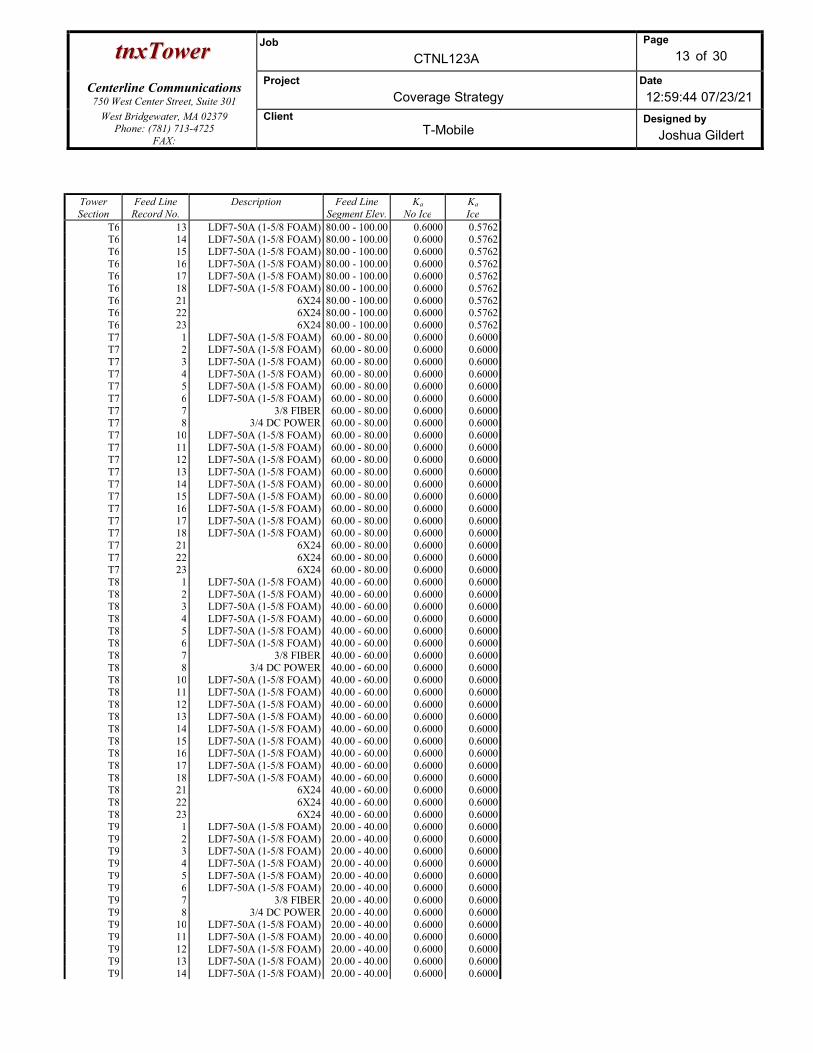
ttnnxxTToowweerr Job
CTNL123A
Page
13 of 30
Centerline Communications
750 West Center Street, Suite 301
Project
Coverage Strategy Date
12:59:44 07/23/21 West Bridgewater, MA 02379
Phone: (781) 713-4725 FAX:
Client T-Mobile
Designed by
Joshua Gildert
Tower Section
Feed Line Record No.
Description Feed Line Segment Elev.
Ka No Ice
Ka Ice
T6 13 LDF7-50A (1-5/8 FOAM) 80.00 - 100.00 0.6000 0.5762 T6 14 LDF7-50A (1-5/8 FOAM) 80.00 - 100.00 0.6000 0.5762 T6 15 LDF7-50A (1-5/8 FOAM) 80.00 - 100.00 0.6000 0.5762 T6 16 LDF7-50A (1-5/8 FOAM) 80.00 - 100.00 0.6000 0.5762 T6 17 LDF7-50A (1-5/8 FOAM) 80.00 - 100.00 0.6000 0.5762 T6 18 LDF7-50A (1-5/8 FOAM) 80.00 - 100.00 0.6000 0.5762 T6 21 6X24 80.00 - 100.00 0.6000 0.5762 T6 22 6X24 80.00 - 100.00 0.6000 0.5762 T6 23 6X24 80.00 - 100.00 0.6000 0.5762 T7 1 LDF7-50A (1-5/8 FOAM) 60.00 - 80.00 0.6000 0.6000 T7 2 LDF7-50A (1-5/8 FOAM) 60.00 - 80.00 0.6000 0.6000 T7 3 LDF7-50A (1-5/8 FOAM) 60.00 - 80.00 0.6000 0.6000 T7 4 LDF7-50A (1-5/8 FOAM) 60.00 - 80.00 0.6000 0.6000 T7 5 LDF7-50A (1-5/8 FOAM) 60.00 - 80.00 0.6000 0.6000 T7 6 LDF7-50A (1-5/8 FOAM) 60.00 - 80.00 0.6000 0.6000 T7 7 3/8 FIBER 60.00 - 80.00 0.6000 0.6000 T7 8 3/4 DC POWER 60.00 - 80.00 0.6000 0.6000 T7 10 LDF7-50A (1-5/8 FOAM) 60.00 - 80.00 0.6000 0.6000 T7 11 LDF7-50A (1-5/8 FOAM) 60.00 - 80.00 0.6000 0.6000 T7 12 LDF7-50A (1-5/8 FOAM) 60.00 - 80.00 0.6000 0.6000 T7 13 LDF7-50A (1-5/8 FOAM) 60.00 - 80.00 0.6000 0.6000 T7 14 LDF7-50A (1-5/8 FOAM) 60.00 - 80.00 0.6000 0.6000 T7 15 LDF7-50A (1-5/8 FOAM) 60.00 - 80.00 0.6000 0.6000 T7 16 LDF7-50A (1-5/8 FOAM) 60.00 - 80.00 0.6000 0.6000 T7 17 LDF7-50A (1-5/8 FOAM) 60.00 - 80.00 0.6000 0.6000 T7 18 LDF7-50A (1-5/8 FOAM) 60.00 - 80.00 0.6000 0.6000 T7 21 6X24 60.00 - 80.00 0.6000 0.6000 T7 22 6X24 60.00 - 80.00 0.6000 0.6000 T7 23 6X24 60.00 - 80.00 0.6000 0.6000 T8 1 LDF7-50A (1-5/8 FOAM) 40.00 - 60.00 0.6000 0.6000 T8 2 LDF7-50A (1-5/8 FOAM) 40.00 - 60.00 0.6000 0.6000 T8 3 LDF7-50A (1-5/8 FOAM) 40.00 - 60.00 0.6000 0.6000 T8 4 LDF7-50A (1-5/8 FOAM) 40.00 - 60.00 0.6000 0.6000 T8 5 LDF7-50A (1-5/8 FOAM) 40.00 - 60.00 0.6000 0.6000 T8 6 LDF7-50A (1-5/8 FOAM) 40.00 - 60.00 0.6000 0.6000 T8 7 3/8 FIBER 40.00 - 60.00 0.6000 0.6000 T8 8 3/4 DC POWER 40.00 - 60.00 0.6000 0.6000 T8 10 LDF7-50A (1-5/8 FOAM) 40.00 - 60.00 0.6000 0.6000 T8 11 LDF7-50A (1-5/8 FOAM) 40.00 - 60.00 0.6000 0.6000 T8 12 LDF7-50A (1-5/8 FOAM) 40.00 - 60.00 0.6000 0.6000 T8 13 LDF7-50A (1-5/8 FOAM) 40.00 - 60.00 0.6000 0.6000 T8 14 LDF7-50A (1-5/8 FOAM) 40.00 - 60.00 0.6000 0.6000 T8 15 LDF7-50A (1-5/8 FOAM) 40.00 - 60.00 0.6000 0.6000 T8 16 LDF7-50A (1-5/8 FOAM) 40.00 - 60.00 0.6000 0.6000 T8 17 LDF7-50A (1-5/8 FOAM) 40.00 - 60.00 0.6000 0.6000 T8 18 LDF7-50A (1-5/8 FOAM) 40.00 - 60.00 0.6000 0.6000 T8 21 6X24 40.00 - 60.00 0.6000 0.6000 T8 22 6X24 40.00 - 60.00 0.6000 0.6000 T8 23 6X24 40.00 - 60.00 0.6000 0.6000 T9 1 LDF7-50A (1-5/8 FOAM) 20.00 - 40.00 0.6000 0.6000 T9 2 LDF7-50A (1-5/8 FOAM) 20.00 - 40.00 0.6000 0.6000 T9 3 LDF7-50A (1-5/8 FOAM) 20.00 - 40.00 0.6000 0.6000 T9 4 LDF7-50A (1-5/8 FOAM) 20.00 - 40.00 0.6000 0.6000 T9 5 LDF7-50A (1-5/8 FOAM) 20.00 - 40.00 0.6000 0.6000 T9 6 LDF7-50A (1-5/8 FOAM) 20.00 - 40.00 0.6000 0.6000 T9 7 3/8 FIBER 20.00 - 40.00 0.6000 0.6000 T9 8 3/4 DC POWER 20.00 - 40.00 0.6000 0.6000 T9 10 LDF7-50A (1-5/8 FOAM) 20.00 - 40.00 0.6000 0.6000 T9 11 LDF7-50A (1-5/8 FOAM) 20.00 - 40.00 0.6000 0.6000 T9 12 LDF7-50A (1-5/8 FOAM) 20.00 - 40.00 0.6000 0.6000 T9 13 LDF7-50A (1-5/8 FOAM) 20.00 - 40.00 0.6000 0.6000 T9 14 LDF7-50A (1-5/8 FOAM) 20.00 - 40.00 0.6000 0.6000

ttnnxxTToowweerr Job
CTNL123A
Page
14 of 30
Centerline Communications
750 West Center Street, Suite 301
Project
Coverage Strategy Date
12:59:44 07/23/21 West Bridgewater, MA 02379
Phone: (781) 713-4725 FAX:
Client T-Mobile
Designed by
Joshua Gildert
Tower Section
Feed Line Record No.
Description Feed Line Segment Elev.
Ka No Ice
Ka Ice
T9 15 LDF7-50A (1-5/8 FOAM) 20.00 - 40.00 0.6000 0.6000 T9 16 LDF7-50A (1-5/8 FOAM) 20.00 - 40.00 0.6000 0.6000 T9 17 LDF7-50A (1-5/8 FOAM) 20.00 - 40.00 0.6000 0.6000 T9 18 LDF7-50A (1-5/8 FOAM) 20.00 - 40.00 0.6000 0.6000 T9 21 6X24 20.00 - 40.00 0.6000 0.6000 T9 22 6X24 20.00 - 40.00 0.6000 0.6000 T9 23 6X24 20.00 - 40.00 0.6000 0.6000
T10 1 LDF7-50A (1-5/8 FOAM) 8.00 - 20.00 0.6000 0.6000 T10 2 LDF7-50A (1-5/8 FOAM) 8.00 - 20.00 0.6000 0.6000 T10 3 LDF7-50A (1-5/8 FOAM) 8.00 - 20.00 0.6000 0.6000 T10 4 LDF7-50A (1-5/8 FOAM) 8.00 - 20.00 0.6000 0.6000 T10 5 LDF7-50A (1-5/8 FOAM) 8.00 - 20.00 0.6000 0.6000 T10 6 LDF7-50A (1-5/8 FOAM) 8.00 - 20.00 0.6000 0.6000 T10 7 3/8 FIBER 8.00 - 20.00 0.6000 0.6000 T10 8 3/4 DC POWER 8.00 - 20.00 0.6000 0.6000 T10 10 LDF7-50A (1-5/8 FOAM) 8.00 - 20.00 0.6000 0.6000 T10 11 LDF7-50A (1-5/8 FOAM) 8.00 - 20.00 0.6000 0.6000 T10 12 LDF7-50A (1-5/8 FOAM) 8.00 - 20.00 0.6000 0.6000 T10 13 LDF7-50A (1-5/8 FOAM) 8.00 - 20.00 0.6000 0.6000 T10 14 LDF7-50A (1-5/8 FOAM) 8.00 - 20.00 0.6000 0.6000 T10 15 LDF7-50A (1-5/8 FOAM) 8.00 - 20.00 0.6000 0.6000 T10 16 LDF7-50A (1-5/8 FOAM) 8.00 - 20.00 0.6000 0.6000 T10 17 LDF7-50A (1-5/8 FOAM) 8.00 - 20.00 0.6000 0.6000 T10 18 LDF7-50A (1-5/8 FOAM) 8.00 - 20.00 0.6000 0.6000 T10 21 6X24 8.00 - 20.00 0.6000 0.6000 T10 22 6X24 8.00 - 20.00 0.6000 0.6000 T10 23 6X24 8.00 - 20.00 0.6000 0.6000
Discrete Tower Loads
Description Face or
Leg
Offset Type
Offsets: Horz
Lateral Vert
ft ft ft
Azimuth Adjustment
°
Placement
ft
CAAA Front
ft2
CAAA Side
ft2
Weight
lb
Lightning Rod 1/2''x3' on 12' Pipe
A None 0.0000 181.00 No Ice 1/2'' Ice 1'' Ice
2.52 3.86 5.10
2.52 3.86 5.10
51.50 79.70
112.42 ***
SRL-420NHD Omni B From Leg 0.00 0.00 0.00
0.0000 180.00 No Ice 1/2'' Ice 1'' Ice
3.60 5.14 6.68
3.60 5.14 6.68
44.20 75.00
105.80 2'' STD x 8' Pipe Mount B From Leg 0.00
0.00 0.00
0.0000 180.00 No Ice 1/2'' Ice 1'' Ice
1.90 2.73 3.40
1.90 2.73 3.40
29.28 43.62 63.24
*** Pirod 15' T-Frame A From Leg 1.50
0.00 0.00
0.0000 173.00 No Ice 1/2'' Ice 1'' Ice
15.00 20.60 26.20
15.00 20.60 26.20
500.00 650.00 800.00
Pirod 15' T-Frame B From Leg 1.50 0.00 0.00
0.0000 173.00 No Ice 1/2'' Ice 1'' Ice
15.00 20.60 26.20
15.00 20.60 26.20
500.00 650.00 800.00
Pirod 15' T-Frame C From Leg 1.50 0.0000 173.00 No Ice 15.00 15.00 500.00
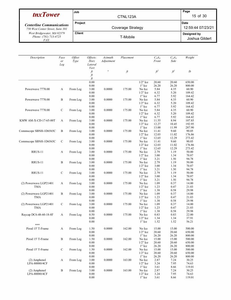
ttnnxxTToowweerr Job
CTNL123A
Page
15 of 30
Centerline Communications
750 West Center Street, Suite 301
Project
Coverage Strategy Date
12:59:44 07/23/21 West Bridgewater, MA 02379
Phone: (781) 713-4725 FAX:
Client T-Mobile
Designed by
Joshua Gildert
Description Face or
Leg
Offset Type
Offsets: Horz
Lateral Vert
ft ft ft
Azimuth Adjustment
°
Placement
ft
CAAA Front
ft2
CAAA Side
ft2
Weight
lb
0.00 0.00
1/2'' Ice 1'' Ice
20.60 26.20
20.60 26.20
650.00 800.00
Powerwave 7770.00 A From Leg 3.00 0.00 0.00
0.0000 175.00 No Ice 1/2'' Ice 1'' Ice
5.84 6.32 6.77
4.35 5.20 5.92
60.90 109.42 164.42
Powerwave 7770.00 B From Leg 3.00 0.00 0.00
0.0000 175.00 No Ice 1/2'' Ice 1'' Ice
5.84 6.32 6.77
4.35 5.20 5.92
60.90 109.42 164.42
Powerwave 7770.00 C From Leg 3.00 0.00 0.00
0.0000 175.00 No Ice 1/2'' Ice 1'' Ice
5.84 6.32 6.77
4.35 5.20 5.92
60.90 109.42 164.42
KMW AM-X-CD-17-65-00T A From Leg 3.00 0.00 0.00
0.0000 175.00 No Ice 1/2'' Ice 1'' Ice
11.55 12.27 13.00
8.94 10.45 11.99
107.85 192.95 287.90
Commscope SBNH-1D6565C B From Leg 3.00 0.00 0.00
0.0000 175.00 No Ice 1/2'' Ice 1'' Ice
11.41 12.03 12.65
9.60 11.02 12.29
90.05 176.86 273.42
Commscope SBNH-1D6565C C From Leg 3.00 0.00 0.00
0.0000 175.00 No Ice 1/2'' Ice 1'' Ice
11.41 12.03 12.65
9.60 11.02 12.29
90.05 176.86 273.42
RRUS-11 A From Leg 3.00 0.00 0.00
0.0000 175.00 No Ice 1/2'' Ice 1'' Ice
2.79 3.00 3.21
1.19 1.34 1.50
50.00 70.87 94.78
RRUS-11 B From Leg 3.00 0.00 0.00
0.0000 175.00 No Ice 1/2'' Ice 1'' Ice
2.79 3.00 3.21
1.19 1.34 1.50
50.00 70.87 94.78
RRUS-11 C From Leg 3.00 0.00 0.00
0.0000 175.00 No Ice 1/2'' Ice 1'' Ice
2.79 3.00 3.21
1.19 1.34 1.50
50.00 70.87 94.78
(2) Powerwave LGP21401 TMA
A From Leg 3.00 0.00 0.00
0.0000 175.00 No Ice 1/2'' Ice 1'' Ice
1.09 1.23 1.38
0.37 0.47 0.58
14.00 21.03 29.98
(2) Powerwave LGP21401 TMA
B From Leg 3.00 0.00 0.00
0.0000 175.00 No Ice 1/2'' Ice 1'' Ice
1.09 1.23 1.38
0.37 0.47 0.58
14.00 21.03 29.98
(2) Powerwave LGP21401 TMA
C From Leg 3.00 0.00 0.00
0.0000 175.00 No Ice 1/2'' Ice 1'' Ice
1.09 1.23 1.38
0.37 0.47 0.58
14.00 21.03 29.98
Raycap DC6-48-60-18-8F A From Leg 0.50 0.00 0.00
0.0000 175.00 No Ice 1/2'' Ice 1'' Ice
0.83 1.34 1.52
0.83 1.34 1.52
22.00 37.91 56.21
*** Pirod 15' T-Frame A From Leg 1.50
0.00 0.00
0.0000 162.00 No Ice 1/2'' Ice 1'' Ice
15.00 20.60 26.20
15.00 20.60 26.20
500.00 650.00 800.00
Pirod 15' T-Frame B From Leg 1.50 0.00 0.00
0.0000 162.00 No Ice 1/2'' Ice 1'' Ice
15.00 20.60 26.20
15.00 20.60 26.20
500.00 650.00 800.00
Pirod 15' T-Frame C From Leg 1.50 0.00 0.00
0.0000 162.00 No Ice 1/2'' Ice 1'' Ice
15.00 20.60 26.20
15.00 20.60 26.20
500.00 650.00 800.00
(2) Amphenol LPA-80080/4CF
A From Leg 3.00 0.00 0.00
0.0000 163.00 No Ice 1/2'' Ice 1'' Ice
2.87 3.24 3.61
7.24 7.95 8.66
30.25 74.63
119.01 (2) Amphenol
LPA-80080/4CF B From Leg 3.00
0.00 0.00
0.0000 163.00 No Ice 1/2'' Ice 1'' Ice
2.87 3.24 3.61
7.24 7.95 8.66
30.25 74.63
119.01
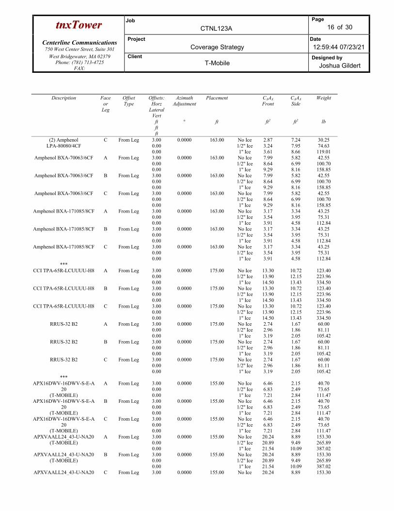
ttnnxxTToowweerr Job
CTNL123A
Page
16 of 30
Centerline Communications
750 West Center Street, Suite 301
Project
Coverage Strategy Date
12:59:44 07/23/21 West Bridgewater, MA 02379
Phone: (781) 713-4725 FAX:
Client T-Mobile
Designed by
Joshua Gildert
Description Face or
Leg
Offset Type
Offsets: Horz
Lateral Vert
ft ft ft
Azimuth Adjustment
°
Placement
ft
CAAA Front
ft2
CAAA Side
ft2
Weight
lb
(2) Amphenol LPA-80080/4CF
C From Leg 3.00 0.00 0.00
0.0000 163.00 No Ice 1/2'' Ice 1'' Ice
2.87 3.24 3.61
7.24 7.95 8.66
30.25 74.63
119.01 Amphenol BXA-70063/6CF A From Leg 3.00
0.00 0.00
0.0000 163.00 No Ice 1/2'' Ice 1'' Ice
7.99 8.64 9.29
5.82 6.99 8.16
42.55 100.70 158.85
Amphenol BXA-70063/6CF B From Leg 3.00 0.00 0.00
0.0000 163.00 No Ice 1/2'' Ice 1'' Ice
7.99 8.64 9.29
5.82 6.99 8.16
42.55 100.70 158.85
Amphenol BXA-70063/6CF C From Leg 3.00 0.00 0.00
0.0000 163.00 No Ice 1/2'' Ice 1'' Ice
7.99 8.64 9.29
5.82 6.99 8.16
42.55 100.70 158.85
Amphenol BXA-171085/8CF A From Leg 3.00 0.00 0.00
0.0000 163.00 No Ice 1/2'' Ice 1'' Ice
3.17 3.54 3.91
3.34 3.95 4.58
43.25 75.31
112.84 Amphenol BXA-171085/8CF B From Leg 3.00
0.00 0.00
0.0000 163.00 No Ice 1/2'' Ice 1'' Ice
3.17 3.54 3.91
3.34 3.95 4.58
43.25 75.31
112.84 Amphenol BXA-171085/8CF C From Leg 3.00
0.00 0.00
0.0000 163.00 No Ice 1/2'' Ice 1'' Ice
3.17 3.54 3.91
3.34 3.95 4.58
43.25 75.31
112.84 ***
CCI TPA-65R-LCUUUU-H8 A From Leg 3.00 0.00 0.00
0.0000 175.00 No Ice 1/2'' Ice 1'' Ice
13.30 13.90 14.50
10.72 12.15 13.43
123.40 223.96 334.50
CCI TPA-65R-LCUUUU-H8 B From Leg 3.00 0.00 0.00
0.0000 175.00 No Ice 1/2'' Ice 1'' Ice
13.30 13.90 14.50
10.72 12.15 13.43
123.40 223.96 334.50
CCI TPA-65R-LCUUUU-H8 C From Leg 3.00 0.00 0.00
0.0000 175.00 No Ice 1/2'' Ice 1'' Ice
13.30 13.90 14.50
10.72 12.15 13.43
123.40 223.96 334.50
RRUS-32 B2 A From Leg 3.00 0.00 0.00
0.0000 175.00 No Ice 1/2'' Ice 1'' Ice
2.74 2.96 3.19
1.67 1.86 2.05
60.00 81.11
105.42 RRUS-32 B2 B From Leg 3.00
0.00 0.00
0.0000 175.00 No Ice 1/2'' Ice 1'' Ice
2.74 2.96 3.19
1.67 1.86 2.05
60.00 81.11
105.42 RRUS-32 B2 C From Leg 3.00
0.00 0.00
0.0000 175.00 No Ice 1/2'' Ice 1'' Ice
2.74 2.96 3.19
1.67 1.86 2.05
60.00 81.11
105.42 ***
APX16DWV-16DWV-S-E-A20
(T-MOBILE)
A From Leg 3.00 0.00 0.00
0.0000 155.00 No Ice 1/2'' Ice 1'' Ice
6.46 6.83 7.21
2.15 2.49 2.84
40.70 73.65
111.47 APX16DWV-16DWV-S-E-A
20 (T-MOBILE)
B From Leg 3.00 0.00 0.00
0.0000 155.00 No Ice 1/2'' Ice 1'' Ice
6.46 6.83 7.21
2.15 2.49 2.84
40.70 73.65
111.47 APX16DWV-16DWV-S-E-A
20 (T-MOBILE)
C From Leg 3.00 0.00 0.00
0.0000 155.00 No Ice 1/2'' Ice 1'' Ice
6.46 6.83 7.21
2.15 2.49 2.84
40.70 73.65
111.47 APXVAALL24_43-U-NA20
(T-MOBILE) A From Leg 3.00
0.00 0.00
0.0000 155.00 No Ice 1/2'' Ice 1'' Ice
20.24 20.89 21.54
8.89 9.49 10.09
153.30 265.89 387.02
APXVAALL24_43-U-NA20 (T-MOBILE)
B From Leg 3.00 0.00 0.00
0.0000 155.00 No Ice 1/2'' Ice 1'' Ice
20.24 20.89 21.54
8.89 9.49 10.09
153.30 265.89 387.02
APXVAALL24_43-U-NA20 C From Leg 3.00 0.0000 155.00 No Ice 20.24 8.89 153.30

ttnnxxTToowweerr Job
CTNL123A
Page
17 of 30
Centerline Communications
750 West Center Street, Suite 301
Project
Coverage Strategy Date
12:59:44 07/23/21 West Bridgewater, MA 02379
Phone: (781) 713-4725 FAX:
Client T-Mobile
Designed by
Joshua Gildert
Description Face or
Leg
Offset Type
Offsets: Horz
Lateral Vert
ft ft ft
Azimuth Adjustment
°
Placement
ft
CAAA Front
ft2
CAAA Side
ft2
Weight
lb
(T-MOBILE) 0.00 0.00
1/2'' Ice 1'' Ice
20.89 21.54
9.49 10.09
265.89 387.02
AIR 6449 B41 (T-MOBILE)
A From Leg 3.00 0.00 0.00
0.0000 155.00 No Ice 1/2'' Ice 1'' Ice
5.68 5.98 6.29
2.49 2.72 2.95
104.00 143.12 186.46
AIR 6449 B41 (T-MOBILE)
B From Leg 3.00 0.00 0.00
0.0000 155.00 No Ice 1/2'' Ice 1'' Ice
5.68 5.98 6.29
2.49 2.72 2.95
104.00 143.12 186.46
AIR 6449 B41 (T-MOBILE)
C From Leg 3.00 0.00 0.00
0.0000 155.00 No Ice 1/2'' Ice 1'' Ice
5.68 5.98 6.29
2.49 2.72 2.95
104.00 143.12 186.46
RADIO 4480 B66 (T-MOBILE)
A From Leg 3.00 0.00 0.00
0.0000 155.00 No Ice 1/2'' Ice 1'' Ice
2.45 2.65 2.85
1.27 1.42 1.59
87.00 106.69 129.33
RADIO 4480 B66 (T-MOBILE)
B From Leg 3.00 0.00 0.00
0.0000 155.00 No Ice 1/2'' Ice 1'' Ice
2.45 2.65 2.85
1.27 1.42 1.59
87.00 106.69 129.33
RADIO 4480 B66 (T-MOBILE)
C From Leg 3.00 0.00 0.00
0.0000 155.00 No Ice 1/2'' Ice 1'' Ice
2.45 2.65 2.85
1.27 1.42 1.59
87.00 106.69 129.33
RADIO 4460 B25_B66 (T-MOBILE)
A From Leg 3.00 0.00 0.00
0.0000 155.00 No Ice 1/2'' Ice 1'' Ice
2.14 2.32 2.51
1.50 1.65 1.81
108.00 130.16 155.36
RADIO 4460 B25_B66 (T-MOBILE)
B From Leg 3.00 0.00 0.00
0.0000 155.00 No Ice 1/2'' Ice 1'' Ice
2.14 2.32 2.51
1.50 1.65 1.81
108.00 130.16 155.36
RADIO 4460 B25_B66 (T-MOBILE)
C From Leg 3.00 0.00 0.00
0.0000 155.00 No Ice 1/2'' Ice 1'' Ice
2.14 2.32 2.51
1.50 1.65 1.81
108.00 130.16 155.36
Site Pro 1 VFA12-HD (T-MOBILE)
A From Leg 1.50 0.00 0.00
0.0000 155.00 No Ice 1/2'' Ice 1'' Ice
13.20 19.50 25.80
9.20 14.60 19.50
658.00 804.00
1015.00 Site Pro 1 VFA12-HD
(T-MOBILE) B From Leg 1.50
0.00 0.00
0.0000 155.00 No Ice 1/2'' Ice 1'' Ice
13.20 19.50 25.80
9.20 14.60 19.50
658.00 804.00
1015.00 Site Pro 1 VFA12-HD
(T-MOBILE) C From Leg 1.50
0.00 0.00
0.0000 155.00 No Ice 1/2'' Ice 1'' Ice
13.20 19.50 25.80
9.20 14.60 19.50
658.00 804.00
1015.00 (4) PIPE MOUNT (8'X2.375''
(T-MOBILE) A From Leg 3.00
0.00 0.00
0.0000 155.00 No Ice 1/2'' Ice 1'' Ice
1.90 2.73 3.40
1.90 2.73 3.40
29.28 43.62 63.24
(4) PIPE MOUNT (8'X2.375'' (T-MOBILE)
B From Leg 3.00 0.00 0.00
0.0000 155.00 No Ice 1/2'' Ice 1'' Ice
1.90 2.73 3.40
1.90 2.73 3.40
29.28 43.62 63.24
(4) PIPE MOUNT (8'X2.375'' (T-MOBILE)
C From Leg 3.00 0.00 0.00
0.0000 155.00 No Ice 1/2'' Ice 1'' Ice
1.90 2.73 3.40
1.90 2.73 3.40
29.28 43.62 63.24
***
Truss-Leg Properties

ttnnxxTToowweerr Job
CTNL123A
Page
18 of 30
Centerline Communications
750 West Center Street, Suite 301
Project
Coverage Strategy Date
12:59:44 07/23/21 West Bridgewater, MA 02379
Phone: (781) 713-4725 FAX:
Client T-Mobile
Designed by
Joshua Gildert
Section Designation
Area
in2
Area Ice
in2
Self Weight
lb
Ice Weight
lb
Equiv. Diameter
in
Equiv. Diameter
Ice in
Leg Area
in2
Pirod 105245 1090.3344 3193.6269 676.81 617.08 7.5718 22.1780 5.3014 Pirod 105218 2263.4687 6625.8954 754.52 1186.30 7.8593 23.0066 7.2158 Pirod 105219 2441.8688 6672.7000 944.27 1200.37 8.4787 23.1691 9.4248 Pirod 105219 2441.8688 6642.9857 944.27 1163.79 8.4787 23.0659 9.4248 Pirod 105220 2578.8005 6678.6036 1121.16 1140.57 8.9542 23.1896 11.9282 Pirod 112743 3466.5160 8827.2724 1689.34 1498.68 12.0365 30.6503 14.7262 Pirod 112743 3466.5160 8768.9018 1689.34 1387.39 12.0365 30.4476 14.7262 Pirod 112744 3599.5585 8725.0272 1904.37 1194.40 12.4985 30.2952 17.8187
Load Combinations Comb.
No. Description
1 Dead Only 2 1.2 Dead+1.6 Wind 0 deg - No Ice 3 0.9 Dead+1.6 Wind 0 deg - No Ice 4 1.2 Dead+1.6 Wind 30 deg - No Ice 5 0.9 Dead+1.6 Wind 30 deg - No Ice 6 1.2 Dead+1.6 Wind 60 deg - No Ice 7 0.9 Dead+1.6 Wind 60 deg - No Ice 8 1.2 Dead+1.6 Wind 90 deg - No Ice 9 0.9 Dead+1.6 Wind 90 deg - No Ice
10 1.2 Dead+1.6 Wind 120 deg - No Ice 11 0.9 Dead+1.6 Wind 120 deg - No Ice 12 1.2 Dead+1.6 Wind 150 deg - No Ice 13 0.9 Dead+1.6 Wind 150 deg - No Ice 14 1.2 Dead+1.6 Wind 180 deg - No Ice 15 0.9 Dead+1.6 Wind 180 deg - No Ice 16 1.2 Dead+1.6 Wind 210 deg - No Ice 17 0.9 Dead+1.6 Wind 210 deg - No Ice 18 1.2 Dead+1.6 Wind 240 deg - No Ice 19 0.9 Dead+1.6 Wind 240 deg - No Ice 20 1.2 Dead+1.6 Wind 270 deg - No Ice 21 0.9 Dead+1.6 Wind 270 deg - No Ice 22 1.2 Dead+1.6 Wind 300 deg - No Ice 23 0.9 Dead+1.6 Wind 300 deg - No Ice 24 1.2 Dead+1.6 Wind 330 deg - No Ice 25 0.9 Dead+1.6 Wind 330 deg - No Ice 26 1.2 Dead+1.0 Ice+1.0 Temp 27 1.2 Dead+1.0 Wind 0 deg+1.0 Ice+1.0 Temp 28 1.2 Dead+1.0 Wind 30 deg+1.0 Ice+1.0 Temp 29 1.2 Dead+1.0 Wind 60 deg+1.0 Ice+1.0 Temp 30 1.2 Dead+1.0 Wind 90 deg+1.0 Ice+1.0 Temp 31 1.2 Dead+1.0 Wind 120 deg+1.0 Ice+1.0 Temp 32 1.2 Dead+1.0 Wind 150 deg+1.0 Ice+1.0 Temp 33 1.2 Dead+1.0 Wind 180 deg+1.0 Ice+1.0 Temp 34 1.2 Dead+1.0 Wind 210 deg+1.0 Ice+1.0 Temp 35 1.2 Dead+1.0 Wind 240 deg+1.0 Ice+1.0 Temp 36 1.2 Dead+1.0 Wind 270 deg+1.0 Ice+1.0 Temp 37 1.2 Dead+1.0 Wind 300 deg+1.0 Ice+1.0 Temp 38 1.2 Dead+1.0 Wind 330 deg+1.0 Ice+1.0 Temp 39 Dead+Wind 0 deg - Service 40 Dead+Wind 30 deg - Service 41 Dead+Wind 60 deg - Service 42 Dead+Wind 90 deg - Service 43 Dead+Wind 120 deg - Service 44 Dead+Wind 150 deg - Service

ttnnxxTToowweerr Job
CTNL123A
Page
19 of 30
Centerline Communications
750 West Center Street, Suite 301
Project
Coverage Strategy Date
12:59:44 07/23/21 West Bridgewater, MA 02379
Phone: (781) 713-4725 FAX:
Client T-Mobile
Designed by
Joshua Gildert
Comb. No.
Description
45 Dead+Wind 180 deg - Service 46 Dead+Wind 210 deg - Service 47 Dead+Wind 240 deg - Service 48 Dead+Wind 270 deg - Service 49 Dead+Wind 300 deg - Service 50 Dead+Wind 330 deg - Service
Maximum Reactions
Location Condition Gov. Load
Comb.
Vertical lb
Horizontal, X lb
Horizontal, Z lb
Leg C Max. Vert 18 378319.19 34152.47 -19421.74 Max. Hx 18 378319.19 34152.47 -19421.74 Max. Hz 7 -330806.50 -30311.02 17211.66 Min. Vert 7 -330806.50 -30311.02 17211.66 Min. Hx 7 -330806.50 -30311.02 17211.66 Min. Hz 18 378319.19 34152.47 -19421.74
Leg B Max. Vert 10 387366.48 -35794.08 -19234.87 Max. Hx 23 -340646.45 31985.45 17030.58 Max. Hz 23 -340646.45 31985.45 17030.58 Min. Vert 23 -340646.45 31985.45 17030.58 Min. Hx 10 387366.48 -35794.08 -19234.87 Min. Hz 10 387366.48 -35794.08 -19234.87
Leg A Max. Vert 2 363788.68 -119.58 37876.75 Max. Hx 19 -161662.49 941.44 -17291.31 Max. Hz 2 363788.68 -119.58 37876.75 Min. Vert 15 -317993.63 110.42 -33473.82 Min. Hx 7 190102.28 -862.27 19547.70 Min. Hz 15 -317993.63 110.42 -33473.82
Tower Mast Reaction Summary
Load Combination
Vertical
lb
Shearx
lb
Shearz
lb
Overturning Moment, Mx
lb-ft
Overturning Moment, Mz
lb-ft
Torque
lb-ft Dead Only 55087.34 -0.00 -0.00 7147.72 3792.95 0.16 1.2 Dead+1.6 Wind 0 deg - No Ice
66104.80 562.95 -55971.21 -5919348.58 -83097.57 -4859.25
0.9 Dead+1.6 Wind 0 deg - No Ice
49578.59 562.91 -55970.21 -5915061.94 -84127.18 -4853.55
1.2 Dead+1.6 Wind 30 deg - No Ice
66104.80 29694.71 -50330.94 -5328449.33 -3175620.23 -1689.44
0.9 Dead+1.6 Wind 30 deg - No Ice
49578.60 29694.82 -50331.12 -5324982.81 -3173386.41 -1690.09
1.2 Dead+1.6 Wind 60 deg - No Ice
66104.80 48775.79 -28174.47 -3007473.42 -5215296.64 8724.48
0.9 Dead+1.6 Wind 60 deg - No Ice
49578.60 48775.97 -28174.58 -3006425.81 -5210893.27 8717.90
1.2 Dead+1.6 Wind 90 deg - No Ice
66104.80 59152.66 -562.81 -78981.38 -6271105.78 35878.15
0.9 Dead+1.6 Wind 90 deg - No Ice
49578.60 59152.88 -562.81 -81023.93 -6265634.49 35866.72
1.2 Dead+1.6 Wind 120 deg - No Ice
66104.80 52565.25 29712.28 3098287.88 -5517833.56 43855.00

ttnnxxTToowweerr Job
CTNL123A
Page
20 of 30
Centerline Communications
750 West Center Street, Suite 301
Project
Coverage Strategy Date
12:59:44 07/23/21 West Bridgewater, MA 02379
Phone: (781) 713-4725 FAX:
Client T-Mobile
Designed by
Joshua Gildert
Load Combination
Vertical
lb
Shearx
lb
Shearz
lb
Overturning Moment, Mx
lb-ft
Overturning Moment, Mz
lb-ft
Torque
lb-ft 0.9 Dead+1.6 Wind 120 deg - No Ice
49578.59 52564.33 29711.79 3092826.88 -5513031.63 43841.67
1.2 Dead+1.6 Wind 150 deg - No Ice
66104.80 28930.41 50132.49 5293791.39 -3044273.16 35485.31
0.9 Dead+1.6 Wind 150 deg - No Ice
49578.60 28930.51 50132.68 5286076.18 -3042220.92 35474.07
1.2 Dead+1.6 Wind 180 deg - No Ice
66104.80 -562.96 54173.57 5802383.19 92294.37 4857.27
0.9 Dead+1.6 Wind 180 deg - No Ice
49578.60 -562.96 54173.78 5794053.40 91038.28 4851.65
1.2 Dead+1.6 Wind 210 deg - No Ice
66104.80 -29694.96 50330.80 5345662.58 3184769.94 1687.68
0.9 Dead+1.6 Wind 210 deg - No Ice
49578.60 -29695.07 50330.99 5337871.72 3180255.56 1688.38
1.2 Dead+1.6 Wind 240 deg - No Ice
66104.80 -50332.61 29073.30 3091824.00 5340619.75 -8724.94
0.9 Dead+1.6 Wind 240 deg - No Ice
49578.59 -50331.72 29072.78 3086318.66 5333682.56 -8718.24
1.2 Dead+1.6 Wind 270 deg - No Ice
66104.80 -59152.67 563.10 96408.20 6280241.47 -35876.42
0.9 Dead+1.6 Wind 270 deg - No Ice
49578.60 -59152.89 563.10 94145.92 6272478.39 -35865.03
1.2 Dead+1.6 Wind 300 deg - No Ice
66104.80 -51008.43 -28813.44 -3013732.88 5410904.02 -43852.41
0.9 Dead+1.6 Wind 300 deg - No Ice
49578.60 -51008.62 -28813.54 -3012724.30 5404055.86 -43839.26
1.2 Dead+1.6 Wind 330 deg - No Ice
66104.80 -28930.17 -50132.63 -5276448.42 3053626.59 -35485.31
0.9 Dead+1.6 Wind 330 deg - No Ice
49578.60 -28930.28 -50132.81 -5273057.69 3049271.09 -35474.08
1.2 Dead+1.0 Ice+1.0 Temp 165485.23 0.18 -0.30 70508.20 37713.61 1.02 1.2 Dead+1.0 Wind 0 deg+1.0 Ice+1.0 Temp
165485.23 0.00 -17206.86 -1721714.18 37783.04 -107.70
1.2 Dead+1.0 Wind 30 deg+1.0 Ice+1.0 Temp
165485.23 8423.69 -14592.11 -1452500.90 -841345.75 817.39
1.2 Dead+1.0 Wind 60 deg+1.0 Ice+1.0 Temp
165485.23 15100.88 -8719.56 -832970.93 -1527161.91 4359.74
1.2 Dead+1.0 Wind 90 deg+1.0 Ice+1.0 Temp
165485.23 18331.47 -0.00 70883.30 -1847432.52 12837.18
1.2 Dead+1.0 Wind 120 deg+1.0 Ice+1.0 Temp
165485.23 16185.00 9345.46 1030403.01 -1623956.44 15035.09
1.2 Dead+1.0 Wind 150 deg+1.0 Ice+1.0 Temp
165485.23 8944.64 15494.38 1677469.79 -889770.85 7102.87
1.2 Dead+1.0 Wind 180 deg+1.0 Ice+1.0 Temp
165485.23 0.00 16996.89 1847846.07 37787.49 107.16
1.2 Dead+1.0 Wind 210 deg+1.0 Ice+1.0 Temp
165485.23 -8423.69 14592.09 1593822.93 917080.19 -817.19
1.2 Dead+1.0 Wind 240 deg+1.0 Ice+1.0 Temp
165485.23 -15282.69 8824.52 982077.27 1615932.59 -4361.24
1.2 Dead+1.0 Wind 270 deg+1.0 Ice+1.0 Temp
165485.23 -18331.47 -0.00 70872.58 1922982.65 -12837.32
1.2 Dead+1.0 Wind 300 deg+1.0 Ice+1.0 Temp
165485.23 -16003.16 -9240.50 -881256.89 1686380.95 -15030.56
1.2 Dead+1.0 Wind 330 deg+1.0 Ice+1.0 Temp
165485.23 -8944.62 -15494.40 -1536103.44 965220.82 -7102.96
Dead+Wind 0 deg - Service 55087.34 124.17 -12345.39 -1299515.34 -15521.41 -1071.34 Dead+Wind 30 deg - Service 55087.34 6549.70 -11101.34 -1169186.47 -697136.19 -377.36 Dead+Wind 60 deg - Service 55087.34 10758.36 -6214.38 -657623.23 -1146729.89 1923.60 Dead+Wind 90 deg - Service 55087.34 13047.13 -124.16 -12141.58 -1379433.53 7917.37 Dead+Wind 120 deg - Service 55087.34 11594.15 6553.54 688202.11 -1213468.04 9673.91 Dead+Wind 150 deg - Service 55087.34 6381.08 11057.59 1172072.99 -668221.77 7821.74

ttnnxxTToowweerr Job
CTNL123A
Page
21 of 30
Centerline Communications
750 West Center Street, Suite 301
Project
Coverage Strategy Date
12:59:44 07/23/21 West Bridgewater, MA 02379
Phone: (781) 713-4725 FAX:
Client T-Mobile
Designed by
Joshua Gildert
Load Combination
Vertical
lb
Shearx
lb
Shearz
lb
Overturning Moment, Mx
lb-ft
Overturning Moment, Mz
lb-ft
Torque
lb-ft Dead+Wind 180 deg - Service 55087.34 -124.17 11948.93 1284202.96 23134.50 1071.13 Dead+Wind 210 deg - Service 55087.34 -6549.71 11101.33 1183521.61 704765.46 377.46 Dead+Wind 240 deg - Service 55087.34 -11101.70 6412.60 686788.42 1179989.80 -1925.36 Dead+Wind 270 deg - Service 55087.34 -13047.13 124.18 26509.57 1387048.36 -7917.44 Dead+Wind 300 deg - Service 55087.34 -11250.80 -6355.31 -659027.15 1195439.41 -9671.56 Dead+Wind 330 deg - Service 55087.34 -6381.07 -11057.60 -1157734.85 675828.49 -7821.75
Solution Summary
Load Comb.
Sum of Applied Forces Sum of Reactions % Error PX
lb PY lb
PZ lb
PX lb
PY lb
PZ lb
1 0.00 -55087.34 -0.00 0.00 55087.34 0.00 0.000% 2 562.97 -66104.81 -55971.87 -562.95 66104.80 55971.21 0.001% 3 562.97 -49578.61 -55971.87 -562.91 49578.59 55970.21 0.002% 4 29695.26 -66104.81 -50331.58 -29694.71 66104.80 50330.94 0.001% 5 29695.26 -49578.61 -50331.58 -29694.82 49578.60 50331.12 0.001% 6 48776.61 -66104.81 -28174.94 -48775.79 66104.80 28174.47 0.001% 7 48776.61 -49578.61 -28174.94 -48775.97 49578.60 28174.58 0.001% 8 59153.50 -66104.81 -562.97 -59152.66 66104.80 562.81 0.001% 9 59153.50 -49578.61 -562.97 -59152.88 49578.60 562.81 0.001%
10 52565.86 -66104.81 29712.61 -52565.25 66104.80 -29712.28 0.001% 11 52565.86 -49578.61 29712.61 -52564.33 49578.59 -29711.79 0.002% 12 28930.70 -66104.81 50133.26 -28930.41 66104.80 -50132.49 0.001% 13 28930.70 -49578.61 50133.26 -28930.51 49578.60 -50132.68 0.001% 14 -562.97 -66104.81 54174.48 562.96 66104.80 -54173.57 0.001% 15 -562.97 -49578.61 54174.48 562.96 49578.60 -54173.78 0.001% 16 -29695.26 -66104.81 50331.58 29694.96 66104.80 -50330.80 0.001% 17 -29695.26 -49578.61 50331.58 29695.07 49578.60 -50330.99 0.001% 18 -50333.20 -66104.81 29073.64 50332.61 66104.80 -29073.30 0.001% 19 -50333.20 -49578.61 29073.64 50331.72 49578.59 -29072.78 0.002% 20 -59153.50 -66104.81 562.97 59152.67 66104.80 -563.10 0.001% 21 -59153.50 -49578.61 562.97 59152.89 49578.60 -563.10 0.001% 22 -51009.27 -66104.81 -28813.91 51008.43 66104.80 28813.44 0.001% 23 -51009.27 -49578.61 -28813.91 51008.62 49578.60 28813.54 0.001% 24 -28930.70 -66104.81 -50133.26 28930.17 66104.80 50132.63 0.001% 25 -28930.70 -49578.61 -50133.26 28930.28 49578.60 50132.81 0.001% 26 0.00 -165485.23 -0.00 -0.18 165485.23 0.30 0.000% 27 0.00 -165485.23 -17207.03 -0.00 165485.23 17206.86 0.000% 28 8423.78 -165485.23 -14592.25 -8423.69 165485.23 14592.11 0.000% 29 15101.04 -165485.23 -8719.65 -15100.88 165485.23 8719.56 0.000% 30 18331.66 -165485.23 -0.00 -18331.47 165485.23 0.00 0.000% 31 16185.15 -165485.23 9345.56 -16185.00 165485.23 -9345.46 0.000% 32 8944.72 -165485.23 15494.55 -8944.64 165485.23 -15494.38 0.000% 33 -0.00 -165485.23 16997.08 -0.00 165485.23 -16996.89 0.000% 34 -8423.78 -165485.23 14592.25 8423.69 165485.23 -14592.09 0.000% 35 -15282.85 -165485.23 8824.62 15282.69 165485.23 -8824.52 0.000% 36 -18331.66 -165485.23 -0.00 18331.47 165485.23 0.00 0.000% 37 -16003.34 -165485.23 -9240.59 16003.16 165485.23 9240.50 0.000% 38 -8944.72 -165485.23 -15494.55 8944.62 165485.23 15494.40 0.000% 39 124.17 -55087.34 -12345.53 -124.17 55087.34 12345.39 0.000% 40 6549.78 -55087.34 -11101.47 -6549.70 55087.34 11101.34 0.000% 41 10758.49 -55087.34 -6214.45 -10758.36 55087.34 6214.38 0.000% 42 13047.29 -55087.34 -124.17 -13047.13 55087.34 124.16 0.000% 43 11594.27 -55087.34 6553.61 -11594.15 55087.34 -6553.54 0.000% 44 6381.15 -55087.34 11057.72 -6381.08 55087.34 -11057.59 0.000% 45 -124.17 -55087.34 11949.08 124.17 55087.34 -11948.93 0.000% 46 -6549.78 -55087.34 11101.47 6549.71 55087.34 -11101.33 0.000%

ttnnxxTToowweerr Job
CTNL123A
Page
22 of 30
Centerline Communications
750 West Center Street, Suite 301
Project
Coverage Strategy Date
12:59:44 07/23/21 West Bridgewater, MA 02379
Phone: (781) 713-4725 FAX:
Client T-Mobile
Designed by
Joshua Gildert
Load
Comb.
Sum of Applied Forces Sum of Reactions % Error PX
lb PY lb
PZ lb
PX lb
PY lb
PZ lb
47 -11101.82 -55087.34 6412.67 11101.70 55087.34 -6412.60 0.000% 48 -13047.29 -55087.34 124.17 13047.13 55087.34 -124.18 0.000% 49 -11250.94 -55087.34 -6355.39 11250.80 55087.34 6355.31 0.000% 50 -6381.15 -55087.34 -11057.72 6381.07 55087.34 11057.60 0.000%
Non-Linear Convergence Results
Load Combination
Converged? Number of Cycles
Displacement Tolerance
Force Tolerance
1 Yes 6 0.00000001 0.00000001 2 Yes 10 0.00000001 0.00005701 3 Yes 9 0.00000001 0.00012103 4 Yes 10 0.00000001 0.00007058 5 Yes 10 0.00000001 0.00005320 6 Yes 10 0.00000001 0.00008108 7 Yes 10 0.00000001 0.00006311 8 Yes 10 0.00000001 0.00007057 9 Yes 10 0.00000001 0.00005322
10 Yes 10 0.00000001 0.00005620 11 Yes 9 0.00000001 0.00011878 12 Yes 10 0.00000001 0.00006988 13 Yes 10 0.00000001 0.00005252 14 Yes 10 0.00000001 0.00008068 15 Yes 10 0.00000001 0.00006272 16 Yes 10 0.00000001 0.00006933 17 Yes 10 0.00000001 0.00005199 18 Yes 10 0.00000001 0.00005649 19 Yes 9 0.00000001 0.00011952 20 Yes 10 0.00000001 0.00006928 21 Yes 10 0.00000001 0.00005198 22 Yes 10 0.00000001 0.00008106 23 Yes 10 0.00000001 0.00006313 24 Yes 10 0.00000001 0.00006984 25 Yes 10 0.00000001 0.00005249 26 Yes 8 0.00000001 0.00009342 27 Yes 11 0.00000001 0.00004713 28 Yes 11 0.00000001 0.00004771 29 Yes 11 0.00000001 0.00004914 30 Yes 11 0.00000001 0.00004892 31 Yes 11 0.00000001 0.00004860 32 Yes 11 0.00000001 0.00004998 33 Yes 11 0.00000001 0.00005077 34 Yes 11 0.00000001 0.00004960 35 Yes 11 0.00000001 0.00004866 36 Yes 11 0.00000001 0.00004977 37 Yes 11 0.00000001 0.00005079 38 Yes 11 0.00000001 0.00004911 39 Yes 10 0.00000001 0.00005235 40 Yes 10 0.00000001 0.00005513 41 Yes 10 0.00000001 0.00005746 42 Yes 10 0.00000001 0.00005512 43 Yes 10 0.00000001 0.00005225 44 Yes 10 0.00000001 0.00005490 45 Yes 10 0.00000001 0.00005731 46 Yes 10 0.00000001 0.00005491 47 Yes 10 0.00000001 0.00005237

ttnnxxTToowweerr Job
CTNL123A
Page
23 of 30
Centerline Communications
750 West Center Street, Suite 301
Project
Coverage Strategy Date
12:59:44 07/23/21 West Bridgewater, MA 02379
Phone: (781) 713-4725 FAX:
Client T-Mobile
Designed by
Joshua Gildert
48 Yes 10 0.00000001 0.00005487 49 Yes 10 0.00000001 0.00005745 50 Yes 10 0.00000001 0.00005486
Maximum Tower Deflections - Service Wind
Section No.
Elevation
ft
Horz. Deflection
in
Gov. Load
Comb.
Tilt °
Twist °
T1 175.4 - 165 3.583 48 0.2002 0.0356 T2 165 - 150 3.138 48 0.1972 0.0349 T3 150 - 140 2.515 48 0.1792 0.0296 T4 140 - 120 2.144 48 0.1622 0.0242 T5 120 - 100 1.514 48 0.1301 0.0174 T6 100 - 80 1.010 43 0.1028 0.0126 T7 80 - 60 0.624 43 0.0744 0.0086 T8 60 - 40 0.340 43 0.0517 0.0051 T9 40 - 20 0.148 43 0.0335 0.0031
T10 20 - 0 0.035 43 0.0149 0.0014
Critical Deflections and Radius of Curvature - Service Wind
Elevation
ft
Appurtenance Gov. Load
Comb.
Deflection
in
Tilt °
Twist °
Radius of Curvature
ft 181.00 Lightning Rod 1/2''x3' on 12' Pipe 48 3.583 0.2002 0.0356 Inf 180.00 SRL-420NHD Omni 48 3.583 0.2002 0.0356 Inf 175.00 Powerwave 7770.00 48 3.566 0.2002 0.0356 Inf 173.00 Pirod 15' T-Frame 48 3.480 0.1999 0.0356 Inf 163.00 (2) Amphenol LPA-80080/4CF 48 3.052 0.1958 0.0345 137262 162.00 Pirod 15' T-Frame 48 3.010 0.1949 0.0342 106184 155.00 APX16DWV-16DWV-S-E-A20 48 2.716 0.1868 0.0319 38184
Maximum Tower Deflections - Design Wind
Section No.
Elevation
ft
Horz. Deflection
in
Gov. Load
Comb.
Tilt °
Twist °
T1 175.4 - 165 16.228 20 0.9078 0.1616 T2 165 - 150 14.211 20 0.8939 0.1583 T3 150 - 140 11.389 20 0.8118 0.1341 T4 140 - 120 9.711 20 0.7346 0.1097 T5 120 - 100 6.855 20 0.5891 0.0788 T6 100 - 80 4.580 10 0.4655 0.0570 T7 80 - 60 2.827 10 0.3370 0.0389 T8 60 - 40 1.540 10 0.2344 0.0230 T9 40 - 20 0.670 10 0.1516 0.0140
T10 20 - 0 0.161 10 0.0673 0.0065

ttnnxxTToowweerr Job
CTNL123A
Page
24 of 30
Centerline Communications
750 West Center Street, Suite 301
Project
Coverage Strategy Date
12:59:44 07/23/21 West Bridgewater, MA 02379
Phone: (781) 713-4725 FAX:
Client T-Mobile
Designed by
Joshua Gildert
Critical Deflections and Radius of Curvature - Design Wind
Elevation
ft
Appurtenance Gov. Load
Comb.
Deflection
in
Tilt °
Twist °
Radius of Curvature
ft 181.00 Lightning Rod 1/2''x3' on 12' Pipe 20 16.228 0.9078 0.1616 230964 180.00 SRL-420NHD Omni 20 16.228 0.9078 0.1616 230964 175.00 Powerwave 7770.00 20 16.151 0.9076 0.1616 230964 173.00 Pirod 15' T-Frame 20 15.763 0.9064 0.1614 230964 163.00 (2) Amphenol LPA-80080/4CF 20 13.824 0.8873 0.1565 30719 162.00 Pirod 15' T-Frame 20 13.631 0.8833 0.1554 23720 155.00 APX16DWV-16DWV-S-E-A20 20 12.300 0.8461 0.1447 8462
Bolt Design Data
Section No.
Elevation
ft
Component Type
Bolt Grade
Bolt Size
in
Number Of
Bolts
Maximum Load
per Bolt lb
Allowable Load
per Bolt lb
Ratio Load
Allowable
Allowable Ratio
Criteria
T1 175.4 Leg A325N 0.7500 5 2982.97 35784.70 0.083 1 Bolt DS
T2 165 Leg A325N 1.0000 6 8915.94 53014.40 0.168 1 Bolt Tension
T3 150 Leg A325N 1.0000 6 10673.10 53014.40 0.201
1 Bolt Tension
Diagonal A325N 1.0000 1 11055.00 16939.50 0.653 1 Member Block Shear
T4 140 Leg A325N 1.0000 6 19430.30 53014.40 0.367
1 Bolt Tension
Diagonal A325N 1.0000 1 10250.10 16939.50 0.605 1 Member Block Shear
T5 120 Leg A325N 1.2500 6 26533.90 82835.00 0.320 1 Bolt Tension
Diagonal A325N 1.2500 1 9268.52 17138.70 0.541
1 Member Block Shear
T6 100 Leg A325N 1.2500 6 32965.40 82835.00 0.398 1 Bolt Tension
Diagonal A325N 1.2500 1 9522.94 17138.70 0.556 1 Member Block Shear
T7 80 Leg A325N 1.2500 6 39183.90 82835.00 0.473
1 Bolt Tension
Diagonal A325N 1.2500 1 10033.90 17138.70 0.585 1 Member Block Shear
T8 60 Leg A325N 1.2500 12 21377.80 82835.00 0.258 1 Bolt Tension
Diagonal A325N 1.0000 2 7560.00 35525.40 0.213 1 Member Block Shear
T9 40 Leg A325N 1.2500 12 24537.60 82835.00 0.296 1 Bolt Tension
Diagonal A325N 1.0000 2 7647.37 35525.40 0.215
1 Member Block Shear
T10 20 Leg A687 1.2500 12 26850.10 86286.40 0.311 1 Bolt Tension
Diagonal A325N 1.0000 2 8286.91 35525.40 0.233 1 Member Block Shear
Compression Checks

ttnnxxTToowweerr Job
CTNL123A
Page
25 of 30
Centerline Communications
750 West Center Street, Suite 301
Project
Coverage Strategy Date
12:59:44 07/23/21 West Bridgewater, MA 02379
Phone: (781) 713-4725 FAX:
Client T-Mobile
Designed by
Joshua Gildert
Leg Design Data (Compression) Section
No. Elevation
ft
Size
L
ft
Lu
ft
Kl/r
A
in2
Pu
lb
Pn
lb
Ratio Pu
Pn T1 175.4 - 165 2 10.40 2.43 58.4
K=1.00 3.1416 -12824.00 110170.00 0.116 1
T2 165 - 150 2 1/4 15.00 2.39 51.0
K=1.00 3.9761 -56161.40 147977.00 0.380 1
T3 150 - 140 Pirod 105245 10.02 10.02 37.8
K=1.00 5.3014 -71240.90 214859.00 0.332 1
T4 140 - 120 Pirod 105218 20.03 10.02 32.4
K=1.00 7.2158 -127767.00 300681.00 0.425 1
T5 120 - 100 Pirod 105219 20.03 10.02 28.4
K=1.00 9.4248 -174207.00 399868.00 0.436 1
T6 100 - 80 Pirod 105219 20.03 10.02 28.4
K=1.00 9.4248 -217092.00 399868.00 0.543 1
T7 80 - 60 Pirod 105220 20.03 10.02 25.2
K=1.00 11.9282 -259466.00 512375.00 0.506 1
T8 60 - 40 Pirod 112743 20.03 20.03 32.6
K=1.00 14.7262 -283744.00 613145.00 0.463 1
T9 40 - 20 Pirod 112743 20.03 20.03 32.6
K=1.00 14.7262 -330233.00 613145.00 0.539 1
T10 20 - 0 Pirod 112744 20.03 20.03 32.6
K=1.00 17.8187 -363749.00 741993.00 0.490 1
1 P u / Pn controls
Truss-Leg Diagonal Data Section
No. Elevation
ft Diagonal Size
Ld
ft Kl/r
Pn lb
A in2
Vu lb
Vn lb
Stress Ratio
T3 150 - 140 0.5 1.47 120.0 238565.00 0.1963 729.69 3446.37 0.213
T4 140 - 120 0.5 1.46 119.0 324713.00 0.1963 462.48 3377.71 0.138
T5 120 - 100 0.625 1.45 94.4 424115.00 0.3068 263.25 6957.62 0.039
T6 100 - 80 0.625 1.45 94.4 424115.00 0.3068 294.84 6957.62 0.043
T7 80 - 60 0.625 1.43 93.6 536771.00 0.3068 1343.94 7011.35 0.193
T8 60 - 40 0.75 1.73 93.9 662680.00 0.4418 639.83 14363.90 0.045
T9 40 - 20 0.75 1.73 93.9 662680.00 0.4418 877.39 14363.90 0.062
T10 20 - 0 0.75 1.71 93.1 801842.00 0.4418 1438.78 14530.80 0.100
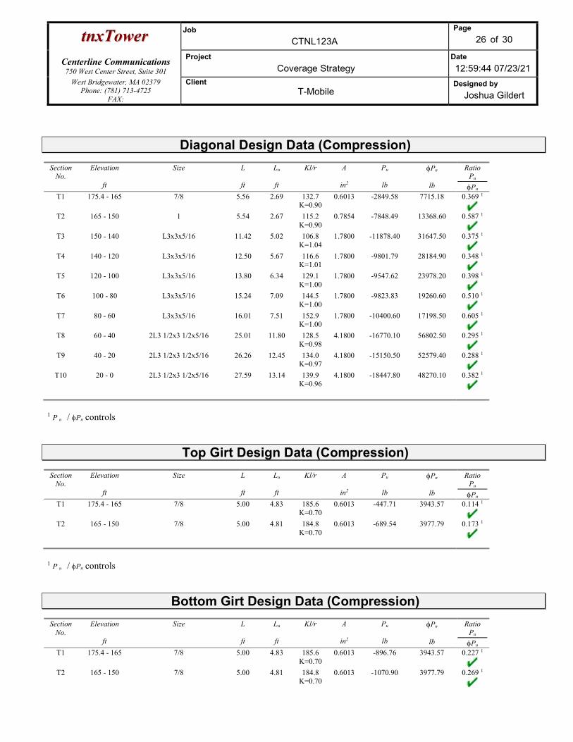
ttnnxxTToowweerr Job
CTNL123A
Page
26 of 30
Centerline Communications
750 West Center Street, Suite 301
Project
Coverage Strategy Date
12:59:44 07/23/21 West Bridgewater, MA 02379
Phone: (781) 713-4725 FAX:
Client T-Mobile
Designed by
Joshua Gildert
Diagonal Design Data (Compression) Section
No. Elevation
ft
Size
L
ft
Lu
ft
Kl/r
A
in2
Pu
lb
Pn
lb
Ratio Pu
Pn T1 175.4 - 165 7/8 5.56 2.69 132.7
K=0.90 0.6013 -2849.58 7715.18 0.369 1
T2 165 - 150 1 5.54 2.67 115.2
K=0.90 0.7854 -7848.49 13368.60 0.587 1
T3 150 - 140 L3x3x5/16 11.42 5.02 106.8
K=1.04 1.7800 -11878.40 31647.50 0.375 1
T4 140 - 120 L3x3x5/16 12.50 5.67 116.6
K=1.01 1.7800 -9801.79 28184.90 0.348 1
T5 120 - 100 L3x3x5/16 13.80 6.34 129.1
K=1.00 1.7800 -9547.62 23978.20 0.398 1
T6 100 - 80 L3x3x5/16 15.24 7.09 144.5
K=1.00 1.7800 -9823.83 19260.60 0.510 1
T7 80 - 60 L3x3x5/16 16.01 7.51 152.9
K=1.00 1.7800 -10400.60 17198.50 0.605 1
T8 60 - 40 2L3 1/2x3 1/2x5/16 25.01 11.80 128.5
K=0.98 4.1800 -16770.10 56802.50 0.295 1
T9 40 - 20 2L3 1/2x3 1/2x5/16 26.26 12.45 134.0
K=0.97 4.1800 -15150.50 52579.40 0.288 1
T10 20 - 0 2L3 1/2x3 1/2x5/16 27.59 13.14 139.9
K=0.96 4.1800 -18447.80 48270.10 0.382 1
1 P u / Pn controls
Top Girt Design Data (Compression) Section
No. Elevation
ft
Size
L
ft
Lu
ft
Kl/r
A
in2
Pu
lb
Pn
lb
Ratio Pu
Pn T1 175.4 - 165 7/8 5.00 4.83 185.6
K=0.70 0.6013 -447.71 3943.57 0.114 1
T2 165 - 150 7/8 5.00 4.81 184.8
K=0.70 0.6013 -689.54 3977.79 0.173 1
1 P u / Pn controls
Bottom Girt Design Data (Compression) Section
No. Elevation
ft
Size
L
ft
Lu
ft
Kl/r
A
in2
Pu
lb
Pn
lb
Ratio Pu
Pn T1 175.4 - 165 7/8 5.00 4.83 185.6
K=0.70 0.6013 -896.76 3943.57 0.227 1
T2 165 - 150 7/8 5.00 4.81 184.8
K=0.70 0.6013 -1070.90 3977.79 0.269 1
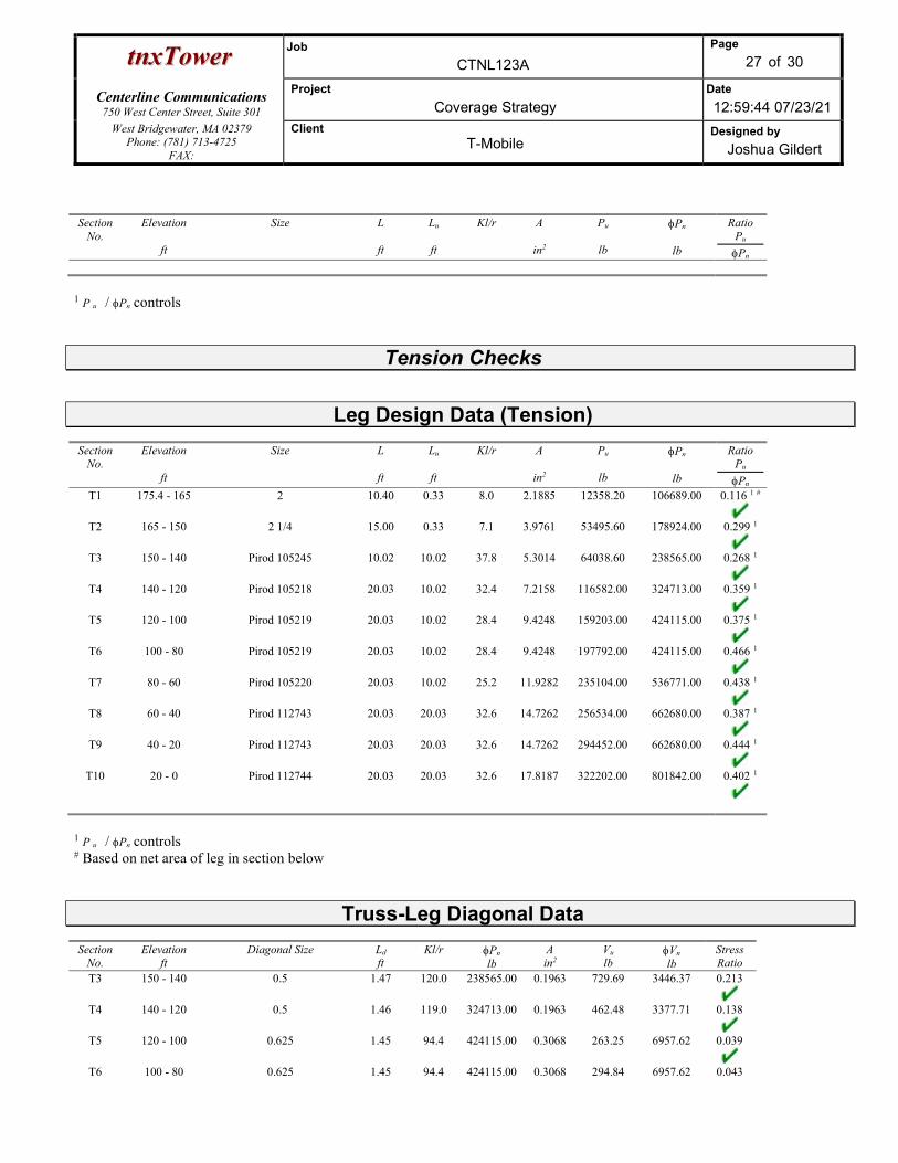
ttnnxxTToowweerr Job
CTNL123A
Page
27 of 30
Centerline Communications
750 West Center Street, Suite 301
Project
Coverage Strategy Date
12:59:44 07/23/21 West Bridgewater, MA 02379
Phone: (781) 713-4725 FAX:
Client T-Mobile
Designed by
Joshua Gildert
Section No.
Elevation
ft
Size
L
ft
Lu
ft
Kl/r
A
in2
Pu
lb
Pn
lb
Ratio Pu
Pn
1 P u / Pn controls
Tension Checks
Leg Design Data (Tension) Section
No. Elevation
ft
Size
L
ft
Lu
ft
Kl/r
A
in2
Pu
lb
Pn
lb
Ratio Pu
Pn T1 175.4 - 165 2 10.40 0.33 8.0 2.1885 12358.20 106689.00 0.116 1 #
T2 165 - 150 2 1/4 15.00 0.33 7.1 3.9761 53495.60 178924.00 0.299 1
T3 150 - 140 Pirod 105245 10.02 10.02 37.8 5.3014 64038.60 238565.00 0.268 1
T4 140 - 120 Pirod 105218 20.03 10.02 32.4 7.2158 116582.00 324713.00 0.359 1
T5 120 - 100 Pirod 105219 20.03 10.02 28.4 9.4248 159203.00 424115.00 0.375 1
T6 100 - 80 Pirod 105219 20.03 10.02 28.4 9.4248 197792.00 424115.00 0.466 1
T7 80 - 60 Pirod 105220 20.03 10.02 25.2 11.9282 235104.00 536771.00 0.438 1
T8 60 - 40 Pirod 112743 20.03 20.03 32.6 14.7262 256534.00 662680.00 0.387 1
T9 40 - 20 Pirod 112743 20.03 20.03 32.6 14.7262 294452.00 662680.00 0.444 1
T10 20 - 0 Pirod 112744 20.03 20.03 32.6 17.8187 322202.00 801842.00 0.402 1
1 P u / Pn controls # Based on net area of leg in section below
Truss-Leg Diagonal Data Section
No. Elevation
ft Diagonal Size
Ld
ft Kl/r
Pn lb
A in2
Vu lb
Vn lb
Stress Ratio
T3 150 - 140 0.5 1.47 120.0 238565.00 0.1963 729.69 3446.37 0.213
T4 140 - 120 0.5 1.46 119.0 324713.00 0.1963 462.48 3377.71 0.138
T5 120 - 100 0.625 1.45 94.4 424115.00 0.3068 263.25 6957.62 0.039
T6 100 - 80 0.625 1.45 94.4 424115.00 0.3068 294.84 6957.62 0.043

ttnnxxTToowweerr Job
CTNL123A
Page
28 of 30
Centerline Communications
750 West Center Street, Suite 301
Project
Coverage Strategy Date
12:59:44 07/23/21 West Bridgewater, MA 02379
Phone: (781) 713-4725 FAX:
Client T-Mobile
Designed by
Joshua Gildert
Section No.
Elevation ft
Diagonal Size
Ld
ft Kl/r
Pn lb
A in2
Vu lb
Vn lb
Stress Ratio
T7 80 - 60 0.625 1.43 93.6 536771.00 0.3068 1343.94 7011.35 0.193
T8 60 - 40 0.75 1.73 93.9 662680.00 0.4418 639.83 14363.90 0.045
T9 40 - 20 0.75 1.73 93.9 662680.00 0.4418 877.39 14363.90 0.062
T10 20 - 0 0.75 1.71 93.1 801842.00 0.4418 1438.78 14530.80 0.100
Diagonal Design Data (Tension) Section
No. Elevation
ft
Size
L
ft
Lu
ft
Kl/r
A
in2
Pu
lb
Pn
lb
Ratio Pu
Pn T1 175.4 - 165 7/8 5.56 2.69 147.4 0.6013 2846.32 27059.40 0.105 1
T2 165 - 150 1 5.54 2.67 128.0 0.7854 7795.23 35342.90 0.221 1
T3 150 - 140 L3x3x5/16 11.42 5.02 67.6 1.0713 11055.00 46602.80 0.237 1
T4 140 - 120 L3x3x5/16 11.93 5.42 72.8 1.0713 10250.10 46602.80 0.220 1
T5 120 - 100 L3x3x5/16 13.13 6.03 81.0 1.0127 9268.52 44053.90 0.210 1
T6 100 - 80 L3x3x5/16 15.24 7.09 94.9 1.0127 9522.94 44053.90 0.216 1
T7 80 - 60 L3x3x5/16 16.01 7.51 100.3 1.0127 10033.90 44053.90 0.228 1
T8 60 - 40 2L3 1/2x3 1/2x5/16 25.01 11.80 134.3 2.6077 15120.00 113433.00 0.133 1
T9 40 - 20 2L3 1/2x3 1/2x5/16 26.26 12.45 141.6 2.6077 15294.70 113433.00 0.135 1
T10 20 - 0 2L3 1/2x3 1/2x5/16 27.59 13.14 149.3 2.6077 16573.80 113433.00 0.146 1
1 P u / Pn controls
Top Girt Design Data (Tension) Section
No. Elevation
ft
Size
L
ft
Lu
ft
Kl/r
A
in2
Pu
lb
Pn
lb
Ratio Pu
Pn T1 175.4 - 165 7/8 5.00 4.83 265.1 0.6013 426.58 27059.40 0.016 1
T2 165 - 150 7/8 5.00 4.81 264.0 0.6013 688.17 27059.40 0.025 1
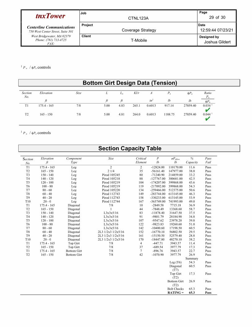
ttnnxxTToowweerr Job
CTNL123A
Page
29 of 30
Centerline Communications
750 West Center Street, Suite 301
Project
Coverage Strategy Date
12:59:44 07/23/21 West Bridgewater, MA 02379
Phone: (781) 713-4725 FAX:
Client T-Mobile
Designed by
Joshua Gildert
1 P u / Pn controls
Bottom Girt Design Data (Tension) Section
No. Elevation
ft
Size
L
ft
Lu
ft
Kl/r
A
in2
Pu
lb
Pn
lb
Ratio Pu
Pn T1 175.4 - 165 7/8 5.00 4.83 265.1 0.6013 917.14 27059.40 0.034 1
T2 165 - 150 7/8 5.00 4.81 264.0 0.6013 1188.75 27059.40 0.044 1
1 P u / Pn controls
Section Capacity Table
Section No.
Elevation ft
Component Type
Size Critical Element
P lb
øPallow
lb %
Capacity Pass Fail
T1 175.4 - 165 Leg 2 2 -12824.00 110170.00 11.6 Pass T2 165 - 150 Leg 2 1/4 35 -56161.40 147977.00 38.0 Pass T3 150 - 140 Leg Pirod 105245 80 -71240.90 214859.00 33.2 Pass T4 140 - 120 Leg Pirod 105218 88 -127767.00 300681.00 42.5 Pass T5 120 - 100 Leg Pirod 105219 104 -174207.00 399868.00 43.6 Pass T6 100 - 80 Leg Pirod 105219 119 -217092.00 399868.00 54.3 Pass T7 80 - 60 Leg Pirod 105220 134 -259466.00 512375.00 50.6 Pass T8 60 - 40 Leg Pirod 112743 149 -283744.00 613145.00 46.3 Pass T9 40 - 20 Leg Pirod 112743 158 -330233.00 613145.00 53.9 Pass
T10 20 - 0 Leg Pirod 112744 167 -363749.00 741993.00 49.0 Pass T1 175.4 - 165 Diagonal 7/8 10 -2849.58 7715.18 36.9 Pass T2 165 - 150 Diagonal 1 44 -7848.49 13368.60 58.7 Pass T3 150 - 140 Diagonal L3x3x5/16 83 -11878.40 31647.50 37.5 Pass T4 140 - 120 Diagonal L3x3x5/16 91 -9801.79 28184.90 34.8 Pass T5 120 - 100 Diagonal L3x3x5/16 107 -9547.62 23978.20 39.8 Pass T6 100 - 80 Diagonal L3x3x5/16 122 -9823.83 19260.60 51.0 Pass T7 80 - 60 Diagonal L3x3x5/16 142 -10400.60 17198.50 60.5 Pass T8 60 - 40 Diagonal 2L3 1/2x3 1/2x5/16 152 -16770.10 56802.50 29.5 Pass T9 40 - 20 Diagonal 2L3 1/2x3 1/2x5/16 161 -15150.50 52579.40 28.8 Pass
T10 20 - 0 Diagonal 2L3 1/2x3 1/2x5/16 170 -18447.80 48270.10 38.2 Pass T1 175.4 - 165 Top Girt 7/8 4 -447.71 3943.57 11.4 Pass T2 165 - 150 Top Girt 7/8 37 -689.54 3977.79 17.3 Pass T1 175.4 - 165 Bottom Girt 7/8 7 -896.76 3943.57 22.7 Pass T2 165 - 150 Bottom Girt 7/8 42 -1070.90 3977.79 26.9 Pass
Summary Leg (T6) 54.3 Pass Diagonal
(T7) 60.5 Pass
Top Girt (T2)
17.3 Pass
Bottom Girt (T2)
26.9 Pass
Bolt Checks 65.3 Pass RATING = 65.3 Pass

ttnnxxTToowweerr Job
CTNL123A
Page
30 of 30
Centerline Communications
750 West Center Street, Suite 301
Project
Coverage Strategy Date
12:59:44 07/23/21 West Bridgewater, MA 02379
Phone: (781) 713-4725 FAX:
Client T-Mobile
Designed by
Joshua Gildert
Program Version 8.1.1.0 - 6/3/2021 File:C:/Users/Joshua Gildert/Box/Projects/New England Projects/T-Mobile/SITES/CT/CTNL123A - 147 BALTIC HANOVER RD - SST/ANCHOR/Structural/Working Files/Analysis/tnx/CTNL123A.eri

6328.181 ft-kips Capacity Demand Rating Check
66.105 kips 286.55 60.38 21.1% Pass
60.381 kips 6.00 1.23 20.5% Pass
387.366 kips 12300.40 6554.61 53.3% Pass
40.635 kips 1284.52 0.00 0.0% Pass
340.646 kips 789.06 0.00 0.0% Pass
36.237 kips #DIV/0! 0.00 0.0% Pass
175.4 ft 10838.75 1931.46 17.8% Pass
20 ft 1363.69 224.50 16.5% Pass
3 in 0.164 0.053 32.5% Pass
12 in 6033.03 0.00 0.0% Pass
0.164 0.000 0.0% Pass
6033.03 0.00 0.0% Pass
ft
ft Soil Rating: 53.3%
Structural Rating: 32.5%
in
3 ft
37.5 ft
3.5 ft
11
44
3 in
60 ksi
3 ksi
150 pcf
120 pcf
8.000 ksf <-- Toggle between Gross and Net
0.000 ksf
30 degrees
0.45
0.00 ft
No
N/A ft
Top & Bot. Pad Rein. Different?:
Anchor Bolt Circle, BC: Flexural 2-way (Comp) (kip*ft)
Flexural 2-way (Tension) (kip*ft)
Pad Flexure (kip*ft)
Pad Shear - Tension 2-way (ksi)
Lateral (Sliding) (kips)
Foundation Analysis Checks
Tower Centroid Offset?:
Pier Properties
Global Moment, M:
Leg Uplift. Shear, Vu_uplift:
BP Dist. Above Fdn, bpdist:
Block Foundation?:
Pad Shear - Comp 2-way (ksi)
Pier Compression (kip)
Pier Flexure (Comp.) (kip*ft)
Pad Shear - 1-way (kips)
Tower Height, H:
Base Face Width, BW:
Leg Uplift, Puplift: Pier Flexure (Tension) (kip*ft)
Bearing Pressure (ksf)
Overturning (kip*ft)
SST Unit Base Foundation
BU # :Site Name:
Leg Compression, Pcomp:
TIA-222 Revision:
App. Number:
Superstructure Analysis Reactions
G
Global Axial, P:
Global Shear, V:
CTNL123A
Leg Comp. Shear, Vu_comp:
Pier Diameter, dpier:
Pier Rebar Quantity, mc:
Pier Tie/Spiral Size, St:
Pier Clear Cover, ccpier:
Neglected Depth, N:
Pier Shape:
Pier Rebar Size, Sc:
Pier Reinforcement Type:
Ext. Above Grade, E:
Pier Tie/Spiral Quantity, mt:
Pad Width, W:
Pad Thickness, T:
Pad Rebar Size (Bottom), Sp:
Foundation Bearing on Rock?
Pad Properties
Groundwater Depth, gw:
Base Friction, μ:
Cohesion, Cu:
Friction Angle, ϕ:
Total Soil Unit Weight, γ:
Ultimate Gross Bearing, Qult:
SPT Blow Count, Nblows:
Soil Properties
Depth, D:
Pad Clear Cover, ccpad:
Dry Concrete Density, δc:
Pad Rebar Quantity (Bottom), mp:
Rebar Grade, Fy:
Concrete Compressive Strength, F'c:
Material Properties
Version 3.2.0

Exhibit F
Mount Analysis

a�����@RVL@RPRQ@
n��������@llc@
QU@c�������@w��L@s����@b@
n�����L@ma@PRWVV@
s������Z@@@ s���������@m����@a���������@l�����@@
s���@idZ@ctnlQRSa@
s���@n���Z@ctnlQRSa@
s���@a������Z@QTW@b�����@h������@r�@
@@@@@@@@@@b�����L@ct@PVSSP@
t�@w���@i�@m��@c������Z@
c���������@c�������������@���@����@����������@��@tMm�����@��@�������@�@����������@����������@��@���@
��������@�������@������@�������@��@���@�����@����������@����N@
b����@��@���@����������@����������L@��@����@���������@����@ ���@��������@�������@������@s���@p��Q@
CvfaQRMhd@���@�������@���@��������@tMm�����@���������@������@�����Z@@
HSI@@rfs@apxQVdwvMQVdwvMsMeMaRP@p����@a�������@
HSI@@rfs@apxvaallRT�TSMuMnRP@p����@a�������@
HSI@@e�������@air@VTTY@bTQ@p����@a�������@
HSI@@e�������@TTXP@bWQKbXU@rru@
HSI@@e�������@TTVP@bRUKbVV@rru@
t���@ ����������@ ���@ ���������@ ��@ ����������@ ����@ ���@ RPQU@ i������������@ b�������@ c���L@ asce@ WMQP@
m������@ d�����@ l����@ ���@ b��������@ ���@ o����@ s���������L@ ansiOtiaMRRRMg@ s���������@ s�������@ ���@
a������@s���������@s���������@���@a�������L@���@���@RPQX@ct@s����@b�������@c���N
s�����@���@����@���@���������L@������@��@���@��������@��@�������@��N@
s��������L@
d����@jN@c������L@pNeN@
d�������@M@aFe@s�������
CN = Derek J. Creaser, P.
E. email =
US O = Centerline
Communications OU =
Director - A&E Services
2021.08.27 08:25:05 -04'00'

Exhibit G
Power Density/RF Emissions Report

750 West Center St. Suite 301 | West Bridgewater, MA 02379
Radio Frequency Emissions Analysis Report
August 26, 2021
Centerline Communications on behalf of T-Mobile
Site Name: CTNL123A
Site Address: 147 Baltic Hanover Rd, Baltic, CT 06330
Site Compliance Summary Compliance Status: Compliant
Carrier MPE%
of FCC General Population Allowable Limit:
4.82703500%
Composite MPE%
of FCC General Population Allowable Limit:
4.82714200%

750 West Center St. Suite 301 | West Bridgewater, MA 02379
August 26, 2021
T-Mobile Connecticut
Attn: Ryan Clark, Site Acquisition Consultant
Emissions Analysis for Site: CTNL123A
Centerline Communications, LLC (“Centerline”) was directed to analyze the proposed T-Mobile facility to be
located a tower near 147 Baltic Hanover Rd, Baltic CT 06330 for the purpose of determining whether the
emissions from the proposed facility are within specified federal limits.
All information used in this report was analyzed as a percentage of current Maximum Permissible Exposure (%
MPE) as listed in the FCC OET Bulletin 65 Edition 97-01 and ANSI/IEEE Std C95.1. The FCC regulates Maximum
Permissible Exposure in units of microwatts per square centimeter (μW/cm2). The number of μW/cm2 calculated
at each sample point is called the power density. The exposure limit for power density varies depending upon the
frequencies being utilized. Wireless Carriers and Paging Services use different frequency bands each with different
exposure limits, therefore it is necessary to report results and limits in terms of percent MPE rather than power
density.
All results were compared to the FCC (Federal Communications Commission) radio frequency exposure rules, 47
CFR 1.1307(b)(1) – (b)(3), to determine compliance with the Maximum Permissible Exposure (MPE) limits for
General Population/Uncontrolled environments as defined below.
General population/uncontrolled exposure limits apply to situations in which the general population may be
exposed or in which persons who are exposed as a consequence of their employment may not be made fully
aware of the potential for exposure or cannot exercise control over their exposure. Therefore, members of the
general population would always be considered under this category when exposure is not employment related, for
example, in the case of a telecommunications tower that exposes persons in a nearby residential area.
Population exposure to radio frequencies is regulated and enforced in units of microwatts per square centimeter
(μW/cm2). The general population exposure limits for the 600MHz (LTE and NR) bands is 400 μW/cm2, for the 700
MHz is 467 μW/cm2, 1900 MHz (LTE and GSM), 2100 (LTE), and 2500 (LTE AND NR) is 1000 μW/cm2.
Occupational/controlled exposure limits apply to situations in which persons are exposed as a consequence of
their employment and in which those persons who are exposed have been made fully aware of the potential for
exposure and can exercise control over their exposure. Occupational/controlled exposure limits also apply where
exposure is of a transient nature as a result of incidental passage through a location where exposure levels may be
above general population/uncontrolled limits, as long as the exposed person has been made fully aware of the
potential for exposure and can exercise control over his or her exposure by leaving the area or by some other
appropriate means. Additional details can be found in FCC OET 65.
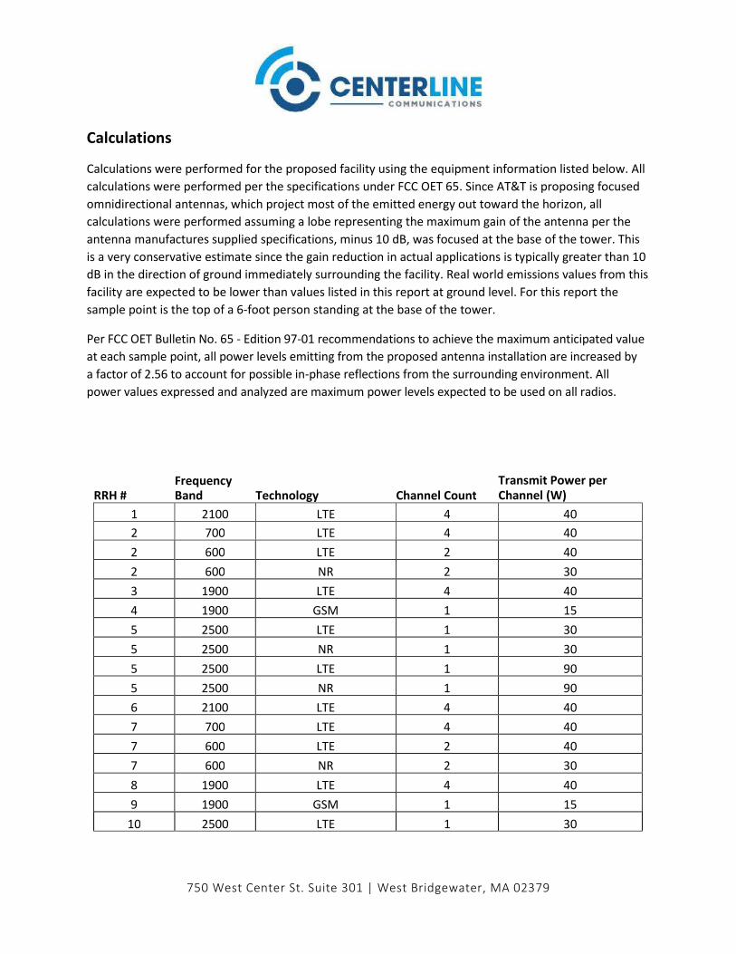
750 West Center St. Suite 301 | West Bridgewater, MA 02379
Calculations
Calculations were performed for the proposed facility using the equipment information listed below. All
calculations were performed per the specifications under FCC OET 65. Since AT&T is proposing focused
omnidirectional antennas, which project most of the emitted energy out toward the horizon, all
calculations were performed assuming a lobe representing the maximum gain of the antenna per the
antenna manufactures supplied specifications, minus 10 dB, was focused at the base of the tower. This
is a very conservative estimate since the gain reduction in actual applications is typically greater than 10
dB in the direction of ground immediately surrounding the facility. Real world emissions values from this
facility are expected to be lower than values listed in this report at ground level. For this report the
sample point is the top of a 6-foot person standing at the base of the tower.
Per FCC OET Bulletin No. 65 - Edition 97-01 recommendations to achieve the maximum anticipated value
at each sample point, all power levels emitting from the proposed antenna installation are increased by
a factor of 2.56 to account for possible in-phase reflections from the surrounding environment. All
power values expressed and analyzed are maximum power levels expected to be used on all radios.
RRH # Frequency Band Technology Channel Count
Transmit Power per
Channel (W)
1 2100 LTE 4 40
2 700 LTE 4 40
2 600 LTE 2 40
2 600 NR 2 30
3 1900 LTE 4 40
4 1900 GSM 1 15
5 2500 LTE 1 30
5 2500 NR 1 30
5 2500 LTE 1 90
5 2500 NR 1 90
6 2100 LTE 4 40
7 700 LTE 4 40
7 600 LTE 2 40
7 600 NR 2 30
8 1900 LTE 4 40
9 1900 GSM 1 15
10 2500 LTE 1 30

750 West Center St. Suite 301 | West Bridgewater, MA 02379
For each sector the following channel counts, frequency bands and power levels were utilized as shown
in Table 1:
Table 1: Channel Data Table
RRH #
Frequency
Band Technology Channel Count
Transmit Power per
Channel (W)
10 2500 NR 1 30
10 2500 LTE 1 90
10 2500 NR 1 90
11 2100 LTE 4 40
12 700 LTE 4 40
12 600 LTE 2 40
12 600 NR 2 30
13 1900 LTE 4 40
14 1900 GSM 1 15
15 2500 LTE 1 30
15 2500 NR 1 30
15 2500 LTE 1 90
15 2500 NR 1 90

750 West Center St. Suite 301 | West Bridgewater, MA 02379
The following antennas listed in Table 2 were used in the modeling for transmission in the 600 MHz (LTE
and NR), 700 MHz (LTE), 1900 (LTE and GSM), 2100 (LTE), and 2500 (LTE AND NR) frequency bands. This
is based on information from the carrier with regard to anticipated antenna selection.
Sector Antenna Number Make / Model Centerline (ft)
A 1 RFS APX16DWV-16DWVS-E-A20 155
A 2 RFS APXVAALL24 43-U-NA20 155
A 2 RFS APXVAALL24 43-U-NA20 155
A 2 RFS APXVAALL24 43-U-NA20 155
A 2 RFS APXVAALL24 43-U-NA20 155
A 2 RFS APXVAALL24 43-U-NA20 155
A 3 ERICSSON AIR6449 LTE BrM 155
A 3 ERICSSON AIR6449 NR BrM 155
A 3 ERICSSON SON_AIR6449 LTE TB 155
A 3 ERICSSON SON_AIR6449 NR TB 155
B 4 RFS APX16DWV-16DWVS-E-A20 155
B 5 RFS APXVAALL24 43-U-NA20 155
B 5 RFS APXVAALL24 43-U-NA20 155
B 5 RFS APXVAALL24 43-U-NA20 155
B 5 RFS APXVAALL24 43-U-NA20 155
B 5 RFS APXVAALL24 43-U-NA20 155
B 6 ERICSSON AIR6449 LTE BrM 155
B 6 ERICSSON AIR6449 NR BrM 155
B 6 ERICSSON SON_AIR6449 LTE TB 155
B 6 ERICSSON SON_AIR6449 NR TB 155
C 7 RFS APX16DWV-16DWVS-E-A20 155
C 8 RFS APXVAALL24 43-U-NA20 155
C 8 RFS APXVAALL24 43-U-NA20 155
C 8 RFS APXVAALL24 43-U-NA20 155
C 8 RFS APXVAALL24 43-U-NA20 155
C 8 RFS APXVAALL24 43-U-NA20 155
C 9 ERICSSON AIR6449 LTE BrM 155
C 9 ERICSSON AIR6449 NR BrM 155
C 9 ERICSSON SON_AIR6449 LTE TB 155
C 9 ERICSSON SON_AIR6449 NR TB 155 Table 2: Antenna Data
All calculations were done with respect to uncontrolled / general population threshold limits.
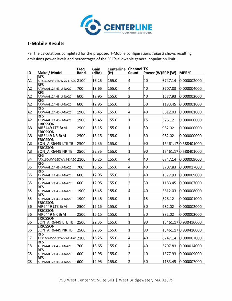
750 West Center St. Suite 301 | West Bridgewater, MA 02379
T-Mobile Results
Per the calculations completed for the proposed T-Mobile configurations Table 3 shows resulting
emissions power levels and percentages of the FCC’s allowable general population limit.
ID Make / Model Freq. Band
Gain (dBd)
Centerline (ft)
Channel Count
TX Power (W) ERP (W) MPE %
A1 RFS
APX16DWV-16DWVS-E-A20 2100 16.25 155.0 4 40 6747.14 0.000002000
A2 RFS APXVAALL24 43-U-NA20 700 13.65 155.0 4 40 3707.83 0.000004000
A2 RFS APXVAALL24 43-U-NA20 600 12.95 155.0 2 40 1577.93 0.000002000
A2 RFS APXVAALL24 43-U-NA20 600 12.95 155.0 2 30 1183.45 0.000001000
A2 RFS APXVAALL24 43-U-NA20 1900 15.45 155.0 4 40 5612.03 0.000001000
A2 RFS APXVAALL24 43-U-NA20 1900 15.45 155.0 1 15 526.12 0.000000000
A3 ERICSSON AIR6449 LTE BrM 2500 15.15 155.0 1 30 982.02 0.000000000
A3 ERICSSON AIR6449 NR BrM 2500 15.15 155.0 1 30 982.02 0.000000000
A3 ERICSSON SON_AIR6449 LTE TB 2500 22.35 155.0 1 90 15461.17 0.588401000
A3 ERICSSON SON_AIR6449 NR TB 2500 22.35 155.0 1 90 15461.17 0.588401000
B4 RFS
APX16DWV-16DWVS-E-A20 2100 16.25 155.0 4 40 6747.14 0.000009000
B5 RFS APXVAALL24 43-U-NA20 700 13.65 155.0 4 40 3707.83 0.000017000
B5 RFS APXVAALL24 43-U-NA20 600 12.95 155.0 2 40 1577.93 0.000009000
B5 RFS APXVAALL24 43-U-NA20 600 12.95 155.0 2 30 1183.45 0.000007000
B5 RFS APXVAALL24 43-U-NA20 1900 15.45 155.0 4 40 5612.03 0.000008000
B5 RFS APXVAALL24 43-U-NA20 1900 15.45 155.0 1 15 526.12 0.000001000
B6 ERICSSON AIR6449 LTE BrM 2500 15.15 155.0 1 30 982.02 0.000002000
B6 ERICSSON AIR6449 NR BrM 2500 15.15 155.0 1 30 982.02 0.000002000
B6 ERICSSON SON_AIR6449 LTE TB 2500 22.35 155.0 1 90 15461.17 0.930416000
B6 ERICSSON SON_AIR6449 NR TB 2500 22.35 155.0 1 90 15461.17 0.930416000
C7 RFS
APX16DWV-16DWVS-E-A20 2100 16.25 155.0 4 40 6747.14 0.000007000
C8 RFS APXVAALL24 43-U-NA20 700 13.65 155.0 4 40 3707.83 0.000014000
C8 RFS APXVAALL24 43-U-NA20 600 12.95 155.0 2 40 1577.93 0.000009000
C8 RFS APXVAALL24 43-U-NA20 600 12.95 155.0 2 30 1183.45 0.000007000
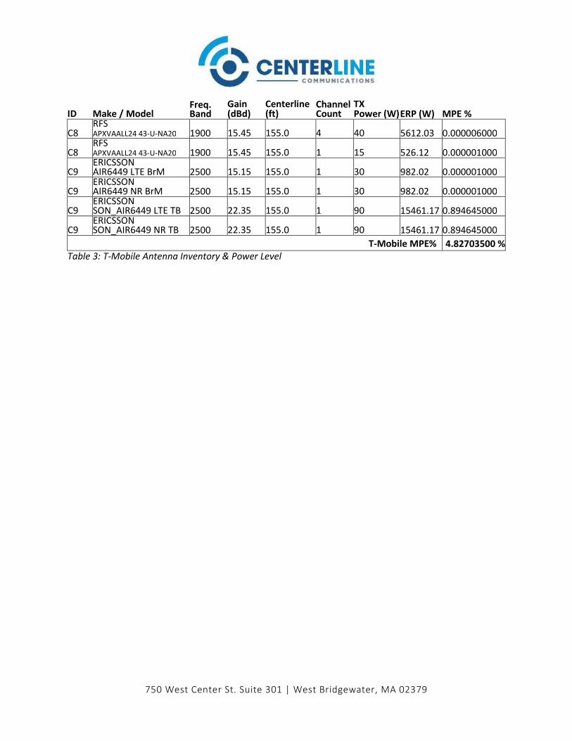
750 West Center St. Suite 301 | West Bridgewater, MA 02379
ID Make / Model Freq. Band
Gain (dBd)
Centerline (ft)
Channel Count
TX Power (W) ERP (W) MPE %
C8 RFS APXVAALL24 43-U-NA20 1900 15.45 155.0 4 40 5612.03 0.000006000
C8 RFS APXVAALL24 43-U-NA20 1900 15.45 155.0 1 15 526.12 0.000001000
C9 ERICSSON AIR6449 LTE BrM 2500 15.15 155.0 1 30 982.02 0.000001000
C9 ERICSSON AIR6449 NR BrM 2500 15.15 155.0 1 30 982.02 0.000001000
C9 ERICSSON SON_AIR6449 LTE TB 2500 22.35 155.0 1 90 15461.17 0.894645000
C9 ERICSSON SON_AIR6449 NR TB 2500 22.35 155.0 1 90 15461.17 0.894645000
T-Mobile MPE% 4.82703500 %
Table 3: T-Mobile Antenna Inventory & Power Level
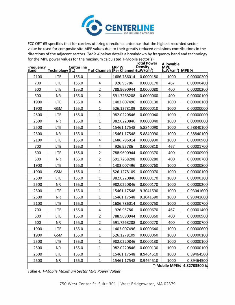
750 West Center St. Suite 301 | West Bridgewater, MA 02379
FCC OET 65 specifies that for carriers utilizing directional antennas that the highest recorded sector
value be used for composite site MPE values due to their greatly reduced emissions contributions in the
directions of the adjacent sectors. Table 4 below details a breakdown by frequency band and technology
for the MPE power values for the maximum calculated T-Mobile sector(s).
Frequency Band Technology
Centerline (ft.) # of Channels
ERP W (Per Channel)
Total Power Density (µW/cm2)
Allowable MPE (µW/cm2) MPE %
2100 LTE 155.0 4 1686.786014 0.0000180 1000 0.00000200
700 LTE 155.0 4 926.95786 0.0000170 467 0.00000400
600 LTE 155.0 2 788.9690944 0.0000080 400 0.00000200
600 NR 155.0 2 591.7268208 0.0000060 400 0.00000100
1900 LTE 155.0 4 1403.007496 0.0000130 1000 0.00000100
1900 GSM 155.0 1 526.1278109 0.0000010 1000 0.00000000
2500 LTE 155.0 1 982.0220846 0.0000040 1000 0.00000000
2500 NR 155.0 1 982.0220846 0.0000040 1000 0.00000000
2500 LTE 155.0 1 15461.17548 5.8840090 1000 0.58840100
2500 NR 155.0 1 15461.17548 5.8840090 1000 0.58840100
2100 LTE 155.0 4 1686.786014 0.0000930 1000 0.00000900
700 LTE 155.0 4 926.95786 0.0000810 467 0.00001700
600 LTE 155.0 2 788.9690944 0.0000370 400 0.00000900
600 NR 155.0 2 591.7268208 0.0000280 400 0.00000700
1900 LTE 155.0 4 1403.007496 0.0000760 1000 0.00000800
1900 GSM 155.0 1 526.1278109 0.0000070 1000 0.00000100
2500 LTE 155.0 1 982.0220846 0.0000170 1000 0.00000200
2500 NR 155.0 1 982.0220846 0.0000170 1000 0.00000200
2500 LTE 155.0 1 15461.17548 9.3041590 1000 0.93041600
2500 NR 155.0 1 15461.17548 9.3041590 1000 0.93041600
2100 LTE 155.0 4 1686.786014 0.0000750 1000 0.00000700
700 LTE 155.0 4 926.95786 0.0000670 467 0.00001400
600 LTE 155.0 2 788.9690944 0.0000360 400 0.00000900
600 NR 155.0 2 591.7268208 0.0000270 400 0.00000700
1900 LTE 155.0 4 1403.007496 0.0000640 1000 0.00000600
1900 GSM 155.0 1 526.1278109 0.0000060 1000 0.00000100
2500 LTE 155.0 1 982.0220846 0.0000130 1000 0.00000100
2500 NR 155.0 1 982.0220846 0.0000130 1000 0.00000100
2500 LTE 155.0 1 15461.17548 8.9464510 1000 0.89464500
2500 NR 155.0 1 15461.17548 8.9464510 1000 0.89464500
T-Mobile MPE% 4.82703500 %
Table 4: T-Mobile Maximum Sector MPE Power Values

750 West Center St. Suite 301 | West Bridgewater, MA 02379
AT&T Results FCC OET 65 specifies that for carriers utilizing directional antennas that the highest recorded sector
value be used for composite site MPE values due to their greatly reduced emissions contributions in the
directions of the adjacent sectors. Table 4 below details a breakdown by frequency band and technology
for the MPE power values for the maximum calculated AT&T sector(s).
Frequency Band Technology
Centerline (ft.)
# of Channels
ERP W (Per Channel)
Total Power Density (µW/cm2)
Allowable MPE (µW/cm2) MPE %
850 - 180.0 1 568.8529308 0.0000070 567 0.00000100
850 -
173.0 1 545.8332546 0.0000040 567 0.00000100
1900 -
173.0 4 970.644038 0.0000110 1000 0.00000100
700 -
173.0 4 1180.483691 0.0000160 467 0.00000300
850 -
173.0 1 545.8332546 0.0000120 567 0.00000200
1900 -
173.0 4 970.644038 0.0000570 1000 0.00000600
700 -
173.0 4 926.95786 0.0000560 467 0.00001200
850 -
173.0 1 545.8332546 0.0000110 567 0.00000200
1900 -
173.0 4 970.644038 0.0000620 1000 0.00000600
AT&T MPE% 0.000044000%
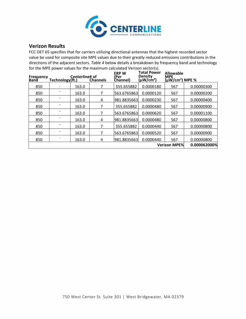
750 West Center St. Suite 301 | West Bridgewater, MA 02379
Verizon Results FCC OET 65 specifies that for carriers utilizing directional antennas that the highest recorded sector
value be used for composite site MPE values due to their greatly reduced emissions contributions in the
directions of the adjacent sectors. Table 4 below details a breakdown by frequency band and technology
for the MPE power values for the maximum calculated Verizon sector(s).
Frequency Band Technology
Centerline (ft.)
# of Channels
ERP W (Per Channel)
Total Power Density (µW/cm2)
Allowable MPE (µW/cm2) MPE %
850 - 163.0 7 355.655882 0.0000180 567 0.00000300
850 -
163.0 7 563.6765863 0.0000120 567 0.00000200
850 -
163.0 4 981.8835663 0.0000230 567 0.00000400
850 -
163.0 7 355.655882 0.0000480 567 0.00000900
850 -
163.0 7 563.6765863 0.0000620 567 0.00001100
850 -
163.0 4 981.8835663 0.0000480 567 0.00000800
850 -
163.0 7 355.655882 0.0000440 567 0.00000800
850 -
163.0 7 563.6765863 0.0000520 567 0.00000900
850 -
163.0 4 981.8835663 0.0000440 567 0.00000800
Verizon MPE% 0.000062000%

750 West Center St. Suite 301 | West Bridgewater, MA 02379
Unknown Carrier Results FCC OET 65 specifies that for carriers utilizing directional antennas that the highest recorded sector
value be used for composite site MPE values due to their greatly reduced emissions contributions in the
directions of the adjacent sectors. Table 4 below details a breakdown by frequency band and technology
for the MPE power values for the maximum calculated Unknown Carrier sector(s).
Frequency Band Technology
Centerline (ft.) # of Channels
ERP W (Per Channel)
Total Power Density (µW/cm2)
Allowable MPE (µW/cm2) MPE %
850 - 180.0 1 568.8529308 0.0000070 567 0.00000100
Unknown Carrier MPE% 0.00000100%

750 West Center St. Suite 301 | West Bridgewater, MA 02379
Summary
All calculations performed for this analysis yielded results that were within the allowable limits
for general population exposure to RF Emissions.
The anticipated maximum composite contributions from the T-Mobile facility as well as the site
composite emissions value with regards to compliance with FCC’s allowable limits for general
population exposure to RF Emissions are shown here:
Carrier Predicted MPE %
T-Mobile 4.82703500%
AT&T 0.00004400%
Verizon 0.00006200%
Unknown 0.00000100%
Composite 4.82714200%
Table 5: Total Predicted MPE(%) by Carrier
Compliance Status:
The anticipated composite MPE value for this site assuming all carriers present is 4.82714200%
of the allowable FCC established general population limit sampled at the ground level.
FCC guidelines state that if a site is found to be out of compliance (over allowable thresholds),
that carriers over a 5% contribution to the composite value will require measures to bring the site
into compliance. For this facility, the composite values calculated were well within the allowable
100% threshold standard per the federal government.
Erin Kavanaugh RF Compliance Consultant
Centerline Communications, LLC
750 West Center St. Suite 301
West Bridgewater, MA 02379

Exhibit H
Mailing Receipts/Proof of Notice

8/23/2021 UPS CampusShip | UPS - United States
https://www.campusship.ups.com/cship/create?ActionOriginPair=default___PrintWindowPage&key=labelWindow&type=html&loc=en_US&instr=A&do… 1/1
UPS CampusShip: View/Print Label
1. Ensure there are no other shipping or tracking labels attached to your package. Select the Print button on theprint dialog box that appears. Note: If your browser does not support this function select Print from the File menu toprint the label.
2. Fold the printed label at the solid line below. Place the label in a UPS Shipping Pouch. If you do not have a pouch,affix the folded label using clear plastic shipping tape over the entire label.
3. GETTING YOUR SHIPMENT TO UPS Customers with a Daily PickupYour driver will pickup your shipment(s) as usual. Customers without a Daily PickupTake your package to any location of The UPS Store®, UPS Access Point(TM) location, UPS Drop Box, UPSCustomer Center, Staples® or Authorized Shipping Outlet near you. Items sent via UPS Return Services(SM)(including via Ground) are also accepted at Drop Boxes. To find the location nearest you, please visit the Resourcesarea of CampusShip and select UPS Locations.Schedule a same day or future day Pickup to have a UPS driver pickup all your CampusShip packages.Hand the package to any UPS driver in your area.
UPS Access Point UPS Access Point UPS Access PointCVS STORE # 972 CVS STORE # 7232 TOWN LINE GENERAL STORE555 WASHINGTON ST 689 DEPOT ST 450 E CENTER STSOUTH EASTON ,MA 02375 NORTH EASTON ,MA 02356 WEST BRIDGEWATER ,MA 02379
FOLD HERE
TM TM TM