Embed Size (px)
Citation preview

TMO Progress Report 42-135 November 15, 1998
T-PPM: A Novel Modulation Scheme for OpticalCommunication Systems Impaired by
Pulse-Width InaccuraciesK. Kiasaleh1 and T.-Y. Yan2
M-ary pulse-position modulation (PPM) has received considerable attention fordirect-detection photon communications over unguided channels. The analysis gen-erally assumes that the signaling set is orthogonal. However, the orthogonality ofthe signaling set will be destroyed by the finite area and bandwidth of optical detec-tors, resulting in severe intersymbol interference. This article presents the analysisof a trellis-based pulse-position modulation (T-PPM) scheme for photon commu-nications with non-rectangular pulses. The novelty of the scheme includes the useof a set-partitioning methodology to increase the minimum distance using a simpleconvolutional encoder. The Viterbi algorithm is used at the receiver to separate thesignaling set as part of the demodulation process. It has been shown that T-PPMwill restore performance losses due to reduced peak intensity during the detectionprocess. Furthermore, for a large range of background radiation levels, the averagenumber of photons per information bit for T-PPM is smaller than that of the regu-lar PPM. Numerical examples show that for a symbol-error rate of 10−3 when thereceived pulses extend over 4 PPM slots, the average laser energy per symbol for256-ary T-PPM could be reduced by as much as 2 dB.
I. Introduction
Pulse-position modulation (PPM) has received considerable attention as the modulation of choice fordirect-detection optical communications over unguided optical channels. There are several key aspects ofthis modulation that are critical to the deployment of this modulation scheme for deep-space communica-tions. First, the presence of a pulse in the symbol frame regardless of the transmitted symbol benefits theclock recovery subsystem, whereas an on–off-keying (OOK) system may suffer a synchronization loss if asequence of 0’s is encountered. Also, if nonreturn-to-zero (NRZ) pulses are used, a sequence of 1’s alsocan disrupt the synchronization subsystem of an OOK system. Unlike the OOK scenario, one does notrequire a priori knowledge of the signal or background noise radiation levels to implement an optimumPPM receiver. The other key requirement of systems considered for space applications is the peak laserpower level that must be large enough to survive huge deep-space losses. For this reason, Q-switchedlasers typically are employed for such applications. The current technology, however, does not supporta scenario where a Q-switched laser can be toggled between the “on” and “off” states at a high rate,
1 Erik Jonsson School of Engineering and Computer Science, The University of Texas at Dallas, Richardson, Texas.
2 Communications Systems and Research Section.
1

limiting severely the data rate that can be supported using an OOK scheme. Hence, an M -ary PPMwith large M is more suitable than its OOK counterpart for deep-space applications.3 Finally, it canbe shown that M -ary PPM for large M is more energy efficient than its OOK counterpart, which is ofcritical importance in a deep-space optical communication environment where energy consumption is akey constraint of the channel.
For many deep-space applications, due to large distances and pointing inaccuracies, the signal levelreceived at the detector is significantly attenuated so that only a small number of photons per PPM slotinterval are typically observed. Since thermal noise is present at the receiver, the detection of signal pulsesin the above condition is significantly hampered. For this reason, avalanche photodetectors (APDs) areutilized to boost the signal level over the additive noise level present at the receiver. An APD, in principle,magnifies each incident photon to a large number of post-detection electrons. One major problem withtoday’s APDs is the excess noise factor of the APD, which manifests itself as a random gain effect. Thatis, the ratio of the number of emitted electrons in response to an incident photon is a random variablewith known statistics. Unfortunately, the complicated statistics of the APD response to incident photonsdo not lead to a closed-form solution for the error rate of optical PPM communication systems.
One key approximation for the statistics of the number of emitted electrons when the received numberof photons obeys the Poisson statistics is due to Webb [1]. This approximation is shown to be fairly accu-rate over a wide range of conditions, and for this reason, this approximation is widely used to assess theerror rates of various optical communication systems with APDs. When the number of incident photonsin a slot interval is fairly large (as compared with the APD noise figure) and the APD possesses a largeaverage gain, it has been shown that the APD’s statistic could be approximated by a Gaussian proba-bility density function (pdf) [2,3]. This approximation leads to a closed-form bit-error-rate expressionfor the PPM channels and usually is valid when large background radiation levels are present (daytimeoperation). However, for a large number of cases when the background radiation level is small, the Gaus-sian approximation fails to accurately predict the statistics of an APD detector. In fact, for a smallnumber of incident photons, the probability mass function (PMF) of the number of released electronssignificantly departs from a Gaussian form [2,3]. In that case, one has to resort to the Webb–McIntyre–Conradi (WMC) pdf, which does not lead to a closed-form expression for the probability of error [1].More significantly, the resulting expression requires a prohibitively large computing time.
In some recent studies, via extensive simulation, it has been demonstrated that when the thermalnoise level is non-negligible, the number of signal photons required to achieve a symbol-error rate in arange of 10−2 to 10−3 using the Gaussian-approximated model and that predicted by the WMC modelare somewhat similar for background noise levels in excess of 1 photon per PPM slot. Since, for mostapplications of interest, one observes in excess of 1 background photon per PPM slot, the Gaussianmodel seems to be a reasonable model to exploit for the above scenario. This by no means implies thatthe Gaussian assumption is a valid approximation for all symbol-error-rate levels. It only underscoresthe negligible loss/gain in the signal photon count associated with the Gaussian assumption for symbol-error rates in the range of 10−2 to 10−3. It also is imperative to note that, for most applications, anuncoded symbol-error rate of 10−2 to 10−3 is of interest. Obviously, with the inclusion of a forward error-correcting code (FEC), a symbol-error rate of 10−6, which is required to support data communication,can be achieved.
Another generic property of optical sensors for detecting narrow laser pulses is the requirement ofhigh-speed electronics to convert optical signals to electrical currents. In general, for deep-space direct-detection applications, larger detector areas potentially could collect more photons, thus increasing the
3 In an M -ary PPM scenario with large M , the laser remains in an “on” state for 1/Mth of the symbol duration, allowingfor log2 M bits to be transmitted in a symbol interval. In an OOK scheme, given the same symbol duration (note thatthere exists an upper limit on how fast the laser can be toggled between the two states), only 1 bit can be transmittedover the same symbol interval.
2

number of photons per information bit. Unfortunately, larger detector sizes imply a lower bandwidth ofthe detector, which tends to smear the observed narrow pulses over several PPM slots. The proposedT-PPM excels in this area by allowing overlapping of the PPM signaling set. That is, as will be demon-strated in this article, the proposed T-PPM could circumvent this effect without degrading the systemend-to-end performance. Furthermore, it will be shown in the ensuing sections that T-PPM can achieve aperformance similar to that of its PPM counterpart at a reduced number of photons per information bit.In addition, T-PPM can accommodate lower peak laser power during slot detection by integrating ener-gies over several slots. The lower peak power is of critical importance in energy-constrained, deep-spacecommunication systems.4
In this article, we are interested in assessing the impact of T-PPM on enhancing the end-to-endperformance of optical communication systems with pulse-width inaccuracies, which often are presentwhen high-power Q-switched lasers are employed. The presence of such inaccuracies results in a significantdegradation in the overall performance of conventional PPM systems.
II. System Model
For an M -ary PPM system, the transmitted laser power, P (t), may be described as
P (t) = Ps
∞∑q=−∞
h (t− CqTslot −NqTs) (1)
where Ps is the peak laser power in watts; h (t) is the pulse shape, which is confined to a PPM symbolduration Ts s; Tslot is the PPM slot duration in seconds; Cq is the PPM symbol taking on the set0, 1, · · · ,M − 1 with equal probability, with M denoting the PPM alphabet size; and N ≥ 1 is aparameter that will be defined shortly. Note that Tslot = Ts/M s. Ideally, the pulse shape h (t) is confinedto a PPM slot duration. In that case, one obtains an ideal PPM signaling scheme. In the scenarioconsidered here, however, it is assumed that h (t) extends beyond a slot interval, causing significantdegradation in performance. Also, note that, in the formulation shown above, N is introduced to allowfor one to generate a “silent” period in between symbol durations in which a PPM pulse is transmitted.This typically is a requirement for operating a high-power laser when the transmission of a symbol isinterrupted by silent periods of several-symbol duration to allow for the recharging of the laser.
Given an unguided optical channel, one can describe the intensity of the received optical signal, λr (t),as
λr (t) = λb + λs
∞∑q=−∞
h (t− CqTslot −NqTs + εqTslot) (2)
where λs = Prη/hν denotes the peak intensity of the received optical signal in photons/s with η, Pr,h, and ν denoting the quantum efficiency of the detector, the received power collected by the opticalassembly, Planck’s constant, and the operating frequency of the laser in hertz, respectively. Moreover,λb in Eq. (2) denotes the intensity of the background noise in photons/s, and εq denotes the timinginaccuracy present due to imperfect time tracking at the receiver, which is assumed to be confined to[−1/2, 1/2].
4 For energy efficiency, one must resort to a large alphabet size PPM scenario. In that event, and for a relatively high datarate, one must employ fairly short laser pulses. Given the fixed required energy, this implies that the laser must generatea large peak power. The large peak power then becomes a major constraint of the system.
3

Since an APD is employed at the receiver, the collected primary electrons cause the generation ofa large number of secondary electrons. In general, one can assume that for the mth detected primaryelectrons, the APD generates Gm secondary electrons. The cumulative generating function (CGF) of Gmis implicitly given by [4]
s = µGm (s)− b ln[a+ (1− a) eµGm (s)
](3)
where µGm (s) denotes the CGF, a = [1+κ (g − 1)]/g, and b = 1/(1−κ), with g and κ denoting the averagegain and the ionization factor of the APD, respectively. Let F = [E
(G2m
)]/g2 = κg + (2− [1/g]) (1− κ)
denote the APD noise figure. Then, it can be shown that the moment-generating function of Gm may beexpressed explicitly as [5]
MGm (s) =F
(F − 1)2
[1−
√1− 2 (F − 1) gs
]− g
F − 1s+ 1 (4)
Note that, by definition, MGm (s) = eµGm (s).
The response of the APD, in terms of the current in the load resistor of the APD, may be modeled asfollows:
x (t) =∞∑
j=−∞GjR (t− tj) + n (t) (5)
where tj denotes the occurrence time of the jth primary electron, governed by a Poisson point process;R (t) is the current response of the APD; and n (t) is the thermal noise present at the receiver. The n (t)commonly is modeled as a zero-mean, additive white Gaussian noise (AWGN) with a two-sided powerspectrum density (PSD) level of N0/2 = (2kT0)/RL A2/Hz with k, T0, and RL denoting Boltzmann’sconstant, the effective temperature of the receiver in kelvins, and the APD load resistance in ohms (Ω).
At the receiver, the PPM detector performs M distinct integrations of the observed current over theM slots of the PPM signal. The symbol associated with the slot with a maximum integrated current isdeclared as the demodulated symbol. This detection strategy is optimum when the integrated currentis governed by Gaussian statistics or when a shot-noise-limited (Poisson-statistics) scenario is considered[2]. It also has been demonstrated that when the statistics of the APD are approximated by WMCdistribution and the observed signal is further corrupted by AWGN, the optimum detection strategyis identical to that used for purely Gaussian or Poisson channels [6]. Therefore, we use the detectionmechanism outlined above to render a decision regarding the transmitted symbol.5
Let us define Xl,n as the outcome of integrating x (t) over the interval Il,n = [lTslot +NnTs, (l + 1)Tslot
+NnTs]. Note that Il,n denotes the lth slot of the nth transmitted symbol.6 We then have
Xl,n =
(l+1)Tslot+NnTs∫lTslot+NnTs
x (τ) dτ ; l = 0, 1, · · · ,M − 1 (6)
5 In the presence of timing error, the above method is no longer optimal. Since in the ensuing analysis we consider negligibletiming error as compared with the pulse-width inaccuracies, we resort to the aforementioned detection mechanism.
6 In the ensuing analysis, and without loss of generality, we consider N = 4 (each transmitted symbol is followed by asilent period of 3Ts s). The selection of N = 4 is dictated by the requirements that currently are imposed on high-powerQ-switched lasers that are being considered for deep-space communication.
4

Given that the APD’s current response is such that it can be approximated with a delta function, wearrive at
Xl,n = eK2 (l, n) + νN (7)
where νN is a zero-mean Gaussian random variable with variance
σ2ν =
2kT0
RLTslot (8)
e is the charge of an electron in C, and K2 (l, n) is the number of secondary electrons observed overIl,n. The PMF of K2 (l, n) in its exact form originally was discovered by McIntyre [7] and was verifiedexperimentally by Conradi [8]. This PMF is given by
Pr K2 (l, n) = k2|K1 (l, n) = k1 =k1Γ
(k2
1−κ + 1)
k2 (k2 − k1)!Γ(κk2
1− κ + 1 + k1
)
×[
1 + κ (g − 1)g
]k1+κk2/(1−κ) [ (1− κ) (g − 1)g
]k2−k1
(9)
where K1 (l, n) is the number of primary electrons observed over the interval Il,n. Given that the primaryelectron statistics obey a Poisson model, Webb has demonstrated that the PMF of the secondary electroncount may be approximated by
PrK2 (l, n) = k2|K1 (l, n) = k1
=
1
(2πC21 )1/2
1
1 +
(k2 − k1g
)C1C2
3/2
exp
−(k2 − k1g
)22C2
1
[1 +
(k2 − k1g
)C1C2
](10)
where K1 (l, n) is the average number of primary electrons observed over Il,n, C21 = g2k1F , and C2
2 =k1F/ (F − 1)2. Given the Poisson statistics, then
K1 (l, n) =
(l+1)Tslot+NnTs∫lTslot+NnTs
λr (τ) dτ = Kb +KsYl,n (11)
where
Yl,n =1
Tslot
(l+1)Tslot+NnTs∫lTslot+NnTs
∞∑q=−∞
h (τ − CqTslot −NqTs + εqTslot) dτ
5

and Kb = λbTslot denotes the average number of primary electrons observed over a PPM slot intervaldue to background noise. Moreover, Ks = λsTslot. Note that the above formulation implies that theaverage number of primary electrons due to signal power observed over the lth slot of the nth symbol,i.e., KsYl,n, decreases as the pulses smear in time, maintaining the average number of primary electronsobserved over a symbol interval (i.e., Ks) constant. That is, we assume that the energy observed over asymbol interval remains constant as pulses spread over the adjacent slots, leading to less observed energyper slot.
In the ensuing analysis, we assume that εq is negligible (since it is a fraction of a slot interval), whereasthe intersymbol interference caused by the shape of the nonideal pulse shape, h (t), is assumed to be quitesignificant. More precisely, we assume that h (t) extends beyond a slot boundary and perhaps extendsover 2 to 4 slot intervals. This causes severe degradation in performance in the absence of a strategyto circumvent intersymbol interference (ISI). In what follows, we assume that the laser pulse obeys aGaussian shape. Namely,
h (t) =Tslot√2πσ2
h
exp
−(t− Tslot
2
)2
2σ2h
(12)
where we have assumed that the laser pulse is centered around the midpoint of the slot interval and thatthe pulse has a standard deviation of σh s. Moreover, note that
∫∞−∞ h (τ) dτ = Tslot. This assumption
is motivated by the fact that if h (t) is replaced with an ideal nonreturn-to-zero (NRZ) pulse of unitamplitude, a similar result will be obtained. This, in turn, implies that regardless of the value of σ2
h, thetotal laser energy over a symbol interval remains constant. That is, as the pulses are smeared in time, thepeak laser power is reduced, maintaining the constant-energy assumption that is critical to space-borneoptical communication systems. Considering that h (t) extends over a few slot intervals and that we havea silent period of 3M slots, and assuming that Cn = j, we have
Zl,j = Yl,n |Cn=j =1
σh√
2π
(l+1)Tslot∫lTslot
exp
−(τ − (2j + 1)Tslot
2
)2
2σ2h
dτ (13)
Note that the integral on the right-hand side of the above equation is a function of l and j only.
III. Performance Analysis—PPM With Imperfect Pulse Shape
Given the above model, one can obtain the performance of a PPM system with imperfect pulses. Akey obstacle, however, is the absence of a tractable model for the statistics of the APD signal whencorrupted by an AWGN. In a recent simulation study, it was demonstrated that the Ks required foran APD-detected 256-ary PPM signal to achieve an error rate in the range of 10−2 to 10−3 and thatpredicted using a Gaussian model differ only slightly over a wide range for Kb (1 ≤ Kb ≤ 1000), allowingone to benefit from the Gaussian approximation for the above range of symbol-error rates. Furthermore,we benefit from a union bound to establish an upper bound on the error rate of the uncoded PPM systemwith imperfect pulse shapes. To that end,
P(u)PPM ≤
1M
M−1∑j=0
M−1∑l=0;j 6=l
Pr (El,j) (14)
6
where we have assumed equally likely PPM symbols. In the above equation, Pr (El,j) is the pair-wise errorprobability of making a decision in favor of the lth symbol when the jth symbol actually is transmittedand P
(u)PPM is the symbol-error rate of the uncoded PPM system. This error event is possible only when
the integrated current of the lth slot exceeds that of the jth slot. As noted earlier, we resort to Gaussianapproximation for the range of error rates stated previously. If one allows for such an approximation,then Xl,n is a Gaussian random variable when conditioned on Cq (assume εq = 0). Hence, the mean andvariance of this random variable will be of interest to establish performance. To that end,
ml,j = E Xl,n|Cn = j = eg (Kb +KsZl,j) + IdcTslot (15)
and
σ2l,j = V ar Xl,n|Cn = j = (eg)2
F (Kb +KsZl,j) + σ2ν + eIdcTslot (16)
where E .|Cn = j and V ar .|Cn = j are the expected value and the variance of the random variableXl,n conditioned on Cn = j and Idc denotes the surface dark current of the APD in amperes, which isassumed to be non-negligible here. In that event, and considering that an erroneous decision in favor ofthe lth symbol is rendered if the integrated APD current over the lth slot exceeds that of the jth slot(note that this is a comparison between Xl,n and Xj,n, which are a pair of conditionally [when conditionedon Cn = j] independent Gaussian random variables), we have
Pr (El,j) =12
erfc
mj,j −ml,j√2(σ2l,j + σ2
j,j
) ; l 6= j (17)
where erfc (x) is the complementary error function. Given that the pulse shape follows a Gaussian pattern,Zl,j and Zj,j may be obtained in terms of erfc (.) or erfc (.). However, we note that
mj,j −ml,j = egKs (Zj,j − Zl,j) (18)
and
σ2l,j + σ2
j,j = (eg)2F [2Kb +Ks (Zl,j + Zj,j)] + 2
(σ2ν + eIdcTslot
)(19)
are functions of Zj,j −Zl,j and Zj,j +Zl,j only. Therefore, Zj,j −Zl,j and Zj,j +Zl,j are only of interest.With some effort, it may be shown that
Zj,j − Zl,j = 1− erfc(
Tslot
2√
2σh
)− 1
2erfc
−Tslot
(l − j +
12
)√
2σh
+12
erfc
−Tslot
(l − j − 1
2
)√
2σh
(20)
and
7

Zj,j + Zl,j = 1− erfc(
Tslot
2√
2σh
)+
12
erfc
−Tslot
(l − j +
12
)√
2σh
− 12
erfc
−Tslot
(l − j − 1
2
)√
2σh
(21)
Now, substituting Eqs. (20) and (21) in Eqs. (18) and (19), respectively, and then substituting theresulting expressions in Eq. (17), we arrive at a closed-form expression for the pair-wise error rate of aPPM system with pulse-width inaccuracies. The remaining task is to compute the upper bound usingEq. (14). We postpone a discussion on the performance of the system using Eq. (14) to Section VI of thisarticle. Instead, we proceed to describe the proposed T-PPM system in the next section.
IV. T-PPM
It is important to note that the use of trellis-coded modulation (TCM) and overlapping PPM (OPPM)to enhance the capacity of PPM channels was originally discussed in [9]. There are several aspects of thepresent analysis that set it apart from its predecessor. First, the analysis in [9] assumes square shapepulses, whereas we will concern ourselves with Gaussian-type pulse shapes in this analysis. Second, theanalysis in [9] assumes either quantum-limited or shot-noise-limited scenarios, whereas a more realisticsituation (as is assumed in what follows) calls for the inclusion of additive Gaussian noise and APD excessnoise factors.
In the previous section, we described the performance of a PPM system impaired by imperfect pulseshapes. Needless to say, the impact of an imperfect pulse shape on the performance of a PPM systemmay be quite severe for pulse shapes extending over several slot intervals. Hence, the introduction ofTCM is necessary to overcome the impact of severe ISI caused by imperfect pulse shapes. Due to theregular shape of the pulse, and from Eq. (17), it can readily be seen that Pr (El,j) is a decreasing functionof |j − l|. That is, the pair-wise error rate is a decreasing function of the “distance” between symbolsj and l, where distance is defined in terms of the number of PPM slots that exit between the positions(in time) of the jth and lth symbols.7 In view of this observation, one can proceed with a set-partitionstrategy for the generation of T-PPM signals that is aimed at increasing the minimum distance of thePPM constellation.
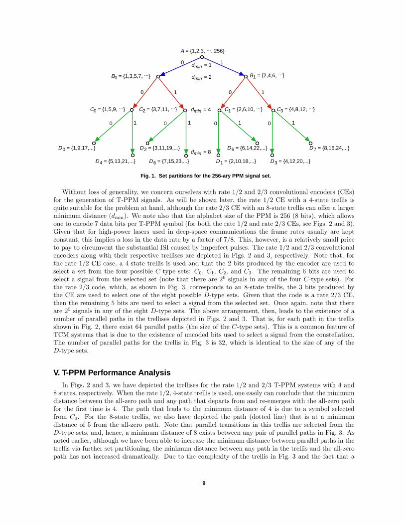
We begin by introducing A = 1, 2, 3, · · · ,M as a set containing the uncoded PPM symbols. Notethat the distance between a pair of symbols j and l selected from A is simply |j − l|. This set is furtherdivided into sets B0 = 1, 3, 5, 7, · · · and B1 = 2, 4, 6, · · ·. Note that a pair of symbols selectedfrom either one of these sets is at a minimum distance of 2, whereas the symbols selected from A are at aminimum distance of 1. Next, we proceed to subdivide set B0 to generate sets C0 = 1, 5, 9, · · · and C2 =3, 7, 11, · · ·. Set B1 also can be subdivided to form C1 = 2, 6, 10, · · · and C3 = 4, 8, 12, · · ·. Finally,we perform one last partitioning of the previous sets to form D0 = 1, 9, 17, · · ·, D4 = 5, 13, 21, · · ·,D2 = 3, 11, 19, · · ·, D6 = 7, 15, 23, · · ·, D1 = 2, 10, 18, · · ·, D5 = 6, 14, 22, · · ·, D3 = 4, 12, 20, · · ·,and D7 = 8, 16, 24. The entire process is depicted in Fig. 1 for M = 256. Note that symbols selectedfrom Dj for any j are at a minimum distance of 8. Furthermore, symbols selected from Dj and Di are ata minimum distance of |i− j| from each other. Although it appears that one can continue this processin hope of increasing the minimum distance beyond 8, the minimum distance between a pair of pathsthrough the trellis (which ultimately dictates the overall performance) cannot be increased indefinitelywith further set partitioning. Also, since we are interested only in eliminating the impact of ISI, aminimum distance of 4 is sufficient to establish orthogonality among the symbols in the set. That is,when the imperfect pulse h (t) stretches over 2 to 4 PPM slots, a minimum distance of 4 slots among thesymbols selected from Cj (for all j) ensures that there exists no overlap among the pulses in the set.
7 Since the jth symbol is represented by a pulse in the jth slot, the distance between the jth and lth symbols is |j − l|.
8
dmin = 4
dmin = 1
A = 1,2,3, ..., 256
0 1
0 101
B0 = 1,3,5,7, ... B1 = 2,4,6, ...
C0 = 1,5,9, ... C2 = 3,7,11, ... C1 = 2,6,10, ... C3 = 4,8,12, ...
dmin = 2
0 1
D 0 = 1,9,17,...
D 4 = 5,13,21,...
D 2 = 3,11,19,...
D 6 = 7,15,23,... D 1 = 2,10,18,...
D 5 = 6,14,22,...
D 3 = 4,12,20,...
D 7 = 8,16,24,...dmin = 8
0 1 0 1 0 1
Fig. 1. Set partitions for the 256-ary PPM signal set.
Without loss of generality, we concern ourselves with rate 1/2 and 2/3 convolutional encoders (CEs)for the generation of T-PPM signals. As will be shown later, the rate 1/2 CE with a 4-state trellis isquite suitable for the problem at hand, although the rate 2/3 CE with an 8-state trellis can offer a largerminimum distance (dmin). We note also that the alphabet size of the PPM is 256 (8 bits), which allowsone to encode 7 data bits per T-PPM symbol (for both the rate 1/2 and rate 2/3 CEs, see Figs. 2 and 3).Given that for high-power lasers used in deep-space communications the frame rates usually are keptconstant, this implies a loss in the data rate by a factor of 7/8. This, however, is a relatively small priceto pay to circumvent the substantial ISI caused by imperfect pulses. The rate 1/2 and 2/3 convolutionalencoders along with their respective trellises are depicted in Figs. 2 and 3, respectively. Note that, forthe rate 1/2 CE case, a 4-state trellis is used and that the 2 bits produced by the encoder are used toselect a set from the four possible C-type sets: C0, C1, C2, and C3. The remaining 6 bits are used toselect a signal from the selected set (note that there are 26 signals in any of the four C-type sets). Forthe rate 2/3 code, which, as shown in Fig. 3, corresponds to an 8-state trellis, the 3 bits produced bythe CE are used to select one of the eight possible D-type sets. Given that the code is a rate 2/3 CE,then the remaining 5 bits are used to select a signal from the selected set. Once again, note that thereare 25 signals in any of the eight D-type sets. The above arrangement, then, leads to the existence of anumber of parallel paths in the trellises depicted in Figs. 2 and 3. That is, for each path in the trellisshown in Fig. 2, there exist 64 parallel paths (the size of the C-type sets). This is a common feature ofTCM systems that is due to the existence of uncoded bits used to select a signal from the constellation.The number of parallel paths for the trellis in Fig. 3 is 32, which is identical to the size of any of theD-type sets.
V. T-PPM Performance Analysis
In Figs. 2 and 3, we have depicted the trellises for the rate 1/2 and 2/3 T-PPM systems with 4 and8 states, respectively. When the rate 1/2, 4-state trellis is used, one easily can conclude that the minimumdistance between the all-zero path and any path that departs from and re-emerges with the all-zero pathfor the first time is 4. The path that leads to the minimum distance of 4 is due to a symbol selectedfrom C0. For the 8-state trellis, we also have depicted the path (dotted line) that is at a minimumdistance of 5 from the all-zero path. Note that parallel transitions in this trellis are selected from theD-type sets, and, hence, a minimum distance of 8 exists between any pair of parallel paths in Fig. 3. Asnoted earlier, although we have been able to increase the minimum distance between parallel paths in thetrellis via further set partitioning, the minimum distance between any path in the trellis and the all-zeropath has not increased dramatically. Due to the complexity of the trellis in Fig. 3 and the fact that a
9

d
C0
C2C2
C0
C1
C3
C3
C1
d = 0
d = 1
(00)
(01)
(10)
(11)C1 C1
C3
C0
C0C2
C2C0
C1C3
C3C1
Fig. 2. The rate 1/2 convolutional encoder along with its 4-state trellis that uses the set partitioning of Fig. 1 for thegeneration of the rate 7/8 T-PPM signals.
D0 D0 D0 D0
D4
D2
D6
D0 D1 D2
dmin = 5
D0 D4 D2 D6
D1 D5 D3 D7
D4 D0 D6 D2
D5 D1 D7 D3
D2 D6 D0 D4
D3 D7 D1 D5
D6 D2 D4 D0
D7 D3 D5 D1
d0d1 = 11
01 10
00d0
d1
Fig. 3. The rate 2/3 convolutional encoder along with its 8-state trellis that uses the set partitioning of Fig. 1 for thegeneration of the rate 7/8 TCM-PPM signals.
10

minimum distance of 4 is sufficient to establish orthogonality among the symbols in the set, in whatfollows, we limit our discussion to the rate 1/2, 4-state trellis depicted in Fig. 2. To that end, let usconsider the parallel paths in the trellis. Given that for any path there exist 63 other parallel paths forM = 256 in Fig. 2 (see Fig. 1), an upper bound on the error rate may be obtained with the aid of a unionbound. This upper bound is given by
P(TCM)PPM ≤ 63 Pr (El,l+4)
where Pr (El,l+4) denotes the pair-wise error rate for a pair of PPM symbols with imperfect pulse shapesthat are separated by 4 time slots. When h (t) extends over 2 to 4 times the duration of a slot, thenPr (El,l+4) is not a function of l.
VI. Numerical Results
To underscore the impact of imperfect pulse shapes, a pair of adjacent Gaussian-type pulses are plottedin Figs. 4 through 6. The laser energy (the area covered by the pulse) within one slot time is computed tobe 98, 78.8, and 59.5 percent, respectively, in Figs. 4 through 6. Note that, for a slot duration of 20 ns, forinstance, the case depicted in Fig. 6 corresponds to an 80-ns pulse scenario. It is immediately obvious thatISI increases in an exponential fashion with σh. Since we are interested in a scenario where h (t) is limitedto 2 to 4 times the duration of a time slot, we limit our analysis to the cases where 0 ≤ σh ≤ 0.6Tslot s.
2.01.8
1.6
1.4
1.2
1.0
0.8
0.6
0.4
0.2
0.0-4 -3 -2 -1 0 1 2 3 4
t /Tslot
GA
US
SIA
N P
ULS
E
Fig. 4. A pair of adjacent Gaussian-typepulses with sh = 0.2Tslot.
1.00.9
0.8
0.7
0.6
0.5
0.4
0.3
0.2
0.1
0.0-4 -3 -2 -1 0 1 2 3 4
t /Tslot
GA
US
SIA
N P
ULS
E
Fig. 5. A pair of adjacent Gaussian-typepulses with sh = 0.4Tslot.
0.7
0.6
0.5
0.4
0.3
0.2
-4 -3 -2 -1 0 1 2 3 4t /Tslot
GA
US
SIA
N P
ULS
E
Fig. 6. A pair of adjacent Gaussian-typepulses with sh = 0.6Tslot.
0.1
0.0
11

We first consider the case where a symbol-error rate of 10−2 is of interest, and subsequently we obtainthe required Ks to achieve the desired error rate for a given Kb. Without loss of generality, we limit ourdiscussion to the following system parameters: M = 256, Tslot = 20 ns, g = 40, κ = 0.007, T0 = 100 K(cooled receiver), RL = 146.65 kΩ, and Idc = 2 nA. In Figs. 7 and 8, the Ks required to achieve asymbol-error rate of 10−2 is plotted versus Kb when the above set of parameters is used. We note thatthe Gaussian assumption considered here does not lead to performance measures that agree with thesimulation results using WMC statistics for the entire range of Kb when an error rate of 10−2 is ofinterest. In particular, when Kb < 50 (Fig. 7), the Gaussian assumption is less reliable than for the caseof Kb > 50 (Fig. 8). Nonetheless, the loss in Ks using the Gaussian approximation is not significant,and hence we proceed with our analysis using the results shown above. Before doing so, however, it isimperative to note that the simulation results for the required Ks using WMC statistics (for the above setof parameters) are shown to be in close agreement with those predicted using the Gaussian assumptionfor a wide range of Kb when a symbol-error rate of 10−3 is considered [10]. Since an error rate of 10−3
is typically of interest, we consider the numerical results shown below for a 10−3 error rate to be a goodapproximation of the results obtained using the more realistic WMC statistics for modeling the APDoutput statistics.
The first observation that can be made from Figs. 7 and 8 is that, when a severe ISI is present (see thecurves associated with 80- and 60-ns pulses), the performance degrades substantially as compared withthe perfect pulse-shape case. The second significant observation is that, in the event of having perfectpulses, the performance improves using T-PPM. This may be attributed to the coding gain. Note that1 of the 7 information bits almost always will be detected correctly, since the major error is due to paralleltransitions in the set.
We also note that the gain in performance as a result of using T-PPM increases almost exponentiallywith an increase in σh. In Figs. 9 and 10, a similar set of results is depicted when an error rate of 10−3
is of interest. We focus on these results, since an error rate of 10−3 typically is needed to ensure a codedperformance8 of 10−6.
140
UP
PE
R B
OU
ND
ON
RE
QU
IRE
D K
s
120
100
80
60
40
20
160
0 5 10 15 20 25 30 35 40 45 50
Kb
Fig. 7. The Ks required to achieve a symbol-error
rate of 10-2 for 256-ary PPM with imperfect pulseswhen Kb is less than 50.
sh = 0sh = 0.2Tslotsh = 0.4Tslotsh = 0.6Tslot
UNCODED PPMT-PPM
sh = 0sh = 0.2Tslotsh = 0.4Tslotsh = 0.6Tslot
UNCODED PPMT-PPM
240
220
200
180
160
140
120
260
50 100 150 200
Kb
Fig. 8. The Ks required to achieve a symbol-error
rate of 10-2 for 256-ary PPM with imperfect pulseswhen Kb is more than 50.
100
80
60
UP
PE
R B
OU
ND
ON
RE
QU
IRE
D K
s
8 It is anticipated that T-PPM will be used in conjunction with other more powerful coding schemes. That is, the informationbits provided to T-PPM may be viewed as coded channel symbols provided by an FEC encoder (such as a Reed–Solomonencoder).
12

200U
PP
ER
BO
UN
D O
N R
EQ
UIR
ED
Ks
180
160
140
120
100
80
220
0 5 10 15 20 25 30 35 40 45 50
Kb
Fig. 9. The Ks required to achieve a symbol-error
rate of 10-3 for 256-ary PPM with imperfect pulseswhen Kb is less than 50.
sh = 0.2Tslotsh = 0.4Tslotsh = 0.6Tslot
UNCODED PPMT-PPM
60
40
sh = 0 sh = 0sh = 0.2Tslotsh = 0.4Tslotsh = 0.6Tslot
300
UP
PE
R B
OU
ND
ON
RE
QU
IRE
D K
s
250
200
150
100
350
50 100 150 200
Kb
Fig. 10. The Ks required to achieve a symbol-error
rate of 10-3 for 256-ary PPM with imperfect pulseswhen Kb is more than 50.
UNCODED PPMT-PPM
50
Before discussing such results, it is imperative to note that the proposed T-PPM system transmits7 information bits, as compared with the 8 bits that are transmitted over each symbol duration for theuncoded system. Hence, it is appropriate to consider the required number of photons per informationbit in comparing the T-PPM scenario with the uncoded PPM case. We then proceed to use the averagenumber of required photons per information bit as a measure of efficiency of the modulation scheme.Hence, in Figs. 11 through 14, we depict the average number of photons per information bit that isrequired to achieve the desired error rate for a wide range of background radiation photon counts. Wenote, however, that the loss of 1 bit in order to achieve the desired performance, given that there exists alimit on laser energy, is a reasonable consideration. Hence, we discuss the performance of T-PPM usingboth the average number of photons as well as the average number of photons per information bit as afunction of background radiation level in what follows.
From Figs. 9 and 10, it can be concluded that when Kb = 1 (night operation), one requires Ks = 133to achieve an error rate of 10−3 when 80-ns pulses are used (20-ns PPM slots). This number is reduced toKs = 79 with T-PPM, a reduction of about 2.2 dB in the required laser energy. However, as noted earlier,T-PPM conveys only 7 bits of information. If one uses the number of photons per bit, in that case therequired number of photons per bit reduces from 133/8 = 16.6 to 79/7 = 11.2 using T-PPM (see Fig. 13).This is a substantial gain in the overall system efficiency. For Kb = 100, the Ks required to achieve anerror rate of 10−3 when 80-ns pulses are used reduces from 249 to 187 using T-PPM, a reduction of nearly1.2 dB in the required laser energy. The number of photons per bit improves from 31.3 to 26.7 usingT-PPM (see Fig. 14). It is important to note that for small pulse spreading (60-ns or smaller pulses), thegain in performance is not substantial and, hence, the gain achieved using T-PPM is noticeable only whensubstantial pulse-width inaccuracies are present. In fact, for all cases considered, the system efficiency interms of the number of photons per bit increases or remains the same when the pulse width is equal toor less than 60 ns. However, when the pulse width is increased to 80 ns, a substantial improvement insystem efficiency is observed (see Figs. 11 through 14).
When an error rate of 10−2 is of interest and Kb = 200, from Fig. 8 one can conclude that Ks =250 photons is needed9 when 80-ns pulses are used. This number is reduced to 209 photons for a T-PPM system, a savings of 0.77 dB in the required laser power. The number of photons per bit improvesfrom 31.2 to 29.8 (see Fig. 12), a gain smaller than that observed for the 10−3 error-rate scenario.
9 Note that, for this large background radiation level, the Gaussian assumption is fairly accurate.
13

RE
QU
IRE
D N
O. O
F P
HO
TO
NS
PE
R B
IT
15
10
20
0 5 10 15 20 25 30 35 40 45 50
Kb
Fig. 11. The average number of photons perinformation bit required to achieve a symbol-errorrate of 10-2 for 256-ary PPM with imperfect pulseswhen Kb is less than 50.
sh = 0.2Tslotsh = 0.4Tslotsh = 0.6Tslot
sh = 0
UNCODED PPMT-PPM
5 RE
QU
IRE
D N
O. O
F P
HO
TO
NS
PE
R B
IT
30
25
35
50 100 150 200
Kb
Fig. 12. The average number of photons perinformation bit required to achieve a symbol-errorrate of 10-2 for 256-ary PPM with imperfect pulseswhen Kb is more than 50.
sh = 0.2Tslotsh = 0.4Tslotsh = 0.6Tslot
sh = 0
UNCODED PPMT-PPM
15
20
10
RE
QU
IRE
D N
O. O
F P
HO
TO
NS
PE
R B
IT
24
22
26
0 5 10 15 20 25 30 35 40 45 50
Kb
Fig. 13. The average number of photons perinformation bit required to achieve a symbol-errorrate of 10-3 for 256-ary PPM with imperfect pulseswhen Kb is less than 50.
sh = 0.2Tslotsh = 0.4Tslotsh = 0.6Tslot
sh = 0
UNCODED PPMT-PPM
18
20
16
14
12
10
8
6 RE
QU
IRE
D N
O. O
F P
HO
TO
NS
PE
R B
IT
30
25
35
50 100 150 200
Kb
Fig. 14. The average number of photons perinformation bit required to achieve a symbol-errorrate of 10-3 for 256-ary PPM with imperfect pulseswhen Kb is more than 50.
sh = 0.2Tslotsh = 0.4Tslotsh = 0.6Tslot
sh = 0
UNCODED PPMT-PPM
15
20
10
40
Finally, in Figs. 15 and 16, we examine the performance of T-PPM when the slot duration is reducedwith the remaining parameters kept fixed. Given that the contribution of thermal noise and APD darkcurrent to the output of the APD have variances that are directly proportional to the integration interval(slot duration), as one decreases the slot duration, a gain in performance (in terms of a reduction inthe number of photons per information bit required to achieve a given error rate, 10−3) is observed.More significantly, as one decreases the slot duration, for a fixed-background-radiation intensity level, theaverage number of received photons per slot decreases accordingly. As seen from these figures, for the2-ns slot scenario, a significant improvement in performance is observed. This result is not surprising.To elaborate, as one decreases the slot duration with the total number of signal photons per slot keptconstant (i.e., when a higher-power laser is utilized), the performance approaches that of a quantum-limited system, leading to the considerable gain in performance observed in Figs. 15 and 16.
14

RE
QU
IRE
D N
O. O
F P
HO
TO
NS
PE
R B
IT
16
14
18
0.0 0.5 1.0 2.0
Fig. 15. The average number of photons perinformation bit required to achieve a symbol-errorrate of 10-3 for T-PPM with imperfect pulses(background intensity less than 2.5 109
photons/s). For all cases, sh = 0.6Tslot.
Tslot = 2 ns
10
12
8
20
BACKGROUND INTENSITY, photons/s ( 109)
2.5
22
Tslot = 20 nsTslot = 16 nsTslot = 8 ns
1.5 8
RE
QU
IRE
D N
O. O
F P
HO
TO
NS
PE
R B
IT
25
20
30
2 3 4 6
Fig. 16. The average number of photons perinformation bit required to achieve a symbol-errorrate of 10-3 for T-PPM with imperfect pulses(background intensity more than 2.5 109
photons/s). For all cases, sh = 0.6Tslot.
Tslot = 2 ns
10
15
35
BACKGROUND INTENSITY, photons/s ( 109)
7
40
Tslot = 20 nsTslot = 16 nsTslot = 8 ns
5 9 10
VII. Conclusions
This article introduced a robust trellis-based pulse-position modulation (T-PPM) as a technique fordeep-space optical communication and analyzed its performance using union bounds. The analysis as-sumes the use of a maximal-likelihood receiver for demodulation while the signaling pulses are allowed toextend over several PPM slots. It has been shown that, using a simple convolutional encoder at the trans-mitter and a Viterbi algorithm at the receiver, T-PPM restores the performance losses due to reducedintensity during the detection process.
Furthermore, using the average number of photons per information bit as a performance measure,T-PPM requires less energy than its regular PPM counterpart by affording a smaller PPM slot width.Numerical examples show that, for a symbol error of 10−3 when the received pulses extend over 4 PPMslots, the average laser energy per symbol for 255-ary T-PPM could be reduced by as much as 2 dB. Inaddition, the increase in the transmitter efficiency could be more profound if the pulse-width durationbecame narrower.
References
[1] P. P Webb, “Properties of Avalanche Photodiodes,” RCA Rev., vol. 35, pp. 234–278, June 1974.
[2] R. M. Gagliardi and S. Karp, Optical Communications, New York: John Wileyand Sons, Inc., 1976.
[3] F. M. Davidson and X. Sun, “Gaussian Approximation Versus Nearly ExactPerformance Analysis of Optical Communication Systems With PPM Signalingand APD Receivers,” IEEE Transactions on Communication, vol. 36, no. 11,pp. 1185–1192, November 1988.
15

[4] S. D. Personick, “Statistics of a General Class of Avalanche Detectors With Ap-plications to Optical Communication Systems,” Bell System Technical Journal,vol. 50, no. 10, pp. 3075–3095, December 1971.
[5] J. T. K. Tang and K. B. Letaief, “The Use of WMC Distribution for PerformanceEvaluation of APD Optical Communication Systems,” IEEE Transactions onCommunications, vol. 46, no. 2, pp. 279–285, February 1998.
[6] V. Vilnrotter, M. Simon, and M. Srinivasan, “Maximum Likelihood Detection ofPPM Signals Governed by an Arbitrary Point Process Plus Additive GaussianNoise,” JPL Publication 98-7, Jet Propulsion Laboratory, Pasadena, California,April 1998.
[7] R. J. McIntyre, “The Distribution of Gains in Uniformly Multiplying avalanchePhotodiodes: Theory,” IEEE Transactions on Electron. Devices, vol. ED-19,pp. 703–713, June 1972.
[8] J. Conradi, “The Distribution of Gains in Uniformly Multiplying Avalanche Pho-todiodes: Experimental,” IEEE Transactions on Electron. Devices, vol. ED-19,pp. 714–718, June 1972.
[9] C. N. Georghiades, “Some Implications of TCM for Optical Direct-DetectionChannels,” IEEE Transactions on Communications, vol. 37, no. 5, pp. 481–487,May 1989.
[10] M. Srinivasan and V. Vilnrotter, “Symbol-Error Probabilities for Pulse-PositionModulation Signaling With an Avalanche Photodiode Receiver and GaussianThermal Noise,” The Telecommunications and Mission Operations Progress Re-port 42-134, April–June 1998, Jet Propulsion Laboratory, Pasadena, California,pp. 1–11, August 15, 1998.http://tmo.jpl.nasa.gov/tmo/progress report/42-134/134E.pdf
16


![Modulation and Demodulation of Pulse Position Modulation ... · Pulse Position Modulation (PPM) is widely employed in Optical communications [1] and wireless communication [2]. One](https://img.pdfslide.net/doc/110x75/5e9e14ede02fbb6b4309a852/modulation-and-demodulation-of-pulse-position-modulation-pulse-position-modulation.jpg)