Embed Size (px)
Citation preview
T-S Fuzzy Control for Maximum Power Point Tracking of Solar Power
Generation Systems
Shao Shiquan, Yin Ming,Xu Limei and Wang Yu
School of Electrical and Information Engineering, Southwest University for Nationalities of China,
Chengdu, Sichuan 610041, China
Keywords: Linear matrix inequalities (LMIs), maximum power point tracking (MPPT),
Takagi–Sugeno (T-S) fuzzy Control.
Abstract. This paper addresses a kind of maximum power point tracking (MPPT) control for a single
solar power generation systems use the Takagi–Sugeno (T-S) fuzzy-model-based approach. In detail,
we consider a dc/dc buck converter to regulate the output power of the photovoltaic panel array. First,
the system is represented by the T-S fuzzy model. Next, give an approximate desire state of the
photovoltaic panel array according to estimating calculate. Next, a fuzzy MPPT controller is
proposed to achieve the given state. Then a popular traditional Perturbation & Observation Method
(P&O) is used to change the given state. Finally, numerical simulation results will be given to
demonstrate the performance of the proposed methods.
Introduction
Photovoltaic energy is considered as an alternative energy to meet the ever increasing demand for
energy in the world because it comes from solar energy which is abundant, renewable, clean and free.
Despite the research developed on photovoltaic systems in the least years, the problem of the
maximum power continues to be studied because photovoltaic conversion systems are nonlinear and
uncertain. To extract the maximum power from PV generators, control algorithms are usually used,
such as perturb & observe method [1,2], incremental conductance method [3], fuzzy logic methods
[4,5], etc. Most of MPPT methods lack strict convergence analysis, and thus, only approximate
MPPT is achieved. Some paper given a desire state to reach by some control system [6], but how to
get the desire state is very complex. In this paper, we first construct the T-S model for our system. T-S
fuzzy model is a kind of nonlinear model and can express dynamic characteristics of the complicated
system in a simple way. Different regions of a nonlinear system can be established as linear models
separately with T-S fuzzy modeling approaches. Next, the linear control theory can be used to the PV
system. We give a approximate desire state by a estimating calculate Every control period. The
control system tracks the given state by the above mentioned method. The P&O liked method is used
to change the given desire state. As the control continued, the system will reach to the MPP quickly.
Fuzzy Modeling of The Solar Power Generation System
In this paper the solar power generation system consists of a PV array and a dc/dc buck converter. The
system is depicted in Fig. 1, and its detailed characteristics are stated in the following sections.
Applied Mechanics and Materials Vols. 84-85 (2011) pp 120-124Online available since 2011/Aug/08 at www.scientific.net© (2011) Trans Tech Publications, Switzerlanddoi:10.4028/www.scientific.net/AMM.84-85.120
All rights reserved. No part of contents of this paper may be reproduced or transmitted in any form or by any means without the written permission of TTP,www.ttp.net. (ID: 132.174.255.116, University of Pittsburgh, Pittsburgh, United States of America-20/06/14,21:52:45)

Fig. 1. Configuration of the solar power generation system
Modelling of The Solar Power Generation System
The PV array system dynamic equation can be expressed as follows:
( )
0
0
0
1
pv
pv
a a
pvb
b L
b
i iV u
C C
vvi u
L L
v i iC
ìï = -ïïïï
= - +íïïï = -ïïî
�
�
�
(1)
where u is the duty ratio; L represents the DC/DC converter storage inductance; io and vb are the
current and voltage on the output terminals of the buck converter, respectively; vb is the voltage on
Cb.
T-S Fuzzy Model
Now, the solar power generation system will be represented in a T-S fuzzy model.
We let 1 2 0 3, ,pv bx V x i x v= = = , and then system (1) can be expressed in the form of
( )
2
1
1 1
12 2
3 32
2
0 0
10 0
010 0
p v
aa
L
b
i x
CC xx x
xx x u
L Lx x
x i
C x
é ù é ùê ú -ê úê ú ê úé ù é ùê ú ê úê ú ê úê ú ê úê ú ê ú= - +ê ú ê úê ú ê úê ú ê úê ú ê úê ú ê úë û ë û-ê ú ê úê ú ê úê ú ë ûë û
�
�
�
(2)
Let,
( )
2
1
11 2 3
2
2
0 0
1( , ) 0 0 , ( , ) , [ , , ]
010 0
pv
aa
T
L
b
i x
CC x
xA x t B x t x x x x
L L
x i
C x
é ù é ùê ú -ê úê ú ê úê ú ê úê ú ê ú
= - = =ê ú ê úê ú ê úê ú ê ú-ê ú ê úê ú ê úê ú ë ûë û ,
then we can get the matrix form of system (2) as,
( ), ( , )x A x t x B x t u= +� (3)
According to the previous expression and the fuzzy modeling method, we have to fuzzify the
matrices A(x, t), B(x, t) by T-S fuzzy rules. By observing the functions of A(x, t), B(x, t), the fuzzy
premise variables are chosen as, ( ) ( ) ( ) ( ) ( )2 2 1
1 2 3 4
1 2
1, , ,
pv L
a b a
i x i x xz t z t z t z t
C x C x C L
-= = = - =
Then, the system (3) can be represented by the following T-S fuzzy rules.
Applied Mechanics and Materials Vols. 84-85 121
Model rule i:
IF z1(t) is Mi1 and … and zp(t) is Mip . Then, i ix A x Bu= +�,i=1,2,3,4. Where Mij (j=1,2,3,4) are
the fuzzy sets: r is the number of fuzzy rules.Ai,, Bi are system matrices with appropriate dimensions.
For simplicity, the membership functions are assumed to the normalized, i.e., 1 11
pr
iji jM= =
=Õå, the
fuzzy system is inferred as follows:
( ) ( )( ) ( ) ( )i i ix t h z t A x t B u t= +å� (4)
Where,( )( ) ( )( )1
p
i ij jjh z t M z t
==Õ
.
In order to achieve the MPP , we first give a approximate desire state xd, after the control system
make the system achieve the given state, a traditional P & O method will be used to change the xd .
Now we define the regulation error as follows,
( ) ( ) ( )de t x t x t= - (5)
Taking time derivative of e(t) yields,
( ) ( )( ) ( )( ) ( )( ) ( )( )( ) ( ) ( )
/d i i d i
i i i
e t d x t x dt h z t A x t x Bu t
h z t Ae t Bu t
= - = - +
= +
åå
�
(6)
The control purpose is to make the error state e(t)=0, according to the IF-THEN rules in the above
model, the fuzzy controller rule is designed as follows:
IF z1(t) is Mi1 and … and zp(t) is Mip . Then, ( ) ( )iu t Fe t= -,i=1,2,3,4.
he fuzzy control system is inferred as follows:
( ) ( )( ) ( )1
r
i ii
u t h z t Fe t=
= -å (7)
The close-loop system is thus obtained,
( ) ( )( )( ) ( )i i i ie t h z t A B F e t= -å� (8)
The feedback gains matrix iF and the system stability is a famous LMI problem. If we construct a
Lyapunov function ( )( ) ( ) ( )TV e t e t Pe t=, where P is a symmetric positive definite matrix. Then
we can have,
( )( ) ( ) ( ) ( ) ( ) ( ) { }1
rT T T T
i i ii
V e t e t Pe t e t Pe t h z e G P PG e=
= + = +å� � � (9)
Gi=Ai-BiFi , It is well known, ( )( ) 0
lim ( ) 0t V X t
e t®¥ <
®, then the inequality
0T
i iG P PG+ <must be
satisfied. These nonlinear (convex) inequalities can now be converted to LMIs using the Schur
complement. The resulting LMIs are,
122 Green Power, Materials and Manufacturing Technology and Applications
0
T T
i i
i i
TX X A M B
i
A X B M Xi
é ùê ú-ê úê ú >ê ú
-ê úê úë û (10)
20
2
T
i j i j j i
i j i j j i
A X A X B M B MX
A X A X B M B MX
é ùì ü+ - -ï ïê úí ýê úï ïî þê ú >ê úì ü+ - -ï ïê úí ýê úï ïê úî þë û (11)
Where, 1, i iX P M F X-= =
P&O Method Revise the Desire State
Consider the real desire state must satisfy the condition dP/dVpv=0, we can find the MPP by the
following indicate.
0
0
0pv
MPP on rightdP
MPPdV
MPP on left
ì>ïï
= =íï<ïî
(12)
Then, according equations (1), we can find the other two state variables.
Simulate Example
In this paper, the corresponding parameters chosen by a Siemens solar PV module SP75 , whose
maximum power is 75W, rated current is 4.4A , rated voltage is 17V , short circuit current is 4.8A ,
open circuit voltage is 21.7V , short-circuit current temperate coefficient is 2.06 mA/℃
,open-circuit voltage temperate coefficient is -0.077 V/℃ , 150µH storage inductance, 1000µF
capacitance Ca and Cb , respectively. According to the fuzzy modeling (2) and
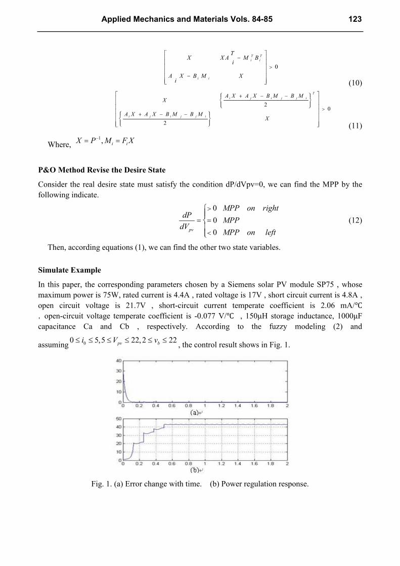
assuming 00 5,5 22, 2 22pv bi V v£ £ £ £ £ £, the control result shows in Fig. 1.
Fig. 1. (a) Error change with time. (b) Power regulation response.
Applied Mechanics and Materials Vols. 84-85 123
In fig.1. (a) , the error is sum of all three state variable formed as follows:
1 2 3error e e e= + +
where,
1
2 0 0
3
pv pvd
d
b bd
e V V
e i i
e v v
ì = -ïï
= -íï
= -ïî
From Fig. 1. , we can see that the output power of the PV system increased rapidly, and the
increase have about 3 steps, that is the result of the P &O control..
Conclusion
This paper proposed a kind of maximum power point tracking (MPPT) control for a single solar
power generation systems use the Takagi–Sugeno (T-S) fuzzy-model-based approach. We use T-S
fuzzy control to simplify the control system, because the system becomes a linear system under the
T-S model. In order to achieve the right MPP, some approximate MPP state variable was given by
some simple calculate. Then, a popular traditional Perturbation & Observation Method is used to
change the given state. Finally, numerical simulation results were given to demonstrate the
performance of the proposed methods.
Acknowledgements
This paper was supported by the science foundation of Southwest University for Nationalities of
China. The project is “REMOTE CONTROL SMART DROP IRRIGATION USING SOLAR
ENENGY ”.
References
[1]. Z. Salameh and D. Taylor, “Step-up maximum power point tracker for photovoltaic arrays,”
Solar Energy, vol. 44, no. 1, pp. 57–61, 1990.
[2]. V. Salas, E. Olias, A. Barrado, and A. Lazaro, “Review of the maximum power point tracking
algorithms for stand-alone photovoltaic systems,” Solar Energy Mater. Solar Cells, vol. 90, pp.
1555–1578, 2006.
[3]. K. H. Hussein, I. Muta, T. Hoshino, and M. Osakada, “Maximum photovoltaic power tracking:
An algorithm for rapidly changing atmospheric condition,” Inst. Elect. Eng. Proc.-Gener.
Trans. Distrib., vol. 142, no. 1, pp. 59–64, 1995.
[4]. I. H. Altasa and A. M. Sharaf, “A novel maximum power fuzzy logic controller for
photovoltaic solar energy systems,” Renewable Energy,vol. 33, pp. 388–399, 2008.
[5]. S. Lalouni, D. Rekioua, T. Rekioua, and E. Matagne, “Fuzzy logic control of stand-alone
photovoltaic system with battery storage,” J. Power Sources, vol. 193, pp. 899–907, 2009.
[6]. K. Lian, Y. Ouyang and W. Wu, “Realization of maximum power tracking approach for
photovomtaic array sytems based on T-S fuzzy method,” IEEE International Conf. on Fuzzy
Systems, vol. 1, no. 1, pp.1874-1879, Jun. 2008.
124 Green Power, Materials and Manufacturing Technology and Applications

Green Power, Materials and Manufacturing Technology and Applications 10.4028/www.scientific.net/AMM.84-85 T-S Fuzzy Control for Maximum Power Point Tracking of Solar Power Generation Systems 10.4028/www.scientific.net/AMM.84-85.120
