Embed Size (px)
Citation preview
GE Oil & Gas
Wellhead HousingsPressure Control T Tubing Head
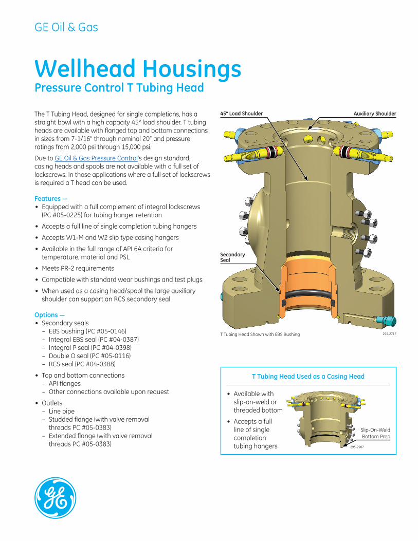
45° Load Shoulder Auxiliary Shoulder The T Tubing Head, designed for single completions, has a straight bowl with a high capacity 45° load shoulder. T tubing heads are available with flanged top and bottom connections in sizes from 7-1/16” through nominal 20” and pressure ratings from 2,000 psi through 15,000 psi.
Due to GE Oil & Gas Pressure Control’s design standard, casing heads and spools are not available with a full set of lockscrews. In those applications where a full set of lockscrews is required a T head can be used.
Features — • Equipped with a full complement of integral lockscrews
(PC #05-0225) for tubing hanger retention
• Accepts a full line of single completion tubing hangers
• Accepts W1-M and W2 slip type casing hangers
• Available in the full range of API 6A criteria fortemperature, material and PSL
• Meets PR-2 requirements
• Compatible with standard wear bushings and test plugs
• When used as a casing head/spool the large auxiliaryshoulder can support an RCS secondary seal
Options — • Secondary seals
– EBS bushing (PC #05-0146)– Integral EBS seal (PC #04-0387)
SecondarySeal
T Tubing Head Shown with EBS Bushing
– Integral P seal (PC #04-0398)– Double O seal (PC #05-0116)– RCS seal (PC #04-0388)
• Top and bottom connections– API flanges– Other connections available upon request
• Outlets– Line pipe– Studded flange (with valve removal
threads PC #05-0383)– Extended flange (with valve removal
threads PC #05-0383)
T Tubing Head Used as a Casing Head
• Available withslip-on-weld orthreaded bottom
• Accepts a fullline of singlecompletiontubing hangers 295-2907
Slip-On-Weld Bottom Prep
295-2717
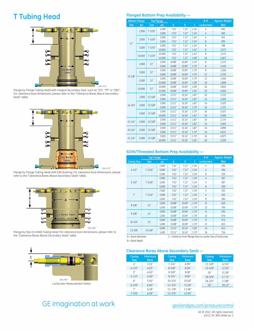
Flanged Bottom Prep Availability —T Tubing Head Bottom Flange Top Flange Size psi Size psi A B
# of C
Approx. Weight Lockscrews (lbs)
2,000 7.01” 7.12” 1.54” 4 4902,000 7-1/16”
3,000 7.01” 7.12” 1.54” 4 500 3,000 7.01” 7.12” 1.54” 4 545
3,000 7-1/16” 5,000 7.01” 7.12” 1.54” 8 599
11” 5,000 7.01” 7.12” 1.54” 8 788
5,000 7-1/16” 10,000 7.01” 7.12” 1.42” 8 1,073 10,000 7.01” 7.12” 1.42” 8 1,474
10,000 7-1/16” 15,000 7.01” 7.12” 1.48” 16 1,667
2,000 10.88” 10.00” 1.76” 8 1,2752,000 11”
3,000 10.88” 10.00” 1.70” 8 1,440 3,000 10.88” 10.00” 1.70” 8 1,366
3,000 11” 5,000 10.88” 10.00” 1.70” 12 1,550
13-5/8” 5,000 10.88” 10.00” 1.70” 12 1,366
5,000 11” 10,000 10.88” 10.00” 1.58” 16 1,890
295-2717 10,000 10.88” 10.00” 1.58” 16 3,85010,000 11”
15,000 10.88” 10.00” 1.56” 20 4,050 For clearance bore dimensions, please refer to the “Clearance Bores Above Secondary 2,000 13.51” 10.16” 1.82” 10 1,515
2,000 13-5/8”Seals” table. 3,000 13.51” 10.16” 1.82” 14 1,585 3,000 13.51” 10.16” 1.82” 14 1,620
16-3/4” 3,000 13-5/8” 5,000 13.51” 10.16” 1.70” 16
AA
1,725 5,000 13.51” 10.16” 1.70” 16 2,625
5,000 13-5/8” 10,000 13.51” 10.16” 1.62” 20 3,000
B 2,000 13.51” 10.16” 1.82” 10 3,274
21-1/4” 2,000 13-5/8” 3,000 13.51” 10.16” 1.82” 14 3,405 3,000 13.51” 10.16” 1.82” 14 3,890
20-3/4” 3,000 13-5/8” 5,000 13.51” 10.16” 1.70” 16 4,015 5,000 13.51” 10.16” 1.70” 16 4,875
21-1/4” 5,000 13-5/8” 10,000 13.51” 10.16” 1.62” 20 5,200
SOW/Threaded Bottom Prep Availability — # of
CB Approx. Weight
Lockscrews (lbs) 7.01” 7.12” 1.54” 4 296 7.01” 7.12” 1.54” 4 296 7.01” 7.12” 1.54” 8 320 7.01” 7.12” 1.54” 4 287 7.01” 7.12” 1.54” 4 287 7.01” 7.12” 1.54” 8 300 7.01” 7.12” 1.54” 4 265 7.01” 7.12” 1.54” 4 265 7.01” 7.12” 1.54” 8 280
10.88” 10.00” 1.70” 8 620 10.88” 10.00” 1.70” 12 700 10.88” 10.00” 1.70” 8 595 10.88” 10.00” 1.70” 12 676 10.88” 10.00” 1.70” 8 575 10.88” 10.00” 1.70” 12 655 13.51” 10.16” 1.82” 14 612 13.51” 10.16” 1.70” 16 736
C = Distance from flange face to center line of lockscrew
A
Casing Size
Minimum Bore
Casing Size
Minimum Bore
7-3/4” 6.99” 13-3/8” 12.50” 8-5/8” 8.00” 13-5/8” 12.50” 9-5/8” 9.00” 16” 15.38” 9-3/4” 9.00” 18-5/8” 17.75”
10-3/4” 10.00” 18-3/4” 17.88” 11-3/4” 11.06” 20” 19.13” 11-7/8” 11.06” 12-3/4” 12.00”
geoilandgas.com/pressurecontrol GE © 2013. All rights reserved.
10/13, PC #05-0048 rev 2
Flange by Flange Tubing Head with Integral Secondary Seal, such as “OO”, “PP” or “EBS”:
B A
See Bores Table
Lockscrew Measurement Detail 295-2907
C
Top Flange Casing Size Size psi
4-1/2” 7-1/16” 2,000 3,000 5,000
5-1/2” 7-1/16” 2,000 3,000 5,000
7” 7-1/16” 2,000 3,000 5,000
8-5/8” 11” 3,000 5,000
9-5/8” 11” 3,000 5,000
10-3/4” 11” 3,000 5,000
13-3/8” 13-5/8” 3,000 5,000
A = Bowl diameter B = Bowl depth
Clearance Bores Above Secondary Seals — Casing
Size Minimum
Bore 4” 3.53”
4-1/2” 4.03” 5” 4.50”
5-1/2” 5.00” 6” 5.50”
6-5/8” 6.00” 7” 6.38”
7-5/8” 6.99”
Flange by Slip-On-Weld Tubing Head: For clearance bore dimensions, please refer to the “Clearance Bores Above Secondary Seals” table.
295-2907
B A
See Bores Table
295-2717
Flange by Flange Tubing Head with EBS Bushing: For clearance bore dimensions, please refer to the “Clearance Bores Above Secondary Seals” table.
See Bores Table