Embed Size (px)
Citation preview
(1828/38, 1918/62, 1940/59,
1958/52, 2017/56, 2162/75,
2176/62, 2223/18, 2286/41,
2437/24, 2486/43, 2536/40,
2650/42)
III(5)a
Certificate Pursuant to section 12 of the
Weights and Measures Act 1985 Series V005 Revision 4
Certification No. Valid Until Certification No. Valid Until
1828/38 Revision 5 19 May 2013 2223/18 Revision 5 5 December 2013
1918/62 Revision 5 26 September 2015 2286/41 Revision 5 2 November 2013
1940/59 Revision 5 5 May 2016 2437/24 Revision 1 17 October 2006
1958/52 Revision 1 17 August 2006 2486/43 Revision 5 29 November 2013
2017/56 Revision 5 4 September 2016 2536/40 Revision 5 26 October 2016
2162/75 Revision 4 2 September 2011 2650/42 Revision 4 30 December 2012
2176/62 Revision 4 13 January 2012
In accordance with the provisions of section 12 of the Weights and Measures Act 1985, the Secretary of State
for Business, Innovation & Skills hereby certifies as suitable for use for trade a pattern of a liquid flowmeter, as
described in the descriptive annex to this Certificate, and having the following characteristics:-
DISPENSER: Dispensers described in certification numbers: 1828, 1918, 1940,
1958, 2017, 2162, 2176, 2223, 2286, 2437, 2486, 2536 and 2650.
FORECOURT CONTROL UNIT:
DOMS PSS 5000 as described in the descriptive annex.
COMBINED KIOSK CONTROL &
POINT OF SALE SYSTEM:
SDL Retail POS as described in the descriptive annex.
Under the provisions of section 12(6) of the said Act, the validity of this certificate is limited as shown above.
This revision replaces previous versions of the certificate.
Note: This certificate relates to the suitability of the equipment for use for trade only in respect of its
metrological characteristics. It does not constitute or imply any guarantee as to the safety of the equipment in
use for trade or otherwise.
Submitted by: Indigo Retail Technology Ltd (formerly Softoption Developments Ltd)
Business Innovation Centre
Binley Business Park
Harry Weston Road
Coventry, CV3 2TX
United Kingdom
Signatory: P R Dixon
for Chief Executive
Reference No: T1118/0017
Date: 11 February 2013
National Measurement Office
Department for Business, Innovation & Skills
Stanton Avenue
Teddington
Middlesex TW11 0JZ
United Kingdom
2
CONTENTS
1 INTRODUCTION
2 CONSTRUCTION
3 OPERATION
4 AUTHORISED ALTERNATIVES
5 RECOMMENDED TESTS
6 CERTIFICATE HISTORY
ILLUSTRATIONS
Figure 1 SDL POS System Schematic
Figure 2 DOMS PSS 5000 enclosure
Figure 3 DOMS PSS 5000 typical electronic component layout
Figure 4 Central Processing Board (CPB508) display and menu navigation keys
Figure 5 Software version number
Figure 6 Operator display ‘summary view’
Figure 7 Operator display ‘detailed view’
Figure 8 Epson IM-310 incorporating DM-D106 customer display and TM-88II
printer
Figure 9 Epson IM600 incorporating DM-D110 customer display
Figure 10 Netgear Fast Ethernet Switch FS308-8 Port 10/100
Figure 11 Netgear Fast Ethernet Switch FS516-16 Port 10/100
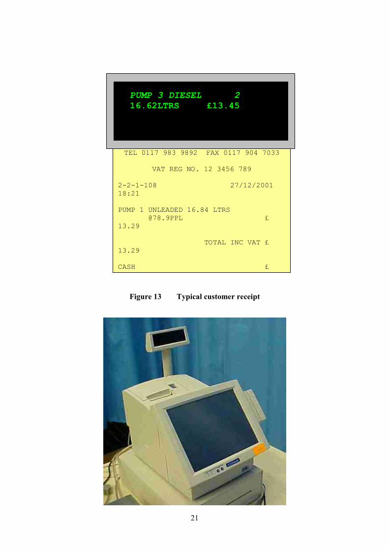
Figure 12 Customer display layout
Figure 13 Typical customer receipt
Figure 14 Epson IR-320 Model no. M156X
Figure 15 Rear of Epson IR-800 Model no. M183A with cover removed
Figure 16 Epson IR 700 – front view
Figure 17 Epson IR 700 – showing rear connections with protective cover removed
Figure 18 P1220 terminal
Figure 19 Port layout of P1220 with integral power supply
Figure 20 Port layout of P1220 with external power supply
Figure 21 P1520 terminal
Figure 22 Port layout of P1520
Figure 23 operators display showing pre-payment button
Figure 24 payment receipt ticket and subsequent refund receipt ticket
Figure 25 View of back panel – cover removed - showing 24 V outlet
Figure 26 Epson IR 700 – front view
Figure 27 Epson IR 700 – showing rear connections with protective cover removed
Figure 28 Toshiba ST-71 with integrated customer display unit
Figure 29 Port layout of ST-71 terminal
Figure 30 Toshiba TEC ST-6501 - showing integrated card swipe
Figure 31 Toshiba TEC ST-6501, schematic view showing ports and connections
- cover removed
Figure 32 Toshiba TEC ST A-10
Figure 33 Panasonic JS-790WS
Figure 34 IBM SurePos 500

3
Descriptive Annex
1 INTRODUCTION
This certificate describes the SDL Retail point of sale (POS) connected to fuel dispensers
described in the certificate.
In addition any compatible CE marked LPG dispensers may be connected to the SDL Retail
point of sale (POS). The dispenser head electronics are compatible, but the dispenser
hydraulics are replaced with types suitable for LPG. (Amendment 1, see 1828/1
Amendment No 45)
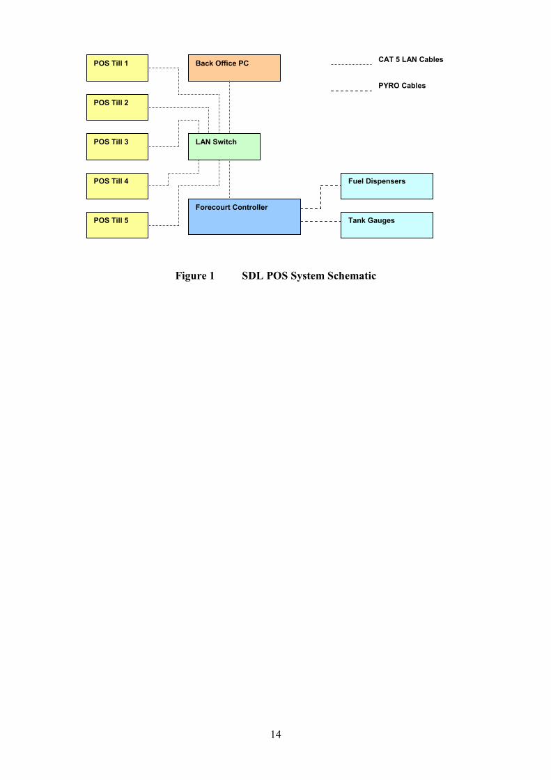
SDL Retail POS is a computerised point of sale system designed to control and process sales
transactions of both fuel and shop goods in a retail environment. The system can be
configured with up to five POS tills, each with integrated pump control, barcode scanning,
and EFT (electronic funds transfer) card swipe capability, and can link to various back office
management systems for sales reconciliation, stock control, and accounting purposes. The
schematic in Figure 1 shows how the main elements of system hardware are connected
together.
All POS tills are connected to the LAN (local area network) by means of category 5 cabling
to the main LAN switch. Also connected to the LAN switch is the Forecourt Controller.
This provides pump control and tank gauge access to all POS tills on the LAN. The back
office PC connected to the LAN switch is used to send product and price updates to the POS
tills and collect sales transaction data from them.
External uninterruptible power supply units protect all connected POS tills, the LAN switch,
and Forecourt Controller by maintaining power for at least 15 minutes after a power failure.
2 CONSTRUCTION
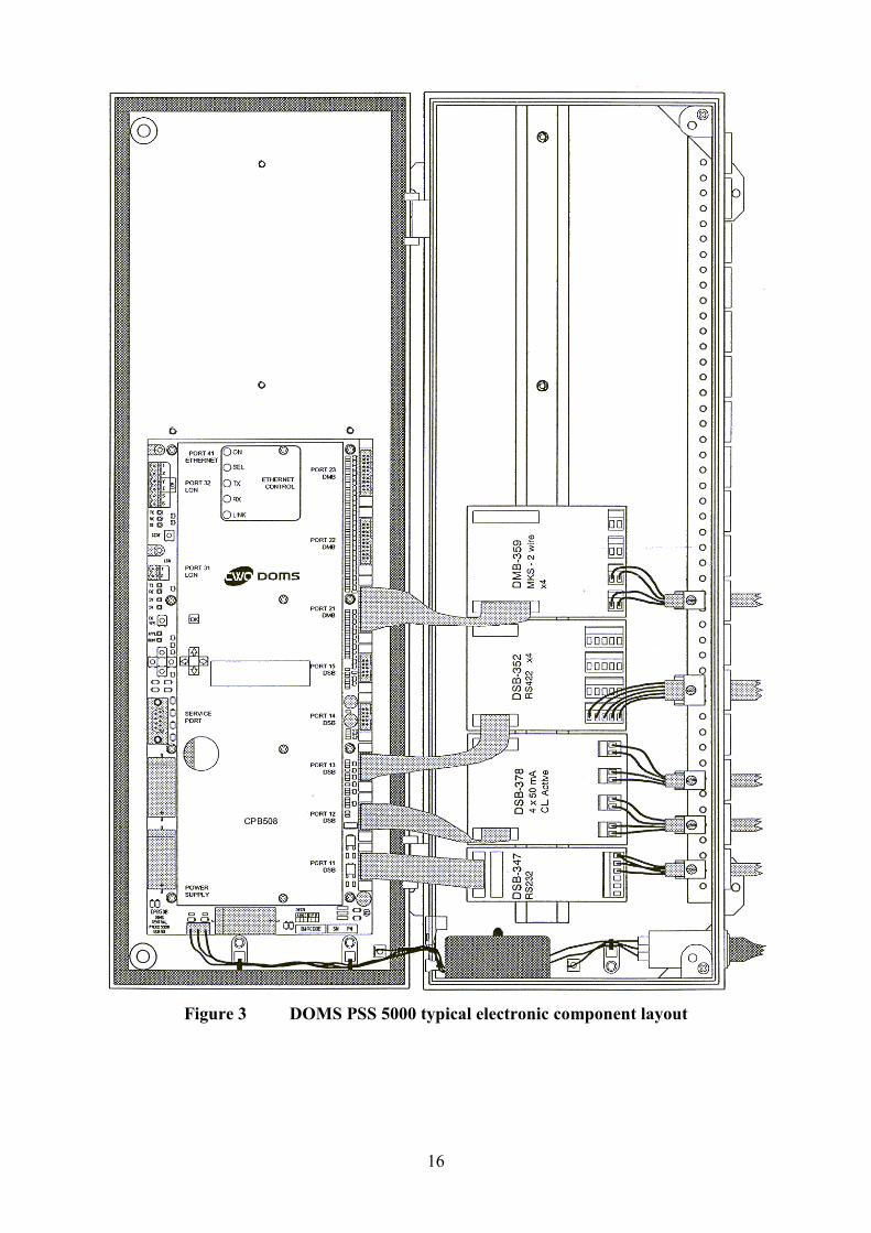
2.1 Forecourt controller DOMS PSS 5000
The DOMS PSS5000 forecourt controller comprises a metal rectangular box (Figure 2)
housing the following main components. The general arrangement is shown in Figure 3.
• A power supply • A Central Processing Board (CPU) with 8 serial ports (CPB508).
This has an LCD 16x2 character alphanumerical display and a keyboard comprising 5
keys for navigating the menu options, an adjacent legend describes the key functions as
shown in Figure 4.
• Hardware interface modules. Dispensers are connected to the CPU board via an appropriate hardware interface module
compatible with the communication protocol of the dispenser.
2.1.1 Software
The DOMS PSS5000 has a legal authority module (LAM) for the UK containing specific
parameter values and functions. The LAM version number is 498-06-100 and the checksum
number is 0D6C. These can be viewed by selecting the appropriate menu heading using the
operator keys on the CPU. The LAM version number and checksum are accessed as follows.

4
When the PSS is powered on, the first line displays the application software version and the
current time. The second line displays the W&M Service menu. Pressing the Down Arrow
once, displays the W & M menu which comprises 7 sub-menus, W.1 to W.7. Press the right
button once to obtain W.1 – LAM INFO and press again to display Version and Checksum
information.
2.1.2 DOMS PSS5000 Compact site controller
As described in section 2.1.1, but in a more compact metal box, with less spaces for hardware
interface modules. The LAM version number is 498-06-101, checksum number is 0D6C
2.2 Kiosk control and point of sale PC
The POS tills are touch-screen PC devices that are equipped with integrated magnetic card
readers and two-line customer displays. Each POS till has its own thermal receipt printer and
laser barcode scanner.
2.2.1 Epson IM-310 incorporating DM-D106 customer display and TM-88II printer
(Figure 8)
Alternatively the Epson TM-H6000 printer may be fitted instead if cheque printing is
required. All cable connections are made at the rear of the unit, with the exception of the laser
scanner, which is plugged into the keyboard port on the right hand side. The hard power
switch is located on the right hand side, and the soft power switch is on the front underneath
the touch panel. The floppy drive is hidden away behind the lockable front access cover, also
located below the touch panel. The printer and customer display are connected internally to
the unit on COM3.
The equipment is identified as follows:
Equipment
Manufacturer Model No
Epson IM-310 POS PC
Mother board
Power supply
Epson
Epson
Epson
M156A
IM-310 MAIN 2034124-02 / 2034698-02
APS-138
Customer display
Epson M58DA
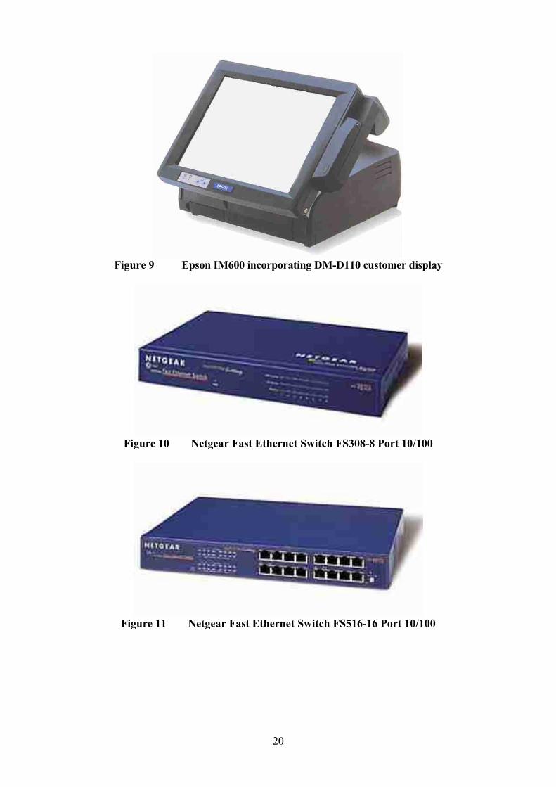
2.2.2 Epson IM600 incorporating DM-D110 customer display (Figure 9)
This POS till uses an external printer. This can be either the standard TM-88II, or the TM-
H6000 if cheque printing is required. All cable connections are made at the rear or
underneath the unit, with the exception of the laser scanner, which is plugged into the
keyboard port on the front below the touch panel. The hard power switch is located on the
rear of the unit inside the plastic casing panel, and the soft power switch is on the front
underneath the touch panel. There is a port to connect an external floppy drive inside the
lockable front access panel, also located below the touch panel. The printer is connected to
the COM3 port found underneath the base of the unit, but the customer display is connected
into the customer display port on the external printer.

5
The equipment is identified as follows:
Equipment
Manufacturer Model No
Epson IM-600 POS PC
Mother board
Power supply
Epson
Epson
Epson
M164A
IM-310 MAIN 2036544-03 / 2036545-03
130 D 601
Customer display
Epson M58DB
2.3 LAN Switch
One of two models manufactured by Netgear may be connected to the LAN, the Fast Ethernet
Switch FS308-8 Port 10/100 (Figure 10) or the Fast Ethernet Switch FS516-16 Port 10/100
(Figure 11).
2.4 Software
2.4.1 Operating System
The SDL Retail POS may run any of the following Microsoft 32bit operating systems:
Windows 95, Windows 98, Windows ME, Windows NT4.0, Windows 2000, Windows XP
2.4.2 Controlled software version number
The software version information is displayed in two parts in a window (Figure 5) which is
accessed in the engineer menu under ‘S/W Version’. The larger bold caption indicates the
overall software version, incorporating both legally relevant and non-legally relevant parts.
The version number of the legally relevant part is 1.0 and is shown separately underneath.
An error in the price calculation software described in Section 2.4.2 has been corrected which
has resulted in Version 1.0 and 2.0 of the “SDL Fuel Dispensing Self-serve System” software
becoming obsolete and therefore should not be in use for trade.
The corrected software is now identified as “SDL Fuel Dispensing Self-serve System Version
3.0” as shown in the amended Figure 5. (Amendment 9, see 1828/38 Amendment No 9)
3. OPERATION
3.1 Application start up
The installed applications on the POS tills have been configured to automatically launch from
the Programs\Start-Up folder whenever the POS tills are switched on. the first screen from
which a user can enter data is the user login screen. The application is displayed full screen,
so that the Windows task bar is not visible to the normal user and cannot gain access to the
Windows task manager.
3.1.1 Password Access
Access to the application is only allowed by entry of a valid user name and password. Access
rights are allocated to users authorised for engineering and management functions. Passwords
6
for normal users, managers and engineers and their associated access rights can only be
configured from the Retail Controller back office application.
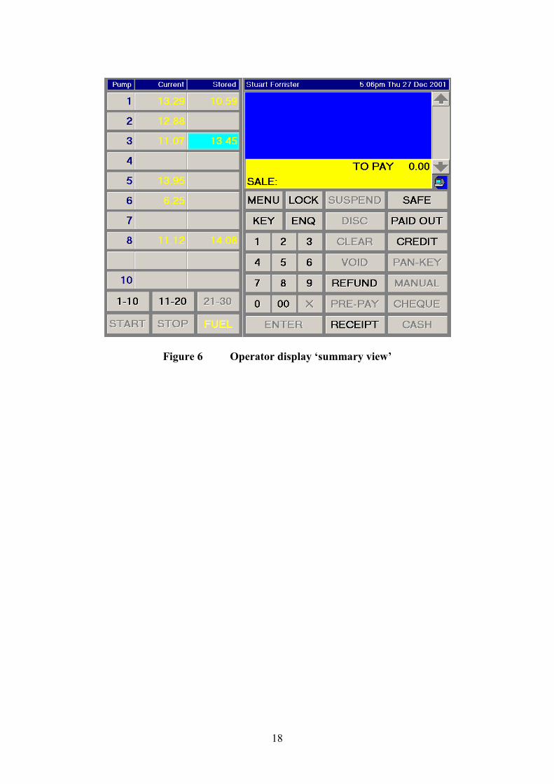
3.2 Sales Functions
Figure 6 shows the main sales screen in its ‘summary view’ mode. A detailed view of
transactions relating to a specific pump can be obtained by pressing the desired pump number
button to obtain ‘detailed view’ mode (Figure 7).
3.2.2 Starting a Pump
When a customer on the forecourt pulls a pump’s nozzle out of its holster, the POS till
operator is advised of the customer’s request for authorisation to fuel by means of an audible
warning, and the associated pump number button flashing green. If the operator was in ‘detail
view’ mode of any other pump, the green VIEW PUMPS button would advise that another
pump was requesting authorisation.
The pump is authorised by pressing the START button, followed by the pump number button
if in the ‘summary view’ mode or pressing the START button only if in ‘detail view’ mode.
The customer can then draw fuel, and the progress is displayed on the POS till’s pump
control display.
3.2.3 Stopping a Pump
An operator may at any time during the fuelling process temporarily stop a dispenser by
pressing the STOP button, followed by the pump number if in ‘summary view’ mode or by
pressing the STOP button only if in ‘detail view’ mode for a specific pump. The STOP button
would then change to a START button. To allow fuelling to continue the operator presses the
START button, followed by the pump number button if in the ‘summary view’ mode or
presses the START button only if in ‘detail view’ mode.
3.2.4 Completing a fuel transaction
When the customer has finished fuelling, and placed the nozzle back in the pump’s holster,
the POS till will advise the operator that the transaction is complete by an audible tone.
Viewed from the summary mode, the outstanding transaction values will then flash yellow.
In the detail view mode the status will flash in yellow the words TO PAY along with the
SELECT button. If transactions are outstanding on other pumps, the VIEW PUMPS button
will also flash yellow.
Note that a maximum of only two fuel transactions can be outstanding against any particular
pump, and until one or both of them are cleared, no further fuelling can commence on that
pump.
When in the summary view mode, the operator selects a particular transaction for processing
by pressing either the current or stored button of the chosen pump on the pump controller.
This will cause the selected transaction button to be highlighted in a turquoise blue colour,
and the FUEL button at the bottom of the pump controller will flash yellow:
Alternatively, the operator can press the pump number button to view the pump transaction
details by pressing either of the SELECT buttons. This will highlight the chosen transaction
in a turquoise blue colour, and the FUEL button will start to flash yellow. In either case, the
7
selected transaction details will also be shown on the customer display at the same time. The
transaction data layout is shown in Figure 12.
Note that on the right-hand end of the top line of the customer display there is a single digit
number. This indicates whether it is the current (most recent) transaction on the pump in
which case the value would be 1, or the stored (oldest) transaction on the pump, in which
case the value would be 2.
Pressing the flashing yellow FUEL button will transfer the selected fuel transaction over to
the POS operator display and add it to the sales transaction currently being compiled for
payment.
3.2.5 Voiding a Selected Fuel Transaction
If a fuel transaction item has been mistakenly passed across to the sales transaction, pressing
the VOID POS function button permits the fuel transaction to be passed back to the pump
controller. The operator may void either a specific item in the sales transaction, or all items in
the sales transaction.
Voiding a fuel transaction item clears it from the operator display, and unlocks the fuel
transaction on the pump controllers of all POS tills on the system. This enables the
transaction to be selected by any POS till.
3.2.6 Printing a Receipt
The operator can print a VAT receipt for any sales transaction that has occurred within the
past twenty shifts. To print a receipt for a transaction that has just been completed, the
operator can press the RECEIPT POS function button. A typical receipt is shown in Figure
13.
3.3 Interlocks and Security features
3.3.1 In the event of a mains power failure the UPS will provide power for a period of no
less than 15 minutes to allow all transactions to be paid off.
3.3.2 Duplicate transaction receipts are clearly marked “COPY RECEIPT”
3.3.3 With both current and stored sales for a pump in the not paid status, no further
Sales may be authorised on that pump until either of the sales for that pump has been
paid.
3.3.4 Grade prices cannot be changed while any sales are currently active on pumps.
4 AUTHORISED ALTERNATIVES
4.1 Printer Any compatible CE marked printer may be connected to the POS till.
4.2 Barcode scanner Any compatible CE marked scanner may be used.

8
4.3 Cash drawer This may be any CE marked simple cash drawer with a solenoid release. It is triggered from
the back of the POS if an internal printer is used, or from the back of the external printer.
4.4 Back Office System Any CE marked PC used for management purposes only may be connected to the LAN
switch.
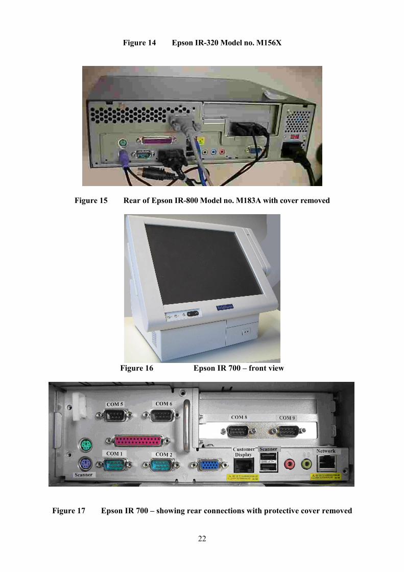
4.5 Alternative POS PC - Epson IR-320 Model no. M156X (Figure 14) (Amendment 2,
see 1828/38 Amendment No 2)
The existing POS PC and associated operator display and customer display unit may be replaced
with the Epson IR320 POS PC.
A protective plastic cover is fitted on the rear of the unit covering the external connection ports
and must not be removed during normal use.
The equipment is identified as follows:
Epson IR-320 PC unit, model number M156X
Epson DM-110 Customer Display Units (CDUs): M58DB or M129C
Note: Any suitable CE marked CDUs may be used.
4.6 Alternative POS PC - Epson IM-800 Model no. M183A (Amendment 3, see
1828/38 Amendment No 3)
The existing POS PC and associated operator display and customer display unit may be replaced
with the Epson IM 800 POS PC (Figure 15).
A protective plastic cover is fitted on the rear of the unit covering the external connection ports
and must not be removed during normal use.
The equipment is identified as follows:
Epson IM-800 PC unit, model number M183A
Epson DM-M820-024 touch screen panel with card swipe, model number S1201D.
Epson DM-110 Customer Display Units (CDUs): M580B or M129C
Note: Any suitable CE marked CDUs and touch screen panel with card swipe may be used.
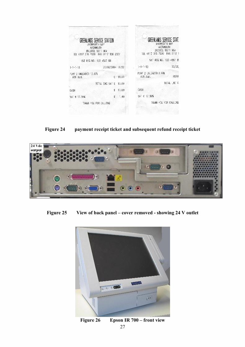
4.6.1 Alternative PSU with 24 V dc output (Amendment 5, see 1828/28 Amendment No 9) 4.6.1.1 Epson MR 800 (IM-800, M183A) as described in the certification, but having fitted an
alternative Power Supply Unit (PSU) providing a 24 Vdc output suitable for supplying printers and/or
till units, or any device requiring 24 Vdc.
4.6.1.2 The modified power supply unit has the part number Delta Electronics INC DPS-180MB-2
XX (where XX=0-9, A-Z or blank). A view of the back panel (cover shown removed) is shown in
Figure 25.
9
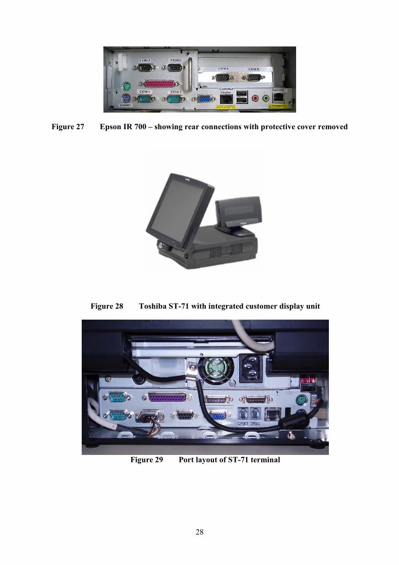
4.7 Alternative POS PC - Epson IR 700, Model number M215A (Amendment 7, see
1828/38 Amendment No 7)
The existing POS PC and associated operator display and customer display unit may be
replaced with the Epson IR 700 POS PC as shown in Figures 26 and 27.
The equipment is identified as follows:
Epson IR 700 PC unit, model number M215A
Epson DM-LX121SV touch screen panel model number M217A.
Epson 3 track magnetic stripe reader (MSR).
Epson DM-D210 Customer Display Unit (CDU): M59DB
Epson printer TM-T88IIIX, model M216A
Note: Any suitable CE marked CDUs and serial port printer may be used.
4.8 Alternative POS PC – Radiant Systems P1220 (Amendment 8, see 1828/38
Amendment No 8)
The existing POS PC and associated operator display and customer display unit may be
replaced with the Radiant Systems P1220 POS PC as shown in Figures 18, 19 and 20. It has
an Intel Celeron M processor and 852 chipset and up to 2 GB of memory. The storage device
may be a hard drive, CF Card, or uDOC
4.9 Alternative POS PC – Radiant Systems P1520 (Amendment 8, see 1828/38
Amendment No 8)
The existing POS PC and associated operator display and customer display unit may be
replaced with the Radiant Systems P1520 POS PC (Figure 21). This is similar to the P1220
but has a 15”LCD operator display. The Port layout is shown in Figure 22.
4.10 WEIGHING INSTRUMENT (Amendment 4, see 1828/38 Amendment No 4)
Any weighing instrument having a type approval certificate in accordance with The Council
Directive 90/384/EEC on Non-Automatic Weighing Instruments may be connected to the
store controller serial port. The software controlling the operation of the weighing instrument
is described in NWML Test Certificate GB-1156. Figure 5 shows software issue status.
4.11 PRE-PAY FACILITY (Amendment 4, see 1828/38 Amendment No 4)
4.11.1 Introduction
In the pre-payment method, fuel is paid for before it has been drawn.
Note: The pre-pay option is only suitable for introduction where the associated dispensers
are equipped with two stage solenoid valves or similar arrangements whereby the dispenser
can stop at a precise volume or monetary value. It is also only suitable for use with manned
kiosks (not suitable for unmanned sites).

10
4.11.2 Construction
Implementation is by software. Issue status is “SDL Fuel Dispensing Self-Serve System
Version 2.0”.
Note: Now Version 3.0 as described in section 2.4.2 (Figure 5)
4.11.3 OPERATION
4.11.3.1 When the pre-payment method is in operation, the PRE button will become
available on the pump controller side of the main sales screen. See Figure 23.
4.11.3.2 To prepare a pre-payment transaction, press the PRE button to display the Fuel
Pre-Payment screen:
Using the PUMP NUMBER button, the hose list, SALE AMOUNT button, and numeric
keypad, enter the necessary information about the proposed transaction. Pressing the
ACCEPT button will then check the availability of the pump for this sale, and if it can
proceed, will create an entry for the sale of this product on the Operator Display of the main
sales screen. This can then be paid for by any available payment method the system is
configured to accept. A receipt ticket will be issued to the customer indicating the amount
paid. See Figure 24
Note: Only one pre-paid transaction can be set up on any dispenser at any one time. It is not
possible to stack pre-payments on the same dispenser. In order to protect the transaction for
the duration of its cycle, the dispenser is locked to the specific till that is processing the
transaction. This prevents other tills on the system accessing the dispenser until it becomes
idle again.
4.11.3.3 After the transaction has been paid for (and receipt generated if required), the
customer can then go back out to the dispenser and perform the fuelling process. Note that
the pump will still call for authorisation when the selected nozzle is removed, but that only
the controlling till is able to release the pump.
4.11.3.4 If the customer draws the full amount to which he is entitled, then upon
replacement of the nozzle in the dispenser’s holster, the sale will complete on the pump
controller display of all kiosk tills (indicated by the audible tone), and automatically clear
from the screen.
4.11.3.5 If the customer draws less then the full amount paid for, the sale will complete
with the audible tone as above, but will remain on the pump controller displays of the kiosk
tills. This is so that a refund can be made for the un-drawn element of the pre-paid
transaction.
Note: The refund procedure can only be carried out on the controlling till, and so if any
other till tries to access this transaction they will be unable to access this data, and a
REFUND message is flashed up over the sale amount displayed.
4.11.3.6 When the controlling till accesses the transaction and presses the FUEL button
to transfer it to the Operator Display a refund entry for the un-drawn amount will
automatically be displayed. This refund can then be completed by the operator by means of
11
any of the payment methods configured on the system. The refund receipt then generated
would appear as in shown in Figure 24.
4.12 Optional alternative fuel POS unit: Epson IR 700 (Amendment 6, see 1828/28
Amendment No 12)
As described in the certification, but having the option to use the Epson IR 700 POS unit as
described below and as shown in Figures 21 and 22.
Alternative PC Assembly (Epson IR 700)
A POS system comprising: Epson IR 700 PC unit, model number M215A
Epson DM-LX121SV touch screen panel model number
M217A.
Epson 3 track magnetic stripe reader (MSR).
Epson DM-D210 Customer Display Units (CDUs): M59DB
Note: Any suitable CE marked CDUs may be used.
Epson printer TM-T88IIIX, model M216A
Note: Any suitable CE marked serial port printer may be used.
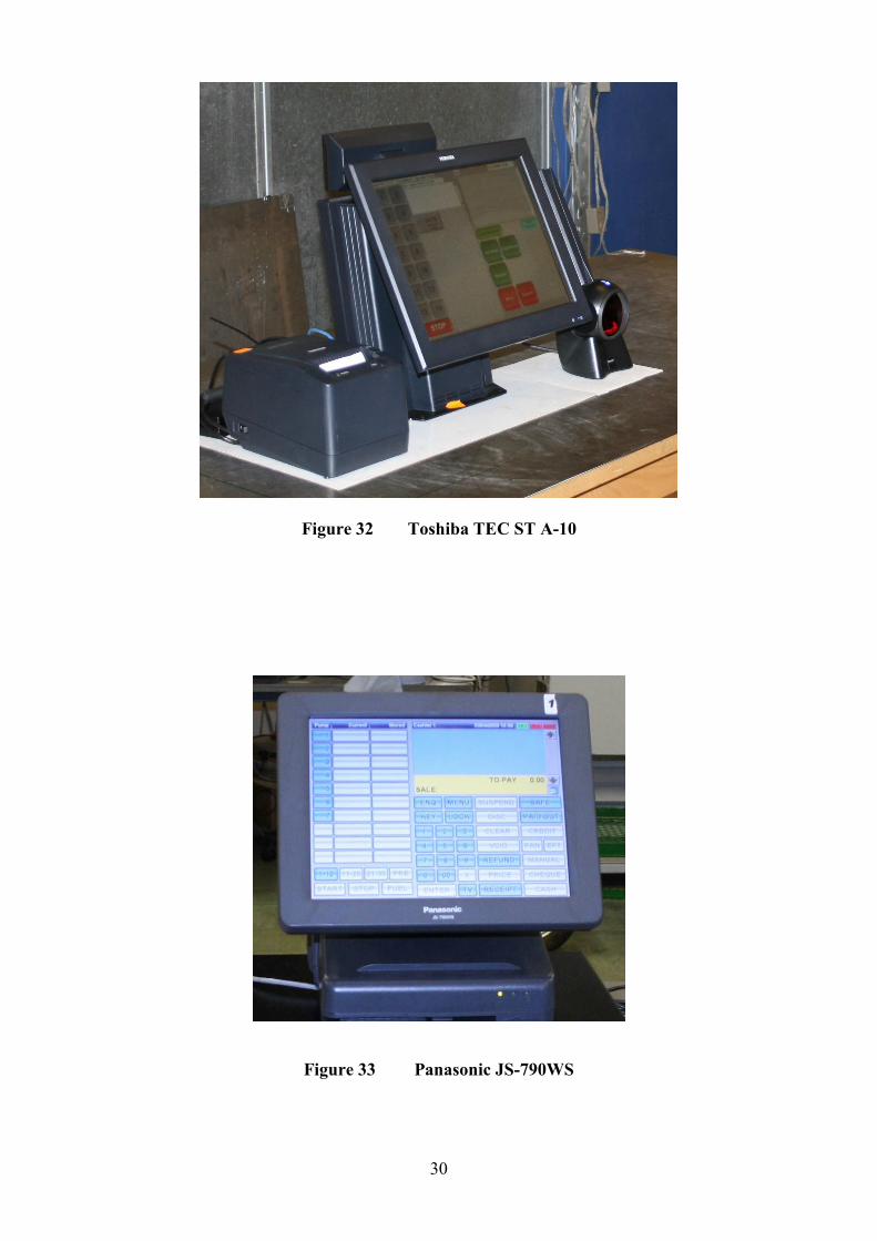
4.13 Alternative POS PC - Toshiba TEC ST-71 (Figure 28)
The Toshiba TEC ST-71 is a POS unit integrating a PC, a touch screen display with card
swipe, and a customer display unit (CDU). The port layout is shown in Figure 29. The system
comprises:
Toshiba TEC ST-71 PC unit, model number ST-71
Toshiba TEC 12 V power supply unit, model number EA10953A1
Note: optionally, any suitable CE marked power supply unit may be used
Toshiba TEC ST-71 touch screen panel with card swipe
Toshiba TEC ST-71 integrated customer display units (CDUs)
Toshiba TEC receipt printer TRST-56-S-1G-QM
Note: Optionally, any suitable CE marked serial port printer may be used
4.14 Alternative POS PC - TEC ST-6501
The Toshiba TEC ST-6501 is a PC based electronic till having an LCD touch screen operator
display with a built-in card swipe as shown in Figures 30 and 31.
4.15 Alternative POS PC - Toshiba TEC ST A-10
As described in the certificate but having the alternative POS PC designated TEC ST A-10
manufactured by Toshiba. The PC may have any peripheral equipment connected identified
in the certificate.
This is a PC based electronic till having an LCD touch screen operator display with a built-in
card swipe as shown in Figure 32.
12
4.16 Alternative POS PC – Panasonic JS-790WS (Figure 33)
This is a PC based electronic till having an LCD touch screen operator display, it may have
any peripheral equipment connected to it as identified in the certificate, however the receipt
printer and customer display must be connected using screened RS232 serial cables.
4.17 Alternative POS PC – IBM SurePos 500
This is a PC based electronic till having an LCD touch screen operator display with a built-in
card swipe as shown in Figure 34. The PC may have any peripheral equipment connected
identified in the certificate.
4.18 Alternative POS PCs: Toshiba models ST-A10 and ST-A20
These are PC based electronic tills having an LCD touch screen operator display with a built-
in card swipe.
4.19 Alternative POS PC: Odysse manufactured by AURES Technologies Ltd
As described in the certificate but having the alternative POS PC designated Odysse
manufactured by AURES Technologies Ltd.
4.20 Alternative POS PC: ELO Model 15D1
This is a PC based electronic till having an LCD touch screen operator display with a built-in
card swipe and integrated customer display.
4.21 Alternative POS PC: Galeo manufactured by AURES Technologies Ltd
As described in the certificate but having the alternative POS PC designated Galeo
manufactured by AURES Technologies Ltd.
This is a PC based electronic till having an LCD touch screen operator display with a built-in
card swipe.
5 RECOMMENDED TESTS
5.1 Check that the UPS maintains power to the system allowing operation to continue for
15 minutes after the power is switched off.
5.2 If a Panasonic JS-790WS POS PC is installed check to ensure that the receipt printer
and customer display are connected using screened RS232 serial cables.
13
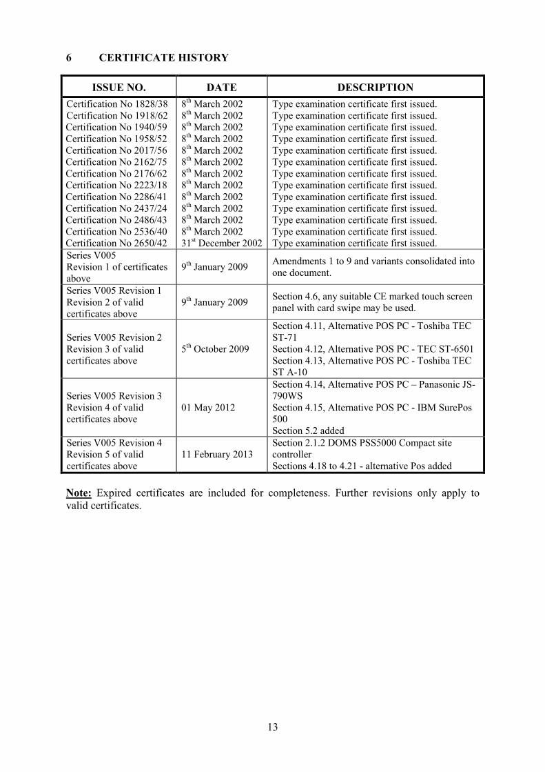
6 CERTIFICATE HISTORY
ISSUE NO. DATE DESCRIPTION
Certification No 1828/38
Certification No 1918/62
Certification No 1940/59
Certification No 1958/52
Certification No 2017/56
Certification No 2162/75
Certification No 2176/62
Certification No 2223/18
Certification No 2286/41
Certification No 2437/24 Certification No 2486/43
Certification No 2536/40
Certification No 2650/42
8th March 2002
8th March 2002
8th March 2002
8th March 2002
8th March 2002
8th March 2002
8th March 2002
8th March 2002
8th March 2002
8th March 2002
8th March 2002
8th March 2002
31st December 2002
Type examination certificate first issued.
Type examination certificate first issued.
Type examination certificate first issued.
Type examination certificate first issued.
Type examination certificate first issued.
Type examination certificate first issued.
Type examination certificate first issued.
Type examination certificate first issued.
Type examination certificate first issued.
Type examination certificate first issued.
Type examination certificate first issued.
Type examination certificate first issued.
Type examination certificate first issued.
Series V005
Revision 1 of certificates
above
9th January 2009
Amendments 1 to 9 and variants consolidated into
one document.
Series V005 Revision 1
Revision 2 of valid
certificates above
9th January 2009
Section 4.6, any suitable CE marked touch screen
panel with card swipe may be used.
Series V005 Revision 2
Revision 3 of valid
certificates above
5th October 2009
Section 4.11, Alternative POS PC - Toshiba TEC
ST-71
Section 4.12, Alternative POS PC - TEC ST-6501
Section 4.13, Alternative POS PC - Toshiba TEC
ST A-10
Series V005 Revision 3
Revision 4 of valid
certificates above
01 May 2012
Section 4.14, Alternative POS PC – Panasonic JS-
790WS
Section 4.15, Alternative POS PC - IBM SurePos
500
Section 5.2 added
Series V005 Revision 4
Revision 5 of valid
certificates above
11 February 2013
Section 2.1.2 DOMS PSS5000 Compact site
controller
Sections 4.18 to 4.21 - alternative Pos added
Note: Expired certificates are included for completeness. Further revisions only apply to
valid certificates.
14
Figure 1 SDL POS System Schematic
POS Till 1
POS Till 2
POS Till 3
POS Till 4
POS Till 5
Back Office PC
Forecourt Controller
LAN Switch
Fuel Dispensers
Tank Gauges
CAT 5 LAN Cables
PYRO Cables

15
Figure 2 DOMS PSS 5000 enclosure
16
Figure 3 DOMS PSS 5000 typical electronic component layout

17
Figure 4 Central Processing Board (CPB508) display and menu navigation keys
Figure 5 Software version number
18
Figure 6 Operator display ‘summary view’

19
Figure 7 Operator display ‘detailed view’
Figure 8 Epson IM-310 incorporating DM-D106 customer display and TM-88II
printer
20
Figure 9 Epson IM600 incorporating DM-D110 customer display
Figure 10 Netgear Fast Ethernet Switch FS308-8 Port 10/100
Figure 11 Netgear Fast Ethernet Switch FS516-16 Port 10/100
21
Figure 12 Customer display layout
Figure 13 Typical customer receipt
MEADOWLANDS SERVICE STATION
17 GREENLANDS WAY
HENBURY
BRISTOL BS10 7PR
TEL 0117 983 9892 FAX 0117 904 7033
VAT REG NO. 12 3456 789
2-2-1-108 27/12/2001
18:21
PUMP 1 UNLEADED 16.84 LTRS
@78.9PPL £
13.29
TOTAL INC VAT £
13.29
CASH £
PUMP 3 DIESEL 2
16.62LTRS £13.45
22
Figure 14 Epson IR-320 Model no. M156X
Figure 15 Rear of Epson IR-800 Model no. M183A with cover removed
Figure 16 Epson IR 700 – front view
Figure 17 Epson IR 700 – showing rear connections with protective cover removed

23
Figure 18 P1220 terminal
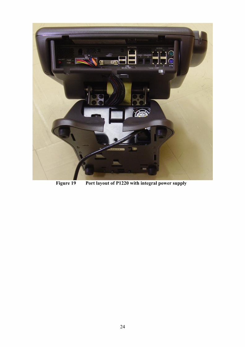
24
Figure 19 Port layout of P1220 with integral power supply

25
Figure 20 Port layout of P1220 with external power supply
Figure 21 P1520 terminal

26
Figure 22 Port layout of P1520
Figure 23 operators display showing pre-payment button
Pre-Payment Button
27
Figure 24 payment receipt ticket and subsequent refund receipt ticket
Figure 25 View of back panel – cover removed - showing 24 V outlet
Figure 26 Epson IR 700 – front view
28
Figure 27 Epson IR 700 – showing rear connections with protective cover removed
Figure 28 Toshiba ST-71 with integrated customer display unit
Figure 29 Port layout of ST-71 terminal

29
Figure 30
Toshiba TEC ST-6501 - showing integrated card swipe
Figure 31
Toshiba TEC ST-6501, schematic view showing ports and connections - cover removed
30
Figure 32 Toshiba TEC ST A-10
Figure 33 Panasonic JS-790WS

31
Figure 34 IBM SurePos 500
© Crown copyright 2013.
This material may be freely reproduced except for sale.


![Week01 diode revision [revision]](https://img.pdfslide.net/doc/110x75/55d7084fbb61eb804d8b4664/week01-diode-revision-revision.jpg)