Embed Size (px)
Citation preview
T221 Flat-Panel Monitor
User’s Guide

ii
Second Edition (July 2003)
The following paragraph does not apply to the United Kingdom or any country where such provisions are
inconsistent with local law: INTERNATIONAL BUSINESS MACHINES CORPORATION PROVIDES THIS PUBLICATION "AS IS" WITHOUT WARRANTY OF ANY KIND, EITHER EXPRESS OR IMPLIED, INCLUDING, BUT NOT LIMITED TO, THE IMPLIED WARRANTIES OF MERCHANTABILITY OR FITNESS FOR A PARTICULAR PURPOSE. Some states do not allow disclaimers of express or implied warranties in certain transactions; therefore, this statement may not apply to you. This publication could include technical inaccuracies or typographical errors. Changes are periodically made to the information herein; these changes will be incorporated in new editions of the publication. IBM may make improvements or changes in the products or the programs described in this publication at any time. IBM Corporation 2003. All rights reserved.
Note to U.S. Government Users - Documentation related to restricted rights - Use, duplication, or disclosure is subject to restrictions set forth in GSA ADP Schedule Contract with IBM Corp. © Copyright International Business Machines

Notices iii
Notices Attention
• Do not exert strong pressure to the surface of the monitor screen. You may break the LCD panel.
• Do not place heavy objects on top of this product. They may damage the monitor.
• Do not touch the monitor screen with your fingers. Fingerprints and oil stains may remain on the screen surface. They are difficult to wipe off.
• The monitor is heavy. Ask the help of others if you cannot carry it by yourself.
• When leaving your office for a long vacation, always unplug the power cords from the main outlet.
LCD considerations
The liquid crystals in the display panel contain several irritants. If the panel is damaged or broken, do not let the liquid come in contact with your skin, eyes, or mouth. If you do come in contact with the liquid, flush the affected part with running water for at least 15 minutes. If any symptom remains, consult a doctor. The fluorescent lamp in the liquid crystal display (LCD) contains mercury (50 mg. (0.002 oz.) maximum). Do not place in trash that is disposed of in landfills. Dispose of it as required by local ordinances or regulations.
Operating considerations
To ensure comfortable operation of the monitor, follow the instruction below: • Place the monitor in front of you for easy viewing. • Place the monitor at a comfortable distance (50 –60 cm) (19 – 24 in.)
from you. • Tilt the monitor so that top of the monitor is at your eye level. • Adjust the angle of the tilt so that there is no reflection of light and
objects. If necessary, turn off the light or lower its luminescence. If near a window, close the curtains or pull down the blind to cut the sunlight.
• Adjust the screen brightness. • Use a chair with a high-reclining back and sit deep into it. • Operating on the screen for long hours can cause fatigue and
eyestrain. Divert your eyes from the screen for short intervals during operation, and take short rests.
License inquiries
References in this publication to IBM products, programs, or services do not imply that IBM intends to make these available in all countries in which IBM operates. Any reference to an IBM product, program, or service is not intended to state or imply that only that IBM product, program, or service may be used. Any functionally equivalent product, program, or service that does not infringe any of the intellectual property rights of IBM may be used instead of the IBM product, program, or service. The evaluation and verification of operation in conjunction with other products, except those expressly designated by IBM, are the responsibility of the user.

iv
IBM may have patents or pending patent applications covering subject matter in this document. The furnishing of this document does not give you any license to these patents. You can send license inquiries, in writing, to: IBM Director of Licensing IBM Corporation North Castle Drive Armonk, NY 10504-1785 U.S.A.
Trademarks The following terms used in this publication are trademarks or service marks of the IBM Corporation in the United States or other countries: HelpCenter Matrox and Matrox MMS are trademarks or registered trademarks of Matrox Electronic Systems Ltd. (or Matrox Graphics Inc.) in the United States or other countries. DVI is a trademark of the Digital Display Working Group (DDWG). ATI, FireGL and RADEON are trademarks or registered trademarks of ATI Technologies Inc. TMDS is a trademark of Silicon Image Incorporated. nVIDIA, Quadro, FX-1000, FX-2000 and FX-3000 are trademarks or registered trademarks of nVIDIA Corporation. EDID is a trademark of the Video Electronics Standard Association (VESA). 3DLabs and Wildcat are trademark or registered trademarks of 3DLabs Inc., Ltd..
Contents v
Contents
NOTICES ................................................................................................................................................ III
ATTENTION ................................................................................................................................................ III LCD CONSIDERATIONS .............................................................................................................................. III OPERATING CONSIDERATIONS.................................................................................................................... III LICENSE INQUIRIES.................................................................................................................................... III TRADEMARKS............................................................................................................................................. IV
CHAPTER 1. BEFORE SETTING UP..................................................................................................... 1
PREREQUISITES ...........................................................................................................................................1 UNPACKING .................................................................................................................................................1 CHECKING PARTS .........................................................................................................................................2
CHAPTER 2. HARDWARE SETUP ........................................................................................................ 3
LOCATIONS ..................................................................................................................................................3 Front view................................................................................................................................................3 Rear view .................................................................................................................................................3
HARDWARE SETUP .......................................................................................................................................3 Storing the connector tool.......................................................................................................................4 Connecting the cables .............................................................................................................................6
CHAPTER 3. ADJUSTING AND MAINTAINING YOUR MONITOR................................................ 11
ADJUSTING THE VIEWING ANGLE ...............................................................................................................11 SETTING THE MONITOR CONTROL BUTTONS.............................................................................................. 12
Accessing the on-screen display (OSD) menus .................................................................................. 13 CHECKING THE OPERATING STATUS OF YOUR MONITOR............................................................................ 16 DISCONNECTING THE CABLES ................................................................................................................... 17 USING THE SECURITY KEYLOCK ................................................................................................................ 18 MAINTAINING YOUR MONITOR .................................................................................................................. 18
CHAPTER 4. TROUBLESHOOTING.................................................................................................... 19
SYMPTOM LIST .......................................................................................................................................... 19
APPENDIX A. SPECIFICATIONS........................................................................................................ 20
RECOMMENDED CONFIGURATION ............................................................................................................. 21 SUPPORTED DISPLAY MODES..................................................................................................................... 22
APPENDIX B. UPDATING THE SETTINGS FOR YOUR MONITOR ............................................... 25
INTRODUCTION ......................................................................................................................................... 25 APPLICABLE MODEL: ALL MODELS WITH THE FOLLOWING FIRMWARE LEVEL ........................................... 25 IMPORTANT NOTICES................................................................................................................................. 27 VALID SETTINGS........................................................................................................................................ 27
APPENDIX C. CONFIGURING YOUR VIDEO GRAPHICS CARD ........ 29
APPENDIX C. CONFIGURING YOUR VIDEO GRAPHICS CARD ........ 29
vi
APPENDIX D. FIELD REPLACEABLE UNITS (FRUS)..................................................................... 30
APPENDIX E. COMPLIANCE .............................................................................................................. 31
TCO’95 ..................................................................................................................................................... 31 FEDERAL COMMUNICATIONS COMMISSION (FCC) STATEMENT ............................................................... 33 INDUSTRY CANADA CLASS A EMISSION COMPLIANCE STATEMENT.......................................................... 33 AVIS DE CONFORMITÉ Á LA RÉGLEMENTATION DÍINDUSTRIE CANADA..................................................... 33 DEUTSCHE EMV-DIREKTIVE (ELECTROMAGNETISCHE VERTRÄGLICHKEIT) ............................................ 34 EUROPEAN UNION – EMC DIRECTIVE ..................................................................................................... 34 UNION EUROPÉENNE – DIRECTIVE CONFORMITÉ ÉLECTROMAGNÉTIQUE................................................ 34 UNION EUROPEA – NORMATIVA EMC ...................................................................................................... 35 UNIONE EUROPEA – DIRECTIVA EMC (CONFORMIDAD ÉLECTROMAGNÉTICA) ........................................ 35 STATEMENTS FOR OTHER COUNTRIES ...................................................................................................... 36 POWER CORD ............................................................................................................................................ 36 MPRII....................................................................................................................................................... 37 HINWEISE ................................................................................................................................................. 37
Chapter 1. Before setting up 1
Chapter 1. Before setting up This guide contains information on how to set up and operate the IBMTM
9503 T221 Flat-Panel Monitor, hereafter called the monitor. This chapter describes the following:
Prerequisites Unpacking Checking parts
Prerequisites You will need a personal computer or a workstation with the following: A DVI-compliant video graphics card. Note: As of the publication date of this manual, only IBM IntelliStations
initially equipped with an ATI FireGLTM 4, nVIDIA Quadro®4 900XGL, nVIDIA Quadro®4 980XGL, nVIDIA Quadro®FX-1000, nVIDIA Quadro®FX-2000 or nVIDIA Quadro®FX-3000 graphics card have been certified to work with this monitor. If the user wishes to use another DVI-compliant video graphics card, IBM is not responsible for any problems arising from its use.
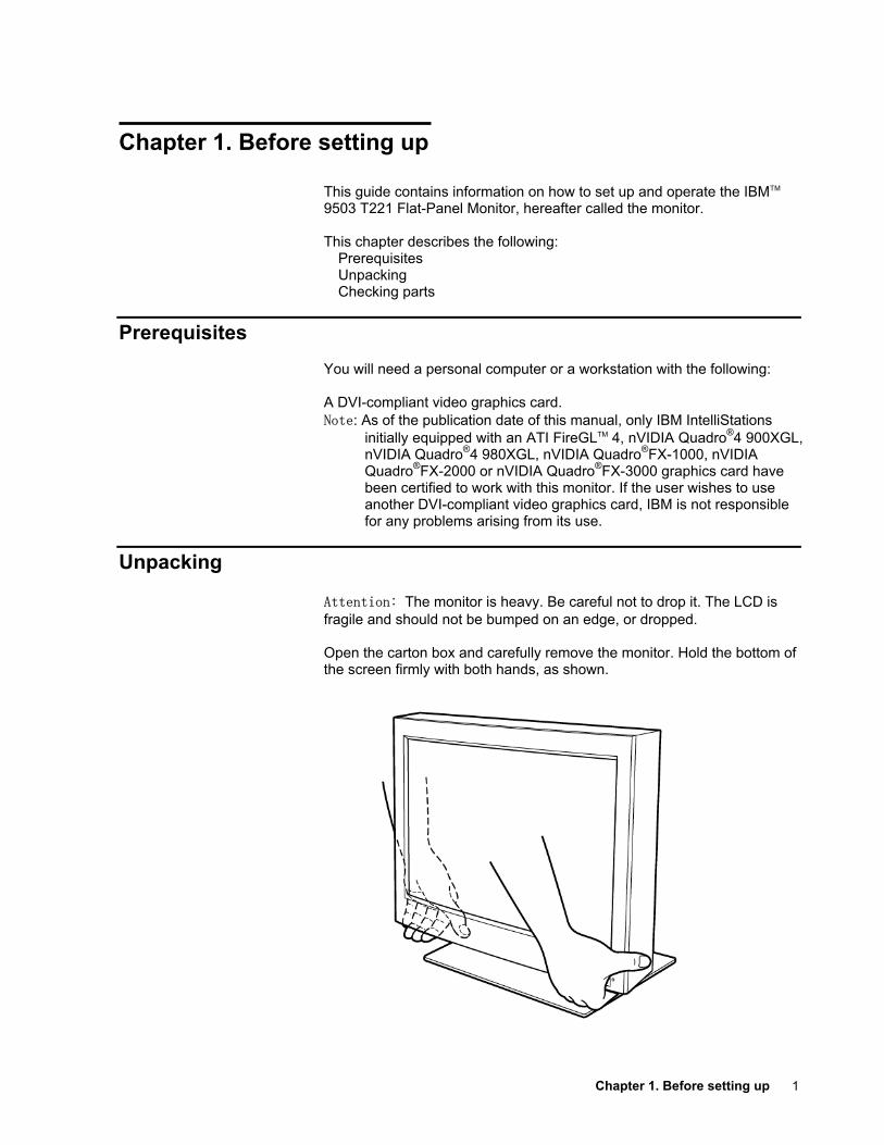
Unpacking
Attention: The monitor is heavy. Be careful not to drop it. The LCD is fragile and should not be bumped on an edge, or dropped. Open the carton box and carefully remove the monitor. Hold the bottom of the screen firmly with both hands, as shown.
2
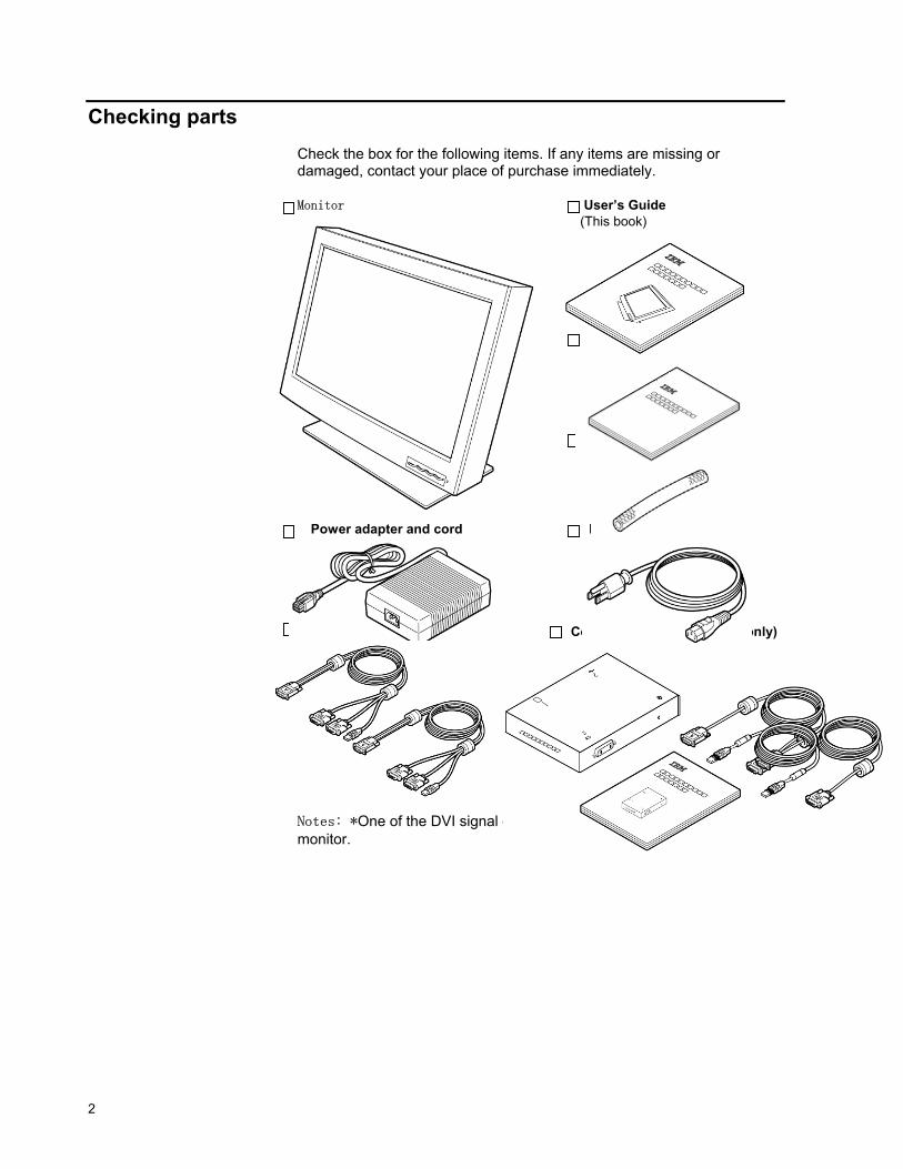
Checking parts
Check the box for the following items. If any items are missing or damaged, contact your place of purchase immediately. Monitor User’s Guide
(This book)
Safety and Warranty
Connector tool
Power adapter and cord Power cord
Digital signal cables (2x)* Converter Box set (for DG5 only)
Notes: *One of the DVI signal cables is shipped already connected to the monitor.
Chapter 2. Hardware setup 3
Chapter 2. Hardware setup This chapter describes the following:
The location of the controls, switches, and connectors. The procedure for setting up the monitor (page 4).
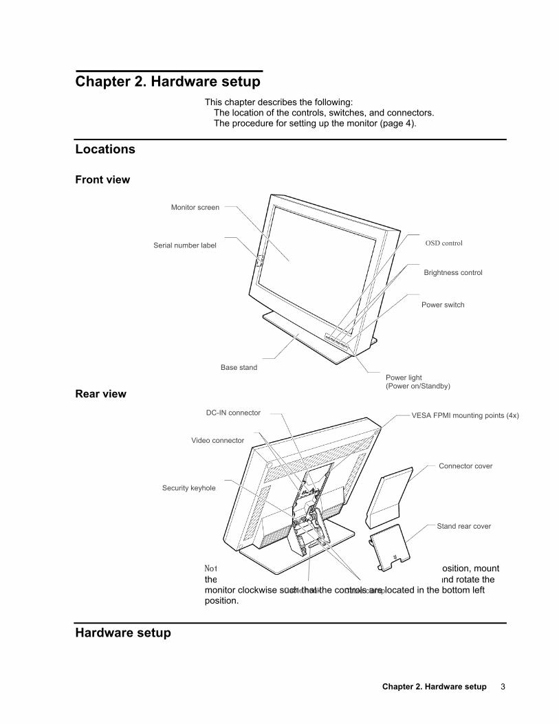
Locations Front view
Rear view
Note: If it is desired to operate the monitor in the portrait position, mount the monitor on a stand meeting the VESA FPMI standard and rotate the monitor clockwise such that the controls are located in the bottom left position.
Hardware setup
OSD control
Brightness control
Power switch
Power light (Power on/Standby)
Base stand
Serial number label
Monitor screen
DC-IN connector
Video connector
Security keyhole
Stand rear cover
Cable clampCable hook
VESA FPMI mounting points (4x)
Connector cover
4
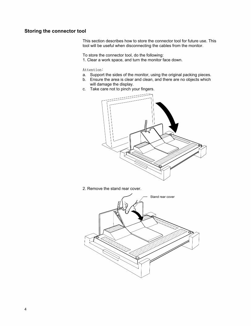
Storing the connector tool
This section describes how to store the connector tool for future use. This tool will be useful when disconnecting the cables from the monitor. To store the connector tool, do the following: 1. Clear a work space, and turn the monitor face down. Attention: a. Support the sides of the monitor, using the original packing pieces. b. Ensure the area is clear and clean, and there are no objects which
will damage the display. c. Take care not to pinch your fingers.
2. Remove the stand rear cover.
Stand rear cover
Chapter 2. Hardware setup 5
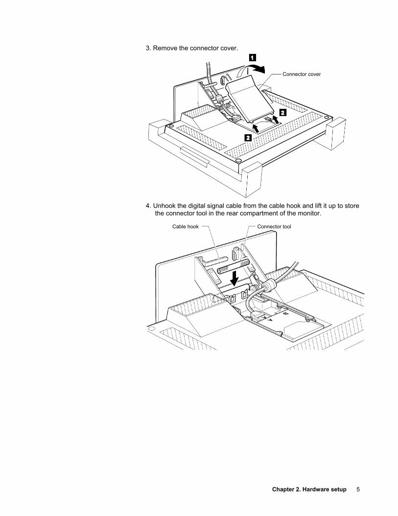
3. Remove the connector cover. 4. Unhook the digital signal cable from the cable hook and lift it up to store
the connector tool in the rear compartment of the monitor.
1 2 2
Connector cover
Connector tool Cable hook
6
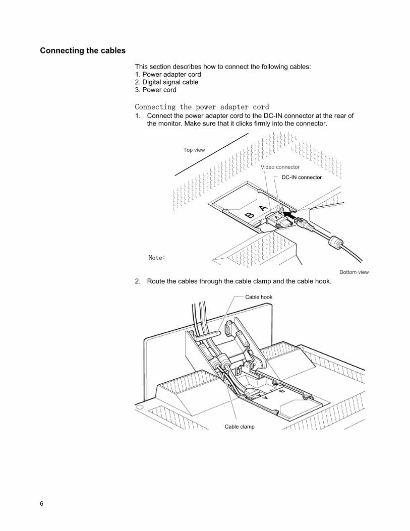
Connecting the cables
This section describes how to connect the following cables: 1. Power adapter cord 2. Digital signal cable 3. Power cord Connecting the power adapter cord 1. Connect the power adapter cord to the DC-IN connector at the rear of
the monitor. Make sure that it clicks firmly into the connector.
Note: The video connectors A and B on the monitor are Safety Extra Low Voltage (SELV) circuits.
2. Route the cables through the cable clamp and the cable hook.
Video connector
Top view
Bottom view
DC-IN connector
Cable hook
Cable clamp
Chapter 2. Hardware setup 7
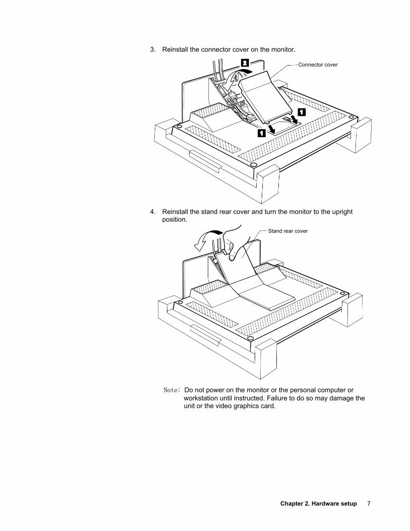
3. Reinstall the connector cover on the monitor. 4. Reinstall the stand rear cover and turn the monitor to the upright
position.
Note: Do not power on the monitor or the personal computer or workstation until instructed. Failure to do so may damage the unit or the video graphics card.
Connector cover
Stand rear cover
8
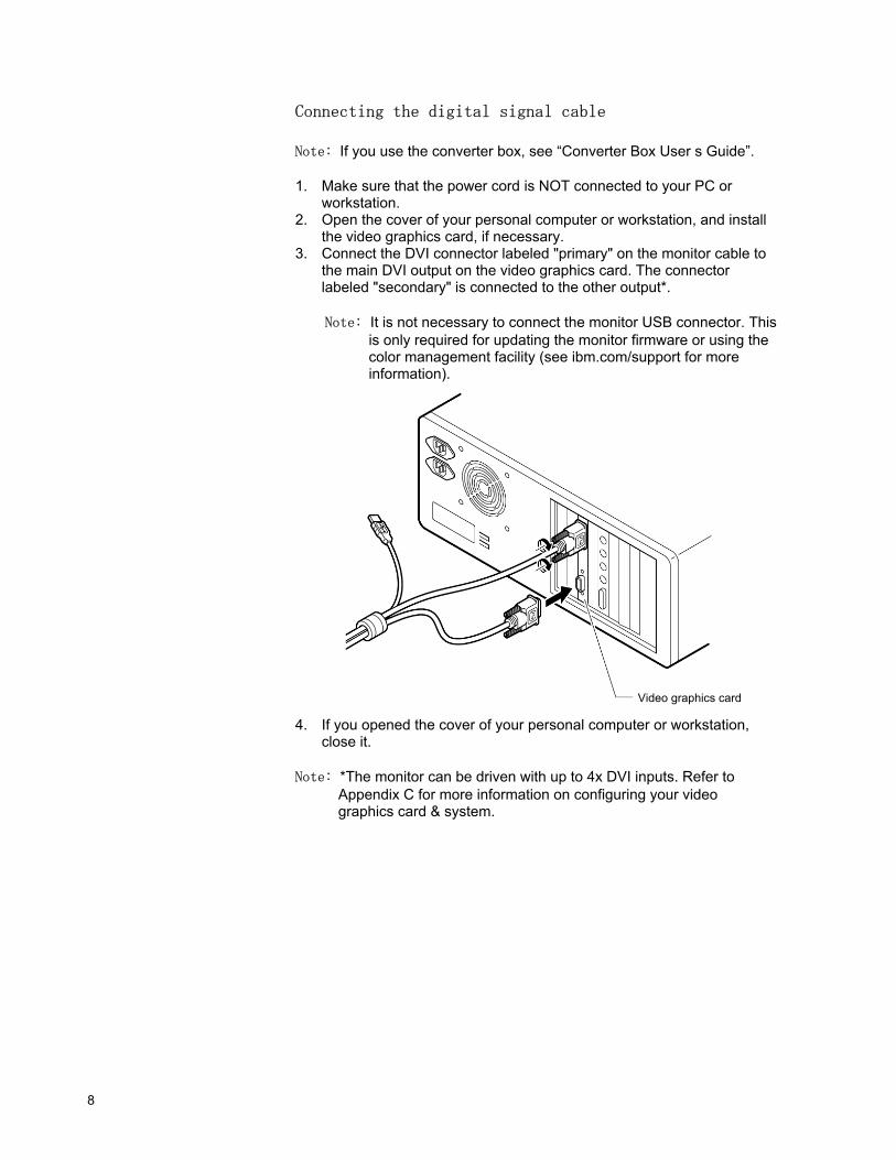
Connecting the digital signal cable
Note: If you use the converter box, see “Converter Box User s Guide”. 1. Make sure that the power cord is NOT connected to your PC or
workstation. 2. Open the cover of your personal computer or workstation, and install
the video graphics card, if necessary. 3. Connect the DVI connector labeled "primary" on the monitor cable to
the main DVI output on the video graphics card. The connector labeled "secondary" is connected to the other output*.
Note: It is not necessary to connect the monitor USB connector. This
is only required for updating the monitor firmware or using the color management facility (see ibm.com/support for more information).
4. If you opened the cover of your personal computer or workstation,
close it. Note: *The monitor can be driven with up to 4x DVI inputs. Refer to
Appendix C for more information on configuring your video graphics card & system.
Video graphics card
Chapter 2. Hardware setup 9
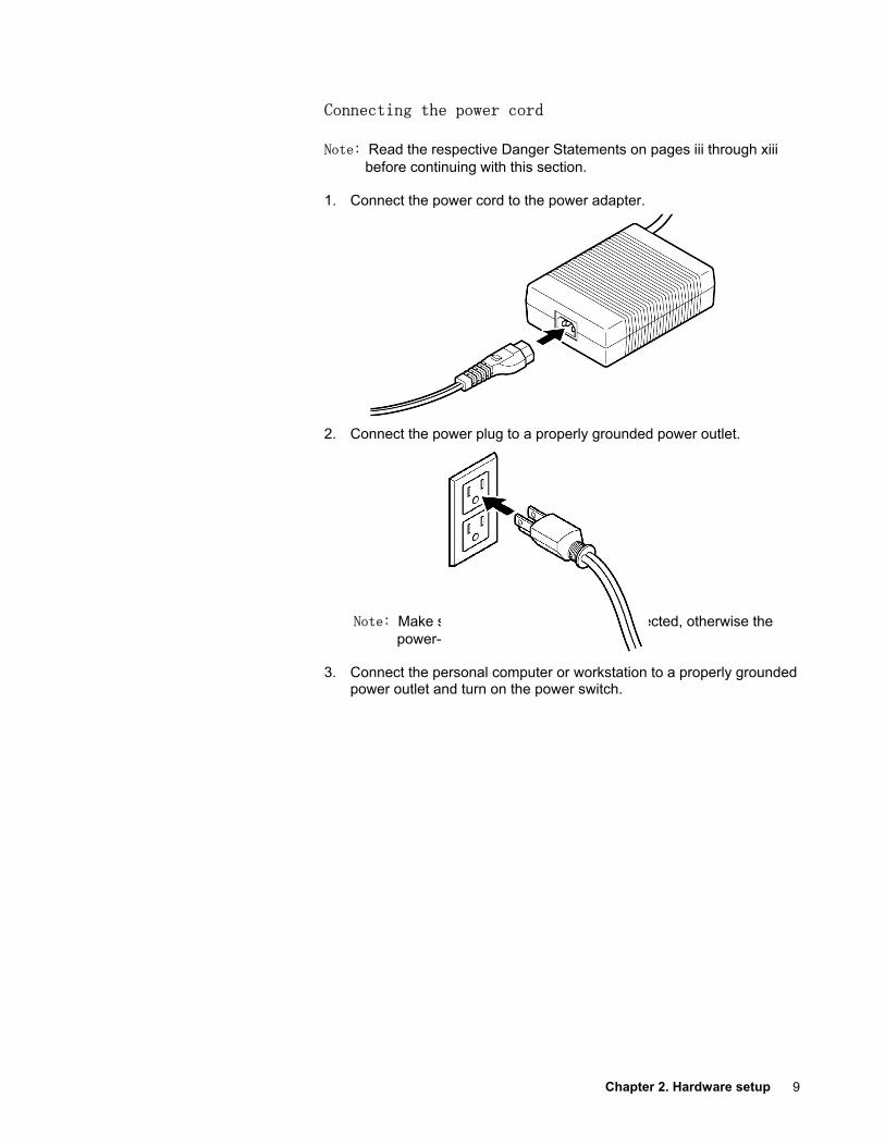
Connecting the power cord
Note: Read the respective Danger Statements on pages iii through xiii before continuing with this section.
1. Connect the power cord to the power adapter. 2. Connect the power plug to a properly grounded power outlet.
Note: Make sure that all the cables are connected, otherwise the power-on light will not turn on.
3. Connect the personal computer or workstation to a properly grounded
power outlet and turn on the power switch.
10
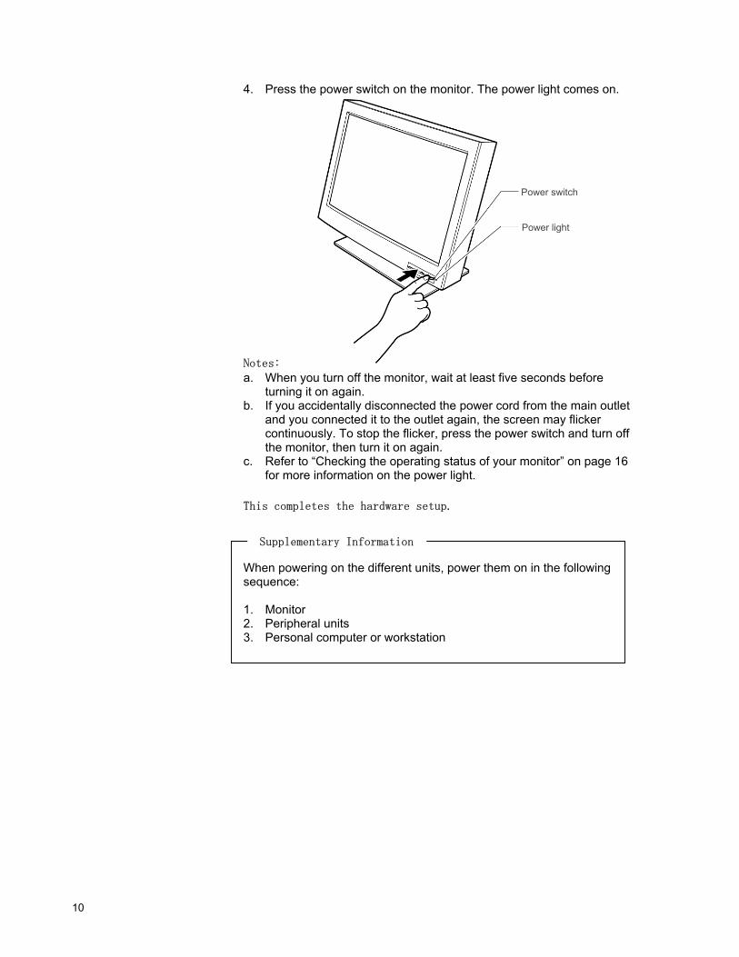
4. Press the power switch on the monitor. The power light comes on.
Notes: a. When you turn off the monitor, wait at least five seconds before
turning it on again. b. If you accidentally disconnected the power cord from the main outlet
and you connected it to the outlet again, the screen may flicker continuously. To stop the flicker, press the power switch and turn off the monitor, then turn it on again.
c. Refer to “Checking the operating status of your monitor” on page 16 for more information on the power light.
This completes the hardware setup.
When powering on the different units, power them on in the following sequence: 1. Monitor 2. Peripheral units 3. Personal computer or workstation
Power switch
Power light
Supplementary Information
Chapter 3. Adjusting and maintaining your monitor 11
Chapter 3. Adjusting and maintaining your monitor This chapter describes the following:
How to adjust the viewing angle. How to set the controls. The operating status of your monitor. How to disconnect the cables. How to use the security keylock. How to maintain your monitor.
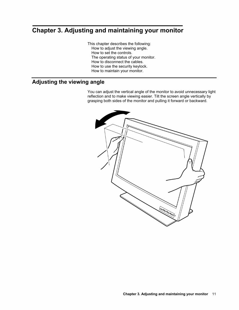
Adjusting the viewing angle You can adjust the vertical angle of the monitor to avoid unnecessary light reflection and to make viewing easier. Tilt the screen angle vertically by grasping both sides of the monitor and pulling it forward or backward.
12
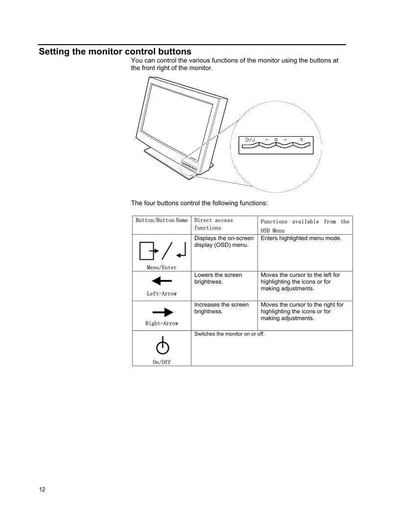
Setting the monitor control buttons You can control the various functions of the monitor using the buttons at the front right of the monitor. The four buttons control the following functions: Button/Button Name Direct access
functions Functions available from the
OSD Menu
Menu/Enter
Displays the on-screen display (OSD) menu.
Enters highlighted menu mode.
Left-Arrow
Lowers the screen brightness.
Moves the cursor to the left for highlighting the icons or for making adjustments.
Right-Arrow
Increases the screen brightness.
Moves the cursor to the right for highlighting the icons or for making adjustments.
On/Off
Switches the monitor on or off.
Chapter 3. Adjusting and maintaining your monitor 13
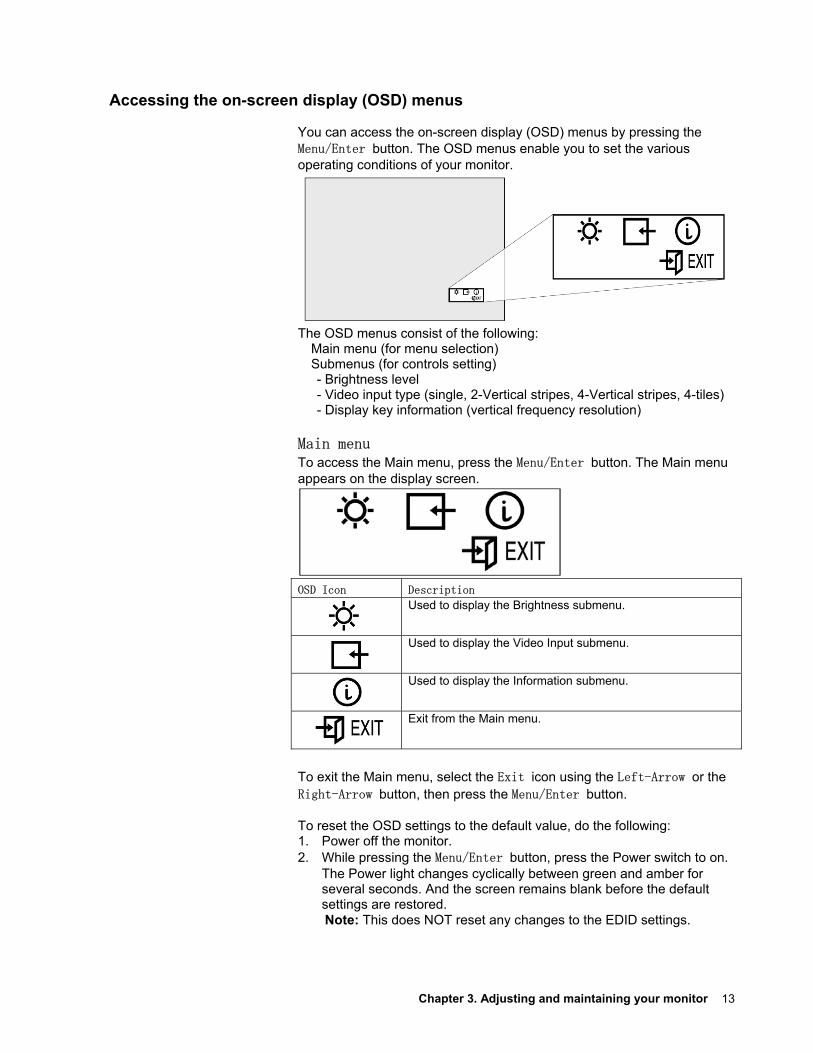
Accessing the on-screen display (OSD) menus You can access the on-screen display (OSD) menus by pressing the Menu/Enter button. The OSD menus enable you to set the various operating conditions of your monitor. The OSD menus consist of the following:
Main menu (for menu selection) Submenus (for controls setting) - Brightness level - Video input type (single, 2-Vertical stripes, 4-Vertical stripes, 4-tiles) - Display key information (vertical frequency resolution)
Main menu To access the Main menu, press the Menu/Enter button. The Main menu appears on the display screen.
OSD Icon Description
Used to display the Brightness submenu.
Used to display the Video Input submenu.
Used to display the Information submenu.
Exit from the Main menu.
To exit the Main menu, select the Exit icon using the Left-Arrow or the Right-Arrow button, then press the Menu/Enter button. To reset the OSD settings to the default value, do the following: 1. Power off the monitor. 2. While pressing the Menu/Enter button, press the Power switch to on.
The Power light changes cyclically between green and amber for several seconds. And the screen remains blank before the default settings are restored. Note: This does NOT reset any changes to the EDID settings.
14
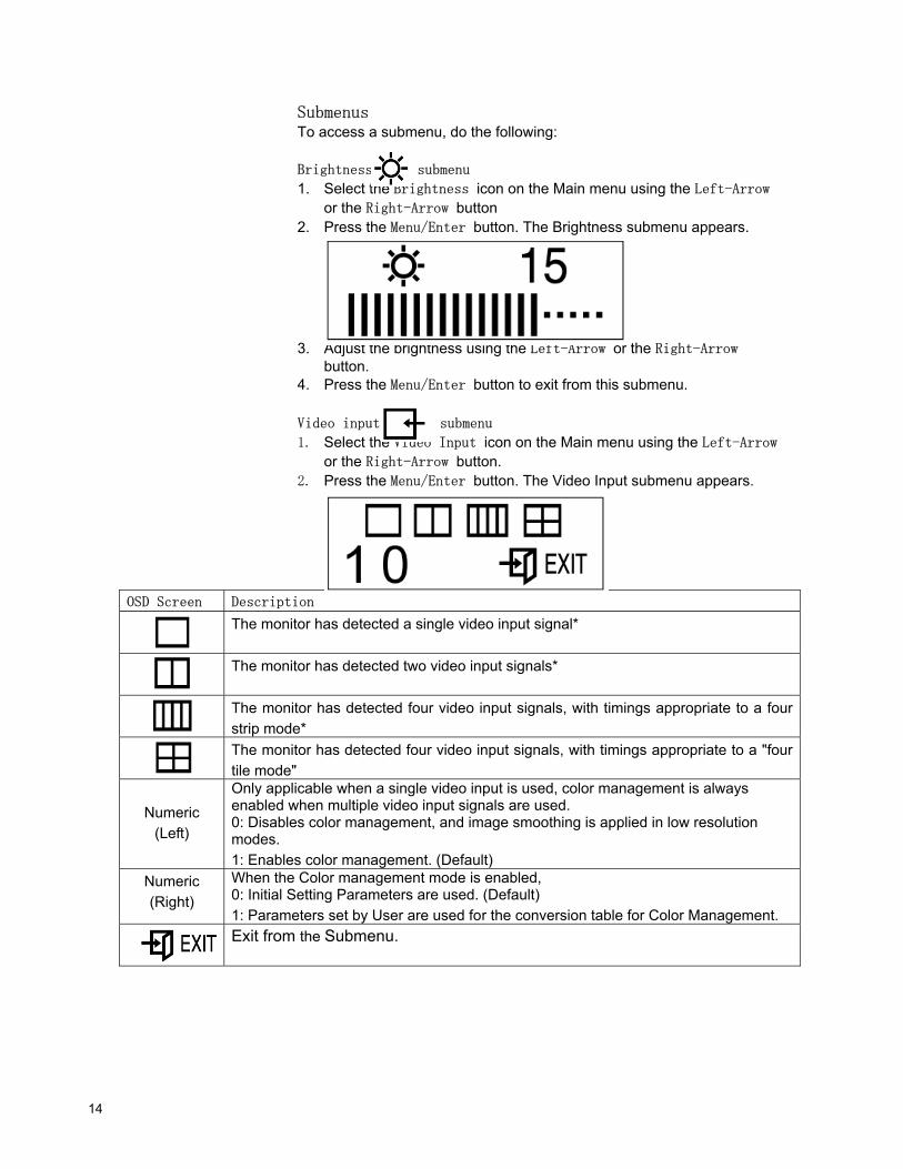
Submenus To access a submenu, do the following:
Brightness submenu
1. Select the Brightness icon on the Main menu using the Left-Arrow or the Right-Arrow button
2. Press the Menu/Enter button. The Brightness submenu appears. 3. Adjust the brightness using the Left-Arrow or the Right-Arrow
button. 4. Press the Menu/Enter button to exit from this submenu.
Video input submenu
1. Select the Video Input icon on the Main menu using the Left-Arrow or the Right-Arrow button.
2. Press the Menu/Enter button. The Video Input submenu appears.
OSD Screen Description
The monitor has detected a single video input signal*
The monitor has detected two video input signals*
The monitor has detected four video input signals, with timings appropriate to a four strip mode*
The monitor has detected four video input signals, with timings appropriate to a "four tile mode"
Numeric (Left)
Only applicable when a single video input is used, color management is always enabled when multiple video input signals are used. 0: Disables color management, and image smoothing is applied in low resolution modes. 1: Enables color management. (Default)
Numeric (Right)
When the Color management mode is enabled, 0: Initial Setting Parameters are used. (Default) 1: Parameters set by User are used for the conversion table for Color Management.
Exit from the Submenu.
Chapter 3. Adjusting and maintaining your monitor 15
3. Press the Left-Arrow button for at least 3 seconds to disable or enable the color management mode when a single video input is being used
4. Press the Menu/Enter button to exit from this submenu.
Note: * The monitor automatically detects the number of video inputs and timings. The OSD doesn't provide a manual override.
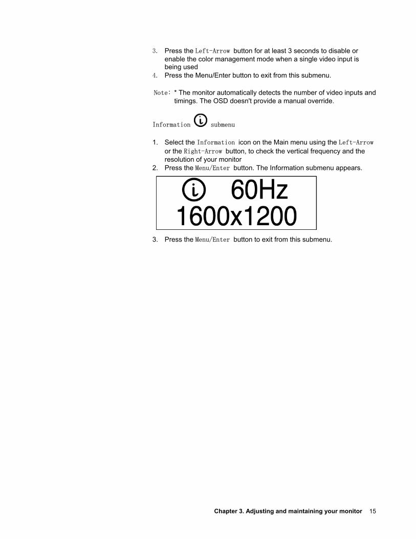
Information submenu
1. Select the Information icon on the Main menu using the Left-Arrow or the Right-Arrow button, to check the vertical frequency and the resolution of your monitor
2. Press the Menu/Enter button. The Information submenu appears. 3. Press the Menu/Enter button to exit from this submenu.
16
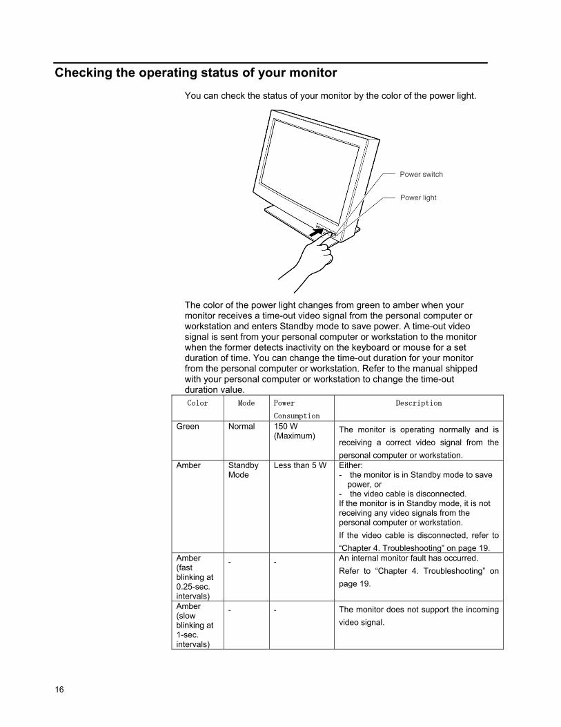
Checking the operating status of your monitor You can check the status of your monitor by the color of the power light. The color of the power light changes from green to amber when your monitor receives a time-out video signal from the personal computer or workstation and enters Standby mode to save power. A time-out video signal is sent from your personal computer or workstation to the monitor when the former detects inactivity on the keyboard or mouse for a set duration of time. You can change the time-out duration for your monitor from the personal computer or workstation. Refer to the manual shipped with your personal computer or workstation to change the time-out duration value. Color Mode Power
Consumption
Description
Green
Normal
150 W (Maximum)
The monitor is operating normally and is receiving a correct video signal from the personal computer or workstation.
Amber
Standby Mode
Less than 5 W
Either: - the monitor is in Standby mode to save
power, or - the video cable is disconnected. If the monitor is in Standby mode, it is not receiving any video signals from the personal computer or workstation. If the video cable is disconnected, refer to “Chapter 4. Troubleshooting” on page 19.
Amber (fast blinking at 0.25-sec. intervals)
- - An internal monitor fault has occurred. Refer to “Chapter 4. Troubleshooting” on page 19.
Amber (slow blinking at 1-sec. intervals)
- - The monitor does not support the incoming video signal.
Power switch
Power light
Chapter 3. Adjusting and maintaining your monitor 17
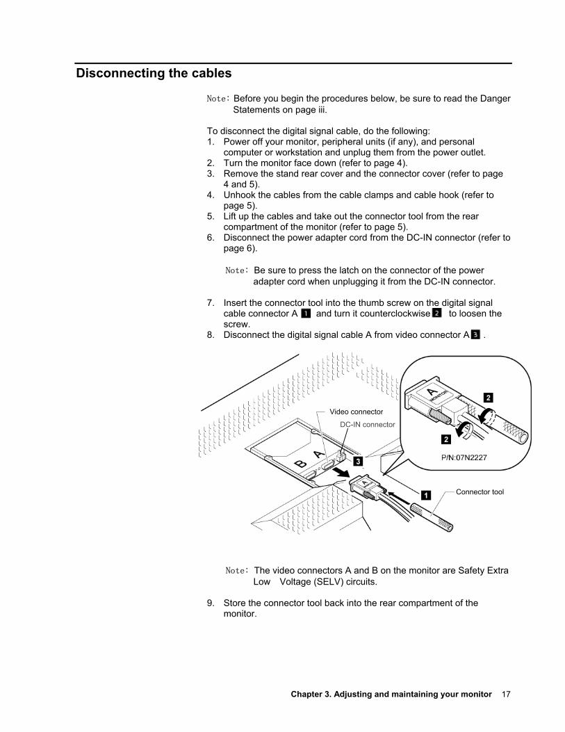
Disconnecting the cables
Note: Before you begin the procedures below, be sure to read the Danger Statements on page iii.
To disconnect the digital signal cable, do the following: 1. Power off your monitor, peripheral units (if any), and personal
computer or workstation and unplug them from the power outlet. 2. Turn the monitor face down (refer to page 4). 3. Remove the stand rear cover and the connector cover (refer to page
4 and 5). 4. Unhook the cables from the cable clamps and cable hook (refer to
page 5). 5. Lift up the cables and take out the connector tool from the rear
compartment of the monitor (refer to page 5). 6. Disconnect the power adapter cord from the DC-IN connector (refer to
page 6).
Note: Be sure to press the latch on the connector of the power adapter cord when unplugging it from the DC-IN connector.
7. Insert the connector tool into the thumb screw on the digital signal
cable connector A and turn it counterclockwise to loosen the screw.
8. Disconnect the digital signal cable A from video connector A . 3 2 2
Note: The video connectors A and B on the monitor are Safety Extra Low Voltage (SELV) circuits.
9. Store the connector tool back into the rear compartment of the
monitor.
Connector tool
Video connector
DC-IN connector
18
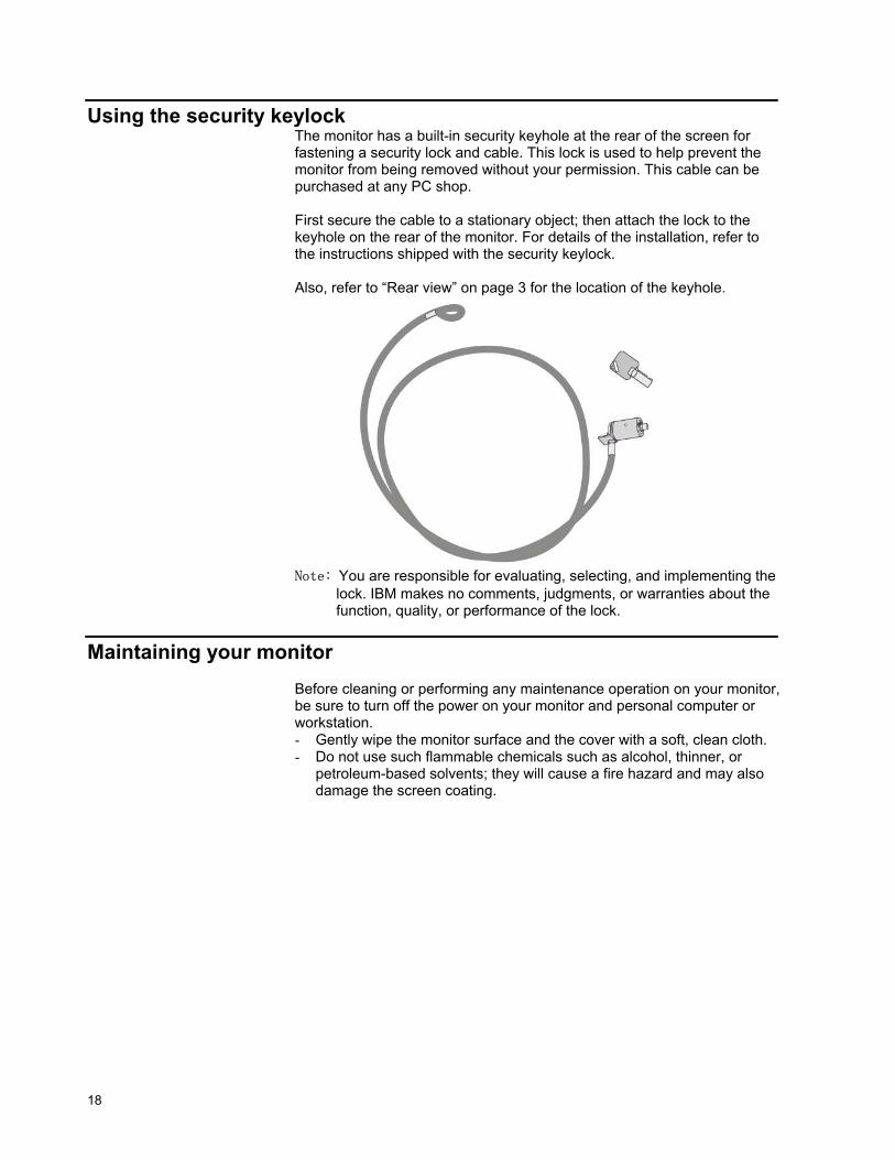
Using the security keylock The monitor has a built-in security keyhole at the rear of the screen for fastening a security lock and cable. This lock is used to help prevent the monitor from being removed without your permission. This cable can be purchased at any PC shop. First secure the cable to a stationary object; then attach the lock to the keyhole on the rear of the monitor. For details of the installation, refer to the instructions shipped with the security keylock. Also, refer to “Rear view” on page 3 for the location of the keyhole. Note: You are responsible for evaluating, selecting, and implementing the
lock. IBM makes no comments, judgments, or warranties about the function, quality, or performance of the lock.
Maintaining your monitor Before cleaning or performing any maintenance operation on your monitor, be sure to turn off the power on your monitor and personal computer or workstation. - Gently wipe the monitor surface and the cover with a soft, clean cloth. - Do not use such flammable chemicals such as alcohol, thinner, or
petroleum-based solvents; they will cause a fire hazard and may also damage the screen coating.
Chapter 4. Troubleshooting 19
Chapter 4. Troubleshooting
If you suspect something is not working correctly, you should: 1. Turn on the computer and monitor.
2. Set the brightness control ( ) to the proper position. 3. Make sure that all cables are securely connected. 4. Disable the computer's screen saver program if it is enabled. 5. Set the display mode to a supported display mode. 6. If you still have trouble, go to the symptom list below and find the
symptom that most resembles yours.
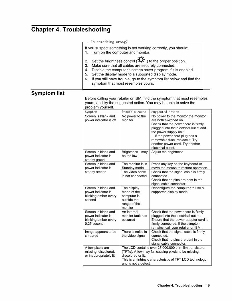
Symptom list Before calling your retailer or IBM, find the symptom that most resembles yours, and try the suggested action. You may be able to solve the problem yourself. Symptom Possible cause Suggested action Screen is blank and power indicator is off
No power to the monitor
No power to the monitor the monitor are both switched on. Check that the power cord is firmly plugged into the electrical outlet and the power supply unit.
If the power cord plug has a removable fuse, replace it. Try another power cord. Try another electrical outlet.
Screen is blank and power indicator is steady green
Brightness may be too low
Adjust the brightness
The monitor is in Standby mode
Press any key on the keyboard or move the mouse to restore operation.
Screen is blank and power indicator is steady amber The video cable
is not connected
Check that the signal cable is firmly connected. Check that no pins are bent in the signal cable connector.
Screen is blank and power indicator is blinking amber every second
The display mode of the computer is outside the range of the monitor
Reconfigure the computer to use a supported display mode.
Screen is blank and power indicator is blinking amber every 0.25 second
An internal monitor fault has occurred
Check that the power cord is firmly plugged into the electrical outlet. Ensure that the power adapter cord is firmly connected. If the symptom remains, call your retailer or IBM.
Image appears to be smeared
There is noise in the video signal
Check that the signal cable is firmly connected. Check that no pins are bent in the signal cable connector.
A few pixels are missing, discolored, or inappropriately lit
The LCD contains over 27,000,000 thin-film transistors (TFTs). A few may fail causing pixels to be missing, discolored or lit. This is an intrinsic characteristic of TFT LCD technology and is not a defect.
Is something wrong?
20
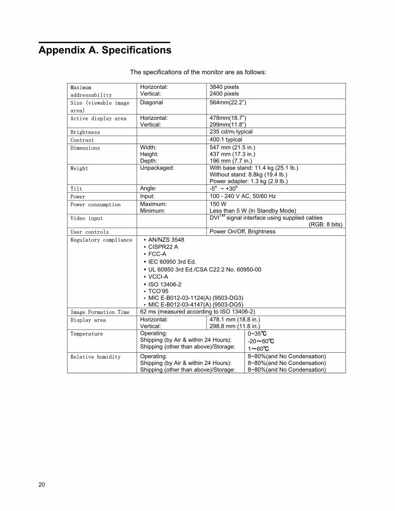
Appendix A. Specifications The specifications of the monitor are as follows:
Maximum
addressability Horizontal: Vertical:
3840 pixels 2400 pixels
Size (viewable image
area) Diagonal 564mm(22.2”)
Active display area Horizontal: Vertical:
478mm(18.7”) 299mm(11.8”)
Brightness 235 cd/m2 typical Contrast 400:1 typical Dimensions Width:
Height: Depth:
547 mm (21.5 in.) 437 mm (17.3 in.) 196 mm (7.7 in.)
Weight Unpackaged: With base stand: 11.4 kg (25.1 lb.) Without stand: 8.8kg (19.4 lb.) Power adapter: 1.3 kg (2.9 lb.)
Tilt Angle: -5°~ +30° Power Input: 100 - 240 V AC, 50/60 Hz Power consumption Maximum:
Minimum: 150 W Less than 5 W (In Standby Mode)
Video input DVITM signal interface using supplied cables (RGB: 8 bits)
User controls Power On/Off, Brightness Regulatory compliance • AN/NZS 3548
• CISPR22 A • FCC-A • IEC 60950 3rd Ed. • UL 60950 3rd Ed./CSA C22.2 No. 60950-00 • VCCI-A • ISO 13406-2 • TCO’95 • MIC E-B012-03-1124(A) (9503-DG3) • MIC E-B012-03-4147(A) (9503-DG5)
Image Formation Time 62 ms (measured according to ISO 13406-2) Display area Horizontal:
Vertical: 478.1 mm (18.8 in.) 298.8 mm (11.8 in.)
Temperature Operating: Shipping (by Air & within 24 Hours): Shipping (other than above)/Storage:
0~35℃
-20~60℃
1~60℃ Relative humidity Operating:
Shipping (by Air & within 24 Hours): Shipping (other than above)/Storage:
8~80%(and No Condensation) 8~80%(and No Condensation) 8~80%(and No Condensation)
Appendix A. Specifications 21
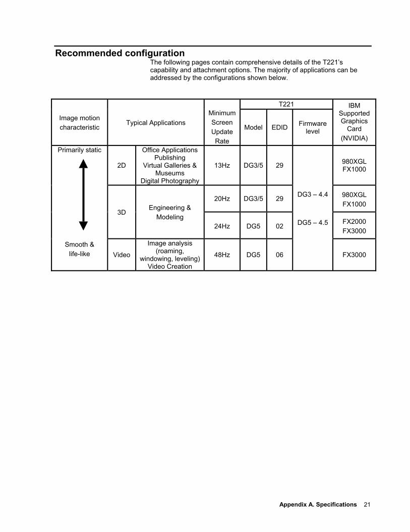
Recommended configuration The following pages contain comprehensive details of the T221’s capability and attachment options. The majority of applications can be addressed by the configurations shown below.
T221
Image motion characteristic
Typical Applications
MinimumScreen Update
Rate
Model EDID Firmware level
IBM Supported Graphics
Card (NVIDIA)
2D
Office ApplicationsPublishing
Virtual Galleries & Museums
Digital Photography
13Hz DG3/5 29 980XGL FX1000
20Hz DG3/5 29 980XGL FX1000
3D Engineering &
Modeling 24Hz DG5 02
FX2000 FX3000
Primarily static
Smooth & life-like Video
Image analysis (roaming,
windowing, leveling)Video Creation
48Hz DG5 06
DG3 – 4.4
DG5 – 4.5
FX3000
22
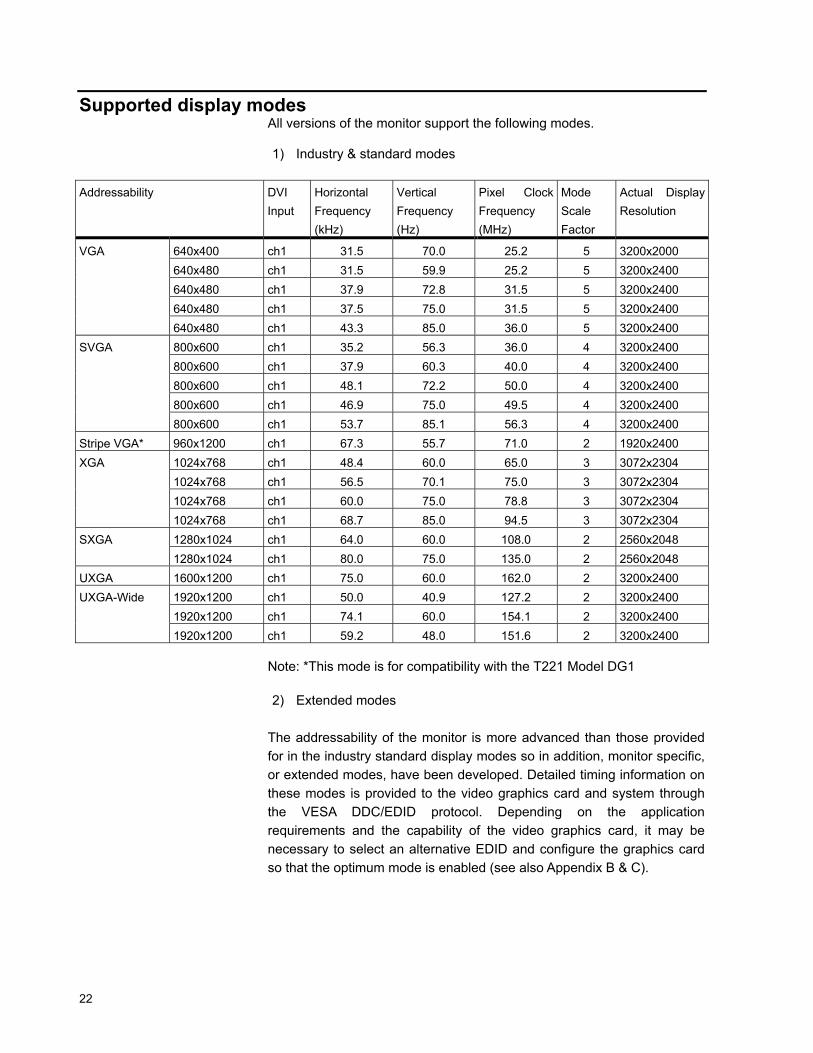
Supported display modes All versions of the monitor support the following modes. 1) Industry & standard modes
Addressability DVI Input
Horizontal Frequency (kHz)
Vertical Frequency (Hz)
Pixel Clock Frequency (MHz)
Mode Scale Factor
Actual Display Resolution
640x400 ch1 31.5 70.0 25.2 5 3200x2000 640x480 ch1 31.5 59.9 25.2 5 3200x2400 640x480 ch1 37.9 72.8 31.5 5 3200x2400 640x480 ch1 37.5 75.0 31.5 5 3200x2400
VGA
640x480 ch1 43.3 85.0 36.0 5 3200x2400 800x600 ch1 35.2 56.3 36.0 4 3200x2400 800x600 ch1 37.9 60.3 40.0 4 3200x2400 800x600 ch1 48.1 72.2 50.0 4 3200x2400 800x600 ch1 46.9 75.0 49.5 4 3200x2400
SVGA
800x600 ch1 53.7 85.1 56.3 4 3200x2400 Stripe VGA* 960x1200 ch1 67.3 55.7 71.0 2 1920x2400
1024x768 ch1 48.4 60.0 65.0 3 3072x2304 1024x768 ch1 56.5 70.1 75.0 3 3072x2304 1024x768 ch1 60.0 75.0 78.8 3 3072x2304
XGA
1024x768 ch1 68.7 85.0 94.5 3 3072x2304 1280x1024 ch1 64.0 60.0 108.0 2 2560x2048 SXGA 1280x1024 ch1 80.0 75.0 135.0 2 2560x2048
UXGA 1600x1200 ch1 75.0 60.0 162.0 2 3200x2400 1920x1200 ch1 50.0 40.9 127.2 2 3200x2400 1920x1200 ch1 74.1 60.0 154.1 2 3200x2400
UXGA-Wide
1920x1200 ch1 59.2 48.0 151.6 2 3200x2400 Note: *This mode is for compatibility with the T221 Model DG1 2) Extended modes
The addressability of the monitor is more advanced than those provided for in the industry standard display modes so in addition, monitor specific, or extended modes, have been developed. Detailed timing information on these modes is provided to the video graphics card and system through the VESA DDC/EDID protocol. Depending on the application requirements and the capability of the video graphics card, it may be necessary to select an alternative EDID and configure the graphics card so that the optimum mode is enabled (see also Appendix B & C).
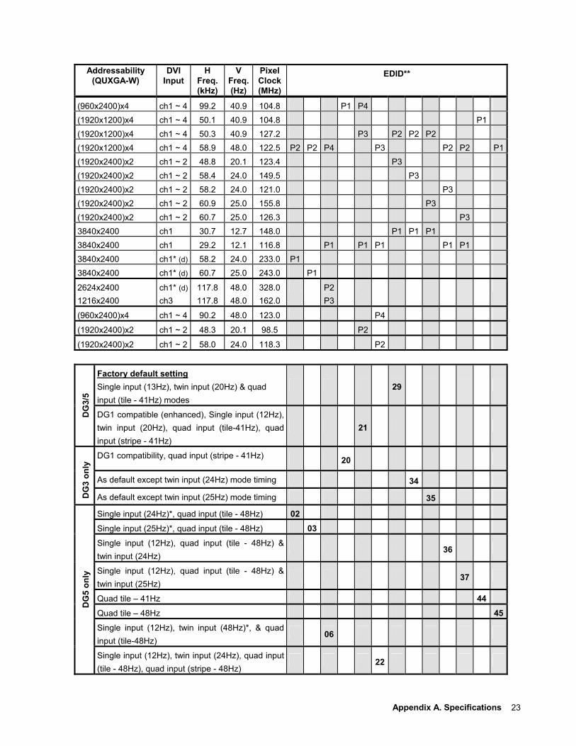
Appendix A. Specifications 23
Addressability (QUXGA-W)
DVI Input
H Freq. (kHz)
V Freq.(Hz)
Pixel Clock (MHz)
EDID**
(960x2400)x4 ch1 ~ 4 99.2 40.9 104.8 P1 P4 (1920x1200)x4 ch1 ~ 4 50.1 40.9 104.8 P1(1920x1200)x4 ch1 ~ 4 50.3 40.9 127.2 P3 P2 P2 P2 (1920x1200)x4 ch1 ~ 4 58.9 48.0 122.5 P2 P2 P4 P3 P2 P2 P1(1920x2400)x2 ch1 ~ 2 48.8 20.1 123.4 P3 (1920x2400)x2 ch1 ~ 2 58.4 24.0 149.5 P3 (1920x2400)x2 ch1 ~ 2 58.2 24.0 121.0 P3 (1920x2400)x2 ch1 ~ 2 60.9 25.0 155.8 P3 (1920x2400)x2 ch1 ~ 2 60.7 25.0 126.3 P33840x2400 ch1 30.7 12.7 148.0 P1 P1 P1 3840x2400 ch1 29.2 12.1 116.8 P1 P1 P1 P1 P13840x2400 ch1* (d) 58.2 24.0 233.0 P1 3840x2400 ch1* (d) 60.7 25.0 243.0 P1
2624x2400 1216x2400
ch1* (d) ch3
117.8 117.8
48.0 48.0
328.0162.0
P2 P3
(960x2400)x4 ch1 ~ 4 90.2 48.0 123.0 P4
(1920x2400)x2 ch1 ~ 2 48.3 20.1 98.5 P2
(1920x2400)x2 ch1 ~ 2 58.0 24.0 118.3 P2
Factory default setting Single input (13Hz), twin input (20Hz) & quad input (tile - 41Hz) modes
29
DG
3/5
DG1 compatible (enhanced), Single input (12Hz), twin input (20Hz), quad input (tile-41Hz), quad input (stripe - 41Hz)
21
DG1 compatibility, quad input (stripe - 41Hz) 20
As default except twin input (24Hz) mode timing 34
DG
3 on
ly
As default except twin input (25Hz) mode timing 35
Single input (24Hz)*, quad input (tile - 48Hz) 02 Single input (25Hz)*, quad input (tile - 48Hz) 03 Single input (12Hz), quad input (tile - 48Hz) & twin input (24Hz)
36
Single input (12Hz), quad input (tile - 48Hz) & twin input (25Hz)
37
Quad tile – 41Hz 44Quad tile – 48Hz 45Single input (12Hz), twin input (48Hz)*, & quad input (tile-48Hz)
06
DG
5 on
ly
Single input (12Hz), twin input (24Hz), quad input (tile - 48Hz), quad input (stripe - 48Hz)
22
24
Notes: * Requires dual-link DVI converter box **Each EDID contains up to four extended timings, the number (P1 - P4) in the top section of the table indicates the order & priority of these timings within the EDID. The selectable EDID number for each configuration is shown in the bottom section of the table. 3) Basic timing requirements
In general, the monitor supports any modes that comply with the following limits:
Vertical frequency : 13 - 85Hz Horizontal frequency : 31 - 118kHz DVI video clock : max. 165MHz (single link, per channel)
Appendix B. Updating the settings for your monitor 25
Appendix B. Updating the settings for your monitor Introduction
Modern monitors internally store data on their performance characteristics and capabilities in an abbreviated format. The information is called the monitor Extended Display Identification Data or EDID and is read by operating systems and video graphics cards to determine the optimum display properties for the system. The IBM T221 is a very advanced and flexible monitor and it exceeds the capability of the EDID system to describe it fully. A special OSD menu allows alternate EDIDs to be selected which are more suitable for certain graphics cards. Unless you change the video graphics card that drives your monitor, there is usually no need to change the EDID settings. The EDID update procedure must be done carefully. If an incorrect EDID is selected, it is possible that the monitor may not display any images afterwards.
Applicable model: All models with the following firmware level The procedure given in this document applies to monitors with firmware at the following levels: DDC CPU Version 3.2 or higher OSD CPU Version 5.0 or higher USB CPU Version 4.0 or higher FPGA LOGIC Version 34 or higher To check each version, see the next page. If you need to change the settings on a monitor that has firmware at a lower level, refer to the IBM technical website for T221 monitor.
1. Setting a. Connect the monitor to the desired graphics card and / or computer
system b. Turn on the monitor and the computer. PC. Wait until the system has
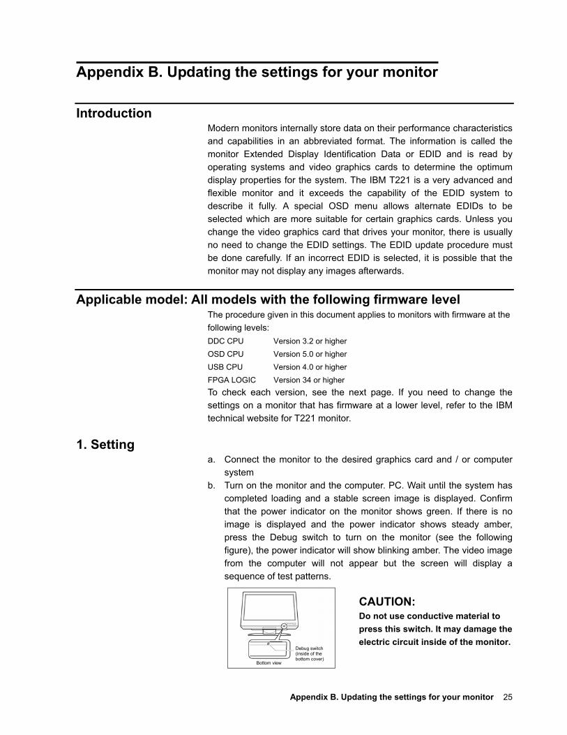
completed loading and a stable screen image is displayed. Confirm that the power indicator on the monitor shows green. If there is no image is displayed and the power indicator shows steady amber, press the Debug switch to turn on the monitor (see the following figure), the power indicator will show blinking amber. The video image from the computer will not appear but the screen will display a sequence of test patterns.
CAUTION: Do not use conductive material to press this switch. It may damage the electric circuit inside of the monitor.
Debug switch (inside of the bottom cover)
Bottom view
26
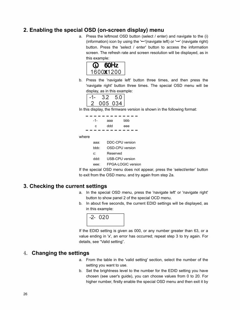
2. Enabling the special OSD (on-screen display) menu a. Press the leftmost OSD button (select / enter) and navigate to the (i)
(information) icon by using the '←'(navigate left) or '→' (navigate right) button. Press the 'select / enter' button to access the information screen. The refresh rate and screen resolution will be displayed, as in this example:
b. Press the 'navigate left' button three times, and then press the 'navigate right' button three times. The special OSD menu will be display, as in this example:
In this display, the firmware version is shown in the following format:
-1- aaa bbb c ddd eee
where aaa: DDC-CPU version bbb: OSD-CPU version c: Reserved ddd: USB-CPU version eee: FPGA-LOGIC version
If the special OSD menu does not appear, press the ‘select/enter’ button to exit from the OSD menu. and try again from step 2a.
3. Checking the current settings a. In the special OSD menu, press the 'navigate left' or 'navigate right'
button to show panel 2 of the special OCD menu. b. In about five seconds, the current EDID settings will be displayed, as
in this example:
If the EDID setting is given as 000, or any number greater than 63, or a value ending in 'x', an error has occurred; repeat step 3 to try again. For details, see “Valid setting”.
4. Changing the settings a. From the table in the 'valid setting' section, select the number of the
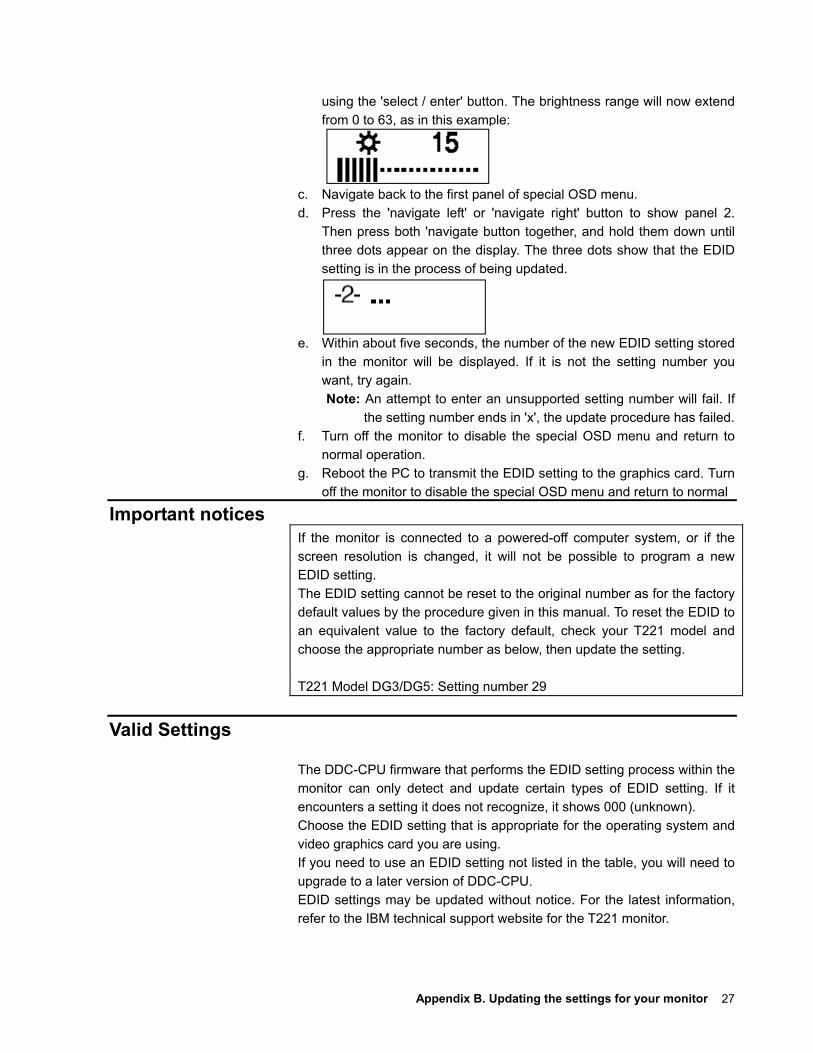
setting you want to use. b. Set the brightness level to the number for the EDID setting you have
chosen (see user's guide), you can choose values from 0 to 20. For higher number, firstly enable the special OSD menu and then exit it by
Appendix B. Updating the settings for your monitor 27
using the 'select / enter' button. The brightness range will now extend from 0 to 63, as in this example:
c. Navigate back to the first panel of special OSD menu. d. Press the 'navigate left' or 'navigate right' button to show panel 2.
Then press both 'navigate button together, and hold them down until three dots appear on the display. The three dots show that the EDID setting is in the process of being updated.
e. Within about five seconds, the number of the new EDID setting stored
in the monitor will be displayed. If it is not the setting number you want, try again. Note: An attempt to enter an unsupported setting number will fail. If
the setting number ends in 'x', the update procedure has failed. f. Turn off the monitor to disable the special OSD menu and return to
normal operation. g. Reboot the PC to transmit the EDID setting to the graphics card. Turn
off the monitor to disable the special OSD menu and return to normal
Important notices If the monitor is connected to a powered-off computer system, or if the screen resolution is changed, it will not be possible to program a new EDID setting. The EDID setting cannot be reset to the original number as for the factory default values by the procedure given in this manual. To reset the EDID to an equivalent value to the factory default, check your T221 model and choose the appropriate number as below, then update the setting. T221 Model DG3/DG5: Setting number 29
Valid Settings
The DDC-CPU firmware that performs the EDID setting process within the monitor can only detect and update certain types of EDID setting. If it encounters a setting it does not recognize, it shows 000 (unknown). Choose the EDID setting that is appropriate for the operating system and video graphics card you are using. If you need to use an EDID setting not listed in the table, you will need to upgrade to a later version of DDC-CPU. EDID settings may be updated without notice. For the latest information, refer to the IBM technical support website for the T221 monitor.
28
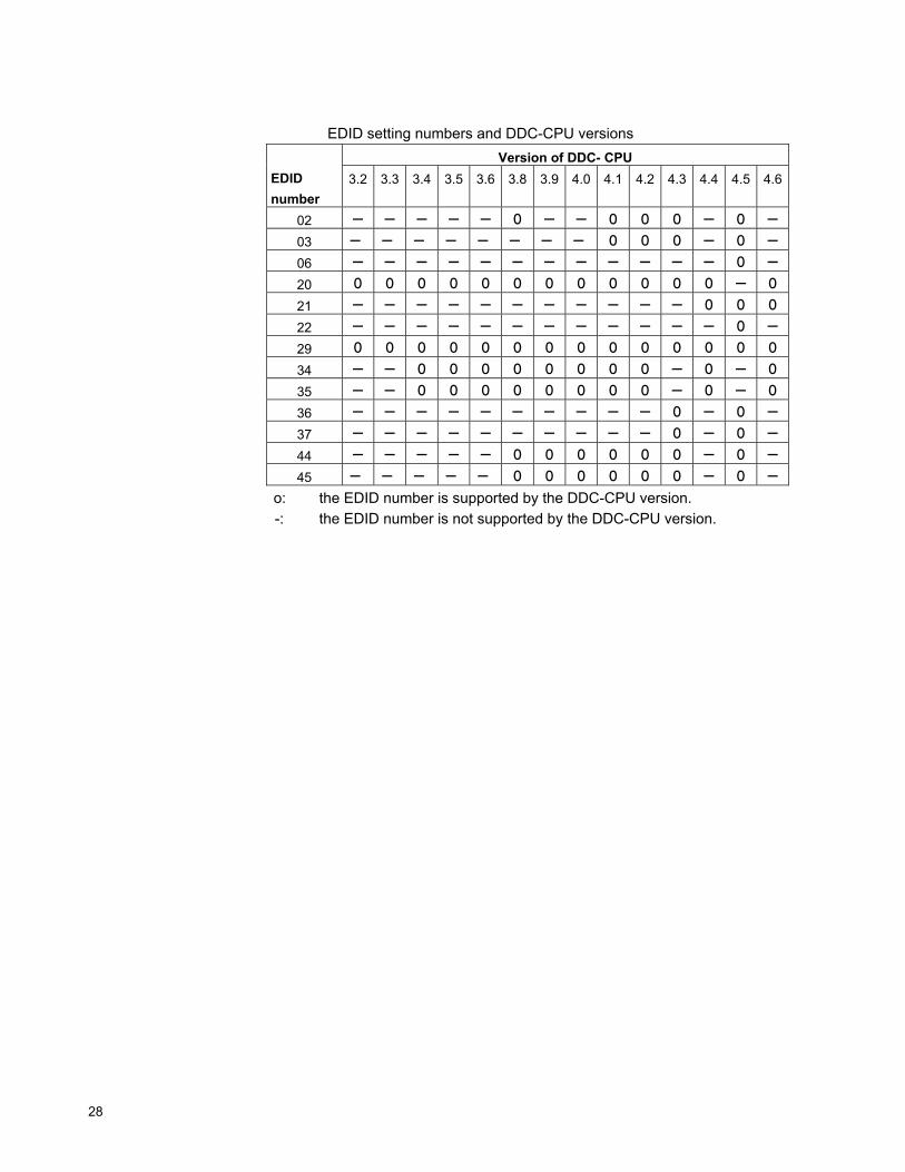
EDID setting numbers and DDC-CPU versions
Version of DDC- CPU EDID number
3.2 3.3 3.4 3.5 3.6 3.8 3.9 4.0 4.1 4.2 4.3 4.4 4.5 4.6
02 - - - - - O - - O O O - O -
03 - - - - - - - - O O O - O -
06 - - - - - - - - - - - - O -
20 O O O O O O O O O O O O - O
21 - - - - - - - - - - - O O O
22 - - - - - - - - - - - - O -
29 O O O O O O O O O O O O O O
34 - - O O O O O O O O - O - O
35 - - O O O O O O O O - O - O
36 - - - - - - - - - - O - O -
37 - - - - - - - - - - O - O -
44 - - - - - O O O O O O - O -
45 - - - - - O O O O O O - O -
o: the EDID number is supported by the DDC-CPU version. -: the EDID number is not supported by the DDC-CPU version.
Appendix C. Configuring your video graphics card 29
Appendix C. Configuring your video graphics card
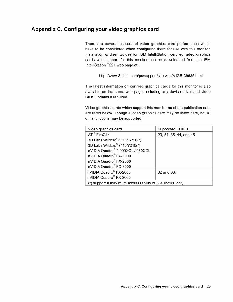
There are several aspects of video graphics card performance which have to be considered when configuring them for use with this monitor. Installation & User Guides for IBM IntelliStation certified video graphics cards with support for this monitor can be downloaded from the IBM IntelliStation T221 web page at:
http://www-3. ibm. com/pc/support/site.wss/MIGR-39635.html The latest information on certified graphics cards for this monitor is also available on the same web page, including any device driver and video BIOS updates if required. Video graphics cards which support this monitor as of the publication date are listed below. Though a video graphics card may be listed here, not all of its functions may be supported.
Video graphics card Supported EDID’s ATI® FireGL4 3D Labs Wildcat® 6110/ 6210(*) 3D Labs Wildcat® 7110/7210(*) nVIDIA Quadro®
4 900XGL / 980XGL nVIDIA Quadro®
FX-1000 nVIDIA Quadro®
FX-2000 nVIDIA Quadro®
FX-3000
29, 34, 35, 44, and 45
nVIDIA Quadro® FX-2000 nVIDIA Quadro® FX-3000
02 and 03.
(*) support a maximum addressability of 3840x2160 only.
30
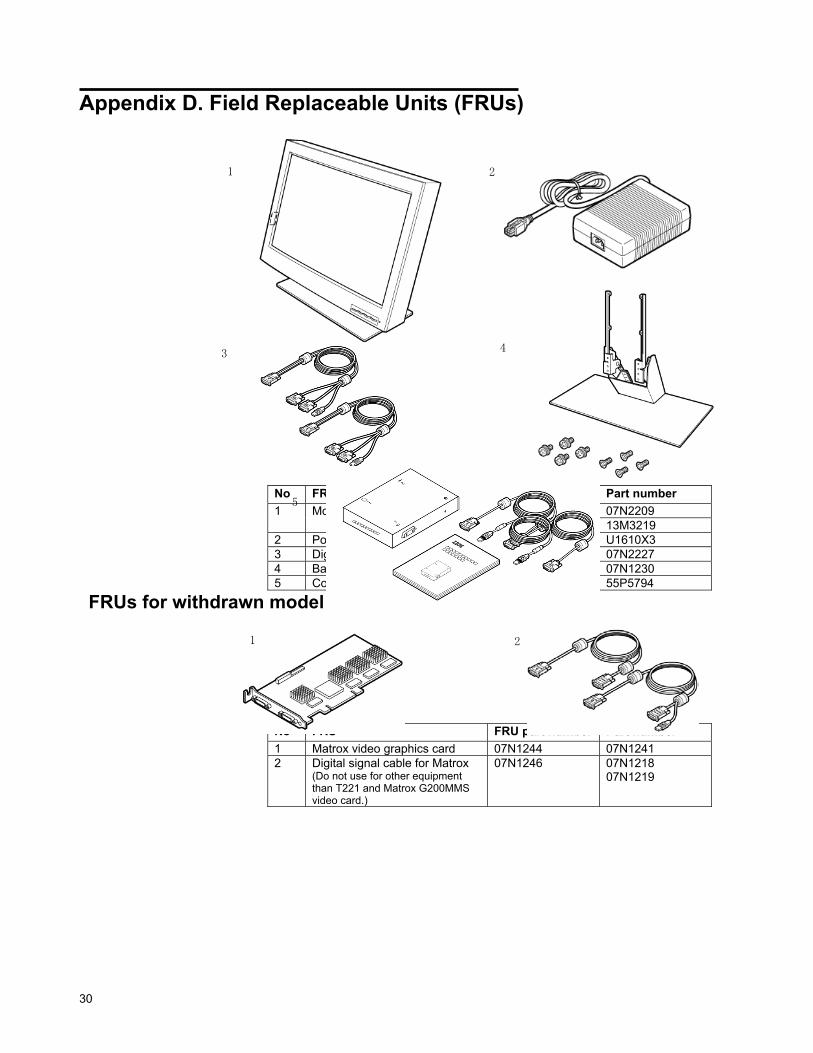
Appendix D. Field Replaceable Units (FRUs)
No FRU FRU part number Part number
(IBM 9503-DG3) 55P5067 07N2209 1 Monitor (IBM 9503-DG5) 13M3229 13M3219
2 Power adapter 55P5077 U1610X3 3 Digital signal cables for DVI 55P0995 07N2227 4 Base stand 07N2194 07N1230 5 Converter box set 13M3200 55P5794
FRUs for withdrawn model
No FRU FRU part number Part number 1 Matrox video graphics card 07N1244 07N1241 2 Digital signal cable for Matrox
(Do not use for other equipment than T221 and Matrox G200MMS video card.)
07N1246 07N1218 07N1219
1 2
3
5
4
1 2

Appendix E. Compliance 31
Appendix E. Compliance TCO’95
Congratulations! You have just purchased a TCO'95 approved and labelled product! Your choice has provided you with a product developed for professional use. Your purchase has also contributed to reducing the burden on the environment and also, to the further development of environmentally adapted electronics products.
Why do we have environmentally labelled computers? In many countries, environmental labelling has become an established method for encouraging the adaptation of goods and services to the environment. The main problem, as far as computers and other electronics equipment are concerned, is that environmentally harmful substances are used both in the products and during the manufacturing. Since it has not been possible for the majority of electronics equipment to be recycled in a satisfactory way, most of these potentially damaging substances sooner or later enter Nature.
There are also other characteristics of a computer, such as energy consumption levels, that are important from the viewpoints of both the work (internal) and natural (external) environments. Since all methods of conventional electricity generation have a negative effect on the environment (acidic and climate-influencing emissions, radioactive waste, etc.), it is vital to conserve energy. Electronics equipment in offices consume an enormous amount of energy since they are often left running continuously.
What does labelling involve? This product meets the requirements for the TCO'95 scheme which provides for international and environmental labelling of personal computers. The labelling scheme was developed as a joint effort by the TCO (The Swedish Confederation of Professional Employees), Naturskyddsforeningen (The Swedish Society for Nature Conservation) and NUTEK (The National Board for Industrial and Technical Development in Sweden).
The requirements cover a wide range of issues: environment, ergonomics, usability, emission of electrical and magnetic fields, energy consumption and electrical and fire safety.
The environmental demands concern restrictions on the presence and use of heavy metals, brominated and chlorinated flame retardants, CFCs (freons) and chlorinated solvents, among other things. The product must be prepared for recycling and the manufacturer is obliged to have an environmental plan which must be adhered to in each country where the company implements its operational policy.
The energy requirements include a demand that the computer and/or

32
display, after a certain period of inactivity, shall reduce its power consumption to a lower level in one or more stages. The length of time to reactivate the computer shall be reasonable for the user. Labelled products must meet strict environmental demands, for example, in respect of the reduction of electric and magnetic fields, physical and visual ergonomics and good usability. On the back page of this folder, you will find a brief summary of the environmental requirements met by this product. The complete environmental criteria document may be ordered from: TCO Development Unit 114 94 Stockholm Sweden Fax: +46 8 782 92 07 Email (Internet): [email protected] Current information regarding TCO'95 approved and labelled products may also be obtained via the Internet, using the address: http://www.tco-info.com/ TCO'95 is a co-operative project between TCO (The Swedish Confederation of Professional Employees), Naturskyddsforeningen (The Swedish Society for Nature Conservation) and NUTEK (The National Board for Industrial and Technical Development in Sweden).
Environmental Requirements Brominated flame retardants
Brominated flame retardants are present in printed circuit boards, cables, wires, casings and housings. In turn, they delay the spread of fire. Up to thirty percent of the plastic in a computer casing can consist of flame retardant substances. These are related to another group of environmental toxins, PCBs, which are suspected to give rise to similar harm, including reproductive damage in fisheating birds and mammals, due to the bio-accumulative*
processes. Flame retardants have been found in human blood and researchers fear that disturbances in foetus development may occur. TCO'95 demand requires that plastic components weighing more than 25 grams must not contain organically bound chlorine and bromine.
Lead** Lead can be found in picture tubes, display screens, solders and capacitors. Lead damages the nervous system and in higher doses, causes lead poisoning.
TCO'95 requirement permits the inclusion of lead since no replacement has yet been developed.
Cadmium** Cadmium is present in rechargeable batteries and in the colour-generating layers of certain computer displays. Cadmium damages the nervous
* Bio-accumulative is defined as substances which accumulate within living organisms ** Lead, Cadmium and Mercury are heavy metals which are Bio-accumulative.
system and is toxic in high doses. TCO'95 requirement states that batteries may not contain more than 25
ppm (parts per million) of cadmium. The colour-generating layers of display screens must not contain any cadmium.
Appendix E. Compliance 33
Mercury** Mercury is sometimes found in batteries, relays and switches. Mercury damages the nervous system and is toxic in high doses. TCO'95 requirement states that batteries may not contain more than 25 ppm (parts per million) of mercury. It also demands that no mercury is present in any of the electrical or electronics components concerned with the display unit. Mercury is, for the time being permitted in the back light system of flat panel monitors as there today is no commercially available alternative. TCO aims on removing this exception when a mercury free alternative is available.
CFCs (freons) CFCs (freons) are sometimes used for washing printed circuit boards and in the manufacturing of expanded foam for packaging. CFCs break down ozone and thereby damage the ozone layer in the stratosphere, causing increased reception on Earth of ultraviolet light with consequent increased risks of skin cancer (malignant melanoma). The relevant TCO'95 requirement: Neither CFCs nor HCFCs may be used during the manufacturing of the product or its packaging.
Federal Communications Commission (FCC) Statement IBM T221 Flat-Panel Monitor (M/T 9503) This equipment has been tested and found to comply with the limits for a Class A digital device, pursuant to Part 15 of the FCC Rules. These limits are designed to provide reasonable protection against harmful interference when the equipment is operated in a commercial environment. This equipment generates, uses, and can radiate radio frequency energy and, if not installed and used in accordance with the instruction manual, may cause harmful interference to radio communications. Operation of this equipment in a residential area is likely to cause harmful interference, in which case the user will be required to correct the interference at his own expense. Properly shielded and grounded cables and connectors must be used in order to meet FCC emission limits. IBM is not responsible for any radio or television interference caused by using other than recommended cables and connectors or by unauthorized changes or modifications to this equipment. Unauthorized changes or modifications could void the user’s authority to operate the equipment. This device complies with Part 15 of the FCC Rules. Operation is subject to the following two conditions: (1) this device may not cause harmful interference, and (2) this device must accept any interference received, including interference that may cause undesired operation.
Industry Canada Class A Emission Compliance Statement This Class A digital apparatus complies with Canadian ICES-003.
Avis de Conformité á la Réglementation díIndustrie Canada Cet appareil numérique de classe A est conforme á la norme NMB-003 du Canada.
34
Deutsche EMV-Direktive (electromagnetische Verträglichkeit) Dieses Gerät ist berechtigt in Übereinstimmung mit dem deutschen EMVG vom 9.Nov.92 das EG-Konformitätszeichen zu f¸ hren. Der Aussteller der Konformitätserklärung ist die IBM UK, Greenock. Dieses Gerät erfüllt die Bedingungen der EN 55022 Klasse A. Für diese Klasse von Geräten gilt folgende Bestimmung nach dem EMVG: Geräte dürfen an Orten, für die sie nicht ausreichend entstört sind, nur mit besonderer Genehmigung des Bundesminesters für Post und Telekommunikation oder des Bundesamtes fur Post und Telekommunikation betrieben werden. Die Genehmigung wird erteilt, wenn keine elektromagnetischen Störungen zu erwarten sind. (Auszug aus dem EMVG vom 9.Nov.92, Para.3. Abs.4) Hinweis: Dieses Genehmigungsverfahren ist von der Deutschen Bundespost noch nicht veröffentlicht worden.
European Union – EMC Directive
This product is in conformity with the protection requirements of the EU Council Directive 89/366/ECC on the approximation of the laws of the Member States relating to electromagnetic compatibility. IBM cannot accept responsibility for any failure to satisfy the protection requirements resulting from a non-recommended modification of the product, including the fitting of non-IBM option cards. This product has been tested and found to comply with the limits for Class A Information Technology Equipment according to CISPR 22/European Standard EN 55022. The limits for Class A equipment were derived for commercial and industrial environments to provide reasonable protection against interference with licensed communication equipment. Warning: This is a Class A product. In a domestic environment this product may cause radio interference, in which case the user may be required to take adequate measures.
Union Européenne – Directive Conformité électromagnétique Ce produit est conforme aux exigences de protection de la Directive 89/336/EEC du Conseil de l’UE sur le rapprochement des lois des États membres en matière de compatibilité électromagnétique. IBM ne peut accepter aucune responsabilité pour le manquement aux exigences de protection résultant d’une modification non recommandée du produit, y compris l’installation de cartes autres que les cartes IBM. Ce produit a été testé et il satisfait les conditions de l’équipement informatique de Classe A en vertu de CISPR22/Standard européen EN 55022. Les conditions pour l’équipement de Classe A ont été définies en fonction d’un contexte d’utilisation commercial et industriel afin de fournir une protection raisonnable contre l’interférence d’appareils de communication autorisés.
Appendix E. Compliance 35
Avertissement: Ceci est un produit de Classe A. Dans un contexte résidentiel ce produit peut causer une interférence radio exigeant que l’utilisateur prenne des measures adéquates.
Union Europea – Normativa EMC Questo prodotto è conforme alle normative di protezione ai sensi della Direttiva del Consiglio dell’Unione Europea 89/336/CEE ull’armonizzazione legislativa degli stati membri in materia di compatibilità elettromagnetica. IBM non accetta responsabilità alcuna per la mancata conformità alle normative di protezione dovuta a modifiche non consigliate al prodotto, compresa l’installazione di schede e componenti di marca diversa da IBM. Le prove effettuate sul presente prodotto hanno accertato che esso rientra nei limiti stabiliti per le le apparecchiature di informatica Classe A ai sensi del CISPR 22/Norma Europea EN 55022. I limiti delle apparecchiature della Classe A sono stati stabiliti al fine di fornire ragionevole protezione da interferenze mediante dispositivi di comunicazione in concessione in ambienti commerciali ed industriali. Avvertimento: Questo è un prodotto appartenente alla Classe A. In ambiente domestico, tale prodotto può essere causa di interferenze radio, nel qual caso l’utente deve prendere misure adeguate.
Unione Europea – Directiva EMC (Conformidad électromagnética) Este producto satisface los requisitos de protección del Consejo de la UE, Directiva 89/336/CEE en lo que a la legislatura de los Estados Miembros sobre compatibilidad electromagnética se refiere. IBM no puede aceptar responsabilidad alguna si este producto deja de satisfacer dichos requisitos de protección como resultado de una modificación no recomendada del producto, incluyendo el ajuste de tarjetas de opción que no sean IBM. Este producto ha sido probado y satisface los limítes para Equipos Informáticos Clase A de conformidad con el Estándar CISPR22 y el Estándar Europeo EN 55022. Los limites para los equipos de Clase A se han establecido para entornos comerciales e industriales a fin de proporcionar una protección razonable contra las interferencias con dispositivos de comunicación licenciados. Advertencia: Este es un producto de Clase A. En un entorno doméstico este producto podría causar radiointerferencias en cuyo caso el usuario deberá tomar las medidas adecuadas.
36
Statements for Other Countries
Power Cord For your safety, IBM provides a power cord with a grounded attachment plug to use with this IBM product. To avoid electrical shock, always use the power cord and plug with a properly grounded power outlet. IBM power cords used in the United States and Canada are listed by the Underwriter’s Laboratories (UL) and/or certified by the Canadian Standards Association (CSA). For units intended to be operated at 115 volts: Use a UL-listed and/or CSA-certified cord set consisting of a minimum 18 AWG, Type SVT or SJT three-conductor cord, a maximum of 15 feet long, and a parallel blade, grounding-type attachment plug rated 15 amperes, 125 volts. For units intended to be operated at 230 volts (U.S. use): Use a UL-listed and/or CSA-certified cord set consisting of a minimum 18 AWG, type SVT or SJT three-conductor cord, a maximum of 15 feet long, and a tandem blade, grounding-type attachment plug rated 15 amperes, 250 volts. For units intended to be operated at 230 volts (outside the U.S.): Use a cord set with a grounding-type attachment plug. The cord set should have the appropriate safety approvals for the country in which the equipment will be installed. IBM power cords for a specific country or region are usually available only in that country or region. IBM power cord part number Used in these countries or regions 13F9959 United States of America 13F9996 Denmark 14F0032 United Kingdom, China (Hong Kong S.A.R.) 39H0212 or 6454377 Japan 14F0050 Switzerland 14F0068 Italy
Appendix E. Compliance 37
MPRII This product complies with Swedish National Council for Metrology (MPR) standards issued in December 1999 (MPRII) for very low frequency (VLF) and extremely low frequency (ELF) emissions.
Hinweise Gemäβ der Amtsblätter des BMPT Nm. 61/1991 und 6/1992 wird der Betreiber darauf aufmerksam gemächt, daβdie von ihm mit diesem Gerät zusammengestellte Anlage auch den technischen Bestimmungen dieser Amtsblätter genügen muβ. Aus ergonomischen Gründen wird empfohlen, die Grundfarbe Blau nicht auf dunklem Untergrund zu verwenden (schlechte Erkennbarkeit, Augenbelastung bei zu geringem Zeichenkontrast). Aus ergonomischen Gründen sollten nur Darstellungen auf dunklem Hintergrund bei Vertikalfrequenzen ab 60 Hz (ohne Zeilensprung) benutzt werden. Die Konvergenz des Bildes kann sich auf Grund des Magnetfeldes am Ort der Aufstellung aus der Korrekten Grundeinstellung verändern. Zur Korrektur empfiehlt es sich deshalb, die Regler an der Frontseite für H STAT und V STAT so einzustellen, daβ die getrennt sichtbaren Farblinien für Rot. Grün und Blau bei z.B. der Darstellung eines Buchstabens zur Deckung (Konvergenz) gelangen. Siehe hierzu auch die Erklärungen zu H STAT und V STAT.