Embed Size (px)
Citation preview
T3700G-28TQ
JetStream 28-Port Gigabit Stackable L3 Managed Switch
REV1.0.1
1910011207

I
COPYRIGHT & TRADEMARKS Specifications are subject to change without notice. is a registered trademark of TP-LINK TECHNOLOGIES CO., LTD. Other brands and product names are trademarks or registered trademarks of their respective holders.
No part of the specifications may be reproduced in any form or by any means or used to make any derivative such as translation, transformation, or adaptation without permission from TP-LINK TECHNOLOGIES CO., LTD. Copyright © 2015 TP-LINK TECHNOLOGIES CO., LTD. All rights reserved.
http://www.tp-link.com
FCC STATEMENT
This equipment has been tested and found to comply with the limits for a Class A digital device, pursuant to part 15 of the FCC Rules. These limits are designed to provide reasonable protection against harmful interference when the equipment is operated in a commercial environment. This equipment generates, uses, and can radiate radio frequency energy and, if not installed and used in accordance with the instruction manual, may cause harmful interference to radio communications. Operation of this equipment in a residential area is likely to cause harmful interference in which case the user will be required to correct the interference at his own expense.
This device complies with part 15 of the FCC Rules. Operation is subject to the following two conditions:
1) This device may not cause harmful interference.
2) This device must accept any interference received, including interference that may cause
undesired operation.
Any changes or modifications not expressly approved by the party responsible for compliance could void the user’s authority to operate the equipment.
CE Mark Warning
This is a class A product. In a domestic environment, this product may cause radio interference, in which case the user may be required to take adequate measures.
Продукт сертифіковано згідно с правилами системи УкрСЕПРО на відповідність вимогам нормативних документів та вимогам, що передбачені чинними законодавчими актами України.
II
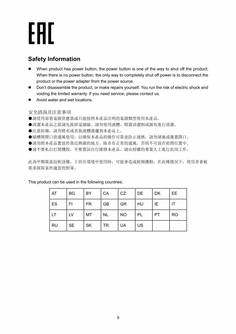
Safety Information When product has power button, the power button is one of the way to shut off the product;
When there is no power button, the only way to completely shut off power is to disconnect the product or the power adapter from the power source.
Don’t disassemble the product, or make repairs yourself. You run the risk of electric shock and voiding the limited warranty. If you need service, please contact us.
Avoid water and wet locations. 安全諮詢及注意事項
●請使用原裝電源供應器或只能按照本產品注明的電源類型使用本產品。
●清潔本產品之前請先拔掉電源線。請勿使用液體、噴霧清潔劑或濕布進行清潔。
●注意防潮,請勿將水或其他液體潑灑到本產品上。
●插槽與開口供通風使用,以確保本產品的操作可靠並防止過熱,請勿堵塞或覆蓋開口。
●請勿將本產品置放於靠近熱源的地方。除非有正常的通風,否則不可放在密閉位置中。
●請不要私自打開機殼,不要嘗試自行維修本產品,請由授權的專業人士進行此項工作。
此為甲類資訊技術設備,于居住環境中使用時,可能會造成射頻擾動,在此種情況下,使用者會被
要求採取某些適當的對策。
This product can be used in the following countries:
AT BG BY CA CZ DE DK EE
ES FI FR GB GR HU IE IT
LT LV MT NL NO PL PT RO
RU SE SK TR UA US
III
CONTENTS
Package Contents ............................................................................................................................ 1
Chapter 1 About This Guide ........................................................................................................... 2
1.1 Intended Readers ........................................................................................................... 2
1.2 Conventions ................................................................................................................... 2
1.3 Overview of This Guide .................................................................................................. 2
Chapter 2 Introduction .................................................................................................................... 7
2.1 Overview of the Switch ................................................................................................... 7
2.2 Main Features ................................................................................................................ 7
2.3 Appearance Description ................................................................................................. 8
2.3.1 Front Panel .......................................................................................................... 8
2.3.2 Rear Panel ........................................................................................................ 11
Chapter 3 Login to the Switch ...................................................................................................... 12
3.1 Login ............................................................................................................................. 12
3.2 Configuration ................................................................................................................ 12
Chapter 4 System ......................................................................................................................... 14
4.1 System Info .................................................................................................................. 14
4.1.1 System Summary .............................................................................................. 14
4.1.2 Device Description ............................................................................................ 16
4.1.3 System Time ...................................................................................................... 17
4.1.4 Daylight Saving Time ........................................................................................ 18
4.2 User Management ........................................................................................................ 19
4.2.1 User Table ......................................................................................................... 19
4.2.2 User Config ....................................................................................................... 19
4.3 System Tools ................................................................................................................ 21
4.3.1 Boot Config ........................................................................................................ 21
4.3.2 Config Restore .................................................................................................. 22
4.3.3 Config Backup ................................................................................................... 23
4.3.4 Firmware Upgrade............................................................................................. 23
4.3.5 System Reboot .................................................................................................. 24
4.3.6 System Reset .................................................................................................... 24
4.4 Access Security ............................................................................................................ 25
4.4.1 Access Control .................................................................................................. 25
4.4.2 SSL Config ........................................................................................................ 26
4.4.3 SSH Config ........................................................................................................ 28
Chapter 5 Stack ............................................................................................................................ 34
5.1 Stack Management ...................................................................................................... 40
IV
5.1.1 Stack Info ........................................................................................................... 40
5.1.2 Stack Config ...................................................................................................... 41
5.1.3 Switch Renumber .............................................................................................. 42
5.2 Application Example for Stack ..................................................................................... 44
Chapter 6 Switching ..................................................................................................................... 45
6.1 Port ............................................................................................................................... 45
6.1.1 Port Config ........................................................................................................ 45
6.1.2 Port Mirror.......................................................................................................... 46
6.1.3 Port Security ...................................................................................................... 48
6.1.4 Port Isolation ..................................................................................................... 50
6.1.5 Loopback Detection .......................................................................................... 51
6.2 LAG .............................................................................................................................. 53
6.2.1 LAG Table .......................................................................................................... 54
6.2.2 Static LAG.......................................................................................................... 55
6.2.3 LACP Config ...................................................................................................... 56
6.3 Traffic Monitor ............................................................................................................... 58
6.3.1 Traffic Summary ................................................................................................ 58
6.3.2 Traffic Statistics ................................................................................................. 59
6.4 MAC Address ............................................................................................................... 61
6.4.1 Address Table .................................................................................................... 62
6.4.2 Static Address .................................................................................................... 63
6.4.3 Dynamic Address .............................................................................................. 65
6.4.4 Filtering Address ................................................................................................ 67
Chapter 7 VLAN............................................................................................................................ 69
7.1 802.1Q VLAN ............................................................................................................... 70
7.1.1 VLAN Config ...................................................................................................... 71
7.1.2 Port Config ........................................................................................................ 73
7.2 Application Example for 802.1Q VLAN ........................................................................ 75
7.3 MAC VLAN ................................................................................................................... 76
7.3.1 MAC VLAN ........................................................................................................ 76
7.3.2 Port Enable ........................................................................................................ 77
7.4 Application Example for MAC VLAN ............................................................................ 78
7.5 Protocol VLAN .............................................................................................................. 80
7.5.1 Protocol Group Table ......................................................................................... 80
7.5.2 Protocol Group .................................................................................................. 81
7.5.3 Protocol Template .............................................................................................. 82
7.6 Application Example for Protocol VLAN ...................................................................... 83
V
7.7 VLAN VPN .................................................................................................................... 85
7.7.1 VPN Config ........................................................................................................ 86
7.7.2 Port Enable ........................................................................................................ 86
7.7.3 VLAN Mapping .................................................................................................. 87
7.8 GVRP ........................................................................................................................... 89
7.9 Private VLAN ................................................................................................................ 93
7.9.1 PVLAN Config ................................................................................................... 94
7.9.2 Port Config ........................................................................................................ 95
7.10 Application Example for Private VLAN ........................................................................ 96
Chapter 8 Spanning Tree .............................................................................................................. 99
8.1 STP Config ................................................................................................................. 104
8.1.1 STP Config ...................................................................................................... 104
8.1.2 STP Summary ................................................................................................. 106
8.2 Port Config ................................................................................................................. 106
8.3 MSTP Instance ........................................................................................................... 108
8.3.1 Region Config .................................................................................................. 108
8.3.2 Instance Config ............................................................................................... 109
8.3.3 Instance Port Config ........................................................................................ 110
8.4 STP Security ............................................................................................................... 112
8.4.1 Port Protect ..................................................................................................... 112
8.4.2 TC Protect ....................................................................................................... 115
8.5 Application Example for STP Function ....................................................................... 115
Chapter 9 Multicast ..................................................................................................................... 120
9.1 IGMP Snooping .......................................................................................................... 122
9.1.1 Snooping Config .............................................................................................. 123
9.1.2 Port Config ...................................................................................................... 124
9.1.3 VLAN Config .................................................................................................... 126
9.1.4 Multicast VLAN ................................................................................................ 127
9.1.5 Querier Config ................................................................................................. 129
9.2 Application Example for Multicast VLAN ................................................................... 131
9.3 Multicast IP ................................................................................................................. 132
9.3.1 Multicast IP Table ............................................................................................ 132
9.3.2 Static Multicast IP ............................................................................................ 133
9.4 Multicast Filter ............................................................................................................ 135
9.4.1 Profile Config ................................................................................................... 135
9.4.2 Profile Binding ................................................................................................. 137
9.5 Packet Statistics ......................................................................................................... 138
VI
Chapter 10 Routing ...................................................................................................................... 140
10.1 Interface ..................................................................................................................... 140
10.2 Routing Table ............................................................................................................. 143
10.3 Static Routing ............................................................................................................. 143
10.3.1 Static Routing .................................................................................................. 143
10.3.2 Application Example for Static Routing ........................................................... 144
10.4 DHCP Server .............................................................................................................. 145
10.4.1 DHCP Server ................................................................................................... 151
10.4.2 Pool Setting ..................................................................................................... 153
10.4.3 Manual Binding ................................................................................................ 154
10.4.4 Binding Table ................................................................................................... 154
10.4.5 Packet Statistics .............................................................................................. 155
10.4.6 Application Example for DHCP Server and Relay .......................................... 157
10.5 DHCP Relay ............................................................................................................... 158
10.5.1 Global Config ................................................................................................... 160
10.5.2 DHCP Server ................................................................................................... 162
10.6 Proxy ARP .................................................................................................................. 162
10.6.1 Proxy ARP ....................................................................................................... 163
10.6.2 Application Example for Proxy ARP ................................................................ 164
10.7 ARP ............................................................................................................................ 165
10.8 RIP .............................................................................................................................. 165
10.8.1 Basic Config .................................................................................................... 168
10.8.2 Interface Config ............................................................................................... 170
10.8.3 RIP Database .................................................................................................. 171
10.8.4 Application Example for RIP ........................................................................... 172
10.9 OSPF .......................................................................................................................... 173
10.9.1 Process ............................................................................................................ 190
10.9.2 Basic ................................................................................................................ 191
10.9.3 Network ........................................................................................................... 193
10.9.4 Interface ........................................................................................................... 194
10.9.5 Area ................................................................................................................. 198
10.9.6 Area Aggregation ............................................................................................. 200
10.9.7 Virtual Link ....................................................................................................... 201
10.9.8 Route Redistribution ........................................................................................ 202
10.9.9 ASBR Aggregation .......................................................................................... 203
10.9.10 Neighbor Table ................................................................................................ 204
10.9.11 Link State Database ........................................................................................ 206
VII
10.9.12 Application Example for OSPF ....................................................................... 206
10.10 VRRP.......................................................................................................................... 208
10.10.1 Basic Config .................................................................................................... 212
10.10.2 Advanced Config ............................................................................................. 214
10.10.3 Virtual IP Config............................................................................................... 215
10.10.4 Track Config .................................................................................................... 216
10.10.5 Virtual Router Statistics ................................................................................... 217
10.10.6 Application Example for VRRP ....................................................................... 219
Chapter 11 Multicast Routing ....................................................................................................... 221
11.1 Global Config .............................................................................................................. 222
11.1.1 Global Config ................................................................................................... 222
11.1.2 Mroute Table .................................................................................................... 223
11.2 IGMP .......................................................................................................................... 224
11.2.1 Interface Config ............................................................................................... 228
11.2.2 Interface State ................................................................................................. 229
11.2.3 Static Multicast Config ..................................................................................... 230
11.2.4 Multicast Group Table...................................................................................... 231
11.2.5 Profile Binding ................................................................................................. 232
11.2.6 Packet Statistics .............................................................................................. 234
11.2.7 Application Example for IGMP ........................................................................ 235
11.3 PIM DM ...................................................................................................................... 236
11.3.1 PIM DM Interface ............................................................................................ 241
11.3.2 PIM DM Neighbor ............................................................................................ 241
11.3.3 Application Example for PIM DM .................................................................... 243
11.4 PIM SM ....................................................................................................................... 244
11.4.1 PIM SM Interface ............................................................................................. 250
11.4.2 PIM SM Neighbor ............................................................................................ 251
11.4.3 BSR ................................................................................................................. 251
11.4.4 RP .................................................................................................................... 253
11.4.5 RP Mapping ..................................................................................................... 254
11.4.6 RP Info ............................................................................................................. 255
11.4.7 Application Example for PIM SM .................................................................... 256
11.5 Static Mroute .............................................................................................................. 257
11.5.1 Static Mroute Config ........................................................................................ 258
11.5.2 Static Mroute Table .......................................................................................... 259
11.5.3 Application Example for Static Mroute ............................................................ 260
Chapter 12 QoS ............................................................................................................................ 262
VIII
12.1 DiffServ ....................................................................................................................... 265
12.1.1 Port Priority ...................................................................................................... 265
12.1.2 Schedule Mode ............................................................................................... 266
12.1.3 802.1P Priority ................................................................................................. 267
12.1.4 DSCP Priority .................................................................................................. 268
12.2 Bandwidth Control ...................................................................................................... 270
12.2.1 Rate Limit ........................................................................................................ 270
12.2.2 Storm Control .................................................................................................. 271
12.3 Voice VLAN ................................................................................................................ 272
12.3.1 Global Config ................................................................................................... 274
12.3.2 Port Config ...................................................................................................... 275
12.3.3 OUI Config ....................................................................................................... 276
Chapter 13 ACL ............................................................................................................................ 278
13.1 Time-Range ................................................................................................................ 278
13.1.1 Time-Range Summary .................................................................................... 278
13.1.2 Time-Range Create ......................................................................................... 279
13.1.3 Holiday Config ................................................................................................. 280
13.2 ACL Config ................................................................................................................. 280
13.2.1 ACL Summary ................................................................................................. 281
13.2.2 ACL Create ...................................................................................................... 281
13.2.3 MAC ACL ......................................................................................................... 282
13.2.4 Standard-IP ACL .............................................................................................. 282
13.2.5 Extend-IP ACL ................................................................................................. 283
13.3 Policy Config .............................................................................................................. 285
13.3.1 Policy Summary .............................................................................................. 285
13.3.2 Policy Create ................................................................................................... 285
13.3.3 Action Create ................................................................................................... 286
13.4 Policy Binding ............................................................................................................. 287
13.4.1 Binding Table ................................................................................................... 287
13.4.2 Port Binding ..................................................................................................... 288
13.4.3 VLAN Binding .................................................................................................. 289
13.5 Application Example for ACL ..................................................................................... 290
Chapter 14 Network Security........................................................................................................ 292
14.1 IP-MAC Binding .......................................................................................................... 292
14.1.1 Binding Table ................................................................................................... 292
14.1.2 Manual Binding ................................................................................................ 293
14.1.3 ARP Scanning ................................................................................................. 295
IX
14.2 DHCP Snooping ......................................................................................................... 297
14.2.1 Global Config ................................................................................................... 299
14.2.2 Port Config ...................................................................................................... 301
14.3 ARP Inspection ........................................................................................................... 302
14.3.1 ARP Detect ...................................................................................................... 305
14.3.2 ARP Defend..................................................................................................... 306
14.3.3 ARP Statistics .................................................................................................. 307
14.4 IP Source Guard ......................................................................................................... 308
14.5 DoS Defend ................................................................................................................ 310
14.5.1 DoS Defend ..................................................................................................... 311
14.6 802.1X ......................................................................................................................... 311
14.6.1 Global Config ................................................................................................... 315
14.6.2 Port Config ...................................................................................................... 316
14.6.3 Radius Server .................................................................................................. 318
Chapter 15 SNMP......................................................................................................................... 320
15.1 SNMP Config .............................................................................................................. 322
15.1.1 Global Config ................................................................................................... 322
15.1.2 SNMP View ..................................................................................................... 323
15.1.3 SNMP Group ................................................................................................... 324
15.1.4 SNMP User ...................................................................................................... 325
15.1.5 SNMP Community ........................................................................................... 327
15.2 Notification .................................................................................................................. 329
15.3 RMON......................................................................................................................... 331
15.3.1 Statistics .......................................................................................................... 331
15.3.2 History ............................................................................................................. 332
15.3.3 Event ............................................................................................................... 333
15.3.4 Alarm ............................................................................................................... 334
Chapter 16 LLDP .......................................................................................................................... 337
16.1 Basic Config ............................................................................................................... 340
16.1.1 Global Config ................................................................................................... 340
16.1.2 Port Config ...................................................................................................... 341
16.2 Device Info ................................................................................................................. 342
16.2.1 Local Info ......................................................................................................... 343
16.2.2 Neighbor Info ................................................................................................... 344
16.3 Device Statistics ......................................................................................................... 345
16.4 LLDP-MED ................................................................................................................. 346
16.4.1 Global Config ................................................................................................... 347
X
16.4.2 Port Config ...................................................................................................... 348
16.4.3 Local Info ......................................................................................................... 350
16.4.4 Neighbor Info ................................................................................................... 351
Chapter 17 Cluster........................................................................................................................ 353
17.1 NDP ............................................................................................................................ 354
17.1.1 Neighbor Info ................................................................................................... 354
17.1.2 NDP Summary ................................................................................................ 355
17.1.3 NDP Config ...................................................................................................... 356
17.2 NTDP .......................................................................................................................... 357
17.2.1 Device Table .................................................................................................... 357
17.2.2 NTDP Summary .............................................................................................. 359
17.2.3 NTDP Config ................................................................................................... 360
17.3 Cluster ........................................................................................................................ 361
17.3.1 Cluster Summary ............................................................................................. 361
17.3.2 Cluster Config .................................................................................................. 364
17.3.3 Member Config ................................................................................................ 367
17.3.4 Cluster Topology .............................................................................................. 368
17.4 Application Example for Cluster Function .................................................................. 370
Chapter 18 Maintenance .............................................................................................................. 372
18.1 System Monitor .......................................................................................................... 372
18.1.1 CPU Monitor .................................................................................................... 372
18.1.2 Memory Monitor .............................................................................................. 373
18.2 Log .............................................................................................................................. 373
18.2.1 Log Table ......................................................................................................... 374
18.2.2 Local Log ......................................................................................................... 375
18.2.3 Remote Log ..................................................................................................... 376
18.2.4 Backup Log ..................................................................................................... 377
18.3 Device Diagnostics ..................................................................................................... 377
18.3.1 Cable Test ........................................................................................................ 377
18.3.2 Loopback ......................................................................................................... 379
18.4 Network Diagnostics .................................................................................................. 379
18.4.1 Ping ................................................................................................................. 379
18.4.2 Tracert ............................................................................................................. 380
Chapter 19 System Maintenance via FTP ................................................................................... 382
Appendix A: Specifications ........................................................................................................... 388
Appendix B: Configuring the PCs................................................................................................. 390
Appendix C: 802.1X Client Software ............................................................................................ 392

XI
Appendix D: Glossary ................................................................................................................... 400
1
Package Contents The following items should be found in your box:
One T3700G-28TQ switch
One Power Cord
One Console Cable
One Power Supply Module Slot Cover
Two mounting brackets and other fittings
Installation Guide
Resource CD for T3700G-28TQ switch, including:
• This User Guide
• The Command Line Interface Guide
• SNMP Mibs
• 802.1X Client Software
• Other Helpful Information
Note:
Make sure that the package contains the above items. If any of the listed items are damaged or missing, please contact your distributor.
2
Chapter 1 About This Guide This User Guide contains information for setup and management of T3700G-28TQ switch. Please read this guide carefully before operation.
1.1 Intended Readers This Guide is intended for network managers familiar with IT concepts and network terminologies.
1.2 Conventions In this Guide the following conventions are used:
The switch or T3700G-28TQ mentioned in this Guide stands for T3700G-28TQ JetStream
28-Port Gigabit Stackable L3 Managed Switch without any explanation.
Menu Name→Submenu Name→Tab page indicates the menu structure. System→System Info→System Summary means the System Summary page under the System Info menu
option that is located under the System menu.
Bold font indicates a button, a toolbar icon, menu or menu item.
Symbols in this Guide:
Symbol Description
Note: Ignoring this type of note might result in a malfunction or damage to the device.
Tips: This format indicates important information that helps you make better use of your device.
1.3 Overview of This Guide
Chapter Introduction
Chapter 1 About This Guide Introduces the guide structure and conventions.
Chapter 2 Introduction Introduces the features, application and appearance of T3700G-28TQ switch.
Chapter 3 Login to the Switch Introduces how to log on to T3700G-28TQ Web management page.
3
Chapter Introduction
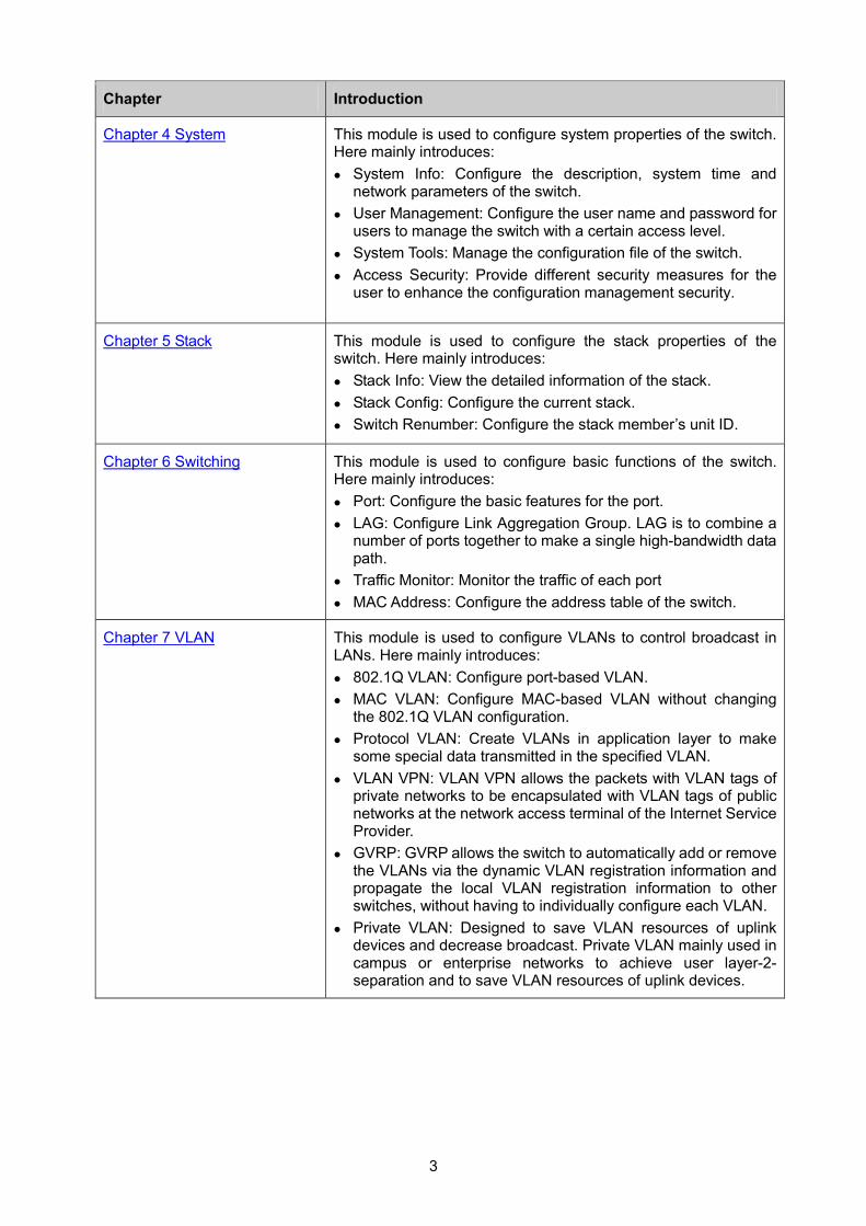
Chapter 4 System This module is used to configure system properties of the switch. Here mainly introduces: System Info: Configure the description, system time and
network parameters of the switch. User Management: Configure the user name and password for
users to manage the switch with a certain access level. System Tools: Manage the configuration file of the switch. Access Security: Provide different security measures for the
user to enhance the configuration management security.
Chapter 5 Stack This module is used to configure the stack properties of the switch. Here mainly introduces: Stack Info: View the detailed information of the stack. Stack Config: Configure the current stack. Switch Renumber: Configure the stack member’s unit ID.
Chapter 6 Switching This module is used to configure basic functions of the switch. Here mainly introduces: Port: Configure the basic features for the port. LAG: Configure Link Aggregation Group. LAG is to combine a
number of ports together to make a single high-bandwidth data path.
Traffic Monitor: Monitor the traffic of each port MAC Address: Configure the address table of the switch.
Chapter 7 VLAN This module is used to configure VLANs to control broadcast in LANs. Here mainly introduces: 802.1Q VLAN: Configure port-based VLAN. MAC VLAN: Configure MAC-based VLAN without changing
the 802.1Q VLAN configuration. Protocol VLAN: Create VLANs in application layer to make
some special data transmitted in the specified VLAN. VLAN VPN: VLAN VPN allows the packets with VLAN tags of
private networks to be encapsulated with VLAN tags of public networks at the network access terminal of the Internet Service Provider.
GVRP: GVRP allows the switch to automatically add or remove the VLANs via the dynamic VLAN registration information and propagate the local VLAN registration information to other switches, without having to individually configure each VLAN.
Private VLAN: Designed to save VLAN resources of uplink devices and decrease broadcast. Private VLAN mainly used in campus or enterprise networks to achieve user layer-2- separation and to save VLAN resources of uplink devices.
4
Chapter Introduction
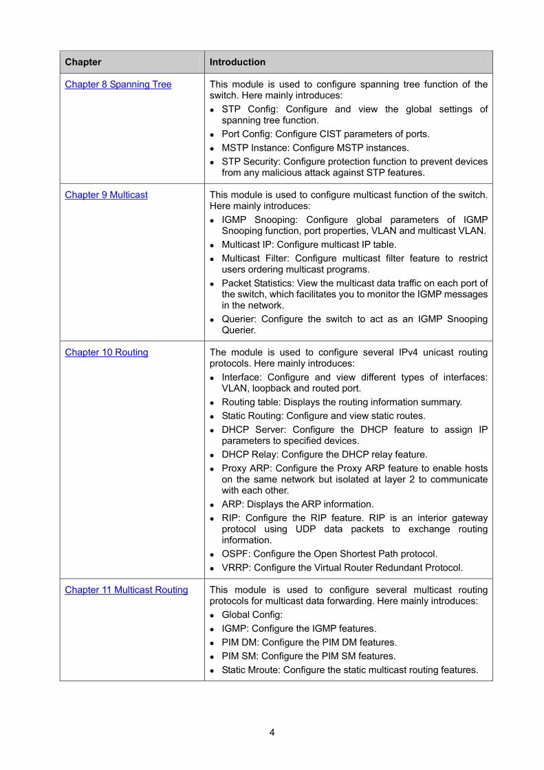
Chapter 8 Spanning Tree This module is used to configure spanning tree function of the switch. Here mainly introduces: STP Config: Configure and view the global settings of
spanning tree function. Port Config: Configure CIST parameters of ports. MSTP Instance: Configure MSTP instances. STP Security: Configure protection function to prevent devices
from any malicious attack against STP features.
Chapter 9 Multicast This module is used to configure multicast function of the switch. Here mainly introduces: IGMP Snooping: Configure global parameters of IGMP
Snooping function, port properties, VLAN and multicast VLAN. Multicast IP: Configure multicast IP table. Multicast Filter: Configure multicast filter feature to restrict
users ordering multicast programs. Packet Statistics: View the multicast data traffic on each port of
the switch, which facilitates you to monitor the IGMP messages in the network.
Querier: Configure the switch to act as an IGMP Snooping Querier.
Chapter 10 Routing The module is used to configure several IPv4 unicast routing protocols. Here mainly introduces: Interface: Configure and view different types of interfaces:
VLAN, loopback and routed port. Routing table: Displays the routing information summary. Static Routing: Configure and view static routes. DHCP Server: Configure the DHCP feature to assign IP
parameters to specified devices. DHCP Relay: Configure the DHCP relay feature. Proxy ARP: Configure the Proxy ARP feature to enable hosts
on the same network but isolated at layer 2 to communicate with each other.
ARP: Displays the ARP information. RIP: Configure the RIP feature. RIP is an interior gateway
protocol using UDP data packets to exchange routing information.
OSPF: Configure the Open Shortest Path protocol. VRRP: Configure the Virtual Router Redundant Protocol.
Chapter 11 Multicast Routing This module is used to configure several multicast routing protocols for multicast data forwarding. Here mainly introduces: Global Config: IGMP: Configure the IGMP features. PIM DM: Configure the PIM DM features. PIM SM: Configure the PIM SM features. Static Mroute: Configure the static multicast routing features.
5
Chapter Introduction
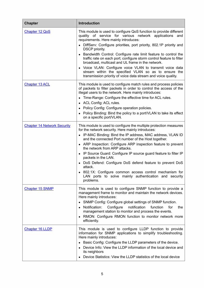
Chapter 12 QoS This module is used to configure QoS function to provide different quality of service for various network applications and requirements. Here mainly introduces: DiffServ: Configure priorities, port priority, 802.1P priority and
DSCP priority. Bandwidth Control: Configure rate limit feature to control the
traffic rate on each port; configure storm control feature to filter broadcast, multicast and UL frame in the network.
Voice VLAN: Configure voice VLAN to transmit voice data stream within the specified VLAN so as to ensure the transmission priority of voice data stream and voice quality.
Chapter 13 ACL This module is used to configure match rules and process policies of packets to filter packets in order to control the access of the illegal users to the network. Here mainly introduces: Time-Range: Configure the effective time for ACL rules. ACL Config: ACL rules. Policy Config: Configure operation policies. Policy Binding: Bind the policy to a port/VLAN to take its effect
on a specific port/VLAN.
Chapter 14 Network Security This module is used to configure the multiple protection measures for the network security. Here mainly introduces: IP-MAC Binding: Bind the IP address, MAC address, VLAN ID
and the connected Port number of the Host together. ARP Inspection: Configure ARP inspection feature to prevent
the network from ARP attacks. IP Source Guard: Configure IP source guard feature to filter IP
packets in the LAN. DoS Defend: Configure DoS defend feature to prevent DoS
attack. 802.1X: Configure common access control mechanism for
LAN ports to solve mainly authentication and security problems.
Chapter 15 SNMP This module is used to configure SNMP function to provide a management frame to monitor and maintain the network devices. Here mainly introduces: SNMP Config: Configure global settings of SNMP function. Notification: Configure notification function for the
management station to monitor and process the events. RMON: Configure RMON function to monitor network more
efficiently.
Chapter 16 LLDP This module is used to configure LLDP function to provide information for SNMP applications to simplify troubleshooting. Here mainly introduces: Basic Config: Configure the LLDP parameters of the device. Device Info: View the LLDP information of the local device and
its neighbors Device Statistics: View the LLDP statistics of the local device
6
Chapter Introduction
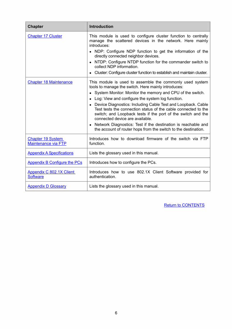
Chapter 17 Cluster This module is used to configure cluster function to centrally manage the scattered devices in the network. Here mainly introduces: NDP: Configure NDP function to get the information of the
directly connected neighbor devices. NTDP: Configure NTDP function for the commander switch to
collect NDP information. Cluster: Configure cluster function to establish and maintain cluster.
Chapter 18 Maintenance This module is used to assemble the commonly used system tools to manage the switch. Here mainly introduces: System Monitor: Monitor the memory and CPU of the switch. Log: View and configure the system log function. Device Diagnostics: Including Cable Test and Loopback. Cable
Test tests the connection status of the cable connected to the switch; and Loopback tests if the port of the switch and the connected device are available.
Network Diagnostics: Test if the destination is reachable and the account of router hops from the switch to the destination.
Chapter 19 System Maintenance via FTP
Introduces how to download firmware of the switch via FTP function.
Appendix A Specifications Lists the glossary used in this manual.
Appendix B Configure the PCs Introduces how to configure the PCs.
Appendix C 802.1X Client Software
Introduces how to use 802.1X Client Software provided for authentication.
Appendix D Glossary Lists the glossary used in this manual.
Return to CONTENTS
7
Chapter 2 Introduction Thanks for choosing the T3700G-28TQ JetStream 28-Port Gigabit Stackable L3 Managed Switch!
2.1 Overview of the Switch T3700G-28TQ is TP-LINK’s JetStream layer 3 stackable switch, supporting up to 4 SFP+ slots. T3700G-28TQ is ideal for large enterprises, campuses or SMB networks requiring an outstanding, reliable and affordable 10 Gigabit solution. T3700G-28TQ supports stacking of up to 8 units, thus providing flexible scalability and protective redundancy for your networks. Moreover, aiming to better protect your network, T3700G-28TQ’s main power is removable, with the help of TP-LINK’s RPS, administrators can easily change its main power if it encounters some problems without shutting down the switch. This feature enables your network to really enjoy the benefit of uninterrupted operation.
2.2 Main Features • Advanced Layer 3 Features
+ Supports abundant Layer 3 routing protocols such as Static Routing, RIP v1/v2, OSPF v2 and PIM SM/PIM DM.
+ Provides many useful Layer 3 features such as DHCP Server, VRRP and ARP Proxy which enable your network to meet the more extended applications.
• Physical Stacking Technology
+ True Physical Stacking technology supports up to 8 units’ physical stacking.
+ Whole stacking system can provides up to 8*128Gbps Switching Capacity.
+ Supports distributed Link Aggregation for active-active connections.
• Removable Power Supply Module and RPS
+ Removable design Power Supply Module enables easily power change when it encounters failure.
+ Hot-swappable Redundant Power Supply (RPS) minimizes downtime, letting your system really enjoy the uninterrupted operation.
• Resiliency and Availability
+ Link aggregation (LACP) increases aggregated bandwidth, optimizing the transport of business critical data.
+ IEEE 802.1s Multiple Spanning Tree provides high link availability in multiple VLAN environments.
+ Multicast snooping automatically prevents flooding of IP multicast traffic.
+ Root Guard protects root bridge from malicious attack or configuration mistakes.
+ Stack technology provides redundant links across the switch stack.
• Layer 2 Switching
+ GVRP (GARP VLAN Registration Protocol) allows automatic learning and dynamic assignment of VLANs.
+ Supports up to 4K VLANs simultaneously (out of 4K VLAN IDs).
8
• Quality of Service
+ Supports L2/L3 granular CoS with 8 priority queues per port.
+ Rate limiting confines the traffic flow accurately according to the preset value.
• Security
+ Supports multiple industry standard user authentication methods such as 802.1x, RADIUS.
+ IP Source Guard prevents IP spoofing attacks.
+ Dynamic ARP Inspection blocks ARP packets from unauthorized hosts, preventing man-in-the-middle attacks.
+ L2/L3/L4 Access Control Lists restrict untrusted access to the protected resource.
+ Provides SSHv1/v2, SSL 2.0/3.0 and TLS v1 for access encryption.
• Manageability
+ IP Clustering provides high scalability and easy Single-IP-Management.
+ Supports Telnet, CLI, SNMP v1/v2c/v3, RMON and web access.
+ Port Mirroring enables monitoring selected ingress/egress traffic.
+ DHCP relay for forwarding User Datagram Protocol (UDP) broadcasts.
+ DHCP server for automatic assignment of IP addresses and other DHCP options to IP hosts.
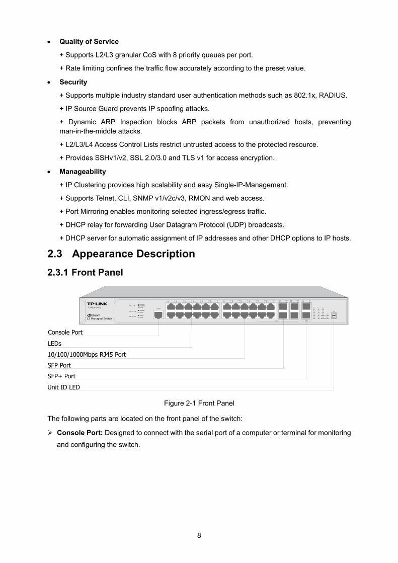
2.3 Appearance Description 2.3.1 Front Panel
Figure 2-1 Front Panel
The following parts are located on the front panel of the switch:
Console Port: Designed to connect with the serial port of a computer or terminal for monitoring
and configuring the switch.
9
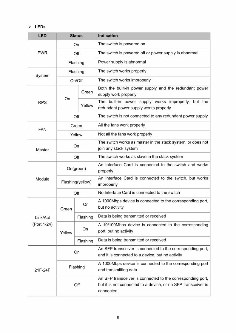
LEDs
LED Status Indication
PWR
On The switch is powered on
Off The switch is powered off or power supply is abnormal
Flashing Power supply is abnormal
System Flashing The switch works properly
On/Off The switch works improperly
RPS On
Green Both the built-in power supply and the redundant power supply work properly
Yellow The built-in power supply works improperly, but the redundant power supply works properly
Off The switch is not connected to any redundant power supply
FAN Green All the fans work properly
Yellow Not all the fans work properly
Master On
The switch works as master in the stack system, or does not join any stack system
Off The switch works as slave in the stack system
Module
On(green) An Interface Card is connected to the switch and works properly
Flashing(yellow) An Interface Card is connected to the switch, but works improperly
Off No Interface Card is connected to the switch
Link/Act (Port 1-24)
Green On
A 1000Mbps device is connected to the corresponding port, but no activity
Flashing Data is being transmitted or received
Yellow On
A 10/100Mbps device is connected to the corresponding port, but no activity
Flashing Data is being transmitted or received
21F-24F
On An SFP transceiver is connected to the corresponding port, and it is connected to a device, but no activity
Flashing A 1000Mbps device is connected to the corresponding port and transmitting data
Off An SFP transceiver is connected to the corresponding port, but it is not connected to a device, or no SFP transceiver is connected
10
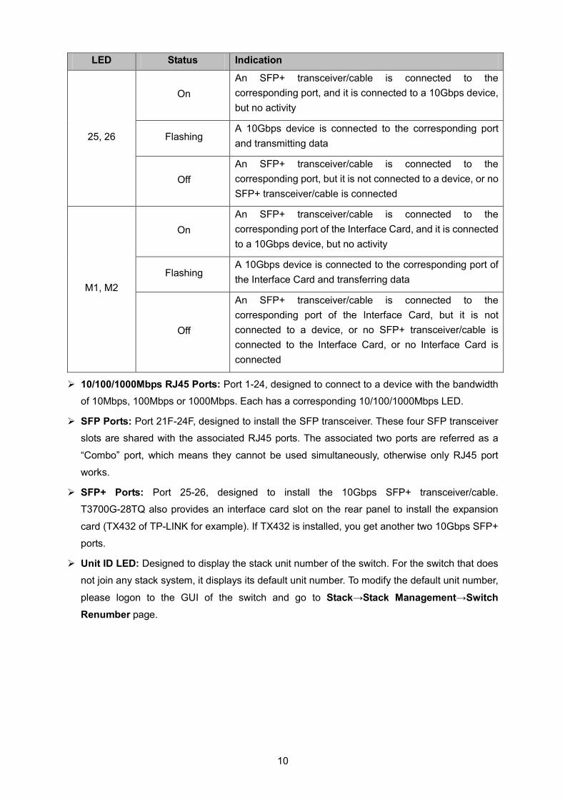
LED Status Indication
25, 26
On An SFP+ transceiver/cable is connected to the corresponding port, and it is connected to a 10Gbps device, but no activity
Flashing A 10Gbps device is connected to the corresponding port and transmitting data
Off An SFP+ transceiver/cable is connected to the corresponding port, but it is not connected to a device, or no SFP+ transceiver/cable is connected
M1, M2
On An SFP+ transceiver/cable is connected to the corresponding port of the Interface Card, and it is connected to a 10Gbps device, but no activity
Flashing A 10Gbps device is connected to the corresponding port of the Interface Card and transferring data
Off
An SFP+ transceiver/cable is connected to the corresponding port of the Interface Card, but it is not connected to a device, or no SFP+ transceiver/cable is connected to the Interface Card, or no Interface Card is connected
10/100/1000Mbps RJ45 Ports: Port 1-24, designed to connect to a device with the bandwidth
of 10Mbps, 100Mbps or 1000Mbps. Each has a corresponding 10/100/1000Mbps LED.
SFP Ports: Port 21F-24F, designed to install the SFP transceiver. These four SFP transceiver
slots are shared with the associated RJ45 ports. The associated two ports are referred as a
“Combo” port, which means they cannot be used simultaneously, otherwise only RJ45 port
works.
SFP+ Ports: Port 25-26, designed to install the 10Gbps SFP+ transceiver/cable.
T3700G-28TQ also provides an interface card slot on the rear panel to install the expansion
card (TX432 of TP-LINK for example). If TX432 is installed, you get another two 10Gbps SFP+
ports.
Unit ID LED: Designed to display the stack unit number of the switch. For the switch that does
not join any stack system, it displays its default unit number. To modify the default unit number,
please logon to the GUI of the switch and go to Stack→Stack Management→Switch Renumber page.
11
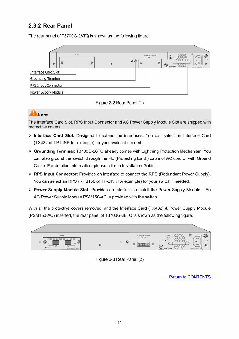
2.3.2 Rear Panel The rear panel of T3700G-28TQ is shown as the following figure.
Figure 2-2 Rear Panel (1)
Note: The Interface Card Slot, RPS Input Connector and AC Power Supply Module Slot are shipped with protective covers.
Interface Card Slot: Designed to extend the interfaces. You can select an Interface Card
(TX432 of TP-LINK for example) for your switch if needed.
Grounding Terminal: T3700G-28TQ already comes with Lightning Protection Mechanism. You
can also ground the switch through the PE (Protecting Earth) cable of AC cord or with Ground
Cable. For detailed information, please refer to Installation Guide.
RPS Input Connector: Provides an interface to connect the RPS (Redundant Power Supply).
You can select an RPS (RPS150 of TP-LINK for example) for your switch if needed.
Power Supply Module Slot: Provides an interface to install the Power Supply Module. An
AC Power Supply Module PSM150-AC is provided with the switch.
With all the protective covers removed, and the Interface Card (TX432) & Power Supply Module
(PSM150-AC) inserted, the rear panel of T3700G-28TQ is shown as the following figure.
Figure 2-3 Rear Panel (2)
Return to CONTENTS
12
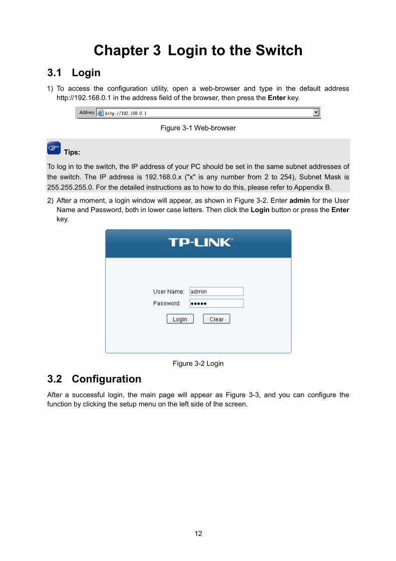
Chapter 3 Login to the Switch 3.1 Login 1) To access the configuration utility, open a web-browser and type in the default address
http://192.168.0.1 in the address field of the browser, then press the Enter key.
Figure 3-1 Web-browser
Tips:
To log in to the switch, the IP address of your PC should be set in the same subnet addresses of the switch. The IP address is 192.168.0.x ("x" is any number from 2 to 254), Subnet Mask is 255.255.255.0. For the detailed instructions as to how to do this, please refer to Appendix B.
2) After a moment, a login window will appear, as shown in Figure 3-2. Enter admin for the User Name and Password, both in lower case letters. Then click the Login button or press the Enter key.
Figure 3-2 Login
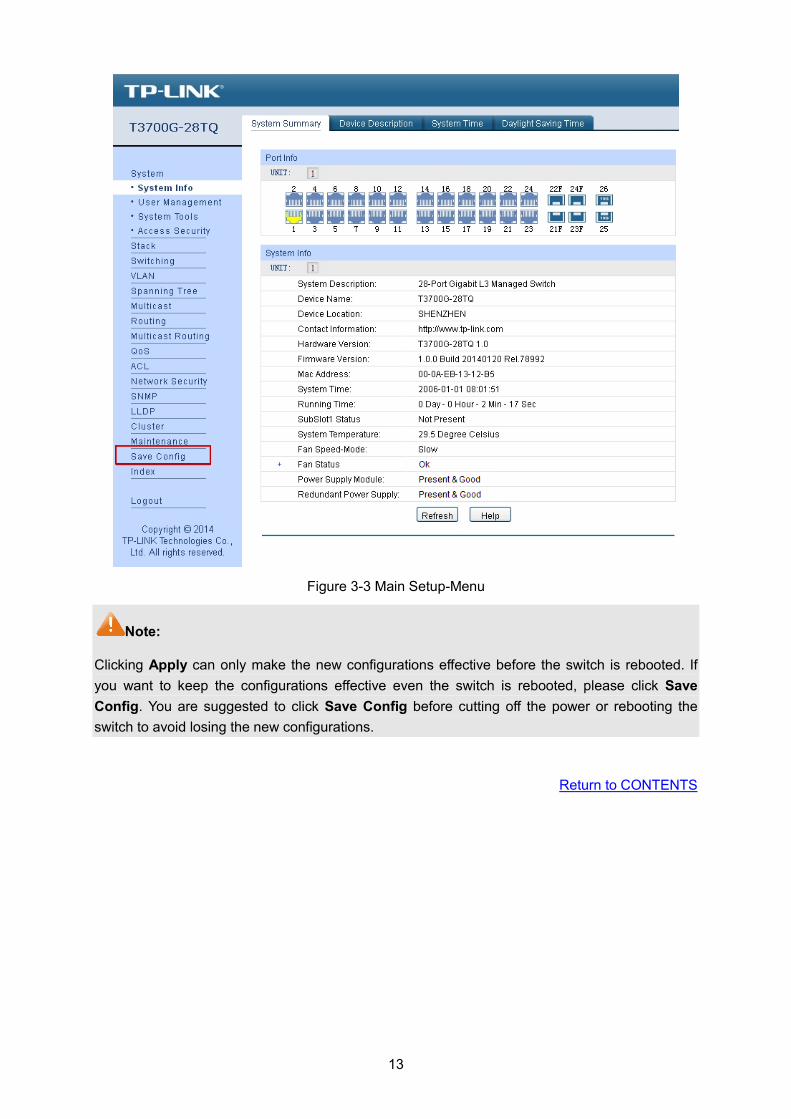
3.2 Configuration After a successful login, the main page will appear as Figure 3-3, and you can configure the function by clicking the setup menu on the left side of the screen.
13
Figure 3-3 Main Setup-Menu
Note:
Clicking Apply can only make the new configurations effective before the switch is rebooted. If you want to keep the configurations effective even the switch is rebooted, please click Save Config. You are suggested to click Save Config before cutting off the power or rebooting the switch to avoid losing the new configurations.
Return to CONTENTS
14
Chapter 4 System The System module is mainly for system configuration of the switch, including four submenus: System Info, User Management, System Tools and Access Security.
4.1 System Info The System Info, mainly for basic properties configuration, can be implemented on System Summary, Device Description, System Time and Daylight Saving Time pages.
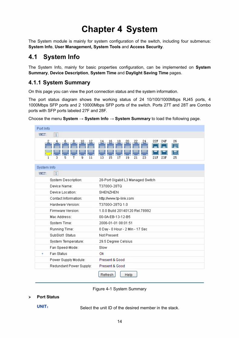
4.1.1 System Summary On this page you can view the port connection status and the system information.
The port status diagram shows the working status of 24 10/100/1000Mbps RJ45 ports, 4 1000Mbps SFP ports and 2 10000Mbps SFP ports of the switch. Ports 27T and 28T are Combo ports with SFP ports labeled 27F and 28F.
Choose the menu System → System Info → System Summary to load the following page.
Figure 4-1 System Summary
Port Status
UNIT: Select the unit ID of the desired member in the stack.
15
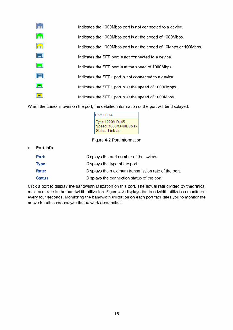
Indicates the 1000Mbps port is not connected to a device.
Indicates the 1000Mbps port is at the speed of 1000Mbps.
Indicates the 1000Mbps port is at the speed of 10Mbps or 100Mbps.
Indicates the SFP port is not connected to a device.
Indicates the SFP port is at the speed of 1000Mbps.
Indicates the SFP+ port is not connected to a device.
Indicates the SFP+ port is at the speed of 10000Mbps.
Indicates the SFP+ port is at the speed of 1000Mbps.
When the cursor moves on the port, the detailed information of the port will be displayed.
Figure 4-2 Port Information
Port Info
Port: Displays the port number of the switch.
Type: Displays the type of the port.
Rate: Displays the maximum transmission rate of the port.
Status: Displays the connection status of the port.
Click a port to display the bandwidth utilization on this port. The actual rate divided by theoretical maximum rate is the bandwidth utilization. Figure 4-3 displays the bandwidth utilization monitored every four seconds. Monitoring the bandwidth utilization on each port facilitates you to monitor the network traffic and analyze the network abnormities.

16
Figure 4-3 Bandwidth Utilization
Bandwidth Utilization
Rx: Select Rx to display the bandwidth utilization of receiving packets on this port.
Tx: Select Tx to display the bandwidth utilization of sending packets on this port.
4.1.2 Device Description On this page you can configure the description of the switch, including device name, device location and system contact.
Choose the menu System → System Info → Device Description to load the following page.
Figure 4-4 Device Description
The following entries are displayed on this screen:
Device Description
Device Name: Enter the name of the switch.
Device Location: Enter the location of the switch.
17
System Contact: Enter your contact information.
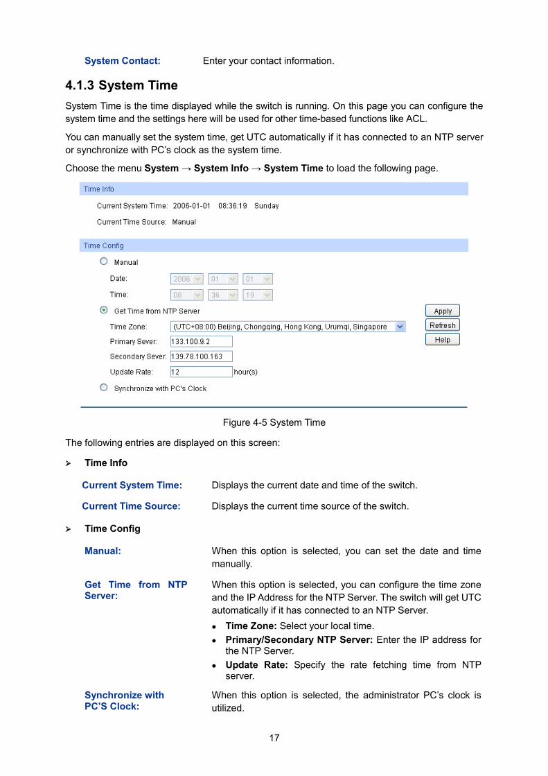
4.1.3 System Time System Time is the time displayed while the switch is running. On this page you can configure the system time and the settings here will be used for other time-based functions like ACL.
You can manually set the system time, get UTC automatically if it has connected to an NTP server or synchronize with PC’s clock as the system time.
Choose the menu System → System Info → System Time to load the following page.
Figure 4-5 System Time
The following entries are displayed on this screen:
Time Info
Current System Time: Displays the current date and time of the switch.
Current Time Source: Displays the current time source of the switch.
Time Config
Manual: When this option is selected, you can set the date and time manually.
Get Time from NTP Server:
When this option is selected, you can configure the time zone and the IP Address for the NTP Server. The switch will get UTC automatically if it has connected to an NTP Server. Time Zone: Select your local time. Primary/Secondary NTP Server: Enter the IP address for
the NTP Server. Update Rate: Specify the rate fetching time from NTP
server.
Synchronize with PC’S Clock:
When this option is selected, the administrator PC’s clock is utilized.
18
Note: 1. The system time will be restored to the default when the switch is restarted and you need to
reconfigure the system time of the switch.
2. When Get Time from NTP Server is selected and no time server is configured, the switch will get time from the time server of the Internet if it has connected to the Internet.
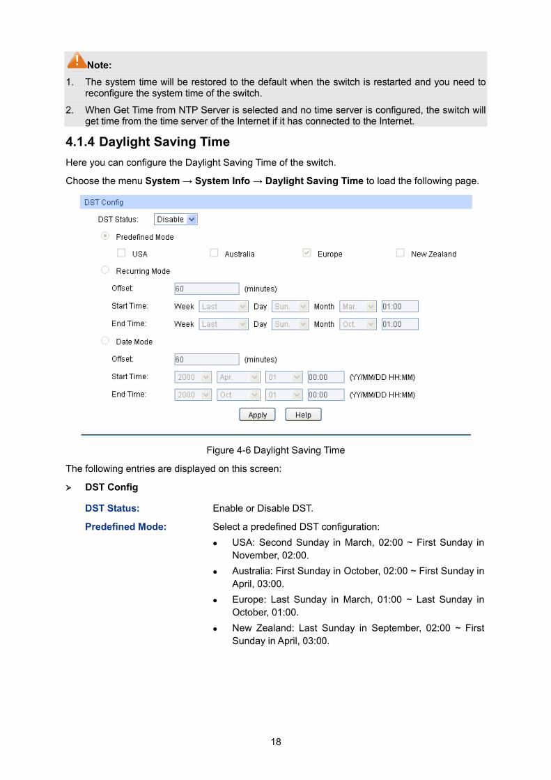
4.1.4 Daylight Saving Time Here you can configure the Daylight Saving Time of the switch.
Choose the menu System → System Info → Daylight Saving Time to load the following page.
Figure 4-6 Daylight Saving Time
The following entries are displayed on this screen: DST Config
DST Status: Enable or Disable DST.
Predefined Mode: Select a predefined DST configuration: USA: Second Sunday in March, 02:00 ~ First Sunday in
November, 02:00. Australia: First Sunday in October, 02:00 ~ First Sunday in
April, 03:00. Europe: Last Sunday in March, 01:00 ~ Last Sunday in
October, 01:00. New Zealand: Last Sunday in September, 02:00 ~ First
Sunday in April, 03:00.
19
Recurring Mode: Specify the DST configuration in recurring mode. This configuration is recurring in use: Offset: Specify the time adding in minutes when Daylight
Saving Time comes. Start/End Time: Select starting time and ending time of
Daylight Saving Time.
Date Mode: Specify the DST configuration in Date mode. This configuration is one-off in use: Offset: Specify the time adding in minutes when Daylight
Saving Time comes. Start/End Time: Select starting time and ending time of
Daylight Saving Time.
Note: 1. When the DST is disabled, the predefined mode, recurring mode and date mode cannot be
configured.
2. When the DST is enabled, the default daylight saving time is of Europe in predefined mode.
4.2 User Management User Management functions to configure the user name and password for users to log on to the Web management page with a certain access level so as to protect the settings of the switch from being randomly changed.
The User Management function can be implemented on User Table and User Config pages.
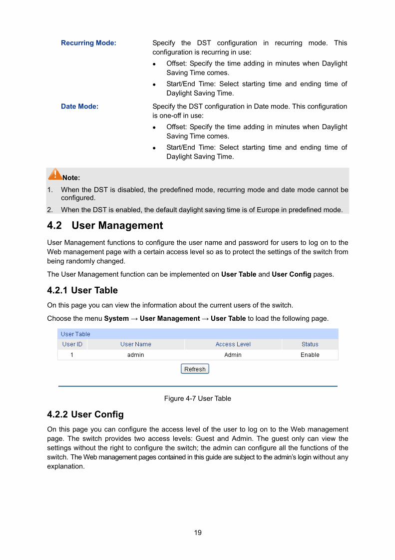
4.2.1 User Table On this page you can view the information about the current users of the switch.
Choose the menu System → User Management → User Table to load the following page.
Figure 4-7 User Table
4.2.2 User Config On this page you can configure the access level of the user to log on to the Web management page. The switch provides two access levels: Guest and Admin. The guest only can view the settings without the right to configure the switch; the admin can configure all the functions of the switch. The Web management pages contained in this guide are subject to the admin’s login without any explanation.
20
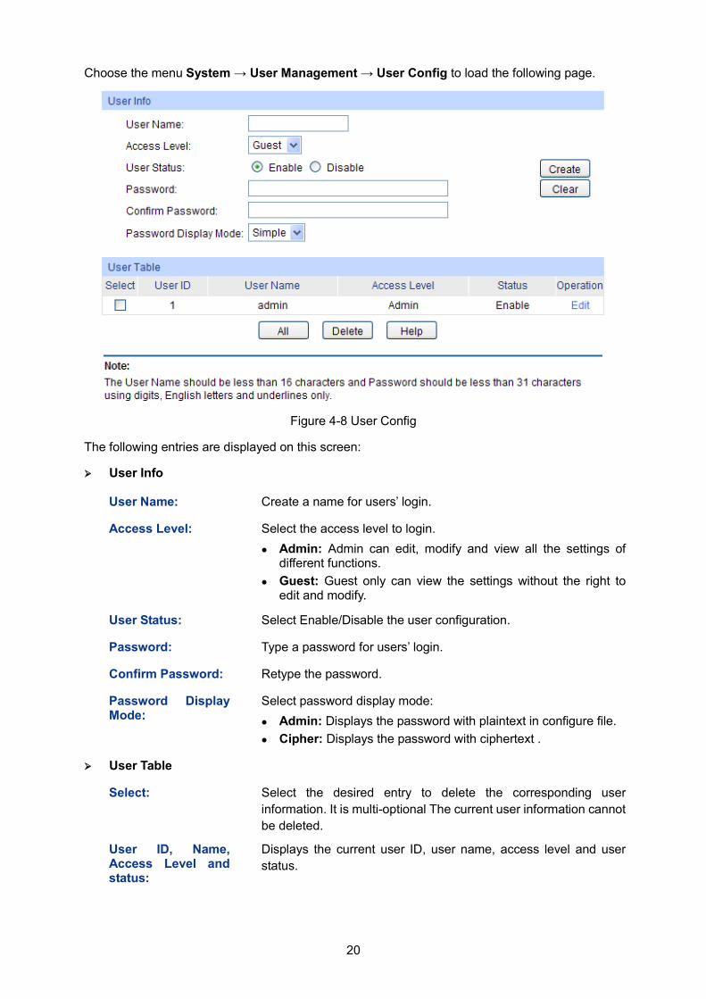
Choose the menu System → User Management → User Config to load the following page.
Figure 4-8 User Config
The following entries are displayed on this screen:
User Info
User Name: Create a name for users’ login.
Access Level: Select the access level to login. Admin: Admin can edit, modify and view all the settings of
different functions. Guest: Guest only can view the settings without the right to
edit and modify.
User Status: Select Enable/Disable the user configuration.
Password: Type a password for users’ login.
Confirm Password: Retype the password.
Password Display Mode:
Select password display mode: Admin: Displays the password with plaintext in configure file. Cipher: Displays the password with ciphertext .
User Table
Select: Select the desired entry to delete the corresponding user information. It is multi-optional The current user information cannot be deleted.
User ID, Name, Access Level and status:
Displays the current user ID, user name, access level and user status.
21
Operation: Click the Edit button of the desired entry, and you can edit the corresponding user information. After modifying the settings, please click the Modify button to make the modification effective. Access level and user status of the current user information cannot be modified.
4.3 System Tools The System Tools function, allowing you to manage the configuration file of the switch, can be implemented on Boot Config, Config Restore, Config Backup, Firmware Upgrade, System Reboot and System Reset pages.
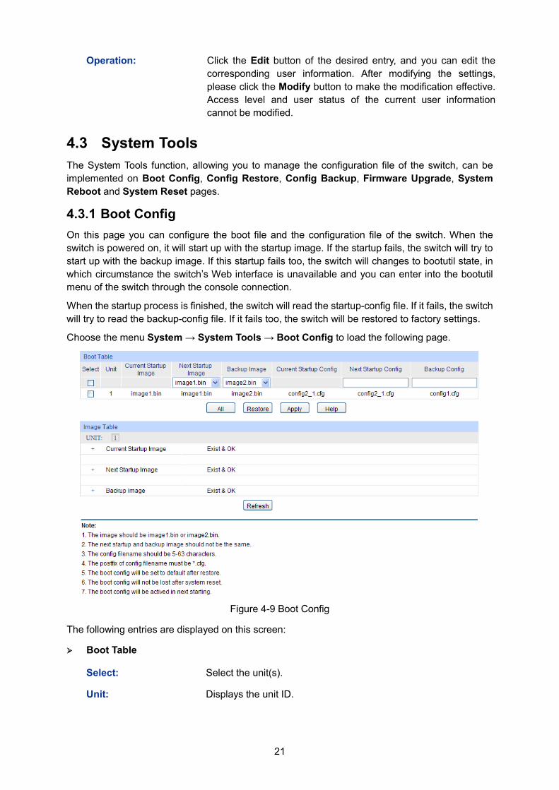
4.3.1 Boot Config On this page you can configure the boot file and the configuration file of the switch. When the switch is powered on, it will start up with the startup image. If the startup fails, the switch will try to start up with the backup image. If this startup fails too, the switch will changes to bootutil state, in which circumstance the switch’s Web interface is unavailable and you can enter into the bootutil menu of the switch through the console connection.
When the startup process is finished, the switch will read the startup-config file. If it fails, the switch will try to read the backup-config file. If it fails too, the switch will be restored to factory settings. Choose the menu System → System Tools → Boot Config to load the following page.
Figure 4-9 Boot Config
The following entries are displayed on this screen:
Boot Table
Select: Select the unit(s).
Unit: Displays the unit ID.
22
Current Startup Image:
Displays the current startup image.
Next Startup Image: Select the next startup image.
Backup Image: Select the backup boot image.
Current Startup Config:
Displays the current startup config filename.
Next Startup Config:
Input the next startup config filename.
Backup Config: Input the backup config filename.
Restore: Set the boot parameter to default.
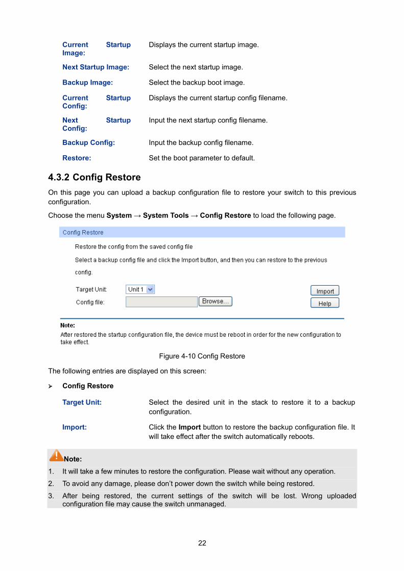
4.3.2 Config Restore On this page you can upload a backup configuration file to restore your switch to this previous configuration. Choose the menu System → System Tools → Config Restore to load the following page.
Figure 4-10 Config Restore
The following entries are displayed on this screen:
Config Restore
Target Unit: Select the desired unit in the stack to restore it to a backup configuration.
Import: Click the Import button to restore the backup configuration file. It will take effect after the switch automatically reboots.
Note: 1. It will take a few minutes to restore the configuration. Please wait without any operation.
2. To avoid any damage, please don’t power down the switch while being restored.
3. After being restored, the current settings of the switch will be lost. Wrong uploaded configuration file may cause the switch unmanaged.
23
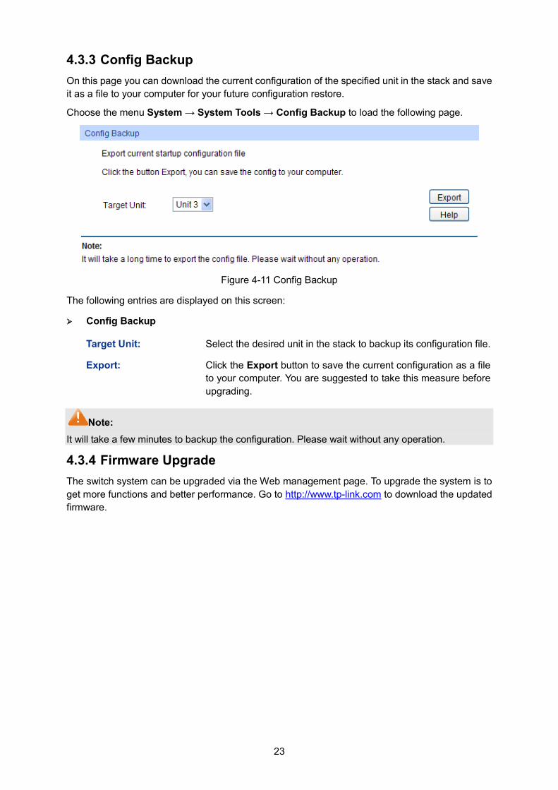
4.3.3 Config Backup On this page you can download the current configuration of the specified unit in the stack and save it as a file to your computer for your future configuration restore.
Choose the menu System → System Tools → Config Backup to load the following page.
Figure 4-11 Config Backup
The following entries are displayed on this screen:
Config Backup
Target Unit: Select the desired unit in the stack to backup its configuration file.
Export: Click the Export button to save the current configuration as a file to your computer. You are suggested to take this measure before upgrading.
Note: It will take a few minutes to backup the configuration. Please wait without any operation.
4.3.4 Firmware Upgrade The switch system can be upgraded via the Web management page. To upgrade the system is to get more functions and better performance. Go to http://www.tp-link.com to download the updated firmware.
24
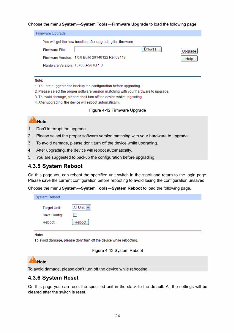
Choose the menu System→System Tools→Firmware Upgrade to load the following page.
Figure 4-12 Firmware Upgrade
Note: 1. Don’t interrupt the upgrade.
2. Please select the proper software version matching with your hardware to upgrade.
3. To avoid damage, please don't turn off the device while upgrading.
4. After upgrading, the device will reboot automatically.
5. You are suggested to backup the configuration before upgrading.
4.3.5 System Reboot On this page you can reboot the specified unit switch in the stack and return to the login page. Please save the current configuration before rebooting to avoid losing the configuration unsaved
Choose the menu System→System Tools→System Reboot to load the following page.
Figure 4-13 System Reboot
Note: To avoid damage, please don't turn off the device while rebooting.
4.3.6 System Reset On this page you can reset the specified unit in the stack to the default. All the settings will be cleared after the switch is reset.
25
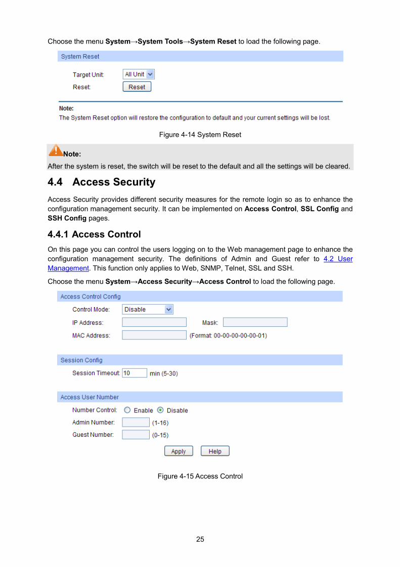
Choose the menu System→System Tools→System Reset to load the following page.
Figure 4-14 System Reset
Note: After the system is reset, the switch will be reset to the default and all the settings will be cleared.
4.4 Access Security Access Security provides different security measures for the remote login so as to enhance the configuration management security. It can be implemented on Access Control, SSL Config and SSH Config pages.
4.4.1 Access Control On this page you can control the users logging on to the Web management page to enhance the configuration management security. The definitions of Admin and Guest refer to 4.2 User Management. This function only applies to Web, SNMP, Telnet, SSL and SSH.
Choose the menu System→Access Security→Access Control to load the following page.
Figure 4-15 Access Control
26
The following entries are displayed on this screen:
Access Control Config
Control Mode: Select the control mode for users to log on to the Web management page. IP-based: Select this option to limit the IP-range of the users
for login. MAC-based: Select this option to limit the MAC Address of
the users for login. Port-based: Select this option to limit the ports for login.
IP Address& Mask: These fields can be available for configuration only when IP-based mode is selected. Only the users within the IP-range you set here are allowed for login.
MAC Address: The field can be available for configuration only when MAC-based mode is selected. Only the user with this MAC Address you set here is allowed for login.
Port: The field can be available for configuration only when Port-based mode is selected. Only the users connected to these ports you set here are allowed for login.
Session Config
Session Timeout: If you do nothing with the Web management page within the timeout time, the system will log out automatically. If you want to reconfigure, please login again.
Access User Number
Number Control: Select Enable/Disable the Number Control function.
Admin Number: Enter the maximum number of the users logging on to the Web management page as Admin.
Guest Number: Enter the maximum number of the users logging on to the Web management page as Guest.
4.4.2 SSL Config SSL (Secure Sockets Layer), a security protocol, is to provide a secure connection for the application layer protocol (e.g. HTTP) communication based on TCP. SSL is widely used to secure the data transmission between the Web browser and servers. It is mainly applied through ecommerce and online banking.
SSL mainly provides the following services:
1. Authenticate the users and the servers based on the certificates to ensure the data are transmitted to the correct users and servers;
2. Encrypt the data transmission to prevent the data being intercepted;
3. Maintain the integrality of the data to prevent the data being altered in the transmission.
Adopting asymmetrical encryption technology, SSL uses key pair to encrypt/decrypt information. A key pair refers to a public key (contained in the certificate) and its corresponding private key. By default the switch has a certificate (self-signed certificate) and a corresponding private key. The Certificate/Key Download function enables the user to replace the default key pair.
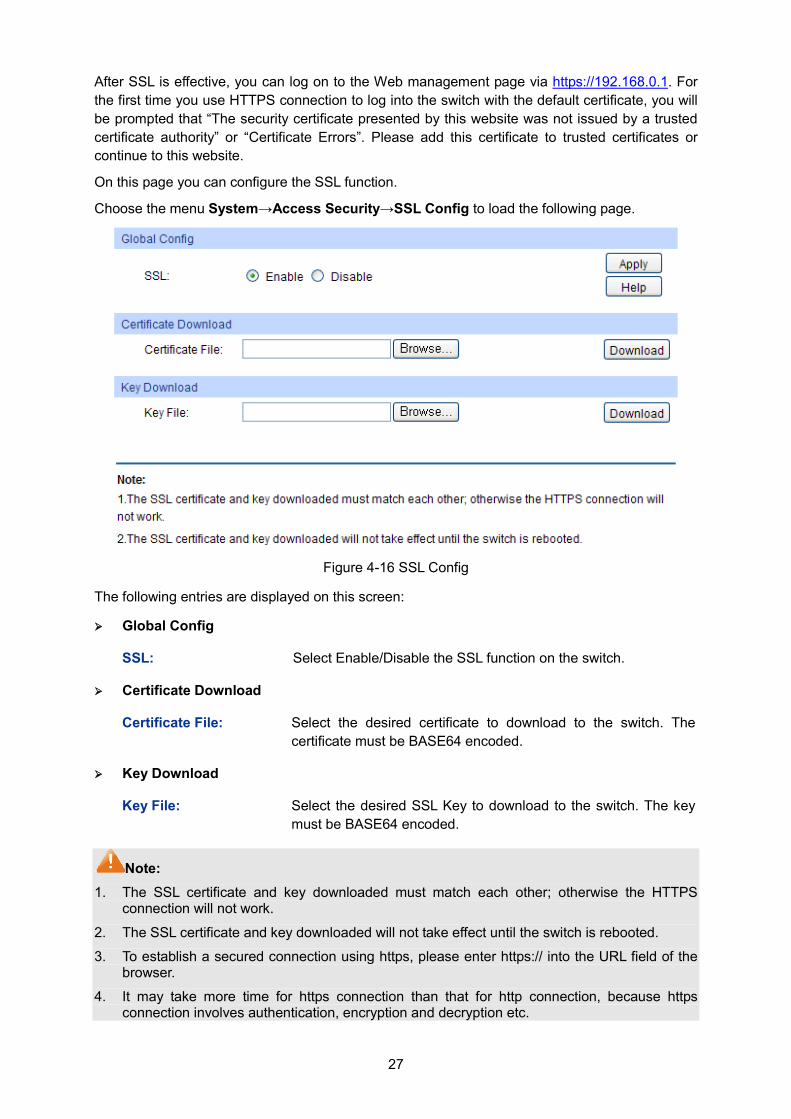
27
After SSL is effective, you can log on to the Web management page via https://192.168.0.1. For the first time you use HTTPS connection to log into the switch with the default certificate, you will be prompted that “The security certificate presented by this website was not issued by a trusted certificate authority” or “Certificate Errors”. Please add this certificate to trusted certificates or continue to this website.
On this page you can configure the SSL function.
Choose the menu System→Access Security→SSL Config to load the following page.
Figure 4-16 SSL Config
The following entries are displayed on this screen:
Global Config
SSL: Select Enable/Disable the SSL function on the switch.
Certificate Download
Certificate File: Select the desired certificate to download to the switch. The certificate must be BASE64 encoded.
Key Download
Key File: Select the desired SSL Key to download to the switch. The key must be BASE64 encoded.
Note: 1. The SSL certificate and key downloaded must match each other; otherwise the HTTPS
connection will not work.
2. The SSL certificate and key downloaded will not take effect until the switch is rebooted.
3. To establish a secured connection using https, please enter https:// into the URL field of the browser.
4. It may take more time for https connection than that for http connection, because https connection involves authentication, encryption and decryption etc.
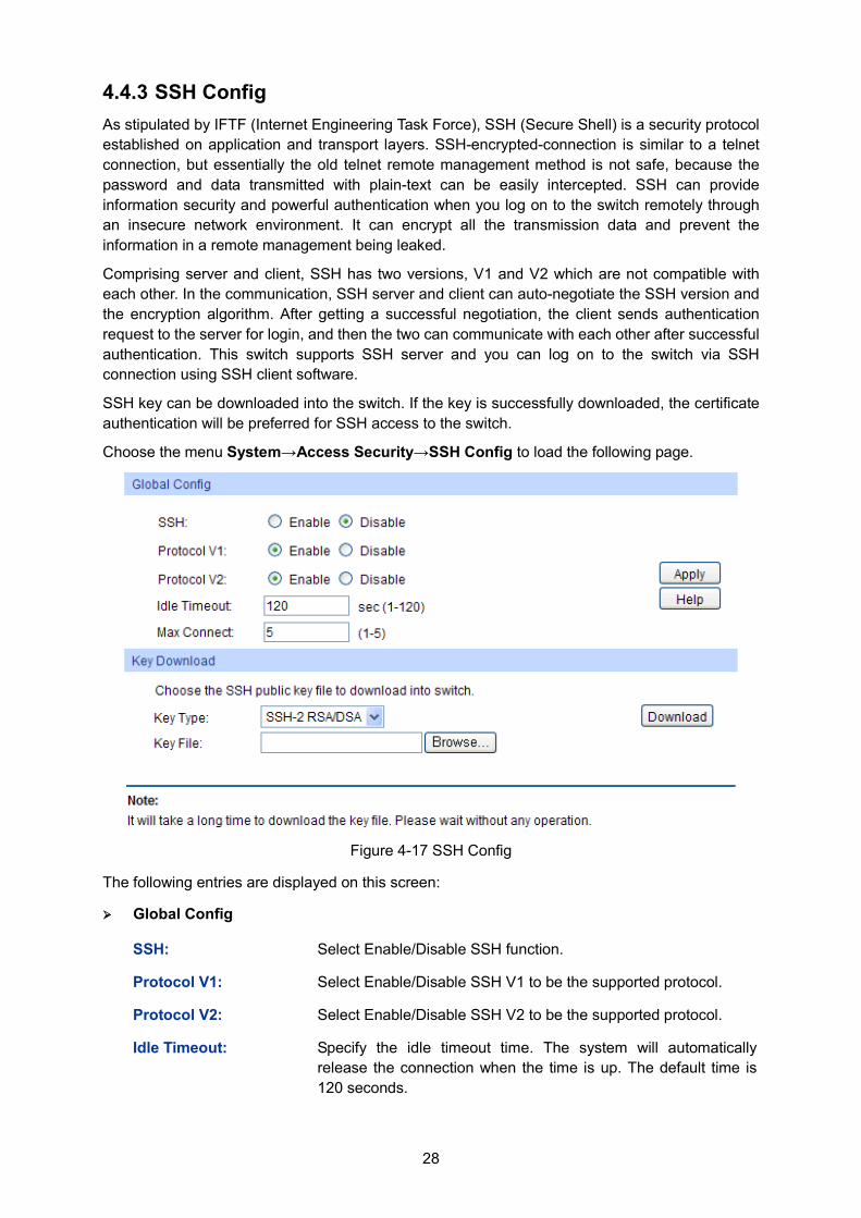
28
4.4.3 SSH Config As stipulated by IFTF (Internet Engineering Task Force), SSH (Secure Shell) is a security protocol established on application and transport layers. SSH-encrypted-connection is similar to a telnet connection, but essentially the old telnet remote management method is not safe, because the password and data transmitted with plain-text can be easily intercepted. SSH can provide information security and powerful authentication when you log on to the switch remotely through an insecure network environment. It can encrypt all the transmission data and prevent the information in a remote management being leaked.
Comprising server and client, SSH has two versions, V1 and V2 which are not compatible with each other. In the communication, SSH server and client can auto-negotiate the SSH version and the encryption algorithm. After getting a successful negotiation, the client sends authentication request to the server for login, and then the two can communicate with each other after successful authentication. This switch supports SSH server and you can log on to the switch via SSH connection using SSH client software.
SSH key can be downloaded into the switch. If the key is successfully downloaded, the certificate authentication will be preferred for SSH access to the switch.
Choose the menu System→Access Security→SSH Config to load the following page.
Figure 4-17 SSH Config
The following entries are displayed on this screen:
Global Config
SSH: Select Enable/Disable SSH function.
Protocol V1: Select Enable/Disable SSH V1 to be the supported protocol.
Protocol V2: Select Enable/Disable SSH V2 to be the supported protocol.
Idle Timeout: Specify the idle timeout time. The system will automatically release the connection when the time is up. The default time is 120 seconds.
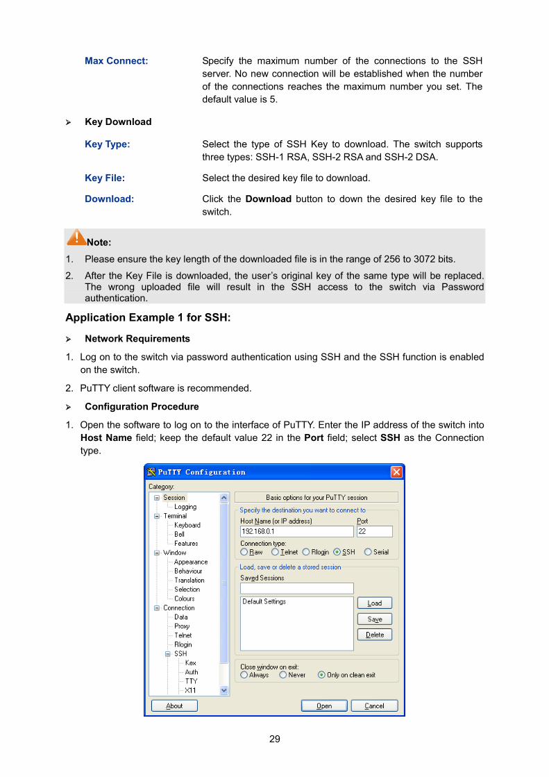
29
Max Connect: Specify the maximum number of the connections to the SSH server. No new connection will be established when the number of the connections reaches the maximum number you set. The default value is 5.
Key Download
Key Type: Select the type of SSH Key to download. The switch supports three types: SSH-1 RSA, SSH-2 RSA and SSH-2 DSA.
Key File: Select the desired key file to download.
Download: Click the Download button to down the desired key file to the switch.
Note: 1. Please ensure the key length of the downloaded file is in the range of 256 to 3072 bits.
2. After the Key File is downloaded, the user’s original key of the same type will be replaced. The wrong uploaded file will result in the SSH access to the switch via Password authentication.
Application Example 1 for SSH:
Network Requirements
1. Log on to the switch via password authentication using SSH and the SSH function is enabled on the switch.
2. PuTTY client software is recommended.
Configuration Procedure
1. Open the software to log on to the interface of PuTTY. Enter the IP address of the switch into Host Name field; keep the default value 22 in the Port field; select SSH as the Connection type.
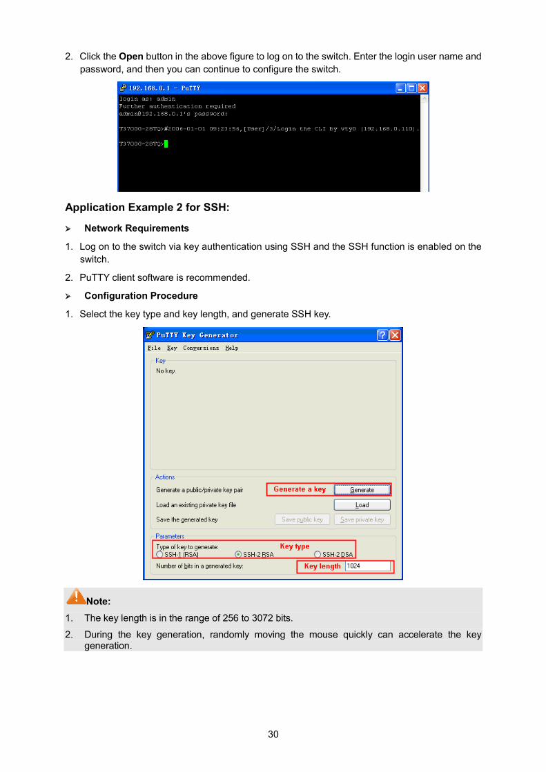
30
2. Click the Open button in the above figure to log on to the switch. Enter the login user name and password, and then you can continue to configure the switch.
Application Example 2 for SSH:
Network Requirements
1. Log on to the switch via key authentication using SSH and the SSH function is enabled on the switch.
2. PuTTY client software is recommended.
Configuration Procedure
1. Select the key type and key length, and generate SSH key.
Note: 1. The key length is in the range of 256 to 3072 bits.
2. During the key generation, randomly moving the mouse quickly can accelerate the key generation.
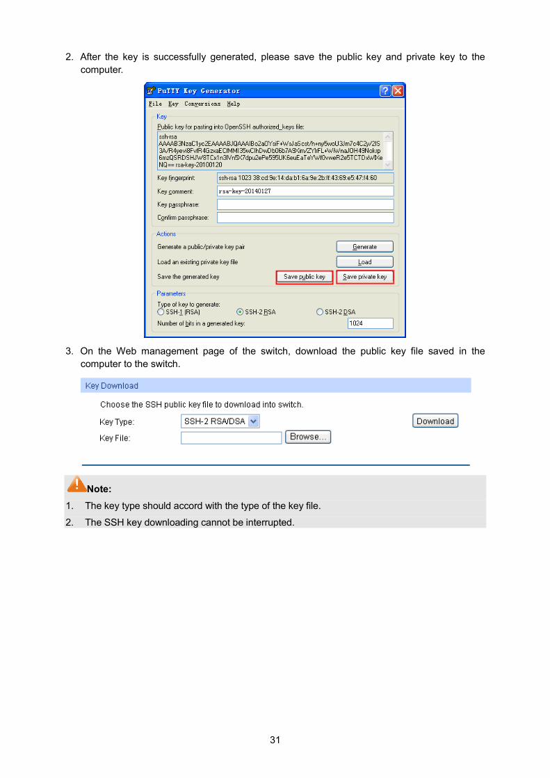
31
2. After the key is successfully generated, please save the public key and private key to the computer.
3. On the Web management page of the switch, download the public key file saved in the
computer to the switch.
Note: 1. The key type should accord with the type of the key file.
2. The SSH key downloading cannot be interrupted.
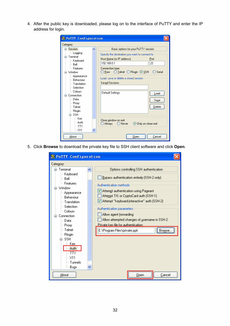
32
4. After the public key is downloaded, please log on to the interface of PuTTY and enter the IP address for login.
5. Click Browse to download the private key file to SSH client software and click Open.
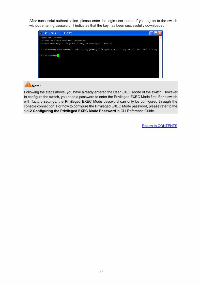
33
After successful authentication, please enter the login user name. If you log on to the switch without entering password, it indicates that the key has been successfully downloaded.
Note: Following the steps above, you have already entered the User EXEC Mode of the switch. However, to configure the switch, you need a password to enter the Privileged EXEC Mode first. For a switch with factory settings, the Privileged EXEC Mode password can only be configured through the console connection. For how to configure the Privileged EXEC Mode password, please refer to the 1.1.2 Configuring the Privileged EXEC Mode Password in CLI Reference Guide.
Return to CONTENTS
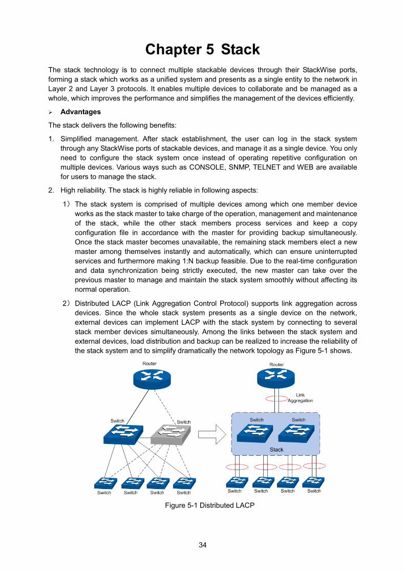
34
Chapter 5 Stack The stack technology is to connect multiple stackable devices through their StackWise ports, forming a stack which works as a unified system and presents as a single entity to the network in Layer 2 and Layer 3 protocols. It enables multiple devices to collaborate and be managed as a whole, which improves the performance and simplifies the management of the devices efficiently.
Advantages
The stack delivers the following benefits:
1. Simplified management. After stack establishment, the user can log in the stack system through any StackWise ports of stackable devices, and manage it as a single device. You only need to configure the stack system once instead of operating repetitive configuration on multiple devices. Various ways such as CONSOLE, SNMP, TELNET and WEB are available for users to manage the stack.
2. High reliability. The stack is highly reliable in following aspects:
1) The stack system is comprised of multiple devices among which one member device works as the stack master to take charge of the operation, management and maintenance of the stack, while the other stack members process services and keep a copy configuration file in accordance with the master for providing backup simultaneously. Once the stack master becomes unavailable, the remaining stack members elect a new master among themselves instantly and automatically, which can ensure uninterrupted services and furthermore making 1:N backup feasible. Due to the real-time configuration and data synchronization being strictly executed, the new master can take over the previous master to manage and maintain the stack system smoothly without affecting its normal operation.
2) Distributed LACP (Link Aggregation Control Protocol) supports link aggregation across devices. Since the whole stack system presents as a single device on the network, external devices can implement LACP with the stack system by connecting to several stack member devices simultaneously. Among the links between the stack system and external devices, load distribution and backup can be realized to increase the reliability of the stack system and to simplify dramatically the network topology as Figure 5-1 shows.
Figure 5-1 Distributed LACP
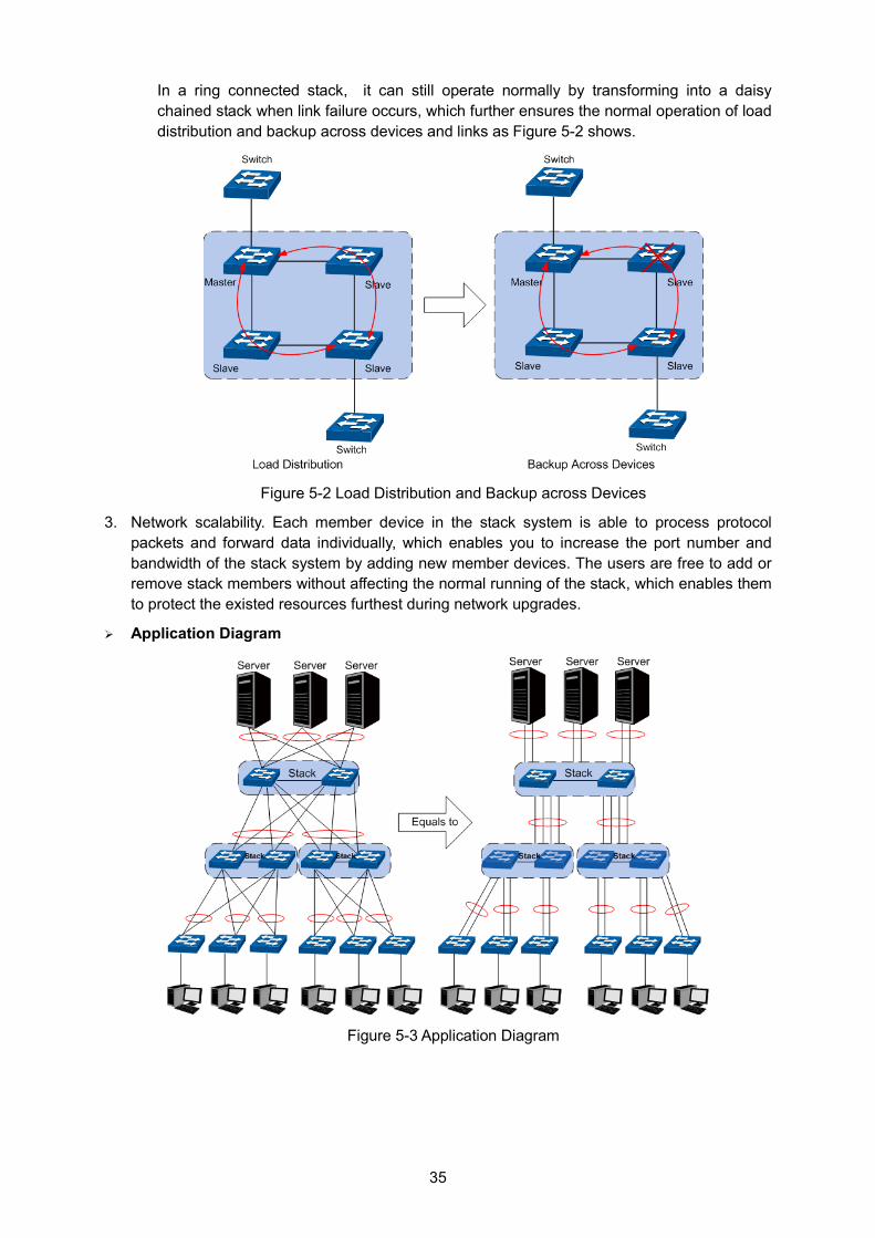
35
In a ring connected stack, it can still operate normally by transforming into a daisy chained stack when link failure occurs, which further ensures the normal operation of load distribution and backup across devices and links as Figure 5-2 shows.
Figure 5-2 Load Distribution and Backup across Devices
3. Network scalability. Each member device in the stack system is able to process protocol packets and forward data individually, which enables you to increase the port number and bandwidth of the stack system by adding new member devices. The users are free to add or remove stack members without affecting the normal running of the stack, which enables them to protect the existed resources furthest during network upgrades.
Application Diagram
Figure 5-3 Application Diagram
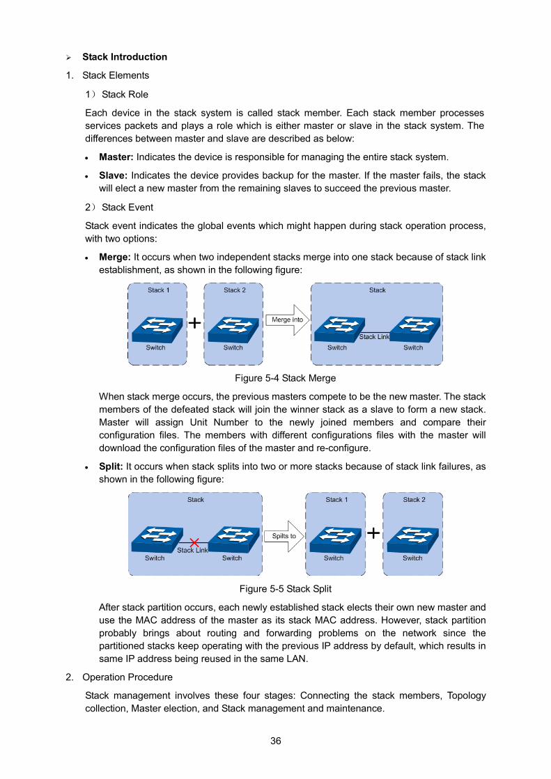
36
Stack Introduction
1. Stack Elements
1) Stack Role
Each device in the stack system is called stack member. Each stack member processes services packets and plays a role which is either master or slave in the stack system. The differences between master and slave are described as below:
• Master: Indicates the device is responsible for managing the entire stack system.
• Slave: Indicates the device provides backup for the master. If the master fails, the stack will elect a new master from the remaining slaves to succeed the previous master.
2) Stack Event
Stack event indicates the global events which might happen during stack operation process, with two options:
• Merge: It occurs when two independent stacks merge into one stack because of stack link establishment, as shown in the following figure:
Figure 5-4 Stack Merge
When stack merge occurs, the previous masters compete to be the new master. The stack members of the defeated stack will join the winner stack as a slave to form a new stack. Master will assign Unit Number to the newly joined members and compare their configuration files. The members with different configurations files with the master will download the configuration files of the master and re-configure.
• Split: It occurs when stack splits into two or more stacks because of stack link failures, as shown in the following figure:
Figure 5-5 Stack Split
After stack partition occurs, each newly established stack elects their own new master and use the MAC address of the master as its stack MAC address. However, stack partition probably brings about routing and forwarding problems on the network since the partitioned stacks keep operating with the previous IP address by default, which results in same IP address being reused in the same LAN.
2. Operation Procedure
Stack management involves these four stages: Connecting the stack members, Topology collection, Master election, and Stack management and maintenance.
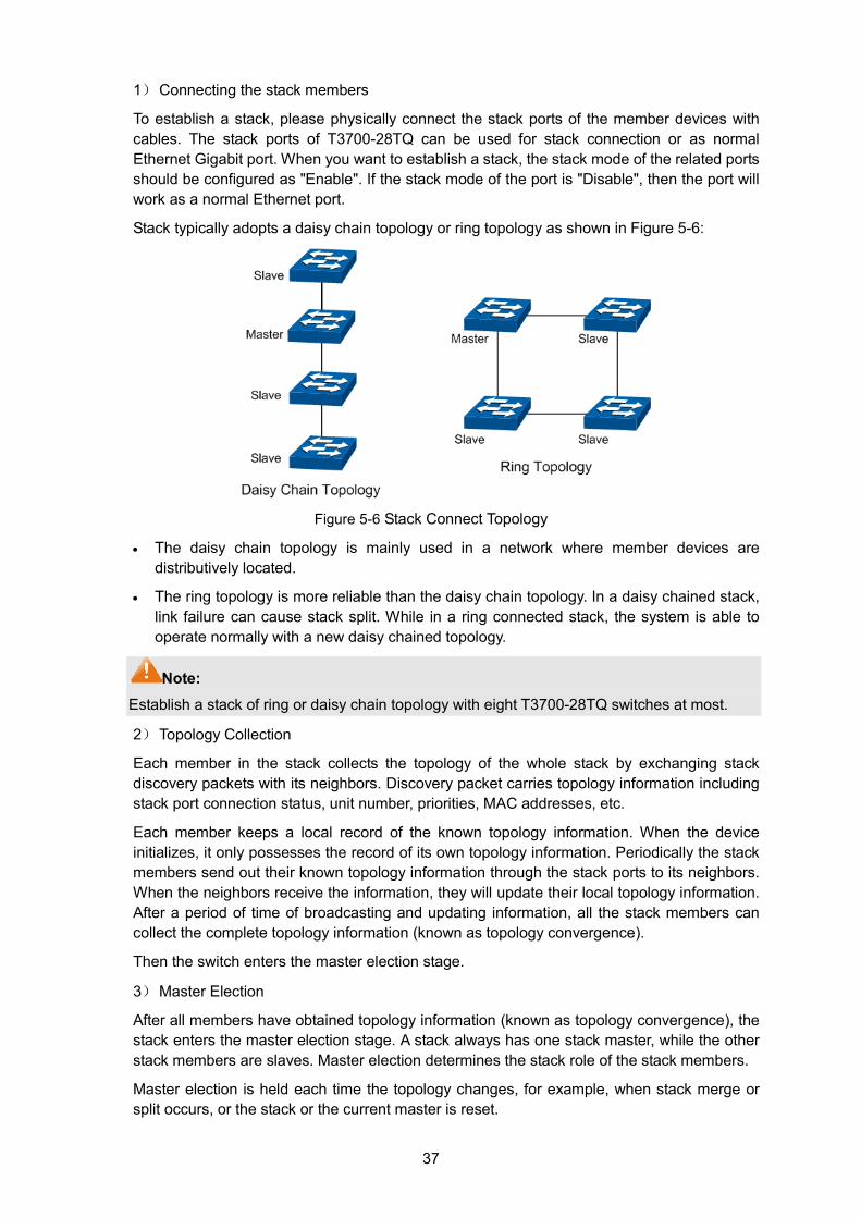
37
1) Connecting the stack members
To establish a stack, please physically connect the stack ports of the member devices with cables. The stack ports of T3700-28TQ can be used for stack connection or as normal Ethernet Gigabit port. When you want to establish a stack, the stack mode of the related ports should be configured as "Enable". If the stack mode of the port is "Disable", then the port will work as a normal Ethernet port.
Stack typically adopts a daisy chain topology or ring topology as shown in Figure 5-6:
Figure 5-6 Stack Connect Topology
• The daisy chain topology is mainly used in a network where member devices are distributively located.
• The ring topology is more reliable than the daisy chain topology. In a daisy chained stack, link failure can cause stack split. While in a ring connected stack, the system is able to operate normally with a new daisy chained topology.
Note: Establish a stack of ring or daisy chain topology with eight T3700-28TQ switches at most.
2) Topology Collection
Each member in the stack collects the topology of the whole stack by exchanging stack discovery packets with its neighbors. Discovery packet carries topology information including stack port connection status, unit number, priorities, MAC addresses, etc.
Each member keeps a local record of the known topology information. When the device initializes, it only possesses the record of its own topology information. Periodically the stack members send out their known topology information through the stack ports to its neighbors. When the neighbors receive the information, they will update their local topology information. After a period of time of broadcasting and updating information, all the stack members can collect the complete topology information (known as topology convergence).
Then the switch enters the master election stage.
3) Master Election
After all members have obtained topology information (known as topology convergence), the stack enters the master election stage. A stack always has one stack master, while the other stack members are slaves. Master election determines the stack role of the stack members.
Master election is held each time the topology changes, for example, when stack merge or split occurs, or the stack or the current master is reset.
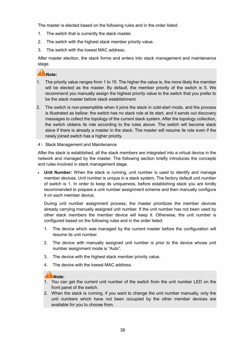
38
The master is elected based on the following rules and in the order listed:
1. The switch that is currently the stack master.
2. The switch with the highest stack member priority value.
3. The switch with the lowest MAC address.
After master election, the stack forms and enters into stack management and maintenance stage.
Note: 1. The priority value ranges from 1 to 15. The higher the value is, the more likely the member
will be elected as the master. By default, the member priority of the switch is 5. We recommend you manually assign the highest priority value to the switch that you prefer to be the stack master before stack establishment.
2. The switch is non-preemptible when it joins the stack in cold-start mode, and the process is illustrated as bellow: the switch has no stack role at its start, and it sends out discovery messages to collect the topology of the current stack system. After the topology collection, the switch obtains its role according to the rules above. The switch will become stack slave if there is already a master in the stack. The master will resume its role even if the newly joined switch has a higher priority.
4) Stack Management and Maintenance
After the stack is established, all the stack members are integrated into a virtual device in the network and managed by the master. The following section briefly introduces the concepts and rules involved in stack management stage.
• Unit Number: When the stack is running, unit number is used to identify and manage member devices. Unit number is unique in a stack system. The factory default unit number of switch is 1. In order to keep its uniqueness, before establishing stack you are kindly recommended to prepare a unit number assignment scheme and then manually configure it on each member device.
During unit number assignment process, the master prioritizes the member devices already carrying manually assigned unit number. If the unit number has not been used by other stack members the member device will keep it. Otherwise, the unit number is configured based on the following rules and in the order listed:
1. The device which was managed by the current master before the configuration will resume its unit number.
2. The device with manually assigned unit number is prior to the device whose unit number assignment mode is “Auto”.
3. The device with the highest stack member priority value.
4. The device with the lowest MAC address.
Note: 1. You can get the current unit number of the switch from the unit number LED on the
front panel of the switch. 2. When the stack is running, if you want to change the unit number manually, only the
unit numbers which have not been occupied by the other member devices are available for you to choose from.
39
• Port Number Format:
The format of port number should be Unit Number/Slot Number/Port Number. Among them:
(1) Unit Number: The default unit number of the switch is 1. If a device has joined stack system, the unit number which the device possesses in the stack system will be kept using as its unit number after the device leaves the stack system.
(2) Slot Number: Indicates the number of the slot the interface card is in. For T3700G-28TQ, the front panel ports belong to slot 0. Slot number starting from 1 each represents an interface card slot.
(3) Physical Port Number: The physical port number on the switch which can be obtained through the front panel of the switch.
For instance: Port number 2/0/3 indicates the physical port3 on the switch whose unit number is 2.
• Configuration Files Application Rules: It includes global configuration and interface configuration two parts.
(1) The global configurations of all stack members are the same. Besides, each member device keeps pace with the global configuration of the master device which enables the stack system to work just like a single entity in the network. The stack system adopts the following methods to ensure the synchronization of global configuration files:
When the stack initializes, the master device will compare the configuration files of each stack member and reconfigure the device whose global configuration is different from its own, so as to ensure the global configuration of the stack members are exactly the same.
When the stack is work normally, any global configuration of users will be recorded to the current configuration files of master and then be synchronized to the other members in the stack.
(2) Each stack member only saves the configuration of its own ports. Even when user sets the configuration for all ports, the configuration will also be saved and implemented only on the related stack member which the ports belong to.
• Stack Maintenance
Stack maintenance mainly functions to monitor the join and leave of member devices, collect the new topology at any times and maintain the current topology.
When the stack is operating normally, packets are transmitted constantly between stack members. The switch can quickly judge the link status of the stack port via monitoring the response of the packets. When the switch detects the link status changes, it will recollect system topology and update topology database to ensure the normal operation of the stack.
The events that will change the link status of the stack port which thus affecting the system topology include: stack member failure or leave, new member's coming, link failure or failure recovery, etc.
When the master switch fails, the stack system elects a new master from the remaining members to succeed the previous master.
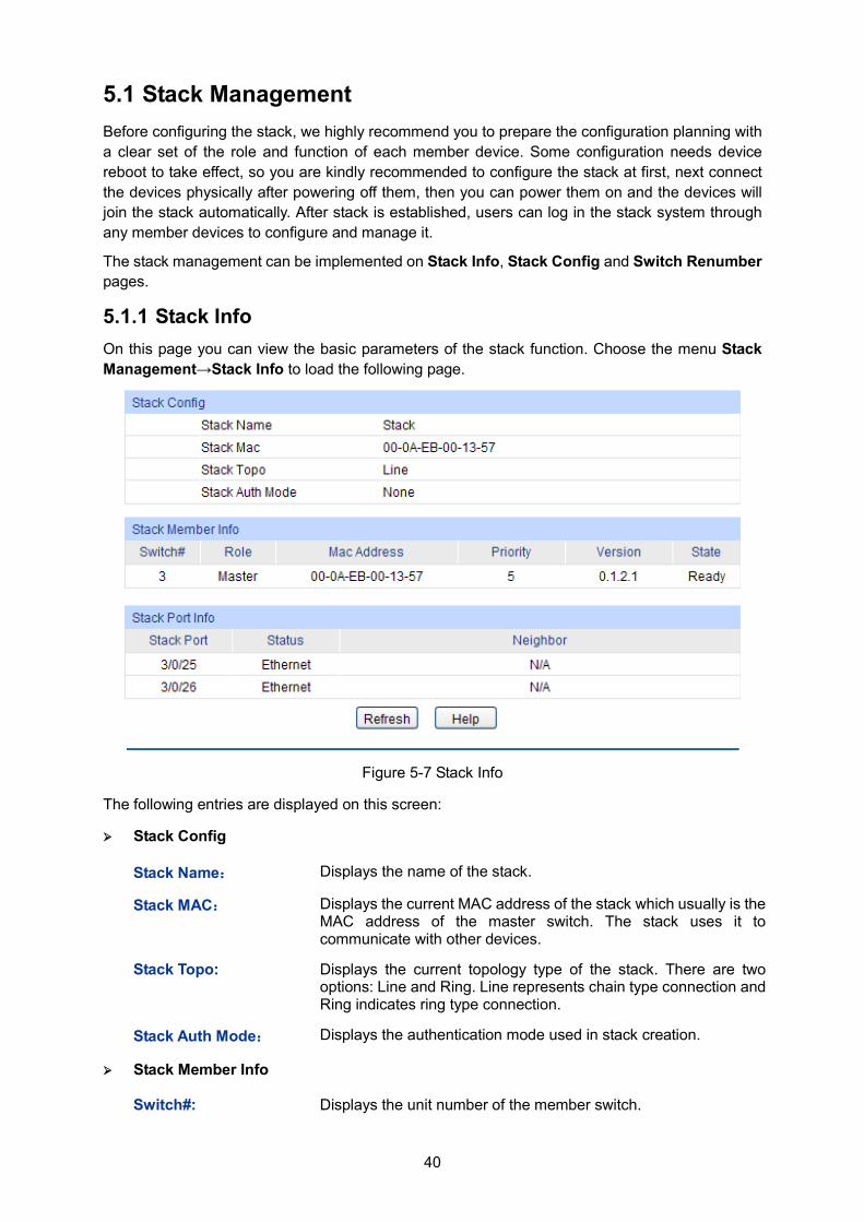
40
5.1 Stack Management Before configuring the stack, we highly recommend you to prepare the configuration planning with a clear set of the role and function of each member device. Some configuration needs device reboot to take effect, so you are kindly recommended to configure the stack at first, next connect the devices physically after powering off them, then you can power them on and the devices will join the stack automatically. After stack is established, users can log in the stack system through any member devices to configure and manage it.
The stack management can be implemented on Stack Info, Stack Config and Switch Renumber pages.
5.1.1 Stack Info On this page you can view the basic parameters of the stack function. Choose the menu Stack Management→Stack Info to load the following page.
Figure 5-7 Stack Info
The following entries are displayed on this screen:
Stack Config
Stack Name: Displays the name of the stack.
Stack MAC: Displays the current MAC address of the stack which usually is the MAC address of the master switch. The stack uses it to communicate with other devices.
Stack Topo: Displays the current topology type of the stack. There are two options: Line and Ring. Line represents chain type connection and Ring indicates ring type connection.
Stack Auth Mode: Displays the authentication mode used in stack creation.
Stack Member Info
Switch#: Displays the unit number of the member switch.
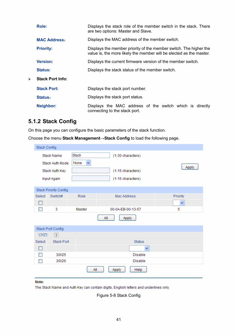
41
Role: Displays the stack role of the member switch in the stack. There are two options: Master and Slave.
MAC Address: Displays the MAC address of the member switch.
Priority: Displays the member priority of the member switch. The higher the value is, the more likely the member will be elected as the master.
Version: Displays the current firmware version of the member switch.
Status: Displays the stack status of the member switch.
Stack Port Info:
Stack Port: Displays the stack port number.
Status: Displays the stack port status.
Neighbor: Displays the MAC address of the switch which is directly connecting to the stack port.
5.1.2 Stack Config On this page you can configure the basic parameters of the stack function.
Choose the menu Stack Management→Stack Config to load the following page.
Figure 5-8 Stack Config
42
The following entries are displayed on this screen:
Stack Config
Stack Name: Enter the name of the stack. The length of this field should be 1-30 characters. After the stack is established, the name of master determines the stack name.
Stack Auth Mode: Select the authentication mode used in stack creation. There are three options: "None", "Simple" and "MD5". • None: Indicates no authentication mode is adopted in stack
creation. • Simple: Indicates simple plain text authentication mode is
adopted in stack creation. • MD5: Indicates MD5 authentication mode is adopted in stack
creation.
Stack Auth Key: Enter the authentication password used in stack authentication if the Stack Auth Mode is "Simple" or "MD5".
Input Again: Retype the authentication password which should be the same with above.
Stack Priority Config
Switch#: The unit number of the switch.
Role: The role of the switch in the stack as Master or Slave.
MAC Address: The unique identification of the switch.
Priority: The priority for the stack member. The priority ranges from 1 to 15. The new priority value takes effect immediately but does not affect the current stack master. The new priority helps determine which stack member is elected as the new stack master when the current stack master or the switch stack resets.
Stack Port Config
Stack Port: Select the desired switch port. It is multi-optional.
Status: Allows you to Enable/Disable the stack feature of the specified port.
5.1.3 Switch Renumber In a stack system, unit number is implemented to identify and manage the member device. Unit number is unique in a stack system. Unit number can be assigned automatically by stack system or manually configured by users. On this page, you can configure the unit number of member switch.
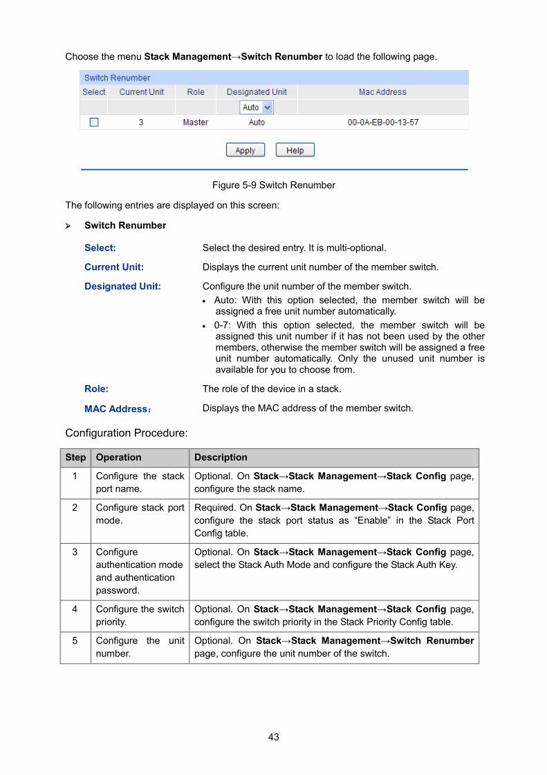
43
Choose the menu Stack Management→Switch Renumber to load the following page.
Figure 5-9 Switch Renumber
The following entries are displayed on this screen:
Switch Renumber
Select: Select the desired entry. It is multi-optional.
Current Unit: Displays the current unit number of the member switch.
Designated Unit: Configure the unit number of the member switch. • Auto: With this option selected, the member switch will be
assigned a free unit number automatically. • 0-7: With this option selected, the member switch will be
assigned this unit number if it has not been used by the other members, otherwise the member switch will be assigned a free unit number automatically. Only the unused unit number is available for you to choose from.
Role: The role of the device in a stack.
MAC Address: Displays the MAC address of the member switch.
Configuration Procedure:
Step Operation Description
1 Configure the stack port name.
Optional. On Stack→Stack Management→Stack Config page, configure the stack name.
2 Configure stack port mode.
Required. On Stack→Stack Management→Stack Config page, configure the stack port status as “Enable” in the Stack Port Config table.
3 Configure authentication mode and authentication password.
Optional. On Stack→Stack Management→Stack Config page, select the Stack Auth Mode and configure the Stack Auth Key.
4 Configure the switch priority.
Optional. On Stack→Stack Management→Stack Config page, configure the switch priority in the Stack Priority Config table.
5 Configure the unit number.
Optional. On Stack→Stack Management→Switch Renumber page, configure the unit number of the switch.
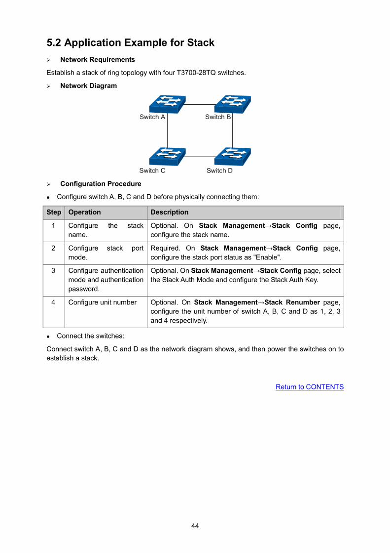
44
5.2 Application Example for Stack Network Requirements
Establish a stack of ring topology with four T3700-28TQ switches.
Network Diagram
Configuration Procedure
Configure switch A, B, C and D before physically connecting them:
Step Operation Description
1 Configure the stack name.
Optional. On Stack Management→Stack Config page, configure the stack name.
2 Configure stack port mode.
Required. On Stack Management→Stack Config page, configure the stack port status as "Enable".
3 Configure authentication mode and authentication password.
Optional. On Stack Management→Stack Config page, select the Stack Auth Mode and configure the Stack Auth Key.
4 Configure unit number Optional. On Stack Management→Stack Renumber page, configure the unit number of switch A, B, C and D as 1, 2, 3 and 4 respectively.
Connect the switches:
Connect switch A, B, C and D as the network diagram shows, and then power the switches on to establish a stack.
Return to CONTENTS
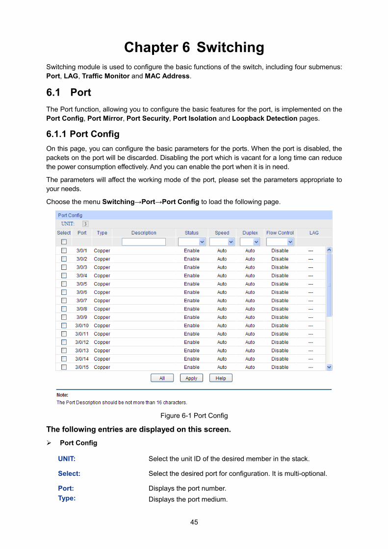
45
Chapter 6 Switching Switching module is used to configure the basic functions of the switch, including four submenus: Port, LAG, Traffic Monitor and MAC Address.
6.1 Port The Port function, allowing you to configure the basic features for the port, is implemented on the Port Config, Port Mirror, Port Security, Port Isolation and Loopback Detection pages.
6.1.1 Port Config On this page, you can configure the basic parameters for the ports. When the port is disabled, the packets on the port will be discarded. Disabling the port which is vacant for a long time can reduce the power consumption effectively. And you can enable the port when it is in need.
The parameters will affect the working mode of the port, please set the parameters appropriate to your needs.
Choose the menu Switching→Port→Port Config to load the following page.
Figure 6-1 Port Config
The following entries are displayed on this screen. Port Config
UNIT: Select the unit ID of the desired member in the stack.
Select: Select the desired port for configuration. It is multi-optional.
Port: Type:
Displays the port number. Displays the port medium.
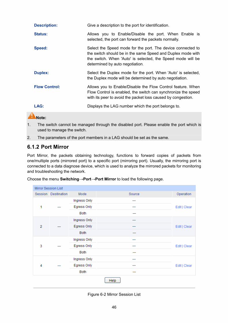
46
Description: Give a description to the port for identification.
Status: Allows you to Enable/Disable the port. When Enable is selected, the port can forward the packets normally.
Speed: Select the Speed mode for the port. The device connected to the switch should be in the same Speed and Duplex mode with the switch. When 'Auto' is selected, the Speed mode will be determined by auto negotiation.
Duplex: Select the Duplex mode for the port. When 'Auto' is selected, the Duplex mode will be determined by auto negotiation.
Flow Control: Allows you to Enable/Disable the Flow Control feature. When Flow Control is enabled, the switch can synchronize the speed with its peer to avoid the packet loss caused by congestion.
LAG: Displays the LAG number which the port belongs to.
Note: 1. The switch cannot be managed through the disabled port. Please enable the port which is
used to manage the switch.
2. The parameters of the port members in a LAG should be set as the same.
6.1.2 Port Mirror Port Mirror, the packets obtaining technology, functions to forward copies of packets from one/multiple ports (mirrored port) to a specific port (mirroring port). Usually, the mirroring port is connected to a data diagnose device, which is used to analyze the mirrored packets for monitoring and troubleshooting the network.
Choose the menu Switching→Port→Port Mirror to load the following page.
Figure 6-2 Mirror Session List
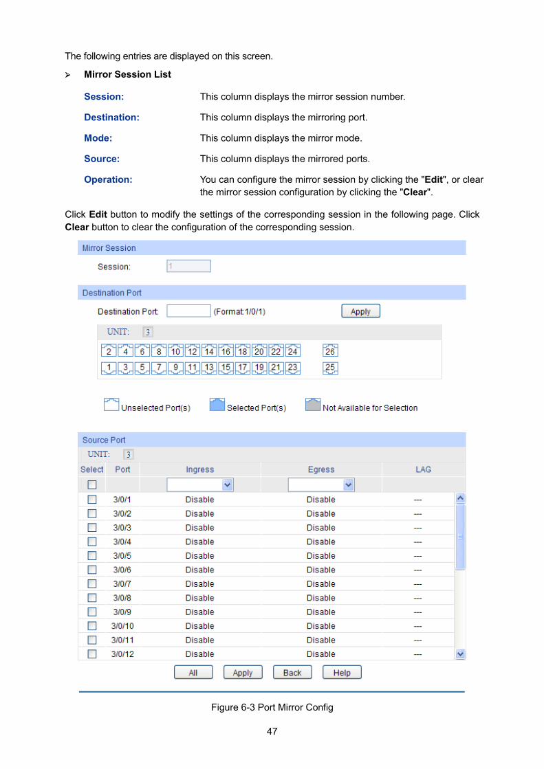
47
The following entries are displayed on this screen.
Mirror Session List
Session: This column displays the mirror session number.
Destination: This column displays the mirroring port.
Mode: This column displays the mirror mode.
Source: This column displays the mirrored ports.
Operation: You can configure the mirror session by clicking the "Edit", or clear the mirror session configuration by clicking the "Clear".
Click Edit button to modify the settings of the corresponding session in the following page. Click Clear button to clear the configuration of the corresponding session.
Figure 6-3 Port Mirror Config
48
The following entries are displayed on this screen.
Mirror Session
Session: Displays session number.
Destination Port
Destination Port: Input or select a physical port from the port panel as the mirroring port.
Source Port
Select: Select the desired port as a mirrored port. It is multi-optional.
Port: Displays the port number.
Ingress: Select Enable/Disable the Ingress feature. When the Ingress is enabled, the incoming packets received by the mirrored port will be copied to the mirroring port.
Egress: Select Enable/Disable the Egress feature. When the Egress is enabled, the outgoing packets sent by the mirrored port will be copied to the mirroring port.
LAG: Displays the LAG number which the port belongs to. The LAG member cannot be selected as the mirrored port or mirroring port.
Note: 1. The LAG member cannot be selected as the mirroring port.
2. A port cannot be set as the mirrored port and the mirroring port simultaneously.
3. The Port Mirror function can span the multiple VLANs.
6.1.3 Port Security MAC Address Table maintains the mapping relationship between the port and the MAC address of the connected device, which is the base of the packet forwarding. The capacity of MAC Address Table is fixed. MAC Address Attack is the attack method that the attacker takes to obtain the network information illegally. The attacker uses tools to generate the cheating MAC address and quickly occupy the MAC Address Table. When the MAC Address Table is full, the switch will broadcast the packets to all the ports. At this moment, the attacker can obtain the network information via various sniffers and attacks. When the MAC Address Table is full, the packets traffic will flood to all the ports, which results in overload, lower speed, packets drop and even breakdown of the system.
Port Security is to protect the switch from the malicious MAC Address Attack by limiting the maximum number of MAC addresses that can be learned on the port. The port with Port Security feature enabled will learn the MAC address dynamically. When the learned MAC address number reaches the maximum, the port will stop learning. Thereafter, the other devices with the MAC address unlearned cannot access to the network via this port.
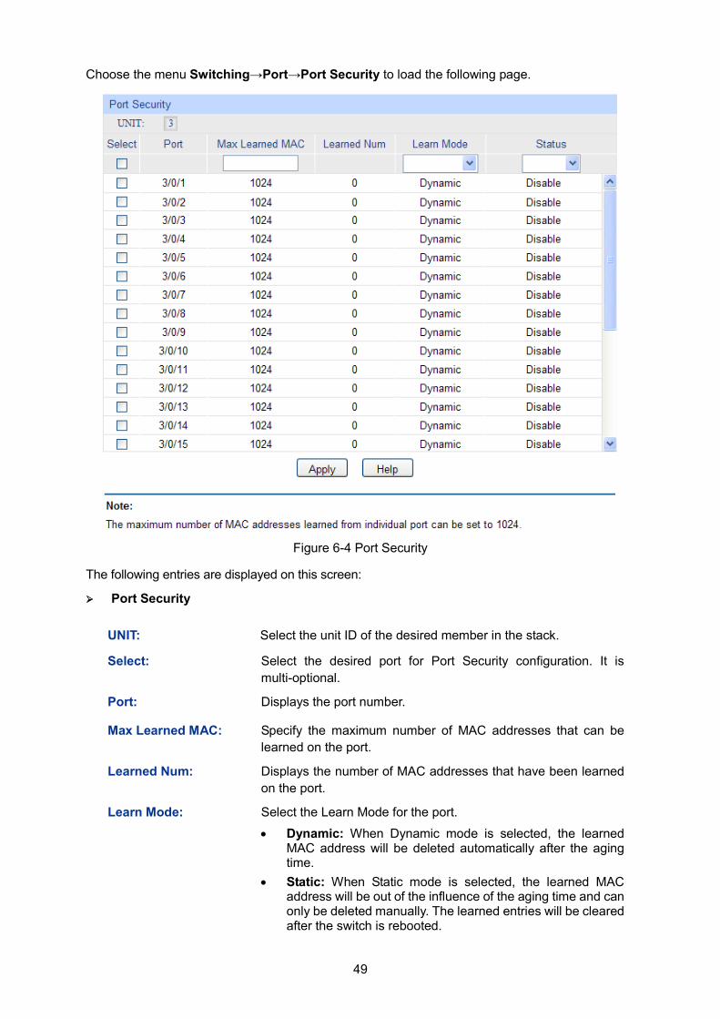
49
Choose the menu Switching→Port→Port Security to load the following page.
Figure 6-4 Port Security
The following entries are displayed on this screen: Port Security
UNIT: Select the unit ID of the desired member in the stack.
Select: Select the desired port for Port Security configuration. It is multi-optional.
Port: Displays the port number.
Max Learned MAC: Specify the maximum number of MAC addresses that can be learned on the port.
Learned Num: Displays the number of MAC addresses that have been learned on the port.
Learn Mode: Select the Learn Mode for the port.
• Dynamic: When Dynamic mode is selected, the learned MAC address will be deleted automatically after the aging time.
• Static: When Static mode is selected, the learned MAC address will be out of the influence of the aging time and can only be deleted manually. The learned entries will be cleared after the switch is rebooted.
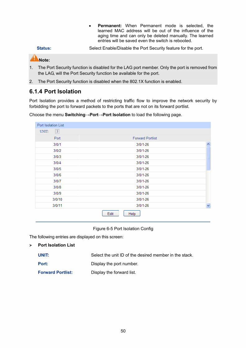
50
• Permanent: When Permanent mode is selected, the learned MAC address will be out of the influence of the aging time and can only be deleted manually. The learned entries will be saved even the switch is rebooted.
Status: Select Enable/Disable the Port Security feature for the port.
Note: 1. The Port Security function is disabled for the LAG port member. Only the port is removed from
the LAG, will the Port Security function be available for the port.
2. The Port Security function is disabled when the 802.1X function is enabled.
6.1.4 Port Isolation Port Isolation provides a method of restricting traffic flow to improve the network security by forbidding the port to forward packets to the ports that are not on its forward portlist.
Choose the menu Switching→Port→Port Isolation to load the following page.
Figure 6-5 Port Isolation Config
The following entries are displayed on this screen: Port Isolation List
UNIT: Select the unit ID of the desired member in the stack.
Port: Display the port number.
Forward Portlist: Display the forward list.
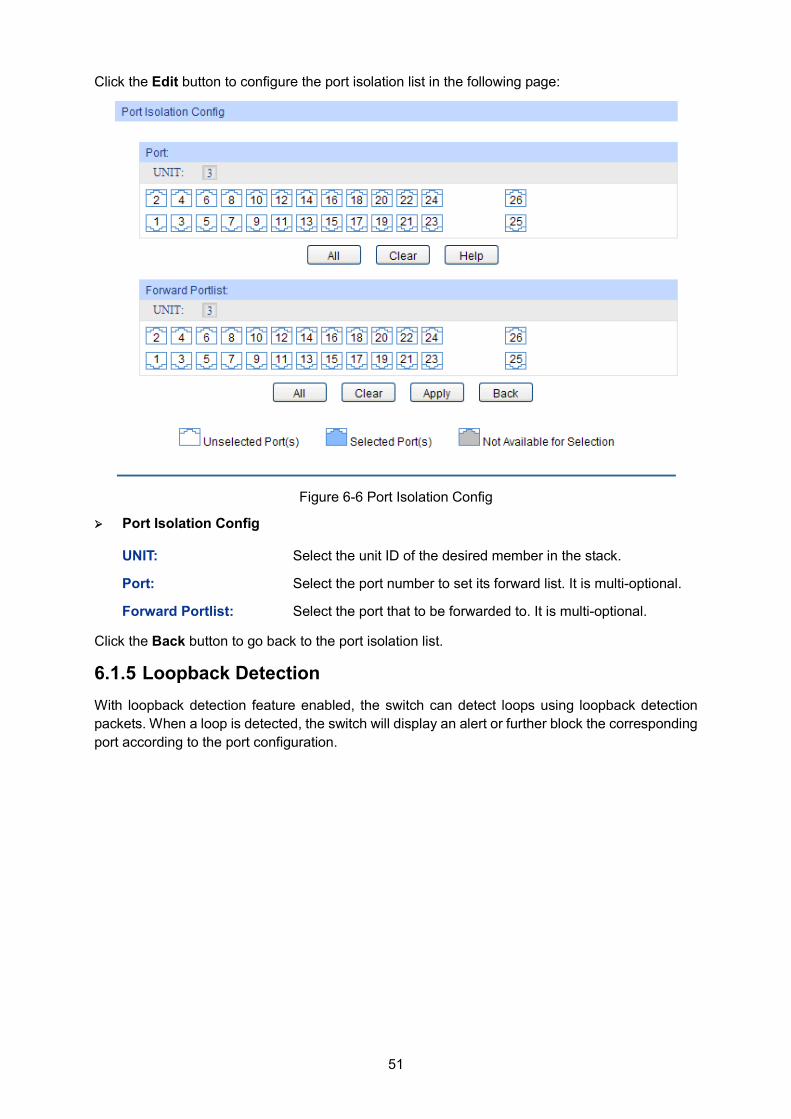
51
Click the Edit button to configure the port isolation list in the following page:
Figure 6-6 Port Isolation Config
Port Isolation Config
UNIT: Select the unit ID of the desired member in the stack.
Port: Select the port number to set its forward list. It is multi-optional.
Forward Portlist: Select the port that to be forwarded to. It is multi-optional.
Click the Back button to go back to the port isolation list.
6.1.5 Loopback Detection With loopback detection feature enabled, the switch can detect loops using loopback detection packets. When a loop is detected, the switch will display an alert or further block the corresponding port according to the port configuration.
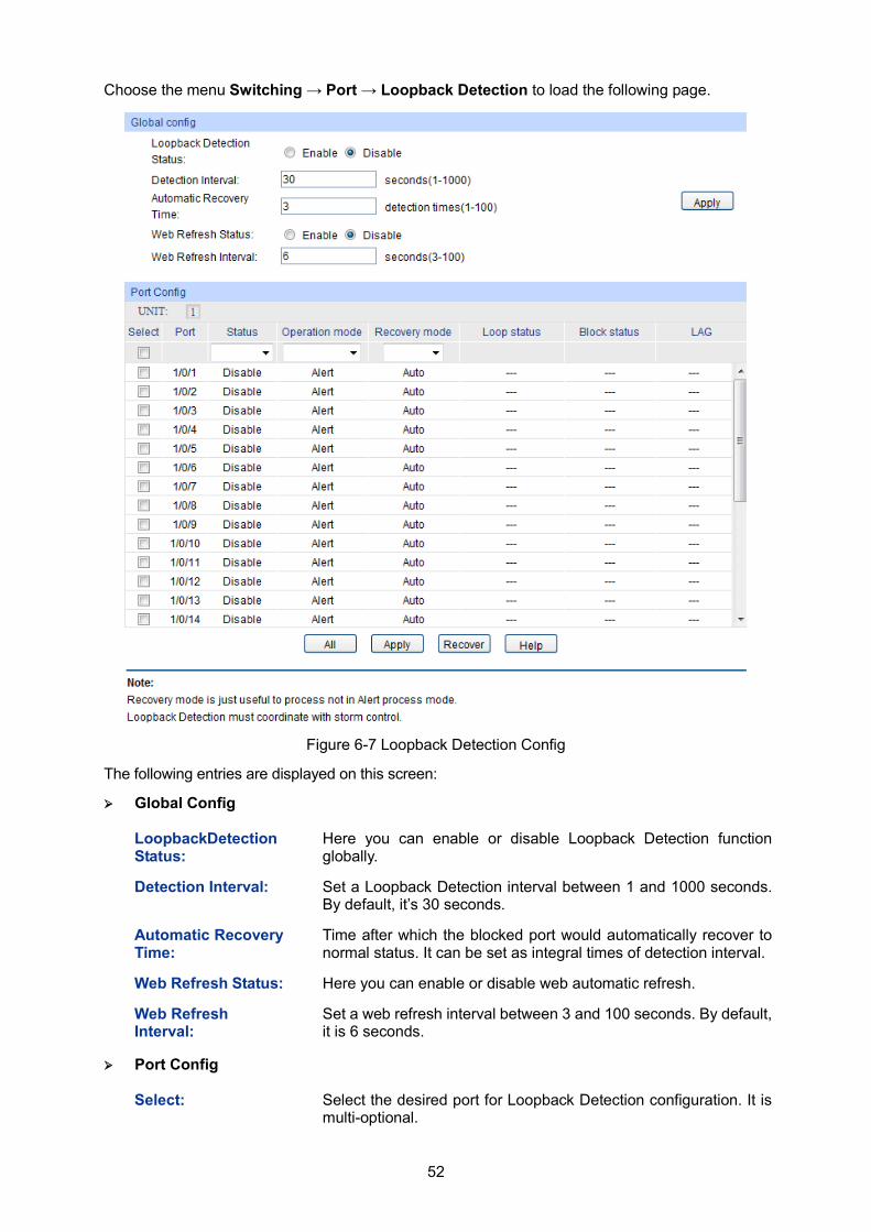
52
Choose the menu Switching → Port → Loopback Detection to load the following page.
Figure 6-7 Loopback Detection Config
The following entries are displayed on this screen:
Global Config
LoopbackDetection Status:
Here you can enable or disable Loopback Detection function globally.
Detection Interval: Set a Loopback Detection interval between 1 and 1000 seconds. By default, it’s 30 seconds.
Automatic Recovery Time:
Time after which the blocked port would automatically recover to normal status. It can be set as integral times of detection interval.
Web Refresh Status: Here you can enable or disable web automatic refresh.
Web Refresh Interval:
Set a web refresh interval between 3 and 100 seconds. By default, it is 6 seconds.
Port Config
Select: Select the desired port for Loopback Detection configuration. It is multi-optional.
53
Port: Displays the port number.
Status: Enable or disable Loopback Detection function for the port.
Operation Mode: Select the mode how the switch processes the detected loops. Alert: When a loop is detected, display an alert. Port based: When a loop is detected, display an alert and
block the port.
Recovery Mode: Select the mode how the blocked port recovers to normal status. Auto: Block status can be automatically removed after
recovery time. Manual: Block status only can be removed manually.
Loop Status: Displays the port status whether a loopback is detected.
Block Status: Displays the port status about block or unblock.
LAG: Displays the LAG number the port belongs to.
Recover: Manually remove the block status of selected ports.
Note: 1. Recovery Mode is not selectable when Alert is chosen in Operation Mode.
2. Loopback Detection must coordinate with storm control.
6.2 LAG LAG (Link Aggregation Group) is to combine a number of ports together to make a single
high-bandwidth data path, so as to implement the traffic load sharing among the member ports in
the group and to enhance the connection reliability.
For the member ports in an aggregation group, their basic configuration must be the same. The
basic configuration includes STP, QoS, GVRP, VLAN, port attributes, MAC Address Learning mode and other associated settings. More details are explained below:
If the ports, which are enabled for the IGMP, IGMP Snooping, GVRP, 802.1Q VLAN, Voice VLAN, STP, QoS, Port Isolation, DHCP Snooping and Port Configuration (Speed, Flow Control), are in a LAG, their configurations should be the same.
The ports, which are enabled for the Port Security, Port Mirror, MAC Address Filtering,
Static MAC Address Binding, 802.1X Authentication, IP Source Guard, half-duplex and
Routed Port cannot be added to the LAG.
It’s not suggested to add the ports with ARP Inspection and DoS Defend enabled to the
LAG.
If the LAG is needed, you are suggested to configure the LAG function here before configuring the
other functions for the member ports.
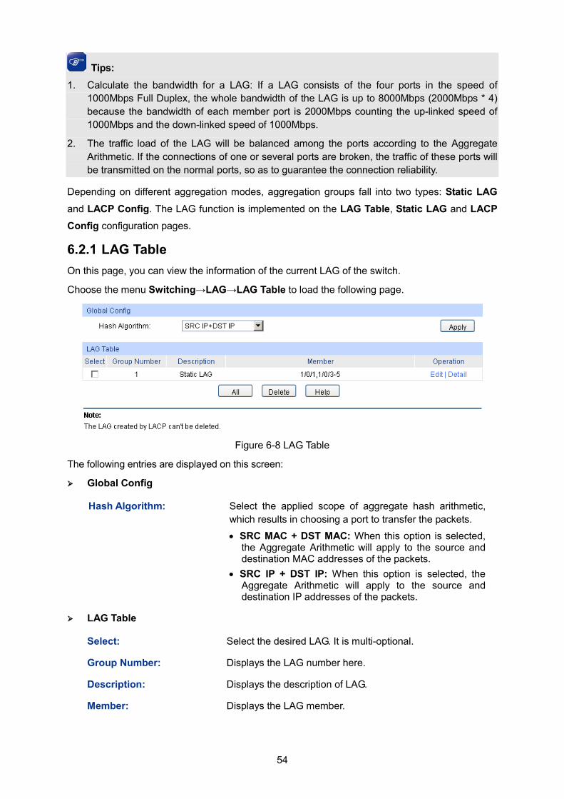
54
Tips: 1. Calculate the bandwidth for a LAG: If a LAG consists of the four ports in the speed of
1000Mbps Full Duplex, the whole bandwidth of the LAG is up to 8000Mbps (2000Mbps * 4) because the bandwidth of each member port is 2000Mbps counting the up-linked speed of 1000Mbps and the down-linked speed of 1000Mbps.
2. The traffic load of the LAG will be balanced among the ports according to the Aggregate Arithmetic. If the connections of one or several ports are broken, the traffic of these ports will be transmitted on the normal ports, so as to guarantee the connection reliability.
Depending on different aggregation modes, aggregation groups fall into two types: Static LAG
and LACP Config. The LAG function is implemented on the LAG Table, Static LAG and LACP Config configuration pages.
6.2.1 LAG Table On this page, you can view the information of the current LAG of the switch.
Choose the menu Switching→LAG→LAG Table to load the following page.
Figure 6-8 LAG Table
The following entries are displayed on this screen: Global Config
Hash Algorithm: Select the applied scope of aggregate hash arithmetic, which results in choosing a port to transfer the packets. • SRC MAC + DST MAC: When this option is selected,
the Aggregate Arithmetic will apply to the source and destination MAC addresses of the packets.
• SRC IP + DST IP: When this option is selected, the Aggregate Arithmetic will apply to the source and destination IP addresses of the packets.
LAG Table
Select: Select the desired LAG. It is multi-optional.
Group Number: Displays the LAG number here.
Description: Displays the description of LAG.
Member: Displays the LAG member.
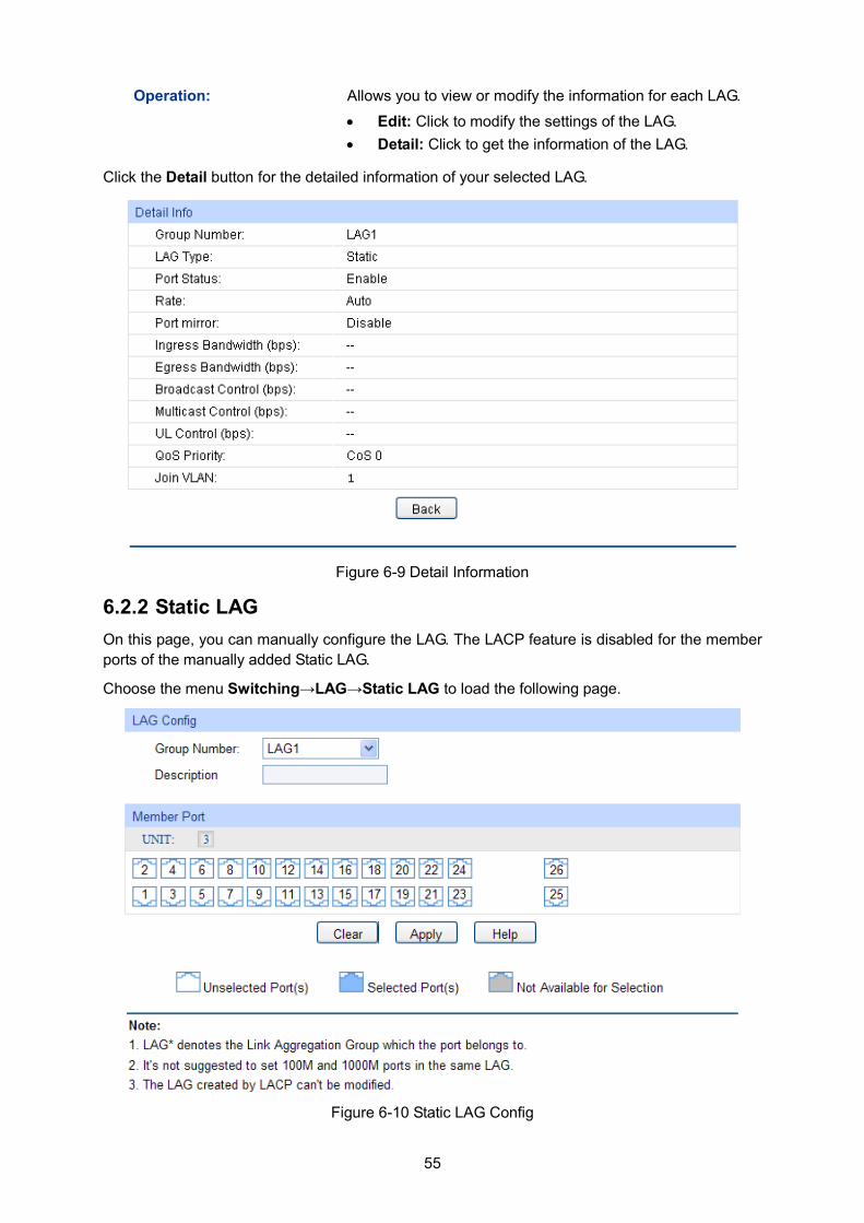
55
Operation: Allows you to view or modify the information for each LAG.
• Edit: Click to modify the settings of the LAG. • Detail: Click to get the information of the LAG.
Click the Detail button for the detailed information of your selected LAG.
Figure 6-9 Detail Information
6.2.2 Static LAG On this page, you can manually configure the LAG. The LACP feature is disabled for the member ports of the manually added Static LAG.
Choose the menu Switching→LAG→Static LAG to load the following page.
Figure 6-10 Static LAG Config
56
The following entries are displayed on this screen: LAG Config
Group Number: Select a Group Number for the LAG.
Description: Displays the description of the LAG for identification.
Member Port
UNIT: Select the unit ID of the desired member in the stack.
Member Port: Select the port as the LAG member. Clearing all the ports of the LAG will delete this LAG.
Tips: 1. The LAG can be deleted by clearing its all member ports.
2. A port can only be added to a LAG. If a port is the member of a LAG or is dynamically aggregated as the LACP member, the port number will be displayed in gray and cannot be selected.
6.2.3 LACP Config LACP (Link Aggregation Control Protocol) is defined in IEEE802.3ad/802.1ax and enables the dynamic link aggregation and disaggregation by exchanging LACP packets with its partner. The switch can dynamically group similarly configured ports into a single logical link, which will highly extend the bandwidth and flexibly balance the load.
With the LACP feature enabled, the port will notify its partner of the system priority, system MAC, port priority, port number and operation key (operation key is determined by the physical properties of the port, upper layer protocol and admin key). The device with higher priority will lead the aggregation and disaggregation. System priority and system MAC decide the priority of the device. The smaller the system priority, the higher the priority of the device is. With the same system priority, the device owning the smaller system MAC has the higher priority. The device with the higher priority will choose the ports to be aggregated based on the port priority, port number and operation key. Only the ports with the same operation key can be selected into the same aggregation group. In an aggregation group, the port with smaller port priority will be considered as the preferred one. If the two port priorities are equal, the port with smaller port number is preferred. After an aggregation group is established, the selected ports can be aggregated together as one port to transmit packets.
On this page, you can configure the LACP feature of the switch.
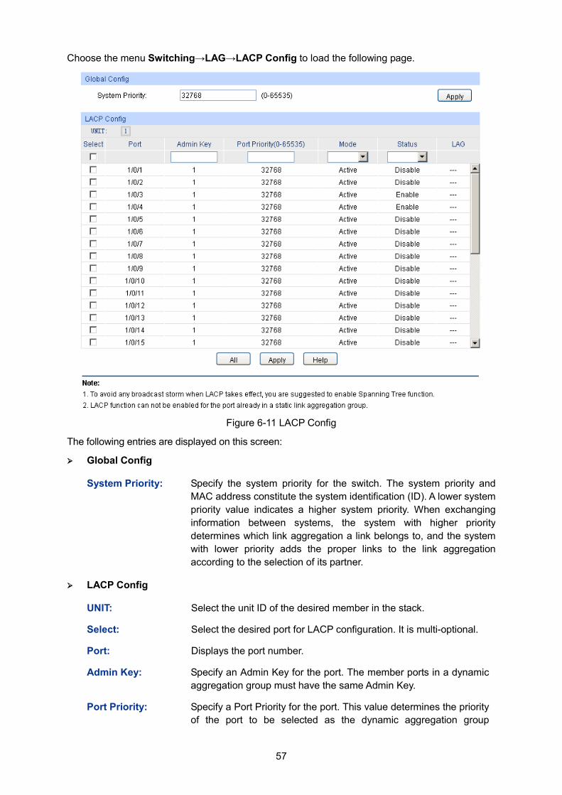
57
Choose the menu Switching→LAG→LACP Config to load the following page.
Figure 6-11 LACP Config
The following entries are displayed on this screen: Global Config
System Priority: Specify the system priority for the switch. The system priority and MAC address constitute the system identification (ID). A lower system priority value indicates a higher system priority. When exchanging information between systems, the system with higher priority determines which link aggregation a link belongs to, and the system with lower priority adds the proper links to the link aggregation according to the selection of its partner.
LACP Config
UNIT: Select the unit ID of the desired member in the stack.
Select: Select the desired port for LACP configuration. It is multi-optional.
Port: Displays the port number.
Admin Key: Specify an Admin Key for the port. The member ports in a dynamic aggregation group must have the same Admin Key.
Port Priority: Specify a Port Priority for the port. This value determines the priority of the port to be selected as the dynamic aggregation group
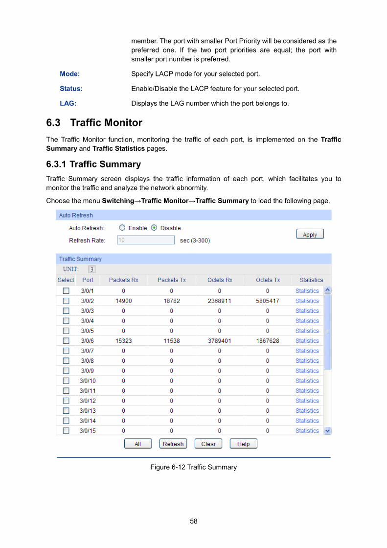
58
member. The port with smaller Port Priority will be considered as the preferred one. If the two port priorities are equal; the port with smaller port number is preferred.
Mode: Specify LACP mode for your selected port.
Status: Enable/Disable the LACP feature for your selected port.
LAG: Displays the LAG number which the port belongs to.
6.3 Traffic Monitor The Traffic Monitor function, monitoring the traffic of each port, is implemented on the Traffic Summary and Traffic Statistics pages.
6.3.1 Traffic Summary Traffic Summary screen displays the traffic information of each port, which facilitates you to monitor the traffic and analyze the network abnormity.
Choose the menu Switching→Traffic Monitor→Traffic Summary to load the following page.
Figure 6-12 Traffic Summary
59
The following entries are displayed on this screen: Auto Refresh
Auto Refresh: Allows you to Enable/Disable refreshing the Traffic Summary automatically.
Refresh Rate: Enter a value in seconds to specify the refresh interval.
Traffic Summary
UNIT: Select the unit ID of the desired member in the stack.
Port Select: Click the Select button to quick-select the corresponding port based on the port number you entered.
Port: Displays the port number.
Packets Rx: Displays the number of packets received on the port. The error packets are not counted in.
Packets Tx: Displays the number of packets transmitted on the port.
Octets Rx: Displays the number of octets received on the port. The error octets are counted in.
Octets Tx: Displays the number of octets transmitted on the port.
Statistics: Click the Statistics button to view the detailed traffic statistics of the port.
6.3.2 Traffic Statistics Traffic Statistics screen displays the detailed traffic information of each port, which facilitates you to monitor the traffic and locate faults promptly.
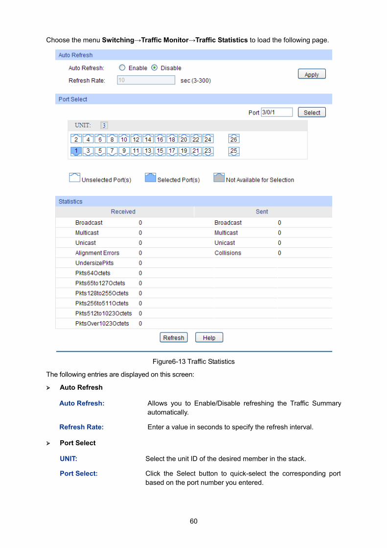
60
Choose the menu Switching→Traffic Monitor→Traffic Statistics to load the following page.
Figure6-13 Traffic Statistics
The following entries are displayed on this screen: Auto Refresh
Auto Refresh: Allows you to Enable/Disable refreshing the Traffic Summary automatically.
Refresh Rate: Enter a value in seconds to specify the refresh interval.
Port Select
UNIT: Select the unit ID of the desired member in the stack.
Port Select: Click the Select button to quick-select the corresponding port based on the port number you entered.
61
Statistics
Port: Enter a port number and click the Select button to view the traffic statistics of the corresponding port.
Received: Displays the details of the packets received on the port.
Sent: Displays the details of the packets transmitted on the port.
Broadcast: Displays the number of good broadcast packets received or transmitted on the port. The error frames are not counted in.
Multicast: Displays the number of good multicast packets received or transmitted on the port. The error frames are not counted in.
Unicast: Displays the number of good unicast packets received or transmitted on the port. The error frames are not counted in.
Alignment Errors: Displays the number of the received packets that have a bad Frame Check Sequence (FCS) with a non-integral octet (Alignment Error) and have a bad FCS with an integral octet (CRC Error). The length of the packet is between 64 bytes and 1518 bytes.
UndersizePkts: Displays the number of the received packets (excluding error packets) that are less than 64 bytes long.
Pkts64Octets: Displays the number of the received packets (including error packets) that are 64 bytes long.
Pkts65to127Octets: Displays the number of the received packets (including error packets) that are between 65 and 127 bytes long.
Pkts128to255Octets: Displays the number of the received packets (including error packets) that are between 128 and 255 bytes long.
Pkts256to511Octets: Displays the number of the received packets (including error packets) that are between 256 and 511 bytes long.
Pkts512to1023Octets: Displays the number of the received packets (including error packets) that are between 512 and 1023 bytes long.
PktsOver1023Octets: Displays the number of the received packets (including error packets) that are more than 1023 bytes long.
Collisions: Displays the number of collisions experienced by a port during packet transmissions.
6.4 MAC Address The main function of the switch is forwarding the packets to the correct ports based on the destination MAC address of the packets. Address Table contains the port-based MAC address information, which is the base for the switch to forward packets quickly. The entries in the Address Table can be updated by auto-learning or configured manually. Most entries are generated and updated by auto-learning. In the stable networks, the static MAC address entries can facilitate the switch to reduce broadcast packets and enhance the efficiency of packets forwarding remarkably.
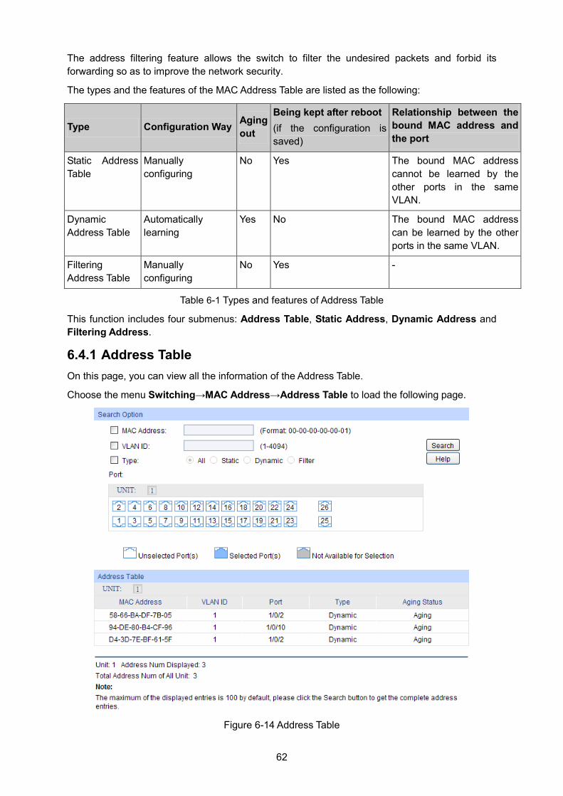
62
The address filtering feature allows the switch to filter the undesired packets and forbid its forwarding so as to improve the network security.
The types and the features of the MAC Address Table are listed as the following:
Type Configuration Way Aging out
Being kept after reboot (if the configuration is saved)
Relationship between the bound MAC address and the port
Static Address Table
Manually configuring
No Yes The bound MAC address cannot be learned by the other ports in the same VLAN.
Dynamic Address Table
Automatically learning
Yes No The bound MAC address can be learned by the other ports in the same VLAN.
Filtering Address Table
Manually configuring
No Yes -
Table 6-1 Types and features of Address Table
This function includes four submenus: Address Table, Static Address, Dynamic Address and Filtering Address.
6.4.1 Address Table On this page, you can view all the information of the Address Table.
Choose the menu Switching→MAC Address→Address Table to load the following page.
Figure 6-14 Address Table
63
The following entries are displayed on this screen: Search Option
MAC Address: Enter the MAC address of your desired entry.
VLAN ID: Enter the VLAN ID of your desired entry.
Port: Select the corresponding port number or link-aggregation number of your desired entry.
Type: Select the type of your desired entry. All: This option allows the address table to display all the
address entries. Static: This option allows the address table to display the static
address entries only. Dynamic: This option allows the address table to display the
dynamic address entries only. Filtering: This option allows the address table to display the
filtering address entries only.
UNIT: Select the unit ID of the desired member in the stack.
Address Table
UNIT: Select the unit ID of the desired member in the stack.
MAC Address: Displays the MAC address learned by the switch.
VLAN ID: Displays the corresponding VLAN ID of the MAC address.
Port: Displays the corresponding port number or link-aggregation number of the MAC address.
Type: Displays the Type of the MAC address.
Aging Status: Displays the Aging status of the MAC address.
6.4.2 Static Address The static address table maintains the static address entries which can be added or removed manually, independent of the aging time. In the stable networks, the static MAC address entries can facilitate the switch to reduce broadcast packets and remarkably enhance the efficiency of packets forwarding without learning the address. The static MAC address learned by the port with Port Security enabled in the static learning mode will be displayed in the Static Address Table.
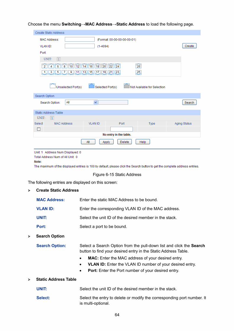
64
Choose the menu Switching→MAC Address→Static Address to load the following page.
Figure 6-15 Static Address
The following entries are displayed on this screen: Create Static Address
MAC Address: Enter the static MAC Address to be bound.
VLAN ID: Enter the corresponding VLAN ID of the MAC address.
UNIT: Select the unit ID of the desired member in the stack.
Port: Select a port to be bound.
Search Option
Search Option: Select a Search Option from the pull-down list and click the Search button to find your desired entry in the Static Address Table.
• MAC: Enter the MAC address of your desired entry. • VLAN ID: Enter the VLAN ID number of your desired entry. • Port: Enter the Port number of your desired entry.
Static Address Table
UNIT: Select the unit ID of the desired member in the stack.
Select: Select the entry to delete or modify the corresponding port number. It is multi-optional.
65
MAC Address: Displays the static MAC Address.
VLAN ID: Displays the corresponding VLAN ID of the MAC address.
Port: Displays the corresponding Port number of the MAC address. Here you can modify the port number to which the MAC address is bound. The new port should be in the same VLAN.
Type: Displays the Type of the MAC address.
Aging Status: Displays the Aging Status of the MAC address.
Note: 1. If the corresponding port number of the MAC address is not correct, or the connected port (or
the device) has been changed, the switch cannot forward the packets correctly. Please reset the static address entry appropriately.
2. If the MAC address of a device has been added to the Static Address Table, connecting the device to another port will cause its address not to be recognized dynamically by the switch. Therefore, please ensure the entries in the Static Address Table are correct and valid.
3. The MAC address in the Static Address Table cannot be added to the Filtering Address Table or bound to a port dynamically.
6.4.3 Dynamic Address The dynamic address can be generated by the auto-learning mechanism of the switch. The Dynamic Address Table can update automatically by auto-learning or the MAC address aging out mechanism.
To fully utilize the MAC address table, which has a limited capacity, the switch adopts an aging mechanism for updating the table. That is, the switch removes the MAC address entries related to a network device if no packet is received from the device within the aging time.
On this page, you can configure the dynamic MAC address entry.
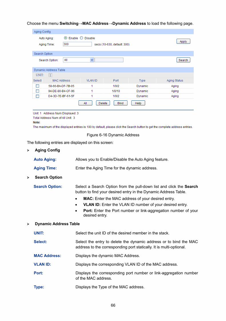
66
Choose the menu Switching→MAC Address→Dynamic Address to load the following page.
Figure 6-16 Dynamic Address
The following entries are displayed on this screen: Aging Config
Auto Aging: Allows you to Enable/Disable the Auto Aging feature.
Aging Time: Enter the Aging Time for the dynamic address.
Search Option
Search Option: Select a Search Option from the pull-down list and click the Search button to find your desired entry in the Dynamic Address Table.
• MAC: Enter the MAC address of your desired entry. • VLAN ID: Enter the VLAN ID number of your desired entry. • Port: Enter the Port number or link-aggregation number of your
desired entry.
Dynamic Address Table
UNIT: Select the unit ID of the desired member in the stack.
Select: Select the entry to delete the dynamic address or to bind the MAC address to the corresponding port statically. It is multi-optional.
MAC Address: Displays the dynamic MAC Address.
VLAN ID: Displays the corresponding VLAN ID of the MAC address.
Port: Displays the corresponding port number or link-aggregation number of the MAC address.
Type: Displays the Type of the MAC address.
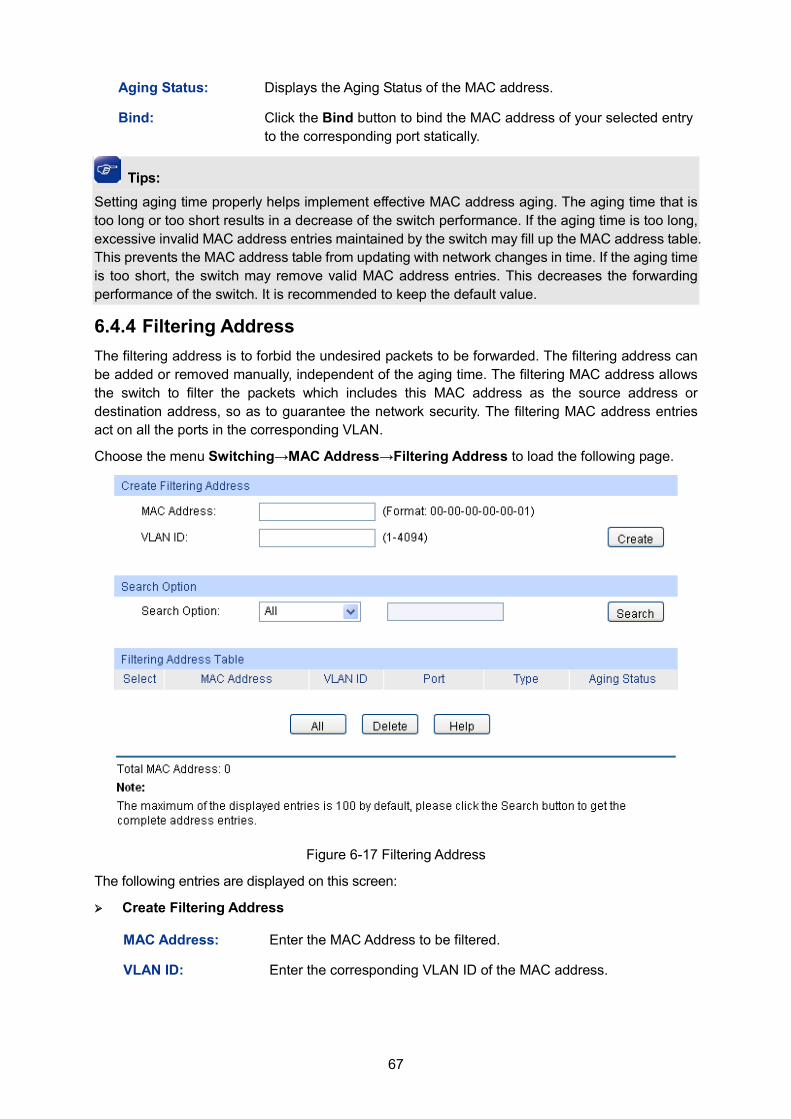
67
Aging Status: Displays the Aging Status of the MAC address.
Bind: Click the Bind button to bind the MAC address of your selected entry to the corresponding port statically.
Tips: Setting aging time properly helps implement effective MAC address aging. The aging time that is too long or too short results in a decrease of the switch performance. If the aging time is too long, excessive invalid MAC address entries maintained by the switch may fill up the MAC address table. This prevents the MAC address table from updating with network changes in time. If the aging time is too short, the switch may remove valid MAC address entries. This decreases the forwarding performance of the switch. It is recommended to keep the default value.
6.4.4 Filtering Address The filtering address is to forbid the undesired packets to be forwarded. The filtering address can be added or removed manually, independent of the aging time. The filtering MAC address allows the switch to filter the packets which includes this MAC address as the source address or destination address, so as to guarantee the network security. The filtering MAC address entries act on all the ports in the corresponding VLAN.
Choose the menu Switching→MAC Address→Filtering Address to load the following page.
Figure 6-17 Filtering Address
The following entries are displayed on this screen: Create Filtering Address
MAC Address: Enter the MAC Address to be filtered.
VLAN ID: Enter the corresponding VLAN ID of the MAC address.
68
Search Option
Search Option: Select a Search Option from the pull-down list and click the Search button to find your desired entry in the Filtering Address Table. • MAC Address: Enter the MAC address of your desired entry. • VLAN ID: Enter the VLAN ID number of your desired entry.
Filtering Address Table
Select: Select the entry to delete the corresponding filtering address. It is multi-optional.
MAC Address: Displays the filtering MAC Address.
VLAN ID: Displays the corresponding VLAN ID.
Port: Here the symbol “__” indicates no specified port.
Type: Displays the Type of the MAC address.
Aging Status: Displays the Aging Status of the MAC address.
Note: 1. The MAC address in the Filtering Address Table cannot be added to the Static Address Table
or bound to a port dynamically.
2. This MAC address filtering function is not available if the 802.1X feature is enabled.
Return to CONTENTS
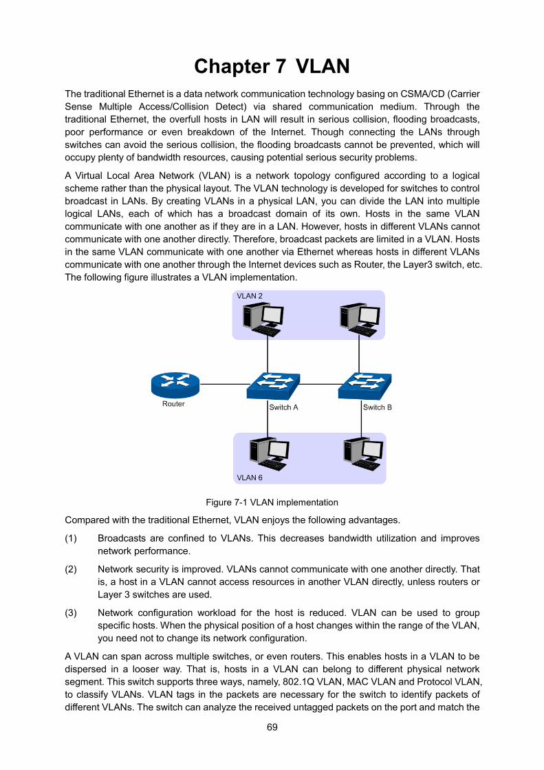
69
Chapter 7 VLAN The traditional Ethernet is a data network communication technology basing on CSMA/CD (Carrier Sense Multiple Access/Collision Detect) via shared communication medium. Through the traditional Ethernet, the overfull hosts in LAN will result in serious collision, flooding broadcasts, poor performance or even breakdown of the Internet. Though connecting the LANs through switches can avoid the serious collision, the flooding broadcasts cannot be prevented, which will occupy plenty of bandwidth resources, causing potential serious security problems.
A Virtual Local Area Network (VLAN) is a network topology configured according to a logical scheme rather than the physical layout. The VLAN technology is developed for switches to control broadcast in LANs. By creating VLANs in a physical LAN, you can divide the LAN into multiple logical LANs, each of which has a broadcast domain of its own. Hosts in the same VLAN communicate with one another as if they are in a LAN. However, hosts in different VLANs cannot communicate with one another directly. Therefore, broadcast packets are limited in a VLAN. Hosts in the same VLAN communicate with one another via Ethernet whereas hosts in different VLANs communicate with one another through the Internet devices such as Router, the Layer3 switch, etc. The following figure illustrates a VLAN implementation.
Figure 7-1 VLAN implementation
Compared with the traditional Ethernet, VLAN enjoys the following advantages.
(1) Broadcasts are confined to VLANs. This decreases bandwidth utilization and improves network performance.
(2) Network security is improved. VLANs cannot communicate with one another directly. That is, a host in a VLAN cannot access resources in another VLAN directly, unless routers or Layer 3 switches are used.
(3) Network configuration workload for the host is reduced. VLAN can be used to group specific hosts. When the physical position of a host changes within the range of the VLAN, you need not to change its network configuration.
A VLAN can span across multiple switches, or even routers. This enables hosts in a VLAN to be dispersed in a looser way. That is, hosts in a VLAN can belong to different physical network segment. This switch supports three ways, namely, 802.1Q VLAN, MAC VLAN and Protocol VLAN, to classify VLANs. VLAN tags in the packets are necessary for the switch to identify packets of different VLANs. The switch can analyze the received untagged packets on the port and match the
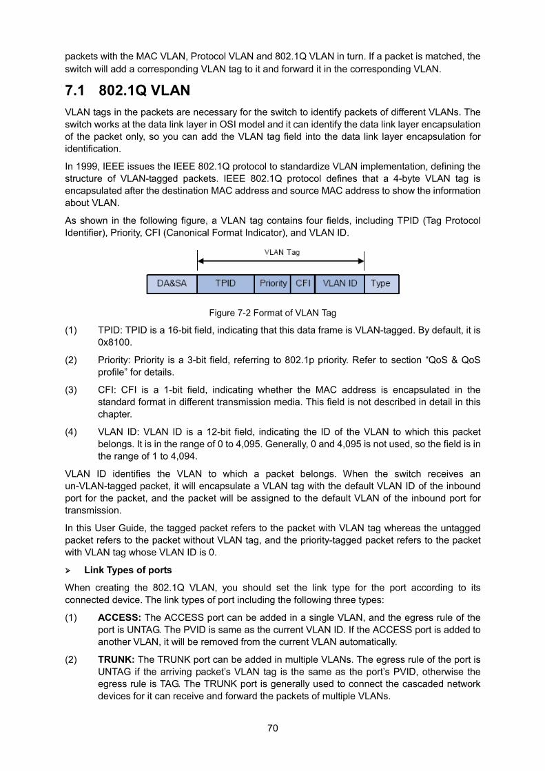
70
packets with the MAC VLAN, Protocol VLAN and 802.1Q VLAN in turn. If a packet is matched, the switch will add a corresponding VLAN tag to it and forward it in the corresponding VLAN.
7.1 802.1Q VLAN VLAN tags in the packets are necessary for the switch to identify packets of different VLANs. The switch works at the data link layer in OSI model and it can identify the data link layer encapsulation of the packet only, so you can add the VLAN tag field into the data link layer encapsulation for identification.
In 1999, IEEE issues the IEEE 802.1Q protocol to standardize VLAN implementation, defining the structure of VLAN-tagged packets. IEEE 802.1Q protocol defines that a 4-byte VLAN tag is encapsulated after the destination MAC address and source MAC address to show the information about VLAN.
As shown in the following figure, a VLAN tag contains four fields, including TPID (Tag Protocol Identifier), Priority, CFI (Canonical Format Indicator), and VLAN ID.
Figure 7-2 Format of VLAN Tag
(1) TPID: TPID is a 16-bit field, indicating that this data frame is VLAN-tagged. By default, it is 0x8100.
(2) Priority: Priority is a 3-bit field, referring to 802.1p priority. Refer to section “QoS & QoS profile” for details.
(3) CFI: CFI is a 1-bit field, indicating whether the MAC address is encapsulated in the standard format in different transmission media. This field is not described in detail in this chapter.
(4) VLAN ID: VLAN ID is a 12-bit field, indicating the ID of the VLAN to which this packet belongs. It is in the range of 0 to 4,095. Generally, 0 and 4,095 is not used, so the field is in the range of 1 to 4,094.
VLAN ID identifies the VLAN to which a packet belongs. When the switch receives an un-VLAN-tagged packet, it will encapsulate a VLAN tag with the default VLAN ID of the inbound port for the packet, and the packet will be assigned to the default VLAN of the inbound port for transmission.
In this User Guide, the tagged packet refers to the packet with VLAN tag whereas the untagged packet refers to the packet without VLAN tag, and the priority-tagged packet refers to the packet with VLAN tag whose VLAN ID is 0.
Link Types of ports
When creating the 802.1Q VLAN, you should set the link type for the port according to its connected device. The link types of port including the following three types:
(1) ACCESS: The ACCESS port can be added in a single VLAN, and the egress rule of the port is UNTAG. The PVID is same as the current VLAN ID. If the ACCESS port is added to another VLAN, it will be removed from the current VLAN automatically.
(2) TRUNK: The TRUNK port can be added in multiple VLANs. The egress rule of the port is UNTAG if the arriving packet’s VLAN tag is the same as the port’s PVID, otherwise the egress rule is TAG. The TRUNK port is generally used to connect the cascaded network devices for it can receive and forward the packets of multiple VLANs.
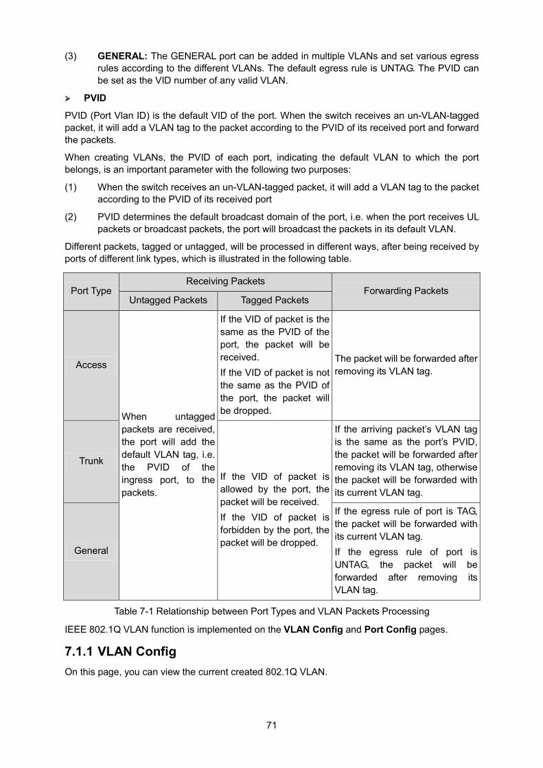
71
(3) GENERAL: The GENERAL port can be added in multiple VLANs and set various egress rules according to the different VLANs. The default egress rule is UNTAG. The PVID can be set as the VID number of any valid VLAN.
PVID
PVID (Port Vlan ID) is the default VID of the port. When the switch receives an un-VLAN-tagged packet, it will add a VLAN tag to the packet according to the PVID of its received port and forward the packets.
When creating VLANs, the PVID of each port, indicating the default VLAN to which the port belongs, is an important parameter with the following two purposes:
(1) When the switch receives an un-VLAN-tagged packet, it will add a VLAN tag to the packet according to the PVID of its received port
(2) PVID determines the default broadcast domain of the port, i.e. when the port receives UL packets or broadcast packets, the port will broadcast the packets in its default VLAN.
Different packets, tagged or untagged, will be processed in different ways, after being received by ports of different link types, which is illustrated in the following table.
Port Type Receiving Packets
Forwarding Packets Untagged Packets Tagged Packets
Access
When untagged packets are received, the port will add the default VLAN tag, i.e. the PVID of the ingress port, to the packets.
If the VID of packet is the same as the PVID of the port, the packet will be received. If the VID of packet is not the same as the PVID of the port, the packet will be dropped.
The packet will be forwarded after removing its VLAN tag.
Trunk If the VID of packet is allowed by the port, the packet will be received. If the VID of packet is forbidden by the port, the packet will be dropped.
If the arriving packet’s VLAN tag is the same as the port’s PVID, the packet will be forwarded after removing its VLAN tag, otherwise the packet will be forwarded with its current VLAN tag.
General
If the egress rule of port is TAG, the packet will be forwarded with its current VLAN tag. If the egress rule of port is UNTAG, the packet will be forwarded after removing its VLAN tag.
Table 7-1 Relationship between Port Types and VLAN Packets Processing
IEEE 802.1Q VLAN function is implemented on the VLAN Config and Port Config pages.
7.1.1 VLAN Config On this page, you can view the current created 802.1Q VLAN.
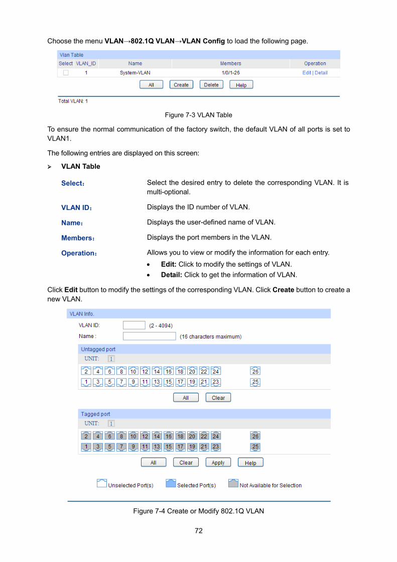
72
Choose the menu VLAN→802.1Q VLAN→VLAN Config to load the following page.
Figure 7-3 VLAN Table
To ensure the normal communication of the factory switch, the default VLAN of all ports is set to VLAN1.
The following entries are displayed on this screen: VLAN Table
Select: Select the desired entry to delete the corresponding VLAN. It is multi-optional.
VLAN ID: Displays the ID number of VLAN.
Name: Displays the user-defined name of VLAN.
Members: Displays the port members in the VLAN.
Operation: Allows you to view or modify the information for each entry.
• Edit: Click to modify the settings of VLAN. • Detail: Click to get the information of VLAN.
Click Edit button to modify the settings of the corresponding VLAN. Click Create button to create a new VLAN.
Figure 7-4 Create or Modify 802.1Q VLAN
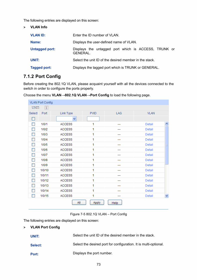
73
The following entries are displayed on this screen: VLAN Info
VLAN ID: Enter the ID number of VLAN.
Name: Displays the user-defined name of VLAN.
Untagged port: Displays the untagged port which is ACCESS, TRUNK or GENERAL.
UNIT: Select the unit ID of the desired member in the stack.
Tagged port: Displays the tagged port which is TRUNK or GENERAL.
7.1.2 Port Config Before creating the 802.1Q VLAN, please acquaint yourself with all the devices connected to the switch in order to configure the ports properly.
Choose the menu VLAN→802.1Q VLAN→Port Config to load the following page.
Figure 7-5 802.1Q VLAN – Port Config
The following entries are displayed on this screen: VLAN Port Config
UNIT: Select the unit ID of the desired member in the stack.
Select: Select the desired port for configuration. It is multi-optional.
Port: Displays the port number.
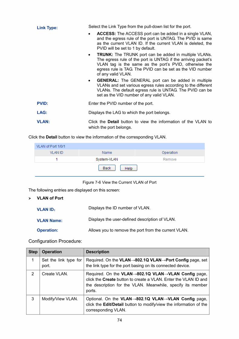
74
Link Type: Select the Link Type from the pull-down list for the port.
• ACCESS: The ACCESS port can be added in a single VLAN, and the egress rule of the port is UNTAG. The PVID is same as the current VLAN ID. If the current VLAN is deleted, the PVID will be set to 1 by default.
• TRUNK: The TRUNK port can be added in multiple VLANs. The egress rule of the port is UNTAG if the arriving packet’s VLAN tag is the same as the port’s PVID, otherwise the egress rule is TAG. The PVID can be set as the VID number of any valid VLAN.
• GENERAL: The GENERAL port can be added in multiple VLANs and set various egress rules according to the different VLANs. The default egress rule is UNTAG. The PVID can be set as the VID number of any valid VLAN.
PVID: Enter the PVID number of the port.
LAG: Displays the LAG to which the port belongs.
VLAN: Click the Detail button to view the information of the VLAN to which the port belongs.
Click the Detail button to view the information of the corresponding VLAN.
Figure 7-6 View the Current VLAN of Port
The following entries are displayed on this screen: VLAN of Port
VLAN ID: Displays the ID number of VLAN.
VLAN Name: Displays the user-defined description of VLAN.
Operation: Allows you to remove the port from the current VLAN.
Configuration Procedure:
Step Operation Description
1 Set the link type for port.
Required. On the VLAN→802.1Q VLAN→Port Config page, set the link type for the port basing on its connected device.
2 Create VLAN. Required. On the VLAN→802.1Q VLAN→VLAN Config page, click the Create button to create a VLAN. Enter the VLAN ID and the description for the VLAN. Meanwhile, specify its member ports.
3 Modify/View VLAN. Optional. On the VLAN→802.1Q VLAN→VLAN Config page, click the Edit/Detail button to modify/view the information of the corresponding VLAN.
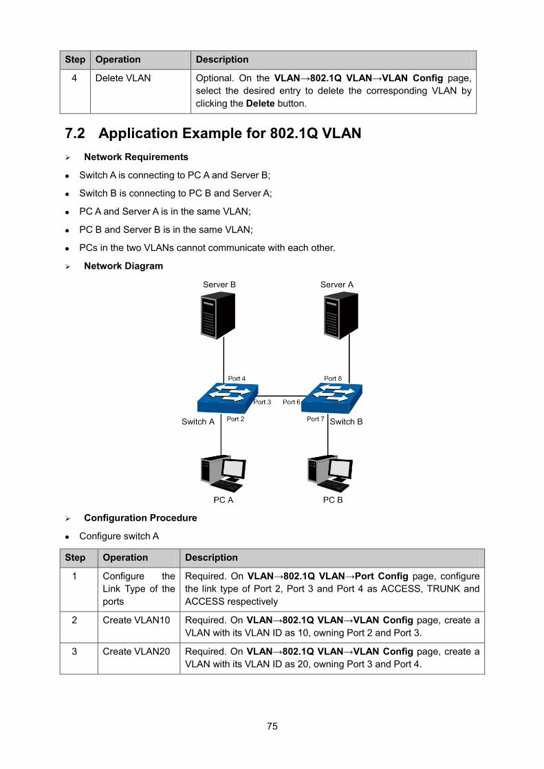
75
Step Operation Description
4 Delete VLAN Optional. On the VLAN→802.1Q VLAN→VLAN Config page, select the desired entry to delete the corresponding VLAN by clicking the Delete button.
7.2 Application Example for 802.1Q VLAN Network Requirements
Switch A is connecting to PC A and Server B;
Switch B is connecting to PC B and Server A;
PC A and Server A is in the same VLAN;
PC B and Server B is in the same VLAN;
PCs in the two VLANs cannot communicate with each other.
Network Diagram
Configuration Procedure
Configure switch A
Step Operation Description
1 Configure the Link Type of the ports
Required. On VLAN→802.1Q VLAN→Port Config page, configure the link type of Port 2, Port 3 and Port 4 as ACCESS, TRUNK and ACCESS respectively
2 Create VLAN10 Required. On VLAN→802.1Q VLAN→VLAN Config page, create a VLAN with its VLAN ID as 10, owning Port 2 and Port 3.
3 Create VLAN20 Required. On VLAN→802.1Q VLAN→VLAN Config page, create a VLAN with its VLAN ID as 20, owning Port 3 and Port 4.
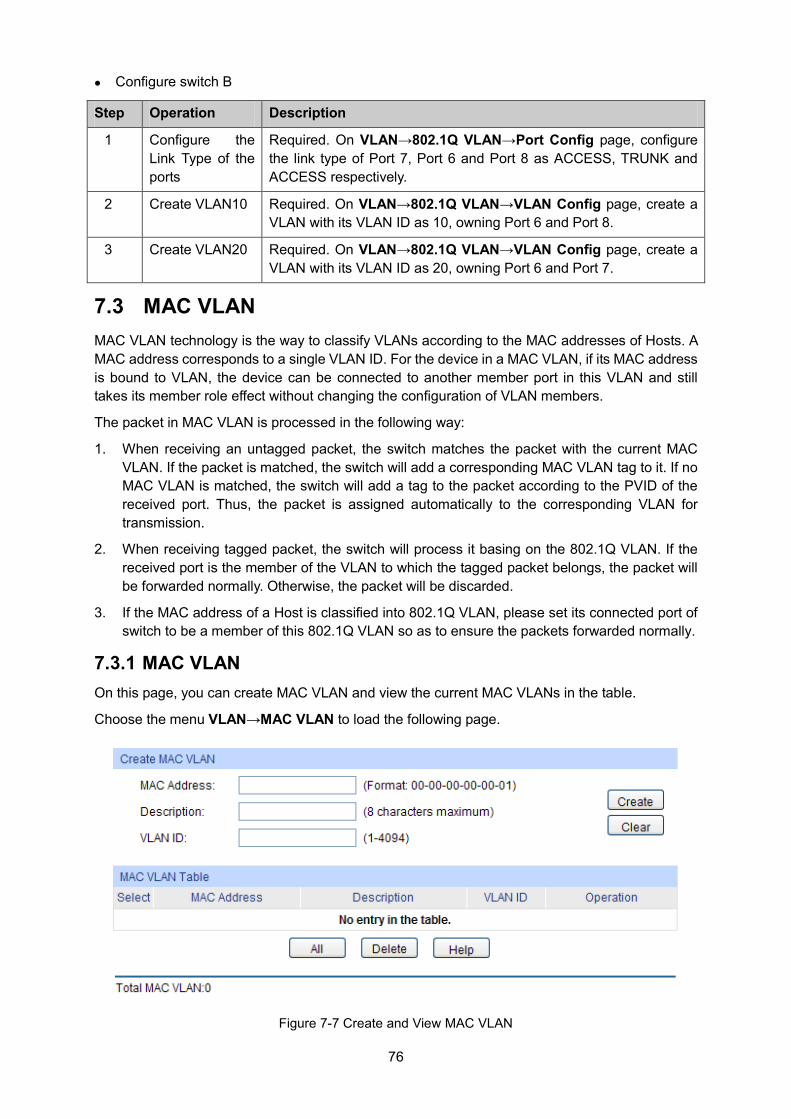
76
Configure switch B
Step Operation Description
1 Configure the Link Type of the ports
Required. On VLAN→802.1Q VLAN→Port Config page, configure the link type of Port 7, Port 6 and Port 8 as ACCESS, TRUNK and ACCESS respectively.
2 Create VLAN10 Required. On VLAN→802.1Q VLAN→VLAN Config page, create a VLAN with its VLAN ID as 10, owning Port 6 and Port 8.
3 Create VLAN20 Required. On VLAN→802.1Q VLAN→VLAN Config page, create a VLAN with its VLAN ID as 20, owning Port 6 and Port 7.
7.3 MAC VLAN MAC VLAN technology is the way to classify VLANs according to the MAC addresses of Hosts. A MAC address corresponds to a single VLAN ID. For the device in a MAC VLAN, if its MAC address is bound to VLAN, the device can be connected to another member port in this VLAN and still takes its member role effect without changing the configuration of VLAN members.
The packet in MAC VLAN is processed in the following way:
1. When receiving an untagged packet, the switch matches the packet with the current MAC VLAN. If the packet is matched, the switch will add a corresponding MAC VLAN tag to it. If no MAC VLAN is matched, the switch will add a tag to the packet according to the PVID of the received port. Thus, the packet is assigned automatically to the corresponding VLAN for transmission.
2. When receiving tagged packet, the switch will process it basing on the 802.1Q VLAN. If the received port is the member of the VLAN to which the tagged packet belongs, the packet will be forwarded normally. Otherwise, the packet will be discarded.
3. If the MAC address of a Host is classified into 802.1Q VLAN, please set its connected port of switch to be a member of this 802.1Q VLAN so as to ensure the packets forwarded normally.
7.3.1 MAC VLAN On this page, you can create MAC VLAN and view the current MAC VLANs in the table.
Choose the menu VLAN→MAC VLAN to load the following page.
Figure 7-7 Create and View MAC VLAN
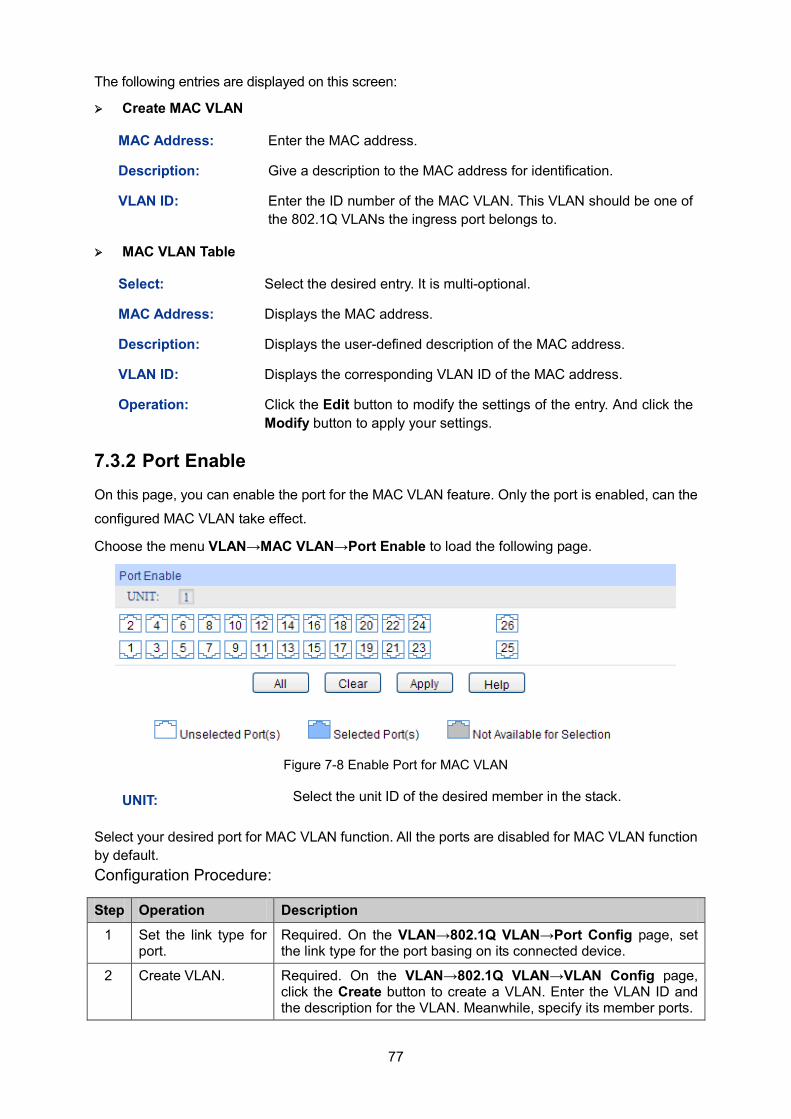
77
The following entries are displayed on this screen: Create MAC VLAN
MAC Address: Enter the MAC address.
Description: Give a description to the MAC address for identification.
VLAN ID: Enter the ID number of the MAC VLAN. This VLAN should be one of the 802.1Q VLANs the ingress port belongs to.
MAC VLAN Table
Select: Select the desired entry. It is multi-optional.
MAC Address: Displays the MAC address.
Description: Displays the user-defined description of the MAC address.
VLAN ID: Displays the corresponding VLAN ID of the MAC address.
Operation: Click the Edit button to modify the settings of the entry. And click the Modify button to apply your settings.
7.3.2 Port Enable On this page, you can enable the port for the MAC VLAN feature. Only the port is enabled, can the
configured MAC VLAN take effect.
Choose the menu VLAN→MAC VLAN→Port Enable to load the following page.
Figure 7-8 Enable Port for MAC VLAN
UNIT: Select the unit ID of the desired member in the stack.
Select your desired port for MAC VLAN function. All the ports are disabled for MAC VLAN function by default. Configuration Procedure:
Step Operation Description
1 Set the link type for port.
Required. On the VLAN→802.1Q VLAN→Port Config page, set the link type for the port basing on its connected device.
2 Create VLAN. Required. On the VLAN→802.1Q VLAN→VLAN Config page, click the Create button to create a VLAN. Enter the VLAN ID and the description for the VLAN. Meanwhile, specify its member ports.
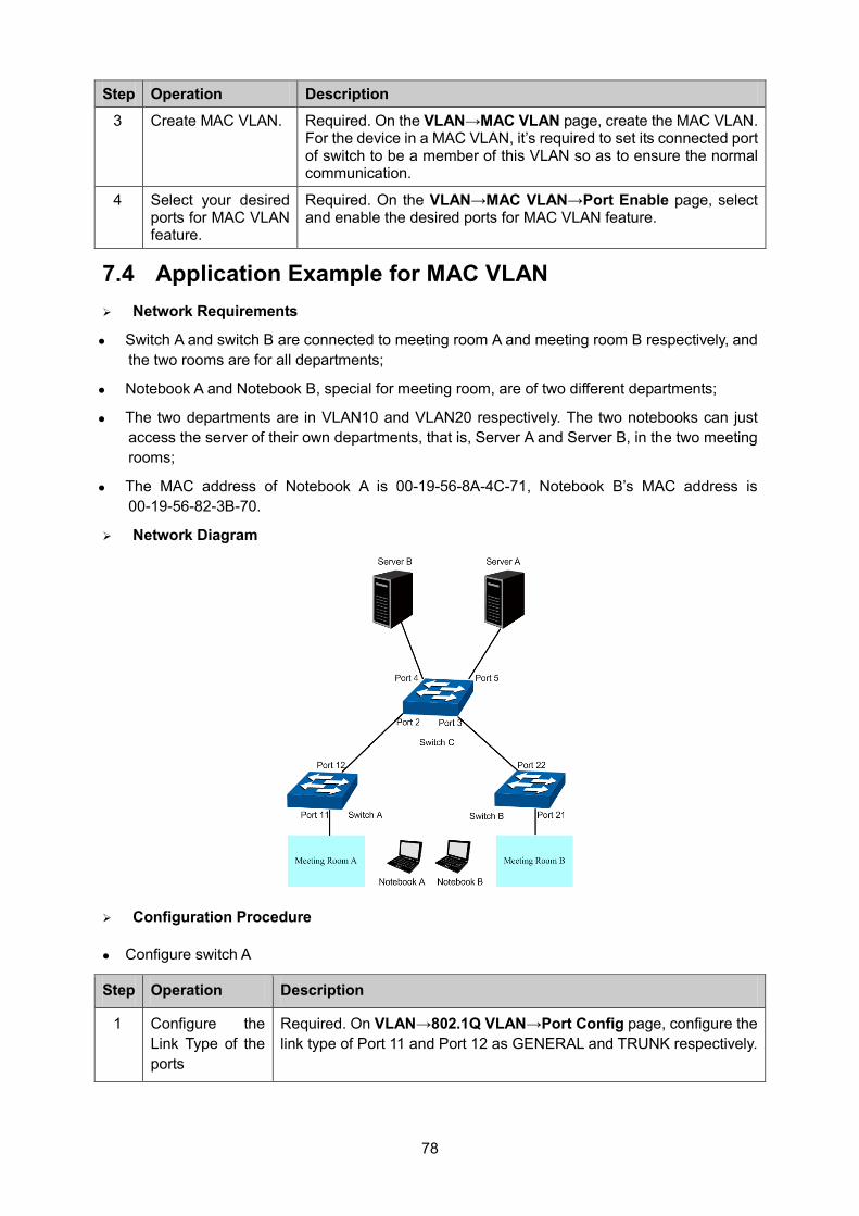
78
Step Operation Description
3 Create MAC VLAN. Required. On the VLAN→MAC VLAN page, create the MAC VLAN. For the device in a MAC VLAN, it’s required to set its connected port of switch to be a member of this VLAN so as to ensure the normal communication.
4 Select your desired ports for MAC VLAN feature.
Required. On the VLAN→MAC VLAN→Port Enable page, select and enable the desired ports for MAC VLAN feature.
7.4 Application Example for MAC VLAN Network Requirements
Switch A and switch B are connected to meeting room A and meeting room B respectively, and the two rooms are for all departments;
Notebook A and Notebook B, special for meeting room, are of two different departments;
The two departments are in VLAN10 and VLAN20 respectively. The two notebooks can just access the server of their own departments, that is, Server A and Server B, in the two meeting rooms;
The MAC address of Notebook A is 00-19-56-8A-4C-71, Notebook B’s MAC address is 00-19-56-82-3B-70.
Network Diagram
Configuration Procedure
Configure switch A
Step Operation Description
1 Configure the Link Type of the ports
Required. On VLAN→802.1Q VLAN→Port Config page, configure the link type of Port 11 and Port 12 as GENERAL and TRUNK respectively.
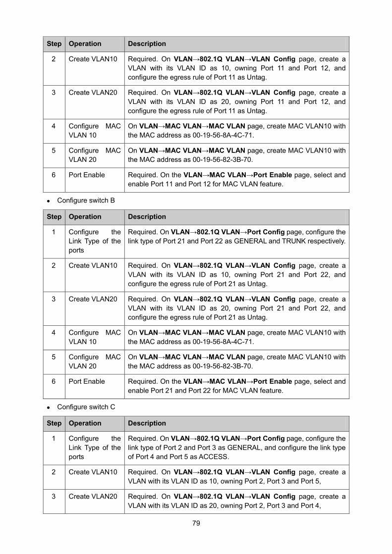
79
Step Operation Description
2 Create VLAN10 Required. On VLAN→802.1Q VLAN→VLAN Config page, create a VLAN with its VLAN ID as 10, owning Port 11 and Port 12, and configure the egress rule of Port 11 as Untag.
3 Create VLAN20 Required. On VLAN→802.1Q VLAN→VLAN Config page, create a VLAN with its VLAN ID as 20, owning Port 11 and Port 12, and configure the egress rule of Port 11 as Untag.
4 Configure MAC VLAN 10
On VLAN→MAC VLAN→MAC VLAN page, create MAC VLAN10 with the MAC address as 00-19-56-8A-4C-71.
5 Configure MAC VLAN 20
On VLAN→MAC VLAN→MAC VLAN page, create MAC VLAN10 with the MAC address as 00-19-56-82-3B-70.
6 Port Enable Required. On the VLAN→MAC VLAN→Port Enable page, select and enable Port 11 and Port 12 for MAC VLAN feature.
Configure switch B
Step Operation Description
1 Configure the Link Type of the ports
Required. On VLAN→802.1Q VLAN→Port Config page, configure the link type of Port 21 and Port 22 as GENERAL and TRUNK respectively.
2 Create VLAN10 Required. On VLAN→802.1Q VLAN→VLAN Config page, create a VLAN with its VLAN ID as 10, owning Port 21 and Port 22, and configure the egress rule of Port 21 as Untag.
3 Create VLAN20 Required. On VLAN→802.1Q VLAN→VLAN Config page, create a VLAN with its VLAN ID as 20, owning Port 21 and Port 22, and configure the egress rule of Port 21 as Untag.
4 Configure MAC VLAN 10
On VLAN→MAC VLAN→MAC VLAN page, create MAC VLAN10 with the MAC address as 00-19-56-8A-4C-71.
5 Configure MAC VLAN 20
On VLAN→MAC VLAN→MAC VLAN page, create MAC VLAN10 with the MAC address as 00-19-56-82-3B-70.
6 Port Enable Required. On the VLAN→MAC VLAN→Port Enable page, select and enable Port 21 and Port 22 for MAC VLAN feature.
Configure switch C
Step Operation Description
1 Configure the Link Type of the ports
Required. On VLAN→802.1Q VLAN→Port Config page, configure the link type of Port 2 and Port 3 as GENERAL, and configure the link type of Port 4 and Port 5 as ACCESS.
2 Create VLAN10 Required. On VLAN→802.1Q VLAN→VLAN Config page, create a VLAN with its VLAN ID as 10, owning Port 2, Port 3 and Port 5,
3 Create VLAN20 Required. On VLAN→802.1Q VLAN→VLAN Config page, create a VLAN with its VLAN ID as 20, owning Port 2, Port 3 and Port 4,
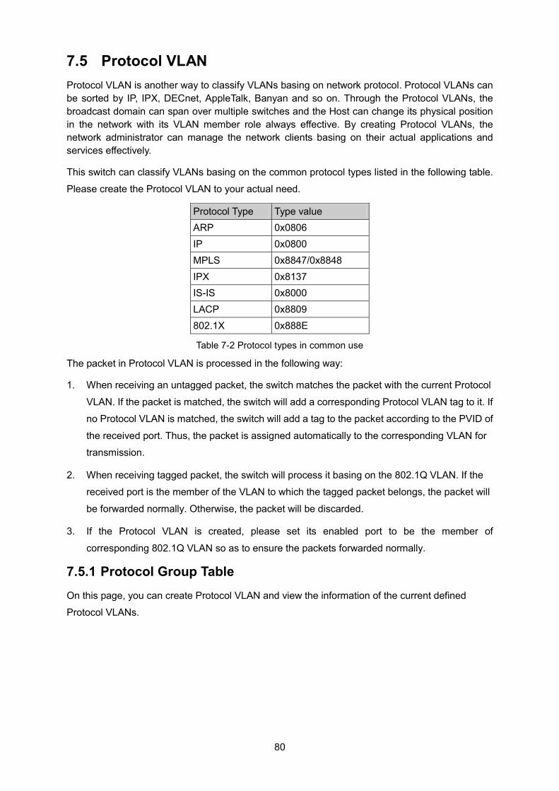
80
7.5 Protocol VLAN Protocol VLAN is another way to classify VLANs basing on network protocol. Protocol VLANs can be sorted by IP, IPX, DECnet, AppleTalk, Banyan and so on. Through the Protocol VLANs, the broadcast domain can span over multiple switches and the Host can change its physical position in the network with its VLAN member role always effective. By creating Protocol VLANs, the network administrator can manage the network clients basing on their actual applications and services effectively.
This switch can classify VLANs basing on the common protocol types listed in the following table.
Please create the Protocol VLAN to your actual need.
Protocol Type Type value ARP 0x0806 IP 0x0800 MPLS 0x8847/0x8848 IPX 0x8137 IS-IS 0x8000 LACP 0x8809 802.1X 0x888E
Table 7-2 Protocol types in common use
The packet in Protocol VLAN is processed in the following way:
1. When receiving an untagged packet, the switch matches the packet with the current Protocol
VLAN. If the packet is matched, the switch will add a corresponding Protocol VLAN tag to it. If
no Protocol VLAN is matched, the switch will add a tag to the packet according to the PVID of
the received port. Thus, the packet is assigned automatically to the corresponding VLAN for
transmission.
2. When receiving tagged packet, the switch will process it basing on the 802.1Q VLAN. If the
received port is the member of the VLAN to which the tagged packet belongs, the packet will
be forwarded normally. Otherwise, the packet will be discarded.
3. If the Protocol VLAN is created, please set its enabled port to be the member of
corresponding 802.1Q VLAN so as to ensure the packets forwarded normally.
7.5.1 Protocol Group Table On this page, you can create Protocol VLAN and view the information of the current defined
Protocol VLANs.
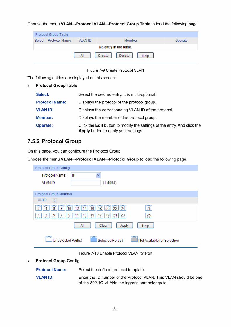
81
Choose the menu VLAN→Protocol VLAN→Protocol Group Table to load the following page.
Figure 7-9 Create Protocol VLAN
The following entries are displayed on this screen: Protocol Group Table
Select: Select the desired entry. It is multi-optional.
Protocol Name: Displays the protocol of the protocol group.
VLAN ID: Displays the corresponding VLAN ID of the protocol.
Member: Displays the member of the protocol group.
Operate: Click the Edit button to modify the settings of the entry. And click the Apply button to apply your settings.
7.5.2 Protocol Group On this page, you can configure the Protocol Group.
Choose the menu VLAN→Protocol VLAN→Protocol Group to load the following page.
Figure 7-10 Enable Protocol VLAN for Port
Protocol Group Config
Protocol Name: Select the defined protocol template.
VLAN ID: Enter the ID number of the Protocol VLAN. This VLAN should be one of the 802.1Q VLANs the ingress port belongs to.
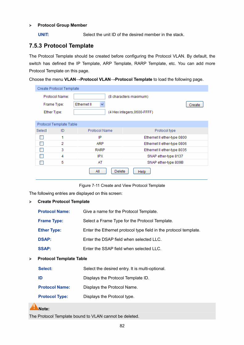
82
Protocol Group Member
UNIT: Select the unit ID of the desired member in the stack.
7.5.3 Protocol Template The Protocol Template should be created before configuring the Protocol VLAN. By default, the
switch has defined the IP Template, ARP Template, RARP Template, etc. You can add more
Protocol Template on this page.
Choose the menu VLAN→Protocol VLAN→Protocol Template to load the following page.
Figure 7-11 Create and View Protocol Template
The following entries are displayed on this screen: Create Protocol Template
Protocol Name: Give a name for the Protocol Template.
Frame Type: Select a Frame Type for the Protocol Template.
Ether Type: Enter the Ethernet protocol type field in the protocol template.
DSAP: Enter the DSAP field when selected LLC.
SSAP: Enter the SSAP field when selected LLC.
Protocol Template Table
Select: Select the desired entry. It is multi-optional.
ID Displays the Protocol Template ID.
Protocol Name: Displays the Protocol Name.
Protocol Type: Displays the Protocol type.
Note: The Protocol Template bound to VLAN cannot be deleted.
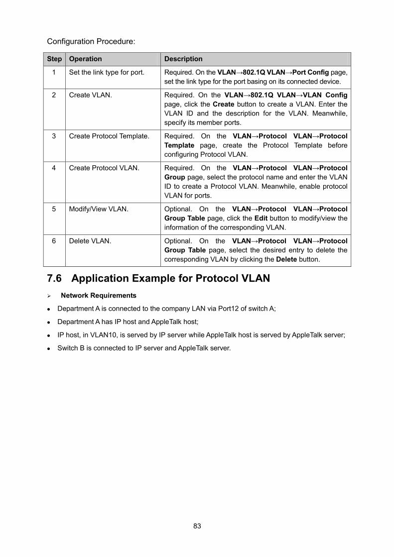
83
Configuration Procedure:
Step Operation Description
1 Set the link type for port. Required. On the VLAN→802.1Q VLAN→Port Config page, set the link type for the port basing on its connected device.
2 Create VLAN. Required. On the VLAN→802.1Q VLAN→VLAN Config page, click the Create button to create a VLAN. Enter the VLAN ID and the description for the VLAN. Meanwhile, specify its member ports.
3 Create Protocol Template. Required. On the VLAN→Protocol VLAN→Protocol Template page, create the Protocol Template before configuring Protocol VLAN.
4 Create Protocol VLAN. Required. On the VLAN→Protocol VLAN→Protocol Group page, select the protocol name and enter the VLAN ID to create a Protocol VLAN. Meanwhile, enable protocol VLAN for ports.
5 Modify/View VLAN. Optional. On the VLAN→Protocol VLAN→Protocol Group Table page, click the Edit button to modify/view the information of the corresponding VLAN.
6 Delete VLAN. Optional. On the VLAN→Protocol VLAN→Protocol Group Table page, select the desired entry to delete the corresponding VLAN by clicking the Delete button.
7.6 Application Example for Protocol VLAN Network Requirements
Department A is connected to the company LAN via Port12 of switch A;
Department A has IP host and AppleTalk host;
IP host, in VLAN10, is served by IP server while AppleTalk host is served by AppleTalk server;
Switch B is connected to IP server and AppleTalk server.
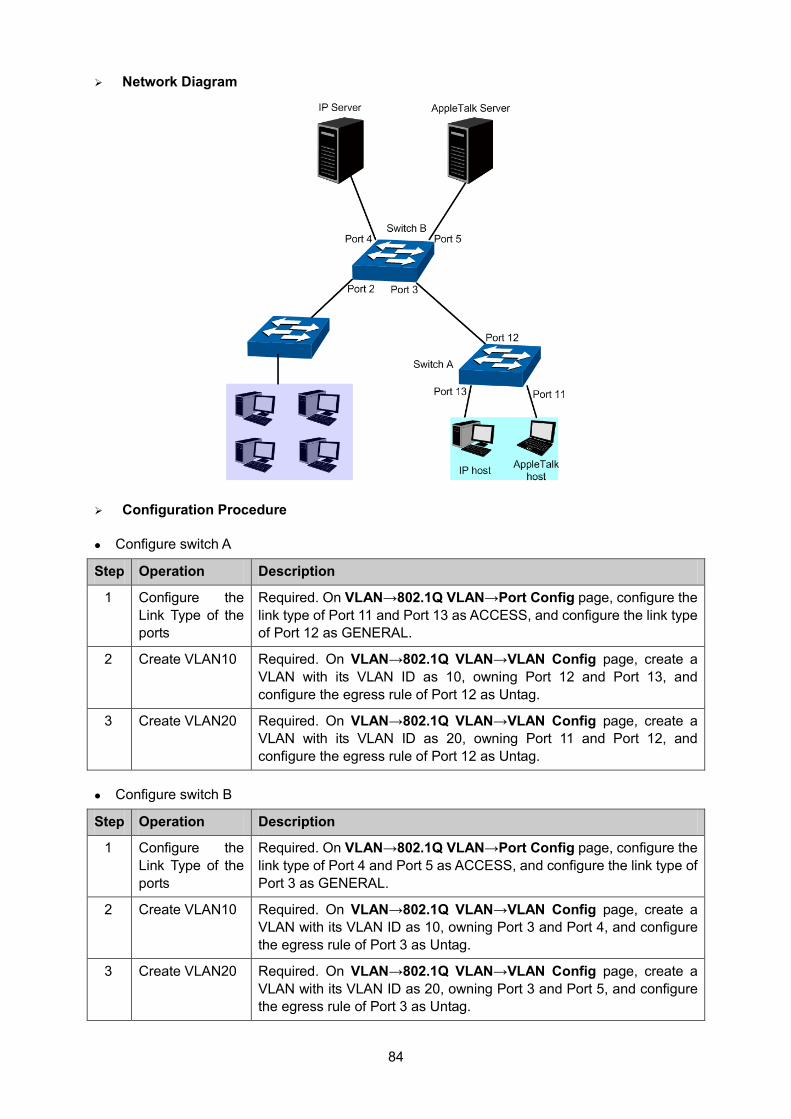
84
Network Diagram
Configuration Procedure
Configure switch A
Step Operation Description
1 Configure the Link Type of the ports
Required. On VLAN→802.1Q VLAN→Port Config page, configure the link type of Port 11 and Port 13 as ACCESS, and configure the link type of Port 12 as GENERAL.
2 Create VLAN10 Required. On VLAN→802.1Q VLAN→VLAN Config page, create a VLAN with its VLAN ID as 10, owning Port 12 and Port 13, and configure the egress rule of Port 12 as Untag.
3 Create VLAN20 Required. On VLAN→802.1Q VLAN→VLAN Config page, create a VLAN with its VLAN ID as 20, owning Port 11 and Port 12, and configure the egress rule of Port 12 as Untag.
Configure switch B
Step Operation Description
1 Configure the Link Type of the ports
Required. On VLAN→802.1Q VLAN→Port Config page, configure the link type of Port 4 and Port 5 as ACCESS, and configure the link type of Port 3 as GENERAL.
2 Create VLAN10 Required. On VLAN→802.1Q VLAN→VLAN Config page, create a VLAN with its VLAN ID as 10, owning Port 3 and Port 4, and configure the egress rule of Port 3 as Untag.
3 Create VLAN20 Required. On VLAN→802.1Q VLAN→VLAN Config page, create a VLAN with its VLAN ID as 20, owning Port 3 and Port 5, and configure the egress rule of Port 3 as Untag.
85
Step Operation Description
4 Create Protocol Template
Required. On VLAN→Protocol VLAN→Protocol Template page, configure the protocol template practically. E.g. the Ether Type of IP network packets is 0800 and that of AppleTalk network packets is 809B.
5 Create Protocol VLAN 10
On VLAN→Protocol VLAN→Protocol Group page, create protocol VLAN 10 with Protocol as IP. Select and enable Port 3, Port 4 and Port 5 for Protocol VLAN feature.
6 Create Protocol VLAN 20
On VLAN→Protocol VLAN→Protocol Group page, create protocol VLAN 20 with Protocol as AppleTalk. Select and enable Port 3, Port 4 and Port 5 for Protocol VLAN feature.
7.7 VLAN VPN With the increasing application of the Internet, the VPN (Virtual Private Network) technology is developed and used to establish the private network through the operators’ backbone networks. VLAN-VPN (Virtual Private Network) function, the implement of a simple and flexible Layer 2 VPN technology, allows the packets with VLAN tags of private networks to be encapsulated with VLAN tags of public networks at the network access terminal of the Internet Service Provider. And these packets will be transmitted with double-tag across the public networks.
The VLAN-VPN function provides you with the following benefits:
(1) Provides simple Layer 2 VPN solutions for small-sized LANs or intranets.
(2) Saves public network VLAN ID resource.
(3) You can have VLAN IDs of your own, which is independent of public network VLAN IDs.
(4) When the network of the Internet Service Provider is upgraded, the user’s network with a relative independence can still work normally without changing the current configurations.
In addition, the switch supports the feature to adjust the TPID Values of VLAN VPN Packets. TPID (Tag Protocol Identifier) is a field of the VLAN tag. IEEE 802.1Q specifies the value of TPID to be 0x8100. This switch adopts the default value of TPID (0x8100) defined by the protocol. Other manufacturers use other TPID values (such as 0x9100 or 0x9200) in the outer tags of VLAN-VPN packets. To be compatible with devices coming from other manufacturers, this switch can adjust the TPID values of VLAN-VPN packets globally. You can configure TPID values by yourself. When a port receives a packet, this port will replace the TPID value in the outer VLAN tag of this packet with the user-defined value and then send the packet again. Thus, the VLAN-VPN packets sent to the public network can be recognized by devices of other manufacturers.
The position of the TPID field in an Ethernet packet is the same as the position of the protocol type field in the packet without VLAN Tag. Thus, to avoid confusion happening when the switch forwards or receives a packet, you must not configure the following protocol type values listed in the following table as the TPID value.
Protocol type Value
ARP 0x0806
IP 0x0800
MPLS 0x8847/0x8848
IPX 0x8137
IS-IS 0x8000
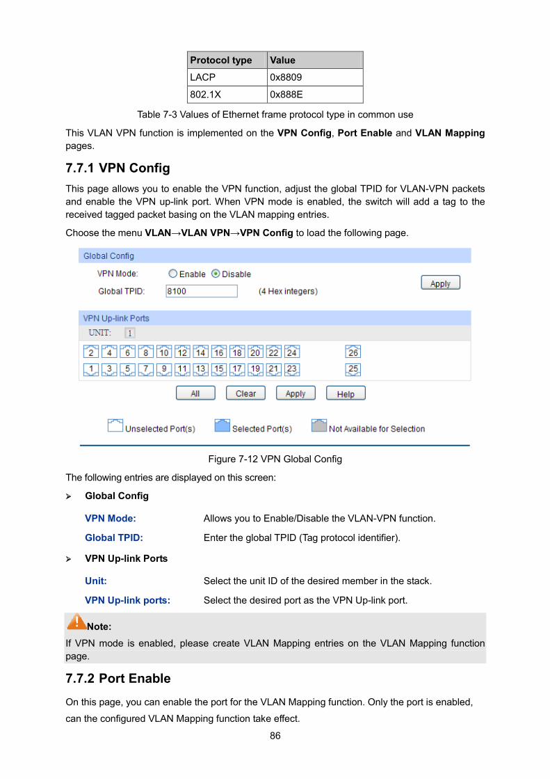
86
Protocol type Value
LACP 0x8809
802.1X 0x888E
Table 7-3 Values of Ethernet frame protocol type in common use
This VLAN VPN function is implemented on the VPN Config, Port Enable and VLAN Mapping pages.
7.7.1 VPN Config This page allows you to enable the VPN function, adjust the global TPID for VLAN-VPN packets and enable the VPN up-link port. When VPN mode is enabled, the switch will add a tag to the received tagged packet basing on the VLAN mapping entries.
Choose the menu VLAN→VLAN VPN→VPN Config to load the following page.
Figure 7-12 VPN Global Config
The following entries are displayed on this screen: Global Config
VPN Mode: Allows you to Enable/Disable the VLAN-VPN function.
Global TPID: Enter the global TPID (Tag protocol identifier).
VPN Up-link Ports
Unit: Select the unit ID of the desired member in the stack.
VPN Up-link ports: Select the desired port as the VPN Up-link port.
Note: If VPN mode is enabled, please create VLAN Mapping entries on the VLAN Mapping function page.
7.7.2 Port Enable On this page, you can enable the port for the VLAN Mapping function. Only the port is enabled,
can the configured VLAN Mapping function take effect.
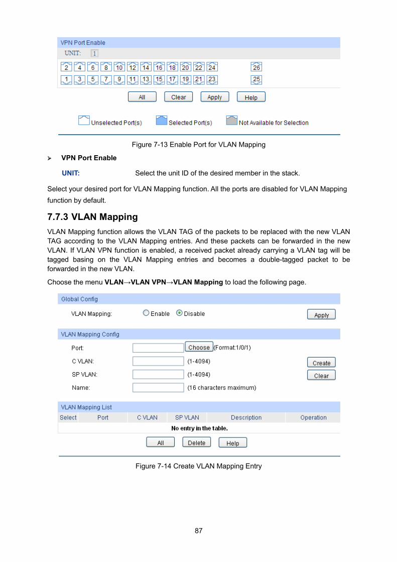
87
Figure 7-13 Enable Port for VLAN Mapping
VPN Port Enable
UNIT: Select the unit ID of the desired member in the stack.
Select your desired port for VLAN Mapping function. All the ports are disabled for VLAN Mapping function by default.
7.7.3 VLAN Mapping VLAN Mapping function allows the VLAN TAG of the packets to be replaced with the new VLAN TAG according to the VLAN Mapping entries. And these packets can be forwarded in the new VLAN. If VLAN VPN function is enabled, a received packet already carrying a VLAN tag will be tagged basing on the VLAN Mapping entries and becomes a double-tagged packet to be forwarded in the new VLAN.
Choose the menu VLAN→VLAN VPN→VLAN Mapping to load the following page.
Figure 7-14 Create VLAN Mapping Entry
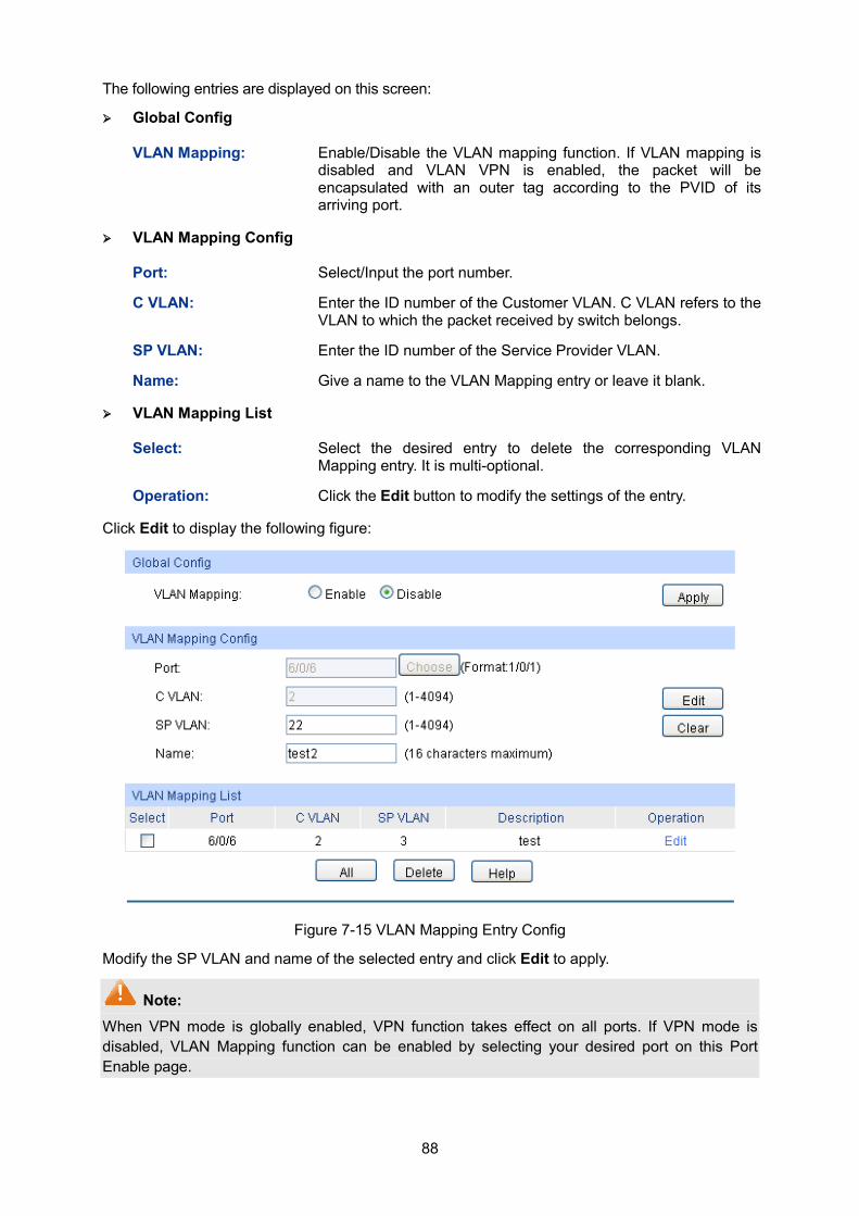
88
The following entries are displayed on this screen:
Global Config
VLAN Mapping: Enable/Disable the VLAN mapping function. If VLAN mapping is disabled and VLAN VPN is enabled, the packet will be encapsulated with an outer tag according to the PVID of its arriving port.
VLAN Mapping Config
Port: Select/Input the port number.
C VLAN: Enter the ID number of the Customer VLAN. C VLAN refers to the VLAN to which the packet received by switch belongs.
SP VLAN: Enter the ID number of the Service Provider VLAN.
Name: Give a name to the VLAN Mapping entry or leave it blank.
VLAN Mapping List
Select: Select the desired entry to delete the corresponding VLAN Mapping entry. It is multi-optional.
Operation: Click the Edit button to modify the settings of the entry.
Click Edit to display the following figure:
Figure 7-15 VLAN Mapping Entry Config
Modify the SP VLAN and name of the selected entry and click Edit to apply.
Note: When VPN mode is globally enabled, VPN function takes effect on all ports. If VPN mode is disabled, VLAN Mapping function can be enabled by selecting your desired port on this Port Enable page.
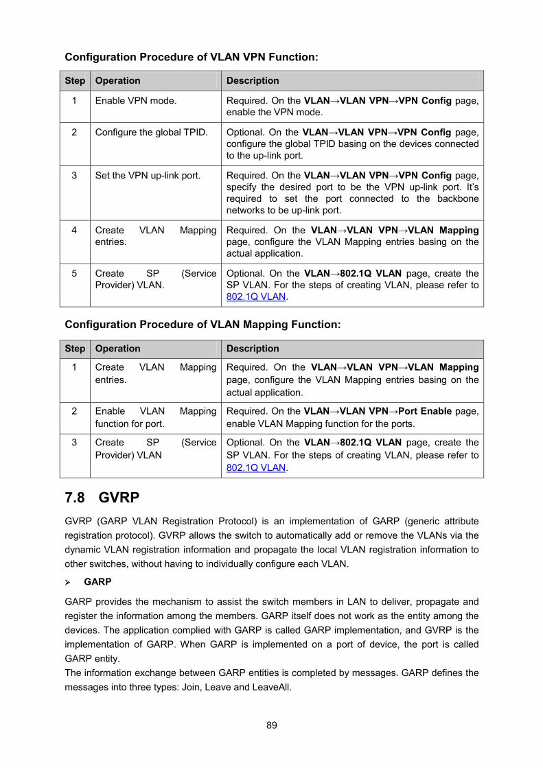
89
Configuration Procedure of VLAN VPN Function:
Step Operation Description
1 Enable VPN mode. Required. On the VLAN→VLAN VPN→VPN Config page, enable the VPN mode.
2 Configure the global TPID. Optional. On the VLAN→VLAN VPN→VPN Config page, configure the global TPID basing on the devices connected to the up-link port.
3 Set the VPN up-link port. Required. On the VLAN→VLAN VPN→VPN Config page, specify the desired port to be the VPN up-link port. It’s required to set the port connected to the backbone networks to be up-link port.
4 Create VLAN Mapping entries.
Required. On the VLAN→VLAN VPN→VLAN Mapping page, configure the VLAN Mapping entries basing on the actual application.
5 Create SP (Service Provider) VLAN.
Optional. On the VLAN→802.1Q VLAN page, create the SP VLAN. For the steps of creating VLAN, please refer to 802.1Q VLAN.
Configuration Procedure of VLAN Mapping Function:
Step Operation Description
1 Create VLAN Mapping entries.
Required. On the VLAN→VLAN VPN→VLAN Mapping page, configure the VLAN Mapping entries basing on the actual application.
2 Enable VLAN Mapping function for port.
Required. On the VLAN→VLAN VPN→Port Enable page, enable VLAN Mapping function for the ports.
3 Create SP (Service Provider) VLAN
Optional. On the VLAN→802.1Q VLAN page, create the SP VLAN. For the steps of creating VLAN, please refer to 802.1Q VLAN.
7.8 GVRP GVRP (GARP VLAN Registration Protocol) is an implementation of GARP (generic attribute registration protocol). GVRP allows the switch to automatically add or remove the VLANs via the dynamic VLAN registration information and propagate the local VLAN registration information to other switches, without having to individually configure each VLAN.
GARP
GARP provides the mechanism to assist the switch members in LAN to deliver, propagate and register the information among the members. GARP itself does not work as the entity among the devices. The application complied with GARP is called GARP implementation, and GVRP is the implementation of GARP. When GARP is implemented on a port of device, the port is called GARP entity. The information exchange between GARP entities is completed by messages. GARP defines the messages into three types: Join, Leave and LeaveAll.
90
• Join Message: When a GARP entity expects other switches to register certain attribute information of its own, it sends out a Join message. And when receiving the Join message from the other entity or configuring some attributes statically, the device also sends out a Join message in order to be registered by the other GARP entities.
• Leave Message: When a GARP entity expects other switches to deregister certain attribute information of its own, it sends out a Leave message. And when receiving the Leave message from the other entity or deregistering some attributes statically, the device also sends out a Leave message.
• LeaveAll Message: Once a GARP entity starts up, it starts the LeaveAll timer. After the timer times out, the GARP entity sends out a LeaveAll message. LeaveAll message is to deregister all the attribute information so as to enable the other GARP entities to re-register attribute information of their own.
Through message exchange, all the attribute information to be registered can be propagated to all the switches in the same switched network.
The interval of GARP messages is controlled by timers. GARP defines the following timers:
• Hold Timer: When a GARP entity receives a piece of registration information, it does not send out a Join message immediately. Instead, to save the bandwidth resources, it starts the Hold timer, puts all registration information it receives before the timer times out into one Join message and sends out the message after the timer times out.
• Join Timer: To transmit the Join messages reliably to other entities, a GARP entity sends each Join message two times. The Join timer is used to define the interval between the two sending operations of each Join message.
• Leave Timer: When a GARP entity expects to deregister a piece of attribute information, it sends out a Leave message. Any GARP entity receiving this message starts its Leave timer, and deregisters the attribute information if it does not receives a Join message again before the timer times out.
• LeaveAll Timer: Once a GARP entity starts up, it starts the LeaveAll timer, and sends out a LeaveAll message after the timer times out, so that other GARP entities can re-register all the attribute information on this entity. After that, the entity restarts the LeaveAll timer to begin a new cycle.
GVRP
GVRP, as an implementation of GARP, maintains dynamic VLAN registration information and
propagates the information to other switches by adopting the same mechanism of GARP.
After the GVRP feature is enabled on a switch, the switch receives the VLAN registration
information from other switches to dynamically update the local VLAN registration information,
including VLAN members, ports through which the VLAN members can be reached, and so on.
The switch also propagates the local VLAN registration information to other switches so that all the
switching devices in the same switched network can have the same VLAN information. The VLAN
registration information includes not only the static registration information configured locally, but
also the dynamic registration information, which is received from other switches.
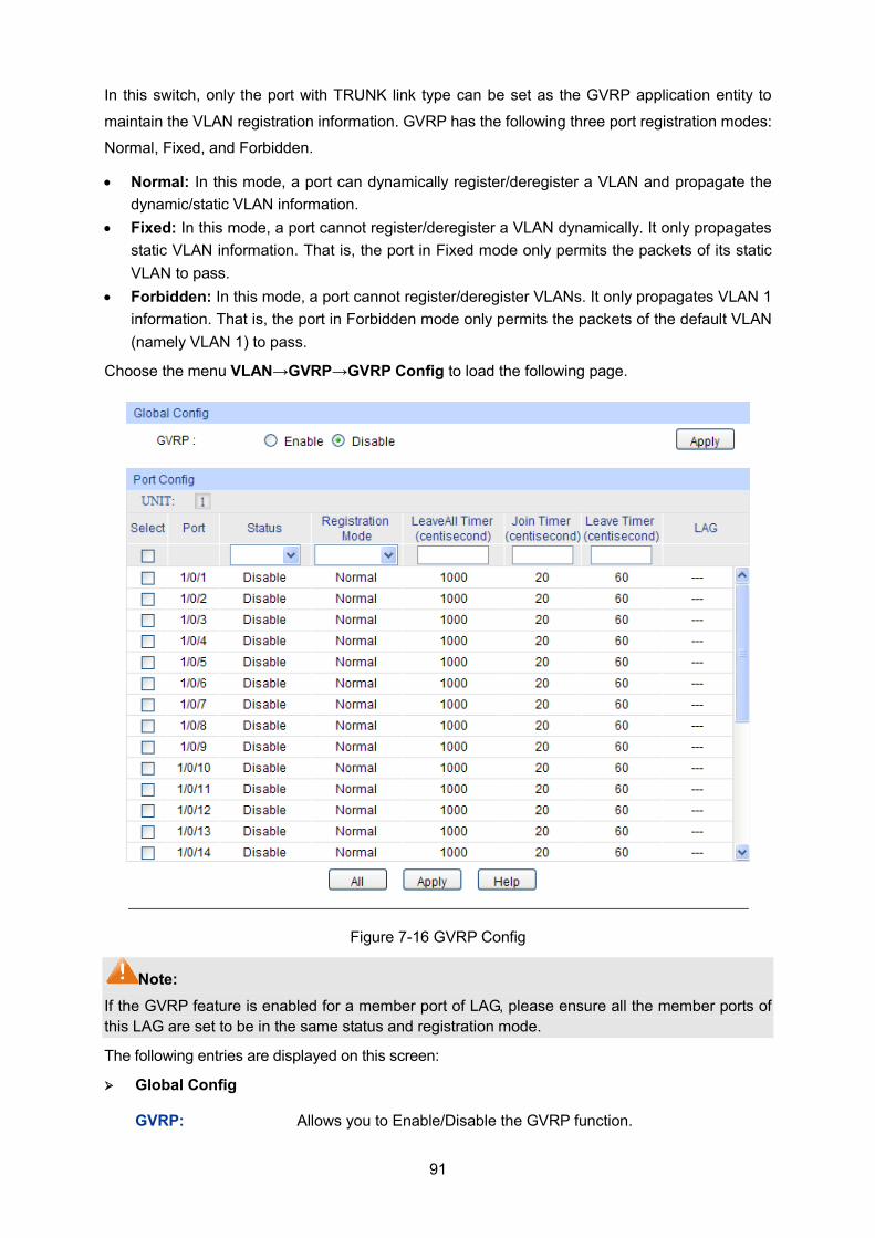
91
In this switch, only the port with TRUNK link type can be set as the GVRP application entity to
maintain the VLAN registration information. GVRP has the following three port registration modes:
Normal, Fixed, and Forbidden.
• Normal: In this mode, a port can dynamically register/deregister a VLAN and propagate the dynamic/static VLAN information.
• Fixed: In this mode, a port cannot register/deregister a VLAN dynamically. It only propagates static VLAN information. That is, the port in Fixed mode only permits the packets of its static VLAN to pass.
• Forbidden: In this mode, a port cannot register/deregister VLANs. It only propagates VLAN 1 information. That is, the port in Forbidden mode only permits the packets of the default VLAN (namely VLAN 1) to pass.
Choose the menu VLAN→GVRP→GVRP Config to load the following page.
Figure 7-16 GVRP Config
Note: If the GVRP feature is enabled for a member port of LAG, please ensure all the member ports of this LAG are set to be in the same status and registration mode.
The following entries are displayed on this screen: Global Config
GVRP: Allows you to Enable/Disable the GVRP function.
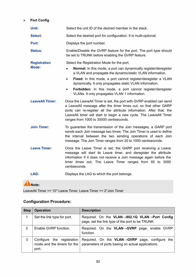
92
Port Config
Unit: Select the unit ID of the desired member in the stack.
Select: Select the desired port for configuration. It is multi-optional.
Port: Displays the port number.
Status: Enable/Disable the GVRP feature for the port. The port type should be set to TRUNK before enabling the GVRP feature.
Registration Mode:
Select the Registration Mode for the port. • Normal: In this mode, a port can dynamically register/deregister
a VLAN and propagate the dynamic/static VLAN information.
• Fixed: In this mode, a port cannot register/deregister a VLAN dynamically. It only propagates static VLAN information.
• Forbidden: In this mode, a port cannot register/deregister VLANs. It only propagates VLAN 1 information.
LeaveAll Timer: Once the LeaveAll Timer is set, the port with GVRP enabled can send a LeaveAll message after the timer times out, so that other GARP ports can re-register all the attribute information. After that, the LeaveAll timer will start to begin a new cycle. The LeaveAll Timer ranges from 1000 to 30000 centiseconds.
Join Timer: To guarantee the transmission of the Join messages, a GARP port sends each Join message two times. The Join Timer is used to define the interval between the two sending operations of each Join message. The Join Timer ranges from 20 to 1000 centiseconds.
Leave Timer: Once the Leave Timer is set, the GARP port receiving a Leave message will start its Leave timer, and deregister the attribute information if it does not receive a Join message again before the timer times out. The Leave Timer ranges from 60 to 3000 centiseconds.
LAG: Displays the LAG to which the port belongs.
Note: LeaveAll Timer >= 10* Leave Timer, Leave Timer >= 2*Join Timer
Configuration Procedure:
Step Operation Description
1 Set the link type for port. Required. On the VLAN→802.1Q VLAN→Port Config page, set the link type of the port to be TRUNK.
2 Enable GVRP function. Required. On the VLAN→GVRP page, enable GVRP function.
3 Configure the registration mode and the timers for the port.
Required. On the VLAN→GVRP page, configure the parameters of ports basing on actual applications.
93
7.9 Private VLAN Private VLANs, designed to save VLAN resources of uplink devices and decrease broadcast, are sets of VLAN pairs that share a common primary identifier. To guarantee user information security, the ease with which to manage and account traffic for service providers, in campus network, service providers usually require that each individual user is Layer-2 separated. VLAN feature can solve this problem. However, as stipulated by IEEE 802.1Q protocol, a device can only support up to 4094 VLANs. If a service provider assigns one VLAN per user, the VLANs will be far from enough; as a result, the number of users this service provider can support is limited.
Private VLAN adopts Layer 2 VLAN structure. A Private VLAN consists of a Primary VLAN and a Secondary VLAN, providing a mechanism for achieving layer-2-separation between ports. For uplink devices, all the packets received from the downstream are without VLAN tags. Uplink devices need to identify Primary VLANs but not Secondary VLANs. Therefore, they can save VLAN resources without considering the VLAN configuration in the lower layer. Meanwhile, the service provider can assign each user an individual Secondary VLAN, so that users are separated at the Layer 2 level.
Private VLAN technology is mainly used in campus or enterprise networks to achieve user Layer-2-separation and to save VLAN resources of uplink devices.
The Elements of a Private VLAN
Promiscuous port: A promiscuous port connects to and communicates with the uplink device.
The PVID of the promiscuous port is the same with the Primary VLAN ID. One promiscuous port
can only join to one Primary VLAN.
Host port: A host port connects to and communicates with terminal device. The PVID of the host
port is the same as the Secondary VLAN ID. One host port can only belong to one Private VLAN.
Primary VLAN: A Private VLAN has one Primary VLAN and one Secondary VLAN. Primary VLAN
is the user VLAN uplink device can identify, but it is not the actual VLAN the end user is in. Every
port in a private VLAN is a member of the primary VLAN. The primary VLAN carries unidirectional
traffic downstream from the promiscuous ports to the host ports and to other promiscuous ports.
Secondary VLAN: .Secondary VLAN is the actual VLAN the end user is in. Secondary VLANs are
associated with a primary VLAN, and are used to carry traffic from hosts to uplink devices. There
are two types of secondary VLANS:
Isolated VLAN-Members in an isolated VLAN are isolated with each other. Each
isolated VLAN must bind to a primary VLAN.
Community VLAN-Members in a community VLAN can communicate with each other
directly. Each community VLAN must bind to a primary VLAN.
Features of Private VLAN
1. A Private VLAN contains one Primary VLAN and one Secondary VLAN.
2. A VLAN cannot be set as the Primary VLAN and Secondary VLAN simultaneously.
3. A Secondary VLAN can only join one private VLAN.
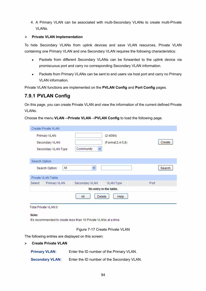
94
4. A Primary VLAN can be associated with multi-Secondary VLANs to create multi-Private
VLANs.
Private VLAN Implementation
To hide Secondary VLANs from uplink devices and save VLAN resources, Private VLAN
containing one Primary VLAN and one Secondary VLAN requires the following characteristics:
Packets from different Secondary VLANs can be forwarded to the uplink device via
promiscuous port and carry no corresponding Secondary VLAN information.
Packets from Primary VLANs can be sent to end users via host port and carry no Primary
VLAN information.
Private VLAN functions are implemented on the PVLAN Config and Port Config pages.
7.9.1 PVLAN Config On this page, you can create Private VLAN and view the information of the current defined Private
VLANs.
Choose the menu VLAN→Private VLAN→PVLAN Config to load the following page.
Figure 7-17 Create Private VLAN
The following entries are displayed on this screen: Create Private VLAN
Primary VLAN: Enter the ID number of the Primary VLAN.
Secondary VLAN: Enter the ID number of the Secondary VLAN.
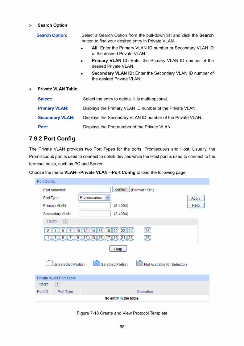
95
Search Option
Search Option: Select a Search Option from the pull-down list and click the Search button to find your desired entry in Private VLAN. All: Enter the Primary VLAN ID number or Secondary VLAN ID
of the desired Private VLAN. Primary VLAN ID: Enter the Primary VLAN ID number of the
desired Private VLAN. Secondary VLAN ID: Enter the Secondary VLAN ID number of
the desired Private VLAN.
Private VLAN Table
Select: Select the entry to delete. It is multi-optional.
Primary VLAN: Displays the Primary VLAN ID number of the Private VLAN.
Secondary VLAN: Displays the Secondary VLAN ID number of the Private VLAN.
Port: Displays the Port number of the Private VLAN.
7.9.2 Port Config The Private VLAN provides two Port Types for the ports, Promiscuous and Host. Usually, the
Promiscuous port is used to connect to uplink devices while the Host port is used to connect to the
terminal hosts, such as PC and Server.
Choose the menu VLAN→Private VLAN→Port Config to load the following page.
Figure 7-18 Create and View Protocol Template
96
The following entries are displayed on this screen: Port Config
Port selected: Select the desired port for configuration. You can input one or select from the port table down the blank.
Port Type: Select the Port Type from the pull-down list for the port.
Primary VLAN: Specify the Primary VLAN the port belongs to.
Secondary VLAN: Specify the Secondary VLAN the port belongs to.
UNIT: Select the unit ID of the desired member in the stack.
Private VLAN Port Table
UNIT: Select the unit ID of the desired member in the stack.
Port ID: Displays the port number.
Port Type: Displays the corresponding Port Type.
Note: 1. A Host Port can only join to one Private VLAN. 2. A Promiscuous Port can only join to one Primary VLAN. 3. If you want to add a Promiscuous port to different Private VLANs with the same Primary VLAN,
you need to add the Promiscuous port to any one of these Private VLANs.
Configuration Procedure:
Step Operation Description
1 Create Private VLAN. Required. On the VLAN→Private VLAN→PVLAN Config page, enter the Primary VLAN and Secondary VLAN, select one type of secondary VLAN and then click the Create button.
2 Add ports to Private VLAN Required. On the VLAN→Private VLAN→Port Config page, select the desired ports and configure the port types and click the Apply button.
3 Delete VLAN. Optional. On the VLAN→Private VLAN→PVLAN Config page, select the desired entry to delete the corresponding VLAN by clicking the Delete button.
7.10 Application Example for Private VLAN Network Requirements
Switch C is connecting to switch A, switch A is connecting to switch B;
Switch A is connecting to VLAN4 and VLAN5;
Switch B is connecting to VLAN5 and VLAN8;
For switch C, packets from switch A and switch B have no VLAN tags. Switch C needs not to consider the VLANs of switch A and switch B;
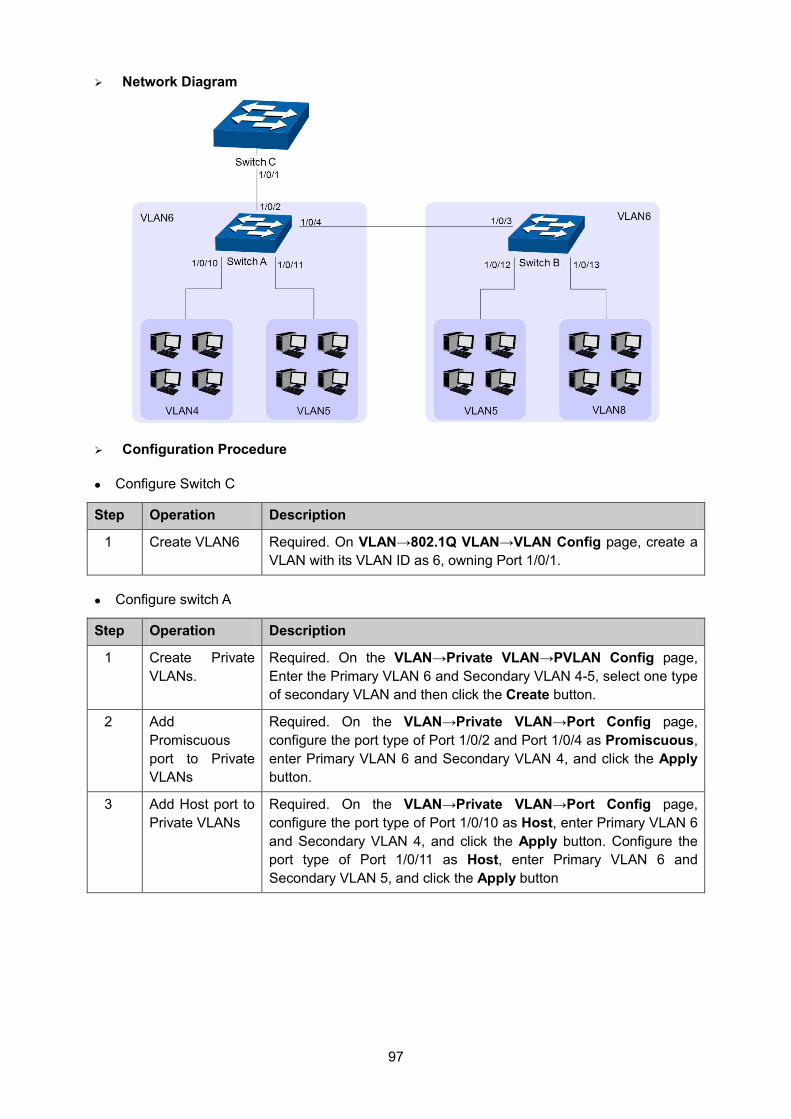
97
Network Diagram
Configuration Procedure
Configure Switch C
Step Operation Description
1 Create VLAN6 Required. On VLAN→802.1Q VLAN→VLAN Config page, create a VLAN with its VLAN ID as 6, owning Port 1/0/1.
Configure switch A
Step Operation Description
1 Create Private VLANs.
Required. On the VLAN→Private VLAN→PVLAN Config page, Enter the Primary VLAN 6 and Secondary VLAN 4-5, select one type of secondary VLAN and then click the Create button.
2 Add Promiscuous port to Private VLANs
Required. On the VLAN→Private VLAN→Port Config page, configure the port type of Port 1/0/2 and Port 1/0/4 as Promiscuous, enter Primary VLAN 6 and Secondary VLAN 4, and click the Apply button.
3 Add Host port to Private VLANs
Required. On the VLAN→Private VLAN→Port Config page, configure the port type of Port 1/0/10 as Host, enter Primary VLAN 6 and Secondary VLAN 4, and click the Apply button. Configure the port type of Port 1/0/11 as Host, enter Primary VLAN 6 and Secondary VLAN 5, and click the Apply button
98
Configure switch B
Step Operation Description
1 Create Private VLANs.
Required. On the VLAN→Private VLAN→PVLAN Config page, enter the Primary VLAN 6 and Secondary VLAN 5 and 8, select one type of secondary VLAN and then click the Create button.
2 Add Promiscuous port to Private VLANs
Required. On the VLAN→Private VLAN→Port Config page, configure the port type of Port 1/0/3 as Promiscuous, enter Primary VLAN 6 and Secondary VLAN 5, and click the Apply button.
3 Add Host port to Private VLANs
Required. On the VLAN→Private VLAN→Port Config page, configure the port type of 1/0/12 as Host, enter Primary VLAN 6 and Secondary VLAN 5, and click the Apply button. Configure the port type of Port 1/0/13 as Host, enter Primary VLAN 6 and Secondary VLAN 8, and click the Apply button
Return to CONTENTS
99
Chapter 8 Spanning Tree STP (Spanning Tree Protocol), subject to IEEE 802.1D standard, is to disbranch a ring network in the Data Link layer in a local network. Devices running STP discover loops in the network and block ports by exchanging information, in that way, a ring network can be disbranched to form a tree-topological ring-free network to prevent packets from being duplicated and forwarded endlessly in the network.
BPDU (Bridge Protocol Data Unit) is the protocol data that STP and RSTP use. Enough information is carried in BPDU to ensure the spanning tree generation. STP is to determine the topology of the network via transferring BPDUs between devices.
To implement spanning tree function, the switches in the network transfer BPDUs between each other to exchange information and all the switches supporting STP receive and process the received BPDUs. BPDUs carry the information that is needed for switches to figure out the spanning tree.
STP Elements
Bridge ID(Bridge Identifier): Indicates the value of the priority and MAC address of the bridge. Bridge ID can be configured and the switch with the lower bridge ID has the higher priority.
Root Bridge: Indicates the switch has the lowest bridge ID. Configure the switch with the best performance in the ring network as the root bridge to ensure best network performance and reliability.
Designated Bridge: Indicates the switch has the lowest path cost from the switch to the root bridge in each network segment. BPDUs are forwarded to the network segment through the designated bridge. The switch with the lowest bridge ID will be chosen as the designated bridge.
Root Path Cost: Indicates the sum of the path cost of the root port and the path cost of all the switches that packets pass through. The root path cost of the root bridge is 0.
Bridge Priority: The bridge priority can be set to a value in the range of 0~61440. The lower value priority has the higher priority. The switch with the higher priority has more chance to be chosen as the root bridge.
Root Port: Indicates the port that has the lowest path cost from this bridge to the Root Bridge and forwards packets to the root.
Designated Port: Indicates the port that forwards packets to a downstream network segment or switch.
Port Priority: The port priority can be set to an integral multiple of 16 in the range of 0~240. The lower value priority has the higher priority. The port with the higher priority has more chance to be chosen as the root port.
Path Cost: Indicates the parameter for choosing the link path by STP. By calculating the path cost, STP chooses the better links and blocks the redundant links so as to disbranch the ring-network to form a tree-topological ring-free network.
The following network diagram shows the sketch map of spanning tree. Switch A, B and C are connected together in order. After STP generation, switch A is chosen as root bridge, the path from port 2 to port 6 is blocked.
Bridge: Switch A is the root bridge in the whole network; switch B is the designated bridge of switch C.
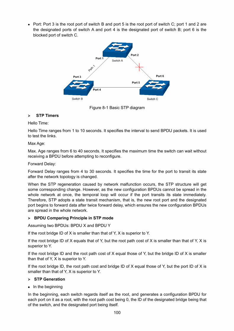
100
Port: Port 3 is the root port of switch B and port 5 is the root port of switch C; port 1 and 2 are the designated ports of switch A and port 4 is the designated port of switch B; port 6 is the blocked port of switch C.
Figure 8-1 Basic STP diagram
STP Timers
Hello Time:
Hello Time ranges from 1 to 10 seconds. It specifies the interval to send BPDU packets. It is used to test the links.
Max Age:
Max. Age ranges from 6 to 40 seconds. It specifies the maximum time the switch can wait without receiving a BPDU before attempting to reconfigure.
Forward Delay:
Forward Delay ranges from 4 to 30 seconds. It specifies the time for the port to transit its state after the network topology is changed.
When the STP regeneration caused by network malfunction occurs, the STP structure will get some corresponding change. However, as the new configuration BPDUs cannot be spread in the whole network at once, the temporal loop will occur if the port transits its state immediately. Therefore, STP adopts a state transit mechanism, that is, the new root port and the designated port begins to forward data after twice forward delay, which ensures the new configuration BPDUs are spread in the whole network.
BPDU Comparing Principle in STP mode
Assuming two BPDUs: BPDU X and BPDU Y
If the root bridge ID of X is smaller than that of Y, X is superior to Y.
If the root bridge ID of X equals that of Y, but the root path cost of X is smaller than that of Y, X is superior to Y.
If the root bridge ID and the root path cost of X equal those of Y, but the bridge ID of X is smaller than that of Y, X is superior to Y.
If the root bridge ID, the root path cost and bridge ID of X equal those of Y, but the port ID of X is smaller than that of Y, X is superior to Y.
STP Generation
In the beginning
In the beginning, each switch regards itself as the root, and generates a configuration BPDU for each port on it as a root, with the root path cost being 0, the ID of the designated bridge being that of the switch, and the designated port being itself.
101
Comparing BPDUs
Each switch sends out configuration BPDUs and receives a configuration BPDU on one of its ports from another switch. The following table shows the comparing operations.
Step Operation
1 If the priority of the BPDU received on the port is lower than that of the BPDU if of the port itself, the switch discards the BPDU and does not change the BPDU of the port.
2 If the priority of the BPDU is higher than that of the BPDU of the port itself, the switch replaces the BPDU of the port with the received one and compares it with those of other ports on the switch to obtain the one with the highest priority.
Table 8-1 Comparing BPDUs Selecting the root bridge The root bridge is selected by BPDU comparing. The switch with the smallest root ID is chosen as the root bridge. Selecting the root port and designate port The operation is taken in the following way:
Step Operation
1 For each switch (except the one chosen as the root bridge) in a network, the port that receives the BPDU with the highest priority is chosen as the root port of the switch.
2 Using the root port BPDU and the root path cost, the switch generates a designated port BPDU for each of its ports. Root ID is replaced with that of the root port; Root path is replaced with the sum of the root path cost of the root port and
the path cost between this port and the root port; The ID of the designated bridge is replaced with that of the switch; The ID of the designated port is replaced with that of the port.
3 The switch compares the resulting BPDU with the BPDU of the desired port whose role you want to determine. If the resulting BPDU takes the precedence over the BPDU of the port, the
port is chosen as the designated port and the BPDU of this port is replaced with the resulting BPDU. The port regularly sends out the resulting BPDU;
If the BPDU of this port takes the precedence over the resulting BPDU, the BPDU of this port is not replaced and the port is blocked. The port only can receive BPDUs.
Table 8-2 Selecting root port and designated port
Tips:
In an STP with stable topology, only the root port and designated port can forward data, and the other ports are blocked. The blocked ports only can receive BPDUs.
RSTP (Rapid Spanning Tree Protocol), evolved from the 802.1D STP standard, enable Ethernet ports to transit their states rapidly. The premises for the port in the RSTP to transit its state rapidly are as follows.
102
The condition for the root port to transit its port state rapidly: The old root port of the switch stops forwarding data and the designated port of the upstream switch begins to forward data.
The condition for the designated port to transit its port state rapidly: The designated port is an edge port or connecting to a point-to-point link. If the designated port is an edge port, it can directly transit to forwarding state; if the designated port is connecting to a point-to-point link, it can transit to forwarding state after getting response from the downstream switch through handshake.
RSTP Elements
Edge Port: Indicates the port connected directly to terminals.
P2P Link: Indicates the link between two switches directly connected.
MSTP (Multiple Spanning Tree Protocol), compatible with both STP and RSTP and subject to IEEE 802.1s standard, not only enables spanning trees to converge rapidly, but also enables packets of different VLANs to be forwarded along their respective paths so as to provide redundant links with a better load-balancing mechanism.
Features of MSTP:
MSTP combines VLANs and spanning tree together via VLAN-to-instance mapping table. It binds several VLANs to an instance to save communication cost and network resources.
MSTP divides a spanning tree network into several regions. Each region has several internal spanning trees, which are independent of each other.
MSTP provides a load-balancing mechanism for the packets transmission in the VLAN.
MSTP is compatible with both STP and RSTP.
MSTP Elements
MST Region (Multiple Spanning Tree Region): An MST Region comprises switches with the same region configuration and VLAN-to-Instances mapping relationship.
MSTI (Multiple Spanning Tree Instance): Multiple spanning trees can be generated in an MST region through MSTP, one spanning tree being independent of another. Each spanning tree is referred to as a multiple spanning tree instance.
IST (Internal Spanning Tree): An IST is a spanning tree in an MST.
CST (Common Spanning Tree): A CST is the spanning tree in a switched network that connects all MST regions in the network.
CIST (Common and Internal Spanning Tree): A CIST, comprising IST and CST, is the spanning tree in a switched network that connects all switches in the network.
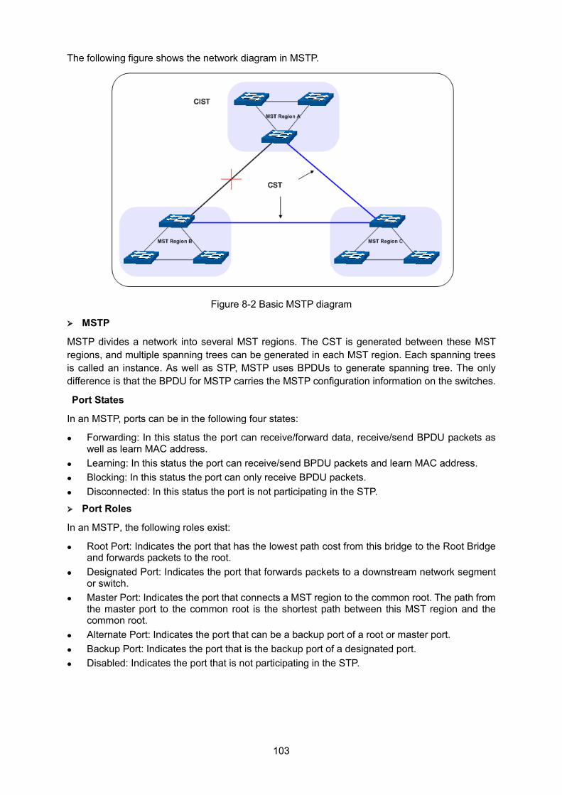
103
The following figure shows the network diagram in MSTP.
Figure 8-2 Basic MSTP diagram
MSTP
MSTP divides a network into several MST regions. The CST is generated between these MST regions, and multiple spanning trees can be generated in each MST region. Each spanning trees is called an instance. As well as STP, MSTP uses BPDUs to generate spanning tree. The only difference is that the BPDU for MSTP carries the MSTP configuration information on the switches.
Port States
In an MSTP, ports can be in the following four states:
Forwarding: In this status the port can receive/forward data, receive/send BPDU packets as well as learn MAC address.
Learning: In this status the port can receive/send BPDU packets and learn MAC address. Blocking: In this status the port can only receive BPDU packets. Disconnected: In this status the port is not participating in the STP.
Port Roles
In an MSTP, the following roles exist:
Root Port: Indicates the port that has the lowest path cost from this bridge to the Root Bridge and forwards packets to the root.
Designated Port: Indicates the port that forwards packets to a downstream network segment or switch.
Master Port: Indicates the port that connects a MST region to the common root. The path from the master port to the common root is the shortest path between this MST region and the common root.
Alternate Port: Indicates the port that can be a backup port of a root or master port. Backup Port: Indicates the port that is the backup port of a designated port. Disabled: Indicates the port that is not participating in the STP.
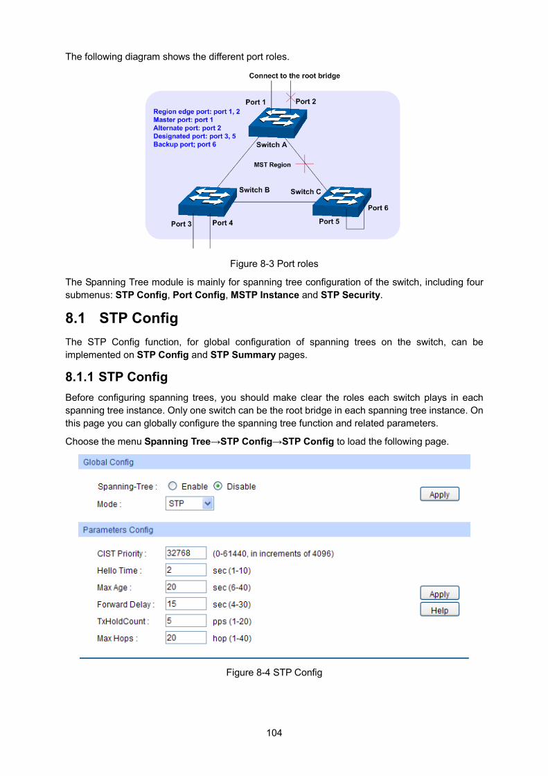
104
The following diagram shows the different port roles.
Figure 8-3 Port roles
The Spanning Tree module is mainly for spanning tree configuration of the switch, including four submenus: STP Config, Port Config, MSTP Instance and STP Security.
8.1 STP Config The STP Config function, for global configuration of spanning trees on the switch, can be implemented on STP Config and STP Summary pages.
8.1.1 STP Config Before configuring spanning trees, you should make clear the roles each switch plays in each spanning tree instance. Only one switch can be the root bridge in each spanning tree instance. On this page you can globally configure the spanning tree function and related parameters.
Choose the menu Spanning Tree→STP Config→STP Config to load the following page.
Figure 8-4 STP Config
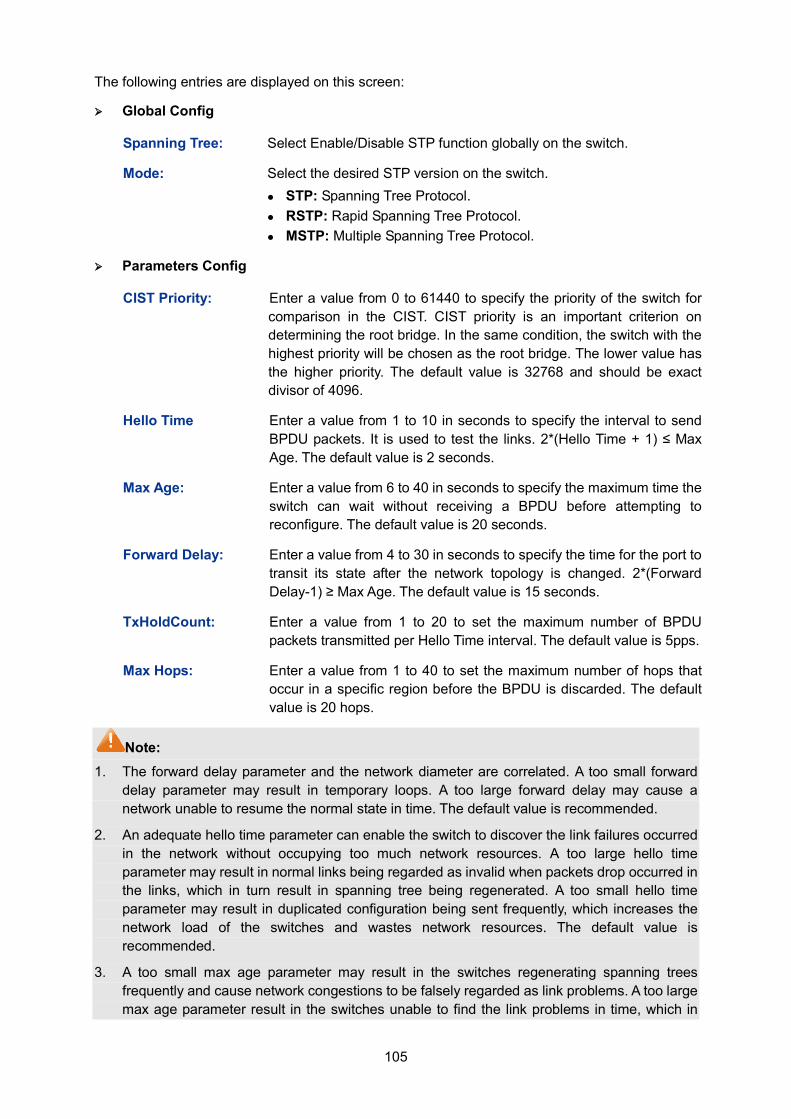
105
The following entries are displayed on this screen:
Global Config
Spanning Tree: Select Enable/Disable STP function globally on the switch.
Mode: Select the desired STP version on the switch. STP: Spanning Tree Protocol. RSTP: Rapid Spanning Tree Protocol. MSTP: Multiple Spanning Tree Protocol.
Parameters Config
CIST Priority: Enter a value from 0 to 61440 to specify the priority of the switch for comparison in the CIST. CIST priority is an important criterion on determining the root bridge. In the same condition, the switch with the highest priority will be chosen as the root bridge. The lower value has the higher priority. The default value is 32768 and should be exact divisor of 4096.
Hello Time Enter a value from 1 to 10 in seconds to specify the interval to send BPDU packets. It is used to test the links. 2*(Hello Time + 1) ≤ Max Age. The default value is 2 seconds.
Max Age: Enter a value from 6 to 40 in seconds to specify the maximum time the switch can wait without receiving a BPDU before attempting to reconfigure. The default value is 20 seconds.
Forward Delay: Enter a value from 4 to 30 in seconds to specify the time for the port to transit its state after the network topology is changed. 2*(Forward Delay-1) ≥ Max Age. The default value is 15 seconds.
TxHoldCount: Enter a value from 1 to 20 to set the maximum number of BPDU packets transmitted per Hello Time interval. The default value is 5pps.
Max Hops: Enter a value from 1 to 40 to set the maximum number of hops that occur in a specific region before the BPDU is discarded. The default value is 20 hops.
Note: 1. The forward delay parameter and the network diameter are correlated. A too small forward
delay parameter may result in temporary loops. A too large forward delay may cause a network unable to resume the normal state in time. The default value is recommended.
2. An adequate hello time parameter can enable the switch to discover the link failures occurred in the network without occupying too much network resources. A too large hello time parameter may result in normal links being regarded as invalid when packets drop occurred in the links, which in turn result in spanning tree being regenerated. A too small hello time parameter may result in duplicated configuration being sent frequently, which increases the network load of the switches and wastes network resources. The default value is recommended.
3. A too small max age parameter may result in the switches regenerating spanning trees frequently and cause network congestions to be falsely regarded as link problems. A too large max age parameter result in the switches unable to find the link problems in time, which in
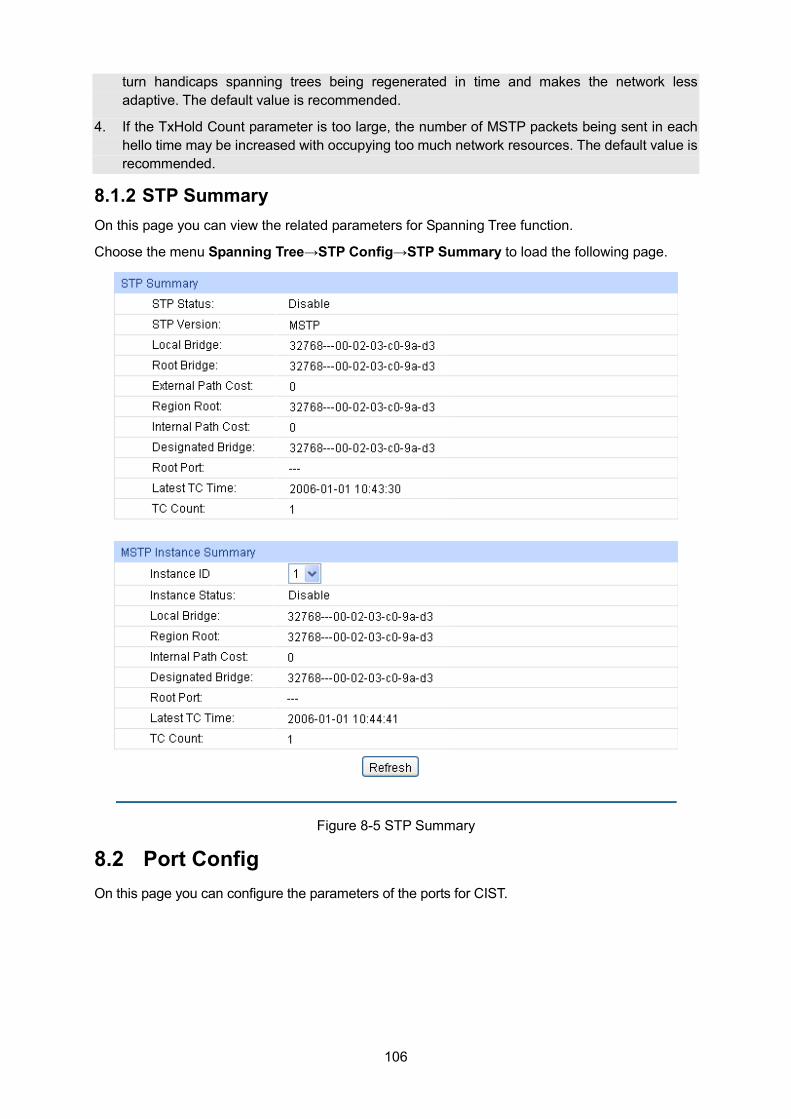
106
turn handicaps spanning trees being regenerated in time and makes the network less adaptive. The default value is recommended.
4. If the TxHold Count parameter is too large, the number of MSTP packets being sent in each hello time may be increased with occupying too much network resources. The default value is recommended.
8.1.2 STP Summary On this page you can view the related parameters for Spanning Tree function.
Choose the menu Spanning Tree→STP Config→STP Summary to load the following page.
Figure 8-5 STP Summary
8.2 Port Config On this page you can configure the parameters of the ports for CIST.
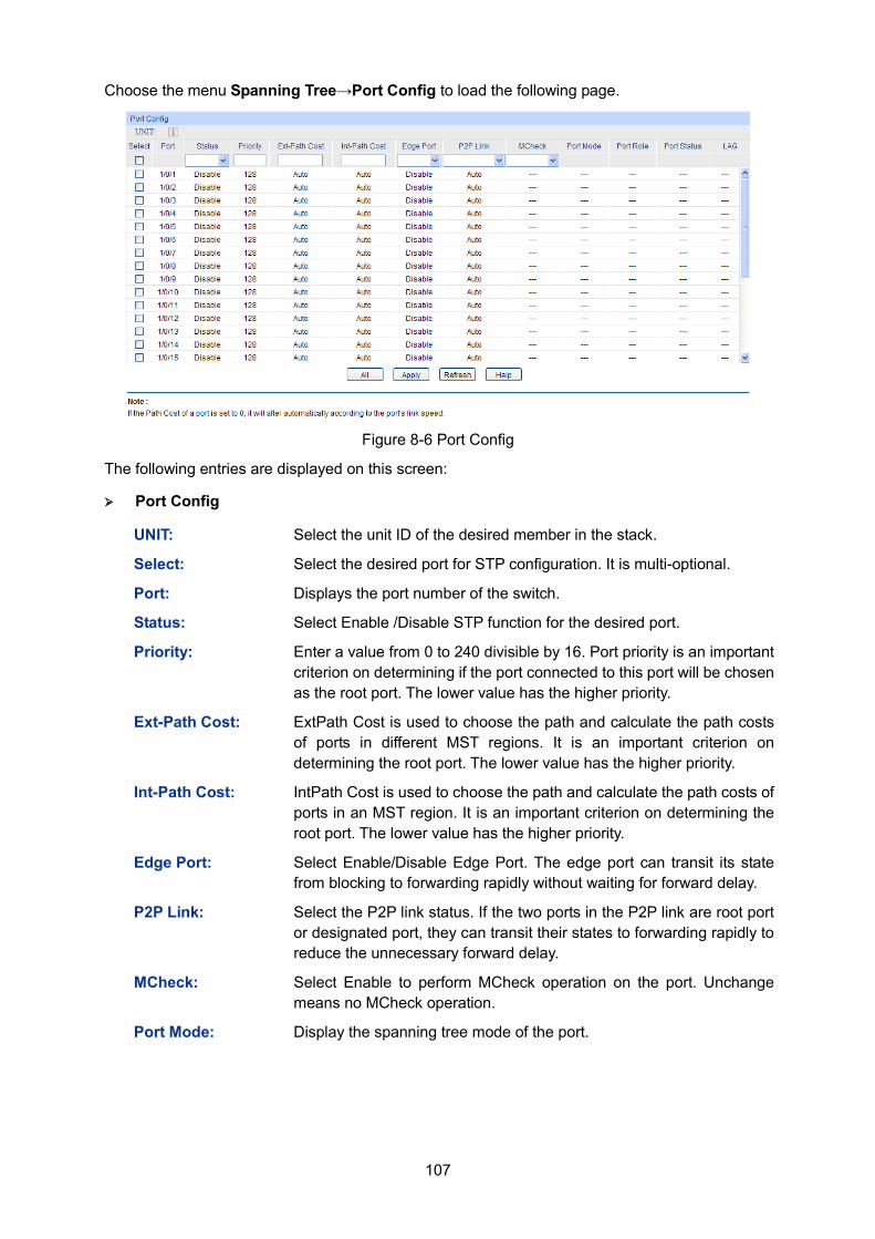
107
Choose the menu Spanning Tree→Port Config to load the following page.
Figure 8-6 Port Config
The following entries are displayed on this screen:
Port Config
UNIT: Select the unit ID of the desired member in the stack.
Select: Select the desired port for STP configuration. It is multi-optional.
Port: Displays the port number of the switch.
Status: Select Enable /Disable STP function for the desired port.
Priority: Enter a value from 0 to 240 divisible by 16. Port priority is an important criterion on determining if the port connected to this port will be chosen as the root port. The lower value has the higher priority.
Ext-Path Cost: ExtPath Cost is used to choose the path and calculate the path costs of ports in different MST regions. It is an important criterion on determining the root port. The lower value has the higher priority.
Int-Path Cost: IntPath Cost is used to choose the path and calculate the path costs of ports in an MST region. It is an important criterion on determining the root port. The lower value has the higher priority.
Edge Port: Select Enable/Disable Edge Port. The edge port can transit its state from blocking to forwarding rapidly without waiting for forward delay.
P2P Link: Select the P2P link status. If the two ports in the P2P link are root port or designated port, they can transit their states to forwarding rapidly to reduce the unnecessary forward delay.
MCheck: Select Enable to perform MCheck operation on the port. Unchange means no MCheck operation.
Port Mode: Display the spanning tree mode of the port.
108
Port Role: Displays the role of the port played in the STP Instance. Root Port: Indicates the port that has the lowest path cost from
this bridge to the Root Bridge and forwards packets to the root. Designated Port: Indicates the port that forwards packets to a
downstream network segment or switch. Master Port: Indicates the port that connects a MST region to the
common root. The path from the master port to the common root is the shortest path between this MST region and the common root.
Alternate Port: Indicates the port that can be a backup port of a root or master port.
Backup Port: Indicates the port that is the backup port of a designated port.
Disabled: Indicates the port that is not participating in the STP.
Port Status: Displays the working status of the port. Forwarding: In this status the port can receive/forward data,
receive/send BPDU packets as well as learn MAC address. Learning: In this status the port can receive/send BPDU packets
and learn MAC address. Blocking: In this status the port can only receive BPDU packets. Disconnected: In this status the port is not participating in the
STP.
LAG: Displays the LAG number which the port belongs to.
Note: 1. Configure the ports connected directly to terminals as edge ports and enable the BPDU
protection function as well. This not only enables these ports to transit to forwarding state rapidly but also secures your network.
2. All the links of ports in a LAG can be configured as point-to-point links.
3. When the link of a port is configured as a point-to-point link, the spanning tree instances owning this port are configured as point-to-point links. If the physical link of a port is not a point-to-point link and you forcibly configure the link as a point-to-point link, temporary loops may be incurred.
8.3 MSTP Instance MSTP combines VLANs and spanning tree together via VLAN-to-instance mapping table (VLAN-to-spanning-tree mapping). By adding MSTP instances, it binds several VLANs to an instance to realize the load balance based on instances.
Only when the switches have the same MST region name, MST region revision and VLAN-to-Instance mapping table, the switches can be regarded as in the same MST region.
The MSTP Instance function can be implemented on Region Config, Instance Config and Instance Port Config pages.
8.3.1 Region Config On this page you can configure the name and revision of the MST region.
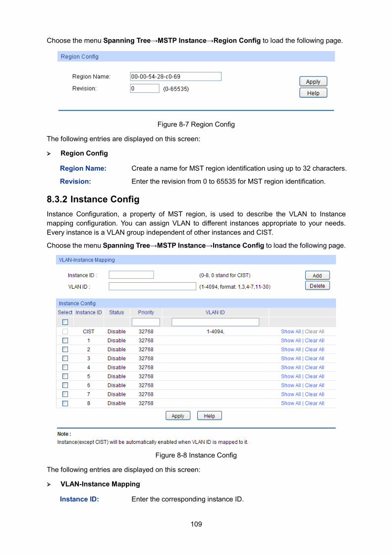
109
Choose the menu Spanning Tree→MSTP Instance→Region Config to load the following page.
Figure 8-7 Region Config
The following entries are displayed on this screen:
Region Config
Region Name: Create a name for MST region identification using up to 32 characters.
Revision: Enter the revision from 0 to 65535 for MST region identification.
8.3.2 Instance Config Instance Configuration, a property of MST region, is used to describe the VLAN to Instance mapping configuration. You can assign VLAN to different instances appropriate to your needs. Every instance is a VLAN group independent of other instances and CIST.
Choose the menu Spanning Tree→MSTP Instance→Instance Config to load the following page.
Figure 8-8 Instance Config
The following entries are displayed on this screen:
VLAN-Instance Mapping
Instance ID: Enter the corresponding instance ID.
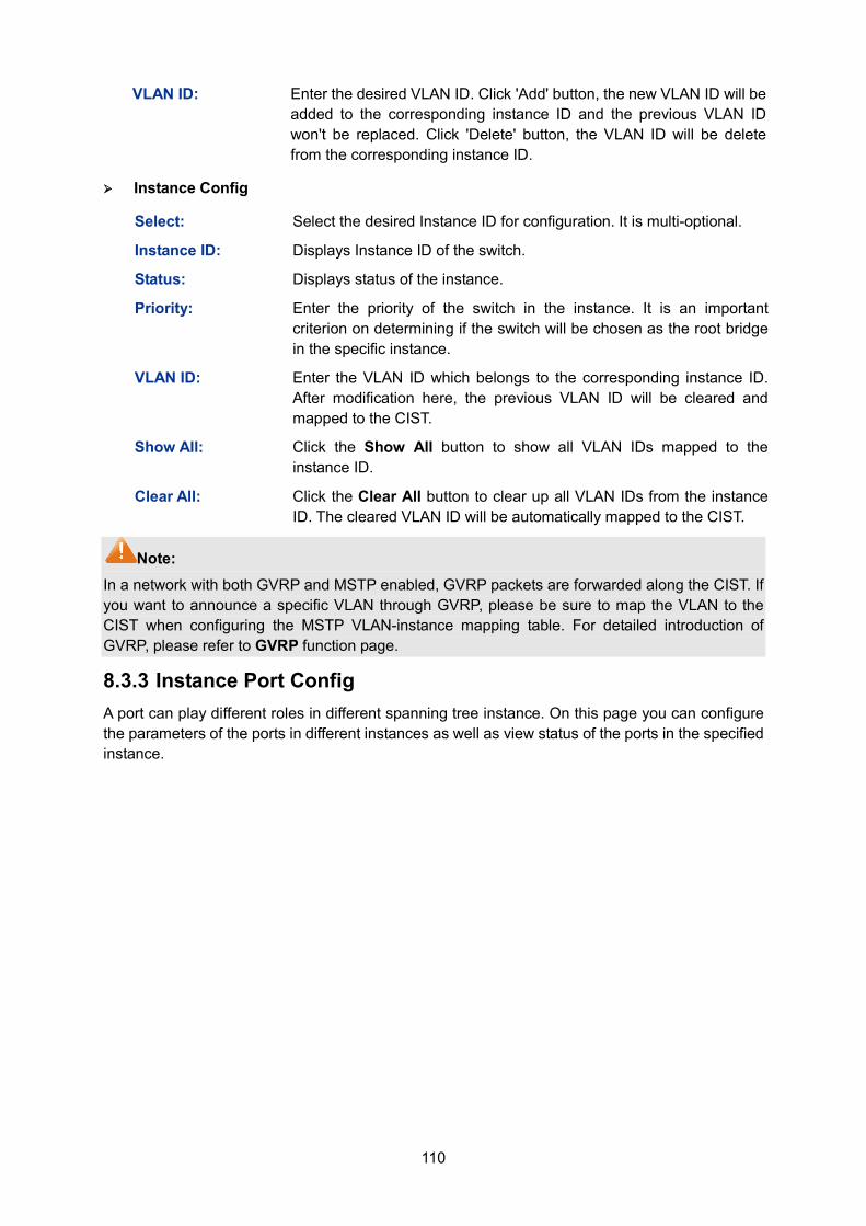
110
VLAN ID: Enter the desired VLAN ID. Click 'Add' button, the new VLAN ID will be added to the corresponding instance ID and the previous VLAN ID won't be replaced. Click 'Delete' button, the VLAN ID will be delete from the corresponding instance ID.
Instance Config
Select: Select the desired Instance ID for configuration. It is multi-optional.
Instance ID: Displays Instance ID of the switch.
Status: Displays status of the instance.
Priority: Enter the priority of the switch in the instance. It is an important criterion on determining if the switch will be chosen as the root bridge in the specific instance.
VLAN ID: Enter the VLAN ID which belongs to the corresponding instance ID. After modification here, the previous VLAN ID will be cleared and mapped to the CIST.
Show All: Click the Show All button to show all VLAN IDs mapped to the instance ID.
Clear All: Click the Clear All button to clear up all VLAN IDs from the instance ID. The cleared VLAN ID will be automatically mapped to the CIST.
Note: In a network with both GVRP and MSTP enabled, GVRP packets are forwarded along the CIST. If you want to announce a specific VLAN through GVRP, please be sure to map the VLAN to the CIST when configuring the MSTP VLAN-instance mapping table. For detailed introduction of GVRP, please refer to GVRP function page.
8.3.3 Instance Port Config A port can play different roles in different spanning tree instance. On this page you can configure the parameters of the ports in different instances as well as view status of the ports in the specified instance.
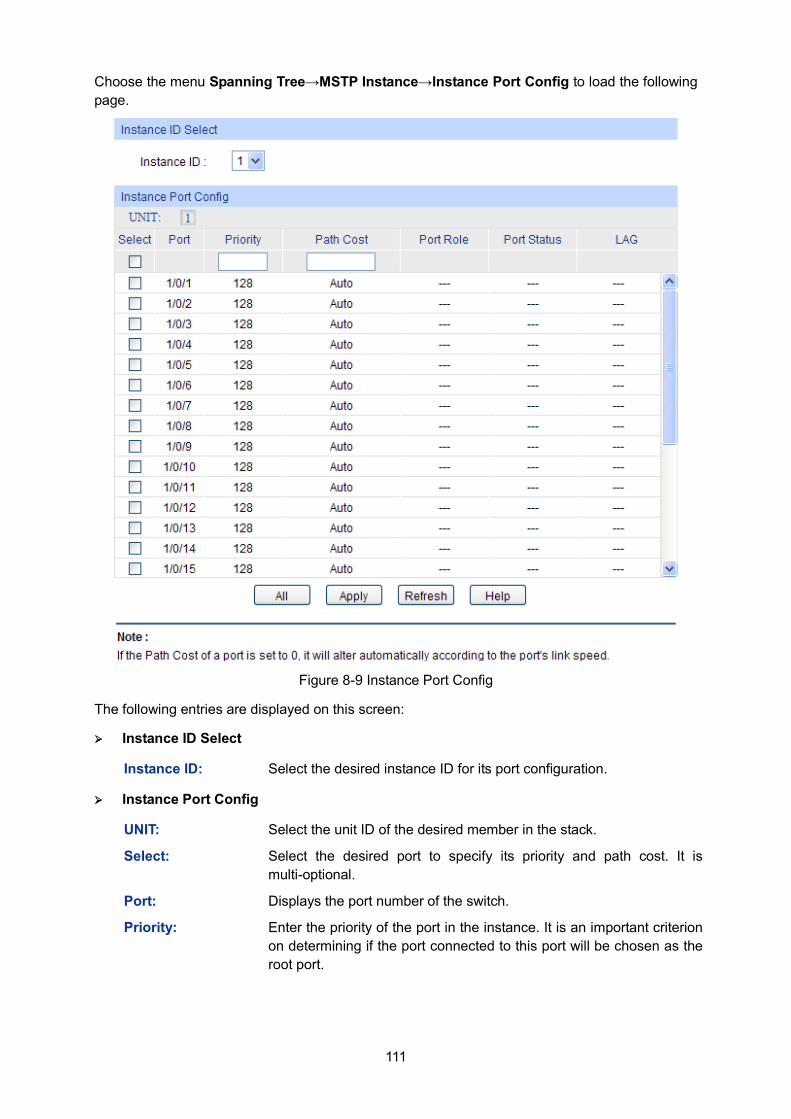
111
Choose the menu Spanning Tree→MSTP Instance→Instance Port Config to load the following page.
Figure 8-9 Instance Port Config
The following entries are displayed on this screen:
Instance ID Select
Instance ID: Select the desired instance ID for its port configuration.
Instance Port Config
UNIT: Select the unit ID of the desired member in the stack.
Select: Select the desired port to specify its priority and path cost. It is multi-optional.
Port: Displays the port number of the switch.
Priority: Enter the priority of the port in the instance. It is an important criterion on determining if the port connected to this port will be chosen as the root port.
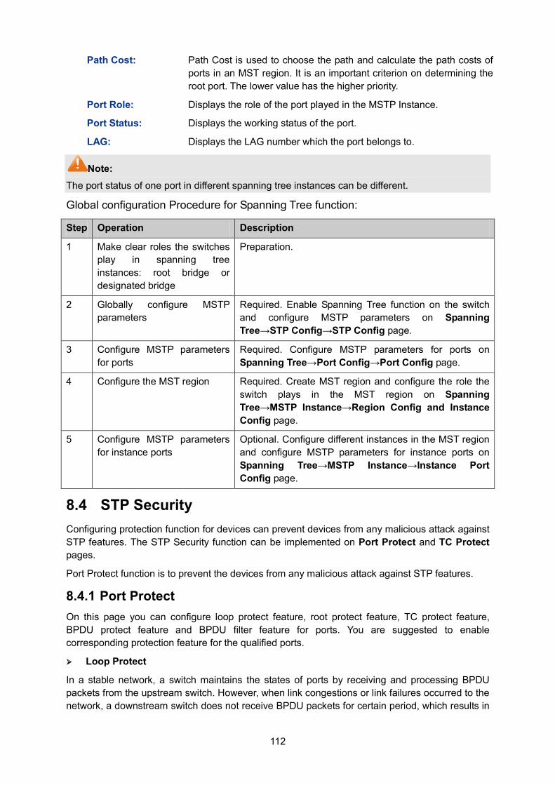
112
Path Cost: Path Cost is used to choose the path and calculate the path costs of ports in an MST region. It is an important criterion on determining the root port. The lower value has the higher priority.
Port Role: Displays the role of the port played in the MSTP Instance.
Port Status: Displays the working status of the port.
LAG: Displays the LAG number which the port belongs to.
Note: The port status of one port in different spanning tree instances can be different.
Global configuration Procedure for Spanning Tree function:
Step Operation Description
1 Make clear roles the switches play in spanning tree instances: root bridge or designated bridge
Preparation.
2 Globally configure MSTP parameters
Required. Enable Spanning Tree function on the switch and configure MSTP parameters on Spanning Tree→STP Config→STP Config page.
3 Configure MSTP parameters for ports
Required. Configure MSTP parameters for ports on Spanning Tree→Port Config→Port Config page.
4 Configure the MST region Required. Create MST region and configure the role the switch plays in the MST region on Spanning Tree→MSTP Instance→Region Config and Instance Config page.
5 Configure MSTP parameters for instance ports
Optional. Configure different instances in the MST region and configure MSTP parameters for instance ports on Spanning Tree→MSTP Instance→Instance Port Config page.
8.4 STP Security Configuring protection function for devices can prevent devices from any malicious attack against STP features. The STP Security function can be implemented on Port Protect and TC Protect pages.
Port Protect function is to prevent the devices from any malicious attack against STP features.
8.4.1 Port Protect On this page you can configure loop protect feature, root protect feature, TC protect feature, BPDU protect feature and BPDU filter feature for ports. You are suggested to enable corresponding protection feature for the qualified ports.
Loop Protect
In a stable network, a switch maintains the states of ports by receiving and processing BPDU packets from the upstream switch. However, when link congestions or link failures occurred to the network, a downstream switch does not receive BPDU packets for certain period, which results in
113
spanning trees being regenerated and roles of ports being reselected, and causes the blocked ports to transit to forwarding state. Therefore, loops may be incurred in the network.
The loop protect function can suppresses loops. With this function enabled, a port, regardless of the role it plays in instances, is always set to blocking state, when the port does not receive BPDU packets from the upstream switch and spanning trees are regenerated, and thereby loops can be prevented.
Root Protect
A CIST and its secondary root bridges are usually located in the high-bandwidth core region. Wrong configuration or malicious attacks may result in configuration BPDU packets with higher priorities being received by the legal root bridge, which causes the current legal root bridge to lose its position and network topology jitter to occur. In this case, flows that should travel along high-speed links may lead to low-speed links, and network congestion may occur.
To avoid this, MSTP provides root protect function. Ports with this function enabled can only be set as designated ports in all spanning tree instances. When a port of this type receives BDPU packets with higher priority, it transits its state to blocking state and stops forwarding packets (as if it is disconnected from the link). The port resumes the normal state if it does not receive any configuration BPDU packets with higher priorities for 60 seconds.
TC Protect
A switch removes MAC address entries upon receiving TC-BPDU packets. If a user maliciously sends a large amount of TC-BPDU packets to a switch in a short period, the switch will be busy with removing MAC address entries, which may decrease the performance and stability of the network.
To prevent the switch from frequently removing MAC address entries, you can enable the TC protect function on the switch. With TC protect function enabled, if the account number of the received TC-BPDUs exceeds the maximum number you set in the TC threshold field, the switch will not performs the removing operation in the TC protect cycle. Such a mechanism prevents the switch from frequently removing MAC address entries.
BPDU Protect
Ports of the switch directly connected to PCs or servers are configured as edge ports to rapidly transit their states. When these ports receive BPDUs, the system automatically configures these ports as non-edge ports and regenerates spanning trees, which may cause network topology jitter. Normally these ports do not receive BPDUs, but if a user maliciously attacks the switch by sending BPDUs, network topology jitter occurs.
To prevent this attack, MSTP provides BPDU protect function. With this function enabled on the switch, the switch shuts down the edge ports’ MTSP function and sets their status as blocking if they receive BPDU packets. These edge ports will restore to their previous status if they do not receive BPDU packets for 60 seconds.
BPDU Filter
BPDU filter function is to prevent BPDUs flood in the STP network. If a switch receives malicious BPDUs, it forwards these BPDUs to the other switched in the network, which may result in spanning trees being continuously regenerated. In this case, the switch occupying too much CPU or the protocol status of BPDUs is wrong.
With BPDU filter function enabled, a port does not receive or forward BPDUs, but it sends out its own BPDUs. Such a mechanism prevents the switch from being attacked by BPDUs so as to guarantee generation the spanning trees correct.
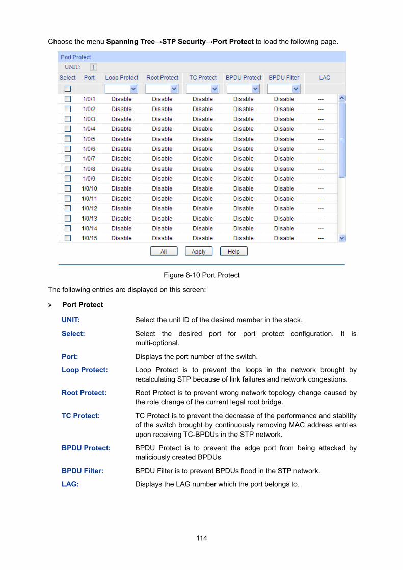
114
Choose the menu Spanning Tree→STP Security→Port Protect to load the following page.
Figure 8-10 Port Protect
The following entries are displayed on this screen:
Port Protect
UNIT: Select the unit ID of the desired member in the stack.
Select: Select the desired port for port protect configuration. It is multi-optional.
Port: Displays the port number of the switch.
Loop Protect: Loop Protect is to prevent the loops in the network brought by recalculating STP because of link failures and network congestions.
Root Protect: Root Protect is to prevent wrong network topology change caused by the role change of the current legal root bridge.
TC Protect: TC Protect is to prevent the decrease of the performance and stability of the switch brought by continuously removing MAC address entries upon receiving TC-BPDUs in the STP network.
BPDU Protect: BPDU Protect is to prevent the edge port from being attacked by maliciously created BPDUs
BPDU Filter: BPDU Filter is to prevent BPDUs flood in the STP network.
LAG: Displays the LAG number which the port belongs to.
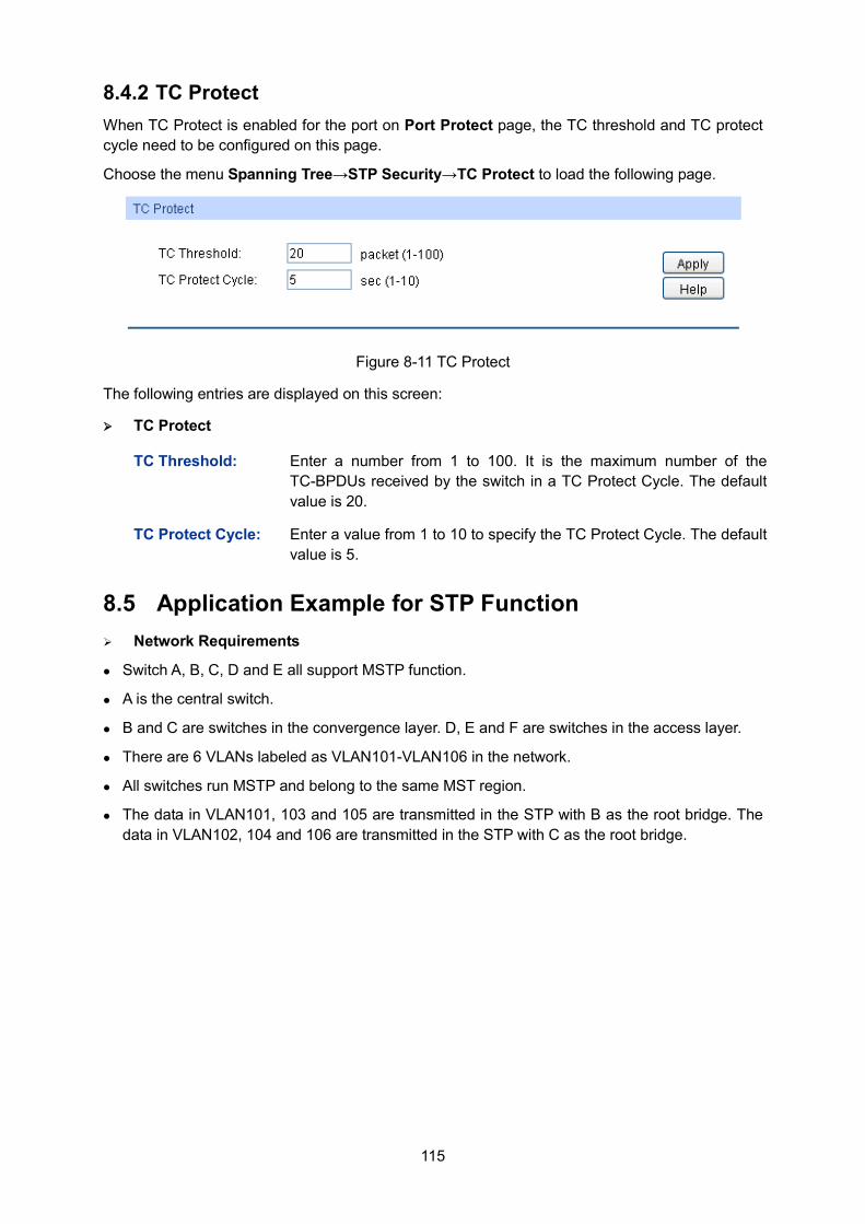
115
8.4.2 TC Protect When TC Protect is enabled for the port on Port Protect page, the TC threshold and TC protect cycle need to be configured on this page.
Choose the menu Spanning Tree→STP Security→TC Protect to load the following page.
Figure 8-11 TC Protect
The following entries are displayed on this screen:
TC Protect
TC Threshold: Enter a number from 1 to 100. It is the maximum number of the TC-BPDUs received by the switch in a TC Protect Cycle. The default value is 20.
TC Protect Cycle: Enter a value from 1 to 10 to specify the TC Protect Cycle. The default value is 5.
8.5 Application Example for STP Function Network Requirements
Switch A, B, C, D and E all support MSTP function.
A is the central switch.
B and C are switches in the convergence layer. D, E and F are switches in the access layer.
There are 6 VLANs labeled as VLAN101-VLAN106 in the network.
All switches run MSTP and belong to the same MST region.
The data in VLAN101, 103 and 105 are transmitted in the STP with B as the root bridge. The data in VLAN102, 104 and 106 are transmitted in the STP with C as the root bridge.
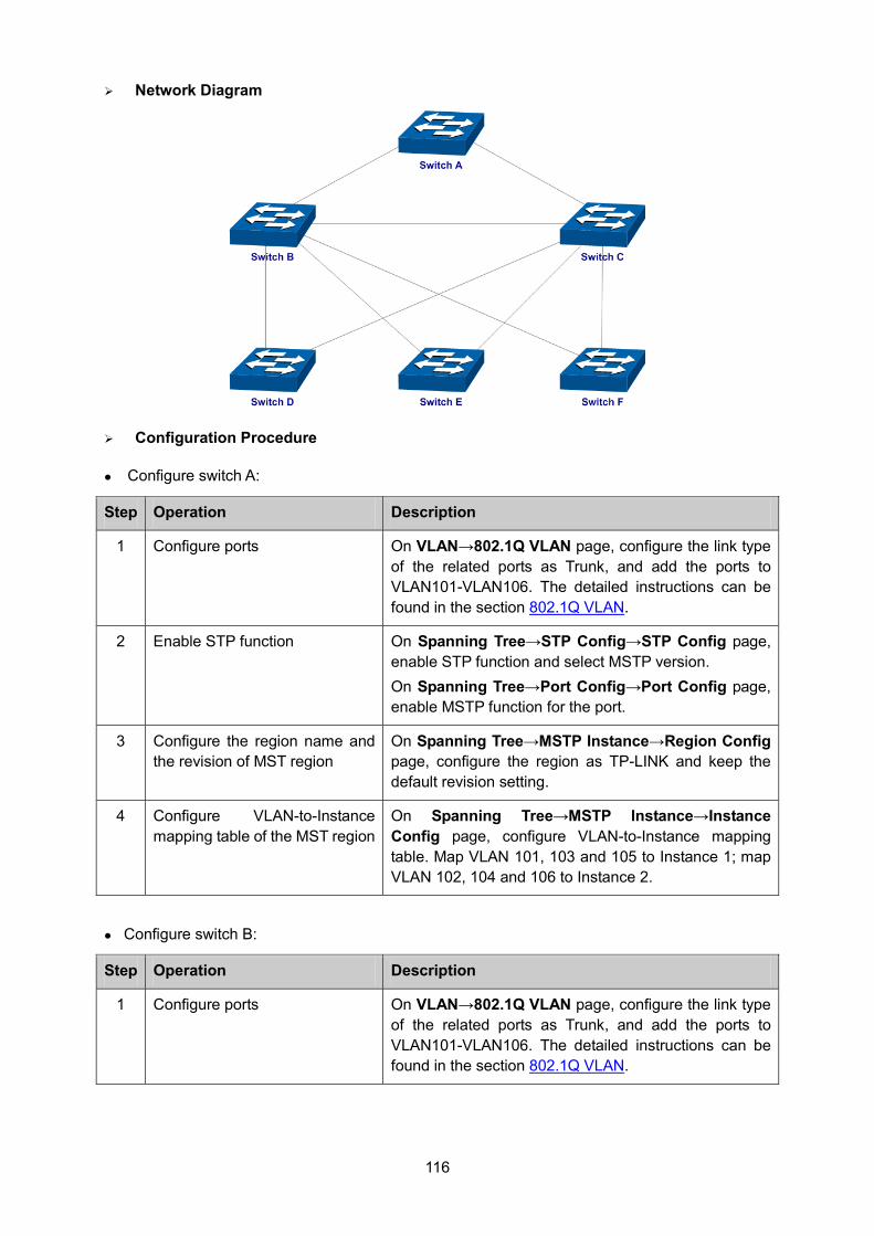
116
Network Diagram
Configuration Procedure
Configure switch A:
Step Operation Description
1 Configure ports On VLAN→802.1Q VLAN page, configure the link type of the related ports as Trunk, and add the ports to VLAN101-VLAN106. The detailed instructions can be found in the section 802.1Q VLAN.
2 Enable STP function On Spanning Tree→STP Config→STP Config page, enable STP function and select MSTP version. On Spanning Tree→Port Config→Port Config page, enable MSTP function for the port.
3 Configure the region name and the revision of MST region
On Spanning Tree→MSTP Instance→Region Config page, configure the region as TP-LINK and keep the default revision setting.
4 Configure VLAN-to-Instance mapping table of the MST region
On Spanning Tree→MSTP Instance→Instance Config page, configure VLAN-to-Instance mapping table. Map VLAN 101, 103 and 105 to Instance 1; map VLAN 102, 104 and 106 to Instance 2.
Configure switch B:
Step Operation Description
1 Configure ports On VLAN→802.1Q VLAN page, configure the link type of the related ports as Trunk, and add the ports to VLAN101-VLAN106. The detailed instructions can be found in the section 802.1Q VLAN.
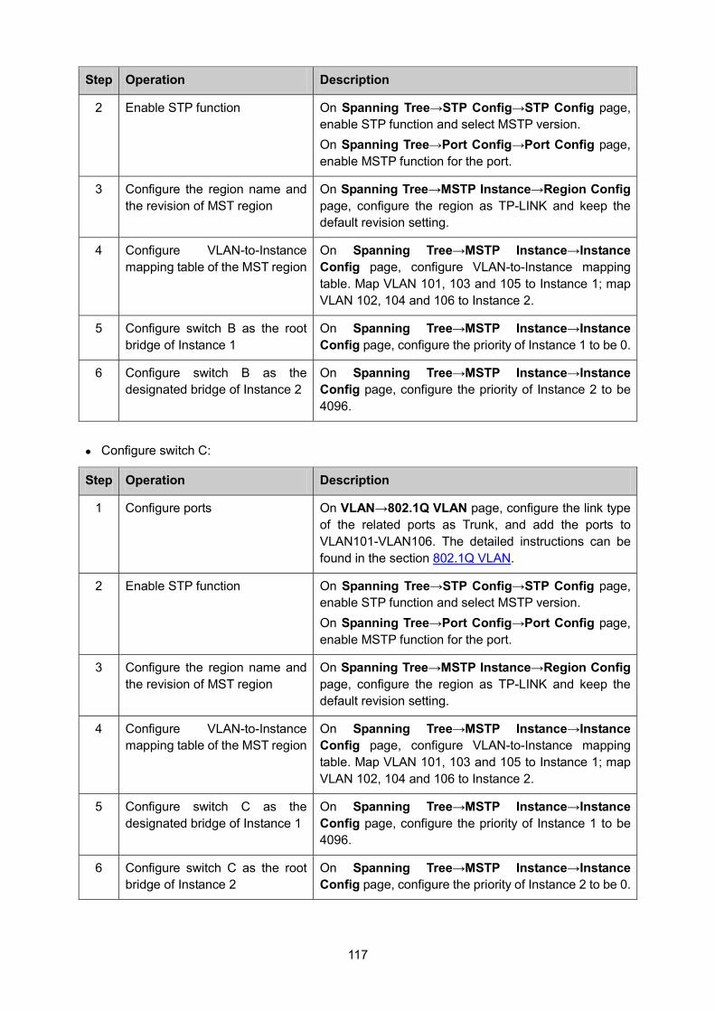
117
Step Operation Description
2 Enable STP function On Spanning Tree→STP Config→STP Config page, enable STP function and select MSTP version. On Spanning Tree→Port Config→Port Config page, enable MSTP function for the port.
3 Configure the region name and the revision of MST region
On Spanning Tree→MSTP Instance→Region Config page, configure the region as TP-LINK and keep the default revision setting.
4 Configure VLAN-to-Instance mapping table of the MST region
On Spanning Tree→MSTP Instance→Instance Config page, configure VLAN-to-Instance mapping table. Map VLAN 101, 103 and 105 to Instance 1; map VLAN 102, 104 and 106 to Instance 2.
5 Configure switch B as the root bridge of Instance 1
On Spanning Tree→MSTP Instance→Instance Config page, configure the priority of Instance 1 to be 0.
6 Configure switch B as the designated bridge of Instance 2
On Spanning Tree→MSTP Instance→Instance Config page, configure the priority of Instance 2 to be 4096.
Configure switch C:
Step Operation Description
1 Configure ports On VLAN→802.1Q VLAN page, configure the link type of the related ports as Trunk, and add the ports to VLAN101-VLAN106. The detailed instructions can be found in the section 802.1Q VLAN.
2 Enable STP function On Spanning Tree→STP Config→STP Config page, enable STP function and select MSTP version. On Spanning Tree→Port Config→Port Config page, enable MSTP function for the port.
3 Configure the region name and the revision of MST region
On Spanning Tree→MSTP Instance→Region Config page, configure the region as TP-LINK and keep the default revision setting.
4 Configure VLAN-to-Instance mapping table of the MST region
On Spanning Tree→MSTP Instance→Instance Config page, configure VLAN-to-Instance mapping table. Map VLAN 101, 103 and 105 to Instance 1; map VLAN 102, 104 and 106 to Instance 2.
5 Configure switch C as the designated bridge of Instance 1
On Spanning Tree→MSTP Instance→Instance Config page, configure the priority of Instance 1 to be 4096.
6 Configure switch C as the root bridge of Instance 2
On Spanning Tree→MSTP Instance→Instance Config page, configure the priority of Instance 2 to be 0.
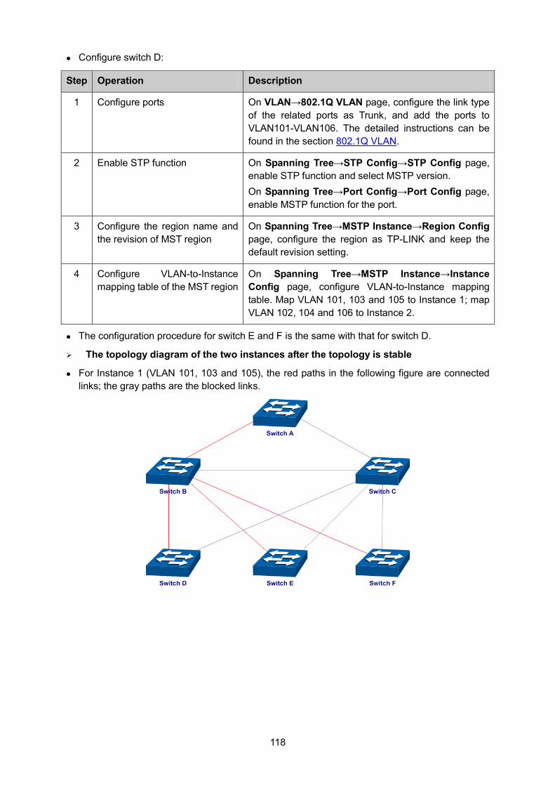
118
Configure switch D:
Step Operation Description
1 Configure ports On VLAN→802.1Q VLAN page, configure the link type of the related ports as Trunk, and add the ports to VLAN101-VLAN106. The detailed instructions can be found in the section 802.1Q VLAN.
2 Enable STP function On Spanning Tree→STP Config→STP Config page, enable STP function and select MSTP version. On Spanning Tree→Port Config→Port Config page, enable MSTP function for the port.
3 Configure the region name and the revision of MST region
On Spanning Tree→MSTP Instance→Region Config page, configure the region as TP-LINK and keep the default revision setting.
4 Configure VLAN-to-Instance mapping table of the MST region
On Spanning Tree→MSTP Instance→Instance Config page, configure VLAN-to-Instance mapping table. Map VLAN 101, 103 and 105 to Instance 1; map VLAN 102, 104 and 106 to Instance 2.
The configuration procedure for switch E and F is the same with that for switch D.
The topology diagram of the two instances after the topology is stable
For Instance 1 (VLAN 101, 103 and 105), the red paths in the following figure are connected links; the gray paths are the blocked links.
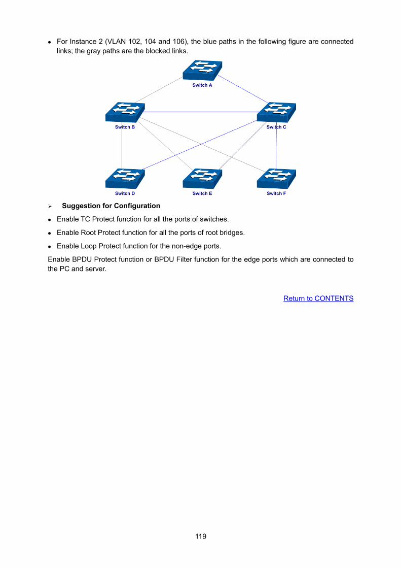
119
For Instance 2 (VLAN 102, 104 and 106), the blue paths in the following figure are connected links; the gray paths are the blocked links.
Suggestion for Configuration
Enable TC Protect function for all the ports of switches.
Enable Root Protect function for all the ports of root bridges.
Enable Loop Protect function for the non-edge ports.
Enable BPDU Protect function or BPDU Filter function for the edge ports which are connected to the PC and server.
Return to CONTENTS
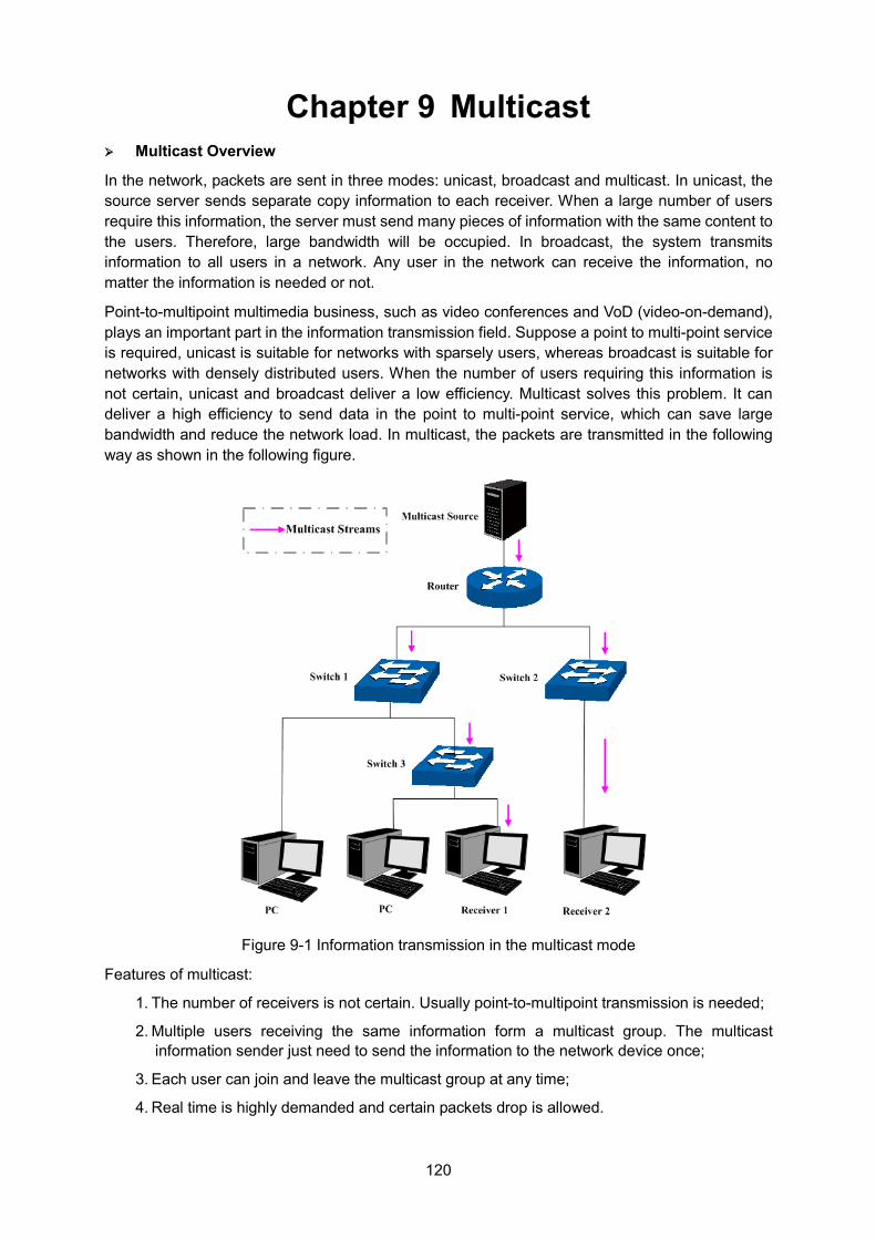
120
Chapter 9 Multicast Multicast Overview
In the network, packets are sent in three modes: unicast, broadcast and multicast. In unicast, the source server sends separate copy information to each receiver. When a large number of users require this information, the server must send many pieces of information with the same content to the users. Therefore, large bandwidth will be occupied. In broadcast, the system transmits information to all users in a network. Any user in the network can receive the information, no matter the information is needed or not.
Point-to-multipoint multimedia business, such as video conferences and VoD (video-on-demand), plays an important part in the information transmission field. Suppose a point to multi-point service is required, unicast is suitable for networks with sparsely users, whereas broadcast is suitable for networks with densely distributed users. When the number of users requiring this information is not certain, unicast and broadcast deliver a low efficiency. Multicast solves this problem. It can deliver a high efficiency to send data in the point to multi-point service, which can save large bandwidth and reduce the network load. In multicast, the packets are transmitted in the following way as shown in the following figure.
Figure 9-1 Information transmission in the multicast mode
Features of multicast:
1. The number of receivers is not certain. Usually point-to-multipoint transmission is needed;
2. Multiple users receiving the same information form a multicast group. The multicast information sender just need to send the information to the network device once;
3. Each user can join and leave the multicast group at any time;
4. Real time is highly demanded and certain packets drop is allowed.
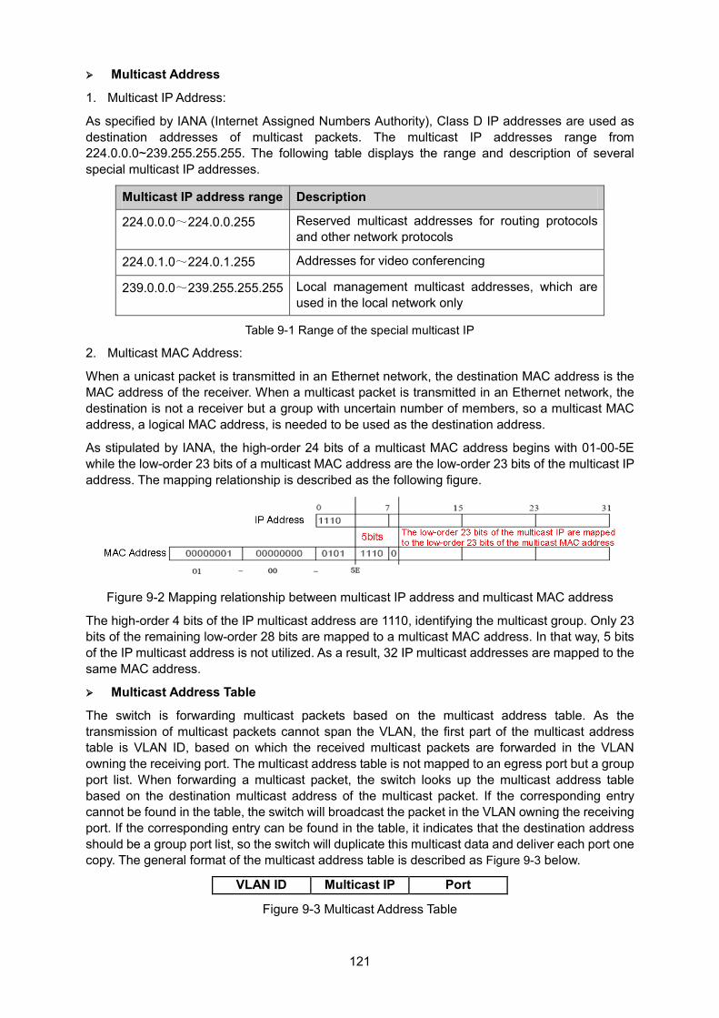
121
Multicast Address
1. Multicast IP Address:
As specified by IANA (Internet Assigned Numbers Authority), Class D IP addresses are used as destination addresses of multicast packets. The multicast IP addresses range from 224.0.0.0~239.255.255.255. The following table displays the range and description of several special multicast IP addresses.
Multicast IP address range Description
224.0.0.0~224.0.0.255 Reserved multicast addresses for routing protocols and other network protocols
224.0.1.0~224.0.1.255 Addresses for video conferencing
239.0.0.0~239.255.255.255 Local management multicast addresses, which are used in the local network only
Table 9-1 Range of the special multicast IP
2. Multicast MAC Address:
When a unicast packet is transmitted in an Ethernet network, the destination MAC address is the MAC address of the receiver. When a multicast packet is transmitted in an Ethernet network, the destination is not a receiver but a group with uncertain number of members, so a multicast MAC address, a logical MAC address, is needed to be used as the destination address.
As stipulated by IANA, the high-order 24 bits of a multicast MAC address begins with 01-00-5E while the low-order 23 bits of a multicast MAC address are the low-order 23 bits of the multicast IP address. The mapping relationship is described as the following figure.
Figure 9-2 Mapping relationship between multicast IP address and multicast MAC address
The high-order 4 bits of the IP multicast address are 1110, identifying the multicast group. Only 23 bits of the remaining low-order 28 bits are mapped to a multicast MAC address. In that way, 5 bits of the IP multicast address is not utilized. As a result, 32 IP multicast addresses are mapped to the same MAC address.
Multicast Address Table
The switch is forwarding multicast packets based on the multicast address table. As the transmission of multicast packets cannot span the VLAN, the first part of the multicast address table is VLAN ID, based on which the received multicast packets are forwarded in the VLAN owning the receiving port. The multicast address table is not mapped to an egress port but a group port list. When forwarding a multicast packet, the switch looks up the multicast address table based on the destination multicast address of the multicast packet. If the corresponding entry cannot be found in the table, the switch will broadcast the packet in the VLAN owning the receiving port. If the corresponding entry can be found in the table, it indicates that the destination address should be a group port list, so the switch will duplicate this multicast data and deliver each port one copy. The general format of the multicast address table is described as Figure 9-3 below.
VLAN ID Multicast IP Port
Figure 9-3 Multicast Address Table
122
IGMP Snooping
In the network, the hosts apply to the near Router for joining (leaving) a multicast group by sending IGMP (Internet Group Management Protocol) messages. When the up-stream device forwards down the multicast data, the switch is responsible for sending them to the hosts. IGMP Snooping is a multicast control mechanism, which can be used on the switch for dynamic registration of the multicast group. The switch, running IGMP Snooping, manages and controls the multicast group via listening to and processing the IGMP messages transmitted between the hosts and the multicast router, thereby effectively prevents multicast groups being broadcasted in the network.
The Multicast module is mainly for multicast management configuration of the switch, including four submenus: IGMP Snooping, Multicast IP, Multicast Filter, Packet Statistics.
9.1 IGMP Snooping IGMP Snooping Process
The switch, running IGMP Snooping, listens to the IGMP messages transmitted between the host and the router, and tracks the IGMP messages and the registered port. When receiving IGMP report message, the switch adds the port to the multicast address table; when the switch listens to IGMP leave message from the host, the router sends the Group-Specific Query message of the port to check if other hosts need this multicast, if yes, the router will receive IGMP report message; if no, the router will receive no response from the hosts and the switch will remove the port from the multicast address table. The router regularly sends IGMP query messages. After receiving the IGMP query messages, the switch will remove the port from the multicast address table if the switch receives no IGMP report message from the host within a period of time.
IGMP Messages
The switch, running IGMP Snooping, processes the IGMP messages of different types as follows.
1. IGMP Query Message
IGMP query message, sent by the router, falls into two types, IGMP general query message and IGMP group-specific-query message. The router regularly sends IGMP general message to query if the multicast groups contain any member. When receiving IGMP leave message, the receiving port of the router will send IGMP group-specific-query message to the multicast group and the switch will forward IGMP group-specific-query message to check if other members in the multicast group of the port need this multicast.
When receiving IGMP general query message, the switch will forward them to all other ports in the VLAN owning the receiving port. The receiving port will be processed: if the receiving port is not a router port yet, it will be added to the router port list with its router port time specified; if the receiving port is already a router port, its router port time will be directly reset.
When receiving IGMP group-specific-query message, the switch will send the group-specific query message to the members of the multicast group being queried.
2. IGMP Report Message
IGMP report message is sent by the host when it applies for joining a multicast group or responses to the IGMP query message from the router.
When receiving IGMP report message, the switch will send the report message via the router port in the VLAN as well as analyze the message to get the address of the multicast group the host applies for joining. The receiving port will be processed: if the receiving port is a new member port, it will be added to the multicast address table with its member port time specified; if the receiving port is already a member port, its member port time will be directly reset.
123
3. IGMP Leave Message
The host, running IGMPv1, does not send IGMP leave message when leaving a multicast group, as a result, the switch cannot get the leave information of the host momentarily. However, after leaving the multicast group, the host does not send IGMP report message any more, so the switch will remove the port from the corresponding multicast address table when its member port time times out. The host, running IGMPv2 or IGMPv3, sends IGMP leave message when leaving a multicast group to inform the multicast router of its leaving.
When receiving IGMP leave message, the querier will forward IGMP group-specific-query message to check if other members in the multicast group of the port need this multicast and reset the member port time to the leave time. When the leave time times out, the switch will remove the port from the corresponding multicast group. If no other member is in the group after the port is removed, the switch will send IGMP leave message to the router and remove the whole multicast group.
IGMP Snooping Fundamentals
1. Ports
Router Port: Indicates the switch port directly connected to the multicast router.
Member Port: Indicates a switch port connected to a multicast group member.
2. Timers
Router Port Time: Within the time, if the switch does not receive IGMP query message from the router port, it will consider this port is not a router port any more. The default value is 300 seconds.
Member Port Time: Within the time, if the switch does not receive IGMP report message from the member port, it will consider this port is not a member port any more. The default value is 260 seconds.
Leave Time: Indicates the interval between the switch receiving a leave message from a host and the switch removing the host from the multicast groups. The default value is 1 second.
The IGMP Snooping function can be implemented on Snooping Config, Port Config, VLAN Config and Multicast VLAN pages.
9.1.1 Snooping Config
To configure the IGMP Snooping on the switch, please firstly configure IGMP global configuration and related parameters on this page.
If the multicast address of the received multicast data is not in the multicast address table, the switch will broadcast the data in the VLAN. When Unknown Multicast Discard feature is enabled, the switch drops the received unknown multicast so as to save the bandwidth and enhance the process efficiency of the system. Please configure this feature appropriate to your needs.
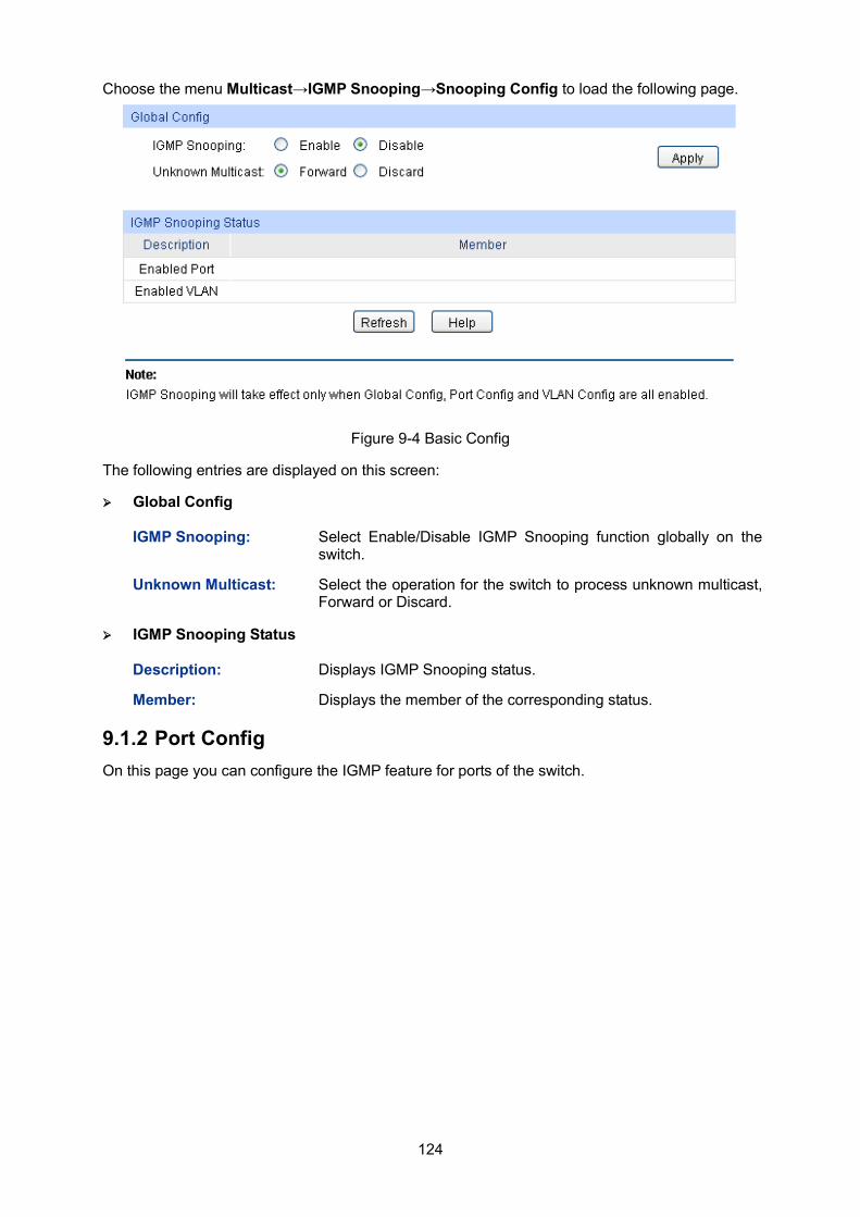
124
Choose the menu Multicast→IGMP Snooping→Snooping Config to load the following page.
Figure 9-4 Basic Config
The following entries are displayed on this screen:
Global Config
IGMP Snooping: Select Enable/Disable IGMP Snooping function globally on the switch.
Unknown Multicast: Select the operation for the switch to process unknown multicast, Forward or Discard.
IGMP Snooping Status
Description: Displays IGMP Snooping status.
Member: Displays the member of the corresponding status.
9.1.2 Port Config On this page you can configure the IGMP feature for ports of the switch.
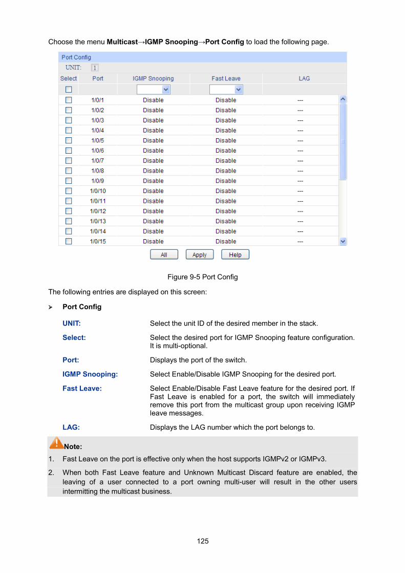
125
Choose the menu Multicast→IGMP Snooping→Port Config to load the following page.
Figure 9-5 Port Config
The following entries are displayed on this screen:
Port Config
UNIT: Select the unit ID of the desired member in the stack.
Select: Select the desired port for IGMP Snooping feature configuration. It is multi-optional.
Port: Displays the port of the switch.
IGMP Snooping: Select Enable/Disable IGMP Snooping for the desired port.
Fast Leave: Select Enable/Disable Fast Leave feature for the desired port. If Fast Leave is enabled for a port, the switch will immediately remove this port from the multicast group upon receiving IGMP leave messages.
LAG: Displays the LAG number which the port belongs to.
Note: 1. Fast Leave on the port is effective only when the host supports IGMPv2 or IGMPv3.
2. When both Fast Leave feature and Unknown Multicast Discard feature are enabled, the leaving of a user connected to a port owning multi-user will result in the other users intermitting the multicast business.
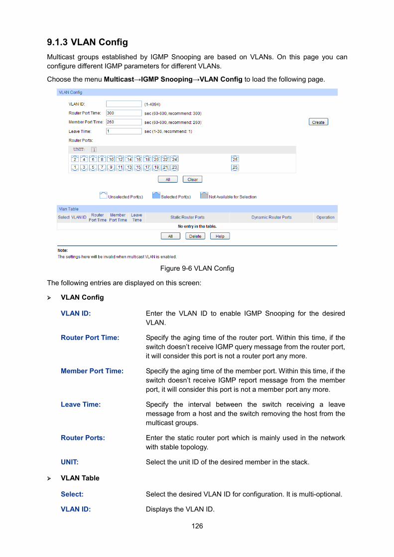
126
9.1.3 VLAN Config Multicast groups established by IGMP Snooping are based on VLANs. On this page you can configure different IGMP parameters for different VLANs.
Choose the menu Multicast→IGMP Snooping→VLAN Config to load the following page.
Figure 9-6 VLAN Config
The following entries are displayed on this screen:
VLAN Config
VLAN ID: Enter the VLAN ID to enable IGMP Snooping for the desired VLAN.
Router Port Time: Specify the aging time of the router port. Within this time, if the switch doesn’t receive IGMP query message from the router port, it will consider this port is not a router port any more.
Member Port Time: Specify the aging time of the member port. Within this time, if the switch doesn’t receive IGMP report message from the member port, it will consider this port is not a member port any more.
Leave Time: Specify the interval between the switch receiving a leave message from a host and the switch removing the host from the multicast groups.
Router Ports: Enter the static router port which is mainly used in the network with stable topology.
UNIT: Select the unit ID of the desired member in the stack.
VLAN Table
Select: Select the desired VLAN ID for configuration. It is multi-optional.
VLAN ID: Displays the VLAN ID.
127
Router Port Time: Displays the router port time of the VLAN.
Member Port Time: Displays the member port time of the VLAN.
Leave Time: Displays the leave time of the VLAN.
Static Router Ports: Displays the static router ports of the VLAN.
Dynamic Router Ports:
Displays the dynamic router ports of the VLAN.
Note: The settings here will be invalid when multicast VLAN is enabled
Configuration procedure:
Step Operation Description
1 Enable IGMP Snooping function
Required. Enable IGMP Snooping globally on the switch and for the port on Multicast→IGMP Snooping→Snooping Config and Port Config page.
2 Configure the multicast parameters for VLANs
Optional. Configure the multicast parameters for VLANs on Multicast→IGMP Snooping→VLAN Config page. If a VLAN has no multicast parameters configuration, it indicates the IGMP Snooping is not enabled in the VLAN, thus the multicast data in the VLAN will be broadcasted.
9.1.4 Multicast VLAN In old multicast transmission mode, when users in different VLANs apply for join the same multicast group, the multicast router will duplicate this multicast information and deliver each VLAN owning a receiver one copy. This mode wastes a lot of bandwidth.
The problem above can be solved by configuring a multicast VLAN. By adding switch ports to the multicast VLAN and enabling IGMP Snooping, you can make users in different VLANs share the same multicast VLAN. This saves the bandwidth since multicast streams are transmitted only within the multicast VLAN and also guarantees security because the multicast VLAN is isolated from user VLANS.
Before configuring a multicast VLAN, you should firstly configure a VLAN as multicast VLAN and add the corresponding ports to the VLAN on the 802.1Q VLAN page. If the multicast VLAN is enabled, the multicast configuration for other VLANs on the VLAN Config page will be invalid, that is, the multicast streams will be transmitted only within the multicast VLAN.
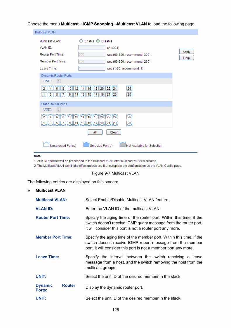
128
Choose the menu Multicast→IGMP Snooping→Multicast VLAN to load the following page.
Figure 9-7 Multicast VLAN
The following entries are displayed on this screen:
Multicast VLAN
Multicast VLAN: Select Enable/Disable Multicast VLAN feature.
VLAN ID: Enter the VLAN ID of the multicast VLAN.
Router Port Time: Specify the aging time of the router port. Within this time, if the switch doesn’t receive IGMP query message from the router port, it will consider this port is not a router port any more.
Member Port Time: Specify the aging time of the member port. Within this time, if the switch doesn’t receive IGMP report message from the member port, it will consider this port is not a member port any more.
Leave Time: Specify the interval between the switch receiving a leave message from a host, and the switch removing the host from the multicast groups.
UNIT: Select the unit ID of the desired member in the stack.
Dynamic Router Ports: Display the dynamic router port.
UNIT: Select the unit ID of the desired member in the stack.
129
Static Router Ports: Select the desired port as the static router port which is mainly used in the network with stable topology.
Note: 1. The router port should be in the multicast VLAN, otherwise the member ports cannot receive
multicast streams.
2. The Multicast VLAN won't take effect unless you first complete the configuration for the corresponding VLAN owning the port on the 802.1Q VLAN page.
3. It is recommended to choose GENERAL as the link type of the member ports in the multicast VLAN.
4. Configure the link type of the router port in the multicast VLAN as TRUNK or configure the egress rule as TAG and the link type as GENERAL otherwise all the member ports in the multicast VLAN cannot receive multicast streams.
5. After a multicast VLAN is created, all the IGMP packets will be processed only within the multicast VLAN.
Configuration procedure:
Step Operation Description
1 Enable IGMP Snooping function
Required. Enable IGMP Snooping globally on the switch and for the port on Multicast→IGMP Snooping→Snooping Config and Port Config page.
2 Create a multicast VLAN Required. Create a multicast VLAN and add all the member ports and router ports to the VLAN on the VLAN→802.1Q VLAN page. Configure the link type of the member ports as
GENERAL. Configure the link type of the router ports as TRUNK or
configure the egress rule as tagged GENERAL.
3 Configure parameters for multicast VLAN
Optional. Enable and configure a multicast VLAN on the Multicast→IGMP Snooping→Multicast VLAN page. It is recommended to keep the default time parameters.
4 Look over the configuration If it is successfully configured, the VLAN ID of the multicast VLAN will be displayed in the IGMP Snooping Status table on the Multicast→IGMP Snooping→Snooping Config page.
9.1.5 Querier Config In an IP multicast network that runs IGMP, a Layer 3 multicast device works as an IGMP querier to send IGMP queries and manage the multicast table. But IGMP is not supported by the devices in Layer 2 network. IGMP Snooping Querier can act as an IGMP Router in Layer 2 network. It can help to create and maintain multicast forwarding table on the switch with the Query messages it generates.
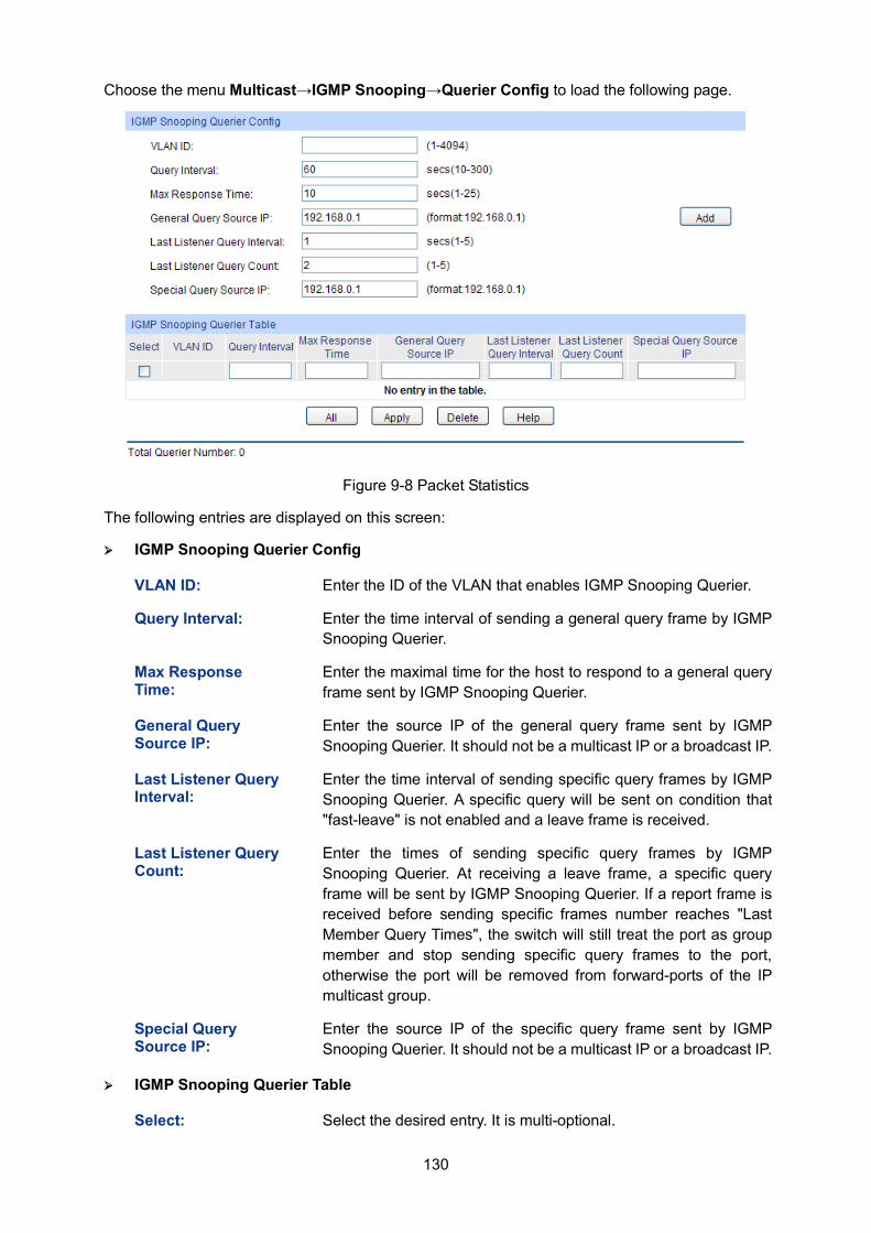
130
Choose the menu Multicast→IGMP Snooping→Querier Config to load the following page.
Figure 9-8 Packet Statistics
The following entries are displayed on this screen:
IGMP Snooping Querier Config
VLAN ID: Enter the ID of the VLAN that enables IGMP Snooping Querier.
Query Interval: Enter the time interval of sending a general query frame by IGMP Snooping Querier.
Max Response Time:
Enter the maximal time for the host to respond to a general query frame sent by IGMP Snooping Querier.
General Query Source IP:
Enter the source IP of the general query frame sent by IGMP Snooping Querier. It should not be a multicast IP or a broadcast IP.
Last Listener Query Interval:
Enter the time interval of sending specific query frames by IGMP Snooping Querier. A specific query will be sent on condition that "fast-leave" is not enabled and a leave frame is received.
Last Listener Query Count:
Enter the times of sending specific query frames by IGMP Snooping Querier. At receiving a leave frame, a specific query frame will be sent by IGMP Snooping Querier. If a report frame is received before sending specific frames number reaches "Last Member Query Times", the switch will still treat the port as group member and stop sending specific query frames to the port, otherwise the port will be removed from forward-ports of the IP multicast group.
Special Query Source IP:
Enter the source IP of the specific query frame sent by IGMP Snooping Querier. It should not be a multicast IP or a broadcast IP.
IGMP Snooping Querier Table
Select: Select the desired entry. It is multi-optional.
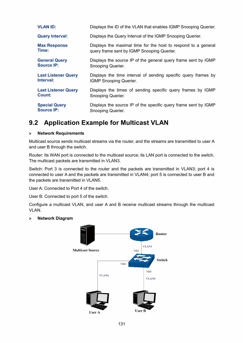
131
VLAN ID: Displays the ID of the VLAN that enables IGMP Snooping Querier.
Query Interval: Displays the Query Interval of the IGMP Snooping Querier.
Max Response Time:
Displays the maximal time for the host to respond to a general query frame sent by IGMP Snooping Querier.
General Query Source IP:
Displays the source IP of the general query frame sent by IGMP Snooping Querier.
Last Listener Query Interval:
Displays the time interval of sending specific query frames by IGMP Snooping Querier.
Last Listener Query Count:
Displays the times of sending specific query frames by IGMP Snooping Querier.
Special Query Source IP:
Displays the source IP of the specific query frame sent by IGMP Snooping Querier.
9.2 Application Example for Multicast VLAN Network Requirements
Multicast source sends multicast streams via the router, and the streams are transmitted to user A and user B through the switch.
Router: Its WAN port is connected to the multicast source; its LAN port is connected to the switch. The multicast packets are transmitted in VLAN3.
Switch: Port 3 is connected to the router and the packets are transmitted in VLAN3; port 4 is connected to user A and the packets are transmitted in VLAN4; port 5 is connected to user B and the packets are transmitted in VLAN5.
User A: Connected to Port 4 of the switch.
User B: Connected to port 5 of the switch.
Configure a multicast VLAN, and user A and B receive multicast streams through the multicast VLAN.
Network Diagram
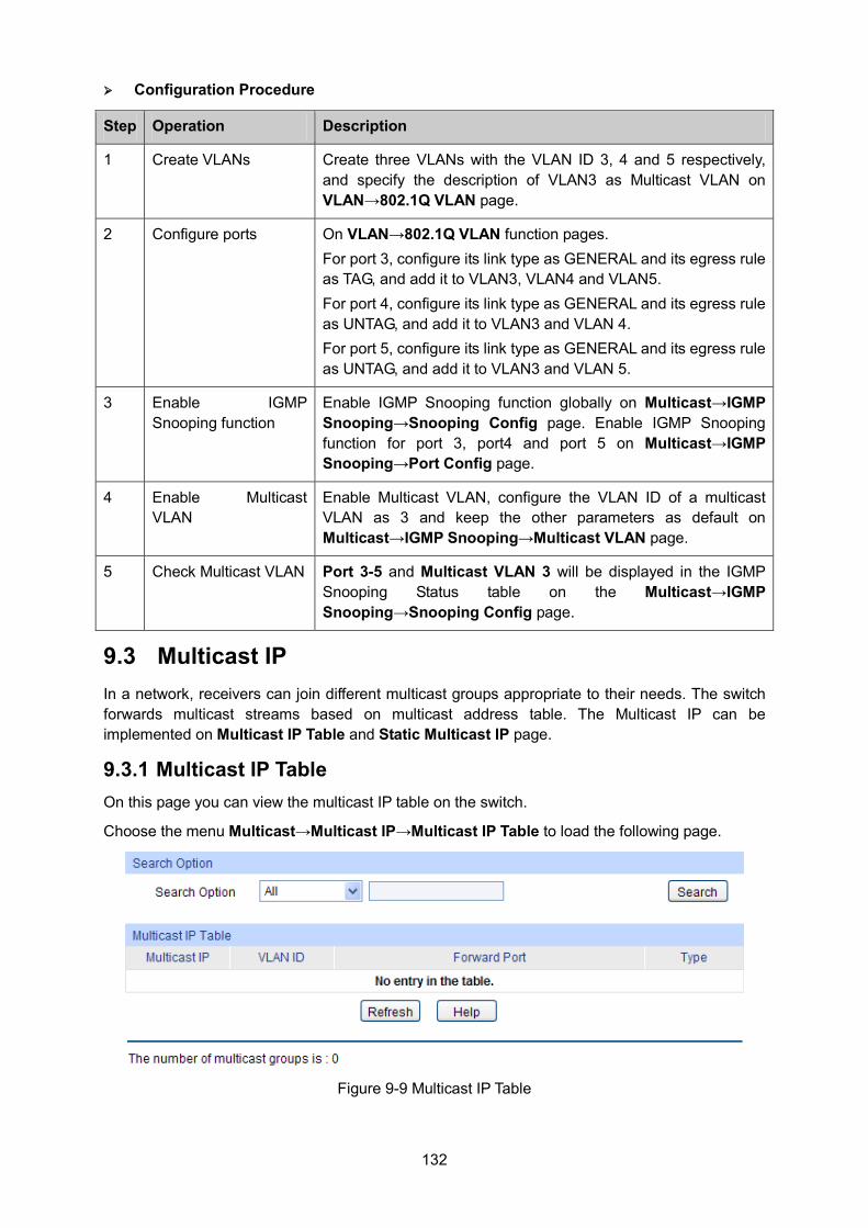
132
Configuration Procedure
Step Operation Description
1 Create VLANs Create three VLANs with the VLAN ID 3, 4 and 5 respectively, and specify the description of VLAN3 as Multicast VLAN on VLAN→802.1Q VLAN page.
2 Configure ports On VLAN→802.1Q VLAN function pages. For port 3, configure its link type as GENERAL and its egress rule as TAG, and add it to VLAN3, VLAN4 and VLAN5. For port 4, configure its link type as GENERAL and its egress rule as UNTAG, and add it to VLAN3 and VLAN 4. For port 5, configure its link type as GENERAL and its egress rule as UNTAG, and add it to VLAN3 and VLAN 5.
3 Enable IGMP Snooping function
Enable IGMP Snooping function globally on Multicast→IGMP Snooping→Snooping Config page. Enable IGMP Snooping function for port 3, port4 and port 5 on Multicast→IGMP Snooping→Port Config page.
4 Enable Multicast VLAN
Enable Multicast VLAN, configure the VLAN ID of a multicast VLAN as 3 and keep the other parameters as default on Multicast→IGMP Snooping→Multicast VLAN page.
5 Check Multicast VLAN Port 3-5 and Multicast VLAN 3 will be displayed in the IGMP Snooping Status table on the Multicast→IGMP Snooping→Snooping Config page.
9.3 Multicast IP In a network, receivers can join different multicast groups appropriate to their needs. The switch forwards multicast streams based on multicast address table. The Multicast IP can be implemented on Multicast IP Table and Static Multicast IP page.
9.3.1 Multicast IP Table On this page you can view the multicast IP table on the switch.
Choose the menu Multicast→Multicast IP→Multicast IP Table to load the following page.
Figure 9-9 Multicast IP Table
133
The following entries are displayed on this screen:
Search Option
Search Option: Select the rules for displaying multicast IP table to find the desired entries quickly. All: Displays all multicast IP entries. Multicast IP: Enter the multicast IP address the desired entry
must carry. VLAN ID: Enter the VLAN ID the desired entry must carry. Forward Port: Enter the forward port number the desired
entry must carry.
Multicast IP Table
Multicast IP Displays multicast IP address.
VLAN ID: Displays the VLAN ID of the multicast group.
Forward Port Displays the forward port of the multicast group.
Type: Displays the type of the multicast IP.
Note: If the configuration on VLAN Config page and multicast VLAN page is changed, the switch will clear up the dynamic multicast addresses in multicast address table and learn new addresses.
9.3.2 Static Multicast IP
Static Multicast IP table, isolated from dynamic multicast group and multicast filter, is not learned by IGMP Snooping. It can enhance the quality and security for information transmission in some fixed multicast groups.
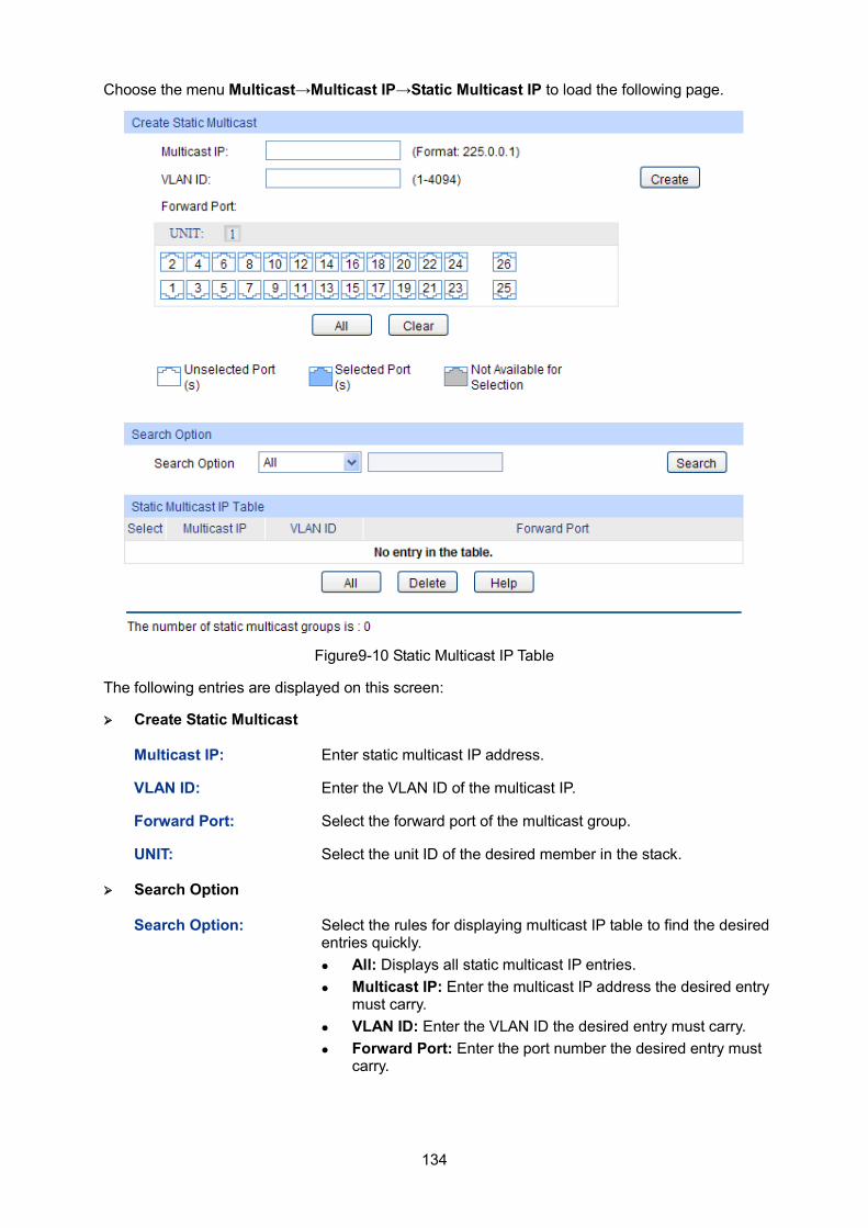
134
Choose the menu Multicast→Multicast IP→Static Multicast IP to load the following page.
Figure9-10 Static Multicast IP Table
The following entries are displayed on this screen:
Create Static Multicast
Multicast IP: Enter static multicast IP address.
VLAN ID: Enter the VLAN ID of the multicast IP.
Forward Port: Select the forward port of the multicast group.
UNIT: Select the unit ID of the desired member in the stack.
Search Option
Search Option: Select the rules for displaying multicast IP table to find the desired entries quickly. All: Displays all static multicast IP entries. Multicast IP: Enter the multicast IP address the desired entry
must carry. VLAN ID: Enter the VLAN ID the desired entry must carry. Forward Port: Enter the port number the desired entry must
carry.
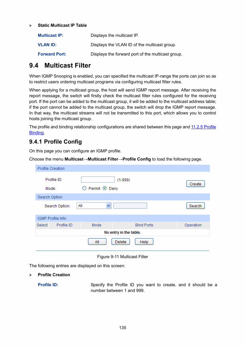
135
Static Multicast IP Table
Multicast IP: Displays the multicast IP.
VLAN ID: Displays the VLAN ID of the multicast group.
Forward Port: Displays the forward port of the multicast group.
9.4 Multicast Filter When IGMP Snooping is enabled, you can specified the multicast IP-range the ports can join so as to restrict users ordering multicast programs via configuring multicast filter rules.
When applying for a multicast group, the host will send IGMP report message. After receiving the report message, the switch will firstly check the multicast filter rules configured for the receiving port. If the port can be added to the multicast group, it will be added to the multicast address table; if the port cannot be added to the multicast group, the switch will drop the IGMP report message. In that way, the multicast streams will not be transmitted to this port, which allows you to control hosts joining the multicast group.
The profile and binding relationship configurations are shared between this page and 11.2.5 Profile Binding.
9.4.1 Profile Config On this page you can configure an IGMP profile.
Choose the menu Multicast→Multicast Filter→Profile Config to load the following page.
Figure 9-11 Multicast Filter
The following entries are displayed on this screen:
Profile Creation
Profile ID: Specify the Profile ID you want to create, and it should be a number between 1 and 999.
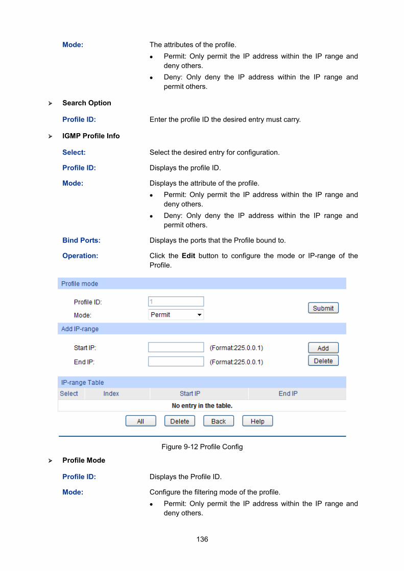
136
Mode: The attributes of the profile. Permit: Only permit the IP address within the IP range and
deny others. Deny: Only deny the IP address within the IP range and
permit others.
Search Option
Profile ID: Enter the profile ID the desired entry must carry.
IGMP Profile Info
Select: Select the desired entry for configuration.
Profile ID: Displays the profile ID.
Mode:
Displays the attribute of the profile. Permit: Only permit the IP address within the IP range and
deny others. Deny: Only deny the IP address within the IP range and
permit others.
Bind Ports: Displays the ports that the Profile bound to.
Operation: Click the Edit button to configure the mode or IP-range of the Profile.
Figure 9-12 Profile Config
Profile Mode
Profile ID: Displays the Profile ID.
Mode: Configure the filtering mode of the profile. Permit: Only permit the IP address within the IP range and
deny others.
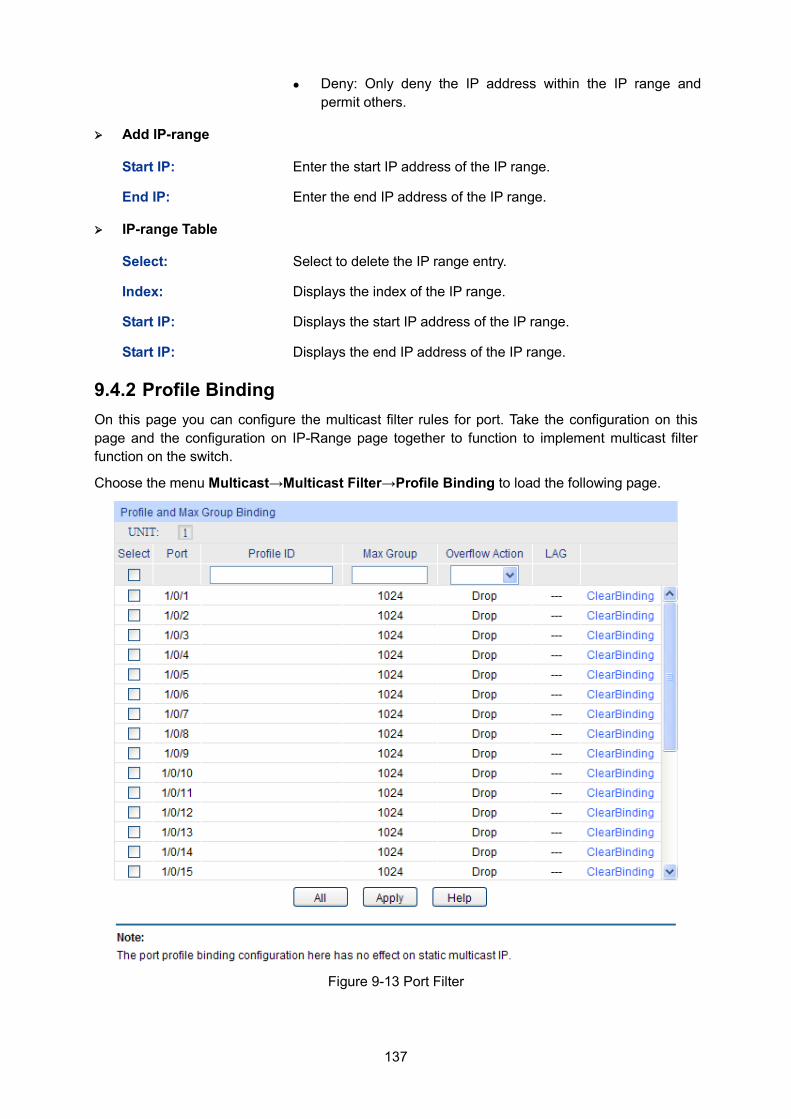
137
Deny: Only deny the IP address within the IP range and permit others.
Add IP-range
Start IP: Enter the start IP address of the IP range.
End IP: Enter the end IP address of the IP range.
IP-range Table
Select: Select to delete the IP range entry.
Index: Displays the index of the IP range.
Start IP: Displays the start IP address of the IP range.
Start IP: Displays the end IP address of the IP range.
9.4.2 Profile Binding On this page you can configure the multicast filter rules for port. Take the configuration on this page and the configuration on IP-Range page together to function to implement multicast filter function on the switch.
Choose the menu Multicast→Multicast Filter→Profile Binding to load the following page.
Figure 9-13 Port Filter
138
The following entries are displayed on this screen:
Profile and Max Group Binding
UNIT: Select the unit ID of the desired member in the stack.
Select: Select the desired entry for configuration.
Port: It is multi-optional. Displays the port number.
Profile ID: The existing Profile ID bound to the selected port.
Max Group: The maximum multicast group a port can join.
Overflow Action: The policy should be taken when the number of multicast group a port has joined reach the maximum. Drop: drop the successive report packet, and this port cannot
join any other multicast group. Replace: when the number of the dynamic multicast groups
that a port joins has exceeded the max-group, the newly joined multicast group will replace an existing multicast group with the lowest multicast group address.
LAG: Displays the LAG number which the port belongs to.
Clear Binding: Click the ClearBinding button to clear all profiles bound to the port.
Note: 1. Multicast Filter feature can only have effect on the VLAN with IGMP Snooping enabled.
2. Multicast Filter feature has no effect on static multicast IP.
Configuration Procedure:
Step Operation Description
1 Create Profile Required. Configure the Profile ID and mode on Multicast→Multicast Filter→Profile Config page.
2 Configure IP-Range Required. Click Edit of the specified entry in the IGMP Profile Info table on Multicast→Multicast Filter→Profile Config page to configure the mode or IP-range of the Profile.
3 Configure Profile Binding for ports
Optional. Configure Profile Binding for ports on Multicast→Multicast Filter→Porfile Binding page.
9.5 Packet Statistics On this page you can view the multicast data traffic on each port of the switch, which facilitates you to monitor the IGMP messages in the network.
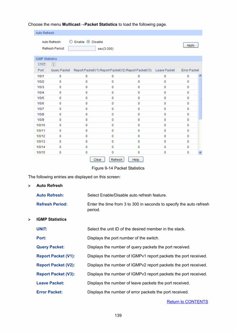
139
Choose the menu Multicast→Packet Statistics to load the following page.
Figure 9-14 Packet Statistics
The following entries are displayed on this screen:
Auto Refresh
Auto Refresh: Select Enable/Disable auto refresh feature.
Refresh Period: Enter the time from 3 to 300 in seconds to specify the auto refresh period.
IGMP Statistics
UNIT: Select the unit ID of the desired member in the stack.
Port: Displays the port number of the switch.
Query Packet: Displays the number of query packets the port received.
Report Packet (V1): Displays the number of IGMPv1 report packets the port received.
Report Packet (V2): Displays the number of IGMPv2 report packets the port received.
Report Packet (V3): Displays the number of IGMPv3 report packets the port received.
Leave Packet: Displays the number of leave packets the port received.
Error Packet: Displays the number of error packets the port received.
Return to CONTENTS
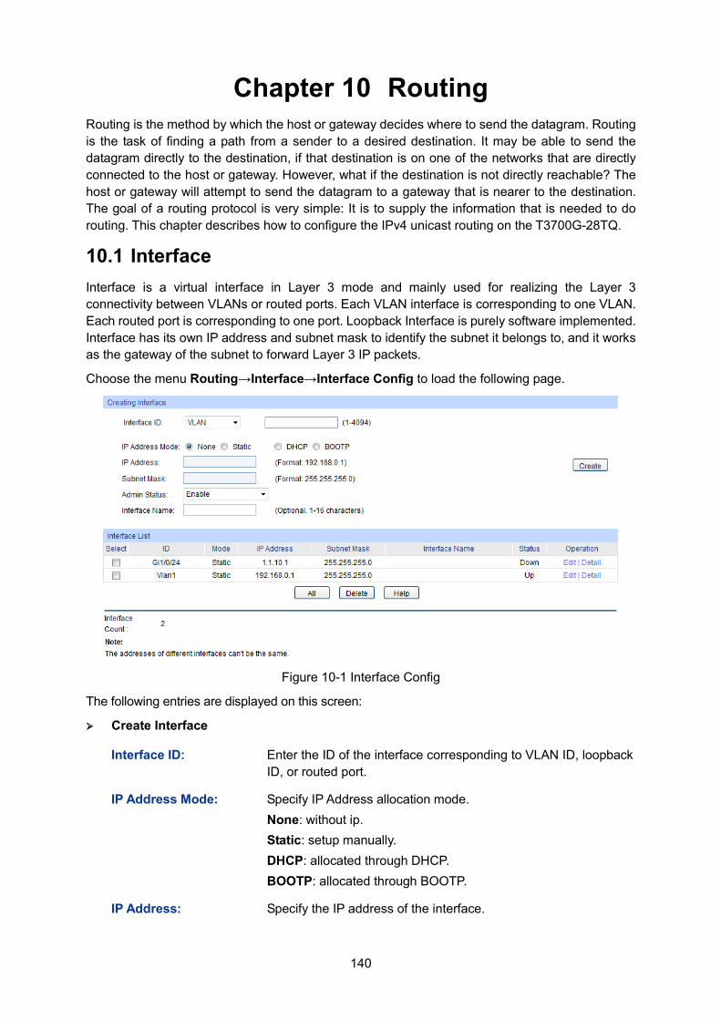
140
Chapter 10 Routing Routing is the method by which the host or gateway decides where to send the datagram. Routing is the task of finding a path from a sender to a desired destination. It may be able to send the datagram directly to the destination, if that destination is on one of the networks that are directly connected to the host or gateway. However, what if the destination is not directly reachable? The host or gateway will attempt to send the datagram to a gateway that is nearer to the destination. The goal of a routing protocol is very simple: It is to supply the information that is needed to do routing. This chapter describes how to configure the IPv4 unicast routing on the T3700G-28TQ.
10.1 Interface Interface is a virtual interface in Layer 3 mode and mainly used for realizing the Layer 3 connectivity between VLANs or routed ports. Each VLAN interface is corresponding to one VLAN. Each routed port is corresponding to one port. Loopback Interface is purely software implemented. Interface has its own IP address and subnet mask to identify the subnet it belongs to, and it works as the gateway of the subnet to forward Layer 3 IP packets.
Choose the menu Routing→Interface→Interface Config to load the following page.
Figure 10-1 Interface Config
The following entries are displayed on this screen: Create Interface
Interface ID: Enter the ID of the interface corresponding to VLAN ID, loopback ID, or routed port.
IP Address Mode: Specify IP Address allocation mode. None: without ip. Static: setup manually. DHCP: allocated through DHCP. BOOTP: allocated through BOOTP.
IP Address: Specify the IP address of the interface.
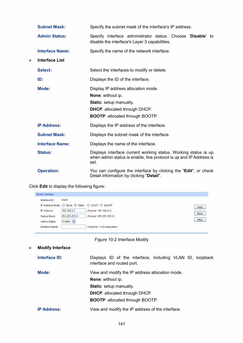
141
Subnet Mask: Specify the subnet mask of the interface's IP address.
Admin Status: Specify interface administrator status. Choose 'Disable' to disable the interface's Layer 3 capabilities.
Interface Name: Specify the name of the network interface.
Interface List
Select : Select the interfaces to modify or delete.
ID: Displays the ID of the interface.
Mode: Display IP address allocation mode. None: without ip. Static: setup manually. DHCP: allocated through DHCP. BOOTP: allocated through BOOTP.
IP Address: Displays the IP address of the interface.
Subnet Mask: Displays the subnet mask of the interface.
Interface Name: Displays the name of the interface.
Status: Displays interface current working status. Working status is up when admin status is enable, line protocol is up and IP Address is set.
Operation: You can configure the interface by clicking the "Edit", or check Detail information by clicking "Detail".
Click Edit to display the following figure:
Figure 10-2 Interface Modify
Modify Interface
Interface ID: Displays ID of the interface, including VLAN ID, loopback interface and routed port.
Mode: View and modify the IP address allocation mode. None: without ip. Static: setup manually. DHCP: allocated through DHCP. BOOTP: allocated through BOOTP.
IP Address: View and modify the IP address of the interface.
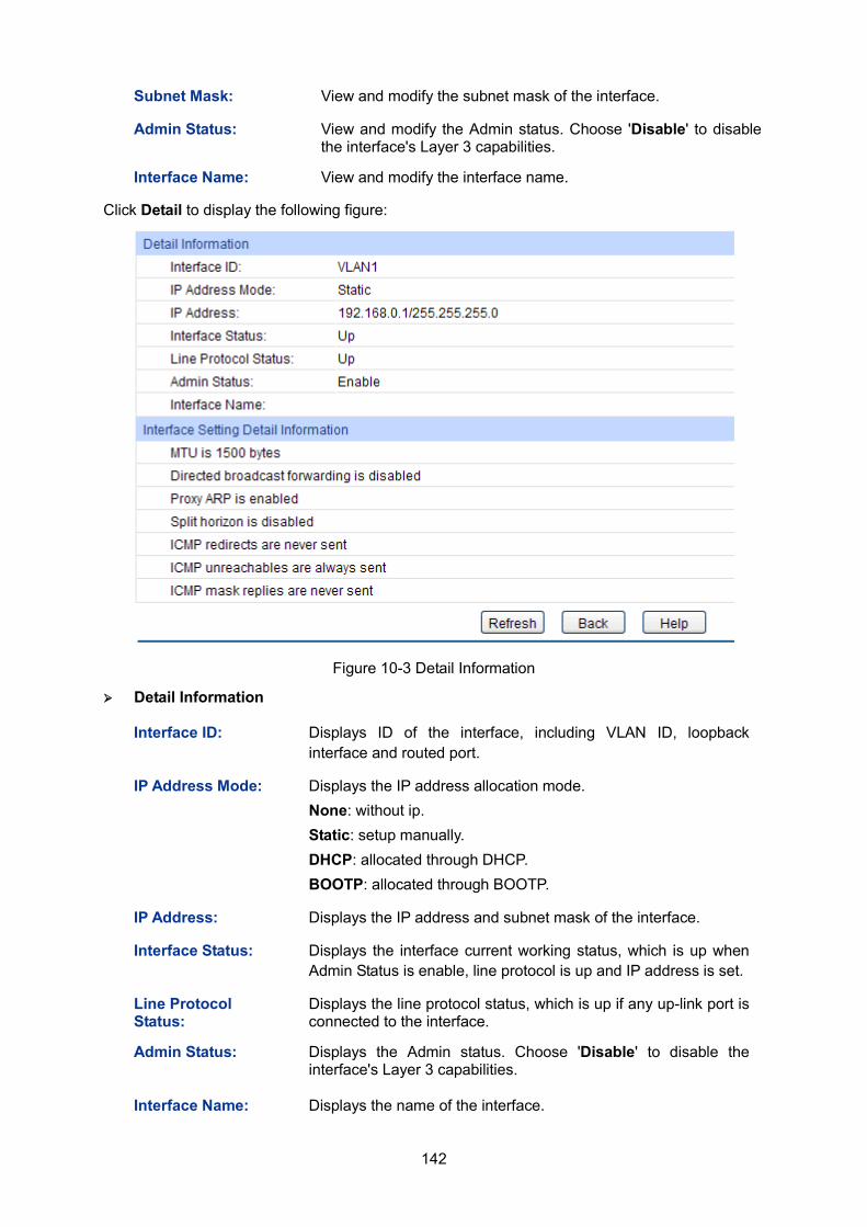
142
Subnet Mask: View and modify the subnet mask of the interface.
Admin Status: View and modify the Admin status. Choose 'Disable' to disable the interface's Layer 3 capabilities.
Interface Name: View and modify the interface name.
Click Detail to display the following figure:
Figure 10-3 Detail Information
Detail Information
Interface ID: Displays ID of the interface, including VLAN ID, loopback interface and routed port.
IP Address Mode: Displays the IP address allocation mode. None: without ip. Static: setup manually. DHCP: allocated through DHCP. BOOTP: allocated through BOOTP.
IP Address: Displays the IP address and subnet mask of the interface.
Interface Status: Displays the interface current working status, which is up when Admin Status is enable, line protocol is up and IP address is set.
Line Protocol Status:
Displays the line protocol status, which is up if any up-link port is connected to the interface.
Admin Status: Displays the Admin status. Choose 'Disable' to disable the interface's Layer 3 capabilities.
Interface Name: Displays the name of the interface.
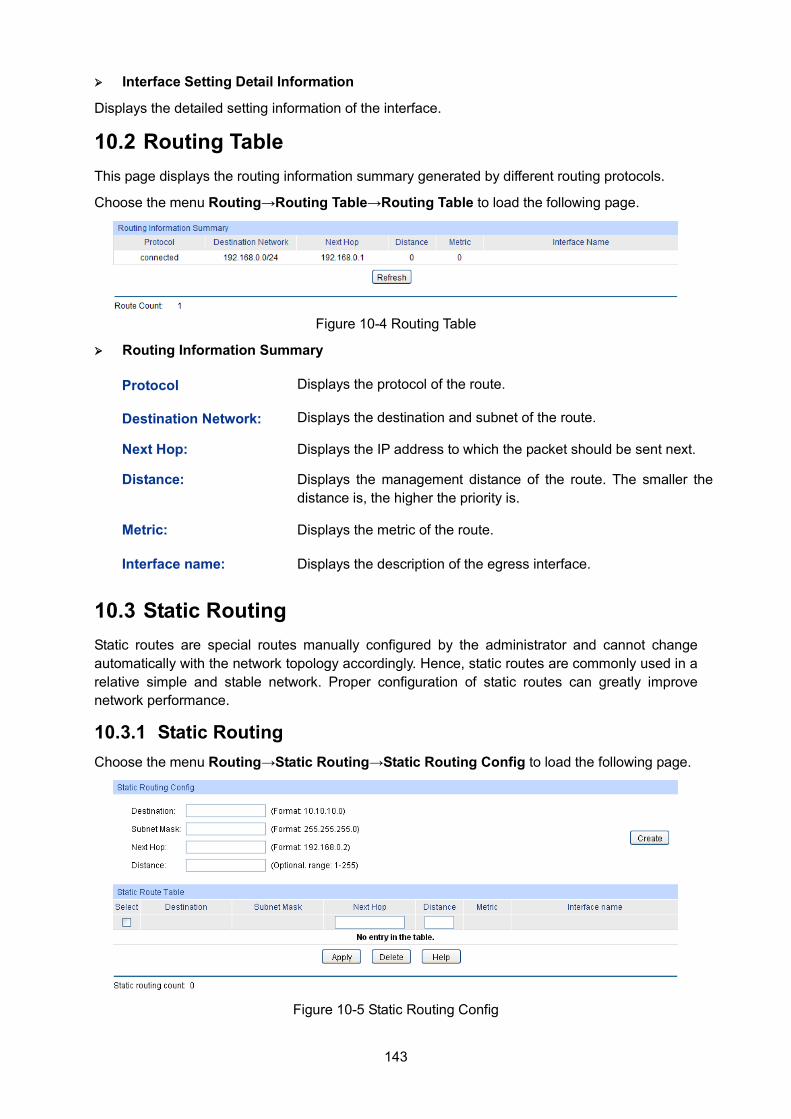
143
Interface Setting Detail Information
Displays the detailed setting information of the interface.
10.2 Routing Table This page displays the routing information summary generated by different routing protocols.
Choose the menu Routing→Routing Table→Routing Table to load the following page.
Figure 10-4 Routing Table
Routing Information Summary
10.3 Static Routing Static routes are special routes manually configured by the administrator and cannot change automatically with the network topology accordingly. Hence, static routes are commonly used in a relative simple and stable network. Proper configuration of static routes can greatly improve network performance.
10.3.1 Static Routing Choose the menu Routing→Static Routing→Static Routing Config to load the following page.
Figure 10-5 Static Routing Config
Protocol Displays the protocol of the route.
Destination Network: Displays the destination and subnet of the route.
Next Hop: Displays the IP address to which the packet should be sent next.
Distance: Displays the management distance of the route. The smaller the distance is, the higher the priority is.
Metric: Displays the metric of the route.
Interface name: Displays the description of the egress interface.
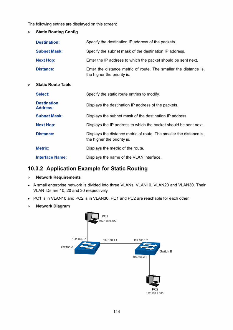
144
The following entries are displayed on this screen: Static Routing Config
Static Route Table
10.3.2 Application Example for Static Routing Network Requirements
A small enterprise network is divided into three VLANs: VLAN10, VLAN20 and VLAN30. Their VLAN IDs are 10, 20 and 30 respectively.
PC1 is in VLAN10 and PC2 is in VLAN30. PC1 and PC2 are reachable for each other.
Network Diagram
Destination: Specify the destination IP address of the packets.
Subnet Mask: Specify the subnet mask of the destination IP address.
Next Hop: Enter the IP address to which the packet should be sent next.
Distance: Enter the distance metric of route. The smaller the distance is, the higher the priority is.
Select: Specify the static route entries to modify.
Destination Address: Displays the destination IP address of the packets.
Subnet Mask: Displays the subnet mask of the destination IP address.
Next Hop: Displays the IP address to which the packet should be sent next.
Distance: Displays the distance metric of route. The smaller the distance is, the higher the priority is.
Metric: Displays the metric of the route.
Interface Name: Displays the name of the VLAN interface.
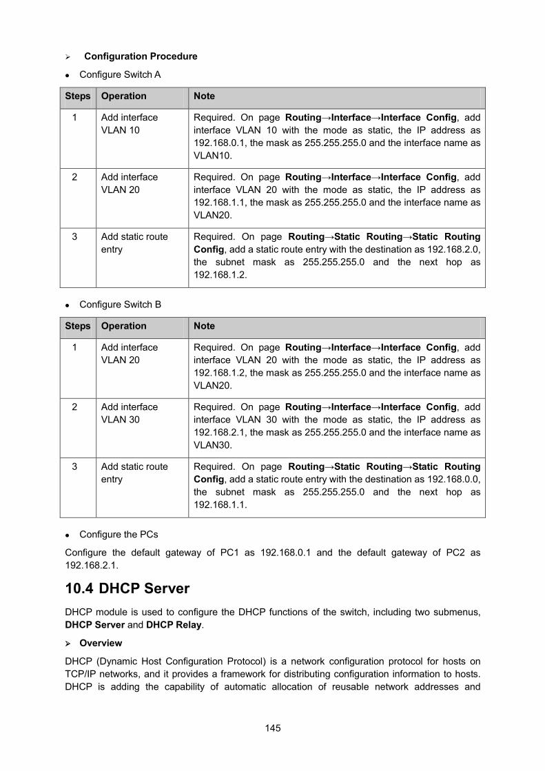
145
Configuration Procedure
Configure Switch A
Steps Operation Note
1 Add interface VLAN 10
Required. On page Routing→Interface→Interface Config, add interface VLAN 10 with the mode as static, the IP address as 192.168.0.1, the mask as 255.255.255.0 and the interface name as VLAN10.
2 Add interface VLAN 20
Required. On page Routing→Interface→Interface Config, add interface VLAN 20 with the mode as static, the IP address as 192.168.1.1, the mask as 255.255.255.0 and the interface name as VLAN20.
3 Add static route entry
Required. On page Routing→Static Routing→Static Routing Config, add a static route entry with the destination as 192.168.2.0, the subnet mask as 255.255.255.0 and the next hop as 192.168.1.2.
Configure Switch B
Steps Operation Note
1 Add interface VLAN 20
Required. On page Routing→Interface→Interface Config, add interface VLAN 20 with the mode as static, the IP address as 192.168.1.2, the mask as 255.255.255.0 and the interface name as VLAN20.
2 Add interface VLAN 30
Required. On page Routing→Interface→Interface Config, add interface VLAN 30 with the mode as static, the IP address as 192.168.2.1, the mask as 255.255.255.0 and the interface name as VLAN30.
3 Add static route entry
Required. On page Routing→Static Routing→Static Routing Config, add a static route entry with the destination as 192.168.0.0, the subnet mask as 255.255.255.0 and the next hop as 192.168.1.1.
Configure the PCs
Configure the default gateway of PC1 as 192.168.0.1 and the default gateway of PC2 as 192.168.2.1.
10.4 DHCP Server DHCP module is used to configure the DHCP functions of the switch, including two submenus, DHCP Server and DHCP Relay.
Overview
DHCP (Dynamic Host Configuration Protocol) is a network configuration protocol for hosts on TCP/IP networks, and it provides a framework for distributing configuration information to hosts. DHCP is adding the capability of automatic allocation of reusable network addresses and
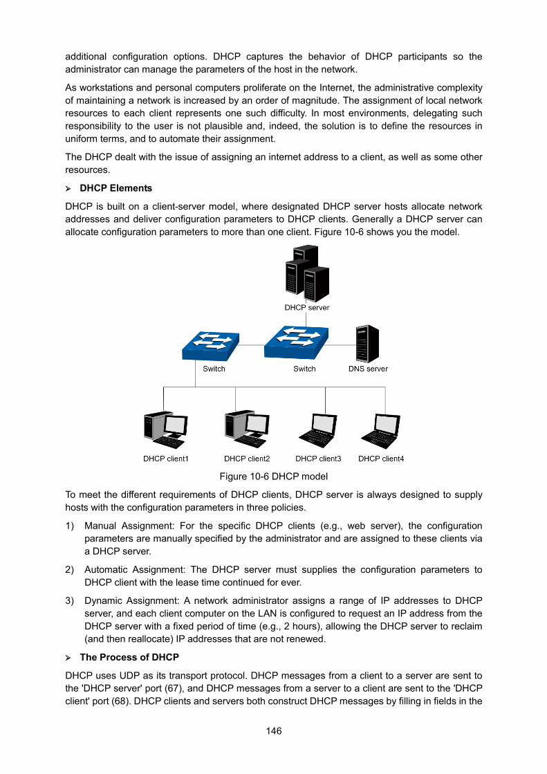
146
additional configuration options. DHCP captures the behavior of DHCP participants so the administrator can manage the parameters of the host in the network.
As workstations and personal computers proliferate on the Internet, the administrative complexity of maintaining a network is increased by an order of magnitude. The assignment of local network resources to each client represents one such difficulty. In most environments, delegating such responsibility to the user is not plausible and, indeed, the solution is to define the resources in uniform terms, and to automate their assignment.
The DHCP dealt with the issue of assigning an internet address to a client, as well as some other resources.
DHCP Elements
DHCP is built on a client-server model, where designated DHCP server hosts allocate network addresses and deliver configuration parameters to DHCP clients. Generally a DHCP server can allocate configuration parameters to more than one client. Figure 10-6 shows you the model.
Figure 10-6 DHCP model
To meet the different requirements of DHCP clients, DHCP server is always designed to supply hosts with the configuration parameters in three policies.
1) Manual Assignment: For the specific DHCP clients (e.g., web server), the configuration parameters are manually specified by the administrator and are assigned to these clients via a DHCP server.
2) Automatic Assignment: The DHCP server must supplies the configuration parameters to DHCP client with the lease time continued for ever.
3) Dynamic Assignment: A network administrator assigns a range of IP addresses to DHCP server, and each client computer on the LAN is configured to request an IP address from the DHCP server with a fixed period of time (e.g., 2 hours), allowing the DHCP server to reclaim (and then reallocate) IP addresses that are not renewed.
The Process of DHCP
DHCP uses UDP as its transport protocol. DHCP messages from a client to a server are sent to the 'DHCP server' port (67), and DHCP messages from a server to a client are sent to the 'DHCP client' port (68). DHCP clients and servers both construct DHCP messages by filling in fields in the
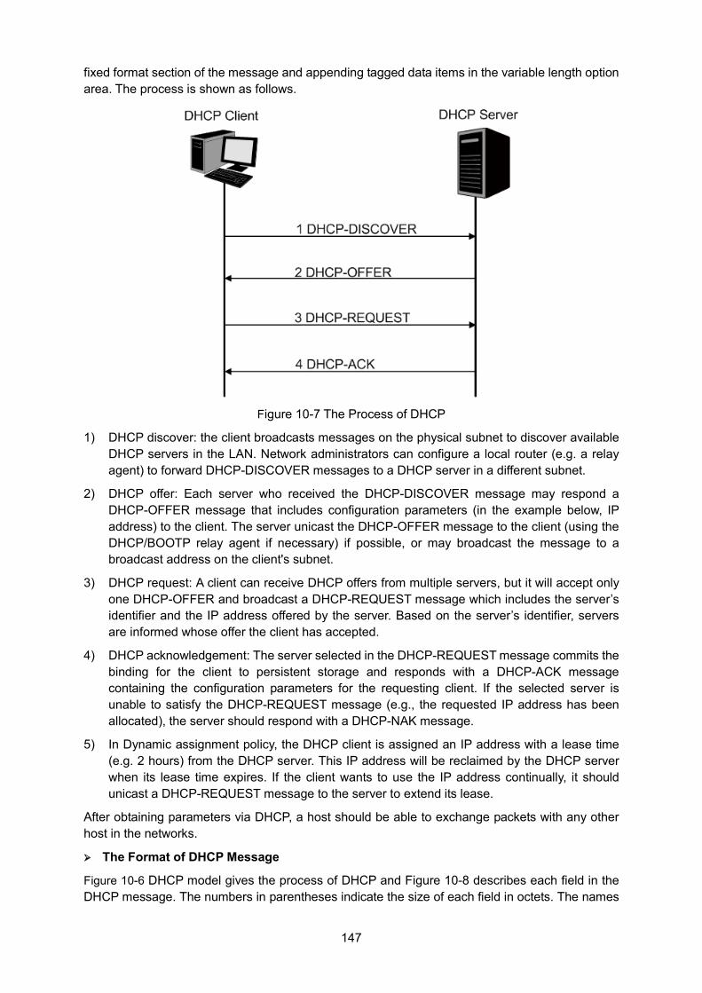
147
fixed format section of the message and appending tagged data items in the variable length option area. The process is shown as follows.
Figure 10-7 The Process of DHCP
1) DHCP discover: the client broadcasts messages on the physical subnet to discover available DHCP servers in the LAN. Network administrators can configure a local router (e.g. a relay agent) to forward DHCP-DISCOVER messages to a DHCP server in a different subnet.
2) DHCP offer: Each server who received the DHCP-DISCOVER message may respond a DHCP-OFFER message that includes configuration parameters (in the example below, IP address) to the client. The server unicast the DHCP-OFFER message to the client (using the DHCP/BOOTP relay agent if necessary) if possible, or may broadcast the message to a broadcast address on the client's subnet.
3) DHCP request: A client can receive DHCP offers from multiple servers, but it will accept only one DHCP-OFFER and broadcast a DHCP-REQUEST message which includes the server’s identifier and the IP address offered by the server. Based on the server’s identifier, servers are informed whose offer the client has accepted.
4) DHCP acknowledgement: The server selected in the DHCP-REQUEST message commits the binding for the client to persistent storage and responds with a DHCP-ACK message containing the configuration parameters for the requesting client. If the selected server is unable to satisfy the DHCP-REQUEST message (e.g., the requested IP address has been allocated), the server should respond with a DHCP-NAK message.
5) In Dynamic assignment policy, the DHCP client is assigned an IP address with a lease time (e.g. 2 hours) from the DHCP server. This IP address will be reclaimed by the DHCP server when its lease time expires. If the client wants to use the IP address continually, it should unicast a DHCP-REQUEST message to the server to extend its lease.
After obtaining parameters via DHCP, a host should be able to exchange packets with any other host in the networks.
The Format of DHCP Message
Figure 10-6 DHCP model gives the process of DHCP and Figure 10-8 describes each field in the DHCP message. The numbers in parentheses indicate the size of each field in octets. The names
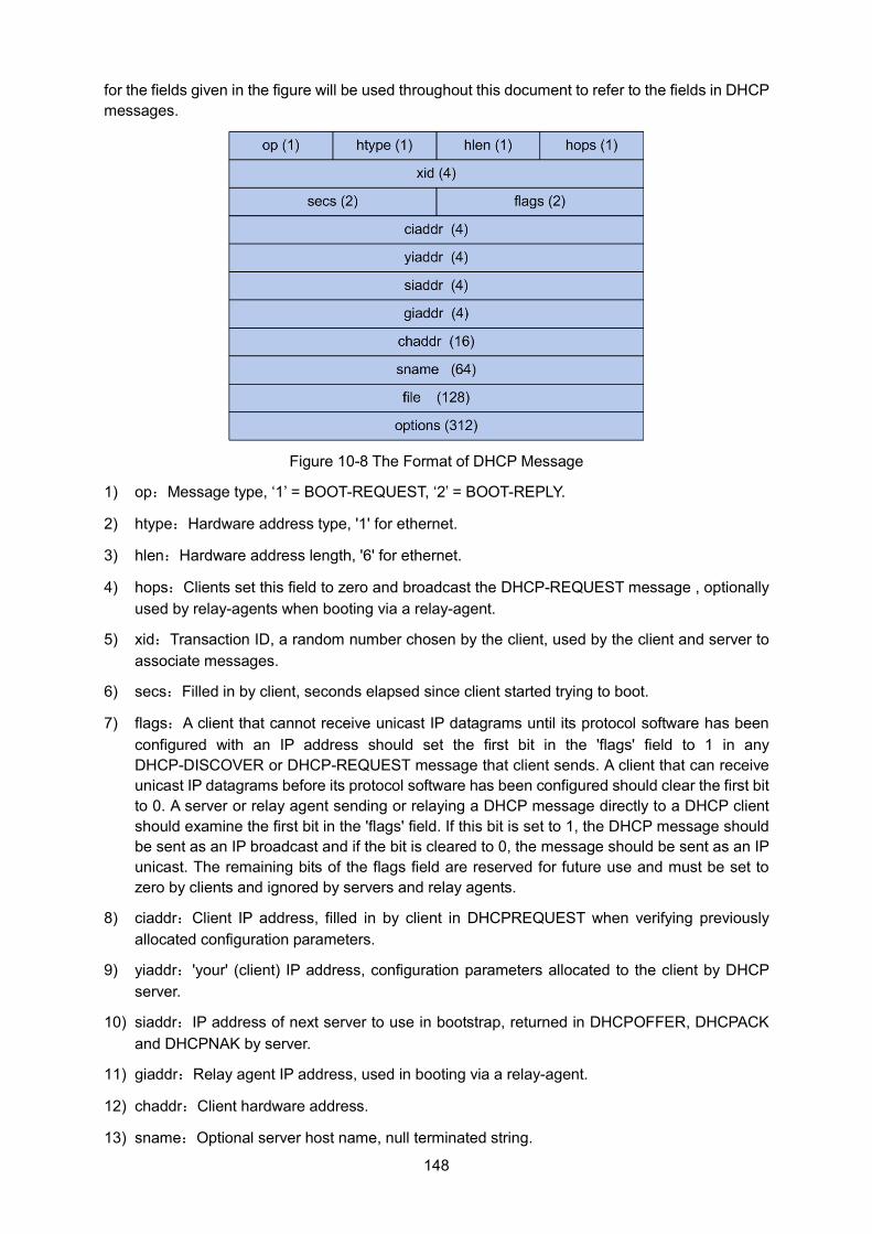
148
for the fields given in the figure will be used throughout this document to refer to the fields in DHCP messages.
Figure 10-8 The Format of DHCP Message
1) op:Message type, ‘1’ = BOOT-REQUEST, ‘2’ = BOOT-REPLY.
2) htype:Hardware address type, '1' for ethernet.
3) hlen:Hardware address length, '6' for ethernet.
4) hops:Clients set this field to zero and broadcast the DHCP-REQUEST message , optionally used by relay-agents when booting via a relay-agent.
5) xid:Transaction ID, a random number chosen by the client, used by the client and server to associate messages.
6) secs:Filled in by client, seconds elapsed since client started trying to boot.
7) flags:A client that cannot receive unicast IP datagrams until its protocol software has been configured with an IP address should set the first bit in the 'flags' field to 1 in any DHCP-DISCOVER or DHCP-REQUEST message that client sends. A client that can receive unicast IP datagrams before its protocol software has been configured should clear the first bit to 0. A server or relay agent sending or relaying a DHCP message directly to a DHCP client should examine the first bit in the 'flags' field. If this bit is set to 1, the DHCP message should be sent as an IP broadcast and if the bit is cleared to 0, the message should be sent as an IP unicast. The remaining bits of the flags field are reserved for future use and must be set to zero by clients and ignored by servers and relay agents.
8) ciaddr:Client IP address, filled in by client in DHCPREQUEST when verifying previously allocated configuration parameters.
9) yiaddr:'your' (client) IP address, configuration parameters allocated to the client by DHCP server.
10) siaddr:IP address of next server to use in bootstrap, returned in DHCPOFFER, DHCPACK and DHCPNAK by server.
11) giaddr:Relay agent IP address, used in booting via a relay-agent.
12) chaddr:Client hardware address.
13) sname:Optional server host name, null terminated string.
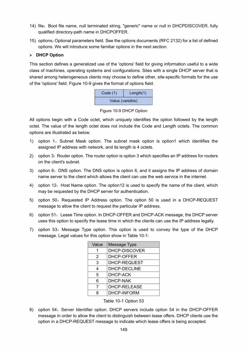
149
14) file:Boot file name, null terminated string, "generic" name or null in DHCPDISCOVER, fully qualified directory-path name in DHCPOFFER.
15) options:Optional parameters field. See the options documents (RFC 2132) for a list of defined options. We will introduce some familiar options in the next section.
DHCP Option
This section defines a generalized use of the 'options' field for giving information useful to a wide class of machines, operating systems and configurations. Sites with a single DHCP server that is shared among heterogeneous clients may choose to define other, site-specific formats for the use of the 'options' field. Figure 10-9 gives the format of options field.
Figure 10-9 DHCP Option
All options begin with a Code octet, which uniquely identifies the option followed by the length octet. The value of the length octet does not include the Code and Length octets. The common options are illustrated as below.
1) option 1:Subnet Mask option. The subnet mask option is option1 which identifies the assigned IP address with network, and its length is 4 octets.
2) option 3:Router option. The router option is option 3 which specifies an IP address for routers on the client's subnet.
3) option 6:DNS option. The DNS option is option 6, and it assigns the IP address of domain name server to the client which allows the client can use the web service in the internet.
4) option 12:Host Name option. The option12 is used to specify the name of the client, which may be requested by the DHCP server for authentication.
5) option 50:Requested IP Address option. The option 50 is used in a DHCP-REQUEST message to allow the client to request the particular IP address.
6) option 51:Lease Time option. In DHCP-OFFER and DHCP-ACK message, the DHCP server uses this option to specify the lease time in which the clients can use the IP address legally.
7) option 53:Message Type option. This option is used to convey the type of the DHCP message. Legal values for this option show in Table 10-1:
Value Message Type 1 DHCP-DISCOVER 2 DHCP-OFFER 3 DHCP-REQUEST 4 DHCP-DECLINE 5 DHCP-ACK 6 DHCP-NAK 7 DHCP-RELEASE 8 DHCP-INFORM
Table 10-1 Option 53
8) option 54:Server Identifier option. DHCP servers include option 54 in the DHCP-OFFER message in order to allow the client to distinguish between lease offers. DHCP clients use the option in a DHCP-REQUEST message to indicate which lease offers is being accepted.
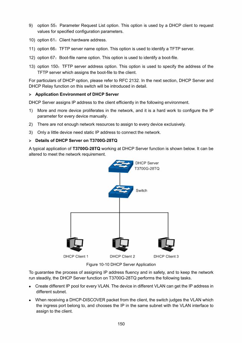
150
9) option 55:Parameter Request List option. This option is used by a DHCP client to request values for specified configuration parameters.
10) option 61:Client hardware address.
11) option 66:TFTP server name option. This option is used to identify a TFTP server.
12) option 67:Boot-file name option. This option is used to identify a boot-file.
13) option 150:TFTP server address option. This option is used to specify the address of the TFTP server which assigns the boot-file to the client.
For particulars of DHCP option, please refer to RFC 2132. In the next section, DHCP Server and DHCP Relay function on this switch will be introduced in detail.
Application Environment of DHCP Server
DHCP Server assigns IP address to the client efficiently in the following environment.
1) More and more device proliferates in the network, and it is a hard work to configure the IP parameter for every device manually.
2) There are not enough network resources to assign to every device exclusively.
3) Only a little device need static IP address to connect the network.
Details of DHCP Server on T3700G-28TQ
A typical application of T3700G-28TQ working at DHCP Server function is shown below. It can be altered to meet the network requirement.
Figure 10-10 DHCP Server Application
To guarantee the process of assigning IP address fluency and in safety, and to keep the network run steadily, the DHCP Server function on T3700G-28TQ performs the following tasks.
Create different IP pool for every VLAN. The device in different VLAN can get the IP address in different subnet.
When receiving a DHCP-DISCOVER packet from the client, the switch judges the VLAN which the ingress port belong to, and chooses the IP in the same subnet with the VLAN interface to assign to the client.
151
With a DHCP Relay running between the client and the server, when receiving a DHCP-DISCOVER packet transmitting from the Relay, the switch will choose the IP from the IP pool in the same subnet with the Relay’s IP to assign to the client. If the IP pool is not configured on the switch or the configured IP pool doesn’t match the Relay’s network segment, the client may not get network parameters successfully.
The switch can detect the IP address automatically before assigning it to avoid conflict.
IP Detection
To avoid IP conflict, the switch will detect the IP address to be assigned in LAN through Ping test.
The DHCP server will send the Ping test packet with the destination IP being the IP address to be assigned. If the server receives the Reply packet from the destination host in the ping time, it means that the IP address has been used, and the server will choose another IP as destination IP to test again. The server will assign the IP address if the server not receives the Reply packet in the Ping time.
Policy of IP Assignment
The switch chooses the IP assigned to clients based on the rules shown as follows.
1) First, the server will choose the IP which has been bound to the client manually.
2) Then, the server will assign the IP which has been assigned to the client once.
3) For the next, the server will assign the IP which is specified in the DHCP-DISCOVER packet from the client.
4) At last, the server will choose the first IP from the IP pool which has not been assigned.
Tips for Configure DHCP Server Function on T3700G-28TQ
1) Configure the Excluded IP address which cannot be assigned by the switch, e.g. web server’s IP, broadcast IP of subnet and gateway’s IP.
2) Specify IP address for specific clients, and then the switch will supply these IP address to them only for ever.
3) Configure the IP pool in which the IP address can be assigned to the clients.
The DHCP Server, allowing the clients in all VLANs to get the IP address from the server automatically, is implemented on the DHCP Server, Pool Setting, Manual Binding, Binding Table and Packet Statistics pages.
10.4.1 DHCP Server This page allows you to enable the DHCP Server function, configure the Excluded IP Address which cannot be assigned by the switch in every network.
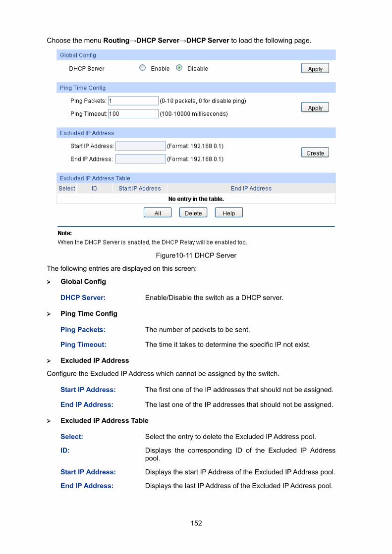
152
Choose the menu Routing→DHCP Server→DHCP Server to load the following page.
Figure10-11 DHCP Server
The following entries are displayed on this screen: Global Config
Ping Time Config
Excluded IP Address
Configure the Excluded IP Address which cannot be assigned by the switch.
Excluded IP Address Table
Select: Select the entry to delete the Excluded IP Address pool.
ID: Displays the corresponding ID of the Excluded IP Address pool.
Start IP Address: Displays the start IP Address of the Excluded IP Address pool.
End IP Address: Displays the last IP Address of the Excluded IP Address pool.
DHCP Server: Enable/Disable the switch as a DHCP server.
Ping Packets: The number of packets to be sent.
Ping Timeout: The time it takes to determine the specific IP not exist.
Start IP Address: The first one of the IP addresses that should not be assigned.
End IP Address: The last one of the IP addresses that should not be assigned.
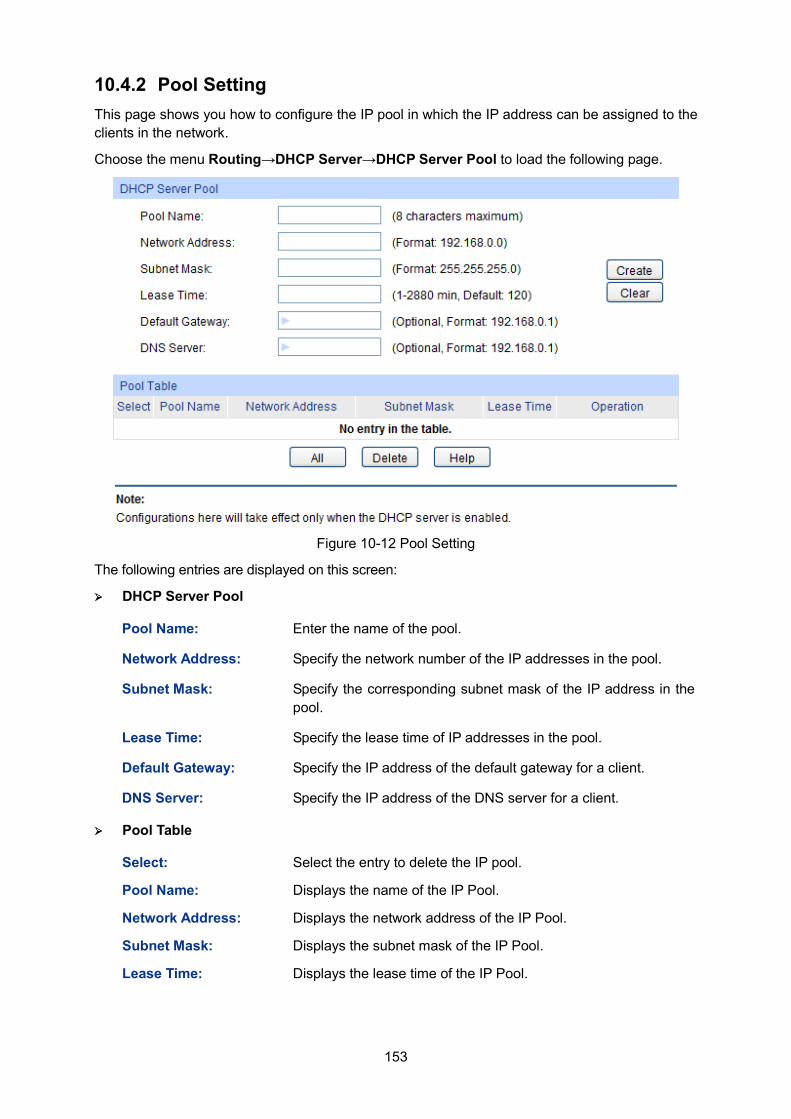
153
10.4.2 Pool Setting This page shows you how to configure the IP pool in which the IP address can be assigned to the clients in the network.
Choose the menu Routing→DHCP Server→DHCP Server Pool to load the following page.
Figure 10-12 Pool Setting
The following entries are displayed on this screen: DHCP Server Pool
Pool Table
Select: Select the entry to delete the IP pool.
Pool Name: Displays the name of the IP Pool.
Network Address: Displays the network address of the IP Pool.
Subnet Mask: Displays the subnet mask of the IP Pool.
Lease Time: Displays the lease time of the IP Pool.
Pool Name: Enter the name of the pool.
Network Address: Specify the network number of the IP addresses in the pool.
Subnet Mask: Specify the corresponding subnet mask of the IP address in the pool.
Lease Time: Specify the lease time of IP addresses in the pool.
Default Gateway: Specify the IP address of the default gateway for a client.
DNS Server: Specify the IP address of the DNS server for a client.
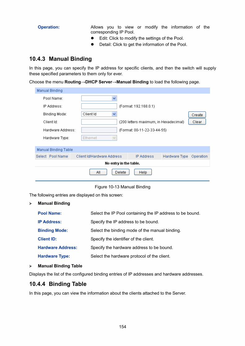
154
Operation: Allows you to view or modify the information of the corresponding IP Pool. Edit: Click to modify the settings of the Pool. Detail: Click to get the information of the Pool.
10.4.3 Manual Binding In this page, you can specify the IP address for specific clients, and then the switch will supply these specified parameters to them only for ever.
Choose the menu Routing→DHCP Server→Manual Binding to load the following page.
Figure 10-13 Manual Binding
The following entries are displayed on this screen:
Manual Binding
Pool Name: Select the IP Pool containing the IP address to be bound.
IP Address: Specify the IP address to be bound.
Binding Mode: Select the binding mode of the manual binding.
Client ID: Specify the identifier of the client.
Hardware Address: Specify the hardware address to be bound.
Hardware Type: Select the hardware protocol of the client.
Manual Binding Table
Displays the list of the configured binding entries of IP addresses and hardware addresses.
10.4.4 Binding Table In this page, you can view the information about the clients attached to the Server.
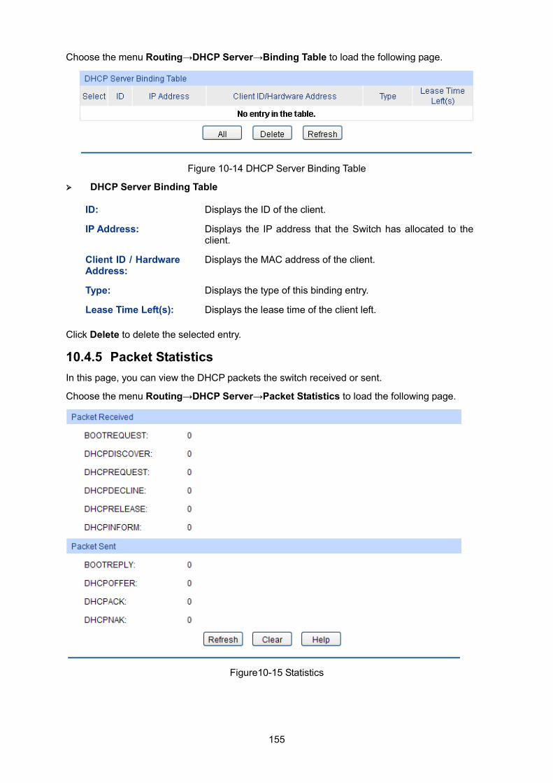
155
Choose the menu Routing→DHCP Server→Binding Table to load the following page.
Figure 10-14 DHCP Server Binding Table
DHCP Server Binding Table
ID: Displays the ID of the client.
IP Address: Displays the IP address that the Switch has allocated to the client.
Client ID / Hardware Address:
Displays the MAC address of the client.
Type: Displays the type of this binding entry.
Lease Time Left(s): Displays the lease time of the client left.
Click Delete to delete the selected entry.
10.4.5 Packet Statistics In this page, you can view the DHCP packets the switch received or sent.
Choose the menu Routing→DHCP Server→Packet Statistics to load the following page.
Figure10-15 Statistics
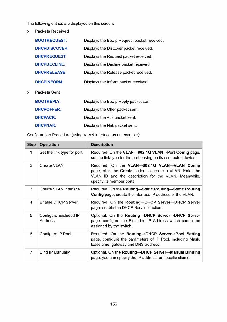
156
The following entries are displayed on this screen:
Packets Received
BOOTREQUEST: Displays the Bootp Request packet received.
DHCPDISCOVER: Displays the Discover packet received.
DHCPREQUEST: Displays the Request packet received.
DHCPDECLINE: Displays the Decline packet received.
DHCPRELEASE: Displays the Release packet received.
DHCPINFORM: Displays the Inform packet received.
Packets Sent
BOOTREPLY: Displays the Bootp Reply packet sent.
DHCPOFFER: Displays the Offer packet sent.
DHCPACK: Displays the Ack packet sent.
DHCPNAK: Displays the Nak packet sent.
Configuration Procedure (using VLAN interface as an example):
Step Operation Description
1 Set the link type for port. Required. On the VLAN→802.1Q VLAN→Port Config page, set the link type for the port basing on its connected device.
2 Create VLAN. Required. On the VLAN→802.1Q VLAN→VLAN Config page, click the Create button to create a VLAN. Enter the VLAN ID and the description for the VLAN. Meanwhile, specify its member ports.
3 Create VLAN interface. Required. On the Routing→Static Routing→Static Routing Config page, create the interface IP address of the VLAN.
4 Enable DHCP Server. Required. On the Routing→DHCP Server→DHCP Server page, enable the DHCP Server function.
5 Configure Excluded IP Address.
Optional. On the Routing→DHCP Server→DHCP Server page, configure the Excluded IP Address which cannot be assigned by the switch.
6 Configure IP Pool. Required. On the Routing→DHCP Server→Pool Setting page, configure the parameters of IP Pool, including Mask, lease time, gateway and DNS address.
7 Bind IP Manually Optional. On the Routing→DHCP Server→Manual Binding page, you can specify the IP address for specific clients.
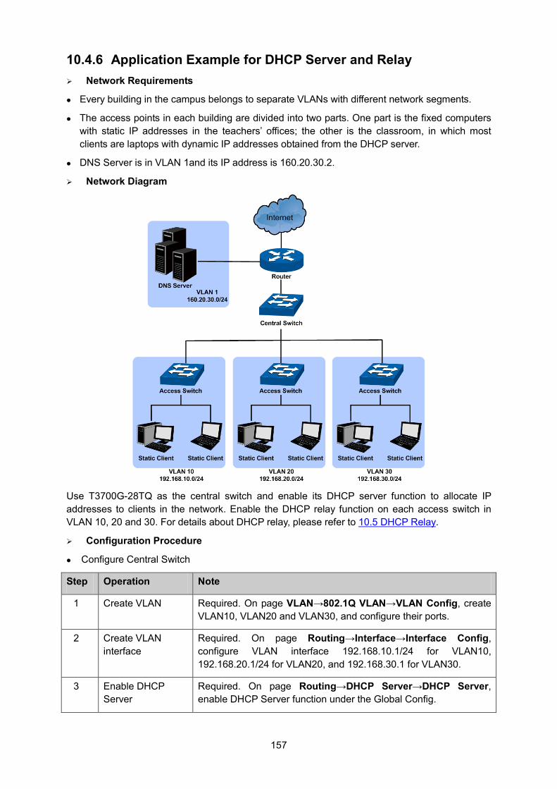
157
10.4.6 Application Example for DHCP Server and Relay Network Requirements
Every building in the campus belongs to separate VLANs with different network segments.
The access points in each building are divided into two parts. One part is the fixed computers with static IP addresses in the teachers’ offices; the other is the classroom, in which most clients are laptops with dynamic IP addresses obtained from the DHCP server.
DNS Server is in VLAN 1and its IP address is 160.20.30.2.
Network Diagram
Use T3700G-28TQ as the central switch and enable its DHCP server function to allocate IP addresses to clients in the network. Enable the DHCP relay function on each access switch in VLAN 10, 20 and 30. For details about DHCP relay, please refer to 10.5 DHCP Relay.
Configuration Procedure
Configure Central Switch
Step Operation Note
1 Create VLAN Required. On page VLAN→802.1Q VLAN→VLAN Config, create VLAN10, VLAN20 and VLAN30, and configure their ports.
2 Create VLAN interface
Required. On page Routing→Interface→Interface Config, configure VLAN interface 192.168.10.1/24 for VLAN10, 192.168.20.1/24 for VLAN20, and 192.168.30.1 for VLAN30.
3 Enable DHCP Server
Required. On page Routing→DHCP Server→DHCP Server, enable DHCP Server function under the Global Config.
158
Step Operation Note
4 Configure the IP address pool
Required. On page Routing→DHCP Server→Pool Setting, configure IP address pool parameters for each VLAN interface. Take VLAN10 as an example, configure its Network Address as 192.168.10.0, Subnet Mask as 255.255.255.0, Default gateway as 192.168.10.1 (the IP address of the VLAN interface), DNS Server as 160.20.30.2, and customize the Pool Name and Lease Time.
5 Configure the reserved addresses
Required. On page Routing→DHCP Server→DHCP Server, under the Excluded IP Address, configure reserved IP addresses for the fixed computers in each VLAN.
6 Manually binding IP addresses
Optional. On page Routing→ DHCP Server→Manual Binding, bind specified ip addresses to the specific clients.
Configure Access Switch
Step Operation Note
1 Enable DHCP Relay.
Required. On the Routing→DHCP Server→Global Config page, enable the DHCP Server function, and the DHCP Relay function will be enabled at the same time.
2 Configure Option 82 support.
Optional. On the Routing→DHCP Relay→Global Config page, configure the Option 82 parameters.
3 Configure DHCP Server.
Required. On the Routing→DHCP Relay→DHCP Server page, specify the DHCP Server with the IP address of the central switch.
10.5 DHCP Relay Application Environment of DHCP Relay
In DHCP model, DHCP clients broadcast its DHCP request, so the DHCP sever and clients must be on the same subnet, which require the DHCP server is available in every subnet. It is costly to build so much DHCP Server. DHCP relay agent solves the problem. Via a relay agent, DHCP clients request an IP address from the DHCP server in another subnet, and DHCP clients in different subnets can share the same DHCP server in the internet.
Details of DHCP Relay on T3700G-28TQ
A typical application of T3700G-28TQ working at DHCP Relay function is shown below. It can be altered to meet the network requirement.
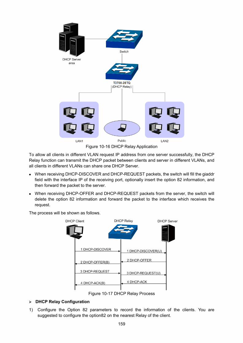
159
Figure 10-16 DHCP Relay Application
To allow all clients in different VLAN request IP address from one server successfully, the DHCP Relay function can transmit the DHCP packet between clients and server in different VLANs, and all clients in different VLANs can share one DHCP Server.
When receiving DHCP-DISCOVER and DHCP-REQUEST packets, the switch will fill the giaddr field with the interface IP of the receiving port, optionally insert the option 82 information, and then forward the packet to the server.
When receiving DHCP-OFFER and DHCP-REQUEST packets from the server, the switch will delete the option 82 information and forward the packet to the interface which receives the request.
The process will be shown as follows.
Figure 10-17 DHCP Relay Process
DHCP Relay Configuration
1) Configure the Option 82 parameters to record the information of the clients. You are suggested to configure the option82 on the nearest Relay of the client.
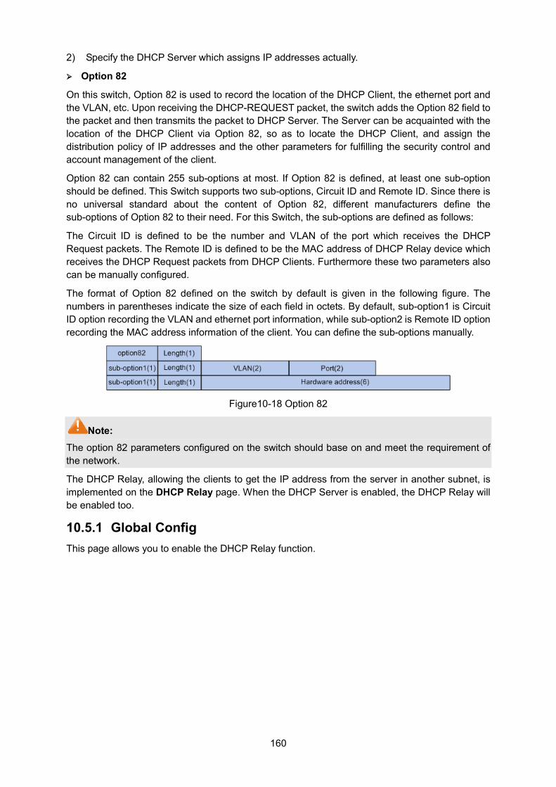
160
2) Specify the DHCP Server which assigns IP addresses actually.
Option 82
On this switch, Option 82 is used to record the location of the DHCP Client, the ethernet port and the VLAN, etc. Upon receiving the DHCP-REQUEST packet, the switch adds the Option 82 field to the packet and then transmits the packet to DHCP Server. The Server can be acquainted with the location of the DHCP Client via Option 82, so as to locate the DHCP Client, and assign the distribution policy of IP addresses and the other parameters for fulfilling the security control and account management of the client.
Option 82 can contain 255 sub-options at most. If Option 82 is defined, at least one sub-option should be defined. This Switch supports two sub-options, Circuit ID and Remote ID. Since there is no universal standard about the content of Option 82, different manufacturers define the sub-options of Option 82 to their need. For this Switch, the sub-options are defined as follows:
The Circuit ID is defined to be the number and VLAN of the port which receives the DHCP Request packets. The Remote ID is defined to be the MAC address of DHCP Relay device which receives the DHCP Request packets from DHCP Clients. Furthermore these two parameters also can be manually configured.
The format of Option 82 defined on the switch by default is given in the following figure. The numbers in parentheses indicate the size of each field in octets. By default, sub-option1 is Circuit ID option recording the VLAN and ethernet port information, while sub-option2 is Remote ID option recording the MAC address information of the client. You can define the sub-options manually.
Figure10-18 Option 82
Note: The option 82 parameters configured on the switch should base on and meet the requirement of the network.
The DHCP Relay, allowing the clients to get the IP address from the server in another subnet, is implemented on the DHCP Relay page. When the DHCP Server is enabled, the DHCP Relay will be enabled too.
10.5.1 Global Config This page allows you to enable the DHCP Relay function.
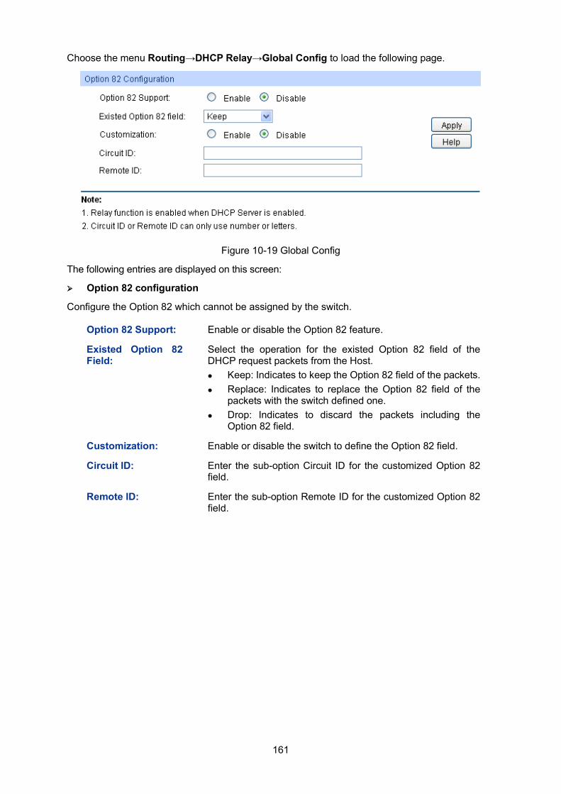
161
Choose the menu Routing→DHCP Relay→Global Config to load the following page.
Figure 10-19 Global Config
The following entries are displayed on this screen:
Option 82 configuration
Configure the Option 82 which cannot be assigned by the switch.
Option 82 Support: Enable or disable the Option 82 feature.
Existed Option 82 Field:
Select the operation for the existed Option 82 field of the DHCP request packets from the Host. Keep: Indicates to keep the Option 82 field of the packets. Replace: Indicates to replace the Option 82 field of the
packets with the switch defined one. Drop: Indicates to discard the packets including the
Option 82 field.
Customization: Enable or disable the switch to define the Option 82 field.
Circuit ID: Enter the sub-option Circuit ID for the customized Option 82 field.
Remote ID: Enter the sub-option Remote ID for the customized Option 82 field.
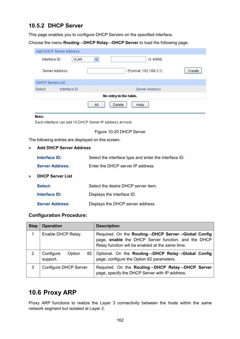
162
10.5.2 DHCP Server This page enables you to configure DHCP Servers on the specified interface.
Choose the menu Routing→DHCP Relay→DHCP Server to load the following page.
Figure 10-20 DHCP Server
The following entries are displayed on this screen:
Add DHCP Server Address
Interface ID: Select the interface type and enter the interface ID.
Server Address: Enter the DHCP server IP address.
DHCP Server List
Select: Select the desire DHCP server item.
Interface ID: Displays the interface ID.
Server Address: Displays the DHCP server address.
Configuration Procedure:
Step Operation Description
1 Enable DHCP Relay. Required. On the Routing→DHCP Server→Global Config page, enable the DHCP Server function, and the DHCP Relay function will be enabled at the same time.
2 Configure Option 82 support.
Optional. On the Routing→DHCP Relay→Global Config page, configure the Option 82 parameters.
3 Configure DHCP Server. Required. On the Routing→DHCP Relay→DHCP Server page, specify the DHCP Server with IP address.
10.6 Proxy ARP Proxy ARP functions to realize the Layer 3 connectivity between the hosts within the same network segment but isolated at Layer 2.
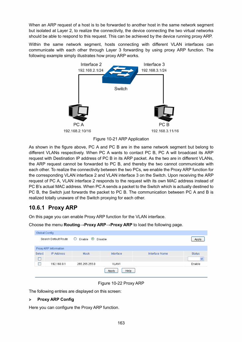
163
When an ARP request of a host is to be forwarded to another host in the same network segment but isolated at Layer 2, to realize the connectivity, the device connecting the two virtual networks should be able to respond to this request. This can be achieved by the device running proxy ARP.
Within the same network segment, hosts connecting with different VLAN interfaces can communicate with each other through Layer 3 forwarding by using proxy ARP function. The following example simply illustrates how proxy ARP works.
Figure 10-21 ARP Application
As shown in the figure above, PC A and PC B are in the same network segment but belong to different VLANs respectively. When PC A wants to contact PC B, PC A will broadcast its ARP request with Destination IP address of PC B in its ARP packet. As the two are in different VLANs, the ARP request cannot be forwarded to PC B, and thereby the two cannot communicate with each other. To realize the connectivity between the two PCs, we enable the Proxy ARP function for the corresponding VLAN interface 2 and VLAN interface 3 on the Switch. Upon receiving the ARP request of PC A, VLAN interface 2 responds to the request with its own MAC address instead of PC B’s actual MAC address. When PC A sends a packet to the Switch which is actually destined to PC B, the Switch just forwards the packet to PC B. The communication between PC A and B is realized totally unaware of the Switch proxying for each other.
10.6.1 Proxy ARP On this page you can enable Proxy ARP function for the VLAN interface.
Choose the menu Routing→Proxy ARP→Proxy ARP to load the following page.
Figure 10-22 Proxy ARP
The following entries are displayed on this screen:
Proxy ARP Config
Here you can configure the Proxy ARP function.
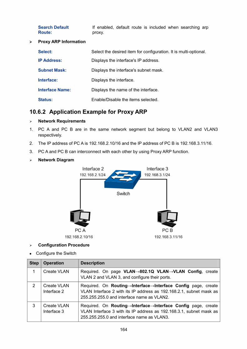
164
Search Default Route:
If enabled, default route is included when searching arp proxy.
Proxy ARP Information
Select: Select the desired item for configuration. It is multi-optional.
IP Address: Displays the interface's IP address.
Subnet Mask: Displays the interface's subnet mask.
Interface: Displays the interface.
Interface Name: Displays the name of the interface.
Status: Enable/Disable the items selected.
10.6.2 Application Example for Proxy ARP Network Requirements
1. PC A and PC B are in the same network segment but belong to VLAN2 and VLAN3 respectively.
2. The IP address of PC A is 192.168.2.10/16 and the IP address of PC B is 192.168.3.11/16.
3. PC A and PC B can interconnect with each other by using Proxy ARP function.
Network Diagram
Configuration Procedure
Configure the Switch
Step Operation Description
1 Create VLAN Required. On page VLAN→802.1Q VLAN→VLAN Config, create VLAN 2 and VLAN 3, and configure their ports.
2 Create VLAN Interface 2
Required. On Routing→Interface→Interface Config page, create VLAN Interface 2 with its IP address as 192.168.2.1, subnet mask as 255.255.255.0 and interface name as VLAN2.
3 Create VLAN Interface 3
Required. On Routing→Interface→Interface Config page, create VLAN Interface 3 with its IP address as 192.168.3.1, subnet mask as 255.255.255.0 and interface name as VLAN3.
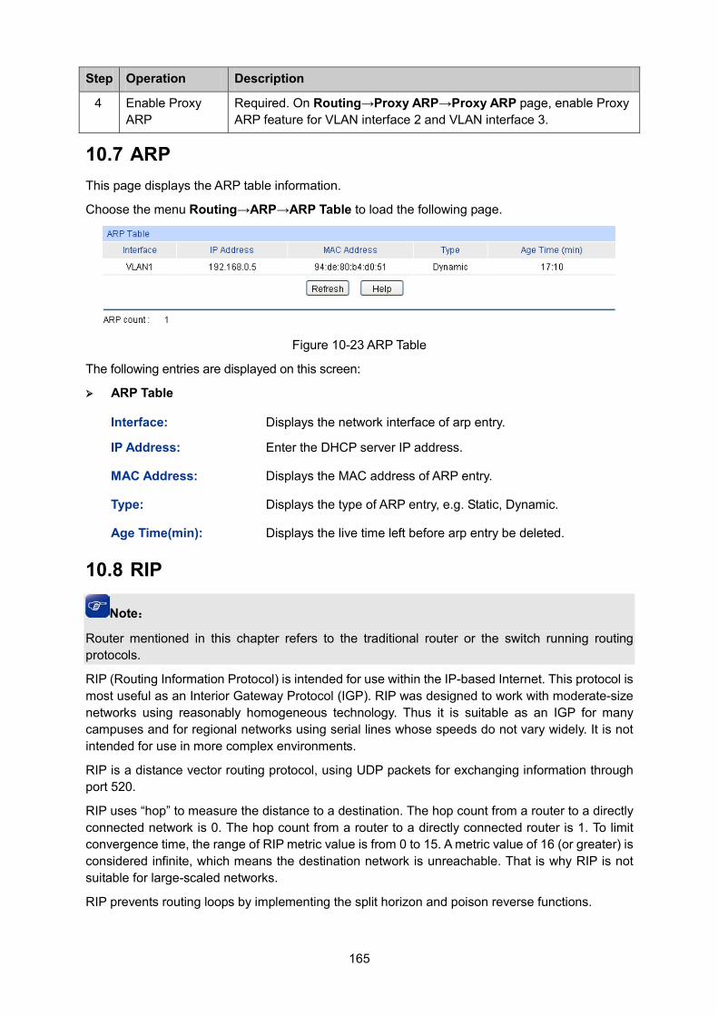
165
Step Operation Description
4 Enable Proxy ARP
Required. On Routing→Proxy ARP→Proxy ARP page, enable Proxy ARP feature for VLAN interface 2 and VLAN interface 3.
10.7 ARP This page displays the ARP table information.
Choose the menu Routing→ARP→ARP Table to load the following page.
Figure 10-23 ARP Table
The following entries are displayed on this screen:
ARP Table
Interface: Displays the network interface of arp entry.
IP Address: Enter the DHCP server IP address.
MAC Address: Displays the MAC address of ARP entry.
Type: Displays the type of ARP entry, e.g. Static, Dynamic.
Age Time(min): Displays the live time left before arp entry be deleted.
10.8 RIP
Note:
Router mentioned in this chapter refers to the traditional router or the switch running routing protocols.
RIP (Routing Information Protocol) is intended for use within the IP-based Internet. This protocol is most useful as an Interior Gateway Protocol (IGP). RIP was designed to work with moderate-size networks using reasonably homogeneous technology. Thus it is suitable as an IGP for many campuses and for regional networks using serial lines whose speeds do not vary widely. It is not intended for use in more complex environments.
RIP is a distance vector routing protocol, using UDP packets for exchanging information through port 520.
RIP uses “hop” to measure the distance to a destination. The hop count from a router to a directly connected network is 0. The hop count from a router to a directly connected router is 1. To limit convergence time, the range of RIP metric value is from 0 to 15. A metric value of 16 (or greater) is considered infinite, which means the destination network is unreachable. That is why RIP is not suitable for large-scaled networks.
RIP prevents routing loops by implementing the split horizon and poison reverse functions.
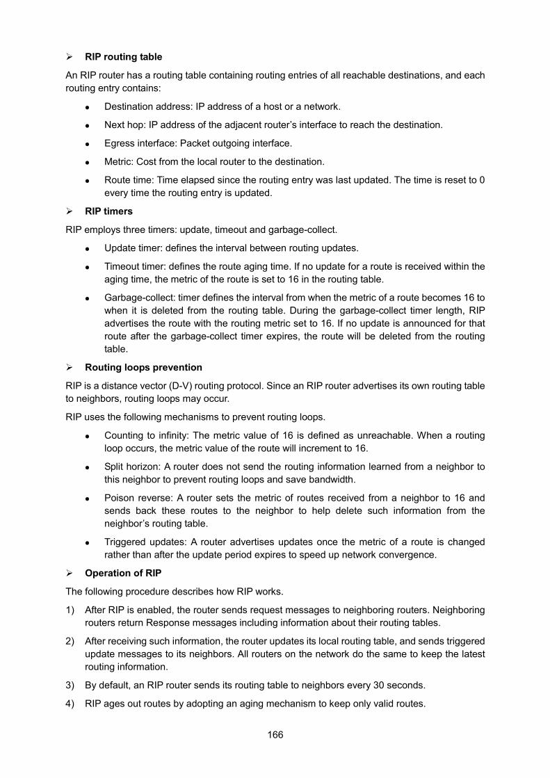
166
RIP routing table
An RIP router has a routing table containing routing entries of all reachable destinations, and each routing entry contains:
Destination address: IP address of a host or a network.
Next hop: IP address of the adjacent router’s interface to reach the destination.
Egress interface: Packet outgoing interface.
Metric: Cost from the local router to the destination.
Route time: Time elapsed since the routing entry was last updated. The time is reset to 0 every time the routing entry is updated.
RIP timers
RIP employs three timers: update, timeout and garbage-collect.
Update timer: defines the interval between routing updates.
Timeout timer: defines the route aging time. If no update for a route is received within the aging time, the metric of the route is set to 16 in the routing table.
Garbage-collect: timer defines the interval from when the metric of a route becomes 16 to when it is deleted from the routing table. During the garbage-collect timer length, RIP advertises the route with the routing metric set to 16. If no update is announced for that route after the garbage-collect timer expires, the route will be deleted from the routing table.
Routing loops prevention
RIP is a distance vector (D-V) routing protocol. Since an RIP router advertises its own routing table to neighbors, routing loops may occur.
RIP uses the following mechanisms to prevent routing loops.
Counting to infinity: The metric value of 16 is defined as unreachable. When a routing loop occurs, the metric value of the route will increment to 16.
Split horizon: A router does not send the routing information learned from a neighbor to this neighbor to prevent routing loops and save bandwidth.
Poison reverse: A router sets the metric of routes received from a neighbor to 16 and sends back these routes to the neighbor to help delete such information from the neighbor’s routing table.
Triggered updates: A router advertises updates once the metric of a route is changed rather than after the update period expires to speed up network convergence.
Operation of RIP
The following procedure describes how RIP works.
1) After RIP is enabled, the router sends request messages to neighboring routers. Neighboring routers return Response messages including information about their routing tables.
2) After receiving such information, the router updates its local routing table, and sends triggered update messages to its neighbors. All routers on the network do the same to keep the latest routing information.
3) By default, an RIP router sends its routing table to neighbors every 30 seconds.
4) RIP ages out routes by adopting an aging mechanism to keep only valid routes.
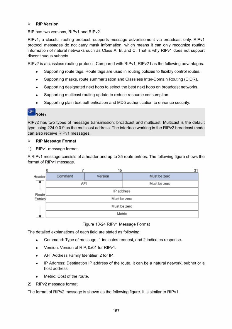
167
RIP Version
RIP has two versions, RIPv1 and RIPv2.
RIPv1, a classful routing protocol, supports message advertisement via broadcast only. RIPv1 protocol messages do not carry mask information, which means it can only recognize routing information of natural networks such as Class A, B, and C. That is why RIPv1 does not support discontinuous subnets.
RIPv2 is a classless routing protocol. Compared with RIPv1, RIPv2 has the following advantages.
Supporting route tags. Route tags are used in routing policies to flexibly control routes.
Supporting masks, route summarization and Classless Inter-Domain Routing (CIDR).
Supporting designated next hops to select the best next hops on broadcast networks.
Supporting multicast routing update to reduce resource consumption.
Supporting plain text authentication and MD5 authentication to enhance security.
Note:
RIPv2 has two types of message transmission: broadcast and multicast. Multicast is the default type using 224.0.0.9 as the multicast address. The interface working in the RIPv2 broadcast mode can also receive RIPv1 messages.
RIP Message Format
1) RIPv1 message format
A RIPv1 message consists of a header and up to 25 route entries. The following figure shows the format of RIPv1 message.
Figure 10-24 RIPv1 Message Format
The detailed explanations of each field are stated as following:
Command: Type of message. 1 indicates request, and 2 indicates response.
Version: Version of RIP, 0x01 for RIPv1.
AFI: Address Family Identifier, 2 for IP.
IP Address: Destination IP address of the route. It can be a natural network, subnet or a host address.
Metric: Cost of the route.
2) RIPv2 message format
The format of RIPv2 message is shown as the following figure. It is similar to RIPv1.
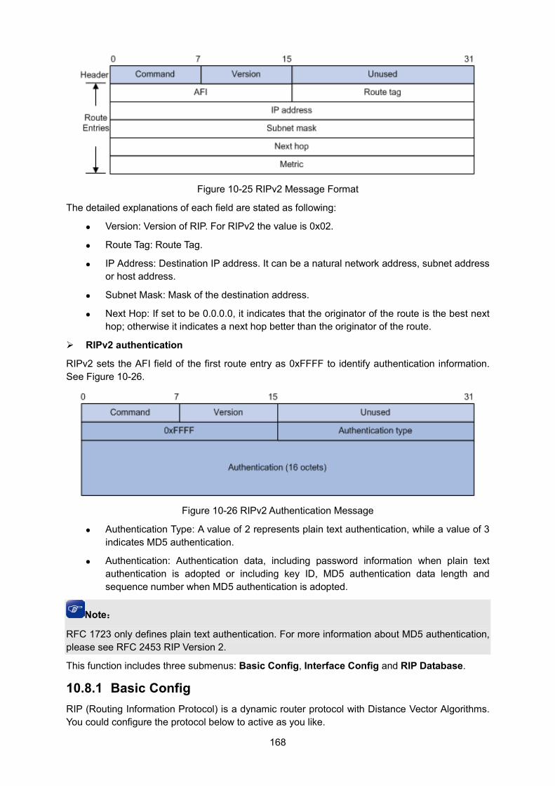
168
Figure 10-25 RIPv2 Message Format
The detailed explanations of each field are stated as following:
Version: Version of RIP. For RIPv2 the value is 0x02.
Route Tag: Route Tag.
IP Address: Destination IP address. It can be a natural network address, subnet address or host address.
Subnet Mask: Mask of the destination address.
Next Hop: If set to be 0.0.0.0, it indicates that the originator of the route is the best next hop; otherwise it indicates a next hop better than the originator of the route.
RIPv2 authentication
RIPv2 sets the AFI field of the first route entry as 0xFFFF to identify authentication information. See Figure 10-26.
Figure 10-26 RIPv2 Authentication Message
Authentication Type: A value of 2 represents plain text authentication, while a value of 3 indicates MD5 authentication.
Authentication: Authentication data, including password information when plain text authentication is adopted or including key ID, MD5 authentication data length and sequence number when MD5 authentication is adopted.
Note:
RFC 1723 only defines plain text authentication. For more information about MD5 authentication, please see RFC 2453 RIP Version 2.
This function includes three submenus: Basic Config, Interface Config and RIP Database.
10.8.1 Basic Config RIP (Routing Information Protocol) is a dynamic router protocol with Distance Vector Algorithms. You could configure the protocol below to active as you like.
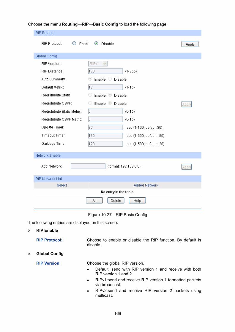
169
Choose the menu Routing→RIP→Basic Config to load the following page.
Figure 10-27 RIP Basic Config
The following entries are displayed on this screen:
RIP Enable
RIP Protocol: Choose to enable or disable the RIP function. By default is disable.
Global Config
RIP Version: Choose the global RIP version. Default: send with RIP version 1 and receive with both
RIP version 1 and 2. RIPv1:send and receive RIP version 1 formatted packets
via broadcast. RIPv2:send and receive RIP version 2 packets using
multicast.
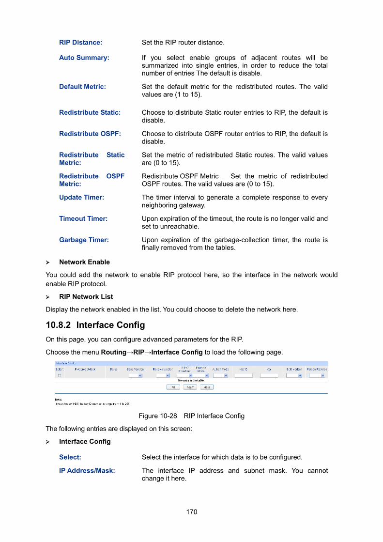
170
RIP Distance: Set the RIP router distance.
Auto Summary: If you select enable groups of adjacent routes will be summarized into single entries, in order to reduce the total number of entries The default is disable.
Default Metric: Set the default metric for the redistributed routes. The valid values are (1 to 15).
Redistribute Static: Choose to distribute Static router entries to RIP, the default is disable.
Redistribute OSPF: Choose to distribute OSPF router entries to RIP, the default is disable.
Redistribute Static Metric:
Set the metric of redistributed Static routes. The valid values are (0 to 15).
Redistribute OSPF Metric:
Redistribute OSPF Metric Set the metric of redistributed OSPF routes. The valid values are (0 to 15).
Update Timer: The timer interval to generate a complete response to every neighboring gateway.
Timeout Timer: Upon expiration of the timeout, the route is no longer valid and set to unreachable.
Garbage Timer: Upon expiration of the garbage-collection timer, the route is finally removed from the tables.
Network Enable
You could add the network to enable RIP protocol here, so the interface in the network would enable RIP protocol.
RIP Network List
Display the network enabled in the list. You could choose to delete the network here.
10.8.2 Interface Config On this page, you can configure advanced parameters for the RIP.
Choose the menu Routing→RIP→Interface Config to load the following page.
Figure 10-28 RIP Interface Config
The following entries are displayed on this screen:
Interface Config
Select: Select the interface for which data is to be configured.
IP Address/Mask: The interface IP address and subnet mask. You cannot change it here.
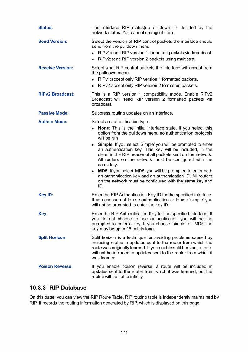
171
Status: The interface RIP status(up or down) is decided by the network status. You cannot change it here.
Send Version: Select the version of RIP control packets the interface should send from the pulldown menu. RIPv1:send RIP version 1 formatted packets via broadcast. RIPv2:send RIP version 2 packets using multicast.
Receive Version: Select what RIP control packets the interface will accept from the pulldown menu. RIPv1:accept only RIP version 1 formatted packets. RIPv2:accept only RIP version 2 formatted packets.
RIPv2 Broadcast: This is a RIP version 1 compatibility mode. Enable RIPv2 Broadcast will send RIP version 2 formatted packets via broadcast.
Passive Mode: Suppress routing updates on an interface.
Authen Mode: Select an authentication type. None: This is the initial interface state. If you select this
option from the pulldown menu no authentication protocols will be run
Simple: If you select 'Simple' you will be prompted to enter an authentication key. This key will be included, in the clear, in the RIP header of all packets sent on the network. All routers on the network must be configured with the same key.
MD5: If you select 'MD5' you will be prompted to enter both an authentication key and an authentication ID. All routers on the network must be configured with the same key and ID.
Key ID: Enter the RIP Authentication Key ID for the specified interface. If you choose not to use authentication or to use 'simple' you will not be prompted to enter the key ID.
Key: Enter the RIP Authentication Key for the specified interface. If you do not choose to use authentication you will not be prompted to enter a key. If you choose 'simple' or 'MD5' the key may be up to 16 octets long.
Split Horizon: Split horizon is a technique for avoiding problems caused by including routes in updates sent to the router from which the route was originally learned. If you enable split horizon, a route will not be included in updates sent to the router from which it was learned.
Poison Reverse : If you enable poison reverse, a route will be included in updates sent to the router from which it was learned, but the metric will be set to infinity.
10.8.3 RIP Database On this page, you can view the RIP Route Table. RIP routing table is independently maintained by RIP. It records the routing information generated by RIP, which is displayed on this page.
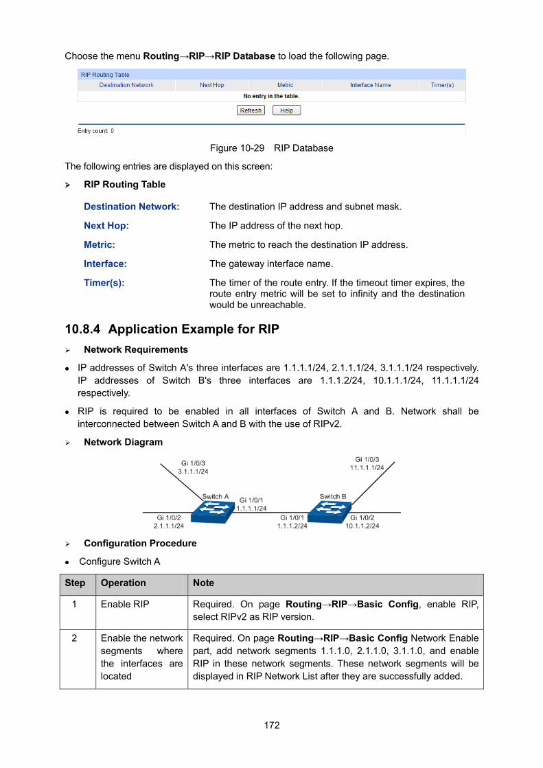
172
Choose the menu Routing→RIP→RIP Database to load the following page.
Figure 10-29 RIP Database
The following entries are displayed on this screen:
RIP Routing Table
Destination Network: The destination IP address and subnet mask.
Next Hop: The IP address of the next hop.
Metric: The metric to reach the destination IP address.
Interface: The gateway interface name.
Timer(s): The timer of the route entry. If the timeout timer expires, the route entry metric will be set to infinity and the destination would be unreachable.
10.8.4 Application Example for RIP Network Requirements
IP addresses of Switch A's three interfaces are 1.1.1.1/24, 2.1.1.1/24, 3.1.1.1/24 respectively. IP addresses of Switch B's three interfaces are 1.1.1.2/24, 10.1.1.1/24, 11.1.1.1/24 respectively.
RIP is required to be enabled in all interfaces of Switch A and B. Network shall be interconnected between Switch A and B with the use of RIPv2.
Network Diagram
Configuration Procedure
Configure Switch A
Step Operation Note
1 Enable RIP Required. On page Routing→RIP→Basic Config, enable RIP, select RIPv2 as RIP version.
2 Enable the network segments where the interfaces are located
Required. On page Routing→RIP→Basic Config Network Enable part, add network segments 1.1.1.0, 2.1.1.0, 3.1.1.0, and enable RIP in these network segments. These network segments will be displayed in RIP Network List after they are successfully added.
173
Configure Switch B
Step Operation Note
1 Enable RIP Required. On page Routing→RIP→Basic Config, enable RIP, select RIPv2 as RIP version.
2 Enable the network segments where the interfaces are located
Required. On page Routing→RIP→Basic Config Network Enable part, add network segments 1.1.1.0, 10.1.1.0, 11.1.1.0, and enable RIP in these network segments. These network segments will be displayed in RIP Network List after they are successfully added.
10.9 OSPF OSPF (Open Shortest Path First) is a routing protocol based on link state and also an internal gateway protocol, which is developed and recommended by IETF. The OSPF protocol standard in current use for IPv4 network is OSPF Version 2, which is defined specifically in RFC2328 and will be introduced generally in this Guide.
Introduction
1. OSPF Features
OSPF protocol is a popular routing protocol in networking with the following features.
Fast convergence – It could send update packets immediately upon the change of network topology, to quickly synchronize the update for the routers in the autonomous system.
Due to the rapid convergence, OSPF routing protocol acts with great speediness and stability in the large-scale network, and is not prone to some harmful routing information.
OSPF protocol introduces the concept of area – to manage the autonomous system by area, which means the routers only need to synchronize the link state database with the other routers in the same area. Thus, the smaller link state database requires lower memory consumption from the routers, and the less routing information to manage also releases certain CPU resources for the routers and meanwhile reduces the network bandwidth occupied by the routing information.
OSPF protocol supports multiple equal-cost routes to one destination for load balance, thus to perform more efficient data forwarding.
OSPF supports VLSM route addressing by variable-length subnet mask.
OSPF supports the message authentication based on interfaces, thus to guarantee the security of message interaction and routing calculation.
OSPF supports using the reserved multicast address in the link of specific network type, to reduce the influence on the other irrelevant routers.
2. OSPF Common Scenario
OSPF protocol is usually applied in the large complex network environment. Shown as below is the instance diagram of a large company, where the large network is divided by department. OSPF protocol works as the fundamental routing protocol among routers, which could guarantee not only the message interaction but also the network independence among departments.
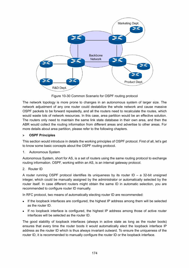
174
Figure 10-30 Common Scenario for OSPF routing protocol
The network topology is more prone to changes in an autonomous system of larger size. The network adjustment of any one router could destabilize the whole network and cause massive OSPF packets to be forward repeatedly, and all the routers need to recalculate the routes, which would waste lots of network resources. In this case, area partition would be an effective solution. The routers only need to maintain the same link state database in their own area, and then the ABR would collect the routing information from different areas and advertise to other areas. For more details about area partition, please refer to the following chapters.
OSPF Principles
This section would introduce in details the working principles of OSPF protocol. First of all, let’s get to know some basic concepts about the OSPF routing protocol.
1. Autonomous System
Autonomous System, short for AS, is a set of routers using the same routing protocol to exchange routing information. OSPF, working within an AS, is an internal gateway protocol.
2. Router ID
A router running OSPF protocol identifies its uniqueness by its router ID – a 32-bit unsigned integer, which could be manually assigned by the administrator or automatically selected by the router itself. In case different routers might obtain the same ID in automatic selection, you are recommended to configure router ID manually.
In RFC protocol, two means of automatically electing router ID are recommended:
If the loopback interfaces are configured, the highest IP address among them will be selected as the router ID.
If no loopback interface is configured, the highest IP address among those of active router interfaces will be selected as the router ID.
The good stability of loopback interfaces (always in active state as long as the router boots) ensures that every time the router boots it would automatically elect the loopback interface IP address as the router ID which is thus always invariant outward. To ensure the uniqueness of the router ID, it is recommended to manually configure the router ID or the loopback interface.
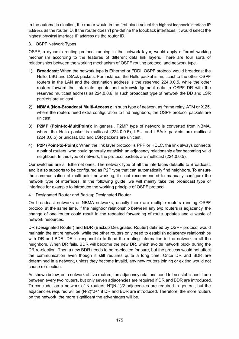
175
In the automatic election, the router would in the first place select the highest loopback interface IP address as the router ID. If the router doesn’t pre-define the loopback interfaces, it would select the highest physical interface IP address as the router ID.
3. OSPF Network Types
OSPF, a dynamic routing protocol running in the network layer, would apply different working mechanism according to the features of different data link layers. There are four sorts of relationships between the working mechanism of OSPF routing protocol and network type.
1) Broadcast: When the network type is Ethernet or FDDI, OSPF protocol would broadcast the Hello, LSU and LSAck packets. For instance, the Hello packet is multicast to the other OSPF routers in the LAN and the destination address is the reserved 224.0.0.5, while the other routers forward the link state update and acknowledgement data to OSPF DR with the reserved multicast address as 224.0.0.6. In such broadcast type of network the DD and LSR packets are unicast.
2) NBMA (Non-Broadcast Multi-Access): In such type of network as frame relay, ATM or X.25, where the routers need extra configuration to find neighbors, the OSPF protocol packets are unicast.
3) P2MP (Point-to-MultiPoint): In general, P2MP type of network is converted from NBMA, where the Hello packet is multicast (224.0.0.5), LSU and LSAck packets are multicast (224.0.0.5) or unicast, DD and LSR packets are unicast.
4) P2P (Point-to-Point): When the link layer protocol is PPP or HDLC, the link always connects a pair of routers, who could generally establish an adjacency relationship after becoming valid neighbors. In this type of network, the protocol packets are multicast (224.0.0.5).
Our switches are all Ethernet ones. The network type of all the interfaces defaults to Broadcast, and it also supports to be configured as P2P type that can automatically find neighbors. To ensure the communication of multi-point networking, it’s not recommended to manually configure the network type of interfaces. In the following guide, we will mainly take the broadcast type of interface for example to introduce the working principle of OSPF protocol.
4. Designated Router and Backup Designated Router
On broadcast networks or NBMA networks, usually there are multiple routers running OSPF protocol at the same time. If the neighbor relationship between any two routers is adjacency, the change of one router could result in the repeated forwarding of route updates and a waste of network resources.
DR (Designated Router) and BDR (Backup Designated Router) defined by OSPF protocol would maintain the entire network, while the other routers only need to establish adjacency relationships with DR and BDR. DR is responsible to flood the routing information in the network to all the neighbors. When DR fails, BDR will become the new DR, which avoids network block during the DR re-election. Then a new BDR needs to be re-elected for sure, but the process would not affect the communication even though it still requires quite a long time. Once DR and BDR are determined in a network, unless they become invalid, any new routers joining or exiting would not cause re-election.
As shown below, on a network of five routers, ten adjacency relations need to be established if one between every two routers, but only seven adjacencies are required if DR and BDR are introduced. To conclude, on a network of N routers, N*(N-1)/2 adjacencies are required in general, but the adjacencies required will be (N-2)*2+1 if DR and BDR are introduced. Therefore, the more routers on the network, the more significant the advantages will be.
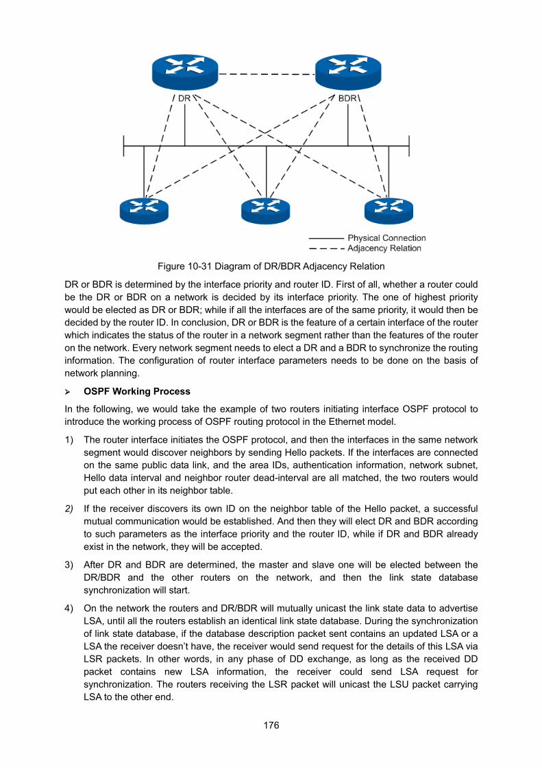
176
Figure 10-31 Diagram of DR/BDR Adjacency Relation
DR or BDR is determined by the interface priority and router ID. First of all, whether a router could be the DR or BDR on a network is decided by its interface priority. The one of highest priority would be elected as DR or BDR; while if all the interfaces are of the same priority, it would then be decided by the router ID. In conclusion, DR or BDR is the feature of a certain interface of the router which indicates the status of the router in a network segment rather than the features of the router on the network. Every network segment needs to elect a DR and a BDR to synchronize the routing information. The configuration of router interface parameters needs to be done on the basis of network planning.
OSPF Working Process
In the following, we would take the example of two routers initiating interface OSPF protocol to introduce the working process of OSPF routing protocol in the Ethernet model.
1) The router interface initiates the OSPF protocol, and then the interfaces in the same network segment would discover neighbors by sending Hello packets. If the interfaces are connected on the same public data link, and the area IDs, authentication information, network subnet, Hello data interval and neighbor router dead-interval are all matched, the two routers would put each other in its neighbor table.
2) If the receiver discovers its own ID on the neighbor table of the Hello packet, a successful mutual communication would be established. And then they will elect DR and BDR according to such parameters as the interface priority and the router ID, while if DR and BDR already exist in the network, they will be accepted.
3) After DR and BDR are determined, the master and slave one will be elected between the DR/BDR and the other routers on the network, and then the link state database synchronization will start.
4) On the network the routers and DR/BDR will mutually unicast the link state data to advertise LSA, until all the routers establish an identical link state database. During the synchronization of link state database, if the database description packet sent contains an updated LSA or a LSA the receiver doesn’t have, the receiver would send request for the details of this LSA via LSR packets. In other words, in any phase of DD exchange, as long as the received DD packet contains new LSA information, the receiver could send LSA request for synchronization. The routers receiving the LSR packet will unicast the LSU packet carrying LSA to the other end.
177
5) After two routers have finished the synchronization of link state database, a complete adjacency relation will be established.
6) When the intra-area routers have an identical link state database, each of them will calculate a loop-free topology through SPF algorithm with itself as the root thus to describe the shortest forward path to every network node it knows, and create a routing table according to the topology of shortest forward path and provide a basis for data forwarding.
7) After the establishment of routing table, if the network remains stable, the neighbors would discover and maintain their neighbor relationships by sending out Hello packets at regular intervals. And the adjacent routers would recalculate the routing table by periodical LSA update in order to maintain valid entries in the routing table.
8) Any new routers joining the network will accept the current DR/BDR and synchronize the link state database with them until a complete adjacency relation is established. During synchronizing the link state database, DR/BDR will obtain LSA from the newly-joint routers and then flood this LSA to the adjacent routers who then will flood it to the other ports till the entire network.
1. Work Flow Diagram
The diagram below takes two routers for example to introduce in the Ethernet module the detailed steps of two routers from failure state to complete adjacency state and the relevant packet types involved in the process.
Note: To facilitate the description the diagram below shows the LSA synchronization after the DD exchange, while in reality these two processes are simultaneous.
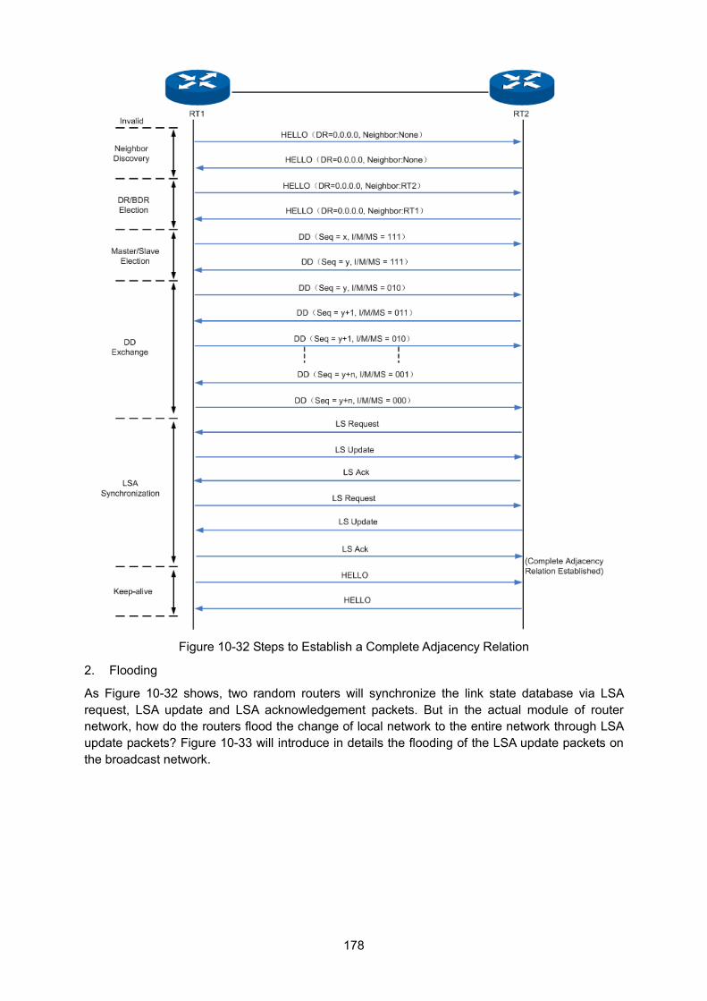
178
Figure 10-32 Steps to Establish a Complete Adjacency Relation
2. Flooding
As Figure 10-32 shows, two random routers will synchronize the link state database via LSA request, LSA update and LSA acknowledgement packets. But in the actual module of router network, how do the routers flood the change of local network to the entire network through LSA update packets? Figure 10-33 will introduce in details the flooding of the LSA update packets on the broadcast network.
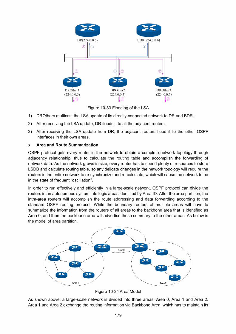
179
Figure 10-33 Flooding of the LSA
1) DROthers multicast the LSA update of its directly-connected network to DR and BDR.
2) After receiving the LSA update, DR floods it to all the adjacent routers.
3) After receiving the LSA update from DR, the adjacent routers flood it to the other OSPF interfaces in their own areas.
Area and Route Summarization
OSPF protocol gets every router in the network to obtain a complete network topology through adjacency relationship, thus to calculate the routing table and accomplish the forwarding of network data. As the network grows in size, every router has to spend plenty of resources to store LSDB and calculate routing table, so any delicate changes in the network topology will require the routers in the entire network to re-synchronize and re-calculate, which will cause the network to be in the state of frequent “oscillation”.
In order to run effectively and efficiently in a large-scale network, OSPF protocol can divide the routers in an autonomous system into logic areas identified by Area ID. After the area partition, the intra-area routers will accomplish the route addressing and data forwarding according to the standard OSPF routing protocol. While the boundary routers of multiple areas will have to summarize the information from the routers of all areas to the backbone area that is identified as Area 0, and then the backbone area will advertise these summary to the other areas. As below is the model of area partition.
Figure 10-34 Area Model
As shown above, a large-scale network is divided into three areas: Area 0, Area 1 and Area 2. Area 1 and Area 2 exchange the routing information via Backbone Area, which has to maintain its
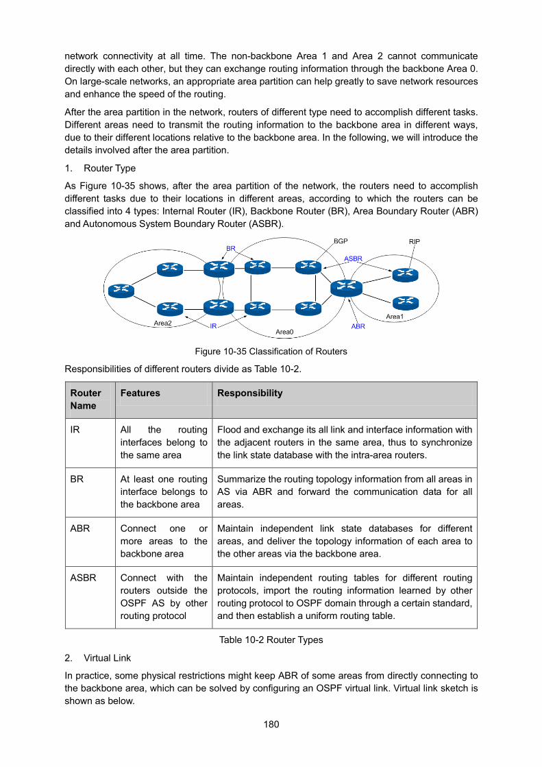
180
network connectivity at all time. The non-backbone Area 1 and Area 2 cannot communicate directly with each other, but they can exchange routing information through the backbone Area 0. On large-scale networks, an appropriate area partition can help greatly to save network resources and enhance the speed of the routing.
After the area partition in the network, routers of different type need to accomplish different tasks. Different areas need to transmit the routing information to the backbone area in different ways, due to their different locations relative to the backbone area. In the following, we will introduce the details involved after the area partition.
1. Router Type
As Figure 10-35 shows, after the area partition of the network, the routers need to accomplish different tasks due to their locations in different areas, according to which the routers can be classified into 4 types: Internal Router (IR), Backbone Router (BR), Area Boundary Router (ABR) and Autonomous System Boundary Router (ASBR).
Figure 10-35 Classification of Routers
Responsibilities of different routers divide as Table 10-2.
Router Name
Features Responsibility
IR All the routing interfaces belong to the same area
Flood and exchange its all link and interface information with the adjacent routers in the same area, thus to synchronize the link state database with the intra-area routers.
BR At least one routing interface belongs to the backbone area
Summarize the routing topology information from all areas in AS via ABR and forward the communication data for all areas.
ABR Connect one or more areas to the backbone area
Maintain independent link state databases for different areas, and deliver the topology information of each area to the other areas via the backbone area.
ASBR Connect with the routers outside the OSPF AS by other routing protocol
Maintain independent routing tables for different routing protocols, import the routing information learned by other routing protocol to OSPF domain through a certain standard, and then establish a uniform routing table.
Table 10-2 Router Types
2. Virtual Link
In practice, some physical restrictions might keep ABR of some areas from directly connecting to the backbone area, which can be solved by configuring an OSPF virtual link. Virtual link sketch is shown as below.
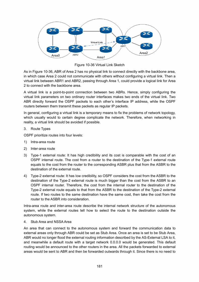
181
Figure 10-36 Virtual Link Sketch
As in Figure 10-36, ABR of Area 2 has no physical link to connect directly with the backbone area, in which case Area 2 could not communicate with others without configuring a virtual link. Then a virtual link between ABR1 and ABR2, passing through Area 1, could provide a logical link for Area 2 to connect with the backbone area.
A virtual link is a point-to-point connection between two ABRs. Hence, simply configuring the virtual link parameters on two ordinary router interfaces makes two ends of the virtual link. Two ABR directly forward the OSPF packets to each other’s interface IP address, while the OSPF routers between them transmit these packets as regular IP packets.
In general, configuring a virtual link is a temporary means to fix the problems of network topology, which usually would to certain degree complicate the network. Therefore, when networking in reality, a virtual link should be avoided if possible.
3. Route Types
OSPF prioritize routes into four levels:
1) Intra-area route
2) Inter-area route
3) Type-1 external route: It has high credibility and its cost is comparable with the cost of an OSPF internal route. The cost from a router to the destination of the Type-1 external route equals to the cost from the router to the corresponding ASBR plus that from the ASBR to the destination of the external route.
4) Type-2 external route: It has low credibility, so OSPF considers the cost from the ASBR to the destination of the Type-2 external route is much bigger than the cost from the ASBR to an OSPF internal router. Therefore, the cost from the internal router to the destination of the Type-2 external route equals to that from the ASBR to the destination of the Type-2 external route. If two routes to the same destination have the same cost, then take the cost from the router to the ASBR into consideration.
Intra-area route and inter-area route describe the internal network structure of the autonomous system, while the external routes tell how to select the route to the destination outside the autonomous system.
4. Stub Area and NSSA Area
An area that can connect to the autonomous system and forward the communication data to external areas only through ABR could be set as Stub Area. Once an area is set to be Stub Area, ABR would no longer flood the external routing information described by the AS-External LSA to it, and meanwhile a default route with a target network 0.0.0.0 would be generated. This default routing would be announced to the other routers in the area. All the packets forwarded to external areas would be sent to ABR and then be forwarded outwards through it. Since there is no need to
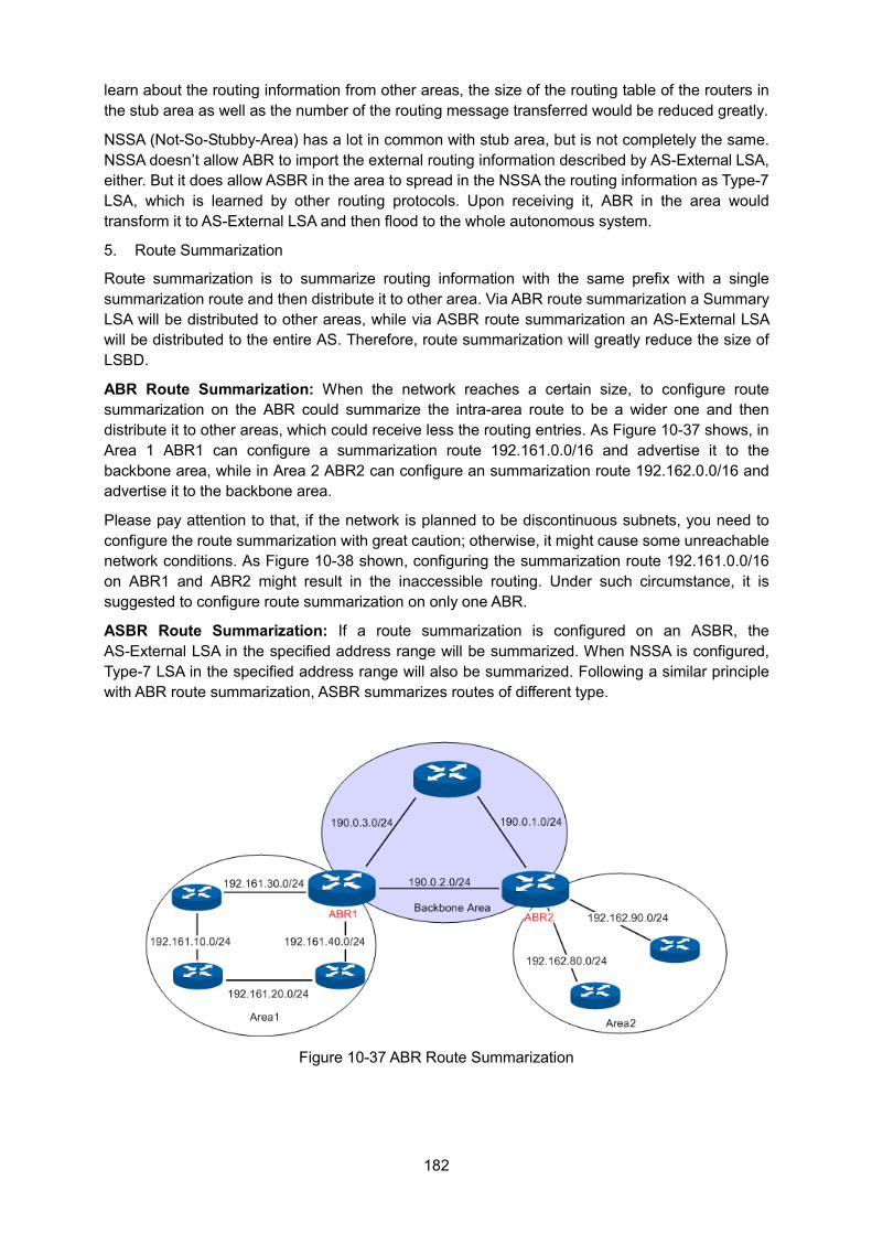
182
learn about the routing information from other areas, the size of the routing table of the routers in the stub area as well as the number of the routing message transferred would be reduced greatly.
NSSA (Not-So-Stubby-Area) has a lot in common with stub area, but is not completely the same. NSSA doesn’t allow ABR to import the external routing information described by AS-External LSA, either. But it does allow ASBR in the area to spread in the NSSA the routing information as Type-7 LSA, which is learned by other routing protocols. Upon receiving it, ABR in the area would transform it to AS-External LSA and then flood to the whole autonomous system.
5. Route Summarization
Route summarization is to summarize routing information with the same prefix with a single summarization route and then distribute it to other area. Via ABR route summarization a Summary LSA will be distributed to other areas, while via ASBR route summarization an AS-External LSA will be distributed to the entire AS. Therefore, route summarization will greatly reduce the size of LSBD.
ABR Route Summarization: When the network reaches a certain size, to configure route summarization on the ABR could summarize the intra-area route to be a wider one and then distribute it to other areas, which could receive less the routing entries. As Figure 10-37 shows, in Area 1 ABR1 can configure a summarization route 192.161.0.0/16 and advertise it to the backbone area, while in Area 2 ABR2 can configure an summarization route 192.162.0.0/16 and advertise it to the backbone area.
Please pay attention to that, if the network is planned to be discontinuous subnets, you need to configure the route summarization with great caution; otherwise, it might cause some unreachable network conditions. As Figure 10-38 shown, configuring the summarization route 192.161.0.0/16 on ABR1 and ABR2 might result in the inaccessible routing. Under such circumstance, it is suggested to configure route summarization on only one ABR.
ASBR Route Summarization: If a route summarization is configured on an ASBR, the AS-External LSA in the specified address range will be summarized. When NSSA is configured, Type-7 LSA in the specified address range will also be summarized. Following a similar principle with ABR route summarization, ASBR summarizes routes of different type.
Figure 10-37 ABR Route Summarization
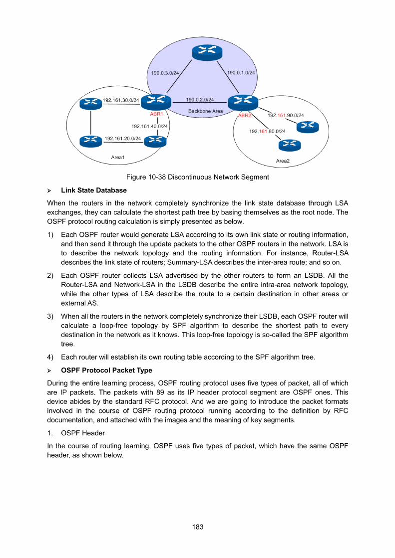
183
Figure 10-38 Discontinuous Network Segment
Link State Database
When the routers in the network completely synchronize the link state database through LSA exchanges, they can calculate the shortest path tree by basing themselves as the root node. The OSPF protocol routing calculation is simply presented as below.
1) Each OSPF router would generate LSA according to its own link state or routing information, and then send it through the update packets to the other OSPF routers in the network. LSA is to describe the network topology and the routing information. For instance, Router-LSA describes the link state of routers; Summary-LSA describes the inter-area route; and so on.
2) Each OSPF router collects LSA advertised by the other routers to form an LSDB. All the Router-LSA and Network-LSA in the LSDB describe the entire intra-area network topology, while the other types of LSA describe the route to a certain destination in other areas or external AS.
3) When all the routers in the network completely synchronize their LSDB, each OSPF router will calculate a loop-free topology by SPF algorithm to describe the shortest path to every destination in the network as it knows. This loop-free topology is so-called the SPF algorithm tree.
4) Each router will establish its own routing table according to the SPF algorithm tree.
OSPF Protocol Packet Type
During the entire learning process, OSPF routing protocol uses five types of packet, all of which are IP packets. The packets with 89 as its IP header protocol segment are OSPF ones. This device abides by the standard RFC protocol. And we are going to introduce the packet formats involved in the course of OSPF routing protocol running according to the definition by RFC documentation, and attached with the images and the meaning of key segments.
1. OSPF Header
In the course of routing learning, OSPF uses five types of packet, which have the same OSPF header, as shown below.
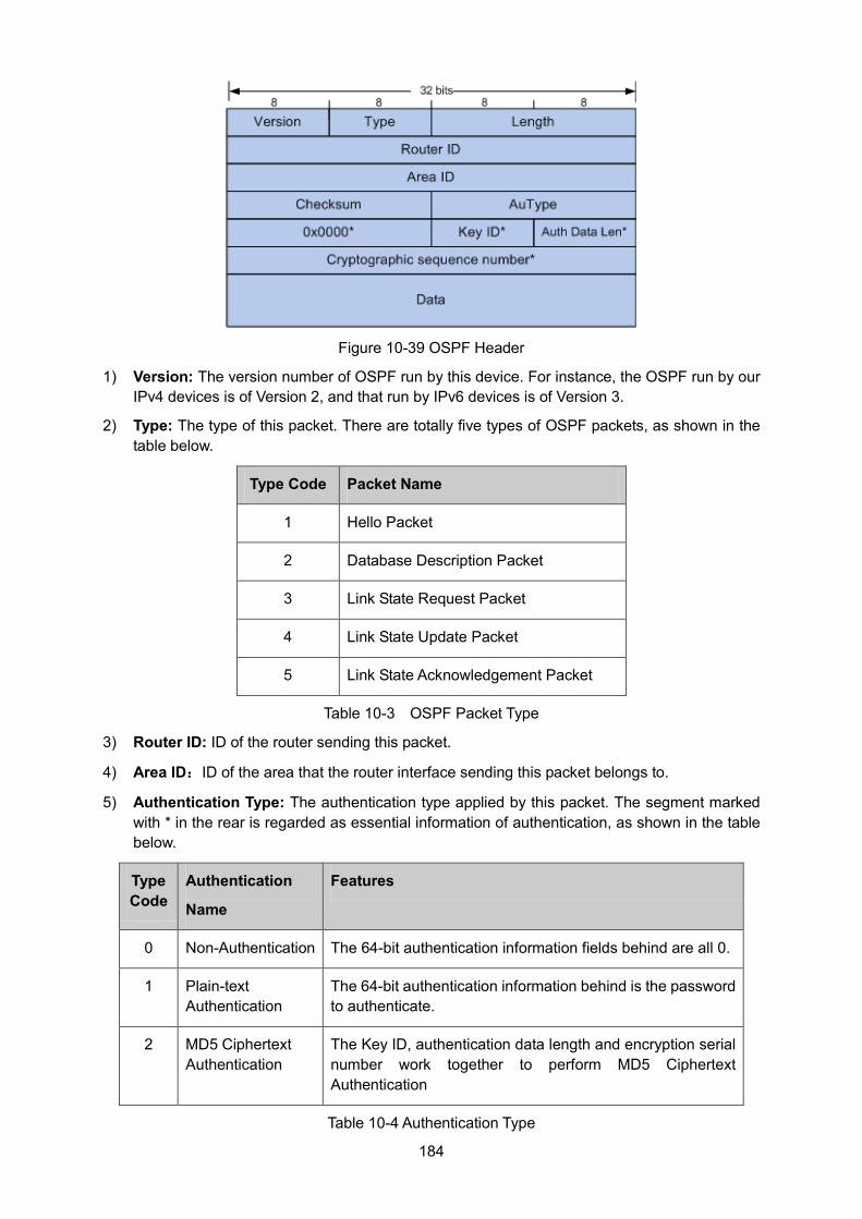
184
Figure 10-39 OSPF Header
1) Version: The version number of OSPF run by this device. For instance, the OSPF run by our IPv4 devices is of Version 2, and that run by IPv6 devices is of Version 3.
2) Type: The type of this packet. There are totally five types of OSPF packets, as shown in the table below.
Type Code Packet Name
1 Hello Packet
2 Database Description Packet
3 Link State Request Packet
4 Link State Update Packet
5 Link State Acknowledgement Packet
Table 10-3 OSPF Packet Type
3) Router ID: ID of the router sending this packet.
4) Area ID:ID of the area that the router interface sending this packet belongs to.
5) Authentication Type: The authentication type applied by this packet. The segment marked with * in the rear is regarded as essential information of authentication, as shown in the table below.
Type Code
Authentication
Name
Features
0 Non-Authentication The 64-bit authentication information fields behind are all 0.
1 Plain-text Authentication
The 64-bit authentication information behind is the password to authenticate.
2 MD5 Ciphertext Authentication
The Key ID, authentication data length and encryption serial number work together to perform MD5 Ciphertext Authentication
Table 10-4 Authentication Type
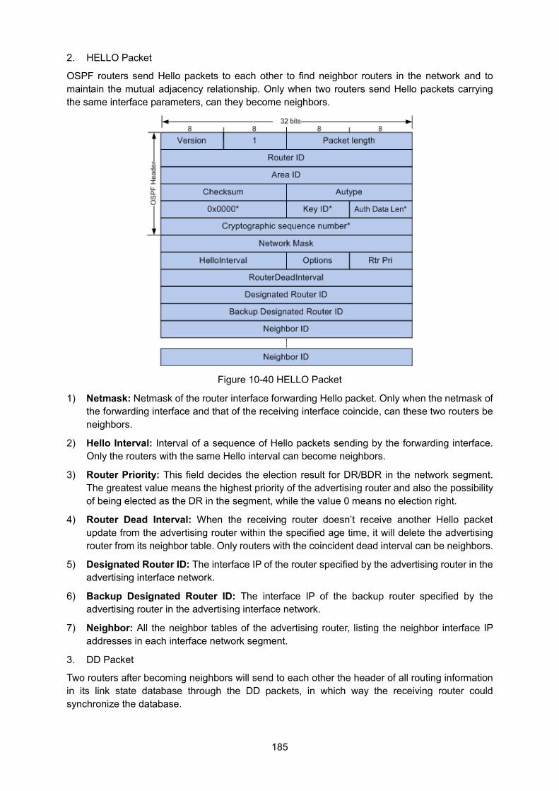
185
2. HELLO Packet
OSPF routers send Hello packets to each other to find neighbor routers in the network and to maintain the mutual adjacency relationship. Only when two routers send Hello packets carrying the same interface parameters, can they become neighbors.
Figure 10-40 HELLO Packet
1) Netmask: Netmask of the router interface forwarding Hello packet. Only when the netmask of the forwarding interface and that of the receiving interface coincide, can these two routers be neighbors.
2) Hello Interval: Interval of a sequence of Hello packets sending by the forwarding interface. Only the routers with the same Hello interval can become neighbors.
3) Router Priority: This field decides the election result for DR/BDR in the network segment. The greatest value means the highest priority of the advertising router and also the possibility of being elected as the DR in the segment, while the value 0 means no election right.
4) Router Dead Interval: When the receiving router doesn’t receive another Hello packet update from the advertising router within the specified age time, it will delete the advertising router from its neighbor table. Only routers with the coincident dead interval can be neighbors.
5) Designated Router ID: The interface IP of the router specified by the advertising router in the advertising interface network.
6) Backup Designated Router ID: The interface IP of the backup router specified by the advertising router in the advertising interface network.
7) Neighbor: All the neighbor tables of the advertising router, listing the neighbor interface IP addresses in each interface network segment.
3. DD Packet
Two routers after becoming neighbors will send to each other the header of all routing information in its link state database through the DD packets, in which way the receiving router could synchronize the database.
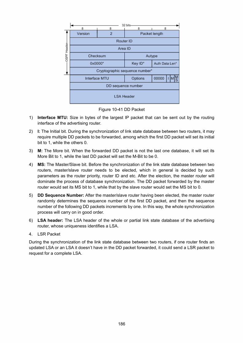
186
Figure 10-41 DD Packet
1) Interface MTU: Size in bytes of the largest IP packet that can be sent out by the routing interface of the advertising router.
2) I: The Initial bit. During the synchronization of link state database between two routers, it may require multiple DD packets to be forwarded, among which the first DD packet will set its initial bit to 1, while the others 0.
3) M: The More bit. When the forwarded DD packet is not the last one database, it will set its More Bit to 1, while the last DD packet will set the M-Bit to be 0.
4) MS: The Master/Slave bit. Before the synchronization of the link state database between two routers, master/slave router needs to be elected, which in general is decided by such parameters as the router priority, router ID and etc. After the election, the master router will dominate the process of database synchronization. The DD packet forwarded by the master router would set its MS bit to 1, while that by the slave router would set the MS bit to 0.
5) DD Sequence Number: After the master/slave router having been elected, the master router randomly determines the sequence number of the first DD packet, and then the sequence number of the following DD packets increments by one. In this way, the whole synchronization process will carry on in good order.
6) LSA header: The LSA header of the whole or partial link state database of the advertising router, whose uniqueness identifies a LSA.
4. LSR Packet
During the synchronization of the link state database between two routers, if one router finds an updated LSA or an LSA it doesn’t have in the DD packet forwarded, it could send a LSR packet to request for a complete LSA.
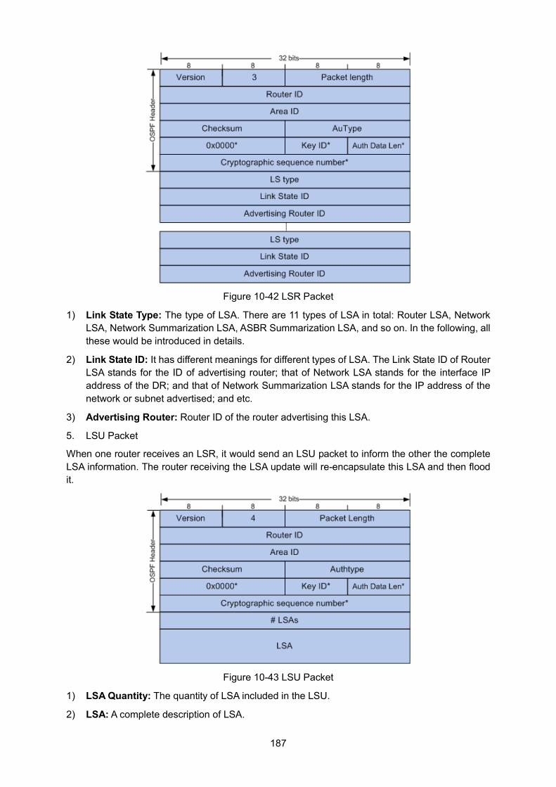
187
Figure 10-42 LSR Packet
1) Link State Type: The type of LSA. There are 11 types of LSA in total: Router LSA, Network LSA, Network Summarization LSA, ASBR Summarization LSA, and so on. In the following, all these would be introduced in details.
2) Link State ID: It has different meanings for different types of LSA. The Link State ID of Router LSA stands for the ID of advertising router; that of Network LSA stands for the interface IP address of the DR; and that of Network Summarization LSA stands for the IP address of the network or subnet advertised; and etc.
3) Advertising Router: Router ID of the router advertising this LSA.
5. LSU Packet
When one router receives an LSR, it would send an LSU packet to inform the other the complete LSA information. The router receiving the LSA update will re-encapsulate this LSA and then flood it.
Figure 10-43 LSU Packet
1) LSA Quantity: The quantity of LSA included in the LSU.
2) LSA: A complete description of LSA.
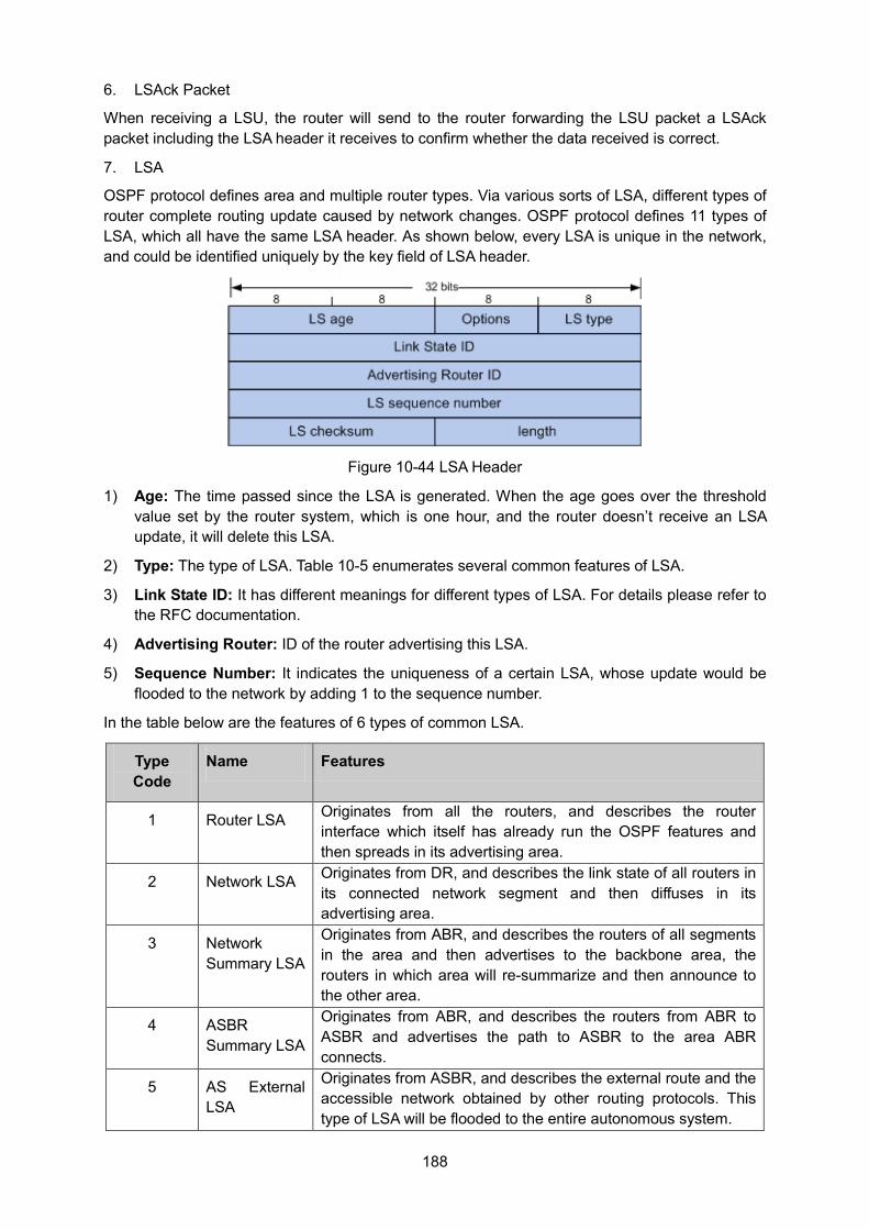
188
6. LSAck Packet
When receiving a LSU, the router will send to the router forwarding the LSU packet a LSAck packet including the LSA header it receives to confirm whether the data received is correct.
7. LSA
OSPF protocol defines area and multiple router types. Via various sorts of LSA, different types of router complete routing update caused by network changes. OSPF protocol defines 11 types of LSA, which all have the same LSA header. As shown below, every LSA is unique in the network, and could be identified uniquely by the key field of LSA header.
Figure 10-44 LSA Header
1) Age: The time passed since the LSA is generated. When the age goes over the threshold value set by the router system, which is one hour, and the router doesn’t receive an LSA update, it will delete this LSA.
2) Type: The type of LSA. Table 10-5 enumerates several common features of LSA.
3) Link State ID: It has different meanings for different types of LSA. For details please refer to the RFC documentation.
4) Advertising Router: ID of the router advertising this LSA.
5) Sequence Number: It indicates the uniqueness of a certain LSA, whose update would be flooded to the network by adding 1 to the sequence number.
In the table below are the features of 6 types of common LSA.
Type Code
Name Features
1 Router LSA Originates from all the routers, and describes the router interface which itself has already run the OSPF features and then spreads in its advertising area.
2 Network LSA Originates from DR, and describes the link state of all routers in its connected network segment and then diffuses in its advertising area.
3 Network Summary LSA
Originates from ABR, and describes the routers of all segments in the area and then advertises to the backbone area, the routers in which area will re-summarize and then announce to the other area.
4 ASBR Summary LSA
Originates from ABR, and describes the routers from ABR to ASBR and advertises the path to ASBR to the area ABR connects.
5 AS External LSA
Originates from ASBR, and describes the external route and the accessible network obtained by other routing protocols. This type of LSA will be flooded to the entire autonomous system.
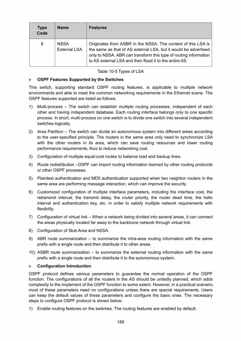
189
Type Code
Name Features
6 NSSA External LSA
Originates from ASBR in the NSSA. The content of this LSA is the same as that of AS external LSA, but it would be advertised only to NSSA. ABR can transform this type of routing information to AS external LSA and then flood it to the entire AS.
Table 10-5 Types of LSA
OSPF Features Supported by the Switches
This switch, supporting standard OSPF routing features, is applicable to multiple network environments and able to meet the common networking requirements in the Ethernet scene. The OSPF features supported are listed as follows.
1) Multi-process – The switch can establish multiple routing processes, independent of each other and having independent database. Each routing interface belongs only to one specific process. In short, multi-process on one switch is to divide one switch into several independent switches logically.
2) Area Partition – The switch can divide an autonomous system into different areas according to the user-specified principle. The routers in the same area only need to synchronize LSA with the other routers in its area, which can save routing resources and lower routing performance requirements, thus to reduce networking cost.
3) Configuration of multiple equal-cost routes to balance load and backup lines.
4) Route redistribution –OSPF can import routing information learned by other routing protocols or other OSPF processes.
5) Plaintext authentication and MD5 authentication supported when two neighbor routers in the same area are performing message interaction, which can improve the security.
6) Customized configuration of multiple interface parameters, including the interface cost, the retransmit interval, the transmit delay, the router priority, the router dead time, the hello interval and authentication key, etc. in order to satisfy multiple network requirements with flexibility.
7) Configuration of virtual link – When a network being divided into several areas, it can connect the areas physically located far away to the backbone network through virtual link.
8) Configuration of Stub Area and NSSA.
9) ABR route summarization – to summarize the intra-area routing information with the same prefix with a single route and then distribute it to other areas.
10) ASBR route summarization – to summarize the external routing information with the same prefix with a single route and then distribute it to the autonomous system.
Configuration Introduction
OSPF protocol defines various parameters to guarantee the normal operation of the OSPF function. The configurations of all the routers in the AS should be unitedly planned, which adds complexity to the implement of the OSPF function to some extent. However, in a practical scenario, most of these parameters need no configurations unless there are special requirements. Users can keep the default values of these parameters and configure the basic ones. The necessary steps to configure OSPF protocol is shown below:
1) Enable routing features on the switches. The routing features are enabled by default.
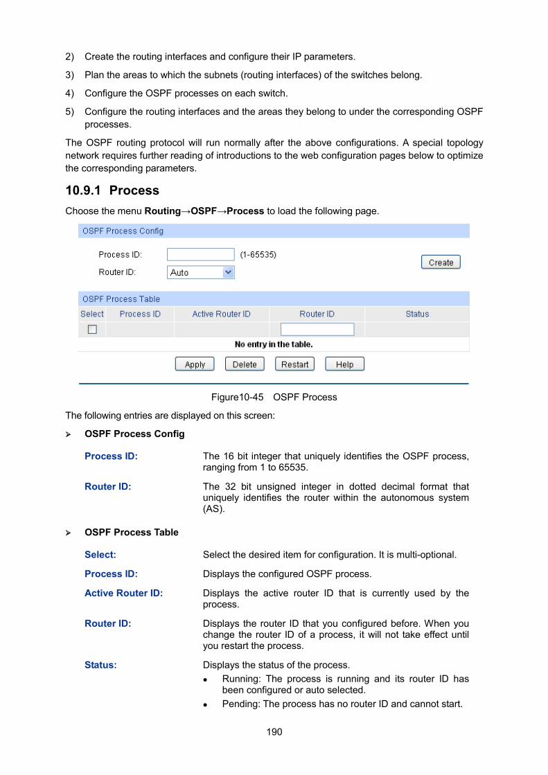
190
2) Create the routing interfaces and configure their IP parameters.
3) Plan the areas to which the subnets (routing interfaces) of the switches belong.
4) Configure the OSPF processes on each switch.
5) Configure the routing interfaces and the areas they belong to under the corresponding OSPF processes.
The OSPF routing protocol will run normally after the above configurations. A special topology network requires further reading of introductions to the web configuration pages below to optimize the corresponding parameters.
10.9.1 Process Choose the menu Routing→OSPF→Process to load the following page.
Figure10-45 OSPF Process
The following entries are displayed on this screen:
OSPF Process Config
Process ID: The 16 bit integer that uniquely identifies the OSPF process, ranging from 1 to 65535.
Router ID: The 32 bit unsigned integer in dotted decimal format that uniquely identifies the router within the autonomous system (AS).
OSPF Process Table
Select: Select the desired item for configuration. It is multi-optional.
Process ID: Displays the configured OSPF process.
Active Router ID: Displays the active router ID that is currently used by the process.
Router ID: Displays the router ID that you configured before. When you change the router ID of a process, it will not take effect until you restart the process.
Status: Displays the status of the process. Running: The process is running and its router ID has
been configured or auto selected. Pending: The process has no router ID and cannot start.
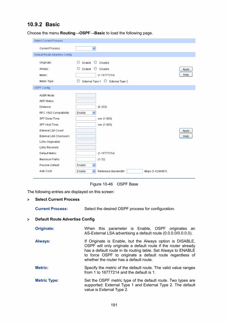
191
10.9.2 Basic Choose the menu Routing→OSPF→Basic to load the following page.
Figure 10-46 OSPF Base
The following entries are displayed on this screen:
Select Current Process
Current Process: Select the desired OSPF process for configuration.
Default Route Advertise Config
Originate: When this parameter is Enable, OSPF originates an AS-External LSA advertising a default route (0.0.0.0/0.0.0.0).
Always: If Originate is Enable, but the Always option is DISABLE, OSPF will only originate a default route if the router already has a default route in its routing table. Set Always to ENABLE to force OSPF to originate a default route regardless of whether the router has a default route.
Metric: Specify the metric of the default route. The valid value ranges from 1 to 16777214 and the default is 1.
Metric Type: Set the OSPF metric type of the default route. Two types are supported: External Type 1 and External Type 2. The default value is External Type 2.
192
OSPF Config
ASBR Mode: The router is an Autonomous System Boundary Router if it is configured to redistribute routes from another protocol, or if it is configured to originate an AS-External LSA advertising the default route.
ABR Status: The router is an Area Border Router if it has active non-virtual interfaces in two or more OSPF areas.
Distance: Specify OSPF route distance. When more than two protocols have routes to the same destination, only the route which have smallest distance will be inserted to IP routing table. The valid value ranges from 0 to 255 and the default is 110.
RFC 1583 Compatibility:
Select the preference rules that will be used when choosing among multiple AS-external LSAs advertising the same destination. If you select Enable, the preference rules will be those defined by RFC 1583. Else the preference rules will be those defined in RFC 2328, which will prevent routing loops when AS-external LSAs for the same destination have been originated from different areas. All routers in the OSPF domain must be configured the same. The default value is 'Enable'.
SPF Delay Time: The number of seconds from when OSPF receives a topology change to the start of the next SPF calculation. The valid value ranges from 1 to 600 seconds and the default is 5.
SPF Hold Time: The minimum time in seconds between two consecutive SPF calculations. The valid value ranges from 1 to 600 seconds and the default is 5.
External LSA Count: The number of AS-External LSAs in the link state database.
External LSA Checksum:
The sum of the LS checksums of the AS-External LSAs contained in the link-state database.
LSAs Originated: This value represents the number of LSAs originated by this router.
LSAs Received: The number of LSAs received from other routers in OSPF domain.
Default Metric: Set a default for the metric of redistributed routes. The valid value ranges from 1 to 16777214 and the default is 20.
Maximum Paths: Set the number of paths that OSPF can report for a given destination. The valid value ranges from 1 to 32 and the default is 5.
Auto Cost: Configure the Auto Cost to control how OSPF calculates link cost. When Enable selected, unless the link cost is manually configured, the link cost is computed by dividing the reference bandwidth by the interface bandwidth. When Disable selected, the link cost should be manually configured or use default value. The default option is 'Enable'.
Reference Bandwidth:
Specify the reference bandwidth in megabits per second. The valid value ranges from 1 to 4294967 Mbps and the default is 1000Mbps.
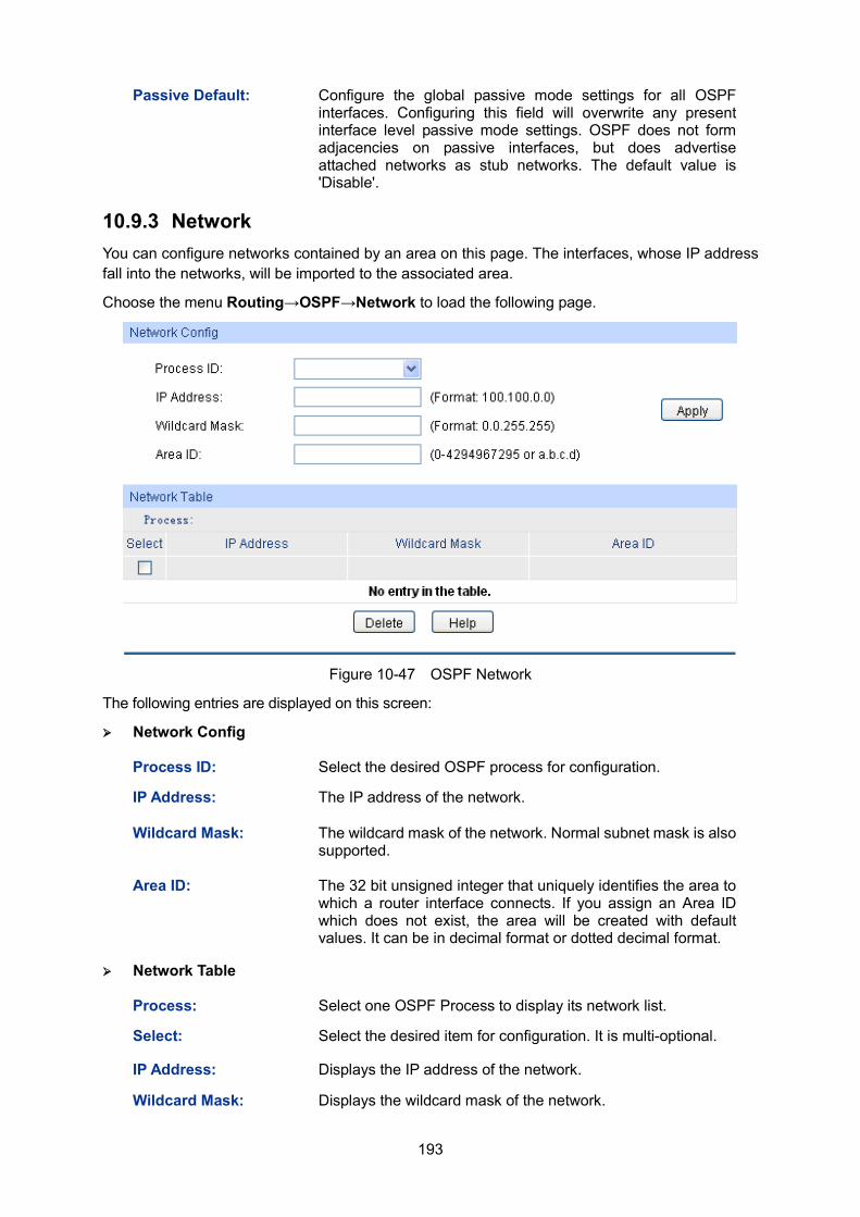
193
Passive Default: Configure the global passive mode settings for all OSPF interfaces. Configuring this field will overwrite any present interface level passive mode settings. OSPF does not form adjacencies on passive interfaces, but does advertise attached networks as stub networks. The default value is 'Disable'.
10.9.3 Network You can configure networks contained by an area on this page. The interfaces, whose IP address fall into the networks, will be imported to the associated area.
Choose the menu Routing→OSPF→Network to load the following page.
Figure 10-47 OSPF Network
The following entries are displayed on this screen:
Network Config
Process ID: Select the desired OSPF process for configuration.
IP Address: The IP address of the network.
Wildcard Mask: The wildcard mask of the network. Normal subnet mask is also supported.
Area ID: The 32 bit unsigned integer that uniquely identifies the area to which a router interface connects. If you assign an Area ID which does not exist, the area will be created with default values. It can be in decimal format or dotted decimal format.
Network Table
Process: Select one OSPF Process to display its network list.
Select: Select the desired item for configuration. It is multi-optional.
IP Address: Displays the IP address of the network.
Wildcard Mask: Displays the wildcard mask of the network.
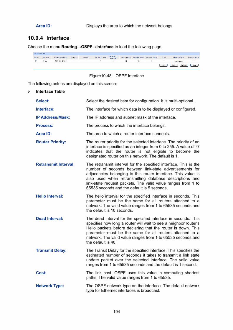
194
Area ID: Displays the area to which the network belongs.
10.9.4 Interface Choose the menu Routing→OSPF→Interface to load the following page.
Figure10-48 OSPF Interface
The following entries are displayed on this screen:
Interface Table
Select: Select the desired item for configuration. It is multi-optional.
Interface: The interface for which data is to be displayed or configured.
IP Address/Mask: The IP address and subnet mask of the interface.
Process: The process to which the interface belongs.
Area ID: The area to which a router interface connects.
Router Priority: The router priority for the selected interface. The priority of an interface is specified as an integer from 0 to 255. A value of '0' indicates that the router is not eligible to become the designated router on this network. The default is 1.
Retransmit Interval: The retransmit interval for the specified interface. This is the number of seconds between link-state advertisements for adjacencies belonging to this router interface. This value is also used when retransmitting database descriptions and link-state request packets. The valid value ranges from 1 to 65535 seconds and the default is 5 seconds.
Hello Interval: The hello interval for the specified interface in seconds. This parameter must be the same for all routers attached to a network. The valid value ranges from 1 to 65535 seconds and the default is 10 seconds.
Dead Interval: The dead interval for the specified interface in seconds. This specifies how long a router will wait to see a neighbor router's Hello packets before declaring that the router is down. This parameter must be the same for all routers attached to a network. The valid value ranges from 1 to 65535 seconds and the default is 40.
Transmit Delay: The Transit Delay for the specified interface. This specifies the estimated number of seconds it takes to transmit a link state update packet over the selected interface. The valid value ranges from 1 to 65535 seconds and the default is 1 second.
Cost: The link cost. OSPF uses this value in computing shortest paths. The valid value ranges from 1 to 65535.
Network Type: The OSPF network type on the interface. The default network type for Ethernet interfaces is broadcast.
195
Passive Mode: Make an interface passive to prevent OSPF from forming an adjacency on an interface. OSPF advertises networks attached to passive interfaces as stub networks. Interfaces are not passive by default.
MTU Ignore: Disables OSPF MTU mismatch detection on received database description packets. Default value is Disable (MTU mismatch detection is enabled).
Database Filter: To prevent outgoing link-state advertisements (LSAs) flooding out of an OSPF interface. The default is Disable, all outgoing LSAs are flooded out of the interface.
Authentication Type:
Displays the authentication type of the interface. One of the following: default: The authentication type is same with the
associated area's authentication type. null: No authentication. simple: Use simple password. md5: Use md5 message-digest algorithm.
Authentication Key ID:
Displays the active authentication key ID of the interface.
Authentication Key: Displays the active authentication key of the interface.
State: Displays the current state of the selected router interface. One of the following: Down: This is the initial interface state. In this state, the
lower-level protocols have indicated that the interface is unusable. In this state, interface parameters will be set to their initial values. All interface timers will be disabled, and there will be no adjacencies associated with the interface.
Loopback: In this state, the router's interface to the network is looped back either in hardware or software. The interface is unavailable for regular data traffic. However, it may still be desirable to gain information on the quality of this interface, either through sending ICMP pings to the interface or through something like a bit error test. For this reason, IP packets may still be addressed to an interface in Loopback state. To facilitate this, such interfaces are advertised in router- LSAs as single host routes, whose destination is the interface IP address.
Waiting: The router is trying to determine the identity of the (Backup) Designated Router by monitoring received Hello Packets. The router is not allowed to elect a Backup Designated Router or a Designated Router until it transitions out of Waiting state. This prevents unnecessary changes of (Backup) Designated Router.
DR: This router is itself the Designated Router on the attached network. Adjacencies are established to all other routers attached to the network. The router must also originate a Network LSA for the network node. The Network LSA will contain links to all routers (including the Designated Router itself) attached to the network.
BDR: This router is itself the Backup Designated Router on the attached network. It will be promoted to Designated Router if the present Designated Router fails.
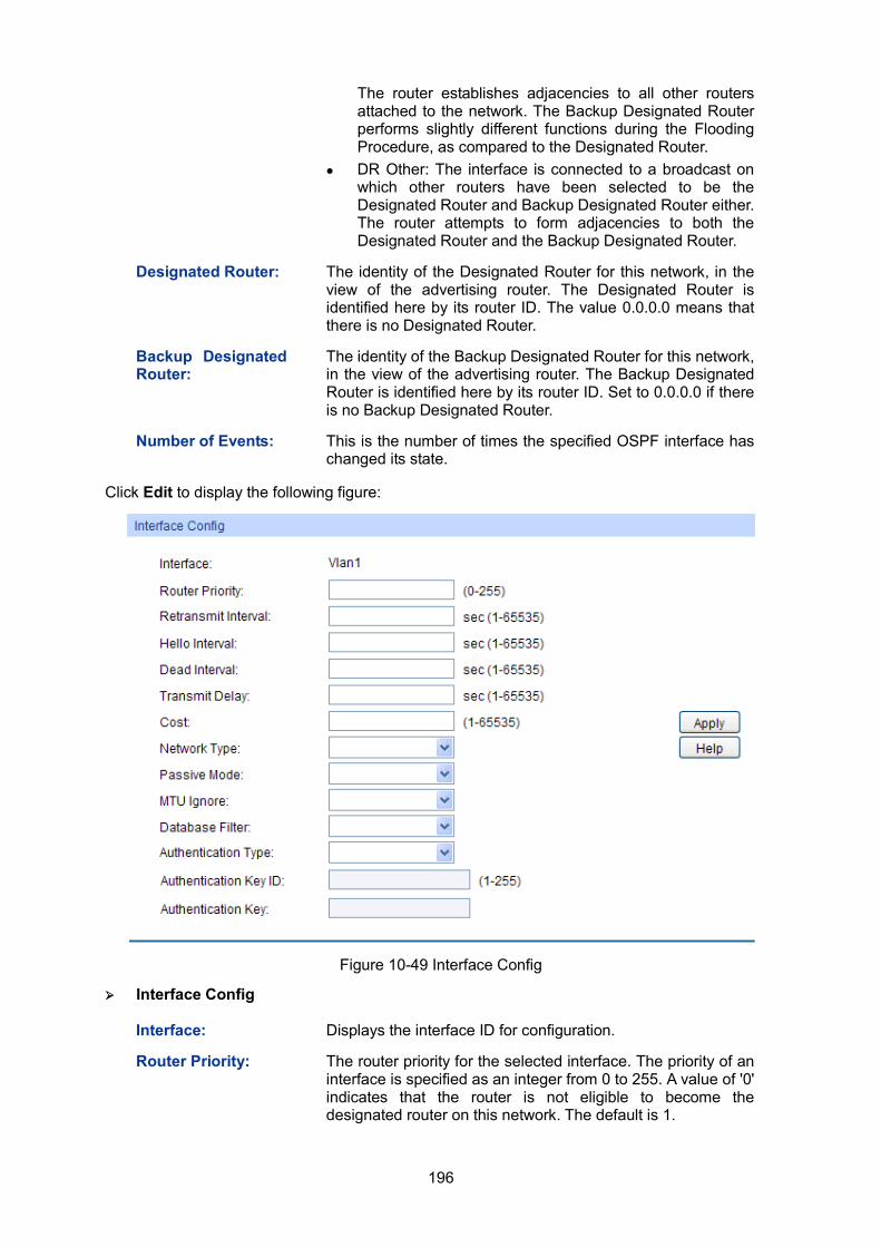
196
The router establishes adjacencies to all other routers attached to the network. The Backup Designated Router performs slightly different functions during the Flooding Procedure, as compared to the Designated Router.
DR Other: The interface is connected to a broadcast on which other routers have been selected to be the Designated Router and Backup Designated Router either. The router attempts to form adjacencies to both the Designated Router and the Backup Designated Router.
Designated Router: The identity of the Designated Router for this network, in the view of the advertising router. The Designated Router is identified here by its router ID. The value 0.0.0.0 means that there is no Designated Router.
Backup Designated Router:
The identity of the Backup Designated Router for this network, in the view of the advertising router. The Backup Designated Router is identified here by its router ID. Set to 0.0.0.0 if there is no Backup Designated Router.
Number of Events: This is the number of times the specified OSPF interface has changed its state.
Click Edit to display the following figure:
Figure 10-49 Interface Config
Interface Config
Interface: Displays the interface ID for configuration.
Router Priority: The router priority for the selected interface. The priority of an interface is specified as an integer from 0 to 255. A value of '0' indicates that the router is not eligible to become the designated router on this network. The default is 1.
197
Retransmit Interval: The retransmit interval for the specified interface. This is the number of seconds between link-state advertisements for adjacencies belonging to this router interface. This value is also used when retransmitting database descriptions and link-state request packets. The valid value ranges from 1 to 65535 seconds and the default is 5 seconds.
Hello Interval: The hello interval for the specified interface in seconds. This parameter must be the same for all routers attached to a network. The valid value ranges from 1 to 65535 seconds and the default is 10 seconds.
Dead Interval: The dead interval for the specified interface in seconds. This specifies how long a router will wait to see a neighbor router's Hello packets before declaring that the router is down. This parameter must be the same for all routers attached to a network. The valid value ranges from 1 to 65535 seconds and the default is 40 seconds.
Transmit Delay: The Transit Delay for the specified interface. This specifies the estimated number of seconds it takes to transmit a link state update packet over the selected interface. The valid value ranges from 1 to 65535 seconds and the default is 1 second.
Cost: The link cost. OSPF uses this value in computing shortest paths. The valid value ranges from 1 to 65535.
Network Type: Sets the OSPF network type. The default network type for Ethernet interfaces is broadcast.
Passive Mode: Make an interface passive to prevent OSPF from forming an adjacency on an interface. OSPF advertises networks attached to passive interfaces as stub networks. Interfaces are not passive by default.
MTU Ignore: Disables OSPF MTU mismatch detection on received database description packets. Default value is Disable (MTU mismatch detection is enabled).
Database Filter: To prevent outgoing link-state advertisements (LSAs) flooding out of an OSPF interface. The default is Disable, all outgoing LSAs are flooded out of the interface.
Authentication Type:
The authentication type of interface. The choices are: default: The authentication type is same with the
associated area's authentication type. null: No authentication. simple: Use simple password. md5: Use md5 message-digest algorithm.
Authentication Key ID:
When you select md5, the key ID should be entered. The valid value ranges from 1 to 255.
Authentication Key: Specify the authentication key. The length of simple key is no more than 8 characters, and md5 key is no more than 16 characters.
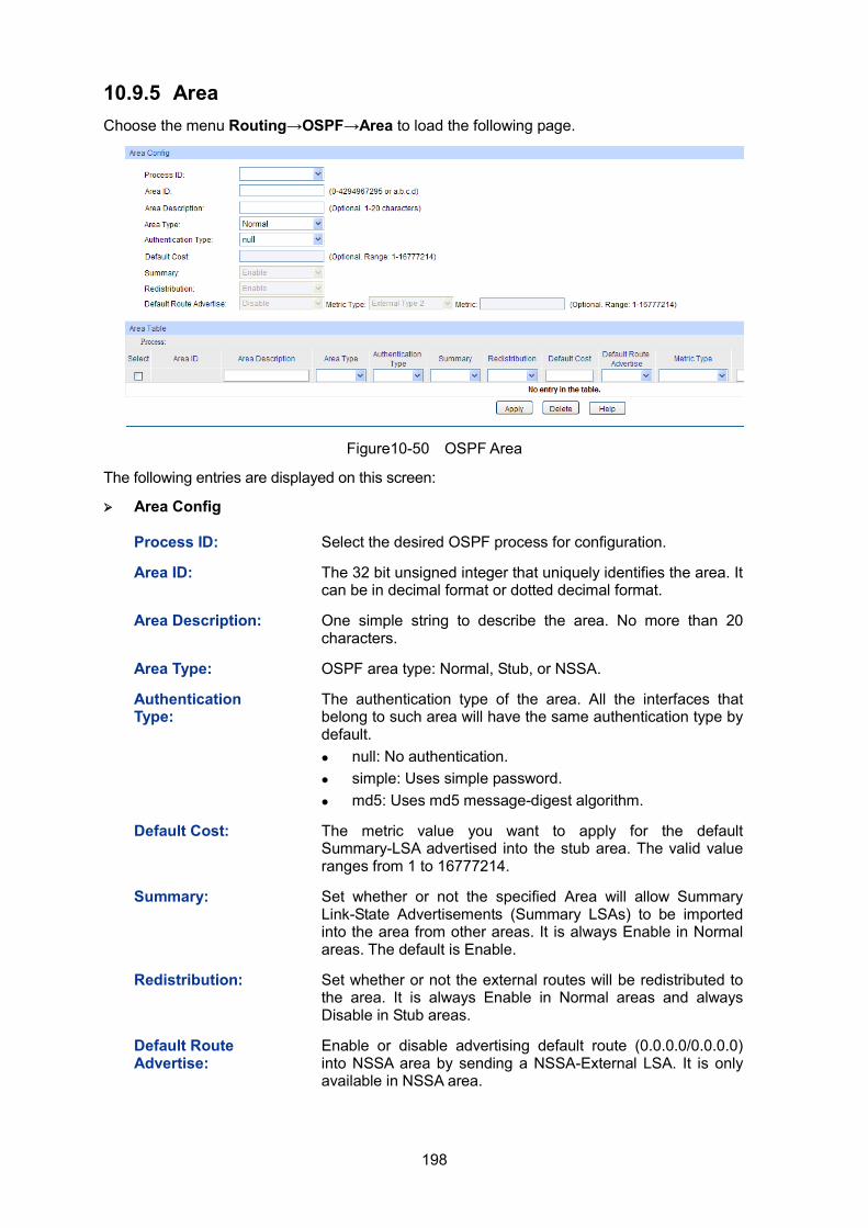
198
10.9.5 Area Choose the menu Routing→OSPF→Area to load the following page.
Figure10-50 OSPF Area
The following entries are displayed on this screen:
Area Config
Process ID: Select the desired OSPF process for configuration.
Area ID: The 32 bit unsigned integer that uniquely identifies the area. It can be in decimal format or dotted decimal format.
Area Description: One simple string to describe the area. No more than 20 characters.
Area Type: OSPF area type: Normal, Stub, or NSSA.
Authentication Type:
The authentication type of the area. All the interfaces that belong to such area will have the same authentication type by default. null: No authentication. simple: Uses simple password. md5: Uses md5 message-digest algorithm.
Default Cost: The metric value you want to apply for the default Summary-LSA advertised into the stub area. The valid value ranges from 1 to 16777214.
Summary: Set whether or not the specified Area will allow Summary Link-State Advertisements (Summary LSAs) to be imported into the area from other areas. It is always Enable in Normal areas. The default is Enable.
Redistribution: Set whether or not the external routes will be redistributed to the area. It is always Enable in Normal areas and always Disable in Stub areas.
Default Route Advertise:
Enable or disable advertising default route (0.0.0.0/0.0.0.0) into NSSA area by sending a NSSA-External LSA. It is only available in NSSA area.
199
Metric Type: Set the OSPF metric type of the default route. Two types are supported: External Type 1 and External Type 2. The default value is External Type 2.
Metric: Specify the metric of the default route. The valid value ranges from 1 to 16777214 and the default is 1.
Area Table
Process: Select one OSPF Process to display its area list.
Select: Select the desired item for configuration. It is multi-optional.
Area ID: Displays the configured area.
Area Description: Displays the description of the area and it can be modified.
Area Type: Displays the type of the area and it can be modified.
Authentication Type:
Displays the authentication type of the area and it can be modified.
Summary: Displays the Summary parameter and it can be modified.
Redistribution: Displays the Redistribution parameter and it can be modified.
Default Cost: Displays the stub cost of the area and it can be modified.
Default Route Advertise:
Displays the Default Route Advertise status and it can be modified.
Metric Type: Displays the type of default route and it can be modified.
Metric: Displays the metric of default route and it can be modified.
SPF runs: Displays the number of times that the intra-area route table has been calculated using this area's link-state database. This is typically done using Dijkstra's algorithm.
ABR Count: Displays the total number of area border routers reachable within this area. This is initially zero, and is calculated in each SPF Pass.
Area LSA Count: Displays the total number of link-state advertisements in this area's link-state database, excluding AS-External LSAs.
Area LSA Checksum:
Displays the 32-bit unsigned sum of the link-state advertisements' LS checksums contained in this area's link-state database. This sum excludes external (LS type 5) link-state advertisements. The sum can be used to determine if there has been a change in a router's link state database, and to compare the link-state databases of two routers.
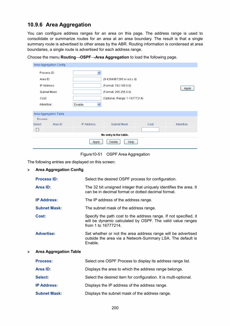
200
10.9.6 Area Aggregation You can configure address ranges for an area on this page. The address range is used to consolidate or summarize routes for an area at an area boundary. The result is that a single summary route is advertised to other areas by the ABR. Routing information is condensed at area boundaries, a single route is advertised for each address range.
Choose the menu Routing→OSPF→Area Aggregation to load the following page.
Figure10-51 OSPF Area Aggregation
The following entries are displayed on this screen:
Area Aggregation Config
Process ID: Select the desired OSPF process for configuration.
Area ID: The 32 bit unsigned integer that uniquely identifies the area. It can be in decimal format or dotted decimal format.
IP Address: The IP address of the address range.
Subnet Mask: The subnet mask of the address range.
Cost: Specify the path cost to the address range. If not specified, it will be dynamic calculated by OSPF. The valid value ranges from 1 to 16777214.
Advertise: Set whether or not the area address range will be advertised outside the area via a Network-Summary LSA. The default is Enable.
Area Aggregation Table
Process: Select one OSPF Process to display its address range list.
Area ID: Displays the area to which the address range belongs.
Select: Select the desired item for configuration. It is multi-optional.
IP Address: Displays the IP address of the address range.
Subnet Mask: Displays the subnet mask of the address range.
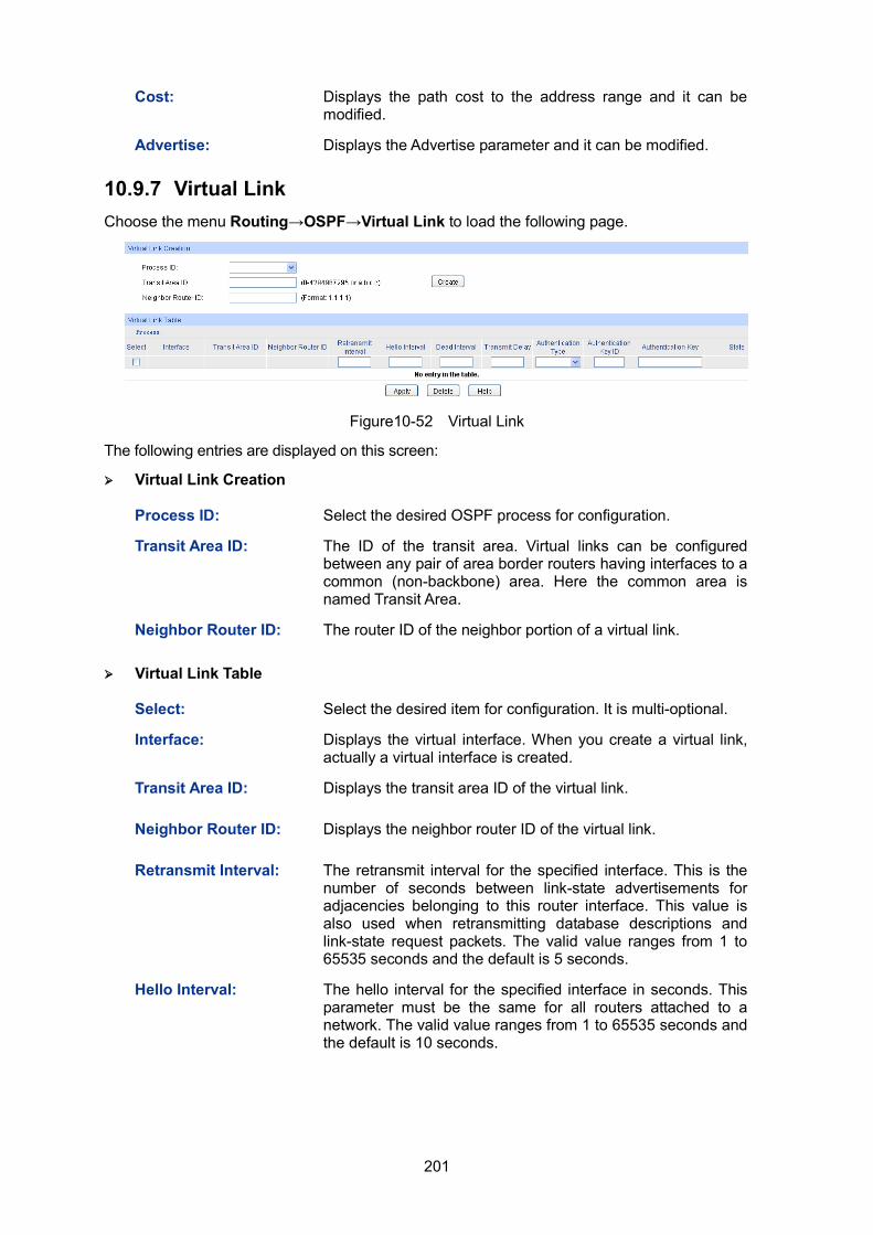
201
Cost: Displays the path cost to the address range and it can be modified.
Advertise: Displays the Advertise parameter and it can be modified.
10.9.7 Virtual Link Choose the menu Routing→OSPF→Virtual Link to load the following page.
Figure10-52 Virtual Link
The following entries are displayed on this screen:
Virtual Link Creation
Process ID: Select the desired OSPF process for configuration.
Transit Area ID: The ID of the transit area. Virtual links can be configured between any pair of area border routers having interfaces to a common (non-backbone) area. Here the common area is named Transit Area.
Neighbor Router ID: The router ID of the neighbor portion of a virtual link.
Virtual Link Table
Select: Select the desired item for configuration. It is multi-optional.
Interface: Displays the virtual interface. When you create a virtual link, actually a virtual interface is created.
Transit Area ID: Displays the transit area ID of the virtual link.
Neighbor Router ID: Displays the neighbor router ID of the virtual link.
Retransmit Interval: The retransmit interval for the specified interface. This is the number of seconds between link-state advertisements for adjacencies belonging to this router interface. This value is also used when retransmitting database descriptions and link-state request packets. The valid value ranges from 1 to 65535 seconds and the default is 5 seconds.
Hello Interval: The hello interval for the specified interface in seconds. This parameter must be the same for all routers attached to a network. The valid value ranges from 1 to 65535 seconds and the default is 10 seconds.
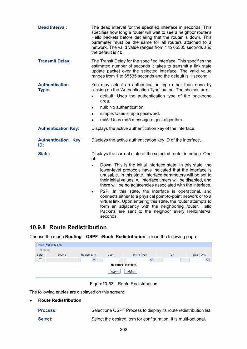
202
Dead Interval: The dead interval for the specified interface in seconds. This specifies how long a router will wait to see a neighbor router's Hello packets before declaring that the router is down. This parameter must be the same for all routers attached to a network. The valid value ranges from 1 to 65535 seconds and the default is 40.
Transmit Delay: The Transit Delay for the specified interface. This specifies the estimated number of seconds it takes to transmit a link state update packet over the selected interface. The valid value ranges from 1 to 65535 seconds and the default is 1 second.
Authentication Type:
You may select an authentication type other than none by clicking on the 'Authentication Type' button. The choices are: default: Uses the authentication type of the backbone
area. null: No authentication. simple: Uses simple password. md5: Uses md5 message-digest algorithm.
Authentication Key: Displays the active authentication key of the interface.
Authentication Key ID:
Displays the active authentication key ID of the interface.
State: Displays the current state of the selected router interface. One of: Down: This is the initial interface state. In this state, the
lower-level protocols have indicated that the interface is unusable. In this state, interface parameters will be set to their initial values. All interface timers will be disabled, and there will be no adjacencies associated with the interface.
P2P: In this state, the interface is operational, and connects either to a physical point-to-point network or to a virtual link. Upon entering this state, the router attempts to form an adjacency with the neighboring router. Hello Packets are sent to the neighbor every HelloInterval seconds.
10.9.8 Route Redistribution Choose the menu Routing→OSPF→Route Redistribution to load the following page.
Figure10-53 Route Redistribution
The following entries are displayed on this screen:
Route Redistribution
Process: Select one OSPF Process to display its route redistribution list.
Select: Select the desired item for configuration. It is multi-optional.
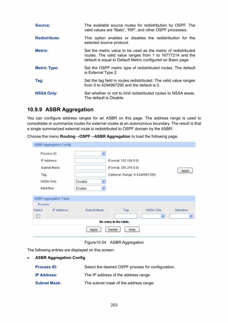
203
Source: The available source routes for redistribution by OSPF. The valid values are 'Static', 'RIP', and other OSPF processes.
Redistribute: This option enables or disables the redistribution for the selected source protocol.
Metric: Set the metric value to be used as the metric of redistributed routes. The valid value ranges from 1 to 16777214 and the default is equal to Default Metric configured on Basic page.
Metric Type: Set the OSPF metric type of redistributed routes. The default is External Type 2.
Tag: Set the tag field in routes redistributed. The valid value ranges from 0 to 4294967295 and the default is 0.
NSSA Only: Set whether or not to limit redistributed routes to NSSA areas. The default is Disable.
10.9.9 ASBR Aggregation You can configure address ranges for an ASBR on this page. The address range is used to consolidate or summarize routes for external routes at an autonomous boundary. The result is that a single summarized external route is redistributed to OSPF domain by the ASBR.
Choose the menu Routing→OSPF→ASBR Aggregation to load the following page.
Figure10-54 ASBR Aggregation
The following entries are displayed on this screen:
ASBR Aggregation Config
Process ID: Select the desired OSPF process for configuration.
IP Address: The IP address of the address range.
Subnet Mask: The subnet mask of the address range.
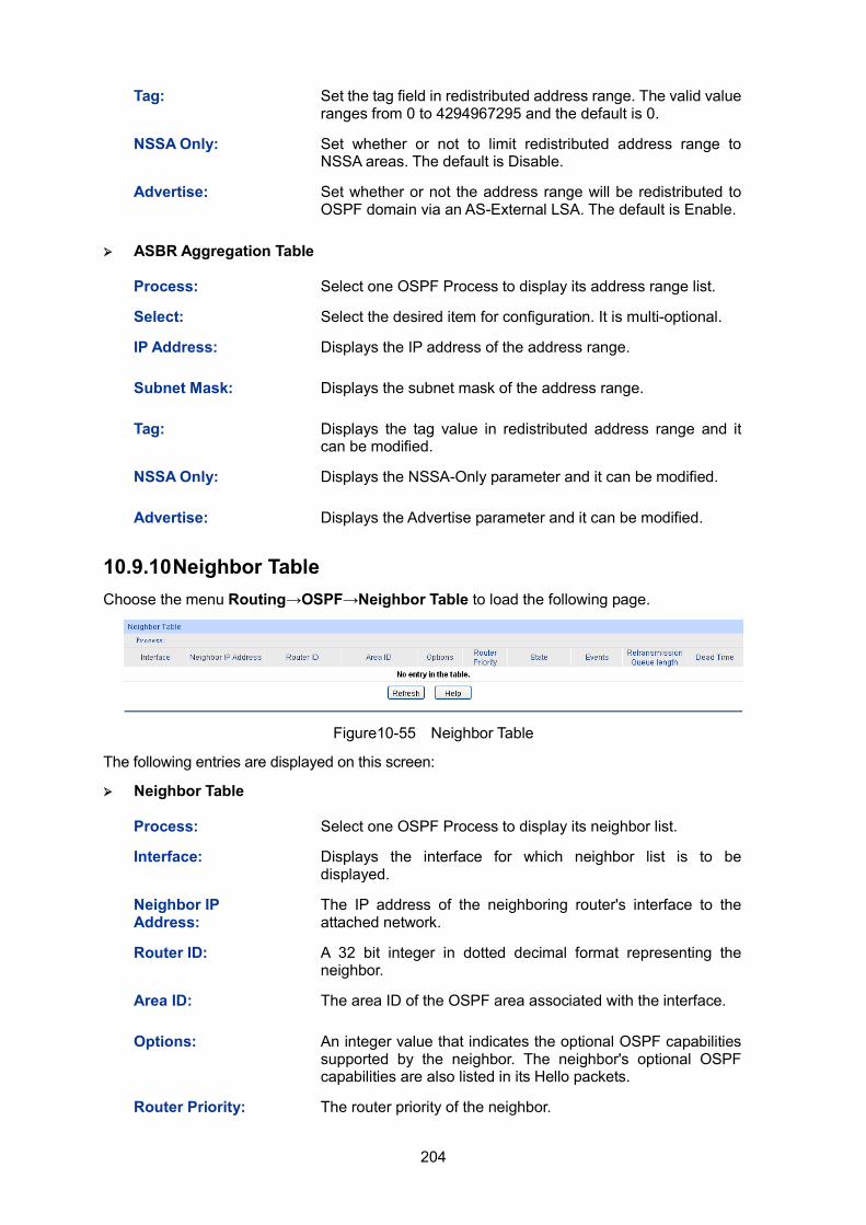
204
Tag: Set the tag field in redistributed address range. The valid value ranges from 0 to 4294967295 and the default is 0.
NSSA Only: Set whether or not to limit redistributed address range to NSSA areas. The default is Disable.
Advertise: Set whether or not the address range will be redistributed to OSPF domain via an AS-External LSA. The default is Enable.
ASBR Aggregation Table
Process: Select one OSPF Process to display its address range list.
Select: Select the desired item for configuration. It is multi-optional.
IP Address: Displays the IP address of the address range.
Subnet Mask: Displays the subnet mask of the address range.
Tag: Displays the tag value in redistributed address range and it can be modified.
NSSA Only: Displays the NSSA-Only parameter and it can be modified.
Advertise: Displays the Advertise parameter and it can be modified.
10.9.10 Neighbor Table Choose the menu Routing→OSPF→Neighbor Table to load the following page.
Figure10-55 Neighbor Table
The following entries are displayed on this screen:
Neighbor Table
Process: Select one OSPF Process to display its neighbor list.
Interface: Displays the interface for which neighbor list is to be displayed.
Neighbor IP Address:
The IP address of the neighboring router's interface to the attached network.
Router ID: A 32 bit integer in dotted decimal format representing the neighbor.
Area ID: The area ID of the OSPF area associated with the interface.
Options: An integer value that indicates the optional OSPF capabilities supported by the neighbor. The neighbor's optional OSPF capabilities are also listed in its Hello packets.
Router Priority: The router priority of the neighbor.
205
State: The state of the neighbor: Down: This is the initial state of a neighbor conversation.
It indicates that there has been no recent information received from the neighbor. On NBMA networks, Hello packets may still be sent to 'Down' neighbors, although at a reduced frequency.
Attempt: This state is only valid for neighbors attached to NBMA networks. It indicates that no recent information has been received from the neighbor, but that a more concerted effort should be made to contact the neighbor. This is done by sending the neighbor Hello packets at intervals of Hello Interval.
Init: In this state, a Hello packet has recently been seen from the neighbor. However, bidirectional communication has not yet been established with the neighbor (i.e., the router itself did not appear in the neighbor's Hello packet). All neighbors in this state (or greater) are listed in the Hello packets sent from the associated interface.
2-Way: In this state, communication between the two routers is bidirectional. This has been assured by the operation of the Hello Protocol. This is the most advanced state short of beginning adjacency establishment. The (Backup) Designated Router is selected from the set of neighbors in state 2-Way or greater.
ExStart: This is the first step in creating an adjacency between the two neighboring routers. The goal of this step is to decide which router is the master, and to decide upon the initial DD sequence number. Neighbor conversations in this state or greater are called adjacencies.
Exchange: In this state the router is describing its entire link state database by sending Database Description packets to the neighbor. In this state, Link State Request Packets may also be sent asking for the neighbor's more recent LSAs. All adjacencies in Exchange state or greater are used by the flooding procedure. These adjacencies are fully capable of transmitting and receiving all types of OSPF routing protocol packets.
Loading: In this state, Link State Request packets are sent to the neighbor asking for the more recent LSAs that have been discovered (but not yet received) in the Exchange state.
Full: In this state, the neighboring routers are fully adjacent. These adjacencies will now appear in Router LSAs and Network LSAs.
Events: The number of times this neighbor relationship has changed state, or an error has occurred.
Retransmission Queue length:
An integer representing the current length of the retransmission queue of the specified neighbor router ID of the specified interface.
Dead Time: The amount of time, in seconds, to wait before the router assumes the neighbor is unreachable.
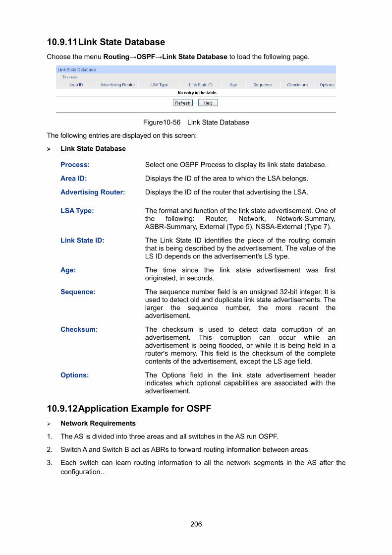
206
10.9.11 Link State Database Choose the menu Routing→OSPF→Link State Database to load the following page.
Figure10-56 Link State Database
The following entries are displayed on this screen:
Link State Database
Process: Select one OSPF Process to display its link state database.
Area ID: Displays the ID of the area to which the LSA belongs.
Advertising Router: Displays the ID of the router that advertising the LSA.
LSA Type: The format and function of the link state advertisement. One of the following: Router, Network, Network-Summary, ASBR-Summary, External (Type 5), NSSA-External (Type 7).
Link State ID: The Link State ID identifies the piece of the routing domain that is being described by the advertisement. The value of the LS ID depends on the advertisement's LS type.
Age: The time since the link state advertisement was first originated, in seconds.
Sequence: The sequence number field is an unsigned 32-bit integer. It is used to detect old and duplicate link state advertisements. The larger the sequence number, the more recent the advertisement.
Checksum: The checksum is used to detect data corruption of an advertisement. This corruption can occur while an advertisement is being flooded, or while it is being held in a router's memory. This field is the checksum of the complete contents of the advertisement, except the LS age field.
Options: The Options field in the link state advertisement header indicates which optional capabilities are associated with the advertisement.
10.9.12 Application Example for OSPF Network Requirements
1. The AS is divided into three areas and all switches in the AS run OSPF.
2. Switch A and Switch B act as ABRs to forward routing information between areas.
3. Each switch can learn routing information to all the network segments in the AS after the configuration..
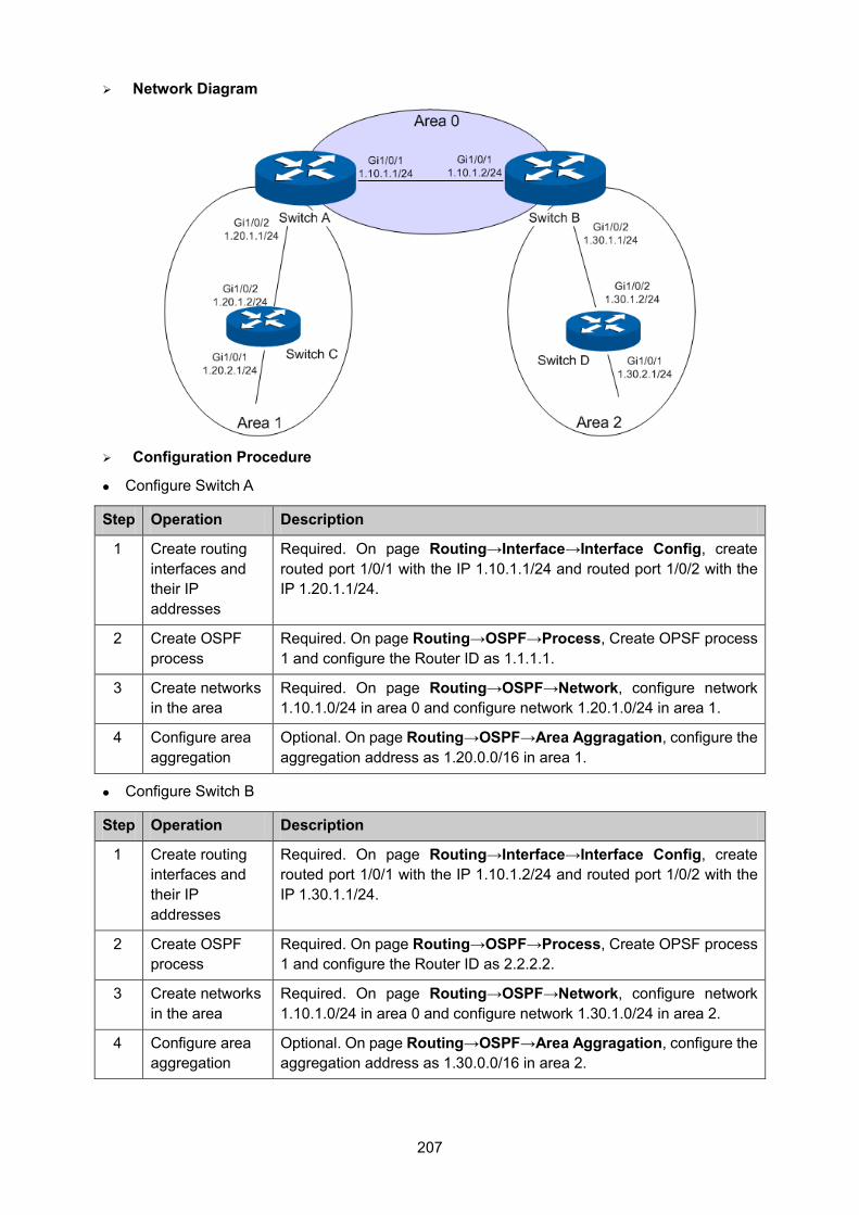
207
Network Diagram
Configuration Procedure
Configure Switch A
Step Operation Description
1 Create routing interfaces and their IP addresses
Required. On page Routing→Interface→Interface Config, create routed port 1/0/1 with the IP 1.10.1.1/24 and routed port 1/0/2 with the IP 1.20.1.1/24.
2 Create OSPF process
Required. On page Routing→OSPF→Process, Create OPSF process 1 and configure the Router ID as 1.1.1.1.
3 Create networks in the area
Required. On page Routing→OSPF→Network, configure network 1.10.1.0/24 in area 0 and configure network 1.20.1.0/24 in area 1.
4 Configure area aggregation
Optional. On page Routing→OSPF→Area Aggragation, configure the aggregation address as 1.20.0.0/16 in area 1.
Configure Switch B
Step Operation Description
1 Create routing interfaces and their IP addresses
Required. On page Routing→Interface→Interface Config, create routed port 1/0/1 with the IP 1.10.1.2/24 and routed port 1/0/2 with the IP 1.30.1.1/24.
2 Create OSPF process
Required. On page Routing→OSPF→Process, Create OPSF process 1 and configure the Router ID as 2.2.2.2.
3 Create networks in the area
Required. On page Routing→OSPF→Network, configure network 1.10.1.0/24 in area 0 and configure network 1.30.1.0/24 in area 2.
4 Configure area aggregation
Optional. On page Routing→OSPF→Area Aggragation, configure the aggregation address as 1.30.0.0/16 in area 2.
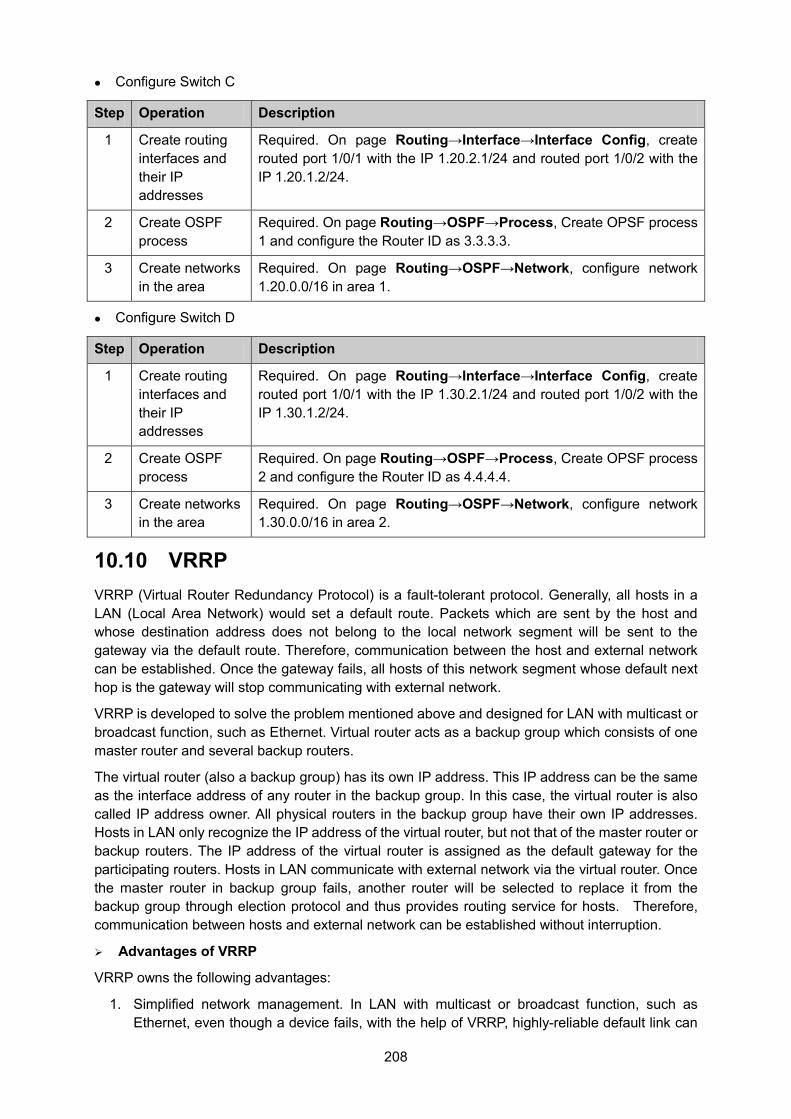
208
Configure Switch C
Step Operation Description
1 Create routing interfaces and their IP addresses
Required. On page Routing→Interface→Interface Config, create routed port 1/0/1 with the IP 1.20.2.1/24 and routed port 1/0/2 with the IP 1.20.1.2/24.
2 Create OSPF process
Required. On page Routing→OSPF→Process, Create OPSF process 1 and configure the Router ID as 3.3.3.3.
3 Create networks in the area
Required. On page Routing→OSPF→Network, configure network 1.20.0.0/16 in area 1.
Configure Switch D
Step Operation Description
1 Create routing interfaces and their IP addresses
Required. On page Routing→Interface→Interface Config, create routed port 1/0/1 with the IP 1.30.2.1/24 and routed port 1/0/2 with the IP 1.30.1.2/24.
2 Create OSPF process
Required. On page Routing→OSPF→Process, Create OPSF process 2 and configure the Router ID as 4.4.4.4.
3 Create networks in the area
Required. On page Routing→OSPF→Network, configure network 1.30.0.0/16 in area 2.
10.10 VRRP VRRP (Virtual Router Redundancy Protocol) is a fault-tolerant protocol. Generally, all hosts in a LAN (Local Area Network) would set a default route. Packets which are sent by the host and whose destination address does not belong to the local network segment will be sent to the gateway via the default route. Therefore, communication between the host and external network can be established. Once the gateway fails, all hosts of this network segment whose default next hop is the gateway will stop communicating with external network.
VRRP is developed to solve the problem mentioned above and designed for LAN with multicast or broadcast function, such as Ethernet. Virtual router acts as a backup group which consists of one master router and several backup routers.
The virtual router (also a backup group) has its own IP address. This IP address can be the same as the interface address of any router in the backup group. In this case, the virtual router is also called IP address owner. All physical routers in the backup group have their own IP addresses. Hosts in LAN only recognize the IP address of the virtual router, but not that of the master router or backup routers. The IP address of the virtual router is assigned as the default gateway for the participating routers. Hosts in LAN communicate with external network via the virtual router. Once the master router in backup group fails, another router will be selected to replace it from the backup group through election protocol and thus provides routing service for hosts. Therefore, communication between hosts and external network can be established without interruption.
Advantages of VRRP
VRRP owns the following advantages:
1. Simplified network management. In LAN with multicast or broadcast function, such as Ethernet, even though a device fails, with the help of VRRP, highly-reliable default link can
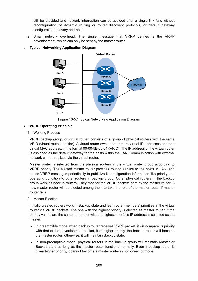
209
still be provided and network interruption can be avoided after a single link fails without reconfiguration of dynamic routing or router discovery protocols, or default gateway configuration on every end-host.
2. Small network overhead. The single message that VRRP defines is the VRRP advertisement, which can only be sent by the master router.
Typical Networking Application Diagram
Figure 10-57 Typical Networking Application Diagram
VRRP Operating Principle
1. Working Process
VRRP backup group, or virtual router, consists of a group of physical routers with the same VRID (virtual route identifier). A virtual router owns one or more virtual IP addresses and one virtual MAC address, in the format 00-00-5E-00-01-{VRID}. The IP address of the virtual router is assigned as the default gateway for the hosts within the LAN. Communication with external network can be realized via the virtual router.
Master router is selected from the physical routers in the virtual router group according to VRRP priority. The elected master router provides routing service to the hosts in LAN, and sends VRRP messages periodically to publicize its configuration information like priority and operating condition to other routers in backup group. Other physical routers in the backup group work as backup routers. They monitor the VRRP packets sent by the master router. A new master router will be elected among them to take the role of the master router if master router fails.
2. Master Election
Initially-created routers work in Backup state and learn other members' priorities in the virtual router via VRRP packets. The one with the highest priority is elected as master router. If the priority values are the same, the router with the highest interface IP address is selected as the master.
• In preemptible mode, when backup router receives VRRP packet, it will compare its priority with that of the advertisement packet. If of higher priority, the backup router will become the master router; otherwise, it will maintain Backup state.
• In non-preemptible mode, physical routers in the backup group will maintain Master or Backup state as long as the master router functions normally. Even if backup router is given higher priority, it cannot become a master router in non-preempt mode.
210
The VRRP priority ranges from 0 to 255 (the bigger the number is, the higher the priority is). Configurable range is 1-254. The priority value 0 is reserved for the current master when it gives up its role as master router. For example, when master router receives shutdown message, it would send VRRP packet with priority 0 to the backup group which the interface belongs to. The priority of the IP address owner must be 255. Therefore, if there exists an IP address owner in the backup group and it works normally, it must be the master router.
3. State Transition
VRRP defines three state modes: Initialize, Master and Backup. Only in Master state can master router provide service for forwarding request via virtual IP address and forward VRRP packet.
When the system just starts, it comes to Initialize state. If the virtual router is not given a virtual IP address, the system would maintain Initialize state. If the virtual IP address is configured properly, when the system receives startup message from interface, it would transition to the Backup state (in which case its priority is not 255) or Master state (in which case its priority is 255). Routers in master or backup state can change to Initialize state only when they receive shutdown message from interface. In Initialize state, router cannot deal with VRRP packet.
If the master router functions properly, it will periodically send VRRP packets informing backup routers in the backup group that it functions properly. VRRP timer can be manually configured to customize the intervals that master router sends VRRP packet. If the backup router waits for a period longer than three times the advertisement timer and fails to receive VRRP packets from the master router, they will assume that the master router is dead and initiate an election process by transitioning to the Master state and forwarding VRRP packets.
To avoid frequent Master-Backup state transition among routers in the backup group and provide enough time for backup routers to collect necessary information, backup router would not preempt to be master as soon as it receives packets with lower priority value. It would wait for a certain time, which is called preempt-mode delay time, and then send packets to take place of the former master. Users can customize the preempt-mode delay time.
4. Authentication Methods
VRRP provides three authentication methods:
• No authentication: the eligibility of VRRP packets is not verified and no security insurance is provided. In a safe network, no authentication can be set as authentication method.
• Simple text password: in a network where security is possible to be threatened, simple text password is recommended. The router which forwards the VRRP packets fills the authentication data in the VRRP packets. The router which has received the VRRP packets compares the data with that in local configuration. If they are the same, the VRRP packet received is considered legitimate. If not, it would be considered as illegitimacy.
• MD5 authentication: in a highly-unsecured network, MD5 authentication is recommended. The router which sends the VRRP packets conducts digest operation on VRRP packets using authentication data and MD5 algorithm. The result is saved in Authentication Header. The router which has received the VRRP packet conducts the same digest operation and compares the result with the content in Authentication Header. If they match, the VRRP packet received is considered legitimate. If not, it would be considered as illegitimacy.
Interface Tracking
This function enhances the backup function. If interface tracking is enabled, when the master router's other interfaces which are not in this backup group (for example, the uplink interface) fail, it would lower its priority value automatically. Therefore, router with more available
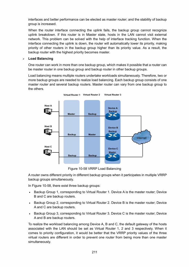
211
interfaces and better performance can be elected as master router; and the stability of backup group is increased.
When the router interface connecting the uplink fails, the backup group cannot recognize uplink breakdown. If this router is in Master state, hosts in the LAN cannot visit external network. This problem can be solved with the help of interface tracking function. When the interface connecting the uplink is down, the router will automatically lower its priority, making priority of other routers in the backup group higher than its priority value. As a result, the backup router with the highest priority becomes master.
Load Balancing
One router can work in more than one backup group, which makes it possible that a router can be master router in one backup group and backup router in other backup groups.
Load balancing means multiple routers undertake workloads simultaneously. Therefore, two or more backup groups are needed to realize load balancing. Each backup group consists of one master router and several backup routers. Master router can vary from one backup group to the others.
Figure 10-58 VRRP Load Balancing
A router owns different priority in different backup groups when it participates in multiple VRRP backup groups simultaneously.
In Figure 10-58, there exist three backup groups:
• Backup Group 1, corresponding to Virtual Router 1. Device A is the master router; Device B and C are backup routers.
• Backup Group 2, corresponding to Virtual Router 2. Device B is the master router; Device A and C are backup routers.
• Backup Group 3, corresponding to Virtual Router 3. Device C is the master router; Device A and B are backup routers.
To realize the workload balancing among Device A, B and C, the default gateway of the hosts associated with the LAN should be set as Virtual Router 1, 2 and 3 respectively. When it comes to priority configuration, it would be better that the VRRP priority values of the three virtual routers are different in order to prevent one router from being more than one master simultaneously.
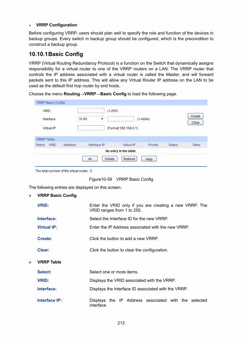
212
VRRP Configuration
Before configuring VRRP, users should plan well to specify the role and function of the devices in backup groups. Every switch in backup group should be configured, which is the precondition to construct a backup group.
10.10.1 Basic Config VRRP (Virtual Routing Redundancy Protocol) is a function on the Switch that dynamically assigns responsibility for a virtual router to one of the VRRP routers on a LAN. The VRRP router that controls the IP address associated with a virtual router is called the Master, and will forward packets sent to this IP address. This will allow any Virtual Router IP address on the LAN to be used as the default first hop router by end hosts.
Choose the menu Routing→VRRP→Basic Config to load the following page.
Figure10-59 VRRP Basic Config
The following entries are displayed on this screen:
VRRP Basic Config
VRID: Enter the VRID only if you are creating a new VRRP. The VRID ranges from 1 to 255.
Interface: Select the Interface ID for the new VRRP.
Virtual IP: Enter the IP Address associated with the new VRRP.
Create: Click the button to add a new VRRP.
Clear: Click the button to clear the configuration.
VRRP Table
Select: Select one or more items.
VRID: Displays the VRID associated with the VRRP.
Interface: Displays the Interface ID associated with the VRRP.
Interface IP: Displays the IP Address associated with the selected interface.
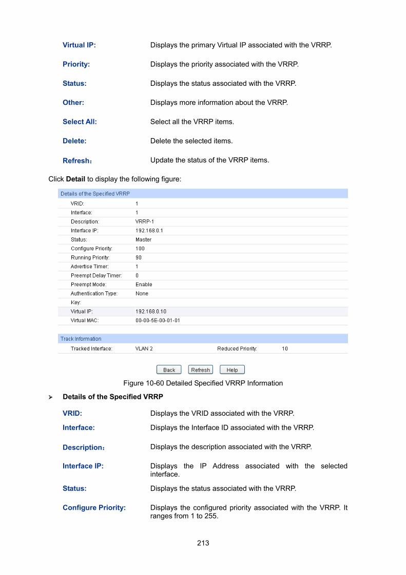
213
Virtual IP: Displays the primary Virtual IP associated with the VRRP.
Priority: Displays the priority associated with the VRRP.
Status: Displays the status associated with the VRRP.
Other: Displays more information about the VRRP.
Select All: Select all the VRRP items.
Delete: Delete the selected items.
Refresh: Update the status of the VRRP items.
Click Detail to display the following figure:
Figure 10-60 Detailed Specified VRRP Information
Details of the Specified VRRP
VRID: Displays the VRID associated with the VRRP.
Interface: Displays the Interface ID associated with the VRRP.
Description: Displays the description associated with the VRRP.
Interface IP: Displays the IP Address associated with the selected interface.
Status: Displays the status associated with the VRRP.
Configure Priority: Displays the configured priority associated with the VRRP. It ranges from 1 to 255.
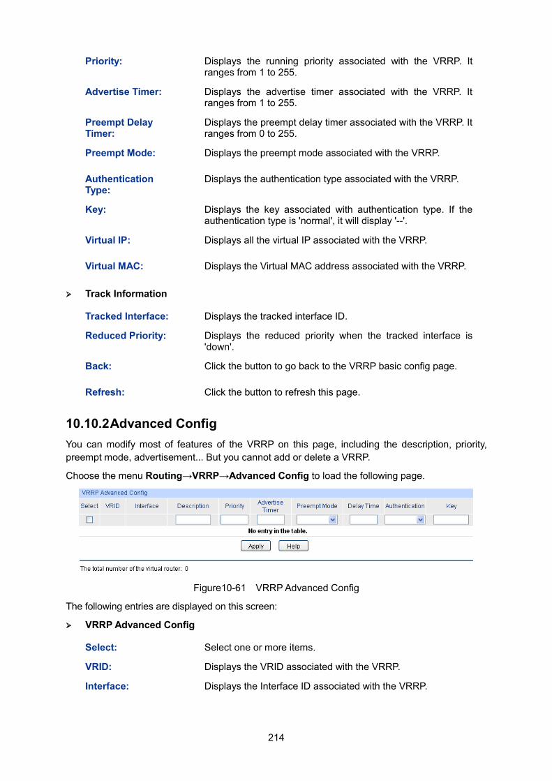
214
Priority: Displays the running priority associated with the VRRP. It ranges from 1 to 255.
Advertise Timer: Displays the advertise timer associated with the VRRP. It ranges from 1 to 255.
Preempt Delay Timer:
Displays the preempt delay timer associated with the VRRP. It ranges from 0 to 255.
Preempt Mode: Displays the preempt mode associated with the VRRP.
Authentication Type:
Displays the authentication type associated with the VRRP.
Key: Displays the key associated with authentication type. If the authentication type is 'normal', it will display '--'.
Virtual IP: Displays all the virtual IP associated with the VRRP.
Virtual MAC: Displays the Virtual MAC address associated with the VRRP.
Track Information
Tracked Interface: Displays the tracked interface ID.
Reduced Priority: Displays the reduced priority when the tracked interface is 'down'.
Back: Click the button to go back to the VRRP basic config page.
Refresh: Click the button to refresh this page.
10.10.2 Advanced Config You can modify most of features of the VRRP on this page, including the description, priority, preempt mode, advertisement... But you cannot add or delete a VRRP.
Choose the menu Routing→VRRP→Advanced Config to load the following page.
Figure10-61 VRRP Advanced Config
The following entries are displayed on this screen:
VRRP Advanced Config
Select: Select one or more items.
VRID: Displays the VRID associated with the VRRP.
Interface: Displays the Interface ID associated with the VRRP.
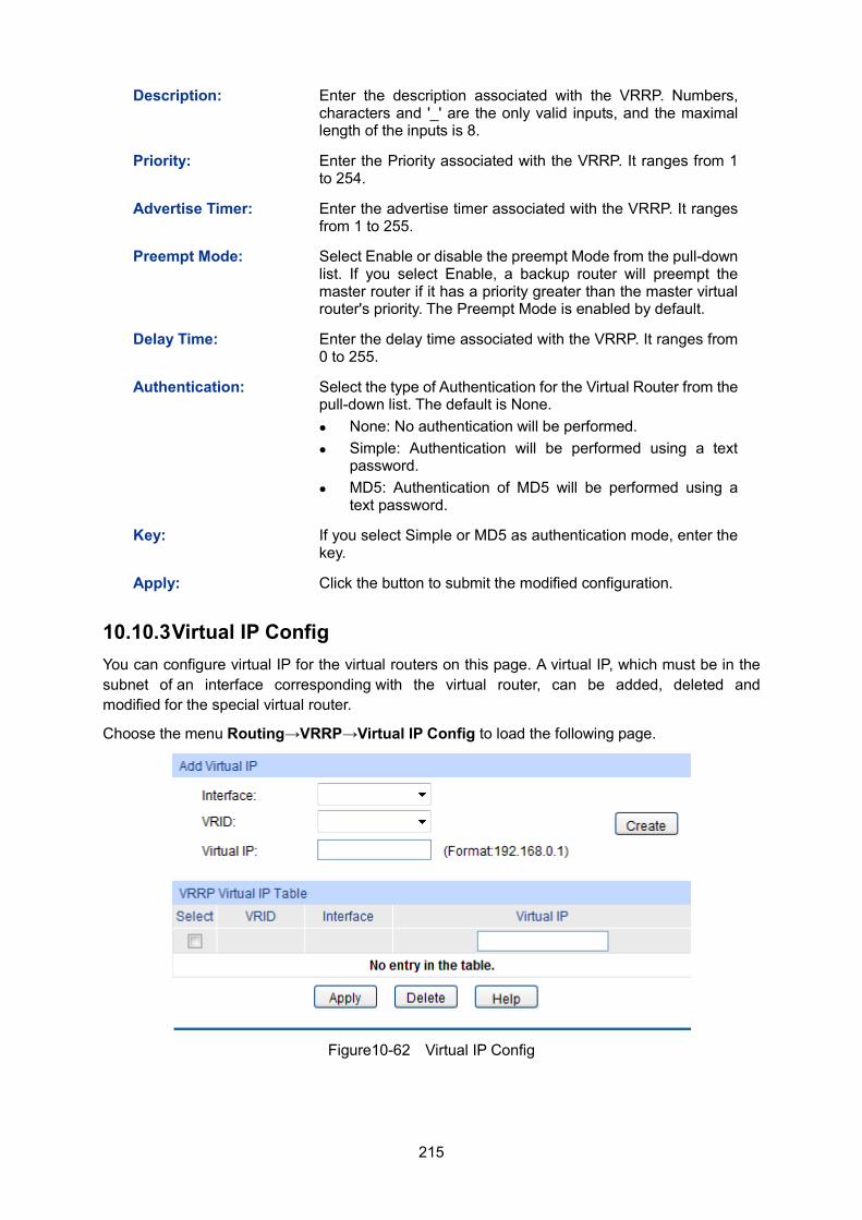
215
Description: Enter the description associated with the VRRP. Numbers, characters and '_' are the only valid inputs, and the maximal length of the inputs is 8.
Priority: Enter the Priority associated with the VRRP. It ranges from 1 to 254.
Advertise Timer: Enter the advertise timer associated with the VRRP. It ranges from 1 to 255.
Preempt Mode: Select Enable or disable the preempt Mode from the pull-down list. If you select Enable, a backup router will preempt the master router if it has a priority greater than the master virtual router's priority. The Preempt Mode is enabled by default.
Delay Time: Enter the delay time associated with the VRRP. It ranges from 0 to 255.
Authentication: Select the type of Authentication for the Virtual Router from the pull-down list. The default is None. None: No authentication will be performed. Simple: Authentication will be performed using a text
password. MD5: Authentication of MD5 will be performed using a
text password.
Key: If you select Simple or MD5 as authentication mode, enter the key.
Apply: Click the button to submit the modified configuration.
10.10.3 Virtual IP Config You can configure virtual IP for the virtual routers on this page. A virtual IP, which must be in the subnet of an interface corresponding with the virtual router, can be added, deleted and modified for the special virtual router.
Choose the menu Routing→VRRP→Virtual IP Config to load the following page.
Figure10-62 Virtual IP Config
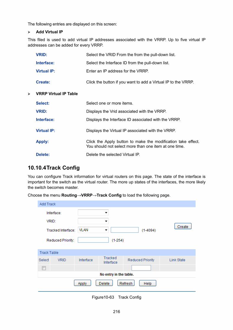
216
The following entries are displayed on this screen:
Add Virtual IP
This filed is used to add virtual IP addresses associated with the VRRP. Up to five virtual IP addresses can be added for every VRRP.
VRID: Select the VRID From the from the pull-down list.
Interface: Select the Interface ID from the pull-down list.
Virtual IP: Enter an IP address for the VRRP.
Create: Click the button if you want to add a Virtual IP to the VRRP.
VRRP Virtual IP Table
Select: Select one or more items.
VRID: Displays the Vrid associated with the VRRP.
Interface: Displays the Interface ID associated with the VRRP.
Virtual IP: Displays the Virtual IP associated with the VRRP.
Apply: Click the Apply button to make the modification take effect. You should not select more than one item at one time.
Delete: Delete the selected Virtual IP.
10.10.4 Track Config You can configure Track information for virtual routers on this page. The state of the interface is important for the switch as the virtual router. The more up states of the interfaces, the more likely the switch becomes master.
Choose the menu Routing→VRRP→Track Config to load the following page.
Figure10-63 Track Config
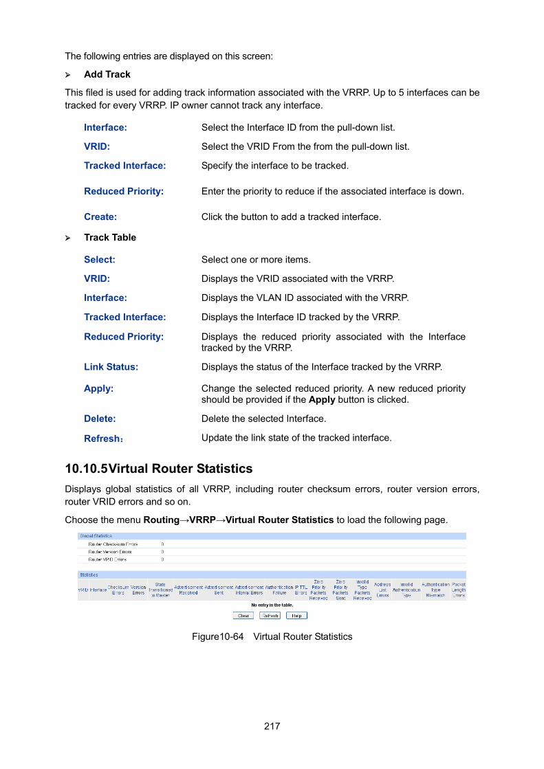
217
The following entries are displayed on this screen:
Add Track
This filed is used for adding track information associated with the VRRP. Up to 5 interfaces can be tracked for every VRRP. IP owner cannot track any interface.
Interface: Select the Interface ID from the pull-down list.
VRID: Select the VRID From the from the pull-down list.
Tracked Interface: Specify the interface to be tracked.
Reduced Priority: Enter the priority to reduce if the associated interface is down.
Create: Click the button to add a tracked interface.
Track Table
Select: Select one or more items.
VRID: Displays the VRID associated with the VRRP.
Interface: Displays the VLAN ID associated with the VRRP.
Tracked Interface: Displays the Interface ID tracked by the VRRP.
Reduced Priority: Displays the reduced priority associated with the Interface tracked by the VRRP.
Link Status: Displays the status of the Interface tracked by the VRRP.
Apply: Change the selected reduced priority. A new reduced priority should be provided if the Apply button is clicked.
Delete: Delete the selected Interface.
Refresh: Update the link state of the tracked interface.
10.10.5 Virtual Router Statistics Displays global statistics of all VRRP, including router checksum errors, router version errors, router VRID errors and so on.
Choose the menu Routing→VRRP→Virtual Router Statistics to load the following page.
Figure10-64 Virtual Router Statistics
218
The following entries are displayed on this screen:
Global Statistics
Router Checksum Errors:
Displays the total number of VRRP packets received with an invalid VRRP checksum value.
Router Version Errors:
Displays the total number of VRRP packets received with an unknown or unsupported version number.
Router VRID Errors: Displays the total number of VRRP packets received with an invalid VRID for this virtual router.
Statistics
Displays specified virtual router statistics. It lists all the statistics for the specified VRRP and can be reset for your convenience when doing statistics.
VRID: The VRID for the selected Virtual Router.
Interface: The interface ID for the selected Virtual Router.
Checksum Errors: Displays the number of VRRP packets received with an invalid VRRP checksum value.
Version Errors: Displays the number of VRRP packets received with an unknown or unsupported version number.
State Transitioned to Master:
Displays the number of times that this virtual router's state has transitioned to Master.
Advertisement Received:
Displays the number of VRRP advertisements received by this virtual router.
Advertisement Sent:
Displays the number of VRRP advertisements sent by this virtual router.
Advertisement Interval Errors:
Displays the number of the received VRRP advertisement packets whose advertisement interval was different from the one configured for the local virtual router.
Authentication Failure:
Displays the number of VRRP packets received that did not pass the authentication check.
IP TTL Errors: Displays the number of VRRP packets received by the virtual router with IP TTL (Time-To-Live) not equal to 255.
Zero Priority Packets Received:
Displays the number of VRRP packets received by the virtual router with a priority of '0'.
Zero Priority Packets Sent:
Displays the number of VRRP packets sent by the virtual router with a priority of '0'.
Address List Errors: Displays the number of packets received for which the address list does not match the locally configured list for the virtual router.
Invalid Authentication Type:
Displays the number of packets received with an unknown authentication type.
Authentication Type Mismatch:
Displays the number of packets received with an authentication type different to the locally configured authentication method.
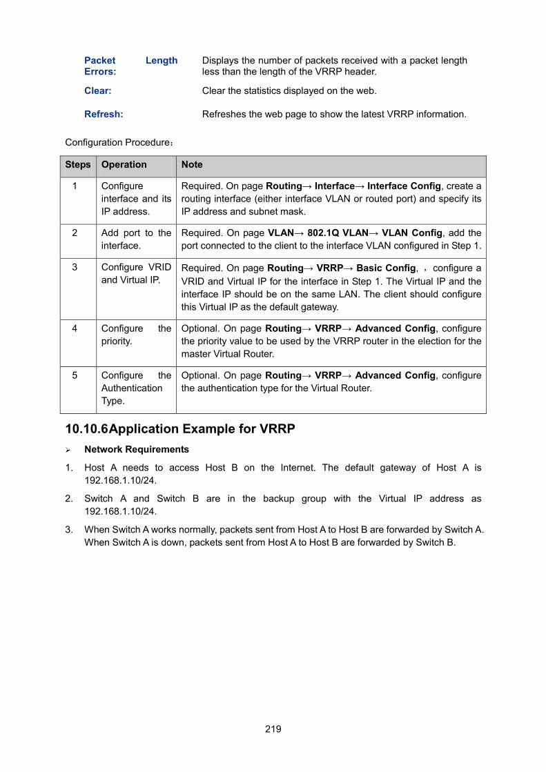
219
Packet Length Errors:
Displays the number of packets received with a packet length less than the length of the VRRP header.
Clear: Clear the statistics displayed on the web.
Refresh: Refreshes the web page to show the latest VRRP information.
Configuration Procedure:
Steps Operation Note
1 Configure interface and its IP address.
Required. On page Routing→ Interface→ Interface Config, create a routing interface (either interface VLAN or routed port) and specify its IP address and subnet mask.
2 Add port to the interface.
Required. On page VLAN→ 802.1Q VLAN→ VLAN Config, add the port connected to the client to the interface VLAN configured in Step 1.
3 Configure VRID and Virtual IP.
Required. On page Routing→ VRRP→ Basic Config, ,configure a VRID and Virtual IP for the interface in Step 1. The Virtual IP and the interface IP should be on the same LAN. The client should configure this Virtual IP as the default gateway.
4 Configure the priority.
Optional. On page Routing→ VRRP→ Advanced Config, configure the priority value to be used by the VRRP router in the election for the master Virtual Router.
5 Configure the Authentication Type.
Optional. On page Routing→ VRRP→ Advanced Config, configure the authentication type for the Virtual Router.
10.10.6 Application Example for VRRP Network Requirements
1. Host A needs to access Host B on the Internet. The default gateway of Host A is 192.168.1.10/24.
2. Switch A and Switch B are in the backup group with the Virtual IP address as 192.168.1.10/24.
3. When Switch A works normally, packets sent from Host A to Host B are forwarded by Switch A. When Switch A is down, packets sent from Host A to Host B are forwarded by Switch B.
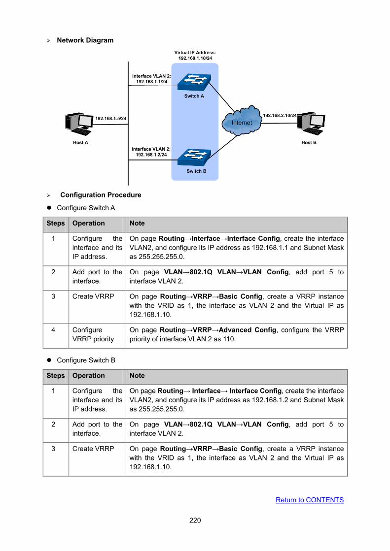
220
Network Diagram
Configuration Procedure
Configure Switch A
Steps Operation Note
1 Configure the interface and its IP address.
On page Routing→Interface→Interface Config, create the interface VLAN2, and configure its IP address as 192.168.1.1 and Subnet Mask as 255.255.255.0.
2 Add port to the interface.
On page VLAN→802.1Q VLAN→VLAN Config, add port 5 to interface VLAN 2.
3 Create VRRP On page Routing→VRRP→Basic Config, create a VRRP instance with the VRID as 1, the interface as VLAN 2 and the Virtual IP as 192.168.1.10.
4 Configure VRRP priority
On page Routing→VRRP→Advanced Config, configure the VRRP priority of interface VLAN 2 as 110.
Configure Switch B
Steps Operation Note
1 Configure the interface and its IP address.
On page Routing→ Interface→ Interface Config, create the interface VLAN2, and configure its IP address as 192.168.1.2 and Subnet Mask as 255.255.255.0.
2 Add port to the interface.
On page VLAN→802.1Q VLAN→VLAN Config, add port 5 to interface VLAN 2.
3 Create VRRP On page Routing→VRRP→Basic Config, create a VRRP instance with the VRID as 1, the interface as VLAN 2 and the Virtual IP as 192.168.1.10.
Return to CONTENTS
221
Chapter 11 Multicast Routing Overview of Multicast Routing Protocols
Note:
The router and router icon mentioned in this chapter represent the router in general or the switch that runs the layer 3 multicast routing protocols.
The multicast routing protocols run in layer 3 multicast devices and they create and maintain multicast routes to forward the multicast packets correctly and efficiently. The multicast routing protocols establish routes for the point-to-multipoint transmissions, known as the multicast distributing tree.
The multicast routing table consists of a group of (S, G) entries, and (S, G) route represents routing information from source S to group G. If no multicast source is specified, the entry will be described as (*, G) with * representing any multicast source. If the router supports multiple multicast routing protocols, its multicast routing table will contain multicast routes generated from multiple protocols.
Multicast routing protocols include protocols as IGMP, PIM, MSDP, DVMRP, and static multicast routing.
The domain mentioned in this guide refers to Autonomous System, which contains a group of routers exchanging routing information with the same routing protocol.
IGMP stands for Internet Group Management Protocol. It is responsible for members management of IP multicast in the TCP/IP, and is used to establish and maintain the multicast member relationships between the IP host and its directly neighboring multicast routers.
PIM (Protocol Independent Multicast) is a typical intra-domain multicast routing protocol among the AS. It provides IP multicast forwarding by leveraging static routes or unicast routing tables generated by any unicast routing protocols, such as RIP (Routing Information Protocol), OSPF (Open Shortest Path First), IS-IS (Intermediate System to Intermediate System) or Border Gateway Protocol (BGP).
MSDP (Multicast Source Discovery Protocol) is an intra-domain multicast resolution which aims at the connection of different PIM SM domains and is used to discover the multicast source information among different ASs.
DVMRP (Distance Vector Multicast Routing Protocol) is mainly applied in the multicast backbone network of the Internet.
The following mainly introduces IGMP, PIM and Static Multicast Routing.
Multicast Roles and Models
There are several different roles in the multicast transmission:
Multicast Source: The sender of the multicast information.
Multicast Group Member: All the receivers of the multicast information.
Multicast Group: The group consists of the multicast group members.
Multicast Router(or the Layer 3 Multicast Device): The router or switch that supports the layer 3
multicast functions, which contains the multicast routing function and the management function
of the multicast group members.
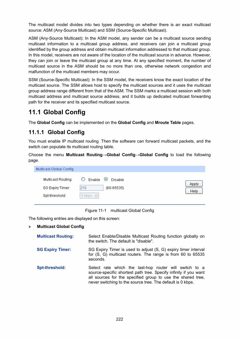
222
The multicast model divides into two types depending on whether there is an exact multicast source: ASM (Any-Source Multicast) and SSM (Source-Specific Multicast).
ASM (Any-Source Multicast): In the ASM model, any sender can be a multicast source sending multicast information to a multicast group address, and receivers can join a multicast group identified by the group address and obtain multicast information addressed to that multicast group. In this model, receivers are not aware of the location of the multicast source in advance. However, they can join or leave the multicast group at any time. At any specified moment, the number of multicast source in the ASM should be no more than one, otherwise network congestion and malfunction of the multicast members may occur.
SSM (Source-Specific Multicast): In the SSM model, the receivers know the exact location of the multicast source. The SSM allows host to specify the multicast sources and it uses the multicast group address range different from that of the ASM. The SSM marks a multicast session with both multicast address and multicast source address, and it builds up dedicated multicast forwarding path for the receiver and its specified multicast source.
11.1 Global Config The Global Config can be implemented on the Global Config and Mroute Table pages.
11.1.1 Global Config You must enable IP multicast routing. Then the software can forward multicast packets, and the switch can populate its multicast routing table.
Choose the menu Multicast Routing→Global Config→Global Config to load the following page.
Figure 11-1 multicast Global Config
The following entries are displayed on this screen:
Multicast Global Config
Multicast Routing: Select Enable/Disable Multicast Routing function globally on the switch. The default is "disable".
SG Expiry Timer: SG Expiry Timer is used to adjust (S, G) expiry timer interval for (S, G) multicast routers. The range is from 60 to 65535 seconds.
Spt-threshold: Select rate which the last-hop router will switch to a source-specific shortest path tree. Specify infinity if you want all sources for the specified group to use the shared tree, never switching to the source tree. The default is 0 kbps.
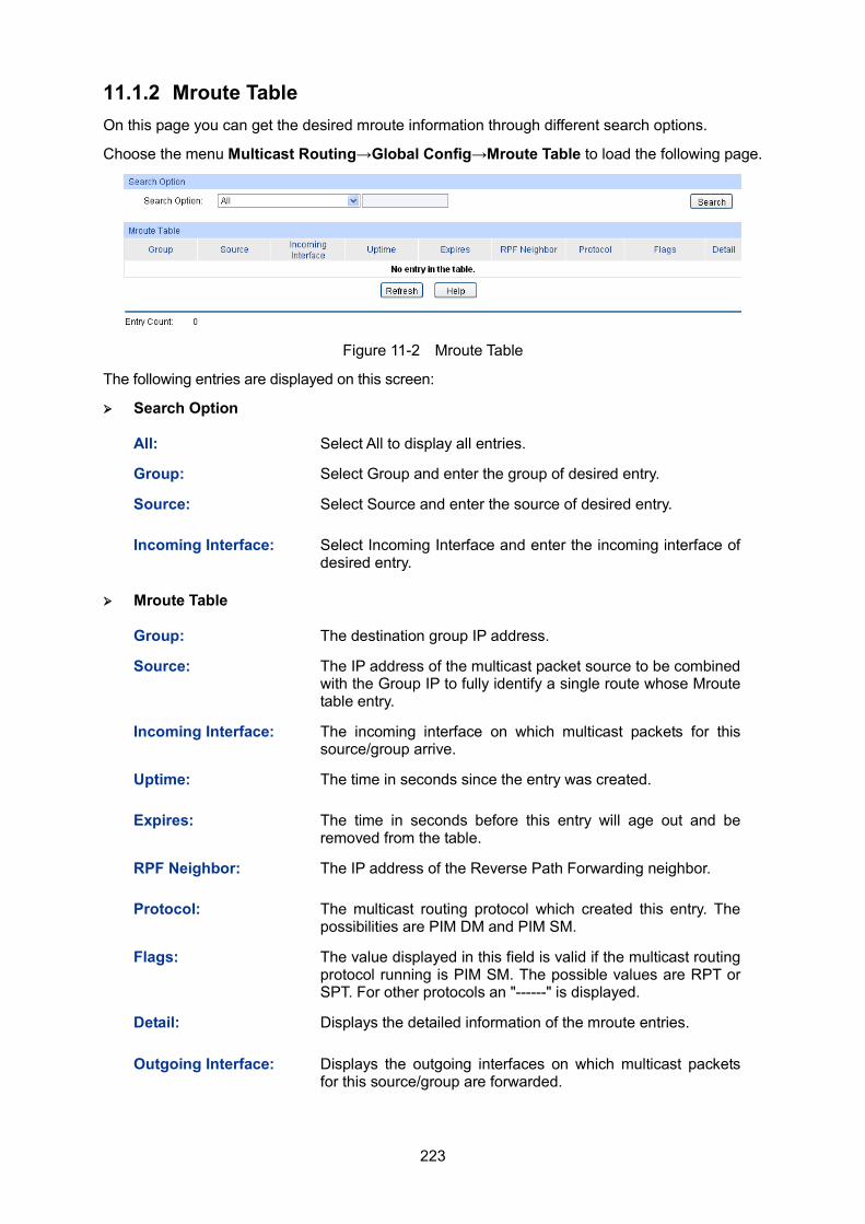
223
11.1.2 Mroute Table On this page you can get the desired mroute information through different search options.
Choose the menu Multicast Routing→Global Config→Mroute Table to load the following page.
Figure 11-2 Mroute Table
The following entries are displayed on this screen:
Search Option
All: Select All to display all entries.
Group: Select Group and enter the group of desired entry.
Source: Select Source and enter the source of desired entry.
Incoming Interface: Select Incoming Interface and enter the incoming interface of desired entry.
Mroute Table
Group: The destination group IP address.
Source: The IP address of the multicast packet source to be combined with the Group IP to fully identify a single route whose Mroute table entry.
Incoming Interface: The incoming interface on which multicast packets for this source/group arrive.
Uptime: The time in seconds since the entry was created.
Expires: The time in seconds before this entry will age out and be removed from the table.
RPF Neighbor: The IP address of the Reverse Path Forwarding neighbor.
Protocol: The multicast routing protocol which created this entry. The possibilities are PIM DM and PIM SM.
Flags: The value displayed in this field is valid if the multicast routing protocol running is PIM SM. The possible values are RPT or SPT. For other protocols an "------" is displayed.
Detail: Displays the detailed information of the mroute entries.
Outgoing Interface: Displays the outgoing interfaces on which multicast packets for this source/group are forwarded.
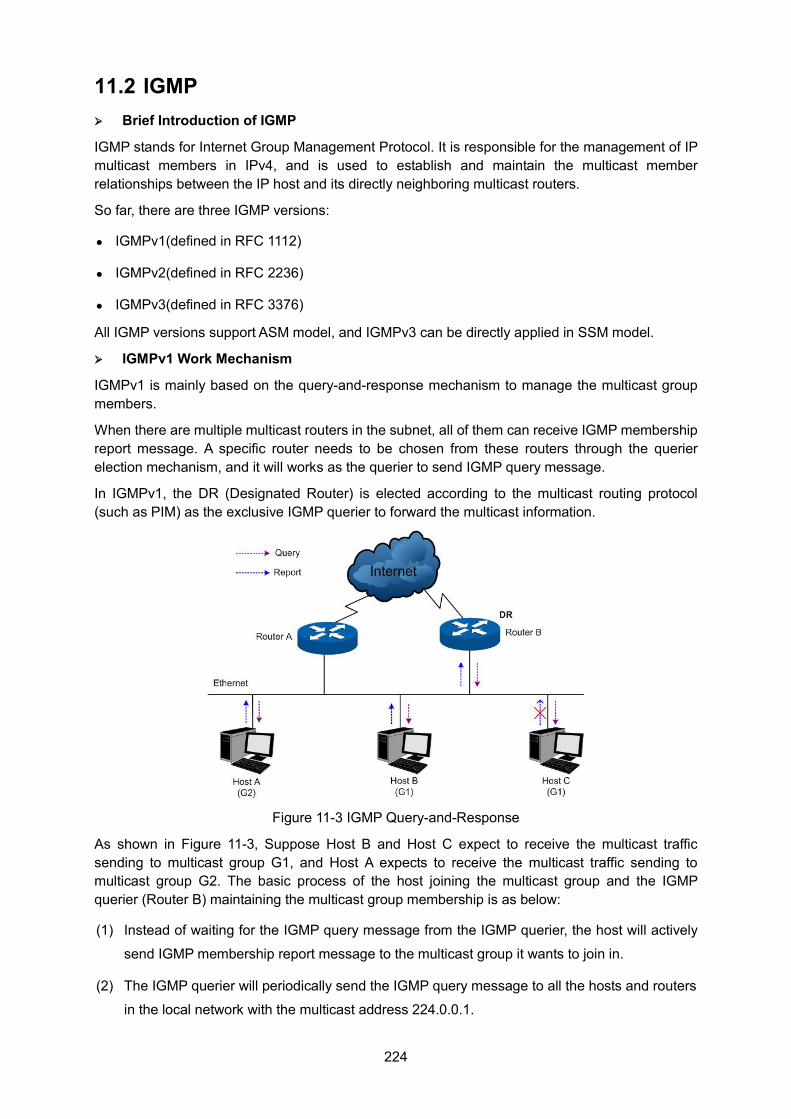
224
11.2 IGMP Brief Introduction of IGMP
IGMP stands for Internet Group Management Protocol. It is responsible for the management of IP multicast members in IPv4, and is used to establish and maintain the multicast member relationships between the IP host and its directly neighboring multicast routers.
So far, there are three IGMP versions:
IGMPv1(defined in RFC 1112)
IGMPv2(defined in RFC 2236)
IGMPv3(defined in RFC 3376)
All IGMP versions support ASM model, and IGMPv3 can be directly applied in SSM model.
IGMPv1 Work Mechanism
IGMPv1 is mainly based on the query-and-response mechanism to manage the multicast group members.
When there are multiple multicast routers in the subnet, all of them can receive IGMP membership report message. A specific router needs to be chosen from these routers through the querier election mechanism, and it will works as the querier to send IGMP query message.
In IGMPv1, the DR (Designated Router) is elected according to the multicast routing protocol (such as PIM) as the exclusive IGMP querier to forward the multicast information.
Figure 11-3 IGMP Query-and-Response
As shown in Figure 11-3, Suppose Host B and Host C expect to receive the multicast traffic sending to multicast group G1, and Host A expects to receive the multicast traffic sending to multicast group G2. The basic process of the host joining the multicast group and the IGMP querier (Router B) maintaining the multicast group membership is as below:
(1) Instead of waiting for the IGMP query message from the IGMP querier, the host will actively
send IGMP membership report message to the multicast group it wants to join in.
(2) The IGMP querier will periodically send the IGMP query message to all the hosts and routers
in the local network with the multicast address 224.0.0.1.
225
(3) After receiving the IGMP query message, the host that is interested in multicast group G1,
either Host B or Host C (depending on whose latency timer runs out first) — for example Host
B, will firstly multicast IGMP membership report message to G1 to declare it belongs to G1.
As all the hosts and routers can receive this membership report message and the IGMP
routers (Router A and Router B) already know there is a host interested in G1, Host C will not
send its report message for G1 after it receives the report message of Host B. This is called
the membership report preventing mechanism and it helps to reduce the traffic in the local
network.
(4) At the same time, as Host A is interested in G2, it will multicast report message to G2 to
declare it belongs to G2.
(5) Through the above query-and-response process, the IGMP router learns that there are group
members of G1 and G2 in the local network. It will generate the multicast forwarding entries (*,
G1) and (*, G2) via the multicast routing protocol, such as PIM, as the basis of the multicast
traffic forwarding. The symbol * represents any multicast source.
(6) When multicast packets sending to G1 or G2 from the multicast source arrive at the IGMP
router via multicast routing, the multicast forwarding entries (*, G1) and (*, G2) in the IGMP
router will guide the multicast packets to the local network and the receiver hosts can receive
them.
IGMPv1 doesn’t specially define the leave group message. When a host running IGMPv1 leaves one multicast group, it wouldn’t send the report message to this multicast group. If no member exists in the multicast group, the IGMP router will not receive any report message to this multicast group, thus it will delete this multicast group’s corresponding multicast forwarding entries after a period of time.
IGMPv2 Work Process
IGMPv2 adds the querier-election mechanism and leave-group mechanism based on IGMPv1.
1. Querier-Election Mechanism
The querier-election mechanism in IGMPv2 is illustrated as below:
(1) Every IGMP router will assume itself as the querier at its initialization, and send IGMP general
query message to all the hosts and routers with the multicast address 224.0.0.1 in the local
network.
(2) After the other IGMPv2 routers in the local network receive this IGMP general query message,
it will compare the message’s source IP address with its interface address. Through the
comparison, the router with the smallest IP address will be elected as the querier and the
other routers as the non-querier.
(3) All the non-queriers will start up a timer, known as the Other Querier Present Timer. This timer
will be reset if the non-querier receives the IGMP query message before the timer runs out;
otherwise the former querier will be assumed as invalid and a new querier-election will be
initiated.
226
2. Leave-Group Mechanism
When a host leaves a multicast group in IGMPv2:
(1) The host will send leave group message to all the multicast routers in the local network with
the multicast address 224.0.0.2.
(2) After receiving this leave group message, the querier will send group-specific query message
to the multicast group that the host announces to leave. (The querying multicast group
address is filled in the destination address field and the group address field of this
group-specific query message.)
(3) When there are other members of this multicast group in the local network, these members
will send their membership report messages after receiving the group-specific query
message within the max response time set in the query message.
(4) If the querier receives the other member’s membership report message of this multicast
group within the max response time, the querier will continue to maintain the memberships of
this multicast group; otherwise the querier will assume that there is no member in this
multicast group and will no longer maintain its memberships.
IGMPv3 Work Process
Compatible of and Inherited from IGMPv1 and IGMPv2, IGMPv3 further enhances the control capacity of the hosts and broaden the functions of the query and report messages.
1. Enhancement of the Hosts
IGMPv3 adds the filtering mode (INCLUDE/EXCLUDE) for the multicast source basing on the group-specific query. This mode allows the hosts to accept or reject multicast traffic from specified multicast sources when joining a multicast group.
When a host joins a multicast group:
If it expects only the multicast data from specified multicast sources, such as S1, S2 … Its
report message can be marked with INCLUDE Sources (S1, S2 …);
If it doesn’t expect any multicast data from the specified multicast sources, such as S2, S2… Its
report message can be marked with EXLUDE Sources (S1,S2 …);
As shown in Figure 11-4, there are two multicast sources, Source 1(S1) and Source 2(S2), sending multicast data to multicast group G. Host B is only expecting the multicast data sending from Source 1 to G.
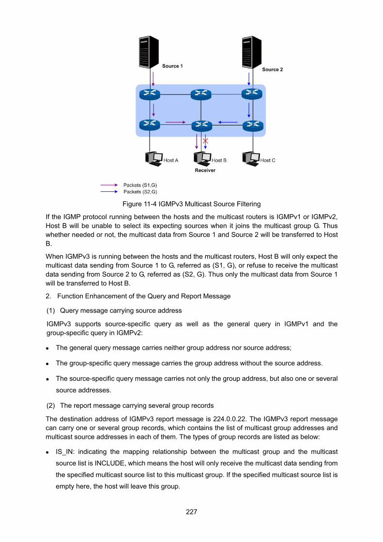
227
Figure 11-4 IGMPv3 Multicast Source Filtering
If the IGMP protocol running between the hosts and the multicast routers is IGMPv1 or IGMPv2, Host B will be unable to select its expecting sources when it joins the multicast group G. Thus whether needed or not, the multicast data from Source 1 and Source 2 will be transferred to Host B.
When IGMPv3 is running between the hosts and the multicast routers, Host B will only expect the multicast data sending from Source 1 to G, referred as (S1, G), or refuse to receive the multicast data sending from Source 2 to G, referred as (S2, G). Thus only the multicast data from Source 1 will be transferred to Host B.
2. Function Enhancement of the Query and Report Message
(1) Query message carrying source address
IGMPv3 supports source-specific query as well as the general query in IGMPv1 and the group-specific query in IGMPv2:
The general query message carries neither group address nor source address;
The group-specific query message carries the group address without the source address.
The source-specific query message carries not only the group address, but also one or several
source addresses.
(2) The report message carrying several group records
The destination address of IGMPv3 report message is 224.0.0.22. The IGMPv3 report message can carry one or several group records, which contains the list of multicast group addresses and multicast source addresses in each of them. The types of group records are listed as below:
IS_IN: indicating the mapping relationship between the multicast group and the multicast
source list is INCLUDE, which means the host will only receive the multicast data sending from
the specified multicast source list to this multicast group. If the specified multicast source list is
empty here, the host will leave this group.
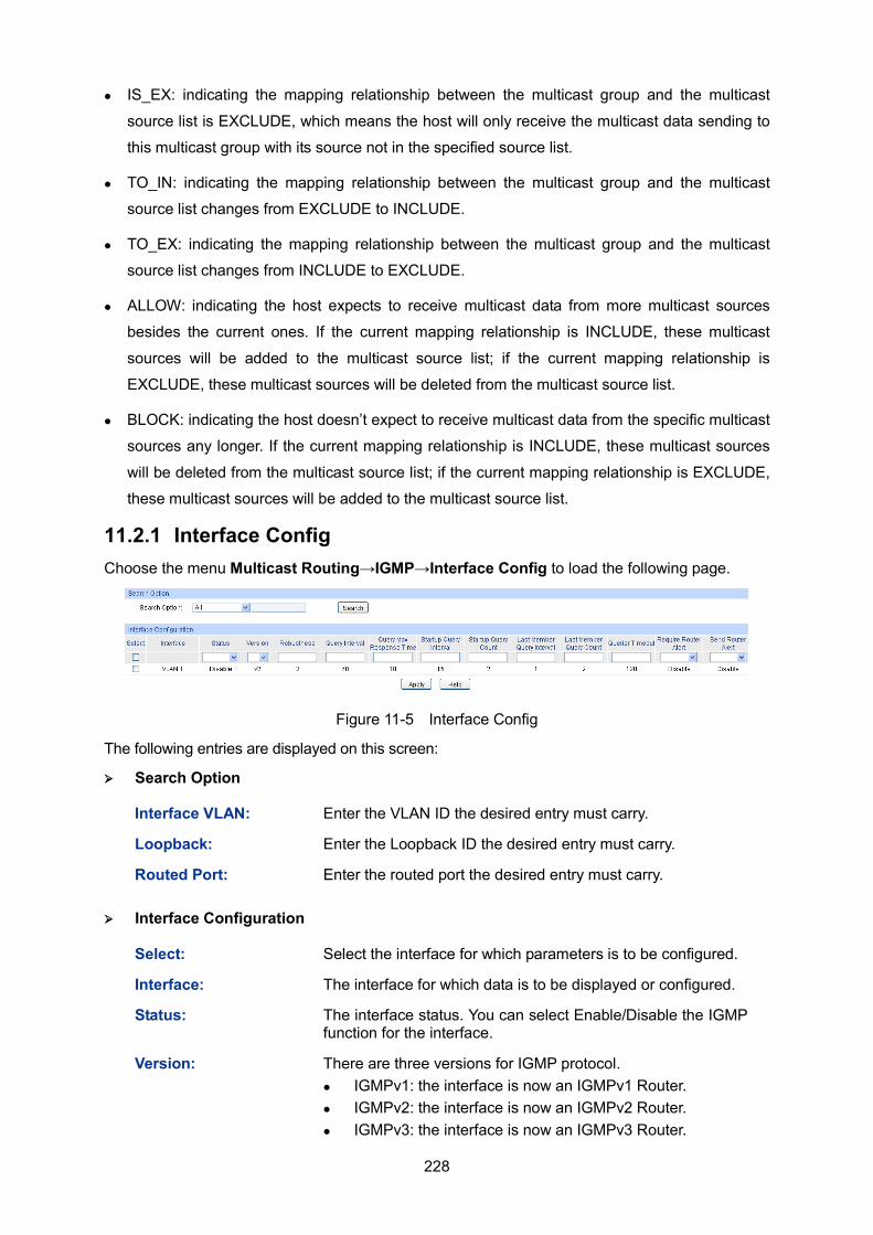
228
IS_EX: indicating the mapping relationship between the multicast group and the multicast
source list is EXCLUDE, which means the host will only receive the multicast data sending to
this multicast group with its source not in the specified source list.
TO_IN: indicating the mapping relationship between the multicast group and the multicast
source list changes from EXCLUDE to INCLUDE.
TO_EX: indicating the mapping relationship between the multicast group and the multicast
source list changes from INCLUDE to EXCLUDE.
ALLOW: indicating the host expects to receive multicast data from more multicast sources
besides the current ones. If the current mapping relationship is INCLUDE, these multicast
sources will be added to the multicast source list; if the current mapping relationship is
EXCLUDE, these multicast sources will be deleted from the multicast source list.
BLOCK: indicating the host doesn’t expect to receive multicast data from the specific multicast
sources any longer. If the current mapping relationship is INCLUDE, these multicast sources
will be deleted from the multicast source list; if the current mapping relationship is EXCLUDE,
these multicast sources will be added to the multicast source list.
11.2.1 Interface Config Choose the menu Multicast Routing→IGMP→Interface Config to load the following page.
Figure 11-5 Interface Config
The following entries are displayed on this screen:
Search Option
Interface VLAN: Enter the VLAN ID the desired entry must carry.
Loopback: Enter the Loopback ID the desired entry must carry.
Routed Port: Enter the routed port the desired entry must carry.
Interface Configuration
Select: Select the interface for which parameters is to be configured.
Interface: The interface for which data is to be displayed or configured.
Status: The interface status. You can select Enable/Disable the IGMP function for the interface.
Version: There are three versions for IGMP protocol. IGMPv1: the interface is now an IGMPv1 Router. IGMPv2: the interface is now an IGMPv2 Router. IGMPv3: the interface is now an IGMPv3 Router.
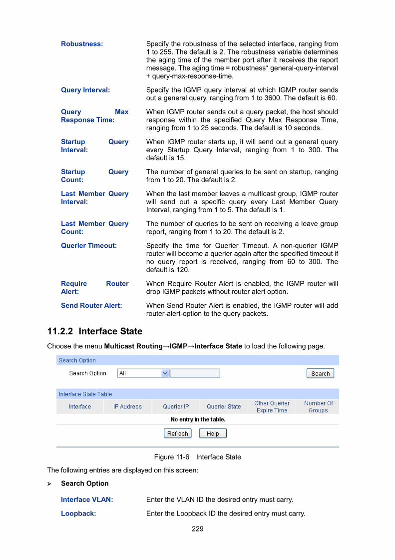
229
Robustness: Specify the robustness of the selected interface, ranging from 1 to 255. The default is 2. The robustness variable determines the aging time of the member port after it receives the report message. The aging time = robustness* general-query-interval + query-max-response-time.
Query Interval: Specify the IGMP query interval at which IGMP router sends out a general query, ranging from 1 to 3600. The default is 60.
Query Max Response Time:
When IGMP router sends out a query packet, the host should response within the specified Query Max Response Time, ranging from 1 to 25 seconds. The default is 10 seconds.
Startup Query Interval:
When IGMP router starts up, it will send out a general query every Startup Query Interval, ranging from 1 to 300. The default is 15.
Startup Query Count:
The number of general queries to be sent on startup, ranging from 1 to 20. The default is 2.
Last Member Query Interval:
When the last member leaves a multicast group, IGMP router will send out a specific query every Last Member Query Interval, ranging from 1 to 5. The default is 1.
Last Member Query Count:
The number of queries to be sent on receiving a leave group report, ranging from 1 to 20. The default is 2.
Querier Timeout: Specify the time for Querier Timeout. A non-querier IGMP router will become a querier again after the specified timeout if no query report is received, ranging from 60 to 300. The default is 120.
Require Router Alert:
When Require Router Alert is enabled, the IGMP router will drop IGMP packets without router alert option.
Send Router Alert: When Send Router Alert is enabled, the IGMP router will add router-alert-option to the query packets.
11.2.2 Interface State Choose the menu Multicast Routing→IGMP→Interface State to load the following page.
Figure 11-6 Interface State
The following entries are displayed on this screen:
Search Option
Interface VLAN: Enter the VLAN ID the desired entry must carry.
Loopback: Enter the Loopback ID the desired entry must carry.
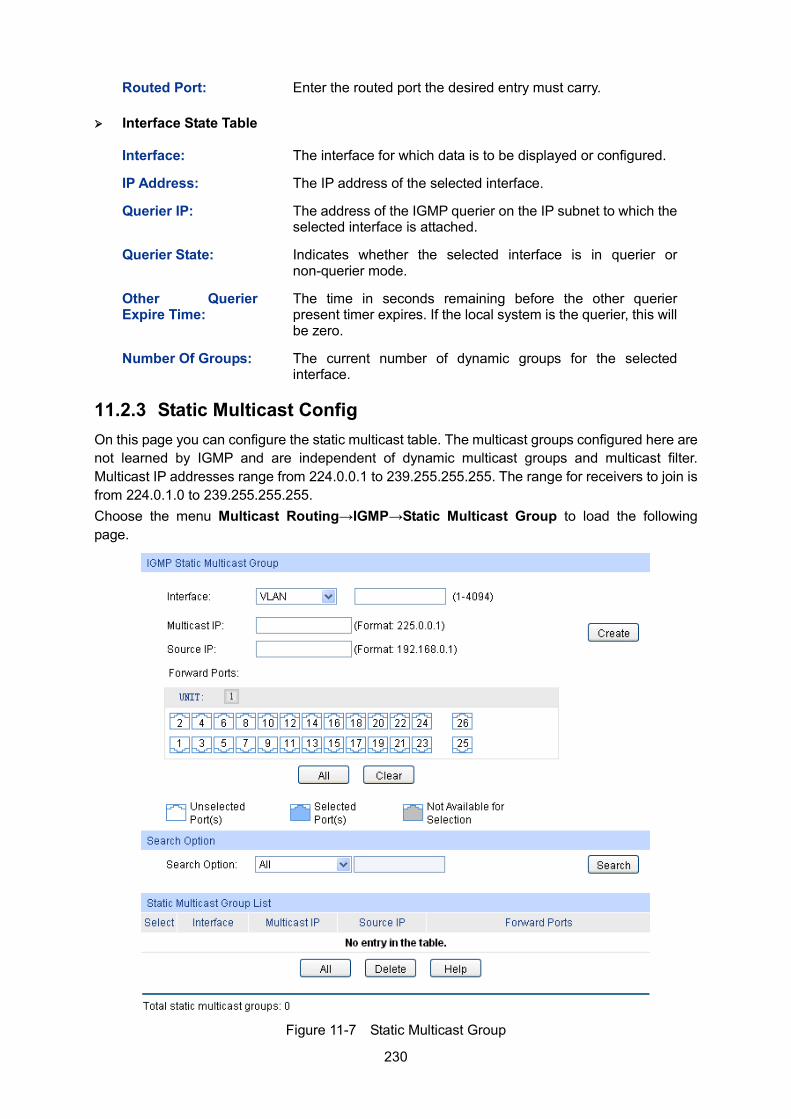
230
Routed Port: Enter the routed port the desired entry must carry.
Interface State Table
Interface: The interface for which data is to be displayed or configured.
IP Address: The IP address of the selected interface.
Querier IP: The address of the IGMP querier on the IP subnet to which the selected interface is attached.
Querier State: Indicates whether the selected interface is in querier or non-querier mode.
Other Querier Expire Time:
The time in seconds remaining before the other querier present timer expires. If the local system is the querier, this will be zero.
Number Of Groups: The current number of dynamic groups for the selected interface.
11.2.3 Static Multicast Config On this page you can configure the static multicast table. The multicast groups configured here are not learned by IGMP and are independent of dynamic multicast groups and multicast filter. Multicast IP addresses range from 224.0.0.1 to 239.255.255.255. The range for receivers to join is from 224.0.1.0 to 239.255.255.255. Choose the menu Multicast Routing→IGMP→Static Multicast Group to load the following page.
Figure 11-7 Static Multicast Group
231
The following entries are displayed on this screen:
IGMP Static Multicast Group
Interface: Enter the ID of the interface corresponds to, VLAN ID or routed port.
Multicast IP: Enter the multicast IP address the desired entry must carry.
Source IP: Displays the Source IP of the entry.
Forward Ports: Select the forward ports.
UNIT: Select the unit ID of the desired member in the stack.
Search Option
Search Option: Select the rules for displaying multicast IP table to find the desired entries quickly. All: Displays all static multicast IP entries.
Multicast IP: Enter the multicast IP address the desired entry must carry.
Interface VLAN: Enter the VLAN ID the desired entry must carry.
Port: Select the port the desired entry must carry. Routed Port: Select the routed port the desired entry
must carry.
Static Multicast Group List
Interface: Display the interface ID of the entry.
Multicast IP: Displays the multicast IP address the entry.
Source IP: Displays the Source IP of the entry.
Forward Ports: Displays the forward port of the multicast group.
11.2.4 Multicast Group Table On this page you can view the information of the multicast groups already on the switch. Multicast IP addresses range from 224.0.0.1 to 239.255.255.255. The range for receivers to join is from 224.0.1.0 to 239.255.255.255.
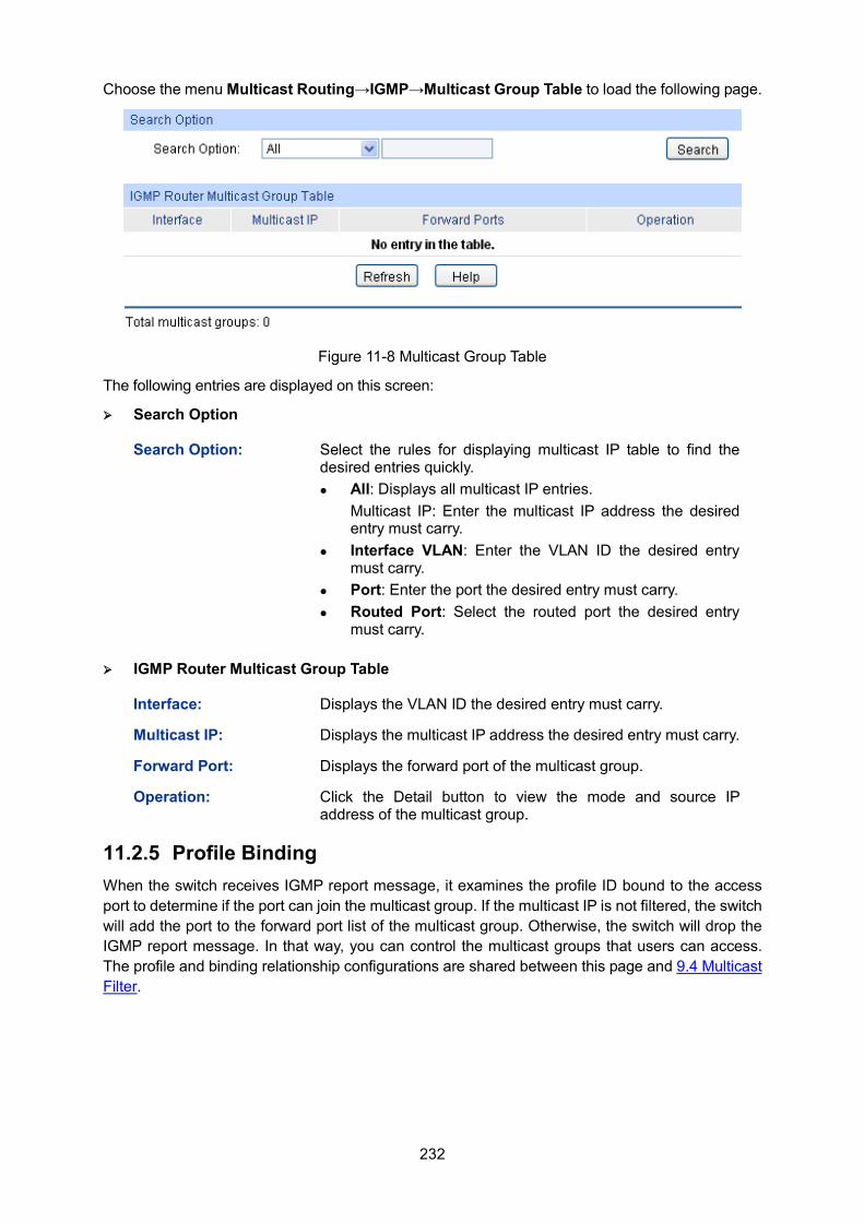
232
Choose the menu Multicast Routing→IGMP→Multicast Group Table to load the following page.
Figure 11-8 Multicast Group Table
The following entries are displayed on this screen:
Search Option
Search Option: Select the rules for displaying multicast IP table to find the desired entries quickly. All: Displays all multicast IP entries.
Multicast IP: Enter the multicast IP address the desired entry must carry.
Interface VLAN: Enter the VLAN ID the desired entry must carry.
Port: Enter the port the desired entry must carry. Routed Port: Select the routed port the desired entry
must carry.
IGMP Router Multicast Group Table
Interface: Displays the VLAN ID the desired entry must carry.
Multicast IP: Displays the multicast IP address the desired entry must carry.
Forward Port: Displays the forward port of the multicast group.
Operation: Click the Detail button to view the mode and source IP address of the multicast group.
11.2.5 Profile Binding When the switch receives IGMP report message, it examines the profile ID bound to the access port to determine if the port can join the multicast group. If the multicast IP is not filtered, the switch will add the port to the forward port list of the multicast group. Otherwise, the switch will drop the IGMP report message. In that way, you can control the multicast groups that users can access. The profile and binding relationship configurations are shared between this page and 9.4 Multicast Filter.
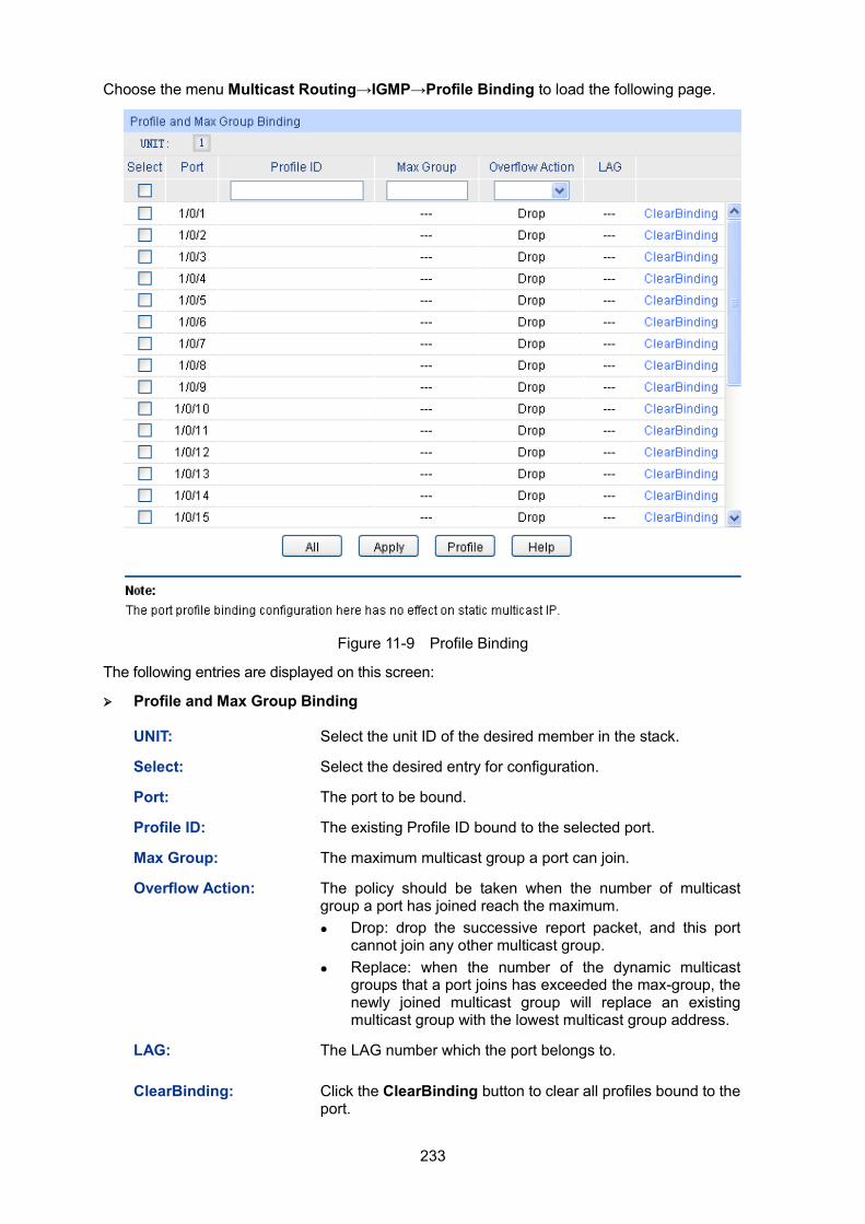
233
Choose the menu Multicast Routing→IGMP→Profile Binding to load the following page.
Figure 11-9 Profile Binding
The following entries are displayed on this screen:
Profile and Max Group Binding
UNIT: Select the unit ID of the desired member in the stack.
Select: Select the desired entry for configuration.
Port: The port to be bound.
Profile ID: The existing Profile ID bound to the selected port.
Max Group: The maximum multicast group a port can join.
Overflow Action: The policy should be taken when the number of multicast group a port has joined reach the maximum. Drop: drop the successive report packet, and this port
cannot join any other multicast group. Replace: when the number of the dynamic multicast
groups that a port joins has exceeded the max-group, the newly joined multicast group will replace an existing multicast group with the lowest multicast group address.
LAG: The LAG number which the port belongs to.
ClearBinding: Click the ClearBinding button to clear all profiles bound to the port.
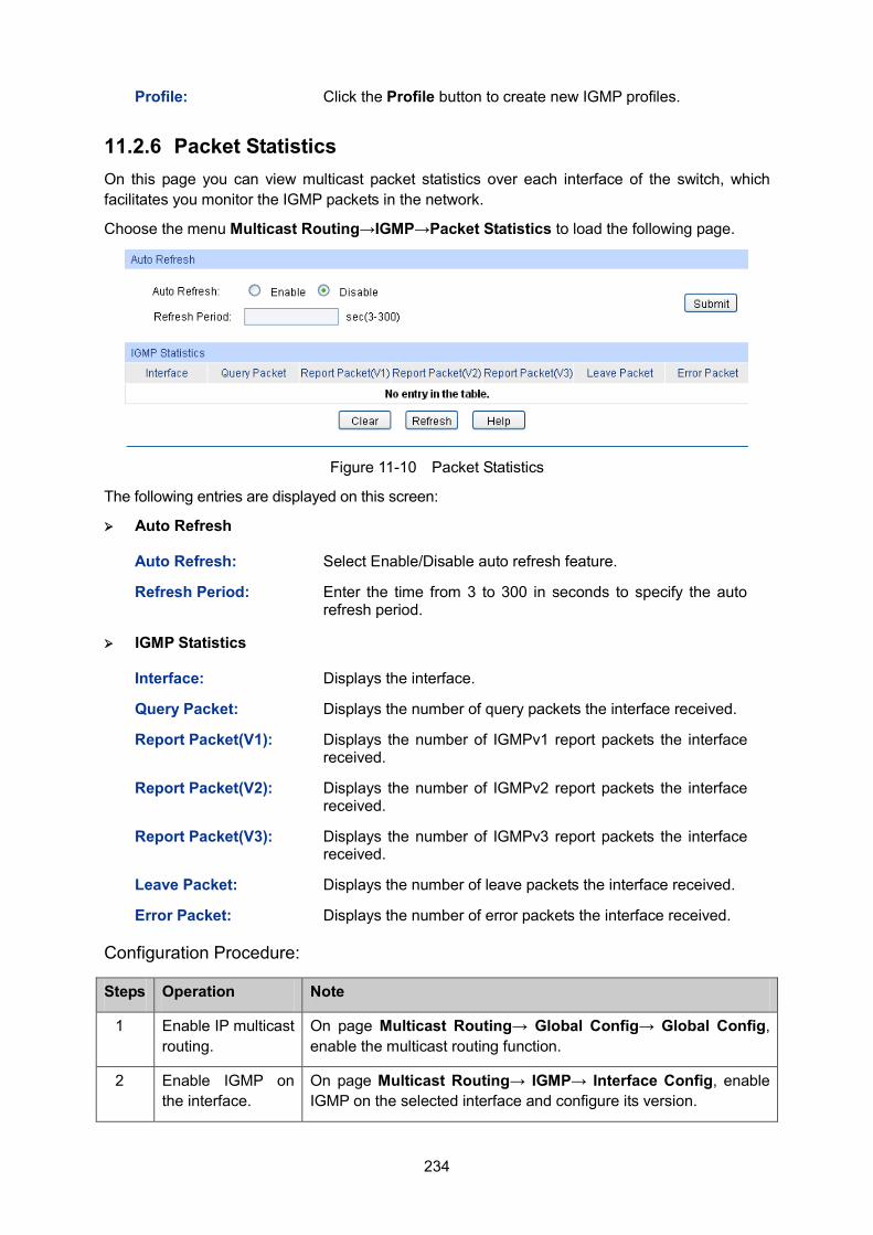
234
Profile: Click the Profile button to create new IGMP profiles.
11.2.6 Packet Statistics On this page you can view multicast packet statistics over each interface of the switch, which facilitates you monitor the IGMP packets in the network.
Choose the menu Multicast Routing→IGMP→Packet Statistics to load the following page.
Figure 11-10 Packet Statistics
The following entries are displayed on this screen:
Auto Refresh
Auto Refresh: Select Enable/Disable auto refresh feature.
Refresh Period: Enter the time from 3 to 300 in seconds to specify the auto refresh period.
IGMP Statistics
Interface: Displays the interface.
Query Packet: Displays the number of query packets the interface received.
Report Packet(V1): Displays the number of IGMPv1 report packets the interface received.
Report Packet(V2): Displays the number of IGMPv2 report packets the interface received.
Report Packet(V3): Displays the number of IGMPv3 report packets the interface received.
Leave Packet: Displays the number of leave packets the interface received.
Error Packet: Displays the number of error packets the interface received.
Configuration Procedure:
Steps Operation Note
1 Enable IP multicast routing.
On page Multicast Routing→ Global Config→ Global Config, enable the multicast routing function.
2 Enable IGMP on the interface.
On page Multicast Routing→ IGMP→ Interface Config, enable IGMP on the selected interface and configure its version.
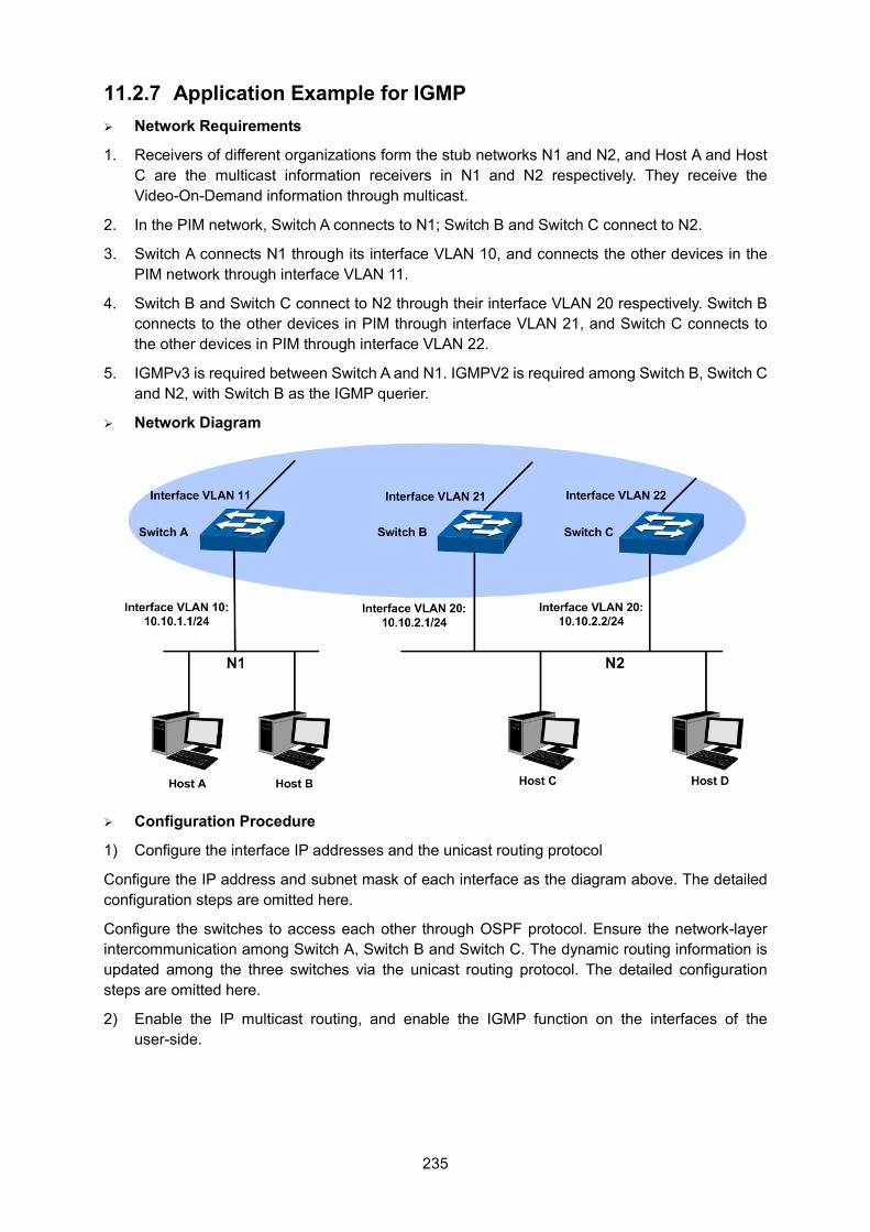
235
11.2.7 Application Example for IGMP Network Requirements
1. Receivers of different organizations form the stub networks N1 and N2, and Host A and Host C are the multicast information receivers in N1 and N2 respectively. They receive the Video-On-Demand information through multicast.
2. In the PIM network, Switch A connects to N1; Switch B and Switch C connect to N2.
3. Switch A connects N1 through its interface VLAN 10, and connects the other devices in the PIM network through interface VLAN 11.
4. Switch B and Switch C connect to N2 through their interface VLAN 20 respectively. Switch B connects to the other devices in PIM through interface VLAN 21, and Switch C connects to the other devices in PIM through interface VLAN 22.
5. IGMPv3 is required between Switch A and N1. IGMPV2 is required among Switch B, Switch C and N2, with Switch B as the IGMP querier.
Network Diagram
Configuration Procedure
1) Configure the interface IP addresses and the unicast routing protocol
Configure the IP address and subnet mask of each interface as the diagram above. The detailed configuration steps are omitted here.
Configure the switches to access each other through OSPF protocol. Ensure the network-layer intercommunication among Switch A, Switch B and Switch C. The dynamic routing information is updated among the three switches via the unicast routing protocol. The detailed configuration steps are omitted here.
2) Enable the IP multicast routing, and enable the IGMP function on the interfaces of the user-side.
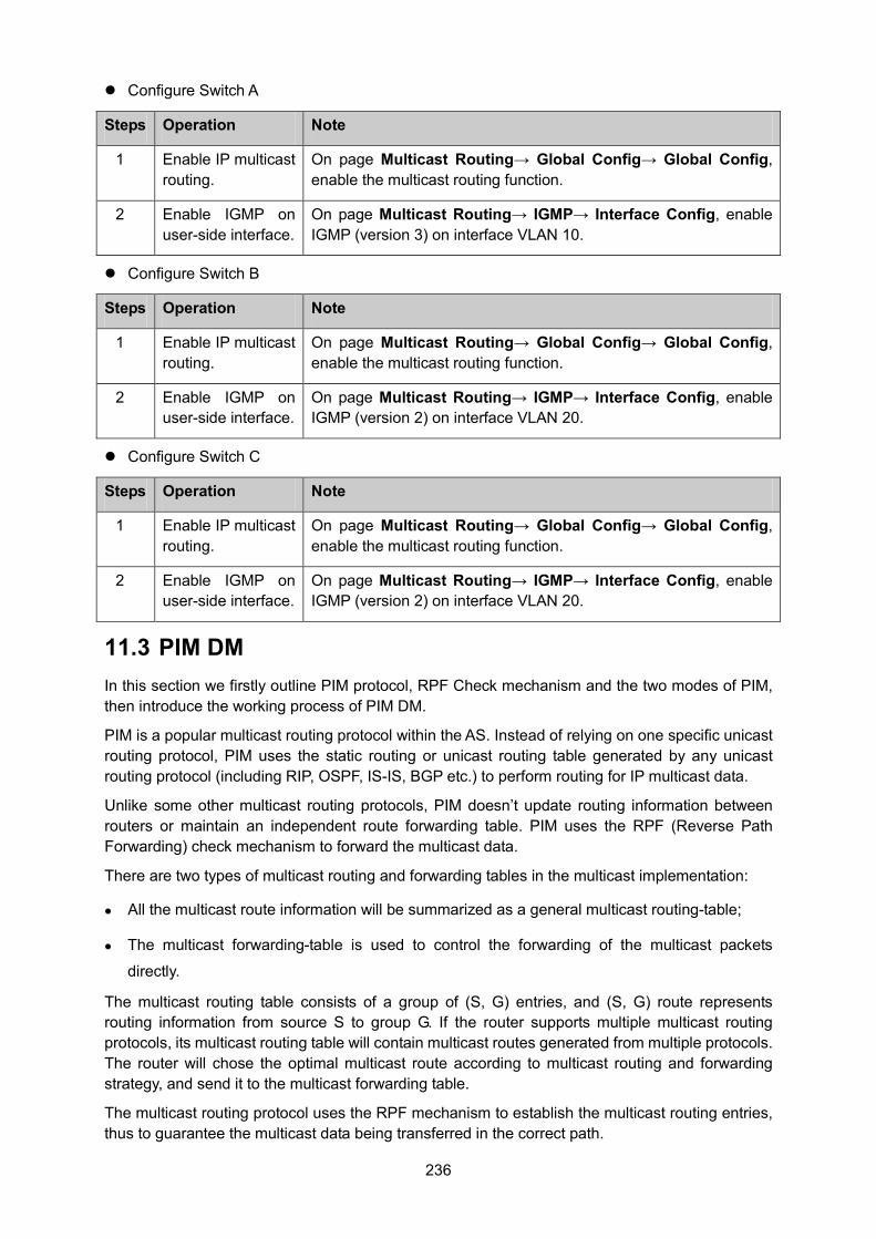
236
Configure Switch A
Steps Operation Note
1 Enable IP multicast routing.
On page Multicast Routing→ Global Config→ Global Config, enable the multicast routing function.
2 Enable IGMP on user-side interface.
On page Multicast Routing→ IGMP→ Interface Config, enable IGMP (version 3) on interface VLAN 10.
Configure Switch B
Steps Operation Note
1 Enable IP multicast routing.
On page Multicast Routing→ Global Config→ Global Config, enable the multicast routing function.
2 Enable IGMP on user-side interface.
On page Multicast Routing→ IGMP→ Interface Config, enable IGMP (version 2) on interface VLAN 20.
Configure Switch C
Steps Operation Note
1 Enable IP multicast routing.
On page Multicast Routing→ Global Config→ Global Config, enable the multicast routing function.
2 Enable IGMP on user-side interface.
On page Multicast Routing→ IGMP→ Interface Config, enable IGMP (version 2) on interface VLAN 20.
11.3 PIM DM In this section we firstly outline PIM protocol, RPF Check mechanism and the two modes of PIM, then introduce the working process of PIM DM.
PIM is a popular multicast routing protocol within the AS. Instead of relying on one specific unicast routing protocol, PIM uses the static routing or unicast routing table generated by any unicast routing protocol (including RIP, OSPF, IS-IS, BGP etc.) to perform routing for IP multicast data.
Unlike some other multicast routing protocols, PIM doesn’t update routing information between routers or maintain an independent route forwarding table. PIM uses the RPF (Reverse Path Forwarding) check mechanism to forward the multicast data.
There are two types of multicast routing and forwarding tables in the multicast implementation:
All the multicast route information will be summarized as a general multicast routing-table;
The multicast forwarding-table is used to control the forwarding of the multicast packets
directly.
The multicast routing table consists of a group of (S, G) entries, and (S, G) route represents routing information from source S to group G. If the router supports multiple multicast routing protocols, its multicast routing table will contain multicast routes generated from multiple protocols. The router will chose the optimal multicast route according to multicast routing and forwarding strategy, and send it to the multicast forwarding table.
The multicast routing protocol uses the RPF mechanism to establish the multicast routing entries, thus to guarantee the multicast data being transferred in the correct path.
237
RPF Mechanism
PIM uses the unicast routing table to perform the RPF check. RPF mechanism ensures the multicast packets being forwarded correctly according to the multicast routing configuration, and avoids loops causing by various reasons.
1. RPF Check
The RPF check relies on unicast route or static multicast route. The unicast routing table aggregates the shortest paths to each destination network segments, and the static multicast routing table lists specified static RPF routing entries configured by the user manually. Instead of maintaining certain unicast routing independently, the multicast routing protocol relies on the current unicast routing information or static multicast routing in the network to establish multicast routing entries.
When performing the RPF check, the router will look up the unicast routing table and the static multicast routing table at the same time. The process is as below:
(1) Chose an optimal route from the unicast routing table and the static routing table respectively:
The router looks up the unicast routing table with the IP address of the packet source as the
destination address, and selects an optimal unicast route automatically. The output interface of
the corresponding entry is the RPF interface, and the next hop is the RPF neighbor. The router
will consider the traveling path of the multicast data sent from the RPF neighbor and received
on the RPF interface as the shortest path from the multicast source S to the local network.
The router looks up the static multicast routing table with the IP address of the packet source
specified as the source address, and selects an optimal static multicast route automatically.
The corresponding entry explicitly specifies the RPF interface and RPF neighbor.
(2) Select one from the two optimal routes as the RPF route:
According to the longest mask matching principle, the longest mask matching route between them will be selected; if the two routes have the same mask, the route with higher priority will be selected; if the two routes also have the same priority, then the static multicast route is prior to the unicast route.
2. RPF Mechanism Application
When the router receives multicast packets sent from multicast source S to multicast group G, it will look up the multicast forwarding table at first:
(1) If the corresponding entry (S, G) exists and the packet’s actual arriving interface is the same
as the input interface in the multicast forwarding table, the packet will be forwarded to all the
output interfaces.
(2) If the corresponding entry (S, G) exists and the packet’s actual arriving interface is different
from the input interface in the multicast forwarding table, the router will perform RPF check on
this packet:
If the check result shows that the RPF interface is the same as the input interface in the current
(S, G) entry, which indicates that the (S, G) entry is correct and the packet from the wrong path
will be discarded;
238
If the check result shows that the RPF interface is the different from the input interface in the
current (S, G) entry, which indicates that the (S, G) entry is invalid and the router will correct the
input interface to the packet’s actual arriving interface, and forward this packet to all the output
interfaces.
(3) If the corresponding entry (S, G) doesn’t exist, the router will still perform the RPF check on
this multicast packet. With the RPF interface as the input interface, the router will create
corresponding entry with the RPF interface as the input interface combining related routing
information, and send this entry to the multicast forwarding table:
If the packet’s actual arriving interface is exactly the RPF interface, the RPF check will pass
and the packet will be forwarded to all the output interfaces;
If the packet’s actual arriving interface is not the RPF interface, the RPF check fails and this
packet will be discarded.
PIM Modes
PIM can be divided into two modes according to different routing mechanisms:
PIM DM: Protocol Independent Multicast-Dense Mode
PIM SM: Protocol Independent Multicast-Sparse Mode
PIM DM
PIM DM (defined in RFC 3973) is a multicast routing protocol in dense mode. It uses Push Mode to transfer multicast packets and applies to small network with relatively dense multicast group members.
The working mechanism of PIM DM is illustrated as below:
PIM DM assumes that there is at least one multicast group member in each subnet of the
network, and the multicast packets will be flooded to all the nodes in the network. Then
branches without receivers are pruned from the distribution tree, leaving only branches that
contain receivers. This “flood-and-prune” process takes place periodically. The pruned
branches can also resume to forwarding state periodically.
When a new receiver on a previously pruned branch of the tree joins a multicast group, the PIM
DM takes the Graft (see Grafting) mechanism to actively resume this node’s function of
forwarding multicast data, thus reducing the time it takes to resume to the forwarding state.
Generally speaking, the packet forwarding tree in the dense mode is Source Tree (a forwarding
tree with multicast source as the root, and multicast members as the branches). As the Source
Tree is a forwarding tree with the shortest path from the multicast source to the receivers, it is
also called Shortest Path Tree (SPT).
The working process of PIM DM can be summarized as follows:
Neighbor Discovering
SPT Building
Grafting
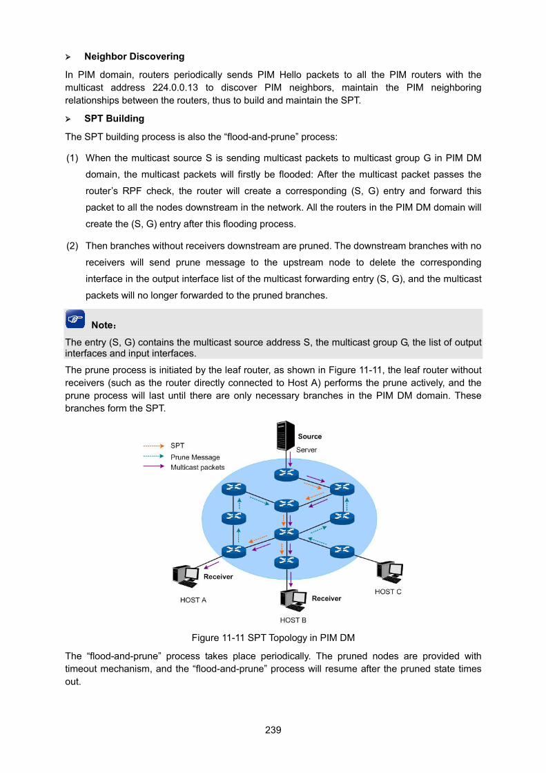
239
Neighbor Discovering
In PIM domain, routers periodically sends PIM Hello packets to all the PIM routers with the multicast address 224.0.0.13 to discover PIM neighbors, maintain the PIM neighboring relationships between the routers, thus to build and maintain the SPT.
SPT Building
The SPT building process is also the “flood-and-prune” process:
(1) When the multicast source S is sending multicast packets to multicast group G in PIM DM
domain, the multicast packets will firstly be flooded: After the multicast packet passes the
router’s RPF check, the router will create a corresponding (S, G) entry and forward this
packet to all the nodes downstream in the network. All the routers in the PIM DM domain will
create the (S, G) entry after this flooding process.
(2) Then branches without receivers downstream are pruned. The downstream branches with no
receivers will send prune message to the upstream node to delete the corresponding
interface in the output interface list of the multicast forwarding entry (S, G), and the multicast
packets will no longer forwarded to the pruned branches.
Note:
The entry (S, G) contains the multicast source address S, the multicast group G, the list of output interfaces and input interfaces.
The prune process is initiated by the leaf router, as shown in Figure 11-11, the leaf router without receivers (such as the router directly connected to Host A) performs the prune actively, and the prune process will last until there are only necessary branches in the PIM DM domain. These branches form the SPT.
Figure 11-11 SPT Topology in PIM DM
The “flood-and-prune” process takes place periodically. The pruned nodes are provided with timeout mechanism, and the “flood-and-prune” process will resume after the pruned state times out.
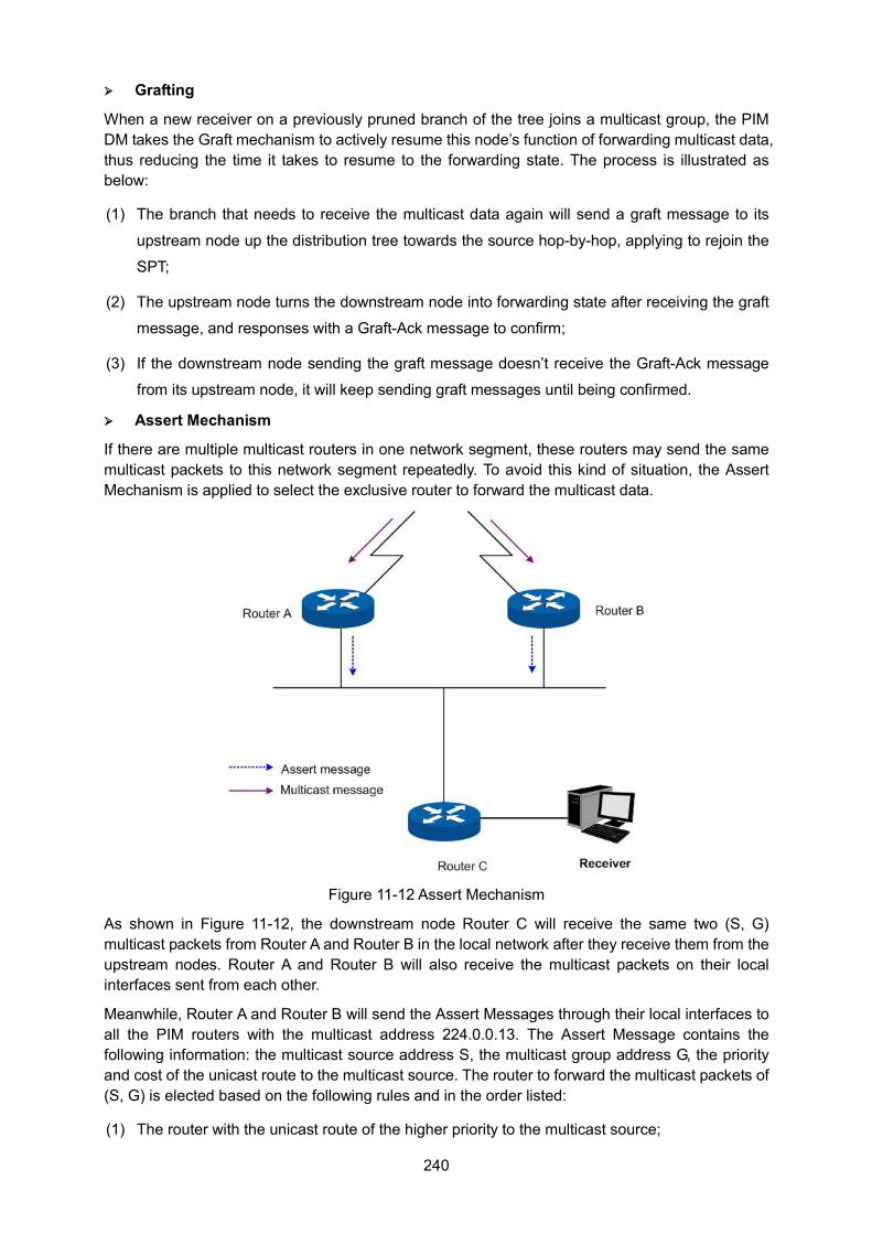
240
Grafting
When a new receiver on a previously pruned branch of the tree joins a multicast group, the PIM DM takes the Graft mechanism to actively resume this node’s function of forwarding multicast data, thus reducing the time it takes to resume to the forwarding state. The process is illustrated as below:
(1) The branch that needs to receive the multicast data again will send a graft message to its
upstream node up the distribution tree towards the source hop-by-hop, applying to rejoin the
SPT;
(2) The upstream node turns the downstream node into forwarding state after receiving the graft
message, and responses with a Graft-Ack message to confirm;
(3) If the downstream node sending the graft message doesn’t receive the Graft-Ack message
from its upstream node, it will keep sending graft messages until being confirmed.
Assert Mechanism
If there are multiple multicast routers in one network segment, these routers may send the same multicast packets to this network segment repeatedly. To avoid this kind of situation, the Assert Mechanism is applied to select the exclusive router to forward the multicast data.
Figure 11-12 Assert Mechanism
As shown in Figure 11-12, the downstream node Router C will receive the same two (S, G) multicast packets from Router A and Router B in the local network after they receive them from the upstream nodes. Router A and Router B will also receive the multicast packets on their local interfaces sent from each other.
Meanwhile, Router A and Router B will send the Assert Messages through their local interfaces to all the PIM routers with the multicast address 224.0.0.13. The Assert Message contains the following information: the multicast source address S, the multicast group address G, the priority and cost of the unicast route to the multicast source. The router to forward the multicast packets of (S, G) is elected based on the following rules and in the order listed:
(1) The router with the unicast route of the higher priority to the multicast source;
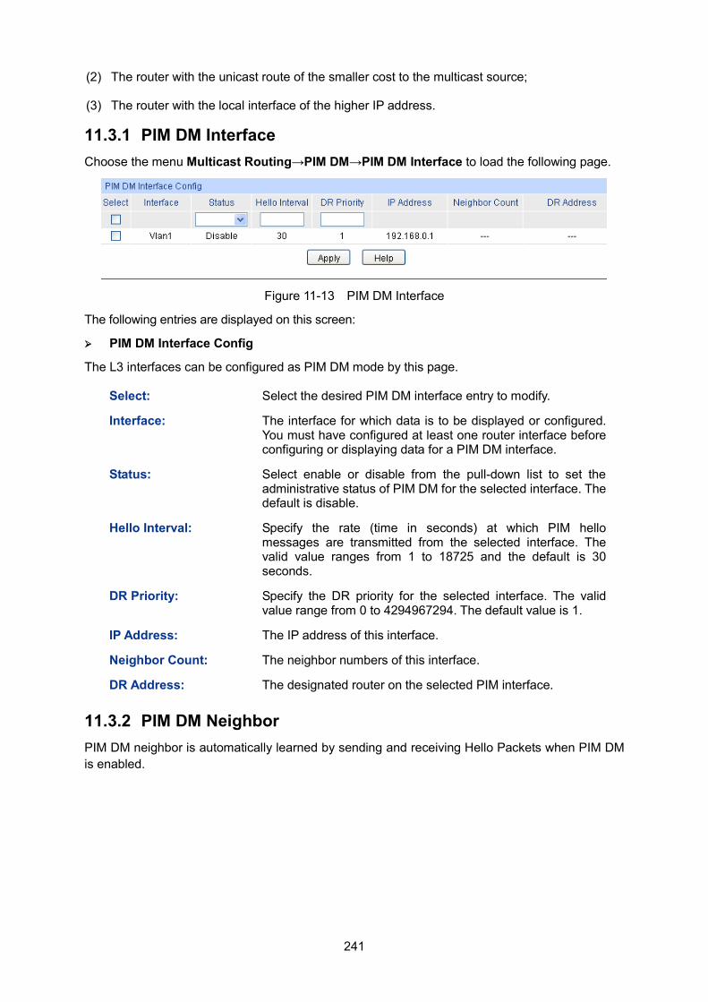
241
(2) The router with the unicast route of the smaller cost to the multicast source;
(3) The router with the local interface of the higher IP address.
11.3.1 PIM DM Interface Choose the menu Multicast Routing→PIM DM→PIM DM Interface to load the following page.
Figure 11-13 PIM DM Interface
The following entries are displayed on this screen:
PIM DM Interface Config
The L3 interfaces can be configured as PIM DM mode by this page.
Select: Select the desired PIM DM interface entry to modify.
Interface: The interface for which data is to be displayed or configured. You must have configured at least one router interface before configuring or displaying data for a PIM DM interface.
Status: Select enable or disable from the pull-down list to set the administrative status of PIM DM for the selected interface. The default is disable.
Hello Interval: Specify the rate (time in seconds) at which PIM hello messages are transmitted from the selected interface. The valid value ranges from 1 to 18725 and the default is 30 seconds.
DR Priority: Specify the DR priority for the selected interface. The valid value range from 0 to 4294967294. The default value is 1.
IP Address: The IP address of this interface.
Neighbor Count: The neighbor numbers of this interface.
DR Address: The designated router on the selected PIM interface.
11.3.2 PIM DM Neighbor PIM DM neighbor is automatically learned by sending and receiving Hello Packets when PIM DM is enabled.
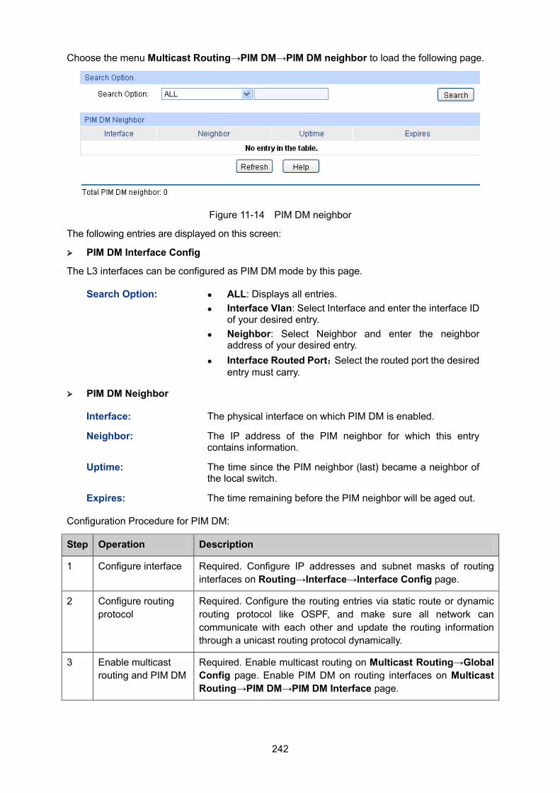
242
Choose the menu Multicast Routing→PIM DM→PIM DM neighbor to load the following page.
Figure 11-14 PIM DM neighbor
The following entries are displayed on this screen:
PIM DM Interface Config
The L3 interfaces can be configured as PIM DM mode by this page.
Search Option: ALL: Displays all entries. Interface Vlan: Select Interface and enter the interface ID
of your desired entry. Neighbor: Select Neighbor and enter the neighbor
address of your desired entry. Interface Routed Port:Select the routed port the desired
entry must carry.
PIM DM Neighbor
Interface: The physical interface on which PIM DM is enabled.
Neighbor: The IP address of the PIM neighbor for which this entry contains information.
Uptime: The time since the PIM neighbor (last) became a neighbor of the local switch.
Expires: The time remaining before the PIM neighbor will be aged out.
Configuration Procedure for PIM DM:
Step Operation Description
1 Configure interface Required. Configure IP addresses and subnet masks of routing interfaces on Routing→Interface→Interface Config page.
2 Configure routing protocol
Required. Configure the routing entries via static route or dynamic routing protocol like OSPF, and make sure all network can communicate with each other and update the routing information through a unicast routing protocol dynamically.
3 Enable multicast routing and PIM DM
Required. Enable multicast routing on Multicast Routing→Global Config page. Enable PIM DM on routing interfaces on Multicast Routing→PIM DM→PIM DM Interface page.
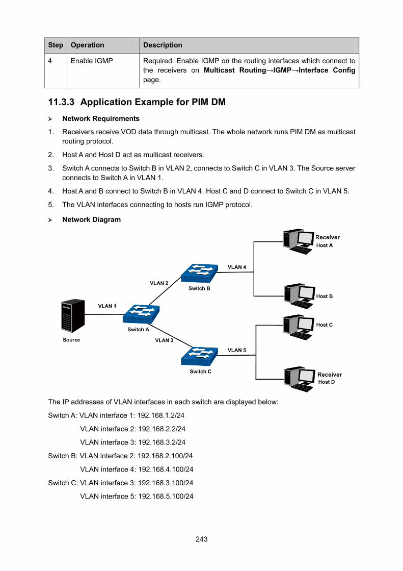
243
Step Operation Description
4 Enable IGMP Required. Enable IGMP on the routing interfaces which connect to the receivers on Multicast Routing→IGMP→Interface Config page.
11.3.3 Application Example for PIM DM Network Requirements
1. Receivers receive VOD data through multicast. The whole network runs PIM DM as multicast routing protocol.
2. Host A and Host D act as multicast receivers.
3. Switch A connects to Switch B in VLAN 2, connects to Switch C in VLAN 3. The Source server connects to Switch A in VLAN 1.
4. Host A and B connect to Switch B in VLAN 4. Host C and D connect to Switch C in VLAN 5.
5. The VLAN interfaces connecting to hosts run IGMP protocol.
Network Diagram
The IP addresses of VLAN interfaces in each switch are displayed below:
Switch A: VLAN interface 1: 192.168.1.2/24
VLAN interface 2: 192.168.2.2/24
VLAN interface 3: 192.168.3.2/24
Switch B: VLAN interface 2: 192.168.2.100/24
VLAN interface 4: 192.168.4.100/24
Switch C: VLAN interface 3: 192.168.3.100/24
VLAN interface 5: 192.168.5.100/24
244
Configuration Procedure Configure Switch A:
Step Operation Description
1 Configure interface. Configure IP addresses and subnet masks of VLAN interfaces 1, 2 and 3 on Routing→ Interface→Interface Config page.
2 Configure routing protocol.
Configure the routing entries via static route or dynamic routing protocol like OSPF, and make sure all the switches can communicate with each other and update the routing information through a unicast routing protocol dynamically.
3 Enable multicast routing and PIM DM
Enable multicast routing on Multicast Routing→Global Config page. Enable PIM DM on VLAN interfaces 1, 2 and 3 on Multicast Routing→PIM DM→PIM DM Interface page.
Configure Switch B and C:
Step Operation Description
1 Configure interface Configure IP addresses and subnet masks of VLAN interfaces 2, 3, 4 and 5 on Routing→Interface→Interface Config page.
2 Configure routing protocol
Configure the routing entries via static route or dynamic routing protocol like OSPF, and make sure all network can communicate with each other.
3 Enable multicast routing and PIM DM
Enable multicast routing on Multicast Routing→Global Config page. Enable PIM DM on VLAN interfaces 2, 3, 4 and 5 on Multicast Routing→PIM DM→PIM DM Interface page.
4 Enable IGMP Enable IGMP on the VLAN interfaces 4 and 5 which connect to the receivers on Multicast Routing→IGMP→Interface Config page.
11.4 PIM SM PIM DM uses the “flood-and-prune” mode to create the SPT for transferring multicast data. Although SPT has the short path, its building-up process is of low efficiency and does not apply to the large and medium-sized network.
PIM SM is a multicast routing protocol in sparse mode. It uses the “Pull Mode” to transfer multicast data and usually applies to large and medium-sized network with relatively sparse multicast group members.
The working mechanism of PIM SM is illustrated as below:
PIM SM assumes that no hosts need to receive the multicast data, the multicast data will not be
forwarded to the host unless there is an explicitly request for the traffic. The core task of PIM
SM to realize multicast forwarding is to build and maintain the RPT (Rendezvous Point Tree).
RPT selects a certain router in the PIM domain as the public RP (rendezvous point), through
which the multicast data is transferred along the RPT to the receivers.
245
The router connected to the receiver sends the join message to the RP of a certain multicast
group. The path along which the join message is sent to the RP hop-by-hop forms a branch of
RPT.
When the multicast source is sending multicast data to a multicast group, the router directly
connected to the multicast source firstly registers to the RP by sending the Register Message
to the RP in unicast mode. The arrival of the register message at the RP triggers the
establishment of the SPT. Then the multicast source sends the multicast data along the SPT to
the RP. The multicast data will be duplicated and distributed to the receivers after they arrive at
the RP.
Note: The duplicating process only takes place at the branching point of the distributing tree, and this process automatically repeats until the packets arrives at the final receivers.
The work process of PIM SM can be generalized below:
Neighbor Discovering
DR Electing
RP Discovering
RPT Building
Multicast Source Registering
Switching from RPT to SPT
Asserting
Neighbor Discovering
The neighbor discovering mechanism of PIM SM and PIM DM is the same, for more details, refer to Neighbor Discovering.
DR Electing
The DR (Designated Router) in the shared network is elected through the Hello message, and works as the exclusive router to forward multicast data in this shared network.
Whether the network connects to the multicast source or the network connects to the receivers, the DR must be elected if the network is a shared one. The DR is responsible for sending join message to the RP in the receiver side and sending register message to the RP in the multicast source side.
Note: The DR is elected between the multiple routers of the network segment by comparing the
priorities and IP addresses carried in Hello packets. The elected DR has practical meaning in PIM SM; with PIM DM operation, the DR has meaning only if IGMPv1 is in use, the elected DR functions as the IGMP querier on account that IGMPv1 does not have an IGMP querier election process.
The device working as DR should be enabled with the IGMP function; otherwise the receivers connected to it would be unable to join the multicast group via this DR.
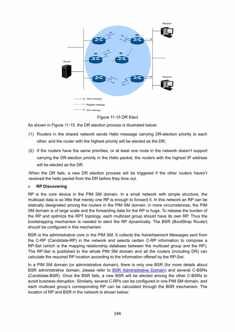
246
Figure 11-15 DR Elect
As shown in Figure 11-15, the DR election process is illustrated below:
(1) Routers in the shared network sends Hello message carrying DR-election priority to each
other, and the router with the highest priority will be elected as the DR;
(2) If the routers have the same priorities, or at least one route in the network doesn’t support
carrying the DR-election priority in the Hello packet, the routers with the highest IP address
will be elected as the DR.
When the DR fails, a new DR election process will be triggered if the other routers haven’t received the hello packet from the DR before they time out.
RP Discovering
RP is the core device in the PIM SM domain. In a small network with simple structure, the multicast data is so little that merely one RP is enough to forward it. In this network an RP can be statically designated among the routers in the PIM SM domain; in more circumstances, the PIM SM domain is of large scale and the forwarding data for the RP is huge. To release the burden of the RP and optimize the RPT topology, each multicast group should have its own RP. Thus the bootstrapping mechanism is needed to elect the RP dynamically. The BSR (BootStrap Router) should be configured in this mechanism.
BSR is the administrative core in the PIM SM. It collects the Advertisement Messages sent from the C-RP (Candidate-RP) in the network and selects certain C-RP information to compose a RP-Set (which is the mapping relationship database between the multicast group and the RP). The RP-Set is published to the whole PIM SM domain and all the routers (including DR) can calculate the required RP location according to the information offered by the RP-Set.
In a PIM SM domain (or administrative domain), there is only one BSR (for more details about BSR administrative domain, please refer to BSR Adminsitrative Domain) and several C-BSRs (Candidate-BSR). Once the BSR fails, a new BSR will be elected among the other C-BSRs to avoid business disruption. Similarly, several C-RPs can be configured in one PIM SM domain, and each multicast group’s corresponding RP can be calculated through the BSR mechanism. The location of RP and BSR in the network is shown below:
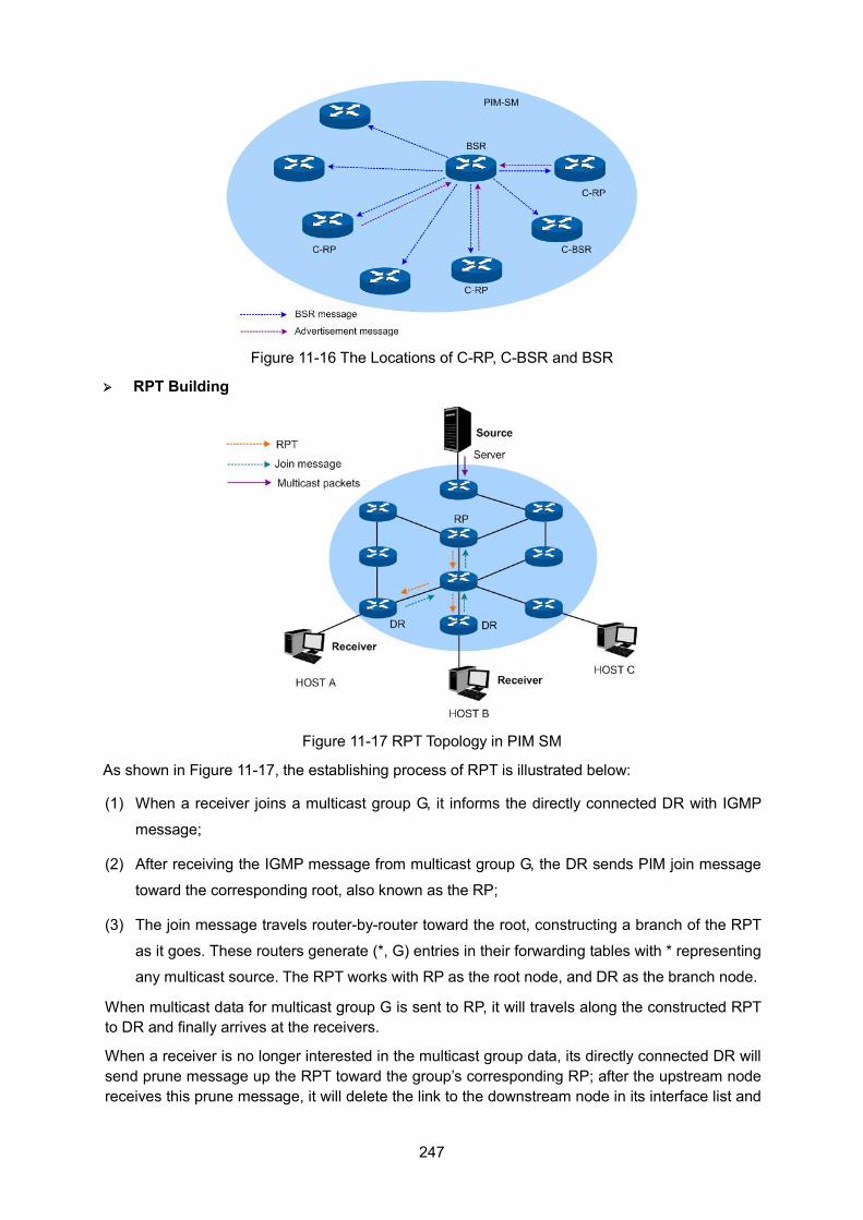
247
Figure 11-16 The Locations of C-RP, C-BSR and BSR
RPT Building
Figure 11-17 RPT Topology in PIM SM
As shown in Figure 11-17, the establishing process of RPT is illustrated below:
(1) When a receiver joins a multicast group G, it informs the directly connected DR with IGMP
message;
(2) After receiving the IGMP message from multicast group G, the DR sends PIM join message
toward the corresponding root, also known as the RP;
(3) The join message travels router-by-router toward the root, constructing a branch of the RPT
as it goes. These routers generate (*, G) entries in their forwarding tables with * representing
any multicast source. The RPT works with RP as the root node, and DR as the branch node.
When multicast data for multicast group G is sent to RP, it will travels along the constructed RPT to DR and finally arrives at the receivers.
When a receiver is no longer interested in the multicast group data, its directly connected DR will send prune message up the RPT toward the group’s corresponding RP; after the upstream node receives this prune message, it will delete the link to the downstream node in its interface list and
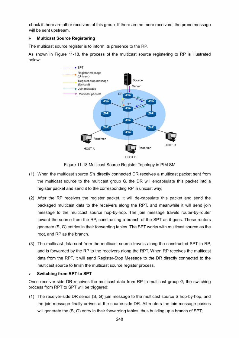
248
check if there are other receivers of this group. If there are no more receivers, the prune message will be sent upstream.
Multicast Source Registering
The multicast source register is to inform its presence to the RP.
As shown in Figure 11-18, the process of the multicast source registering to RP is illustrated below:
Figure 11-18 Multicast Source Register Topology in PIM SM
(1) When the multicast source S’s directly connected DR receives a multicast packet sent from
the multicast source to the multicast group G, the DR will encapsulate this packet into a
register packet and send it to the corresponding RP in unicast way;
(2) After the RP receives the register packet, it will de-capsulate this packet and send the
packaged multicast data to the receivers along the RPT, and meanwhile it will send join
message to the multicast source hop-by-hop. The join message travels router-by-router
toward the source from the RP, constructing a branch of the SPT as it goes. These routers
generate (S, G) entries in their forwarding tables. The SPT works with multicast source as the
root, and RP as the branch.
(3) The multicast data sent from the multicast source travels along the constructed SPT to RP,
and is forwarded by the RP to the receivers along the RPT. When RP receives the multicast
data from the RPT, it will send Register-Stop Message to the DR directly connected to the
multicast source to finish the multicast source register process.
Switching from RPT to SPT
Once receiver-side DR receives the multicast data from RP to multicast group G, the switching process from RPT to SPT will be triggered:
(1) The receiver-side DR sends (S, G) join message to the multicast source S hop-by-hop, and
the join message finally arrives at the source-side DR. All routers the join message passes
will generate the (S, G) entry in their forwarding tables, thus building up a branch of SPT;
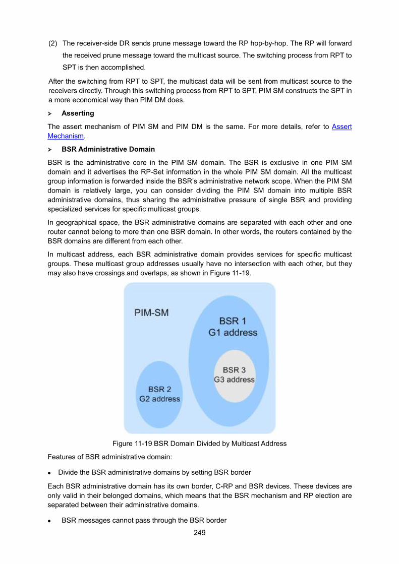
249
(2) The receiver-side DR sends prune message toward the RP hop-by-hop. The RP will forward
the received prune message toward the multicast source. The switching process from RPT to
SPT is then accomplished.
After the switching from RPT to SPT, the multicast data will be sent from multicast source to the receivers directly. Through this switching process from RPT to SPT, PIM SM constructs the SPT in a more economical way than PIM DM does.
Asserting
The assert mechanism of PIM SM and PIM DM is the same. For more details, refer to Assert Mechanism.
BSR Administrative Domain
BSR is the administrative core in the PIM SM domain. The BSR is exclusive in one PIM SM domain and it advertises the RP-Set information in the whole PIM SM domain. All the multicast group information is forwarded inside the BSR’s administrative network scope. When the PIM SM domain is relatively large, you can consider dividing the PIM SM domain into multiple BSR administrative domains, thus sharing the administrative pressure of single BSR and providing specialized services for specific multicast groups.
In geographical space, the BSR administrative domains are separated with each other and one router cannot belong to more than one BSR domain. In other words, the routers contained by the BSR domains are different from each other.
In multicast address, each BSR administrative domain provides services for specific multicast groups. These multicast group addresses usually have no intersection with each other, but they may also have crossings and overlaps, as shown in Figure 11-19.
Figure 11-19 BSR Domain Divided by Multicast Address
Features of BSR administrative domain:
Divide the BSR administrative domains by setting BSR border
Each BSR administrative domain has its own border, C-RP and BSR devices. These devices are only valid in their belonged domains, which means that the BSR mechanism and RP election are separated between their administrative domains.
BSR messages cannot pass through the BSR border
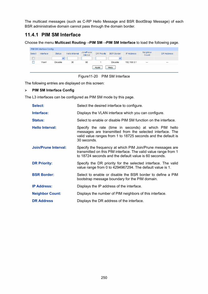
250
The multicast messages (such as C-RP Hello Message and BSR BootStrap Message) of each BSR administrative domain cannot pass through the domain border.
11.4.1 PIM SM Interface Choose the menu Multicast Routing→PIM SM→PIM SM Interface to load the following page.
Figure11-20 PIM SM Interface
The following entries are displayed on this screen:
PIM SM Interface Config
The L3 interfaces can be configured as PIM SM mode by this page.
Select: Select the desired interface to configure.
Interface: Displays the VLAN interface which you can configure.
Status: Select to enable or disable PIM SM function on the interface.
Hello Interval: Specify the rate (time in seconds) at which PIM hello messages are transmitted from the selected interface. The valid value ranges from 1 to 18725 seconds and the default is 30 seconds.
Join/Prune Interval: Specify the frequency at which PIM Join/Prune messages are transmitted on this PIM interface. The valid value range from 1 to 18724 seconds and the default value is 60 seconds.
DR Priority: Specify the DR priority for the selected interface. The valid value range from 0 to 4294967294. The default value is 1.
BSR Border: Select to enable or disable the BSR border to define a PIM bootstrap message boundary for the PIM domain.
IP Address: Displays the IP address of the interface.
Neighbor Count: Displays the number of PIM neighbors of this interface.
DR Address Displays the DR address of the interface.
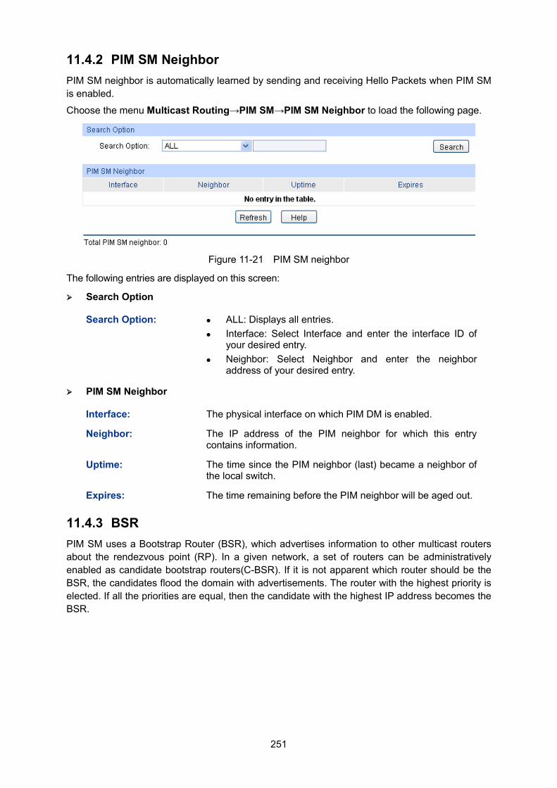
251
11.4.2 PIM SM Neighbor PIM SM neighbor is automatically learned by sending and receiving Hello Packets when PIM SM is enabled.
Choose the menu Multicast Routing→PIM SM→PIM SM Neighbor to load the following page.
Figure 11-21 PIM SM neighbor
The following entries are displayed on this screen:
Search Option
Search Option: ALL: Displays all entries. Interface: Select Interface and enter the interface ID of
your desired entry. Neighbor: Select Neighbor and enter the neighbor
address of your desired entry.
PIM SM Neighbor
Interface: The physical interface on which PIM DM is enabled.
Neighbor: The IP address of the PIM neighbor for which this entry contains information.
Uptime: The time since the PIM neighbor (last) became a neighbor of the local switch.
Expires: The time remaining before the PIM neighbor will be aged out.
11.4.3 BSR PIM SM uses a Bootstrap Router (BSR), which advertises information to other multicast routers about the rendezvous point (RP). In a given network, a set of routers can be administratively enabled as candidate bootstrap routers(C-BSR). If it is not apparent which router should be the BSR, the candidates flood the domain with advertisements. The router with the highest priority is elected. If all the priorities are equal, then the candidate with the highest IP address becomes the BSR.
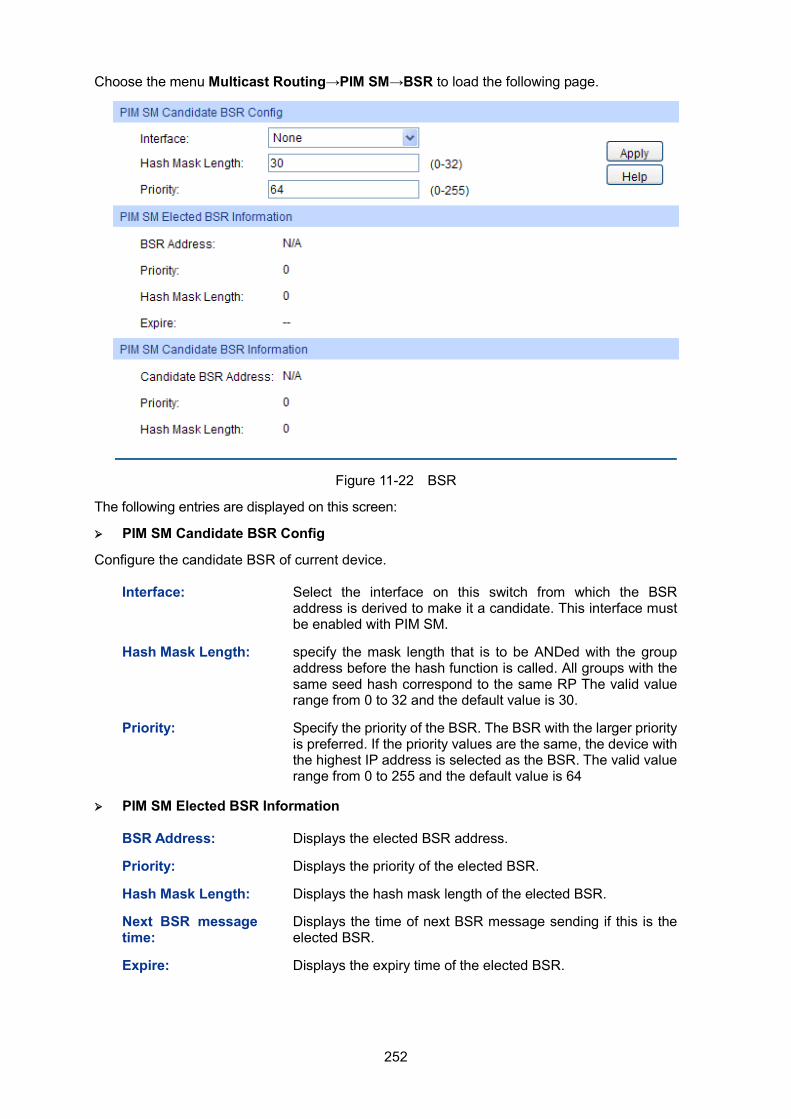
252
Choose the menu Multicast Routing→PIM SM→BSR to load the following page.
Figure 11-22 BSR
The following entries are displayed on this screen:
PIM SM Candidate BSR Config
Configure the candidate BSR of current device.
Interface: Select the interface on this switch from which the BSR address is derived to make it a candidate. This interface must be enabled with PIM SM.
Hash Mask Length: specify the mask length that is to be ANDed with the group address before the hash function is called. All groups with the same seed hash correspond to the same RP The valid value range from 0 to 32 and the default value is 30.
Priority: Specify the priority of the BSR. The BSR with the larger priority is preferred. If the priority values are the same, the device with the highest IP address is selected as the BSR. The valid value range from 0 to 255 and the default value is 64
PIM SM Elected BSR Information
BSR Address: Displays the elected BSR address.
Priority: Displays the priority of the elected BSR.
Hash Mask Length: Displays the hash mask length of the elected BSR.
Next BSR message time:
Displays the time of next BSR message sending if this is the elected BSR.
Expire: Displays the expiry time of the elected BSR.
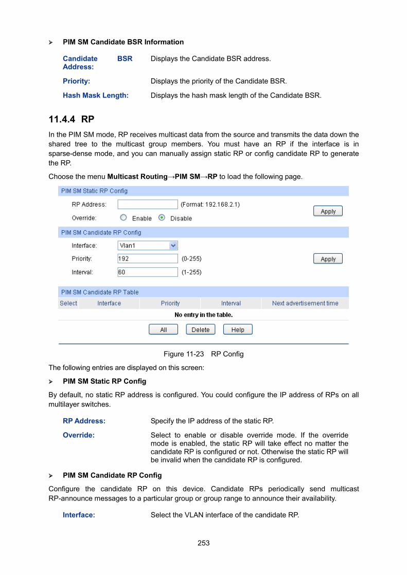
253
PIM SM Candidate BSR Information
Candidate BSR Address:
Displays the Candidate BSR address.
Priority: Displays the priority of the Candidate BSR.
Hash Mask Length: Displays the hash mask length of the Candidate BSR.
11.4.4 RP In the PIM SM mode, RP receives multicast data from the source and transmits the data down the shared tree to the multicast group members. You must have an RP if the interface is in sparse-dense mode, and you can manually assign static RP or config candidate RP to generate the RP.
Choose the menu Multicast Routing→PIM SM→RP to load the following page.
Figure 11-23 RP Config
The following entries are displayed on this screen:
PIM SM Static RP Config
By default, no static RP address is configured. You could configure the IP address of RPs on all multilayer switches.
RP Address: Specify the IP address of the static RP.
Override: Select to enable or disable override mode. If the override mode is enabled, the static RP will take effect no matter the candidate RP is configured or not. Otherwise the static RP will be invalid when the candidate RP is configured.
PIM SM Candidate RP Config
Configure the candidate RP on this device. Candidate RPs periodically send multicast RP-announce messages to a particular group or group range to announce their availability.
Interface: Select the VLAN interface of the candidate RP.
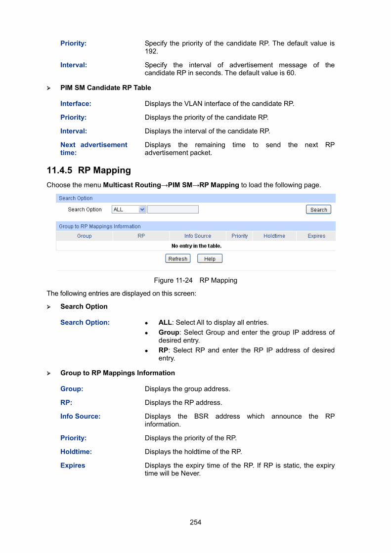
254
Priority: Specify the priority of the candidate RP. The default value is 192.
Interval: Specify the interval of advertisement message of the candidate RP in seconds. The default value is 60.
PIM SM Candidate RP Table
Interface: Displays the VLAN interface of the candidate RP.
Priority: Displays the priority of the candidate RP.
Interval: Displays the interval of the candidate RP.
Next advertisement time:
Displays the remaining time to send the next RP advertisement packet.
11.4.5 RP Mapping Choose the menu Multicast Routing→PIM SM→RP Mapping to load the following page.
Figure 11-24 RP Mapping
The following entries are displayed on this screen:
Search Option
Search Option: ALL: Select All to display all entries. Group: Select Group and enter the group IP address of
desired entry. RP: Select RP and enter the RP IP address of desired
entry.
Group to RP Mappings Information
Group: Displays the group address.
RP: Displays the RP address.
Info Source: Displays the BSR address which announce the RP information.
Priority: Displays the priority of the RP.
Holdtime: Displays the holdtime of the RP.
Expires Displays the expiry time of the RP. If RP is static, the expiry time will be Never.
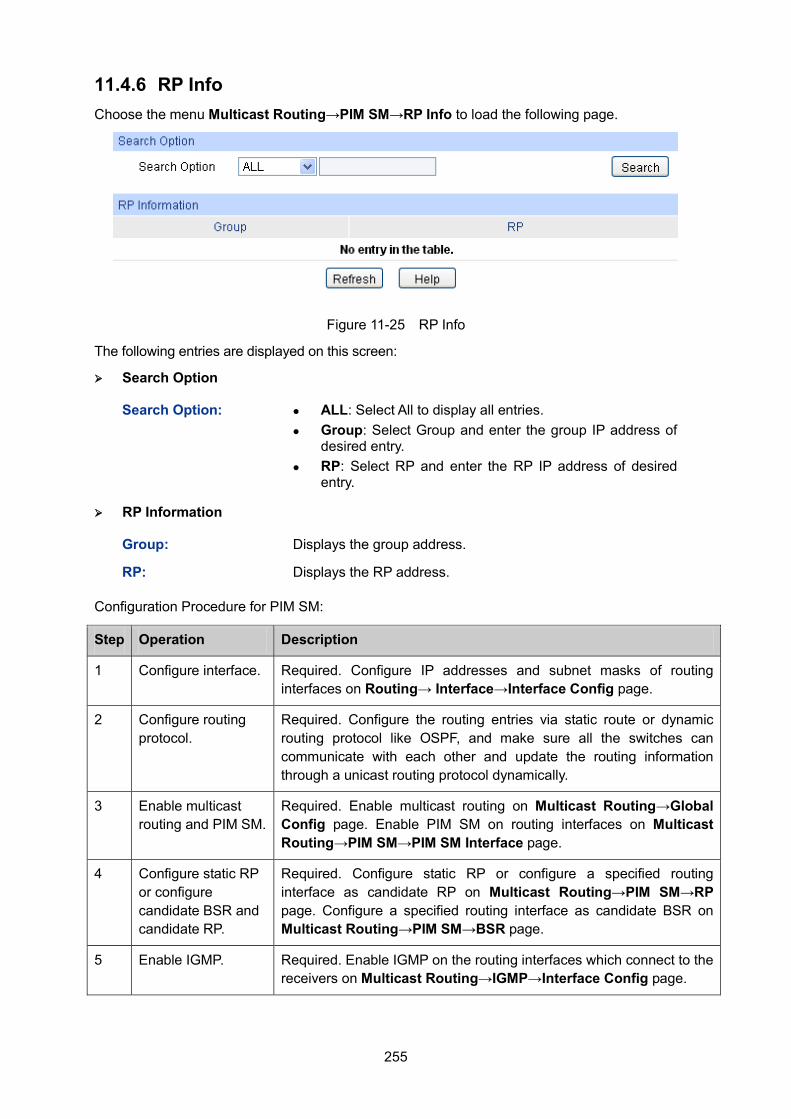
255
11.4.6 RP Info Choose the menu Multicast Routing→PIM SM→RP Info to load the following page.
Figure 11-25 RP Info
The following entries are displayed on this screen:
Search Option
Search Option: ALL: Select All to display all entries. Group: Select Group and enter the group IP address of
desired entry. RP: Select RP and enter the RP IP address of desired
entry.
RP Information
Group: Displays the group address.
RP: Displays the RP address.
Configuration Procedure for PIM SM:
Step Operation Description
1 Configure interface. Required. Configure IP addresses and subnet masks of routing interfaces on Routing→ Interface→Interface Config page.
2 Configure routing protocol.
Required. Configure the routing entries via static route or dynamic routing protocol like OSPF, and make sure all the switches can communicate with each other and update the routing information through a unicast routing protocol dynamically.
3 Enable multicast routing and PIM SM.
Required. Enable multicast routing on Multicast Routing→Global Config page. Enable PIM SM on routing interfaces on Multicast Routing→PIM SM→PIM SM Interface page.
4 Configure static RP or configure candidate BSR and candidate RP.
Required. Configure static RP or configure a specified routing interface as candidate RP on Multicast Routing→PIM SM→RP page. Configure a specified routing interface as candidate BSR on Multicast Routing→PIM SM→BSR page.
5 Enable IGMP. Required. Enable IGMP on the routing interfaces which connect to the receivers on Multicast Routing→IGMP→Interface Config page.
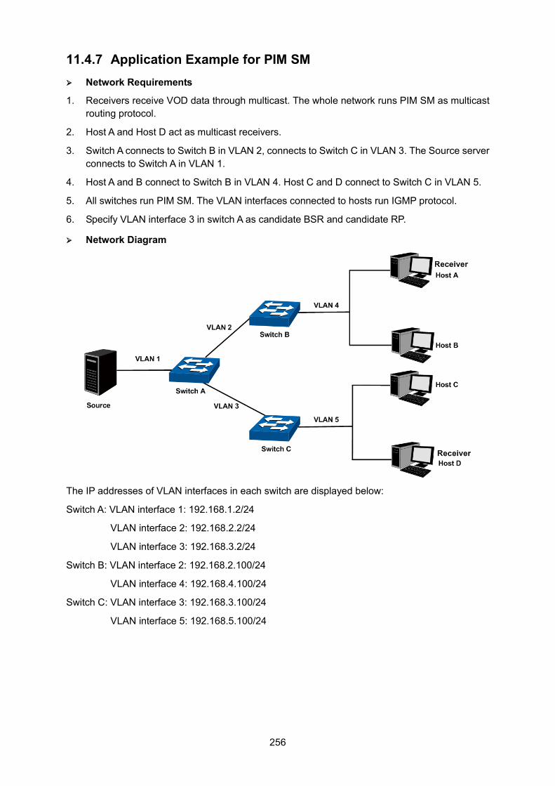
256
11.4.7 Application Example for PIM SM Network Requirements
1. Receivers receive VOD data through multicast. The whole network runs PIM SM as multicast routing protocol.
2. Host A and Host D act as multicast receivers.
3. Switch A connects to Switch B in VLAN 2, connects to Switch C in VLAN 3. The Source server connects to Switch A in VLAN 1.
4. Host A and B connect to Switch B in VLAN 4. Host C and D connect to Switch C in VLAN 5.
5. All switches run PIM SM. The VLAN interfaces connected to hosts run IGMP protocol.
6. Specify VLAN interface 3 in switch A as candidate BSR and candidate RP.
Network Diagram
The IP addresses of VLAN interfaces in each switch are displayed below:
Switch A: VLAN interface 1: 192.168.1.2/24
VLAN interface 2: 192.168.2.2/24
VLAN interface 3: 192.168.3.2/24
Switch B: VLAN interface 2: 192.168.2.100/24
VLAN interface 4: 192.168.4.100/24
Switch C: VLAN interface 3: 192.168.3.100/24
VLAN interface 5: 192.168.5.100/24
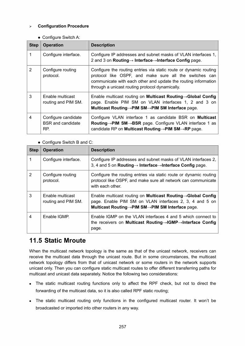
257
Configuration Procedure
Configure Switch A:
Step Operation Description
1 Configure interface. Configure IP addresses and subnet masks of VLAN interfaces 1, 2 and 3 on Routing→ Interface→Interface Config page.
2 Configure routing protocol.
Configure the routing entries via static route or dynamic routing protocol like OSPF, and make sure all the switches can communicate with each other and update the routing information through a unicast routing protocol dynamically.
3 Enable multicast routing and PIM SM.
Enable multicast routing on Multicast Routing→Global Config page. Enable PIM SM on VLAN interfaces 1, 2 and 3 on Multicast Routing→PIM SM→PIM SM Interface page.
4 Configure candidate BSR and candidate RP.
Configure VLAN interface 1 as candidate BSR on Multicast Routing→PIM SM→BSR page. Configure VLAN interface 1 as candidate RP on Multicast Routing→PIM SM→RP page.
Configure Switch B and C:
Step Operation Description
1 Configure interface. Configure IP addresses and subnet masks of VLAN interfaces 2, 3, 4 and 5 on Routing→ Interface→Interface Config page.
2 Configure routing protocol.
Configure the routing entries via static route or dynamic routing protocol like OSPF, and make sure all network can communicate with each other.
3 Enable multicast routing and PIM SM.
Enable multicast routing on Multicast Routing→Global Config page. Enable PIM SM on VLAN interfaces 2, 3, 4 and 5 on Multicast Routing→PIM SM→PIM SM Interface page.
4 Enable IGMP. Enable IGMP on the VLAN interfaces 4 and 5 which connect to the receivers on Multicast Routing→IGMP→Interface Config page.
11.5 Static Mroute When the multicast network topology is the same as that of the unicast network, receivers can receive the multicast data through the unicast route. But in some circumstances, the multicast network topology differs from that of unicast network or some routers in the network supports unicast only. Then you can configure static multicast routes to offer different transferring paths for multicast and unicast data separately. Notice the following two considerations:
The static multicast routing functions only to affect the RPF check, but not to direct the
forwarding of the multicast data, so it is also called RPF static routing;
The static multicast routing only functions in the configured multicast router. It won’t be
broadcasted or imported into other routers in any way.
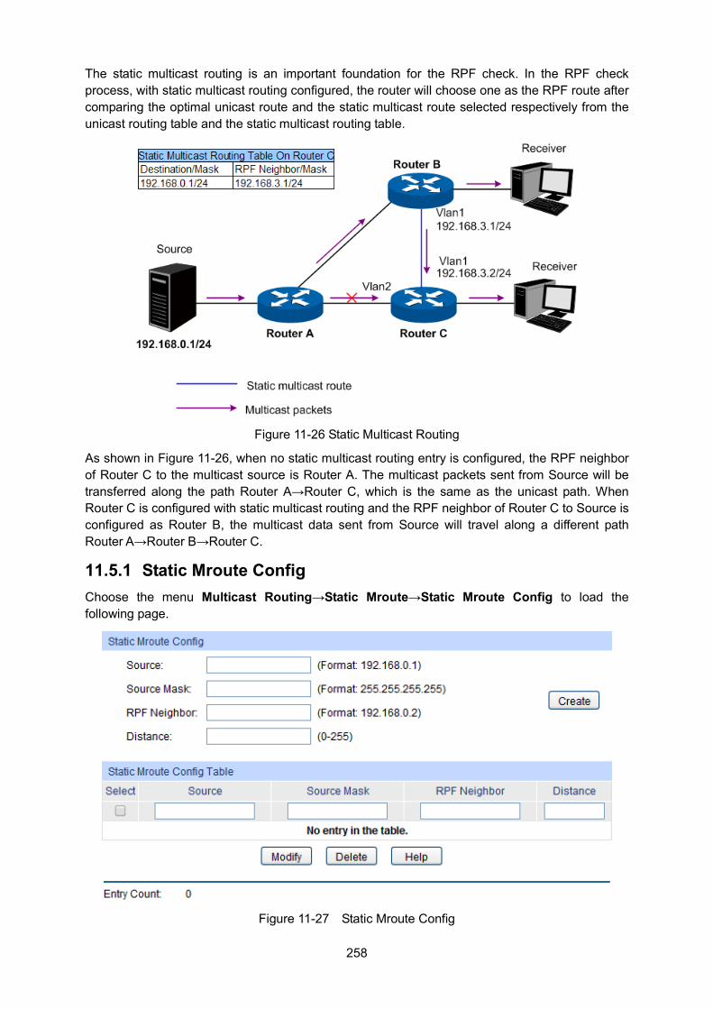
258
The static multicast routing is an important foundation for the RPF check. In the RPF check process, with static multicast routing configured, the router will choose one as the RPF route after comparing the optimal unicast route and the static multicast route selected respectively from the unicast routing table and the static multicast routing table.
Figure 11-26 Static Multicast Routing
As shown in Figure 11-26, when no static multicast routing entry is configured, the RPF neighbor of Router C to the multicast source is Router A. The multicast packets sent from Source will be transferred along the path Router A→Router C, which is the same as the unicast path. When Router C is configured with static multicast routing and the RPF neighbor of Router C to Source is configured as Router B, the multicast data sent from Source will travel along a different path Router A→Router B→Router C.
11.5.1 Static Mroute Config Choose the menu Multicast Routing→Static Mroute→Static Mroute Config to load the following page.
Figure 11-27 Static Mroute Config
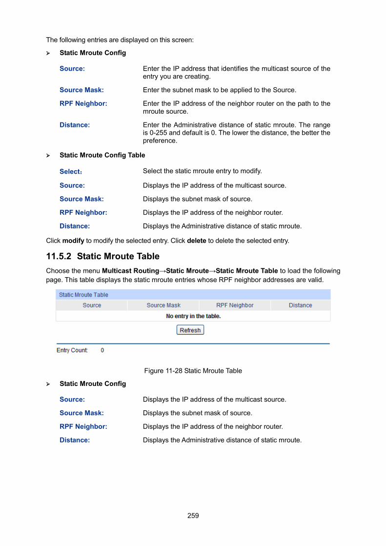
259
The following entries are displayed on this screen:
Static Mroute Config
Source: Enter the IP address that identifies the multicast source of the entry you are creating.
Source Mask: Enter the subnet mask to be applied to the Source.
RPF Neighbor: Enter the IP address of the neighbor router on the path to the mroute source.
Distance: Enter the Administrative distance of static mroute. The range is 0-255 and default is 0. The lower the distance, the better the preference.
Static Mroute Config Table
Select: Select the static mroute entry to modify.
Source: Displays the IP address of the multicast source.
Source Mask: Displays the subnet mask of source.
RPF Neighbor: Displays the IP address of the neighbor router.
Distance: Displays the Administrative distance of static mroute.
Click modify to modify the selected entry. Click delete to delete the selected entry.
11.5.2 Static Mroute Table Choose the menu Multicast Routing→Static Mroute→Static Mroute Table to load the following page. This table displays the static mroute entries whose RPF neighbor addresses are valid.
Figure 11-28 Static Mroute Table
Static Mroute Config
Source: Displays the IP address of the multicast source.
Source Mask: Displays the subnet mask of source.
RPF Neighbor: Displays the IP address of the neighbor router.
Distance: Displays the Administrative distance of static mroute.
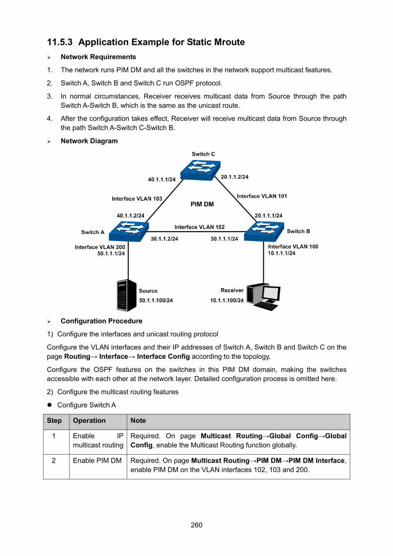
260
11.5.3 Application Example for Static Mroute Network Requirements
1. The network runs PIM DM and all the switches in the network support multicast features.
2. Switch A, Switch B and Switch C run OSPF protocol.
3. In normal circumstances, Receiver receives multicast data from Source through the path Switch A-Switch B, which is the same as the unicast route.
4. After the configuration takes effect, Receiver will receive multicast data from Source through the path Switch A-Switch C-Switch B.
Network Diagram
Configuration Procedure
1) Configure the interfaces and unicast routing protocol
Configure the VLAN interfaces and their IP addresses of Switch A, Switch B and Switch C on the page Routing→ Interface→ Interface Config according to the topology,
Configure the OSPF features on the switches in this PIM DM domain, making the switches accessible with each other at the network layer. Detailed configuration process is omitted here.
2) Configure the multicast routing features
Configure Switch A
Step Operation Note
1 Enable IP multicast routing
Required. On page Multicast Routing→Global Config→Global Config, enable the Multicast Routing function globally.
2 Enable PIM DM Required. On page Multicast Routing→PIM DM→PIM DM Interface, enable PIM DM on the VLAN interfaces 102, 103 and 200.
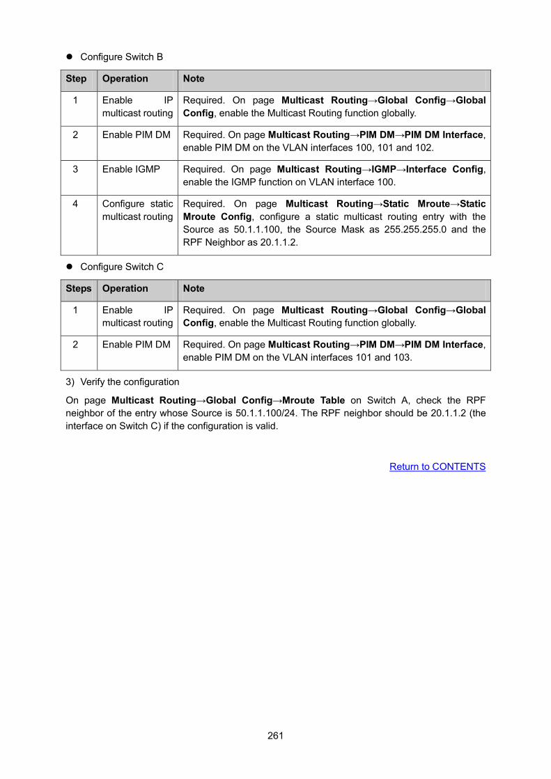
261
Configure Switch B
Step Operation Note
1 Enable IP multicast routing
Required. On page Multicast Routing→Global Config→Global Config, enable the Multicast Routing function globally.
2 Enable PIM DM Required. On page Multicast Routing→PIM DM→PIM DM Interface, enable PIM DM on the VLAN interfaces 100, 101 and 102.
3 Enable IGMP Required. On page Multicast Routing→IGMP→Interface Config, enable the IGMP function on VLAN interface 100.
4 Configure static multicast routing
Required. On page Multicast Routing→Static Mroute→Static Mroute Config, configure a static multicast routing entry with the Source as 50.1.1.100, the Source Mask as 255.255.255.0 and the RPF Neighbor as 20.1.1.2.
Configure Switch C
Steps Operation Note
1 Enable IP multicast routing
Required. On page Multicast Routing→Global Config→Global Config, enable the Multicast Routing function globally.
2 Enable PIM DM Required. On page Multicast Routing→PIM DM→PIM DM Interface, enable PIM DM on the VLAN interfaces 101 and 103.
3) Verify the configuration
On page Multicast Routing→Global Config→Mroute Table on Switch A, check the RPF neighbor of the entry whose Source is 50.1.1.100/24. The RPF neighbor should be 20.1.1.2 (the interface on Switch C) if the configuration is valid.
Return to CONTENTS
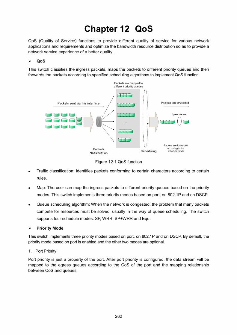
262
Chapter 12 QoS QoS (Quality of Service) functions to provide different quality of service for various network applications and requirements and optimize the bandwidth resource distribution so as to provide a network service experience of a better quality.
QoS
This switch classifies the ingress packets, maps the packets to different priority queues and then forwards the packets according to specified scheduling algorithms to implement QoS function.
Figure 12-1 QoS function
Traffic classification: Identifies packets conforming to certain characters according to certain
rules.
Map: The user can map the ingress packets to different priority queues based on the priority
modes. This switch implements three priority modes based on port, on 802.1P and on DSCP.
Queue scheduling algorithm: When the network is congested, the problem that many packets
compete for resources must be solved, usually in the way of queue scheduling. The switch
supports four schedule modes: SP, WRR, SP+WRR and Equ.
Priority Mode
This switch implements three priority modes based on port, on 802.1P and on DSCP. By default, the priority mode based on port is enabled and the other two modes are optional.
1. Port Priority
Port priority is just a property of the port. After port priority is configured, the data stream will be mapped to the egress queues according to the CoS of the port and the mapping relationship between CoS and queues.
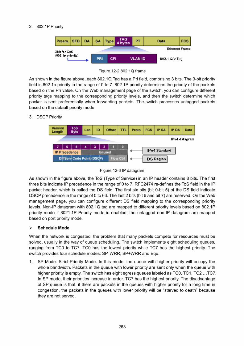
263
2. 802.1P Priority
Figure 12-2 802.1Q frame
As shown in the figure above, each 802.1Q Tag has a Pri field, comprising 3 bits. The 3-bit priority field is 802.1p priority in the range of 0 to 7. 802.1P priority determines the priority of the packets based on the Pri value. On the Web management page of the switch, you can configure different priority tags mapping to the corresponding priority levels, and then the switch determine which packet is sent preferentially when forwarding packets. The switch processes untagged packets based on the default priority mode.
3. DSCP Priority
Figure 12-3 IP datagram
As shown in the figure above, the ToS (Type of Service) in an IP header contains 8 bits. The first three bits indicate IP precedence in the range of 0 to 7. RFC2474 re-defines the ToS field in the IP packet header, which is called the DS field. The first six bits (bit 0-bit 5) of the DS field indicate DSCP precedence in the range of 0 to 63. The last 2 bits (bit 6 and bit 7) are reserved. On the Web management page, you can configure different DS field mapping to the corresponding priority levels. Non-IP datagram with 802.1Q tag are mapped to different priority levels based on 802.1P priority mode if 8021.1P Priority mode is enabled; the untagged non-IP datagram are mapped based on port priority mode.
Schedule Mode
When the network is congested, the problem that many packets compete for resources must be solved, usually in the way of queue scheduling. The switch implements eight scheduling queues, ranging from TC0 to TC7. TC0 has the lowest priority while TC7 has the highest priority. The switch provides four schedule modes: SP, WRR, SP+WRR and Equ.
1. SP-Mode: Strict-Priority Mode. In this mode, the queue with higher priority will occupy the whole bandwidth. Packets in the queue with lower priority are sent only when the queue with higher priority is empty. The switch has eight egress queues labeled as TC0, TC1, TC2 …TC7. In SP mode, their priorities increase in order. TC7 has the highest priority. The disadvantage of SP queue is that: if there are packets in the queues with higher priority for a long time in congestion, the packets in the queues with lower priority will be “starved to death” because they are not served.
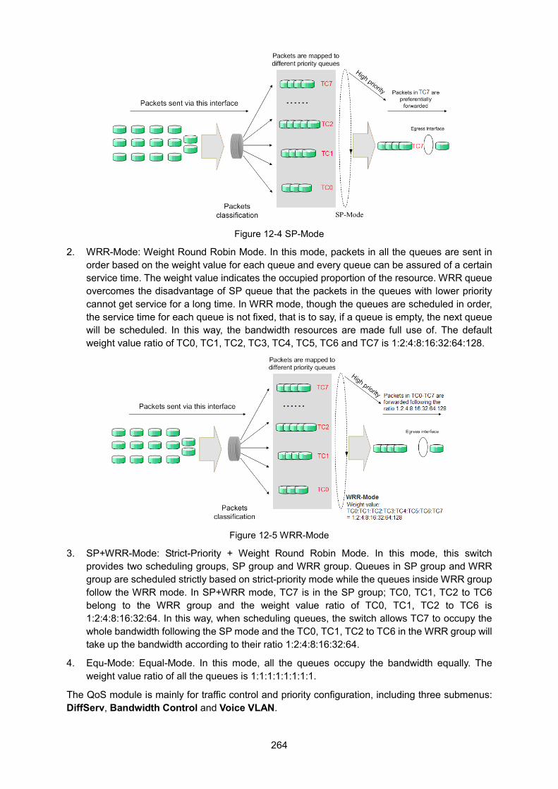
264
Figure 12-4 SP-Mode
2. WRR-Mode: Weight Round Robin Mode. In this mode, packets in all the queues are sent in order based on the weight value for each queue and every queue can be assured of a certain service time. The weight value indicates the occupied proportion of the resource. WRR queue overcomes the disadvantage of SP queue that the packets in the queues with lower priority cannot get service for a long time. In WRR mode, though the queues are scheduled in order, the service time for each queue is not fixed, that is to say, if a queue is empty, the next queue will be scheduled. In this way, the bandwidth resources are made full use of. The default weight value ratio of TC0, TC1, TC2, TC3, TC4, TC5, TC6 and TC7 is 1:2:4:8:16:32:64:128.
Figure 12-5 WRR-Mode
3. SP+WRR-Mode: Strict-Priority + Weight Round Robin Mode. In this mode, this switch provides two scheduling groups, SP group and WRR group. Queues in SP group and WRR group are scheduled strictly based on strict-priority mode while the queues inside WRR group follow the WRR mode. In SP+WRR mode, TC7 is in the SP group; TC0, TC1, TC2 to TC6 belong to the WRR group and the weight value ratio of TC0, TC1, TC2 to TC6 is 1:2:4:8:16:32:64. In this way, when scheduling queues, the switch allows TC7 to occupy the whole bandwidth following the SP mode and the TC0, TC1, TC2 to TC6 in the WRR group will take up the bandwidth according to their ratio 1:2:4:8:16:32:64.
4. Equ-Mode: Equal-Mode. In this mode, all the queues occupy the bandwidth equally. The weight value ratio of all the queues is 1:1:1:1:1:1:1:1.
The QoS module is mainly for traffic control and priority configuration, including three submenus: DiffServ, Bandwidth Control and Voice VLAN.
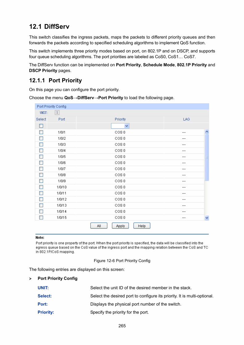
265
12.1 DiffServ This switch classifies the ingress packets, maps the packets to different priority queues and then forwards the packets according to specified scheduling algorithms to implement QoS function.
This switch implements three priority modes based on port, on 802.1P and on DSCP, and supports four queue scheduling algorithms. The port priorities are labeled as CoS0, CoS1… CoS7.
The DiffServ function can be implemented on Port Priority, Schedule Mode, 802.1P Priority and DSCP Priority pages.
12.1.1 Port Priority On this page you can configure the port priority.
Choose the menu QoS→DiffServ→Port Priority to load the following page.
Figure 12-6 Port Priority Config
The following entries are displayed on this screen:
Port Priority Config
UNIT: Select the unit ID of the desired member in the stack.
Select: Select the desired port to configure its priority. It is multi-optional.
Port: Displays the physical port number of the switch.
Priority: Specify the priority for the port.
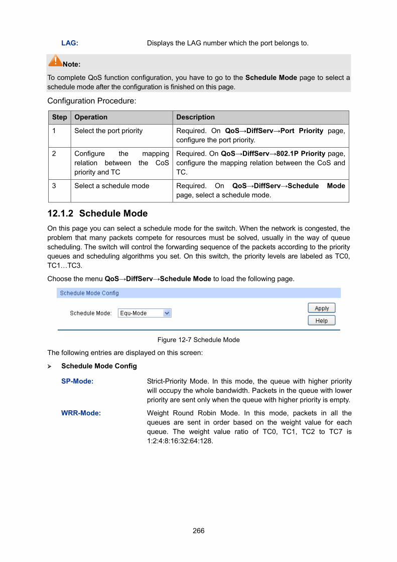
266
LAG: Displays the LAG number which the port belongs to.
Note:
To complete QoS function configuration, you have to go to the Schedule Mode page to select a schedule mode after the configuration is finished on this page.
Configuration Procedure:
Step Operation Description
1 Select the port priority Required. On QoS→DiffServ→Port Priority page, configure the port priority.
2 Configure the mapping relation between the CoS priority and TC
Required. On QoS→DiffServ→802.1P Priority page, configure the mapping relation between the CoS and TC.
3 Select a schedule mode Required. On QoS→DiffServ→Schedule Mode page, select a schedule mode.
12.1.2 Schedule Mode On this page you can select a schedule mode for the switch. When the network is congested, the problem that many packets compete for resources must be solved, usually in the way of queue scheduling. The switch will control the forwarding sequence of the packets according to the priority queues and scheduling algorithms you set. On this switch, the priority levels are labeled as TC0, TC1…TC3.
Choose the menu QoS→DiffServ→Schedule Mode to load the following page.
Figure 12-7 Schedule Mode
The following entries are displayed on this screen: Schedule Mode Config
SP-Mode: Strict-Priority Mode. In this mode, the queue with higher priority will occupy the whole bandwidth. Packets in the queue with lower priority are sent only when the queue with higher priority is empty.
WRR-Mode: Weight Round Robin Mode. In this mode, packets in all the queues are sent in order based on the weight value for each queue. The weight value ratio of TC0, TC1, TC2 to TC7 is 1:2:4:8:16:32:64:128.
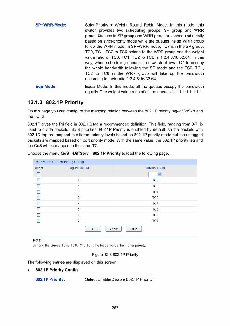
267
SP+WRR-Mode: Strict-Priority + Weight Round Robin Mode. In this mode, this switch provides two scheduling groups, SP group and WRR group. Queues in SP group and WRR group are scheduled strictly based on strict-priority mode while the queues inside WRR group follow the WRR mode. In SP+WRR mode, TC7 is in the SP group; TC0, TC1, TC2 to TC6 belong to the WRR group and the weight value ratio of TC0, TC1, TC2 to TC6 is 1:2:4:8:16:32:64. In this way, when scheduling queues, the switch allows TC7 to occupy the whole bandwidth following the SP mode and the TC0, TC1, TC2 to TC6 in the WRR group will take up the bandwidth according to their ratio 1:2:4:8:16:32:64.
Equ-Mode: Equal-Mode. In this mode, all the queues occupy the bandwidth equally. The weight value ratio of all the queues is 1:1:1:1:1:1:1:1.
12.1.3 802.1P Priority On this page you can configure the mapping relation between the 802.1P priority tag-id/CoS-id and the TC-id.
802.1P gives the Pri field in 802.1Q tag a recommended definition. This field, ranging from 0-7, is used to divide packets into 8 priorities. 802.1P Priority is enabled by default, so the packets with 802.1Q tag are mapped to different priority levels based on 802.1P priority mode but the untagged packets are mapped based on port priority mode. With the same value, the 802.1P priority tag and the CoS will be mapped to the same TC.
Choose the menu QoS→DiffServ→802.1P Priority to load the following page.
Figure 12-8 802.1P Priority
The following entries are displayed on this screen: 802.1P Priority Config
802.1P Priority: Select Enable/Disable 802.1P Priority.
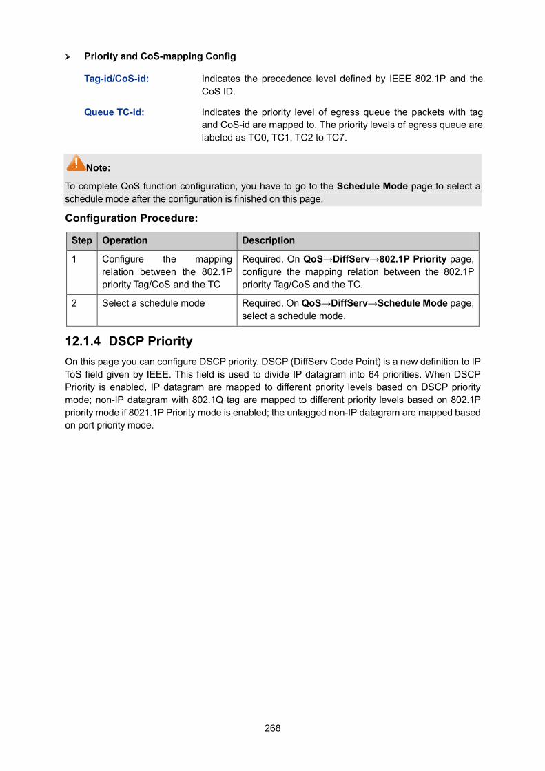
268
Priority and CoS-mapping Config
Tag-id/CoS-id: Indicates the precedence level defined by IEEE 802.1P and the CoS ID.
Queue TC-id: Indicates the priority level of egress queue the packets with tag and CoS-id are mapped to. The priority levels of egress queue are labeled as TC0, TC1, TC2 to TC7.
Note:
To complete QoS function configuration, you have to go to the Schedule Mode page to select a schedule mode after the configuration is finished on this page.
Configuration Procedure:
Step Operation Description
1 Configure the mapping relation between the 802.1P priority Tag/CoS and the TC
Required. On QoS→DiffServ→802.1P Priority page, configure the mapping relation between the 802.1P priority Tag/CoS and the TC.
2 Select a schedule mode Required. On QoS→DiffServ→Schedule Mode page, select a schedule mode.
12.1.4 DSCP Priority On this page you can configure DSCP priority. DSCP (DiffServ Code Point) is a new definition to IP ToS field given by IEEE. This field is used to divide IP datagram into 64 priorities. When DSCP Priority is enabled, IP datagram are mapped to different priority levels based on DSCP priority mode; non-IP datagram with 802.1Q tag are mapped to different priority levels based on 802.1P priority mode if 8021.1P Priority mode is enabled; the untagged non-IP datagram are mapped based on port priority mode.
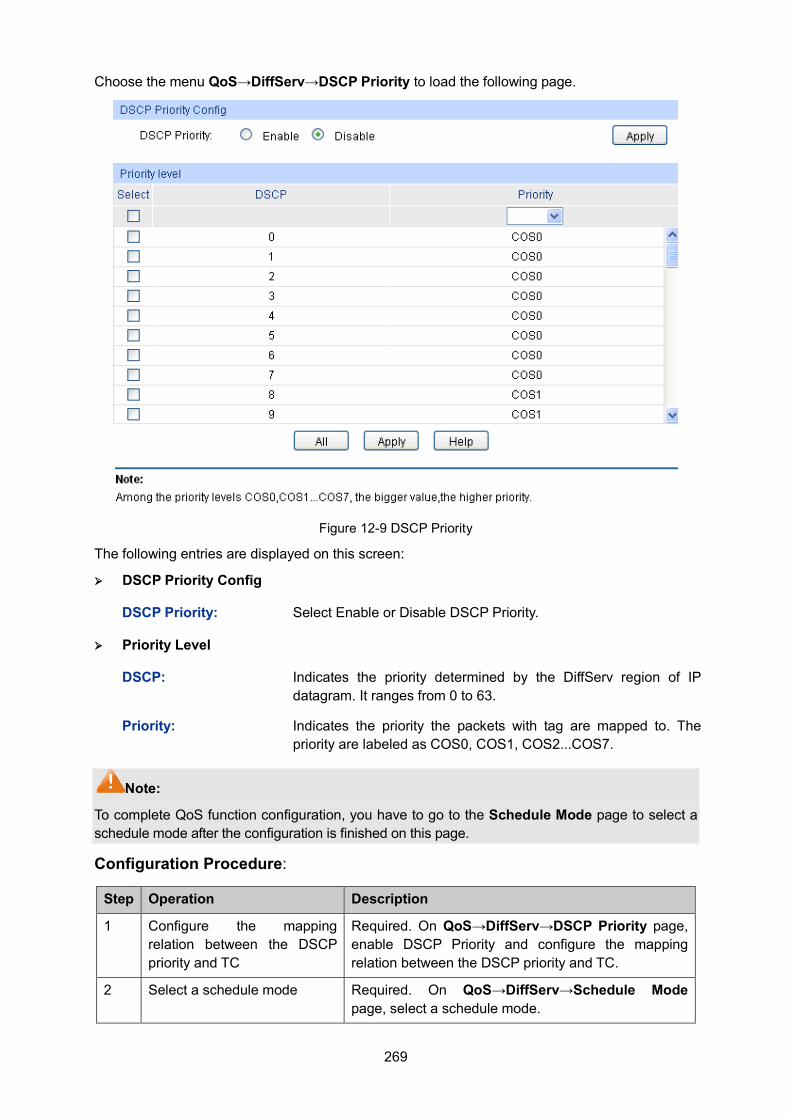
269
Choose the menu QoS→DiffServ→DSCP Priority to load the following page.
Figure 12-9 DSCP Priority
The following entries are displayed on this screen: DSCP Priority Config
DSCP Priority: Select Enable or Disable DSCP Priority.
Priority Level
DSCP: Indicates the priority determined by the DiffServ region of IP datagram. It ranges from 0 to 63.
Priority: Indicates the priority the packets with tag are mapped to. The priority are labeled as COS0, COS1, COS2...COS7.
Note:
To complete QoS function configuration, you have to go to the Schedule Mode page to select a schedule mode after the configuration is finished on this page.
Configuration Procedure:
Step Operation Description
1 Configure the mapping relation between the DSCP priority and TC
Required. On QoS→DiffServ→DSCP Priority page, enable DSCP Priority and configure the mapping relation between the DSCP priority and TC.
2 Select a schedule mode Required. On QoS→DiffServ→Schedule Mode page, select a schedule mode.
270
12.2 Bandwidth Control Bandwidth function, allowing you to control the traffic rate and broadcast flow on each port to ensure network in working order, can be implemented on Rate Limit and Storm Control pages.
12.2.1 Rate Limit Rate limit functions to control the ingress/egress traffic rate on each port via configuring the available bandwidth of each port. In this way, the network bandwidth can be reasonably distributed and utilized.
Choose the menu QoS→Bandwidth Control→Rate Limit to load the following page.
Figure 12-10 Rate Limit
The following entries are displayed on this screen:
Rate Limit Config
UNIT: Select the unit ID of the desired member in the stack.
Select: Select the desired port for Rate configuration. It is multi-optional.
Port: Displays the port number of the switch.
Ingress Rate: Select the bandwidth for receiving packets on the port.
Egress Rate: Select the bandwidth for sending packets on the port.
LAG: Displays the LAG number which the port belongs to.
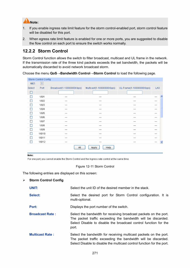
271
Note: 1. If you enable ingress rate limit feature for the storm control-enabled port, storm control feature
will be disabled for this port.
2. When egress rate limit feature is enabled for one or more ports, you are suggested to disable the flow control on each port to ensure the switch works normally.
12.2.2 Storm Control Storm Control function allows the switch to filter broadcast, multicast and UL frame in the network. If the transmission rate of the three kind packets exceeds the set bandwidth, the packets will be automatically discarded to avoid network broadcast storm.
Choose the menu QoS→Bandwidth Control→Storm Control to load the following page.
Figure 12-11 Storm Control
The following entries are displayed on this screen:
Storm Control Config
UNIT: Select the unit ID of the desired member in the stack.
Select: Select the desired port for Storm Control configuration. It is multi-optional.
Port: Displays the port number of the switch.
Broadcast Rate : Select the bandwidth for receiving broadcast packets on the port. The packet traffic exceeding the bandwidth will be discarded. Select Disable to disable the broadcast control function for the port.
Multicast Rate : Select the bandwidth for receiving multicast packets on the port. The packet traffic exceeding the bandwidth will be discarded. Select Disable to disable the multicast control function for the port.
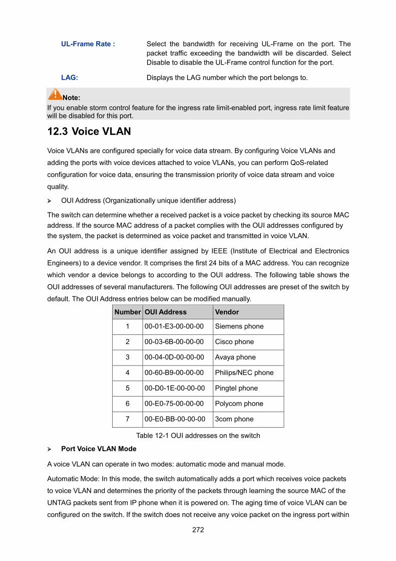
272
UL-Frame Rate : Select the bandwidth for receiving UL-Frame on the port. The packet traffic exceeding the bandwidth will be discarded. Select Disable to disable the UL-Frame control function for the port.
LAG: Displays the LAG number which the port belongs to.
Note: If you enable storm control feature for the ingress rate limit-enabled port, ingress rate limit feature will be disabled for this port.
12.3 Voice VLAN Voice VLANs are configured specially for voice data stream. By configuring Voice VLANs and
adding the ports with voice devices attached to voice VLANs, you can perform QoS-related
configuration for voice data, ensuring the transmission priority of voice data stream and voice
quality.
OUI Address (Organizationally unique identifier address)
The switch can determine whether a received packet is a voice packet by checking its source MAC address. If the source MAC address of a packet complies with the OUI addresses configured by the system, the packet is determined as voice packet and transmitted in voice VLAN.
An OUI address is a unique identifier assigned by IEEE (Institute of Electrical and Electronics
Engineers) to a device vendor. It comprises the first 24 bits of a MAC address. You can recognize
which vendor a device belongs to according to the OUI address. The following table shows the
OUI addresses of several manufacturers. The following OUI addresses are preset of the switch by
default. The OUI Address entries below can be modified manually.
Number OUI Address Vendor
1 00-01-E3-00-00-00 Siemens phone
2 00-03-6B-00-00-00 Cisco phone
3 00-04-0D-00-00-00 Avaya phone
4 00-60-B9-00-00-00 Philips/NEC phone
5 00-D0-1E-00-00-00 Pingtel phone
6 00-E0-75-00-00-00 Polycom phone
7 00-E0-BB-00-00-00 3com phone
Table 12-1 OUI addresses on the switch
Port Voice VLAN Mode
A voice VLAN can operate in two modes: automatic mode and manual mode.
Automatic Mode: In this mode, the switch automatically adds a port which receives voice packets
to voice VLAN and determines the priority of the packets through learning the source MAC of the
UNTAG packets sent from IP phone when it is powered on. The aging time of voice VLAN can be
configured on the switch. If the switch does not receive any voice packet on the ingress port within
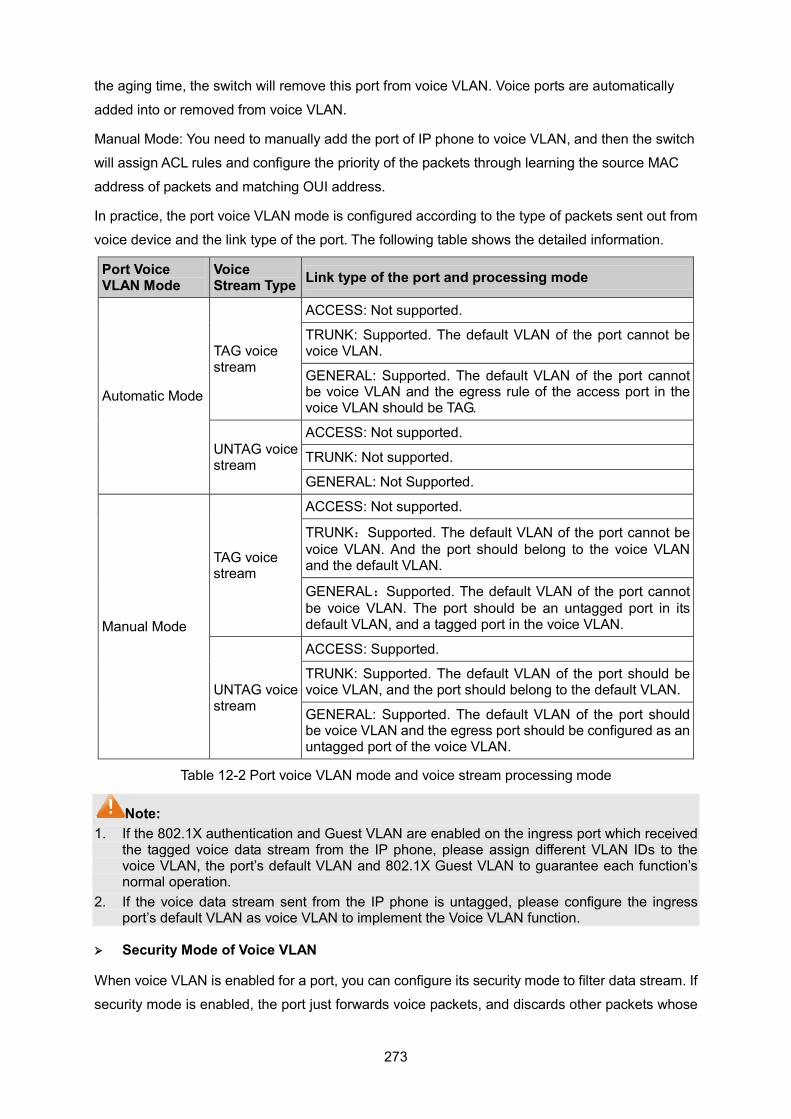
273
the aging time, the switch will remove this port from voice VLAN. Voice ports are automatically
added into or removed from voice VLAN.
Manual Mode: You need to manually add the port of IP phone to voice VLAN, and then the switch
will assign ACL rules and configure the priority of the packets through learning the source MAC
address of packets and matching OUI address.
In practice, the port voice VLAN mode is configured according to the type of packets sent out from
voice device and the link type of the port. The following table shows the detailed information.
Port Voice VLAN Mode
Voice Stream Type Link type of the port and processing mode
Automatic Mode
TAG voice stream
ACCESS: Not supported.
TRUNK: Supported. The default VLAN of the port cannot be voice VLAN.
GENERAL: Supported. The default VLAN of the port cannot be voice VLAN and the egress rule of the access port in the voice VLAN should be TAG.
UNTAG voice stream
ACCESS: Not supported.
TRUNK: Not supported.
GENERAL: Not Supported.
Manual Mode
TAG voice stream
ACCESS: Not supported.
TRUNK:Supported. The default VLAN of the port cannot be voice VLAN. And the port should belong to the voice VLAN and the default VLAN.
GENERAL:Supported. The default VLAN of the port cannot be voice VLAN. The port should be an untagged port in its default VLAN, and a tagged port in the voice VLAN.
UNTAG voice stream
ACCESS: Supported.
TRUNK: Supported. The default VLAN of the port should be voice VLAN, and the port should belong to the default VLAN.
GENERAL: Supported. The default VLAN of the port should be voice VLAN and the egress port should be configured as an untagged port of the voice VLAN.
Table 12-2 Port voice VLAN mode and voice stream processing mode
Note: 1. If the 802.1X authentication and Guest VLAN are enabled on the ingress port which received
the tagged voice data stream from the IP phone, please assign different VLAN IDs to the voice VLAN, the port’s default VLAN and 802.1X Guest VLAN to guarantee each function’s normal operation.
2. If the voice data stream sent from the IP phone is untagged, please configure the ingress port’s default VLAN as voice VLAN to implement the Voice VLAN function.
Security Mode of Voice VLAN
When voice VLAN is enabled for a port, you can configure its security mode to filter data stream. If
security mode is enabled, the port just forwards voice packets, and discards other packets whose
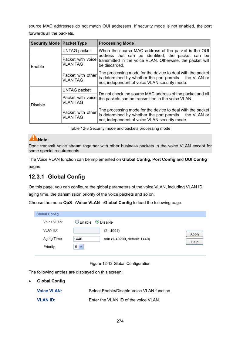
274
source MAC addresses do not match OUI addresses. If security mode is not enabled, the port
forwards all the packets.
Security Mode Packet Type Processing Mode
Enable
UNTAG packet When the source MAC address of the packet is the OUI address that can be identified, the packet can be transmitted in the voice VLAN. Otherwise, the packet will be discarded.
Packet with voice VLAN TAG
Packet with other VLAN TAG
The processing mode for the device to deal with the packet is determined by whether the port permits the VLAN or not, independent of voice VLAN security mode.
Disable
UNTAG packet Do not check the source MAC address of the packet and all the packets can be transmitted in the voice VLAN. Packet with voice
VLAN TAG
Packet with other VLAN TAG
The processing mode for the device to deal with the packet is determined by whether the port permits the VLAN or not, independent of voice VLAN security mode.
Table 12-3 Security mode and packets processing mode
Note: Don’t transmit voice stream together with other business packets in the voice VLAN except for some special requirements.
The Voice VLAN function can be implemented on Global Config, Port Config and OUI Config pages.
12.3.1 Global Config On this page, you can configure the global parameters of the voice VLAN, including VLAN ID,
aging time, the transmission priority of the voice packets and so on.
Choose the menu QoS→Voice VLAN→Global Config to load the following page.
Figure 12-12 Global Configuration
The following entries are displayed on this screen:
Global Config
Voice VLAN: Select Enable/Disable Voice VLAN function.
VLAN ID: Enter the VLAN ID of the voice VLAN.
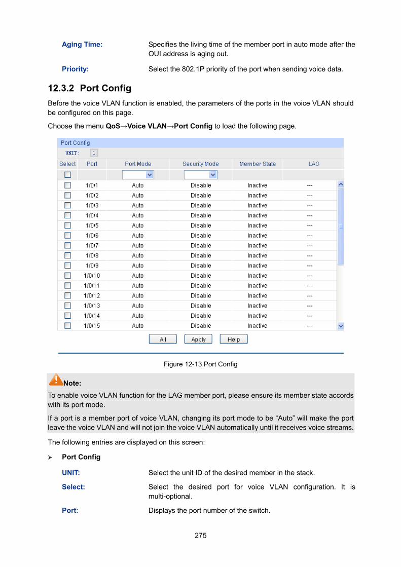
275
Aging Time: Specifies the living time of the member port in auto mode after the OUI address is aging out.
Priority: Select the 802.1P priority of the port when sending voice data.
12.3.2 Port Config Before the voice VLAN function is enabled, the parameters of the ports in the voice VLAN should be configured on this page.
Choose the menu QoS→Voice VLAN→Port Config to load the following page.
Figure 12-13 Port Config
Note: To enable voice VLAN function for the LAG member port, please ensure its member state accords with its port mode.
If a port is a member port of voice VLAN, changing its port mode to be “Auto” will make the port leave the voice VLAN and will not join the voice VLAN automatically until it receives voice streams.
The following entries are displayed on this screen:
Port Config
UNIT: Select the unit ID of the desired member in the stack.
Select: Select the desired port for voice VLAN configuration. It is multi-optional.
Port: Displays the port number of the switch.
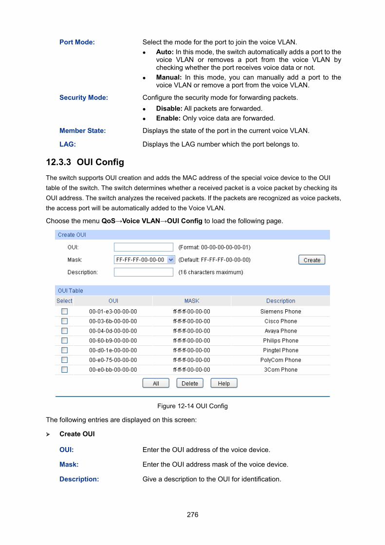
276
Port Mode: Select the mode for the port to join the voice VLAN. Auto: In this mode, the switch automatically adds a port to the
voice VLAN or removes a port from the voice VLAN by checking whether the port receives voice data or not.
Manual: In this mode, you can manually add a port to the voice VLAN or remove a port from the voice VLAN.
Security Mode: Configure the security mode for forwarding packets. Disable: All packets are forwarded. Enable: Only voice data are forwarded.
Member State: Displays the state of the port in the current voice VLAN.
LAG: Displays the LAG number which the port belongs to.
12.3.3 OUI Config The switch supports OUI creation and adds the MAC address of the special voice device to the OUI table of the switch. The switch determines whether a received packet is a voice packet by checking its OUI address. The switch analyzes the received packets. If the packets are recognized as voice packets, the access port will be automatically added to the Voice VLAN.
Choose the menu QoS→Voice VLAN→OUI Config to load the following page.
Figure 12-14 OUI Config
The following entries are displayed on this screen:
Create OUI
OUI: Enter the OUI address of the voice device.
Mask: Enter the OUI address mask of the voice device.
Description: Give a description to the OUI for identification.
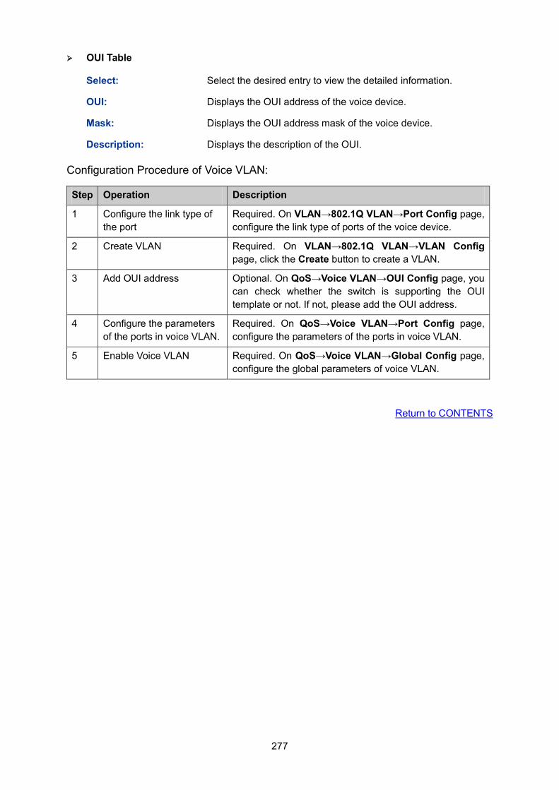
277
OUI Table
Select: Select the desired entry to view the detailed information.
OUI: Displays the OUI address of the voice device.
Mask: Displays the OUI address mask of the voice device.
Description: Displays the description of the OUI.
Configuration Procedure of Voice VLAN:
Step Operation Description
1 Configure the link type of the port
Required. On VLAN→802.1Q VLAN→Port Config page, configure the link type of ports of the voice device.
2 Create VLAN Required. On VLAN→802.1Q VLAN→VLAN Config page, click the Create button to create a VLAN.
3 Add OUI address Optional. On QoS→Voice VLAN→OUI Config page, you can check whether the switch is supporting the OUI template or not. If not, please add the OUI address.
4 Configure the parameters of the ports in voice VLAN.
Required. On QoS→Voice VLAN→Port Config page, configure the parameters of the ports in voice VLAN.
5 Enable Voice VLAN Required. On QoS→Voice VLAN→Global Config page, configure the global parameters of voice VLAN.
Return to CONTENTS
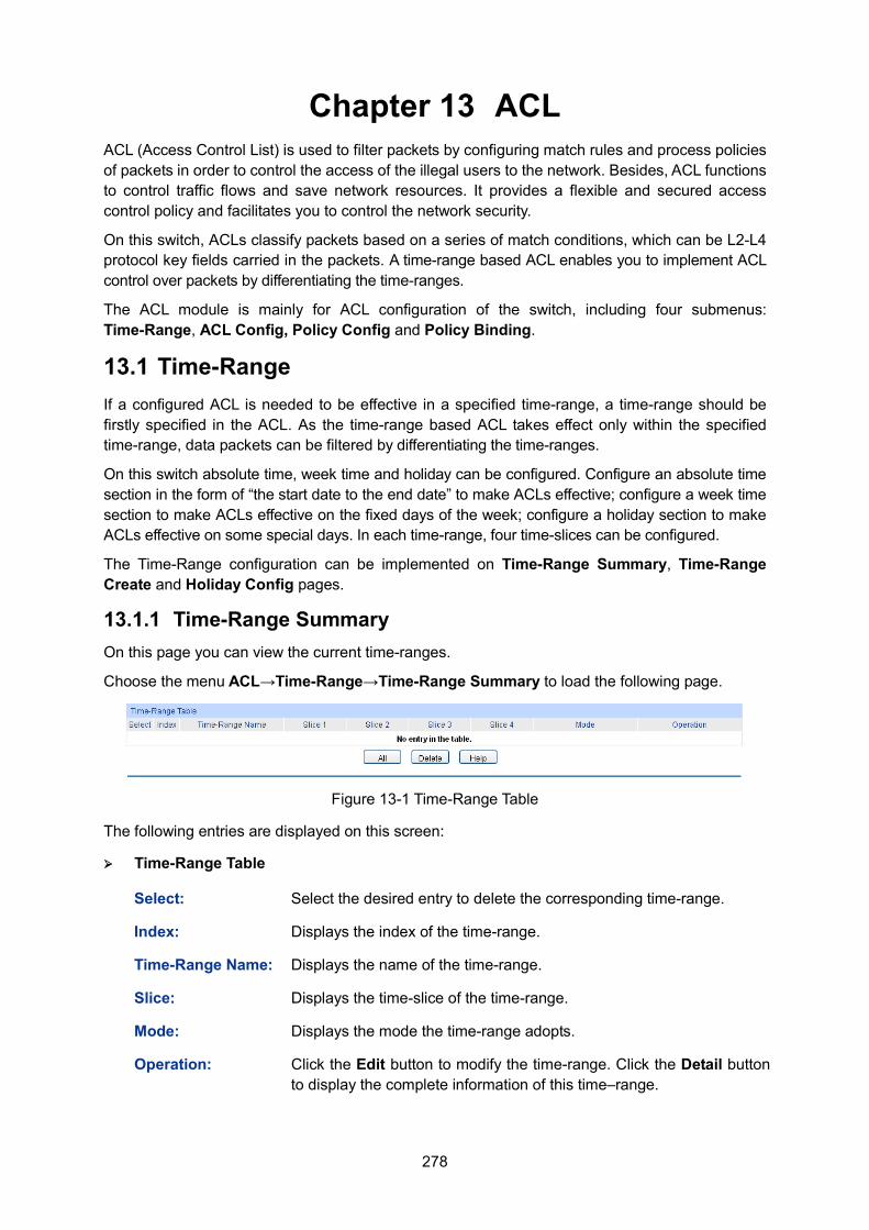
278
Chapter 13 ACL ACL (Access Control List) is used to filter packets by configuring match rules and process policies of packets in order to control the access of the illegal users to the network. Besides, ACL functions to control traffic flows and save network resources. It provides a flexible and secured access control policy and facilitates you to control the network security.
On this switch, ACLs classify packets based on a series of match conditions, which can be L2-L4 protocol key fields carried in the packets. A time-range based ACL enables you to implement ACL control over packets by differentiating the time-ranges.
The ACL module is mainly for ACL configuration of the switch, including four submenus: Time-Range, ACL Config, Policy Config and Policy Binding.
13.1 Time-Range If a configured ACL is needed to be effective in a specified time-range, a time-range should be firstly specified in the ACL. As the time-range based ACL takes effect only within the specified time-range, data packets can be filtered by differentiating the time-ranges.
On this switch absolute time, week time and holiday can be configured. Configure an absolute time section in the form of “the start date to the end date” to make ACLs effective; configure a week time section to make ACLs effective on the fixed days of the week; configure a holiday section to make ACLs effective on some special days. In each time-range, four time-slices can be configured.
The Time-Range configuration can be implemented on Time-Range Summary, Time-Range Create and Holiday Config pages.
13.1.1 Time-Range Summary On this page you can view the current time-ranges.
Choose the menu ACL→Time-Range→Time-Range Summary to load the following page.
Figure 13-1 Time-Range Table
The following entries are displayed on this screen:
Time-Range Table
Select: Select the desired entry to delete the corresponding time-range.
Index: Displays the index of the time-range.
Time-Range Name: Displays the name of the time-range.
Slice: Displays the time-slice of the time-range.
Mode: Displays the mode the time-range adopts.
Operation: Click the Edit button to modify the time-range. Click the Detail button to display the complete information of this time–range.
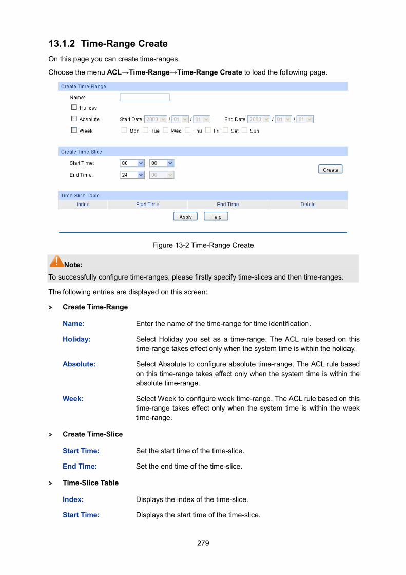
279
13.1.2 Time-Range Create On this page you can create time-ranges.
Choose the menu ACL→Time-Range→Time-Range Create to load the following page.
Figure 13-2 Time-Range Create
Note: To successfully configure time-ranges, please firstly specify time-slices and then time-ranges.
The following entries are displayed on this screen:
Create Time-Range
Name: Enter the name of the time-range for time identification.
Holiday: Select Holiday you set as a time-range. The ACL rule based on this time-range takes effect only when the system time is within the holiday.
Absolute: Select Absolute to configure absolute time-range. The ACL rule based on this time-range takes effect only when the system time is within the absolute time-range.
Week: Select Week to configure week time-range. The ACL rule based on this time-range takes effect only when the system time is within the week time-range.
Create Time-Slice
Start Time: Set the start time of the time-slice.
End Time: Set the end time of the time-slice.
Time-Slice Table
Index: Displays the index of the time-slice.
Start Time: Displays the start time of the time-slice.
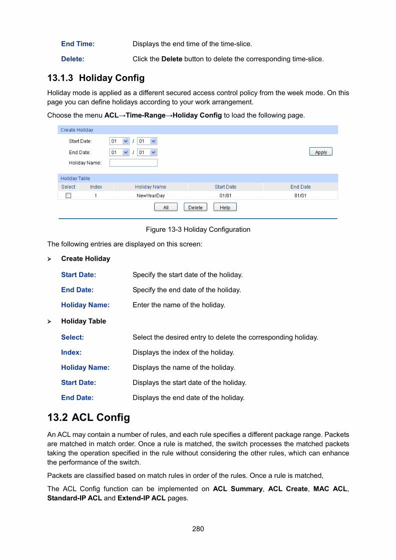
280
End Time: Displays the end time of the time-slice.
Delete: Click the Delete button to delete the corresponding time-slice.
13.1.3 Holiday Config Holiday mode is applied as a different secured access control policy from the week mode. On this page you can define holidays according to your work arrangement.
Choose the menu ACL→Time-Range→Holiday Config to load the following page.
Figure 13-3 Holiday Configuration
The following entries are displayed on this screen:
Create Holiday
Start Date: Specify the start date of the holiday.
End Date: Specify the end date of the holiday.
Holiday Name: Enter the name of the holiday.
Holiday Table
Select: Select the desired entry to delete the corresponding holiday.
Index: Displays the index of the holiday.
Holiday Name: Displays the name of the holiday.
Start Date: Displays the start date of the holiday.
End Date: Displays the end date of the holiday.
13.2 ACL Config An ACL may contain a number of rules, and each rule specifies a different package range. Packets are matched in match order. Once a rule is matched, the switch processes the matched packets taking the operation specified in the rule without considering the other rules, which can enhance the performance of the switch.
Packets are classified based on match rules in order of the rules. Once a rule is matched,
The ACL Config function can be implemented on ACL Summary, ACL Create, MAC ACL, Standard-IP ACL and Extend-IP ACL pages.
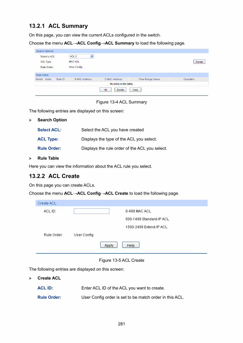
281
13.2.1 ACL Summary On this page, you can view the current ACLs configured in the switch.
Choose the menu ACL→ACL Config→ACL Summary to load the following page.
Figure 13-4 ACL Summary
The following entries are displayed on this screen:
Search Option
Select ACL: Select the ACL you have created
ACL Type: Displays the type of the ACL you select.
Rule Order: Displays the rule order of the ACL you select.
Rule Table
Here you can view the information about the ACL rule you select.
13.2.2 ACL Create On this page you can create ACLs.
Choose the menu ACL→ACL Config→ACL Create to load the following page.
Figure 13-5 ACL Create
The following entries are displayed on this screen:
Create ACL
ACL ID: Enter ACL ID of the ACL you want to create.
Rule Order: User Config order is set to be match order in this ACL.
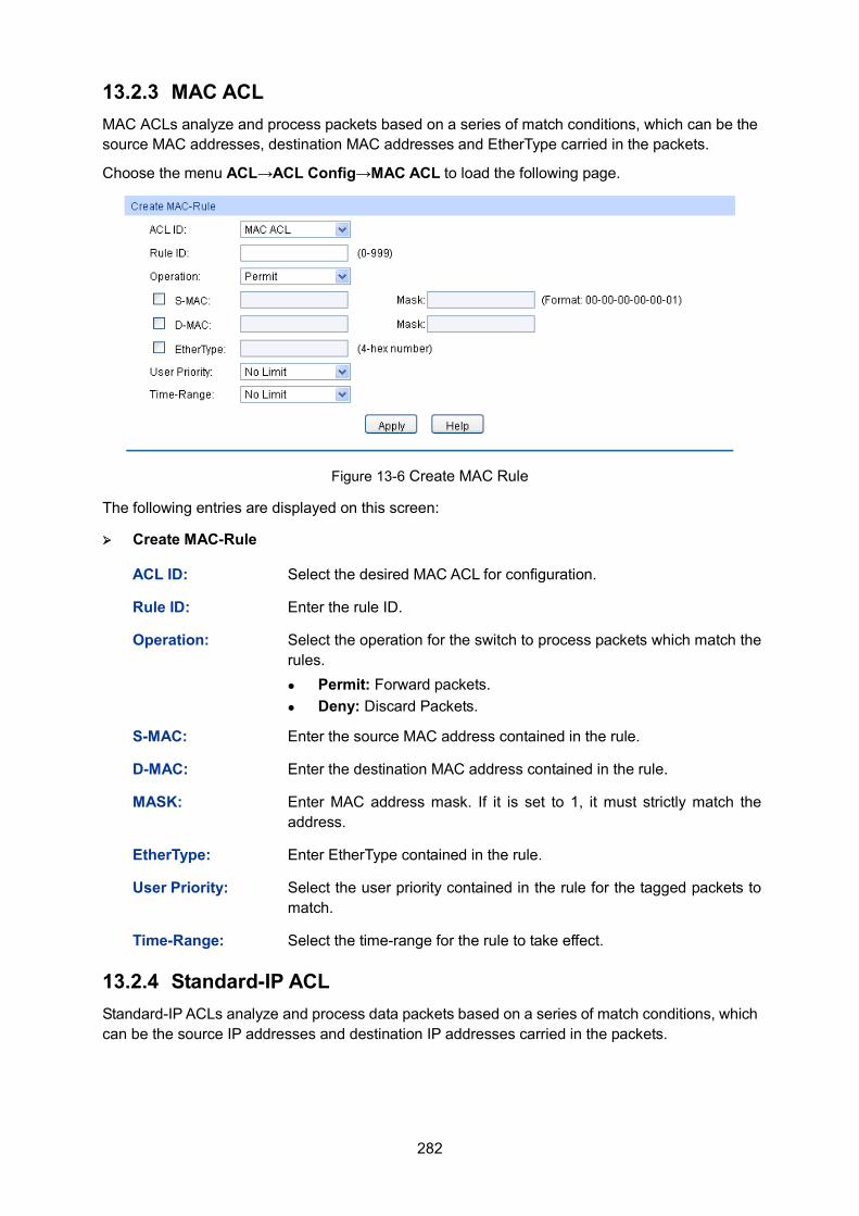
282
13.2.3 MAC ACL MAC ACLs analyze and process packets based on a series of match conditions, which can be the source MAC addresses, destination MAC addresses and EtherType carried in the packets.
Choose the menu ACL→ACL Config→MAC ACL to load the following page.
Figure 13-6 Create MAC Rule
The following entries are displayed on this screen:
Create MAC-Rule
ACL ID: Select the desired MAC ACL for configuration.
Rule ID: Enter the rule ID.
Operation: Select the operation for the switch to process packets which match the rules. Permit: Forward packets. Deny: Discard Packets.
S-MAC: Enter the source MAC address contained in the rule.
D-MAC: Enter the destination MAC address contained in the rule.
MASK: Enter MAC address mask. If it is set to 1, it must strictly match the address.
EtherType: Enter EtherType contained in the rule.
User Priority: Select the user priority contained in the rule for the tagged packets to match.
Time-Range: Select the time-range for the rule to take effect.
13.2.4 Standard-IP ACL Standard-IP ACLs analyze and process data packets based on a series of match conditions, which can be the source IP addresses and destination IP addresses carried in the packets.
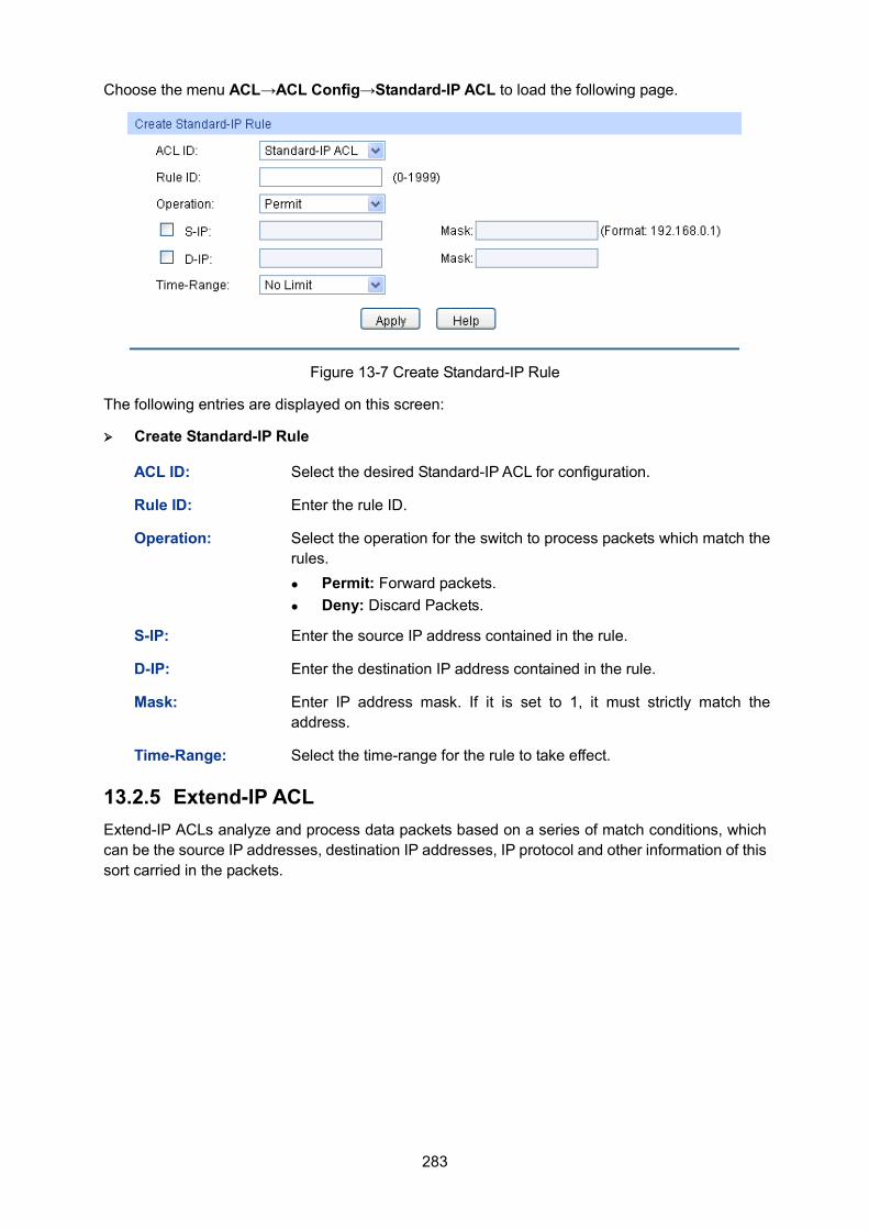
283
Choose the menu ACL→ACL Config→Standard-IP ACL to load the following page.
Figure 13-7 Create Standard-IP Rule
The following entries are displayed on this screen:
Create Standard-IP Rule
ACL ID: Select the desired Standard-IP ACL for configuration.
Rule ID: Enter the rule ID.
Operation: Select the operation for the switch to process packets which match the rules. Permit: Forward packets. Deny: Discard Packets.
S-IP: Enter the source IP address contained in the rule.
D-IP: Enter the destination IP address contained in the rule.
Mask: Enter IP address mask. If it is set to 1, it must strictly match the address.
Time-Range: Select the time-range for the rule to take effect.
13.2.5 Extend-IP ACL Extend-IP ACLs analyze and process data packets based on a series of match conditions, which can be the source IP addresses, destination IP addresses, IP protocol and other information of this sort carried in the packets.
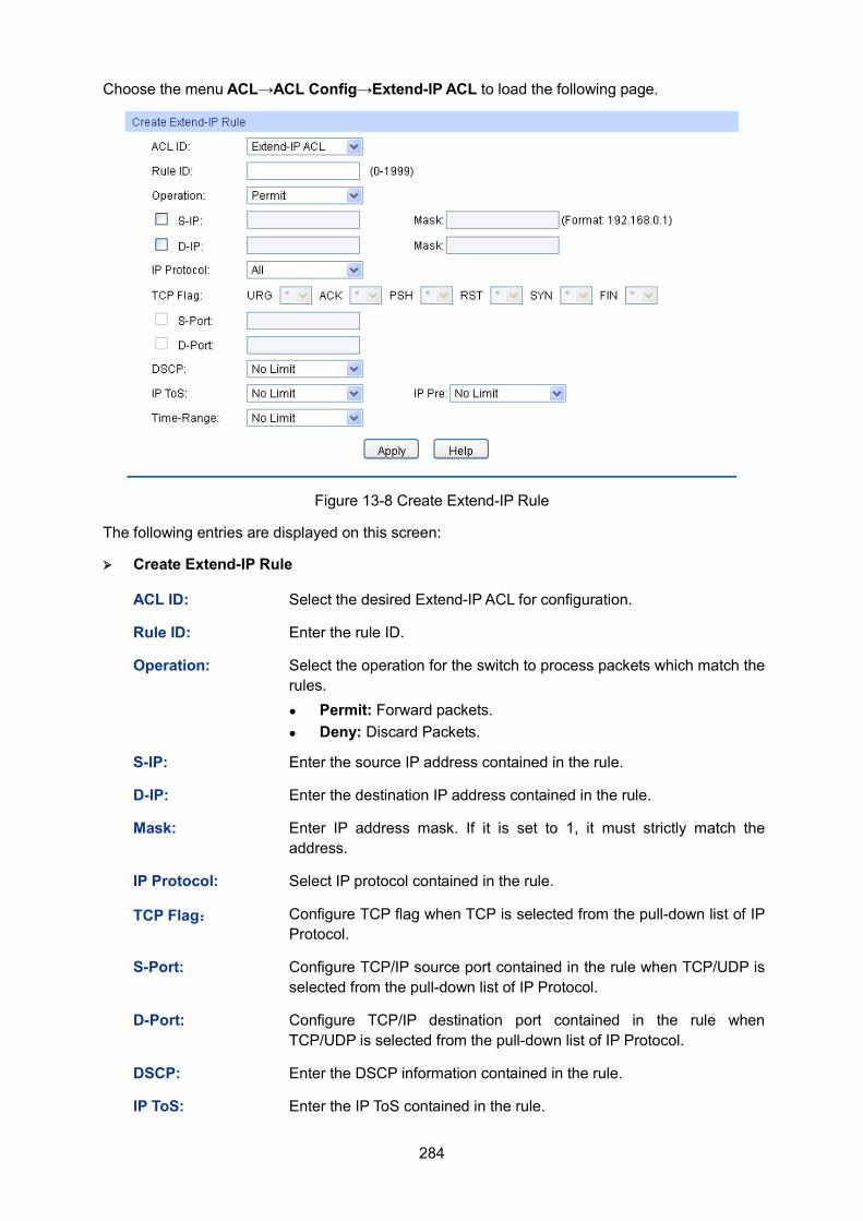
284
Choose the menu ACL→ACL Config→Extend-IP ACL to load the following page.
Figure 13-8 Create Extend-IP Rule
The following entries are displayed on this screen:
Create Extend-IP Rule
ACL ID: Select the desired Extend-IP ACL for configuration.
Rule ID: Enter the rule ID.
Operation: Select the operation for the switch to process packets which match the rules. Permit: Forward packets. Deny: Discard Packets.
S-IP: Enter the source IP address contained in the rule.
D-IP: Enter the destination IP address contained in the rule.
Mask: Enter IP address mask. If it is set to 1, it must strictly match the address.
IP Protocol: Select IP protocol contained in the rule.
TCP Flag: Configure TCP flag when TCP is selected from the pull-down list of IP Protocol.
S-Port: Configure TCP/IP source port contained in the rule when TCP/UDP is selected from the pull-down list of IP Protocol.
D-Port: Configure TCP/IP destination port contained in the rule when TCP/UDP is selected from the pull-down list of IP Protocol.
DSCP: Enter the DSCP information contained in the rule.
IP ToS: Enter the IP ToS contained in the rule.
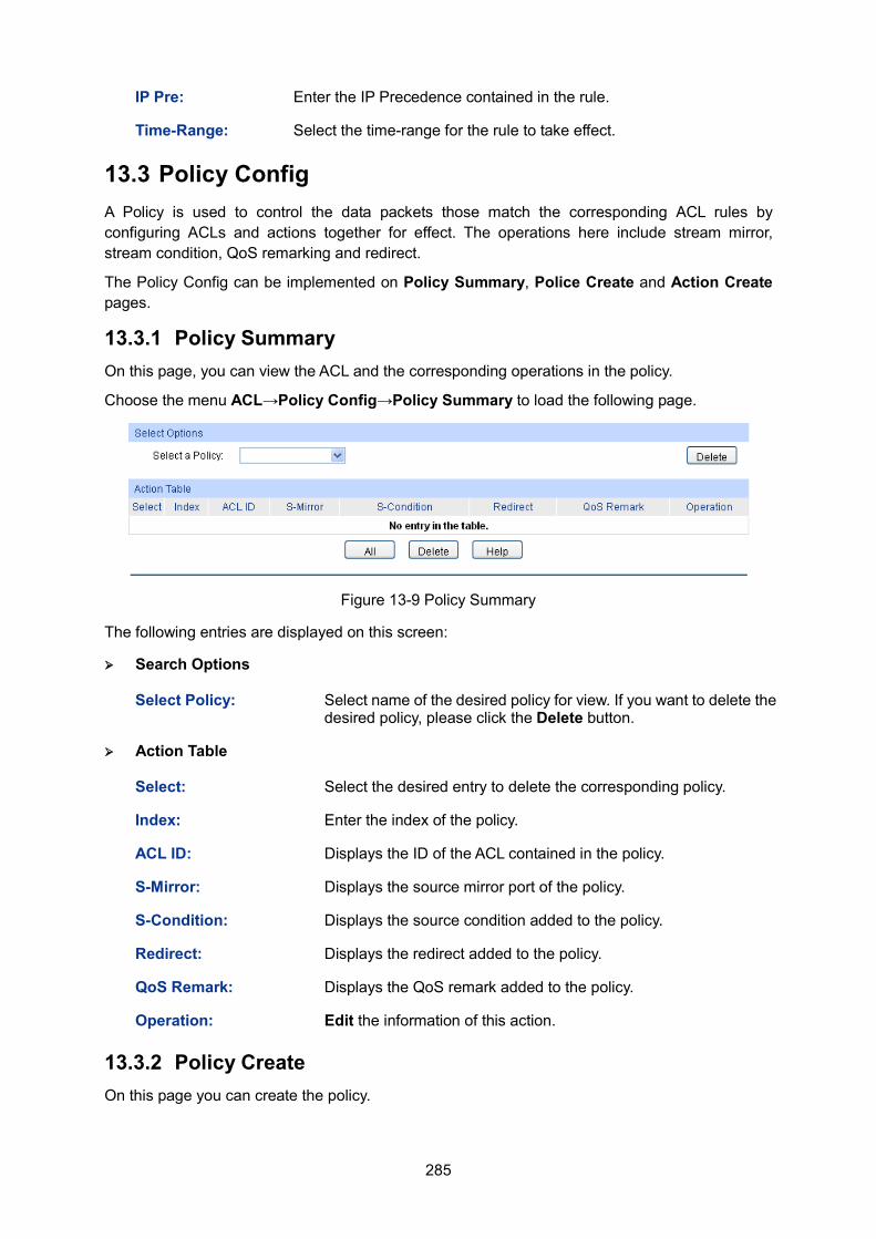
285
IP Pre: Enter the IP Precedence contained in the rule.
Time-Range: Select the time-range for the rule to take effect.
13.3 Policy Config A Policy is used to control the data packets those match the corresponding ACL rules by configuring ACLs and actions together for effect. The operations here include stream mirror, stream condition, QoS remarking and redirect.
The Policy Config can be implemented on Policy Summary, Police Create and Action Create pages.
13.3.1 Policy Summary On this page, you can view the ACL and the corresponding operations in the policy.
Choose the menu ACL→Policy Config→Policy Summary to load the following page.
Figure 13-9 Policy Summary
The following entries are displayed on this screen:
Search Options
Select Policy: Select name of the desired policy for view. If you want to delete the desired policy, please click the Delete button.
Action Table
Select: Select the desired entry to delete the corresponding policy.
Index: Enter the index of the policy.
ACL ID: Displays the ID of the ACL contained in the policy.
S-Mirror: Displays the source mirror port of the policy.
S-Condition: Displays the source condition added to the policy.
Redirect: Displays the redirect added to the policy.
QoS Remark: Displays the QoS remark added to the policy.
Operation: Edit the information of this action.
13.3.2 Policy Create On this page you can create the policy.
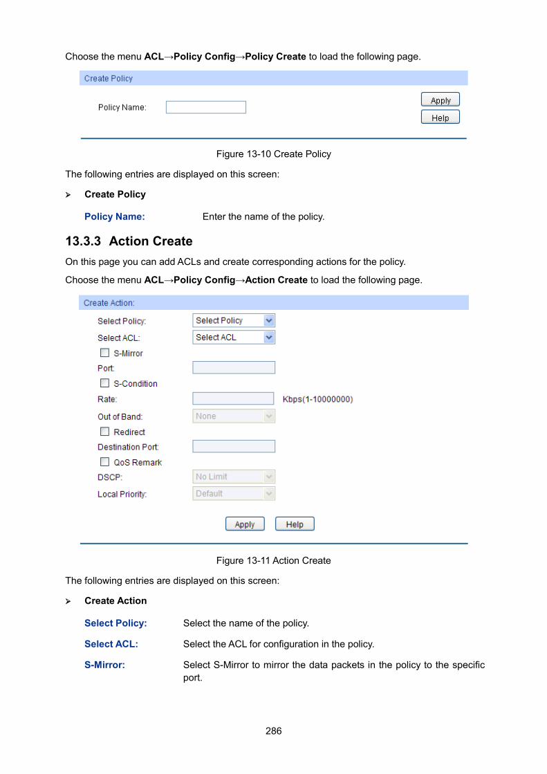
286
Choose the menu ACL→Policy Config→Policy Create to load the following page.
Figure 13-10 Create Policy
The following entries are displayed on this screen:
Create Policy
Policy Name: Enter the name of the policy.
13.3.3 Action Create On this page you can add ACLs and create corresponding actions for the policy.
Choose the menu ACL→Policy Config→Action Create to load the following page.
Figure 13-11 Action Create
The following entries are displayed on this screen:
Create Action
Select Policy: Select the name of the policy.
Select ACL: Select the ACL for configuration in the policy.
S-Mirror: Select S-Mirror to mirror the data packets in the policy to the specific port.
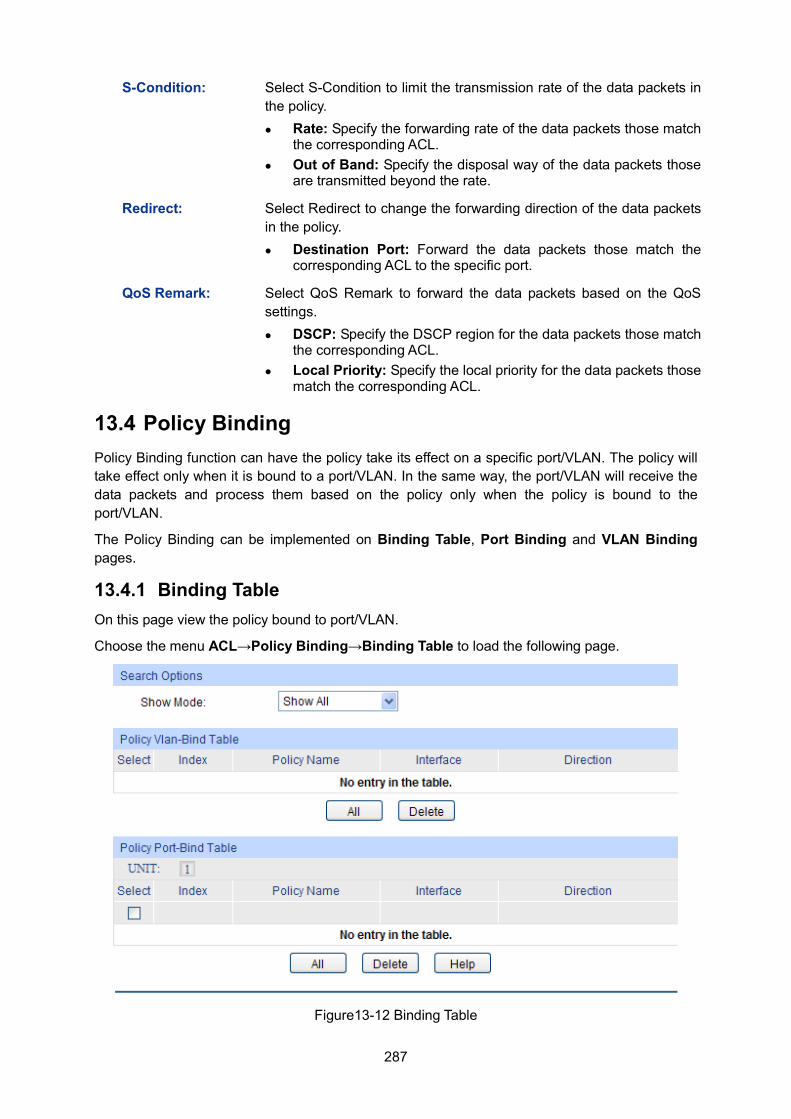
287
S-Condition: Select S-Condition to limit the transmission rate of the data packets in the policy. Rate: Specify the forwarding rate of the data packets those match
the corresponding ACL. Out of Band: Specify the disposal way of the data packets those
are transmitted beyond the rate.
Redirect: Select Redirect to change the forwarding direction of the data packets in the policy. Destination Port: Forward the data packets those match the
corresponding ACL to the specific port.
QoS Remark: Select QoS Remark to forward the data packets based on the QoS settings. DSCP: Specify the DSCP region for the data packets those match
the corresponding ACL. Local Priority: Specify the local priority for the data packets those
match the corresponding ACL.
13.4 Policy Binding Policy Binding function can have the policy take its effect on a specific port/VLAN. The policy will take effect only when it is bound to a port/VLAN. In the same way, the port/VLAN will receive the data packets and process them based on the policy only when the policy is bound to the port/VLAN.
The Policy Binding can be implemented on Binding Table, Port Binding and VLAN Binding pages.
13.4.1 Binding Table On this page view the policy bound to port/VLAN.
Choose the menu ACL→Policy Binding→Binding Table to load the following page.
Figure13-12 Binding Table
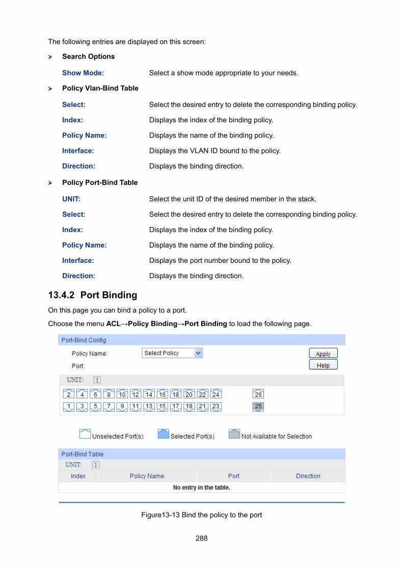
288
The following entries are displayed on this screen:
Search Options
Show Mode: Select a show mode appropriate to your needs.
Policy Vlan-Bind Table
Select: Select the desired entry to delete the corresponding binding policy.
Index: Displays the index of the binding policy.
Policy Name: Displays the name of the binding policy.
Interface: Displays the VLAN ID bound to the policy.
Direction: Displays the binding direction.
Policy Port-Bind Table
UNIT: Select the unit ID of the desired member in the stack.
Select: Select the desired entry to delete the corresponding binding policy.
Index: Displays the index of the binding policy.
Policy Name: Displays the name of the binding policy.
Interface: Displays the port number bound to the policy.
Direction: Displays the binding direction.
13.4.2 Port Binding On this page you can bind a policy to a port.
Choose the menu ACL→Policy Binding→Port Binding to load the following page.
Figure13-13 Bind the policy to the port
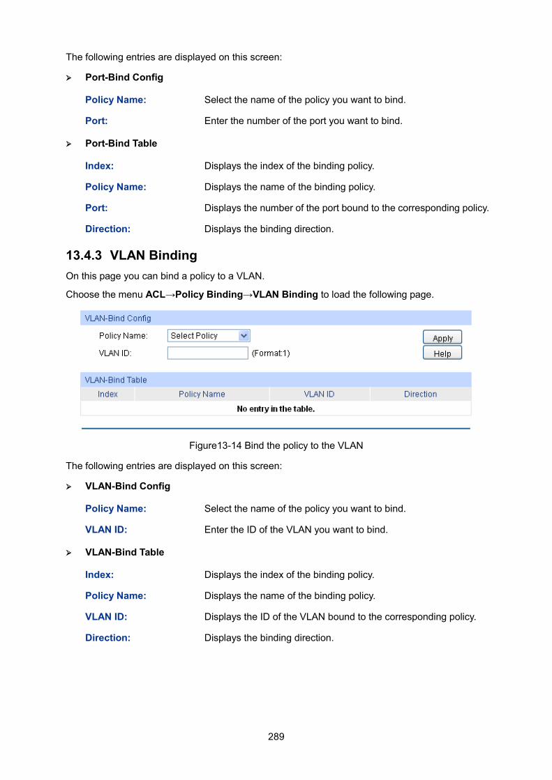
289
The following entries are displayed on this screen:
Port-Bind Config
Policy Name: Select the name of the policy you want to bind.
Port: Enter the number of the port you want to bind.
Port-Bind Table
Index: Displays the index of the binding policy.
Policy Name: Displays the name of the binding policy.
Port: Displays the number of the port bound to the corresponding policy.
Direction: Displays the binding direction.
13.4.3 VLAN Binding On this page you can bind a policy to a VLAN.
Choose the menu ACL→Policy Binding→VLAN Binding to load the following page.
Figure13-14 Bind the policy to the VLAN
The following entries are displayed on this screen:
VLAN-Bind Config
Policy Name: Select the name of the policy you want to bind.
VLAN ID: Enter the ID of the VLAN you want to bind.
VLAN-Bind Table
Index: Displays the index of the binding policy.
Policy Name: Displays the name of the binding policy.
VLAN ID: Displays the ID of the VLAN bound to the corresponding policy.
Direction: Displays the binding direction.
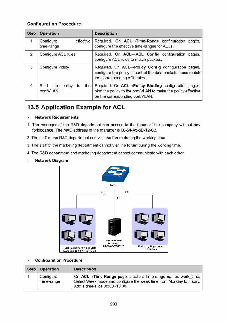
290
Configuration Procedure:
Step Operation Description
1 Configure effective time-range
Required. On ACL→Time-Range configuration pages, configure the effective time-ranges for ACLs.
2 Configure ACL rules Required. On ACL→ACL Config configuration pages, configure ACL rules to match packets.
3 Configure Policy Required. On ACL→Policy Config configuration pages, configure the policy to control the data packets those match the corresponding ACL rules.
4 Bind the policy to the port/VLAN
Required. On ACL→Policy Binding configuration pages, bind the policy to the port/VLAN to make the policy effective on the corresponding port/VLAN.
13.5 Application Example for ACL Network Requirements
1. The manager of the R&D department can access to the forum of the company without any forbiddance. The MAC address of the manager is 00-64-A5-5D-12-C3.
2. The staff of the R&D department can visit the forum during the working time.
3. The staff of the marketing department cannot visit the forum during the working time.
4. The R&D department and marketing department cannot communicate with each other.
Network Diagram
Configuration Procedure
Step Operation Description
1 Configure Time-range
On ACL→Time-Range page, create a time-range named work_time. Select Week mode and configure the week time from Monday to Friday. Add a time-slice 08:00~18:00.
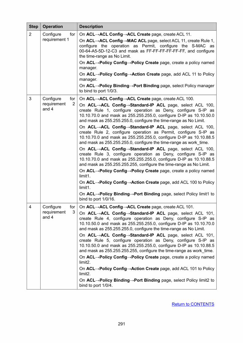
291
Step Operation Description
2 Configure for requirement 1
On ACL→ACL Config→ACL Create page, create ACL 11. On ACL→ACL Config→MAC ACL page, select ACL 11, create Rule 1, configure the operation as Permit, configure the S-MAC as 00-64-A5-5D-12-C3 and mask as FF-FF-FF-FF-FF-FF, and configure the time-range as No Limit. On ACL→Policy Config→Policy Create page, create a policy named manager. On ACL→Policy Config→Action Create page, add ACL 11 to Policy manager. On ACL→Policy Binding→Port Binding page, select Policy manager to bind to port 1/0/3.
3 Configure for requirement 2 and 4
On ACL→ACL Config→ACL Create page, create ACL 100. On ACL→ACL Config→Standard-IP ACL page, select ACL 100, create Rule 1, configure operation as Deny, configure S-IP as 10.10.70.0 and mask as 255.255.255.0, configure D-IP as 10.10.50.0 and mask as 255.255.255.0, configure the time-range as No Limit. On ACL→ACL Config→Standard-IP ACL page, select ACL 100, create Rule 2, configure operation as Permit, configure S-IP as 10.10.70.0 and mask as 255.255.255.0, configure D-IP as 10.10.88.5 and mask as 255.255.255.0, configure the time-range as work_time. On ACL→ACL Config→Standard-IP ACL page, select ACL 100, create Rule 3, configure operation as Deny, configure S-IP as 10.10.70.0 and mask as 255.255.255.0, configure D-IP as 10.10.88.5 and mask as 255.255.255.255, configure the time-range as No Limit. On ACL→Policy Config→Policy Create page, create a policy named limit1. On ACL→Policy Config→Action Create page, add ACL 100 to Policy limit1. On ACL→Policy Binding→Port Binding page, select Policy limit1 to bind to port 1/0/16.
4 Configure for requirement 3 and 4
On ACL→ACL Config→ACL Create page, create ACL 101. On ACL→ACL Config→Standard-IP ACL page, select ACL 101, create Rule 4, configure operation as Deny, configure S-IP as 10.10.50.0 and mask as 255.255.255.0, configure D-IP as 10.10.70.0 and mask as 255.255.255.0, configure the time-range as No Limit. On ACL→ACL Config→Standard-IP ACL page, select ACL 101, create Rule 5, configure operation as Deny, configure S-IP as 10.10.50.0 and mask as 255.255.255.0, configure D-IP as 10.10.88.5 and mask as 255.255.255.255, configure the time-range as work_time. On ACL→Policy Config→Policy Create page, create a policy named limit2. On ACL→Policy Config→Action Create page, add ACL 101 to Policy limit2. On ACL→Policy Binding→Port Binding page, select Policy limit2 to bind to port 1/0/4.
Return to CONTENTS
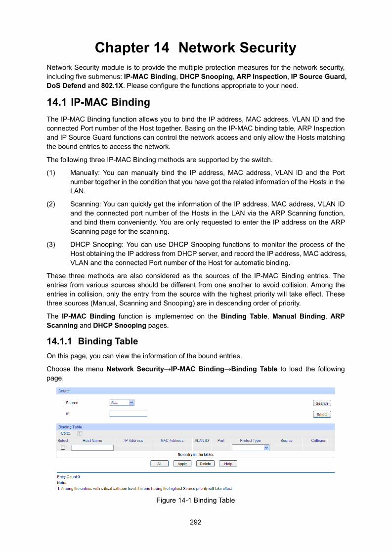
292
Chapter 14 Network Security Network Security module is to provide the multiple protection measures for the network security, including five submenus: IP-MAC Binding, DHCP Snooping, ARP Inspection, IP Source Guard, DoS Defend and 802.1X. Please configure the functions appropriate to your need.
14.1 IP-MAC Binding The IP-MAC Binding function allows you to bind the IP address, MAC address, VLAN ID and the connected Port number of the Host together. Basing on the IP-MAC binding table, ARP Inspection and IP Source Guard functions can control the network access and only allow the Hosts matching the bound entries to access the network.
The following three IP-MAC Binding methods are supported by the switch.
(1) Manually: You can manually bind the IP address, MAC address, VLAN ID and the Port number together in the condition that you have got the related information of the Hosts in the LAN.
(2) Scanning: You can quickly get the information of the IP address, MAC address, VLAN ID and the connected port number of the Hosts in the LAN via the ARP Scanning function, and bind them conveniently. You are only requested to enter the IP address on the ARP Scanning page for the scanning.
(3) DHCP Snooping: You can use DHCP Snooping functions to monitor the process of the Host obtaining the IP address from DHCP server, and record the IP address, MAC address, VLAN and the connected Port number of the Host for automatic binding.
These three methods are also considered as the sources of the IP-MAC Binding entries. The entries from various sources should be different from one another to avoid collision. Among the entries in collision, only the entry from the source with the highest priority will take effect. These three sources (Manual, Scanning and Snooping) are in descending order of priority.
The IP-MAC Binding function is implemented on the Binding Table, Manual Binding, ARP Scanning and DHCP Snooping pages.
14.1.1 Binding Table On this page, you can view the information of the bound entries.
Choose the menu Network Security→IP-MAC Binding→Binding Table to load the following page.
Figure 14-1 Binding Table
293
The following entries are displayed on this screen: Search
Source: Displays the Source of the entry. • All: All the bound entries will be displayed. • Manual: Only the manually added entries will be
displayed. • Scanning: Only the entries formed via ARP Scanning
will be displayed. • Snooping: Only the entries formed via DHCP Snooping
will be displayed.
IP Select Click the Select button to quick-select the corresponding entry based on the IP address you entered.
Binding Table
UNIT: Select the unit ID of the desired member in the stack.
Select: Select the desired entry to modify the Host Name and Protect Type. It is multi-optional.
Host Name Displays the Host Name here.
IP Address Displays the IP Address of the Host.
MAC Address Displays the MAC Address of the Host.
VLAN ID: Displays the VLAN ID here.
Port: Displays the number of port connected to the Host.
Protect Type: Allows you to view and modify the Protect Type of the entry.
Source: Displays the Source of the entry.
Collision: Displays the Collision status of the entry.
• Warning: Indicates that the collision may be caused by the MSTP function.
• Critical: Indicates that the entry has a collision with the other entries.
Note: Among the entries with Critical collision level, the one with the highest Source priority will take effect.
14.1.2 Manual Binding You can manually bind the IP address, MAC address, VLAN ID and the Port number together in the condition that you have got the related information of the Hosts in the LAN.
Choose the menu Network Security→IP-MAC Binding→Manual Binding to load the following page.
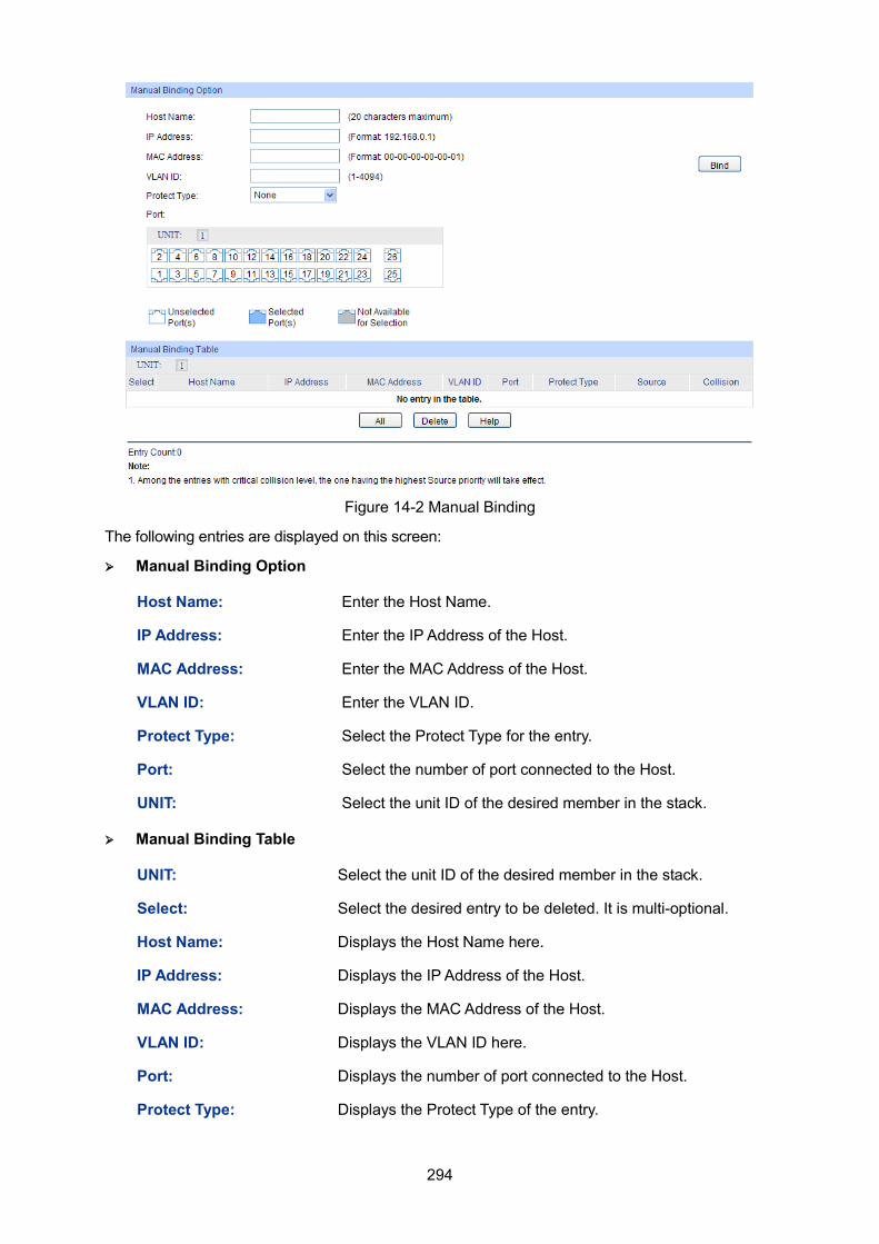
294
Figure 14-2 Manual Binding
The following entries are displayed on this screen: Manual Binding Option
Host Name: Enter the Host Name.
IP Address: Enter the IP Address of the Host.
MAC Address: Enter the MAC Address of the Host.
VLAN ID: Enter the VLAN ID.
Protect Type: Select the Protect Type for the entry.
Port: Select the number of port connected to the Host.
UNIT: Select the unit ID of the desired member in the stack.
Manual Binding Table
UNIT: Select the unit ID of the desired member in the stack.
Select: Select the desired entry to be deleted. It is multi-optional.
Host Name: Displays the Host Name here.
IP Address: Displays the IP Address of the Host.
MAC Address: Displays the MAC Address of the Host.
VLAN ID: Displays the VLAN ID here.
Port: Displays the number of port connected to the Host.
Protect Type: Displays the Protect Type of the entry.
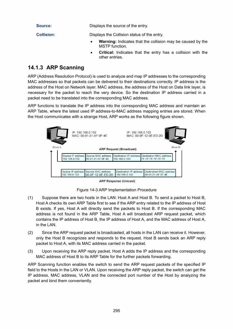
295
Source: Displays the source of the entry.
Collision: Displays the Collision status of the entry.
• Warning: Indicates that the collision may be caused by the MSTP function.
• Critical: Indicates that the entry has a collision with the other entries.
14.1.3 ARP Scanning ARP (Address Resolution Protocol) is used to analyze and map IP addresses to the corresponding MAC addresses so that packets can be delivered to their destinations correctly. IP address is the address of the Host on Network layer. MAC address, the address of the Host on Data link layer, is necessary for the packet to reach the very device. So the destination IP address carried in a packet need to be translated into the corresponding MAC address.
ARP functions to translate the IP address into the corresponding MAC address and maintain an ARP Table, where the latest used IP address-to-MAC address mapping entries are stored. When the Host communicates with a strange Host, ARP works as the following figure shown.
Figure 14-3 ARP Implementation Procedure
(1) Suppose there are two hosts in the LAN: Host A and Host B. To send a packet to Host B, Host A checks its own ARP Table first to see if the ARP entry related to the IP address of Host B exists. If yes, Host A will directly send the packets to Host B. If the corresponding MAC address is not found in the ARP Table, Host A will broadcast ARP request packet, which contains the IP address of Host B, the IP address of Host A, and the MAC address of Host A, in the LAN.
(2) Since the ARP request packet is broadcasted, all hosts in the LAN can receive it. However, only the Host B recognizes and responds to the request. Host B sends back an ARP reply packet to Host A, with its MAC address carried in the packet.
(3) Upon receiving the ARP reply packet, Host A adds the IP address and the corresponding MAC address of Host B to its ARP Table for the further packets forwarding.
ARP Scanning function enables the switch to send the ARP request packets of the specified IP field to the Hosts in the LAN or VLAN. Upon receiving the ARP reply packet, the switch can get the IP address, MAC address, VLAN and the connected port number of the Host by analyzing the packet and bind them conveniently.
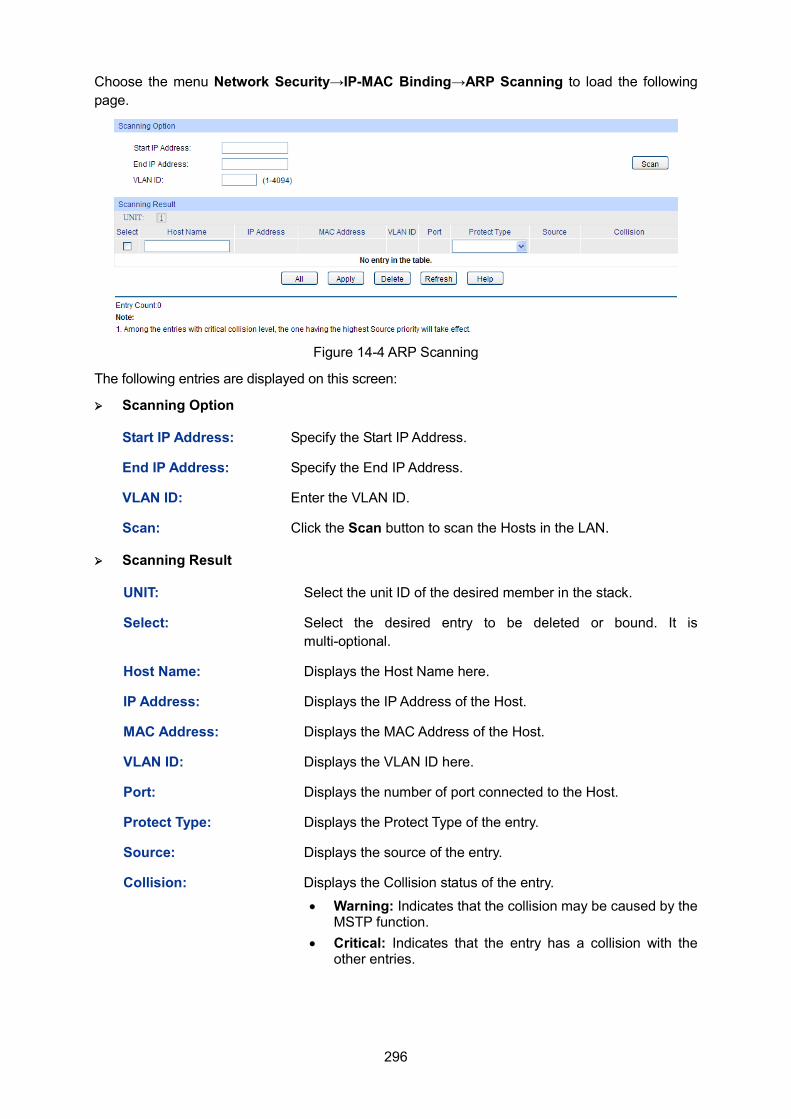
296
Choose the menu Network Security→IP-MAC Binding→ARP Scanning to load the following page.
Figure 14-4 ARP Scanning
The following entries are displayed on this screen: Scanning Option
Start IP Address: Specify the Start IP Address.
End IP Address: Specify the End IP Address.
VLAN ID: Enter the VLAN ID.
Scan: Click the Scan button to scan the Hosts in the LAN.
Scanning Result
UNIT: Select the unit ID of the desired member in the stack.
Select: Select the desired entry to be deleted or bound. It is multi-optional.
Host Name: Displays the Host Name here.
IP Address: Displays the IP Address of the Host.
MAC Address: Displays the MAC Address of the Host.
VLAN ID: Displays the VLAN ID here.
Port: Displays the number of port connected to the Host.
Protect Type: Displays the Protect Type of the entry.
Source: Displays the source of the entry.
Collision: Displays the Collision status of the entry.
• Warning: Indicates that the collision may be caused by the MSTP function.
• Critical: Indicates that the entry has a collision with the other entries.
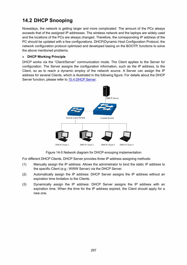
297
14.2 DHCP Snooping Nowadays, the network is getting larger and more complicated. The amount of the PCs always exceeds that of the assigned IP addresses. The wireless network and the laptops are widely used and the locations of the PCs are always changed. Therefore, the corresponding IP address of the PC should be updated with a few configurations. DHCP(Dynamic Host Configuration Protocol, the network configuration protocol optimized and developed basing on the BOOTP, functions to solve the above mentioned problems.
DHCP Working Principle DHCP works via the “Client/Server” communication mode. The Client applies to the Server for configuration. The Server assigns the configuration information, such as the IP address, to the Client, so as to reach a dynamic employ of the network source. A Server can assign the IP address for several Clients, which is illustrated in the following figure. For details about the DHCP Server function, please refer to 10.4 DHCP Server.
Figure 14-5 Network diagram for DHCP-snooping implementation
For different DHCP Clients, DHCP Server provides three IP address assigning methods:
(1) Manually assign the IP address: Allows the administrator to bind the static IP address to the specific Client (e.g.: WWW Server) via the DHCP Server.
(2) Automatically assign the IP address: DHCP Server assigns the IP address without an expiration time limitation to the Clients.
(3) Dynamically assign the IP address: DHCP Server assigns the IP address with an expiration time. When the time for the IP address expired, the Client should apply for a new one.
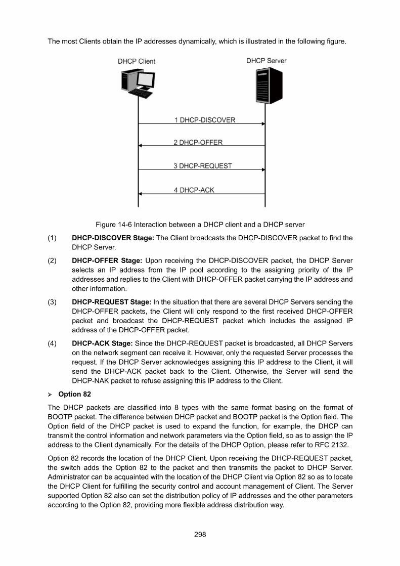
298
The most Clients obtain the IP addresses dynamically, which is illustrated in the following figure.
Figure 14-6 Interaction between a DHCP client and a DHCP server
(1) DHCP-DISCOVER Stage: The Client broadcasts the DHCP-DISCOVER packet to find the DHCP Server.
(2) DHCP-OFFER Stage: Upon receiving the DHCP-DISCOVER packet, the DHCP Server selects an IP address from the IP pool according to the assigning priority of the IP addresses and replies to the Client with DHCP-OFFER packet carrying the IP address and other information.
(3) DHCP-REQUEST Stage: In the situation that there are several DHCP Servers sending the DHCP-OFFER packets, the Client will only respond to the first received DHCP-OFFER packet and broadcast the DHCP-REQUEST packet which includes the assigned IP address of the DHCP-OFFER packet.
(4) DHCP-ACK Stage: Since the DHCP-REQUEST packet is broadcasted, all DHCP Servers on the network segment can receive it. However, only the requested Server processes the request. If the DHCP Server acknowledges assigning this IP address to the Client, it will send the DHCP-ACK packet back to the Client. Otherwise, the Server will send the DHCP-NAK packet to refuse assigning this IP address to the Client.
Option 82
The DHCP packets are classified into 8 types with the same format basing on the format of BOOTP packet. The difference between DHCP packet and BOOTP packet is the Option field. The Option field of the DHCP packet is used to expand the function, for example, the DHCP can transmit the control information and network parameters via the Option field, so as to assign the IP address to the Client dynamically. For the details of the DHCP Option, please refer to RFC 2132.
Option 82 records the location of the DHCP Client. Upon receiving the DHCP-REQUEST packet, the switch adds the Option 82 to the packet and then transmits the packet to DHCP Server. Administrator can be acquainted with the location of the DHCP Client via Option 82 so as to locate the DHCP Client for fulfilling the security control and account management of Client. The Server supported Option 82 also can set the distribution policy of IP addresses and the other parameters according to the Option 82, providing more flexible address distribution way.
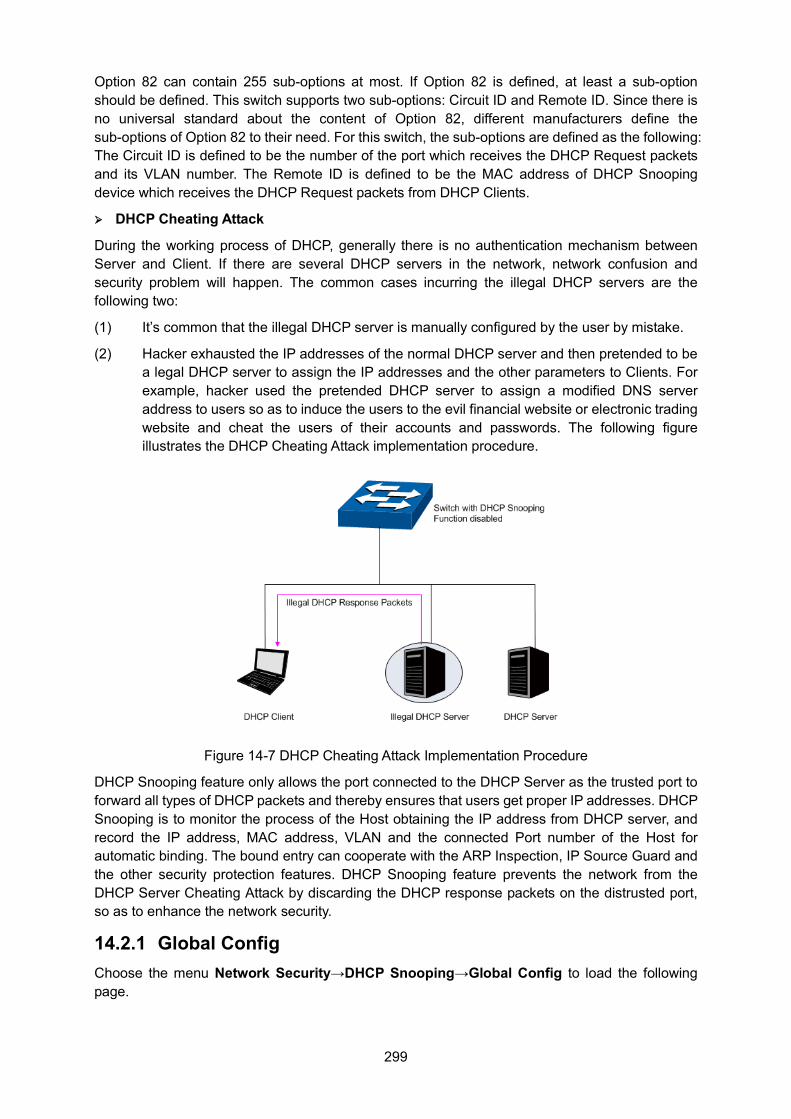
299
Option 82 can contain 255 sub-options at most. If Option 82 is defined, at least a sub-option should be defined. This switch supports two sub-options: Circuit ID and Remote ID. Since there is no universal standard about the content of Option 82, different manufacturers define the sub-options of Option 82 to their need. For this switch, the sub-options are defined as the following: The Circuit ID is defined to be the number of the port which receives the DHCP Request packets and its VLAN number. The Remote ID is defined to be the MAC address of DHCP Snooping device which receives the DHCP Request packets from DHCP Clients.
DHCP Cheating Attack
During the working process of DHCP, generally there is no authentication mechanism between Server and Client. If there are several DHCP servers in the network, network confusion and security problem will happen. The common cases incurring the illegal DHCP servers are the following two:
(1) It’s common that the illegal DHCP server is manually configured by the user by mistake.
(2) Hacker exhausted the IP addresses of the normal DHCP server and then pretended to be a legal DHCP server to assign the IP addresses and the other parameters to Clients. For example, hacker used the pretended DHCP server to assign a modified DNS server address to users so as to induce the users to the evil financial website or electronic trading website and cheat the users of their accounts and passwords. The following figure illustrates the DHCP Cheating Attack implementation procedure.
Figure 14-7 DHCP Cheating Attack Implementation Procedure
DHCP Snooping feature only allows the port connected to the DHCP Server as the trusted port to forward all types of DHCP packets and thereby ensures that users get proper IP addresses. DHCP Snooping is to monitor the process of the Host obtaining the IP address from DHCP server, and record the IP address, MAC address, VLAN and the connected Port number of the Host for automatic binding. The bound entry can cooperate with the ARP Inspection, IP Source Guard and the other security protection features. DHCP Snooping feature prevents the network from the DHCP Server Cheating Attack by discarding the DHCP response packets on the distrusted port, so as to enhance the network security.
14.2.1 Global Config Choose the menu Network Security→DHCP Snooping→Global Config to load the following page.
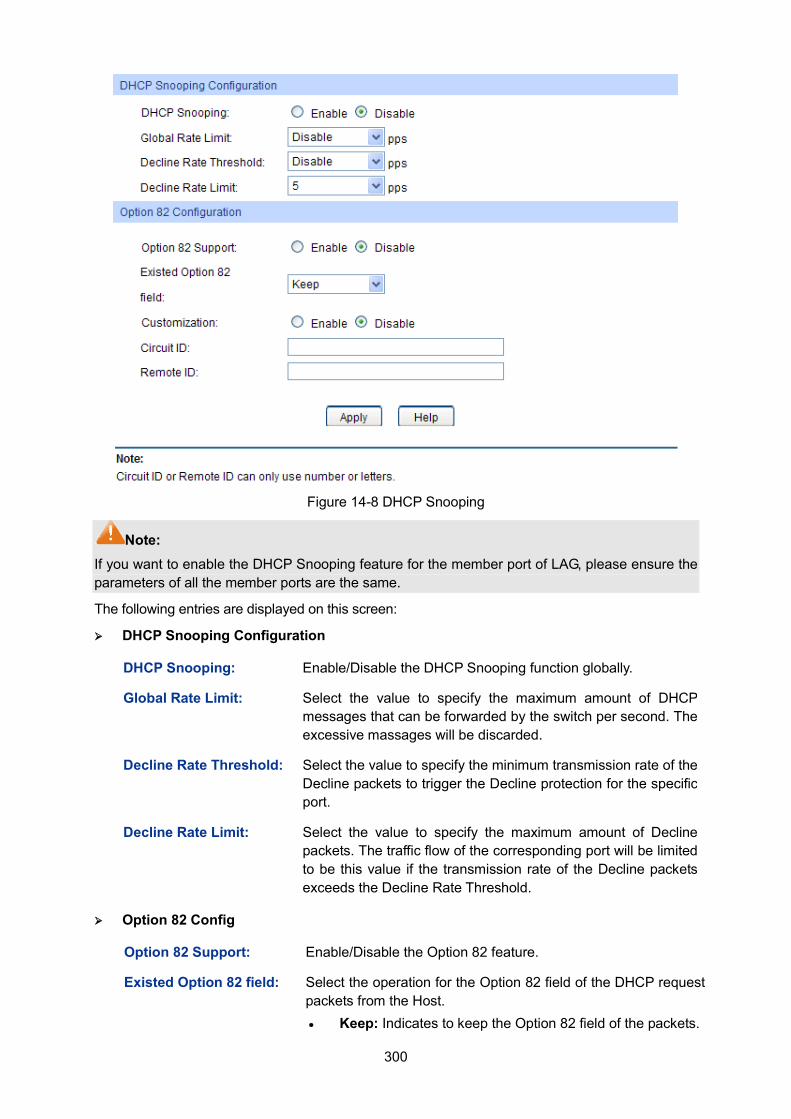
300
Figure 14-8 DHCP Snooping
Note: If you want to enable the DHCP Snooping feature for the member port of LAG, please ensure the parameters of all the member ports are the same.
The following entries are displayed on this screen: DHCP Snooping Configuration
DHCP Snooping: Enable/Disable the DHCP Snooping function globally.
Global Rate Limit: Select the value to specify the maximum amount of DHCP messages that can be forwarded by the switch per second. The excessive massages will be discarded.
Decline Rate Threshold: Select the value to specify the minimum transmission rate of the Decline packets to trigger the Decline protection for the specific port.
Decline Rate Limit: Select the value to specify the maximum amount of Decline packets. The traffic flow of the corresponding port will be limited to be this value if the transmission rate of the Decline packets exceeds the Decline Rate Threshold.
Option 82 Config
Option 82 Support: Enable/Disable the Option 82 feature.
Existed Option 82 field: Select the operation for the Option 82 field of the DHCP request packets from the Host. • Keep: Indicates to keep the Option 82 field of the packets.
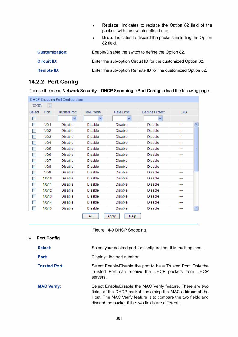
301
• Replace: Indicates to replace the Option 82 field of the packets with the switch defined one.
• Drop: Indicates to discard the packets including the Option 82 field.
Customization: Enable/Disable the switch to define the Option 82.
Circuit ID: Enter the sub-option Circuit ID for the customized Option 82.
Remote ID: Enter the sub-option Remote ID for the customized Option 82.
14.2.2 Port Config Choose the menu Network Security→DHCP Snooping→Port Config to load the following page.
Figure 14-9 DHCP Snooping
Port Config
Select: Select your desired port for configuration. It is multi-optional.
Port: Displays the port number.
Trusted Port: Select Enable/Disable the port to be a Trusted Port. Only the Trusted Port can receive the DHCP packets from DHCP servers.
MAC Verify: Select Enable/Disable the MAC Verify feature. There are two fields of the DHCP packet containing the MAC address of the Host. The MAC Verify feature is to compare the two fields and discard the packet if the two fields are different.
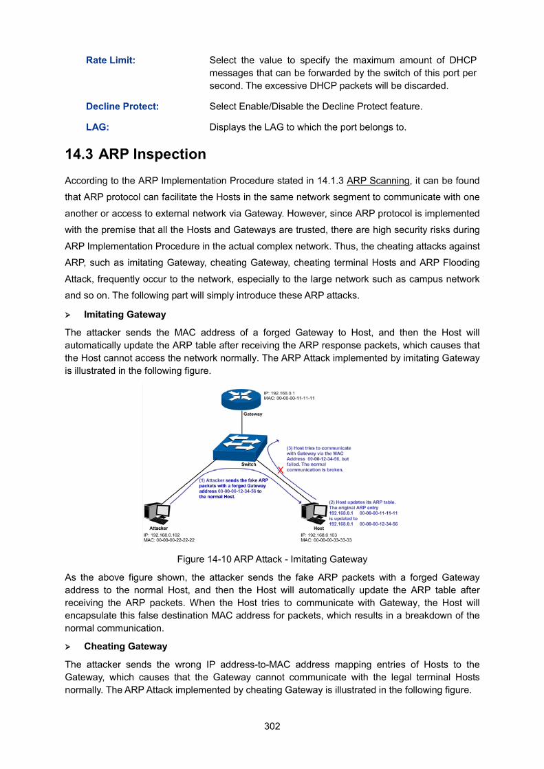
302
Rate Limit: Select the value to specify the maximum amount of DHCP messages that can be forwarded by the switch of this port per second. The excessive DHCP packets will be discarded.
Decline Protect: Select Enable/Disable the Decline Protect feature.
LAG: Displays the LAG to which the port belongs to.
14.3 ARP Inspection According to the ARP Implementation Procedure stated in 14.1.3 ARP Scanning, it can be found
that ARP protocol can facilitate the Hosts in the same network segment to communicate with one
another or access to external network via Gateway. However, since ARP protocol is implemented
with the premise that all the Hosts and Gateways are trusted, there are high security risks during
ARP Implementation Procedure in the actual complex network. Thus, the cheating attacks against
ARP, such as imitating Gateway, cheating Gateway, cheating terminal Hosts and ARP Flooding
Attack, frequently occur to the network, especially to the large network such as campus network
and so on. The following part will simply introduce these ARP attacks.
Imitating Gateway
The attacker sends the MAC address of a forged Gateway to Host, and then the Host will automatically update the ARP table after receiving the ARP response packets, which causes that the Host cannot access the network normally. The ARP Attack implemented by imitating Gateway is illustrated in the following figure.
Figure 14-10 ARP Attack - Imitating Gateway
As the above figure shown, the attacker sends the fake ARP packets with a forged Gateway address to the normal Host, and then the Host will automatically update the ARP table after receiving the ARP packets. When the Host tries to communicate with Gateway, the Host will encapsulate this false destination MAC address for packets, which results in a breakdown of the normal communication.
Cheating Gateway
The attacker sends the wrong IP address-to-MAC address mapping entries of Hosts to the Gateway, which causes that the Gateway cannot communicate with the legal terminal Hosts normally. The ARP Attack implemented by cheating Gateway is illustrated in the following figure.
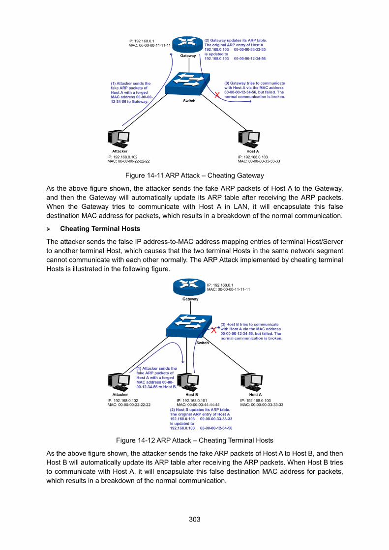
303
Figure 14-11 ARP Attack – Cheating Gateway
As the above figure shown, the attacker sends the fake ARP packets of Host A to the Gateway, and then the Gateway will automatically update its ARP table after receiving the ARP packets. When the Gateway tries to communicate with Host A in LAN, it will encapsulate this false destination MAC address for packets, which results in a breakdown of the normal communication.
Cheating Terminal Hosts
The attacker sends the false IP address-to-MAC address mapping entries of terminal Host/Server to another terminal Host, which causes that the two terminal Hosts in the same network segment cannot communicate with each other normally. The ARP Attack implemented by cheating terminal Hosts is illustrated in the following figure.
Figure 14-12 ARP Attack – Cheating Terminal Hosts
As the above figure shown, the attacker sends the fake ARP packets of Host A to Host B, and then Host B will automatically update its ARP table after receiving the ARP packets. When Host B tries to communicate with Host A, it will encapsulate this false destination MAC address for packets, which results in a breakdown of the normal communication.
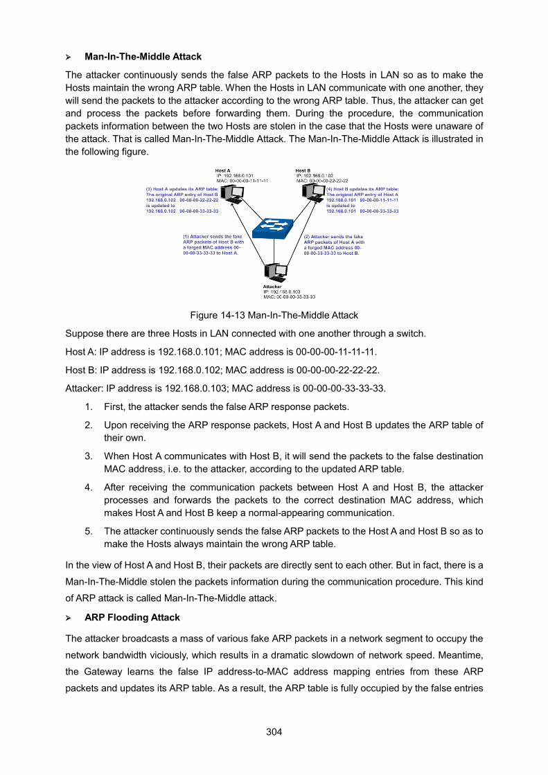
304
Man-In-The-Middle Attack
The attacker continuously sends the false ARP packets to the Hosts in LAN so as to make the Hosts maintain the wrong ARP table. When the Hosts in LAN communicate with one another, they will send the packets to the attacker according to the wrong ARP table. Thus, the attacker can get and process the packets before forwarding them. During the procedure, the communication packets information between the two Hosts are stolen in the case that the Hosts were unaware of the attack. That is called Man-In-The-Middle Attack. The Man-In-The-Middle Attack is illustrated in the following figure.
Figure 14-13 Man-In-The-Middle Attack
Suppose there are three Hosts in LAN connected with one another through a switch.
Host A: IP address is 192.168.0.101; MAC address is 00-00-00-11-11-11.
Host B: IP address is 192.168.0.102; MAC address is 00-00-00-22-22-22.
Attacker: IP address is 192.168.0.103; MAC address is 00-00-00-33-33-33.
1. First, the attacker sends the false ARP response packets.
2. Upon receiving the ARP response packets, Host A and Host B updates the ARP table of their own.
3. When Host A communicates with Host B, it will send the packets to the false destination MAC address, i.e. to the attacker, according to the updated ARP table.
4. After receiving the communication packets between Host A and Host B, the attacker processes and forwards the packets to the correct destination MAC address, which makes Host A and Host B keep a normal-appearing communication.
5. The attacker continuously sends the false ARP packets to the Host A and Host B so as to make the Hosts always maintain the wrong ARP table.
In the view of Host A and Host B, their packets are directly sent to each other. But in fact, there is a
Man-In-The-Middle stolen the packets information during the communication procedure. This kind
of ARP attack is called Man-In-The-Middle attack.
ARP Flooding Attack
The attacker broadcasts a mass of various fake ARP packets in a network segment to occupy the
network bandwidth viciously, which results in a dramatic slowdown of network speed. Meantime,
the Gateway learns the false IP address-to-MAC address mapping entries from these ARP
packets and updates its ARP table. As a result, the ARP table is fully occupied by the false entries
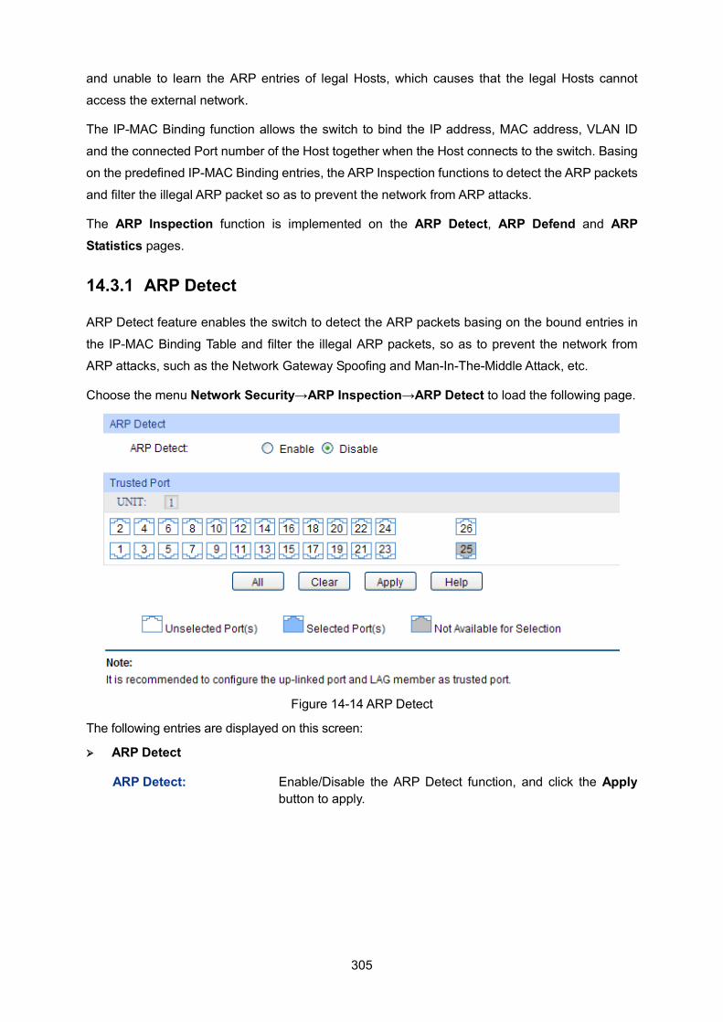
305
and unable to learn the ARP entries of legal Hosts, which causes that the legal Hosts cannot
access the external network.
The IP-MAC Binding function allows the switch to bind the IP address, MAC address, VLAN ID
and the connected Port number of the Host together when the Host connects to the switch. Basing
on the predefined IP-MAC Binding entries, the ARP Inspection functions to detect the ARP packets
and filter the illegal ARP packet so as to prevent the network from ARP attacks.
The ARP Inspection function is implemented on the ARP Detect, ARP Defend and ARP Statistics pages.
14.3.1 ARP Detect
ARP Detect feature enables the switch to detect the ARP packets basing on the bound entries in
the IP-MAC Binding Table and filter the illegal ARP packets, so as to prevent the network from
ARP attacks, such as the Network Gateway Spoofing and Man-In-The-Middle Attack, etc.
Choose the menu Network Security→ARP Inspection→ARP Detect to load the following page.
Figure 14-14 ARP Detect
The following entries are displayed on this screen: ARP Detect
ARP Detect: Enable/Disable the ARP Detect function, and click the Apply button to apply.
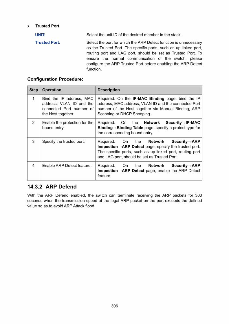
306
Trusted Port
UNIT: Select the unit ID of the desired member in the stack.
Trusted Port: Select the port for which the ARP Detect function is unnecessary as the Trusted Port. The specific ports, such as up-linked port, routing port and LAG port, should be set as Trusted Port. To ensure the normal communication of the switch, please configure the ARP Trusted Port before enabling the ARP Detect function.
Configuration Procedure:
Step Operation Description
1 Bind the IP address, MAC address, VLAN ID and the connected Port number of the Host together.
Required. On the IP-MAC Binding page, bind the IP address, MAC address, VLAN ID and the connected Port number of the Host together via Manual Binding, ARP Scanning or DHCP Snooping.
2 Enable the protection for the bound entry.
Required. On the Network Security→IP-MAC Binding→Binding Table page, specify a protect type for the corresponding bound entry.
3 Specify the trusted port. Required. On the Network Security→ARP Inspection→ARP Detect page, specify the trusted port. The specific ports, such as up-linked port, routing port and LAG port, should be set as Trusted Port.
4 Enable ARP Detect feature. Required. On the Network Security→ARP Inspection→ARP Detect page, enable the ARP Detect feature.
14.3.2 ARP Defend With the ARP Defend enabled, the switch can terminate receiving the ARP packets for 300 seconds when the transmission speed of the legal ARP packet on the port exceeds the defined value so as to avoid ARP Attack flood.
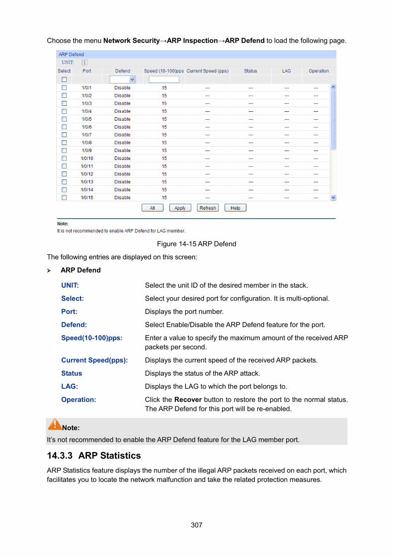
307
Choose the menu Network Security→ARP Inspection→ARP Defend to load the following page.
Figure 14-15 ARP Defend
The following entries are displayed on this screen: ARP Defend
UNIT: Select the unit ID of the desired member in the stack.
Select: Select your desired port for configuration. It is multi-optional.
Port: Displays the port number.
Defend: Select Enable/Disable the ARP Defend feature for the port.
Speed(10-100)pps: Enter a value to specify the maximum amount of the received ARP packets per second.
Current Speed(pps): Displays the current speed of the received ARP packets.
Status Displays the status of the ARP attack.
LAG: Displays the LAG to which the port belongs to.
Operation: Click the Recover button to restore the port to the normal status. The ARP Defend for this port will be re-enabled.
Note: It’s not recommended to enable the ARP Defend feature for the LAG member port.
14.3.3 ARP Statistics ARP Statistics feature displays the number of the illegal ARP packets received on each port, which facilitates you to locate the network malfunction and take the related protection measures.
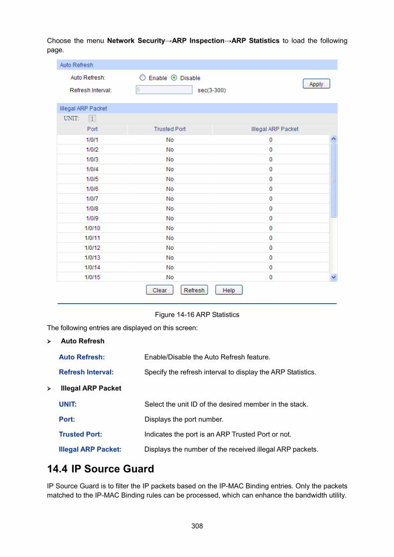
308
Choose the menu Network Security→ARP Inspection→ARP Statistics to load the following page.
Figure 14-16 ARP Statistics
The following entries are displayed on this screen: Auto Refresh
Auto Refresh: Enable/Disable the Auto Refresh feature.
Refresh Interval: Specify the refresh interval to display the ARP Statistics.
Illegal ARP Packet
UNIT: Select the unit ID of the desired member in the stack.
Port: Displays the port number.
Trusted Port: Indicates the port is an ARP Trusted Port or not.
Illegal ARP Packet: Displays the number of the received illegal ARP packets.
14.4 IP Source Guard IP Source Guard is to filter the IP packets based on the IP-MAC Binding entries. Only the packets matched to the IP-MAC Binding rules can be processed, which can enhance the bandwidth utility.
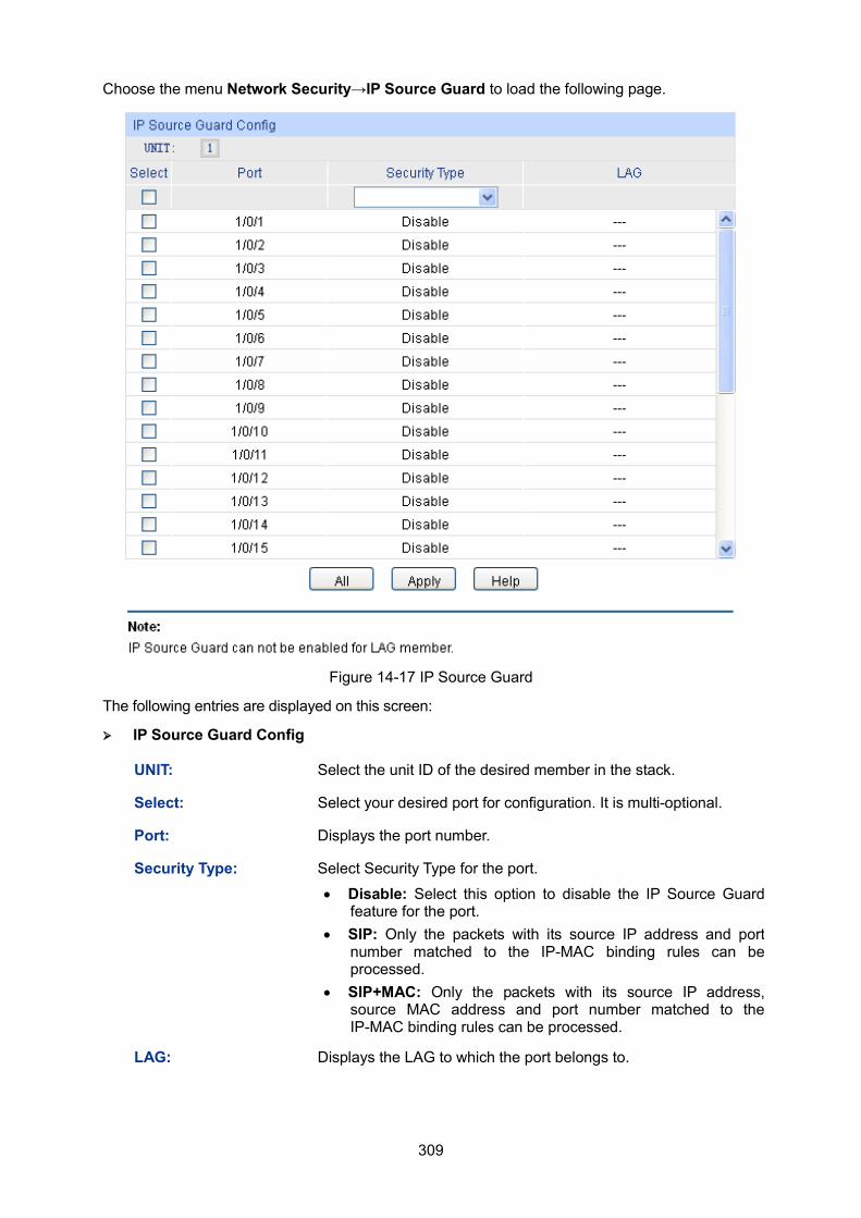
309
Choose the menu Network Security→IP Source Guard to load the following page.
Figure 14-17 IP Source Guard
The following entries are displayed on this screen: IP Source Guard Config
UNIT: Select the unit ID of the desired member in the stack.
Select: Select your desired port for configuration. It is multi-optional.
Port: Displays the port number.
Security Type: Select Security Type for the port.
• Disable: Select this option to disable the IP Source Guard feature for the port.
• SIP: Only the packets with its source IP address and port number matched to the IP-MAC binding rules can be processed.
• SIP+MAC: Only the packets with its source IP address, source MAC address and port number matched to the IP-MAC binding rules can be processed.
LAG: Displays the LAG to which the port belongs to.
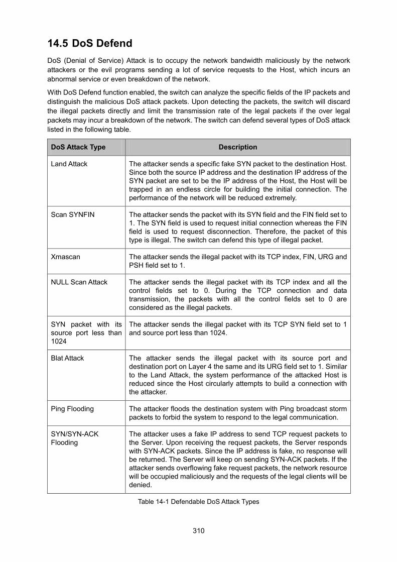
310
14.5 DoS Defend DoS (Denial of Service) Attack is to occupy the network bandwidth maliciously by the network attackers or the evil programs sending a lot of service requests to the Host, which incurs an abnormal service or even breakdown of the network.
With DoS Defend function enabled, the switch can analyze the specific fields of the IP packets and distinguish the malicious DoS attack packets. Upon detecting the packets, the switch will discard the illegal packets directly and limit the transmission rate of the legal packets if the over legal packets may incur a breakdown of the network. The switch can defend several types of DoS attack listed in the following table.
DoS Attack Type Description
Land Attack The attacker sends a specific fake SYN packet to the destination Host. Since both the source IP address and the destination IP address of the SYN packet are set to be the IP address of the Host, the Host will be trapped in an endless circle for building the initial connection. The performance of the network will be reduced extremely.
Scan SYNFIN The attacker sends the packet with its SYN field and the FIN field set to 1. The SYN field is used to request initial connection whereas the FIN field is used to request disconnection. Therefore, the packet of this type is illegal. The switch can defend this type of illegal packet.
Xmascan The attacker sends the illegal packet with its TCP index, FIN, URG and PSH field set to 1.
NULL Scan Attack The attacker sends the illegal packet with its TCP index and all the control fields set to 0. During the TCP connection and data transmission, the packets with all the control fields set to 0 are considered as the illegal packets.
SYN packet with its source port less than 1024
The attacker sends the illegal packet with its TCP SYN field set to 1 and source port less than 1024.
Blat Attack The attacker sends the illegal packet with its source port and destination port on Layer 4 the same and its URG field set to 1. Similar to the Land Attack, the system performance of the attacked Host is reduced since the Host circularly attempts to build a connection with the attacker.
Ping Flooding The attacker floods the destination system with Ping broadcast storm packets to forbid the system to respond to the legal communication.
SYN/SYN-ACK Flooding
The attacker uses a fake IP address to send TCP request packets to the Server. Upon receiving the request packets, the Server responds with SYN-ACK packets. Since the IP address is fake, no response will be returned. The Server will keep on sending SYN-ACK packets. If the attacker sends overflowing fake request packets, the network resource will be occupied maliciously and the requests of the legal clients will be denied.
Table 14-1 Defendable DoS Attack Types

311
14.5.1 DoS Defend On this page, you can enable the DoS Defend type appropriate to your need.
Choose the menu Network Security→DoS Defend→DoS Defend to load the following page.
Figure 14-18 DoS Defend
The following entries are displayed on this screen: Defend Config
DoS Defend: Allows you to Enable/Disable DoS Defend function.
Defend Table
Select: Select the entry to enable the corresponding Defend Type.
Defend Type: Displays the Defend Type name.
14.6 802.1X The 802.1X protocol was developed by IEEE802 LAN/WAN committee to deal with the security issues of wireless LANs. It was then used in Ethernet as a common access control mechanism for LAN ports to solve mainly authentication and security problems.
802.1X is a port-based network access control protocol. It authenticates and controls devices requesting for access in terms of the ports of LAN access control devices. With the 802.1X protocol enabled, a supplicant can access the LAN only when it passes the authentication, whereas those failing to pass the authentication are denied when accessing the LAN.
Architecture of 802.1X Authentication
802.1X adopts a client/server architecture with three entities: a supplicant system, an authenticator system, and an authentication server system, as shown in the following figure.
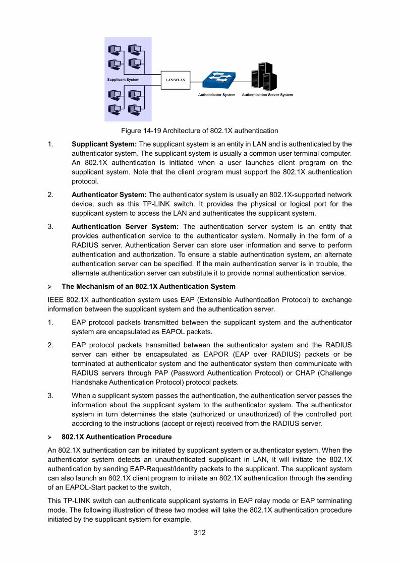
312
Figure 14-19 Architecture of 802.1X authentication
1. Supplicant System: The supplicant system is an entity in LAN and is authenticated by the authenticator system. The supplicant system is usually a common user terminal computer. An 802.1X authentication is initiated when a user launches client program on the supplicant system. Note that the client program must support the 802.1X authentication protocol.
2. Authenticator System: The authenticator system is usually an 802.1X-supported network device, such as this TP-LINK switch. It provides the physical or logical port for the supplicant system to access the LAN and authenticates the supplicant system.
3. Authentication Server System: The authentication server system is an entity that provides authentication service to the authenticator system. Normally in the form of a RADIUS server. Authentication Server can store user information and serve to perform authentication and authorization. To ensure a stable authentication system, an alternate authentication server can be specified. If the main authentication server is in trouble, the alternate authentication server can substitute it to provide normal authentication service.
The Mechanism of an 802.1X Authentication System
IEEE 802.1X authentication system uses EAP (Extensible Authentication Protocol) to exchange information between the supplicant system and the authentication server.
1. EAP protocol packets transmitted between the supplicant system and the authenticator system are encapsulated as EAPOL packets.
2. EAP protocol packets transmitted between the authenticator system and the RADIUS server can either be encapsulated as EAPOR (EAP over RADIUS) packets or be terminated at authenticator system and the authenticator system then communicate with RADIUS servers through PAP (Password Authentication Protocol) or CHAP (Challenge Handshake Authentication Protocol) protocol packets.
3. When a supplicant system passes the authentication, the authentication server passes the information about the supplicant system to the authenticator system. The authenticator system in turn determines the state (authorized or unauthorized) of the controlled port according to the instructions (accept or reject) received from the RADIUS server.
802.1X Authentication Procedure
An 802.1X authentication can be initiated by supplicant system or authenticator system. When the authenticator system detects an unauthenticated supplicant in LAN, it will initiate the 802.1X authentication by sending EAP-Request/Identity packets to the supplicant. The supplicant system can also launch an 802.1X client program to initiate an 802.1X authentication through the sending of an EAPOL-Start packet to the switch,
This TP-LINK switch can authenticate supplicant systems in EAP relay mode or EAP terminating mode. The following illustration of these two modes will take the 802.1X authentication procedure initiated by the supplicant system for example.
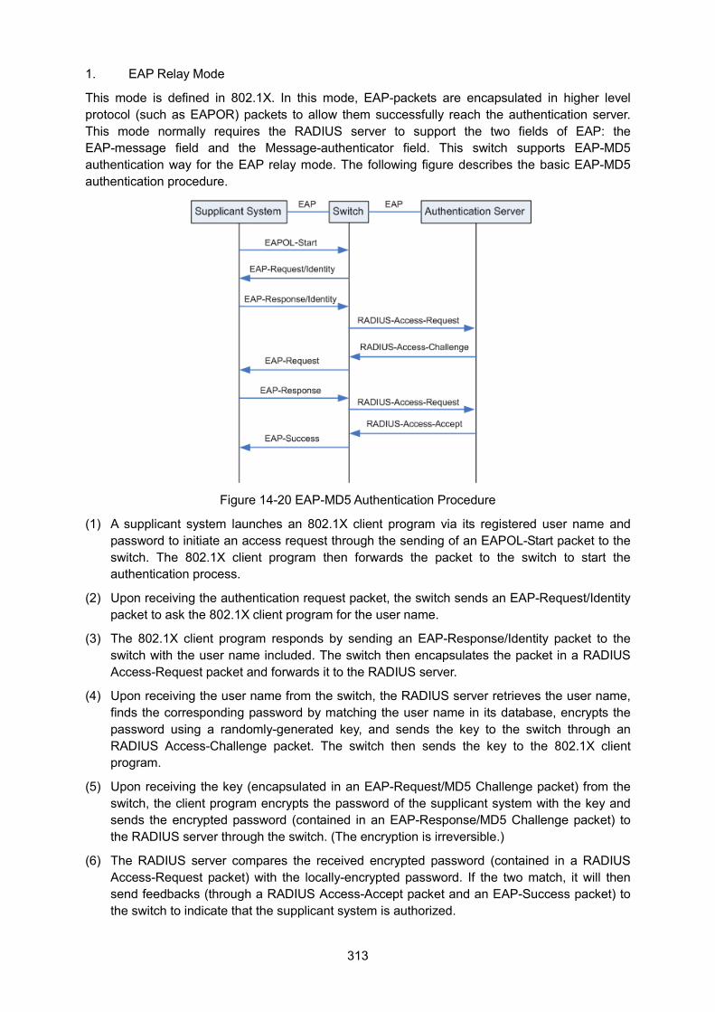
313
1. EAP Relay Mode
This mode is defined in 802.1X. In this mode, EAP-packets are encapsulated in higher level protocol (such as EAPOR) packets to allow them successfully reach the authentication server. This mode normally requires the RADIUS server to support the two fields of EAP: the EAP-message field and the Message-authenticator field. This switch supports EAP-MD5 authentication way for the EAP relay mode. The following figure describes the basic EAP-MD5 authentication procedure.
Figure 14-20 EAP-MD5 Authentication Procedure
(1) A supplicant system launches an 802.1X client program via its registered user name and password to initiate an access request through the sending of an EAPOL-Start packet to the switch. The 802.1X client program then forwards the packet to the switch to start the authentication process.
(2) Upon receiving the authentication request packet, the switch sends an EAP-Request/Identity packet to ask the 802.1X client program for the user name.
(3) The 802.1X client program responds by sending an EAP-Response/Identity packet to the switch with the user name included. The switch then encapsulates the packet in a RADIUS Access-Request packet and forwards it to the RADIUS server.
(4) Upon receiving the user name from the switch, the RADIUS server retrieves the user name, finds the corresponding password by matching the user name in its database, encrypts the password using a randomly-generated key, and sends the key to the switch through an RADIUS Access-Challenge packet. The switch then sends the key to the 802.1X client program.
(5) Upon receiving the key (encapsulated in an EAP-Request/MD5 Challenge packet) from the switch, the client program encrypts the password of the supplicant system with the key and sends the encrypted password (contained in an EAP-Response/MD5 Challenge packet) to the RADIUS server through the switch. (The encryption is irreversible.)
(6) The RADIUS server compares the received encrypted password (contained in a RADIUS Access-Request packet) with the locally-encrypted password. If the two match, it will then send feedbacks (through a RADIUS Access-Accept packet and an EAP-Success packet) to the switch to indicate that the supplicant system is authorized.
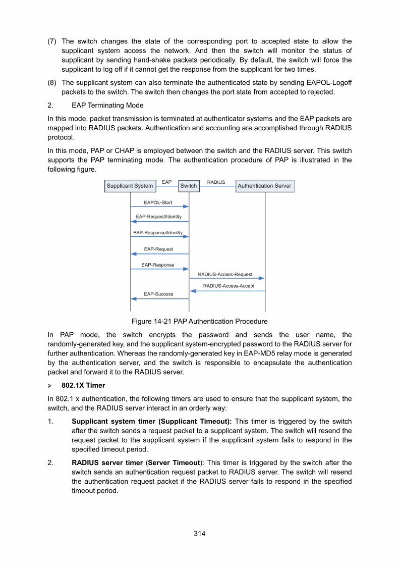
314
(7) The switch changes the state of the corresponding port to accepted state to allow the supplicant system access the network. And then the switch will monitor the status of supplicant by sending hand-shake packets periodically. By default, the switch will force the supplicant to log off if it cannot get the response from the supplicant for two times.
(8) The supplicant system can also terminate the authenticated state by sending EAPOL-Logoff packets to the switch. The switch then changes the port state from accepted to rejected.
2. EAP Terminating Mode
In this mode, packet transmission is terminated at authenticator systems and the EAP packets are mapped into RADIUS packets. Authentication and accounting are accomplished through RADIUS protocol.
In this mode, PAP or CHAP is employed between the switch and the RADIUS server. This switch supports the PAP terminating mode. The authentication procedure of PAP is illustrated in the following figure.
Figure 14-21 PAP Authentication Procedure
In PAP mode, the switch encrypts the password and sends the user name, the randomly-generated key, and the supplicant system-encrypted password to the RADIUS server for further authentication. Whereas the randomly-generated key in EAP-MD5 relay mode is generated by the authentication server, and the switch is responsible to encapsulate the authentication packet and forward it to the RADIUS server.
802.1X Timer
In 802.1 x authentication, the following timers are used to ensure that the supplicant system, the switch, and the RADIUS server interact in an orderly way:
1. Supplicant system timer (Supplicant Timeout): This timer is triggered by the switch after the switch sends a request packet to a supplicant system. The switch will resend the request packet to the supplicant system if the supplicant system fails to respond in the specified timeout period.
2. RADIUS server timer (Server Timeout): This timer is triggered by the switch after the switch sends an authentication request packet to RADIUS server. The switch will resend the authentication request packet if the RADIUS server fails to respond in the specified timeout period.
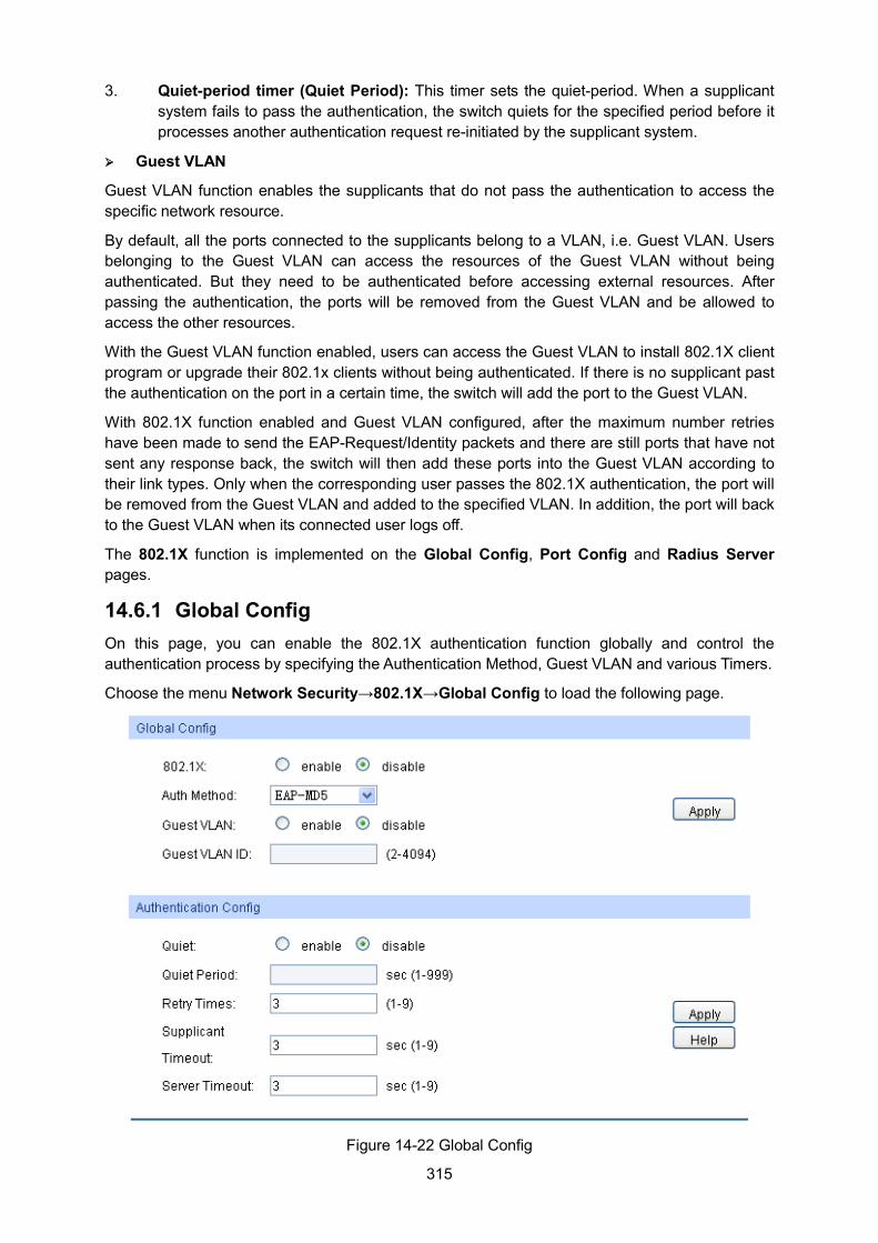
315
3. Quiet-period timer (Quiet Period): This timer sets the quiet-period. When a supplicant system fails to pass the authentication, the switch quiets for the specified period before it processes another authentication request re-initiated by the supplicant system.
Guest VLAN
Guest VLAN function enables the supplicants that do not pass the authentication to access the specific network resource.
By default, all the ports connected to the supplicants belong to a VLAN, i.e. Guest VLAN. Users belonging to the Guest VLAN can access the resources of the Guest VLAN without being authenticated. But they need to be authenticated before accessing external resources. After passing the authentication, the ports will be removed from the Guest VLAN and be allowed to access the other resources.
With the Guest VLAN function enabled, users can access the Guest VLAN to install 802.1X client program or upgrade their 802.1x clients without being authenticated. If there is no supplicant past the authentication on the port in a certain time, the switch will add the port to the Guest VLAN.
With 802.1X function enabled and Guest VLAN configured, after the maximum number retries have been made to send the EAP-Request/Identity packets and there are still ports that have not sent any response back, the switch will then add these ports into the Guest VLAN according to their link types. Only when the corresponding user passes the 802.1X authentication, the port will be removed from the Guest VLAN and added to the specified VLAN. In addition, the port will back to the Guest VLAN when its connected user logs off.
The 802.1X function is implemented on the Global Config, Port Config and Radius Server pages.
14.6.1 Global Config On this page, you can enable the 802.1X authentication function globally and control the authentication process by specifying the Authentication Method, Guest VLAN and various Timers.
Choose the menu Network Security→802.1X→Global Config to load the following page.
Figure 14-22 Global Config
316
The following entries are displayed on this screen: Global Config
802.1X: Enable/Disable the 802.1X function.
Auth Method: Select the Authentication Method from the pull-down list.
• EAP-MD5: IEEE 802.1X authentication system uses extensible authentication protocol (EAP) to exchange information between the switch and the client. The EAP protocol packets with authentication data can be encapsulated in the advanced protocol (such as RADIUS) packets to be transmitted to the authentication server.
• PAP: IEEE 802.1X authentication system uses extensible authentication protocol (EAP) to exchange information between the switch and the client. The transmission of EAP packets is terminated at the switch and the EAP packets are converted to the other protocol (such as RADIUS) packets for transmission.
Guest VLAN: Enable/Disable the Guest VLAN feature.
Guest VLAN ID: Enter your desired VLAN ID to enable the Guest VLAN feature. The supplicants in the Guest VLAN can access the specified network source.
Authentication Config
Quiet: Enable/Disable the Quiet timer.
Quiet Period: Specify a value for Quiet Period. Once the supplicant failed to the 802.1X Authentication, then the switch will not respond to the authentication request from the same supplicant during the Quiet Period.
Retry Times: Specify the maximum transfer times of the repeated authentication request.
Supplicant Timeout: Specify the maximum time for the switch to wait for the response from supplicant before resending a request to the supplicant.
Server Timeout: Specify the maximum time for the switch to wait for the response from authentication server before resending a request to the authentication server.
14.6.2 Port Config On this page, you can configure the 802.1X features for the ports basing on the actual network.
Choose the menu Network Security→802.1X→Port Config to load the following page.
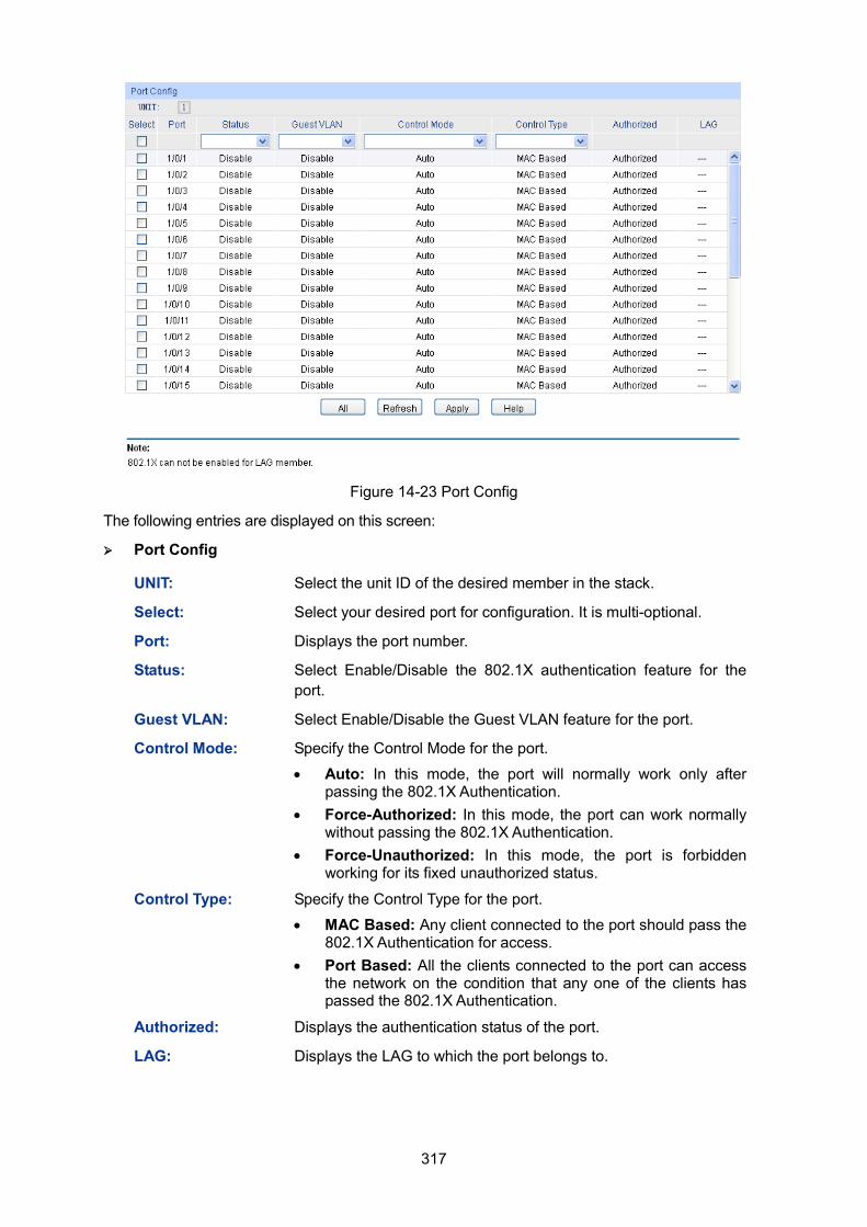
317
Figure 14-23 Port Config
The following entries are displayed on this screen: Port Config
UNIT: Select the unit ID of the desired member in the stack.
Select: Select your desired port for configuration. It is multi-optional.
Port: Displays the port number.
Status: Select Enable/Disable the 802.1X authentication feature for the port.
Guest VLAN: Select Enable/Disable the Guest VLAN feature for the port.
Control Mode: Specify the Control Mode for the port.
• Auto: In this mode, the port will normally work only after passing the 802.1X Authentication.
• Force-Authorized: In this mode, the port can work normally without passing the 802.1X Authentication.
• Force-Unauthorized: In this mode, the port is forbidden working for its fixed unauthorized status.
Control Type: Specify the Control Type for the port.
• MAC Based: Any client connected to the port should pass the 802.1X Authentication for access.
• Port Based: All the clients connected to the port can access the network on the condition that any one of the clients has passed the 802.1X Authentication.
Authorized: Displays the authentication status of the port.
LAG: Displays the LAG to which the port belongs to.
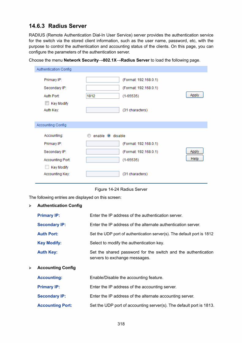
318
14.6.3 Radius Server RADIUS (Remote Authentication Dial-In User Service) server provides the authentication service for the switch via the stored client information, such as the user name, password, etc, with the purpose to control the authentication and accounting status of the clients. On this page, you can configure the parameters of the authentication server.
Choose the menu Network Security→802.1X→Radius Server to load the following page.
Figure 14-24 Radius Server
The following entries are displayed on this screen: Authentication Config
Primary IP: Enter the IP address of the authentication server.
Secondary IP: Enter the IP address of the alternate authentication server.
Auth Port: Set the UDP port of authentication server(s). The default port is 1812
Key Modify: Select to modify the authentication key.
Auth Key: Set the shared password for the switch and the authentication servers to exchange messages.
Accounting Config
Accounting: Enable/Disable the accounting feature.
Primary IP: Enter the IP address of the accounting server.
Secondary IP: Enter the IP address of the alternate accounting server.
Accounting Port: Set the UDP port of accounting server(s). The default port is 1813.
319
Key Modify: Select to modify the accounting key.
Accounting Key: Set the shared password for the switch and the accounting servers to exchange messages.
Note: 1. The 802.1X function takes effect only when it is enabled globally on the switch and for the port.
2. The 802.1X function cannot be enabled for LAG member ports. That is, the port with 802.1X function enabled cannot be added to the LAG.
3. The 802.1X function should not be enabled for the port connected to the authentication server. In addition, the authentication parameters of the switch and the authentication server should be the same.
Configuration Procedure:
Step Operation Description
1 Connect an authentication server to the switch and do some configuration.
Required. Record the information of the client in the LAN to the authentication server and configure the corresponding authentication username and password for the client.
2 Install the 802.1X client software.
Required. For the client computers, you are required to install the 802.1X software TpSupplicant provided on the CD. For the installation guide, please refer to Return to CONTENTS Appendix C: 802.1X Client Software.
3 Configure the 802.1X globally.
Required. By default, the global 802.1X function is disabled. On the Network Security→802.1X→Global Config page, configure the 802.1X function globally.
4 Configure the parameters of the authentication server
Required. On the Network Security→802.1X→Radius Server page, configure the parameters of the server.
5 Configure the 802.1X for the port.
Required. On the Network Security→802.1X→Port Config page, configure the 802.1X feature for the port of the switch basing on the actual network.
Return to CONTENTS
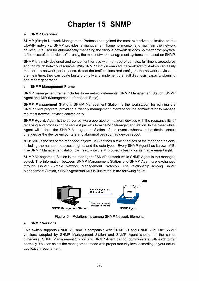
320
Chapter 15 SNMP SNMP Overview
SNMP (Simple Network Management Protocol) has gained the most extensive application on the UDP/IP networks. SNMP provides a management frame to monitor and maintain the network devices. It is used for automatically managing the various network devices no matter the physical differences of the devices. Currently, the most network management systems are based on SNMP.
SNMP is simply designed and convenient for use with no need of complex fulfillment procedures and too much network resources. With SNMP function enabled, network administrators can easily monitor the network performance, detect the malfunctions and configure the network devices. In the meantime, they can locate faults promptly and implement the fault diagnosis, capacity planning and report generating.
SNMP Management Frame
SNMP management frame includes three network elements: SNMP Management Station, SNMP Agent and MIB (Management Information Base).
SNMP Management Station: SNMP Management Station is the workstation for running the SNMP client program, providing a friendly management interface for the administrator to manage the most network devices conveniently.
SNMP Agent: Agent is the server software operated on network devices with the responsibility of receiving and processing the request packets from SNMP Management Station. In the meanwhile, Agent will inform the SNMP Management Station of the events whenever the device status changes or the device encounters any abnormalities such as device reboot.
MIB: MIB is the set of the managed objects. MIB defines a few attributes of the managed objects, including the names, the access rights, and the data types. Every SNMP Agent has its own MIB. The SNMP Management station can read/write the MIB objects basing on its management right.
SNMP Management Station is the manager of SNMP network while SNMP Agent is the managed object. The information between SNMP Management Station and SNMP Agent are exchanged through SNMP (Simple Network Management Protocol). The relationship among SNMP Management Station, SNMP Agent and MIB is illustrated in the following figure.
Figure15-1 Relationship among SNMP Network Elements
SNMP Versions
This switch supports SNMP v3, and is compatible with SNMP v1 and SNMP v2c. The SNMP versions adopted by SNMP Management Station and SNMP Agent should be the same. Otherwise, SNMP Management Station and SNMP Agent cannot communicate with each other normally. You can select the management mode with proper security level according to your actual application requirement.
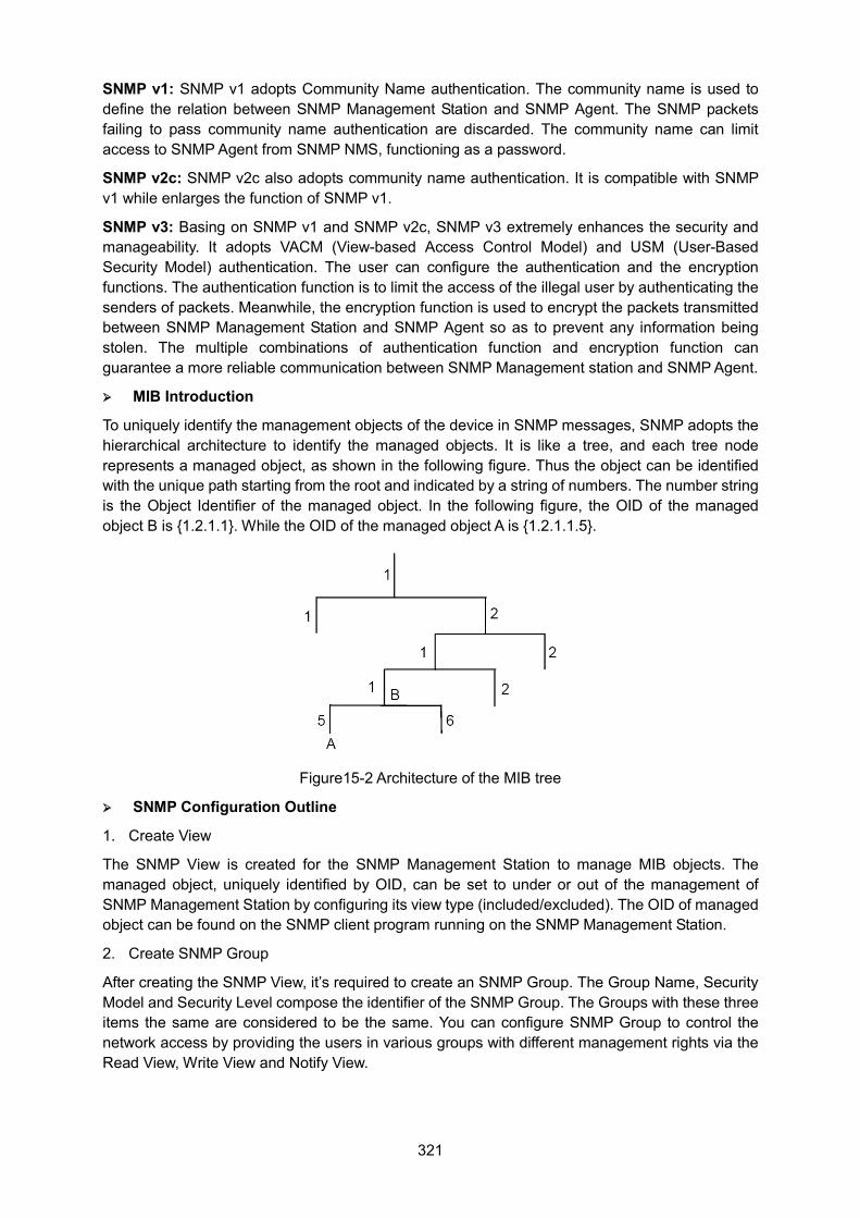
321
SNMP v1: SNMP v1 adopts Community Name authentication. The community name is used to define the relation between SNMP Management Station and SNMP Agent. The SNMP packets failing to pass community name authentication are discarded. The community name can limit access to SNMP Agent from SNMP NMS, functioning as a password.
SNMP v2c: SNMP v2c also adopts community name authentication. It is compatible with SNMP v1 while enlarges the function of SNMP v1.
SNMP v3: Basing on SNMP v1 and SNMP v2c, SNMP v3 extremely enhances the security and manageability. It adopts VACM (View-based Access Control Model) and USM (User-Based Security Model) authentication. The user can configure the authentication and the encryption functions. The authentication function is to limit the access of the illegal user by authenticating the senders of packets. Meanwhile, the encryption function is used to encrypt the packets transmitted between SNMP Management Station and SNMP Agent so as to prevent any information being stolen. The multiple combinations of authentication function and encryption function can guarantee a more reliable communication between SNMP Management station and SNMP Agent.
MIB Introduction
To uniquely identify the management objects of the device in SNMP messages, SNMP adopts the hierarchical architecture to identify the managed objects. It is like a tree, and each tree node represents a managed object, as shown in the following figure. Thus the object can be identified with the unique path starting from the root and indicated by a string of numbers. The number string is the Object Identifier of the managed object. In the following figure, the OID of the managed object B is {1.2.1.1}. While the OID of the managed object A is {1.2.1.1.5}.
Figure15-2 Architecture of the MIB tree
SNMP Configuration Outline
1. Create View
The SNMP View is created for the SNMP Management Station to manage MIB objects. The managed object, uniquely identified by OID, can be set to under or out of the management of SNMP Management Station by configuring its view type (included/excluded). The OID of managed object can be found on the SNMP client program running on the SNMP Management Station.
2. Create SNMP Group
After creating the SNMP View, it’s required to create an SNMP Group. The Group Name, Security Model and Security Level compose the identifier of the SNMP Group. The Groups with these three items the same are considered to be the same. You can configure SNMP Group to control the network access by providing the users in various groups with different management rights via the Read View, Write View and Notify View.
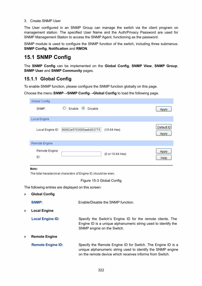
322
3. Create SNMP User
The User configured in an SNMP Group can manage the switch via the client program on management station. The specified User Name and the Auth/Privacy Password are used for SNMP Management Station to access the SNMP Agent, functioning as the password.
SNMP module is used to configure the SNMP function of the switch, including three submenus: SNMP Config, Notification and RMON.
15.1 SNMP Config The SNMP Config can be implemented on the Global Config, SNMP View, SNMP Group, SNMP User and SNMP Community pages.
15.1.1 Global Config To enable SNMP function, please configure the SNMP function globally on this page.
Choose the menu SNMP→SNMP Config→Global Config to load the following page.
Figure 15-3 Global Config
The following entries are displayed on this screen: Global Config
SNMP: Enable/Disable the SNMP function.
Local Engine
Local Engine ID: Specify the Switch’s Engine ID for the remote clients. The Engine ID is a unique alphanumeric string used to identify the SNMP engine on the Switch.
Remote Engine
Remote Engine ID: Specify the Remote Engine ID for Switch. The Engine ID is a unique alphanumeric string used to identify the SNMP engine on the remote device which receives informs from Switch.
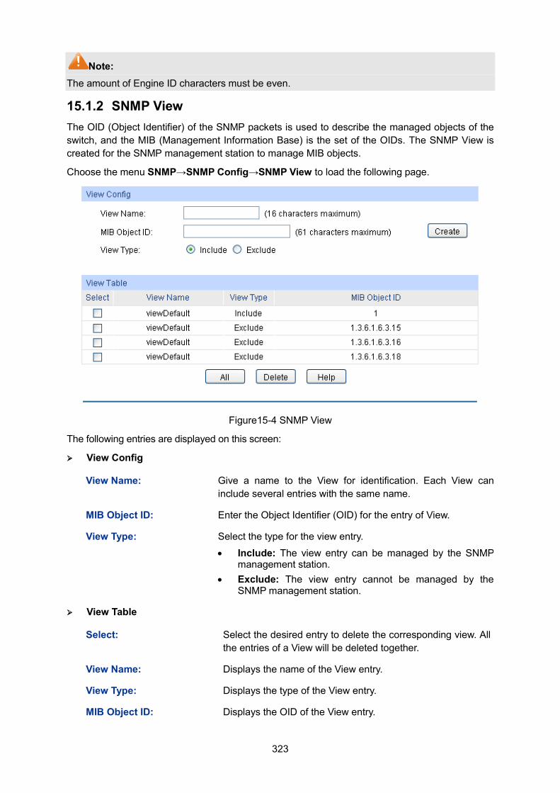
323
Note: The amount of Engine ID characters must be even.
15.1.2 SNMP View The OID (Object Identifier) of the SNMP packets is used to describe the managed objects of the switch, and the MIB (Management Information Base) is the set of the OIDs. The SNMP View is created for the SNMP management station to manage MIB objects.
Choose the menu SNMP→SNMP Config→SNMP View to load the following page.
Figure15-4 SNMP View
The following entries are displayed on this screen: View Config
View Name: Give a name to the View for identification. Each View can include several entries with the same name.
MIB Object ID: Enter the Object Identifier (OID) for the entry of View.
View Type: Select the type for the view entry.
• Include: The view entry can be managed by the SNMP management station.
• Exclude: The view entry cannot be managed by the SNMP management station.
View Table
Select: Select the desired entry to delete the corresponding view. All the entries of a View will be deleted together.
View Name: Displays the name of the View entry.
View Type: Displays the type of the View entry.
MIB Object ID: Displays the OID of the View entry.
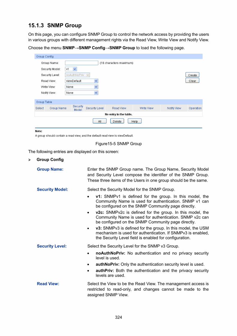
324
15.1.3 SNMP Group On this page, you can configure SNMP Group to control the network access by providing the users in various groups with different management rights via the Read View, Write View and Notify View.
Choose the menu SNMP→SNMP Config→SNMP Group to load the following page.
Figure15-5 SNMP Group
The following entries are displayed on this screen: Group Config
Group Name: Enter the SNMP Group name. The Group Name, Security Model and Security Level compose the identifier of the SNMP Group. These three items of the Users in one group should be the same.
Security Model: Select the Security Model for the SNMP Group. • v1: SNMPv1 is defined for the group. In this model, the
Community Name is used for authentication. SNMP v1 can be configured on the SNMP Community page directly.
• v2c: SNMPv2c is defined for the group. In this model, the Community Name is used for authentication. SNMP v2c can be configured on the SNMP Community page directly.
• v3: SNMPv3 is defined for the group. In this model, the USM mechanism is used for authentication. If SNMPv3 is enabled, the Security Level field is enabled for configuration.
Security Level: Select the Security Level for the SNMP v3 Group.
• noAuthNoPriv: No authentication and no privacy security level is used.
• authNoPriv: Only the authentication security level is used. • authPriv: Both the authentication and the privacy security
levels are used.
Read View: Select the View to be the Read View. The management access is restricted to read-only, and changes cannot be made to the assigned SNMP View.
325
Write View: Select the View to be the Write View. The management access is writing only and changes can be made to the assigned SNMP View. The View defined both as the Read View and the Write View can be read and modified.
Notify View: Select the View to be the Notify View. The management station can receive notification messages of the assigned SNMP view generated by the switch's SNMP agent.
Group Table
Select: Select the desired entry to delete the corresponding group. It's multi-optional.
Group Name: Displays the Group Name here.
Security Model: Displays the Security Model of the group.
Security Level: Displays the Security Level of the group.
Read View: Displays the Read View name in the entry.
Write View: Displays the Write View name in the entry.
Notify View: Displays the Notify View name in the entry.
Operation: Click the Edit button to modify the Views in the entry and click the Modify button to apply.
Note: Every Group should contain a Read View. The default Read View is viewDefault.
15.1.4 SNMP User The User in an SNMP Group can manage the switch via the management station software. The User and its Group have the same security level and access right. You can configure the SNMP User on this page.
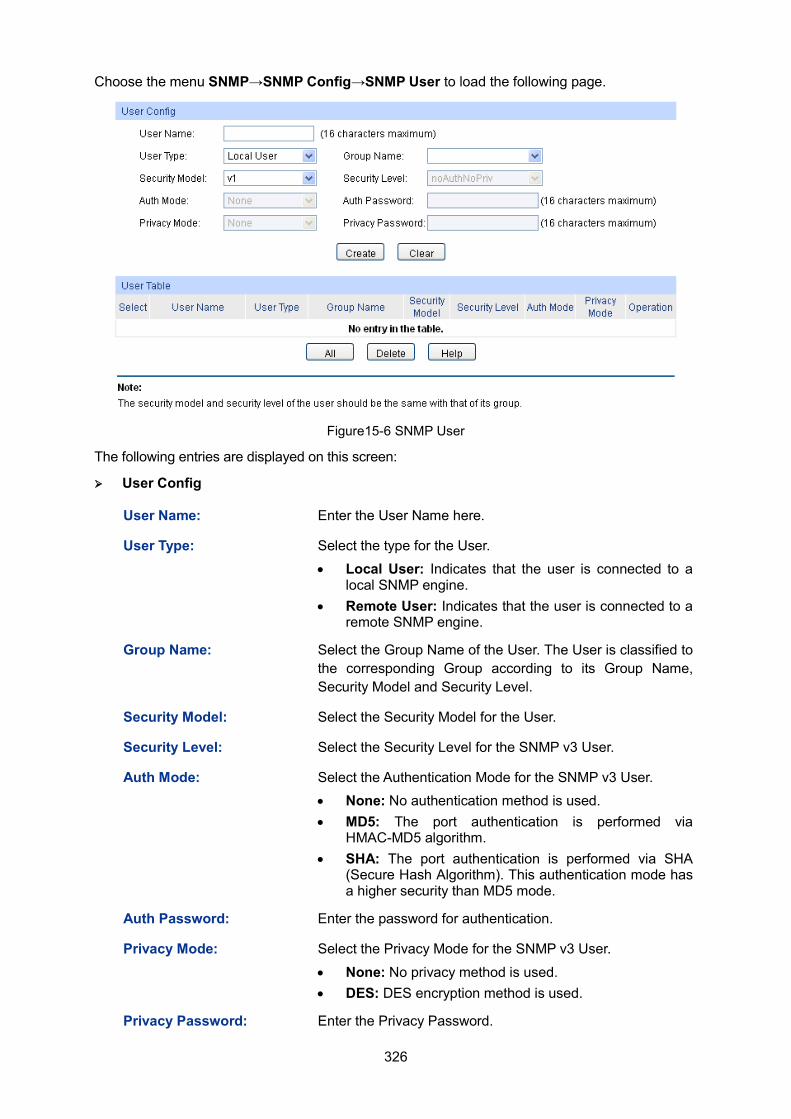
326
Choose the menu SNMP→SNMP Config→SNMP User to load the following page.
Figure15-6 SNMP User
The following entries are displayed on this screen: User Config
User Name: Enter the User Name here.
User Type: Select the type for the User. • Local User: Indicates that the user is connected to a
local SNMP engine. • Remote User: Indicates that the user is connected to a
remote SNMP engine.
Group Name: Select the Group Name of the User. The User is classified to the corresponding Group according to its Group Name, Security Model and Security Level.
Security Model: Select the Security Model for the User.
Security Level: Select the Security Level for the SNMP v3 User.
Auth Mode: Select the Authentication Mode for the SNMP v3 User. • None: No authentication method is used. • MD5: The port authentication is performed via
HMAC-MD5 algorithm. • SHA: The port authentication is performed via SHA
(Secure Hash Algorithm). This authentication mode has a higher security than MD5 mode.
Auth Password: Enter the password for authentication.
Privacy Mode: Select the Privacy Mode for the SNMP v3 User.
• None: No privacy method is used. • DES: DES encryption method is used.
Privacy Password: Enter the Privacy Password.
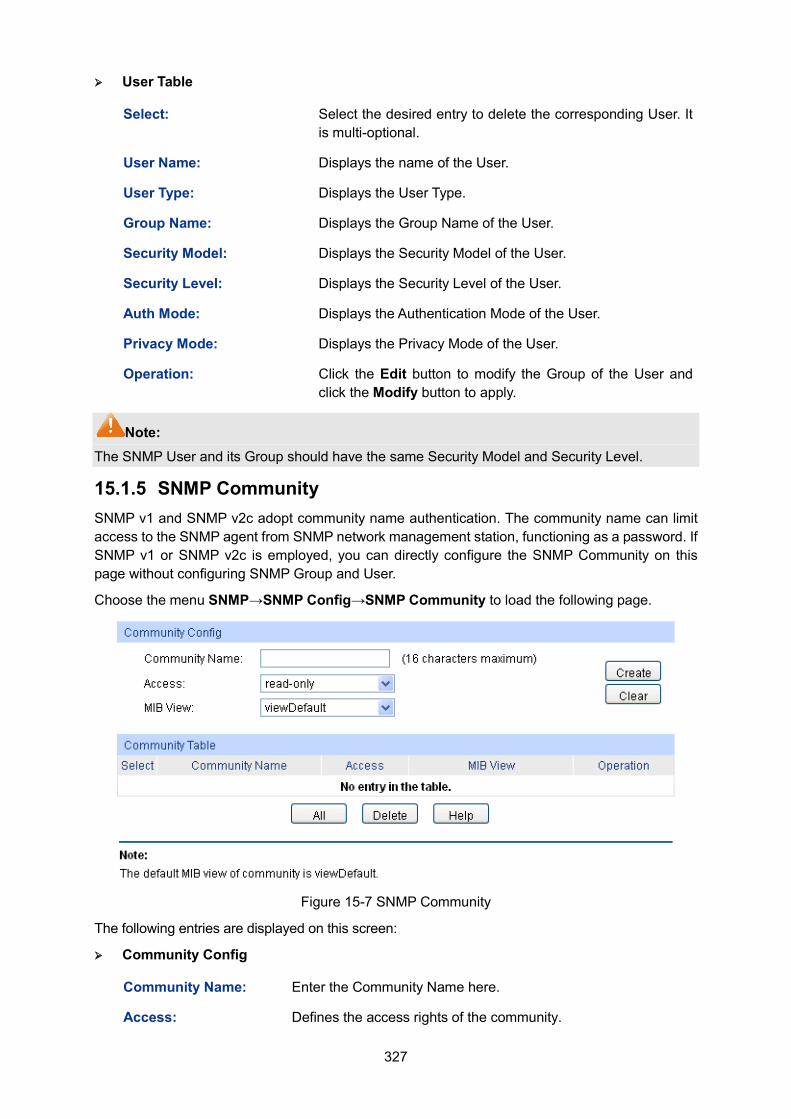
327
User Table
Select: Select the desired entry to delete the corresponding User. It is multi-optional.
User Name: Displays the name of the User.
User Type: Displays the User Type.
Group Name: Displays the Group Name of the User.
Security Model: Displays the Security Model of the User.
Security Level: Displays the Security Level of the User.
Auth Mode: Displays the Authentication Mode of the User.
Privacy Mode: Displays the Privacy Mode of the User.
Operation: Click the Edit button to modify the Group of the User and click the Modify button to apply.
Note: The SNMP User and its Group should have the same Security Model and Security Level.
15.1.5 SNMP Community SNMP v1 and SNMP v2c adopt community name authentication. The community name can limit access to the SNMP agent from SNMP network management station, functioning as a password. If SNMP v1 or SNMP v2c is employed, you can directly configure the SNMP Community on this page without configuring SNMP Group and User.
Choose the menu SNMP→SNMP Config→SNMP Community to load the following page.
Figure 15-7 SNMP Community
The following entries are displayed on this screen: Community Config
Community Name: Enter the Community Name here.
Access: Defines the access rights of the community.
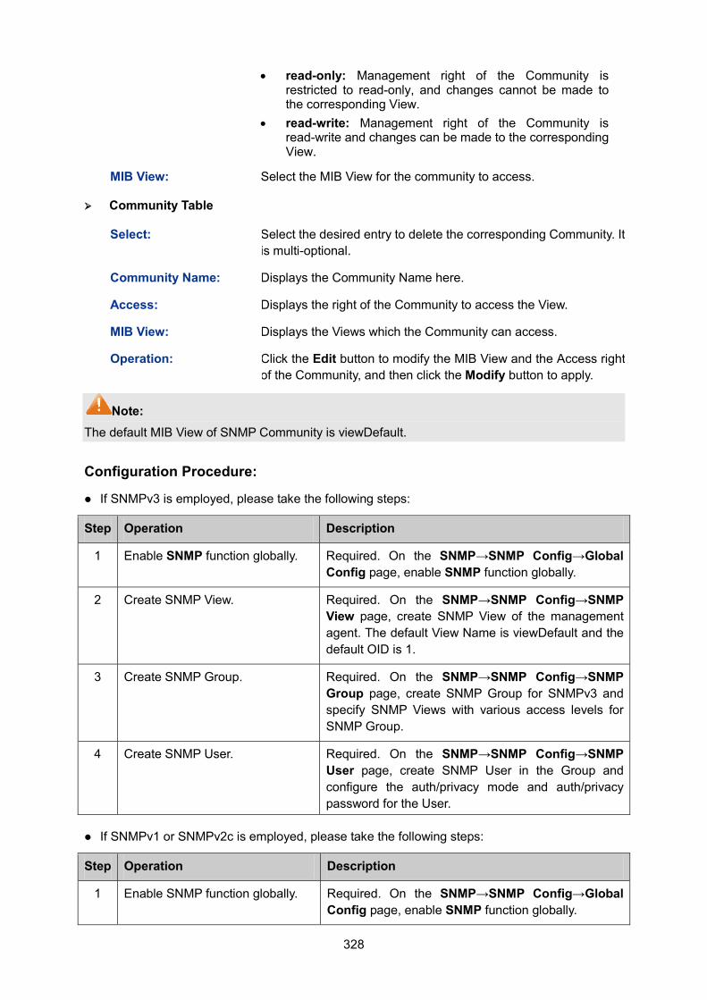
328
• read-only: Management right of the Community is restricted to read-only, and changes cannot be made to the corresponding View.
• read-write: Management right of the Community is read-write and changes can be made to the corresponding View.
MIB View: Select the MIB View for the community to access.
Community Table
Select: Select the desired entry to delete the corresponding Community. It is multi-optional.
Community Name: Displays the Community Name here.
Access: Displays the right of the Community to access the View.
MIB View: Displays the Views which the Community can access.
Operation: Click the Edit button to modify the MIB View and the Access right of the Community, and then click the Modify button to apply.
Note: The default MIB View of SNMP Community is viewDefault.
Configuration Procedure:
If SNMPv3 is employed, please take the following steps:
Step Operation Description
1 Enable SNMP function globally. Required. On the SNMP→SNMP Config→Global Config page, enable SNMP function globally.
2 Create SNMP View. Required. On the SNMP→SNMP Config→SNMP View page, create SNMP View of the management agent. The default View Name is viewDefault and the default OID is 1.
3 Create SNMP Group. Required. On the SNMP→SNMP Config→SNMP Group page, create SNMP Group for SNMPv3 and specify SNMP Views with various access levels for SNMP Group.
4 Create SNMP User. Required. On the SNMP→SNMP Config→SNMP User page, create SNMP User in the Group and configure the auth/privacy mode and auth/privacy password for the User.
If SNMPv1 or SNMPv2c is employed, please take the following steps:
Step Operation Description
1 Enable SNMP function globally. Required. On the SNMP→SNMP Config→Global Config page, enable SNMP function globally.
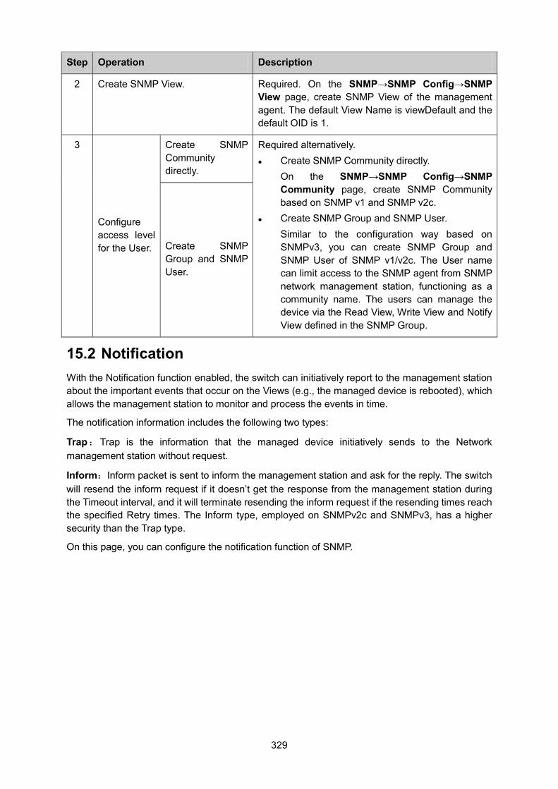
329
Step Operation Description
2 Create SNMP View. Required. On the SNMP→SNMP Config→SNMP View page, create SNMP View of the management agent. The default View Name is viewDefault and the default OID is 1.
3
Configure access level for the User.
Create SNMP Community directly.
Required alternatively. Create SNMP Community directly.
On the SNMP→SNMP Config→SNMP Community page, create SNMP Community based on SNMP v1 and SNMP v2c.
Create SNMP Group and SNMP User. Similar to the configuration way based on SNMPv3, you can create SNMP Group and SNMP User of SNMP v1/v2c. The User name can limit access to the SNMP agent from SNMP network management station, functioning as a community name. The users can manage the device via the Read View, Write View and Notify View defined in the SNMP Group.
Create SNMP Group and SNMP User.
15.2 Notification With the Notification function enabled, the switch can initiatively report to the management station about the important events that occur on the Views (e.g., the managed device is rebooted), which allows the management station to monitor and process the events in time.
The notification information includes the following two types:
Trap:Trap is the information that the managed device initiatively sends to the Network management station without request.
Inform:Inform packet is sent to inform the management station and ask for the reply. The switch will resend the inform request if it doesn’t get the response from the management station during the Timeout interval, and it will terminate resending the inform request if the resending times reach the specified Retry times. The Inform type, employed on SNMPv2c and SNMPv3, has a higher security than the Trap type.
On this page, you can configure the notification function of SNMP.
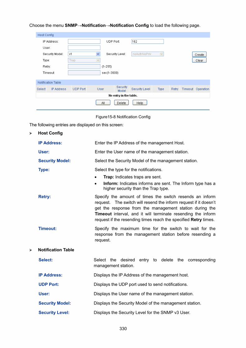
330
Choose the menu SNMP→Notification→Notification Config to load the following page.
Figure15-8 Notification Config
The following entries are displayed on this screen: Host Config
IP Address: Enter the IP Address of the management Host.
User: Enter the User name of the management station.
Security Model: Select the Security Model of the management station.
Type: Select the type for the notifications.
• Trap: Indicates traps are sent. • Inform: Indicates informs are sent. The Inform type has a
higher security than the Trap type.
Retry: Specify the amount of times the switch resends an inform request. The switch will resend the inform request if it doesn’t get the response from the management station during the Timeout interval, and it will terminate resending the inform request if the resending times reach the specified Retry times.
Timeout: Specify the maximum time for the switch to wait for the response from the management station before resending a request.
Notification Table
Select: Select the desired entry to delete the corresponding management station.
IP Address: Displays the IP Address of the management host.
UDP Port: Displays the UDP port used to send notifications.
User: Displays the User name of the management station.
Security Model: Displays the Security Model of the management station.
Security Level: Displays the Security Level for the SNMP v3 User.
331
Type: Displays the type of the notifications.
Retry: Displays the maximum time for the switch to wait for the response from the management station before resending a request.
Timeout: Displays the amount of times the switch resends an inform request.
Operation: Click the Edit button to modify the corresponding entry and click the Modify button to apply.
15.3 RMON RMON (Remote Monitoring) basing on SNMP (Simple Network Management Protocol) architecture, functions to monitor the network. RMON is currently a commonly used network management standard defined by Internet Engineering Task Force (IETF), which is mainly used to monitor the data traffic across a network segment or even the entire network so as to enable the network administrator to take the protection measures in time to avoid any network malfunction. In addition, RMON MIB records network statistics information of network performance and malfunction periodically, based on which the management station can monitor network at any time effectively. RMON is helpful for network administrator to manage the large-scale network since it reduces the communication traffic between management station and managed agent.
RMON Group
This switch supports the following four RMON Groups defined on the RMON standard (RFC1757): History Group, Event Group, Statistic Group and Alarm Group.
RMON Group Function
History Group After a history group is configured, the switch collects and records network statistics information periodically, based on which the management station can monitor network effectively.
Event Group Event Group is used to define RMON events. Alarms occur when an event is detected.
Statistic Group Statistic Group is set to monitor the statistic of alarm variables on the specific ports.
Alarm Group Alarm Group is configured to monitor the specific alarm variables. When the value of a monitored variable exceeds the threshold, an alarm event is generated, which triggers the switch to act in the set way.
The RMON Groups can be configured on the Statistics, History, Event and Alarm pages.
15.3.1 Statistics On this page you can configure and view the statistics entry.
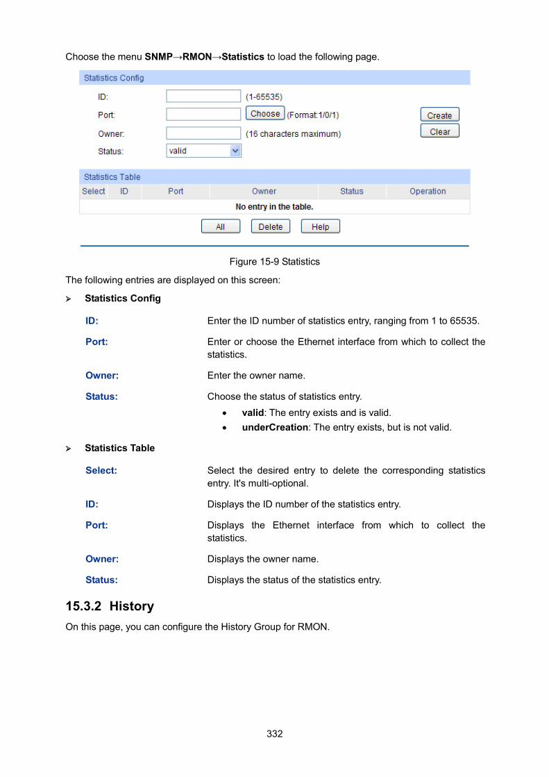
332
Choose the menu SNMP→RMON→Statistics to load the following page.
Figure 15-9 Statistics
The following entries are displayed on this screen:
Statistics Config
ID: Enter the ID number of statistics entry, ranging from 1 to 65535.
Port: Enter or choose the Ethernet interface from which to collect the statistics.
Owner: Enter the owner name.
Status: Choose the status of statistics entry. • valid: The entry exists and is valid. • underCreation: The entry exists, but is not valid.
Statistics Table
Select: Select the desired entry to delete the corresponding statistics entry. It's multi-optional.
ID: Displays the ID number of the statistics entry.
Port: Displays the Ethernet interface from which to collect the statistics.
Owner: Displays the owner name.
Status: Displays the status of the statistics entry.
15.3.2 History On this page, you can configure the History Group for RMON.
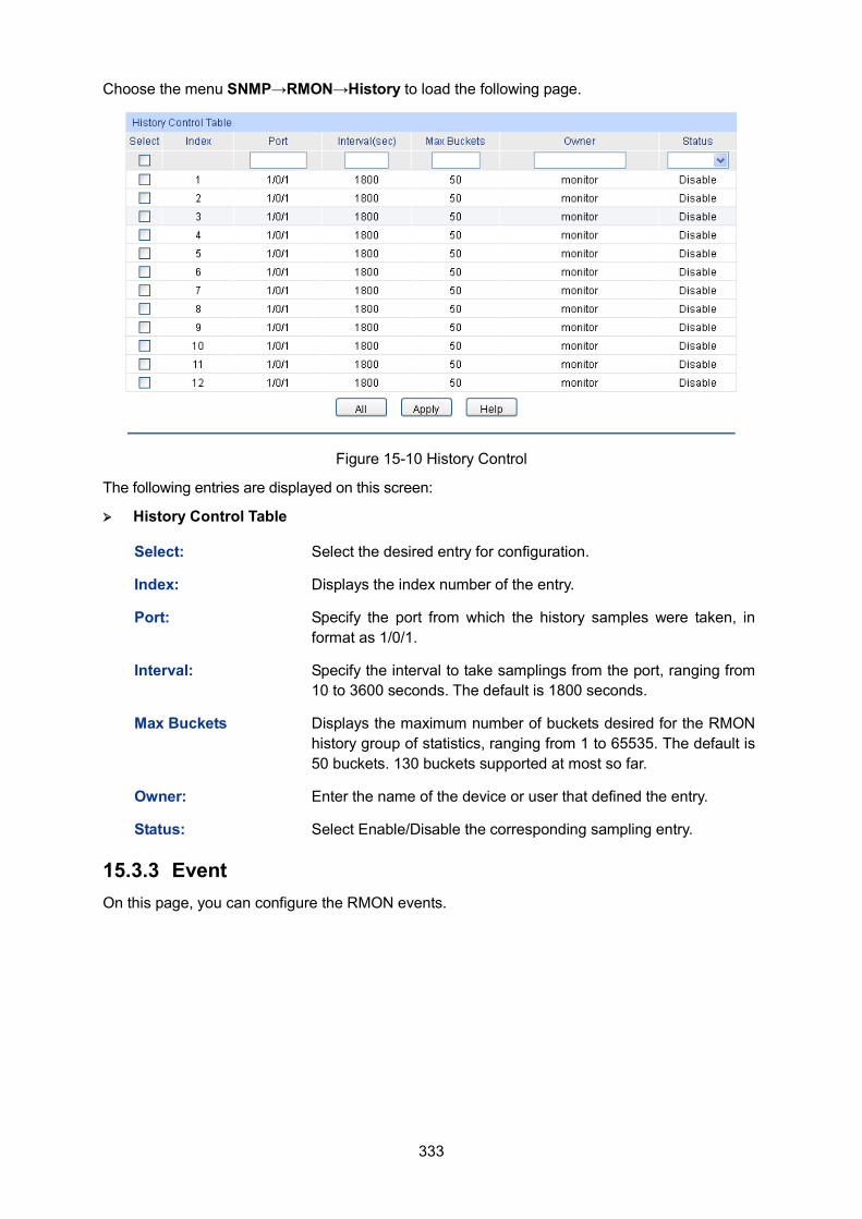
333
Choose the menu SNMP→RMON→History to load the following page.
Figure 15-10 History Control
The following entries are displayed on this screen: History Control Table
Select: Select the desired entry for configuration.
Index: Displays the index number of the entry.
Port: Specify the port from which the history samples were taken, in format as 1/0/1.
Interval: Specify the interval to take samplings from the port, ranging from 10 to 3600 seconds. The default is 1800 seconds.
Max Buckets Displays the maximum number of buckets desired for the RMON history group of statistics, ranging from 1 to 65535. The default is 50 buckets. 130 buckets supported at most so far.
Owner: Enter the name of the device or user that defined the entry.
Status: Select Enable/Disable the corresponding sampling entry.
15.3.3 Event On this page, you can configure the RMON events.
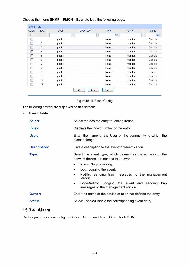
334
Choose the menu SNMP→RMON→Event to load the following page.
Figure15-11 Event Config
The following entries are displayed on this screen: Event Table
Select: Select the desired entry for configuration.
Index: Displays the index number of the entry.
User: Enter the name of the User or the community to which the event belongs.
Description: Give a description to the event for identification.
Type: Select the event type, which determines the act way of the network device in response to an event.
• None: No processing. • Log: Logging the event. • Notify: Sending trap messages to the management
station. • Log&Notify: Logging the event and sending trap
messages to the management station.
Owner: Enter the name of the device or user that defined the entry.
Status: Select Enable/Disable the corresponding event entry.
15.3.4 Alarm On this page, you can configure Statistic Group and Alarm Group for RMON.
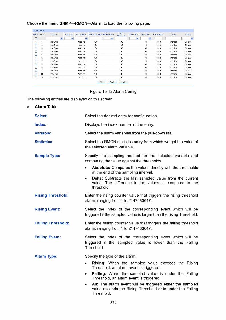
335
Choose the menu SNMP→RMON→Alarm to load the following page.
Figure 15-12 Alarm Config
The following entries are displayed on this screen: Alarm Table
Select: Select the desired entry for configuration.
Index: Displays the index number of the entry.
Variable: Select the alarm variables from the pull-down list.
Statistics Select the RMON statistics entry from which we get the value of the selected alarm variable.
Sample Type: Specify the sampling method for the selected variable and comparing the value against the thresholds. • Absolute: Compares the values directly with the thresholds
at the end of the sampling interval. • Delta: Subtracts the last sampled value from the current
value. The difference in the values is compared to the threshold.
Rising Threshold: Enter the rising counter value that triggers the rising threshold alarm, ranging from 1 to 2147483647.
Rising Event: Select the index of the corresponding event which will be triggered if the sampled value is larger than the rising Threshold.
Falling Threshold: Enter the falling counter value that triggers the falling threshold alarm, ranging from 1 to 2147483647.
Falling Event: Select the index of the corresponding event which will be triggered if the sampled value is lower than the Falling Threshold.
Alarm Type: Specify the type of the alarm.
• Rising: When the sampled value exceeds the Rising Threshold, an alarm event is triggered.
• Falling: When the sampled value is under the Falling Threshold, an alarm event is triggered.
• All: The alarm event will be triggered either the sampled value exceeds the Rising Threshold or is under the Falling Threshold.

336
Interval: Enter the alarm interval time in seconds, ranging from 10 to 3600.
Owner: Enter the name of the device or user that defined the entry.
Status: Select Enable/Disable the corresponding alarm entry.
Note: When alarm variables exceed the Threshold on the same direction continuously for several times, an alarm event will only be generated on the first time, that is, the Rising Alarm and Falling Alarm are triggered alternately for that the alarm following to Rising Alarm is certainly a Falling Alarm and vice versa.
Return to CONTENTS
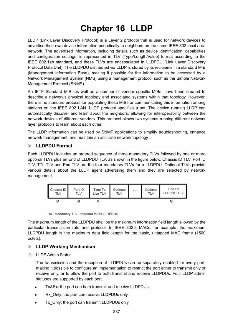
337
Chapter 16 LLDP LLDP (Link Layer Discovery Protocol) is a Layer 2 protocol that is used for network devices to advertise their own device information periodically to neighbors on the same IEEE 802 local area network. The advertised information, including details such as device identification, capabilities and configuration settings, is represented in TLV (Type/Length/Value) format according to the IEEE 802.1ab standard, and these TLVs are encapsulated in LLDPDU (Link Layer Discovery Protocol Data Unit). The LLDPDU distributed via LLDP is stored by its recipients in a standard MIB (Management Information Base), making it possible for the information to be accessed by a Network Management System (NMS) using a management protocol such as the Simple Network Management Protocol (SNMP).
An IETF Standard MIB, as well as a number of vendor specific MIBs, have been created to describe a network's physical topology and associated systems within that topology. However, there is no standard protocol for populating these MIBs or communicating this information among stations on the IEEE 802 LAN. LLDP protocol specifies a set. The device running LLDP can automatically discover and learn about the neighbors, allowing for interoperability between the network devices of different vendors. This protocol allows two systems running different network layer protocols to learn about each other.
The LLDP information can be used by SNMP applications to simplify troubleshooting, enhance network management, and maintain an accurate network topology.
LLDPDU Format Each LLDPDU includes an ordered sequence of three mandatory TLVs followed by one or more optional TLVs plus an End of LLDPDU TLV, as shown in the figure below. Chassis ID TLV, Port ID TLV, TTL TLV and End TLV are the four mandatory TLVs for a LLDPDU. Optional TLVs provide various details about the LLDP agent advertising them and they are selected by network management.
The maximum length of the LLDPDU shall be the maximum information field length allowed by the particular transmission rate and protocol. In IEEE 802.3 MACs, for example, the maximum LLDPDU length is the maximum data field length for the basic, untagged MAC frame (1500 octets).
LLDP Working Mechanism 1) LLDP Admin Status
The transmission and the reception of LLDPDUs can be separately enabled for every port, making it possible to configure an implementation to restrict the port either to transmit only or receive only, or to allow the port to both transmit and receive LLDPDUs. Four LLDP admin statuses are supported by each port.
Tx&Rx: the port can both transmit and receive LLDPDUs.
Rx_Only: the port can receive LLDPDUs only.
Tx_Only: the port can transmit LLDPDUs only.
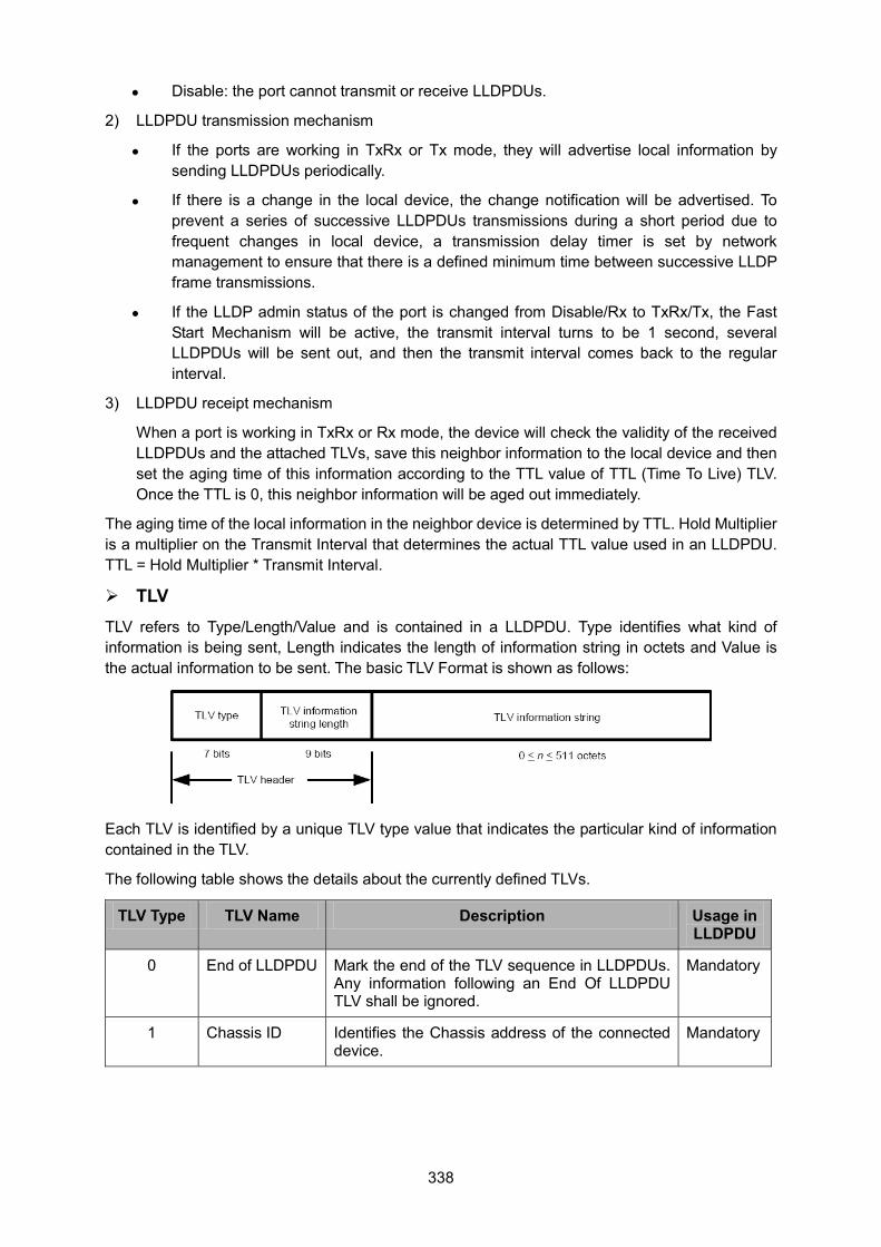
338
Disable: the port cannot transmit or receive LLDPDUs.
2) LLDPDU transmission mechanism
If the ports are working in TxRx or Tx mode, they will advertise local information by sending LLDPDUs periodically.
If there is a change in the local device, the change notification will be advertised. To prevent a series of successive LLDPDUs transmissions during a short period due to frequent changes in local device, a transmission delay timer is set by network management to ensure that there is a defined minimum time between successive LLDP frame transmissions.
If the LLDP admin status of the port is changed from Disable/Rx to TxRx/Tx, the Fast Start Mechanism will be active, the transmit interval turns to be 1 second, several LLDPDUs will be sent out, and then the transmit interval comes back to the regular interval.
3) LLDPDU receipt mechanism
When a port is working in TxRx or Rx mode, the device will check the validity of the received LLDPDUs and the attached TLVs, save this neighbor information to the local device and then set the aging time of this information according to the TTL value of TTL (Time To Live) TLV. Once the TTL is 0, this neighbor information will be aged out immediately.
The aging time of the local information in the neighbor device is determined by TTL. Hold Multiplier is a multiplier on the Transmit Interval that determines the actual TTL value used in an LLDPDU. TTL = Hold Multiplier * Transmit Interval.
TLV TLV refers to Type/Length/Value and is contained in a LLDPDU. Type identifies what kind of information is being sent, Length indicates the length of information string in octets and Value is the actual information to be sent. The basic TLV Format is shown as follows:
Each TLV is identified by a unique TLV type value that indicates the particular kind of information contained in the TLV.
The following table shows the details about the currently defined TLVs.
TLV Type TLV Name Description Usage in LLDPDU
0 End of LLDPDU Mark the end of the TLV sequence in LLDPDUs. Any information following an End Of LLDPDU TLV shall be ignored.
Mandatory
1 Chassis ID Identifies the Chassis address of the connected device.
Mandatory
339
TLV Type TLV Name Description Usage in LLDPDU
2 Port ID Identifies the specific port that transmitted the LLDP frame. When the device does not advertise MED TLV, this field displays the port name of the port; when the device advertises MED TLV, this field displays the MAC address of the port.
Mandatory
3 Time To Live Indicates the number of seconds that the neighbor device is to regard the local information to be valid.
Mandatory
4 Port Description Identifies the description string of the port. Optional
5 System Name Identifies the system name. Optional
6 System Description
Identifies the system description. Optional
7 System Capabilities
Identifies the main functions of the system and the functions enabled.
Optional
8 Management Address
Identifies the management IP address, the corresponding interface number and OID (Object Identifier). The management IP address is specified by the user.
Optional
127 Organizationally Specific
Allows different organizations, such as IEEE 802.1, IEEE 802.3, IETF, as well as individual software and equipment vendors, to define TLVs that advertise information to remote device.
Optional
Optional TLVs are grouped into two categories including basic management TLV and Organizationally-specific TLV.
1) Basic Management TLV
A set of TLVs considered to be basic to the management of the network stations are required for all LLDP implementations.
2) Organizationally Specific TLV
Different organizations have defined various TLVs. For instance, Port VLAN ID TLV, Port and Protocol VLAN ID TLV, VLAN Name TLV And Protocol Identity TLV are defined by IEEE 802.1, while MAC/PHY Configuration/Status TLV, Power Via MDI TLV, Link Aggregation TLV and Maximum Frame TLV are defined by IEEE 802.3.
Note:
For detailed introduction of TLV, please refer to IEEE 802.1AB standard.
In TP-LINK switch, the following LLDP optional TLVs are supported.
Port Description TLV The Port Description TLV allows network management to advertise the IEEE 802 LAN station's port description.
System Capabilities TLV The System Capabilities TLV identifies the primary functions of the system and whether or not these primary functions are enabled.
340
System Description TLV The System Description TLV allows network management to advertise the system's description, which should include the full name and version identification of the system's hardware type, software operating system, and networking software.
System Name TLV The System Name TLV allows network management to advertise the system's assigned name, which should be the system's fully qualified domain name.
Management Address TLV
The Management Address TLV identifies an address associated with the local LLDP agent that may be used to reach higher entities to assist discovery by network management.
Port VLAN ID TLV The Port VLAN ID TLV allows a VLAN bridge port to advertise the port's VLAN identifier (PVID) that will be associated with untagged or priority tagged frames.
Port And Protocol VLAN ID TLV
The Port And Protocol VLAN ID TLV allows a bridge port to advertise a port and protocol VLAN ID.
VLAN Name TLV The VLAN Name TLV allows an IEEE 802.1Q-compatible IEEE 802 LAN station to advertise the assigned name of any VLAN with which it is configured.
Link Aggregation TLV The Link Aggregation TLV indicates whether the link is capable of being aggregated, whether the link is currently in an aggregation, and if in an aggregation, the port identification of the aggregation.
MAC/PHY Configuration/ Status TLV
The MAC/PHY Configuration/Status TLV identifies: a)The duplex and bit-rate capability of the sending IEEE 802.3 LAN node that is connected to the physical medium; b)The current duplex and bit-rate settings of the sending IEEE 802.3 LAN node; c)Whether these settings are the result of auto-negotiation during link initiation or of manual set override action.
Max Frame Size TLV The Maximum Frame Size TLV indicates the maximum frame size capability of the implemented MAC and PHY.
Power Via MDI TLV The Power Via MDI TLV allows network management to advertise and discover the MDI power support capabilities of the sending IEEE 802.3 LAN station.
The LLDP module is mainly for LLDP function configuration of the switch, including three submenus: Basic Config, Device Info and Device Statistics.
16.1 Basic Config LLDP is configured on the Global Config and Port Config pages.
16.1.1 Global Config On this page you can configure the LLDP parameters of the device globally.
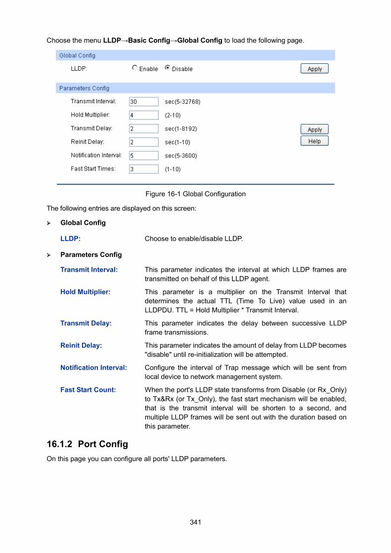
341
Choose the menu LLDP→Basic Config→Global Config to load the following page.
Figure 16-1 Global Configuration
The following entries are displayed on this screen:
Global Config
LLDP: Choose to enable/disable LLDP.
Parameters Config
Transmit Interval: This parameter indicates the interval at which LLDP frames are transmitted on behalf of this LLDP agent.
Hold Multiplier: This parameter is a multiplier on the Transmit Interval that determines the actual TTL (Time To Live) value used in an LLDPDU. TTL = Hold Multiplier * Transmit Interval.
Transmit Delay: This parameter indicates the delay between successive LLDP frame transmissions.
Reinit Delay: This parameter indicates the amount of delay from LLDP becomes "disable" until re-initialization will be attempted.
Notification Interval: Configure the interval of Trap message which will be sent from local device to network management system.
Fast Start Count: When the port's LLDP state transforms from Disable (or Rx_Only) to Tx&Rx (or Tx_Only), the fast start mechanism will be enabled, that is the transmit interval will be shorten to a second, and multiple LLDP frames will be sent out with the duration based on this parameter.
16.1.2 Port Config On this page you can configure all ports' LLDP parameters.
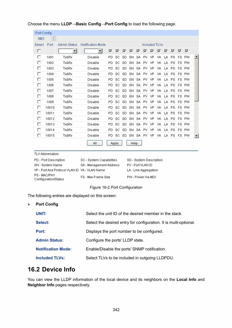
342
Choose the menu LLDP→Basic Config→Port Config to load the following page.
Figure 16-2 Port Configuration
The following entries are displayed on this screen:
Port Config
UNIT: Select the unit ID of the desired member in the stack.
Select: Select the desired entry for configuration. It is multi-optional.
Port: Displays the port number to be configured.
Admin Status: Configure the ports' LLDP state.
Notification Mode: Enable/Disable the ports' SNMP notification.
Included TLVs: Select TLVs to be included in outgoing LLDPDU.
16.2 Device Info You can view the LLDP information of the local device and its neighbors on the Local Info and Neighbor Info pages respectively.
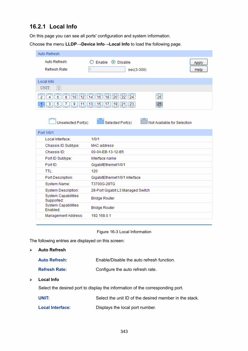
343
16.2.1 Local Info On this page you can see all ports' configuration and system information.
Choose the menu LLDP→Device Info→Local Info to load the following page.
Figure 16-3 Local Information
The following entries are displayed on this screen:
Auto Refresh
Auto Refresh: Enable/Disable the auto refresh function.
Refresh Rate: Configure the auto refresh rate.
Local Info
Select the desired port to display the information of the corresponding port.
UNIT: Select the unit ID of the desired member in the stack.
Local Interface: Displays the local port number.
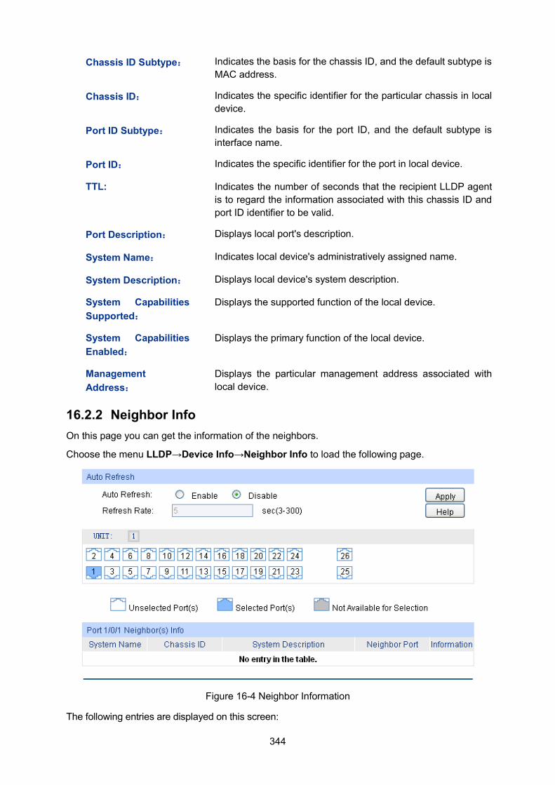
344
Chassis ID Subtype: Indicates the basis for the chassis ID, and the default subtype is MAC address.
Chassis ID: Indicates the specific identifier for the particular chassis in local device.
Port ID Subtype: Indicates the basis for the port ID, and the default subtype is interface name.
Port ID: Indicates the specific identifier for the port in local device.
TTL: Indicates the number of seconds that the recipient LLDP agent is to regard the information associated with this chassis ID and port ID identifier to be valid.
Port Description: Displays local port's description.
System Name: Indicates local device's administratively assigned name.
System Description: Displays local device's system description.
System Capabilities Supported:
Displays the supported function of the local device.
System Capabilities Enabled:
Displays the primary function of the local device.
Management Address:
Displays the particular management address associated with local device.
16.2.2 Neighbor Info On this page you can get the information of the neighbors.
Choose the menu LLDP→Device Info→Neighbor Info to load the following page.
Figure 16-4 Neighbor Information
The following entries are displayed on this screen:
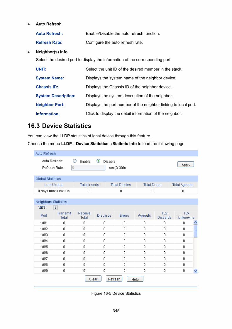
345
Auto Refresh
Auto Refresh: Enable/Disable the auto refresh function.
Refresh Rate: Configure the auto refresh rate.
Neighbor(s) Info
Select the desired port to display the information of the corresponding port.
UNIT: Select the unit ID of the desired member in the stack.
System Name: Displays the system name of the neighbor device.
Chassis ID: Displays the Chassis ID of the neighbor device.
System Description: Displays the system description of the neighbor.
Neighbor Port: Displays the port number of the neighbor linking to local port.
Information: Click to display the detail information of the neighbor.
16.3 Device Statistics You can view the LLDP statistics of local device through this feature.
Choose the menu LLDP→Device Statistics→Statistic Info to load the following page.
Figure 16-5 Device Statistics
346
The following entries are displayed on this screen: Auto Refresh
Auto Refresh: Enable/Disable the auto refresh function.
Refresh Rate: Configure the auto refresh rate.
Global Statistics
Last Update: Display latest update time of the statistics.
Total Inserts: Display the number of neighbors during latest update time.
Total Deletes: Displays the number of neighbors deleted by local device.
Total Drops: Displays the number of neighbors dropped by local device.
Total Ageouts: Displays the number of overtime neighbors in local device.
Neighbors Statistics
UNIT: Select the unit ID of the desired member in the stack.
Port: Display local device's port number.
Transmit Total: Displays the number of LLDPDUs sent by this port.
Receive Total: Displays the number of LLDPDUs received by this port.
Discards: Displays the number of LLDPDUs discarded by this port.
Errors: Displays the number of error LLDPDUs received by this port.
Ageouts: Displays the number of overtime neighbors linking to this port.
TLV Discards: Displays the number of TLVs dropped by this port.
TLV Unknowns: Displays the number of unknown TLVs received by this port.
16.4 LLDP-MED LLDP-MED is an extension of LLDP intended for managing endpoint devices such as Voice over IP phones and network switches. The LLDP-MED TLVs advertise information such as network policy, power via MDI, inventory management, and device location details.
Elements LLDP-MED Device: Refers to any device which implements this Standard.
LLDP-MED Device Type: LLDP-MED devices are comprised of two primary device types: Network Connectivity Devices and Endpoint Devices. Network Connectivity Device: Refers to an LLDP-MED Device that provides access to the IEEE 802 based LAN infrastructure for LLDP-MED Endpoint Devices. Bridge is a Network Connectivity Device. Endpoint Device: Refers to an LLDP-MED Device at the network edge, providing some aspects of IP communications service, based on IEEE 802 LAN technology. Endpoint Devices may be a member of any of the Endpoint Device Classes. Endpoint Devices are composed of three defined Classes: Class I, Class II and Class III. Generic Endpoint Device (Class I): The most basic class of Endpoint Device.
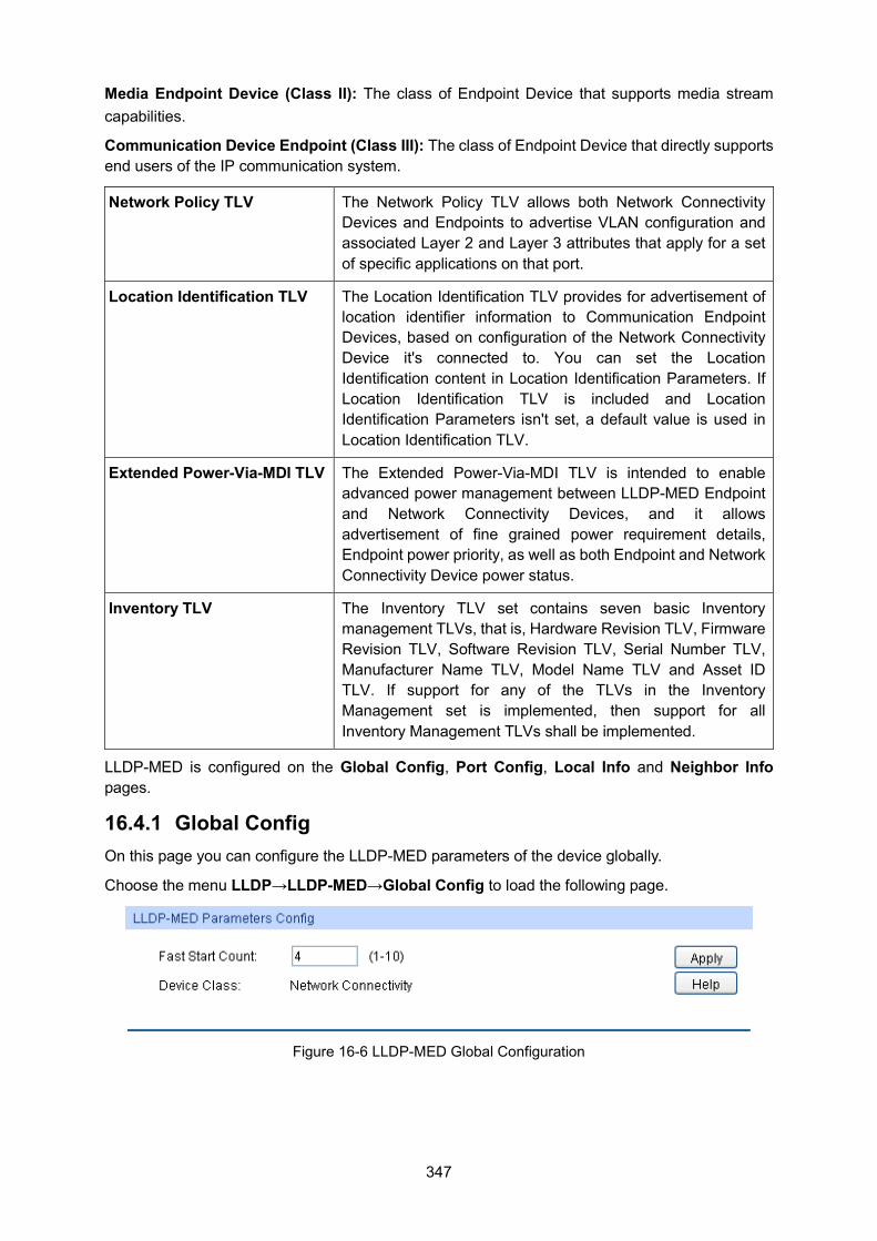
347
Media Endpoint Device (Class II): The class of Endpoint Device that supports media stream capabilities.
Communication Device Endpoint (Class III): The class of Endpoint Device that directly supports end users of the IP communication system.
Network Policy TLV The Network Policy TLV allows both Network Connectivity Devices and Endpoints to advertise VLAN configuration and associated Layer 2 and Layer 3 attributes that apply for a set of specific applications on that port.
Location Identification TLV The Location Identification TLV provides for advertisement of location identifier information to Communication Endpoint Devices, based on configuration of the Network Connectivity Device it's connected to. You can set the Location Identification content in Location Identification Parameters. If Location Identification TLV is included and Location Identification Parameters isn't set, a default value is used in Location Identification TLV.
Extended Power-Via-MDI TLV The Extended Power-Via-MDI TLV is intended to enable advanced power management between LLDP-MED Endpoint and Network Connectivity Devices, and it allows advertisement of fine grained power requirement details, Endpoint power priority, as well as both Endpoint and Network Connectivity Device power status.
Inventory TLV The Inventory TLV set contains seven basic Inventory management TLVs, that is, Hardware Revision TLV, Firmware Revision TLV, Software Revision TLV, Serial Number TLV, Manufacturer Name TLV, Model Name TLV and Asset ID TLV. If support for any of the TLVs in the Inventory Management set is implemented, then support for all Inventory Management TLVs shall be implemented.
LLDP-MED is configured on the Global Config, Port Config, Local Info and Neighbor Info pages.
16.4.1 Global Config On this page you can configure the LLDP-MED parameters of the device globally.
Choose the menu LLDP→LLDP-MED→Global Config to load the following page.
Figure 16-6 LLDP-MED Global Configuration
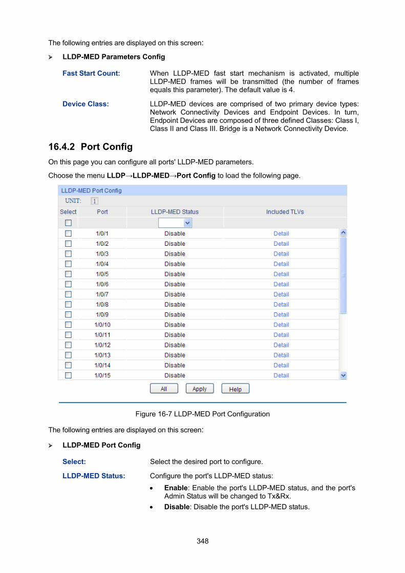
348
The following entries are displayed on this screen:
LLDP-MED Parameters Config
Fast Start Count: When LLDP-MED fast start mechanism is activated, multiple LLDP-MED frames will be transmitted (the number of frames equals this parameter). The default value is 4.
Device Class: LLDP-MED devices are comprised of two primary device types: Network Connectivity Devices and Endpoint Devices. In turn, Endpoint Devices are composed of three defined Classes: Class I, Class II and Class III. Bridge is a Network Connectivity Device.
16.4.2 Port Config On this page you can configure all ports' LLDP-MED parameters. Choose the menu LLDP→LLDP-MED→Port Config to load the following page.
Figure 16-7 LLDP-MED Port Configuration
The following entries are displayed on this screen:
LLDP-MED Port Config
Select: Select the desired port to configure.
LLDP-MED Status: Configure the port's LLDP-MED status:
• Enable: Enable the port's LLDP-MED status, and the port's Admin Status will be changed to Tx&Rx.
• Disable: Disable the port's LLDP-MED status.
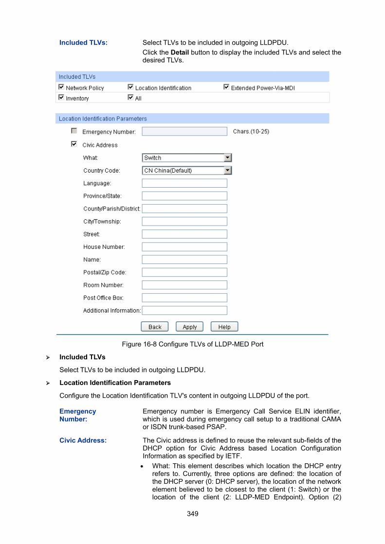
349
Included TLVs: Select TLVs to be included in outgoing LLDPDU. Click the Detail button to display the included TLVs and select the desired TLVs.
Figure 16-8 Configure TLVs of LLDP-MED Port
Included TLVs
Select TLVs to be included in outgoing LLDPDU.
Location Identification Parameters
Configure the Location Identification TLV's content in outgoing LLDPDU of the port.
Emergency Number:
Emergency number is Emergency Call Service ELIN identifier, which is used during emergency call setup to a traditional CAMA or ISDN trunk-based PSAP.
Civic Address: The Civic address is defined to reuse the relevant sub-fields of the DHCP option for Civic Address based Location Configuration Information as specified by IETF. • What: This element describes which location the DHCP entry
refers to. Currently, three options are defined: the location of the DHCP server (0: DHCP server), the location of the network element believed to be closest to the client (1: Switch) or the location of the client (2: LLDP-MED Endpoint). Option (2)
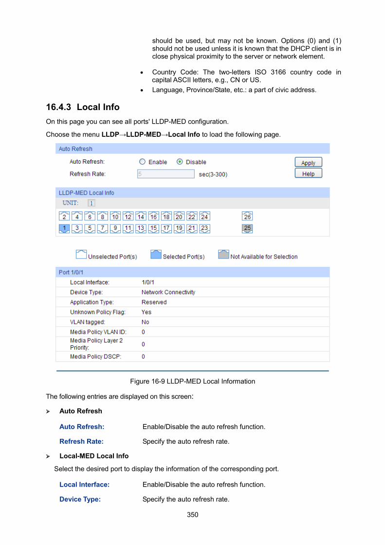
350
should be used, but may not be known. Options (0) and (1) should not be used unless it is known that the DHCP client is in close physical proximity to the server or network element.
• Country Code: The two-letters ISO 3166 country code in capital ASCII letters, e.g., CN or US.
• Language, Province/State, etc.: a part of civic address.
16.4.3 Local Info On this page you can see all ports' LLDP-MED configuration.
Choose the menu LLDP→LLDP-MED→Local Info to load the following page.
Figure 16-9 LLDP-MED Local Information
The following entries are displayed on this screen:
Auto Refresh
Auto Refresh: Enable/Disable the auto refresh function.
Refresh Rate: Specify the auto refresh rate.
Local-MED Local Info
Select the desired port to display the information of the corresponding port.
Local Interface: Enable/Disable the auto refresh function.
Device Type: Specify the auto refresh rate.
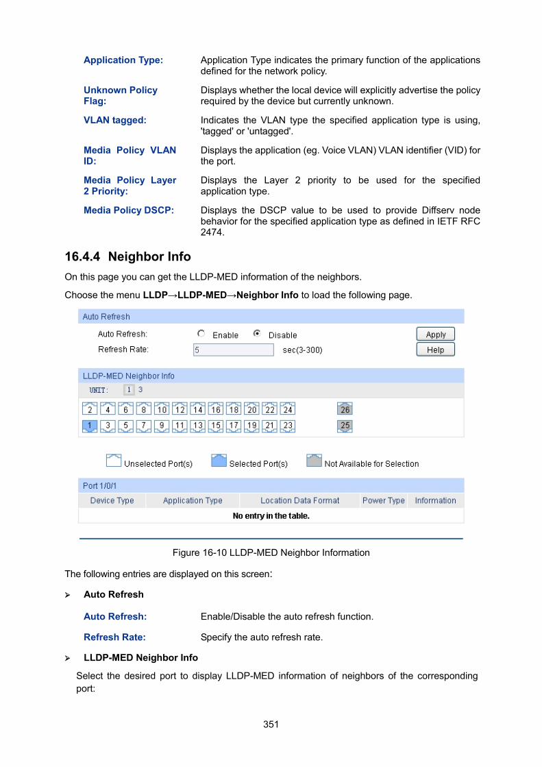
351
Application Type: Application Type indicates the primary function of the applications defined for the network policy.
Unknown Policy Flag:
Displays whether the local device will explicitly advertise the policy required by the device but currently unknown.
VLAN tagged: Indicates the VLAN type the specified application type is using, 'tagged' or 'untagged'.
Media Policy VLAN ID:
Displays the application (eg. Voice VLAN) VLAN identifier (VID) for the port.
Media Policy Layer 2 Priority:
Displays the Layer 2 priority to be used for the specified application type.
Media Policy DSCP: Displays the DSCP value to be used to provide Diffserv node behavior for the specified application type as defined in IETF RFC 2474.
16.4.4 Neighbor Info On this page you can get the LLDP-MED information of the neighbors.
Choose the menu LLDP→LLDP-MED→Neighbor Info to load the following page.
Figure 16-10 LLDP-MED Neighbor Information
The following entries are displayed on this screen:
Auto Refresh
Auto Refresh: Enable/Disable the auto refresh function.
Refresh Rate: Specify the auto refresh rate.
LLDP-MED Neighbor Info
Select the desired port to display LLDP-MED information of neighbors of the corresponding port:

352
Unit: Select the unit ID of the desired member in the stack.
Device Type: Displays the device type of the neighbor.
Application Type: Displays the application type of the neighbor. Application Type indicates the primary function of the applications defined for the network policy.
Local Data Format: Displays the location identification of the neighbor.
Power Type: Displays the power type of the neighbor device, either Power Sourcing Entity (PSE) or Powered Device (PD).
Information: Click the Information button to display the detailed information of the corresponding neighbor.
Return to CONTENTS
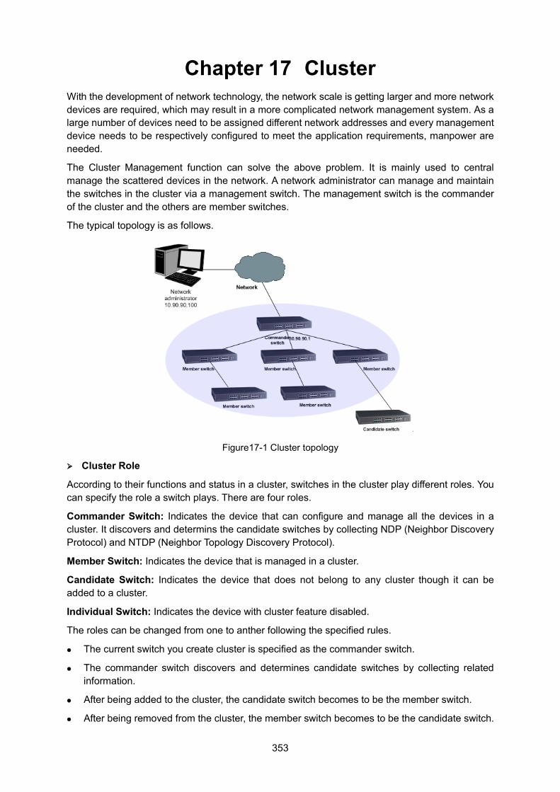
353
Chapter 17 Cluster With the development of network technology, the network scale is getting larger and more network devices are required, which may result in a more complicated network management system. As a large number of devices need to be assigned different network addresses and every management device needs to be respectively configured to meet the application requirements, manpower are needed.
The Cluster Management function can solve the above problem. It is mainly used to central manage the scattered devices in the network. A network administrator can manage and maintain the switches in the cluster via a management switch. The management switch is the commander of the cluster and the others are member switches.
The typical topology is as follows.
Figure17-1 Cluster topology
Cluster Role
According to their functions and status in a cluster, switches in the cluster play different roles. You can specify the role a switch plays. There are four roles.
Commander Switch: Indicates the device that can configure and manage all the devices in a cluster. It discovers and determins the candidate switches by collecting NDP (Neighbor Discovery Protocol) and NTDP (Neighbor Topology Discovery Protocol).
Member Switch: Indicates the device that is managed in a cluster.
Candidate Switch: Indicates the device that does not belong to any cluster though it can be added to a cluster.
Individual Switch: Indicates the device with cluster feature disabled.
The roles can be changed from one to anther following the specified rules.
The current switch you create cluster is specified as the commander switch.
The commander switch discovers and determines candidate switches by collecting related information.
After being added to the cluster, the candidate switch becomes to be the member switch.
After being removed from the cluster, the member switch becomes to be the candidate switch.
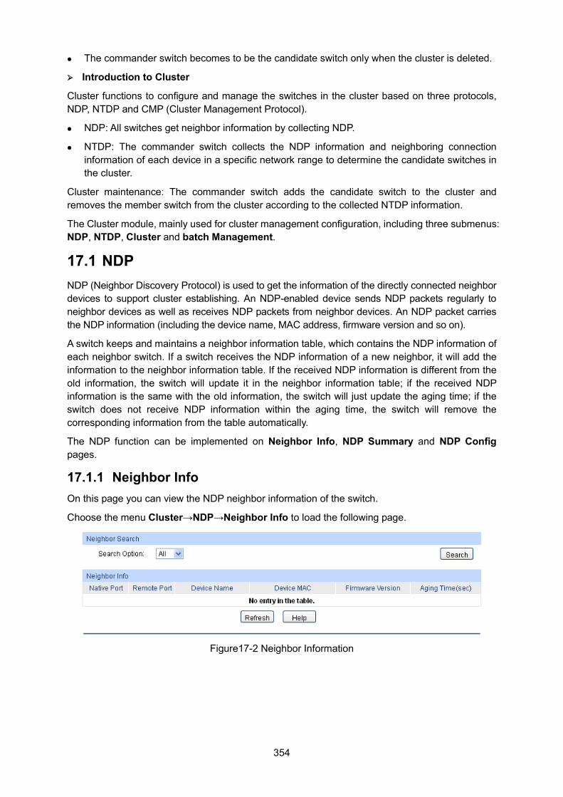
354
The commander switch becomes to be the candidate switch only when the cluster is deleted.
Introduction to Cluster
Cluster functions to configure and manage the switches in the cluster based on three protocols, NDP, NTDP and CMP (Cluster Management Protocol).
NDP: All switches get neighbor information by collecting NDP.
NTDP: The commander switch collects the NDP information and neighboring connection information of each device in a specific network range to determine the candidate switches in the cluster.
Cluster maintenance: The commander switch adds the candidate switch to the cluster and removes the member switch from the cluster according to the collected NTDP information.
The Cluster module, mainly used for cluster management configuration, including three submenus: NDP, NTDP, Cluster and batch Management.
17.1 NDP NDP (Neighbor Discovery Protocol) is used to get the information of the directly connected neighbor devices to support cluster establishing. An NDP-enabled device sends NDP packets regularly to neighbor devices as well as receives NDP packets from neighbor devices. An NDP packet carries the NDP information (including the device name, MAC address, firmware version and so on).
A switch keeps and maintains a neighbor information table, which contains the NDP information of each neighbor switch. If a switch receives the NDP information of a new neighbor, it will add the information to the neighbor information table. If the received NDP information is different from the old information, the switch will update it in the neighbor information table; if the received NDP information is the same with the old information, the switch will just update the aging time; if the switch does not receive NDP information within the aging time, the switch will remove the corresponding information from the table automatically.
The NDP function can be implemented on Neighbor Info, NDP Summary and NDP Config pages.
17.1.1 Neighbor Info On this page you can view the NDP neighbor information of the switch.
Choose the menu Cluster→NDP→Neighbor Info to load the following page.
Figure17-2 Neighbor Information
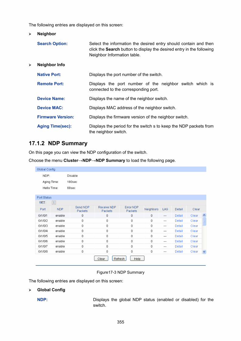
355
The following entries are displayed on this screen:
Neighbor
Search Option: Select the information the desired entry should contain and then click the Search button to display the desired entry in the following Neighbor Information table.
Neighbor Info
Native Port: Displays the port number of the switch.
Remote Port: Displays the port number of the neighbor switch which is connected to the corresponding port.
Device Name: Displays the name of the neighbor switch.
Device MAC: Displays MAC address of the neighbor switch.
Firmware Version: Displays the firmware version of the neighbor switch.
Aging Time(sec): Displays the period for the switch s to keep the NDP packets from the neighbor switch.
17.1.2 NDP Summary On this page you can view the NDP configuration of the switch.
Choose the menu Cluster→NDP→NDP Summary to load the following page.
Figure17-3 NDP Summary
The following entries are displayed on this screen:
Global Config
NDP: Displays the global NDP status (enabled or disabled) for the switch.
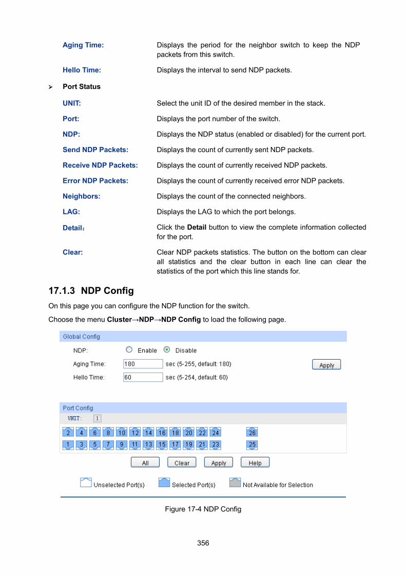
356
Aging Time: Displays the period for the neighbor switch to keep the NDP packets from this switch.
Hello Time: Displays the interval to send NDP packets.
Port Status
UNIT: Select the unit ID of the desired member in the stack.
Port: Displays the port number of the switch.
NDP: Displays the NDP status (enabled or disabled) for the current port.
Send NDP Packets: Displays the count of currently sent NDP packets.
Receive NDP Packets: Displays the count of currently received NDP packets.
Error NDP Packets: Displays the count of currently received error NDP packets.
Neighbors: Displays the count of the connected neighbors.
LAG: Displays the LAG to which the port belongs.
Detail: Click the Detail button to view the complete information collected for the port.
Clear: Clear NDP packets statistics. The button on the bottom can clear all statistics and the clear button in each line can clear the statistics of the port which this line stands for.
17.1.3 NDP Config On this page you can configure the NDP function for the switch.
Choose the menu Cluster→NDP→NDP Config to load the following page.
Figure 17-4 NDP Config
357
The following entries are displayed on this screen:
Global Config
NDP: Select Enable/Disable NDP function globally.
Aging Time: Enter the period for the neighbor switch to keep the NDP packets from this switch.
Hello Time: Enter the interval to send NDP packets.
Port Config
UNIT: Select the unit ID of the desired member in the stack.
Selected Port(s): Select a port will enable NDP function of the port.
Unselected Port(s): Unselect a port will disable NDP function of the port.
Note: 1. NDP function is effective only when NDP function is enabled globally and for the port.
2. The aging time should be set over the hello time value; otherwise this setting will be invalid and will not take effect.
17.2 NTDP NTDP (Neighbor Topology Discovery Protocol)is used for the commander switch to collect NDP information. NTDP transmits and forwards NTDP topology collection request based on NDP neighbor information table, and collects the NDP information and neighboring connection information of each device in a specific network range. The commander switch can collects the specified topology in the network regularly and you can also enable topology collection manually on the commander switch.
After the commander switch sends out NTDP request packets, lots of switches receive the request packets and send out response packets at the same time, which may result in network congestion and the commander switch overload. To avoid the above problem, two time parameters are designed to control the spread speed of NTDP request packets.
NTDP hop delay: Indicates the time between the switch receiving NTDP request packets and the switch forwarding NTDP request packets for the first time.
NTDP port delay: Indicates the time between the port forwarding NTDP request packets and its adjacent port forwarding NTDP request packets over.
The NTDP function can be implemented on Device Table, NTDP Summary and NTDP Config pages.
17.2.1 Device Table On this page you can view the information of the devices collected by NTDP. Meanwhile, no matter whether a cluster is established, on this page you can manually collect NTDP information at any time to manage and control devices.
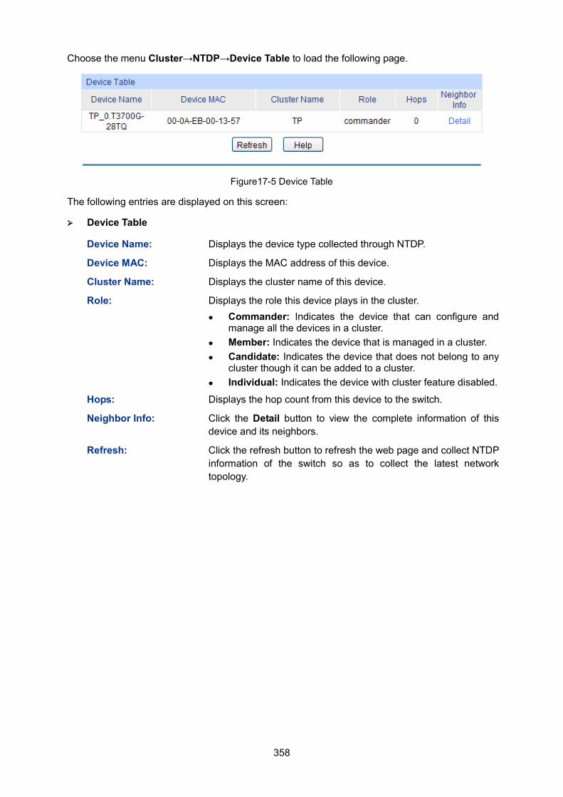
358
Choose the menu Cluster→NTDP→Device Table to load the following page.
Figure17-5 Device Table
The following entries are displayed on this screen:
Device Table
Device Name: Displays the device type collected through NTDP.
Device MAC: Displays the MAC address of this device.
Cluster Name: Displays the cluster name of this device.
Role: Displays the role this device plays in the cluster. Commander: Indicates the device that can configure and
manage all the devices in a cluster. Member: Indicates the device that is managed in a cluster. Candidate: Indicates the device that does not belong to any
cluster though it can be added to a cluster. Individual: Indicates the device with cluster feature disabled.
Hops: Displays the hop count from this device to the switch.
Neighbor Info: Click the Detail button to view the complete information of this device and its neighbors.
Refresh: Click the refresh button to refresh the web page and collect NTDP information of the switch so as to collect the latest network topology.
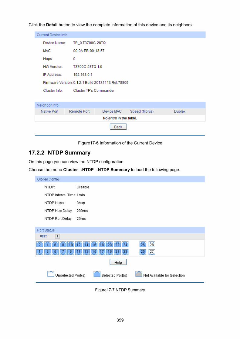
359
Click the Detail button to view the complete information of this device and its neighbors.
Figure17-6 Information of the Current Device
17.2.2 NTDP Summary On this page you can view the NTDP configuration.
Choose the menu Cluster→NTDP→NTDP Summary to load the following page.
Figure17-7 NTDP Summary
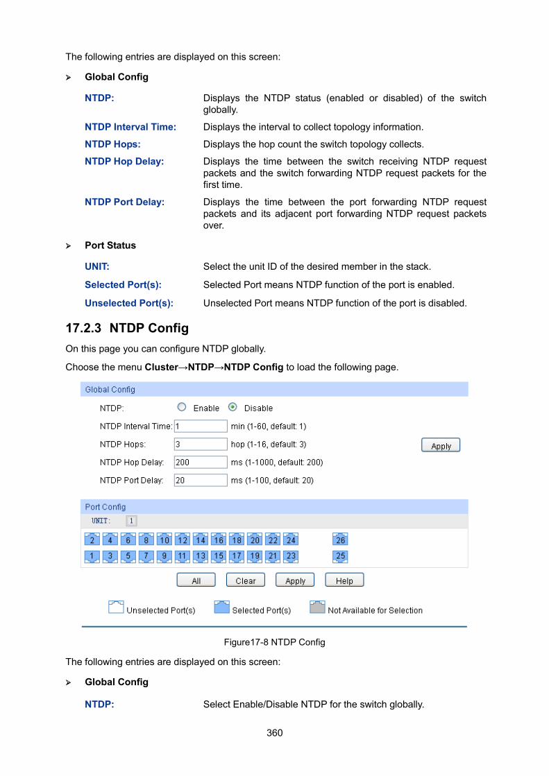
360
The following entries are displayed on this screen:
Global Config
NTDP: Displays the NTDP status (enabled or disabled) of the switch globally.
NTDP Interval Time: Displays the interval to collect topology information.
NTDP Hops: Displays the hop count the switch topology collects.
NTDP Hop Delay: Displays the time between the switch receiving NTDP request packets and the switch forwarding NTDP request packets for the first time.
NTDP Port Delay: Displays the time between the port forwarding NTDP request packets and its adjacent port forwarding NTDP request packets over.
Port Status
UNIT: Select the unit ID of the desired member in the stack.
Selected Port(s): Selected Port means NTDP function of the port is enabled.
Unselected Port(s): Unselected Port means NTDP function of the port is disabled.
17.2.3 NTDP Config On this page you can configure NTDP globally.
Choose the menu Cluster→NTDP→NTDP Config to load the following page.
Figure17-8 NTDP Config
The following entries are displayed on this screen:
Global Config
NTDP: Select Enable/Disable NTDP for the switch globally.
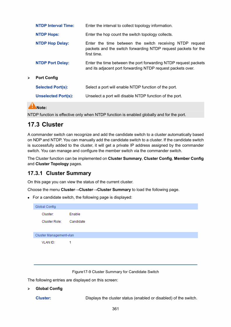
361
NTDP Interval Time: Enter the interval to collect topology information.
NTDP Hops: Enter the hop count the switch topology collects.
NTDP Hop Delay: Enter the time between the switch receiving NTDP request packets and the switch forwarding NTDP request packets for the first time.
NTDP Port Delay: Enter the time between the port forwarding NTDP request packets and its adjacent port forwarding NTDP request packets over.
Port Config
Selected Port(s): Select a port will enable NTDP function of the port.
Unselected Port(s): Unselect a port will disable NTDP function of the port.
Note: NTDP function is effective only when NTDP function is enabled globally and for the port.
17.3 Cluster A commander switch can recognize and add the candidate switch to a cluster automatically based on NDP and NTDP. You can manually add the candidate switch to a cluster. If the candidate switch is successfully added to the cluster, it will get a private IP address assigned by the commander switch. You can manage and configure the member switch via the commander switch.
The Cluster function can be implemented on Cluster Summary, Cluster Config, Member Config and Cluster Topology pages.
17.3.1 Cluster Summary On this page you can view the status of the current cluster.
Choose the menu Cluster→Cluster→Cluster Summary to load the following page.
For a candidate switch, the following page is displayed:
Figure17-9 Cluster Summary for Candidate Switch
The following entries are displayed on this screen:
Global Config
Cluster: Displays the cluster status (enabled or disabled) of the switch.
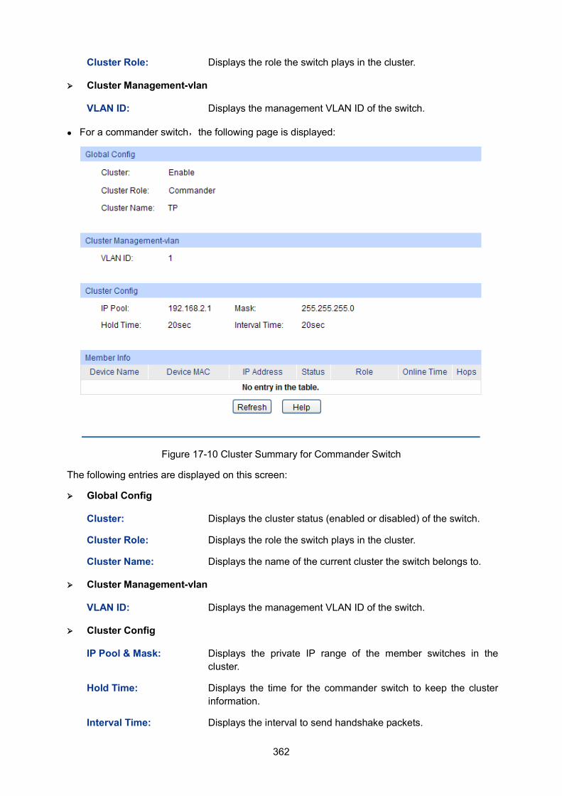
362
Cluster Role: Displays the role the switch plays in the cluster.
Cluster Management-vlan
VLAN ID: Displays the management VLAN ID of the switch.
For a commander switch,the following page is displayed:
Figure 17-10 Cluster Summary for Commander Switch
The following entries are displayed on this screen:
Global Config
Cluster: Displays the cluster status (enabled or disabled) of the switch.
Cluster Role: Displays the role the switch plays in the cluster.
Cluster Name: Displays the name of the current cluster the switch belongs to.
Cluster Management-vlan
VLAN ID: Displays the management VLAN ID of the switch.
Cluster Config
IP Pool & Mask: Displays the private IP range of the member switches in the cluster.
Hold Time: Displays the time for the commander switch to keep the cluster information.
Interval Time: Displays the interval to send handshake packets.
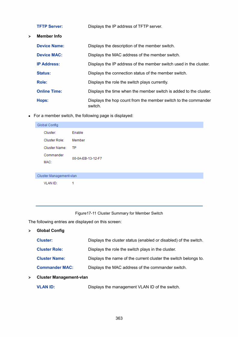
363
TFTP Server: Displays the IP address of TFTP server.
Member Info
Device Name: Displays the description of the member switch.
Device MAC: Displays the MAC address of the member switch.
IP Address: Displays the IP address of the member switch used in the cluster.
Status: Displays the connection status of the member switch.
Role: Displays the role the switch plays currently.
Online Time: Displays the time when the member switch is added to the cluster.
Hops: Displays the hop count from the member switch to the commander switch.
For a member switch, the following page is displayed:
Figure17-11 Cluster Summary for Member Switch
The following entries are displayed on this screen:
Global Config
Cluster: Displays the cluster status (enabled or disabled) of the switch.
Cluster Role: Displays the role the switch plays in the cluster.
Cluster Name: Displays the name of the current cluster the switch belongs to.
Commander MAC: Displays the MAC address of the commander switch.
Cluster Management-vlan
VLAN ID: Displays the management VLAN ID of the switch.
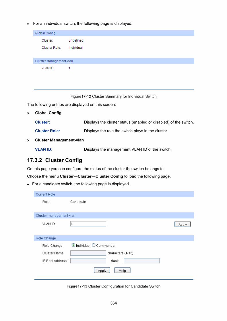
364
For an individual switch, the following page is displayed:
Figure17-12 Cluster Summary for Individual Switch
The following entries are displayed on this screen:
Global Config
Cluster: Displays the cluster status (enabled or disabled) of the switch.
Cluster Role: Displays the role the switch plays in the cluster.
Cluster Management-vlan
VLAN ID: Displays the management VLAN ID of the switch.
17.3.2 Cluster Config On this page you can configure the status of the cluster the switch belongs to.
Choose the menu Cluster→Cluster→Cluster Config to load the following page.
For a candidate switch, the following page is displayed.
Figure17-13 Cluster Configuration for Candidate Switch
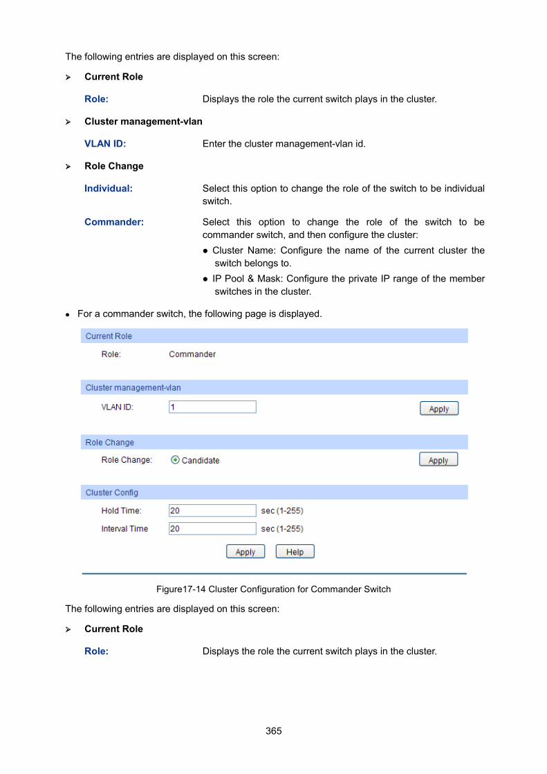
365
The following entries are displayed on this screen:
Current Role
Role: Displays the role the current switch plays in the cluster.
Cluster management-vlan
VLAN ID: Enter the cluster management-vlan id.
Role Change
Individual: Select this option to change the role of the switch to be individual switch.
Commander: Select this option to change the role of the switch to be commander switch, and then configure the cluster: Cluster Name: Configure the name of the current cluster the
switch belongs to. IP Pool & Mask: Configure the private IP range of the member
switches in the cluster.
For a commander switch, the following page is displayed.
Figure17-14 Cluster Configuration for Commander Switch
The following entries are displayed on this screen:
Current Role
Role: Displays the role the current switch plays in the cluster.
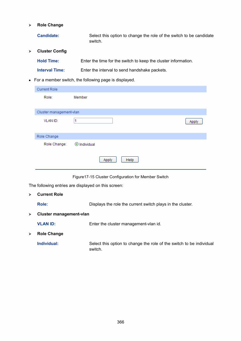
366
Role Change
Candidate: Select this option to change the role of the switch to be candidate switch.
Cluster Config
Hold Time: Enter the time for the switch to keep the cluster information.
Interval Time: Enter the interval to send handshake packets.
For a member switch, the following page is displayed.
Figure17-15 Cluster Configuration for Member Switch
The following entries are displayed on this screen:
Current Role
Role: Displays the role the current switch plays in the cluster.
Cluster management-vlan
VLAN ID: Enter the cluster management-vlan id.
Role Change
Individual: Select this option to change the role of the switch to be individual switch.
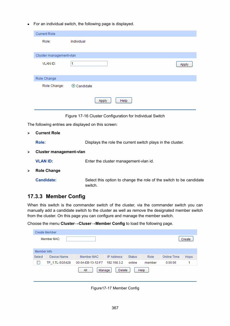
367
For an individual switch, the following page is displayed.
Figure 17-16 Cluster Configuration for Individual Switch
The following entries are displayed on this screen:
Current Role
Role: Displays the role the current switch plays in the cluster.
Cluster management-vlan
VLAN ID: Enter the cluster management-vlan id.
Role Change
Candidate: Select this option to change the role of the switch to be candidate switch.
17.3.3 Member Config When this switch is the commander switch of the cluster, via the commander switch you can manually add a candidate switch to the cluster as well as remove the designated member switch from the cluster. On this page you can configure and manage the member switch.
Choose the menu Cluster→Cluser→Member Config to load the following page.
Figure17-17 Member Config
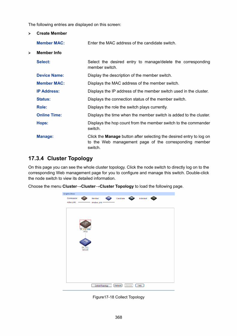
368
The following entries are displayed on this screen:
Create Member
Member MAC: Enter the MAC address of the candidate switch.
Member Info
Select: Select the desired entry to manage/delete the corresponding member switch.
Device Name: Display the description of the member switch.
Member MAC: Displays the MAC address of the member switch.
IP Address: Displays the IP address of the member switch used in the cluster.
Status: Displays the connection status of the member switch.
Role: Displays the role the switch plays currently.
Online Time: Displays the time when the member switch is added to the cluster.
Hops: Displays the hop count from the member switch to the commander switch.
Manage: Click the Manage button after selecting the desired entry to log on to the Web management page of the corresponding member switch.
17.3.4 Cluster Topology On this page you can see the whole cluster topology. Click the node switch to directly log on to the corresponding Web management page for you to configure and manage this switch. Double-click the node switch to view its detailed information.
Choose the menu Cluster→Cluster→Cluster Topology to load the following page.
Figure17-18 Collect Topology
369
The following entries are displayed on this screen: Graphic Show
Collect Topology: Click the Collect Topology button to display the cluster topology.
Refresh: Click the Refresh button to refresh the cluster topology.
Manage: If the current device is the commander switch in the cluster and the selected device is a member switch in the cluster, you can click the Manage button to log on to Web management page of the corresponding switch.
Global configuration procedure of the Cluster function:
Before configuring a cluster, you should make clear the role each device will play in the cluster in advance and make sure the devices in the cluster can communicate with each other.
To configure the switch to be a commander switch in the cluster, please take the following steps.
Step Operation Description
1 Enable the NDP function globally and for the port, and then configure NDP parameters
Optional. On Cluster→NDP→NDP Config page, enable the NDP function on the switch.
2 Enable the NTDP function globally and for the port, and then configure NTDP parameters
Optional. On Cluster→NTDP→NTDP Config page, enable the NTDP function on the switch.
3 Establish a cluster and configure the related parameters
Optional. On Cluster→Cluster→Cluster Config page, establish a cluster and configure the related parameters.
4 Manage the device in the cluster
Optional. On Cluster→Cluster→Member Config page, select the desired member switches and click the Manage button to log on to its Web management page for configuration. Or On Cluster→Cluster→Collect Topology page, double- click the icon of the switch to view its detailed information; click the icon, and then click the Manage button to log on to its Web management page for configuration.
To configure the switch to be a member switch in the cluster, please take the following steps.
Step Operation Description
1 Enable the NDP function globally and for the port, and then configure NDP parameters
Optional. On Cluster→NDP→NDP Config page, enable the NDP function on the switch.
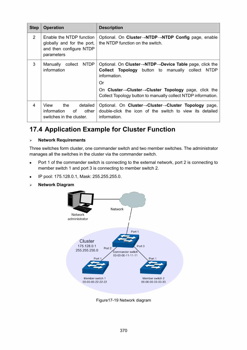
370
Step Operation Description
2 Enable the NTDP function globally and for the port, and then configure NTDP parameters
Optional. On Cluster→NTDP→NTDP Config page, enable the NTDP function on the switch.
3 Manually collect NTDP information
Optional. On Cluster→NTDP→Device Table page, click the Collect Topology button to manually collect NTDP information. Or On Cluster→Cluster→Cluster Topology page, click the Collect Topology button to manually collect NTDP information.
4 View the detailed information of other switches in the cluster.
Optional. On Cluster→Cluster→Cluster Topology page, double-click the icon of the switch to view its detailed information.
17.4 Application Example for Cluster Function Network Requirements
Three switches form cluster, one commander switch and two member switches. The administrator manages all the switches in the cluster via the commander switch.
Port 1 of the commander switch is connecting to the external network, port 2 is connecting to member switch 1 and port 3 is connecting to member switch 2.
IP pool: 175.128.0.1, Mask: 255.255.255.0.
Network Diagram
Figure17-19 Network diagram
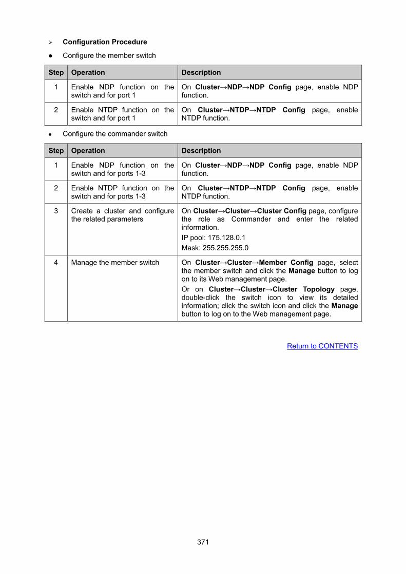
371
Configuration Procedure
Configure the member switch
Step Operation Description
1 Enable NDP function on the switch and for port 1
On Cluster→NDP→NDP Config page, enable NDP function.
2 Enable NTDP function on the switch and for port 1
On Cluster→NTDP→NTDP Config page, enable NTDP function.
Configure the commander switch
Step Operation Description
1 Enable NDP function on the switch and for ports 1-3
On Cluster→NDP→NDP Config page, enable NDP function.
2 Enable NTDP function on the switch and for ports 1-3
On Cluster→NTDP→NTDP Config page, enable NTDP function.
3 Create a cluster and configure the related parameters
On Cluster→Cluster→Cluster Config page, configure the role as Commander and enter the related information. IP pool: 175.128.0.1 Mask: 255.255.255.0
4 Manage the member switch On Cluster→Cluster→Member Config page, select the member switch and click the Manage button to log on to its Web management page. Or on Cluster→Cluster→Cluster Topology page, double-click the switch icon to view its detailed information; click the switch icon and click the Manage button to log on to the Web management page.
Return to CONTENTS
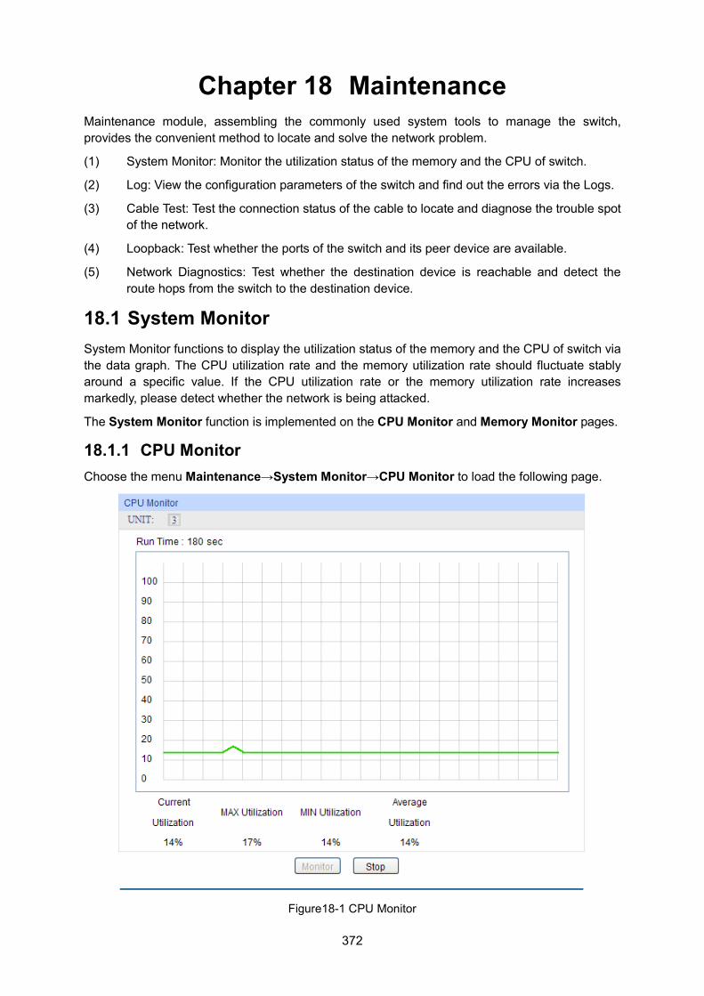
372
Chapter 18 Maintenance Maintenance module, assembling the commonly used system tools to manage the switch, provides the convenient method to locate and solve the network problem.
(1) System Monitor: Monitor the utilization status of the memory and the CPU of switch.
(2) Log: View the configuration parameters of the switch and find out the errors via the Logs.
(3) Cable Test: Test the connection status of the cable to locate and diagnose the trouble spot of the network.
(4) Loopback: Test whether the ports of the switch and its peer device are available.
(5) Network Diagnostics: Test whether the destination device is reachable and detect the route hops from the switch to the destination device.
18.1 System Monitor System Monitor functions to display the utilization status of the memory and the CPU of switch via the data graph. The CPU utilization rate and the memory utilization rate should fluctuate stably around a specific value. If the CPU utilization rate or the memory utilization rate increases markedly, please detect whether the network is being attacked.
The System Monitor function is implemented on the CPU Monitor and Memory Monitor pages.
18.1.1 CPU Monitor Choose the menu Maintenance→System Monitor→CPU Monitor to load the following page.
Figure18-1 CPU Monitor
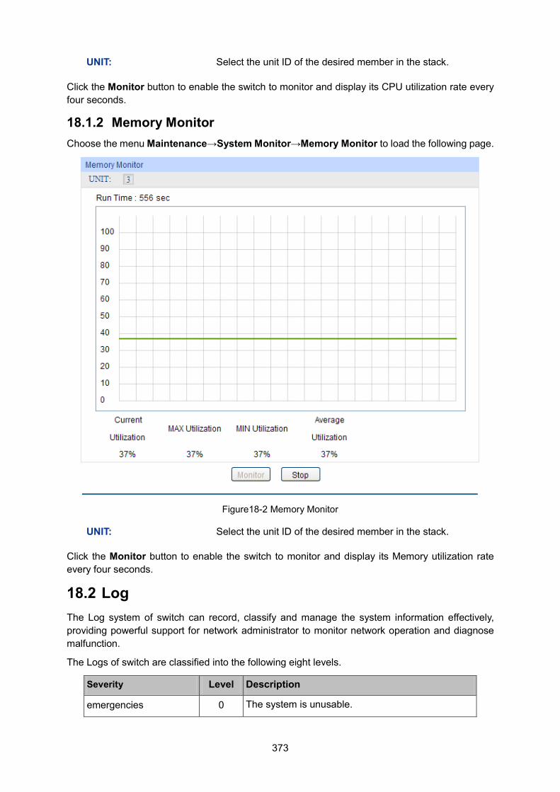
373
UNIT: Select the unit ID of the desired member in the stack.
Click the Monitor button to enable the switch to monitor and display its CPU utilization rate every four seconds.
18.1.2 Memory Monitor Choose the menu Maintenance→System Monitor→Memory Monitor to load the following page.
Figure18-2 Memory Monitor
UNIT: Select the unit ID of the desired member in the stack.
Click the Monitor button to enable the switch to monitor and display its Memory utilization rate every four seconds.
18.2 Log The Log system of switch can record, classify and manage the system information effectively, providing powerful support for network administrator to monitor network operation and diagnose malfunction.
The Logs of switch are classified into the following eight levels.
Severity Level Description
emergencies 0 The system is unusable.
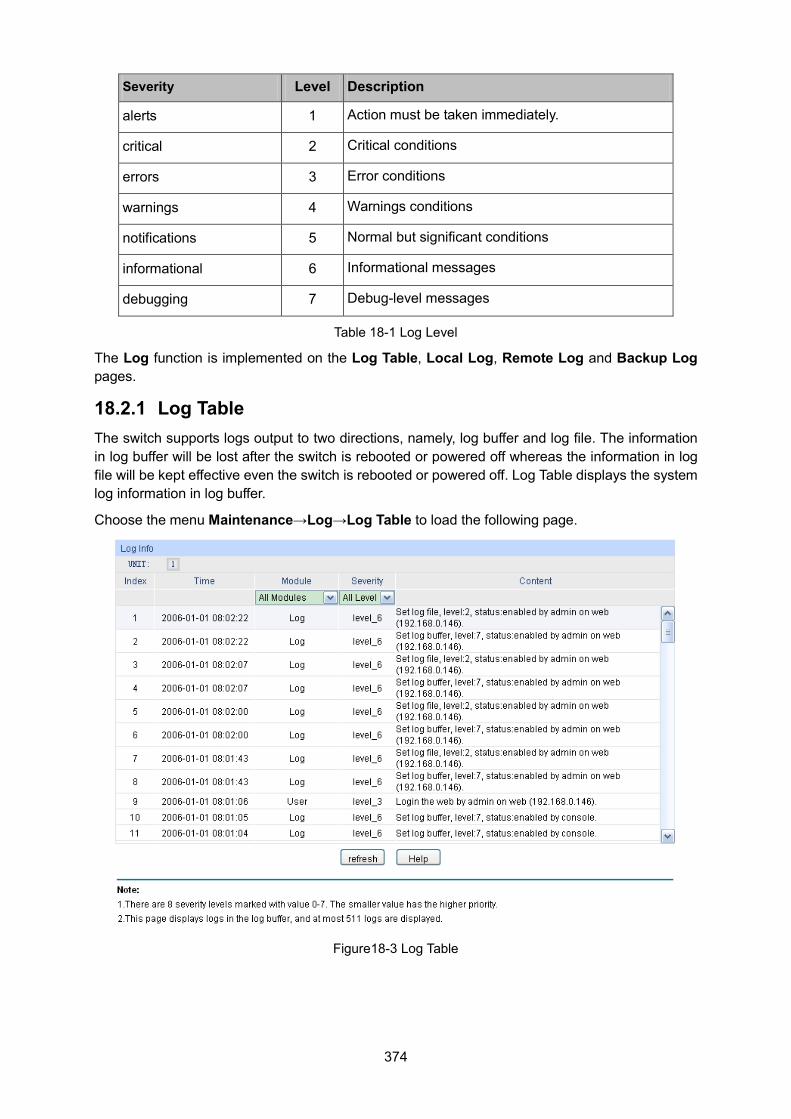
374
Severity Level Description
alerts 1 Action must be taken immediately.
critical 2 Critical conditions
errors 3 Error conditions
warnings 4 Warnings conditions
notifications 5 Normal but significant conditions
informational 6 Informational messages
debugging 7 Debug-level messages
Table 18-1 Log Level
The Log function is implemented on the Log Table, Local Log, Remote Log and Backup Log pages.
18.2.1 Log Table The switch supports logs output to two directions, namely, log buffer and log file. The information in log buffer will be lost after the switch is rebooted or powered off whereas the information in log file will be kept effective even the switch is rebooted or powered off. Log Table displays the system log information in log buffer.
Choose the menu Maintenance→Log→Log Table to load the following page.
Figure18-3 Log Table
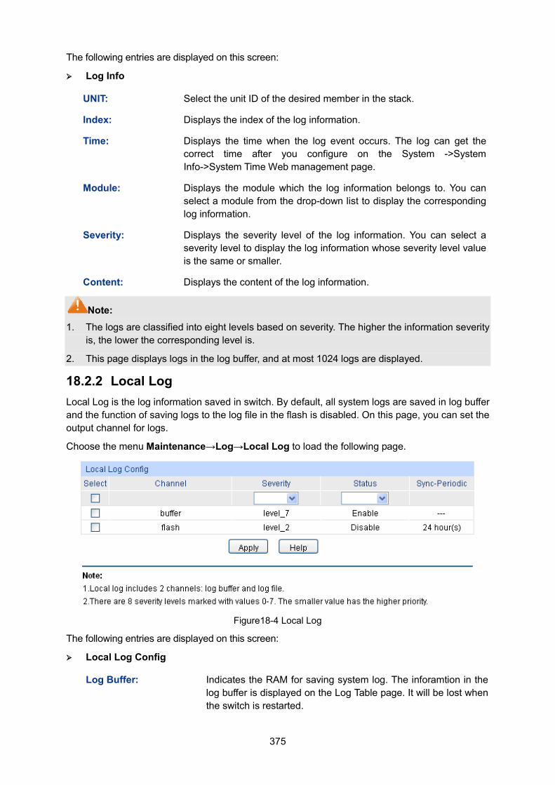
375
The following entries are displayed on this screen: Log Info
UNIT: Select the unit ID of the desired member in the stack.
Index: Displays the index of the log information.
Time: Displays the time when the log event occurs. The log can get the correct time after you configure on the System ->System Info->System Time Web management page.
Module: Displays the module which the log information belongs to. You can select a module from the drop-down list to display the corresponding log information.
Severity: Displays the severity level of the log information. You can select a severity level to display the log information whose severity level value is the same or smaller.
Content: Displays the content of the log information.
Note: 1. The logs are classified into eight levels based on severity. The higher the information severity
is, the lower the corresponding level is.
2. This page displays logs in the log buffer, and at most 1024 logs are displayed.
18.2.2 Local Log Local Log is the log information saved in switch. By default, all system logs are saved in log buffer and the function of saving logs to the log file in the flash is disabled. On this page, you can set the output channel for logs.
Choose the menu Maintenance→Log→Local Log to load the following page.
Figure18-4 Local Log
The following entries are displayed on this screen: Local Log Config
Log Buffer: Indicates the RAM for saving system log. The inforamtion in the log buffer is displayed on the Log Table page. It will be lost when the switch is restarted.
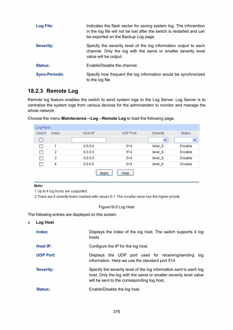
376
Log File: Indicates the flash sector for saving system log. The inforamtion in the log file will not be lost after the switch is restarted and can be exported on the Backup Log page.
Severity: Specify the severity level of the log information output to each channel. Only the log with the same or smaller severity level value will be output.
Status: Enable/Disable the channel.
Sync-Periodic Specify how frequent the log information would be synchronized to the log file.
18.2.3 Remote Log Remote log feature enables the switch to send system logs to the Log Server. Log Server is to centralize the system logs from various devices for the administrator to monitor and manage the whole network.
Choose the menu Maintenance→Log→Remote Log to load the following page.
Figure18-5 Log Host
The following entries are displayed on this screen: Log Host
Index: Displays the index of the log host. The switch supports 4 log hosts.
Host IP: Configure the IP for the log host.
UDP Port: Displays the UDP port used for receiving/sending log information. Here we use the standard port 514.
Severity: Specify the severity level of the log information sent to each log host. Only the log with the same or smaller severity level value will be sent to the corresponding log host.
Status: Enable/Disable the log host.
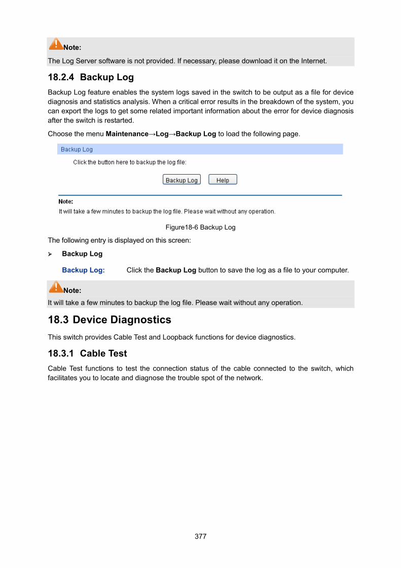
377
Note:
The Log Server software is not provided. If necessary, please download it on the Internet.
18.2.4 Backup Log Backup Log feature enables the system logs saved in the switch to be output as a file for device diagnosis and statistics analysis. When a critical error results in the breakdown of the system, you can export the logs to get some related important information about the error for device diagnosis after the switch is restarted.
Choose the menu Maintenance→Log→Backup Log to load the following page.
Figure18-6 Backup Log
The following entry is displayed on this screen:
Backup Log
Backup Log: Click the Backup Log button to save the log as a file to your computer.
Note: It will take a few minutes to backup the log file. Please wait without any operation.
18.3 Device Diagnostics This switch provides Cable Test and Loopback functions for device diagnostics.
18.3.1 Cable Test Cable Test functions to test the connection status of the cable connected to the switch, which facilitates you to locate and diagnose the trouble spot of the network.
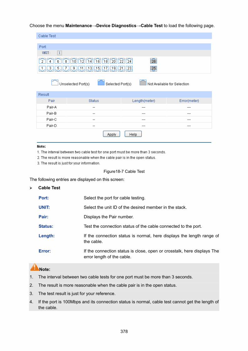
378
Choose the menu Maintenance→Device Diagnostics→Cable Test to load the following page.
Figure18-7 Cable Test
The following entries are displayed on this screen: Cable Test
Port: Select the port for cable testing.
UNIT: Select the unit ID of the desired member in the stack.
Pair: Displays the Pair number.
Status: Test the connection status of the cable connected to the port.
Length: If the connection status is normal, here displays the length range of the cable.
Error: If the connection status is close, open or crosstalk, here displays The error length of the cable.
Note: 1. The interval between two cable tests for one port must be more than 3 seconds.
2. The result is more reasonable when the cable pair is in the open status.
3. The test result is just for your reference.
4. If the port is 100Mbps and its connection status is normal, cable test cannot get the length of the cable.
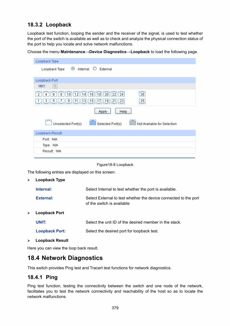
379
18.3.2 Loopback Loopback test function, looping the sender and the receiver of the signal, is used to test whether the port of the switch is available as well as to check and analyze the physical connection status of the port to help you locate and solve network malfunctions.
Choose the menu Maintenance→Device Diagnostics→Loopback to load the following page.
Figure18-8 Loopback
The following entries are displayed on this screen: Loopback Type
Internal: Select Internal to test whether the port is available.
External: Select External to test whether the device connected to the port of the switch is available
Loopback Port
UNIT: Select the unit ID of the desired member in the stack.
Loopback Port: Select the desired port for loopback test.
Loopback Result
Here you can view the loop back result.
18.4 Network Diagnostics This switch provides Ping test and Tracert test functions for network diagnostics.
18.4.1 Ping Ping test function, testing the connectivity between the switch and one node of the network, facilitates you to test the network connectivity and reachability of the host so as to locate the network malfunctions.
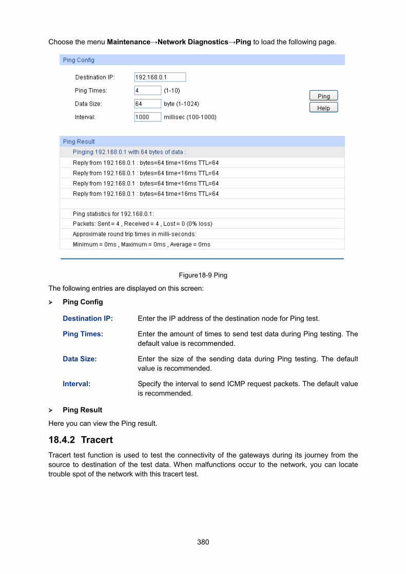
380
Choose the menu Maintenance→Network Diagnostics→Ping to load the following page.
Figure18-9 Ping
The following entries are displayed on this screen: Ping Config
Destination IP: Enter the IP address of the destination node for Ping test.
Ping Times: Enter the amount of times to send test data during Ping testing. The default value is recommended.
Data Size: Enter the size of the sending data during Ping testing. The default value is recommended.
Interval: Specify the interval to send ICMP request packets. The default value is recommended.
Ping Result
Here you can view the Ping result.
18.4.2 Tracert Tracert test function is used to test the connectivity of the gateways during its journey from the source to destination of the test data. When malfunctions occur to the network, you can locate trouble spot of the network with this tracert test.
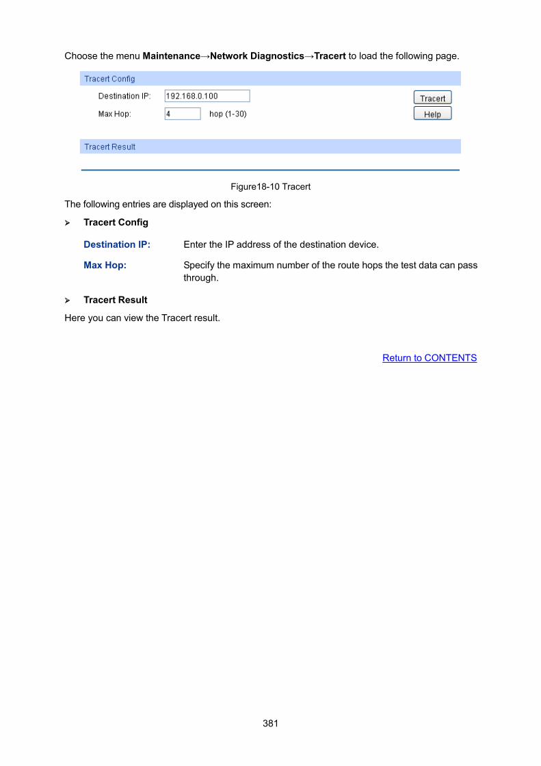
381
Choose the menu Maintenance→Network Diagnostics→Tracert to load the following page.
Figure18-10 Tracert
The following entries are displayed on this screen: Tracert Config
Destination IP: Enter the IP address of the destination device.
Max Hop: Specify the maximum number of the route hops the test data can pass through.
Tracert Result
Here you can view the Tracert result.
Return to CONTENTS
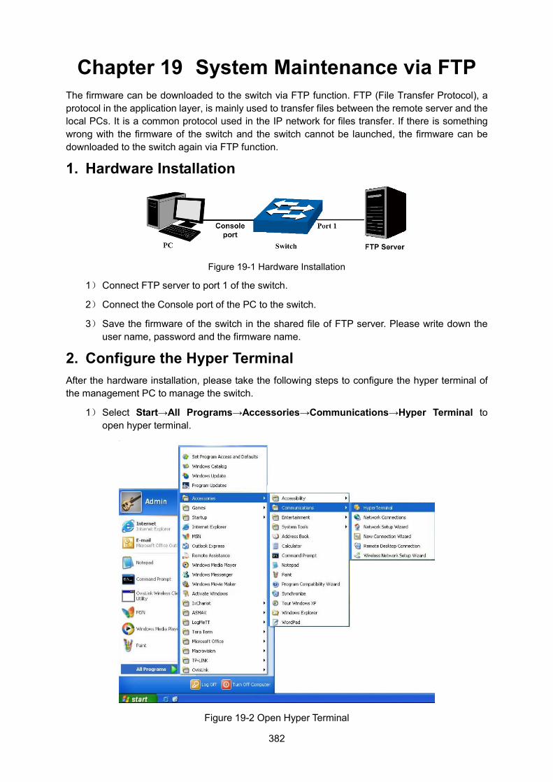
382
Chapter 19 System Maintenance via FTP The firmware can be downloaded to the switch via FTP function. FTP (File Transfer Protocol), a protocol in the application layer, is mainly used to transfer files between the remote server and the local PCs. It is a common protocol used in the IP network for files transfer. If there is something wrong with the firmware of the switch and the switch cannot be launched, the firmware can be downloaded to the switch again via FTP function.
1. Hardware Installation
Figure 19-1 Hardware Installation
1) Connect FTP server to port 1 of the switch.
2) Connect the Console port of the PC to the switch.
3) Save the firmware of the switch in the shared file of FTP server. Please write down the user name, password and the firmware name.
2. Configure the Hyper Terminal After the hardware installation, please take the following steps to configure the hyper terminal of the management PC to manage the switch.
1) Select Start→All Programs→Accessories→Communications→Hyper Terminal to open hyper terminal.
Figure 19-2 Open Hyper Terminal
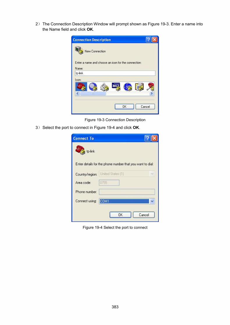
383
2) The Connection Description Window will prompt shown as Figure 19-3. Enter a name into the Name field and click OK.
Figure 19-3 Connection Description
3) Select the port to connect in Figure 19-4 and click OK.
Figure 19-4 Select the port to connect
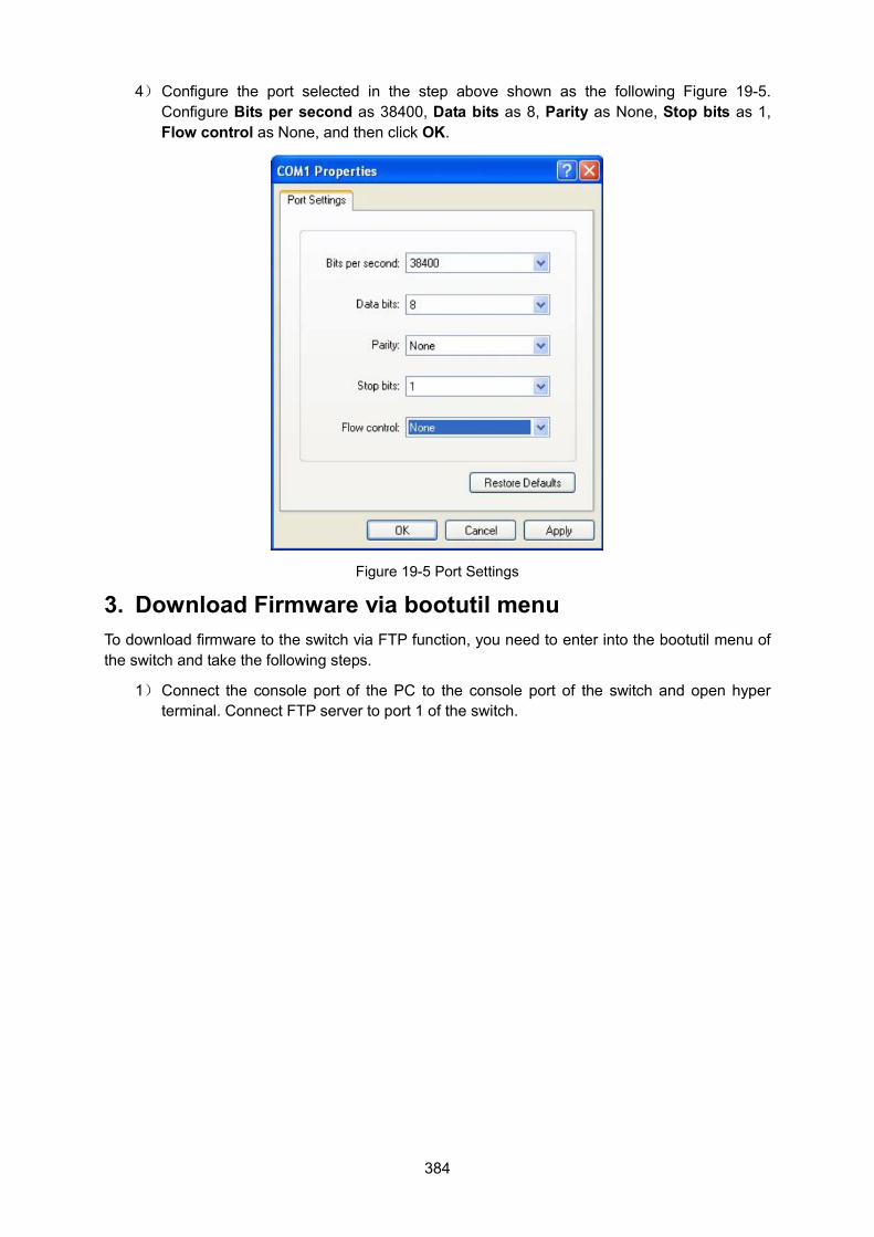
384
4) Configure the port selected in the step above shown as the following Figure 19-5. Configure Bits per second as 38400, Data bits as 8, Parity as None, Stop bits as 1, Flow control as None, and then click OK.
Figure 19-5 Port Settings
3. Download Firmware via bootutil menu To download firmware to the switch via FTP function, you need to enter into the bootutil menu of the switch and take the following steps.
1) Connect the console port of the PC to the console port of the switch and open hyper terminal. Connect FTP server to port 1 of the switch.
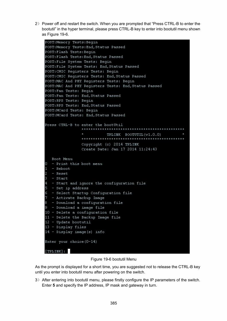
385
2) Power off and restart the switch. When you are prompted that “Press CTRL-B to enter the bootutil” in the hyper terminal, please press CTRL-B key to enter into bootutil menu shown as Figure 19-6.
Figure 19-6 bootutil Menu
As the prompt is displayed for a short time, you are suggested not to release the CTRL-B key until you enter into bootutil menu after powering on the switch.
3) After entering into bootutil menu, please firstly configure the IP parameters of the switch. Enter 5 and specify the IP address, IP mask and gateway in turn.
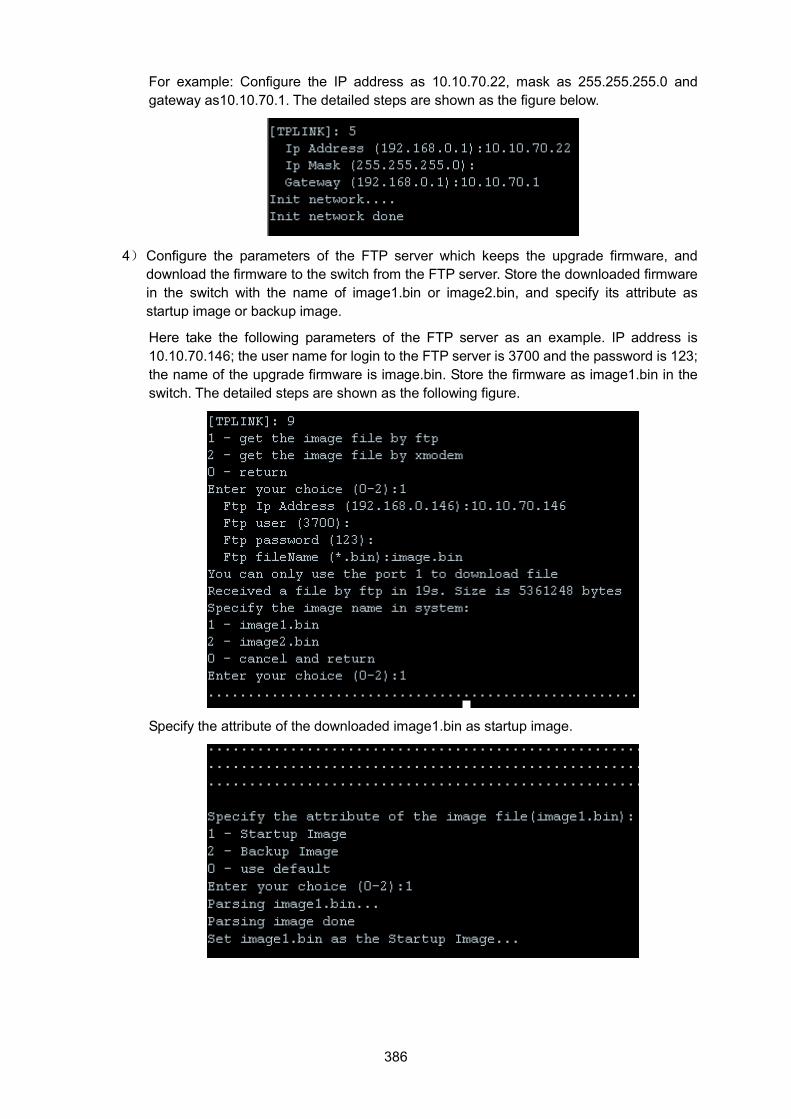
386
For example: Configure the IP address as 10.10.70.22, mask as 255.255.255.0 and gateway as10.10.70.1. The detailed steps are shown as the figure below.
4) Configure the parameters of the FTP server which keeps the upgrade firmware, and download the firmware to the switch from the FTP server. Store the downloaded firmware in the switch with the name of image1.bin or image2.bin, and specify its attribute as startup image or backup image.
Here take the following parameters of the FTP server as an example. IP address is 10.10.70.146; the user name for login to the FTP server is 3700 and the password is 123; the name of the upgrade firmware is image.bin. Store the firmware as image1.bin in the switch. The detailed steps are shown as the following figure.
Specify the attribute of the downloaded image1.bin as startup image.
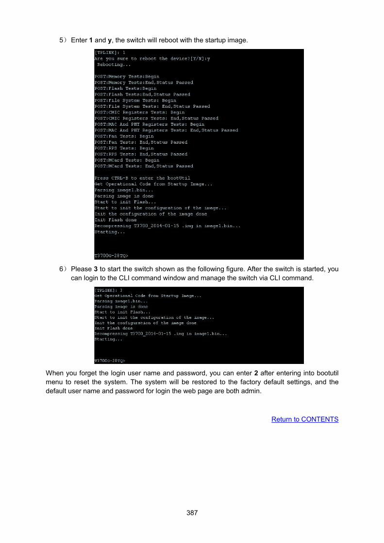
387
5) Enter 1 and y, the switch will reboot with the startup image.
6) Please 3 to start the switch shown as the following figure. After the switch is started, you can login to the CLI command window and manage the switch via CLI command.
When you forget the login user name and password, you can enter 2 after entering into bootutil menu to reset the system. The system will be restored to the factory default settings, and the default user name and password for login the web page are both admin.
Return to CONTENTS
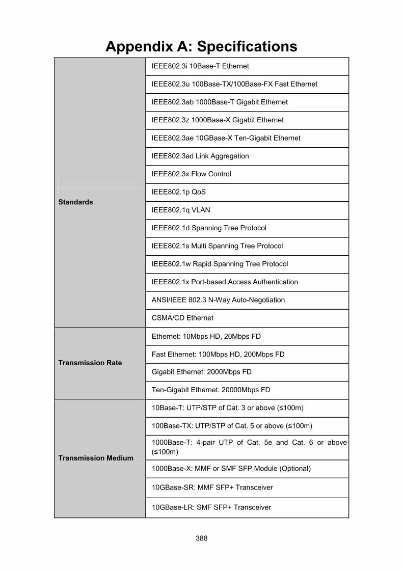
388
Appendix A: Specifications
Standards
IEEE802.3i 10Base-T Ethernet
IEEE802.3u 100Base-TX/100Base-FX Fast Ethernet
IEEE802.3ab 1000Base-T Gigabit Ethernet
IEEE802.3z 1000Base-X Gigabit Ethernet
IEEE802.3ae 10GBase-X Ten-Gigabit Ethernet
IEEE802.3ad Link Aggregation
IEEE802.3x Flow Control
IEEE802.1p QoS
IEEE802.1q VLAN
IEEE802.1d Spanning Tree Protocol
IEEE802.1s Multi Spanning Tree Protocol
IEEE802.1w Rapid Spanning Tree Protocol
IEEE802.1x Port-based Access Authentication
ANSI/IEEE 802.3 N-Way Auto-Negotiation
CSMA/CD Ethernet
Transmission Rate
Ethernet: 10Mbps HD, 20Mbps FD
Fast Ethernet: 100Mbps HD, 200Mbps FD
Gigabit Ethernet: 2000Mbps FD
Ten-Gigabit Ethernet: 20000Mbps FD
Transmission Medium
10Base-T: UTP/STP of Cat. 3 or above (≤100m)
100Base-TX: UTP/STP of Cat. 5 or above (≤100m)
1000Base-T: 4-pair UTP of Cat. 5e and Cat. 6 or above (≤100m)
1000Base-X: MMF or SMF SFP Module (Optional)
10GBase-SR: MMF SFP+ Transceiver
10GBase-LR: SMF SFP+ Transceiver
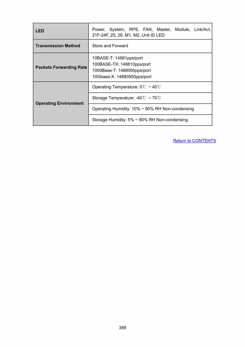
389
LED Power, System, RPS, FAN, Master, Module, Link/Act, 21F-24F, 25, 26, M1, M2, Unit ID LED
Transmission Method Store and Forward
Packets Forwarding Rate
10BASE-T: 14881pps/port 100BASE-TX: 148810pps/port 1000Base-T: 1488095pps/port 10Gbase-X: 14880950pps/port
Operating Environment
Operating Temperature: 0℃ ~ 40℃
Storage Temperature: -40℃ ~ 70℃
Operating Humidity: 10% ~ 90% RH Non-condensing
Storage Humidity: 5% ~ 90% RH Non-condensing
Return to CONTENTS
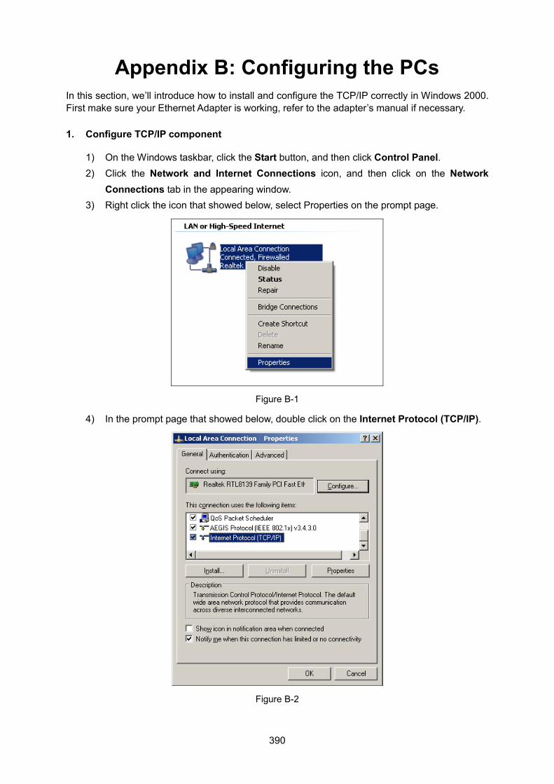
390
Appendix B: Configuring the PCs In this section, we’ll introduce how to install and configure the TCP/IP correctly in Windows 2000. First make sure your Ethernet Adapter is working, refer to the adapter’s manual if necessary.
1. Configure TCP/IP component
1) On the Windows taskbar, click the Start button, and then click Control Panel. 2) Click the Network and Internet Connections icon, and then click on the Network
Connections tab in the appearing window. 3) Right click the icon that showed below, select Properties on the prompt page.
Figure B-1
4) In the prompt page that showed below, double click on the Internet Protocol (TCP/IP).
Figure B-2
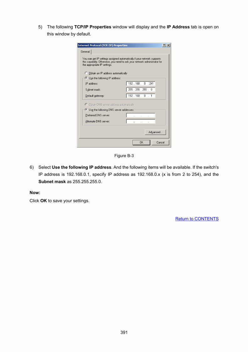
391
5) The following TCP/IP Properties window will display and the IP Address tab is open on this window by default.
Figure B-3
6) Select Use the following IP address. And the following items will be available. If the switch's IP address is 192.168.0.1, specify IP address as 192.168.0.x (x is from 2 to 254), and the Subnet mask as 255.255.255.0.
Now:
Click OK to save your settings.
Return to CONTENTS
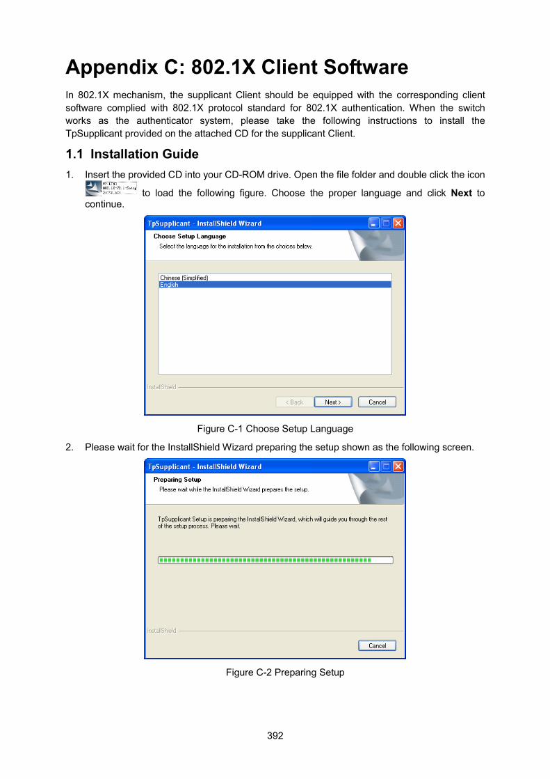
392
Appendix C: 802.1X Client Software In 802.1X mechanism, the supplicant Client should be equipped with the corresponding client software complied with 802.1X protocol standard for 802.1X authentication. When the switch works as the authenticator system, please take the following instructions to install the TpSupplicant provided on the attached CD for the supplicant Client.
1.1 Installation Guide 1. Insert the provided CD into your CD-ROM drive. Open the file folder and double click the icon
to load the following figure. Choose the proper language and click Next to continue.
Figure C-1 Choose Setup Language
2. Please wait for the InstallShield Wizard preparing the setup shown as the following screen.
Figure C-2 Preparing Setup
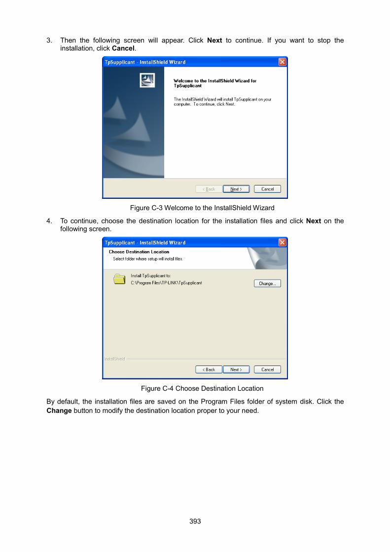
393
3. Then the following screen will appear. Click Next to continue. If you want to stop the installation, click Cancel.
Figure C-3 Welcome to the InstallShield Wizard
4. To continue, choose the destination location for the installation files and click Next on the following screen.
Figure C-4 Choose Destination Location
By default, the installation files are saved on the Program Files folder of system disk. Click the Change button to modify the destination location proper to your need.
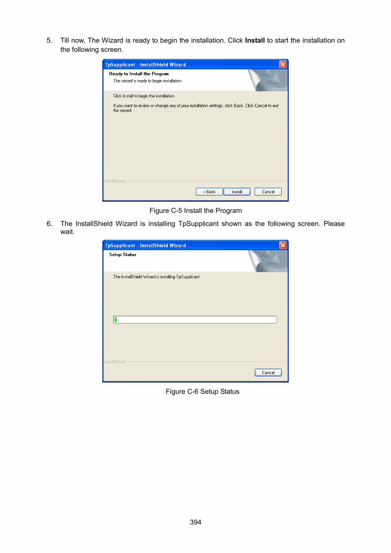
394
5. Till now, The Wizard is ready to begin the installation. Click Install to start the installation on the following screen.
Figure C-5 Install the Program
6. The InstallShield Wizard is installing TpSupplicant shown as the following screen. Please wait.
Figure C-6 Setup Status
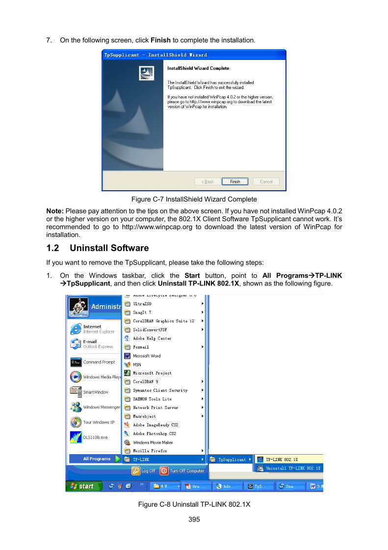
395
7. On the following screen, click Finish to complete the installation.
Figure C-7 InstallShield Wizard Complete
Note: Please pay attention to the tips on the above screen. If you have not installed WinPcap 4.0.2 or the higher version on your computer, the 802.1X Client Software TpSupplicant cannot work. It’s recommended to go to http://www.winpcap.org to download the latest version of WinPcap for installation.
1.2 Uninstall Software If you want to remove the TpSupplicant, please take the following steps:
1. On the Windows taskbar, click the Start button, point to All ProgramsTP-LINK TpSupplicant, and then click Uninstall TP-LINK 802.1X, shown as the following figure.
Figure C-8 Uninstall TP-LINK 802.1X
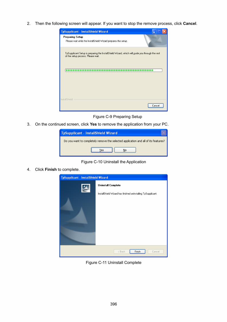
396
2. Then the following screen will appear. If you want to stop the remove process, click Cancel.
Figure C-9 Preparing Setup
3. On the continued screen, click Yes to remove the application from your PC.
Figure C-10 Uninstall the Application
4. Click Finish to complete.
Figure C-11 Uninstall Complete
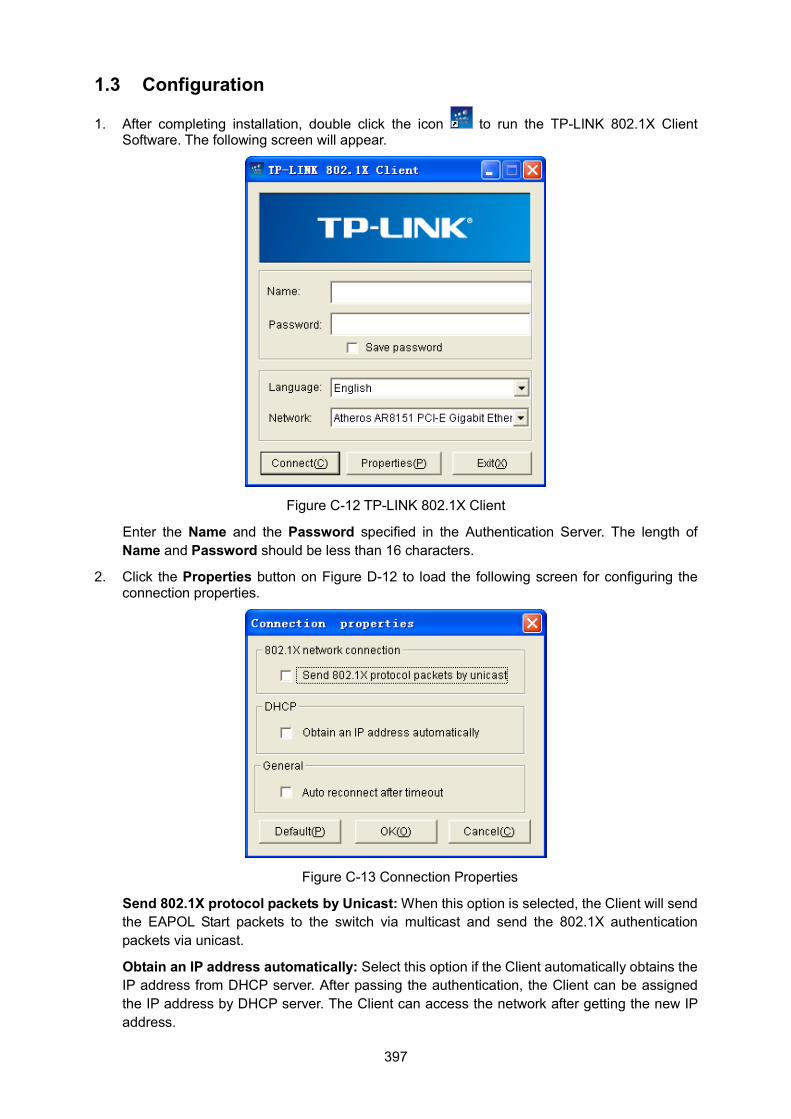
397
1.3 Configuration
1. After completing installation, double click the icon to run the TP-LINK 802.1X Client Software. The following screen will appear.
Figure C-12 TP-LINK 802.1X Client
Enter the Name and the Password specified in the Authentication Server. The length of Name and Password should be less than 16 characters.
2. Click the Properties button on Figure D-12 to load the following screen for configuring the connection properties.
Figure C-13 Connection Properties
Send 802.1X protocol packets by Unicast: When this option is selected, the Client will send the EAPOL Start packets to the switch via multicast and send the 802.1X authentication packets via unicast.
Obtain an IP address automatically: Select this option if the Client automatically obtains the IP address from DHCP server. After passing the authentication, the Client can be assigned the IP address by DHCP server. The Client can access the network after getting the new IP address.
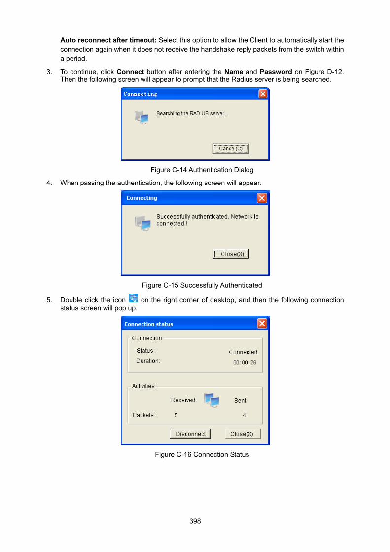
398
Auto reconnect after timeout: Select this option to allow the Client to automatically start the connection again when it does not receive the handshake reply packets from the switch within a period.
3. To continue, click Connect button after entering the Name and Password on Figure D-12. Then the following screen will appear to prompt that the Radius server is being searched.
Figure C-14 Authentication Dialog
4. When passing the authentication, the following screen will appear.
Figure C-15 Successfully Authenticated
5. Double click the icon on the right corner of desktop, and then the following connection status screen will pop up.
Figure C-16 Connection Status
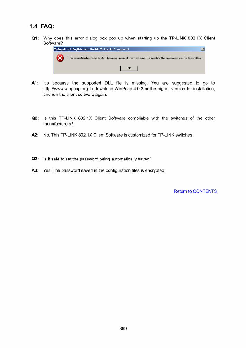
399
1.4 FAQ:
Q1: Why does this error dialog box pop up when starting up the TP-LINK 802.1X Client Software?
A1: It’s because the supported DLL file is missing. You are suggested to go to http://www.winpcap.org to download WinPcap 4.0.2 or the higher version for installation, and run the client software again.
Q2: Is this TP-LINK 802.1X Client Software compliable with the switches of the other manufacturers?
A2: No. This TP-LINK 802.1X Client Software is customized for TP-LINK switches.
Q3: Is it safe to set the password being automatically saved?
A3: Yes. The password saved in the configuration files is encrypted.
Return to CONTENTS
400
Appendix D: Glossary Access Control List (ACL) ACLs can limit network traffic and restrict access to certain users or devices by checking each packet for certain IP or MAC (i.e., Layer 2) information.
Boot Protocol (BOOTP) BOOTP is used to provide bootup information for network devices, including IP address information, the address of the TFTP server that contains the devices system files, and the name of the boot file.
Class of Service (CoS) CoS is supported by prioritizing packets based on the required level of service, and then placing them in the appropriate output queue. Data is transmitted from the queues using weighted round-robin service to enforce priority service and prevent blockage of lower-level queues. Priority may be set according to the port default, the packet’s priority bit (in the VLAN tag), TCP/UDP port number, or DSCP priority bit.
Differentiated Services Code Point (DSCP) DSCP uses a six-bit tag to provide for up to 64 different forwarding behaviors. Based on network policies, different kinds of traffic can be marked for different kinds of forwarding. The DSCP bits are mapped to the Class of Service categories, and then into the output queues.
Domain Name Service (DNS) A system used for translating host names for network nodes into IP addresses.
Dynamic Host Control Protocol (DHCP) Provides a framework for passing configuration information to hosts on a TCP/IP network. DHCP is based on the Bootstrap Protocol (BOOTP), adding the capability of automatic allocation of reusable network addresses and additional configuration options.
Extensible Authentication Protocol over LAN (EAPOL) EAPOL is a client authentication protocol used by this switch to verify the network access rights for any device that is plugged into the switch. A user name and password is requested by the switch, and then passed to an authentication server (e.g., RADIUS) for verification. EAPOL is implemented as part of the IEEE 802.1X Port Authentication standard.
GARP VLAN Registration Protocol (GVRP) Defines a way for switches to exchange VLAN information in order to register necessary VLAN members on ports along the Spanning Tree so that VLANs defined in each switch can work automatically over a Spanning Tree network.
Generic Attribute Registration Protocol (GARP) The GARP provides a generic attribute dissemination capability that is used by participants in GARP Applications (GARP Participants) to register and de-register attribute values with other GARP Participants within a Bridged LAN. The definition of the attribute types, the values that they can carry, and the semantics that are associated with those values when registered, are specific to the operation of the GARP Application concerned.
401
Generic Multicast Registration Protocol (GMRP) GMRP allows network devices to register end stations with multicast groups. GMRP requires that any participating network devices or end stations comply with the IEEE 802.1p standard.
Group Attribute Registration Protocol (GARP) See Generic Attribute Registration Protocol.
IEEE 802.1D Specifies a general method for the operation of MAC bridges, including the Spanning Tree Protocol.
IEEE 802.1Q VLAN Tagging—Defines Ethernet frame tags which carry VLAN information. It allows switches to assign endstations to different virtual LANs, and defines a standard way for VLANs to communicate across switched networks.
IEEE 802.1p An IEEE standard for providing quality of service (QoS) in Ethernet networks. The standard uses packet tags that define up to eight traffic classes and allows switches to transmit packets based on the tagged priority value.
IEEE 802.1X Port Authentication controls access to the switch ports by requiring users to first enter a user ID and password for authentication.
IEEE 802.3ac Defines frame extensions for VLAN tagging.
IEEE 802.3x Defines Ethernet frame start/stop requests and timers used for flow control on full-duplex links. (Now incorporated in IEEE 802.3-2002)
Internet Group Management Protocol (IGMP) A protocol through which hosts can register with their local router for multicast services. If there is more than one multicast switch/router on a given subnetwork, one of the devices acts as the “querier” and assumes responsibility for keeping track of group membership.
IGMP Snooping Listening to IGMP Query and IGMP Report packets transferred between IP Multicast Routers and IP Multicast host groups to identify IP Multicast group members.
IGMP Query On each subnetwork, one IGMP-capable device will act as the querier — that is, the device that asks all hosts to report on the IP multicast groups they wish to join or to which they already belong. The elected querier will be the device with the lowest IP address in the subnetwork.
IP Multicast Filtering It is a feature to allow or deny the Client to add the specified multicast group.
Multicast Switching A process whereby the switch filters incoming multicast frames for services for which no attached host has registered, or forwards them to all ports contained within the designated multicast group.
402
Layer 2 Data Link layer in the ISO 7-Layer Data Communications Protocol. This is related directly to the hardware interface for network devices and passes on traffic based on MAC addresses.
Link Aggregation See Port Trunk.
Link Aggregation Control Protocol (LACP) Allows ports to automatically negotiate a trunked link with LACP-configured ports on another device.
Management Information Base (MIB) An acronym for Management Information Base. It is a set of database objects that contains information about a specific device.
MD5 Message-Digest Algorithm An algorithm that is used to create digital signatures. It is intended for use with 32 bit machines and is safer than the MD4 algorithm, which has been broken. MD5 is a one-way hash function, meaning that it takes a message and converts it into a fixed string of digits, also called a message digest.
Network Time Protocol (NTP) NTP provides the mechanisms to synchronize time across the network. The time servers operate in a hierarchical-master-slave configuration in order to synchronize local clocks within the subnet and to national time standards via wire or radio.
Port Authentication See IEEE 802.1X.
Port Mirroring A method whereby data on a target port is mirrored to a monitor port for troubleshooting with a logic analyzer or RMON probe. This allows data on the target port to be studied unobstructively.
Port Trunk Defines a network link aggregation and trunking method which specifies how to create a single high-speed logical link that combines several lower-speed physical links.
Remote Authentication Dial-in User Service (RADIUS) RADIUS is a logon authentication protocol that uses software running on a central server to control access to RADIUS-compliant devices on the network.
Remote Monitoring (RMON) RMON provides comprehensive network monitoring capabilities. It eliminates the polling required in standard SNMP, and can set alarms on a variety of traffic conditions, including specific error types.
Rapid Spanning Tree Protocol (RSTP) RSTP reduces the convergence time for network topology changes to about 10% of that required by the older IEEE 802.1D STP standard.
403
Secure Shell (SSH) A secure replacement for remote access functions, including Telnet. SSH can authenticate users with a cryptographic key, and encrypt data connections between management clients and the switch.
Simple Network Management Protocol (SNMP) The application protocol in the Internet suite of protocols which offers network management services.
Simple Network Time Protocol (SNTP) SNTP allows a device to set its internal clock based on periodic updates from a Network Time Protocol (NTP) server. Updates can be requested from a specific NTP server, or can be received via broadcasts sent by NTP servers.
Spanning Tree Algorithm (STA) A technology that checks your network for any loops. A loop can often occur in complicated or backup linked network systems. Spanning Tree detects and directs data along the shortest available path, maximizing the performance and efficiency of the network.
Telnet Defines a remote communication facility for interfacing to a terminal device over TCP/IP.
Transmission Control Protocol/Internet Protocol (TCP/IP) Protocol suite that includes TCP as the primary transport protocol, and IP as the network layer protocol.
Trivial File Transfer Protocol (TFTP) A TCP/IP protocol commonly used for software downloads.
User Datagram Protocol (UDP) UDP provides a datagram mode for packet-switched communications. It uses IP as the underlying transport mechanism to provide access to IP-like services. UDP packets are delivered just like IP packets – connection-less datagrams that may be discarded before reaching their targets. UDP is useful when TCP would be too complex, too slow, or just unnecessary.
Virtual LAN (VLAN) A Virtual LAN is a collection of network nodes that share the same collision domain regardless of their physical location or connection point in the network. A VLAN serves as a logical workgroup with no physical barriers, and allows users to share information and resources as though located on the same LAN.
Return to CONTENTS


![Fatal Fury - King of Fighters / Garou Densetsu - … CONTROL START BUTTON DIRECTIONAL BUTTON [D] A BUTTON B BUTTON DIRECTIONAL BUTTON [D] USING THE DIRECTIONALPAD [D] WHEN PLAYER'S](https://img.pdfslide.net/doc/110x75/5b39d8d37f8b9a310e8ee570/fatal-fury-king-of-fighters-garou-densetsu-control-start-button-directional.jpg)