Embed Size (px)
DESCRIPTION
MILLING Cero
Citation preview

Milling using Creo Parametric 2.0
T3908-390-02
Authored and published using
For PTC In
ternal
Use O
nly

Copyright © 2012 Parametric Technology Corporation. All Rights Reserved.Copyright for PTC software products is with Parametric Technology Corporation, its subsidiary companies (collectively “PTC”),and their respective licensors. This software is provided under written license agreement, contains valuable trade secrets andproprietary information, and is protected by the copyright laws of the United States and other countries. It may not be copiedor distributed in any form or medium, disclosed to third parties, or used in any manner not provided for in the software licensesagreement except with written prior approval from PTC.
UNAUTHORIZED USE OF SOFTWARE OR ITS DOCUMENTATION CAN RESULT IN CIVIL DAMAGES AND CRIMINALPROSECUTION.
User and training guides and related documentation from PTC is subject to the copyright laws of the United States and othercountries and is provided under a license agreement that restricts copying, disclosure, and use of such documentation. PTChereby grants to the licensed software user the right to make copies in printed form of this documentation if provided onsoftware media, but only for internal/personal use and in accordance with the license agreement under which the applicablesoftware is licensed. Any copy made shall include the PTC copyright notice and any other proprietary notice provided by PTC.Training materials may not be copied without the express written consent of PTC. This documentation may not be disclosed,transferred, modified, or reduced to any form, including electronic media, or transmitted or made publicly available by anymeans without the prior written consent of PTC and no authorization is granted to make copies for such purposes.
Information described herein is furnished for general information only, is subject to change without notice, and should not beconstrued as a warranty or commitment by PTC. PTC assumes no responsibility or liability for any errors or inaccuracies thatmay appear in this document.
For Important Copyright, Trademark, Patent and Licensing Information see backside of this guide.
For PTC In
ternal
Use O
nly

About PTC UniversityWelcome to PTC University!With an unmatched depth and breadth of product development knowledge, PTC University helpsyou realize the most value from PTC products. Only PTC University offers:• An innovative learning methodology – PTC’s Precision Learning Methodology is a provenproprietary approach used by PTC to develop and deliver learning solutions.
• Flexible Delivery Options – PTC University ensures you receive the same quality training programsregardless of the learning style. Our extensive experience, innovative learning techniques, andtargeted learning modules facilitate the rapid retention of concepts, and higher user productivity.
• Premier Content and Expertise – A thorough instructor certification process and direct access tothe PTC product development and PTC consulting organizations means that only PTC coursescan give you highly-qualified instructors, the most up-to-date product information and bestpractices derived from thousands of deployments.
• Global Focus – PTC University delivers training where and when you need it by providing over100 training centers located across 35 countries offering content in nine languages.
• Delivering Value – A role-based learning design ensures the right people have the right tools to dotheir jobs productively while supporting the organization’s overall performance goals.
The course you are about to take will expose you to a number of learning offerings that PTCUniversity has available. These include:• Instructor-led Training (ILT) – The ideal blend of classroom lectures, personal demonstrations,hands-on workshops, assessments, and post-classroom tools.
• Pro/FICIENCY – This Web-based, skills assessment and development-planning tool will helpimprove your skills and productivity.
• eLearning Libraries – 24/7 access to Web-based training that will compliment your instructor-ledcourse.
• Precision LMS – A powerful learning management system that will manage your eLearningLibrary and Pro/FICIENCY assessments.
PTC University additionally offers Precision Learning Programs. These are corporate learningprograms designed to your organization’s specific goals, current skills, desired competencies, andtraining preferences.Whatever your learning needs are, PTC University can help you get the most out of your PTCproducts.
For PTC In
ternal
Use O
nly

PTC Telephone and Fax NumbersNorth America• Education Services Registration– Tel: (888) 782-3773– Fax: (781) 370-5307
• Technical Support (Monday - Friday)– Tel: (800) 477-6435– Fax: (781) 707-0328
• License Management and Contracts– Tel: 877-ASK-4-PTC (877-275-4782)– Fax: (781) 707-0331
Europe• Technical Support, License Management, Training & Consulting– Tel: +800-PTC-4-HELP (00-800-78-24-43-57)
Asia• Please refer to http://www.ptc.com/services/training/contact.htm for contact information.In addition, you can access the PTC Web site at www.ptc.com. Our Web site contains the latesttraining schedules, registration information, directions to training facilities, and course descriptions.You can also reach technical support, and register for online service options such as knowledgebase searches, reference libraries, and documentation. You can also find general information aboutPTC, PTC Products, Consulting Services, Customer Support, and PTC Partners.
For PTC In
ternal
Use O
nly

Precision LearningPrecision Learning in the ClassroomPTC University uses the Precision Learning methodology to develop effective, comprehensive classmaterial that will improve the productivity of both individuals and organizations. PTC then teachesusing the proven instructional design principal of ‘Tell Me, Show Me, Let Me Do’:• Topics are introduced through a short presentation, highlighting the key concepts.• These key concepts are then reinforced by seeing them applied in the software application.• You then apply the concepts through structured exercises.After the course, a Pro/FICIENCY assessment is provided to enable you to assess yourunderstanding of the materials. The assessment results will also identify the class topics thatrequire further review.At the end of the class, you will either take a Pro/FICIENCY assessment via your PTC UniversityeLearning account, or your instructor will provide training on how to do this after the class.
Precision Learning After the ClassEach student that enrolls in a PTC class has a PTC University eLearning account. This account willbe automatically created if you do not already have one.As part of the class, you receive additional content in your account:• A Pro/FICIENCY assessment from the course content that generates a Recommended LearningReport based on your results.
• A Web-based training version of the course, based on the same instructional approach of lecture,demonstration, and exercise. The Recommended Learning Report will link directly to sectionsof this training that you may want to review.
Please note that Web-based training may not be available in all languages. The Web-based trainingis available in your account for one year after the live class.
For PTC In
ternal
Use O
nly

Precision Learning RecommendationsPTC uses a role-based training approach. The roles and the associated trainingare graphically displayed in a curriculum map. Curriculum maps are available fornumerous PTC products and versions in the training section of our Web site athttp://www.ptc.com/services/edserv/learning/paths/index.htm.
Please note that a localized map may not be available in every language and that the map above ispartial and for illustration purposes only.Before the end of the class, your instructor will review the map corresponding to the course youare taking. This review, along with instructor recommendations, should give you some ideas foradditional training that corresponds to your role and job functions.For P
TC Inter
nal Use
Only

Training AgendaDay 1Module 01 ― Introduction to Manufacturing
Module 02 ― Creating and Using NC Model Assemblies
Module 03 ― Creating Manufacturing Models
Module 04 ― Configuring Operations
Module 05 ― Using Reference Models
Module 06 ― Using Workpiece Models
Module 07 ― Creating and Configuring Workcells
Day 2Module 08 ― Creating and Configuring Tools
Module 09 ― Using Template Manufacturing Models
Module 10 ― Using Manufacturing Parameters
Module 11 ― Creating Face Milling Sequences
Day 3Module 12 ― Creating Volume Milling Sequences
Module 13 ― Creating Profile Milling Sequences
Module 14 ― Creating Straight Cut Surface Milling Sequences
Module 15 ― Creating From Surface Isolines Surface Milling Sequences
Day 4Module 16 ― Creating Cut Line Surface Milling Sequences
Module 17 ― Advanced Surface Milling Options
Module 18 ― Creating Roughing and Re-roughing Sequences
Module 19 ― Creating Finishing Sequences
Day 5Module 20 ― Creating Trajectory Milling Sequences
Module 21 ― Creating Holemaking Sequences
Module 22 ― Using the Process Manager
Module 23 ― Creating and Post-Processing CL Data FilesFor P
TC Inter
nal Use
Only

Table of ContentsMilling using Creo Parametric 2.0Configuring Operations . . . . . . . . . . . . . . . . . . . . . . . . . . . . . . . . . . . . . . . . . . . . . . . . . . . . . . . . . . . . . . 4-1Configuring a Milling Operation . . . . . . . . . . . . . . . . . . . . . . . . . . . . . . . . . . . . . . . . . . . . . . . . . . . . . . . 4-2
Using Reference Models . . . . . . . . . . . . . . . . . . . . . . . . . . . . . . . . . . . . . . . . . . . . . . . . . . . . . . . . . . . . . 5-1Different Methods for Assembling Reference Models . . . . . . . . . . . . . . . . . . . . . . . . . . . . . . . . . . . . 5-2
Using Workpiece Models . . . . . . . . . . . . . . . . . . . . . . . . . . . . . . . . . . . . . . . . . . . . . . . . . . . . . . . . . . . . . 6-1Creating a Workpiece with Inherited Features . . . . . . . . . . . . . . . . . . . . . . . . . . . . . . . . . . . . . . . . . . 6-2
Creating and Configuring Tools. . . . . . . . . . . . . . . . . . . . . . . . . . . . . . . . . . . . . . . . . . . . . . . . . . . . . . . 8-1Creating and Configuring Tools . . . . . . . . . . . . . . . . . . . . . . . . . . . . . . . . . . . . . . . . . . . . . . . . . . . . . . . 8-2
Creating Face Milling Sequences . . . . . . . . . . . . . . . . . . . . . . . . . . . . . . . . . . . . . . . . . . . . . . . . . . . . 11-1Creating Face Milling Sequences . . . . . . . . . . . . . . . . . . . . . . . . . . . . . . . . . . . . . . . . . . . . . . . . . . . . 11-2
Creating Volume Milling Sequences. . . . . . . . . . . . . . . . . . . . . . . . . . . . . . . . . . . . . . . . . . . . . . . . . . 12-1Creating Volume Milling Sequences: Extrude and Trimming . . . . . . . . . . . . . . . . . . . . . . . . . . . . . 12-2Creating Volume Milling Sequences with Mill Windows. . . . . . . . . . . . . . . . . . . . . . . . . . . . . . . . . . 12-6Using Customize in Volume Milling . . . . . . . . . . . . . . . . . . . . . . . . . . . . . . . . . . . . . . . . . . . . . . . . . . . 12-9
Creating Profile Milling Sequences. . . . . . . . . . . . . . . . . . . . . . . . . . . . . . . . . . . . . . . . . . . . . . . . . . . 13-1Creating Profile Milling Sequences . . . . . . . . . . . . . . . . . . . . . . . . . . . . . . . . . . . . . . . . . . . . . . . . . . . 13-2
Creating Straight Cut Surface Milling Sequences . . . . . . . . . . . . . . . . . . . . . . . . . . . . . . . . . . . . . 14-1Creating Straight Cut Surface Milling Sequences. . . . . . . . . . . . . . . . . . . . . . . . . . . . . . . . . . . . . . . 14-2
Creating From Surface Isolines Surface Milling Sequences . . . . . . . . . . . . . . . . . . . . . . . . . . . . 15-1Creating From Surface Isolines Surface Milling Sequences. . . . . . . . . . . . . . . . . . . . . . . . . . . . . . 15-2
Creating Cut Line Surface Milling Sequences . . . . . . . . . . . . . . . . . . . . . . . . . . . . . . . . . . . . . . . . . 16-1Creating Cut Line Surface Milling Sequences. . . . . . . . . . . . . . . . . . . . . . . . . . . . . . . . . . . . . . . . . . 16-2
Advanced Surface Milling Options . . . . . . . . . . . . . . . . . . . . . . . . . . . . . . . . . . . . . . . . . . . . . . . . . . . 17-1Using Advanced Surface Milling Options . . . . . . . . . . . . . . . . . . . . . . . . . . . . . . . . . . . . . . . . . . . . . . 17-2
Creating Roughing and Re-roughing Sequences . . . . . . . . . . . . . . . . . . . . . . . . . . . . . . . . . . . . . . 18-1Mold Core Roughing and Re-Roughing . . . . . . . . . . . . . . . . . . . . . . . . . . . . . . . . . . . . . . . . . . . . . . . 18-2
Creating Finishing Sequences . . . . . . . . . . . . . . . . . . . . . . . . . . . . . . . . . . . . . . . . . . . . . . . . . . . . . . . 19-1Mold Core Finishing. . . . . . . . . . . . . . . . . . . . . . . . . . . . . . . . . . . . . . . . . . . . . . . . . . . . . . . . . . . . . . . . 19-2
Creating Trajectory Milling Sequences . . . . . . . . . . . . . . . . . . . . . . . . . . . . . . . . . . . . . . . . . . . . . . . 20-1Slot Milling . . . . . . . . . . . . . . . . . . . . . . . . . . . . . . . . . . . . . . . . . . . . . . . . . . . . . . . . . . . . . . . . . . . . . . . . 20-2
Creating Holemaking Sequences . . . . . . . . . . . . . . . . . . . . . . . . . . . . . . . . . . . . . . . . . . . . . . . . . . . . 21-1Creating Holemaking Sequences . . . . . . . . . . . . . . . . . . . . . . . . . . . . . . . . . . . . . . . . . . . . . . . . . . . . 21-2
Using the Process Manager . . . . . . . . . . . . . . . . . . . . . . . . . . . . . . . . . . . . . . . . . . . . . . . . . . . . . . . . . 23-1Creating NC Sequences Using the Process Manager. . . . . . . . . . . . . . . . . . . . . . . . . . . . . . . . . . . 23-2
For PTC In
ternal
Use O
nly

Module 4Configuring Operations
© 2012 PTC Module 4 | Page 1
For PTC In
ternal
Use O
nly

Exercise 1: Configuring a Milling Operation
ObjectivesAfter successfully completing this exercise, you will be able to:• Create manufacturing operations.• Select existing workcells when configuring machine tools.• Assemble fixtures.• Create coordinate systems when specifying machine zero positions.• Specify retract planes.
ScenarioYou need to configure an operation that involves specifying a machine tool by selecting apre-configured fadal workcell. You also assemble a fixture that represents the fadal machine tool.You configure the machine zero coordinate system for the operation. This involves creating anew coordinate system in the manufacturing model. This coordinate system references modelgeometry from the fixture assembly. Finally, you specify the retract plane relative to the machinecoordinate system.
Close Window Erase Not Displayed
Milling\Operations_Configure FADAL_EXAMPLE.ASM
Task 1: Create an operation and configure a machine tool.
1. Enable only the following Datum Display type: Csys Display .2. Click the Work Center drop-down list from the Machine Tool Setup group.
• Select User-Defined Work Center.• Select the FADALVMC.GPH workcell, and click Open.
You have retrieved an existing workcell for the fadal-vmc machine type; this workcell canhave pre-configured options such as maximum spindle speed, and travel limits.
3. Select the FADALVMC01 work center from themodel tree.• Right-click and select Edit Definition.• Select the Travel tab; note the tool travel limitsin the X-, Y-, and Z-directions.
• In the Milling Work Center dialog box, clickAccept Changes .
Task 2: Assemble a fixture.
1. Click Operation from the Process group.• Open the Fixture Setup tab.
• Click Add Fixture .• Select FADAL_VMC.ASM, and click Open.
Module 4 | Page 2 © 2012 PTC
For PTC In
ternal
Use O
nly

2. Select the datum coordinate systemNC_ASM_DEF_CSYS on the manufacturingmodel.
3. Select the datum coordinate systemFADAL_REF on the fixture assembly.• Click Complete Component in thedashboard.
Task 3: Specify a machine zero coordinate system in the manufacturing model.
1. Create a new coordinate system by referencingexisting geometry.• Select the Model tab in the ribbon.
• Start the Coordinate System from theDatum group.
• Zoom in to the model.• Press CTRL, and select the front and leftedges on X-AXIS-TABLE.PRT, as shown.
• Note the position of the coordinate system andthe direction of the axes.
You can select many alternative references to configure coordinate systems. In this case,you could have selected three orthogonal surfaces to locate the coordinate system.
2. Reorient the coordinate system axes.• In the Coordinate System dialog box, click theOrientation tab.
• Click Flip to change the X-axis direction.• Observe the axes directions update, asshown.
• Click OK in the Coordinate System dialogbox.
© 2012 PTC Module 4 | Page 3
For PTC In
ternal
Use O
nly

Task 4: Specify a retract plane.
1. Select the Operation tab in the ribbon.• Select the Clearance tab.– In the Retract box, select Plane from the
Type drop-down menu.– Select ACS0 for the Reference.– Type 200 and press ENTER for the Value.
• Click Refit from the Graphics toolbar.
2. Click Complete Feature in the Operation dashboard.
• Disable Csys Display .
3. Save the manufacturing model and erase all objects from memory.• Click Save from the Quick Access toolbar.• Click OK in the Save Object dialog box.
• ClickClose from the Quick Access toolbar.• Click File > Manage Session > Erase Not Displayed.• Click OK to erase all objects from memory.
This completes the exercise.
Module 4 | Page 4 © 2012 PTC
For PTC In
ternal
Use O
nly

Module 5Using Reference Models
© 2012 PTC Module 5 | Page 1
For PTC In
ternal
Use O
nly

Exercise 1: Different Methods for Assembling ReferenceModels
ObjectivesAfter successfully completing this exercise, you will be able to:• Assemble reference models using the Merge by Reference option.• Assemble reference models using the Inherited option.
ScenarioYou need to assemble reference models to two different manufacturing models. You start byopening the mold cavity manufacturing model and assemble the mold cavity part using the Mergeby Reference option. This option copies all the mold cavity geometry into one merge feature inthe reference model.You then open the cover manufacturing model and assemble the cover part using the Inheritedoption. The Inherited option gives you the flexibility to modify geometry and features on the inheritedreference part without changing the original cover part if required.
Close Window Erase Not Displayed
Milling\Reference_Models MOLD_CAVITY.ASM
Task 1: Assemble the mold cavity reference model.
1. Disable all Datum Display types.
2. Click Merge Reference Model from the Reference Model drop-down menu.• Select MOLD_CAVITY.PRT, and click Open.
3. Create the first assembly constraint.• Select the front surface on MOLD_CAVITY.PRT.
• Select the front surface on X-AXIS-TABLE.PRT, as shown.
• If necessary, edit the offset value to 0.
4. Create the second assembly constraint.• Select the hidden underside surface onMOLD_CAVITY.PRT.
• Select the top surface on X-AXIS-TABLE.PRT,as shown.
• Edit the offset value to 0.
5. Create the third assembly constraint.• Select the right surface on MOLD_CAVITY.PRT.
• Select the right surface on X-AXIS-TABLE.PRT, as shown.
• Edit the offset value to –300.
Module 5 | Page 2 © 2012 PTC
For PTC In
ternal
Use O
nly

6. Click Complete Component in the dashboard.7. In the Create Reference Model dialog box, notice the Merge by Reference option is set.
• Accept the default name of MOLD_CAVITY_REF.PRT for the new reference model.• Click OK.• In the model tree, expand MOLD_CAVITY_REF.PRT.• Select the EXTERNAL MERGE feature in the model tree.• Notice the feature highlights in the MOLD_CAVITY_REF.PRT model.
An external merge feature has been created in the new reference model. Note thegeometry of the merge feature cannot be edited directly; however, additional features canbe added to the new reference model as required. In addition, the merge feature can beupdated to show any changes from the original reference part.
8. Save the manufacturing model and erase all objects from memory.• Click Save from the Quick Access toolbar.• Click OK in the Save Object dialog box.• Click OK in the Conflicts dialog box.
• Click Close Window from the Quick Access toolbar.• Click File > Manage Session > Erase Not Displayed.• Click OK to erase all objects from memory.
Task 2: Open the cover manufacturing model.
1. From the Quick Access toolbar, click Open .• Select COVER_OP010.ASM, and click Open.
• Enable Csys Display .
Task 3: Assemble the cover reference model.
1. Click Inherit Reference Model from the Reference Model drop-down menu.• Select COVER.PRT, and click Open.
© 2012 PTC Module 5 | Page 3
For PTC In
ternal
Use O
nly

2. Create the assembly constraint.• Select datum coordinate system OP010 onthe cover model.
• Select datum coordinate system MACH_0 onthe manufacturing model, as shown.
3. Click Complete Component in the dashboard.4. In the Create Reference Model dialog box, notice the Inherited option.
• Note the default name COVER_OP010_REF in the Name text box.• Click OK to create a new reference model.• Expand COVER_OP010_REF.PRT in the model tree.• Expand the EXTERNAL INHERITANCE feature in the model tree.
Note an external inheritance feature has been created in the new reference model. Youcan edit inherited features without changing the original reference part.
5. Suppress a number of reference model features that are not required for machining in thefirst operation.• In the model tree, select feature HOLE 1.• Press CTRL and select features EXTRUDE 4 and EXTRUDE 6 in the model tree.• Right-click and select Suppress.• Click OK to suppress the related round features.
Module 5 | Page 4 © 2012 PTC
For PTC In
ternal
Use O
nly
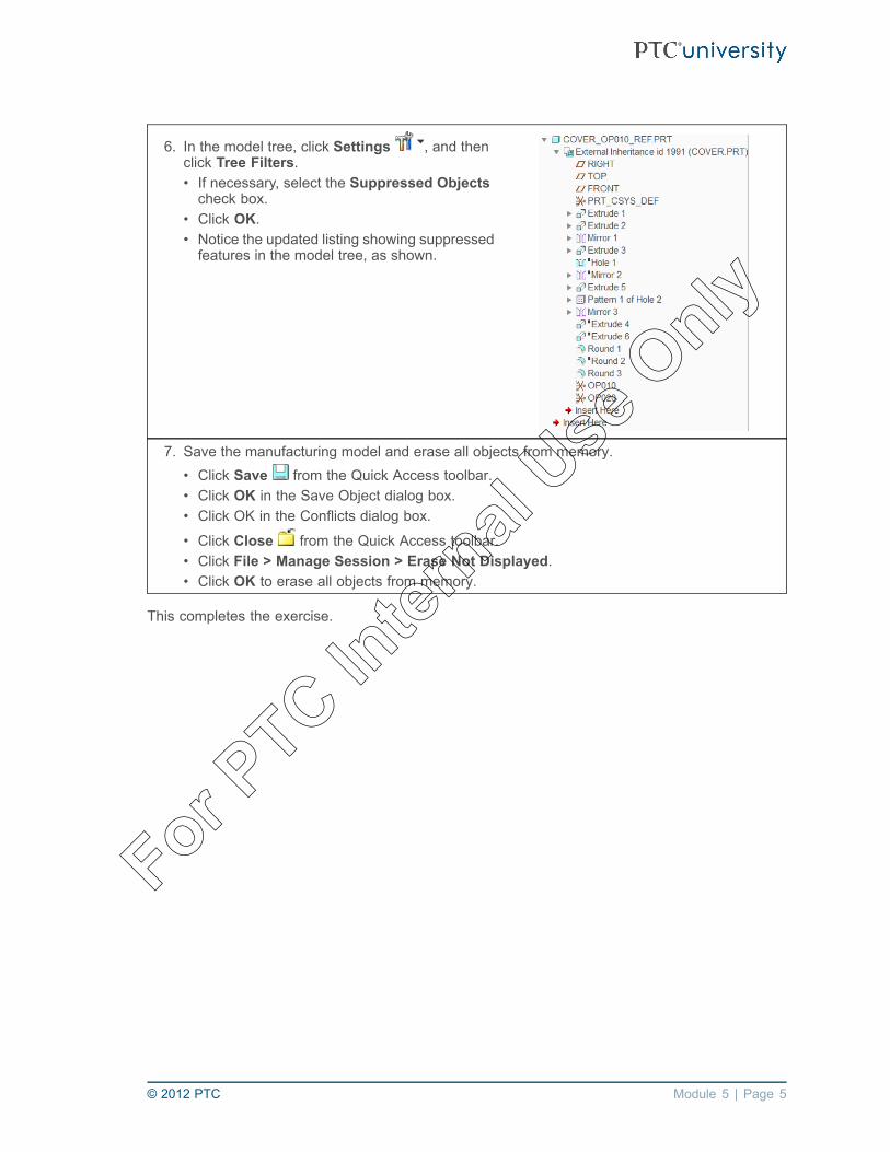
6. In the model tree, click Settings , and thenclick Tree Filters.• If necessary, select the Suppressed Objectscheck box.
• Click OK.• Notice the updated listing showing suppressedfeatures in the model tree, as shown.
7. Save the manufacturing model and erase all objects from memory.• Click Save from the Quick Access toolbar.• Click OK in the Save Object dialog box.• Click OK in the Conflicts dialog box.
• Click Close from the Quick Access toolbar.• Click File > Manage Session > Erase Not Displayed.• Click OK to erase all objects from memory.
This completes the exercise.
© 2012 PTC Module 5 | Page 5
For PTC In
ternal
Use O
nly

Module 5 | Page 6 © 2012 PTC
For PTC In
ternal
Use O
nly

Module 6Using Workpiece Models
© 2012 PTC Module 6 | Page 1
For PTC In
ternal
Use O
nly

Exercise 1: Creating a Workpiece with Inherited Features
ObjectivesAfter successfully completing this exercise, you will be able to:• Create workpiece models using the Inherited Feature option.• Suppress features in workpiece models with inherited features.• Add features to workpiece models with inherited features.
ScenarioYou need to create a workpiece in a manufacturing model using the Inherited Features option. Theworkpiece represents a casting, so you need to suppress a number of features in the workpieceand add material to the workpiece to ensure the workpiece accurately represents the “as-cast”version of the casting.
Close Window Erase Not Displayed
Milling\Workpiece_Models GEARBOX_CASTING.ASM
Task 1: Assemble the gearbox casting as the workpiece model.
1. Enable only the following Datum Display type: Csys Display .
2. Click Inherit Workpiece from the Workpiece drop-down menu.• Select GEARBOX.PRT, and click Open.
3. Create the assembly constraint.• Select datum coordinate system REF on thegearbox casting model.
• Select datum coordinate system REF on themanufacturing model.
4. Click Complete Component in the dashboard.5. In the Create Stock-Workpiece dialog box, note the Inherited option is already selected.
• Note the default name GEARBOX_CASTING_WRK in the Name text box.• Click OK to create a new workpiece model.• Expand the GEARBOX_CASTING_WRK.PRT in the model tree.• Expand the EXTERNAL INHERITANCE feature in the model tree.
An external inheritance feature has been created in the new workpiece part. You can editinherited features in the workpiece part without changing the original part. This is useful ifyou want to edit the workpiece to represent the as-cast version of the model.
Module 6 | Page 2 © 2012 PTC
For PTC In
ternal
Use O
nly

Task 2: Edit the workpiece to represent the as-cast version of the casting.
1. Suppress a number of workpiece model features.• In the model tree, select feature SLOT_1.• Press CTRL and select group HOLES.• Right-click and select Suppress.• Click OK to suppress the related roundfeature.
2. Activate the casting part.• Select GEARBOX_CASTING_WRK.PRT in the model tree.• Right-click and select Activate.
3. Add material to the top of the casting.
• Click Extrude from the Shapes group.• Right-click and select Define Internal Sketch.• Cursor over the workpiece model, andright-click and select the hidden surface onGEARBOX_CASTING_WRK.PRT, as shown.
• Click Sketch.• In the model tree, select the VERTICAL datumfeature, and then select the HORIZONTALdatum feature as sketching references.
• In the References dialog box, click Close.4. Select the first loop of edges for the sketch.
• From the Main toolbar, select Sketch View from Setup group in the ribbon.• Click Project from Sketching group in the ribbon.• Select the Loop option.• Cursor over the workpiece model, and right-click until the top surface on theGEARBOX_CASTING_WRK.PRT highlights, as shown.
• Select the highlighted surface.• Click Accept to select the outer loop of edges, as shown.
© 2012 PTC Module 6 | Page 3
For PTC In
ternal
Use O
nly

5. Select the second loop of edges for the sketch.• Cursor over the workpiece model, and right-click until the surface on theGEARBOX_CASTING_WRK.PRT highlights, as shown.
• Select the highlighted surface.• Click Next > Accept to select the inner loop of edges, as shown.
6. Complete the extrusion.• Click OK from the Sketcher toolbar.• Press CTRL + D to return to the standardorientation.
• In the dashboard, edit the depth to 2.• Click Complete Feature .• Select GEARBOX_CASTING.ASM in themodel tree.
• Right-click and select Activate.• Select the EXTRUDE 1 feature in the modeltree.
• Observe the material added to the top of thecasting, as shown.
You could also vary the dimensions of the external inheritance features in the gearboxcasting workpiece if required.
7. Save the manufacturing model and erase all objects from memory.• Click Save from the Quick Access toolbar.• Click OK in the Save Object dialog box.• Click OK in the Conflicts dialog box.
• Click Close from the Quick Access toolbar.• Click File > Manage Session > Erase Not Displayed .• Click OK to erase all objects from memory.
This completes the exercise.
Module 6 | Page 4 © 2012 PTC
For PTC In
ternal
Use O
nly
Module 8Creating and Configuring Tools
© 2012 PTC Module 8 | Page 1
For PTC In
ternal
Use O
nly

Exercise 1: Creating and Configuring Tools
ObjectivesAfter successfully completing this exercise, you will be able to:• Create tools by configuring tool parameters.• Use cutting data during the configuration of tools.• Retrieve tools from a tool library.• Configure a solid tool.
ScenarioYou need to configure a number of tools for an existing fadal-vmc workcell. You create a number ofnew tools and retrieve some existing tools from a tool library. You also configure a solid tool andadd it to the workcell configuration.
Close Window Erase Not Displayed
Milling\Tools_Configuring FADAL_TOOLS.ASM
Task 1: Review the existing tools for the FADAL_VMC workcell.
1. Enable only the following Datum Display types: Plane Display and Csys Display .2. Load a configuration option to specify the tool directory.
• Click File > Options.• Select Configuration Editor.• Select Import/Export button.• Select Import Configuration file.• Select the CONFIG.PRO file, and click Open.• Click OK to close the Options dialog box.• Click No in the Creo Parametric Options Panel.
3. Click Cutting Tools to open the Tools Setup dialog box.• Observe the tools currently associated with the FADAL_VMC workcell, as shown.
4. Review a center drill tool.• Ensure that the CTRDRILL_04 tool is selectedin the tool table.
• Notice that the tool parameters and toolgeometry appear in the General tab, asshown.
• Select the Settings tab.• Notice the tool number and offset number arealready configured, as shown.
Module 8 | Page 2 © 2012 PTC
For PTC In
ternal
Use O
nly

5. Display the tool geometry.• Select the General tab.• Click Hide Details. Notice that the toolgeometry no longer appears.
• Click Show Details to display the toolgeometry again.
• In the Tool Setup dialog box, click DisplayTool .
• Notice that the tool geometry appears ina separate window, as shown. The toolgeometry updates as parameter values areedited.
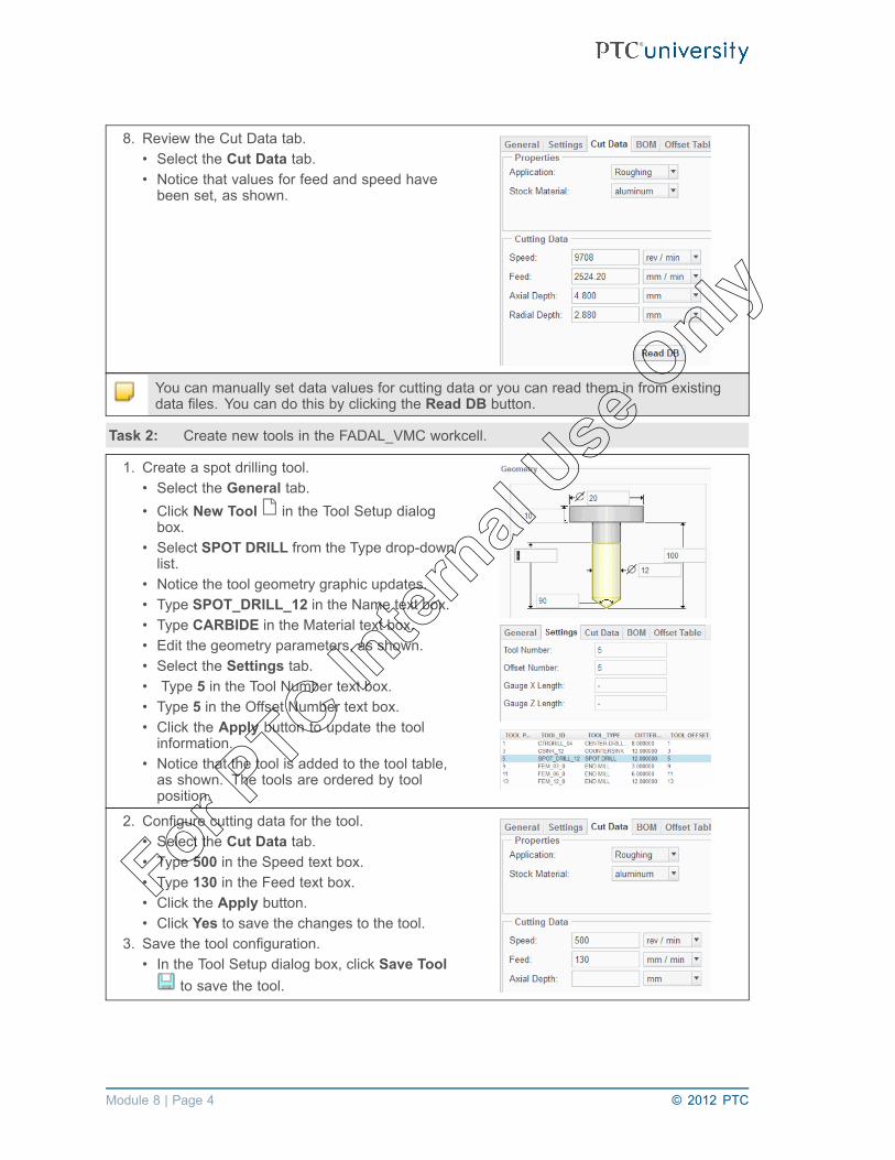
• Click Close to close the tool display window.6. Review the Cut Data tab.
• Select the Cut Data tab.• Notice that values for feed and speed havebeen set, as shown.
You can store cutting data for specific stock materials with tools. You can then use thiscutting data when creating NC sequences.
7. Review an end mill tool.• Select the FEM_06_0 tool in the tool table.• Select the General tab.• Notice that the tool parameters and toolgeometry appear in the General tab, asshown.
• Select the Settings tab.• Notice that the tool number and offset numberare already configured, as shown.
You can use the Material and Number of Flutes parameters with a machinability databaseto determine cut feed and spindle speed.
© 2012 PTC Module 8 | Page 3
For PTC In
ternal
Use O
nly
8. Review the Cut Data tab.• Select the Cut Data tab.• Notice that values for feed and speed havebeen set, as shown.
You can manually set data values for cutting data or you can read them in from existingdata files. You can do this by clicking the Read DB button.
Task 2: Create new tools in the FADAL_VMC workcell.
1. Create a spot drilling tool.• Select the General tab.• Click New Tool in the Tool Setup dialogbox.
• Select SPOT DRILL from the Type drop-downlist.
• Notice the tool geometry graphic updates.• Type SPOT_DRILL_12 in the Name text box.• Type CARBIDE in the Material text box.• Edit the geometry parameters, as shown.• Select the Settings tab.• Type 5 in the Tool Number text box.• Type 5 in the Offset Number text box.• Click the Apply button to update the toolinformation.
• Notice that the tool is added to the tool table,as shown. The tools are ordered by toolposition.
2. Configure cutting data for the tool.• Select the Cut Data tab.• Type 500 in the Speed text box.• Type 130 in the Feed text box.• Click the Apply button.• Click Yes to save the changes to the tool.
3. Save the tool configuration.• In the Tool Setup dialog box, click Save Tool
to save the tool.
Module 8 | Page 4 © 2012 PTC
For PTC In
ternal
Use O
nly

The tool information is saved to a file named spot_drill_12.xml. All saved tools are storedin the current pro_mf_tprm_dir folder (or the current working directory if no tool folderis specified). You can then manually move the saved tool file to a suitable sub-folder.Repeating this process enables you to add tools to a tool library.
4. Create a ball mill tool.• Select the General tab.• Click New Tool in the Tool Setup dialogbox.
• Select BALL MILL from the Type drop-downlist.
• Notice that the tool geometry graphic updates.• Type BEM_12_0 in the Name text box.• Type CARBIDE in the Material text box.• Type 2 in the Number of Flutes text box.• Edit the geometry parameters, as shown.• Select the Settings tab.• Type 7 in the Tool Number text box.• Type 7 in the Offset Number text box.• Click the Apply button to update the toolinformation.
• Notice that the tool is added to the tool table,as shown.
Task 3: Retrieve a tool from a tool library, and configure the tool.
1. Retrieve a flat end mill tool.• Select the General tab.• Select MILLING from the Type drop-down list.• Note that you must change the tool typebefore retrieving the required tool.
• Click Retrieve Tool in the Tools Setupdialog box.
• Notice you are selecting from the previouslyconfigured pro_mf_tprm_dir folder.
• Double-click the MILL_TOOLS folder.• Select the MMFLT20.XML tool, and clickOpen.
• Note, all stored tool parameters are retrievedwith the tool, as shown.
2. Edit the Settings tab.• Select the Settings tab.• Type 15 in the Tool Number text box.• Type 15 in the Offset Number text box.• Click the Apply button.• Click Move to move the tool to an existingpocket.
• Notice that the tool is appended to the end ofthe tool table, as shown.
© 2012 PTC Module 8 | Page 5
For PTC In
ternal
Use O
nly

3. Configure cutting data for the tool.• Select the Cut Data tab.• Type 2330 in the Speed text box.• Type 605 in the Feed text box.• Type 20 in the Axial Depth text box.• Type 12 in the Radial Depth text box.• Click the Apply button.• Click Yes when prompted.• Click OK to close the Tools Setup dialog box.
4. Save the manufacturing model.• From the Quick Access toolbar, click Save .• Click OK to save the manufacturing model.• Note the tool information is stored with the manufacturing model.
Task 4: Review and configure a solid model tool.
1. Open a solid model tool.
• From the Quick Access toolbar, click Open .• Select BEM_25_0_SOLID.PRT and click Open.
2. Edit the dimension symbol text.• In the model tree, select the REVOLVE 1feature, right-click, and select Edit.
• Observe the model dimensions, as shown.• Select the 100 linear dimension, right-click,and select Properties.
• Type length in the Name text box.• Click OK in the Dimension Properties dialogbox.
• Select the 25 diameter dimension, right-click,and select Properties.
• Type cutter_diam in the Name text box.• Click OK in the Dimension Properties dialogbox.
• Select the 12.5 radius dimension, right-click,and select Properties.
• Type corner_radius in the Name text box.• Click OK in the Dimension Properties dialogbox.
3. Review the model relations and symbolicdimension values.• From the main toolbar, click Tools >Relations.
• Notice the model dimension symbols, asshown.
Module 8 | Page 6 © 2012 PTC
For PTC In
ternal
Use O
nly

Changing the dimension symbols to length, cutter_diam, and corner_radius creates a linkbetween the tool model's dimensions and the corresponding tool parameters.Notice that the solid model tool has a coordinate system named TIP. This representsthe tool tip (often referred to as the control point). This point specifies the X-, Y-, andZ-positions for the tool in NC sequences.
4. Add relations to the solid model tool.• In the Relations dialog box, type the relations,as shown.
• These relations assign a material to the toolmodel, and set the number of teeth.
• Click OK to close the Relations dialog box.
5. Click Close from the Quick Access toolbar toreturn to the manufacturing model.
6. Open the Tool Setup dialog box.
• Click Cutting Tools to open the Tools Setup dialog box.
7. Configure a solid model tool.• Select MILLING from the Type drop-down list.• Note, you must set the correct tool type beforeretrieving a tool.
• Click File > New in the Tool Setup dialog box.• Click File > Open Tool Library > ByReference in the Tool Setup dialog box.
• In the Open dialog box, click WorkingDirectory .
• Select BEM_25_0_SOLID.PRT and clickOpen.
• Notice that the tool parameters have beenassigned from the solid model, as shown.
8. Edit the settings tab.• Select the Settings tab.• Type 17 in the Tool Number text box.• Type 17 in the Offset Number text box.• Click the Apply button.• Click Move to move the tool to an existingpocket.
• Notice that the tool is appended to the end ofthe tool table, as shown.
© 2012 PTC Module 8 | Page 7
For PTC In
ternal
Use O
nly

9. Change the tool table listing.• In the Tools Setup dialog box, click the CutterDiam column header.
• Notice that the tool table listing updates, asshown.
• In the Tools Setup dialog box, click the ToolPosition column header.
• Notice the tool table listing updates again, asshown.
• In the Tools Setup dialog box, click File >Save Tool List.
• This saves the tool list to a file namedtool_dialog_tool_list.xml.
• Click OK to close the Tools Setup dialog box.
10. Review the tool listing in the workcell and savethe workcell.
• Click Cutting Tools .• Notice this opens the Tool Setup dialog box,as shown.
• Click OK to close the Tools Setup dialog box.• The tool information can be saved with theworkcell configuration.
• Select FADAL_VMC in the model tree.• Select Save Work Center from the WorkCenter drop-down menu, in the Machine ToolSetup group.
11. Save the manufacturing model and erase all objects from memory.• Click Save from the Quick Access toolbar and click OK to save the model.• Click Close from the Quick Access toolbar, to close the window.• Click File > Manage Session > Erase Not Displayed.• Click OK to erase all objects from memory.
This completes the exercise.
Module 8 | Page 8 © 2012 PTC
For PTC In
ternal
Use O
nly
Module 11Creating Face Milling Sequences
© 2012 PTC Module 11 | Page 1
For PTC In
ternal
Use O
nly

Exercise 1: Creating Face Milling Sequences
ObjectivesAfter successfully completing this exercise, you will be able to:• Create mill window geometry.• Create face milling sequences.• Edit milling parameters to adjust face milling sequences.
ScenarioYou need to create a face milling sequence to machine the top face of a cover component. Duringthe creation of this sequence, you adjust sequence parameters and references to create a moreefficient toolpath.
Close Window Erase Not Displayed
Milling\Face_Cover COVER_FACING.ASM
Task 1: Create a mill window as a machining reference.
1. Disable all Datum Display types.
2. Click Mill Window from the ManufacturingGeometry toolbar.
3. Click Chain Window in the dashboard.4. To configure the window plane, cursor over the
model, right-click, and select the hidden modelsurface, as shown.
5. Right-click and select Chain to active theselection of edges.
6. Select one of the chain of edges at the top of theworkpiece, as shown.
7. Press SHIFT, cursor over the model, and selectthe top surface of the workpiece, as shown.• Notice the loop of edges on the top surface ofthe workpiece are selected, as shown.
8. Click Complete Feature in the dashboard.
Task 2: Create a face milling sequence.
1. Select the Mill tab.
2. Click Face from the Milling group.• Select the drop-down arrow next to the text box containing “No Tool” and select the50_0_E_MILL.
Module 11 | Page 2 © 2012 PTC
For PTC In
ternal
Use O
nly

3. Retrieve stored face milling parameters.• Select the Parameters tab.
• Click Step Parameters .• If necessary, click the All button, and selectAll categories from the Categories drop-downlist.
• In the Edit Parameters dialog box, click File> Open.
• Select the FACE.MIL parameter file, and clickOpen.
• Notice that the required parameter valuesare now configured. You can retrieve storedparameter files to expedite the configurationof manufacturing parameters.
• Click OK in the Edit Parameters dialog box.
4. Configure the surface for machining.• Select the Reference tab.• Change Type from Mill Window to Surface.• Click in the Machining References box.• Select the top surface of the model, as shown.
5. Review the resulting toolpath.
• Click Display Toolpath .• Click Play .• Notice that the toolpath follows the outline ofthe selected model surface. You can changethis by editing the TRIM_TO_WORKPIECEparameter value.
• Click Close in the Play Path dialog box whenfinished.
6. Edit the trim to workpiece parameter.• Select the Parameters tab.
• Click Step Parameters .7. Edit TRIM_TO_WORKPIECE to YES.
• Click OK.8. Review the resulting toolpath.
• Click Display Toolpath .• Click Play .• Notice that the toolpath now follows the outlineof the workpiece, as shown.
• Click Close in the Play Path dialog box whenfinished.
© 2012 PTC Module 11 | Page 3
For PTC In
ternal
Use O
nly

9. Edit the trim to workpiece parameter to NO.• Select the Parameters tab.
• Click Step Parameters .• Edit TRIM_TO_WORKPIECE to NO.• Click OK.
Alternatively, you can adjust the outline of the toolpath by using a mill window.
Task 3: Use a mill window as a machining reference for the NC sequence.
1. Select the Reference tab.• Change Type from Surface to Mill Window.
2. Select the Mill Window in the model tree.
3. Review the updated toolpath.
• Click Display Toolpath .• Click Play .• Notice that the toolpath now follows the outlineof the mill window, as shown.
4. Click Close in the Play Path dialog box whenfinished.
Alternatively, you can adjust the outline of the toolpath by using a mill surface.
Task 4: Use a mill surface as a machining reference for the NC sequence.
1. Select the Reference tab.• Change Type from Mill Window to Surface.
2. Select the hidden feature Fill 1 in the model tree.
3. Review the updated toolpath.
• Click Display Toolpath .• Click Play .• Notice that the toolpath now follows the outlineof the mill surface, as shown.
• Click Close in the Play Path dialog box whenfinished.
Module 11 | Page 4 © 2012 PTC
For PTC In
ternal
Use O
nly

Task 5: Edit the sequence parameters to adjust the approach and exit moves, the step depth,and the cut angle.
1. Select the Parameters tab.
• Click Step Parameters .• Edit the following parameters.• Edit STEP_DEPTH to 4.• Edit CUT_ANGLE to 90.• Edit APPROACH_DISTANCE to CUTTER_DIAM/2.• Edit EXIT_DISTANCE to CUTTER_DIAM/2.• Click OK.
2. Review the updated toolpath.
• Click Display Toolpath .• Click Play .• Click Close in the Play Path dialog box whenfinished.
By configuring an APPROACH_DISTANCE and EXIT_DISTANCE, the tool clears theworkpiece at the beginning and end of the toolpath. By configuring a STEP_DEPTH of 4, wehave three passes (our stock is 10 mm). Notice that the third pass is much smaller than theother two. The CUT_ANGLE makes the toolpath rotate 90 degrees relative to the X-axis.
3. Edit the cut angle and number cuts parameters.• Select the Parameters tab.
• Click Step Parameters .4. Edit the following parameters.
• Edit CUT_ANGLE to 0.• Edit NUMBER_CUTS to 3.• Click OK.
5. Review the updated toolpath.
• Click Display Toolpath .• Click Play .• Click Close in the Play Path dialog box whenfinished.
Configuring the NUMBER_CUTS to 3 computes a smaller step depth, so NUMBER_CUTSoverrides the STEP_DEPTH parameter and you get three evenly spaced passes.
© 2012 PTC Module 11 | Page 5
For PTC In
ternal
Use O
nly

Task 6: Edit the sequence parameters to adjust the over travel on each pass and the initial andfinal edge offsets.
1. Select the Parameters tab.
• Click Step Parameters .2. Edit the following parameters.
• Edit START_OVERTRAVEL to 25.• Edit END_OVERTRAVEL to 25.• Edit ENTRY_EDGE to CENTER.• Edit CLEARANCE_EDGE to CENTER.• Click OK.
3. Orient the model using a named view.
• From the Graphics toolbar, click Named Views and select TOP from the drop-down list.
4. Review the updated toolpath.
• Click Display Toolpath .• Click Play .• Click Close in the Play Path dialog box whenfinished.
You specify which part of the tool to measure the over travel on each pass by changing theENTRY_EDGE and CLEARANCE_EDGE to CENTER. Configuring START_OVERTRAVELand END_OVERTRAVEL to 25 causes the center of the tool to move 25 mm past themachined surface for each approach move and each exit move.
5. Edit the edge offset parameters.• Select the Parameters tab.
• Click Step Parameters .6. Edit the following parameters.
• Edit INITIAL_EDGE_OFFSET toCUTTER_DIAM/4.
• Edit FINAL_EDGE_OFFSET toCUTTER_DIAM/4.
• Click OK.7. Review the updated toolpath.
• Click Display Toolpath .• Click Play .
You can configure the edge offset parameters to move the toolpath toward or away fromthe initial and final edges (passes). A positive value moves the toolpath into the machinedsurface. A negative value moves it away from the machined surface.
8. Click Close in the Play Path dialog box when finished.9. Click Apply Changes .10. Press CTRL + D to return to the standard orientation.
Module 11 | Page 6 © 2012 PTC
For PTC In
ternal
Use O
nly
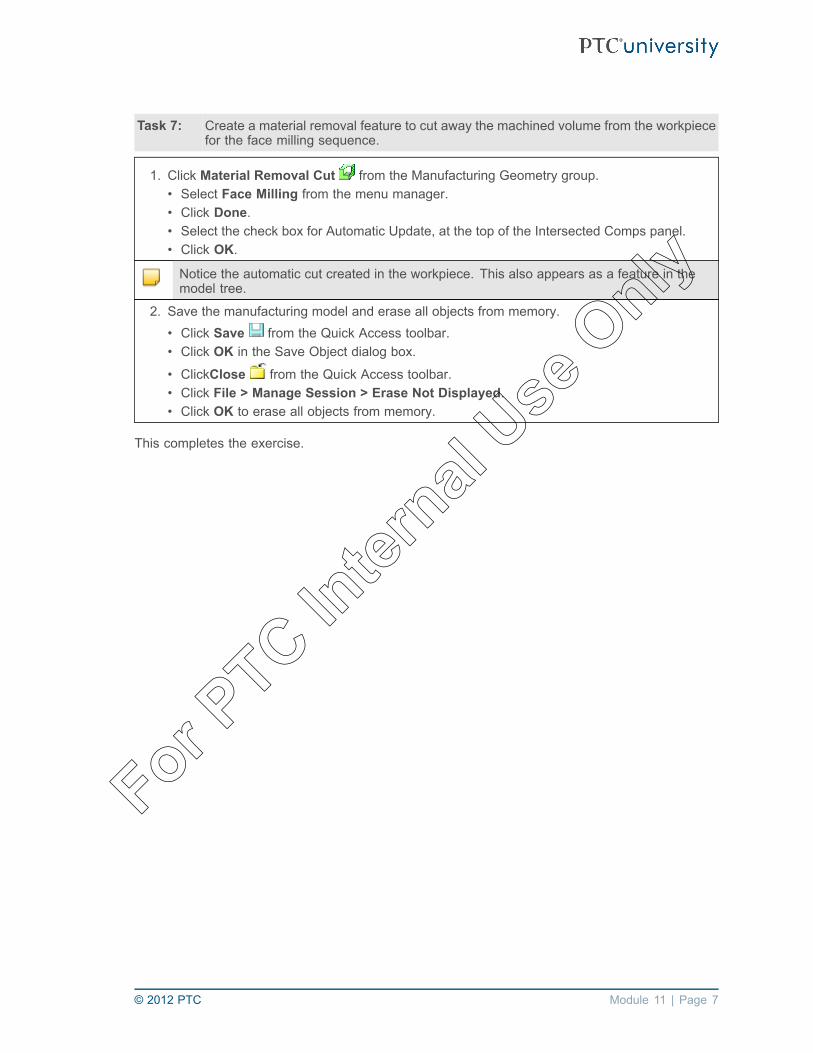
Task 7: Create a material removal feature to cut away the machined volume from the workpiecefor the face milling sequence.
1. Click Material Removal Cut from the Manufacturing Geometry group.• Select Face Milling from the menu manager.• Click Done.• Select the check box for Automatic Update, at the top of the Intersected Comps panel.• Click OK.
Notice the automatic cut created in the workpiece. This also appears as a feature in themodel tree.
2. Save the manufacturing model and erase all objects from memory.• Click Save from the Quick Access toolbar.• Click OK in the Save Object dialog box.
• ClickClose from the Quick Access toolbar.• Click File > Manage Session > Erase Not Displayed.• Click OK to erase all objects from memory.
This completes the exercise.
© 2012 PTC Module 11 | Page 7
For PTC In
ternal
Use O
nly

Module 11 | Page 8 © 2012 PTC
For PTC In
ternal
Use O
nly

Module 12Creating Volume Milling Sequences
© 2012 PTC Module 12 | Page 1
For PTC In
ternal
Use O
nly

Exercise 1: Creating Volume Milling Sequences: Extrudeand Trimming
ObjectivesAfter successfully completing this exercise, you will be able to:• Create volume milling sequences.• Create extruded mill volumes.• Edit mill volumes using trim and offset functionality.• Configure approach walls for mill volumes.
ScenarioYou need to create a volume milling sequence to rough out material for an electrode. You use anextruded mill volume which you trim to the reference model. You also extend the mill volume andconfigure approach walls to get the desired toolpath.
Close Window Erase Not Displayed
Milling\Volume ELECTRODE.ASM
Task 1: Create a volume milling sequence and create a trimmed mill volume during theconfiguration of the NC sequence.
1. Disable all Datum Display types.2. In the ribbon, select the Mill tab.
3. Select Volume Rough from the Roughing drop-down menu in the Milling group.• Notice that in the SEQ SETUP menu, the Tool, Parameters, and Window check boxes areautomatically selected. These items must be configured to generate a toolpath.
• Select the Volume check box.• Click Done.
4. Ensure that the 20_E_MILL tool is selected, and then right-click and select Select tooland return.
5. Retrieve stored volume milling parameters.• If necessary, click the All button, and select All categories from the Categories drop-downlist.
• In the Edit Parameters dialog box, click File > Open.• Select the ROUGH_ELECTRODE.MIL parameter file, and click Open.• Click OK.
Module 12 | Page 2 © 2012 PTC
For PTC In
ternal
Use O
nly

6. Create a mill volume using an extrude feature.
• Click Mill Volume from the ManufacturingGeometry group.
7. Click Extrude .8. Right-click and select Define Internal Sketch.9. Select the top surface of the workpiece, as
shown.10. Click Sketch.
11. Click References from the Setup group.Select the top and right edges of the workpieceas references, as shown.
12. Click Close in the References dialog box.13. Click Project from the Sketching group.14. Select the Loop option.15. Select the top surface of the workpiece model
again.16. Click OK .17. Click Change Depth Direction in the Extrude
dashboard.18. Edit the depth to 80.19. Click Complete Feature in the Extrude
dashboard.• Notice that an extruded volume is created, asshown.
You have created an extruded mill volume. You can now subtract the reference model fromthe mill volume geometry using the trim functionality.
20. Trim the reference model geometry from the millvolume.• Click Trim from the Volume Featuresgroup.
21. Select the reference model, as shown.• Notice that the reference model is subtractedfrom the mold volume geometry, as shown.
You can offset mill volume walls to extend the mill volume beyond the edges of theworkpiece.
© 2012 PTC Module 12 | Page 3
For PTC In
ternal
Use O
nly

22. Offset the side walls of the mill volume.• Click Offset Vertical Walls from theVolume Features group.
23. Edit the offset value to 15.24. Click Complete Feature in the dashboard.
• Notice the mill volume vertical walls havebeen offset, as shown.
25. Click OK .
26. Review the resulting toolpath.• From the menu manager, click Play Path >Screen Play.
• Click Play .
• Click Repaint .• Notice that the tool machines material withinthe offset mill volume.
You can also configure approach walls to avoid plunging into the workpiece material.
27. From the NC SEQUENCE menu, click SeqSetup.
28. Select the Appr Walls check box, and clickDone.• Press CTRL and select the front and backwalls of the mill volume, as shown.
• Click OK.• Click Done/Return.
29. Hide the mill volume.• Select EXTRUDE 1 mill volume in the modeltree, right-click, and select Hide.
You can hide mill volumes to enable easier viewing of toolpaths. You can unhide millvolumes for editing when required.
30. Review the resulting toolpath.• From the menu manager, click Play Path >Screen Play.
• Click Play .• Notice that the tool now approaches theselected approach walls when possible.
31. Click Close in the Play Path dialog box when finished.32. Click Done Seq.
Module 12 | Page 4 © 2012 PTC
For PTC In
ternal
Use O
nly

Task 2: Create a material removal feature to cut away the machined volume from the workpiecefor the volume milling sequence.
1. From the menu manager, click MaterialRemoval Cut from the ManufacturingGeometry Group drop-down menu.• Click Volume Milling.• Click Automatic > Done.• Click the Auto Add button to select theworkpiece to intersect.
• Click OK to complete the feature.
The automatic cut is created in the workpiece. The cut geometry is based on the stockallowance parameter values in the volume milling sequence.
2. Save the manufacturing model and erase all objects from memory.• Click Save from the Quick Access toolbar.• Click OK in the Save Object dialog box.• Click File > Close.• Click File > Manage Session > Erase Not Displayed.• Click OK to erase all objects from memory.
This completes the exercise.
© 2012 PTC Module 12 | Page 5
For PTC In
ternal
Use O
nly

Exercise 2: Creating Volume Milling Sequences with MillWindows
ObjectivesAfter successfully completing this exercise, you will be able to:• Create volume milling sequences.• Create sketched mill windows.
ScenarioYou need to create a volume milling sequence to machine the inside of a pocket in the housingcomponent. During the creation of this sequence, you create a sketched mill window to specifythe machined volume.
Close Window Erase Not Displayed
Milling\Volume_Mill_Window HOUSING.ASM
Task 1: Create a mill window to use as a machining reference.
1. Disable all Datum Display types.2. Configure a mill window using the Sketch
Window option.
• Click Mill Window from the ManufacturingGeometry group.
• In the model tree, select datum planeRETRACT as the window plane.
• Click Sketch Window in the dashboard.• Click Sketch in the dashboard.• Select NC_ASM_FRONT in the model tree asthe sketch orientation reference.
• Click Sketch.• Orient the sketching plane parallel to thescreen.
• Select Corner Rectangle from theRectangle drop-down menu in the Sketchinggroup.
• Sketch a rectangle, as shown.• Middle-click to finish sketching.• Edit the sketch dimensions, as shown.• Click OK .• Press CTRL + D to return to the standardorientation.
• Click Complete Feature .• Notice that a mill window is created, as shown.
Module 12 | Page 6 © 2012 PTC
For PTC In
ternal
Use O
nly

Task 2: Create a volume milling sequence using the Sketched Mill window.
1. In the ribbon, select the Mill tab.
2. Select Volume Rough from the Roughing drop-down menu in the Milling group.• Click Done.
3. Ensure the 20_E_MILL tool is selected, and then right-click and select Select tool and return.4. Retrieve stored volume milling parameters.
• If necessary, click the All button, and selectAll categories from the Categories drop-downlist.
• In the Edit Parameters dialog box, click File> Open.
• Select the VOLUME.MIL parameter file, andclick Open.
Notice that the required parameter values are now configured. You can retrieve storedparameter files to speed up the configuring of manufacturing parameters.
5. Click OK in the Edit Parameters dialog box.6. Select the sketched mill window on the model,
as shown.
7. Review the resulting toolpath.• From the menu manager, click Play Path >Screen Play.
• If necessary, click the CL data bar in the PlayPath dialog box. This makes the CL datavisible.
• Click Play .8. Orient the model using a named view.
• From the In Graphics toolbar, click NamedViews . Select TOP from the drop-downlist.
• Click Play Path > Screen Play.• Click Play .
Notice that the toolpath machines up to the edge of the mill window outline. You canedit this by changing mill window options.
9. From the NC SEQUENCE menu, click Seq Setup.10. Select the Window check box, and click Done.11. Click Redef Wind to redefine the existing mill window.
• In the dashboard, click Options.• Select the On window contour option.• Click Complete Feature .
© 2012 PTC Module 12 | Page 7
For PTC In
ternal
Use O
nly

12. Review the resulting toolpath.• From the menu manager, click Play Path >Screen Play.
• Click Play .
Notice that the toolpath now machines onto the edge of the mill window outline, as shown.
13. Click Close in the Play Path dialog box when finished.14. Click Done Seq to complete the NC sequence.15. Press CTRL + D to return to the standard orientation.
16. Save the manufacturing model and erase all objects from memory.• Click Save from the Quick Access toolbar.• Click OK in the Save Object dialog box.• Click File > Close.• Click File > Manage Session > Erase Not Displayed.• Click OK to erase all objects from memory.
This completes the exercise.
Module 12 | Page 8 © 2012 PTC
For PTC In
ternal
Use O
nly

Exercise 3: Using Customize in Volume Milling
ObjectivesAfter successfully completing this exercise, you will be able to:• Use the customize functionality to modify cut motions.
ScenarioYou need make the volume milling sequence more efficient. You can do this using the customizefunctionality.
Close Window Erase Not Displayed
Milling\Volume_Toolpaths BLOCK_CUSTOMIZE.ASM
Task 1: Use customize to create new cut motions and modify machining parameters in aspecific cut motion.
This manufacturing model does not contain a workpiece to enable easier viewing of the cutmotions.
1. Disable all Datum Display types.2. Select the VOLUME MILLING NC sequence in
the model tree.• Right-click and select Edit Definition.
3. Click Play Path > Screen Play.• Click Play .
The tool machines across each pocket region by region. However, you need to change theCUT_ANGLE to 90 degrees when the tool machines the three smaller pockets. You can dothis by editing the toolpath using the customize functionality.
4. Click Customize in the NC SEQUENCE menu.5. Create a new cut motion to machine the top
region of the pocket.• In the Customize dialog box, click Insert.• Click Upto Depth > Done.• Click Depth.• Select the bottom surface of the large pocket,as shown.
• Click Done Cut.• Notice that a new automatic cut motion plusan auto plunge, and a follow cut have beenadded to the Customize dialog box, as shown.
© 2012 PTC Module 12 | Page 9
For PTC In
ternal
Use O
nly

6. Create another cut motion to machine the threelower pockets.• In the Customize dialog box, click Insert.• Click From-To Depth > Done.• Click From Depth > Z Depth.• Type –11 for the height relative to the NCsequence coordinate system, and pressENTER.
• Click To Depth.• Select the bottom surface of the referencemodel, as shown.
• Click Parameters.• Edit CUT_ANGLE to 90. Click OK.• Note, this only changes the cut angle for thiscut motion.
• Click Done Cut.• Notice a retract cut motion plus a newautomatic cut, an auto plunge, and a followcut have been added to the Customize dialogbox, as shown.
Notice that the new cut motions supersede the original automatic cut motions. You canremove the original cut motions as they are no longer required.
7. Delete the original automatic cut motions.• In the Customize dialog box, scroll up the cutmotion list and select the first cut motion 1:Automatic Cut.
• Press SHIFT and select the retract motion 4:Retract, as shown.
• Click Delete.• Click Yes to confirm deleting.• Notice that the new cut motions are reorderedin the Customize dialog box, as shown.
• Click OK.
8. Review the resulting toolpath.• Click Play Path.• Select the Compute CL check box.• You must select this check box to recalculatethe updated toolpath.
• Click Screen Play.• Click Play .
Module 12 | Page 10 © 2012 PTC
For PTC In
ternal
Use O
nly

Notice that the tool machines the first region of the pocket with a cut angle of 0 degrees,and then machines the next three regions of the pocket with a cut angle of 90 degrees.
9. Click Close in the Play Path dialog box when finished.10. Click Done Seq.11. Save the manufacturing model and erase all objects from memory.
• Click Save from the Quick Access toolbar.• Click OK in the Save Object dialog box.• Click File > Close.• Click File > Manage Session > Erase Not Displayed.• Click OK to erase all objects from memory.
This completes the exercise.
© 2012 PTC Module 12 | Page 11
For PTC In
ternal
Use O
nly

Module 12 | Page 12 © 2012 PTC
For PTC In
ternal
Use O
nly

Module 13Creating Profile Milling Sequences
© 2012 PTC Module 13 | Page 1
For PTC In
ternal
Use O
nly
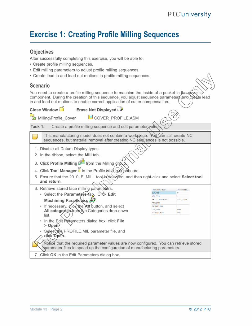
Exercise 1: Creating Profile Milling Sequences
ObjectivesAfter successfully completing this exercise, you will be able to:• Create profile milling sequences.• Edit milling parameters to adjust profile milling sequences.• Create lead in and lead out motions in profile milling sequences.
ScenarioYou need to create a profile milling sequence to machine the inside of a pocket in the covercomponent. During the creation of this sequence, you adjust sequence parameters and create leadin and lead out motions to enable correct application of cutter compensation.
Close Window Erase Not Displayed
Milling\Profile_Cover COVER_PROFILE.ASM
Task 1: Create a profile milling sequence and edit parameter values.
This manufacturing model does not contain a workpiece. You can still create NCsequences, but material removal after creating NC sequences is not possible.
1. Disable all Datum Display types.2. In the ribbon, select the Mill tab.
3. Click Profile Milling from the Milling group.
4. Click Tool Manager in the Profile Milling dashboard.5. Ensure that the 20_0_E_MILL tool is selected, and then right-click and select Select tool
and return.6. Retrieve stored face milling parameters.
• Select the Parameters tab. Click EditMachining Parameters .
• If necessary, click the All button, and selectAll categories from the Categories drop-downlist.
• In the Edit Parameters dialog box, click File> Open.
• Select the PROFILE.MIL parameter file, andclick Open.
Notice that the required parameter values are now configured. You can retrieve storedparameter files to speed up the configuration of manufacturing parameters.
7. Click OK in the Edit Parameters dialog box.
Module 13 | Page 2 © 2012 PTC
For PTC In
ternal
Use O
nly

8. Configure the surfaces for machining.• Select the Reference tab in the dashboard.Click Details below the Machining Referencescollector.
• In the Surface Sets dialog box, click Add.• Notice the default rule selection is Loopsurfaces.
• Cursor over the model, and select the topsurface of the reference model, as shown.
• Select the inner edge of the reference model,as shown.
• Notice that the selected loop of surfaceshighlight.
• Click OK.9. Review the resulting toolpath.
• Click Display Toolpath in the ProfileMilling dashboard.
• If necessary, click the CL data bar in the PlayPath dialog box. This makes the CL datavisible.
• Click Play .
Notice the toolpath makes two profile passes. You can apply lead in and lead out motionsby editing manufacturing parameters.
10. Create a lead in and lead out motion.• Click Resume Feature .• Select the Parameters tab, and click EditMachining Parameters .
11. Select LEAD_IN from the CUT_ENTRY_EXTdrop-down menu.
12. Select LEAD_OUT from the CUT_EXIT_EXTdrop-down menu.
13. Edit LEAD_RADIUS to 14.14. Click OK.15. Review the resulting toolpath.
• Click Display Toolpath .• Click Play .
Notice that a lead in and a lead out motions are now created, as shown. You can adjust theentry and exit moves as required.
© 2012 PTC Module 13 | Page 3
For PTC In
ternal
Use O
nly

16. Adjust the entry and exit moves.• Click Resume Feature .• Select the Parameters tab, and click EditMachining Parameters .
17. Edit TANGENT_LEAD_STEP to 12.18. Edit NORMAL_LEAD_STEP to 12.19. Edit OVERTRAVEL_DISTANCE to 8.20. Click OK.21. Review the resulting toolpath.
• Click Display Toolpath .• Click Play .
Notice that the over travel distance removes any witness lines from the machined surfaces.
22. Add cutter compensation to the lead in and leadout moves.• Click Resume Feature .• Select the Parameters tab, and click EditMachining Parameters .
23. Select ON from the CUTCOM drop-down menu.24. Click OK.25. Review the resulting toolpath.
• Click Display Toolpath .• Click Play .
Notice that during the lead in and lead out moves, cutter compensation is applied, as shown.
Task 2: Create an approach and exit position.
1. Click Resume Feature .2. Enable .
Module 13 | Page 4 © 2012 PTC
For PTC In
ternal
Use O
nly

3. Create a datum axis for the lead in and lead outposition.• In the Profile Milling dashboard , select Axis
from the Datum drop-down menu.• Select the surface at the bottom of the pocketto position the datum axis, as shown.
• Drag the positioning handles to snap onto therear and left surfaces of the pocket, as shown.
• Edit the horizontal positional dimension to 16and the vertical positional dimension to 40, asshown.
• Click OK to complete the datum axisconfiguration.
• Click Resume in the Milling dashboard.4. Select the Options tab in the dashboard.5. Select the Approach Axis text box in the
Options tab.• This enables the selection of Approach axis.• From the model, select axis AA_1.
6. Select the Exit Axis text box in the Options tab.• From the model, select axis AA_1, again.
7. Select the Parameters tab, and click EditMachining Parameters .
8. Edit LEAD_RADIUS to 6.9. Edit TANGENT_LEAD_STEP to 0.10. Edit NORMAL_LEAD_STEP to 0.11. Click OK.12. Review the resulting toolpath.
• Click Display Toolpath .• Click Play .
The approach and exit location on the profile is based on the axis position. Notice that theNORMAL_LEAD_STEP is zero as this move is controlled by the position of the axis.
13. Create an additional profiling pass to reduce the lateral depth of cut.• Click Resume Feature .
• Select the Parameters tab, and click Edit Machining Parameters .14. Edit NUM_PROF_PASSES to 2.15. Edit PROF_INCREMENT to 3.16. Click OK.
© 2012 PTC Module 13 | Page 5
For PTC In
ternal
Use O
nly

17. Review the resulting toolpath.
• Click Display Toolpath .• Click Play .• Notice that the toolpath now makes twopasses at each depth, as shown. This reducesthe lateral depth of cut.
18. Change the view orientation.
• Click Named Views from the In Graphicstoolbar.
• Select the named view TOP.• Click Rewind .• Click Play again.• Notice the tool increments horizontally by 3between each profile pass, as shown.
19. Click Close.20. Click Complete Feature .
21. Save the manufacturing model and erase all objects from memory.• Click Save from the Quick Access toolbar.• Click OK in the Save Object dialog box.
• Click Close from the Quick Access toolbar.• In the ribbon, click Erase Not Displayed from the Data group.• Click OK to erase all objects from memory.
This completes the exercise.
Module 13 | Page 6 © 2012 PTC
For PTC In
ternal
Use O
nly

Module 14Creating Straight Cut Surface Milling Sequences
© 2012 PTC Module 14 | Page 1
For PTC In
ternal
Use O
nly

Exercise 1: Creating Straight Cut Surface MillingSequences
ObjectivesAfter successfully completing this exercise, you will be able to:• Create and edit mill surface reference geometry.• Create straight cut surface milling sequences.
ScenarioYou need to machine the top surface of the cap part using a semi-finish surface milling sequence.You first create a mill surface as a reference for surface milling sequences. You then create asemi-finish sequence by creating a straight cut surface milling sequence using a 25 millimeterball end mill.
Close Window Erase Not Displayed
Milling\Surface_Straight-Cap CAP_STRAIGHT.ASM
Task 1: Create a mill surface by copying a reference model surface.
This manufacturing model does not contain a workpiece to enable easier viewing of millsurface geometry.
1. Disable all Datum Display types.
2. Click Mill Surface .3. Copy the curved surface on the reference model.
• Select the reference model, as shown.• Select the curved surface on the referencemodel, as shown.
• In the ribbon, select the Manufacturing tab.Click Copy .
• Click Paste .
4. Fill the holes.• Click Options in the dashboard.• Select the Exclude surfaces and Fill holesoption.
• Press CTRL, and select the four hole edges,as shown.
• Notice that the holes are filled, as shown.• Click Complete Feature in the SURFACE:Copy dashboard.
• Notice the updated mill surface, as shown.
Module 14 | Page 2 © 2012 PTC
For PTC In
ternal
Use O
nly

5. Extend the outer edges of the mill surface.• Select the COPY 1 mill surface in the modeltree.
• Select one outer edge of the mill surface, asshown.
• Press SHIFT and select the mill surface, untilthe tangent chain of edges are selected, asshown.
• Notice the tangent chain of edges highlight onthe model, as shown.
• Select the Mill Surface tab. Click Extendfrom the Editing group.
• Edit the extend value to 2.5.• Click Complete Feature in the Extenddashboard.
• Notice the extended surface on the model, asshown.
6. Extend the inner edges of the mill surface.• Select the COPY 1 mill surface in the modeltree.
• Select one inner edge of the mill surface, asshown.
• Press SHIFT and select the other inner edgeof the mill surface, as shown.
• Click Extend from the Editing group.• Edit the extend value to 3.0, as shown.• Click Complete Feature in the Extenddashboard.
• Click OK from the Controls group.• Notice the extended surface on the model, asshown.
© 2012 PTC Module 14 | Page 3
For PTC In
ternal
Use O
nly

Task 2: Create a semi-finish surface milling NC sequence using the Straight Cut option.
1. In the ribbon, select Mill tab.
2. Click Surface Milling from the Milling group.• Notice that in the SEQ SETUP menu, the Tool, Parameters, Surfaces, and Define Cutcheck boxes are automatically selected.
• You must configure these items to generate a toolpath.• Click Done.
3. Ensure that the 25_BEM tool is selected, and then right-click and select Select tool andreturn.
4. Retrieve stored semi-finish surface millingparameters.• In the Edit Parameters dialog box, click File> Open.
• Select the SEMI_FINISH_SURF.MILparameter file, and click Open.
• Click OK.
5. Configure the surface for machining.• Click Mill Surface > Done.• Select the extended surface from the model,as shown.
• Click Okay to machine the top side of thesurface.
• Click Select All > Done/Return.6. Configure the cut definition.
• Notice that the Cut Type option is configuredas Straight Cut by default.
• Click OK.
7. Review the resulting toolpath.• From the menu manager, click Play Path >Screen Play.
• Click Play .
Notice that the tool machines past the edges of the model surfaces to the edge of the largermill surface, but the step-over is too large to produce an acceptable surfaced finish.
Module 14 | Page 4 © 2012 PTC
For PTC In
ternal
Use O
nly

8. Edit the scallop height to control the step-over distance, and edit the profile stock allowance.
• Click Step Parameters .9. Edit PROF_STOCK_ALLOW to 0.15.10. Edit SCALLOP_HGT to 0.1. Click OK.11. Review the resulting toolpath.
• Click Screen Play.• Click Play .
Notice that the resulting step-over has been reduced and is now calculated using theSCALLOP_HGT parameter, as shown. Notice also 0.15 millimeters of stock are remainingon the machined surface. Notice that the tool also machines over the opening in the topsurface. You can change this using the SCAN_TYPE parameter. In addition, the cutdirection is parallel to the X-axis of the sequence coordinate system, which is controlledby the CUT_ANGLE parameter.
12. Edit the NC sequence parameters to control the scan type and cutting angle.
• Click Step Parameters .13. Edit CUT_ANGLE to 90.14. Select TYPE_3 from the SCAN_TYPE drop-down menu.15. Click OK.16. Review the resulting toolpath.
• Click Screen Play.• Click Play .
Modifying the SCAN_TYPE to TYPE_3 eliminates machining over the opening in the topsurface. Modifying the CUT_ANGLE to 90 degrees changes the direction of the cuttingmotions.Notice that the tool performs a lacing move between passes. This is controlled by theLACE_OPTION parameter.
17. Edit the lace option parameter.
• Click Step Parameters .18. Select ARC_CONNECT from the LACE_OPTION drop-down menu.19. Click OK.
© 2012 PTC Module 14 | Page 5
For PTC In
ternal
Use O
nly

20. Review the resulting toolpath.• Click Screen Play.• Click Play .• Zoom in to a lacing move on the toolpath, asshown.
• Press CTRL + D to return to the standardorientation.
Modifying the LACE_OPTION to ARC_CONNECT connects each pass with a smoothmotion.
21. Click Close in the Play Path dialog box.22. Click Done Seq.23. Hide the mill surface.
• Select the COPY 1 mill surface in the modeltree.
• Right-click, and select Hide.• Notice that in the model, the mill surface nolonger appears, as shown.
You can unhide and redefine this mill surface at any time, as required.
24. Save the manufacturing model and erase all objects from memory.• Click Save from the Quick Access toolbar.• Click OK in the Save Object dialog box.
• Click Close from the Quick Access toolbar.• In the ribbon, click Erase Not Displayed from the Data group.• Click OK to erase all objects from memory.
This completes the exercise.
Module 14 | Page 6 © 2012 PTC
For PTC In
ternal
Use O
nly

Module 15Creating From Surface Isolines Surface Milling
Sequences
© 2012 PTC Module 15 | Page 1
For PTC In
ternal
Use O
nly

Exercise 1: Creating From Surface Isolines SurfaceMilling Sequences
ObjectivesAfter successfully completing this exercise, you will be able to:• Create and edit from surface isolines surface milling sequences.
ScenarioYou need to machine the top surface of the cap part and leave a small amount of stock remaining onthe part. An extended mill surface has already been created to be used as a machining reference.You create a from surface isolines surface milling sequence using a 25 millimeter ball end mill.
Close Window Erase Not Displayed
Milling\Surface_Isolines CAP_ISOLINES.ASM
Task 1: Create a surface milling NC sequence using the From Surface Isolines option.
1. Disable all Datum Display types.2. In the ribbon, select the Mill tab.
3. Click Surface Milling in the Milling group.• Notice that in the SEQ SETUP menu, the Tool, Parameters, Surfaces, and Define Cutcheck boxes are automatically selected.
• You must configure these items to generate a toolpath.• Click Done.
4. Ensure that the 25_BEM tool is selected, and then right-click and select Select tool andreturn.
5. Retrieve stored finish surface milling parameters.• In the Edit Parameters dialog box, click File > Open.• Select the FINISH_SURF.MIL parameter file, and click Open.• Note you can edit these parameters to precisely meet your requirements at any time.• Click OK.
6. Configure the surface for machining.• Click Mill Surface > Done.• Select the extended surface from the model,as shown.
• Click Okay to machine the top side of thesurface.
• Click Select All > Done/Return.7. Configure the cut definition.
• Select the From Surface Isolines option.• Select the first surface in the Surface list. Notethat the cut direction highlights on the model,as shown.
• Click OK.
Module 15 | Page 2 © 2012 PTC
For PTC In
ternal
Use O
nly

8. Review the resulting toolpath.• From the menu manager, click Play Path >Screen Play.
• Click Play .
Notice that the cut direction follows the contour of the surface (UV vectors) instead of a truelinear cut. Notice that the tool machines past the edges of the model surfaces to the edgeof the larger mill surface. The tool also machines over the opening in the mill surface. Youcan change this using the SCAN_TYPE parameter. You can also improve the surface finishby reducing the SCALLOP_HGT parameter value, and you can leave stock remaining onthe surface by editing the PROF_STOCK_ALLOW parameter value.
9. Edit the manufacturing parameters to produce a more efficient toolpath.
• Click Step Parameters .10. Edit PROF_STOCK_ALLOW to 0.1.11. Edit SCALLOP_HGT to 0.05.12. Select TYPE_3 from the SCAN_TYPE drop-down menu.13. Click OK.14. Review the resulting toolpath.
• Click Screen Play.• Click Play .
Notice that the resulting step-over has been reduced to provide a better surface finish.Modifying the SCAN_TYPE to TYPE_3 eliminates machining over the opening in the topsurface. Notice also 0.1 millimeters of stock now remain on the machined surface.
15. Click Close in the Play Path dialog box.16. Click Done Seq.17. Hide the mill surface.
• Select the COPY 1 mill surface in the modeltree.
• Right-click, and select Hide.• Notice that the mill surface no longer appearsin the model, as shown.
You can unhide and redefine this mill surface at any time, as required.
© 2012 PTC Module 15 | Page 3
For PTC In
ternal
Use O
nly

18. Save the manufacturing model and erase all objects from memory.• Click Save from the Quick Access toolbar.• Click OK in the Save Object dialog box.
• Click Close from the Quick Access toolbar.• Click File > Manage Session Erase Not Displayed .• Click OK to erase all objects from memory.
This completes the exercise.
Module 15 | Page 4 © 2012 PTC
For PTC In
ternal
Use O
nly

Module 16Creating Cut Line Surface Milling Sequences
© 2012 PTC Module 16 | Page 1
For PTC In
ternal
Use O
nly

Exercise 1: Creating Cut Line Surface Milling Sequences
ObjectivesAfter successfully completing this exercise, you will be able to:• Create and edit cut line surface milling sequences.
ScenarioYou need to finish machine the top surface of the cap model. You create a cut line surface millingsequence using a 25 millimeter ball end mill.
Close Window Erase Not Displayed
Milling\Surface_Cut-Line CAP_CUT_LINE.ASM
Task 1: Create a surface milling NC sequence using the Cut Line option.
1. Disable all Datum Display types.2. In the ribbon, select the Mill tab.
• Click Cut Line Milling from the Milling group drop-down list.
3. Next to the Tool Manager icon, in the dashboard, click the down arrow next to NO TOOL andselect 01:25_BEM.
4. Retrieve stored finish surface milling parameters.• Select the Parameters tab.
• Click the Step Parameters .• In the Edit Parameters dialog box, click File > Open.• Select the FINISH_SURF.MIL parameter file, and click Open.• Notice that you can edit these parameters to precisely meet your requirements at any time.• Click OK.
5. Configure the surface for machining.• Select the Reference tab.• Click in the Machining Reference area.• Select the top surface of the model as shown.
6. Configure the first closed cut line.• Select the Cut Lines tab.• Click the Details button, below References.• Press CTRL and select the 2 curves of theinside circle, as shown.
• Click OK.• Click Start Point.• Type 0.5 in the value box and press ENTER.• Click Accept Changes .
Module 16 | Page 2 © 2012 PTC
For PTC In
ternal
Use O
nly

7. Configure the second closed cut line.• Select Cutline 2.• Click the Details button, below References.• Press CTRL and select the outside curves ofthe top surface, as shown.
• Click OK.• Click Start Point.• Type 0.5 in the value box and press ENTER.• Click Accept Changes .
• Click View Toolpath from the dashboard.
8. Review the resulting toolpath.• From the dashboard, click Show Toolpath
.• Click Play .• Click Close in the Play Path dialog box whenfinished.
Notice that the toolpath gradually changes shape between the start and end cut lines. Youcan also improve the surface finish by reducing the SCALLOP_HGT parameter value.
9. Reduce the scallop height.• Select the Parameters tab.
10. Edit SCALLOP_HGT to 0.025.11. Review the resulting toolpath.
• From the dashboard, click Show Toolpath.
• Click Play .
Notice that the resulting step-over has been reduced to provide a better surface finish.
12. Click Close in the Play Path dialog box.13. Click Accept Changes from the dashboard.
© 2012 PTC Module 16 | Page 3
For PTC In
ternal
Use O
nly

14. Save the manufacturing model and erase all objects from memory.• Click Save from the Quick Access toolbar.• Click OK in the Save Object dialog box.• Click File > Close.• Click File > Manage Session > Erase Not Displayed.• Click OK to erase all objects from memory.
This completes the exercise.
Module 16 | Page 4 © 2012 PTC
For PTC In
ternal
Use O
nly

Module 17Advanced Surface Milling Options
© 2012 PTC Module 17 | Page 1
For PTC In
ternal
Use O
nly

Exercise 1: Using Advanced Surface Milling Options
ObjectivesAfter successfully completing this exercise, you will be able to:• Gouge check surface milling sequences.• Configure approach and exit moves to surface milling sequences.
ScenarioYou need to adjust the surface milling sequence to avoid the clamp surfaces. You also need toconfigure approach and exit motions to remove witness lines on the machined surface.
Close Window Erase Not Displayed
Milling\Surface_Advanced CAP_CHECK_SURFS.ASM
Task 1: Gouge check the surface milling sequence.
1. Disable all Datum Display types.2. Review the current toolpath. Select the
STRAIGHT_CUT NC sequence in the modeltree.• Right-click and select Edit Definition.• Click Play Path > Screen Play.• Click Play .
Notice that the toolpath may be gouging into the vise at the beginning and end of eachpass. You can check and correct this.
3. Configure surfaces for gouge checking.• From the Play Path menu, click GougeCheck.
4. Press CTRL and select the six top surfaces onthe vise part.
5. Click OK > Done/Return > Done/Return.6. Perform gouge checking. Click Run from the
GOUGE CHECK menu.7. Notice that gouges were found.8. Click Show All to view all detected gouges on
the toolpath, as shown.9. Click Done/Return > Done/Return >
Done/Return.
10. Click Repaint from the In Graphics toolbar.11. Configure check surfaces.12. From the NC SEQUENCE menu, click Seq
Setup.13. Select the Check Surfs check box, and click
Done.14. Press CTRL and select the six top surfaces on
the vise part, as shown.15. Click OK > Done/Return > Done/Return.
Module 17 | Page 2 © 2012 PTC
For PTC In
ternal
Use O
nly

16. Perform gouge checking again. Click Play Path> Gouge Check.
17. Press CTRL and select the six top surfaces onthe vise part, as before.
18. Click OK > Done/Return > Done/Return.19. Click Run. Notice that no gouges were found.20. Click Done/Return > Done/Return.
21. Adjust the check surface stock allowance. In the ribbon, click Step Parameters fromthe Update group.
22. Edit CHK_SRF_STOCK_ALLOW to 2.23. Click OK.24. Review the resulting toolpath.
• Click Play Path.• Click Screen Play.• Click Play .• Notice that the toolpath is adjusted to avoidthe check surfaces.
Task 2: Use Customize to split the automatic cut motion and configure approach and exit motionsto remove witness lines on the machined surface.
1. Click Customize in the NC SEQUENCE menu.2. Split the follow cut, cut motion.
• In the Customize dialog box, select the cutmotion 3: Follow Cut.
• Click Redefine.• Click Split.• Click Add.• Zoom in to the toolpath and select the point,as shown.
• Click Add again.• In the same area of the toolpath, select thepoint, as shown.
• Click OK > OK.• You now have three follow cut, cut motions,as shown.
© 2012 PTC Module 17 | Page 3
For PTC In
ternal
Use O
nly

3. Configure a tangent approach move.• In the Customize dialog box, select the cutmotion 3: Follow Cut, as shown.
• Select Tangent Approach from the drop-downlist.
• Type 10 in the Approach Distance text box.• Click Preview.• Observe the previewed cut motion, as shown.• Click OK in the Tangent Approach dialog box.• Notice that a tangent approach is inserted infront of the selected cut motion, as shown.
4. Configure a second tangent approach move.• In the Customize dialog box, select the cutmotion 6: Follow Cut.
• Select Tangent Approach from the drop-downlist.
• Type 10 in the Approach Distance text box.• Click Preview.• Observe the previewed cut motion, as shown.• Click OK in the Tangent Approach dialog box.• Notice that a tangent approach is inserted infront of the selected cut motion, as shown.
Note, you can remove an unwanted cut motion.
Module 17 | Page 4 © 2012 PTC
For PTC In
ternal
Use O
nly

5. Delete the unwanted cut motion.• Select the cut motion 5: Follow Cut, asshown.
• Click Delete.• Click Yes to confirm deletion.• Notice that the cut motions are reordered inthe Customize dialog box, as shown.
• Click OK in the Customize dialog box.
6. Review the resulting toolpath.• Click Play Path.• Click Screen Play.• Click Play .
Notice that the tool now makes a tangent approach move before machining the surface.
7. Click Close in the Play Path dialog box when finished.8. Click Done Seq.9. Save the manufacturing model and erase all objects from memory.
• Click Save from the Quick Access toolbar.• Click OK in the Save Object dialog box.
• Click Close from the Quick Access toolbar.• In the ribbon, click Erase Not Displayed .• Click OK to erase all objects from memory.
This completes the exercise.
© 2012 PTC Module 17 | Page 5
For PTC In
ternal
Use O
nly

Module 17 | Page 6 © 2012 PTC
For PTC In
ternal
Use O
nly

Module 18Creating Roughing and Re-roughing Sequences
© 2012 PTC Module 18 | Page 1
For PTC In
ternal
Use O
nly

Exercise 1: Mold Core Roughing and Re-Roughing
ObjectivesAfter successfully completing this exercise, you will be able to:• Create roughing NC sequences.• Create re-roughing NC sequences.• Create mill windows for roughing sequences.
ScenarioYou create a roughing sequence and then re-roughing sequence to machine the mold core. Youedit parameters to apply high speed machining methods. The re-roughing sequence machinesmaterial remaining from the roughing sequence.
Close Window Erase Not Displayed
Milling\Roughing_Mold-Core MOLD_CORE.ASM
Task 1: Create a roughing NC sequence and edit parameter values.
1. Disable all Datum Display types.2. Configure a mill window using the Chain Window
option.
• Click Mill Window to start the Mill Windowtool from the Manufacturing Geometry group.
• Select the top surface of the reference modelas the window placement plane, as shown.
• Click Chain Window in the Mill Windowdashboard.
• Right-click and select Chain to activate theselection of edges.
• Select one of the inner chain of edges at thetop of the pocket, as shown.
• Press SHIFT and select another edge in theloop, as shown.
• Notice that the tangent chain of edgeshighlights on the model, as shown.
• Click Complete Feature .
3. In the ribbon, select the Mill tab.
4. Select Roughing from the Roughing drop-down menu in the Milling group.
5. Click Tool Manager in the Roughing dashboard.6. Ensure that the 20_FEM tool is selected, and then right-click and select Select tool and
return.
Module 18 | Page 2 © 2012 PTC
For PTC In
ternal
Use O
nly

7. Retrieve stored rough milling parameters.• Select the Parameters tab in the Roughingdashboard.
• Click Edit Machining Parameters .• In the Edit Parameters dialog box, click File> Open.
• Select the ROUGH.MIL parameter file, andclick Open.
• Note, you can edit the stored parametervalues as required.
8. Edit the following roughing related parameters for the NC sequence.• Edit MAX_STEP_DEPTH to 5.• Edit INSIDE_TOLERANCE to 0.04.• Click OK.
9. Review the resulting toolpath.
• Click Display Toolpath in the Roughingdashboard.
• Click Play .
10. Change the view orientation.
• Click Named Views from an In Graphicstoolbar.
• Select the named view FRONT.• Click Repaint to see the toolpath.
Notice that the tool is making passes at approximately 5 millimeter depth increments. Youneed to modify the ROUGH_SCALLOP_CONTROL and ROUGH_SCALLOP parametersto create additional passes between the roughing passes.
11. Click Resume Feature in the dashboard.12. Edit the step scallop height control parameters.
• Select the Parameters tab in the Roughing dashboard.
• Click Edit Machining Parameters .13. If necessary, click the All button.14. Select DURING from the ROUGH_SCALLOP_CONTROL drop-down menu.15. Edit ROUGH_SCALLOP to 0.4.16. Click OK.17. Review the resulting toolpath.
• Press CTRL + D to return to the standardorientation.
• Click Display Toolpath .• If necessary, drag the Display Speed slider tothe left to slow down the toolpath simulation.
• Click Play .
© 2012 PTC Module 18 | Page 3
For PTC In
ternal
Use O
nly

Notice that the tool has created additional passes between the initial roughing passes.The ROUGH_SCALLOP_CONTROL parameter enables you to create the passes eitherduring or after the initial roughing passes. The ROUGH_SCALLOP parameter specifies themaximum allowable scallop height on the walls of the cavity. The resulting scallop height isnow reduced, leaving a more uniform thickness of remaining material.
18. Click Close in the Play Path dialog box when finished.
The manufacturing parameter CLOSED_AREA_SCAN is currently configuredwith the default value of CONSTANT_LOAD. This produces a toolpath with anapproximately constant tool load. Alternatively, you can use MAINTAIN_CUT_TYPE orMAINTAIN_CUT_DIRECTION values to minimize retract moves during the toolpath.Note, for reviewing purposes, you can see the toolpath more easily by disablingROUGH_SCALLOP_CONTROL.
19. Edit the scan parameter.• Select the Parameters tab in the Roughing dashboard.
• Click Edit Machining Parameters .• Select MAINTAIN_CUT_TYPE from the CLOSED_AREA_SCAN drop-down menu.• Select NO from the ROUGH_SCALLOP_CONTROL menu.• Click OK.
20. Review the resulting toolpath.
• Click Display Toolpath .• If necessary, drag the Display Speed slider tothe left to slow down the toolpath simulation.
• Click Play .
Notice that the toolpath now maintains the cut direction. You can round the sharp cornermoves using the SMOOTH_SHARP_CORNERS option.
21. Click Resume Feature .22. Edit corner option parameters.
• Select the Parameters tab.
• Click Edit Machining Parameters .23. Select MAX_RADIUS from the SMOOTH_SHARP_CORNERS drop-down menu.24. Edit SMOOTH_RADIUS to 10.25. Click OK.26. Review the resulting toolpath.
• Click Display Toolpath .• If necessary, drag the Display Speed slider tothe left to slow down the toolpath simulation.
• Click Play .
Notice that the sharp corners have been rounded. Setting SMOOTH_SHARP_CORNERSto MAX_RADIUS rounds sharp corners using the largest possible radius between 10%and 100% of the SMOOTH_RADIUS value.
Module 18 | Page 4 © 2012 PTC
For PTC In
ternal
Use O
nly

27. Click Close in the Play Path dialog box when finished.28. Click Complete Feature .
Task 2: Create a re-roughing NC sequence and reference the previous roughing sequence.
1. Click Re-Rough from the Milling group .• Ensure that the Roughing sequence is selected in the dashboard.
2. Click Tool Manager in the Re-roughing dashboard.3. Select the 12_BEM tool, and then right-click and select Select tool and return.4. Retrieve stored re-roughing milling parameters.
• Select the Parameters tab.
• Click Edit Machining Parameters .• In the Edit Parameters dialog box, click File > Open.• Select the RE_ROUGH.MIL parameter file, and click Open.• Note you can edit the stored parameter values as required.
5. Edit the following parameters for the sequence.• Select MAINTAIN_CUT_TYPE from the CLOSED_AREA_SCAN drop-down menu.• Edit MIN_STEP_DEPTH to 0.2.• Edit MAX_STEP_DEPTH to 2.0.• Click OK.
6. Review the resulting toolpath.
• Click Display Toolpath in the Re-roughingdashboard.
• If necessary, drag the Display Speed slider tothe left to slow down the toolpath simulation.
• Click Play .
Notice that the tool machines only the areas where the previous roughing sequence couldnot reach.
7. Click Close in the Play Path dialog box when finished.8. Click Complete Feature .
9. Save the manufacturing model and erase all objects from memory.• Click Save from the Quick Access toolbar.• Click OK in the Save Object dialog box.
• Click Close from the Quick Access toolbar.• In the ribbon, click Erase Not Displayed .• Click OK to erase all objects from memory.
This completes the exercise.
© 2012 PTC Module 18 | Page 5
For PTC In
ternal
Use O
nly

Module 18 | Page 6 © 2012 PTC
For PTC In
ternal
Use O
nly

Module 19Creating Finishing Sequences
© 2012 PTC Module 19 | Page 1
For PTC In
ternal
Use O
nly
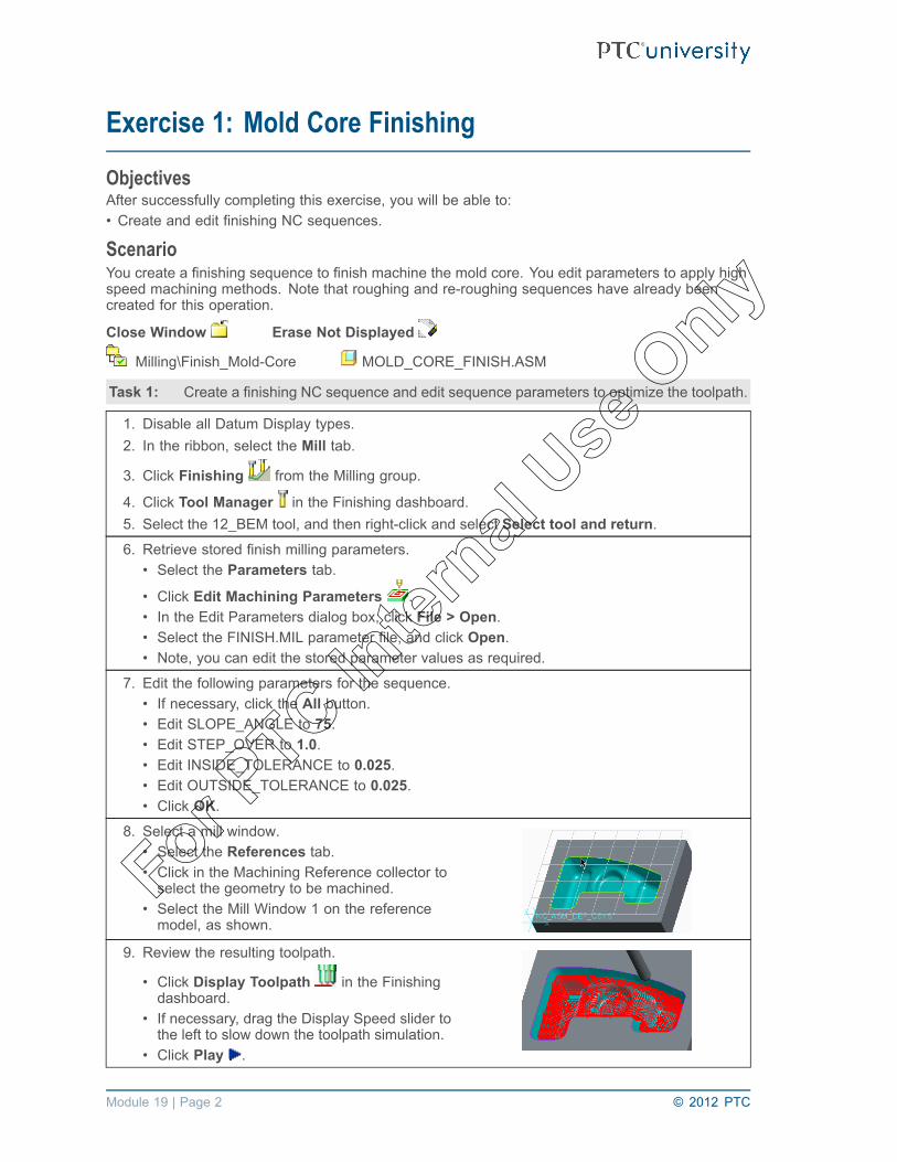
Exercise 1: Mold Core Finishing
ObjectivesAfter successfully completing this exercise, you will be able to:• Create and edit finishing NC sequences.
ScenarioYou create a finishing sequence to finish machine the mold core. You edit parameters to apply highspeed machining methods. Note that roughing and re-roughing sequences have already beencreated for this operation.
Close Window Erase Not Displayed
Milling\Finish_Mold-Core MOLD_CORE_FINISH.ASM
Task 1: Create a finishing NC sequence and edit sequence parameters to optimize the toolpath.
1. Disable all Datum Display types.2. In the ribbon, select the Mill tab.
3. Click Finishing from the Milling group.
4. Click Tool Manager in the Finishing dashboard.5. Select the 12_BEM tool, and then right-click and select Select tool and return.6. Retrieve stored finish milling parameters.
• Select the Parameters tab.
• Click Edit Machining Parameters .• In the Edit Parameters dialog box, click File > Open.• Select the FINISH.MIL parameter file, and click Open.• Note, you can edit the stored parameter values as required.
7. Edit the following parameters for the sequence.• If necessary, click the All button.• Edit SLOPE_ANGLE to 75.• Edit STEP_OVER to 1.0.• Edit INSIDE_TOLERANCE to 0.025.• Edit OUTSIDE_TOLERANCE to 0.025.• Click OK.
8. Select a mill window.• Select the References tab.• Click in the Machining Reference collector toselect the geometry to be machined.
• Select the Mill Window 1 on the referencemodel, as shown.
9. Review the resulting toolpath.
• Click Display Toolpath in the Finishingdashboard.
• If necessary, drag the Display Speed slider tothe left to slow down the toolpath simulation.
• Click Play .
Module 19 | Page 2 © 2012 PTC
For PTC In
ternal
Use O
nly
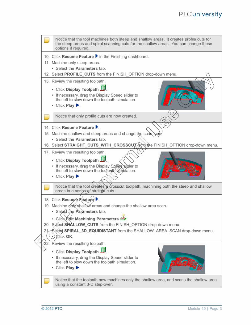
Notice that the tool machines both steep and shallow areas. It creates profile cuts forthe steep areas and spiral scanning cuts for the shallow areas. You can change theseoptions if required.
10. Click Resume Feature in the Finishing dashboard.11. Machine only steep areas.
• Select the Parameters tab.12. Select PROFILE_CUTS from the FINISH_OPTION drop-down menu.
13. Review the resulting toolpath.
• Click Display Toolpath .• If necessary, drag the Display Speed slider tothe left to slow down the toolpath simulation.
• Click Play .
Notice that only profile cuts are now created.
14. Click Resume Feature .15. Machine shallow and steep areas and change the scan type.
• Select the Parameters tab.16. Select STRAIGHT_CUTS_WITH_CROSSCUT from the FINISH_OPTION drop-down menu.
17. Review the resulting toolpath.
• Click Display Toolpath .• If necessary, drag the Display Speed slider tothe left to slow down the toolpath simulation.
• Click Play .
Notice that the tool creates a crosscut toolpath, machining both the steep and shallowareas in a series of straight cuts.
18. Click Resume Feature .19. Machine only shallow areas and change the shallow area scan.
• Select the Parameters tab.
• Click Edit Machining Parameters .20. Select SHALLOW_CUTS from the FINISH_OPTION drop-down menu.21. Select SPIRAL_3D_EQUIDISTANT from the SHALLOW_AREA_SCAN drop-down menu.
• Click OK.22. Review the resulting toolpath.
• Click Display Toolpath .• If necessary, drag the Display Speed slider tothe left to slow down the toolpath simulation.
• Click Play .
Notice that the toolpath now machines only the shallow area, and scans the shallow areausing a constant 3-D step-over.
© 2012 PTC Module 19 | Page 3
For PTC In
ternal
Use O
nly

23. Click Resume Feature .24. Machine both shallow and steep areas.
• Select the Parameters tab.25. Select COMBINED_CUTS from the FINISH_OPTION drop-down menu.
26. Review the resulting toolpath.
• Click Display Toolpath in the Finishingdashboard.
• If necessary, drag the Display Speed slider tothe left to slow down the toolpath simulation.
• Click Play .
Notice that the tool machines both steep and shallow areas. It creates spiral scanningcuts with a constant 3-D step-over for the shallow areas and creates profile cuts for thesteep areas.
27. Click Close in the Play Path dialog box when finished.28. Click Complete Feature .
29. Save the manufacturing model and erase all objects from memory.• Click Save from the Quick Access toolbar.• Click OK in the Save Object dialog box.
• Click Close from the Quick Access toolbar.• In the ribbon, click Erase Not Displayed .• Click OK to erase all objects from memory.
This completes the exercise.
Module 19 | Page 4 © 2012 PTC
For PTC In
ternal
Use O
nly
Module 20Creating Trajectory Milling Sequences
© 2012 PTC Module 20 | Page 1
For PTC In
ternal
Use O
nly

Exercise 1: Slot Milling
ObjectivesAfter successfully completing this exercise, you will be able to:• Use 3-axis trajectory milling sequences to create slots.• Create sketched tools.
ScenarioYou create a 3-axis trajectory milling sequence to machine a slot in a fixing plate. You create two cutmotions and specify approach and exit moves. You also create a sketched tool for the sequence.
Close Window Erase Not Displayed
Milling\Slot FIXING_PLATE.ASM
Task 1: Create a sketched tool.
1. Disable all Datum Display types.
2. Click Cutting Tools from the Machine Tool Setup group to open the Tools Setup dialogbox.
3. Configure a sketched tool.• Click Edit > Sketch in the Tool Setup dialog box.• Type 65_DEG_SLOT_10 in the Name text box.• Click the Sketcher button to open Sketcher.
4. Sketch the tool section.• Select Centerline from the Centerlinedrop-down menu in the Sketching group.
• Sketch a vertical centerline.• Click Line Chain from the Line drop-downmenu in the Sketching group.
• Sketch the tool outline, as shown.• Middle-click to stop sketching lines.
5. Dimension the sketch.• Right-click and select Dimension.• Dimension the sketch, as shown. Note yourdimension values will vary from those shown.
• Middle-click to stop creating dimensions.• Edit the dimensions, as shown.
Module 20 | Page 2 © 2012 PTC
For PTC In
ternal
Use O
nly

6. Add a Sketcher coordinate system to specify thetool tip.
• Click Coordinate System .• Select a location for the coordinate system onthe sketch, as shown.
• Middle-click to stop creating Sketchercoordinate systems.
• Click Save from the Quick Access toolbar.• Click OK to save the section.• Click OK .
7. Finalize the tool configuration.• In the Tools Setup dialog box, click Apply.• Click OK to complete the tool configuration.
You can save the sketched tool configuration with the workcell ready for future use, or saveit with the manufacturing model.
Task 2: Create a 3-axis trajectory milling sequence and configure cut motion options.
1. In the ribbon, select the Mill tab.
2. Click Custom Trajectory from the Milling group.• Notice that 3 Axis is selected in the MACH AXES menu manager.• Click Done.• Notice that in the SEQ SETUP menu, the Tool and Parameters check boxes areautomatically selected.
• You must configure these items to generate a toolpath.• Click Done.
3. Ensure that the 65_DEG_SLOT_10 tool is selected, and then right-click and select Selecttool and return.
4. Edit the required parameters for the NC sequence.• Edit CUT_FEED to 100.• Edit CLEAR_DIST to 2.• Edit SPINDLE_SPEED to 500.• Click OK.
5. Specify the first cut motion configuration.• Click Insert in the Customize dialog box to insert an automatic cut motion.• Click Edge > Done.• Ensure that the Edge, Direction, and Offset check boxes are selected.• Click Done.
© 2012 PTC Module 20 | Page 3
For PTC In
ternal
Use O
nly

6. Create a cut motion to machine the first edge.• Select the hidden edge of the slot on themodel, as shown.
• Click OK > Done.• Click Flip > Okay to reverse the direction.• Click Right > Done to specify the offset, asshown.
• Notice that a cut motion appears, as shown.
7. Extend the ends of the cut motion.• Click Ends > Start.• Select the Specify check box, and click Done.• Drag the start point to a new location, asshown.
• Click to finalize the location.• Click Ext Length.• Type 40 for the extension length, and pressENTER.
• Click End.• Select the Specify check box, and click Done.• Drag the end point to a new location, asshown.
• Click to finalize the location.• Click Ext Length.• Type 40 for the extension length, and pressENTER.
• Click Done/Return.• Click Done Cut.• Notice that the cut motion appears, as shown.
You can create additional cut motions as required. The cut motions are joined to formone toolpath.
8. Specify the second cut motion configuration.• Click Insert in the Customize dialog box to insert an automatic cut motion.• Click Edge > Done.• Ensure that the Edge, Direction, and Offset check boxes are selected.• Click Done.
Module 20 | Page 4 © 2012 PTC
For PTC In
ternal
Use O
nly

9. Create a cut motion to machine the secondedge.• Select the hidden edge of the slot on themodel, as shown.
• Click OK > Done.• Click Okay to specify the direction.• Click Right > Done to specify the offset.• Notice that a cut motion appears, as shown.
10. Extend the ends of the second cut motion.• Click Ends > Start.• Select the Specify check box, and click Done.• Drag the start point to a new location, asshown.
• Click to finalize the location.• Click Ext Length.• Type 40 for the extension length, and pressENTER.
• Click End.• Select the Specify check box, and click Done.• Drag the end point to a new location, asshown.
• Click to finalize the location.• Click Ext Length.• Type 40 for the extension length, and pressENTER.
• Click Done/Return.• Click Done Cut.• Notice that the cut motion appears, as shown.
© 2012 PTC Module 20 | Page 5
For PTC In
ternal
Use O
nly

11. Delete unwanted cut motions.• Select cut motion 4: Retract, as shown.• Click Delete, and click Yes to confirm deletingthe cut motion.
• Select cut motion 5: Auto Plunge, as shown.• Click Delete, and click Yes to confirm deletingthe cut motion.
• Notice the updated cut motion list in theCustomize dialog box, as shown.
• Click OK in the Customize dialog box.
12. Review the resulting toolpath.• From the menu manager, click Play Path >Screen Play.
• If necessary, click the CL data bar to make theCL data visible.
• Click Next Record repeatedly to singlestep through the toolpath until you reach theend.
Notice that the two cut motions are joined to form a single toolpath.
13. Click Close in the Play Path dialog box when finished.14. Click Done Seq.15. Save the manufacturing model and erase all objects from memory.
• Click Save from the Quick Access toolbar.• Click OK in the Save Object dialog box.
• Click Close from the Quick Access toolbar.• In the ribbon, click Erase Not Displayed .• Click OK to erase all objects from memory.
This completes the exercise.
Module 20 | Page 6 © 2012 PTC
For PTC In
ternal
Use O
nly

Module 21Creating Holemaking Sequences
© 2012 PTC Module 21 | Page 1
For PTC In
ternal
Use O
nly

Exercise 1: Creating Holemaking Sequences
ObjectivesAfter successfully completing this exercise, you will be able to:• Create drill groups.• Create center-drilling sequences.• Create standard drilling sequences.• Create tapping sequences.• Create boring sequences.
ScenarioYou need to machine holes in a new machining bracket fixture. You create drill groups to enableeasy selection of the holes for the holemaking sequences. You center-drill all the holes in the model.You create a holemaking sequence to drill the seven holes on the stepped face of the model. Youthen drill and tap the four holes in the bolt hole pattern on the top face of the model and finish bydrilling and boring the large hole on the top face.
Close Window Erase Not Displayed
Milling\Drilling_Bracket BRACKET_DRILL.ASM
Module 21 | Page 2 © 2012 PTC
For PTC In
ternal
Use O
nly

Task 1: Create two drill groups – one for the seven holes on the stepped face and the other forthe holes in the bolt hole pattern.
1. Disable all Datum Display types.2. In the ribbon, select the Mill tab.3. Configure the drill groups.
• Click Drill Group from the ManufacturingGeometry group.
• Select the Properties tab in the Drilling Groupdialog box.
• Type GROUP_14_0 in the Name text box.• Select the Definition tab.• Select the Rule: diameters from the Subsetslist.
• Select the 14.000000 diameter from theAvailable list and click Add .
• Notice seven axes highlight on the model, asshown.
• Click Done in the Drilling Group dialog box.
• Click Drill Group from the ManufacturingGeometry group.
• Select the Properties tab and typeGROUP_M_18_0 in the Name text box.
• Select the Definition tab.• Select the Rule: diameters from the Subsetslist.
• Select the 18.000000 diameter from theAvailable list and click Add .
• Notice four axes highlight on the model, asshown.
• Click Done in the Drilling Group dialog box.
Task 2: Create a holemaking sequence to center-drill all the holes.
1. Click Standard from the Holemaking Cycles group.
2. Click Tool Manager in the Drilling dashboard.3. Select the CTRDRILL_04 tool, and then right-click and select Select tool and return.4. Edit the required parameters for the NC sequence.
• Select the Parameters tab.• Edit CUT_FEED to 150.• Edit CLEAR_DIST to 2.• Edit SPINDLE_SPEED to 500.
© 2012 PTC Module 21 | Page 3
For PTC In
ternal
Use O
nly

5. Configure the first set of holes for center-drilling.• Select the References tab.• Click Details.• Ensure that the Holes tab is selected in theHoles dialog box. Select the Individual Axesfrom the Subsets list.
• Select the large hole in the center of the topface of the model, as shown.
• Notice the five holes to be drilled highlight onthe model, as shown.
• Select the Depth tab in the Holes dialog box.• From the Start drop-down list, click SelectStart Surface .
• Select the top surface on the model, as shown.• From the End drop-down list, click Blind .• Type 4 in the End Value text box, and pressENTER.
• Select By Tip from the Measure drop-downlist.
• Click Done in the Holes dialog box.
6. Configure the second set of holes forcenter-drilling.• Select New Set in the References tab.• Click Details.• Ensure that the Holes tab is selected in theHoles dialog box. Select Rule:drill groupsfrom the Subsets list.
• Select the GROUP_14_0 group from theAvailable list.
• Click Add .• Notice the seven holes to be drilled highlighton the model, as shown.
• Select the Depth tab in the Holes dialog box.• From the Start drop-down list, click SelectStart Surface .
• Select the stepped surface of the model asthe start surface, as shown.
• From the End drop-down list, click Blind .• Type 4 in the End Value text box, and pressENTER.
• Select By Tip from the Measure drop-downlist.
• Click Done in the Holes dialog box.
Module 21 | Page 4 © 2012 PTC
For PTC In
ternal
Use O
nly

7. Review the resulting toolpath.
• Click Display Toolpath in the Drillingdashboard.
• Click Play .• Notice that all holes on the model arecenter-drilled, as shown.
8. Click Close in the Play Path dialog box when finished.9. Click Complete Feature .
Task 3: Create a standard drilling sequence to drill the seven holes on the stepped face ofthe model.
1. Click Standard from the Holemaking Cycles group.
2. Click Tool Manager in the Drilling dashboard.3. Select the DRILL_14_0 tool, and then right-click and select Select tool and return.4. Edit the required parameters for the NC sequence.
• Select the Parameters tab.• Edit CUT_FEED to 200.• Edit BREAKOUT_DISTANCE to 2.• Edit CLEAR_DIST to 2.• Edit SPINDLE_SPEED to 1500.
5. Configure the holes for drilling.• Select the References tab.• Click Details.• Ensure that the Holes tab is selected in theHoles dialog box. Select Rule:drill groupsfrom the Subsets list.
• Select the GROUP_14_0 group from theAvailable list.
• Click Add .• Notice the seven holes to be drilled highlighton the model, as shown.
• Select the Depth tab in the Holes dialog box.• From the End drop-down list, click ThroughAll .
• Click Done in the Holes dialog box.
© 2012 PTC Module 21 | Page 5
For PTC In
ternal
Use O
nly

6. Review the resulting toolpath.
• Click Display Toolpath in the Drillingdashboard.
• Click Play .• Click the CL Data bar to make the CL datavisible.
• Notice that all holes on the stepped surfaceare drilled, as shown.
Notice that the BREAKOUT_DISTANCE is added to the depth of all holes drilled using theTHRU ALL option.
7. Click Close in the Play Path dialog box when finished.8. Click Complete Feature .
Task 4: Create a holemaking sequence using a tapping drill to drill the four holes in the bolthole pattern.
1. Click Standard from the Holemaking Cycles group.
2. Click Tool Manager in the Drilling dashboard.3. Select the DRILL_15_5 tool, and then right-click and select Select tool and return.4. Edit the required parameters for the NC sequence.
• Select the Parameters tab.• Edit CUT_FEED to 200.• Edit BREAKOUT_DISTANCE to 2.• Edit CLEAR_DIST to 2.• Edit SPINDLE_SPEED to 1500.
5. Configure the holes for drilling.• Select the References tab.• Click Details.• Ensure that the Holes tab is selected in theHoles dialog box. Select Rule:drill groupsfrom the Subsets list.
• Select the GROUP_M_18_0 group from theAvailable list.
• Click Add .• Notice the four holes to be drilled highlight onthe model, as shown.
• Select the Depth tab in the Holes dialog box.• From the End drop-down list, click ThroughAll .
• Click Done in the Holes dialog box.
Module 21 | Page 6 © 2012 PTC
For PTC In
ternal
Use O
nly

6. Review the resulting toolpath.
• Click Display Toolpath in the Drillingdashboard.
• Click Play .• Notice that four holes on the top surface aredrilled, as shown.
7. Click Close in the Play Path dialog box when finished.8. Click Complete Feature .
Task 5: Create a holemaking sequence to tap the four holes in the bolt hole pattern.
1. Click Tapping from the Holemaking Cycles group.
2. Click Tool Manager in the Tapping dashboard.3. Select the TAP_18_0 tool, and then right-click and select Select tool and return.4. Edit the following parameters for the NC sequence.
• Select the Parameters tab.• Edit THREAD_FEED to 2.5.• Select MMPR from the THREAD_FEED_UNITS drop-down menu.• Edit CLEAR_DIST to 2.• Edit SPINDLE_SPEED to 300.
5. Configure the holes for drilling.• Select the References tab.• Click Details.• Ensure that the Holes tab is selected in theHoles dialog box. Select Rule:drill groupsfrom the Subsets list.
• Select the GROUP_M_18_0 group from theAvailable list.
• Click Add .• Notice the four holes to be drilled highlight onthe model, as shown.
• Select the Depth tab in the Holes dialog box.• From the End drop-down list, click ThroughAll .
• Click Done in the Holes dialog box.
© 2012 PTC Module 21 | Page 7
For PTC In
ternal
Use O
nly

6. Review the resulting toolpath.
• Click Display Toolpath in the Tappingdashboard.
• Click Play .• Notice four holes on the top surface aretapped, as shown.
Notice a CYCLE/TAP statement is output in the CL data file, as shown.
7. Click Close in the Play Path dialog box when finished.8. Click Complete Feature .
Task 6: Create a holemaking sequence to drill the large hole on the top face of the model.
1. Click Standard from the Holemaking Cycles group.
2. Click Tool Manager in the Drilling dashboard.3. Select the DRILL_24_0 tool, and then right-click and select Select tool and return.4. Edit the following parameters for the NC sequence.
• Select the Parameters tab.• Edit CUT_FEED to 200.• Edit BREAKOUT_DISTANCE to 2.• Edit CLEAR_DIST to 2.• Edit SPINDLE_SPEED to 800.
5. Configure the hole for drilling.• Select the References tab.• Click Details.• Ensure that the Holes tab is selected in theHoles dialog box. Select the Individual Axes.
• Select the large hole on the model, as shown.• Select the Depth tab in the Holes dialog box.• From the End drop-down list, click ThroughAll .
• Click Done in the Holes dialog box.
6. Review the resulting toolpath.
• Click Display Toolpath in the Drillingdashboard.
• Click Play .• Notice that the large hole is drilled, as shown.
Module 21 | Page 8 © 2012 PTC
For PTC In
ternal
Use O
nly

7. Click Close in the Play Path dialog box when finished.8. Click Complete Feature .
Task 7: Create a holemaking sequence to counter bore the large hole on the top face of themodel.
1. Select Boring from the Boring drop-down menu in the Holemaking Cycles group.
2. Click Tool Manager in the Boring dashboard.3. Select the BORE_40_0 tool, and then right-click and select Select tool and return.4. Edit the following parameters for the NC sequence.
• Select the Parameters tab.• Edit CUT_FEED to 200.• Edit CLEAR_DIST to 2.• Edit SPINDLE_SPEED to 500.
5. Configure the hole for drilling.• Select the References tab.• Click Details.• Ensure that the Holes tab is selected in theHoles dialog box. Select the Individual Axes.
• Select the large hole on the model, as shown.• Select the Depth tab in the Holes dialog box.• From the Start drop-down list, click SelectStart Surface .
• Select the top surface on the model, as shown.• From the End drop-down list, click Select EndSurface .
• Select the surface at the bottom of the counterbore on the model, as shown.
• Select By Tip from the Measure drop-downlist.
• Click Done in the Holes dialog box.
6. Review the resulting toolpath.
• Click Display Toolpath in the Boringdashboard.
• Click Play .• Notice that the large hole is counter bored, asshown.
© 2012 PTC Module 21 | Page 9
For PTC In
ternal
Use O
nly

Notice that a CYCLE/BORE statement is output in the CL data file, as shown.
7. Click Close in the Play Path dialog box when finished.8. Click Complete Feature .
9. Save the manufacturing model and erase all objects from memory.• Click Save from the Quick Access toolbar.• Click OK in the Save Object dialog box.
• Click Close from the Quick Access toolbar.• In the ribbon, click Erase Not Displayed .• Click OK to erase all objects from memory.
This completes the exercise.
Module 21 | Page 10 © 2012 PTC
For PTC In
ternal
Use O
nly

Module 23Using the Process Manager
© 2012 PTC Module 23 | Page 1
For PTC In
ternal
Use O
nly

Exercise 1: Creating NC Sequences Using the ProcessManager
ObjectivesAfter successfully completing this exercise, you will be able to:• Create and edit holemaking sequences using the process manager.
ScenarioClose Window Erase Not Displayed
Milling\Process_Plate PLATE.ASM
Task 1: Create a standard drilling step to center drill holes in the plate model.
1. Disable all Datum Display types.2. Open the process table.
• In the ribbon, click Process Managerfrom the Process group.
• Notice that a fixture and an operation stephave been created.
• Notice that a workcell and tooling have alsobeen configured.
3. In the Manufacturing Process Table dialog box,select the operation row, as shown.
4. In the Manufacturing Process Table, click Insert > Step > Drilling Step.• Type CENTER_DRILLING in the Name text box.• Click OK to create a standard drilling step.• In the Drilling dashboard, click Complete Feature .
5. Edit the standard drilling step.
• Click Edit .• Notice that the status column indicates amissing tool for the drilling step.
6. Configure the tool.• In the Drilling dashboard, click Tool Manager
.• Ensure that the CTRDRILL_04 tool isselected, and then right-click and selectSelect tool and return.
• In the Drilling dashboard, click CompleteFeature .
• Notice that the status column indicatesmissing parameters for the drilling step, asshown.
Module 23 | Page 2 © 2012 PTC
For PTC In
ternal
Use O
nly

7. Edit the manufacturing parameters.
• Click Edit .
• In the Drilling dashboard, select the Parameters tab. Click Step Parameters .8. Edit the required parameters.
• Edit CUT_FEED to 150.• Edit CLEAR_DIST to 2.• Edit SPINDLE_SPEED to 500.• Click OK.• In the Drilling dashboard, click Complete Feature .
Notice that the status column in the process table indicates missing holesets.
9. Configure the holes for machining.
• Click Edit .• In the Drilling dashboard, select theReferences tab.
• Click Details.• Select the Individual Axes.• Press CTRL and select the five holes on themodel, as shown.
10. Configure the hole depth.• In the Holes dialog box, select the Depth tab.• From the Start drop-down list, click SelectStart Surface .
• Select the top surface on the model, asshown.
• From the End drop-down list, click Blind .• Type 4 in the End Value text box, and pressENTER.
• Select By Tip from the Measure drop-downlist.
• Click Done in the Holes dialog box.• In the Drilling dashboard, click CompleteFeature .
11. Review the operation toolpath.
• Click Show Toolpath .• To slow down the toolpath simulation, drag thedisplay speed slider to the left.
• Click Play .• Notice that the selected holes are centerdrilled, as shown.
• Click Close when finished.
© 2012 PTC Module 23 | Page 3
For PTC In
ternal
Use O
nly

Task 2: Create a standard drilling step to drill the four blind holes in the plate model.
1. In the Manufacturing Process Table dialog box,ensure that the CENTER_DRILLING row isselected, as shown.
2. In the process table, click Insert > Step > Drilling Step.• Type DRILL_10_0_HOLES in the Name text box.• Click OK to create a standard drilling step.• In the Drilling dashboard, select No tool from the Edit Tool drop-down menu, and clickComplete Feature .
3. Edit the standard drilling step.
• Click Edit .• Notice that the status column indicates amissing tool for the drilling step.
4. Configure the tool.• In the Drilling dashboard, click Tool Manager
.• Select the 10_0_DRILL tool, and thenright-click and select Select tool and return.
• In the Drilling dashboard, click CompleteFeature .
• Notice that the status column indicatesmissing parameters for the drilling step, asshown.
5. Edit the manufacturing parameters.
• Click Edit .• In the Drilling dashboard, select theParameters tab. In the Parameters tab, clickStep Parameters .
6. Edit the required parameters.• Edit CUT_FEED to 200.• Edit CLEAR_DIST to 2.• Edit SPINDLE_SPEED to 1500.• Click OK.• In the Drilling dashboard, click CompleteFeature .
• Notice that the status column in the processtable indicates missing holesets, as shown.
Module 23 | Page 4 © 2012 PTC
For PTC In
ternal
Use O
nly

7. Configure the holes for machining.
• Click Edit .• In the Drilling dashboard, select theReferences tab.
• Click Details.• Select the Individual Axes.• Press CTRL and select the four 10 millimeterholes on the model, as shown.
8. Configure the hole depth.• In the Holes dialog box, select the Depthtab. Notice that the End Depth is configuredto Auto, and Measure is configured to ByShoulder, as shown.
• You do not have to change these depthsettings.
• Click Done in the Holes dialog box.• In the Drilling dashboard, click CompleteFeature .
9. Review the operation toolpath.
• Click Show Toolpath .• To slow down the toolpath simulation, dragthe display speed slider to the left.
• Click Play .• Notice that the selected holes are drilled.• Click Close when finished.
Task 3: Create a standard drilling step to drill the 30 millimeter diameter hole in the plate model.
1. In the Manufacturing Process Table dialogbox, ensure the DRILL_10_0_HOLES row isselected, as shown.
2. In the Manufacturing Process Table, click Insert > Step > Drilling Step.• Type DRILL_30_0_HOLE in the Name text box.• Click OK to create a standard drilling step.• In the Drilling dashboard, select No tool from the Edit Tool drop-down menu, and clickComplete Feature .
© 2012 PTC Module 23 | Page 5
For PTC In
ternal
Use O
nly

3. Edit the standard drilling step.
• Click Edit .• Notice that the status column indicates amissing tool for the drilling step.
4. Configure the tool.• In the Drilling dashboard, click Tool Manager
.• Select the 30_0_DRILL tool, and thenright-click and select Select tool and return.
• In the Drilling dashboard, click CompleteFeature .
• Notice that the status column indicatesmissing parameters for the drilling step, asshown.
5. Edit the manufacturing parameters.
• Click Edit .• In the Drilling dashboard, select theParameters tab. In the Parameters tab, clickStep Parameters .
6. Edit the following parameters.• Edit CUT_FEED to 200.• Edit BREAKOUT_DISTANCE to 2.• Edit CLEAR_DIST to 2.• Edit SPINDLE_SPEED to 800.• Click OK.• In the Drilling dashboard, click CompleteFeature .
• Notice that the status column in the processtable indicates missing holesets, as shown.
7. Configure the hole for machining.
• Click Edit .• In the Drilling dashboard, select theReferences tab.
• Click Details.• Select the Individual Axes.• Select the 30 millimeter hole on the model,as shown.
8. Configure the hole depth.• Select the Depth tab and click Through All
from the End drop-down list.• Click Done in the Holes dialog box.• In the Drilling dashboard, click CompleteFeature .
Module 23 | Page 6 © 2012 PTC
For PTC In
ternal
Use O
nly

9. Review the operation toolpath.
• Click Show Toolpath .• To slow down the toolpath simulation, dragthe display speed slider to the left.
• If necessary, click the CL Data bar to makethe CL data visible.
• Click Play .• Notice that the selected hole is drilled, asshown.
• Notice that the BREAKOUT_DISTANCE isadded to the hole depth in the CYCLE/DRILLstatement in the CL data.
• Click Close when finished.
Task 4: Create a countersink drilling step to countersink the four blind holes in the plate model.
1. In the Manufacturing Process Table dialog box,ensure that the DRILL_30_0_HOLE row isselected, as shown.
2. In the Manufacturing Process Table, click Insert > Step > Drilling Step.• Type COUNTERSINK_10_0_HOLES in the Name text box.• Select COUNTERSINK from the Type drop-down list.• Click OK to create a standard drilling step.• In the Countersinking dashboard, select No tool from the Edit Tool drop-down menu,and click Complete Feature .
3. Edit the standard drilling step.
• Click Edit .• Notice that the status column indicates amissing tool for the drilling step.
4. Configure the tool.• In the Countersinking dashboard, click ToolManager .
• Select the CSINK_18_0 tool, and thenright-click and select Select tool and return.
• Click Complete Feature .• Notice that the status column indicatesmissing parameters for the drilling step, asshown.
© 2012 PTC Module 23 | Page 7
For PTC In
ternal
Use O
nly

5. Edit the manufacturing parameters.
• Click Edit .• In the Countersinking dashboard, select the
Parameters tab. Click Step Parameters .6. Edit the required parameters.
• Edit CUT_FEED to 150.• Edit CLEAR_DIST to 2.• Edit SPINDLE_SPEED to 800.• Click OK.• Click Complete Feature .• Notice that the status column in the processtable indicates missing holesets, as shown.
7. Configure the holes for machining.
• Click Edit .• In the Countersinking dashboard, select theReferences tab.
• Click Details.• Select the Individual Axes.• Press CTRL and select the four 10 millimeterholes on the model, as shown.
8. Configure the hole start surface and depth.• Select the Depth tab.• Select the top surface of the model as Startsurface, as shown.
• Edit Countersink Diameter value to 18 andpress ENTER.
• Click Done in the Holes dialog box.• In the Countersinking dashboard, clickComplete Feature .
Module 23 | Page 8 © 2012 PTC
For PTC In
ternal
Use O
nly

9. Review the operation toolpath.
• Click Show Toolpath .• To slow down the toolpath simulation, dragthe display speed slider to the left.
• Click Play .• Notice that the selected holes are countersinkdrilled, as shown.
• Notice the countersink diameter is included inthe CYCLE/CSINK statement in the CL data.
• Click Close when finished.
10. Apply changes to the manufacturing model.• Click Close in the Manufacturing ProcessTable dialog box.
• Notice that four NC sequences are added tothe model tree listing, as shown.
11. Save the manufacturing model and erase all objects from memory.• Click Save from the Quick Access toolbar.• Click OK in the Save Object dialog box.
• Click Close from the Quick Access toolbar.• In the ribbon, click Erase Not Displayed .• Click OK to erase all objects from memory.
This completes the exercise.
© 2012 PTC Module 23 | Page 9
For PTC In
ternal
Use O
nly

CopyrightMilling using Creo Parametric 2.0Copyright © 2012 Parametric Technology Corporation and/or Its Subsidiary Companies. All Rights Reserved.User and training guides and related documentation from Parametric Technology Corporation and its subsidiary companies (collectively "PTC") are subject to the copyright laws of the United States andother countries and are provided under a license agreement that restricts copying, disclosure, and use of such documentation. PTC hereby grants to the licensed software user the right to make copiesin printed form of this documentation if provided on software media, but only for internal/personal use and in accordance with the license agreement under which the applicable software is licensed. Anycopy made shall include the PTC copyright notice and any other proprietary notice provided by PTC. Training materials may not be copied without the express written consent of PTC. This documentationmay not be disclosed, transferred, modified, or reduced to any form, including electronic media, or transmitted or made publicly available by any means without the prior written consent of PTC and noauthorization is granted to make copies for such purposes.Information described herein is furnished for general information only, is subject to change without notice, and should not be construed as a warranty or commitment by PTC. PTC assumes no responsibilityor liability for any errors or inaccuracies that may appear in this document.The software described in this document is provided under written license agreement, contains valuable trade secrets and proprietary information, and is protected by the copyright laws of the UnitedStates and other countries. It may not be copied or distributed in any form or medium, disclosed to third parties, or used in any manner not provided for in the software licenses agreement except withwritten prior approval from PTC.UNAUTHORIZED USE OF SOFTWARE OR ITS DOCUMENTATION CAN RESULT IN CIVIL DAMAGES AND CRIMINAL PROSECUTION. PTC regards software piracy as the crime it is, and we viewoffenders accordingly. We do not tolerate the piracy of PTC software products, and we pursue (both civilly and criminally) those who do so using all legal means available, including public and privatesurveillance resources. As part of these efforts, PTC uses data monitoring and scouring technologies to obtain and transmit data on users of illegal copies of our software. This data collection is notperformed on users of legally licensed software from PTC and its authorized distributors. If you are using an illegal copy of our software and do not consent to the collection and transmission of suchdata (including to the United States), cease using the illegal version, and contact PTC to obtain a legally licensed copy.Important Copyright, Trademark, Patent, and Licensing Information: See the About Box, or copyright notice, of your PTC software.UNITED STATES GOVERNMENT RESTRICTED RIGHTS LEGENDThis document and the software described herein are Commercial Computer Documentation and Software, pursuant to FAR 12.212(a)-(b) (OCT’95) or DFARS 227.7202-1(a) and 227.7202-3(a) (JUN’95),and are provided to the US Government under a limited commercial license only. For procurements predating the above clauses, use, duplication, or disclosure by the Government is subject to therestrictions set forth in subparagraph (c)(1)(ii) of the Rights in Technical Data and Computer Software Clause at DFARS 252.227-7013 (OCT’88) or Commercial Computer Software-Restricted Rights atFAR 52.227-19(c)(1)-(2) (JUN’87), as applicable. 01012012Parametric Technology Corporation, 140 Kendrick Street, Needham, MA 02494 USA
PRINTING HISTORYDocument No. Date DescriptionT3908-390-02 06/04/2012 Initial Printing of:
Milling using Creo Parametric 2.0Order Number DT-T3908-390-02Printed in the U.S.A
For PTC In
ternal
Use O
nly